JP2020131663A - 型締装置 - Google Patents
型締装置 Download PDFInfo
- Publication number
- JP2020131663A JP2020131663A JP2019031757A JP2019031757A JP2020131663A JP 2020131663 A JP2020131663 A JP 2020131663A JP 2019031757 A JP2019031757 A JP 2019031757A JP 2019031757 A JP2019031757 A JP 2019031757A JP 2020131663 A JP2020131663 A JP 2020131663A
- Authority
- JP
- Japan
- Prior art keywords
- mold clamping
- mold
- tie bar
- clamping device
- clamping means
- Prior art date
- Legal status (The legal status is an assumption and is not a legal conclusion. Google has not performed a legal analysis and makes no representation as to the accuracy of the status listed.)
- Granted
Links
- 230000007246 mechanism Effects 0.000 claims abstract description 45
- 238000002347 injection Methods 0.000 claims description 8
- 239000007924 injection Substances 0.000 claims description 8
- 230000000452 restraining effect Effects 0.000 claims description 8
- 238000000465 moulding Methods 0.000 claims 2
- 230000002093 peripheral effect Effects 0.000 description 8
- 230000005415 magnetization Effects 0.000 description 6
- 229910000831 Steel Inorganic materials 0.000 description 5
- 239000010959 steel Substances 0.000 description 5
- 230000004907 flux Effects 0.000 description 4
- 239000011347 resin Substances 0.000 description 4
- 229920005989 resin Polymers 0.000 description 4
- 229910000828 alnico Inorganic materials 0.000 description 3
- 238000010586 diagram Methods 0.000 description 3
- 230000009471 action Effects 0.000 description 2
- 238000000034 method Methods 0.000 description 2
- 230000004048 modification Effects 0.000 description 2
- 238000012986 modification Methods 0.000 description 2
- 229910001172 neodymium magnet Inorganic materials 0.000 description 2
- 230000004323 axial length Effects 0.000 description 1
- 230000015572 biosynthetic process Effects 0.000 description 1
- 230000008859 change Effects 0.000 description 1
- 238000012790 confirmation Methods 0.000 description 1
- 230000005611 electricity Effects 0.000 description 1
- 238000005265 energy consumption Methods 0.000 description 1
- 239000000463 material Substances 0.000 description 1
- JLCXRPSKXNFCOX-UHFFFAOYSA-N neodymium Chemical compound [Nd].[Nd] JLCXRPSKXNFCOX-UHFFFAOYSA-N 0.000 description 1
- 230000008569 process Effects 0.000 description 1
- 238000005728 strengthening Methods 0.000 description 1
Images

Classifications
-
- B—PERFORMING OPERATIONS; TRANSPORTING
- B29—WORKING OF PLASTICS; WORKING OF SUBSTANCES IN A PLASTIC STATE IN GENERAL
- B29C—SHAPING OR JOINING OF PLASTICS; SHAPING OF MATERIAL IN A PLASTIC STATE, NOT OTHERWISE PROVIDED FOR; AFTER-TREATMENT OF THE SHAPED PRODUCTS, e.g. REPAIRING
- B29C45/00—Injection moulding, i.e. forcing the required volume of moulding material through a nozzle into a closed mould; Apparatus therefor
- B29C45/17—Component parts, details or accessories; Auxiliary operations
- B29C45/64—Mould opening, closing or clamping devices
- B29C45/67—Mould opening, closing or clamping devices hydraulic
- B29C45/6707—Mould opening, closing or clamping devices hydraulic without relative movement between the piston and the cylinder of the clamping device during the mould opening or closing movement
- B29C45/6714—Mould opening, closing or clamping devices hydraulic without relative movement between the piston and the cylinder of the clamping device during the mould opening or closing movement using a separate element transmitting the mould clamping force from the clamping cylinder to the mould
- B29C45/6728—Mould opening, closing or clamping devices hydraulic without relative movement between the piston and the cylinder of the clamping device during the mould opening or closing movement using a separate element transmitting the mould clamping force from the clamping cylinder to the mould the separate element consisting of coupling rods
-
- B—PERFORMING OPERATIONS; TRANSPORTING
- B29—WORKING OF PLASTICS; WORKING OF SUBSTANCES IN A PLASTIC STATE IN GENERAL
- B29C—SHAPING OR JOINING OF PLASTICS; SHAPING OF MATERIAL IN A PLASTIC STATE, NOT OTHERWISE PROVIDED FOR; AFTER-TREATMENT OF THE SHAPED PRODUCTS, e.g. REPAIRING
- B29C45/00—Injection moulding, i.e. forcing the required volume of moulding material through a nozzle into a closed mould; Apparatus therefor
- B29C45/17—Component parts, details or accessories; Auxiliary operations
- B29C45/64—Mould opening, closing or clamping devices
- B29C45/68—Mould opening, closing or clamping devices hydro-mechanical
-
- H—ELECTRICITY
- H01—ELECTRIC ELEMENTS
- H01F—MAGNETS; INDUCTANCES; TRANSFORMERS; SELECTION OF MATERIALS FOR THEIR MAGNETIC PROPERTIES
- H01F7/00—Magnets
- H01F7/02—Permanent magnets [PM]
-
- B—PERFORMING OPERATIONS; TRANSPORTING
- B29—WORKING OF PLASTICS; WORKING OF SUBSTANCES IN A PLASTIC STATE IN GENERAL
- B29C—SHAPING OR JOINING OF PLASTICS; SHAPING OF MATERIAL IN A PLASTIC STATE, NOT OTHERWISE PROVIDED FOR; AFTER-TREATMENT OF THE SHAPED PRODUCTS, e.g. REPAIRING
- B29C45/00—Injection moulding, i.e. forcing the required volume of moulding material through a nozzle into a closed mould; Apparatus therefor
- B29C45/17—Component parts, details or accessories; Auxiliary operations
- B29C45/64—Mould opening, closing or clamping devices
- B29C2045/645—Mould opening, closing or clamping devices using magnetic means
-
- B—PERFORMING OPERATIONS; TRANSPORTING
- B29—WORKING OF PLASTICS; WORKING OF SUBSTANCES IN A PLASTIC STATE IN GENERAL
- B29C—SHAPING OR JOINING OF PLASTICS; SHAPING OF MATERIAL IN A PLASTIC STATE, NOT OTHERWISE PROVIDED FOR; AFTER-TREATMENT OF THE SHAPED PRODUCTS, e.g. REPAIRING
- B29C45/00—Injection moulding, i.e. forcing the required volume of moulding material through a nozzle into a closed mould; Apparatus therefor
- B29C45/17—Component parts, details or accessories; Auxiliary operations
- B29C45/64—Mould opening, closing or clamping devices
- B29C45/66—Mould opening, closing or clamping devices mechanical
- B29C2045/664—Mould opening, closing or clamping devices mechanical using mould clamping means operating independently from the mould closing means
-
- B—PERFORMING OPERATIONS; TRANSPORTING
- B29—WORKING OF PLASTICS; WORKING OF SUBSTANCES IN A PLASTIC STATE IN GENERAL
- B29K—INDEXING SCHEME ASSOCIATED WITH SUBCLASSES B29B, B29C OR B29D, RELATING TO MOULDING MATERIALS OR TO MATERIALS FOR MOULDS, REINFORCEMENTS, FILLERS OR PREFORMED PARTS, e.g. INSERTS
- B29K2905/00—Use of metals, their alloys or their compounds, as mould material
Landscapes
- Engineering & Computer Science (AREA)
- Manufacturing & Machinery (AREA)
- Mechanical Engineering (AREA)
- Physics & Mathematics (AREA)
- Electromagnetism (AREA)
- Power Engineering (AREA)
- Moulds For Moulding Plastics Or The Like (AREA)
- Injection Moulding Of Plastics Or The Like (AREA)
Abstract
Description
図7は従来の型締装置の基本構成を説明する図であり、ベース101に、固定盤102が固定され、可動盤103及び型締手段104がタイバー105の軸方向に移動可能に載せられている。
固定盤102と可動盤103とが型開閉手段106で連結され、可動盤103と型締手段104とが連結手段107で連結されている。
型締手段104には、周溝108に噛み合う歯を有するハーフナット109が、上下移動可能に取付けられている。ハーフナット109は、上下2個で1セットとなり、互いに接近する(閉じる)ことで周溝108に噛み合い、互いに離れる(開く)ことで噛み合いが解除される。
ハーフナット109を開き、型開閉手段106を縮動すると、固定型111に可動型112が当たる。
合致したら、ハーフナット109を閉じる。次に、ピストン113により、型締めを実施する。
ピッチを大きくすると、強度が確保できる。反面、型締手段104の細かい位置決めはできなくなる。
この型締装置は、前記タイバーに前記型締手段又は前記固定盤を拘束状態にする拘束機構を備え、
この拘束機構は、前記タイバーに対して前記型締手段又は前記固定盤を拘束状態にすることと非拘束状態にすることとを切り換える磁石機構を備えていることを特徴とする。
前記拘束機構は、前記タイバーとの間に所定の距離を保って配置されていることを特徴とする。
前記磁石機構は、複数の永久磁石と、一部の永久磁石の極性を制御する電磁コイルとを備えていることを特徴とする。
前記拘束機構は、前記タイバーを囲いつつ、前記型締手段から前記可動盤を貫通して延び、先端が前記可動盤から前記固定盤側へ突き出ている筒部を備えていることを特徴とする。
前記拘束機構は、前記タイバーを囲いつつ、前記固定盤を貫通して延び、先端が前記固定盤から射出装置側へ突き出ている筒部を備えていることを特徴とする。
すなわち、本発明によれば、任意の位置で型締手段を位置決めすることができる型締装置が提供される。
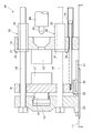
また、型開閉手段16は、固定盤13と型締手段15とに掛け渡してもよい。
さらにまた、型開閉手段16は、ベース11と可動盤18(又は型締手段15)とに掛け渡してもよい。
また、例えば、型締手段15は、ベース11の上面に貼った摺り板23に直接載せて、ベース11に対して 型締手段15を水平に移動させるようにしてもよい。
可動盤18を摺り板23に載せることや、型締手段15をスライダー22を介してレール21に載せることは差し支えない。
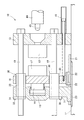
拘束機構30は、例えば、一端に設けたフランジ31と、このフランジ31を型締手段32に固定する複数本のボルト32と、フランジ31からタイバー19に沿って延びる筒部33とからなる。
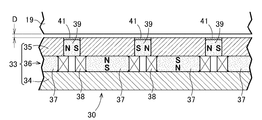
図3に示すように、筒部33は、例えば、鋼製の外筒34と、鋼製の内筒35と、これら外筒34と内筒35の間に配置される磁石機構36とからなる。
この磁石機構36は、例えば、外筒34と内筒35の間に配置される複数の第1の永久磁石37と、この第1の永久磁石37を囲う電磁コイル38と、隣り合う電磁コイル38、38の間に且つ内筒35に取付けられた第2の永久磁石39とからなる。電磁コイル38は、電磁石に相当する。
また、第2の永久磁石39においては、ある第2の永久磁石39のN極と隣りの第2の永久磁石39のN極が向かい合い、ある第2の永久磁石39のS極と隣りの第2の永久磁石39のS極が向かい合うように配置する。
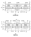
図4(a)、(b)において、図左から右へ、第2の永久磁石39は、第2の永久磁石39A、39B、39Cと呼ぶ(A、B、Cは位置を区別するための添え字である)。
隣り合う第2の永久磁石39A、39Bの間に位置する第1の永久磁石37を第1の永久磁石37X、隣り合う第2の永久磁石39A、39Bの間に位置する第1の永久磁石37を第1の永久磁石37Yと呼ぶ。
磁力線はN極からS極に向かうため、第1の永久磁石37Xの上面のN極から出た磁力線は矢印(1)のように、最も近い第2の永久磁石39BのS極に向かう。
第2の永久磁石39BのN極から出た磁力線は矢印(2)のように、最も近い第1の永久磁石37YのS極に向かう。
第1の永久磁石37YのN極から出た磁力線は矢印(3)のように、最も近い第1の永久磁石37XのS極に向かう。
隣の第2の永久磁石39A、39Cにおいては、図反時計回りの磁力線42が形成される。
何れの磁力線42も、タイバー19には関与していないため、タイバー19に対して、筒部33は、図面左又は右へ移動可能となる。この状態は、非拘束状態に相当する。
中央の第2の永久磁石39BのN極から出た磁力線42は、矢印(4)のように、直近のタイバー19を経由して自己のS極に至る。
また、右側の第1の永久磁石37YのN極から出た磁力線42は、矢印(5)のように、タイバー19を経由して、左側の第1の永久磁石37XのS極に至る。
なお、鋼製の内筒35が、(N)極や(S)極となるため、鋼製の内筒35が、磁力線42の形成及び強化に寄与している。
これらの磁力線42により、タイバー19に対して、筒部33は拘束状態になる。拘束状態では、筒部33は図左右へ移動しない。
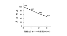
本発明者らが確かめたところ、図5に示すように、筒部33とタイバー19との距離Dを横軸に取ったとき、拘束力は右下がりの緩い曲線で得られた。
距離Dが0mmの場合の拘束力を100%とした場合、距離Dが1mmでの拘束力は83%で、距離Dが2mmでの拘束力は64%で、距離Dが3mmでの拘束力は50%であった。
距離Dを数mmにすることで、筒部33とタイバー19との機械的接触が回避され、筒部33の摩耗及びタイバー19の摩耗を回避できる。
図1では、固定型12から可動型17が離れている。型締めするには、拘束機構30を非拘束状態にし、型開閉手段16を縮動する。すると、可動盤18及び型締手段15は、固定盤13に接近する。この接近により、固定型12に可動型17が当たる。
次に、拘束機構30を拘束状態にする。そして、型締手段15を伸動して、固定型12へ可動型17を高圧型締めする。
図4(b)に示す拘束状態が、例えば60秒間続けられるとする。電磁コイル38には、1秒間通電し、59秒間は通電しないため、通電率は1÷60=0.017の計算により、通電時間は、全体の1.7%に止まる。図4(a)においても同様である。
したがって、本実施例では、電気エネルギーの消費はごく僅かである。
電磁石であれば、高価な永久磁石37、39が不要であるために、磁石機構36は安価となる。しかし、電磁石では、拘束中は連続して通電するため、電気エネルギーの消費は格段に大きくなる。
よって、電気エネルギーの消費の点では、電磁石よりは、永久磁石が勝る。
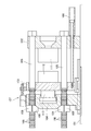
図6に示すように、拘束機構30は、固定盤13側に設けてもよい。その他の構成は図1と同じであるから、図1の符号を流用し、構造の詳細な説明は省略する。
拘束機構30は、固定盤13から筒部33の先端を射出装置44側に突出させることで、筒部33の十分な長さを確保することができる。
Claims (5)
- ベースに固定され固定型を支える固定盤と、前記ベースに移動可能に載せられ可動型を支える可動盤と、この可動盤の外側に配置されると共に前記ベースに移動可能に載せられ前記可動型を前記固定型へ型締めする型締手段と、少なくとも前記可動盤を貫通して延びるタイバーと、前記固定盤に対して前記可動盤又は前記型締手段を前記タイバーに沿って移動する型開閉手段とを有する型締装置であって、
この型締装置は、前記タイバーに前記型締手段又は前記固定盤を拘束状態にする拘束機構を備え、
この拘束機構は、前記タイバーに対して前記型締手段又は前記固定盤を拘束状態にすることと非拘束状態にすることとを切り換える磁石機構を備えていることを特徴とする型締装置。 - 請求項1記載の型締装置であって、
前記拘束機構は、前記タイバーとの間に所定の距離を保って配置されていることを特徴とする型締装置。 - 請求項1又は請求項2記載の型締装置であって、
前記磁石機構は、複数の永久磁石と、一部の永久磁石の極性を制御する電磁コイルとを備えていることを特徴とする型締装置。 - 請求項1〜3のいずれか1項記載の型締装置であって、
前記拘束機構は、前記タイバーを囲いつつ、前記型締手段から前記可動盤を貫通して延び、先端が前記可動盤から前記固定盤側へ突き出ている筒部を備えていることを特徴とする型締装置。 - 請求項1〜3のいずれか1項記載の型締装置であって、
前記拘束機構は、前記タイバーを囲いつつ、前記固定盤を貫通して延び、先端が前記固定盤から射出装置側へ突き出ている筒部を備えていることを特徴とする型締装置。
Priority Applications (5)
| Application Number | Priority Date | Filing Date | Title |
|---|---|---|---|
| JP2019031757A JP6854838B2 (ja) | 2019-02-25 | 2019-02-25 | 型締装置 |
| EP20762436.2A EP3932588B1 (en) | 2019-02-25 | 2020-02-14 | Mold-clamping machine |
| CN202080016514.XA CN113474104B (zh) | 2019-02-25 | 2020-02-14 | 合模装置 |
| US17/423,225 US12257754B2 (en) | 2019-02-25 | 2020-02-14 | Mold-clamping machine |
| PCT/JP2020/005682 WO2020175166A1 (ja) | 2019-02-25 | 2020-02-14 | 型締装置 |
Applications Claiming Priority (1)
| Application Number | Priority Date | Filing Date | Title |
|---|---|---|---|
| JP2019031757A JP6854838B2 (ja) | 2019-02-25 | 2019-02-25 | 型締装置 |
Publications (2)
| Publication Number | Publication Date |
|---|---|
| JP2020131663A true JP2020131663A (ja) | 2020-08-31 |
| JP6854838B2 JP6854838B2 (ja) | 2021-04-07 |
Family
ID=72238277
Family Applications (1)
| Application Number | Title | Priority Date | Filing Date |
|---|---|---|---|
| JP2019031757A Active JP6854838B2 (ja) | 2019-02-25 | 2019-02-25 | 型締装置 |
Country Status (5)
| Country | Link |
|---|---|
| US (1) | US12257754B2 (ja) |
| EP (1) | EP3932588B1 (ja) |
| JP (1) | JP6854838B2 (ja) |
| CN (1) | CN113474104B (ja) |
| WO (1) | WO2020175166A1 (ja) |
Cited By (1)
| Publication number | Priority date | Publication date | Assignee | Title |
|---|---|---|---|---|
| CN117577443A (zh) * | 2024-01-16 | 2024-02-20 | 淄博速悦电子有限公司 | 一种组合式电流互感器及其制备工艺 |
Citations (4)
| Publication number | Priority date | Publication date | Assignee | Title |
|---|---|---|---|---|
| JP2001315130A (ja) * | 2000-05-02 | 2001-11-13 | Meiki Co Ltd | 型締装置とその制御方法 |
| KR20030043289A (ko) * | 2001-11-27 | 2003-06-02 | 엘지전선 주식회사 | 자기유변유체를 이용한 형체결장치 |
| JP2017121797A (ja) * | 2016-01-08 | 2017-07-13 | 株式会社コスメック | マグネットクランプシステム |
| KR20180045683A (ko) * | 2016-10-26 | 2018-05-04 | 엘에스엠트론 주식회사 | 사출성형기의 하프 너트 체결 장치 |
Family Cites Families (9)
| Publication number | Priority date | Publication date | Assignee | Title |
|---|---|---|---|---|
| US5188850A (en) * | 1990-07-27 | 1993-02-23 | Nissie Jushi Kogyo K.K. | Clamping apparatus for molding machine |
| JP4531737B2 (ja) * | 2006-11-07 | 2010-08-25 | 住友重機械工業株式会社 | 型締装置 |
| US7611346B2 (en) * | 2007-02-05 | 2009-11-03 | Husky Injection Molding Systems Ltd. | Molding-system clamp |
| WO2008105041A1 (ja) * | 2007-02-23 | 2008-09-04 | Pascal Engineering Corporation | 磁力式固定装置 |
| JP4516097B2 (ja) * | 2007-06-13 | 2010-08-04 | 株式会社名機製作所 | 型締装置 |
| JP5634899B2 (ja) * | 2011-01-31 | 2014-12-03 | 住友重機械工業株式会社 | 型締装置 |
| JP5749127B2 (ja) * | 2011-09-20 | 2015-07-15 | 住友重機械工業株式会社 | 射出成形機 |
| JP6177217B2 (ja) * | 2014-11-05 | 2017-08-09 | 日精樹脂工業株式会社 | 型締装置 |
| JP6480384B2 (ja) | 2016-06-29 | 2019-03-06 | 日精樹脂工業株式会社 | 型締装置 |
-
2019
- 2019-02-25 JP JP2019031757A patent/JP6854838B2/ja active Active
-
2020
- 2020-02-14 EP EP20762436.2A patent/EP3932588B1/en active Active
- 2020-02-14 CN CN202080016514.XA patent/CN113474104B/zh active Active
- 2020-02-14 WO PCT/JP2020/005682 patent/WO2020175166A1/ja not_active Ceased
- 2020-02-14 US US17/423,225 patent/US12257754B2/en active Active
Patent Citations (4)
| Publication number | Priority date | Publication date | Assignee | Title |
|---|---|---|---|---|
| JP2001315130A (ja) * | 2000-05-02 | 2001-11-13 | Meiki Co Ltd | 型締装置とその制御方法 |
| KR20030043289A (ko) * | 2001-11-27 | 2003-06-02 | 엘지전선 주식회사 | 자기유변유체를 이용한 형체결장치 |
| JP2017121797A (ja) * | 2016-01-08 | 2017-07-13 | 株式会社コスメック | マグネットクランプシステム |
| KR20180045683A (ko) * | 2016-10-26 | 2018-05-04 | 엘에스엠트론 주식회사 | 사출성형기의 하프 너트 체결 장치 |
Cited By (2)
| Publication number | Priority date | Publication date | Assignee | Title |
|---|---|---|---|---|
| CN117577443A (zh) * | 2024-01-16 | 2024-02-20 | 淄博速悦电子有限公司 | 一种组合式电流互感器及其制备工艺 |
| CN117577443B (zh) * | 2024-01-16 | 2024-04-02 | 淄博速悦电子有限公司 | 一种组合式电流互感器及其制备工艺 |
Also Published As
| Publication number | Publication date |
|---|---|
| EP3932588B1 (en) | 2023-10-11 |
| US20220063164A1 (en) | 2022-03-03 |
| US12257754B2 (en) | 2025-03-25 |
| WO2020175166A1 (ja) | 2020-09-03 |
| CN113474104B (zh) | 2023-01-06 |
| CN113474104A (zh) | 2021-10-01 |
| EP3932588C0 (en) | 2023-10-11 |
| EP3932588A4 (en) | 2022-12-07 |
| JP6854838B2 (ja) | 2021-04-07 |
| EP3932588A1 (en) | 2022-01-05 |
Similar Documents
| Publication | Publication Date | Title |
|---|---|---|
| US10460864B2 (en) | Magnetic substance holding device | |
| CN103862646B (zh) | 注射成形机的喷嘴接触机构 | |
| JP2010173333A (ja) | 型締装置及び型厚調整方法 | |
| US9969061B2 (en) | Magnetic substance holding device | |
| JP6854838B2 (ja) | 型締装置 | |
| JP2009029086A (ja) | 型締装置 | |
| CN107877771A (zh) | 一种附加取向磁场的磁铁注塑机 | |
| JP5183891B2 (ja) | 型締装置 | |
| CN207509591U (zh) | 一种附加取向磁场的磁铁注塑机 | |
| ATE498186T1 (de) | Bistabiler elektromagnetischer aktuator | |
| JP5005478B2 (ja) | 射出成形機 | |
| US20110244065A1 (en) | Injection molding machine | |
| KR101327254B1 (ko) | 사출성형기 | |
| JP4648870B2 (ja) | 型締力制御方法及び型締装置 | |
| JP5005972B2 (ja) | 型締装置 | |
| KR20170048783A (ko) | 자기 형체력을 이용한 형체장치 | |
| JP5290510B2 (ja) | 型締装置 | |
| KR101327253B1 (ko) | 사출성형기 | |
| KR101339972B1 (ko) | 사출성형기 | |
| KR20130098923A (ko) | 사출성형기 | |
| CN205703426U (zh) | 一种电控永磁换模系统 | |
| TWI395393B (zh) | Rod type linear motor | |
| JP2012158025A (ja) | 成形機 | |
| JP2005348505A (ja) | 電磁アクチュエータ | |
| BG67104B1 (bg) | Поляризиран електромагнит |
Legal Events
| Date | Code | Title | Description |
|---|---|---|---|
| A621 | Written request for application examination |
Free format text: JAPANESE INTERMEDIATE CODE: A621 Effective date: 20200116 |
|
| A131 | Notification of reasons for refusal |
Free format text: JAPANESE INTERMEDIATE CODE: A131 Effective date: 20201222 |
|
| A521 | Request for written amendment filed |
Free format text: JAPANESE INTERMEDIATE CODE: A523 Effective date: 20210212 |
|
| TRDD | Decision of grant or rejection written | ||
| A01 | Written decision to grant a patent or to grant a registration (utility model) |
Free format text: JAPANESE INTERMEDIATE CODE: A01 Effective date: 20210302 |
|
| A61 | First payment of annual fees (during grant procedure) |
Free format text: JAPANESE INTERMEDIATE CODE: A61 Effective date: 20210316 |
|
| R150 | Certificate of patent or registration of utility model |
Ref document number: 6854838 Country of ref document: JP Free format text: JAPANESE INTERMEDIATE CODE: R150 |
|
| R250 | Receipt of annual fees |
Free format text: JAPANESE INTERMEDIATE CODE: R250 |