JP2020067541A - Laminate sheet - Google Patents
Laminate sheet Download PDFInfo
- Publication number
- JP2020067541A JP2020067541A JP2018199785A JP2018199785A JP2020067541A JP 2020067541 A JP2020067541 A JP 2020067541A JP 2018199785 A JP2018199785 A JP 2018199785A JP 2018199785 A JP2018199785 A JP 2018199785A JP 2020067541 A JP2020067541 A JP 2020067541A
- Authority
- JP
- Japan
- Prior art keywords
- base material
- information
- laminated sheet
- slip
- peeling piece
- Prior art date
- Legal status (The legal status is an assumption and is not a legal conclusion. Google has not performed a legal analysis and makes no representation as to the accuracy of the status listed.)
- Pending
Links
Images


Abstract
Description
本発明は、複数の層からなり、表面に情報が表示された層を剥がして利用可能な積層シートに関する。 The present invention relates to a laminated sheet which is composed of a plurality of layers and which can be used by peeling off the layer on which information is displayed.
従来、配荷物や配送商品を配送業者が配送する際に、配送物に貼付して使用する配送伝票が用いられている。近年、一枚の伝票用紙上に複数種類の伝票を配列させて、各伝票を同時にプリンタ印字したものを組とする1パート形式の配送伝票(以下、1パート配送伝票という)が多く利用されるようになってきている。 2. Description of the Related Art Conventionally, when a delivery company delivers a package or a delivery item, a delivery slip attached to a delivery item is used. 2. Description of the Related Art In recent years, a one-part type delivery slip (hereinafter, referred to as a one-part delivery slip) is often used in which a plurality of types of slips are arranged on one slip sheet, and each slip is printed by a printer at the same time. Is starting to appear.
その代表的な1パート配送伝票は、剥離紙、粘着剤層、中間基材の順に積層されてなるタックシートの中間基材側の面に接着層を介して配達票と貼付票とを面状に配置して形成する伝票用紙が設けられ、少なくとも配達票はタックシートから剥離可能な構造を有している(特許文献1参照)。 A typical one-part delivery slip is a delivery sheet and a sticker sheet that are sheet-shaped with an adhesive layer on the surface of the tack sheet that is formed by laminating a release paper, an adhesive layer, and an intermediate substrate in this order. Is provided with a slip sheet, and at least the delivery slip has a structure that can be peeled from the tack sheet (see Patent Document 1).
1パート配送伝票は、上記のように一枚の伝票用紙上に配達票と貼付票が設けられているので、コンピュータで管理されている配送情報に基づき、お届け先情報、依頼元情報、その他バーコード等の管理用の情報などを、プリンタで配送伝票上の所定箇所に高速で印字することが可能である。その使用に当たっては、事前に所定事項がプリンタで印字された1パート配送伝票を用意し、当該1パート配送伝票を構成するタックシートの剥離紙を剥がし、粘着剤層を介して所定の配送物に貼付する。 As described above, the 1-part delivery slip has a delivery slip and an attachment slip on one slip sheet, so based on the delivery information managed by the computer, the delivery destination information, request source information, and other It is possible to print management information such as codes at a high speed at a predetermined location on the delivery slip with a printer. Before using it, prepare a 1-part delivery slip with the prescribed items printed on it in advance, peel off the release paper of the tack sheet that composes the 1-part delivery slip, and put it on the specified delivery item via the adhesive layer. Attach it.
配送業者は、配送物を届けた際、当該配送物を受取人に渡した証しとして、受取人に上記配達票へ受領印あるいはサインを施してもらった後タックシートから剥離し、これを受け取る。通常は受け取った配達票に付されているバーコードを用いて、コンピュータで管理されている配送情報の消し込み処理などを行う。 When the delivery company delivers the delivered product, as a proof that the delivery product has been delivered to the recipient, the delivery company removes the tack sheet from the tack sheet after receiving the delivery stamp or signature on the delivery slip, and receives it. Normally, the delivery information managed by a computer is erased by using the barcode attached to the received delivery slip.
上記配達票は、荷物を受領した旨の印またはサインが受取人によりなされることにより受領証としての役割を果たすが、この配達票の表面には、上述のように、捺印/サイン欄以外にも、お届け先情報、依頼元情報が印字、または記入されている。お届け先情報、依頼元情報には、住所・氏名等の個人情報が含まれている。一方、貼付票は、荷物に貼付されることを目的とする票であり、届け先に荷物が届けられ、配達票が剥離された後も、荷物に貼付された状態となっている。 The delivery slip serves as a receipt when a mark or signature indicating that the package has been received is made by the recipient, but on the surface of this delivery slip, as described above, other than the stamp / sign field, , Delivery address information and request source information are printed or filled in. The addressee information and the requester information include personal information such as address and name. On the other hand, the sticking slip is a sticker intended to be stuck to the parcel, and is still stuck to the parcel even after the parcel is delivered to the destination and the delivery slip is peeled off.
上述のように、貼付票は、届け先に届けられた後も、荷物に貼付された状態となっている。しかし、貼付票には、個人情報が表示されているため、個人情報が把握され難い状態にして廃棄する必要が生じる。貼付票が、配達票と同様に、剥離容易に形成されていたとしても、剥離した後、シュレッダー等を用いて個人情報が表示された部分を切り刻む必要があり、廃棄に手間が掛かってしまう。このような問題は、配送伝票に限らず、表面に個人情報が表示された基材に接着層等が重ねて形成された積層シート全般においても同様に生じている。 As described above, the pasting slip remains attached to the package even after it is delivered to the destination. However, since the personal information is displayed on the sticker, it becomes necessary to discard the personal information in a state where it is difficult to understand. Similar to the delivery slip, even if the sticking slip is easily peeled off, it is necessary to cut the portion on which the personal information is displayed using a shredder or the like after peeling off, and it takes time to dispose. Such a problem is not limited to delivery slips, and similarly occurs in general laminated sheets in which an adhesive layer or the like is formed on a base material on the surface of which personal information is displayed.
そこで、本発明は、表示された情報の漏えいの惧れを低減することが可能な積層シートを提供することを課題とする。 Therefore, it is an object of the present invention to provide a laminated sheet that can reduce the risk of leakage of displayed information.
上記課題を解決するため、本発明は、
剥離片を備える表面基材が中間基材と接着されているとともに、前記中間基材が粘着剤層を介して剥離基材に貼り合わされており、前記剥離片と中間基材は擬似接着されており、前記中間基材から前記剥離片が剥離可能な積層シートであって、
前記剥離片は、表面から視認可能に情報を表示するための情報表示部を備えており、
前記剥離片には、前記剥離片の外縁の一辺における一端から、渦巻き状に延びる部分を備えて、前記一辺とは異なる他の辺における他端まで延び、前記一端から他端まで連続して表面基材を貫通する切り込みが、前記情報表示部を通るように形成されていることを特徴とする積層シートを提供する。
In order to solve the above problems, the present invention provides
The surface base material including the peeling piece is bonded to the intermediate base material, and the intermediate base material is attached to the peeling base material via the adhesive layer, and the peeling piece and the intermediate base material are pseudo-bonded. A laminated sheet in which the peeling piece can be peeled from the intermediate base material,
The peeling piece includes an information display unit for displaying information visibly from the surface,
The peeling piece includes a portion that extends in a spiral shape from one end on one side of the outer edge of the peeling piece, extends to the other end on another side different from the one side, and continuously extends from the one end to the other surface. There is provided a laminated sheet characterized in that a notch penetrating a base material is formed so as to pass through the information display section.
また、本発明は、
剥離片を備える表面基材が支持基材と擬似接着されており、前記支持基材から前記剥離片が剥離可能な積層シートであって、
前記剥離片は、表面から視認可能に情報を表示するための情報表示部を備えており、
前記剥離片には、前記剥離片の外縁の一辺における一端から、渦巻き状に延びる部分を備えて、前記一辺とは異なる他の辺における他端まで延び、前記一端から他端まで連続して表面基材を貫通する切り込みが、前記情報表示部を通るように形成されていることを特徴とする積層シートを提供する。
Further, the present invention is
A surface sheet comprising a peeling piece is pseudo-bonded to a supporting base material, and the peeling piece is a laminated sheet that can be peeled from the supporting base material,
The peeling piece includes an information display unit for displaying information visibly from the surface,
The peeling piece includes a portion that extends in a spiral shape from one end on one side of the outer edge of the peeling piece, extends to the other end on another side different from the one side, and continuously extends from the one end to the other surface. There is provided a laminated sheet characterized in that a notch penetrating a base material is formed so as to pass through the information display section.
また、本発明の積層シートは、前記渦巻き状に延びる部分は直線部分を備え、当該直線部分と並行する直線部分との間隔が等しくなるように形成されていることを特徴とする。 Further, the laminated sheet of the present invention is characterized in that the spirally extending portion is provided with a straight line portion, and the straight line portion and the parallel straight line portion are formed at equal intervals.
また、本発明の積層シートは、前記間隔は、3.0mm以上7.0mm以下であることを特徴とする。 Further, the laminated sheet of the present invention is characterized in that the interval is 3.0 mm or more and 7.0 mm or less.
また、本発明の積層シートは、前記切り込みは、前記情報を表示する文字を分断(分割)する位置に形成されていることを特徴とする。 Further, the laminated sheet of the present invention is characterized in that the notch is formed at a position where the character for displaying the information is divided (divided).
また、本発明の積層シートは、前記情報表示部は、情報を記入または印字するための欄であることを特徴とする。 Further, the laminated sheet of the present invention is characterized in that the information display section is a column for writing or printing information.
また、本発明の積層シートは、前記切り込みの一端が位置する前記表面基材の外縁の一辺は、前記剥離片と他の部分を区分し、表面基材を貫通する第2の切り込み(H2)が形成される位置であることを特徴とする。 Further, in the laminated sheet of the present invention, one side of the outer edge of the surface base material where one end of the notch is located separates the peeling piece from the other portion, and a second cut (H2) penetrating the surface base material. Is a position where is formed.
また、本発明は、
表面基材が剥離基材と接着された積層シートであって、
前記表面基材は、表面から視認可能に情報を表示するための情報表示部を備えており、
前記表面基材には、前記表面基材の外縁の一辺における一端から、渦巻き状に延びる部分を備えて、前記一辺とは異なる他の辺における他端まで延び、前記一端から他端まで連続して表面基材を貫通する切り込みが、前記情報表示部を通るように形成されていることを特徴とする積層シートを提供する。
Further, the present invention is
A laminated sheet in which a surface base material is adhered to a release base material,
The surface substrate includes an information display unit for displaying information visibly from the surface,
The surface base material includes a portion that extends in a spiral shape from one end on one side of the outer edge of the surface base material, extends to the other end on another side different from the one side, and continues from the one end to the other end. A cutout that penetrates the surface base material is formed so as to pass through the information display section.
本発明によれば、表示された情報の漏えいの惧れを低減することが可能となる。 According to the present invention, it is possible to reduce the risk of leakage of displayed information.
以下、本発明の好適な実施形態について、図面を参照して詳細に説明する。
<1.配送伝票(積層シート)の構造>
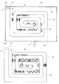
図1は、本発明に係る積層シートの一実施形態としての配送伝票を示す図である。このうち、図1(a)は表面側の平面図、図1(b)は図1(a)におけるA−Aに対応する断面図である。
Hereinafter, preferred embodiments of the present invention will be described in detail with reference to the drawings.
<1. Structure of delivery slip (laminated sheet)>
FIG. 1 is a diagram showing a delivery slip as an embodiment of a laminated sheet according to the present invention. Of these, FIG. 1A is a plan view on the front surface side, and FIG. 1B is a cross-sectional view corresponding to AA in FIG.
図1に示すように、本実施形態に係る配送伝票は、表面に配送情報記入部(図示省略)が印字された配達票2aと、表面に配送情報記入部(図示省略)が印字された貼付票2bが縦方向に配置された表面基材2が最上層に設けられている。本来、上層下層の区別はないが、説明の便宜上、本明細書では、表面基材2側を最上層、剥離基材8側を最下層として説明することにする。また、平面方向においても、本来、上下左右の区別はないが、説明の便宜上、本明細書では、図1に示した状態において、配達票2aが配置された側を上側、貼付票2bが配置された側を下側とし、左に位置する側を左側、右に位置する側を右側として説明することにする。実際の態様においては、上下と左右を入れ替えることも可能である。
As shown in FIG. 1, the delivery slip according to the present embodiment has a
表面基材2は、図1(a)に示すように、横方向(図1(a)における左右方向)に形成されたハーフカットH2により配達票2aと貼付票2bに区分されている。ハーフカットH2は表面基材2を貫通し、中間基材6を貫通しない切り込みである。配送伝票全体としては、中間基材6や剥離基材8を貫通せず、途中まで切り込まれるため、ハーフカットと呼ばれる。後述のハーフカットH1と区別するため、第2の切り込みと表現することもできる。配達票2aは、荷物を受領した旨の印またはサインが受取人によりなされることにより受領証としての役割を果たすものであり、接着剤層4から剥離可能に接着されて剥離片として機能する。また、貼付票2bは、荷物が届け先に届き、配送が完了した後まで、荷物に貼付されるものであり、配送後、受取人が廃棄し易いように、接着剤層4から剥離可能に接着されて剥離片として機能する。
As shown in FIG. 1A, the surface base material 2 is divided into a
図2は、本実施形態の配送伝票の貼付票2bの表面を示した図である。このうち、図2(a)は、ハーフカットH1の形状を詳細に示すため、情報表示部である配送情報記入部を重ねていない状態の図であり、図2(b)は、配送情報記入部とハーフカットH1の位置関係を示すため、配送情報記入部を重ねた状態を示している。図2は、図1(a)と同様、表面側から見た状態であるが、貼付票2bのみを示しており、図1(a)において省略したハーフカットH1を図示している。図2(a)に示すように、貼付票2bには、表面基材2である貼付票2bを貫通し、中間基材6を貫通しない切り込みであるハーフカットH1が形成されている。ハーフカットH1の平面形状は、剥離片である貼付票2bの外縁の一辺に一端を設け、渦巻き状に延びる部分を備えて、一端が設けられた一辺と対向する辺に設けられた他端まで延び、一端から他端まで連続して貼付票2b(表面基材2)を貫通するものとなっている。本実施形態では、一端である開始点E1から他端である終了点E2まで連続している。E3は、開始点E1から終了点E2まで形成されているハーフカットH1の中間点である。ハーフカットH1は、中間点E3に対して点対称となるように形成されている。なお、ここでは、説明の便宜上、剥離開始点S1に近いE1を開始点、他方のE2を終了点と呼ぶが、E1を終了点、他方のE2を開始点と呼んでもよい。
FIG. 2 is a diagram showing the surface of the
図2(b)においては、図1において省略した配送情報記入部を図示している。配送情報記入部は、配送情報を記入または印字するための部分であり、記入または印字を行う前は、空欄となっており、記入・印字等された情報を表面から視認可能に表示するための情報表示部としての役割を果たす。図2の例では、配送情報記入部に、お届け先情報として「〒100−0001東京都○○区○○ ○○○○様」、依頼元情報として「○○○○」が印字された状態を示している。お届け先情報、依頼元情報として記入された配送情報は、個人情報に相当すると考えられる。配送情報記入部の大部分は、渦巻き状領域H1aと重なるように配置される。ここで、渦巻き状領域とは、ハーフカットH1のうち上端の切り込み、下端の切り込み、左端の切り込み、右端の切り込みを4辺とし、この4辺で囲まれる矩形状の領域であり、図2(b)において破線で囲まれた領域である。図2(b)の例では、情報表示部である配送情報記入部に記載された文字は、その全てが渦巻き状領域H1aに含まれた状態となっている。 In FIG. 2B, the delivery information entry unit omitted in FIG. 1 is illustrated. The delivery information entry part is a part for entering or printing delivery information.Before writing or printing, it is blank and is used to display the filled and printed information so that it can be seen from the surface. Functions as an information display unit. In the example of FIG. 2, the delivery information entry section is printed with the delivery address information “Mr. ○○○○○○, ○○ Ward, Tokyo 100-0001” and the requester information “○○○○”. Is shown. The delivery information entered as the delivery destination information and the request source information is considered to correspond to personal information. Most of the delivery information writing section is arranged so as to overlap the spiral area H1a. Here, the spiral region is a rectangular region surrounded by the four sides including a cut at the upper end, a cut at the lower end, a cut at the left end, and a cut at the right end of the half cut H1, and is a rectangular region surrounded by the four sides, as shown in FIG. It is a region surrounded by a broken line in b). In the example of FIG. 2B, all the characters written in the delivery information entry section, which is the information display section, are in a state of being included in the spiral region H1a.
ハーフカットH1の形成態様については、貼付票2b(表面基材2)を、開始点E1から終了点E2まで亘って分離することができる態様であれば、特に限定されないが、本実施形態では、開始点E1から終了点E2までの間において、並行する切り込みが存在する場合に、隣接する各切り込み間の間隔が等間隔であるよう形成されている。具体的には、ハーフカットH1の平面形状は、渦巻き状に延びる部分を備えているが、この渦巻き状の部分は、ハーフカットH2に平行な方向(図2における左右方向)、ハーフカットH2に垂直な方向(図2における上下方向)、に延びる直線部分を備えている。図2の例では、この直線部分と並行する直線部分との間隔が等しくなるように形成されている。したがって、図2に示したように、並行する切り込みが存在する場合における任意の位置における隣接する切り込み間の間隔W1、W2、W3、W4がいずれも等しくなっている。隣接する切り込み間の間隔については適宜設定することができるが、3.0mm以上7.0mm以下であることが好ましく、4.0mm以上6.0mm以下であることがより好ましい。本実施形態では、全て5.0mmとしている。ハーフカットH1の切り取りが行われると、並行する切り込みに挟まれた部分は、帯状分離部Ta、Tbとなり、帯状分離部Ta、Tbの幅は、渦巻き状領域H1aにおける並行する切り込み間の間隔と等しくなる。帯状分離部Ta、Tbを剥離する際、途中で千切れないようにするために、ハーフカットH1において、直交する直線部分の間は円弧状の曲線で結ばれた状態としている。円弧状の部分は、隣接する切り込み間の間隔が5.0mmの場合、例えば、曲率半径5.0mmの円弧とすることができる。
The form of the half-cut H1 is not particularly limited as long as it can separate the sticking
帯状分離部Ta、Tbの先端は、円弧状となっており、帯状分離部Ta、Tbは、それぞれ先端の点E4、E5まで連続している。先端の点E4、E5を含む円弧状の部分は、隣接する切り込み間の間隔が5.0mmの場合、曲率半径2.5mmの円弧とすることができる。隣接する切り込みの間隔が狭すぎると、隣接する切り込みに挟まれた帯状分離部Ta、Tbが、それぞれの先端の点E4、E5まで連続せず、途中で切れてしまい、先端の点E4、E5付近に表示された情報を分断できなくなる。逆に、隣接する切り込みの間隔が広すぎると、ハーフカットH1を先端の点E4、E5まで連続して切り取ることができた場合でも、並行する切り込み間である帯状分離部Ta、Tbに表示された情報が、十分に認識可能な情報となってしまい、情報の漏えいを十分に防止することが難しくなる。図2に示した例では、配送情報記入部に印字された文字を、渦巻き状領域H1aに位置する切り込みが横切る状態、すなわち情報表示部を通るような状態となっており、この状態で切り込みから分離されると、文字が分断(分割)されるようになっている。 The tip ends of the strip-shaped separating portions Ta and Tb have an arc shape, and the strip-shaped separating portions Ta and Tb are continuous to points E4 and E5 at the tip ends, respectively. The arc-shaped portion including the points E4 and E5 at the tip can be an arc having a curvature radius of 2.5 mm when the distance between the adjacent cuts is 5.0 mm. If the interval between the adjacent cuts is too narrow, the strip-shaped separation portions Ta and Tb sandwiched by the adjacent cuts do not continue to the respective points E4 and E5 at the tips, and are cut in the middle, resulting in the points E4 and E5 at the tips. Information displayed in the vicinity cannot be divided. On the contrary, if the intervals between the adjacent cuts are too wide, even if the half cut H1 can be continuously cut to the points E4 and E5 at the tip, the half cuts H1 are displayed in the strip-shaped separation portions Ta and Tb which are between the parallel cuts. The information thus obtained becomes sufficiently recognizable information, and it becomes difficult to sufficiently prevent information leakage. In the example shown in FIG. 2, the characters printed on the delivery information entry section are in a state in which the notch located in the spiral region H1a crosses, that is, passes through the information display section. When separated, the character is divided (divided).
図1(b)のA−A断面図に示すように、配達票2a(表面基材2)、貼付票2b(表面基材2)の下層には、剥離層3、接着剤層4を介して、表面に目止め層5、裏面に粘着剤層7が設けられた中間基材6が重ね合わされており、粘着剤層7の下層には、剥離基材8が剥離可能な状態で積層されている。剥離層3と接着剤層4の2つの層により擬似的に接着可能な擬似接着層を形成している。配送伝票は、剥離基材8を剥離させた後に、粘着剤層7により配送物に貼付して使用する。
As shown in the AA cross-sectional view of FIG. 1B, a
図1(a)において破線で示した12は、配達票2aの下層における接着剤層4の端部の位置を示している。実際には、表面基材2に隠れて表面からは見えない線であるが、ここでは、剥離開始点Sとの位置関係を示すため、便宜上、平面図に示してある。接着剤層4において、この端部12まで接着剤が塗布され、剥離開始点Sである左端の角部には、接着剤は塗布されない。従って、配達票2a(表面基材2)の下層における端部12より図中左下方向(図1(a))の領域には非接着部12aが形成され、非接着部12aでは、配達票2aは、中間基材6に接着されていない状態となっている。直線状の端部12の角度には特に限定はないが、ハーフカットH2との角度が135度(45度)に近付くように、すなわち、配達票2aの左端の辺と、ハーフカットH2上の辺と端部12により形成される非接着部12aが、二等辺三角形に近付くように形成するのが望ましい。
In FIG. 1A, the
図1(a)、図2において破線で示した13は、貼付票2bの下層における接着剤層4の端部の位置を示している。実際には、表面基材2に隠れて表面からは見えない線であるが、ここでは、剥離開始点Sとの位置関係を示すため、便宜上、平面図に示してある。接着剤層4において、この端部13まで接着剤が塗布され、剥離開始点Sである左端の角部には、接着剤は塗布されない。従って、貼付票2b(表面基材2)の下層における端部13より図中左上方向(図1(a)、図2)の領域には非接着部13aが形成され、非接着部13aでは、貼付票2bは、中間基材6に接着されていない状態となっている。直線状の端部13の角度には特に限定はないが、ハーフカットH2との角度が135度(45度)に近付くように、すなわち、貼付票2bの左端の辺と、ハーフカットH2上の辺と端部13により形成される非接着部13aが、二等辺三角形に近付くように形成するのが望ましい。なお、非接着部13aは、必ずしも形成する必要はなく、貼付票2b全体が中間基材6に接着されていてもよい。ただし、非接着部13aを敢えて形成しなくても、隣接する配達票2aの下層の非接着部12aが貼付票2bの下層まで及び、結果としてわずかな非接着部が、貼付票2bの角部付近の下層に形成されることもある。
The
開始点E1は、剥離開始点Sが位置する貼付票2bの一辺上に位置する。すなわち、開始点E1と剥離開始点Sは、貼付票2b(表面基材)の外縁のうち同じ側に位置する。そのため、剥離開始点Sから貼付票2bの剥離を開始すると、貼付票2bは、左端を含む帯状分離部Taの部分が剥離され、右端を含む帯状分離部Tbの部分が剥離されずに配送伝票本体に残ることになる。
The starting point E1 is located on one side of the sticking
貼付票2bの下層の接着剤層4は、貼付票2bの下層側全面に形成されるのではなく、配達票2aに接する側の左上側角である剥離開始点Sを含む三角形状の部分を残したものとなっている。貼付票2bの下層側においては、三角形状の非接着部13aに接着剤が塗布されていない。このため、貼付票2bの剥離の切っ掛けとなる。なお、本実施形態では、剥離層3を貼付票2bの下層側全面に渡って設けているが、接着剤層4に合わせて、剥離層3の端部を接着剤層4の端部13と合わせるようにしても良い。
The
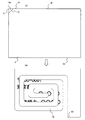
<2.配送伝票の製造>
本実施形態に係る配送伝票は、表面基材2、剥離層3、接着剤層4により構成される1枚目シートと、目止め層5、中間基材6、粘着剤層7、剥離基材8により構成される2枚目シートを貼り合わせた構成の積層シートとなっている。図3は、1枚目シートと2枚目シートの関係を示す図である。製造工程においては、1枚目シート、2枚目シートともに、複数の配送伝票を連続させたものとなっており、図3の例では、3つ分の配送伝票に対応している。
<2. Manufacturing of delivery slips>
The delivery slip according to the present embodiment includes a first sheet composed of a surface base material 2, a
図3において、H2は既に説明したハーフカットである。2枚目シートにおいて、横方向の破線で示すH2´は、貼り合わせた際にハーフカットH2が位置する線であるハーフカット対応線を示している。したがって、ハーフカット対応線H2´は、説明の便宜上図示したものであり、実際には、存在しない。このハーフカットH2は、1枚目シートにのみ形成されており、2枚目シートには形成されていない。 In FIG. 3, H2 is the half cut already described. In the second sheet, H2 'indicated by a broken line in the lateral direction indicates a half-cut corresponding line which is a line where the half-cut H2 is located when the pieces are laminated. Therefore, the half-cut corresponding line H2 'is shown for convenience of explanation, and does not actually exist. The half cut H2 is formed only on the first sheet, and is not formed on the second sheet.
1枚目シートは、上側片14aと下側片15aを備え、2枚目シートは、上側片14bと下側片15bを備えている。2枚目シートとしては、市販のタックシートを利用することができる。製造工程においては、まず、2枚目シートに対して、中間基材6の表面に絵柄等の印刷を行った後、印刷等により、目止め層5を形成する。その後、1枚目シートと2枚目シートの4つの角を合わせて貼り合わせる。そして、1枚目シート側から、表面基材2を貫通し、中間基材6に達しないハーフカット加工を行ってハーフカットH2を形成する。
The first sheet has an
また、ピナクル(登録商標)刃を用いて、1枚目シート側から、表面基材2を貫通し、中間基材6に達しないハーフカット加工を行ってハーフカットH1を形成する。ハーフカットH2とハーフカットH1の形成は、同時に行ってもよいし、連続して行ってもよい。なお、図3においては、ハーフカットH1については省略してある。さらに、貼り合わされた上側片14aと上側片14b、下側片15aと下側片15bを切除する。その後、図中上下方向に延びる一点鎖線で示す線分により切断することにより各配送伝票は分離される。
Further, using a Pinnacle (registered trademark) blade, a half-cut processing is performed from the first sheet side so as to penetrate the surface base material 2 and not reach the
<3.各層の組成>
表面基材2としては、充分な強度とプリンタによる印字適性及び搬送適性を有するものであれば使用でき、例えば、上質紙、クラフト紙、複写用紙、グラシン紙、パーチメント紙、レーヨン紙、コート紙、合成紙、樹脂フィルムによりラミネートされた紙等の紙が好適に用いられるが、セロファン、延伸ポリプロピレン、ポリエチレンテレフタレート、延伸ポリスチレン、ポリ塩化ビニル等の樹脂フィルムであっても良い。表面基材2の厚さは20〜200μm程度が好ましい。さらに、控票などを配送伝票の上に重ねた場合に、複写特性をもたせるために、ロイコ系染料などからなる感熱発色層を設けても良い。
<3. Composition of each layer>
As the surface base material 2, any material having sufficient strength and printability and transportability by a printer can be used. For example, high-quality paper, kraft paper, copy paper, glassine paper, parchment paper, rayon paper, coated paper, Paper such as synthetic paper and paper laminated with a resin film is preferably used, but resin films such as cellophane, stretched polypropylene, polyethylene terephthalate, stretched polystyrene and polyvinyl chloride may be used. The thickness of the surface base material 2 is preferably about 20 to 200 μm. Furthermore, a thermosensitive coloring layer made of a leuco dye or the like may be provided in order to provide copy characteristics when a slip or the like is placed on the delivery slip.
中間基材6としては、表面基材2と同様の紙や樹脂フィルムが用いられる。中間基材6に絵柄や説明文を印刷する場合は、一般印刷適性を備えたものを用いることが好ましい。
As the
上記剥離層3、接着剤層4、目止め層5、粘着剤層7は、本実施形態に係る配達伝票に適したものであれば、その組成については特に限定されるものではないが、好ましい例を以下に列挙する。
The composition of the
剥離層3としては、配達票2a、貼付票2bが中間基材6から容易に剥離できるような接着性の低い樹脂を使用することが好ましく、ポリエチレン、ポリプロピレン、ポリブチレン等のオレフィン系(共)重合体を用いることが最も好ましいが、他にも、ポリスチレン、ポリビニルブチラール、酢酸ビニル共重合体、エチレン−酢酸ビニル共重合体、塩化ビニル−酢酸ビニル共重合体、アクリル樹脂、セルロース樹脂等の熱可塑性樹脂及びこれらの混合物からなるフィルムでも良い。また、ポリウレタン等の熱硬化性樹脂等から形成されたフィルムを用いても良い。さらに、必要に応じて、酸化防止剤、熱安定剤、紫外線吸収剤、スリップ剤、帯電防止剤、防曇剤、着色剤、フィラー等が添加されていても良い。剥離層3を形成するための樹脂の塗布量・塗布厚は特に限定されないが、好ましくは、塗布厚は0.1〜10μmである。
As the
接着剤層4は、例えば、ウレタン系、アクリル系などの熱可塑性樹脂を使用することができ、フレキソ法、グラビア法などの公知の印刷法又はコーティング法によって、厚み0.1〜50μm程度に塗布し、貼り合わせ後に、必要に応じて乾燥させる。表面基材2と中間基材6は、接着剤(又は樹脂)が乾燥していない状態で貼り合わせるウェット又はセミウェットラミネート方式、熱圧着方式や感圧方式によって貼り合わせる。
The
目止め層5としては、中間基材6への接着剤の浸透を防止し、接着力を安定させるためのものであれば、公知の様々なものを用いることができる。例えば、公知の塩化ビニル系樹脂、アクリル系樹脂、ウレタン系樹脂、ポリエステル系樹脂、ポリアミド系樹脂、セルロース誘導体等の熱可塑性樹脂、熱硬化性樹脂、反応型樹脂やこれらの混合物が使用できる。必要に応じて添加剤を加え、公知の印刷法又はコーティング法によって塗布する。なお、目止め層5は接着力を安定させるために用いられるものであるため、接着剤層4に用いられる接着剤が十分な接着力を有するものであれば、必ずしも形成する必要はない。
As the
粘着剤層7は、配送物に配送伝票を貼付可能とする層であり、アクリル系粘着剤が最も好ましいが、天然ゴム系粘着剤、合成ゴム系粘着剤、シリコーンゴム系粘着剤等でも良い。粘着剤層7を形成するための粘着剤の塗布量・塗布厚は特に限定されないが、好ましくは、塗布量は0.1〜50g/m2であり、塗布厚は0.1〜50μmである。配送物等の被着体に対する粘着剤層7の接着力は、剥離層3と接着剤層4との接着力よりも大きくする必要があり、配送物等の被着体に応じて、適宜、調整が必要である。
The pressure-
<4.配送伝票の使用時の説明>
次に、本実施形態に係る配送伝票の使用時について説明する。配送物に貼付する際には、従来の配送伝票と同様、剥離基材8を中間基材6から剥離する。そして、従来の配送伝票と同様、粘着剤層7を介して配送物に貼付する。配送物への貼付後、配達票2aを剥がす。この際、配達票2aは、その全体がハーフカットH2により分離される。受取人が貼付票2bを廃棄する際には、貼付票2bを剥がす。この際、貼付票2bにおいては、ハーフカットH2とハーフカットH1により分離される。例えば、図2に示した例では、剥離開始点Sを切っ掛けとして剥がし始め、剥離開始点Sと開始点E1の間の部分から下方に向かう帯状の部分を剥がしていくことになる。この帯状の部分は、帯状分離部Taの一部となる。
<4. Explanation when using delivery slip>
Next, the use of the delivery slip according to this embodiment will be described. When affixing to a delivery, the
帯状分離部Taを渦巻き状に剥がしていき、帯状分離部Taの先端となる点E4に達すると、帯状分離部Taは完全に配送伝票本体から分離されることになる。このとき、帯状分離部Tbは剥離されずに配送伝票本体側に残った状態となる。図4は、帯状分離部Taを剥離した状態を示す図である。このうち、図4(a)は、帯状分離部Taが分離されて、帯状分離部Tbが残った配送伝票を示している。また、図4(b)は、分離された帯状分離部Taを示している。図4に示すように、ハーフカットH1により区分された一方の帯状分離部Taを分離することにより、貼付票に印刷された情報は、判別が難しくなる。剥離された帯状分離部Taにおいても印刷された情報も、判別が難しくなる。 When the strip separating portion Ta is peeled off in a spiral shape and reaches a point E4 which is the tip of the strip separating portion Ta, the strip separating portion Ta is completely separated from the delivery slip body. At this time, the strip-shaped separating portion Tb is not peeled off and remains on the delivery slip body side. FIG. 4 is a diagram showing a state in which the strip-shaped separation portion Ta is peeled off. Among them, FIG. 4A shows a delivery slip in which the strip-shaped separating portion Ta is separated and the strip-shaped separating portion Tb remains. Moreover, FIG.4 (b) has shown the strip | belt-shaped isolation | separation part Ta isolate | separated. As shown in FIG. 4, by separating one of the strip-shaped separating portions Ta separated by the half cut H1, it becomes difficult to determine the information printed on the sticky note. It is difficult to determine the information printed even in the strip-shaped separation portion Ta that has been peeled off.
図4(a)に示した配送伝票では、終了点E2の右と左で段差ができている。これは、終了点E2の右側は、貼付票2bの一部である帯状分離部Tbが残っており、終了点E2の左側は、帯状分離部Tbが剥離され、接着剤層が表出した状態となっているためである。終了点E2における段差を利用して、終了点E2を切っ掛けとして剥がし始め、貼付票の右端を含む帯状の部分を上方に剥がしていくことになる。この帯状の部分は、帯状分離部Tbの一部となる。
In the delivery slip shown in FIG. 4A, a step is formed on the right and left of the end point E2. This is a state in which the strip-shaped separating portion Tb that is a part of the sticking
帯状分離部Tbを渦巻き状に剥がしていき、帯状分離部Tbの先端となる点E5に達すると、帯状分離部Tbは完全に配送伝票本体から分離されることになる。このとき、配送伝票本体は、接着剤層4が全体に表出した状態となる。図5は、帯状分離部Tbを剥離した状態を示す図である。このうち、図5(a)は、帯状分離部Tbが分離されて、接着剤層4が全体に表出した配送伝票を示している。また、図5(b)は、分離された帯状分離部Tbを示している。図5(b)に示すように、剥離された帯状分離部Taにおいても印刷された情報は、判別が難しくなる。
When the strip separating portion Tb is spirally peeled off and reaches a point E5 which is the tip of the strip separating portion Tb, the strip separating portion Tb is completely separated from the delivery slip body. At this time, the delivery slip body is in a state in which the
分離された帯状分離部Ta、Tbは、各単体においては、文字が分断されている。すなわち、ハーフカットH1の切り込みにより分断されることになる。したがって、情報全体が把握し難くなっており、情報の漏えいの防止に十分効果がある。実際には、印刷する文字サイズに合わせて、情報が把握し難い程度に文字が十分に分断されるように、帯状部分の幅を調整することになる。ただし、分離後の帯状分離部Ta、Tbに文字が見える状態で残ったとしても、W1〜W4として示したように帯状部分の幅が十分に狭いため、帯状分離部Ta、Tbを手で簡単に千切ることができ、シュレッダーを用いなくても情報漏えいの防止効果を高めることができる。 In each of the separated strip-shaped separating portions Ta and Tb, the characters are divided. That is, it is divided by the cut of the half cut H1. Therefore, it is difficult to grasp the whole information, and it is sufficiently effective to prevent the leakage of information. In practice, the width of the strip portion is adjusted according to the size of the characters to be printed so that the characters are sufficiently divided to the extent that information is difficult to grasp. However, even if the characters remain in the strip-shaped separating portions Ta and Tb after separation, the width of the strip-shaped portions is sufficiently narrow as shown by W1 to W4, so that the strip-shaped separating portions Ta and Tb can be easily handled by hand. The information can be prevented from leaking without using a shredder.
上述のように、利用者は、荷物の受取後、剥離開始点Sから1アクションで帯状分離部Taを剥離し、続いて、終了点E2から1アクションで帯状分離部Tbを剥離する。全体では、単純に引っ張るという簡単な作業を2回行うだけで、印刷された情報を分断でき、情報の漏えいを防止することができる。上記の例では、先に剥離開始点Sから帯状分離部Taを剥離し、後で残った帯状分離部Tbを終了点E2から剥離するようにしたが、先に終了点E2または図2に示した貼付票2bの右下端から帯状分離部Tbを剥離し、後で残った帯状分離部Taを剥離開始点Sから剥離するようにすることも可能である。
As described above, after receiving the package, the user peels the strip-shaped separating portion Ta from the peeling start point S by one action, and then peels the strip-shaped separating portion Tb from the end point E2 by one action. As a whole, printed information can be divided and leakage of information can be prevented by simply performing a simple pulling operation twice. In the above example, the strip-shaped separation portion Ta is peeled off from the peeling start point S first, and the strip-shaped separation portion Tb that remains afterward is peeled off from the end point E2. It is also possible to peel off the strip-shaped separation portion Tb from the lower right end of the attached
以上、本発明の好適な実施形態について説明したが、本発明は上記実施形態に限定されず、種々の変形が可能である。例えば、上記実施形態では、ハーフカットH1の形成態様について、並行する切り込み間の間隔が等間隔であるよう形成したが、必ずしも等間隔でなくてもよい。例えば、一部が異なる間隔になっていてもよいし、外周側の間隔W1から間隔W2、間隔W3、中心の間隔W4に向かって徐々に間隔が狭まるようにしてもよいし、逆に徐々に間隔が広がるようにしてもよい。 Although the preferred embodiment of the present invention has been described above, the present invention is not limited to the above embodiment, and various modifications can be made. For example, in the above-described embodiment, the half cuts H1 are formed so that the intervals between the parallel cuts are equal, but the intervals are not necessarily equal. For example, a part may have different intervals, or the intervals may gradually decrease from the outer peripheral side distance W1 toward the distance W2, the distance W3, and the center distance W4, or conversely gradually. The interval may be widened.
また、上記実施形態では、配達票2aの下層の接着剤層4は、配達票2aの下層全面に形成されず、貼付票2bに接する側の左下側角である剥離開始点Sを含む三角形状の部分を非接着部12aとしたが、この部分を非接着部12aとせず、配達票2aの下層全面に接着剤を塗布した態様としてもよい。また、貼付票2bの下層の接着剤層4は、貼付票2bの下層全面に形成されず、配達票2aに接する側の左上側角である剥離開始点Sを含む三角形状の部分を非接着部13aとしたが、この部分を非接着部13aとせず、貼付票2bの下層全面に接着剤を塗布した態様としてもよい。この場合、剥離開始点Sがどこであるかを示す説明文を剥離開始点S付近に印刷しておくことが好ましい。
Further, in the above embodiment, the
また、上記実施形態では、積層シートの一実施形態として、表面基材、中間基材、剥離基材という3枚の基材が積層された例を示したが、本発明の積層シートは、表面基材、支持基材の2層構成とする形態であってもよい。この場合、例えば、図1に示した中間基材6が支持基材としての役割を果たす。
Further, in the above embodiment, an example in which three base materials, that is, a surface base material, an intermediate base material, and a release base material, are stacked is shown as one embodiment of the laminated sheet. A two-layer structure of a base material and a supporting base material may be used. In this case, for example, the
また、上記実施形態では、渦巻き状に延びる部分を備えて他端まで延び、一端から他端まで連続して表面基材を貫通する切り込みであるハーフカットH1を、貼付票に形成するようにしたが、配達票に形成するようにしてもよい。また、貼付票と配達票の双方に形成するようにしてもよい。 Further, in the above-described embodiment, the half-cut H1 which is a notch having a spirally extending portion and extending to the other end and continuously penetrating the surface base material from one end to the other end is formed on the sticking slip. However, it may be formed on the delivery form. Further, it may be formed on both the sticking slip and the delivery slip.
上記実施形態では、積層シートの一実施形態として配送伝票を例にとって説明したが、本発明の積層シートは、配送伝票以外にも適用することができる。例えば、表面基材2と粘着剤層7と剥離基材8による三層構造とし、図2に示したような態様のハーフカットH1を形成しておき、個人情報を表示した宛名ラベルに適用することができる。この場合も、剥離時に個人情報が分断されるため、情報の漏えいを防止することが可能となる。
In the above-described embodiment, the delivery slip is described as an example of the laminated sheet, but the laminated sheet of the present invention can be applied to other than the delivery slip. For example, a three-layer structure including the surface base material 2, the
2・・・表面基材
2a・・・配達票(剥離片)
2b・・・貼付票(剥離片)
3・・・剥離層
4・・・接着剤層
5・・・目止め層
6・・・中間基材
7・・・粘着剤層
8・・・剥離基材
12、13・・・端部
12a、13a・・・非接着部
E1・・・開始点
E2・・・終了点
E3・・・点(中間点)
E4、E5・・・(先端の)点
H1・・・ハーフカット(切り込み)
H1a・・・渦巻き状領域
H2・・・ハーフカット(第2の切り込み)
S・・・剥離開始点
Ta、Tb・・・帯状分離部
W1〜W4・・・(並行する切り込み間の)間隔
2 ...
2b ・ ・ ・ Attachment sheet (peeling piece)
3 ...
E4, E5 ... (tip) point H1 ... Half cut (cut)
H1a ... Swirl region H2 ... Half cut (second notch)
S ... Separation start point Ta, Tb ... Strip-shaped separation part W1-W4 ... Interval (between parallel cuts)
Claims (8)
前記剥離片は、表面から視認可能に情報を表示するための情報表示部を備えており、
前記剥離片には、前記剥離片の外縁の一辺における一端から、渦巻き状に延びる部分を備えて、前記一辺とは異なる他の辺における他端まで延び、前記一端から他端まで連続して表面基材を貫通する切り込みが、前記情報表示部を通るように形成されていることを特徴とする積層シート。 The surface base material including the peeling piece is bonded to the intermediate base material, and the intermediate base material is attached to the peeling base material via the adhesive layer, and the peeling piece and the intermediate base material are pseudo-bonded. A laminated sheet in which the peeling piece can be peeled from the intermediate base material,
The peeling piece includes an information display unit for displaying information visibly from the surface,
The peeling piece includes a portion that extends in a spiral shape from one end on one side of the outer edge of the peeling piece, extends to the other end on another side different from the one side, and continuously extends from the one end to the other surface. A laminated sheet, characterized in that a notch penetrating the base material is formed so as to pass through the information display section.
前記剥離片は、表面から視認可能に情報を表示するための情報表示部を備えており、
前記剥離片には、前記剥離片の外縁の一辺における一端から、渦巻き状に延びる部分を備えて、前記一辺とは異なる他の辺における他端まで延び、前記一端から他端まで連続して表面基材を貫通する切り込みが、前記情報表示部を通るように形成されていることを特徴とする積層シート。 A surface sheet comprising a peeling piece is pseudo-bonded to a supporting base material, and the peeling piece is a laminated sheet that can be peeled from the supporting base material,
The peeling piece includes an information display unit for displaying information visibly from the surface,
The peeling piece includes a portion that extends in a spiral shape from one end on one side of the outer edge of the peeling piece, extends to the other end on another side different from the one side, and continuously extends from the one end to the other surface. A laminated sheet, characterized in that a notch penetrating the base material is formed so as to pass through the information display section.
前記表面基材は、表面から視認可能に情報を表示するための情報表示部を備えており、
前記表面基材には、前記表面基材の外縁の一辺における一端から、渦巻き状に延びる部分を備えて、前記一辺とは異なる他の辺における他端まで延び、前記一端から他端まで連続して表面基材を貫通する切り込みが、前記情報表示部を通るように形成されていることを特徴とする積層シート。 A laminated sheet in which a surface base material is adhered to a release base material,
The surface substrate includes an information display unit for displaying information visibly from the surface,
The surface base material includes a portion that extends in a spiral shape from one end on one side of the outer edge of the surface base material, extends to the other end on another side different from the one side, and continues from the one end to the other end. A laminated sheet, wherein a notch penetrating the surface base material is formed so as to pass through the information display section.
Priority Applications (1)
| Application Number | Priority Date | Filing Date | Title |
|---|---|---|---|
| JP2018199785A JP2020067541A (en) | 2018-10-24 | 2018-10-24 | Laminate sheet |
Applications Claiming Priority (1)
| Application Number | Priority Date | Filing Date | Title |
|---|---|---|---|
| JP2018199785A JP2020067541A (en) | 2018-10-24 | 2018-10-24 | Laminate sheet |
Publications (1)
| Publication Number | Publication Date |
|---|---|
| JP2020067541A true JP2020067541A (en) | 2020-04-30 |
Family
ID=70390223
Family Applications (1)
| Application Number | Title | Priority Date | Filing Date |
|---|---|---|---|
| JP2018199785A Pending JP2020067541A (en) | 2018-10-24 | 2018-10-24 | Laminate sheet |
Country Status (1)
| Country | Link |
|---|---|
| JP (1) | JP2020067541A (en) |
Citations (3)
| Publication number | Priority date | Publication date | Assignee | Title |
|---|---|---|---|---|
| JP2001175175A (en) * | 1999-12-14 | 2001-06-29 | Dainippon Printing Co Ltd | Label with individual information |
| JP2013003535A (en) * | 2011-06-21 | 2013-01-07 | Kobayashi Create Co Ltd | Label with two-dimensional code |
| JP2017226168A (en) * | 2016-06-24 | 2017-12-28 | 大日本印刷株式会社 | Delivery slip and continuous slip sheet |
-
2018
- 2018-10-24 JP JP2018199785A patent/JP2020067541A/en active Pending
Patent Citations (3)
| Publication number | Priority date | Publication date | Assignee | Title |
|---|---|---|---|---|
| JP2001175175A (en) * | 1999-12-14 | 2001-06-29 | Dainippon Printing Co Ltd | Label with individual information |
| JP2013003535A (en) * | 2011-06-21 | 2013-01-07 | Kobayashi Create Co Ltd | Label with two-dimensional code |
| JP2017226168A (en) * | 2016-06-24 | 2017-12-28 | 大日本印刷株式会社 | Delivery slip and continuous slip sheet |
Similar Documents
| Publication | Publication Date | Title |
|---|---|---|
| JP2010264611A (en) | Delivery slip | |
| JP2001353987A (en) | Delivery slip | |
| JP6040520B2 (en) | Delivery slip | |
| JP5957849B2 (en) | Delivery slip | |
| JP2011079151A (en) | Delivery slip | |
| JP5974459B2 (en) | Delivery slip | |
| JP2016153857A (en) | Label sheet | |
| JP7131202B2 (en) | laminated sheet | |
| JP2020067541A (en) | Laminate sheet | |
| JP6819137B2 (en) | Delivery slip | |
| JP6907472B2 (en) | Delivery slips and continuous slip sheets | |
| JP5609359B2 (en) | Delivery slip | |
| JP2004291292A (en) | Business form for delivery slip | |
| JP5648337B2 (en) | Delivery slip | |
| JP2020006590A (en) | Laminated sheet | |
| JP6303319B2 (en) | Delivery slip | |
| JP2004291293A (en) | Business form for delivery slip | |
| JP6291891B2 (en) | Delivery slip | |
| JP2012208470A (en) | Pseudo adhesive label | |
| JP5987311B2 (en) | Delivery slip | |
| JP5482511B2 (en) | Delivery slip | |
| JP6398209B2 (en) | Wrapping paper integrated delivery slip | |
| JP6364759B2 (en) | Delivery slip | |
| JP2012006274A (en) | Delivery slip | |
| JP6155658B2 (en) | Delivery slip |
Legal Events
| Date | Code | Title | Description |
|---|---|---|---|
| A621 | Written request for application examination |
Free format text: JAPANESE INTERMEDIATE CODE: A621 Effective date: 20210802 |
|
| A977 | Report on retrieval |
Free format text: JAPANESE INTERMEDIATE CODE: A971007 Effective date: 20220615 |
|
| A131 | Notification of reasons for refusal |
Free format text: JAPANESE INTERMEDIATE CODE: A131 Effective date: 20220621 |
|
| A521 | Request for written amendment filed |
Free format text: JAPANESE INTERMEDIATE CODE: A523 Effective date: 20220810 |
|
| A02 | Decision of refusal |
Free format text: JAPANESE INTERMEDIATE CODE: A02 Effective date: 20221018 |