JP2020060862A - Machine tool and machine tool authentication system - Google Patents
Machine tool and machine tool authentication system Download PDFInfo
- Publication number
- JP2020060862A JP2020060862A JP2018190246A JP2018190246A JP2020060862A JP 2020060862 A JP2020060862 A JP 2020060862A JP 2018190246 A JP2018190246 A JP 2018190246A JP 2018190246 A JP2018190246 A JP 2018190246A JP 2020060862 A JP2020060862 A JP 2020060862A
- Authority
- JP
- Japan
- Prior art keywords
- unit
- machine tool
- maintenance unit
- maintenance
- spindle
- Prior art date
- Legal status (The legal status is an assumption and is not a legal conclusion. Google has not performed a legal analysis and makes no representation as to the accuracy of the status listed.)
- Pending
Links
Images


Classifications
-
- G—PHYSICS
- G05—CONTROLLING; REGULATING
- G05B—CONTROL OR REGULATING SYSTEMS IN GENERAL; FUNCTIONAL ELEMENTS OF SUCH SYSTEMS; MONITORING OR TESTING ARRANGEMENTS FOR SUCH SYSTEMS OR ELEMENTS
- G05B19/00—Programme-control systems
- G05B19/02—Programme-control systems electric
- G05B19/418—Total factory control, i.e. centrally controlling a plurality of machines, e.g. direct or distributed numerical control [DNC], flexible manufacturing systems [FMS], integrated manufacturing systems [IMS], computer integrated manufacturing [CIM]
- G05B19/4183—Total factory control, i.e. centrally controlling a plurality of machines, e.g. direct or distributed numerical control [DNC], flexible manufacturing systems [FMS], integrated manufacturing systems [IMS], computer integrated manufacturing [CIM] characterised by data acquisition, e.g. workpiece identification
-
- G—PHYSICS
- G05—CONTROLLING; REGULATING
- G05B—CONTROL OR REGULATING SYSTEMS IN GENERAL; FUNCTIONAL ELEMENTS OF SUCH SYSTEMS; MONITORING OR TESTING ARRANGEMENTS FOR SUCH SYSTEMS OR ELEMENTS
- G05B19/00—Programme-control systems
- G05B19/02—Programme-control systems electric
- G05B19/18—Numerical control [NC], i.e. automatically operating machines, in particular machine tools, e.g. in a manufacturing environment, so as to execute positioning, movement or co-ordinated operations by means of programme data in numerical form
- G05B19/406—Numerical control [NC], i.e. automatically operating machines, in particular machine tools, e.g. in a manufacturing environment, so as to execute positioning, movement or co-ordinated operations by means of programme data in numerical form characterised by monitoring or safety
- G05B19/4065—Monitoring tool breakage, life or condition
-
- B—PERFORMING OPERATIONS; TRANSPORTING
- B23—MACHINE TOOLS; METAL-WORKING NOT OTHERWISE PROVIDED FOR
- B23Q—DETAILS, COMPONENTS, OR ACCESSORIES FOR MACHINE TOOLS, e.g. ARRANGEMENTS FOR COPYING OR CONTROLLING; MACHINE TOOLS IN GENERAL CHARACTERISED BY THE CONSTRUCTION OF PARTICULAR DETAILS OR COMPONENTS; COMBINATIONS OR ASSOCIATIONS OF METAL-WORKING MACHINES, NOT DIRECTED TO A PARTICULAR RESULT
- B23Q17/00—Arrangements for observing, indicating or measuring on machine tools
- B23Q17/007—Arrangements for observing, indicating or measuring on machine tools for managing machine functions not concerning the tool
- B23Q17/008—Life management for parts of the machine
-
- B—PERFORMING OPERATIONS; TRANSPORTING
- B23—MACHINE TOOLS; METAL-WORKING NOT OTHERWISE PROVIDED FOR
- B23Q—DETAILS, COMPONENTS, OR ACCESSORIES FOR MACHINE TOOLS, e.g. ARRANGEMENTS FOR COPYING OR CONTROLLING; MACHINE TOOLS IN GENERAL CHARACTERISED BY THE CONSTRUCTION OF PARTICULAR DETAILS OR COMPONENTS; COMBINATIONS OR ASSOCIATIONS OF METAL-WORKING MACHINES, NOT DIRECTED TO A PARTICULAR RESULT
- B23Q1/00—Members which are comprised in the general build-up of a form of machine, particularly relatively large fixed members
- B23Q1/70—Stationary or movable members for carrying working-spindles for attachment of tools or work
-
- B—PERFORMING OPERATIONS; TRANSPORTING
- B23—MACHINE TOOLS; METAL-WORKING NOT OTHERWISE PROVIDED FOR
- B23Q—DETAILS, COMPONENTS, OR ACCESSORIES FOR MACHINE TOOLS, e.g. ARRANGEMENTS FOR COPYING OR CONTROLLING; MACHINE TOOLS IN GENERAL CHARACTERISED BY THE CONSTRUCTION OF PARTICULAR DETAILS OR COMPONENTS; COMBINATIONS OR ASSOCIATIONS OF METAL-WORKING MACHINES, NOT DIRECTED TO A PARTICULAR RESULT
- B23Q17/00—Arrangements for observing, indicating or measuring on machine tools
- B23Q17/007—Arrangements for observing, indicating or measuring on machine tools for managing machine functions not concerning the tool
-
- G—PHYSICS
- G05—CONTROLLING; REGULATING
- G05B—CONTROL OR REGULATING SYSTEMS IN GENERAL; FUNCTIONAL ELEMENTS OF SUCH SYSTEMS; MONITORING OR TESTING ARRANGEMENTS FOR SUCH SYSTEMS OR ELEMENTS
- G05B19/00—Programme-control systems
- G05B19/02—Programme-control systems electric
- G05B19/418—Total factory control, i.e. centrally controlling a plurality of machines, e.g. direct or distributed numerical control [DNC], flexible manufacturing systems [FMS], integrated manufacturing systems [IMS], computer integrated manufacturing [CIM]
- G05B19/4184—Total factory control, i.e. centrally controlling a plurality of machines, e.g. direct or distributed numerical control [DNC], flexible manufacturing systems [FMS], integrated manufacturing systems [IMS], computer integrated manufacturing [CIM] characterised by fault tolerance, reliability of production system
-
- G—PHYSICS
- G05—CONTROLLING; REGULATING
- G05B—CONTROL OR REGULATING SYSTEMS IN GENERAL; FUNCTIONAL ELEMENTS OF SUCH SYSTEMS; MONITORING OR TESTING ARRANGEMENTS FOR SUCH SYSTEMS OR ELEMENTS
- G05B23/00—Testing or monitoring of control systems or parts thereof
- G05B23/02—Electric testing or monitoring
- G05B23/0205—Electric testing or monitoring by means of a monitoring system capable of detecting and responding to faults
- G05B23/0259—Electric testing or monitoring by means of a monitoring system capable of detecting and responding to faults characterized by the response to fault detection
- G05B23/0283—Predictive maintenance, e.g. involving the monitoring of a system and, based on the monitoring results, taking decisions on the maintenance schedule of the monitored system; Estimating remaining useful life [RUL]
-
- G—PHYSICS
- G06—COMPUTING; CALCULATING OR COUNTING
- G06K—GRAPHICAL DATA READING; PRESENTATION OF DATA; RECORD CARRIERS; HANDLING RECORD CARRIERS
- G06K17/00—Methods or arrangements for effecting co-operative working between equipments covered by two or more of main groups G06K1/00 - G06K15/00, e.g. automatic card files incorporating conveying and reading operations
- G06K17/0022—Methods or arrangements for effecting co-operative working between equipments covered by two or more of main groups G06K1/00 - G06K15/00, e.g. automatic card files incorporating conveying and reading operations arrangements or provisious for transferring data to distant stations, e.g. from a sensing device
- G06K17/0029—Methods or arrangements for effecting co-operative working between equipments covered by two or more of main groups G06K1/00 - G06K15/00, e.g. automatic card files incorporating conveying and reading operations arrangements or provisious for transferring data to distant stations, e.g. from a sensing device the arrangement being specially adapted for wireless interrogation of grouped or bundled articles tagged with wireless record carriers
-
- G—PHYSICS
- G06—COMPUTING; CALCULATING OR COUNTING
- G06Q—INFORMATION AND COMMUNICATION TECHNOLOGY [ICT] SPECIALLY ADAPTED FOR ADMINISTRATIVE, COMMERCIAL, FINANCIAL, MANAGERIAL OR SUPERVISORY PURPOSES; SYSTEMS OR METHODS SPECIALLY ADAPTED FOR ADMINISTRATIVE, COMMERCIAL, FINANCIAL, MANAGERIAL OR SUPERVISORY PURPOSES, NOT OTHERWISE PROVIDED FOR
- G06Q30/00—Commerce
- G06Q30/018—Certifying business or products
- G06Q30/0185—Product, service or business identity fraud
-
- G—PHYSICS
- G05—CONTROLLING; REGULATING
- G05B—CONTROL OR REGULATING SYSTEMS IN GENERAL; FUNCTIONAL ELEMENTS OF SUCH SYSTEMS; MONITORING OR TESTING ARRANGEMENTS FOR SUCH SYSTEMS OR ELEMENTS
- G05B2219/00—Program-control systems
- G05B2219/20—Pc systems
- G05B2219/24—Pc safety
- G05B2219/24001—Maintenance, repair
-
- G—PHYSICS
- G05—CONTROLLING; REGULATING
- G05B—CONTROL OR REGULATING SYSTEMS IN GENERAL; FUNCTIONAL ELEMENTS OF SUCH SYSTEMS; MONITORING OR TESTING ARRANGEMENTS FOR SUCH SYSTEMS OR ELEMENTS
- G05B2219/00—Program-control systems
- G05B2219/20—Pc systems
- G05B2219/24—Pc safety
- G05B2219/24167—Encryption, password, user access privileges
-
- G—PHYSICS
- G05—CONTROLLING; REGULATING
- G05B—CONTROL OR REGULATING SYSTEMS IN GENERAL; FUNCTIONAL ELEMENTS OF SUCH SYSTEMS; MONITORING OR TESTING ARRANGEMENTS FOR SUCH SYSTEMS OR ELEMENTS
- G05B2219/00—Program-control systems
- G05B2219/20—Pc systems
- G05B2219/25—Pc structure of the system
- G05B2219/25294—Part, workpiece, code, tool identification
-
- G—PHYSICS
- G05—CONTROLLING; REGULATING
- G05B—CONTROL OR REGULATING SYSTEMS IN GENERAL; FUNCTIONAL ELEMENTS OF SUCH SYSTEMS; MONITORING OR TESTING ARRANGEMENTS FOR SUCH SYSTEMS OR ELEMENTS
- G05B2219/00—Program-control systems
- G05B2219/30—Nc systems
- G05B2219/36—Nc in input of data, input key till input tape
- G05B2219/36542—Cryptography, encrypt, access, authorize with key, code, password
-
- G—PHYSICS
- G05—CONTROLLING; REGULATING
- G05B—CONTROL OR REGULATING SYSTEMS IN GENERAL; FUNCTIONAL ELEMENTS OF SUCH SYSTEMS; MONITORING OR TESTING ARRANGEMENTS FOR SUCH SYSTEMS OR ELEMENTS
- G05B2219/00—Program-control systems
- G05B2219/30—Nc systems
- G05B2219/49—Nc machine tool, till multiple
- G05B2219/49297—Spindle identification in multispindle station
-
- G—PHYSICS
- G05—CONTROLLING; REGULATING
- G05B—CONTROL OR REGULATING SYSTEMS IN GENERAL; FUNCTIONAL ELEMENTS OF SUCH SYSTEMS; MONITORING OR TESTING ARRANGEMENTS FOR SUCH SYSTEMS OR ELEMENTS
- G05B2219/00—Program-control systems
- G05B2219/30—Nc systems
- G05B2219/49—Nc machine tool, till multiple
- G05B2219/49305—Store, memory on tool with control and maintenance data
Abstract
Description
本発明は、工作機械、及び工作機械の認証システムに関する。 The present invention relates to a machine tool and a machine tool authentication system.
工作機械では、例えば主軸のような保守が必要なパーツがある。工作機械では、例えば主軸を含む主軸ユニットのような所定の単位で交換可能な保守ユニットが販売される(例えば、特許文献1及び2参照)。
In machine tools, there are parts such as spindles that require maintenance. In machine tools, maintenance units that are replaceable in predetermined units, such as a spindle unit including a spindle, are sold (for example, see
このような保守ユニットは、第三者によって分解、調査されることが可能であるため、正規品のコピー品(非正規品)を製作することが可能である。保守者が非正規品を用いて保守を行った場合、特に主軸のような被駆動パーツにおいては工作機械全体として本来の性能を発揮できない可能性が大きい。 Since such a maintenance unit can be disassembled and investigated by a third party, it is possible to produce a copy of a genuine product (non-genuine product). When a maintenance person performs maintenance using a non-genuine product, there is a large possibility that the original performance of the machine tool as a whole cannot be exhibited, especially in driven parts such as the spindle.
そこで、保守ユニットの交換が行われたか否かを判定し、保守ユニットが正規品であるか否かを判定することを自動で行うことが望まれている。しかし、特許文献1及び2には、保守ユニットの交換が行われたか否かを自動で判定する方法が記載されていない。
Therefore, it is desired to automatically determine whether the maintenance unit has been replaced and whether the maintenance unit is a genuine product. However,
本発明は、保守ユニットの交換が行われたか否かを判定する工作機械、及び工作機械の認証システムを提供することを目的とする。 An object of the present invention is to provide a machine tool that determines whether or not a maintenance unit has been replaced, and a machine tool authentication system.
(1) 本発明に係る工作機械(例えば、後述の工作機械1)は、所定の単位で交換可能な保守ユニット(例えば、後述の主軸ユニット16)を備える工作機械であって、前記保守ユニットの劣化に伴って次第に変化する特徴量を監視する監視部(例えば、後述の監視部22)と、前記監視部によって監視された特徴量の変化の傾向に基づいて、前記保守ユニットの交換が行われたか否かを判定する判定部(例えば、後述の判定部24)とを備える。
(1) A machine tool (for example, a
(2) (1)に記載の工作機械において、前記特徴量は、前記工作機械の動作時の情報であってもよい。 (2) In the machine tool described in (1), the characteristic amount may be information during operation of the machine tool.
(3) (2)に記載の工作機械において、前記保守ユニットは、前記工作機械における駆動部(例えば、後述の主軸モータ14)に連結されて駆動される被駆動パーツ(例えば、後述の主軸)を含むユニットであってもよく、前記動作時の情報は、前記駆動部の負荷又は駆動電流の値あるいは波形に関する情報を含んでもよい。
(3) In the machine tool according to (2), the maintenance unit is a driven part (for example, a spindle described later) that is driven by being connected to a drive unit (for example, a
(4) (1)から(3)のいずれかに記載の工作機械において、前記判定部は、前記監視部によって監視された特徴量の変化が、前記保守ユニットの劣化に伴う変化と反対方向の変化、又は、前記保守ユニットの劣化に伴う連続的な変化と異なる不連続的な変化であるときに、前記保守ユニットの交換が行われたと判定してもよい。 (4) In the machine tool according to any one of (1) to (3), the determination unit may determine that a change in the characteristic amount monitored by the monitoring unit is in a direction opposite to a change due to deterioration of the maintenance unit. It may be determined that the maintenance unit has been replaced when the change or the discontinuous change is different from the continuous change due to the deterioration of the maintenance unit.
(5) (1)から(4)のいずれかに記載の工作機械は、前記保守ユニットに取り付けられ、前記保守ユニットの識別子情報を有するIDタグ(例えば、後述のRFIDタグ50)と、前記IDタグの識別子情報の読み取りを行うIDリーダ(例えば、後述のRFIDリーダ60)と、前記判定部によって前記保守ユニットの交換が行われたと判定された場合に、前記IDリーダを用いて、前記保守ユニットにおける前記IDタグの識別子情報を読み取る読取部(例えば、後述の読取部26)とを備えてもよく、前記判定部は、前記読取部の読み取り結果に基づいて、前記保守ユニットが正規品であるか否かを判定してもよい。
(5) The machine tool according to any one of (1) to (4), which is attached to the maintenance unit, has an ID tag (for example, an
(6) (5)に記載の工作機械は、前記読取部によって前記IDタグの識別子情報が読み取られ、前記判定部によって前記保守ユニットが正規品であると判定された場合に、前記IDリーダを用いて、前記IDタグに、使用済みであることを示す情報を書き込むことにより、前記IDタグの再利用を制限する制限部(例えば、後述の制限部28)を更に備えてもよい。
(6) In the machine tool described in (5), when the reading unit reads the identifier information of the ID tag and the determination unit determines that the maintenance unit is a genuine product, the ID reader is By using the ID tag, by writing information indicating that the ID tag has been used, a restriction unit (for example, a
(7) (5)に記載の工作機械は、前記読取部によって前記IDタグの識別子情報が読み取られず、前記判定部によって前記保守ユニットが正規品でないと判定された場合に、前記工作機械の動作を制限する制限部(例えば、後述の制限部28)を更に備えてもよい。
(7) In the machine tool according to (5), when the reading unit does not read the identifier information of the ID tag and the determining unit determines that the maintenance unit is not a genuine product, the operation of the machine tool is performed. May further include a restriction unit (for example, a
(8) 本発明に係る工作機械の認証システム(例えば、後述の認証システム100)は、(1)〜(4)のいずれかに記載の工作機械と、前記工作機械における前記保守ユニットの認証を行う認証装置(例えば、後述の認証装置5)とを備え、前記工作機械は、前記判定部によって前記保守ユニットの交換が行われたと判定された場合に、前記保守ユニットの識別子情報を保守者に要求し、保守者によって入力された前記保守ユニットの識別子情報を前記認証装置に送信し、前記認証装置は、正規品の識別子情報を予め記憶し、前記工作機械から受信した前記保守ユニットの識別子情報と、記憶した前記正規品の識別子情報とに基づいて、前記保守ユニットが正規品であるか否かの認証を行う。
(8) A machine tool authentication system (for example, an
(9) (8)に記載の工作機械の認証システムにおいて、前記認証装置は、前記保守ユニットが正規品であると認証した場合に、認証結果を工作機械に通知すると共に、前記保守ユニットの識別子情報と、使用済みであることを示す情報とを関連付けて記憶することにより、前記識別子情報の再利用を制限してもよい。 (9) In the machine tool authentication system according to (8), when the authentication unit authenticates the maintenance unit as a genuine product, the authentication device notifies the machine tool of the authentication result and also identifies the maintenance unit. By storing the information and the information indicating that it has been used in association with each other, the reuse of the identifier information may be restricted.
(10) (9)に記載の工作機械の認証システムにおいて、前記認証装置は、前記保守ユニットが正規品でない場合、又は、前記保守ユニットが正規品であるが使用済みである場合、この認証結果を工作機械に通知してもよく、前記工作機械は、前記認証装置から通知された認証結果に基づいて、動作を制限してもよい。 (10) In the machine tool authentication system according to (9), in the authentication device, when the maintenance unit is not a genuine product, or when the maintenance unit is a genuine product but has been used, the authentication result is obtained. May be notified to the machine tool, and the machine tool may limit the operation based on the authentication result notified from the authentication device.
本発明によれば、保守ユニットの交換が行われたか否かを判定する工作機械、及び工作機械の認証システムを提供することができる。 According to the present invention, it is possible to provide a machine tool that determines whether or not a maintenance unit has been replaced, and a machine tool authentication system.
以下、添付の図面を参照して本発明の実施形態の一例について説明する。なお、各図面において同一又は相当の部分に対しては同一の符号を附すこととする。 Hereinafter, an example of an embodiment of the present invention will be described with reference to the accompanying drawings. In each drawing, the same or corresponding parts are designated by the same reference numerals.
図1は、本実施形態に係る工作機械の構成を示す図である。図1に示す工作機械1は、機械本体部10と、制御部20と、RFIDタグ(IDタグ)50と、RFIDリーダ(IDリーダ)60とを備える。
FIG. 1 is a diagram showing a configuration of a machine tool according to the present embodiment. The
機械本体部10は、基体部12と、主軸モータ(駆動部)14と、主軸(被駆動パーツ)を含む主軸ユニット(保守ユニット)16とを有する。
基体部12は、主軸モータ14及び主軸ユニットを保持する。基体部12は、例えば送り軸モータ(図示省略)によって、主軸モータ14及び主軸ユニット16を移動させる。主軸モータ14は、主軸ユニット16における主軸に連結し、主軸を回転駆動する。
機械本体部10における主軸モータ14及び送り軸モータは、数値制御装置(図示省略)及びサーボ制御装置(図示省略)によって制御される。
The
The
The
主軸ユニット16における主軸は、稼働時間に伴って次第に劣化するパーツである。そのため、主軸ユニット16は、主軸を含む所定の単位で交換可能な保守ユニットである。主軸ユニット16は、後述するRFIDタグ(IDタグ)50を含む。
The spindle in the
以下では、保守ユニットの所定の単位として、主軸を含む主軸ユニットを例示するが、保守ユニットの所定の単位はこれに限定されず、例えば主軸のみの単一パーツであってもよい。
また、以下では、保守ユニットとして、主軸を含む主軸ユニット16を例示するが、保守ユニットはこれに限定されず、例えば送り軸のような、稼働時間に伴って次第に劣化する被駆動パーツを含むユニットであってもよい。
更には、保守ユニットは、経時的に次第に劣化する被駆動パーツ以外のパーツを含むユニットであってもよい。
Hereinafter, a spindle unit including a spindle is exemplified as the predetermined unit of the maintenance unit, but the predetermined unit of the maintenance unit is not limited to this, and may be, for example, a single part having only the spindle.
Further, in the following, a
Furthermore, the maintenance unit may be a unit that includes parts other than the driven parts that gradually deteriorate over time.
RFIDタグ50は、上述したように、主軸ユニット16に取り付けられている。RFIDタグ50は、主軸ユニット16の識別子情報を有する。
The
RFIDリーダ60は、機械本体部10に取り付けられていてもよいし、機械本体部10に接続可能なユニットとして別に配置されてもよい。RFIDリーダ60は、後述する制御部20からの指令に応じて、主軸ユニット16に取り付けられたRFIDタグ50から、主軸ユニット16の識別子情報を読み取る。
The
制御部20は、監視部22と、判定部24と、読取部26と、制限部28と、記憶部30とを有する。制御部20は、上述した数値制御装置に搭載されてもよいし、サーボ制御装置に搭載されてもよい。
The
監視部22は、主軸ユニット16における主軸の劣化に伴って次第に変化する特徴量を監視する。
主軸のような被駆動パーツでは、工作機械の動作時に、その劣化に伴って次第に変化する情報がある。例えば、主軸では、工作機械の動作時に、図2に示すように、主軸の劣化(稼働時間)に伴って、主軸モータ14の負荷及び駆動電流値、あるいはその波形のスペクトル等の情報が次第に変化(本実施例では増加)する。
The
For driven parts such as a spindle, there is information that gradually changes due to deterioration of the machine tool during operation. For example, in the spindle, as shown in FIG. 2, during the operation of the machine tool, information such as the load and drive current value of the
これにより、監視部22は、これらの情報のうちの何れか1つ、又はこれらの情報のうちの少なくとも2つの積算値を、主軸ユニット16の特徴量として監視する。監視部22は、監視する主軸ユニット16の特徴量を、記憶部30に一旦記憶してもよい。
Accordingly, the
判定部24は、監視部22によって監視された主軸ユニット16の特徴量の変化の傾向に基づいて、主軸ユニット16の交換が行われたか否かを判定する。
主軸ユニット16の交換が行われると、主軸ユニット16の特徴量、例えば図2に示すように主軸モータ14の負荷及び駆動電流値、あるいはその波形のスペクトル等の情報は、主軸の劣化(稼働時間)に伴う変化と反対方向に変化(本実施例では減少)する、或いは主軸の劣化(稼働時間)に伴う連続的な変化と異なって不連続的に変化(本実施例では減少)する(図2における○囲み箇所)。
The
When the
これにより、判定部24は、監視部22によって監視された主軸ユニット16の特徴量の変化が、主軸の劣化に伴う変化と反対方向の変化、又は、主軸の劣化に伴う連続的な変化と異なる不連続的な変化であるときに、主軸ユニット16の交換が行われたと判定する。
As a result, the
また、判定部24は、後述する読取部26による主軸ユニット16のRFIDタグ50の識別子情報の読み取り結果に基づいて、主軸ユニット16が正規品(純正品)であるか否かを判定する。
具体的には、判定部24は、読取部26によって主軸ユニット16のRFIDタグ50の識別子情報が読み取られた場合に、主軸ユニット16が正規品であると判定する。一方、読取部26によって主軸ユニット16のRFIDタグ50の識別子情報が読み取られない場合に、判定部24は、主軸ユニット16が非正規品(コピー品)であると判定する。
The
Specifically, the
読取部26は、判定部24によって主軸ユニット16の交換が行われたと判定された場合に、RFIDリーダ60を用いて、主軸ユニット16に取り付けられたRFIDタグ50から、主軸ユニット16の識別子情報を読み取る。
このとき、読取部26は、RFIDリーダ60を自動的に制御してもよいし、或いはディスプレイ等の表示装置を用いて保守者に手動でのRFIDリーダ60の読み取り操作を要求してもよい。
When the
At this time, the
制限部28は、読取部26によって主軸ユニット16のRFIDタグ50の識別子情報が読み取られ、判定部24によって主軸ユニット16が正規品であると判定された場合に、RFIDリーダ60を用いて、主軸ユニット16に取り付けられたRFIDタグ50に、使用済みであることを示す情報(例えば、フラグ)を書き込む。
When the
ここで、正規品に取り付けられたRFIDタグを再利用し、このRFIDを非正規品に取り付けることが予想される。
この点に関し、制限部28は、主軸ユニット16に取り付けられたRFIDタグ50に、使用済みであることを示す情報を書き込むことにより、RFIDタグの再利用ができないように制限する。
RFIDタグにおいて、使用済みであることを示す情報の書き込みを行う領域は、Write onceな領域であると好ましい。
Here, it is expected to reuse the RFID tag attached to the genuine product and attach this RFID to the non-genuine product.
In this respect, the limiting
In the RFID tag, the area in which the information indicating that it has been used is written is preferably a write once area.
また、制限部28は、読取部26によって主軸ユニット16のRFIDタグ50の識別子情報が読み取られず、判定部24によって主軸ユニット16が非正規品(コピー品)であると判定された場合に、工作機械1の動作を制限する。
例えば、制限部28は、即時に、工作機械1の稼働を停止してもよい。或いは、制限部28は、表示部(図示省略)に警告表示を行ったり、アラームを通知したりし、又は主軸の最高回転数の制限を行ったり、送り軸の移動速度の制限を行ったりし(動作制限)、所定時間経過後に工作機械1を停止してもよい。
In addition, when the
For example, the
記憶部30は、監視部22によって監視された主軸ユニット16の特徴量を一旦記憶する。
記憶部30は、例えばEEPROM等の書き換え可能なメモリである。また、記憶部30は、制御部20の各種機能を実現するための所定のソフトウェア(プログラム)を格納する。
The
The
制御部20(記憶部30除く)は、例えば、DSP(Digital Signal Processor)、FPGA(Field-Programmable Gate Array)等の演算プロセッサで構成される。制御部20(記憶部30除く)の機能は、記憶部30に格納された所定のソフトウェア(プログラム)を実行することで実現される。制御部20(記憶部30除く)の機能は、ハードウェアとソフトウェアとの協働で実現されてもよいし、ハードウェア(電子回路)のみで実現されてもよい。
The control unit 20 (excluding the storage unit 30) is configured by an arithmetic processor such as a DSP (Digital Signal Processor) and an FPGA (Field-Programmable Gate Array). The function of the control unit 20 (excluding the storage unit 30) is realized by executing predetermined software (program) stored in the
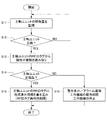
次に、図3を参照して、本実施形態に係る工作機械1の動作について説明する。図3は、本実施形態に係る工作機械1による動作を示すフローチャートである。
Next, the operation of the
まず、制御部20の監視部22は、主軸ユニット16における主軸の劣化に伴って次第に変化する特徴量を監視する(S11)。監視部22は、例えば主軸モータ14の負荷及び駆動電流値、あるいはその波形のスペクトル等の情報のうちの何れか1つ、又はこれらの情報のうちの少なくとも2つの積算値を、主軸ユニット16の特徴量として監視する(例えば、図2参照)。監視部22は、監視した主軸ユニット16の特徴量を、記憶部30に一旦記憶してもよい。
First, the
次に、判定部24は、監視部22によって監視された主軸ユニット16の特徴量の変化の傾向に基づいて、主軸ユニット16の交換が行われたか否かを判定する(S12)。判定部24は、例えば監視部22によって監視された主軸ユニット16の特徴量の変化が、主軸の劣化に伴う変化と反対方向の変化、又は、主軸の劣化に伴う連続的な変化と異なる不連続的な変化であるときに、主軸ユニット16の交換が行われたと判定する(例えば、図2参照)。
Next, the
判定部24によって主軸ユニット16の交換が行われていないと判定された場合(S12においてNO)、ステップS11に戻り、主軸ユニット16における主軸の特徴量の監視を継続する。
When the
一方、判定部24によって主軸ユニット16の交換が行われたと判定された場合に(S12においてYES)、読取部26は、RFIDリーダ60を用いて、主軸ユニット16に取り付けられたRFIDタグ50から、主軸ユニット16の識別子情報を読み取る(D13)。
On the other hand, when the
次に、判定部24は、読取部26による主軸ユニット16のRFIDタグ50の識別子情報の読み取り結果に基づいて、主軸ユニット16が正規品(純正品)であるか否かを判定する(S14)。
Next, the
読取部26によって主軸ユニット16のRFIDタグ50の識別子情報が読み取られ、判定部24によって主軸ユニット16が正規品であると判定された場合に(S14においてYES)、制限部28は、RFIDリーダ60を用いて、主軸ユニット16に取り付けられたRFIDタグ50に、使用済みであることを示す情報(例えば、フラグ)を書き込む(S15)。これにより、制限部28は、RFIDタグの再利用ができないように制限する。
When the
一方、読取部26によって主軸ユニット16のRFIDタグ50の識別子情報が読み取られず、判定部24によって主軸ユニット16が非正規品(コピー品)であると判定された場合に(S14においてNO)、制限部28は、工作機械1の動作を制限する(S16)。例えば、制限部28は、即時に、工作機械1の稼働を停止してもよい。或いは、制限部28は、表示部(図示省略)に警告表示を行ったり、アラームを通知したりし、又は主軸の最高回転数の制限を行ったり、送り軸の移動速度の制限を行ったりし(動作制限)、所定時間経過後に工作機械1を停止してもよい。
On the other hand, when the
以上説明したように、本実施形態の工作機械1によれば、主軸の劣化に伴って次第に変化する特徴量を監視し、監視した特徴量の変化の傾向に基づいて主軸ユニット16の交換が行われたか否かを判定することができる。
As described above, according to the
本実施形態の工作機械1では、主軸ユニット16等の保守ユニットの交換が検知された場合に、それまで取り付けられていた保守ユニットの識別子情報(RFIDタグの識別子情報)と稼働情報とを関連付けて、工作機械の制御部内部に自動で記録してもよい。また、これらの情報は、工作機械にネットワーク等を介して接続されたサーバ装置に保存され、複数の工作機械における情報がサーバ装置において集中管理されてもよい(例えば、FIELD system:FANUC Intelligent Edge Link & Drive system)。
In the
この場合、サーバ装置において、集中管理している各種情報に基づいて、保守ユニットが交換されたか否かの判定が行われてもよい。この場合、保守ユニットが交換されたか否かを判定する特徴量として、生産性の変化(急な向上)、スループットの変化(急な向上)、品質の変化(急な向上)等が用いられてもよい。 In this case, the server device may determine whether or not the maintenance unit has been replaced, based on various information that is centrally managed. In this case, changes in productivity (sudden improvement), changes in throughput (sudden improvement), changes in quality (sudden improvement), etc. are used as feature quantities for determining whether or not the maintenance unit has been replaced. Good.
(変形例)
上述した実施形態では、主軸ユニット16の交換が検出された場合に、RFIDタグ50及びRFIDリーダ60を用いて、工作機械1単体で、主軸ユニット16が正規品(純正品)であるか否かの認証を行った。
しかし、主軸ユニット16が正規品(純正品)であるか否かの認証は、工作機械1にネットワーク等を介して接続された装置を用いて行ってもよい。
(Modification)
In the above-described embodiment, when the replacement of the
However, the authentication as to whether or not the
図4は、本実施形態の変形例に係る工作機械を備える認証システムの構成を示す図である。図4に示すように、認証システム100は、変形例の工作機械1と、工作機械1に例えばネットワークを介して接続された認証装置5とを備える。
FIG. 4 is a diagram showing a configuration of an authentication system including a machine tool according to a modified example of this embodiment. As shown in FIG. 4, the
図4に示す工作機械1は、図1に示す工作機械1においてRFIDタグ50及びRFIDリーダ60を備えない点で上述した実施形態と異なる。また、図4に示す工作機械1は、図1に示す工作機械1において、制御部20の機能及び動作が異なる点で、上述した実施形態と異なる。
The
具体的には、制御部20(例えば、読取部26)は、判定部24によって主軸ユニット(保守ユニット)16の交換が行われたと判定された場合に、主軸ユニット16の識別子情報を保守者に要求する。例えば、制御部20は、ディスプレイ等の表示装置を用いて、主軸ユニット16の識別子情報を保守者に要求する。
これにより、保守者は、主軸ユニット16に貼付された例えばシール55に表示された主軸ユニット16のシリアル番号を入力する。
Specifically, when the
Thereby, the maintenance person inputs the serial number of the
制御部20は、保守者によって入力された主軸ユニット16のシリアル番号(識別子情報)を認証装置5に送信する。このとき、制御部20は、予め記憶した工作機械1のシリアル番号(機番)も認証装置5に送信してもよい。
The
認証装置5は、工作機械1における主軸ユニット16の認証を行う。例えば、認証装置5は、工作機械1及び正規品の主軸ユニット(保守ユニット)16を製造するメーカに設置され、工作機械1のシリアル番号(機番)、及び正規品の主軸ユニット(保守ユニット)のシリアル番号(識別子情報)を予め記憶する。認証装置5は、工作機械1から受信した主軸ユニット(保守ユニット)16のシリアル番号(識別子情報)と、記憶した正規品のシリアル番号(識別子情報)とに基づいて、主軸ユニット(保守ユニット)16が正規品であるか否かの認証を行う。
The
認証装置5は、主軸ユニット(保守ユニット)16が正規品であると認証した場合に、認証結果を工作機械1に通知する。
また、この場合、認証装置5は、主軸ユニット(保守ユニット)16のシリアル番号(識別子情報)と、使用済みであることを示す情報(例えば、フラグ)とを関連付けて記憶する。これにより、認証装置5は、シリアル番号(識別子情報)の再利用ができないように制限する。
The
Further, in this case, the
一方、認証装置5は、主軸ユニット(保守ユニット)16が非正規品である場合、又は、主軸ユニット(保守ユニット)16が正規品であるが使用済みである場合、この認証結果を工作機械1に通知する。
これにより、工作機械1における制御部20の制限部28は、認証装置5から通知された認証結果に基づいて、上述したように工作機械1の動作を制限する。例えば、制限部28は、即時に、工作機械1の稼働を停止してもよい。或いは、制限部28は、表示部(図示省略)に警告表示を行ったり、アラームを通知したりし、又は主軸の最高回転数の制限を行ったり、送り軸の移動速度の制限を行ったりし(動作制限)、所定時間経過後に工作機械1を停止してもよい。
On the other hand, in the
As a result, the
以上、本発明の実施形態について説明したが、本発明は上述した実施形態に限定されることなく、種々の変更及び変形が可能である。例えば、上述した実施形態では、工作機械を例示したが、本発明の特徴はこれに限定されず、保守ユニット(又は、保守部品)を含む産業機械又はロボット等の種々の機械に適用可能である。 Although the embodiments of the present invention have been described above, the present invention is not limited to the above-described embodiments, and various changes and modifications can be made. For example, in the above-described embodiment, the machine tool is exemplified, but the features of the present invention are not limited to this, and are applicable to various machines such as an industrial machine including a maintenance unit (or maintenance parts) or a robot. .
1 工作機械
5 認証装置
10 機械本体部
20 制御部
12 基体部
14 主軸モータ(駆動部)
16 主軸(被駆動パーツ)を含む主軸ユニット(保守ユニット)
22 監視部
24 判定部
26 読取部
28 制限部
30 記憶部
50 RFIDタグ(IDタグ)
60 RFIDリーダ(IDリーダ)
100 認証システム
DESCRIPTION OF
16 Spindle unit (maintenance unit) including spindle (driven parts)
22
60 RFID reader (ID reader)
100 authentication system
Claims (10)
前記保守ユニットの劣化に伴って次第に変化する特徴量を監視する監視部と、
前記監視部によって監視された特徴量の変化の傾向に基づいて、前記保守ユニットの交換が行われたか否かを判定する判定部と、
を備える、工作機械。 A machine tool including a maintenance unit that can be replaced in a predetermined unit,
A monitoring unit that monitors a feature amount that gradually changes with deterioration of the maintenance unit,
Based on the tendency of the change of the characteristic amount monitored by the monitoring unit, a determination unit that determines whether or not the maintenance unit has been replaced,
A machine tool equipped with.
前記動作時の情報は、前記駆動部の負荷又は駆動電流の値あるいは波形に関する情報を含む、
請求項2に記載の工作機械。 The maintenance unit is a unit including a driven part that is driven by being connected to a drive unit in the machine tool,
The information at the time of operation includes information about the value or waveform of the load or drive current of the drive unit,
The machine tool according to claim 2.
前記IDタグの識別子情報の読み取りを行うIDリーダと、
前記判定部によって前記保守ユニットの交換が行われたと判定された場合に、前記IDリーダを用いて、前記保守ユニットにおける前記IDタグの識別子情報を読み取る読取部と、
を備え、
前記判定部は、前記読取部の読み取り結果に基づいて、前記保守ユニットが正規品であるか否かを判定する、
請求項1〜4のいずれか1項に記載の工作機械。 An ID tag attached to the maintenance unit and having identifier information of the maintenance unit;
An ID reader for reading the identifier information of the ID tag,
A reading unit that reads the identifier information of the ID tag in the maintenance unit using the ID reader when the determination unit determines that the maintenance unit has been replaced;
Equipped with
The determination unit determines whether the maintenance unit is a genuine product based on the reading result of the reading unit,
The machine tool according to any one of claims 1 to 4.
前記工作機械における前記保守ユニットの認証を行う認証装置と、
を備え、
前記工作機械は、
前記判定部によって前記保守ユニットの交換が行われたと判定された場合に、前記保守ユニットの識別子情報を保守者に要求し、
保守者によって入力された前記保守ユニットの識別子情報を前記認証装置に送信し、
前記認証装置は、
正規品の識別子情報を予め記憶し、
前記工作機械から受信した前記保守ユニットの識別子情報と、記憶した前記正規品の識別子情報とに基づいて、前記保守ユニットが正規品であるか否かの認証を行う、
工作機械の認証システム。 A machine tool according to any one of claims 1 to 4,
An authentication device for authenticating the maintenance unit in the machine tool,
Equipped with
The machine tool is
When it is determined that the maintenance unit has been replaced by the determination unit, request the maintenance person identifier information of the maintenance unit,
Transmitting the maintenance unit identifier information input by a maintenance person to the authentication device,
The authentication device is
Pre-stored genuine identifier information,
Based on the identifier information of the maintenance unit received from the machine tool and the stored identifier information of the genuine product, authentication of whether the maintenance unit is a genuine product is performed.
Machine tool authentication system.
認証結果を工作機械に通知すると共に、
前記保守ユニットの識別子情報と、使用済みであることを示す情報とを関連付けて記憶することにより、前記識別子情報の再利用を制限する、請求項8に記載の工作機械の認証システム。 When the authentication device authenticates the maintenance unit as a genuine product,
Notify the machine tool of the authentication result,
9. The machine tool authentication system according to claim 8, wherein reuse of the identifier information is restricted by storing the identifier information of the maintenance unit and the information indicating that the maintenance unit has been used in association with each other.
前記工作機械は、前記認証装置から通知された認証結果に基づいて、動作を制限する、
請求項9に記載の工作機械の認証システム。 If the maintenance unit is not a genuine product, or if the maintenance unit is a genuine product but has been used, the authentication device notifies the machine tool of this authentication result,
The machine tool limits the operation based on the authentication result notified from the authentication device,
The machine tool authentication system according to claim 9.
Priority Applications (4)
| Application Number | Priority Date | Filing Date | Title |
|---|---|---|---|
| JP2018190246A JP2020060862A (en) | 2018-10-05 | 2018-10-05 | Machine tool and machine tool authentication system |
| US16/556,027 US20200110387A1 (en) | 2018-10-05 | 2019-08-29 | Machine tool and authentication system of machine tool |
| CN201910912128.8A CN111002058A (en) | 2018-10-05 | 2019-09-25 | Machine tool and machine tool authentication system |
| DE102019215145.0A DE102019215145A1 (en) | 2018-10-05 | 2019-10-01 | MACHINE TOOL AND AUTHENTICATION SYSTEM OF A MACHINE TOOL |
Applications Claiming Priority (1)
| Application Number | Priority Date | Filing Date | Title |
|---|---|---|---|
| JP2018190246A JP2020060862A (en) | 2018-10-05 | 2018-10-05 | Machine tool and machine tool authentication system |
Publications (1)
| Publication Number | Publication Date |
|---|---|
| JP2020060862A true JP2020060862A (en) | 2020-04-16 |
Family
ID=69886616
Family Applications (1)
| Application Number | Title | Priority Date | Filing Date |
|---|---|---|---|
| JP2018190246A Pending JP2020060862A (en) | 2018-10-05 | 2018-10-05 | Machine tool and machine tool authentication system |
Country Status (4)
| Country | Link |
|---|---|
| US (1) | US20200110387A1 (en) |
| JP (1) | JP2020060862A (en) |
| CN (1) | CN111002058A (en) |
| DE (1) | DE102019215145A1 (en) |
Families Citing this family (1)
| Publication number | Priority date | Publication date | Assignee | Title |
|---|---|---|---|---|
| CN117233602B (en) * | 2023-11-07 | 2024-01-30 | 迈为技术(珠海)有限公司 | Aging detection method of crystal-piercing machine and crystal-piercing machine |
Citations (7)
| Publication number | Priority date | Publication date | Assignee | Title |
|---|---|---|---|---|
| JP2007328677A (en) * | 2006-06-09 | 2007-12-20 | Hitachi Ltd | Workability management system, workability management method and workability management program |
| JP2008027241A (en) * | 2006-07-21 | 2008-02-07 | Komatsu Ltd | Part monitoring apparatus for working machine, and part monitoring method for working machine |
| JP2012048287A (en) * | 2010-08-24 | 2012-03-08 | Mitsubishi Electric Corp | Component management device, component management system, component management method and component management program |
| JP2017140675A (en) * | 2016-02-10 | 2017-08-17 | アイシン・エィ・ダブリュ株式会社 | Cutting tool monitoring device |
| JP2018012164A (en) * | 2016-07-21 | 2018-01-25 | 株式会社リコー | Diagnostic device, diagnostic system, diagnostic method and program |
| JP2018032146A (en) * | 2016-08-23 | 2018-03-01 | Towa株式会社 | Management system and management method |
| JP2018097494A (en) * | 2016-12-09 | 2018-06-21 | Dmg森精機株式会社 | Information processing method, information processing system and information processing apparatus |
-
2018
- 2018-10-05 JP JP2018190246A patent/JP2020060862A/en active Pending
-
2019
- 2019-08-29 US US16/556,027 patent/US20200110387A1/en not_active Abandoned
- 2019-09-25 CN CN201910912128.8A patent/CN111002058A/en not_active Withdrawn
- 2019-10-01 DE DE102019215145.0A patent/DE102019215145A1/en not_active Withdrawn
Patent Citations (7)
| Publication number | Priority date | Publication date | Assignee | Title |
|---|---|---|---|---|
| JP2007328677A (en) * | 2006-06-09 | 2007-12-20 | Hitachi Ltd | Workability management system, workability management method and workability management program |
| JP2008027241A (en) * | 2006-07-21 | 2008-02-07 | Komatsu Ltd | Part monitoring apparatus for working machine, and part monitoring method for working machine |
| JP2012048287A (en) * | 2010-08-24 | 2012-03-08 | Mitsubishi Electric Corp | Component management device, component management system, component management method and component management program |
| JP2017140675A (en) * | 2016-02-10 | 2017-08-17 | アイシン・エィ・ダブリュ株式会社 | Cutting tool monitoring device |
| JP2018012164A (en) * | 2016-07-21 | 2018-01-25 | 株式会社リコー | Diagnostic device, diagnostic system, diagnostic method and program |
| JP2018032146A (en) * | 2016-08-23 | 2018-03-01 | Towa株式会社 | Management system and management method |
| JP2018097494A (en) * | 2016-12-09 | 2018-06-21 | Dmg森精機株式会社 | Information processing method, information processing system and information processing apparatus |
Also Published As
| Publication number | Publication date |
|---|---|
| US20200110387A1 (en) | 2020-04-09 |
| DE102019215145A1 (en) | 2020-04-09 |
| CN111002058A (en) | 2020-04-14 |
Similar Documents
| Publication | Publication Date | Title |
|---|---|---|
| JP2018173859A (en) | Component mounting position guidance device, component mounting position guidance system, and component mounting position guidance method | |
| US9141105B2 (en) | Method and apparatus for monitoring or controlling a machine tool system | |
| US10795341B2 (en) | Control system for controlling operation of a numerically controlled machine tool, and back-end and front-end control devices for use in such system | |
| US10209702B2 (en) | Tool management system and method thereof | |
| JP5268637B2 (en) | Method of operating an evaluation device for a production machine | |
| JP2009039393A (en) | Managing system for sewing machine | |
| JP2009282822A (en) | Machine tool system | |
| JP2020060862A (en) | Machine tool and machine tool authentication system | |
| JP2020123191A (en) | Numeric control system | |
| WO2018154605A1 (en) | Method and apparatus for performing an automatic health checkup for a cnc turning center | |
| JP6426565B2 (en) | Machine control system that displays machine operation information according to the operator | |
| JP2008176579A (en) | Controller of machine | |
| JP5058246B2 (en) | Control unit with built-in machine model | |
| JP6625154B2 (en) | Machine tool control device | |
| JP2010287034A (en) | Address display system of modbus protocol communication between external equipment and plc | |
| US20200026255A1 (en) | Abnormality detection device of machine tool | |
| JP2008250479A (en) | Machine tool, operation permission control program, recording medium, restoration operation permission control program, and recording medium | |
| JP2000334187A (en) | Information transmitting device for sewing machine | |
| JP6815964B2 (en) | Computers for mechanical systems and control | |
| KR100636191B1 (en) | Compatibleness of parts checking system and method | |
| JP2008234278A (en) | Numerical control device, control program, control program recording medium, and machine tool | |
| JP2009175905A (en) | Parameter setting device for machine tool and parameter use numerical control machine tool equipment | |
| JP5673151B2 (en) | Error display system and display device | |
| JP2019113021A (en) | Control device, electronic apparatus, control method and program | |
| JP7294901B2 (en) | FAN MOTOR, FAN MOTOR DRIVE AND COOLING DEVICE |
Legal Events
| Date | Code | Title | Description |
|---|---|---|---|
| A621 | Written request for application examination |
Free format text: JAPANESE INTERMEDIATE CODE: A621 Effective date: 20200323 |
|
| A871 | Explanation of circumstances concerning accelerated examination |
Free format text: JAPANESE INTERMEDIATE CODE: A871 Effective date: 20200521 |
|
| A975 | Report on accelerated examination |
Free format text: JAPANESE INTERMEDIATE CODE: A971005 Effective date: 20200616 |
|
| A977 | Report on retrieval |
Free format text: JAPANESE INTERMEDIATE CODE: A971007 Effective date: 20201012 |
|
| A131 | Notification of reasons for refusal |
Free format text: JAPANESE INTERMEDIATE CODE: A131 Effective date: 20201020 |
|
| A521 | Request for written amendment filed |
Free format text: JAPANESE INTERMEDIATE CODE: A523 Effective date: 20201207 |
|
| A02 | Decision of refusal |
Free format text: JAPANESE INTERMEDIATE CODE: A02 Effective date: 20201222 |
|
| A521 | Request for written amendment filed |
Free format text: JAPANESE INTERMEDIATE CODE: A523 Effective date: 20210203 |
|
| C60 | Trial request (containing other claim documents, opposition documents) |
Free format text: JAPANESE INTERMEDIATE CODE: C60 Effective date: 20210203 |
|
| A911 | Transfer to examiner for re-examination before appeal (zenchi) |
Free format text: JAPANESE INTERMEDIATE CODE: A911 Effective date: 20210215 |
|
| C21 | Notice of transfer of a case for reconsideration by examiners before appeal proceedings |
Free format text: JAPANESE INTERMEDIATE CODE: C21 Effective date: 20210216 |
|
| A912 | Re-examination (zenchi) completed and case transferred to appeal board |
Free format text: JAPANESE INTERMEDIATE CODE: A912 Effective date: 20210305 |
|
| C211 | Notice of termination of reconsideration by examiners before appeal proceedings |
Free format text: JAPANESE INTERMEDIATE CODE: C211 Effective date: 20210309 |
|
| C22 | Notice of designation (change) of administrative judge |
Free format text: JAPANESE INTERMEDIATE CODE: C22 Effective date: 20210706 |
|
| C13 | Notice of reasons for refusal |
Free format text: JAPANESE INTERMEDIATE CODE: C13 Effective date: 20210907 |
|
| C302 | Record of communication |
Free format text: JAPANESE INTERMEDIATE CODE: C302 Effective date: 20211130 |
|
| C23 | Notice of termination of proceedings |
Free format text: JAPANESE INTERMEDIATE CODE: C23 Effective date: 20211207 |
|
| C03 | Trial/appeal decision taken |
Free format text: JAPANESE INTERMEDIATE CODE: C03 Effective date: 20220111 |
|
| C30A | Notification sent |
Free format text: JAPANESE INTERMEDIATE CODE: C3012 Effective date: 20220111 |