JP5058246B2 - Control unit with built-in machine model - Google Patents
Control unit with built-in machine model Download PDFInfo
- Publication number
- JP5058246B2 JP5058246B2 JP2009501985A JP2009501985A JP5058246B2 JP 5058246 B2 JP5058246 B2 JP 5058246B2 JP 2009501985 A JP2009501985 A JP 2009501985A JP 2009501985 A JP2009501985 A JP 2009501985A JP 5058246 B2 JP5058246 B2 JP 5058246B2
- Authority
- JP
- Japan
- Prior art keywords
- control device
- operator
- interface
- description
- production machine
- Prior art date
- Legal status (The legal status is an assumption and is not a legal conclusion. Google has not performed a legal analysis and makes no representation as to the accuracy of the status listed.)
- Active
Links
Images


Classifications
-
- G—PHYSICS
- G05—CONTROLLING; REGULATING
- G05B—CONTROL OR REGULATING SYSTEMS IN GENERAL; FUNCTIONAL ELEMENTS OF SUCH SYSTEMS; MONITORING OR TESTING ARRANGEMENTS FOR SUCH SYSTEMS OR ELEMENTS
- G05B19/00—Programme-control systems
- G05B19/02—Programme-control systems electric
- G05B19/04—Programme control other than numerical control, i.e. in sequence controllers or logic controllers
- G05B19/042—Programme control other than numerical control, i.e. in sequence controllers or logic controllers using digital processors
- G05B19/0426—Programming the control sequence
-
- G—PHYSICS
- G05—CONTROLLING; REGULATING
- G05B—CONTROL OR REGULATING SYSTEMS IN GENERAL; FUNCTIONAL ELEMENTS OF SUCH SYSTEMS; MONITORING OR TESTING ARRANGEMENTS FOR SUCH SYSTEMS OR ELEMENTS
- G05B19/00—Programme-control systems
- G05B19/02—Programme-control systems electric
- G05B19/418—Total factory control, i.e. centrally controlling a plurality of machines, e.g. direct or distributed numerical control [DNC], flexible manufacturing systems [FMS], integrated manufacturing systems [IMS], computer integrated manufacturing [CIM]
- G05B19/41845—Total factory control, i.e. centrally controlling a plurality of machines, e.g. direct or distributed numerical control [DNC], flexible manufacturing systems [FMS], integrated manufacturing systems [IMS], computer integrated manufacturing [CIM] characterised by system universality, reconfigurability, modularity
-
- G—PHYSICS
- G05—CONTROLLING; REGULATING
- G05B—CONTROL OR REGULATING SYSTEMS IN GENERAL; FUNCTIONAL ELEMENTS OF SUCH SYSTEMS; MONITORING OR TESTING ARRANGEMENTS FOR SUCH SYSTEMS OR ELEMENTS
- G05B2219/00—Program-control systems
- G05B2219/20—Pc systems
- G05B2219/25—Pc structure of the system
- G05B2219/25077—Each module can be programmed for number of input and output
-
- G—PHYSICS
- G05—CONTROLLING; REGULATING
- G05B—CONTROL OR REGULATING SYSTEMS IN GENERAL; FUNCTIONAL ELEMENTS OF SUCH SYSTEMS; MONITORING OR TESTING ARRANGEMENTS FOR SUCH SYSTEMS OR ELEMENTS
- G05B2219/00—Program-control systems
- G05B2219/20—Pc systems
- G05B2219/25—Pc structure of the system
- G05B2219/25454—Retrofitting
-
- G—PHYSICS
- G05—CONTROLLING; REGULATING
- G05B—CONTROL OR REGULATING SYSTEMS IN GENERAL; FUNCTIONAL ELEMENTS OF SUCH SYSTEMS; MONITORING OR TESTING ARRANGEMENTS FOR SUCH SYSTEMS OR ELEMENTS
- G05B2219/00—Program-control systems
- G05B2219/30—Nc systems
- G05B2219/32—Operator till task planning
- G05B2219/32019—Dynamic reconfiguration to maintain optimal design, fabrication, assembly
-
- G—PHYSICS
- G05—CONTROLLING; REGULATING
- G05B—CONTROL OR REGULATING SYSTEMS IN GENERAL; FUNCTIONAL ELEMENTS OF SUCH SYSTEMS; MONITORING OR TESTING ARRANGEMENTS FOR SUCH SYSTEMS OR ELEMENTS
- G05B2219/00—Program-control systems
- G05B2219/30—Nc systems
- G05B2219/34—Director, elements to supervisory
- G05B2219/34459—Plausibility check on connection of module, control unit to machine
-
- Y—GENERAL TAGGING OF NEW TECHNOLOGICAL DEVELOPMENTS; GENERAL TAGGING OF CROSS-SECTIONAL TECHNOLOGIES SPANNING OVER SEVERAL SECTIONS OF THE IPC; TECHNICAL SUBJECTS COVERED BY FORMER USPC CROSS-REFERENCE ART COLLECTIONS [XRACs] AND DIGESTS
- Y02—TECHNOLOGIES OR APPLICATIONS FOR MITIGATION OR ADAPTATION AGAINST CLIMATE CHANGE
- Y02P—CLIMATE CHANGE MITIGATION TECHNOLOGIES IN THE PRODUCTION OR PROCESSING OF GOODS
- Y02P90/00—Enabling technologies with a potential contribution to greenhouse gas [GHG] emissions mitigation
- Y02P90/02—Total factory control, e.g. smart factories, flexible manufacturing systems [FMS] or integrated manufacturing systems [IMS]
Description
本発明は、制御装置内に格納されている制御プログラムに応じて生産機械を制御可能であり、生産機械がインターフェースに接続されている少なくとも2つの要素を有する制御装置に関する。 The present invention relates to a control device capable of controlling a production machine according to a control program stored in the control device, and the production machine having at least two elements connected to an interface.
この種の制御装置は一般に公知である。例えば、この種の制御装置はプログラマブルコントローラおよび数値制御装置である。 This type of control device is generally known. For example, this type of control device is a programmable controller and a numerical control device.
相応する生産機械の要素は、例えば機械的、電気的、電子的またはデータ技術的要素である。機械的要素の例が、ねじスピンドルまたは減速歯車装置である。電気的要素の例が、駆動装置またはモータ操作可能な工具ホルダである。電子的要素の例が、センサまたは分散周辺ユニットである。データ技術要素の例が、ソフトウェアモジュールまたは通信プログラムである。いずれにせよ、本発明の要素は生産機械の設計時に個別に設計されるユニットである。 Corresponding production machine elements are, for example, mechanical, electrical, electronic or data technology elements. An example of a mechanical element is a screw spindle or a reduction gear device. An example of an electrical element is a drive or a tool holder that can be operated by a motor. Examples of electronic elements are sensors or distributed peripheral units. Examples of data technology elements are software modules or communication programs. In any case, the elements of the present invention are units that are individually designed when designing a production machine.
相応する生産機械のインターフェースは多様な性質である。インターフェースは、機械的インターフェース、電気的インターフェース、データ技術インターフェース等を含む。 Corresponding production machine interfaces are of various nature. Interfaces include mechanical interfaces, electrical interfaces, data technology interfaces, and the like.
生産機械の規則にかなった動作のためには、生産機械が正しく設計されることが必要である。設計は、一般に、生産機械をモデル化することができるモデル化プログラムを介して行なわれる。モデル化プログラムはコンピュータ上で動作し、このコンピュータは生産機械用の制御装置ではなく、市販のPCである。 For proper operation of production machines, the production machines need to be designed correctly. The design is generally done via a modeling program that can model the production machine. The modeling program runs on a computer, which is not a control device for a production machine but a commercially available PC.
モデル化プログラムは、変更要素の要素記述を含み、要素記述は、それぞれ、存在するインターフェースの少なくとも1つのリストを含み、それによってどの要素が互いに接続可能であるかを求めることができる。モデル化プログラムにより、生産機械がどの要素を有し、どのインターフェースを介して要素が互いに接続されているかを含む目標構成記述が作成される。目標構成記述はモデル化プログラムのオペレータによって設定可能であり、かつ変更可能である。更に、既に作成された目標構成記述を呼び出すことができる。作成された目標構成記述は生産機械の制御装置へ格納可能である。制御装置はオペレータインターフェースを有し、このインターフェースを介して目標構成記述がオペレータに出力可能である。 The modeling program includes an element description of the changed elements, each element description including at least one list of existing interfaces, which can determine which elements can be connected to each other. The modeling program creates a target configuration description that includes which elements the production machine has and which elements are connected to each other. The target configuration description can be set and changed by the operator of the modeling program. Furthermore, the target configuration description already created can be called up. The created target configuration description can be stored in the control device of the production machine. The control device has an operator interface through which the target configuration description can be output to the operator.
生産機械は時々要素を変更される。この種の要素変更の例が、他の要素の増設、既存の要素の削減、要素の交換または新たな様式への変更である。このように要素変更される要素を以下においては“変更要素”と呼ぶ。したがって、制御装置において常に生産機械の現在の構成状態を用意するために、従来技術では構成の変更をコンピュータおよびモデル化プログラムにより把握し、新たな目標構成記述を制御装置に格納することが必要である。 Production machines are sometimes changed elements. Examples of this type of element change are the addition of other elements, the reduction of existing elements, the replacement of elements, or the change to a new format. The element that is changed in this way is hereinafter referred to as “changed element”. Therefore, in order to always prepare the current configuration state of the production machine in the control device, it is necessary in the prior art to grasp the configuration change by the computer and the modeling program, and to store a new target configuration description in the control device. is there.
本発明の課題は、目標構成記述が従来技術におけるよりも簡単に更新可能であるように制御装置を発展させることにある。 The object of the present invention is to develop the control device so that the target configuration description can be updated more easily than in the prior art.
この課題は、本発明によれば、制御装置によって生産機械が制御装置内に格納されている制御プログラムに応じて制御可能であり、生産機械が、インターフェースを備えインターフェースに互いに接続されている少なくとも2つの要素を有し、制御装置が、変更要素の要素記述を格納した蓄積領域を有し、どの変更要素が互いに接続可能であるかを制御装置によって求め得るように、各要素記述が、それぞれの変更要素の存在するインターフェースの少なくとも1つのリストを含み、制御装置が、目標構成記述を格納した構成設定領域を有し、目標構成記述は、生産機械がどの要素を有しかつ要素がどのインターフェースを介して互いに接続されているかを少なくとも含み、制御装置がオペレータインターフェースを有し、オペレータインターフェースを介して目標構成記述が生産機械のオペレータ(操作者)によって要求可能であり、要求に応じてオペレータに出力可能であり、かつオペレータによって変更可能であることによって解決される(請求項1)。
本発明の有利な実施態様は次の通りである。
・蓄積領域内に、変更要素をどのようにインターフェースを介して互いに接続すべきかおよび/または互いに分離すべきかに関する組立情報および/または分解情報が格納され、組立情報および/または分解情報もオペレータインターフェースを介してオペレータによって要求可能であり、かつオペレータに出力可能である(請求項2)。
・蓄積領域)内に、変更要素をどのように始動するかに関する始動情報が格納され、始動情報もオペレータインターフェースを介してオペレータによって要求可能であり、かつオペレータに出力可能である(請求項3)。
・目標構成記述が、存在する要素のパラメータ化を有し、パラメータ化もオペレータインターフェースを介してオペレータに出力可能であり、かつオペレータによって変更可能である(請求項4)。
・オペレータによって変更された目標構成記述が構成設定領域内に元の目標構成記述に対して代替または追加として格納可能である(請求項5)。
・制御装置にオペレータによって特定の要素の1つのインターフェースの選択が設定可能であり、選択されたインターフェースに接続可能な変更要素の要素記述がオペレータインターフェースを介してオペレータに出力可能である(請求項6)。
・制御装置によって、選択されたインターフェースに接続可能な変更要素を求める際に、どの要素が特定の要素の他のインターフェースに接続されているが付加的に考慮可能である(請求項7)。
・目標構成記述が、存在する各要素のために要素記述の事例を含むことによって構成されている(請求項8)。
・制御装置によって、生産機械の制御中に、存在する要素の規則正しい動作が監視可能であり、制御装置によって、存在する要素の内の1つの要素の誤動作時にオペレータインターフェースを介して警報がオペレータに出力可能であり、警報に基づいてオペレータによって、どの要素において誤動作が発生しているかが認識可能である(請求項9)。
・制御装置によって出力可能な警報が、どの要素において誤動作が発生しているかが光学的に強調されている生産機械の投影表示を含む(請求項10)。
・制御装置によって生産機械の実際の構成が検出可能である(請求項11)。
・生産機械の実際の構成が制御装置によって自動的に生産機械の実際構成として制御装置内に格納可能である(請求項12)。
According to the present invention, the object is that the control device can control the production machine according to a control program stored in the control device, and the production machine has at least two interfaces and is connected to the interface. one of a element, the control unit has a storage area storing the element description of the modifier, what modifier can be connected to each other so as determined by the control unit, each element described, respectively Including at least one list of interfaces in which the changed element exists, the control device having a configuration setting area storing the target configuration description , the target configuration description including which element the production machine has and which interface the element has comprising at least whether it is connected to one another via the control device has an operator interface, the operator interface Through the face target configuration description are possible request by the operator of the production machine (the operator), it is capable of outputting to the operator in response to a request, and is solved by a changeable by the operator (claim 1) .
Advantageous embodiments of the present invention are as follows .
In the storage area, assembly information and / or disassembly information on how the change elements are to be connected to each other and / or separated from each other via the interface is stored, and the assembly information and / or disassembly information is also stored in the operator interface. Can be requested by the operator and output to the operator (claim 2) .
In the storage area), start information on how to start the change element is stored, the start information can also be requested by the operator via the operator interface and can be output to the operator (claim 3) .
The target configuration description has parameterization of existing elements, and parameterization can also be output to the operator via the operator interface and can be changed by the operator (claim 4) .
The target configuration description changed by the operator can be stored in the configuration setting area as an alternative or addition to the original target configuration description (claim 5) .
The selection of one interface of a specific element can be set by the operator in the control device, and the element description of the change element connectable to the selected interface can be output to the operator via the operator interface. )
When determining the change elements connectable to the selected interface by the control device, which elements are connected to other interfaces of the specific element can be additionally taken into account (claim 7) .
The target configuration description is configured by including an example of the element description for each existing element (claim 8) .
・ The control unit can monitor the regular operation of existing elements during the control of the production machine, and the control unit outputs an alarm to the operator via the operator interface when one of the existing elements malfunctions. It is possible to recognize in which element the malfunction has occurred based on the alarm (claim 9) .
The alarm that can be output by the control device includes a projection display of the production machine in which the element in which the malfunction has occurred is optically emphasized (claim 10) .
The actual configuration of the production machine can be detected by the control device (claim 11) .
The actual configuration of the production machine can be automatically stored in the control device as the actual configuration of the production machine by the control device (claim 12) .
好ましくは、制御装置内に、変更要素をどのようにインターフェースを介して互いに接続すべきかおよび/または互いに分離すべきかに関する組立情報および/または分解情報も格納されている。というのは、組立情報および/または分解情報もオペレータインターフェースを介してオペレータによって要求可能であり、かつオペレータに出力可能であるからである。 Preferably, assembly information and / or disassembly information is also stored in the control device as to how the changing elements are to be connected to each other via an interface and / or separated from each other. This is because assembly information and / or disassembly information can also be requested by the operator via the operator interface and can be output to the operator.
更に、好ましくは、制御装置内に、変更要素をどのように始動するかに関する始動情報が格納されている。というのは、始動情報もオペレータインターフェースを介してオペレータによって要求可能であり、かつオペレータに出力可能であるからである。 Furthermore, preferably startup information is stored in the control device regarding how to start the changing element. This is because the start information can also be requested by the operator via the operator interface and can be output to the operator.
有利な形態においては、目標構成記述が、存在する要素のパラメータ化を有する。パラメータ化もオペレータインターフェースを介してオペレータに出力可能であり、かつオペレータによって変更可能である。 In an advantageous form, the target configuration description has a parameterization of the elements present. Parameterization can also be output to the operator via the operator interface and can be changed by the operator.
本発明による制御装置の有利な実施態様においては、オペレータによって変更された目標構成記述が制御装置内に元の目標構成記述に対して代替または追加として格納可能である。というのは、特に元の目標構成記述に対して代替として格納することによって、古くなった構成の書き換えが可能であるからである。元の目標構成記述に対して追加として格納することによって、頻繁に必要とされる多数の目標構成記述を同時に制御装置内に保持することの可能性が開かれる。この場合に制御装置内には、当然のことながら、どれが現在有効な目標構成記述であるかが書き込まれるべきである。 In an advantageous embodiment of the control device according to the invention, the target configuration description changed by the operator can be stored in the control device as an alternative or in addition to the original target configuration description. This is because it is possible to rewrite an old configuration by storing it as an alternative to the original target configuration description. Storing in addition to the original target configuration description opens up the possibility of simultaneously holding a large number of frequently required target configuration descriptions in the controller. In this case, of course, which is the currently valid target configuration description should be written in the control device.
制御装置にオペレータによって特定の要素の1つのインターフェースの選択が設定可能であることが好ましい。この場合に、選択されたインターフェースに接続可能な変更要素の要素記述が、オペレータインターフェースを介してオペレータに出力可能であることが好ましい。この実施態様に基づいて、特に生産機械の投影時におけるオペレータ案内が可能である。 Preferably, the selection of one interface of a particular element can be set by the operator on the control device. In this case, it is preferable that the element description of the change element connectable to the selected interface can be output to the operator via the operator interface. Based on this embodiment, it is possible to guide the operator especially when the production machine is projected.
生産機械の投影は、制御装置によって、選択されたインターフェースに接続可能な変更要素を求める際に、どの要素が特定の要素の他のインターフェースに接続されているが付加的に考慮可能である場合に、更に拡張される。それによって、例えば相互の影響および非互換性を考慮することができる。 Production machine projections when a control device seeks a change element that can be connected to a selected interface, if any element is connected to other interfaces of a particular element but can be additionally considered Further expanded. Thereby, for example, mutual influences and incompatibilities can be taken into account.
本発明の有利な実施態様では、目標構成記述が、存在する各要素のために要素記述の事例を含むことによって構成されている。それによって目標構成記述の作成が特に簡単である。 In an advantageous embodiment of the invention, the target configuration description is constructed by including an element description instance for each element present. Thereby, the creation of the target configuration description is particularly simple.
制御装置によって、生産機械の制御中に、存在する要素の規則正しい動作が監視可能であり、存在する要素の1つの誤動作時にオペレータインターフェースを介して警報がオペレータに出力可能であることが好ましい。警報に基づいてオペレータによって、どの要素において誤動作が発生しているかを認識可能である。 The control device can preferably monitor the regular operation of the existing elements during the control of the production machine, and can output an alarm to the operator via the operator interface when one of the existing elements malfunctions. Based on the alarm, the operator can recognize in which element the malfunction has occurred.
故障位置の認識可能性は、制御装置によって出力可能な警報が、どの要素において誤動作が発生しているかが光学的に強調されている生産機械の投影表示を含むならば、オペレータにとって特に簡単である。 The recognizability of the fault location is particularly simple for the operator if the alarm that can be output by the control device includes a projection display of the production machine that optically highlights which elements are malfunctioning. .
制御装置によって生産機械の実際の構成が検出可能であるとよい。この場合に、例えば制御装置によって実際の構成が自動的に制御装置内に実際構成として格納されるとよい。 It is desirable that the actual configuration of the production machine can be detected by the control device. In this case, for example, the actual configuration may be automatically stored as an actual configuration in the control device by the control device.
実際構成がオペレータインターフェースを介してオペレータによって要求可能であり、要求に基づいてオペレータに出力可能である。 The actual configuration can be requested by the operator via the operator interface and can be output to the operator based on the request.
実際構成が構成設定部分および要素部分を有し、構成設定部分がフォーマットに関して目標構成記述に対応し、要素部分が生産機械の要素の動的なデータを含むとよい。 The actual configuration may have a configuration setting portion and an element portion, the configuration setting portion may correspond to the target configuration description with respect to the format, and the element portion may include dynamic data of elements of the production machine.
構成設定部分がオペレータによって変更可能でないことが好ましい。構成設定部分は目標構成記述として受取られるとよい。受取られた目標構成記述は再び変更可能である。 Preferably, the configuration setting part is not changeable by the operator. The configuration setting portion may be received as a target configuration description. The received target configuration description can be changed again.
要素部分がオペレータによって少なくとも部分的に変更可能であるとよい。 The element part may be at least partially changeable by the operator.
制御装置が実際構成を生産機械の動作中に更新するとよい。 The control device may update the actual configuration during operation of the production machine.
他の利点および詳細を以下における図面を参照した実施例の説明から明らかにする。図面において原理表示にて、
図1は模範的に生産機械のブロック図を示し、
図2は図1の生産機械のための制御装置のブロック図を示し、
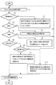
図3乃至6はフローチャートを示す。
Other advantages and details will become apparent from the following description of embodiments with reference to the drawings. In the principle display in the drawing,
FIG. 1 schematically shows a block diagram of a production machine,
FIG. 2 shows a block diagram of a control device for the production machine of FIG.
3 to 6 show flowcharts.
図1には、純粋に模範的に、生産機械1が示されている。生産機械1は種々の要素2〜14を有する。模範的に図1には、
基台2と、
ワークスライド3と、ワークスライド3を移動させるスライドスピンドル4およびスライド駆動装置5と、
それぞれチャック8,9を有する第1および第2のワークホルダ6,7と、第1および第2のワークホルダ6,7を互いに相対的に移動させるホルダ駆動装置10およびホルダスピンドル11と、
回転軸線12”を中心としてワーク12'の回転を可能にするワーク駆動装置12と、
多数の工具14を含む工具マガジン13と、
が示されている。
In FIG. 1, a
A
First and
A
A tool magazine 13 containing a number of tools 14;
It is shown.
要素2〜14はインターフェースを介して機械的に互いに結合されている。例えば、スライド駆動装置5は概略的に示されているねじボルト15を介して基台2に結合されている。それゆえ、基台2のボルト穴およびスライド駆動装置5のボルト穴は、基台2とスライド駆動装置5との間の機械的インターフェースの一部である。更に、スライド駆動装置5は相応の結合要素を介してスライドスピンドル4に結合されている。この結合も、ここではスライドスピンドル4とスライド駆動装置5との間の機械的インターフェースである。類似の構成が要素2〜14の他の要素についても当てはまる。例えばワークスライド3はスライドスピンドル4の直径およびねじピッチに合わせられている。
Elements 2-14 are mechanically coupled to one another via an interface. For example, the
更に、電気的インターフェースも与えられ、特に給電線、信号線および通信線のための接続が与えられている。これらのインターフェースも互いに適切に接続されていなければならない。例えば、ある電気的インターフェースは、個々の導体の接続のためのねじ端子または単極または多極の予め規格化された差込結合を有する。データ技術的インターフェースも注意を払われなければならない。例えば、データ伝送速度、プロトコル、信号種類等が考慮の対象となる。 Furthermore, an electrical interface is also provided, in particular connections for feed lines, signal lines and communication lines. These interfaces must also be properly connected to each other. For example, some electrical interfaces have screw terminals or single pole or multipole pre-standardized plug connections for connection of individual conductors. Care must also be taken in data technology interfaces. For example, data transmission speed, protocol, signal type, etc. are considered.
生産機械1は図2によれば制御装置16によって制御される。このために制御装置16は、とりわけ制御プログラム18が格納されているメモリ17を有する。制御プログラム18は制御装置16のプロセッサ19によって読み出されて処理される。制御プログラム18に応じてプロセッサ19がマシンインターフェース20を介して生産機械1を制御する。
The
メモリ17には、実際構成21および記述21’,21”が格納されているとよい。実際構成21および記述21’,21”は、オペレータインターフェース22を介して生産機械1のオペレータ(操作者)23に出力可能であり、部分的な呼び出しおよび変更が可能である。オペレータインターフェース22は、このために視覚ユニット(ディスプレイ)および入力装置(例えば、キーボードおよび/またはカーソル制御)を含む。
The
図2によれば、記述21'がメモリ17の蓄積領域24に、そして記述21"がメモリ17の構成設定領域25に記憶されている。
According to FIG. 2, the
以下において、図3を参照して、制御装置16内に格納されている記述21',21"を詳細に説明する。
In the following, with reference to FIG. 3,
記述21'は要素記述21'である。これらは、図3にしたがってその都度、生産機械1の変更要素26を記述する。要素記述21'は、その都度の変更要素26に固有に、次の内容を有する。
a)その都度の変更要素26の存在するインターフェースのリストおよびこれらのインターフェースの記述:これらの記述は、一方ではオペレータインターフェース22を介してオペレータ23に出力可能であるクリアテキスト部分を含み、他方では他のどの変更要素26のどのインターフェースがこの変更要素26のインターフェースに接続可能であるかを求めるために、制御装置16によって内部で使用されるデータ処理指向の前処理部分を含んでいる。
b)その都度の変更要素26がそれのインターフェースを介して他の変更要素26にどのようにして接続されるべきかに関する組立情報、
c)その都度の変更要素26が他の変更要素26からどのようにして分離されるべきかに関する分解情報、
d)その都度の変更要素26がどのようにして始動されるべきかに関する始動情報、
e)可能なパラメータおよびこれらのパラメータについての最大もしくは最小の許容限界値のリスト。
The
a) List of interfaces in which the respective change element 26 exists and descriptions of these interfaces: These descriptions contain on the one hand clear text parts that can be output to the
b) assembly information on how each change element 26 should be connected to other change elements 26 via its interface;
c) Disassembly information on how each change element 26 should be separated from other change elements 26;
d) start-up information on how each change element 26 should be started,
e) A list of possible parameters and the maximum or minimum allowable limits for these parameters.
組立情報、分解情報および始動情報は、クリアテキストにて、例えばASCIIコードにて格納され、オペレータインターフェース22を介してオペレータ23に出力可能である。
Assembly information, disassembly information, and start-up information are stored in clear text, for example, ASCII code, and can be output to the
蓄積領域24内に保存された記述21’はオペレータ23によって変更可能である。しかし、それらはオペレータ23によって変更不能であることもあり得る。
The
構成設定領域25内には少なくとも1つの目標構成記述21”が格納されている。必要に応じて構成設定領域25内に複数の目標構成記述21”が格納されていてもよい。構成設定領域25内に2つ以上の目標構成記述21”が格納されている場合には、現在どの目標構成記述21”が有効(活性状態)であるかが一緒に記憶されているべきである。
At least one
目標構成記述21”はオペレータインターフェース22を介してオペレータ23から要求可能である。オペレータ23がこのような要求を入力した場合に、要求された目標構成記述21”が制御装置16からオペレータインターフェース22を介してオペレータ23に出力される。その後にオペレータ23によって目標構成記述21”を変更することができる。
The
図3によれば、生産機械1がその都度の目標構成記述21”にしたがって有する各要素2〜14のための各目標構成記述21”は、蓄積領域24内に格納されている要素記述21’の1つの事例を含む。事例はパラメータ化されている。したがって、それぞれの要素2〜14の可能なパラメータに具体的な値が割り当てられている。更に、それぞれの事例には、もちろん、他のどの要素2〜14がそれぞれの事例とされた要素2〜14に接続されているかの情報が割り当てられている。したがって、目標構成記述21”は、生産機械1がどの要素2〜14を持ち、どのインターフェースを介して要素2〜14が互いに接続されているかを含む。
According to FIG. 3, each
実際構成21も構成設定領域25内に格納されている。実際構成21はオペレータインターフェース22を介してオペレータ23から要求可能である。実際構成21は要求時にオペレータインターフェース22を介してオペレータ23に出力される。
The
実際構成21は構成設定部分21aおよび要素部分21bを含んでいる。構成設定部分21aも要素部分21bもオペレータ23によって要求可能である。
The
構成設定部分21aはフォーマットに関して目標構成記述21"に対応する。構成設定部分21aはオペレータ23によって目標構成記述21"として受取られる。しかし、構成設定部分21aの変更はオペレータ23には可能でない。オペレータ23は構成設定部分21aを目標構成記述21"として受取ったときはじめて変更を行なうことができる。
The
要素部分21bは生産機械1の要素2〜14の動的なデータを含んでいる。例えば、要素部分21bは、生産機械1の要素2〜14の動作時間、最後のメンテナンスまたは検査の時点、消耗状態等を含んでいる。要素部分21bは、少なくとも部分的に、オペレータ23によって変更可能である。
The
ここで図4に関連させて制御装置16とオペレータ23との対話を、制御装置16内に格納されている記述21’,21”に関して説明する。
Here, the interaction between the
図4によれば、制御装置16がステップS1においてオペレータインターフェース22を介してオペレータ23から入力を受け取る。ステップS2において、制御装置16は、オペレータ入力が目標構成記述21”の選択であるかどうかをチェックする。これがそうである場合には、制御装置16は、ステップS3において、オペレータ23がどの目標構成記述21”を選択したかを求める。更に、制御装置16は、選択された目標構成記述21”をバッファメモリ27内に受け入れ、それをオペレータインターフェース22を介してオペレータ23に出力する。
According to FIG. 4, the
ステップS1の入力が目標構成記述21”の選択でない場合に、制御装置16は、ステップS4において、ステップS1の入力が選択された目標構成記述21”の変更設定であるかどうかをチェックする。これがそうである場合に、制御装置16は、ステップS5において、選択された目標構成記述21”を変更設定に応じて変更する。しかし、変更は、バッファメモリ27内に記憶されている目標構成記述21”に関してのみ行なわれる。構成設定領域25内に格納されている目標構成記述21”は変更されない。ステップS5には、後で図5に関連して更に詳細に説明する。
When the input in step S1 is not the selection of the
ステップS1の入力が変更設定でもない場合に、制御装置16は、ステップS6において、入力が要素2〜14の組立、分解または始動に関する情報の出力のための要求であるかどうかをチェックする。これがそうである場合に、制御装置16は、ステップS7において、要求された情報をオペレータインターフェース22を介してオペレータ23に出力する。
If the input in step S1 is not a change setting, the
ステップS1の入力が情報要求でもない場合に、制御装置16は、ステップS8において、先の入力が記憶されるべきかどうかをチェックする。これがそうである場合に、制御装置16は、ステップS9において更に、バッファメモリ27内に記憶されている目標構成記述21”が、構成設定領域25内に格納されている対応する元の目標構成記述21”と置き換えられるべきかどうかをチェックする。これがそうである場合に、制御装置16は、ステップS10において、バッファメモリ27内に一時記憶されている目標構成記述21”を、元の目標構成記述21”の代わりに構成設定領域25内に記憶させる。そうでない場合に制御装置16はステップS11を実行する。ステップS11において、制御装置16は、バッファメモリ27内に一時記憶されている目標構成記述21”を、既に構成設定領域25に格納されている目標構成記述21”に追加して記憶する。したがって、制御装置16は、オペレータ23によって変更された目標構成記述21”を元の目標構成記述21”に対して代替または追加として制御装置16内に格納することができる。
If the input in step S1 is not an information request, the
更に、制御装置16はその後ステップS12を実行する。ステップS12において制御装置16は、バッファメモリ27に前もって目標構成記述21”が記憶されていた場合に、バッファメモリ27を消去する。ステップS12は、構成設定領域25内で記憶が行なわれるべきでない場合にも実行される。
Furthermore, the
図5によれば、図4のステップS5が、例えば次のように実現されている。 According to FIG. 5, step S5 of FIG. 4 is implemented as follows, for example.
ステップS21において、制御装置16は、オペレータ23の変更設定が要素2〜14の内の1つの要素に関する選択入力であるかどうかをチェックする。これがそうである場合に、制御装置16は、ステップS22において、その都度の要素2〜14の記述またはこの記述の少なくとも一部を、オペレータインターフェース22を介してオペレータ23に出力する。更に、制御装置16は、内部にこの要素2〜14が選択されたことを記録する。
In step S <b> 21, the
変更設定が要素2〜14の選択でない場合に、制御装置16は、ステップS23において、入力がパラメータの変更のための設定であったかどうかをチェックする。これがそうである場合に、制御装置16は、ステップS24において、選択された要素2〜14のパラメータを、オペレータインターフェース22を介してオペレータ23に出力する。ステップS25において制御装置16は当該パラメータ設定を受け取る。
When the change setting is not the selection of the
ステップS1の変更設定が1つの要素2〜14の選択でもパラメータの設定でもなかった場合に、制御装置16は、ステップS26において、オペレータ23が前もって選択された要素2〜14の複数のインターフェースの内の1つのインターフェースを選択したかどうかをチェックする。これがそうである場合に、制御装置16は、選択されたインターフェースの記述および変更要素26のインターフェースの記述に基づいて、どの変更要素26が選択されたインターフェースに接続可能であるかを求める。選択されたインターフェースに接続可能である変更要素26を求める際に、制御装置16は、特定の要素2〜14の他のインターフェースにどの要素2〜14が既に接続されているかを考慮することが好ましい。
If the change setting in step S1 is neither the selection of one
ステップS28において、制御装置16は、ステップS27において求められた変更要素26の記述21’(もしくは記述の一部)をオペレータインターフェース22を介してオペレータ23に出力する。最後にステップS29において制御装置16はオペレータ23から変更要素26の1つの相応の選択を受け取る。
In step S <b> 28, the
生産機械1の動作中に、制御装置16は、図6にしたがってステップS31において、先ず生産機械1の実際の構成を、これが制御装置16にとって可能である限り求めることが好ましい。
During the operation of the
その後制御装置16は、ステップS32において、構成設定領域25内に既に実際構成21が記憶されているどうかをチェックする。構成設定領域25にまだ実際構成21が記憶されていない場合に、制御装置16は今まさに求めた実際の構成をステップS33において自動的に実際構成21として記憶する。この場合に、構成設定部分21aも要素部分21bも記憶する。構成設定領域25内に既に実際構成21が記憶されている場合には、記憶されている実際構成21がステップS34において実際の構成の情報により更新される。実際構成21の更新時に、構成設定部分21aは上書きされ、要素21bのデータはこれが有効で実現可能である限りにおいてそのまま維持される。
Thereafter, in step S32, the
ステップS35において、制御装置16は、ステップS31において求められた生産機械1の実際の構成が、1つの目標構成記述21”による生産機械1の構成(もしくは複数の目標構成記述21”の場合には、活性化されている1つの目標構成記述21”による構成)と一致しているかどうかをチェックする。実際の構成(したがって、構成設定部分21a)が目標構成記述21”と一致している場合には、制御装置16はステップS36へ分岐する。これに反して違いがある場合に、制御装置16は、ステップS37において、オペレータインターフェース22を介してオペレータ23に警報を出力し、オペレータ23の入力を待つ。
In step S35, the
ステップS38において、制御装置16は、ステップS37のオペレータ入力が新たな目標構成記述21"として構成設定部分21aを受取るための指令であるかどうかをチェックする。これがそうである場合に、制御装置16は、ステップS39において、構成設定部分21aを目標構成記述21"として受取り、場合によってはこの新たな目標構成記述21"に活性化のマーキングを付与し、そしてステップS36へ移行する。オペレータ入力の種類に応じて、新たな目標構成記述21"が、以前からの目標構成記述21"を排除するか、あるいはこれまでの記憶されている目標構成記述21"に追加されて構成設定領域25内に記憶され得る。
In step S38, the
ステップS37のオペレータ入力が構成設定部分21aを受取るための指令でない場合に、制御装置16は、ステップS40において、オペレータ入力が生産機械1の制御継続のための指令であるかどうかをチェックする。これがそうである場合に、制御プログラム18の爾後処理がステップS41において中断される。
When the operator input in step S37 is not a command for receiving the
ステップS36への分岐が行なわれた場合に、制御装置16は生産機械1を制御プログラム18の処理のもとで制御する。同様に、ステップS36の枠内において制御装置16は生産機械1の要素2〜14の規則に適った動作(機能性)を監視する。制御装置16は、ステップS36の枠内において、要素部分21bの動的なデータも、有効で現実的である限り更新する。
When the process branches to step S36, the
ステップS42において、制御装置16は、要素2〜14が規則どおりに動作するかどうかをチェックする。これがそうである場合に、制御装置16は、ステップS36へ戻る。そうでない場合に、制御装置16は、ステップS43において、どの要素2〜14において誤動作が発生しているかを求める。ステップS44において、オペレータインターフェース22を介して警報がオペレータ23に出力され、それに基づいてオペレータ23は、どの要素2〜14において誤動作が発生しているかを認識することができる。
In step S42, the
警報は、特に生産機械1の投影表示、例えば図1の表示に類似した表示を含み、その表示においては、どの要素2〜14において誤動作が発生しているかが光学的に強調されている。光学的強調は、例えば、誤動作を発生している要素2〜14が点滅表示および/または残りの要素2〜14とは異なったカラーでの表示が行なわれることにある。異常のある要素2〜14が、例えば矢印28(図1参照)によりマーキングされてもよい。異なる措置の組み合わせも可能である。
The alarm includes, in particular, a projection display of the
それゆえ、本発明にしたがって構成されている制御装置16により、目標構成記述21”の快適な構成設定および再構成設定が、現場において、すなわち生産機械1において可能である。
Therefore, a comfortable configuration setting and reconfiguration setting of the
1 生産機械
2 基台
3 ワークスライド
4 スライドスピンドル
5 スライド駆動装置
6 ワークホルダ
7 ワークホルダ
8 チャック
9 チャック
10 ホルダ駆動装置
11 ホルダスピンドル
12 ワーク駆動装置
12’ ワーク
12” 回転軸線
13 工具マガジン
14 工具
15 ねじボルト
16 制御装置
17 メモリ
18 制御プログラム
19 プロセッサ
20 マシンインターフェース
21 実際構成
21a 構成設定部分
21b 要素部分
21’ 要素記述
21” 目標構成記述
22 オペレータインターフェース
23 オペレータ
24 蓄積領域
25 構成設定領域
26 変更要素
27 バッファメモリ
28 矢印
DESCRIPTION OF
Claims (12)
生産機械(1)が、インターフェースを備えインターフェースに互いに接続されている少なくとも2つの要素(2〜14)を有し、
制御装置が、変更要素(26)の要素記述(21')を格納した蓄積領域(24)を有し、
どの変更要素(26)が互いに接続可能であるかを制御装置によって求め得るように、各要素記述(21')が、それぞれの変更要素(26)の存在するインターフェースの少なくとも1つのリストを含み、
制御装置が、目標構成記述(21")を格納した構成設定領域(25)を有し、
目標構成記述(21")は、生産機械(1)がどの要素(2〜14)を有しかつ要素(2〜14)がどのインターフェースを介して互いに接続されているかを少なくとも含み、
制御装置がオペレータインターフェース(22)を有し、オペレータインターフェース(22)を介して目標構成記述(21")が生産機械(1)のオペレータ(23)によって要求可能であり、要求に応じてオペレータ(23)に出力可能であり、かつオペレータ(23)によって変更可能である
ことを特徴とする制御装置。The control device can control the production machine (1) according to a control program (18) stored in the control device,
The production machine (1) has at least two elements (2-14) provided with an interface and connected to each other ;
The control device has an accumulation area (24) in which the element description (21 ′) of the change element (26) is stored,
Each element description (21 ′) includes at least one list of interfaces on which each change element (26) exists, so that the controller can determine which change elements (26) are connectable to each other;
The control device has a configuration setting area (25) storing a target configuration description (21 ") ,
The target configuration description (21 ") at least includes which elements (2-14) the production machine (1) has and which elements (2-14) are connected to each other,
The control device has an operator interface (22), and the target configuration description (21 ") can be requested by the operator (23) of the production machine (1) via the operator interface (22). 23), and can be changed by an operator (23).
Applications Claiming Priority (3)
| Application Number | Priority Date | Filing Date | Title |
|---|---|---|---|
| DE102006015029 | 2006-03-31 | ||
| DE102006015029.5 | 2006-03-31 | ||
| PCT/EP2007/051604 WO2007113047A1 (en) | 2006-03-31 | 2007-02-20 | Control device having an integrated machine model |
Publications (2)
| Publication Number | Publication Date |
|---|---|
| JP2009531756A JP2009531756A (en) | 2009-09-03 |
| JP5058246B2 true JP5058246B2 (en) | 2012-10-24 |
Family
ID=38050222
Family Applications (1)
| Application Number | Title | Priority Date | Filing Date |
|---|---|---|---|
| JP2009501985A Active JP5058246B2 (en) | 2006-03-31 | 2007-02-20 | Control unit with built-in machine model |
Country Status (5)
| Country | Link |
|---|---|
| US (1) | US8295956B2 (en) |
| EP (1) | EP2002316B1 (en) |
| JP (1) | JP5058246B2 (en) |
| DE (1) | DE502007002186D1 (en) |
| WO (1) | WO2007113047A1 (en) |
Families Citing this family (5)
| Publication number | Priority date | Publication date | Assignee | Title |
|---|---|---|---|---|
| CN101918903B (en) * | 2008-01-18 | 2013-01-09 | 西门子公司 | Planning device and method for planning a technical installation |
| EP2375296A1 (en) | 2010-04-07 | 2011-10-12 | Siemens Aktiengesellschaft | Method for operating an automated machine and calculation device |
| EP2407842B1 (en) | 2010-07-16 | 2021-03-17 | Siemens Aktiengesellschaft | Method for operating machines or machines in a machine series and design system |
| CN103226645B (en) * | 2012-01-30 | 2016-08-31 | 上海西门子医疗器械有限公司 | The control method of armarium and control system |
| JP5997330B1 (en) | 2015-07-31 | 2016-09-28 | ファナック株式会社 | Machine learning apparatus capable of determining whether or not spindle replacement is required, spindle replacement determination apparatus, control apparatus, machine tool and production system, and machine learning method |
Family Cites Families (6)
| Publication number | Priority date | Publication date | Assignee | Title |
|---|---|---|---|---|
| US4438459A (en) * | 1976-08-27 | 1984-03-20 | Levine Alfred B | Multiplex photocopier system with portable scanner |
| US5781710A (en) | 1995-06-07 | 1998-07-14 | Xerox Corporation | Generic method for scheduling print engines using print engine capabilities |
| JP3362246B2 (en) | 1996-12-26 | 2003-01-07 | 株式会社日立製作所 | Component removal order creation apparatus and method, and recording medium recording component removal order program |
| DE19917102C2 (en) * | 1999-04-15 | 2002-07-18 | Moeller Gmbh | Project planning and diagnostic device for an electrical system |
| ITBO20010030A1 (en) * | 2001-01-23 | 2002-07-23 | Gd Spa | METHOD AND UNIT FOR PERFORMING A CONFIGURATION CHANGE IN AN AUTOMATIC OPERATING MACHINE |
| JP2006085328A (en) | 2004-09-15 | 2006-03-30 | Toyoda Mach Works Ltd | Machine tool controller |
-
2007
- 2007-02-20 WO PCT/EP2007/051604 patent/WO2007113047A1/en active Application Filing
- 2007-02-20 JP JP2009501985A patent/JP5058246B2/en active Active
- 2007-02-20 EP EP07726425A patent/EP2002316B1/en active Active
- 2007-02-20 DE DE502007002186T patent/DE502007002186D1/en active Active
- 2007-02-20 US US12/225,837 patent/US8295956B2/en active Active
Also Published As
| Publication number | Publication date |
|---|---|
| US20090276063A1 (en) | 2009-11-05 |
| EP2002316A1 (en) | 2008-12-17 |
| DE502007002186D1 (en) | 2010-01-14 |
| JP2009531756A (en) | 2009-09-03 |
| WO2007113047A1 (en) | 2007-10-11 |
| EP2002316B1 (en) | 2009-12-02 |
| US8295956B2 (en) | 2012-10-23 |
Similar Documents
| Publication | Publication Date | Title |
|---|---|---|
| JP6557274B2 (en) | Component mounting position guidance device, component mounting position guidance system, and component mounting position guidance method | |
| JP6310076B2 (en) | Control system for controlling the operation of numerically controlled machine tools, and backend and frontend control devices for use in such a system | |
| JP4462449B2 (en) | Control system setting device | |
| JP4220979B2 (en) | Control unit display system | |
| US9645572B2 (en) | Device class information support for multi-option devices | |
| JP5058246B2 (en) | Control unit with built-in machine model | |
| JP2005327263A (en) | Control system setting device | |
| JP6434434B2 (en) | A processing robot system that connects a processing device to a robot for processing | |
| US11402819B2 (en) | Screen creation device and screen creation system | |
| US20140344428A1 (en) | System architecture support tool | |
| WO2019167512A1 (en) | Display device, screen generation method, and screen generation program | |
| JP5994862B2 (en) | Development support device and development support program | |
| JP2010287034A (en) | Address display system of modbus protocol communication between external equipment and plc | |
| EP3101537A1 (en) | Control device, control system, control method for control device, and control method for control system | |
| JP2018129066A (en) | Control system for controlling operation of numerical control machine tool, and back-end and front-end controllers for using the control system | |
| JP5027820B2 (en) | Method for controlling a modular production machine composed of apparatus and components | |
| WO2019176337A1 (en) | Factory automation (fa) system, controller, and control method | |
| JP6213400B2 (en) | Monitoring device | |
| WO2021149116A1 (en) | Design assistance device, design assistance method, and design assistance program | |
| JP2007528537A (en) | Projection method for automated systems | |
| WO2020217435A1 (en) | Screen data generating system, screen data generating method, and program | |
| JP2023134972A (en) | Information processing apparatus, information processing method, and program | |
| JP2019197566A (en) | Component mounting position guidance device, component mounting position guidance system, and component mounting position guidance method | |
| JP2001306139A (en) | Process monitoring device | |
| JP2005346144A (en) | Support device for servo-controlled system |
Legal Events
| Date | Code | Title | Description |
|---|---|---|---|
| A621 | Written request for application examination |
Free format text: JAPANESE INTERMEDIATE CODE: A621 Effective date: 20090903 |
|
| RD03 | Notification of appointment of power of attorney |
Free format text: JAPANESE INTERMEDIATE CODE: A7423 Effective date: 20090903 |
|
| A977 | Report on retrieval |
Free format text: JAPANESE INTERMEDIATE CODE: A971007 Effective date: 20111017 |
|
| A131 | Notification of reasons for refusal |
Free format text: JAPANESE INTERMEDIATE CODE: A131 Effective date: 20111108 |
|
| A521 | Request for written amendment filed |
Free format text: JAPANESE INTERMEDIATE CODE: A523 Effective date: 20120208 |
|
| TRDD | Decision of grant or rejection written | ||
| A01 | Written decision to grant a patent or to grant a registration (utility model) |
Free format text: JAPANESE INTERMEDIATE CODE: A01 Effective date: 20120703 |
|
| A01 | Written decision to grant a patent or to grant a registration (utility model) |
Free format text: JAPANESE INTERMEDIATE CODE: A01 |
|
| A61 | First payment of annual fees (during grant procedure) |
Free format text: JAPANESE INTERMEDIATE CODE: A61 Effective date: 20120731 |
|
| FPAY | Renewal fee payment (event date is renewal date of database) |
Free format text: PAYMENT UNTIL: 20150810 Year of fee payment: 3 |
|
| R150 | Certificate of patent or registration of utility model |
Ref document number: 5058246 Country of ref document: JP Free format text: JAPANESE INTERMEDIATE CODE: R150 Free format text: JAPANESE INTERMEDIATE CODE: R150 |
|
| R250 | Receipt of annual fees |
Free format text: JAPANESE INTERMEDIATE CODE: R250 |
|
| R250 | Receipt of annual fees |
Free format text: JAPANESE INTERMEDIATE CODE: R250 |
|
| R250 | Receipt of annual fees |
Free format text: JAPANESE INTERMEDIATE CODE: R250 |
|
| R250 | Receipt of annual fees |
Free format text: JAPANESE INTERMEDIATE CODE: R250 |
|
| R250 | Receipt of annual fees |
Free format text: JAPANESE INTERMEDIATE CODE: R250 |
|
| R250 | Receipt of annual fees |
Free format text: JAPANESE INTERMEDIATE CODE: R250 |
|
| R250 | Receipt of annual fees |
Free format text: JAPANESE INTERMEDIATE CODE: R250 |
|
| R250 | Receipt of annual fees |
Free format text: JAPANESE INTERMEDIATE CODE: R250 |
|
| R250 | Receipt of annual fees |
Free format text: JAPANESE INTERMEDIATE CODE: R250 |
|
| R250 | Receipt of annual fees |
Free format text: JAPANESE INTERMEDIATE CODE: R250 |