JP2020020719A - Analytic method, reagent kit, and analyzer - Google Patents
Analytic method, reagent kit, and analyzer Download PDFInfo
- Publication number
- JP2020020719A JP2020020719A JP2018146102A JP2018146102A JP2020020719A JP 2020020719 A JP2020020719 A JP 2020020719A JP 2018146102 A JP2018146102 A JP 2018146102A JP 2018146102 A JP2018146102 A JP 2018146102A JP 2020020719 A JP2020020719 A JP 2020020719A
- Authority
- JP
- Japan
- Prior art keywords
- substance
- responsive
- responsive polymer
- sample
- stimulus
- Prior art date
- Legal status (The legal status is an assumption and is not a legal conclusion. Google has not performed a legal analysis and makes no representation as to the accuracy of the status listed.)
- Pending
Links
- ACFVPYQFGCKHKH-UHFFFAOYSA-N C=NC1CCCC1 Chemical compound C=NC1CCCC1 ACFVPYQFGCKHKH-UHFFFAOYSA-N 0.000 description 1
Images


Classifications
-
- G—PHYSICS
- G01—MEASURING; TESTING
- G01N—INVESTIGATING OR ANALYSING MATERIALS BY DETERMINING THEIR CHEMICAL OR PHYSICAL PROPERTIES
- G01N21/00—Investigating or analysing materials by the use of optical means, i.e. using sub-millimetre waves, infrared, visible or ultraviolet light
- G01N21/62—Systems in which the material investigated is excited whereby it emits light or causes a change in wavelength of the incident light
- G01N21/63—Systems in which the material investigated is excited whereby it emits light or causes a change in wavelength of the incident light optically excited
- G01N21/64—Fluorescence; Phosphorescence
- G01N21/6428—Measuring fluorescence of fluorescent products of reactions or of fluorochrome labelled reactive substances, e.g. measuring quenching effects, using measuring "optrodes"
-
- G—PHYSICS
- G01—MEASURING; TESTING
- G01N—INVESTIGATING OR ANALYSING MATERIALS BY DETERMINING THEIR CHEMICAL OR PHYSICAL PROPERTIES
- G01N33/00—Investigating or analysing materials by specific methods not covered by groups G01N1/00 - G01N31/00
- G01N33/48—Biological material, e.g. blood, urine; Haemocytometers
- G01N33/50—Chemical analysis of biological material, e.g. blood, urine; Testing involving biospecific ligand binding methods; Immunological testing
- G01N33/53—Immunoassay; Biospecific binding assay; Materials therefor
- G01N33/536—Immunoassay; Biospecific binding assay; Materials therefor with immune complex formed in liquid phase
- G01N33/542—Immunoassay; Biospecific binding assay; Materials therefor with immune complex formed in liquid phase with steric inhibition or signal modification, e.g. fluorescent quenching
-
- G—PHYSICS
- G01—MEASURING; TESTING
- G01N—INVESTIGATING OR ANALYSING MATERIALS BY DETERMINING THEIR CHEMICAL OR PHYSICAL PROPERTIES
- G01N21/00—Investigating or analysing materials by the use of optical means, i.e. using sub-millimetre waves, infrared, visible or ultraviolet light
- G01N21/62—Systems in which the material investigated is excited whereby it emits light or causes a change in wavelength of the incident light
- G01N21/63—Systems in which the material investigated is excited whereby it emits light or causes a change in wavelength of the incident light optically excited
- G01N21/64—Fluorescence; Phosphorescence
- G01N21/6428—Measuring fluorescence of fluorescent products of reactions or of fluorochrome labelled reactive substances, e.g. measuring quenching effects, using measuring "optrodes"
- G01N2021/6439—Measuring fluorescence of fluorescent products of reactions or of fluorochrome labelled reactive substances, e.g. measuring quenching effects, using measuring "optrodes" with indicators, stains, dyes, tags, labels, marks
Abstract
Description
本発明の実施形態は、分析方法、試薬キット及び分析装置に関する。 Embodiments of the present invention relate to an analysis method, a reagent kit, and an analyzer.
近年、刺激応答性高分子を用いて試料中の標的物質を検出する方法が行われてきている。刺激応答性高分子とは、温度、pH、光、塩濃度等の変化により極性が変化する高分子をいう。 In recent years, a method of detecting a target substance in a sample using a stimuli-responsive polymer has been performed. The stimulus-responsive polymer refers to a polymer whose polarity changes with changes in temperature, pH, light, salt concentration, and the like.
例えば、特許文献1は、温度応答性高分子を結合させた、検出対象に親和性のある第1の親和性物質と、電荷を有する物質で標識した、検出対象に親和性のある第2の親和性物質と試料とを混合し、高温条件下で温度応答性高分子を疎水性にして凝集させ、凝集体を磁力により分離し、分離された分画の吸光度を測定し、それによって標的物質を検出する方法を開示している。
For example,
また、試料中の標的物質を高感度、ワイドレンジに検出する方法として、ELISA法やCLEIA法が用いられてきた。 As a method for detecting a target substance in a sample with high sensitivity and a wide range, an ELISA method and a CLEIA method have been used.
しかしながら、特許文献1のような検出方法は、標的物質が微量である場合に検出や定量を正確に行うことが困難である。また、ELISA法やCLEIA法は工程途中での分離や洗浄が不可欠であり、操作が煩雑である。
However, it is difficult for the detection method as disclosed in
本発明の実施形態によれば、より簡便で、より精度の高い分析方法、試薬キット及び分析装置が提供される。 According to the embodiment of the present invention, a simpler, more accurate analysis method, a reagent kit, and an analyzer are provided.
実施形態に従う分析方法は、試料中の標的物質を検出する方法である。分析方法は、a)刺激応答性高分子と、刺激応答性高分子の一方の端に結合した環境応答性蛍光物質とを含む第1の物質、b)標的物質と特異的に結合する第1の捕捉体を含む第2の物質、及びc)刺激応答性高分子の凝集を阻害する凝集阻害物質で標識された、標的物質と特異的に結合する第2の捕捉体を含む第3の物質を、試料と混合し、この混合物を刺激応答性高分子が凝集する条件下に維持し、環境応答性蛍光物質からの蛍光を検出し、当該検出の結果に基づいて、試料中の標的物質の有無又は量を決定することを含む。 The analysis method according to the embodiment is a method for detecting a target substance in a sample. The analysis method comprises: a) a first substance containing a stimuli-responsive polymer and an environment-responsive fluorescent substance bound to one end of the stimuli-responsive polymer; b) a first substance that specifically binds to a target substance. And c) a third substance comprising a second capturer that specifically binds to a target substance, which is labeled with an aggregation inhibitor that inhibits aggregation of the stimulus-responsive polymer. Is mixed with the sample, the mixture is maintained under conditions under which the stimuli-responsive polymer aggregates, the fluorescence from the environmentally responsive fluorescent substance is detected, and the target substance in the sample is detected based on the result of the detection. Including determining the presence or absence or amount.
・分析方法
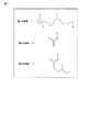
実施形態に従う分析方法は、試料中の標的物質を検出する方法である。実施形態に従う分析方法は、第1〜第3の物質を用いて行われる。図1は、第1〜第3の物質の一例を示す模式図である。
-Analysis method The analysis method according to the embodiment is a method for detecting a target substance in a sample. The analysis method according to the embodiment is performed using the first to third substances. FIG. 1 is a schematic diagram showing an example of the first to third substances.
第1の物質は、刺激応答性高分子と、環境応答性蛍光物質とを含む。 The first substance includes a stimuli-responsive polymer and an environment-responsive fluorescent substance.
刺激応答性高分子は、特定の条件を境に、水への溶解性が可逆的に変化する物質である。即ち、当該高分子は、水溶液中において、ある条件下で親水性であり凝集せず、当該条件とは異なる特定の条件下で疎水性となり疎水結合で凝集する。ここでは、刺激応答性高分子が温度応答性高分子1である例を示す。温度応答性高分子1は、低温条件下で親水性であり凝集せず、高温条件下で疎水性となり疎水結合で凝集する。刺激応答性高分子は、温度応答性高分子に限られるものではなく、他の高分子を用いてもよい。
Stimuli-responsive polymers are substances whose solubility in water reversibly changes under certain conditions. That is, in an aqueous solution, the polymer is hydrophilic under certain conditions and does not aggregate, but becomes hydrophobic under specific conditions different from the conditions and aggregates through hydrophobic bonds. Here, an example in which the stimulus-responsive polymer is the temperature-
環境応答性蛍光物質は、周囲の環境に依存して、生ずる蛍光の波長が変化する蛍光物質である。ここでは、環境応答性蛍光物質が極性応答性蛍光物質2である例を示す。極性応答性蛍光物質2は、周囲の極性、即ち、親水性又は疎水性に依存して、生ずる蛍光の波長が変化する蛍光物質である。環境応答性蛍光物質は、極性応答性蛍光物質に限られるものではなく、他の蛍光物質を用いてもよい。
An environment-responsive fluorescent substance is a fluorescent substance in which the wavelength of generated fluorescence changes depending on the surrounding environment. Here, an example in which the environment-responsive fluorescent substance is the polar-responsive
極性応答性蛍光物質2は、温度応答性高分子1の一方の端3に結合している。
The polarity-responsive
第2の物質は、第1の捕捉体5を含む。第1の捕捉体5は、標的物質と特異的に結合することができる物質である。この例において、第1の捕捉体5は抗体である。
The second substance includes the first capturing
第1の捕捉体5と、温度応答性高分子1の他方の端4とは、互いに結合することができるように構成される。温度応答性高分子1と結合する第1の捕捉体5の部位は、標的物質との結合に影響を与えない部位である。
The first capturing
第3の物質は、凝集阻害物質7で標識された第2の捕捉体6を含む。第2の捕捉体は、標的物質に特異的に結合する物質である。第1の捕捉体と第2の捕捉体とは、標的物質の互いに異なる部位にそれぞれ結合するように構成されることが好ましい。この例において、第2の捕捉体6は、抗体である。凝集阻害物質7は、温度応答性高分子1の近傍に存在する場合、温度応答性高分子1の凝集を阻害することができる物質である。凝集阻害物質7は、第2の捕捉体6の標的物質への結合に影響を与えない部位に結合されている。
The third substance includes the second capturing body 6 labeled with the
図2は、実施形態の分析方法の一例の概略フローを示す。分析方法は、以下の工程を含む:
(S1)第1の物質、第2の物質、及び第3の物質を用意すること;
(S2)試料と第1の物質、第2の物質及び第3の物質とを混合すること;
(S3)前記混合により得られた混合物を刺激応答性高分子が凝集する温度に維持すること;
(S4)前記環境応答性蛍光物質からの蛍光を検出すること;及び
(S5)前記検出の結果に基づいて、前記試料中の前記標的物質の有無又は量を決定すること。
FIG. 2 shows a schematic flow of an example of the analysis method of the embodiment. The analysis method includes the following steps:
(S1) preparing a first substance, a second substance, and a third substance;
(S2) mixing the sample with the first substance, the second substance, and the third substance;
(S3) maintaining the mixture obtained by the mixing at a temperature at which the stimuli-responsive polymer is aggregated;
(S4) detecting fluorescence from the environment-responsive fluorescent substance; and (S5) determining the presence or absence or amount of the target substance in the sample based on the result of the detection.
以下、上記各工程を実行することにより標的物質が検出又は定量される原理について詳細に説明する。ここでは、刺激応答性高分子が温度応答性高分子1であり、環境応答性蛍光物質が極性応答性蛍光物質2である例を示す。
Hereinafter, the principle of detecting or quantifying a target substance by performing each of the above steps will be described in detail. Here, an example in which the stimulus-responsive polymer is the temperature-
まず、工程(S1)において、上記第1〜第3の物質を用意する。次に工程(S2)において、試料と第1〜第3の物質とを混合する。図3は、試料中に標的物質8が存在する場合の、試料と第1〜第3の物質とを混合した際の混合物内の各成分の様子を示す。混合により、標的物質8を含む複合体9が形成され得る。複合体9は、例えば、極性応答性蛍光物質2と、温度応答性高分子1と、第1の捕捉体5と、標的物質8と、第2の捕捉体6と、凝集阻害物質7とが結合している(図3の(a))。第1の捕捉体5及び第2の捕捉体6がこの例のように複数の標的物質結合部位を有する物質である場合、それぞれの複数の標的物質結合部位に、更なる標的物質8と第1の捕捉体5又は第2の捕捉体6とが結合してもよい。一方、試料中に標的物質8が十分に存在しない場合、混合物中には複合体9を生成しない第1〜第3の物質も存在する(図3の(b))。その場合、第1の物質及び第2の物質が結合し得る。
First, in the step (S1), the first to third substances are prepared. Next, in a step (S2), the sample and the first to third substances are mixed. FIG. 3 shows a state of each component in the mixture when the sample and the first to third substances are mixed when the target substance 8 is present in the sample. By mixing, a complex 9 containing the target substance 8 can be formed. The complex 9 includes, for example, a polar-
工程(S3)において、前記混合により得られた混合物を温度応答性高分子1が凝集する温度に維持する。そのときの各成分の様子を図4に示す。第1〜第3の物質が複合体9を形成した場合(図4の(a))、凝集阻害物質7が温度応答性高分子1aの近傍に存在する。そのため、温度応答性高分子1aは親水性の状態が維持され、凝集が阻害される。したがって、極性応答性蛍光物質2aの周囲が親水性である状態が維持され、その蛍光の波長は変化しない。
In the step (S3), the mixture obtained by the mixing is maintained at a temperature at which the temperature-
一方、複合体9を形成しない第1及び第2の物質においては(図4の(b))、温度応答性高分子1bは、凝集阻害物質7が近傍に存在しない。そのため、温度応答性高分子1bは疎水性となって凝集する(以下、温度応答性高分子1bが凝集した第1の物質及び第2の物質を「凝集体10」と称する)。凝集体10は、図4の(b)に示すように、例えば、1つの温度応答性高分子1bが分子内で凝集したものであるか、或いは、複数の温度応答性高分子1bが分子間で凝集したものである。凝集した温度応答性高分子1bにおいては、極性応答性蛍光物質2bがその疎水性の内部に取り込まれる。即ち、極性応答性蛍光物質2bが疎水性条件下に存在することとなる。それによって、極性応答性蛍光物質2bの発する蛍光の波長が変化する。
On the other hand, in the first and second substances that do not form the complex 9 ((b) in FIG. 4), the aggregation-inhibiting
図5は、標的物質の量の異なる試料における第1〜第3の物質の様子を示す。例えば、図5の(a)に示すように標的物質が多く存在する場合、複合体9がより多く生成される。その結果、蛍光の波長が変化しない極性応答性蛍光物質2aの数は、蛍光の波長が変化した極性応答性蛍光物質2bの数よりも多くなる。図5の(b)に示すように標的物質がより少ない場合、極性応答性蛍光物質2aの数は、極性応答性蛍光物質2bの数よりも少なくなる。図5の(c)示すように標的物質が存在しない場合、極性応答性蛍光物質2aは存在せず、極性応答性蛍光物質2bだけが存在する。
FIG. 5 shows the states of the first to third substances in samples having different amounts of the target substance. For example, as shown in FIG. 5A, when a large number of target substances are present, more complex 9 is generated. As a result, the number of the polar responsive
次に、工程(S4)において、極性応答性蛍光物質2からの蛍光を検出する。蛍光の検出は、例えば、蛍光の波長が変化した極性応答性蛍光物質2bの励起光を混合物に照射し、混合物から生じた蛍光を検出することにより行われる。その場合、例えば、図5の(a)に示すように標的物質が多く存在するとき、検出される蛍光強度は弱い。図5の(b)、(c)に示すように標的物質がよりも少ない又は存在しないとき、図5の(a)の場合よりも検出される蛍光強度は強い。即ち、標的物質が多く存在するほど検出される蛍光は弱くなる。
Next, in the step (S4), fluorescence from the polarity-
蛍光の検出は、上記のように極性応答性蛍光物質2bの励起光を照射しておこなってもよいが、波長が変化していない極性応答性蛍光物質2aの励起光を照射してもよい。その場合、蛍光強度に関して逆の結果が得られる。或いは、極性応答性蛍光物質2aと極性応答性蛍光物質2bの両方の励起光を照射し、両者の蛍光強度を測定してもよい。
The fluorescence may be detected by irradiating the excitation light of the polarity-
蛍光強度の検出は、例えば、経時的に行ってもよい。経時的とは、間隔を置いて複数の時点で行ってもよいし、継続して行ってもよい。 The detection of the fluorescence intensity may be performed, for example, over time. The term “temporarily” may be performed at a plurality of time points at intervals or may be continuously performed.
次に、工程(S5)において、上記検出の結果に基づいて、試料中の標的物質8の有無又は量を決定する。例えば、蛍光の波長が変化した極性応答性蛍光物質2bの励起光を照射し、蛍光が検出されなかった場合、標的物質が存在すると決定してもよい。又は、当該蛍光の強度が予め設定した閾値よりも弱い場合に標的物質が存在すると決定し、閾値よりも強い場合に標的物質が存在しないと決定してもよい。閾値は、例えば、標的物質の濃度が既知の標準試料によって蛍光強度を測定することによって予め決定される。或いは、このような標準試料の蛍光強度測定によって検量線を作成し、その検量線に従って、分析されるべき試料の標的物質の量を決定してもよい。或いは、蛍光の立ち上がり時間と標的物質との関係を示す検量線を作成し、蛍光の立ち上がり時間から標的物質の量を決定してもよい。
Next, in step (S5), the presence or absence or amount of the target substance 8 in the sample is determined based on the result of the detection. For example, when the excitation light of the polarity-
以上に説明した分析方法によれば、検出工程が極性応答性蛍光物質からの蛍光強度を測定することにより行われる。そのため従来よりも精度よくワイドレンジに標的物質を検出することができる。例えば、従来の温度応答性高分子を用いる方法の100倍〜1000倍以上の精度で標的物質の検出及び定量を行うことができる。また、ELISA法、CLEIA法よりも更に精度よく検出及び定量を行うことができる。 According to the analysis method described above, the detection step is performed by measuring the fluorescence intensity from the polar responsive fluorescent substance. Therefore, the target substance can be detected in a wider range with higher accuracy than before. For example, the detection and quantification of a target substance can be performed with an accuracy of 100 to 1000 times or more that of a conventional method using a temperature-responsive polymer. In addition, detection and quantification can be performed with higher accuracy than the ELISA method and the CLEIA method.
加えて、この方法によれば、蛍光を指標とするため夾雑物による影響を受けにくいことから、従来のように試料と試薬とを含む混合物を分離したり、洗浄したりする必要がない。したがって、実施形態の分析方法は、試料に第1〜第3の物質を添加し、混合物の温度制御をすればよい。そのためコンタミネーションを防止でき、従来の方法よりもはるかに簡単に、精度の高い検出又は定量が可能である。このように手順が簡単であるため、実施形態の分析方法は一般的な分析方法に用いる機器を用いて行うこともできる。 In addition, according to this method, there is no need to separate or wash a mixture containing a sample and a reagent as in the related art since fluorescence is used as an index and is not easily affected by contaminants. Therefore, in the analysis method of the embodiment, the first to third substances may be added to the sample to control the temperature of the mixture. Therefore, contamination can be prevented, and highly accurate detection or quantification can be performed much more easily than conventional methods. Since the procedure is thus simple, the analysis method of the embodiment can also be performed by using a device used for a general analysis method.
上記分析方法に用いられる試料は、その中に標的物質を含み得る分析対象である。試料は、例えば、液体である。試料は、例えば、生物学的材料、環境由来の材料、食物若しくは飲料由来の材料、工業由来の材料、人工的に作製された調整物又はこれらの何れかの組み合わせなどである。 The sample used in the above-mentioned analysis method is an analysis target that can contain a target substance therein. The sample is, for example, a liquid. The sample is, for example, a biological material, an environment-derived material, a food or beverage-derived material, an industrial-derived material, an artificially prepared preparation, or a combination of any of these.
標的物質は、例えば、核酸、タンパク質、内分泌物、細胞、血球、ウイルス、微生物、有機化合物、無機化合物又は低分子化合物などである。 The target substance is, for example, a nucleic acid, protein, endocrine secretion, cell, blood cell, virus, microorganism, organic compound, inorganic compound or low molecular compound.
温度応答性高分子1は、例えば、0℃〜30℃で親水性であり、32℃以上で疎水性となって凝集する物質であることが好ましい。温度応答性高分子1として、例えば、下限臨界溶液温度(以下、LCSTとも称する)を有するポリマーや上限臨界溶液温度を有するポリマーなどを用いることができる。下限臨界溶液温度を有するポリマーとしては、N−n−プロピルアクリルアミド、N−イソプロピルアクリルアミド、N−エチルアクリルアミド、N、N−ジメチルアクリルアミド、N−アクリロイルピロリジン、N−アクリロイルピペリジン、N−アクリロイルモルホリン、N−n−プロピルメタクリルアミド、N−イソプロピルメタクリルアミド、N−エチルメタクリルアミド、N、N−ジメチルメタクリルアミド、N−メタクリロイルピロリジン、N−メタクリロイルピペリジン、N−メタクリロイルモルホリン等のN置換(メタ)アクリルアミド誘導体からなるポリマー;ヒドロキシプロピルセルロース、ポリビニルアルコール部分酢化物、ポリビニルメチルエーテル、(ポリオキシエチレン−ポリオキシプロピレン)ブロックコポリマー、ポリオキシエチレンラウリルアミン等のポリオキシエチレンアルキルアミン誘導体;ポリオキシエチレンソルビタンラウレート等のポリオキシエチレンソルビタンエステル誘導体;(ポリオキシエチレンノニルフェニルエーテル)アクリレート、(ポリオキシエチレンオクチルフェニルエーテル)メタクリレート等の(ポリオキシエチレンアルキルフェニルエーテル)(メタ)アクリレート類;及び(ポリオキシエチレンラウリルエーテル)アクリレート、(ポリオキシエチレンオレイルエーテル)メタクリレート等の(ポリオキシエチレンアルキルエーテル)(メタ)アクリレート類等のポリオキシエチレン(メタ)アクリル酸エステル誘導体等が挙げられる。更に、これらのポリマー及びこれらの少なくとも2種のモノマーからなるコポリマーも利用できる。また、N−イソプロピルアクリルアミドとN−t−ブチルアクリルアミドのコポリマーも利用できる。(メタ)アクリルアミド誘導体を含むポリマーを使用する場合、このポリマーにその他の共重合可能なモノマー上限臨界溶液温度を有するポリマーとしては、アクロイルグリシンアミド、アクロイルニペコタミド、アクリロイルアスパラギンアミド及びアクリロイルグルタミンアミド等からなる群から選ばれる少なくとも1種のモノマーからなるポリマーが利用できる。また、これらの少なくとも2種のモノマーからなるコポリマーであってもよい。これらのポリマーには、アクリルアミド、アセチルアクリルアミド、ビオチノールアクリレート、N−ビオチニル−N’−メタクロイルトリメチレンアミド、アクロイルザルコシンアミド、メタクリルザルコシンアミド、アクロイルメチルウラシル等、その他の共重合可能なモノマーを、上限臨界溶液温度を有する範囲で共重合してもよい。
For example, the temperature-
極性応答性蛍光物質2は、周囲が親水性から疎水性になると、例えば、少なくとも約400nm〜700nm、蛍光波長が変化する物質である。極性応答性蛍光物質2として、例えば、POLARIC(登録商標)などを用いることができる。
The polarity-
温度応答性高分子1への極性応答性蛍光物質2の結合は、例えば、カルボキシル基を利用した共有結合又はチオール基を利用した共有結合等の方法を用いて行うことができる。例えば、温度応答性高分子1への極性応答性蛍光物質2の結合は、極性応答性蛍光物質2をメタクリル基やアクリル基等の重合性官能基と結合させて付加重合性モノマーとし、他のモノマーと共重合することにより行うことができる。又は、ポリマーの重合時にカルボン酸、アミノ基又はエポキシ基等の官能基を持つモノマーを他のモノマーと共重合させ、この官能基を介して、当技術分野で周知の方法に従って共有結合させることにより行うことができる。
The binding of the polarity-
第1の捕捉体5として、例えば、抗体又は抗原結合フラグメント(例えば、Fab、F(ab’)2、F(ab’)、Fv、scFvなど)、或いは、天然由来核酸、人工核酸、アプタマー、ペプチドアプタマー、オリゴペプチド、酵素又は補酵素などを用いることができる。
As the
第1の捕捉体5及び温度応答性高分子1の他方の端4は予め結合され、工程(S1)において第1の物質と第2の物質とが一体として用意されてもよい。当該結合は、直接的な結合であってもよいし、間接的な結合であってもよい。詳しくは後述するが、両者は、ビオチン及びストレプトアビジンを介して結合するように構成されていてもよい。
The
第2の捕捉体6として、例えば、抗体又は抗原結合フラグメント(例えば、Fab、F(ab’)2、F(ab’)、Fv、scFvなど)、或いは、天然由来核酸、人工核酸、アプタマー、ペプチドアプタマー、オリゴペプチド、酵素又は補酵素などを用いることができる。 As the second capturing body 6, for example, an antibody or an antigen-binding fragment (for example, Fab, F (ab ′) 2, F (ab ′), Fv, scFv, or the like), or a naturally occurring nucleic acid, an artificial nucleic acid, an aptamer, Peptide aptamers, oligopeptides, enzymes or coenzymes can be used.
凝集阻害物質7は、例えば、温度応答性高分子1との距離が近接した場合に温度応答性高分子1の凝集を阻害する物質である。凝集阻害物質7は、例えば、水溶性高分子を用いることができる。水溶性高分子は、例えば、天然高分子(例えば、植物由来の多糖類、微生物由来の水溶性高分子、動物由来の水溶性高分子等)、半合成高分子(セルロース系高分子、デンプン系高分子、アルギン酸高分子等)、合成高分子(ビニル系高分子等)を用いることができる。
The aggregation-inhibiting
凝集阻害物質7は、第2の捕捉体6の標的物質への結合に影響を与えない部位に結合させることが好ましい。第2の捕捉体6への凝集阻害物質7の結合は、公知の何れかの方法を用いて行うことができる。
The
第1〜第3の物質は、それぞれ適切な溶媒に含ませた状態で用意されてもよい。適切な溶媒は、例えば、水、緩衝液等の水溶液などである。 Each of the first to third substances may be prepared in a state of being contained in an appropriate solvent. Suitable solvents are, for example, water, aqueous solutions such as buffers and the like.
例えば、実施形態の分析方法において、温度応答性高分子以外の刺激応答性高分子を用いる場合、(S3)は、用いた刺激応答性高分子を凝集させることができる特定の条件、例えば、特定のpH、光、塩濃度などの条件に混合物を維持することにより行われればよい。 For example, when a stimuli-responsive polymer other than a temperature-responsive polymer is used in the analysis method of the embodiment, (S3) is a specific condition under which the used stimuli-responsive polymer can be aggregated, for example, a specific condition. It may be carried out by maintaining the mixture under conditions such as pH, light and salt concentration.
更なる実施形態において、上記工程(S2)即ち、試料と第1〜第3の物質とを混合する工程は、次の2つの工程により行われてもよい:(S2−1)試料に第2の物質及び第3の物質を混合し、標的物質に第1の捕捉体と第2の捕捉体を結合させること;及び(S2−2)次いで、試料に第1の物質を混合し、第1の捕捉体と、前記温度応答性高分子の他方の端とを結合させ、複合体を形成すること。このように第2及び第3の物質の添加と、第1の物質の添加とを分けて順次行うことによって、工程(S3)を行う前までにより多くの第2及び第3の物質が標的物質と結合することができる。このような方法が好ましい例については後述する。 In a further embodiment, the step (S2), that is, the step of mixing the sample with the first to third substances may be performed by the following two steps: (S2-1) The second step is performed on the sample. Mixing the first substance and the third substance, and binding the first and second capturing bodies to the target substance; and (S2-2) Then, mixing the first substance with the sample, And binding the other end of the temperature-responsive polymer to form a complex. In this way, by sequentially performing the addition of the second and third substances and the addition of the first substance separately, more of the second and third substances become the target substance before the step (S3) is performed. Can be combined with An example in which such a method is preferable will be described later.
以上に説明した実施形態の分析方法は、例えば、生体外における疾患の診断、微生物感染の診断、食品検査、ドーピング検査等、様々な分野における物質の検出又は定量に用いることができる。実施形態の分析方法は、試料に含まれる微量な標的物質を検出する際に特に有用である。 The analysis method of the embodiment described above can be used for detecting or quantifying a substance in various fields, for example, diagnosis of a disease outside a living body, diagnosis of a microbial infection, food inspection, doping inspection, and the like. The analysis method of the embodiment is particularly useful when detecting a trace amount of a target substance contained in a sample.
・自動分析装置を用いた分析方法
実施形態の分析方法は、例えば、自動分析装置を用いて行うことができる。自動分析装置は、例えば、試料へ第1〜第3の物質を添加し、極性応答性蛍光物質の励起光を照射し、蛍光の測定を行い、蛍光に関するデータを生成する分析システムを備える。このような分析システムについて図6を用いて説明する。
-Analysis method using automatic analyzer The analysis method of the embodiment can be performed using, for example, an automatic analyzer. The automatic analyzer includes, for example, an analysis system that adds first to third substances to a sample, irradiates excitation light of a polar responsive fluorescent substance, measures fluorescence, and generates data on fluorescence. Such an analysis system will be described with reference to FIG.
図6は、分析システム200の一例を示す平面図である。分析システム200は、例えば、試料調製・検出部201及び分析制御部202を備える。
FIG. 6 is a plan view showing an example of the
試料調製・検出部201は、反応装置211を備えている。反応装置211は、円環状の反応ディスク212と、反応ディスク212内に所望の間隙を保ってそれと同心円状に配置された円環状ブロック213とを備えている。
The sample preparation /
反応ディスク212は、図示しない駆動部材により、例えば反時計回り方向に間欠的に回転する。反応ディスク212上には、複数の反応容器214が円周方向に並んで埋設されている。なお、以後の反応ディスク212と他の部材の位置関係は、反応ディスク212を時計盤と見做し、例えば3時、6時、9時、12時等と表記する。
The
円環状ブロック213の上部には、円環状の凹部215が設けられ、当該凹部215より外周リング216及び内周リング217が形成されている。円環状ブロック213の外周面は、例えば、図示しない複数の歯を刻設したラックを有し、当該ラックの歯に歯合する駆動歯車によって、例えば反時計回り方向に間欠的に回転する。円環状ブロック213の凹部215には、複数の第2試薬容器218が円周方向に並んで固定されている。各第2試薬容器218は、一端が幅広で、他端に向けて幅を狭くしたテーパ形状を有する。各第2試薬容器218は、一端が外周リング216に、他端が内周リング217に、それぞれ当接され、外周リング216と当接する一端側に第2試薬取出口219を開口している。外周リング216より内側の円環状ブロック213部分は、第2試薬保冷庫として機能する。
An annular
第2試薬分注部材220は、反応ディスク212の時計盤の10時に位置する垂直方向に延びる軸(図示せず)の一端に連結されたアーム221を備えている。アーム221は、軸により往復回動可能な構造になっている。アーム221は、内部に流路(図示せず)を有し、かつその軸と反対側の端の下面に、流路と連通する吸引・吐出ノズル222が取付けられている。吸引・吐出ノズル222は、アーム221によって上下移動される。なお、アーム221内部には分注ポンプユニット(図示せず)が取り付けられている。このような第2試薬分注部材220において、アーム221の往復回動時、吸引・吐出ノズル222の軌跡(図中の破線)の下には反応容器214の1つ及び複数の第2試薬容器218の第2試薬取出口219の1つが位置される。
The second
図示しない撹拌アームは、その下面に上下移動可能及び回転可能な撹拌子を有する。当該撹拌子は、反応ディスク212の時計盤の何れかの位置に配置される。このような撹拌アームにおいて、反応ディスク212の反時計回り方向への回転により移動される検出すべき反応容器214の直上に撹拌子が位置した時、当該撹拌子を下降させて反応容器214内に挿入し、当該撹拌子を回転させることにより214内の液体を撹拌できる。
The stirring arm (not shown) has a vertically movable and rotatable stirrer on its lower surface. The stirrer is arranged at any position on the clock face of the
検出ユニット223は、反応ディスク212の時計盤の6時に位置する外縁部に設けられている。検出ユニット223には、検出すべき反応容器214に向けて励起光の照射するための照射部材(図示せず)と、照射部材から励起光が照射された反応容器214からの蛍光を検出する検出器(図示せず)とを備えている。
The
サンプルディスク224は、反応装置211の反応ディスク212の時計盤の略5時の位置に対向して隣接する。サンプルディスク224の外周縁部上には、例えば試料又は標準試料を収容するための複数の試料容器225が円周方向に並べて固定されている。
The
試料分注部材226は、垂直方向に延びる軸(図示せず)を一端に連結されたるアーム227を備えている。アーム227は、軸により往復回動可能な構造になっている。アーム227は、流路(図示せず)を有し、かつ軸と反対側の端の下面に流路と連通する吸引・吐出ノズル228が取付けられている。吸引・吐出ノズル228は、アーム227によって上下移動される。なお、軸の内部には分注ポンプユニット(図示せず)が取り付けられている。このような試料分注部材226において、アーム227の往復回動時、吸引・吐出ノズル228の軌跡(図中の破線)の下には複数の反応容器214の1つ及び複数の試料容器225の1つが位置される。
The
第1試薬用円環状ブロック229は、反応ディスク212の時計盤の3時の位置に対向して隣接する。第1試薬用円環状ブロック229の上部には、円環状の凹部230が設けられ、当該凹部230により外周リング231及び内周リング232が形成される。第1試薬用円環状ブロック229の外周面は、例えば、図示しない複数の歯を刻設したラックを有し、当該ラックの歯に歯合する駆動歯車によって、例えば反時計回り方向に間欠的に回転する。第1試薬用円環状ブロック229の凹部230には、複数の第1試薬容器233が円周方向に並んで固定されている。各第1試薬容器233は、一端が幅広で、他端に向けて幅を狭くしたテーパ形状を有する。各第1試薬容器233は、一端が外周リング231に、他端が内周リング232に、それぞれ当接され、外周リング231と当接する一端側に第1試薬取出口234を開口している。外周リング231より内側の第1試薬用円環状ブロック229部分は、第1試薬保冷庫として機能する。
The first reagent
第1試薬分注部材235は、垂直方向に延びる軸(図示せず)を一端に連結されたるアーム236を備えている。アーム236は、軸により往復回動可能な構造になっている。アーム236は、内部に流路(図示せず)を有し、かつ軸と反対側の下面に流路と連通する吸引・吐出ノズル237が取付けられている。吸引・吐出ノズル237は、アーム221によって上下移動される。なお、アーム236内部には分注ポンプユニット(図示せず)が取り付けられている。このような第1試薬分注部材235において、アーム236の往復回動時、吸引・吐出ノズル237の軌跡(図中の破線)の下には複数の反応容器214の1つ及び複数の第1試薬容器233の第1試薬取出口234の1つが位置される。
The first
分析制御部202は、反応ディスク212、円環状ブロック213、サンプルディスク224及び第1試薬用円環状ブロック229の間欠的な回転タイミングを制御し、かつ第2試薬分注部材220、試料分注部材226、第1試薬分注部材235及び撹拌アームの撹拌子の駆動タイミングを制御し、さらに照射部材から励起光の照射タイミング、検出ユニット223の検出タイミング等を制御する。また、分析制御部202は反応容器214、試料容器225、第1試薬保冷庫及び第2試薬保冷庫の温度を制御する。
The
自動分析装置100の一例のブロック図を図7に示す。
FIG. 7 shows a block diagram of an example of the
自動分析装置100は、分析システム200で生成された蛍光に関するデータを受け取り、処理し、標的物質の有無又は量のデータ(以下、「分析データ」と称する)及び標準データを生成するデータ処理部30を備える。データ処理部30は、演算部31及び記憶部32を備える。演算部31は、標準試料に関し、蛍光値と標的物質の濃度との関係を示す標準データ(例えば、検量データ)を生成する。また、演算部31は、分析すべき試料に関し、例えば標準データを用いて分析データを生成する。また、記憶部32は、メモリデバイスを備え、演算部31で生成された標準データ及び分析データを保存する。
The
また、自動分析装置100は、データ処理部30で生成されたデータを出力する出力部40を備える。出力部40は、データ処理部30で生成された標準データや分析データを印刷出力する印刷部41及び/又はモニタなどに表示出力する表示部42を備える。
In addition, the
また、自動分析装置100は、分析に必要な分析パラメータを設定する入力、分析システム200を立ち上げる入力、キャリブレーションを実行させる入力等を行う操作部50を備えている。操作部50は、キーボード、マウス、ボタン、タッチパネルなどの入力デバイスを備える。
Further, the
また、自動分析装置100は、分析システム200に含まれる分析制御部202、データ処理部30及び出力部40を制御するシステム制御部60を備える。システム制御部60は、CPU及び記憶回路を備える。記憶回路には、操作部50から入力された情報、プログラム、蛍光に関するデータ、分析データ、標準データなどが記憶される。CPUは、入力情報及び/又はプログラムに従って、分析制御部202、データ処理部30及び出力部40を統括してシステム全体を制御する。
In addition, the
以上に説明した自動分析装置100を用いて行う分析方法について以下に説明する。
An analysis method performed using the
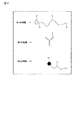
この例において、第1の物質と第2の物質とは、別体として用意される。図8は、この分析方法に用いられる第1〜第3の物質の一例を示す模式図である。この例において、温度応答性高分子1の他方の端4及び第1の捕捉体5は、両者が結合するための更なる構成成分を備えている。更なる構成成分は、互いに結合する2つの物質であればよい。これらの物質は、第1〜第3の物質の各構成成分の機能を阻害しない分子量を有する物質であることが好ましい。また、これら2つの物質の親和性は、第1及び第2の捕捉体と標的物質との親和性よりも高い物質であることが好ましい。例えば、このような物質として、ビオチン及びストレプトアビジン、プロテインA、プロテインG、メロンゲル、核酸などを用いることができる。図8に示す例においては、第1の物質の温度応答性高分子1の他方の端4にストレプトアビジン11が結合しており、第2の物質の第1の捕捉体5にビオチン12が結合している。それ以外の構成は、上述したものと同じものを用いることができる。
In this example, the first substance and the second substance are prepared separately. FIG. 8 is a schematic diagram showing an example of the first to third substances used in this analysis method. In this example, the other end 4 of the temperature-
以下に、当該分析方法の工程について、前述した図6の分析システム200及び図9の第1〜第3の物質の挙動を示す模式図を参照して説明する。
Hereinafter, the steps of the analysis method will be described with reference to the above-described
まず、自動分析装置100の複数の試料容器225内に異なる試料をそれぞれ収容する。また、複数の第2試薬容器218に同種の第2試薬(即ち、第1の物質)をそれぞれ収容し、第1試薬容器233に同種の第1試薬(即ち、第2及び第3の物質)をそれぞれ収容する。各試料容器225は2℃〜20℃で維持されるように分析制御部202により制御する。第2試薬容器218及び第1試薬容器233は第2試薬保冷庫及び第1試薬保冷庫によりそれぞれ2℃〜20℃で維持されている。
First, different samples are stored in the plurality of
次いで、試料分注部材226のアーム227をサンプルディスク224に向けて回転させて、その吸引・吐出ノズル228を検出すべき試料が収容された試料容器225の直上に位置させた後、当該吸引・吐出ノズル228の先端を試料容器225内の試料に下降させる。つづいて、吸引・吐出ノズル228で試料容器225に収容された試料を吸引させる。吸引・吐出ノズル228を上昇させ、アーム227を反応ディスク212に向けて回動させて、吸引・吐出ノズル228を反応ディスク212上の1つの反応容器214の直上に位置させた後、当該吸引・吐出ノズル228の先端を反応容器214内に下降させる。その後、吸引・吐出ノズル228内の試料を反応容器214内に吐出して、試料を反応容器214内に注入する。吸引・吐出ノズル228を上昇させ、アーム227を回動して元の位置に復帰させる。
Next, the
反応ディスク212を反時計回り方向に回転させ、試料が収納された反応容器214を第1試薬用円環状ブロック229と対向する時計盤の3時に相当する箇所に移動する。第1試薬分注部材235を前記試料の注入と同様にアーム236を第1試薬用円環状ブロック229に向けて回転する操作等を行うことによって、第1試薬容器233から第1試薬を反応容器214内に注入し、第2の物質及び第3の物質を試料に添加する(図9の(a)参照)。
The
その後、反応ディスク212を反時計回り方向に回転し、反応容器214を図示しない撹拌アームの撹拌子の直下に位置させる。撹拌子を反応容器214内の混合物に下降させ、回転することにより、混合物を撹拌する。このとき、図9の(b)に示すように第2の物質と、試料中の標的物質と、第3の物質とが結合する。
Thereafter, the
次いで、反応ディスク212を反時計回り方向に回転し、反応容器214を時計盤の9時の位置に移動させる。第2試薬分注部材220を前記試料の注入と同様にアーム221を円環状ブロック213に向けて回動する操作等を行うことによって、第2試薬容器218から第2試薬を反応容器214に注入し、反応容器214内の混合物に添加する。第2試薬(第1の物質)の添加(図9の(c))によって、反応容器214に含まれる混合物の温度は低下する。また、図9の(d)に示すように第1の物質と第2の物質とが、ストレプトアビジン11及びビオチン12を介して結合し、複合体を形成する。その後、反応容器214は予め30℃〜40℃で維持されるように制御されているため、反応容器214に含まれる混合物は、例えば、約1分〜30分でその温度まで自動的に上昇する。それによって、複合体を形成していない第1の物質の温度応答性高分子が凝集し、凝集体が生成する(図9の(e))。
Next, the
前記第2及び第3の物質の試料への添加(a)から(d)の工程後、温度が上昇するまでの時間は、例えば、約1分〜約30分である。この時間は、標的物質に第1の捕捉体及び第2の捕捉体が結合するのに十分な時間である。また、第1の物質の添加(c)から(d)の工程後、温度が上昇するまでの時間は、例えば、約1分〜約30分である。この時間は、(a)〜(d)の工程の直前までの時間よりも短いが、ストレプトアビジン11及びビオチン12の親和性がより高いことにより、この時間でも十分に結合することができる。このような方法により、標的物質に第1及び第2の物質が結合する前に温度が上昇して温度応答性高分子1が凝集することを防止することができる。即ち、第1の物質と第2の物質を予め結合させておく場合、この結合物の添加から温度上昇までの時間が約1分〜約30分であるために、第2の物質が標的物質に結合する前に凝集が起こる可能性がある。一方、前記方法によれば第2の物質の添加と第1の物質の添加とを分け、第2の物質を先に添加して第2の物質が標的物質に結合する十分な時間を設けることにより、第1の物質の添加から温度が戻るまでの時間が短い場合であっても標的物質に第2の物質が結合する前に温度応答性高分子1が凝集することが防止される。
After the steps (a) to (d) of adding the second and third substances to the sample, the time until the temperature rises is, for example, about 1 minute to about 30 minutes. This time is a time sufficient for the first capturing body and the second capturing body to bind to the target substance. Further, the time from the addition of the first substance (c) to the step (d) until the temperature rises is, for example, about 1 minute to about 30 minutes. This time is shorter than the time immediately before the steps (a) to (d), but due to the higher affinity of streptavidin 11 and
反応容器214内の混合物が温度上昇した後、反応ディスク212を反時計回り方向に回転し、当該反応容器214を時計盤の6時に位置に検出ユニット223と対向させる。検出ユニット223の照射部材(図示せず)から疎水性条件下における極性応答性蛍光物質を励起する励起光を反応容器214内に混合物に照射する。つづいて、反応容器214内の混合物から生じる蛍光を検出ユニット223の検出器(図示せず)で検出する。
After the temperature of the mixture in the
検出により得られた蛍光に関するデータは、図7に示すデータ処理部30に送られ、標的物質の有無又は量のデータ(分析データ)及び標準データが生成される。分析データ及び標準データは、出力部40に出力される。上記工程の一部又は全ては、書き込まれたプログラムによって自動的に行うことができる。 The data on the fluorescence obtained by the detection is sent to the data processing unit 30 shown in FIG. 7, and data on the presence or absence or amount of the target substance (analysis data) and standard data are generated. The analysis data and the standard data are output to the output unit 40. Some or all of the above steps can be performed automatically by the written program.
なお、前述した自動分析装置による試料中の標的物質の自動分析において、サンプルディスク224の試料容器225内の試料を反応容器214内に注入後、サンプルディスク224を、例えば反時計回り方向に回転して試料容器225を1コマ分移動する。第1試薬用円環状ブロック229の第1試薬容器233内の第1試薬を反応容器214内に注入後も、例えば反時計回り方向に回転して第1試薬容器233を1コマ分移動する。同様に、円環状ブロック213の第2試薬容器218内の第2試薬を反応容器214内に注入後、円環状ブロック213を、例えば反時計回り方向に回転して第2試薬容器218を1コマ分移動する。このような操作により、次の試料の自動分析の準備をする。
In the above-mentioned automatic analysis of the target substance in the sample by the automatic analyzer, after the sample in the
以上のようにして自動分析装置によって実施形態の分析方法を行うことができる。実施形態の分析方法によれば、このような自動分析装置を用いて行う場合であっても、試料の添加工程から蛍光の検出工程まで、例えば、各試薬を順次添加するごとに混合物を分離したり洗浄したりする必要がない。そのため、一つの反応容器214で標的物質の検出又は定量までを行うことができるため、コンタミネーションが防止でき、より簡単に制度の高い検出及び定量を行うことが可能である。
・競合法を用いた分析方法
更なる実施形態において、分析方法は、競合法を用いて行うことができる。
As described above, the analysis method of the embodiment can be performed by the automatic analyzer. According to the analysis method of the embodiment, even when using such an automatic analyzer, from the sample addition step to the fluorescence detection step, for example, the mixture is separated every time each reagent is added sequentially No need for cleaning or cleaning. Therefore, detection or quantification of a target substance can be performed in one
-Analysis method using competition method In a further embodiment, the analysis method can be performed using a competition method.
この方法に用いる第1〜第3の物質について、図10を用いて説明する。第1の物質及び第2の物質は、上記の何れかの第1の物質及び第2の物質と同じものを用いることができる。第3の物質は、凝集阻害物質7で標識された競合物質13を含む。凝集阻害物質7は、上記の何れかのものと同じものを用いることができる。
First to third substances used in this method will be described with reference to FIG. As the first substance and the second substance, any of the first substance and the second substance described above can be used. The third substance includes a
競合物質13は、第1の捕捉体に対して親和性を有し、第1の捕捉体への結合に対して標的物質と競合する物質である。競合物質は、例えば、標的物質の第1の捕捉体への結合部位と似た構造を有する部位を備える。例えば、第1の捕捉体5と競合物質13との親和性は、第1の捕捉体5と標的物質との親和性よりも弱いことが好ましい。
The
競合法を用いた分析方法の一例の概略フローを図11に示す。当該分析方法は、例えば、以下の工程を含む:
(S11)上述の第1の物質、第2の物質及び第3の物質を用意すること;
(S12)前記試料に第2の物質及び第3の物質を混合し、次いで第1の物質を混合すること;
(S13)前記混合により得られた混合物を刺激応答性高分子が凝集する温度に維持すること;
(S14)環境応答性蛍光物質からの蛍光を検出すること;及び
(S15)前記検出の結果に基づいて、試料中の標的物質の有無又は量を決定すること。
FIG. 11 shows a schematic flow of an example of the analysis method using the competition method. The analysis method includes, for example, the following steps:
(S11) preparing the above-mentioned first substance, second substance and third substance;
(S12) mixing a second substance and a third substance with the sample, and then mixing the first substance;
(S13) maintaining the mixture obtained by the mixing at a temperature at which the stimulus-responsive polymer aggregates;
(S14) detecting the fluorescence from the environment-responsive fluorescent substance; and (S15) determining the presence or absence or amount of the target substance in the sample based on the result of the detection.
当該分析方法について以下に説明する。ここでは、刺激応答性高分子が温度応答性高分子1であり、環境応答性蛍光物質が極性応答性蛍光物質2である例を示す。
The analysis method will be described below. Here, an example in which the stimulus-responsive polymer is the temperature-
工程(S12)において、試料に第2及び第3の物質を混合することにより、図12の(a)に示す第1の複合体14が生成する。第1の複合体14は、例えば、極性応答性蛍光物質2aと、温度応答性高分子1aと、第1の捕捉体5と、競合物質13と、第2の捕捉体6と、凝集阻害物質7とが結合している。第1の捕捉体5がこの例のように複数の標的物質結合部位を有する物質である場合、複数の標的物質結合部位に、更なる競合物質13と凝集阻害物質7とが結合してもよい。次いで、第1の物質を混合することにより、試料中に標的物質が存在する場合、第1の複合体14における第1の捕捉体5への競合物質13の結合が、標的物質8の結合に置き換わり、第2の複合体15が生成する(図12の(b))。第2の複合体15は、例えば、極性応答性蛍光物質2bと、温度応答性高分子1bと、第1の捕捉体5と、標的物質8とが結合している。
In the step (S12), the first complex 14 shown in FIG. 12A is formed by mixing the sample with the second and third substances. The first complex 14 includes, for example, a polarity-
工程(S13)において、温度応答性高分子が凝集する温度に維持する。そのときの第1の複合体14、第2の複合体15を図13に示す。第1の複合体14の温度応答性高分子1aは凝集阻害物質7が近傍に存在することにより凝集しない(図13の(a))。そのため、極性応答性蛍光物質2aの蛍光の波長は変化しない。対して、第2の複合体15に含まれる温度応答性高分子1bは疎水性となって凝集し、凝集体10を形成する(図13の(b))。そのため、極性応答性蛍光物質2bの蛍光の波長は変化する。
In the step (S13), the temperature is maintained at a temperature at which the temperature-responsive polymer aggregates. FIG. 13 shows the first complex 14 and the second complex 15 at that time. The temperature-responsive polymer 1a of the first complex 14 does not aggregate due to the presence of the aggregation
したがって、図14の(a)に示すように、標的物質が多く存在する場合、より多くの前記置き換えが起こり、蛍光の波長が変化しない極性応答性蛍光物質2aの数が蛍光の波長が変化した極性応答性蛍光物質2bの数よりも少なくなる。図14の(b)に示すように標的物質がより少ない場合、極性応答性蛍光物質2aの数は、極性応答性蛍光物質2bの数よりも多くなる。
Therefore, as shown in FIG. 14 (a), when a large number of target substances are present, more replacement occurs, and the number of the polarity-
工程(S14)において、極性応答性蛍光物質2からの蛍光を検出する。蛍光の検出は、例えば、上記工程(S4)と同様の方法行うことができる。しかしながら、蛍光波長の変化した極性応答性蛍光物質2bの励起光を照射する場合、標的物質の存在量と得られる蛍光強度との関係は、工程(S4)と逆である。即ち、標的物質が多く存在するほど検出される蛍光強度が強くなる。
In the step (S14), the fluorescence from the polarity-
蛍光の検出は、上記のように極性応答性蛍光物質2bの励起光を照射してもよいが、波長が変化していない極性応答性蛍光物質2aの励起光を照射してもよい。その場合、蛍光強度に関して逆の結果が得られる。或いは、極性応答性蛍光物質2aと極性応答性蛍光物質2bの両方の励起光を照射し、両者の蛍光強度を測定してもよい。
The fluorescence may be detected by irradiating the excitation light of the polar responsive
工程(S15)において、上記検出の結果に基づいて、試料中の標的物質8の有無又は量を決定する。例えば、蛍光の波長が変化した極性応答性蛍光物質2bの励起光を照射したときに蛍光が検出された場合、標的物質が存在すると決定してもよい。又は、当該蛍光の強度が予め設定した閾値よりも強い場合に標的物質が存在すると決定し、閾値よりも弱い場合に標的物質が存在しないと決定してもよい。閾値は、例えば、標的物質の濃度が既知の標準試料によって蛍光強度を測定することによって予め決定される。或いは、このような標準試料の蛍光強度測定によって検量線を作成し、その検量線に従って、分析されるべき試料の標的物質の量を決定してもよい。或いは、蛍光の立ち上がり時間を基に標的物質の量を決定してもよい。
In step (S15), the presence or absence or amount of the target substance 8 in the sample is determined based on the result of the detection. For example, when the fluorescence is detected when the excitation light of the polarity-
以上に説明した競合法を用いた分析方法は、上記の自動分析装置100を用いて行うこともできる。競合法を用いた分析方法によれば、より分子量の小さな標的物質もより精度よく検出又は定量することができる。
The analysis method using the competition method described above can also be performed using the
・試薬キット
更なる実施形態によれば、実施形態の分析方法に用いるための試薬キットが提供される。実施形態の試薬キットは、例えば、実施形態の第1の物質、第2の物質及び第3の物質を含む。第1〜第3の物質は、別々の容器に収容されていてもよいし、第2及び第3の物質が同じ容器に一緒に収容されていてもよい。或いは、第1の物質の温度応答性高分子1の他方の端4と、第2の物質の第1の捕捉体とが予め結合されて一つの容器に収容されていてもよい。
-Reagent kit According to a further embodiment, a reagent kit for use in the analysis method of the embodiment is provided. The reagent kit of the embodiment includes, for example, the first substance, the second substance, and the third substance of the embodiment. The first to third substances may be contained in separate containers, or the second and third substances may be contained together in the same container. Alternatively, the other end 4 of the temperature-
第1〜第3の物質は、例えば、上記の適切な溶媒に含まれていてもよい。 The first to third substances may be included in, for example, the above-mentioned appropriate solvent.
1、1a、1b…温度応答性高分子、2、2a、2b…極性応答性蛍光物質、
3…一方の端、4…他方の端、5…第1の捕捉体、6…第2の捕捉体、7…凝集阻害物質、
8…標的物質、9…複合体、11…ストレプトアビジン、12…ビオチン、
13…競合物質、14…第1の複合体、15…第2の複合体。
1, 1a, 1b: temperature-responsive polymer, 2, 2a, 2b: polarity-responsive fluorescent substance,
3 ... one end, 4 ... the other end, 5 ... first capturing body, 6 ... second capturing body, 7 ... aggregation inhibitor,
8 target substance, 9 complex, 11 streptavidin, 12 biotin,
13: competitor, 14: first complex, 15: second complex.
Claims (15)
(S2)前記試料と前記第1の物質、第2の物質及び第3の物質とを混合すること、ここで、前記試料中に前記標的物質が存在する場合、前記環境応答性蛍光物質と、前記刺激応答性高分子と、前記第1の捕捉体と、前記標的物質と、前記第2の捕捉体と、前記凝集阻害物質とが結合した複合体が生成する;
(S3)前記混合により得られた混合物を前記刺激応答性高分子が凝集する条件に維持し、前記複合体を形成していない前記刺激応答性高分子を凝集させ、当該刺激応答性高分子に結合した前記環境応答性蛍光物質を疎水性条件下に存在させること;
(S4)前記環境応答性蛍光物質からの蛍光を検出すること;及び
(S5)前記検出の結果に基づいて、前記試料中の前記標的物質の有無又は量を決定すること;
を含む請求項1に記載の分析方法。 (S1) a) a first substance containing a stimuli-responsive polymer and an environment-responsive fluorescent substance bound to one end of the stimuli-responsive polymer, b) a first substance that specifically binds to the target substance A second substance containing one capturer, and c) the second capturer that specifically binds to the target substance, which is labeled with an aggregation inhibitor that inhibits aggregation of the stimuli-responsive polymer. Providing a third substance;
(S2) mixing the sample with the first substance, the second substance, and the third substance, wherein, when the target substance is present in the sample, the environment-responsive fluorescent substance; A complex is formed in which the stimulus-responsive polymer, the first capturing body, the target substance, the second capturing body, and the aggregation-inhibiting substance are bound;
(S3) maintaining the mixture obtained by the mixing under conditions under which the stimulus-responsive polymer aggregates, aggregating the stimulus-responsive polymer not forming the complex, and Causing the bound environmentally responsive fluorescent substance to exist under hydrophobic conditions;
(S4) detecting fluorescence from the environment-responsive fluorescent substance; and (S5) determining the presence or absence or amount of the target substance in the sample based on the result of the detection;
The analysis method according to claim 1, comprising:
(S2−1)前記試料に前記第2の物質及び前記第3の物質を混合し、前記標的物質に前記第1の捕捉体と前記第2の捕捉体を結合させること;及び
(S2−2)次いで、前記試料に前記第1の物質を混合し、前記第1の捕捉体と、前記前記刺激応答性高分子の他方の端とを結合させ、前記複合体を形成すること;
を含む請求項2に記載の方法。 The step (S2) includes:
(S2-1) mixing the second substance and the third substance with the sample, and binding the first capturing body and the second capturing body to the target substance; and (S2-2) Then, mixing the first substance with the sample and binding the first capturing body and the other end of the stimuli-responsive polymer to form the complex;
The method of claim 2, comprising:
(S12)前記試料に第2の物質及び第3の物質を混合し、前記環境応答性蛍光物質と、前記刺激応答性高分子と、前記第1の捕捉体と、前記競合物質と、前記凝集阻害物質とが結合した第1の複合体を生成させ、次いで第1の物質を混合し、前記試料中に前記標的物質が存在する場合、前記第1の複合体の前記第1の捕捉体と前記競合物質との結合を、前記標的物質との結合に置き換え、前記刺激応答性高分子と、前記第1の捕捉体と、前記標的物質とが結合した第2の複合体を生成させること;
(S13)前記混合により得られた混合物を前記刺激応答性高分子が凝集する条件に維持し前記第1の複合体を形成していない前記刺激応答性高分子を凝集させ、当該刺激応答性高分子に結合した前記環境応答性蛍光物質を疎水性条件下に存在させること;
(S14)前記環境応答性蛍光物質からの蛍光を検出すること;及び
(S15)前記検出の結果に基づいて、前記試料中の前記標的物質の有無又は量を決定することを含む請求項5に記載の分析方法。 (S11) a) a first substance containing a stimuli-responsive polymer and an environment-responsive fluorescent substance bound to one end of the stimuli-responsive polymer, b) a first substance that specifically binds to the target substance Preparing a second substance containing one capturer and c) a third substance containing a competitor labeled with an aggregation inhibitor that inhibits aggregation of the stimuli-responsive polymer, wherein the competition The substance is a substance that has an affinity for the first capturing body and competes with the target substance for binding to the first capturing body;
(S12) A second substance and a third substance are mixed with the sample, and the environment-responsive fluorescent substance, the stimulus-responsive polymer, the first capturing body, the competitor, and the aggregation are mixed. Forming a first complex to which the inhibitor is bound, then mixing the first substance and, if the target substance is present in the sample, the first complex and the first capturer of the first complex; Replacing the binding with the competitor with the binding with the target substance to form a second complex in which the stimulus-responsive polymer, the first capturing body, and the target substance are bound;
(S13) The mixture obtained by the mixing is maintained under the condition that the stimuli-responsive polymer is aggregated, and the stimuli-responsive polymer not forming the first complex is aggregated to increase the stimuli-responsiveness. Causing the environment-responsive fluorescent substance bound to a molecule to exist under hydrophobic conditions;
(S14) detecting fluorescence from the environment-responsive fluorescent substance; and (S15) determining the presence or absence or amount of the target substance in the sample based on the result of the detection. Analysis method as described.
a)刺激応答性高分子と、前記刺激応答性高分子の一方の端に結合した環境応答性蛍光物質とを含む第1の物質、
b)前記標的物質と特異的に結合する第1の捕捉体を含む第2の物質、及び
c)前記刺激応答性高分子の凝集を阻害する凝集阻害物質で標識された、前記標的物質と特異的に結合する第2の捕捉体を含む第3の物質
を含む試薬キット。 A kit for detecting a target substance in a sample,
a) a first substance comprising a stimulus-responsive polymer and an environment-responsive fluorescent substance bound to one end of the stimulus-responsive polymer;
b) a second substance containing a first capturer that specifically binds to the target substance; and c) a specific substance that is labeled with an aggregation inhibitor that inhibits aggregation of the stimulus-responsive polymer. A reagent kit comprising a third substance containing a second capture body that binds specifically.
a)刺激応答性高分子と、前記刺激応答性高分子の一方の端に結合した環境応答性蛍光物質とを含む第1の物質、
b)前記標的物質と特異的に結合する第1の捕捉体を含む第2の物質、及び
c)前記刺激応答性高分子の凝集を阻害する凝集阻害物質で標識された競合物質を含む第3の物質を含み、
前記競合物質は、前記第1の捕捉体に対して親和性を有し、前記第1の捕捉体への結合に対して前記標的物質と競合する物質である
試薬キット。 A kit for detecting a target substance in a sample,
a) a first substance comprising a stimulus-responsive polymer and an environment-responsive fluorescent substance bound to one end of the stimulus-responsive polymer;
b) a second substance including a first capturer that specifically binds to the target substance, and c) a third substance including a competitor labeled with an aggregation inhibitor that inhibits aggregation of the stimulus-responsive polymer. Containing the substance
A reagent kit, wherein the competitor has an affinity for the first capturer and is a substance that competes with the target for binding to the first capturer.
前記試料と前記第1〜第3の物質とを混合し、この混合物に前記環境応答性蛍光物質の励起光を照射し、蛍光の測定を行い、蛍光に関するデータを生成する分析システム、および
前記蛍光に関するデータから前記標的物質の有無又は量のデータを生成するデータ処理部
を含む装置。 An apparatus for use in the analysis method according to claim 1,
An analysis system for mixing the sample and the first to third substances, irradiating the mixture with excitation light of the environment-responsive fluorescent substance, measuring the fluorescence, and generating data relating to the fluorescence; A data processing unit for generating data on the presence or absence or amount of the target substance from the data on the target substance.
Priority Applications (4)
| Application Number | Priority Date | Filing Date | Title |
|---|---|---|---|
| JP2018146102A JP2020020719A (en) | 2018-08-02 | 2018-08-02 | Analytic method, reagent kit, and analyzer |
| DE112019003898.2T DE112019003898T5 (en) | 2018-08-02 | 2019-07-31 | ANALYSIS PROCEDURE, REAGENT KIT, AND ANALYSIS DEVICE |
| PCT/JP2019/030103 WO2020027234A1 (en) | 2018-08-02 | 2019-07-31 | Analysis method, reagent kit, and analyzing device |
| US17/163,623 US20210156849A1 (en) | 2018-08-02 | 2021-02-01 | Analytical method, reagent kit and analytic device |
Applications Claiming Priority (1)
| Application Number | Priority Date | Filing Date | Title |
|---|---|---|---|
| JP2018146102A JP2020020719A (en) | 2018-08-02 | 2018-08-02 | Analytic method, reagent kit, and analyzer |
Publications (1)
| Publication Number | Publication Date |
|---|---|
| JP2020020719A true JP2020020719A (en) | 2020-02-06 |
Family
ID=69230508
Family Applications (1)
| Application Number | Title | Priority Date | Filing Date |
|---|---|---|---|
| JP2018146102A Pending JP2020020719A (en) | 2018-08-02 | 2018-08-02 | Analytic method, reagent kit, and analyzer |
Country Status (4)
| Country | Link |
|---|---|
| US (1) | US20210156849A1 (en) |
| JP (1) | JP2020020719A (en) |
| DE (1) | DE112019003898T5 (en) |
| WO (1) | WO2020027234A1 (en) |
Families Citing this family (1)
| Publication number | Priority date | Publication date | Assignee | Title |
|---|---|---|---|---|
| JP2021135247A (en) * | 2020-02-28 | 2021-09-13 | キヤノン株式会社 | Test drug, test kit and test method |
Family Cites Families (7)
| Publication number | Priority date | Publication date | Assignee | Title |
|---|---|---|---|---|
| ATE216594T1 (en) * | 1995-09-01 | 2002-05-15 | Univ Washington | INTERACTIVE MOLECULAR CONJUGATES |
| JP5306995B2 (en) * | 2007-03-23 | 2013-10-02 | 国立大学法人 東京医科歯科大学 | Target substance detection method, tag, DNA, vector, probe and detection kit used therefor |
| JP2008268186A (en) * | 2007-03-27 | 2008-11-06 | Canon Inc | Material for improving sensitivity of magnetic sensor, and method therefor |
| WO2010137532A1 (en) * | 2009-05-29 | 2010-12-02 | チッソ株式会社 | Detection method and quantification method of detection target |
| US20100317032A1 (en) * | 2009-06-10 | 2010-12-16 | Fujifilm Corporation | Method for detecting antigen and antigen detection device |
| JP6179521B2 (en) * | 2012-09-04 | 2017-08-16 | Jnc株式会社 | Substance measurement sensor |
| JPWO2015129901A1 (en) * | 2014-02-27 | 2017-03-30 | 株式会社セルシード | Amino acid derivative fluorescent polymer and fluorescent probe using the same |
-
2018
- 2018-08-02 JP JP2018146102A patent/JP2020020719A/en active Pending
-
2019
- 2019-07-31 DE DE112019003898.2T patent/DE112019003898T5/en active Pending
- 2019-07-31 WO PCT/JP2019/030103 patent/WO2020027234A1/en active Application Filing
-
2021
- 2021-02-01 US US17/163,623 patent/US20210156849A1/en active Pending
Also Published As
| Publication number | Publication date |
|---|---|
| WO2020027234A1 (en) | 2020-02-06 |
| DE112019003898T5 (en) | 2021-05-06 |
| US20210156849A1 (en) | 2021-05-27 |
Similar Documents
| Publication | Publication Date | Title |
|---|---|---|
| JP6878742B2 (en) | Assay system | |
| RU2526198C2 (en) | Exciting magnetic spheres using feedback for ftir based biosensor | |
| EP1723411B1 (en) | Method and device for the characterization of interactions between different species | |
| US6562209B1 (en) | Automated computer controlled reporter device for conducting imunnoassay and molecular biology procedures | |
| WO2008072870A1 (en) | Apparatus for measuring blood cell aggregation using stirring | |
| McGrath et al. | Development of a rapid low cost fluorescent biosensor for the detection of food contaminants | |
| WO2009154377A3 (en) | Real-time continuous detection device | |
| US9372187B2 (en) | Detection method and determination method for detection target | |
| US8940495B2 (en) | Rapid and sensitive method for quantitative determination of the level of heparin—PF4 complex induced immunoglobulin antibodies | |
| EP3662268A1 (en) | Method of monitoring an operation of detection of an analyte in a liquid sample | |
| CN116008553A (en) | Method and device for measuring physiological properties of biological samples | |
| JP2002511926A (en) | Assays using magnetic particles | |
| NL2020419B1 (en) | Field portable, handheld, recirculating surface acoustic wave and method for operating the same | |
| WO2020027234A1 (en) | Analysis method, reagent kit, and analyzing device | |
| CN103890588A (en) | Magnetic particle detection with incubation period | |
| US20130130243A1 (en) | Method and device for detecting and quantifying an analyte with recycling of the reagents | |
| JP2013543981A (en) | Method and system for printing in-well calibration functions | |
| US11567097B2 (en) | Apparatus for optically monitoring a dosing of a liquid to be pipetted | |
| CN1853096A (en) | Method and device for the detection of very small quantities of particles | |
| US11733323B2 (en) | Systems and methods for measuring cellular response to target analytes by controlled application of an oscillating stimulus | |
| US20170016831A1 (en) | Systems and methods for determining concentration of a component in a fluid sample | |
| JP2012202736A (en) | Inspection object acceptor, inspection method, and inspection device | |
| KR100749939B1 (en) | Detection antibody immobilization automation device | |
| US6933143B2 (en) | Automated enzyme-linked immunosorbent assay device with ONP-GP | |
| JP4096242B2 (en) | Surface plasmon resonance measuring device |