JP2020006694A - Heat transfer sheet, coating liquid for release layer, and method for manufacturing heat transfer sheet - Google Patents
Heat transfer sheet, coating liquid for release layer, and method for manufacturing heat transfer sheet Download PDFInfo
- Publication number
- JP2020006694A JP2020006694A JP2019148956A JP2019148956A JP2020006694A JP 2020006694 A JP2020006694 A JP 2020006694A JP 2019148956 A JP2019148956 A JP 2019148956A JP 2019148956 A JP2019148956 A JP 2019148956A JP 2020006694 A JP2020006694 A JP 2020006694A
- Authority
- JP
- Japan
- Prior art keywords
- layer
- release layer
- transfer
- coating liquid
- parts
- Prior art date
- Legal status (The legal status is an assumption and is not a legal conclusion. Google has not performed a legal analysis and makes no representation as to the accuracy of the status listed.)
- Granted
Links
Images


Classifications
-
- B—PERFORMING OPERATIONS; TRANSPORTING
- B41—PRINTING; LINING MACHINES; TYPEWRITERS; STAMPS
- B41M—PRINTING, DUPLICATING, MARKING, OR COPYING PROCESSES; COLOUR PRINTING
- B41M5/00—Duplicating or marking methods; Sheet materials for use therein
- B41M5/50—Recording sheets characterised by the coating used to improve ink, dye or pigment receptivity, e.g. for ink-jet or thermal dye transfer recording
- B41M5/52—Macromolecular coatings
-
- B—PERFORMING OPERATIONS; TRANSPORTING
- B32—LAYERED PRODUCTS
- B32B—LAYERED PRODUCTS, i.e. PRODUCTS BUILT-UP OF STRATA OF FLAT OR NON-FLAT, e.g. CELLULAR OR HONEYCOMB, FORM
- B32B23/00—Layered products comprising a layer of cellulosic plastic substances, i.e. substances obtained by chemical modification of cellulose, e.g. cellulose ethers, cellulose esters, viscose
- B32B23/04—Layered products comprising a layer of cellulosic plastic substances, i.e. substances obtained by chemical modification of cellulose, e.g. cellulose ethers, cellulose esters, viscose comprising such cellulosic plastic substance as the main or only constituent of a layer, which is next to another layer of the same or of a different material
- B32B23/08—Layered products comprising a layer of cellulosic plastic substances, i.e. substances obtained by chemical modification of cellulose, e.g. cellulose ethers, cellulose esters, viscose comprising such cellulosic plastic substance as the main or only constituent of a layer, which is next to another layer of the same or of a different material of synthetic resin
-
- B—PERFORMING OPERATIONS; TRANSPORTING
- B32—LAYERED PRODUCTS
- B32B—LAYERED PRODUCTS, i.e. PRODUCTS BUILT-UP OF STRATA OF FLAT OR NON-FLAT, e.g. CELLULAR OR HONEYCOMB, FORM
- B32B27/00—Layered products comprising a layer of synthetic resin
- B32B27/06—Layered products comprising a layer of synthetic resin as the main or only constituent of a layer, which is next to another layer of the same or of a different material
- B32B27/08—Layered products comprising a layer of synthetic resin as the main or only constituent of a layer, which is next to another layer of the same or of a different material of synthetic resin
-
- B—PERFORMING OPERATIONS; TRANSPORTING
- B32—LAYERED PRODUCTS
- B32B—LAYERED PRODUCTS, i.e. PRODUCTS BUILT-UP OF STRATA OF FLAT OR NON-FLAT, e.g. CELLULAR OR HONEYCOMB, FORM
- B32B27/00—Layered products comprising a layer of synthetic resin
- B32B27/16—Layered products comprising a layer of synthetic resin specially treated, e.g. irradiated
-
- B—PERFORMING OPERATIONS; TRANSPORTING
- B32—LAYERED PRODUCTS
- B32B—LAYERED PRODUCTS, i.e. PRODUCTS BUILT-UP OF STRATA OF FLAT OR NON-FLAT, e.g. CELLULAR OR HONEYCOMB, FORM
- B32B27/00—Layered products comprising a layer of synthetic resin
- B32B27/18—Layered products comprising a layer of synthetic resin characterised by the use of special additives
- B32B27/20—Layered products comprising a layer of synthetic resin characterised by the use of special additives using fillers, pigments, thixotroping agents
-
- B—PERFORMING OPERATIONS; TRANSPORTING
- B32—LAYERED PRODUCTS
- B32B—LAYERED PRODUCTS, i.e. PRODUCTS BUILT-UP OF STRATA OF FLAT OR NON-FLAT, e.g. CELLULAR OR HONEYCOMB, FORM
- B32B27/00—Layered products comprising a layer of synthetic resin
- B32B27/18—Layered products comprising a layer of synthetic resin characterised by the use of special additives
- B32B27/22—Layered products comprising a layer of synthetic resin characterised by the use of special additives using plasticisers
-
- B—PERFORMING OPERATIONS; TRANSPORTING
- B32—LAYERED PRODUCTS
- B32B—LAYERED PRODUCTS, i.e. PRODUCTS BUILT-UP OF STRATA OF FLAT OR NON-FLAT, e.g. CELLULAR OR HONEYCOMB, FORM
- B32B27/00—Layered products comprising a layer of synthetic resin
- B32B27/28—Layered products comprising a layer of synthetic resin comprising synthetic resins not wholly covered by any one of the sub-groups B32B27/30 - B32B27/42
- B32B27/281—Layered products comprising a layer of synthetic resin comprising synthetic resins not wholly covered by any one of the sub-groups B32B27/30 - B32B27/42 comprising polyimides
-
- B—PERFORMING OPERATIONS; TRANSPORTING
- B32—LAYERED PRODUCTS
- B32B—LAYERED PRODUCTS, i.e. PRODUCTS BUILT-UP OF STRATA OF FLAT OR NON-FLAT, e.g. CELLULAR OR HONEYCOMB, FORM
- B32B27/00—Layered products comprising a layer of synthetic resin
- B32B27/28—Layered products comprising a layer of synthetic resin comprising synthetic resins not wholly covered by any one of the sub-groups B32B27/30 - B32B27/42
- B32B27/285—Layered products comprising a layer of synthetic resin comprising synthetic resins not wholly covered by any one of the sub-groups B32B27/30 - B32B27/42 comprising polyethers
-
- B—PERFORMING OPERATIONS; TRANSPORTING
- B32—LAYERED PRODUCTS
- B32B—LAYERED PRODUCTS, i.e. PRODUCTS BUILT-UP OF STRATA OF FLAT OR NON-FLAT, e.g. CELLULAR OR HONEYCOMB, FORM
- B32B27/00—Layered products comprising a layer of synthetic resin
- B32B27/28—Layered products comprising a layer of synthetic resin comprising synthetic resins not wholly covered by any one of the sub-groups B32B27/30 - B32B27/42
- B32B27/286—Layered products comprising a layer of synthetic resin comprising synthetic resins not wholly covered by any one of the sub-groups B32B27/30 - B32B27/42 comprising polysulphones; polysulfides
-
- B—PERFORMING OPERATIONS; TRANSPORTING
- B32—LAYERED PRODUCTS
- B32B—LAYERED PRODUCTS, i.e. PRODUCTS BUILT-UP OF STRATA OF FLAT OR NON-FLAT, e.g. CELLULAR OR HONEYCOMB, FORM
- B32B27/00—Layered products comprising a layer of synthetic resin
- B32B27/28—Layered products comprising a layer of synthetic resin comprising synthetic resins not wholly covered by any one of the sub-groups B32B27/30 - B32B27/42
- B32B27/288—Layered products comprising a layer of synthetic resin comprising synthetic resins not wholly covered by any one of the sub-groups B32B27/30 - B32B27/42 comprising polyketones
-
- B—PERFORMING OPERATIONS; TRANSPORTING
- B32—LAYERED PRODUCTS
- B32B—LAYERED PRODUCTS, i.e. PRODUCTS BUILT-UP OF STRATA OF FLAT OR NON-FLAT, e.g. CELLULAR OR HONEYCOMB, FORM
- B32B27/00—Layered products comprising a layer of synthetic resin
- B32B27/30—Layered products comprising a layer of synthetic resin comprising vinyl (co)polymers; comprising acrylic (co)polymers
- B32B27/302—Layered products comprising a layer of synthetic resin comprising vinyl (co)polymers; comprising acrylic (co)polymers comprising aromatic vinyl (co)polymers, e.g. styrenic (co)polymers
-
- B—PERFORMING OPERATIONS; TRANSPORTING
- B32—LAYERED PRODUCTS
- B32B—LAYERED PRODUCTS, i.e. PRODUCTS BUILT-UP OF STRATA OF FLAT OR NON-FLAT, e.g. CELLULAR OR HONEYCOMB, FORM
- B32B27/00—Layered products comprising a layer of synthetic resin
- B32B27/30—Layered products comprising a layer of synthetic resin comprising vinyl (co)polymers; comprising acrylic (co)polymers
- B32B27/304—Layered products comprising a layer of synthetic resin comprising vinyl (co)polymers; comprising acrylic (co)polymers comprising vinyl halide (co)polymers, e.g. PVC, PVDC, PVF, PVDF
-
- B—PERFORMING OPERATIONS; TRANSPORTING
- B32—LAYERED PRODUCTS
- B32B—LAYERED PRODUCTS, i.e. PRODUCTS BUILT-UP OF STRATA OF FLAT OR NON-FLAT, e.g. CELLULAR OR HONEYCOMB, FORM
- B32B27/00—Layered products comprising a layer of synthetic resin
- B32B27/30—Layered products comprising a layer of synthetic resin comprising vinyl (co)polymers; comprising acrylic (co)polymers
- B32B27/308—Layered products comprising a layer of synthetic resin comprising vinyl (co)polymers; comprising acrylic (co)polymers comprising acrylic (co)polymers
-
- B—PERFORMING OPERATIONS; TRANSPORTING
- B32—LAYERED PRODUCTS
- B32B—LAYERED PRODUCTS, i.e. PRODUCTS BUILT-UP OF STRATA OF FLAT OR NON-FLAT, e.g. CELLULAR OR HONEYCOMB, FORM
- B32B27/00—Layered products comprising a layer of synthetic resin
- B32B27/32—Layered products comprising a layer of synthetic resin comprising polyolefins
-
- B—PERFORMING OPERATIONS; TRANSPORTING
- B32—LAYERED PRODUCTS
- B32B—LAYERED PRODUCTS, i.e. PRODUCTS BUILT-UP OF STRATA OF FLAT OR NON-FLAT, e.g. CELLULAR OR HONEYCOMB, FORM
- B32B27/00—Layered products comprising a layer of synthetic resin
- B32B27/34—Layered products comprising a layer of synthetic resin comprising polyamides
-
- B—PERFORMING OPERATIONS; TRANSPORTING
- B32—LAYERED PRODUCTS
- B32B—LAYERED PRODUCTS, i.e. PRODUCTS BUILT-UP OF STRATA OF FLAT OR NON-FLAT, e.g. CELLULAR OR HONEYCOMB, FORM
- B32B27/00—Layered products comprising a layer of synthetic resin
- B32B27/36—Layered products comprising a layer of synthetic resin comprising polyesters
- B32B27/365—Layered products comprising a layer of synthetic resin comprising polyesters comprising polycarbonates
-
- B—PERFORMING OPERATIONS; TRANSPORTING
- B32—LAYERED PRODUCTS
- B32B—LAYERED PRODUCTS, i.e. PRODUCTS BUILT-UP OF STRATA OF FLAT OR NON-FLAT, e.g. CELLULAR OR HONEYCOMB, FORM
- B32B7/00—Layered products characterised by the relation between layers; Layered products characterised by the relative orientation of features between layers, or by the relative values of a measurable parameter between layers, i.e. products comprising layers having different physical, chemical or physicochemical properties; Layered products characterised by the interconnection of layers
- B32B7/04—Interconnection of layers
- B32B7/06—Interconnection of layers permitting easy separation
-
- B—PERFORMING OPERATIONS; TRANSPORTING
- B41—PRINTING; LINING MACHINES; TYPEWRITERS; STAMPS
- B41M—PRINTING, DUPLICATING, MARKING, OR COPYING PROCESSES; COLOUR PRINTING
- B41M5/00—Duplicating or marking methods; Sheet materials for use therein
- B41M5/26—Thermography ; Marking by high energetic means, e.g. laser otherwise than by burning, and characterised by the material used
- B41M5/382—Contact thermal transfer or sublimation processes
- B41M5/38207—Contact thermal transfer or sublimation processes characterised by aspects not provided for in groups B41M5/385 - B41M5/395
- B41M5/38214—Structural details, e.g. multilayer systems
-
- B—PERFORMING OPERATIONS; TRANSPORTING
- B41—PRINTING; LINING MACHINES; TYPEWRITERS; STAMPS
- B41M—PRINTING, DUPLICATING, MARKING, OR COPYING PROCESSES; COLOUR PRINTING
- B41M5/00—Duplicating or marking methods; Sheet materials for use therein
- B41M5/26—Thermography ; Marking by high energetic means, e.g. laser otherwise than by burning, and characterised by the material used
- B41M5/40—Thermography ; Marking by high energetic means, e.g. laser otherwise than by burning, and characterised by the material used characterised by the base backcoat, intermediate, or covering layers, e.g. for thermal transfer dye-donor or dye-receiver sheets; Heat, radiation filtering or absorbing means or layers; combined with other image registration layers or compositions; Special originals for reproduction by thermography
- B41M5/405—Thermography ; Marking by high energetic means, e.g. laser otherwise than by burning, and characterised by the material used characterised by the base backcoat, intermediate, or covering layers, e.g. for thermal transfer dye-donor or dye-receiver sheets; Heat, radiation filtering or absorbing means or layers; combined with other image registration layers or compositions; Special originals for reproduction by thermography characterised by layers cured by radiation
-
- B—PERFORMING OPERATIONS; TRANSPORTING
- B41—PRINTING; LINING MACHINES; TYPEWRITERS; STAMPS
- B41M—PRINTING, DUPLICATING, MARKING, OR COPYING PROCESSES; COLOUR PRINTING
- B41M5/00—Duplicating or marking methods; Sheet materials for use therein
- B41M5/26—Thermography ; Marking by high energetic means, e.g. laser otherwise than by burning, and characterised by the material used
- B41M5/40—Thermography ; Marking by high energetic means, e.g. laser otherwise than by burning, and characterised by the material used characterised by the base backcoat, intermediate, or covering layers, e.g. for thermal transfer dye-donor or dye-receiver sheets; Heat, radiation filtering or absorbing means or layers; combined with other image registration layers or compositions; Special originals for reproduction by thermography
- B41M5/42—Intermediate, backcoat, or covering layers
- B41M5/44—Intermediate, backcoat, or covering layers characterised by the macromolecular compounds
- B41M5/443—Silicon-containing polymers, e.g. silicones, siloxanes
-
- B—PERFORMING OPERATIONS; TRANSPORTING
- B41—PRINTING; LINING MACHINES; TYPEWRITERS; STAMPS
- B41M—PRINTING, DUPLICATING, MARKING, OR COPYING PROCESSES; COLOUR PRINTING
- B41M5/00—Duplicating or marking methods; Sheet materials for use therein
- B41M5/50—Recording sheets characterised by the coating used to improve ink, dye or pigment receptivity, e.g. for ink-jet or thermal dye transfer recording
- B41M5/502—Recording sheets characterised by the coating used to improve ink, dye or pigment receptivity, e.g. for ink-jet or thermal dye transfer recording characterised by structural details, e.g. multilayer materials
-
- B—PERFORMING OPERATIONS; TRANSPORTING
- B41—PRINTING; LINING MACHINES; TYPEWRITERS; STAMPS
- B41M—PRINTING, DUPLICATING, MARKING, OR COPYING PROCESSES; COLOUR PRINTING
- B41M7/00—After-treatment of prints, e.g. heating, irradiating, setting of the ink, protection of the printed stock
- B41M7/0027—After-treatment of prints, e.g. heating, irradiating, setting of the ink, protection of the printed stock using protective coatings or layers by lamination or by fusion of the coatings or layers
-
- B—PERFORMING OPERATIONS; TRANSPORTING
- B32—LAYERED PRODUCTS
- B32B—LAYERED PRODUCTS, i.e. PRODUCTS BUILT-UP OF STRATA OF FLAT OR NON-FLAT, e.g. CELLULAR OR HONEYCOMB, FORM
- B32B2255/00—Coating on the layer surface
- B32B2255/10—Coating on the layer surface on synthetic resin layer or on natural or synthetic rubber layer
-
- B—PERFORMING OPERATIONS; TRANSPORTING
- B32—LAYERED PRODUCTS
- B32B—LAYERED PRODUCTS, i.e. PRODUCTS BUILT-UP OF STRATA OF FLAT OR NON-FLAT, e.g. CELLULAR OR HONEYCOMB, FORM
- B32B2255/00—Coating on the layer surface
- B32B2255/26—Polymeric coating
-
- B—PERFORMING OPERATIONS; TRANSPORTING
- B32—LAYERED PRODUCTS
- B32B—LAYERED PRODUCTS, i.e. PRODUCTS BUILT-UP OF STRATA OF FLAT OR NON-FLAT, e.g. CELLULAR OR HONEYCOMB, FORM
- B32B2255/00—Coating on the layer surface
- B32B2255/28—Multiple coating on one surface
-
- B—PERFORMING OPERATIONS; TRANSPORTING
- B32—LAYERED PRODUCTS
- B32B—LAYERED PRODUCTS, i.e. PRODUCTS BUILT-UP OF STRATA OF FLAT OR NON-FLAT, e.g. CELLULAR OR HONEYCOMB, FORM
- B32B2270/00—Resin or rubber layer containing a blend of at least two different polymers
-
- B—PERFORMING OPERATIONS; TRANSPORTING
- B32—LAYERED PRODUCTS
- B32B—LAYERED PRODUCTS, i.e. PRODUCTS BUILT-UP OF STRATA OF FLAT OR NON-FLAT, e.g. CELLULAR OR HONEYCOMB, FORM
- B32B2307/00—Properties of the layers or laminate
- B32B2307/30—Properties of the layers or laminate having particular thermal properties
- B32B2307/306—Resistant to heat
-
- B—PERFORMING OPERATIONS; TRANSPORTING
- B32—LAYERED PRODUCTS
- B32B—LAYERED PRODUCTS, i.e. PRODUCTS BUILT-UP OF STRATA OF FLAT OR NON-FLAT, e.g. CELLULAR OR HONEYCOMB, FORM
- B32B2307/00—Properties of the layers or laminate
- B32B2307/40—Properties of the layers or laminate having particular optical properties
- B32B2307/406—Bright, glossy, shiny surface
-
- B—PERFORMING OPERATIONS; TRANSPORTING
- B32—LAYERED PRODUCTS
- B32B—LAYERED PRODUCTS, i.e. PRODUCTS BUILT-UP OF STRATA OF FLAT OR NON-FLAT, e.g. CELLULAR OR HONEYCOMB, FORM
- B32B2307/00—Properties of the layers or laminate
- B32B2307/40—Properties of the layers or laminate having particular optical properties
- B32B2307/408—Matt, dull surface
-
- B—PERFORMING OPERATIONS; TRANSPORTING
- B32—LAYERED PRODUCTS
- B32B—LAYERED PRODUCTS, i.e. PRODUCTS BUILT-UP OF STRATA OF FLAT OR NON-FLAT, e.g. CELLULAR OR HONEYCOMB, FORM
- B32B2307/00—Properties of the layers or laminate
- B32B2307/50—Properties of the layers or laminate having particular mechanical properties
- B32B2307/514—Oriented
- B32B2307/516—Oriented mono-axially
-
- B—PERFORMING OPERATIONS; TRANSPORTING
- B32—LAYERED PRODUCTS
- B32B—LAYERED PRODUCTS, i.e. PRODUCTS BUILT-UP OF STRATA OF FLAT OR NON-FLAT, e.g. CELLULAR OR HONEYCOMB, FORM
- B32B2307/00—Properties of the layers or laminate
- B32B2307/50—Properties of the layers or laminate having particular mechanical properties
- B32B2307/514—Oriented
- B32B2307/518—Oriented bi-axially
-
- B—PERFORMING OPERATIONS; TRANSPORTING
- B32—LAYERED PRODUCTS
- B32B—LAYERED PRODUCTS, i.e. PRODUCTS BUILT-UP OF STRATA OF FLAT OR NON-FLAT, e.g. CELLULAR OR HONEYCOMB, FORM
- B32B2307/00—Properties of the layers or laminate
- B32B2307/50—Properties of the layers or laminate having particular mechanical properties
- B32B2307/538—Roughness
-
- B—PERFORMING OPERATIONS; TRANSPORTING
- B32—LAYERED PRODUCTS
- B32B—LAYERED PRODUCTS, i.e. PRODUCTS BUILT-UP OF STRATA OF FLAT OR NON-FLAT, e.g. CELLULAR OR HONEYCOMB, FORM
- B32B2307/00—Properties of the layers or laminate
- B32B2307/50—Properties of the layers or laminate having particular mechanical properties
- B32B2307/584—Scratch resistance
-
- B—PERFORMING OPERATIONS; TRANSPORTING
- B32—LAYERED PRODUCTS
- B32B—LAYERED PRODUCTS, i.e. PRODUCTS BUILT-UP OF STRATA OF FLAT OR NON-FLAT, e.g. CELLULAR OR HONEYCOMB, FORM
- B32B2307/00—Properties of the layers or laminate
- B32B2307/70—Other properties
- B32B2307/726—Permeability to liquids, absorption
- B32B2307/7265—Non-permeable
-
- B—PERFORMING OPERATIONS; TRANSPORTING
- B32—LAYERED PRODUCTS
- B32B—LAYERED PRODUCTS, i.e. PRODUCTS BUILT-UP OF STRATA OF FLAT OR NON-FLAT, e.g. CELLULAR OR HONEYCOMB, FORM
- B32B2307/00—Properties of the layers or laminate
- B32B2307/70—Other properties
- B32B2307/732—Dimensional properties
-
- B—PERFORMING OPERATIONS; TRANSPORTING
- B32—LAYERED PRODUCTS
- B32B—LAYERED PRODUCTS, i.e. PRODUCTS BUILT-UP OF STRATA OF FLAT OR NON-FLAT, e.g. CELLULAR OR HONEYCOMB, FORM
- B32B2307/00—Properties of the layers or laminate
- B32B2307/70—Other properties
- B32B2307/748—Releasability
-
- B—PERFORMING OPERATIONS; TRANSPORTING
- B32—LAYERED PRODUCTS
- B32B—LAYERED PRODUCTS, i.e. PRODUCTS BUILT-UP OF STRATA OF FLAT OR NON-FLAT, e.g. CELLULAR OR HONEYCOMB, FORM
- B32B2425/00—Cards, e.g. identity cards, credit cards
-
- B—PERFORMING OPERATIONS; TRANSPORTING
- B41—PRINTING; LINING MACHINES; TYPEWRITERS; STAMPS
- B41M—PRINTING, DUPLICATING, MARKING, OR COPYING PROCESSES; COLOUR PRINTING
- B41M2205/00—Printing methods or features related to printing methods; Location or type of the layers
- B41M2205/02—Dye diffusion thermal transfer printing (D2T2)
-
- B—PERFORMING OPERATIONS; TRANSPORTING
- B41—PRINTING; LINING MACHINES; TYPEWRITERS; STAMPS
- B41M—PRINTING, DUPLICATING, MARKING, OR COPYING PROCESSES; COLOUR PRINTING
- B41M2205/00—Printing methods or features related to printing methods; Location or type of the layers
- B41M2205/06—Printing methods or features related to printing methods; Location or type of the layers relating to melt (thermal) mass transfer
-
- B—PERFORMING OPERATIONS; TRANSPORTING
- B41—PRINTING; LINING MACHINES; TYPEWRITERS; STAMPS
- B41M—PRINTING, DUPLICATING, MARKING, OR COPYING PROCESSES; COLOUR PRINTING
- B41M2205/00—Printing methods or features related to printing methods; Location or type of the layers
- B41M2205/10—Post-imaging transfer of imaged layer; transfer of the whole imaged layer
-
- B—PERFORMING OPERATIONS; TRANSPORTING
- B41—PRINTING; LINING MACHINES; TYPEWRITERS; STAMPS
- B41M—PRINTING, DUPLICATING, MARKING, OR COPYING PROCESSES; COLOUR PRINTING
- B41M2205/00—Printing methods or features related to printing methods; Location or type of the layers
- B41M2205/30—Thermal donors, e.g. thermal ribbons
-
- B—PERFORMING OPERATIONS; TRANSPORTING
- B41—PRINTING; LINING MACHINES; TYPEWRITERS; STAMPS
- B41M—PRINTING, DUPLICATING, MARKING, OR COPYING PROCESSES; COLOUR PRINTING
- B41M2205/00—Printing methods or features related to printing methods; Location or type of the layers
- B41M2205/38—Intermediate layers; Layers between substrate and imaging layer
Landscapes
- Physics & Mathematics (AREA)
- Optics & Photonics (AREA)
- Laminated Bodies (AREA)
- Thermal Transfer Or Thermal Recording In General (AREA)
- Printing Methods (AREA)
- Application Of Or Painting With Fluid Materials (AREA)
Abstract
Description
本発明は、熱転写シート、離型層用塗工液、及び熱転写シートの製造方法に関する。 The present invention relates to a thermal transfer sheet, a coating liquid for a release layer, and a method for producing a thermal transfer sheet.
被転写体の表面の保護、例えば、熱転写受像シートに形成された画像や、カード基材上に形成された画像の保護を目的として、保護層(剥離層と称される場合もある)を含む単層構造、或いは積層構造の転写層を備えた熱転写シート(保護層転写シートと称される場合もある)を用い、被転写体上に転写層を転写することが行われている。転写層が転写された被転写体は、身分証明書、運転免許証、会員証等のIDカードをはじめ、その用途は多岐にわたっている。また、受容層を含む単層構成、或いは積層構成の転写層が設けられた熱転写シート(中間転写媒体と称される場合もある)等も知られている。被転写体上への転写層の転写は、被転写体と、転写層を備える熱転写シートとを重ねあわせ、熱転写シートにエネルギーを印加し、被転写体上に転写層を転写させた後に、この転写層を、熱転写シートの基材側から剥離することにより行われる。 In order to protect the surface of the transfer-receiving member, for example, to protect an image formed on a thermal transfer image-receiving sheet or an image formed on a card substrate, a protective layer (also referred to as a release layer) is included. 2. Description of the Related Art Using a thermal transfer sheet having a transfer layer having a single-layer structure or a laminated structure (sometimes referred to as a protective layer transfer sheet), a transfer layer is transferred onto an object to be transferred. The transfer object to which the transfer layer has been transferred has a wide variety of uses, including ID cards such as identification cards, driver's licenses, and membership cards. Further, a thermal transfer sheet (sometimes referred to as an intermediate transfer medium) provided with a transfer layer having a single-layer structure or a laminated structure including a receiving layer is also known. The transfer of the transfer layer onto the object to be transferred is performed by superposing the object to be transferred and the thermal transfer sheet provided with the transfer layer, applying energy to the thermal transfer sheet, and transferring the transfer layer onto the object to be transferred. This is performed by peeling the transfer layer from the substrate side of the thermal transfer sheet.
このような熱転写シートには、転写層の耐久性が良好であること、及び被転写体上に転写した転写層を、熱転写シートの基材側から剥離するときの剥離性(離型性と称される場合もある)が良好であることが求められている。 Such a thermal transfer sheet has good durability of a transfer layer, and a releasability (referred to as a releasability) when a transfer layer transferred onto a transfer target is peeled from a substrate side of the thermal transfer sheet. May be good).
転写層の耐久性については、種々の検討がなされており、例えば、特許文献1では、基材上に、転写層として、剥離層、応力緩和層を順次設け、剥離層を、電離放射線硬化型樹脂から構成した熱転写シートが提案されている。特許文献1に提案がされている熱転写シートによれば、電離放射線硬化型樹脂によって剥離層の硬度を高めることで、転写層に高い耐久性を付与できるとされている。
Various studies have been made on the durability of the transfer layer. For example, in
しかしながら、転写層の剥離性は、転写層の耐久性とトレードオフの関係にあり、転写層の耐久性を向上させるべく、転写層の硬度を高めていった場合には、転写層の剥離性が低下していく傾向にある。特に、転写層に耐久性を付与した場合には、転写層の剥離先頭部における剥離性が低くなり、本来であれば、被転写体側に転写され、熱転写シートの基材側から剥離されるべき転写層が、基材側から剥離されずに熱転写シート側に残存してしまう転写層の先頭部の未転写(以下、先頭未転写と言う)が生じやすくなる。また、転写層の剥離性を主眼として、転写層の硬度を低くしていった場合には、転写層の耐久性は低下していく傾向にある。なお、転写層の剥離性が低下していった場合には、転写層の未転写や、尾引き等が生じやすくなる。 However, the peelability of the transfer layer is in a trade-off relationship with the durability of the transfer layer. If the hardness of the transfer layer is increased to improve the durability of the transfer layer, the peelability of the transfer layer Tend to decrease. In particular, when durability is imparted to the transfer layer, the releasability at the peeling top portion of the transfer layer becomes low, and originally, it should be transferred to the transfer-receiving body side and peeled from the substrate side of the thermal transfer sheet. The untransferred portion (hereinafter, referred to as untransferred portion) of the top portion of the transfer layer in which the transfer layer remains on the thermal transfer sheet side without being separated from the base material side is likely to occur. In addition, when the hardness of the transfer layer is reduced with the main focus on the releasability of the transfer layer, the durability of the transfer layer tends to decrease. When the releasability of the transfer layer decreases, untransfer of the transfer layer, tailing, and the like are likely to occur.
また、転写層の剥離性を良好なものとできる熱転写シートとして、基材と転写層との間に離型層を設け、離型層と転写層との界面を転写界面とした熱転写シート等が提案されている。なお、ここで言う離型層は、転写層を転写したときに基材側に残存する層である。 Further, as a thermal transfer sheet capable of improving the releasability of the transfer layer, a thermal transfer sheet provided with a release layer between the base material and the transfer layer, and having an interface between the release layer and the transfer layer as a transfer interface, may be used. Proposed. The release layer referred to here is a layer that remains on the substrate side when the transfer layer is transferred.
このような離型層の形成は、離型性を有する成分を適当な溶媒に溶解、或いは分散した塗工液を調製し、この塗工液を基材上に塗布・乾燥することにより行われる。ところで、離型層に離型性を付与するための成分は、当該成分を含有する塗工液を塗布・乾燥して離型層を形成するときの外部環境に影響を受けやすく、最終的に形成される離型層に付与される離型性の性能にばらつきが生じやすいといった問題が内在している。 Such a release layer is formed by dissolving or releasing a component having releasability in an appropriate solvent, preparing a coating liquid, and applying and drying this coating liquid on a substrate. . By the way, the component for imparting the release property to the release layer is easily affected by the external environment when the coating liquid containing the component is applied and dried to form the release layer, and finally, There is a problem that the performance of the releasability imparted to the formed release layer tends to vary.
本発明はこのような状況に鑑みてなされたものであり、被転写体上に転写層を転写するときの先頭未転写の発生を抑制でき、且つ、被転写体上に転写層を転写することで得られる印画物に耐久性を付与できる熱転写シートを提供することを主たる課題とする。
また、本発明は、性能差のばらつきが小さい離型層を安定的に形成できる離型層用塗工液を提供すること、また、この離型層用塗工液を用いた熱転写シートの製造方法を提供すること、また、安定した離型性を有する熱転写シートを提供することを主たる課題とする。
The present invention has been made in view of such circumstances, and it is possible to suppress occurrence of untransferred top when transferring a transfer layer on a transfer target body, and to transfer a transfer layer on a transfer target body. The main object of the present invention is to provide a thermal transfer sheet capable of imparting durability to a print obtained by the method.
Further, the present invention provides a release layer coating liquid capable of stably forming a release layer having a small variation in the performance difference, and production of a thermal transfer sheet using the release layer coating liquid. It is a main object to provide a method and to provide a thermal transfer sheet having stable release properties.
上記課題を解決するための本開示の実施の形態に係る熱転写シートは、基材と、前記基材上に設けられた離型層と、前記離型層上に設けられた転写層とを有し、前記転写層は、前記離型層から剥離可能に設けられ、前記離型層が、シルセスキオキサンを含有しており、前記離型層の総質量に対する、前記シルセスキオキサンの質量が80質量%以上である。
また、上記課題を解決するための本開示の実施の形態に係る熱転写シートは、基材と、基材上に設けられた離型層と、離型層上に設けられた転写層とを有し、転写層は、離型層から剥離可能に設けられ、離型層が、シルセスキオキサンを含有している。
A thermal transfer sheet according to an embodiment of the present disclosure for solving the above problems includes a base material, a release layer provided on the base material, and a transfer layer provided on the release layer. The transfer layer is provided so as to be peelable from the release layer, the release layer contains silsesquioxane, and the mass of the silsesquioxane with respect to the total mass of the release layer. Is 80% by mass or more.
Further, a thermal transfer sheet according to an embodiment of the present disclosure for solving the above problem has a base material, a release layer provided on the base material, and a transfer layer provided on the release layer. The transfer layer is provided so as to be peelable from the release layer, and the release layer contains silsesquioxane.
また、上記課題を解決するための本開示の実施の形態に係る熱転写シートは、基材と、基材上に設けられた離型層と、離型層上に設けられた転写層と、を有する熱転写シートであって、転写層は、離型層から剥離可能に設けられ、離型層が、シルセスキオキサンを含有しており、剥離温度20℃以上40℃以下、剥離角度90°の条件で、転写層を剥離したときの初期破断剥離力が5mN/m以下であり、剥離温度20℃以上70℃以下、剥離角度60°以上の条件で、転写層を剥離したときの初期破断剥離力が1.97mN/m以下であり、転写層の基材側に位置する面を、JIS−K−5600−5−5に準拠した方法で測定したときの引っかき硬度(先端半径0.1mmサファイア針使用)が、200g以上である。 Further, a thermal transfer sheet according to an embodiment of the present disclosure for solving the above problems, a base material, a release layer provided on the base material, and a transfer layer provided on the release layer, A thermal transfer sheet having a transfer layer, the transfer layer is provided to be releasable from the release layer, the release layer contains silsesquioxane, a release temperature of 20 ° C or more and 40 ° C or less, and a release angle of 90 °. The initial rupture peel strength when the transfer layer is peeled off under the conditions that the initial rupture peel force when the transfer layer is peeled is 5 mN / m or less, the peel temperature is 20 ° C. or more and 70 ° C. or less, and the peel angle is 60 ° or more. When the force is 1.97 mN / m or less, the surface of the transfer layer located on the side of the base material has a scratch hardness (tip radius: 0.1 mm sapphire) measured by a method based on JIS-K-5600-5-5. Needle) is 200 g or more.
また、上記課題を解決するための本開示の実施の形態に係る熱転写シートは、基材と、基材上に設けられた離型層と、離型層上に設けられた転写層とを有し、転写層は、離型層から剥離可能に設けられ、離型層が、エポキシ基を有するシルセスキオキサンと、カルボキシル基を有する樹脂との反応物を有している。 Further, a thermal transfer sheet according to an embodiment of the present disclosure for solving the above problem has a base material, a release layer provided on the base material, and a transfer layer provided on the release layer. The transfer layer is provided so as to be peelable from the release layer, and the release layer has a reaction product of silsesquioxane having an epoxy group and a resin having a carboxyl group.
また、上記熱転写シートにおいて、カルボキシル基を有する樹脂の酸価が、10mgKOH/g以上であってもよい。 In the thermal transfer sheet, the acid value of the resin having a carboxyl group may be 10 mgKOH / g or more.
また、上記課題を解決するための本開示の実施の形態に係る離型層用塗工液は、シルセスキオキサンを含有しており、前記離型層用塗工液の総質量(但し、溶媒は除く)に対する、前記シルセスキオキサンの質量が80質量%以上である。
また、上記課題を解決するための本開示の実施の形態に係る離型層用塗工液は、熱転写シートの離型層を形成するための離型層用塗工液であって、シルセスキオキサンを含有している。
Further, the coating solution for a release layer according to the embodiment of the present disclosure for solving the above-described problem contains silsesquioxane, and the total mass of the coating solution for a release layer (provided that, The mass of the silsesquioxane with respect to the solvent (excluding the solvent) is 80% by mass or more.
Further, a coating solution for a release layer according to an embodiment of the present disclosure for solving the above-mentioned problem is a coating solution for a release layer for forming a release layer of a thermal transfer sheet, Contains oxane.
また、上記離型層用塗工液において、離型層用塗工液が、さらに、カルボキシル基を有する樹脂を含有しており、シルセスキオキサンが、エポキシ基を有するシルセスキオキサンであってもよい。 Further, in the release layer coating liquid, the release layer coating liquid further contains a resin having a carboxyl group, and the silsesquioxane is a silsesquioxane having an epoxy group. You may.
また、上記離型層用塗工液において、カルボキシル基を有する樹脂の酸価が、10mgKOH/g以上であってもよい。 In the release layer coating liquid, the acid value of the resin having a carboxyl group may be 10 mgKOH / g or more.
また、上記課題を解決するための本開示の実施の形態に係る熱転写シートの製造方法は、基材上に離型層を形成する工程と、離型層上に転写層を形成する工程とを含み、離型層を形成する工程が、上記離型層用塗工液を塗布・乾燥する工程である。 Further, a method for manufacturing a thermal transfer sheet according to an embodiment of the present disclosure for solving the above problems includes a step of forming a release layer on a base material and a step of forming a transfer layer on the release layer. The step of forming and including the release layer is a step of applying and drying the coating liquid for a release layer.
また、上記課題を解決するための本開示の実施の形態に係る熱転写シートは、基材と、基材上に設けられた転写層と、を有する熱転写シートであって、剥離温度20℃以上40℃以下、剥離角度90°の条件で、転写層を剥離したときの初期破断剥離力が5mN/m以下であり、転写層の基材側に位置する面を、JIS−K−5600−5−5に準拠した方法で測定したときの引っかき硬度(先端半径0.1mmサファイア針使用)が、200g以上である。 Further, a thermal transfer sheet according to an embodiment of the present disclosure for solving the above-mentioned problem is a thermal transfer sheet having a base material and a transfer layer provided on the base material, and has a peeling temperature of 20 ° C. or more and 40 ° C. or more. When the transfer layer was peeled at a peeling angle of 90 ° C. or less at an initial peeling strength of 5 mN / m or less, the surface of the transfer layer located on the substrate side was JIS-K-5600-5- Scratch hardness (using a sapphire needle with a tip radius of 0.1 mm) as measured by a method based on No. 5 is 200 g or more.
また、上記課題を解決するための本開示の実施の形態に係る熱転写シートは、基材と、基材上に設けられた転写層と、を有する熱転写シートであって、転写層は、保護層のみからなる単層構造、又は保護層を含む積層構造を呈しており、保護層が、活性光線硬化性樹脂の硬化物を含有しており、剥離温度20℃以上40℃以下、剥離角度90°の条件で、転写層を剥離したときの初期破断剥離力が5mN/m以下である。 Further, a thermal transfer sheet according to an embodiment of the present disclosure for solving the above problem is a thermal transfer sheet having a base material and a transfer layer provided on the base material, wherein the transfer layer is a protective layer. A protective layer containing a cured product of an actinic ray-curable resin, a peeling temperature of 20 ° C or more and 40 ° C or less, and a peeling angle of 90 °. Under the conditions described above, the initial breaking peel force when the transfer layer is peeled is 5 mN / m or less.
また、上記の熱転写シートにおいて、基材と、転写層との間に、転写層と直接的に接する離型層が位置しており、離型層の転写層側に位置する表面の表面粗さ(SRa)が、0.05μm以上0.08μm以下であってもよい。 In the thermal transfer sheet described above, a release layer that is in direct contact with the transfer layer is located between the base material and the transfer layer, and the surface roughness of the surface located on the transfer layer side of the release layer. (SRa) may be 0.05 μm or more and 0.08 μm or less.
また、上記の熱転写シートにおいて、基材と、転写層との間に、転写層と直接的に接する離型層が位置しており、離型層が、当該離型層の総質量に対し、0.5質量%以上1.5質量%以下でフィラーを含有しており、フィラーの体積平均粒子径が2μm以上5μm以下であってもよい。 Further, in the thermal transfer sheet, a release layer that is directly in contact with the transfer layer is located between the base material and the transfer layer, and the release layer is based on the total mass of the release layer. The filler may be contained at 0.5% by mass or more and 1.5% by mass or less, and the volume average particle size of the filler may be 2 μm or more and 5 μm or less.
また、上記の熱転写シートにおいて、被転写体上に転写後の転写層の表面を、JIS−Z−8741に準拠した方法で測定したときの光沢度(測定角度20°)が、55%以上であってもよい。 Further, in the above thermal transfer sheet, the glossiness (measuring angle 20 °) of the surface of the transfer layer after the transfer on the transfer object was measured by a method in accordance with JIS-Z-8741 was 55% or more. There may be.
また、上記課題を解決するための本開示の実施の形態に係る熱転写シートは、基材と、基材上に設けられた転写層と、を有する熱転写シートであって、転写層は、保護層を含む単層構造、又は積層構造を呈しており 、保護層が、活性光線硬化性樹脂の硬化物を含有し、剥離温度20℃以上70℃以下、剥離角度60°以上の条件で、転写層を剥離したときの初期破断剥離力が1.97mN/m以下である。 Further, a thermal transfer sheet according to an embodiment of the present disclosure for solving the above problem is a thermal transfer sheet having a base material and a transfer layer provided on the base material, wherein the transfer layer is a protective layer. The protective layer contains a cured product of an actinic ray-curable resin, and has a peeling temperature of 20 ° C or more and 70 ° C or less and a peeling angle of 60 ° or more. Is not more than 1.97 mN / m.
上記の熱転写シートにおいて、転写層の基材側に位置する面を、JIS−K−5600−5−5に準拠した方法で測定したときの引っかき硬度(先端半径0.1mmサファイア針使用)が、200g以上であってもよい。 In the above thermal transfer sheet, the surface located on the substrate side of the transfer layer has a scratch hardness (tip radius of 0.1 mm using a sapphire needle) as measured by a method in accordance with JIS-K-5600-5-5. It may be 200 g or more.
上記の熱転写シートにおいて、保護層が、体積平均粒子径が0.1μm以上2μm以下の第1のフィラー、及び体積平均粒子径が40nm以下の第2のフィラーをさらに含有していてもよい。 In the thermal transfer sheet described above, the protective layer may further contain a first filler having a volume average particle diameter of 0.1 μm or more and 2 μm or less, and a second filler having a volume average particle diameter of 40 nm or less.
本開示の実施の形態に係る熱転写シートによれば、被転写体上に転写層を転写するときの先頭未転写の発生を抑制でき、且つ、被転写体上に転写層を転写することで得られる印画物に耐久性を付与できる。また、本開示の実施の形態に係る離型層用塗工液によれば、性能差のばらつきが小さい離型層を安定的に形成できる。また、また、本開示の実施の形態に係る熱転写シートの製造方法によれば、離型性の性能差のばらつきが小さい熱転写シートを安定的に製造できる。また、本開示の実施の形態に係る熱転写シートによれば、離型層に安定した離型性を付与できる。 According to the thermal transfer sheet according to the embodiment of the present disclosure, it is possible to suppress the occurrence of untransferred top when transferring the transfer layer onto the transfer target, and obtain the transfer by transferring the transfer layer onto the transfer target. Durability can be imparted to the printed matter to be obtained. Further, according to the coating liquid for a release layer according to the embodiment of the present disclosure, a release layer having a small variation in the performance difference can be stably formed. In addition, according to the method for manufacturing a thermal transfer sheet according to the embodiment of the present disclosure, a thermal transfer sheet having a small variation in the releasability performance can be stably manufactured. Further, according to the thermal transfer sheet according to the embodiment of the present disclosure, stable release properties can be imparted to the release layer.
以下、本発明について図面を参照しながら説明する。なお、本発明は多くの異なる態様での実施が可能であり、以下に例示する実施の形態の記載内容に限定して解釈されるものではない。また、図面は説明をより明確にするため、実際の態様に比べ、各部の幅、厚さ、形状等について模式的に表される場合があるが、あくまで一例であって、本発明の解釈を限定するものではない。また、本願明細書と各図において、既出の図に関して前述したものと同様の要素には、同一の符号を付して、詳細な説明を適宜省略することがある。また、特に断りがある場合を除き、以下で説明する各層は、各層において例示する成分の1種を単独で含有していてもよく、2種以上を含有していてもよい。また、例示した以外の成分を含有していてもよい。 Hereinafter, the present invention will be described with reference to the drawings. Note that the present invention can be implemented in many different modes and is not to be construed as being limited to the description of the embodiments described below. In addition, in order to make the description clearer, the width, thickness, shape, and the like of each part may be schematically illustrated as compared with actual embodiments, but this is merely an example, and the interpretation of the present invention is not limited thereto. There is no limitation. In the specification and the drawings of the application, the same reference numerals are given to the same elements as those described above with respect to the already described drawings, and the detailed description may be appropriately omitted. Unless otherwise specified, each layer described below may contain one kind of the components exemplified in each layer alone, or may contain two or more kinds. Further, components other than those exemplified above may be contained.
<<第1実施形態の熱転写シート>>
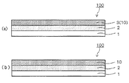
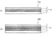
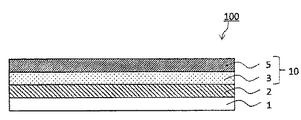
図1(a)、図2(a)、図3に示すように、本開示の第1の実施の形態に係る熱転写シート(以下、本開示の第1実施形態の熱転写シートと言う)は、基材1と、当該基材1から剥離可能に設けられた転写層10とを有している。転写層10は、保護層3を含む単層構造、又は積層構造を呈している。なお、図1(a)、図2(a)、図3は、本開示の第1実施形態の熱転写シートの一例を示す概略断面図であり、図1(a)に示す形態の熱転写シート100は、基材1上に、保護層3のみからなる単層構造の転写層10が設けられた構成を呈している。図2に示す形態の熱転写シート100は、図1(a)に示す形態の熱転写シート100において、基材1と転写層10との間に離型層2が設けられている。図3(a)に示す形態の熱転写シート100は、転写層10が、基材1側から、保護層3、接着層5がこの順で積層されてなる積層構造を呈しており、図3(b)に示す形態の熱転写シート100は、転写層10が、剥離層4、保護層3、接着層5がこの順で積層されてなる積層構造を呈している。
<< thermal transfer sheet of the first embodiment >>
As shown in FIGS. 1A, 2A, and 3, the thermal transfer sheet according to the first embodiment of the present disclosure (hereinafter, referred to as the thermal transfer sheet of the first embodiment of the present disclosure) It has a
本開示の第1実施形態の熱転写シート、及び後述する第2実施形態の熱転写シートの優位性を説明するにあたり、初期破断剥離力と先頭未転写の発生との関係について説明する。 In describing the superiority of the thermal transfer sheet according to the first embodiment of the present disclosure and the thermal transfer sheet according to a second embodiment described below, the relationship between the initial breaking peel force and the occurrence of untransferred top will be described.
基材上に、転写層が設けられた熱転写シートを用いて、被転写体上に転写層の転写するときの剥離力、具体的には、被転写体上に転写層を融着、或いは接着させ、この転写層を基材側から剥離していくときの剥離力は、図5に示すような挙動を示し、基材側から転写層の先頭部分(剥離開始部)を剥離するときの剥離力(初期破断剥離力)は、その後の剥離力(安定時剥離力)と比較して大きな値を示している。つまり、剥離力が大きくなる転写層の先頭部は、基材側から正確に剥離されにくく、本来であれば、被転写体側に転写され、熱転写シートの基材側から剥離されるべき転写層が、基材側から剥離されずに熱転写シート側に残存してしまう先頭部の未転写(以下、先頭未転写と言う)が生じやすくなる。さらに、初期破断剥離力の大きさは、転写層(保護層と読み替えてもよい)の強度と密接的な関連性を有しており、転写層の強度が高くなるにしたがい、転写層の初期破断剥離力も大きくなる。つまり、基材上に、転写層が設けられた熱転写シートにおいて、転写層に十分な耐久性を付与すべく、転写層の強度を高くしていった場合には、これにともない、先頭未転写が発生しやすい状況となっている。 Using a thermal transfer sheet provided with a transfer layer on a base material, a peeling force when transferring the transfer layer on the transfer target, specifically, fusing or bonding the transfer layer on the transfer target The peeling force when the transfer layer is peeled off from the substrate side shows the behavior as shown in FIG. 5, and the peeling force when the head portion (peeling start portion) of the transfer layer is peeled off from the substrate side. The force (initial breaking peeling force) shows a large value as compared with the subsequent peeling force (stable peeling force). In other words, the leading portion of the transfer layer where the peeling force is large is difficult to be accurately peeled off from the base material side. In addition, untransferred portions (hereinafter, referred to as untransferred portions) of a leading portion which are not peeled off from the base material and remain on the thermal transfer sheet side easily occur. Further, the magnitude of the initial rupture peel force is closely related to the strength of the transfer layer (which may be read as a protective layer), and as the strength of the transfer layer increases, the initial strength of the transfer layer increases. The breaking peel force also increases. In other words, in a thermal transfer sheet provided with a transfer layer on a base material, if the strength of the transfer layer is increased in order to impart sufficient durability to the transfer layer, the top untransferred Is likely to occur.
また、転写層を剥離するときの剥離性は、転写層を熱転写シートの基材側から剥離するときの剥離角度に依存し、転写層の剥離性を良好なものとするためには、所望の剥離角度における転写層の剥離性を考慮する必要がある。 Further, the releasability at the time of peeling the transfer layer depends on the peel angle when the transfer layer is peeled from the substrate side of the thermal transfer sheet, and in order to make the peelability of the transfer layer favorable, It is necessary to consider the peelability of the transfer layer at the peel angle.
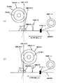
図6(a)、(b)は、熱転写シートの剥離角度を説明するための模式図であり、それぞれ、巻取りロールの初期位置、及び巻取りロールによる巻取り方向を異ならせている。同図に示す模式図は、熱転写シート(転写層を転写する前の熱転写シート)を供給する供給ロール、供給ロールから供給された熱転写シートの転写層と被転写体とを融着させる加熱手段、被転写体上に融着させた転写層を、熱転写シートの基材側から剥離する剥離手段(例えば、剥離ロールや、剥離板)、転写層を転写後の熱転写シート(熱転写シートの転写層以外の構成部材)を巻き取る巻取ロール、供給ロールから供給される熱転写シートを搬送経路に導くガイドロール等を有している。同図に示す形態では、剥離手段による剥離が完了することで、被転写体上に転写層が転写された印画物を得る。 FIGS. 6A and 6B are schematic diagrams for explaining the peeling angle of the thermal transfer sheet, in which the initial position of the winding roll and the winding direction of the winding roll are different. The schematic diagram shown in the figure is a supply roll that supplies a thermal transfer sheet (a thermal transfer sheet before transferring a transfer layer), a heating unit that fuses the transfer layer of the thermal transfer sheet supplied from the supply roll and an object to be transferred, Peeling means (for example, a peeling roll or a peeling plate) for peeling the transfer layer fused on the transfer object from the substrate side of the thermal transfer sheet, and a thermal transfer sheet after transfer of the transfer layer (other than the thermal transfer sheet transfer layer) And a guide roll for guiding the thermal transfer sheet supplied from the supply roll to the transport path. In the embodiment shown in the figure, the printed matter having the transfer layer transferred onto the transfer target body is obtained by the completion of the peeling by the peeling means.
図6(a)、(b)における巻き径小は、転写層の剥離初期の段階における巻取りロールの巻き径を示し、巻き径大は、転写層の剥離を進めていったときの巻取りロールの巻き径を示す。同図に示す形態では、剥離時(転写時)における被転写体の面と剥離方向X1の軸とのなす角である剥離角度α1が90°となるように設定している。換言すれば、巻取りロールの巻き径小における剥離角度α1が90°となるように設定している。なお、剥離角度90°は、転写層を剥離するときの箔切れ性が良好であり、尾引きの発生を抑制できる剥離角度である。本願明細書で言う転写層の箔切れ性とは、転写層を被転写体上に転写するときの尾引きの抑制度合いを示し、箔切れ性が良好であるという場合には、尾引きの発生を抑制できることを意味する。また、本願明細書でいう尾引きとは、転写層を被転写体上に転写するときに、転写層の転写領域と非転写領域の境界を起点とし、該境界から非転写領域側にはみ出すように転写層が転写されてしまう現象を意味する。 6A and 6B, the small winding diameter indicates the winding diameter of the winding roll in the initial stage of the peeling of the transfer layer, and the large winding diameter indicates the winding when the peeling of the transfer layer is advanced. Indicates the winding diameter of the roll. In the embodiment shown in the figure, the peeling angle α1, which is the angle formed between the surface of the transferred body and the axis of the peeling direction X1 at the time of peeling (transfer), is set to be 90 °. In other words, the setting is such that the peeling angle α1 when the winding diameter of the winding roll is small is 90 °. Note that the peeling angle of 90 ° is a peeling angle at which the foil can be cut easily when the transfer layer is peeled off and the occurrence of tailing can be suppressed. The foil cutting property of the transfer layer as referred to in the specification of the present application indicates the degree of suppression of tailing when the transfer layer is transferred onto the object to be transferred, and when the foil cutting property is good, the occurrence of tailing occurs. Can be suppressed. Further, the term “tailing” as used in the specification of the present application means that when a transfer layer is transferred onto a transfer target, a boundary between a transfer region and a non-transfer region of the transfer layer is a starting point, and the tail protrudes from the boundary toward the non-transfer region. Means a phenomenon in which the transfer layer is transferred to the substrate.
転写層を熱転写シートの基材側から剥離するときの剥離角度は、剥離時における被転写体の面と剥離方向(張力方向)の軸とのなす角により決定される。ここで、熱転写シートの基材側から転写層の剥離(転写層の転写)を進めていき、巻取りロールによる巻き径が大きくなっていった場合には、剥離方向は初期の段階における剥離方向X1から変動していき、これにより、剥離角度も変動していくこととなる。例えば、図6(a)に示す形態では、巻取りロールによる巻取りを進めていき、巻取りロールの巻き径が大きくなっていった場合(巻き径大とした場合)に、剥離時における被転写体の面と剥離方向X2とのなす角である剥離角度α2は、剥離初期の段階における剥離角度α1よりも大きな角度となる。一方で、図6(b)に示す形態では、巻取りロールによる巻取りを進めていき、巻取りロールの巻き径が大きくなっていった場合(巻き径大とした場合)に、剥離時における被転写体の面と剥離方向X2とのなす角である剥離角度α2は、剥離初期の段階における剥離角度α1よりも小さな角度となる。 The peeling angle when the transfer layer is peeled from the substrate side of the thermal transfer sheet is determined by the angle between the surface of the transferred body and the axis of the peeling direction (tension direction) at the time of peeling. Here, the peeling of the transfer layer (transfer of the transfer layer) proceeds from the substrate side of the thermal transfer sheet, and when the winding diameter of the winding roll increases, the peeling direction is the peeling direction in the initial stage. The peeling angle fluctuates from X1, which also causes the peeling angle to fluctuate. For example, in the embodiment shown in FIG. 6A, the winding by the winding roll is advanced, and when the winding diameter of the winding roll becomes large (when the winding diameter is increased), the material to be removed at the time of peeling is removed. The peel angle α2, which is the angle between the surface of the transfer member and the peel direction X2, is larger than the peel angle α1 in the initial stage of peeling. On the other hand, in the embodiment shown in FIG. 6B, the winding by the winding roll is advanced, and when the winding diameter of the winding roll becomes large (when the winding diameter is increased), the peeling at the time of peeling is performed. The peel angle α2, which is the angle between the surface of the transfer object and the peel direction X2, is smaller than the peel angle α1 in the initial stage of peeling.
したがって、先頭未転写の発生を抑制するためには、所望の剥離角度(図示する形態では剥離角度90°)における初期破断剥離力を考慮するのみでは足りず、剥離角度の変動を考慮して、変動後の剥離角度においても先頭未転写の発生を抑制できる初期破断剥離力とすることが必要となる。 Therefore, in order to suppress the occurrence of untransferred top, it is not enough to consider only the initial rupture peel force at a desired peel angle (the peel angle of 90 ° in the illustrated embodiment). It is necessary to have an initial breaking peel force that can suppress the occurrence of untransferred top even at the peel angle after the change.
なお、図6(a)、(b)では、転写層を剥離した後の熱転写シートを巻き取る巻取ロールの巻き径と、剥離角度との関係について説明をしているが、剥離角度の変動は、これ以外の要因によっても生じうる。例えば、剥離手段として剥離ロールを使用する場合には、剥離ロールの径の大きさによって剥離角度は異なる場合もある。また、供給ロールの巻き径や、転写層を転写していくときに熱転写シートにかかるテンションによって、剥離角度が変動する場合もある。また、これ以外の要因によって、剥離角度が変動する場合もある。このような剥離角度の変動は、剥離時における被転写体の面に対する剥離角度90°の軸を基準軸としたときに、この基準軸に対して、±30°の範囲である。 6A and 6B, the relationship between the winding diameter of the take-up roll for winding the thermal transfer sheet after the transfer layer is peeled off and the peeling angle is described. Can also be caused by other factors. For example, when a peeling roll is used as the peeling means, the peeling angle may vary depending on the diameter of the peeling roll. Further, the peeling angle may vary depending on the winding diameter of the supply roll or the tension applied to the thermal transfer sheet when transferring the transfer layer. In addition, the peel angle may fluctuate due to other factors. Such a variation of the peeling angle is within a range of ± 30 ° with respect to the reference axis when an axis at a peeling angle of 90 ° with respect to the surface of the transfer target body at the time of peeling is used as a reference axis.
この点を考慮した本開示の第1実施形態の熱転写シート100は、以下の条件1、2を満たしている。
条件1:転写層10が、保護層3を含む単層構造、又は積層構造を呈しており、保護層3が、活性光線硬化性樹脂の硬化物を含有していること。
条件2:剥離温度20℃以上70℃以下、剥離角度60°以上の条件で、転写層10を剥離したときの初期破断剥離力が1.97mN/m以下であること。
In consideration of this point, the
Condition 1: the
Condition 2: The initial breaking peel force when the
上記条件1、2を満たす本開示の第1実施形態の熱転写シート100によれば、保護層3を含む転写層10に良好な耐久性を付与しつつも、転写層10を剥離するときに先頭未転写が発生することを抑制できる。
According to the
なお、条件1において剥離角度を60°と規定しているのは、剥離温度20℃以上70℃以下、剥離角度60°の条件で転写層10を剥離したときの初期破断剥離力が1.97mN/m以下である場合には、剥離角度が60°より大きい場合にも、初期破断剥離力が1.97mN/m以下となることによる。具体的には、上記条件を満たせば、剥離角度の変動が想定される上限の剥離角度120°においても、初期破断剥離力が1.97mN/m以下となることによる。したがって、本開示の第1実施形態の熱転写シート100は、条件1を満たし、且つ、剥離温度20℃以上70℃以下、剥離角度60°の条件で、転写層10を剥離したときの初期破断剥離力が1.97mN/m以下であればよい。また、本開示の第1実施形態の熱転写シート100は、条件1を満たし、且つ、剥離温度20℃以上70℃以下、剥離角度60°以上120°以下の条件で、転写層10を剥離したときの初期破断剥離力が1.97mN/m以下であればよい。
The reason why the peel angle is defined as 60 ° in
さらに、上記条件1、2を満たす本開示の第1実施形態の熱転写シート100によれば、上記で例示した種々の要因により、設定した剥離角度から、実際の剥離角度が変動した場合であっても、先頭未転写の発生を抑制できる。また、上記先頭未転写の発生を、熱時剥離方式、及び冷時剥離方式の何れの剥離方式においても抑制できる。本願明細書でいう熱時剥離方式とは、熱転写シートにエネルギーを印加して転写層を溶融或いは軟化させ、この転写層が固化する前に、被転写体上に転写済みの転写層のみを熱転写シートから剥離する剥離方式であり、冷時剥離方式とは、転写層が固化した後に、被転写体上に転写済みの転写層のみを熱転写シートから剥離する剥離方式を意味する。
Further, according to the
(初期破断剥離力の算出方法1)
本開示の第1実施形態の熱転写シートにおける初期破断剥離力は、以下の方法で算出される剥離力を意味する。
(A)測定対象である熱転写シートを、所定の幅(以下、幅Aと言う)にカットする。なお、測定対象である熱転写シートは、基材と、当該基材から剥離可能に設けられた転写層とを備えている。したがって、カット後の転写層の幅も、幅Aとなる。
(B)カットした測定対象の熱転写シートを、剥離解析装置(VPA−3 協和界面化学(株))のステージに貼りつける。
(C−1)剥離解析装置における剥離角度を60°に設定し、ステージ温度:20℃(剥離温度:20℃)、剥離速度:1464mm/min.の条件で、熱転写シートの基材側から剥離させていき、剥離開始位置である初期剥離部から剥離方向に向かって5mm離れた位置(5mmは除く)までの剥離力を、剥離解析装置に付属のロードセル計測ユニットにより測定する。次いで、測定される剥離力のうち、その値が最大となる剥離力(測定範囲における最大剥離力)を、熱転写シートの幅方向の長さ(幅A)で除することで、剥離温度20℃における初期破断剥離力を算出できる。
(C−2)ステージ温度を70℃に温調した、剥離温度:70℃についても同様にして初期破断剥離力の算出を行う。
(C−3)剥離角度90°、120°についても上記と同様にして初期判断剥離力の算出を行う。
上記(C−1)〜(C−3)の何れにおいても、初期破断剥離力の値が、1.97mN/m以下である場合には、転写層を剥離するときの初期破断剥離力が上記条件2を満たすものと判別できる。
(Method of calculating initial rupture peel force 1)
The initial rupture peel force in the thermal transfer sheet according to the first embodiment of the present disclosure means a peel force calculated by the following method.
(A) A thermal transfer sheet to be measured is cut into a predetermined width (hereinafter referred to as width A). In addition, the thermal transfer sheet to be measured includes a base material and a transfer layer that is provided so as to be peelable from the base material. Therefore, the width of the transfer layer after cutting is also the width A.
(B) The cut thermal transfer sheet to be measured is attached to a stage of a peeling analyzer (VPA-3 Kyowa Interface Chemical Co., Ltd.).
(C-1) The peeling angle in the peeling analyzer was set to 60 °, the stage temperature: 20 ° C (peeling temperature: 20 ° C), the peeling speed: 1464 mm / min. Peeling from the substrate side of the thermal transfer sheet under the conditions described above, the peeling force from the initial peeling part, which is the peeling start position, to a
(C-2) The initial rupture peeling force is similarly calculated for a peeling temperature of 70 ° C in which the stage temperature is controlled to 70 ° C.
(C-3) For the peel angles 90 ° and 120 °, the initial judgment peel force is calculated in the same manner as described above.
In any of the above (C-1) to (C-3), when the value of the initial rupture peeling force is 1.97 mN / m or less, the initial rupture peeling force when peeling the transfer layer is as described above. It can be determined that the
本開示の第1実施形態の熱転写シート100は、上記初期破断剥離力の算出方法により算出される初期破断剥離力が、剥離温度20℃以上40℃以下、剥離角度60°の条件で、1.28mN/m以下が好ましく、0.99mN/m以下がより好ましい。この形態の熱転写シート100によれば、冷時剥離方式により転写層10を剥離するときの、剥離角度依存性をより小さくでき、設定した剥離角度から、実際の剥離角度が変動した場合であっても、先頭未転写の発生をさらに効果的に抑制できる。
The
また、本開示の第1実施形態の熱転写シート100は、上記条件1、2を満たし、且つ、剥離温度20℃以上70℃以下、剥離角度60°以上の条件で、転写層10を剥離したときの安定時断剥離力が0.098mN/m以上1.97mN/m以下であることが好ましく、0.098mN/m以上0.99mN/m以下であることがより好ましく、0.098mN/m以上0.5mN/m以下が特に好ましい。この形態の熱転写シート100によれば、先頭未転写を抑制しつつ、さらに、良好な箔切れ性をもって、被転写体上に転写層10を転写できる。
The
(安定時剥離力の算出方法1)
本願明細書でいう安定時剥離力とは、上記初期破断剥離力の算出方法において、初期剥離部(図5、図7参照)から剥離方向に向かって5mm離れた位置から15mm離れた位置までの間、つまりは、初期剥離部から剥離方向に向かって5mm離れた位置を起点とし、この起点から剥離方向に向かって10mm離れた位置までの間を(剥離長さ10mm)を測定範囲として測定される剥離力であり、測定される剥離力のうち、その値が最大となる剥離力(測定範囲における最大剥離力)を、熱転写シートの幅方向の長さ(幅A)で除した値を意味している。つまりは、上記初期破断剥離力の算出方法1において、「初期剥離部から剥離方向に向かって5mm離れた位置(5mmは除く)までの剥離力」とある記載を、「初期剥離部から剥離方向に向かって5mm離れた位置から15mm離れた位置までの間の剥離力」と読み替えればよい。
(Method of calculating stable peel force 1)
The term "peeling force at stable time" as used in the specification of the present application refers to a value in the above-described method for calculating the initial breaking peeling force from a
また、本開示の第1実施形態の熱転写シート100は、上記条件1、2を満たし、且つ、転写層10の基材1側に位置する面を、JIS−K−5600−5−5に準拠した方法で測定したときの引っかき硬度(先端半径0.1mmサファイア針使用)は、200g以上が好ましく、210g以上がより好ましい。以下、転写層10の基材1側に位置する面を、JIS−K−5600−5−5に準拠した方法で測定したときの引っかき硬度(先端半径0.1mmサファイア針使用)のことを、転写層10の基材1側に位置する面の引っかき硬度と略記する場合がある。
Further, the
転写層10の基材1側に位置する面の引っかき硬度は、被転写体上に、転写層10を転写することで測定できる。引っかき硬度の測定は、表面性測定機(HEIDON TYPE:14、新東科学(株))を用いた。後述する本開示の第2実施形態の熱転写シート100についても同様である。
The scratch hardness of the surface of the
以下、本開示の第1実施形態の熱転写シート100の各構成について具体的に説明する。
Hereinafter, each configuration of the
(基材)
基材1は、本開示の第1実施形態の熱転写シート100を構成する転写層10、或いは、基材1と転写層10との間に設けられる任意の層(例えば、離型層2)を保持する。基材1の材料について特に限定はないが、転写層10を被転写体へ転写するとき(融着、或いは接着させるとき)の熱エネルギー(例えば、サーマルヘッド、ヒートローラー、ホットスタンプマシン)に耐え得る耐熱性を有し、転写層10を支持できる機械的強度や耐溶剤性を有していることが好ましい。このような基材1の材料としては、例えば、ポリエチレンテレフタレート、ポリブチレンテレフタレート、ポリエチレンナフタレート、ポリエチレンテレフタレート−イソフタレート共重合体、テレフタル酸−シクロヘキサンジメタノール−エチレングリコール共重合体、ポリエチレンテレフタレート/ポリエチレンナフタレートの共押し出しフィルムなどのポリエステル、ナイロン6、ナイロン66などのポリアミド、ポリエチレン、ポリプロピレン、ポリメチルペンテンなどのポリオレフィン、ポリ塩化ビニルなどのビニル樹脂、ポリアクリレート、ポリ(メタ)アクリレート、ポリメチル(メタ)アクリレートなどのアクリル樹脂、ポリイミド、ポリエーテルイミドなどのイミド樹脂、ポリアリレート、ポリスルホン、ポリエーテルスルホン、ポリフェニレンエーテル、ポリフェニレンスルフィド(PPS)、ポリアラミド、ポリエーテルケトン、ポリエーテルニトリル、ポリエーテルエーテルケトン、ポリエーテルサルファイトなどのエンジニアリング樹脂、ポリカーボネート、ポリスチレン、高衝撃性ポリスチレン、アクリロニトリル−スチレン共重合体(AS樹脂)、アクリロニトリル−ブタジエン−スチレン共重合体(ABS樹脂)などのポリスチレン、セロファン、セルロースアセテート、ニトロセルロース等のセルロースを例示できる。
(Base material)
The
基材1は、上記で例示した樹脂を主成分とする共重合体、若しくは混合体(アロイを含む)、又は複数層からなる積層体であっても良い。また、基材は、延伸フィルムであっても、未延伸フィルムであってもよいが、強度を向上させる目的で、一軸方向、又は二軸方向に延伸されたフィルムを使用することが好ましい。基材1は、これら樹脂の少なくとも1層からなるフィルム、シート、ボード状として使用できる。上記で例示した樹脂からなる基材の中でも、ポリエチレンテレフタレート、ポリエチレンナフタレートなどのポリエステルフィルムは、耐熱性、機械的強度に優れるため好適に使用され、この中でもポリエチレンテレフタレートフィルムがより好ましい。
The
また、ブロッキング防止のために、必要に応じて基材1の表面に凹凸を付与できる。基材1の表面に凹凸を形成する手段としては、マット剤練り込み加工、サンドブラスト加工、ヘアライン加工、マットコーティング加工、ケミカルエッチング加工などが挙げられる。マット剤練り込み加工は、無機物、又は有機物を練り込んだ樹脂により、基材を形成する加工法である。マットコーティング加工は、基材表面に、有機物、又は無機物を含むコート剤をコーティングし、基材表面に凹凸を付与する加工法である。
Moreover, in order to prevent blocking, the surface of the
基材1の厚みについて特に限定はないが、一般的には、0.5μm以上100μm以下である。好ましくは、0.5μm以上50μm以下であり、より好ましくは、4μm以上25μm以下である。好ましい基材の厚みとすることで熱転写シート100から転写層10を転写するときのエネルギーを転写層10側に十分に伝達でき、転写層10を転写するときの転写性の更なる向上を図ることができる。また、基材1の機械的強度を高めることができ、転写層10を十分に支持できる。
The thickness of the
基材1の転写層10側に位置する面には、予め、コロナ放電処理、プラズマ処理、オゾン処理、フレーム処理、プライマー(アンカーコート、接着促進剤、易接着剤とも呼ばれる)塗布処理、予熱処理、除塵埃処理、蒸着処理、アルカリ処理、帯電防止層付与などの易接着処理を行ってもよい。また、基材1には、必要に応じて、充填材、可塑剤、着色剤、帯電防止剤などの添加材を加えても良い。
On the surface of the
(転写層)
図1(a)、図2(a)、図3に示すように、基材1上には、直接的に、又は他の層を介して間接的に転写層10が設けられている。
(Transfer layer)
As shown in FIGS. 1A, 2A and 3, a
(保護層)
転写層10は、保護層3のみからなる単層構造、又は保護層3を含む積層構造を呈している。本開示の第1実施形態の熱転写シート100は、転写層10を構成する保護層3が、各種硬化性樹脂の硬化物を含有している(上記条件1)。換言すれば、保護層3が、活性光線硬化性樹脂に活性光線を照射することで得られる樹脂を含有している。活性光線硬化性樹脂の硬化物を含有している。
(Protective layer)
The
本願明細書で言う活性光線硬化性樹脂とは、活性光線を照射する前の前駆体、又は組成物を意味する。また、本願明細書で言う活性光線とは、活性光線硬化性樹脂に対して化学的に作用させて重合を促進せしめる放射線を意味し、具体的には、可視光線、紫外線、X線、電子線、α線、β線、γ線などを意味する。以下、活性光線硬化性樹脂の硬化物をなす、活性光線硬化性樹脂について説明する。 The actinic ray-curable resin referred to in the present specification means a precursor or a composition before irradiation with actinic rays. Further, the actinic ray referred to in the specification of the present application means a radiation that chemically acts on an actinic ray-curable resin to promote polymerization, and specifically, visible rays, ultraviolet rays, X-rays, and electron rays. , Α-rays, β-rays, γ-rays and the like. Hereinafter, the actinic ray curable resin, which is a cured product of the actinic ray curable resin, will be described.
一例としての活性光線硬化性樹脂は、重合成分として、分子中に(メタ)アクリロイル基、及び(メタ)アクリロイルオキシ基などの重合性不飽和結合、又はエポキシ基を有するポリマー、プレポリマー、オリゴマー及び/又はモノマーを適宜混合した組成物等を含んでいる。 The actinic ray-curable resin as an example is a polymer, a prepolymer, an oligomer, or a polymer having a polymerizable unsaturated bond such as a (meth) acryloyl group and a (meth) acryloyloxy group, or an epoxy group in a molecule as a polymerization component. And / or a composition in which monomers are appropriately mixed.
一例としての活性光線硬化性樹脂は、重合成分として、多官能(メタ)アクリレートを含んでいる。多官能(メタ)アクリレートとしては、官能基数が5以上15以下の多官能(メタ)アクリレートが好ましく、官能基数が6以上15以下の多官能(メタ)アクリレートがより好ましい。また、他の一例としての活性光線硬化性樹脂は、重合成分として、ウレタン(メタ)アクリレートを含んでおり、好ましくは、多官能ウレタン(メタ)アクリレートを含んでいる。多官能ウレタン(メタ)アクリレートとしては、官能基数が5以上15以下の多官能ウレタン(メタ)アクリレートが好ましく、官能基数が6以上15以下の多官能ウレタン(メタ)アクリレートがより好ましい。 The actinic ray-curable resin as an example contains a polyfunctional (meth) acrylate as a polymerization component. As the polyfunctional (meth) acrylate, a polyfunctional (meth) acrylate having 5 to 15 functional groups is preferable, and a polyfunctional (meth) acrylate having 6 to 15 functional groups is more preferable. The actinic ray curable resin as another example contains urethane (meth) acrylate as a polymerization component, and preferably contains a polyfunctional urethane (meth) acrylate. As the polyfunctional urethane (meth) acrylate, a polyfunctional urethane (meth) acrylate having 5 to 15 functional groups is preferable, and a polyfunctional urethane (meth) acrylate having 6 to 15 functional groups is more preferable.
本願明細書でいう(メタ)アクリレートは、アクリレート、メタクリレートを含み、(メタ)アクリル酸は、アクリル酸や、メタクリル酸を含み、(メタ)アクリル酸エステルは、アクリル酸エステルや、メタクリル酸エステルを含む。 (Meth) acrylate referred to in the specification of the present application includes acrylate and methacrylate, (meth) acrylic acid includes acrylic acid and methacrylic acid, and (meth) acrylic ester includes acrylic ester and methacrylic ester. Including.
保護層3の総質量に対する活性光線硬化性樹脂の硬化物の含有量について特に限定はないが、5質量%以上80質量%以下が好ましく、5質量%以上70質量%以下がより好ましく、10質量%以上50質量%以下がさらに好ましい。
The content of the cured product of the actinic ray-curable resin with respect to the total mass of the
また、保護層3は、活性光線硬化性樹脂の硬化物として、ウレタン(メタ)アクリレートの硬化物、特には、多官能ウレタン(メタ)アクリレートの硬化物を上記の含有量で含有していることが好ましい。
In addition, the
また、保護層の耐溶剤性と、屈曲性の両立の観点からは、保護層3は、(i)官能基数が5以上15以下、特には官能基数が6以上15以下の多官能ウレタン(メタ)アクリレートと、(ii)官能基数が2以上4以下の多官能ウレタン(メタ)アクリレート、及び官能基数が2以上5以下の(メタ)アクリレートの何れか一方、又は双方と、の硬化物を含有していることが好ましい。或いは、保護層3は、(iii)官能基数が5以上15以下、特には官能基数が6以上15以下の多官能ウレタン(メタ)アクリレートの硬化物と、(iv)官能基数が2以上4以下の多官能ウレタン(メタ)アクリレートの硬化物、及び官能基数が2以上5以下の(メタ)アクリレートの硬化物の何れか一方、又は双方と、を含有していることが好ましい。上記(ii)官能基数が2以上4以下の多官能ウレタン(メタ)アクリレート、及び官能基数が2以上5以下の(メタ)アクリレート由来の成分の含有量は、保護層3の総質量に対し、5質量%以上80質量%以下が好ましく、10質量%以上70質量%以下がより好ましい。上記(iv)官能基数が2以上4以下の多官能ウレタン(メタ)アクリレートの硬化物、及び官能基数が2以上5以下の(メタ)アクリレートの硬化物の含有量についても同様である。
In addition, from the viewpoint of compatibility between the solvent resistance of the protective layer and the flexibility, the
また、重合成分としての多官能ウレタン(メタ)アクリレートは、その重量平均分子量が400以上20000以下のものが好ましく、500以上10000以下のものがより好ましい。ウレタン(メタ)アクリレートとして、その重量平均分子量が、上記好ましい範囲のものを用いることで、保護層3の耐摩耗性や箔切れ性の更なる向上を図ることができる。同様の理由から、官能基数が2以上5以下の(メタ)アクリレートの重量平均分子量は、200以上5000以下が好ましい。なお、本願明細書において「重量平均分子量」とは、ポリスチレンを標準物質としてゲルパーミエーションクロマトグラフィーにより測定した値を意味し、JIS−K−7252−1(2008)に準拠した方法で測定できる。
The polyfunctional urethane (meth) acrylate as a polymerization component preferably has a weight average molecular weight of 400 or more and 20,000 or less, more preferably 500 or more and 10,000 or less. By using the urethane (meth) acrylate having a weight average molecular weight in the preferable range described above, it is possible to further improve the abrasion resistance and foil cutting property of the
また、一例としての活性光線硬化性樹脂は、重合成分として、不飽和結合含有(メタ)アクリレート共重合体(以下、不飽和結合含有アクリル共重合体と言う場合がある)を含んでいる。不飽和結合含有(メタ)アクリレート共重合体としては、例えば、ポリエステル(メタ)アクリレート、エポキシ(メタ)アクリレート、メラミン(メタ)アクリレート、及びトリアジン(メタ)アクリレート等が挙げられる。 The actinic ray-curable resin as an example contains an unsaturated bond-containing (meth) acrylate copolymer (hereinafter sometimes referred to as an unsaturated bond-containing acrylic copolymer) as a polymerization component. Examples of the unsaturated bond-containing (meth) acrylate copolymer include polyester (meth) acrylate, epoxy (meth) acrylate, melamine (meth) acrylate, and triazine (meth) acrylate.
また、重合成分としての不飽和結合含有アクリル共重合体は、その酸価が5mgKOH/g以上500mgKOH/g以下のものが好ましく、10mgKOH/g以上150mgKOH/g以下のものがより好ましい。不飽和結合含有アクリル共重合体として、その酸価が、上記好ましい範囲のものを用いることで、保護層3の表面強度を高めることができる。ポリマーの酸価は、ポリマーを構成するモノマー成分の比率を調整することにより適宜調整できる。
The unsaturated bond-containing acrylic copolymer as a polymerization component preferably has an acid value of 5 mgKOH / g to 500 mgKOH / g, more preferably 10 mgKOH / g to 150 mgKOH / g. The surface strength of the
また、不飽和結合含有アクリル共重合体としては、その重量平均分子量が、3000以上100000以下のものが好ましく、10000以上80000以下のものがより好ましい。不飽和結合含有アクリル共重合体として、その重量平均分子量が、上記範囲のものを用いることで、保護層3に、より高い耐熱性、耐薬品性等の化学的耐久性、スクラッチ強度等の物理的耐久性を付与できる。また、保護層を形成するための保護層用塗工液の保存中におけるゲル化反応を抑制でき、保護層用塗工液の保存安定性を向上させることができる。
The unsaturated bond-containing acrylic copolymer preferably has a weight average molecular weight of 3,000 to 100,000, more preferably 10,000 to 80,000. By using an unsaturated bond-containing acrylic copolymer having a weight average molecular weight in the above range, the
不飽和結合含有アクリル共重合体は、活性光線硬化性樹脂中に10質量%以上80質量%以下で含有されていることが好ましく、20質量%以上70質量%以下で含有されていることがより好ましく、20質量%以上50質量%以下で含有されていることがさらに好ましい。 The unsaturated bond-containing acrylic copolymer is preferably contained in the actinic ray-curable resin at 10% by mass or more and 80% by mass or less, more preferably 20% by mass or more and 70% by mass or less. More preferably, the content is 20% by mass or more and 50% by mass or less.
また、活性光線硬化性樹脂は、重合成分として、不飽和結合含有アクリル共重合体以外にも、(メタ)アクリル酸、スチレン、酢酸ビニル、ヒドロキシエチルビニルエーテル、エチレングリコールジビニルエーテル、ペンタエリスリトールトリビニルエーテル、(メタ)アクリルアミド、N−ヒドロキシメチル(メタ)アクリルアミド、N−ビニルホルムアミド、及びアクリロニトリルなどのオリゴマー及び/又はモノマーを含んでいてもよい。また、以下のようなプレポリマー、オリゴマー及び/又はモノマーを含んでいてもよい。 The actinic ray-curable resin, as a polymerization component, in addition to the unsaturated bond-containing acrylic copolymer, (meth) acrylic acid, styrene, vinyl acetate, hydroxyethyl vinyl ether, ethylene glycol divinyl ether, pentaerythritol trivinyl ether, It may contain oligomers and / or monomers such as (meth) acrylamide, N-hydroxymethyl (meth) acrylamide, N-vinylformamide, and acrylonitrile. Further, it may contain the following prepolymer, oligomer and / or monomer.
プレポリマーとしては、例えば、アジピン酸、トリメリット酸、マレイン酸、フタル酸、テレフタル酸、ハイミック酸、マロン酸、コハク酸、グルタール酸、イタコン酸、ピロメリット酸、フマル酸、グルタール酸、ピメリン酸、セバシン酸、ドデカン酸、テトラヒドロフタル酸等の多塩基酸と、エチレングリコール、プロピレングルコール、ジエチレングリコール、プロピレンオキサイド、1,4−ブタンジオール、トリエチレングリコール、テトラエチレングリコール、ポリエチレングリコール、グリセリン、トリメチロールプロパン、ペンタエリスリトール、ソルビトール、1,6−ヘキサンジオール、1,2,6−ヘキサントリオール等の多価のアルコールの結合で得られるポリエステルに(メタ)アクリル酸を導入したポリエステル(メタ)アクリレート類、例えば、ビスフェノールA・エピクロルヒドリン・(メタ)アクリル酸、フェノールノボラック・エピクロルヒドリン・(メタ)アクリル酸のようにエポキシ樹脂に(メタ)アクリル酸を導入したエポキシ(メタ)アクリレート類、例えば、エチレングリコール・アジピン酸・トリレンジイソシアネート・2−ヒドロキシエチルアクリレート、ポリエチレングリコール・トリレンジイソシアネート・2−ヒドロキシエチルアクリレート、ヒドロキシエチルフタリルメタクリレート・キシレンジイソシアネート、1,2−ポリブタジエングリコール・トリレンジイソシアネート・2−ヒドロキシエチルアクリレート、トリメチロールプロパン・プロピレングリコール・トリレンジイソシアネート・2−ヒドロキシエチルアクリレートのように、ポリウレタンに(メタ)アクリル酸を導入したウレタン(メタ)アクリレート、例えば、ポリシロキサン(メタ)アクリレート、ポリシロキサン・ジイソシアネート・2−ヒドロキシエチル(メタ)アクリレート等のシリコーン樹脂アクリレート類、その他、油変性アルキッド樹脂に(メタ)アクリロイル基を導入したアルキッド変性(メタ)アクリレート類、スピラン樹脂アクリレート類等が挙げられる。 As the prepolymer, for example, adipic acid, trimellitic acid, maleic acid, phthalic acid, terephthalic acid, hymic acid, malonic acid, succinic acid, glutaric acid, itaconic acid, pyromellitic acid, fumaric acid, glutaric acid, pimelic acid , Sebacic acid, dodecanoic acid, polybasic acids such as tetrahydrophthalic acid and ethylene glycol, propylene glycol, diethylene glycol, propylene oxide, 1,4-butanediol, triethylene glycol, tetraethylene glycol, polyethylene glycol, glycerin, triglyceride Polyester obtained by introducing (meth) acrylic acid into a polyester obtained by bonding polyhydric alcohols such as methylolpropane, pentaerythritol, sorbitol, 1,6-hexanediol, and 1,2,6-hexanetriol. (Meth) acrylates, for example, epoxy (meth) acrylates obtained by introducing (meth) acrylic acid into an epoxy resin such as bisphenol A / epichlorohydrin / (meth) acrylic acid, phenol novolak / epichlorohydrin / (meth) acrylic acid; For example, ethylene glycol, adipic acid, tolylene diisocyanate, 2-hydroxyethyl acrylate, polyethylene glycol, tolylene diisocyanate, 2-hydroxyethyl acrylate, hydroxyethyl phthalyl methacrylate, xylene diisocyanate, 1,2-polybutadiene glycol tolylene diisocyanate・ 2-hydroxyethyl acrylate, trimethylolpropane ・ propylene glycol ・ tolylene diisocyanate Urethane (meth) acrylate in which (meth) acrylic acid is introduced into polyurethane like acrylate, for example, silicone resin acrylates such as polysiloxane (meth) acrylate, polysiloxane / diisocyanate / 2-hydroxyethyl (meth) acrylate And alkyd-modified (meth) acrylates in which a (meth) acryloyl group is introduced into an oil-modified alkyd resin, spirane resin acrylates, and the like.
モノマー、又はオリゴマーとしては、例えば、2−エチルヘキシルアクリレート、2−ヒドロキシプロピルアクリレート、グリセロールアクリレート、テトラヒドロフルフリルアクリレート、フェノキシエチルアクリレート、ノニルフェノキシエチルアクリレート、テトラヒドロフルフリルオキシエチルアクリレート、テトラヒドロフルフリルオキシヘキサノリドアクリレート、1,3−ジオキサンアルコールのε−カプロラクトン付加物のアクリレート、1,3−ジオキソランアクリレート等の単官能アクリル酸エステル類を例示できる。 Examples of the monomer or oligomer include 2-ethylhexyl acrylate, 2-hydroxypropyl acrylate, glycerol acrylate, tetrahydrofurfuryl acrylate, phenoxyethyl acrylate, nonylphenoxyethyl acrylate, tetrahydrofurfuryloxyethyl acrylate, and tetrahydrofurfuryloxyhexanol. Monofunctional acrylates such as acrylate, acrylate of ε-caprolactone adduct of 1,3-dioxane alcohol, and 1,3-dioxolane acrylate can be exemplified.
例えば、エチレングリコールジアクリレート、トリエチレングルコールジアクリレート、ペンタエリスリトールジアクリレート、ハイドロキノンジアクリレート、レゾルシンジアクリレート、ヘキサンジオールジアクリレート、ネオペンチルグリコールジアクリレート、トリプロピレングリコールジアクリレート、ヒドロキシピバリン酸ネオペンチルグリコールのジアクリレート、ネオペンチルグリコールアジペートのジアクリレート、ヒドロキシピバリン酸ネオペンチルグリコールのε−カプロラクトン付加物のジアクリレート、2−(2−ヒドロキシ−1,1−ジメチルエチル)−5−ヒドロキシメチル−5−エチル−1,3−ジオキサンジアクリレート、トリシクロデカンジメチロールアクリレート、トリシクロデカンジメチロールアクリレートのε−カプロラクトン付加物、1,6−ヘキサンジオールのジグリシジルエーテルのジアクリレート等の2官能アクリル酸エステル類、トリメチロールプロパントリアクリレート、ジトリメチロールプロパンテトラアクリレート、トリメチロールエタントリアクリレート、ペンタエリスリトールトリアクリレート、ペンタエリスリトールテトラアクリレート、ジペンタエリスリトールテトラアクリレート、ジペンタエリスリトールペンタアクリレート、ジペンタエリスリトールヘキサアクリレート、ジペンタエリスリトールヘキサアクリレートのε−カプロラクトン付加物、ピロガロールトリアクリレート、プロピオン酸・ジペンタエリスリトールトリアクリレート、プロピオン酸・ジペンタエリスリトールテトラアクリレート、ヒドロキシピバリルアルデヒド変性ジメチロールプロパントリアクリレート等の多官能アクリル酸エステル酸、ホスファゼンモノマー、トリエチレングリコール、イソシアヌール酸EO変性ジアクリレート、イソシアヌール酸EO変性トリアクリレート、ジメチロールトリシクロデカンジアクリレート、トリメチロールプロパンアクリル酸安息香酸エステル、アルキレングリコールタイプアクリル酸変性、ウレタン変性アクリレート等が挙げられる。また、これらのアクリレートをメタクリレート、イタコネート、クロトネート、マレエートに代えたメタクリル酸、イタコン酸、クロトン酸、マレイン酸エステル等を用いてもよい。 For example, ethylene glycol diacrylate, triethylene glycol diacrylate, pentaerythritol diacrylate, hydroquinone diacrylate, resorcin diacrylate, hexanediol diacrylate, neopentyl glycol diacrylate, tripropylene glycol diacrylate, neopentyl glycol hydroxypivalate Diacrylate of neopentyl glycol adipate, diacrylate of ε-caprolactone adduct of neopentyl glycol hydroxypivalate, 2- (2-hydroxy-1,1-dimethylethyl) -5-hydroxymethyl-5- Ethyl-1,3-dioxane diacrylate, tricyclodecane dimethylol acrylate, tricyclodecane dimethylol acrylate Ε-caprolactone adduct of acrylate, bifunctional acrylates such as diacrylate of diglycidyl ether of 1,6-hexanediol, trimethylolpropane triacrylate, ditrimethylolpropane tetraacrylate, trimethylolethane triacrylate, pentaerythritol Triacrylate, pentaerythritol tetraacrylate, dipentaerythritol tetraacrylate, dipentaerythritol pentaacrylate, dipentaerythritol hexaacrylate, ε-caprolactone adduct of dipentaerythritol hexaacrylate, pyrogallol triacrylate, propionic acid / dipentaerythritol triacrylate , Propionic acid / dipentaerythritol tetraacrylate, Multifunctional acrylic acid esters such as roxypivalylaldehyde-modified dimethylolpropane triacrylate, phosphazene monomers, triethylene glycol, isocyanuric acid EO-modified diacrylate, isocyanuric acid EO-modified triacrylate, dimethylol tricyclodecane diacrylate, Examples include trimethylolpropane acrylic acid benzoate, alkylene glycol type acrylic acid-modified, urethane-modified acrylate, and the like. Also, methacrylic acid, itaconic acid, crotonic acid, maleic acid ester, or the like, in which these acrylates are replaced with methacrylate, itaconate, crotonate, or maleate, may be used.
保護層3は、活性光線硬化性樹脂の硬化物として1種を単独で含有していてもよく、2種以上を含有していてもよい。また、保護層3は、活性光線硬化性樹脂の硬化物とともに、他の樹脂を含有していてもよい。他の樹脂は、硬化剤等によって硬化されたものであってもよく、未硬化のものであってもよい。後述する第2形態の転写層10における保護層3についても同様である。
The
好ましい形態の保護層3は、体積平均粒子径が0.1μm以上2μm以下のフィラーを含有している。以下、体積平均粒子径が0.1μm以上2μm以下のフィラーのことを、第1のフィラーと言う。本願明細書でいうフィラーの体積平均粒子径は、JIS−Z−8819−2(2001)に準拠し、粒度分布・粒径分布測定装置(ナノトラック粒度分布測定装置 日機装(株))を用いて測定したときの値である。
The
第1のフィラーを含有する保護層3によれば、先頭未転写の発生を、より効果的に抑制できる。
According to the
第1のフィラーの成分について特に限定はなく、有機フィラー、無機フィラー、及び有機−無機のハイブリッド型のフィラーを例示できる。また、フィラーは、粉体であっても、ゾル状のものであってもよいが、保護層用塗工液を調製する際の溶剤の選択性が広いため、粉体のフィラーを用いることが好ましい。 The component of the first filler is not particularly limited, and examples thereof include an organic filler, an inorganic filler, and an organic-inorganic hybrid type filler. Further, the filler may be a powder or a sol, but since the selectivity of the solvent when preparing the coating liquid for the protective layer is wide, it is possible to use the powder filler. preferable.
粉体の有機フィラーとしては、非架橋アクリル粒子、架橋アクリル粒子などのアクリル粒子、ポリアミド粒子、フッ素粒子、ポリエチレンワックス、シリコーン粒子などを挙げることが出来る。また、粉体の無機フィラーとしては、アルミニウム粒子、ジルコニア粒子、炭酸カルシウム粒子、シリカ粒子、酸化チタン、酸化亜鉛粒子等の金属酸化物粒子等を例示できる。また、有機−無機のハイブリッド型のフィラーとしては、アクリル樹脂にシリカ粒子をハイブリッドしたもの等を例示できる。さらに、ゾル状のフィラーとしては、シリカゾル系、オルガノゾル系のもの等を例示できる。また、γ−アミノプロピルトリエトキシシラン、γ−メタクリロキシプロピルトリメトキシシランなどのシランカップリング剤などを用いて表面処理が施された粒子を用いることもできる。これらのフィラーは、1種を単独で用いてもよく、2種以上を混合して用いてもよい。これらの中でも、シリカ粒子が好適である。 Examples of the powdered organic filler include acrylic particles such as non-crosslinked acrylic particles and crosslinked acrylic particles, polyamide particles, fluorine particles, polyethylene wax, and silicone particles. Examples of the inorganic filler in the powder include aluminum oxide particles, zirconia particles, calcium carbonate particles, silica particles, metal oxide particles such as titanium oxide and zinc oxide particles. Examples of the organic-inorganic hybrid filler include those obtained by hybridizing silica particles with an acrylic resin. Further, examples of the sol filler include silica sol-based and organosol-based fillers. Further, particles that have been subjected to a surface treatment using a silane coupling agent such as γ-aminopropyltriethoxysilane and γ-methacryloxypropyltrimethoxysilane can also be used. These fillers may be used alone or in a combination of two or more. Among these, silica particles are preferred.
第1のフィラーの形状についても限定はなく、球状、多角形状、針状、羽毛状、不定形状等の形状を例示できる。 The shape of the first filler is not limited, and examples thereof include a spherical shape, a polygonal shape, a needle shape, a feather shape, and an irregular shape.
保護層3の総質量に対する、第1のフィラーの含有量は、2質量%以上30質量%以下が好ましく、6質量%以上30質量%以下がより好ましく、6質量%以上20質量%以下がさらに好ましく、8質量%以上20質量%以下が特に好ましい。第1のフィラーの含有量を、上記好ましい含有量とすることで、先頭未転写の発生をさらに効果的に抑制できる。また、転写層の箔切れ性をさらに良好なものとできる。
The content of the first filler with respect to the total mass of the
また、好ましい形態の保護層3は、体積平均粒子径が40nm以下のフィラーを含有している。以下、体積平均粒子径が40nm以下のフィラーのことを、第2のフィラーと言う。第2のフィラーの体積平均粒子径の下限について限定はなく、一例として1nm程度である。
Further, the
第2のフィラーを含有する保護層3によれば、転写層10の耐久性をより良好なものとできる。特に好ましい形態の保護層3は、第1のフィラー、第2のフィラーの双方を含有している。
According to the
第2のフィラーは、体積平均粒子径が40nm以下である点で、上記で説明した第1のフィラーと相違し、この相違点を除いて、上記で説明した第1のフィラーの構成を適宜選択して用いることができる。 The second filler is different from the first filler described above in that the volume average particle diameter is 40 nm or less, and the configuration of the first filler described above is appropriately selected except for this difference. Can be used.
保護層3の総質量に対する、第2のフィラーの含有量は、5質量%以上60質量%以下が好ましく、10質量%以上50質量%以下がより好ましく、20質量%以上40質量%以下がさらに好ましい。第2のフィラーの含有量を、上記好ましい含有量とすることで、保護層3の耐久性をさらに良好なものとできる。これにより、当該保護層3を含む転写層10を、被転写体上に転写することで得られる印画物に十分な耐久性を付与できる。
The content of the second filler with respect to the total mass of the
保護層3は、第1のフィラー、及び第2のフィラーとして、1種を含有していてもよく、2種以上を含有していてもよい。また、第1のフィラー、第2のフィラーとは異なる体積平均粒子径を有するフィラーを含有していてもよい。
The
保護層3の厚みの厚みについて特に限定はないが、1μm以上15μm以下であることが好ましく、2μm以上6μm以下であることが好ましい。保護層3の厚みをこの範囲とすることで、箔切れ性を良好なものとできる。またさらに、転写層10の転写時に紙むけや欠けといった転写不良が生ずることも抑制できる。
The thickness of the
保護層3の形成方法について特に限定はないが、活性光線硬化性樹脂、及び任意の成分を含む保護層用塗工液を調製し、この塗工液を、基材1上、或いは基材1上に設けられる任意の層(例えば、離型層2)上に塗布・乾燥して保護層の塗膜を形成し、この塗膜に対して活性光線を照射し、上記重合可能な共重合体などの重合成分を、架橋・硬化させることで形成できる。活性光線の照射として、紫外線を照射する場合には、従来公知の紫外線照射装置を用いることができ、例えば、高圧水銀灯、低圧水銀灯、カーボンアーク、キセノンアーク、メタルハライドランプ、無電極紫外線ランプ、LED等、種々のものを制限なく使用できる。また、活性光線の照射として、電子線を照射する場合には、100keV以上300keV以下のエネルギーで電子線を照射する高エネルギー型電子線照射装置や100keV以下のエネルギーで電子線を照射する低エネルギー型電子線照射装置等を用いることができる。また、照射方式も、走査型やカーテン型いずれの方式の照射装置であってもよい。保護層用塗工液の塗布方法について特に限定はなく、従来公知の塗布方法を適宜選択して用いることができる。塗布方法としては、例えば、グラビア印刷法、スクリーン印刷法、グラビア版を用いたリバースコーティング法等を挙げることができる。また、これ以外の塗布方法を用いることもできる。このことは、後述する各種塗工液の塗布方法についても同様である。乾燥方法としては、熱風乾燥等によって溶媒を除去する方法等を挙げることができる。
The method for forming the
(接着層)
また、図3(a)、(b)に示すように、転写層10を、保護層3上に接着層5を設けた積層構造としてもよい。この形態の熱転写シート100によれば、接着層5の存在により、被転写体50上に転写層10を転写するときの、転写層10と被転写体50との密着性を良好なものとできる。図3は、本開示の第1実施形態の熱転写シートの一例を示す概略断面図である。また、各図において、転写層10を構成する各層間にプライマー層等の任意の層を位置させてもよい。
(Adhesive layer)
Further, as shown in FIGS. 3A and 3B, the
接着層は、接着性を有する成分を含有している。接着性を有する成分としては、アイオノマー樹脂、酸変性ポリオレフィン、エチレン−(メタ)エチルアクリレート共重合体等のエチレン−(メタ)アクリル酸共重合体、エチレン−(メタ)アクリル酸エステル共重合体等のアクリル酸エステル共重合体、ポリウレタン、α−オレフィン−無水マレイン酸等のポリオレフィン、ポリエステル、アクリル樹脂、エポキシ樹脂、ウレア樹脂、メラミン樹脂、フェノール樹脂、酢酸ビニル、塩化ビニル−酢酸ビニル共重合体等のビニル樹脂、シアノアクリレート、アクリル酸エステル、マレイン酸樹脂、ポリビニルブチラール、アルキッド樹脂、ポリエチレンオキサイド、フェノール樹脂、ユリア樹脂、メラミン−アルキッド樹脂、セルロース樹脂、ポリウレタン、ポリビニルエーテル、シリコーン樹脂、ゴム系樹脂等を例示できる。また、これらの樹脂を硬化剤によって硬化させたものを用いることもできる。硬化剤としては、イソシアネート化合物が一般的であるが、脂肪族アミン、環状脂肪族アミン、芳香族アミン、酸無水物等を使用できる。 The adhesive layer contains a component having adhesiveness. Examples of the component having adhesiveness include an ionomer resin, an acid-modified polyolefin, an ethylene- (meth) acrylic acid copolymer such as an ethylene- (meth) ethyl acrylate copolymer, and an ethylene- (meth) acrylate copolymer. Acrylate copolymer, polyurethane, polyolefin such as α-olefin-maleic anhydride, polyester, acrylic resin, epoxy resin, urea resin, melamine resin, phenol resin, vinyl acetate, vinyl chloride-vinyl acetate copolymer, etc. Vinyl resin, cyanoacrylate, acrylate ester, maleic acid resin, polyvinyl butyral, alkyd resin, polyethylene oxide, phenol resin, urea resin, melamine-alkyd resin, cellulose resin, polyurethane, polyvinyl ether, silicone Resin, a rubber resin and the like. Further, those obtained by curing these resins with a curing agent can also be used. As the curing agent, isocyanate compounds are generally used, but aliphatic amines, cyclic aliphatic amines, aromatic amines, acid anhydrides, and the like can be used.
上記に例示した成分の中でも、ビニル樹脂、アクリル樹脂、ポリビニルブチラール、ポリエステル、エチレン−(メタ)アクリル酸共重合体、アクリル酸エステル共重合体が好ましい。 Among the components exemplified above, vinyl resin, acrylic resin, polyvinyl butyral, polyester, ethylene- (meth) acrylic acid copolymer, and acrylic ester copolymer are preferable.
また、接着層5に受容層としての機能を付与してもよい。接着層5が受容層の機能を備える場合には、染料層を備える熱転写シートを用いて、受容層の機能を備える接着層5に熱転写画像を形成し、熱転写画像が形成された接着層5を含む転写層10を被転写体上に転写することで、熱転写画像を有する印画物を得ることができる。接着層5が、受容層としての機能を果たす場合、昇華性染料、又は熱溶融性インキなどの熱移行性の色材を受容し易い従来公知の樹脂材料を使用できる。例えば、ポリプロピレンなどのポリオレフィン、ポリ塩化ビニル、若しくはポリ塩化ビニリデンなどのハロゲン化樹脂、ポリ酢酸ビニル、塩化ビニル−酢酸ビニル共重合体、エチレン−酢酸ビニル共重合体、若しくはポリアクリル酸エステル等のビニル樹脂、ポリエチレンテレフタレート、若しくはポリブチレンテレフタレートなどのポリエステル、ポリスチレン、ポリアミド、エチレン、若しくはプロピレンなどのオレフィンと他のビニルポリマーとの共重合体、アイオノマー、若しくはセルロースジアセテートなどのセルロース樹脂、ポリカーボネート等を例示できる。これらの中でも、塩化ビニル−酢酸ビニル共重合体、又はポリ塩化ビニルが好ましく、塩化ビニル−酢酸ビニル共重合体がより好ましい。
Moreover, the function as a receiving layer may be provided to the
接着層5の形成方法について特に限定はなく、接着性を有する成分、必要に応じて添加される各種の添加材を、適当な溶媒に分散、或いは溶解した接着層用塗工液を調製し、この塗工液を、保護層3上に、塗布・乾燥して形成できる。接着層の厚みは、0.1μm以上10μm以下が好ましく、0.5μm以上10μm以下がより好ましく、0.8μm以上3μm以下がさらに好ましく、0.3μm以上2μm以下が特に好ましい。
There is no particular limitation on the method for forming the
(剥離層)
図3(b)に示すように、転写層10構成する層のうち、基材1側から最も近くに剥離層4を位置させてもよい。剥離層4を転写層10の転写界面に位置させることで、転写層10の転写性を良好なものとできる。
(Release layer)
As shown in FIG. 3B, of the layers constituting the
剥離層4の成分としては、エチレン−酢酸ビニル共重合体、塩化ビニル−酢酸ビニル共重合体、マレイン酸変性塩化ビニル−酢酸ビニル共重合体、ポリアミド、ポリエステル、ポリエチレン、エチレン−イソブチルアクリレート共重合体、ポリビニルブチラール、ポリ酢酸ビニル、及びその共重合体、アイオノマー樹脂、酸変性ポリオレフィン、アクリル樹脂、(メタ)アクリル樹脂、(メタ)アクリル酸エステル樹脂、エチレン−(メタ)アクリル酸共重合体、エチレン−(メタ)アクリル酸エステル共重合体、ポリメチル(メタ)アクリレート、セルロース樹脂、ポリビニルエーテル、ポリウレタン、ポリカーボネート、ポリプロピレン、エポキシ樹脂、フェノール樹脂、ビニル樹脂、マレイン酸樹脂、アルキッド樹脂、ポリエチレンオキサイド、ユリア樹脂、メラミン樹脂、メラミン−アルキッド樹脂、シリコーン樹脂、ゴム系樹脂、スチレン−ブタジエン−スチレンブロック共重合体(SBS)、スチレン−イソプレン−スチレンブロック共重合体(SIS)、スチレン−エチレン−ブチレン−スチレンブロック共重合体(SEBS)、スチレン−エチレン−プロピレン−スチレンブロック共重合体(SEPS)等を例示できる。剥離層4は、これらの成分として1種を単独で使用してもよく、2種以上を組合せて使用してもよい。
Components of the
剥離層4の形成方法について特に限定はなく、上記で例示した成分、必要に応じて添加される添加材を適当な溶媒に分散、或いは溶解した剥離層用塗工液を調製し、この塗工液を、基材1上、或いは基材1上に任意に設けられる層上に、塗布・乾燥して形成できる。剥離層4の厚みについて特に限定はないが、1μm以上15μm以下が好ましい。
The method for forming the
(離型層)
図2に示すように、基材1と転写層10との間に離型層2を設けてもよい。離型層は、本開示の第1実施形態の転写シート100における任意の構成であり、転写層10を構成しない層であり、被転写体上に転写層10を転写するときに、基材1側に残存する層である。基材1と転写層10との間に離型層を設けることで、転写層10の転写性を良好なものとできる。
(Release layer)
As shown in FIG. 2, a
離型層2の成分としては、ワックス類、シリコーンワックス、シリコーン樹脂、シリコーン変性樹脂、フッ素樹脂、フッ素変性樹脂、ポリビニルアルコール、アクリル樹脂、熱架橋性エポキシ−アミノ樹脂、熱架橋性アルキッド−アミノ樹脂、ポリエステル等を例示できる。また、離型層は、1種の樹脂からなるものであってもよく、2種以上の樹脂からなるものであってもよい。また離型層は、離型性樹脂に加えイソシアネート化合物等の架橋剤、錫系触媒、アルミニウム系触媒等の触媒を用いて形成してもよい。
The components of the
なお、本開示の第1実施形態の熱転写シート100は、上記条件2を満たしており、これにともない、転写層10の安定時剥離力も下がる傾向にある。したがって、基材1と転写層10との間に、離型層2を設ける場合には、当該離型層2は、ポリエステルを含有していることが好ましい。ポリエステルを含有する離型層2を備える本開示の第1実施形態の熱転写シートによれば、転写層を転写するときの安定時剥離力を良好なものとできる。これにより、転写層の箔切れ性をより良好なものとでき、尾引きの発生をより効果的に抑制できる。離型層2の総質量に対する、ポリエステルの含有量は、0.5質量%以上5質量%以下が好ましい。
In addition, the
離型層の厚みは0.2μm以上5μm以下が一般的である。離型層の形成方法としては、上記成分を適当な溶媒に分散、或いは溶解した離型層用塗工液を調製し、この塗工液を、基材1上、或いは、基材1上に任意に設けられる層上に塗布・乾燥して形成できる。
The thickness of the release layer is generally 0.2 μm or more and 5 μm or less. As a method for forming a release layer, a coating liquid for a release layer in which the above components are dispersed or dissolved in an appropriate solvent is prepared, and the coating liquid is coated on the
次に、活性光線硬化性樹脂の硬化物を含有する保護層3を含み、且つ、上記条件2を満たす転写層10とする手段について一例を挙げて説明する。なお、本開示の第1実施形態の熱転写シート100は、以下で例示する手段により製造されたものに限定されるものではなく、上記条件1、2を満たすものであればよい。
Next, means for forming the
(第1の手段)
第1の手段は、保護層3に所定の体積平均粒子径のフィラーを含有せしめる手段である。具体的には、保護層3に、体積平均粒子径が0.1μm以上のフィラーを含有せしめる手段を例示できる。
(First means)
The first means is to make the
(第2の手段)
第2の手段は、活性光線硬化性樹脂の硬化物を得るにあたり、換言すれば、活性光線硬化性樹脂を含有する保護層用塗工液を塗布・乾燥し、この塗布膜に活性光線を照射して活性光線硬化性樹脂の硬化物を得るにあたり、活性光線のピーク照度や、積算露光量を調整する手段である。具体的には、(i)ピーク照度が1000mW/cm2以下、且つ積算露光量が400mJ/cm2以下となる条件で、活性光線硬化性樹脂に活性光線を照射して保護層を得る手段や、(ii)活性光線の照射を2回以上行い、最初の活性光線の照射を、ピーク照度が1000mW/cm2以下、且つ積算露光量が200mJ/cm2以下となる条件で行い、2回目以降の活性光線の照射を、ピーク照度が1000mW/cm2を超え、積算露光量が200mJ/cm2以下となる条件で行い、各回の積算露光量の合計が400mJ/cm2となるように活性光線硬化性樹脂に活性光線を照射して保護層を得る手段を例示できる。また、上記第1の手段と組み合わせて、上記第2の条件を満たすこともできる。
(Second means)
The second means is to apply and dry a coating liquid for a protective layer containing an actinic ray-curable resin, in order to obtain a cured product of the actinic ray-curable resin, and to irradiate the coat with actinic rays. This is a means for adjusting the peak illuminance of the active light beam and the integrated exposure amount when obtaining a cured product of the active light-curable resin. Specifically, (i) means for obtaining a protective layer by irradiating an actinic ray-curable resin with actinic light under conditions that the peak illuminance is 1000 mW / cm 2 or less and the integrated exposure amount is 400 mJ / cm 2 or less; (Ii) irradiation with actinic light is performed twice or more, and the first irradiation with actinic light is performed under the conditions that the peak illuminance is 1000 mW / cm 2 or less and the integrated exposure amount is 200 mJ / cm 2 or less. Is performed under the condition that the peak illuminance exceeds 1000 mW / cm 2 and the integrated exposure amount is 200 mJ / cm 2 or less, and the active light beam is adjusted such that the total integrated exposure amount of each time becomes 400 mJ / cm 2. Means for obtaining a protective layer by irradiating the curable resin with actinic rays can be exemplified. Further, the second condition can be satisfied in combination with the first means.
(第3の手段)
第3の手段は、基材1と転写層10との間に離型層を設ける手段である。第3の手段としては、離型層にシリコーン樹脂を含有せしめる手段や、離型層にフィラーを含有せしめる手段を例示できる。第3の手段は、上記条件2を満たすための補助的な手段の一例であり、第3の手段は、上記第1の手段や、第2の手段と組み合わせて行うことが好ましい。
(Third means)
The third means is to provide a release layer between the
本願明細書で言うシリコーン樹脂は、分子構造内にシロキサン結合を有する化合物を意味し、未変性のシリコーン樹脂、変性されたシリコーン樹脂、シリコーン変性樹脂の何れをも含む概念である。シリコーン変性樹脂は、例えば、ポリシロキサン基含有ビニルモノマーと別の種類のビニルモノマーとの共重合、熱可塑性樹脂と反応性シリコーン樹脂との反応等により調製できる。 The silicone resin referred to in the specification of the present application means a compound having a siloxane bond in a molecular structure, and is a concept including any of an unmodified silicone resin, a modified silicone resin, and a silicone-modified resin. The silicone-modified resin can be prepared by, for example, copolymerization of a polysiloxane group-containing vinyl monomer with another type of vinyl monomer, or reaction of a thermoplastic resin with a reactive silicone resin.
シリコーン変性樹脂としては、熱可塑性樹脂とポリシロキサン基含有ビニルモノマーをブロック共重合させる方法、熱可塑性樹脂とポリシロキサン基含有ビニルモノマーをグラフト共重合させる方法、又は、熱可塑性樹脂に反応性シリコーン樹脂を反応させる方法により調製したものが挙げられる。シリコーン変性樹脂を構成する熱可塑性樹脂としては、アクリル樹脂、ポリウレタン、ポリエステル、エポキシ樹脂、ポリビニルアセタール、ポリカーボネート、ポリイミド等を例示できる。 As the silicone modified resin, a method of block copolymerizing a thermoplastic resin and a polysiloxane group-containing vinyl monomer, a method of graft copolymerizing a thermoplastic resin and a polysiloxane group-containing vinyl monomer, or a method of reacting a thermoplastic resin with a reactive silicone resin And those prepared by a method of reacting Examples of the thermoplastic resin constituting the silicone-modified resin include acrylic resin, polyurethane, polyester, epoxy resin, polyvinyl acetal, polycarbonate, and polyimide.
反応性シリコーン樹脂とは、主鎖にポリシロキサン構造を有し、片末端又は両末端に熱可塑性樹脂の官能基と反応する反応性官能基を有する化合物である。上記反応性官能基としては、アミノ基、水酸基、エポキシ基、ビニル基、カルボキシル基等を例示できる。 The reactive silicone resin is a compound having a polysiloxane structure in the main chain and having a reactive functional group that reacts with a functional group of the thermoplastic resin at one end or both ends. Examples of the reactive functional group include an amino group, a hydroxyl group, an epoxy group, a vinyl group, and a carboxyl group.
また、上記第1手段〜第3手段を適宜組み合わせてもよい。 Further, the first to third means may be appropriately combined.
<<第2実施形態の熱転写シート>>
図1、図2、図3に示すように、本開示の第2の実施の形態に係る熱転写シート(以下、本開示の第2実施形態の熱転写シートと言う)は、基材1と、当該基材1から剥離可能に設けられた転写層10とを有している。転写層10は、単層構造を呈していてもよく、2以上の層が積層されてなる積層構造を呈していてもよい。なお、図1、図2、図3は、本開示の第2実施形態の熱転写シートの一例を示す概略断面図であり、図1(b)に示す形態の熱転写シート100は、基材1上に、転写層10が設けられた構成を呈している。図2(b)に示す形態の熱転写シート100は、基材1上に離型層2が設けられ、離型層2上に、転写層10が設けられた構成を呈している。
<< thermal transfer sheet of the second embodiment >>
As shown in FIGS. 1, 2, and 3, a thermal transfer sheet according to a second embodiment of the present disclosure (hereinafter, referred to as a thermal transfer sheet of a second embodiment of the present disclosure) includes a
上記構成を呈する本開示の第2実施形態の熱転写シート100は、以下の条件3、4を満たしている。
(条件3):剥離温度20℃以上40℃以下、剥離角度90°の条件で、転写層10を剥離したときの初期破断剥離力が5mN/m以下である。
(条件4):転写層10の基材1側に位置する面を、JIS−K−5600−5−5に準拠した方法で測定したときの引っかき硬度(先端半径0.1mmサファイア針使用)が、200g以上である。
The
(Condition 3): Under the conditions of a peeling temperature of 20 ° C. or more and 40 ° C. or less and a peel angle of 90 °, the initial breaking peel force when the
(Condition 4): The surface of the
上記条件3を満たす本開示の第2実施形態の熱転写シート100によれば、当該転写層10を剥離するときの先頭未転写を抑制できる。先頭未転写と初期破断剥離力との関係については上述の通りである。
According to the
また、上記条件4を満たす本開示の第2実施形態の熱転写シート100によれば、転写層10に十分な耐久性を付与できる。これにより、被転写体上に転写層10を転写することで得られる印画物60(図4参照)に高い耐久性を付与できる。なお、転写層10の基材1側に位置する面は、当該転写層10を被転写体50上に転写したときの最表面となる。
Further, according to the
上記条件3、4を満たす本開示の第2実施形態の熱転写シート100によれば、耐久性に優れた転写層10を、先頭未転写の発生を抑制した状態で被転写体50上に転写できる。
According to the
つまり、本開示の第2実施形態の熱転写シート100では、条件3、4を満たす構成とすることで、転写層の耐久性の向上と、転写層を転写するときの先頭未転写の抑制の両立を実現している。
In other words, in the
なお、このことは、上記条件4を満たす転写層10にかえて、転写層10を、保護層3のみからなる単層構造(図1(a)参照)、又は保護層3を含む積層構造(図3(a)、(b)参照)とし、当該保護層3に活性光線硬化性樹脂の硬化物を含有せしめた転写層10についても同様である。以下、本開示の第2実施形態の熱転写シート100の各構成について、第1実施形態の熱転写シート100の各構成との相違点を中心に具体的に説明する。
This means that, instead of the
(基材)
基材1は、本開示の第2実施形態の熱転写シート100を構成する転写層10、或いは、基材1と転写層10との間に設けられる任意の層(例えば、離型層2)を保持する。基材について限定はなく、上記第1実施形態の熱転写シート100で説明した基材を適宜選択して用いることができる。
(Base material)
The
以下、基材1上に設けられる転写層10について、第1形態の転写層、第2形態の転写層を例に挙げて説明する。また、以下、転写層と言う場合には、第1形態の転写層、第2形態の転写層の双方を含むものとする。
Hereinafter, the
(第1形態の転写層)
第1形態の転写層10は、当該転写層10の基材1側に位置する面を、JIS−K−5600−5−5に準拠した方法で測定したときの引っかき硬度(先端半径0.1mmサファイア針使用)が、200g以上である。つまり、上記条件4を満たしている。好ましい第1形態の転写層10は、当該転写層10の基材1側に位置する面の引っかき硬度が250g以上となっている。
(Transfer layer of the first embodiment)
The
第1形態の転写層10は、単層構造を呈していてもよく、積層構造を呈していてもよい。第1形態の転写層10が積層構造を呈する場合には、当該転写層10を構成する層のうち、基材1側から最も近くに、その表面の引っかき硬度が200g以上となる層が位置している。以下、基底層と言う場合には、転写層10を構成する層のうち基材1側から最も近くに位置する層を意味する。なお、第1形態の転写層10が単層構造を呈する場合には、当該転写層10自体が基底層となる。
The
一例としての第1形態の転写層10は、基底層が各種硬化性樹脂の硬化物を含有している。基底層が各種硬化性樹脂の硬化物を含有している第1形態の転写層10によれば、これら各種硬化性樹脂の硬化物の含有量や、基底層の厚みを適宜設定することで、当該転写層10の基材1側に位置する面の引っかき硬度を200g以上に調整できる。各種硬化性樹脂の硬化物としては、例えば、熱可塑性樹脂の硬化物、活性光線硬化性樹脂の硬化物等を挙げることができる。基底層は、これらの硬化物として、1種を含有していてもよく、2種以上を含有していてもよい。
In the
熱可塑性樹脂の硬化物をなす熱可塑性樹脂としては、例えば、ポリエステル、ポリアクリル酸エステル、ポリ酢酸ビニル、アクリル−スチレン共重合体、ポリウレタン、ポリエチレンや、ポリプロピレン等のポリオレフィン、ポリスチレン、ポリ塩化ビニル、ポリエーテル、ポリアミド、ポリイミド、ポリアミドイミド、ポリカーボネート、ポリアクリルアミド、ポリビニルクロリド、ポリビニルブチラールやポリビニルアセトアセタール等のポリビニルアセタール、及びこれらのシリコーン変性物等を挙げることができる。第1形態の転写層10は、熱可塑性樹脂の硬化物として、1種を含有していてもよく、2種以上を含有していてもよい。
As the thermoplastic resin forming the cured product of the thermoplastic resin, for example, polyester, polyacrylate, polyvinyl acetate, acryl-styrene copolymer, polyurethane, polyethylene, or polyolefin such as polypropylene, polystyrene, polyvinyl chloride, Examples include polyether, polyamide, polyimide, polyamideimide, polycarbonate, polyacrylamide, polyvinyl chloride, polyvinyl acetal such as polyvinyl butyral and polyvinyl acetoacetal, and silicone modified products thereof. The
上記熱可塑性樹脂の硬化物を得るための硬化剤としては、例えば、イソシアネート系硬化剤などを挙げることができる。 As a curing agent for obtaining a cured product of the thermoplastic resin, for example, an isocyanate-based curing agent can be given.
活性光線硬化性樹脂の硬化物については、第2形態の転写層で説明する。 The cured product of the actinic ray-curable resin will be described in the transfer layer of the second embodiment.
(第2形態の転写層)
第2形態の転写層10は、保護層3のみからなる単層構造(図1(b)参照)、又は保護層3を含む積層構造(図3(a)、図3(b)参照)を呈している。第2形態の転写層10は、図示する形態に限定されるものではなく、例えば、基材1と転写層10との間に、離型層を設けた構成としてもよい。
(Transfer layer of the second embodiment)
The
第2形態の転写層10をなす保護層3は、活性光線硬化性樹脂の硬化物を含有している。換言すれば、活性光線硬化性樹脂に活性光線を照射することで得られる樹脂を含有している。活性光線硬化性樹脂の硬化物を含有している第2形態の転写層10によれば、当該転写層10を転写することで得られる印画物に耐久性を付与できる。
The
第2形態の転写層10は、さらに上記条件4を満たしていてもよい。つまり、第1形態の転写層10と適宜組み合わせた構成としてもよい。
The
活性光線硬化性樹脂は、上記本開示の第1実施形態の熱転写シートで説明したものを適宜選択することができ、ここでの詳細な説明は省略する。 As the actinic ray-curable resin, those described in the thermal transfer sheet of the first embodiment of the present disclosure can be appropriately selected, and the detailed description is omitted here.
第2形態の転写層10をなす保護層3の総質量に対する活性光線硬化性樹脂の硬化物の含有量について特に限定はないが、30質量%以上が好ましく、50質量%以上がより好ましい。また、保護層3は、活性光線硬化性樹脂の硬化物として、ウレタン(メタ)アクリレートの硬化物、特には、多官能ウレタン(メタ)アクリレートの硬化物を上記の含有量で含有していることが好ましい。上限値について特に限定はなく、任意に添加される成分等に応じて適宜設定できる。一例としては、100質量%である。
The content of the cured product of the actinic ray-curable resin with respect to the total mass of the
第2形態の転写層10をなす保護層3は、活性光線硬化性樹脂の硬化物とともに、他の成分を含有していてもよい。他の成分としては、フィラー等を挙げることができる。保護層3にフィラーを含有せしめることで、転写層10の箔切れ性を向上させることができる。
The
フィラーについて限定はなく、上記本開示の第1実施形態の熱転写シートにおいて説明した第1のフィラーや、第2のフィラーを適宜選択して用いればよい。 The filler is not limited, and the first filler and the second filler described in the thermal transfer sheet of the first embodiment of the present disclosure may be appropriately selected and used.
第2形態の転写層10をなす保護層3は、体積平均粒子径が1nm以上1μm以下のフィラーを含有していることが好ましく、体積平均粒子径が1nm以上50nm以下のフィラーを含有していることがより好ましく、体積平均粒子径が7nm以上25nm以下のフィラーを含有していることがさらに好ましい。体積平均粒子径が上記範囲のフィラーを、第2形態の転写層10をなす保護層3に含有させることで、転写性の更なる向上を図ることができる。
The
第2形態の転写層10をなす保護層3の総質量に対する上記フィラーの含有量は、10質量%以上60質量%以下が好ましく、10質量%以上50質量%以下がより好ましく、20質量%以上40質量%以下がさらに好ましい。
The content of the filler with respect to the total mass of the
第2形態の転写層10をなす保護層3の厚みの厚みについて特に限定はないが、1μm以上15μm以下が好ましく、2μm以上6μm以下が好ましい。第2形態の転写層10をなす保護層3の厚みをこの範囲とすることで、箔切れ性の更なる向上を図ることができる。またさらに、転写層10の転写時に紙むけや欠けといった転写不良が生ずることも抑制できる。
The thickness of the
第2形態の転写層10をなす保護層3の形成方法について限定はなく、上記本開示の第1実施形態の熱転写シートにおいて説明した保護層の形成方法等を用いて形成できる。
There is no limitation on the method of forming the
(接着層)
また、保護層3上に接着層5を設けた積層構造としてもよい(図3(a)、図3(b)参照)。この形態の熱転写シート100によれば、接着層5の存在により、被転写体50上に転写層10を転写するときの、第2形態の転写層10と被転写体50との密着性を良好なものとできる。
(Adhesive layer)
Alternatively, a laminated structure in which the
接着層は、上記本開示の第1実施形態の熱転写シートで説明した接着層を適宜選択して用いることができる。 As the adhesive layer, the adhesive layer described in the thermal transfer sheet of the first embodiment of the present disclosure can be appropriately selected and used.
(転写層の初期破断剥離力)
本開示の第2実施形態の熱転写シート100は、剥離温度20℃以上40℃以下、剥離角度90°の条件で、当該転写層10を、基材1側から剥離したときの初期破断剥離力が5mN/m以下である。つまり、上記条件3を満たす。本開示の第2実施形態の熱転写シートによれば、被転写体50上に、上記第1形態、及び第2形態の転写層10を、先頭未転写を生じさせることなく、或いは先頭未転写を抑えた状態で転写できる。
(Initial fracture peeling force of transfer layer)
The
(初期破断剥離力の算出方法2)
本開示の第2実施形態の熱転写シートで言う初期破断剥離力とは、以下の方法で算出される剥離力を意味する。
基材1と、基材1上に設けられた転写層10を備える熱転写シート100を、所定の幅(以下、幅Aと言う)にカットする。なお、このときの転写層10の幅も、幅Aとなる。次いで、図7に示すように、20℃に温調したホットステージ200上に、カットした熱転写シート100を、ホットステージ200の表面と転写層10の表面が対向するように、透明両面テープ(ナイスタック(登録商標)NW−15 ニチバン(株))を用いて貼り合わせる。次いで、貼り合わせた熱転写シートの転写層10を、剥離角度90°、剥離速度5mm/sec.の条件で熱転写シート100の基材1側から剥離させていき、初期剥離部(図5、図7参照)から剥離方向に向かって5mm離れた位置(5mmは除く)までの剥離力を、剥離力計測器(デジタルフォースゲージ DPX−5 (株)イマダ)により測定する。次いで、測定される剥離力のうち、その値が最大となる剥離力(測定範囲における最大剥離力)を、熱転写シートの幅方向の長さ(幅A)で除することで、剥離温度20℃における初期破断剥離力を算出できる。これ以外の剥離温度についても同様にして初期破断剥離力の算出を行い、剥離温度の範囲の中で、その値が最大となる剥離力を、剥離温度20℃以上40℃以下の範囲における転写層10の初期破断剥離力とする。なお、上記で測定される初期破断剥離力の数値、g/cmの単位として算出されるため、算出される数値をmN/mに単位換算している。
(
The initial rupture peel force in the thermal transfer sheet according to the second embodiment of the present disclosure means a peel force calculated by the following method.
The
転写層10の初期破断剥離力を、上記範囲とする手段について特に限定はなく、例えば、基材1と転写層10との間に離型層を設け、上記条件3を満たすようにしてもよい。なお、離型層2を設けることなく、上記条件3を満たす場合には、離型層を設けることを要しない。また、図3(b)に示すように、転写層10を構成する層のうち、基材1から最も近くに剥離層を設け、上記条件3を満たすようにしてもよい。
There is no particular limitation on the means for setting the initial breaking peel force of the
(離型層)
上記条件3を満たすための、一例としての本開示の第2実施形態の熱転写シート100は、図2に示すように、基材1と転写層10との間に、転写層10と直接的に接する離型層2が設けられており、この離型層がシリコーン樹脂を含有している。シリコーン樹脂を含有する離型層2によれば、シリコーン樹脂の種別、含有量等を適宜設定することで、上記条件3を満たす調整ができる。
(Release layer)
As shown in FIG. 2, the
本願明細書で言うシリコーン樹脂は、分子構造内にシロキサン結合を有する化合物を意味し、未変性のシリコーン樹脂、変性されたシリコーン樹脂、シリコーン変性樹脂の何れをも含む概念である。シリコーン変性樹脂は、例えば、ポリシロキサン基含有ビニルモノマーと別の種類のビニルモノマーとの共重合、熱可塑性樹脂と反応性シリコーン樹脂との反応等により調製できる。 The silicone resin referred to in the specification of the present application means a compound having a siloxane bond in a molecular structure, and is a concept including any of an unmodified silicone resin, a modified silicone resin, and a silicone-modified resin. The silicone-modified resin can be prepared by, for example, copolymerization of a polysiloxane group-containing vinyl monomer with another type of vinyl monomer, or reaction of a thermoplastic resin with a reactive silicone resin.
シリコーン変性樹脂としては、熱可塑性樹脂とポリシロキサン基含有ビニルモノマーをブロック共重合させる方法、熱可塑性樹脂とポリシロキサン基含有ビニルモノマーをグラフト共重合させる方法、又は、熱可塑性樹脂に反応性シリコーン樹脂を反応させる方法により調製したものが挙げられる。シリコーン変性樹脂を構成する熱可塑性樹脂としては、例えば、アクリル樹脂、ポリウレタン、ポリエステル、エポキシ樹脂、ポリビニルアセタール、ポリカーボネート、ポリイミド等を挙げることができ、なかでも、シリコーン変性アクリル樹脂を好適に用いることができる。 As the silicone modified resin, a method of block copolymerizing a thermoplastic resin and a polysiloxane group-containing vinyl monomer, a method of graft copolymerizing a thermoplastic resin and a polysiloxane group-containing vinyl monomer, or a method of reacting a thermoplastic resin with a reactive silicone resin And those prepared by a method of reacting As the thermoplastic resin constituting the silicone-modified resin, for example, acrylic resin, polyurethane, polyester, epoxy resin, polyvinyl acetal, polycarbonate, polyimide and the like can be mentioned, and among them, the silicone-modified acrylic resin is preferably used. it can.
反応性シリコーン樹脂とは、主鎖にポリシロキサン構造を有し、片末端又は両末端に熱可塑性樹脂の官能基と反応する反応性官能基を有する化合物である。上記反応性官能基としては、アミノ基、水酸基、エポキシ基、ビニル基、カルボキシル基等が挙げられる。 The reactive silicone resin is a compound having a polysiloxane structure in the main chain and having a reactive functional group that reacts with a functional group of the thermoplastic resin at one end or both ends. Examples of the reactive functional group include an amino group, a hydroxyl group, an epoxy group, a vinyl group, and a carboxyl group.
また、シリコーン樹脂として、シルセスキオキサンを好適に用いることができる。好ましい形態の離型層2は、カルボキシル基を有する樹脂と、当該カルボキシル基と反応可能な官能基を有するシルセスキオキサンとの反応物を含有している。好ましい形態の離型層2によれば、離型層2に耐溶剤性を付与できる。シルセスキオキサンを含有する離型層2については後述する。
Further, silsesquioxane can be suitably used as the silicone resin. The
また、離型層2は、シルセスキオキサンとして、一の官能基を有するシルセスキオキサンと、当該一の官能基と反応可能な他の一の官能基を有する樹脂との反応物を含有していてもよい。
The
また、上記シリコーン樹脂とともに、或いはこれにかえて、剥離力調整剤を用いて、転写層の初期破断剥離力を5mN/m以下に調整してもよい。 Further, the initial breaking release force of the transfer layer may be adjusted to 5 mN / m or less by using a release force adjusting agent together with or instead of the silicone resin.
剥離力調整剤としては、例えば、水酸基価が3mgKOH/g以上100mgKOH/g以下の水酸基含有樹脂、熱可塑性アクリル樹脂、熱可塑性エラストマー、ロジンエステル樹脂、ポリエステル、ガラス転移温度(Tg)が30℃以上130℃以下の熱可塑性樹脂等を挙げることができる。 Examples of the release force adjusting agent include a hydroxyl group-containing resin having a hydroxyl value of 3 mgKOH / g to 100 mgKOH / g, a thermoplastic acrylic resin, a thermoplastic elastomer, a rosin ester resin, a polyester, and a glass transition temperature (Tg) of 30 ° C or more. Examples thereof include a thermoplastic resin having a temperature of 130 ° C. or lower.
水酸基含有樹脂としては、例えば、水酸基を含有するアクリル樹脂、水酸基を含有するロジン樹脂、水酸基を含有するポリエステル、ポリビニルアセタール、ポリビニルアルコール、ポリエステルポリオール、ポリエーテルポリオール、ウレタンポリオール等を挙げることができる。 Examples of the hydroxyl group-containing resin include an acrylic resin having a hydroxyl group, a rosin resin having a hydroxyl group, a polyester having a hydroxyl group, polyvinyl acetal, polyvinyl alcohol, a polyester polyol, a polyether polyol, and a urethane polyol.
上記水酸基含有樹脂としては、水酸基価が3mgKOH/g以上100mgKOH/g以下の水酸基含有樹脂が好ましい。また、ガラス転移温度(Tg)が30℃以上130℃以下の水酸基含有樹脂が好ましい。 As the hydroxyl-containing resin, a hydroxyl-containing resin having a hydroxyl value of 3 mgKOH / g or more and 100 mgKOH / g or less is preferable. Further, a hydroxyl group-containing resin having a glass transition temperature (Tg) of 30 ° C. or more and 130 ° C. or less is preferable.
本願明細書で言う水酸基価とは、JIS−K−0070(1992)に準拠した水酸基価法により測定した値を意味する。また、本願明細書で言うガラス転移温度(Tg)とは、JIS−K−7121(2012)に準拠し、DSC(示差走査熱量測定)による熱量変化の測定(DSC法)に基づき求められる温度を意味する。 The hydroxyl value referred to in the specification of the present application means a value measured by a hydroxyl value method based on JIS-K-0070 (1992). In addition, the glass transition temperature (Tg) referred to in the specification of the present application is a temperature determined based on measurement of a calorific value change (DSC method) by DSC (differential scanning calorimetry) in accordance with JIS-K-7121 (2012). means.
一例としての離型層2は、当該離型層2の総質量に対し、剥離力調整剤を3質量%以上45質量%以下で含有している。
The
また、上記条件3を満たすための、一例としての離型層2は、フィラーを含有している。フィラーを含有する離型層2によれば、当該フィラーの含有量を適宜設定することで、転写層10を転写するときの初期破断剥離力を調整できる。
Further, the
より具体的には、離型層2が含有しているフィラーの含有量が多くなるにつれ、初期破断剥離力の値は小さくなる傾向にある。したがって、離型層2の総質量に対するフィラーの含有量を適宜設定することで、転写層10を転写するときの初期破断剥離力が上記条件3を満たすように調整できる。また、フィラーの体積平均粒子径について着目すると、フィラーの含有量が同一であると仮定した場合、離型層2が含有しているフィラーの体積平均粒子径が小さくなるにつれ、離型層2の単位面積あたりに占めるフィラーの個数は多くなる。そして、離型層2の単位面積あたりに占めるフィラーの個数が多くなるにつれ、当該離型層2と直接的に接している転写層10を被転写体上に転写することで得られる印画物の光沢感は低下していく傾向にある。したがって、印画物に付与される光沢感の向上を図る場合には、フィラーの含有量とともに、当該フィラーの体積平均粒子径を考慮した離型層2とすればよい。
More specifically, as the content of the filler contained in the
一例としての離型層2は、当該離型層2の総質量に対し、0.5質量%以上1.5質量%以下で、体積平均粒子径が2μm以上5μm以下のフィラーを含有している。この形態の離型層2によれば、被転写体上に転写層を転写することで得られる印画物に付与される光沢感の低下を抑えつつ、転写層を転写するときの初期破断剥離力が上記条件3を満たすように調整できる。また、後述する安定時剥離力を好ましい範囲にできる。フィラーとしては、上記保護層3で説明したフィラーを適宜選択して用いることができる。
The
また、離型層2に上記フィラーを含有せしめることにかえて、或いはこれとともに、離型層2の転写層10側に位置する面の表面粗さ(SRa)を、0.05μm以上0.08μm以下とすることで、被転写体50上に転写層10を転写することで得られる印画物の光沢感の低下を抑えつつも、初期破断剥離力が上記条件3を満たすように調整できる。また、後述する安定時剥離力を好ましい範囲にできる。表面粗さ(SRa)の測定装置としては、3次元表面粗さ形状測定機(サーフコム(登録商標)1400 (株)東京精密)を用いた。
Instead of or together with the above-mentioned filler being contained in the
離型層2の厚みについて特に限定はないが、0.3μm以上2μm以下であることが好ましく、0.5μm以上1μm以下であることがより好ましい。
The thickness of the
また、被転写体50上に転写後の転写層10の表面を、JIS−Z−8741に準拠した方法で測定したときの光沢度(測定角度20°)は、55%以上であることが好ましい。光沢度の測定装置としては、光沢計(VG2000 日本電色工業(株))を用いた。
Also, the glossiness (measuring angle 20 °) of the surface of the
本開示の第2実施形態の熱転写シート100は、上記条件4を満たし、且つ、剥離温度20℃以上40℃以下、剥離角度90°の条件で、転写層を剥離したときの安定時断剥離力が0.19mN/m以上4mN/m以下が好ましく、0.19mN/m以上1mN/m以下がより好ましい。この形態の熱転写シート100によれば、先頭未転写を抑制しつつ、さらに、良好な箔切れ性をもって、被転写体上に転写層10を転写できる。
The
本開示の第2実施形態の熱転写シートで言う安定時剥離力とは、上記初期破断剥離力の算出方法2において、初期剥離部(図5、図7参照)から剥離方向に向かって5mm離れた位置から15mm離れた位置までの間、つまりは、初期剥離部から剥離方向に向かって5mm離れた位置を起点とし、この起点から剥離方向に向かって10mm離れた位置までの間を(剥離長さ10mm)を測定範囲として測定される剥離力であり、測定される剥離力のうち、その値が最大となる剥離力(測定範囲における最大剥離力)を、熱転写シートの幅方向の長さ(幅A)で除した値を意味している。つまりは、上記初期破断剥離力の算出方法2において、「初期剥離部から剥離方向に向かって5mm離れた位置(5mmは除く)までの剥離力」とある記載を、「初期剥離部から剥離方向に向かって5mm離れた位置から15mm離れた位置までの間の剥離力」と読み替えればよい。
The stable release force referred to in the thermal transfer sheet of the second embodiment of the present disclosure is 5 mm away from the initial release portion (see FIGS. 5 and 7) in the release direction in the above-described
安定時剥離力を上記好ましい範囲とする手段について特に限定はないが、例えば、上記で説明した好ましい形態の離型層2とすることで、安定時剥離力を上記好ましい範囲に調整できる。
There is no particular limitation on the means for setting the stable release force to the above preferred range. For example, the stable release force can be adjusted to the above preferred range by forming the
<<離型層用塗工液>>
次に、本開示の実施の形態に係る離型層用塗工液(以下、本開示の離型層用塗工液と言う場合がある)について説明する。なお、本開示の離型層用塗工液は、熱転写シートの離型層を形成するための塗工液であり、本開示の離型層用塗工液を用いて形成される離型層を備える熱転写シート100は、図8、図9に示すように、基材1と、基材1上(図示する形態では基材1の上面)に設けられた離型層2と、離型層2上に設けられた転写層10とを有する。図8、図9に示す形態の転写層10は、基材1側(離型層2側)から、保護層3、接着層5がこの順で積層されてなる積層構成を呈しているが、図2(a)、(b)に示すように、転写層10は、単層構成を呈するものであってもよい。
<< Coating liquid for release layer >>
Next, a coating liquid for a release layer according to an embodiment of the present disclosure (hereinafter, may be referred to as a coating liquid for a release layer of the present disclosure) will be described. The release layer coating liquid of the present disclosure is a coating liquid for forming a release layer of a thermal transfer sheet, and a release layer formed using the release layer coating liquid of the present disclosure. As shown in FIGS. 8 and 9, the
また、本開示の離型層用塗工液を用いて形成される離型層を備える熱転写シート100は、任意の対象物(以下、被転写体と言う)上に、転写層10を転写するために用いられる熱転写シートである。
In addition, the
熱転写シートの離型層を形成するための本開示の離型層用塗工液は、シルセスキオキサンを含有している。シルセスキオキサンを含有している本開示の離型層用塗工液によれば、当該塗工液を用いて、性能差のばらつきが小さい離型層2を安定的に形成できる。換言すれば、形成される離型層の離型性にばらつきが生じることを抑制できる。具体的には、基材上に離型層用塗工液を塗工して離型層2を形成するときの外部環境に依存せずに、性能差のばらつきが小さい離型層2を安定的に形成できる。より具体的には、基材1上に離型層用塗工液を塗布・乾燥して離型層2を形成するときに、大気中に含まれる水分の影響によって、形成される離型層に付与される離型性に変動が生ずることを抑制できる。これにより、性能差のばらつきが小さい離型層2を安定的に形成できる。この作用効果は、シルセスキオキサンの骨格構造によるものと推察される。なお、離型層用塗工液として、本開示の離型層用塗工液の要件を満たさない塗工液を用いた場合には、大気中の水分の影響により、本開示の離型層用塗工液を用いて離型層を形成した場合と比較して、形成される離型層の離型性にばらつきが生じやすくなる傾向にある。また、本開示の離型層用塗工液を用いて、耐溶剤性が良好な離型層を形成できる(但し、シルセスキオキサンと、後述の酸価が10mgKOH/g以上のカルボキシル基を有する樹脂を含有する離型層用塗工液とした場合は除く)。
The release layer coating liquid of the present disclosure for forming the release layer of the thermal transfer sheet contains silsesquioxane. According to the coating liquid for a release layer of the present disclosure containing silsesquioxane, the
本願明細書で言うシルセスキオキサンとは、主鎖骨格がSi−O結合からなるシロキサン系化合物(下式1)であり、単位組成中に1.5個の酸素を有するシロキサン化合物を意味する。なお、シルセスキオキサンには、下式1中の有機基Rに、各種の官能基を導入したものも含まれる。
The silsesquioxane referred to in the specification of the present application is a siloxane compound whose main chain skeleton is composed of a Si—O bond (the following formula 1), and means a siloxane compound having 1.5 oxygen atoms in a unit composition. . The silsesquioxane includes those obtained by introducing various functional groups into the organic group R in the following
(RSiO1.5)n・・・(式1)
(式中のRは、有機基である。)
(RSiO 1.5 ) n ... (Formula 1)
(R in the formula is an organic group.)
シルセスキオキサンの骨格構造としては、ランダム型、カゴ型、ハシゴ型構造等種々の骨格構造を挙げることができるが、いずれの骨格構造であっても使用可能である。中でも、ランダム型や、カゴ型の骨格構造のシルセスキオキサンが好ましく、ランダム型が特に好ましい。 Examples of the skeleton structure of silsesquioxane include various skeleton structures such as a random type, a cage type, and a ladder type structure, and any skeletal structure can be used. Of these, silsesquioxane having a skeleton structure of a random type or a cage type is preferable, and a random type is particularly preferable.
本開示の離型層用塗工液の総質量(但し、溶媒は除く)に対する、シルセスキオキサンの質量について特に限定はないが、80質量%以上100質量%以下が好ましく、85質量%以上95質量%以下がより好ましい。なお、本開示の離型層用塗工液が、シルセスキオキサンとともに、当該シルセスキオキサンと反応可能な、他の樹脂を含有している場合は、この限りではない。 The mass of silsesquioxane is not particularly limited with respect to the total mass of the coating liquid for a release layer of the present disclosure (excluding the solvent), but is preferably 80% by mass or more and 100% by mass or less, and more preferably 85% by mass or more. It is more preferably at most 95% by mass. Note that this is not limited to the case where the coating liquid for a release layer of the present disclosure contains, in addition to silsesquioxane, another resin capable of reacting with the silsesquioxane.
本開示の離型層用塗工液は、シルセスキオキサンとして、1種を単独で含有していてもよく、2種以上を含有していてもよい。 The release layer coating liquid of the present disclosure may contain one kind alone or two or more kinds as silsesquioxane.
本開示の離型層用塗工液は、一の官能基を有するシルセスキオキサンと、当該一の官能基と反応可能な他の一の官能基を有する樹脂とを含有していてもよい。この形態の塗工液によれば、一の官能基を有するシルセスキオキサンと、当該一の官能基と反応可能な他の一の官能基を有する樹脂との反応物を含有する離型層2を形成できる。したがって、この形態の塗工液によれば、当該塗工液を用いて、離型性ともに、他の一の官能基を有する樹脂の作用効果により、別途の機能を有する離型層2を形成できる。
The coating liquid for a release layer of the present disclosure may contain a silsesquioxane having one functional group, and a resin having another functional group capable of reacting with the one functional group. . According to the coating liquid of this aspect, a release layer containing a reaction product of silsesquioxane having one functional group and a resin having another functional group capable of reacting with the one
好ましい本開示の離型層用塗工液は、他の一の官能基を有する樹脂として、カルボキシル基を有する樹脂を含有している。この場合、シルセスキオキサンとしては、当該カルボキシル基を有する樹脂と反応可能な官能基を有するシルセスキオキサンを用いればよい。したがって、好ましい形態の離型層2は、カルボキシル基を有する樹脂と、シルセスキオキサンとの反応物を含有している。
A preferred coating solution for a release layer of the present disclosure contains a resin having a carboxyl group as another resin having a functional group. In this case, silsesquioxane having a functional group capable of reacting with the resin having the carboxyl group may be used as silsesquioxane. Therefore, the
カルボキシル基を有する樹脂と、当該カルボキシル基と反応可能な官能基を有するシルセスキオキサンを含有する本開示の離型層用塗工液によれば、当該塗工液を用いて形成される離型層に、より高い離型性を付与できる。 According to the coating liquid for a release layer of the present disclosure containing a resin having a carboxyl group and a silsesquioxane having a functional group capable of reacting with the carboxyl group, a release layer formed using the coating liquid is provided. Higher releasability can be imparted to the mold layer.
カルボキシル基を有する樹脂と反応可能な官能基を有するシルセスキオキサンとしては、エポキシ基を有するシルセスキオキサンを挙げることができる。これ以外にも、例えば、水酸基、アミノ基、メルカプト基を有するシルセスキオキサンを用いることもできる。 Examples of the silsesquioxane having a functional group capable of reacting with a resin having a carboxyl group include silsesquioxane having an epoxy group. In addition, for example, silsesquioxane having a hydroxyl group, an amino group, or a mercapto group can also be used.
カルボキシル基を有する樹脂としては、例えば、アクリル系重合体等を挙げることができる。アクリル系重合体としては、(メタ)アクリル酸の重合体、或いはその誘導体、(メタ)アクリル酸エステルの重合体、或いはその誘導体、(メタ)アクリル酸と他のモノマーとの共重合体、或いはその誘導体、(メタ)アクリル酸エステルと他のモノマーとの共重合体、或いはその誘導体を挙げることができる。また、これ以外にも、カルボキシル基を有する樹脂として、カルボキシル基を有するポリエステル、ポリウレタン、シリコーン樹脂、ロジン樹脂等を挙げることができる。 Examples of the resin having a carboxyl group include an acrylic polymer. Examples of the acrylic polymer include a polymer of (meth) acrylic acid or a derivative thereof, a polymer of (meth) acrylic ester or a derivative thereof, a copolymer of (meth) acrylic acid and another monomer, or Derivatives, copolymers of (meth) acrylic acid esters with other monomers, and derivatives thereof can be given. In addition, examples of the resin having a carboxyl group include polyester, polyurethane, silicone resin, and rosin resin having a carboxyl group.
より好ましい形態の塗工液は、上記カルボキシル基を有する樹脂として、酸価が10mgKOH/g以上の樹脂を含有している。この形態の塗工液によれば、当該塗工液を用いて形成される離型層に、より高い離型性とともに、高い耐溶剤性を付与できる。これにより、当該塗工液を用いて形成される離型層が有機溶剤によってダメージを受けることを抑制できる。具体的には、離型層に耐溶剤性を付与することで、熱転写シートを形成するべく、本開示の離型層用塗工液を用いて形成される離型層上に、有機溶剤を含有する転写層用塗工液を塗布した場合であっても、本開示の離型層用塗工液を用いて形成される離型層が、有機溶剤によってダメージを受けることを抑制できる。したがって、好ましい形態の離型層2は、酸価が10mgKOH/gのカルボキシル基を有する樹脂と、シルセスキオキサンとの反応物を含有している。なお、本願明細書中で言う酸価とは、ポリマー1g中に含まれる酸成分(例えば、カルボキシル基)を中和するのに必要な水酸化カリウムのミリグラム数を意味し、JIS−K−2501(2003)に準拠した方法により測定できる。好ましい酸価の上限値について特に限定はないが、一例としては、200mgKOH/gである。
A more preferred form of the coating liquid contains, as the resin having a carboxyl group, a resin having an acid value of 10 mgKOH / g or more. According to the coating liquid of this mode, a high release resistance and high solvent resistance can be imparted to the release layer formed using the coating liquid. This can prevent the release layer formed using the coating liquid from being damaged by the organic solvent. Specifically, by imparting solvent resistance to the release layer, an organic solvent is formed on the release layer formed using the release layer coating liquid of the present disclosure to form a thermal transfer sheet. Even when a coating solution for a transfer layer is contained, the release layer formed using the coating solution for a release layer of the present disclosure can be prevented from being damaged by an organic solvent. Therefore, the
本開示の離型層用塗工液を、エポキシ基を有するシルセスキオキサンと、カルボキシル基を有する樹脂を含有する塗工液とする場合、当該塗工液の総質量(但し、溶媒は除く)に対する、一例としてのエポキシ基を有するシルセスキオキサンの質量は、10質量%以上95質量%以下であり、カルボキシル基を有する樹脂の質量は、5質量%以上90質量%以下である。この場合、カルボキシル基を有する樹脂と、シルセスキオキサンとの反応物の総質量に対する、シルセスキオキサン由来の成分の質量は10質量%以上95質量%以下であり、カルボキシル基を有する樹脂由来の成分の質量は、5質量%以上90質量%以下となる。また、他の一例としてのエポキシ基を有するシルセスキオキサンの質量は、10質量%以上40質量%以下であり、カルボキシル基を有する樹脂の質量は、60質量%以上90質量%以下である。また、本開示の離型層用塗工液が、後述する反応触媒を含有する場合、一例としての当該塗工液の総質量(但し、溶媒は除く)に対する、エポキシ基を有するシルセスキオキサンと、カルボキシル基を有する樹脂との合計質量は、80質量%以上96質量%以下であり、好ましくは、85質量%以上91質量%以下である。 When the release layer coating liquid of the present disclosure is a coating liquid containing a silsesquioxane having an epoxy group and a resin having a carboxyl group, the total mass of the coating liquid (excluding the solvent) ), The mass of the silsesquioxane having an epoxy group as an example is from 10% by mass to 95% by mass, and the mass of the resin having a carboxyl group is from 5% by mass to 90% by mass. In this case, the mass of the component derived from silsesquioxane is 10% by mass or more and 95% by mass or less based on the total mass of the reaction product of the resin having a carboxyl group and silsesquioxane, Is 5 mass% or more and 90 mass% or less. Further, as another example, the mass of the silsesquioxane having an epoxy group is from 10% by mass to 40% by mass, and the mass of the resin having a carboxyl group is from 60% by mass to 90% by mass. In addition, when the coating liquid for a release layer of the present disclosure contains a reaction catalyst described later, silsesquioxane having an epoxy group based on the total mass of the coating liquid as an example (however, excluding the solvent). And the total mass of the resin having a carboxyl group is from 80% by mass to 96% by mass, preferably from 85% by mass to 91% by mass.
また、本開示の離型層用塗工液は、反応触媒を含有していることが好ましい。反応触媒について特に限定はなく、本開示の離型層用塗工液に含有されているシルセスキオキサンが有する官能基、或いは、必要に応じて含有されるシルセスキオキサンと反応する樹脂の官能基に応じて適宜決定すればよい。例えば、本開示の離型層用塗工液が、エポキシ基を有するシルセスキオキサンと、カルボキシル基を有する樹脂を含有する塗工液である場合は、本開示の離型層用塗工液は、反応触媒として、有機金属化合物(有機金属化合物のキレート(錯体)を含む)を含有していることがより好ましく、有機ジルコニウムキレート剤を含有していることがより好ましい。 Further, the coating liquid for a release layer of the present disclosure preferably contains a reaction catalyst. There is no particular limitation on the reaction catalyst, and the functional group of the silsesquioxane contained in the coating solution for the release layer of the present disclosure, or the resin that reacts with the silsesquioxane contained as necessary. What is necessary is just to determine suitably according to a functional group. For example, when the coating liquid for a release layer of the present disclosure is a coating liquid containing a silsesquioxane having an epoxy group and a resin having a carboxyl group, the coating liquid for a release layer of the present disclosure More preferably contains an organometallic compound (including a chelate (complex) of an organometallic compound) as a reaction catalyst, and more preferably contains an organic zirconium chelating agent.
反応触媒の含有量について特に限定はないが、本開示の離型層用塗工液の総質量(但し、溶媒を除く)に対し、4質量%以上20質量%以下が好ましく、9質量%以上15質量%以下がより好ましい。 The content of the reaction catalyst is not particularly limited, but is preferably 4% by mass or more and 20% by mass or less, and more preferably 9% by mass or more based on the total mass (excluding the solvent) of the release layer coating liquid of the present disclosure. 15 mass% or less is more preferable.
また、本開示の離型層用塗工液は、シルセスキオキサンを溶解、或いは分散するための溶媒を含有している。溶媒について特に限定はないが、例えば、メチルエチルケトン、トルエン、キシレン、メチルイソブチルケトン、酢酸エチル、イソプロピルアルコール、エタノール等の有機溶剤や、水等を挙げることができる。 Further, the coating liquid for a release layer of the present disclosure contains a solvent for dissolving or dispersing silsesquioxane. The solvent is not particularly limited, and examples thereof include organic solvents such as methyl ethyl ketone, toluene, xylene, methyl isobutyl ketone, ethyl acetate, isopropyl alcohol, and ethanol, and water.
また、本開示の離型層用塗工液は、シルセスキオキサン、当該シルセスキオキサンと反応可能な樹脂、反応触媒のほかに、任意の成分を含有していてもよい。任意の成分としては、例えば、ワックス類、シリコーンワックス、シリコーン樹脂、シリコーン変性樹脂、フッ素樹脂、フッ素変性樹脂、ポリビニルアルコール、アクリル樹脂、ロジン樹脂、ポリエステル、ポリビニルブチラールやポリビニルアセトアセタール等のポリビニルアセタール、ポリエステルポリオール、ポリエーテルポリオール、ウレタンポリオール等(但し、これらの樹脂のうち、シルセスキオキサンや、シルセスキオキサンと反応可能な樹脂は除く)を挙げることができる。これら任意の成分は、本開示の離型層用塗工液の総質量(但し、溶媒は除く)に対し、10質量%以下であることが好ましい。 In addition, the coating liquid for a release layer of the present disclosure may contain arbitrary components in addition to silsesquioxane, a resin capable of reacting with the silsesquioxane, and a reaction catalyst. As optional components, for example, waxes, silicone wax, silicone resin, silicone-modified resin, fluorine resin, fluorine-modified resin, polyvinyl alcohol, acrylic resin, rosin resin, polyester, polyvinyl acetal such as polyvinyl butyral and polyvinyl acetoacetal, Examples thereof include polyester polyols, polyether polyols, and urethane polyols (however, among these resins, silsesquioxane and resins that can react with silsesquioxane are excluded). These optional components are preferably 10% by mass or less based on the total mass of the release layer coating liquid of the present disclosure (excluding the solvent).
本開示の離型層用塗工液は、シルセスキオキサン、及び必要に応じて添加される、シルセスキオキサンと反応可能な樹脂、反応触媒、さらには、任意の成分を、適当な溶媒に分散、或いは溶解することで得ることができる。 The coating liquid for a release layer of the present disclosure is silsesquioxane and, if necessary, a resin capable of reacting with silsesquioxane, a reaction catalyst, and further, an optional component containing an appropriate solvent. Can be obtained by dispersing or dissolving in water.
<<第3実施形態の熱転写シート>>
図2(a)、(b)、図8、図9に示すように、本開示の第3の実施の形態に係る熱転写シート(以下、本開示の第3実施形態の熱転写シートと言う)は、基材1と、基材上に設けられた離型層2と、離型層2上に設けられた転写層10とを有する。転写層10は、離型層2から剥離可能に設けられている。
<< thermal transfer sheet of the third embodiment >>
As shown in FIGS. 2A, 2B, 8 and 9, the thermal transfer sheet according to the third embodiment of the present disclosure (hereinafter, referred to as the thermal transfer sheet of the third embodiment of the present disclosure) , A
(離型層)
本開示の第3実施形態の熱転写シート100は、離型層2が、シルセスキオキサンを含有している。この離型層2を有する本開示の第3実施形態の熱転写シート100によれば、離型層2に安定した離型性を付与できる。
(Release layer)
In the
なお、離型層2が含有している、シルセスキオキサンには、上式1のシルセスキオキサンの有機基Rに各種の官能基を導入したものも含まれる。
The silsesquioxane contained in the
離型層が、シルセスキオキサンを含有しているか否かは、下記の方法により特定できる。 Whether or not the release layer contains silsesquioxane can be specified by the following method.
測定方法:
29Si cross polarization(CP)/magic−angle spinning (MAS) NMR
測定条件:
装置名:BRUKER核磁気共鳴装置(NMR)AVANCEIII HD
共鳴周波数:79.51MHz
繰り返し時間:4sec.
接触時間:3msec.
試料回転数:5kHz
Measuring method:
29 Si cross polarization (CP) / magic-angle spinning (MAS) NMR
Measurement condition:
Apparatus name: BRUKER nuclear magnetic resonance apparatus (NMR) AVANCE III HD
Resonant frequency: 79.51MHz
Repetition time: 4 sec.
Contact time: 3 msec.
Sample rotation speed: 5 kHz
具体的には、対象となる熱転写シートの離型層を削り取ったサンプルを準備し、このサンプルを上記測定方法、及び測定条件で測定したときに、化学シフト(Chemical Shift)−45ppm〜−70ppmの間に発現するシルセスキオキサン由来の下記T成分のピークが確認できるか否かにより特定できる。なお、シリカ(SiO2)由来のピークは、化学シフト−80〜−110ppmに発現することから、この点で、離型層が含有している成分が、シリカであるか、シルセスキオキサンであるかを明確に区別できる。なお、図12(a)、(b)は、シルセスキオキサンを含有する離型層を、上記測定方法で測定したときの測定結果の一例である。 Specifically, a sample from which the release layer of the target thermal transfer sheet has been scraped is prepared, and when this sample is measured by the above-described measurement method and measurement conditions, a chemical shift (Chemical Shift) of -45 ppm to -70 ppm is obtained. It can be specified by whether or not a peak of the following T component derived from silsesquioxane expressed in between can be confirmed. In addition, since the peak derived from silica (SiO 2 ) appears at a chemical shift of −80 to −110 ppm, at this point, the component contained in the release layer is silica or silsesquioxane. Can be clearly distinguished. FIGS. 12A and 12B are examples of measurement results when the release layer containing silsesquioxane was measured by the above measurement method.

また、一例としての離型層2は、エポキシ基を有するシルセスキオキサンと、カルボキシル基を有する樹脂との反応物を含有している。この形態の熱転写シート100によれば、離型層2に、さらに耐溶剤性を付与できる。このような反応物を含有する離型層2は、エポキシ基を有するシルセスキオキサンと、カルボキシル基を有する樹脂を含有する塗工液を、基材1上に塗布・乾燥することで得ることができる。また、反応を促進させるべく、上記本開示の離型層用塗工液で説明した反応触媒を用いてもよい。
Further, the
また、エポキシ基を有するシルセスキオキサンと、カルボキシル基を有する樹脂を反応させて得られる反応物を予め準備し、この反応物を含有する塗工液を、基材1上に塗布・乾燥して離型層2を得ることもできる。
Further, a reactant obtained by reacting a silsesquioxane having an epoxy group with a resin having a carboxyl group is prepared in advance, and a coating solution containing the reactant is applied to the
より好ましい本開示の第3実施形態の熱転写シート100は、離型層2が、エポキシ基を有するシルセスキオキサンと、カルボキシル基を含有し、その酸価が10mgKOH/g以上の樹脂との反応物を含有している。この反応物を含有する離型層を備える熱転写シート100によれば、離型層2に付与される耐溶剤性のさらなる向上を図ることができる。
In a more preferable
上記の離型層2において、当該離型層2の総質量に対する、エポキシ基を有するシルセスキオキサンとカルボキシル基を有する樹脂との反応物の含有量は、75質量%以上95質量%以下が好ましく、80質量%以上90質量%以下がより好ましい。
In the
本開示の第3実施形態の熱転写シートの離型層2は、上記本開示の離型層用塗工液で説明した、離型層用塗工液を適宜選択して形成でき、ここでの詳細な説明は省略する。
The
離型層2の厚みについて特に限定はないが、0.3μm以上2μm以下が好ましく、0.5μm以上1μm以下がより好ましい。
The thickness of the
離型層2は、基材1上に、上記で説明した本開示の離型層用塗工液を塗布・乾燥することで得ることができる。
The
(基材)
基材1は、本開示の第3実施形態の熱転写シート100を構成する離型層2、及び転写層10を保持する。基材について限定はなく、上記第1実施形態の熱転写シート100で説明した基材を適宜選択して用いることができる。
(Base material)
The
(転写層)
図8、図9に示すように、離型層2上には、転写層10が設けられている。転写層10は、当該転写層10の基材1と対向する側の面を剥離界面として剥離される層であり、熱転写時において、被転写体上に移行する層である。具体的には、本開示の第3実施形態の熱転写シート100では、離型層2上に転写層10が設けられており、転写層10は、熱転写時において、離型層2から剥離され被転写体上に移行する。一例としての転写層10は、基材1側から、保護層3、接着層5がこの順で積層されてなる積層構成を呈している。なお、転写層10は、1つの層からなる単層構成を呈していてもよく、2以上の層が積層されてなる積層構成を呈していてもよい。また、上記本開示の第1実施形態、及び第2実施形態で説明した転写層10を適宜選択して用いてもよい。以下、転写層10が、基材1側から、保護層3、接着層5がこの順で積層されてなる転写層である場合を中心に説明する。
(Transfer layer)
As shown in FIGS. 8 and 9, a
(保護層)
一例としての転写層10に含まれる保護層3は、被転写体上に転写層10を転写することで得られる印画物に耐久性を付与するための層である。なお、保護層3は、転写層10を構成する層のうち、基材1から最も近くに位置しており、被転写体上に転写層10を転写することで得られる印画物において最表面に位置する。つまり、この形態の熱転写シートは、離型層2と保護層3との界面において、転写層10が剥離される形態をとる。
(Protective layer)
The
保護層3について特に限定はなく、熱転写シートや、保護層転写シートの分野で従来公知の保護層を適宜選択して用いることができる。保護層3を構成する成分としては、例えば、ポリエステル、ポリスチレン、アクリル樹脂、ポリウレタン、アクリルウレタン、これらの各樹脂をシリコーン変性させた樹脂、これらの各樹脂の混合物等を挙げることができる。
The
印画物に耐久性を付与するための好ましい形態の保護層3は、活性光線硬化性樹脂の硬化物を含有している。本開示の第3実施形態の熱転写シート100は、保護層として、上記本開示の第1実施形態、及び第2実施形態で説明した保護層3を好適に使用できる。
The
(接着層)
図8、図9に示すように、保護層3上に、上記本開示の第1実施形態の熱転写シートで説明した接着層5を設けてもよい。
(Adhesive layer)
As shown in FIGS. 8 and 9, the
また、接着層5にかえて、保護層3上に受容層を設けた形態とすることもできる(図示しない)。本開示の第1実施形態、及び第2実施形態の熱転写シートについても同様である。受容層の材料としては、例えば、ポリプロピレン等のポリオレフィン、ポリ塩化ビニル、若しくはポリ塩化ビニリデン等のハロゲン化樹脂、ポリ酢酸ビニル、塩化ビニル−酢酸ビニル系共重合体、エチレン−酢酸ビニル共重合体、若しくはポリアクリル酸エステル等のビニル樹脂、ポリエチレンテレフタレート、若しくはポリブチレンテレフタレート等のポリエステル、ポリスチレン、ポリアミド、エチレン、若しくはプロピレン等のオレフィンと他のビニルポリマーとの共重合体、アイオノマー若しくはセルロースジアセテート等のセルロース樹脂、ポリカーボネート、アクリル樹脂等の溶剤系の樹脂を挙げることができる。受容層の厚さは、0.5μm以上10μm以下が好ましく、1μm以上3μm以下がより好ましい。
Further, a mode in which a receiving layer is provided on the
また、転写層10を1つの層から構成される単層構成とすることもできる。例えば、被転写体側において、転写層10との密着性を向上させるための対策がなされている場合には、転写層10を保護層3のみからなる単層構成としてもよい。また、接着層のみからなる単層構成としてもよい。また、転写層10を、保護層3、受容層からなる積層構成としてもよい。また、接着層のみからなる単層構成としてもよい。また、これ以外の構成としてもよい。つまり、本開示の第3実施形態の熱転写シート100において、転写層10についていかなる限定もされることはなく、離型層2との界面で剥離され、被転写体上に転写されるものであればよい。
Further, the
好ましい本開示の第3実施形態の熱転写シート100は、転写層10が転写された印画物に十分な耐久性を付与するべく、転写層10が、上記で説明した保護層3、接着層5がこの順で積層されてなる積層構成を呈している。また、染料受容性を有する接着層とすることもできる。或いは、転写層10を、上記好ましい形態の保護層3、受容層がこの順で積層されてなる積層構成とし、受容層に接着性を付与した形態とすることもできる。
In the
(密着層)
また、基材1と離型層2との密着力が、離型層2と転写層10との密着力よりも低い場合には、図9に示すように、基材1と離型層2との密着力が、離型層2と転写層10との密着力よりも高くなるように、基材1と離型層2との間に密着層7(アンカーコート層等と称される場合もある。)を設けてもよい。なお、密着層7は、第2実施形態の熱転写シート100における任意の構成である。例えば、上記で説明したように基材1上に、易接着処理を施すことで、基材1と離型層2との密着力が、離型層2と転写層10との密着力よりも高くなっている場合には、密着層7を設けることを特に要しない。密着層の成分としては、基材1と離型層2との密着力が、離型層2と転写層10との密着力よりも高くできる成分を適宜選択して用いればよい。
(Adhesion layer)
When the adhesion between the
(染料層)
上記各種実施形態の熱転写シートにおいて、転写層10と面順次に染料層(図示しない)を設けてもよい。染料層は単一の染料層であってもよく、複数の染料層、例えば、イエロー染料層、マゼンタ染料層、シアン染料層のうちの2つ、或いは全てを面順次に設けたものであってもよい。さらに、これら染料層とともに、溶融層等を面順次に設けてものであってもよい。
(Dye layer)
In the thermal transfer sheet of each of the above-described embodiments, a dye layer (not shown) may be provided in the surface order of the
(背面層)
また、上記各種実施形態の熱転写シートにおいて基材1の転写層10が設けられている面とは反対側の面に、耐熱性や、走行性等の向上を目的とする背面層(図示しない)を設けることもできる。
(Back layer)
In the thermal transfer sheet of each of the above embodiments, a back layer (not shown) for improving heat resistance, running properties, and the like is provided on a surface of the
背面層は、従来公知の熱可塑性樹脂等を適宜選択して形成できる。このような、熱可塑性樹脂としては、例えば、ポリエステル、ポリアクリル酸エステル、ポリ酢酸ビニル、スチレンアクリレート、ポリウレタン、ポリエチレン、ポリプロピレン等のポリオレフィン、ポリスチレン、ポリ塩化ビニル、ポリエーテル、ポリアミド、ポリイミド、ポリアミドイミド、ポリカーボネート、ポリアクリルアミド、ポリビニルクロリド、ポリビニルブチラールや、ポリビニルアセトアセタール樹脂等のポリビニルアセタール、及びこれらのシリコーン変性物等を挙げることができる。 The back layer can be formed by appropriately selecting a conventionally known thermoplastic resin or the like. Examples of such thermoplastic resins include, for example, polyester, polyacrylate, polyvinyl acetate, styrene acrylate, polyurethane, polyethylene, polyolefin such as polypropylene, polystyrene, polyvinyl chloride, polyether, polyamide, polyimide, polyamide imide. And polyvinyl acetal such as polycarbonate, polyacrylamide, polyvinyl chloride, polyvinyl butyral, and polyvinyl acetoacetal resin, and silicone modified products thereof.
また、背面層は、スリップ性を向上させる目的で、ワックス、高級脂肪酸アミド、リン酸エステル化合物、金属石鹸、シリコーンオイル、界面活性剤等の離型剤、フッ素樹脂等の有機粉末、シリカ、クレー、タルク、炭酸カルシウム等の無機粒子等の各種添加材を含有していることが好ましく、リン酸エステル又は金属石鹸の少なくとも1種が含有されていることが特に好ましい。 In addition, the back layer is used for the purpose of improving slip properties, a wax, a higher fatty acid amide, a phosphate compound, a metal soap, a silicone oil, a release agent such as a surfactant, an organic powder such as a fluororesin, silica, clay, and the like. It is preferable that various additives such as inorganic particles such as talc, calcium carbonate and the like are contained, and it is particularly preferable that at least one of phosphoric acid ester and metal soap is contained.
背面層は、例えば、上記熱可塑性樹脂、必要に応じて添加される各種添加材を適当な溶媒に分散又は溶解させた背面層用塗工液を調製し、この塗工液を、基材1上に、塗布・乾燥して形成できる。背面層の厚みは、耐熱性等の向上等の点から、0.1μm以上5μm以下が好ましく、0.3μm以上2.0μm以下がより好ましい。 The back layer is prepared, for example, by preparing a back layer coating liquid in which the above-mentioned thermoplastic resin and various additives added as necessary are dispersed or dissolved in an appropriate solvent. On top, it can be formed by coating and drying. The thickness of the back layer is preferably 0.1 μm or more and 5 μm or less, more preferably 0.3 μm or more and 2.0 μm or less, from the viewpoint of improving heat resistance and the like.
以上、本開示の熱転写シートについて、第1実施形態〜第3実施形態の熱転写シートを挙げて具体的に説明を行ったが、各種実施形態の熱転写シートで説明した構成を適宜組合せた熱転写シートとしてもよい。好ましい形態の熱転写シートは、上記第1実施形態〜第3実施形態の熱転写シートのうち、2以上の実施形態の熱転写シートの構成を充足する。より好ましい形態の熱転写シートは、上記第1実施形態〜第3実施形態の熱転写シートの構成を充足する。具体的には、この構成の熱転写シート100は、基材1と、基材1上に設けられた離型層2と、離型層2上に設けられた転写層10とを有し、転写層10は、離型層2から剥離可能に設けられ、離型層2が、シルセスキオキサンを含有しており、剥離温度20℃以上40℃以下、剥離角度90°の条件で、転写層10を剥離したときの初期破断剥離力が5mN/m以下であり、剥離温度20℃以上70℃以下、剥離角度60°以上の条件で、転写層10を剥離したときの初期破断剥離力が1.97mN/m以下であり、転写層10の基材1側に位置する面を、JIS−K−5600−5−5に準拠した方法で測定したときの引っかき硬度(先端半径0.1mmサファイア針使用)が、200g以上である。
As described above, the thermal transfer sheet of the present disclosure has been specifically described with reference to the thermal transfer sheets of the first embodiment to the third embodiment. However, as a thermal transfer sheet appropriately combining the configurations described in the thermal transfer sheets of various embodiments. Is also good. The thermal transfer sheet of a preferred embodiment satisfies the configurations of the thermal transfer sheets of two or more of the thermal transfer sheets of the first to third embodiments. The thermal transfer sheet of a more preferred embodiment satisfies the configuration of the thermal transfer sheet of the first to third embodiments. Specifically, the
この形態の熱転写シートによれば、被転写体上に転写層を転写するときの先頭未転写の発生を十分に抑制でき、且つ、被転写体上に転写層を転写することで得られる印画物に十分な耐久性を付与できる。また、離型層に安定した離型性を付与できる。 According to the thermal transfer sheet of this embodiment, a printed matter obtained by transferring the transfer layer onto the transfer object can sufficiently suppress occurrence of untransferred top when transferring the transfer layer onto the transfer object. Sufficient durability. In addition, stable release properties can be imparted to the release layer.
<転写層の転写>
上記で説明した本開示の各実施形態の熱転写シート100を用いて、被転写体上に転写層10を転写する方法としては、例えば、熱刻印によるホットスタンプ(箔押)、ヒートロールによる全面又はストライプ転写、サーマルヘッド(感熱印画ヘッド)によるサーマルプリンタ(熱転写プリンタと称される場合もある)などの公知の方法を例示できる。
<Transfer of transfer layer>
As a method of transferring the
<被転写体>
熱転写シートの転写層10が転写される被転写体についていかなる限定もされることはなく、例えば、ICカードやIDカード等のプラスチックフィルム、従来公知の熱転写受像シート、塩化ビニル、塩化ビニル−酢酸ビニル共重合体、ポリカーボネートを主体として構成されるプラスチックカード、普通紙、上質紙、天然繊維紙、コート紙、トレーシングペーパー、ガラス、金属、セラミックス、木材、布等を挙げることができる。また、被転写体として所定の画像を有するものを用いることもできる。また、被転写体は着色されたものであってもよく、透明性を有するものであってもよい。被転写体は、単層からなるものであっても、複数層からなるものであってもよい。
<Transfer object>
There is no particular limitation on the transfer object to which the
プラスチックフィルムとしては、例えば、ポリエチレンテレフタレート(PET)、ポリブチレンテレフタレート(PBT)、ポリエチレンナフタレート(PEN)、ポリエチレンテレフタレート−イソフタレート共重合体、テレフタル酸−シクロヘキサンジメタノール−エチレングリコール共重合体、ポリエチレンテレフタレート/ポリエチレンナフタレートの共押し出しフィルム等のポリエステル、ナイロン6、ナイロン6,6等のポリアミド、ポリエチレン、ポリプロピレン、ポリメチルペンテン等のポリオレフィン、ポリ塩化ビニル等のビニル樹脂、ポリ(メタ)アクリレート、ポリメチル(メタ)アクリレート等のアクリル樹脂、ポリイミド、ポリエーテルイミド等のイミド樹脂、ポリアリレート、ポリスルホン、ポリエーテルスルホン、ポリフェニレンエーテル、ポリフェニレンスルフィド(PPS)、ポリアラミド、ポリエーテルケトン、ポリエーテルニトリル、ポリエーテルエーテルケトン、ポリエーテルサルファイト等のエンジニアリング樹脂、ポリスチレン、高衝撃性ポリスチレン、アクリロニトリル−スチレン共重合体(AS樹脂)、アクリロニトリル−ブタジエン−スチレン共重合体(ABS樹脂)等のスチレン樹脂、セロファン、セルロースアセテート、ニトロセルロース等のセルロース系フィルム、ポリカーボネート等が挙げられる。プラスチックフィルムは、上記した樹脂を主成分とする共重合樹脂若しくは混合体(アロイを含む)であってもよい。 Examples of the plastic film include polyethylene terephthalate (PET), polybutylene terephthalate (PBT), polyethylene naphthalate (PEN), polyethylene terephthalate-isophthalate copolymer, terephthalic acid-cyclohexanedimethanol-ethylene glycol copolymer, and polyethylene. Polyester such as coextruded film of terephthalate / polyethylene naphthalate, polyamide such as nylon 6, nylon 6,6, polyolefin such as polyethylene, polypropylene, polymethylpentene, vinyl resin such as polyvinyl chloride, poly (meth) acrylate, polymethyl Acrylic resin such as (meth) acrylate, imide resin such as polyimide and polyetherimide, polyarylate, polysulfone, polyethers Hong, polyphenylene ether, polyphenylene sulfide (PPS), engineering resins such as polyaramid, polyether ketone, polyether nitrile, polyether ether ketone, polyether sulfite, polystyrene, high impact polystyrene, acrylonitrile-styrene copolymer (AS) Resins), styrene resins such as acrylonitrile-butadiene-styrene copolymer (ABS resin), cellulose films such as cellophane, cellulose acetate, nitrocellulose, and polycarbonate. The plastic film may be a copolymer resin containing the above-mentioned resin as a main component or a mixture (including an alloy).
また、ICカードやIDカード等は、通常、意匠性やセキュリティー性が要求されるため、被転写体として、その表面に予め印刷層やホログラム層等が設けられたものを用いることもできる。 Further, since an IC card, an ID card, and the like usually require designability and security, a transfer target body having a surface provided with a print layer, a hologram layer, or the like in advance can also be used.
<<熱転写シートの製造方法>>
以下、本開示の実施の形態に係る熱転写シートの製造方法(以下、本開示の製造方法と言う場合がある)について説明する。本開示の製造方法は、基材上に離型層を形成する工程と、離型層上に転写層を形成する工程とを含む。そして、本開示の製造方法は、離型層を形成する工程が、基材上に上記本開示の離型層用塗工液を塗布・乾燥する工程である。
<< Production method of thermal transfer sheet >>
Hereinafter, a method of manufacturing a thermal transfer sheet according to an embodiment of the present disclosure (hereinafter, may be referred to as a manufacturing method of the present disclosure) will be described. The production method of the present disclosure includes a step of forming a release layer on a base material and a step of forming a transfer layer on the release layer. In the production method of the present disclosure, the step of forming a release layer is a step of applying and drying the above-described coating liquid for a release layer of the present disclosure on a substrate.
なお、基材上に離型層用塗工液を塗布・乾燥する工程には、基材上に、直接的に離型層用塗工液を塗布・乾燥する工程のみならず、基材上に、間接的に離型層用塗工液を塗布・乾燥する工程、つまりは、基材上に任意に設けられる層上に、離型層用塗工液を塗布・乾燥する工程も含まれる。 In addition, the step of applying and drying the coating liquid for the release layer on the base material includes not only the step of directly applying and drying the coating liquid for the release layer on the base material, but also The step of indirectly applying and drying a release layer coating liquid, that is, the step of applying and drying a release layer coating liquid on a layer arbitrarily provided on a substrate is also included. .
本開示の製造方法によれば、当該製造方法によって製造される熱転写シートの離型層に、安定的に離型性を付与できる。また、本開示の離型層用塗工液として、上記好ましい形態の塗工液を用いることで、離型層に、離型性と、耐溶剤性を付与できる。 According to the production method of the present disclosure, the release property of the release layer of the thermal transfer sheet produced by the production method can be stably provided. In addition, by using the coating liquid of the preferred embodiment as the coating liquid for a release layer of the present disclosure, release properties and solvent resistance can be imparted to the release layer.
特に、離型層に、離型性とともに、耐溶剤性を付与することで、離型層を形成する工程の後に、離型層上に転写層を形成する工程において、当該転写層を形成するための塗工液として、有機溶剤を含有する塗工液を用いた場合であっても、当該塗工液が含有している有機溶剤によって、離型層がダメージを受けることを抑制できる。 In particular, by providing the release layer with the releasability and solvent resistance, after the step of forming the release layer, in the step of forming a transfer layer on the release layer, the transfer layer is formed. Even if a coating liquid containing an organic solvent is used as the coating liquid for the purpose, it is possible to prevent the release layer from being damaged by the organic solvent contained in the coating liquid.
離型層を形成する工程で用いられる離型層用塗工液は、上記本開示の離型層用塗工液で説明した塗工液を適宜選択して用いることができ、ここでの詳細な説明は省略する。 The coating liquid for the release layer used in the step of forming the release layer can be appropriately selected from the coating liquids described above for the coating liquid for the release layer of the present disclosure and can be used in detail. Detailed description is omitted.
転写層を形成する工程では、離型層上に、第1の転写層用塗工液を塗布・乾燥して単層構成の転写層を形成してもよく、離型層上に、第1の転写層用塗工液を塗布・乾燥して第1の転写層を形成した後に、第1の転写層上に、第2の転写層用塗工液を塗布・乾燥して第2の転写層を形成してもよい。つまりは、単層構成の転写層を形成する工程であってもよく、積層構成の転写層を形成する工程であってもよい。 In the step of forming the transfer layer, a first transfer layer coating solution may be applied on the release layer and dried to form a single-layer transfer layer. After the first transfer layer is formed by applying and drying the first transfer layer coating solution, the second transfer layer coating solution is applied and dried on the first transfer layer. A layer may be formed. That is, it may be a step of forming a transfer layer having a single-layer structure or a step of forming a transfer layer having a laminated structure.
また、積層構成の転写層を形成する場合に、各転写層間に、任意の層、例えば、プライマー層を形成する工程を含んでいてもよい。また、本開示の製造方法は、基材と離型層との間に、任意の層、例えば、密着層を形成する工程を含んでいてもよい。また、基材の離型層が形成される側の面とは、反対側の面に、背面層を形成する工程を含んでいてもよい。 Further, when forming a transfer layer having a laminated structure, a step of forming an arbitrary layer, for example, a primer layer, between each transfer layer may be included. Further, the manufacturing method of the present disclosure may include a step of forming an arbitrary layer, for example, an adhesion layer between the base material and the release layer. Further, the method may include a step of forming a back layer on a surface of the substrate opposite to the surface on which the release layer is formed.
次に実施例及び比較例を挙げて本発明を更に具体的に説明する。以下、特に断りのない限り、部、又は%は質量基準であり、固形分に換算する前の質量(仕込み量)を示している。 Next, the present invention will be described more specifically with reference to examples and comparative examples. Hereinafter, unless otherwise specified, parts or% are based on mass, and indicate mass (prepared amount) before being converted into solid content.
(実施例1−1)
基材として、厚さ25μmのPET(ポリエチレンテレフタレート)フィルムを使用し、この基材の一方の面上に、下記組成の剥離層用塗工液を塗布・乾燥して、厚さ0.5μmの剥離層を形成した。次いで、剥離層上に、下記組成の保護層用塗工液1を塗布・乾燥した後に、UV露光機(Fusion UV、F600V、LH10ランプ、Hバルブ、反射鏡はコールドタイプ)を用いて、下表1に示す条件で紫外線を照射し、厚さ4.5μmの保護層を形成した。次いで、保護層上に、下記組成のプライマー層用塗工液1を塗布・乾燥して、厚さ0.8μmのプライマー層を形成した。次いで、プライマー層上に、下記組成の接着層用塗工液を塗布・乾燥して、厚さ0.6μmの接着層を形成し、基材の一方の面上に、転写層が設けられた実施例1−1の熱転写シートを得た。なお、実施例1−1の熱転写シートにおける転写層は、基材側から剥離層、保護層、プライマー層、接着層がこの順で積層されてなる積層構造を呈している。
(Example 1-1)
A 25 μm thick PET (polyethylene terephthalate) film was used as a substrate, and a coating liquid for a release layer having the following composition was applied to one surface of the substrate and dried to form a 0.5 μm thick film. A release layer was formed. Then, after coating and drying the protective
<剥離層用塗工液>
・アクリル樹脂 95部
(ダイヤナール(登録商標)BR−87 三菱ケミカル(株))
・ポリエステル 5部
(バイロン(登録商標)200 東洋紡(株))
・トルエン 200部
・メチルエチルケトン 200部
<Coating liquid for release layer>
・ Acrylic resin 95 parts (Dianal (registered trademark) BR-87 Mitsubishi Chemical Corporation)
・
・
<保護層用塗工液1>
・多官能アクリレート 18部
(NKエステルA−9300 新中村化学工業(株))
・ウレタンアクリレート 18部
(NKオリゴマーEA1020 新中村化学工業(株))
・ウレタンアクリレート 10部
(NKエステルU−15HA 新中村化学工業(株))
・反応性バインダー(不飽和基含有) 4部
(NKポリマーC24T 新中村化学工業(株))
・第1のフィラー(体積平均粒子径0.7μm) 10部
(XC99−A8808 モメンティブ・パフォーマンス・マテリアルズ・ジャパン製)
・第2のフィラー(体積平均粒子径12nm) 34部
(MEK−AC2140Z 日産化学工業(株))
・界面活性剤(アクリル系界面活性剤) 1部
(LF−1984 楠本化学(株))
・光重合開始剤 5部
(イルガキュア(登録商標)184 BASFジャパン(株))
・トルエン 100部
・メチルエチルケトン 100部
<
・ 18 parts of polyfunctional acrylate (NK ester A-9300 Shin-Nakamura Chemical Co., Ltd.)
・ 18 parts urethane acrylate (NK oligomer EA1020 Shin-Nakamura Chemical Co., Ltd.)
-
・ Reactive binder (containing unsaturated group) 4 parts (NK Polymer C24T Shin-Nakamura Chemical Co., Ltd.)
・ First filler (volume average particle diameter 0.7 μm) 10 parts (manufactured by XC99-A8808 Momentive Performance Materials Japan)
-34 parts of 2nd filler (volume average particle diameter 12nm) (MEK-AC2140Z Nissan Chemical Industries, Ltd.)
・ Surfactant (acrylic surfactant) 1 part (LF-1984 Kusumoto Chemical Co., Ltd.)
-
・
<プライマー層用塗工液1>
・ポリエステル 3.3部
(バイロン(登録商標)200 東洋紡(株))
・塩化ビニル−酢酸ビニル共重合体 2.7部
(ソルバイン(登録商標)CNL 日信化学工業(株))
・ポリイソシアネート硬化剤 1.5部
(タケネート(登録商標)D110N 三井化学(株))
・トルエン 3.3部
・メチルエチルケトン 6.7部
<
3.3 parts of polyester (Byron (registered trademark) 200 Toyobo Co., Ltd.)
2.7 parts of vinyl chloride-vinyl acetate copolymer (Solvain (registered trademark) CNL Nissin Chemical Industry Co., Ltd.)
-Polyisocyanate curing agent 1.5 parts (Takenate (registered trademark) D110N Mitsui Chemicals, Inc.)
・ Toluene 3.3 parts ・ Methyl ethyl ketone 6.7 parts
<接着層用塗工液>
・変性ポリオレフィン 31.5部
(アローベース(登録商標)SQ1221NQ ユニチカ(株))
・(メタ)アクリル樹脂(Tg:76℃) 3.5部
(ジュリマー(登録商標)AT−613 東亞合成(株))
・水 36部
・イソプロピルアルコール 18部
<Coating liquid for adhesive layer>
・ 31.5 parts of modified polyolefin (Arrow Base (registered trademark) SQ1221NQ Unitika Ltd.)
3.5 parts of (meth) acrylic resin (Tg: 76 ° C) (Julima (registered trademark) AT-613 Toagosei Co., Ltd.)
・ 36 parts of water ・ 18 parts of isopropyl alcohol
(実施例1−2)
保護層の形成条件を、下表1に示す条件に変更した以外は、全て実施例1−1と同様にして実施例1−2の熱転写シートを得た。
(Example 1-2)
A thermal transfer sheet of Example 1-2 was obtained in the same manner as in Example 1-1, except that the conditions for forming the protective layer were changed to the conditions shown in Table 1 below.
(実施例1−3)
保護層用塗工液1を、下記組成の保護層用塗工液2に変更し、保護層の形成条件を、下表1に示す条件とした以外は、全て実施例1−1と同様にして実施例1−3の熱転写シートを得た。
(Example 1-3)
Protective
<保護層用塗工液2>
・多官能アクリレート 19部
(NKエステルA−9300 新中村化学工業(株))
・ウレタンアクリレート 19部
(NKオリゴマーEA1020 新中村化学工業(株))
・ウレタンアクリレート 11部
(NKエステルU−15HA 新中村化学工業(株))
・反応性バインダー(不飽和基含有) 5部
(NKポリマーC24T 新中村化学工業(株))
・第1のフィラー(体積平均粒子径0.7μm) 5部
(XC99−A8808 モメンティブ・パフォーマンス・マテリアルズ・ジャパン製)
・第2のフィラー(体積平均粒子径12nm) 34部
(MEK−AC2140Z 日産化学工業(株))
・界面活性剤(アクリル系界面活性剤) 1部
(LF−1984 楠本化学(株))
・光重合開始剤 5部
(イルガキュア(登録商標)184 BASFジャパン(株))
・トルエン 100部
・メチルエチルケトン 100部
<
・ 19 parts of polyfunctional acrylate (NK ester A-9300 Shin-Nakamura Chemical Co., Ltd.)
・ Urethane acrylate 19 parts (NK oligomer EA1020 Shin-Nakamura Chemical Co., Ltd.)
・ Urethane acrylate 11 parts (NK ester U-15HA Shin-Nakamura Chemical Co., Ltd.)
-Reactive binder (containing unsaturated group) 5 parts (NK Polymer C24T Shin-Nakamura Chemical Co., Ltd.)
・ First filler (volume average particle diameter 0.7 μm) 5 parts (manufactured by XC99-A8808 Momentive Performance Materials Japan)
-34 parts of 2nd filler (volume average particle diameter 12nm) (MEK-AC2140Z Nissan Chemical Industries, Ltd.)
・ Surfactant (acrylic surfactant) 1 part (LF-1984 Kusumoto Chemical Co., Ltd.)
-
・
(実施例1−4)
保護層用塗工液1を、下記組成の保護層用塗工液3に変更し、保護層の形成条件を、下表1に示す条件とした以外は、全て実施例1−1と同様にして実施例1−4の熱転写シートを得た。
(Example 1-4)
Protective
<保護層用塗工液3>
・多官能アクリレート 16部
(NKエステルA−9300 新中村化学工業(株))
・ウレタンアクリレート 16部
(NKオリゴマーEA1020 新中村化学工業(株))
・ウレタンアクリレート 9部
(NKエステルU−15HA 新中村化学工業(株))
・反応性バインダー(不飽和基含有) 4部
(NKポリマーC24T 新中村化学工業(株))
・第1のフィラー(体積平均粒子径0.7μm) 15部
(XC99−A8808 モメンティブ・パフォーマンス・マテリアルズ・ジャパン製)
・第2のフィラー(体積平均粒子径12nm) 34部
(MEK−AC2140Z 日産化学工業(株))
・界面活性剤(アクリル系界面活性剤) 1部
(LF−1984 楠本化学(株))
・光重合開始剤 5部
(イルガキュア(登録商標)184 BASFジャパン(株))
・トルエン 100部
・メチルエチルケトン 100部
<
・ 16 parts of polyfunctional acrylate (NK ester A-9300 Shin-Nakamura Chemical Co., Ltd.)
・ 16 parts urethane acrylate (NK oligomer EA1020 Shin-Nakamura Chemical Co., Ltd.)
-Urethane acrylate 9 parts (NK ester U-15HA Shin-Nakamura Chemical Co., Ltd.)
・ Reactive binder (containing unsaturated group) 4 parts (NK Polymer C24T Shin-Nakamura Chemical Co., Ltd.)
・ First filler (volume average particle diameter 0.7 μm) 15 parts (XC99-A8808 manufactured by Momentive Performance Materials Japan)
-34 parts of 2nd filler (volume average particle diameter 12nm) (MEK-AC2140Z Nissan Chemical Industries, Ltd.)
・ Surfactant (acrylic surfactant) 1 part (LF-1984 Kusumoto Chemical Co., Ltd.)
-
・
(実施例1−5)
保護層の形成条件を、下表1に示す条件に変更した以外は、全て実施例1−1と同様にして実施例1−5の熱転写シートを得た。
(Example 1-5)
A thermal transfer sheet of Example 1-5 was obtained in the same manner as in Example 1-1, except that the conditions for forming the protective layer were changed to the conditions shown in Table 1 below.
(実施例1−6)
基材として、厚さ25μmのPET(ポリエチレンテレフタレート)フィルムを使用し、この基材の一方の面上に、下記組成の離型層用塗工液1を塗布・乾燥して、厚さ0.6μmの離型層を形成した。次いで、離型層上に、上記組成の保護層用塗工液1を塗布・乾燥した後に、UV露光機(Fusion UV、F600V、LH10ランプ、Hバルブ、反射鏡はコールドタイプ)を用いて、下表1に示す条件で紫外線を照射し、厚さ4.5μmの保護層を形成した。次いで、保護層上に、上記組成のプライマー層用塗工液1を塗布・乾燥して、厚さ0.8μmのプライマー層を形成した。次いで、プライマー層上に、上記組成の接着層用塗工液を塗布・乾燥して、厚さ0.6μmの接着層を形成し、基材の一方の面上に、転写層が設けられた実施例1−6の熱転写シートを得た。なお、実施例1−6の熱転写シートにおける転写層は、基材側から保護層、プライマー層、接着層がこの順で積層されてなる積層構造を呈している。
(Example 1-6)
A 25 μm-thick PET (polyethylene terephthalate) film was used as a substrate, and a
<離型層用塗工液1>
・エポキシ基含有シルセスキオキサン 90部
(SQ502−8 荒川化学工業(株))
・硬化触媒 8部
(セルトップ(登録商標)CAT−A (株)ダイセル)
・ポリエステルポリウレタン 2部
(バイロンUR−1700 東洋紡(株))
・トルエン 80部
・メチルエチルケトン 160部
<Coating liquid for
・ Epoxy group-containing silsesquioxane 90 parts (SQ502-8 Arakawa Chemical Industry Co., Ltd.)
・ Curing catalyst 8 parts (Celltop (registered trademark) CAT-A Daicel Co., Ltd.)
・ 2 parts of polyester polyurethane (Byron UR-1700 Toyobo Co., Ltd.)
・ Toluene 80 parts ・ Methyl ethyl ketone 160 parts
(実施例1−7)
離型層用塗工液1にかえて、下記組成の離型層用塗工液2を用いて、離型層を形成した以外は、全て実施例1−6と同様にして、実施例1−7の熱転写シートを得た。
(Example 1-7)
Example 1 was repeated in the same manner as in Example 1-6, except that a release layer was formed using a release
<離型層用塗工液2>
・エポキシ基含有シルセスキオキサン 92部
(SQ502−8 荒川化学工業(株))
・硬化触媒 8部
(セルトップ(登録商標)CAT−A (株)ダイセル)
・トルエン 80部
・メチルエチルケトン 160部
<
・ 92 parts of epoxy group-containing silsesquioxane (SQ502-8 Arakawa Chemical Industry Co., Ltd.)
・ Curing catalyst 8 parts (Celltop (registered trademark) CAT-A Daicel Co., Ltd.)
・ Toluene 80 parts ・ Methyl ethyl ketone 160 parts
(実施例1−8)
保護層用塗工液1を、下記組成の保護層用塗工液4に変更し、保護層の形成条件を、下表1に示す条件とした以外は、全て実施例1−1と同様にして実施例1−8の熱転写シートを得た。
(Example 1-8)
Protective
<保護層用塗工液4>
・多官能アクリレート 13部
(NKエステルA−9300 新中村化学工業(株))
・ウレタンアクリレート 13部
(NKオリゴマーEA1020 新中村化学工業(株))
・ウレタンアクリレート 7部
(NKエステルU−15HA 新中村化学工業(株))
・反応性バインダー(不飽和基含有) 3部
(NKポリマーC24T 新中村化学工業(株))
・第1のフィラー(体積平均粒子径0.7μm) 25部
(XC99−A8808 モメンティブ・パフォーマンス・マテリアルズ・ジャパン製)
・第2のフィラー(体積平均粒子径12nm) 34部
(MEK−AC2140Z 日産化学工業(株))
・界面活性剤(アクリル系界面活性剤) 1部
(LF−1984 楠本化学(株))
・光重合開始剤 5部
(イルガキュア(登録商標)184 BASFジャパン(株))
・トルエン 100部
・メチルエチルケトン 100部
<
・ 13 parts of polyfunctional acrylate (NK ester A-9300 Shin-Nakamura Chemical Co., Ltd.)
-Urethane acrylate 13 parts (NK oligomer EA1020 Shin-Nakamura Chemical Co., Ltd.)
・ 7 parts urethane acrylate (NK ester U-15HA Shin-Nakamura Chemical Co., Ltd.)
・ Reactive binder (containing unsaturated group) 3 parts (NK Polymer C24T Shin-Nakamura Chemical Co., Ltd.)
25 parts of first filler (volume average particle diameter 0.7 μm) (manufactured by XC99-A8808 Momentive Performance Materials Japan)
-34 parts of 2nd filler (volume average particle diameter 12nm) (MEK-AC2140Z Nissan Chemical Industries, Ltd.)
・ Surfactant (acrylic surfactant) 1 part (LF-1984 Kusumoto Chemical Co., Ltd.)
-
・
(実施例1−9)
保護層用塗工液1を、下記組成の保護層用塗工液5に変更し、保護層の形成条件を、下表1に示す条件とした以外は、全て実施例1−1と同様にして実施例1−9の熱転写シートを得た。
(Example 1-9)
Protective
<保護層用塗工液5>
・多官能アクリレート 19部
(NKエステルA−9300 新中村化学工業(株))
・ウレタンアクリレート 19部
(NKオリゴマーEA1020 新中村化学工業(株))
・ウレタンアクリレート 11部
(NKエステルU−15HA 新中村化学工業(株))
・反応性バインダー(不飽和基含有) 5部
(NKポリマーC24T 新中村化学工業(株))
・第1のフィラー(体積平均粒子径0.7μm) 7部
(XC99−A8808 モメンティブ・パフォーマンス・マテリアルズ・ジャパン製)
・第2のフィラー(体積平均粒子径12nm) 34部
(MEK−AC2140Z 日産化学工業(株))
・界面活性剤(アクリル系界面活性剤) 1部
(LF−1984 楠本化学(株))
・光重合開始剤 5部
(イルガキュア(登録商標)184 BASFジャパン(株))
・トルエン 100部
・メチルエチルケトン 100部
<
・ 19 parts of polyfunctional acrylate (NK ester A-9300 Shin-Nakamura Chemical Co., Ltd.)
・ Urethane acrylate 19 parts (NK oligomer EA1020 Shin-Nakamura Chemical Co., Ltd.)
・ Urethane acrylate 11 parts (NK ester U-15HA Shin-Nakamura Chemical Co., Ltd.)
-Reactive binder (containing unsaturated group) 5 parts (NK Polymer C24T Shin-Nakamura Chemical Co., Ltd.)
-7 parts of the first filler (volume average particle diameter 0.7 µm) (manufactured by XC99-A8808 Momentive Performance Materials Japan)
-34 parts of 2nd filler (volume average particle diameter 12nm) (MEK-AC2140Z Nissan Chemical Industries, Ltd.)
・ Surfactant (acrylic surfactant) 1 part (LF-1984 Kusumoto Chemical Co., Ltd.)
-
・
(比較例1−1)
保護層用塗工液1を、下記組成の保護層用塗工液Aに変更し、保護層の形成条件を、下表1に示す条件に変更した以外は、全て実施例1−1と同様にして比較例1−1の熱転写シートを得た。
(Comparative Example 1-1)
Except that the
<保護層用塗工液A>
・多官能アクリレート 21部
(NKエステルA−9300 新中村化学工業(株))
・ウレタンアクリレート 21部
(NKオリゴマーEA1020 新中村化学工業(株))
・ウレタンアクリレート 12部
(NKエステルU−15HA 新中村化学工業(株))
・反応性バインダー(不飽和基含有) 5部
(NKポリマーC24T 新中村化学工業(株))
・第2のフィラー(体積平均粒子径12nm) 34部
(MEK−AC2140Z 日産化学工業(株))
・界面活性剤(アクリル系界面活性剤) 1部
(LF−1984 楠本化学(株))
・光重合開始剤 5部
(イルガキュア(登録商標)184 BASFジャパン(株))
・トルエン 100部
・メチルエチルケトン 100部
<Coating liquid A for protective layer>
・ 21 parts of polyfunctional acrylate (NK ester A-9300 Shin-Nakamura Chemical Co., Ltd.)
・ 21 parts urethane acrylate (NK oligomer EA1020 Shin-Nakamura Chemical Co., Ltd.)
・ Urethane acrylate 12 parts (NK ester U-15HA Shin-Nakamura Chemical Co., Ltd.)
-Reactive binder (containing unsaturated group) 5 parts (NK Polymer C24T Shin-Nakamura Chemical Co., Ltd.)
-34 parts of 2nd filler (volume average particle diameter 12nm) (MEK-AC2140Z Nissan Chemical Industries, Ltd.)
・ Surfactant (acrylic surfactant) 1 part (LF-1984 Kusumoto Chemical Co., Ltd.)
-
・
(比較例1−2)
保護層用塗工液1を、上記組成の保護層用塗工液Aに変更し、保護層の形成条件を、下表1に示す条件とした以外は、全て実施例1−1と同様にして比較例1−2の熱転写シートを得た。
(Comparative Example 1-2)
Protective
(比較例1−3)
保護層用塗工液1を、下記組成の保護層用塗工液Bに変更し、保護層の形成条件を、下表1に示す条件とした以外は、全て実施例1−1と同様にして比較例1−3の熱転写シートを得た。
(Comparative Example 1-3)
Protective
<保護層用塗工液B>
・多官能アクリレート 33部
(NKエステルA−9300 新中村化学工業(株))
・ウレタンアクリレート 33部
(NKオリゴマーEA1020 新中村化学工業(株))
・ウレタンアクリレート 19部
(NKエステルU−15HA 新中村化学工業(株))
・反応性バインダー(不飽和基含有) 8部
(NKポリマーC24T 新中村化学工業(株))
・界面活性剤(アクリル系界面活性剤) 1部
(LF−1984 楠本化学(株))
・光重合開始剤 5部
(イルガキュア(登録商標)184 BASFジャパン(株))
・トルエン 100部
・メチルエチルケトン 100部
<Coating liquid B for protective layer>
・ 33 parts of polyfunctional acrylate (NK ester A-9300 Shin-Nakamura Chemical Co., Ltd.)
-Urethane acrylate 33 parts (NK oligomer EA1020 Shin-Nakamura Chemical Co., Ltd.)
・ Urethane acrylate 19 parts (NK ester U-15HA Shin-Nakamura Chemical Co., Ltd.)
-Reactive binder (containing unsaturated group) 8 parts (NK Polymer C24T Shin-Nakamura Chemical Co., Ltd.)
・ Surfactant (acrylic surfactant) 1 part (LF-1984 Kusumoto Chemical Co., Ltd.)
-
・
(比較例1−4)
保護層用塗工液1を、下記組成の保護層用塗工液Cに変更し、保護層の形成条件を、下表1に示す条件とした以外は、全て実施例1−1と同様にして比較例1−4の熱転写シートを得た。
(Comparative Example 1-4)
Protective
<保護層用塗工液C>
・多官能アクリレート 30部
(NKエステルA−9300 新中村化学工業(株))
・ウレタンアクリレート 30部
(NKオリゴマーEA1020 新中村化学工業(株))
・ウレタンアクリレート 17部
(NKエステルU−15HA 新中村化学工業(株))
・反応性バインダー(不飽和基含有) 7部
(NKポリマーC24T 新中村化学工業(株))
・第1のフィラー(体積平均粒子径0.7μm) 10部
(XC99−A8808 モメンティブ・パフォーマンス・マテリアルズ・ジャパン製)
・界面活性剤(アクリル系界面活性剤) 1部
(LF−1984 楠本化学(株))
・光重合開始剤 5部
(イルガキュア(登録商標)184 BASFジャパン(株))
・トルエン 100部
・メチルエチルケトン 100部
<Coating liquid C for protective layer>
・ 30 parts of polyfunctional acrylate (NK ester A-9300 Shin-Nakamura Chemical Co., Ltd.)
-Urethane acrylate 30 parts (NK oligomer EA1020 Shin-Nakamura Chemical Co., Ltd.)
・ Urethane acrylate 17 parts (NK ester U-15HA Shin-Nakamura Chemical Co., Ltd.)
・ Reactive binder (containing unsaturated group) 7 parts (NK Polymer C24T Shin-Nakamura Chemical Co., Ltd.)
・ First filler (volume average particle diameter 0.7 μm) 10 parts (manufactured by XC99-A8808 Momentive Performance Materials Japan)
・ Surfactant (acrylic surfactant) 1 part (LF-1984 Kusumoto Chemical Co., Ltd.)
-
・
(比較例1−5)
保護層用塗工液1を、下記組成の保護層用塗工液Dに変更し、紫外線を照射せずに保護層を形成した以外は、全て実施例1−1と同様にして比較例1−5の熱転写シートを得た。
(Comparative Example 1-5)
Comparative Example 1 was repeated in the same manner as in Example 1-1, except that the protective
<保護層用塗工液D>
・スチレン−アクリル共重合体 150部
(ミューティクル(登録商標)PP320P 三井化学(株))
・ポリビニルアルコール 100部
(C−318 (株)DNPファインケミカル)
・水 25部
・溶剤 50部
(ソルミックス(登録商標)A−11 日本アルコール販売(株))
<Coating liquid D for protective layer>
・ Styrene-acrylic copolymer 150 parts (Muticle (registered trademark) PP320P Mitsui Chemicals, Inc.)
・ 100 parts of polyvinyl alcohol (C-318 DNP Fine Chemical Co., Ltd.)
・ 25 parts of water ・ 50 parts of solvent (Solmix (registered trademark) A-11 Nippon Alcohol Sales Co., Ltd.)
(初期破断剥離力の測定)
実施例1−1〜1−9、及び比較例1−1〜1−5の熱転写シートを用い、上記「初期破断剥離力の算出方法1」で説明した方法を用いて、剥離温度30℃、剥離角度60°、90°、120°における初期破断剥離力、及び剥離温度60℃における、剥離角度60°、90°、120°の初期破断剥離力をそれぞれ算出した。算出結果を表2に示す。
(Measurement of initial breaking peel force)
Using the thermal transfer sheets of Examples 1-1 to 1-9 and Comparative Examples 1-1 to 1-5, using the method described in the above “Method for calculating initial
(安定時剥離力の測定)
実施例1−1〜1−9の熱転写シートを用い、上記「安定時剥離力の算出方法1」で説明した方法を用いて、剥離温度30℃、60℃のそれぞれについて、剥離角度90°における安定時剥離力を算出した。算出結果を表2に示す。
(Measurement of peeling force when stable)
Using the thermal transfer sheets of Examples 1-1 to 1-9, using the method described in “
(被転写体の作成)
厚さ188μmの白色PET(ポリエチレンテレフタレート)フィルムの一方の面に、下記組成のクッション層用塗工液を塗布・乾燥し、水銀灯(300mJ/cm2)を用いて活性光線を照射し、硬化させることで、厚さ10μmのクッション層を形成した。次いで、クッション層上に、ゼラチンを塗布・乾燥して、厚さ0.7μmのバリア層を形成した。次いで、バリア層上に、下記組成の受容層用塗工液を塗布・乾燥して、厚さ2.45μmの受容層を形成した。次いで、受容層上に、下記組成の樹脂層用塗工液を塗布・乾燥し、厚さ0.4μmの樹脂層を形成した。次いで、下記テストプリンタ条件にて、下記で作成した画像形成用熱転写シートを用い、樹脂層上に、黒ベタ画像(画像階調:0/255)を形成することで、被転写体を得た。
(Preparation of transfer object)
One side of a 188 μm thick white PET (polyethylene terephthalate) film is coated with a cushion layer coating solution having the following composition, dried, and irradiated with an actinic ray using a mercury lamp (300 mJ / cm 2 ) to cure. Thereby, a cushion layer having a thickness of 10 μm was formed. Next, gelatin was applied and dried on the cushion layer to form a barrier layer having a thickness of 0.7 μm. Next, a coating liquid for a receiving layer having the following composition was applied and dried on the barrier layer to form a receiving layer having a thickness of 2.45 μm. Next, a coating liquid for a resin layer having the following composition was applied and dried on the receiving layer to form a resin layer having a thickness of 0.4 μm. Then, under the following test printer conditions, a black solid image (image gradation: 0/255) was formed on the resin layer using the thermal transfer sheet for image formation prepared below to obtain a transfer-receiving body. .
<クッション層用塗工液>
・ウレタンアクリレートオリゴマー 50部
(NKオリゴUA−160TM 新中村化学工業(株))
・アクリル酸エステルポリマー 30部
(バナレジンGH−5270 新中村化学工業(株))
・ウレタンアクリレートオリゴマー 18部
(NKオリゴUA−1280T 新中村化学工業(株))
・重合開始剤 2部
(イルガキュア(登録商標)127 BASFジャパン社)
・メチルエチルケトン 100部
<Coating liquid for cushion layer>
-
・ Acrylic ester polymer 30 parts (Vanaresin GH-5270 Shin-Nakamura Chemical Co., Ltd.)
・ 18 parts of urethane acrylate oligomer (NK Oligo UA-1280T Shin-Nakamura Chemical Co., Ltd.)
・ 2 parts of polymerization initiator (Irgacure (registered trademark) 127 BASF Japan)
・ 100 parts of methyl ethyl ketone
<受容層用塗工液>
・ポリビニルブチラール 6部
(エスレック(登録商標)BX−1 積水化学工業(株))
・金属イオン含有化合物 4部
(Ni2+[C7H15COC(COOCH3)=C(CH3)O-]2)
・メチルエチルケトン 80部
・酢酸n−ブチル 10部
<Coating liquid for receiving layer>
・ Polyvinyl butyral 6 parts (Eslec (registered trademark) BX-1 Sekisui Chemical Co., Ltd.)
4 parts of metal ion-containing compound (Ni 2+ [C 7 H 15 COC (COOCH 3 ) = C (CH 3 ) O − ] 2 )
・ 80 parts of methyl ethyl ketone ・ 10 parts of n-butyl acetate
<樹脂層用塗工液>
・ポリプロピレンワックスエマルジョン(固形分30%) 33部
(ハイテックE433N 東邦化学工業(株))
・水 67部
<Coating liquid for resin layer>
・ Polypropylene wax emulsion (solid content 30%) 33 parts (Hitec E433N Toho Chemical Industry Co., Ltd.)
・ 67 parts of water
(画像形成用熱転写シートの作成)
基材として厚さ6μmの易接着処理済みPET(ポリエチレンテレフタレート)フィルム上に、下記組成の背面層用塗工液を塗布、乾燥し、基材の一方の面に乾燥時の厚さが1μmの背面層を形成した。次いで、基材の他方の面に、イエロー染料層用塗工液、マゼンタ染料層用塗工液、シアン染料層用塗工液をそれぞれ乾燥時の厚さが1.1μmとなるように面順次に塗布、乾燥して染料層を形成し、画像形成用熱転写シートを得た。
(Preparation of thermal transfer sheet for image formation)
A coating liquid for a back layer having the following composition is applied to a 6 μm-thick PET (polyethylene terephthalate) film which has been subjected to an easy-adhesion treatment, and dried. A back layer was formed. Next, on the other surface of the base material, a yellow dye layer coating solution, a magenta dye layer coating solution, and a cyan dye layer coating solution were sequentially subjected to a surface drying such that the thickness when dried was 1.1 μm. Was applied and dried to form a dye layer, thereby obtaining a thermal transfer sheet for image formation.
<背面層用塗工液>
・ポリビニルブチラール 2部
(エスレック(登録商標)BX−1 積水化学工業(株))
・ポリイソシアネート硬化剤 9.2部
(バーノック(登録商標)D750 DIC(株))
・リン酸エステル 1.3部
(プライサーフ(登録商標)A208S 第一工業製薬(株))
・タルク 0.3部
(ミクロエース(登録商標)P−3 日本タルク工業(株))
・メチルエチルケトン 43.6部
・トルエン 43.6部
<Coating liquid for back layer>
・
-9.2 parts of polyisocyanate curing agent (Bernock (registered trademark) D750 DIC Corporation)
1.3 parts phosphate ester (Plysurf (registered trademark) A208S Daiichi Kogyo Seiyaku Co., Ltd.)
・ Talc 0.3 parts (Micro Ace (registered trademark) P-3 Nippon Talc Corporation)
・ Methyl ethyl ketone 43.6 parts ・ Toluene 43.6 parts
<イエロー染料層用塗工液>
・下記の化学式で表される色素(Y−1) 3部
・ポリビニルアセタール 5.5部
(エスレック(登録商標)KS−5 積水化学工業(株))
・エポキシ変性アクリル樹脂 1部
(レゼダ(登録商標)GP−305 東亞合成(株))
・ウレタン変性シリコーンオイル 0.5部
(ダイアロマー(登録商標)SP2105 大日精化工業(株))
・メチルエチルケトン 80部
・トルエン 10部
<Coating solution for yellow dye layer>
-3 parts of dye (Y-1) represented by the following chemical formula-5.5 parts of polyvinyl acetal (S-LEC (registered trademark) KS-5 Sekisui Chemical Co., Ltd.)
・ Epoxy-modified
-Urethane-modified silicone oil 0.5 parts (Dialomer (registered trademark) SP2105, Dainichi Seika Kogyo Co., Ltd.)
・ Methyl ethyl ketone 80 parts ・
<マゼンタ染料層用塗工液>
・下記の化学式で表される色素(M−1) 3部
・ポリビニルアセタール 5.5部
(エスレック(登録商標)KS−5 積水化学工業(株))
・エポキシ変性アクリル樹脂 1部
(レゼダ(登録商標)GP−305 東亞合成(株))
・ウレタン変性シリコーンオイル 0.5部
(ダイアロマー(登録商標)SP2105 大日精化工業(株))
・メチルエチルケトン 80部
・トルエン 10部
<Coating solution for magenta dye layer>
-3 parts of dye (M-1) represented by the following chemical formula-5.5 parts of polyvinyl acetal (S-LEC (registered trademark) KS-5 Sekisui Chemical Co., Ltd.)
・ Epoxy-modified
-Urethane-modified silicone oil 0.5 parts (Dialomer (registered trademark) SP2105, Dainichi Seika Kogyo Co., Ltd.)
・ Methyl ethyl ketone 80 parts ・
<シアン染料層用塗工液>
・下記の化学式で表される色素(C−1) 3部
・ポリビニルアセタール 5.5部
(エスレック(登録商標)KS−5 積水化学工業(株))
・エポキシ変性アクリル樹脂 1部
(レゼダ(登録商標)GP−305 東亞合成(株))
・ウレタン変性シリコーンオイル 0.5部
(ダイアロマー(登録商標)SP2105 大日精化工業(株))
・メチルエチルケトン 80部
・トルエン 10部
<Coating solution for cyan dye layer>
-3 parts of dye (C-1) represented by the following chemical formula-5.5 parts of polyvinyl acetal (S-LEC (registered trademark) KS-5 Sekisui Chemical Co., Ltd.)
・ Epoxy-modified
-Urethane-modified silicone oil 0.5 parts (Dialomer (registered trademark) SP2105, Dainichi Seika Kogyo Co., Ltd.)
・ Methyl ethyl ketone 80 parts ・
(テストプリンタ条件)
・サーマルヘッド:KEE−57−12GAN2−STA(京セラ(株))
・印画電圧:25.5(V)
・発熱体平均抵抗値:5545(Ω)
・主走査方向印字密度:300(dpi)
・副走査方向印字密度:300(dpi)
・ライン周期:2(msec./line)
・印字開始温度:30(℃)
(Test printer conditions)
・ Thermal head: KEE-57-12GAN2-STA (Kyocera Corporation)
-Printing voltage: 25.5 (V)
Heating element average resistance value: 5545 (Ω)
-Print density in the main scanning direction: 300 (dpi)
-Print density in the sub-scanning direction: 300 (dpi)
-Line cycle: 2 (msec./line)
-Printing start temperature: 30 (° C)
(印画物の作成)
上記の方法で作成した被転写体と、実施例1−1〜1−9、及び比較例1−1〜1−5の熱転写シートとを、被転写体の樹脂層と熱転写シートの転写層が接するように重ね合わせ、ラミネーター(GL835PRO 日本ジー・ビー・シー(株))を使用し、上下のロール温度150℃、ラミネートスピード15.07mm/sec.、ロールニップ幅1mmの条件にて、被転写体上に、各実施例、及び比較例の熱転写シートをラミネートした。被転写体上にラミネートされた熱転写シートから、転写層のみが被転写体側に残るように剥離することで、被転写体上に、各実施例、及び比較例の熱転写シートの転写層が転写されてなる、実施例1−1〜1−9、及び比較例1−1〜1−5の印画物を作成した。
(Creation of prints)
The transfer object prepared by the above method, and the thermal transfer sheets of Examples 1-1 to 1-9 and Comparative Examples 1-1 to 1-5, the resin layer of the transfer object and the transfer layer of the thermal transfer sheet Using a laminator (GL835PRO Japan B.C. Co., Ltd.), the transfer medium was placed under the conditions of an upper and lower roll temperature of 150 ° C., a laminating speed of 15.07 mm / sec., And a roll nip width of 1 mm. The thermal transfer sheets of the respective examples and comparative examples were laminated on the above. From the thermal transfer sheet laminated on the transfer body, the transfer layer of each of the thermal transfer sheets of the respective examples and the comparative examples is transferred onto the transfer body by peeling off such that only the transfer layer remains on the transfer body side. Prints of Examples 1-1 to 1-9 and Comparative examples 1-1 to 1-5 were prepared.
(引っかき硬度の測定)
上記の方法で作成した実施例1−1〜1−9、及び比較例1−1〜1−5の印画物の表面の引っかき硬度を、JIS−K−5600−5−5に準拠した方法で測定した(先端半径0.1mmサファイア針使用)。測定結果を表2に示す。
(Measurement of scratch hardness)
The scratch hardness of the surface of the prints of Examples 1-1 to 1-9 and Comparative Examples 1-1 to 1-5 prepared by the above method was determined by a method based on JIS-K-5600-5-5. It was measured (using a sapphire needle with a tip radius of 0.1 mm). Table 2 shows the measurement results.
(耐久性評価)
上記の方法で作成した実施例1−1〜1−9、及び比較例1−1〜1−5の印画物の表面の耐久性を、ANSI−INCITS322−2002、5.9 Surface Abrasionに準拠して、テーバー式摩耗試験機(No.410 (株)東洋精機製作所)で実施した。250サイクル毎に、摩耗部の反射濃度を、分光光度計RD918(X−Rite社、ビジュアルフィルタ使用)で測定し、摩耗前の濃度に対して、50%未満となった時点で、摩耗を終了し、下記評価基準に基づいて、耐久性の評価を行った。評価結果を表2に示す。
(Durability evaluation)
The durability of the surfaces of the prints of Examples 1-1 to 1-9 and Comparative Examples 1-1 to 1-5 prepared by the above method was based on ANSI-INCITS 322-2002, 5.9 Surface Abrasion. And a Taber abrasion tester (No. 410, Toyo Seiki Seisaku-sho, Ltd.). Every 250 cycles, the reflection density of the abraded part was measured with a spectrophotometer RD918 (X-Rite, using a visual filter), and when the density was less than 50% of the density before abrasion, the abrasion was terminated. Then, the durability was evaluated based on the following evaluation criteria. Table 2 shows the evaluation results.
「評価基準」
A:50%未満となった時点のサイクル数が2000サイクル以上。
B:50%未満となった時点のサイクル数が1000サイクル以上2000サイクル未満。
NG:50%未満となった時点のサイクル数が1000サイクル未満。
"Evaluation criteria"
A: The number of cycles at the time of being less than 50% is 2000 cycles or more.
B: The number of cycles at the time of being less than 50% is 1000 cycles or more and less than 2000 cycles.
NG: The number of cycles at the time of less than 50% is less than 1000 cycles.
(転写性評価(先頭未転写評価))
上記で作成した被転写体上に、表面温度を200℃としたヒートローラーを用い、上記で作成した被転写体上に、実施例1−1〜1−9、及び比較例1−1〜1−5の熱転写シートの転写層を融着させ、この転写層を、剥離ロール(φ5mm)を用いて、熱転写シートの基材側から剥離して、被転写体上に各実施例、及び比較例の熱転写シートの転写層が転写された実施例1−1〜1−9、及び比較例1−1〜1−5の印画物を得た。剥離ロールを用いて剥離するときの剥離角度は、60°、及び90°とし、剥離温度30℃、60℃のそれぞれについて行った。転写速度、及び剥離速度は、ともに1464mm/min.とした。剥離温度は、放射温度計を使用し、剥離ロール近傍に位置する転写層の表面を非接触で測定したときの値である。
(Evaluation of transferability (Evaluation of untransferred top))
Using a heat roller having a surface temperature of 200 ° C. on the above-prepared transfer object, Examples 1-1 to 1-9 and Comparative Examples 1-1 to 1 were formed on the transfer object prepared above. -5, the transfer layer of the thermal transfer sheet is fused, and the transfer layer is peeled off from the base material side of the thermal transfer sheet using a peeling roll (φ5 mm), and each of the examples and comparative examples is placed on a transfer receiving body. The prints of Examples 1-1 to 1-9 and Comparative Examples 1-1 to 1-5 to which the transfer layer of the thermal transfer sheet was transferred were obtained. The peeling angle when peeling using a peeling roll was 60 ° and 90 °, and the peeling was performed at each of a peeling temperature of 30 ° C and 60 ° C. The transfer speed and the peeling speed were both 1464 mm / min. And The peeling temperature is a value obtained by measuring the surface of the transfer layer located near the peeling roll in a non-contact manner using a radiation thermometer.
「評価基準」
A:被転写体上への未転写部の発生が、転写層の転写開始端部から0.5mm未満。
B:被転写体上への未転写部の発生が、転写層の転写開始端部から0.5mm以上1mm未満。
NG:被転写体上への未転写部の発生が、転写層の転写開始端部から1mm以上。
"Evaluation criteria"
A: The occurrence of an untransferred portion on the transfer object is less than 0.5 mm from the transfer start end of the transfer layer.
B: The untransferred portion on the transfer object is 0.5 mm or more and less than 1 mm from the transfer start end of the transfer layer.
NG: An untransferred portion on the transfer object is 1 mm or more from the transfer start end of the transfer layer.
(箔切れ性評価(尾引き評価))
上記転写性評価(先頭未転写)の評価で得られた印画物の終端部の尾引きの長さを測定し、以下の評価基準に基づいて尾引き評価を行った。評価結果を表2に示す。なお、箔切れ性評価の結果は、剥離温度、巻き径にかかわらず同じ結果となっている。
(Evaluation of foil breakability (tailing evaluation))
The length of the tail at the end of the print obtained by the evaluation of the transferability evaluation (untransferred at the head) was measured, and the tail was evaluated based on the following evaluation criteria. Table 2 shows the evaluation results. In addition, the result of evaluation of foil breakability is the same regardless of the peeling temperature and the winding diameter.
「評価基準」
A:尾引きの長さが0.5mm未満。
B:尾引きの長さが0.5mm以上1mm未満。
NG:尾引きの長さが1mm以上。
"Evaluation criteria"
A: The tail length is less than 0.5 mm.
B: The length of the tail is 0.5 mm or more and less than 1 mm.
NG: The length of the tail is 1 mm or more.
(実施例2−1)
基材として、厚さ25μmのPET(ポリエチレンテレフタレート)フィルムを使用し、この基材の一方の面上に、上記組成の剥離層用塗工液を塗布・乾燥して、厚さ0.5μmの剥離層を形成した。次いで、剥離層上に、下記組成の保護層用塗工液6を塗布・乾燥した後に、UV露光機(Fusion UV、F600V、LH10ランプ、Hバルブ、反射鏡はコールドタイプ)を用いて紫外線を照射(露光量(220mJ/cm2))し、厚さ4.5μmの保護層を形成した。次いで、保護層上に、上記組成のプライマー層用塗工液1を塗布・乾燥して、厚さ0.8μmのプライマー層を形成した。次いで、プライマー層上に、上記組成の接着層用塗工液を塗布・乾燥して、厚さ0.6μmの接着層を形成し、基材の一方の面上に、転写層が設けられた実施例2−1の熱転写シートを得た。なお、実施例2−1の熱転写シートにおける転写層は、基材側から剥離層、保護層、プライマー層、接着層がこの順で積層されてなる積層構造を呈している。
(Example 2-1)
A 25 μm-thick PET (polyethylene terephthalate) film was used as a substrate, and a coating liquid for a release layer having the above composition was applied to one surface of the substrate and dried to form a 0.5 μm-thick film. A release layer was formed. Next, after applying and drying a coating liquid 6 for a protective layer having the following composition on the release layer, ultraviolet rays were irradiated using a UV exposure machine (Fusion UV, F600V, LH10 lamp, H bulb, and reflecting mirror were cold type). Irradiation (exposure amount (220 mJ / cm 2 )) formed a protective layer having a thickness of 4.5 μm. Next, the primer
<保護層用塗工液6>
・多官能アクリレート 20部
(NKエステルA−9300 新中村化学工業(株))
・ウレタンアクリレート 20部
(NKオリゴマーEA1020 新中村化学工業(株))
・ウレタンアクリレート 10部
(NKエステルU−15HA 新中村化学工業(株))
・反応性バインダー(不飽和基含有) 5部
(NKポリマーC24T 新中村化学工業(株))
・フィラー(体積平均粒子径12nm) 40部
(MEK−AC2140Z 日産化学工業(株))
・界面活性剤(アクリル系界面活性剤) 0.1部
(LF−1984 楠本化学(株))
・トルエン 200部
・メチルエチルケトン 200部
<Coating liquid 6 for protective layer>
・ 20 parts of polyfunctional acrylate (NK ester A-9300 Shin-Nakamura Chemical Co., Ltd.)
・ 20 parts urethane acrylate (NK oligomer EA1020 Shin-Nakamura Chemical Co., Ltd.)
-
-Reactive binder (containing unsaturated group) 5 parts (NK Polymer C24T Shin-Nakamura Chemical Co., Ltd.)
-40 parts of filler (volume average particle diameter 12 nm) (MEK-AC2140Z Nissan Chemical Industry Co., Ltd.)
・ Surfactant (acrylic surfactant) 0.1 part (LF-1984 Kusumoto Chemical Co., Ltd.)
・
(実施例2−2)
基材として、厚さ25μmのPET(ポリエチレンテレフタレート)フィルムを使用し、この基材の一方の面上に、下記組成のプライマー層用塗工液2を、塗布・乾燥して、厚さ0.5μmのプライマー層を形成した。次いで、プライマー層上に、下記組成の離型層用塗工液3を塗布・乾燥して、厚さ0.6μmの離型層を形成した。次いで、離型層上に、上記組成の保護層用塗工液6を塗布・乾燥した後に、UV露光機(Fusion UV、F600V、LH10ランプ、Hバルブ、反射鏡はコールドタイプ)を用いて紫外線を照射(露光量(220mJ/cm2))し、厚さ4.5μmの保護層を形成した。次いで、保護層上に、上記組成のプライマー層用塗工液1を塗布・乾燥して、厚さ0.8μmのプライマー層を形成した。次いで、プライマー層上に、上記組成の接着層用塗工液を塗布・乾燥して、厚さ0.6μmの接着層を形成し、基材の一方の面上に、転写層が設けられた実施例2−2の熱転写シートを得た。なお、実施例2−2の熱転写シートにおける転写層は、基材側から保護層、プライマー層、接着層がこの順で積層されてなる積層構造を呈している。
(Example 2-2)
As a substrate, a PET (polyethylene terephthalate) film having a thickness of 25 μm was used, and a
<プライマー層用塗工液2>
・水系ポリウレタン 82部
(ハイドラン(登録商標)AP−40N DIC(株))
・エポキシ樹脂 18部
(ウォーターゾール(登録商標)WSA−950 DIC(株))
・水 450部
・溶剤 450部
(ソルミックス(登録商標)A−11 日本アルコール販売(株))
<
・ Water-based polyurethane 82 parts (Hydran (registered trademark) AP-40N DIC Corporation)
・ Epoxy resin 18 parts (Watersol (registered trademark) WSA-950 DIC Corporation)
・ 450 parts of water ・ 450 parts of solvent (Solmix (registered trademark) A-11 Nippon Alcohol Sales Co., Ltd.)
<離型層用塗工液3>
・エポキシ基含有シルセスキオキサン 90部
(SQ502−8 荒川化学工業(株))
・硬化触媒 8部
(セルトップ(登録商標)CAT−A (株)ダイセル)
・シリコーン樹脂フィラー(平均粒子径6.0μm) 2部
(トスパール(登録商標)2000B モメンティブ・パフォーマンス・マテリアルズ・ジャパン)
・トルエン 80部
・メチルエチルケトン 160部
<
・ Epoxy group-containing silsesquioxane 90 parts (SQ502-8 Arakawa Chemical Industry Co., Ltd.)
・ Curing catalyst 8 parts (Celltop (registered trademark) CAT-A Daicel Co., Ltd.)
・ 2 parts silicone resin filler (average particle diameter 6.0 μm) (Tospearl (registered trademark) 2000B Momentive Performance Materials Japan)
・ Toluene 80 parts ・ Methyl ethyl ketone 160 parts
(実施例2−3)
離型層用塗工液3を、下記組成の離型層用塗工液4に変更して離型層を形成した以外は、全て実施例2−2と同様にして、実施例2−3の熱転写シートを得た。
(Example 2-3)
Example 2-3 was performed in the same manner as in Example 2-2 except that the release
<離型層用塗工液4>
・エポキシ基含有シルセスキオキサン 91.2部
(SQ502−8 荒川化学工業(株))
・硬化触媒 8.2部
(セルトップ(登録商標)CAT−A (株)ダイセル)
・シリコーン樹脂フィラー(平均粒子径3.0μm) 0.6部
(トスパール(登録商標)130 モメンティブ・パフォーマンス・マテリアルズ・ジャパン)
・トルエン 80部
・メチルエチルケトン 160部
<
・ 91.2 parts of epoxy group-containing silsesquioxane (SQ502-8 Arakawa Chemical Industry Co., Ltd.)
・ Curing catalyst 8.2 parts (CELLTOP (registered trademark) CAT-A Co., Ltd. Daicel)
・ 0.6 parts of silicone resin filler (average particle diameter 3.0 μm) (Tospearl (registered trademark) 130 Momentive Performance Materials Japan)
・ Toluene 80 parts ・ Methyl ethyl ketone 160 parts
(比較例2−1)
保護層用塗工液6を、上記組成の保護層用塗工液Dに変更して保護層を形成した以外は、全て実施例2−2と同様にして、比較例2−1の熱転写シートを得た。
(Comparative Example 2-1)
Except that the protective layer coating liquid 6 was changed to the protective layer coating liquid D having the above composition to form the protective layer, the same procedure as in Example 2-2 was performed, and the thermal transfer sheet of Comparative Example 2-1 was used. I got
(比較例2−2)
離型層用塗工液3を、下記組成の離型層用塗工液Aに変更して離型層を形成した以外は、全て実施例2−2と同様にして、比較例2−2の熱転写シートを得た。
(Comparative Example 2-2)
Comparative Example 2-2, except that the release layer was formed by changing the release
<離型層用塗工液A>
・エポキシ基含有シルセスキオキサン 91.3部
(SQ502−8 荒川化学工業(株))
・硬化触媒 8.4部
(セルトップ(登録商標)CAT−A (株)ダイセル)
・シリコーン樹脂フィラー(平均粒子径0.7μm) 0.3部
(X−52−854 信越化学工業(株))
・トルエン 80部
・メチルエチルケトン 160部
<Coating liquid A for release layer>
-91.3 parts of epoxy group-containing silsesquioxane (SQ502-8 Arakawa Chemical Industry Co., Ltd.)
・ Curing catalyst 8.4 parts (Celltop (registered trademark) CAT-A Daicel Co., Ltd.)
・ Silicone resin filler (average particle diameter 0.7 μm) 0.3 parts (X-52-854 Shin-Etsu Chemical Co., Ltd.)
・ Toluene 80 parts ・ Methyl ethyl ketone 160 parts
(表面粗さ(SRa)の測定)
実施例2−1、2−2、及び比較例2−2の熱転写シートについては、これらの熱転写シートを得るにあたり、離型層上に保護層を形成する前の段階で、離型層の表面の表面粗さ(SRa)を、3次元表面粗さ形状測定機(サーフコム(登録商標)1400 (株)東京精密)を用いて測定した。測定結果を表3に示す。
(Measurement of surface roughness (SRa))
Regarding the thermal transfer sheets of Examples 2-1 and 2-2 and Comparative Example 2-2, in obtaining these thermal transfer sheets, the surface of the release layer was formed before forming the protective layer on the release layer. Was measured using a three-dimensional surface roughness profile measuring device (Surfcom (registered trademark) 1400, Tokyo Seimitsu Co., Ltd.). Table 3 shows the measurement results.
(初期破断剥離力の測定)
各実施例、及び比較例の熱転写シートを65mm幅にカットし、カットした各実施例、及び比較例の熱転写シートを、20℃に温調したホットステージ(HP2000 新東科学(株))上に、ホットステージの表面と転写層の表面とが対向するように、透明両面テープ(ナイスタック(登録商標)NW−15 ニチバン(株))を用いて貼り合わせた。熱転写シートの温度を20℃に保った状態で、貼り合わせた熱転写シートの転写層を、剥離角度90°、剥離速度5mm/sec.の条件で、熱転写シートの基材側から剥離させていき、初期剥離部(図7参照)を起点として、当該起点から5mm(5mmは除く)までの範囲の剥離力を剥離力計測器(デジタルフォースゲージ DPX−5 (株)イマダ)により連続して測定し、この測定範囲において剥離力が最大となる値を、熱転写シートの幅(65mm)で除することで初期破断剥離力を算出した。30℃、40℃の初期破断剥離力の算出も同様にして行った。初期破断剥離力の算出結果を表1に示す。なお、上記透明両面テープは、初期剥離部(図7参照)を起点として、ホットステージと熱転写シートとを、初期剥離部から剥離方向に向かって15mm貼り合わせている。
(Measurement of initial breaking peel force)
The thermal transfer sheet of each Example and Comparative Example was cut to a width of 65 mm, and the cut thermal transfer sheet of each Example and Comparative Example was placed on a hot stage (HP2000 Shinto Kagaku Co., Ltd.) controlled at 20 ° C. Then, a transparent double-sided tape (Nystack (registered trademark) NW-15 Nichiban Co., Ltd.) was attached so that the surface of the hot stage and the surface of the transfer layer faced each other. With the temperature of the thermal transfer sheet kept at 20 ° C., the transfer layer of the bonded thermal transfer sheet is peeled off from the substrate side of the thermal transfer sheet at a peeling angle of 90 ° and a peeling speed of 5 mm / sec. Starting from the initial peeling portion (see FIG. 7), the peeling force in a range from the starting point to 5 mm (excluding 5 mm) is continuously measured by a peeling force measuring instrument (Digital Force Gauge DPX-5 Imada Co., Ltd.). The initial breaking peeling force was calculated by dividing the value at which the peeling force was maximum in this measurement range by the width (65 mm) of the thermal transfer sheet. Calculation of the initial breaking peel force at 30 ° C. and 40 ° C. was performed in the same manner. Table 1 shows the calculation results of the initial breaking peel force. The transparent double-sided tape has a hot stage and a thermal transfer sheet bonded to each other by 15 mm from the initial peeling part in the peeling direction from the initial peeling part (see FIG. 7).
(引っかき硬度の測定)
上記の方法で作成した被転写体と、実施例2−1〜2−3、及び比較例2−1、2−2の熱転写シートを、被転写体の樹脂層と、熱転写シートの転写層が接するように重ね合わせ、上記実施例1−1〜1−9、比較例1−1〜1−5と同様の方法で、実施例2−1〜2−3、及び比較例2−1、2−2の印画物を作成した。作成した各実施例、及び比較例の印画物の表面の引っかき硬度を、JIS−K−5600−5−5に準拠した方法で測定した(先端半径0.1mmサファイア針使用)。測定結果を表3に示す。
(Measurement of scratch hardness)
The object to be transferred prepared by the above method, the thermal transfer sheets of Examples 2-1 to 2-3, and Comparative Examples 2-1 and 2-2, the resin layer of the object to be transferred and the transfer layer of the thermal transfer sheet They are superposed so as to be in contact with each other, and in the same manner as in Examples 1-1 to 1-9 and Comparative examples 1-1 to 1-5, Examples 2-1 to 2-3 and Comparative examples 2-1 and 2 are performed. -2 prints were prepared. The scratch hardness of the surface of the printed matter of each of the prepared examples and comparative examples was measured by a method based on JIS-K-5600-5-5 (using a sapphire needle with a tip radius of 0.1 mm). Table 3 shows the measurement results.
(耐久性評価)
上記実施例1−1〜1−9、比較例1−1〜1−5と同様の方法で、実施例2−1〜2−3、及び比較例2−1、2−2の印画物を作成した。作成した各実施例、及び比較例の印画物の表面の耐久性を、上記実施例1−1〜1−9、比較例1−1〜1−5と同様の方法で測定し、上記実施例1−1〜1−9、比較例1−1〜1−5と同様の評価基準に基づいて、耐久性の評価を行った。評価結果を表3に示す。
(Durability evaluation)
In the same manner as in Examples 1-1 to 1-9 and Comparative examples 1-1 to 1-5, the prints of Examples 2-1 to 2-3 and Comparative examples 2-1 and 2-2 were obtained. Created. The durability of the surface of the printed matter of each of the created examples and comparative examples was measured in the same manner as in Examples 1-1 to 1-9 and Comparative Examples 1-1 to 1-5. The durability was evaluated based on the same evaluation criteria as in 1-1 to 1-9 and Comparative Examples 1-1 to 1-5. Table 3 shows the evaluation results.
(転写性評価(先頭未転写評価))
上記実施例1−1〜1−9、比較例1−1〜1−5と同様の方法で、実施例2−1〜2−3、及び比較例2−1、2−2の印画物を作成した。作成した各実施例、及び比較例の印画物の被転写体上への転写層の転写状況を確認し、下記評価基準に基づいて、転写性評価(先頭未転写評価)を行った。評価結果を表3に示す。
(Evaluation of transferability (Evaluation of untransferred top))
In the same manner as in Examples 1-1 to 1-9 and Comparative examples 1-1 to 1-5, the prints of Examples 2-1 to 2-3 and Comparative examples 2-1 and 2-2 were obtained. Created. The transfer state of the transfer layer of each of the prepared prints of Examples and Comparative Examples onto the transfer receiving body was confirmed, and transferability evaluation (leading untransferred evaluation) was performed based on the following evaluation criteria. Table 3 shows the evaluation results.
「評価基準」
A:被転写体上への未転写部の発生が、転写層の転写開始端部から0.5mm未満。
B:被転写体上への未転写部の発生が、転写層の転写開始端部から0.5mm以上1mm未満。
NG:被転写体上への未転写部の発生が、転写層の転写開始端部から1mm以上。
"Evaluation criteria"
A: The occurrence of an untransferred portion on the transfer object is less than 0.5 mm from the transfer start end of the transfer layer.
B: The untransferred portion on the transfer object is 0.5 mm or more and less than 1 mm from the transfer start end of the transfer layer.
NG: An untransferred portion on the transfer object is 1 mm or more from the transfer start end of the transfer layer.
(光沢度の測定)
上記実施例1−1〜1−9、比較例1−1〜1−5と同様の方法で、実施例2−1〜2−3、及び比較例2−1、2−2の印画物を作成した。作成した各実施例、及び比較例の印画物の表面の光沢度を、光沢度計(VG2000 日本電色(株))を用いて測定した(測定角度20°)。測定結果を表3に示す。
(Measurement of glossiness)
In the same manner as in Examples 1-1 to 1-9 and Comparative examples 1-1 to 1-5, the prints of Examples 2-1 to 2-3 and Comparative examples 2-1 and 2-2 were obtained. Created. The glossiness of the surface of the printed matter of each of the created examples and comparative examples was measured using a glossmeter (VG2000 Nippon Denshoku Co., Ltd.) (measuring angle 20 °). Table 3 shows the measurement results.
(実施例3−1)
基材として、厚さ12μmのポリエチレンテレフタレート(PET)フィルムを用い、当該基材の一方面に下記組成のアンカーコート層用塗工液を、乾燥後の厚みが0.5μmとなるように塗布・乾燥してアンカーコート層を形成した。アンカーコート層上に、下記組成の離型層用塗工液5を、乾燥後の厚みが0.7μmとなるように塗布・乾燥し、60℃のオーブン内で84時間養生し離型層を形成した。離型層上に、下記組成の保護層用塗工液7を塗布・乾燥させた後にUV露光器を用いて露光後の厚みが4.5μmとなるように露光(露光量(220mJ/cm2))して保護層を形成し、基材側からアンカーコート層、離型層、転写層としての保護層がこの順で積層されてなる実施例3−1の熱転写シートを得た。なお、UV露光器は出力可変型UVランプシステム(DRS−10/12QN フュージョンUVシステムズ・ジャパン(株))を用いた。
(Example 3-1)
A polyethylene terephthalate (PET) film having a thickness of 12 μm was used as a substrate, and a coating solution for an anchor coat layer having the following composition was applied to one surface of the substrate so that the thickness after drying was 0.5 μm. After drying, an anchor coat layer was formed. On the anchor coat layer, a
<アンカーコート層用塗工液>
・ポリウレタン(固形分35%) 7.2部
(AP−40N DIC(株))
・エポキシ系硬化剤 0.5部
(ウォーターゾール(登録商標)WSA−950 DIC(株))
溶媒 9.8部
(ソルミックス(登録商標)A−11 日本アルコール販売(株))
・水 2.4部
<Coating liquid for anchor coat layer>
・ 7.2 parts of polyurethane (solid content 35%) (AP-40N DIC Corporation)
・ Epoxy-based curing agent 0.5 parts (Watersol (registered trademark) WSA-950 DIC Corporation)
9.8 parts of solvent (Solmix (registered trademark) A-11 Japan Alcohol Sales Co., Ltd.)
・ 2.4 parts of water
<離型層用塗工液5>
・エポキシ基含有シルセスキオキサン(固形分72.6%) 5.8部
(SQ502−8 荒川化学工業(株))
・アルミニウム触媒(固形分10%) 3.8部
(セルトップ(登録商標)CAT−A (株)ダイセル)
・トルエン 3.5部
・メチルエチルケトン 6.9部
<Coating liquid for
5.8 parts of epoxy group-containing silsesquioxane (solid content: 72.6%) (SQ502-8 Arakawa Chemical Industry Co., Ltd.)
3.8 parts of aluminum catalyst (
・ Toluene 3.5 parts ・ Methyl ethyl ketone 6.9 parts
<保護層用塗工液7>
・3官能アクリレート 1.4部
(NKエステルA−9300 新中村化学工業(株))
・ビスフェノールA型エポキシアクリレート 1.4部
(NKオリゴマーEA−1020 新中村化学工業(株))
・15官能ウレタンアクリレート 1.4部
(NKエステルU−15HA 新中村化学工業(株))
・ポリマーアクリレート(固形分50%) 0.7部
(NKエステルC−24T 新中村化学工業(株))
・フィラー(シリカ)(平均粒径12nm)(固形分50%) 5.9部
(MEK−AC2140Z 日産化学工業(株))
・光重合開始剤 0.14部
(イルガキュア(登録商標)184 BASFジャパン社)
・表面調整剤(固形分50%) 0.14部
(LF1984 楠本化成(株))
・トルエン 4.8部
・メチルエチルケトン 9.5部
<Coating liquid 7 for protective layer>
・ 1.4 parts of trifunctional acrylate (NK ester A-9300 Shin-Nakamura Chemical Co., Ltd.)
・ Bisphenol A type epoxy acrylate 1.4 parts (NK oligomer EA-1020 Shin-Nakamura Chemical Co., Ltd.)
・ 1.4 parts of 15-functional urethane acrylate (NK ester U-15HA Shin-Nakamura Chemical Co., Ltd.)
-0.7 parts of polymer acrylate (50% solid content) (NK ester C-24T Shin-Nakamura Chemical Co., Ltd.)
-Filler (silica) (average particle size 12 nm) (
-Photopolymerization initiator 0.14 parts (Irgacure (registered trademark) 184 BASF Japan)
・ Surface conditioner (
・ Toluene 4.8 parts ・ Methyl ethyl ketone 9.5 parts
(実施例3−2)
離型層用塗工液5を、下記組成の離型層用塗工液6に変更して離型層を形成した以外は、全て実施例3−1と同様にして、実施例3−2の熱転写シートを得た。
(Example 3-2)
Example 3-2 Example 3-2 was carried out in the same manner as in Example 3-1 except that the release
<離型層用塗工液6>
・エポキシ基含有シルセスキオキサン(固形分72.6%) 5.8部
(SQ502−8 荒川化学工業(株))
・アルミニウム触媒(固形分10%) 3.8部
(セルトップ(登録商標)CAT−A (株)ダイセル)
・トルエン 3.4部
・メチルエチルケトン 6.8部
・水 0.2部
<Coating liquid 6 for release layer>
5.8 parts of epoxy group-containing silsesquioxane (solid content: 72.6%) (SQ502-8 Arakawa Chemical Industry Co., Ltd.)
3.8 parts of aluminum catalyst (
・ Toluene 3.4 parts ・ Methyl ethyl ketone 6.8 parts ・ Water 0.2 parts
(実施例3−3)
離型層用塗工液5を、下記組成の離型層用塗工液7に変更して離型層を形成した以外は、全て実施例3−1と同様にして、実施例3−3の熱転写シートを得た。
(Example 3-3)
Example 3-3 was carried out in the same manner as in Example 3-1 except that the release
<離型層用塗工液7>
・エポキシ基含有シルセスキオキサン(固形分72.6%) 5.8部
(SQ502−8 荒川化学工業(株))
・アルミニウム触媒(固形分10%) 3.8部
(セルトップ(登録商標)CAT−A (株)ダイセル)
・トルエン 3.3部
・メチルエチルケトン 6.6部
・水 0.5部
<Coating liquid 7 for release layer>
5.8 parts of epoxy group-containing silsesquioxane (solid content: 72.6%) (SQ502-8 Arakawa Chemical Industry Co., Ltd.)
3.8 parts of aluminum catalyst (
・ Toluene 3.3 parts ・ Methyl ethyl ketone 6.6 parts ・ Water 0.5 parts
(実施例3−4)
離型層用塗工液5を、下記組成の離型層用塗工液8に変更して離型層を形成した以外は、全て実施例3−1と同様にして、実施例3−4の熱転写シートを得た。
(Example 3-4)
Example 3-4 was repeated in the same manner as in Example 3-1 except that the release
<離型層用塗工液8>
・エポキシ基含有シルセスキオキサン(固形分72.6%) 5.8部
(SQ502−8 荒川化学工業(株))
・アルミニウム触媒(固形分10%) 3.8部
(セルトップ(登録商標)CAT−A (株)ダイセル)
・トルエン 3.2部
・メチルエチルケトン 6.4部
・水 0.8部
<Coating liquid 8 for release layer>
5.8 parts of epoxy group-containing silsesquioxane (solid content: 72.6%) (SQ502-8 Arakawa Chemical Industry Co., Ltd.)
3.8 parts of aluminum catalyst (
・ Toluene 3.2 parts ・ Methyl ethyl ketone 6.4 parts ・ Water 0.8 parts
(実施例3−5)
離型層用塗工液5を、下記組成の離型層用塗工液9に変更して離型層を形成した以外は、全て実施例3−1と同様にして、実施例3−5の熱転写シートを得た。
(Example 3-5)
Example 3-5 was performed in the same manner as in Example 3-1 except that the release
<離型層用塗工液9>
・エポキシ基含有シルセスキオキサン(固形分72.6%) 5.8部
(SQ502−8 荒川化学工業(株))
・アルミニウム触媒(固形分10%) 3.8部
(セルトップ(登録商標)CAT−A (株)ダイセル)
・トルエン 3.1部
・メチルエチルケトン 6.2部
・水 1.1部
<Coating liquid 9 for release layer>
5.8 parts of epoxy group-containing silsesquioxane (solid content: 72.6%) (SQ502-8 Arakawa Chemical Industry Co., Ltd.)
3.8 parts of aluminum catalyst (
・ Toluene 3.1 parts ・ Methyl ethyl ketone 6.2 parts ・ Water 1.1 parts
(実施例3−6)
離型層用塗工液5を、下記組成の離型層用塗工液10変更して離型層を形成した以外は、全て実施例3−1と同様にして、実施例3−6の熱転写シートを得た。
(Example 3-6)
Except that the release
<離型層用塗工液10>
・エポキシ基含有シルセスキオキサン(固形分72.6%) 5.6部
(SQ502−8 荒川化学工業(株))
・ポリエステル(酸価<2mgKOH/g) 0.1部
(バイロン(登録商標)226 東洋紡(株))
・アルミニウム触媒(固形分10%) 3.8部
(セルトップ(登録商標)CAT−A (株)ダイセル)
・トルエン 3.2部
・メチルエチルケトン 6.4部
・水 0.8部
<
5.6 parts of epoxy group-containing silsesquioxane (solid content 72.6%) (SQ502-8 Arakawa Chemical Industry Co., Ltd.)
-Polyester (acid value <2 mgKOH / g) 0.1 part (Vylon (registered trademark) 226 Toyobo Co., Ltd.)
3.8 parts of aluminum catalyst (
・ Toluene 3.2 parts ・ Methyl ethyl ketone 6.4 parts ・ Water 0.8 parts
(実施例3−7)
離型層用塗工液5を、下記組成の離型層用塗工液11に変更して離型層を形成した以外は、全て実施例3−1と同様にして、実施例3−7の熱転写シートを得た。
(Example 3-7)
Example 3-7 was carried out in the same manner as in Example 3-1 except that the release
<離型層用塗工液11>
・エポキシ基含有シルセスキオキサン(固形分72.6%) 5.6部
(SQ502−8 荒川化学工業(株))
・ウレタン変性ポリエステル(固形分30%)(酸価26mgKOH/g)
0.1部
(バイロン(登録商標)UR−1700 東洋紡(株))
・アルミニウム触媒(固形分10%) 3.8部
(セルトップ(登録商標)CAT−A (株)ダイセル)
・トルエン 3.2部
・メチルエチルケトン 6.4部
・水 0.8部
<Coating liquid 11 for release layer>
5.6 parts of epoxy group-containing silsesquioxane (solid content 72.6%) (SQ502-8 Arakawa Chemical Industry Co., Ltd.)
・ Urethane-modified polyester (solid content 30%) (acid value 26mgKOH / g)
0.1 parts (Byron (registered trademark) UR-1700 Toyobo Co., Ltd.)
3.8 parts of aluminum catalyst (
・ Toluene 3.2 parts ・ Methyl ethyl ketone 6.4 parts ・ Water 0.8 parts
(実施例3−8)
離型層用塗工液5を、下記組成の離型層用塗工液12に変更して離型層を形成した以外は、全て実施例3−1と同様にして、実施例3−8の熱転写シートを得た。
(Example 3-8)
Example 3-8 Example 3-8 was carried out in the same manner as in Example 3-1 except that the release
<離型層用塗工液12>
・エポキシ基含有シルセスキオキサン(固形分72.6%) 1.1部
(SQ502−8 荒川化学工業(株))
・ウレタン変性ポリエステル(固形分40%)(酸価35mgKOH/g)
8.2部
(バイロン(登録商標)UR−3500 東洋紡(株))
・ジルコニア触媒(固形分45%) 1.1部
(ZC−540 マツモトファインケミカル(株))
・アセチルアセトン 3.1部
・トルエン 2.2部
・メチルエチルケトン 4.3部
<Coating liquid 12 for release layer>
・ Epoxy group-containing silsesquioxane (solid content 72.6%) 1.1 parts (SQ502-8 Arakawa Chemical Industry Co., Ltd.)
・ Urethane-modified polyester (solid content 40%) (acid value 35mgKOH / g)
8.2 parts (Byron (registered trademark) UR-3500 Toyobo Co., Ltd.)
・ Zirconia catalyst (solid content: 45%) 1.1 parts (ZC-540 Matsumoto Fine Chemical Co., Ltd.)
3.1 parts of acetylacetone 2.2 parts of toluene 4.3 parts of methyl ethyl ketone
(実施例3−9)
離型層用塗工液5を、下記組成の離型層用塗工液13に変更して離型層を形成した以外は、全て実施例3−1と同様にして、実施例3−9の熱転写シートを得た。
(Example 3-9)
Example 3-9 Example 3-9 was carried out in the same manner as Example 3-1 except that the release
<離型層用塗工液13>
・エポキシ基含有シルセスキオキサン(固形分72.6%) 1.1部
(SQ502−8 荒川化学工業(株))
・ウレタン変性ポリエステル(固形分40%)(酸価35mgKOH/g)
8.2部
(バイロン(登録商標)UR−3500 東洋紡(株))
・ジルコニア触媒(固形分45%) 1.1部
(ZC−540 マツモトファインケミカル(株))
・アセチルアセトン 3.1部
・トルエン 2.1部
・メチルエチルケトン 4.2部
・水 0.2部
<Coating liquid 13 for release layer>
・ Epoxy group-containing silsesquioxane (solid content 72.6%) 1.1 parts (SQ502-8 Arakawa Chemical Industry Co., Ltd.)
・ Urethane-modified polyester (solid content 40%) (acid value 35mgKOH / g)
8.2 parts (Byron (registered trademark) UR-3500 Toyobo Co., Ltd.)
・ Zirconia catalyst (solid content: 45%) 1.1 parts (ZC-540 Matsumoto Fine Chemical Co., Ltd.)
・ Acetone acetone 3.1 parts ・ Toluene 2.1 parts ・ Methyl ethyl ketone 4.2 parts ・ Water 0.2 parts
(実施例3−10)
離型層用塗工液5を、下記組成の離型層用塗工液14に変更して離型層を形成した以外は、全て実施例3−1と同様にして、実施例3−10の熱転写シートを得た。
(Example 3-10)
Example 3-10 Example 3-10 was carried out in the same manner as in Example 3-1 except that the release
<離型層用塗工液14>
・エポキシ基含有シルセスキオキサン(固形分72.6%) 1.1部
(SQ502−8 荒川化学工業(株))
・ウレタン変性ポリエステル(固形分40%)(酸価35mgKOH/g)
8.2部
(バイロン(登録商標)UR−3500 東洋紡(株))
・ジルコニア触媒(固形分45%) 1.1部
(ZC−540 マツモトファインケミカル(株))
・アセチルアセトン 3.1部
・トルエン 2部
・メチルエチルケトン 4部
・水 0.5部
<Coating liquid 14 for release layer>
・ Epoxy group-containing silsesquioxane (solid content 72.6%) 1.1 parts (SQ502-8 Arakawa Chemical Industry Co., Ltd.)
・ Urethane-modified polyester (solid content 40%) (acid value 35mgKOH / g)
8.2 parts (Byron (registered trademark) UR-3500 Toyobo Co., Ltd.)
・ Zirconia catalyst (solid content: 45%) 1.1 parts (ZC-540 Matsumoto Fine Chemical Co., Ltd.)
3.1 parts of
(実施例3−11)
離型層用塗工液5を、下記組成の離型層用塗工液15に変更して離型層を形成した以外は、全て実施例3−1と同様にして、実施例3−11の熱転写シートを得た。
(Example 3-11)
Example 3-11 was carried out in the same manner as in Example 3-1 except that the release
<離型層用塗工液15>
・エポキシ基含有シルセスキオキサン(固形分72.6%) 1.1部
(SQ502−8 荒川化学工業(株))
・ウレタン変性ポリエステル(固形分40%)(酸価35mgKOH/g)
8.2部
(バイロン(登録商標)UR−3500 東洋紡(株))
・ジルコニア触媒(固形分45%) 1.1部
(ZC−540 マツモトファインケミカル(株))
・アセチルアセトン 3.1部
・トルエン 1.9部
・メチルエチルケトン 3.8部
・水 0.8部
<Coating liquid 15 for release layer>
・ Epoxy group-containing silsesquioxane (solid content 72.6%) 1.1 parts (SQ502-8 Arakawa Chemical Industry Co., Ltd.)
・ Urethane-modified polyester (solid content 40%) (acid value 35mgKOH / g)
8.2 parts (Byron (registered trademark) UR-3500 Toyobo Co., Ltd.)
・ Zirconia catalyst (solid content: 45%) 1.1 parts (ZC-540 Matsumoto Fine Chemical Co., Ltd.)
・ Acetone acetone 3.1 parts ・ Toluene 1.9 parts ・ Methyl ethyl ketone 3.8 parts ・ Water 0.8 parts
(比較例3−1)
離型層用塗工液5を、下記組成の離型層用塗工液Bに変更して離型層を形成した以外は、全て実施例3−1と同様にして、比較例3−1の熱転写シートを得た。
(Comparative Example 3-1)
Comparative Example 3-1 was performed in the same manner as in Example 3-1 except that the release
<離型層用塗工液B>
・エポキシ基含有シリコーン変性アクリル樹脂(固形分50%) 8.4部
(セルトップ(登録商標)226 (株)ダイセル)
・アルミニウム触媒(固形分10%) 3.8部
(セルトップ(登録商標)CAT−A (株)ダイセル)
・トルエン 2.6部
・メチルエチルケトン 5.2部
<Coating liquid B for release layer>
・ Epoxy group-containing silicone-modified acrylic resin (solid content: 50%) 8.4 parts (Celtop (registered trademark) 226, Daicel Corporation)
3.8 parts of aluminum catalyst (
・ Toluene 2.6 parts ・ Methyl ethyl ketone 5.2 parts
(比較例3−2)
離型層用塗工液5を、下記組成の離型層用塗工液Cに変更して離型層を形成した以外は、全て実施例3−1と同様にして、比較例3−2の熱転写シートを得た。
(Comparative Example 3-2)
Comparative Example 3-2 except that the release
<離型層用塗工液C>
・エポキシ基含有シリコーン変性アクリル樹脂(固形分50%) 8.4部
(セルトップ(登録商標)226 (株)ダイセル)
・アルミニウム触媒(固形分10%) 3.8部
(セルトップ(登録商標)CAT−A (株)ダイセル)
・トルエン 2.5部
・メチルエチルケトン 5.1部
・水 0.2部
<Coating liquid C for release layer>
・ Epoxy group-containing silicone-modified acrylic resin (solid content: 50%) 8.4 parts (Celtop (registered trademark) 226, Daicel Corporation)
3.8 parts of aluminum catalyst (
・ Toluene 2.5 parts ・ Methyl ethyl ketone 5.1 parts ・ Water 0.2 parts
(比較例3−3)
離型層用塗工液5を、下記組成の離型層用塗工液Dに変更して離型層を形成した以外は、全て実施例3−1と同様にして、比較例3−3の熱転写シートを得た。
(Comparative Example 3-3)
Comparative Example 3-3, except that the release
<離型層用塗工液D>
・エポキシ基含有シリコーン変性アクリル樹脂(固形分50%) 8.4部
(セルトップ(登録商標)226 (株)ダイセル)
・アルミニウム触媒(固形分10%) 3.8部
(セルトップ(登録商標)CAT−A (株)ダイセル)
・トルエン 2.4部
・メチルエチルケトン 4.8部
・水 0.5部
<Coating liquid D for release layer>
・ Epoxy group-containing silicone-modified acrylic resin (solid content: 50%) 8.4 parts (Celtop (registered trademark) 226, Daicel Corporation)
3.8 parts of aluminum catalyst (
・ Toluene 2.4 parts ・ Methyl ethyl ketone 4.8 parts ・ Water 0.5 parts
(比較例3−4)
離型層用塗工液5を、下記組成の離型層用塗工液Eに変更して離型層を形成した以外は、全て実施例3−1と同様にして、比較例3−4の熱転写シートを得た。
(Comparative Example 3-4)
Comparative Example 3-4, except that the release
<離型層用塗工液E>
・エポキシ基含有シリコーン変性アクリル樹脂(固形分50%) 8.4部
(セルトップ(登録商標)226 (株)ダイセル)
・アルミニウム触媒(固形分10%) 3.8部
(セルトップ(登録商標)CAT−A (株)ダイセル)
・トルエン 2.3部
・メチルエチルケトン 4.6部
・水 0.8部
<Coating liquid E for release layer>
・ Epoxy group-containing silicone-modified acrylic resin (solid content: 50%) 8.4 parts (Celtop (registered trademark) 226, Daicel Corporation)
3.8 parts of aluminum catalyst (
・ Toluene 2.3 parts ・ Methyl ethyl ketone 4.6 parts ・ Water 0.8 parts
(塗工液の安定性評価)
離型層用塗工液6〜11、13〜15、及び離型層用塗工液C〜Eをそれぞれ調合し、スターラーにより5分間撹拌した後、5分間静置する。また、各離型層用塗工液6〜11、13〜15、及び離型層用塗工液C〜Eにおいて、その配合から水を除いた塗工液を別途準備し、スターラーにより5分間撹拌した後、5分間静置する。静置後の各塗工液を目視で確認を行い、水添加の有無による塗工液の状態を目視で確認し、以下の評価基準に基づいて水添加の有無による塗工液の安定性評価を行った。なお、離型層用塗工液6〜11、13〜15、及び離型層用塗工液C〜Eは、それぞれ、実施例3−2〜3−7、3−9〜3−11、比較例3−2〜3−4に対応している。
(Evaluation of coating liquid stability)
The coating liquids 6 to 11 and 13 to 15 for the release layer and the coating liquids CE for the release layer are respectively prepared, stirred for 5 minutes by a stirrer, and then allowed to stand for 5 minutes. In each of the release layer coating liquids 6 to 11, 13 to 15, and the release layer coating liquids C to E, a coating liquid prepared by removing water from the composition was separately prepared, and stirred for 5 minutes by a stirrer. After stirring, let stand for 5 minutes. Visually check each coating liquid after standing, visually check the state of the coating liquid with or without water addition, and evaluate the stability of the coating liquid with or without water addition based on the following evaluation criteria. Was done. The release layer coating liquids 6 to 11 and 13 to 15 and the release layer coating liquids C to E were prepared in Examples 3-2 to 3-7 and 3-9 to 3-11, respectively. This corresponds to Comparative Examples 3-2 to 3-4.
<評価基準>
A:水添加の有無による変化がない。
B:水添加により塗工液の状態が僅かに変化する。
NG:水添加により塗工液の状態が大きく変化する。
<Evaluation criteria>
A: There is no change due to the presence or absence of water addition.
B: The state of the coating liquid slightly changes due to the addition of water.
NG: The state of the coating liquid changes significantly due to the addition of water.
(耐溶剤性評価)
各実施例及び比較例の熱転写シートの形成において、離型層の形成後、その表面を、メチルエチルケトン(MEK)とトルエンを2:1の質量比に混合した溶液に浸した綿棒で1回擦るラビングをし、離型層表面の状態を目視での確認を行い、以下の評価基準に基づいて耐溶剤性の評価を行った。評価結果を表4に示す。
(Solvent resistance evaluation)
In the formation of the thermal transfer sheets of Examples and Comparative Examples, after forming the release layer, rubbing the surface once with a cotton swab dipped in a solution in which methyl ethyl ketone (MEK) and toluene were mixed at a mass ratio of 2: 1. Then, the state of the release layer surface was visually confirmed, and the solvent resistance was evaluated based on the following evaluation criteria. Table 4 shows the evaluation results.
<評価基準>
A:離型層表面にダメージが見られない。
B:離型層に僅かなダメージが見られるが使用上問題ないレベルである。
NG:離型層にダメージが見られ、使用上も問題になるレベルである。
<Evaluation criteria>
A: No damage is seen on the release layer surface.
B: Slight damage is seen in the release layer, but at a level that does not cause any problem in use.
NG: Damage is seen in the release layer, which is a problem in use.
(剥離安定性評価(離型性の性能ばらつき評価))
初期破断剥離力の測定を5回行うべく、図10(a)に示すように、幅方向長さ80mm、剥離方向長さ15mmに切り出した透明両面テープ(ナイスタック(登録商標)NW−15)を5枚準備した。次いで、準備した5枚の透明両面テープを、70℃に温調したホットステージ(HP2000 新東科学(株))上に、剥離方向に7.5mmの間隔をあけて貼りつけた。次いで、図10(b)に示すように、幅方向長さ65mm、剥離方向長さ80mmに成型した実施例3−1の熱転写シートを、5枚の透明両面テープを一括して覆うように重ね、透明両面テープと実施例3−1の熱転写シートとを貼り合せた。透明両面テープと実施例3−1の熱転写シートは、透明両面テープと転写層とが接するようにして行った。図10(b)において、透明両面テープと重なっている熱転写シートの領域が、転写層の剥離対象領域である(図中の点線で閉じられた1回目〜5回目部分)。次いで、実施例3−1の熱転写シートを70℃に保った状態で、図11(a)に示すように、透明両面テープと重なっていない熱転写シート部分を、透明両面テープの剥離方向の上流端部の境界を起点に90°折り曲げ、図11(b)に示すように、透明両面テープ側に転写層のみが残るように、ホットステージの面に対して、剥離角度90°、剥離速度5mm/sec.の条件で転写層を剥離し、剥離が開始される起点である透明両面テープの剥離方向の上流端部から、剥離方向の下流に向かって5mm離れた位置(剥離が開始される起点を0mmとしたときに、0mm〜5mm)までの剥離力を、デジタルフォースゲージ(デジタルフォースゲージZTA−5N イマダ(株))を用いて測定し、この測定範囲において剥離力が最大となる値を初期破断剥離力とした。この測定を、剥離対象領域のそれぞれ(図中の点線で閉じられた1回目〜5回目部分)に対し行い、上記の手法で測定された初期破断剥離力の標準偏差(各剥離対象領域において測定される初期破断剥離力の標準偏差)を算出し、剥離安定性の評価を行った。実施例3−2〜3−11、比較例3−1〜3−4の熱転写シートについても、実施例3−1の熱転写シートと同様にして、標準偏差を算出した。算出される剥離力の標準偏差、及び下記評価基準に基づく剥離安定性の評価結果を表4に示す。なお、標準偏差の値が小さいほど、性能にばらつきなく離型層を形成できる。また、上記の剥離は、各実施例、及び比較例の熱転写シートに対し、剥離が開始される起点から、透明両面テープの剥離方向長さの終端である剥離方向に向かって15mm離れた位置(0mm〜15mm)まで、つまりは、透明両面テープの剥離方向の上流端部から、剥離方向の下流端部まで行い、後述する尾引きの評価を行った(図11(c)参照)。なお、透明両面テープの剥離方向の上流端部から5mm離れた位置を起点とし、当該起点から15mm離れた位置(5mm〜15mm)までの剥離は、上記デジタルフォースゲージ(デジタルフォースゲージZTA−5N イマダ(株))にかえて、扇型テンションゲージ(片振50g O−KT0.5N (株)大場計器製作所)を用いて行った。図11(c)は、尾引きの長さを説明するための図であり、剥離対象領域の剥離を終了した後に、透明両面テープ上に残っている転写層の状態を示している。
(Evaluation of peeling stability (evaluation of performance variation of release property))
As shown in FIG. 10A, a transparent double-sided tape (Nystack (registered trademark) NW-15) cut out to a length of 80 mm in a width direction and a length of 15 mm in a peeling direction as shown in FIG. Were prepared. Next, the prepared five transparent double-sided tapes were stuck on a hot stage (HP2000, Shinto Kagaku Co., Ltd.) controlled at 70 ° C. with an interval of 7.5 mm in the peeling direction. Next, as shown in FIG. 10B, the thermal transfer sheet of Example 3-1 molded to a length of 65 mm in the width direction and a length of 80 mm in the peeling direction was overlapped so as to cover five transparent double-sided tapes at a time. Then, the transparent double-sided tape and the thermal transfer sheet of Example 3-1 were bonded together. The transparent double-sided tape and the thermal transfer sheet of Example 3-1 were performed such that the transparent double-sided tape and the transfer layer were in contact with each other. In FIG. 10B, the area of the thermal transfer sheet that overlaps the transparent double-sided tape is the area where the transfer layer is to be peeled (the first to fifth parts closed by dotted lines in the figure). Next, with the thermal transfer sheet of Example 3-1 kept at 70 ° C., as shown in FIG. 11A, a portion of the thermal transfer sheet not overlapping with the transparent double-sided tape was moved to the upstream end in the peeling direction of the transparent double-sided tape. The sheet was bent 90 ° from the boundary of the portion, and as shown in FIG. 11 (b), a peeling angle of 90 ° and a peeling speed of 5 mm / with respect to the surface of the hot stage so that only the transfer layer remained on the transparent double-sided tape side. sec. 5 mm away from the upstream end of the transparent double-sided tape in the peeling direction, which is the starting point at which peeling is started, and 5 mm downstream in the peeling direction (the starting point at which peeling is started is 0 mm. The peel force up to 0 mm to 5 mm) was measured using a digital force gauge (Digital Force Gauge ZTA-5N Imada Co., Ltd.), and the value at which the peel force was maximized in this measurement range was determined as the initial fracture peel. Power. This measurement is performed for each of the peeling target areas (the first to fifth times closed by the dotted line in the figure), and the standard deviation of the initial fracture peeling force measured by the above method (measured in each peeling target area) The standard deviation of the initial rupture peeling force) was calculated, and the peeling stability was evaluated. The standard deviations of the thermal transfer sheets of Examples 3-2 to 3-11 and Comparative Examples 3-1 to 3-4 were calculated in the same manner as in the thermal transfer sheet of Example 3-1. Table 4 shows the calculated standard deviation of the peeling force and the evaluation results of the peeling stability based on the following evaluation criteria. Note that the smaller the value of the standard deviation is, the more the release layer can be formed without variation in performance. In addition, the above-described peeling was performed at a position 15 mm away from the starting point of peeling in the peeling direction, which is the end of the length of the transparent double-sided tape in the peeling direction, with respect to the thermal transfer sheets of Examples and Comparative Examples ( 0 mm to 15 mm), that is, from the upstream end in the peeling direction of the transparent double-sided tape to the downstream end in the peeling direction, and the tailing described later was evaluated (see FIG. 11C). The starting point is a
<評価基準>
A:剥離力の標準偏差が2未満。
B:剥離力の標準偏差が2以上5未満。
NG:剥離力の標準偏差が5以上。
<Evaluation criteria>
A: The standard deviation of the peeling force is less than 2.
B: The standard deviation of the peeling force is 2 or more and less than 5.
NG: The standard deviation of the peeling force is 5 or more.
(尾引き評価(離型性評価))
上記各剥離対象領域に対し、透明両面テープの剥離方向の上流端部から、剥離方向下流端部まで剥離(0mm〜15mmまで剥離)した後に、ホットステージ側に残っている転写層を目視で確認し、以下の評価基準に基づいて尾引き評価を行った。尾引きの評価は、上記5回の尾引きの長さの平均値に基づく。評価結果を表4に示す。なお、尾引きの長さとは、被転写体(透明両面テープ)上に転写層を転写したときに、転写層の転写領域と非転写領域の境界(剥離終端である透明両面テープの剥離方向の下流端部)を起点とし、該境界から、透明両面テープと重ならない非転写領域側にはみ出すようにして転写された転写層の長さを意味し(図11(c)参照)、転写層の離型性が良好なほど、尾引きの長さは短くなる。つまり、透明両面テープと重なる形状に沿って、転写層が残ることとなる。
(Tail evaluation (release evaluation))
After peeling from the upstream end in the peeling direction of the transparent double-sided tape to the downstream end in the peeling direction (peeling from 0 mm to 15 mm), the transfer layer remaining on the hot stage side is visually confirmed for each of the above peeling target areas. Then, tailing evaluation was performed based on the following evaluation criteria. The tailing evaluation is based on the average of the lengths of the five tailings. Table 4 shows the evaluation results. The length of the tail is defined as the boundary between the transfer area and the non-transfer area of the transfer layer when the transfer layer is transferred onto the transfer object (transparent double-sided tape) Starting from the downstream end), the length of the transfer layer transferred from the boundary to the non-transfer area side that does not overlap the transparent double-sided tape (see FIG. 11C), The better the releasability, the shorter the length of the tail. That is, the transfer layer remains along the shape overlapping the transparent double-sided tape.
<評価基準>
A:尾引きの長さが1mm以下。
B:尾引きの長さが1mmより長く2mm以下。
C:尾引きの長さが2mmより長い。
<Evaluation criteria>
A: The tail length is 1 mm or less.
B: The length of the tail is longer than 1 mm and 2 mm or less.
C: The length of the tail is longer than 2 mm.
1・・・基材
2・・・離型層
3・・・保護層
4・・・剥離層
5・・・接着層
7・・・密着層
10・・・転写層
100・・・熱転写シート
50・・・被転写体
60・・・・・・印画物
DESCRIPTION OF
Claims (3)
前記転写層は、前記離型層から剥離可能に設けられ、
前記離型層が、シルセスキオキサンを含有しており、
前記離型層の総質量に対する、前記シルセスキオキサンの質量が80質量%以上である、熱転写シート。 Base material, a release layer provided on the base material, and a transfer layer provided on the release layer, a thermal transfer sheet,
The transfer layer is provided so as to be peelable from the release layer,
The release layer contains silsesquioxane,
A thermal transfer sheet, wherein the mass of the silsesquioxane is 80% by mass or more based on the total mass of the release layer.
シルセスキオキサンを含有しており、
前記離型層用塗工液の総質量(但し、溶媒は除く)に対する、前記シルセスキオキサンの質量が80質量%以上である、離型層用塗工液。 A coating liquid for a release layer for forming a release layer of a thermal transfer sheet,
Contains silsesquioxane,
A coating liquid for a release layer, wherein the mass of the silsesquioxane is 80% by mass or more based on the total mass of the coating solution for a release layer (excluding a solvent).
基材上に離型層を形成する工程と、前記離型層上に転写層を形成する工程と、を含み、
前記離型層を形成する工程が、前記基材上に請求項2に記載の離型層用塗工液を塗布・乾燥する工程である、熱転写シートの製造方法。 A method for producing a thermal transfer sheet,
A step of forming a release layer on a substrate, and a step of forming a transfer layer on the release layer,
A method for producing a thermal transfer sheet, wherein the step of forming the release layer is a step of applying and drying the release layer coating liquid according to claim 2 on the substrate.
Applications Claiming Priority (6)
| Application Number | Priority Date | Filing Date | Title |
|---|---|---|---|
| JP2018015583 | 2018-01-31 | ||
| JP2018015583 | 2018-01-31 | ||
| JP2018015584 | 2018-01-31 | ||
| JP2018015584 | 2018-01-31 | ||
| JP2018125383 | 2018-06-29 | ||
| JP2018125383 | 2018-06-29 |
Related Parent Applications (1)
| Application Number | Title | Priority Date | Filing Date |
|---|---|---|---|
| JP2019534769A Division JP6575740B1 (en) | 2018-01-31 | 2019-01-31 | Thermal transfer sheet, release layer coating liquid, and thermal transfer sheet manufacturing method |
Publications (2)
| Publication Number | Publication Date |
|---|---|
| JP6614392B1 JP6614392B1 (en) | 2019-12-04 |
| JP2020006694A true JP2020006694A (en) | 2020-01-16 |
Family
ID=67479280
Family Applications (4)
| Application Number | Title | Priority Date | Filing Date |
|---|---|---|---|
| JP2019534769A Active JP6575740B1 (en) | 2018-01-31 | 2019-01-31 | Thermal transfer sheet, release layer coating liquid, and thermal transfer sheet manufacturing method |
| JP2019148957A Active JP6652217B2 (en) | 2018-01-31 | 2019-08-14 | Thermal transfer sheet |
| JP2019148956A Active JP6614392B1 (en) | 2018-01-31 | 2019-08-14 | Thermal transfer sheet, release layer coating liquid, and thermal transfer sheet manufacturing method |
| JP2020009500A Active JP6711472B2 (en) | 2018-01-31 | 2020-01-23 | Thermal transfer sheet |
Family Applications Before (2)
| Application Number | Title | Priority Date | Filing Date |
|---|---|---|---|
| JP2019534769A Active JP6575740B1 (en) | 2018-01-31 | 2019-01-31 | Thermal transfer sheet, release layer coating liquid, and thermal transfer sheet manufacturing method |
| JP2019148957A Active JP6652217B2 (en) | 2018-01-31 | 2019-08-14 | Thermal transfer sheet |
Family Applications After (1)
| Application Number | Title | Priority Date | Filing Date |
|---|---|---|---|
| JP2020009500A Active JP6711472B2 (en) | 2018-01-31 | 2020-01-23 | Thermal transfer sheet |
Country Status (8)
| Country | Link |
|---|---|
| US (2) | US11148450B2 (en) |
| EP (1) | EP3702167B1 (en) |
| JP (4) | JP6575740B1 (en) |
| KR (1) | KR102419773B1 (en) |
| CN (2) | CN114523782B (en) |
| MY (1) | MY197947A (en) |
| TW (1) | TWI770354B (en) |
| WO (1) | WO2019151391A1 (en) |
Families Citing this family (2)
| Publication number | Priority date | Publication date | Assignee | Title |
|---|---|---|---|---|
| JP7380034B2 (en) * | 2019-09-30 | 2023-11-15 | 大日本印刷株式会社 | thermal transfer sheet |
| JP7439634B2 (en) | 2020-04-30 | 2024-02-28 | 大日本印刷株式会社 | Thermal transfer sheet, method for manufacturing thermal transfer sheet, and method for manufacturing transfer material |
Citations (8)
| Publication number | Priority date | Publication date | Assignee | Title |
|---|---|---|---|---|
| JP2007216615A (en) * | 2006-02-20 | 2007-08-30 | Panac Co Ltd | Laminate with releasabilty and manufacturing method of the same |
| JP2011068047A (en) * | 2009-09-28 | 2011-04-07 | Dainippon Printing Co Ltd | Protective layer transfer sheet and printed matter |
| WO2015004868A1 (en) * | 2013-07-12 | 2015-01-15 | 凸版印刷株式会社 | Matte tone transfer film and molded article using same |
| JP2016064505A (en) * | 2014-09-22 | 2016-04-28 | 大日本印刷株式会社 | Protective layer transfer sheet and intermediate transfer medium |
| JP2016190373A (en) * | 2015-03-31 | 2016-11-10 | 大日本印刷株式会社 | Thermal transfer sheet and printing method |
| WO2016190426A1 (en) * | 2015-05-28 | 2016-12-01 | 大日本印刷株式会社 | Transfer foil |
| WO2016190427A1 (en) * | 2015-05-28 | 2016-12-01 | 大日本印刷株式会社 | Transfer foil |
| WO2017170963A1 (en) * | 2016-03-31 | 2017-10-05 | 大日本印刷株式会社 | Thermal transfer sheet |
Family Cites Families (24)
| Publication number | Priority date | Publication date | Assignee | Title |
|---|---|---|---|---|
| JP3440339B2 (en) | 1993-12-24 | 2003-08-25 | 大日本印刷株式会社 | Transfer sheet |
| JP2006037058A (en) * | 2004-07-30 | 2006-02-09 | Hitachi Chem Co Ltd | Printing ink composition, method for letterpress reversed offset, method for forming resist pattern, method for producing electronic component and electronic component |
| JP4319964B2 (en) * | 2004-10-25 | 2009-08-26 | 大日本印刷株式会社 | Thermal transfer sheet |
| JP4690737B2 (en) * | 2005-02-10 | 2011-06-01 | リンテック株式会社 | Resin composition containing ladder-type polysilsesquioxane and use thereof |
| US7687593B2 (en) | 2005-09-28 | 2010-03-30 | Chisso Corporation | Fluorinated polymer and polymer composition |
| US7772332B2 (en) * | 2006-04-20 | 2010-08-10 | Kaneka Corporation | Curable composition |
| JP2009034846A (en) * | 2007-07-31 | 2009-02-19 | Chisso Corp | Transfer film |
| WO2009069465A1 (en) * | 2007-11-30 | 2009-06-04 | Showa Denko K.K. | Curable composition for transfer material and method for forming fine pattern using the composition |
| JP2009292041A (en) * | 2008-06-05 | 2009-12-17 | Sony Corp | Thermal transfer laminated film, thermal transfer sheet and image forming device |
| JP5215833B2 (en) * | 2008-12-11 | 2013-06-19 | 株式会社日立ハイテクノロジーズ | Stamper for fine pattern transfer and manufacturing method thereof |
| JP2010194786A (en) * | 2009-02-24 | 2010-09-09 | Oji Paper Co Ltd | Thermal transfer receiving sheet |
| JP2010269583A (en) * | 2009-04-21 | 2010-12-02 | Oji Paper Co Ltd | Thermal transfer receptive sheet |
| JP2010253892A (en) * | 2009-04-28 | 2010-11-11 | Oji Paper Co Ltd | Thermal transfer receiving sheet |
| JP2012066530A (en) * | 2010-09-25 | 2012-04-05 | Dainippon Printing Co Ltd | Thermal transfer sheet and image forming method using the same |
| JP6110843B2 (en) * | 2012-03-08 | 2017-04-05 | 株式会社きもと | Sheet for thermal transfer and method for producing printed matter |
| JP6306162B2 (en) * | 2014-05-07 | 2018-04-04 | 富士フイルム株式会社 | Pigment dispersion, decorative material, transfer material for decorative material formation, base material with decorative material, touch panel, information display device, graft type silicone polymer |
| CN105655369A (en) * | 2014-08-28 | 2016-06-08 | 汤宝林 | Serial thermal printing light emitting display |
| WO2016031396A1 (en) * | 2014-08-28 | 2016-03-03 | 富士フイルム株式会社 | Base with decorative material, transfer material for forming decorative layer, touch panel and information display device |
| JP6366564B2 (en) * | 2015-12-08 | 2018-08-01 | キヤノンファインテックニスカ株式会社 | Transfer material, recorded matter, production apparatus and production method thereof |
| KR102110997B1 (en) * | 2016-02-25 | 2020-05-14 | 다이니폰 인사츠 가부시키가이샤 | A method of forming a combination and phosphide of a thermal transfer sheet and an object to be transferred, and a thermal transfer sheet |
| JP2017177782A (en) * | 2016-03-31 | 2017-10-05 | 大日本印刷株式会社 | Transfer foil |
| JP6951323B2 (en) * | 2016-03-31 | 2021-10-20 | 太陽インキ製造株式会社 | Curable resin composition, dry film, cured product and printed wiring board |
| JP6896377B2 (en) * | 2016-06-01 | 2021-06-30 | ソニーグループ株式会社 | Communication equipment, communication methods, and programs |
| CN105885354B (en) * | 2016-06-06 | 2018-01-05 | 北京化工大学 | A kind of preparation method and application of cage-type silsesquioxane modified carbon nano-tube |
-
2019
- 2019-01-31 JP JP2019534769A patent/JP6575740B1/en active Active
- 2019-01-31 EP EP19746822.6A patent/EP3702167B1/en active Active
- 2019-01-31 CN CN202210155628.3A patent/CN114523782B/en active Active
- 2019-01-31 US US16/768,365 patent/US11148450B2/en active Active
- 2019-01-31 TW TW108103758A patent/TWI770354B/en active
- 2019-01-31 CN CN201980005436.0A patent/CN111295289B/en active Active
- 2019-01-31 WO PCT/JP2019/003355 patent/WO2019151391A1/en unknown
- 2019-01-31 MY MYPI2020002690A patent/MY197947A/en unknown
- 2019-01-31 KR KR1020207012232A patent/KR102419773B1/en active IP Right Grant
- 2019-08-14 JP JP2019148957A patent/JP6652217B2/en active Active
- 2019-08-14 JP JP2019148956A patent/JP6614392B1/en active Active
-
2020
- 2020-01-23 JP JP2020009500A patent/JP6711472B2/en active Active
-
2021
- 2021-09-15 US US17/447,707 patent/US11912053B2/en active Active
Patent Citations (8)
| Publication number | Priority date | Publication date | Assignee | Title |
|---|---|---|---|---|
| JP2007216615A (en) * | 2006-02-20 | 2007-08-30 | Panac Co Ltd | Laminate with releasabilty and manufacturing method of the same |
| JP2011068047A (en) * | 2009-09-28 | 2011-04-07 | Dainippon Printing Co Ltd | Protective layer transfer sheet and printed matter |
| WO2015004868A1 (en) * | 2013-07-12 | 2015-01-15 | 凸版印刷株式会社 | Matte tone transfer film and molded article using same |
| JP2016064505A (en) * | 2014-09-22 | 2016-04-28 | 大日本印刷株式会社 | Protective layer transfer sheet and intermediate transfer medium |
| JP2016190373A (en) * | 2015-03-31 | 2016-11-10 | 大日本印刷株式会社 | Thermal transfer sheet and printing method |
| WO2016190426A1 (en) * | 2015-05-28 | 2016-12-01 | 大日本印刷株式会社 | Transfer foil |
| WO2016190427A1 (en) * | 2015-05-28 | 2016-12-01 | 大日本印刷株式会社 | Transfer foil |
| WO2017170963A1 (en) * | 2016-03-31 | 2017-10-05 | 大日本印刷株式会社 | Thermal transfer sheet |
Also Published As
| Publication number | Publication date |
|---|---|
| JP6711472B2 (en) | 2020-06-17 |
| JP6575740B1 (en) | 2019-09-18 |
| EP3702167A1 (en) | 2020-09-02 |
| CN111295289B (en) | 2022-03-11 |
| TW201940325A (en) | 2019-10-16 |
| US11148450B2 (en) | 2021-10-19 |
| JP2020006695A (en) | 2020-01-16 |
| EP3702167B1 (en) | 2023-03-29 |
| CN114523782B (en) | 2023-11-14 |
| WO2019151391A1 (en) | 2019-08-08 |
| JP6614392B1 (en) | 2019-12-04 |
| US20200369012A1 (en) | 2020-11-26 |
| EP3702167A4 (en) | 2021-08-25 |
| US11912053B2 (en) | 2024-02-27 |
| JP2020078938A (en) | 2020-05-28 |
| JP6652217B2 (en) | 2020-02-19 |
| KR20200058519A (en) | 2020-05-27 |
| JPWO2019151391A1 (en) | 2020-02-06 |
| KR102419773B1 (en) | 2022-07-13 |
| CN114523782A (en) | 2022-05-24 |
| US20210402819A1 (en) | 2021-12-30 |
| MY197947A (en) | 2023-07-25 |
| CN111295289A (en) | 2020-06-16 |
| TWI770354B (en) | 2022-07-11 |
Similar Documents
| Publication | Publication Date | Title |
|---|---|---|
| JP6402840B2 (en) | Thermal transfer sheet | |
| JP5945927B2 (en) | Method for producing protective layer transfer sheet | |
| JP6213857B1 (en) | Thermal transfer sheet | |
| KR102468525B1 (en) | Jeonsa Park | |
| TWI679114B (en) | Transfer foil | |
| US11912053B2 (en) | Thermal transfer sheet, coating liquid for release layer, and method for producing thermal transfer sheet | |
| JP6709538B2 (en) | Transfer foil | |
| JP6425127B2 (en) | Transfer foil | |
| JP2017065017A (en) | Transfer foil | |
| JP2011101960A (en) | Image forming method using intermediate transfer recording medium |
Legal Events
| Date | Code | Title | Description |
|---|---|---|---|
| A621 | Written request for application examination |
Free format text: JAPANESE INTERMEDIATE CODE: A621 Effective date: 20190814 |
|
| A871 | Explanation of circumstances concerning accelerated examination |
Free format text: JAPANESE INTERMEDIATE CODE: A871 Effective date: 20190814 |
|
| A975 | Report on accelerated examination |
Free format text: JAPANESE INTERMEDIATE CODE: A971005 Effective date: 20190829 |
|
| TRDD | Decision of grant or rejection written | ||
| A01 | Written decision to grant a patent or to grant a registration (utility model) |
Free format text: JAPANESE INTERMEDIATE CODE: A01 Effective date: 20191008 |
|
| A61 | First payment of annual fees (during grant procedure) |
Free format text: JAPANESE INTERMEDIATE CODE: A61 Effective date: 20191021 |
|
| R150 | Certificate of patent or registration of utility model |
Ref document number: 6614392 Country of ref document: JP Free format text: JAPANESE INTERMEDIATE CODE: R150 |