JP2020003292A - Clamp sensor and measurement device - Google Patents

Clamp sensor and measurement device Download PDF

Info

Publication number
JP2020003292A
JP2020003292A JP2018121863A JP2018121863A JP2020003292A JP 2020003292 A JP2020003292 A JP 2020003292A JP 2018121863 A JP2018121863 A JP 2018121863A JP 2018121863 A JP2018121863 A JP 2018121863A JP 2020003292 A JP2020003292 A JP 2020003292A
Authority
JP
Japan
Prior art keywords
clamp
sensor
length
clamp arms
distance
Prior art date
Legal status (The legal status is an assumption and is not a legal conclusion. Google has not performed a legal analysis and makes no representation as to the accuracy of the status listed.)
Pending
Application number
JP2018121863A
Other languages
Japanese (ja)
Inventor
謙太郎 中島
Kentaro Nakajima
謙太郎 中島
中村 哲也
Tetsuya Nakamura
哲也 中村
健明 宮澤
Takeaki Miyazawa
健明 宮澤
裕介 安部
Yusuke Abe
裕介 安部
Current Assignee (The listed assignees may be inaccurate. Google has not performed a legal analysis and makes no representation or warranty as to the accuracy of the list.)
Hioki EE Corp
Original Assignee
Hioki EE Corp
Priority date (The priority date is an assumption and is not a legal conclusion. Google has not performed a legal analysis and makes no representation as to the accuracy of the date listed.)
Filing date
Publication date
Application filed by Hioki EE Corp filed Critical Hioki EE Corp
Priority to JP2018121863A priority Critical patent/JP2020003292A/en
Publication of JP2020003292A publication Critical patent/JP2020003292A/en
Pending legal-status Critical Current

Links

Images

Abstract

To surely clamp a clamp object.SOLUTION: A clamp sensor comprises: clamp arms 11a, 11b for forming an annular body 100 in a state in which tip parts 21a, 21b are closed. The clamp arms 11a, 11b comprise respectively, a core 41 on which a magnetic field occurs by a current flowing through the clamp object. An area of a contour of a cut plane on tip part side portions 51, 51b between a boundary plane Sb1 which is orthogonal to a straight line H1 passing through a regulation point P101 in a range of a length L101 corresponding to 40% of a distance D101 from a top part 100a to a centroid C1 with the centroid C1 on the straight line H1 passing through the top part 100a of the annular body 100 and the centroid C1 of a graphic in plan view of a magnetic circuit Mc formed by respective cores 41, as a center, and the tip parts 21a, 21b, is smaller than an area of a contour of a cut plan on base end part side portions 52a, 52b between the boundary plane Sb1 and base ends 22a, 22b.SELECTED DRAWING: Figure 5

Description

本発明は、平面視略弧状の一対のクランプアームでクランプ対象をクランプした状態においてクランプ対象についての被検出量を検出するクランプセンサ、およびそのクランプセンサを備えてクランプ対象についての被測定量を測定する測定装置に関するものである。   The present invention relates to a clamp sensor for detecting a detected amount of a clamp target in a state where the clamp target is clamped by a pair of clamp arms having a substantially arc shape in a plan view, and measuring the measured amount of the clamp target by including the clamp sensor. The present invention relates to a measuring device that performs measurement.

この種のクランプセンサとして、下記特許文献1において出願人が開示したクランプセンサが知られている。このクランプセンサは、平面視略円弧状にそれぞれ形成された可動側センサおよび固定側センサを備えて構成されている。この場合、可動側センサは、基端部に連結ピンが挿通されることにより、基端部を中心として回動可能に連結されている。このクランプセンサを用いて、例えば電線に流れる電流を検出する際には、可動側センサの基端部に設けられたレバーを握持する。この際に、可動側センサが回動して、各センサの各先端部同士が離反する。次いで、離間部分に電線を通し、続いて、レバーに対する握持状態を解除する。この際に、ばねの付勢力によって各センサの各先端部同士が当接して、各センサによって構成される環状体によって電線が取り囲まれてクランプされる。次いで、各センサによって電線に流れる電流が検出される。   As a clamp sensor of this type, a clamp sensor disclosed by the applicant in Patent Document 1 below is known. The clamp sensor includes a movable-side sensor and a fixed-side sensor which are respectively formed in a substantially arc shape in plan view. In this case, the movable sensor is rotatably connected around the base end by inserting a connection pin through the base end. When detecting a current flowing through an electric wire using this clamp sensor, for example, a lever provided at the base end of the movable sensor is gripped. At this time, the movable-side sensor rotates, and the respective distal ends of the sensors separate from each other. Next, an electric wire is passed through the separated portion, and subsequently, the grip state of the lever is released. At this time, the respective tips of the sensors come into contact with each other by the biasing force of the spring, and the electric wire is surrounded and clamped by the annular body formed by the sensors. Next, the current flowing through the electric wire is detected by each sensor.

特開2007−17188号公報(第4−5頁、第1図)JP 2007-17188 A (pages 4 to 5, FIG. 1)

ところが、上記のクランプセンサには、改善すべき以下の課題がある。具体的には、上記のクランプセンサを含むこの種のクランプセンサでは、十分な強度を確保するため、各センサが、基端部から先端部まで一様に比較的太い形状に形成されている。このため、上記のクランプセンサには、検出対象の電線の近傍に他の電線が配線されていたり、検出対象の電線の近傍に障害物が存在していたりするときには、検出対象の電線と他の電線や障害物との間の隙間に各センサの先端部を挿入させることが困難で、検出対象の電線を各センサでクランプすることができないことがあるという課題が存在し、この点の改善が望まれている。   However, the above clamp sensor has the following problems to be improved. Specifically, in this type of clamp sensor including the above-described clamp sensor, each sensor is uniformly formed in a relatively thick shape from the base end to the distal end in order to secure sufficient strength. For this reason, in the above clamp sensor, when another electric wire is wired near the electric wire to be detected or when an obstacle exists near the electric wire to be detected, the electric wire to be detected is not connected to another electric wire. There is a problem that it is difficult to insert the tip of each sensor into the gap between the wires and obstacles, and it may not be possible to clamp the wire to be detected with each sensor. Wanted.

本発明は、かかる改善すべき課題に鑑みてなされたものであり、クランプ対象を確実にクランプし得るクランプセンサおよび測定装置を提供することを主目的とする。   The present invention has been made in view of such a problem to be improved, and has as its main object to provide a clamp sensor and a measuring device capable of securely clamping an object to be clamped.

上記目的を達成すべく請求項1記載のクランプセンサは、平面視略弧状にそれぞれ形成されると共に各先端部同士が開閉するように少なくとも一方が基端部側を回動中心として回動可能に構成されて当該各先端部同士が閉じた状態において環状体を形成する一対のクランプアームを備え、当該各クランプアームでクランプ対象をクランプした状態において当該クランプ対象についての被検出量を検出可能に構成されたクランプセンサであって、前記各クランプアームは、前記クランプ対象に流れる電流によって磁界が生じるコアをそれぞれ備え、前記各先端部に対応する前記環状体の頂部と当該環状体の形成状態において前記各コアによって形成される環状の磁気回路の平面視図形の図心とを通る直線上における当該図心を中心として当該頂部から当該図心までの直線距離の40%に相当する長さの範囲内のいずれかの点を通って当該直線に直交する平面を境界面として、当該境界面と前記先端部との間の部位における当該各クランプアームの長さ方向に直交する切断面の外形の面積が、当該境界面と前記基端部との間の部位における当該長さ方向に直交する切断面の外形の面積よりも小さくなるように形成されている。   In order to achieve the above object, the clamp sensor according to claim 1 is formed in a substantially arc shape in a plan view, and at least one of the clamp sensors is rotatable about a base end side so that each of the front ends opens and closes. A pair of clamp arms configured to form an annular body in a state where the respective distal ends are closed, and configured to be able to detect a detected amount of the clamp target in a state where the clamp target is clamped by the clamp arms. Wherein each of the clamp arms includes a core in which a magnetic field is generated by a current flowing through the object to be clamped, and the top of the annular body corresponding to each of the distal ends and the annular body in a state where the annular body is formed. The apex centered on the straight line passing through the center of the plan view figure of the annular magnetic circuit formed by each core and the center of the figure A plane perpendicular to the straight line passing through any point within a range corresponding to 40% of a straight line distance from the center to the centroid, as a boundary surface, a portion between the boundary surface and the front end portion The area of the outer shape of the cut surface orthogonal to the length direction of each of the clamp arms is smaller than the area of the outer shape of the cut surface orthogonal to the length direction at a portion between the boundary surface and the base end portion. It is formed so that it becomes.

また、請求項2記載のクランプセンサは、平面視略弧状にそれぞれ形成されると共に各先端部同士が開閉するように少なくとも一方が基端部側を回動中心として回動可能に構成されて当該各先端部同士が閉じた状態において環状体を形成する一対のクランプアームを備え、当該各クランプアームでクランプ対象をクランプした状態において当該クランプ対象についての被検出量を検出可能に構成されたクランプセンサであって、前記各クランプアームは、前記各先端部に対応する前記環状体の頂部と当該環状体における内周の平面視図形の図心とを通る直線上における当該図心を中心として当該頂部から当該図心までの直線距離の40%に相当する長さの範囲内のいずれかの点を通って当該直線に直交する平面を境界面として、当該境界面と前記先端部との間の部位における当該各クランプアームの長さ方向に直交する切断面の外形の面積が、当該境界面と前記基端部との間の部位における当該長さ方向に直交する切断面の外形の面積よりも小さくなるように形成されている。   Further, the clamp sensor according to claim 2 is formed in a substantially arc shape in a plan view, and at least one of the clamp sensors is configured to be rotatable around the base end side so that the respective distal ends are opened and closed. A clamp sensor comprising a pair of clamp arms forming an annular body when each tip is closed, and capable of detecting a detected amount of the clamp target in a state where the clamp target is clamped by each clamp arm. Wherein each of the clamp arms is arranged such that the top portion is centered on a straight line passing through a top of the annular body corresponding to each of the distal end portions and a center of a plan view figure of an inner circumference of the annular body. And a plane perpendicular to the straight line passing through any point within a length corresponding to 40% of the straight line distance from the center to the centroid is defined as a boundary surface. The area of the outer shape of the cut surface orthogonal to the length direction of each of the clamp arms at a position between the distal end portion and the cut surface orthogonal to the length direction at a position between the boundary surface and the base end portion It is formed so as to be smaller than the area of the outer shape of the surface.

また、請求項3記載のクランプセンサは、請求項1または2記載のクランプセンサにおいて、前記各クランプアームは、前記直線に直交しかつ前記環状体の開口面に平行な方向に沿って前記頂部の中心から15mmだけ離間する位置と前記環状体の外周面との間の前記直線に沿った長さが9mm以上11mm以下の範囲内となるように形成されている。   According to a third aspect of the present invention, in the clamp sensor according to the first or second aspect, each of the clamp arms has a top portion extending along a direction perpendicular to the straight line and parallel to an opening surface of the annular body. The length along the straight line between a position separated by 15 mm from the center and the outer peripheral surface of the annular body is formed in a range of 9 mm or more and 11 mm or less.

また、請求項4記載のクランプセンサは、請求項1から3のいずれかに記載のクランプセンサにおいて、前記各クランプアームは、前記境界面と前記先端部側との間の部位における前記切断面の前記外形におけるいずれか2つの点の間の直線距離の中の最長の距離が、当該各クランプアームの前記各先端部同士が最大に離間した状態における当該各先端部間の離間距離の1/6以上1/5以下の範囲内となるように形成されている。   According to a fourth aspect of the present invention, in the clamp sensor according to any one of the first to third aspects, each of the clamp arms is configured such that a portion of the cut surface at a portion between the boundary surface and the distal end portion side. The longest distance among the straight line distances between any two points in the outer shape is 1/6 of the separation distance between the respective tips in a state where the respective tips of the respective clamp arms are maximally separated from each other. It is formed so as to be within the range of not less than 1/5.

また、請求項5記載の測定装置は、請求項1から4のいずれかに記載のクランプセンサと、当該クランプセンサによって検出された前記被検出量に基づいて前記クランプ対象についての被測定量を測定する測定部とを備えている。   According to a fifth aspect of the present invention, there is provided a measuring device for measuring a measured amount of the clamp target based on the clamped sensor according to any one of the first to fourth aspects and the detected amount detected by the clamp sensor. And a measuring unit for performing the measurement.

請求項1記載のクランプセンサ、および請求項5記載の測定装置では、環状体の頂部と磁気回路の平面視図形の図心とを通る直線上における図心を中心として頂部から図心までの直線距離の40%に相当する長さの範囲内の点を通って直線に直交する境界面と先端部との間の部位における切断面の外形の面積が、境界面と基端部との間の部位における切断面の外形の面積よりも小さくなるように各クランプアームが形成されている。この場合、40%に相当する長さの範囲を超えて頂部に近い点を通る面を境界面として規定したときには、面積が小さい(つまり、細い)先端部側の部位の長さが短くなり、狭い間隔で並んで配設されている数多くのクランプ対象のうちの1つをクランプする際に、各クランプアームの各先端部を隣接する各クランプ対象間の狭い隙間の奥まで挿入することが困難となる。一方、40%に相当する長さの範囲を超えて基端部に近い点を通る面を境界面として規定したときには、面積が大きい(つまり、太い)基端部側の部位の長さが短くなり、各クランプアームの強度が低下する。これに対して、このクランプセンサおよび測定装置では、40%に相当する長さの範囲内において規定した点を通る面を境界面として規定しているため、各クランプアームの強度を低下させることなく、各クランプアームの各先端部を隣接する各クランプ対象間の狭い隙間の奥まで容易に挿入させることができる。したがって、このクランプセンサおよび測定装置によれば、クランプ対象を確実にクランプすることができる。   In the clamp sensor according to the first aspect and the measuring device according to the fifth aspect, a straight line from the top to the center of gravity is centered on a center of gravity on a straight line passing through the top of the annular body and the center of the magnetic circuit in a plan view. The area of the outer shape of the cut surface at the portion between the boundary surface and the tip portion, which is orthogonal to a straight line through a point within the length corresponding to 40% of the distance, is defined as the distance between the boundary surface and the base end portion. Each clamp arm is formed so as to be smaller than the area of the outer shape of the cut surface at the site. In this case, when a plane passing through a point near the top beyond the range of the length corresponding to 40% is defined as the boundary surface, the length of the portion on the tip side having a small area (that is, thin) becomes short, When clamping one of many clamp objects arranged side by side at a narrow interval, it is difficult to insert each tip of each clamp arm into the narrow gap between adjacent clamp objects. It becomes. On the other hand, when a surface passing through a point close to the base end beyond the range of the length corresponding to 40% is defined as the boundary surface, the area of the base end side having a large area (that is, thick) is short. And the strength of each clamp arm decreases. On the other hand, in the clamp sensor and the measuring device, since a plane passing through a point defined within a range corresponding to 40% is defined as a boundary surface, the strength of each clamp arm is not reduced. In addition, each tip of each clamp arm can be easily inserted into the narrow gap between adjacent clamp objects. Therefore, according to the clamp sensor and the measuring device, the clamp target can be reliably clamped.

また、請求項2記載のクランプセンサ、および請求項5記載の測定装置では、環状体の頂部と環状体における内周の平面視図形の図心とを通る直線上における図心を中心として頂部から図心までの直線距離の40%に相当する長さの範囲内の点を通って直線に直交する境界面と先端部との間の部位における切断面の外形の面積が、境界面と基端部との間の部位における切断面の外形の面積よりも小さくなるように各クランプアームが形成されている。この場合、40%に相当する長さの範囲を超えて頂部に近い点を通る面を境界面として規定したときには、面積が小さい(つまり、細い)先端部側の部位の長さが短くなり、狭い間隔で並んで配設されている数多くのクランプ対象のうちの1つをクランプする際に、各クランプアームの各先端部を隣接する各クランプ対象間の狭い隙間の奥まで挿入することが困難となる。一方、40%に相当する長さの範囲を超えて基端部に近い点を通る面を境界面として規定したときには、面積が大きい(つまり、太い)基端部側の部位の長さが短くなり、各クランプアームの強度が低下する。これに対して、このクランプセンサおよび測定装置では、40%に相当する長さの範囲内において規定した点を通る面を境界面として規定しているため、各クランプアームの強度を低下させることなく、各クランプアームの各先端部を隣接する各クランプ対象間の狭い隙間の奥まで容易に挿入させることができる。したがって、このクランプセンサおよび測定装置によれば、クランプ対象を確実にクランプすることができる。   Further, in the clamp sensor according to the second aspect and the measuring device according to the fifth aspect, the center is located at a center on a straight line passing through the top of the annular body and the center of a figure in a plan view of the inner circumference of the annular body. The area of the outer shape of the cut surface at the portion between the boundary surface and the distal end perpendicular to the straight line passing through a point having a length corresponding to 40% of the linear distance to the centroid is defined as the boundary surface and the base end. Each clamp arm is formed so as to be smaller than the area of the outer shape of the cut surface at a portion between the two. In this case, when a plane passing through a point near the top beyond the range of the length corresponding to 40% is defined as the boundary surface, the length of the portion on the tip side having a small area (that is, thin) becomes short, When clamping one of many clamp objects arranged side by side at a narrow interval, it is difficult to insert each tip of each clamp arm into the narrow gap between adjacent clamp objects. It becomes. On the other hand, when a surface passing through a point close to the base end beyond the range of the length corresponding to 40% is defined as the boundary surface, the area of the base end side having a large area (that is, thick) is short. And the strength of each clamp arm decreases. On the other hand, in the clamp sensor and the measuring device, since a plane passing through a point defined within a range corresponding to 40% is defined as a boundary surface, the strength of each clamp arm is not reduced. In addition, each tip of each clamp arm can be easily inserted into the narrow gap between adjacent clamp objects. Therefore, according to the clamp sensor and the measuring device, the clamp target can be reliably clamped.

また、請求項3記載のクランプセンサ、および請求項5記載の測定装置では、環状体の頂部と図心とを通る直線に直交しかつ環状体の開口面に平行な方向に沿って頂部の中心から15mmだけ離間する位置と環状体の外周面との間の直線に沿った長さが9mm以上11mm以下の範囲内となるように各クランプアームが形成されている。この場合、上記の長さが11mmを超えるように各クランプアームを形成したときには、各クランプアームの先端部側の形状が細長すぎて、例えば、壁面の近傍に配設されているクランプ対象を各クランプアームでクランプしようとする際に、各クランプアームの各先端部が壁面に接触してクランプが困難となるおそれがある。また、上記の長さが11mmを超えるように各クランプアームを形成したときには、環状体の頂部側が極端に細長い形状となって被検出量の検出特性が悪化するおそれがある。一方、上記の長さが9mmを下回るように各クランプアームを形成したときには、各クランプアームの先端部側の形状が円弧状に近くなり、例えば、近接して配置されている複数のクランプ対象のうちの1つのクランプ対象を各クランプアームでクランプしようとする際に、隣接する他のクランプ対象との間の隙間に各先端部を挿入し難くなり、クランプが困難となるおそれがある。これに対して、このクランプセンサおよび測定装置によれば、上記の長さが9mm以上11mm以下の範囲内となるように各クランプアームを形成したことにより、磁界の検出特性を良好に維持しつつ、クランプ対象をより確実にクランプすることができる。   Further, in the clamp sensor according to the third aspect and the measuring device according to the fifth aspect, the center of the top is perpendicular to a straight line passing through the top of the annular body and the centroid and parallel to the opening surface of the annular body. Each clamp arm is formed so that the length along a straight line between the position separated by 15 mm and the outer peripheral surface of the annular body is in the range of 9 mm or more and 11 mm or less. In this case, when each of the clamp arms is formed so that the above-mentioned length exceeds 11 mm, the shape of the distal end side of each of the clamp arms is too thin, and, for example, each of the clamp objects disposed near the wall surface has a different shape. When trying to clamp with the clamp arm, each tip of each clamp arm may come into contact with the wall surface, making clamping difficult. Further, when each of the clamp arms is formed so that the above-mentioned length exceeds 11 mm, there is a possibility that the top side of the annular body becomes extremely elongated and the detection characteristic of the detected amount is deteriorated. On the other hand, when each of the clamp arms is formed so that the above-mentioned length is less than 9 mm, the shape of the distal end side of each of the clamp arms becomes close to an arc shape. When one of the clamp objects is to be clamped by each clamp arm, it is difficult to insert each tip into a gap between adjacent clamp objects, which may make clamping difficult. On the other hand, according to the clamp sensor and the measuring device, each clamp arm is formed so that the length is in the range of 9 mm or more and 11 mm or less. Thus, the object to be clamped can be more reliably clamped.

また、請求項4記載のクランプセンサ、および請求項5記載の測定装置では、境界面と先端部側との間の部位における切断面の外形におけるいずれか2つの点の間の最長の距離が、各クランプアームの各先端部同士が最大に離間した状態における各先端部間の離間距離の1/6以上1/5以下の範囲内となるように各クランプアームが形成されている。この場合、上記の比率が1/5を超えるように各クランプアームを形成したときには、狭い間隔で並んで配設されている数多くのクランプ対象のうちの1つをクランプする際に、各クランプアームの各先端部を隣接する各クランプ対象間の狭い隙間に挿入することが困難となる。一方、上記の比率が1/6を下回るように各クランプアームを形成したときには、各クランプアームを開く(各先端部同士を離間させる)レバーを最大に押し込んで各先端部同士が最大に離間した状態での離間距離が長すぎて、狭い間隔で数多くのクランプ対象が並んでいるときには、複数のクランプ対象をクランプしてしまうおそれがあるため、レバーの押し込み量を加減する必要があり、操作性が悪化するおそれがある。これに対して、このクランプセンサおよび測定装置によれば、対向距離が離間距離の1/6以上1/5以下の範囲内となるように各クランプアームを形成したことにより、レバーを最大に押し込んだ状態で隣接する各クランプ対象間の狭い隙間に各先端部を容易に挿入することができるため、操作性を十分に向上させつつ複数のクランプ対象の1つだけをさらに確実にクランプすることができる。   Further, in the clamp sensor according to the fourth aspect and the measuring device according to the fifth aspect, the longest distance between any two points in the outer shape of the cut surface in the portion between the boundary surface and the tip end portion is as follows: Each clamp arm is formed so as to be within a range of not less than 1/6 and not more than 1/5 of a separation distance between the respective tips in a state where the respective tips of the clamp arms are maximally separated from each other. In this case, when each of the clamp arms is formed so that the above ratio exceeds 1/5, each of the clamp arms may be clamped when one of a large number of clamp objects arranged at a narrow interval is clamped. It is difficult to insert each of the end portions into a narrow gap between adjacent clamp objects. On the other hand, when the clamp arms were formed such that the above ratio was less than 1/6, the levers for opening the clamp arms (to separate the distal ends) were pushed to the maximum, and the distal ends were separated to the maximum. If the separation distance in the state is too long and many clamping objects are lined up at narrow intervals, there is a risk that multiple clamping objects may be clamped, so it is necessary to adjust the lever pushing amount, and operability May worsen. On the other hand, according to the clamp sensor and the measuring device, each clamp arm is formed so that the opposing distance is in a range of not less than 1/6 and not more than 1/5 of the separation distance. Since each tip can be easily inserted into a narrow gap between adjacent clamp objects in a squeezed state, it is possible to more reliably clamp only one of the plurality of clamp objects while sufficiently improving operability. it can.

クランプメータ1の斜視図である。FIG. 2 is a perspective view of the clamp meter 1. クランプメータ1の構成を示す構成図である。FIG. 2 is a configuration diagram illustrating a configuration of a clamp meter 1. クランプセンサ2が開状態のときのクランプメータ1の斜視図である。FIG. 4 is a perspective view of the clamp meter 1 when the clamp sensor 2 is in an open state. クランプメータ1の正面図である。FIG. 2 is a front view of the clamp meter 1. センサケース10a,10bおよび本体ケース30の一部などを取り外した状態のクランプメータ1の概略正面図である。FIG. 2 is a schematic front view of the clamp meter 1 in a state where sensor cases 10a and 10b and a part of a main body case 30 are removed. 図4におけるA−A線断面およびB−B線断面を比較する断面図である。FIG. 5 is a cross-sectional view comparing a cross section taken along line AA and a cross section taken along line BB in FIG. 4. 図4におけるA−A線断面である。5 is a sectional view taken along line AA in FIG. 4. クランプアーム11a,11bの構成を説明する説明図である。FIG. 4 is an explanatory diagram illustrating a configuration of clamp arms 11a and 11b. クランプアーム11a,11bを開いた状態のクランプメータ1の正面図である。FIG. 4 is a front view of the clamp meter 1 with the clamp arms 11a and 11b opened. クランプメータ1の使用方法を説明する第1の説明図である。FIG. 3 is a first explanatory diagram illustrating a method of using the clamp meter 1. クランプメータ1の使用方法を説明する第2の説明図である。FIG. 4 is a second explanatory diagram illustrating a method of using the clamp meter 1. クランプメータ1の使用方法を説明する第3の説明図である。FIG. 9 is a third explanatory diagram illustrating a method of using the clamp meter 1. クランプメータ1Aの正面図である。It is a front view of 1 A of clamp meters.

以下、クランプセンサおよび測定装置の実施の形態について、添付図面を参照して説明する。   Hereinafter, embodiments of a clamp sensor and a measuring device will be described with reference to the accompanying drawings.

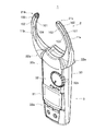
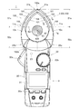
最初に、図1に示すクランプメータ1の構成について説明する。クランプメータ1は、測定装置の一例であって、例えば図10に示すクランプ対象としての導体400に流れる電流(被測定量の一例)を非接触(金属非接触)で測定可能に構成されている。具体的には、クランプメータ1は、図1〜図3に示すように、クランプセンサ2および本体部3を備えて構成されている。   First, the configuration of the clamp meter 1 shown in FIG. 1 will be described. The clamp meter 1 is an example of a measuring device, and is configured to be able to measure, for example, a current (an example of an amount to be measured) flowing through a conductor 400 as a clamp target illustrated in FIG. 10 in a non-contact (metal non-contact) manner. . Specifically, as shown in FIGS. 1 to 3, the clamp meter 1 includes a clamp sensor 2 and a main body 3.

クランプセンサ2は、図1,3に示すように、一対のクランプアーム11a,11b(以下、区別しないときには「クランプアーム11」ともいう)を備え、図4に示すように、クランプアーム11a,11bで導体400をクランプした(取り囲んだ)状態において、導体400に電流が流れているときに生じる被検出量としての磁界を非接触で検出する。   As shown in FIGS. 1 and 3, the clamp sensor 2 includes a pair of clamp arms 11a and 11b (hereinafter, also referred to as “clamp arm 11” when not distinguished), and as shown in FIG. 4, the clamp arms 11a and 11b. In a state in which the conductor 400 is clamped (surrounded) by, a magnetic field as a detected amount generated when a current flows through the conductor 400 is detected in a non-contact manner.

また、このクランプセンサ2では、図1,3に示すように、クランプアーム11b(クランプアーム11a,11bの一方)が、クランプアーム11a,11bの先端部21a,21b同士が開閉(接離)するように回動軸23(図4参照)を中心として回動可能に構成され、クランプアーム11aが、回動しない状態で本体部3の本体ケース30に固定されている。また、このクランプセンサ2では、本体ケース30に配設されているレバー30aに対する操作(押し込み、および押し込みの解除)に応じてクランプアーム11bが回動するように構成されている。なお、以下の説明において、クランプアーム11a,11bの先端部21a,21b同士が閉じた状態(図1に示す状態)を「閉状態」ともいい、先端部21a,21b同士が開いた状態(図3,9に示す状態)を「開状態」ともいう。   In the clamp sensor 2, as shown in FIGS. 1 and 3, the clamp arm 11b (one of the clamp arms 11a and 11b) opens and closes (contacts and separates) the tip portions 21a and 21b of the clamp arms 11a and 11b. As described above, the clamp arm 11a is configured to be rotatable around the rotation shaft 23 (see FIG. 4), and the clamp arm 11a is fixed to the main body case 30 of the main body 3 in a non-rotated state. Further, in the clamp sensor 2, the clamp arm 11b is configured to rotate in accordance with an operation (push-in and release of the push-in) of the lever 30a provided in the main body case 30. In the following description, a state in which the distal ends 21a, 21b of the clamp arms 11a, 11b are closed (the state shown in FIG. 1) is also referred to as a "closed state", and a state in which the distal ends 21a, 21b are open (FIG. 3 and 9) is also referred to as an “open state”.

また、クランプアーム11aは、図4に示すように、センサケース10aと、センサケース10a内に収容されたコア41(図5,7参照)と、図外の磁気検出素子(一例として、ホール素子)とを備えて構成されている。また、クランプアーム11bは、図4に示すように、センサケース10bと、センサケース10b内に収容されたコア41(図5,7参照)とを備えて構成されている。   As shown in FIG. 4, the clamp arm 11a includes a sensor case 10a, a core 41 (see FIGS. 5 and 7) housed in the sensor case 10a, and a magnetic detection element (not shown, for example, a Hall element). ). Further, as shown in FIG. 4, the clamp arm 11b includes a sensor case 10b and a core 41 (see FIGS. 5 and 7) housed in the sensor case 10b.

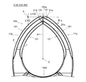
また、クランプアーム11a,11bは、図4に示すように、厚み方向(回動軸23の軸線方向)で見た平面視が略弧状にそれぞれ形成されて、先端部21a,21b同士が閉じた閉状態において環状体100を形成する。この場合、同図に示すように、環状体100は、クランプアーム11a,11bにおける基端部22a,22b側の各部位(以下「基端部側部位52a,52b」ともいう)によって基端部100b側の内周面が平面視半円状に形成されると共に、クランプアーム11a,11bの先端部21a,21b側の各部位(以下「先端部側部位51a,51b」ともいう)によって頂部100a(先端部21a,21bに対応する部位)側が平面視弧状の細長い環状に形成され、かつ頂部100a側の内周面が基端部100b側の内周面よりも曲率が小さく(曲率半径が大きく)なるように構成されている。   As shown in FIG. 4, the clamp arms 11a and 11b are each formed in a substantially arc shape when viewed in the thickness direction (axial direction of the rotating shaft 23), and the distal ends 21a and 21b are closed. An annular body 100 is formed in the closed state. In this case, as shown in the figure, the annular body 100 is divided into base portions 22a and 22b on the clamp arms 11a and 11b (hereinafter, also referred to as “base end portions 52a and 52b”). The inner peripheral surface on the 100b side is formed in a semicircular shape in plan view, and the top portions 100a are formed by the respective portions of the clamp arms 11a and 11b on the tip portions 21a and 21b side (hereinafter also referred to as “tip portion portions 51a and 51b”). The (parts corresponding to the distal ends 21a and 21b) side are formed in a slender annular shape having an arc shape in plan view, and the inner peripheral surface on the side of the top 100a has a smaller curvature (larger radius of curvature) than the inner peripheral surface on the side of the base end 100b. ).

また、クランプアーム11a,11bは、図5に示すように、環状体100を形成した状態において各コア41によって環状(略楕円状)の磁気回路Mcを形成する。この場合、クランプアーム11a,11bで取り囲んだ(クランプした)導体400に電流が流れているときには、その電流によって磁気回路Mcに磁界が生じ、クランプアーム11aの磁気検出素子がその磁界を検出する。   As shown in FIG. 5, each of the clamp arms 11a and 11b forms an annular (substantially elliptical) magnetic circuit Mc in a state where the annular body 100 is formed. In this case, when a current flows through the conductor 400 surrounded (clamped) by the clamp arms 11a and 11b, a magnetic field is generated in the magnetic circuit Mc by the current, and the magnetic detection element of the clamp arm 11a detects the magnetic field.

また、クランプアーム11a,11bは、図6に示すように、先端部側部位51a,51bの長さ方向に直交する切断面Sc1(例えば、図4におけるA−A線断面)の外形が略八角形となるように形成され、基端部側部位52a,52bの長さ方向に直交する切断面Sc2(例えば、図4におけるB−B線断面)の外形が略矩形となるように形成されている。また、クランプアーム11a,11bは、図6に示すように、先端部側部位51a,51bにおける切断面Sc1の外形の面積Sa1が、基端部側部位52a,52bにおける切断面Sc2の外形の面積Sa2(以下、面積Sa1,Sa2を区別しないときには「面積Sa」ともいう)よりも小さくなるように(面積Sa2が面積Sa1よりも大きくなるように)形成されている。つまり、クランプアーム11a,11bは、先端部側部位51a,51bが基端部側部位52a,52bよりも細くなるように形成されている。   Also, as shown in FIG. 6, the clamp arms 11a and 11b have an outer shape of a cut surface Sc1 (for example, a cross section taken along line AA in FIG. 4) orthogonal to the longitudinal direction of the distal end portions 51a and 51b. It is formed so that it may become a square, and the external shape of the cut surface Sc2 (for example, BB line cross section in FIG. 4) orthogonal to the length direction of the base end side parts 52a and 52b may be substantially rectangular. I have. As shown in FIG. 6, the clamp arm 11a, 11b has an outer area Sa1 of the cut surface Sc1 at the distal end portions 51a, 51b, and an outer area of the cut surface Sc2 at the proximal end portions 52a, 52b. It is formed so as to be smaller than Sa2 (hereinafter also referred to as “area Sa” when the areas Sa1 and Sa2 are not distinguished) (so that the area Sa2 is larger than the area Sa1). That is, the clamp arms 11a and 11b are formed such that the distal end portions 51a and 51b are thinner than the proximal end portions 52a and 52b.

ここで、このクランプセンサ2では、先端部側部位51a,51bおよび基端部側部位52a,52bが次のようにして規定されている。まず、図5に示すように、環状体100の頂部100aと、各コア41によって形成される磁気回路Mc(同図に破線で示す)の平面視図形の図心C1とを通る直線H1を規定する。次いで、頂部100a(具体的には、頂部100aにおける外側の対向面101)から図心C1までの距離D101(直線距離)の40%に相当する長さL101を特定し、直線H1上における図心C1を中心とする長さL101の範囲内におけるいずれかの点を規定する(以下、「規定点P101」ともいう)。この場合、この例では、距離D101の17%に相当する長さだけ図心C1から頂部100aに向かって離間する点を規定点P101として規定している。続いて、規定点P101を通って直線H1に直交する平面を境界面Sb1として規定し、クランプアーム11a,11bにおける境界面Sb1と先端部21a,21bとの間の部位を先端部側部位51a,51bとして規定し、境界面Sb1と基端部22a,22bとの間の部位を基端部側部位52a,52bとして規定する。   Here, in the clamp sensor 2, the distal end portions 51a and 51b and the proximal end portions 52a and 52b are defined as follows. First, as shown in FIG. 5, a straight line H1 passing through a top 100a of the annular body 100 and a centroid C1 of a plan view figure of a magnetic circuit Mc (shown by a broken line in FIG. 5) formed by each core 41 is defined. I do. Next, a length L101 corresponding to 40% of the distance D101 (linear distance) from the top 100a (specifically, the outer facing surface 101 at the top 100a) to the centroid C1 is specified, and the centroid on the straight line H1 is specified. Any point within the range of the length L101 centered on C1 is defined (hereinafter, also referred to as “defined point P101”). In this case, in this example, a point separated from the centroid C1 toward the top 100a by a length corresponding to 17% of the distance D101 is defined as the defined point P101. Subsequently, a plane passing through the defined point P101 and orthogonal to the straight line H1 is defined as a boundary surface Sb1, and a portion between the boundary surface Sb1 and the distal ends 21a, 21b of the clamp arms 11a, 11b is defined as a distal side portion 51a, 51b, and a portion between the boundary surface Sb1 and the base portions 22a and 22b is defined as base portion-side portions 52a and 52b.

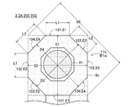
また、クランプアーム11a,11bの各先端部側部位51a,51bは、図1,3,4に示すように、環状体100の外周面および内周面を構成する一対の対向面101と、環状体100の2つの側面を構成する一対の対向面102と、対向面101,102に斜めに交差する一対の対向面103および一対の対向面104を有して、図7に示すように、クランプアーム11a,11bの長さ方向に直交する切断面Sc1(図4におけるA−A線断面)の外形が八角形(略八角形)をなす形状に形成されている。言い換えると、クランプアーム11a,11bの各先端部側部位51a,51bは、図7に破線で示す四角柱の各角部を面取りした八角柱状に形成されている。なお、各先端部側部位51a,51bの断面形状が同様であるため、同図では、先端部側部位51aの断面形状のみを図示し、先端部側部位51bの断面形状の図示を省略している。   Further, as shown in FIGS. 1, 3, and 4, each of the distal end side portions 51a and 51b of the clamp arms 11a and 11b has a pair of opposed surfaces 101 forming an outer peripheral surface and an inner peripheral surface of the annular body 100, and an annular surface. As shown in FIG. 7, the body 100 has a pair of opposed surfaces 102 forming two side surfaces of the body 100, and a pair of opposed surfaces 103 and 104 obliquely intersecting the opposed surfaces 101 and 102. The outer shape of the cut surface Sc1 (cross section taken along the line AA in FIG. 4) orthogonal to the length direction of the arms 11a and 11b is formed in an octagonal (substantially octagonal) shape. In other words, the distal end side portions 51a and 51b of the clamp arms 11a and 11b are formed in an octagonal column shape in which each corner of a quadrangular column indicated by a broken line in FIG. 7 is chamfered. In addition, since the cross-sectional shape of each front-end | tip part 51a, 51b is the same, only the cross-sectional shape of the front-end | tip part 51a is illustrated in the figure, and illustration of the cross-sectional shape of the front-end | tip part 51b is omitted. I have.

また、このクランプセンサ2では、図7に示すように、クランプアーム11a,11bの各先端部側部位51a,51bにおける先端部21a,21bを除く部位が、切断面Sc1の外形である八角形の各辺のうちの、各対向面101に対応する各辺E1および各対向面102に対応する各辺E2が同じ長さL1となり、各対向面103に対応する各辺E3の長さ(各辺E3における各々の両端部を結ぶ線分の長さ)および各対向面104に対応する各辺E4の長さ(各辺E4における各々の両端部を結ぶ線分の長さ)が同じ長さL2となるように形成されている。さらに、このクランプセンサ2では、同図に示すように、長さL2が長さL1(各辺E1,E2の長さのうちの最短の長さ)よりも長くなるように各先端部側部位51a,51bが形成されている。   In the clamp sensor 2, as shown in FIG. 7, the portions of the clamp arms 11a and 11b other than the distal ends 21a and 21b in the distal end portions 51a and 51b have an octagonal shape which is the outer shape of the cut surface Sc1. Of each side, each side E1 corresponding to each facing surface 101 and each side E2 corresponding to each facing surface 102 have the same length L1, and the length of each side E3 corresponding to each facing surface 103 (each side) The length L2 of the line segment connecting both ends at E3 and the length of each side E4 corresponding to each facing surface 104 (the length of the line segment connecting both ends at each side E4) are the same length L2. It is formed so that it becomes. Further, in the clamp sensor 2, as shown in the figure, the distal end side portion is set so that the length L2 is longer than the length L1 (the shortest length of the lengths of the sides E1 and E2). 51a and 51b are formed.

なお、図7に示す例では、辺E3,E4がそれぞれ直線であるため、辺E3,E4における各々の両端部を結ぶ線分の長さと各辺E3,E4とが同一となるが、辺E3,E4が曲線(弧状)である構成(切断面Sc1の外形が略八角形の構成)を採用することもでき、この構成では、辺E3,E4における各々の両端部を結ぶ線分の長さを長さL2として、長さL2が長さL1(各辺E1,E2の長さのうちの最短の長さ)よりも長くなるように各先端部側部位51a,51bを形成する。   In the example shown in FIG. 7, since the sides E3 and E4 are straight lines, the length of the line connecting both ends of the sides E3 and E4 is the same as the sides E3 and E4. , E4 may have a curved (arc-shaped) configuration (a configuration in which the outer shape of the cut surface Sc1 is substantially octagonal). In this configuration, the length of a line segment connecting both ends of the sides E3, E4 is also possible. Is the length L2, and the distal end side portions 51a and 51b are formed such that the length L2 is longer than the length L1 (the shortest length of the lengths of the sides E1 and E2).

このクランプセンサ2では、各辺E1,E2の長さL1および各辺E3,E4の長さL2をこのように規定したことで、図7に示すように、各辺E3の対向距離D3および各辺E4の対向距離D4が、各辺E1の対向距離D1および各辺E2の対向距離D2よりも短くなるように各先端部側部位51a,51bが形成されている。   In this clamp sensor 2, the length L1 of each side E1, E2 and the length L2 of each side E3, E4 are defined in this way, so that the facing distance D3 of each side E3 and each The distal end side portions 51a and 51b are formed such that the facing distance D4 of the side E4 is shorter than the facing distance D1 of each side E1 and the facing distance D2 of each side E2.

また、このクランプセンサ2では、図8に示すように、クランプアーム11a,11bの先端部21a,21bにおける外周側の対向面101(環状体100の外周面を構成する対向面101)が、環状体100の形成状態において環状体100の頂部100aと基端部100bとを結ぶ方向(同図における上下方向)に直交する1つの平面をなすように形成されている。つまり、環状体100の頂部100aにおける外周側の一部(同図に破線で示す部分)を平面で切り欠いた形状に形成されている。このように形成することにより、このクランプセンサ2では、同図に示すように、先端部21a,21bにおける各対向面101の対向距離D1(以下、この対向距離D1を「対向距離D1a」ともいう)が、クランプアーム11a,11bの先端部21a,21bを除く他の部位における各対向面101の対向距離D1(以下、この対向距離D1を「対向距離D1b」ともいう)よりも短くなるように各クランプアーム11a,11bが形成されている。このため、このクランプセンサ2では、先端部21a,21bにおける各対向面101の対向距離D1aが短い分、頂部100aと基端部100bとを結ぶ方向に沿った環状体100の長さが短くなっている。   Further, in the clamp sensor 2, as shown in FIG. 8, the opposing surface 101 on the outer peripheral side (the opposing surface 101 constituting the outer peripheral surface of the annular body 100) at the distal ends 21a and 21b of the clamp arms 11a and 11b is annular. In the state in which the body 100 is formed, the annular body 100 is formed so as to form one plane orthogonal to the direction connecting the top portion 100a and the base end portion 100b (vertical direction in the figure). In other words, a part of the top part 100a of the annular body 100 on the outer peripheral side (the part shown by the broken line in the figure) is formed in a shape in which the plane is cut out. By forming in this manner, in this clamp sensor 2, as shown in the figure, the facing distance D1 of each facing surface 101 at the distal ends 21a and 21b (hereinafter, this facing distance D1 is also referred to as "facing distance D1a"). ) Is shorter than an opposing distance D1 of each opposing surface 101 in other portions except for the distal ends 21a and 21b of the clamp arms 11a and 11b (hereinafter, this opposing distance D1 is also referred to as “opposing distance D1b”). Each clamp arm 11a, 11b is formed. For this reason, in the clamp sensor 2, the length of the annular body 100 along the direction connecting the top 100a and the base end 100b becomes shorter by the shorter the opposing distance D1a between the opposing surfaces 101 at the distal ends 21a and 21b. ing.

また、このクランプセンサ2では、クランプアーム11a,11bが、図8に示すように、上記した直線H1に直交しかつ環状体100の開口面Fに平行な方向に沿って頂部100aの中心から15mm(以下、この長さを「長さL102」ともいう)だけ離間する位置Pと、環状体100の外側の対向面101との間の直線H1に沿った長さL103が9mm以上11mm以下の範囲内となるように形成されている。つまり、クランプアーム11a,11bは、長さL102に対する長さL103の比が9/15以上11/15以下の範囲内となるように形成されている。   Further, in this clamp sensor 2, the clamp arms 11a and 11b are positioned at a distance of 15 mm from the center of the top 100a along a direction perpendicular to the straight line H1 and parallel to the opening surface F of the annular body 100 as shown in FIG. (Hereinafter, this length is also referred to as “length L102”). The length L103 along the straight line H1 between the position P separated from the position P and the outer facing surface 101 of the annular body 100 is in the range of 9 mm to 11 mm. It is formed to be inside. That is, the clamp arms 11a and 11b are formed such that the ratio of the length L103 to the length L102 is in the range from 9/15 to 11/15.

ここで、例えば、長さL103が11mmを超えるようにクランプアーム11a,11bを形成したときには、クランプアーム11a,11bの先端部21a,21b側の形状が細長すぎて、例えば、壁面の近傍に配設されている(背後に壁面が存在する)導体400をクランプアーム11a,11bでクランプしようとする際に、クランプアーム11a,11bの先端部21a,21bが壁面に接触してクランプが困難となるおそれがある。また、長さL103が11mmを超えるようにクランプアーム11a,11bを形成したときには、環状体100の頂部100a側が極端に細長い形状となって磁界(被検出量)の検出特性が悪化するおそれがある。一方、長さL103が9mmを下回るようにクランプアーム11a,11bを形成したときには、クランプアーム11a,11bの先端部21a,21b側の形状が円弧状に近くなり、例えば、近接して配置されている複数の導体400のうちの1つの導体400をクランプアーム11a,11bでクランプしようとする際に、隣接する他の導体400との間の隙間に先端部21a,21bを挿入し難くなり、クランプが困難となるおそれがある。これに対して、このクランプセンサ2では、直線H1に直交しかつ環状体100の開口面Fに平行な方向に沿って頂部100aの中心から15mmだけ離間する位置Pと環状体100の外側の対向面101との間の直線H1に沿った長さL103が9mm以上11mm以下の範囲内となるようにクランプアーム11a,11bを形成することで、磁界の検出特性を良好に維持しつつ、導体400を確実にクランプすることが可能となっている。   Here, for example, when the clamp arms 11a and 11b are formed so that the length L103 exceeds 11 mm, the shape of the distal ends 21a and 21b of the clamp arms 11a and 11b is too narrow, and is disposed near, for example, a wall surface. When clamping the provided conductor 400 (having a wall surface behind) with the clamp arms 11a and 11b, the distal ends 21a and 21b of the clamp arms 11a and 11b come into contact with the wall surface to make clamping difficult. There is a risk. Further, when the clamp arms 11a and 11b are formed so that the length L103 exceeds 11 mm, the top 100a side of the annular body 100 becomes extremely elongated, and the detection characteristics of the magnetic field (detected amount) may be deteriorated. . On the other hand, when the clamp arms 11a and 11b are formed so that the length L103 is less than 9 mm, the shape of the distal ends 21a and 21b of the clamp arms 11a and 11b becomes closer to an arc shape. When one of the plurality of conductors 400 is to be clamped by the clamp arms 11a and 11b, it is difficult to insert the tips 21a and 21b into the gap between the adjacent conductors 400 and the clamps. May be difficult. On the other hand, in the clamp sensor 2, the position P which is perpendicular to the straight line H1 and is separated from the center of the top 100a by 15 mm in a direction parallel to the opening surface F of the annular body 100 is opposed to the outside of the annular body 100. By forming the clamp arms 11a and 11b so that the length L103 along the straight line H1 between the plane 101 and the surface 101 is in the range of 9 mm or more and 11 mm or less, the conductor 400 can be maintained while maintaining good magnetic field detection characteristics. Can be securely clamped.

また、このクランプセンサ2では、クランプアーム11a,11bが、図9に示すように、先端部側部位51a,51bにおける切断面Sc1の外形におけるいずれか2つの点の間の直線距離の中の最長の距離を対向距離D1(図7も参照)として、各クランプアーム11a,11bの各先端部21a,21b同士が最大に離間した状態における各先端部21a,21b間の離間距離D102としたときに、離間距離D102に対する対向距離D1の比率Rが1/6以上1/5以下の範囲内となるように形成されている。なお、このクランプセンサ2では、一例として、離間距離D102が56.8mm±25%の範囲内となるように規定されると共に、対向距離D1が11mm±25%の範囲内となるように規定されている。   Further, in this clamp sensor 2, as shown in FIG. 9, the clamp arms 11a and 11b are the longest of the linear distances between any two points in the outer shape of the cut surface Sc1 at the distal end portions 51a and 51b. Is defined as a facing distance D1 (see also FIG. 7) and a separation distance D102 between the distal ends 21a and 21b in a state where the distal ends 21a and 21b of the clamp arms 11a and 11b are maximally separated from each other. , The ratio R of the facing distance D1 to the separation distance D102 is in the range of 1/6 or more and 1/5 or less. In the clamp sensor 2, for example, the separation distance D102 is defined to be within a range of 56.8 mm ± 25%, and the facing distance D1 is defined to be within a range of 11 mm ± 25%. ing.

ここで、比率Rが1/5を超えるようにクランプアーム11a,11bを形成したときには、例えば、図10に示すように、狭い間隔で並んで配設されている数多くの導体400のうちの1つをクランプする際に、クランプアーム11a,11bの先端部21a,21bを隣接する各導体400間の狭い隙間G1,G2に挿入することが困難となることが、発明者らの実験結果から明らかとなっている。一方、比率Rが1/6を下回るようにクランプアーム11a,11bを形成したときには、各先端部21a,21b同士が最大に離間した状態、つまりレバー30aを最大に押し込んだ状態での離間距離D102が長すぎて、狭い間隔で数多くの導体400が並んでいるときには、各導体400の1つだけをクランプしようとしても、複数の導体400をクランプしてしまうおそれがあるため、レバー30aの押し込み量を加減する必要があり、操作性が悪化するおそれがある。これに対して、このクランプセンサ2では、比率Rが1/6以上1/5以下の範囲内となるようにクランプアーム11a,11bを形成することで、レバー30aを最大に押し込んだ状態で隣接する各導体400間の狭い隙間G1,G2に先端部21a,21bを容易に挿入することが可能となっている。このため、このクランプセンサ2では、レバー30aの押し込み量を加減する必要がないため、操作性を十分に向上させることが可能となっている。   Here, when the clamp arms 11a and 11b are formed so that the ratio R exceeds 1/5, for example, as shown in FIG. 10, one of a large number of conductors 400 arranged at a narrow interval is used. It is clear from the experimental results of the inventors that it becomes difficult to insert the distal ends 21a and 21b of the clamp arms 11a and 11b into the narrow gaps G1 and G2 between the adjacent conductors 400 when clamping the two. It has become. On the other hand, when the clamp arms 11a and 11b are formed so that the ratio R is less than 1/6, the separation distance D102 in a state where the tips 21a and 21b are maximally separated from each other, that is, in a state where the lever 30a is pushed maximally. Is too long, and a large number of conductors 400 are arranged at a narrow interval, there is a risk that a plurality of conductors 400 may be clamped even if only one of the conductors 400 is clamped. Must be adjusted, and operability may be deteriorated. On the other hand, in the clamp sensor 2, the clamp arms 11a and 11b are formed so that the ratio R is in the range of 1/6 or more and 1/5 or less, so that the lever 30a is pushed to the maximum in the state where the lever 30a is pushed to the maximum. The tip portions 21a and 21b can be easily inserted into the narrow gaps G1 and G2 between the respective conductors 400. For this reason, in the clamp sensor 2, it is not necessary to increase or decrease the pushing amount of the lever 30a, so that the operability can be sufficiently improved.

また、このクランプセンサ2では、上記したように、クランプアーム11a,11bの基端部側部位52a,52bが断面略矩形をなす形状に形成されると共に、図4に示すように、先端部側部位51a,51bが基端部側部位52a,52bよりも細く、つまり、図6に示すように、先端部側部位51a,51bにおける切断面Sc1の外形の面積Sa1が、基端部側部位52a,52bにおける切断面Sc2の外形の面積Sa2よりも小さくなるように各クランプアーム11a,11bが形成されている。言い換えると、基端部側部位52a,52bが先端部側部位51a,51bよりも太く、つまり、基端部側部位52a,52bの切断面Sc2の面積が先端部側部位51a,51bの切断面Sc1の面積よりも大きくなるように各クランプアーム11a,11bが形成されている。このため、このクランプセンサ2では、先端部側部位51a,51bの切断面Sc1の面積、および基端部側部位52a,52bの切断面Sc2の面積が同じ面積となるように各クランプアーム11a,11bを形成した構成と比較して、クランプアーム11a,11bの強度が十分に高められている。   Further, in the clamp sensor 2, as described above, the proximal end portions 52a and 52b of the clamp arms 11a and 11b are formed in a substantially rectangular cross section, and as shown in FIG. The parts 51a and 51b are thinner than the base end parts 52a and 52b. That is, as shown in FIG. 6, the area Sa1 of the outer shape of the cut surface Sc1 in the distal end parts 51a and 51b is equal to the base end part 52a. , 52b, the clamp arms 11a and 11b are formed so as to be smaller than the area Sa2 of the outer shape of the cut surface Sc2. In other words, the proximal end portions 52a and 52b are thicker than the distal end portions 51a and 51b, that is, the area of the cut surface Sc2 of the proximal end portions 52a and 52b is equal to the cut surface of the distal end portions 51a and 51b. Each of the clamp arms 11a and 11b is formed to be larger than the area of Sc1. For this reason, in this clamp sensor 2, each of the clamp arms 11a, The strength of the clamp arms 11a and 11b is sufficiently increased as compared with the configuration in which the 11b is formed.

また、このクランプセンサ2では、上記したように、磁気回路Mcの平面視図形の図心C1を中心として、頂部100aから図心C1までの距離D101の40%に相当する長さL101の範囲内において規定した規定点P101を通って直線H1に直交する境界面Sb1と先端部21a,21bとの間の部位を先端部側部位51a,51bとして規定し、境界面Sb1と基端部22a,22bとの間の部位を基端部側部位52a,52bとして規定している。この場合、長さL101の範囲を超えて頂部100aに近い点を通る面を境界面Sb1として規定したときには、面積Saが小さい(細い)先端部側部位51a,51bの長さが短くなり、狭い間隔で並んで配設されている数多くの導体400のうちの1つをクランプする際に、クランプアーム11a,11bの先端部21a,21bを隣接する各導体400間の狭い隙間G1,G2の奥まで挿入することが困難となる。一方、長さL101の範囲を超えて基端部100bに近い点を通る面を境界面Sb1として規定したときには、面積Saが大きい(太い)基端部側部位52a,52bの長さが短くなり、クランプアーム11a,11bの強度が低下する。これに対して、このクランプセンサ2では、長さL101の範囲内において規定した規定点P101を通る面を境界面Sb1として規定しているため、クランプアーム11a,11bの強度を低下させることなく、クランプアーム11a,11bの先端部21a,21bを隣接する各導体400間の狭い隙間G1,G2の奥まで容易に挿入させることが可能となっている。   Further, in the clamp sensor 2, as described above, the center of the centroid C1 of the figure of the magnetic circuit Mc in the plan view is within the range of the length L101 corresponding to 40% of the distance D101 from the top 100a to the centroid C1. Are defined between the boundary surface Sb1 passing through the defined point P101 and orthogonal to the straight line H1 and the distal end portions 21a and 21b as distal end side portions 51a and 51b, and the boundary surface Sb1 and the base end portions 22a and 22b are defined. Are defined as base-end-side portions 52a and 52b. In this case, when a surface passing through a point near the top 100a beyond the range of the length L101 is defined as the boundary surface Sb1, the lengths of the tip-side portions 51a and 51b having a small (thin) area Sa are short and narrow. When one of the many conductors 400 arranged side by side at a distance is clamped, the distal ends 21a, 21b of the clamp arms 11a, 11b are placed in the narrow gaps G1, G2 between the adjacent conductors 400. It becomes difficult to insert up to. On the other hand, when a plane passing through a point near the base end 100b beyond the range of the length L101 is defined as the boundary surface Sb1, the length of the base end side parts 52a, 52b having a large (thick) area Sa becomes short. Thus, the strength of the clamp arms 11a and 11b decreases. On the other hand, in the clamp sensor 2, since the surface passing through the specified point P101 defined within the range of the length L101 is defined as the boundary surface Sb1, the strength of the clamp arms 11a and 11b is not reduced. The distal ends 21a, 21b of the clamp arms 11a, 11b can be easily inserted into the narrow gaps G1, G2 between the adjacent conductors 400.

本体部3は、図2に示すように、表示部31、操作部32、処理部33、およびこれらの各部が収容または配設される本体ケース30(図1,3,4参照)を備えて構成されている。   As shown in FIG. 2, the main body unit 3 includes a display unit 31, an operation unit 32, a processing unit 33, and a main body case 30 (see FIGS. 1, 3, and 4) in which these units are housed or arranged. It is configured.

表示部31は、例えば液晶パネルで構成されて、図1,3,4に示すように、本体ケース30の正面パネルに配設されている。また、表示部31は、処理部33の制御に従って電流の測定値等を表示する。操作部32は、本体ケース30の正面パネルに配設された各種のスイッチ32aやダイヤル32b等を備えて構成され、これらの操作に応じた操作信号を出力する。   The display unit 31 is formed of, for example, a liquid crystal panel, and is disposed on a front panel of the main body case 30 as shown in FIGS. Further, the display unit 31 displays a measured value of the current and the like according to the control of the processing unit 33. The operation unit 32 includes various switches 32a and dials 32b provided on the front panel of the main body case 30, and outputs operation signals corresponding to these operations.

処理部33は、操作部32から出力される操作信号に従って本体部3を構成する各部を制御する。また、処理部33は、測定部として機能し、クランプセンサ2(磁気検出素子)から出力される検出信号に基づいて導体400に流れる電流の電流値を測定して表示部31に表示させる。   The processing unit 33 controls each unit configuring the main unit 3 according to an operation signal output from the operation unit 32. In addition, the processing unit 33 functions as a measurement unit, measures the value of the current flowing through the conductor 400 based on the detection signal output from the clamp sensor 2 (magnetic detection element), and causes the display unit 31 to display the measured value.

次に、クランプメータ1の使用方法、およびその際のクランプメータ1の動作について、図面を参照して説明する。一例として、図10に示すように、狭い間隔で並んで配設されている複数の導体400のうちの1つ(例えば、同図に示す導体400a)に流れる電流の電流値を測定する場合の使用方法について説明する。この場合、この例では、直径が21mmの複数の導体400が12mmの間隔で(隣接する導体400間の隙間が12mmとなるように)並んで配設されているものとする。   Next, a method of using the clamp meter 1 and an operation of the clamp meter 1 at that time will be described with reference to the drawings. As an example, as shown in FIG. 10, when a current value of a current flowing through one of a plurality of conductors 400 arranged side by side at a narrow interval (for example, a conductor 400 a shown in FIG. 10) is measured. How to use will be described. In this case, in this example, it is assumed that a plurality of conductors 400 having a diameter of 21 mm are arranged side by side at an interval of 12 mm (so that a gap between adjacent conductors 400 is 12 mm).

まず、クランプメータ1における本体部3のレバー30a(図1,4参照)を押し込む。この際に、図外のばねの付勢力に抗して、クランプセンサ2におけるクランプアーム11a,11bの先端部21a,21b同士が開く向きにクランプアーム11bが回動して、図3に示すように、クランプアーム11a,11bが開状態となる。   First, the lever 30a (see FIGS. 1 and 4) of the main body 3 of the clamp meter 1 is pushed in. At this time, the clamp arm 11b rotates in a direction in which the distal ends 21a and 21b of the clamp arms 11a and 11b in the clamp sensor 2 open against the urging force of a spring (not shown), as shown in FIG. Then, the clamp arms 11a and 11b are opened.

次いで、図10に示すように、測定対象(クランプ対象)の導体400aにクランプアーム11a,11bの先端部21a,21bを近づける。続いて、図11に示すように、クランプメータ1の長さ方向(図4に示す環状体100の頂部100aと基端部100bとを結ぶ方向)を軸として回動させるようにクランプメータ1を傾け、導体400aの右側に隣接する導体400bと導体400aとの間の隙間G1にクランプアーム11aの先端部21aを挿入すると共に、導体400aの左側に隣接する導体400cと導体400aとの間の隙間G2にクランプアーム11bの先端部21bを挿入する。   Next, as shown in FIG. 10, the tips 21a and 21b of the clamp arms 11a and 11b are brought closer to the conductor 400a to be measured (clamp target). Subsequently, as shown in FIG. 11, the clamp meter 1 is rotated so as to rotate about the length direction of the clamp meter 1 (the direction connecting the top portion 100a and the base end portion 100b of the annular body 100 shown in FIG. 4). The tip of the clamp arm 11a is inserted into the gap G1 between the conductor 400b and the conductor 400a adjacent to the right side of the conductor 400a and the gap between the conductor 400c and the conductor 400a adjacent to the left side of the conductor 400a. The distal end 21b of the clamp arm 11b is inserted into G2.

ここで、図7に破線で示すように、クランプアーム11a,11bの各先端部側部位51a,51bにおける切断面Sc1の外形が四角形をなすように形成された従来の構成(四角柱の各角部を面取りしていない構成)では、切断面Sc1の外形である四角形における対向する各角部の間の距離(同図に示す対角距離D5)が、各辺E1の対向距離D1および各辺E2の対向距離D2よりも長くなる。このため、従来の構成では、図11に示すように、導体400a,400b間の隙間G1や導体400a,400c間の隙間G2が狭い場合において、クランプメータ1を傾けたときには、各隙間G1,G2にクランプアーム11a,11bの先端部21a,21bを挿入することが困難となる。   Here, as shown by a broken line in FIG. 7, a conventional configuration in which the outer shape of the cut surface Sc1 at each of the distal end side portions 51a and 51b of the clamp arms 11a and 11b is formed as a square (each corner of the square prism) In the configuration in which the part is not chamfered), the distance (diagonal distance D5 shown in the figure) between the opposing corners of the rectangle, which is the outer shape of the cut surface Sc1, is the opposing distance D1 of each side E1 and each side. It is longer than the facing distance D2 of E2. Therefore, in the conventional configuration, as shown in FIG. 11, when the gap G1 between the conductors 400a and 400b and the gap G2 between the conductors 400a and 400c are narrow, when the clamp meter 1 is tilted, the gaps G1 and G2 It is difficult to insert the distal ends 21a, 21b of the clamp arms 11a, 11b into the arm.

これに対して、このクランプセンサ2では、上記したように、クランプアーム11a,11bの各先端部側部位51a,51bが、四角柱の各角部を面取りして切断面Sc1の外形が八角形をなす八角柱状に形成され、さらに切断面Sc1の外形である八角形の辺E3,E4の長さL2が辺E1,E2の長さL1よりも長くなるように形成されている。このため、このクランプセンサ2では、各辺E3の対向距離D3および各辺E4の対向距離D4が、各辺E1の対向距離D1および各辺E2の対向距離D2よりも短くなっている。したがって、このクランプセンサ2では、従来の構成と比較して、クランプメータ1を傾けた状態でクランプアーム11a,11bの先端部21a,21bを狭い隙間G1,G2に容易に挿入することが可能となっている。   On the other hand, in the clamp sensor 2, as described above, each of the distal end portions 51 a and 51 b of the clamp arms 11 a and 11 b chamfers each corner of the quadrangular prism and the outer shape of the cut surface Sc 1 is octagonal. And the length L2 of the sides E3 and E4 of the octagon, which is the outer shape of the cut surface Sc1, is longer than the length L1 of the sides E1 and E2. Therefore, in the clamp sensor 2, the facing distance D3 of each side E3 and the facing distance D4 of each side E4 are shorter than the facing distance D1 of each side E1 and the facing distance D2 of each side E2. Therefore, in the clamp sensor 2, it is possible to easily insert the distal ends 21a, 21b of the clamp arms 11a, 11b into the narrow gaps G1, G2 with the clamp meter 1 tilted as compared with the conventional configuration. Has become.

また、このクランプセンサ2では、上記したように、各クランプアーム11a,11bの各先端部21a,21b同士が最大に離間した状態における各先端部21a,21b間の離間距離D102に対する先端部側部位51a,51bにおける切断面Sc1の外形におけるいずれか2つの点の間の最長の距離である対向距離D1の比率Rが1/6以上1/5以下の範囲内となるようにクランプアーム11a,11bが形成されているため、レバー30aを最大に押し込んだ状態で、隣接する各導体400間の狭い隙間G1,G2に先端部21a,21bを容易に挿入することが可能となっている。このため、このクランプセンサ2では、レバー30aの押し込み量を加減する必要がないため、操作性を十分に向上させることが可能となっている。   Further, in the clamp sensor 2, as described above, the tip side portion relative to the separation distance D102 between the respective tips 21a and 21b in a state where the tips 21a and 21b of the clamp arms 11a and 11b are maximally separated from each other. Clamp arms 11a, 11b such that the ratio R of the opposing distance D1, which is the longest distance between any two points in the outer shape of the cut surface Sc1 at 51a, 51b, is in the range of 1/6 to 1/5. Are formed, it is possible to easily insert the tips 21a and 21b into the narrow gaps G1 and G2 between the adjacent conductors 400 with the lever 30a pushed to the maximum. For this reason, in the clamp sensor 2, it is not necessary to increase or decrease the pushing amount of the lever 30a, so that the operability can be sufficiently improved.

次いで、隙間G1,G2にクランプアーム11a,11bの先端部21a,21bをそれぞれ挿入した状態で、レバー30aに対する押し込みを解除する。この際に、図外のばねの付勢力によってクランプアーム11a,11bの先端部21a,21b同士が接触する向きにクランプアーム11bが回動して、図12に示すように、クランプアーム11a,11bが閉状態となる。これにより、同図に示すように、クランプアーム11a,11bによって導体400aがクランプされる。   Next, with the distal ends 21a, 21b of the clamp arms 11a, 11b inserted into the gaps G1, G2, the pushing on the lever 30a is released. At this time, the biasing force of a spring (not shown) rotates the clamp arm 11b in a direction in which the tips 21a, 21b of the clamp arms 11a, 11b come into contact with each other, and as shown in FIG. 12, the clamp arms 11a, 11b. Is closed. Thereby, the conductor 400a is clamped by the clamp arms 11a and 11b, as shown in FIG.

この場合、このクランプセンサ2では、上記したように、頂部100aから磁気回路Mcの平面視図形の図心C1までの距離D101の40%に相当する長さL101の範囲内において規定した規定点P101を通る境界面Sb1とクランプアーム11a,11bの先端部21a,21bとの間の部位を先端部側部位51a,51bとして規定し、境界面Sb1とクランプアーム11a,11bの基端部22a,22bとの間の部位を基端部側部位52a,52bとして規定し、先端部側部位51a,51bにおける切断面Sc1の外形の面積Sa1が、基端部側部位52a,52bにおける切断面Sc2の外形の面積Sa2よりも小さくなるように各クランプアーム11a,11bが形成されている。このため、このクランプセンサ2では、クランプアーム11a,11bの強度を低下させることなく、クランプアーム11a,11bの先端部21a,21bを隣接する各導体400間の狭い隙間G1,G2の奥まで容易に挿入させることができる。したがって、このクランプセンサ2では、導体400aを確実にクランプすることが可能となっている。   In this case, in the clamp sensor 2, as described above, the specified point P101 defined within the range of the length L101 corresponding to 40% of the distance D101 from the top 100a to the centroid C1 of the magnetic circuit Mc in plan view. Between the boundary surface Sb1 passing through and the distal ends 21a and 21b of the clamp arms 11a and 11b are defined as distal end portions 51a and 51b, and the base surfaces 22a and 22b of the boundary surface Sb1 and the clamp arms 11a and 11b. Are defined as the proximal end portions 52a and 52b, and the area Sa1 of the outer shape of the cut surface Sc1 in the distal end portions 51a and 51b is equal to the outer shape of the cut surface Sc2 in the proximal end portions 52a and 52b. Each of the clamp arms 11a and 11b is formed to be smaller than the area Sa2. For this reason, in the clamp sensor 2, the distal ends 21a, 21b of the clamp arms 11a, 11b can be easily extended to the depths of the narrow gaps G1, G2 between the adjacent conductors 400 without reducing the strength of the clamp arms 11a, 11b. Can be inserted. Therefore, in the clamp sensor 2, the conductor 400a can be reliably clamped.

続いて、クランプアーム11aに配設されている磁気検出素子が、導体400aに流れる電流によってクランプアーム11a,11bの各コアに生じる磁界を検出して検出信号を出力する。この場合、このクランプセンサ2では、上記したように、直線H1に直交しかつ環状体100の開口面Fに平行な方向に沿って頂部100aの中心から15mmだけ離間する位置Pと環状体100の外側の対向面101との間の直線H1に沿った長さL103が9mm以上11mm以下の範囲内となるようにクランプアーム11a,11bが形成されている。このため、このクランプセンサ2では、磁界の検出特性を良好に維持することが可能となっている。したがって、このクランプセンサ2では、導体400aに流れる電流を正確に測定可能な検出信号を出力することが可能となっている。次いで、本体部3の処理部33が、検出信号に基づいて導体400aに流れる電流の電流値を測定する。続いて、処理部33は、測定値を表示部31に表示させる。   Subsequently, a magnetic detection element provided on the clamp arm 11a detects a magnetic field generated in each core of the clamp arms 11a and 11b by a current flowing through the conductor 400a, and outputs a detection signal. In this case, in the clamp sensor 2, as described above, the position P, which is perpendicular to the straight line H1 and is separated from the center of the top 100 a by 15 mm along the direction parallel to the opening surface F of the annular body 100, The clamp arms 11a and 11b are formed such that the length L103 along the straight line H1 between the outer surface 101 and the outer facing surface 101 is within a range from 9 mm to 11 mm. For this reason, in this clamp sensor 2, it is possible to maintain good magnetic field detection characteristics. Therefore, in the clamp sensor 2, it is possible to output a detection signal capable of accurately measuring the current flowing through the conductor 400a. Next, the processing unit 33 of the main body 3 measures the current value of the current flowing through the conductor 400a based on the detection signal. Subsequently, the processing unit 33 causes the display unit 31 to display the measured value.

次いで、測定を終了したときには、レバー30aを押し込んで、クランプアーム11a,11bを開状態とさせ、続いて、導体400aからクランプセンサ2を引き離す。次いで、レバー30aに対する押し込みを解除して、クランプアーム11a,11bを閉状態とさせる。   Next, when the measurement is completed, the lever 30a is pushed in to open the clamp arms 11a and 11b, and then the clamp sensor 2 is separated from the conductor 400a. Next, the pressing on the lever 30a is released, and the clamp arms 11a and 11b are closed.

このように、このクランプセンサ2およびクランプメータ1では、環状体100の頂部100aと磁気回路Mcの平面視図形の図心C1とを通る直線H1上における図心C1を中心として頂部100aから図心C1までの距離D101の40%に相当する長さL101の範囲内の点を通って直線H1に直交する境界面Sb1と先端部21a,21bとの間の先端部側部位51a,51bにおける切断面Sc1の外形の面積Sa1が、境界面Sb1と基端部22a,22bとの間の基端部側部位52a,52bにおける切断面Sc2の外形の面積Sa2よりも小さくなるように各クランプアーム11a,11bが形成されている。この場合、長さL101の範囲を超えて頂部100aに近い点を通る面を境界面Sb1として規定したときには、面積Sa1が小さい(つまり、細い)先端部側部位51a,51bの長さが短くなり、狭い間隔で並んで配設されている数多くの導体400のうちの1つをクランプする際に、クランプアーム11a,11bの先端部21a,21bを隣接する各導体400間の狭い隙間G1,G2の奥まで挿入することが困難となる。一方、長さL101の範囲を超えて基端部100bに近い点を通る面を境界面Sb1として規定したときには、面積Sa2が大きい(つまり、太い)基端部側部位52a,52bの長さが短くなり、クランプアーム11a,11bの強度が低下する。これに対して、このクランプセンサ2では、長さL101の範囲内において規定した規定点P101を通る面を境界面Sb1として規定しているため、クランプアーム11a,11bの強度を低下させることなく、クランプアーム11a,11bの先端部21a,21bを隣接する各導体400間の狭い隙間G1,G2の奥まで容易に挿入させることができる。したがって、このクランプセンサ2によれば、導体400を確実にクランプすることができる。   As described above, in the clamp sensor 2 and the clamp meter 1, the centroid from the top 100a on the straight line H1 on the straight line H1 passing through the top 100a of the annular body 100 and the centroid C1 of the magnetic circuit Mc in plan view. A cut surface at the distal end side portions 51a and 51b between the boundary surface Sb1 and the distal end portions 21a and 21b passing through a point within the range of the length L101 corresponding to 40% of the distance D101 to C1 and orthogonal to the straight line H1. Each clamp arm 11a, so that the area Sa1 of the outer shape of Sc1 is smaller than the area Sa2 of the outer shape of the cut surface Sc2 at the base end side portions 52a, 52b between the boundary surface Sb1 and the base ends 22a, 22b. 11b is formed. In this case, when a surface passing through a point near the top 100a beyond the range of the length L101 is defined as the boundary surface Sb1, the area Sa1 is small (that is, thin), and the length of the tip side portions 51a and 51b is short. When one of the many conductors 400 arranged side by side at a narrow interval is clamped, the distal ends 21a, 21b of the clamp arms 11a, 11b are narrowed by the narrow gaps G1, G2 between the adjacent conductors 400. It becomes difficult to insert it deeply. On the other hand, when a surface passing through a point close to the base end portion 100b beyond the range of the length L101 is defined as the boundary surface Sb1, the area Sa2 is large (that is, thick) and the length of the base end side portions 52a, 52b is large. And the strength of the clamp arms 11a and 11b decreases. On the other hand, in the clamp sensor 2, since the surface passing through the specified point P101 defined within the range of the length L101 is defined as the boundary surface Sb1, the strength of the clamp arms 11a and 11b is not reduced. The distal ends 21a, 21b of the clamp arms 11a, 11b can be easily inserted into the narrow gaps G1, G2 between the adjacent conductors 400. Therefore, according to the clamp sensor 2, the conductor 400 can be reliably clamped.

また、このクランプセンサ2およびクランプメータ1では、直線H1に直交しかつ環状体100の開口面Fに平行な方向に沿って頂部100aの中心から15mmだけ離間する位置Pと環状体100の外側の対向面101との間の直線H1に沿った長さL103が9mm以上11mm以下の範囲内となるようにクランプアーム11a,11bが形成されている。この場合、長さL103が11mmを超えるようにクランプアーム11a,11bを形成したときには、クランプアーム11a,11bの先端部21a,21b側の形状が細長すぎて、例えば、壁面の近傍に配設されている導体400をクランプアーム11a,11bでクランプしようとする際に、クランプアーム11a,11bの先端部21a,21bが壁面に接触してクランプが困難となるおそれがある。また、長さL103が11mmを超えるようにクランプアーム11a,11bを形成したときには、環状体100の頂部100a側が極端に細長い形状となって磁界(被検出量)の検出特性が悪化するおそれがある。一方、長さL103が9mmを下回るようにクランプアーム11a,11bを形成したときには、クランプアーム11a,11bの先端部21a,21b側の形状が円弧状に近くなり、例えば、近接して配置されている複数の導体400のうちの1つの導体400をクランプアーム11a,11bでクランプしようとする際に、隣接する他の導体400との間の隙間に先端部21a,21bを挿入し難くなり、クランプが困難となるおそれがある。これに対して、このクランプセンサ2によれば、長さL103が9mm以上11mm以下の範囲内となるようにクランプアーム11a,11bを形成したことにより、磁界の検出特性を良好に維持しつつ、導体400をより確実にクランプすることができる。   Further, in the clamp sensor 2 and the clamp meter 1, a position P which is perpendicular to the straight line H 1 and is separated from the center of the top 100 a by 15 mm in a direction parallel to the opening surface F of the annular body 100 and the outside of the annular body 100. The clamp arms 11a and 11b are formed so that the length L103 along the straight line H1 between the opposite surface 101 and the straight line H1 is within a range of 9 mm or more and 11 mm or less. In this case, when the clamp arms 11a and 11b are formed so that the length L103 exceeds 11 mm, the shapes of the distal ends 21a and 21b of the clamp arms 11a and 11b are too narrow, and are disposed, for example, near the wall surface. When the conductor 400 is clamped by the clamp arms 11a and 11b, there is a possibility that the distal ends 21a and 21b of the clamp arms 11a and 11b come into contact with the wall surface, making clamping difficult. Further, when the clamp arms 11a and 11b are formed so that the length L103 exceeds 11 mm, the top 100a side of the annular body 100 becomes extremely elongated, and the detection characteristics of the magnetic field (detected amount) may be deteriorated. . On the other hand, when the clamp arms 11a and 11b are formed so that the length L103 is less than 9 mm, the shape of the distal ends 21a and 21b of the clamp arms 11a and 11b becomes closer to an arc shape. When one of the plurality of conductors 400 is to be clamped by the clamp arms 11a and 11b, it is difficult to insert the tips 21a and 21b into the gap between the adjacent conductors 400 and the clamps. May be difficult. On the other hand, according to the clamp sensor 2, the clamp arms 11a and 11b are formed so that the length L103 is in the range of 9 mm or more and 11 mm or less. The conductor 400 can be more reliably clamped.

また、このクランプセンサ2およびクランプメータ1では、先端部側部位51a,51bにおける切断面Sc1の外形におけるいずれか2つの点の間の最長の距離である対向距離D1が各クランプアーム11a,11bの各先端部21a,21b同士が最大に離間した状態における各先端部21a,21b間の離間距離D102の1/6以上1/5以下の範囲内となるようにクランプアーム11a,11bが形成されている。この場合、比率Rが1/5を超えるようにクランプアーム11a,11bを形成したときには、狭い間隔で並んで配設されている数多くの導体400のうちの1つをクランプする際に、クランプアーム11a,11bの先端部21a,21bを隣接する各導体400間の狭い隙間G1,G2に挿入することが困難となる。一方、比率Rが1/6を下回るようにクランプアーム11a,11bを形成したときには、レバー30aを最大に押し込んで各先端部21a,21b同士が最大に離間した状態での離間距離D102が長すぎて、狭い間隔で数多くの導体400が並んでいるときには、複数の導体400をクランプしてしまうおそれがあるため、レバー30aの押し込み量を加減する必要があり、操作性が悪化するおそれがある。これに対して、このクランプセンサ2によれば、対向距離D1が離間距離D102の1/6以上1/5以下の範囲内となるようにクランプアーム11a,11bを形成したことにより、レバー30aを最大に押し込んだ状態で隣接する各導体400間の狭い隙間G1,G2に先端部21a,21bを容易に挿入することができるため、操作性を十分に向上させつつ複数の導体400の1つだけをさらに確実にクランプすることができる。   Further, in the clamp sensor 2 and the clamp meter 1, the opposing distance D1, which is the longest distance between any two points in the outer shape of the cut surface Sc1 at the distal end side portions 51a, 51b, is equal to the distance between the clamp arms 11a, 11b. The clamp arms 11a and 11b are formed so that the distance between the distal ends 21a and 21b in the state where the distal ends 21a and 21b are maximally separated is in the range of 1/6 to 1/5 of the distance D102 between the distal ends 21a and 21b. I have. In this case, when the clamp arms 11a and 11b are formed so that the ratio R exceeds 1/5, when clamping one of the many conductors 400 arranged side by side at a narrow interval, the clamp arm It becomes difficult to insert the tip portions 21a, 21b of 11a, 11b into the narrow gaps G1, G2 between the adjacent conductors 400. On the other hand, when the clamp arms 11a and 11b are formed so that the ratio R is less than 1/6, the separation distance D102 when the levers 30a are pushed to the maximum and the distal ends 21a and 21b are separated from each other is too long. When a large number of conductors 400 are arranged at a narrow interval, the plurality of conductors 400 may be clamped. Therefore, it is necessary to increase or decrease the pushing amount of the lever 30a, and the operability may be deteriorated. On the other hand, according to the clamp sensor 2, the clamp arms 11a and 11b are formed such that the facing distance D1 is in the range of not less than 1/6 and not more than 1/5 of the separation distance D102. Since the tips 21a and 21b can be easily inserted into the narrow gaps G1 and G2 between the adjacent conductors 400 in a state where the conductors 400 are pushed to the maximum, only one of the plurality of conductors 400 is improved while operability is sufficiently improved. Can be more reliably clamped.

なお、クランプセンサおよび測定装置の構成は、上記の構成に限定されない。例えば、辺E3,E4が曲線をなすように(弧状となるように)、各クランプアーム11a,11bの各先端部側部位51a,51bおよび各基端部側部位52a,52bの双方を形成する構成を採用することもできる。   Note that the configurations of the clamp sensor and the measuring device are not limited to the above configurations. For example, both the distal end portions 51a and 51b and the proximal end portions 52a and 52b of the clamp arms 11a and 11b are formed so that the sides E3 and E4 form a curved line (to form an arc). A configuration can also be employed.

また、切断面Sc1の外形である八角形の各辺E1,E2が同じ長さL1で、各辺E3,E4が同じ長さL2となるようにクランプアーム11a,11bの各先端部側部位51a,51bを形成した例について上記したが、各辺E1,E2を異なる長さとしたり、各辺E3,E4を異なる長さとしたりして、クランプアーム11a,11bの各先端部側部位51a,51b(または、各先端部側部位51a,51bおよび各基端部側部位52a,52bの双方)を形成する構成を採用することもできる。   Also, the distal end side portions 51a of the clamp arms 11a and 11b such that the sides E1 and E2 of the octagon, which is the outer shape of the cut surface Sc1, have the same length L1 and the sides E3 and E4 have the same length L2. , 51b have been described above, but the sides E1, E2 have different lengths, and the sides E3, E4 have different lengths, so that the distal end side portions 51a, 51b of the clamp arms 11a, 11b ( Alternatively, it is also possible to adopt a configuration in which each of the distal end portions 51a and 51b and each of the proximal end portions 52a and 52b are formed.

また、各辺E3,E4のすべての長さL2が各辺E1,E2の長さL1よりも長くなるように各クランプアーム11a,11bの各先端部側部位51a,51bを形成した例について上記したが、各辺E3,E4の少なくとも1つの長さが各辺E1,E2の長さのうちの最短の長さよりも長くなるとの条件を満たす限り、各辺E1,E2,E3,E4の長さは任意に規定することができる。   In addition, the above-described example in which the distal end side portions 51a and 51b of the clamp arms 11a and 11b are formed such that the entire length L2 of each side E3 and E4 is longer than the length L1 of each side E1 and E2. However, as long as the condition that at least one length of each side E3, E4 is longer than the shortest length of the lengths of each side E1, E2, the length of each side E1, E2, E3, E4 is satisfied. The length can be arbitrarily defined.

また、環状体100の頂部100aにおける外周側の一部(図8に破線で示す部分)を切り欠いて、先端部21a,21bにおける各対向面101の対向距離D1aが、クランプアーム11a,11bの先端部21a,21bを除く他の部位における各対向面101の対向距離D1bよりも短くなるように各クランプアーム11a,11bを形成した例について上記したが、頂部100aにおける外周側の一部(図8に破線で示す部分)を切り欠かない構成を採用することもできる。   In addition, a part of the outer periphery of the top portion 100a of the annular body 100 (a portion shown by a broken line in FIG. 8) is cut away, and the facing distance D1a of each facing surface 101 at the tip portions 21a and 21b is equal to that of the clamp arms 11a and 11b. The example in which the clamp arms 11a and 11b are formed so as to be shorter than the opposing distance D1b of the opposing surfaces 101 in the other parts except the tip parts 21a and 21b has been described above. 8 (a portion shown by a broken line) can be employed.

また、クランプセンサ2が被検出量としての磁界を検出し、処理部33が被測定量としての電流を測定する例について上記したが、被検出量や被測定量は、磁界や電流に限定されず、電圧、電力および抵抗などの各種の物理量が含まれる。   Further, the example in which the clamp sensor 2 detects the magnetic field as the detected amount and the processing unit 33 measures the current as the measured amount has been described above, but the detected amount and the measured amount are limited to the magnetic field and the current. And various physical quantities such as voltage, power and resistance.

また、図13に示すクランプセンサ2Aおよび本体部3を備えたクランプメータ1Aを採用することもできる。なお、以下の説明において、上記したクランプセンサ2およびクランプメータ1と同様の構成要素については、同じ符号を付して、重複する説明を省略する。   Further, a clamp meter 1A including the clamp sensor 2A and the main body 3 shown in FIG. 13 can be employed. In the following description, the same components as those of the clamp sensor 2 and the clamp meter 1 described above are denoted by the same reference numerals, and redundant description will be omitted.

このクランプセンサ2Aでは、先端部側部位51a,51bおよび基端部側部位52a,52bが次のようにして規定されている。まず、図13に示すように、環状体100の頂部100aと、環状体100における内周の平面視図形(同図において斜線付した図形)の図心C2とを通る直線H2を規定する。次いで、頂部100a(具体的には、図8に示す頂部100aにおける外側の対向面101)から図心C2までの距離D101A(直線距離)の40%に相当する長さL101Aを特定し、直線H2上における図心C2を中心とする長さL101Aの範囲内におけるいずれかの点を規定する(以下、「規定点P101A」ともいう)。この場合、この例では、距離D101Aの14%に相当する長さだけ図心C2から頂部100aに向かって離間する点を規定点P101Aとして規定している。続いて、規定点P101A通って直線H2に直交する平面を境界面Sb2として規定し、クランプアーム11a,11bにおける境界面Sb2と先端部21a,21bとの間の部位を先端部側部位51a,51bとして規定し、境界面Sb1と基端部22a,22bとの間の部位を基端部側部位52a,52bとして規定する。   In the clamp sensor 2A, the distal end portions 51a and 51b and the proximal end portions 52a and 52b are defined as follows. First, as shown in FIG. 13, a straight line H2 passing through the top 100a of the annular body 100 and the centroid C2 of a plan view figure (a figure hatched in FIG. 13) of the inner periphery of the annular body 100 is defined. Next, the length L101A corresponding to 40% of the distance D101A (linear distance) from the top 100a (specifically, the outer facing surface 101 of the top 100a shown in FIG. 8) to the centroid C2 is specified, and the straight line H2 is determined. Any point within the range of the length L101A centered on the centroid C2 above is defined (hereinafter, also referred to as “defined point P101A”). In this case, in this example, a point separated from the centroid C2 toward the top 100a by a length corresponding to 14% of the distance D101A is defined as the defined point P101A. Subsequently, a plane that passes through the specified point P101A and is orthogonal to the straight line H2 is defined as the boundary surface Sb2, and the region between the boundary surface Sb2 and the distal end portions 21a and 21b in the clamp arms 11a and 11b is defined as the distal end portion 51a and 51b. And the portion between the boundary surface Sb1 and the base portions 22a and 22b is defined as the base portion side portions 52a and 52b.

このクランプセンサ2Aにおいても、図7に示すように、クランプアーム11a,11bの各先端部側部位51a,51bが、クランプセンサ2における同等の部位と同様の形状に形成されている。また、このクランプセンサ2Aにおいても、図6に示すように、先端部側部位51a,51bにおける切断面Sc1の外形の面積Sa1が、基端部側部位52a,52bにおける切断面Sc2の外形の面積Sa2よりも小さくなるように各クランプアーム11a,11bが形成されている。このため、このクランプセンサ2Aによれば、クランプセンサ2と同様にして、クランプアーム11a,11bの強度を低下させることなく、クランプアーム11a,11bの先端部21a,21bを隣接する各導体400間の狭い隙間G1,G2の奥まで容易に挿入させることが可能となっている。したがって、このクランプセンサ2によれば、導体400を確実にクランプすることができる。   Also in this clamp sensor 2A, as shown in FIG. 7, the distal end side parts 51a, 51b of the clamp arms 11a, 11b are formed in the same shape as the equivalent parts in the clamp sensor 2. Also in this clamp sensor 2A, as shown in FIG. 6, the area Sa1 of the outer shape of the cut surface Sc1 at the distal end portions 51a and 51b is equal to the area of the outer shape of the cut surface Sc2 at the proximal end portions 52a and 52b. Each clamp arm 11a, 11b is formed so as to be smaller than Sa2. Therefore, according to the clamp sensor 2A, similarly to the clamp sensor 2, the distal ends 21a and 21b of the clamp arms 11a and 11b are connected between the adjacent conductors 400 without reducing the strength of the clamp arms 11a and 11b. Can be easily inserted into the deep gaps G1 and G2. Therefore, according to the clamp sensor 2, the conductor 400 can be reliably clamped.

また、このクランプセンサ2Aにおいても、図8に示すように、直線H1に直交しかつ環状体100の開口面Fに平行な方向に沿って頂部100aの中心から15mmだけ離間する位置Pと環状体100の外側の対向面101との間の直線H1に沿った長さL103が9mm以上11mm以下の範囲内となるようにクランプアーム11a,11bが形成されている。このため、このクランプセンサ2Aによれば、クランプセンサ2と同様にして、磁界の検出特性を良好に維持しつつ、導体400をより確実にクランプすることができる。   Also in this clamp sensor 2A, as shown in FIG. 8, the position P which is perpendicular to the straight line H1 and is separated from the center of the top 100a by 15 mm along a direction parallel to the opening surface F of the annular body 100. The clamp arms 11a and 11b are formed so that a length L103 along a straight line H1 between the outer surface 100 and the opposing surface 101 is within a range from 9 mm to 11 mm. Therefore, according to the clamp sensor 2A, similarly to the clamp sensor 2, the conductor 400 can be more reliably clamped while maintaining good magnetic field detection characteristics.

また、このクランプセンサ2Aにおいても、図9に示すように、クランプアーム11a,11bが、先端部側部位51a,51bにおける切断面Sc1の外形におけるいずれか2つの点の間の直線距離の中の最長の距離を対向距離D1(図7も参照)とし、各クランプアーム11a,11bの各先端部21a,21b同士が最大に離間した状態における各先端部21a,21b間の離間距離D102としたときに、離間距離D102に対する対向距離D1の比率Rが1/6以上1/5以下の範囲内となるように形成されている。このため、このクランプセンサ2Aによれば、クランプセンサ2と同様にして、レバー30aを最大に押し込んだ状態で隣接する各導体400間の狭い隙間G1,G2に先端部21a,21bを容易に挿入することができるため、操作性を十分に向上させつつ複数の導体400の1つだけをさらに確実にクランプすることができる。   Also in this clamp sensor 2A, as shown in FIG. 9, the clamp arms 11a and 11b are arranged so that the clamp arms 11a and 11b are within the linear distance between any two points in the outer shape of the cut surface Sc1 at the distal end portions 51a and 51b. When the longest distance is the facing distance D1 (see also FIG. 7) and the distance D102 between the tips 21a and 21b in a state where the tips 21a and 21b of the clamp arms 11a and 11b are maximally separated from each other. The ratio R of the opposing distance D1 to the separation distance D102 is in the range of 1/6 or more and 1/5 or less. Therefore, according to the clamp sensor 2A, similarly to the clamp sensor 2, the tips 21a and 21b are easily inserted into the narrow gaps G1 and G2 between the adjacent conductors 400 while the lever 30a is pushed to the maximum. Therefore, only one of the plurality of conductors 400 can be more securely clamped while operability is sufficiently improved.

また、図7に示すクランプセンサ202を採用することもできる。このクランプセンサ202では、上記したクランプセンサ2と同様にして、クランプアーム11a,11bの各先端部側部位51a,51bが、一対の対向面101、一対の対向面102、一対の対向面103、および一対の対向面104を有して、同図に示すように、クランプアーム11a,11bの長さ方向に直交する切断面Sc1の外形が八角形(略八角形)をなす形状(同図に破線で示す四角柱の各角部を面取りした八角柱状)に形成されている。   Further, a clamp sensor 202 shown in FIG. 7 can be employed. In the clamp sensor 202, similarly to the clamp sensor 2 described above, the distal end side portions 51a and 51b of the clamp arms 11a and 11b are formed by a pair of opposing surfaces 101, a pair of opposing surfaces 102, a pair of opposing surfaces 103, And a pair of opposing surfaces 104, as shown in the figure, the outer shape of the cut surface Sc1 orthogonal to the length direction of the clamp arms 11a and 11b forms an octagon (substantially octagon) (see FIG. It is formed in an octagonal prism shape in which each corner of a quadrangular prism indicated by a broken line is chamfered.

また、このクランプセンサ202では、図5に示すように、上記したクランプセンサ2と同様にして、直線H1上における図心C1を中心とする長さL101の範囲内で規定した規定点P101を通って直線H1に直交する境界面Sb1と先端部21a,21bとの間の部位を先端部側部位51a,51bとして規定され、境界面Sb1と基端部22a,22bとの間の部位を基端部側部位52a,52bとして規定されている。なお、図13に示すように、上記したクランプセンサ2Aと同様にして、直線H2上における図心C2を中心とする長さL101Aの範囲内で規定した規定点P101Aを通って直線H2に直交する境界面Sb2と先端部21a,21bとの間の部位を先端部側部位51a,51bとして規定し、境界面Sb2と基端部22a,22bとの間の部位を基端部側部位52a,52bとして規定する構成を採用することもできる。   Further, as shown in FIG. 5, the clamp sensor 202 passes through a specified point P101 defined within a range of a length L101 centered on the center C1 on the straight line H1 in the same manner as the clamp sensor 2 described above. Between the boundary surface Sb1 perpendicular to the straight line H1 and the distal end portions 21a and 21b are defined as distal end portions 51a and 51b, and the region between the boundary surface Sb1 and the proximal end portions 22a and 22b is defined as a proximal end. It is defined as part side parts 52a and 52b. As shown in FIG. 13, similarly to the clamp sensor 2A described above, it passes through a specified point P101A defined within a range of a length L101A centered on the centroid C2 on the straight line H2 and is orthogonal to the straight line H2. The portion between the boundary surface Sb2 and the distal portions 21a and 21b is defined as the distal portion 51a and 51b, and the portion between the boundary Sb2 and the proximal portions 22a and 22b is defined as the proximal portion 52a and 52b. Alternatively, a configuration defined as

また、このクランプセンサ202では、図7に示すように、クランプアーム11a,11bの各先端部側部位51a,51bにおける先端部21a,21bを除く部位が、切断面Sc1の外形である八角形の各辺のうちの、各対向面101に対応する各辺E1および各対向面102に対応する各辺E2が同じ長さL1となり、各対向面103に対応する各辺E3および各対向面104に対応する各辺E4が同じ長さL2となるように形成されている。また、このクランプセンサ202では、各辺E1の対向距離D1および各辺E2の対向距離D2が同じ距離で、かつ各辺E3の対向距離D3(各辺E3の一方の両端部を結ぶ線分と各辺E3辺の他方の両端部を結ぶ線分との対向距離)および各辺E4の対向距離D4(各辺E4の一方の両端部を結ぶ線分と各辺E4辺の他方の両端部を結ぶ線分との対向距離)が同じ距離となるように、各先端部側部位51a,51bが形成されている。さらに、このクランプセンサ202では、対向距離D3,D4が対向距離D1,D2(対向距離D1,D2のうちのいずれか短い距離)の(100/√2)%超110%以下(一例として、99%)となるように各先端部側部位51a,51bが形成されている。   Further, in the clamp sensor 202, as shown in FIG. 7, the portions of the clamp arms 11a and 11b other than the distal ends 21a and 21b in the distal end portions 51a and 51b are formed in an octagonal shape which is the outer shape of the cut surface Sc1. Of each side, each side E1 corresponding to each facing surface 101 and each side E2 corresponding to each facing surface 102 have the same length L1, and each side E3 and each facing surface 104 corresponding to each facing surface 103 have the same length L1. The corresponding sides E4 are formed to have the same length L2. Further, in the clamp sensor 202, the facing distance D1 of each side E1 and the facing distance D2 of each side E2 are the same distance, and the facing distance D3 of each side E3 (a line connecting one end of each side E3 and The opposing distance between a line connecting the other end of each side E3) and the opposing distance D4 of each side E4 (the line connecting the one end of each side E4 and the other end of each side E4). The distal end side portions 51a and 51b are formed such that the distances facing the connecting line segments are the same distance. Further, in the clamp sensor 202, the facing distances D3 and D4 are more than (100 / √2)% and 110% or less of the facing distances D1 and D2 (whichever is shorter of the facing distances D1 and D2) (for example, 99% or less). %), The distal end side portions 51a and 51b are formed.

この場合、対向距離D3,D4を対向距離D1,D2の(100/√2)%以下とする構成では切断面Sc1の形状が薄い形状(縦長または横長の形状)となり、これに伴ってコア41も薄くなるため、磁気特性が悪化して、被検出量の検出精度が低下するおそれがある。一方、対向距離D3,D4を対向距離D1,D2の110%よりも長くする構成では、対向距離D3,D4を短くすることによる後述する効果を十分に発揮することが困難となる。したがって、このクランプセンサ202では、被検出量の検出精度を高精度に維持しつつ対向距離D3,D4を短くすることによる効果を十分に発揮させるために、対向距離D3,D4を対向距離D1,D2の(100/√2)%超110%以下の範囲内とする構成が採用されている。   In this case, in a configuration in which the facing distances D3 and D4 are (100 / √2)% or less of the facing distances D1 and D2, the shape of the cut surface Sc1 becomes thin (vertically or horizontally long), and the core 41 Therefore, the magnetic characteristics may be deteriorated, and the detection accuracy of the detected amount may be reduced. On the other hand, in a configuration in which the opposing distances D3 and D4 are longer than 110% of the opposing distances D1 and D2, it is difficult to sufficiently exert the effect described below by shortening the opposing distances D3 and D4. Therefore, in the clamp sensor 202, in order to sufficiently exhibit the effect of shortening the facing distances D3 and D4 while maintaining the detection accuracy of the detected amount with high accuracy, the facing distances D3 and D4 are set to the facing distances D1 and D1. A configuration in which D2 is in the range of more than (100 / √2)% and 110% or less is adopted.

なお、図7に示す例では、各辺E3がそれぞれ直線であるため、各辺E3の一方の両端部を結ぶ線分と各辺E3辺の他方の両端部を結ぶ線分との対向距離、および各辺E3の対向距離D3が同一となるが、各辺E3が曲線(弧状)である構成(切断面Sc1の外形が略八角形の構成)を採用することもでき、この構成では、各辺E3の一方の両端部を結ぶ線分と各辺E3辺の他方の両端部を結ぶ線分との対向距離を対向距離D3として、対向距離D3が対向距離D1,D2の(100/√2)%超110%以下の範囲内となるように各先端部側部位51a,51bを形成する。同様にして、同図に示す例では、各辺E4がそれぞれ直線であるため、各辺E4の一方の両端部を結ぶ線分と各辺E4辺の他方の両端部を結ぶ線分との対向距離、および各辺E4の対向距離D4が同一となるが、各辺E4が曲線(弧状)である構成(切断面Sc1の外形が略八角形の構成)を採用することもでき、この構成では、各辺E4の一方の両端部を結ぶ線分と各辺E4辺の他方の両端部を結ぶ線分との対向距離を対向距離D4として、対向距離D4が対向距離D1,D2の(100/√2)%超110%以下の範囲内となるように各先端部側部位51a,51bを形成する。   In the example shown in FIG. 7, since each side E3 is a straight line, the opposing distance between the line connecting one end of each side E3 and the line connecting the other end of each side E3, And the opposing distance D3 of each side E3 is the same, but a configuration in which each side E3 is a curve (arc shape) (a configuration in which the outer shape of the cut surface Sc1 is substantially octagonal) can also be adopted. The facing distance between the line segment connecting one end of the side E3 and the line connecting the other end of each side E3 is defined as the facing distance D3, and the facing distance D3 is (100/1002) of the facing distances D1 and D2. ) Each of the distal end portions 51a and 51b is formed so as to be in the range of more than% and 110% or less. Similarly, in the example shown in the figure, since each side E4 is a straight line, a line connecting one end of each side E4 and a line connecting the other end of each side E4 are opposed to each other. Although the distance and the opposing distance D4 of each side E4 are the same, a configuration in which each side E4 is a curved line (arc shape) (a configuration in which the outer shape of the cut surface Sc1 is substantially octagonal) can be adopted. The opposing distance between the line connecting one end of each side E4 and the line connecting the other end of each side E4 is defined as the opposing distance D4, and the opposing distance D4 is (100 / √2) Form the distal end side portions 51a and 51b so as to be within the range of more than% and 110% or less.

また、このクランプセンサ202においても、図6に示すように、クランプアーム11a,11bの基端部側部位52a,52bが断面略矩形をなす形状に形成されると共に、基端部側部位52a,52bの切断面Sc2の外形の面積Sa2が先端部側部位51a,51bの切断面Sc1の外形の面積Sa1よりも大きくなるように(面積Sa1が面積Sa2よりも小さくなるように)各クランプアーム11a,11bが形成されている。   Also in this clamp sensor 202, as shown in FIG. 6, the proximal end portions 52a, 52b of the clamp arms 11a, 11b are formed in a substantially rectangular cross section, and the proximal end portions 52a, 52b are formed. Each clamp arm 11a such that the outer surface area Sa2 of the cut surface Sc2 of 52b is larger than the outer surface area Sa1 of the cut surface Sc1 of the distal end portions 51a and 51b (so that the area Sa1 is smaller than the area Sa2). , 11b are formed.

また、このクランプセンサ202においても、図8に示すように、クランプアーム11a,11bの先端部21a,21bにおける環状体100の外周面を構成する対向面101が、環状体100の形成状態において環状体100の頂部100aと基端部100bとを結ぶ方向に直交する1つの平面をなすように形成されている。このように形成することにより、このクランプセンサ202では、先端部21a,21bにおける各対向面101の対向距離D1aが、クランプアーム11a,11bの先端部21a,21bを除く他の部位における各対向面101の対向距離D1bよりも短くなるように各クランプアーム11a,11bが形成されている。このため、このクランプセンサ202では、先端部21a,21bにおける各対向面101の対向距離D1aが短い分、頂部100aと基端部100bとを結ぶ方向に沿った環状体100の長さが短くなっている。   Also, in the clamp sensor 202, as shown in FIG. 8, the opposing surface 101 of the distal end portions 21a and 21b of the clamp arms 11a and 11b, which constitutes the outer peripheral surface of the annular body 100, is annular when the annular body 100 is formed. The body 100 is formed so as to form one plane orthogonal to the direction connecting the top 100a and the base 100b. With this configuration, in the clamp sensor 202, the facing distance D1a of each of the facing surfaces 101 at the distal ends 21a and 21b is different from the facing distance of the other parts except the distal ends 21a and 21b of the clamp arms 11a and 11b. Each clamp arm 11a, 11b is formed so as to be shorter than the facing distance D1b of 101. For this reason, in the clamp sensor 202, the length of the annular body 100 along the direction connecting the top 100a and the base end 100b is shortened by the shorter the opposing distance D1a between the opposing surfaces 101 at the distal ends 21a and 21b. ing.

ここで、図7に破線で示すように、クランプアーム11a,11bの各先端部側部位51a,51bにおける切断面Sc1の外形が四角形をなすように形成された従来の構成(四角柱の各角部を面取りしていない構成)では、切断面Sc1の外形である四角形における対向する各角部の間の距離(同図に示す対角距離D5)が、各辺E1の対向距離D1および各辺E2の対向距離D2の141%程度(切断面Sc1が正方形の場合)となる。このため、従来の構成では、図11に示すように、導体400a,400b間の隙間G1や導体400a,400c間の隙間G2が狭い場合において、クランプメータ1を傾けたときには、各隙間G1,G2にクランプアーム11a,11bの先端部21a,21bを挿入することが困難となる。   Here, as shown by a broken line in FIG. 7, a conventional configuration in which the outer shape of the cut surface Sc1 at each of the distal end side portions 51a and 51b of the clamp arms 11a and 11b is formed as a square (each corner of the square prism) In the configuration in which the part is not chamfered), the distance (diagonal distance D5 shown in the figure) between the opposing corners of the rectangle, which is the outer shape of the cut surface Sc1, is the opposing distance D1 of each side E1 and each side. It is about 141% of the facing distance D2 of E2 (when the cut surface Sc1 is a square). Therefore, in the conventional configuration, as shown in FIG. 11, when the gap G1 between the conductors 400a and 400b and the gap G2 between the conductors 400a and 400c are narrow, when the clamp meter 1 is tilted, the gaps G1 and G2 It is difficult to insert the distal ends 21a, 21b of the clamp arms 11a, 11b into the arm.

これに対して、このクランプセンサ202、およびクランプセンサ202を備えたクランプメータ1では、上記したように、切断面Sc1の外形が八角形(または、略八角形)をなすと共に、その八角形(または、略八角形)の各辺のうちの各辺E3の対向距離D3(または、各辺E3の一方の両端部を結ぶ線分と各辺E3辺の他方の両端部を結ぶ線分との対向距離D3)および各辺E4の対向距離D4(または、各辺E4の一方の両端部を結ぶ線分と各辺E4辺の他方の両端部を結ぶ線分との対向距離D4)が各辺E1の対向距離D1および各辺E2の対向距離D2の(100/√2)%超110%以下の範囲内となるようにクランプアーム11a,11bの各先端部側部位51a,51bが形成されている。このため、このクランプセンサ202およびクランプメータ1によれば、対向距離D3,D4を従来の構成における切断面Sc1の対角距離D5よりも十分に短くすることができるため、従来の構成と比較して、クランプメータ1を傾けた状態でクランプアーム11a,11bの先端部21a,21bを狭い隙間G1,G2(図10〜図12参照)に容易に挿入することができる。したがって、このクランプセンサ202およびクランプメータ1によれば、クランプ対象の導体400の近傍に他の導体400や障害物が存在している場合においても、クランプ対象の導体400を確実にクランプすることができる。   On the other hand, in the clamp sensor 202 and the clamp meter 1 including the clamp sensor 202, as described above, the outer shape of the cut surface Sc1 forms an octagon (or substantially an octagon) and the octagon ( Or, a distance D3 between opposing sides E3 (or a line connecting one end of each side E3) and a line connecting the other end of each side E3 among the sides of each of the sides (approximately octagon). The opposing distance D3) and the opposing distance D4 of each side E4 (or the opposing distance D4 between the line segment connecting one end of each side E4 and the line connecting the other end of each side E4) are each side. The distal end side portions 51a, 51b of the clamp arms 11a, 11b are formed so as to be within a range of more than (100 / √2)% and 110% or less of the facing distance D1 of E1 and the facing distance D2 of each side E2. I have. For this reason, according to the clamp sensor 202 and the clamp meter 1, the opposing distances D3 and D4 can be made sufficiently shorter than the diagonal distance D5 of the cut surface Sc1 in the conventional configuration. Thus, the distal ends 21a, 21b of the clamp arms 11a, 11b can be easily inserted into the narrow gaps G1, G2 (see FIGS. 10 to 12) with the clamp meter 1 tilted. Therefore, according to the clamp sensor 202 and the clamp meter 1, even when another conductor 400 or an obstacle exists near the clamp target conductor 400, the clamp target conductor 400 can be reliably clamped. it can.

また、このクランプセンサ202およびクランプメータ1によれば、対向距離D3,D4の双方(または、各辺E3の一方の両端部を結ぶ線分と各辺E3辺の他方の両端部を結ぶ線分との対向距離D3、および各辺E4の一方の両端部を結ぶ線分と各辺E4辺の他方の両端部を結ぶ線分との対向距離D4の双方)が対向距離D2,D3の(100/√2)%超110%以下の範囲内となるように各クランプアーム11a,11bの各先端部側部位51a,51bを形成したことにより、対向距離D3,D4の双方を従来の構成における切断面Sc1の対角距離D5よりも十分に短くすることができる。このため、このクランプセンサ202およびクランプメータ1によれば、例えば、クランプメータ1の長さ方向を軸として、右回りおよび左回りのいずれの回動方向に回動させるようにクランプメータ1を傾けた状態においても、クランプアーム11a,11bの先端部21a,21bを狭い隙間G1,G2に容易に挿入することができる。   Further, according to the clamp sensor 202 and the clamp meter 1, both the opposing distances D3 and D4 (or a line segment connecting one end of each side E3 and a line segment connecting the other end of each side E3). And both the line segment connecting one end of each side E4 and the line segment D4 connecting the other end of each side E4) are (100) of the opposing distances D2 and D3. / √2) By forming the distal end side portions 51a, 51b of the clamp arms 11a, 11b so as to be within the range of more than 110% or less, the opposing distances D3, D4 are both cut in the conventional configuration. This can be made sufficiently shorter than the diagonal distance D5 of the surface Sc1. For this reason, according to the clamp sensor 202 and the clamp meter 1, for example, the clamp meter 1 is tilted so as to rotate in the clockwise direction or the counterclockwise direction around the length direction of the clamp meter 1. In this state, the distal ends 21a and 21b of the clamp arms 11a and 11b can be easily inserted into the narrow gaps G1 and G2.

また、このクランプセンサ202およびクランプメータ1においても、基端部側部位52a,52bの切断面Sc2の面積が先端部側部位51a,51bの切断面Sc1の面積よりも大きくなるように各クランプアーム11a,11bを形成したことにより、先端部側部位51a,51bの切断面Sc1の面積、および基端部側部位52a,52bの切断面Sc2の面積が同じ面積となるように各クランプアーム11a,11bを形成する構成と比較して、クランプアーム11a,11bの強度を十分に高めることができる。   Also in the clamp sensor 202 and the clamp meter 1, each of the clamp arms such that the area of the cut surface Sc2 of the base end portions 52a and 52b is larger than the area of the cut surface Sc1 of the distal end portions 51a and 51b. By forming the first and second clamp arms 11a and 11b, each of the clamp arms 11a, The strength of the clamp arms 11a and 11b can be sufficiently increased as compared to the configuration in which the clamp arms 11b are formed.

また、このクランプセンサ202においても、上記したように、先端部側部位51a,51bにおける切断面Sc1の外形の面積Sa1が、基端部側部位52a,52bにおける切断面Sc2の外形の面積Sa2よりも小さくなるように各クランプアーム11a,11bが形成されている(図6参照)。このため、このクランプセンサ202によれば、クランプセンサ2と同様にして、クランプアーム11a,11bの強度を低下させることなく、クランプアーム11a,11bの先端部21a,21bを隣接する各導体400間の狭い隙間G1,G2の奥まで容易に挿入させることが可能となっている。したがって、このクランプセンサ202によれば、導体400を確実にクランプすることができる。   Also in this clamp sensor 202, as described above, the area Sa1 of the outer shape of the cut surface Sc1 at the distal end portions 51a and 51b is larger than the area Sa2 of the outer shape of the cut surface Sc2 at the proximal end portions 52a and 52b. Each of the clamp arms 11a and 11b is formed so as to be smaller (see FIG. 6). For this reason, according to the clamp sensor 202, similarly to the clamp sensor 2, the distal ends 21 a and 21 b of the clamp arms 11 a and 11 b are connected between the adjacent conductors 400 without reducing the strength of the clamp arms 11 a and 11 b. Can be easily inserted into the deep gaps G1 and G2. Therefore, according to the clamp sensor 202, the conductor 400 can be reliably clamped.

また、このクランプセンサ202においても、図8に示すように、直線H1に直交しかつ環状体100の開口面Fに平行な方向に沿って頂部100aの中心から15mmだけ離間する位置Pと環状体100の外側の対向面101との間の直線H1に沿った長さL103が9mm以上11mm以下の範囲内となるようにクランプアーム11a,11bが形成されている。このため、このクランプセンサ202によれば、クランプセンサ2と同様にして、磁界の検出特性を良好に維持しつつ、導体400をより確実にクランプすることができる。   Also in this clamp sensor 202, as shown in FIG. 8, a position P which is perpendicular to the straight line H1 and is separated from the center of the top 100a by 15 mm along a direction parallel to the opening surface F of the annular body 100. The clamp arms 11a and 11b are formed so that a length L103 along a straight line H1 between the outer surface 100 and the opposing surface 101 is within a range from 9 mm to 11 mm. Therefore, according to the clamp sensor 202, similarly to the clamp sensor 2, the conductor 400 can be more reliably clamped while maintaining good magnetic field detection characteristics.

また、このクランプセンサ202においても、図9に示すように、クランプアーム11a,11bが、先端部側部位51a,51bにおける切断面Sc1の外形におけるいずれか2つの点の間の直線距離の中の最長の距離を対向距離D1(図7も参照)とし、各クランプアーム11a,11bの各先端部21a,21b同士が最大に離間した状態における各先端部21a,21b間の離間距離D102としたときに、離間距離D102に対する対向距離D1の比率Rが1/6以上1/5以下の範囲内となるように形成されている。このため、このクランプセンサ202によれば、クランプセンサ2と同様にして、レバー30aを最大に押し込んだ状態で隣接する各導体400間の狭い隙間G1,G2に先端部21a,21bを容易に挿入することができるため、操作性を十分に向上させつつ複数の導体400の1つだけをさらに確実にクランプすることができる。   Also in this clamp sensor 202, as shown in FIG. 9, the clamp arms 11a and 11b are arranged so that the clamp arms 11a and 11b are within the linear distance between any two points in the outer shape of the cut surface Sc1 at the distal end portions 51a and 51b. When the longest distance is the facing distance D1 (see also FIG. 7) and the distance D102 between the tips 21a and 21b in a state where the tips 21a and 21b of the clamp arms 11a and 11b are maximally separated from each other. The ratio R of the opposing distance D1 to the separation distance D102 is in the range of 1/6 or more and 1/5 or less. For this reason, according to the clamp sensor 202, similarly to the clamp sensor 2, the distal ends 21a and 21b are easily inserted into the narrow gaps G1 and G2 between the adjacent conductors 400 while the lever 30a is pushed to the maximum. Therefore, only one of the plurality of conductors 400 can be more securely clamped while operability is sufficiently improved.

また、このクランプセンサ202およびクランプメータ1においても、各クランプアーム11a,11bの各先端部21a,21bにおける外周側の各対向面101を環状体100の形成状態において環状体100の頂部100aと基端部100bとを結ぶ方向に直交する1つの平面をなすように形成し、各先端部21a,21bにおける各対向面101の対向距離D1aが各クランプアーム11a,11bの各先端部21a,21bを除く他の部位における各対向面101の対向距離D1bよりも短くなるように、各クランプアーム11a,11bを形成したことにより、クランプアーム11a,11bの先端部21a,21bを狭い隙間G1,G2にさらに容易に挿入することができる。また、各先端部21a,21bにおける各対向面101の対向距離D1aが短いため、例えば、クランプ対象の導体400の後方に壁などの障害物が存在して導体400と障害物との間の隙間が狭い場合においても、障害物と各クランプアーム11a,11bとの接触を避けつつ、クランプ対象の導体400を確実にクランプすることができる。   Also in the clamp sensor 202 and the clamp meter 1, each of the opposing surfaces 101 on the outer peripheral side of each of the distal ends 21 a and 21 b of each of the clamp arms 11 a and 11 b is connected to the top 100 a of the annular body 100 when the annular body 100 is formed. It is formed so as to form one plane orthogonal to the direction connecting the end 100b, and the facing distance D1a of each facing surface 101 at each tip 21a, 21b is equal to the tip 21a, 21b of each clamp arm 11a, 11b. By forming each of the clamp arms 11a and 11b so as to be shorter than the facing distance D1b of each of the facing surfaces 101 in the other parts except for the above, the distal ends 21a and 21b of the clamp arms 11a and 11b are formed in the narrow gaps G1 and G2. It can be inserted more easily. Further, since the facing distance D1a between the facing surfaces 101 at the tip portions 21a and 21b is short, for example, an obstacle such as a wall exists behind the conductor 400 to be clamped and a gap between the conductor 400 and the obstacle is present. Is small, the conductor 400 to be clamped can be reliably clamped while avoiding contact between the obstacle and each of the clamp arms 11a and 11b.

また、このクランプセンサ202においても、切断面Sc1の外形である八角形の各辺E1,E2を異なる長さとしたり、各辺E3,E4を異なる長さとしたりする構成を採用することができる。また、このクランプセンサ202において、対向距離D1,D2を異なる距離としたり、対向距離D3,D4を異なる距離としたりする構成を採用することもできる。また、このクランプセンサ202において、対向距離D3,D4の一方のみを対向距離D1,D2(対向距離D1,D2のうちのいずれか短い距離)の(100/√2)%超110%以下の範囲内となるように各先端部側部位51a,51bを形成する構成を採用することもできる。また、このクランプセンサ202においても、辺E3,E4が曲線をなすように(弧状となるように)、各クランプアーム11a,11bの各先端部側部位51a,51bおよび各基端部側部位52a,52bの双方を形成する構成を採用することができる。また、このクランプセンサ202においても、環状体100の頂部100aにおける外周側の一部(図8に破線で示す部分)を切り欠かない構成を採用することもできる。   Also in this clamp sensor 202, it is possible to adopt a configuration in which the sides E1, E2 of the octagon, which is the outer shape of the cut surface Sc1, have different lengths, and the sides E3, E4 have different lengths. Further, in the clamp sensor 202, it is also possible to adopt a configuration in which the facing distances D1 and D2 are different or the facing distances D3 and D4 are different. Further, in this clamp sensor 202, only one of the facing distances D3 and D4 is set to a range of more than (100 / √2)% of the facing distances D1 and D2 (either shorter of the facing distances D1 and D2) and 110% or less. It is also possible to adopt a configuration in which the distal end side portions 51a and 51b are formed so as to be inside. Also in this clamp sensor 202, the distal end portions 51a, 51b and the proximal end portions 52a of the clamp arms 11a, 11b are formed so that the sides E3, E4 are curved (in an arc shape). , 52b can be adopted. Further, also in the clamp sensor 202, a configuration in which a part on the outer peripheral side of the top 100a of the annular body 100 (a part shown by a broken line in FIG. 8) can be employed.

また、図7に示すクランプセンサ302を採用することもできる。このクランプセンサ302では、上記したクランプセンサ2と同様にして、クランプアーム11a,11bの各先端部側部位51a,51bが、一対の対向面101、一対の対向面102、一対の対向面103、および一対の対向面104を有して、同図に示すように、クランプアーム11a,11bの長さ方向に直交する切断面Sc1の外形が八角形(略八角形)をなす形状(同図に破線で示す四角柱の各角部を面取りした八角柱状)に形成されている。   Further, a clamp sensor 302 shown in FIG. 7 can be employed. In this clamp sensor 302, similarly to the clamp sensor 2 described above, the distal end side portions 51a and 51b of the clamp arms 11a and 11b are formed by a pair of opposing surfaces 101, a pair of opposing surfaces 102, a pair of opposing surfaces 103, And a pair of opposing surfaces 104, as shown in the figure, the outer shape of the cut surface Sc1 orthogonal to the length direction of the clamp arms 11a and 11b forms an octagon (substantially octagon) (see FIG. It is formed in an octagonal prism shape in which each corner of a quadrangular prism indicated by a broken line is chamfered.

また、このクランプセンサ302では、図5に示すように、上記したクランプセンサ2と同様にして、直線H1上における図心C1を中心とする長さL101の範囲内で規定した規定点P101を通って直線H1に直交する境界面Sb1と先端部21a,21bとの間の部位を先端部側部位51a,51bとして規定され、境界面Sb1と基端部22a,22bとの間の部位を基端部側部位52a,52bとして規定されている。なお、図13に示すように、上記したクランプセンサ2Aと同様にして、直線H2上における図心C2を中心とする長さL101Aの範囲内で規定した規定点P101Aを通って直線H2に直交する境界面Sb2と先端部21a,21bとの間の部位を先端部側部位51a,51bとして規定し、境界面Sb2と基端部22a,22bとの間の部位を基端部側部位52a,52bとして規定する構成を採用することもできる。   Further, as shown in FIG. 5, the clamp sensor 302 passes through a specified point P101 defined within a range of a length L101 centered on the center C1 on the straight line H1 in the same manner as the clamp sensor 2 described above. Between the boundary surface Sb1 perpendicular to the straight line H1 and the distal end portions 21a and 21b are defined as distal end portions 51a and 51b, and the region between the boundary surface Sb1 and the proximal end portions 22a and 22b is defined as a proximal end. It is defined as part side parts 52a and 52b. As shown in FIG. 13, similarly to the clamp sensor 2A described above, it passes through a specified point P101A defined within a range of a length L101A centered on the centroid C2 on the straight line H2 and is orthogonal to the straight line H2. The portion between the boundary surface Sb2 and the distal portions 21a and 21b is defined as the distal portion 51a and 51b, and the portion between the boundary Sb2 and the proximal portions 22a and 22b is defined as the proximal portion 52a and 52b. Alternatively, a configuration defined as

また、このクランプセンサ302では、図7に示すように、クランプアーム11a,11bの各先端部側部位51a,51bにおける先端部21a,21bを除く部位が、切断面Sc1の外形である八角形の各辺のうちの、各対向面101に対応する各辺E1および各対向面102に対応する各辺E2が同じ長さL1となり、各対向面103に対応する各辺E3および各対向面104に対応する各辺E4が同じ長さL2となるように形成されている。また、このクランプセンサ302では、各辺E3,E4の長さL2が各辺E1,E2の長さL1(各辺E1,E2の長さのうちの最短の長さ)の57%以上1000%未満の範囲内(一例として、106%)となるように各先端部側部位51a,51bが形成されている。   Further, in the clamp sensor 302, as shown in FIG. 7, the portions of the clamp arms 11a and 11b other than the distal ends 21a and 21b in the distal end portions 51a and 51b are formed in an octagonal shape which is the outer shape of the cut surface Sc1. Of each side, each side E1 corresponding to each facing surface 101 and each side E2 corresponding to each facing surface 102 have the same length L1, and each side E3 and each facing surface 104 corresponding to each facing surface 103 have the same length L1. The corresponding sides E4 are formed to have the same length L2. In the clamp sensor 302, the length L2 of each side E3, E4 is 57% or more and 1000% of the length L1 of each side E1, E2 (the shortest length of the length of each side E1, E2). The distal end side portions 51a and 51b are formed so as to be within a range of less than (for example, 106%).

この場合、長さL2を長さL1の1000%以上とする構成では切断面Sc1の形状が薄い形状(縦長または横長の形状)なり、これに伴ってコア41も薄くなるため、磁気特性が悪化し、被検出量の検出精度が低下するおそれがある。一方、長さL2を長さL1の57%未満とする構成では、四角柱の各角部を面取りして長さL2がある程度長くなることによる後述する効果を十分に発揮することが困難となる。したがって、このクランプセンサ2では、被検出量の検出精度を高精度に維持しつつ長さL2をある程度長くすることによる効果を十分に発揮させるために、長さL2を長さL1の57%以上1000%未満の範囲内とする構成が採用されている。   In this case, in the configuration in which the length L2 is set to 1000% or more of the length L1, the shape of the cut surface Sc1 becomes thin (vertically or horizontally long), and the core 41 becomes thin accordingly, so that the magnetic characteristics deteriorate. However, the detection accuracy of the detected amount may be reduced. On the other hand, in a configuration in which the length L2 is less than 57% of the length L1, it is difficult to sufficiently exhibit the effects described below due to chamfering each corner of the quadrangular prism and increasing the length L2 to some extent. . Therefore, in the clamp sensor 2, the length L2 is set to 57% or more of the length L1 in order to sufficiently exert the effect of increasing the length L2 to some extent while maintaining the detection accuracy of the detected amount with high accuracy. A configuration in which the range is less than 1000% is adopted.

なお、図7に示す例では、辺E3,E4がそれぞれ直線であるため、辺E3,E4における各々の両端部を結ぶ線分の長さと各辺E3,E4とが同一となるが、辺E3,E4が曲線(弧状)である構成(切断面Sc1の外形が略八角形の構成)を採用することもでき、この構成では、辺E3,E4における各々の両端部を結ぶ線分の長さを長さL2として、長さL2が長さL1(各辺E1,E2の長さのうちの最短の長さ)の57%以上1000%未満の範囲内となるように各先端部側部位51a,51bを形成する。   In the example shown in FIG. 7, since the sides E3 and E4 are straight lines, the length of the line connecting both ends of the sides E3 and E4 is the same as the sides E3 and E4. , E4 may have a curved (arc-shaped) configuration (a configuration in which the outer shape of the cut surface Sc1 is substantially octagonal). In this configuration, the length of a line segment connecting both ends of the sides E3, E4 is also possible. Is the length L2, and each tip portion 51a is set so that the length L2 is in the range of 57% or more and less than 1000% of the length L1 (the shortest length of the lengths of the sides E1 and E2). , 51b.

また、このクランプセンサ302においても、クランプアーム11a,11bの基端部側部位52a,52bが断面略矩形をなす形状に形成されると共に、基端部側部位52a,52bの切断面Sc2の面積が先端部側部位51a,51bの切断面Sc1の面積よりも大きくなるように(面積Sa1が面積Sa2よりも小さくなるように)各クランプアーム11a,11bが形成されている。   Also in this clamp sensor 302, the proximal end portions 52a and 52b of the clamp arms 11a and 11b are formed to have a substantially rectangular cross section, and the area of the cut surface Sc2 of the proximal end portions 52a and 52b. Are formed so as to be larger than the area of the cut surface Sc1 of the distal end side portions 51a and 51b (so that the area Sa1 is smaller than the area Sa2).

また、このクランプセンサ302においても、図8に示すように、クランプアーム11a,11bの先端部21a,21bにおける環状体100の外周面を構成する対向面101が、環状体100の形成状態において環状体100の頂部100aと基端部100bとを結ぶ方向に直交する1つの平面をなすように形成されている。このように形成することにより、このクランプセンサ302では、先端部21a,21bにおける各対向面101の対向距離D1aが、クランプアーム11a,11bの先端部21a,21bを除く他の部位における各対向面101の対向距離D1bよりも短くなるように各クランプアーム11a,11bが形成されている。このため、このクランプセンサ302では、先端部21a,21bにおける各対向面101の対向距離D1aが短い分、頂部100aと基端部100bとを結ぶ方向に沿った環状体100の長さが短くなっている。   Also, in the clamp sensor 302, as shown in FIG. 8, the opposing surface 101 constituting the outer peripheral surface of the annular body 100 at the distal ends 21a and 21b of the clamp arms 11a and 11b is annular when the annular body 100 is formed. It is formed so as to form one plane orthogonal to the direction connecting the top part 100a and the base end part 100b of the body 100. By forming in this manner, in the clamp sensor 302, the facing distance D1a of each facing surface 101 at the distal end portions 21a and 21b is different from the facing distance at other portions except the leading end portions 21a and 21b of the clamp arms 11a and 11b. Each clamp arm 11a, 11b is formed so as to be shorter than the opposing distance D1b of 101. For this reason, in the clamp sensor 302, the length of the annular body 100 along the direction connecting the top 100a and the base end 100b becomes shorter by the shorter the opposing distance D1a between the opposing surfaces 101 at the front ends 21a and 21b. ing.

ここで、図7に破線で示すように、クランプアーム11a,11bの各先端部側部位51a,51bにおける切断面Sc1の外形が四角形をなすように形成された従来の構成(四角柱の各角部を面取りしていない構成)では、切断面Sc1の外形である四角形における対向する各角部の間の距離(同図に示す対角距離D5)が、各辺E1の対向距離D1および各辺E2の対向距離D2よりも長くなる。このため、従来の構成では、図11に示すように、導体400a,400b間の隙間G1や導体400a,400c間の隙間G2が狭い場合において、クランプメータ1を傾けたときには、各隙間G1,G2にクランプアーム11a,11bの先端部21a,21bを挿入することが困難となる。   Here, as shown by a broken line in FIG. 7, a conventional configuration in which the outer shape of the cut surface Sc1 at each of the distal end side portions 51a and 51b of the clamp arms 11a and 11b is formed as a square (each corner of the square prism) In the configuration in which the part is not chamfered), the distance (diagonal distance D5 shown in the figure) between the opposing corners of the rectangle, which is the outer shape of the cut surface Sc1, is the opposing distance D1 of each side E1 and each side. It is longer than the facing distance D2 of E2. Therefore, in the conventional configuration, as shown in FIG. 11, when the gap G1 between the conductors 400a and 400b and the gap G2 between the conductors 400a and 400c are narrow, when the clamp meter 1 is tilted, the gaps G1 and G2 It is difficult to insert the distal ends 21a, 21b of the clamp arms 11a, 11b into the arm.

これに対して、このクランプセンサ302、およびクランプセンサ302を備えたクランプメータ1では、上記したように、四角柱の各角部を面取りして切断面Sc1の外形が八角形(または、略八角形)をなすと共に、その八角形(または、略八角形)の各辺のうちの各辺E3,E4の長さL2(または、辺E3,E4における各々の両端部を結ぶ線分の長さL2)が各辺E1,E2の長さL1の57%以上1000%未満の範囲内となるようにクランプアーム11a,11bの各先端部側部位51a,51bが形成されている。このため、このクランプセンサ302およびクランプメータ1によれば、長さL2がある程度長くなることで、対向距離D3,D4を従来の構成における切断面Sc1の対角距離D5よりも十分に短くすることができるため、従来の構成と比較して、クランプメータ1を傾けた状態でクランプアーム11a,11bの先端部21a,21bを狭い隙間G1,G2(図10〜図12参照)に容易に挿入することができる。したがって、このクランプセンサ302およびクランプメータ1によれば、クランプ対象の導体400の近傍に他の導体400や障害物が存在している場合においても、クランプ対象の導体400を確実にクランプすることができる。   On the other hand, in the clamp sensor 302 and the clamp meter 1 including the clamp sensor 302, as described above, the outer shape of the cut surface Sc1 is octagonal (or substantially octagonal) by chamfering each corner of the quadrangular prism. And the length L2 of each of the sides E3 and E4 of the sides of the octagon (or substantially the octagon) (or the length of the line segment connecting both ends of the sides E3 and E4) The distal ends 51a and 51b of the clamp arms 11a and 11b are formed such that L2) is within the range of 57% or more and less than 1000% of the length L1 of each side E1 and E2. For this reason, according to the clamp sensor 302 and the clamp meter 1, the opposing distances D3 and D4 can be made sufficiently shorter than the diagonal distance D5 of the cut surface Sc1 in the conventional configuration by increasing the length L2 to some extent. As compared with the conventional configuration, the distal ends 21a and 21b of the clamp arms 11a and 11b can be easily inserted into the narrow gaps G1 and G2 (see FIGS. 10 to 12) with the clamp meter 1 inclined. be able to. Therefore, according to the clamp sensor 302 and the clamp meter 1, even when another conductor 400 or an obstacle exists near the conductor 400 to be clamped, the conductor 400 to be clamped can be reliably clamped. it can.

また、このクランプセンサ302およびクランプメータ1によれば、各辺E3,E4のすべての長さL2(または、辺E3,E4における各々の両端部を結ぶ線分のすべての長さL2)が辺E1,E2の長さL1の57%以上1000%未満の範囲内となるように各クランプアーム11a,11bの各先端部側部位51a,51bを形成したことにより、対向距離D3,D4の双方を従来の構成における切断面Sc1の対角距離D5よりも十分に短くすることができる。このため、このクランプセンサ302およびクランプメータ1によれば、例えば、クランプメータ1の長さ方向を軸として、右回りおよび左回りのいずれの回動方向に回動させるようにクランプメータ1を傾けた状態においても、クランプアーム11a,11bの先端部21a,21bを狭い隙間G1,G2に容易に挿入することができる。   Further, according to the clamp sensor 302 and the clamp meter 1, all the lengths L2 of the sides E3 and E4 (or all the lengths L2 of the lines connecting both ends of the sides E3 and E4) are the sides. By forming the tip side portions 51a, 51b of the clamp arms 11a, 11b so as to be within the range of 57% or more and less than 1000% of the length L1 of E1, E2, both of the opposing distances D3, D4 can be reduced. It can be made sufficiently shorter than the diagonal distance D5 of the cut surface Sc1 in the conventional configuration. For this reason, according to the clamp sensor 302 and the clamp meter 1, for example, the clamp meter 1 is tilted so that the clamp meter 1 is rotated in either the clockwise direction or the counterclockwise direction around the length direction of the clamp meter 1. In this state, the distal ends 21a and 21b of the clamp arms 11a and 11b can be easily inserted into the narrow gaps G1 and G2.

また、このクランプセンサ302およびクランプメータ1においても、基端部側部位52a,52bの切断面Sc2の面積が先端部側部位51a,51bの切断面Sc1の面積よりも大きくなるように各クランプアーム11a,11bを形成したことにより、先端部側部位51a,51bの切断面Sc1の面積、および基端部側部位52a,52bの切断面Sc2の面積が同じ面積となるように各クランプアーム11a,11bを形成する構成と比較して、クランプアーム11a,11bの強度を十分に高めることができる。   Also in the clamp sensor 302 and the clamp meter 1, each of the clamp arms is such that the area of the cut surface Sc2 of the proximal end portions 52a and 52b is larger than the area of the cut surface Sc1 of the distal end portions 51a and 51b. By forming the first and second clamp arms 11a and 11b, each of the clamp arms 11a, The strength of the clamp arms 11a and 11b can be sufficiently increased as compared to the configuration in which the clamp arms 11b are formed.

また、このクランプセンサ302においても、上記したように、先端部側部位51a,51bにおける切断面Sc1の外形の面積Sa1が、基端部側部位52a,52bにおける切断面Sc2の外形の面積Sa2よりも小さくなるように各クランプアーム11a,11bが形成されている(図6参照)。このため、このクランプセンサ302によれば、クランプセンサ2と同様にして、クランプアーム11a,11bの強度を低下させることなく、クランプアーム11a,11bの先端部21a,21bを隣接する各導体400間の狭い隙間G1,G2の奥まで容易に挿入させることが可能となっている。したがって、このクランプセンサ302によれば、導体400を確実にクランプすることができる。   Also in this clamp sensor 302, as described above, the area Sa1 of the outer shape of the cut surface Sc1 at the distal end portions 51a and 51b is larger than the area Sa2 of the outer shape of the cut surface Sc2 at the proximal end portions 52a and 52b. Each of the clamp arms 11a and 11b is formed so as to be smaller (see FIG. 6). Therefore, according to the clamp sensor 302, similarly to the clamp sensor 2, the distal ends 21a, 21b of the clamp arms 11a, 11b are connected between the adjacent conductors 400 without reducing the strength of the clamp arms 11a, 11b. Can be easily inserted into the deep gaps G1 and G2. Therefore, according to the clamp sensor 302, the conductor 400 can be reliably clamped.

また、このクランプセンサ302においても、図8に示すように、直線H1に直交しかつ環状体100の開口面Fに平行な方向に沿って頂部100aの中心から15mmだけ離間する位置Pと環状体100の外側の対向面101との間の直線H1に沿った長さL103が9mm以上11mm以下の範囲内となるようにクランプアーム11a,11bが形成されている。このため、このクランプセンサ302によれば、クランプセンサ2と同様にして、磁界の検出特性を良好に維持しつつ、導体400をより確実にクランプすることができる。   Also in this clamp sensor 302, as shown in FIG. 8, a position P that is perpendicular to the straight line H1 and is separated from the center of the top 100a by 15 mm along a direction parallel to the opening surface F of the annular body 100. The clamp arms 11a and 11b are formed so that a length L103 along a straight line H1 between the outer surface 100 and the opposing surface 101 is within a range from 9 mm to 11 mm. Therefore, according to the clamp sensor 302, similarly to the clamp sensor 2, the conductor 400 can be more reliably clamped while maintaining good magnetic field detection characteristics.

また、このクランプセンサ302においても、図9に示すように、クランプアーム11a,11bが、先端部側部位51a,51bにおける切断面Sc1の外形におけるいずれか2つの点の間の直線距離の中の最長の距離を対向距離D1(図7も参照)とし、各クランプアーム11a,11bの各先端部21a,21b同士が最大に離間した状態における各先端部21a,21b間の離間距離D102としたときに、離間距離D102に対する対向距離D1の比率Rが1/6以上1/5以下の範囲内となるように形成されている。このため、このクランプセンサ302によれば、クランプセンサ2と同様にして、レバー30aを最大に押し込んだ状態で隣接する各導体400間の狭い隙間G1,G2に先端部21a,21bを容易に挿入することができるため、操作性を十分に向上させつつ複数の導体400の1つだけをさらに確実にクランプすることができる。   Also in this clamp sensor 302, as shown in FIG. 9, the clamp arms 11a and 11b are arranged so that the clamp arms 11a and 11b are within the straight line distance between any two points in the outer shape of the cut surface Sc1 at the distal end portions 51a and 51b. When the longest distance is the facing distance D1 (see also FIG. 7) and the distance D102 between the tips 21a and 21b in a state where the tips 21a and 21b of the clamp arms 11a and 11b are maximally separated from each other. The ratio R of the opposing distance D1 to the separation distance D102 is in the range of 1/6 or more and 1/5 or less. Therefore, according to the clamp sensor 302, similarly to the clamp sensor 2, the distal ends 21a and 21b are easily inserted into the narrow gaps G1 and G2 between the adjacent conductors 400 while the lever 30a is pushed to the maximum. Therefore, only one of the plurality of conductors 400 can be more securely clamped while operability is sufficiently improved.

また、このクランプセンサ302およびクランプメータ1においても、各クランプアーム11a,11bの各先端部21a,21bにおける外周側の各対向面101を環状体100の形成状態において環状体100の頂部100aと基端部100bとを結ぶ方向に直交する1つの平面をなすように形成し、各先端部21a,21bにおける各対向面101の対向距離D1aが各クランプアーム11a,11bの各先端部21a,21bを除く他の部位における各対向面101の対向距離D1bよりも短くなるように、各クランプアーム11a,11bを形成したことにより、クランプアーム11a,11bの先端部21a,21bを狭い隙間G1,G2にさらに容易に挿入することができる。また、各先端部21a,21bにおける各対向面101の対向距離D1aが短いため、例えば、クランプ対象の導体400の後方に壁などの障害物が存在して導体400と障害物との間の隙間が狭い場合においても、障害物と各クランプアーム11a,11bとの接触を避けつつ、クランプ対象の導体400を確実にクランプすることができる。   Also, in the clamp sensor 302 and the clamp meter 1, the respective opposing surfaces 101 on the outer peripheral side of the distal ends 21 a and 21 b of the clamp arms 11 a and 11 b are connected to the top 100 a of the annular body 100 when the annular body 100 is formed. It is formed so as to form one plane orthogonal to the direction connecting the end 100b, and the facing distance D1a of each facing surface 101 at each tip 21a, 21b is equal to the tip 21a, 21b of each clamp arm 11a, 11b. By forming each of the clamp arms 11a and 11b so as to be shorter than the facing distance D1b of each of the facing surfaces 101 in the other parts except for the above, the distal ends 21a and 21b of the clamp arms 11a and 11b are formed in the narrow gaps G1 and G2. It can be inserted more easily. Further, since the facing distance D1a between the facing surfaces 101 at the tip portions 21a and 21b is short, for example, an obstacle such as a wall exists behind the conductor 400 to be clamped and a gap between the conductor 400 and the obstacle is present. Is small, the conductor 400 to be clamped can be reliably clamped while avoiding contact between the obstacle and each of the clamp arms 11a and 11b.

また、このクランプセンサ302においても、切断面Sc1の外形である八角形の各辺E1,E2を異なる長さとしたり、各辺E3,E4を異なる長さとしたりする構成を採用することができる。また、このクランプセンサ302において、各辺E3,E4の少なくとも1つの長さが各辺E1,E2の長さのうちの最短の長さの57%以上1000%未満の範囲内となるとの条件を満たす限り、各辺E1,E2,E3,E4の長さは任意に規定することができる。また、このクランプセンサ302においても、辺E3,E4が曲線をなすように(弧状となるように)、各クランプアーム11a,11bの各先端部側部位51a,51bおよび各基端部側部位52a,52bの双方を形成する構成を採用することができる。また、このクランプセンサ302においても、環状体100の頂部100aにおける外周側の一部(図8に破線で示す部分)を切り欠かない構成を採用することもできる。   Also in this clamp sensor 302, it is possible to adopt a configuration in which the sides E1 and E2 of the octagon, which is the outer shape of the cut surface Sc1, have different lengths, and the sides E3 and E4 have different lengths. In this clamp sensor 302, the condition that at least one of the sides E3 and E4 is within a range of 57% or more and less than 1000% of the shortest length of the lengths of the sides E1 and E2 is set. The length of each side E1, E2, E3, E4 can be arbitrarily defined as long as it is satisfied. Also in the clamp sensor 302, the distal end portions 51a, 51b and the proximal end portions 52a of the clamp arms 11a, 11b are formed so that the sides E3, E4 are curved (in an arc shape). , 52b can be adopted. Further, also in this clamp sensor 302, a configuration in which a part on the outer peripheral side of the top 100a of the annular body 100 (a part shown by a broken line in FIG. 8) can be employed.

また、クランプアーム11a,11bにおける先端部側部位51a,51bの切断面Sc1の外形形状が略八角形となるように先端部側部位51a,51bを形成した例について上記したが、切断面Sc1の外形形状が略八角形以外の形状(例えば、略八角形以外の略多角形、円形および楕円形等)となるように先端部側部位51a,51bを形成することもできる。   In addition, the example in which the distal end portions 51a and 51b are formed such that the outer shape of the cut surface Sc1 of the distal end portions 51a and 51b in the clamp arms 11a and 11b is substantially octagonal is described above. The distal end side portions 51a and 51b can be formed so that the outer shape is a shape other than the substantially octagon (for example, a substantially polygon other than the substantially octagon, a circle, an ellipse, and the like).

また、クランプアーム11b(クランプアーム11a,11bの一方)を回動可能に構成した例について上記したが、クランプアーム11aを回動可能に構成したり、クランプアーム11a,11bの双方を回動可能に構成したりすることもできる。   In addition, while the above description has been given of the example in which the clamp arm 11b (one of the clamp arms 11a and 11b) is configured to be rotatable, the clamp arm 11a is configured to be rotatable and both the clamp arms 11a and 11b are rotatable. It can also be configured.

1 クランプメータ
2,2A,202,302 クランプセンサ
11a,11b クランプアーム
21a,21b 先端部
22a,22b 基端部
23 回動軸
33 処理部
41 コア
51a,51b 先端部側部位
52a,52b 基端部側部位
100 環状体
100a 頂部
400,400a 導体
C1,C2 図心
D1 対向距離
D102 離間距離
H1,H2 直線
L101,L101A,L102,L103 長さ
Mc 磁気回路
P 位置
P101,P101A 規定点
Sa1,Sa2 面積
Sb1,Sb2 境界面
Sc1,Sc2 切断面
DESCRIPTION OF SYMBOLS 1 Clamp meter 2, 2A, 202, 302 Clamp sensor 11a, 11b Clamp arm 21a, 21b Tip part 22a, 22b Base end part 23 Rotation axis 33 Processing part 41 Core 51a, 51b Tip side part 52a, 52b Base end part Side part 100 Annular body 100a Top 400, 400a Conductor C1, C2 Centroid D1 Opposing distance D102 Separation distance H1, H2 Straight line L101, L101A, L102, L103 Length Mc Magnetic circuit P Position P101, P101A Prescribed points Sa1, Sa2 Area Sb1 , Sb2 Boundary surface Sc1, Sc2 Cutting surface

Claims (5)

平面視略弧状にそれぞれ形成されると共に各先端部同士が開閉するように少なくとも一方が基端部側を回動中心として回動可能に構成されて当該各先端部同士が閉じた状態において環状体を形成する一対のクランプアームを備え、当該各クランプアームでクランプ対象をクランプした状態において当該クランプ対象についての被検出量を検出可能に構成されたクランプセンサであって、
前記各クランプアームは、前記クランプ対象に流れる電流によって磁界が生じるコアをそれぞれ備え、前記各先端部に対応する前記環状体の頂部と当該環状体の形成状態において前記各コアによって形成される環状の磁気回路の平面視図形の図心とを通る直線上における当該図心を中心として当該頂部から当該図心までの直線距離の40%に相当する長さの範囲内のいずれかの点を通って当該直線に直交する平面を境界面として、当該境界面と前記先端部との間の部位における当該各クランプアームの長さ方向に直交する切断面の外形の面積が、当該境界面と前記基端部との間の部位における当該長さ方向に直交する切断面の外形の面積よりも小さくなるように形成されているクランプセンサ。
An annular body is formed in a substantially arcuate shape in a plan view, and at least one is rotatable around a base end side so as to open and close the respective distal ends, and the respective distal ends are closed. A clamp sensor comprising a pair of clamp arms forming a clamp sensor configured to be able to detect a detected amount of the clamp target in a state where the clamp target is clamped by each clamp arm,
Each of the clamp arms includes a core in which a magnetic field is generated by a current flowing through the object to be clamped, and a top portion of the annular body corresponding to each of the distal ends and an annular shape formed by each of the cores in a state where the annular body is formed. Through any point within a length corresponding to 40% of the linear distance from the top to the centroid on a straight line passing through the centroid of the magnetic circuit plan view figure and the centroid. With the plane perpendicular to the straight line as the boundary surface, the area of the outer shape of the cut surface orthogonal to the length direction of each of the clamp arms at the portion between the boundary surface and the distal end portion is the boundary surface and the base end. The clamp sensor is formed so as to be smaller than the area of the outer shape of a cut surface orthogonal to the length direction at a portion between the first and second portions.
平面視略弧状にそれぞれ形成されると共に各先端部同士が開閉するように少なくとも一方が基端部側を回動中心として回動可能に構成されて当該各先端部同士が閉じた状態において環状体を形成する一対のクランプアームを備え、当該各クランプアームでクランプ対象をクランプした状態において当該クランプ対象についての被検出量を検出可能に構成されたクランプセンサであって、
前記各クランプアームは、前記各先端部に対応する前記環状体の頂部と当該環状体における内周の平面視図形の図心とを通る直線上における当該図心を中心として当該頂部から当該図心までの直線距離の40%に相当する長さの範囲内のいずれかの点を通って当該直線に直交する平面を境界面として、当該境界面と前記先端部との間の部位における当該各クランプアームの長さ方向に直交する切断面の外形の面積が、当該境界面と前記基端部との間の部位における当該長さ方向に直交する切断面の外形の面積よりも小さくなるように形成されているクランプセンサ。
An annular body is formed in a substantially arcuate shape in a plan view, and at least one is rotatable around a base end side so as to open and close the respective distal ends, and the respective distal ends are closed. A clamp sensor comprising a pair of clamp arms forming a clamp sensor configured to be able to detect a detected amount of the clamp target in a state where the clamp target is clamped by each clamp arm,
Each of the clamp arms extends from the apex to the apex centered on a straight line that passes through the apex of the annular body corresponding to each of the tip portions and the centroid of a plan view figure of the inner circumference of the annular body. A plane orthogonal to the straight line passing through any point within a range corresponding to 40% of the straight line distance to the straight line, as a boundary surface, the respective clamps at a portion between the boundary surface and the tip portion Formed so that the area of the outer shape of the cut surface orthogonal to the length direction of the arm is smaller than the area of the outer shape of the cut surface orthogonal to the length direction at a portion between the boundary surface and the base end portion. Is a clamp sensor.
前記各クランプアームは、前記直線に直交しかつ前記環状体の開口面に平行な方向に沿って前記頂部の中心から15mmだけ離間する位置と前記環状体の外周面との間の前記直線に沿った長さが9mm以上11mm以下の範囲内となるように形成されている請求項1または2記載のクランプセンサ。   Each of the clamp arms extends along a straight line between a position perpendicular to the straight line and separated from the center of the apex by 15 mm in a direction parallel to an opening surface of the annular body and an outer peripheral surface of the annular body. 3. The clamp sensor according to claim 1, wherein the length of the clamp sensor is in a range of 9 mm or more and 11 mm or less. 前記各クランプアームは、前記境界面と前記先端部側との間の部位における前記切断面の前記外形におけるいずれか2つの点の間の直線距離の中の最長の距離が、当該各クランプアームの前記各先端部同士が最大に離間した状態における当該各先端部間の離間距離の1/6以上1/5以下の範囲内となるように形成されている請求項1から3のいずれかに記載のクランプセンサ。   In each of the clamp arms, the longest distance among linear distances between any two points in the outer shape of the cut surface at a portion between the boundary surface and the tip end side is the maximum length of the clamp arm. 4. The device according to claim 1, wherein each of the distal ends is formed to be in a range of not less than 6 and not more than の of a distance between the distal ends in a state where the distal ends are maximally separated from each other. 5. Clamp sensor. 請求項1から4のいずれかに記載のクランプセンサと、当該クランプセンサによって検出された前記被検出量に基づいて前記クランプ対象についての被測定量を測定する測定部とを備えている測定装置。   A measuring device comprising: the clamp sensor according to claim 1; and a measuring unit that measures a measured amount of the clamp target based on the detected amount detected by the clamp sensor.
JP2018121863A 2018-06-27 2018-06-27 Clamp sensor and measurement device Pending JP2020003292A (en)

Priority Applications (1)

Application Number Priority Date Filing Date Title
JP2018121863A JP2020003292A (en) 2018-06-27 2018-06-27 Clamp sensor and measurement device

Applications Claiming Priority (1)

Application Number Priority Date Filing Date Title
JP2018121863A JP2020003292A (en) 2018-06-27 2018-06-27 Clamp sensor and measurement device

Publications (1)

Publication Number Publication Date
JP2020003292A true JP2020003292A (en) 2020-01-09

Family

ID=69099518

Family Applications (1)

Application Number Title Priority Date Filing Date
JP2018121863A Pending JP2020003292A (en) 2018-06-27 2018-06-27 Clamp sensor and measurement device

Country Status (1)

Country Link
JP (1) JP2020003292A (en)

Citations (6)

* Cited by examiner, † Cited by third party
Publication number Priority date Publication date Assignee Title
US4518913A (en) * 1981-05-22 1985-05-21 H.E.M.E. International Limited Measuring probes
US20030006754A1 (en) * 1999-01-12 2003-01-09 Bernard Landre A clamp for measuring an electrical current flowing in conductors
JP2009002819A (en) * 2007-06-22 2009-01-08 Hioki Ee Corp Measuring device
JP2016011898A (en) * 2014-06-30 2016-01-21 日置電機株式会社 Clamp sensor and measuring apparatus
JP2016161387A (en) * 2015-03-02 2016-09-05 日置電機株式会社 Core sensor and measurement device
JP2018031608A (en) * 2016-08-23 2018-03-01 日置電機株式会社 Clamp sensor and measuring device

Patent Citations (6)

* Cited by examiner, † Cited by third party
Publication number Priority date Publication date Assignee Title
US4518913A (en) * 1981-05-22 1985-05-21 H.E.M.E. International Limited Measuring probes
US20030006754A1 (en) * 1999-01-12 2003-01-09 Bernard Landre A clamp for measuring an electrical current flowing in conductors
JP2009002819A (en) * 2007-06-22 2009-01-08 Hioki Ee Corp Measuring device
JP2016011898A (en) * 2014-06-30 2016-01-21 日置電機株式会社 Clamp sensor and measuring apparatus
JP2016161387A (en) * 2015-03-02 2016-09-05 日置電機株式会社 Core sensor and measurement device
JP2018031608A (en) * 2016-08-23 2018-03-01 日置電機株式会社 Clamp sensor and measuring device

Similar Documents

Publication Publication Date Title
US8193805B2 (en) Magnetic sensor
WO2019159718A1 (en) Clamp sensor and measuring device
JP2011149827A (en) Energization information measuring device
JP6333955B2 (en) Clamp type ammeter
JP6840491B2 (en) Clamp sensor and measuring device
JP6296920B2 (en) Clamp sensor and measuring device
WO2007126255A1 (en) Non-grounded type sheath thermocouple and method of manufacturing the same
JP2020003292A (en) Clamp sensor and measurement device
JP2020008551A (en) Clamp sensor and measuring apparatus
JP6598040B2 (en) Current detection structure
JP4989276B2 (en) Measuring system
JP2019074522A (en) Integrated magnetic structure
JP2018119811A (en) Torque detector
CN104819733B (en) rotation angle detector and actuator
JP6691500B2 (en) Torque detector
JP7396089B2 (en) rotation detection device
JP7393230B2 (en) Clamp sensor and measuring device
JP2021120665A (en) Clamp sensor and measurement device
JP7075110B2 (en) Vibration sensor
JP5333957B2 (en) Magnetic sensor and rotation angle detection device
JP4456163B2 (en) Rotation angle detector
JP2000230874A (en) Torque detecting apparatus
JP2015132514A (en) Electric current detection structure
JP7272300B2 (en) Cable with sensor and rotation detector
JP5101251B2 (en) Voltage probe

Legal Events

Date Code Title Description
A621 Written request for application examination

Free format text: JAPANESE INTERMEDIATE CODE: A621

Effective date: 20210423

A977 Report on retrieval

Free format text: JAPANESE INTERMEDIATE CODE: A971007

Effective date: 20220323

A131 Notification of reasons for refusal

Free format text: JAPANESE INTERMEDIATE CODE: A131

Effective date: 20220329

A521 Request for written amendment filed

Free format text: JAPANESE INTERMEDIATE CODE: A523

Effective date: 20220517

A131 Notification of reasons for refusal

Free format text: JAPANESE INTERMEDIATE CODE: A131

Effective date: 20220705

A02 Decision of refusal

Free format text: JAPANESE INTERMEDIATE CODE: A02

Effective date: 20221227