JP2019513825A - Electrically polarizable compounds and capacitors - Google Patents
Electrically polarizable compounds and capacitors Download PDFInfo
- Publication number
- JP2019513825A JP2019513825A JP2019503391A JP2019503391A JP2019513825A JP 2019513825 A JP2019513825 A JP 2019513825A JP 2019503391 A JP2019503391 A JP 2019503391A JP 2019503391 A JP2019503391 A JP 2019503391A JP 2019513825 A JP2019513825 A JP 2019513825A
- Authority
- JP
- Japan
- Prior art keywords
- group
- groups
- electropolarizable
- core
- compound
- Prior art date
- Legal status (The legal status is an assumption and is not a legal conclusion. Google has not performed a legal analysis and makes no representation as to the accuracy of the status listed.)
- Pending
Links
- 0 CC(C(C=C1)c2ccc3c4c2c2ccc4C*(C*)C3)(C2=CC=C23)C2=C1c1c2c3cccc2ccc1 Chemical compound CC(C(C=C1)c2ccc3c4c2c2ccc4C*(C*)C3)(C2=CC=C23)C2=C1c1c2c3cccc2ccc1 0.000 description 3
Images

Classifications
-
- H—ELECTRICITY
- H01—ELECTRIC ELEMENTS
- H01G—CAPACITORS; CAPACITORS, RECTIFIERS, DETECTORS, SWITCHING DEVICES OR LIGHT-SENSITIVE DEVICES, OF THE ELECTROLYTIC TYPE
- H01G4/00—Fixed capacitors; Processes of their manufacture
- H01G4/002—Details
- H01G4/018—Dielectrics
- H01G4/06—Solid dielectrics
- H01G4/14—Organic dielectrics
-
- C—CHEMISTRY; METALLURGY
- C07—ORGANIC CHEMISTRY
- C07D—HETEROCYCLIC COMPOUNDS
- C07D471/00—Heterocyclic compounds containing nitrogen atoms as the only ring hetero atoms in the condensed system, at least one ring being a six-membered ring with one nitrogen atom, not provided for by groups C07D451/00 - C07D463/00
- C07D471/22—Heterocyclic compounds containing nitrogen atoms as the only ring hetero atoms in the condensed system, at least one ring being a six-membered ring with one nitrogen atom, not provided for by groups C07D451/00 - C07D463/00 in which the condensed systems contains four or more hetero rings
-
- C—CHEMISTRY; METALLURGY
- C09—DYES; PAINTS; POLISHES; NATURAL RESINS; ADHESIVES; COMPOSITIONS NOT OTHERWISE PROVIDED FOR; APPLICATIONS OF MATERIALS NOT OTHERWISE PROVIDED FOR
- C09B—ORGANIC DYES OR CLOSELY-RELATED COMPOUNDS FOR PRODUCING DYES, e.g. PIGMENTS; MORDANTS; LAKES
- C09B5/00—Dyes with an anthracene nucleus condensed with one or more heterocyclic rings with or without carbocyclic rings
- C09B5/002—Dyes with an anthracene nucleus condensed with one or more heterocyclic rings with or without carbocyclic rings the heterocyclic rings being condensed in peri position and in 1-2 or 2-3 position
- C09B5/008—Dyes with an anthracene nucleus condensed with one or more heterocyclic rings with or without carbocyclic rings the heterocyclic rings being condensed in peri position and in 1-2 or 2-3 position only N-containing hetero rings
-
- C—CHEMISTRY; METALLURGY
- C09—DYES; PAINTS; POLISHES; NATURAL RESINS; ADHESIVES; COMPOSITIONS NOT OTHERWISE PROVIDED FOR; APPLICATIONS OF MATERIALS NOT OTHERWISE PROVIDED FOR
- C09B—ORGANIC DYES OR CLOSELY-RELATED COMPOUNDS FOR PRODUCING DYES, e.g. PIGMENTS; MORDANTS; LAKES
- C09B5/00—Dyes with an anthracene nucleus condensed with one or more heterocyclic rings with or without carbocyclic rings
- C09B5/62—Cyclic imides or amidines of peri-dicarboxylic acids of the anthracene, benzanthrene, or perylene series
-
- C—CHEMISTRY; METALLURGY
- C09—DYES; PAINTS; POLISHES; NATURAL RESINS; ADHESIVES; COMPOSITIONS NOT OTHERWISE PROVIDED FOR; APPLICATIONS OF MATERIALS NOT OTHERWISE PROVIDED FOR
- C09B—ORGANIC DYES OR CLOSELY-RELATED COMPOUNDS FOR PRODUCING DYES, e.g. PIGMENTS; MORDANTS; LAKES
- C09B57/00—Other synthetic dyes of known constitution
- C09B57/08—Naphthalimide dyes; Phthalimide dyes
-
- H—ELECTRICITY
- H01—ELECTRIC ELEMENTS
- H01G—CAPACITORS; CAPACITORS, RECTIFIERS, DETECTORS, SWITCHING DEVICES OR LIGHT-SENSITIVE DEVICES, OF THE ELECTROLYTIC TYPE
- H01G4/00—Fixed capacitors; Processes of their manufacture
- H01G4/002—Details
- H01G4/005—Electrodes
-
- H—ELECTRICITY
- H01—ELECTRIC ELEMENTS
- H01G—CAPACITORS; CAPACITORS, RECTIFIERS, DETECTORS, SWITCHING DEVICES OR LIGHT-SENSITIVE DEVICES, OF THE ELECTROLYTIC TYPE
- H01G4/00—Fixed capacitors; Processes of their manufacture
- H01G4/002—Details
- H01G4/018—Dielectrics
- H01G4/06—Solid dielectrics
- H01G4/14—Organic dielectrics
- H01G4/18—Organic dielectrics of synthetic material, e.g. derivatives of cellulose
-
- H—ELECTRICITY
- H01—ELECTRIC ELEMENTS
- H01G—CAPACITORS; CAPACITORS, RECTIFIERS, DETECTORS, SWITCHING DEVICES OR LIGHT-SENSITIVE DEVICES, OF THE ELECTROLYTIC TYPE
- H01G4/00—Fixed capacitors; Processes of their manufacture
- H01G4/32—Wound capacitors
Abstract
電気分極性化合物が、一般式(I)を有する。コア1は、芳香族多環式共役分子である。R1及びR1’は、それぞれ電子供与基及び受容基である;m、m’は、0、1、2、3、4、5、6であり得るが、m=m’=0ではない。R2は、イオン性置換基であり、p=0、1、2、3、4である。フラグメントNLEは、分極の非線形効果を有する。コア2は、自己組織化導電性オリゴマーであり、n=0、2又は4である。R3は、イオン性置換基であり、s=0、1、2、3、4である。R4は、抵抗性置換基であり、k=0、1、2、3、4、5、6、7、8である。【選択図】図1AThe electrically polarizable compound has the general formula (I). Core 1 is an aromatic polycyclic conjugated molecule. R1 and R1 'are respectively an electron donating group and an accepting group; m, m' may be 0, 1, 2, 3, 4, 5, 6 but m = m '= 0. R2 is an ionic substituent and p = 0, 1, 2, 3, 4. Fragment NLE has the non-linear effect of polarization. Core 2 is a self-assembled conducting oligomer, where n = 0, 2 or 4. R3 is an ionic substituent and s = 0, 1, 2, 3, 4; R4 is a resistive substituent and k = 0, 1, 2, 3, 4, 5, 6, 7, 8. [Selected figure] Figure 1A
Description
優先権の主張
本出願は、2016年4月4日出願の米国特許出願第15/090,509号の優先利益を主張し、その内容全体が、参考として本明細書に組み込まれている。本出願は、2016年5月24日出願の米国特許出願第15/163,595号の優先利益を主張し、その内容全体が、参考として本明細書に組み込まれており、これは、米国特許出願第15/090,509号の一部継続出願である。
This application claims the priority benefit of US Patent Application No. 15 / 090,509, filed April 4, 2016, the entire contents of which are incorporated herein by reference. This application claims the priority benefit of US Patent Application No. 15 / 163,595, filed May 24, 2016, the entire contents of which are incorporated herein by reference. It is a continuation-in-part application of application number 15 / 90,509.
本開示は一般に、電気回路の受動素子及びより詳細には電気分極性化合物及びこの材料に基づき、エネルギーの蓄積を意図したコンデンサーに関する。 The present disclosure relates generally to passive components of electrical circuits and more particularly to electrically polarizable compounds and capacitors based on this material that are intended for the storage of energy.
コンデンサーは、静電場の形態でエネルギーを蓄積するために使用される受動電子部品であり、誘電体層によって分けられた一対の電極を備える。2つの電極間に電位差が存在するとき、誘電体層に電場が存在する。理想的なコンデンサーは、単一の静電容量の値によって特徴付けられ、それは、それぞれの電極におけるそれらの間の電位差に対する電荷の比率である。高電圧用途用にはるかに大きなコンデンサーを使用しなければならない。 A capacitor is a passive electronic component used to store energy in the form of an electrostatic field and comprises a pair of electrodes separated by dielectric layers. When a potential difference exists between the two electrodes, an electric field is present in the dielectric layer. An ideal capacitor is characterized by a single capacitance value, which is the ratio of charge to potential difference between them at each electrode. A much larger capacitor must be used for high voltage applications.
誘電体材料の重要な特徴の1つは、その絶縁電界である。絶縁電界は、材料が、壊滅的な破損を受け、電極間で電気を伝導する電場強度の値に相当する。大部分のコンデンサーの配置に関して、誘電体の電場は、通常、誘電体層の厚みである、電極間の間隔によって分けられる、2つの電極間の電圧によって近似できる。厚みは通常一定なので、絶縁電界よりも絶縁破壊電圧に言及する方がより一般的である。絶縁破壊電圧を急激に減少させる多数の因子がある。特に、導電性の電極の形態が、コンデンサー用途に対する、絶縁破壊電圧に影響する重要な因子である。特に、鋭角又は鋭い先端は、局所的に電場強度が非常に増大し、局所的な絶縁破壊をもたらし得る。局所的な絶縁破壊が、任意の位置で始まると、絶縁破壊は、反対の電極に達し、短絡を引き起こすまで、誘電体層をすぐさま「たどる(trace)」。 One of the key features of a dielectric material is its isolated electric field. The isolated electric field corresponds to the value of the electric field strength at which the material is subjected to catastrophic failure and conducts electricity between the electrodes. For most capacitor arrangements, the electric field of the dielectric can be approximated by the voltage between the two electrodes, which is usually divided by the spacing between the electrodes, which is the thickness of the dielectric layer. Because the thickness is usually constant, it is more general to mention the breakdown voltage than the insulating field. There are a number of factors that cause the breakdown voltage to decrease sharply. In particular, the form of the conductive electrode is an important factor affecting the breakdown voltage for capacitor applications. In particular, sharp or sharp tips can greatly increase the electric field strength locally, leading to local breakdown. If local breakdown starts at any location, the breakdown will immediately "trace" the dielectric layer until it reaches the opposite electrode and causes a short circuit.
誘電体層の絶縁破壊は通常、以下の通り生じる。電場の強度が、誘電体材料の原子から電子を「引き抜く」ほど十分に高くなり、1つの電極から別の電極に電流を伝導させる。誘電体中の不純物の存在又は結晶構造の不完全性は、半導体デバイスで観察されるようにアバランシェ降伏をもたらし得る。 The dielectric breakdown of the dielectric layer usually occurs as follows. The strength of the electric field is high enough to "extract" electrons from the atoms of the dielectric material, conducting current from one electrode to another. The presence of impurities in the dielectric or imperfections in the crystal structure can result in avalanche breakdown as observed in semiconductor devices.
誘電体材料の別の重要な特徴は、その誘電体の誘電率である。異なる種類の誘電体材料が、コンデンサーに使用され、セラミック、ポリマーフィルム、紙及び異なる種類の電解コンデンサーが挙げられる。最も広く使用されるポリマーフィルム材料は、ポリプロピレン及びポリエステルである。誘電体の誘電率が増大することによって、体積エネルギー密度の増大が可能になり、それが重要な技術的課題となっている。 Another important feature of a dielectric material is the dielectric constant of that dielectric. Different types of dielectric materials are used in capacitors, including ceramics, polymer films, paper and different types of electrolytic capacitors. The most widely used polymer film materials are polypropylene and polyester. The increase in the dielectric constant of the dielectric enables an increase in volumetric energy density, which is an important technical issue.
有機分子における2次の非線形光学(NLO)効果は、無機結晶を通じたそれらの利点に関して、広範囲にわたって研究されてきた。研究されてきた特性として、例えば、それらの大きな光学非線形性、超高速応答速度、高い損傷閾値及び低い吸収損失等が挙げられる。特に、優れた光学特性を有する有機薄膜は、光学スイッチ、データ操作及び情報処理などの集積型光学素子に非常に大きな可能性を有する。有機NLO分子のうち、アゾ染料発色団は、p電子雲の非局在化によるそれらの比較的大きな分子の超分極(b)のため、多くの研究者が、特別の関心を示してきた。それらは、過去10年間、最も頻繁には、ポリマーマトリックスにゲストとして組み込まれる(ゲスト−ホストポリマー)か又はポリマーマトリックスにグラフト化(官能化ポリマー)されてきた。 Second-order nonlinear optical (NLO) effects in organic molecules have been extensively studied with regard to their benefits through inorganic crystals. Properties that have been studied include, for example, their large optical non-linearities, ultrafast response speeds, high damage thresholds and low absorption losses. In particular, organic thin films with excellent optical properties have great potential for integrated optical elements such as optical switches, data manipulation and information processing. Among the organic NLO molecules, azo dye chromophores have been of particular interest to many researchers due to the hyperpolarization (b) of their relatively large molecules due to delocalization of p-electron clouds. They have been incorporated as a guest into a polymer matrix (guest-host polymer) or grafted onto a polymer matrix (functionalized polymer) most frequently for the last 10 years.
有機化合物の超電子分極は、Roger D.Hartman and Herbert A.Pohlの「Hyper−electronic Polarization in Macromolecular Solids」,Journal of Polymer Science:Part A−l Vol.6,pp.1135−1152(1968)に詳細に記載されている。超電子分極は、電荷が分子的に分離され、分子的に制限された領域に及ぶ励起子の電荷対との柔軟な相互作用による電気分極の外部電場と見なしてよい。この論文では、4つのポリアセンのキノンラジカルポリマーについて研究された。これらのポリマーは、100Hzで1800〜2400の誘電率を有し、100,000Hzで約58〜100に減少する。記載された材料の製造方法について本質的な欠点は、誘電率の測定を目的とする試料を形成するために高圧(最大20kbar)を使用することである。 The superelectron polarization of organic compounds is described by Roger D. Hartman and Herbert A. Pohl's "Hyper-electronic Polarization in Macromolecular Solids", Journal of Polymer Science: Part A-l Vol. 6, pp. 1135-1152 (1968). Superelectronic polarization may be viewed as the external electric field of electrical polarization due to the flexible interaction of charge with molecularly separated, excitonic charge pairs that span molecularly restricted regions. In this paper, four polyacene quinone radical polymers were studied. These polymers have a dielectric constant of 1800-2400 at 100 Hz and decrease to about 58-100 at 100,000 Hz. An essential disadvantage of the described method of manufacturing the material is the use of high pressure (up to 20 kbar) to form a sample intended for the measurement of the dielectric constant.
本開示は、次の一般式(I)を有する電気分極性化合物を提供する。

コア1は、2次元の平面的な形態を有し、カラム様超分子のpi−piスタッキングによって自己組織化した芳香族多環式共役分子であり、R1は、芳香族多環式共役分子(コア1)に結合した電子供与基であり、R1’は、芳香族多環式共役分子(コア1)に結合した電子受容基であり、mは、受容基R1の数であり、m’は、供与基R’の数であり、m及びm’は、0、1、2、3、4、5又は6に等しく、式中、m及びm’の双方が、0に等しくはなく、R2は、芳香族多環式共役分子(コア1)に直接又は連結基を介して結合した、イオン性液体に使用されるある種類のイオン性化合物からの、1つ以上のイオン基を含む置換基であり、pは、イオン基R2の数であり、0、1、2、3又は4に等しい。少なくとも1つの基R1及び/又はR1’を有するコア1を含有するNLEと印がつけられたフラグメントは、分極による非線形効果を有する。
コア2は、導電性オリゴマーであり、導電性オリゴマーの数nは、0、2又は4に等しい。R3は、導電性オリゴマー(コア2)に直接又は連結基を介して結合した、イオン性液体に使用されるある種類のイオン性化合物からの、1つ以上のイオン基を含む置換基であり、sは、イオン基R3の数であり、0、1、2、3又は4に等しい。 The core 2 is a conductive oligomer, and the number n of conductive oligomers is equal to 0, 2 or 4. R 3 is a substituent comprising one or more ionic groups from certain types of ionic compounds used in ionic liquids, directly or via a linking group, attached to the conductive oligomer (core 2), s is the number of ionic groups R 3 and is equal to 0, 1, 2, 3 or 4.
R4は、溶媒中における有機化合物の溶解性をもたらし、カラム様超分子を互いに電気的に絶縁させ、芳香族多環式共役分子(コア1)及び/又は導電性オリゴマー(コア2)に直接又は連結基を介して結合した抵抗性置換基である。パラメーターkは、置換基R4の数であり、0、1、2、3、4、5、6、7又は8に等しい。 R4 provides the solubility of the organic compound in the solvent, electrically insulating the column-like supramolecules from one another, directly to the aromatic polycyclic conjugated molecule (core 1) and / or the conductive oligomer (core 2) or It is a resistant substituent linked via a linking group. The parameter k is the number of substituents R 4 and is equal to 0, 1, 2, 3, 4, 5, 6, 7 or 8.
一態様では、本開示は、有機溶媒及び少なくとも1種類の開示された電気分極性化合物を含む溶液を提供する。 In one aspect, the present disclosure provides a solution comprising an organic solvent and at least one of the disclosed electrically polarizable compounds.
別の態様では、本開示は、上記に開示されるような電気分極性化合物の混合物を含む結晶メタ誘電体(metadielectric)層を提供する。少なくとも1つの基R1を有する芳香族多環式共役分子を含む非線形フラグメントは、溶媒中における有機化合物の溶解性をもたらし、カラム様超分子を互いに電気的に絶縁させる、抵抗性置換基R4によって形成される抵抗誘電性エンベロープに設置される。 In another aspect, the present disclosure provides a crystalline metadielectric layer comprising a mixture of electrically polarizable compounds as disclosed above. A non-linear fragment comprising an aromatic polycyclic conjugated molecule having at least one group R1 is formed by a resistive substituent R4, which provides solubility of the organic compound in the solvent and electrically insulates column-like supramolecules from one another Placed in the resistive dielectric envelope.
更に別の態様では、本発明は、互いに平行に位置する2つの金属電極を含むメタコンデンサー(meta−capacitor)を提供し、これは、前記電極間に前記メタ誘電体(metadielectric)層を有し、巻いているか又は平面及び平板であり得、メタ誘電体(metadielectric)層は、1種類以上の本開示の電気分極体を含む。少なくとも1つの基R1、導電性オリゴマー及び電子及び/又はイオン型分極率を有するイオン基を有する芳香族多環式共役分子を含む非線形の分極性フラグメントは、溶媒中における有機化合物の溶解性をもたらし、カラム様超分子を互いに電気的に絶縁させる、抵抗性置換基によって形成される抵抗誘電性エンベロープに設置される。
参照による組み込み
In yet another aspect, the present invention provides a meta-capacitor comprising two metal electrodes positioned parallel to one another, which comprises the metadielectric layer between the electrodes The metadielectric layer, which may be rolled or flat and flat, includes one or more of the presently disclosed electrical polarisers. A non-linear polarizable fragment comprising at least one
Embed by reference
本明細書で言及した全ての出版物、特許及び特許出願は、それぞれ個々の出版物、特許又は特許出願が、具体的及び個別に示され、参照により組み込まれるのと同程度に、参照により本明細書に組み込まれる。 All publications, patents and patent applications mentioned herein are hereby incorporated by reference to the same extent as if each individual publication, patent or patent application was specifically and individually indicated and incorporated by reference. It is incorporated in the specification.
本発明の様々な実施形態を本明細書に示し、説明したが、こうした実施形態はあくまで例として与えられたものであることは当業者には明らかであろう。当業者であれば、本発明から逸脱することなく多くの変形、変更及び代用を想到し得る。本明細書に記載した本発明の実施形態には、様々な代替例を用い得ることが理解されるべきである。 While various embodiments of the present invention have been shown and described herein, it will be apparent to those skilled in the art that such embodiments are given by way of example only. One of ordinary skill in the art would recognize many variations, modifications, and substitutions without departing from the present invention. It should be understood that various alternatives may be used to the embodiments of the invention described herein.
本開示は、電気分極性化合物を提供する。芳香族多環式共役分子(コア1)における求電子基(アクセプター)及び求核性基(ドナー)の存在は、共役分子における電子密度の不均一分布を促進する。:ある場所(供与帯)における過剰な電子及びその他の場所(受容帯)における電子の不足。共役分子に沿った電子密度の不均一分布への外部電場の影響は、誘起された分極Pindをもたらす。一般的な場合、誘起された分極は、局所的な電場Elocの強度の非線形関数である。弱い非線形性の仮定では、誘起された分極を一連の局所的な電場強度に分解することを幾つかの項に限定することが可能であるとき、誘起された分極の(分子の)環境を次の形態で記すことができる。
![]()
![]()
本開示の本質的な特徴は、抵抗性置換基としての堅い非共役末端炭素構造の使用である。このような構造は、「太った」尾(アルキル、アリール、置換アルキル、置換アリール、フッ素化アルキル、塩素化アルキル、分岐鎖及び錯体のアルキルなど)によって形成される誘電性構造から区別することで完全に決定され、これは、屈曲(湾曲する)することができ、その電気絶縁破壊をもたらす誘電性構造における電子密度の確率分布をもたらす。したがって、シクロヘキサン、シクロペンタン及び空隙/空間を含有せず、環式分子からタイルとして構築され、;H及びFの置換を有するSP3炭素による高密度の充填を有する、平面的構造のような堅い/固定した空間的構造を有する環式炭化水素などの非共役化合物が、抵抗性置換基R4として使用される。そうでなければ太った尾の使用は、もろい誘電性構造(フィルム、層及びエンベロープ)の形成をもたらす。もろい構造では常に電子密度が、ゼロに等しく、自由電子で占められ得る(電気絶縁破壊をもたらす)、局所的な領域(「ホール」)が発生する可能性がある。1つの分子が、規則的な構造(結晶格子)から「取り除かれる」とき、分子ホールの概念を提起することが可能である。この場合、空の(非占有)エネルギーレベルである、量子物体(量子ホール、量子ポイント)が形成される。一連のこのような物体によって、電子による伝導性及び誘電性構造の電気絶縁破壊の状態が生じる。したがって、本開示では、規則的な結晶誘電層を形成する、明らかにされた構造が、開示されており、その構造では、電子が物質を通り抜けることが不可能である。 An essential feature of the present disclosure is the use of a rigid non-conjugated terminal carbon structure as a resistive substituent. Such structures are perfect by distinguishing them from dielectric structures formed by "fat" tails (such as alkyl, aryl, substituted alkyl, substituted aryl, fluorinated alkyl, chlorinated alkyl, branched chain and complexed alkyl) This can be bent (curved), resulting in a probability distribution of electron density in the dielectric structure that leads to its electrical breakdown. Thus, it is constructed as a tile from cyclohexane, cyclopentane and voids / spaces, but not from cyclic molecules; rigid / flat like planar structure with dense packing by SP3 carbon with H and F substitution A non-conjugated compound such as a cyclic hydrocarbon having a fixed spatial structure is used as the resistive substituent R4. Otherwise the use of a fat tail results in the formation of a fragile dielectric structure (film, layer and envelope). In fragile structures, the electron density is always equal to zero and may be occupied by free electrons (resulting in electrical breakdown), local areas ("holes") may occur. When one molecule is "removed" from a regular structure (crystal lattice), it is possible to raise the concept of molecular holes. In this case, quantum objects (quantum holes, quantum points) are formed which are empty (unoccupied) energy levels. A series of such objects results in the state of electrical breakdown of the conductive and dielectric structures by electrons. Thus, in the present disclosure, a disclosed structure is disclosed that forms a regular crystalline dielectric layer, in which no electrons can pass through the material.
導電性オリゴマーの存在は、導電性オリゴマーにおける電子の非常に優れた伝導性のため、本開示の電気分極性化合物における分極率の増大をもたらす。イオン基は、本開示の電気分極性化合物におけるイオン性成分の分極を増大させる。少なくとも1つのドーパント基、導電性オリゴマー及びイオン基を有する芳香族多環式共役分子を含む非線形の分極性フラグメントは、溶媒中における有機化合物の溶解性をもたらし、カラム様超分子を互いに電気的に絶縁させる、抵抗性置換基によって形成される抵抗誘電性エンベロープに設置される。抵抗性置換基は、これら電気分極性化合物の電気強度及びそれらに基づき作製される誘電体層の絶縁破壊電圧を増大させる。 The presence of the conductive oligomer results in an increase in polarizability in the electropolarizable compounds of the present disclosure due to the very good conductivity of the electrons in the conductive oligomer. The ionic groups increase the polarization of the ionic component in the electropolarizable compounds of the present disclosure. A non-linear polarizable fragment comprising an aromatic polycyclic conjugated molecule having at least one dopant group, a conductive oligomer and an ionic group results in the solubility of the organic compound in the solvent, electrically connecting the column-like supramolecules to one another It is placed on the resistive dielectric envelope formed by the resistive substituents, which insulate. Resistive substituents increase the electrical strength of these electrically polarizable compounds and the dielectric breakdown voltage of the dielectric layer produced therefrom.
本開示の一実施形態では、芳香族多環式共役分子(コア1)は、リレン(rylene)フラグメントを含み、これは、フェニルアミド、ナフタレンアミド及び/又はアントラセンアミドと共役してよい。本開示の電気分極性化合物の別の実施形態では、リレン(rylene)フラグメントは、表2に示す1〜12の構造から選択される。
本開示の一実施形態では、電子供与基及び受容基(R1)は、求核性基(ドナー)及び求電子基(アクセプター)から選択され、m要素を含有する一連の(様々な)基(R1)mは、ドナー(R1’)及び/又はアクセプター(R1)を含む。求電子基(アクセプター)は、−NO2、−NH3+及び−NR3+(第4級窒素の塩)、対イオンCl−又はBr−、−CHO(アルデヒド)、−CRO(ケト基)、−SO3H(スルホン酸)、−SO3R(スルホン酸塩)、−SO2NH2(スルホンアミド)、−COOH(カルボン酸)、−COOR(カルボン酸側からのエステル)、−COCl(カルボン酸塩化物)、−CONH2(カルボン酸側からのアミド)、−CF3、−CCl3、−CN、−C(CN)2から選択され、式中、Rは、アルキル(メチル、エチル、イソプロピル、tert−ブチル、ネオペンチル、シクロヘキシル等)、アリル(−CH2−CH=CH2)、ベンジル(−CH2C6H5)基、フェニル(+置換フェニル)及びその他のアリール(芳香族)基を含む一覧から選択されるラジカルである。求核性基(ドナー)は、−O−(−ONa又は−OKのようなフェノキシド)、−NH2、−NHR、−NR2、−OH、−OR(エーテル)、−NHCOR(アミン側からのアミド)、−OCOR(アルコール側からのエステル)、アルキル、−C6H5、ビニルから選択され、式中、Rは、アルキル(メチル、エチル、イソプロピル、tert−ブチル、ネオペンチル、シクロヘキシル等)、アリル(−CH2−CH=CH2)、ベンジル(−CH2C6H5)基、フェニル(+置換フェニル)及びその他のアリール(芳香族)基を含む一覧から選択されるラジカルである。 In one embodiment of the present disclosure, the electron donating group and the accepting group (R1) are selected from nucleophilic groups (donors) and electrophilic groups (acceptors) and a series of (various) groups containing m elements R1) m comprises a donor (R1 ') and / or an acceptor (R1). Electrophilic groups (acceptors) are -NO 2 , -NH 3 + and -NR 3 + (salts of quaternary nitrogen), counter ion Cl-or Br-, -CHO (aldehyde), -CRO (keto group) , -SO 3 H (sulfonic acid), -SO 3 R (sulfonic acid salt), -SO 2 NH 2 (sulfonamide), -COOH (carboxylic acid), -COOR (ester from carboxylic acid side), -COCl (Carboxyl chloride), -CONH 2 (amide from the carboxylic acid side), -CF 3 , -CCl 3 , -CN, -C (CN) 2 wherein R is alkyl (methyl, Ethyl, isopropyl, tert-butyl, neopentyl, cyclohexyl etc., allyl (-CH 2 -CH = CH 2 ), benzyl (-CH 2 C 6 H 5 ) group, phenyl (+ substituted phenyl) and others Is a radical selected from the list comprising aryl (aromatic) groups of The nucleophilic group (donor) is —O— (phenoxide such as —ONa or —OK), —NH 2 , —NHR, —NR 2 , —OH, —OR (ether), —NHCOR (from the amine side) A) amides of -OCOR (esters from the alcohol side), alkyl, -C 6 H 5 , vinyl, wherein R is alkyl (methyl, ethyl, isopropyl, tert-butyl, neopentyl, cyclohexyl etc.) , Allyl (-CH 2 -CH = CH 2 ), benzyl (-CH 2 C 6 H 5 ), phenyl (+ substituted phenyl) and other aryl (aromatic) groups. .
本開示の電気分極性化合物の更に別の実施形態では、少なくとも1つの連結基が、次の構造(表3に示す13〜23、Xは、水素(H)又はアルキル基)を含む一覧から選択される。
本開示の一実施形態では、少なくとも1つの連結基は、CH2、CF2、SiR2O、CH2CH2Oの群から選択され、式中、Rは、H、アルキル及びフッ素を含む一覧から選択される。本開示の別の実施形態では、少なくとも1つの連結基は、表4に示す構造24〜29からなる群から選択される。
本開示の更に別の実施形態では、抵抗性置換基R4は、アルキル、アリール、置換アルキル、置換アリール、フッ素化アルキル、塩素化アルキル、分岐鎖及び錯体のアルキル、分岐鎖及び錯体のフッ素化アルキル、分岐鎖及び錯体の塩素化アルキル基並びに任意のそれらの組合せの群から選択され、式中、アルキル基は、メチル、エチル、プロピル、n−ブチル、iso−ブチル及びtert−ブチル基から選択され、アリール基は、フェニル、ベンジル及びナフチル基若しくはシロキサン並びに/又は直鎖又は分岐鎖としてのポリエチレングリコールから選択される。本開示の更に別の実施形態では、抵抗性置換基R4は、CXQ2X+1であり、式中、X≧1であり、Qは、水素(H)、フッ素(F)又は塩素(Cl)である。 In yet another embodiment of the present disclosure, the resistive substituent R4 is alkyl, aryl, substituted alkyl, substituted aryl, fluorinated alkyl, chlorinated alkyl, alkyl of branched chain and complex, fluorinated alkyl of branched chain and complex , Branched chain and complex chlorinated alkyl groups and any combination thereof, wherein alkyl groups are selected from methyl, ethyl, propyl, n-butyl, iso-butyl and tert-butyl groups The aryl groups are selected from phenyl, benzyl and naphthyl groups or siloxanes and / or polyethylene glycol as linear or branched chain. In yet another embodiment of the present disclosure, the resistance substituent R4 is C X Q 2X + 1, wherein a X ≧ 1, Q is, selected from hydrogen (H), fluorine (F) or chlorine (Cl) It is.
電気分極性化合物の一実施形態では、芳香族多環式共役分子(コア1)及び基(R1)は、非中心対称性分子構造を形成する。電気分極性化合物の別の実施形態では、芳香族多環式共役分子(コア1)、基(R1)及び抵抗性置換基(R4)は、非中心対称性分子構造を形成する。 In one embodiment of the electropolarizable compound, the polycyclic aromatic conjugated molecule (Core 1) and the group (R1) form a non-centrosymmetric molecular structure. In another embodiment of the electropolarizable compound, the polycyclic aromatic conjugated molecule (Core 1), the group (R1) and the resistive substituent (R4) form a non-centrosymmetric molecular structure.
本開示の一実施形態では、電気分極性化合物は、次の一般式(II)を有する。
一般式IIでは、コア1は、芳香族多環式共役分子であり、上述のように、抵抗性置換基R4は、開示した化合物の非共役部分であり、これは、シクロヘキサン、シクロペンタン、多環式ペルフルオロヘキシル、多環式ペルフルオロペンチル及び環式炭素分子のタイルから構築される構造が挙げられるが、これらに限定されない、堅い空間的構造を有する飽和及び縮合環式炭化水素又は飽和及び縮合環式ハロカーボンであってよい。式中、環式炭素分子のタイルは、H、F、Cl、Brで飽和したSP3炭素の高密度の充填を有する。及び、式中、パラメーターn=p=s=0である。電気分極性化合物の別の実施形態では、非共役部分の長さは、その抵抗率が1018ohm・cm超であるように選択される。電気分極性化合物の更に別の実施形態では、抵抗性置換基R4は、多環式アルキル基及び多環式ハロ−アルキルであり、式中、多環式ハロ−アルキル基では、求電子基(アクセプター)R1が結合したコア1の先端に結合するか又は求核性基(ドナー)R1’が結合したコア1の先端に結合するが、両方ではない。電気分極性化合物の更に別の実施形態では、抵抗性置換基R4は、長いC25H34及びC25H35又はC25F34及びC25F35を含む一覧から選択され、コア1のフェニル環の先端に位置する抵抗性多環式置換基である。本開示の一実施形態では、電気分極性化合物は、次の一般式(III)を有する。
一般式IIIでは、パラメーターmは、4に等しく、R1’は、供与基であり、R1は、受容基であり、kは、2に等しい。電気分極性化合物の別の実施形態では、コア1は、繰り返しパラメーターtが、0〜5で変化する整数である場合、次の構造式を有するリレン(rylene)フラグメントである。
本開示の別の実施形態では、電気分極性化合物は、次の一般式(V)を有する。
本開示の一実施形態では、電気分極性化合物における誘起された分極Pindは、一連の局所的な電場Elocの強度に分解する形で記してよい。
![]()
![]()
一態様では、本開示は、本開示の電気分極性化合物を含む有機溶媒を提供する。一実施形態では、溶液は、異なる電気分極性化合物の混合物を含む。本開示の有機溶媒の別の実施形態では、電気分極性化合物の混合物は、異なる長さのリレン(rylene)フラグメントを含む。更に別の実施形態では、有機溶媒は、ケトン、カルボン酸、炭化水素、環式炭化水素、塩化炭化水素、アルコール、エーテル、エステル及び任意のそれらの組合せを含む一覧から選択される。更に別では、有機溶媒は、アセトン、キシレン、トルエン、エタノール、メチルシクロヘキサン、エチルアセテート、ジエチルエーテル、オクタン、クロロホルム、塩化メチレン、ジクロロエタン、トリクロロエテン、テトラクロロエテン、四塩化炭素、1,4−ジオキサン、テトラヒドロフラン、ピリジン、トリエチルアミン、ニトロメタン、アセトニトリル、ジメチルホルムアミド、ジメチルスルホキシド及び任意のそれらの組合せを含む一覧から選択される。開示された更に別の実施形態では、溶液は、リオトロピック液晶溶液である。 In one aspect, the present disclosure provides an organic solvent comprising the electropolarizable compound of the present disclosure. In one embodiment, the solution comprises a mixture of different electropolarizable compounds. In another embodiment of the organic solvent of the present disclosure, the mixture of electrically polarizable compounds comprises rylene fragments of different lengths. In yet another embodiment, the organic solvent is selected from the list comprising ketones, carboxylic acids, hydrocarbons, cyclic hydrocarbons, chlorinated hydrocarbons, alcohols, ethers, esters and any combination thereof. In yet another example, the organic solvent is acetone, xylene, toluene, ethanol, methylcyclohexane, ethyl acetate, diethyl ether, octane, chloroform, methylene chloride, dichloroethane, trichloroethene, tetrachloroethene, carbon tetrachloride, 1,4-dioxane It is selected from the list comprising: tetrahydrofuran, pyridine, triethylamine, nitromethane, acetonitrile, dimethylformamide, dimethyl sulfoxide and any combination thereof. In yet another disclosed embodiment, the solution is a lyotropic liquid crystal solution.
別の態様では、本開示の態様は、少なくとも1種類の本開示の電気分極性化合物を含む結晶メタ誘電体(metadielectric)層を提供する。結晶メタ誘電体(metadielectric)層は、カスケード結晶化によって本開示の有機化合物から作製される;Optivaプロセスとして既知の薄い結晶フィルム(又は薄い結晶層)の製造方法。米国特許第5,739,296号及び同第6,049,428号並びにP.Lazarevらの「X−ray Diffraction by Large Area Organic Crystalline Nano−films」,Molecular Materials,14(4),303−311(2001)、及びBobrovの「Spectral Properties of Thin Crystal Film Polarizers」,Molecular Materials,14(3),191−203(2001)を参照のこと。 In another aspect, aspects of the present disclosure provide a crystalline metadielectric layer comprising at least one electropolarizable compound of the present disclosure. A crystalline metadielectric layer is made from the organic compounds of the present disclosure by cascade crystallization; a method of making a thin crystalline film (or thin crystalline layer) known as the Optiva process. U.S. Patent Nos. 5,739,296 and 6,049,428; Lazarev et al., "X-ray Diffraction by Large Area Organic Crystalline Nano-films", Molecular Materials, 14 (4), 303-311 (2001), and Bobrov "Spectral Properties of Thin Crystal Film Polarizers", Molecular Materials, 14 (3), 191-203 (2001).
カスケード結晶化プロセスは、結晶メタ誘電体(metadielectric)層形成中における、化学修飾工程及び4つの配列工程を含む。化学修飾工程は、本開示の有機化合物の分子の周辺に親水性基を導入し、本分子に両親媒性特性付与する。両親媒性分子は、互いに超分子へとスタッキングし、これが、第1の配列工程である。ある濃度で、超分子は、液晶状態へと転換し、リオトロピック液晶を形成し、これが、第2の配列工程である。リオトロピック液晶は、せん断力(又はメニスカス)方向が、得られた固体結晶層の結晶軸方向を決定するように、せん断力(又はメニスカス力)の作用下でMayer Rodのせん断技術に基づいて、基材に付着される。リオトロピック液晶に対する外部整列処理は任意のその他の手法を使用して、例えば、通常温度又は高温で、追加の、照度、磁場又は光学的な場(例えば、コヒーレント光起電力効果)とともに又はそれなしで、外部電場を印加することによって行うことができ、;外部整列処理の程度は、リオトロピック液晶の超分子に必要な配向を付与し、誘電体層の結晶格子の基礎として作用する構造を形成するために十分でなければならない。この方向性のある付着は、第3の配列工程であり、基材表面における結晶構造又は多結晶構造の広範囲の配列を示す。カスケード結晶化プロセスにおける最後の第4の工程は、乾燥/結晶化であり、この工程では、リオトロピック液晶を固体結晶誘電体層へと転換させる。用語、カスケード結晶化プロセスは、組合せのプロセスとして化学修飾及び4つの配列工程を意味するために使用される。 The cascade crystallization process comprises a chemical modification step and four alignment steps during crystalline metadielectric layer formation. The chemical modification step introduces a hydrophilic group around the molecule of the organic compound of the present disclosure to impart amphiphilic character to the molecule. Amphiphilic molecules stack on top of each other into supramolecules, which is the first sequence step. At a certain concentration, the supramolecules convert to the liquid crystalline state and form lyotropic liquid crystals, which is the second alignment step. Lyotropic liquid crystals are based on the shear technology of Mayer Rod under the action of shear force (or meniscus force) so that the shear force (or meniscus) direction determines the crystallographic orientation of the resulting solid crystalline layer. It adheres to the material. The external alignment process for lyotropic liquid crystals may be performed using any other technique, for example, at normal temperature or elevated temperature, with or without additional illumination, magnetic fields or optical fields (eg, coherent photovoltaic effect) Can be performed by applying an external electric field; the degree of external alignment treatment is to impart the required alignment to the supramolecules of the lyotropic liquid crystal and form a structure that acts as a basis for the crystal lattice of the dielectric layer It must be enough. This directional attachment is a third alignment step and exhibits a wide array of crystalline or polycrystalline structures on the substrate surface. The final fourth step in the cascade crystallization process is drying / crystallization, which converts the lyotropic liquid crystal into a solid crystalline dielectric layer. The term cascade crystallization process is used to mean chemical modification and four sequencing steps as a combined process.
カスケード結晶化プロセスは、結晶性メタ誘電体(metadielectric)の薄層を作製するために使用される。カスケード結晶化プロセスによって作製された誘電体層は、広範囲の秩序性を有し、これは、基材表面全体にわたる層の結晶軸の方向が、本付着プロセスによって制御されることを意味する。付着した材料の分子は、拡散又は運動の自由が限定された超分子へとパッキングされる。結晶誘電体の薄層は、一光学軸の方向において3.4±0.3オングストローム(A)の格子面間隔によって特徴付けられる。 Cascade crystallization processes are used to make thin layers of crystalline metadielectrics. The dielectric layers produced by the cascade crystallization process have a wide range of order, which means that the orientation of the crystallographic axes of the layer across the surface of the substrate is controlled by this deposition process. The molecules of the attached material are packed into supramolecules with limited diffusion or freedom of movement. A thin layer of crystalline dielectric is characterized by a lattice spacing of 3.4 ± 0.3 Angstroms (A) in the direction of one optical axis.
本開示の一実施形態では、結晶メタ誘電体(metadielectric)層は、異なる長さのリレン(rylene)フラグメントを含む電気分極性化合物によって形成されるカラム様超分子を含む。リレン(rylene)フラグメントの様々な長さによって、スタッキングのランダム性が増大する。本開示における態様の一実施形態では、層の比誘電率は、1000以上である。一実施形態では、結晶メタ誘電体(metadielectric)層について比誘電率(ε’)の実数部分は、次式の1次(ε(1))及び2次(ε(2))誘電率を含む。
式中、V0は、結晶メタ誘電体(metadielectric)層に印加されるDC電圧であり、dは、層厚みである。本発明の別の実施形態では、層の抵抗率は、1013ohm/cm以上である。 Where V 0 is the DC voltage applied to the crystalline metadielectric layer and d is the layer thickness. In another embodiment of the invention, the resistivity of the layer is 10 13 ohm / cm or more.
本開示は、互いに平行に位置する2つの金属電極を含むメタコンデンサー(metacapacitor)を提供し、これは、巻いているか又は平面及び平板であり得、前記電極間のメタ誘電体(metadielectric)層であり得る。この層は、上記に開示されるような電気分極性化合物を含む。 The present disclosure provides a metacapacitor comprising two metal electrodes positioned parallel to one another, which may be rolled or flat and flat, with a metadielectric layer between said electrodes possible. This layer comprises an electropolarizable compound as disclosed above.
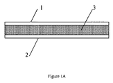
メタコンデンサー(metacapacitor)は、図1Aに示すように、第1電極1、第2電極2及び前記第1及び第2電極間に配置されたメタ誘電体(metadielectric)層3を備える。電極1及び2は、銅、亜鉛若しくはアルミニウムなどの金属又はグラファイト若しくはカーボンナノ材料などのその他の導電性材料から作製してよく、一般に平板な形状である。
As shown in FIG. 1A, a metacapacitor includes a
電極1、2は、平面的及び平板であって、互いに平行に位置してよい。あるいは、電極は、平板及び平行であってよいが、平面的である必要はなく、それらは、コイル状か、巻いているか、折れ曲がっているか、折りたたまれているか又はその他の形状であってよく、コンデンサーの全体的な波形率を減少させる。電極は、非平面的、非平板若しくは非平行又はこれらにおける2つ以上の幾つかの組合せもまた可能である。限定されないが例として、電極1及び2間の間隔は、約100nm〜約100μmの範囲であってよい。電極1及び2間の最大電圧Vbdは、およそ絶縁電界Ebd及び電極間隔dの積である。電極1及び2間のEbd=0.1V/nm及び間隔dが、100マイクロメートル(100,000nm)である場合、最大電圧Vbdは、10,000ボルトになる。
The
電極1及び2は、互いに同一形状、同一寸法及び同一面積Aを有していてよい。限定されないが例として、それぞれの電極1及び2の面積Aは、約0.01m2〜約1000m2の範囲であってよい。巻いているコンデンサーに関して、限定されないが例として、電極は、最大で、例えば、1000m長さ及び1m幅である。
The
これらの範囲は、限定されない。電極間隔d及び面積Aのその他の範囲は、本開示の態様の範囲内である。 These ranges are not limited. Other ranges of electrode spacing d and area A are within the scope of the embodiments of the present disclosure.
間隔dが、電極における特有の直線上の寸法(例えば、長さ及び/又は幅)と比較して小さい場合、コンデンサーの静電容量Cは、次式によって近似してよい。
![]()
![]()
![]()
![]()
エネルギーの蓄積容量Uは、誘電率ε、面積A及び絶縁電界Ebdによって決定される。適切な工学技術によって、コンデンサー又はコンデンサーバンクを任意の所望のエネルギー蓄積容量Uを有するように設計してよい。限定されないが例として、本開示の態様のコンデンサーについて、誘電率ε、電極面積A及び絶縁電界Ebdに関して上記に示す範囲は、約500ジュール〜約2・1016ジュールの範囲のエネルギー蓄積容量Uを有してよい。 The energy storage capacity U is determined by the dielectric constant ε, the area A and the insulating electric field E bd . The capacitor or capacitor bank may be designed to have any desired energy storage capacity U by appropriate engineering techniques. By way of non-limiting example, for the capacitors of the embodiments of the present disclosure, the ranges given above for dielectric constant ε, electrode area A and insulation field E bd range from about 500 joules to about 2 · 10 16 joules of energy storage capacity U You may have.
本明細書に記載される種類のコンデンサーは、実施する際にそれほど限定されないものの、例えば、約100〜約1,000,000の範囲の誘電率ε及び例えば、約0.1及び0.5V/nm間の定数である絶縁電界Ebdに対して、約10W・h/kg〜最大約100,000W・h/kgの範囲の、単位質量当たりの比エネルギー容量を有してよい。 Capacitors of the type described herein, for example, although not so limited in practice, have a dielectric constant ε in the range of, for example, about 100 to about 1,000,000 and, for example, about 0.1 and 0.5 V /. For insulating field E bd , which is a constant between nm, it may have a specific energy capacity per unit mass ranging from about 10 W · h / kg up to about 100,000 W · h / kg.
本開示は、例えば、図1Bに示すようなコイル状である、メタコンデンサー(metacapacitor)を含む。本実施例では、メタコンデンサー(metacapacitor)20は、第1電極21、第2電極22及び前記第1及び第2電極間に配置され、本明細書で上記される種類のメタ誘電体(metadielectric)材料層23を備える。電極21及び22は、銅、亜鉛若しくはアルミニウムなどの金属又はグラファイト若しくはカーボンナノ材料などのその他の導電性材料から作製してよく、一般に平板な形状である。一実施では、電極及びメタ誘電体(metadielectric)材料層23は、互いに挟まれた材料における長い帯状の形態であり、電極21及び22間の電気的短絡を防ぐために、絶縁材料、例えば、ポリプロピレン又はポリエステルなどのプラスチックフィルムに沿ってコイル状に巻き付けられる。
The present disclosure includes metacapacitors, for example, coiled as shown in FIG. 1B. In this embodiment, a
本発明が、より容易に理解され得るために、本発明の例示を意図しているが、範囲を限定することを意図していない次の実施例を参照する。
実施例1:本実施例は、次の構造の機構に従って本開示の有機化合物の合成を記載する。
Example 1: This example describes the synthesis of the organic compounds of the present disclosure according to the following structural scheme.
テリレン(Terrylene)無水物1(1当量)及び1−ブロモメタンアミン(1当量)を、イミダゾール中において130℃で一晩攪拌した。混合物をTHFに溶解させ、水で3回洗浄した。この有機物質を混ぜ合わせて、MgSO4上で乾燥した。溶媒を減圧下で除去し、2を得た。
テリレン(Terrylene)イミド2(1当量)を、THFに溶解させ、氷浴で攪拌した。THFに溶解した水素化リチウムアルミニウム(5当量)をゆっくりと添加した。混合物を周囲温度まで暖め、18時間攪拌した。混合物を2MNaOHでクエンチし、ろ過し、MgSO4上で乾燥し、溶媒を減圧下で除去し、3を得た。
テリレン(Terrylene)3(1当量)及びPd/C(20%wt/wt)を、H2バルーンを取り付けた三つ口フラスコ内のTHF中で18時間攪拌した。混合物を、セライトを通してろ過し、溶媒を減圧下で除去し、4を得た。
ブロモアミン4(1当量)、アントラセン5(1当量)、Pd(Ph)4(10mol%)、K2CO3(1.5当量)を、トルエン中において70℃で18時間攪拌した。混合物を、セライトを通してろ過し、ろ液をNaHCO3及びブラインで洗浄した。この有機物質をMgSO4上で乾燥し、溶媒を減圧下で除去し、6を得た。
ナフタレン無水物7(1当量)及びアントラセン6(1当量)を130℃にてイミダゾール中で一晩攪拌した。混合物をTHFに溶解させ、水で3回洗浄した。この有機物質を混ぜ合わせて、MgSO4上で乾燥した。溶媒を減圧下で除去し、8を得た。
アミジン8(1当量)及びPd/C(20%wt/wt)をH2バルーンを取り付けた三つ口フラスコ内のTHF中で18時間攪拌した。混合物を、セライトを通してろ過し、溶媒を減圧下で除去し、9を得た。
アミジン8(1当量)をTHF中に溶解させ、−80℃で攪拌した。N−ブチルリチウム(1.2当量、ヘキサン中2.5M)を滴加した。1時間後、トリイソプロピルボランを滴加し、室温まで一晩暖めた。混合物をNaHCO3及びブラインで洗浄し、MgSO4上で乾燥した。溶媒を減圧下で除去し、10を得た。
ブロモ−アミジン9(1当量)、アミジンボロン酸エステル10(1当量)、Pd(Ph)4(10mol%)、K2CO3(1.5当量)を、トルエン中において70℃で18時間攪拌した。混合物を、セライトを通してろ過し、ろ液をNaHCO3及びブラインで洗浄した。この有機物質をMgSO4上で乾燥し、溶媒を減圧下で除去し、11を得た。
1.48g(13mmol)のカリウムtert−ブトキシド、2.30g(15.1mmol)のジアザビシクロ[5.4.0]ウンデカ−7−エン(DBU)、2.2gで36.3mmol)のエタノールアミン及び1.0gの11の混合物を140℃まで11時間加熱した。その後、同一量のカリウムtert−ブトキシド、DBU及びエタノールアミンを添加し、混合物を140℃で18時間維持した。反応混合物を室温まで冷却し、250mlの1MHClに注ぎ、ろ過し、中性のpHまで洗浄し、次に乾燥し、最終生成物12を得た。
実施例2:本実施例は、次の構造の機構に従って本開示の有機化合物の合成を記載する。
Example 2 This example describes the synthesis of an organic compound of the present disclosure according to the mechanism of the following structure:
ブロモアミン4(1当量)、ナフタレン14(1当量)、Pd(Ph)4(10mol%)、K2CO3(1.5当量)をトルエン中において70℃で18時間攪拌した。混合物を、セライトを通してろ過し、ろ液をNaHCO3及びブラインで洗浄した。この有機物質をMgSO4上で乾燥し、溶媒を減圧下で除去し、15を得た。
ナフタレン無水物16(1当量)及びナフタレン15(1当量)をイミダゾール中において130℃で一晩攪拌した。混合物をTHFに溶解させ、水で3回洗浄した。この有機物質を混ぜ合わせて、MgSO4上で乾燥した。溶媒を減圧下で除去し、17を得た。
アミジン17(1当量)及びPd/C(20%wt/wt)をH2バルーンを取り付けた三つ口フラスコ内のTHF中で18時間攪拌した。混合物を、セライトを通してろ過し、溶媒を減圧下で除去し、18を得た。
アミジン17(1当量)をTHF中に溶解させ、−80℃で攪拌した。N−ブチルリチウム(1.2当量、ヘキサン中2.5M)を滴加した。1時間後、トリイソプロピルボランを滴加し、室温まで一晩暖めた。混合物をNaHCO3及びブラインで洗浄し、MgSO4上で乾燥した。溶媒を減圧下で除去し、19を得た。
ブロモ−アミジン18(1当量)、アミジンボロン酸エステル19(1当量)、Pd(Ph)4(10mol%)、K2CO3(1.5当量)をトルエン中において70℃で18時間攪拌した。混合物を、セライトを通してろ過し、ろ液をNaHCO3及びブラインで洗浄した。この有機物質をMgSO4上で乾燥し、溶媒を減圧下で除去し、20を得た。
1.48g(13mmol)のカリウムtert−ブトキシド、2.30g(15.1mmol)のジアザビシクロ[5.4.0]ウンデカ−7−エン(DBU)、2.2gで36.3mmol)のエタノールアミン及び1.0gの20の混合物を140℃まで11時間加熱した。その後、同一量のカリウムtert−ブトキシド、DBU及びエタノールアミンを添加し、混合物を140℃で18時間維持した。反応混合物を室温まで冷却し、250mlの1MHClに注ぎ、ろ過し、中性のpHまで洗浄し、次に乾燥し、最終生成物21を得た。 1.48 g (13 mmol) of potassium tert-butoxide, 2.30 g (15.1 mmol) of diazabicyclo [5.4.0] undec-7-ene (DBU), 2.2 g of 36.3 mmol) of ethanolamine and 1.0 g of the 20 mixture was heated to 140 ° C. for 11 hours. Thereafter, the same amounts of potassium tert-butoxide, DBU and ethanolamine were added and the mixture was maintained at 140 ° C. for 18 hours. The reaction mixture was cooled to room temperature, poured into 250 ml of 1 M HCl, filtered, washed to neutral pH and then dried to obtain final product 21.
本開示の態様は、高い非線形電気分極率によって特徴付けられる化合物を提供する。このような化合物は、非常に高い静電容量及び非常に高いエネルギー蓄積容量を有するメタコンデンサー(meta−capacitor)用の高い誘電率のメタ誘電体(metadielectric)として有用である。上記が、本発明における好ましい実施形態の完成した記載であるものの、様々な代替、修正及び均等物に使用することが可能である。したがって、本発明の範囲は、上記を参照することなく決定されるべきであるが、その代わりに、添付の特許請求の範囲とそれらの完全な範囲の等価物を参照して決定されるべきである。好ましいか又はそうでないかいずれにせよ、本明細書に記載される任意の特徴は、好ましいか又はそうでないかいずれにせよ、本明細書に記載される任意のその他の特徴と組み合わせてよい。以下の特許請求の範囲では、不定冠詞「A」又は「An」は、明示的に別段の指定がある場合を除いて、その冠詞に続く品目の1つ以上の量を意味する。本発明で使用する場合、代替要素として列挙されるときの用語「又は」は、明示的に別段の指定がある場合を除いて、論理的に包括する意味で使用され、例えば、「X又はY」は、Xのみ、Yのみ又はXとYの双方一緒を含む。代替として列挙される2つ以上の要素は、共に組み合わせてよい。添付の特許請求の範囲は、語句「〜する手段(means for)」を使用する所定の特許請求の範囲でこのような限定が明示されない限り、ミーンズ−プラス−ファンクションの限定を含むと解釈されるべきでない。 Aspects of the present disclosure provide compounds characterized by high non-linear electrical polarizability. Such compounds are useful as high dielectric constant metadielectrics for meta-capacitors with very high capacitance and very high energy storage capacity. While the above is a complete description of the preferred embodiments of the present invention, it is possible to use various alternatives, modifications and equivalents. Accordingly, the scope of the present invention should be determined without reference to the above, but instead should be determined with reference to the appended claims and their full scope of equivalents. is there. Either preferred or not, any of the features described herein may be combined with any other features described herein, which may be preferred or not. In the following claims, the indefinite article "A" or "An" means one or more quantities of the item following the article, unless expressly specified otherwise. When used in the present invention, the term "or" when listed as a substitute element is used in a logically inclusive sense, unless explicitly stated otherwise, eg, "X or Y" "Includes only X, only Y or both X and Y together. Two or more elements listed as alternatives may be combined together. The appended claims are to be construed as including means-plus-function limitations unless such limitation is explicitly stated in a given claim using the term "means for" I should not.
Claims (34)
式中、少なくとも1つの基R1及び/又はR1’を有する前記コア1を含有するNLEと印がつけられたフラグメントは、分極の非線形効果を有し、
式中、コア2は、導電性オリゴマーであり、nは、前記導電性オリゴマーの数であり、0、2又は4に等しく、R3は、前記電気導電性オリゴマー(コア2)に直接又は連結基を介して結合した、イオン性液体に使用されるある種類のイオン性化合物からの、1つ以上のイオン基を含む置換基であり、sは、前記イオン基R3の数であり、0、1、2、3又は4に等しく、
式中、R4は、溶媒中における有機化合物の溶解性をもたらし、前記カラム様超分子を互いに電気的に絶縁させ、前記芳香族多環式共役分子(コア1)及び/又は前記導電性オリゴマー(コア2)に直接又は連結基を介して結合した抵抗性置換基であり、kは、置換基R4の数であり、0、1、2、3、4、5、6、7又は8に等しい、電気分極性化合物。 An electrically polarizable compound having the following general formula (I):
In which the fragment marked NLE containing said core 1 having at least one group R1 and / or R1 'has the non-linear effect of polarization,
Wherein core 2 is a conductive oligomer, n is the number of said conductive oligomers, equal to 0, 2 or 4 and R 3 is directly or linked to said electrically conductive oligomer (core 2) A substituent comprising one or more ionic groups from one type of ionic compound used in the ionic liquid, bound via s, s is the number of said ionic groups R 3, 0, 1 , 2, 3 or 4 equal to
Wherein R 4 provides the solubility of the organic compound in the solvent, electrically insulating the column-like supramolecules from one another, the aromatic polycyclic conjugated molecule (core 1) and / or the conductive oligomer ( K is a number of substituents R 4 and is equal to 0, 1, 2, 3, 4, 5, 6, 7 or 8 being a resistive substituent directly or via a linking group attached to the core 2) , Electrically polarizable compounds.
Applications Claiming Priority (5)
| Application Number | Priority Date | Filing Date | Title |
|---|---|---|---|
| US15/090,509 US9978517B2 (en) | 2016-04-04 | 2016-04-04 | Electro-polarizable compound and capacitor |
| US15/090,509 | 2016-04-04 | ||
| US15/163,595 US10153087B2 (en) | 2016-04-04 | 2016-05-24 | Electro-polarizable compound and capacitor |
| US15/163,595 | 2016-05-24 | ||
| PCT/US2017/024600 WO2017176510A1 (en) | 2016-04-04 | 2017-03-28 | Electro-polarizable compound and capacitor |
Publications (2)
| Publication Number | Publication Date |
|---|---|
| JP2019513825A true JP2019513825A (en) | 2019-05-30 |
| JP2019513825A5 JP2019513825A5 (en) | 2020-05-07 |
Family
ID=59961137
Family Applications (1)
| Application Number | Title | Priority Date | Filing Date |
|---|---|---|---|
| JP2019503391A Pending JP2019513825A (en) | 2016-04-04 | 2017-03-28 | Electrically polarizable compounds and capacitors |
Country Status (8)
| Country | Link |
|---|---|
| US (2) | US10153087B2 (en) |
| EP (1) | EP3440059A4 (en) |
| JP (1) | JP2019513825A (en) |
| CN (1) | CN109641847A (en) |
| CA (1) | CA3019943A1 (en) |
| SG (1) | SG11201808688YA (en) |
| TW (1) | TW201806952A (en) |
| WO (1) | WO2017176510A1 (en) |
Cited By (1)
| Publication number | Priority date | Publication date | Assignee | Title |
|---|---|---|---|---|
| JP2019516780A (en) * | 2016-04-04 | 2019-06-20 | キャパシタ サイエンシス インコーポレイテッド | Electrically polarizable compounds and capacitors |
Families Citing this family (17)
| Publication number | Priority date | Publication date | Assignee | Title |
|---|---|---|---|---|
| US10319523B2 (en) | 2014-05-12 | 2019-06-11 | Capacitor Sciences Incorporated | Yanli dielectric materials and capacitor thereof |
| US10340082B2 (en) | 2015-05-12 | 2019-07-02 | Capacitor Sciences Incorporated | Capacitor and method of production thereof |
| US20170301477A1 (en) | 2016-04-04 | 2017-10-19 | Capacitor Sciences Incorporated | Electro-polarizable compound and capacitor |
| WO2015175558A2 (en) | 2014-05-12 | 2015-11-19 | Capacitor Sciences Incorporated | Energy storage device and method of production thereof |
| US10347423B2 (en) | 2014-05-12 | 2019-07-09 | Capacitor Sciences Incorporated | Solid multilayer structure as semiproduct for meta-capacitor |
| US9932358B2 (en) | 2015-05-21 | 2018-04-03 | Capacitor Science Incorporated | Energy storage molecular material, crystal dielectric layer and capacitor |
| US9941051B2 (en) | 2015-06-26 | 2018-04-10 | Capactor Sciences Incorporated | Coiled capacitor |
| US10600574B2 (en) | 2015-10-21 | 2020-03-24 | Capacitor Sciences Incorporated | Organic compound, crystal dielectric layer and capacitor |
| US10636575B2 (en) | 2016-02-12 | 2020-04-28 | Capacitor Sciences Incorporated | Furuta and para-Furuta polymer formulations and capacitors |
| US20170236648A1 (en) * | 2016-02-12 | 2017-08-17 | Capacitor Sciences Incorporated | Grid capacitive power storage system |
| US20170232853A1 (en) * | 2016-02-12 | 2017-08-17 | Capacitor Sciences Incorporated | Electric vehicle powered by capacitive energy storage modules |
| US10566138B2 (en) * | 2016-04-04 | 2020-02-18 | Capacitor Sciences Incorporated | Hein electro-polarizable compound and capacitor thereof |
| US10153087B2 (en) * | 2016-04-04 | 2018-12-11 | Capacitor Sciences Incorporated | Electro-polarizable compound and capacitor |
| US10395841B2 (en) | 2016-12-02 | 2019-08-27 | Capacitor Sciences Incorporated | Multilayered electrode and film energy storage device |
| US10163575B1 (en) * | 2017-11-07 | 2018-12-25 | Capacitor Sciences Incorporated | Non-linear capacitor and energy storage device comprising thereof |
| WO2019100026A1 (en) * | 2017-11-20 | 2019-05-23 | Capacitor Sciences Incorporated | Hein electro-polarizable compound and capacitor thereof |
| US10403435B2 (en) | 2017-12-15 | 2019-09-03 | Capacitor Sciences Incorporated | Edder compound and capacitor thereof |
Citations (9)
| Publication number | Priority date | Publication date | Assignee | Title |
|---|---|---|---|---|
| JPS5959686A (en) * | 1982-09-29 | 1984-04-05 | Mitsubishi Chem Ind Ltd | Bis(imidazopyridono)perylene compound and sensitized material for electrophotography having photosensitive layer containing it |
| JPH056016A (en) * | 1990-02-23 | 1993-01-14 | Eastman Kodak Co | Manufacture of coating composition containing photoconductive perylene pigment |
| JP2000100484A (en) * | 1998-09-24 | 2000-04-07 | Fuji Xerox Co Ltd | Light semiconductor electrode, photoelectric conversion device and photoelectric conversion method |
| WO2009008277A1 (en) * | 2007-07-11 | 2009-01-15 | Idemitsu Kosan Co., Ltd. | Material for organic electroluminescent element, and organic electroluminescent element |
| WO2009158553A2 (en) * | 2008-06-26 | 2009-12-30 | Carben Semicon Limited | Film and device using layer based on ribtan material |
| JP2010508677A (en) * | 2006-11-06 | 2010-03-18 | カーベン セミコン リミテッド | Anisotropic semiconductor film and manufacturing method thereof |
| US20110079773A1 (en) * | 2009-08-21 | 2011-04-07 | Wasielewski Michael R | Selectively Functionalized Rylene Imides and Diimides |
| WO2015024064A1 (en) * | 2013-08-23 | 2015-02-26 | Flurosol Industries Pty Ltd | Light harvesting array |
| JP2019516780A (en) * | 2016-04-04 | 2019-06-20 | キャパシタ サイエンシス インコーポレイテッド | Electrically polarizable compounds and capacitors |
Family Cites Families (202)
| Publication number | Priority date | Publication date | Assignee | Title |
|---|---|---|---|---|
| GB547853A (en) | 1941-03-12 | 1942-09-15 | Norman Hulton Haddock | New perylene derivatives |
| GB923148A (en) | 1960-03-24 | 1963-04-10 | Ici Ltd | New anthraquinone dyestuffs |
| US3407394A (en) | 1964-10-23 | 1968-10-22 | Xerox Corp | Selenium trapping memory |
| GB2084585B (en) | 1980-09-25 | 1983-11-30 | Dearborn Chemicals Ltd | The preparation of high molecular weight hydrophilic polymer gels |
| JPS60146405A (en) | 1983-12-30 | 1985-08-02 | 日石三菱株式会社 | Refined electrically insulating oil and oil-immersed electric device |
| DE3401338A1 (en) | 1984-01-17 | 1985-07-25 | Merck Patent Gmbh, 6100 Darmstadt | LIQUID CRYSTAL PHASE |
| US4694377A (en) | 1986-05-28 | 1987-09-15 | Aerovox Incorporated | Segmented capacitor |
| JPS6386731A (en) | 1986-09-30 | 1988-04-18 | Asahi Chem Ind Co Ltd | Production of poly-p-phenylene terephthalamide film |
| EP0268354A3 (en) | 1986-10-07 | 1988-06-15 | Imperial Chemical Industries Plc | Substituted pyrazoline |
| DE3904797A1 (en) | 1989-02-17 | 1990-08-30 | Merck Patent Gmbh | NONLINEAR OPTICAL MATERIALS WITH VICINAL DONOR AND ACCEPTANCE GROUPS |
| DE3926563A1 (en) | 1989-08-11 | 1991-02-14 | Hoechst Ag | PERYLENE COMPOUNDS CONTAINING SULPHONIC ACID, METHOD FOR THE PRODUCTION THEREOF AND THEIR USE |
| JP2786298B2 (en) | 1990-03-02 | 1998-08-13 | 株式会社日立製作所 | Film capacitor and method of manufacturing the same |
| US6294593B1 (en) | 1990-12-07 | 2001-09-25 | University Of Massachusetts Lowell | Method and crosslinkable polymers for forming crosslinked second order nonlinear optical polymers |
| US5395556A (en) | 1990-12-12 | 1995-03-07 | Enichem S.P.A. | Tricyanovinyl substitution process for NLO polymers |
| US5514799A (en) | 1993-08-02 | 1996-05-07 | Enichem S.P.A. | 1,1-vinyl substituted nonlinear optical materials |
| US5516785A (en) | 1991-03-01 | 1996-05-14 | University Of Florida Research Foundation, Incorporated | Use of nicotinic analogs for treatment of degenerative diseases of the nervous system |
| JP3362865B2 (en) | 1991-03-21 | 2003-01-07 | クラリアント・ゲゼルシヤフト・ミト・ベシユレンクテル・ハフツング | Internal salt of perylene compound, production method thereof and use thereof |
| JP2741804B2 (en) | 1991-06-14 | 1998-04-22 | 松下電器産業株式会社 | Capacitor and manufacturing method thereof |
| CA2074848C (en) | 1992-07-29 | 1998-02-10 | Joseph P. Ellul | Method of forming electrodes for trench capacitors |
| EP0585999A1 (en) | 1992-08-14 | 1994-03-09 | ENICHEM S.p.A. | Functional heteroaromatics for NLO applications |
| US5384521A (en) | 1992-09-25 | 1995-01-24 | Coe; Carlos J. | Power capacitor powertrain |
| US5312896A (en) | 1992-10-09 | 1994-05-17 | Sri International | Metal ion porphyrin-containing poly(imide) |
| US5597661A (en) | 1992-10-23 | 1997-01-28 | Showa Denko K.K. | Solid polymer electrolyte, battery and solid-state electric double layer capacitor using the same as well as processes for the manufacture thereof |
| EP0602654A1 (en) | 1992-12-18 | 1994-06-22 | ENICHEM S.p.A. | Efficient electron-donating groups for nonlinear optical applictions |
| FR2713387B1 (en) | 1993-11-30 | 1996-01-12 | Merlin Gerin | Power condenser. |
| US6501093B1 (en) | 1994-04-04 | 2002-12-31 | Alvin M. Marks | Quantum energy storage or retrieval device |
| US6025094A (en) | 1994-11-23 | 2000-02-15 | Polyplus Battery Company, Inc. | Protective coatings for negative electrodes |
| US5679763A (en) | 1995-02-24 | 1997-10-21 | Enichem S.P.A. | Polyquinoline-based nonlinear optical materials |
| US5583359A (en) | 1995-03-03 | 1996-12-10 | Northern Telecom Limited | Capacitor structure for an integrated circuit |
| EP0791849A1 (en) | 1996-02-26 | 1997-08-27 | ENICHEM S.p.A. | Non-linear optical compounds |
| JP3637163B2 (en) | 1996-10-01 | 2005-04-13 | 本田技研工業株式会社 | Energy storage power supply |
| US5742471A (en) | 1996-11-25 | 1998-04-21 | The Regents Of The University Of California | Nanostructure multilayer dielectric materials for capacitors and insulators |
| FR2760911B1 (en) | 1997-03-13 | 1999-05-07 | Renault | POWER SUPPLY DEVICE WITH ACCUMULATOR BATTERY AND SUPERCAPACITOR |
| US6555027B2 (en) | 1998-07-27 | 2003-04-29 | Pacific Wave Industries, Inc. | Second-order nonlinear optical chromophores containing dioxine and/or bithiophene as conjugate bridge and devices incorporating the same |
| JP4103975B2 (en) | 1998-09-10 | 2008-06-18 | 富士フイルム株式会社 | Electrolyte, photoelectrochemical cell, and method for forming electrolyte layer |
| DE10006839A1 (en) | 1999-02-17 | 2000-08-24 | Hitachi Maxell | Electrode used for capacitors in electric vehicles comprises a collector having a polarizable material layer consisting of activated charcoal, conducting auxiliary aid |
| US6426861B1 (en) | 1999-06-22 | 2002-07-30 | Lithium Power Technologies, Inc. | High energy density metallized film capacitors and methods of manufacture thereof |
| JP2001093778A (en) | 1999-09-20 | 2001-04-06 | Toray Ind Inc | Metalized film and capacitor using the same |
| US6426863B1 (en) | 1999-11-25 | 2002-07-30 | Lithium Power Technologies, Inc. | Electrochemical capacitor |
| US6341056B1 (en) | 2000-05-17 | 2002-01-22 | Lsi Logic Corporation | Capacitor with multiple-component dielectric and method of fabricating same |
| HUP0303085A2 (en) | 2000-09-27 | 2003-12-29 | The Procter & Gamble Co. | Melanocortin receptor ligands and pharmaceutical compositions containing them |
| BR0114544A (en) | 2000-10-10 | 2004-01-20 | American Electric Power Compan | Electric energy storage and distribution system, and method of storing and distributing electric energy |
| ES2270803T3 (en) | 2000-10-25 | 2007-04-16 | Maxwell Technologies, Inc. | ELECTRICAL ENERGY ACCUMULATION DEVICE CONSTITUTED BY SHRINK OF SUPERPOSED RIBBONS AND THE PROCEDURE FOR MANUFACTURING. |
| US6391104B1 (en) | 2000-12-01 | 2002-05-21 | Bayer Corporation | Perylene pigment compositions |
| US7033406B2 (en) | 2001-04-12 | 2006-04-25 | Eestor, Inc. | Electrical-energy-storage unit (EESU) utilizing ceramic and integrated-circuit technologies for replacement of electrochemical batteries |
| JP4633960B2 (en) | 2001-05-10 | 2011-02-16 | 日清紡ホールディングス株式会社 | Power storage system for automobiles |
| AU2002327747A1 (en) | 2001-09-27 | 2003-04-07 | 3M Innovative Properties Company | Substituted pentacene semiconductors |
| UA77459C2 (en) | 2001-11-03 | 2006-12-15 | Thin-film capacitor and a method for producing the capacitor | |
| US6765781B2 (en) | 2001-12-03 | 2004-07-20 | Tdk Corporation | Multilayer capacitor |
| RU2199450C1 (en) | 2002-01-08 | 2003-02-27 | Московский государственный авиационный институт (технический университет) | Power supply source of mobile object |
| EP1476885A1 (en) | 2002-01-24 | 2004-11-17 | Toray Plastics (America), Inc. | Polymer coated capacitor films |
| DE10203918A1 (en) | 2002-01-31 | 2003-08-21 | Bayerische Motoren Werke Ag | Electrical energy storage device for motor vehicle, especially for hybrid drive, has of capacitors with several individual capacitor cells of cylindrical or essentially rectangular section |
| US6519136B1 (en) | 2002-03-29 | 2003-02-11 | Intel Corporation | Hybrid dielectric material and hybrid dielectric capacitor |
| US7371336B2 (en) | 2002-09-24 | 2008-05-13 | E.I. Du Pont Nemours And Company | Water dispersible polyanilines made with polymeric acid colloids for electronics applications |
| DE10248722A1 (en) | 2002-10-18 | 2004-05-06 | Infineon Technologies Ag | Integrated circuit arrangement with capacitor and manufacturing process |
| EP1592029B1 (en) | 2003-02-07 | 2019-07-03 | Showa Denko K.K. | Production method for the capacitor |
| JP4734823B2 (en) | 2003-06-11 | 2011-07-27 | 富士通株式会社 | Film multilayer structure and actuator element, capacitive element, and filter element using the same |
| US7025900B2 (en) | 2003-06-25 | 2006-04-11 | Nitto Denko Corporation | Perylenetetracarboxylic acid dibenzimidazole sulfoderivatives containing oxo-groups in the perylene core which form part of a para-quinoid system of bonds, lyotropic liquid crystal systems and anisotropic films containing the same, and methods for making the same |
| JP4715079B2 (en) | 2003-06-26 | 2011-07-06 | パナソニック株式会社 | Vehicle power supply |
| US20050118083A1 (en) | 2003-09-05 | 2005-06-02 | Japan Storage Battery Co., Ltd. | Process for the production of lithium-containing material and non-aqueous electrolyte electrochemical cells using it |
| US7625497B2 (en) | 2003-11-21 | 2009-12-01 | Board Of Regents Of The Nevada System Of Higher Education On Behalf Of The University Of Nevada, Reno | Materials and methods for the preparation of anisotropically-ordered solids |
| US8110714B2 (en) | 2004-02-25 | 2012-02-07 | Asahi Kasei Corporation | Polyacene compound and organic semiconductor thin film |
| US7354532B2 (en) | 2004-04-13 | 2008-04-08 | E.I. Du Pont De Nemours And Company | Compositions of electrically conductive polymers and non-polymeric fluorinated organic acids |
| US8344142B2 (en) | 2004-06-14 | 2013-01-01 | Georgia Tech Research Corporation | Perylene charge-transport materials, methods of fabrication thereof, and methods of use thereof |
| US7466536B1 (en) | 2004-08-13 | 2008-12-16 | Eestor, Inc. | Utilization of poly(ethylene terephthalate) plastic and composition-modified barium titanate powders in a matrix that allows polarization and the use of integrated-circuit technologies for the production of lightweight ultrahigh electrical energy storage units (EESU) |
| US7211824B2 (en) | 2004-09-27 | 2007-05-01 | Nitto Denko Corporation | Organic semiconductor diode |
| JP2006147606A (en) | 2004-11-16 | 2006-06-08 | Nec Toppan Circuit Solutions Inc | Sheet-like capacitor and its manufacturing method |
| US7428137B2 (en) | 2004-12-03 | 2008-09-23 | Dowgiallo Jr Edward J | High performance capacitor with high dielectric constant material |
| US7342755B1 (en) | 2005-01-26 | 2008-03-11 | Horvat Branimir L | High energy capacitor and charging procedures |
| DE102005010162B4 (en) | 2005-03-02 | 2007-06-14 | Ormecon Gmbh | Conductive polymers of particles with anisotropic morphology |
| DE102005018172A1 (en) | 2005-04-19 | 2006-10-26 | Conti Temic Microelectronic Gmbh | power capacitor |
| JP3841814B1 (en) | 2005-04-28 | 2006-11-08 | 三井金属鉱業株式会社 | Capacitor layer forming material and method for manufacturing the capacitor layer forming material |
| DE102005021362A1 (en) | 2005-05-04 | 2006-11-09 | Basf Ag | Terrylene and Quaterrylene Derivatives |
| US7244999B2 (en) | 2005-07-01 | 2007-07-17 | Alps Electric Co., Ltd. | Capacitor applicable to a device requiring large capacitance |
| DE102005053995A1 (en) | 2005-11-10 | 2007-05-24 | Basf Ag | Use of rylene derivatives as photosensitizers in solar cells |
| JP4241714B2 (en) | 2005-11-17 | 2009-03-18 | パナソニック電工株式会社 | Battery pack for power tools |
| DE102005055075A1 (en) | 2005-11-18 | 2007-05-24 | Bayerische Motoren Werke Ag | Motor vehicle with a capacitor device for storing electrical energy |
| US20090030152A1 (en) | 2005-12-28 | 2009-01-29 | Qiming Zhang | High Electric Energy Density Polymer Capacitors With Fast Discharge Speed and High Efficiency Based On Unique Poly (Vinylidene Fluoride) Copolymers and Terpolymers as Dielectric Materials |
| US7460352B2 (en) | 2006-01-09 | 2008-12-02 | Faradox Energy Storage, Inc. | Flexible dielectric film and method for making |
| US20070181973A1 (en) | 2006-02-06 | 2007-08-09 | Cheng-Chou Hung | Capacitor structure |
| JP2007287829A (en) | 2006-04-14 | 2007-11-01 | Matsushita Electric Ind Co Ltd | Metallized film capacitor |
| JP4501893B2 (en) | 2006-04-24 | 2010-07-14 | トヨタ自動車株式会社 | Power supply system and vehicle |
| ATE520158T1 (en) * | 2006-05-04 | 2011-08-15 | Basf Se | METHOD FOR PRODUCING ORGANIC FIELD EFFECT TRANSISTORS |
| US20080002329A1 (en) | 2006-07-02 | 2008-01-03 | Pohm Arthur V | High Dielectric, Non-Linear Capacitor |
| US7990679B2 (en) | 2006-07-14 | 2011-08-02 | Dais Analytic Corporation | Nanoparticle ultracapacitor |
| GB0616358D0 (en) | 2006-08-16 | 2006-09-27 | Crysoptix Ltd | Anisotropic polymer film and method of production thereof |
| GB0618955D0 (en) | 2006-09-26 | 2006-11-08 | Cryscade Solar Ltd | Organic compound and organic photovoltaic device |
| US7994657B2 (en) | 2006-12-22 | 2011-08-09 | Solarbridge Technologies, Inc. | Modular system for unattended energy generation and storage |
| JP2010515684A (en) | 2007-01-08 | 2010-05-13 | ポリエラ コーポレイション | Method for preparing arene-bis (dicarboximide) based semiconductor materials and related intermediates for preparing the same |
| FR2912265B1 (en) | 2007-02-06 | 2009-04-24 | Batscap Sa | BATTERY WITH SERIES CELL MODULES, AND VEHICLE EQUIPPED WITH SAME |
| WO2009005555A2 (en) | 2007-04-11 | 2009-01-08 | The Penn State Research Foundation | Methods to improve the efficiency and reduce the energy losses in high energy density capacitor films and articles comprising the same |
| US7804678B2 (en) | 2007-04-25 | 2010-09-28 | Industrial Technology Research Institute | Capacitor devices |
| JP4825167B2 (en) | 2007-05-11 | 2011-11-30 | 株式会社リコー | Electrophotographic photosensitive member, image forming apparatus, and process cartridge |
| US7745821B2 (en) | 2007-05-15 | 2010-06-29 | Eastman Kodak Company | Aryl dicarboxylic acid diimidazole-based compounds as n-type semiconductor materials for thin film transistors |
| WO2009034971A1 (en) | 2007-09-12 | 2009-03-19 | Fujifilm Corporation | Process for production of desubstituted compounds, organic semiconductor film and process for production of the film |
| JP5670736B2 (en) | 2007-11-12 | 2015-02-18 | コートザイム アンパーツゼルスカブ | Antifouling composition comprising airgel |
| EP2062944A1 (en) | 2007-11-20 | 2009-05-27 | Max-Planck-Gesellschaft zur Förderung der Wissenschaften e.V. | Water-soluble rylene dyes, methods for preparing the same and uses thereof as fluorescent labels for biomolecules |
| DE102008061452A1 (en) | 2007-12-12 | 2010-07-08 | Langhals, Heinz, Prof. Dr. | Imidazoloperylenbisimide |
| FR2925790B1 (en) | 2007-12-19 | 2010-01-15 | Sagem Defense Securite | ALTERNATIVE / CONTINUOUS CONVERTER WITH GALVANIC INSULATION |
| EP2240970B1 (en) | 2008-02-05 | 2018-03-14 | Basf Se | Perylene semiconductors and methods of preparation and use thereof |
| GB0802912D0 (en) | 2008-02-15 | 2008-03-26 | Carben Semicon Ltd | Thin-film transistor, carbon-based layer and method of production thereof |
| EP2108673A1 (en) | 2008-04-11 | 2009-10-14 | DuPont Teijin Films U.S. Limited Partnership | Plastic film having a high breakdown voltage |
| WO2009144205A1 (en) | 2008-05-30 | 2009-12-03 | Basf Se | Rylene-based semiconductor materials and methods of preparation and use thereof |
| US8512824B2 (en) | 2008-08-19 | 2013-08-20 | Crysoptix Kk | Composition of organic compounds, optical film and method of production thereof |
| JP4868183B2 (en) | 2008-09-30 | 2012-02-01 | 日産化学工業株式会社 | Novel fluorinated tetracarboxylic dianhydride, polyimide precursor obtained therefrom, polyimide and its use |
| US8611068B2 (en) | 2008-10-16 | 2013-12-17 | Case Western Reserve University | Multilayer polymer dialectric film having a charge-delocalizing interface |
| JP5024454B2 (en) | 2008-10-31 | 2012-09-12 | トヨタ自動車株式会社 | Electric vehicle power supply system and control method thereof |
| US20100157527A1 (en) | 2008-12-23 | 2010-06-24 | Ise Corporation | High-Power Ultracapacitor Energy Storage Pack and Method of Use |
| JP2010160989A (en) | 2009-01-09 | 2010-07-22 | Toyo Ink Mfg Co Ltd | Method of manufacturing conductive film |
| AU2010204926A1 (en) | 2009-01-16 | 2011-07-14 | The Board Of Trustees Of The Leland Stanford Junior University | Quantum dot ultracapacitor and electron battery |
| KR20100096625A (en) | 2009-02-25 | 2010-09-02 | 삼성전기주식회사 | Capacitor and method of manufacturing the same |
| US20120012919A1 (en) | 2009-03-27 | 2012-01-19 | Cornell University | Nonvolatile flash memory structures including fullerene molecules and methods for manufacturing the same |
| TWI471424B (en) | 2009-03-30 | 2015-02-01 | Mitsubishi Materials Corp | Method for manufacturing aluminum porous sintered body and aluminum porous sintered body |
| KR101662863B1 (en) | 2009-03-31 | 2016-10-07 | 히다찌 겐끼 가부시키가이샤 | Construction machine and industrial vehicle provided with power supply system |
| WO2010114600A1 (en) | 2009-04-01 | 2010-10-07 | The Board Of Trustees Of The Leland Stanford Junior University | All-electron battery having area-enhanced electrodes |
| US7989919B2 (en) | 2009-06-03 | 2011-08-02 | Infineon Technologies Ag | Capacitor arrangement and method for making same |
| WO2010145230A1 (en) | 2009-06-15 | 2010-12-23 | Hak Hon Chau | Fault tolerant modular battery management system |
| US7911029B2 (en) | 2009-07-11 | 2011-03-22 | Ji Cui | Multilayer electronic devices for imbedded capacitor |
| JP2011029442A (en) | 2009-07-27 | 2011-02-10 | Daikin Industries Ltd | Film for film capacitor, film capacitor using the same and method of manufacturing the film and the film capacitor |
| WO2011056903A1 (en) | 2009-11-03 | 2011-05-12 | Henry Tran | Compositions and methods for generating conductive films and coatings of oligomers |
| CN101786864B (en) | 2009-12-22 | 2012-12-05 | 广东风华高新科技股份有限公司 | Ceramic dielectric material matched with nickel inner electrode and production method of capacitor produced by ceramic dielectric material |
| EP2519582A2 (en) | 2009-12-28 | 2012-11-07 | Akzo Nobel Chemicals International B.V. | Functionalized polyvinyl alcohol films |
| US20110228442A1 (en) | 2010-03-16 | 2011-09-22 | Strategic Polymer Sciences, Inc. | Capacitor having high temperature stability, high dielectric constant, low dielectric loss, and low leakage current |
| DE102010012949A1 (en) | 2010-03-26 | 2011-09-29 | Siemens Aktiengesellschaft | Capacitor module, has control unit for controlling temperature of cells, where control unit includes phase change material, which is in contact with cells to absorb heat delivered by cells and located on surface of cooling body |
| US20110269966A1 (en) | 2010-04-30 | 2011-11-03 | Deepak Shukla | Semiconducting articles |
| KR20110122051A (en) | 2010-05-03 | 2011-11-09 | 제일모직주식회사 | Compound for organic photoelectric device and organic photoelectric device including the same |
| US20120008251A1 (en) | 2010-07-12 | 2012-01-12 | Wei-Ching Yu | Film capacitors comprising melt-stretched films as dielectrics |
| WO2012012672A2 (en) | 2010-07-21 | 2012-01-26 | Cleanvolt Energy, Inc. | Use of organic and organometallic high dielectric constant material for improved energy storage devices and associated methods |
| US8929054B2 (en) | 2010-07-21 | 2015-01-06 | Cleanvolt Energy, Inc. | Use of organic and organometallic high dielectric constant material for improved energy storage devices and associated methods |
| JP5562169B2 (en) | 2010-08-09 | 2014-07-30 | 小島プレス工業株式会社 | Multilayer film capacitor and manufacturing method thereof |
| JP5257708B2 (en) | 2010-08-25 | 2013-08-07 | 株式会社豊田中央研究所 | Nanocomposite and dispersion containing the same |
| CN103124549B (en) | 2010-08-27 | 2017-07-14 | 塞安纳生物制药公司 | Composition and method for targetting thermal conditioning |
| US9572880B2 (en) | 2010-08-27 | 2017-02-21 | Sienna Biopharmaceuticals, Inc. | Ultrasound delivery of nanoparticles |
| US20120056600A1 (en) | 2010-09-03 | 2012-03-08 | Nevin Donald M | Capacitor vehicle having high speed charging ability and method of operating a capacitor vehicle |
| EP2638126B1 (en) | 2010-11-09 | 2015-02-18 | Crysoptix K.K. | Negative dispersion retardation plate and achromatic circular polarizer |
| CN102545317B (en) | 2010-12-20 | 2015-08-05 | 株式会社电装 | The system risen for causing battery temperature |
| DE102010063718A1 (en) | 2010-12-21 | 2012-06-21 | Siemens Aktiengesellschaft | Dielectric layer for an electrical component, dielectric component with a dielectric layer and method for producing a dielectric component with a dielectric layer |
| WO2012122312A1 (en) | 2011-03-10 | 2012-09-13 | Cryscade Solar Limited | Organic compound and photovoltaic device comprising the same |
| US9457496B2 (en) | 2011-03-23 | 2016-10-04 | Akron Polymer Systems, Inc. | Aromatic polyamide films for transparent flexible substrates |
| WO2012142460A1 (en) | 2011-04-15 | 2012-10-18 | Georgia Tech Research Corporation | Naphthalene-diimide-heterocycle-naphthalene diimide oligomers as organic semiconductors and transistors therefrom |
| US8922063B2 (en) | 2011-04-27 | 2014-12-30 | Green Charge Networks, Llc | Circuit for rendering energy storage devices parallelable |
| DE102011101304A1 (en) | 2011-05-12 | 2012-11-15 | Hans-Josef Sterzel | High energy density exhibiting electrical energy storage unit i.e. capacitor, for use in electrical vehicle, has electrodes separated from each other by semiconductor layers exhibiting type of conductivity different from that of electrodes |
| BR112013030106B1 (en) | 2011-05-24 | 2022-02-22 | Fastcap Systems Corporation | Power system adapted to supply power in a high temperature environment |
| WO2013005468A1 (en) | 2011-07-05 | 2013-01-10 | 株式会社村田製作所 | Dielectric thin film, dielectric thin film element, and thin film capacitor |
| WO2013009772A1 (en) | 2011-07-11 | 2013-01-17 | Quantumscape Corporation | Solid state energy storage devices |
| MX344931B (en) | 2011-09-09 | 2017-01-11 | Sz Dji Technology Co Ltd | Dual-axis ball head for use in small unmanned aerial vehicle and triple-axis ball head for use in small unmanned aerial vehicle. |
| WO2013033954A1 (en) | 2011-09-09 | 2013-03-14 | 深圳市大疆创新科技有限公司 | Gyroscopic dynamic auto-balancing ball head |
| SG10201604526UA (en) | 2011-12-09 | 2016-07-28 | Univ Nanyang Tech | Graft Copolymers Of A Poly(Vinylidene Fluoride)-Based Polymer And At Least One Type Of Electrically Conductive Polymer, And Methods For Forming The Graft Copolymers |
| US9508488B2 (en) | 2012-01-10 | 2016-11-29 | Samsung Electronics Co., Ltd. | Resonant apparatus for wireless power transfer |
| WO2013110273A1 (en) | 2012-01-27 | 2013-08-01 | Kk-Electronic A/S | Control system for power stacks in a power converter, power converter with such control system and wind turbine with such power converter |
| US9087645B2 (en) | 2012-01-30 | 2015-07-21 | QuantrumScape Corporation | Solid state energy storage devices |
| FR2987180B1 (en) | 2012-02-16 | 2014-12-05 | Alstom Transport Sa | ENERGY STORAGE CHAIN FOR VEHICLE, COMPRISING AT LEAST ONE MODULE OF SUPERCONDENSATORS, ENERGY STORAGE SYSTEM COMPRISING SUCH A CHAIN AND RAILWAY VEHICLE COMPRISING SUCH A SYSTEM |
| US20130224473A1 (en) | 2012-02-23 | 2013-08-29 | Research Foundation Of The City University Of New York | Prevention of hydrophobic dewetting through nanoparticle surface treatment |
| JP2013247206A (en) | 2012-05-25 | 2013-12-09 | Kojima Press Industry Co Ltd | Film capacitor element and film capacitor and manufacturing method of film capacitor |
| US20130334657A1 (en) | 2012-06-15 | 2013-12-19 | Taiwan Semiconductor Manufacturing Co., Ltd. | Planar interdigitated capacitor structures and methods of forming the same |
| TWI450907B (en) | 2012-06-26 | 2014-09-01 | Far Eastern New Century Corp | Method for the preparation of conductive polymer dispersion, conductive polymer material made therefrom and solid electrolytic capacitor using the material |
| GB201212487D0 (en) | 2012-07-13 | 2012-08-29 | Secr Defence | A device for measuring the hydration level of humans |
| RU2512880C2 (en) | 2012-08-16 | 2014-04-10 | Общество с ограниченной ответственностью "Системы Постоянного Тока" | Electric energy accumulation system based on accumulator batteries and supercapacitor with network enhancement function |
| DE102012016438A1 (en) | 2012-08-18 | 2014-02-20 | Audi Ag | Energy storage arrangement for motor vehicle, has rechargeable energy storage device with lithium-based storage element, and another rechargeable energy storage device in form of double layer capacitor |
| CN203118781U (en) | 2012-08-21 | 2013-08-07 | 深圳圣融达科技有限公司 | Multilayer composite dielectric film capacitor |
| TWI588188B (en) | 2012-10-09 | 2017-06-21 | 沙烏地基礎工業公司 | Graphene-based composite materials, method of manufacture and applications thereof |
| CN104937685A (en) | 2012-11-21 | 2015-09-23 | 3M创新有限公司 | Multilayer film including first and second dielectric layers |
| US20140158340A1 (en) | 2012-12-11 | 2014-06-12 | Caterpillar Inc. | Active and passive cooling for an energy storage module |
| JP2014139296A (en) | 2012-12-21 | 2014-07-31 | Toray Ind Inc | Aromatic polyamide, aromatic polyamide film and laminate |
| US9928966B2 (en) | 2012-12-28 | 2018-03-27 | Intel Corporation | Nanostructured electrolytic energy storage devices |
| US20160001662A1 (en) | 2013-02-25 | 2016-01-07 | Ut-Battelle, Llc | Buffering energy storage systems for reduced grid and vehicle battery stress for in-motion wireless power transfer systems |
| TWI478185B (en) | 2013-03-12 | 2015-03-21 | Univ Nat Taiwan | Super capacitor and method for manufacturing the same |
| US8818601B1 (en) | 2013-03-14 | 2014-08-26 | GM Global Technology Operations LLC | Extended-range electric vehicle with supercapacitor range extender |
| CN105283926B (en) | 2013-03-15 | 2019-05-10 | 克林伏特能源有限公司 | Utilize the electrode and electric current and its improved method in organic and organic metal high dielectric constant material improvement energy storage device |
| CN103258656B (en) | 2013-04-25 | 2015-08-19 | 华中科技大学 | Preparation method of a kind of electrode of super capacitor based on nickel foam and products thereof |
| EP2821640B1 (en) | 2013-07-05 | 2016-12-21 | Alstom Renovables España, S.L. | Pitch drive system with a switching device controlled back-up power supply and method thereof |
| JP5867459B2 (en) | 2013-07-08 | 2016-02-24 | トヨタ自動車株式会社 | Power system |
| ES2703147T3 (en) | 2013-07-09 | 2019-03-07 | Evonik Degussa Gmbh | Electroactive polymers, method of manufacturing them, electrode and use thereof |
| CN203377785U (en) | 2013-07-15 | 2014-01-01 | 深圳桑达国际电源科技有限公司 | Charging and discharging type DC-DC conversion circuit and new energy power generation system |
| US9592744B2 (en) | 2013-12-06 | 2017-03-14 | SZ DJI Technology Co., Ltd | Battery and unmanned aerial vehicle with the battery |
| CN103755703B (en) | 2013-12-24 | 2016-05-18 | 北京化工大学 | A kind of synthetic and application of difunctional water-soluble perylene diimide derivatives |
| CN103986224A (en) | 2014-03-14 | 2014-08-13 | 北京工业大学 | Wind, solar and electricity complementary type portable power source |
| US10319523B2 (en) | 2014-05-12 | 2019-06-11 | Capacitor Sciences Incorporated | Yanli dielectric materials and capacitor thereof |
| US10340082B2 (en) | 2015-05-12 | 2019-07-02 | Capacitor Sciences Incorporated | Capacitor and method of production thereof |
| WO2015175558A2 (en) | 2014-05-12 | 2015-11-19 | Capacitor Sciences Incorporated | Energy storage device and method of production thereof |
| WO2015175522A1 (en) | 2014-05-12 | 2015-11-19 | Capacitor Sciences Incorporated | Capacitor and method of production thereof |
| CN105517664B (en) | 2014-05-30 | 2018-11-20 | 深圳市大疆创新科技有限公司 | Unmanned vehicle docking system and method |
| WO2016073522A1 (en) | 2014-11-04 | 2016-05-12 | Capacitor Sciences Incorporated | Energy storage devices and methods of production thereof |
| SG11201706689QA (en) | 2015-02-26 | 2017-09-28 | Capacitor Sciences Inc | Self-healing capacitor and methods of production thereof |
| US9932358B2 (en) | 2015-05-21 | 2018-04-03 | Capacitor Science Incorporated | Energy storage molecular material, crystal dielectric layer and capacitor |
| US20180137984A1 (en) | 2015-05-21 | 2018-05-17 | Capacitor Sciences Incorporated | Solid state energy storage device |
| US9941051B2 (en) | 2015-06-26 | 2018-04-10 | Capactor Sciences Incorporated | Coiled capacitor |
| US10026553B2 (en) | 2015-10-21 | 2018-07-17 | Capacitor Sciences Incorporated | Organic compound, crystal dielectric layer and capacitor |
| US10460873B2 (en) | 2015-11-09 | 2019-10-29 | Facebook Technologies, Llc | Enhancing dielectric constants of elastomer sheets |
| US10305295B2 (en) | 2016-02-12 | 2019-05-28 | Capacitor Sciences Incorporated | Energy storage cell, capacitive energy storage module, and capacitive energy storage system |
| US20170233528A1 (en) | 2016-02-12 | 2017-08-17 | Capacitor Sciences Incorporated | Sharp polymer and capacitor |
| US20170237274A1 (en) | 2016-02-12 | 2017-08-17 | Capacitor Sciences Incorporated | Grid capacitive power storage system |
| US20180126857A1 (en) | 2016-02-12 | 2018-05-10 | Capacitor Sciences Incorporated | Electric vehicle powered by capacitive energy storage modules |
| US10636575B2 (en) | 2016-02-12 | 2020-04-28 | Capacitor Sciences Incorporated | Furuta and para-Furuta polymer formulations and capacitors |
| US20170236641A1 (en) | 2016-02-12 | 2017-08-17 | Capacitor Sciences Incorporated | Furuta co-polymer and capacitor |
| US20170232853A1 (en) | 2016-02-12 | 2017-08-17 | Capacitor Sciences Incorporated | Electric vehicle powered by capacitive energy storage modules |
| US20170236648A1 (en) | 2016-02-12 | 2017-08-17 | Capacitor Sciences Incorporated | Grid capacitive power storage system |
| US20170236642A1 (en) | 2016-02-12 | 2017-08-17 | Capacitor Sciences Incorporated | para-FURUTA POLYMER AND CAPACITOR |
| US20180122143A1 (en) | 2016-03-15 | 2018-05-03 | Sutherland Cook Ellwood, JR. | Hybrid photonic vr/ar systems |
| US10566138B2 (en) | 2016-04-04 | 2020-02-18 | Capacitor Sciences Incorporated | Hein electro-polarizable compound and capacitor thereof |
| US10153087B2 (en) | 2016-04-04 | 2018-12-11 | Capacitor Sciences Incorporated | Electro-polarizable compound and capacitor |
| US10395841B2 (en) | 2016-12-02 | 2019-08-27 | Capacitor Sciences Incorporated | Multilayered electrode and film energy storage device |
-
2016
- 2016-05-24 US US15/163,595 patent/US10153087B2/en active Active
-
2017
- 2017-03-28 JP JP2019503391A patent/JP2019513825A/en active Pending
- 2017-03-28 CN CN201780034420.3A patent/CN109641847A/en active Pending
- 2017-03-28 EP EP17779545.7A patent/EP3440059A4/en not_active Withdrawn
- 2017-03-28 CA CA3019943A patent/CA3019943A1/en not_active Abandoned
- 2017-03-28 SG SG11201808688YA patent/SG11201808688YA/en unknown
- 2017-03-28 WO PCT/US2017/024600 patent/WO2017176510A1/en active Application Filing
- 2017-03-30 TW TW106110889A patent/TW201806952A/en unknown
-
2018
- 2018-12-04 US US16/208,953 patent/US10672560B2/en active Active
Patent Citations (10)
| Publication number | Priority date | Publication date | Assignee | Title |
|---|---|---|---|---|
| JPS5959686A (en) * | 1982-09-29 | 1984-04-05 | Mitsubishi Chem Ind Ltd | Bis(imidazopyridono)perylene compound and sensitized material for electrophotography having photosensitive layer containing it |
| JPH056016A (en) * | 1990-02-23 | 1993-01-14 | Eastman Kodak Co | Manufacture of coating composition containing photoconductive perylene pigment |
| JP2000100484A (en) * | 1998-09-24 | 2000-04-07 | Fuji Xerox Co Ltd | Light semiconductor electrode, photoelectric conversion device and photoelectric conversion method |
| JP2010508677A (en) * | 2006-11-06 | 2010-03-18 | カーベン セミコン リミテッド | Anisotropic semiconductor film and manufacturing method thereof |
| WO2009008277A1 (en) * | 2007-07-11 | 2009-01-15 | Idemitsu Kosan Co., Ltd. | Material for organic electroluminescent element, and organic electroluminescent element |
| WO2009158553A2 (en) * | 2008-06-26 | 2009-12-30 | Carben Semicon Limited | Film and device using layer based on ribtan material |
| US20100173134A1 (en) * | 2008-06-26 | 2010-07-08 | Carben Semicon Limited | Film and Device Using Layer Based on Ribtan Material |
| US20110079773A1 (en) * | 2009-08-21 | 2011-04-07 | Wasielewski Michael R | Selectively Functionalized Rylene Imides and Diimides |
| WO2015024064A1 (en) * | 2013-08-23 | 2015-02-26 | Flurosol Industries Pty Ltd | Light harvesting array |
| JP2019516780A (en) * | 2016-04-04 | 2019-06-20 | キャパシタ サイエンシス インコーポレイテッド | Electrically polarizable compounds and capacitors |
Non-Patent Citations (3)
| Title |
|---|
| "Method for fabricating arrays of graphene nanoribbons", MRS ONLINE PROCEEDINGS LIBRARY, vol. 1362, JPN6021006229, 2011, ISSN: 0004451920 * |
| TSAI, HSING-YANG 他: "Synthesis and optical properties of novel asymmetric perylene bisimides", JOURNAL OF LUMINESCENCE, vol. 149, JPN6021006231, 2014, pages 103 - 111, XP028624073, ISSN: 0004451918, DOI: 10.1016/j.jlumin.2014.01.031 * |
| ZHAO, ZHENBO 他: "Regioselective Photocyclization To Prepare Multifunctional Blocks for Ladder-Conjugated Materials", JOURNAL OF ORGANIC CHEMISTRY, vol. 78(11), JPN6021006233, 2013, pages 5544 - 5549, ISSN: 0004451919 * |
Cited By (1)
| Publication number | Priority date | Publication date | Assignee | Title |
|---|---|---|---|---|
| JP2019516780A (en) * | 2016-04-04 | 2019-06-20 | キャパシタ サイエンシス インコーポレイテッド | Electrically polarizable compounds and capacitors |
Also Published As
| Publication number | Publication date |
|---|---|
| US10153087B2 (en) | 2018-12-11 |
| US10672560B2 (en) | 2020-06-02 |
| CA3019943A1 (en) | 2017-10-12 |
| US20190108944A1 (en) | 2019-04-11 |
| SG11201808688YA (en) | 2018-11-29 |
| EP3440059A4 (en) | 2020-01-08 |
| US20170287638A1 (en) | 2017-10-05 |
| EP3440059A1 (en) | 2019-02-13 |
| TW201806952A (en) | 2018-03-01 |
| CN109641847A (en) | 2019-04-16 |
| WO2017176510A1 (en) | 2017-10-12 |
Similar Documents
| Publication | Publication Date | Title |
|---|---|---|
| JP2019513825A (en) | Electrically polarizable compounds and capacitors | |
| US10566138B2 (en) | Hein electro-polarizable compound and capacitor thereof | |
| US20200343045A1 (en) | Yanli dielectric materials and capacitor thereof | |
| US20180137984A1 (en) | Solid state energy storage device | |
| CN106575573B (en) | Energy storage device and its manufacturing method | |
| JP2019516780A (en) | Electrically polarizable compounds and capacitors | |
| TWI637005B (en) | Sharp polymer and capacitor | |
| JP2019501870A (en) | Organic compounds, crystalline dielectric layers and capacitors | |
| AU2016264757A1 (en) | Energy storage molecular material, crystal dielectric layer and capacitor | |
| US10872733B2 (en) | YanLi material and dielectric and capacitor thereof | |
| Han et al. | Precisely controlled two-dimensional rhombic copolymer micelles for sensitive flexible tunneling devices | |
| US20170283618A1 (en) | Non-linear dielectric materials and capacitor | |
| KR20200123084A (en) | HEIN electro-polarizable compounds and capacitors thereof | |
| Phillipson | Functionalization of Graphene with Physisorbed Self-assembled Networks for Electronic Applications | |
| Mourokh et al. | Nonlinear Organic Dielectrics for Energy Storage Applications | |
| Manaka et al. | Electrical properties of polythylene Langmuir-Blodgett films: preparation and electrical breakdown |
Legal Events
| Date | Code | Title | Description |
|---|---|---|---|
| A521 | Request for written amendment filed |
Free format text: JAPANESE INTERMEDIATE CODE: A523 Effective date: 20200326 |
|
| A621 | Written request for application examination |
Free format text: JAPANESE INTERMEDIATE CODE: A621 Effective date: 20200326 |
|
| A977 | Report on retrieval |
Free format text: JAPANESE INTERMEDIATE CODE: A971007 Effective date: 20210210 |
|
| A131 | Notification of reasons for refusal |
Free format text: JAPANESE INTERMEDIATE CODE: A131 Effective date: 20210302 |
|
| A601 | Written request for extension of time |
Free format text: JAPANESE INTERMEDIATE CODE: A601 Effective date: 20210602 |
|
| A02 | Decision of refusal |
Free format text: JAPANESE INTERMEDIATE CODE: A02 Effective date: 20211026 |