US8818601B1 - Extended-range electric vehicle with supercapacitor range extender - Google Patents
Extended-range electric vehicle with supercapacitor range extender Download PDFInfo
- Publication number
- US8818601B1 US8818601B1 US13/803,000 US201313803000A US8818601B1 US 8818601 B1 US8818601 B1 US 8818601B1 US 201313803000 A US201313803000 A US 201313803000A US 8818601 B1 US8818601 B1 US 8818601B1
- Authority
- US
- United States
- Prior art keywords
- battery pack
- engine
- powertrain
- clutches
- neutral
- Prior art date
- Legal status (The legal status is an assumption and is not a legal conclusion. Google has not performed a legal analysis and makes no representation as to the accuracy of the status listed.)
- Expired - Fee Related
Links
Images


Classifications
-
- B60L11/1879—
-
- B—PERFORMING OPERATIONS; TRANSPORTING
- B60—VEHICLES IN GENERAL
- B60K—ARRANGEMENT OR MOUNTING OF PROPULSION UNITS OR OF TRANSMISSIONS IN VEHICLES; ARRANGEMENT OR MOUNTING OF PLURAL DIVERSE PRIME-MOVERS IN VEHICLES; AUXILIARY DRIVES FOR VEHICLES; INSTRUMENTATION OR DASHBOARDS FOR VEHICLES; ARRANGEMENTS IN CONNECTION WITH COOLING, AIR INTAKE, GAS EXHAUST OR FUEL SUPPLY OF PROPULSION UNITS IN VEHICLES
- B60K6/00—Arrangement or mounting of plural diverse prime-movers for mutual or common propulsion, e.g. hybrid propulsion systems comprising electric motors and internal combustion engines ; Control systems therefor, i.e. systems controlling two or more prime movers, or controlling one of these prime movers and any of the transmission, drive or drive units
- B60K6/20—Arrangement or mounting of plural diverse prime-movers for mutual or common propulsion, e.g. hybrid propulsion systems comprising electric motors and internal combustion engines ; Control systems therefor, i.e. systems controlling two or more prime movers, or controlling one of these prime movers and any of the transmission, drive or drive units the prime-movers consisting of electric motors and internal combustion engines, e.g. HEVs
- B60K6/22—Arrangement or mounting of plural diverse prime-movers for mutual or common propulsion, e.g. hybrid propulsion systems comprising electric motors and internal combustion engines ; Control systems therefor, i.e. systems controlling two or more prime movers, or controlling one of these prime movers and any of the transmission, drive or drive units the prime-movers consisting of electric motors and internal combustion engines, e.g. HEVs characterised by apparatus, components or means specially adapted for HEVs
- B60K6/28—Arrangement or mounting of plural diverse prime-movers for mutual or common propulsion, e.g. hybrid propulsion systems comprising electric motors and internal combustion engines ; Control systems therefor, i.e. systems controlling two or more prime movers, or controlling one of these prime movers and any of the transmission, drive or drive units the prime-movers consisting of electric motors and internal combustion engines, e.g. HEVs characterised by apparatus, components or means specially adapted for HEVs characterised by the electric energy storing means, e.g. batteries or capacitors
-
- B—PERFORMING OPERATIONS; TRANSPORTING
- B60—VEHICLES IN GENERAL
- B60K—ARRANGEMENT OR MOUNTING OF PROPULSION UNITS OR OF TRANSMISSIONS IN VEHICLES; ARRANGEMENT OR MOUNTING OF PLURAL DIVERSE PRIME-MOVERS IN VEHICLES; AUXILIARY DRIVES FOR VEHICLES; INSTRUMENTATION OR DASHBOARDS FOR VEHICLES; ARRANGEMENTS IN CONNECTION WITH COOLING, AIR INTAKE, GAS EXHAUST OR FUEL SUPPLY OF PROPULSION UNITS IN VEHICLES
- B60K6/00—Arrangement or mounting of plural diverse prime-movers for mutual or common propulsion, e.g. hybrid propulsion systems comprising electric motors and internal combustion engines ; Control systems therefor, i.e. systems controlling two or more prime movers, or controlling one of these prime movers and any of the transmission, drive or drive units
- B60K6/20—Arrangement or mounting of plural diverse prime-movers for mutual or common propulsion, e.g. hybrid propulsion systems comprising electric motors and internal combustion engines ; Control systems therefor, i.e. systems controlling two or more prime movers, or controlling one of these prime movers and any of the transmission, drive or drive units the prime-movers consisting of electric motors and internal combustion engines, e.g. HEVs
- B60K6/22—Arrangement or mounting of plural diverse prime-movers for mutual or common propulsion, e.g. hybrid propulsion systems comprising electric motors and internal combustion engines ; Control systems therefor, i.e. systems controlling two or more prime movers, or controlling one of these prime movers and any of the transmission, drive or drive units the prime-movers consisting of electric motors and internal combustion engines, e.g. HEVs characterised by apparatus, components or means specially adapted for HEVs
- B60K6/38—Arrangement or mounting of plural diverse prime-movers for mutual or common propulsion, e.g. hybrid propulsion systems comprising electric motors and internal combustion engines ; Control systems therefor, i.e. systems controlling two or more prime movers, or controlling one of these prime movers and any of the transmission, drive or drive units the prime-movers consisting of electric motors and internal combustion engines, e.g. HEVs characterised by apparatus, components or means specially adapted for HEVs characterised by the driveline clutches
- B60K6/387—Actuated clutches, i.e. clutches engaged or disengaged by electric, hydraulic or mechanical actuating means
-
- B—PERFORMING OPERATIONS; TRANSPORTING
- B60—VEHICLES IN GENERAL
- B60K—ARRANGEMENT OR MOUNTING OF PROPULSION UNITS OR OF TRANSMISSIONS IN VEHICLES; ARRANGEMENT OR MOUNTING OF PLURAL DIVERSE PRIME-MOVERS IN VEHICLES; AUXILIARY DRIVES FOR VEHICLES; INSTRUMENTATION OR DASHBOARDS FOR VEHICLES; ARRANGEMENTS IN CONNECTION WITH COOLING, AIR INTAKE, GAS EXHAUST OR FUEL SUPPLY OF PROPULSION UNITS IN VEHICLES
- B60K6/00—Arrangement or mounting of plural diverse prime-movers for mutual or common propulsion, e.g. hybrid propulsion systems comprising electric motors and internal combustion engines ; Control systems therefor, i.e. systems controlling two or more prime movers, or controlling one of these prime movers and any of the transmission, drive or drive units
- B60K6/20—Arrangement or mounting of plural diverse prime-movers for mutual or common propulsion, e.g. hybrid propulsion systems comprising electric motors and internal combustion engines ; Control systems therefor, i.e. systems controlling two or more prime movers, or controlling one of these prime movers and any of the transmission, drive or drive units the prime-movers consisting of electric motors and internal combustion engines, e.g. HEVs
- B60K6/42—Arrangement or mounting of plural diverse prime-movers for mutual or common propulsion, e.g. hybrid propulsion systems comprising electric motors and internal combustion engines ; Control systems therefor, i.e. systems controlling two or more prime movers, or controlling one of these prime movers and any of the transmission, drive or drive units the prime-movers consisting of electric motors and internal combustion engines, e.g. HEVs characterised by the architecture of the hybrid electric vehicle
-
- B—PERFORMING OPERATIONS; TRANSPORTING
- B60—VEHICLES IN GENERAL
- B60W—CONJOINT CONTROL OF VEHICLE SUB-UNITS OF DIFFERENT TYPE OR DIFFERENT FUNCTION; CONTROL SYSTEMS SPECIALLY ADAPTED FOR HYBRID VEHICLES; ROAD VEHICLE DRIVE CONTROL SYSTEMS FOR PURPOSES NOT RELATED TO THE CONTROL OF A PARTICULAR SUB-UNIT
- B60W10/00—Conjoint control of vehicle sub-units of different type or different function
- B60W10/02—Conjoint control of vehicle sub-units of different type or different function including control of driveline clutches
-
- B—PERFORMING OPERATIONS; TRANSPORTING
- B60—VEHICLES IN GENERAL
- B60W—CONJOINT CONTROL OF VEHICLE SUB-UNITS OF DIFFERENT TYPE OR DIFFERENT FUNCTION; CONTROL SYSTEMS SPECIALLY ADAPTED FOR HYBRID VEHICLES; ROAD VEHICLE DRIVE CONTROL SYSTEMS FOR PURPOSES NOT RELATED TO THE CONTROL OF A PARTICULAR SUB-UNIT
- B60W20/00—Control systems specially adapted for hybrid vehicles
-
- B—PERFORMING OPERATIONS; TRANSPORTING
- B60—VEHICLES IN GENERAL
- B60K—ARRANGEMENT OR MOUNTING OF PROPULSION UNITS OR OF TRANSMISSIONS IN VEHICLES; ARRANGEMENT OR MOUNTING OF PLURAL DIVERSE PRIME-MOVERS IN VEHICLES; AUXILIARY DRIVES FOR VEHICLES; INSTRUMENTATION OR DASHBOARDS FOR VEHICLES; ARRANGEMENTS IN CONNECTION WITH COOLING, AIR INTAKE, GAS EXHAUST OR FUEL SUPPLY OF PROPULSION UNITS IN VEHICLES
- B60K1/00—Arrangement or mounting of electrical propulsion units
- B60K1/04—Arrangement or mounting of electrical propulsion units of the electric storage means for propulsion
- B60K2001/0405—Arrangement or mounting of electrical propulsion units of the electric storage means for propulsion characterised by their position
- B60K2001/0438—Arrangement under the floor
-
- B—PERFORMING OPERATIONS; TRANSPORTING
- B60—VEHICLES IN GENERAL
- B60Y—INDEXING SCHEME RELATING TO ASPECTS CROSS-CUTTING VEHICLE TECHNOLOGY
- B60Y2400/00—Special features of vehicle units
- B60Y2400/11—Electric energy storages
- B60Y2400/114—Super-capacities
-
- Y02T10/7005—
-
- Y—GENERAL TAGGING OF NEW TECHNOLOGICAL DEVELOPMENTS; GENERAL TAGGING OF CROSS-SECTIONAL TECHNOLOGIES SPANNING OVER SEVERAL SECTIONS OF THE IPC; TECHNICAL SUBJECTS COVERED BY FORMER USPC CROSS-REFERENCE ART COLLECTIONS [XRACs] AND DIGESTS
- Y02—TECHNOLOGIES OR APPLICATIONS FOR MITIGATION OR ADAPTATION AGAINST CLIMATE CHANGE
- Y02T—CLIMATE CHANGE MITIGATION TECHNOLOGIES RELATED TO TRANSPORTATION
- Y02T90/00—Enabling technologies or technologies with a potential or indirect contribution to GHG emissions mitigation
- Y02T90/10—Technologies relating to charging of electric vehicles
- Y02T90/14—Plug-in electric vehicles
-
- Y—GENERAL TAGGING OF NEW TECHNOLOGICAL DEVELOPMENTS; GENERAL TAGGING OF CROSS-SECTIONAL TECHNOLOGIES SPANNING OVER SEVERAL SECTIONS OF THE IPC; TECHNICAL SUBJECTS COVERED BY FORMER USPC CROSS-REFERENCE ART COLLECTIONS [XRACs] AND DIGESTS
- Y10—TECHNICAL SUBJECTS COVERED BY FORMER USPC
- Y10S—TECHNICAL SUBJECTS COVERED BY FORMER USPC CROSS-REFERENCE ART COLLECTIONS [XRACs] AND DIGESTS
- Y10S903/00—Hybrid electric vehicles, HEVS
- Y10S903/902—Prime movers comprising electrical and internal combustion motors
- Y10S903/903—Prime movers comprising electrical and internal combustion motors having energy storing means, e.g. battery, capacitor
- Y10S903/946—Characterized by control of driveline clutch
Definitions
- the present disclosure relates to an extended range electric vehicle having a supercapacitor range extender.
- An extended-range electric vehicle powertrain provides one or more electric-vehicle (EV) modes.
- EV electric-vehicle
- a high-voltage electric traction motor is powered via a rechargeable battery pack.
- Output torque from the electric traction motor is typically delivered to a transmission having one or more planetary gear sets.
- Braking energy may be recovered during a regenerative braking event to recharge the battery pack.
- the EV range of the vehicle may be extended by selective operation of a small internal combustion engine, with engine torque used to generate additional electricity as needed.
- the vehicle includes a powertrain having reduced cost relative to conventional designs.
- the powertrain makes selective use of a stored electrical charge from a semiconductor module, and may be further characterized by an absence of any planetary gear sets.
- the vehicle includes an internal combustion engine, an electric traction motor, a rechargeable battery pack, and a final drive assembly.
- the final drive assembly is powered via output torque from the electric traction motor.
- the vehicle also includes first and second rotating clutches and a controller in communication with the various powertrain elements.
- the battery pack may include multiple lead acid battery cells, e.g., eight 6-volt or six 8-volt lead acid battery cells in an example 48 VDC embodiment.
- Lead acid batteries are typically less efficient at recovering regenerative braking energy relative to lithium ion and nickel metal hydride batteries.
- lead acid batteries may not provide the required power as effectively or efficiently as these other common battery types, particularly during periods of peak vehicle acceleration. As with most battery types, frequent charging and discharging may serve to reduce the useful operating life of the battery pack.
- the present approach electrically connects a supercapacitor module with the battery pack and uses the stored charge of the semiconductor module to help preserve the state of charge (SOC) of the battery pack.
- SOC state of charge
- Use of the supercapacitor module in the powertrain disclosed herein may help to extend the useful operating life of the battery pack, for instance by reducing the frequency of battery charge/discharge events.
- An air conditioning compressor or other substantially constant electrical load is absorbed by the engine, thereby allowing the engine to operate at or near its optimum Brake-Specific Fuel Consumption (BSFC) point, as that term is defined herein and well known in the art.
- BSFC Brake-Specific Fuel Consumption
- the controller selectively applies a designated clutch to establish one of two powertrain operating modes: a drive mode and a neutral-charging mode.
- drive mode the first clutch is released and the second clutch is applied.
- the electric traction motor drives the output member while the engine supplies the necessary power for running the load, e.g., the air conditioning compressor noted above.
- the electric traction motor draws any required power first from the supercapacitor module and then from the battery pack, thereby moderating the rate of discharge of the battery pack relative to conventional power flow control approaches.
- the clutch apply states of the drive mode are simply reversed. That is, the first clutch is applied and the second clutch is released.
- the battery pack and the supercapacitor module may be recharged as needed in this mode.
- the first and second clutches are not applied or released at the same time. In other words, the apply states of the first and second clutches are mutually exclusive.
- the vehicle in another embodiment, includes an engine having a displacement of less than 300 cubic centimeters, an electric traction motor, a final drive assembly, a rechargeable lead acid battery pack, and a supercapacitor module that is electrically connected to the battery pack.
- the vehicle also includes first and second pneumatically-actuated clutches, an air conditioning compressor, and a controller.
- the clutches have, at all times, opposite apply states.
- the first clutch connects the driveshaft of the engine to the electric traction motor when applied to thereby establish the neutral-charging mode
- application of the second clutch connects the motor output shaft to the final drive assembly to establish the drive mode.
- the air conditioning compressor is driven via the driveshaft in the drive mode.
- the controller automatically selects between the drive and neutral-charging modes.
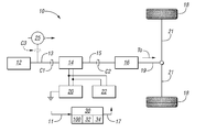
- FIG. 1 is a schematic illustration of an extended-range electric vehicle having a range-extending supercapacitor module as described herein.
- FIG. 2 is a table describing two powertrain operating modes of the vehicle shown in FIG. 1 .
- FIG. 3A is a schematic lever diagram describing a first of the two operating modes of FIG. 2 , i.e., a drive mode, which may be pneumatically applied.
- FIG. 3B is a schematic lever diagram describing a second of the two operating modes shown in FIG. 2 , i.e., a neutral-charging mode.
- FIG. 4A includes example time plots of the states of charge (SOC) of a battery pack using the present approach and a nominal approach, with time plotted on the x-axis and SOC plotted on the y-axis.
- SOC states of charge
- FIG. 4B is a time plot of changing vehicle speed, with time plotted on the x-axis and velocity plotted on the y-axis.
- FIG. 4C is a time plot of the level of energy stored in a supercapacitor module of the vehicle shown in FIG. 1 , with time plotted on the x-axis and the level of energy plotted on the y-axis.
- an extended-range electric vehicle 10 is shown in schematically in FIG. 1 .
- the vehicle 10 includes a controller 30 having a processor 32 and sufficient tangible, non-transitory memory 34 .
- Computer-executable code embodying a method 100 which is recorded in the memory 34 , is selectively executed via the processor 32 to command a shift between two different powertrain operating modes.
- the two powertrain operating modes of the vehicle 10 are a drive mode and a neutral-charging mode.
- Example designs for achieving the drive and neutral-charging modes are shown in FIGS. 3A and 3B , respectively, each of which shows an optional pneumatically-actuated embodiment.
- FIGS. 4A-C collectively illustrate control values used in the execution of the present method 100 , with FIG. 4A depicting the effect of the method 100 on the state of charge (SOC) of a battery pack 20 given a changing vehicle speed, as shown in FIG. 4B , and a changing percentage of remaining percentage of a maximum charge of a supercapacitor module 22 as shown in FIG. 4C .
- SOC state of charge
- the vehicle 10 of FIG. 1 may include a small internal combustion engine 12 , an electric traction motor 14 , and a final drive assembly 16 , the latter of which provides a desired output gear ratio.
- the term “small” when applied to the engine 12 describes a displacement of less than about 300 cubic centimeters (cc), with a range of 200-250 cc provided in an example embodiment.
- An output member 19 of the final drive assembly 16 is connected to a set of drive wheels 18 via one or more drive axles 21 . Therefore, output torque (arrow T O ) from the final drive assembly 16 is ultimately delivered to the drive wheels 18 to propel the vehicle 10 .
- a driveshaft 13 of the engine 12 is respectively connected to/disconnected from the electric traction motor 14 via application/release of a first clutch C 1 .
- an output shaft 15 of the electric traction motor 14 is selectively connected to/disconnected from the final drive assembly 16 via a second clutch C 2 .
- the states of clutches C 1 and C 2 are at all times mutually exclusive. That is, when clutch C 1 is applied, C 2 is released and vice versa.
- Application of the respective first and second clutches C 1 and C 2 may be via any suitable actuator, including via pneumatically-actuated or hydraulically-actuated pistons. An example of the former, which provides a relatively low-cost approach to clutch actuation, is described below with reference to FIGS. 3A and 3B .
- the first and second clutches C 1 and C 2 may be rotating clutches having interspaced friction plates or any other conventional torque transfer mechanism.
- the electric traction motor 14 of FIG. 1 draws electrical energy from the battery pack 20 .
- the battery pack 20 is configured as a multi-cell lead acid battery pack, e.g., six 8-volt cells or eight 6-volt cells in possible non-limiting 48VDC examples.
- the battery pack 20 is electrically connected to the supercapacitor module 22 .
- the term “super” as used herein refers generally to the higher levels of capacitance relative to typical capacitors, as is well known in the art.
- the supercapacitor module 22 may have a capacitance level sufficient for storing 125% to 140% or more of the voltage of the battery pack 20 .
- Other combinations of capacitance and battery voltage may be used without departing from the intended inventive scope.
- the supercapacitor module 22 shown schematically in FIG. 1 may use one or more double-layer capacitors (DLCs) to help store sufficient standby energy.
- DLCs double-layer capacitors
- Such DLCs may use a series of electrodes and a suitable electrolyte, e.g., an organic electrolyte, although other capacitor designs may be employed in the alternative.
- a supercapacitor such as those used to construct the supercapacitor module 22 can be charged very rapidly relative to the conventional battery cells. The rapid-charging characteristics thus allow selective use of the supercapacitor module 22 of the present approach in the overall operation of the simplified powertrain shown in FIG. 1 .
- torque from the engine 12 may be supplied via the driveshaft 13 to an air conditioning compressor 25 or other comparable electrical load, which is cycled on and off as needed via the controller 30 to cool a passenger compartment (not shown) of the vehicle 10 of FIG. 1 .
- the air conditioning compressor 25 acts as a substantially constant electrical load on the engine 12 , for instance a load of 1.5 kW in some designs. Therefore, the engine 12 should be sized to account for the constant load of the air conditioning compressor 25 as well as all other constant and intermittent electrical loads.
- An optional compressor clutch C 3 as shown in phantom may be used to disconnect the air conditioning compressor 25 from the engine 12 and thus minimize spin losses when the air conditioning compressor 25 is not otherwise needed, e.g., when the air conditioning compressor 25 is sufficiently charged.
- the controller 30 shown schematically in FIG. 1 may be embodied as a digital computer or multiple such computers each having the processor 32 and sufficient amounts of the memory 34 , e.g., read only memory (ROM), random access memory (RAM), optical memory, additional magnetic memory, flash memory, and/or electrically-erasable programmable read only memory (EEPROM).
- Other associated hardware components of the controller 30 may include a high-speed digital clock, analog-to-digital (A/D) and digital-to-analog (D/A) circuitry, and any required input/output circuitry and devices (I/O), as well as appropriate signal conditioning and buffer circuitry.
- Any computer-executable code required for operation of the vehicle 10 including instructions embodying the method 100 , can be recorded in memory 34 and automatically executed by the processor 32 to thereby establish a required or requested powertrain operating mode.
- the controller 30 which is in communication with the engine 12 , the electric traction motor 14 , the respective first and second clutches C 1 and C 2 , and the optional air conditioning compressor clutch C 3 , via a controller area network (CAN) and/or other wired/wireless network connection, receives input signals (arrow 11 ) from the various systems. In response to the received input signals (arrow 11 ), the controller 30 generates output signals (arrow 17 ), some of which cause the clutches C 1 -C 3 to either apply or release, with the commanded clutch state depending on the required powertrain operating mode. Two possible operating modes will now be described with reference to FIG. 2 .
- CAN controller area network
- a table 40 is shown in FIG. 2 that describes the two basic operating modes of the vehicle 10 shown in FIG. 1 , i.e., the drive mode (D) and the neutral-charging (N-C) mode.
- the first clutch C 1 is released (O) and the second clutch C 2 is engaged (X).
- the electric traction motor 14 draws ( ⁇ ) power from the battery pack 20 and/or the supercapacitor module 22 as needed, with discharge priority given to the supercapacitor module 22 as set forth below.
- the engine 12 of FIG. 1 supplies any required output energy for powering the air conditioning compressor 25 .
- ⁇ is the rotational speed of the engine 12 in radians/second
- ⁇ is engine torque in Newton meters.
- neutral-charging mode the apply states of the respective first and second clutches C 1 and C 2 are simply reversed. That is, the first clutch C 1 is applied (X) and the second clutch C 2 is released (O).
- the engine 12 may power the electric traction motor 14 as a generator.
- the electric traction motor 14 may charge (+) the battery pack 20 and/or the supercapacitor module 22 .
- the neutral-charging mode set forth herein may be particularly beneficial when operating the vehicle 10 of FIG. 1 in a high-density area such as a city or other high-traffic environment in which the vehicle 10 is expected to spend a fair amount of time idling.
- This otherwise wasted time is used advantageously via the present control approach to recharge the battery pack 20 and/or the supercapacitor module 22 .
- Use of the supercapacitor module 22 also allows the battery pack 20 to be downsized without sacrificing responsiveness to instantaneous electric power demands.
- FIGS. 3A and 3B schematic lever diagrams are shown for the two powertrain operating modes of FIG. 2 , with FIGS. 3A and 3B both showing an example low-cost pneumatically-actuated design.
- Diagram 50 of FIG. 3A corresponds to the neutral-charging mode noted immediately above, wherein the first clutch C 1 is applied and the second clutch C 2 is released.
- First, second, and third linkages 52 , 54 , and 59 are connected to each other via hinges 57 , which allows linkages 52 , 54 , and 59 to rotate with respect to each other as needed.
- FIGS. 3A and 3B such a design may provide substantial cost, weight, and component count advantages relative to conventional hydraulic designs.
- a control solenoid 75 may be de-energized ( ⁇ ) via the controller 30 of FIG. 1 to draw an arm 71 in the direction of arrow 80 .
- Inlet air pressure (arrow I)
- a return spring 74 moves a plunger 72 within a cylinder 70 in the same direction to unblock an air passage 65 .
- Air pressure is fed into a pneumatic valve 60 through the air passage 65 , thus moving a piston 62 in the direction of arrow 80 .
- a return spring 78 is thus compressed within the pneumatic valve. Air in the housing 70 can escape to atmosphere as indicated by arrow A.
- the piston 62 may be connected to a rod 64 and the first linkage 52 as shown such that movement of the piston 62 in the direction of arrow 80 pulls the first linkage 52 in the same direction. Movement of the first linkage 52 in turn pulls open the second clutch C 2 , and thus establishes the released (O) state of second clutch C 2 needed for the neutral-charging state. The same movement rotates the second linkage 54 , thus forcing the third linkage 59 in the direction of arrow 77 . The third linkage 59 compresses the first clutch C 1 into an applied (X) state. A spring 61 connected between the second linkage 54 and a stationary member 42 is thus compressed, thereby storing return energy for use in entering the drive mode.
- FIG. 3B shows the drive mode via diagram 150 .
- the second clutch C 2 is applied and the first clutch C 1 is released.
- the control solenoid 75 is energized (+) and inlet air pressure (arrow I of FIG. 3A ) is discontinued.
- the plunger 62 moves in the direction of arrow 77 , compresses the spring 74 , and is thus properly positioned for entering a subsequent neutral-charging mode.
- the return spring 78 within the pneumatic valve 60 pushes the piston 62 and rod 64 in the direction of arrow 77 . This moves the first linkage 52 in the same direction, which causes the second linkage 54 to rotate counterclockwise with respect to the perspective of FIG. 3B , assisted via stored energy in the spring 61 .
- the movement of the first and second linkages 52 and 54 pulls the third linkage 59 in the direction of arrow 80 , and thus releases (O) the first clutch C 1 .
- the same movement pushes the first linkage 52 in the direction of arrow 77 to apply (X) the second clutch C 2 .
- the spring 61 may stretch in this motion to store potential return energy for entering the neutral-charging mode shown in FIG. 3A .
- the vehicle 10 shown in FIG. 1 with its simplified clutching architecture may provide distinct advantages relative to prior art extended-range electric vehicle powertrains.
- the battery pack 20 may be downsized for a given EV range, which may effectively address space constraints in certain emerging markets.
- the vehicle 10 may use a single electric traction motor 14 to drive the vehicle 10 in drive mode, and to charge the battery pack 20 and/or the supercapacitor module 22 in the neutral-charging mode.
- Certain limitations in performance of lead acid battery may be overcome via selective use of the supercapacitor module 22 , which can also extend the life of the battery pack 20 .
- the engine 12 does not directly drives the output, and therefore the engine 12 can be operated at its best BSFC point with reduced emissions.
- the supercapacitor module 22 may also improve the regenerative energy captured during the drive cycle. This particular advantage is illustrated in FIGS. 4A-C .
- time (t) is plotted on the horizontal axis.
- FIG. 4A illustrates, via trace 82 , the manner in which the SOC of the battery pack 20 of FIG. 1 may decrease using the present control approach. Three nominal SOC levels are shown, from highest SOC to lowest, as S 3 , S 2 , and S 1 .
- trace 182 shows a typical trajectory for a decreasing SOC of a nominal battery pack controlled using existing methods. While traces 82 and 182 both decrease over time, note that the rate of decrease using the present method 100 may be substantially reduced relative the rate of decrease of trace 182 .
- FIG. 4B shows changing velocity of the vehicle 10 shown in FIG. 1 as trace 84 over the same time period, with relative velocities of N 1 , N 2 , and N 3 .
- the pattern of trace 84 is typical of driving in heavy traffic or in other stop-and-go driving routes, e.g., on urban surface streets having a substantial number of intersections and/or traffic lights.
- FIG. 4C illustrates, via trace 86 , the level of energy as a percentage (%) stored in the supercapacitor module 22 of FIG. 1 .
- trace 86 of FIG. 4C shows that, in the same interval of time, the supercapacitor module 22 is actively charging.
- the neutral-charging mode disclosed herein helps to slow the rate of decrease in SOC of the battery pack 20 , thereby extending the effective EV range of the vehicle 10 of FIG. 1 .
Landscapes
- Engineering & Computer Science (AREA)
- Transportation (AREA)
- Mechanical Engineering (AREA)
- Chemical & Material Sciences (AREA)
- Combustion & Propulsion (AREA)
- Automation & Control Theory (AREA)
- Electric Propulsion And Braking For Vehicles (AREA)
Abstract
Description
Claims (6)
Priority Applications (2)
| Application Number | Priority Date | Filing Date | Title |
|---|---|---|---|
| US13/803,000 US8818601B1 (en) | 2013-03-14 | 2013-03-14 | Extended-range electric vehicle with supercapacitor range extender |
| CN201410096179.5A CN104044476B (en) | 2013-03-14 | 2014-03-14 | Extended-range electric vehicle with ultracapacitor distance increasing unit |
Applications Claiming Priority (1)
| Application Number | Priority Date | Filing Date | Title |
|---|---|---|---|
| US13/803,000 US8818601B1 (en) | 2013-03-14 | 2013-03-14 | Extended-range electric vehicle with supercapacitor range extender |
Publications (2)
| Publication Number | Publication Date |
|---|---|
| US8818601B1 true US8818601B1 (en) | 2014-08-26 |
| US20140277870A1 US20140277870A1 (en) | 2014-09-18 |
Family
ID=51358659
Family Applications (1)
| Application Number | Title | Priority Date | Filing Date |
|---|---|---|---|
| US13/803,000 Expired - Fee Related US8818601B1 (en) | 2013-03-14 | 2013-03-14 | Extended-range electric vehicle with supercapacitor range extender |
Country Status (2)
| Country | Link |
|---|---|
| US (1) | US8818601B1 (en) |
| CN (1) | CN104044476B (en) |
Cited By (17)
| Publication number | Priority date | Publication date | Assignee | Title |
|---|---|---|---|---|
| US9796277B2 (en) | 2015-02-27 | 2017-10-24 | GM Global Technology Operations LLC | Electric bike extended range battery power electronics and control |
| CN107336622A (en) * | 2017-05-26 | 2017-11-10 | 苏州紫荆清远新能源汽车技术有限公司 | A kind of stroke-increasing electric automobile and its control method |
| US9852846B2 (en) | 2015-02-26 | 2017-12-26 | Capacitor Sciences Incorporated | Self-healing capacitor and methods of production thereof |
| US9899843B2 (en) | 2015-03-31 | 2018-02-20 | General Electric Company | Energy storage system with range extender and energy management and control method |
| US9899150B2 (en) | 2014-05-12 | 2018-02-20 | Capacitor Sciences Incorporated | Energy storage device and method of production thereof |
| US9916931B2 (en) | 2014-11-04 | 2018-03-13 | Capacitor Science Incorporated | Energy storage devices and methods of production thereof |
| US9932358B2 (en) | 2015-05-21 | 2018-04-03 | Capacitor Science Incorporated | Energy storage molecular material, crystal dielectric layer and capacitor |
| US9941051B2 (en) | 2015-06-26 | 2018-04-10 | Capactor Sciences Incorporated | Coiled capacitor |
| US9978517B2 (en) | 2016-04-04 | 2018-05-22 | Capacitor Sciences Incorporated | Electro-polarizable compound and capacitor |
| US10026553B2 (en) | 2015-10-21 | 2018-07-17 | Capacitor Sciences Incorporated | Organic compound, crystal dielectric layer and capacitor |
| US10056755B2 (en) | 2015-03-31 | 2018-08-21 | General Electric Company | Multi-source energy storage system and energy management and control method |
| US10153087B2 (en) | 2016-04-04 | 2018-12-11 | Capacitor Sciences Incorporated | Electro-polarizable compound and capacitor |
| US10305295B2 (en) | 2016-02-12 | 2019-05-28 | Capacitor Sciences Incorporated | Energy storage cell, capacitive energy storage module, and capacitive energy storage system |
| US10340082B2 (en) | 2015-05-12 | 2019-07-02 | Capacitor Sciences Incorporated | Capacitor and method of production thereof |
| US10347423B2 (en) | 2014-05-12 | 2019-07-09 | Capacitor Sciences Incorporated | Solid multilayer structure as semiproduct for meta-capacitor |
| US10395841B2 (en) | 2016-12-02 | 2019-08-27 | Capacitor Sciences Incorporated | Multilayered electrode and film energy storage device |
| CN113619410A (en) * | 2021-09-13 | 2021-11-09 | 东风汽车集团股份有限公司 | Power assembly arrangement and connection device of range-extending type electric off-road vehicle |
Families Citing this family (3)
| Publication number | Priority date | Publication date | Assignee | Title |
|---|---|---|---|---|
| CN105083032A (en) * | 2015-08-21 | 2015-11-25 | 上海英纳工业材料有限公司 | Wind power charging device and car |
| CN107225960A (en) * | 2017-06-13 | 2017-10-03 | 重庆大学 | A kind of method of the engine behavior regulation of hybrid electric vehicle |
| CN114537368A (en) * | 2022-04-14 | 2022-05-27 | 浙江吉利控股集团有限公司 | Vehicle control method, vehicle control device, vehicle and storage medium |
Citations (8)
| Publication number | Priority date | Publication date | Assignee | Title |
|---|---|---|---|---|
| US7127337B2 (en) * | 2003-10-14 | 2006-10-24 | General Motors Corporation | Silent operating mode for reducing emissions of a hybrid electric vehicle |
| US20090139781A1 (en) * | 2007-07-18 | 2009-06-04 | Jeffrey Brian Straubel | Method and apparatus for an electrical vehicle |
| US20100133025A1 (en) * | 2009-11-05 | 2010-06-03 | Ise Corporation | Expandable Energy Storage Control System Architecture |
| US20110100735A1 (en) * | 2009-11-05 | 2011-05-05 | Ise Corporation | Propulsion Energy Storage Control System and Method of Control |
| US7993155B2 (en) * | 2008-09-19 | 2011-08-09 | Better Place GmbH | System for electrically connecting batteries to electric vehicles |
| US8006793B2 (en) * | 2008-09-19 | 2011-08-30 | Better Place GmbH | Electric vehicle battery system |
| US20130285581A1 (en) * | 2012-04-30 | 2013-10-31 | GM Global Technology Operations LLC | Passive high-voltage dc bus discharge circuit for a vehicle |
| US20140080648A1 (en) * | 2011-08-26 | 2014-03-20 | Means Industries, Inc. | Drive system including a transmission for a hybrid electric vehicle |
Family Cites Families (5)
| Publication number | Priority date | Publication date | Assignee | Title |
|---|---|---|---|---|
| JP3458795B2 (en) * | 1999-10-08 | 2003-10-20 | トヨタ自動車株式会社 | Hybrid drive |
| CN1307986A (en) * | 2000-01-12 | 2001-08-15 | 张立军 | Efficient accumulator car without environment pollution |
| JP2002115573A (en) * | 2000-10-10 | 2002-04-19 | Honda Motor Co Ltd | Hybrid vehicle |
| CN1311999C (en) * | 2005-01-31 | 2007-04-25 | 上海汽车工业(集团)总公司汽车工程研究院 | Parallel connection mixed power driving system and its driving method |
| JP4265568B2 (en) * | 2005-04-28 | 2009-05-20 | 日産自動車株式会社 | Mode transition control device for hybrid vehicle |
-
2013
- 2013-03-14 US US13/803,000 patent/US8818601B1/en not_active Expired - Fee Related
-
2014
- 2014-03-14 CN CN201410096179.5A patent/CN104044476B/en not_active Expired - Fee Related
Patent Citations (12)
| Publication number | Priority date | Publication date | Assignee | Title |
|---|---|---|---|---|
| US7127337B2 (en) * | 2003-10-14 | 2006-10-24 | General Motors Corporation | Silent operating mode for reducing emissions of a hybrid electric vehicle |
| US20090139781A1 (en) * | 2007-07-18 | 2009-06-04 | Jeffrey Brian Straubel | Method and apparatus for an electrical vehicle |
| US7993155B2 (en) * | 2008-09-19 | 2011-08-09 | Better Place GmbH | System for electrically connecting batteries to electric vehicles |
| US8006793B2 (en) * | 2008-09-19 | 2011-08-30 | Better Place GmbH | Electric vehicle battery system |
| US20110297470A1 (en) * | 2008-09-19 | 2011-12-08 | Yoav Heichal | Electric Vehicle Battery System |
| US8454377B2 (en) * | 2008-09-19 | 2013-06-04 | Better Place GmbH | System for electrically connecting batteries to electric vehicles |
| US8517132B2 (en) * | 2008-09-19 | 2013-08-27 | Better Place GmbH | Electric vehicle battery system |
| US20100133025A1 (en) * | 2009-11-05 | 2010-06-03 | Ise Corporation | Expandable Energy Storage Control System Architecture |
| US20110100735A1 (en) * | 2009-11-05 | 2011-05-05 | Ise Corporation | Propulsion Energy Storage Control System and Method of Control |
| US8245801B2 (en) * | 2009-11-05 | 2012-08-21 | Bluways Usa, Inc. | Expandable energy storage control system architecture |
| US20140080648A1 (en) * | 2011-08-26 | 2014-03-20 | Means Industries, Inc. | Drive system including a transmission for a hybrid electric vehicle |
| US20130285581A1 (en) * | 2012-04-30 | 2013-10-31 | GM Global Technology Operations LLC | Passive high-voltage dc bus discharge circuit for a vehicle |
Cited By (24)
| Publication number | Priority date | Publication date | Assignee | Title |
|---|---|---|---|---|
| US10347423B2 (en) | 2014-05-12 | 2019-07-09 | Capacitor Sciences Incorporated | Solid multilayer structure as semiproduct for meta-capacitor |
| US9899150B2 (en) | 2014-05-12 | 2018-02-20 | Capacitor Sciences Incorporated | Energy storage device and method of production thereof |
| US10347424B2 (en) | 2014-05-12 | 2019-07-09 | Capacitor Sciences Incorporated | Energy storage device and method of production thereof |
| US10685782B2 (en) | 2014-05-12 | 2020-06-16 | Capacitor Sciences Incorporated | Capacitor and method of production thereof |
| US9916931B2 (en) | 2014-11-04 | 2018-03-13 | Capacitor Science Incorporated | Energy storage devices and methods of production thereof |
| US9852846B2 (en) | 2015-02-26 | 2017-12-26 | Capacitor Sciences Incorporated | Self-healing capacitor and methods of production thereof |
| US9796277B2 (en) | 2015-02-27 | 2017-10-24 | GM Global Technology Operations LLC | Electric bike extended range battery power electronics and control |
| US10056755B2 (en) | 2015-03-31 | 2018-08-21 | General Electric Company | Multi-source energy storage system and energy management and control method |
| US9899843B2 (en) | 2015-03-31 | 2018-02-20 | General Electric Company | Energy storage system with range extender and energy management and control method |
| US10340082B2 (en) | 2015-05-12 | 2019-07-02 | Capacitor Sciences Incorporated | Capacitor and method of production thereof |
| US9932358B2 (en) | 2015-05-21 | 2018-04-03 | Capacitor Science Incorporated | Energy storage molecular material, crystal dielectric layer and capacitor |
| US10672561B2 (en) | 2015-06-26 | 2020-06-02 | Capacitor Sciences Incorporated | Coiled capacitor |
| US9941051B2 (en) | 2015-06-26 | 2018-04-10 | Capactor Sciences Incorporated | Coiled capacitor |
| US10854386B2 (en) | 2015-06-26 | 2020-12-01 | Capacitor Sciences Incorporated | Coiled capacitor |
| US10026553B2 (en) | 2015-10-21 | 2018-07-17 | Capacitor Sciences Incorporated | Organic compound, crystal dielectric layer and capacitor |
| US10305295B2 (en) | 2016-02-12 | 2019-05-28 | Capacitor Sciences Incorporated | Energy storage cell, capacitive energy storage module, and capacitive energy storage system |
| US10153087B2 (en) | 2016-04-04 | 2018-12-11 | Capacitor Sciences Incorporated | Electro-polarizable compound and capacitor |
| US10672560B2 (en) | 2016-04-04 | 2020-06-02 | Capacitor Sciences Incorporated | Electro-polarizable compound and capacitor |
| US9978517B2 (en) | 2016-04-04 | 2018-05-22 | Capacitor Sciences Incorporated | Electro-polarizable compound and capacitor |
| US10707019B2 (en) | 2016-04-04 | 2020-07-07 | Capacitor Science Incorporated | Electro-polarizable compound and capacitor |
| US10395841B2 (en) | 2016-12-02 | 2019-08-27 | Capacitor Sciences Incorporated | Multilayered electrode and film energy storage device |
| CN107336622A (en) * | 2017-05-26 | 2017-11-10 | 苏州紫荆清远新能源汽车技术有限公司 | A kind of stroke-increasing electric automobile and its control method |
| CN113619410A (en) * | 2021-09-13 | 2021-11-09 | 东风汽车集团股份有限公司 | Power assembly arrangement and connection device of range-extending type electric off-road vehicle |
| CN113619410B (en) * | 2021-09-13 | 2023-08-08 | 东风汽车集团股份有限公司 | Range-extending type electric off-road vehicle power assembly arrangement and connecting device |
Also Published As
| Publication number | Publication date |
|---|---|
| US20140277870A1 (en) | 2014-09-18 |
| CN104044476A (en) | 2014-09-17 |
| CN104044476B (en) | 2017-09-01 |
Similar Documents
| Publication | Publication Date | Title |
|---|---|---|
| US8818601B1 (en) | Extended-range electric vehicle with supercapacitor range extender | |
| CN110949368B (en) | Control method and device for hybrid vehicle, storage medium and vehicle | |
| US8296032B2 (en) | Hybrid vehicle and a method of control for improved power management | |
| CN103895641B (en) | A kind of gas-electricity hybrid power coach whole-control system and control method thereof | |
| US20160129811A1 (en) | System, architecture, and method for minimizing power consumption and increasing performance in electric vehicles | |
| US8701804B1 (en) | Constant recharging air and electric alternating vehicle power system | |
| US20110017532A1 (en) | A hybrid powertrain | |
| US10486684B2 (en) | HEV energy management for high performance operation | |
| CN103158711A (en) | Torque control method for hybrid vehicle and system thereof | |
| EP2125414B1 (en) | Hybrid vehicle auxiliary equipment energy management | |
| CN201784620U (en) | Series-and-parallel hybrid power drive system | |
| CN205736908U (en) | A kind of Novel environmental-sanitation car dynamical system and a kind of Novel environmental-sanitation car | |
| CN203157693U (en) | Bi-motor multi-mode hybrid power driving system | |
| CN102529679A (en) | Automobile three-clutch hybrid power driving device and control method thereof | |
| CN202345361U (en) | Double-axle drive unit of electrohydraulic composite hybrid power vehicles | |
| CN113459791A (en) | Hybrid electric vehicle and energy management control method applying same | |
| CN203157694U (en) | Extended range hybrid power city coach | |
| CN106004859A (en) | Vehicle Performance Preload Enabler | |
| CN104071017A (en) | Power balance power system of wholly electrically-driven electric automobile | |
| CN111634183A (en) | Double-planet-row hybrid power system and auxiliary braking method thereof | |
| CN101934718B (en) | Automobile hybrid drive system | |
| CN106183779B (en) | Double clutch mixed power automobile driving system configurations | |
| CN207257301U (en) | A kind of on-board air conditioner dynamical system | |
| KR20150074437A (en) | Hybrid vehicle and control method thereof | |
| CN116141989A (en) | Battery control method of extended range electric automobile, storage medium and vehicle |
Legal Events
| Date | Code | Title | Description |
|---|---|---|---|
| AS | Assignment |
Owner name: GM GLOBAL TECHNOLOGY OPERATIONS LLC, MICHIGAN Free format text: ASSIGNMENT OF ASSIGNORS INTEREST;ASSIGNORS:G V, RAVIKANTH;NAIDU, KUMPATLA V;TIWARI, AWADESH;AND OTHERS;SIGNING DATES FROM 20130227 TO 20130304;REEL/FRAME:029997/0046 |
|
| FEPP | Fee payment procedure |
Free format text: PAYOR NUMBER ASSIGNED (ORIGINAL EVENT CODE: ASPN); ENTITY STATUS OF PATENT OWNER: LARGE ENTITY |
|
| AS | Assignment |
Owner name: WILMINGTON TRUST COMPANY, DELAWARE Free format text: SECURITY INTEREST;ASSIGNOR:GM GLOBAL TECHNOLOGY OPERATIONS LLC;REEL/FRAME:033135/0336 Effective date: 20101027 |
|
| STCF | Information on status: patent grant |
Free format text: PATENTED CASE |
|
| AS | Assignment |
Owner name: GM GLOBAL TECHNOLOGY OPERATIONS LLC, MICHIGAN Free format text: RELEASE BY SECURED PARTY;ASSIGNOR:WILMINGTON TRUST COMPANY;REEL/FRAME:034287/0601 Effective date: 20141017 |
|
| MAFP | Maintenance fee payment |
Free format text: PAYMENT OF MAINTENANCE FEE, 4TH YEAR, LARGE ENTITY (ORIGINAL EVENT CODE: M1551) Year of fee payment: 4 |
|
| FEPP | Fee payment procedure |
Free format text: MAINTENANCE FEE REMINDER MAILED (ORIGINAL EVENT CODE: REM.); ENTITY STATUS OF PATENT OWNER: LARGE ENTITY |
|
| LAPS | Lapse for failure to pay maintenance fees |
Free format text: PATENT EXPIRED FOR FAILURE TO PAY MAINTENANCE FEES (ORIGINAL EVENT CODE: EXP.); ENTITY STATUS OF PATENT OWNER: LARGE ENTITY |
|
| STCH | Information on status: patent discontinuation |
Free format text: PATENT EXPIRED DUE TO NONPAYMENT OF MAINTENANCE FEES UNDER 37 CFR 1.362 |
|
| FP | Lapsed due to failure to pay maintenance fee |
Effective date: 20220826 |