JP2019216786A - Game machine - Google Patents
Game machine Download PDFInfo
- Publication number
- JP2019216786A JP2019216786A JP2018114089A JP2018114089A JP2019216786A JP 2019216786 A JP2019216786 A JP 2019216786A JP 2018114089 A JP2018114089 A JP 2018114089A JP 2018114089 A JP2018114089 A JP 2018114089A JP 2019216786 A JP2019216786 A JP 2019216786A
- Authority
- JP
- Japan
- Prior art keywords
- game
- symbol
- special
- ball
- displayed
- Prior art date
- Legal status (The legal status is an assumption and is not a legal conclusion. Google has not performed a legal analysis and makes no representation as to the accuracy of the status listed.)
- Pending
Links
Images


Classifications
-
- Y—GENERAL TAGGING OF NEW TECHNOLOGICAL DEVELOPMENTS; GENERAL TAGGING OF CROSS-SECTIONAL TECHNOLOGIES SPANNING OVER SEVERAL SECTIONS OF THE IPC; TECHNICAL SUBJECTS COVERED BY FORMER USPC CROSS-REFERENCE ART COLLECTIONS [XRACs] AND DIGESTS
- Y02—TECHNOLOGIES OR APPLICATIONS FOR MITIGATION OR ADAPTATION AGAINST CLIMATE CHANGE
- Y02E—REDUCTION OF GREENHOUSE GAS [GHG] EMISSIONS, RELATED TO ENERGY GENERATION, TRANSMISSION OR DISTRIBUTION
- Y02E60/00—Enabling technologies; Technologies with a potential or indirect contribution to GHG emissions mitigation
- Y02E60/10—Energy storage using batteries
Abstract
Description
本発明は、パチンコ機に代表される遊技機に関するものである。 The present invention relates to a gaming machine represented by a pachinko machine.
パチンコ機等の遊技機には、始動入賞口への遊技球の入賞に基づいて行われる抽選の結果が当たりだった場合に、当たり遊技を実行するものがある。かかる遊技機の中には、抽選が実行されるまでに抽選結果を事前判別し、その事前判別結果を示唆する演出を実行することで遊技者の遊技に対する興趣向上を図っているものがある。 Some gaming machines, such as pachinko machines, execute a hit game when a result of a lottery performed based on winning of a game ball in a starting winning port is a hit. In some of such gaming machines, the lottery result is preliminarily determined before the lottery is executed, and an effect that suggests the preliminarily determined result is executed to improve the interest of the player in the game.
しかしながら、更なる興趣の向上が求められている。 However, there is a need for further enhancement of interest.
本発明は、上記例示した問題点等を解決するためになされたものであり、遊技者の遊技に対する興趣を向上させることができる遊技機を提供することを目的としている。 The present invention has been made to solve the above-described problems and the like, and an object of the present invention is to provide a gaming machine capable of improving a player's interest in playing a game.
この目的を達成するために請求項1記載の遊技機は、取得条件の成立に基づいて情報を取得する情報取得手段と、その情報取得手段により取得された前記情報を、少なくとも当該情報に対する判別条件が成立するまで、所定数を上限に記憶可能な記憶手段と、前記判別条件が成立した場合に、前記記憶手段に記憶されている前記情報に基づいて判別を実行する判別手段と、その判別手段の判別結果を示すための識別情報を表示手段に動的表示させる動的表示手段と、その動的表示手段により動的表示された前記識別情報が、特定の前記判別結果を示すための特定識別情報で停止表示された場合に特定遊技を実行可能な特定遊技実行手段と、を有し、前記記憶手段に記憶されている前記情報に基づく前記判別が実行されるまでに、当該情報に基づく事前判別を実行する事前判別手段と、その事前判別手段による前記事前判別の結果に基づいて所定数の特定図柄を前記表示手段に表示させる特定図柄表示手段と、その特定図柄表示手段により表示される前記特定図柄の表示数を、前記情報の数に関わらず可変表示させることが可能な図柄数可変表示手段と、を有するものである。
In order to achieve this object, the gaming machine according to
請求項2記載の遊技機は、請求項1記載の遊技機において、前記特定図柄表示手段は、前記記憶手段に記憶可能な前記情報の数を上限に前記特定図柄を表示可能なものである。 According to a second aspect of the present invention, in the gaming machine according to the first aspect, the specific symbol display unit is capable of displaying the specific symbol up to the number of pieces of the information that can be stored in the storage unit.
請求項3記載の遊技機は、請求項1または2記載の遊技機において、前記図柄数可変表示手段は、前記記憶手段に記憶されている前記情報の数が1以上である場合には、前記特定図柄の数として1以上の範囲で前記特定図柄の表示数を可変するものである。 According to a third aspect of the present invention, in the gaming machine according to the first or second aspect, the symbol number variable display means is configured such that when the number of the information stored in the storage means is one or more, The number of the specific symbols to be displayed is changed within one or more ranges as the number of the specific symbols.
請求項4記載の遊技機は、請求項1から3の何れかに記載の遊技機において、第1遊技状態と、その第1遊技状態よりも遊技者に有利となる第2遊技状態と、を含む複数の遊技状態のうち、一の遊技状態を設定可能な遊技状態設定手段を有し、前記遊技状態設定手段は、少なくとも前記第2遊技状態が設定されている状態で終了条件が成立した場合に前記第1遊技状態を設定可能なものであり、前記特定図柄表示手段は、前記第2遊技状態が設定されている間、前記特定図柄を前記表示手段に表示可能なものである。 A gaming machine according to a fourth aspect is the gaming machine according to any one of the first to third aspects, wherein the first gaming state and a second gaming state that is more advantageous to the player than the first gaming state. Among a plurality of game states including a game state setting means capable of setting one game state, wherein the game state setting means determines that at least the second game state is set and an end condition is satisfied. The specific symbol display means can display the specific symbol on the display means while the second game state is set.
請求項5記載の遊技機は、請求項4記載の遊技機において、前記図柄数可変表示手段は、前記表示手段に表示されている前記特定図柄の表示数を2以上可変させることが可能なものである。 According to a fifth aspect of the present invention, in the gaming machine according to the fourth aspect, the symbol number variable display means is capable of changing the display number of the specific symbol displayed on the display means by two or more. It is.
請求項1記載の遊技機によれば、取得条件の成立に基づいて情報を取得する情報取得手段と、その情報取得手段により取得された前記情報を、少なくとも当該情報に対する判別条件が成立するまで、所定数を上限に記憶可能な記憶手段と、前記判別条件が成立した場合に、前記記憶手段に記憶されている前記情報に基づいて判別を実行する判別手段と、その判別手段の判別結果を示すための識別情報を表示手段に動的表示させる動的表示手段と、その動的表示手段により動的表示された前記識別情報が、特定の前記判別結果を示すための特定識別情報で停止表示された場合に特定遊技を実行可能な特定遊技実行手段と、を有し、前記記憶手段に記憶されている前記情報に基づく前記判別が実行されるまでに、当該情報に基づく事前判別を実行する事前判別手段と、その事前判別手段による前記事前判別の結果に基づいて所定数の特定図柄を前記表示手段に表示させる特定図柄表示手段と、その特定図柄表示手段により表示される前記特定図柄の表示数を、前記情報の数に関わらず可変表示させることが可能な図柄数可変表示手段と、を有するものである。
According to the gaming machine described in
これにより、遊技者の遊技に対する興趣を向上させることができるという効果がある。 As a result, there is an effect that the interest of the player in the game can be improved.
請求項2記載の遊技機によれば、請求項1記載の遊技機の奏する効果に加え、前記特定図柄表示手段は、前記記憶手段に記憶可能な前記情報の数を上限に前記特定図柄を表示可能なものである。 According to the gaming machine of the second aspect, in addition to the effect of the gaming machine of the first aspect, the specific symbol display means displays the specific symbol up to the number of pieces of the information that can be stored in the storage means. It is possible.
これにより、遊技者の遊技に対する興趣を向上させることができるという効果がある。 As a result, there is an effect that the interest of the player in the game can be improved.
請求項3記載の遊技機によれば、請求項1または2記載の遊技機の奏する効果に加え、前記図柄数可変表示手段は、前記記憶手段に記憶されている前記情報の数が1以上である場合には、前記特定図柄の数として1以上の範囲で前記特定図柄の表示数を可変するものである。 According to the gaming machine of the third aspect, in addition to the effects achieved by the gaming machine of the first or second aspect, the symbol number variable display means is configured such that the number of the information stored in the storage means is one or more. In some cases, the display number of the specific symbol is changed within a range of one or more as the number of the specific symbol.
これにより、遊技者の遊技に対する興趣を向上させることができるという効果がある。 As a result, there is an effect that the interest of the player in the game can be improved.
請求項4記載の遊技機によれば、請求項1から3の何れかに記載の遊技機の奏する効果に加え、第1遊技状態と、その第1遊技状態よりも遊技者に有利となる第2遊技状態と、を含む複数の遊技状態のうち、一の遊技状態を設定可能な遊技状態設定手段を有し、前記遊技状態設定手段は、少なくとも前記第2遊技状態が設定されている状態で終了条件が成立した場合に前記第1遊技状態を設定可能なものであり、前記特定図柄表示手段は、前記第2遊技状態が設定されている間、前記特定図柄を前記表示手段に表示可能なものである。 According to the gaming machine of the fourth aspect, in addition to the effect of the gaming machine according to any one of the first to third aspects, the first gaming state and a second gaming state which is more advantageous to the player than the first gaming state. And a game state setting unit that can set one game state among a plurality of game states including the second game state, wherein the game state setting unit is configured to set at least the second game state in a state where the second game state is set. When the end condition is satisfied, the first game state can be set, and the specific symbol display means can display the specific symbol on the display means while the second game state is set. Things.
これにより、遊技者の遊技に対する興趣を向上させることができるという効果がある。 As a result, there is an effect that the interest of the player in the game can be improved.
請求項5記載の遊技機によれば、請求項4記載の遊技機の奏する効果に加え、前記図柄数可変表示手段は、前記表示手段に表示されている前記特定図柄の表示数を2以上可変させることが可能なものである。 According to the gaming machine of the fifth aspect, in addition to the effect of the gaming machine of the fourth aspect, the symbol number variable display means changes the number of the specific symbols displayed on the display means by two or more. It is something that can be done.
これにより、遊技者の遊技に対する興趣を向上させることができるという効果がある。 As a result, there is an effect that the interest of the player in the game can be improved.
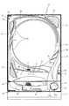
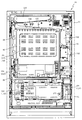
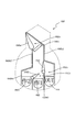
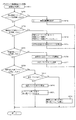
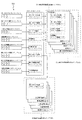
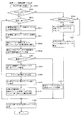
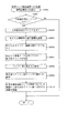
以下、本発明の実施形態について、添付図面を参照して説明する。まず、図1から図87を参照し、第1実施形態として、本発明をパチンコ遊技機(以下、単に「パチンコ機」という)10に適用した場合の一実施形態について説明する。図1は、第1実施形態におけるパチンコ機10の正面図であり、図2はパチンコ機10の遊技盤13の正面図であり、図3〜5はパチンコ機10の遊技盤13の正面視右下領域に設けられた普電入賞装置640の構造を模式的に示した模式図であり、図6〜図9はパチンコ機10の遊技盤13の正面視左上領域に設けられた特殊可変入賞装置65の構造を模式的に示した模式図であり、図10はパチンコ機10の後面図である。
Hereinafter, embodiments of the present invention will be described with reference to the accompanying drawings. First, an embodiment in which the present invention is applied to a pachinko gaming machine (hereinafter, simply referred to as “pachinko machine”) 10 will be described as a first embodiment with reference to FIGS. FIG. 1 is a front view of the
図1に示すように、パチンコ機10は、略矩形状に組み合わせた木枠により外殻が形成される外枠11と、その外枠11と略同一の外形形状に形成され外枠11に対して開閉可能に支持された内枠12とを備えている。外枠11には、内枠12を支持するために正面視(図1参照)左側の上下2カ所に金属製のヒンジ18が取り付けられ、そのヒンジ18が設けられた側を開閉の軸として内枠12が正面手前側へ開閉可能に支持されている。
As shown in FIG. 1, the
内枠12には、多数の釘や球が入球可能な入球口63,64,640等を有する遊技盤13(図2参照)が裏面側から着脱可能に装着される。この遊技盤13の正面を球(遊技球)が流下することにより弾球遊技が行われる。なお、内枠12には、球を遊技盤13の正面領域(遊技領域)に発射する球発射ユニット112a(図21参照)やその球発射ユニット112aから発射された球を遊技盤13の正面領域まで誘導する発射レール(図示せず)等が取り付けられている。尚、遊技盤13に設けられた多数の入球口の内容については、図2を参照して後述する。
A game board 13 (see FIG. 2) having ball entrances 63, 64, 640, etc., into which a large number of nails and balls can enter, is detachably attached to the
内枠12の正面側には、その正面上側を覆う正面枠14と、その下側を覆う下皿ユニット15とが設けられている。正面枠14及び下皿ユニット15を支持するために正面視(図1参照)左側の上下2カ所に金属製のヒンジ19が取り付けられ、そのヒンジ19が設けられた側を開閉の軸として正面枠14及び下皿ユニット15が正面手前側へ開閉可能に支持されている。なお、内枠12の施錠と正面枠14の施錠とは、シリンダ錠20の鍵穴21に専用の鍵を差し込んで所定の操作を行うことでそれぞれ解除される。
On the front side of the
正面枠14は、装飾用の樹脂部品や電気部品等を組み付けたものであり、その略中央部には略楕円形状に開口形成された窓部14cが設けられている。正面枠14の裏面側には2枚の板ガラスを有するガラスユニット16が配設され、そのガラスユニット16を介して遊技盤13の正面がパチンコ機10の正面側に視認可能となっている。
The
正面枠14には、球を貯留する上皿17が正面側へ張り出して上面を開放した略箱状に形成されており、この上皿17に賞球や貸出球などが排出される。上皿17の底面は正面視(図1参照)右側に下降傾斜して形成され、その傾斜により上皿17に投入された球が球発射ユニット112a(図21参照)へと案内される。また、上皿17の上面には、枠ボタン22が設けられている。この枠ボタン22は、例えば、第3図柄表示装置81(図2参照)で表示される演出のステージを変更したり、スーパーリーチの演出内容を変更したりする場合などに、遊技者により操作される。
On the
正面枠14には、その周囲(例えばコーナー部分)に各種ランプ等の発光手段が設けられている。これら発光手段は、大当たり時や所定のリーチ時等における遊技状態の変化に応じて、点灯又は点滅することにより発光態様が変更制御され、遊技中の演出効果を高める役割を果たす。窓部14cの周縁には、LED等の発光手段を内蔵した電飾部29〜33が設けられている。パチンコ機10においては、これら電飾部29〜33が大当たりランプ等の演出ランプとして機能し、大当たり時やリーチ演出時等には内蔵するLEDの点灯や点滅によって各電飾部29〜33が点灯または点滅して、大当たり中である旨、或いは大当たり一歩手前のリーチ中である旨が報知される。また、正面枠14の正面視(図1参照)左上部には、LED等の発光手段が内蔵され賞球の払い出し中とエラー発生時とを表示可能な表示ランプ34が設けられている。
Light emitting means such as various lamps is provided around the front frame 14 (for example, at a corner). These light-emitting means are controlled to change the light-emitting mode by lighting or blinking according to a change in the game state at the time of a big hit or at a predetermined reach, and play a role of enhancing the effect of the effect during the game. At the periphery of the
また、右側の電飾部32下側には、正面枠14の裏面側を視認できるように裏面側より透明樹脂を取り付けて小窓35が形成され、遊技盤13正面の貼着スペースK1(図2参照)に貼付される証紙等がパチンコ機10の正面から視認可能とされている。また、パチンコ機10においては、より煌びやかさを醸し出すために、電飾部29〜33の周りの領域にクロムメッキを施したABS樹脂製のメッキ部材36が取り付けられている。
Further, a
窓部14cの下方には、貸球操作部40が配設されている。貸球操作部40には、度数表示部41と、球貸しボタン42と、返却ボタン43とが設けられている。パチンコ機10の側方に配置されるカードユニット(球貸しユニット)(図示せず)に紙幣やカード等を投入した状態で貸球操作部40が操作されると、その操作に応じて球の貸出が行われる。具体的には、度数表示部41はカード等の残額情報が表示される領域であり、内蔵されたLEDが点灯して残額情報として残額が数字で表示される。球貸しボタン42は、カード等(記録媒体)に記録された情報に基づいて貸出球を得るために操作されるものであり、カード等に残額が存在する限りにおいて貸出球が上皿17に供給される。返却ボタン43は、カードユニットに挿入されたカード等の返却を求める際に操作される。なお、カードユニットを介さずに球貸し装置等から上皿17に球が直接貸し出されるパチンコ機、いわゆる現金機では貸球操作部40が不要となるが、この場合には、貸球操作部40の設置部分に飾りシール等を付加して部品構成は共通のものとしても良い。カードユニットを用いたパチンコ機と現金機との共通化を図ることができる。
A ball
上皿17の下側に位置する下皿ユニット15には、その中央部に上皿17に貯留しきれなかった球を貯留するための下皿50が上面を開放した略箱状に形成されている。下皿50の右側には、球を遊技盤13の正面へ打ち込むために遊技者によって操作される操作ハンドル51が配設される。
In the
操作ハンドル51の内部には、球発射ユニット112aの駆動を許可するためのタッチセンサ51aと、押下操作している期間中には球の発射を停止する発射停止スイッチ51bと、操作ハンドル51の回動操作量(回動位置)を電気抵抗の変化により検出する可変抵抗器(図示せず)などが内蔵されている。操作ハンドル51が遊技者によって右回りに回動操作されると、タッチセンサ51aがオンされると共に可変抵抗器の抵抗値が回動操作量に対応して変化し、その可変抵抗器の抵抗値に対応した強さ(発射強度)で球が発射され、これにより遊技者の操作に対応した飛び量で遊技盤13の正面へ球が打ち込まれる。また、操作ハンドル51が遊技者により操作されていない状態においては、タッチセンサ51aおよび発射停止スイッチ51bがオフとなっている。
Inside the
下皿50の正面下方部には、下皿50に貯留された球を下方へ排出する際に操作するための球抜きレバー52が設けられている。この球抜きレバー52は、常時、右方向に付勢されており、その付勢に抗して左方向へスライドさせることにより、下皿50の底面に形成された底面口が開口して、その底面口から球が自然落下して排出される。この球抜きレバー52の操作は、通常、下皿50の下方に下皿50から排出された球を受け取る箱(一般に「千両箱」と称される)を置いた状態で行われる。下皿50の右方には、上述したように操作ハンドル51が配設され、下皿50の左方には灰皿53が取り付けられている。
At the lower front part of the
図2に示すように、遊技盤13は、正面視略正方形状に切削加工したベース板60に、球案内用の多数の釘(図示せず)や風車の他、レール61,62、一般入球口63、特図入球口64、640、可変入賞装置65、V入賞装置650、普通図柄始動口(スルーゲート)67、可変表示装置ユニット80等を組み付けて構成され、その周縁部が内枠12(図1参照)の裏面側に取り付けられる。ベース板60は光透過性の樹脂材料からなり、その正面側からベース板60の後面側に配設された各種構造体を遊技者に視認させることが可能に形成される。一般入球口63、特図入球口64、普電入賞装置640、V入賞装置65、可変入賞装置650、可変表示装置ユニット80は、ルータ加工によってベース板60に形成された貫通穴に配設され、遊技盤13の正面側からタッピングネジ等により固定されている。
As shown in FIG. 2, the
遊技盤13の正面中央部分は、正面枠14の窓部14c(図1参照)を通じて内枠12の正面側から視認することができる。以下に、主に図2を参照して、遊技盤13の構成について説明する。
The front central portion of the
遊技盤13の正面には、帯状の金属板を略円弧状に屈曲加工して形成した外レール62が植立され、その外レール62の内側位置には外レール62と同様に帯状の金属板で形成した円弧状の内レール61が植立される。この内レール61と外レール62とにより遊技盤13の正面外周が囲まれ、遊技盤13とガラスユニット16(図1参照)とにより前後が囲まれることにより、遊技盤13の正面には、球の挙動により遊技が行われる遊技領域が形成される。遊技領域は、遊技盤13の正面であって2本のレール61,62とレール間を繋ぐ樹脂製の外縁部材73とにより区画して形成される領域(入賞口等が配設され、発射された球が流下する領域)である。
An
2本のレール61,62は、球発射ユニット112a(図9参照)から発射された球を遊技盤13上部へ案内するために設けられたものである。内レール61の先端部分(図2の左上部)には戻り球防止部材68が取り付けられ、一旦、遊技盤13の上部へ案内された球が再度球案内通路内に戻ってしまうといった事態が防止される。外レール62の先端部(図2の右上部)には、球の最大飛翔部分に対応する位置に返しゴム69が取り付けられ、所定以上の勢いで発射された球は、返しゴム69に当たって、勢いが減衰されつつ中央部側へ跳ね返される。
The two
返しゴム69の左上側には第1図柄表示装置37が設けられている。この第1図柄表示装置37は、透明の樹脂(例えば、ABS)にて形成されている遊技盤13の裏面(遊技領域を形成する面とは反対側の面)に覆われるように配設されており、発射された球が第1図柄表示装置37に衝突しないように構成している。
The first
この第1図柄表示装置37には、発光手段である複数のLED及び7セグメント表示器を備える第1図柄表示装置37が配設されている。第1図柄表示装置37は、主制御装置110(図21参照)で行われる各制御に応じた表示がなされるものであり、主にパチンコ機10の遊技状態の表示が行われる。本実施形態では、球が、特図入球口64へ入球(入賞)した場合に、第1図柄表示装置37が作動するように構成されている。つまり、第1図柄表示装置37は、特図入球口64に球が入球した場合に実行される抽選(特図抽選)の抽選結果を示すための表示手段である。なお、本実施形態では、特別図柄の種別が1種類のパチンコ機10を用いているため、第1図柄表示装置37にて1種類の特図抽選の結果が表示されるが、例えば、特別図柄の種別を2種類(第1特別図柄、第2特別図柄)有するパチンコ機10であれば、第1図柄表示装置37に各特別図柄の種別に応じた表示領域を設ければ良い。
The first
また、第1図柄表示装置37は、LEDにより、パチンコ機10の遊技状態(例えば、通常状態、時短状態等)の何れであるかを点灯状態により示したり、特別図柄(第1図柄)が変動中(抽選結果を示すための図柄の組み合わせを停止表示させるための動的表示中)であるか否かを点灯状態により示したり、停止図柄が遊技者に有利な大当たりに対応した図柄か不利な大当たりに対応した図柄か外れ図柄であるかを点灯状態により示したり、保留球数を点灯状態により示すと共に、7セグメント表示装置により、大当たり中のラウンド数やエラー表示を行う。また、特別図柄の変動を一時的に停止(中断)させている状態であることも点灯状態にて示すことが可能に構成している。複数のLEDは、それぞれのLEDの発光色(例えば、赤、緑、青)が異なるよう構成され、その発光色の組み合わせにより、少ないLEDでパチンコ機10の各種遊技状態を示唆することができる。なお、本実施形態では、発光手段(7セグメント表示装置)の発光色の組み合わせにより各種遊技状態を報知するように構成しているが、遊技者が各種遊技状態を識別可能な構成であれば良く、例えば、発光手段が点灯している期間と消灯している期間との長さ(点滅態様)を可変させることにより各種遊技状態を報知するように構成しても良い。
In addition, the first
尚、本パチンコ機10では、特図入球口64へ入球(入賞)があったことを契機として抽選(特別図柄の抽選)が行われる。そして、その特別図柄の抽選において、大当たりか否かの当否判定(大当たり抽選)を行う。ここで、大当たりに当選したと判定されたことに基づいて、遊技者に有利な特典遊技状態となる大当たり遊技が実行される。
In the
大当たり遊技が実行されると、可変入賞装置650の特定入賞口650aに球を容易に入賞させることが可能な開放状態となり、特定入賞口650aに球を入賞させることで多くの賞球を短期間で獲得可能な遊技が実行される。この大当たり遊技は、特別図柄の抽選結果が停止表示(確定表示)された後に(場合に)実行されるものであり、所定時間(例えば1秒)のオープニング期間(可変入賞装置650の特定入賞口650aに球を入球させ難い閉鎖状態が設定される期間)と、開放状態が設定されるラウンド遊技期間と、1のラウンド遊技期間が終了した後に、次のラウンド遊技が開始されるまでの所定期間(例えば、0.5秒)、閉鎖状態が設定されるインターバル期間と、最後のラウンド遊技期間が終了した後に、所定期間(例えば、2秒)の閉鎖状態が設定されるエンディング期間と、からなる大当たり遊技期間が設定される。
When the jackpot game is executed, the special winning
このように、大当たり当選を示す特別図柄の抽選結果が停止表示(確定表示)された後に、オープニング期間が設定することにより、大当たり遊技中において特定入賞口650aが開放状態となるタイミングに合わせて球を任意の方向に向けて発射させる準備を行うことができるため、大当たり遊技を円滑に行わせることができる。また、このオープニング期間を、今回の大当たり遊技の遊技内容を遊技者に報知する期間として用いることができるため、分かり易い遊技を提供することができる。
In this way, by setting the opening period after the lottery result of the special symbol indicating the jackpot winning is stopped and displayed (fixed display), the ball is set at the timing when the specific winning
また、大当たり遊技の最終期間としてエンディング期間を設定することにより、最後のラウンド遊技が終了した直後から、新たな特別図柄の抽選が実行されることを抑制することができるため、大当たり遊技の終了後に実行される遊技に向けて、球を任意の方向に向けて発射させる準備を行うことができるため、遊技の切り替えを円滑に行わせることができる。 Also, by setting the ending period as the last period of the jackpot game, it is possible to suppress the execution of a new special symbol lottery immediately after the end of the last round game, For the game to be executed, preparations can be made to launch the ball in any direction, so that the game can be switched smoothly.
なお、特別図柄の抽選で大当たり当選した場合に実行される大当たり遊技の各期間(オープニング期間、ラウンド期間、エンディング期間)の長さについては、大当たり当選した時点における遊技状態や、当選した大当たりの種別に応じて異なる長さを設定しても良く、例えば、大当たり遊技終了後に実行される遊技内容として、大当たり当選時の遊技内容とは異なる遊技内容が設定される大当たりに当選した場合には、その大当たり遊技のエンディング期間(例えば、10秒)が、他の大当たり遊技のエンディング期間(例えば、2秒)よりも長くなるように設定しておき、そのエンディング期間中に遊技者に対して大当たり遊技終了後に実行される遊技内容を事前に案内する演出を実行可能に構成すると良い。これにより、遊技者に対して分かり易い遊技を提供することができる。 Note that the length of each jackpot game (opening period, round period, ending period) executed when a jackpot is won in the special symbol lottery is determined by the gaming state at the time of jackpot winning and the type of jackpot won. Different lengths may be set according to, for example, as a game content to be executed after the end of the jackpot game, if the game content that is different from the game content at the time of the jackpot winning is won, a big hit is won. The ending period of the jackpot game (for example, 10 seconds) is set to be longer than the ending period of another jackpot game (for example, 2 seconds), and the jackpot game is ended for the player during the ending period. It is preferable that an effect for guiding in advance game contents to be executed later is executable. This makes it possible to provide an easy-to-understand game to the player.
一方、大当たり当選時の遊技内容と、大当たり遊技終了後に実行される遊技内容とが同一となる大当たりに当選した場合には、その大当たりのエンディング期間(例えば、1秒)を、他の大当たり遊技のエンディング期間(例えば、2秒)よりも短くなるように設定するように構成すると良い。これにより、遊技者に対して効率良く遊技を行わせることができる。 On the other hand, when the game content at the time of winning the jackpot and the game content executed after the end of the jackpot game are won, the ending period of the jackpot (for example, 1 second) is changed to the other jackpot game. It is preferable to set so as to be shorter than the ending period (for example, 2 seconds). This allows the player to play the game efficiently.
また、大当たり当選時の遊技内容と、大当たり遊技終了後に実行される遊技内容とを実際に判別する構成を用いること無く、例えば、当選した大当たりの種別と、大当たり当選した時点における遊技状態とに基づいて、大当たり遊技終了後に設定される遊技状態を予め規定しておき、その規定内容に応じて、各大当たり遊技のエンディング期間を予め設定しておけば良い。 Also, without using a configuration to actually determine the game content at the time of the jackpot win and the game content executed after the jackpot game, for example, based on the type of the jackpot won and the game state at the time of the jackpot win Then, the game state set after the end of the jackpot game may be defined in advance, and the ending period of each jackpot game may be set in advance in accordance with the specified contents.
具体的な説明は後述するが、本実施形態におけるパチンコ機10では、遊技状態が通常状態(特別図柄の低確率状態、普通図柄の低確率状態)である場合に遊技者に実行させる遊技と、時短状態(特別図柄の低確率状態、普通図柄の高確率状態)である場合に遊技者に実行させる遊技と、を異ならせるように構成し、通常状態中に実行させる遊技よりも、時短状態中に実行させる遊技のほうが遊技者に有利となる(大当たり遊技が実行され易くなる)ように構成している。
Although a specific description will be given later, in the
つまり、通常状態が設定されている状態で大当たり当選し、その大当たり当選に基づいて実行される大当たり遊技の終了後に時短状態が設定される大当たり遊技のエンディング期間のほうが、既に時短状態が設定されている状態で大当たり当選し、その大当たり当選に基づいて実行される大当たり遊技の終了後に再度時短状態が設定される大当たり遊技のエンディング期間よりも長くなるように大当たり遊技の内容(動作シナリオ)を規定しておけば良い。これにより、予め規定された内容に従って大当たり遊技を実行するだけで、遊技者に適した期間のエンディング期間を設定することができる。 In other words, a jackpot game is won in the state where the normal state is set, and the time-saving state is already set in the ending period of the jackpot game in which the time-saving state is set after the end of the jackpot game executed based on the jackpot winning. The content of the jackpot game (operation scenario) is defined so as to be longer than the ending period of the jackpot game in which the time-saving state is set again after the end of the jackpot game executed based on the jackpot winning in the state where the jackpot is won. You should leave it. Thus, the ending period suitable for the player can be set only by executing the jackpot game in accordance with the predetermined content.
なお、当選した大当たりの種別や、大当たり当選時の遊技状態に応じてエンディング期間以外の期間を異ならせるように予め規定しても良く、オープニング期間や、インターバル期間を異ならせても良い。また、当選した大当たりの種別が同一であっても、大当たり当選時の遊技状態に応じて大当たり遊技中の各期間の長さを異ならせるように構成しても良い。これにより、遊技者に対して、どの大当たり種別で大当たり当選したか(特別図柄の抽選結果)だけでは無く、大当たり当選時の遊技状態についても興味を持たせることができ、遊技の興趣を向上させることができる。 It should be noted that the period other than the ending period may be defined in advance in accordance with the type of the winning jackpot or the game state at the time of the winning, and the opening period and the interval period may be different. Further, even if the type of the winning jackpot is the same, the length of each period during the jackpot game may be made different depending on the gaming state at the time of winning the jackpot. This allows the player to be interested not only in the jackpot type in which the jackpot has been won (special symbol lottery result), but also in the gaming state at the time of the jackpot winning, thereby improving the interest of the game. be able to.
さらに、大当たり抽選において大当たり当選した場合は、その大当たり種別の判定も行う。詳細な説明は後述するが、判定される大当たり種別としては、大当たり遊技のラウンド数が4ラウンドで大当たり遊技終了後に時短状態(特別図柄の低確率状態、普通図柄の高確率状態)が付与される4R時短大当たりとして、時短状態の継続期間を異ならせた大当たり種別(時短状態が設定された後、大当たり当選することなく特別図柄の抽選が4回実行されるまで時短状態が継続する時短大当たり(時短回数4回)と、大当たり当選することなく特別図柄の抽選が15回実行されるまで時短状態が継続する時短大当たり(時短回数15回))が用意されている。 Further, when a jackpot is won in the jackpot lottery, the type of the jackpot is also determined. As will be described in detail later, as the jackpot type to be determined, the number of rounds of the jackpot game is four, and a time-saving state (a low probability state of a special symbol, a high probability state of a normal symbol) is given after the end of the jackpot game. As the 4R time-saving jackpot, a jackpot type with a different duration of the time-saving state (after the time-saving state is set, the time-saving jackpot in which the time-saving state continues until the special symbol lottery is executed four times without winning the jackpot The number of times (4 times) and the time-saving big hit (15 times of time saving) in which the time-saving state continues until the lottery of the special symbol is executed 15 times without winning the big hit.
なお、本実施形態では、特別図柄の抽選で大当たりに当選しなかった場合は外れと判定され、遊技者に特典が付与されないように構成しているが、これに限ること無く、例えば、大当たり抽選の抽選結果として上述した大当たりでは無い外れと判定された場合の一部において、上述した大当たりよりも遊技者に付与される特典が少ない(例えば、1ラウンドのみV入賞装置65を開放させる特典)小当たり遊技が実行されるように構成しても良い。第1図柄表示装置37には、変動終了後の停止図柄として抽選の結果が大当たりであるか否か(小当たりであるか否か)が示されるだけでなく、大当たりである場合はその大当たり種別に応じた図柄が示される。
In this embodiment, if a special symbol lottery does not win a jackpot, it is determined to be out of place, and a bonus is not given to the player. However, the present invention is not limited to this. In some of the cases where it is determined that the hit is not a jackpot as a result of the lottery, the privilege given to the player is smaller than the jackpot described above (for example, the privilege of opening the
本実施形態では、遊技状態として、「通常状態」、「時短状態」の何れかが設定されるように構成している。通常状態は、特別図柄の大当たり確率が低確率(1/100)に設定され、普通図柄の当たり確率が低確率(1/1000)に設定される遊技状態(以下、特別図柄の低確率状態、普通図柄の低確率状態と称す)であり、時短状態は、特別図柄の大当たり確率が低確率(1/100)に設定され、普通図柄の当たり確率が高確率(300/1000)に設定される遊技状態(以下、特別図柄の低確率状態、普通図柄の高確率状態と称す)である。 In the present embodiment, one of the “normal state” and the “time reduction state” is set as the gaming state. The normal state is a game state in which the special symbol large jackpot probability is set to a low probability (1/100) and the normal symbol hit probability is set to a low probability (1/1000) (hereinafter, a special symbol low probability state, In the time saving state, the jackpot probability of a special symbol is set to a low probability (1/100) and the hit probability of a normal symbol is set to a high probability (300/1000). It is a gaming state (hereinafter, referred to as a special symbol low probability state and a normal symbol high probability state).
ここで、「4R大当たり(時短4回)」とは、最大ラウンド数が4ラウンドの大当たり遊技(可変入賞装置650を4ラウンド分開放させる大当たり遊技)の後に、時短状態(特別図柄の低確率状態、普通図柄の高確率状態)へ移行させることが可能な大当たりのことであって、大当たり遊技終了後に時短回数が4回の時短状態が設定される。
Here, “4R jackpot (4 time savings)” refers to a jackpot game in which the maximum number of rounds is 4 rounds (a jackpot game in which the
「4R大当たり(時短15回)」とは、最大ラウンド数が4ラウンドの大当たり遊技(可変入賞装置650を4ラウンド分開放させる大当たり遊技)の後に、時短状態(特別図柄の低確率状態、普通図柄の高確率状態)へ移行させることが可能な大当たりのことであって、大当たり遊技終了後に時短回数が15回の時短状態が設定される。
“4R jackpot (15 time savings)” means a jackpot game in which the maximum number of rounds is 4 rounds (a jackpot game in which the
本実施形態では、時短状態が設定された後、所定の終了条件(時短終了条件)が成立した場合に、遊技状態が時短状態から通常状態へと移行するように構成しており、上述した時短回数とは、時短終了条件を示すものである。つまり、時短回数4回とは、時短状態が設定されてから大当たりに当選すること無く、特別図柄の抽選が4回実行された(4回目の特別図柄変動が停止表示した)場合に時短終了条件が成立し、時短回数15回とは、時短状態が設定されてから大当たりに当選すること無く、特別図柄の抽選が15回実行された(15回目の特別図柄変動が停止表示した)場合に時短終了条件が成立するように規定されている。
In the present embodiment, the game state is changed from the time saving state to the normal state when a predetermined end condition (time saving end condition) is satisfied after the time saving state is set. The number of times indicates a time saving end condition. In other words, the time saving frequency of four times means that the special symbol lottery is executed four times (the fourth special symbol change is stopped and displayed) without winning a jackpot after the time saving state is set. Is established, and the time reduction number of
即ち、「4R大当たり(時短4回)」のほうが、「4R大当たり(時短15回)」よりも、成立し易い時短終了条件が規定されている大当たり種別となるため、「4R大当たり(時短4回)」よりも、「4R大当たり(時短15回)」のほうが、時短状態が継続し易い大当たり種別となり、遊技者に有利となる大当たり種別となる。 That is, "4R jackpot (4 time reductions)" is a type of jackpot in which the time reduction termination condition that is more easily satisfied is defined than "4R jackpot (4 time reductions)" than "4R jackpot (15 time reductions)". )), The "4R jackpot (15 time reductions)" is a jackpot type in which the time saving state is easy to continue, and a jackpot type that is advantageous to the player.
なお、本実施形態では、時短状態を終了させるための時短終了条件として、時短状態中の特別図柄抽選の回数に関する条件(時短回数)を規定しているが、時短終了条件としてそれ以外の構成を用いても良く、例えば、特別図柄抽選の結果が大当たり以外であって、特定の抽選結果(特定の外れ)である回数が所定回数(例えば、3回)に到達した場合に成立する時短終了条件や、時短状態が設定されてからの経過時間が所定時間(例えば、100秒)経過した場合に成立する時短終了条件や、時短状態中に球が特定の入球口(例えば、一般入球口63a)に入球した個数が所定個数(例えば、5個)に到達した場合に成立する終了条件を設定しても良い。 In the present embodiment, a condition relating to the number of times of the special symbol lottery during the time reduction state (time reduction number) is defined as the time reduction termination condition for terminating the time reduction state. For example, a time-saving termination condition that is satisfied when the result of the special symbol lottery is other than a jackpot and the number of times of a specific lottery result (specific loss) reaches a predetermined number of times (for example, three times). Also, a time saving end condition that is satisfied when a predetermined time (for example, 100 seconds) has elapsed since the time saving state was set, or a specific ball entry port (for example, a general entry port) during the time saving state An end condition that is satisfied when the number of balls entered in 63a) reaches a predetermined number (for example, five) may be set.
図2に戻り説明を続ける。遊技盤13の表面に形成される遊技領域の左下方側には、球が入球することにより10個の球が賞球として払い出される複数の左一般入球口63aが配設されている。また、遊技領域の中央部分には、可変表示装置ユニット80が配設されている。可変表示装置ユニット80には、特図入球口64への入球(始動入賞)をトリガとして、第1図柄表示装置37における変動表示と同期させながら、第3図柄の変動表示を行う液晶ディスプレイ(以下単に「表示装置」と略す)で構成された第3図柄表示装置81と、普通図柄始動口(スルーゲート)67への球の通過をトリガとして普通図柄(第2図柄)を変動表示するLEDで構成される第2図柄表示装置(図示せず)とが設けられている。また、可変表示装置ユニット80には、第3図柄表示装置81の外周を囲むようにして、センターフレーム86が配設されている。
Returning to FIG. 2, the description will be continued. On the lower left side of the game area formed on the surface of the
第3図柄表示装置81は15インチサイズの大型の液晶ディスプレイで構成されるものであり、表示制御装置114(図21参照)によって表示内容が制御されることにより、例えば左、中及び右の3つの図柄列が表示される。各図柄列は複数の図柄(第3図柄)によって構成され、これらの第3図柄が図柄列毎に縦スクロールして第3図柄表示装置81の表示画面上にて第3図柄が可変表示(動的表示)されるようになっている。本実施形態の第3図柄表示装置81は、主制御装置110(図21参照)の制御に伴った遊技状態の表示が第1図柄表示装置37で行われるのに対して、その第1図柄表示装置37の表示に応じた装飾的な表示を行うものである。なお、表示装置に代えて、例えばリール等を用いて第3図柄表示装置81を構成するようにしても良い。
The third
第2図柄表示装置は、球が普通図柄始動口(スルーゲート)67を通過する毎に表示図柄(第2図柄(図示せず))としての「○」の図柄と「×」の図柄とを所定時間交互に点灯させる変動表示を行うものである。パチンコ機10では、球が普通図柄始動口(スルーゲート)67を通過したことが検出されると、当たり抽選が行われる。その当たり抽選の結果、当たりであれば、第2図柄表示装置において、第2図柄の変動表示後に「○」の図柄が停止表示される。また、当たり抽選の結果、外れであれば、第2図柄表示装置において、第3図柄の変動表示後に「×」の図柄が停止表示される。
The second symbol display device displays a symbol “O” and a symbol “X” as a display symbol (second symbol (not shown)) each time the ball passes through the ordinary symbol starting port (through gate) 67. The variable display for alternately lighting for a predetermined time is performed. In the
パチンコ機10は、第2図柄表示装置における変動表示が所定図柄(本実施形態においては「○」の図柄)で停止した場合に、普電入賞装置640に付随された電動役物640aが所定時間だけ作動状態(開放状態)となる当たり遊技(普図当たり遊技)が実行されるよう構成している。
In the case of the
第2図柄の変動表示にかかる時間は、普図抽選の結果、及び、普通図柄の確率状態(低確率状態、高確率状態)に関わらず常に一定(3秒)となるように構成されている。このように構成することで、例えば、普通図柄の低確率状態中(通常状態中)に普図当たり遊技が実行され難くするために、普通図柄の変動表示にかかる時間(普図変動時間)が時短状態中よりも通常状態中のほうが長くなるように構成したパチンコ機10において、普通図柄の当たり遊技(普図当たり遊技)が実行され難い通常状態(普通図柄の低確率状態)から、普図当たり遊技が実行され易い時短状態(普通図柄の高確率状態)へと遊技状態が移行する場合に、通常状態中に実行された長時間の普通図柄変動(時短状態中よりも遊技者に不利となる普図当たり遊技)の実行中に時短状態へと移行してしまい、時短状態が設定されたにも関わらず、時短状態中の普通図柄抽選が実行されない期間が長時間設定されてしまうことを抑制することができる。
The time required for the variable display of the second symbol is configured to be always constant (3 seconds) irrespective of the result of the ordinary symbol lottery and the ordinary symbol probability state (low probability state, high probability state). . With such a configuration, for example, in order to make it difficult to execute a game per ordinary symbol during the low probability state of the ordinary symbol (during the ordinary state), the time required for the variation display of the ordinary symbol (the ordinary symbol variation time) is increased. In the
本実施形態では、通常状態と時短状態とで、普通図柄の変動時間を可変させること無く、実行される普図当たり遊技の遊技内容(電動役物640aの開放パターン)を異ならせるように構成している。具体的には、通常状態中に実行される普図当たり遊技よりも、時短状態中に実行される普図当たり遊技のほうが、遊技者に有利な普図当たり遊技、即ち、球が、特電作動口643に入賞し易くなるように構成している。具体的には、通常状態が設定されている場合は、4.1秒間のオープニング期間(電動役物640aの閉鎖期間)を経て、0.1秒の開放期間が設定される普図当たり遊技(通常普図当たり遊技)が実行され、時短状態が設定されている場合は、0.1秒のオープニング期間(電動役物640aの閉鎖期間)を経て、3秒の開放期間が設定される普図当たり遊技(時短普図当たり遊技)が実行される。
In the present embodiment, the game content (opening pattern of the
このように、普通図柄の確率状態に応じて、電動役物640aが開放状態となる期間を異ならせた普図当たり遊技を実行することにより、通常状態(普通図柄の低確率状態)よりも時短状態(普通図柄の高確率状態)のほうが普図当たり遊技中に普電入賞装置640内に球を入賞させ易くすることができる。
As described above, by executing the per-figure game in which the period during which the
さらに、詳細な説明は後述するが、本実施形態では、通常状態と、時短状態とで普図当たり遊技中に普電入賞装置640に入賞した球が特電作動口643へと入球する割合を異ならせるように構成している。具体的には、通常状態中に実行される通常普図当たり遊技中に普電入賞装置640に入賞した球よりも、時短普図当たり遊技中に普電入賞装置640に入賞した球のほうが、特電作動口643に入球し易くなるように構成している。このように構成することで、通常状態が設定されている場合は、球を普電入賞装置640に入賞させ難く、且つ、たとえ普電入賞装置640に入賞した場合であっても特電作動口643へと入球し難くし、時短状態が設定されている場合は、球を普電入賞装置640に入賞させ易く、且つ、普電入賞装置640に入賞した場合に特電作動口643へと球を入球させ易くすることができる。
Further, although a detailed description will be given later, in the present embodiment, the ratio of the ball that has won the general winning a
つまり、本実施形態では、発射された球が特電作動口643へと入球するまでの複数の過程において、特電作動口643への球の入球を許容する状態と、規制する状態とを設定される遊技状態に応じて可変しているため、特電作動口643への球の入球のし易さを、設定される遊技状態に応じて確実に異ならせることができる。
That is, in the present embodiment, in a plurality of processes until the fired ball enters the special
図2を参照して上述した通り、本実施形態では、通常状態が設定されている遊技状態中も、時短状態が設定されている遊技状態中も、遊技者に有利となる遊技方法が同一(左打ち遊技)となるように構成している。このように構成されたパチンコ機10では、通常状態中にも普通図柄の抽選契機が成立し(スルーゲート67への球通過が発生し)、普通図柄の抽選が実行される。そして、普通図柄抽選の結果、当たり当選した場合には、左打ち遊技によって発射された球が到達可能な遊技領域に設けられた電動役物640aが開放制御されるため、時短普図当たり遊技よりも普電入賞装置640内に球を入賞させ難い通常普図当たり遊技の実行中において、球が普電入賞装置640に入賞してしまう虞があった。
As described above with reference to FIG. 2, in the present embodiment, the gaming method that is advantageous to the player is the same in both the gaming state in which the normal state is set and the gaming state in which the time reduction state is set ( (Left-handed game). In the
これに対して、本実施形態のパチンコ機10は、通常状態中に実行される普図当たり遊技中に球が普電入賞装置640に入賞したとしても、その入賞球が特電作動口643へと入球し難くなるように構成している。このように構成することで、通常状態(普通図柄の低確率状態)と、時短状態(普通図柄の高確率状態)と、で同一の遊技方法で遊技を実行する構成を有するパチンコ機10において、通常状態中に普電入賞装置640に球が入球してしまったとしても、その球が特電作動口643へと入球してしまうことを抑制することができる。
On the other hand, the
なお、本実施形態では、通常状態(普通図柄の低確率状態)と、時短状態(普通図柄の高確率状態)とで、普通図柄の変動パターンとして同一の変動時間(3秒)が設定されるように構成しているが、これに限ること無く、例えば、遊技状態が普通図柄の低確率状態(通常状態)の場合と、普通図柄の高確率状態(時短状態)の場合とで、普通図柄の高確率状態(時短状態)の方が普通図柄の変動時間が短くなるように構成しても良い。また、普通図柄の高確率状態中(普図高確中)において、普通図柄の当たり確率を高める、1回の当たりに対する電動役物640aの開放時間や開放回数を増やすなど、その他の方法を用いて普通図柄の高確率状態を、普通図柄の低確率状態よりも普電入賞装置640へ球が入球しやすい状態としている場合は、第2図柄の変動表示にかかる時間を遊技状態にかかわらず一定としてもよい。一方、第2図柄の変動表示にかかる時間を、普図高確中において通常状態よりも短く設定する場合は、当たり確率を遊技状態にかかわらず一定にしてもよいし、また、1回の当たりに対する電動役物640aの開放時間や開放回数を遊技状態にかかわらず一定にしてもよい。
In the present embodiment, the same fluctuation time (3 seconds) is set as the fluctuation pattern of the normal symbol in the normal state (low probability state of the normal symbol) and the time reduction state (high probability state of the normal symbol). However, the present invention is not limited to this. For example, in the case where the game state is a low probability state (normal state) of a normal symbol and in the case of a high probability state (time saving state) of a normal symbol, a normal symbol is used. May be configured such that the fluctuation time of the symbol is generally shorter in the high probability state (time saving state). Further, in the high probability state of the ordinary symbol (in the ordinary figure high probability), other methods are used, such as increasing the probability of the ordinary symbol hitting, increasing the opening time and the number of times of opening the
普通図柄始動口(スルーゲート)67は、可変表示装置ユニット80の左側の領域(左側領域)において遊技盤13に組み付けられ、遊技盤に発射された球のうち、遊技盤13の左側領域を流下する球の殆ど(約100%)が通過可能に構成されている。普通図柄始動口(スルーゲート)67を球が通過すると、第2図柄の当たり抽選が行われる。この第2図柄の当たり抽選の後、第2図柄表示装置にて変動表示を行い、当たり抽選の結果が当たりであれば、変動表示の停止図柄として「○」の図柄を表示し、当たり抽選の結果が外れであれば、変動表示の停止図柄として「×」の図柄を表示する。
The normal symbol starting port (through gate) 67 is assembled to the
球の普通図柄始動口(スルーゲート)67の通過回数は、合計で最大1回まで保留され、その保留球数が上述した第2図柄保留ランプ84において表示される。第2図柄保留ランプ84は、最大保留数分の1つ設けられ、第3図柄表示装置81の下方に左右対称に配設されている。
The number of times the ball has passed through the normal symbol starting port (through gate) 67 is held up to a maximum of one time in total, and the number of held balls is displayed on the second
なお、第2図柄の変動表示は、本実施形態のように、第2図柄表示装置において複数のランプの点灯と非点灯を切り換えることにより行うものの他、第1図柄表示装置37a,37b及び第3図柄表示装置81の一部を使用して行うようにしても良い。同様に、第2図柄保留ランプの点灯を第3図柄表示装置81の一部で行うようにしても良い。また、普通図柄始動口(スルーゲート)67の球の通過に対する最大保留球数は1回に限定されるものでなく、2回以上の回数(例えば、8回)に設定しても良い。また、普通図柄始動口(スルーゲート)67の組み付け数は1つに限定されるものではなく、複数(例えば、2つ)であっても良い。また、普通図柄始動口(スルーゲート)67の組み付け位置は可変表示装置ユニット80の左方に限定されるものではなく、例えば、可変表示装置ユニット80の右方でも良い。また、本実施形態では、左打ち遊技によって遊技盤13の左側領域を流下する球の殆どがスルーゲート67を通過するように構成しているが、これに限ること無く、一部の球のみがスルーゲート67を通過するように構成しても良い。
The variable display of the second symbol is performed by switching on and off of a plurality of lamps in the second symbol display device as in the present embodiment, as well as the first
次に、普通図柄抽選で当たり当選した場合に開放状態となる普電入賞装置640の構成について説明をする。普電入賞装置640は、図2に示した通り、可変表示装置ユニット80の下方に設けられており、その内部へと球を入賞可能にする開放状態と、その開放状態よりも入賞し難い閉鎖状態とに可変可能な電動役物640aが、遊技盤13上に形成された遊技領域のうち左側領域(可変表示装置ユニット80よりも正面視左側の領域)を流下する球が到達する箇所に電動役物640aが付設されている。本実施形態では、左打ち遊技によって発射された球が、約3球の1球の割合で普電入賞装置640へと到達(電動役物640aが開放状態であれば普電入賞装置640へと入賞可能な位置に到達)するように構成している。
Next, a description will be given of a configuration of the general
電動役物640aは、通常、閉鎖状態を維持しているものであり、普通図柄抽選で当たり当選した場合に、電動役物640aが予め定められた可変パターンで所定期間開放状態へと可変動作される普図当たり遊技が実行される。つまり、本実施形態では、普通図柄抽選によって当たり当選し普図当たり遊技が実行させることにより、普電入賞装置640に球が入賞し易い状態を遊技者に提供可能に構成している。
The
以上、説明をした通り、本実施形態では、継続して左打ち遊技を実行することにより、普通図柄の抽選契機を成立可能にし(スルーゲート67へと球を通過可能にし)、且つ、普通図柄の抽選で当たり当選した場合に開放状態となる普電入賞装置640内に球を入賞させることが可能となるように構成している。さらに、左打ち遊技によって、特別図柄の抽選契機も成立させることができるように構成している。加えて、特別図柄の抽選で大当たりに当選した場合に実行される大当たり遊技によって可変動作される可変入賞装置650も左打ち遊技によって発射された球が入賞可能となる位置に配設されている。
As described above, in the present embodiment, by continuously executing the left-handed game, it is possible to establish a lottery opportunity of a normal symbol (allow a ball to pass to the through gate 67) and to execute a normal symbol. It is configured so that a ball can be won in the general
このように構成することで、遊技状態に関わらず、常に同一の遊技方法(左打ち遊技)で遊技者に遊技を行わせることができるため、遊技者に対して遊技方法を変更させる煩わしさを与えることが無く、スムーズに遊技を行わせることができる。 With this configuration, the player can always play the same game method (left-handed game) irrespective of the game state, so that the trouble of changing the game method for the player is eliminated. The game can be smoothly performed without giving.
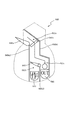
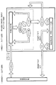
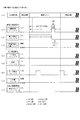
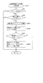
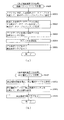
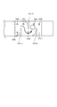
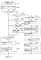
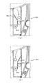
ここで、図3から図5を参照して、普電入賞装置640の構成および普電入賞装置640内に入賞した球の流れについて詳細に説明をする。図3は、普電入賞装置640の内部構成を模式的に示した模式図であって、図4は、普電入賞装置640内に入賞した球がアウト口644へ流入する流れを示した模式図であって、図5は、普電入賞装置640内に入賞した球が特電作動口643に入球する流れを示した模式図である。
Here, with reference to FIG. 3 to FIG. 5, the configuration of the general winning a
本実施形態では、スルーゲート67を球が通過したことを契機に普通図柄の抽選が実行され、普通図柄の抽選で当たりに当選した場合に、電動役物640aを所定の可変パターンで開放動作させる普図当たり遊技が実行される。そして、この普図当たり遊技にて電動役物640aが開放状態へと可変すると、球が普電入賞装置640内へと入賞し得る状態となる。
In the present embodiment, the ordinary symbol lottery is executed in response to the ball passing through the through
図3に示した通り、普電入賞装置640内には第2可動弁642が設けられている。この第2可動弁642は、普図当たり遊技の実行を契機に、普電入賞装置640内に流入し第1流路641aを流下した球を、特電作動口643へと連通する第2流路641bへと誘導可能な第1状態と、アウト口644へと連通する第3流路641cへと誘導可能な第2状態とに所定の可変パターンで可変するように構成されている。また、普電入賞装置640に入賞した球は、球検知センサ640sにより検知され、1回の普図当たり遊技における普電入賞装置640への球の入賞数を計測可能に構成している。詳細な説明は省略するが、本実施形態では、1回の普図当たり遊技にて普電入賞装置640へと入賞した球数が所定個数(例えば10個)に到達した場合には、その時点で普図当たり遊技が終了するように構成している。なお、本実施形態では、球が特電作動口643へと入賞した場合に賞球(4個)が払い出され、アウト口644に入球した場合には賞球が払い出されないように構成している。
As shown in FIG. 3, a second
この普電入賞装置640は、遊技者が普電入賞装置640内の球流れを視認できるように透過性を有するアクリル樹脂でカバー体が形成されており、そのカバー体が遊技盤13に取り付けられている。よって、普電入賞装置640内の球流れを遊技者に視認させることができるため、普電入賞装置640に入賞した球の挙動を遊技者に楽しませることができる。
In this general winning a
普電入賞装置640に設けられた電動役物640aは、第2隔壁640k2の上端部側を回動の基部として設けられており、球が普電入賞装置640へと入賞し難い閉鎖状態(図3参照)と、その閉鎖状態よりも球が普電入賞装置640へと入賞し易い開放状態(図4参照)と、に可変可能に構成されている。図3に示した通り、閉鎖状態中の電動役物640aは、普電入賞装置640内に収納されるように構成されており、具体的には、第2隔壁640k2の垂直線上よりも左側(図3の視点で左側)に第1隔壁640k1の先端部が突出するように構成されており、その第1隔壁640k1の先端部の下方位置に閉鎖状態の電動役物640aが収まるように構成している。このように構成することで、閉鎖状態の電動役物640aが、左打ち遊技によって発射された球と接触し難くすることができるため、電動役物640aが破損する事態を発生させ難くすることができる。
The
詳細な説明は後述するが、本実施形態では普図当たり遊技が実行される時点にて設定されている遊技状態に応じて、普電入賞装置640内に入賞した球が特電作動口643に入賞する確率(入賞のし易さ)を異ならせるように構成している。具体的には、普図当たり遊技が実行されてから電動役物640aが所定の開放パターンで開放制御されるまでの期間(普図当たりオープニング期間)を異ならせることにより、通常状態中に実行される普図当たり遊技にて普電入賞装置640内に入賞した球が、時短状態中に実行される普図当たり遊技にて普電入賞装置640内に入賞した球よりも、特電作動口643に入賞し難くなるように構成している。
Although a detailed description will be given later, in the present embodiment, the ball won in the general
このように構成することで、通常状態中も時短状態中も同一の遊技方法(左打ち遊技)で遊技を行わせる本実施形態のパチンコ機10において、通常状態中に特電作動口643へ球が入賞することを抑制することができる。さらに、本実施形態では、通常状態中に実行される普図当たり遊技のほうが、時短状態中に実行される普図当たり遊技よりも球が普電入賞装置640内に入賞し難い普図当たり遊技が実行されるように構成している。この構成によっても、通常状態中に特電作動口643へ球が入賞することを抑制することができる。つまり、本実施形態では、通常状態中は時短状態中よりも普電入賞装置640内に球を入賞させ難くする対策に加え、通常状態中に普電入賞装置640内に球が入賞した場合には、時短状態中に普電入賞装置640内に球が入賞した場合よりも特電作動口643に球が入賞し難くする対策を有している。このように、通常状態中における特電作動口643への球の入賞を抑制する構成を複数段階で設けることにより、より確実に抑制することができる。
With such a configuration, in the
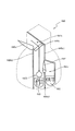
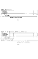
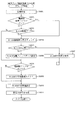
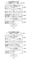
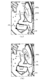
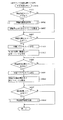
次に、図4を参照して、通常状態が設定されている場合に実行される普図当たり遊技にて球が普電入賞装置640内に入賞した際の球流れについて説明をする。図4は、通常状態中における普図当たり遊技にて普電入賞装置640に入賞した球の流れを示した模式図である。本実施形態では、遊技者に遊技方法を変更させる煩わしさを与えないようにするために、常時左打ち遊技で遊技が実行可能となるように構成している。よって、普通図柄の低確率状態である通常状態中においても、普通図柄の抽選契機が成立し(スルーゲート67へと球が通過し)、普図当たり遊技が実行された場合に普電入賞装置640内に球が入賞する虞があった。
Next, with reference to FIG. 4, a description will be given of a ball flow when a ball has won a prize in the
即ち、通常状態(普通図柄の低確率状態)は、普電入賞装置640内に球を入賞させ易い時短状態(普通図柄の高確率状態)に比べて、普電入賞装置640内に球を入賞させ難い遊技状態ではあるが、本実施形態では、通常状態と時短状態とで同一の遊技方法(左打ち遊技)が実行されるため、低確率ではあるが、通常状態中に普電入賞装置640内に球が入賞してしまう可能性があった。
That is, in the normal state (the low probability state of the ordinary symbol), a ball is awarded in the general electricity
上述した通り、普電入賞装置640内には、V入賞装置65を開放動作させる当たり遊技(役物当たり遊技)の実行契機となる特電作動口643が設けられており、通常状態中に球が特電作動口643へ入球し、役物当たり遊技が実行されてしまうと、通常状態の遊技を行っている遊技者に対して過剰に有利な遊技を提供してしまうという問題があった。
As described above, the special electricity
これに対して、本実施形態では、通常状態中に普電入賞装置640に入賞した球が特電作動口643に入球する割合と、時短状態中に普電入賞装置640に入賞した球が特電作動口643に入球する割合と、を異ならせるように構成している。具体的には、通常状態で普図当たり遊技が実行される場合は、時短状態で普図当たり遊技が実行される場合よりも、普図当たり遊技が開始されてから電動役物640aが開放状態となる(最初に開放状態となる)までの期間を長く設定し、普図当たり遊技の開始に基づいて可動する第2可動弁642が第2状態(普電入賞装置640に入賞した球をアウト口644へと誘導可能な状態)を維持するタイミングでのみ球が普電入賞装置640に入賞し得るように構成している。
On the other hand, in the present embodiment, the ratio of the balls that have won the general
つまり、図4に示した通り、通常状態中に実行される普図当たり遊技中に普電入賞装置640へと球が入賞すると、球の流下期間が約0.5秒に設計された第1流路641aを球が流下し、第2状態に位置する第2可動弁642によって第3流路641cへと誘導され、アウト口644に入球することになる(第2可動弁642に到達してからアウト口644へと入球するまでの期間が約0.3秒に設計)。このように構成することで、たとえ、通常状態中に普電入賞装置640に球が入賞したとしても、特電作動口643に球が入球することを抑制することができるため、通常状態の遊技を行っている遊技者に対して過剰に有利な遊技を提供してしまうことを抑制することができる。
That is, as shown in FIG. 4, when a ball wins the general
また、通常状態中に球が特電作動口643に入球することを抑制するために、通常状態中に実行される普図当たり遊技によって球が普電入賞装置640に入賞しないようにするための特殊な構成を用いる必要が無いため、遊技盤13の設計自由度を高めることができる。
In addition, in order to prevent the ball from entering the special
さらに、詳細な説明は後述するが、通常状態中に実行される普図当たり遊技では、第2可動弁642を第2状態へと可変させるタイミング(普図当たり遊技開始時)が、電動役物640aが開放状態となるタイミング(普図当たり遊技開始から4.1秒後)よりも早く、例え、第2可動弁642が第1状態に位置している状態で普図当たり遊技が開始されたとしても、第2可動弁642が可変動作している際中に球が第2可動弁642に到達することが無いように構成している。このように構成することで、可変動作中の第2可動弁642と普電入賞装置640に入賞した球とが接触してしまい、普電入賞装置640内で球詰まりが発生してしまう事態や、第2可動弁642が故障してしまう事態を防止することができる。
Further, as will be described in detail later, in the game-per-game executed during the normal state, the timing of changing the second
なお、本実施形態では、普電入賞装置640内に設けられた特電作動口643に球が入球した場合には、賞球として4個の球が払い出され、アウト口644に球が入球した場合には、賞球が払い出されないように構成しているが、これに限ること無く、例えば、アウト口644に球が入球した場合には、特電作動口643に球が入球した場合よりも多くの数の賞球(例えば、10個)が払い出されるように構成しても良い。このように構成することで、普通図柄の抽選に基づいて遊技者に付与される特典を遊技状態に応じて可変させることが可能となる。具体的には、通常状態が設定されている状態では、遊技者に対して時短状態よりも多くの賞球を特典として付与し、時短状態が設定されている状態では、遊技者に対して、通常状態よりも少ない賞球に加え、通常状態では付与されない(され難い)役物当たり遊技を特典として付与することができる。よって、何れの遊技状態が設定されている場合であっても、普通図柄の抽選結果に対して遊技者に興味を持たせることができる。
In this embodiment, when a ball enters the special
また、特電作動口643に球が入球した場合と、アウト口644に球が入球した場合と、で同一数の賞球(4個)を払い出すように構成しても良く、この場合、普電入賞装置640に入賞した球が特電作動口643に入球したのか、アウト口644に入球したのかを分かり難くするように構成すると良い。これにより、払い出された賞球の数によって何れの入球口(特電作動口643、アウト口644)に球が入球したのかを遊技者が把握できないため、遊技者に対して普電入賞装置640に球を入賞させた後、V入賞装置65を開放動作させる当たり遊技(役物当たり遊技)が実行されるか否かが抽選で決定されているように思わせる演出を実行することができ、演出効果を高めることができる。さらに、この場合、球検知センサ640sが球を検知した場合に、賞球(4個)を払い出すように構成すると良い、これにより、遊技者に対して普電入賞装置640への球の入賞に基づいて遊技者に付与される賞球をいち早く払い出すことができる。
The same number of prize balls (four) may be paid out when a ball enters the special
図4に示した通り、電動役物640aが開放状態へと位置した場合は、第1隔壁640k1の先端側と電動役物640aとが略並行となりその間に球流路が形成される。よって、開放状態へと位置した電動役物640aが球を受け止めた際に、その衝撃で球が普電入賞装置640外に跳ね返ってしまうことを抑制することができる。
As shown in FIG. 4, when the
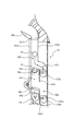
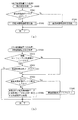
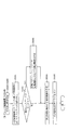
次に、図5を参照して、時短状態が設定されている場合に実行される普図当たり遊技にて球が普電入賞装置640内に入賞した際の球流れについて説明をする。図5は、時短状態中における普図当たり遊技にて普電入賞装置640に入賞した球の流れを示した模式図である。図5に示した通り、時短状態中に普図当たり遊技が実行された場合は、通常状態中に実行される普図当たり遊技よりも、普図当たり遊技が開始されてから電動役物640aが開放状態(最初に開放状態)となるまでの期間が短く設定されているため、第2可動弁642が第1状態(普電入賞装置640に入賞した球を特電作動口643へと誘導可能な状態)を維持しているタイミングで電動役物640aが開放状態となる。
Next, with reference to FIG. 5, a description will be given of a ball flow when a ball wins in the general winning a
よって、普電入賞装置640に入賞した球が第1流路641aを流下し、第2可動弁642へと到達した場合には(普電入賞装置640に球が入賞してから0.5秒には)、第2可動弁642が第1状態に位置しているため、第1流路641aと連通する第2流路641bを流下し(流下期間は約0.2秒に設計)、特電作動口643に入球する。そして、特電作動口643への球の入球を図示しない検知手段(近接センサ)が検知することに基づいてV入賞装置65を開放動作させる役物当たり遊技が開始される。
Therefore, when the ball that has won the general
図5に示した通り、第2可動弁642が第1状態に位置した場合には、第1流路641aを流下(図5の視点で垂直下方向に流下)する球が第2可動弁642と接触し難くなる位置まで、第2可動弁642が可変するように構成している。これにより、球と第2可動弁642とが頻繁に接触してしまい第2可動弁642が故障してしまうことを抑制することができる。なお、詳細な説明は後述するが、時短状態中に普図当たり遊技が実行される場合には、普図当たり遊技が開始されてから0.1秒後に電動役物640aが開放状態となり、普電入賞装置640に球が入賞可能な状態となる。よって、普図当たり遊技が実行されてから第2可動弁642の位置に球を到達させるまでの最短期間は、0.6秒(普図当たり遊技が開始してから電動役物640aが開放状態となるまでの0.1秒と、普電入賞装置640に入賞した球が第2可動弁642に到達するまでの0.5秒とを、合算した値)となる。
As shown in FIG. 5, when the second
第2可動642は、普図当たり遊技が開始されると同時に可変動作し、その可変動作期間(第1状態から第2状態(第2状態から第1状態)へと可変させるために要する期間)が0.1秒となるように構成している。また、普図当たり遊技にて電動役物640aが閉鎖状態となってから1秒後に第2可動弁642を可変動作させるように構成しているため、電動役物640aが閉鎖状態へと可変される直前に普電入賞装置640に入賞した球が第2可動弁642に到達するまでの期間(0.5秒)の倍の期間(1秒)が経過した場合に第2可動弁642を可変動作するように構成している。よって、時短状態中に実行される普図当たり遊技においても、可変動作中の第2可動弁642と球とが接触し難くすることができる。
The second movable 642 operates variably at the same time as the start of the game per ordinary drawing, and its variable operation period (a period required for changing from the first state to the second state (the second state to the first state)). Is set to 0.1 second. In addition, since the second
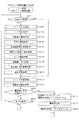
図2に戻り説明を続ける。可変表示装置ユニット80の左方(図2の視点で左方)には、左打ち遊技によって発射され左側領域を流下する球が入賞し得るようにV入賞装置65が設けられている。ここで、図6から図9を参照して、V入賞装置65の具体的な構成、及び、V入賞装置65内に入賞した球の流れについて説明をする。本実施形態では、普電入賞装置640内に設けられた特電作動口643に球が入球したことを契機に、V入賞装置65を開放動作させる役物当たり遊技が実行されるように構成している。そして、V入賞装置65内に設けられたV入賞口165に球が入賞することで大当たり遊技(V大当たり遊技)が実行されるように構成している。
Returning to FIG. 2, the description will be continued.
つまり、本実施形態では、特別図柄の抽選で大当たり当選した場合に成立する大当たり遊技(特図大当たり遊技)の実行契機に加え、特定の入賞口(V入賞口165)に球が入賞した場合に成立する大当たり遊技(V大当たり遊技)の実行契機を有している。このように、大当たり遊技を実行させるための契機を複数設けることにより、遊技者に対して飽きの来ない遊技を提供することができる。 That is, in the present embodiment, in addition to the execution timing of the jackpot game (special figure jackpot game) which is established when the jackpot is won by the special symbol lottery, when the ball wins a specific winning opening (V winning opening 165). There is an opportunity to execute the jackpot game to be established (V jackpot game). Thus, by providing a plurality of occasions for executing the jackpot game, it is possible to provide the player with a game that does not get tired.
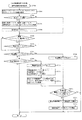
まず、図6を参照して、V入賞装置65の構成について説明をする。V入賞装置65には、V入賞装置65内に球が入賞し易い開放状態と、その開放状態よりも球が入賞し難い閉鎖状態とに可変可能な開閉扉65aが設けられている。この開閉扉65aは、遊技盤13の左側領域を流下する球が到達し得る位置(図2参照)に設けられており、役物当たり遊技が実行される場合に開放状態へと可変される。
First, the configuration of the
V入賞装置65内には、開放状態中の開閉扉65aを通過した球が流下する第1流路65bが第1隔壁65k1と第2隔壁65k2との間の空間に形成され、その第1流路65bを流下した球(流下期間0.5秒)が到達する位置に貯留弁66aが設けられている。この貯留弁66aの上面には球を1個貯留可能な貯留部が形成されており、役物当たり遊技中に最初にV入賞装置65に入賞した球が貯留部に一時的に貯留するように構成している。また、貯留弁66aの上方には貯留センサ65sが設けられており、球が貯留部に貯留されていることを検知可能に構成している。さらに、V入賞装置65に入賞した球を検知するための球検知センサ65s2が第1流路65bの上流側に設けられており、球検知センサ65s2が球を検知したことに基づいて、役物当たり遊技中にV入賞装置65へと入賞した球数を計測すると共に、入賞した球に対する賞球払出制御が実行される。このように、V入賞装置65に入賞した球が直後に流下する位置に球検知センサ65s2を設けることにより、V入賞装置65へと規定数以上の球が入賞してしまう事態を抑制することができると共に、役物当たり遊技中の賞球を遊技者に即座に付与することができる。
In the
また、第1流路65bと連通するように第2流路65cが形成されており、第2流路65cの下流側には、第1アウト口163aが設けられている。図6に示した通り、第2流路65cは、第1流路65bを流下した球が直接流入するのでは無く、貯留弁66aの貯留部に球が貯留されている状態で、第1流路65bを流下した後続の球が、貯留弁66aの貯留部に貯留されている球と接触し、第2流路65cへと誘導されるように構成している。第2流路65cの下流側に設けられた第1アウト口163aは、入球した球をパチンコ機10の外部へと排出するための入球口であって、第2流路65cを流下(流下期間0.1秒)し、第1アウト口163aに入球した球は、図示しない球排出経路を流下してパチンコ機10の外部へと排出される。
Further, a
詳細な説明は後述するが、貯留弁66aは、役物当たり遊技の進行に応じて(役物当たり遊技が実行される動作シナリオに対応させて)、球を貯留可能な貯留状態と、その貯留状態よりも球を貯留し難い解除状態と、に可変動作されるように構成している。この貯留弁66aが解除状態に位置すると、第1流路65bと、第3流路65dと、が連通し、第1流路65bを流下した球、又は、貯留弁66aの貯留部に貯留されていた球が第3流路65dを流下する。この第3流路65dは、第1隔壁65k1の下端側と、第3隔壁65k3との間の空間に形成された幅が約15ミリの垂直方向に直線状に形成された流路である。
As will be described in detail later, the
第3流路65dの下流側が臨む位置には、第1可動弁66bが配設されている。この第1可動弁66bは、パチンコ機10に電源が投入されたことを契機に予め定められた可動パターンで、第3流路65dを流下した球を受け止め可能な誘導位置(突出位置)と、第3流路65dを流下した球を受け止め不可能な通過位置(埋没位置)と、に可動するように構成している。具体的には、主制御装置110の入出力ポート205に接続され、主制御装置110によって駆動制御される第1可動弁ソレノイド209dの動作に応じて可動するように構成しており、第1可動弁ソレノイド209dがオンに設定された場合(通電させた場合)に、第1可動弁66bがV入賞装置65内から退避する通過位置(遊技盤13に埋没する位置)へと可動し、第1可動弁ソレノイド209dがオフに設定された場合(電気を遮断させた場合)に、第1可動弁66bがV入賞装置65内に突出する誘導位置(遊技盤13から突出する位置)へと可動するように構成している。
The first
誘導位置(突出位置)に位置する第1可動弁66bは、その上面を球が流下可能に構成されており、図6に示した通り、第1可動弁66bの上面の下流端側が第4流路65eに向けて下り傾斜するように構成している。よって、第1可動弁66bが誘導位置(突出位置)に位置した状態で第3流路65dを流下した球(流下期間0.2秒)は、第1可動弁66bの上面を第4流路65eに向けて流下することになる。第4流路65eの下流側には第2アウト口163bが設けられており、第4流路65eを流下した球(流下期間0.2秒)は第2アウト口163bに入球する。この第2アウト口163bは、上述した第1アウト口163aと同様に、入球した球をパチンコ機10の外部へと排出させるための入球口であって、第2アウト口163bに入球した球は図示しない球排出経路を流下し、パチンコ機10の外部へと排出される。
The first
一方、第1可動弁66bが通過位置に位置している状態では、第3流路65dと、第5流路65fとが連通し、第3流路65dを流下した球(流下期間0.2秒)が第5流路65f(流下期間0.1秒)へと流入する。そして、第5流路65fの下流側にはV入賞口165が設けられている。V入賞口165は、大当たり遊技を実行するための契機となり得る入賞口であって、大当たり遊技が実行されていない状態で球がV入賞口165に入賞した場合に、大当たり遊技が実行される。
On the other hand, in a state where the first
図6に示した通り、V入賞装置65内には、第1アウト口163aと、第2アウト口163bとが設けられている。このように構成することで、貯留弁66aが貯留状態である場合にV入賞装置65に入賞した球が、貯留弁66aが解除状態となった場合に球が通過し得る流路(第3流路65d、第4流路65e、第5流路65f)へと流入することを確実に防止することができる。なお、本実施形態の構成に限ること無く、例えば、第1アウト口163aを排除し、第2流路65cと、第4流路65eと、を連通させ、貯留弁66aが貯留状態であって、第2流路65cを流下した球が、第2アウト口163bへと入球するように構成しても良い。この場合、図6では垂直方向に直線的に設けられている第3隔壁65k3を、上端側から下端側に向けて図6の視点で右下方向へと傾けて、即ち、隔壁65k3の下端側方向に向けての延長線上が第4隔壁65k4の右側(図6の視点で右側)となるように設けると良い。このように構成することで、第2流路65cを流下した球が第5流路65fへと流入してしまう事態を抑制することができる。
As shown in FIG. 6, the
このように、本実施形態では、大当たり遊技を実行させる契機が2つ、即ち、特別図柄の抽選によって大当たり当選したことを契機として大当たり遊技を実行させる場合と、役物当たり遊技中に球がV入賞口165へと入賞したことを契機として大当たり遊技を実行させる場合とがある。以降、実行契機を区分けして大当たり遊技を説明する際に、V入賞口165へと入賞したことを契機として実行される大当たり遊技のことをV大当たり遊技とも称す。
As described above, in the present embodiment, there are two occasions for executing the jackpot game, that is, the case where the jackpot game is executed when the jackpot is won by the special symbol lottery, and the case where the ball There is a case where the jackpot game is executed when the winning is made to the winning
上述した通り、本実施形態のV入賞装置65は、役物当たり遊技が実行されることで球が入賞可能な開放状態となり、貯留弁66aに貯留された1個の球のみが第3流路65dを流下するように構成し、第3流路65dを流下した球が第1可動弁66bに到達した際における第1可動弁66bの稼働状況に応じて、V入賞口165に球が入賞するか否かが決定するように構成している。
As described above, the
詳細な説明は後述するが、第1可動弁66bは、誘導位置に位置する時間(球がV入賞口165へと入賞し得ない時間)が5秒に対して、通過位置に位置する時間(球がV入賞口165へと入賞し得る時間)が0.5秒となる可動パターンで常時可動しているため、第3流路65dを流下した球がV入賞口165へと入賞する割合は、約1/11となる。
Although a detailed description will be given later, the first
また、1回の役物当たり遊技においてV入賞装置65へと複数個の球を入賞させたとしても、第3流路65dを流下させる球数が1個となるように貯留弁66aが動作制御されるため、役物当たり遊技が11回実行された場合に1回の大当たり遊技が実行される割合となるように構成している。
In addition, even if a plurality of balls are won in the V-
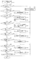
次に、図7から図9を参照して、役物当たり遊技の実行中におけるV入賞装置65に入賞した球流れの内容について説明をする。まず、図7を参照して、役物当たり遊技の前半期間(貯留弁66aが貯留状態である期間)における球流れについて説明をする。図7は、役物当たり遊技のうち、貯留弁66aが貯留状態である場合におけるV入賞装置65内の球流れを示す模式図である。詳細な説明は後述するが、貯留弁66aは、役物当たり遊技が実行されてから、V入賞装置65が閉鎖状態となるまでの間、貯留状態となるように動作制御されるように構成している。そして、貯留弁66aが貯留状態中に複数の球がV入賞装置65に入賞した場合には、最初に入賞した球P1が貯留弁66aに形成される貯留部に貯留され、次点で入賞した球P2は、貯留弁66aに貯留されている球P1と当接し、第2流路65cを流下し、アウト口163aに入球する。
Next, with reference to FIG. 7 to FIG. 9, a description will be given of the content of the ball flow that has won the
このように、貯留弁66aが貯留状態である場合は、貯留弁66aの貯留部に貯留された球P1以外の入賞球(例えば、球P2)が、全てアウト口163aに入球するように構成しているため、複数の球がV入賞装置65内に滞留することが無い。また、貯留弁66aは、V入賞装置65のV開閉扉65aが閉鎖状態となってから(閉鎖状態にさせるための動作制御を実行してから)、貯留状態が解除されるため、1回の役物当たり遊技にて第3流路65dを流下させる球数を確実に1個にすることが可能となる。
As described above, when the
このように構成することで、役物当たり遊技中にV入賞装置65へと球を入賞させるタイミングや、入賞数に応じて、V入賞口165への球の入賞のし易さが可変することが無いため、全ての遊技者に対して公平な遊技を提供することができる。
With such a configuration, the ease with which a ball can be awarded to the
次に、図8を参照して、貯留弁66aが貯留状態から解除状態へと移行した際の球流れ(役物当たり遊技の後半期間)の内容について説明をする。図8は、役物当たり遊技のうち、貯留弁66aが貯留状態から解除状態へと移行した場合における球流れを示す模式図である。図8に示した通り、V開閉扉65aが閉鎖状態となり、新たな球がV入賞装置65に入賞し得ない状態となった後に、貯留弁66aが解除状態(図では点線で表示)へと移行すると、貯留弁66aの貯留部に貯留されていた球P1(図7参照)が、第3流路65dを流下する。図8に示した状態では、第1可動弁66bが誘導位置に位置しているため、球P1が第1可動弁66bの上面に形成された下り傾斜を転動し、第4流路65eを流下し、第2アウト口163bに入球する。
Next, with reference to FIG. 8, a description will be given of the content of the ball flow (the latter half period of the game per accessory) when the
一方、貯留弁66aの貯留部に貯留されていた球P1(図7参照)が、第3流路65dを流下し、第1可動弁66bに到達したタイミングで、第1可動弁66bが通過位置に位置している場合の球流れについて、図9を参照して説明をする。図9は、役物当たり遊技のうち、貯留弁66aが貯留状態から解除状態へと移行した場合における球流れを示す模式図である。図9に示した通り、第3流路65dを流下した球が第1可動弁66bに到達したタイミングにおいて、第1可動弁66bが通過位置に位置している場合は、第5流路66fを流下し、V入賞口165へと入賞する。
On the other hand, when the ball P1 (see FIG. 7) stored in the storage portion of the
図2に戻り説明を続ける。可変表示装置ユニット80の下方には、球が入球し得る特図入球口64が配設されている。この特図入球口64へ球が入球すると遊技盤13の裏面側に設けられる特図入球口スイッチ(図示せず)がオンとなり、その特図入球口スイッチのオンに起因して主制御装置110(図21参照)で大当たりの抽選がなされ、その抽選結果に応じた表示が第1図柄表示装置37aで示される。また、特図入球口64に球が入球した場合には、特典として4個の賞球が払い出される。本実施形態では、左打ち遊技によって発射された球のうち、約15球に1球の割合で球が特図入球口64へと入球し得るように構成している。
Returning to FIG. 2, the description will be continued. Below the
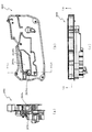
図10に示すように、パチンコ機10の後面側には、制御基板ユニット90,91と、裏パックユニット94とが主に備えられている。制御基板ユニット90は、主基板(主制御装置110)と音声ランプ制御基板(音声ランプ制御装置113)と表示制御基板(表示制御装置114)とが搭載されてユニット化されている。制御基板ユニット91は、払出制御基板(払出制御装置111)と発射制御基板(発射制御装置112)と電源基板(電源装置115)とカードユニット接続基板116とが搭載されてユニット化されている。
As shown in FIG. 10, on the rear side of the
裏パックユニット94は、保護カバー部を形成する裏パック92と払出ユニット93とがユニット化されている。また、各制御基板には、各制御を司る1チップマイコンとしてのMPU、各種機器との連絡をとるポート、各種抽選の際に用いられる乱数発生器、時間計数や同期を図る場合などに使用されるクロックパルス発生回路等が、必要に応じて搭載されている。
In the
なお、主制御装置110、音声ランプ制御装置113及び表示制御装置114、払出制御装置111及び発射制御装置112、電源装置115、カードユニット接続基板116は、それぞれ基板ボックス100〜104に収納されている。基板ボックス100〜104は、ボックスベースと該ボックスベースの開口部を覆うボックスカバーとを備えており、そのボックスベースとボックスカバーとが互いに連結されて、各制御装置や各基板が収納される。
The
また、基板ボックス100(主制御装置110)及び基板ボックス102(払出制御装置111及び発射制御装置112)は、ボックスベースとボックスカバーとを封印ユニット(図示せず)によって開封不能に連結(かしめ構造による連結)している。また、ボックスベースとボックスカバーとの連結部には、ボックスベースとボックスカバーとに亘って封印シール(図示せず)が貼着されている。この封印シールは、脆性な素材で構成されており、基板ボックス100,102を開封するために封印シールを剥がそうとしたり、基板ボックス100,102を無理に開封しようとすると、ボックスベース側とボックスカバー側とに切断される。よって、封印ユニット又は封印シールを確認することで、基板ボックス100,102が開封されたかどうかを知ることができる。
Further, the substrate box 100 (main control device 110) and the substrate box 102 (dispensing
払出ユニット93は、裏パックユニット94の最上部に位置して上方に開口したタンク130と、タンク130の下方に連結され下流側に向けて緩やかに傾斜するタンクレール131と、タンクレール131の下流側に縦向きに連結されるケースレール132と、ケースレール132の最下流部に設けられ、払出モータ216(図21参照)の所定の電気的構成により球の払出を行う払出装置133とを備えている。タンク130には、遊技ホールの島設備から供給される球が逐次補給され、払出装置133により必要個数の球の払い出しが適宜行われる。タンクレール131には、当該タンクレール131に振動を付加するためのバイブレータ134が取り付けられている。
The dispensing
また、払出制御装置111には状態復帰スイッチ120が設けられ、発射制御装置112には可変抵抗器の操作つまみ121が設けられ、電源装置115にはRAM消去スイッチ122が設けられている。状態復帰スイッチ120は、例えば、払出モータ216(図21参照)部の球詰まり等、払出エラーの発生時に球詰まりを解消(正常状態への復帰)するために操作される。操作つまみ121は、発射ソレノイドの発射力を調整するために操作される。RAM消去スイッチ122は、パチンコ機10を初期状態に戻したい場合に電源投入時に操作される。
The dispensing
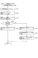
次に、図21を参照して、本パチンコ機10の電気的構成について説明する。図21は、パチンコ機10の電気的構成を示すブロック図である。
Next, the electrical configuration of the
主制御装置110には、演算装置である1チップマイコンとしてのMPU201が搭載されている。MPU201には、該MPU201により実行される各種の制御プログラムや固定値データを記憶したROM202と、そのROM202内に記憶される制御プログラムの実行に際して各種のデータ等を一時的に記憶するためのメモリであるRAM203と、そのほか、割込回路やタイマ回路、データ送受信回路などの各種回路が内蔵されている。主制御装置110では、MPU201によって、大当たり抽選や第1図柄表示装置37a,37b及び第3図柄表示装置81における表示の設定、第2図柄表示装置における表示結果の抽選といったパチンコ機10の主要な処理を実行する。
The
なお、払出制御装置111や音声ランプ制御装置113などのサブ制御装置に対して動作を指示するために、主制御装置110から該サブ制御装置へ各種のコマンドがデータ送受信回路によって送信されるが、かかるコマンドは、主制御装置110からサブ制御装置へ一方向にのみ送信される。
Various commands are transmitted from the
RAM203は、各種エリア、カウンタ、フラグのほか、MPU201の内部レジスタの内容やMPU201により実行される制御プログラムの戻り先番地などが記憶されるスタックエリアと、各種のフラグおよびカウンタ、I/O等の値が記憶される作業エリア(作業領域)とを有している。なお、RAM203は、パチンコ機10の電源の遮断後においても電源装置115からバックアップ電圧が供給されてデータを保持(バックアップ)できる構成となっており、RAM203に記憶されるデータは、すべてバックアップされる。
The
停電などの発生により電源が遮断されると、その電源遮断時(停電発生時を含む。以下同様)のスタックポインタや、各レジスタの値がRAM203に記憶される。一方、電源投入時(停電解消による電源投入を含む。以下同様)には、RAM203に記憶される情報に基づいて、パチンコ機10の状態が電源遮断前の状態に復帰される。RAM203への書き込みはメイン処理(図示せず)によって電源遮断時に実行され、RAM203に書き込まれた各値の復帰は電源投入時の立ち上げ処理(図示せず)において実行される。なお、MPU201のNMI端子(ノンマスカブル割込端子)には、停電等の発生による電源遮断時に、停電監視回路252からの停電信号SG1が入力されるように構成されており、その停電信号SG1がMPU201へ入力されると、停電時処理としてのNMI割込処理(図示せず)が即座に実行される。
When the power is shut down due to the occurrence of a power failure or the like, the stack pointer and the value of each register at the time of the power shutdown (including when a power failure occurs; the same applies hereinafter) are stored in the
主制御装置110のMPU201には、アドレスバス及びデータバスで構成されるバスライン204を介して入出力ポート205が接続されている。入出力ポート205には、払出制御装置111、音声ランプ制御装置113、第1図柄表示装置37a,37b、第2図柄表示装置、第2図柄保留ランプが接続される。また、大当たり遊技が実行される場合に可変入賞装置650の特定入賞口650aを開状態と閉状態とに可変させるための開閉扉を開閉駆動するための特定入賞口ソレノイド209a、V入賞装置65の開閉扉を開閉駆動するためのV入賞口ソレノイド209b、V入賞装置65内に設けられた貯留弁66aを可変駆動させるための貯留ソレノイド209c、同じく、V入賞装置65内に設けられた第1可動弁66bを可変駆動させるための第1可動弁ソレノイド209d、普電入賞装置640内に設けられた第2可動弁641を可変駆動させるための第2可動弁ソレノイド209e、その他の各種装置を駆動させるためのその他ソレノイド209z等からなるソレノイド209が接続され、MPU201は、入出力ポート205を介してこれらに対し各種コマンドや制御信号を送信する。
An input /
また、入出力ポート205には、図示しないスイッチ群(各入球口に球が入球したことを検知するスイッチや、球が特定位置に位置していることを検知するスイッチ等)からなる各種スイッチ208、電源装置115に設けられた後述のRAM消去スイッチ回路253が接続され、MPU201は各種スイッチ208から出力される信号や、RAM消去スイッチ回路253より出力されるRAM消去信号SG2に基づいて各種処理を実行する。
The input /
払出制御装置111は、払出モータ216を駆動させて賞球や貸出球の払出制御を行うものである。演算装置であるMPU211は、そのMPU211により実行される制御プログラムや固定値データ等を記憶したROM212と、ワークメモリ等として使用されるRAM213とを有している。
The
払出制御装置111のRAM213は、主制御装置110のRAM203と同様に、MPU211の内部レジスタの内容やMPU211により実行される制御プログラムの戻り先番地などが記憶されるスタックエリアと、各種のフラグおよびカウンタ、I/O等の値が記憶される作業エリア(作業領域)とを有している。RAM213は、パチンコ機10の電源の遮断後においても電源装置115からバックアップ電圧が供給されてデータを保持(バックアップ)できる構成となっており、RAM213に記憶されるデータは、すべてバックアップされる。なお、主制御装置110のMPU201と同様、MPU211のNMI端子にも、停電等の発生による電源遮断時に停電監視回路252から停電信号SG1が入力されるように構成されており、その停電信号SG1がMPU211へ入力されると、停電時処理としてのNMI割込処理(図示せず)が即座に実行される。
Like the
払出制御装置111のMPU211には、アドレスバス及びデータバスで構成されるバスライン214を介して入出力ポート215が接続されている。入出力ポート215には、主制御装置110や払出モータ216、発射制御装置112などがそれぞれ接続されている。また、図示はしないが、払出制御装置111には、払い出された賞球を検出するための賞球検出スイッチが接続されている。なお、該賞球検出スイッチは、払出制御装置111に接続されるが、主制御装置110には接続されていない。
An input /
発射制御装置112は、主制御装置110により球の発射の指示がなされた場合に、操作ハンドル51の回動操作量に応じた球の打ち出し強さとなるよう球発射ユニット112aを制御するものである。球発射ユニット112aは、図示しない発射ソレノイドおよび電磁石を備えており、その発射ソレノイドおよび電磁石は、所定条件が整っている場合に駆動が許可される。具体的には、遊技者が操作ハンドル51に触れていることをタッチセンサ51aにより検出し、球の発射を停止させるための発射停止スイッチ51bがオフ(操作されていないこと)を条件に、操作ハンドル51の回動操作量(回動位置)に対応して発射ソレノイドが励磁され、操作ハンドル51の操作量に応じた強さで球が発射される。
The
音声ランプ制御装置113は、音声出力装置(図示しないスピーカなど)226における音声の出力、ランプ表示装置(電飾部29〜33、表示ランプ34など)227における点灯および消灯の出力、変動演出(変動表示)や予告演出といった表示制御装置114で行われる第3図柄表示装置81の表示態様の設定などを制御するものである。演算装置であるMPU221は、そのMPU221により実行される制御プログラムや固定値データ等を記憶したROM222と、ワークメモリ等として使用されるRAM223とを有している。
The sound
音声ランプ制御装置113のMPU221には、アドレスバス及びデータバスで構成されるバスライン224を介して入出力ポート225が接続されている。入出力ポート225には、主制御装置110、表示制御装置114、音声出力装置226、ランプ表示装置227、その他装置228、枠ボタン22などがそれぞれ接続されている。その他装置228には、パチンコ機10に設けられる演出用の駆動役物を動作させるための各種駆動モータが含まれる。
The input /
音声ランプ制御装置113は、主制御装置110から受信した各種のコマンド(変動パターンコマンド、停止種別コマンド等)に基づいて、第3図柄表示装置81の表示態様を決定し、決定した表示態様をコマンド(表示用変動パターンコマンド、表示用停止種別コマンド等)によって表示制御装置114へ通知する。また、音声ランプ制御装置113は、枠ボタン22からの入力を監視し、遊技者によって枠ボタン22が操作された場合は、第3図柄表示装置81で表示されるステージを変更したり、スーパーリーチ時の演出内容を変更したりするように、表示制御装置114へ指示する。ステージが変更される場合は、変更後のステージに応じた後面画像を第3図柄表示装置81に表示させるべく、変更後のステージに関する情報を含めた後面画像変更コマンドを表示制御装置114へ送信する。ここで、後面画像とは、第3図柄表示装置81に表示させる主要な画像である第3図柄の後面側に表示される画像のことである。表示制御装置114は、この音声ランプ制御装置113から送信されるコマンドに従って、第3図柄表示装置81に各種の画像を表示する。
The sound
なお、遊技者によって枠ボタン22が操作された場合に、図示しない演出用の役物を駆動させるためにその他装置228へ役物駆動コマンドを送信したり、枠ボタン22への操作内容に対応した音声を音声出力装置226に出力させるための音声出力コマンドを設定したり、枠ボタン22への操作内容に対応した発光態様でランプ表示装置227を発光させるためのランプ出力コマンドを設定したりするように構成しても良い。
In addition, when the
また、音声ランプ制御装置113は、表示制御装置114から第3図柄表示装置81の表示内容を表すコマンド(表示コマンド)を受信する。音声ランプ制御装置113では、表示制御装置114から受信した表示コマンドに基づき、第3図柄表示装置81の表示内容に合わせて、その表示内容に対応する音声を音声出力装置226から出力し、また、その表示内容に対応させてランプ表示装置227の点灯および消灯を制御する。
Further, the sound
表示制御装置114は、音声ランプ制御装置113及び第3図柄表示装置81が接続され、音声ランプ制御装置113より受信したコマンドに基づいて、第3図柄表示装置81における第3図柄の変動演出などの表示を制御するものである。また、表示制御装置114は、第3図柄表示装置81の表示内容を通知する表示コマンドを適宜音声ランプ制御装置113へ送信する。音声ランプ制御装置113は、この表示コマンドによって示される表示内容にあわせて音声出力装置226から音声を出力することで、第3図柄表示装置81の表示と音声出力装置226からの音声出力とをあわせることができる。
The
電源装置115は、パチンコ機10の各部に電源を供給するための電源部251と、停電等による電源遮断を監視する停電監視回路252と、RAM消去スイッチ122(図10参照)が設けられたRAM消去スイッチ回路253とを有している。電源部251は、図示しない電源経路を通じて、各制御装置110〜114等に対して各々に必要な動作電圧を供給する装置である。その概要としては、電源部251は、外部より供給される交流24ボルトの電圧を取り込み、各種スイッチ208などの各種スイッチや、ソレノイド209などのソレノイド、モータ等を駆動するための12ボルトの電圧、ロジック用の5ボルトの電圧、RAMバックアップ用のバックアップ電圧などを生成し、これら12ボルトの電圧、5ボルトの電圧及びバックアップ電圧を各制御装置110〜114等に対して必要な電圧を供給する。
The
停電監視回路252は、停電等の発生による電源遮断時に、主制御装置110のMPU201及び払出制御装置111のMPU211の各NMI端子へ停電信号SG1を出力するための回路である。停電監視回路252は、電源部251から出力される最大電圧である直流安定24ボルトの電圧を監視し、この電圧が22ボルト未満になった場合に停電(電源断、電源遮断)の発生と判断して、停電信号SG1を主制御装置110及び払出制御装置111へ出力する。停電信号SG1の出力によって、主制御装置110及び払出制御装置111は、停電の発生を認識し、NMI割込処理を実行する。なお、電源部251は、直流安定24ボルトの電圧が22ボルト未満になった後においても、NMI割込処理の実行に充分な時間の間、制御系の駆動電圧である5ボルトの電圧の出力を正常値に維持するように構成されている。よって、主制御装置110及び払出制御装置111は、NMI割込処理(図示せず)を正常に実行し完了することができる。
The power failure monitoring circuit 252 is a circuit for outputting a power failure signal SG1 to each NMI terminal of the
RAM消去スイッチ回路253は、RAM消去スイッチ122(図10参照)が押下された場合に、主制御装置110へ、バックアップデータをクリアさせるためのRAM消去信号SG2を出力するための回路である。主制御装置110は、パチンコ機10の電源投入時に、RAM消去信号SG2を入力した場合に、バックアップデータをクリアすると共に、払出制御装置111においてバックアップデータをクリアさせるための払出初期化コマンドを払出制御装置111に対して送信する。
The RAM
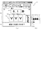
次に、本実施形態における第3図柄表示装置81の表示内容について図11〜図19を参照して説明する。図11(a)および(b)は本実施形態における第3図柄表示装置81の表示内容を模式的に示した模式図である。第3図柄表示装置81は、15インチサイズの液晶ディスプレイで構成されるものであり、後述する表示制御装置114によって表示内容が制御されることにより、例えば上、中及び下の3つの図柄列(L1〜L3)が表示される(図11(b)参照)。第3図柄表示装置81の表示画面に表示される第3図柄(特別図柄)の変動表示に対応して変動する装飾図柄)は、「0」から「9」の数字を模した識別情報が付された10種類の主図柄によりそれぞれ構成されている。
Next, display contents of the third
本実施形態のパチンコ機10では、主図柄が数字を模した識別情報に応じて異なる種類の表示態様を用いて形成されている。このように、各識別情報に対応させた表示態様を用いることで、遊技者に対して特別図柄の抽選結果を視覚的に報知することができるため分かり易い遊技を行わせることができる。また、本実施形態のパチンコ機10においては、後述する主制御装置110による抽選結果が大当たりであった場合に、同一の主図柄が揃う(例えば「777」)変動表示が行われ、その変動表示が終わった後に大当たりが発生するよう構成されている。つまり、第3図柄は、主制御装置110による特別図柄の抽選結果を示すための図柄として第3図柄表示装置81に表示されるものである。
In the
主表示領域Dmは、左・中・右のそれぞれ3つの図柄列Z1,Z2,Z3が表示される。各図柄列Z1〜Z3には、上述した第3図柄が規定の順序で表示される。即ち、各図柄列Z1〜Z3には、数字の昇順または降順に主図柄が配列され、図柄列Z1〜Z3毎に周期性をもって上下方向へスクロールして変動表示が行われる。 The main display area Dm displays three symbol rows Z1, Z2, and Z3 for left, middle, and right. In each of the symbol rows Z1 to Z3, the above-described third symbol is displayed in a prescribed order. That is, the main symbols are arranged in the symbol rows Z1 to Z3 in ascending or descending numerical order, and the symbol rows Z1 to Z3 are scrolled up and down periodically to perform variable display.
そして、図11(a)に示した通り、主表示領域Dmは、左右方向に形成される1つの有効ラインL1を有しており、各図柄列Z1〜Z3が停止表示された状態で、第3図柄が有効ラインL1上に大当たり図柄の組合せ(本第1実施形態では、同一の主図柄の組合せ)で揃って停止されれば、大当たりとして大当たり動画が表示される。 Then, as shown in FIG. 11A, the main display area Dm has one effective line L1 formed in the left-right direction, and in a state where the symbol rows Z1 to Z3 are stopped and displayed, If all three symbols are stopped on the activated line L1 in a combination of big hit symbols (in the first embodiment, the same combination of main symbols), a big hit video is displayed as a big hit.
なお、第3図柄表示装置81における第3図柄の変動表示の態様は、上記のものに限定されることはなく任意であり、図柄列の数、図柄列における図柄の変動表示の方向、各図柄列の図柄数などは適宜変更可能である。また、第3図柄表示装置81にて変動表示される図柄は上記に限られることはなく、例えば図形やキャラクタ等の画像と数字とを組み合わせた図柄を第3図柄として構成してもよい。さらに、第3図柄が変動表示される領域を可変させる構成にしてもよく、例えば、第3図柄表示装置81の表示画面上で特定の演出が実行される場合は、第3図柄の変動表示領域を小さくしたり、変動表示領域を遊技者が視認し難い位置(例えば、表示画面の隅部)へと移動させたりすることで、第3図柄が変動しているか否かを遊技者が分かり難くするようにしてもよい。また、特別図柄が変動している期間中に、第3図柄の変動を一旦停止(仮停止)させ、再度変動させるように構成してもよい。
In addition, the mode of the variable display of the third symbol in the third
さらに、本実施形態では、特別図柄の変動に対応した第3図柄を変動表示(動的表示)させるように構成しているが、これに限ること無く、普通図柄の変動に対応した第3図柄を変動表示(動的表示)させるように構成しても良い。この場合、第3図柄表示装置81の表示面にて実行されている第3図柄の変動表示が特別図柄の変動に対応しているのか、普通図柄の変動に対応しているのかを、遊技者に分かり難く報知するように構成しても良い。これにより、第3図柄表示装置81の表示面にて実行されている第3図柄の変動表示の結果に応じてどのような特典が遊技者に付与されるのかを分かり難くすることができる。
Further, in the present embodiment, the third symbol corresponding to the change of the special symbol is configured to be changed (dynamic display). However, the present invention is not limited to this. May be configured to perform variable display (dynamic display). In this case, the player determines whether the variation display of the third symbol executed on the display surface of the third
また、特別図柄の変動(抽選)に対応した変動表示と、普通図柄の変動(抽選)に対応した変動表示と、を共に実行可能に構成したパチンコ機10であれば、実行される遊技内容(遊技状態)に応じて第3図柄の対象を切り替えるように構成しても良く、例えば、通常状態中は特別図柄の変動(抽選)に対応させた第3図柄の変動表示を実行し、時短状態中は普通図柄の変動(抽選)に対応させた第3図柄の変動表示を実行するように構成しても良い。この場合、遊技者に有利な抽選(遊技者が抽選結果をより注視する側の抽選)が実行される図柄種別に対応させて第3図柄を変動表示させると良い。一方、変動している図柄の種別に対応するように第3図柄の表示態様や表示領域を異ならせても良い。これにより分かり易い遊技を遊技者に提供することができる。
Further, if the
図11(a)に示すように、第3図柄表示装置81の表示画面は、大きくは上下に2分割され、下側の2/3が第3図柄を変動表示する主表示領域Dm、それ以外の上側の1/3が予告演出、キャラクタおよび保留球数などを表示する副表示領域Dsとなっている。
As shown in FIG. 11 (a), the display screen of the third
主表示領域Dmは、左・中・右の3つの表示領域Dm1〜Dm3に区分けされており、その3つの表示領域Dm1〜Dm3に、それぞれ3つの図柄列Z1,Z2,Z3が表示される。各図柄列Z1〜Z3には、上述した第3図柄が規定の順序で表示される。即ち、各図柄列Z1〜Z3には、数字の昇順または降順に主図柄が配列され、図柄列Z1〜Z3毎に周期性をもって上から下へとスクロールして変動表示が行われる。特に、左図柄列Z1においては主図柄の数字が降順に現れるように配列され、中図柄列Z2及び右図柄列Z3においては主図柄の数字が昇順に現れるように配列されている。 The main display area Dm is divided into three display areas Dm1 to Dm3 of left, middle, and right, and three symbol arrays Z1, Z2, and Z3 are displayed in the three display areas Dm1 to Dm3, respectively. In each of the symbol rows Z1 to Z3, the above-described third symbol is displayed in a prescribed order. That is, the main symbols are arranged in the symbol columns Z1 to Z3 in ascending or descending numerical order, and the symbol columns Z1 to Z3 are scrolled from top to bottom with a periodicity to perform variable display. Particularly, in the left symbol row Z1, the numbers of the main symbols are arranged so as to appear in descending order, and in the middle symbol row Z2 and the right symbol row Z3, the numbers of the main symbols are arranged so as to appear in ascending order.
また、主表示領域Dmには、図柄列Z1〜Z3毎に上・中・下の3段に第3図柄が表示される。この主表示領域Dmの中段部が有効ラインL1として設定されており、毎回の遊技に際して、左図柄列Z1→右図柄列Z3→中図柄列Z2の順に、有効ラインL1上に第3図柄が停止表示される。この停止表示状態は最低1秒間保持される。このように、停止した第3図柄を一定期間(1秒以上)表示させておくことで、遊技者が大当たりに対応する第3図柄の組み合わせであるか否か(特別図柄の抽選結果が大当たりであるか否か)を見落としてしまうことを抑制することができる。また、第3図柄の停止時に有効ラインL1上に大当たり図柄の組合せ(本実施形態では、同一の主図柄の組合せ)が揃えば、大当たりが確定し、大当たり遊技が開始され、大当たり動画(オープニング演出)が表示される。 Further, in the main display area Dm, third symbols are displayed in three stages of upper, middle, and lower for each of the symbol columns Z1 to Z3. The middle part of the main display area Dm is set as the activated line L1, and the third symbol stops on the activated line L1 in the order of the left symbol row Z1 → the right symbol row Z3 → the middle symbol row Z2 in each game. Is displayed. This stop display state is maintained for at least one second. In this way, by displaying the stopped third symbol for a certain period (1 second or more), it is determined whether or not the player is the combination of the third symbol corresponding to the big hit (the lottery result of the special symbol is the big hit). Overlooked or not) can be suppressed. Further, if the combination of the big hit symbols (in the present embodiment, the combination of the same main symbols) is aligned on the activated line L1 when the third symbol is stopped, the big hit is determined, the big hit game is started, and the big hit video (opening effect) ) Is displayed.
また、停止表示された第3図柄の組み合わせが外れに対応する組み合わせであって、保留球が存在する場合は、1秒間の停止表示(確定表示)後に、保留球に基づく抽選に対応する変動表示が開始される。なお、複数の保留球が存在する場合は、時間的に最も古い入球に対応する保留球に基づいて抽選が実行される。 In addition, when the combination of the third symbols stopped and displayed is a combination corresponding to the departure and there is a reserved ball, after a stop display (confirmation display) for one second, a variable display corresponding to a lottery based on the reserved ball. Is started. When there are a plurality of reserved balls, the lottery is executed based on the reserved ball corresponding to the oldest ball entered.
一方、保留球が存在しない状態で、特別図柄の外れに対応する組み合わせの第3図柄が1秒間停止表示(確定表示)された場合は、その後も第3図柄が停止表示された状態が継続する。この状態は、所定時間(例えば、15秒)が経過するか、または、特図入球口64に対して新たに遊技球が入球するまで継続する。そして、第3図柄が停止表示されてから所定時間(例えば、15秒)が経過した場合は、遊技が実行されていないことを示すデモ演出が表示される。遊技者が遊技球を所定時間(例えば、15秒)連続して発射させているにも関わらず、特図入球口64への入球が無いという状況は稀であり、第3図柄が停止表示された状態が所定時間(例えば、15秒)継続する場合の多くは、遊技者が遊技を辞めたことで、パチンコ機10による遊技が全く行われていないことに起因する。よって、本実施形態のパチンコ機10では、第3図柄が停止表示されてから所定時間(例えば、15秒)が経過した時点で、遊技者が遊技を行っていないと判断し、デモ演出を開始する。これにより、遊技を開始するためにパチンコ機10を選択しようとしている遊技者が、デモ演出の表示の有無に基づいて遊技が行われているか否かを容易に判断することができる。一方、所定時間(例えば、15秒)が経過する前に特図入球口64に対して新たに遊技球が入球した場合は、その新たな入球に対応する第3図柄の変動表示が実行される。
On the other hand, when the third symbol of the combination corresponding to the departure of the special symbol is stopped and displayed (confirmed display) for one second in the state where the reserved ball does not exist, the state where the third symbol is stopped and displayed continues thereafter. . This state continues until a predetermined time (for example, 15 seconds) elapses or until a new game ball enters the
副表示領域Dsは、主表示領域Dmよりも上方に横長に設けられており、さらに左右方向に3つの小領域Ds1〜Ds3に等区分されている。このうち、小領域Ds1は、特図入球口64、スルーゲート67に入球された遊技球のうち変動が未実行である遊技球(保留球)の数である保留球数を表示する領域であり、小領域Ds2およびDs3は、予告演出画像を表示する領域である。
The sub-display area Ds is provided horizontally above the main display area Dm, and is equally divided in the left-right direction into three small areas Ds1 to Ds3. Of these, the small area Ds1 is an area for displaying the number of reserved balls that is the number of game balls (reserved balls) that have not been changed among the game balls entered into the
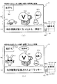
実際の表示画面では、図11(b)に示すように、主表示領域Dmに第3図柄の主図柄が合計9個表示される。副表示領域Dsにおいては、右の小領域Ds3に動画が表示され、通常より大当たりへ遷移し易い状態であることが遊技者に示唆される。中央の小領域Ds2では、通常は、所定のキャラクタ710(本実施形態ではハチマキを付けた少年)が所定動作をし、時として所定動作とは別の特別な動作をしたり、別のキャラクタが現出する等して予告演出が行われる。 On the actual display screen, as shown in FIG. 11B, a total of nine main symbols of the third symbol are displayed in the main display area Dm. In the sub-display area Ds, a moving image is displayed in the right small area Ds3, and it is suggested to the player that the transition to the big hit is easier than usual. In the central small area Ds2, normally, a predetermined character 710 (a boy with a beeper in this embodiment) performs a predetermined operation, and sometimes performs a special operation different from the predetermined operation, or another character may perform a specific operation. A notice effect is performed by appearing.
一方、第3図柄表示装置81(第1図柄表示装置37)にて変動表示が行われている間に球が特図入球口64に入球した場合、その入球回数は最大4個まで保留され、その保留球数は第1図柄表示装置37により示されると共に、副表示領域Dsの小領域Ds1においても示される。またスルーゲート67へ入球した場合、その入球回数は最大1回まで保留され、その保留球数は第1図柄表示装置37により示されると共に、副表示領域Dsの小領域Ds1においても示される。小領域Ds1には、保留球数1球につき1つの保留球数図柄が表示され、その保留球数図柄の表示数に応じて、保留球数が表示される。即ち、小領域Ds1に1つの保留球数図柄が表示されている場合は、保留球数が1球であることを示し、4つの保留球数図柄が表示されている場合は、保留球数が4球であることを示す。また、小領域Ds1に保留球数図柄が表示されていない場合は、保留球数が0球である、即ち、保留球が存在しないことを示す。なお、小領域Ds1のうち、左半分には、特図入球口64への入球に基づく保留球数を示す保留球数図柄を表示し、小領域Ds1のうち、右半分には、スルーゲート67への入球に基づく保留球数を示す保留球数図柄を表示する構成としている。図11(b)の例では、小領域Ds1の左半分に4つの保留球数図柄が表示されている一方で、右半分には保留球数図柄が1つも表示されていないので、特別図柄の保留球が4つ存在するが、普通図柄の保留球は0個となっている状態を示している。
On the other hand, if the ball enters the
なお、本実施形態においては、特図入球口64への入球は、最大4回まで保留されるように構成し、スルーゲート67への入球は、最大1回まで保留されるように構成したが、最大保留球数はこれに限定されるものでなく、3回以下、又は、5回以上の回数(例えば、8回)に設定しても良い。また、小領域Ds1における保留球数図柄の表示に代えて、保留球数を第3図柄表示装置81の一部に数字で、或いは、4つに区画された領域を保留球数分だけ異なる態様(例えば、色や点灯パターン)にして表示するようにしても良い。また、第1図柄表示装置37により保留球数が示されるので、第3図柄表示装置81に保留球数を表示させないものとしてもよい。更に、可変表示装置ユニット80に、保留球数を示す保留ランプを最大保留数分の4つ設け、点灯状態の保留ランプの数に応じて、保留球数を表示するものとしてもよい。
In the present embodiment, the configuration is such that the ball entering the
また、図11を参照して示した表示画面では、主表示領域Dmの上方に副表示領域Dsが形成されているが、表示領域をこれ以外の態様で形成しても良く、例えば、主表示領域Dmの下方に副表示領域Dsを形成しても良い。また、この場合、設定されている遊技状態に応じて、第3図柄表示装置81の表示画面の表示領域を可変形成すると良い。これにより、第3図柄表示装置81の表示画面を見るだけで、異なる遊技状態へ移行したことを遊技者が容易に把握することができる。さらに、特別図柄の抽選結果が大当たり当選している期待度が高いことを示す第3図柄の変動表示が実行されている状態といった、遊技者に対して主表示領域Dmの表示態様を注視させる状態では、副表示領域Dsの表示領域を小さくしたり、副表示領域Dsを非表示にしたりするように構成しても良い。
In the display screen shown with reference to FIG. 11, the sub-display area Ds is formed above the main display area Dm. However, the display area may be formed in other forms. The sub-display area Ds may be formed below the area Dm. In this case, the display area of the display screen of the third
<第1実施形態における第3図柄表示装置81での演出内容について>
次に、図12〜図19を参照して、本実施形態における第3図柄表示装置81で実行される演出内容について説明する。本実施形態では、特別図柄の抽選(特図抽選)で大当たりに当選した場合、その大当たり遊技終了後に、時短状態(特別図柄の低確率状態、普通図柄の高確率状態)が設定される。この時短状態は、特別図柄の抽選が規定回数に達するまで(予め定められた時短状態の終了条件が成立するまで)継続され、特別図柄の抽選が規定回数実行されると、時短状態の終了条件が成立し、通常状態が設定されるように構成している。
<About the effect contents on the third
Next, with reference to FIG. 12 to FIG. 19, description will be given on the effect contents executed by the third
時短状態は、普通図柄の高確率状態が設定される状態であり、遊技状態が通常状態である場合と比べ、普図当たり遊技によって普電入賞装置640へと球が入球可能な開放状態が設定され易くなるように構成している。
The time saving state is a state in which a high probability state of a normal symbol is set, and an open state in which a ball can enter the general winning a
そして、普通図柄の当たりに当選し、球が普電入賞装置640内の特電作動口643に入球すると役物当たり遊技が実行され、V入賞装置65内に設けられたV入賞口165に球を入賞させるための遊技が実行される。
Then, when the player wins the normal symbol and the ball enters the special
ここで、本実施形態では、遊技盤13の左側領域を狙って発射した遊技球は、100%の確率でスルーゲート67を通過するよう構成されている。そして、スルーゲート67を遊技球が通過したことで実行される普通図柄の抽選において、時短状態が設定されている場合は、3/10の確率で当たり当選するように設計されており、普通図柄の抽選で当たり当選した場合には、電動役物640aが開放状態となる普図当たり遊技が実行される。
Here, in the present embodiment, a game ball fired aiming at the left area of the
時短状態中に実行される普図当たり遊技は、左打ち遊技を継続して実行することでその殆どで(約100%)球を普電入賞装置640へと入賞させることができる期間(3秒間)電動役物640aが開放状態となる普図当たり遊技が実行される。
In the time per game performed during the time saving state, most of the time (approximately 100%) can be achieved by continuously executing the left-handed game so that the ball can be awarded to the general electric winning device 640 (3 seconds). ) An ordinary winning game in which the
さらに、時短状態中に実行される普図当たり遊技では、普電入賞装置640に入賞した球の殆どが特電作動口643へと入球するように構成され、球が特電作動口643へと入球したことを契機に役物当たり遊技が実行される。そして、役物当たり遊技が実行されることでV入賞装置65が開放動作され、V入賞装置65に入賞した球が約1/11の割合でV入賞口165へと入賞し、V入賞口165へと球の入賞を契機に大当たり遊技(V大当たり遊技)が実行されるように構成している。
Further, in the general game per game executed during the time saving state, most of the balls that have won the general
つまり、時短状態中は、特別図柄の抽選で大当たり当選を狙う遊技(特図遊技)を実行するよりも、V入賞口165に遊技球を入賞(V入賞)させることで大当たりを狙う遊技(特電遊技)のほうが大当たり遊技を実行させ易くできるので、遊技者は特電遊技において役物当たり遊技によるV入賞(V大当たり遊技)を所望しながら遊技を実行することになる。
In other words, during the time reduction state, a game (special electric game) aiming at a jackpot by causing a game ball to be awarded (V winning) to the
上述したように、本実施形態では、特電遊技として普電入賞装置640に球を入賞させるため(普通図柄抽選の実行契機となるスルーゲート67に球を通過させるため)に遊技盤13の左側領域を狙って球を発射する必要がある。さらに、本実施形態では、遊技盤13の左側領域を狙って遊技(左打ち遊技)を実行していると、特図入球口64にも球が入球するため、時短状態中において、特図遊技(特別図柄の抽選を行う遊技)と、特電遊技(普通図柄の抽選を行う遊技)と、の両方が実行されることになる。
As described above, in the present embodiment, the left side area of the
特図遊技よりも特電遊技のほうが遊技者に有利な遊技となる時短状態は、特図遊技によって実行される特別図柄抽選が規定回数に達するまでの時間(即ち、規定回数分の特別図柄の変動時間)が経過するまで継続するように構成しているため、遊技状態が時短状態へ移行すると、その時短状態が終了し通常状態へと移行する契機となる特別図柄の変動時間が経過するまでに、特電遊技によるV入賞を期待しながら遊技を実行することが、本実施形態における時短状態中の基本的な遊技方法となる。 The time saving state in which the special electric game is more advantageous to the player than the special figure game is the time required for the special symbol lottery executed by the special game to reach the specified number of times (that is, the fluctuation of the special symbol for the specified number of times). Time), so that when the gaming state transitions to the time reduction state, the special symbol fluctuation time that triggers the end of the time reduction state and transition to the normal state elapses Executing a game while expecting a V prize by a special electric game is a basic game method during the time saving state in the present embodiment.
この時短遊技の状態を、遊技者に分かり易く伝えるべく、第3図柄表示装置81において、様々な演出を実行する。詳しくは、図12〜図19を参照して後述するが、大当たり遊技が実行され、大当たり終了時に、遊技状態が遊技者にとって有利な状態である時短状態であることを示すためのVラッシュモードへと移行し、時短状態が設定されたことを報知する。そして、Vラッシュ中における様々な演出について説明する。以下、説明の簡略化のために、時短状態を「Vラッシュ」と称す。
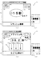
Various effects are executed on the third
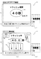
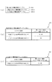
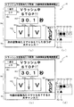
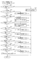
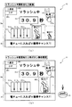
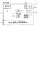
まず、図12(a)を参照して、本実施形態における第3図柄表示装置81において表示される大当たりエンディング画面について説明する。図12(a)は、大当たり(遊技)のエンディング画面の一例を示した図である。大当たり遊技の最終ラウンドが終了すると、図12(a)に示した通り、第3図柄表示装置81の副表示領域Dsには、「大当たり終了後Vラッシュが始まるよ!!」という文字が表示され、大当たり遊技終了後に時短状態が設定されることを示すVラッシュモードに移行することを遊技者に分かりやすく示している。そして、主表示領域Dmには、大当たり遊技の終了後に設定される時短状態が継続する期間を示すための残時短期間態様801が「40秒」の「Vラッシュ期間40秒ゲット」というコメントが表示される。
First, with reference to FIG. 12A, the big hit ending screen displayed on the third
ここで、残時短期間態様801の表示内容について説明をする。本実施形態では、上述したように、時短状態の終了条件として、特別図柄の抽選回数が規定回数(例えば、4回)に到達した場合に成立する終了条件が設定されている。よって、特別図柄の抽選が規定回数に達するまでの時間(即ち、規定回数分の特別図柄の変動時間を合計した時間)が経過するまで時短状態が継続される。残時短期間態様801は、時短状態の終了条件が成立するまでの特別図柄の変動時間を合計した合計時間の示す表示態様が表示される。
Here, the display contents of the remaining short
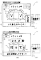
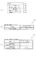
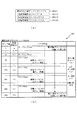
次に、図12(a)に示した状態における各図柄の保留状況について図12(c)を参照して説明をする。図12(c)は、図12(a)に示した表示画面が表示される場合における各図柄の保留状況を示した模式図である。本実施形態では、特別図柄の保留記憶を最大で4個、普通図柄の保留記憶を最大で1個、記憶可能に構成している。図12(c)では、実行中の特別図柄変動の状況を説明するための実行中特図th0と、保留記憶されている特別図柄の入賞情報を説明するための特図第1保留th1〜特図第4保留th4と、実行中の普通図柄変動の状況を説明するための実行中普図fh0と、保留記憶されている普通図柄の入賞情報を説明するための普図第1保留fh1と、を用いて各図柄の状況を説明している。 Next, the holding status of each symbol in the state shown in FIG. 12A will be described with reference to FIG. FIG. 12C is a schematic diagram showing the holding status of each symbol when the display screen shown in FIG. 12A is displayed. In the present embodiment, a maximum of four special symbols can be stored and a maximum of one ordinary symbol can be stored. In FIG. 12 (c), the running special figure th0 for explaining the situation of the special symbol fluctuation during execution, and the special figure first holding th1 to special for explaining the winning information of the special symbol stored and stored. FIG. 4th hold th4, a running general symbol fh0 for explaining the situation of the running normal symbol fluctuation, a general diagram first hold fh1 for explaining the winning information of the normal symbol stored and stored, Is used to explain the situation of each symbol.
図12(c)は、特図第1保留th1〜特図第4保留th4には、10秒間の変動パターンが設定されている特別図柄の保留が4つ貯まっている状態である。つまり、今回の時短状態の期間は、特別図柄抽選4回分の変動時間を合算した値である40秒が設定される。よって、遊技者にとって有利となる遊技状態の継続期間を示すための残時短期間表示態様801には「40秒」の文字が表示され、Vラッシュの期間がいつまで続くかを分かり易く報知することができる。
FIG. 12C shows a state in which four special symbols in which a fluctuation pattern for 10 seconds is set are stored in the special figure first hold th1 to the special figure fourth hold th4. That is, in the period of this time saving state, 40 seconds, which is a value obtained by adding the fluctuation times of four special symbol lotteries, is set. Therefore, the character “40 seconds” is displayed in the remaining short
なお、上述したように、本実施形態では、遊技者に有利となるVラッシュの継続期間を残時短期間表示態様801に示すように、具体的な秒数で表示するよう構成したが、継続期間の残期間が分かるものであればよく、インジケータなどを用いて遊技者に報知しても良い。このように構成することで、遊技者によりどきどき感のある遊技を提供することができる。
As described above, in the present embodiment, the duration of the V rush that is advantageous to the player is displayed in a specific number of seconds as shown in the remaining short
また、本実施形態では、図12(a)に示した通り、Vラッシュの継続期間として算出された「40秒」の全てを示す表示態様で残時短期間態様801を表示しているが、これに限ること無く、Vラッシュに突入することを報知する時点では、Vラッシュの継続期間として算出された値(例えば、40秒)のうち一部のみ(例えば、30秒)を報知するように構成し、Vラッシュの実行中に未報知分(例えば、10秒)に対応する値を追加報知するように構成しても良い。
Further, in the present embodiment, as shown in FIG. 12A, the remaining short
この場合、例えば、時短回数4回が設定される場合において、獲得済の4個の特別図柄の保留(特図保留)のうち、3個の特図保留に対応する特別図柄の変動時間を合算した値、つまり、図12(c)の場合であれば、特図第1保留th1〜特図第3保留th3の合算値である「30秒」をVラッシュ突入時に表示すれば良い。このように構成することで、Vラッシュの継続期間として算出された値の一部のみを報知するための処理を簡素化することができる。 In this case, for example, when the number of times saved is set to four, the fluctuation times of the special symbols corresponding to three special symbol holdings among the four special symbol holdings already acquired (special symbol holdings) are added. In the case of FIG. 12 (c), the total value of the special figure first hold th1 to the special figure third hold th3, "30 seconds", may be displayed when the V rush enters. With this configuration, it is possible to simplify the process of notifying only a part of the value calculated as the duration of the V rush.
図12(a)に示した通り、本実施形態では、時短状態が終了するまでに実行される複数回の特別図柄抽選の変動時間を合算してVラッシュの継続期間を表示するように構成している。さらに、現在の特図保留数が遊技者に把握され難くするために、第3図柄表示装置81の表示面にて特図保留数を示すための表示態様を表示しないように構成している。これにより、Vラッシュの継続期間として表示される残時短期間態様801の値が、何個分の特図保留に対応した変動時間の合算値であるかを遊技者に分かり難くすることができる。また、個々の特別図柄抽選の変動時間を遊技者に分かり難くすることができる。
As shown in FIG. 12A, in the present embodiment, the duration of the V rush is displayed by adding the fluctuation times of a plurality of special symbol lotteries executed until the time saving state ends. ing. Further, in order to make it difficult for the player to grasp the current number of special figure reservations, a display mode for indicating the number of special figure reservations is not displayed on the display surface of the third
よって、例えば、特別図柄の抽選結果が大当たりである場合と、外れである場合とで異なる変動時間の変動パターンが設定されるパチンコ機10であっても、残時短期間態様801の表示態様によって、特図保留内の抽選結果(特図保留内に大当たり当選に対応する入賞情報が含まれているか否か)が遊技者に事前に把握されてしまうことを抑制することができる。
Therefore, for example, even in the case of the
また、例えば、特別図柄の抽選結果が大当たりである場合に変動時間が50秒の変動パターンが選択されるように構成し、特別図柄の抽選結果が外れである場合に変動時間が10秒、20秒、30秒の何れかの変動パターンが選択されるように構成したパチンコ機10であって、特図第1保留th1が「10秒」、特図第2保留th2が「30秒」、特図第3保留th3が「20秒」、特図第4保留th4が「10秒」である場合には、Vラッシュの継続期間を示す残時短期間態様801の表示態様として、「50秒」を表示させるように構成すると良い。このように構成することで、Vラッシュの継続期間である「90秒」(特図保留4個分の変動時間の合算値)よりも少ない期間であって、且つ、時短状態中に実行される特別図柄抽選にて大当たり当選(時短1回目の特別図柄抽選が大当たり当選しており、変動時間50秒が設定)していることに対する期待感を遊技者に持たせることができる。
In addition, for example, when the lottery result of the special symbol is a big hit, a fluctuation pattern with a fluctuation time of 50 seconds is selected, and when the lottery result of the special symbol is off, the fluctuation time is 10 seconds, 20 seconds. A
つまり、Vラッシュが継続する全期間では無く、一部の期間のみを表示する場合には、上述したように大当たり当選している場合に設定される変動時間(50秒)に対応した値を表示する構成以外にも、例えば、時短1回目が外れ変動(変動時間10秒)で、時短2回目が大当たり変動(変動時間50秒)であると遊技者に思わせる「60秒」の表示態様で残時短期間態様801を表示するように構成しても良い。つまり、実際のVラッシュの継続期間を示す値よりも小さく、且つ、少なくとも大当たり変動で選択され得る変動時間と、外れ変動で選択され得る変動時間と、を組み合わせた場合に算出される値を表示すれば良い。
That is, when displaying only a part of the period, not the entire period in which the V rush continues, a value corresponding to the fluctuation time (50 seconds) set when the big hit is won as described above is displayed. In addition to the configuration described above, for example, the display mode of “60 seconds” that makes the player think that the first time saving time is out of fluctuation (fluctuation time of 10 seconds) and the second time saving time is a big hit fluctuation (fluctuation time of 50 seconds). It may be configured to display the remaining short
なお、本実施形態では、第3図柄表示装置81の表示面に獲得済の特図保留数を表示しないように構成しているが、これに限ること無く、特図保留数を示すための表示態様を表示しても良い。この場合であっても、特図保留数を示すための表示態様を遊技者がその内容を視認し難い表示態様で表示することで遊技者に対して現在獲得している特図保留数を分かり難くすることができる。
In the present embodiment, the acquired number of reserved special figures is not displayed on the display surface of the third
次に、図12(b)を参照し、第3図柄表示装置81において表示されるVラッシュ開始画面について説明する。図12(b)は、大当たりのエンディング期間が終了し、Vラッシュが開始される表示態様の一例を示した図であり、図12(d)は、図12(b)に示した表示画面が表示された場合における各図柄状況を示した図である。つまり、図12(b)は、大当たりのエンディング時に特図第1保留th1で示されていた特図保留が変動を開始する時点における表示画面を示したものであって、大当たりのエンディング時に特図第1保留th1であった特図保留が実行中特図th0へとシフトし、また、特図第2保留th2は特図第1保留th1に、特図第3保留th3は特図第2保留th2に、特図第4保留th4は特図第3保留th3にそれぞれシフトされた状態における表示画面である。また、Vラッシュが開始されてから新たに特図入球口64に入球が無く、特図第4保留th4が空の状態である。そして、実行中普図fh0に示す様に、普通図柄の抽選も変動を開始しており、普図第1保留fh1に保留が貯まっている状態である(図12(d)参照)。
Next, the V-rush start screen displayed on the third
Vラッシュが開始されると、主表示領域Dmには、現在がVラッシュ期間であることを示す遊技状況報知態様として「Vラッシュ中」の文字が表示される。そして主表示領域Dmの横には、うさぎを模したキャラクタ810が袋810aの中から何かを取り出そうとしているように動的表示される。これは、普通図柄が変動中であることを示している。
When the V rush is started, the characters “V rushing” are displayed in the main display area Dm as a game status notification mode indicating that the current time is the V rush period. Next to the main display area Dm, a
そして、主表示領域Dmの中央には、遊技者に有利となるVラッシュ期間の残期間を示すためのタイマ812が表示されている。このタイマ812には、時短状態の終了契機までの特別図柄の規定回数分の変動時間が合算された値が表示される。図12(b)では、時短状態中の特別図柄の抽選回数が4回に規定されており、実行中特図th0の変動時間である10秒と、特図第1保留th1から特図第3保留th3までの変動時間を合算した値である「40.0秒」がタイマ812に示されている。このタイマ812は、実行中特図th0の変動時間が減算される度にその値が減算されるように表示され、遊技者がVラッシュの期間が進行していることを容易に理解させることができる。
At the center of the main display area Dm, a
さらに、副表示領域Dsには、「タイマが0になるとVラッシュ終了!!」の文字が表示され、減算されているタイマ812の値が0になった場合に、Vラッシュが終了してしまうことを遊技者に報知している。上述したように、Vラッシュ期間中は、遊技者は、V入賞口165に球を入球させることを目的として遊技が実行される。よって、遊技者は、タイマ812に表示されている値の変位状況を視認することにより有利期間が終了してしまうまでの期間(残期間)を容易に理解することができる。
In addition, in the sub-display area Ds, a character "V rush ends when the timer reaches 0!" Is displayed, and when the value of the subtracted
そして、主表示領域Dmの左上の表示領域HR1には「1連目」の文字が示され、通常状態から大当たりに当選し(所謂、初当たり)、Vラッシュが開始されてから、遊技状態が通常状態に移行しないまま何回目のVラッシュ期間であるかを示している。さらに、表示領域HR1の下に示される表示領域HR2には「0pt」が表示されており、Vラッシュ期間中に当選した大当たりで獲得した賞球数が表示される。このように、表示領域HR1にVラッシュが継続している回数、表示領域HR2にVラッシュ中の大当たりで獲得した賞球数を表示しておくことで、遊技者が遊技者自身のタイミングで、遊技履歴を確認することができ、遊技の利便性を向上することができる。 Then, in the upper left display area HR1 of the main display area Dm, the characters of "first series" are shown, and the jackpot is won from the normal state (so-called first hit), and after the V rush is started, the gaming state is changed. This shows how many V rush periods it is without shifting to the normal state. Further, “0pt” is displayed in the display area HR2 shown below the display area HR1, and the number of prize balls obtained in the jackpot won during the V rush period is displayed. In this way, by displaying the number of times the V rush continues in the display area HR1 and the number of award balls acquired in the jackpot during the V rush in the display area HR2, The game history can be checked, and the convenience of the game can be improved.
また、主表示領域Dmには、Vラッシュ変動領域811が表示され、このVラッシュ変動領域811の左領域811a、中領域811b、右領域811cにはそれぞれ図柄が変動(動的表示)するような表示態様が表示されている。このVラッシュ変動領域811には、Vラッシュ中の遊技状況を遊技者に示唆するための情報が表示される。図12(b)では、現在、特図と普図との変動中であり、Vラッシュ変動領域811によって、Vラッシュ期間が経過していることを示している。
In the main display area Dm, a V
次に、図13(a)を参照して、本実施形態における第3図柄表示装置81において表示されるVラッシュ中に普図当たりに当選した場合の表示画面について説明する。図13(a)は、Vラッシュ中に普図当たりに当選した場合の表示画面の一例を示した図であり、図13(c)は、図13(a)に示した表示画面が表示された場合における各図柄状況を示した図である。本実施形態では、上述したように、普通図柄の抽選に当選した場合に、普電入賞装置640に付随する電動役物640aが、遊技球が入球可能となるよう開放される。
Next, with reference to FIG. 13 (a), a display screen in a case where a winning is made per ordinary figure during a V rush displayed on the third
図13(c)に示すように、実行中普図保留fh0は、普通図柄の抽選で当たり当選したことを示す「○」が示される。そして、主表示領域Dmの右上には、Vラッシュの開始時には(図12(b)参照)袋810aから何かを探していたキャラ810が、普通図柄の抽選に当選し特典を獲得したことを示すための報知態様である「ラッキー」の文字が書かれたチケット810bを取り出すアニメーションが表示される。そして、主表示領域Dmの右下の表示領域HR3には、普電入賞装置640を模式的に示した画像が表示され、普通図柄の抽選に当選し、電動役物640aが開放されている状態で表示されている。さらに、副表示領域Dsには「電チューに入ればV獲得チャンス!!」という文字が表示される。これらの表示内容により、遊技者は電チューを狙って遊技を実行することを理解できるので、正しい遊技方法を遊技者に案内することができる。つまり、上述した表示領域HR3の表示態様、および、副表示領域Dsの表示態様は、遊技者に対して実行すべき遊技の内容を案内するための案内報知態様となる。
As shown in FIG. 13 (c), during the execution, the normal drawing hold fh0 is indicated by “○” indicating that the winning has been achieved in the normal symbol lottery. At the top right of the main display area Dm, at the start of the V rush (see FIG. 12 (b)), the
また、主表示領域Dm中央に表示されているタイマ812は、その値として30.9秒が表示されている。図13(a)の遊技状況では、実行中特図th0に示される実行中の特図変動の残り変動時間は、0.9秒であり、特図第1保留th1〜特図第3保留th3までの特図抽選がVラッシュの期間である。よって、その合算した値である30.9秒がタイマ812に表示されている。なお、図13(a)では、Vラッシュの開始時(図12(b)参照)には貯留されていなかった特図第4保留th4が保留されているが、これはVラッシュの規定回数の期間が経過した後に実行される特図抽選となるため、この特図第4保留th4の変動時間は合算されない。よって、特図第4保留th4には「‐」が示されている(図13(c)参照)。
The
次に、図13(b)を参照して、本実施形態における第3図柄表示装置81において表示されるVラッシュ中に役物当たりした場合の表示画面について説明する。図13(b)は、Vラッシュ中に役物当たり遊技が実行された場合の表示画面の一例を示した図であり、図13(d)は、図13(b)に示した表示画面が表示された場合における各図柄状況を示した図である。本実施形態では、上述したように、普電入賞装置640内の特電作動口643に遊技球が入賞した場合には、V入賞装置65に付随するV開閉扉65aが開放状態となる役物当たり遊技が実行される。
Next, with reference to FIG. 13B, a display screen in the case where a character hits during a V rush displayed on the third
図13(b)は、図13(a)で示した普図当たりによって普電入賞装置640内の特電作動口643に遊技球が入賞した場合の表示画面である。図13(a)では、特図第1保留th1に保留されていた保留球が、図13(b)では実行中特図th0にシフトされている。そして、その残変動時間が9.9秒であり変動が仮停止していることを示す「?」が示されている(図13(d)参照)。本実施形態では、役物当たり遊技、或いは、大当たり遊技が実行される場合に、実行中の特別図柄変動の変動時間の減算を、各当たり遊技が終了するまで中断(仮停止)させるように構成している。
FIG. 13B is a display screen when a game ball wins in the special
そして、主表示領域Dmには、図13(a)までは、特図の変動時間と共に減少していたタイマ812の値の減算表示が、特図の変動(特別図柄変動の変動時間の減算)が中断された時間(即ち、特電作動口643に入賞した時間)で中断表示されている。さらに、タイマ812の減算表示が中断していることを示すための「STOP!!」の文字が表示される。これらの表示内容により、遊技者はVラッシュの期間が経過することが中断されていることを把握することができる。そして、表示領域HR3には、V開閉扉65aが開放された状態のV入賞装置65が模式的に表示され、「狙え!!」という文字と共に表示されている。
Then, in the main display area Dm, the subtraction display of the value of the
これにより遊技者は、V入賞装置65のV開閉扉65aの開放していること(役物当たり遊技が実行されていること)を、第3図柄表示装置81を視認することで理解することができる。つまり、図13(b)における表示領域HR3の表示態様、及び、副表示領域Dsの表示態様は、Vラッシュ中における遊技状況を遊技者に報知するための遊技状況報知態様の機能と、役物当たり遊技中において実行すべき遊技を遊技者に案内するための案内報知態様の機能と、を有するものとなる。
Thereby, the player can understand that the V opening /
また、Vラッシュ変動領域811は、左領域811aと右領域811cとに「V」の文字が停止表示され、所謂リーチ表示態様となるように表示されている。さらに、副表示領域Dsには、「Vに入れば大当たり!!」の文字が表示されており、これらの表示内容により、遊技者は、もう少しでV入賞口165に遊技球を入賞させることができるのではないかという期待感をもちながら遊技を実行することができる。
In the V
つまり、図11(b)に示した通り、パチンコ機10における一般的な遊技、即ち、特別図柄の抽選を実行し、その抽選結果が大当たり当選であることを期待しながら実行される遊技(特図遊技)では、抽選結果を示すための複数の識別情報(第3図柄表示装置81にて動的表示される各図柄(第3図柄))が複数列(例えば、3列)で変動表示(動的表示)され、その複数の図柄列のうち、一の図柄列を除いた他の図柄列が大当たり当選を示すための識別情報の組合せとなるリーチ表示態様(例えば、同一の識別情報の組合せ)で停止表示されると、大当たり当選の期待度が高まるリーチ演出が実行されるように構成している。
That is, as shown in FIG. 11B, a general game in the
本実施形態のパチンコ機10における時短状態(Vラッシュ)中に実行される遊技(特電遊技)は、特別図柄の抽選では無く、普通図柄の抽選を基点に様々な過程を経て最終的にV入賞口165へと球を入賞させることで大当たり遊技(V大当たり遊技)を実行させる遊技となるため、特電遊技の具体的な遊技内容を遊技者が理解し難いという問題があった。これに対して、本実施形態では、上述した複雑な遊技性を有する特電遊技の進行状況(大当たり遊技が実行されるまでの各種過程)に応じて、Vラッシュ変動領域811の左領域811a、中領域811b、右領域811cの各領域にて変動表示(動的表示)される図柄(文字)の変動表示態様を、あたかも特図遊技が実行されているかのような演出態様が実行されるように構成している。このように構成することで、遊技者は特電遊技における具体的な遊技内容を把握しなくとも、第3図柄表示装置81の表示面に表示される各表示態様を把握することができるため、遊技者に対して分かり易い遊技を提供することができる。
In the
次に、図14(a)を参照して、本実施形態における第3図柄表示装置81において表示されるVラッシュ中の役物当たり遊技中のV入賞画面について説明する。図14(a)は、Vラッシュ中の役物当たり遊技中にV入賞口165に遊技球が入賞し、大当たりが付与される場合の表示画面の一例を示した図であり、図14(c)は、図14(a)に示した表示画面が表示された場合における各図柄状況を示した図である。本実施形態では上述したように、Vラッシュ中に、役物当たり遊技が実行され、役物当たり遊技中にV入賞口165に球を入賞した場合(V入賞した場合)には、大当たり遊技(V大当たり遊技)が付与される。
Next, with reference to FIG. 14 (a), a description will be given of a V winning screen during a game per hit during a V rush displayed on the third
図14(a)は、図13(b)で示した役物当たり遊技中に、V入賞口165に球が入賞した場合の表示画面である。上述した通り、役物当たり遊技中は特別図柄の変動が中断されているため、実行中特図th0は、変動時間を9.9秒残したまま仮停止している。そして、特図第1保留th1と特図第2保留th2は今回のVラッシュの規定回数内の保留であり、変動時間はそれぞれ10秒が設定されている。よって、Vラッシュ期間の残期間は、図13(b)で示した時点から変わること無く「29.9秒」となる(図14(c)参照)。
FIG. 14A is a display screen when a ball wins in the
そして、球がV入賞して大当たり遊技(V大当たり遊技)が実行されることが確定した場合には、Vラッシュ期間の減算が所定期間(大当たり遊技期間)の間減算されない状態となるため、図13(b)に示したタイマ812にて表示させた「29.9秒」の表示態様が、そのタイマ812よりも目立たない表示領域HR4にて表示される。表示領域HR4には「タイムストック29.9秒」が表示されている。
Then, when it is determined that the ball wins V and the jackpot game (V jackpot game) is executed, the V rush period is not subtracted for a predetermined period (jackpot game period). The display mode of “29.9 seconds” displayed by the
本実施形態では、特図の仮停止中にV入賞(V大当たり遊技)が発生した場合には、その仮停止していた特図変動が終了した後に実行される特別図柄抽選が今回実行される大当たり遊技の大当たり種別に対応して設定される時短回数分実行されるまで時短状態が継続するように構成している。即ち、大当たり遊技終了後に実行される中断されていた特別図柄変動(再開特図変動)によって、時短終了条件を成立させるための情報(時短回数)が更新(減算)されないように構成している。 In the present embodiment, if a V prize (V jackpot game) occurs during the temporary stop of the special figure, a special symbol lottery executed after the temporary stop of the temporarily stopped special figure change is executed this time. The time saving state is configured to be continued until the number of time savings set in accordance with the jackpot type of the jackpot game is executed. In other words, the information (time savings) for establishing the time saving end condition is not updated (subtracted) by the interrupted special symbol change (restart special figure change) executed after the end of the big hit game.
つまり、図14(c)に示した状態では、大当たり遊技終了後に時短回数4回が設定される場合には、中断中の特別図柄変動の残期間(9.9秒)に、特図保留4個分の特図変動時間を合算した値が、次のVラッシュの継続期間となる。このように構成することで、通常状態において特図遊技を行い、大当たり当選することで設定される時短状態(Vラッシュ初突入時)に対して、Vラッシュ中に大当たり遊技(V大当たり遊技)が実行され、その大当たり遊技終了後に再度設定される時短状態(Vラッシュ継続時)のほうが、再開特図変動の変動時間(残変動時間)分、Vラッシュ継続期間を長く設定することができるため、Vラッシュ初突入時よりも、Vラッシュ継続時のほうが遊技者に有利なVラッシュを提供し易くすることができる。よって、遊技者に対して、Vラッシュが継続することをより期待させながら遊技を行わせることができる。 That is, in the state shown in FIG. 14 (c), if four time savings are set after the end of the jackpot game, the special figure hold 4 during the remaining period of the suspended special symbol change (9.9 seconds). The sum of the special figure fluctuation times for the individual pieces is the duration of the next V rush. With this configuration, the special figure game is performed in the normal state, and the jackpot game (V jackpot game) is performed during the V rush against the time-saving state (at the time of the first rush of the V rush) set by winning the jackpot. The time-saving state (when the V rush continues) that is executed and set again after the end of the jackpot game can set the V rush continuation period longer by the fluctuation time (remaining fluctuation time) of the restart special figure fluctuation, It is easier to provide a V rush advantageous to the player when the V rush is continued than when the V rush enters for the first time. Therefore, it is possible to cause the player to play the game while further expecting the V rush to continue.
なお、Vラッシュ初突入時よりも、Vラッシュ継続時のほうが遊技者に有利な時短状態を設定するために他の手法を用いても良く、例えば、通常状態中に大当たり遊技の実行条件が成立(特図抽選で大当たりに当選)し、その大当たり遊技終了後に時短状態が設定される場合と、時短状態で大当たり遊技の実行条件が成立(特電遊技でV入賞)し、その大当たり遊技終了後に時短状態が設定される場合とで、特別図柄の変動パターンとして異なる変動パターンが選択されるように構成しても良く、具体的には、通常状態中に大当たり遊技の実行条件が成立(特図抽選で大当たりに当選)し、その大当たり遊技終了後に時短状態が設定される場合よりも、時短状態で大当たり遊技の実行条件が成立(特電遊技でV入賞)し、その大当たり遊技終了後に時短状態が設定される場合のほうが長い変動時間の変動パターンが選択され易くなるように構成すると良い。このように構成することで、Vラッシュ初突入時よりも、Vラッシュ継続時のほうが時短状態中に実行される特別図柄変動の変動時間を長くし易くすることができるため、結果として、Vラッシュの継続期間を長くすることができる。よって、Vラッシュを継続させた遊技者に対して付加価値を付与することができるため遊技者の遊技意欲を高めることができる。 It should be noted that another method may be used to set a time saving state in which the V rush continuation is more advantageous to the player than the V rush first entry, for example, the execution condition of the jackpot game is satisfied during the normal state. (Special drawing lottery wins), the time-saving state is set after the jackpot game is completed, and the execution condition of the jackpot game is satisfied in the time-saving state (V winning in special electric game), and the time-saving is completed after the jackpot game ends When the state is set, a different variation pattern may be selected as the variation pattern of the special symbol. Specifically, the execution condition of the jackpot game is established during the normal state (special figure lottery). The jackpot game is executed in the time-saving state, and the execution condition of the jackpot game is satisfied (V prize in the special electric game), and the end of the jackpot game is smaller than when the time-saving state is set after the end of the jackpot game. After it may be configured to more is easily selected movement pattern of long fluctuation time when time reduction state is set. With this configuration, the variation time of the special symbol variation executed during the time saving state can be easily made longer during the V rush continuation than at the time of the first rush V rush entry. Can be extended. Therefore, an added value can be added to the player who has continued the V rush, so that the player's willingness to play can be increased.
一方、本実施形態のパチンコ機10とは反対の技術思想として、再開特図変動の実行により時短終了条件を成立させるための情報(時短回数)が更新(減算)されるように構成しても良いし、Vラッシュ初突入時のほうがVラッシュ継続時よりも長い変動時間の特別図柄変動が実行され易くなるように構成しても良い。このように構成することで、Vラッシュが過剰に継続してしまうことを抑制しつつ、Vラッシュ中に実行される特電遊技にて一度も大当たり遊技(V大当たり遊技)を実行させることなくVラッシュが終了してしまい遊技意欲が低下することを抑制することができる。
On the other hand, as a technical idea opposite to that of the
また、本実施形態のように、実行中の特図変動の中断タイミングが、大当たり遊技(V大当たり遊技)終了後のVラッシュの継続期間の長さに大きな影響を与える構成を用いる場合には、特図変動を中断させることが可能となる状態(例えば、普通当たり遊技に当選した状態)において、実行中の特図変動の残変動時間を示すための情報を遊技者に報知するように構成し、遊技者が、特図変動を中断させるか否かを選択し得るように構成しても良い。つまり、実行中の特図変動の残変動時間が所定時間よりも長い(例えば、30秒)である場合には、特図変動を中断させるための遊技(普図当たり遊技中に特電作動口643に球を入賞させ役物当たり遊技を実行させる遊技)を実行し、V入賞を狙う遊技を選択し、実行中の特図変動の残変動時間が所定時間よりも短い(例えば、2秒)である場合には、特図変動を中断させない遊技を選択することが可能となるように構成しても良い。
In the case of using a configuration in which the interruption timing of the special figure fluctuation during execution greatly affects the duration of the V rush after the end of the jackpot game (V jackpot game) as in the present embodiment, In a state where it is possible to interrupt the special figure change (for example, in a state where the normal winning game is won), the information for indicating the remaining change time of the special figure change being executed is notified to the player. Alternatively, the player may be configured to select whether or not to suspend the special figure change. In other words, if the remaining variation time of the special figure change being executed is longer than a predetermined time (for example, 30 seconds), a game for interrupting the special figure change (special
また、V入賞によって大当たり遊技(V大当たり遊技)が付与された場合には、その仮停止していた特別図柄の変動時間と、その時点で保留されていたVラッシュの規定回数内の特別図柄の変動時間が次のVラッシュの予め設定された期間として表示されるよう構成している。そしてその時間を主表示領域DmのH表示領域HR4に表示するよう構成している。よって、遊技者は、表示領域HR4を確認することで、次のVラッシュにストックされた期間を確認することができる。 In addition, when a jackpot game (V jackpot game) is awarded due to a V prize, the fluctuation time of the temporarily stopped special symbol and the special symbol within the specified number of V rushes held at that point in time are displayed. The variation time is displayed as a preset period of the next V rush. The time is displayed in the H display area HR4 of the main display area Dm. Therefore, the player can confirm the period stocked in the next V rush by confirming the display area HR4.
そして、主表示領域DmのVラッシュ中の遊技状態を示すためのVラッシュ変動領域811では、図13(b)では変動していた中領域811bに「V」が停止表示される。そして、左領域811aと右領域811cは役物当たりが実行された際に、「V」の文字が停止表示されているため、左領域811aと中領域811bと右領域811cとを合わせて「VVV」と大当たりに当選したことを示唆する報知態様が表示される。また、副表示領域Dsには「大当たりおめでとう!!」の文字が表示される。これらの表示内容により、役物当たり中に、V入賞口165に遊技球を入賞させ、大当たりが付与されたことを遊技者に分かりやすく示している。
Then, in the V
なお、本実施形態では、Vラッシュ変動領域811は、役物当たりが実行された場合に左領域811aと右領域811cとを停止表示し、役物当たり中にV入賞した場合に中領域811bを停止表示するよう構成したが、これに限ることなく、普図当たりに当選した場合に、左領域811aを、役物当たりが実行された場合に、右領域811cを、V入賞した場合に中領域811bを停止表示するよう構成しても良い。このように遊技条件の成立などを契機として、段階的な演出を実行するよう構成することで、遊技者はV変動領域811を視認すると、遊技段階がどの段階なのかを瞬時に判断することができる。よって、遊技者により多くの情報を提供することができる。また、停止される文字は、大当たりが付与され、遊技者が特典を獲得することが出来ることを示すためのものならよく、「当たり」や「V入賞」などと表示してもよい。このように大当たりを示す文字を複数表示されるよう構成することで、よりバリエーションのある演出を遊技者に提供することができる。
In the present embodiment, the V
次に、図14(b)を参照して、本実施形態における第3図柄表示装置81において表示されるVラッシュ中の役物当たり中の外れ画面について説明する。図14(b)は、Vラッシュ中の役物当たり中にV入賞口165に遊技球が入賞しなかった場合の表示画面の一例を示した図である。本実施形態では、役物当たりに実行された場合に、実行されていた特別図柄の変動を仮停止するよう構成したが、役物当たり中にV入賞できなかった場合には、その仮停止していた特別図柄の変動が再開される。
Next, with reference to FIG. 14 (b), a description will be given of a screen that is displayed on the third
図14(b)は、図13(b)において役物当たりが実行された場合からV入賞口165に遊技球が入賞しなかった場合の表示画面である。主表示領域Dmの、Vラッシュ中の遊技状況を示すV変動領域811では、中領域811bにV入賞しなかったことを示す「×」の文字が表示される。よってVラッシュ変動領域811には「V×V」という外れ表示態様が表示される。これにより、遊技者は、今回の役物当たり中に、V入賞口165に遊技球を入賞させることができなかったことを理解することができる。
FIG. 14B is a display screen in a case where a gaming ball has not been won in the
そして、主表示領域Dmには、仮停止していた特図の変動が再開することを示すための「再開!!」という文字が表示される。そして、タイマ812に示されるVラッシュの残期間を示すための表示態様が、実行中特図th0に示す特図の変動再開(図14(d)参照)とともに再び減少し始める。これにより遊技者は、このタイマ812に示す時間内にV入賞させることを目指して遊技を実行しなければならないことを容易に理解できる。
Then, in the main display area Dm, the character "Resume !!" is displayed to indicate that the fluctuation of the temporarily stopped special figure is restarted. Then, the display mode for indicating the remaining period of the V rush indicated by the
次に、図15(a)を参照して、本実施形態における第3図柄表示装置81において表示されるVラッシュ中の大当たりエンディング画面について説明する。図15(a)は、Vラッシュ中の大当たりエンディングの表示画面の一例を示した図であり、図15(c)は、図15(a)に示した表示画面が表示された場合における各図柄状況を示した図である。本実施形態では、Vラッシュ期間中に、大当たりに当選、或いは、V入賞した場合には、再度Vラッシュ期間(時短状態)が設定される。
Next, with reference to FIG. 15A, the big hit ending screen during the V rush displayed on the third
図15(a)は、図14(a)に示したV入賞より付与された大当たりのエンディング画面を示した図である。上述したように、Vラッシュ中に大当たりが付与された場合には、仮停止していた実行中特図th0と前回のVラッシュ期間の規定回数であった特図第2保留th2までの変動時間を合算した値がタイムストックとして表示領域HR4に「タイムストック29.9秒」の文字が表示されている。そして、図15(c)の特図第3保留th3に対応する特図保留、即ち、大当たり遊技が実行される前のVラッシュ中では、Vラッシュ期間(時短期間)として加算されていなかった特図保留の変動時間が算出される。 FIG. 15A is a diagram showing a big hit ending screen awarded from the V prize shown in FIG. 14A. As described above, when the jackpot is awarded during the V rush, the fluctuation time between the temporarily stopped running special figure th0 and the special figure second hold th2, which is the specified number of times of the previous V rush period, is given. Is displayed as a time stock in the display area HR4, and the character of "time stock 29.9 seconds" is displayed. Then, in the special figure reservation corresponding to the special figure third reservation th3 in FIG. 15C, that is, during the V rush before the jackpot game is executed, the special figure not added as the V rush period (time saving period). The figure fluctuating time is calculated.
上述したように、Vラッシュ中に大当たりが付与された場合には、その大当たり遊技の終了時に、再度Vラッシュが設定される。そのVラッシュの期間は大当たり中に仮停止していた特図の変動の残時間と、大当たり種別により付与された特図の抽選回数分の変動時間が合算された値が設定される。図15(a)では、表示領域HR4に表示されているようにタイムストックとして29.9秒、即ち、中断されている特図変動の残期間(9.9秒)と、前回のVラッシュ中に既にタイマ812に加算表示されていた特図第1保留th1、及び特図第2保留th2に対応する特図保留の変動時間(合計20秒)を合算した秒数がタイムストックとして既に表示されており、このタイムストックされている秒数に対して、大当たり遊技終了時点において新たにVラッシュ期間に加算可能な値として特図第3保留th3に対応する特図保留の変動時間(15秒)が加算される。
As described above, when the big hit is given during the V rush, the V rush is set again at the end of the big hit game. In the V rush period, a value is set which is the sum of the remaining time of the change of the special figure temporarily stopped during the big hit and the change time of the number of lotteries of the special figure given by the big hit type. In FIG. 15A, as shown in the display area HR4, the time stock is 29.9 seconds, that is, the remaining period of the suspended special figure change (9.9 seconds) and the time during the previous V rush. The total number of seconds (total 20 seconds) of the special figure hold corresponding to the special figure first hold th1 and the special figure second hold th2 already added and displayed on the
なお、図15(a)に示した例では、大当たり遊技の終了後に時短4回が付与される大当たり遊技のエンディング画面を示しており、タイムストックとして保留されている特図保留は特図第2保留th2まで(特図保留2個分)であるため、あと2個分の特図保留の変動時間を今回のVラッシュ期間としてタイマ812に加算表示することができるが、図15(a)では、タイマ812に加算表示可能な特図保留が1個しか無いため(特図第4保留th4に特図保留が記憶されていないため)、特図第3保留th3に対応する特図保留の変動時間のみが加算表示される。
In the example shown in FIG. 15A, the ending screen of the jackpot game in which four time savings are given after the end of the jackpot game is shown. Since it is up to the hold th2 (for two special figure reservations), the fluctuation time of the remaining two special figure reservations can be added and displayed on the
本実施形態では、Vラッシュ中に大当たりが付与され、その時点でタイムストックされている特図保留数が今回付与される時短(Vラッシュ)の規定回数(時短回数)に足りない場合には、大当たり遊技終了後までに保留記憶された特図保留に対応する変動時間を、タイムストックの値に上乗せする演出を実行するように構成しており、図15(a)では、特図第3保留th3に示された15秒の外れ変動パターンが実行される特図保留に対応させて上乗せ期間表示態様802に「+15秒GET」の文字が表示される。これにより、遊技者は、遊技者にとって有利となる期間がさらに延長されたという喜びを得ることができる。さらに、本実施形態では、大当たり遊技のエンディング期間中にVラッシュ期間を上乗せする演出を実行するように構成しているため、大当たり遊技のエンディング時に有利期間が延長されるのではないかという期待感を持ちながら遊技を実行することができるため、大当たり中の演出により注目させることが出来る。
In the present embodiment, if a jackpot is given during the V rush and the number of special figure reservations that are time-stocked at that time is less than the prescribed number of time savings (V rushes) to be given this time, An effect of adding the fluctuation time corresponding to the special figure reservation stored and stored until after the end of the big hit game to the value of the time stock is executed. In FIG. 15 (a), the special figure third reservation is performed. The character “+15 seconds GET” is displayed in the additional
また、主表示領域Dmの表示領域HR1にはVラッシュが2回継続されたことを示す「2連目」の文字が表示され、また、表示領域HR2にはVラッシュ中の大当たりで獲得出来た賞球数である「670P」が表示される。このように、遊技結果を遊技者が視認しやすい位置に表示し、大当たりが実行され特典を得るたびにその値が増加することで、より満足感を遊技者に与えることができる。そして、副表示領域Dsには、Vラッシュが再度設定されたことを示す「Vラッシュ継続」の文字が表示される。これにより遊技者は、遊技者にとって有利となるVラッシュが継続されることを容易に理解することができる。 In addition, a character of "second series" indicating that the V rush has been continued twice is displayed in the display area HR1 of the main display area Dm, and a win in the V rush has been achieved in the display area HR2. “670P”, which is the number of award balls, is displayed. As described above, the game result is displayed at a position where the player can easily recognize the bonus, and the value is increased each time the big hit is performed and the privilege is obtained, so that the player can be more satisfied. Then, in the sub-display area Ds, the character “V rush continuation” indicating that the V rush has been set again is displayed. Thereby, the player can easily understand that the V rush which is advantageous to the player is continued.
次に、図15(b)を参照して、本実施形態における第3図柄表示装置81において表示されるVラッシュ中のタイマ上乗せ画面について説明する。図15(b)は、Vラッシュ中のタイマ上乗せ画面の表示内容の一例を示した図である。上述したように、本実施形態では、Vラッシュ中に実行された大当たりエンディング時に新たに入賞した特図保留や、大当たり前にはVラッシュの規定回数の期間外であった特別図柄の変動時間の上乗せ演出を実行する。そして、大当たり終了時にVラッシュの規定回数分の保留球数が保留されていない状態である場合には、Vラッシュの規定回数分の特図保留が貯まるまで、Vラッシュ期間中も新たに増加した保留球数分の上乗せ演出を実行する。
Next, with reference to FIG. 15B, a description will be given of the timer addition screen during the V rush displayed on the third
図15(b)は、図15(a)に示した大当たりのエンディング時から遊技が進行し、新たに特図入球口64に遊技球が入賞した場合の表示画面を示した図であり、図15(d)は、図15(b)に示した表示画面が表示された場合における各図柄状況を示した図である。主表示領域Dmには、Vラッシュ変動領域がVラッシュの期間が経過していることを示す変動表示態様が表示されている。図15(b)は、図15(d)に示した通り、実行中特図th0が変動を再開し、残変動時間が3.2秒となり、特図第1保留th1と特図第2保留th2とには、変動時間としてそれぞれ10秒が設定されている保留が記憶されている。そして、特図第3保留th3は15秒の変動時間の保留球が記憶されている状態である。よって、第3図柄表示装置81の主表示領域Dmに表示されているタイマ812は、これらの値が合算された「38.2」秒が表示されている。
FIG. 15B is a diagram showing a display screen when a game has progressed from the end of the jackpot shown in FIG. 15A and a new game ball has been awarded at the
図15(a)の状態は、上述した通り、Vラッシュ期間として新たな特図保留2個分の変動時間を上乗せ可能な状態であるが、新たな特図保留を1個しか獲得していない状態(特図第3保留th3のみ)である。この場合、図15(b)に示した通り、次に新たな特図保留を獲得した場合に、その獲得した特図保留の変動時間が上乗せ表示されるように構成している。 The state of FIG. 15A is a state in which the fluctuation time for two new special figure reservations can be added as the V rush period as described above, but only one new special figure reservation is acquired. This is the state (only the special figure third reservation th3). In this case, as shown in FIG. 15B, when a new special figure reservation is acquired next, the acquired fluctuation time of the special figure reservation is added and displayed.
具体的には、特図第4保留th4には追加入賞があったことが示されており、この新たな特図保留には、20秒の変動時間が設定されている。よって、今回のVラッシュ期間に20秒が加算される演出が実行される。そして主表示領域Dmに表示されているキャラ810が、Vラッシュの期間が追加され、遊技者に有利期間延長を示すためのチケット810bを、Vラッシュの残期間を示すためのタイマ812に投げている様子が表示される。この演出が実行された後、タイマ812に表示されている残期間に今回追加入賞した特図の変動時間がVラッシュの残期間に加算され、タイマ812にその値である「58.2秒」が表示される。また、副表示領域Dsには、「タイマ上乗せ!!」の文字が表示され、Vラッシュ期間が延長(追加)されたことを分かり易く報知している。
Specifically, it is shown that the special figure fourth hold th4 has an additional prize, and a fluctuation time of 20 seconds is set in this new special figure hold. Therefore, an effect in which 20 seconds are added to the current V rush period is executed. Then, the
次に、図16(a)を参照して、本実施形態における第3図柄表示装置81において表示されるVラッシュ終了画面について説明する。図16(a)は、Vラッシュの終了を示す表示画面の一例を示した図であり、図16(c)は、図16(a)に示した表示画面が表示された場合における各図柄状況を示した図である。本実施形態では、Vラッシュ期間中に、V入賞口165に遊技球を入賞させられなかった場合、或いは、特別図柄の抽選で大当たりに当選しなかった場合には、Vラッシュ期間が終了し、遊技状態が通常状態へと移行する。
Next, with reference to FIG. 16A, a V-rush end screen displayed on the third
図16(c)に示した通り、今回のVラッシュの最終変動である実行中特図th0fが外れで停止したことを示す「×」の表示が示されている。特図第1保留th1〜特図第3保留th3まで保留球は貯まっているが、これらの保留球はVラッシュの規定回数外の保留球である。なお、実行中普図fh0は変動している状態であり、普図第1保留fh1普図保留球が貯まっている。 As shown in FIG. 16 (c), a display of "x" indicating that the running special figure th0f, which is the final fluctuation of the current V rush, has stopped due to deviation has been shown. The reserved balls are accumulated from the first special figure reserved th1 to the third special figure reserved th3, but these reserved balls are those that are out of the specified number of times of the V rush. During the execution, the general figure fh0 is in a fluctuating state, and the general figure first reserved fh1 general figure reserved ball is accumulated.
そして、主表示領域Dmには「VGET×2」という今回何回Vラッシュが継続されたかどうか示す文字が表示され、さらに、「PGET×1500」という今回のVラッシュ中の大当たりで、賞球(特典)をどれだけ獲得できたかを示すための文字が表示される。これにより、今回のVラッシュの遊技結果を遊技者が分かり易く報知している。また、副表示領域Dsには、有利期間が終了してしまったことを報知するための「Vラッシュ終了」の文字が表示される。これらの表示態様により、遊技者に対し、Vラッシュ期間が終了してしまったことを遊技者に対し分かり易く報知することができる。 Then, in the main display area Dm, a character “VGET × 2” indicating how many times the V rush has been continued this time is displayed. Characters are displayed to show how much you gained. Thereby, the player is notified of the V rush game result this time in an easy-to-understand manner. In addition, in the sub-display area Ds, a character "V rush end" for notifying that the advantageous period has ended is displayed. According to these display modes, it is possible to inform the player that the V rush period has ended in an easy-to-understand manner.
次に、図16(b)を参照して、Vラッシュ延長画面について説明する。図16(b)は、Vラッシュの期間が延長したことを示す表示画面の一例を示した図であり、図16(d)は、図16(b)に示した表示画面が表示された場合における各図柄状況を示した図である。 Next, the V rush extension screen will be described with reference to FIG. FIG. 16B is a diagram illustrating an example of a display screen indicating that the period of the V rush has been extended, and FIG. 16D illustrates a case where the display screen illustrated in FIG. 16B is displayed. It is a figure showing each symbol situation in.
本実施形態では、時短状態が設定されている場合において、Vラッシュ演出を実行するように構成している。そして、時短状態は、予め定められた規定回数の特別図柄変動が終了した場合に終了するように構成している。具体的には、時短回数4回が設定された場合には、時短状態が設定されてから4回目の特別図柄変動が停止表示(確定表示)した場合に、時短状態を終了し、通常状態へと移行するように構成している。ここで、特別図柄の抽選(変動)と、普通図柄の抽選(変動)とは、独立して実行されるものであるため、Vラッシュ期間の終了間際(時短状態における特別図柄の最終変動が停止表示する直前)に、普図当たり遊技が実行された場合には、時短状態が終了した後(通常状態へと移行した後)に、役物当たり遊技を実行させることができる場合がある。 In the present embodiment, when the time saving state is set, the V rush effect is executed. Then, the time saving state is configured to end when the special symbol change of a predetermined number of times ends. Specifically, when the number of times of saving time is set to four, the time saving state is set, and when the fourth special symbol change is stopped (confirmed display), the time saving state is ended and the state returns to the normal state. And it is configured to shift. Here, since the special symbol lottery (fluctuation) and the ordinary symbol lottery (fluctuation) are executed independently, immediately before the end of the V rush period (the final fluctuation of the special symbol in the time reduction state is stopped). In the case where the game per ordinary drawing is executed immediately before the display (after the display), after the time-saving state ends (after shifting to the normal state), it may be possible to execute the game per accessory.
この場合、遊技状態が時短状態から通常状態へと移行するタイミングでVラッシュ演出を終了してしまうと、Vラッシュ演出が終了したにも関わらず、役物当たり遊技が開始される事態は発生してしまい、遊技者を困惑させてしまう虞があった。そこで、本実施形態では、Vラッシュ期間の終了タイミング(時短状態における特別図柄の最終変動停止タイミング)において、普図当たり遊技が実行されている場合には、その普図当たり遊技が終了するまで、或いは、その普図当たり遊技を契機に実行される役物当たり遊技が終了するまで、Vラッシュ演出を延長するように構成している。これにより、V大当たり遊技を狙う特電遊技期間に対応させてVラッシュ演出を実行することができるため、遊技者に分かり易い演出を実行することができる。 In this case, if the V rush effect ends at the timing when the gaming state shifts from the time saving state to the normal state, a situation in which the per-accessory game starts even though the V rush effect ends. This may be confusing to the player. Therefore, in the present embodiment, when the game per ordinary figure is executed at the end timing of the V rush period (the final fluctuation stop timing of the special symbol in the time saving state), until the game per ordinary figure ends, Alternatively, the V rush effect is configured to be extended until the per-bonus game executed in response to the ordinary per-game is completed. Thus, the V rush effect can be executed in correspondence with the special electric game period aiming at the V jackpot game, so that an effect that can be easily understood by the player can be executed.
具体的には、図16(d)に示した通り、実行中普図tf0に当たり当選したことを示す「○」の文字が示される状態、即ち、普図当たり遊技中に、時短状態の最終変動である特別図柄変動が停止表示(実行中特図th0が外れで停止していることを示す「×」で停止表示)した場合には、図16(b)に示した通り、第3図柄表示装置81の主表示領域Dmには、Vラッシュ中の遊技状況を示すためのVラッシュ変動領域811の左領域811a、中領域811b、右領域811cが変動している状態で表示されている。即ち、Vラッシュが継続されていることを遊技者に示唆している。
Specifically, as shown in FIG. 16 (d), a state in which the character "O" indicating that the player has won the game during the running game is displayed, that is, the final variation of the time reduction state during the game playing the game. When the special symbol change is stopped (the stop symbol "x" indicating that the running special symbol th0 is off and stopped) is displayed as shown in FIG. 16 (b), the third symbol display is performed. In the main display area Dm of the
そして、タイマ812には、時短状態の規定回数分の特図の変動が全て終了したことを示す「00.0秒」が表示される。しかしながら、主表示領域の上方には、「Vラッシュ延長中」の文字が表示されている。このように表示されることで、遊技者は、終了してしまったと思っていたVラッシュが延長されていることを知り、思わぬ喜びを得ることができる。そして、副表示領域Dsには「ラストチャンス!!」の文字が表示され、今回の普図当たりで特電作動口643に遊技球を入賞させ、V入賞口165に遊技球を入賞させなければ、Vラッシュが終了してしまうことを、遊技者は容易に理解することができる。
Then, the
なお、図16(b)に示した状態、即ち、Vラッシュの延長表示中に球を特電作動口643へと入球させた場合には、通常のVラッシュ期間中と同様に役物当たり遊技が実行される。この場合、図13(b)に示した役物当たり遊技中の表示画面が表示されると共に、副表示領域Dsには継続して「ラストチャンス!!」の文字が表示される。これにより、今回の役物当たり遊技にてV入賞口165に球が入賞しなければVラッシュ期間が終了してしまうことを遊技者に分かり易く報知することができる。そして、「ラストチャンス!!」と表示された役物当たり遊技にて球がV入賞口165に入賞した場合には、通常のVラッシュ期間中と同一のV大当たり遊技が実行される。一方で球がV入賞口165に入賞しなかった場合には、役物当たり遊技終了後に、図16(a)に示したVラッシュ終了画面が表示される。
In the state shown in FIG. 16B, that is, when the ball is made to enter the special
以上、図16(a)、及び図16(b)を参照して説明をした通り、本実施形態では、遊技状態の移行状況では無く、特電遊技を実行可能な期間をVラッシュ期間として一連のVラッシュ演出を実行するように構成している。このように構成することで遊技者に分かり易い演出を提供することができる。なお、図16(a)に示したVラッシュ期間の終了を示す終了画面の表示タイミングは、Vラッシュ期間の特別図柄の最終変動が停止表示された後に限ること無く、例えば、特別図柄の最終変動の残期間が所定時間(例えば、5秒)となった場合に表示を開始し、特別図柄の最終変動が停止表示され、次の特図変動が開始されるタイミングで終了画面の表示を終了させるように構成しても良い。この場合、タイマ812に表示するVラッシュ期間を、Vラッシュの終了画面が表示されるまでの期間として算出すると良い。
As described above with reference to FIGS. 16 (a) and 16 (b), in the present embodiment, not a transition state of the gaming state, but a series of times during which a special electric game can be executed as a V rush period. It is configured to execute a V rush effect. With this configuration, it is possible to provide an effect that is easy for the player to understand. The display timing of the end screen indicating the end of the V rush period shown in FIG. 16A is not limited to after the final change of the special symbol in the V rush period is stopped and displayed, for example, the final change of the special symbol. Is started when the remaining period becomes a predetermined time (for example, 5 seconds), the final change of the special symbol is stopped and displayed, and the display of the end screen is ended at the timing when the next special figure change is started. You may comprise so that it may be. In this case, the V rush period displayed on the
このように構成することで、タイマ812の値が0になった後に、所定時間(例えば、5秒)を用いて終了画面を表示することができるため、遊技者にVラッシュ期間中の遊技結果を分かり易く報知することができる。なお、このような構成を用いた場合には、例えば、Vラッシュの終了画面を表示する時点において普通図柄の抽選状況を事前判別し、Vラッシュの終了画面を表示し得る期間内にて普図当たり遊技が実行されると事前判別した場合には、Vラッシュの終了画面を表示するタイミングにて、図16(b)に示した延長画面を表示するように構成しても良いし、一旦終了画面を表示した後に、普図当たり遊技が実行された場合に、終了画面を延長画面へと切り替えるように構成しても良い。このよに、終了画面を延長画面へと切り替えるように構成を用いることで、終了画面が表示された後にもV大当たり遊技を狙える可能性を残すことができるため、遊技者に対して最後まで期待感を持たせたまま遊技を行わせることができる。なお、本実施形態では、図16(b)に示した延長画面が表示されている状態では、遊技状態として通常状態が設定されるように構成している。このような構成を用いた場合、例えば、時短状態中にV大当たり遊技が実行される場合よりも、通常状態中にV大当たり遊技が実行された場合のほうが遊技者に有利となる大当たり遊技が実行されるように構成すると良い。これにより、延長画面が表示されている期間は、Vラッシュ期間が間もなく終了してしまうことを示す期間であると共に、有利な大当たり遊技が実行され得る期間であることを示すことになる。よって、Vラッシュ期間中の遊技を行っている遊技者に対して、最後まで期待感を持たせた遊技を行わせることができる。加えて、この場合、遊技状態として通常状態が設定されている状態を、Vラッシュ期間が延長している特殊通常状態と、通常の通常状態とに区分けして管理可能に構成し、特殊通常状態が設定されている場合のみ、遊技者に有利な大当たり遊技が付与されるように構成し、通常の通常状態中にV大当たり遊技が実行された場合にはペナルティとして賞球を殆ど得ることが出来ず、大当たり遊技の終了後に通常状態が設定される不利大当たり遊技が実行されるように構成すると良い。また、これに限ること無く、例えば、Vラッシュ期間の特別図柄の最終変動が停止表示された時点で延長画面の表示条件が成立している場合には、時短状態を終了させず、延長画面表示の終了条件が成立した場合に時短状態を終了させるように構成しても良い。これにより、時短状態が終了するタイミングが可変することになるため、遊技者に対して、どのタイミングで時短状態が終了するのかを分かり難くすることができる。
With this configuration, since the end screen can be displayed using a predetermined time (for example, 5 seconds) after the value of the
次に、図17(a)を参照して、本実施形態における第3図柄表示装置81において表示される大当たり遊技のエンディング時の特殊画面について説明する。図17(a)は、大当たり遊技のエンディング時の特殊画面の表示画面の一例を示した図であり、図17(c)は、図17(a)に示した表示画面が表示された場合における各図柄状況を示した図である。本実施形態では、上述したように、Vラッシュ中に大当たり遊技が実行された場合に、大当たり遊技の終了後、再度Vラッシュの期間が特別図柄の保留球数と変動時間とに基づいて設定されるが、大当たり遊技のエンディング時に保留球内に変動時間が200秒の当たり変動が実行される保留球があれば、所定期間の経過後に必ず大当たりに当選することを示す天国モード演出が実行される。
Next, with reference to FIG. 17A, a special screen at the end of the big hit game displayed on the third
図17(a)は、大当たり遊技のエンディング時に、変動時間が200秒の当たり変動が保留されている場合の表示画面である。図17(c)に示すように、図17(a)で示す大当たり遊技のエンディング時の各図柄の保留状況は、実行中特図th0は、大当たり遊技中であるため特別図柄の変動が実行されていない。また、実行中普図fh0は変動中であることを示す「↓」が示されており、普図第1保留fh1は記憶されていることが示されている。そして、特図第1保留th1と特図第2保留th2とには、それぞれ10秒の外れ変動パターンが実行される保留球が記憶されていることが示されている。 FIG. 17A is a display screen in a case where a hit change of 200 seconds is suspended at the end of the big hit game. As shown in FIG. 17 (c), the holding status of each symbol at the time of the ending of the big hit game shown in FIG. Not. Further, “↓” indicating that the running figure fh0 is fluctuating is shown, indicating that the figure first holding fh1 is stored. It is shown that the special figure first hold th1 and the special figure second hold th2 each store a hold ball in which a variation pattern of 10 seconds is executed.
そして、特図第3保留th3には、200秒の当たり変動パターンが実行される保留球が示されている。本実施形態では、詳しくは後述するが、時短遊技中(Vラッシュ中)の特別図柄の変動パターンとして、当否判定結果が当たりである場合に、変動時間が200秒の当たりロング変動(以下、特殊当たりと称す)が実行される場合がある。さらに、特別図柄の抽選において当選する大当たり(大当たりA、大当たりB)においては、大当たり遊技終了後に時短状態が設定される。よって、遊技者はこの特殊当たりの変動が停止するまで(天国モード中)は、特電遊技においてV入賞口165に入賞させることができなくても、必ず、特殊当たりにより当選した大当たり遊技により、大当たり遊技終了後再度Vラッシュの期間が設定されることため、安心して特電遊技を実行することができる。なお、図17(c)に示すように、特図第4保留th4は保留球があることを示しているが、特図第3保留th3において大当たり遊技が実行されるので、特図第3保留th3の保留球によって実行される大当たり遊技の終了後に設定されるVラッシュの期間として設定されるため、変動時間は「‐」が示されている。
And, in the special figure third holding th3, a holding ball on which the hit variation pattern of 200 seconds is executed is shown. In the present embodiment, as will be described later in detail, as a variation pattern of a special symbol during a time reduction game (during a V rush), when the result of determination is a hit, the variation time is 200 seconds per hit long variation (hereinafter, a special variation). May be executed. Furthermore, in the jackpots (jackpot A and jackpot B) to be won in the special symbol lottery, a time saving state is set after the jackpot game is over. Therefore, until the fluctuation of the special hit stops (in the heaven mode), even if the special winning game cannot be made to win in the
そして、図17(a)に示す様に、大当たり遊技のエンディング時に保留内に特殊当たりがある場合には、第3図柄表示装置81の主表示領域Dmにおいて、保留内に特殊当たりがあることを示す「天国モード突入」の文字が表示される。また、遊技状態が通常状態である場合や、保留内に特殊当たりがないVラッシュ中には表示されない第1ラッキーキャラクタ820aと第2ラッキーキャラクタ820bが表示される。また、副表示領域Dsに「超ラッキー!!」の文字が表示される。このように、通常状態時や保留内に特殊当たりがないVラッシュ中には表示されない第1ラッキーキャラクタ820aと第2ラッキーキャラクタ820bとが表示されることで遊技者は、遊技状況が特殊な状況であるのではないかという期待感を持つことができ、わくわくしながら遊技を継続することができる。つまり、第1ラッキーキャラクタ820aと第2ラッキーキャラクタ820bとは、遊技者にとって現在の遊技状況が特殊な遊技状況であることを示唆するための特殊遊技状況示唆態様となる。
Then, as shown in FIG. 17 (a), when there is a special hit in the hold at the time of the ending of the big hit game, it is determined that there is a special hit in the hold in the main display area Dm of the third
また、主表示領域Dmの中央には、「220秒」と書かれた特殊期間表示態様803が表示される。この特殊期間表示態様803に表示される値は、特別図柄の抽選で特殊当たりに当選する変動が停止するまでの時間、即ち、天国モードの期間として設定される値が表示される。つまり、これから実行される特殊遊技期間を示すための特殊遊技期間報知態様となる。よって、この特殊期間表示態様803に表示される値は、特殊当たりの変動時間である200秒と、特殊当たりに当選するまでの保留球数分の変動時間が合算された値が表示される。図17(c)では、特図第1保留th1と特図第2保留th2とがそれぞれ10秒の変動時間が設定されている。さらに、特図第3保留th3に示される特殊当たりの変動時間は200秒であるため、特図第1保留th1〜特図第3保留th3までの変動時間の値を合算した「220秒」が、天国モードが設定される期間である。
In the center of the main display area Dm, a special
本実施形態のパチンコ機10における時短状態(Vラッシュ)の期間は、大当たり遊技のエンディング時に第3図柄表示装置81において遊技者に対し報知するよう構成したが、時短遊技状態における特別図柄の変動時間は、特殊当たり変動である200秒を除くと最大でも50秒が最長の変動時間として設定される変動パターンが実行されるよう構成している(図25(c)参照)。よって、図17(a)に示す様に、200秒を超える極端に長い時間が特殊期間表示態様803に表示される場合には、必ず再度時短状態が設定されることを遊技者は理解することができ、安心して特電遊技を実行することができる。
In the
なお、本実施形態では、大当たり遊技のエンディング時に、保留球内に特殊当たり変動があるかを判別し、特殊当たりがある場合には、大当たり遊技のエンディング時に、遊技者に対し報知するよう構成したが、報知態様はこれに限られるものではない。例えば、保留内に特殊当たりがある場合には、大当たりのエンディング時には、特殊当たり変動が実行されるまでの時間を報知するよう構成し、特殊当たりの変動が開始される時に、「200秒」の期間延長があったことを遊技者に報知するようにしてもよい。このように構成することで、終わってしまったかと思われたVラッシュの期間が、突然長い期間延長されたという思わぬ喜びを遊技者に対し与えることができる。 In the present embodiment, at the time of the ending of the jackpot game, it is determined whether there is a special hit change in the reserved ball, and if there is a special hit, the player is notified at the time of the ending of the big hit game. However, the notification mode is not limited to this. For example, if there is a special hit in the hold, at the end of the big hit, the time until the special hit change is executed is notified, and when the change of the special hit is started, “200 seconds” is set. The player may be notified that the period has been extended. With such a configuration, it is possible to provide the player with unexpected joy that the period of the V rush that seems to have ended is suddenly extended for a long period of time.
次に、図17(b)を参照して、本実施形態における第3図柄表示装置81において表示される天国モード中の画面について説明する。図17(b)は、天国モード中の表示画面の一例を示した図であり、図17(d)は、図17(b)に示した表示画面が表示された場合における各図柄状況を示した図である。本実施形態では、大当たりのエンディング時に保留球内に特殊当たりがある場合に、その特殊当たりの変動が停止するまでの時間を、天国モードと称し、遊技者が安心して特電遊技を実行することができる期間となるよう構成している。図17(b)は、図17(a)に示した天国モードに移行してから、遊技状況が進行した場合の表示画面の一例である。
Next, a screen in the heaven mode displayed on the third
図17(b)に示す様に、主表示領域Dmの表示領域HR1には、遊技状態が通常状態から時短状態(Vラッシュ)に移行してから10回目のVラッシュ期間であることを示す「10連目」の文字が表示されている。そして、表示領域HR1の下方に設けられている表示領域HR2には、Vラッシュに移行してから実行された大当たり遊技によって獲得した賞球数を示す「6000pt」の文字が表示されている。主表示領域Dmの上方には「天国モード中」の文字が表示され、現在の遊技状態を遊技者が瞬時に判断できるよう示している。また、Vラッシュ中と同様に、Vラッシュ変動領域811が表示され、左領域811a、中領域811b、右領域811cの各領域には、普通図柄の抽選が実行されており、特電遊技が進行していることを示す変動表示態様が示されている。また、Vラッシュ中と同様に、主表示領域Dmの右上には、キャラクタ810が袋810aの中から何かを探しているアニメーションが表示される。これは、普通図柄の抽選が実行されていることを示すものである。
As shown in FIG. 17B, the display area HR1 of the main display area Dm indicates that the gaming state is the tenth V rush period after the transition from the normal state to the time saving state (V rush). The character "10th station" is displayed. Then, in the display area HR2 provided below the display area HR1, characters of "6000 pt" indicating the number of prize balls acquired by the jackpot game executed after shifting to the V rush are displayed. Above the main display area Dm, the characters "during heaven mode" are displayed to indicate that the player can instantly judge the current game state. In the same manner as during the V rush, the V
そして、図17(d)に示す様に、実行中特図th0では、残り変動時間30秒の特別図柄の変動が実行されている。この実行中特図th0は、図17(c)に示した遊技状況では、特図第3保留th3に示されていた特殊当たりが実行される保留球が変動を開始しているものである。よって図17(b)で実行されている天国モードの残期間は、この実行中特図th0の残変動時間である30秒である。また、特図第1保留th1〜特図第3保留th3には保留球が存在していることを示しているが、実行されている天国モードの期間外に実行される特図抽選であるため、変動時間は「‐」が示されている。また、実行中普図fh0は、普図抽選が実行されていることを示す「↓」が示されており、また普図第1保留fh1にも保留球が記憶されている状況である。 Then, as shown in FIG. 17 (d), in the running special figure th0, a special symbol is changed with a remaining change time of 30 seconds. In the executing special figure th0, in the gaming state shown in FIG. 17C, the reserved ball in which the special hit shown in the special figure third reserved th3 is started to change. Therefore, the remaining period of the heaven mode executed in FIG. 17B is 30 seconds, which is the remaining fluctuation time of this executing special figure th0. Also, the special figure first hold th1 to the special figure third hold th3 indicate that there is a reserved ball, but because the special figure lottery is executed outside the period of the heaven mode being executed. , And the fluctuation time is indicated by "-". In addition, “↓”, which indicates that the general drawing lottery is being executed, is shown in the running general drawing fh0, and the reserved ball is also stored in the first general drawing fh1.
主表示領域Dmのタイマ812は、実行中特図th0の変動の残期間に合わせて減算されるよう表示されている。図17(d)に示す様に、実行中特図th0の残変動時間はth0であるため、タイマ812には「30.0秒」の文字が表示されている(図17(b)参照)。また、副表示領域Dsには「タイマ0でいいことがあるよ」という文字が表示され、タイマ812に表示されている残期間の値が0になると大当たりに当選することを遊技者に対して示唆している。つまり、副表示領域Dsには、これからの遊技状況を遊技者に対して示唆するための示唆演出報知態様が表示される。
The
上述したように、本実施形態では、特殊当たりに当選し、当たり図柄が停止するまでの期間である天国モード中の一部の表示態様を、Vラッシュモードと同一となるよう構成している。このように構成することで、天国モード中もVラッシュ中と同様に、特電遊技を実行し、V入賞口165に遊技球を入賞させることが、遊技者にとって有利となる基本的な遊技方法であることを遊技者に対し案内することができる。よって、分かり易い遊技を遊技者に提供することができる。
As described above, in the present embodiment, a part of the display mode in the heaven mode, which is a period until a special symbol is won and the symbol is stopped, is configured to be the same as the V rush mode. With this configuration, it is a basic game method that is advantageous for the player to execute the special electric game and make the game prize to the
なお、表示態様はこれに限られるものではなく、天国モード専用の演出を実行するように構成しても良い。このように構成することで、演出の種類に幅を持たせることができ、演出効果を更に高めることができる。 Note that the display mode is not limited to this, and an effect dedicated to the heaven mode may be executed. With such a configuration, it is possible to provide a variety of types of effects, and it is possible to further enhance the effect of the effects.
次に、図18(a)を参照して、本実施形態における第3図柄表示装置81において表示される役物当たり中のチャンス演出画面について説明する。図18(a)は、役物当たり中のチャンス演出の表示画面の一例を示した図であり、図18(c)は、図18(a)に示した表示画面が表示された場合における各図柄状況を示した図である。本実施形態では、上述したように、普通図柄の当たりに当選し、特電作動口643に遊技球が入賞すると役物当たりが実行され、役物当たりの実行中にV入賞装置65内のV入賞口165に遊技球が入賞した場合に大当たりが付与される。図18(a)では、図13(b)に示した遊技状況から役物当たり中にV入賞口165内に遊技球が入賞しやすいタイミングをチャンス演出とし遊技者に対し報知する。
Next, with reference to FIG. 18A, a description is given of a chance effect screen in which a third character is displayed on the third
図18(c)に示すように、図18(a)の各図柄の保留状況は、実行中特図th0は役物当たり中であるため、変動を仮停止していることを示す「?」が示されている。そして、特図第1保留th1〜特図第2保留th2までの各保留球は、それぞれ10秒のはずれ変動を示している。また、特図第3保留th3は、現在実行されているVラッシュの期間外に実行される特図変動であるため、変動時間は「‐」を示している。さらに、特図第4保留th4は保留されていないことを示している。そして、実行中普図fh0は、普図抽選の当たりに当選したことを示す「○」が示されている。 As shown in FIG. 18 (c), the pending status of each symbol in FIG. 18 (a) indicates that the running special figure th0 is hitting a character, and that the change is temporarily stopped. It is shown. Then, each of the reserved balls from the first special figure holding th1 to the second special figure holding th2 shows a 10-second loss variation. Further, since the special figure third hold th3 is a special figure change executed outside the currently executed V rush period, the change time indicates “−”. Further, the special figure fourth reservation th4 indicates that it is not reserved. In addition, “普” indicating that a winning has been achieved in the general drawing lottery is shown in the running general drawing fh0.
そして、図18(a)は、図13(b)に示した役物当たり中に、V入賞口165に遊技球が入賞しやすいことを遊技者に報知するための報知画面である。本実施形態では、上述したように、役物当たり中にV入賞装置65内に入賞した遊技球は、貯留弁66aに貯留される。そして、この貯留弁66aは、3秒の期間のうち1.5秒間は、遊技球が第3流路65d(図7参照)を流下するよう開放状態となるよう構成されている。そして、V入賞口165の上方に配設されている第1可動弁66bは、遊技状態に関わらず5.5秒間の内、0.5秒間遊技球が、V入賞口165への第5流路を流下可能な開放状態となるよう構成されている(図27(a)参照)。
FIG. 18A is a notification screen for notifying a player that a game ball is likely to win in the
つまり、V入賞口165に遊技球を入賞させるには、貯留弁66aが開放されてから第3流路65dを流下した遊技球を第1可動弁66bが開放状態に設定されている間に、V入賞口165に入球させる必要がある。よって、本実施形態では、貯留弁66aが開放状態に設定されてから2秒以内に第1可動弁66bが開放状態になるかを判別し、2秒以内に第1可動弁66bが開放状態となると判別した場合には、図18(a)に示すように、主表示領域Dmに表示されているVラッシュ変動領域811のまわりに強調態様811zを表示する。そして、副表示領域Dsには、「V入賞の大チャンス!!」という文字が表示される。つまり、遊技者に対し強調態様811zは、有利となる遊技状態に移行しやすいタイミングを報知するためのタイミング報知態様となる。このように構成することで遊技者は、V入賞し易いタイミングを理解することができ、遊技を実行しやすくなる。
In other words, in order for the game ball to win in the
なお、本実施形態では、V入賞し易いタイミングを強調表示態様811zや、副表示領域Dsのコメントにて報知するよう構成したが、これに限ることなく、V入賞し難いタイミングも報知するよう構成しても良い。このように構成することで、より親切な遊技を遊技者に対し提供することができる。
Note that, in the present embodiment, the timing at which the V winning is easy is notified by the highlighting
次に、図18(b)を参照して、本実施形態における第3図柄表示装置81において表示されるVラッシュ中の普図停止画面について説明する。図18(b)は、Vラッシュの期間中に普通図柄の抽選が停止した場合の表示画面の一例を示した図であり、図18(d)は、図18(b)に示した表示画面が表示された場合における各図柄状況を示した図である。本実施形態では、上述したように、Vラッシュ(時短状態)中には、普通図柄の抽選に当選し、特電作動口643に遊技球を入賞させ、V入賞を狙う特電遊技を実行することが、遊技者にとって最も有利な遊技方法となる。よって、このVラッシュ中に、普通図柄の抽選が実行されていない場合には、特電遊技を実行できない状態であるため、遊技球の発射を促す演出を第3図柄表示装置81において実行する。
Next, with reference to FIG. 18B, a general-purpose stop screen during the V rush displayed on the third
図18(d)に示す様に、図18(a)のVラッシュ中の各図柄の保留状況は、実行中特図th0は変動中であり、残変動時間が2秒であることが示されている。また、特図第1保留th1と特図第2保留th2とにはそれぞれ10秒間の外れ変動が実行される保留球が記憶されている。そして、特図第3保留th3と特図第4保留th4とは、保留球が記憶されていない状態である。よって、図18(b)に示すVラッシュの残期間は実行中特図th0の残変動時間と、特図第1保留th1と特図第2保留th2との変動時間を合算した22.2秒である。そして、実行中普図fh0は、普図抽選が実行されていないことを示す「‐」が示されている。さらに、普通第1保留fh1にも保留球が記憶されていない。 As shown in FIG. 18D, the holding status of each symbol during the V rush in FIG. 18A indicates that the running special figure th0 is fluctuating and the remaining fluctuation time is 2 seconds. ing. Also, the special figure first hold th1 and the special figure second hold th2 each store a hold ball for which a deviation change of 10 seconds is executed. The special figure third reservation th3 and the special figure fourth reservation th4 are in a state where the reserved ball is not stored. Therefore, the remaining period of the V rush shown in FIG. 18 (b) is 22.2 seconds which is the sum of the remaining fluctuation time of the running special figure th0 and the fluctuation time of the special figure first reservation th1 and the special figure second reservation th2. It is. In addition, "-" indicating that the general drawing lottery is not executed is shown in the running general drawing fh0. Further, normally, the reserved ball is not stored in the first reserved fh1.
図18(d)に示した様に、Vラッシュ中に普通図柄の抽選が実行されずに停止している場合には、普通入賞装置640に付随する電動役物640aが開放状態に設定されず、特電作動口643に遊技球を入球させることは不可能である。つまり、Vラッシュ中の基本的な遊技方法となる特電遊技を実行することができず、さらに、特図抽選は実行されているため、規定回数分の特図抽選が狩猟した場合にそのままVラッシュが終了してしまう。さらに、本実施形態では、特図入球口64、或いは、普通入賞装置640に遊技球を入球させるには、遊技盤13の左側領域を狙って遊技球を発射する左打ち遊技を実行する必要があり、左打ち遊技を実行した場合には、普通図柄の抽選の契機となるスルーゲート67への遊技球の通過が100%実行されるよう構成している。つまり、図18(b)に示した特図抽選は実行されていながら、普図抽選が実行されていないという遊技状況は、遊技球が発射されていない状況である。よって、第3図柄表示装置81において、遊技者に対して、遊技球の発射を促す演出を実行する。
As shown in FIG. 18 (d), when a normal symbol lottery is not executed during the V rush and stopped, the
主表示領域Dmには「Vラッシュ中」の文字が表示され、さらに、タイマ812にはVラッシュの残り期間を示す「22.2秒」が時間の経過に合わせて減算されているように表示している。これらの表示内容により、遊技者はVラッシュ遊技が実行されており、その残期間が減少していることを容易に理解することができる。また、普通図柄の抽選が実行されている場合には変動表示が実行されていたV変動領域811では、左領域811aには「打」、中領域811bには「っ」、右領域には「て」と合わせて「打って」という文字が、キャラクタ810が案内しているアニメーションによって、遊技者に示されている。つまり、V変動領域811は、普通図柄の抽選が実行されていないことを示し、Vラッシュが終了してしまうことを遊技者に対し示すための警告表示態様となっている。
In the main display area Dm, the character "V rushing" is displayed, and further, the
また、副表示領域Dsには「遊技を開始してください」の文字が表示される。これらの表示内容により、遊技者に対し、普通図柄の抽選が実行されておらず特電遊技が実行できないことを報知することができ、また、特図抽選は実行されているため、このまま遊技者にとって有利な期間となるVラッシュ期間が終了してしまうことを警告することができる。このように構成することで、遊技者が思わぬ形で有利期間が終了してしまうことを抑制することができる。 In addition, the characters "Please start the game" are displayed in the sub display area Ds. By these display contents, it is possible to inform the player that the normal symbol lottery is not executed and the special electric game cannot be executed, and since the special figure lottery is executed, It is possible to warn that the V rush period, which is an advantageous period, will end. With this configuration, it is possible to prevent the advantageous period from ending unexpectedly for the player.
なお、上述した遊技球の発射を促す演出は、この表示態様に限られるものではない。つまり、普通図柄の抽選が実行されていないことが遊技者に対して伝わるものであればよく、「WARNING」など危険を示す文字を第3図柄表示装置81全体に表示しても良い。このように構成することで、遊技者が損をしてしまう恐れがあることをより警告することができる。
In addition, the effect of prompting the above-described firing of the game ball is not limited to this display mode. In other words, it is only necessary to inform the player that the normal symbol lottery has not been executed, and characters indicating a danger such as "WARNING" may be displayed on the entire third
次に、図19(a)を参照して、本実施形態における第3図柄表示装置81において表示されるVラッシュ中の特図停止画面について説明する。図19(a)は、Vラッシュ中に特別図柄の抽選が実行されていない場合の表示画面の一例を示した図であり、図19(c)は、図19(a)に示した表示画面が表示された場合における各図柄状況を示した図である。本実施形態では、上述したように、時短状態(Vラッシュ)は、特別図柄の抽選がその規定回数分実行されるまで継続し、その規定回数分の変動時間を合算した値をVラッシュの規定期間として遊技者に対し報知するよう構成している。よって、特別図柄の抽選が実行されていない場合には、その規定された期間が判別されていないため、遊技者にVラッシュがいつまで続くかを期待させるような演出を実行する。
Next, with reference to FIG. 19A, a special figure stop screen during V rush displayed on the third
図19(c)に示すように、図19(a)に示す遊技状況の各保留図柄の保留状況は、実行中特図th0は特別図柄の抽選が実行されていないことを示す「‐」が示されている。また特図第1保留th1〜特図第4保留th4は、保留球が記憶されていないことを示している。一方、実行中普図fh0は普図抽選が実行されていることを示す「↓」が示めされており、普図第1保留fh1も記憶されている状態である。 As shown in FIG. 19 (c), in the holding status of each holding symbol in the gaming status shown in FIG. It is shown. In addition, the special figure first reservation th1 to the special figure fourth reservation th4 indicate that the reserved ball is not stored. On the other hand, “普” indicating that the general drawing lottery is being executed is shown in the general-purpose drawing fh0 during execution, and the general-purpose first holding fh1 is also stored.
このように、Vラッシュ中に特図抽選が実行されていない場合には、規定回数分の特別図柄の抽選が実行されるまで、特電遊技を実行することができる。図19(a)に示す様に、タイマ812には特別図柄の抽選が実行されておらず、また規定期間に到達していないことを示す「???秒」の文字が表示されている。またV変動領域811には普通図柄の抽選が実行されていることを示す「↓↓↓」の変動表示が表示されている。そして、副表示領域Dsには、「いつまで続くかドキドキ」というVラッシュの規定期間に到達していないことを示唆するための報知態様が表示されている。これらの表示内容により、遊技者は、特別図柄の抽選が実行されていないためVラッシュの残期間が減っていない状態であるが、普通図柄の抽選は実行されているため特電遊技を実行できていることを理解することができる。このように構成することで、Vラッシュの期間が経過しないまま特電遊技を実行できるという遊技者にとって有利な遊技状況がいつまで続くかを遊技者がわくわくしながら遊技を実行することができる。つまり、図19(a)に示す表示内容は、遊技者に対し、有利な状態であることを示すための示唆報知内容となっている。
In this way, when the special figure lottery is not executed during the V rush, the special electric game can be executed until the special symbol lottery for the specified number of times is executed. As shown in FIG. 19A, the characters “??? second” indicating that the special symbol lottery is not executed and the specified period has not been reached are displayed on the
なお、上述したようにVラッシュ期間中に特別図柄の保留球がなくなった場合には、一度Vラッシュの期間が終了してしまったように報知し、次に特図入球口64に遊技球が入球した場合に、Vラッシュの期間が復活したような復活演出を実行しても良い。このように構成することで、遊技者は終了してしまったかと思われたVラッシュ期間が復活したように思い、思わぬ喜びを得ることができる。
In addition, as described above, when the reserved ball of the special symbol runs out during the V rush period, it is notified that the period of the V rush has ended once, and then the game ball enters the special
次に、図19(b)を参照して、本実施形態における第3図柄表示装置81において表示されるVラッシュ中のラッキータイム画面について説明する。図19(b)は、Vラッシュ中のラッキータイム画面の一例を示した図であり、図19(d)は、図19(b)に示した表示画面が表示された場合における各図柄状況を示した図である。本実施形態では、上述したように、時短状態(Vラッシュ)中にV大当たり遊技が実行されると、中断中の特別図柄変動の残時間と、V大当たり遊技終了後に設定される時短回数(4回)分の特別図柄変動時間が、V大当たり遊技終了後の時短期間(Vラッシュ期間)として設定されるように構成している。
Next, a lucky time screen during a V rush displayed on the third
よって、V大当たり遊技が実行される時点において中断されている特別図柄変動の残期間が長ければ長いほど、次回のVラッシュ期間を長くすることができる。しかしながら、第3図柄表示装置81の表示面ではVラッシュ期間をタイマ812の表示態様を用いて表示(減算表示)しているが、実行中の特別図柄変動の残期間は表示していないため、遊技者は、特別図柄変動が中断する毎に、実行中の特別図柄変動の残期間の長さが長いことを期待しながら遊技を行う必要があった。
Therefore, the longer the remaining period of the special symbol change suspended at the time when the V jackpot game is executed, the longer the next V rush period can be. However, although the V rush period is displayed (subtracted) on the display surface of the third
そこで、本実施形態では、実行中の特別図柄変動の残期間の長さが所定条件を満たしている場合に、その旨を遊技者に報知するための演出を実行するように構成している。具体的には、特別図柄変動の残期間が所定時間(例えば、30秒)よりも長い場合、或いは、次に実行される特別図柄変動の変動時間よりも、実行中の特別図柄変動の残期間が長い場合に、ラッキータイム演出を実行し得るように構成している。このように構成することで、ラッキータイム中にV当たり遊技を実行させた場合には、次回のVラッシュ期間を長くすることができるため、遊技者に対して、意欲的に遊技を行わせることができる。 Thus, in the present embodiment, when the length of the remaining period of the special symbol change being executed satisfies a predetermined condition, an effect for notifying the player to that effect is executed. Specifically, when the remaining time of the special symbol change is longer than a predetermined time (for example, 30 seconds), or the remaining time of the special symbol change being executed is longer than the changing time of the next special symbol change. Is long, the lucky time effect can be executed. With this configuration, when the game per V is executed during the lucky time, the next V rush period can be lengthened, so that the player is motivated to play the game. Can be.
ラッキータイム演出が実行されると、主表示領域Dmに「ラッキータイム突入」の文字が表示されると共に、期間表示態様851として「10秒」が表示される。図19(b)に示した表示画面では、実行中の特別図柄変動の残期間が、次に実行される特別図柄変動の変動時間よりも長い状態であることを示すラッキータイム演出が実行されており、図19(d)に示した通り、実行中の特別図柄変動の残期間が20秒で、次に実行される特別図柄変動の変動時間が10秒である場合に、その差分である10秒が期間表示態様851に表示される。この期間表示態様851に表示された秒数は、特別図柄変動の変動時間の減算に対応させて減算表示され、0秒が表示された場合に、ラッキータイム演出が終了する。
When the lucky time effect is executed, the characters "Lucky time entry" are displayed in the main display area Dm, and "10 seconds" is displayed as the
そして、副表示領域Dsには、ラッキータイム中の特典を遊技者に案内するための案内表示態様として「ラッキータイム中の役物当たりはチャンス」のコメントが表示される。これにより、遊技者に対してラッキータイム中の遊技を意欲的に行わせることができる。なお、詳細な図示は省略したが、本実施形態では、実行中の特別図柄変動の残期間が所定時間未満(例えば、5秒未満)である場合に、その旨を遊技者に報知可能な演出としてアンラッキー演出も実行可能に構成している。つまり、このアンラッキー演出が実行されている場合にV大当たり遊技が実行されると、次に設定されるVラッシュ期間が短くなり易いことを遊技者に把握させることができるように構成している。 Then, in the sub-display area Ds, a comment of “a chance of hitting a bonus during a lucky time” is displayed as a guidance display mode for guiding a bonus during a lucky time to a player. Thereby, the player can be motivated to play the game during the lucky time. Although detailed illustration is omitted, in the present embodiment, when the remaining period of the special symbol change being executed is less than a predetermined time (for example, less than 5 seconds), an effect to notify the player to that effect. It is configured to be able to perform unlucky effects. In other words, when the V jackpot game is executed while the unlucky effect is being executed, the player can be made aware that the next set V rush period is likely to be short. .
このようにアンラッキー演出を実行することで、遊技者に対して、Vラッシュ期間中に取りあえずV大当たり遊技を実行させるためにアンラッキー演出中も積極的に特電遊技を実行するか、Vラッシュ期間は減算されていくが、アンラッキー演出が終了するまで特電遊技を行わず、V大当たり遊技終了後により長いVラッシュ期間が設定されることを目指すかを選択させることが可能となり、遊技の興趣を向上させることができる。 By executing the unlucky effect in this way, the player can actively perform the special electric game during the unlucky effect in order to execute the V jackpot game during the V rush period. Will be subtracted, but it will be possible to select whether to aim for a longer V rush period after the end of the V jackpot game without performing the special electric game until the end of the unlucky production, Can be improved.
なお、本実施形態では、上述したラッキータイム演出やアンラッキー演出を特別図柄の変動時間が所定条件を満たした場合に実行するように構成しているが、これに限ること無く、所定条件を満たした場合に、演出の実行の有無を抽選で決定するように構成しても良いし、遊技者が操作可能な操作手段(枠ボタン22)への操作結果に基づいて演出の実行の有無を決定するように構成しても良い。さらに、ラッキータイム演出やアンラッキー演出として表示可能な期間の長さに応じて演出の実行頻度を可変させても良く、実行中の特別図柄変動の残期間が50秒を越える場合には、高確率でラッキータイム演出が実行されるように構成しても良い。 In the present embodiment, the lucky time effect and the unlucky effect described above are configured to be executed when the fluctuation time of the special symbol satisfies a predetermined condition. However, the present invention is not limited to this. In this case, it may be configured to determine whether or not the effect is to be executed by lottery, or to determine whether or not to execute the effect based on the operation result of the operation means (frame button 22) that can be operated by the player. May be configured. Furthermore, the execution frequency of the effect may be varied according to the length of the period that can be displayed as a lucky time effect or an unlucky effect. If the remaining period of the special symbol change during execution exceeds 50 seconds, a high level is set. You may comprise so that a lucky time effect may be performed with a probability.
本実施形態では、図19(b)に示した通り、ラッキータイム演出が実行されている期間中に、遊技者に有利となる期間を、期間表示態様851を用いて遊技者に報知しているが、これに限ること無く、期間表示態様851を表示すること無くラッキータイムであることを示す表示態様のみを表示するように構成しても良い。これにより、遊技者に対して、有利度合いを把握させ難くすることができるため、V大当たり遊技終了後に設定されるVラッシュ期間の長さを予測する楽しみを提供することができる。
In the present embodiment, as shown in FIG. 19B, during the period in which the lucky time effect is being executed, a period that is advantageous to the player is notified to the player using the
さらに、ラッキータイム演出やアンラッキー演出の実行条件として、Vラッシュ期間の残期間、即ち、時短状態が終了するまでの特別図柄変動の合算期間が所定時間(例えば、30秒)以上であることを実行条件として設けても良いし、Vラッシュ期間における特別図柄の最終変動中はラッキータイム演出やアンラッキー演出が実行されないように構成しても良い。 Further, as the execution condition of the lucky time effect and the unlucky effect, the remaining period of the V rush period, that is, the total period of the special symbol fluctuation until the time saving state ends, is a predetermined time (for example, 30 seconds) or more. It may be provided as an execution condition, or the lucky time effect or the unlucky effect may not be executed during the final change of the special symbol during the V rush period.
<第1実施形態におけるパチンコ機10の遊技状態の遷移について>
次に、図20を参照して、本第1実施形態におけるパチンコ機10の遊技状態の遷移内容について説明をする。図20は本第1実施形態におけるパチンコ機10にて設定される遊技状態の流れを示した遷移図である。
<Transition of the gaming state of the
Next, with reference to FIG. 20, transition contents of the gaming state of the
本第1実施形態では、遊技状態として、通常状態(特別図柄の低確率状態、普通図柄の低確率状態)と、時短状態(特別図柄の低確率状態、普通図柄の高確率状態)と、2つの遊技状態を設定可能に構成しており、遊技状態に関わらず、大当たり遊技が終了した後に時短状態が設定され、その時短状態中に時短終了条件(例えば、特別図柄抽選が大当たりに当選すること無く所定回数(4回)実行された場合に成立する条件)が成立した場合に通常状態が設定されるように構成している。 In the first embodiment, the gaming state includes a normal state (a low probability state of a special symbol, a low probability state of a normal symbol), a time reduction state (a low probability state of a special symbol, and a high probability state of a normal symbol), It is configured to be able to set three game states, regardless of the game state, the time saving state is set after the jackpot game ends, and during that time saving state, the time saving end condition (for example, the special symbol lottery wins The normal state is set when a predetermined number of times (four times) are satisfied and a condition that is satisfied) is satisfied.
まず、遊技状態として通常状態が設定されている場合について説明をする。本実施形態のパチンコ機10では、初期状態(主制御装置110の立ち上げ処理(図54参照)にてRAM消去スイッチ122(図10参照)が操作されたと判別した際の処理が実行された状態)では、遊技状態として通常状態が設定される。この通常状態は、普通図柄の低確率状態となるため普電入賞装置640内に球を入賞させ難い(普通図柄の高確率状態よりも入賞させ難い)遊技状態であることから、特図入球口64に球を入球させるための左打ち遊技が実行される。
First, a case where the normal state is set as the gaming state will be described. In the
この通常状態中において、特別図柄(特図)の抽選(特図抽選)にて大当たりに当選した場合には、大当たり種別として大当たりA、或いは大当たりBの何れかが設定され、大当たり遊技が実行される。詳細な説明は、図24を参照して後述するが、本実施形態では、特図抽選で大当たりに当選した場合の99%の割合で大当たり種別として「大当たりA(4R(ラウンド)、時短4回)」が設定され、1%の割合で大当たり種別として「大当たりB(4R(ラウンド)、時短15回)」が設定されるように構成している。 In the normal state, if a special pattern (special figure) lottery (special figure lottery) is won, the big hit type is set to either big hit A or big hit B, and the big hit game is executed. You. Although a detailed description will be given later with reference to FIG. 24, in the present embodiment, at the rate of 99% of the case where the jackpot is won in the special figure lottery, the jackpot type is “jackpot A (4R (round), four times of working hours). )) Is set, and "big hit B (4R (round), 15 time savings)" is set as the big hit type at a rate of 1%.
つまり、通常状態中に大当たりに当選した場合には、大当たり遊技終了後に時短状態が設定されるように構成しており、設定された大当たり種別に応じて時短状態の終了条件が異なるように構成している。具体的には、設定され易い大当たり種別(大当たりA)のほうが、設定され難い大当たり種別(大当たりB)よりも、成立し易い時短終了条件が設定されるように構成している。このように構成することで、通常状態の遊技を行っている遊技者に対して、特図抽選で大当たり当選を目指す遊技に加え、設定される大当たり種別が遊技者に有利な大当たり種別(大当たりB)となることを期待しながら遊技を行わせることができる。 In other words, if a jackpot is won during the normal state, the time-saving state is set after the jackpot game ends, and the end conditions of the time-saving state differ according to the set jackpot type. ing. More specifically, the jackpot type (small jackpot A) that is easy to be set is set to be shorter than the jackpot type (small jackpot B) that is hard to be set. With such a configuration, in addition to the game aiming to win a jackpot by special drawing lottery, a jackpot type (jackpot B ) Can be made to play while expecting to be.
なお、詳細な説明は省略するが、通常状態が設定されている間は、特図抽選の抽選結果を示すための動的表示(演出表示)が第3図柄表示装置81の表示面にて実行され、第3図柄表示装置81の表示面にて実行される動的表示態様(演出態様)を把握することにより、実行中の特図抽選の結果を遊技者が予測できるように構成している。また、上述した通り、通常状態中は、普通図柄の低確率状態が設定されているため、普通図柄の抽選(普図抽選)によって普電入賞装置640に球が入賞し難い状態であることから、第3図柄表示装置81の表示面にて普図抽選の結果を遊技者に示唆するための演出表示が実行されない、或いは、特図抽選の結果を示唆するための動的表示態様よりも、目立たない表示態様で実行するように構成している。
Although detailed description is omitted, a dynamic display (effect display) for indicating the lottery result of the special figure lottery is executed on the display surface of the third
このように構成することで、通常状態が設定されている期間は、普図抽選の結果に基づいて実行される演出よりも、特図抽選の結果に基づいて実行される演出を、遊技者に注視させることができるため、通常状態中は、特図抽選を主とした遊技(特図遊技)が実行されることを視覚的に把握させることが可能となる。よって、遊技者に分かり易い遊技を提供することができる。 With such a configuration, during the period in which the normal state is set, the effect performed based on the result of the special figure lottery is given to the player, rather than the effect performed based on the result of the general figure lottery. Since it is possible to gaze, during the normal state, it is possible to visually recognize that a game (special figure game) mainly performing a special figure lottery is executed. Therefore, it is possible to provide a game that is easy for the player to understand.
そして、大当たり遊技の終了後に時短状態(特別図柄の低確率状態、普通図柄の高確率状態)が設定されると、普図抽選に基づいて普電入賞装置640が開放状態となり易くなり、普図抽選に基づいて特電作動口643に球を入球させることで実行される役物当たり遊技にて大当たり遊技(V大当たり遊技)を目指す遊技(特電遊技)のほうが、特図抽選に基づいて大当たり遊技(特図大当たり遊技)を目指す遊技(特図遊技)よりも遊技者に有利な遊技となるように構成している。
Then, when the time-saving state (low probability state of special symbol, high probability state of ordinary symbol) is set after the end of the jackpot game, the general
このように、設定される遊技状態に応じて遊技者が狙うべき大当たりの実行契機を異ならせることで、設定される遊技状態に応じて異なる遊技を遊技者に実行させることができるため、遊技者が遊技に早期に飽きてしまうことを抑制することができる。なお、本実施形態では、通常状態中は特図抽選を狙う特図遊技が普図抽選を狙う特電遊技よりも遊技者に有利となるように構成し、時短状態中は普図抽選を狙う特電遊技が特図抽選を狙う特図遊技よりも遊技者に有利となるように構成することで、遊技状態に応じて遊技者が実行すべき遊技の内容を異ならせているが、これに限ること無く、特別図柄の種別を複数設け(第1特別図柄、第2特別図柄)、設定される遊技状態に応じて、遊技者が実行すべき特図抽選に対応する特別図柄の種別を異ならせるように構成しても良く、例えば、通常状態が設定されている場合は、第1特別図柄の特図抽選を狙う第1特図遊技が第2特別図柄の特図抽選を狙う第2特図遊技よりも遊技者に有利となるようにし、通常状態とは異なる遊技状態(例えば、時短状態)が設定されている場合は、第2特別図柄の特図抽選を狙う第2特図遊技が第1特別図柄の特図抽選を狙う第1特図遊技よりも遊技者に有利となるように構成しても良い。 In this way, by changing the execution timing of the jackpot to be aimed at by the player according to the set game state, it is possible to cause the player to execute different games according to the set game state. Can be prevented from getting tired of the game early. In this embodiment, during the normal state, the special figure game aiming at the special figure lottery is configured to be more advantageous to the player than the special figure game aiming at the general figure lottery. By configuring the game so that it is more advantageous to the player than the special figure game aiming for special figure lottery, the content of the game to be executed by the player differs according to the game state, but it is not limited to this In addition, a plurality of special symbol types are provided (first special symbol, second special symbol), and the type of the special symbol corresponding to the special symbol lottery to be executed by the player is made different according to the set game state. For example, when the normal state is set, the first special figure game aiming at the special figure lottery of the first special symbol is the second special figure game aiming at the special figure lottery of the second special symbol To be more advantageous to the player than in the normal state (e.g., When the short state is set, the second special figure game aiming at the special figure lottery of the second special symbol is more advantageous to the player than the first special figure game aiming at the special figure lottery of the first special symbol. You may comprise so that it may be.
また、本実施形態では、図2を参照して上述した通り、特図遊技を実行する場合も、特電遊技を実行する場合も、同一の遊技方法(左打ち遊技)を実行させるように遊技盤13を構成することで、遊技状態が可変する毎に遊技方法を可変させる煩わしさを遊技者に与え無いように構成しているが、これに限ること無く、設定される遊技状態に応じて遊技方法を異ならせるように構成しても良く、例えば、通常状態中は左打ち遊技(可変表示装置ユニット80の左側に形成される遊技領域(左側領域)を狙う遊技)を実行させ、時短状態中は右打ち遊技(可変表示装置ユニット80の右側に形成される遊技領域(右側領域)を狙う遊技)を実行させるように構成しても良い。この場合、左側領域に特図遊技を実行させるための構成として、特図入球口64を設け、右側領域に特電遊技を実行させるための構成として、スルーゲート67、普電入賞装置640、V入賞装置65を設け、左側領域、或いは右側領域を流下した球が到達可能な遊技領域(下方領域)に、大当たり遊技として開放動作される可変入賞装置650を設けるように構成すると良い。
Further, in the present embodiment, as described above with reference to FIG. 2, the game board is configured to execute the same game method (left-handed game) both when executing the special figure game and when executing the special electric game. By configuring the
このように構成することで、遊技者に主として実行させる遊技内容(特図遊技、特電遊技)に応じて遊技方法(左打ち遊技、右打ち遊技)を異ならせることができるため、遊技者に対して、遊技方法を可変させる楽しさを提供することができる。 With such a configuration, the game method (left-handed game, right-handed game) can be made different depending on the game content (special figure game, special electric game) mainly executed by the player. Thus, it is possible to provide a pleasure of changing the game method.
また、このように、遊技者に主として実行させる遊技内容(特図遊技、特電遊技)に応じて遊技方法(左打ち遊技、右打ち遊技)を異ならせる場合には、遊技者に対して実行すべき遊技方法(左打ち遊技、右打ち遊技)を案内するための案内報知(例えば、第3図柄表示装置81の表示面にて表示される「右打ち」の表示態様)を実行するように構成すると良い。 In this way, when the game method (left-handed game, right-handed game) is made different depending on the game content (special figure game, special electric game) mainly executed by the player, the execution is performed on the player. It is configured to execute guidance notification (for example, a “right-handed” display mode displayed on the display surface of the third symbol display device 81) for guiding a game method to be performed (left-handed game, right-handed game). Good.
さらに、遊技者に主として実行させる遊技内容(特図遊技、特電遊技)に応じて遊技方法(左打ち遊技、右打ち遊技)を異ならせる場合に、左側領域、或いは右側領域を流下した球が到達可能な遊技領域(下方領域)に、大当たり遊技として開放動作される可変入賞装置650を設けることで、特図遊技に基づいて大当たり遊技が実行される場合も、特電遊技に基づいて大当たり遊技が実行される場合も、大当たり遊技の実行を契機に遊技方法を可変させる必要が無く、円滑に遊技を行わせることができる。
Furthermore, when the game method (left-handed game, right-handed game) is made different according to the game content (special figure game, special electric game) mainly executed by the player, the ball flowing down the left area or the right area reaches By providing the
図20に戻り説明を続ける。本実施形態では、特別図柄の変動回数(特図抽選の回数)に基づいて時短状態の終了条件が成立するように構成している。また、普通図柄の抽選(普図抽選)は、特別図柄の抽選(特図抽選)に関わること無く独立して実行可能に構成している。つまり、普図抽選の実行契機は、特図抽選の状況に関わらず成立するように構成している。 Returning to FIG. 20, the description will be continued. In the present embodiment, it is configured such that the end condition of the time saving state is satisfied based on the number of times of the change of the special symbol (number of times of the special figure lottery). In addition, the lottery of the ordinary symbols (general figure lottery) can be executed independently without being involved in the lottery of the special symbols (special figure lottery). In other words, the execution timing of the regular figure lottery is established regardless of the state of the special figure lottery.
加えて、本実施形態では、特別図柄変動(特図変動)普電入賞装置640内に設けられた特電作動口643に球が入賞し、役物当たり遊技が実行されると、実行中の特別図柄変動を中断するように構成し、役物当たり遊技が終了した場合に、中断していた特別図柄変動を再開させるように構成している。また、役物当たり遊技中に球がV入賞口165に入賞し大当たり遊技(V大当たり遊技)が実行された場合には、その大当たり遊技が終了した場合に、中断していた特別図柄変動を再開させるように構成している。
In addition, in the present embodiment, when a ball wins in the special
このように構成された本実施形態では、時短状態が設定されている場合に、特図抽選に基づいて成立し得る時短状態の終了条件(時短終了条件)が成立するまでに、即ち、所定回数(例えば、4回)の特図抽選が実行されるまでに、数多くのV大当たり遊技を狙う特電遊技が実行される。具体的に例を示すと、時短終了条件として特図変動4回が設定された場合には、4回目の特図抽選が終了するまでの期間、即ち、4回の特図抽選に対してそれぞれ10秒の変動時間が設定された場合には、今回設定された時短状態が40秒後(4回目の特図抽選が終了するタイミング)まで継続することになる。 In the present embodiment configured as described above, when the time-saving state is set, the time-saving state end condition (time-saving end condition) that can be satisfied based on the special figure lottery is satisfied, that is, the predetermined number of times. Until the special figure lottery (for example, four times) is executed, a special electric game aiming at a large number of V jackpot games is executed. As a specific example, when four special figure changes are set as the time saving end condition, a period until the fourth special figure lottery ends, that is, for each of the four special figure lotteries, When the fluctuation time of 10 seconds is set, the time saving state set this time continues until 40 seconds later (the timing when the fourth special drawing lottery ends).
この場合、図12(a)に示した通り、大当たり遊技終了時に特図保留数が4個ある場合には、大当たり遊技終了後に設定される時短状態が終了するまでの期間として「40秒」が表示される。 In this case, as shown in FIG. 12A, when there are four special figure reservations at the end of the jackpot game, “40 seconds” is set as the period until the time saving state set after the jackpot game ends. Is displayed.
さらに、上述した通り、本実施形態では、時短状態中の役物当たり遊技や大当たり遊技(V大当たり遊技)が実行されている間、実行中の特図変動の変動時間が減算されないように構成しているため、実際に時短状態が設定される期間は、時短終了条件が成立するまでの特図変動時間と、その特図変動時間の減算が中断されている中断時間と、を合算した期間となる。特図変動の減算が中断される中断時間は、上述した通り、当たり遊技(役物当たり遊技、大当たり遊技)が実行されている期間が該当し、その当たり遊技の実行期間は、遊技者の遊技内容によって期間の長さが前後するため遊技者に対して中断時間を正確に報知することができない。 Further, as described above, in the present embodiment, the configuration is such that the fluctuation time of the running special figure fluctuation is not subtracted while the game per hit and the big hit game (V big hit game) during the time reduction state are being executed. Therefore, the period in which the time saving state is actually set is the sum of the special figure fluctuation time until the time reduction end condition is satisfied and the interruption time in which the subtraction of the special figure fluctuation time is suspended. Become. As described above, the interruption time during which the subtraction of the special figure change is interrupted corresponds to the period in which the winning game (game per item, big hit game) is executed, and the execution period of the winning game is the game period of the player. Since the length of the period varies depending on the content, the interruption time cannot be accurately notified to the player.
よって、本実施形態では、時短状態が終了するまでの残時間(特図変動時間)を表示し(図13(a)参照)、特図変動時間の減算が中断される場合には、その減算が再開されるまで、時短状態が終了するまでの残時間(特図変動時間)の減算表示が中断されていることを示すための表示態様(図13(b)参照)を表示するように構成している。 Therefore, in the present embodiment, the remaining time (the special figure variation time) until the time saving state ends is displayed (see FIG. 13A), and when the subtraction of the special figure variation time is interrupted, the subtraction is performed. Until the time is resumed, a display mode (see FIG. 13B) is displayed to indicate that the subtraction display of the remaining time (special figure fluctuation time) until the time saving state ends is interrupted. are doing.
このように構成することで、第3図柄表示装置81の表示面に表示される時短状態が終了するまでの期間を示す表示態様(図12(a)の残時短期間表示態様801)の表示内容と、実際に時短状態が終了するまで期間と、が相違すること無く、遊技者に分かり易い遊技を提供することができる。
With this configuration, the display contents of the display mode (remaining short
時短状態(普通図柄の高確率状態)中に実行される普通図柄抽選(普図抽選)は、当たり当選の確率が約33%となるように構成しており、通常状態(普通図柄の低確率状態)中に実行される普通図柄抽選(普図抽選)の当たり確率(1%)に比べて、普図当たりに当選し易くなるように構成している。さらに、本実施形態では、設定されている遊技状態に関わらず、普通図柄の変動パターンとして3秒の変動時間が設定されるように構成している。よって、時短状態中に継続して左打ち遊技を実行することにより、約10秒に1回は普図当たり遊技が実行され普電入賞装置640が開放状態となるように構成している。
The ordinary symbol lottery (ordinary symbol lottery) executed during the time reduction state (ordinary symbol high probability state) is configured so that the probability of winning is about 33%, and the normal symbol lottery (ordinary symbol low probability) is performed. It is configured such that it is easier to win per regular figure than the winning probability (1%) of the ordinary symbol lottery (regular figure lottery) executed during (state). Further, in the present embodiment, a variation time of 3 seconds is set as a variation pattern of a normal symbol regardless of the set game state. Therefore, by continuously executing the left-handed game during the time-saving state, the game is executed once every 10 seconds, and the general
図3から図5を参照して上述した通り、時短状態中に普図当たり遊技が実行された場合には、普電入賞装置640に入賞した球が特電作動口643へと入球し易く(通常状態中に実行される普図当たり遊技よりも入球し易く)なるように構成しており、普図当たり遊技の実行回数と略同一回数の役物当たり遊技を実行可能に構成している。そして、図6から図9を参照して上述した通り、1回の役物遊技において球がV入賞口165に入賞し、大当たり遊技(V大当たり遊技)が実行される確率が約1/11となるように構成している。
As described above with reference to FIGS. 3 to 5, in the case where the game per day is executed during the time reduction state, the ball that has won the general
つまり、本第1実施形態では、時短状態中において、約10秒に1回の割合で、球をV入賞口165に入賞させるチャンスとなる役物当たり遊技が実行されるように構成している。役物当たり遊技の遊技結果がV入賞口165へと球を入賞できた場合(V入賞である場合)は、役物当たり遊技の後、大当たり遊技(大当たり種別が大当たりCの大当たり遊技(10R(ラウンド)、時短4回))が実行され、その大当たり遊技終了後に再度時短状態が設定される。つまり、時短状態中にV大当たり遊技(球をV入賞口165に入賞させることにより実行される大当たり遊技)が実行された場合には、その大当たり遊技終了後に必ず時短状態が設定されるように構成している。よって、一旦時短状態が設定されると、特電遊技にて大当たり遊技を実行させ続ける限り時短状態が終了することが無いため、遊技者に対して期待感を持たせて特電遊技を実行させることができる。
That is, in the first embodiment, during the time-saving state, a game per accessory which is a chance to make the ball win the
また、詳細な説明は後述するが、特電遊技によって大当たり遊技が実行された場合は、その大当たり遊技の終了後に、中断していた特図変動が再開されることになるが、その再開された特図変動によって、時短終了条件を成立させるための特図抽選(特図変動)回数が更新されないように構成している。即ち、再開後の特図変動が終了した後に、特図変動が4回実行されるまで時短状態が継続するように構成している。 In addition, as will be described in detail later, if a jackpot game is executed by a special jackpot game, the suspended special map change will be resumed after the jackpot game ends. It is configured that the number of special figure lotteries (special figure fluctuations) for satisfying the time saving end condition is not updated by the figure fluctuation. In other words, the configuration is such that the time saving state is continued until the special figure change is executed four times after the special figure change after the restart is completed.
つまり、特図変動の残期間が長時間(例えば、30秒)である場合に役物当たり遊技が実行され、その役物当たり遊技によってV大当たり遊技が実行された場合には、大当たり遊技後に設定される時短状態の期間が、「30秒+特図変動4回分」となるのに対して、特図変動の残期間が短時間(例えば、0.5秒)である場合に役物当たり遊技が実行され、その役物当たり遊技によってV大当たり遊技が実行された場合には、大当たり遊技後に設定される時短状態の期間が、「0.5秒+特図変動4回分」となる。 That is, if the remaining period of the special figure change is a long time (for example, 30 seconds), the game per accessory is executed, and if the V jackpot game is executed by the per game, the setting is performed after the jackpot game. When the remaining time period of the special figure change is a short time (for example, 0.5 seconds) while the period of the reduced time saving state is “30 seconds + four times of the special figure change”, Is executed, and the V jackpot game is executed by the bonus hit game, the period of the time saving state set after the jackpot game is “0.5 seconds + four special figure fluctuations”.
このように構成することで、経過時間に基づいて終了条件が成立する時短状態中にV大当たり遊技を狙う特電遊技を実行する場合において、V大当たり遊技が早く実行されるほうが遊技者に有利となるのでは無く、実行中の特図変動の残期間が長い状態でV大当たり遊技が実行されたほうが遊技者に有利とすることが可能となる。よって、時短状態が設定されてから所定期間が経過した状態でV大当たり遊技が実行されていない場合であっても、遊技者に対して期待感を持たせながら継続して遊技を行わせることが可能となる。 With this configuration, it is advantageous for the player that the V jackpot game is executed earlier in the case of executing the special electric game aiming at the V jackpot game during the time-saving state in which the termination condition is satisfied based on the elapsed time. Instead, it is possible for the player to be more advantageous to execute the V jackpot game in a state where the remaining period of the special figure change being executed is long. Therefore, even if the V jackpot game has not been executed after a predetermined period has elapsed since the time saving state was set, it is possible to cause the player to continue playing while giving a sense of expectation. It becomes possible.
なお、本実施形態では、大当たり終了後に再開される特図変動に基づいて時短回数(時短終了条件を成立させるために更新される特図変動回数)が更新(減算)されないように構成しているが、これに限ること無く、大当たり終了後に再開される特図変動に基づいて時短回数(時短終了条件を成立させるために更新される特図変動回数)が更新されるように構成しても良い。このように構成した場合であっても、再開後の特図変動期間(残変動期間)が長いほど、遊技者に有利とすることができるため、時短状態が設定されてから所定期間が経過した状態でV大当たり遊技が実行されていない場合であっても、遊技者に対して期待感を持たせながら継続して遊技を行わせることが可能となる。 In the present embodiment, the number of time savings (the number of times the special figure is changed to satisfy the time saving end condition) is not updated (subtracted) based on the special figure changes restarted after the end of the big hit. However, the present invention is not limited to this, and the number of time savings (the number of special figure fluctuations updated to satisfy the time saving end condition) may be updated based on the special figure fluctuation restarted after the jackpot. . Even with this configuration, the longer the special figure fluctuation period (remaining fluctuation period) after resumption, the more advantageous the player can be, so that a predetermined period has elapsed since the time reduction state was set. Even if the V jackpot game is not executed in this state, it is possible to cause the player to continue playing the game while having a sense of expectation.
図20に戻り、説明を続ける。時短状態中に実行される役物当たり遊技の遊技結果が、V入賞口165へと球を入賞させることが出来なかった場合(非V入賞の場合)は、時短状態が終了するまで繰り返し特電遊技が実行される。 Returning to FIG. 20, the description will be continued. In the case where the game result of the per-accessory game executed during the time-saving state fails to make the ball win the V winning opening 165 (in the case of the non-V winning), the special electric game is repeated until the time-saving state ends. Is executed.
また、時短状態中において、特別図柄変動(特図変動)が終了すると、時短終了条件が成立しているか、即ち、時短終了条件として設定された回数分の特図変動が終了したかが判別され、時短終了条件が成立している場合には、遊技状態が通常状態へと移行し、特図遊技が実行される。一方、時短終了条件が成立していない場合は、次の特図変動が実行される。詳細な説明は図25(c)を参照して後述するが、本実施形態では、時短状態中に実行される特図抽選の変動パターンとして、特図抽選の結果が当たり当選(1/100)の場合には50秒、或いは200秒の変動時間が設定される変動パターンが選択され、特図抽選の結果が外れ(99/100)の場合には、10秒〜50秒の変動時間が設定される変動パターンが選択されるように構成している。即ち、時短終了条件が成立するまでに実行される特図抽選(時短終了条件として時短4回が設定された場合には、大当たり遊技終了後に実行される4回の特図抽選)にて大当たり当選した場合のほうが、長い期間時短状態を継続させ易くすることができるように構成している。さらに、時短状態中に特図抽選で大当たり当選した場合には、その大当たり遊技終了後に再度時短状態が設定される。よって、時短状態が設定される限られた期間内で特図抽選により大当たり当選した場合の付加価値を遊技者に提供することができるため、遊技の興趣を向上させることができる。 Further, when the special symbol change (special figure change) is completed in the time saving state, it is determined whether the time saving end condition is satisfied, that is, whether the special figure change for the number of times set as the time saving end condition is completed. If the time saving end condition is satisfied, the gaming state shifts to the normal state, and the special figure game is executed. On the other hand, when the time saving end condition is not satisfied, the next special figure change is executed. Although a detailed description will be given later with reference to FIG. 25C, in the present embodiment, the result of the special figure lottery is a win (1/100) as a fluctuation pattern of the special figure lottery executed during the time saving state. In the case of, a fluctuation pattern in which a fluctuation time of 50 seconds or 200 seconds is set is selected, and in the case where the result of the special figure lottery is out of order (99/100), a fluctuation time of 10 seconds to 50 seconds is set. The selected variation pattern is selected. In other words, the special figure lottery executed until the time saving end condition is satisfied (or four special figure lotteries executed after the end of the jackpot game if four time savings are set as the time saving end condition). In this case, it is possible to make it easier to continue the time-saving state for a longer period. Furthermore, if a special jackpot is won during the time reduction state, the time reduction state is set again after the end of the big hit game. Therefore, it is possible to provide a player with an added value in the case of winning a jackpot by a special figure lottery within a limited period in which the time saving state is set, so that the interest of the game can be improved.
なお、本実施形態では、大当たり遊技終了時に獲得している特別図柄の保留記憶内に200秒の変動時間が設定される大当たり情報があると判別した場合には、その旨を報知するための特殊演出を実行するように構成している(図17(a)参照)。 In the present embodiment, when it is determined that the special symbol acquired at the end of the big hit game has the big hit information in which the fluctuation time of 200 seconds is set, the special symbol for notifying that fact is provided. An effect is configured to be performed (see FIG. 17A).
さらに、本実施形態では、大当たり遊技終了後に設定される時短状態の終了条件として、成立し易い時短終了条件(時短4回)と、成立し難い時短終了条件(時短15回)と、を設定可能に構成している。ここで、時短15回が設定された場合には、時短状態中に実行される15回目の特図抽選が終了するまで時短状態が継続することになるため、特図変動回数の増加分に応じて時短期間を長くすることができると共に、時短状態中に大当たり当選する確率を高くすることができ、大当たり当選時に設定される長時間の変動パターンによってより時短期間を長くすることができる。 Furthermore, in this embodiment, as the end conditions of the time-saving state set after the end of the jackpot game, a time-saving end condition that is easy to be satisfied (four times) and a time-saving end condition that is difficult to be satisfied (15 times) can be set. It is composed. Here, if 15 time savings are set, the time savings state is continued until the fifteenth special figure lottery executed during the time savings state is completed. As a result, the probability of winning a jackpot during the time reduction state can be increased, and the time reduction period can be further extended by the long-term fluctuation pattern set at the time of winning the jackpot.
また、本第1実施形態のパチンコ機10は、図2に示した通り、通常状態中も、時短状態中も、大当たり遊技中も、全て同一の遊技方法(左打ち遊技)で遊技を行わせるように構成されているため、時短状態中に特図抽選が実行されない状況が発生することを抑制することができる。なお、本実施形態では、特図変動の変動パターンが特別図柄の保留数(特図保留数)に関わらず選択されるように構成しているが、これに限ること無く、例えば、時短状態が設定されている場合は、特図保留数が多いほど長い変動時間が設定される変動パターンが選択され易くなるように構成すると良い。
In addition, as shown in FIG. 2, the
このように構成することで、時短状態が設定される前段階(例えば、大当たり遊技中)において、特図保留数を上限(4個)に到達させようと意欲的に遊技を行わせることができる。また、時短状態中に特図変動が実行されない状態(時短終了条件が成立しない状態)が発生することを抑制することができる。 With this configuration, in a stage before the time saving state is set (for example, during a jackpot game), it is possible to enthusiastically play a game to reach the upper limit (four) of the special figure reservation. . Further, it is possible to suppress occurrence of a state in which the special figure fluctuation is not executed during the time reduction state (a state in which the time reduction termination condition is not satisfied).
さらに、詳細な説明は省略するが、本実施形態では、時短状態が設定されている期間中において、即ち、所定回数の特別図柄変動(特図変動)が終了するまでの期間において、普通図柄の抽選を実行させ、最終的にV入賞装置65内のV入賞口165に球を入賞させる特電遊技を実行させるように構成している。そして、V入賞装置65は役物当たり遊技中に球を入賞させ易く構成しており、役物当たり遊技中は特図変動の変動時間が減算されない(中断する)ように構成している。さらに、役物当たり遊技は複数の終了条件を有しており、具体的には、役物当たり遊技中にV入賞装置65に入賞した球数が所定数(3個)に到達した場合に成立する第1終了条件(球入賞終了条件)と、役物当たり遊技が実行されてからの経過期間が所定期間(3秒)に到達した場合に成立する第2終了条件(時間経過終了条件)と、を有しており、第1終了条件、或いは、第2終了条件のうち何れかの終了条件が成立した場合に、役物当たり遊技を終了するように構成している。また、普通図柄の変動期間中、及び、普図当たり遊技の実行期間中は、新たな普通図柄の抽選(普図抽選)が実行されないが、普図当たり遊技中に特電作動口643へと球が入賞し、役物当たり遊技が実行されている期間中は、新たな普図抽選を実行可能に構成している。
Although detailed description is omitted, in the present embodiment, during the period in which the time saving state is set, that is, during the period until the predetermined number of special symbol changes (special symbol changes) is completed, the normal symbol It is configured to execute a lottery and finally execute a special electric game in which a ball is won in the
このように構成されたパチンコ機10では、時短状態中に役物当たり遊技を実行させることで、特図変動を中断させながらより多くの役物当たり遊技が実行されることを目指して特電遊技が行われる。しかしながら、普通図柄の抽選結果が停止表示されるまでの普通図柄の変動期間や、普図当たり遊技の実行期間中において球を普電入賞装置640へと入賞させることができない期間(電動役物640aが閉鎖状態となる期間)といった役物当たり遊技を実行させることができない期間は、時短状態中における特別図柄の変動時間を無駄に減算させる期間となるため、時短状態中において、遊技者に不利な不利時短期間となる。
In the
よって、例えば、時短状態中に設定される普通図柄の変動パターンとして、変動時間が短い普図短変動パターン(変動時間3秒)と、変動時間が長い普図長変動パターン(変動時間15秒)と、を選択可能に構成した場合には、上述した不利時短期間が短くなるように、普図短変動パターンが選択されることを期待しながら遊技を行うことになる。さらに、本実施形態のように、役物当たり遊技の実行期間中は特図変動が中断される(特図変動の変動時間を減算する処理を中断させる)構成を用いた場合には、不利時短期間と、特図変動の中断期間と、が重複する期間を長くすることにより、不利時短期間中に特別図柄の変動時間が減算されてしまうことを抑制することができる。 Therefore, for example, as a variation pattern of a normal symbol set during the time saving state, a general figure short variation pattern (variation time of 3 seconds) and a general figure length variation pattern (variation time of 15 seconds) having a short variation time are used. In a case where is configured to be selectable, a game is played while expecting that the normal figure short fluctuation pattern is selected so that the above-mentioned disadvantageous short time period is shortened. Further, in the case of using a configuration in which the special figure change is interrupted during the execution period of the per-accessory game (the processing for subtracting the change time of the special figure change) is used as in the present embodiment, the disadvantageous time reduction By increasing the period in which the period and the suspension period of the special figure change overlap, it is possible to prevent the fluctuation time of the special symbol from being subtracted during the disadvantageous short time period.
そこで、時短状態中の不利時短期間を短くするために、時短状態中において役物当たり遊技が実行される場合に実行中の普図変動の残時間を判別し、その残時間が所定時間(例えば、10秒)よりも長い場合は、役物当たり遊技を球入賞によって終了させるのでは無く、時間経過によって終了させたほうが良いことを促す演出を実行するように構成すると良い。このように構成することで、役物当たり遊技の実行期間を長くすることができる分、不利時短期間を短くすることができる。 Therefore, in order to shorten the disadvantageous shortening period during the time reduction state, when the game per hit is performed during the time reduction state, the remaining time of the normal figure change during execution is determined, and the remaining time is determined by a predetermined time (for example, If the time is longer than (10 seconds), it may be configured to execute an effect that prompts that it is better not to end the game per character by lapse of time but to end the game over time. With such a configuration, it is possible to lengthen the execution period of the game per accessory, and accordingly, it is possible to shorten the disadvantageous short time period.
<第1実施形態におけるパチンコ機10の電気的構成について>
次に、図21を参照して、本パチンコ機10の電気的構成について説明する。図21は、パチンコ機10の電気的構成を示すブロック図である。
<Electrical Configuration of
Next, an electrical configuration of the
主制御装置110には、演算装置である1チップマイコンとしてのMPU201が搭載されている。MPU201には、該MPU201により実行される各種の制御プログラムや固定値データを記憶したROM202と、そのROM202内に記憶される制御プログラムの実行に際して各種のデータ等を一時的に記憶するためのメモリであるRAM203と、そのほか、割込回路やタイマ回路、データ送受信回路などの各種回路が内蔵されている。なお、払出制御装置111や音声ランプ制御装置113などのサブ制御装置に対して動作を指示するために、主制御装置110から該サブ制御装置へ各種のコマンドがデータ送受信回路によって送信されるが、かかるコマンドは、主制御装置110からサブ制御装置へ一方向にのみ送信される。
The
主制御装置110では、特別図柄の抽選、普通図柄の抽選、第1図柄表示装置37における表示の設定、第2図柄表示装置83における表示の設定、および、第3図柄表示装置81における表示の設定といったパチンコ機10の主要な処理を実行する。そして、RAM203には、これらの処理を制御するための各種カウンタが設けられている。ここで、図22を参照して、主制御装置110のRAM203内に設けられるカウンタ等について説明する。図22は、主制御装置110のRAM203内に設けられるカウンタ等を模式的に示した模式図である。これらのカウンタ等は、特別図柄の抽選、普通図柄の抽選、第1図柄表示装置37における表示の設定、第2図柄表示装置83における表示の設定、および、第3図柄表示装置81における表示の設定などを行うために、主制御装置110のMPU201で使用される。
In the
特別図柄の抽選や、第1図柄表示装置37および第3図柄表示装置81の表示の設定には、特別図柄の抽選に使用する第1当たり乱数カウンタC1と、特別図柄の大当たり種別を選択するために使用する第1当たり種別カウンタC2と、特別図柄における外れの停止種別を選択するために使用する停止種別選択カウンタ(図示せず)と、第1当たり乱数カウンタC1の初期値設定に使用する第1初期値乱数カウンタCINI1と、変動パターン選択に使用する変動種別カウンタCS1と、が用いられる。
In order to select the special symbol lottery and the display setting of the first
また、普通図柄の抽選には、第2当たり乱数カウンタC4が用いられ、第2当たり乱数カウンタC4の初期値設定には第2初期値乱数カウンタCINI2と、普通図柄の変動パターン選択に使用する変動種別カウンタCS1と、が用いられる。これら各カウンタは、更新の都度、前回値に1が加算され、最大値に達した後0に戻るループカウンタとなっている。 In addition, the random number counter C4 is used for the lottery of the ordinary symbols, the second initial value random number counter CINI2 is used for setting the initial value of the second random number counter C4, and the variation used for selecting the variation pattern of the ordinary symbol. The type counter CS1 is used. Each of these counters is a loop counter that adds 1 to the previous value and returns to 0 after reaching the maximum value each time the counter is updated.
各カウンタは、例えば、タイマ割込処理(図39参照)の実行間隔である2ミリ秒間隔で更新され、また、一部のカウンタは、メイン処理(図55参照)の中で不定期に更新されて、その更新値がRAM203の所定領域に設定されたカウンタ用バッファに適宜格納される。RAM203には、4つの保留エリア(保留第1〜第4エリア)とからなる特図入球口64への入球に対応する特別図柄保留球格納エリア203aが設けられており、特別図柄保留球格納エリア203aには、特図入球口64への入球タイミングに合わせて、第1当たり乱数カウンタC1、第1当たり種別カウンタC2、停止種別選択カウンタC3、及び変動種別カウンタCS1の各値がそれぞれ格納される。
Each counter is updated, for example, at an interval of 2 milliseconds, which is the execution interval of the timer interrupt processing (see FIG. 39), and some counters are updated irregularly in the main processing (see FIG. 55). Then, the updated value is appropriately stored in a counter buffer set in a predetermined area of the
そして、特別図柄の始動条件(変動条件)が成立した場合に、特別図柄保留球格納エリア203aの保留第1エリアに格納されている各種値を特別図柄実行エリアへシフトし、格納されている各種値に基づいた特別図柄変動が開始される。
When the special symbol starting condition (variation condition) is satisfied, the various values stored in the first reserved area of the special symbol reserved
なお、本実施形態では、特別図柄の種別が1種類の構成を用いているが、これに限ること無く、特別図柄の種別を2種類以上設けても良い。この場合、例えば、特図入球口64(第1入球口)への球の入球に基づいて一の特別図柄種別(例えば、第1特別図柄)の抽選条件を成立させるために、第1特別図柄保留球格納エリアに上述した各値を格納し、特図入球口64(第1入球口)とは異なる入球口(例えば、第2入球口)への球の入球に基づいて他の特別図柄種別(例えば、第2特別図柄)の抽選条件を成立させるために、第1特別図柄保留球格納エリアとは異なる第2特別図柄保留球格納エリアに上述した各値を格納するように構成すれば良い。 In the present embodiment, one type of special symbol is used. However, the present invention is not limited to this, and two or more types of special symbols may be provided. In this case, for example, in order to establish a lottery condition of one special symbol type (for example, the first special symbol) based on the entry of a ball into the special symbol entrance 64 (first entrance), The above-mentioned values are stored in the 1 special symbol holding ball storage area, and the ball enters a ball entrance (for example, a second ball entrance) different from the special figure entrance 64 (first ball entrance). In order to establish a lottery condition of another special symbol type (for example, a second special symbol) based on the above, the above-described values are stored in a second special symbol holding ball storage area different from the first special symbol holding ball storage area. What is necessary is just to comprise so that it may store.
そして、第1特別図柄の始動条件(変動条件)、或いは、第2特別図柄の始動条件(変動条件)が成立した場合に、対応する特別図柄種別の特別図柄保留球格納エリアの保留第1エリアに格納されている各種値を特別図柄実行エリアへシフトし、格納されている各種値に基づいた特別図柄変動が開始されるように構成すれば良い。このように構成することで、複数の特別図柄種別を用いたパチンコ機10であっても、各々の特別図柄変動を円滑に実行することができる。
When the starting condition (fluctuation condition) of the first special symbol or the starting condition (fluctuation condition) of the second special symbol is satisfied, the reserved first area of the special symbol retaining ball storage area of the corresponding special symbol type. May be shifted to the special symbol execution area, and a special symbol change based on the various values stored may be started. With this configuration, even with the
さらに、複数の特別図柄種別(第1特別図柄、第2特別図柄)を有するパチンコ機10であれば、第1特別図柄の抽選と、第2特別図柄の抽選とを同時に(並行して)実行可能に構成しても良く、この場合、各特別図柄保留球格納エリア(第1特別図柄保留球格納エリア、第2特別図柄保留球格納エリア)がそれぞれ特別図柄実行エリアを有するように構成すれば良い。これにより、各特別図柄の始動条件が成立した場合に、速やかに次の特別図柄変動を実行させることができる。
Furthermore, if the
また、本実施形態では、特別図柄の抽選結果が大当たりと外れのみとなるように構成しているが、これに限ること無く、例えば、特別図柄の抽選結果が外れである場合の一部において、大当たり当選時よりも少ない特典(大当たり当選時とは異なる特典)を遊技者に付与可能な小当たりに当選し得るように構成しても良い。このように構成することで、大当たり当選しなかった場合であっても、遊技者に特典を付与する機会を設けることができるため、遊技の興趣を向上させることができる。この場合、主制御装置110のRAM203内に、小当たり種別カウンタを設け、取得した小当たり種別カウンタの値を特別図柄保留球格納エリアに格納可能に構成し、特別図柄の抽選を実行する場合に参照するように構成すれば良い。
In addition, in the present embodiment, the lottery result of the special symbol is configured to be only a big hit and a deviation, but is not limited to this, for example, in a case where the lottery result of the special symbol is a deviation, A configuration may be made so that a smaller number of benefits (benefits different from those at the time of the jackpot winning) than at the time of the jackpot winning can be won at the small hit that can be given to the player. With such a configuration, even if a big hit has not been won, an opportunity to give a privilege to the player can be provided, so that the interest of the game can be improved. In this case, when the small hit type counter is provided in the
加えて、特別図柄抽選で小当たり当選可能に構成した場合には、例えば、大当たり当選に基づく遊技状態の移行内容と、小当たり当選に基づく遊技状態の移行内容と、を異ならせるように構成しても良く、例えば、大当たり当選した場合は、大当たり遊技の開始時に遊技状態を通常状態へと移行させ、さらに、設定された大当たり種別に基づいて、大当たり遊技終了後に新たな遊技状態を設定可能に構成し、小当たり当選した場合は、小当たり当選時の遊技状態を維持したまま小当たり遊技を実行し、その小当たり遊技終了後も遊技状態を移行させないように構成しても良い。 In addition, when the special symbol lottery is configured to be able to win a small hit, for example, the content of the transition of the gaming state based on the big win and the content of the transition of the gaming state based on the small win are configured to be different. For example, if a big hit is won, the game state is shifted to the normal state at the start of the big hit game, and further, based on the set big hit type, a new game state can be set after the big hit game ends. When the small hitting is won, the small hitting game may be executed while the gaming state at the time of the small hitting winning is maintained, and the gaming state may not be shifted after the small hitting game is finished.
このように構成することで、当選した当たり種別(大当たり、小当たり)に応じて、遊技状態の移行の有無や、移行内容を異ならせることができるため、バリエーションに富んだ遊技を提供することができる。 With this configuration, the presence or absence of the transition of the gaming state and the content of the transition can be made different according to the winning type (big hit, small hit) which has been won, so that a variety of games can be provided. it can.
さらに、本実施形態のRAM203には、1つの保留エリア(保留第1エリア)からなるスルーゲート67への入球(球の通過)に対応する普通図柄保留球格納エリア203bが設けられており、普通図柄保留球格納エリア203bには、スルーゲート67への入球タイミングに合わせて、第2当たり乱数カウンタC4、及び普図変動種別カウンタCS2の各値がそれぞれ格納される。
Further, the
そして、普通図柄の始動条件(変動条件)が成立した場合に、普通図柄保留球格納エリア203bの保留第1エリアに格納されている各種値を普通図柄実行エリアへシフトし、格納されている各種値に基づいた普通図柄変動が開始される。
When the start condition (variation condition) of the ordinary symbol is satisfied, the various values stored in the first reserved area of the ordinary symbol retaining
次に、図22を参照して、各カウンタについて詳しく説明する。第1当たり乱数カウンタC1は、所定の範囲(例えば、0〜399)内で順に1ずつ加算され、最大値(例えば、0〜399の値を取り得るカウンタの場合は399)に達した後0に戻る構成となっている。特に、第1当たり乱数カウンタC1が1周した場合、その時点の第1初期値乱数カウンタCINI1の値が当該第1当たり乱数カウンタC1の初期値として読み込まれる。 Next, each counter will be described in detail with reference to FIG. The first random number counter C1 is incremented by one in order within a predetermined range (for example, 0 to 399), and reaches 0 after reaching the maximum value (for example, 399 in the case of a counter that can take a value of 0 to 399). The configuration is returned to. In particular, when the first random number counter C1 makes one round, the value of the first initial value random number counter CINI1 at that time is read as the initial value of the first random number counter C1.
また、第1初期値乱数カウンタCINI1は、第1当たり乱数カウンタC1と同一範囲で更新されるループカウンタとして構成される。即ち、例えば、第1当たり乱数カウンタC1が0〜399の値を取り得るループカウンタである場合には、第1初期値乱数カウンタCINI1もまた、0〜399の範囲のループカウンタである。この第1初期値乱数カウンタCINI1は、タイマ割込処理(図39参照)の実行毎に1回更新されると共に、メイン処理(図55参照)の残余時間内で繰り返し更新される。 In addition, the first initial value random number counter CINI1 is configured as a loop counter that is updated in the same range as the first random number counter C1. That is, for example, when the first random number counter C1 is a loop counter that can take a value of 0 to 399, the first initial value random number counter CINI1 is also a loop counter in the range of 0 to 399. The first initial value random number counter CINI1 is updated once each time the timer interrupt process (see FIG. 39) is executed, and is repeatedly updated within the remaining time of the main process (see FIG. 55).
第1当たり乱数カウンタC1の値は、例えば定期的に(本実施形態ではタイマ割込処理毎に1回)更新され、球が特図入球口64に入球したタイミングでRAM203の特別図柄保留球格納エリア203aに格納される。そして、特別図柄の大当たりとなる乱数の値は、主制御装置110のROM202に格納される第1当たり乱数テーブル202aによって設定されており、第1当たり乱数カウンタC1の値が、第1当たり乱数テーブル202aによって設定された大当たりとなる乱数の値と一致する場合に、特別図柄の大当たりと判定する。
The value of the first random number counter C1 is, for example, updated periodically (once for each timer interrupt process in the present embodiment), and the special symbol is held in the
ここで、図23(b)を参照して、第1当たり乱数テーブル202aについて説明する。図23(b)は、第1当たり乱数テーブル202aに規定されている内容を模式的に示した模式図である。この第1当たり乱数テーブル202aは、特別図柄の抽選において、大当たりと判別される乱数値(判定値)が規定されたテーブルである。 Here, the first random number table 202a will be described with reference to FIG. FIG. 23B is a schematic diagram schematically showing the contents defined in the first random number table 202a. The first winning random number table 202a is a table in which a random number value (determination value) determined to be a big hit in a special symbol lottery is defined.
具体的には、第1当たり乱数テーブル202aには、大当たりと判定される判定値が所定範囲内に規定されており所定範囲の判定値が規定されている。図23(b)に示した通り、第1当たり乱数カウンタC1の値のうち「0〜3」が大当たり判定値として規定されており、それ以外の値(「4〜399」)が外れの判定値として規定されている。 Specifically, in the first random number table 202a, a determination value for determining a jackpot is defined within a predetermined range, and a determination value for a predetermined range is defined. As shown in FIG. 23B, among the values of the first random number counter C1, “0 to 3” is defined as the jackpot determination value, and other values (“4 to 399”) are determined to be out. Specified as a value.
なお、本実施形態では、大当たりに当選する確率が遊技状態に関わらず同一の確率となるように構成しているが、これに限ること無く、遊技状態に応じて大当たり確率が異なる様に構成しても良い。また、その場合、特別図柄の大当たり確率を、高確率状態と低確率状態の2種類、或いは、3種類以上にしても良い。この場合、例えば、特別図柄の状態と、普通図柄の状態と、を組み合わせることによって設定される最大で4種類の遊技状態毎に特別図柄の大当たり確率を異ならせるように構成しても良いし、単純に、特別図柄の状態を高確率状態、通常確率状態、低確率状態のように3種類以上設定可能にし、各状態に対して異なる大当たり確率を設定するように構成しても良い。 In this embodiment, the probability of winning a jackpot is configured to be the same regardless of the game state. However, the present invention is not limited to this, and the jackpot probability is configured to be different depending on the game state. May be. Also, in that case, the jackpot probability of the special symbol may be two types, that is, a high probability state and a low probability state, or three or more types. In this case, for example, a special symbol state and a normal symbol state may be configured so that the special symbol jackpot probability is different for each of up to four types of gaming states set by combining the special symbol states, Simply, three or more types of special symbol states such as a high probability state, a normal probability state, and a low probability state may be set, and a different big hit probability may be set for each state.
なお、特別図柄の抽選結果として「小当たり」に当選し得るように構成する場合は、第1当たり乱数テーブル202aに「小当たり」に対応する第1当たり乱数カウンタC1の値を規定するように構成すれば良い。このように構成することで、特別図柄の大当たり抽選と小当たり抽選と、を同一の処理で実行することができるため、大当たり抽選と小当たり抽選とを異なる処理で実行する場合に比べ、主制御装置110の処理負荷を軽減することができる。また、1つの特別図柄抽選において、大当たりと小当たりとに重複して当選してしまうことを禁止することができる。
In the case where the special symbol lottery result can be won as “small hit”, the value of the first random number counter C1 corresponding to “small hit” is defined in the first random number table 202a. What is necessary is just to configure. With such a configuration, the big hit lottery and the small hit lottery of the special symbol can be executed by the same process, so that the main control lottery and the small hit lottery are executed in different processes. The processing load on the
第1当たり種別カウンタC2は、特別図柄の大当たりとなった場合に、第1図柄表示装置37の表示態様を決定するものであり、所定の範囲(例えば、0〜99)内で順に1ずつ加算され、最大値(例えば、0〜99の値を取り得るカウンタの場合は99)に達した後0に戻る構成となっている。第1当たり種別カウンタC2の値は、例えば、定期的に(本実施形態ではタイマ割込処理毎に1回)更新され、球が特図入球口64へと入球したタイミングでRAM203の特別図柄保留球格納エリア203aに格納される。
The first hit type counter C2 determines the display mode of the first
本実施形態のパチンコ機10における第1当たり種別カウンタC2の値は、0〜99の範囲のループカウンタとして構成されている。本実施形態では取得した第1当たり種別カウンタC2の値を用いて、第1当たり種別選択テーブル202cを参照して大当たりに当選した場合の大当たり種別を判別するように構成している。ここで、図24を参照して第1当たり種別選択テーブル202c内容について説明をする。
The value of the first hit type counter C2 in the
図24(a)は、第1当たり種別選択テーブル202cに規定されている内容を模式的に示した模式図である。図24(a)に示した通り、この第1当たり種別選択テーブル202cには、特別図柄の抽選で大当たりに当選した場合に参照される特図大当たり種別選択テーブル202c1と、V入賞口165へと球が入賞(V入賞)した場合に参照されるV大当たり種別選択テーブル202c2と、を有している。
FIG. 24A is a schematic diagram schematically showing the contents specified in the first hit type selection table 202c. As shown in FIG. 24A, the first hit type selection table 202c includes a special figure jackpot type selection table 202c1 that is referred to when a jackpot is won by a special symbol lottery, and a
まず、図24(b)を参照して、特図大当たり種別選択テーブル202c1の内容について説明をする。図24(b)は、特図大当たり種別選択テーブル202c1に規定されている内容を示した模式図である。上述した通り、この特図大当たり種別選択テーブル202c1は、特別図柄の抽選で大当たり当選した場合に設定する大当たり種別を選択するためのデータテーブルであって、取得した第1当たり種別カウンタC2の値に応じて異なる大当たり種別が規定されているものである。 First, the contents of the special figure jackpot type selection table 202c1 will be described with reference to FIG. FIG. 24B is a schematic diagram showing the contents specified in the special figure jackpot type selection table 202c1. As described above, this special figure jackpot type selection table 202c1 is a data table for selecting a jackpot type set when a jackpot is won in a special symbol lottery, and includes a value of the acquired first hit type counter C2. Different jackpot types are defined accordingly.
具体的には、第1当たり種別カウンタC2の値が「0〜98」の範囲には、「大当たりA」が規定されており、「99」の値には、「大当たりB」が規定されている。 Specifically, "big hit A" is defined in the range of the value of the first hit type counter C2 from "0 to 98", and "big hit B" is defined in the value of "99". I have.
ここで、各大当たり種別に対応して実行される大当たり遊技の内容、及び、大当たり遊技終了後に設定される遊技状態の内容について説明をする。本実施形態では、各大当たり種別に応じて実行される大当たり遊技の開放動作内容(ラウンド遊技内容)、即ち、大当たり遊技中に実行される可動部材(可変入賞装置650)に対する動作内容(開放タイミング、開放回数)を時系列に規定した開放動作シナリオが主制御装置110のROM202が有する各種動作シナリオテーブル202eに予め記憶されている。
Here, the content of the jackpot game executed corresponding to each jackpot type and the content of the game state set after the end of the jackpot game will be described. In the present embodiment, the opening operation content of the jackpot game (round game content) executed according to each jackpot type, that is, the operation content (opening timing, opening timing, and the like for the movable member (variable winning device 650) executed during the jackpot game Opening operation scenarios in which the number of times of opening are specified in a time series are stored in advance in various operation scenario tables 202e of the
そして、大当たりに当選した場合に設定された大当たり種別に対応する開放動作シナリオが各種動作シナリオテーブル202eから読み出され、主制御装置110のRAM203内の実行中シナリオ格納エリア(図示せず)に格納される。開放動作シナリオが実行中シナリオ格納エリア(図示せず)に格納されると、主制御装置110のメイン処理(図55参照)が実行される毎(4ミリ秒毎)に、シナリオ内容が更新され、大当たり遊技中の制御を実行する大当たり制御処理(図56のS1804参照)において、現在のシナリオ内容を判別し、その判別結果に基づいた処理を実行するように構成している。
Then, the opening operation scenario corresponding to the jackpot type set when the jackpot is won is read from the various operation scenario tables 202e and stored in the running scenario storage area (not shown) in the
このように構成することで、例えば、一つの開放動作制御によって複数の可動部材を可動させる場合において、各可動部材の動作内容を時系列に規定した開放動作シナリオを用いることにより、複数の可動部材に対する動作制御を一元管理することができる。よって、各可動部材に対して別個に動作制御を実行する場合に比べて、各可動部材の動作タイミングを適正に設定することができるとともに、一つの可動部材に不具合が生じた場合における他の可動部材に対する動作処理を円滑に実行することができる。 With this configuration, for example, when a plurality of movable members are moved by one opening operation control, by using an opening operation scenario in which the operation content of each movable member is defined in a time series, a plurality of movable members Can be unifiedly managed. Therefore, the operation timing of each movable member can be set appropriately as compared with the case where the operation control is separately performed for each movable member, and the other movable members can be set when one movable member fails. The operation process for the member can be smoothly performed.
「大当たりA」は、大当たり遊技としてラウンド数(ラウンド遊技が実行される回数)が4ラウンドで、4ラウンドの間、可変入賞装置650が開放動作される大当たり遊技が実行される大当たり種別である。このラウンド遊技とは、球が可変入賞装置650に10球入賞する、或いは、開放期間が30秒を経過するまでの間、第1アタッカ650を継続して開放させる遊技のことである。つまり、4ラウンドのラウンド遊技が実行される「大当たりA」では、最大で40個の球を可変入賞装置650へと入賞させることができる大当たり遊技となる。
“Big hit A” is a big hit type in which the number of rounds (the number of times the round game is executed) is four rounds as the big hit game, and the big hit game in which the
さらに、「大当たりA」は、大当たり遊技終了後に時短状態(特別図柄の低確率状態、普通図柄の高確率状態)が設定されるように規定されており、時短状態が継続する期間として「時短4回」、即ち、時短状態中に特別図柄の抽選で大当たり当選すること無く4回実行されるまで(4回目の特別図柄の抽選結果が停止表示(確定表示)されるまで)の時短期間が規定されている。 Further, the "big hit A" is defined so that a time saving state (a low probability state of a special symbol, a high probability state of a normal symbol) is set after the end of the big hit game. Times ", that is, a time-saving period until a special symbol lottery is executed four times without a jackpot during the time-saving state (until the fourth special symbol lottery result is stopped (confirmed)). Have been.
「大当たりB」は、大当たり遊技としてラウンド数(ラウンド遊技が実行される回数)が4ラウンドで、4ラウンドの間、可変入賞装置650が開放動作される大当たり遊技が実行される大当たり種別である。そして、大当たり遊技終了後に時短状態(特別図柄の低確率状態、普通図柄の高確率状態)が設定されるように規定されており、時短状態が継続する期間として「時短15回」、即ち、時短状態中に特別図柄の抽選で大当たり当選すること無く15回実行されるまで(15回目の特別図柄の抽選結果が停止表示(確定表示)されるまで)の時短期間が規定されている。
The "big hit B" is a big hit type in which the number of rounds (the number of times the round game is executed) is four rounds as the big hit game, and the big hit game in which the
つまり、本実施形態では、特別図柄の抽選で大当たりに当選した場合には、必ず4ラウンドの大当たり遊技が実行され、その大当たり遊技の終了後に時短状態が設定されるように構成している。そして、設定された大当たり種別が「大当たりA」である場合(大当たり当選時の99%)には時短回数「4回」が、「大当たりB」である場合(大当たり当選時の1%)には時短回数「15回」が設定されるように構成している。 In other words, in the present embodiment, when a jackpot is won by a special symbol lottery, the jackpot game of four rounds is always executed, and the time saving state is set after the jackpot game is completed. If the set jackpot type is “big hit A” (99% of the big hit), if the number of times of saving “4” is “big hit B” (1% of the big hit), It is configured so that the number of time savings “15” is set.
本実施形態のパチンコ機10では、時短状態中に、通常状態中における特図遊技(特図入球口64へと球を入球させ、特別図柄抽選で大当たり当選を目指す遊技)よりも、大当たり遊技が実行され易い特電遊技(普通図柄の抽選を基点としてV入賞口165に球を入賞(V入賞)させることで大当たりを目指す遊技)が実行されるように構成しており、通常状態よりも時短状態のほうが遊技者に有利な遊技状態となるように構成している。よって、遊技者に有利な遊技状態である時短状態が終了し難い(時短状態の終了条件が成立し難い)「大当たりB」のほうが、「大当たりA」よりも遊技者に有利な大当たり種別となる。
In the
なお、本実施形態では、特別図柄の抽選で大当たりに当選した場合に、全ての大当たりで同一のラウンド数の大当たり遊技が実行されるように構成しているが、これに限ることなく、選択された大当たり種別に応じて異なる数のラウンド遊技を実行可能に構成しても良い。また、本実施形態では、特別図柄の抽選で大当たりに当選した場合に、全ての大当たりで大当たり遊技終了後に時短状態を設定するように構成し、大当たり種別に応じて時短回数(時短終了条件)を異ならせるように構成しているが、これに限ること無く、選択される大当たり種別に応じて大当たり遊技終了時に時短状態が設定される大当たり種別と、通常状態が設定される大当たり種別と、を設けても良い。 In the present embodiment, when a jackpot is won by a special symbol lottery, the jackpot game of the same number of rounds is executed in all jackpots. However, the present invention is not limited to this. A different number of round games may be executed according to the jackpot type. Further, in the present embodiment, when a jackpot is won by a special symbol lottery, the time saving state is set after the jackpot game is completed in all jackpots, and the number of time savings (time saving termination condition) is set according to the jackpot type. It is configured to be different, but without being limited to this, a jackpot type in which the time saving state is set at the end of the jackpot game according to the selected jackpot type and a jackpot type in which the normal state is set are provided. May be.
次に、図24(c)を参照して、V大当たり種別選択テーブル202c2の内容について説明をする。図24(c)は、V大当たり種別選択テーブル202c2に規定されている内容を模式的に示した模式図である。このV大当たり種別選択テーブル202c2は、球がV入賞口165に入賞(V入賞)したことを契機に実行される大当たり遊技(V大当たり遊技)の遊技内容が規定されているデータテーブルである。具体的には、第1当たり種別カウンタC2の値が「0〜99」の全範囲に「大当たりC」が規定されている。 Next, the contents of the V jackpot type selection table 202c2 will be described with reference to FIG. FIG. 24C is a schematic diagram schematically showing the contents specified in the V jackpot type selection table 202c2. The V jackpot type selection table 202c2 is a data table in which game contents of the jackpot game (V jackpot game) executed when the ball has won the V winning port 165 (V jackpot) are defined. Specifically, “big hit C” is defined in the entire range of the value of the first hit type counter C2 from “0 to 99”.
この「大当たりC」は、大当たり遊技としてラウンド数(ラウンド遊技が実行される回数)が10ラウンドで、10ラウンドの間、可変入賞装置650が開放動作される大当たり遊技が実行される大当たり種別である。そして、大当たり遊技終了後に時短状態(特別図柄の低確率状態、普通図柄の高確率状態)が設定されるように規定されており、時短状態が継続する期間として「時短4回」、即ち、時短状態中に特別図柄の抽選で大当たり当選すること無く4回実行されるまで(4回目の特別図柄の抽選結果が停止表示(確定表示)されるまで)の時短期間が規定されている。
The “big hit C” is a big hit type in which the number of rounds (the number of times the round game is executed) is 10 rounds as the big hit game and the big hit game in which the
つまり、本実施形態では、特図抽選に基づいて実行される大当たり遊技(特図遊技で実行される大当たり遊技)よりも、V入賞に基づいて実行される大当たり遊技(特電遊技で実行される大当たり遊技)のほうが、ラウンド数の多い大当たり遊技が実行されるように構成している。つまり、大当たり遊技中に付与される特典量(賞球数)の面でも、通常状態よりも時短状態のほうが遊技者に有利な遊技状態となる。 In other words, in the present embodiment, the jackpot game executed based on the V winning (the jackpot executed in the special electric game) is more than the jackpot game executed based on the special figure lottery (the jackpot game executed in the special figure game). (Game) is configured to execute a jackpot game with a larger number of rounds. In other words, in terms of the amount of privilege (the number of prize balls) given during the jackpot game, the time reduction state is more advantageous to the player than the normal state.
本実施形態では、特電作動口643に球が入賞したことに基づいて、第1当たり種別カウンタC2の値を取得するように構成し、役物当たり遊技中にV入賞したことに基づいて実行される大当たり遊技(V大当たり遊技)は、V入賞した役物当たり遊技の実行契機となった特電作動口643への球の入賞時に取得した第1当たり種別カウンタC2の値に基づいてV大当たり種別選択テーブル202c2を参照して選択された大当たり種別に基づいて実行されるように構成している。
In the present embodiment, the value of the first hit type counter C2 is configured to be acquired based on the fact that a ball has been won in the special
なお、本実施形態では、V大当たり種別選択テーブル202c2に規定されている大当たり種別が1種類(大当たりC)のみであるため、何れの役物当たり遊技によってV入賞した場合であっても同一内容の大当たり遊技が実行されるものであるが、これに限ること無く、V大当たり種別選択テーブル202c2に、取得した第1当たり種別カウンタC2の値に応じて複数の大当たり種別を規定しても良い。また、普電入賞装置640内に複数の特電作動口を設け、その複数の特電作動口のうち球が入賞した特電作動口に対応させて大当たり種別を設定するように構成しても良い。さらに、役物当たり遊技が実行されている間にV入賞口165に球が入賞したことに基づいて第1当たり種別カウンタC2の値を取得し、その取得した第1当たり種別カウンタC2の値に基づいて大当たり種別を選択するように構成しても良い。
In the present embodiment, since there is only one jackpot type (jackpot C) specified in the V jackpot type selection table 202c2, the same content is obtained regardless of which of the bonus games per player wins the game. Although the big hit game is executed, a plurality of big hit types may be defined in the V big hit type selection table 202c2 according to the acquired value of the first hit type counter C2 without being limited to this. Further, a plurality of special power operation ports may be provided in the general
また、本実施形態では、大当たりに当選した時点、或いは、V入賞口165に球が入賞した時点において設定されている遊技状態に関わらず、大当たり遊技終了後の遊技状態を選択するように構成しているが、これに限ることなく、大当たりに当選した時点、或いは、V入賞口165に球が入賞した時点において設定されている遊技状態に応じて、大当たり遊技終了後に設定される遊技状態を可変させるように構成しても良く、この場合、例えば、時短状態の終了間際(時短状態における特別図柄の最終変動の停止直前)に、普図当たり遊技が実行され、時短状態が終了した後の通常状態が設定されている状態で実行される役物当たり遊技中にV入賞した場合、即ち、通常状態中に特電遊技でV入賞した場合にのみ、大当たり遊技の終了後に時短終了条件が成立し難い時短状態(例えば、時短回数が20回の時短状態)が設定されるように構成しても良い。
In the present embodiment, the game state after the jackpot game is selected regardless of the game state set at the time of winning the jackpot or at the time of the ball winning the
本実施形態では、大当たり種別の種類は3種類としたが、それに限らず、2種類以下でもよいし、4種類以上設けるように構成してもよい。また、特別図柄の抽選で大当たりに当選した場合と、特電遊技でV入賞した場合とで、同一の大当たり種別が設定され得るように構成しても良い。さらに、過去に選択された大当たり種別に関する情報(例えば、大当たり遊技内容や、遊技状態の移行内容)に基づいて、今回選択される大当たり種別の選択割合や種類を異ならせるように構成しても良い。このように構成することで、過去の遊技履歴(大当たり履歴)に対しても遊技者に興味を持たせることができる。また、この場合、過去の大当たり履歴に基づいて次回の大当たり時に設定され易い大当たり種別を遊技者に示唆可能な示唆演出を実行するように構成すると良い。これにより、遊技者に対して遊技を継続的に行わせ易くすることができる。 In the present embodiment, three types of jackpot types are used. However, the number of types is not limited thereto, and two or less types may be provided, or four or more types may be provided. In addition, the same jackpot type may be set in a case where a jackpot is won in a special symbol lottery and in a case where a V prize is won in a special electric game. Furthermore, the selection ratio and the type of the jackpot type selected this time may be made different based on the information on the jackpot type selected in the past (for example, the content of the jackpot game or the transition of the game state). . With this configuration, the player can be interested in the past game history (big hit history). In this case, it is preferable to execute a suggestion effect capable of suggesting to the player a jackpot type that is likely to be set at the next jackpot based on the past jackpot history. This makes it easier for the player to continue playing the game.
変動種別カウンタCS1は、例えば0〜198の範囲内で順に1ずつ加算され、最大値(つまり198)に達した後0に戻る構成となっている。変動種別カウンタCS1によって、いわゆる短時間外れ、長時間外れ、ノーマルリーチ、スーパーリーチ等の大まかな表示態様(変動時間)が決定される。表示態様の決定は、具体的には、図柄変動の変動時間の決定である。変動種別カウンタCS1により決定された変動時間に基づいて、音声ランプ制御装置113や表示制御装置114により第3図柄表示装置81で表示される第3図柄のリーチ種別や細かな図柄変動態様が決定される。変動種別カウンタCS1の値は、後述するメイン処理(図55参照)が1回実行される毎に1回更新され、当該メイン処理内の残余時間内でも繰り返し更新される。尚、変動種別カウンタCS1の値(乱数値)から、図柄変動の変動時間を一つ決定する乱数値を格納した変動パターン選択テーブル202d(図25参照)は、主制御装置110のROM202内に設けられている。
The variation type counter CS1 is configured to be incremented by one, for example, in the range of 0 to 198, and to return to 0 after reaching the maximum value (that is, 198). The rough display mode (variable time) such as so-called short-time deviation, long-time deviation, normal reach, super reach, or the like is determined by the variation type counter CS1. The determination of the display mode is, specifically, the determination of the variation time of the symbol variation. Based on the variation time determined by the variation type counter CS1, the reach type and the detailed symbol variation mode of the third symbol displayed on the third
ここで、図25を参照して変動パターン選択テーブル202dの内容について説明をする。図25(a)は変動パターン選択テーブル202dに規定されている内容を模式的に示した模式図である。図25(a)に示した通り、変動パターン選択テーブル202dには、遊技状態として通常状態を設定している状態で用いられる通常用テーブル202d1と、時短状態を設定している状態で用いられる時短用テーブル202d2と、が規定されている。詳細については後述するが、本実施形態では遊技状態に応じて変動パターンを選択するために用いるデータテーブルを異ならせているため、遊技状態に応じて選択される変動パターン(変動時間)を異ならせることができる。 Here, the contents of the variation pattern selection table 202d will be described with reference to FIG. FIG. 25A is a schematic diagram schematically showing the contents specified in the variation pattern selection table 202d. As shown in FIG. 25A, the variation pattern selection table 202d includes a normal table 202d1 used when the normal state is set as the game state, and a time table used when the time reduction state is set. Table 202d2. Although details will be described later, in the present embodiment, the data table used to select the variation pattern according to the game state is different, so that the variation pattern (variation time) selected according to the game state is different. be able to.
次に、変動パターン選択テーブル202dに規定されている各テーブルの詳細な内容について、図25(b)及び図25(c)を参照して説明をする。図25(b)は通常用テーブル202d1に規定されている内容を模式図に示した模式図である。この通常用テーブル202d1は、遊技状態として通常状態が設定されている場合に参照されるデータテーブルであって、特別図柄の抽選結果が大当たりである場合のほうが、外れである場合よりも長い変動時間の変動パターンが選択され易くなるように規定している。 Next, detailed contents of each table specified in the variation pattern selection table 202d will be described with reference to FIGS. 25 (b) and 25 (c). FIG. 25B is a schematic diagram illustrating the contents defined in the normal table 202d1. The normal table 202d1 is a data table that is referred to when the normal state is set as the game state, and has a longer fluctuation time when the special symbol lottery result is a big hit than when the special symbol lottery result is lost. Are defined so that the variation pattern of the pattern can be easily selected.
具体的には、図25(b)に示した通り、特別図柄(特図)の抽選結果が「大当たり(当たり)」であって、変動種別カウンタCS1の値が「0〜50」の範囲に変動時間が20秒の当たりノーマルリーチ各種が対応付けて規定され、「51〜198」の範囲に変動時間が60秒〜120秒の当たりスーパーリーチが規定されている。図25(b)では、当たりスーパーリーチの変動パターンの説明を簡略化するために、変動種別カウンタCS1の値が「51〜198」の範囲に「60秒〜120秒」と示しているが、実際には、予め定められた変動時間(例えば、変動時間60秒、変動時間100秒、変動時間120秒)が、対応する変動種別カウンタCS1の値の範囲にそれぞれ規定されているものである。つまり、特別図柄の抽選結果が「大当たり(当たり)」であって、取得した変動種別カウンタCS1の値が「51〜198」の範囲である場合には、取得した値に対応する「60秒〜120秒」の何れかの変動時間が設定された変動パターンが設定されるものである。 Specifically, as shown in FIG. 25B, the lottery result of the special symbol (special figure) is “big hit”, and the value of the variation type counter CS1 is in the range of “0 to 50”. Various types of normal reach with a fluctuation time of 20 seconds are defined in association with each other, and a super reach with a fluctuation time of 60 seconds to 120 seconds is defined in the range of "51 to 198". In FIG. 25 (b), the value of the variation type counter CS1 is shown as "60 seconds to 120 seconds" in the range of "51 to 198" to simplify the description of the variation pattern of the hit super reach. Actually, predetermined fluctuation times (for example, fluctuation time of 60 seconds, fluctuation time of 100 seconds, and fluctuation time of 120 seconds) are respectively defined in the corresponding value range of the fluctuation type counter CS1. That is, when the lottery result of the special symbol is “big hit” and the obtained value of the variation type counter CS1 is in the range of “51 to 198”, “60 seconds to” corresponding to the obtained value is obtained. A variation pattern in which any variation time of “120 seconds” is set.
また、抽選結果が「外れ」の場合は、変動種別カウンタCS1の値が「0〜179」の範囲に変動時間が8秒の短外れが対応付けて規定され、「180〜194」の範囲に変動時間が20秒の外れノーマルリーチ対応付けて規定され、「195〜198」の範囲に変動時間が60秒〜120秒の外れスーパーリーチが対応付けて規定されている。なお、抽選結果が「外れ」であって、変動種別カウンタCS1の値が「195〜198」の範囲に示した内容は、上述した抽選結果が「大当たり(当たり)」の場合と同一の目的であり、その説明を簡素化したものである。 When the lottery result is “out of range”, the value of the variation type counter CS1 is defined in a range of “0 to 179” in association with a short range of 8 seconds in the variation time, and in the range of “180 to 194”. A fluctuation time of 20 seconds is defined in association with the normal reach, and a range of "195 to 198" is defined with a fluctuation time of 60 seconds to 120 seconds. Note that the content of the lottery result being “out of place” and the value of the variation type counter CS1 being in the range of “195 to 198” is for the same purpose as in the case where the lottery result is “big hit (hit)”. Yes, the explanation is simplified.
つまり、本実施形態では、通常状態中において実行される特別図柄抽選の結果に関わらず、選択され得る変動時間の種類を同一にし、各変動時間が選択される割合のみを異ならせるように構成している。そして、特別図柄の抽選結果が大当たり(当たり)である場合のほうが、外れである場合よりも長い変動時間が選択される割合を高くするように構成している。よって、実行中の特別図柄変動が長くなればなるほど、大当たり当選の期待度を高めることができるため、長い変動時間の特別図柄変動が実行された場合において、その変動時間が経過するまでに遊技者が遊技に飽きてしまうことを抑制することができる。 That is, in the present embodiment, regardless of the result of the special symbol lottery executed in the normal state, the type of the variable time that can be selected is made the same, and only the rate at which each variable time is selected is made different. ing. Then, when the lottery result of the special symbol is a big hit (hit), the rate of selection of the longer fluctuation time is higher than in the case of the loss. Therefore, the longer the special symbol fluctuation during execution becomes, the higher the expectation of the jackpot win can be raised. Therefore, when a special symbol fluctuation with a long fluctuation time is executed, the player is not allowed to change until the fluctuation time elapses. Can be prevented from getting tired of the game.
なお、本実施形態では、つまり、本実施形態では、通常状態で実行される特別図柄の抽選に対して設定される変動時間として、第1特別図柄の保留球数が少ないほど長い変動時間が設定されるように構成している。このように構成することで、第1特別図柄の抽選が実行されない期間が頻繁に発生してしまう事態を抑制することができる。また、第1特別図柄の保留球数が上限に到達している場合には、短い変動時間が設定されるため、保留球数が上限に到達した状態で特図入球口64に球が入球してしまう事態を抑制することができる。
In the present embodiment, that is, in the present embodiment, as the fluctuation time set for the special symbol lottery executed in the normal state, a longer fluctuation time is set as the number of retained balls of the first special symbol is smaller. It is configured to be. With this configuration, it is possible to suppress a situation in which a period in which the lottery of the first special symbol is not executed frequently occurs. When the number of reserved balls of the first special symbol has reached the upper limit, a short fluctuation time is set, so that a ball enters the
また、本実施形態では、通常状態中において実行される特別図柄抽選の結果に関わらず、選択され得る変動時間の種類が同一となるように構成することで、設定される変動時間の長さを把握することにより特別図柄の抽選結果が遊技者に事前にばれてしまうことを抑制することができるように構成しているが、これに限ること無く、特別図柄の抽選結果が大当たり(当たり)の場合のみ選択される変動時間や、外れの場合のみ選択される変動時間を一部設定可能に構成しても良い。 Further, in the present embodiment, the length of the set variable time is set by configuring the type of the variable time that can be selected to be the same regardless of the result of the special symbol lottery executed in the normal state. By grasping, it is configured so that the lottery result of the special symbol can be prevented from being exposed to the player in advance, but without being limited to this, the lottery result of the special symbol is The variation time selected only in the case or the variation time selected only in the case of the departure may be partially settable.
図25(b)に示した通り、本実施形態では、特別図柄の抽選結果(当否判定結果)と、取得した変動種別カウンタCS1の値と、に基づいて変動パターンを選択するように構成しているが、これに限ること無く、例えば、大当たり当選した場合において設定される大当たり種別に基づいて変動パターンを選択するように構成しても良い。 As shown in FIG. 25B, in the present embodiment, a variation pattern is selected based on a special symbol lottery result (win / fail determination result) and the acquired value of the variation type counter CS1. However, the present invention is not limited to this. For example, a variation pattern may be selected based on a jackpot type set when a jackpot is won.
次に、図25(c)を参照して変動パターン選択テーブル202dに設けられた時短用テーブル202d2の内容について説明をする。図25(c)は時短用テーブル202d2に規定された内容を模式的に示した模式図である。図25(c)に示した通り、時短用テーブル202d2には、図柄種別、抽選結果、および変動種別カウンタCS1の値の範囲と、変動パターンとが対応付けて規定されている。 Next, the contents of the time saving table 202d2 provided in the variation pattern selection table 202d will be described with reference to FIG. FIG. 25C is a schematic diagram schematically showing the contents defined in the time saving table 202d2. As shown in FIG. 25C, the symbol type, the lottery result, and the range of the value of the variation type counter CS1 are associated with the variation pattern in the time reduction table 202d2.
具体的には、図25(c)に示した通り、当否判定結果(抽選結果)が「当たり(大当たり)」である場合は、変動種別カウンタCS1の値が「0〜99」の範囲に変動時間が50秒の「当たりショート」が規定され、「100〜198」の範囲に変動時間が200秒の「当たりロング」が規定されている。また、「外れ」である場合は、変動種別カウンタCS1の値が「0〜149」の範囲、に変動時間が10秒の「ショート外れA」が規定され、「150〜169」の範囲に、変動時間が15秒の「ショート外れB」が規定され、「170〜189」の範囲に、変動時間が20秒の「ショート外れC」が規定され、「190〜196」の範囲に、変動時間が30秒の「ロング外れA」が規定され、「197,198」の値に、変動時間が50秒の「ロング外れB」が規定されている。 More specifically, as shown in FIG. 25 (c), when the result of the hit / fail determination (lottery result) is "win (big hit)", the value of the variation type counter CS1 varies within the range of "0 to 99". A “hit short” with a time of 50 seconds is defined, and a “long hit” with a variation time of 200 seconds is defined in the range of “100 to 198”. In the case of “missing”, the value of the variation type counter CS1 is in a range of “0 to 149”, and “short missing A” with a variation time of 10 seconds is defined, and in a range of “150 to 169”, "Short off B" with a fluctuation time of 15 seconds is defined, "Short off C" with a fluctuation time of 20 seconds is defined in the range of "170 to 189", and the fluctuation time is set in the range of "190 to 196". Is defined as “long out-of-length A” of 30 seconds, and “197, 198” is defined as “long out-of-length B” with a variation time of 50 seconds.
上述した通り、時短状態中は、通常状態中とは異なり、特別図柄の抽選結果が当たりである場合と、外れである場合とで、選択され得る変動時間の種類が異なるように構成しており、大当たりに当選した場合に選択され得る変動時間のほうが、外れの場合に選択され得る変動時間よりも長くなるように構成している。 As described above, during the time reduction state, unlike the normal state, the type of the fluctuating time that can be selected is different depending on whether the special symbol lottery result is winning or not. , The fluctuation time that can be selected when a jackpot is won is longer than the fluctuation time that can be selected in the case of a loss.
本実施形態では、上述した通り、時短状態が設定されている期間が遊技者に有利な遊技状態となり、その時短期間において、普通図柄の抽選を基点に特電遊技が実行される。また、時短状態の終了条件(時短終了条件)として、特別図柄の変動回数(抽選回数)に基づく終了条件(時短回数)が設定されている。 In the present embodiment, as described above, the period in which the time reduction state is set is a gaming state advantageous to the player, and during that time reduction period, the special electric game is executed based on the lottery of the ordinary symbols. In addition, as an end condition of the time saving state (time saving end condition), an end condition (the number of time savings) based on the number of times of changing the special symbol (the number of lotteries) is set.
よって、時短状態中に実行される特別図柄変動として、長い変動時間が選択されたほうが、遊技者に有利な遊技状態である時短状態が設定される期間を長くすることができる。そして、時短状態中に実行される特別図柄抽選、例えば、時短4回が設定されている場合には、時短状態が設定されてから実行される4回分の特別図柄抽選において、大当たり当選(1/100)した場合に、その付加価値として長い変動時間の変動パターンが選択されるように構成している。このように構成することで、時短状態という限られた期間内に特別図柄の大当たりに当選した場合に、遊技者により有利な遊技を提供することができるため、遊技者に対して意欲的に遊技を行わせることができる。 Therefore, when the long variation time is selected as the special symbol variation executed during the time reduction state, the period during which the time reduction state, which is a gaming state advantageous to the player, can be set longer. Then, in the special symbol lottery executed during the time saving state, for example, when four time savings are set, the special symbol lottery for four times executed after the time saving state is set is a jackpot winning (1 / 100), a fluctuation pattern with a long fluctuation time is selected as the added value. With this configuration, when a special symbol jackpot is won within a limited period of time reduction, a more advantageous game can be provided to the player. Can be performed.
また、特別図柄の抽選結果が外れである場合にも、「10秒〜50秒」と選択される変動時間に最大で5倍の差を設けているため、より長い変動時間の外れ変動が選択されることを遊技者に期待させながら遊技を行うことができる。 In addition, even when the lottery result of the special symbol is out of order, since the fluctuation time selected as "10 seconds to 50 seconds" has a maximum difference of 5 times, the deviation fluctuation with a longer fluctuation time is selected. It is possible to play a game while expecting the player to perform the game.
なお、本実施形態では、図12(a)に示した通り、大当たり遊技の終了画面において、時短状態の期間(Vラッシュ期間)の長さを示すための残時短期間態様801が表示されるように構成しており、この残時短期間態様801は、時短終了条件が成立するまでの範囲内であって、既に獲得済の特別図柄保留に含まれる入賞情報に基づいて事前に判別された変動時間を合算した値を表示するように構成している。
In the present embodiment, as shown in FIG. 12A, the remaining time
このように構成することで、残時短期間態様801として表示された秒数が、複数個の外れ変動の変動時間を合算した表示態様なのか、それとも1個の大当たり変動の変動時間に対応する表示態様なのか、を遊技者に予測させる楽しみを提供することができる。
With such a configuration, whether the number of seconds displayed as the remaining short
図22に戻り説明を続ける。第2当たり乱数カウンタC4は、例えば0〜999の範囲内で順に1ずつ加算され、最大値(つまり999)に達した後0に戻るループカウンタとして構成されている。また、第2当たり乱数カウンタC4が1周した場合、その時点の第2初期値乱数カウンタCINI2の値が当該第2当たり乱数カウンタC4の初期値として読み込まれる。第2当たり乱数カウンタC4の値は、本実施形態ではタイマ割込処理(図39参照)毎に、例えば定期的に更新され、球が普通始動口(スルーゲート)67を通過したことが検知された時に取得され、RAM203の普通図柄保留球格納エリア203bに格納される。
Returning to FIG. 22, the description will be continued. The second hit random number counter C4 is configured as a loop counter that is incremented by one, for example, in the range of 0 to 999, and returns to 0 after reaching the maximum value (that is, 999). When the second random number counter C4 makes one round, the value of the second initial value random number counter CINI2 at that time is read as the initial value of the second random number counter C4. In this embodiment, the value of the second hit random number counter C4 is updated, for example, periodically at each timer interrupt process (see FIG. 39), and it is detected that the ball has passed the normal starting port (through gate) 67. And is stored in the ordinary symbol holding
そして、普通図柄の当たりとなる乱数の値は、主制御装置のROM202に格納される第2当たり乱数テーブル202bによって設定されており、第2当たり乱数カウンタC4の値が、第2当たり乱数テーブル202bによって設定された当たりとなる乱数の値と一致する場合に、普通図柄(第2図柄)の当たりと判定する。また、この第2当たり乱数テーブル202bは、普通図柄の低確率時用と、その低確率時より普通図柄の当たりとなる確率の高い高確率時用との2種類に分けられ、それぞれに含まれる大当たりとなる乱数の個数が異なって設定されている。このように、当たりとなる乱数の個数を異ならせることにより、普通図柄の低確率時と普通図柄の高確率時とで、当たりとなる確率が変更される。
Then, the value of the random number which is a hit for the normal symbol is set by the second random number table 202b stored in the
この第2当たり乱数テーブル202bに規定されている内容について、図23(c)を参照して説明をする。図23(c)は、第2当たり乱数テーブル202bに規定されている内容を模式的に示した模式図である。図23(c)に示した通り、普通図柄の低確率状態である場合は、取得した第2当たり乱数カウンタC4が「0」の値に普図当たりが規定され、普通図柄の高確率状態である場合は、取得した第2当たり乱数カウンタC4が「0〜299」の範囲に普図当たりが規定されている。 The contents defined in the second random number table 202b will be described with reference to FIG. FIG. 23C is a schematic diagram schematically showing the contents defined in the second random number table 202b. As shown in FIG. 23 (c), in the case of the low probability state of the ordinary symbol, the acquired second random number counter C4 is set to the value of “0” for the ordinary symbol, and in the high probability state of the ordinary symbol. In some cases, the per-figure winning is defined in the range of the acquired second random number counter C4 of “0 to 299”.
つまり、本実施形態では、普通図柄の低確率状態が設定されている場合には、普通図柄の抽選で当たりとなる確率(1/1000)が低確率に設定されている。これにより、普通図柄の低確率状態である通常状態と、普通図柄の高確率状態である時短状態と、で同一の遊技方法(左打ち遊技)が実行される本実施形態において、通常状態中に普図当たりに当選し難くすることができるため、通常状態中に普図当たり遊技が実行され普電入賞装置640内に球が入賞する事態を発生し難くすることができる。一方、普通図柄の高確率状態が設定されている場合には、普通図柄の抽選で当たりとなる確率(300/1000)が高確率に設定されている。これにより、時短状態中において普通図柄の当たり当選に基づく普図当たり遊技を実行し易くすることができる。
That is, in the present embodiment, when the low probability state of the ordinary symbol is set, the probability (1/1000) of winning in the ordinary symbol lottery is set to the low probability. Accordingly, in the present embodiment in which the same game method (left-handed game) is executed in the normal state, which is the low probability state of the normal symbol, and the time reduction state, which is the high probability state of the normal symbol, in the normal state, Since it is possible to make it harder to win per ordinary figure, it is possible to make it harder for a situation where a game per ordinary figure is executed during the normal state and a ball wins in the ordinary
なお、本実施形態では上述した通り、通常状態中に実行される普図当たり遊技では、時短状態中に実行される普図当たり遊技に対して、球が普電入賞装置640に入賞し難くなるように構成し、さらに、通常状態中に普電入賞装置640に球が入賞したとしても、その入賞した球が特電作動口643に入球し難くなるように構成している。即ち、本実施形態では、通常状態中において普図当たりに当選し難くし、万が一、普図当たりに当選した場合であっても、その普図当たり遊技中に球が普電入賞装置640に入賞し難くし、さらに、球が普電入賞装置640に入賞したとしても、その入賞した球が特電作動口643に入賞し難くなるように構成している。
In the present embodiment, as described above, in the per-figure per game executed during the normal state, the ball is less likely to win the per-
このように、普通図柄の抽選が実行されてから特電作動口643へと球が入賞するまでの複数の過程(3つの過程)において、通常状態中は時短状態中よりも遊技を進行させ難くするように構成することで、通常状態中に実行された普通図柄の抽選を契機に特電作動口643に球が入賞し、役物当たり遊技が実行されることを確実に防止することができる。
As described above, in a plurality of processes (three processes) from the execution of the normal symbol lottery to the prize winning of the ball to the special
また、本実施形態では、上述した3つの過程において、通常状態中に普通図柄の抽選が実行されたことに基づく特電作動口643への球の入賞を規制するように構成するかわりに、通常状態中においても普通図柄の変動時間として短い変動時間(時短状態中と同一の3秒)が設定されるように構成している。つまり、短い期間で普通図柄の抽選が実行され易くなるように構成したとしても、上述した3つの過程における規制によって、球が特電作動口643に入賞することを規制しているため、通常状態中に実行された普通図柄の抽選を契機に特電作動口643に球が入賞し、役物当たり遊技が実行されることを確実に防止することができる。
Further, in the present embodiment, in the above-described three processes, instead of controlling the winning of a ball to the special
このように、通常状態中における普通図柄の変動時間を短く設定することで、遊技状態が切り替わるタイミング、例えば、大当たり遊技終了後に時短状態が設定されるタイミングにおいて、通常状態(普通図柄の低確率状態)中に実行された長い変動時間の普通図柄変動が遊技状態の移行タイミングを跨いで実行されてしまい、時短状態中の特別図柄変動が開始されたにも関わらず、時短状態中の普通図柄の抽選を実行することができない事態が発生することを抑制することができる。よって、本実施形態のように、時短状態が期間管理されるパチンコ機10において、限定された時短期間を有効に用いた遊技(特電遊技)を遊技者に提供することができる。
In this way, by setting the fluctuation time of the normal symbol in the normal state to be short, at the timing when the game state is switched, for example, at the timing when the time reduction state is set after the end of the big hit game, the normal state (the low probability state of the normal symbol) ), The normal symbol change of the long fluctuation time executed during the transition timing of the game state is executed, and the special symbol change in the time reduction state is started, but the normal symbol change in the time reduction state is started. It is possible to suppress the occurrence of a situation where a lottery cannot be executed. Therefore, as in the present embodiment, in the
なお、本実施形態では、上述した3つの過程(普通図柄の当たり確率、普図当たり遊技における普電入賞装置640への球の入賞率、普電入賞装置640に入賞した球が特電作動口643へと入賞する入賞率)において、通常状態中における特電作動口643への球の入賞を規制するように構成しているが、これに限ること無く、2つ以下の過程において規制するように構成しても良い。また、本実施形態では、普電入賞装置640に入賞した球が特電作動口643に入賞しない場合は、アウト口644に入球し、遊技者に特典(例えば、賞球)が付与されないように構成しているが、これに限ること無く、例えば、アウト口644に球が入球した場合には、特電作動口643に球が入球した場合よりも多くの賞球が払い出されるように構成しても良い。
In the present embodiment, the above-described three processes (probability of winning a normal symbol, winning rate of a ball to the general
このように構成することにより、通常状態中に特電作動口643へと球が入賞することを抑制しながらも、普電入賞装置640に入賞した場合に異なる特典(役物当たり遊技を実行する特典とは異なる特典)を遊技者に付与することができるため、遊技者に対して、意外性のある遊技を提供することができる。また、普通図柄の低確率状態が設定されている状態において、普図当たり当選した場合の付加価値を遊技者に提供することができる。
With this configuration, it is possible to prevent a ball from arriving at the special
第2初期値乱数カウンタCINI2は、第2当たり乱数カウンタC4と同一範囲で更新されるループカウンタとして構成され(値=0〜999)、タイマ割込処理(図39参照)毎に1回更新されると共に、メイン処理(図55参照)の残余時間内で繰り返し更新される。 The second initial value random number counter CINI2 is configured as a loop counter that is updated in the same range as the second random number counter C4 (value = 0 to 999), and is updated once every timer interrupt processing (see FIG. 39). At the same time, it is repeatedly updated within the remaining time of the main processing (see FIG. 55).
このように、RAM203には種々のカウンタ等が設けられており、主制御装置110では、このカウンタ等の値に応じて大当たり抽選や第1図柄表示装置37および第3図柄表示装置81における表示の設定、第2図柄表示装置83における表示結果の抽選といったパチンコ機10の主要な処理を実行することができる。
As described above, the
普図変動種別カウンタCS2は、例えば0〜198の範囲内で順に1ずつ加算され、最大値(つまり198)に達した後0に戻る構成となっている。この普図変動種別カウンタCS2の値は、後述するメイン処理(図55参照)が1回実行される毎に1回更新され、当該メイン処理内の残余時間内でも繰り返し更新される。そして、普図変動種別カウンタCS2の値によって、普通図柄の変動時間が決定される。具体的には、取得した普図変動種別カウンタCS2の値を用いて、普通図柄の変動時間が決定されるように構成している。 The ordinary figure variation type counter CS2 is configured to be incremented by one in order within a range of, for example, 0 to 198, and to return to 0 after reaching the maximum value (that is, 198). The value of the normal figure fluctuation type counter CS2 is updated once each time a main process (see FIG. 55) described later is executed once, and is repeatedly updated even within the remaining time in the main process. Then, the variation time of the ordinary symbol is determined by the value of the ordinary symbol variation type counter CS2. Specifically, it is configured such that the fluctuation time of the ordinary symbol is determined using the acquired value of the general fluctuation type counter CS2.
図21に戻り説明を続ける。ROM202は、図22に図示した各種カウンタに対応して規定される各種データテーブル等を有している。ここで、図23(a)を参照して、本実施形態のパチンコ機10における主制御装置110のROM202の内容について説明をする。図23(a)は、本実施形態におけるパチンコ機10の主制御装置110のROM202の内容を模式的に示した模式図である。
Returning to FIG. 21, the description will be continued. The
図23(a)に示した通り、本実施形態におけるパチンコ機10の主制御装置110のROM202は、第1当たり乱数テーブル202a、第2当たり乱数テーブル202b、大当たり種別選択テーブル202c、変動パターン選択テーブル202d、各種動作シナリオテーブル202eを少なくとも有している。なお、第1当たり乱数テーブル202a、第2当たり乱数テーブル202b、大当たり種別選択テーブル202c、変動パターン選択テーブル202dについては、図22に図示した各種カウンタを説明する際に上述したため、その説明を省略する。
As shown in FIG. 23A, the
各種動作シナリオテーブル202eは、主制御装置110が動作制御を管理する各種可動部材の動作内容が予め時系列で規定されている動作シナリオを有するデータテーブルであって、主制御装置110の制御処理において、可動部材を動作制御する際に読み出されるものである。本実施形態では、可動部材を動作制御する際に、この各種動作シナリオテーブル202eのうち、今回の動作制御条件と合致する動作シナリオを読み出し、その読み出した動作シナリオをRAM203の記憶エリアに一時的に記憶する。そして、4ミリ秒間隔で実行されるメイン処理(図55参照)において、記憶エリアに記憶された動作シナリオの内容を定期的に(4ミリ秒単位で)更新させ、更新後の値に対応するエリアに可動部材を可変動作させる動作シナリオがある場合には、その動作シナリオに基づく動作制御を実行するように構成している。また、各動作シナリオテーブルは、可動部材毎に設けられるのでは無く、可動部材を動作制御させる1つのイベント(大当たり遊技、普図当たり遊技、役物当たり遊技)単位で設定されるものである。よって、1つのイベント内で複数の可動部材を動作制御する必要があるイベント(例えば、普図当たり遊技)に対応する動作シナリオテーブルには、複数の可動部材に対して実行する動作制御内容が規定されている。
The various operation scenario table 202e is a data table having an operation scenario in which operation contents of various movable members for which the
ここで、図26〜図28を参照して、各種動作シナリオテーブル202eの内容について説明をする。図26(a)は、各種動作シナリオテーブル202eの内容を模式的に示した模式図である。図26(a)に示した通り、各種動作シナリオテーブル202eには、大当たり動作シナリオテーブル202e1、役物当たり動作シナリオテーブル202e2、普図当たり動作シナリオテーブル202e3、第1可動弁シナリオテーブル202e4を有している。 Here, the contents of the various operation scenario tables 202e will be described with reference to FIGS. FIG. 26A is a schematic diagram schematically showing the contents of the various operation scenario tables 202e. As shown in FIG. 26A, the various operation scenario tables 202e include a jackpot operation scenario table 202e1, an accessory operation scenario table 202e2, an ordinary figure operation scenario table 202e3, and a first movable valve scenario table 202e4. ing.
まず、図26(b)を参照して、役物当たり動作シナリオテーブル202e2の内容について説明をする。図26(b)は、役物当たり動作シナリオテーブル202e2に規定されている各種内容を模式的に示した模式図である。役物当たり動作シナリオテーブル202e2は、役物当たり遊技中の動作内容が設定された役物当たりシナリオが規定されているデータテーブルであり、役物当たり遊技のオープニング期間(役物当たり遊技が開始されてからV入賞装置65が開放するまで(V入賞口ソレノイド209bがオンに設定されるまで)の期間)、ラウンド期間(V入賞装置65が開放される最大期間)、エンディング期間(V入賞装置65の開放期間が終了し、貯留ソレノイド209cがオフに設定されてからの猶予期間)が規定されており、役物当たり遊技が開始される場合に設定され、周期的(主制御装置110のメイン処理が実行される毎に)値が1加算されるシナリオカウンタ(図示せず)の値に対応した動作制御が実行される。
First, with reference to FIG. 26B, the contents of the per-principal operation scenario table 202e2 will be described. FIG. 26 (b) is a schematic diagram schematically illustrating various contents defined in the per-principal operation scenario table 202e2. The per-government operation scenario table 202e2 is a data table in which the per-government scenario in which the operation content during the per-government game is set is defined. From when the
具体的には、役物当たり遊技が開始されると、シナリオカウンタの値が「1」にセットされる。シナリオカウンタ「1」には、対応する動作シナリオとして、貯留ソレノイド209cをオンに設定する動作シナリオが規定されているため、役物当たり遊技の開始と同時に貯留ソレノイド209cがオンに設定され、貯留弁66aの上面に形成される貯留部に球を貯留可能な状態へと貯留弁66aが可動される。そして、シナリオカウンタの値が4ミリ秒毎に加算されていき、シナリオカウンタ「25」、即ち、役物当たり遊技が開始されてから0.1秒後にオープニング期間を終了させ、次いで、シナリオカウンタの値が「26」となるタイミングでV入賞口ソレノイド209bをオンに設定し、V開閉扉65a(Vアタッカー)を開放させる。つまり、本実施形態では、役物当たり遊技が開始されてからV入賞装置65を開放状態とするまでの期間を用いて貯留弁66aを貯留状態へと可変させるように構成している。このように構成することで、V入賞装置65が開放状態となった直後に勢いよく球がV入賞装置65へと入賞したとしても、V入賞装置65が開放状態となるタイミングにおいて既に貯留弁66aを貯留状態へと可変されているため、球が貯留弁66aを通過してV入賞口165に入賞してしまうことを確実に防止することができる。
More specifically, when the bonus game is started, the value of the scenario counter is set to “1”. Since the operation scenario of setting the
次いで、シナリオカウンタの値が「375」のタイミング、即ち、役物当たり遊技が開始されてから1.6秒経過したタイミングに、V入賞口ソレノイド209bをオフに設定し、V開閉扉65a(Vアタッカー)を閉鎖させるシナリオが規定されている。そして、V開閉扉65a(Vアタッカー)の閉鎖制御を実行後、即ち、シナリオカウンタの値が「376」のタイミングで、役物当たり遊技のエンディング期間が設定され、貯留ソレノイド209cがオフに設定されるように規定している。そして、シナリオカウンタの値が「750」に到達するまで、役物当たり遊技の閉鎖状態(エンディング期間)が設定される。
Next, at the timing when the value of the scenario counter is "375", that is, at the timing when 1.6 seconds have elapsed since the start of the per-prize game, the V winning
つまり、本実施形態のパチンコ機10において実行される役物当たり遊技では、貯留弁66aを貯留状態へと移行させた後に、V入賞装置65が開放するように構成している。そして、V入賞装置65を閉鎖するタイミング(シナリオカウンタ「375」)よりも後に、貯留ソレノイド209cがオフに設定されるようにシナリオが規定されている。このように構成することで、役物当たり遊技の開始時、或いは終了時において、不測の事態が発生してしまい、意図しないタイミングで役物当たり遊技が実行されることを抑制することができる。
In other words, in the per-bonus game executed in the
次に、図27(a)を参照して、第1可動弁動作シナリオ202e4の内容について説明をする。図27(a)は、第1可動弁シナリオ202e4に規定されているシナリオの内容を示した模式図である。本実施形態の第1可動弁66bは、パチンコ機10に電源が投入されている間、予め定められた動作パターンで可動するように動作制御されるものであり、パチンコ機10に電源が投入された場合に実行される主制御装置110の立ち上げ処理(図54参照)にて第1可動弁66bの動作が設定されるものである(図54のS1715参照)。そして、主制御装置110のメイン処理(図55参照)にて4ミリ秒毎に実行される処理によってシナリオカウンタの値が更新(1加算)されるように構成されている。
Next, the content of the first movable valve operation scenario 202e4 will be described with reference to FIG. FIG. 27A is a schematic diagram showing the contents of the scenario defined in the first movable valve scenario 202e4. The first
図27(a)に示した通り、本実施形態における第1可動弁66bは、V入賞口165へと球を入賞させることが可能なV入賞可能状態と、V入賞口165へと球を入賞させることが困難なV入賞困難状態との何れかの状態に位置するように構成している。第1可動弁動作シナリオ202e4は、シナリオカウンタの値が「1」〜「1500」の範囲に対して、第1可動弁ソレノイド209dをオン(第1可動弁66bを球がV入賞口165に入賞可能な状態)にする動作シナリオと、第1可動弁ソレノイド209dをオフ(第1可動弁66bを球がV入賞口165に入賞困難な状態)にする動作シナリオと、が規定されている。
As shown in FIG. 27 (a), the first
具体的には、シナリオカウンタの値が「1」〜「1250」の範囲、即ち、第1可動弁動作シナリオ202e4が設定されてから5秒が経過するまでは、第1可動弁ソレノイド209dがオフ、シナリオカウンタの値が「1251」〜「1500」の範囲、即ち、第1可動弁動作シナリオ202e4が設定されてから5秒〜5.5秒の間は、第1可動弁ソレノイド209dがオンに設定されるように動作シナリオが規定されている。そして、シナリオカウンタの値が上限値「1500」に到達した場合には、次のメイン処理(図55参照)が実行される際に、シナリオカウンタの値を「1500」から「1」へと切り替え、以降、パチンコ機10の電源が断されるまで繰り返し第1可動弁動作シナリオ202e4に基づく動作制御を実行するように構成している。
Specifically, the value of the scenario counter is in the range of “1” to “1250”, that is, the first
つまり、本実施形態のパチンコ機10では、V入賞口165への球の入賞を許容、禁止するための可変部材である第1可動弁66bを、5.5秒間の間、0.5秒間だけV入賞口165に球を入賞させることが可能な状態へと切り替えるように可変動作するように構成している。これにより、第1可動弁66bにランダムなタイミングで球が到達した場合において、その球が第1可動弁66bを通過し、V入賞口165へと入賞する確率は、1/11となるように構成している。よって、遊技者に対してどの役物当たり遊技でV入賞口165へと球が入賞するのかを分かり難くすることができ、全ての役物当たり遊技において意欲的に遊技を行わせることができる。
That is, in the
さらに、本実施形態のパチンコ機10では、1回の役物当たり遊技中にV入賞装置65へと複数個の球が入賞したとしても、第1可動弁66bへと到達し得る球の数が1個となるように構成している。これにより、役物当たり遊技における大当たり確率(球がV入賞口165へと入賞する確率)が約1/11となるため、遊技者に対して過剰に大当たり遊技が提供されてしまうことを抑制することができる。
Furthermore, in the
なお、本実施形態では、第1可動弁66bの動作内容として、パチンコ機10に電源が投入されている期間中、常時同一の動作内容が設定されるように構成しているが、これに限らず予め定められている動作パターンで有れば良く、例えば、第1可動弁ソレノイド209dのオフ期間(5.5秒)、オン期間(0.5)秒と規定される第1動作パターンと、オフ期間(3秒)、オン期間(0.2秒)、オフ期間(2秒)、オン期間(0.3秒)と規定される第2動作パターンと、を順に設定する動作シナリオを設定しても良い。
In the present embodiment, the operation content of the first
また、本実施形態では、パチンコ機10に電源が投入されてから同一の動作シナリオを繰り返し設定するように構成しているが、これに限ること無く、例えば、パチンコ機10に電源が投入されてからの経過時間を計測する計測手段を設け、その計測手段による計測結果に基づいて、異なる動作シナリオへと切り替えるように構成しても良い。この場合、計測手段の計測結果が特定の計測結果(例えば、電源投入から1時間以内や、電源投入から3時間〜3時間10分等)である場合のみ、通常の動作シナリオよりも、第1可動弁ソレノイド209dがオンに設定される期間の割合が、オフに設定される期間の割合に対して高くなるように構成すると良い。このように構成することで、特定の期間だけ時短遊技中に大当たり遊技(V大当たり遊技)が実行され易くすることができ、その期間を目指して遊技者に遊技を行わせることが可能となり、遊技の稼働を向上させることができる。
In the present embodiment, the same operation scenario is repeatedly set after the power of the
また、遊技状況に応じて動作シナリオの制御内容を異ならせても良く、例えば、特定の大当たり遊技が実行されるタイミング、終了するタイミング、にて第1可動弁動作シナリオ202e4を初期状態(シナリオカウンタの値「1」)から開始させるように構成しても良いし、特別図柄抽選の結果が所定回数(例えば、本パチンコ機10の大当たり確率の逆数である300回)に渡って連続して外れであった場合に、通常の動作シナリオよりも、第1可動弁ソレノイド209dがオンに設定される期間の割合が、オフに設定される期間の割合に対して高くなる特殊動作シナリオを設定するように構成しても良い。そして、この特殊動作シナリオが一旦設定されると、その後、時短状態が設定され、その時短状態が終了するまでの期間継続して設定され続けるように構成すると良い。これにより、特殊動作シナリオが設定されることで遊技者に対して継続して遊技を行わせることができる。なお、この場合、遊技者に対して特殊動作シナリオが設定されたことを報知するための報知手段を設けると良い。このように構成することで、遊技者に対して特殊動作シナリオが設定されていることを分かり易く報知することができる。
Further, the control content of the operation scenario may be changed according to the game situation. For example, the first movable valve operation scenario 202e4 is set to the initial state (scenario counter) at the timing when a specific big hit game is executed and the timing when it ends. Of the symbol “1”), or the result of the special symbol lottery continuously deviates for a predetermined number of times (for example, 300 times which is the reciprocal of the jackpot probability of the pachinko machine 10). In this case, a special operation scenario in which the ratio of the period in which the first
次に、図27(b)を参照して、普図当たり動作シナリオテーブル202e3の内容について説明をする。図27(b)は、普図当たり動作シナリオテーブル202e3に規定されている内容を示した模式図である。この普図当たり動作シナリオテーブル202e3は、普通図柄抽選で当たり当選した場合に実行される普図当たり遊技の動作パターンが格納されているデータテーブルであって、普図当たり遊技が開始される時点において設定されている遊技状態に対応した動作シナリオが設定されるものである。 Next, the contents of the per-figure-per-figure operation scenario table 202e3 will be described with reference to FIG. FIG. 27B is a schematic diagram showing the contents defined in the per-figure per-operation scenario table 202e3. The per-figure-per-movement scenario table 202e3 is a data table that stores a per-figure per-figure game operation pattern that is executed when a win is made in the ordinary symbol lottery. An operation scenario corresponding to the set game state is set.
具体的には、普図当たり動作シナリオテーブル202e3には、通常状態中に実行される普図当たり遊技の動作シナリオが規定されている通常用普図当たりシナリオ202e31と、時短状態中に実行される普図当たり遊技の動作シナリオが規定されている時短用普図当たりシナリオ202e32と、が規定されている。 Specifically, the per-figure per-figure operation scenario table 202e3 includes a per-figure per-figure per-figure scenario 202e31 in which a per-figure per-figure game operation scenario to be executed during the normal state is executed, and is executed during the time-saving state. A time-saving general-purpose per-scroll scenario 202e32 in which an operation scenario of a general-purpose per-game is defined.
ここで、図27(c)を参照して、通常用普図当たりシナリオ202e31の内容について説明をする。図27(c)は、通常用普図当たりシナリオ202e31に規定されているシナリオ内容を示した模式図である。この通常用普図当たりシナリオ202e31は、普通図柄変動処理(図48のS106参照)において、当たり当選した普通図柄変動が停止した(確定した)時点における遊技状態が通常状態であると判別した場合(図48のS1118:No)設定される動作シナリオである。 Here, with reference to FIG. 27 (c), the content of the normal general-purpose per-scenario scenario 202e31 will be described. FIG. 27C is a schematic diagram showing the scenario contents defined in the normal general-purpose per-scenario scenario 202e31. In the normal symbol winning scenario 202e31, in the normal symbol variation process (see S106 in FIG. 48), it is determined that the gaming state at the time when the winning winning ordinary symbol variation is stopped (confirmed) is the normal state ( This is an operation scenario to be set (S1118 in FIG. 48: No).
通常用普図当たりシナリオ202e31は、シナリオカウンタの値が「1」〜「1050」の範囲に対して、普電入賞装置640の電動役物640aを動作制御する普電ソレノイドと、普電入賞装置640へと入賞した球の流下先を振り分ける第2可動弁642を動作制御する第2可動弁ソレノイド209eと、をそれぞれオン、オフに設定するための動作シナリオが規定されている。
The normal-purpose-per-drawing scenario 202e31 includes a general-purpose solenoid that controls the operation of the
具体的には、シナリオカウンタの値が「1」〜「1025」の範囲、即ち、通常用普図当たりシナリオ202e31が設定されてから(通常状態中の普図当たり遊技が実行されてから)4.1秒が経過するまでは、普電ソレノイドがオフ(電動役物640aが閉鎖状態)、第2可動弁ソレノイド209eがオフ(球をアウト口644へと流下させる状態)が継続し、その後、シナリオカウンタの値が「1026」〜「1050」の範囲、即ち、通常用普図当たりシナリオ202e31が実行されてから4.1秒から4.2秒の間の0.1秒間、普電ソレノイドがオン(電動役物640aが開放状態)、第2可動弁ソレノイド209eがオン(球を特電作動口643へと流下させる状態)となるように動作シナリオが規定されている。
Specifically, after the value of the scenario counter is in the range of “1” to “1025”, that is, after the normal general-purpose per-scenario scenario 202e31 is set (after the general-purpose per-figure game in the normal state is executed), 4 Until one second elapses, the general-purpose solenoid is off (the
つまり、通常状態で普図当たり遊技が実行された場合には、閉鎖状態(4.1秒)、開放状態(0.1秒)の普図当たり遊技が実行される。さらに、0.1秒間の開放状態中に球が普電入賞装置640へと入賞したとしても、その時点では第2可動弁643が入賞球をアウト口644へと流下させる位置(図4参照)へと可変しているため、球が特電作動口643へと入賞することを確実に防止することができる。
In other words, when the game is executed in the normal state, the game in the closed state (4.1 seconds) and the open state (0.1 seconds) are executed. Furthermore, even if the ball wins the general
次に、図28を参照して、時短用普図当たりシナリオ202e32の内容について説明をする。図28は、時短用普図当たりシナリオ202e32に規定されているシナリオ内容を示した模式図である。この時短用普図当たりシナリオ202e32は、普通図柄変動処理(図48のS106参照)において、当たり当選した普通図柄変動が停止した(確定した)時点における遊技状態が通常状態であると判別した場合(図48のS1118:Yes)設定される動作シナリオである。 Next, with reference to FIG. 28, the content of the time-saving general-purpose figure per-day scenario 202e32 will be described. FIG. 28 is a schematic diagram showing the scenario contents defined in the time-saving general-purpose per-scenario scenario 202e32. In this time saving general symbol winning scenario 202e32, in the normal symbol variation process (see S106 in FIG. 48), it is determined that the gaming state at the time when the winning symbol variation stops (confirmed) is the normal state ( This is an operation scenario to be set (S1118 in FIG. 48: Yes).
時短用普図当たりシナリオ202e32、シナリオカウンタの値が「1」〜「1025」の範囲に対して、普電入賞装置640の電動役物640aを動作制御する普電ソレノイドと、普電入賞装置640へと入賞した球の流下先を振り分ける第2可動弁642を動作制御する第2可動弁ソレノイド209eと、をそれぞれオン、オフに設定するための動作シナリオが規定されている。
For the time-saving general-purpose scenario 202e32 and a scenario counter value of “1” to “1025”, a general-purpose solenoid for controlling the operation of the
具体的には、シナリオカウンタの値が「1」〜「25」の範囲、即ち、通常用普図当たりシナリオ202e31が設定されてから(通常状態中の普図当たり遊技が実行されてから)0.1秒が経過するまでは、普電ソレノイドがオフ(電動役物640aが閉鎖状態)、第2可動弁ソレノイド209eがオン(球を特電作動口643へと流下させる状態)に設定される状態を継続し、その後、シナリオカウンタの値が「26」〜「775」の範囲、即ち、時短用普図当たりシナリオ202e32が設定されてから0.1秒から3.1秒の間の3秒間、普電ソレノイドがオン(電動役物640aが開放状態)に設定され、第2可動弁ソレノイド209eが継続してオンに設定され、シナリオカウンタの値が「776」〜「1024」の範囲、即ち、時短用普図当たりシナリオ202e32が設定されてから3.1秒〜4.1秒が経過するまでは、普電ソレノイドがオフ(電動役物640aが閉鎖状態)、第2可動弁ソレノイド209eがオン(球を特電作動口643へと流下させる状態)に設定され、シナリオカウンタの値が「1025」、即ち、時短用普図当たりシナリオ202e32に規定される上限値となった場合に、第2可動弁ソレノイド209eがオフ(球をアウト口644へと流下させる状態)となるように動作シナリオが規定されている。
Specifically, the value of the scenario counter is in the range of “1” to “25”, that is, 0 after the normal general-purpose per-scenario scenario 202e31 is set (after the per-normal-period game in the normal state is executed). Until one second elapses, the state in which the normal electric solenoid is set to OFF (the
つまり、時短状態で普図当たり遊技が実行された場合には、短時間の閉鎖状態(0.1秒)、を経て、即座に普図当たり遊技における電動役物640aの開放動作が3秒間実行される。よって、通常状態における普図当たり遊技よりも、球を普電入賞装置640へと入賞させ易くすることができる。
In other words, when the per-figure-period game is executed in the time-saving state, the opening operation of the
さらに、時短用普図当たりシナリオ202e32では、球が普電入賞装置640へと入賞可能な期間において、第2可動弁643を特電作動口643へと球を入賞させることが可能な位置(図5参照)を設定することができるため、普図当たり遊技中に特電作動口643へと球を入賞させ易くすることができる。
Further, in the time-saving general-purpose per-scenario scenario 202e32, during the period in which the ball can win the general-
加えて、上述した通常用普図当たりシナリオ202e31と、時短用普図当たりシナリオ202e32と、では、第2可動弁ソレノイド209dに対する動作シナリオが同一となるように規定しているため、動作シナリオに基づく動作制御内容を統一化することができ、可変部材を制御する処理を簡略化することができる。
In addition, the above-described normal scenario per figure 202e31 and the time-saving general figure per scenario 202e32 define the operation scenario for the second
なお、詳細な説明は省略するが、この普図当たり遊技には、時間経過に基づいて成立する時間終了条件(普図当たりシナリオが上限値まで更新される成立する条件)と、普電入賞装置640への球の入賞数が上限値(例えば、5個)に到達した場合に成立する入賞終了条件と、が設定されている。通常の遊技を行っている場合は、時間終了条件が先に成立するように入賞終了条件が設定されている。これにより、例えば、普図当たり遊技において、普電入賞装置640内へと不正に球を大量に入賞させる行為を抑制することができる。
Although a detailed description is omitted, the game per game drawing includes a time ending condition that is established based on the passage of time (a condition that the scenario per game is updated to an upper limit) and a game winning device. A winning ending condition that is satisfied when the winning number of balls to 640 reaches the upper limit value (for example, five) is set. When a normal game is played, the winning ending condition is set such that the time ending condition is satisfied first. Thus, for example, in a per-figure game, it is possible to suppress an act of illegally winning a large number of balls into the general-
図21に戻り、説明を続ける。RAM203は、図22に図示した各種カウンタのほか、MPU201の内部レジスタの内容やMPU201により実行される制御プログラムの戻り先番地などが記憶されるスタックエリアと、各種のフラグおよびカウンタ、I/O等の値が記憶される作業エリア(作業領域)とを有している。
Returning to FIG. 21, the description will be continued. The
なお、RAM203は、パチンコ機10の電源の遮断後においても電源装置115からバックアップ電圧が供給されてデータを保持(バックアップ)できる構成となっており、RAM203に記憶されるデータは、すべてバックアップされる。
The
停電などの発生により電源が遮断されると、その電源遮断時(停電発生時を含む。以下同様)のスタックポインタや、各レジスタの値がRAM203に記憶される。一方、電源投入時(停電解消による電源投入を含む。以下同様)には、RAM203に記憶される情報に基づいて、パチンコ機10の状態が電源遮断前の状態に復帰される。RAM203への書き込みはメイン処理(図55参照)によって電源遮断時に実行され、RAM203に書き込まれた各値の復帰は電源投入時の立ち上げ処理(図54参照)において実行される。なお、MPU201のNMI端子(ノンマスカブル割込端子)には、停電等の発生による電源遮断時に、停電監視回路252からの停電信号SG1が入力されるように構成されており、その停電信号SG1がMPU201へ入力されると、停電時処理としてのNMI割込処理(図53参照)が即座に実行される。
When the power is shut down due to the occurrence of a power failure or the like, the stack pointer and the value of each register at the time of the power shutdown (including when a power failure occurs; the same applies hereinafter) are stored in the
また、RAM203は、図29に示すように、特別図柄保留球格納エリア203a、普通図柄保留球格納エリア203b、特別図柄保留球数カウンタ203c、普通図柄保留球数カウンタ203d、入賞個数カウンタ203e、動作カウンタ群203f、遊技状態格納エリア203g、時短カウンタ203h、大当たりフラグ203i、時短終了フラグ203j、役物当たりフラグ203k、特図仮停止フラグ203m、特図変動時間カウンタ203n、Vフラグ203p、その他メモリエリア203zを有している。
As shown in FIG. 29, the
特別図柄保留球格納エリア203aは、上限個数(本実施形態では、4個)まで、特図入球口64に球が入球(始動入賞)したことに基づいて取得された各種カウンタ値を記憶するための記憶エリアである。
The special symbol holding
特別図柄保留球実行エリア(図示せず)は、特別図柄を変動表示開始するための各種カウンタ値が格納される記憶エリアであり、特別図柄が変動停止した場合に、特別図柄保留球格納エリア203aに各種カウンタ値が記憶されている場合に、その各種カウンタ値がシフトして記憶される記憶エリアである。
The special symbol holding ball execution area (not shown) is a storage area for storing various counter values for starting the variable display of the special symbol, and when the special symbol stops changing, the special symbol holding
特別図柄保留球格納エリア203a、特別図柄保留球実行エリア(図示せず)は、始動入賞の検出に伴ってカウンタ用バッファ(図22参照)より取得した第1当たり乱数カウンタC1、第1当たり種別カウンタC2、変動種別カウンタCS1の値がそれぞれ記憶される。MPU201は、タイマ割込処理(図39参照)の中で、球が特図入球口64へ球が入球(始動入賞)したことを検出すると、カウンタ用バッファから各カウンタC1〜C2,CS1の値を取得し、特別図柄保留球格納エリア203aにそれぞれ格納する。
The special symbol holding
MPU201は、特別図柄変動(抽選)の実行開始タイミングであることを検出すると、大当たり抽選や、第1図柄表示装置37または第3図柄表示装置81の表示の設定等の処理を実行するために、上述した特別図柄保留球格納エリア203aに記憶されている各始動入賞に対応するデータ(カウンタC1〜C2,CS1の各値)のうち、一の始動入賞に対応するデータを、この特別図柄保留球実行エリアへシフトする。なお、本実施形態におけるシフトとは、一の領域に記憶されているデータを別の領域へ移動させることを示す。
When the
普通図柄保留球格納エリア203bはスルーゲート67への球の通過(始動入賞)検出に伴ってカウンタ用バッファ(図22参照)より取得した第2当たり乱数カウンタC4、普図変動種別カウンタCS2の各値が記憶される記憶エリアである。主制御装置110のMPU201は、タイマ割込処理(図39参照)の中で、球がスルーゲート67を通過(始動入賞)したことを検出すると、カウンタ用バッファから第2当たり乱数カウンタC4の値、普図変動種別カウンタCS2の値を取得し、普通図柄保留球格納エリア203bに格納する。普通図柄保留球格納エリア203bは、一の始動入賞に対応するデータ(カウンタC4,CS2の値)が、最大1回分まで記憶(保留)できるように、1つの保留エリアを有している。普通図柄保留球格納エリア203bには、スルーゲート67へ通過(始動入賞)した順に保留球のデータが、データが空いている保留エリアの内、消化される順序の早い保留エリアから順に記憶される。
The normal symbol holding
また、普通図柄保留球実行エリア(図示せず)は、始動入賞に基づいて、普通図柄の変動表示演出の実行開始タイミングであることを検出すると、各カウンタ値が格納され、普通図柄の当たり抽選や、第1図柄表示装置37または第3図柄表示装置81の表示(変動パターン)の設定等の処理において参照すべきデータ(カウンタC4,CS2の値)を記憶するためのメモリである。
When the normal symbol holding ball execution area (not shown) detects that it is the execution start timing of the variation display effect of the ordinary symbol based on the winning start, each counter value is stored and a lottery of the ordinary symbol is won. And a memory for storing data (values of the counters C4 and CS2) to be referred to in processing such as setting of a display (variation pattern) of the first
なお、MPU201は、普通図柄の変動表示演出の実行開始タイミングであることを検出すると、当たり抽選や、第2図柄表示装置83の表示の設定等の処理を実行するために、上述した普通図柄保留球格納エリア203bに記憶されている各始動入賞に対応するデータ(第2当たり乱数カウンタC4の値、普図変動種別カウンタCS2の値)のうち、一の始動入賞に対応するデータを、この普通図柄保留球実行エリア(図示せず)へシフトする。なお、本実施形態におけるシフトとは、一の領域に記憶されているデータを別の領域へ移動させることを示す。
When the
第1特別図柄保留球数カウンタ203c、2ミリ秒毎に定期的に実行されるタイマ割込処理(図39参照)の中で検出される特図入球口64への入賞に基づいて、第1図柄表示装置37で行われる変動表示演出(第3図柄表示装置81で行われる変動表示演出)の保留球数(待機回数)を最大4回まで計数するカウンタである。特別図柄保留球数カウンタ203cは、電源投入後のRAM203の初期設定処理(図54のS1701参照)によって、初期値としてゼロが設定される。そして、始動入賞が検出されて変動表示の保留球数が増加する毎に、それぞれ最大値4まで1加算される。一方、特別図柄保留球数カウンタ203cは、変動表示演出が実行される毎に1減算される。
The first special symbol holding
また、特別図柄保留球数カウンタ203cの値(即ち、保留球数)は、特特図入球口64に球が入球(始動入賞)したことに基づいて、特別図柄保留球格納エリア203aにカウンタ値が格納された場合に、主制御装置110から出力される特別図柄保留球数コマンドによって音声ランプ制御装置113に通知される。特別図柄保留球数コマンドは、始動入賞が検出されて特別図柄保留球数カウンタ203cが1加算される毎に、主制御装置110から音声ランプ制御装置113に対して送信されるコマンドである。
The value of the special symbol reserved
MPU201は、特別図柄保留球実行エリア(図示せず)にカウンタ用バッファから取得される上記カウンタC1〜C2,CS1の各値がそれぞれ記憶された場合には、特別図柄保留球実行エリア(図示せず)に格納されたデータを、特別図柄変動開始処理(図41のS205参照)において参照し、その参照データに基づいて大当たり抽選を行うと共に、その抽選結果に対応する変動パターン及び停止種別を決定する。第1図柄表示装置37では、主制御装置110の制御により、この決定された変動パターンおよび停止種別に基づいて、変動表示が行われる。
When the values of the counters C1 to C2 and CS1 obtained from the counter buffer are stored in the special symbol holding ball execution area (not shown), the
また、ここで決定された変動パターン及び停止種別は、特図変動パターンコマンドおよび停止種別コマンドによって、音声ランプ制御装置113や表示制御装置114へ通知される。そして、表示制御装置114の制御によって、第3図柄表示装置81では、変動パターンコマンドおよび停止種別コマンドにより通知された変動パターンおよび停止種別に基づいて、変動表示演出が行われる。
Further, the determined variation pattern and stop type are notified to the sound
普通図柄保留球数カウンタ203dは、2ミリ秒毎に定期的に実行されるタイマ割込処理(図39参照)の中で検出されるスルーゲート67を球が通過(以下「始動入賞」と称す)したことに基づいて、第2図柄表示装置83で行われる変動表示の保留球数(待機回数)を最大1回まで計数するカウンタである。この普通図柄保留球数カウンタ203dは、スルーゲート67を球が通過したことに基づいて記憶される保留球数の合計を記憶するカウンタである。電源投入後のRAM203の初期設定処理(図54のS1701参照)によって、初期値としてゼロが設定される。そして、始動入賞が検出されて変動表示の保留球数が増加する毎に、最大値まで1加算される(図49のS1204参照)。一方、普通図柄保留球数カウンタ203dは、普通図柄の変動表示が実行される毎に1減算される(図48のS1105参照)。
In the normal symbol holding
入賞個数カウンタ203eは、役物当たり遊技におけるラウンド遊技中にV入賞装置65に入賞した球の数や可変入賞装置650の特定入賞口650aに入賞した球の数をカウントするためのカウンタである。具体的には、V入賞装置65に設けられた検出口(図示せず)を球が通過したと検出されることに基づいて、1ずつ加算されて更新される。一方、1つのラウンドが終了した場合に、V入賞装置65に入賞した個数(入賞個数カウンタ203eの値)と排出された個数(各入賞口に設けられた球の通過数を検知可能な検知手段の検知結果を累積した個数)とが一致しているか判別された後に、初期値である「0」にリセットされる。なお、この入賞個数カウンタ203eの値は、電源断時にはバックアップされる。また、初期化された状態では、0に設定される。
The winning
動作カウンタ群203kは、設定された各種動作シナリオの進行状況を計測(更新)するためのカウンタであって、各種動作シナリオテーブル202eに格納されているシナリオのそれぞれに対応させたシナリオカウンタから構成されており、各種動作シナリオテーブル202eの何れかの動作シナリオが設定された場合に、主制御装置110のメイン処理(図55参照)における4ミリ秒毎に実行される処理として、カウンタ値の更新処理が実行される。
The
本実施形態では、各種動作シナリオテーブル202eに格納されているシナリオが重複して実行される場合がある。例えば、普図当たり遊技に関するシナリオと、役物当たり遊技に関するシナリオは同時に実行可能に構成している。よって、シナリオカウンタを各種動作シナリオテーブル202eに格納されているシナリオに対応させて設けているが、これに限ること無く、同時に実行し得るシナリオの上限数分のシナリオカウンタを設けて場良い。この場合、シナリオカウンタに種別を設け、新たな動作シナリオを設定する場合に、未使用のシナリオカウンタ種別を判別し、その判別結果に基づいてシナリオカウンタを設定し、設定したシナリオカウンタに対して、どの動作シナリオで用いるかを示すための使用情報を設定し、主制御装置110のRAM203の記憶手段に設定した使用情報を設定するように構成すれば良い。さらに、使用情報が設定される記憶手段に対して、他のRAM203の各種構成と同様に、パチンコ機10の電源が断された状態でも記憶された情報を保持可能なバックアップ機能を持たせると良い。このように構成することで、動作シナリオに基づく動作制御中に停電等によりパチンコ機10の電源が断された場合であっても、電源復旧後の動作制御を、停電前の状態から継続させることが可能となる。
In the present embodiment, the scenarios stored in the various operation scenario tables 202e may be executed in duplicate. For example, a scenario related to a per-figure game and a scenario related to a per-accessory game are configured to be simultaneously executable. Therefore, the scenario counters are provided corresponding to the scenarios stored in the various operation scenario tables 202e. However, the present invention is not limited to this, and the scenario counters for the upper limit number of scenarios that can be executed simultaneously may be provided. In this case, when the scenario counter is provided with a type and a new operation scenario is set, an unused scenario counter type is determined, and a scenario counter is set based on the determination result. Use information for indicating which operation scenario is used may be set, and the use information set in the storage unit of the
遊技状態格納エリア203gは、現在設定されている遊技状態を一時的に格納するための記憶領域であって、大当たり遊技終了後に設定される遊技状態(時短カウンタ203hの設定状況)に対応した遊技状態が記憶される。具体的には、時短カウンタ203hの値が0である場合に通常状態が記憶され、時短カウンタ203hの値が0よりも大きい値である場合に時短状態が記憶される。
The gaming
さらに、大当たり遊技や、役物当たり遊技が実行されている状態では、各当たり遊技が実行されている状態であることを示す当たり遊技状態(大当たり状態、役物当たり遊技状態)と、実行されている大当たり遊技に対応する大当たり種別を示す種別情報も記憶されるように構成されている。加えて、普図当たり遊技の実行中であることを示す普図当たり遊技中情報も記憶されるように構成されている。 Furthermore, in the state where the big hit game and the bonus game are being executed, a win game state (a big hit state and a bonus game state) indicating that each win game is being executed is executed. Type information indicating a jackpot type corresponding to a jackpot game is also stored. In addition, it is configured to also store the per-figure-per-game information indicating that the per-figure per-game is being executed.
そして、遊技状態格納エリア203gに格納(記憶)された情報に基づいて、状態コマンドが設定され、その状態コマンドが音声ランプ制御装置113へと出力される。音声ランプ制御装置113では出力された状態コマンドを受信し、従状態設定エリア223gに一時的に記憶する。
Then, a state command is set based on the information stored (stored) in the game
この遊技状態格納エリア203gに記憶された情報は、パチンコ機10の電源が断された場合であっても、その情報を保持可能に構成されており、パチンコ機10の電源を入れた際に実行される立ち上げ処理(図54参照)において、遊技状態格納エリア203gに記憶されている情報に対応する状態コマンドを設定するように構成している。
The information stored in the gaming
これにより、停電等によりパチンコ機10の電源が断された場合であっても、現在の遊技状態を音声ランプ制御装置113側が判別可能にすることができる。
Thus, even when the power of the
時短カウンタ203jは、普通図柄の高確率状態が設定されている状態を示すためのカウンタであって、普通図柄の高確率状態が設定されている場合に対応する値が設定される。この時短カウンタ203jには、大当たり遊技終了後に、その当選した大当たり種別に対応した値が設定される(図56のS1914,1915)。そして、大当たり遊技に当選した場合に0にクリアされる。これにより、大当たり遊技中は普通図柄の高確率状態が設定されないため、大当たり遊技中において遊技者に過度な特典を付与してしまうことを抑制することができる。
The
なお、本実施形態では、普通図柄の高確率状態が設定されると、時短カウンタ203jの値がセットされ、特別図柄抽選(変動)に基づいて、時短カウンタ203jの値が減算され、時短カウンタ203jの値が0となった場合に、時短状態が終了し、通常状態へと移行するように構成しているが、これに限ること無く、例えば、次回の大当たり遊技が実行されるまでは、普通図柄の高確率状態が継続するように構成しても良い。この場合、時短カウンタ203jの値として、「10000」を設定するように構成すれば良い。
In this embodiment, when the high probability state of the ordinary symbol is set, the value of the
また、本実施形態では、時短状態を終了させるための条件、時短カウンタ203jの値を減算させるための条件として、特別図柄抽選(変動)の回数に基づいて時短カウンタ203jの値を減算させる条件のみを設定しているが、これに限ること無く、例えば、主制御装置110の実行する各種処理の処理内容によって成立し得る終了条件が成立した場合に、時短カウンタ203jの値を減算するように構成してもよい。具体的には、普通図柄の高確率状態が設定されている状態で実行される各図柄抽選の抽選結果が所定の抽選結果(例えば、特殊外れ当選)となった場合、或いは、普通図柄抽選の結果が所定の抽選結果(例えば、特殊普図当たり当選)となった場合にも、時短カウンタ203jの値を減算させるように構成しても良いし、特電作動口643へと球が入賞した場合に、時短カウンタ203jの値を減算させるように構成しても良い。
In the present embodiment, only the condition for terminating the time-saving state and the condition for subtracting the value of the time-saving
加えて、本実施形態では、時短カウンタ203jの値を1ずつ減算するように構成しているが、成立した終了条件の種別に応じて、時短カウンタ203jの値を複数まとめて(例えば、2)減算するように構成しても良いし、現状の時短カウンタ203jの値に関わらず、時短カウンタ203jの値が「0」になるように減算するように構成しても良い。このように構成することで、時短状態がいつまで継続するのかを遊技者に分かり難くすることができ、時短状態中の遊技に対して遊技者に興味を持たせることができる。
In addition, in the present embodiment, the value of the
さらに、時短状態が設定される条件の成立内容(大当たり種別)に応じて、時短状態を終了させる条件を異ならせても良い。これにより、遊技者に対して、大当たり遊技を実行させることだけでは無く、実行された大当たり遊技に対応する大当たり種別に対しても興味を持たせることができ、遊技の興趣を向上させることができる。 Furthermore, the conditions for terminating the time-saving state may be made different depending on the content of the conditions for setting the time-saving state (big hit type). As a result, not only can the player execute the jackpot game, but also the player can be interested in the jackpot type corresponding to the executed jackpot game, and the interest of the game can be improved. .
大当たりフラグ203iは、特図入球口64に球が入球したことに基づいて、取得した第1当たり乱数カウンタC1の値が、変動開始時に大当たりであると判定された場合に、オンに設定されるフラグである。また、大当たり遊技が終了するとオフに設定される。
The big hit flag 203i is set to ON when the value of the first random number counter C1 obtained is determined to be a big hit at the start of the fluctuation based on the fact that the ball has entered the
時短終了フラグ203hは、時短の終了条件が成立している状態であることを示すためのフラグであって、時短の終了条件が成立している場合にオンに設定されるものである。この時短終了フラグ203hは、主制御装置110のMPU201が実行する特別図柄変動開始処理(図41のS205参照)において、時短カウンタ203hの値が1である、即ち、今回の特図変動が時短状態の最終変動であると判別した場合にオンに設定される(図41のS311参照)。そして、特別図柄変動停止処理(図45のS208参照)において参照され(図45のS802参照)、オンであると判別した場合に、時短カウンタ203jの値を「0」にリセットし、時短状態を終了させるための処理を実行し(図45のS803参照)、オフに設定される(図45のS804参照)。
The time-saving
また、時短終了フラグ203jがオンに設定されている状態で実行される特別図柄変動中(時短状態の最終変動中)において、V入賞口165に球が入賞しV大当たり遊技が実行された場合にも、オフに設定される(図52のS1508参照)。
Further, during a special symbol change executed while the time
つまり、本実施形態では、特別図柄の変動開始タイミングにて時短カウンタ203hの減算処理を実行し、特別図柄の変動停止タイミングにて時短終了を決定するための終了処理を実行するように構成している。そして、特別図柄の変動中に役物当たり遊技によって特別図柄変動が中断され、その役物当たり遊技を契機に大当たり遊技(V大当たり遊技)が実行された場合には、時短終了フラグ203hがオフに設定されるように構成している。
That is, the present embodiment is configured to execute the subtraction process of the time-saving
よって、例えば、時短終了フラグ203hがオンに設定されている状態でV大当たり遊技が実行され、その大当たり遊技終了後に中断されていた特別図柄変動を再開したとしても、その再開された特別図柄変動の変動停止タイミングにて時短状態が終了してしまうことを抑制することができる。さらに、本実施形態のパチンコ機10では、特別図柄の変動開始時にて時短カウンタ203hの減算処理を実行しているため、特別図柄変動の再開時に時短終了フラグ203hの減算処理が実行されることが無い。よって、大当たり遊技の終了後に時短状態が設定される場合には、再開後の特別図柄変動が終了した次の特別図柄変動が開始された時点から時短カウンタ203jの値を減算する処理が実行される。
Therefore, for example, even if the V jackpot game is executed in a state where the time
このように構成することで、遊技者に対して設定された時短状態でより長く遊技を行わせることが可能となり、遊技者の遊技意欲を高めることができる。なお、本実施形態では、時短状態の最終変動のみ時短状態を更新させる処理を特別図柄の変動停止時としているが、これに限ること無く、例えば、時短カウンタ203jの値が所定値(例えば、2)である場合も時短状態を更新させる処理を特別図柄の変動停止時としても良い。
With this configuration, the player can play the game for a longer time in the set time saving state, and the player's willingness to play can be increased. In the present embodiment, the process of updating the time-saving state only for the final fluctuation of the time-saving state is performed when the fluctuation of the special symbol is stopped. However, the present invention is not limited to this. For example, the value of the time-saving
役物当たりフラグ203kは、役物当たり遊技が実行されることを示すためのフラグであって、役物当たり遊技が実行される場合にオンに設定されるものである。この役物当たりフラグ203kは、普図当たり遊技中において普電入賞装置640に入賞した球が特電作動口643へと入賞し、且つその時点で、役物当たり遊技が実行されていない場合にオンに設定される(図50のS1307参照)。そして、主制御装置110のMPU201により実行される各種処理において、役物当たり遊技中であるかを判別する際に参照され、役物当たり遊技が終了する場合にオフに設定される。なお、本実施形態では、役物当たりフラグ203kがオンに設定されている場合は、特別図柄変動が中断されるように構成している。
The accessory hit
特図仮停止フラグ203mは、特図の変動時間の更新(減算)を停止する期間を示すフラグであって、オンに設定されている場合に変動時間の更新(減算)を停止し、オンに設定された状態からオフに設定された場合に、停止されていた変動時間の更新(減算)が再開されるものである。
The special figure
この特図仮停止フラグ203mは、特別図柄変動が仮停止(中断)されていることを示すためのものであって、特別図柄変動が仮停止(中断)されている場合に、オンに設定されものである。なお、本実施形態では、特電作動口643に球を入賞させた場合に役物当たり遊技を実行可能に構成し、その役物当たり遊技が実行されると、実行中の特別図柄の変動が停止されるように構成している。
The special figure
特図変動時間カウンタ203nは、特別図柄の変動時間を計測するためのカウンタであって、特別図柄変動パターン選択処理(図43のS6のS307参照)にて選択された変動パターンに対応する変動時間を示す値がセットされる(図43のSS509参照)。そして、特別図柄変動実行中処理(図44のS206参照)が実行される毎に値が更新(減算)される。特別図柄変動処理(図40のS104参照)にて値が0であるかが判別される(図40のS204参照)。ここで、特図変動時間カウンタ203aの値が0であると判別されると(図40のS204:No)、変動中の特別図柄を停止させるための特別図柄変動停止処理(図45のS287参照)が実行される。
The special figure
さらに、この特図変動時間カウンタ203nは、役物当たり遊技や大当たり遊技が実行された場合に、その値を減算するための処理が中断されるように構成されている。よって、役物当たり遊技中、或いは、大当たり遊技中に特図変動時間カウンタ203nの値が減算されることがない。
Further, when a special hit game or a big hit game is executed, the special figure
Vフラグ203pは、役物当たり遊技中に球がV入賞口へと入賞したことを示すためのフラグであって、役物当たり遊技中に球がV入賞口へと入賞した場合にオンに設定されるものである。このVフラグ203pの設定状況は、役物当たり制御処理(図58のS1805参照)において参照され(図58のS2008参照)、オンに設定されている場合は大当たり遊技(V大当たり遊技)の開始が設定される(図58のS2010参照)。その後、オフに設定される(図58のS2011参照)。
The
その他メモリエリア203zは、遊技に必要なその他のデータや、カウンタ、フラグ等が設定(記憶)される。
In the
図9に戻って説明を続ける。主制御装置110のMPU201には、アドレスバス及びデータバスで構成されるバスライン204を介して入出力ポート205が接続されている。入出力ポート205には、払出制御装置111、音声ランプ制御装置113、第1図柄表示装置37、第2図柄表示装置83、第2図柄保留ランプ、特定入賞口650aの開閉板650bの下辺を軸として前方側に開閉駆動するための特定入賞口ソレノイド209aや、V入賞装置65の開閉扉65aを開閉駆動するためのV入賞口ソレノイド209bや、V入賞装置65内に設けられた貯留弁66aを駆動させるための貯留ソレノイド209cや、第1可動弁66bを駆動させるための第1可動弁ソレノイド209dや、普電入賞装置640内の第2可動弁643を駆動させるための第2可動弁ソレノイド209eや、電動役物640aを駆動するためのソレノイド(その他ソレノイド209z)などからなるソレノイド209が接続され、MPU201は、入出力ポート205を介してこれらに対し各種コマンドや制御信号を送信する。
Returning to FIG. 9, the description will be continued. An input /
また、入出力ポート205には、図示しないスイッチ群やセンサ群(例えば、V入賞装置65内の貯留弁66aに形成される貯留部に貯留されている球を検知する貯留センサ65s等)などからなる各種スイッチ208や、電源装置115に設けられた後述のRAM消去スイッチ回路253が接続され、MPU201は各種スイッチ208から出力される信号や、RAM消去スイッチ回路253より出力されるRAM消去信号SG2に基づいて各種処理を実行する。
In addition, the input /
払出制御装置111は、払出モータ216を駆動させて賞球や貸出球の払出制御を行うものである。演算装置であるMPU211は、そのMPU211により実行される制御プログラムや固定値データ等を記憶したROM212と、ワークメモリ等として使用されるRAM213とを有している。
The
払出制御装置111のRAM213は、主制御装置110のRAM203と同様に、MPU211の内部レジスタの内容やMPU211により実行される制御プログラムの戻り先番地などが記憶されるスタックエリアと、各種のフラグおよびカウンタ、I/O等の値が記憶される作業エリア(作業領域)とを有している。RAM213は、パチンコ機10の電源の遮断後においても電源装置115からバックアップ電圧が供給されてデータを保持(バックアップ)できる構成となっており、RAM213に記憶されるデータは、すべてバックアップされる。なお、主制御装置110のMPU201と同様、MPU211のNMI端子にも、停電等の発生による電源遮断時に停電監視回路252から停電信号SG1が入力されるように構成されており、その停電信号SG1がMPU211へ入力されると、停電時処理としてのNMI割込処理(図53参照)が即座に実行される。
Like the
払出制御装置111のMPU211には、アドレスバス及びデータバスで構成されるバスライン214を介して入出力ポート215が接続されている。入出力ポート215には、主制御装置110や払出モータ216、発射制御装置112などがそれぞれ接続されている。また、図示はしないが、払出制御装置111には、払い出された賞球を検出するための賞球検出スイッチが接続されている。なお、該賞球検出スイッチは、払出制御装置111に接続されるが、主制御装置110には接続されていない。
An input /
発射制御装置112は、主制御装置110により球の発射の指示がなされた場合に、操作ハンドル51の回転操作量に応じた球の打ち出し強さとなるよう球発射ユニット112aを制御するものである。球発射ユニット112aは、図示しない発射ソレノイドおよび電磁石を備えており、その発射ソレノイドおよび電磁石は、所定条件が整っている場合に駆動が許可される。具体的には、遊技者が操作ハンドル51に触れていることをタッチセンサ51aにより検出し、球の発射を停止させるための打ち止めスイッチ51bがオフ(操作されていないこと)を条件に、操作ハンドル51の回動量に対応して発射ソレノイドが励磁され、操作ハンドル51の操作量に応じた強さで球が発射される。
The
音声ランプ制御装置113は、音声出力装置(図示しないスピーカなど)226における音声の出力、ランプ表示装置(電飾部29〜33、表示ランプ34など)227における点灯および消灯の出力、変動演出(変動表示)や予告演出といった表示制御装置114で行われる第3図柄表示装置81の表示態様の設定などを制御するものである。演算装置であるMPU221は、そのMPU221により実行される制御プログラムや固定値データ等を記憶したROM222と、ワークメモリ等として使用されるRAM223とを有している。
The sound
音声ランプ制御装置113のMPU221には、アドレスバス及びデータバスで構成されるバスライン224を介して入出力ポート225が接続されている。入出力ポート225には、主制御装置110、表示制御装置114、音声出力装置226、ランプ表示装置227、枠ボタン22などがそれぞれ接続されている。
The input /
音声ランプ制御装置113は、枠ボタン22からの入力を監視し、遊技者によって枠ボタン22が操作された場合は、第3図柄表示装置81で表示されるステージを変更したり、スーパーリーチ時の演出内容を変更したりするように、音声出力装置226、ランプ表示装置227を制御し、また、表示制御装置114へ指示する。ステージが変更される場合は、変更後のステージに応じた背面画像を第3図柄表示装置81に表示させるべく、変更後のステージに関する情報を含めた背面画像変更コマンドを表示制御装置114へ送信する。ここで、背面画像とは、第3図柄表示装置81に表示させる主要な画像である第3図柄の背面側に表示される画像のことである。
The voice
音声ランプ制御装置113は、主制御装置110からのコマンドや、音声ランプ制御装置113に接続された各種装置等の状況に応じてエラーを判定し、そのエラーの種別を含めてエラーコマンドを表示制御装置114へ送信する。表示制御装置114では、受信したエラーコマンドによって示されるエラー種別(例えば、振動エラー)に応じたエラーメッセージ画像を第3図柄表示装置81に遅滞無く表示させる制御が行われる。
The sound
音声ランプ制御装置113のROM222には、図30(a)に示すように、変動パターン選択テーブル222aと、動作シナリオテーブル222bと、が少なくとも記憶されている。
As shown in FIG. 30A, the
変動パターン選択テーブル222aは、図示しない変動パターン選択用のカウンタ値に各変動パターンの種別(ど外れ、リーチ外れ、リーチ各種等)の変動パターンがそれぞれ設定されている。音声ランプ制御装置113は、主制御装置110より受信した変動パターンコマンドが示す変動パターン種別、当否判定結果、取得した選択用のカウンタ値に基づいて、詳細な変動パターンを選択する。これにより、変動時間や変動パターンの種別等の大まかな情報は厳守しつつ、音声ランプ制御装置113が多種多様の変動態様を選択することができる。よって、同じ変動表示態様等が頻繁に表示されることが防止でき、遊技者が早期に飽きてしまう不具合を抑制できる。
In the variation pattern selection table 222a, the variation pattern of each variation pattern type (outlier, out-of-reach, various types of reach, etc.) is set in a counter value for variation pattern selection (not shown). The sound
なお、本実施形態では、遊技状態が通常状態である場合には、実行される特別図柄変動に対応させて第3図柄表示装置81にて第3図柄が変動表示される変動演出が実行される。この変動演出では、主制御装置110より受信した変動パターンコマンドが示す変動パターン種別、当否判定結果、取得した選択用のカウンタ値に基づいて、詳細な変動パターンが決定されるため、遊技者は、第3図柄表示装置81にて実行される変動演出を視認することで今回の特別図柄変動が大当たり当選しているか否かを予測しながら遊技(特図遊技)を行うことができる。
In the present embodiment, when the gaming state is the normal state, a variation effect in which the third symbol is variably displayed on the third
一方、時短状態が設定されている場合は、特別図柄抽選の結果を示すための変動演出が第3図柄表示装置81にて実行されず、普通図柄の抽選を契機にV当たり遊技を目指す特電遊技の遊技内容を案内するための演出(Vラッシュ演出)が実行されるように構成している。よって、変動パターン選択テーブル222aには、遊技状態が通常状態である場合に参照される変動パターンとして様々な変動パターンが規定されており、時短状態である場合に参照される変動パターンが規定されていない。なお、時短状態中において第3図柄表示装置81の表示面にて特別図柄変動に対応させて第3図柄を小さく表示する場合には、主制御装置110より受信した変動パターンコマンドが示す変動パターン種別(変動時間)に対応させた変動表示態様のみを規定するように構成すれば良い。
On the other hand, when the time saving state is set, a special effect for aiming at a V-winning game at the occasion of the ordinary symbol lottery is not performed on the third
動作シナリオテーブル222bは、主制御装置110側で実行されている各種装置に対する動作制御の状況を音声ランプ制御装置113側で把握するためのデータテーブルであって、主制御装置110のROM202が有する各種動作シナリオテーブル202eと同一のデータテーブルから形成されるものである。この動作シナリオテーブル222bは、主制御装置110側から動作制御の開始を示すコマンド(例えば、当たり遊技の開始を示すコマンド)を受信した場合に、受信したコマンドに対応する動作シナリオを設定する際に参照される。ここで設定された動作シナリオは、主制御装置110側の更新動作と同期するように更新制御される。
The operation scenario table 222b is a data table for the voice
このように構成することで、動作制御の開始を示すコマンドのみを主制御装置110側から出力するだけで、音声ランプ制御装置113側で各種装置の動作状況や今後の動作展開を容易に把握することが可能となる。なお、本実施形態では、主制御装置110側の処理負荷を軽減させることを目的として、音声ランプ制御装置113側に動作シナリオテーブル222bを設けているが、これに限ること無く、主制御装置110の各種動作シナリオテーブル202eが有する各種動作シナリオの進捗状況をコマンド設定し、音声ランプ制御装置113側へと出力するように構成しても良い。
With this configuration, only the command indicating the start of operation control is output from the
次に、図30(b)を参照して、音声ランプ制御装置113のMPU221のRAM223について説明する。図30(b)に示すように、音声ランプ制御装置113のRAM223には、コマンド記憶領域223a、入賞情報格納エリア223b、特別図柄保留球数カウンタ223c、特図変動開始フラグ223d、停止種別選択フラグ223e、演出カウンタ223f、従状態設定エリア223g、先読みカウンタ223h、時短期間カウンタ223i、未報知期間格納エリア223j、未報知保留数格納エリア223k、中断フラグ223m、特殊当たりフラグ223n、延長フラグ223p、Vラッシュフラグ223q、変動時間カウンタ223r、報知済保留数格納エリア223s、その他メモリエリア223zが少なくとも設けられている。
Next, the
コマンド記憶領域223aは、主制御装置110から音声ランプ制御装置113へ出力された各種コマンドがそのコマンドに対する処理が実行されるまで一時的に記憶され領域である。詳細には、リングバッファで構成され、FIFO(First In First Out)方式によってデータの読み書きが行われる。音声ランプ処理装置113のコマンド判定処理(図61参照)が実行されると、コマンド記憶領域223aに記憶された未処理のコマンドのうち、最初に格納されたコマンドが読み出され、コマンド判定処理によって、そのコマンドが解析されて、そのコマンドに応じた処理が行われる。
The
入賞情報格納エリア223bは、1つの実行エリアと、4つのエリア(第1エリア〜第4エリア)とを特別図柄に対して有しており、これらの各エリアには、入賞情報がそれぞれ格納される。この入賞情報格納エリア223aに格納される情報により、保留球の抽選結果等が変動開始前に音声ランプ制御装置113により判別できる。
The winning
特別図柄保留球数カウンタ223cは、主制御装置110の特別図柄保留球数カウンタ203cと同様に、第1図柄表示装置37(および第3図柄表示装置81)で行われる変動演出(変動表示)であって、主制御装置110において保留されている変動演出の保留球数(待機回数)を最大4回まで計数するカウンタである。即ち、特別図柄に対応する保留球の数が、主制御装置110より出力される保留球数コマンドに基づいて設定される。
The special symbol retaining
上述したように、音声ランプ制御装置113は、主制御装置110に直接アクセスして、主制御装置110のRAM203に格納されている特別図柄保留球数カウンタ203cの値を取得することができない。よって、音声ランプ制御装置113では、主制御装置110から送信される保留球数コマンドに基づいて保留球数をカウントし、特別図柄保留球数カウンタ223cにて、その保留球数を管理するようになっている。
As described above, the sound
具体的には、主制御装置110では、特図入球口64への入球によって変動表示の保留球数が加算された場合、又は、主制御装置110において特別図柄における変動表示が実行されて保留球数が減算された場合に、加算後または減算後の特別図柄保留球数カウンタ203cの値を示す保留球数コマンドを、音声ランプ制御装置113へ送信する。
Specifically, in the
音声ランプ制御装置113は、主制御装置110より送信される保留球数コマンドを受信すると、その保留球数コマンドから、主制御装置110の特別図柄保留球数カウンタ203cの値を取得して、特別図柄保留球数カウンタ223cに格納する。このように、音声ランプ制御装置113では、主制御装置110より送信される保留球数コマンドに従って、特別図柄保留球数カウンタ223cの値を更新するので、主制御装置110の特別図柄保留球数カウンタ203cと同期させながら、その値を更新することができる。
When receiving the reserved ball count command transmitted from the
特別図柄保留球数カウンタ223cの値は、保留球数図柄の表示に用いられる。即ち、音声ランプ制御装置113は、保留球数コマンドの受信に応じて、そのコマンドにより示される保留球数を特別図柄保留球数カウンタ223cに格納すると共に、格納後の特別図柄保留球数カウンタ223cの値を表示制御装置114に通知するべく、表示用保留球数コマンドを表示制御装置114に対して送信する。
The value of the special symbol reserved
表示制御装置114では、この表示用保留球数コマンドを受信すると、そのコマンドにより示される保留球数の値、即ち、音声ランプ制御装置113の特別図柄保留球数カウンタ223cの値分の保留球数を第3図柄表示装置81の副表示領域Ds1(図11(b)参照)に表示するように、画像の描画を制御する。上述したように、第1特別図柄保留球数カウンタ223cは、主制御装置110の特別図柄保留球数カウンタ203cと同期しながら、その値が変更される。従って、第3図柄表示装置81に表示される保留球数図柄の数も、主制御装置110の特別図柄保留球数カウンタ203cの値に同期させながら、変化させることができる。よって、第3図柄表示装置81には、変動表示が保留されている保留球の数を正確に表示させることができる。
When the
特図変動開始フラグ223dは、電源投入時に初期値としてオフに設定され、主制御装置110から出力された特別図柄の変動パターンを通知する特図変動パターンコマンドを受信した場合にオンに設定される。一方、第3図柄表示装置81における変動表示の設定がなされるときにオフされる。
The special figure change start
特図停止種別選択フラグ223eは、主制御装置110から出力される特別図柄の変動停止種別を通知する停止種別コマンドを受信した場合にオンに設定される。一方、第3図柄表示装置81における変動表示の設定がなされるときにオフされる。
The special figure stop
演出カウンタ223fは、変動パターンの選択や、各種演出の選択等に使用されるカウンタであって、0から98の範囲で繰り返し更新される。なお、メイン処理が実行される毎に1ずつ加算されて更新される。
The
従状態設定エリア223gは、主制御装置110から出力される状態コマンドに対応したデータが設定される。従状態設定エリア223gに設定されるデータにより、現在の遊技状態を音声ランプ制御装置113でも判別することができる。なお、状態設定コマンドは、電源投入時にも主制御装置110より出力されて、バックアップされた遊技状態が音声ランプ制御装置113により判別可能に構成されている。
In the slave
先読みカウンタ223hは、時短状態として設定される時短回数のうち、変動時間が先読みされている特図保留数を計測するためのカウンタであって、時短状態が設定される場合に設定される時短回数に対応する値がセットされ、変動時間の先読みを実行した特図保留数に応じて減算されるものである。そして、後述する時短期間カウンタ223iの値が0となった場合において参照され、先読みカウンタ223hの値が0では無い場合は、時短状態中にも関わらず、特別図柄変動が実行されている状態となり、専用の演出(図19(a)参照)を表示するための処理が実行される。
The look-
時短期間カウンタ223iは、時短状態が終了するまでの特別図柄変動の時間(特図変動時間)を示すカウンタであって、時短状態の終了条件が成立する特別図柄変動が終了するまでの複数個の特図変動時間を累積した値が設定されるものである。この時短期間カウンタ223iの値は、音声ランプ制御処理113のメイン処理(図60参照)にて1ミリ秒毎に実行される演出更新処理(図72のS4111)において、参照、減算される(図72のS5303,S5304参照)。
The time
時短期間カウンタ223iの示す値は、時短状態中に実行されるVラッシュ演出にてVラッシュの残期間を示すためタイマ812の表示態様を設定する際に用いられる(図12(c)参照))。本実施形態では、図2に示した通り、通常状態中、大当たり遊技中、時短状態中と同一の遊技方法(左打ち遊技)で遊技が行われるように構成しており、大当たり遊技終了後に設定される時短状態が開始されるタイミングでは特別図柄保留球数カウンタ223cの値が上限(4)に到達し易くなるように構成している。
The value indicated by the
よって、時短回数4回が設定される大当たり遊技のエンディング画面(図12(a)参照)では、その時点で獲得している特別図柄保留情報(入賞情報格納エリア223bに格納されている特別図柄の入賞情報)に基づいて、時短状態が終了するまでの変動時間(特図変動4回分の変動時間の累計値)が表示される。
Therefore, on the ending screen of the jackpot game in which the number of times saved is set to four (see FIG. 12A), the special symbol holding information (the special symbol stored in the winning
なお、時短回数が特別図柄保留球数カウンタ223cの上限値(4)よりも多い値であったり、時短回数4回が設定された場合であっても、大当たり遊技終了時の特別図柄保留数(特図保留数)が4個に到達していない場合は、その時点で獲得されている特別図柄保留情報に応じて時短期間カウンタ223iの値を設定すると共に、先読みカウンタ223hの値から、時短期間カウンタ223iに加算された特別図柄保留の数が減算される。そして、新たな特別図柄保留情報を獲得した場合に、獲得した特別図柄保留情報に基づいて特別図柄変動時間が時短期間カウンタ223iに加算され、先読みカウンタ223hの値が減算される。
Even if the number of time savings is a value larger than the upper limit value (4) of the special symbol holding
未報知期間格納エリア223jは、時短期間カウンタ223iに変動時間を加算可能な状態、即ち、先読みカウンタ223hの値が1以上である場合において、入賞コマンドを受信したにも関わらず、その入賞コマンドに含まれる特別図柄保留情報に応じた特図変動時間の値を時短期間カウンタ223iに加算できない場合(例えば、大当たり遊技中、役物当たり遊技中)において、受信した入賞コマンドに含まれる特別図柄保留情報に応じた特図変動時間を一時的に格納するエリアである。
The unreported
この未報知期間格納エリア223jに格納された値(特図変動時間)は、時短期間を加算可能な状態となった場合に読み出され、時短期間カウンタ223iに加算する際に参照される。このように構成することで、時短期間を加算可能な状態か否かに関わらず、入賞コマンドを受信した際に、その入賞コマンドに含まれる特図変動時間を読み出す処理を実行するだけで良く、音声ランプ制御装置113の処理負荷を軽減することができる。
The value (special figure fluctuating time) stored in the unreported
未報知保留数格納エリア223kは、上述した未報知期間格納エリア223jに特図変動時間が格納された入賞コマンドの数、即ち、特別図柄保留球の数を一時的に格納するための記憶エリアであって、時短期間を加算可能な状態となった場合に読み出され、読み出した値に対応させて先読みカウンタ223hの値が減算される。
The unreported number-of-
中断フラグ223mは、時短期間カウンタ223hの値が減算されない状態であることを示すためのフラグであって、時短期間カウンタ223hの値が減算されない状態、即ち、役物当たり遊技、大当たり遊技が実行される場合にオンに設定されるものである。
The
特殊当たりフラグ223nは、保留記憶されている特別図柄内に特殊当たり(「大当たりB」)を示す入賞情報が含まれている場合にオンに設定されるフラグである。この特殊当たりフラグ223nは、大当たり終了処理(図69のS4914参照)において、保留記憶内に特殊当たりを示す入賞情報が含まれていると判別した場合にオンに設定される(図69のS5013参照)。
The
本実施形態では、大当たり遊技終了時点で獲得している特図保留内に特殊当たりが存在する場合には、その特殊当たりに対応する特別図柄変動が終了するまでの期間のみがVラッシュ中の時短期間として表示されるように構成し、さらに、特図保留内に特殊当たりが存在していることを遊技者に報知するための演出(天国モード)が実行されるように構成している(図17(a)参照)。 In this embodiment, if there is a special win in the special figure reservation acquired at the end of the big hit game, only the period until the end of the special symbol change corresponding to the special win is reduced during the V rush. It is configured to be displayed as a period, and further configured to execute an effect (heaven mode) for notifying the player that a special hit exists in the special map reservation (FIG. 17 (a)).
このように構成することで、遊技者に対して、所定期間経過後(第3図柄表示装置81の表示面に表示される時短期間の経過後)に、大当たり遊技(特図抽選で当選した大当たり遊技)が実行されることを事前に報知することができるため、遊技者に安心して遊技を行わせることができる。さらに、本実施形態では、天国モードが設定された場合には、特殊当たりに対応する特別図柄変動の変動時間が終了するまでの期間が時短期間として報知されるように構成しているため、大当たり遊技(特殊当たり)時点における時短期間の残期間を0秒にすることができる。よって、何秒後に大当たり遊技が実行されるのかを遊技者に分かり易く報知することができるため、天国モードの時短期間中(特殊当たりの大当たり遊技が実行されるまでの期間中)に、V大当たり遊技を何回実行させることができるかを楽しませながら遊技を行わせることができる。 With this configuration, after a predetermined period of time (after a short period of time displayed on the display surface of the third symbol display device 81), a jackpot game (a jackpot won by the special figure lottery) is given to the player. Since the execution of the game can be notified in advance, the player can play the game with peace of mind. Furthermore, in this embodiment, when the heaven mode is set, the period until the change time of the special symbol change corresponding to the special hit ends is notified as a shortened time period, so the big hit The remaining period of time and short-term at the time of a game (special hit) can be set to 0 seconds. Therefore, since it is possible to easily inform the player how many seconds later the jackpot game will be executed, the V jackpot during the short time period in the heaven mode (during the time until the special jackpot game is executed). The game can be performed while the player can enjoy how many times the game can be executed.
さらに、天国モードが設定された場合には、特殊当たりに対応する特別図柄変動の変動時間が終了するまでの期間が時短期間として報知されるように構成しているため、特殊当たりに対応する特図保留よりも後に獲得した特図保留に対応する特図変動時間を遊技者が事前に判別できないようにすることができる。これにより、例えば、時短期間が残り10秒の段階で特殊当たりに対応した大当たり遊技が実行された場合に、次に実行される特別図柄変動の変動時間が10秒であることが事前に遊技者に把握されてしまい、遊技意欲が低下してしまうことを抑制することができる。 Furthermore, when the heaven mode is set, the period until the change time of the special symbol change corresponding to the special hit is ended is notified as a shortened time period, so that the special hit corresponding to the special hit is set. The special figure fluctuating time corresponding to the special figure hold acquired after the figure hold can be prevented from being determined in advance by the player. Thereby, for example, when the jackpot game corresponding to the special hit is executed at a stage where the time saving period is 10 seconds remaining, the fluctuation time of the next special symbol change to be executed is 10 seconds in advance. It is possible to suppress that the game motivation is reduced and the willingness to play is reduced.
延長フラグ223pは、時短状態の終了条件が成立したタイミングで普図当たり遊技が実行されていることを示すためのフラグであって、時短状態の終了条件が成立したタイミングで普図当たり遊技が実行されている場合に、オンに設定される。本実施形態では、普図当たり遊技の動作シナリオとして、通常状態中の普図当たり遊技に対応する通常用普図当たりシナリオ202e31と、時短状態中の普図当たり遊技に対応する時短用普図当たりシナリオ202e32と、を有しており、普図当たり遊技の実行タイミングにおいて設定されている遊技状態に基づいて普図当たり遊技の遊技内容を可変設定するように構成している。
The
よって、例えば、時短状態の終了間際に普図当たり遊技が実行された場合には、遊技状態が通常状態へと移行した後も、時短状態中の普図当たり遊技が実行される場合がある。そのような状態が発生した場合には、時短状態中の遊技モードを示すVラッシュ演出の終了タイミングを普図当たり遊技の終了タイミングまで延長させた演出を実行するように構成している(図16(c)参照)。これにより、遊技者に対してV入賞を狙うべき期間(Vラッシュ期間)を分かり易く報知することができる。 Therefore, for example, when the game per day drawing is executed just before the end of the time reduction state, the game per day drawing during the time reduction state may be executed even after the game state has shifted to the normal state. When such a state occurs, an effect is produced in which the end timing of the V rush effect indicating the game mode during the time saving state is extended to the end timing of the game per ordinary figure (FIG. 16). (C)). This makes it possible to inform the player of the period in which the player should aim for the V prize (V rush period) in an easily understandable manner.
Vラッシュフラグ223qは、Vラッシュ期間であることを示すためのフラグであって、通常状態中の特別図柄抽選(特図抽選)にて大当たり当選した場合にオンに設定され、時短状態の終了条件が成立した場合にオフに設定されるものである。このVラッシュフラグ223qは、時短期間中(Vラッシュ中)に大当たり遊技が実行される場合も継続してオンが設定されるように構成している。これにより、Vラッシュ期間における各種累積情報(V大当たり遊技獲得数や、Vラッシュ期間中の獲得球数を示すための情報)の算出対象となる期間を容易に設定することができる。
The
変動時間カウンタ223rは、特別図柄の変動時間を計測するためのカウンタであって、特別図柄の変動パターンコマンドを受信した場合に、受信した変動パターンコマンドに対応する変動時間が設定され、音声ランプ制御処理113のメイン処理(図60参照)にて1ミリ秒毎に実行される演出更新処理(図72のS4111)において、参照、減算される(図72のS5303,S5304参照)。この変動時間カウンタ223hの値は、特別図柄変動が中断し得るタイミングにおける実行中の特別図柄変動の残期間を判別する際に参照され、その残期間に応じて異なる演出態様を設定するために用いられる。
The
報知済保留数格納エリア223sは、既に時短期間カウンタ223iの値に加算した変動時間に対応する特図保留数を格納するためのエリアであって、未報知保留数格納エリア223kの値が更新された際に、更新された値が格納されると共に、特別図柄変動が終了した場合に値が減算されるものである。そして、新たな時短回数が設定される大当たり遊技の終了時において、先読みカウンタ223hに設定される値から報知済保留数格納エリア223sに格納される値を減算することで、新たな時短状態が設定された場合において、既に、時短状態の残期間として報知されている特別図柄保留球数を減算し、時短期間を新たに加算表示可能な特別図柄保留球数を先読みカウンタ223hの値に対応させるために用いられる。
The notified number-of-reserved-
その他メモリエリア223zは上述したデータ以外のデータを格納する領域として設けられており、音声ランプ制御装置113のMPU221が使用するその他カウンタ値などを一時的に記憶しておくための領域である。
The
なお、本実施形態では、通常状態中において獲得している特図保留に対応した変動時間を遊技者に示唆する演出が実行されないように構成しているが、これに限ること無く、通常状態における特図保留内容に応じて演出態様を可変させるように構成しても良い。 In the present embodiment, the effect that suggests the fluctuation time corresponding to the special figure hold acquired during the normal state to the player is not executed. However, the present invention is not limited to this. You may be comprised so that the production | presentation aspect may be changed according to the special figure reservation content.
例えば、特別図柄の停止種別(大当たりを示す第3図柄の組合せ)を、獲得している特図保留に対応した変動時間に基づいて可変設定しても良く、特図保留の変動時間の合計が100秒を越えている状態で大当たり当選した場合に、奇数の数字がぞろ目で停止表示される第3図柄の組合せを表示するように構成しても良い。 For example, the special symbol stop type (combination of the third symbols indicating the jackpot) may be variably set based on the variable time corresponding to the acquired special figure hold, and the total of the special figure hold change times is When a jackpot is won in a state where the time exceeds 100 seconds, a combination of the third symbols in which odd numbers are stopped and displayed at the same time may be displayed.
また、通常状態中に第3図柄表示装置81の表示面に表示される保留図柄の表示態様を、特図抽選による大当たり当選の有無に加え、変動時間の長短に基づいて可変設定するように構成しても良い。
Further, the display mode of the reserved symbol displayed on the display surface of the third
なお、本実施形態では、Vラッシュに突入した場合に、獲得済の特図保留に基づく変動時間を全て報知するように構成しているが、これに限ること無く、例えば、獲得済の特図保留に基づく変動時間の一部のみを遊技者に報知するように構成しても良いし、遊技者が操作手段を操作することにより、Vラッシュの継続期間(時短状態が終了するまでの期間)を示すための特別図柄の変動時間が報知されない遊技性を選択可能に構成しても良い。 In the present embodiment, when the vehicle enters the V rush, all the variable times based on the acquired special figure reservation are notified, but the present invention is not limited to this. It may be configured to notify the player of only a part of the fluctuation time based on the hold, or the player may operate the operation means, thereby continuing the V rush (a period until the time-saving state ends). May be configured to be selectable for a game in which the special symbol fluctuation time for indicating the game is not notified.
また、本実施形態では、時短終了条件が成立するまでに実行される複数回の特図変動に対応する変動時間を合算して報知するように構成しているが、これに限ること無く、個々の特図保留に対応する変動時間を通技者が識別可能となるように構成しても良い。この場合、例えば、時短終了条件が成立するまでに実行される特図変動に対応する特図保留の表示態様を、キャラクタを模した表示態様で表示し、その表示されるキャラクタの種別に応じて当該特図保留に対応する特図変動の変動時間の長さを遊技者が大まかに把握できるように構成しても良い。 Further, in the present embodiment, a configuration is adopted in which the fluctuation times corresponding to a plurality of special figure fluctuations executed until the time saving end condition is satisfied are notified by summing up the fluctuation times. May be configured so that the technician can identify the variable time corresponding to the suspension of the special map. In this case, for example, a special figure hold display mode corresponding to a special figure change executed until the time saving end condition is satisfied is displayed in a display mode imitating a character, and the display mode is simulated according to the type of the displayed character. You may comprise so that a player may grasp | ascertain roughly the length of the fluctuation | variation time of the special figure change corresponding to the said special figure reservation.
本実施形態では、大当たり遊技が実行された後に必ず遊技者に有利な遊技状態である時短状態が設定されるように構成しているため、大当たり遊技が実行されるとVラッシュフラグを設定するための処理を実行するように構成しているが、例えば、大当たり遊技終了後に時短状態と、通常状態とが特定の割合で設定されるように構成している場合には、大当たり遊技が実行されたとしても、その大当たり遊技の終了後に時短状態が設定されない虞がある。この場合は、大当たり遊技終了後(大当たり遊技のエンディング期間中)に、大当たり遊技終了後に時短状態が設定されるか否かを設定されている大当たり種別に基づいて判別し、時短状態が設定されると判別した場合に、その時点で獲得している特図保留後に可変させることができる。 In the present embodiment, since the time saving state which is a gaming state advantageous to the player is always set after the big hit game is executed, the V rush flag is set when the big hit game is executed. However, for example, if the time-saving state and the normal state are set at a specific ratio after the end of the jackpot game, the jackpot game is executed. Even after that, the time-saving state may not be set after the end of the big hit game. In this case, after the big hit game ends (during the ending period of the big hit game), whether or not the time saving state is set after the big hit game is determined based on the set big hit type, and the time saving state is set. , It can be changed after the suspension of the special figure acquired at that time.
次に、本実施形態のパチンコ機10における普通図柄抽選を契機に実行される遊技内容について、図31及び図32を参照して説明をする。図31は、通常状態において、普図当たり遊技が実行された場合の遊技の流れを示したタイミングチャートであって、図32は、時短状態において、普図当たり遊技が実行された場合の遊技の流れを示したタイミングチャートである。
Next, the contents of the game executed in the
ここで、図31を参照して、通常状態において、普図当たり遊技が実行された場合の遊技の流れについて説明をする。本実施形態では、普通図柄の抽選で当たり当選したことを契機に、普図当たり遊技、役物当たり遊技、大当たり遊技(V大当たり遊技)の順で進行し得る遊技(特電遊技)を実行可能に構成している。つまり、特別図柄の抽選を行うこと無く、大当たり遊技を実行させることができるように構成している。 Here, with reference to FIG. 31, the flow of the game in the case where the game per ordinary figure is executed in the normal state will be described. In the present embodiment, a game (special electric game) that can proceed in the order of a game per a regular figure, a game per an accessory, and a jackpot game (a V jackpot game) can be executed in response to a winning in a regular symbol lottery. Make up. In other words, it is configured such that the jackpot game can be executed without performing a special symbol lottery.
まず、通常状態において、普通図柄抽選で当たり当選した場合は、通常用普図当たりシナリオ202e31(図27(c)参照)に基づいた普図当たり遊技が実行され、普電入賞装置640が開放制御される。通常状態中に実行される普図当たり遊技では、図27(c)に示した通り、普図当たり遊技が開始されてから電動役物640aが開放状態となるまでに4秒(t1)を要し、その後0.1秒(t2)の開放状態を経て、1秒(t3)の閉鎖状態を経て、普図当たり遊技が終了する。そして、普図当たり遊技の開始タイミングから4秒(t4)の間、第2可動弁643を球が特電作動口643へと入賞可能な状態となるように第2可動弁ソレノイド209eがオンに設定され、その後、球がアウト口644へと誘導される状態となるように第2可動弁ソレノイド209eがオフに設定される。
First, in the normal state, when a win is made in the ordinary symbol lottery, a general per-game winning game based on the normal general-purpose per-game scenario 202e31 (see FIG. 27C) is executed, and the general
よって、通常状態中に実行される普図当たり遊技では、球が普電入賞装置640内へ入賞し難く、且つ、入賞した場合であっても、その入賞球がアウト口644へと誘導されることになる。これにより、通常状態中に特電作動口643へと球が入賞し、役物当たり遊技が実行されることを確実に抑制することができる。このように構成することで、特別図柄の抽選により大当たり遊技の実行を狙う特図遊技が実行される通常状態中と、普通図柄の抽選により大当たり遊技の実行を狙う特電遊技が実行される時短状態中と、で同一の遊技方法を実行させるように構成したとしても、通常状態中に特電遊技によって大当たり遊技が実行されることを抑制し、遊技者に過剰に大当たり遊技を提供してしまうことを抑制することができる。
Therefore, in the per-figure game executed during the normal state, it is difficult for the ball to enter the general-
また、本実施形態では、時短状態中において特別図柄抽選が所定回数(4回、又は15回)実行されることで時短状態が終了するように構成しているため、時短状態中に特別図柄抽選が実行されない事態を防止する必要がある。これに対して、本実施形態では、通常状態、大当たり遊技状態、時短状態と、同一の遊技方法を実行させるように構成しているため、時短状態中に普通図柄の抽選のみを実行させる遊技が行われることを抑制することができる。 In the present embodiment, the special symbol lottery is executed a predetermined number of times (four times or fifteen times) during the time reduction state, so that the special symbol lottery is completed. Must be prevented from being executed. On the other hand, in the present embodiment, the normal state, the jackpot game state, and the time saving state are configured to execute the same game method, so that during the time saving state, a game in which only the normal symbol lottery is executed is performed. This can be suppressed.
なお、本実施形態では、通常状態中に特電遊技が実行されることを禁止するように普図当たり遊技の動作内容を設定しているが、これに限ること無く、例えば、通常状態中に実行される普図当たり遊技の一部にて、時短状態中に実行される普図当たり遊技と同一の動作シナリオが選択されるように構成しても良い。これにより、遊技者に対して意外性のある遊技を行わせることができる。 In the present embodiment, the operation content of the per-figure game is set so as to prohibit the execution of the special electric game during the normal state. However, the present invention is not limited to this. It may be configured such that the same operation scenario as that of the per-figure game executed during the time reduction state is selected in a part of the per-figure per-game. As a result, it is possible to cause the player to play a surprising game.
図31に戻り説明を続ける。上述した通り、通常状態中に普図当たり遊技が実行された場合は、普電入賞装置640に入賞した球が特電作動口643へと入賞することが無いため、特電作動口643への球の入賞を契機に実行される役物当たり遊技が実行されることが無く、V入賞装置65が開放動作される役物当たり遊技、及び、可変入賞装置650が開放動作される大当たり遊技が実行されず、普図当たり遊技が終了したことに基づいて新たな普通図柄変動(普図変動)が実行される。なお、第1可動弁66b(図31(h))は、パチンコ機10に電源が投入されている期間、常時駆動する動作シナリオが設定されるため、役物当たり遊技の実行の有無に関わらず、第1可動弁動作シナリオ202e4(図27(a)参照)に基づいた動作パターンで駆動されている。
Returning to FIG. 31, the description will be continued. As described above, in the case where the game is performed per normal figure during the normal state, the ball that has won the general
次に、図32を参照して、時短状態において、普図当たり遊技が実行された場合の遊技の流れのうち、大当たり遊技(V大当たり遊技)が実行される場合における遊技の流れについて説明をする。 Next, with reference to FIG. 32, the flow of the game in the case where the big hit game (V big hit game) is executed among the flow of the game in the case where the normal time hit game is executed in the time saving state will be described. .
まず、時短状態において、普通図柄抽選で当たり当選した場合は、時短用普図当たりシナリオ202e32(図28参照)に基づいた普図当たり遊技が実行され、普電入賞装置640が開放制御される。時短状態中に実行される普図当たり遊技では、図28に示した通り、普図当たり遊技が開始されてから電動役物640aが開放状態となるまで0.1秒(t1)を要し、その後3秒(t2)の開放状態を経て、1秒(t3)の閉鎖状態を経て、普図当たり遊技が終了する。そして、普図当たり遊技の開始タイミングから4秒(t4)の間、第2可動弁643を球が特電作動口643へと入賞可能な状態となるように第2可動弁ソレノイド209eがオンに設定され、その後、球がアウト口644へと誘導される状態となるように第2可動弁ソレノイド209eがオフに設定される。
First, in the time reduction state, when a normal symbol lottery is won, a general time per game based on the time reduction general time scenario 202e32 (see FIG. 28) is executed, and the general
よって、時短状態中に実行される普図当たり遊技では、球が普電入賞装置640内へ入賞し易く(通常状態中の普図当たり遊技よりも入賞し易く)、且つ、入賞球が特電作動口643へと入賞し易く(通常状態中の普図当たり遊技よりも入賞し易く)なるように構成している。これにより、時短状態中に実行される普図当たり遊技にて、特電作動口643へと球を入賞させ易くし役物当たり遊技を実行され易くすることができる。
Therefore, in the game per day map performed during the time saving state, the ball is likely to enter the general-purpose winning device 640 (it is easier to win than the game per day map in the normal state), and the winning ball is activated by the special electric power. The
特電作動口643へと入賞した球、図示しない特電作動口入賞スイッチ(図32(e))により球の通過(入賞)が検知され、その検知結果を契機にV入賞装置65を開放動作させる役物当たり遊技が実行される。役物当たり遊技が開始されると、0.1秒(t5)の待機期間を経過した後に、V開閉扉65aを開放させるためにV入賞口ソレノイド209bが1.5秒(t6)オンに設定され、その後、1.4秒(t7)の間V入賞口ソレノイド209bをオフに設定する役物当たり遊技が実行される。また、役物当たり遊技の開始を契機に、1.6秒(t8)の間、貯留弁66aを貯留状態に位置させるために貯留ソレノイド209cがオンに設定される。つまり、役物当たり遊技によって球がV入賞装置65へと入賞可能となる期間においては、貯留弁66aが貯留状態(図7参照)に維持されるため、1回の役物当たり遊技中に、V入賞口165に複数の球が到達し得ないようにすることができる。
The passing of the ball (winning) is detected by the special winning opening switch (FIG. 32 (e)) (not shown), and the opening of the
そして、期間t8の経過後に貯留ソレノイド209cがオフに設定されると、貯留弁66aの貯留部に貯留されていた1個の球が第1可動弁66bに向けて流下する。第1可動弁66bは5秒(t10)の閉鎖状態と、0.5秒(t9)の開放状態と、に交互に切り替わるように第1可動弁動作シナリオ202e4に基づいて駆動されており、貯留弁66aにて貯留されていた球が第1可動弁66aに到達した場合に、第1可動弁66bが閉鎖状態であれば球が第2アウト口163bに向けて流下し、第1可動弁66bが開放状態であれば球がV入賞口165に向けて流下する。V入賞口165に球が入賞すると、図示しないV入賞スイッチ(図32(i))により、球の通過が検知され、その検知結果に基づいて、大当たり遊技(V大当たり遊技)が開始される。
When the
以上、説明をした通り、本実施形態では、時短状態中に普図当たり遊技が実行される場合には、普電入賞装置640に球を入賞させ易く(通常状態中の普図当たり遊技よりも入賞させ易く)、且つ、入賞した球が特電作動口643へと入賞し易い普図当たり遊技を実行し、通常状態中に普図当たり遊技が実行される場合には、普電入賞装置640に球を入賞させ難く(時短状態中の普図当たり遊技よりも入賞させ難く)、且つ、球が普電入賞装置640に入賞した場合であっても、その入賞した球が特電作動口643へと入賞し難い普図当たり遊技を実行するように構成している。
As described above, in the present embodiment, in the case where the game per game is executed during the time saving state, it is easy to make the general
このように構成することで、時短状態中に特別図柄変動を継続的に実行させるために、特別図柄の抽選契機となる特別入球口64を狙う遊技方法と、普通図柄の抽選契機となるスルーゲート67を狙う遊技方法と、を同一にした場合であっても、遊技状態に応じて役物当たり遊技が実行される確率を大きく異ならせることができる。また、通常状態中の普図当たり遊技において、不正に球を普電入賞装置640へと入賞させる行為(例えば、電動役物640aの近傍に球を磁石で止めておき、開放タイミングに合わせて球を入賞させる行為)が実行されたとしても、その入賞球が特電作動口643に入賞することを防止することができるため、遊技者に公平な遊技を提供することができる。
With such a configuration, in order to continuously execute the special symbol change during the time saving state, a game method aiming at the
また、本実施形態では、特別図柄の抽選契機、或いは、普通図柄の抽選契機を成立させるための遊技だけでは無く、普図当たり遊技、役物当たり遊技、大当たり遊技の何れも左打ち遊技で実行させることができるため、遊技者に対して遊技方法を変更させる煩わしさを感じさせること無く円滑に遊技を行うことができる。 Further, in the present embodiment, not only a game for establishing a special symbol lottery trigger or a regular symbol lottery trigger, but also a left-hitting game for each of the general per-game, the per-accessible, and the jackpot games Therefore, it is possible to smoothly play the game without causing the player to feel troublesome to change the game method.
表示制御装置114は、音声ランプ制御装置113及び第3図柄表示装置81が接続され、音声ランプ制御装置113より受信したコマンドに基づいて、第3図柄表示装置81における第3図柄の変動表示(変動演出)や予告演出を制御するものである。この表示制御装置114の詳細については、詳細について後述する。
The
電源装置115は、パチンコ機10の各部に電源を供給するための電源部251と、停電等による電源遮断を監視する停電監視回路252と、RAM消去スイッチ122(図10参照)が設けられたRAM消去スイッチ回路253とを有している。電源部251は、図示しない電源経路を通じて、各制御装置110〜114等に対して各々に必要な動作電圧を供給する装置である。その概要としては、電源部251は、外部より供給される交流24ボルトの電圧を取り込み、各種スイッチ208などの各種スイッチや、ソレノイド209などのソレノイド、モータ等を駆動するための12ボルトの電圧、ロジック用の5ボルトの電圧、RAMバックアップ用のバックアップ電圧などを生成し、これら12ボルトの電圧、5ボルトの電圧及びバックアップ電圧を各制御装置110〜114等に対して必要な電圧を供給する。
The
停電監視回路252は、停電等の発生による電源遮断時に、主制御装置110のMPU201及び払出制御装置111のMPU211の各NMI端子へ停電信号SG1を出力するための回路である。停電監視回路252は、電源部251から出力される最大電圧である直流安定24ボルトの電圧を監視し、この電圧が22ボルト未満になった場合に停電(電源断、電源遮断)の発生と判断して、停電信号SG1を主制御装置110及び払出制御装置111へ出力する。停電信号SG1の出力によって、主制御装置110及び払出制御装置111は、停電の発生を認識し、NMI割込処理を実行する。なお、電源部251は、直流安定24ボルトの電圧が22ボルト未満になった後においても、NMI割込処理の実行に充分な時間の間、制御系の駆動電圧である5ボルトの電圧の出力を正常値に維持するように構成されている。よって、主制御装置110及び払出制御装置111は、NMI割込処理(図53参照)を正常に実行し完了することができる。
The power failure monitoring circuit 252 is a circuit for outputting a power failure signal SG1 to each NMI terminal of the
RAM消去スイッチ回路253は、RAM消去スイッチ122(図10参照)が押下された場合に、主制御装置110へ、バックアップデータをクリアさせるためのRAM消去信号SG2を出力するための回路である。主制御装置110は、パチンコ機10の電源投入時に、RAM消去信号SG2を入力した場合に、バックアップデータをクリアすると共に、払出制御装置111においてバックアップデータをクリアさせるための払出初期化コマンドを払出制御装置111に対して送信する。
The RAM
<第1実施形態における表示制御装置の電気的構成について>
次に、図33〜図38を参照して、本第1制御例における表示制御装置114の電気的構成について説明する。図33は、表示制御装置114の電気的構成を示すブロック図である。表示制御装置114は、MPU231と、ワークRAM233と、キャラクタROM234と、常駐用ビデオRAM235と、通常用ビデオRAM236と、画像コントローラ237と、入力ポート238と、出力ポート239と、バスライン240,241とを有している。
<Electrical Configuration of Display Control Device According to First Embodiment>
Next, an electrical configuration of the
入力ポート238の入力側には音声ランプ制御装置113の出力側が接続され、入力ポート238の出力側には、MPU231、ワークRAM233、キャラクタROM234、画像コントローラ237がバスライン240を介して接続されている。画像コントローラ237には、常駐用ビデオRAM235及び通常用ビデオRAM236が接続されると共に、バスライン241を介して出力ポート239が接続されている。また、出力ポート239の出力側には、第3図柄表示装置81が接続されている。
The input side of the
なお、パチンコ機10は、特別図柄の大当たりとなる抽選確率や、1回の特別図柄の大当たりで払い出される賞球数が異なる別機種であっても、第3図柄表示装置81で表示される図柄構成が全く同じ仕様の機種があるので、表示制御装置114は共通部品化されコスト低減が図られている。
In addition, the
以下では、先にMPU231、キャラクタROM234、画像コントローラ237、常駐用ビデオRAM235、通常用ビデオRAM236について説明し、次いで、ワークRAM233について説明する。
Hereinafter, the
まず、MPU231は、主制御装置110の変動パターンコマンドに基づく音声ランプ制御装置113から出力された表示用変動パターンコマンドに基づいて、第3図柄表示装置81の表示内容を制御するものである。MPU231は、命令ポインタ231aを内蔵しており、命令ポインタ231aで示されるアドレスに格納された命令コードを読み出してフェッチし、その命令コードに従って各種処理を実行する。MPU231には、電源投入(停電からの復電を含む。以下、同じ。)直後に、電源装置115からシステムリセットがかけられるようになっており、そのシステムリセットが解除されると、命令ポインタ231aは、MPU231のハードウェアによって自動的に「0000H」に設定される。そして、命令コードがフェッチされる度に、命令ポインタ231aは、その値が1ずつ加算される。また、MPU231が命令ポインタの設定命令を実行した場合は、その設定命令により指示されたポインタの値が命令ポインタ231aにセットされる。
First, the
なお、詳細については後述するが、本実施形態において、MPU231によって実行される制御プログラムや、その制御プログラムで使用される各種の固定値データは、従来の遊技機のように専用のプログラムROMを設けて記憶させるのではなく、第3図柄表示装置81に表示させる画像のデータを記憶させるために設けられたキャラクタROM234に記憶させている。
Although details will be described later, in the present embodiment, a control program executed by the
詳細については後述するが、キャラクタROM234は、小面積で大容量化を図ることが可能なNAND型フラッシュメモリ234aによって構成されている。これにより、画像データだけでなく制御プログラム等を十分に記憶させておくことができる。そして、キャラクタROM234に制御プログラム等を記憶させておけば、制御プログラム等を記憶する専用のプログラムROMを設ける必要がない。よって、表示制御装置114における部品点数を削減することができ、製造コストを削減できるほか、部品数増加による故障発生率の増加を抑制することができる。
As will be described in detail later, the
一方で、一般的にNAND型フラッシュメモリは、特にランダムアクセスを行う場合において読み出し速度が遅くなるという問題点がある。例えば、複数のページに連続して並んだデータの読み出しを行う場合において、2ページ目以降のデータは高速読み出しが可能であるが、最初の1ページ目のデータの読み出しには、アドレスが指定されてからデータが出力されるまでに大きな時間を要する。また、連続していないデータを読み出す場合は、そのデータを読み出す度に大きな時間を要する。このように、NAND型フラッシュメモリは、その読み出しに係る速度が遅いため、MPU231が直接キャラクタROM234から制御プログラムを読み出して各種処理を実行するように構成すると、制御プログラムを構成する命令の読み出しに時間がかかる場合が発生し、MPU231として高性能のプロセッサを用いても、表示制御装置114の処理性能を悪化させてしまうおそれがある。
On the other hand, in general, the NAND flash memory has a problem that the reading speed is reduced particularly when random access is performed. For example, in a case where data arranged continuously on a plurality of pages is read, high-speed reading of data on the second and subsequent pages is possible, but an address is specified for reading data of the first page. It takes a long time from when the data is output until the data is output. In addition, when data that is not continuous is read, a long time is required every time the data is read. As described above, since the reading speed of the NAND flash memory is low, if the
そこで、本実施形態では、MPU231のシステムリセットが解除されると、まず、キャラクタROM234のNAND型フラッシュメモリ234aに記憶されている制御プログラムを、各種データの一時記憶用に設けたワークRAM233に転送して格納する。そして、MPU231はワークRAM233に格納された制御プログラムに従って、各種処理を実行する。ワークRAM233は、後述するようにDRAM(Dynamic RAM)によって構成され、高速でデータの読み書きが行われるので、MPU231は遅滞なく制御プログラムを構成する命令の読み出しを行うことができる。よって、表示制御装置114において高い処理性能を保つことができ、第3図柄表示装置81を用いて、多様化、複雑化させた演出を容易に実行することができる。
Therefore, in the present embodiment, when the system reset of the
キャラクタROM234は、MPU231において実行される制御プログラムや、第3図柄表示装置81に表示される画像のデータを記憶したメモリであり、MPU231とバスライン240を介して接続されている。MPU231は、バスライン240を介してシステムリセット解除後にキャラクタROM234に直接アクセスし、そのキャラクタROM234の後述する第2プログラム記憶エリア234a1に記憶された制御プログラムを、ワークRAM233のプログラム格納エリア233aへ転送する。また、バスライン240には画像コントローラ237も接続されており、画像コントローラ237はキャラクタROM234の後述するキャラクタ記憶エリア234a2に格納された画像データを、画像コントローラ237に接続されている常駐用ビデオRAM235や通常用ビデオRAM236へ転送する。
The
このキャラクタROM234は、NAND型フラッシュメモリ234a、ROMコントローラ234b、バッファRAM234c、NOR型ROM234dをモジュール化して構成されている。
The
NAND型フラッシュメモリ234aは、キャラクタROM234におけるメインの記憶部として設けられる不揮発性のメモリであり、MPU231によって実行される制御プログラムの大部分や第3図柄表示装置81を駆動させるための固定値データを記憶する第2プログラム記憶エリア234a1と、第3図柄表示装置81に表示させる画像(キャラクタ等)のデータを格納するキャラクタ記憶エリア234a2とを少なくとも有する。
The
ここで、NAND型フラッシュメモリは、小さな面積で大きな記憶容量が得られる特徴を有しており、キャラクタROM234を容易に大容量化することができる。これにより、本パチンコ機において、例えば2ギガバイトの容量を持つNAND型フラッシュメモリ234aを用いることにより、第3図柄表示装置81に表示させる画像として、多くの画像をキャラクタ記憶エリア234a2に記憶させることができる。よって、遊技者の興趣をより高めるために、第3図柄表示装置81に表示される画像を多様化、複雑化することができる。
Here, the NAND flash memory has a feature that a large storage capacity can be obtained in a small area, and the capacity of the
また、NAND型フラッシュメモリ234aは、多くの画像データをキャラクタ記憶エリア234a2に記憶させた状態で、更に、制御プログラムや固定値データも第2プログラム記憶エリア234a1に記憶させることができる。このように、制御プログラムや固定値データを、従来の遊技機のように専用のプログラムROMを設けて記憶させることなく、第3図柄表示装置81に表示させる画像のデータを記憶させるために設けられたキャラクタROM234に記憶させることができるので、表示制御装置114における部品点数を削減することができ、製造コストを削減できるほか、部品数増加による故障発生率の増加を抑制することができる。
Further, the
ROMコントローラ234bは、キャラクタROM234の動作を制御するためのコントローラであり、例えば、バスライン240を介してMPU231や画像コントローラ237から伝達されたアドレスに基づいて、NAND型フラッシュメモリ234a等から該当するデータを読み出し、バスライン240を介してMPU231又は画像コントローラ237へ出力する。
The
ここで、NAND型フラッシュメモリ234aは、その性質上、データの書き込み時にエラービット(誤ったデータが書き込まれたビット)が比較的多く発生したり、データを書き込むことができない不良データブロックが発生したりする。そこで、ROMコントローラ234bは、NAND型フラッシュメモリ234aから読み出したデータに対して公知の誤り訂正を施し、また、不良データブロックを避けてNAND型フラッシュメモリ234aへのデータの読み書きが行われるように公知のデータアドレスの変換を実行する。
Here, due to the nature of the
このROMコントローラ234bにより、エラービットを含むNAND型フラッシュメモリ234aから読み出されたデータに対して誤り訂正が行われるので、キャラクタROM234としてNAND型フラッシュメモリ234aを用いたとしても、誤ったデータに基づいてMPU231が処理を行ったり、画像コントローラ237が各種画像を生成したりすることを抑制することができる。
Since the
また、ROMコントローラ234bによってNAND型フラッシュメモリ234aの不良データブロックが解析され、その不良データブロックへのアクセスが回避されるので、MPU231や画像コントローラ237は、個々のNAND型フラッシュメモリ234aで異なる不良データブロックのアドレス位置を考慮することなく、キャラクタROM234へのアクセスを容易に行うことができる。よって、キャラクタROM234にNAND型フラッシュメモリ234aを用いても、キャラクタROM234へのアクセス制御が複雑化することを抑制することができる。
Further, the defective data block of the
バッファRAM234cは、NAND型フラッシュメモリ234aから読み出したデータを一時的に記憶するバッファとして用いられるメモリである。MPU231や画像コントローラ237からバスライン240を介してキャラクタROM234に割り振られたアドレスが指定されると、ROMコントローラ234bは、その指定されたアドレスに対応するデータを含む1ページ分(例えば、2キロバイト)のデータがバッファRAM234cにセットされているか否かを判断する。そして、セットされていなければ、その指定されたアドレスに対応するデータを含む1ページ分(例えば、2キロバイト)のデータをNAND型フラッシュメモリ234a(またはNOR型ROM234d)より読み出してバッファRAM234cに一旦セットする。そして、ROMコントローラ234bは、公知の誤り訂正処理を施した上で、指定されたアドレスに対応するデータを、バスライン240を介してMPU231や画像コントローラ237に出力する。
The
このバッファRAM234cは、2バンクで構成されており、1バンク当たりNAND型フラッシュメモリ234aの1ページ分のデータがセットできるようになっている。これにより、ROMコントローラ234bは、例えば、一方のバンクにデータをセットした状態のまま他方のバンクを使用して、NAND型フラッシュメモリ234aのデータを外部に出力したり、MPU231や画像コントローラ237より指定されたアドレスに対応するデータを含む1ページ分のデータをNAND型フラッシュメモリ234aから一方のバンクに転送してセットする処理と、MPU231や画像コントローラ237によって指定されたアドレスに対応するデータを他方のバンクから読み出してMPU231や画像コントローラ237に対して出力する処理とを、並列して処理したりすることができる。よって、キャラクタROM234の読み出しにおける応答性を向上させることができる。
The
NOR型ROM234dは、キャラクタROM234におけるサブの記憶部として設けられる不揮発性のメモリであり、NAND型フラッシュメモリ234aを補完することを目的にそのNAND型フラッシュメモリ234aよりも極めて小容量(例えば、2キロバイト)に構成されている。このNOR型ROM234dには、キャラクタROM234に記憶される制御プログラムのうち、NAND型フラッシュメモリ234aの第2プログラム記憶エリア234a1に記憶されていないプログラム、具体的には、MPU231においてシステムリセット解除後に最初に実行されるブートプログラムの一部を格納する第1プログラム記憶エリア234d1が少なくとも設けられている。
The NOR
ブートプログラムは、第3図柄表示装置81に対する各種制御が実行可能となるように表示制御装置114を起動するための制御プログラムであり、システムリセット解除後にMPU231が先ずこのブートプログラムを実行する。これにより、表示制御装置114において各種制御が実行可能に状態とすることができる。第1プログラム記憶エリア234d1は、このブートプログラムのうち、バッファRAM234cの1バンク分(即ち、NAND型フラッシュメモリ234aの1ページ分)の容量の範囲で、システムリセット解除後にMPU231によって最初に処理すべき命令から所定数の命令(例えば、1ページの容量が2キロバイトであれば、1024ワード(1ワード=2バイト)分の命令)を格納する。なお、第1プログラム記憶エリア234d1に格納されるブートプログラムの命令数は、バッファRAM234cの1バンク分の容量以下に収まっていればよく、表示制御装置114の仕様に合わせて適宜設定されるものであってもよい。
The boot program is a control program for activating the
MPU231は、システムリセットが解除されると、ハードウェアによって命令ポインタ231aの値を「0000H」に設定すると共に、バスライン240に対して命令ポインタ231aにて示されるアドレス「0000H」を指定するように構成されている。一方、キャラクタROM234のROMコントローラ234bは、バスライン240にアドレス「0000H」が指定されたことを検知すると、NOR型ROM234dの第1プログラム記憶エリア234d1に記憶されたブートプログラムをバッファRAM234cの一方のバンクにセットして、対応するデータ(命令コード)をMPU231へ出力する。
When the system reset is released, the
MPU231は、キャラクタROM234から受け取った命令コードをフェッチすると、そのフェッチした命令コードに従って各種処理を実行するとともに、命令ポインタ231aを1だけ加算し、命令ポインタ231aにて示されるアドレスをバスライン240に対して指定する。そして、キャラクタROM234のROMコントローラ234bは、バスライン240によって指定されたアドレスがNOR型ROM234dに記憶されたプログラムを指し示すアドレスである間、先にNOR型ROM234dからバッファRAM234cにセットされたプログラムの中から、対応するアドレスの命令コードをバッファRAM234cより読み出して、MPU231に対して出力する。
When fetching the instruction code received from the
ここで、本実施形態において、制御プログラムを全てNAND型フラッシュメモリ234aに格納するのではなく、ブートプログラムのうち、システムリセット解除後にMPU231によって最初に処理すべき命令から所定数の命令をNOR型ROM234dに格納するのは、次の理由による。即ち、NAND型フラッシュメモリ234aは、上述したように、最初の1ページ目のデータの読み出しにおいて、アドレスを指定してからデータが出力されるまでに大きな時間を要する、というNAND型フラッシュメモリ特有の問題がある。
Here, in the present embodiment, instead of storing all the control programs in the
このようなNAND型フラッシュメモリ234aに対して制御プログラムを全て格納すると、システムリセット解除後にMPU231が最初に実行すべき命令コードをフェッチするためにMPU231からバスライン240を介してアドレス「0000H」が指定された場合、キャラクタROM234はアドレス「0000H」に対応するデータ(命令コード)を含む1ページ分のデータをNAND型フラッシュメモリ234aから読み出してバッファRAM234cにセットしなければならい。そして、NAND型フラッシュメモリ234aの性質上、その読み出しからバッファRAM234cへのセットに多大な時間を要することになるので、MPU231は、アドレス「0000H」を指定してからアドレス「0000H」に対応する命令コードを受け取るまでに多くの待ち時間を消費する。よって、MPU231の起動にかかる時間が長くなるので、結果として、表示制御装置114における第3図柄表示装置81の制御が即座に開始されないおそれがあるという問題点が生じる。
When all the control programs are stored in such a
これに対し、NOR型ROMは高速にデータを読み出すことが可能なメモリであるので、ブートプログラムのうち、システムリセット解除後にMPU231によって最初に処理すべき命令から所定数の命令をNOR型ROM234dに格納することによって、システムリセット解除後にMPU231からバスライン240を介してアドレス「0000H」が指定されると、キャラクタROM234は即座にNOR型ROM234dの第1プログラム記憶エリア234d1に記憶されたブートプログラムをバッファRAM234cにセットして、対応するデータ(命令コード)をMPU231へ出力することができる。よって、MPU231は、アドレス「0000H」を指定してから短い時間でアドレス「0000H」に対応する命令コードを受け取ることができ、MPU231の起動を短時間で行うことができる。従って、読み出し速度の遅いNAND型フラッシュメモリ234aで構成されたキャラクタROM234に制御プログラムを格納しても、表示制御装置114における第3図柄表示装置81の制御を即座に開始することができる。
On the other hand, since the NOR ROM is a memory from which data can be read at high speed, a predetermined number of instructions of the boot program to be processed first by the
さて、ブートプログラムは、NAND型フラッシュメモリ234aの第2プログラム記憶エリア234a1に記憶されている制御プログラム、即ち、NOR型ROM234dの第1プログラム記憶エリア234d1に記憶されているブートプログラムを除く制御プログラムや、その制御プログラムで用いられる固定値データ(例えば、後述する表示データテーブル、転送データテーブルなど)を、所定量(例えば、NAND型フラッシュメモリ234aの1ページ分の容量)ずつワークRAM233のプログラム格納エリア233aやデータテーブル格納エリア233bへ転送するようにプログラミングされている。そして、MPU231は、まず、システムリセット解除後に第1プログラム記憶エリア234d1から読み出したブートプログラムに従って、第2プログラム記憶エリア234a1に記憶されている制御プログラムを、第1プログラム記憶エリア234d1のブートプログラムがセットされているバッファRAM234cのバンクとは異なるバンクを使用しながら、所定量だけプログラム格納エリア233aに転送し、格納する。
The boot program is a control program stored in the second program storage area 234a1 of the
ここで、第1プログラム記憶エリア234d1に記憶されているブートプログラムは、上述したように、バッファRAM234cの1バンク分に相当する容量で構成されているので、内部バスのアドレスが「0000H」に指定されたことを受けて第1プログラム記憶エリア234d1のブートプログラムがバッファRAM234cにセットされる場合、そのブートプログラムはバッファRAM234cの一方のバンクにのみセットされる。よって、第1プログラム記憶エリア234d1のブートプログラムに従って、第2プログラム記憶エリア234a1に記憶されている制御プログラムをプログラム格納エリア233aに転送する場合は、バッファRAM234cの一方のバンクにセットされた第1プログラム記憶エリア234d1のブートプログラムを残したまま、他方のバンクを使用してその転送処理を実行することができる。従って、その転送処理後に、第1プログラム記憶エリア234d1のブートプログラムを再度バッファRAM234cにセットし直すといった処理が不要であるので、ブート処理に係る時間を短くすることができる。
Here, since the boot program stored in the first program storage area 234d1 has a capacity corresponding to one bank of the
第1プログラム記憶エリア234d1に記憶されているブートプログラムは、第2プログラム記憶エリア234a1に記憶されている制御プログラムを所定量だけプログラム格納エリア233aに転送すると、命令ポインタ231aをプログラム格納エリア233a内の第1の所定番地に設定するようにプログラミングされている。これにより、システムリセット解除後、MPU231によって第2プログラム記憶エリア234a1に記憶されている制御プログラムが所定量だけプログラム格納エリア233aに転送されると、命令ポインタ231aがプログラム格納エリア233aの第1の所定番地に設定される。
When the control program stored in the second program storage area 234a1 is transferred to the
よって、第2プログラム記憶エリア234a1に記憶されている制御プログラムのうち所定量のプログラムがプログラム格納エリア233aに格納されると、MPU231は、そのプログラム格納エリア233aに格納された制御プログラムを読み出して、各種処理を実行することができる。即ち、MPU231は、第2プログラム記憶エリア234a1を有するNAND型フラッシュメモリ234aから制御プログラムを読み出して命令フェッチするのではなく、プログラム格納エリア233aを有するワークRAM233に転送された制御プログラムを読み出して命令フェッチし、各種処理を実行することになる。後述するように、ワークRAM233はDRAMによって構成されるため、高速に読み出し動作が行われる。よって、制御プログラムの殆どを読み出し速度の遅いNAND型フラッシュメモリ234aに記憶させた場合であっても、MPU231は高速に命令をフェッチし、その命令に対する処理を実行することができる。
Therefore, when a predetermined amount of programs among the control programs stored in the second program storage area 234a1 is stored in the
ここで、第2プログラム記憶エリア234a1に記憶されている制御プログラムには、第1プログラム記憶エリア234d1に記憶されていない残りのブートプログラムが含まれている。一方、第1プログラム記憶エリア234d1に記憶されているブートプログラムは、ワークRAM233のプログラム格納エリア233aに所定量だけ第2プログラム記憶エリア234a1から転送される制御プログラムの中に、その残りのブートプログラムが含まれるようにプログラミングされていると共に、プログラム格納エリア233aに格納されたその残りのブートプログラムの先頭アドレスを第1の所定番地として命令ポインタ231aを設定するようにプログラミングされている。
Here, the control programs stored in the second program storage area 234a1 include the remaining boot programs not stored in the first program storage area 234d1. On the other hand, the boot programs stored in the first program storage area 234d1 include the remaining boot programs among the control programs transferred by a predetermined amount from the second program storage area 234a1 to the
これにより、MPU231は、第1プログラム記憶エリア234d1に記憶されているブートプログラムによって、第2プログラム記憶エリア234a1に記憶されている制御プログラムを所定量だけプログラム格納エリア233aに転送した後、その転送した制御プログラムに含まれる残りのブートプログラムを実行する。
Thus, the
この残りのブートプログラムでは、プログラム格納エリア233aに転送されていない残りの制御プログラムやその制御プログラムで用いられる固定値データ(例えば、後述する表示データテーブル、転送データテーブルなど)を全て第2プログラム記憶エリア234a1から所定量ずつプログラム格納エリア233a又はデータテーブル格納エリア233bに転送する処理を実行する。また、ブートプログラムの最後で、命令ポインタ231aをプログラム格納エリア233a内の第2の所定番地に設定する。具体的には、この第2の所定番地として、プログラム格納エリア233aに格納された、ブートプログラムによるブート処理(図73のS6001参照)の終了後に実行される初期設定処理(図73のS6002参照)に対応するプログラムの先頭アドレスを設定する。
In the remaining boot programs, all remaining control programs not transferred to the
MPU231は、この残りのブートプログラムを実行することによって、第2プログラム記憶エリア234a1に記憶されている制御プログラムや固定値データが全てプログラム格納エリア233a又はデータテーブル格納エリア233bに転送される。そして、ブートプログラムがMPU231により最後まで実行されると、命令ポインタ231aが第2の所定番地に設定され、以後、MPU231は、NAND型フラッシュメモリ234aを参照することなく、プログラム格納エリア233aに転送された制御プログラムを用いて各種処理を実行する。
By executing the remaining boot program, the MPU 231 transfers all control programs and fixed value data stored in the second program storage area 234a1 to the
よって、制御プログラムの殆どを読み出し速度の遅いNAND型フラッシュメモリ234aによって構成されるキャラクタROM234に記憶させた場合であっても、システムリセット解除後にその制御プログラムをワークRAM233のプログラム格納エリア233aに転送することで、MPU231は、読み出し速度が高速なDRAMによって構成されるワークRAMから制御プログラムを読み出して各種制御を行うことができる。従って、表示制御装置114において高い処理性能を保つことができ、第3図柄表示装置81を用いて、多様化、複雑化させた演出を容易に実行することができる。
Therefore, even when most of the control programs are stored in the
また、上述したように、NOR型ROM234dにブートプログラムを全て格納せずに、システムリセット解除後にMPU231によって最初に処理すべき命令から所定数の命令を格納しておき、残りのブートプログラムについては、NAND型フラッシュメモリ234aの第2プログラム記憶エリア234a1に記憶させても、第2プログラム記憶エリア234a1に記憶されている制御プログラムを確実にプログラム格納エリア233aに転送することができる。よって、キャラクタROM234は、極めて小容量のNOR型ROM234dを追加するだけで、MPU231の起動を短時間で行うことができるようになるので、その短時間化に伴うキャラクタROM234のコスト増加を抑制することができる。
Further, as described above, without storing all the boot programs in the
画像コントローラ237は、画像を描画し、その描画した画像を所定のタイミングで第3図柄表示装置81に表示させるデジタル信号プロセッサ(DSP)である。画像コントローラ237は、MPU231から送信される後述の描画リスト(図38参照)に基づき1フレーム分の画像を描画して、後述する第1フレームバッファ236bおよび第2フレームバッファ236cのいずれか一方のフレームバッファに描画した画像を展開すると共に、他方のフレームバッファにおいて先に展開された1フレーム分の画像情報を第3図柄表示装置81へ出力することによって、第3図柄表示装置81に画像を表示させる。画像コントローラ237は、この1フレーム分の画像の描画処理と1フレーム分の画像の表示処理とを、第3図柄表示装置81における1フレーム分の画像表示時間(本実施形態では、20ミリ秒)の中で並列処理する。
The
画像コントローラ237は、1フレーム分の画像の描画処理が完了する20ミリ秒毎に、MPU231に対して垂直同期割込信号(以下、「V割込信号」と称す)を送信する。MPU231は、このV割込信号を検出する度に、V割込処理(図75(b)参照)を実行し、画像コントローラ237に対して、次の1フレーム分の画像の描画を指示する。この指示により、画像コントローラ237は、次の1フレーム分の画像の描画処理を実行すると共に、先に描画によって展開された画像を第3図柄表示装置81に表示させる処理を実行する。
The
このように、MPU231は、画像コントローラ237からのV割込信号に伴ってV割込処理を実行し、画像コントローラ237に対して描画指示を行うので、画像コントローラ237は、画像の描画処理および表示処理間隔(20ミリ秒)毎に、画像の描画指示をMPU231より受け取ることができる。よって、画像コントローラ237では、画像の描画処理や表示処理が終了していない段階で、次の画像の描画指示を受け取ることがないので、画像の描画途中で新たな画像の描画を開始したり、表示中の画像情報が格納されているフレームバッファに、新たな描画指示に伴って画像が展開されたりすることを防止することができる。
As described above, the MPU 231 executes the V interrupt processing in accordance with the V interrupt signal from the
画像コントローラ237は、また、MPU231からの転送指示や、描画リストに含まれる転送データ情報に基づいて、画像データをキャラクタROM234から常駐用ビデオRAM235や通常用ビデオRAM236に転送する処理も実行する。
The
なお、画像の描画は、常駐用ビデオRAM235および通常用ビデオRAM236に格納された画像データを用いて行われる。即ち、描画の際に必要となる画像データは、その描画が行われる前に、MPU231からの指示に基づき、キャラクタROM234から常駐用ビデオRAM235または通常用ビデオRAM236へ転送される。
The image is drawn using the image data stored in the
ここで、一般的にNAND型フラッシュメモリは、ROMの大容量化を容易にする一方、読み出し速度がその他のROM(マスクROMやEEPROMなど)と比して遅い。これに対し、表示制御装置114では、MPU231が、キャラクタROM234に格納されている画像データのうち一部の画像データを電源投入後に常駐用ビデオRAM235に転送するように、画像コントローラ237に対して指示するよう構成されている。そして、後述するように、常駐用ビデオRAM235に格納された画像データは、上書きされることなく常駐されるように制御される。
Here, the NAND flash memory generally facilitates increasing the capacity of the ROM, but has a lower read speed than other ROMs (such as a mask ROM and an EEPROM). On the other hand, in the
これにより、電源が投入されてから常駐用ビデオRAM235に常駐すべき画像データの転送が終了した後は、常駐用ビデオRAM235に常駐された画像データを使用しながら、画像コントローラ237にて画像の描画処理を行うことができる。よって、描画処理に使用する画像データが常駐用ビデオRAM235に常駐されていれば、画像描画時に読み出し速度の遅いNAND型フラッシュメモリ234aで構成されたキャラクタROM234から対応する画像データを読み出す必要がないため、その読み出しにかかる時間を省略でき、画像の描画を即座に行って第3図柄表示装置81に描画した画像を表示することができる。
Thereby, after the transfer of the image data to be resident in the
特に、常駐用ビデオRAM235には、頻繁に表示される画像の画像データや、主制御装置110または表示制御装置114によって表示が決定された後、即座に表示すべき画像の画像データを常駐させるので、キャラクタROM234をNAND型フラッシュメモリ234aで構成しても、第3図柄表示装置81に何らかの画像を表示させるまでの応答性を高く保つことができる。
In particular, in the
また、表示制御装置114は、常駐用ビデオRAM235に非常駐の画像データを用いて画像の描画を行う場合は、その描画が行われる前に、キャラクタROM234から通常用ビデオRAM236に対して描画に必要な画像データを転送するように、MPU231が画像コントローラ237に対して指示するよう構成されている。後述するように、通常用ビデオRAM236に転送された画像データは、画像の描画に用いられた後、上書きによって削除される可能性はあるものの、画像描画時には、読み出し速度の遅いNAND型フラッシュメモリ234aで構成されたキャラクタROM234から対応する画像データを読み出す必要がなく、その読み出しにかかる時間を省略できるので、画像の描画を即座に行って第3図柄表示装置81に描画した画像を表示することができる。
Further, when drawing an image using non-resident image data in the
また、通常用ビデオRAM236にも画像データを格納することによって、全ての画像データを常駐用ビデオRAM235に常駐させておく必要がないため、大容量の常駐用ビデオRAM235を用意する必要がない。よって、常駐用ビデオRAM235を設けたことによるコスト増大を抑えることができる。
Further, since the image data is also stored in the
画像コントローラ237は、NAND型フラッシュメモリ234aの1ブロック分の容量である132キロバイトのSRAMによって構成されたバッファRAM237aを有している。
The
MPU231が、転送指示や描画リストの転送データ情報によって画像コントローラ237に対して行う画像データの転送指示には、転送すべき画像データが格納されているキャラクタROM234の先頭アドレス(格納元先頭アドレス)と最終アドレス(格納元最終アドレス)、転送先の情報(常駐用ビデオRAM235及び通常用ビデオRAM236のいずれに転送するかを示す情報)、及び転送先(常駐用ビデオRAM235又は通常用ビデオRAM236)の先頭アドレスが含まれる。なお、格納元最終アドレスに代えて、転送すべき画像データのデータサイズを含めてもよい。
The transfer instruction of the image data performed by the
画像コントローラ237は、この転送指示の各種情報に従って、キャラクタROM234の所定アドレスから1ブロック分のデータを読み出して一旦バッファRAM237aに格納し、常駐用ビデオRAM235または通常用ビデオRAM236の未使用時に、バッファRAM237aに格納された画像データを常駐RAM235または通常用ビデオRAM236に転送する。そして、転送指示により示された格納元先頭アドレスから格納元最終アドレスに格納された画像データが全て転送されるまで、その処理を繰り返し実行する。
The
これにより、キャラクタROM234から時間をかけて読み出された画像データを一旦そのバッファRAM237aに格納し、その後、その画像データをバッファRAM237aから常駐用ビデオRAM235又は通常用ビデオRAM236へ短時間で転送することができる。よって、キャラクタROM234から画像データが常駐用ビデオRAM235又は通常用ビデオRAM236へ転送される間に、常駐用ビデオRAM235又は通常用ビデオRAM236が、その画像データの転送で長時間占有されるのを防止することができる。従って、画像データの転送により常駐用ビデオRAM235や通常用ビデオRAM236が占有されることで、画像の描画処理にそれらのビデオRAM235,236が使用できず、結果として必要な時間までに画像の描画や、第3図柄表示装置81への表示が間に合わないことを防止することができる。
As a result, the image data read from the
また、バッファRAM234cから常駐用ビデオRAM235又は通常用ビデオRAM236への画像データへの転送は、画像コントローラ237によって行われるので、常駐用ビデオRAM235及び通常用ビデオRAM236が画像の描画処理や第3図柄表示装置81への表示処理に未使用である期間を容易に判定することができ、処理の単純化を図ることができる。
Further, since the transfer of the image data from the
常駐用ビデオRAM235は、キャラクタROM234より転送された画像データが、電源投入中、上書きされることがなく保持され続けるように用いられ、電源投入時主画像エリア235a、背面画像エリア235c、キャラクタ図柄エリア235e、エラーメッセージ画像エリア235fが設けられているほか、電源投入時変動画像エリア235b、第3図柄エリア235dが少なくとも設けられている。
The
電源投入時主画像エリア235aは、電源が投入されてから常駐用ビデオRAM235に常駐すべき全ての画像データが格納されるまでの間に第3図柄表示装置81に表示する電源投入時主画像に対応するデータを格納する領域である。また、電源投入時変動画像エリア235bは、第3図柄表示装置81に電源投入時主画像が表示されている間に遊技者によって遊技が開始され、特図入球口64への入球が検出された場合に、主制御装置110において行われた抽選結果を変動演出によって表示する電源投入時変動画像に対応する画像データを格納する領域である。
The power-on
MPU231は、電源部251から電源供給が開始されたときに、キャラクタROM234から電源投入時主画像および電源投入時変動画像に対応する画像データを電源投入時主画像エリア235aへ転送するように、画像コントローラ237へ転送指示を送信する(図73のS6003,S6004参照)。
The
ここで、図34を参照して、電源投入時変動画像について説明する。図34は、表示制御装置114が電源投入直後において、常駐用ビデオRAM235に対して格納すべき画像データをキャラクタROM234から転送している間に、第3図柄表示装置81にて表示される電源投入時画像を説明する説明図である。
Here, the power-on fluctuation image will be described with reference to FIG. FIG. 34 shows a power-on state displayed on the third
表示制御装置114は、電源投入直後に、キャラクタROM234から電源投入時主画像および電源投入時変動画像に対応する画像データを、電源投入時主画像エリア235aおよび電源投入時変動画像エリア235bへ転送すると、続いて、常駐用ビデオRAM235に格納すべき残りの画像データを、キャラクタROM234から常駐用ビデオRAM235に対して転送する。この残りの画像データの転送が行われている間、表示制御装置114は、先に電源投入時主画像エリア235aに格納された画像データを用いて、図34(a)に示す電源投入時主画像を第3図柄表示装置81に表示させる。
The
このとき、変動開始の指示コマンドである主制御装置110からの変動パターンコマンドに基づき音声ランプ制御装置113から送信される表示用変動パターンコマンドを受信すると、表示制御装置114は、図34(b)に示すように、電源投入時主画像の表示画面上に、画面に向かって右下の位置に「○」図柄の電源投入時変動画像と、図34(c)に示すように、「○」図柄と同位置に「×」図柄の電源投入時変動画像とを、変動期間中、交互に繰り返して表示する。そして、主制御装置110からの変動パターンコマンドや停止種別コマンドに基づき音声ランプ制御装置113から送信される表示用変動パターンコマンドおよび表示用停止種別コマンドから、主制御装置110にて行われた抽選の結果を判断し、「特別図柄の大当たり」である場合は図34(b)に示す画像を変動演出の停止後に一定期間表示させ、「特別図柄の外れ」である場合は図34(c)に示す画像を変動演出の停止後に一定期間表示させる。
At this time, when the
MPU231は、常駐用ビデオRAM235に常駐すべき全ての画像データが常駐用ビデオRAM235に対して転送されるまで、画像コントローラ237に対し、電源投入時主画像エリア235aに格納された画像データを用いて電源投入時主画像の描画を行うよう指示する。これにより、残りの常駐すべき画像データが常駐用ビデオRAM235に転送されている間、遊技者やホール関係者は、第3図柄表示装置81に表示された電源投入時主画像を確認することができる。よって、表示制御装置114は、電源投入時主画像を第3図柄表示装置81に表示させている間に、時間をかけて残りの常駐すべき画像データをキャラクタROM234から常駐用ビデオRAM235に転送することができる。また、遊技者等は、電源投入時主画像が第3図柄表示装置81に表示されている間、何らかの処理が行われていることを認識できるので、残りの常駐用ビデオRAM235に常駐すべき画像データが、キャラクタROM234から常駐用ビデオRAM235に転送されるまでの間、動作が停止していないか、といった不安を持つことなく、常駐用ビデオRAM235への画像データの転送が完了するまで待機することができる。
The
また、製造時の工場等における動作チェックにおいても、電源投入時主画像がすぐに第3図柄表示装置81に表示されることによって、第3図柄表示装置81が電源投入によって問題なく動作が開始されていることをすぐに確認することができ、更に、キャラクタROM234に読み出し速度の遅いNAND型フラッシュメモリ234aを用いることにより動作チェックの効率が悪化することを抑制できる。
Also, in an operation check at a factory or the like at the time of manufacturing, the main image at the time of turning on the power is immediately displayed on the third
また、電源投入時主画像が第3図柄表示装置81に表示されている間に遊技者が遊技を開始し、特図入球口64に入球が検出された場合は、電源投入時変動画像エリア235bに常駐された電源投入時変動画像に対応する画像データを用いて電源投入時変動画像が描画され、図34(b)及び(c)に示す画像が交互に第3図柄表示装置81に表示されるように、MPU231から画像コントローラ237に対して指示される。これにより、電源投入時変動画像を用いて簡単な変動演出を行うことができる。よって、遊技者は、電源投入時主画像が第3図柄表示装置81に表示されている間であっても、その簡単な変動演出によって確実に抽選が行われたことを確認することができる。
In addition, when the player starts the game while the main image at power-on is displayed on the third
また、電源投入時主画像が第3図柄表示装置81に表示される段階で、すでに電源投入時変動演出画像に対応する画像データが電源投入時変動画像エリア235bに常駐されているので、電源投入時主画像が第3図柄表示装置81に表示されている間に特図入球口64に入球が検出された場合は、対応する変動演出を第3図柄表示装置81に即座に表示させることができる。
When the main image at the time of power-on is displayed on the third
図33に戻って、説明を続ける。背面画像エリア235cは、第3図柄表示装置81に表示される背面画像に対応する画像データを格納する領域である。ここで、図35を参照して、背面画像と、その背面画像のうち、背面画像エリア235cに格納される背面画像の範囲について説明する。図35は、4種類の背面画像と、各背面画像に対して常駐用ビデオRAM235の背面画像エリア235cに格納される背面画像の範囲を説明する説明図であり、図35(a)は、「街中ステージ」に対応する背面Aに対して、図35(b)は、「森ステージ」、「川ステージ」、および「空ステージ」に対応する背面B〜Dに対してそれぞれ示したものである。また、図28は、「島ステージ」に対応する背面Eに対して示したものである。
Returning to FIG. 33, the description will be continued. The
各背面A〜Dに対応する背面画像は、図35に示すように、いずれも第3図柄表示装置81において表示される表示領域よりも水平方向に長い画像が、キャラクタROM234に用意されている。画像コントローラ237は、その画像を水平方向に左から右へスクロールさせながら背面画像が第3図柄表示装置81に表示されるように、画像の描画をおこなう。
As shown in FIG. 35, as the back images corresponding to the back surfaces A to D, images that are longer in the horizontal direction than the display area displayed on the third
各背面A〜Dに用意された画像(以下、「スクロール用画像」と称す。)は、いずれも位置aおよび位置cのところで背面画像が連続するように画像が構成されている。そして、位置cから位置dの間の画像および位置aから位置a’の間の画像は、表示領域の水平方向の幅分の画像によって構成されており、位置cから位置dの間にある画像が表示領域として第3図柄表示装置81に表示された後に、位置aから位置a’の間にある画像を表示領域として第3図柄表示装置81に表示させると、第3図柄表示装置81にスムーズなつながりで背面画像がスクロール表示されるようになっている。
The images prepared on each of the rear surfaces A to D (hereinafter, referred to as “scroll images”) are configured such that the rear images are continuous at positions a and c. The image between the position c and the position d and the image between the position a and the position a ′ are composed of images corresponding to the horizontal width of the display area, and are images between the position c and the position d. Is displayed on the third
背面種別選択テーブル(図示せず)に基づいて背面種別の変更が決定され、ステージが「街中ステージ」、「森ステージ」、「川ステージ」、または「空ステージ」に変更されると、MPU231は、対応する背面画像のまず位置aから位置a’の間を表示領域の初期位置として設定し、その初期位置の画像が第3図柄表示装置81に表示されるように、画像コントローラ237を制御する。そして、時間の経過とともに、表示領域をスクロール用画像に対して左から右に移動させ、順次その表示領域が第3図柄表示装置81に表示されるように画像コントローラ237を制御し、更に、表示領域が位置cから位置dの間の画像に到達した場合、再び表示領域を位置aから位置a’の画像として第3図柄表示装置81に表示されるように画像コントローラ237を制御する。よって、第3図柄表示装置81には、位置a〜位置cの間の画像を、左方向に向かって流れるように、スムーズなつながりで繰り返しスクロールされて表示させることができる。
When the change of the back type is determined based on the back type selection table (not shown) and the stage is changed to “city stage”, “forest stage”, “river stage” or “sky stage”, the
一方、背面Eにおける背面画像は、時間の経過とともに、(a)→(b)→(c)→(a)→・・・の順で、第3図柄表示装置81に表示される。具体的には、背面Eは、島にそびえる山の画像と、山のふもとに広がる砂浜の画像と、島を囲む海の画像とが、その表示される位置が固定された状態で第3図柄表示装置81に表示される。一方、山の上に広がる空の画像は、その色調が時間経過とともに変化する。
On the other hand, the back image on the back E is displayed on the third
ステージが「島ステージ」に変更されると、背面Eの初期背面画像として、朝やけを示すオレンジ色の空が表示される。そして、時間の経過とともに空の色調がオレンジ色から徐々に鮮やかな青色に変化して、所定時間経過後、昼を示す鮮やかな青色の空が表示される。次に、時間の経過とともに空の色調が鮮やかな青色から徐々に黒色に変化して、所定時間経過後、夜を示す黒色の空が表示される。その後、時間の経過とともに空の色調が黒色から徐々に白みはじめ更にオレンジ色に変化する。そして、所定時間経過後、朝やけ示す背面画像に戻る繰り返し背面画像が第3図柄表示装置81に表示される。
When the stage is changed to the “island stage”, an orange sky indicating dawn is displayed as the initial back image of the back E. Then, the color tone of the sky gradually changes from orange to bright blue with the passage of time, and after a lapse of a predetermined time, a bright blue sky indicating the day is displayed. Next, as the time elapses, the color tone of the sky gradually changes from vivid blue to black, and after the elapse of a predetermined time, a black sky indicating night is displayed. After that, the color of the sky gradually changes from black to white with time, and further changes to orange. Then, after a lapse of a predetermined time, the back image repeatedly returning to the back image showing the morning is displayed on the third
次いで、各背面画像において、背面画像エリア235cに格納される背面画像の範囲について説明する。初期ステージである街中ステージに対応する背面Aは、図35(a)に示すように、その背面Aの全範囲、即ち、位置aから位置dに対応する画像データが全て常駐用ビデオRAM235の背面画像エリア235cに格納される。通常、初期ステージである「街中ステージ」を表示させたまま、ステージを変更せずに遊技が行われる場合が多いので、多頻度で表示される「街中ステージ」に対応する背面Aの画像データを全て背面画像エリア235cに常駐させておくことで、キャラクタROM234へのデータアクセス回数を減らすことができる。よって、表示制御装置114にかかる処理負荷を軽減することができる。
Next, in each back image, the range of the back image stored in the
一方、「森ステージ」に対応する背面B、「川ステージ」に対応する背面C、および「空ステージ」に対応する背面Dは、図35(b)に示すように、その背面の一部領域、即ち、位置aから位置bの間の画像に対応する画像データだけが常駐用ビデオRAM235の背面画像エリア235cに格納される。また、島ステージに対応する背面Eに対応する画像データが、電源投入後の立ち上げ処理の中で常駐用ビデオRAM235の背面画像エリア235cに格納され、常駐される。
On the other hand, the back surface B corresponding to the “forest stage”, the back surface C corresponding to the “river stage”, and the back surface D corresponding to the “sky stage” are, as shown in FIG. That is, only the image data corresponding to the image between the position a and the position b is stored in the
ここで、即座に背面画像を変更するためには、全ての背面画像について全範囲の画像データを常駐用ビデオRAM235に常駐させておくことが理想的であるが、そのようにすると常駐用ビデオRAM235として非常に大きな容量のRAMを用いなければならず、コストの増大につながるおそれがある。
Here, in order to immediately change the rear image, it is ideal that the entire range of image data for all the rear images is resident in the
これに対し、本パチンコ機10では、ステージが変更された場合に最初に表示される背面画像の初期位置を、位置aから位置a’の範囲に固定し、その初期位置を含む位置aから位置bの間の画像に対応する画像データを常駐用ビデオRAM235の背面画像エリア235cに格納しておく構成としているので、キャラクタROM234を読み出し速度の遅いNAND型フラッシュメモリ234aで構成しても、変動開始時の抽選によりステージの変更が決定された場合に、常駐用ビデオRAM235の背面画像エリア235cに常駐されている画像データを用いることによって、即座にその背面B〜Dの初期位置を第3図柄表示装置81に表示させることができ、また、時間経過とともにスクロール表示または色調を変化させながら表示させることができる。また、背面B〜Dについては、一部範囲の画像に対応する画像データだけを格納するので、常駐用ビデオRAM235の記憶容量の増大を抑制でき、コストの増大を抑えることができる。
On the other hand, in the
また、背面B〜Dは、初期位置の画像が表示された後、常駐用ビデオRAM235の背面画像エリア235cに常駐された画像データを用いて位置aから位置bの範囲を左から右に向けてスクロールさせている間に、位置b’から位置dの画像に対応する画像データをキャラクタROM234から通常用RAM236へ転送完了できるように、その位置aから位置bの範囲が設定されている。これにより、位置aから位置bの範囲をスクロールさせる間に位置b’から位置dの画像データを通常用ビデオRAM236へ転送できるので、常駐用ビデオRAM235の背面画像エリア235cに格納された画像データを用いて位置aから位置bの範囲をスクロールさせた後、遅滞なく通常用ビデオRAM236に格納された背面画像に対応する画像データを用いて、位置b’から位置dの範囲をスクロールさせて第3図柄表示装置81に表示させることができる。
After the image at the initial position is displayed, the rear surfaces BD use the image data resident in the
同様に、背面Eは、初期位置の画像が表示された後、常駐用ビデオRAM235の背面画像エリア235cに常駐された画像データを用いて画像を表示させている間に、残りの画像の画像データがキャラクタROM234から通常用RAM236へ転送が完了できるように、画像データの範囲が設定されている。これにより、画像を表示させている間に残りの画像に対応する画像データを通常用ビデオRAM236へ転送できるので、常駐用ビデオRAM235の背面画像エリア235cに常駐された画像データを用いて画像を表示させた後、遅滞なく通常用ビデオRAM236に格納された背面画像に対応する画像データを用いて、残りの画像を時間経過とともに、順次、第3図柄表示装置81に表示させることができる。
Similarly, after the image at the initial position is displayed, while the image is displayed using the image data resident in the
なお、背面B〜Eにおいて、通常用ビデオRAM236に格納される画像データは、通常用ビデオRAM236の画像格納エリア236a(図33参照)に設けられた背面画像専用のサブエリアに格納される。これにより、背面画像専用のサブエリアに格納された背面画像データが、他の画像データによって上書きされることがないので、背面画像を確実に表示させることができる。
On the rear sides B to E, the image data stored in the
また、背面B〜Dにおいて、常駐用ビデオRAM235の背面画像エリア235cに格納される画像データと、通常用ビデオRAM236に格納される画像データとでは、位置b’から位置bの間の画像に対応する画像データが重複して格納される。そして、MPU231による画像コントローラ237の制御により、常駐用ビデオRAM235の背面画像エリア235cに格納された画像データを用いて位置bまでの画像を第3図柄表示装置81に表示させ、次いで、通常用ビデオRAM236に格納された画像データを用いて位置b’からの画像を第3図柄表示装置81に表示させることで、第3図柄表示装置81にスムーズなつながりで背面画像がスクロール表示されるようになっている。
On the back sides B to D, the image data stored in the
更に、MPU231は、通常用ビデオRAM236の画像データを用いて、位置cから位置dの間の画像を表示領域として第3図柄表示装置81に表示されるように画像コントローラ237を制御すると、次いで、MPU231は、常駐用ビデオRAM235の背面画像エリア235cの画像データを用いて、位置aから位置a’の間の画像を表示領域として第3図柄表示装置81に表示されるように画像コントローラ237を制御する。これにより、第3図柄表示装置81には、位置a〜位置cの間の画像が、左方向に向かって流れるように、スムーズなつながりで繰り返しスクロールされて表示させることができる。
Further, when the
図33に戻って、説明を続ける。第3図柄エリア235dは、第3図柄表示装置81に表示される変動演出において使用される第3図柄を常駐するためのエリアである。即ち、第3図柄エリア235dには、第3図柄である「0」から「9」の数字を付した上述の10種類の主図柄に対応する画像データが常駐される。これにより、第3図柄表示装置81にて変動演出を行う場合、逐一キャラクタROM234から画像データを読み出す必要がないので、キャラクタROM234にNAND型フラッシュメモリ234aを用いても、第3図柄表示装置81において素早く変動演出を開始することができる。よって、特図入球口64、または第2入球口640への入球が発生してから、第1図柄表示装置37では変動演出が開始されているにも関わらず、第3図柄表示装置81において変動演出が即座に開始されないような状態が発生するのを抑制することができる。
Returning to FIG. 33, the description will be continued. The
また、第3図柄エリア235dには、「0」から「9」の数字が付されていない主図柄として、木箱といった後方図柄からなる主図柄や、後方図柄とかんな,風呂敷,ヘルメット等のキャラクタを模した付属図柄とからなる主図柄に対応する画像データも常駐される。これらの画像データは、一の変動演出が停止してから所定時間経過しても、始動入賞に伴う次の変動演出が開始されない場合に、第3図柄表示装置81に表示されるデモ演出に用いられる。これにより、デモ演出が第3図柄表示装置81に表示されると、そのデモ演出において、第3図柄として数字の付されていない主図柄が表示される。よって、遊技者は、数字の付されていない主図柄を第3図柄表示装置81の表示画像から視認することによって、当該パチンコ機10がデモ状態にあることを容易に認識することができる。
Further, in the
キャラクタ図柄エリア235eは、第3図柄表示装置81に表示される各種演出で使用されるキャラクタ図柄に対応する画像データを格納する領域である。本パチンコ機10では、「少年」や「老人」、「少女」をはじめとする様々なキャラクタが各種演出にあわせて表示されるようになっており、これらに対応するデータがキャラクタ図柄エリア235eに常駐されることにより、表示制御装置114は、音声ランプ制御装置113より受信したコマンドの内容に基づいてキャラクタ図柄を変更する場合、キャラクタROM234から対応の画像データを新たに読み出すのではなく、常駐用ビデオRAM235のキャラクタ図柄エリア235eに予め常駐されている画像データを読み出すことによって、画像コントローラ237にて所定の画像を描画できるようになっている。これにより、キャラクタROM234から対応の画像データを読み出す必要がないので、キャラクタROM234に読み出し速度の遅いNAND型フラッシュメモリ234aを用いても、キャラクタ図柄を即座に変更することができる。
The
エラーメッセージ画像エリア235fは、パチンコ機10内にエラーが発生した場合に表示されるエラーメッセージに対応する画像データを格納する領域である。本パチンコ機10では、例えば、遊技盤13の裏面に取り付けられた振動センサ(図示せず)の出力から、音声ランプ制御装置113によって振動を検出すると、音声ランプ制御装置113は振動エラーの発生をエラーコマンドによって表示制御装置114に通知する。また、音声ランプ制御装置113により、その他のエラーの発生が検出された場合にも、音声ランプ制御装置113は、エラーコマンドによって、そのエラーの発生をそのエラー種別と共に表示制御装置114へ通知する。表示制御装置114では、エラーコマンドを受信すると、その受信したエラーに対応するエラーメッセージを第3図柄表示装置81に表示させるように構成されている。
The error
ここで、エラーメッセージは、遊技者の不正防止やエラーに対する遊技者の保護の観点から、エラーの発生とほぼ同時に表示されることが求められる。本パチンコ機10では、エラーメッセージ画像エリア235fに、各種エラーメッセージに対応する画像データが予め常駐されているので、表示制御装置114は、受信したエラーコマンドに基づいて、常駐用ビデオRAM235のエラーメッセージ画像エリア235fに予め常駐されている画像データを読み出すことによって、画像コントローラ237にて各エラーメッセージ画像を即座に描画できるようになっている。これにより、キャラクタROM234から逐次エラーメッセージに対応する画像データを読み出す必要がないので、キャラクタROM234に読み出し速度の遅いNAND型フラッシュメモリ234aを用いても、エラーコマンドを受信してから対応するエラーメッセージを即座に表示させることができる。
Here, the error message is required to be displayed almost simultaneously with the occurrence of the error, from the viewpoint of preventing the player from cheating and protecting the player against the error. In the
通常用ビデオRAM236は、データが随時上書きされ更新されるように用いられるもので、画像格納エリア236a、第1フレームバッファ236b、第2フレームバッファ236cが少なくとも設けられている。
The
画像格納エリア236aは、第3図柄表示装置81に表示させる画像の描画に必要な画像データのうち、常駐用ビデオRAM235に常駐されていない画像データを格納するためのエリアである。画像格納エリア236aは、複数のサブエリアに分割されており、サブエリア毎に、そのサブエリアに格納される画像データの種別が予め定められている。
The
MPU231は、常駐用ビデオRAM235に常駐されていない画像データのうち、その後の画像の描画で必要となる画像データを、キャラクタROM234から通常用ビデオRAM236の画像格納エリア236aに設けられたサブエリアのうち、その画像データの種別を格納すべき所定のサブエリアに転送するように、画像コントローラ237に対して指示をする。これにより画像コントローラ237は、MPU231により指示された画像データをキャラクタROM234から読み出し、バッファRAM237aを介して、画像格納エリア236aの指定された所定のサブエリアにその読み出した画像データを転送する。
The
なお、画像データの転送指示は、MPU231が画像コントローラ237に対して画像の描画を指示する後述の描画リストの中に、転送データ情報を含めることによって行われる。これにより、MPU231は、画像の描画指示と、画像データの転送指示とを、描画リストを画像コントローラ237に送信するだけで行うことができるので、処理負荷を低減することができる。
The transfer instruction of the image data is performed by including the transfer data information in a later-described drawing list in which the
第1フレームバッファ236bおよび第2フレームバッファ236cは、第3図柄表示装置81に表示すべき画像を展開するためのバッファである。画像コントローラ237は、MPU231からの指示に従って描画した1フレーム分の画像を、第1フレームバッファ236bおよび第2フレームバッファ236cのいずれか一方のフレームバッファに書き込むことによって、そのフレームバッファに1フレーム分の画像を展開すると共に、その一方のフレームバッファに画像を展開している間、他方のフレームバッファから先に展開された1フレーム分の画像情報を読み出し、駆動信号と共に第3図柄表示装置81に対してその画像情報を送信することによって、第3図柄表示装置81に、その1フレーム分の画像を表示させる処理を実行する。
The first frame buffer 236b and the second frame buffer 236c are buffers for developing an image to be displayed on the third
このように、フレームバッファとして、第1フレームバッファ236bおよび第2フレームバッファ236cの2つを設けることによって、画像コントローラ237は、一方のフレームバッファに描画した1フレーム分の画像を展開しながら、同時に、他方のフレームバッファから先に展開された1フレーム分の画像を読み出して、第3図柄表示装置81にその読み出した1フレーム分の画像を表示させることができる。
As described above, by providing the first frame buffer 236b and the second frame buffer 236c as the frame buffers, the
そして、1フレーム分の画像を展開するフレームバッファと、第3図柄表示装置81に画像を表示させるために1フレーム分の画像情報が読み出されるフレームバッファとは、1フレーム分の画像の描画処理が完了する20ミリ秒毎に、MPU231によって、それぞれ第1フレームバッファ236bおよび第2フレームバッファ236cのいずれかが交互に入れ替えて指定される。
The frame buffer for expanding the image for one frame and the frame buffer for reading the image information for one frame to display the image on the third
即ち、あるタイミングで、1フレーム分の画像を展開するフレームバッファとして第1フレームバッファ236bが指定され、1フレーム分の画像情報が読み出されるフレームバッファとして第2フレームバッファ236cが指定されて、画像の描画処理および表示処理が実行されると、1フレーム分の画像の描画処理が完了する20ミリ秒後に、1フレーム分の画像を展開するフレームバッファとして第2フレームバッファ236cが指定され、1フレーム分の画像情報が読み出されるフレームバッファとして第1フレームバッファ236bが指定される。これにより、先に第1フレームバッファ236bに展開された画像の画像情報が読み出されて第3図柄表示装置81に表示させることができると同時に、第2フレームバッファ236cに新たな画像が展開される。
That is, at a certain timing, the first frame buffer 236b is specified as a frame buffer for developing an image of one frame, and the second frame buffer 236c is specified as a frame buffer from which image information of one frame is read. When the drawing process and the display process are executed, the second frame buffer 236c is designated as a frame buffer for developing the image of one
そして、更に次の20ミリ秒後には、1フレーム分の画像を展開するフレームバッファとして第1フレームバッファ236bが指定され、1フレーム分の画像情報が読み出されるフレームバッファとして第2フレームバッファ236cが指定される。これにより、先に第2フレームバッファ236cに展開された画像の画像情報が読み出されて第3図柄表示装置81に表示させることができると同時に、第1フレームバッファ236bに新たな画像が展開される。以後、1フレーム分の画像を展開するフレームバッファと、1フレーム分の画像情報が読み出されるフレームバッファとを、20ミリ秒毎に、それぞれ第1フレームバッファ236bおよび第2フレームバッファ236cのいずれかを交互に入れ替えて指定することによって、1フレーム分の画像の描画処理を行いながら、1フレーム分の画像の表示処理を20ミリ秒単位で連続的に行わせることができる。
Then, after the next 20 milliseconds, the first frame buffer 236b is designated as a frame buffer for developing an image of one frame, and the second frame buffer 236c is designated as a frame buffer from which image information of one frame is read. Is done. Thereby, the image information of the image previously developed in the second frame buffer 236c can be read and displayed on the third
ワークRAM233は、キャラクタROM234に記憶された制御プログラムや固定値データを格納したり、MPU231による各種制御プログラムの実行時に使用されるワークデータやフラグを一時的に記憶するためのメモリであり、DRAMによって構成される。このワークRAM233は、プログラム格納エリア233a、データテーブル格納エリア233b、簡易画像表示フラグ233c、表示データテーブルバッファ233d、転送データテーブルバッファ233e、ポインタ233f、描画リストエリア233g、計時カウンタ233h、格納画像データ判別フラグ233i、描画対象バッファフラグ233j、背面画像変更フラグ233w、背面画像判別フラグ233x、デモ表示フラグ233y、確定表示フラグ233zを少なくとも有している。
The
プログラム格納エリア233aは、MPU231によって実行される制御プログラムを格納するためのエリアである。MPU231は、システムリセットが解除されると、キャラクタROM234から制御プログラムを読み出してワークRAM233へ転送し、このプログラム格納エリア233aに格納する。そして、全ての制御プログラムをプログラム格納エリア233aに格納すると、以後、MPU231はプログラム格納エリア233aに格納された制御プログラムを用いて各種制御を実行する。上述したように、ワークRAM233はDRAMによって構成されるため、高速に読み出し動作が行われる。よって、制御プログラムを読み出し速度の遅いNAND型フラッシュメモリ234aによって構成されるキャラクタROM234に記憶させた場合であっても、表示制御装置114において高い処理性能を保つことができ、第3図柄表示装置81を用いて、多様化、複雑化させた演出を容易に実行することができる。
The
データテーブル格納エリア233bは、主制御装置110からのコマンドに基づき表示させる一の演出に対し、時間経過に伴い第3図柄表示装置81に表示すべき表示内容を記載した表示データテーブルと、表示データテーブルにより表示される一の演出において使用される画像データのうち常駐用ビデオRAM235に常駐されていない画像データの転送データ情報ならびに転送タイミングを規定した転送データテーブルとが格納される領域である。
The data
これらのデータテーブルは、通常、キャラクタROM234のNAND型フラッシュメモリ234aに設けられた第2プログラム記憶エリア234a1に固定値データの一種として記憶されており、システムリセット解除後にMPU231によって実行されるブートプログラムに従って、これらのデータテーブルがキャラクタROM234からワークRAM233へ転送され、このデータテーブル格納エリア233bに格納される。そして、全てのデータテーブルがデータテーブル格納エリア233bに格納されると、以後、MPU231は、データテーブル格納エリア233bに格納されたデータテーブルを用いて第3図柄表示装置81の表示を制御する。上述したように、ワークRAM233はDRAMによって構成されるため、高速に読み出し動作が行われる。よって、各種データテーブルを読み出し速度の遅いNAND型フラッシュメモリ234aによって構成されるキャラクタROM234に記憶させた場合であっても、表示制御装置114において高い処理性能を保つことができ、第3図柄表示装置81を用いて、多様化、複雑化させた演出を容易に実行することができる。
These data tables are usually stored as a type of fixed value data in a second program storage area 234a1 provided in the
ここで、各種データテーブルの詳細について説明する。まず、表示データテーブルは、主制御装置110からのコマンドに基づいて第3図柄表示装置81に表示される各演出の演出態様毎に1つずつ用意されるもので、例えば、変動演出、オープニング演出、ラウンド演出、エンディング演出、デモ演出に対応する表示データテーブルが用意されている。
Here, details of various data tables will be described. First, one display data table is prepared for each effect mode of each effect displayed on the third
変動演出は、音声ランプ制御装置113からの表示用変動パターンコマンドを受信した場合に、第3図柄表示装置81おいて開始される演出である。なお、表示用変動パターンコマンドが受信される場合には、変動演出の停止種別を示す表示用停止種別コマンドも受信される。例えば、変動演出が開始された場合に、その変動演出の停止種別が外れであれば、外れを示す停止図柄が最終的に停止表示される一方、その変動演出の停止種別が大当たりA、大当たりBのいずれかであれば、それぞれの大当たり示す停止図柄が最終的に停止表示される。遊技者は、この変動演出における停止図柄を視認することで大当たり種別を認識でき、大当たり種別に応じて付与される遊技価値を容易に判断することができる。
The fluctuation effect is an effect started on the third
オープニング演出は、これからパチンコ機10が特別遊技状態へ移行して、通常時には閉鎖されている大開放口が繰り返し開放されることを遊技者に報知するための演出であり、ラウンド演出は、これから開始されるラウンド数を遊技者に報知するための演出である。エンディング演出は、特別遊技状態の終了を遊技者に報知するための演出である。
The opening effect is an effect for notifying the player that the
なお、デモ演出は、上述したように、一の変動演出が停止してから所定時間経過しても、始動入賞に伴う次の変動演出が開始されない場合に、第3図柄表示装置81に表示される演出であり、「0」から「9」の数字が付されていない主図柄からなる第3図柄が停止表示されると共に、背面画像のみが変化する。第3図柄表示装置81にデモ演出が表示されていれば、遊技者やホール関係者が、当該パチンコ機10において遊技が行われていないことを認識することができる。
As described above, the demonstration effect is displayed on the third
データテーブル格納エリア233bには、オープニング演出、ラウンド演出、エンディング演出およびデモ演出に対応する表示データテーブルをそれぞれ1つずつ格納する。また、変動演出用の表示データテーブルである変動表示データテーブルは、設定される変動演出パターンが32パターンあれば、1変動演出パターンに1テーブル、合計で32テーブルが用意される。
The data
ここで、図36を参照して、表示データテーブルの詳細について説明する。図36は、表示データテーブルのうち、変動表示データテーブルの一例を模式的に示した模式図である。表示データテーブルは、第3図柄表示装置81において1フレーム分の画像が表示される時間(本実施形態では、20ミリ秒)を1単位として表したアドレスに対応させて、その時間に表示すべき1フレーム分の画像の内容(描画内容)を詳細に規定したものである。
Here, the display data table will be described in detail with reference to FIG. FIG. 36 is a schematic diagram schematically showing an example of the variable display data table among the display data tables. The display data table should be displayed at the time corresponding to the address in which the time (20 milliseconds in the present embodiment) in which the image for one frame is displayed in the third
描画内容には、1フレーム分の画像を構成する表示物であるスプライト毎に、そのスプライトの種別を規定すると共に、そのスプライトの種別に応じて、表示位置座標、拡大率、回転角度、半透明値、αブレンディング情報、色情報、フィルタ指定情報といった、スプライトを第3図柄表示装置81に描画させるための描画情報が規定されている。
In the drawing content, the type of the sprite is defined for each sprite that is a display object constituting an image for one frame, and the display position coordinates, the enlargement ratio, the rotation angle, the translucency, and the like are determined according to the type of the sprite. Drawing information, such as a value, α blending information, color information, and filter designation information, for drawing a sprite on the third
スプライトの種別は、表示すべきスプライトを特定するための情報である。表示位置座標は、そのスプライトを表示すべき第3図柄表示装置81上の座標を特定するための情報である。拡大率は、そのスプライトに対して予め設定された標準的な表示サイズに対する拡大率を指定するための情報で、その拡大率に従って表示されるスプライトの大きさが特定される。なお、拡大率が100%より大きい場合は、そのスプライトが標準的な大きさよりも拡大されて表示され、拡大率が100%未満の場合は、そのスプライトが標準的な大きさもよりも縮小されて表示される。
The sprite type is information for specifying a sprite to be displayed. The display position coordinates are information for specifying the coordinates on the third
回転角度は、スプライトを回転させて表示させる場合の回転角度を特定するための情報である。半透明値は、スプライト全体の透明度を特定するためのものであり、半透明値が高いほど、スプライトの背面側に表示される画像が透けて見えるように画像が表示される。αブレンディング情報は、他のスプライトとの重ね合わせ処理を行う場合に用いられる既知のαブレンディング係数を特定するための情報である。色情報は、表示すべきスプライトの色調を指定するための情報である。そして、フィルタ指定情報は、指定されたスプライトを描画する場合に、そのスプライトに対して施すべき画像フィルタを指定するための情報である。 The rotation angle is information for specifying the rotation angle when the sprite is rotated and displayed. The translucent value is for specifying the transparency of the entire sprite, and the higher the translucent value, the more the image displayed on the back side of the sprite is displayed. The α blending information is information for specifying a known α blending coefficient used when performing a superimposition process with another sprite. The color information is information for specifying a color tone of a sprite to be displayed. The filter designation information is information for designating an image filter to be applied to the designated sprite when drawing the designated sprite.
変動表示データテーブルでは、各アドレスに対応して規定される1フレーム分の描画内容として、1つの背面画像、9個の第3図柄(図柄1,図柄2,・・・)、その画像において光の差し込みなどを表現するエフェクト、少年画像や文字などの各種演出に用いられるキャラクタといった各スプライトに対する描画情報が、アドレス毎に規定されている。なお、エフェクトやキャラクタに関する情報は、そのフレームに表示すべき内容に合わせて、1つ又は複数規定される。
In the variation display data table, one back image, nine third symbols (
ここで、背面画像は、表示位置は第3図柄表示装置81の画面全体に固定され、拡大率、回転角度、半透明値、αブレンディング情報、色情報およびフィルタ指定情報は、時間経過に対して一定とされるので、変動表示データテーブルでは、背面画像の種別を特定するための情報である背面種別のみが規定されている。この背面種別は、遊技者によって選択されているステージ(「街中ステージ」、「森ステージ」、「川ステージ」、「空ステージ」、「島ステージ」のいずれか)に対応する背面A〜Eのいずれかを表示させるか、背面A〜Eとは異なる背面画像を表示させるかを特定する情報が記載されている。また、背面種別は、背面A〜Eとは異なる背面画像を表示させることを特定する場合、どの背面画像を表示させるかを特定する情報も合わせて記載されている。
Here, the display position of the rear image is fixed to the entire screen of the third
MPU231は、この背面種別によって、背面A〜Eのいずれかを表示させることが特定される場合は、背面A〜Eのうち抽選により決定されたステージに対応する背面画像を描画対象として特定し、また、そのフレームに対して表示すべき背面画像の範囲を時間経過に合わせて特定する。一方、背面A〜Eとは異なる背面画像を表示させることが特定される場合は、背面種別から表示させるべき背面画像を特定する。
If it is specified by the back type that any of the back A to E is to be displayed, the
なお、本実施形態では、表示データテーブルにおいて、背面画像の描画内容として背面種別のみを規定する場合について説明するが、これに代えて、背面種別と、その背面種別に対応する背面画像のどの範囲を表示すべきかを示す位置情報とを規定するようにしてもよい。この位置情報は、例えば、初期位置に対応する範囲の背面画像が表示されてからの経過時間を示す情報であってもよい。この場合、MPU231は、そのフレームに対して表示すべき背面画像の範囲を、位置情報により示される初期位置に対応する範囲の背面画像が表示されてからの経過時間に基づいて特定する。
In the present embodiment, a case will be described in which only the back type is specified as the drawing content of the back image in the display data table. Instead, the back type and the range of May be defined as position information indicating whether or not to be displayed. The position information may be, for example, information indicating an elapsed time from when the rear image in the range corresponding to the initial position is displayed. In this case, the
また、位置情報は、この表示データテーブルに基づく画像の描画(もしくは、第3図柄表示装置81の表示)が開始されてからの経過時間を示す情報であってもよい。この場合、MPU231は、そのフレームに対して表示すべき背面画像の範囲を、表示用データベースに基づき画像の描画(もしくは、第3図柄表示装置81の表示)が開始された段階で表示されていた背面画像の位置と、位置情報により示される該画像の描画(もしくは、第3図柄表示装置81の表示)が開始されてからの経過時間とに基づいて特定する。
Further, the position information may be information indicating an elapsed time from the start of drawing of an image based on the display data table (or display of the third symbol display device 81). In this case, the
更に、位置情報は、背面種別に応じて、初期位置に対応する範囲の背面画像が表示されてからの経過時間を示す情報および表示データテーブルに基づく画像の描画(もしくは、第3図柄表示装置81の表示)が開始されてからの経過時間を示す情報のいずれかを示すものであってもよいし、背面種別および位置情報とともに、その位置情報の種別情報(例えば、初期位置に対応する範囲の背面画像が表示されてからの経過時間を示す情報であるか、表示用データベースに基づく画像の描画(もしくは、第3図柄表示装置81の表示)が開始されてからの経過時間を示す情報であるかを示す情報)を、背面画像の描画内容として規定してもよい。その他、位置情報は、経過時間を示す情報ではなく、表示すべき背面画像の範囲が格納されたアドレスを示す情報であってもよい。 Further, the position information includes information indicating the elapsed time since the rear image in the range corresponding to the initial position is displayed and drawing of an image based on the display data table according to the rear type (or the third symbol display device 81). May indicate any of the information indicating the elapsed time from the start of the display, or the type information of the position information (for example, the range of the range corresponding to the initial position) together with the back type and the position information. This is information indicating the elapsed time since the back image was displayed, or information indicating the elapsed time since the drawing of the image based on the display database (or the display of the third symbol display device 81) was started. May be defined as the drawing content of the back image. In addition, the position information may not be the information indicating the elapsed time, but may be the information indicating the address where the range of the rear image to be displayed is stored.
第3図柄(図柄1,図柄2,・・・)は、表示すべき第3図柄を特定するための図柄種別情報として、図柄種別オフセット情報が記載されている。このオフセット情報は、各第3図柄に付された数字の差分を表す情報である。第3図柄の種別を直接特定するのではなく、オフセット情報を特定するのは、変動演出における第3図柄の表示は、1つ前に行われた変動演出の停止図柄および今回行われる変動演出の停止図柄に応じて変わるためであり、変動が開始されてから所定時間経過するまでの図柄オフセット情報では、1つ前に行われた変動演出の停止図柄からのオフセット情報を記載する。これにより、1つ前の変動演出における停止図柄から変動演出が開始される。
The third symbol (
一方、変動が開始されてから所定時間経過後は、音声ランプ制御装置113を介して主制御装置110より受信した停止種別コマンド(表示用停止種別コマンド)に応じて設定される停止図柄からのオフセット情報を記載する。これにより、変動演出を、主制御装置110より指定された停止種別に応じた停止図柄で停止させることができる。
On the other hand, after a lapse of a predetermined time from the start of the fluctuation, the offset from the stop symbol set according to the stop type command (display stop type command) received from the
なお、各第3図柄には固有の数字が付されているので、1つ前の変動演出における変動図柄や、主制御装置110より指定された停止種別に応じた停止図柄を、その第3図柄に付された数字で管理し、また、オフセット情報を、各第3図柄に付された数字の差分で表すことにより、そのオフセット情報から容易に表示すべき第3図柄を特定することができる。
In addition, since each 3rd symbol is given a unique number, a variable symbol in the immediately preceding variable effect and a stop symbol corresponding to the stop type specified by the
また、図柄オフセット情報において、1つ前に行われた変動演出の停止図柄のオフセット情報から今回行われている変動演出の停止図柄のオフセット情報に切り替えられる所定時間は、第3図柄が高速に変動表示されている時間となるように設定されている。第3図柄が高速に変動表示されている間は、その第3図柄が遊技者に視認不能な状態であるので、その間に、図柄オフセット情報を1つ前に行われた変動演出の停止図柄のオフセット情報から今回行われている変動演出の停止図柄のオフセット情報に切り替えることによって、第3図柄の数字の連続性が途切れても、その数字の連続性の途切れを遊技者に認識させないようにすることができる。 Further, in the symbol offset information, the predetermined time during which the offset information of the stop symbol of the variable effect performed immediately before is switched to the offset information of the stop symbol of the variable effect performed this time, the third symbol fluctuates at high speed. It is set to be the time displayed. While the third symbol is being displayed at a high speed, the third symbol is invisible to the player, and during that time, the stop effect of the variable effect performed immediately before the symbol offset information is displayed. By switching from the offset information to the offset information of the stop symbol of the fluctuation effect performed this time, even if the continuity of the number of the third symbol is interrupted, the player is not made aware of the discontinuity of the continuity of the number. be able to.
表示データテーブルの先頭アドレスである「0000H」には、データテーブルの開始を示す「Start」情報が記載され、表示データテーブルの最終アドレス(図37の例では、「02F0H」)には、データテーブルの終了を示す「End」情報が記載されている。そして、「Start」情報が記載されたアドレス「0000H」と「End」情報が記載されたアドレスとの間の各アドレスに対して、その表示データテーブルで規定すべき演出態様に対応させた描画内容が記載されている。 “Start” information indicating the start of the data table is described in “0000H” which is the start address of the display data table, and the data table is stored in the last address (“02F0H” in the example of FIG. 37) of the display data table. "End" information indicating the end of the process is described. Then, for each address between the address “0000H” in which the “Start” information is described and the address in which the “End” information is described, the drawing content corresponding to the rendering mode to be defined in the display data table Is described.
MPU231は、主制御装置110からのコマンド等に基づき音声ランプ制御装置113から送信されるコマンド(例えば、表示用変動パターンコマンド)等に応じて、使用する表示データテーブルを選定し、その選定した表示データテーブルをデータテーブル格納エリア233bから読み出して、表示データテーブルバッファ233dに格納すると共に、ポインタ233fを初期化する。そして、1フレーム分の描画処理が完了する度にポインタ233fを1加算し、表示データテーブルバッファ233dに格納された表示データテーブルにおいて、ポインタ233fが示すアドレスに規定された描画内容に基づき、次に描画すべき画像内容を特定して後述する描画リスト(図33参照)を作成する。この描画リストを画像コントローラ237に送信することで、その画像の描画指示を行う。これにより、ポインタ233fの更新に従って、表示データテーブルで規定された順に描画内容が特定されるので、その表示データテーブルで規定された通りの画像が第3図柄表示装置81に表示される。
The
このように、本パチンコ機10では、表示制御装置114において、主制御装置110からのコマンド等に基づき音声ランプ制御装置113から送信されるコマンド(例えば、表示用変動パターンコマンド)等に応じて、MPU231により実行すべきプログラムを変更するのではなく、表示データテーブルを表示データテーブルバッファ233dに適宜置き換えるという単純な操作だけで、第3図柄表示装置81に表示すべき演出画像を変更することができる。
As described above, in the
ここで、従来のパチンコ機のように、第3図柄表示装置81に表示させる演出画像を変更する度にMPU231で実行されるプログラムを起動するように構成した場合、演出画像の多種多様化に伴って複雑かつ膨大化するプログラムの起動や実行の処理に多大な負荷がかかるため、表示制御装置114における処理能力が制限となって、制御可能な演出画像の多様化に限界が生じてしまうおそれがあった。これに対し、本パチンコ機10では、表示データテーブルを表示データテーブルバッファ233dに適宜置き換えるという単純な操作だけで、第3図柄表示装置81に表示すべき演出画像を変更することができるので、表示制御装置114の処理能力に関係なく、多種多様な演出画像を第3図柄表示装置81に表示させることができる。
Here, when a program executed by the
また、このように各演出態様に対応して表示データテーブルを用意し、表示すべき演出態様に応じた表示データテーブルバッファを設定して、その設定されたデータテーブルに従い、1フレームずつ描画リストを作成することができるのは、パチンコ機10では、始動入賞に基づいて行われる抽選の結果に基づいて、予め第3図柄表示装置81に表示させる演出が決定されるためである。これに対し、パチンコ機といった遊技機を除くゲーム機などでは、ユーザの操作に基づいてその場その場で表示内容が変わるため、表示内容を予測することができず、よって、上述したような各演出態様に対応する表示データテーブルを持たせることはできない。このように、各演出態様に対応して表示データテーブルを用意し、表示すべき演出態様に応じた表示データテーブルバッファを設定して、その設定されたデータテーブルに従い、1フレームずつ描画リストを作成する構成は、パチンコ機10が、始動入賞に基づいて行われる抽選の結果に基づき予め第3図柄表示装置81に表示させる演出態様を決定する構成であることに基づいて初めて実現できるものである。
Also, a display data table is prepared corresponding to each of the rendering modes, a display data table buffer corresponding to the rendering mode to be displayed is set, and a drawing list is drawn frame by frame according to the set data table. The reason why the effect can be created is that in the
次いで、図37を参照して、転送データテーブルの詳細について説明する。図37は、転送データテーブルの一例を模式的に示した模式図である。転送データテーブルは、演出毎に用意された表示データテーブルに対応して用意されるもので、上述したように、表示データテーブルで規定されている演出において使用されるスプライトの画像データのうち、常駐用ビデオRAM235に常駐されていない画像データをキャラクタROM234から通常用ビデオRAM236の画像格納エリア236aに転送するための転送データ情報ならびにその転送タイミングが規定されている。
Next, details of the transfer data table will be described with reference to FIG. FIG. 37 is a schematic diagram schematically illustrating an example of the transfer data table. The transfer data table is prepared corresponding to the display data table prepared for each effect, and as described above, among the sprite image data used in the effect specified in the display data table, the resident The transfer data information for transferring image data not resident in the
なお、表示データテーブルに規定された演出において使用されるスプライトの画像データが、全て常駐用ビデオRAM235に格納されていれば、その表示データテーブルに対応する転送データテーブルは用意されていない。これにより、データテーブル格納エリア233bの容量増大を抑制することができる。
Note that if all the image data of the sprites used in the effects specified in the display data table are stored in the
転送データテーブルは、表示データテーブルにおいて規定されるアドレスに対応させて、そのアドレスで示される時間に転送を開始すべきスプライトの画像データ(以下、「転送対象画像データ」と称す)の転送データ情報が記載されている(図37のアドレス「0001H」及び「0097H」が該当)。ここで、表示データテーブルに従って所定のスプライトの描画が開始されるまでに、その所定のスプライトに対応する画像データが画像格納エリア236aに格納されるように、その転送対象画像データの転送開始タイミングが設定されており、転送データテーブルでは、その転送開始タイミングに対応するアドレスに対応させて、転送対象画像データの転送データ情報が規定される。
The transfer data table corresponds to an address defined in the display data table, and is transfer data information of image data of a sprite to be transferred at a time indicated by the address (hereinafter, referred to as “transfer target image data”). (Corresponding to the addresses “0001H” and “0097H” in FIG. 37). Here, the transfer start timing of the transfer target image data is set so that the image data corresponding to the predetermined sprite is stored in the
一方、表示データテーブルにおいて規定されるアドレスで示される時間に、転送を開始すべき転送対象画像データが存在しない場合は、そのアドレスに対応して転送を開始すべき転送対象画像データが存在しないことを意味するNullデータが規定される(図37のアドレス「0002H」が該当)。 On the other hand, if there is no transfer target image data to start transfer at the time indicated by the address specified in the display data table, there is no transfer target image data to start transfer corresponding to that address. Null data is defined (address “0002H” in FIG. 37 corresponds).
転送データ情報としては、その転送対象画像データが格納されているキャラクタROM234の先頭アドレス(格納元先頭アドレス)と最終アドレス(格納元最終アドレス)、及び、転送先(通常用ビデオRAM236)の先頭アドレスが含まれる。
The transfer data information includes a start address (storage source start address) and a final address (storage source end address) of the
なお、転送データテーブルの先頭アドレスである「0000H」には、表示データテーブルと同様に、データテーブルの開始を示す「Start」情報が記載され、転送データテーブルの最終アドレス(図37の例では、「02F0H」)には、データテーブルの終了を示す「End」情報が記載されている。そして、「Start」情報が記載されたアドレス「0000H」と「End」情報が記載されたアドレスとの間の各アドレスに対して、その転送データテーブルで規定すべき転送対象画像データの転送データ情報が記載されている。 Note that, as in the display data table, “Start” information indicating the start of the data table is described in the head address “0000H” of the transfer data table, and the final address of the transfer data table (in the example of FIG. 37, “02F0H”) describes “End” information indicating the end of the data table. Then, for each address between the address “0000H” in which the “Start” information is described and the address in which the “End” information is described, the transfer data information of the transfer target image data to be defined in the transfer data table. Is described.
MPU231は、主制御装置110からのコマンド等に基づき音声ランプ制御装置113から送信されるコマンド(例えば、表示用変動パターンコマンド)等に応じて、使用する表示データテーブルを選定すると、その表示データテーブルに対応する転送データテーブルが存在する場合は、その転送データテーブルをデータテーブル格納エリア233bから読み出して、後述するワークRAM233の転送データテーブルバッファ233eに格納する。そして、ポインタ233fの更新毎に、表示データテーブルバッファ233dに格納された表示データテーブルから、ポインタ233fが示すアドレスに規定された描画内容を特定して、後述する描画リスト(図33参照)を作成すると共に、転送データテーブルバッファ233eに格納された転送データテーブルから、その時点において転送を開始すべき所定のスプライトの画像データの転送データ情報を取得して、その転送データ情報を作成した描画リストに追加する。
When the
例えば、図37の例では、ポインタ233fが「0001H」や「0097H」となった場合に、MPU231は、転送データテーブルの当該アドレスに規定された転送データ情報を、表示データテーブルに基づいて作成した描画リストに追加して、その追加後の描画リストを画像コントローラ237へ送信する。一方、ポインタ233fが「0002H」である場合、転送データテーブルのアドレス「0002H」には、Nullデータが規定されているので、転送を開始すべき転送対象画像データが存在しないと判断し、生成した描画リストに転送データ情報を追加せずに、描画リストを画像コントローラ237へ送信する。
For example, in the example of FIG. 37, when the
そして、画像コントローラ237は、MPU231より受信した描画リストに転送データ情報が記載されていた場合、その転送データ情報に従って、転送対象画像データを、キャラクタROM234から画像格納エリア236aの所定のサブエリアに転送する処理を実行する。
When the transfer data information is described in the drawing list received from the
ここで、上述したように、表示データテーブルに従って所定のスプライトの描画が開始されるまでに、その所定のスプライトに対応する画像データが画像格納エリア236aに格納されるように、転送データテーブルでは、転送対象画像データの転送データ情報が所定のアドレスに対して規定されているので、この転送データテーブルに規定された転送データ情報に従って、画像データをキャラクタROM234から画像格納エリア236aに転送することにより、表示データテーブルに従って所定のスプライトを描画する場合に、そのスプライトの描画に必要な常駐用ビデオRAM235に常駐されていない画像データを、必ず画像格納エリア236aに格納させておくことができる。そして、その画像格納エリア236aに格納された画像データを用いて、表示データテーブルに基づき、所定のスプライトの描画を行うことができる。
Here, as described above, in the transfer data table, the image data corresponding to the predetermined sprite is stored in the
これにより、読み出し速度の遅いNAND型フラッシュメモリ234aによってキャラクタROM234を構成しても、遅滞なく表示に必要な画像を予めキャラクタROM234から読み出し、通常用ビデオRAM236へ転送しておくことができるので、表示データテーブルで指定された各スプライトの画像を描画しながら、対応する演出を第3図柄表示装置81に表示させることができる。また、転送データテーブルの記載によって、常駐用ビデオRAM235に非常駐の画像データだけを容易に且つ確実にキャラクタROM234から通常用ビデオRAM236へ転送することができる。
Thus, even if the
また、本パチンコ機10では、表示制御装置114において、主制御装置110からのコマンド等に基づき音声ランプ制御装置113から送信されるコマンド(例えば、表示用変動パターンコマンド)等に応じて、表示データテーブルを表示データテーブルバッファ233dに設定するのに合わせて、その表示データテーブルに対応する転送データテーブルが転送データテーブルバッファ233eに設定されるので、その表示データテーブルで用いられるスプライトの画像データを、所望のタイミングで確実にキャラクタROM234から通常用ビデオRAM236へ転送することができる。
In the
また、転送データテーブルでは、スプライトに対応する画像データ毎にキャラクタROM234から通常用ビデオRAM236へ画像データが転送されるように、その転送データ情報を規定する。これにより、その画像データの転送をスプライト毎に管理し、また、制御することができるので、その転送に係る処理を容易に行うことができる。そして、スプライト単位でキャラクタROM234から通常用ビデオRAM236への画像データの転送を制御することにより、その処理を容易にしつつ、詳細に画像データの転送を制御できる。よって、転送にかかる負荷の増大を効率よく抑制することができる。
In the transfer data table, transfer data information is defined so that image data is transferred from the
また、転送データテーブルは、表示データテーブルと同様のデータ構造を有し、表示データテーブルにおいて規定されるアドレスに対応させて、そのアドレスで示される時間に転送を開始すべき転送対象画像データの転送データ情報が規定されているので、表示データテーブルバッファ233dに設定された表示データテーブルに基づいて所定のスプライトの画像データが用いられる前に、確実にその画像データが通常用ビデオRAM236へ格納されるように、転送開始のタイミングを指示することができるので、読み出し速度の遅いNAND型フラッシュメモリ234aによってキャラクタROM234を構成しても、多種多様な演出画像を容易に第3図柄表示装置81に表示させることができる。
The transfer data table has the same data structure as the display data table, and corresponds to an address specified in the display data table, and transfers transfer target image data to start transfer at the time indicated by the address. Since the data information is defined, before the image data of a predetermined sprite is used based on the display data table set in the display
簡易画像表示フラグ233cは、第3図柄表示装置81に、図34(a)〜(c)に示す電源投入時画像(電源投入時主画像および電源投入時変動画像)を表示するか否かを示すフラグである。この簡易画像表示フラグ233cは、電源投入時主画像および電源投入時変動画像に対応する画像データが常駐用ビデオRAMの電源投入時主画像エリア235a又は電源投入時変動画像エリア235bに転送された後に、MPU231により実行されるメイン処理(図73参照)の中でオンに設定される(図73のS6005参照)。そして、画像転送処理の常駐画像転送処理によって、全ての常駐対象画像データが常駐用ビデオRAM235に格納された段階で、第3図柄表示装置81に電源投入時画像以外の画像を表示させるために、オフに設定される(図85(b)のS7605参照)。
The simple
この簡易画像表示フラグ233cは、画像コントローラ237から送信されるV割込信号を検出する毎にMPU231によって実行されるV割込処理の中で参照され(図75(b)のS6301参照)、簡易画像表示フラグ233cがオンである場合は、電源投入時画像が第3図柄表示装置81に表示されるように、簡易コマンド判定処理(図75(b)のS6308参照)および簡易表示設定処理(図75(b)のS6309参照)が実行される。一方、簡易画像表示フラグ233cがオフである場合は、主制御装置110からのコマンド等に基づき音声ランプ制御装置113から送信されるコマンドに応じて、種々の画像が表示されるように、コマンド判定処理(図76〜図81参照)および表示設定処理(図82〜図84参照)が実行される。
The simple
また、簡易画像表示フラグ233cは、V割込処理の中でMPU231により実行される転送設定処理の中で参照され(図85(a)のS7501参照)、簡易画像表示フラグ233cがオンである場合は、常駐用ビデオRAM235に格納されていない常駐対象画像データが存在するため、常駐対象画像データをキャラクタROM234から常駐用ビデオRAM235へ転送する常駐画像転送設定処理(図85(b)参照)を実行し、簡易画像表示フラグ233cがオフである場合は、描画処理に必要な画像データをキャラクタROM234から通常用ビデオRAM236へ転送する通常画像転送設定処理(図86参照)を実行する。
The simple
表示データテーブルバッファ233dは、主制御装置110からのコマンド等に基づき音声ランプ制御装置113から送信されるコマンド等に応じて第3図柄表示装置81に表示させる演出態様に対応する表示データテーブルを格納するためのバッファである。MPU231は、その音声ランプ制御装置113から送信されるコマンド等に基づいて、第3図柄表示装置81に表示させる演出態様を判断し、その演出態様に対応する表示データテーブルをデータテーブル格納エリア233bから選定して、その選定された表示データテーブルを表示データテーブルバッファ233dに格納する。そして、MPU231は、ポインタ233fを1ずつ加算しながら、表示データテーブルバッファ233dに格納された表示データテーブルにおいてそのポインタ233fで示されるアドレスに規定された描画内容に基づき、1フレーム毎に画像コントローラ237に対する画像描画の指示内容を記載した後述の描画リスト(図33参照)を生成する。これにより、第3図柄表示装置81には、表示データテーブルバッファ233dに格納された表示データテーブルに対応する演出が表示される。
The display
MPU231は、ポインタ233fを1ずつ加算しながら、表示データテーブルバッファ233dに格納された表示データテーブルにおいてそのポインタ233fで示されるアドレスに規定された描画内容に基づき、1フレーム毎に画像コントローラ237に対する画像描画の指示内容を記載した後述の描画リスト(図38参照)を生成する。これにより、第3図柄表示装置81には、表示データテーブルに対応する演出が表示される。
The
転送データテーブルバッファ233eは、主制御装置110からのコマンド等に基づき音声ランプ制御装置113から送信されるコマンド等に応じて、表示データテーブルバッファ233dに格納された表示データテーブルに対応する転送データテーブルを格納するためのバッファである。MPU231は、表示データテーブルバッファ233dに表示データテーブルを格納するのに合わせて、その表示データテーブルに対応する転送データテーブルをデータテーブル格納エリア233bから選定して、その選定された転送データテーブルを転送データテーブルバッファ233eに格納する。なお、表示データテーブルバッファ233dに格納される表示データテーブルにおいて用いられるスプライトの画像データが全て常駐用ビデオRAM235に格納されている場合は、その表示データテーブルに対応する転送データテーブルが用意されていないので、MPU231は、転送データテーブルバッファ233eに転送対象画像データが存在しないことを意味するNullデータを書き込むことで、その内容をクリアする。
The transfer
そして、MPU231は、ポインタ233fを1ずつ加算しながら、転送データテーブルバッファ233eに格納された転送データテーブルにおいてそのポインタ233fで示されるアドレスに規定された転送対象画像データの転送データ情報が規定されていれば(即ち、Nullデータが記載されていなければ)、1フレーム毎に生成される画像コントローラ237に対する画像描画の指示内容を記載した後述の描画リスト(図38参照)に、その転送データ情報を追加する。
Then, the
これにより、画像コントローラ237は、MPU231より受信した描画リストに転送データ情報が記載されていた場合、その転送データ情報に従って、転送対象画像データを、キャラクタROM234から画像格納エリア236aの所定のサブエリアに転送する処理を実行する。ここで、上述したように、表示データテーブルに従って所定のスプライトの描画が開始されるまでに、その所定のスプライトに対応する画像データが画像格納エリア236aに格納されるように、転送データテーブルでは、転送対象画像データの転送データ情報が所定のアドレスに対して規定されている。よって、この転送データテーブルに規定された転送データ情報に従って、画像データをキャラクタROM234から画像格納エリア236aに転送することにより、表示データテーブルに従って所定のスプライトを描画する場合に、そのスプライトの描画に必要な常駐用ビデオRAM235に常駐されていない画像データを、必ず画像格納エリア236aに格納させておくことができる。
Accordingly, when the transfer data information is described in the drawing list received from the
これにより、読み出し速度の遅いNAND型フラッシュメモリ234aによってキャラクタROM234を構成しても、遅滞なく表示に必要な画像を予めキャラクタROM234から読み出し、通常用ビデオRAM236へ転送しておくことができるので、表示データテーブルで指定された各スプライトの画像を描画しながら、対応する演出を第3図柄表示装置81に表示させることができる。また、転送データテーブルの記載によって、常駐用ビデオRAM235に非常駐の画像データだけを容易に且つ確実にキャラクタROM234から通常用ビデオRAM236へ転送することができる。
Thus, even if the
ポインタ233fは、表示データテーブルバッファ233dおよび転送データテーブルバッファ233eの各バッファにそれぞれ格納された表示データテーブルおよび転送データテーブルから、対応する描画内容もしくは転送対象画像データの転送データ情報を取得すべきアドレスを指定するためのものである。MPU231は、表示データテーブルバッファ233dに表示データテーブルが格納されるのに合わせて、ポインタ233fを一旦0に初期化する。そして、画像コントローラ237から1フレーム分の画像の描画処理が完了する20ミリ秒ごとに送信されるV割込信号に基づいてMPU231により実行されるV割込処理の表示設定処理(図75(b)のS6303参照)の中で、ポインタ更新処理(図84のS7205参照)が実行され、ポインタ233fの値が1ずつ加算される。
The
MPU231は、このようなポインタ233fの更新が行われる毎に、表示データテーブルバッファ233dに格納された表示データテーブルから、ポインタ233fが示すアドレスに規定された描画内容を特定して、後述する描画リスト(図38参照)を作成すると共に、転送データテーブルバッファ233eに格納された転送データテーブルから、その時点において転送を開始すべき所定のスプライトの画像データの転送データ情報を取得して、その転送データ情報を作成した描画リストに追加する。
Each time such an update of the
これにより、表示データテーブルバッファ233dに格納された表示データテーブルに対応する演出が第3図柄表示装置81に表示される。よって、表示データテーブルバッファ233dに格納する表示データテーブルを変更するだけで、容易に第3図柄表示装置81に表示させる演出を変更することができる。従って、表示制御装置114の処理能力に関わらず、多種多様な演出を表示させることができる。
Thereby, the effect corresponding to the display data table stored in the display
また、転送データテーブルバッファ233eに格納された転送データテーブルが格納されている場合は、その転送データテーブルに基づいて、対応する表示データテーブルによって所定のスプライトの描画が開始されるまでに、そのスプライトの描画で用いられる常駐用ビデオRAM235に常駐されていない画像データを、必ず画像格納エリア236aに格納させておくことができる。これにより、読み出し速度の遅いNAND型フラッシュメモリ234aによってキャラクタROM234を構成しても、遅滞なく表示に必要な画像を予めキャラクタROM234から読み出し、通常用ビデオRAM236へ転送しておくことができるので、表示データテーブルで指定された各スプライトの画像を描画しながら、対応する演出を第3図柄表示装置81に表示させることができる。また、転送データテーブルの記載によって、常駐用ビデオRAM235に非常駐の画像データだけを容易に且つ確実にキャラクタROM234から通常用ビデオRAM236へ転送することができる。
Further, when the transfer data table stored in the transfer
描画リストエリア233gは、表示データテーブルバッファ233dに格納された表示データテーブル、及び、転送データテーブルバッファ233eに格納された転送データテーブルに基づいて生成される、1フレーム分の画像の描画を画像コントローラ237に指示する描画リストを格納するためのエリアである。
The
ここで、図38を参照して、描画リストの詳細について説明する。図38は、描画リストの内容を模式的に示した模式図である。描画リストは、画像コントローラ237に対して、1フレーム分の画像の描画を指示する指示表であり、図38に示すように、1フレームの画像で使用する背面画像、第3図柄(図柄1,図柄2,・・・)、エフェクト(エフェクト1,エフェクト2,・・・)、キャラクタ(キャラクタ1,キャラクタ2,・・・,保留球数図柄1,保留球数図柄2,・・・,エラー図柄)といったスプライト毎に、そのスプライトの詳細な描画情報(詳細情報)を記述したものである。また、描画リストには、画像コントローラ237に対して所定の画像データをキャラクタROM234から通常用ビデオRAM236へ転送させるための転送データ情報もあわせて記述される。
Here, the details of the drawing list will be described with reference to FIG. FIG. 38 is a schematic diagram schematically showing the contents of the drawing list. The drawing list is an instruction table for instructing the
各スプライトの詳細な描画情報(詳細情報)には、対応するスプライト(表示物)の画像データが格納されているRAM種別(常駐用ビデオRAM235か、通常用ビデオRAM236か)を示す情報と、そのアドレスとが記述されており、画像コントローラ237は、そのRAM種別およびアドレスによって指定されるメモリ領域から、当該スプライトの画像データを取得する。また、その詳細な描画情報(詳細情報)には、表示位置座標、拡大率、回転角度、半透明値、αブレンディング情報、色情報およびフィルタ指定情報が含まれており、画像コントローラ237は、各種ビデオRAMより読み出した当該スプライトの画像データにより生成される標準的な画像に対し、拡大率に応じて拡大縮小処理を施し、回転角度に応じて回転処理を施し、半透明値に応じて半透明化処理を施し、αブレンディング情報に応じて他のスプライトとの合成処理を施し、色情報に応じて色調補正処理を施し、フィルタ指定情報に応じてその情報により指定された方法でフィルタリング処理を施した上で、表示位置座標に示される表示位置に各種処理を施して得られた画像を描画する。そして、描画した画像は、画像コントローラ237によって、描画対象バッファフラグ233jで指定される第1フレームバッファ236b又は第2フレームバッファ236cのいずれかに展開される。
The detailed drawing information (detailed information) of each sprite includes information indicating the RAM type (
MPU231は、表示データテーブルバッファ233dに格納された表示データテーブルにおいて、ポインタ233fによって示されるアドレスに規定された描画内容と、その他の描画すべき画像の内容(例えば、保留球数図柄を表示する保留画像や、エラーの発生を通知する警告画像など)とに基づき、1フレーム分の画像の描画に用いられる全スプライトに対する詳細な描画情報(詳細情報)を生成すると共に、その詳細情報をスプライト毎に並び替えることによって描画リストを作成する。
In the display data table stored in the display
ここで、各スプライトの詳細情報のうち、スプライト(表示物)のデータの格納RAM種別とアドレスとは、表示データテーブルに規定されるスプライト種別や、その他の画像の内容から特定されるスプライト種別に応じて生成される。即ち、スプライト毎に、そのスプライトの画像データが格納される常駐用ビデオRAM235のエリア、又は、通常用ビデオRAM236の画像格納エリア236aのサブエリアが固定されているので、MPU231は、スプライト種別に応じて、そのスプライトの画像データが格納されている格納RAM種別とアドレスとを即座に特定し、それらの情報を描画リストの詳細情報に容易に含めることができる。
Here, in the detailed information of each sprite, the storage RAM type and the address of the data of the sprite (display object) correspond to the sprite type specified in the display data table and the sprite type specified from other image contents. Generated accordingly. That is, for each sprite, the area of the
また、MPU231は、各スプライトの詳細情報のうち、その他の情報(表示位置座標、拡大率、回転角度、半透明値、αブレンディング情報、色情報およびフィルタ指定情報)について、表示データテーブルに規定されるそれらの情報をそのままコピーする。
Further, the
また、MPU231は、描画リストを生成するにあたり、1フレーム分の画像の中で、最も背面側に配置すべきスプライトから前面側に配置すべきスプライト順に並び替えて、それぞれのスプライトに対する詳細な描画情報(詳細情報)を記述する。即ち、描画リストでは、最初に背面画像に対応する詳細情報が記述され、次いで、第3図柄(図柄1,図柄2,・・・)、エフェクト(エフェクト1,エフェクト2,・・・)、キャラクタ(キャラクタ1,キャラクタ2,・・・,保留球数図柄1,保留球数図柄2,・・・,エラー図柄)の順に、それぞれのスプライトに対応する詳細情報が記述される。
Further, when generating the drawing list, the
画像コントローラ237では、描画リストに記述された順番に従って、各スプライトの描画処理を実行し、フレームバッファにその描画されたスプライトを上書きによって展開していく。従って、描画リストによって生成した1フレーム分の画像において、最初に描画したスプライトが最も背面側に配置させ、最後に描画したスプライトが最も前面側に配置させることができるのである。
The
また、MPU231は、転送データテーブルバッファ233eに格納された転送データテーブルにおいて、ポインタ233fによって示されるアドレスに転送データ情報が記載されている場合、その転送データ情報(転送対象画像データが格納されたキャラクタROM234における格納元先頭アドレスおよび格納元最終アドレスと、その転送対象画像データを格納すべき画像格納エリア236aに設けられたサブエリアの格納先先頭アドレス)を、描画リストの最後に追加する。画像コントローラ237は、描画リストにこの転送データ情報が含まれていれば、その転送データ情報に基づいて、キャラクタROM234の所定の領域(格納元先頭アドレスおよび格納元最終アドレスによって示される領域)から画像データを読み出して、通常用ビデオRAM236の画像格納エリア236aに設けられた所定のサブエリア(格納先アドレス)に、転送対象となる画像データを転送する。
When the transfer data table stored in the transfer data table stored in the transfer
計時カウンタ233hは、表示データテーブルバッファ233dに格納された表示データテーブルにより第3図柄表示装置81にて表示される演出の演出時間をカウントするカウンタである。MPU231は、表示データテーブルバッファ233dに一の表示データテーブルを格納するのに合わせて、その表示データテーブルに基づいて表示される演出の演出時間を示す時間データを設定する。この時間データは、演出時間を第3図柄表示装置81における1フレーム分の画像表示時間(本実施形態では、20ミリ秒)で割った値である。
The
そして、1フレーム分の画像の描画処理および表示処理が完了する20ミリ秒毎に画像コントローラ237から送信されるV割込信号に基づいて、MPU231により実行されるV割込処理(図75(b)参照)の表示設定処理が実行される度に、計時カウンタ233hが1ずつ減算される(図82のS7207参照)。その結果、計時カウンタ233hの値が0以下となった場合、MPU231は、表示データテーブルバッファ233dに格納された表示データテーブルにより表示される演出が終了したことを判断し、演出終了に合わせて行うべき種々の処理を実行する。
Then, based on the V interrupt signal transmitted from the
格納画像データ判別フラグ233iは、対応する画像データが常駐用ビデオRAM235に常駐されない全てのスプライトに対して、それぞれ、そのスプライトに対応する画像データが通常用ビデオRAM236の画像格納エリア236aに格納されているか否かを表す格納状態を示すフラグである。
The stored image
この格納画像データ判別フラグ233iは、電源投入時にメイン処理の中でMPU231により実行される初期設定処理(図74のS6002参照)によって生成される。ここで生成される格納画像データ判別フラグ233iは、全てのスプライトに対する格納状態が、画像格納エリア236aに格納されていないことを示す「オフ」に設定される。
The stored image
そして、格納画像データ判別フラグ233iの更新は、MPU231により実行される通常画像転送設定処理(図86参照)の中で、一のスプライトに対応する転送対象画像データの転送指示を設定した場合に行われる。この更新では、転送指示が設定された一のスプライトに対応する格納状態を、対応する画像データが画像格納エリア236aに格納されていることを示す「オン」に設定する。また、その一のスプライトと同じ画像格納エリア236aのサブエリアに格納されることになっているその他のスプライトの画像データは、一のスプライトの画像データが格納されることによって必ず未格納状態となるので、その他のスプライトに対応する格納状態を「オフ」に設定する。
The stored image
また、MPU231は、常駐用ビデオRAM235に画像データが常駐されていないスプライトの画像データをキャラクタROM234から通常用ビデオRAM236へ転送する際に、格納画像データ判別フラグ233iを参照し、転送対象のスプライトの画像データが、既に通常用ビデオRAM236の画像格納エリア236aに格納されているか否かを判断する(図86のS7713参照)。そして、転送対象のスプライトに対応する格納状態が「オフ」であり、対応する画像データが画像格納エリア236aに格納されていなければ、その画像データの転送指示を設定し(図86のS7714参照)、画像コントローラ237に対して、その画像データをキャラクタROM234から画像格納エリア236aの所定サブエリアに転送させる。一方、転送対象のスプライトに対応する格納状態が「オン」であれば、既に対応する画像データが画像格納エリア236aに格納されているので、その画像データの転送処理を中止する。これにより、無駄にキャラクタROM234から通常用ビデオRAM236に対して転送されるのを抑制することができ、表示制御装置114の各部における処理負担の軽減や、バスライン240におけるトラフィックの軽減を図ることができる。
The
描画対象バッファフラグ233jは、2つのフレームバッファ(第1フレームバッファ236bおよび第2フレームバッファ236c)の中から、画像コントローラ237によって描画された画像を展開するフレームバッファ(以下、「描画対象バッファ」と称す)を指定するためのフラグで、描画対象バッファフラグ233jが0である場合は描画対象バッファとして第1フレームバッファ236bを指定し、1である場合は第2フレームバッファ236cを指定する。そして、この指定された描画対象バッファの情報は、描画リストと共に画像コントローラ237に送信される(図87のS7802参照)。
The drawing target buffer flag 233j is a frame buffer (hereinafter referred to as a “drawing target buffer”) that develops an image drawn by the
これにより、画像コントローラ237は、描画リストに基づいて描画した画像を、指定された描画対象バッファ上に展開する描画処理を実行する。また、画像コントローラ237は、描画処理と同時並列的に、描画対象バッファとは異なるフレームバッファから先に展開済みの描画画像情報を読み出し、駆動信号と共に第3図柄表示装置81に対して、その画像情報を転送することで、第3図柄表示装置81に画像を表示させる表示処理を実行する。
As a result, the
描画対象バッファフラグ233jは、描画対象バッファ情報が描画リストと共に画像コントローラ237に対して送信されるのに合わせて、更新される。この更新は、描画対象バッファフラグ233jの値を反転させることにより、即ち、その値が「0」であった場合は「1」に、「1」であった場合は「0」に設定することによって行われる。これにより、描画対象バッファは、描画リストが送信される度に、第1フレームバッファ236bと第2フレームバッファ236cとの間で交互に設定される。また、描画リストの送信は、1フレーム分の画像の描画処理および表示処理が完了する20ミリ秒毎に画像コントローラ237から送信されるV割込信号に基づいて、MPU231により実行されるV割込処理の描画処理(図75(b)のS6306参照)が実行される度に行われる。
The drawing target buffer flag 233j is updated at the same time that the drawing target buffer information is transmitted to the
即ち、あるタイミングで、1フレーム分の画像を展開するフレームバッファとして第1フレームバッファ236bが指定され、1フレーム分の画像情報が読み出されるフレームバッファとして第2フレームバッファ236cが指定されて、画像の描画処理および表示処理が実行されると、1フレーム分の画像の描画処理が完了する20ミリ秒後に、1フレーム分の画像を展開するフレームバッファとして第2フレームバッファ236cが指定され、1フレーム分の画像情報が読み出されるフレームバッファとして第1フレームバッファ236bが指定される。これにより、先に第1フレームバッファ236bに展開された画像の画像情報が読み出されて第3図柄表示装置81に表示させることができると同時に、第2フレームバッファ236cに新たな画像が展開される。
That is, at a certain timing, the first frame buffer 236b is specified as a frame buffer for developing an image of one frame, and the second frame buffer 236c is specified as a frame buffer from which image information of one frame is read. When the drawing process and the display process are executed, the second frame buffer 236c is designated as a frame buffer for developing the image of one
そして、更に次の20ミリ秒後には、1フレーム分の画像を展開するフレームバッファとして第1フレームバッファ236bが指定され、1フレーム分の画像情報が読み出されるフレームバッファとして第2フレームバッファ236cが指定される。これにより、先に第2フレームバッファ236cに展開された画像の画像情報が読み出されて第3図柄表示装置81に表示させることができると同時に、第1フレームバッファ236bに新たな画像が展開される。以後、1フレーム分の画像を展開するフレームバッファと、1フレーム分の画像情報が読み出されるフレームバッファとを、20ミリ秒毎に、それぞれ第1フレームバッファ236bおよび第2フレームバッファ236cのいずれかを交互に入れ替えて指定することによって、1フレーム分の画像の描画処理を行いながら、1フレーム分の画像の表示処理を20ミリ秒単位で連続的に行わせることができる。
Then, after the next 20 milliseconds, the first frame buffer 236b is designated as a frame buffer for developing an image of one frame, and the second frame buffer 236c is designated as a frame buffer from which image information of one frame is read. Is done. Thereby, the image information of the image previously developed in the second frame buffer 236c can be read and displayed on the third
背面画像変更フラグ233wは、第3図柄表示装置81に表示される背面画像の種別を変更するか否かを判別するためのフラグである。この背面画像変更フラグ233wがオンであれば、背面画像の種別を変更することを意味し、オフであれば変更を行わないことを意味する。背面画像変更フラグ233wは、音声ランプ制御装置113から送信される背面画像変更コマンドを受信した場合にオンに設定される(図81(a)のS7001参照)。また、この背面画像変更フラグ233wは、通常画像転送設定処理において参照され(図86のS7709参照)、背面画像の変更処理が実行される際にオフに設定される(図86のS7710参照)。これにより、音声ランプ制御装置113から受信した背面画像変更コマンドや演出モード変更コマンドに対応した背面画像を表示することができる。
The rear
背面画像判別フラグ233xは、設定されている背面画像種別を示すフラグである。このフラグは、例えば1バイトで構成されており、各ビットに対して各背面種別が対応付けられている。この背面画像判別フラグ233xのうち、いずれかのビットがオンであれば、そのオンのビットに対応する背面種別が現在の背面種別として設定されていることを意味する。例えば、背面画像判別フラグ233xの0ビット目がオンであれば、背面Aが設定されていることを意味する。この背面画像判別フラグ233xは、音声ランプ制御装置113から送信される背面画像変更コマンドを受信した場合に、そのコマンドにより通知された背面画像に対応するビットがオンに設定される(図81(a)のS7002参照)。この際、他のビットは全てオフに設定される。この背面画像判別フラグ233xにより、容易に現在設定されている背面種別を特定することができる。
The back
デモ表示フラグ233yは、デモ演出中であるか否かを示すフラグである。このデモ表示フラグ233yがオンであればデモ演出中であることを意味し、オフであればデモ演出中でないことを意味する。このデモ表示フラグ233yは、表示設定処理(図82参照)において、デモ用表示データテーブルを表示データテーブルバッファ233dに設定した場合にオンに設定され(図82のS7221参照)、デモ用表示データテーブル以外の他の表示データテーブルが表示データテーブルバッファ233dに対して設定された場合にオフに設定される(図77(a)のS6505、図78(a)のS6705、図78(b)のS6805、図79のS6905参照)。このデモ表示フラグ233yにより、現在がデモ演出中であるか否かを容易に判別することができる。
The demonstration display flag 233y is a flag indicating whether or not a demonstration is being performed. If the demonstration display flag 233y is on, it means that the demonstration is being performed, and if it is off, it means that the demonstration is not being performed. The demonstration display flag 233y is set to ON when the demonstration display data table is set in the display
確定表示フラグ233zは、確定表示演出の実行中であるか否かを示すフラグである。ここで、確定表示演出とは、変動パターン後に停止図柄を所定期間(例えば、1秒)停止表示(確定表示)する演出を示す。この確定表示フラグ233zがオンであれば、確定表示演出中であることを意味し、オフであれば、確定表示演出中でないことを意味する。確定表示フラグ233zは、表示設定処理(図82参照)の中で、確定表示データテーブルを表示データテーブルバッファ233dに設定した場合にオンに設定され(図82のS7214)、確定表示データテーブル以外の他の表示データテーブルが表示データテーブルバッファ233dに対して設定された場合にオフに設定される(図86(a)のS6505、図78(a)のS6705、図78(b)のS6805、図79のS6905参照)。この確定表示フラグ233zにより、現在が確定表示演出中であるか否かを容易に判別することができる。
The fixed display flag 233z is a flag indicating whether or not the fixed display effect is being executed. Here, the fixed display effect is an effect in which the stop symbol is stopped (fixed display) for a predetermined period (for example, 1 second) after the fluctuation pattern. If the confirmed display flag 233z is on, it means that the confirmed display effect is being performed, and if it is off, it means that the confirmed display effect is not being performed. The confirmed display flag 233z is set to ON when the confirmed display data table is set in the display
<第1実施形態における主制御装置により実行される制御処理について>
次に、図39から図58のフローチャートを参照して、主制御装置110内のMPU201により実行される各制御処理を説明する。かかるMPU201の処理としては大別して、電源投入に伴い起動される立ち上げ処理と、その立ち上げ処理後に実行されるメイン処理と、定期的に(本実施形態では2m秒間隔で)起動されるタイマ割込処理と、NMI端子への停電信号SG1の入力により起動されるNMI割込処理とがあり、説明の便宜上、はじめにタイマ割込処理とNMI割込処理とを説明し、その後、立ち上げ処理とメイン処理とを説明する。
<Regarding Control Process Executed by Main Controller in First Embodiment>
Next, control processes executed by the
図39は、主制御装置110内のMPU201により実行されるタイマ割込処理を示すフローチャートである。タイマ割込処理は、例えば2ミリ秒毎に実行される定期処理である。タイマ割込処理では、まず各種入賞スイッチの読み込み処理を実行する(S101)。即ち、主制御装置110に接続されている各種スイッチの状態を読み込むと共に、当該スイッチの状態を判定して検出情報(入賞検知情報)を保存する。
FIG. 39 is a flowchart showing the timer interrupt processing executed by the
次に、第1初期値乱数カウンタCINI1と第2初期値乱数カウンタCINI2の更新を実行する(S102)。具体的には、第1初期値乱数カウンタCINI1を1加算すると共に、そのカウンタ値が最大値(本実施形態では399)に達した際、0にクリアする。そして、第1初期値乱数カウンタCINI1の更新値を、RAM203の該当するバッファ領域に格納する。同様に、第2初期値乱数カウンタCINI2を1加算すると共に、そのカウンタ値が最大値(本実施形態では999)に達した際、0にクリアし、その第2初期値乱数カウンタCINI2の更新値をRAM203の該当するバッファ領域に格納する。
Next, the first initial value random number counter CINI1 and the second initial value random number counter CINI2 are updated (S102). Specifically, the first initial value random number counter CINI1 is incremented by one, and is cleared to zero when the counter value reaches a maximum value (399 in this embodiment). Then, the updated value of the first initial value random number counter CINI1 is stored in a corresponding buffer area of the
更に、第1当たり乱数カウンタC1、第1当たり種別カウンタC2、第2当たり乱数カウンタC4の更新を実行する(S103)。具体的には、第1当たり乱数カウンタC1、第1当たり種別カウンタC2、第2当たり乱数カウンタC4をそれぞれ1加算すると共に、それらのカウンタ値が最大値(本実施形態ではそれぞれ、399,99,999)に達した際、それぞれ0にクリアする。そして、各カウンタC1,C2,C4の更新値を、RAM203の該当するバッファ領域に格納する。
Further, the first random number counter C1, the first type counter C2, and the second random number counter C4 are updated (S103). More specifically, the first random number counter C1, the first type counter C2, and the second random number counter C4 are each incremented by one, and their counter values are maximized (in the present embodiment, 399, 99, respectively). 999), each is cleared to 0. Then, the updated values of the counters C1, C2, C4 are stored in the corresponding buffer areas of the
次に、第1図柄表示装置37a,37bにおいて表示を行うための処理であると共に、第3図柄表示装置81による第3図柄の変動パターンなどを設定する特別図柄変動処理を実行する(S104)。その後、特図入球口64への球の入球(始動入賞)や普電入賞装置640への球の入球(始動入賞)に伴う始動入賞処理を実行する(S105)。尚、特別図柄変動処理、始動入賞処理の詳細は、図40〜図47を参照して後述する。
Next, in addition to the processing for displaying on the first
始動入賞処理を実行した後は、第2図柄表示装置において表示を行うための処理である普通図柄変動処理を実行し(S106)、普通図柄始動口(スルーゲート)67における球の通過に伴うスルーゲート通過処理を実行する(S107)。尚、普通図柄変動処理、及び、スルーゲート通過処理の詳細は、図48および図49を参照して後述する。スルーゲート通過処理を実行した後は、特電始動口入賞処理を実行し(S108)、次いで、V入口通過処理(S109)とV通過処理(S110)を実行する。尚、特電始動口入賞処理、V入口通過処理、およびV通過処理の詳細は、図50から52を参照して後述する。V通過処理を実行した後は、次いで、発射制御処理を実行し(S111)、更に、定期的に実行すべきその他の処理を実行して(S112)、タイマ割込処理を終了する。なお、発射制御処理は、遊技者が操作ハンドル51に触れていることをタッチセンサ51aにより検出し、且つ、発射を停止させるための発射停止スイッチ51bが操作されていないことを条件に、球の発射のオン/オフを決定する処理である。主制御装置110は、球の発射がオンである場合に、発射制御装置112に対して球の発射指示をする。
After the start winning process, the normal symbol variation process, which is a process for displaying on the second symbol display device, is executed (S106), and the normal symbol start-up port (through gate) 67 passes through the ball when passing through the ball. A gate passing process is performed (S107). The details of the ordinary symbol change process and the through gate passage process will be described later with reference to FIGS. After executing the through gate passing process, the special power starting opening winning process is executed (S108), and then the V entrance passing process (S109) and the V passing process (S110) are executed. The details of the special power starting opening winning process, the V entrance passing process, and the V passing process will be described later with reference to FIGS. After the V-pass process is executed, a firing control process is executed (S111), and other processes that should be executed periodically are executed (S112), and the timer interrupt process ends. Note that the firing control process detects that the player is touching the operation handle 51 with the
次に、図40を参照して、主制御装置110内のMPU201により実行されるタイマ割込処理の一処理である特別図柄変動処理(S104)を説明する。図40は、この特別図柄変動処理(S104)を示すフローチャートである。特別図柄変動処理(図40、S104)は、特別図柄を、取得した各カウンタ値に基づいて、各種判定(当否判定)や決定を行い、所定の制御によりその決定された変動表示態様で、第1図柄表示装置37に変動表示を可能に制御したり、第3図柄表示装置81にて第3図柄、第4図柄の変動表示演出を実行させるための各種コマンドを設定したり、判定結果(当否判定結果)を示す表示態様で停止表示させるための制御が実行される。以下、特別図柄変動処理(図40、S104)について説明する。
Next, with reference to FIG. 40, a special symbol change process (S104), which is one process of the timer interrupt process executed by the
特別図柄変動処理(図40、S104)では、まず、大当たり遊技中(大当たり中)、或いは役物当たり遊技中(役物当たり中)であるかを判別する(S201)。ここでは、遊技状態格納エリア203gに記憶されている情報に基づいて現在が大当たり遊技中(大当たり中)、或いは役物当たり遊技中(役物当たり中)であるかが判別される。
In the special symbol change process (FIG. 40, S104), first, it is determined whether a big hit game is being played (during a big hit) or a bonus game is being played (a hit bonus is being played) (S201). Here, based on the information stored in the gaming
S201の処理において、大当たり中又は役物当たり中であると判別した場合には(S201:Yes)、次に、特図仮停止フラグ203mがオンに設定されているかを判別し(S202)、オンに設定されていると判別した場合は(S202:Yes)、仮停止されている特図に対応する第1図柄表示装置83の表示を更新し(S203)、本処理を終了する。一方、S202の処理において、特図仮停止フラグ203mがオンに設定されていないと判別した場合は(S202:No)、そのまま本処理を終了する。
In the process of S201, if it is determined that the big hit or the hit is being hit (S201: Yes), it is next determined whether or not the special figure
ここで、特図仮停止フラグ203mは、役物当たり遊技が実行される場合オンに設定されるものである。本実施形態では、役物当たり遊技が実行されている間は、特別図柄の抽選結果を示すための変動表示(特図変動表示)に設定されている変動時間が更新(減算)されないように構成しており、その期間は、第1図柄表示装置83にて特別図柄の変動表示が仮停止されていることを示すための仮停止表示態様が表示されるように構成している。
Here, the special figure
このように構成することで、遊技者に対して、役物当たり遊技の開始に伴って実行中であった特別図柄の変動表示が仮停止していることを報知することができるため、実行中の特別図柄変動が消滅してしまったと遊技者に不信感を与えてしまうことを抑制することができる。なお、特別図柄の変動表示が仮停止中であることを示すための表示態様としては、例えば、通常の変動表示中であることを示すための表示態様(例えば、0.2秒間隔で点灯、消灯を繰り返す点滅表示態様)と同一の表示態様でも良いし、変動表示中であることを示すための表示態様よりも点滅間隔が遅い表示態様(例えば、0.5秒間隔で点灯、消灯を繰り替える点滅表示態様)を用いても良い。さらに、第1図柄表示装置83の表示態様として複数色の表示態様を表示可能に構成している場合は、仮停止中である場合にのみ表示され得る専用色を用いた点滅表示態様を用いても良い。
With this configuration, it is possible to notify the player that the display of the change of the special symbol that has been executed along with the start of the per-bonus game is temporarily stopped. It is possible to prevent the player from feeling distrust that the special symbol change has disappeared. In addition, as a display mode for indicating that the variable display of the special symbol is temporarily stopped, for example, a display mode for indicating that the normal variable display is being performed (for example, lighting at intervals of 0.2 seconds, The display mode may be the same as the display mode in which the display is repeatedly turned off, or may be a display mode in which the flashing interval is slower than the display mode for indicating that variable display is being performed (for example, switching on and off at 0.5 second intervals) Flashing display mode). Further, when the first
一方、S201の処理において、現在が大当たり中、或いは役物当たり中では無いと判別した場合には(S201:No)、特図変動時間カウンタ203nの値が0よりも大きいか、即ち、特別図柄が変動表示中であるかを判別する(S204)。特別図柄の変動表示中である(特図変動時間カウンタ203nの値が0よりも大きい)と判別した場合には(S204:Yes)、特別図柄変動実行中処理を実行する(S206)。
On the other hand, in the processing of S201, when it is determined that the present is not a big hit or a hit, (S201: No), the value of the special figure
この特別図柄変動実行中処理(S206)では、特別図柄が変動している期間中に第1図柄表示装置83に表示されている特別図柄の変動表示態様を可変(更新)するための処理が実行される。この特別図柄変動実行中処理(S206)については、図44を参照して詳しく後述する。
In this special symbol change execution process (S206), a process for changing (updating) the change display mode of the special symbol displayed on the first
そして、S206の処理を終えると、次に、特別図柄変動実行中処理(S206)にて更新された特図変動時間カウンタ203nの値が0であるかを判別し(S207)、S207の処理にて特図変動時間カウンタ203nが0であると判別した場合は(S207:Yes)、特別図柄変動停止処理を実行し(S208)、その後、本処理を終了する。
Then, when the processing of S206 is completed, it is next determined whether or not the value of the special figure
特別図柄変動停止処理(S208)では、変動表示中の特別図柄に規定されている変動時間が経過した場合に、特別図柄の抽選結果を示す図柄で変動表示を停止する処理が実行される。この特別図柄変動停止処理(S208)の詳細については、図45を参照して後述する。また、S207の処理にて特図変動時間カウンタ203nが0では無いと判別した場合は(S207:No)、そのまま本処理を終了する。
In the special symbol change stop process (S208), when the change time specified for the special symbol during the change display has elapsed, a process of stopping the change display with the symbol indicating the lottery result of the special symbol is executed. Details of the special symbol change stop processing (S208) will be described later with reference to FIG. When it is determined that the special figure
一方、S204の処理において特図変動時間カウンタ203nが0よりも大きくない(0である)と判別した場合は(S204:No)、即ち、現在が特図変動中では無いと判別した場合は、次に、特別図柄変動開始処理を実行する(S205)。この特別図柄変動開始処理(S205)では、特別図柄の新たな抽選(変動)を実行するための処理が行われるものであり、新たな抽選(変動)を実行可能な状態であるかの判別と、新たな抽選(変動)を実行可能な状態である場合には、新たな抽選(変動)を行う処理が実行される。この特別図柄変動開始処理(S205)については、図41から図43を参照して詳しく後述する。特別図柄変動開始処理(S205)を実行した後、本処理を終了する。
On the other hand, if it is determined in the processing of S204 that the special figure
以上、図40を参照して説明をした通り、本実施形態では特別図柄の抽選(変動)を実行可能な構成において、1回の特別図柄変動処理内で特別図柄に関する変動処理(S204〜S208)を実行するように構成している。よって、特別図柄に対して新たな抽選(変動)の実行が可能となった場合に遅滞なく変動処理を実行することができ、円滑な遊技を提供することができる。 As described above with reference to FIG. 40, in the present embodiment, in a configuration in which a lottery (fluctuation) of a special symbol can be executed, a fluctuation process related to a special symbol in one special symbol fluctuation process (S204 to S208). Is configured to be executed. Therefore, when it becomes possible to execute a new lottery (change) for a special symbol, the change process can be executed without delay, and a smooth game can be provided.
次に、図41を参照して、特別図柄変動処理(図40、S104)の一処理である特別図柄変動開始処理(S205)について説明する。図41は、この特別図柄変動開始処理(S205)を示すフローチャートである。 Next, the special symbol change start process (S205), which is one of the special symbol change processes (S104 in FIG. 40), will be described with reference to FIG. FIG. 41 is a flowchart showing the special symbol change start process (S205).
特別図柄変動開始処理(図41のS205)では、まず、特別図柄保留球数カウンタ203cの値(N1)を取得し(S301)、取得した特別図柄保留球数カウンタ203cの値(N1)が0より大きいかを判別する(S302)。特別図柄保留球数カウンタ203cの値(N1)が0であると判別した場合には(S302:No)、そのまま本処理を終了する。一方、特別図柄保留球数カウンタ203cの値(N1)が0より大きいと判別した場合には(S302:Yes)、特別図柄保留球数カウンタ203cの値(N1)を1減算する(S303)。
In the special symbol change start process (S205 in FIG. 41), first, the value (N1) of the special symbol reserved
そして、減算後の保留球数を示した保留球数コマンドを設定し(S304)、特別図柄保留球格納エリア203aの保留エリア1〜保留エリア4に格納されているデータを、実行エリア側に順にシフトさせる処理を行う(S305)。より具体的には、保留エリア1→実行エリア、保留エリア2→保留エリア1、保留エリア3→保留エリア2、保留エリア4→保留エリア3といった具合に各エリア内のデータをシフトする。
Then, a reserved ball number command indicating the number of reserved balls after the subtraction is set (S304), and the data stored in the
次に、特別図柄大当たり判定処理を実行する(S306)。この特別図柄大当たり判定処理(S306)の詳細については、図42を参照して後述するが、特別図柄保留球実行エリア(図示せず)にシフトされた第1当たり乱数カウンタC1の値を用いて、設定されている遊技状態に基づいて、大当たりか否かの大当たり判定を実行する。 Next, a special symbol jackpot determination process is executed (S306). The details of this special symbol big hit determination processing (S306) will be described later with reference to FIG. 42, but using the value of the first random number counter C1 shifted to the special symbol holding ball execution area (not shown). The big hit determination is performed based on the set gaming state.
次に、特別図柄変動パターン選択処理が実行される(S307)。特別図柄変動パターン選択処理(S307)は、詳しく後述するが、特別図柄保留球実行エリア(図示せず)に格納された変動種別カウンタCS2の値に基づいた当否判定の結果に基づいて、変動パターンを各カウンタ値に基づいて選択するための処理である。 Next, a special symbol variation pattern selection process is executed (S307). The special symbol variation pattern selection processing (S307), which will be described in detail later, is performed based on the result of the hit / fail determination based on the value of the variation type counter CS2 stored in the special symbol holding ball execution area (not shown). Is a process for selecting based on each counter value.
S307の処理を実行後、次いで、時短カウンタ203hの値が0より大きいかを判別する(S308)。時短カウンタ203hの値が0であると判別した場合には(S308:No)、そのまま本処理を終了する。一方、時短カウンタ203hの値が0より大きいと判別した場合には(S308:Yes)、次に、時短カウンタ203hの値が1であるか否かを判別する(S309)。時短カウンタ203hの値が1ではないと判別した場合には(S309:No)、時短カウンタ203hの値を1減算し(S310)、その後、本処理を終了する。一方、時短カウンタ203hの値が1であると判別した場合には(S309:Yes)、時短終了フラグ203jをオンに設定し(S311)、その後、本処理を終了する。
After executing the processing of S307, it is then determined whether or not the value of the
つまり、本実施形態では、時短状態中において、特別図柄の変動開始タイミングに時短回数を更新するための処理を実行し、今回の特別図柄変動が時短状態における最終変動である場合には、時間回数を更新すること無く、時短終了フラグ203jをオンに設定する処理を実行するように構成している。詳細は後述するが、この時短終了フラグ203jの設定状況は、特別図柄の変動停止時に参照され、特別図柄の変動停止時に時短終了フラグ203jがオンに設定されている場合には、時短カウンタ203hの値を0にセットし、時短状態を終了させるように構成している。そして、特別図柄の変動中に特電遊技によって役物当たり遊技が実行され、V大当たり遊技が開始されると、時短終了フラグ203jをオフに設定する処理を実行するように構成している。
That is, in the present embodiment, during the time saving state, a process for updating the number of time savings at the start timing of the change of the special symbol is executed, and if the current special symbol change is the final change in the time saving state, the time Is configured to execute a process of setting the time-saving
このように構成することで、例えば、時短状態における特別図柄の最終変動中にV大当たり遊技が実行されることに基づいて、特別図柄変動が中断した場合には、その大当たり遊技終了後において、中断していた特別図柄変動の残期間に対応する特別図柄変動が再開されるが、その再開後の特別図柄変動が停止表示された場合には、時短終了フラグ203jがオフに設定されているため、時短状態が終了することが無い。また、特別図柄変動の再開時には、特別図柄変動開始処理(図41のS205参照)が実行されないため、時短カウンタ203hの値が減算されることも無い。
With this configuration, for example, when the special symbol change is interrupted based on the fact that the special jackpot game is executed during the final change of the special symbol in the time saving state, the interrupt is performed after the jackpot game ends. The special symbol change corresponding to the remaining period of the special symbol change that has been resumed is restarted, but if the special symbol change after the restart is stopped and displayed, the time
これにより、時短状態中に大当たり遊技(V大当たり遊技)が実行された場合には、その大当たり遊技に対応する大当たり種別(大当たりC)に対応する時短回数(4回)に中断中の特別図柄変動の残期間を加算した期間が、時短状態が設定される時短期間として設定されることになる。よって、通常状態中に特図遊技を実行し、特別図柄抽選で大当たり当選した場合に設定される時短状態の継続期間よりも、時短状態中に特電遊技を実行し、V入賞口165へと球の入賞で大当たり遊技(V大当たり遊技)を実行した場合のほうが、中断されている特別図柄変動の残期間が加算される分、遊技者に有利となる時短状態の継続期間を長くし易くすることができる。
Thereby, when the jackpot game (V jackpot game) is executed during the time saving state, the special symbol change interrupted in the number of time savings (four times) corresponding to the jackpot type (jackpot C) corresponding to the jackpot game Is set as the time-saving period in which the time-saving state is set. Therefore, the special figure game is executed during the normal state, and the special electric game is executed during the time reduction state, and the ball is transferred to the
即ち、通常状態中の遊技に基づいて時短状態が設定される場合よりも、時短状態中の遊技に基づいて時短状態が再度設定される場合のほうが、設定される時短状態の継続期間を長くし易くすることができるため、遊技者に対して、より有利な遊技状態が設定されることを期待しながら意欲的に遊技を行わせることができる。 That is, when the time-saving state is set again based on the game during the time-saving state, the duration of the time-saving state that is set is longer than when the time-saving state is set based on the game during the normal state. Since the game can be easily performed, the player can be motivated to play the game while expecting a more advantageous game state to be set.
さらに、特別図柄の変動開始タイミングに、時短回数を更新するための処理と、時短状態を終了させるための処理と、を実行する構成を用いた場合では、特別図柄変動の再開時には、特別図柄変動開始処理(図41のS205参照)が実行されないため、時短カウンタ203hの値が減算されることは無いが、時短状態における最後の特別図柄変動の変動期間中の遊技状態が通常状態となるため、時短状態中の遊技を遊技者に最大限提供することができないという問題があった。
Further, when the special symbol change is restarted at the special symbol change timing, a process for updating the number of time savings and a process for ending the time saving state are used. Since the start process (see S205 in FIG. 41) is not executed, the value of the
これに対して、本実施形態では、時短回数を更新するための処理と、時短状態を終了させるための処理と、を異なるタイミングで実行可能に構成している。具体的には、特別図柄の変動開始タイミングにて時短回数を更新するための処理を実行し、特別図柄の変動停止タイミングにて時短状態を終了させるための処理を実行するように構成している。このように構成することで、特別図柄変動の再開時に時短回数が更新されること無く、且つ、時短状態における最後の特別図柄変動の変動期間中の遊技状態として時短状態を設定することができるため、遊技者に対して時短状態中の遊技を最大限提供することができる。 On the other hand, in the present embodiment, the processing for updating the number of time savings and the processing for ending the time saving state can be executed at different timings. Specifically, it is configured to execute a process for updating the number of time savings at a special symbol change start timing, and to execute a process for ending the time saving state at a special symbol change stop timing. . With this configuration, the time saving number is not updated when the special symbol change is restarted, and the time saving state can be set as the gaming state during the last special symbol change fluctuation period in the time saving state. In addition, it is possible to provide the player with the maximum number of games in the reduced working hours.
なお、本実施形態では、特別図柄の変動停止タイミングにて時短状態を終了させるための処理を実行するように構成しているが、これに限ること無く、例えば、次の特別図柄変動の開始条件が成立した状態であって、次の特別図柄変動の抽選が実行されるまでの期間、例えば、特別図柄変動開始処理(図41のS205参照)においてS305の処理が実行され、S306の処理が実行される前のタイミングで時短状態を終了させるための処理を実行するように構成しても良い。 In the present embodiment, the processing for terminating the time saving state is executed at the special symbol change stop timing. However, the present invention is not limited to this. Is established, and until the next special symbol variation lottery is executed, for example, in the special symbol variation start process (see S205 in FIG. 41), the process of S305 is executed, and the process of S306 is executed. The processing for ending the time saving state may be executed at a timing before the processing is performed.
また、詳細な説明は後述するが、本実施形態では、時短状態中における残時短回数の管理を音声ランプ制御装置113側で実行するように構成している。つまり、大当たり遊技終了時に設定される状態コマンドに含まれる遊技状態を示す情報(時短状態が設定されることを示す情報、時短回数を示す情報)を受信したことに基づいて、今回設定される時短状態の情報を記憶し、特別図柄変動が開始されることを示す特図変動パターンコマンドを受信したことに基づいて、残時短回数を更新することで、音声ランプ制御装置113側で時短状態の遊技状況を管理するように構成している。
In addition, as will be described later in detail, in the present embodiment, the management of the number of remaining working hours during the time saving state is performed on the sound
このように構成することで、主制御装置110の制御処理において、残時短回数を示すためのコマンドや、時短状態の最終変動(時短終了フラグ203jがオンに設定されたこと)を示すためのコマンドを設定しなくても、音声ランプ制御装置113が時短状態の遊技状況を管理し、現在の遊技状況に対応した演出態様を設定することができる。よって、主制御装置110における制御処理を簡素化することができる。
With such a configuration, in the control processing of
次に、図42を参照して、特別図柄変動開始処理(図41のS205)の一処理である特別図柄大当たり判定処理(S306)について説明する。図42は、この特別図柄大当たり判定処理(S306)を示すフローチャートである。 Next, with reference to FIG. 42, the special symbol jackpot determination process (S306), which is one of the special symbol change start processes (S205 in FIG. 41), will be described. FIG. 42 is a flowchart showing the special symbol jackpot determination process (S306).
特別図柄大当たり判定処理(図42のS306)では、まず、特別図柄保留球実行エリア(図示せず)に記憶されている各カウンタ値を取得する(S401)。そして、第1当たり乱数テーブル202a(図23(b)参照)に基づいて、S401の処理で取得した第1当たり乱数カウンタC1の値が大当たり判定値と一致するか否かを判定し、その抽選結果(判定結果)を取得する(S402)。 In the special symbol jackpot determination process (S306 in FIG. 42), first, each counter value stored in the special symbol holding ball execution area (not shown) is obtained (S401). Then, based on the first random number table 202a (see FIG. 23B), it is determined whether or not the value of the first random number counter C1 acquired in the process of S401 matches the big hit determination value, and the lottery is performed. A result (determination result) is obtained (S402).
S402の処理を終えると、次に、今回の抽選結果が大当たりであるかを判別し(S403)、大当たりであると判別した場合は(S403:Yes)、特別図柄の大当たり当選を示すように大当たりフラグ203iをオンに設定する(S404)。本実施形態では大当たりフラグ203iが、大当たり当選の有無を示す情報を記憶(設定)することが可能に構成されている。 After finishing the process of S402, it is next determined whether or not the current lottery result is a jackpot (S403). If it is determined that the jackpot is a jackpot (S403: Yes), the jackpot is determined to indicate the special symbol jackpot winning. The flag 203i is set to ON (S404). In the present embodiment, the jackpot flag 203i is configured to be able to store (set) information indicating whether or not a jackpot has been won.
そして、特別図柄の抽選結果を大当たりに設定し(S405)、取得した当たり種別カウンタC2の値に基づいて、第1図柄表示装置37に表示する特別図柄の大当たり図柄をセットし(S406)、本処理を終了する。一方、S403の処理において今回の抽選結果が大当たりでは無いと判別した場合は(S403:No)、第1図柄表示装置37に特別図柄の外れ図柄をセットし(S407)、本処理を終了する。
Then, the special symbol lottery result is set as a big hit (S405), and based on the obtained value of the hit type counter C2, a special symbol big hit symbol displayed on the first
次に、図43を参照して、特別図柄変動開始処理(図41のS205)の一処理である特別図柄変動パターン選択処理(S307)について説明する。図43はこの特別図柄変動パターン選択処理(S307)を示すフローチャートである。 Next, the special symbol variation pattern selection process (S307), which is one process of the special symbol variation start process (S205 in FIG. 41), will be described with reference to FIG. FIG. 43 is a flowchart showing the special symbol variation pattern selection processing (S307).
特別図柄変動パターン選択処理(図43のS307)では、まず、特別図柄大当たり判定処理(図42のS306)において、特別図柄の抽選結果が大当たりであるか否か、即ち、特別図柄の大当たりが設定されているか否かを判別する(S501)。ここで、大当たりであるか否かの判定は、特別図柄に対して大当たりフラグ203iがオンであるか否かで判別される。この大当たりフラグ203iは、上述した特別図柄大当たり判定処理(図42参照)におけるS404の処理でオンに設定されるものである。 In the special symbol variation pattern selection process (S307 in FIG. 43), first, in the special symbol jackpot determination process (S306 in FIG. 42), it is set whether or not the lottery result of the special symbol is a jackpot, that is, the special symbol jackpot is set. It is determined whether or not it has been performed (S501). Here, the determination as to whether or not a big hit is made is based on whether or not the big hit flag 203i is turned on for the special symbol. The big hit flag 203i is set to ON in the processing of S404 in the special symbol big hit determination processing (see FIG. 42) described above.
S501の処理において、特別図柄の大当たりが設定されていると判別された場合には(S501:Yes)、大当たり種別選択テーブル202c(図24参照)と、取得している第1当たり種別カウンタC2の値とに基づいて、大当たり種別を決定する(S502)。次いで、特別図柄実行エリアに格納されている変動種別カウンタCS2の値を取得し(S503)、遊技状態格納エリア203gに記憶されている情報に対応する現在の遊技状態(通常状態、潜伏状態、確変状態)に対応した変動パターン選択テーブル202dを読み出す(S504)。
In the process of S501, when it is determined that the special symbol big hit is set (S501: Yes), the big hit type selection table 202c (see FIG. 24) and the acquired first hit type counter C2 are set. The jackpot type is determined based on the value (S502). Next, the value of the variation type counter CS2 stored in the special symbol execution area is obtained (S503), and the current gaming state (normal state, latent state, probable change) corresponding to the information stored in the gaming
そして、S503の処理で取得した変動種別カウンタCS2の値と、S504の処理で読み出した変動パターン選択テーブル202dとに基づいて変動パターンを選択し(S505)、S505の処理で選択した変動パターンに基づいて、特図変動パターンコマンドを設定する(S506)。ここで設定される特図変動パターンコマンドには、特別図柄抽選の抽選結果、特別図柄の変動時間を示す情報が含まれており、主制御装置110のメイン処理(図55)の外部出力処理(図55のS1801参照)にて音声ランプ制御装置113へと出力される。
Then, a variation pattern is selected based on the value of the variation type counter CS2 acquired in the process of S503 and the variation pattern selection table 202d read in the process of S504 (S505), and based on the variation pattern selected in the process of S505. Then, a special figure variation pattern command is set (S506). The special figure variation pattern command set here includes information indicating the result of the special symbol lottery and the variation time of the special symbol. The external output processing (FIG. 55) of the main processing (FIG. 55) of the
次に、特別図柄の停止図柄を示す特図停止種別コマンドを設定し(S507)、第1図柄表示装置37で特別図柄の変動開始を設定し(S508)、選択した変動パターンの変動時間を示す値を特図変動時間カウンタ203nの値にセットし(S509)、本処理を終了する。S507の処理で設定される特図停止種別コマンドには、今回の特別図柄変動の結果を示す停止図柄の種別、即ち、リーチ外れや、リーチにならない外れといった大まかな種別を示す情報が含まれており、主制御装置110のメイン処理(図55)の外部出力処理(図55のS1801参照)にて音声ランプ制御装置113へと出力される。
Next, a special symbol stop type command indicating a special symbol stop symbol is set (S507), the special
一方、S501の処理において、特別図柄の抽選結果が外れである(即ち、特別図柄に対する大当たりフラグ203iがオフである)と判別した場合には(S501:No)、S502の処理をスキップしてS503の処理へ移行する。 On the other hand, in the processing of S501, when it is determined that the special symbol lottery result is out of place (that is, the jackpot flag 203i for the special symbol is off) (S501: No), the processing of S502 is skipped and S503 is skipped. Move to the processing of.
次に、図44を参照して、特別図柄変動処理(図40のS104)の一処理である特別図柄変動実行中処理(S206)について説明をする。図44は特別図柄変動実行中処理(S206)を示すフローチャートである。この特別図柄変動実行中処理(S206)では、実行中の特別図柄変動の変動時間を更新するための処理が実行される。 Next, with reference to FIG. 44, the special symbol variation executing process (S206), which is one process of the special symbol variation process (S104 in FIG. 40), will be described. FIG. 44 is a flowchart showing the special symbol change execution process (S206). In the special symbol variation execution process (S206), a process for updating the variation time of the special symbol variation being executed is executed.
特別図柄変動実行中処理(S206)では、まず、特図仮停止フラグ203mがオンに設定されているかを判別する(S701)。
In the special symbol change execution process (S206), first, it is determined whether or not the special figure
S701の処理において、特図仮停止フラグ203mがオンに設定されていると判別した場合は(S701:Yes)、特図変動再開コマンドを設定し(S702)、特図仮停止フラグ203mをオフに設定し(S703)、特図変動時間カウンタ203nの値を1減算し(S704)、第1図柄表示装置37の特別図柄の表示を更新し(S705)、本処理を終了する。
In the processing of S701, when it is determined that the special figure
本実施形態では、2ミリ秒毎に実行されるタイマ割込処理(図39参照)にて実行される特別図柄変動処理(図40のS104参照)内で、特別図柄変動実行中処理(図44のS206参照)を実行するように構成しており、その特別図柄変動実行中処理(図44のS205参照)内で特図変動時間カウンタ203nの値を更新(1減算)するように構成している。よって、例えば、特別図柄の変動時間として30秒の変動時間が設定された場合には、特図変動時間カウンタ203nの値として「15000」が設定され、2ミリ秒毎に値が1減算されるように構成している。
In the present embodiment, in the special symbol variation process (see S104 in FIG. 40) executed in the timer interrupt process (see FIG. 39) executed every 2 milliseconds, the special symbol variation executing process (see FIG. 44) (See S206 in FIG. 44), and the value of the special figure
一方、S701の処理において特図仮停止フラグ203mがオンに設定されていないと判別した場合(S701:No)は、S702,S703の処理をスキップしてS704の処理へ移行する。
On the other hand, if it is determined in the processing of S701 that the special figure
次に、図45を参照して、特別図柄変動処理(図40のS104)の一処理である特別図柄変動停止処理(S208)について説明する。図45はこの特別図柄変動停止処理(S208)を示すフローチャートである。この特別図柄変動停止処理(S208)は、現在が特図変動時間カウンタ203nの値が「0」であると判別した場合、即ち、特別図柄(特図)の変動時間が経過した場合に実行される処理である。
Next, with reference to FIG. 45, the special symbol variation stop process (S208), which is one process of the special symbol variation process (S104 in FIG. 40), will be described. FIG. 45 is a flowchart showing the special symbol change stop processing (S208). This special symbol fluctuation stop processing (S208) is executed when the value of the special symbol
特別図柄変動停止処理(図45のS208)を実行すると、まず大当たりフラグ203iがオンに設定されているかを判別する(S801)。大当たりフラグ203iがオンに設定されていると判別した場合には(S801:Yes)、次に、今回の特別図柄変動で当選した大当たりシナリオを設定し(S806)、大当たりフラグ202i、時短カウンタ203hの値をリセットし(S807)、遊技状態格納エリア203gに現在の遊技状態が大当たり中(大当たり遊技中)であることを示す情報を記憶し(S808)、S809の処理へ移行する。遊技状態格納エリア203gは、抽選遊技に関する遊技状態(通常状態、時短状態)と、当たり遊技に関する遊技状態を記憶することができるように構成しており、S808の処理を実行することにより、大当たり当選したタイミングにおける抽選遊技に関する遊技状態(通常状態、時短状態)と、大当たり中であることを示す遊技状態とが記憶される。
When the special symbol change stop processing (S208 in FIG. 45) is executed, first, it is determined whether the big hit flag 203i is set to ON (S801). If it is determined that the big hit flag 203i is set to ON (S801: Yes), then the big hit scenario won by the special symbol change this time is set (S806), and the big hit flag 202i and the
このように構成することで、大当たり遊技終了時点で、大当たりに当選したタイミングで設定されていた遊技状態を判別することができる。 With such a configuration, at the end of the big hit game, the gaming state set at the timing of winning the big hit can be determined.
一方、S801の処理において、大当たりフラグ203iがオフに設定されていると判別した場合、即ち、今回の特別図柄抽選の結果が外れであった場合には(S801:No)、次いで、時短終了フラグ203jがオンに設定されているか否かを判別する(S802)。時短終了フラグ203jがオンに設定されていると判別した場合には(S802:Yes)、即ち、今回変動停止された特別図柄変動が時短状態の最終変動であると判別した場合は、時短カウンタ203hの値を0にリセットし(S803)、時短終了フラグ203jをオフに設定し(S804)、遊技状態格納エリア203gに現在の遊技状態が通常状態であることを示す情報を記憶し(S805)、S809の処理へ移行する。S802の処理において、時短終了フラグ203jがオフに設定されていると判別した場合には(S802:No)、S803〜S805の処理をスキップし、S809の処理へ移行する。
On the other hand, in the processing of S801, when it is determined that the big hit flag 203i is set to off, that is, when the result of the special symbol lottery is out of this time (S801: No), the time reduction end flag It is determined whether or not 203j is set to ON (S802). If it is determined that the time
S809の処理では、特別図柄を確定停止することを音声ランプ制御装置113に対して指示するための特図確定コマンドを設定し(S809)、第1図柄表示装置37で変動表示している特別図柄の変動表示を停止する処理を実行し(S810)、本処理を終了する。
In the processing of S809, a special figure determination command for instructing the voice
このように、特別図柄変動停止処理(S208)では、特別図柄の抽選(抽選遊技)結果を示す図柄で変動表示を停止する処理(S809,S810)が実行される。 As described above, in the special symbol fluctuation stop processing (S208), the processing (S809, S810) for stopping the fluctuation display with the symbol indicating the result of the special symbol lottery (lottery game) is executed.
なお、本実施形態では、特電作動口643に球が入賞し、役物当たり遊技が実行されると、実行中の特別図柄変動を中断させるように構成しているが、これに限ること無く、例えば、特電作動口643に球が入賞した場合に実行される所定判別の結果に基づいて、実行中の特別図柄変動を中断させるのでは無く、破棄するように構成しても良い。このように構成することで、時短状態の継続期間を示す特別図柄変動が中断する場合と、破棄される場合とを現出させることが可能となるため、時短状態の継続期間を急に減算(終了)させることが可能となり、遊技者に対して緊張感のある演出を実行することができる。
In addition, in this embodiment, when a ball wins in the special
次に、図46を参照して、主制御装置110内のMPU201により実行されるタイマ割込処理(図39)の一処理である始動入賞処理(S105)を説明する。図46は、この始動入賞処理(S105)を示すフローチャートである。始動入賞処理(図46のS105)は、特図入球口64に球が入球(始動入賞)したか判別して、始動入賞した場合には、保留上限個数(特図入球口64に最大4個)まで、取得した各カウンタ値を特別図柄保留球格納エリア203aにそれぞれ格納する処理である。
Next, with reference to FIG. 46, a description will be given of a start winning process (S105), which is one of the timer interrupt processes (FIG. 39) executed by the
また、保留球に基づいて取得された各カウンタ値が、特別図柄保留球格納エリア203aにそれぞれ記憶されると、特別図柄保留球格納エリア203aのそれぞれに記憶されている各カウンタ値に基づいて、事前に当否判定結果や選択される変動パターン等を予測する処理(所謂、先読み処理)が実行される。以下、始動入賞処理(図46のS105)について説明する。
Further, when each counter value obtained based on the reserved ball is stored in the special symbol reserved
始動入賞処理(図46のS105)では、まず、球が始動口である特図入球口64に入球(始動入賞)したか否かを判別する(S901)。ここでは、特図入球口64内に設けられた球検知スイッチ(図示せず)への球の入球を検出する。球が特図入球口64に入球した(始動入賞があった)と判別した場合には(S901:Yes)、特別図柄保留球数カウンタ203cの値(N1)を取得し(S902)、その取得した値(N1)が4未満であるかを判別する(S903)。
In the start winning process (S105 in FIG. 46), first, it is determined whether or not the ball has entered (start win) a
つまり、現時点で特図入球口64に対する保留個数が上限値である4個よりも少ない状態であるか(即ち、保留個数が上限値まで記憶されていないか)が判別される。取得した値(N1)が4未満であると判別した場合には(S903:Yes)、特別図柄保留球数カウンタ203cの値(N1)を1加算し(904)、音声ランプ制御装置113に対して始動口の保留個数(特別図柄の抽選権利保留数)を通知するための保留球数コマンドを設定する(S905)。
That is, it is determined whether or not the number of reserves with respect to the
そして、各種カウンタ値(第1当たり乱数カウンタC1、第1当たり種別カウンタC2、変動種別カウンタCS1)の各値をカウンタ用バッファから読み出し(取得して)、RAM203の特別図柄保留球実行エリアの対応する保留球数の記憶エリアに各々保留(格納)する(S906)。
Then, each value of various counter values (first random number counter C1, first hit type counter C2, variation type counter CS1) is read out (obtained) from the counter buffer, and the corresponding special symbol holding ball execution area of
次に、先読み処理を実行し(S907)、その後、本処理を終了する。この先読み処理(S907)については、図47を参照して後述するが、新たに特別図柄保留球格納エリア203aに記憶された各カウンタ値から当否判定結果や、決定される変動パターン、停止種別等を判別する処理が実行される。なお、本実施形態では、新たに記憶された各カウンタ値に基づいて当否判定結果や、決定される変動パターン、停止種別等を判別する処理を実行するように構成しているが、これに限ること無く、例えば、新たな始動入賞があった場合に、特別図柄保留球格納エリア203aに記憶(格納)されている全ての保留記憶に対して当否判定結果や、決定される変動パターン、停止種別等を判別する処理を実行するように構成しても良い。
Next, a pre-reading process is executed (S907), and thereafter, the present process ends. The pre-reading process (S907) will be described later with reference to FIG. 47. However, based on the counter values newly stored in the special symbol holding
また、本実施形態では、特別図柄保留球格納エリア203aに新たな情報(入賞情報)を格納する場合、即ち、特別図柄の抽選権利を新たに獲得した場合に、特別図柄の抽選権利(入賞情報)の内容を事前に判別する構成としているが、これに限ること無く、例えば、球がスルーゲート67を通過した場合や、普通図柄の抽選結果に応じて、特別図柄の抽選権利(入賞情報)の内容を事前に判別するように構成しても良い。
In the present embodiment, when new information (winning information) is stored in the special symbol holding
また、S901の処理で球が特図入球口64に入球していないと判別した場合(S901:No)、或いは、S903の処理で、現時点で特図入球口64に対する保留個数が上限値であると判別した場合(S903:No)は、特別図柄保留球数カウンタ203cの値(N1)を加算する処理をスキップして、本処理を終了する。
When it is determined in the processing of S901 that the ball has not entered the special figure entrance 64 (S901: No), or in the processing of S903, the number of reserves for the
上述した通り、本実施形態では、特別図柄保留球数カウンタ203cの値(N1)を加算した場合に、加算された入賞に関する情報(入賞情報)に基づいた先読み処理(S907)を実行するように構成しているが、これに限ること無く、例えば、S903の処理で特別図柄保留球数カウンタ203cの値(N1)が上限数(4)であると判別した場合(S903:No)、即ち、特別図柄の保留球数が上限に到達している状態で特図入球口64に球を入球させた場合に先読み処理(S907)を実行することができるように構成しても良い。これにより、特別図柄の保留球数が上限に到達している状態においても、先読み処理を実行させるために遊技者に継続して遊技を行わせることができる。また、特別図柄の保留球数が上限に到達している状態で特図入球口64に球を入球させた場合に付加価値を付与することができるため、特別図柄の保留球数が上限に到達している状態で特図入球口64に球が入球した際に遊技意欲が低下してしまうことを抑制することができる。
As described above, in the present embodiment, when the value (N1) of the special symbol reserved
次に、図47を参照して、始動入賞処理(図46のS105)の一処理である先読み処理(S907)について説明する。図47は、この先読み処理(S907)を示すフローチャートである。 Next, with reference to FIG. 47, the prefetching process (S907), which is one process of the start winning process (S105 in FIG. 46), will be described. FIG. 47 is a flowchart showing the prefetching process (S907).
先読み処理(図47のS907)では、まず、新たに特別図柄保留格納エリア203aに記憶された格納エリアから各種カウンタ値である、第1当たり乱数カウンタC1、第1当たり種別カウンタC2、変動種別カウンタCS1の各値を読み出す(S1001)。そして、読み出したデータを先読み保留記憶エリアの空いている記憶エリアのうち、入賞順序がもっとも小さいエリアに記憶する(S1002)。
In the pre-reading process (S907 in FIG. 47), first, a random number counter C1, a first hit type counter C2, a change type counter, which are various counter values from the storage area newly stored in the special symbol holding
次に、新たに先読み保留記憶エリアに記憶された各カウンタ値に基づいて、当否判定結果を判定する。なお、ここでは、特別図柄の低確率状態である場合の当否判定と、特別図柄の高確率状態である場合の当否判定との両方が判別される。これは、新たな保留記憶が発生したタイミング(特別図柄保留格納エリア203aに新たな保留(入賞情報)が記憶されたタイミング)と、今回新たに保留された入賞情報に基づいて大当たり判定が実行されるタイミングとにはタイムラグが発生することから、今回新たに保留された入賞情報に基づく大当たり判定が実行されるタイミングで設定されている遊技状態(特別図柄の確率状態)を予測することが困難だからである。
Next, based on each counter value newly stored in the pre-reading hold storage area, the result of the determination as to whether or not the answer is valid is determined. In this case, both the determination as to whether the special symbol is in the low probability state and the determination as to whether the special symbol is in the high probability state are determined. This is because the jackpot determination is performed based on the timing at which a new hold is generated (the timing at which a new hold (winning information) is stored in the special symbol holding
次に、当否判別結果が大当たりであるか否かを判別する(S1003)。判別結果が大当たりであると判別した場合は(S1003:Yes)、大当たりに当選する条件(抽選時に設定される遊技状態)と、当選した場合の大当たり種別とを示す入賞コマンドを設定し(S1004)、その後、本処理を終了する。 Next, it is determined whether the result of the hit determination is a jackpot (S1003). When it is determined that the jackpot is a jackpot (S1003: Yes), a winning command indicating a condition for winning a jackpot (game state set at the time of lottery) and a jackpot type when the jackpot is won is set (S1004). After that, this processing ends.
一方、S1003の処理における判別結果が大当たりでは無いと判別した場合は(S1003:No)、外れを示す入賞コマンドを設定し(S1005)、その後、本処理を終了する。 On the other hand, if it is determined that the result of the determination in the processing of S1003 is not a big hit (S1003: No), a winning command indicating a loss is set (S1005), and then this processing is ended.
ここで、S1004、或いはS1005の処理で設定された入賞コマンドは、上述した当否判定結果を示すための情報(当否判定結果に基づいて異なる意味を持たせる情報)に加え、共通情報として、S1001の処理によって読み出された各種カウンタ値の値を示すための情報も含んで設定される。そして、本処理で設定された入賞コマンドが主制御装置110のメイン処理(図55参照)にて実行される外部出力処理(S1801)によって音声ランプ制御装置113に対して出力される。
Here, the winning command set in the processing of S1004 or S1005 includes, in addition to the information for indicating the above-described determination result of the success / failure (information giving a different meaning based on the result of the success / failure determination), as well as the common information of S1001 It is set including information for indicating the values of the various counter values read out by the processing. Then, the winning command set in this process is output to the sound
音声ランプ制御装置113側では、入賞コマンドを受信した場合に、入賞コマンドに含まれる各種情報に基づいて、保留球の表示態様を可変させて(例えば、保留球の色を通常とは異なる色で可変して)表示させたり、変動開始前に予告図柄等を表示して遊技者に当否判定結果を示唆したりする演出(先読み演出)を実行できる。
When receiving the winning command, the sound
なお、本実施形態では、特別図柄の確率状態が1つ(特別図柄の低確率状態)しかないため、入賞コマンドに設定する情報(当否判定結果)を遊技状態に関わらず設定することができるが、例えば、特別図柄の確率状態を複数(特別図柄の高確率状態、特別図柄の低確率状態)有する遊技機においては、特別図柄の高確率状態の場合の当否判定結果と、特別図柄の低確率状態の場合の当否判定結果とを判別し、各判別の結果に基づいた入賞コマンドを設定するように構成しても良いし、特別図柄が高確率状態であっても、低確率状態であっても大当たりと判定される判定値(第1当たり乱数カウンタC1の値)を規定し、その判定値を読み出した場合のみ特別図柄の大当たりを示す入賞コマンドを設定するように構成しても良い。 In this embodiment, since there is only one special symbol probability state (special symbol low probability state), the information (win / fail judgment result) set in the winning command can be set regardless of the gaming state. For example, in a gaming machine having a plurality of special symbol probability states (a special symbol high probability state and a special symbol low probability state), a winning / failing determination result in the special symbol high probability state and a special symbol low probability It may be configured to determine the winning / failing determination result in the case of the state and to set a winning command based on the result of each determination, or even if the special symbol is in the high probability state, it is in the low probability state. Also, a determination value (a value of the first random number counter C1) determined to be a big hit may be specified, and a winning command indicating a special symbol big hit may be set only when the determination value is read.
このように構成することで、音声ランプ制御装置113側に対して、特定の大当たりであることを事前判別した場合のみ大当たりを示す入賞コマンドを出力することになるため、先読み演出が実行されない特別図柄変動に対して、大当たり当選の期待感を持たせることができる。
With such a configuration, the winning command indicating the jackpot is output to the audio
さらに、特別図柄保留格納エリア203aに格納(記憶)されている保留記憶(入賞情報)に基づく特別図柄の抽選が行われる際の遊技状態を正確に判別して、その遊技状態に基づいて当否判定を実行するように構成してもよい。この場合には、変動パターンの選択を保留球数によって可変するのではなく、変動開始時の保留球数に関わらず一定の変動パターンを選択するように構成することで判別が可能となる。先読みを実行する場合に、その保留球が変動開始されるまでの変動順序を保留記憶されている情報に基づいて判別することで変動開始時の遊技状態を判別できる。
Further, the game state at the time of performing the special symbol lottery based on the hold storage (winning information) stored (stored) in the special symbol
また、本実施形態では、特別図柄保留格納エリア203aに新たな保留記憶(入賞情報)が格納(記憶)された場合に、その入賞情報に基づく先読み処理を実行し、その先読み処理の中で当否判定を事前に予測する構成を用いているが、これに限ること無く、主制御装置110の先読み処理において、特別図柄保留格納エリア203aに新たに格納(記憶)された入賞情報(保留記憶)の内容(各カウンタ値)を示す情報を入賞コマンドとして設定し、音声ランプ制御装置113側で受信した入賞コマンドに含まれる情報に基づいて当否判定結果を予測するように構成しても良い。
Further, in the present embodiment, when a new hold storage (winning information) is stored (stored) in the special symbol holding
このように構成することで、主制御装置110の処理負荷を軽減することができる。また、音声ランプ制御装置113側で、先読み演出を実行するか否かを判別する処理を実行し、先読み演出を実行すると判別した場合に、主制御装置110から受信した入賞コマンドに含まれる情報を解析(当否判定結果の予測)するように構成すると良い。これにより、先読み演出を実行しない場合には、具体的な先読み処理(当否判定結果の予測)が実行されないため、パチンコ機10にて無駄な制御が実行されることを抑制することができる。また、無題に実行された先読み処理の結果を遊技者に不正に取得されてしまう不具合を抑制することができる。
With this configuration, the processing load on
次に、図48を参照して、主制御装置110内のMPU201により実行されるタイマ割込処理の一処理である普通図柄変動処理(S106)について説明する。図48は、この普通図柄変動処理(S106)を示すフローチャートである。普通図柄変動処理(S106)は、第2図柄(普通図柄)の変動表示や、電動役物640aの開放時間などを制御するための処理である。
Next, with reference to FIG. 48, the ordinary symbol variation process (S106), which is one of the timer interrupt processes executed by the
この普通図柄変動処理(図48のS106)では、まず、今現在が、普通図柄(第2図柄)の当たり中であるかを判別する。(S1101)。普通図柄(第2図柄)の当たり中としては、第2図柄表示装置83において当たりを示す表示がなされてから(当たり図柄が停止表示してから)電動役物640aの開閉制御がなされている最中まで(当たり遊技が終了するまで)が含まれる。普通図柄(第2図柄)の当たり中であると判別した場合には(S1101:Yes)、そのまま本処理を終了する。
In the ordinary symbol variation process (S106 in FIG. 48), first, it is determined whether or not the present is hitting an ordinary symbol (second symbol). (S1101). As for the hit during the normal symbol (second symbol), the opening and closing control of the
一方、普通図柄(第2図柄)の当たり中でないと判別した場合には(S1101:No)、第2図柄表示装置83の普通図柄が変動表示中であるかを判別する(S1102)。普通図柄の変動表示中では無い、即ち、現在が新たな普通図柄変動(抽選)を実行可能な状態であると判別した場合は(S1102:No)、次に、普通図柄保留球数カウンタ203dの値(M)を取得し(S1103)、その値が0よりも大きいかを判別する(S1104)。
On the other hand, when it is determined that the normal symbol (the second symbol) is not hit (S1101: No), it is determined whether the ordinary symbol of the second
S1104の処理で普通図柄保留球数カウンタ203dの値(M)が0であると判別された場合には(S1104:No)、そのまま本処理を終了する。一方、普通図柄保留球数カウンタ203dの値が0よりも大きいと判別した場合は(S1104:Yes)、普通図柄保留球数カウンタ203dの値(M)を1減算する(S1105)。つまり、S1104の処理において新たな普通図柄変動を実行するための条件(普通図柄変動に用いるための入賞情報が保留記憶されていること)が成立していると判別された場合は、保留記憶されている入賞情報を用いて普通図柄変動を実行するため、普通図柄保留球数カウンタ203dの値を1減算する。
If it is determined in step S1104 that the value (M) of the ordinary symbol-reserved-
次に、普通図柄保留球格納エリア203bに格納されたデータをシフトする(S1106)。S1106の処理では、普通図柄保留球格納エリア203bの普通図柄保留1〜普通図柄保留4に格納されているデータを、実行エリア側に順にシフトさせる処理を行う。より具体的には、普通図柄保留1→実行エリアといった具合に各エリア内のデータをシフトする。データをシフトした後は、普通図柄保留球実行エリア(図示せず)に格納されている第2当たり乱数カウンタC4の値を取得する(S1107)。
Next, the data stored in the ordinary symbol holding
次に、時短カウンタ203hがオンであるか否か、即ち、現在が普通図柄の高確率状態であるか否かを判別し(S1108)、時短カウンタ203hがオンに設定されていると判別した場合は(S1108:Yes)、高確率時用の第2当たり乱数テーブル202b(図23(c)参照)の当たり判定値に基づいて当否判定結果(抽選結果)を取得しS1111の処理へ移行する。一方、時短カウンタ203hがオフであると判別した場合は(S1108:No)、低確率時用の第2当たり乱数テーブル202b(図23(c)参照)の当たり判定値に基づいて、当否判定結果が取得され(S1110)、S1111の処理へ移行する。
Next, it is determined whether or not the
S1111の処理では、今回の普通図柄変動(抽選)が当たりであるかを判別し(S1111)、当たりであると判別した場合は(S1111:Yes)、当たり時の表示態様である「○」の表示態様を設定し(S1112)、普図変動種別カウンタの値を用いて普図変動パターンに基づいて普通図柄の変動時間を決定する(S1114)。一方、S1111の処理で、今回の普通図柄変動(抽選)が当たりでは無い(外れである)と判別した場合は(S1111:No)、外れ時の表示態様である「×」の表示態様を設定し(S1113)、上述したS1114の処理へ移行する。 In the process of S1111, it is determined whether or not the current ordinary symbol change (lottery) is a hit (S1111). If it is determined that the hit is a hit (S1111: Yes), the display mode of the hitting time “○” is determined. The display mode is set (S1112), and the variation time of the ordinary symbol is determined based on the ordinary symbol variation pattern using the value of the ordinary symbol variation type counter (S1114). On the other hand, if it is determined in the processing of S1111 that the current ordinary symbol change (lottery) is not a hit (is a loss) (S1111: No), a display mode of “X” which is a display mode at the time of the loss is set. Then (S1113), the flow shifts to the process of S1114 described above.
上述した通り、本実施形態では、設定されている遊技状態に関わらず、常に変動時間として3秒が設定されるように構成している。このように構成することで、遊技状態が切り替わるタイミングにおいて、具体的には、一般的に長い変動時間が設定され易い通常状態(普通図柄の低確率状態)から、短い変動時間が設定され易い時短状態(普通図柄の高確率状態)へと遊技状態が切り替わる大当たり遊技終了のタイミングにおいて、長い変動時間の普通図柄変動が実行されており、時短状態が設定されたにも関わらず、時短状態中の普通図柄抽選が実行されない事態が発生することを抑制することができる。 As described above, the present embodiment is configured such that 3 seconds is always set as the fluctuation time regardless of the set game state. With this configuration, at the timing at which the gaming state is switched, specifically, from a normal state in which a generally long fluctuation time is likely to be set (a low probability state of an ordinary symbol), a time reduction in which a short fluctuation time is likely to be set At the end of the jackpot game in which the gaming state switches to the state (normally high probability state of the symbol), the ordinary symbol fluctuation for a long fluctuation time is executed, and the time reduction state is set even though the time reduction state is set. It is possible to suppress the occurrence of a situation in which the normal symbol lottery is not executed.
また、本実施形態では、時短状態中において普通図柄抽選を契機に大当たり遊技(V大当たり遊技)を狙う特電遊技(Vラッシュ)が実行されるように構成しており、時短状態中(Vラッシュ中)は、第3図柄表示装置81の表示面にも、普通図柄抽選に基づく演出が表示されるように構成している。このように、普通図柄抽選(変動)に基づく演出を実行する場合において、変動時間を統一させることで演出データの量を減らすことができる。
Further, in the present embodiment, a special electric game (V rush) aiming at a big hit game (V big hit game) is executed in response to a normal symbol lottery during the time reduction state. ) Is configured such that the effect based on the ordinary symbol lottery is also displayed on the display surface of the third
さらに、本実施形態では、通常状態中に普図当たり遊技が実行され、普電入賞装置640へと球が入賞した場合であっても、役物当たり遊技の実行契機となる特電作動口643へと球が入賞させ難くなるように構成している。よって、同一の変動時間(3秒)のみが設定されるように構成したとしても、普図当たり遊技の実行タイミングを計って遊技を行うメリットを生じなくさせることができる。
Furthermore, in the present embodiment, even if the game is executed during the normal state during the normal state, and the ball wins the general
なお、普通図柄の変動時間の設定方法については、本実施形態の構成に限ること無く、遊技状態に応じて変動時間を異ならせたり、普図保留球数に応じて変動時間を異ならせたり、取得した所定値に応じて変動時間を異ならせたりしても良く、例えば、本実施形態では、普通図柄変動の変動時間を、設定されている普通図柄の確率状態(高確率状態、低確率状態)と、普通図柄保留球数カウンタ203dの値(普図保留数)と、に基づいて可変設定するように構成しても良い。さらに、設定された普通図柄の変動時間によって、普電入賞装置640への球の入球のし易さが異なるように構成しても良い。
In addition, the setting method of the fluctuation time of the normal symbol is not limited to the configuration of the present embodiment, and the fluctuation time is varied according to the game state, the fluctuation time is varied according to the number of ordinary figure holding balls, The variation time may be varied according to the acquired predetermined value. For example, in the present embodiment, the variation time of the ordinary symbol variation is changed to the set ordinary symbol probability state (high probability state, low probability state). ) And the value of the ordinary symbol reserved
このように、設定される普通図柄の変動時間の長さに応じて、普電入賞装置640への球の入球具合を可変させるように構成することで、普電入賞装置640への球の入球のし易さを遊技状態に応じて容易に可変することができるため、様々な遊技性を創り出すことができる。
In this way, by changing the degree of the ball entering the general
一方、S1102の処理において、普通図柄(第2図柄)が変動表示中ではないと判別した場合には(S1102:No)、第2図柄表示装置83において実行している普通図柄の変動時間が経過したかを判別し(S1115)、変動時間が経過していないと判別した場合は(S1115:No)、そのまま本処理を終了する。
On the other hand, in the process of S1102, when it is determined that the ordinary symbol (the second symbol) is not in the variable display (S1102: No), the variation time of the ordinary symbol executed in the second
一方、S1115の処理において変動時間が経過していると判別した場合は(S1115:Yes)、次に、第2図柄表示装置83の停止表示を設定する(S1116)。S1116の処理では、今回の普通図柄の抽選が当たりである場合には、第2図柄表示装置83には「○」図柄が停止表示(点灯表示)されるように設定する。一方、普通図柄の抽選が外れである場合には、第2図柄表示装置83には「×」図柄が停止表示(点灯表示)される。つまり、上述したS1112、或いはS1113の処理で設定された表示態様を停止表示させるための設定が行われる。
On the other hand, if it is determined in the processing of S1115 that the fluctuating time has elapsed (S1115: Yes), stop display of the second
S1116の処理により、停止表示を設定すると、第2図柄表示装置83における変動表示が終了し、S1112の処理、或いはS1113の処理で設定された表示態様で、停止図柄(第2図柄)が第2図柄表示装置83に停止表示(点灯表示)される。
When the stop display is set by the process of S1116, the variable display on the second
次に、今回の普通図柄の抽選結果は当たりであるかを判別する(S1117)。今回の普通図柄の抽選結果は当たりであると判別した場合には(S1117:Yes)、電動役物640aの開閉制御態様(開放パターン)を設定するための処理が実行される。一方、子泣きの普通図柄の抽選結果が当たりでは無い(外れである)と判別した場合は(S1117:No)、そのまま本処理を終了する。
Next, it is determined whether or not the lottery result of the ordinary symbol this time is a win (S1117). When it is determined that the lottery result of the ordinary symbol this time is a win (S1117: Yes), a process for setting the opening / closing control mode (opening pattern) of the
次に、本実施形態における電動役物640aの開閉制御態様(開放パターン)について説明をする。本実施形態のパチンコ機10では、普通図柄の当否判定を行うタイミング(S1108〜S1111の処理を行うタイミング)にて設定されている普通図柄の確率状態(高確率状態、低確率状態)に基づいて普通図柄の当否判定を実行し、電動役物640aの開放制御態様(開放パターン)を設定するタイミング(S1115の処理で変動時間が経過したと判別したタイミング)にて設定されている普通図柄の確率状態(高確率状態、低確率状態)に基づいて電動役物640aの開放制御態様(開放パターン)を設定するように構成している。
Next, an opening / closing control mode (opening pattern) of the
即ち、本実施形態では、普通図柄に関する変動処理(抽選処理)と、特別図柄に関する変動処理(抽選処理)とが独立して実行されるように構成されており、さらに、特別図柄に関する変動処理(抽選処理)の結果に基づいて普通図柄の確率状態(高確率状態、低確率状態)が可変するように構成している。よって、普通図柄に関する変動処理(抽選処理)が実行されている期間中に並行して実行される特別図柄に関する変動処理(抽選処理)の結果によっては、普通図柄の当否判定を行うタイミングでは普通図柄の高確率状態が設定され、電動役物640aの開放制御態様(開放パターン)を設定するタイミングでは普通図柄の低確率状態が設定される場合が発生する。
That is, in the present embodiment, the variation process (lottery process) relating to the ordinary symbol and the variation process (lottery process) relating to the special symbol are configured to be executed independently. The probability state (high-probability state, low-probability state) of the ordinary symbol is configured to be variable based on the result of the lottery process. Therefore, depending on the result of the fluctuation process (lottery process) relating to the special symbol, which is executed in parallel during the period in which the fluctuation process (lottery process) relating to the normal symbol is being executed, the timing at which the determination of the award of the normal symbol is made, Is set at the timing when the opening control mode (opening pattern) of the
このような状況において、例えば、普通図柄の当否判定を行うタイミングにて設定されている普通図柄の確率状態(高確率状態、低確率状態)に基づいて、電動役物640aの開放制御態様(開放パターン)を設定してしまうと、普通図柄の低確率状態が設定されている状態で、電動役物640aがロング開放(普通図柄の高確率状態中が設定されている場合に実行される開放パターン)してしまうという問題があった。
In such a situation, for example, based on the probability state (high-probability state, low-probability state) of the ordinary symbol set at the timing of determining whether or not the ordinary symbol is correct, the opening control mode of the
そこで、本実施形態では、電動役物640aの開放制御態様(開放パターン)を設定するタイミングにおける普通図柄の確率状態(高確率状態、低確率状態)を判別し、その判別結果に基づいて電動役物640aの開放制御態様(開放パターン)を設定するように構成している。これにより、設定されている遊技状態に応じた開放パターンで電動役物640aを開放させることができる。
Therefore, in the present embodiment, the probability state (high-probability state, low-probability state) of an ordinary symbol at the timing of setting the opening control mode (opening pattern) of the
S1117の処理において、今回の普通図柄の抽選結果が当たりであると判別した場合は(S1117:Yes)、次に、現在の普通図柄の確率状態(高確率状態、低確率状態)を判別するために、時短カウンタ203hがオンであるかを判別し(S1118)、時短カウンタ203hがオンでは無い(オフである)、即ち、現在が普通図柄の低確率状態であると判別した場合は(S1118:No)、通常用普図当たりシナリオ動作を設定する(S1119)。
In the process of S1117, if it is determined that the current lottery result of the ordinary symbol is a win (S1117: Yes), then the probability state (high probability state, low probability state) of the current ordinary symbol is determined. Next, it is determined whether or not the hour-saving
一方、S1118の処理において、時短カウンタ203hがオンに設定されていると判別した場合は(S1118:Yes)、時短用普図当たりシナリオ動作を設定する(S1120)。
On the other hand, if it is determined in the processing of S1118 that the
次いで、S1119、或いはS1120の処理において設定されたシナリオに基づいて電動役物640aの開閉制御開始を設定し(S1121)、本処理を終了する。
Next, based on the scenario set in the processing of S1119 or S1120, opening / closing control start of the
なお、本実施形態では、普通図柄の当否判定を行うタイミングにおける普通図柄の確率状態に基づいて普通図柄の当否判定を実行し、普通図柄の当たり遊技にて可動させる電動役物640aの開放制御態様(開放パターン)を設定するタイミングにおける普通図柄の確率状態に基づいて電動役物640aの開放パターンを設定するように構成しているが、これに限ること無く、例えば、普通図柄の当否判定を行うタイミングで普通図柄の高確率状態が設定されており、且つ普通図柄の当たり遊技にて可動させる電動役物640aの開放制御態様(開放パターン)を設定するタイミングでも普通図柄の高確率状態が設定されている場合にのみ、電動役物640aがロング開放するように構成しても良いし、普通図柄の当否判定を行うタイミングで設定されている遊技状態に基づいて、電動役物640aの開放パターンを設定するように構成しても良い。
In the present embodiment, the open / close control mode of the
また、詳細な説明は省略しているが、普通図柄変動処理(図48のS106参照)において決定された各種情報(普通図柄抽選の結果、普通図柄変動の変動時間、普図当たりシナリオ等)は、それぞれ各種情報の内容を示すコマンドが設定され、主制御装置110のメイン処理(図55)の外部出力処理(図55のS1801参照)にて音声ランプ制御装置113へと出力される。
Although detailed description is omitted, various kinds of information (the result of the ordinary symbol lottery, the variation time of the ordinary symbol variation, the scenario per ordinary symbol, and the like) determined in the ordinary symbol variation process (see S106 in FIG. 48) are described below. Commands indicating the contents of various types of information are set, and are output to the sound
次に、図49を参照して、本第1実施形態にて実行されるスルーゲート通過処理(S107)を実行する。本処理は、タイマ割込処理(図39参照)の中で実行され、普通図柄始動口(スルーゲート)67における球の通過の有無を判断し、球の通過があった場合に、第2当たり乱数カウンタC4が示す値を取得し実行エリアに格納するための処理である。 Next, referring to FIG. 49, a through gate passage process (S107) executed in the first embodiment is executed. This processing is executed in the timer interrupt processing (see FIG. 39), and it is determined whether or not a ball has passed through the normal symbol starting port (through gate) 67. This is a process for acquiring the value indicated by the random number counter C4 and storing it in the execution area.
スルーゲート通過処理(図49のS107)では、まず、球が普通図柄始動口(スルーゲート)67を通過したか否かを判定する(S1201)。ここでは、普通図柄始動口(スルーゲート)67における球の通過を3回のタイマ割込処理にわたって検出する。そして、球が普通図柄始動口(スルーゲート)67を通過したと判定されると(S1201:Yes)、次に、普通図柄保留球数カウンタ203dの値(M)を取得し(S1202)、次いで、その取得した普通図柄保留球数カウンタ203dの値(M)が1よりも大きくないか(普通図柄の保留球数が上限値に到達していないか)を判別する(S1203)。
In the through gate passage process (S107 in FIG. 49), first, it is determined whether or not the ball has passed the ordinary symbol starting port (through gate) 67 (S1201). Here, the passage of the ball through the normal symbol starting port (through gate) 67 is detected over three timer interrupt processes. Then, when it is determined that the ball has passed the ordinary symbol starting port (through gate) 67 (S1201: Yes), the value (M) of the ordinary symbol retaining
S1203の処理で、普通図柄保留球数カウンタ203dの値(M)が1よりも大きい(上限値の1である)と判別した場合は(S1203:No)、そのまま本処理を終了する。一方、普通図柄保留球数カウンタ203dの値(M)が1よりも大きくない(0である)と判別した場合は(S1203:Yes)、普通図柄保留球数カウンタ203dの値(M)に1を加算し(S1204)、普図保留球数コマンド(普通図柄保留球数カウンタ203dの値(M)を示すためのコマンド)を設定し(S1205)、第2当たり乱数カウンタC4の値を普通図柄保留球格納エリア203bに格納し(S1206)、本処理を終了する。
In the process of S1203, when it is determined that the value (M) of the ordinary symbol holding
次に、図50を参照して、主制御装置110内のMPU201により実行される特電始動口入賞処理(S108)について説明する。図50は、タイマ割込処理(図39参照)の中で実行される特電始動口入賞処理(S108)を示すフローチャートである。本実施形態のパチンコ機10は、図2に示した通り、普電入賞装置640内に特電作動口643を有しており、球を特電作動口643に入賞させることにより、V入賞装置65を所定の可変パターンが開放させる役物当たり遊技を実行するように構成している。この特電始動口入賞処理(S108)では、特電作動口643に球が入賞した場合における各種処理が実行される。
Next, with reference to FIG. 50, the special power start opening winning process (S108) executed by the
特電始動口入賞処理(S108)が実行されると、まず、特電始動入賞、即ち、特電作動口643に遊技球が入賞したかを判別する(S1301)。このS1301の処理では、特電作動口643に入賞した球を検知可能な検知スイッチ(図示せず)から球を検知したことを示す検知信号が出力されたか(されているか)が判別される。S1301の処理において、特電作動口643に遊技球が入賞していないと判別した場合は(S1301:No)、そのまま本処理を終了する。
When the special power starting port winning process (S108) is executed, first, it is determined whether or not a game ball has won the special power starting port 643 (S1301). In the process of S1301, it is determined whether or not a detection signal indicating that a ball has been detected has been output (or not) from a detection switch (not shown) capable of detecting the ball that has won the special
一方、特電作動口643に遊技球が入賞したと判別した場合は(S1301:Yes)、次いで、現在が普通図柄の当たり遊技中であるかを判別する(S1302)。現在が普通図柄の当たり遊技中ではないと判別した場合は(S1302:No)、特電作動口643に球が入賞し得ない状態であるため、エラーコマンドを設定し(S1309)、その後、本処理を終了する。S1309の処理を行うことで、普図当たり遊技期間外に遊技球が特電作動口643に入賞した状態、即ち、不正に遊技球を特電作動口643に入賞させる遊技が行われた場合、或いは、特電作動口643に付設された部材(例えば、電動役物640a、第2可動弁642)の不具合が発生している場合を迅速に外部に報知することができる。
On the other hand, when it is determined that the game ball has won the special power operation port 643 (S1301: Yes), it is then determined whether or not the current game is a regular symbol hit game (S1302). If it is determined that the current game is not a normal symbol hit game (S1302: No), an error command is set (S1309) because a ball cannot be won in the special power operation port 643 (S1309). To end. By performing the processing of S1309, a state in which the game ball has won the special
S1302の処理において、現在が普通図柄の当たり遊技中であると判別した場合は(S1302:Yes)、次に、現在が特電作動中(役物当たり遊技中)であるかを判別し(S1303)、現在が特電作動中(役物当たり遊技中)であると判別した場合は(S1303:Yes)、新たな役物当たり遊技を実行することができない状態であるため、そのまま本処理を終了する。一方、現在が特電作動中(役物当たり遊技中)ではないと判別した場合は(S1303:Yes)、次いで、現在が特別図柄の変動中であるか否かを判別する(S1304)。現在が特別図柄の変動中であると判別した場合には(S1304:Yes)、特図仮停止フラグ203mをオンに設定し(S1305)、特図仮停止コマンドを設定し(S1306)、役物当たりフラグ203kをオンに設定し(S1307)、S1308の処理へ移行する。
In the process of S1302, when it is determined that the current game is a normal symbol hit game (S1302: Yes), it is next determined whether the special power operation is in progress (the game is a special character game) (S1303). If it is determined that the special power operation is being performed (the game is being played per character) (S1303: Yes), the process is terminated because it is not possible to execute the new game per character. On the other hand, when it is determined that the special electric power is not currently being operated (the game is being played per accessory) (S1303: Yes), it is then determined whether or not the special symbol is currently changing (S1304). If it is determined that the special symbol is currently changing (S1304: Yes), the special figure
即ち、S1304の処理において、現在が特別図柄の変動中であると判別した場合には、実行中の特別図柄変動の変動時間の減算を中断させるためにS1305,S1306の処理を実行する。これにより、役物当たり遊技が実行される場合に実行中の特別図柄変動が中断する。また、S1307の処理において設定された仮停止コマンドは、主制御装置110のメイン処理(図55)の外部出力処理(図55のS1801参照)にて音声ランプ制御装置113へと出力される。
That is, if it is determined in the process of S1304 that the special symbol is currently fluctuating, the processes of S1305 and S1306 are executed to interrupt the subtraction of the variation time of the running special symbol. As a result, the special symbol change being executed is interrupted when the bonus game is executed. Further, the temporary stop command set in the process of S1307 is output to the sound
一方、S1304の処理において、現在が特別図柄の変動中ではないと判別した場合には(S1304:No)、S1305,S1306の処理をスキップし、S1307の処理へ移行する。S1308の処理では、特電作動コマンドを設定し(S1308)、その後、本処理を終了する。 On the other hand, in the process of S1304, if it is determined that the special symbol is not currently fluctuating (S1304: No), the processes of S1305 and S1306 are skipped, and the process proceeds to S1307. In the process of S1308, a special power operation command is set (S1308), and thereafter, the process ends.
以上、説明をした通り、特電始動口入賞処理(S108)は、特電作動口643に球が入賞した場合において、その入賞が正常に入賞したものであるかの判別処理手段と、その入賞に基づいて新たな役物当たり遊技を実行可能であるかの判別処理手段と、特別図柄変動に対する処理(実行中の特別図柄変動を中断させる処理、役物当たり遊技中に新たな特別図柄変動が実行されないようにする処理)を実行する手段と、役物当たり遊技を実行する手段と、を有するものである。
As described above, the special power starting port winning process (S108) is based on the determination processing means for determining whether or not the winning is a normal one when the ball wins in the special
次に、図51を参照して、主制御装置110内のMPU201により実行されるV入口通過処理(S109)について説明する。図51は、タイマ割込処理(図39参照)の中で実行されるV入口通過処理(S109)を示すフローチャートである。
Next, the V entrance passage process (S109) executed by the
V入口通過処理(S109)では、まず貯留センサ65s(図6参照)がオンであるかを判定し(S1401)、貯留センサ65sがオンでなければ(貯留センサ65s01:No)、そのまま本処理を終了する。一方、貯留センサ65sがオンであると判定した場合は(S1401:Yes)、次に、V入賞口開放期間中、即ち、役物当たり遊技中であるかを判別する(S1402)。S1402の処理において、V入賞口開放期間中(役物当たり遊技中)であると判別された場合は(S1402:Yes)、V入口通過コマンドを設定し(S1403)、本処理を終了する。V入賞口開放期間中ではない場合は(S1402:No)、役物当たり遊技中でないにも関わらず、V入賞装置65へ遊技球が入球した場合であるので、エラーコマンドを設定し(S1404)、本処理を終了する。
In the V entrance passage process (S109), first, it is determined whether or not the
S1403の処理において設定されたV入口通過コマンドは、RAM203に設けられたコマンド送信用のリングバッファに記憶され、MPU201により実行されるメイン処理(図55参照)の外部出力処理(S1801)の中で、音声ランプ制御装置113に向けて送信される。音声ランプ制御装置113では、V入口通過コマンドを受信すると、V入口を通過した遊技球をカウントすると共に、表示制御装置114へV入口通過に基づく演出を実行させるためのコマンドを送信する。これにより、V入賞装置65への入球に基づく役物当たり遊技中の演出を実行することができる。
The V entrance passage command set in the process of S1403 is stored in the command transmission ring buffer provided in the
次に、図52を参照して、主制御装置110内のMPU201により実行されるV通過処理(S110)について説明する。図52は、タイマ割込処理(図39参照)の中で実行されるV通過処理(S110)を示すフローチャートである。
Next, with reference to FIG. 52, the V passing process (S110) executed by the
V通過処理(S110)が実行されると、まず、V通過ありか、即ち、V入賞口165に遊技球が入賞したかを判別し(S1501)、V入賞口165に遊技球が入賞していないと判別した場合は(S1501:No)、そのまま本処理を終了する。V入賞口165に遊技球が入賞したと判別した場合は(S1501:Yes)、次いで、現在がV有効期間中であるかを判別する(S1502)。S1502の処理では、役物当たり遊技に関する動作シナリオが設定されている期間をV有効期間中であると判別し、それ以外の場合に、V有効期間中では無いと判別する。
When the V passing process (S110) is executed, first, it is determined whether there is a V passing, that is, whether a game ball has won the V winning opening 165 (S1501), and the game ball has won the
S1502の処理において、V有効期間中であると判別した場合は(S1502:Yes)、次に、現在が役物当たり遊技中であるかを判別し(S1503)、役物当たり遊技中であれば(S1503:Yes)、今回の役物当たり遊技に対応するV通過時大当たり種別値を取得し(S1504)、大当たり種別に対応したVフラグをオンに設定し(S1505)、時短カウンタ203hの値を0に設定し(S1506)、S1507の処理へ移行する。
In the process of S1502, when it is determined that the game is in the V validity period (S1502: Yes), it is determined whether or not the game is currently being played per character (S1503). (S1503: Yes), a V-passing jackpot type value corresponding to the current per-game hit is acquired (S1504), the V flag corresponding to the jackpot type is set to ON (S1505), and the value of the time-saving
つまり、S1504〜S1506の処理では、役物当たり遊技中に遊技球がV入賞口165へ入賞したことに基づいて、大当たり遊技を実行するための処理が実行される。一方、S1503の処理において、役物当たり遊技中では無いと判別した場合は(S1503:No)、新たに大当たり遊技を実行するための処理を行う必要が無いため、S1504〜S1506の処理をスキップして、S1507の処理へ移行する。
In other words, in the processes of S1504 to S1506, a process for executing the big hit game is executed based on the fact that the game ball has won the
S1507の処理では、V通過コマンドを設定し(S1507)、本処理を終了する。ここで設定されるV通過コマンドは、主制御装置110の制御処理で設定される他のコマンドと同様に音声ランプ制御装置113へと送信される。音声ランプ制御装置113がV通過コマンドを受信した場合、例えば、役物当たり遊技中にV通過コマンドを受信した場合は、役物当たり遊技中に実行されるVラッシュ中の演出に成功し、役物当たり遊技に続いて、大当たり遊技が実行されることを示すための演出を実行する。また、大当たり遊技中にV通過コマンドを受信した場合は、役物当たり遊技中にV通過コマンドを受信した場合と同様の演出を実行する。
In the processing of S1507, a V-pass command is set (S1507), and this processing ends. The V-pass command set here is transmitted to the sound
一方で、役物当たり遊技中の所定タイミングでV通過コマンドを受信しなかった場合は、Vチャレンジに失敗したことを示すための残念演出を実行し、大当たり遊技中の所定タイミングでV通過コマンドを受信しなかった場合は、残念演出からの復活演出を実行し、継続して大当たり遊技が実行されることを遊技者に報知する。 On the other hand, if the V-pass command is not received at the predetermined timing during the per-game play, a disappointing effect to indicate that the V-challenge has failed is executed, and the V-pass command is executed at the predetermined timing during the jackpot game. If not received, a resurrection effect from the disappointing effect is executed, and the player is notified that the jackpot game is continuously executed.
なお、本実施形態では、V入賞口165に遊技球が入賞したことを示すためのコマンド(V通過コマンド)のみを設定する構成を示したが、V入賞口165に遊技球が入賞しなかったことを示すためのコマンド(例えば、V非通過コマンド)を設定するように構成しても良い。この場合、例えば、本実施形態ではV入賞口165に入球可能な遊技球は、貯留弁66aにより滞留されている遊技球(例えば、1個)だけであるため、貯留弁66aに貯留されている遊技球の有無(個数)を判別する個数判別手段と、痔亜2アウト高163bへの遊技球の通過を検知する検知手段と、を設け、個数判別手段により判別された個数分の遊技球が検知手段により検知された場合に、上述したV非通過コマンドを設定するように構成すれば良い。これにより、音声ランプ制御装置113にて適切な演出を実行することができ、演出効果を高めることができる。また、上述した構成を用いることで、V入賞装置65内で遊技球が詰まったことを迅速に判別することができる。
In the present embodiment, a configuration is shown in which only a command (V passing command) for indicating that a game ball has won the
一方、S1502の処理において、現在がV有効期間中では無いと判別した場合は(S1502:No)、エラーコマンドを設定し(S1508)、本処理を終了する。S1508の処理を行うことで、V有効期間外に遊技球がV入賞口165に入賞した状態、即ち、不正に遊技球をV入賞口165に入賞させる遊技が行われた場合、或いは、V入賞口165に付設された部材(例えば、V開閉扉65a、貯留弁66a、第1可動弁66b)の不具合が発生している場合を迅速に外部に報知することができる。
On the other hand, if it is determined in the processing of S1502 that the current time is not within the V validity period (S1502: No), an error command is set (S1508), and this processing ends. By performing the processing of S1508, a state in which the game ball has won the
なお、本実施形態では、図26(b)に示した通り、役物当たり遊技において球がV入賞口165へと入賞し得るタイミングが役物当たり遊技のエンディング期間となるように動作シナリオを規定しているため、S1506〜S1508の処理をV通過処理(S110)にて実行するように、即ち、球がV入賞口165へと入賞したタイミングで実行するように構成しているが、これに限ること無く、例えば、役物当たり遊技中に常に球がV入賞口165へと入賞し得るように役物当たり遊技の動作シナリオが規定されている場合であれば、V通過処理(S110)では、S1505の処理のみを実行し、S1506〜S1508の処理を、役物当たり制御処理(図58のS1805参照)において、Vフラグがオンに設定されている場合に実行される処理として実行するように構成すると良い。これにより、役物当たり遊技中が実行された直後に球がV入賞口165に入賞したとしても、大当たり遊技が開始されるまでは時短状態を継続させることができるため、遊技者に違和感を与えること無く遊技を行わせることができる。
In the present embodiment, as shown in FIG. 26 (b), the operation scenario is defined such that the timing at which the ball can enter the
次に、図53を参照して、NMI割込処理について説明をする。図53は、主制御装置110内のMPU201により実行されるNMI割込処理を示すフローチャートである。NMI割込処理は、停電の発生等によるパチンコ機10の電源遮断時に、主制御装置110のMPU201により実行される処理である。このNMI割込処理により、電源断の発生情報がRAM203に記憶される。即ち、停電の発生等によりパチンコ機10の電源が遮断されると、停電信号SG1が停電監視回路252から主制御装置110内のMPU201のNMI端子に出力される。すると、MPU201は、実行中の制御を中断してNMI割込処理を開始し、電源断の発生情報の設定として、電源断の発生情報をRAM203に記憶し(S1601)、NMI割込処理を終了する。
Next, the NMI interrupt processing will be described with reference to FIG. FIG. 53 is a flowchart showing an NMI interruption process executed by the
なお、上記のNMI割込処理は、払出発射制御装置111でも同様に実行され、かかるNMI割込処理により、電源断の発生情報がRAM213に記憶される。即ち、停電の発生等によりパチンコ機10の電源が遮断されると、停電信号SG1が停電監視回路252から払出制御装置111内のMPU211のNMI端子に出力され、MPU211は実行中の制御を中断して、NMI割込処理を開始するのである。
Note that the above-described NMI interrupt processing is executed in the same manner by the payout and
次に、図54を参照して、主制御装置110に電源が投入された場合に主制御装置110内のMPU201により実行される立ち上げ処理について説明する。図54は、この立ち上げ処理を示すフローチャートである。
Next, with reference to FIG. 54, a description will be given of a start-up process executed by the
この立ち上げ処理は電源投入時のリセットにより起動される。立ち上げ処理(図54)では、まず、電源投入に伴う初期設定処理を実行する(S1701)。例えば、スタックポインタに予め決められた所定値を設定する。次いで、サブ側の制御装置(音声ランプ制御装置113、払出制御装置111等の周辺制御装置)が動作可能な状態になるのを待つために、ウエイト処理(本実施形態では1秒)を実行する(S1702)。そして、RAM203のアクセスを許可する(S1703)。
This start-up process is started by a reset at power-on. In the start-up process (FIG. 54), first, an initial setting process accompanying power-on is executed (S1701). For example, a predetermined value is set in the stack pointer. Next, a wait process (one second in the present embodiment) is executed in order to wait until the sub-side control devices (the peripheral control devices such as the voice
その後は、電源装置115に設けたRAM消去スイッチ122(図10参照)がオンされているか否かを判別し(S1704)、オンされていれば(S1704:Yes)、処理をS1712へ移行する。一方、RAM消去スイッチ122がオンされていなければ(S1704:No)、更にRAM203に電源断の発生情報が記憶されているか否かを判別し(S1705)、記憶されていなければ(S1705:No)、前回の電源遮断時の処理が正常に終了しなかった可能性があるので、この場合も、処理をS1712へ移行する。
Thereafter, it is determined whether or not the RAM erase switch 122 (see FIG. 10) provided on the
RAM203に電源断の発生情報が記憶されていれば(S1705:Yes)、RAM判定値を算出し(S1706)、算出したRAM判定値が正常でなければ(S1707:No)、即ち、算出したRAM判定値が電源遮断時に保存したRAM判定値と一致しなければ、バックアップされたデータは破壊されているので、かかる場合にも処理をS1712へ移行する。なお、RAM判定値は、例えばRAM203の作業領域アドレスにおけるチェックサム値である。このRAM判定値に代えて、RAM203の所定のエリアに書き込まれたキーワードが正しく保存されているか否かによりバックアップの有効性を判断するようにしても良い。
If the power-off occurrence information is stored in the RAM 203 (S1705: Yes), the RAM determination value is calculated (S1706). If the calculated RAM determination value is not normal (S1707: No), that is, the calculated RAM If the determination value does not match the RAM determination value stored when the power is turned off, the backed-up data has been destroyed, and the process also proceeds to S1712 in such a case. The RAM determination value is, for example, a checksum value at a work area address of the
S1712の処理では、サブ側の制御装置(周辺制御装置)となる払出制御装置111を初期化するために払出初期化コマンドを送信する(S1712)。払出制御装置111は、この払出初期化コマンドを受信すると、RAM213のスタックエリア以外のエリア(作業領域)をクリアし、初期値を設定して、遊技球の払い出し制御を開始可能な状態となる。主制御装置110は、払出初期化コマンドの送信後は、RAM203の初期化処理(S1713、S1714)を実行する。
In the process of S1712, a payout initialization command is transmitted to initialize the
上述したように、本パチンコ機10では、例えばホールの営業開始時など、電源投入時にRAMデータを初期化する場合にはRAM消去スイッチ122を押しながら電源が投入される。従って、立ち上げ処理の実行時にRAM消去スイッチ122が押されていれば、RAM203の初期化処理(S1713、S1714)を実行する。
As described above, in the
また、電源断の発生情報が設定されていない場合や、RAM判定値(チェックサム値等)によりバックアップの異常が確認された場合も同様に、RAM203の初期化処理(S1713、S1714)を実行する。RAMの初期化処理(S1713、S1714)では、RAM203の使用領域を0クリアし(S1713)、その後、RAM203の初期値を設定する(S1714)。RAM203の初期化処理の実行後は、S1710の処理へ移行する。
Similarly, the initialization processing of the RAM 203 (S1713, S1714) is executed also when the power-off occurrence information is not set or when the backup abnormality is confirmed by the RAM determination value (checksum value or the like). . In the initialization processing of the RAM (S1713, S1714), the used area of the
一方、RAM消去スイッチ122がオンされておらず(S1704:No)、電源断の発生情報が記憶されており(S1705:Yes)、更にRAM判定値(チェックサム値等)が正常であれば(S1707:Yes)、RAM203にバックアップされたデータを保持したまま、電源断の発生情報をクリアする(S1708)。次に、サブ側の制御装置(周辺制御装置)を駆動電源遮断時の遊技状態に復帰させるための復電時の払出復帰コマンドを送信し(S1709)、S1710の処理へ移行する。払出制御装置111は、この払出復帰コマンドを受信すると、RAM213に記憶されたデータを保持したまま、遊技球の払い出し制御を開始可能な状態となる。
On the other hand, if the
次に、音声ランプ制御装置113に対して、各種演出を実行することを許可する演出許可コマンドを出力する(S1710)。その後、割込みを許可し(S1711)、第1可動弁動作シナリオに基づく動作を設定する(S1715)。そして、後述するメイン処理に移行する。 Next, an effect permission command for permitting execution of various effects is output to the sound lamp control device 113 (S1710). Thereafter, the interruption is permitted (S1711), and the operation based on the first movable valve operation scenario is set (S1715). Then, the process proceeds to a main process described later.
次に、図55を参照して、上記した立ち上げ処理後に主制御装置110内のMPU201により実行されるメイン処理について説明する。図55は、このメイン処理を示すフローチャートである。このメイン処理では、大別して、カウンタの更新処理と、電源断時処理とが実行される。
Next, a main process executed by the
メイン処理(図55参照)においては、まず、タイマ割込処理(図39参照)の中でRAM223に設けられたコマンド送信用のリングバッファに記憶されたコマンド等の出力データをサブ側の各制御装置(周辺制御装置)に送信する外部出力処理を実行する(S1801)。具体的には、タイマ割込処理(図39参照)におけるスイッチ読み込み処理で検出した入賞検知情報の有無を判別し、入賞検知情報があれば払出制御装置111に対して獲得球数に対応する賞球コマンドを送信する。また、特別図柄変動処理(図40参照)や始動入賞処理(図46参照)で設定された保留球数コマンドを音声ランプ制御装置113に送信する。更に、この外部出力処理(図55のS1801)により、主制御装置110の各種処理にて設定された各種コマンドを音声ランプ制御装置113に送信し、第3図柄表示装置81にて表示される各種演出(変動演出、装飾演出等)を設定するための情報とする。また、大当たり制御処理(図56参照)で設定されたオープニングコマンド、ラウンド数コマンド、エンディングコマンドを音声ランプ制御装置113へ送信する。さらに、その他制御処理において設定された各種コマンドを音声ランプ制御装置113へ送信する。加えて、球の発射を行う場合には、発射制御装置112へ球発射信号を送信する。
In the main processing (see FIG. 55), first, in the timer interrupt processing (see FIG. 39), output data such as commands stored in the command transmission ring buffer provided in the
次に、変動種別カウンタCS1の値を更新する(S1802)。具体的には、変動種別カウンタCS1を1加算すると共に、そのカウンタ値が最大値(本実施形態では198)に達した際、0にクリアする。そして、変動種別カウンタCS1の更新値を、RAM203の該当するバッファ領域に格納する。
Next, the value of the variation type counter CS1 is updated (S1802). Specifically, the variation type counter CS1 is incremented by one, and is cleared to zero when the counter value reaches a maximum value (198 in the present embodiment). Then, the updated value of the variation type counter CS1 is stored in a corresponding buffer area of the
変動種別カウンタCS1の更新が終わると、払出制御装置111より受信した賞球計数信号や払出異常信号を読み込み(S1803)、次いで、特別図柄の大当たり状態である場合に、音声ランプ制御装置113にて大当たり演出を実行させるためのコマンドの設定や、可変入賞装置650の特定入賞口(大開放口)650aを開放動作するための大当たり制御処理を実行する(S1804)。
When the update of the variation type counter CS1 is completed, the prize ball counting signal and the abnormal payout signal received from the
大当たり制御処理(S1804)の詳細な内容については、図56〜図57を参照して後述するが、この大当たり制御処理(S1804)では、大当たり状態のラウンド毎に特定入賞口650a(以下、入賞口等と称す)を開放し、入賞口等(特定入賞口650a)の最大開放時間が経過したか、又は入賞口等(特定入賞口650a)に球が規定数入賞したかを判定する。そして、これら何れかの条件が成立すると入賞口等(特定入賞口650a)を閉鎖する。この入賞口等(特定入賞口650a)の開放と閉鎖とを所定ラウンド数繰り返し実行する。尚、本実施形態では、大当たり制御処理(S1804)をメイン処理において実行しているが、タイマ割込処理において実行しても良い。
The details of the jackpot control process (S1804) will be described later with reference to FIGS. 56 to 57. In the jackpot control process (S1804), a specific winning
次いで、球が特電作動口643に入賞した場合に実行される役物当たり遊技に関する役物当たり制御処理を実行する(S1805)。この役物当たり制御処理(S1805)では、役物当たり遊技中に開放動作されるV入賞装置65に対して、V開閉扉65aを開放する期間と、閉鎖する期間とを、予め定められたシナリオ(役物当たり動作シナリオ)に基づいて設定するための処理が実行される。なお。役物当たり制御処理(S1805)の詳細な内容については、図58を参照して後述する。
Next, an accessory hit control process related to an accessory hit game that is executed when the ball has won the special power operation port 643 (S1805). In this accessory hit control process (S1805), a predetermined scenario is set in which a period during which the V opening /
次に、普電入賞装置640に付随する電動役物640aの開閉制御を行う電動役物開閉処理を実行する(S1806)。電動役物開閉処理では、普通図柄変動処理(図48参照)のS1121の処理によって電動役物の開閉制御開始が設定された場合に、電動役物の開閉制御を開始する。尚、この電動役物の開閉制御は、普通図柄変動処理におけるS1119の処理、S1120の処理、によって設定された期間が終了するまで継続される。
Next, an electric accessory opening / closing process for controlling the opening / closing of the
次に、第1図柄表示装置37A,37Bの表示を更新する第1図柄表示更新処理を実行する(S1807)。第1図柄表示更新処理では、特別図柄変動開始処理(図41のS205)によって変動パターンが設定された場合に、その変動パターンに応じた変動表示を、第1図柄表示装置37A,37Bにおいて開始する。本実施形態では、第1図柄表示装置37A,37BのLEDの内、変動が開始されてから変動時間が経過するまでは、例えば、現在点灯しているLEDが赤であれば、その赤のLEDを消灯すると共に緑のLEDを点灯させ、緑のLEDが点灯していれば、その緑のLEDを消灯すると共に青のLEDを点灯させ、青のLEDが点灯していれば、その青のLEDを消灯すると共に赤のLEDを点灯させる。
Next, a first symbol display update process for updating the display of the first
なお、メイン処理は4ミリ秒毎に実行されるが、そのメイン処理の実行毎にLEDの点灯色を変更すると、LEDの点灯色の変化を遊技者が確認することができない。そこで、遊技者がLEDの点灯色の変化を確認することができるように、メイン処理が実行される毎にカウンタ(図示せず)を1カウントし、そのカウンタが100に達した場合に、LEDの点灯色の変更を行う。即ち、0.4s毎にLEDの点灯色の変更を行う。尚、カウンタの値は、LEDの点灯色が変更されたら、0にリセットされる。 The main process is executed every 4 milliseconds. However, if the lighting color of the LED is changed every time the main process is executed, the player cannot confirm the change in the lighting color of the LED. Therefore, a counter (not shown) is counted by one each time the main processing is executed so that the player can confirm the change of the lighting color of the LED. Change the lighting color of. That is, the lighting color of the LED is changed every 0.4 seconds. Note that the value of the counter is reset to 0 when the lighting color of the LED is changed.
また、第1図柄表示更新処理では、特別図柄変動開始処理(図41参照)によって設定された変動パターンに対応する変動時間が終了した場合に、第1図柄表示装置37A,37Bにおいて実行されている変動表示を終了し、特別図柄変動停止処理(図45のS208参照)によって、特別図柄変動パターン選択処理(図43のS307参照)のS507で設定された表示態様で、停止図柄を第1図柄表示装置37A,37Bに停止表示(点灯表示)する。
In addition, the first symbol display updating process is executed in the first
さらに、本実施形態では、一方の特別図柄が大当たりを示す表示態様(大当たり図柄)で停止表示された場合に、他方の特別図柄を、外れを示す表示態様(外れ図柄)で停止表示させるように構成しており、そのための停止表示も実行される。 Further, in the present embodiment, when one special symbol is stopped and displayed in a display mode indicating a big hit (big hit symbol), the other special symbol is stopped and displayed in a display mode indicating a departure (a deviated symbol). The stop display for that purpose is also executed.
次に、第2図柄表示装置の表示を更新する第2図柄表示更新処理を実行する(S1808)。第2図柄表示更新処理では、普通図柄変動開始処理(図48参照)のS1114の処理によって第2図柄の変動時間が設定された場合に、第2図柄表示装置において変動表示を開始する。これにより、第2図柄表示装置では、第2図柄としての「○」の図柄と「×」の図柄とを交互に点灯させる変動表示が行われる。また、第2図柄表示更新処理(S1808)では、普通図柄変動処理(図48参照)のS1116の処理によって第2図柄表示装置の停止表示が設定された場合に、第2図柄表示装置において実行されている変動表示を終了し、普通図柄変動開始処理(図48参照)のS1112の処理またはS1113の処理によって設定された表示態様で、停止図柄(第2図柄)を第2図柄表示装置に停止表示(点灯表示)する。 Next, a second symbol display update process for updating the display of the second symbol display device is executed (S1808). In the second symbol display update process, when the variation time of the second symbol is set by the process of S1114 of the ordinary symbol variation start process (see FIG. 48), the variation display is started on the second symbol display device. As a result, in the second symbol display device, the variable display in which the symbol “O” and the symbol “X” as the second symbol are alternately lit is performed. In the second symbol display updating process (S1808), when the stop display of the second symbol display device is set by the process of S1116 of the ordinary symbol variation process (see FIG. 48), the process is executed in the second symbol display device. The changed symbol display is terminated, and the stopped symbol (the second symbol) is stopped and displayed on the second symbol display device in the display mode set by the process of S1112 or the process of S1113 of the ordinary symbol variation start process (see FIG. 48). (Lit display).
その後は、RAM203に電源断の発生情報が記憶されているか否かを判別し(S1809)、RAM203に電源断の発生情報が記憶されていなければ(S1809:No)、停電監視回路252から停電信号SG1は出力されておらず、電源は遮断されていない。よって、かかる場合には、次のメイン処理の実行タイミングに至ったか否か、即ち今回のメイン処理の開始から所定時間(本実施形態では4m秒)が経過したか否かを判別し(S1810)、既に所定時間が経過していれば(S1810:Yes)、処理をS1801へ移行し、上述したS1801以降の各処理を繰り返し実行する。 After that, it is determined whether or not the power failure occurrence information is stored in the RAM 203 (S1809). If the power failure occurrence information is not stored in the RAM 203 (S1809: No), the power failure monitoring circuit 252 sends a power failure signal. SG1 is not output, and the power is not cut off. Therefore, in such a case, it is determined whether or not the execution timing of the next main process has been reached, that is, whether or not a predetermined time (4 ms in the present embodiment) has elapsed from the start of the current main process (S1810). If the predetermined time has already passed (S1810: Yes), the process proceeds to S1801, and the processes from S1801 onward are repeatedly executed.
一方、今回のメイン処理の開始から未だ所定時間が経過していなければ(S1810:No)、所定時間に至るまで間、即ち、次のメイン処理の実行タイミングに至るまでの残余時間内において、第1初期値乱数カウンタCINI1、第2初期値乱数カウンタCINI2及び変動種別カウンタCS1の更新を繰り返し実行する(S1811,S1812)。 On the other hand, if the predetermined time has not yet elapsed from the start of the main processing this time (S1810: No), the first time is reached until the predetermined time, that is, the remaining time until the execution timing of the next main processing is reached. The first initial value random number counter CINI1, the second initial value random number counter CINI2, and the variation type counter CS1 are repeatedly updated (S1811, S1812).
まず、第1初期値乱数カウンタCINI1と第2初期値乱数カウンタCINI2との更新を実行する(S1811)。具体的には、第1初期値乱数カウンタCINI1と第2初期値乱数カウンタCINI2を1加算すると共に、そのカウンタ値が最大値(本実施形態では479、232)に達した際、0にクリアする。そして、第1初期値乱数カウンタCINI1と第2初期値乱数カウンタCINI2の更新値を、RAM203の該当するバッファ領域にそれぞれ格納する。次に、変動種別カウンタCS1の更新を、S1811の処理と同一の方法によって実行する(S1812)。なお、このS1812の処理では、変動種別カウンタCS1の値と同様に普図変動種別カウンタCS2の値も更新される。
First, the first initial value random number counter CINI1 and the second initial value random number counter CINI2 are updated (S1811). Specifically, the first initial value random number counter CINI1 and the second initial value random number counter CINI2 are incremented by 1 and cleared to 0 when the counter value reaches the maximum value (479, 232 in the present embodiment). . Then, the updated values of the first initial value random number counter CINI1 and the second initial value random number counter CINI2 are stored in the corresponding buffer areas of the
ここで、S1801〜S1808の各処理の実行時間は遊技の状態に応じて変化するため、次のメイン処理の実行タイミングに至るまでの残余時間は一定でなく変動する。故に、かかる残余時間を使用して第1初期値乱数カウンタCINI1と第2初期値乱数カウンタCINI2の更新を繰り返し実行することにより、第1初期値乱数カウンタCINI1と第2初期値乱数カウンタCINI2(即ち、第1当たり乱数カウンタC1の初期値、第2当たり乱数カウンタC4の初期値)をランダムに更新することができ、同様に変動種別カウンタCS1、普図変動種別カウンタCS2の値についてもランダムに更新することができる。よって、特別図柄や普通図柄の抽選に関する判定値を更新するための処理内容を把握され難くすることができ、当たりに対応する判定値が取得されるタイミングを狙った不正遊技が実行されることを抑制することができる。 Here, since the execution time of each processing of S1801 to S1808 changes according to the state of the game, the remaining time until the execution timing of the next main processing is not constant but fluctuates. Therefore, by repeatedly updating the first initial value random number counter CINI1 and the second initial value random number counter CINI2 using the remaining time, the first initial value random number counter CINI1 and the second initial value random number counter CINI2 (ie, , The initial value of the first random number counter C1 and the initial value of the second random number counter C4), and similarly, the values of the fluctuation type counter CS1 and the ordinary figure fluctuation type counter CS2 are also randomly updated. can do. Therefore, it is possible to make it difficult to grasp the processing content for updating the determination value regarding the lottery of the special symbol and the ordinary symbol, and that the illegal game is executed at the timing at which the determination value corresponding to the hit is obtained. Can be suppressed.
また、S1809の処理において、RAM203に電源断の発生情報が記憶されていれば(S1809:Yes)、停電の発生または電源のオフにより電源が遮断され、停電監視回路252から停電信号SG1が出力された結果、図53のNMI割込処理が実行されたということなので、S1813以降の電源遮断時の処理が実行される。まず、各割込処理の発生を禁止し(S1813)、電源が遮断されたことを示す電源断コマンドを他の制御装置(払出制御装置111や音声ランプ制御装置113等の周辺制御装置)に対して送信する(S1814)。そして、RAM判定値を算出して、その値を保存し(S1815)、RAM203のアクセスを禁止して(S1816)、電源が完全に遮断して処理が実行できなくなるまで無限ループを継続する。ここで、RAM判定値は、例えば、RAM203のバックアップされるスタックエリア及び作業エリアにおけるチェックサム値である。
Further, in the process of S1809, if the power-off occurrence information is stored in the RAM 203 (S1809: Yes), the power is shut off due to the occurrence of the power failure or the power-off, and the power failure monitoring circuit 252 outputs the power failure signal SG1. As a result, since the NMI interrupt process of FIG. 53 has been executed, the process at the time of power-off after S1813 is executed. First, the occurrence of each interrupt process is prohibited (S1813), and a power-off command indicating that the power is turned off is sent to another control device (a peripheral control device such as the
なお、S1809の処理は、S1801〜S1808で行われる遊技の状態変化に対応した一連の処理の終了時、又は、残余時間内に行われるS1811とS1812の処理の1サイクルの終了時となるタイミングで実行されている。よって、主制御装置110のメイン処理において、各設定が終わったタイミングで電源断の発生情報を確認しているので、電源遮断の状態から復帰する場合には、立ち上げ処理の終了後、処理をS1801の処理から開始することができる。即ち、立ち上げ処理において初期化された場合と同様に、処理をS1801の処理から開始することができる。よって、電源遮断時の処理において、MPU201が使用している各レジスタの内容をスタックエリアへ退避したり、スタックポインタの値を保存しなくても、初期設定の処理(S1701)において、スタックポインタが所定値(初期値)に設定されることで、S1801の処理から開始することができる。従って、主制御装置110の制御負担を軽減することができると共に、主制御装置110が誤動作したり暴走したりすることなく正確な制御を行うことができる。
Note that the processing of S1809 is performed at the end of a series of processing corresponding to the game state change performed in S1801 to S1808 or at the end of one cycle of the processing of S1811 and S1812 performed within the remaining time. It is running. Therefore, in the main processing of the
次に、図56のフローチャートを参照して、主制御装置110内のMPU201により実行される大当たり制御処理(S1804)を説明する。図56は、この大当たり制御処理(S1804)を示すフローチャートである。この大当たり制御処理(S1804)は、メイン処理(図55参照)の中で実行され、パチンコ機10が特別図柄の大当たり状態である場合に、大当たりに応じた各種演出を実行するための情報(コマンド)の設定や、入賞口等(特定入賞口(大開放口)650a)を開放又は閉鎖するための処理である。
Next, the jackpot control process (S1804) executed by the
大当たり制御処理(S1804)では、まず、特別図柄の大当たりが開始されるタイミングであるかを判別する(S1901)。具体的には、特別図柄変動停止処理(図45のS208参照)のS806の処理が実行され、特別図柄の大当たりの開始が設定されている場合、或いは、役物当たり制御処理(図58のS1805参照)のS2010の処理が実行され、大当たりの開始が設定されている場合に、各種動作シナリオテーブル202eが有する大当たり動作シナリオテーブル202e1に対応させて動作カウンタがセットされる。そして、動作カウンタの値が大当たり動作シナリオテーブル202e1に規定されている大当たり開始タイミングと一致した場合に、大当たりが開始されると判別する。S1901の処理において、特別図柄の大当たり開始タイミングであると判別した場合には(S1901:Yes)、オープニングコマンドを設定して(S1902)、本処理を終了する。 In the jackpot control process (S1804), first, it is determined whether it is the timing to start the special symbol jackpot (S1901). Specifically, the process of S806 of the special symbol change stop process (see S208 of FIG. 45) is executed, and the start of the special symbol big hit is set, or the accessory hit control process (S1805 of FIG. 58). If the start of the jackpot is set, the operation counter is set corresponding to the jackpot operation scenario table 202e1 of the various operation scenario tables 202e. Then, when the value of the operation counter matches the jackpot start timing specified in the jackpot operation scenario table 202e1, it is determined that the jackpot is started. If it is determined in the processing of S1901 that it is the timing to start the special symbol jackpot (S1901: Yes), an opening command is set (S1902), and this processing ends.
なお、オープニングコマンドは遊技状態や大当たり種別に応じて遅延(可変)して送信するように構成してもよい。具体的には、定期的(4ms毎)に更新されるオープニングカウンタを設ける。そして、特別図柄の大当たりまたは役物当たりが開始される場合に、オープニングカウンタを0に初期化して、その後、オープニングカウンタが所定値(例えば、大当たりA,Bの場合は2500、大当たりCの場合は5000)となった場合に、オープニングコマンドを送信するようにすればよい。このようにすることで、例えば、左打ち遊技であって、特図抽選で大当たりとなった場合には、大当たりの開始(特定入賞口650aが開放される)までの時間を短くし、左打ち遊技であって、特電遊技の結果、役物当たり遊技にて大当たりとなった場合には、大当たりの開始(特定入賞口650aが開放される)までの時間を長くすることができる。このように構成することで、役物当たり遊技中の球流れ状況を注視していた遊技者に対して大当たり遊技への準備をさせる期間を確保することができる。
Note that the opening command may be configured to be transmitted with a delay (variable) according to a game state or a jackpot type. Specifically, an opening counter that is updated periodically (every 4 ms) is provided. When the special symbol jackpot or accessory hit is started, the opening counter is initialized to 0, and thereafter the opening counter is set to a predetermined value (for example, 2500 for jackpots A and B, and 2500 for jackpot C). 5000), an opening command may be transmitted. In this way, for example, in the case of a left-handed game and a jackpot in a special drawing lottery, the time until the start of the jackpot (the specific winning
一方、S1901の処理において、大当たり開始タイミングでは無いと判別した場合は(S1901:No)、次に、現在が大当たり中であるかを判別する(S1903)。このS1903の処理では、遊技状態格納エリア203gに記憶されている当たり遊技に関する遊技情報を読み出して判別が行われる。
On the other hand, if it is determined in the processing of S1901 that it is not the big hit start timing (S1901: No), it is next determined whether or not the current big hit is occurring (S1903). In the processing of S1903, the game information related to the hit game stored in the game
大当たり中としては、第1図柄表示装置37及び第3図柄表示装置81において特別図柄の大当たり(特別図柄の大当たり遊技中も含む)を示す表示がなされている最中と、大当たり遊技終了後の所定時間の最中とが含まれる。また、V入賞口165に球が入賞したことを示す表示がなされている最中も含まれる。S1903の処理において大当たり中では無いと判別した場合は(S1903:No)、そのまま本処理を終了する。一方、大当たり中であると判別した場合は(S1903:Yes)、次に、新たなラウンドの開始タイミングであるか判別する(S1904)。
As the jackpot, the first
S1904の処理において新たなラウンドの開始タイミングであると判別した場合、即ち、取得した動作カウンタの値が大当たり動作シナリオテーブル202e1に規定されているラウンド遊技の開始タイミングであると判別した場合は(S1904:Yes)、特定入賞口ソレノイド209aをオンに設定し(S1905)、新たに開始するラウンド数を示すラウンド数コマンドを設定し(S1906)、その後、本処理を終了する。
If it is determined in the processing of S1904 that it is the start timing of a new round, that is, if it is determined that the acquired value of the operation counter is the start timing of the round game specified in the jackpot operation scenario table 202e1 (S1904) : Yes), the specific winning
一方、S1904の処理において、新たなラウンドの開始タイミングではないと判別した場合には(S1904:No)、ラウンドの終了タイミングであるか判別する(S1907)。ラウンドの終了タイミングであると判別した場合には、即ち、取得した動作カウンタの値が大当たり動作シナリオテーブル202e1に規定されているラウンド遊技の終了タイミングであると判別した場合は(S1907:Yes)、特定入賞口ソレノイド209aをオフに設定し(S1908)、入賞個数カウンタ203eの値を0にクリアする(S1909)。その後、この処理を終了する。
On the other hand, in the process of S1904, when it is determined that it is not the start timing of a new round (S1904: No), it is determined whether it is the end timing of the round (S1907). If it is determined that it is the end timing of the round, that is, if it is determined that the acquired value of the operation counter is the end timing of the round game specified in the jackpot operation scenario table 202e1 (S1907: Yes), The special
一方、S1907の処理において、ラウンドの終了タイミングでないと判別した場合には(S1907:No)、エンディング演出の開始タイミングであるか判別する(S1910)。エンディング演出の開始タイミングは、大当たり遊技における最終ラウンド(大当たりAの場合であれば4ラウンド目)が終了して特定入賞口650aが閉状態にされ、球はけ時間である待機時間(本実施形態では、3秒)が経過した場合に、エンディング演出の開始タイミングであると判別する。エンディング演出の開始タイミングであると判別した場合には(S1910:Yes)、エンディングの開始を示すエンディングコマンドを設定して(S1911)、本処理を終了する。
On the other hand, if it is determined in the processing of S1907 that it is not the timing to end the round (S1907: No), it is determined whether it is the timing to start the ending effect (S1910). The start timing of the ending effect is the standby time (the present embodiment) in which the final round (the fourth round in the case of the jackpot A) in the jackpot game is completed, the specific winning
一方、S1910の処理において、エンディング演出の開始タイミングでないと判別した場合は(S1910:No)、次に、大当たりの終了タイミングであるか否かを判別する(S1912)。なお、大当たりの終了タイミングとは、具体的には、取得した動作カウンタの値が大当たり動作シナリオテーブル202e1に規定されている大当たり遊技の終了タイミングである。S1912の処理において、大当たりの終了タイミング(エンディング演出の終了タイミング)であると判別した場合は(S1912:Yes)、次いで、大当たりの種別が大当たりBであるか否かを判別する(S1913)。大当たりBであると判別した場合は(S1913:Yes)、時短カウンタ203hの値に15を設定し(S1914)、S1916の処理へ移行する。S1913の処理において、大当たりの種別が大当たりBではない(大当たりA、又は大当たりCである)と判別した場合には(S1913:No)、S1915の処理へ移行する。
On the other hand, if it is determined in the processing of S1910 that it is not the ending effect start timing (S1910: No), it is next determined whether or not it is the jackpot end timing (S1912). Note that the jackpot end timing is specifically the jackpot game end timing in which the value of the acquired operation counter is specified in the jackpot operation scenario table 202e1. In the process of S1912, if it is determined that it is the jackpot end timing (ending timing of the ending effect) (S1912: Yes), then, it is determined whether or not the jackpot type is the jackpot B (S1913). If it is determined that it is the jackpot B (S1913: Yes), the value of the
S1915の処理では、時短カウンタ203hの値に4を設定し(S1915)、次に、大当たり後の遊技状態に対応する状態コマンドを設定し(S1916)、大当たりの終了を設定するための大当たり終了を設定して(S1917)、本処理を終了する。
In the process of S1915, the value of the
一方、S1912の処理において、大当たり終了のタイミングではないと判別した場合には(S1912:No)、入賞処理を実行し(S1918)、その後、本処理を終了する。ここで、図57を参照して、この入賞処理(S1918)について詳細に説明する。図57は、この入賞処理(S1918)の内容を示したフローチャートである。 On the other hand, in the process of S1912, if it is determined that the timing is not the end of the big hit (S1912: No), the winning process is executed (S1918), and thereafter, the process ends. Here, the winning process (S1918) will be described in detail with reference to FIG. FIG. 57 is a flowchart showing the content of the winning process (S1918).
入賞処理(図57のS1918)では、まず、ラウンド有効期間であるか判別する(S2001)。ラウンド有効期間とは、ラウンド遊技が設定されている期間、即ち、特定入賞口650aが開放している期間である。ラウンド有効期間外であると判別した場合には(S2001:No)、この処理を終了する。一方、ラウンド有効期間内であると判別した場合には(S2001:Yes)、次いで、特定入賞口650aを球が通過したかを判別する(S2002)。特定入賞口650aを球が通過したと判別した場合には(S2002:Yes)、入賞個数カウンタの値に1加算して更新し(S2003)、加算後の入球数を示すコマンドを設定する(S2004)。一方、特定入賞口650aを球が通過していないと判別した場合には(S2002:No)、そのまま本処理を終了する。
In the winning process (S1918 in FIG. 57), first, it is determined whether or not the round is valid (S2001). The round validity period is a period in which a round game is set, that is, a period in which the specific winning
S2004の処理を実行後、次いで、入賞個数カウンタの値が10であるか判別する(S2005)。入賞個数カウンタの値が10であると判別した場合には(S2005:Yes)、動作カウンタの値を現在のラウンド終了を示す値の1つ手前に更新し(S2006)、その後、本処理を終了する。S2005の処理において、入賞個数カウンタの値が10ではないと判別した場合には(S2005:No)、S2006の処理をスキップし、そのまま本処理を終了する。 After executing the processing of S2004, it is determined whether the value of the winning number counter is 10 (S2005). When it is determined that the value of the winning number counter is 10 (S2005: Yes), the value of the operation counter is updated to one immediately before the value indicating the end of the current round (S2006), and thereafter, the present processing is ended. I do. In the process of S2005, if it is determined that the value of the winning number counter is not 10 (S2005: No), the process of S2006 is skipped and the process ends.
このように構成することで、ラウンド遊技の終了条件として、時間の経過(30秒経過)を契機に成立する終了条件と、球の入賞(10個入賞)を契機に成立する終了条件と、を設けた場合において、何れの終了条件が成立した場合であっても、同一の動作シナリオに基づいて大当たり遊技の動作制御を実行することができる。よって、主制御装置110の制御処理を簡素化することができる。
With this configuration, as the end condition of the round game, an end condition that is established when time elapses (30 seconds have elapsed) and an end condition that is established when a ball is won (10 wins) are obtained. In such a case, the operation control of the jackpot game can be executed based on the same operation scenario regardless of which end condition is satisfied. Therefore, control processing of
次に、図58のフローチャートを参照して、主制御装置110内のMPU201により実行される役物当たり制御処理(S1805)を説明する。図58は、この役物当たり制御処理(S1805)を示すフローチャートである。この役物当たり制御処理(S1805)は、メイン処理(図55参照)の中で実行されるものであり、特電始動口入賞処理(図50のS108参照)にて役物当たりフラグ203kがオンに設定されたことを契機に設定される動作シナリオ(役物当たり動作シナリオテーブル202e2に規定されている動作シナリオ)の更新状況(取得した動作カウンタの値)に基づいて各種制御処理が実行される。
Next, with reference to the flowchart in FIG. 58, the control processing per accessory performed by the
役物当たり制御処理(S1805)では、まず、役物当たりが開始されるタイミングであるかを判別する(S2101)。ここでは、役物当たり動作シナリオテーブル202e(図26(b)参照)に対応する動作カウンタの値が1であるかを判別する。役物当たりの開始タイミングであると判別した場合には(S2101:Yes)、役物当たりオープニングコマンドを設定して(S2102)、本処理を終了する。 In the accessory hit control process (S1805), it is first determined whether it is time to start a hit with an accessory (S2101). Here, it is determined whether or not the value of the action counter corresponding to the accessory-based action scenario table 202e (see FIG. 26B) is 1. If it is determined that it is the start timing for the accessory (S2101: Yes), the opening command for the accessory is set (S2102), and the process ends.
一方、S2101の処理において、役物当たり開始タイミングでは無いと判別した場合は(S2101:No)、次に、現在が役物当たり中であるかを判別する(S2103)。役物当たり中では無いと判別した場合は(S2103:No)、そのまま本処理を終了する。一方、役物当たり中であると判別した場合は(S2103:Yes)、次に、開放動作のタイミングであるか判別する(S2104)。具体的には、役物当たり動作シナリオテーブル202eに対応する動作カウンタの値が26であるかを判別する。開放動作のタイミングであると判別した場合には(S2104:Yes)、開放ソレノイド(V入賞口ソレノイド209b)をオンに設定し(S2105)、その後、本処理を終了する。なお、図示は省略するが、V入賞装置65の役物当たり動作シナリオテーブル202eに対応する動作カウンタの値に応じて、開放ソレノイド(V入賞口ソレノイド209b)を閉鎖(オフに設定)する処理や、貯留ソレノイド209cをオンに設定する処理が実行される。
On the other hand, in the process of S2101, if it is determined that it is not the timing of starting the hit of an accessory (S2101: No), it is next determined whether or not the present is a hit of an accessory (S2103). If it is determined that the character is not hit (S2103: No), the present process ends. On the other hand, when it is determined that the character is hitting (S2103: Yes), it is next determined whether it is the timing of the opening operation (S2104). Specifically, it is determined whether the value of the operation counter corresponding to the accessory-based operation scenario table 202e is 26. If it is determined that it is the timing of the opening operation (S2104: Yes), the opening solenoid (V winning
一方、S2104の処理において、開放動作のタイミングではないと判別した場合には(S2104:No)、次に、役物当たり終了のタイミングであるか判別する(S2106)。具体的には、役物当たり動作シナリオテーブル202eに対応する動作カウンタの値が750であるかを判別する。役物当たり終了のタイミングであると判別した場合には(S2106:Yes)、役物当たりフラグ203kをオフに設定し(S2107)、次に、Vフラグ203pがオンであるか否かを判別する(S2108)。Vフラグ203pがオフであると判別した場合には(S2108:No)、そのまま本処理を終了する。Vフラグ203pがオンであると判別した場合には(S2108:Yes)、大当たりの開始を設定し(S2110)、Vフラグ203pをオフに設定し(S2111)、その後、本処理を終了する。
On the other hand, if it is determined in the processing of S2104 that it is not the timing of the opening operation (S2104: No), then it is determined whether it is the timing of the end of the accessory (S2106). Specifically, it is determined whether or not the value of the operation counter corresponding to the accessory-based operation scenario table 202e is 750. If it is determined that the timing is the end timing of the accessory (S2106: Yes), the
一方、S2106の処理において、役物当たり終了のタイミングではないと判別した場合には(S2106:No)、V通過検出処理を実行し(S2112)、その後、本処理を終了する。 On the other hand, in the process of S2106, if it is determined that the timing is not the end timing for the accessory (S2106: No), the V-pass detection process is executed (S2112), and thereafter, the present process ends.
<第1実施形態における音声ランプ制御装置により実行される制御処理について>
次に、図59から図72を参照して、音声ランプ制御装置113内のMPU221により実行される各制御処理を説明する。かかるMPU221の処理としては大別して、電源投入に伴い起動される立ち上げ処理と、その立ち上げ処理後に実行されるメイン処理とがある。
<Regarding Control Process Executed by Voice Lamp Control Device in First Embodiment>
Next, each control process executed by the
まず、図59を参照して、音声ランプ制御装置113内のMPU221により実行される立ち上げ処理を説明する。図59は、この立ち上げ処理を示したフローチャートである。この立ち上げ処理は電源投入時に起動される。
First, with reference to FIG. 59, a start-up process executed by the
立ち上げ処理が実行されると、まず、電源投入に伴う初期設定処理を実行する(S4001)。具体的には、スタックポインタに予め決められた所定値を設定する。その後、電源断処理中フラグがオンしているか否かによって、今回の立ち上げ処理が瞬間的な電圧降下(瞬間的な停電、所謂「瞬停」)によって、S4117の電源断処理(図60参照)の実行途中に開始されたものであるか否かが判断される(S4002)。図60を参照して後述する通り、音声ランプ制御装置113は、主制御装置110から電源断の発生情報を受信すると(図60のS4114参照)、S4117の電源断処理を実行する。かかる電源断処理の実行前に、電源断処理中フラグがオンされ、該電源断処理の終了後に、電源断処理中フラグはオフされる。よって、S4117の電源断処理が実行途中であるか否かは、電源断処理中フラグの状態によって判断できる。
When the start-up process is executed, first, an initial setting process accompanying power-on is executed (S4001). Specifically, a predetermined value is set in the stack pointer. Thereafter, depending on whether the power-off processing flag is on or not, the power-on processing of S4117 is performed (see FIG. 60) due to the instantaneous voltage drop (momentary power failure, so-called “momentary power failure”). ) Are determined to be started during the execution (S4002). As will be described later with reference to FIG. 60, upon receiving the power-off occurrence information from main controller 110 (see S4114 in FIG. 60), sound
電源断処理中フラグがオフであれば(S4002:No)、今回の立ち上げ処理は、電源が完全に遮断された後に開始されたか、瞬間的な停電が生じた後であってS4117の電源断処理の実行を完了した後に開始されたか、或いは、ノイズなどによって音声ランプ制御装置113のMPU221にのみリセットがかかって(主制御装置110からの電源断コマンドを受信することなく)開始されたものである。よって、これらの場合には、RAM223のデータが破壊されているか否かを確認する(S4003)。
If the power-off processing flag is off (S4002: No), the current startup processing is started after the power supply is completely cut off, or after a momentary power failure, and the power-off processing in S4117 is performed. It is started after the execution of the process is completed, or started only by resetting the
RAM223のデータ破壊の確認は、次のように行われる。即ち、RAM223の特定の領域には、S4006の処理によって「55AAh」のキーワードとしてのデータが書き込まれている。よって、その特定領域に記憶されるデータをチェックし、該データが「55AAh」であればRAM223のデータ破壊は無く、逆に「55AAh」でなければRAM223のデータ破壊を確認することができる。RAM223のデータ破壊が確認されれば(S4003:Yes)、S4004へ移行して、RAM223の初期化を開始する。一方、RAM223のデータ破壊が確認されなければ(S4003:No)、S4008へ移行する。
Confirmation of data destruction of the
なお、今回の立ち上げ処理が、電源が完全に遮断された後に開始された場合には、RAM223の特定領域に「55AAh」のキーワードは記憶されていないので(電源断によってRAM223の記憶は喪失するから)、RAM223のデータ破壊と判断され(S4003:Yes)、S4004へ移行する。一方、今回の立ち上げ処理が、瞬間的な停電が生じた後であってS4117の電源断処理の実行を完了した後に開始されたか、或いは、ノイズなどによって音声ランプ制御装置113のMPU221にのみリセットがかかって開始された場合には、RAM223の特定領域には「55AAh」のキーワードが記憶されているので、RAM223のデータは正常と判断されて(S4003:No)、S4008へ移行する。
If the current startup process is started after the power supply is completely shut off, the keyword “55AAh” is not stored in the specific area of the RAM 223 (the storage in the
電源断処理中フラグがオンであれば(S4002:Yes)、今回の立ち上げ処理は、瞬間的な停電が生じた後であって、S4117の電源断処理の実行途中に、音声ランプ制御装置113のMPU221にリセットがかかって開始されたものである。かかる場合は電源断処理の実行途中なので、RAM223の記憶状態は必ずしも正しくない。よって、かかる場合には制御を継続することはできないので、処理をS4004へ移行して、RAM223の初期化を開始する。
If the power-off processing flag is on (S4002: Yes), this startup processing is performed after a momentary power failure occurs, and during the execution of the power-off processing in S4117, the audio
S4004の処理では、RAM223の全範囲の記憶領域をチェックする(S4004)。チェック方法としては、まず、1バイト毎に「0FFh」を書き込み、それを1バイト毎に読み出して「0FFh」であるか否かを確認し、「0FFh」であれば正常と判別する。かかる1バイト毎の書き込み及び確認を、「0FFh」に次いで、「55h」、「0AAh」、「00h」の順に行う。このRAM223の読み書きチェックにより、RAM223のすべての記憶領域が0クリアされる。
In the process of S4004, the storage area of the entire range of the
RAM223のすべての記憶領域について、読み書きチェックが正常と判別されれば(S4005:Yes)、RAM223の特定領域に「55AAh」のキーワードを書き込んで、RAM破壊チェックデータを設定する(S4006)。この特定領域に書き込まれた「55AAh」のキーワードを確認することにより、RAM223にデータ破壊があるか否かがチェックされる。一方、RAM223のいずれかの記憶領域で読み書きチェックの異常が検出されれば(S4005:No)、RAM223の異常を報知して(S4007)、電源が遮断されるまで無限ループする。RAM223の異常は、表示ランプ34により報知される。なお、音声出力装置226により音声を出力してRAM223の異常報知を行うようにしても良いし、表示制御装置114にエラーコマンドを送信して、第3図柄表示装置81にエラーメッセージを表示させるようにしてもよい。
If the read / write check is determined to be normal for all the storage areas of the RAM 223 (S4005: Yes), the keyword “55AAh” is written to the specific area of the
S4008の処理では、電源断フラグがオンされているか否かを判別する(S4008)。電源断フラグはS4117の電源断処理の実行時にオンされる(図60のS4116参照)。つまり、電源断フラグは、S4117の電源断処理が実行される前にオンされるので、電源断フラグがオンされた状態でS4008の処理に至るのは、今回の立ち上げ処理が、瞬間的な停電が生じた後であってS4117の電源断処理の実行を完了した状態で開始された場合である。従って、かかる場合には(S4008:Yes)、音声ランプ制御装置113の各処理を初期化するためにRAMの作業エリアをクリアし(S4009)、RAM223の初期値を設定した後(S4010)、割込み許可を設定して(S4011)、メイン処理へ移行する。なお、RAM223の作業エリアとしては、主制御装置110から受信したコマンド等を記憶する領域以外の領域をいう。
In the processing of S4008, it is determined whether or not the power-off flag is turned on (S4008). The power-off flag is turned on when the power-off process is performed in S4117 (see S4116 in FIG. 60). In other words, since the power-off flag is turned on before the power-off process of S4117 is executed, the process of S4008 in the state where the power-off flag is on is that the current startup process is instantaneous. This is a case where the process is started after the occurrence of the power failure and in a state where the execution of the power-off process in S4117 is completed. Therefore, in such a case (S4008: Yes), the work area of the RAM is cleared to initialize each process of the sound ramp control device 113 (S4009), and the initial value of the
一方、電源断フラグがオフされた状態でS4008の処理に至るのは、今回の立ち上げ処理が、例えば電源が完全に遮断された後に開始されたためにS4004からS4006の処理を経由してS4008の処理へ至ったか、或いは、ノイズなどによって音声ランプ制御装置113のMPU221にのみリセットがかかって(主制御装置110からの電源断コマンドを受信することなく)開始された場合である。よって、かかる場合には(S4008:No)、RAM223の作業領域のクリア処理であるS4009をスキップして、処理をS4010へ移行し、RAM223の初期値を設定する(S4010)。
On the other hand, the reason why the process of step S4008 is reached in a state where the power-off flag is turned off is that the start-up process of this time is started after the power is completely cut off, for example, and thus the process of step S4008 is performed through steps S4004 to S4006. This is the case where the processing has been reached or the
なお、S4009のクリア処理をスキップするのは、S4004からS4006の処理を経由してS4008の処理へ至った場合には、S4004の処理によって、既にRAM223のすべての記憶領域はクリアされているし、ノイズなどによって音声ランプ制御装置113のMPU221にのみリセットがかかって、立ち上げ処理が開始された場合には、RAM223の作業領域のデータをクリアせず保存しておくことにより、音声ランプ制御装置113の制御を継続できるからである。
The reason why the clearing process in S4009 is skipped is that when the process from S4004 to the process in S4006 is performed via the process in S4006, all the storage areas in the
次に、図60を参照して、音声ランプ制御装置113の立ち上げ処理後に音声ランプ制御装置113内のMPU221により実行されるメイン処理について説明する。図60は、このメイン処理を示したフローチャートである。メイン処理が実行されると、まず、該メイン処理が開始されてから、又は、前回S4101の処理が実行されてから1ミリ秒以上が経過したか否かが判別され(S4101)、1ミリ秒以上経過していなければ(S4101:No)、S4102〜S4111の処理を行わずにS4112の処理へ移行する。S4101の処理で、1ミリ秒経過したか否かを判別するのは、S4102〜S4111が表示(演出)に関する処理であり、短い周期(1ミリ秒以内)で編集する必要がないのに対して、S4112のコマンド判定処理やS4113の変動表示設定処理を短い周期で実行する方が好ましいからである。S4112の処理が短い周期で実行されることにより、主制御装置110から送信されるコマンドの受信洩れを防止でき、S4112の処理が短い周期で実行されることにより、コマンド判定処理によって受信されたコマンドに基づき、変動表示演出に関する設定を遅滞なく行うことができる。
Next, a main process executed by the
S4101の処理で1ミリ秒以上経過していれば(S4101:Yes)、まず、S4103〜S4113の処理によって設定された、表示制御装置114に対する各種コマンドを、表示制御装置114に対して送信するコマンド出力処理を実行する(S4102)。次いで、表示ランプ34の点灯態様の設定や後述するS4108の処理で編集されるランプの点灯態様となるよう各ランプの出力を設定し(S4103)、その後電源投入報知処理を実行する(S4104)。電源投入報知処理は、電源が投入された場合に所定の時間(例えば30秒)電源が投入されたことを知らせる報知を行うものであり、その報知は音声出力装置226やランプ表示装置227により行われる。また、第3図柄表示装置81の画面において電源が供給されたことを報知するようコマンドを表示制御装置114に送信するものとしても良い。なお、電源投入時でなければ、電源投入報知処理による報知は行わずにS4105の処理へ移行する。
If one millisecond or more has elapsed in the process of S4101, (S4101: Yes), first, various commands for the
S4105の処理では客待ち演出が実行され、その後、保留個数表示更新処理が実行される(S4106)。客待ち演出では、パチンコ機10が遊技者により遊技されない時間が所定時間経過した場合に、第3図柄表示装置81の表示をタイトル画面に切り替える設定などが行われ、その設定がコマンドとして表示制御装置114に送信される。
In the process of S4105, a customer waiting effect is executed, and thereafter, a held number display update process is executed (S4106). In the customer waiting effect, when the
その後、枠ボタン入力監視・演出処理が実行される(S4107)。この枠ボタン入力監視・演出処理では、演出効果を高めるために遊技者に操作される枠ボタン22が押されたか否かの入力を監視し、枠ボタン22の入力が確認された場合に対応した演出を行うよう設定する処理である。この処理では、枠ボタン22の遊技者による操作が検出されると、表示制御装置114に対して枠ボタン22が操作されたことを通知する枠ボタン操作コマンドを設定する。
Thereafter, a frame button input monitoring / effect process is executed (S4107). In this frame button input monitoring / production process, an input as to whether or not the
枠ボタン入力監視・演出処理が終わると、次いで、ランプ編集処理を実行し(S4108)、その後音編集・出力処理を実行する(S4109)。ランプ編集処理では、第3図柄表示装置81で行われる表示に対応するよう電飾部29〜33の点灯パターンなどが設定される。音編集・出力処理では、第3図柄表示装置81で行われる表示に対応するよう音声出力装置226の出力パターンなどが設定され、その設定に応じて音声出力装置226から音が出力される。
When the frame button input monitoring / production process is completed, a lamp editing process is executed (S4108), and a sound editing / output process is executed (S4109). In the lamp editing process, the lighting patterns of the
S4109の処理後、液晶演出実行管理処理を実行し(S4110)、次に、演出更新処理を実行する(S4111)。この演出更新処理(S4111)の詳細については、図72を参照して後述する。S4111の処理を実行後、S4112の処理へ移行する。液晶演出実行管理処理では、主制御装置110から送信される変動パターンコマンドに基づいて第3図柄表示装置81で行われる変動表示に要する時間と同期した時間が設定される。この液晶演出実行監視処理で設定された時間に基づいてS4108のランプ編集処理が実行される。なお、S4109の音編集・出力処理も第3図柄表示装置81で行われる変動表示に要する時間と同期した時間で実行される。
After the processing of S4109, a liquid crystal effect execution management process is executed (S4110), and then an effect update process is executed (S4111). Details of the effect update processing (S4111) will be described later with reference to FIG. After performing the process of S4111, the process moves to the process of S4112. In the liquid crystal effect execution management processing, a time synchronized with the time required for the fluctuation display performed by the third
S4111の処理後、主制御装置110より受信したコマンドに応じた処理を行うコマンド判定処理(S4112)が実行され、S4113の処理へ移行する。このコマンド判定処理(S4112)の詳細については、図61を参照して後述する。
After the process in S4111, a command determination process (S4112) for performing a process according to the command received from the
S4113の処理では、第3図柄表示装置81において変動表示演出を表示させるために、主制御装置110より受信した変動パターンコマンドに基づいて表示用変動パターンコマンドを生成し、そのコマンドを表示制御装置114に送信するために設定する処理である変動表示設定処理を実行する。この変動表示設定処理の詳細については、図71を参照して後述する。
In the process of S4113, a variation pattern command for display is generated based on the variation pattern command received from the
S4113の処理が終わると、ワークRAM233に電源断の発生情報が記憶されているか否かを判別する(S4114)。電源断の発生情報は、主制御装置110から電源断コマンドを受信した場合に記憶される。S4114の処理で電源断の発生情報が記憶されていれば(S4114:Yes)、電源断フラグ及び電源断処理中フラグを共にオンして(S4116)、電源断処理を実行する(S4117)。電源断処理の実行後は、電源断処理中フラグをオフし(S4118)、その後、処理を、無限ループする。電源断処理では、割込処理の発生を禁止すると共に、各出力ポートをオフして、音声出力装置226およびランプ表示装置227からの出力をオフする。また、電源断の発生情報の記憶も消去する。
Upon completion of the process in S4113, it is determined whether or not power-off occurrence information is stored in the work RAM 233 (S4114). The power-off information is stored when a power-off command is received from
一方、S4114の処理で電源断の発生情報が記憶されていなければ(S4114:No)、RAM223に記憶されるキーワードに基づき、RAM223が破壊されているか否かが判別され(S4115)、RAM223が破壊されていなければ(S4115:No)、S4101の処理へ戻り、繰り返しメイン処理が実行される。一方、RAM223が破壊されていれば(S4115:Yes)、以降の処理の実行を停止させるために、処理を無限ループする。ここで、RAM破壊と判別されて無限ループするとメイン処理が実行されないので、その後、第3図柄表示装置81による表示が変化しない。よって、遊技者は、異常が発生したことを知ることができるので、ホールの店員などを呼びパチンコ機10の修復などを頼むことができる。また、RAM223が破壊されていると確認された場合に、音声出力装置226やランプ表示装置227によりRAM破壊の報知を行うものとしても良い。
On the other hand, if the power-off occurrence information is not stored in the process of S4114 (S4114: No), it is determined whether or not the
次に、図61を参照して、音声ランプ制御装置113内のMPU221により実行されるコマンド判定処理(S4112)について説明する。図61は、このコマンド判定処理(S4112)を示したフローチャートである。このコマンド判定処理(S4112)は、音声ランプ制御装置113内のMPU221により実行されるメイン処理(図60参照)の中で実行され、上述したように、主制御装置110から受信したコマンドを判定する。以下、コマンド判定処理(S4112)の詳細を説明する。
Next, the command determination processing (S4112) executed by the
コマンド判定処理(S4112)では、まず、RAM223に設けられたコマンド記憶領域223aから、未処理のコマンドのうち主制御装置110より受信した最初のコマンドを読み出して解析し、主制御装置110より第1可動弁動作コマンドを受信したか否かを判別する(S4201)。第1可動弁動作コマンドを受信したと判別された場合には(S4201:Yes)、受信した第1可動弁動作コマンドに基づいて、動作シナリオの更新を設定し(S4202)、その後、本処理を終了する。
In the command determination process (S4112), first, among the unprocessed commands, the first command received from the
つまり、本実施形態では、パチンコ機10において電源投入時に実行される第1可動弁66bへの動作制御に関するコマンド(第1可動弁動作コマンド)を受信した場合に、遅滞無く動作シナリオを更新させるために、コマンド判定処理の最優先判別順序に第1可動弁コマンドの受信を判別するための処理を設けている。このように構成することで、主制御装置110側の動作制御内容と、音声ランプ制御装置113側での状況把握内容とを容易に同期させることができる。
That is, in the present embodiment, in order to update the operation scenario without delay when a command (first movable valve operation command) relating to the operation control of the first
なお、本実施形態では、パチンコ機10において電源投入時に実行される第1可動弁66bへの動作制御に関するコマンド(第1可動弁動作コマンド)を受信した場合にのみ動作シナリオ(第1可動弁66bの動作状況を音声ランプ制御装置113側で把握するための動作シナリオ)を設定するように構成しているが、これに限ること無く、例えば、所定期間毎(1時間毎)に主制御装置110側から第1可動弁66bの動作制御内容を示すコマンドを出力したり、大当たり遊技が実行される毎に第1可動弁66bの動作制御内容を示すコマンドを出力したりするように構成しても良い。そして、受信したコマンドの内容と、更新している動作シナリオの内容と、を比較し、動作シナリオの更新内容を補正する処理を実行しても良い。これにより、音声ランプ制御装置113側による主制御装置110側の動作制御内容の把握精度をより高めることができる。さらに、主制御装置110側から出力されるコマンドを受信するまでに要するタイムラグを予め考慮して、音声ランプ制御装置113側の動作シナリオの更新処理を実行するように構成しても良い。
In the present embodiment, the operation scenario (the first
一方、S4201の処理において、第1可動弁動作コマンドを受信していないと判別された場合には(S4201:No)、主制御装置110より特図変動パターンコマンドを受信したか否かを判別する(S4203)。ここで、特図変動パターンコマンドは、特別図柄の変動パターン(変動時間)を通知するためのコマンドである。S4203の処理において、特図変動パターンコマンドを受信したと判別された場合には(S4203:Yes)、特図変動開始処理を実行し(S4204)、本処理を終了する。この特図変動開始処理(S4204)の詳細については、図62を参照して後述する。
On the other hand, if it is determined in the processing of S4201 that the first movable valve operation command has not been received (S4201: No), it is determined whether or not a special figure variation pattern command has been received from the
一方、S4203の処理において、特図変動パターンコマンドを受信していないと判別した場合には(S4203:No)、特図停止種別コマンドを受信したか否かを判別する(S4205)。特図停止種別コマンドを受信したと判別した場合は(S4205:Yes)、停止種別選択フラグ223eをオンに設定し(S4206)、受信した特図停止種別コマンドから停止種別を抽出し(S4207)、その後、本処理を終了する。
On the other hand, if it is determined in the process of S4203 that the special figure variation pattern command has not been received (S4203: No), it is determined whether a special figure stop type command has been received (S4205). If it is determined that the special figure stop type command has been received (S4205: Yes), the stop
一方、S4205の処理において、特図停止種別コマンドを受信していないと判別した場合は(S4205:No)、次に、主制御装置110より保留球数コマンドを受信したか判別する(S4208)。ここで、保留球数コマンドを受信したと判別した場合には(S4208:Yes)、受信した保留球数コマンドの図柄種別(特別図柄、普通図柄)を解析し、音声ランプ制御装置113のRAM223に設けられた対応するカウンタの値を更新する(S4209)。具体的には、特別図柄の保留球数コマンドを受信した場合は、その保留球数コマンドに含まれる主制御装置110の特別図柄保留球数カウンタ203cの値(即ち、特別図柄の変動表示の保留球数)を抽出し、その抽出したカウンタ値に合わせて、音声ランプ制御装置113のRAM223に設けられた特別図柄保留球数カウンタ223cの値を更新する。
On the other hand, if it is determined in the processing of S4205 that the special figure stop type command has not been received (S4205: No), it is next determined whether or not a pending ball count command has been received from the main control device 110 (S4208). Here, if it is determined that the command of the number of retained balls is received (S4208: Yes), the symbol type (special symbol, ordinary symbol) of the received number of retained balls command is analyzed and stored in the
また、普通図柄の保留球数コマンドを受信した場合は、その保留球数コマンドに含まれる主制御装置110の普通図柄保留球数カウンタ203dの値(即ち、普通図柄の変動表示の保留球数)を抽出し、その抽出したカウンタ値に合わせて、音声ランプ制御装置113のRAM223に設けられた普通図柄保留球数カウンタの値を更新する。
When the command for retaining the number of ordinary balls is received, the value of the ordinary symbol retaining
ここで、保留球数コマンドは、球が各種入球口(特図入球口64、スルーゲート67)に入球(始動入賞)し、各種保留球数カウンタの値が加算された場合、或いは、各種変動開始処理を実行する際に、各種保留球数カウンタの値が減算されたときに主制御装置110から送信されるものであるので、始動入賞時や変動表示設定時毎に、S4209の処理によって、音声ランプ制御装置113の特別図柄保留球数カウンタ223c、普通図柄保留球数カウンタの値を、主制御装置110の特別図柄保留球数カウンタ203c、普通図柄保留球数カウンタ203dの値に合わせることができる。
Here, the reserved ball number command is issued when the ball enters the various entrances (
よって、ノイズなどの影響により、音声ランプ制御装置113のRAM223が有する特別図柄保留球数カウンタ223cの値が、主制御装置110の各種保留球数カウンタ203c,203dの値とずれてしまっても、始動入賞時、変動表示設定時、即ち、各種保留球数変更されることに基づいて保留球数コマンドが通知されれば、音声ランプ制御装置113の特別図柄保留球数カウンタ223cの値を修正し、主制御装置110の各種保留球数カウンタ各種保留球数カウンタ203c,203dの値に合わせることができる。
Therefore, even if the value of the special symbol reserved
また、S4208の処理において、保留球数コマンドを受信していないと判別した場合は(S4208:No)、主制御装置110より入賞コマンドを受信したか判別する(S4210)。S4210の処理において、入賞コマンドを受信したと判別した場合は(S4210:Yes)、入賞コマンド処理を実行し(S4211)、本処理を終了する。この入賞コマンド処理(S4211)は、受信した入賞情報コマンドに含まれる入賞情報に対応する図柄種別(特別図柄、普通図柄)を解析し、その解析結果に対応する記憶領域(音声ランプ制御装置113のRAM223内の入賞情報格納エリア223b)に格納(記憶)する処理と、受信した入賞情報に基づいた演出(先読み演出)を実行するための処理を行うものである。なお、詳細な内容については、図63を参照して後述する。
If it is determined in the processing of S4208 that the command for holding balls has not been received (S4208: No), it is determined whether or not a winning command has been received from the main control device 110 (S4210). In the processing of S4210, when it is determined that the winning command has been received (S4210: Yes), the winning command processing is executed (S4211), and this processing ends. This winning command processing (S4211) analyzes the symbol type (special symbol, ordinary symbol) corresponding to the winning information included in the received winning information command, and stores the storage area (the sound lamp control device 113) corresponding to the analysis result. The processing for storing (storing) in the winning
S4210の処理において、入賞コマンドを受信していないと判別した場合は(S4210:No)、次に、主制御装置110より状態コマンドを受信したか否かを判別する(S4212)。状態コマンドを受信したと判別した場合には(S4212:Yes)、状態コマンド受信処理を実行し(S4213)、本処理を終了する。この状態コマンド受信処理(S4213)の詳細については、図64を参照して後述するが、主制御装置110から出力される状態コマンドに基づいてパチンコ機10の遊技状態(通常状態、時短状態)と、当たり遊技状態(大当たり中、役物当たり中)を従状態設定エリア223gに設定する処理が実行される。
If it is determined in the processing of S4210 that no winning command has been received (S4210: No), it is next determined whether or not a status command has been received from the main control device 110 (S4212). If it is determined that the status command has been received (S4212: Yes), a status command receiving process is executed (S4213), and this process ends. The details of the state command reception processing (S4213) will be described later with reference to FIG. 64. However, based on the state command output from
次に、S4212の処理において、状態コマンドを受信していないと判別した場合は(S4212:No)、主制御装置110より停止関連コマンドを受信したかを判別する(S4214)。S4214の処理において停止関連コマンドを受信したと判別した場合は(S4214:Yes)、停止関連処理を実行し(S4215)、本処理を終了する。この停止関連処理(S4215)の詳細な説明は図65を参照して後述するが、主制御装置110から出力される各種停止コマンドに基づいて、第3図柄表示装置81に表示される第3図柄や第4図柄を用いた変動演出の表示態様を設定するための処理が実行される。
Next, in the process of S4212, when it is determined that a status command has not been received (S4212: No), it is determined whether a stop-related command has been received from the main control device 110 (S4214). If it is determined that the stop-related command has been received in the processing of S4214 (S4214: Yes), the stop-related processing is executed (S4215), and this processing ends. A detailed description of this stop-related processing (S4215) will be described later with reference to FIG. 65, but a third symbol displayed on the third
本実施形態では、特別図柄の変動表示が実行される期間として、特別図柄変動を実行する際に変動パターン(変動時間)を予め設定するように構成しているが、予め設定された変動パターンに基づいて特別図柄変動を実行している最中でも、他の特別図柄変動の結果に応じて強制的に特別図柄変動を停止させる処理を実行する場合がある。そのため、音声ランプ制御装置113側で停止関連処理(S4215)を実行し、特別図柄変動が停止されたタイミングに対応させて第3図柄、第4図柄の変動表示(変動演出)を停止することができるように構成している。これにより、特別図柄の変動状況と第3図柄表示装置81に表示される変動演出の状況とを同期させることができ、遊技者に分かり易い表示態様を提供することができる。
In the present embodiment, the variation pattern (variation time) is set in advance when performing the special symbol variation as a period in which the variation display of the special symbol is performed. Even while the special symbol change is being executed based on the special symbol change, a process of forcibly stopping the special symbol change may be executed according to the result of another special symbol change. Therefore, the voice
一方、S4214の処理において、停止関連コマンドを受信していないと判別した場合は(S4214:No)、主制御装置110より普図関連コマンドを受信したかを判別し(S4216)、普図関連コマンドを受信したと判別した場合は(S4216:Yes)、普図関連処理を実行し(S4217)、本処理を終了する。普図関連処理(S4217)の詳細については、図66を参照して後述する。 On the other hand, if it is determined in the processing of S4214 that the stop-related command has not been received (S4214: No), it is determined whether a general-purpose related command has been received from the main controller 110 (S4216). Is received (S4216: Yes), the general-purpose-related process is executed (S4217), and this process ends. Details of the general figure-related processing (S4217) will be described later with reference to FIG.
S4216の処理において、普図関連コマンドを受信していないと判別した場合には(S4216:No)、主制御装置110より当たり関連コマンドを受信したかを判別し(S4218)、当たり関連コマンドを受信したと判別した場合は(S4218:Yes)、当たり関連処理を実行し(S4219)、本処理を終了する。当たり関連処理(S4219)の詳細については、図67を参照して後述するが、特別図柄の抽選の結果、大当たり又は小当たりに当選した場合に実行される大当たり遊技又は小当たり遊技に対応した演出表示を第3図柄表示装置81に実行させるための処理を行うものである。
In the process of S4216, when it is determined that the general command related command has not been received (S4216: No), it is determined whether the hit related command has been received from the main controller 110 (S4218), and the hit related command has been received. If it is determined that it has been performed (S4218: Yes), the hit-related processing is executed (S4219), and this processing ends. The details of the win-related processing (S4219) will be described later with reference to FIG. 67. However, as a result of the special symbol lottery, an effect corresponding to a big hit game or a small hit game executed when a big hit or a small hit is won. This is a process for causing the third
S4218の処理において、当たり関連コマンドを受信していないと判別した場合には(S4218:No)、その他のコマンドに応じた処理を実行して(S4220)、本処理を終了する。S4220の処理では、その他のコマンドが、音声ランプ制御装置113で用いるコマンドであればそのコマンドに対応した処理を行い、処理結果をRAM223に記憶し、表示制御装置114で用いるコマンドであればそのコマンドを表示制御装置114に送信するように、コマンドの設定を行うものである。
In the process of S4218, when it is determined that the hit-related command has not been received (S4218: No), a process according to another command is executed (S4220), and this process ends. In the process of S4220, if the other command is a command used by the sound
以上、本実施形態の音声ランプ制御装置113にて実行されるコマンド判定処理(図61のS4112)について説明をしたが、コマンド判定処理(S4112)において、各種コマンドに対する受信の有無を判別する順序について、本実施形態に示した順序以外の順序を用いても良く、例えば、状態コマンドを受信したか否かを判別する処理を、特図変動パターンコマンドを受信したか否かを判別する処理よりも先に実行するよう判別順序を規定しても良い。
The command determination process (S4112 in FIG. 61) executed by the voice
このように構成することで、変動パターンコマンドと状態コマンドとが同時に主制御装置110から出力される場合、即ち、主制御装置110の特別図柄変動開始処理(図41のS205参照)の中で、特別図柄変動パターン選択処理(図43のS307参照)を実行し、特図変動パターンコマンドを設定し、その後に遊技状態が可変したことを示す状態コマンドを設定した場合であっても、音声ランプ制御装置113側で現在設定されている遊技状態を特図変動パターンコマンドよりも先に判定することができる。
With this configuration, when the fluctuation pattern command and the status command are output from the
次に、図62を参照して、音声ランプ制御装置113内のMPU221により実行される特図変動開始処理(S4204)について説明をする。図62は、特図変動開始処理(S4204)を示したフローチャートである。この特図変動開始処理(S4204)は、音声ランプ制御装置113内のMPU221により実行されるコマンド判定処理(図61参照)の中で実行されるものであって、設定されている遊技状態に応じて第3図柄表示装置81に表示される特別図柄に対応する表示態様(主変動用変動パターン、従変動用変動パターン)を設定する処理が実行される。
Next, the special figure change start process (S4204) executed by the
そして、表示制御装置114は、ここで設定された表示態様(表示用コマンド)と、後述する変動表示設定処理(図71参照)にて設定された表示用変動パターンコマンドとに基づいて第3図柄表示装置81の表示領域に表示される表示態様を設定する。以下、特図変動開始処理(S4204)の詳細を説明する。
Then, the
特図変動開始処理が設定されると、まず。特図変動開始フラグ223dをオンに設定し(S4301)、受信した特図変動パターンコマンドから変動パターンを抽出し(S4302)、変動パターン選択テーブル222aを用いて詳細な表示態様を選択する(S4303)。
When the special figure change start process is set, first. The special figure variation start
次に、従状態設定エリア223gに設定(記憶)されている情報(現在の遊技状態を示す情報)を読み出して、現在の遊技状態が時短状態であるかを判別する(S4304)。S4304の処理で、現在が時短状態では無い(通常状態)であると判別した場合は(S4304:No)、通常状態中の表示用コマンドを設定し(S4305)、本処理を終了する。S4305の処理において表示用コマンドが設定されると、音声ランプ制御装置113のメイン処理(図60参照)のコマンド出力処理(図60のS4102)において、表示制御装置114へと送信され、図11(b)に示したような主表示領域Dmにて特別図柄抽選の結果を示すための演出態様が設定される。
Next, information (information indicating the current game state) set (stored) in the slave
一方、S4304の処理で、現在の遊技状態が時短状態であると判別した場合は(S4304:Yes)、時短状態中の表示用コマンドを設定し(S4306)、報知済保留数格納エリア223sの値を1減算し(S4307)、今回受信した変動パターンに対応する値(変動時間)を、変動時間カウンタ223rにセットし(S4308)、本処理を終了する。
On the other hand, if it is determined in the processing of S4304 that the current gaming state is the time saving state (S4304: Yes), a display command during the time saving state is set (S4306), and the value of the notified suspended
次に、図63を参照して音声ランプ制御装置113内のMPU221により実行される入賞コマンド処理(S4211)について説明をする。図63は、入賞コマンド処理(S4211)を示したフローチャートである。この入賞コマンド処理(S4211)は、音声ランプ制御装置113内のMPU221により実行されるコマンド判定処理(図61参照)の中で実行されものであって、受信した入賞コマンドの種別(特別図柄、普通図柄)と、現在の遊技状態と、に応じて入賞コマンド受信時に実行する演出(所謂、先読み演出)を設定するための処理が実行される。
Next, the winning command processing (S4211) executed by the
入賞コマンド処理(S4211)を実行すると、まず、受信した入賞コマンドに含まれる情報に基づいてどの図柄種別に対応するものであるのかを解析し、対応する入賞情報記憶エリア223bに設定(格納)する(S4401)。そして、Vラッシュフラグ223qがオンに設定されているかを判別し(S4402)、オンに設定されていないと判別した場合は(S4402:No)、S4412の処理へ移行し、その後、本処理を終了する。一方、オンに設定されていると判別した場合は(S4402:Yes)、受信した入賞コマンドに含まれる変動時間情報を抽出する(S4403)。
When the winning command processing (S4211) is executed, first, it is analyzed which symbol type corresponds to which symbol type based on the information included in the received winning command, and is set (stored) in the corresponding winning
そして、先読みカウンタ223hの値が1以上であるか否かを判別する(S4404)。先読みカウンタ223hの値が1より小さい(0である)と判別した場合は(S4404:No)、今回受信した入賞情報に含まれる変動時間(特別図柄の変動時間)を、Vラッシュの残期間として上乗せ報知することが出来ない状態であるため、抽出した変動時間を未報知期間格納エリア223jに格納し(S4410)、未報知保留数格納エリア223kの値を1加算し(S4411)、S4412の処理へ移行する。
Then, it is determined whether or not the value of the
一方、S4404の処理において、先読みカウンタ223hの値が1以上であると判別した場合は(S4404:Yes)、今回受信した入賞コマンドに含まれる変動時間(特別図柄の変動時間)を、Vラッシュの残期間として上乗せ報知することが可能な状態であるため、次いで、中断フラグ223mがオンであるか否かを判別する(S4405)。S44405の処理では、現時点が上乗せ報知を実行可能なタイミングであるかを判別する。本実施形態では、Vラッシュ中において、役物当たり遊技期間中、及び大当たり遊技期間中は、Vラッシュの残期間を上乗せ報知しないように構成している。このように構成することで、遊技者に対して各種当たり遊技に集中させて遊技を行わせることができる。
On the other hand, in the process of S4404, when it is determined that the value of the
S4405の処理において、中断フラグ223mがオフであると判別した場合は(S4404:No)、次に、特殊当たりフラグ223nがオンであるか否かを判別する(S4406)。特殊当たりフラグ223nがオフであると判別した場合は(S4406:No)、現在が、上乗せ報知を実行可能な状態であるため、時短期間カウンタ223iの値にS4403の処理で抽出した変動時間に対応する値を加算し(S4407)、報知済保留数格納エリア223sの値を1加算し、S4409の処理へ移行する。
If it is determined in the processing of S4405 that the
図示は省略するが、S4407の処理において変動時間が加算された場合には、その加算値に対応する表示用コマンドが設定され第3図柄表示装置81の表示面にて上乗せ報知演出(図15(a)参照)が実行される。なお、本実施形態では、上乗せ報知演出として、S4407の処理で加算された全ての値を報知するように構成しているが、これに限ること無く、加算された値を上限に複数回に分けて上乗せ報知演出を実行するように構成しても良い。このように構成することで、何を契機にVラッシュの残期間(残時短期間)が上乗せされているのかを遊技者に分かり難くすることができるため、遊技者が早期に飽きることの無い演出を実行することができる。 Although illustration is omitted, when the fluctuation time is added in the process of S4407, a display command corresponding to the added value is set, and an additional notification effect is provided on the display surface of the third symbol display device 81 (FIG. a) is executed. Note that, in the present embodiment, as the additional notification effect, all values added in the process of S4407 are configured to be notified. However, the present invention is not limited to this, and the added value is divided into a plurality of times up to the upper limit. May be configured to execute an additional notification effect. With this configuration, it is possible to make it difficult for the player to understand what triggers the addition of the remaining period of the V rush (short time remaining), so that the player does not get bored early. Can be performed.
また、それ以外にも、S4407の処理において加算された値が所定値に到達するまで、或いは、時短期間カウンタ223iの値が所定値まで減算するまでは、S4407の処理において加算された値を報知しないように構成し、複数の入賞コマンドに含まれる変動時間(特別図柄の変動時間)を合算して報知するように構成しても良い。これにより、1回の上乗せ報知演出にて上乗せされる残時短期間の長さに意外性を持たせることができる。また、この場合、例えば、特別図柄の大当たり当選時に設定される長さの変動時間(例えば、50秒)と同一の変動時間分の時短期間カウンタ223iに加算された場合に、上乗せ報知演出にて50秒の上乗せ報知演出を実行するように構成すると良い。このように構成することで、特別図柄の大当たりに当選したのではと遊技者に思わせることができ、演出効果を高めることができる。
In addition, the value added in the process of S4407 is notified until the value added in the process of S4407 reaches a predetermined value or the value of the
一方、S4405の処理において、中断フラグ223mがオンであると判別した場合と(S4405:Yes)、S4406の処理において、特殊当たりフラグ223nがオンであると判別した場合は(S4406:Yes)、抽出した変動時間を未報知期間格納エリア223jに格納し(S4410)、上述したS4411の処理へ移行する。
On the other hand, when the
S4411の処理を終えると、先読みカウンタ223hの値を1減算し(S4409)、次いで、その他の処理を実行し(S4412)、その後、本処理を終了する。
When the process of S4411 is completed, the value of the look-
次に、図64を参照して、音声ランプ制御装置113内のMPU221により実行される状態コマンド受信処理(S4212)について説明する。図64は、この状態コマンド受信処理(S4212)を示したフローチャートである。この状態コマンド受信処理(S4212)は、音声ランプ制御装置113内のMPU221により実行されるコマンド判定処理(図61参照)の中で実行されるものであって、設定されている遊技状態に応じて第3図柄表示装置81に表示される表示モードを異ならせて設定するための処理を実行するものである。以下、状態コマンド受信処理(S4213)の詳細を説明する。
Next, the state command receiving process (S4212) executed by the
状態コマンド受信処理(S4213)が実行されると、まず、現在設定されている遊技状態が変更されるか否かを判別する(S4501)。ここでは、従状態設定エリア223gに設定されている遊技状態と、今回受信した状態コマンドが示す遊技状態とが、相違するか否かが判別される。S4501の処理において、遊技状態に変更がないと判別した場合は(S4501:No)、S4502〜S4508の処理をスキップし、S4509の処理へ移行する。遊技状態に変更があると判別した場合は(S4501:Yes)、変更後の遊技状態が通常状態であるかを判別する(S4502)。
When the state command receiving process (S4213) is executed, first, it is determined whether or not the currently set gaming state is changed (S4501). Here, it is determined whether or not the gaming state set in the slave
S4502の処理において、変更後の遊技状態が通常状態であると判別した場合(今回受信した状態コマンドが通常状態を示すコマンドである場合)は(S4502:Yes)、次いで、現在が、普通図柄の当たり中であるか否かを判別する(S4503)。普通図柄の当たり中ではないと判別した場合は(S4503:No)、通常モードを示す表示用コマンドを設定し(S4504)、今回受信した状態コマンドが示す情報を従状態設定エリア223gに記憶(設定)し(S4509)、本処理を終了する。 In the process of S4502, when it is determined that the changed gaming state is the normal state (when the status command received this time is a command indicating the normal state) (S4502: Yes), then, the current symbol is the normal symbol. It is determined whether or not a hit is made (S4503). If it is determined that the normal symbol is not hit (S4503: No), a display command indicating the normal mode is set (S4504), and the information indicated by the status command received this time is stored (set) in the slave status setting area 223g. ) (S4509), and terminates this process.
ここで、S4504の処理で設定されたコマンドが表示制御装置114に通知されることにより通常状態中における変動演出表示が実行されることになる。このように、本実施形態では、音声ランプ制御装置113にて、主制御装置110から出力された状態コマンドに基づいて第3図柄表示装置81の表示領域にて表示される各種表示態様の種別(モード、背景)を設定し、その種別を示すコマンドを表示制御装置114へと出力するように構成している。
Here, when the command set in the processing of S4504 is notified to the
このように構成することで、例えば、音声ランプ制御装置113側で設定されている遊技状態に対してそれぞれ変動演出表示の表示態様を設定する必要を無くすことが可能となる。つまり、現在設定されている遊技状態に対応する各種表示態様の種別を示すコマンド(種別コマンド)と、特別図柄の変動表示に対応する変動パターンコマンド(共通コマンド)とを表示制御装置114に出力するだけで、表示制御装置114側で受信した種別コマンドと、共通コマンドとに基づいて、現在の遊技状態と受信した変動パターンとに対応した表示態様で第3図柄表示装置81に表示させる表示データを設定することができる。よって、音声ランプ制御装置113の処理負荷を軽減させることができる。
With such a configuration, for example, it is possible to eliminate the need to set the display mode of the variable effect display for each of the game states set on the audio
なお、上述したように、音声ランプ制御装置113から受信した複数のコマンドを表示制御装置114側で組み合わせることにより第3図柄表示装置81に表示させる表示データを設定するように構成した場合には、表示制御装置114側から音声ランプ制御装置113側へと設定後の表示データの内容を示す情報(確認情報)を出力するように構成し、音声ランプ制御装置113側で受信した確認情報が適正であるかを判別する判別手段を設け、その判別結果が適正では無いと判別した場合に、適正な情報を示す簡易的な表示用変動パターンコマンドを設定し、既に設定されている表示データの内容を簡易的な表示データに書き換えるように構成すると良い。
As described above, in the case where the display data to be displayed on the third
このように構成することで、音声ランプ制御装置113が主制御装置110から受信した各種コマンドに対して適正な表示データが設定されなかった場合に、適正な情報を示す簡易的な表示データを設定することができ、その簡易的な表示データに基づく変動演出表示を表示することができる。よって、実際の遊技結果(特別図柄の抽選結果)とは異なる内容の変動演出表示が実行されてしまい、遊技者の遊技意欲が低下してしまうことを抑制することができる。また、上述した簡易的な表示データにとしては、例えば、どの遊技状態にも対応しない特殊モード(例えば、黒背景のモード)を表示する表示データや、第4図柄の変動表示を実行する表示データといった、通常の変動演出表示にて用いる表示データよりもデータ量の少ない表示データを用いれば良い。
With such a configuration, when appropriate display data is not set for various commands received from the
なお、本実施形態では、上述した構成を用いているがこれに限ること無く、音声ランプ制御装置113側で、現在の遊技状態と、受信した変動パターンとに基づいた表示用変動パターンコマンドを設定するように構成しても良い。
In the present embodiment, the above-described configuration is used. However, the present invention is not limited to this, and the audio
図64に戻り説明を続ける。S4502の処理において、変更後の遊技状態が通常状態では無いと判別した場合(今回受信した状態コマンドが通常状態を示すコマンドでは無い場合)は(S4502:No)、次いで、変更後の遊技状態が時短状態であるかを判別し(S4507)、遊技状態が時短状態である(今回受信した状態コマンドが時短状態を示すコマンドである)と判別した場合は(S4507:Yes)、Vラッシュモードを示す表示用コマンドを設定し(S4508)、上述したS4509の処理へ移行する。遊技状態が時短状態はないと判別した場合は(S4507:No)、S4508の処理をスキップし、本処理を終了する。 Returning to FIG. 64, the description will be continued. In the process of S4502, if it is determined that the changed gaming state is not the normal state (if the status command received this time is not a command indicating the normal state) (S4502: No), then the changed gaming state is changed to the normal state. It is determined whether the game is in the time reduction state (S4507), and when it is determined that the gaming state is the time reduction state (the status command received this time is a command indicating the time reduction state) (S4507: Yes), the V rush mode is indicated. The display command is set (S4508), and the flow shifts to the process of S4509 described above. If it is determined that the gaming state is not the time reduction state (S4507: No), the processing of S4508 is skipped, and this processing ends.
一方、S4503の処理において、現在が普通図柄の当たり中であると判別した場合は(S4503:Yes)、延長モードを示す表示用コマンドを設定し(S4505)、延長フラグ223pをオンに設定し(S4506)、上述したS4509の処理へ移行する。S4505の処理において表示用コマンドが設定されると、音声ランプ制御装置113のメイン処理(図60参照)のコマンド出力処理(図60のS4102)において、表示制御装置114へと送信され、図16(b)に示した延長画面を示す表示態様が設定される。
On the other hand, in the process of S4503, when it is determined that the present is a normal symbol (S4503: Yes), a display command indicating the extension mode is set (S4505), and the
次に、図65を参照して、音声ランプ制御装置113内のMPU221により実行されるコマンド判定処理(図61参照)内の一処理である停止関連処理(S4215)について説明する。図65は、停止関連処理(S4215)の内容を示したフローチャートである。この停止関連処理(S4215)は、主制御装置110から停止関連コマンド(他の特別図柄抽選の抽選結果に基づいて停止表示される場合に設定されるコマンド)を受信した場合の表示態様を設定するための処理が実行される。
Next, a stop-related process (S4215), which is one of the command determination processes (see FIG. 61) executed by the
停止関連処理(S4215)が実行されると、まず、今回受信した停止関連コマンドが特図確定コマンドであるかを判別する(S4601)。特図確定コマンドであると判別した場合は(S4601:Yes)、変動停止用の表示コマンドを設定し(S4602)、S4603の処理へ移行する。一方、特図確定コマンドを受信していないと判別した場合は(S4601:No)、S4602の処理をスキップし、S4603の処理へ移行する。 When the stop-related processing (S4215) is executed, first, it is determined whether or not the stop-related command received this time is a special figure determination command (S4601). If it is determined that the command is a special figure fixing command (S4601: Yes), a display command for fluctuation stop is set (S4602), and the flow shifts to the processing of S4603. On the other hand, if it is determined that the special figure determination command has not been received (S4601: No), the process of S4602 is skipped, and the process proceeds to S4603.
S4603の処理では、今回受信した停止関連コマンドが特図仮停止コマンドであるかを判別する(S4603)。特図仮停止コマンドを受信したと判別した場合は(S4603:Yes)、中断フラグ223mをオンに設定し(S4604)、特別図柄の仮停止態様を示す表示コマンドを設定し(S4605)、S4606の処理へ移行する。一方、特図仮停止コマンドを受信していないと判別した場合は(S4603:No)、S4604,S4605の処理をスキップし、S4606の処理へ移行する。
In the process of S4603, it is determined whether the stop-related command received this time is a special figure temporary stop command (S4603). If it is determined that the special figure temporary stop command has been received (S4603: Yes), the
S4605の処理で特別図柄の仮停止態様を示す表示コマンドが設定されると、図13(b)に示したように、仮停止中であることを示す表示態様(「STOP」の文字)が表示されると共に、特別図柄変動の残期間を示すためのタイマ812の減算表示が中断される。
When the display command indicating the temporary stop mode of the special symbol is set in the processing of S4605, the display mode (the character of “STOP”) indicating that the temporary stop is being performed is displayed as shown in FIG. At the same time, the subtraction display of the
S4606の処理では、今回受信した停止関連コマンドが特図変動再開コマンドであるかを判別する(S4606)。この特図変動再開コマンドは、主制御装置110の特別図柄変動実行中処理(図44のS206参照)において、特別図柄の変動が再開した場合に設定されるコマンドである(図44のS702参照)。特図変動再開コマンドを受信したと判別した場合は(S4606:Yes)、中断フラグ223mをオフに設定し(S4607)、特別図柄の変動再開を示す表示コマンドを設定し(S4608)する。
In the process of S4606, it is determined whether or not the stop-related command received this time is a special figure change restart command (S4606). This special figure change restart command is a command that is set when the change of the special symbol is restarted in the special symbol change execution process (see S206 in FIG. 44) of the main controller 110 (see S702 in FIG. 44). . If it is determined that the special figure change restart command has been received (S4606: Yes), the
そして、中断フラグ223mがオンに設定されていた期間中に、未報知情報の更新があったかを判別する(S4609)。この処理では、未報知期間格納エリア223j、未報知保留数格納エリア223kに新たな変動時間を示す情報が格納されたかを判別する。S4609の処理において、更新が無いと判別した場合は(S4609:No)、そのまま本処理を終了する。一方、更新があると判別した場合は(S4609:Yes)、更新内容に対応させて時短期間カウンタ223iの値を加算し(S4610)、未報知期間格納エリア223j、未報知保留数格納エリア223k、報知済保留数格納エリア223sの情報を更新し、本処理を終了する。一方、特図変動再開コマンドを受信していないと判別した場合は(S4606:No)、そのまま本処理を終了する。
Then, it is determined whether the unreported information has been updated during the period in which the
なお、S4610の処理によって加算された値は、中断フラグ223がオフに設定されるタイミング、即ち、特図変動が再開され、第3図柄表示装置81の表示面にて表示されるタイマ812の数値が減算を開始するタイミングで纏めて上乗せ報知される。このように構成することで、特別図柄の変動時間の減算がストップしている状態では、各種当たり遊技に注視させると共に、各種当たり遊技の終了後に纏めて上乗せ報知演出が実行されるため、各種当たり遊技の終了後においても遊技者にVラッシュの残期間が大量に上乗せされることに期待を持たせることができる。
It should be noted that the value added by the processing of S4610 is the value of the
次に、図66を参照して、音声ランプ制御装置113内のMPU221により実行される普図関連処理(S4217)について説明する。図66は、この普図関連処理(S4217)を示したフローチャートである。この普図関連処理(S4217)は、音声ランプ制御装置113内のMPU221により実行されるコマンド判定処理(図61参照)の中で実行されるものである。以下、普図関連処理(S4217)の詳細を説明する。
Next, with reference to FIG. 66, a general-purpose-related process (S4217) executed by the
普図関連処理(S4217)が実行されると、まず、今回受信した普図関連コマンドが普図変動パターンコマンドであるか否かを判別する(S4701)。受信したコマンドが普図変動パターンコマンドであると判別した場合は(S4701:Yes)、表示用小当たり開始コマンドを設定し(S4702)、その後、本処理を終了する。 When the general figure related processing (S4217) is executed, first, it is determined whether or not the general figure related command received this time is a general figure change pattern command (S4701). When it is determined that the received command is the ordinary figure variation pattern command (S4701: Yes), a small hit start command for display is set (S4702), and thereafter, the present process ends.
S4701の処理において、受信したコマンドが普図変動パターンコマンドではないと判別した場合は(S4701:No)、次いで、今回受信した普図関連コマンドが普図当たり開始コマンドであるか否かを判別する(S4703)。受信したコマンドが普図当たり開始コマンドであると判別した場合は(S4703:Yes)、表示用小当たり入賞コマンドを設定し(S4704)、その後、本処理を終了する。 If it is determined in the processing of S4701 that the received command is not the general-figure variation pattern command (S4701: No), it is then determined whether the general-figure-related command received this time is a general-figure start command. (S4703). If it is determined that the received command is the ordinary figure start command (S4703: Yes), a small win winning command for display is set (S4704), and thereafter, the present process ends.
S4703の処理において、受信したコマンドが普図当たり開始コマンドではないと判別した場合は(S4703:No)、次いで、今回受信した普図関連コマンドが特電作動コマンドであるか否かを判別する(S4705)。受信したコマンドが特電作動コマンドであると判別した場合は(S4705:Yes)、表示用V当たり入賞コマンドを設定し(S4706)、次いで、延長フラグ223pがオンに設定されているかを判別し(S4707)、オンに設定されていると判別した場合、即ち、時短状態の終了タイミングにおいて実行中の普図当たり遊技にて特電作動口643へと球が入賞したことにより実行された役物当たり遊技であると判別した場合は(S4707:Yes)、延長フラグ223pをオフに設定し(S4708)、その後、本処理を終了する。一方、S4707の処理において延長フラグ223pがオンでは無いと判別した場合は(S4707:No)、S4708の処理をスキップして本処理を終了する。
In the process of S4703, if it is determined that the received command is not the start command per general figure (S4703: No), it is then determined whether the general command related command received this time is a special power operation command (S4705). ). If it is determined that the received command is a special power operation command (S4705: Yes), a winning command per display V is set (S4706), and then it is determined whether the
S4705の処理において、受信したコマンドが特電作動コマンドではないと判別した場合は(S4705:No)、次いで、今回受信した普図関連コマンドが普図当たり終了コマンドであるか否かを判別する(S4709)。受信したコマンドが普図当たり終了コマンドではないと判別した場合は(S4709:No)、そのまま本処理を終了する。受信したコマンドが普図当たり終了コマンドであると判別した場合は(S4709:Yes)、次いで、延長フラグ223pがオンであるか否かを判別する(S4710)。延長フラグ223pがオンであると判別した場合は(S4710:Yes)、延長フラグ223pをオフに設定し(S4711)、Vラッシュ終了を示す表示用コマンドを設定し(S4712)、Vラッシュフラグ223qをオフに設定し(S4713)、その後、本処理を終了する。
If it is determined in the process of S4705 that the received command is not a special power operation command (S4705: No), it is then determined whether or not the currently received general-purpose related command is a general-purpose end command (S4709). ). When it is determined that the received command is not the end command per ordinary figure (S4709: No), the present process is terminated as it is. If it is determined that the received command is the end command per ordinary figure (S4709: Yes), then it is determined whether the
S4710の処理において、延長フラグ223pがオフであると判別は(S4710:No)、普図当たり終了を示す表示用コマンドを設定し(S4714)、その後、本処理を終了する。
In the processing of S4710, when it is determined that the
以上、説明をした通り、本実施形態では、時短状態における特別図柄の最終変動が停止した状態で普図当たり遊技が実行されている場合には、Vラッシュ演出を延長させるために延長フラグ223pがオンに設定される。そして、その普図当たり遊技に基づいて実行される特電遊技の進行状況に応じて、Vラッシュ演出の終了タイミングを異ならせている。具体的には、普図当たり遊技にて特電作動口643へと球が入賞しなかった場合は、その普図当たり遊技の終了タイミングでVラッシュ演出を終了させ、特電作動口643へと球が入賞し、役物当たり遊技が実行された場合は、その役物当たり遊技の終了タイミングでVラッシュ演出を終了させる。なお、役物当たり遊技にてV入賞口165へと球が入賞した場合は、大当たり遊技(V大当たり遊技)に基づく演出が優先して実行される。
As described above, in the present embodiment, in the case where the game per game is executed in a state where the final change of the special symbol in the time saving state is stopped, the
このように構成することで、遊技者に対して、V大当たり遊技を目指すことが可能な期間を遊技状態に問わず報知することができるため、遊技者に分かり易い遊技を提供することができる。 With this configuration, it is possible to notify the player of the period in which the player can aim for the V jackpot game regardless of the game state, so that it is possible to provide a game that is easy for the player to understand.
次に、図67を参照して、音声ランプ制御装置113内のMPU221により実行されるコマンド判定処理(図61参照)内の一処理である当たり関連処理(S4219)について説明する。図67は、当たり関連処理(S4219)の内容を示したフローチャートである。この当たり関連処理(S4219)では、特別図柄の抽選の結果、大当たり又は役物当たりに当選した場合に実行される大当たり遊技又は役物当たり遊技に対応した演出表示を第3図柄表示装置81に実行させるための処理を行うものであり、大当たり又は役物当たりに当選した場合に主制御装置110から送信される様々なコマンドに対応した処理が実行される。
Next, with reference to FIG. 67, the hit-related process (S4219) which is one of the command determination processes (see FIG. 61) executed by the
加えて、当たり遊技(大当たり遊技、役物当たり遊技)中に獲得した賞球の数を示すための賞球数コマンドを受信した場合に、その賞球数コマンドが示す賞球数を累積し、累積結果に基づいた表示用賞球数コマンドを設定する処理が実行される。 In addition, when receiving a prize ball number command for indicating the number of prize balls acquired during a winning game (big hit game, game per role), the number of prize balls indicated by the prize ball command is accumulated, A process of setting a display prize ball number command based on the accumulation result is executed.
当たり関連処理(S4219)では、まず、コマンド判定処理(図61参照)により受信したコマンドが、大当たり関連コマンドであるかを判別する(S4801)。受信したコマンドが大当たり関連コマンドであると判別した場合には(S4801:Yes)、大当たり関連処理を実行し(S4802)、本処理を終了する。 In the win-related processing (S4219), first, it is determined whether or not the command received by the command determination processing (see FIG. 61) is a big-hit-related command (S4801). If it is determined that the received command is a jackpot-related command (S4801: Yes), a jackpot-related process is executed (S4802), and this process ends.
ここで、図68を参照して、音声ランプ制御装置113内のMPU221により実行される当たり関連処理(図67のS4219)内の一処理である大当たり関連処理(S4802)について説明する。図68は、大当たり関連処理(S4802)の内容を示したフローチャートである。大当たり関連処理では、大当たりに当選した場合に実行される大当たり遊技に対応した演出表示を第3図柄表示装置81に実行させるための処理を行うものであり、大当たりに当選した場合に、主制御装置110から送信される様々なコマンドに対応した処理が実行される。
Here, the jackpot-related process (S4802), which is one of the hit-related processes (S4219 in FIG. 67) executed by the
大当たり関連処理(S4802)では、まず、当たり関連処理(図67のS4801)により受信した当たり関連のコマンドが、大当たり開始コマンドであるかを判別する(S4901)。大当たり開始コマンドであると判別した場合には(S4901:Yes)、表示用大当たり開始コマンドを設定する(S4902)。ここで設定される表示用大当たり開始コマンドは、RAM223に設けられたコマンド送信用のリングバッファに記憶され、MPU221により実行されるメイン処理(図60参照)のコマンド出力処理(S4102)の中で、表示制御装置114に向けて送信される。表示制御装置114は、表示用大当たり開始コマンドを受信すると、大当たりの開始を示唆する演出を第3図柄表示装置81に表示する。
In the jackpot-related processing (S4802), first, it is determined whether or not the hit-related command received in the hit-related processing (S4801 in FIG. 67) is a jackpot start command (S4901). If it is determined that the command is a jackpot start command (S4901: Yes), a display jackpot start command is set (S4902). The display jackpot start command set here is stored in a command transmission ring buffer provided in the
次いで、Vラッシュフラグ223qがオンであるか否かを判別する(S4903)。Vラッシュフラグ223qがオンであると判別した場合は(S4903:Yes)、今回の大当たりが特殊当たり(大当たりB)であるかを判別し(S4911)、特殊当たり(大当たりB)であると判別した場合は(S4911:Yes)、特殊当たりフラグ223nをオフに設定し(S4912)、そのまま本処理を終了する。一方、S4911の処理で今回の大当たりが特殊当たり(大当たりB)では無いと判別した場合は(S4911:No)、S4912の処理をスキップして、そのまま本処理を終了する。
Next, it is determined whether or not the
S4903の処理において、Vラッシュフラグ223qがオフであると判別した場合は(S4903:No)、今回実行される大当たりで付与される時短回数を抽出し(S4904)、入賞情報格納エリア223bに格納されている特図入賞情報を読み出し(S4905)、読み出した特図入賞情報から抽出した時短回数を上限に対象を選定し(S4906)、選定した特図入賞情報の数を未報知保留数格納エリア223kに格納し(S4907)、選定した特図入賞情報に含まれる変動時間を算出し(S4908)、算出した変動時間を未報知期間格納エリア223jに格納し(S4909)、Vラッシュフラグ223qをオンに設定し(S4910)、その後、本処理を終了する。
In the process of S4903, when it is determined that the
一方、S4901の処理において、大当たり開始コマンドを受信していないと判別した場合には(S4901:No)、次に、ラウンド数コマンドを受信したか判別する(S4913)。ラウンド数コマンドを受信した場合には(S4913:Yes)、ラウンド数に基づいて表示用ラウンド数コマンドを設定し(S4914)、本処理を終了する。なお、本実施形態では主制御装置110からラウンド数コマンドとしてラウンド数を示す情報を送信しているため、受信したラウンド数コマンドに基づいて表示用ラウンド数コマンドを設定しているが、例えば、主制御装置110から送信するコマンドデータの容量を軽減するために、主制御装置110から新たなラウンドが開始されたことを示すための情報をラウンド更新コマンドとして送信する構成する場合は、音声ランプ制御装置113のRAM223にラウンド更新コマンドを受信した場合に、受信したラウンド更新コマンドの数を蓄積するラウンド数蓄積カウンタを設け、そのラウンド数蓄積カウンタの値に基づいて音声ランプ制御装置113側で現在のラウンド数を算出し、表示用ラウンド数コマンドを設定するように構成しても良い。
On the other hand, if it is determined in the processing of S4901 that the jackpot start command has not been received (S4901: No), it is next determined whether a round number command has been received (S4913). If the round number command has been received (S4913: Yes), the display round number command is set based on the round number (S4914), and the process ends. In the present embodiment, since the information indicating the number of rounds is transmitted from the
一方、S4913の処理において、ラウンド数コマンドを受信していないと判別した場合には(S4913:No)、大当たり終了コマンドを受信したか判別する(S4915)。大当たり終了コマンドを受信していないと判別した場合には(S4915:No)、そのまま本処理を終了する。一方、大当たり終了コマンドを受信したと判別した場合には(S4915:Yes)、大当たり終了処理を実行し(S4916)、本処理を終了する。 On the other hand, in the process of S4913, when it is determined that the round number command has not been received (S4913: No), it is determined whether a jackpot end command has been received (S4915). If it is determined that the jackpot end command has not been received (S4915: No), the present process ends. On the other hand, if it is determined that the big hit end command has been received (S4915: Yes), the big hit end processing is executed (S4916), and this processing ends.
ここで、図69を参照して、音声ランプ制御装置113内のMPU221により実行される大当たり関連処理(図68のS4802)内の一処理である大当たり終了処理(S4919)について説明する。図69は、大当たり終了処理(S4919)の内容を示したフローチャートである。
Here, with reference to FIG. 69, the jackpot termination process (S4919), which is one of the jackpot-related processes (S4802 in FIG. 68) executed by the
大当たり終了処理(S4919)では、今回実行される大当たりで付与される時短回数を先読みカウンタ223hにセットし(S5001)、先読みカウンタ223hの値から、報知済保留数格納エリア223sの値を減算し(S5002)、その後、未報知保留数格納エリア223kに格納されている値を読み出す(S5003)。次いで、未報知保留数格納エリア223kの値が1以上であるか否かを判別し(S5004)。未報知保留数格納エリア223kの値が1より小さい(0である)と判別した場合は(S5004:No)、大当たり遊技のエンディング画面(図15(a)参照)にて上乗せ報知演出を実行することが出来ない状態であるため(上乗せさせる変動時間情報が無いため)、表示用上乗せ無しコマンドを設定し(S5014)、その後、本処理を終了する。
In the jackpot ending process (S4919), the number of time savings given in the jackpot executed this time is set in the look-
一方、S5004の処理において、未報知保留数格納エリア223kの値が1以上であると判別した場合は(S5004:Yes)、即ち、上乗せ報知可能な変動時間を示す情報(上乗せ報知に用いられていない特別図柄の変動時間情報)がある場合は、読み出した値に対応させて先読みカウンタ223hの値を減算し(S5005)、未報知保留数格納エリア223kに格納されている値のうち、S5005の処理で減算された値に対応した値をクリアし(S5006)、未報知期間格納エリア223jに格納されている変動時間を読み出す(S5007)。
On the other hand, in the process of S5004, when it is determined that the value of the unreported pending
その後、入賞情報格納エリア223bに含まれている入賞情報(特図保留情報)の中に特殊当たり(大当たりB)の当選を示す入賞情報が含まれているかを判別し(S5008)、含まれていないと判別した場合は(S5008:No)、読み出した変動時簡に対応する表示用上乗せコマンドを設定し(S5009)、未報知期間格納エリア223jに格納されている変動時間のうち、今回今回の上乗せ演出に用いられた変動時間に対応する期間をクリアし(S5010)、本処理を終了する。
After that, it is determined whether or not the winning information (special figure reservation information) included in the winning
一方、S5008の処理において、入賞情報格納エリア223b内に特殊当たり(大当たりB)の当選を示す入賞情報が含まれていると判別した場合は(S5008:Yes)、特殊当たり変動が終了するまでの変動時間に対応する表示用コマンドを設定する(S5011)。つまり、次々々回に実行される特別図柄変動が特殊当たり当選に対応する特別図柄変動である場合は、たとえ、上乗せ報知演出として特別図柄保留4個分の変動時間を合算して報知可能な状態であったとしても、次回の特別図柄変動の変動時間と、次々回の特別図柄変動の変動時間と、特殊当たり当選に対応する特別図柄変動(特殊当たり変動)の変動時間とを合算した変動時間のみが上乗せ報知演出で用いられる。
On the other hand, if it is determined in the processing of S5008 that the winning
さらに、特殊モード(天国モード)を示す表示用コマンドを設定し(S5012)、特殊当たりフラグ223nをオンに設定し(S5013)、上述したS5010の処理へ移行する。
Further, a display command indicating the special mode (heaven mode) is set (S5012), the
これにより、大当たり遊技の終了時点で特別図柄の保留内に特殊当たり(大当たりB)の当選を示す入賞情報がある場合には、図17(a)に示した通り、特殊モード(天国モード)への移行を報知する演出と、特殊当たり変動が終了するまでの変動時間「220秒」が表示されることになる。よって、特殊当たり遊技(大当たりBが設定される大当たり遊技)が実行されるまでの期間を遊技者に分かり易く報知することができる。また、特殊当たり遊技の終了後は、再度時短状態が設定されるため、遊技者に安心して天国モード中の遊技を行わせることができる。さらに、特殊当たり変動より後に保留記憶されている特別図柄の変動時間を遊技者に報知することが無いため、大当たり遊技終了後に設定される時短状態(Vラッシュ)の期間を大当たり遊技が終了するまで遊技者に分かり難くすることができる。 With this, if there is winning information indicating the winning of the special hit (big hit B) in the special symbol holding at the end of the big hit game, as shown in FIG. 17A, the special mode (heaven mode) is entered. And a fluctuation time “220 seconds” until the special hit fluctuation ends. Therefore, the period until the special winning game (big hit game in which the big hit B is set) is executed can be easily notified to the player. Further, after the end of the special win game, the time saving state is set again, so that the player can play the game in the heaven mode with peace of mind. Furthermore, since the fluctuation time of the special symbol stored and held after the special hit change is not notified to the player, the period of the time saving state (V rush) set after the big hit game is ended until the big hit game ends. It can be difficult for the player to understand.
図67に戻り、説明を続ける。S4801の処理において、受信したコマンドが大当たり関連コマンドではないと判別した場合には(S4801:No)、受信したコマンドが、役物当たり関連コマンドであるかを判別する(S4803)。受信したコマンドが役物当たり関連コマンドであると判別した場合には(S4803:Yes)、役物当たり関連処理(S4804)を実行し、本処理を終了する。 Referring back to FIG. 67, the description will be continued. If it is determined in the process of S4801 that the received command is not a jackpot-related command (S4801: No), it is determined whether the received command is a accessory-related command (S4803). If it is determined that the received command is an accessory-related command (S4803: Yes), an accessory-related process (S4804) is executed, and this process ends.
ここで、図70を参照して、音声ランプ制御装置113内のMPU221により実行される当たり関連処理(図67のS4219)内の一処理である役物当たり関連処理(S4804)について説明する。図70は、役物当たり関連処理(S4804)の内容を示したフローチャートである。役物当たり関連処理では、役物当たりが実行された場合に実行される役物当たり遊技に対応した演出表示を第3図柄表示装置81に実行させるための処理を行うものであり、役物当たりが実行された場合に、主制御装置110から送信される様々なコマンドに対応した処理が実行される。
Here, with reference to FIG. 70, the hit hit-related process (S4804), which is one of the hit-related processes (S4219 in FIG. 67) executed by the
役物当たり関連処理(S4804)では、まず、当たり関連処理(図67のS4219)により受信した当たり関連のコマンドが、役物当たり開始コマンドであるかを判別する(S5101)。 In the hit-related process (S4804), first, it is determined whether or not the hit-related command received by the hit-related process (S4219 in FIG. 67) is a hit-start command (S5101).
S5101の処理において、役物当たり開始コマンドを受信したと判別した場合には(S5101:Yes)、表示用役物当たり開始コマンドを設定し(S5102)、本処理を終了する。 In the processing of S5101, if it is determined that the start command per accessory has been received (S5101: Yes), a start command per accessory for display is set (S5102), and this processing ends.
一方、S5101の処理において、受信したコマンドが役物当たり開始コマンドではないと判別した場合には(S5101:No)、次に、受信したコマンドがV入口通過コマンドであるかを判別する(S5103)。 On the other hand, if it is determined in the processing of S5101 that the received command is not the accessory-based start command (S5101: No), then it is determined whether the received command is a V-entrance passing command (S5103). .
S5103の処理において、V入口通過コマンドを受信したと判別した場合には(S5103:Yes)、表示用役物当たり入賞コマンドを設定し(S5104)、本処理を終了する。 In the process of S5103, when it is determined that the V entrance passage command has been received (S5103: Yes), a winning command per display accessory is set (S5104), and this process ends.
一方、S5103の処理において、受信したコマンドがV入口通過コマンドではないと判別した場合には(S5103:No)、次に、受信したコマンドがV通過コマンドであるかを判別する(S5105)。 On the other hand, if it is determined in the processing of S5103 that the received command is not the V-entry passing command (S5103: No), it is next determined whether the received command is the V-passing command (S5105).
S5105の処理において、V通過コマンドを受信したと判別した場合には(S5105:Yes)、表示用V当たりコマンドを設定し(S5106)、本処理を終了する。 In the process of S5105, if it is determined that the V-pass command has been received (S5105: Yes), the display V-hit command is set (S5106), and this process ends.
一方、S5105の処理において、受信したコマンドがV通過コマンドではないと判別した場合には(S5105:No)、次に、受信したコマンドがエンディングコマンドであるかを判別する(S5107)。受信したコマンドがエンディングコマンドではないと判別した場合には(S5107:No)、そのまま本処理を終了する。一方、受信したコマンドがエンディングコマンドであると判別した場合には(S5107:Yes)、表示用エンディングコマンドを設定し(S5108)、本処理を終了する。 On the other hand, if it is determined in the process of S5105 that the received command is not a V-pass command (S5105: No), it is next determined whether the received command is an ending command (S5107). If it is determined that the received command is not the ending command (S5107: No), the process ends. On the other hand, if it is determined that the received command is an ending command (S5107: Yes), an ending command for display is set (S5108), and this processing ends.
図67に戻り、説明を続ける。S4803の処理において、受信したコマンドが役物当たり関連コマンドではないと判別した場合には(S4803:No)、賞球コマンドを受信したかどうか判別する(S4805)。受信したコマンドが賞球コマンドではないと判別した場合には(S4805:No)、そのまま本処理を終了する。一方、受信したコマンドが、賞球コマンドであると判別した場合には(S4805:Yes)、受信したコマンドに対応する値を賞球数カウンタ(図示せず)の値に加算し(S4806)、加算した後の賞球数カウンタの値に対応した表示用賞球数コマンドを設定し(S4807)、本処理を終了する。 Referring back to FIG. 67, the description will be continued. In the process of S4803, if it is determined that the received command is not the accessory hit related command (S4803: No), it is determined whether a prize ball command has been received (S4805). If it is determined that the received command is not a prize ball command (S4805: No), the process ends. On the other hand, if it is determined that the received command is a prize ball command (S4805: Yes), a value corresponding to the received command is added to a value of a prize ball counter (not shown) (S4806). A display prize ball number command corresponding to the value of the prize ball counter after the addition is set (S4807), and this processing ends.
なお、詳細な説明は省略するが、本実施形態のパチンコ機10では、Vラッシュフラグ223qがオンに設定されている期間(有利継続期間)中に受信した賞球数コマンドに対応する賞球数を賞球数カウンタにて累積するように構成している。そして、当たり遊技(大当たり遊技、役物当たり遊技)中やVラッシュ演出中に、賞球数カウンタの累積値に応じた賞球数を示す情報が表示されるように構成している(図12(c)の表示領域HR2参照)。
Although detailed description is omitted, in the
このように構成することで、時短状態(Vラッシュ)が設定されてから、Vラッシュが終了するまでの期間(有利継続期間)中に獲得した球数の累計を遊技者に分かり易く報知することができる。 With this configuration, the total number of balls acquired during the period from the time saving state (V rush) to the end of the V rush (advantageous continuation period) is notified to the player in an easily understandable manner. Can be.
本実施形態では、有利継続期間中に獲得した賞球数の累計値を有利継続期間中に表示するように構成しているが、有利継続期間中に獲得した賞球数を遊技者に報知可能な構成であれば良く、例えば、有利継続期間中のうち、大当たり遊技で獲得した賞球数と、役物当たり遊技で獲得した賞球数とを区分けして表示するように構成しても良い。この場合、賞球コマンドを受信した時点の当たり遊技状態(大当たり中、役物当たり中)を従状態設定エリア223gに設定されている情報に基づいて判別し、判別結果毎に賞球数を累積する手段を設けると良い。これにより、有利継続期間中に獲得した賞球数を容易に区分けすることができる。
In the present embodiment, the cumulative value of the number of prize balls acquired during the advantageous continuation period is configured to be displayed during the advantageous continuation period, but the number of prize balls acquired during the advantageous continuation period can be notified to the player. For example, during the advantageous continuation period, the number of prize balls acquired in the jackpot game and the number of prize balls acquired in the game per accessory may be displayed separately. . In this case, the winning game state (during a big hit or during a hit) at the time of receiving the prize ball command is determined based on the information set in the dependent
さらに、有利継続期間内における1回の遊技期間(大当たり遊技期間と、次の大当たり遊技が実行されるまでの潜確状態期間とを合わせた期間)において獲得した賞球数を累積して表示するように構成しても良い。この場合、1回の遊技期間内に獲得した賞球数の累積数を履歴情報として記憶する記憶手段を設け、その記憶手段に記憶されている情報を履歴表示するように構成すると良い。 Furthermore, the number of prize balls acquired in one game period (a period in which the jackpot game period and the latent state period until the next jackpot game are executed) within the advantageous continuation period is accumulated and displayed. You may comprise so that it may be. In this case, it is preferable to provide storage means for storing the cumulative number of awarded balls acquired during one game period as history information, and to display the information stored in the storage means as history.
また、本実施形態では、Vラッシュ期間中において特電遊技に基づいて実行されたV大当たり遊技の回数を累積表示するように構成している(図12(c)の表示領域HR1参照)が、これに限ること無く、上述した通り、有利継続期間内に獲得した賞球数を累積表示する構成を用いる場合は、特別図柄の抽選結果が遊技者に有利となる抽選結果(大当たり)となった回数を表示したり、特別図柄の抽選結果が遊技者に有利となる抽選結果(大当たり)となった抽選確率を表示したりするように構成しても良い。 Further, in the present embodiment, the number of the V jackpot games executed based on the special electric game during the V rush period is configured to be cumulatively displayed (see the display area HR1 in FIG. 12C). In the case of using a configuration in which the number of prize balls acquired during the advantageous continuation period is cumulatively displayed as described above, the number of times the special symbol lottery result becomes a lottery result (big hit) that is advantageous to the player, as described above. Or the lottery probability that the lottery result of the special symbol becomes a lottery result (big hit) that is advantageous to the player may be displayed.
このように構成することで、有利継続期間中に実行された特別図柄の抽選結果と、有利継続期間中に獲得した賞球数と、を遊技者に分析させることが可能となり、意欲的に遊技を行わせることができる。 With this configuration, it becomes possible for the player to analyze the result of the special symbol lottery executed during the advantageous continuation period and the number of prize balls acquired during the advantageous continuation period, and to eagerly play the game. Can be performed.
次に、図71を参照して、音声ランプ制御装置113内のMPU221により実行される変動表示設定処理(S4113)について説明する。図71は、この変動表示設定処理(S4113)を示したフローチャートである。この変動表示設定処理(図71のS4113)は、音声ランプ制御装置113内のMPU221により実行されるメイン処理(図60参照)の一処理である。上述したように、変動表示設定処理(図71のS4113)は、第3図柄表示装置81において変動表示演出を表示させるために、主制御装置110より受信した変動パターンコマンドに基づいて、特別図柄の表示用変動パターンコマンドを設定し、そのコマンドを表示制御装置114に送信する処理を実行する。また、抽出した停止種別(大当たりA〜大当たりC)に基づいて、その停止種別を表示制御装置114に通知するための表示用特図停止種別コマンドを設定する処理を実行する。
Next, the variable display setting process (S4113) executed by the
変動表示設定処理(S4113)では、まず、RAM223に設けられた特図変動開始フラグ223dがオンに設定されているか判別する(S5201)。そして、特図変動開始フラグ223dはオフであると判別した場合には(S5201:No)、主制御装置110より特図変動パターンコマンドを受信していない状態であるので、S5205の処理へ移行する。一方、特図変動開始フラグ223dはオンであると判別した場合には(S5201:Yes)、特図変動開始フラグ223dをオフに設定する(S5202)。
In the variation display setting process (S4113), first, it is determined whether the special figure variation start
そして、コマンド判定処理(図61のS4112参照)にて実行される特図変動開始処理(図62のS4204参照)のS4302の処理において、主制御装置110から受信した変動パターンコマンドから抽出した変動演出に関する変動パターンに基づいて、特別図柄の表示用変動パターンコマンドを設定し(S5203)、特別図柄保留球数カウンタ223cの値を1減算し(S5204)、S5205の処理へ移行する。
Then, in the process of S4302 of the special figure variation start process (see S4204 of FIG. 62) executed in the command determination process (see S4112 of FIG. 61), the variation effect extracted from the variation pattern command received from the
S5203の処理で設定された表示用変動パターンコマンドは、音声ランプ制御装置113のメイン処理(図60参照)で実行されるコマンド出力処理(図60のS4102)にて表示制御装置114へと出力される。表示制御装置114は受信した表示用変動パターンコマンドと、遊技状態を示すための各種表示用コマンドとに基づいて第3図柄表示装置81の表示領域(表示画面)に表示する表示データを作成する。
The display variation pattern command set in the process of S5203 is output to the
S5205の処理では、停止種別選択フラグ223eがオンに設定されているかを判別し(S5205)、オンに設定されていないと判別した場合は(S5205:No)、そのまま本処理を終了する。一方、オンに設定されていると判別した場合は(S5205:Yes)、停止種別選択フラグ223eをオフに設定し(S5206)、抽出した停止種別をそのまま設定し(S5207)、表示用特図停止種別コマンドを設定し(S5208)、本処理を終了する。
In the process of S5205, it is determined whether or not the stop
次に、図72を参照して、音声ランプ制御装置113内のMPU221により実行される演出更新処理(S4111)について説明する。図72は、この演出更新処理(S4111)を示したフローチャートである。この演出更新処理(S4111)は、音声ランプ制御装置113内のMPU221により実行されるメイン処理(図60参照)の一処理であり、Vラッシュ期間中に設定された各種カウンタの値を更新すると共に、更新後のカウンタの値に基づいた演出態様を設定するための処理を実行するものである。
Next, the effect update process (S4111) executed by the
演出更新処理(S4111)では、まず、中断フラグ223mがオンに設定されているかを判別し(S5300)、中断フラグ223mがオンに設定されている場合は(S5300:Yes)、S5309の処理へ移行し、本処理を終了する。一方、中断フラグ223mがオンに設定されていない場合、即ち、特別図柄変動が中断されていない場合は(S5300:No)、次に、変動時間カウンタ223rの値が0より大きいか否かを判別する(S5301)。変動時間カウンタ223rの値が0よりも大きく無い(0である)と判別した場合は(S5301:No)、S5309の処理へ移行する。変動時間カウンタの値が0より大きいと判別した場合は(S5301:Yes)、変動時間カウンタの値を更新し(S5302)、次いで、時短期間カウンタ223iの値が0より大きいか否かを判別する(S5303)。時短期間カウンタ223iの値が0であると判別した場合は(S5303:No)、そのまま本処理を終了する。
In the effect update processing (S4111), first, it is determined whether or not the
一方、S5303の処理において、時短期間カウンタ223iの値が0より大きいと判別した場合は(S5303:Yes)、時短期間カウンタ223iの値を更新し(S5304)、次いで、更新後の時短期間カウンタ223iの値が0であるか否かを判別する(S5305)。更新後の時短期間カウンタ223iの値が0ではないと判別した場合は(S5305:No)、時短期間カウンタ223iの値に対応する表示用コマンドを設定する(S5306)。ここで設定された表示用コマンドは、他の表示用コマンドと同様に、音声ランプ制御装置113のメイン処理(図60参照)のコマンド出力処理(図60のS4102参照)にて表示制御装置114へと出力される。そして、表示制御装置114にて画像データが作成され、Vラッシュ中に第3図柄表示装置81の表示面に表示されるタイマ812の表示態様として表示される(図13(a)参照)。
On the other hand, in the process of S5303, when it is determined that the value of the time
次いで、変動時間カウンタの値が残期間5秒を示す値であるか否かを判別する(S5307)。S5307の処理において、変動時間カウンタ223rの値が残期間5秒を示す値であると判別した場合は(S5307:Yes)、残変動時間が少ないことを示す表示用コマンドを設定し(S5308)、S5309の処理へ移行する。S5308の処理において表示用コマンドが設定されると、音声ランプ制御装置113のメイン処理(図60参照)のコマンド出力処理(図60のS4102)において、表示制御装置114へと送信され、遊技者に対して、実行中の特別図柄変動の残時間が少ないことを示すための演出態様(例えば、アンラッキー演出)が設定される。これにより、遊技者は、V大当たり遊技を実行させるための特電遊技を実行するか否かを選択しながら遊技を行うことが出来る。
Next, it is determined whether or not the value of the fluctuation time counter is a value indicating a remaining period of 5 seconds (S5307). In the process of S5307, if it is determined that the value of the
なお、本実施形態では、実行中の特別図柄変動の残期間が5秒となった場合に(S5307:Yes)、残変動時間が少ないことを示す表示用コマンドを設定するように構成しているが、これに限ること無く、例えば、S5308の処理を実行する前に、残変動時間が少ないことを示す表示用コマンドを設定するか否かを決定するための抽選処理を実行し、その抽選処理の結果が表示用コマンドを設定すると決定した場合にのみ残変動時間が少ないことを示す表示用コマンドを設定するように構成しても良い。このように構成することで、実行中の特別図柄変動の残時間が少ないことを示すための演出態様(例えば、アンラッキー演出)が設定されていない(第3図柄表示装置81にてアンラッキー演出が実行されていない)状態では、実行中の特別図柄変動の残期間が長いか短いかを遊技者が判別し難くすることができる。 In this embodiment, when the remaining period of the special symbol change during execution becomes 5 seconds (S5307: Yes), a display command indicating that the remaining change time is short is set. However, without being limited to this, for example, before executing the process of S5308, a lottery process for determining whether to set a display command indicating that the remaining fluctuation time is short is executed, and the lottery process is performed. May be configured to set a display command indicating that the remaining fluctuation time is short only when it is determined that the display command is to be set according to the result. With this configuration, the effect mode (for example, unlucky effect) for indicating that the remaining time of the special symbol change during execution is short is not set (unlucky effect on the third symbol display device 81). Is not executed), it is difficult for the player to determine whether the remaining period of the special symbol change being executed is long or short.
また、S5307の処理において、変動時間カウンタ223rの値が残期間5秒を示し値では無いと判別した場合は(S5307:No)、入賞情報格納エリア223bから次変動の変動時間(次に実行される特別図柄変動の変動時間)を読み出し(S5313)、変動時間カウンタ223rの値が示す秒数(実行中の特別図柄変動の残秒数)に10秒を加算した値のほうが、S5313の処理で読み出した次変動の変動時間を示す秒数よりも大きいか(長いか)を判別する(S5314)。
Further, in the processing of S5307, when it is determined that the value of the
S5314の処理で、変動時間カウンタ223rの値が示す秒数(実行中の特別図柄変動の残秒数)に10秒を加算した値のほうが、S5313の処理で読み出した次変動の変動時間を示す秒数よりも大きい(長い)と判別した場合は(S5314:Yes)、現在の状況が遊技者に有利な状況、即ち、V大当たり遊技を実行した場合に、V大当たり遊技終了後に設定されるVラッシュ期間が長くなり易い状況であることを遊技者に報知するためのラッキータイムを示す表示用コマンドを設定し(S5315)、S5309の処理へ移行する。一方、S5314の処理で、変動時間カウンタ223rの値が示す秒数(実行中の特別図柄変動の残秒数)に10秒を加算した値のほうが、S5313の処理で読み出した次変動の変動時間を示す秒数よりも大きくない(短い)と判別した場合は(S5314:No)、S5315の処理をスキップしてS5309の処理へ移行する。
In the processing of S5314, the value obtained by adding 10 seconds to the number of seconds indicated by the value of the
S5315の処理において表示用コマンドが設定されると、音声ランプ制御装置113のメイン処理(図60参照)のコマンド出力処理(図60のS4102)において、表示制御装置114へと送信され、図19(b)に示したラッキータイム演出の表示態様が設定される。このように構成することで、Vラッシュ期間において遊技者により有利となる期間を遊技者が把握することができるため、Vラッシュ期間中の遊技が単調になることを抑制することができる。なお、本実施形態では、ラッキータイム演出の実行契機として、実行中の特別図柄変動の残期間が、次の特別図柄変動の変動時間よりも10秒以上長い場合を設定しているが、これに限ること無く、特別図柄変動を中断させた場合に残変動時間が長くなる期間をラッキータイム演出にて遊技者に報知できれば良く、例えば、次の特別図柄変動の変動時間に関わらず、実行中の特別図柄変動の残期間が所定秒数(例えば、50秒)以上であると判別したことをラッキータイム演出の実行契機としても良い。
When the display command is set in the process of S5315, the command is transmitted to the
また、本実施形態では、S5314の処理において、変動時間カウンタ223rの値が示す秒数(実行中の特別図柄変動の残秒数)に10秒を加算した値のほうが、S5313の処理で読み出した次変動の変動時間を示す秒数よりも大きい(長い)場合に、必ずS5315の処理を実行するように構成しているが、これに限ること無く、例えば、S5315の処理を実行する前に、残変動時間が長いことを示す表示用コマンドを設定するか否かを決定するための抽選処理を実行し、その抽選処理の結果が表示用コマンドを設定すると決定した場合にのみ残変動時間が長いことを示す表示用コマンドを設定するように構成しても良い。このように構成することで、実行中の特別図柄変動の残時間が長いことを示すための演出態様(例えば、ラッキータイム演出)が設定されていない(第3図柄表示装置81にてラッキータイム演出が実行されていない)状態では、実行中の特別図柄変動の残期間が長いか短いかを遊技者が判別し難くすることができる。
In the present embodiment, in the process of S5314, the value obtained by adding 10 seconds to the number of seconds indicated by the value of the
一方、S5305の処理において、更新後の時短期間カウンタ223iの値が0であると判別した場合は(S5305:Yes)、先読みカウンタ223hの値が0より大きいか否かを判別する(S5310)。先読みカウンタ223hの値が0より大きいと判別した場合は(S5310:Yes)、時短状態の終了条件が成立していないにも関わらず、特別図柄変動が実行されていない状態であるため、Vラッシュ継続の「???」を示す表示用コマンドを設定し(S5311)、S5309の処理へ移行する。S5311の処理にて設定された表示コマンドは、他の表示用コマンドと同様に、音声ランプ制御装置113のメイン処理(図60参照)のコマンド出力処理(図60のS4102参照)にて表示制御装置114へと出力される。そして、表示制御装置114にて画像データが作成され、Vラッシュ中にて、時短終了条件が更新されない期間であることを示す表示態様(図19(a)参照)が表示される。
On the other hand, if it is determined in the process of S5305 that the value of the updated time-saving
一方、S5310の処理において、先読みカウンタ223hの値が0であると判別した場合は(S5310:No)、Vラッシュ終了を示す表示用コマンドを設定し(S5312)、Vラッシュフラグ223qをオフに設定し、S5309の処理へ移行する。S5309の処理では、その他の演出更新処理を実行し(S5309)、本処理を終了する。
On the other hand, in the process of S5310, if it is determined that the value of the
<第1実施形態における表示制御装置の制御処理について>
次に、図73から図87を参照して、表示制御装置114のMPU231により実行される各制御について説明する。かかるMPU231の処理としては大別して、電源投入後から繰り返し実行されるメイン処理と、音声ランプ制御装置113よりコマンドを受信した場合に実行されるコマンド割込処理と、画像コントローラ237より1フレーム分の画像の描画処理が完了する20ミリ秒毎に送信されるV割込信号をMPU231が検出した場合に実行されるV割込処理とがある。MPU231は、通常、メイン処理を実行し、コマンドの受信やV割込信号の検出に合わせて、コマンド割込処理やV割込処理を実行する。なお、コマンドの受信とV割込信号の検出とが同時に行われた場合は、コマンド受信処理を優先的に実行する。これにより、音声ランプ制御装置113より受信したコマンドの内容を素早く反映して、V割込処理を実行させることができる。
<Regarding the control processing of the display control device in the first embodiment>
Next, each control executed by the
まず、図73を参照して、表示制御装置114内のMPU231により実行されるメイン処理について説明する。図73は、このメイン処理を示したフローチャートである。メイン処理は、電源投入時の初期化処理を実行するものである。
First, with reference to FIG. 73, a main process executed by the
このメイン処理の起動は、具体的には、以下の流れに従って行われる。電源装置115から表示制御装置114に対して電源が投入され、システムリセットが解除されると、MPU231は、そのハードウェア構成によって、MPU231内に設けられた命令ポインタ231aを「0000H」に設定すると共に、命令ポインタ231aにて示されるアドレス「0000H」をバスライン240に対して指定する。キャラクタROM234のROMコントローラ234bは、バスライン240に指定されたアドレスが「0000H」であることを検知すると、NOR型ROM234dの第1プログラム記憶エリア234d1に記憶されたブートプログラムをバッファRAM234cにセットして、対応するデータ(命令コード)をMPU231へ出力する。そして、MPU231は、キャラクタROM234から受け取った命令コードをフェッチし、そのフェッチした命令に応じた処理の実行を開始することで、メイン処理を起動する。
The activation of the main processing is specifically performed according to the following flow. When the power is supplied to the
ここで、仮にシステムリセット解除後にMPU231によって最初に処理されるブートプログラムを全てNAND型フラッシュメモリ234aに記憶させた場合、キャラクタROM234は、バスライン240に指定されたアドレスが「0000H」であることを検知すると、アドレス「0000H」に対応するデータ(命令コード)を含む1ページ分のデータをNAND型フラッシュメモリ234aから読み出してバッファRAM234cにセットしなければならない。そして、NAND型フラッシュメモリ234aの性質上、その読み出しからバッファRAM234cへのセットに多大な時間を要するので、MPU231は、アドレス「0000H」を指定してからアドレス「0000H」に対応する命令コードを受け取るまでに多くの待ち時間を消費することとなる。よって、MPU231の起動にかかる時間が長くなるので、結果として、表示制御装置114における第3図柄表示装置81の制御が即座に開始されないおそれがあるという問題点が生じる。
Here, if all boot programs to be processed first by the
これに対し、本実施形態のように、ブートプログラムのうち、システムリセット解除後にMPU231によって最初に処理すべき命令から所定数の命令がNOR型ROM234dに格納されることにより、NOR型ROMは高速にデータを読み出すことが可能なメモリであるため、システムリセット解除後にMPU231からバスライン240を介してアドレス「0000H」が指定されると、キャラクタROM234は即座にNOR型ROM234dの第1プログラム記憶エリア234d1に記憶されたブートプログラムをバッファRAM234cにセットして、対応するデータ(命令コード)をMPU231へ出力することができる。よって、MPU231は、アドレス「0000H」を指定してから短い時間でアドレス「0000H」に対応する命令コードを受け取ることができるので、MPU231においてメイン処理の起動を短時間で行うことができる。従って、読み出し速度の遅いNAND型フラッシュメモリ234aで構成されたキャラクタROM234に制御プログラムを格納しても、表示制御装置114における第3図柄表示装置81の制御を即座に開始することができる。
On the other hand, as in the present embodiment, a predetermined number of instructions from the first to be processed by the
以上のようにしてメイン処理が実行されると、まず、ブートプログラムによって実行されるブート処理を実行し(S6001)、第3図柄表示装置81に対する各種制御が実行可能となるように表示制御装置114を起動する。
When the main process is executed as described above, first, a boot process executed by a boot program is executed (S6001), and the
ここで、図74を参照して、ブート処理(S6001)について説明する。図74は、表示制御装置114のMPU231において、メイン処理の中で実行されるブート処理(S6001)を示すフローチャートである。
Here, the boot process (S6001) will be described with reference to FIG. FIG. 74 is a flowchart showing the boot process (S6001) executed in the main process in the
上述したように、本実施形態では、MPU231によって実行される制御プログラムや固定値データは、従来の遊技機のように専用のプログラムROMを設けて記憶させるのではなく、第3図柄表示装置81に表示させる画像のデータを記憶させるために設けられたキャラクタROM234に記憶させている。そしてキャラクタROM234は、小面積で大容量化を図ることが可能なNAND型フラッシュメモリ234aによって構成されているため、画像データだけでなく制御プログラム等を十分に記憶させておくことができる一方、制御プログラム等を記憶する専用のプログラムROMを設ける必要がない。よって、表示制御装置114における部品点数を削減することができ、製造コストを削減できるほか、部品数増加による故障発生率の増加を抑制することができる。
As described above, in the present embodiment, the control program and fixed value data executed by the
一方、NAND型フラッシュメモリは、特にランダムアクセスを行う場合において読み出し速度が遅いため、MPU231がNAND型フラッシュメモリ234aに格納された制御プログラムや固定値データを直接読み出して処理していては、MPU231として高性能のプロセッサを用いても、表示制御装置114の処理性能を悪化させてしまうおそれがある。そこで、本ブート処理では、NAND型フラッシュメモリ234aの第2プログラム記憶エリア234a1に記憶されている制御プログラム及び固定値データを、DRAMによって構成されるワークRAM233に設けられたプログラム格納エリア233aやデータテーブル格納エリア233bへ転送し格納する処理を実行する。
On the other hand, since the reading speed of the NAND flash memory is particularly low when performing random access, the
具体的には、まず、上述のMPU231及びキャラクタROM234のハードウェアによる動作に基づき、システムリセット解除後にNOR型ROM234dの第1プログラム記憶エリア234d1より読み出されバッファRAM234cにセットされたブートプログラムに従って、第2プログラム記憶エリア234a1に記憶されている制御プログラムのうち、所定量だけプログラム格納エリア233aへ転送する(S6101)。ここで転送される所定量の制御プログラムには、第1プログラム記憶エリア234d1に記憶されていない残りのブートプログラムが含まれる。
Specifically, first, based on the hardware operation of the
そして、命令ポインタ231aをプログラム格納エリア233aの第1の所定番地、即ち、プログラム格納エリア233aに格納されたその残りのブートプログラムの先頭アドレスを設定する(S6102)。これにより、MPU231は、S6101の処理によってプログラム格納エリア233aに転送され格納された制御プログラムに含まれる残りのブートプログラムの実行を開始する。
Then, the
また、S6102の処理により命令ポインタ231aをプログラム格納エリア233aの所定番地に設定することで、MPU231は、そのワークRAM233のプログラム格納エリア233aに格納された制御プログラムを読み出しながら、各種処理を実行することになる。即ち、MPU231は、第2プログラム記憶エリア234a1を有するNAND型フラッシュメモリ234aから制御プログラムを読み出して命令フェッチするのではなく、プログラム格納エリア233aを有するワークRAM233に転送された制御プログラムを読み出して命令フェッチし、各種処理を実行する。上述したように、ワークRAM233はDRAMによって構成されるため、高速に読み出し動作が行われる。よって、制御プログラムを読み出し速度の遅いNAND型フラッシュメモリ234aによって構成されるキャラクタROM234に記憶させた場合であっても、MPU231は高速に命令をフェッチし、その命令に対する処理を実行することができる。
Also, by setting the
S6102の処理により命令ポインタ231aが設定されると、続いて、その設定された命令ポインタ231aによって実行が開始される残りのブートプログラムに従って、NAND型フラッシュメモリ234aの第2プログラム記憶エリア234a1に記憶されている制御プログラムのうちプログラム格納エリア233aに未転送である残りの制御プログラムと固定値データとを、所定量ずつプログラム格納エリア233a又はデータテーブル格納エリア233bへ転送する(S6103)。具体的には、制御プログラムおよび一部の固定データを、ワークRAM233のプログラム格納エリア233aに格納し、また、固定値データのうち上述の各種データテーブル(表示データテーブル、転送データテーブル)をデータテーブル格納エリア233bに転送する。
When the
そして、ブート処理に必要なその他の処理を実行(S6104)した後、命令ポインタ231aをプログラム格納エリア233aの第2の所定番地、即ち、このブート処理(図73のS6001参照)の終了後に実行すべき初期化処理(図73のS6002参照)に対応するプログラムの先頭アドレスを設定することで(S6105)、ブートプログラムの実行を終え、本ブート処理を終了する。
After executing other processes necessary for the boot process (S6104), the
このように、ブート処理(S6001)が実行されることによって、NAND型フラッシュメモリ234aの第2プログラム記憶エリア234a1に記憶されている制御プログラム及び固定値データは、全てDRAMによって構成されたワークRAM233のプログラム格納エリア233a及びデータテーブル格納エリア233bに転送され、格納される。そして、ブート処理の終了時に、命令ポインタ231aが上述の第2の所定番地に設定され、以後、MPU231は、NAND型フラッシュメモリ234aを参照することなく、プログラム格納エリア233aに転送された制御プログラムを用いて各種処理を実行する。
By executing the boot process (S6001) in this manner, the control program and the fixed value data stored in the second program storage area 234a1 of the
よって、制御プログラムを読み出し速度の遅いNAND型フラッシュメモリ234aによって構成されるキャラクタROM234に記憶させた場合であっても、システムリセット解除後にその制御プログラムや固定値データをワークRAM233のプログラム格納エリア233a及びデータテーブル格納エリア233bに転送することで、MPU231は、読み出し速度が高速なDRAMによって構成されるワークRAMから制御プログラムや固定値データを読み出して各種制御を行うことができるので、表示制御装置114において高い処理性能を保つことができ、補助演出部を用いて多様化、複雑化させた演出を容易に実行することができる。
Therefore, even when the control program is stored in the
一方、NOR型ROM234dにブートプログラムを全て格納せずに、システムリセット解除後にMPU231によって最初に処理すべき命令から所定数の命令を格納しておき、残りのブートプログラムについては、NAND型フラッシュメモリ234aの第2プログラム記憶エリア234a1に記憶させても、第2プログラム記憶エリア234a1に記憶されている制御プログラムを確実にプログラム格納エリア233aに転送することができる。よって、キャラクタROM234は、極めて小容量のNOR型ROM234dを追加するだけで、MPU231の起動を短時間で行うことができるようになるので、その短時間化に伴うキャラクタROM234のコスト増加を抑制することができる。
On the other hand, the entire boot program is not stored in the NOR
なお、図74に示すブート処理では、S6101の処理によってプログラム格納エリア233aに転送される所定量の制御プログラムに、第1プログラム記憶エリア234d1に記憶されていない残りのブートプログラムが全て含まれるように構成されているが、必ずしもこれに限られるものではなく、S6101の処理によってプログラム格納エリア233aに転送される所定量の制御プログラムは、S6102の処理に続いて処理すべきブート処理を実行するブートプログラムの一部としてもよい。ここで転送されるブートプログラムは、残りのブートプログラムを全て含む制御プログラムを所定量だけプログラム格納エリア233aに転送し、更に、これによりプログラム格納エリア233aに格納されたブートプログラムの先頭アドレスを命令ポインタ231aに設定する処理を実行するものであってもよい。そして、プログラム格納エリア233aに格納された残り全てのブートプログラムによって、S6103〜S6105の処理を実行するようにしてもよい。
In the boot process shown in FIG. 74, the predetermined amount of the control program transferred to the
また、S6101の処理によって転送されるブートプログラムは、残りのブートプログラムの一部を更に所定量だけプログラム格納エリア233aに転送し、続いて、これによりプログラム格納エリア233aに格納されたブートプログラムの先頭アドレスを命令ポインタ231aに設定する処理を実行するものであってもよい。また、この処理によってプログラム格納エリア233aに格納された一部のブートプログラムは、更に残りのブートプログラムの一部を所定量だけプログラム格納エリア233aに転送し、続いて、これによりプログラム格納エリア233aに格納されたブートプログラムの先頭アドレスを命令ポインタ231aに設定する処理を実行するものであってもよい。そして、残りのブートプログラムの一部を所定量だけプログラム格納エリア233aに転送し、続いて、これによりプログラム格納エリア233aに格納されたブートプログラムの先頭アドレスを命令ポインタ231aに設定する処理を、S6101及びS6102の処理を含めて複数回繰り返した後、S6103〜S6105の処理を実行するようにしてもよい。
The boot program transferred by the processing of S6101 further transfers a part of the remaining boot program to the
これにより、ブートプログラムのプログラムサイズが大きく、第1プログラム記憶エリア234d1に記憶されていない残りのブートプログラムが一度にプログラム格納エリア233aへ転送できなくても、MPU231はプログラム格納エリア233aに既に格納されたブートプログラムを使用して、所定量ずつプログラム格納エリア233aに転送することができる。
Accordingly, even if the program size of the boot program is large and the remaining boot programs not stored in the first program storage area 234d1 cannot be transferred to the
また、本実施形態では、第1プログラム記憶エリア234d1に、ブートプログラムのうち、システムリセット解除時にまずMPU231によって実行されるブートプログラムの一部を記憶させる場合について説明したが、全てのブートプログラムを第1プログラム記憶エリア234d1に記憶させてもよい。この場合、MPU231は、ブート処理を開始すると、S6101及びS6102の処理を行わずに、S6103〜S6105の処理を実行してもよい。これにより、ブートプログラムをプログラム格納エリア233aへ転送する処理が不要となるので、キャラクタROM234かプログラム格納エリア233aへのプログラムの転送処理回数が減るため、ブート処理の処理時間を減らすことができる。よって、ブート処理後に可能となるMPU231における補助演出部の制御の開始をより早く行うことができる。
Further, in the present embodiment, a case where a part of the boot program executed by the
ここで、図73の説明に戻る。ブート処理を終了すると、次いで、ワークRAM233のプログラム格納エリア233aに転送され格納された制御プログラムに従って、初期設定処理を実行する(S6002)。具体的には、スタックポインタの値をMPU231内に設定すると共に、MPU231内のレジスタ群や、I/O装置等に対する各種の設定などを行う。また、ワークRAM233、常駐用ビデオRAM235、通常用ビデオRAM236の記憶をクリアする処理などが行われる。更に、ワークRAM233に各種フラグを設け、それぞれのフラグに初期値を設定する。なお、各フラグの初期値として、特に明示した場合を除き、「オフ」又は「0」が設定される。
Here, the description returns to FIG. After the boot process is completed, an initialization process is executed according to the control program transferred and stored in the
更に、初期設定処理では、画像コントローラ237の初期設定を行った後、第3図柄表示装置81に特定の色の画像が画面全体に表示されるように、画像コントローラ237に対して、画像の描画および表示処理の実行を指示する。これにより、電源投入直後において、第3図柄表示装置81には、まず、特定の色の画像が画面全体に表示される。ここで、電源投入直後に第3図柄表示装置81の画面全体に表示される画像の色が、パチンコ機の機種に応じて異なる色となるように設定されている。これにより、製造時の工場等における動作チェックにおいて、電源投入直後に、その機種に応じた色の画像が第3図柄表示装置81に表示されるか否かを検査することで、パチンコ機10が正常に起動開始できるか否かを簡易かつ即座に判断することができる。
Further, in the initial setting process, after performing the initial setting of the
次いで、電源投入時主画像に対応する画像データを常駐用ビデオRAM235の電源投入時主画像エリア235aへ転送するように、画像コントローラ237に対して転送指示を送信する(S6003)。この転送指示には、電源投入時主画像に対応する画像データが格納されているキャラクタROM234の先頭アドレスおよび最終アドレスと、転送先の情報(ここでは、常駐用ビデオRAM235)と、転送先である電源投入時主画像エリア235aの先頭アドレスとが含まれており、画像コントローラ237は、この転送指示に従って、電源投入時主画像に対応する画像データがキャラクタROM234から常駐用ビデオRAM235の電源投入時主画像エリア235aに転送される。
Next, a transfer instruction is transmitted to the
そして、転送指示により示された画像データの転送が全て完了すると、画像コントローラ237は、MPU231に対して転送終了を示す転送終了信号を送信する。MPU231はこの転送終了信号を受信することにより、転送指示で指定した画像データの転送が終了したことを把握することができる。なお、画像コントローラ237は、転送指示により示された画像データの転送を全て完了した場合、画像コントローラ237の内部に設けられたレジスタまたは内蔵メモリの一部領域に、転送終了を示す転送終了情報を書き込むようにしてもよい。そして、MPU231は随時このレジスタまたは内蔵メモリの一部領域の情報を読み出し、画像コントローラ237による転送終了情報の書き込みを検出することによって、転送指示で指定した画像データの転送が終了したことを把握するようにしてもよい。
Then, when all the transfer of the image data indicated by the transfer instruction is completed, the
電源投入時主画像エリア235aに転送された画像データは、電源が遮断されるまで上書きされないように保持される。S6003の処理により画像コントローラ237に対して送信された転送指示に基づき、電源投入時主画像に対応する画像データの電源投入時主画像エリア235aへの転送が終了すると、次いで、電源投入時変動画像に対応する画像データを常駐用ビデオRAM235の電源投入時変動画像エリア235bへ転送するように、画像コントローラに対して転送指示を送信する(S6004)。この転送指示には、電源投入時変動画像に対応する画像データが格納されているキャラクタROM234の先頭アドレスと、その画像データのデータサイズと、転送先の情報(ここでは、常駐用ビデオRAM235)と、転送先である電源投入時変動画像エリア235bの先頭アドレスとが含まれており、画像コントローラは、この転送指示に従って、電源投入時変動画像に対応する画像データがキャラクタROM234から常駐用ビデオRAM235の電源投入時変動画像エリア235bに転送される。そして、電源投入時変動画像エリア235bに転送された画像データは、電源が遮断されるまで上書きされないように保持される。
The image data transferred to the
S6004の処理により画像コントローラ237に対して送信された転送指示に基づき、電源投入時変動画像に対応する画像データの電源投入時変動画像エリア235bへの転送が終了すると、次いで、簡易画像表示フラグ233cをオンする(S6005)。これにより、簡易画像表示フラグ233cがオンの間は、後述する転送設定処理(図85(a)参照)において、常駐用ビデオRAM235に常駐すべき全ての画像データをキャラクタROM234から常駐用ビデオRAM235へ転送するように画像コントローラ237へ転送を指示する常駐画像転送設定処理が実行される(図85(a)のS7502参照)。
Upon completion of the transfer of the image data corresponding to the power-on fluctuation image to the power-on
また、簡易画像表示フラグ233cは、この常駐画像転送設定処理による画像コントローラ237への転送指示に基づき、常駐用ビデオRAM235に常駐すべき全ての画像データのキャラクタROM234から常駐用ビデオRAM235への転送が終了するまでの間、オンに維持される。これにより、その間は、V割込処理(図75(b)参照)において、電源投入時画像(電源投入時主画像や電源投入時変動画像)(図示せず)が描画されるように、簡易コマンド判定処理(図75(b)のS6308参照)および簡易表示設定処理(図75(b)のS6309参照)が実行される。
Also, the simple
上述したように、本パチンコ機10では、キャラクタROM234にNAND型フラッシュメモリ234aを用いているため、その読み出し速度が遅いことに起因して、常駐用ビデオRAM235に格納すべき全ての画像データが、キャラクタROM234から常駐用ビデオRAM235に転送されるまでに多くの時間を要する。そこで、本メイン処理のように、電源が投入された後、まず先に電源投入時主画像および電源投入時変動画像をキャラクタROM234から常駐用ビデオRAM235へ転送し、電源投入時主画像を第3図柄表示装置81に表示することで、残りの常駐すべき画像データが常駐用ビデオRAM235に転送されている間、遊技者やホール関係者は、第3図柄表示装置81に表示された電源投入時主画像を確認することができる。よって、表示制御装置114は、電源投入時主画像を第3図柄表示装置81に表示させている間に、時間をかけて残りの常駐すべき画像データをキャラクタROM234から常駐用ビデオRAM235に転送することができる。一方、遊技者等は、電源投入時主画像が第3図柄表示装置81に表示されている間、何らかの初期化処理が行われていることを認識できるので、残りの常駐用ビデオRAM235に常駐すべき画像データがキャラクタROM234から常駐用ビデオRAM235に転送されるまでの間、動作が停止していないか、といった不安を持つことなく、初期化が完了するまで待機することができる。
As described above, since the
また、製造時の工場等における動作チェックにおいても、電源投入時主画像がすぐに第3図柄表示装置81に表示されることによって、第3図柄表示装置81が電源投入によって問題なく動作が開始されていることをすぐに確認することができ、キャラクタROM234に読み出し速度の遅いNAND型フラッシュメモリ234aを用いることにより動作チェックの効率が悪化することを抑制できる。
Also, in an operation check at a factory or the like at the time of manufacturing, the main image at power-on is immediately displayed on the third
また、パチンコ機10の表示制御装置114では、電源投入後に電源投入時主画像とあわせて電源投入時変動画像もキャラクタROM234から常駐用ビデオRAM235へ転送するので、電源投入時主画像が第3図柄表示装置81に表示されている間に遊技者が遊技を開始したことにより、特図入球口64へ入球(始動入賞)があり、変動演出の開始指示が主制御装置110より音声ランプ制御装置113を介してあった場合、即ち、表示用変動パターンコマンドを受信した場合は、電源投入時変動画像をその変動演出期間中に即座に表示させ、簡単な変動演出を行うことができる。よって、遊技者は、電源投入時主画像が第3図柄表示装置81に表示されている間であっても、その簡単な変動演出によって確実に抽選が行われたことを確認することができる。
In the
また、上述したように、残りの常駐すべき画像データがキャラクタROM234から常駐用ビデオRAM235に転送されている間は、第3図柄表示装置81に電源投入時主画像が表示され続けるが、キャラクタROM234は読み出し速度の遅いNAND型フラッシュメモリ234aによって構成されており、その転送に時間がかかるので、電源投入後、電源投入時主画像が表示され続ける時間も長くなる。しかしながら、本パチンコ機10では、電源投入後に常駐用ビデオRAM235に転送された電源投入時変動画像を用いて簡易的な変動演出を行うことができるので、電源が投入された直後、例えば、停電復帰直後などにおいて、電源投入時主画像が表示されている間であっても、遊技者に安心して遊技を行わせることができる。
As described above, while the remaining image data to be resident is being transferred from the
S6005の処理の後、割込許可を設定し(S6006)、以後、メイン処理は電源が切断されるまで、無限ループ処理を実行する。これにより、S6006の処理によって割込許可が設定されて以降、コマンドの受信およびV割込信号の検出に従って、コマンド割込処理およびV割込処理を実行する。 After the processing in S6005, interruption permission is set (S6006), and thereafter, the main processing executes an infinite loop processing until the power is turned off. Thus, after the interruption permission is set by the processing of S6006, the command interruption processing and the V interruption processing are executed in accordance with the reception of the command and the detection of the V interruption signal.
次いで、図75(a)を参照して、表示制御装置114のMPU231で実行されるコマンド割込処理について説明する。図75(a)は、そのコマンド割込処理を示すフローチャートである。上述したように、音声ランプ制御装置113からコマンドを受信すると、MPU231によってコマンド割込処理が実行される。
Next, the command interruption process executed by the
このコマンド割込処理では、受信したコマンドデータを抽出し、ワークRAM233に設けられたコマンドバッファ領域に、その抽出したコマンドデータを順次格納して(S6201)、終了する。このコマンド割込処理によってコマンドバッファ領域に格納された各種コマンドは、後述するV割込処理のコマンド判定処理または簡易コマンド判定処理によって読み出され、そのコマンドに応じた処理が行われる。 In this command interruption processing, the received command data is extracted, the extracted command data is sequentially stored in a command buffer area provided in the work RAM 233 (S6201), and the process ends. Various commands stored in the command buffer area by the command interrupt processing are read out by a command determination processing or a simple command determination processing of a V interrupt processing described later, and processing according to the command is performed.
次いで、図75(b)を参照して、表示制御装置114のMPU231で実行されるV割込処理について説明する。図75(b)は、そのV割込処理を示すフローチャートである。このV割込処理では、コマンド割込処理によってコマンドバッファ領域に格納されたコマンドに対応する各種処理を実行すると共に、第3図柄表示装置81に表示させる画像を特定した上で、その画像の描画リストを作成し、その描画リストを画像コントローラ237に送信することで、画像コントローラ237に対し、その画像の描画処理および表示処理の実行を指示するものである。
Next, with reference to FIG. 75 (b), the V interrupt processing executed by the
上述したように、このV割込処理は、画像コントローラ237からのV割込信号が検出されることによって実行が開始される。このV割込信号は、画像コントローラ237において、1フレーム分の画像の描画処理が完了する20ミリ秒毎に生成され、MPU231に対して送信される信号である。よって、このV割込信号に同期させてV割込処理を実行することにより、画像コントローラ237に対して描画指示が、1フレーム分の画像の描画処理が完了する20ミリ秒毎に行われることになる。よって、画像コントローラ237では、画像の描画処理や表示処理が終了していない段階で、次の画像の描画指示を受け取ることがないので、画像の描画途中で新たな画像の描画を開始したり、表示中の画像情報が格納されているフレームバッファに、新たな描画指示に伴って画像が展開されたりすることを防止することができる。
As described above, the execution of the V interrupt processing is started when a V interrupt signal from the
ここでは、まず、V割込処理のフローの概略について説明し、次いで、各処理の詳細について他の図面を参照して説明する。このV割込処理では、図75(b)に示すように、まず、簡易画像表示フラグ233cがオンであるか否かを判別し(S6301)、簡易画像表示フラグ233cがオンではない、即ち、オフであれば(S6301:No)、常駐用ビデオRAM235に常駐すべき全ての画像データの転送が完了していることを意味するので、電源投入時画像ではなく、通常の演出画像を第3図柄表示装置81に表示させるべく、コマンド判定処理(S6302)を実行し、次いで、表示設定処理(S6303)を実行する。
Here, first, an outline of the flow of the V interrupt processing will be described, and then details of each processing will be described with reference to other drawings. In this V interrupt processing, as shown in FIG. 75 (b), it is first determined whether or not the simple
コマンド判定処理(S6302)では、コマンド割込処理によってコマンドバッファ領域に格納された音声ランプ制御装置113からのコマンドの内容を解析し、そのコマンドに応じた処理を実行すると共に、表示用デモコマンドや表示用変動パターンコマンドが格納されていた場合は、デモ用表示データテーブル又は変動パターン種別に応じた変動表示データテーブルを表示データテーブルバッファ233dに設定すると共に、設定された表示データテーブルに対応する転送データテーブルを転送データテーブルバッファ233eに設定する。
In the command determination process (S6302), the contents of the command from the audio
このコマンド判定処理では、その時点でコマンドバッファ領域に格納されている全てのコマンドを解析して、処理を実行する。これは、コマンド判定処理が、V割込処理の実行される20ミリ秒間隔で行われるため、その20ミリ秒の間に複数のコマンドがコマンドバッファ領域に格納されている可能性が高いためである。特に、主制御装置110において、変動演出の開始が決定された場合、表示用変動パターンコマンドや表示用停止種別コマンドなどが同時にコマンドバッファ領域に格納されている可能性が高い。従って、これらのコマンドを一度に解析して実行することによって、主制御装置110や音声ランプ制御装置113によって選定された変動演出の態様や停止種別を素早く把握し、その態様に応じた演出画像を第3図柄表示装置81に表示させるように、画像の描画を制御することができる。なお、このコマンド判定処理の詳細については、図76〜図81を参照して後述する。
In this command determination processing, all commands stored in the command buffer area at that time are analyzed and the processing is executed. This is because the command determination processing is performed at intervals of 20 milliseconds during which the V interrupt processing is executed, and thus there is a high possibility that a plurality of commands are stored in the command buffer area during the 20 milliseconds. is there. In particular, when the start of the fluctuation effect is determined in the
表示設定処理(S6303)では、コマンド判定処理(S6302)などによって表示データテーブルバッファ233dに設定された表示データテーブルの内容に基づき、第3図柄表示装置81において次に表示すべき1フレーム分の画像の内容を具体的に特定する。また、処理の状況などに応じて、第3図柄表示装置81に表示すべき演出態様を決定し、その決定した演出態様に対応する表示データテーブルを表示データテーブルバッファ233dに設定する。なお、この表示設定処理の詳細については、図82〜図84を参照して後述する。
In the display setting process (S6303), based on the contents of the display data table set in the display
表示設定処理が実行された後、次いで、タスク処理を実行する(S6304)。このタスク処理では、表示設定処理(S6303)もしくは簡易表示設定処理(S6309)によって特定された、第3図柄表示装置81に表示すべき次の1フレーム分の画像の内容に基づき、その画像を構成するスプライト(表示物)の種別を特定すると共に、各スプライト毎に、表示座標位置や拡大率、回転角度といった描画に必要な各種パラメータを決定する。
After the display setting process has been executed, a task process is executed (S6304). In this task process, the image is formed based on the content of the image for the next one frame to be displayed on the third
次に、転送設定処理を実行する(S6305)。この転送設定処理では、簡易画像表示フラグ233cがオンである間は、画像コントローラ237に対して、常駐用ビデオRAM235に常駐すべき画像データをキャラクタROM234から常駐用ビデオRAM235の所定エリアへ転送させる転送指示を設定する。また、簡易画像表示フラグ233cがオフである間は、転送データテーブルバッファ233eに設定される転送データテーブルの転送データ情報に基づき、画像コントローラ237に対して、所定の画像データをキャラクタROM234から通常用ビデオRAM236の画像格納エリア236aの所定サブエリアへ転送させる転送指示を設定すると共に、音声ランプ制御装置113から連続予告コマンドや背面画像変更コマンドを受信した場合にも、画像コントローラ237に対して、連続予告演出で使用する連続予告画像の画像データや変更後の背面画像の画像データをキャラクタROM234から通常用ビデオRAM236の画像格納エリア236aの所定サブエリアへ転送させる転送指示を設定する。なお、転送設定処理の詳細については、図85および図86を参照して後述する。
Next, a transfer setting process is executed (S6305). In this transfer setting process, while the simple
次いで、描画処理を実行する(S6306)。この描画処理では、タスク処理(S6304)で決定された、1フレームを構成する各種スプライトの種別やそれぞれのスプライトの描画に必要なパラメータと、転送設定処理(S6305)により設定された転送指示とから、図38に示す描画リストを生成し、描画対象バッファ情報と共に、その描画リストを画像コントローラ237に対して送信する。これにより、画像コントローラ237では、描画リストに従って、画像の描画処理を実行する(S6306)。なお、描画処理の詳細については、図87を参照して後述する。
Next, a drawing process is executed (S6306). In this drawing processing, the type of various sprites constituting one frame determined in the task processing (S6304), parameters necessary for drawing each sprite, and the transfer instruction set in the transfer setting processing (S6305) are used. 38 is generated, and the drawing list is transmitted to the
次いで、表示制御装置114に設けられた各種カウンタの更新処理を実行する(S6307)。そして、V割込処理を終了する。S6307の処理によって更新されるカウンタとしては、例えば、停止図柄を決定するための停止図柄カウンタ(図示せず)がある。この停止図柄カウンタの値は、ワークRAM233に格納され、V割込処理が実行される度に、更新処理が行われる。そして、コマンド判定処理において、表示用停止種別コマンドの受信が検出されると、表示用停止種別コマンドにより示される停止種別(大当たりA、大当たりB、前後外れリーチ、前後外れ以外リーチ、完全外れ)に対応する停止種別テーブルと停止種別カウンタとが比較され、第3図柄表示装置81に表示される変動演出後の停止図柄が最終的に設定される。
Next, an update process of various counters provided in the
一方、S6301の処理において、簡易画像表示フラグ233cがオンであると判別されると(S6301:Yes)、常駐用ビデオRAM235に常駐すべき全ての画像データの転送が完了していないことを意味するので、電源投入時画像を第3図柄表示装置81に表示させるべく、簡易コマンド判定処理(S6308)を実行し、次いで、簡易表示設定処理(S6309)を実行して、S6304の処理へ移行する。
On the other hand, if it is determined in the process of S6301 that the simple
次いで、図76〜図81を参照して、表示制御装置114のMPU231で実行されるV割込処理の一処理である上述のコマンド判定処理(S6302)の詳細について説明する。まず、図76は、このコマンド判定処理を示すフローチャートである。
Next, with reference to FIGS. 76 to 81, details of the above-described command determination processing (S6302), which is one processing of the V interrupt processing executed by the
このコマンド判定処理では、図76に示すように、まず、コマンドバッファ領域に未処理の新規コマンドがあるか否かを判別し(S6401)、未処理の新規コマンドがなければ(S6401:No)、コマンド判定処理を終了してV割込処理に戻る。一方、未処理の新規コマンドがあれば(S6401:Yes)、オン状態で新規コマンドを処理したことを表示設定処理(S6303)に通知する新規コマンドフラグをオンに設定し(S6402)、次いで、コマンドバッファ領域に格納されている未処理のコマンドすべてについて、そのコマンドの種別を解析する(S6403)。 In this command determination process, as shown in FIG. 76, it is first determined whether there is an unprocessed new command in the command buffer area (S6401). If there is no unprocessed new command (S6401: No), The command determination process ends, and the process returns to the V interrupt process. On the other hand, if there is an unprocessed new command (S6401: Yes), a new command flag that notifies the display setting process (S6303) that the new command has been processed in the ON state is set to ON (S6402). The type of each unprocessed command stored in the buffer area is analyzed (S6403).
そして、未処理のコマンドの中に、表示用変動パターンコマンドがあるか否かを判別する(S6404)。そして、表示用変動パターンコマンドがあれば(S6404:Yes)、変動パターンコマンド処理を実行して(S6405)、S6401の処理へ戻る。 Then, it is determined whether or not there is a display variation pattern command among the unprocessed commands (S6404). If there is a display variation pattern command (S6404: Yes), a variation pattern command process is executed (S6405), and the process returns to S6401.
ここで、図77(a)を参照して、変動パターンコマンド処理(S6405)の詳細について説明する。図77(a)は、変動パターンコマンド処理(S6405)を示すフローチャートである。この変動パターンコマンド処理(S6405)は、音声ランプ制御装置113より受信した表示用変動パターンコマンドに対応する処理を実行するものである。
Here, the variation pattern command processing (S6405) will be described in detail with reference to FIG. FIG. 77A is a flowchart showing the variation pattern command processing (S6405). This fluctuation pattern command processing (S6405) executes processing corresponding to the display fluctuation pattern command received from the audio
変動パターンコマンド処理では、まず、表示用変動パターンコマンドによって示される変動演出パターンに対応した変動表示データテーブルを決定し、その決定した変動表示データテーブルをデータテーブル格納エリア233bから読み出して、表示データテーブルバッファ233dに設定する(S6501)。
In the variation pattern command processing, first, a variation display data table corresponding to the variation effect pattern indicated by the display variation pattern command is determined, and the determined variation display data table is read from the data
ここで、主制御装置110において変動の開始の判断は、必ず数秒以上離れて行われるので、20ミリ秒以内に2以上の表示用変動パターンコマンドを受信することはなく、したがって、コマンド判定処理を実行する場合に、コマンドバッファ領域に2以上の表示用変動パターンコマンドが格納されている場合はあり得ないが、ノイズ等の影響によってコマンドの一部が変化し、別のコマンドが誤って表示用変動パターンコマンドとして解釈されるおそれもあり得る。S6501の処理では、このような場合に備え、2以上の表示用変動パターンコマンドがコマンドバッファ領域に格納されていると判断される場合は、変動時間が最も短い変動パターンに対応する変動表示データテーブルを表示データテーブルバッファ233dに設定する。
Here, since the determination of the start of the fluctuation in the
仮に、変動時間の長い変動パターンに対応する変動表示データテーブルを表示データテーブルバッファ233dに設定してしまうと、実際には、設定した表示データテーブルよりも短い変動時間を有する変動演出が主制御装置110によって指示されていた場合に、設定された変動表示データテーブルに従った変動演出を第3図柄表示装置81に表示させている最中に主制御装置110から次の表示用変動パターンコマンドを受信することとなり、別の変動表示が急に開始されてしまうので、遊技者に対して違和感を持たせるおそれがあった。
If a fluctuation display data table corresponding to a fluctuation pattern having a long fluctuation time is set in the display
これに対し、本実施形態のように、変動時間が最も短い変動パターンに対応する変動表示データテーブルを表示データテーブルバッファ233dに設定することで、実際には、設定した表示データテーブルよりも長い変動時間を有する変動演出が主制御装置110によって指示されていた場合であっても、後述するように、表示データテーブルバッファ233dに従った変動演出が終了したのち、主制御装置110から次の表示用パターンコマンドを受信するまでの間、デモ演出が表示されるように、表示設定処理によって、第3図柄表示装置81の表示が制御されるので、遊技者は違和感なく第3図柄表示装置81における第3図柄の変動を見続けることができる。
On the other hand, by setting the fluctuation display data table corresponding to the fluctuation pattern with the shortest fluctuation time in the display
次いで、S6501で設定された表示データテーブルに対応する転送データテーブルを決定してデータテーブル格納エリア233bから読み出し、それを転送データテーブルバッファ233eに設定する(S6502)。そして、S6501の処理によって表示データテーブルバッファ233dに設定された変動表示データテーブルに対応する変動パターンの変動時間を基に、その変動時間を表す時間データを計時カウンタ233hに設定し(S6503)、ポインタ233fを0に初期化する(S6504)。そして、デモ表示フラグおよび確定表示フラグをいずれもオフに設定して(S6505)、変動パターンコマンドを終了し、コマンド判定処理に戻る。
Next, a transfer data table corresponding to the display data table set in S6501 is determined, read from the data
この変動パターンコマンド処理が実行されることにより、表示設定処理では、S6505の処理によって初期化されたポインタ233fを更新しながら、S6501の処理によって表示データテーブルバッファ233dに設定された変動表示データテーブルから、ポインタ233fに示されるアドレスに規定された描画内容を抽出し、第3図柄表示装置81において次に表示すべき1フレーム分の画像の内容を特定すると同時に、S6502の処理によって転送データテーブルバッファ233eに設定された転送データテーブルから、ポインタ233fに示されるアドレスに規定された転送データ情報を抽出し、設定された変動表示データテーブルにおいて必要なスプライトの画像データが、予めキャラクタROM234から通常用ビデオRAM236の画像格納エリア236aに転送されるように、画像コントローラ237を制御する。
By executing the variation pattern command processing, in the display setting processing, while updating the
また、表示設定処理では、S6503の処理によって時間データが設定された計時カウンタ233hを用いて、変動表示データテーブルで規定された変動演出の時間を計時し、変動表示データテーブルにおける変動演出が終了すると判断された場合、主制御装置110からの表示用停止種別コマンドに応じた停止図柄を第3図柄表示装置81に表示するように、その停止表示の設定を制御する。
In the display setting process, the time of the fluctuation effect specified in the fluctuation display data table is measured using the
ここで、図76の説明に戻る。S6404の処理において、表示用変動パターンコマンドがないと判別されると(S6404:No)、次いで、未処理のコマンドの中に、表示用停止種別コマンドがあるか否かを判別し(S6406)、表示用停止種別コマンドがあれば(S6406:Yes)、停止種別コマンド処理を実行して(S6407)、S6401の処理へ戻る。 Here, the description returns to FIG. In the process of S6404, if it is determined that there is no display variation pattern command (S6404: No), then it is determined whether or not there is a display stop type command among unprocessed commands (S6406). If there is a display stop type command (S6406: Yes), a stop type command process is executed (S6407), and the process returns to S6401.
ここで、図77(b)を参照して、停止種別コマンド処理(S6407)の詳細について説明する。図77(b)は、停止種別コマンド処理を示すフローチャートである。この停止種別コマンド処理は、音声ランプ制御装置113より受信した表示用変動種別コマンドに対応する処理を実行するものである。
Here, the details of the stop type command processing (S6407) will be described with reference to FIG. 77 (b). FIG. 77 (b) is a flowchart showing stop type command processing. The stop type command process executes a process corresponding to the display variation type command received from the audio
停止種別コマンド処理(S6407)では、まず、表示用停止種別コマンドによって示される停止種別情報(大当たりA〜G、小当たりA〜C、リーチ外れ、完全外れ、のいずれか)に対応する停止種別テーブルを決定し(S6601)、その停止種別テーブルと、V割込処理(図75(b)参照)が実行されるたびに更新される停止種別カウンタの値とを比較して、第3図柄表示装置81に表示される変動演出後の停止図柄を最終的に設定する(S6602)。 In the stop type command processing (S6407), first, the stop type table corresponding to the stop type information (any of big hits A to G, small hits A to C, out of reach, or completely out of reach) indicated by the stop type command for display. (S6601), and compares the stop type table with the value of the stop type counter updated each time the V interrupt processing (see FIG. 75 (b)) is executed. A stop symbol after the fluctuation effect displayed in 81 is finally set (S6602).
そして、各停止図柄毎に設けられた停止図柄判別フラグのうち、S6602の処理によって設定された停止図柄に対応する停止図柄判別フラグをオンすると共に、その他の停止図柄に対応する停止図柄判別フラグをオンに設定し(S6603)、コマンド判定処理に戻る。 Then, among the stop symbol determination flags provided for each stop symbol, the stop symbol determination flag corresponding to the stop symbol set by the process of S6602 is turned on, and the stop symbol determination flag corresponding to the other stop symbols is set. It is set to ON (S6603), and returns to the command determination process.
ここで、上述したように、変動表示データテーブルでは、そのデータテーブルに基づく変動が開始されてから所定時間経過後において、第3図柄表示装置81に表示すべき第3図柄を特定する種別情報として、S6602の処理によって設定された停止図柄からのオフセット情報(図柄オフセット情報)が記載されている。上述のタスク処理(S6304)では、変動が開始されてから所定時間が経過した後、S6603によって設定された停止図柄判別フラグからS6602の処理によって設定された停止図柄を特定すると共に、その特定した停止図柄に対して表示設定処理により取得された図柄オフセット情報を加算することによって、実際に表示すべき第3図柄を特定する。そして、この特定された第3図柄に対応する画像データが格納されたアドレスを特定する。第3図柄に対応する画像データは、上述したように、常駐用ビデオRAM235の第3図柄エリア235dに格納されている。
Here, as described above, in the variation display data table, after a lapse of a predetermined time from the start of the variation based on the data table, as the type information for specifying the third symbol to be displayed on the third
なお、主制御装置110において変動の開始の判断は、必ず数秒以上離れて行われるので、20ミリ秒以内に2以上の表示用停止種別コマンドを受信することはなく、したがって、コマンド判定処理を実行する場合に、コマンドバッファ領域に2以上の表示用停止種別コマンドが格納されている場合はあり得ないが、ノイズ等の影響によってコマンドの一部が変化し、別のコマンドが誤って表示用停止種別コマンドとして解釈されるおそれもあり得る。S6601の処理では、このような場合に備え、2以上の表示用停止種別コマンドがコマンドバッファ領域に格納されていると判断される場合は、停止種別が完全外れであると仮定して、停止種別テーブルを決定する。これにより、完全外れに対応する停止図柄がS6602の処理によって設定される。
Note that the start of the change is always determined at least several seconds in the
仮に、「特別図柄の大当たり」に対応する停止図柄が設定されてしまうと、実際には、「特別図柄の外れ」であった場合であっても、第3図柄表示装置81には「特別図柄の大当たり」に対応する停止図柄が表示されることとなり、遊技者にパチンコ機10が「特別図柄の大当たり」となったと勘違いさせてしまい、パチンコ機10の信頼性を低下させるおそれがあった。これに対し、本実施形態のように、完全外れに対応する停止図柄が設定されることで、実際には、「特別図柄の大当たり」であれば、第3図柄表示装置81に完全外れの停止図柄が表示されても、パチンコ機10が「特別図柄の大当たり」になるので、遊技者を喜ばせることができる。
If a stop symbol corresponding to the "special symbol jackpot" is set, the third
図76に戻り、説明を続ける。S6406の処理において、表示用停止種別コマンドがないと判別されると(S6406:No)、次いで、未処理のコマンドの中に、表示用オープニングコマンドがあるか否かを判別し(S6408)、表示用オープニングコマンドがあれば(S6408:Yes)、オープニングコマンド処理を実行して(S6409)、S6401の処理へ戻る。 Returning to FIG. 76, the description will be continued. In the processing of S6406, if it is determined that there is no display stop type command (S6406: No), then it is determined whether or not there is a display opening command among the unprocessed commands (S6408). If there is an opening command for use (S6408: Yes), an opening command process is executed (S6409), and the process returns to S6401.
ここで、図78(a)を参照して、オープニングコマンド処理(S6409)の詳細について説明する。図78(a)は、オープニングコマンド処理を示すフローチャートである。このオープニングコマンド処理は、音声ランプ制御装置113より受信したオープニングコマンドに対応する処理を実行するものである。
Here, the opening command processing (S6409) will be described in detail with reference to FIG. FIG. 78A is a flowchart showing the opening command processing. The opening command process executes a process corresponding to the opening command received from the audio
オープニングコマンド処理では、まず、オープニング表示データテーブルを表示データテーブルバッファ233dに設定する(S6701)。その後、オープニング表示データテーブルに対応する転送データテーブルを転送データテーブルバッファ233eに設定し(S6702)、設定したオープニング表示データテーブルを基に、時間データを計時カウンタ233hに設定する(S6703)。その後、ポインタ233fを0に初期化する(S6704)。そして、デモ表示フラグ233y、および確定表示フラグ233zをいずれもオフに設定して(S6705)、オープニングコマンドを終了し、コマンド判定処理に戻る。
In the opening command processing, first, an opening display data table is set in the display
図76に戻り、説明を続ける。S6408の処理において、表示用オープニングコマンドがないと判別されると(S6408:No)、次いで、未処理のコマンドの中に、表示用ラウンド数コマンドがあるか否かを判別し(S6410)、表示用ラウンド数コマンドがあれば(S6410:Yes)、ラウンド数コマンド処理を実行して(S6411)、S6401の処理へ戻る。 Returning to FIG. 76, the description will be continued. In the process of S6408, if it is determined that there is no opening command for display (S6408: No), then it is determined whether or not there is a display round number command among unprocessed commands (S6410). If there is a round number command for use (S6410: Yes), round number command processing is executed (S6411), and the process returns to S6401.
ここで、図78(b)を参照して、ラウンド数コマンド処理(S6411)の詳細について説明する。図78(b)は、ラウンド数コマンド処理を示すフローチャートである。このラウンド数コマンド処理は、音声ランプ制御装置113より受信した表示用ラウンド数コマンドに対応する処理を実行するものである。
Here, the details of the round number command processing (S6411) will be described with reference to FIG. FIG. 78B is a flowchart showing the round number command processing. The round number command process executes a process corresponding to the display round number command received from the audio
ラウンド数コマンド処理では、まず、表示用ラウンド数コマンドによって示されるラウンド数に対応したラウンド数表示データテーブルを決定し、その決定したラウンド数表示データテーブルをデータテーブル格納エリア233bから読み出して、表示データテーブルバッファ233dに設定する(S6801)。次いで、転送データテーブルバッファ233eにNullデータを書き込むことで、その内容をクリアする(S6802)。
In the round number command processing, first, a round number display data table corresponding to the round number indicated by the display round number command is determined, and the determined round number display data table is read out from the data
そして、S6801の処理によって表示データテーブルバッファ233dに設定されたラウンド数表示データテーブルを基に、その演出時間を表す時間データを計時カウンタ233hに設定し(S6803)、ポインタ233fを0に初期化する(S6804)。そして、デモ表示フラグ233y、および確定表示フラグ233zをいずれもオフに設定して(S6805)、ラウンド数コマンド処理を終了し、コマンド判定処理に戻る。
Then, based on the round number display data table set in the display
図76に戻って説明を続ける。S6410の処理において、表示用ラウンド数コマンドがないと判別されると(S6410:No)、次いで、未処理のコマンドの中に、表示用エンディングコマンドがあるか否かを判別し(S6412)、表示用エンディングコマンドがあれば(S6412:Yes)、エンディングコマンド処理を実行して(S6413)、S6401の処理へ戻る。 Returning to FIG. 76, the description will be continued. In the process of S6410, if it is determined that there is no display round number command (S6410: No), then it is determined whether or not there is a display ending command among the unprocessed commands (S6412). If there is an ending command for use (S6412: Yes), the ending command process is executed (S6413), and the process returns to S6401.
ここで、図79を参照して、エンディングコマンド処理(S6413)の詳細について説明する。図79は、エンディングコマンド処理を示すフローチャートである。このエンディングコマンド処理は、音声ランプ制御装置113より受信した表示用エンディングコマンドに対応する処理を実行するものである。
Here, the ending command processing (S6413) will be described in detail with reference to FIG. FIG. 79 is a flowchart showing the ending command processing. The ending command process executes a process corresponding to the display ending command received from the audio
エンディングコマンド処理では、まず、表示用エンディングコマンドによって示されるエンディング演出の表示態様に対応したエンディング表示データテーブルを決定し、その決定したエンディング表示データテーブルをデータテーブル格納エリア233bから読み出して、表示データテーブルバッファ233dに設定する(S6901)。次いで、転送データテーブルバッファ233eにNullデータを書き込むことで、その内容をクリアする(S6902)。
In the ending command processing, first, an ending display data table corresponding to the display mode of the ending effect indicated by the display ending command is determined, and the determined ending display data table is read out from the data
次いで、S6901の処理によって表示データテーブルバッファ233dに設定されたエンディング表示データテーブルを基に、その演出時間を表す時間データを計時カウンタ233hに設定し(S6903)、ポインタ233fを0に初期化する(S6904)。そして、デモ表示フラグ233y、および確定表示フラグ233zをいずれもオフに設定して(S6905)、エンディングコマンド処理を終了し、コマンド判定処理に戻る。
Next, based on the ending display data table set in the display
図76に戻り、説明を続ける。S6412の処理において、表示用エンディングコマンドがないと判別されると(S6412:No)、次いで、未処理のコマンドの中に、表示用変動停止コマンドがあるか否かを判別し(S6414)、表示用変動停止コマンドがあれば(S6414:Yes)、変動停止コマンド処理を実行して(S6415)、S6401の処理へ戻る。 Returning to FIG. 76, the description will be continued. In the process of S6412, if it is determined that there is no ending command for display (S6412: No), then it is determined whether or not there is a fluctuation stop command for display among unprocessed commands (S6414). If there is a variation stop command for use (S6414: Yes), a variation stop command process is executed (S6415), and the process returns to S6401.
ここで、図80(a)を参照して、変動停止コマンド処理(S6415)の詳細について説明する。図80(a)は、変動停止コマンド処理を示すフローチャートである。この変動停止コマンド処理は、音声ランプ制御装置113より受信した表示用変動停止コマンドに対応する処理を実行するものである。
Here, the details of the fluctuation stop command processing (S6415) will be described with reference to FIG. FIG. 80A is a flowchart showing the fluctuation stop command processing. This fluctuation stop command processing executes processing corresponding to the display fluctuation stop command received from the audio
この表示用変動停止コマンドとは、音声ランプ制御装置113の変動表示設定処理(図73のS4112参照)において設定された表示用変動パターンコマンドの終了タイミング、即ち、主制御装置110における各特別図柄の変動パターンを設定する処理にて設定された変動パターン(変動時間)の終了タイミング(主制御装置110が停止コマンドを設定するタイミング)にて、音声ランプ制御装置113から出力される表示用停止コマンド(正常停止コマンド)と、音声ランプ制御装置113のへ変動停止処理(図70のS4217参照)にて設定された各種表示コマンドを示すものである。
The display fluctuation stop command is the end timing of the display fluctuation pattern command set in the fluctuation display setting process (see S4112 in FIG. 73) of the audio
上述した通り、本実施形態のパチンコ機10は、第1特別図柄の抽選(変動)と、第2特別図柄の抽選(変動)とを独立(並行)して実行可能に構成されており、さらに、一方の特別図柄が特定の抽選結果(例えば、大当たり)を示す図柄で停止(確定)表示された場合に、変動中の他方の特別図柄を、予め定められた変動パターン(変動時間)の終了の有無に関わらず、強制的に外れを示す図柄で停止表示するように構成している。
As described above, the
そして、音声ランプ制御装置113では主制御装置110から強制的に特別図柄の変動を停止させる際に設定されるコマンドを受信した場合に、変動停止処理(図70のS4217参照)を実行することで、特別図柄変動に対応する第3図柄、或いは第4図柄の表示態様を可変表示(強制的に停止表示される特別図柄の表示態様に対応させるように可変表示)させるための表示用コマンド(強制停止コマンド)を設定するように構成している。
Then, when the voice
なお、本実施形態では、上述した正常停止コマンドを既に受信している場合であっても、第3図柄表示装置81に第3図柄、或いは第4図柄が停止表示されていない状態であれば、後で受信した強制停止コマンドに基づく停止表示が実行されるように構成している。即ち、強制停止コマンドが、正常停止コマンドよりも優先して処理されるように構成している。これにより、主制御装置110の制御内容に対応した表示態様で第3図柄、第4図柄を確実に表示することができる。
In the present embodiment, even if the above-described normal stop command has already been received, if the third symbol or the fourth symbol is not stopped and displayed on the third
加えて、表示用変動停止コマンドには、音声ランプ制御装置113の変動停止処理(図70のS4217参照)において設定される仮停止を示す表示コマンドも含まれており、この仮停止を示す表示コマンド(表示用仮停止コマンド)を受信した場合には、変動停止表示データとして、停止表示される図柄が若干揺動する表示データが設定されるデータテーブルが決定されるように構成している。
In addition, the display fluctuation stop command also includes a display command indicating a temporary stop set in the fluctuation stop processing (see S4217 in FIG. 70) of the audio
変動停止コマンド処理では、まず、表示用変動停止コマンドによって示される変動停止データテーブルを決定し、その決定した変動停止データテーブルをデータテーブル格納エリア233bから読み出して、表示データテーブルバッファ233dに設定する(S6931)。次いで、転送データテーブルバッファ233eにNullデータを書き込むことで、その内容をクリアする(S6932)。
In the fluctuation stop command processing, first, the fluctuation stop data table indicated by the display fluctuation stop command is determined, the determined fluctuation stop data table is read from the data
次いで、S6931の処理によって表示データテーブルバッファ233dに設定された変動停止データテーブルを基に、その演出時間を表す時間データを計時カウンタ233hに設定し(S6933)、ポインタ233fを0に初期化する(S6934)。そして、デモ表示フラグ233y、および確定表示フラグ233zをいずれもオフに設定して(S6935)、変動停止コマンド処理を終了し、コマンド判定処理に戻る。
Next, based on the fluctuation stop data table set in the display
図76に戻り、説明を続ける。S6412の処理において、変動停止コマンドがないと判別されると(S6414:No)、次いで、未処理のコマンドの中に、表示用報知コマンドがあるか否かを判別し(S6416)、表示用報知コマンドがあれば(S6416:Yes)、表示用報知コマンド処理を実行して(S6417)、S6401の処理へ戻る。 Returning to FIG. 76, the description will be continued. In the process of S6412, if it is determined that there is no fluctuation stop command (S6414: No), then it is determined whether or not there is a display notification command among the unprocessed commands (S6416), and the display notification is performed. If there is a command (S6416: Yes), display notification command processing is executed (S6417), and the process returns to S6401.
ここで、図80(b)を参照して、追加演出コマンド処理(S6415)の詳細について説明する。図80(b)は、報知コマンド処理を示すフローチャートである。この報知コマンド処理は、音声ランプ制御装置113より受信した(表示用)報知コマンドに対応する処理を実行するものである。
Here, the details of the additional effect command processing (S6415) will be described with reference to FIG. FIG. 80B is a flowchart showing the notification command processing. This notification command processing is to execute processing corresponding to the (display) notification command received from the audio
この報知コマンドは、主制御装置110にて設定された各種異常状態を示すためのコマンドを音声ランプ制御装置113が受信した場合に設定される各種報知コマンドのうち、表示制御装置114に出力された表示用報知コマンドを表示制御装置114が受信した場合に実行される処理である。
This notification command is output to the
報知コマンド処理では、まず、報知コマンドによって示される報知態様に対応した表示(報知)データテーブルを決定し、その決定した表示(報知)データテーブルをデータテーブル格納エリア233bから読み出して、表示データテーブルバッファ233dに設定する(S6951)。次いで、転送データテーブルバッファ233eにNullデータを書き込むことで、その内容をクリアする(S6952)。
In the notification command processing, first, a display (report) data table corresponding to the notification mode indicated by the notification command is determined, and the determined display (report) data table is read from the data
次いで、S6951の処理によって表示データテーブルバッファ233dに設定された表示(報知)データテーブルを基に、その演出時間を表す時間データを計時カウンタ233hに設定し(S6953)、ポインタ233fを0に初期化する(S6954)。そして、デモ表示フラグ233y、および確定表示フラグ233zをいずれもオフに設定して(S6955)、報知コマンド処理を終了し、コマンド判定処理に戻る。
Next, based on the display (notification) data table set in the display
なお、本実施形態では、音声ランプ制御装置113の設定した各種報知コマンドのうち、報知対象が第3図柄表示装置81(表示装置)であることを示す表示用コマンドのみを表示制御装置114が判別するように構成しているが、これに限ること無く、表示用コマンド以外の発光用コマンドや、音声出力用コマンドや、役物駆動用コマンドといった関連コマンドも一旦受信し、表示制御装置114の処理にて設定されたデータ内容(表示態様)を示すための情報を追加した状態で、関連コマンドを対応する制御装置に出力するように構成しても良い。
In the present embodiment, the
図76に戻り、説明を続ける。S6416の処理において、表示用報知コマンドがないと判別されると(S6416:No)、次いで、未処理のコマンドの中に、背面画像変更コマンドがあるか否かを判別し(S6418)、背面画像変更コマンドがあれば(S6418:Yes)、背面画像変更コマンド処理を実行して(S6419)、S6401の処理へ戻る。 Returning to FIG. 76, the description will be continued. In the process of S6416, when it is determined that there is no display notification command (S6416: No), it is determined whether or not there is a back image change command among the unprocessed commands (S6418). If there is a change command (S6418: Yes), a back image change command process is executed (S6419), and the process returns to S6401.
ここで、図81を参照して、背面画像変更コマンド処理(S6419)の詳細について説明する。図81は、背面画像変更コマンド処理を示すフローチャートである。この背面画像変更コマンド処理は、音声ランプ制御装置113より受信した背面画像変更コマンドに対応する処理を実行するものである。
Here, the details of the back image change command processing (S6419) will be described with reference to FIG. FIG. 81 is a flowchart showing the back image change command processing. The rear image change command process executes a process corresponding to the rear image change command received from the audio
背面画像変更コマンド処理では、まず、オン状態で背面画像変更コマンドを受信したことに伴う背面画像の変更を通常画像転送設定処理(S7503)に通知する背面画像変更フラグ233wをオンに設定する(S7001)。そして、背面画像種別(背面A,B)毎に設けられた背面画像判別フラグ233xの各ビットのうち、背面画像変更コマンドによって示された背面画像種別に対応するビットをオンに設定すると共に、その他の背面画像種別に対応するビットをオフに設定して(S7002)、この背面画像変更コマンド処理を終了し、コマンド判定処理に戻る。
In the rear image change command processing, first, the rear
通常画像転送設定処理では、S7001の処理により設定される背面画像変更フラグ233wがオンされていることを検出すると、S7002の処理によって設定される背面画像判別フラグ233xから、変更後の背面画像種別を特定する。
In the normal image transfer setting process, when it is detected that the rear
また、タスク処理では、表示データテーブルに規定された背面画像の背面種別によって、背面A,Bのいずれかを表示させることが規定されていた場合、S7002によって設定された背面画像判別フラグ233xから、その時点において表示すべき背面画像種別を特定し、更に、表示すべき背面画像の範囲を時間経過に合わせて特定して、その背面画像の範囲に対応する画像データが格納されているRAM種別(常駐用ビデオRAM235か、通常用ビデオRAM236か)と、そのRAMのアドレスを特定する。
In the task processing, if it is specified that either the back A or B is to be displayed according to the back type of the back image specified in the display data table, the back
なお、遊技者が枠ボタン22を20ミリ秒以下で連続して操作することはないので、20ミリ秒以内に2以上の背面画像変更コマンドを受信することはなく、したがって、コマンド判定処理を実行する場合に、コマンドバッファ領域に2以上の背面画像変更コマンドが格納されている場合はないはずであるが、ノイズ等の影響によってコマンドの一部が変化し、別のコマンドが誤って背面画像変更コマンドとして解釈されるおそれもあり得る。S7002の処理では、2以上の背面画像コマンドがコマンドバッファ領域に格納されていると判断される場合、先に受信した背面画像コマンドによって示される背面画像種別に対応する背面画像判別フラグ233xをオンしてもよいし、後に受信した背面画像コマンドによって示される背面画像種別に対応する背面画像判別フラグ233xをオンしてもよい。また、任意の1の背面画像変更コマンドを抽出し、そのコマンドによって示される背面画像種別に対応する背面画像判別フラグ233xをオンしてもよい。この背面画像の変更は、パチンコ機10における遊技価値の直接影響を与えるものではないので、パチンコ機10の特性や操作性に応じて、適宜設定するのが好ましい。
Since the player does not continuously operate the
ここで、図76の説明に戻る。S6418の処理において、背面画像変更コマンドがないと判別されると(S6418:No)、次いで、未処理のコマンドの中に、エラーコマンドがあるか否かを判別し(S6420)、エラーコマンドがあれば(S6420:Yes)、エラーコマンド処理を実行して(S6421)、S6401の処理へ戻る。 Here, the description returns to FIG. In the process of S6418, if it is determined that there is no rear image change command (S6418: No), then, it is determined whether or not there is an error command among unprocessed commands (S6420). If (S6420: Yes), an error command process is executed (S6421), and the process returns to S6401.
ここで、図81(b)を参照して、エラーコマンド処理(S6421)の詳細について説明する。図81(b)は、エラーコマンド処理を示すフローチャートである。このエラーコマンド処理は、音声ランプ制御装置113より受信したエラーコマンドに対応する処理を実行するものである。
Here, the details of the error command processing (S6421) will be described with reference to FIG. FIG. 81B is a flowchart showing the error command processing. This error command process executes a process corresponding to the error command received from the audio
エラーコマンド処理では、まず、オン状態でエラーが発生していることを示すエラー発生フラグをオンに設定する(S7101)。そして、エラー種別毎に設けられたエラー判別フラグのうち、エラーコマンドによって示されるエラー種別に対応するエラー判別フラグをオンすると共に、その他のエラー判別フラグをオフに設定して(S7102)、エラーコマンド処理を終了し、コマンド判定処理に戻る。 In the error command processing, first, an error occurrence flag indicating that an error has occurred in the ON state is set to ON (S7101). Then, among the error determination flags provided for each error type, the error determination flag corresponding to the error type indicated by the error command is turned on, and the other error determination flags are set to off (S7102). The process ends, and returns to the command determination process.
表示設定処理では、S7101の処理によって設定されたエラー発生フラグに基づいて、エラーの発生を検出すると、S7102の処理によって設定されたエラー判別フラグから発生したエラー種別を判断し、そのエラー種別に対応する警告画像を第3図柄表示装置81に表示させるように処理を実行する。
In the display setting process, when the occurrence of an error is detected based on the error occurrence flag set in the process of S7101, the type of error generated from the error determination flag set in the process of S7102 is determined, and the corresponding error type is determined. The processing is executed so that the third
なお、2以上のエラーコマンドがコマンドバッファ領域に格納されていると判断される場合、S7102に処理では、それぞれのエラーコマンドによって示される全てのエラー種別に対応するエラー判別フラグをオンに設定する。これにより、全てのエラー種別に対応する警告画像が第3図柄表示装置81に表示されるので、遊技者やホール関係者が、エラーの発生状況を正しく把握することができる。
If it is determined that two or more error commands are stored in the command buffer area, in step S7102, error determination flags corresponding to all error types indicated by the respective error commands are set to ON. As a result, warning images corresponding to all error types are displayed on the third
ここで、図76の説明に戻る。S6416の処理において、エラーコマンドがないと判別されると(S6420:No)、次いで、その他の未処理のコマンドに対応する処理を実行し(S6422)、S6401の処理へ戻る。 Here, the description returns to FIG. In the process of S6416, when it is determined that there is no error command (S6420: No), a process corresponding to another unprocessed command is executed (S6422), and the process returns to S6401.
各コマンドの処理が実行された後に再び実行されるS6401の処理では、再度、コマンドバッファ領域に未処理の新規コマンドがあるか否かを判別し、未処理の新規コマンドがあれば(S6401:Yes)、再びS6402〜S6422の処理を実行する。そして、コマンドバッファ領域に未処理の新規コマンドがなくなるまで、S6401〜S6422の処理が繰り返し実行され、S6401の処理で、コマンドバッファ領域に未処理の新規コマンドがないと判別されると、このコマンド判定処理を終了する。 In the processing of S6401 executed again after the processing of each command is executed, it is determined again whether there is an unprocessed new command in the command buffer area, and if there is an unprocessed new command (S6401: Yes) ), And execute the processing of S6402 to S6422 again. Until there is no unprocessed new command in the command buffer area, the processing of S6401 to S6422 is repeatedly executed. If it is determined in the processing of S6401 that there is no unprocessed new command in the command buffer area, this command determination is performed. The process ends.
なお、V割込処理(図75(b)参照)において簡易画像表示フラグ233cがオンの場合に実行される簡易コマンド判定処理(S6308)も、コマンド判定処理と同様の処理が行われる。ただし、簡易コマンド判定処理では、コマンドバッファ領域に格納されている未処理のコマンドから、電源投入時画像を表示するのに必要なコマンド、即ち、表示用変動パターンコマンドおよび表示用停止種別コマンドだけを抽出して、それぞれのコマンドに対応する処理である、変動パターンコマンド処理(図77(a)参照)および停止種別コマンド処理(図77(b)参照)を実行すると共に、その他のコマンドについては、そのコマンドに対応する処理を実行せずに破棄する処理を行う。
The simple command determination process (S6308) executed when the simple
ここで、この場合に実行される、変動パターンコマンド処理(図77(a)参照)では、S6501の処理で、電源投入時変動画像の表示に対応した表示データテーブルバッファが表示データテーブルバッファ233dに設定され、また、その場合に必要となる電源投入時主画像および電源投入時変動画像の画像データは常駐用ビデオRAM235の電源投入時主画像エリア235aおよび電源投入時変動画像エリア235bに格納されているので、S6502の処理では、転送データテーブルバッファ233eにはNullデータを書き込み、その内容をクリアする処理が行われる。
Here, in the variation pattern command processing (see FIG. 77A) executed in this case, the display data table buffer corresponding to the display of the power-on variation image is stored in the display
次いで、図82〜図84を参照して、表示制御装置114のMPU231で実行されるV割込処理の一処理である上述の表示設定処理(S6303)の詳細について説明する。図82は、この表示設定処理を示すフローチャートである。
Next, details of the above-described display setting process (S6303), which is one process of the V interrupt process executed by the
この表示設定処理では、図82に示すように、まず、新規コマンドフラグがオンであるか否かを判別し(S7201)、新規コマンドフラグがオンではない、即ち、オフであれば(S7201:No)、先に実行されるコマンド判定処理において新規コマンドが処理されていないと判断して、S7202〜S7204の処理をスキップし、S7205の処理へ移行する。一方、新規コマンドフラグがオンであれば(S7201:Yes)、先に実行されるコマンド判定処理において新規コマンドが処理されたと判断し、新規コマンドフラグをオフに設定した後(S7202)、S7203〜S7204の処理によって、新規コマンドに対応する処理を実行する。 In this display setting process, as shown in FIG. 82, first, it is determined whether or not the new command flag is on (S7201). If the new command flag is not on, that is, it is off (S7201: No) ), It is determined that the new command has not been processed in the previously executed command determination process, and the process of S7202 to S7204 is skipped, and the process proceeds to S7205. On the other hand, if the new command flag is on (S7201: Yes), it is determined that the new command has been processed in the previously executed command determination process, and the new command flag is set to off (S7202), and then S7203 to S7204. The processing corresponding to the new command is executed.
S7203の処理では、エラー発生フラグがオンであるか否かを判別する(S7203)。そして、エラー発生フラグがオンであれば(S7203:Yes)、警告画像設定処理を実行する(S7204)。 In the process of S7203, it is determined whether the error occurrence flag is on (S7203). If the error occurrence flag is on (S7203: Yes), a warning image setting process is executed (S7204).
ここで、図83を参照して、警告画像設定処理の詳細について説明する。図83は、警告画像設定処理を示すフローチャートである。この処理は、発生したエラーに対応する警告画像を第3図柄表示装置81に表示させる画像データを展開するための処理で、まず、エラー判別フラグを参照し、オンが設定された全てのエラー判別フラグに対応したエラーの警告画像を第3図柄表示装置81に表示させる警告画像データを展開する(S7301)。
Here, the warning image setting process will be described in detail with reference to FIG. FIG. 83 is a flowchart showing the warning image setting process. This process is a process for developing image data for displaying a warning image corresponding to an error that has occurred on the third
タスク処理(S6304)では、この展開された警告画像データを元に、その警告画像を構成するスプライト(表示物)の種別を特定すると共に、各スプライト毎に、表示座標位置や拡大率、回転角度といった描画に必要な各種パラメータを決定する。 In the task processing (S6304), based on the expanded warning image data, the type of a sprite (display object) constituting the warning image is specified, and the display coordinate position, enlargement ratio, rotation angle, and the like for each sprite are specified. And various parameters necessary for drawing.
そして、警告画像設定処理では、S7301の処理の後、エラー発生フラグをオフに設定して(S7302)、表示設定処理に戻る。 In the warning image setting process, after the process of S7301, the error occurrence flag is set to off (S7302), and the process returns to the display setting process.
ここで、図82の説明に戻る。警告画像設定処理(S7204)の後、又は、S7203の処理において、エラー発生フラグがオンではない、即ち、オフであると判別されると(S7203:No)、次いで、S7205の処理へ移行する。 Here, the description returns to FIG. After the warning image setting process (S7204) or in the process of S7203, if it is determined that the error occurrence flag is not on, that is, it is off (S7203: No), the process proceeds to S7205.
S7205では、ポインタ更新処理を実行する(S7205)。ここで、図84を参照して、ポインタ更新処理の詳細について説明する。図84は、ポインタ更新処理を示すフローチャートである。このポインタ更新処理は、表示データテーブルバッファ233dおよび転送データテーブルバッファ233eの各バッファにそれぞれ格納された表示データテーブルおよび転送データテーブルから、対応する描画内容もしくは転送対象画像データの転送データ情報を取得すべきアドレスを指定するポインタ233fの更新を行う処理である。
In S7205, a pointer update process is performed (S7205). Here, the details of the pointer update process will be described with reference to FIG. FIG. 84 is a flowchart showing the pointer update processing. This pointer updating process acquires the corresponding drawing content or transfer data information of the transfer target image data from the display data table and the transfer data table stored in the display
このポインタ更新処理では、まず、ポインタ233fに1を加算する(S7401)。即ち、ポインタ233fは、原則、V割込処理が実行される度に1だけ加算されるように更新処理が行われる。また、上述したように、各種データテーブルは、アドレス「0000H」には、Start情報が記載されており、それぞれのデータの実体はアドレス「0001H」以降に規定されているところ、表示データテーブルが表示データテーブルバッファ233dに格納されるのに合わせてポインタ233fの値が0に初期化された場合は、このポインタ更新処理によってその値が1に更新されるので、アドレス「0001H」から順に、それぞれのデータテーブルから実体的なデータを読み出すことができる。
In this pointer update processing, first, 1 is added to the
S7401の処理によって、ポインタ233fの値を更新した後、次いで、表示データテーブルバッファ233dに設定された表示データテーブルにおいて、その更新後のポインタ233fで示されるアドレスのデータがEnd情報であるか否かを判別する(S7402)。その結果、End情報であれば(S7402:Yes)、表示データテーブルバッファ233dに設定された表示データテーブルにおいて、その実体データが記載されたアドレスを過ぎてポインタ233fが更新されたことを意味する。
After the value of the
そこで、表示データテーブルバッファ233dに格納されている表示データテーブルがデモ用表示データテーブルであるか否かを判別して(S7403)、デモ用表示データテーブルであれば(S7403:Yes)、表示データテーブルバッファ233dに設定されているデモ用表示データテーブルの演出時間に対応する時間データを計時カウンタ233hに設定し(S7404)、ポインタ233fを1に設定して初期化し(S7405)、本処理を終了し、表示設定処理に戻る。これにより、表示設定処理では、デモ用表示データテーブルの先頭から順に描画内容を展開することができるので、第3図柄表示装置81には、デモ演出を繰り返し表示させることができる。
Therefore, it is determined whether or not the display data table stored in the display
一方、S7403の処理において、表示データテーブルバッファ233dに格納されている表示データテーブルがデモ用表示データテーブルでないと判別された場合は(S7403:No)、ポインタ233fの値を1だけ減算して(S7406)、本処理を終了し、表示設定処理に戻る。これにより、表示設定処理では、表示データテーブルバッファ233dにデモ用表示データテーブル以外の表示データテーブル、例えば、変動表示データテーブルが設定されている場合は、End情報が記載された1つ前のアドレスの描画内容が常に展開されるので、第3図柄表示装置81には、その表示データテーブルで規定される最後の画像を停止させた状態で表示させることができる。一方、S7402の処理において、更新後のポインタ233fで示されるアドレスのデータがEnd情報でなければ(S7402:No)、本処理を終了し、表示設定処理に戻る。
On the other hand, in the process of S7403, when it is determined that the display data table stored in the display
ここで、図82に戻り説明を続ける。ポインタ更新処理の後、表示データテーブルバッファ233dに設定されている表示データテーブルから、ポインタ更新処理によって更新されたポインタ233fで示されるアドレスの描画内容を取得する(S7206)。タスク処理(S6304)では、先に展開された警告画像などと共に、S7206の処理で展開された描画内容を元に、画像を構成するスプライト(表示物)の種別を特定すると共に、各スプライト毎に、表示座標位置や拡大率、回転角度といった描画に必要な各種パラメータを決定する。
Here, returning to FIG. 82, the description is continued. After the pointer updating process, the drawing content at the address indicated by the
次いで、計時カウンタ233hの値を1だけ減算し(S7207)、減算後の計時カウンタ233hの値が0以下であるか否かを判別する(S7208)。そして、計時カウンタ233hの値が1以上である場合は(S7208:No)、そのまま表示設定処理を終了してV割込処理に戻る。一方、計時カウンタ233hの値が0以下である場合は(S7208:Yes)、表示データテーブルバッファ233dに設定されている表示データテーブルに対応する演出の演出時間が経過したことを意味する。このとき、表示データテーブルバッファ233dに変動表示データテーブルが設定されている場合は、その変動表示を終了すると共に停止表示を行うタイミングであるので、確定表示フラグがオンであるか否かを確認する(S7209)。
Next, the value of the
その結果、確定表示フラグがオフであれば(S7209:No)、まだ確定表示の演出を行っておらず、確定表示の演出を行うタイミングなので、まず、確定表示データテーブルを表示データテーブルバッファ233dに設定し(S7210)、次いで、転送データテーブルバッファ233eにNullデータを書き込むことで、その内容をクリアする(S7211)。そして、確定表示データテーブルの演出時間に対応する時間データを計時カウンタ233hに設定し(S7212)、更に、ポインタ233fの値を0に初期化する(S7213)。そして、オン状態で確定表示演出中であることを示す確定表示フラグをオンに設定した後(S7214)、停止図柄判別フラグの内容をそのままワークRAM233に設けられた前回停止図柄判別フラグにコピーして(S7215)、V割込処理に戻る。
As a result, if the confirmed display flag is off (S7209: No), the effect of the confirmed display has not yet been performed, and it is the timing to perform the effect of the confirmed display. First, the confirmed display data table is stored in the display
これにより、表示データテーブルバッファ233dに変動表示データテーブルが設定されている場合などにおいて、その演出の終了に合わせて、変動演出における停止図柄の確定表示演出が第3図柄表示装置81に表示されるように、その描画内容を設定することができる。また、表示データテーブルバッファ233dに設定される表示データテーブルを確定表示データテーブルに変更するだけで、容易に、第3図柄表示装置81に表示させる演出を確定表示演出に変更することができる。そして、従来のように、別のプログラムを起動させることによって表示内容を変更する場合と比較して、プログラムが複雑かつ肥大化することなく、よって、MPU231に多大な負荷がかかることがないので、表示制御装置114の処理能力に関係なく、多種多様な演出画像を第3図柄表示装置81に表示させることができる。
Thus, in the case where the variable display data table is set in the display
なお、S7215の処理によって設定された前回停止図柄判別フラグは、次に行われる変動演出において第3図柄表示装置81に表示すべき第3図柄を特定するために用いられる。即ち、上述したように、変動演出における第3図柄の表示は、1つ前に行われた変動演出の停止図柄に応じて変わるためであり、変動表示データテーブルでは、そのデータテーブルに基づく変動が開始されてから所定時間経過するまでは、1つ前に行われた変動演出の停止図柄からの図柄オフセット情報が記載されている。タスク処理(S6304)では、変動が開始されてから所定時間が経過するまで、S7215によって設定された前回停止図柄判別フラグから、1つ前に行われた変動演出の停止図柄を特定すると共に、その特定した停止図柄に対して表示設定処理により取得された図柄オフセット情報を加算することによって、実際に表示すべき第3図柄を特定する。これにより、1つ前の変動演出における停止図柄から変動演出が開始される。
The previously stopped symbol determination flag set by the process of S7215 is used to specify the third symbol to be displayed on the third
一方、S7209の処理において、確定表示フラグがオンであれば(S7209:Yes)、デモ表示フラグがオンであるか否かを判別する(S7216)。そして、デモ表示フラグがオフであれば(S7216:No)、確定表示演出の終了に伴って計時カウンタ233hの値が0以下になったことを意味するので、確定表示演出の終了から一定時間経過後に、第3図柄表示装置81にデモ演出を表示させるための処理を行う。
On the other hand, in the process of S7209, if the confirmed display flag is on (S7209: Yes), it is determined whether the demonstration display flag is on (S7216). If the demonstration display flag is off (S7216: No), it means that the value of the
まず、デモ表示データテーブルを取得して表示データテーブルバッファ233dへ設定し(S7217)、転送データテーブルバッファ233eにNullデータを書き込むことで、その内容をクリアする(S7218)。そして、デモ表示データテーブルの演出時間に対応する時間データを計時カウンタ233hに設定する(S7219)。そして、ポインタ233fを0に初期化し(S7220)、オン状態でデモ演出中であることを示すデモ表示フラグをオンに設定して(S7221)、本処理を終了し、V割込処理に戻る。
First, the demo display data table is acquired and set in the display
これにより、確定表示演出が終了した後に、次の変動演出開始を示す表示用変動パターンコマンドを受信しなかった場合には、自動的に、第3図柄表示装置81にデモ演出が表示されるように、その描画内容を設定することができる。
Thereby, when the display variation pattern command indicating the start of the next variation effect is not received after the final display effect is completed, the demonstration effect is automatically displayed on the third
S7216の処理において、デモ表示フラグがオンであれば(S7216:Yes)、確定表示演出が終了した後にデモ演出が行われ、そのデモ演出が終了したことを意味するので、そのまま表示設定処理を終了し、V割込処理に戻る。そして、この場合、次回のV割込処理の中で実行されるポインタ更新処理によって、上述したように、再びデモ演出が開始されるように、各種設定が行われるので、音声ランプ制御装置113より新たな表示用変動パターンコマンドを受信するまでは、デモ演出を繰り返し第3図柄表示装置81に表示させることができる。
In the process of S7216, if the demonstration display flag is ON (S7216: Yes), the demonstration effect is performed after the finalized display effect ends, and this means that the demonstration effect has ended, and the display setting process ends as it is. Then, the process returns to the V interrupt processing. Then, in this case, as described above, various settings are performed by the pointer update process executed in the next V interrupt process so that the demonstration effect is started again. Until a new display variation pattern command is received, the demonstration effect can be repeatedly displayed on the third
なお、V割込処理(図75(b)参照)において簡易画像表示フラグ233cがオンの場合に実行される簡易表示設定処理(S6309)でも、表示設定処理と同様の処理が行われる。ただし、簡易表示設定処理では、電源投入時変動画像による変動演出の演出時間が終了した後、所定時間、表示用停止種別コマンドに基づいて設定された停止図柄に応じた電源投入時変動画像の一方の画像を停止表示させることを規定した表示データテーブルを、表示データテーブルバッファ233dに設定する処理が行われる。
Note that the same processing as the display setting processing is also performed in the simple display setting processing (S6309) executed when the simple
次いで、図85及び図86を参照して、表示制御装置114のMPU231で実行されるV割込処理の一処理である上述の転送設定処理(S6305)の詳細について説明する。まず、図85(a)は、この転送設定処理を示すフローチャートである。
Next, with reference to FIG. 85 and FIG. 86, details of the above-described transfer setting process (S6305), which is one process of the V interrupt process executed by the
この転送設定処理では、まず、簡易画像表示フラグ233cがオンか否かを判別する(S7501)。そして、簡易画像表示フラグ233cがオンであれば、(S7501:Yes)、常駐用ビデオRAM235に常駐すべき全ての画像データがキャラクタROM234から常駐用ビデオRAM235に転送されていないので、常駐画像転送設定処理を実行して(S7502)、転送設定処理を終了し、V割込処理へ戻る。これにより、画像コントローラ237に対して、常駐用ビデオRAM235に常駐すべき画像データをキャラクタROM234から常駐用ビデオRAM235へ転送させるための転送指示が設定される。なお、常駐画像転送設定処理の詳細については、図85(b)を参照して後述する。
In this transfer setting process, first, it is determined whether the simple
一方、S7501の処理の結果、簡易画像表示フラグ233cがオンではない、即ち、オフであれば、(S7501:No)、常駐用ビデオRAM235に常駐すべき全ての画像データがキャラクタROM234から常駐用ビデオRAM235に転送されている。この場合は、通常画像転送設定処理を実行し(S7503)、転送設定処理を終了して、V割込処理へ戻る。これにより、以後のキャラクタROM234からの画像データの転送は、通常用ビデオRAM236に対して行われるように転送指示が設定される。なお、通常画像転送設定処理の詳細については、図86を参照して後述する。
On the other hand, as a result of the processing in S7501, if the simple
次いで、図85(b)を参照して、表示制御装置114のMPU231で実行される転送設定処理(S6305)の一処理である常駐画像転送設定処理(S7502)について説明する。図85(b)は、この常駐画像転送設定処理(S7502)を示すフローチャートである。
Next, the resident image transfer setting process (S7502), which is one of the transfer setting processes (S6305) executed by the
この常駐画像転送設定処理では、まず、画像コントローラ237に対して、未転送の画像データの転送指示をしているか否かを判別し(S7601)、転送指示を送信していれば(S7601:Yes)、更に、その転送指示に基づき画像コントローラ237により行われる画像データの転送処理が終了したか否かを判別する(S7602)。このS7602の処理では、画像コントローラ237に対して画像データの転送指示を行った後、画像コントローラ237から、転送処理の終了を示す転送終了信号を受信した場合に、転送処理が終了したと判断する。そして、S7602の処理により、転送処理が終了していないと判別される場合(S7602:No)、画像コントローラ237において画像の転送処理が継続して行われているので、この常駐画像転送設定処理を終了する。一方、転送処理が終了したと判別される場合(S7602:Yes)、S7603の処理へ移行する。また、S7601の処理の結果、画像コントローラ237に対して、未転送の画像データの転送指示を送信していない場合も(S7601:No)、S7603の処理へ移行する。
In this resident image transfer setting process, first, it is determined whether or not an instruction to transfer untransferred image data has been issued to the image controller 237 (S7601), and if the transfer instruction has been transmitted (S7601: Yes) ) Further, it is determined whether or not the image data transfer processing performed by the
S7603の処理では、常駐用ビデオRAM235に常駐すべき全ての常駐対象画像データを転送したか否かを判別し(S7603)、未転送の常駐対象画像データがあれば(S7603:No)、その未転送の常駐対象画像データをキャラクタROM234から常駐用ビデオRAM235へ転送するように、画像コントローラ237に対する転送指示を設定し(S7604)、本処理を終了する。
In the process of S7603, it is determined whether or not all the resident target image data to be resident in the
これにより、描画処理において画像コントローラ237に対して送信される描画リストに、未転送の常駐対象画像データに関する転送データ情報が含められることになり、画像コントローラ237は、その描画リストに記載された転送データ情報を基に、常駐対象画像データをキャラクタROM234から常駐用ビデオRAM235へ転送することができる。なお、転送データ情報には、常駐対象画像データが格納されているキャラクタROM234の先頭アドレスと最終アドレス、転送先の情報(この場合は、常駐用ビデオRAM235)、及び転送先(ここで転送される常駐対象画像データを格納すべき常駐用ビデオRAM235に設けられたエリア)の先頭アドレスが含められる。画像コントローラ237は、この転送データ情報に基づいて画像転送処理を実行し、転送処理で指定された画像データをキャラクタROM234から読み出して一旦バッファRAM237aに格納した後、常駐用ビデオRAM235の未使用期間中に、常駐用ビデオRAM235の指定されたアドレスに転送する。そして、転送が完了すると、MPU231に対して、転送終了信号を送信する。
As a result, the drawing list transmitted to the
S7603の処理の結果、全ての常駐対象画像データが転送されていれば(S7603:Yes)、簡易画像表示フラグ233cをオフに設定して(S7605)、本処理を終了する。これにより、V割込処理(図75(b)参照)において、簡易コマンド判定処理(図75(b)のS6308参照)および簡易表示設定処理(図75(b)のS6309参照)ではなく、コマンド判定処理(図76〜図81参照)および表示設定処理(図82〜図84参照)が実行されるので、通常時の画像の描画が設定されることになり、第3図柄表示装置81には通常時の画像が表示される。また、以後のキャラクタROM234からの画像データの転送は、通常画像転送設定処理(図86参照)により、通常用ビデオRAM236に対して行われる(図85(a)のS7501:No参照)。
As a result of the processing in S7603, if all the resident target image data has been transferred (S7603: Yes), the simple
MPU231は、この常駐画像転送設定処理を実行することにより、既にメイン処理の中で転送されている電源投入時主画像および電源投入時変動画像を除く、常駐用ビデオRAM235に常駐すべき全ての常駐対象画像データをキャラクタROM234から常駐用ビデオRAM235に対して転送することができる。そして、MPU231は、常駐用ビデオRAM235に転送された画像データを、電源投入中、上書きすることなく保持され続けるよう制御する。これにより、常駐画像転送設定処理によって常駐用ビデオRAM235に転送された画像データは、電源投入中、常駐用ビデオRAM235に常駐されることになる。
By executing the resident image transfer setting process, the
よって、常駐用ビデオRAM235に常駐すべき全ての画像データが常駐用ビデオRAM235に転送された後、表示制御装置114は、この常駐用ビデオRAM235に常駐された画像データを使用しながら、画像コントローラ237にて画像の描画処理を行うことができる。これにより、描画処理に使用する画像データが常駐用ビデオRAM235に常駐されていれば、画像描画時に読み出し速度の遅いNAND型フラッシュメモリ234aで構成されたキャラクタROM234から対応する画像データを読み出す必要がないため、その読み出しにかかる時間を省略でき、画像の描画を即座に行って第3図柄表示装置81に描画した画像を表示することができる。
Therefore, after all the image data to be resident in the
特に、常駐用ビデオRAM235には、背面画像や、第3図柄、キャラクタ図柄、エラーメッセージといった、頻繁に表示される画像の画像データや、主制御装置110、音声ランプ制御装置113や表示制御装置114などによって表示が決定された後、即座に表示すべき画像の画像データを常駐させるので、キャラクタROM234をNAND型フラッシュメモリ234aで構成しても、遊技者によって任意のタイミングで行われる種々の操作から、第3図柄表示装置81に何らかの画像を表示させるまでの応答性を高く保つことができる。
In particular, the
次いで、図86を参照して、表示制御装置114のMPU231で実行される転送設定処理(S6305)の一処理である通常画像転送設定処理(S7503)について説明する。図86は、この通常画像転送設定処理(S7503)を示すフローチャートである。
Next, the normal image transfer setting process (S7503), which is one process of the transfer setting process (S6305) executed by the
この通常画像転送設定処理では、まず、転送データテーブルバッファ233eに設定されている転送データテーブルから、先に実行された表示設定処理(S6303)のポインタ更新処理(S7205)によって更新されたポインタ233fで示されるアドレスに記載された情報を取得する(S7701)。そして、取得した情報が転送データ情報であるか否かを判別し(S7702)、転送データ情報であれば(S7702:Yes)、その転送データ情報から、転送対象画像データが格納されているキャラクタROM234の先頭アドレス(格納元先頭アドレス)と最終アドレス(格納元最終アドレス)、及び、転送先(通常用ビデオRAM236)の先頭アドレスを抽出して、ワークRAM233に設けられた転送データバッファに格納し(S7703)、更に、ワークRAM233に設けられ、オン状態で転送開始すべき画像データが存在することを示す転送開始フラグをオンに設定して(S7704)、S7705の処理へ移行する。
In the normal image transfer setting process, first, the transfer data table set in the transfer
また、S7702の処理において、取得した情報が転送データ情報ではなく、Nullデータであれば(S7702:No)、S7703及びS7704の処理をスキップして、S7705の処理へ移行する。S7705の処理では、画像コントローラ237に対して、前回行われた画像データの転送が終了した後に、新たに画像データの転送指示を設定したか否かを判別し(S7705)、転送指示を設定していれば(S7705:Yes)、更に、その転送指示に基づき画像コントローラ237により行われる画像データの転送が終了したか否かを判別する(S7706)。
Also, in the process of S7702, if the acquired information is not transfer data information but Null data (S7702: No), the process of S7703 and S7704 is skipped, and the process proceeds to S7705. In the processing of S7705, it is determined whether a new image data transfer instruction has been set to the
このS7706の処理では、画像コントローラ237に対して画像データの転送指示を設定した後、画像コントローラ237から、転送処理の終了を示す転送終了信号を受信した場合に、転送処理が終了したと判断する。そして、S7706の処理により、転送処理が終了していないと判別される場合(S7706:No)、画像コントローラ237において画像の転送処理が継続して行われているので、この通常画像転送設定処理を終了する。一方、転送処理が終了したと判別される場合(S7706:Yes)、S7707の処理へ移行する。また、S7705の処理の結果、前回の転送処理の終了後に、画像コントローラ237に対して画像データの転送指示を設定していない場合も(S7705:No)、S7707の処理へ移行する。
In the process of S7706, after setting a transfer instruction of image data to the
S7707の処理では、転送開始フラグがオンか否かを判別し(S7707)、転送開始フラグがオンであれば(S7707:Yes)、転送開始すべき画像データが存在しているので、転送開始フラグをオフにし(S7708)、S7703の処理によって転送データバッファに格納した各種情報によって示されるスプライトの画像データを転送対象画像データに設定した上で、S7713の処理へ移行する。一方、転送開始フラグがオンではなく、オフであれば(S7707:No)、次いで、背面画像変更フラグ233wはオンか否かを判別する(S7709)。そして、背面画像変更フラグ233wがオンではなく、オフであれば(S7709:No)、転送開始すべき画像データが存在していないので、そのまま通常画像転送設定処理を終了する。
In the process of S7707, it is determined whether or not the transfer start flag is on (S7707). If the transfer start flag is on (S7707: Yes), there is image data to be transferred, so the transfer start flag is set. Is turned off (S7708), the image data of the sprite indicated by the various information stored in the transfer data buffer by the processing of S7703 is set as the transfer target image data, and then the flow shifts to the processing of S7713. On the other hand, if the transfer start flag is not on but off (S7707: No), then it is determined whether or not the rear
一方、背面画像変更フラグ233wがオンであれば(S7709:Yes)、背面画像の変更を意味するので、背面画像変更フラグ233wをオフに設定した後(S7710)、背面画像種別毎に設けられた背面画像判別フラグ233xのうち、オン状態にある背面画像判別フラグ233xに対応する背面画像の画像データを特定し、その画像データを転送対象画像データに設定する(S7711)。更に、オン状態にある背面画像判別フラグ233xに対応する背面画像の画像データが格納されているキャラクタROM234の先頭アドレス(格納元先頭アドレス)と最終アドレス(格納元最終アドレス)、及び、転送先(通常用ビデオRAM236)の先頭アドレスを取得し(S7712)、S7713の処理へ移行する。
On the other hand, if the back
S7713の処理では、転送対象画像データが通常用ビデオRAM236に既に格納されているか否かを判別する(S7713)。このS7713の処理における判別では、格納画像データ判別フラグ233iを参照することによって行われる。即ち、転送対象画像データとされたスプライトに対応する格納状態を格納画像データ判別フラグ233iより読み出して、その格納状態が「オン」であれば、転送対象となったスプライトの画像データが通常用ビデオRAM236に格納されていると判断し、格納状態が「オフ」であれば、転送対象となったスプライトの画像データが通常用ビデオRAM236に格納されていないと判断する。
In the process of S7713, it is determined whether or not the transfer target image data has already been stored in the normal video RAM 236 (S7713). The determination in the process of S7713 is performed by referring to the stored image
そして、S7713の処理の結果、転送対象画像データが通常用ビデオRAM236に格納されていれば(S7713:Yes)、キャラクタROM234から通常用ビデオRAM236に対して、その画像データを転送する必要がないので、そのまま通常画像転送設定処理を終了する。これにより、無駄に画像データがキャラクタROM234から通常用ビデオRAM236に対して転送されるのを抑制することができ、表示制御装置114の各部における処理負担の軽減や、バスライン240におけるトラフィックの軽減を図ることができる。
If the image data to be transferred is stored in the
一方、S7713の処理の結果、転送対象画像データが通常用ビデオRAM236に格納されていなければ(S7713:No)、その転送対象画像データの転送指示を設定する(S7714)。これにより、描画処理において画像コントローラ237に対して送信される描画リストに、転送対象画像データの転送データ情報が含められることになり、画像コントローラ237は、その描画リストに記載された転送データ情報を基に、転送対象画像の画像データをキャラクタROM234から通常用ビデオRAM236へ転送することができる。なお、転送データ情報には、転送対象画像の画像データが格納されているキャラクタROM234の先頭アドレスと最終アドレス、転送先の情報(この場合は、通常用ビデオRAM236)、及び転送先(ここで転送される転送対象画像の画像データを格納すべき通常用ビデオRAM236の画像格納エリア236aに設けられたサブエリア)の先頭アドレスが含められる。画像コントローラ237は、この転送データ情報に基づいて画像転送処理を実行し、転送処理で指定された画像データをキャラクタROM234から読み出して、指定されたビデオRAM(ここでは、通常用ビデオRAM236)の指定されたアドレスに転送する。そして、転送が完了すると、MPU231に対して、転送終了信号を送信する。
On the other hand, as a result of the processing in S7713, if the transfer target image data is not stored in the normal video RAM 236 (S7713: No), the transfer instruction of the transfer target image data is set (S7714). Thereby, the transfer data information of the transfer target image data is included in the drawing list transmitted to the
S7714の処理の後、格納画像データ判別フラグ233iを更新し(S7715)、この通常用転送設定処理を終了する。格納画像データ判別フラグ233iの更新は、上述したように、転送対象画像データとなったスプライトに対応する格納状態を「オン」に設定し、また、その一のスプライトと同じ画像格納エリア236aのサブエリアに格納されることになっているその他のスプライトに対応する格納状態を「オフ」に設定することによって行われる。
After the processing in S7714, the stored image
このように、この通常用画像転送処理を実行することによって、先に実行されたコマンド判定処理の中で、表示用停止種別コマンドに対応する処理が実行され、その結果、表示用停止種別コマンドによって示される停止種別情報が大当たりの停止種別であると判別された場合は、ファンファーレ演出において使用する画像データを遅滞なくキャラクタROM234から通常用ビデオRAM236に転送させることができる。また、先に実行されたコマンド判定処理の中で背面画像変更コマンドの受信に基づいて背面画像の変更が行われた場合は、その背面画像で用いられる画像データのうち、常駐用ビデオRAM235の背面画像エリア235cに格納されていない画像データを、遅滞なく、キャラクタROM234から通常用ビデオRAM236に転送させることができる。
As described above, by executing the normal image transfer processing, the processing corresponding to the display stop type command is executed in the previously executed command determination processing, and as a result, the display stop type command When it is determined that the indicated stop type information is the jackpot type, the image data used in the fanfare effect can be transferred from the
また、本実施形態では、主制御装置110からのコマンド等に基づき音声ランプ制御装置113から送信されるコマンド(例えば、表示用変動パターンコマンド)等に応じて、表示データテーブルが表示データテーブルバッファ233dに設定されるのに合わせて、その表示データテーブルに対応する転送データテーブルが転送データテーブルバッファ233eに設定される。そして、MPU231は、通常画像転送設定処理を実行することにより、転送データテーブルバッファ233eに設定された転送データテーブルのポインタ233fで示されるエリアに記載されている転送データ情報に従って、画像コントローラ237に対し転送対象画像データの転送指示を設定するので、表示データテーブルバッファ233dに設定された表示データテーブルで用いられるスプライトの画像データを、所望のタイミングで確実にキャラクタROM234から通常用ビデオRAM236へ転送することができる。
Further, in the present embodiment, the display data table is stored in the display
ここで、表示データテーブルに従って所定のスプライトの描画が開始されるまでに、その所定のスプライトに対応する画像データが画像格納エリア236aに格納されるように、転送データテーブルでは、転送対象画像データの転送データ情報が所定のアドレスに対して規定されているので、この転送データテーブルに規定された転送データ情報に従って、画像データをキャラクタROM234から画像格納エリア236aに転送することにより、表示データテーブルに従って所定のスプライトを描画する場合に、そのスプライトの描画に必要な常駐用ビデオRAM235に常駐されていない画像データを、必ず画像格納エリア236aに格納させておくことができる。
Here, in the transfer data table, the image data of the transfer target image data is stored so that the image data corresponding to the predetermined sprite is stored in the
これにより、読み出し速度の遅いNAND型フラッシュメモリ234aによってキャラクタROM234を構成しても、遅滞なく表示に必要な画像を予めキャラクタROM234から読み出し、通常用ビデオRAM236へ転送しておくことができるので、表示データテーブルで指定された各スプライトの画像を描画しながら、対応する演出を第3図柄表示装置81に表示させることができる。また、転送データテーブルの記載によって、常駐用ビデオRAM235に非常駐の画像データだけを容易に且つ確実にキャラクタROM234から通常用ビデオRAM236へ転送することができる。
Thus, even if the
また、転送データテーブルでは、スプライトに対応する画像データ毎にキャラクタROM234から通常用ビデオRAM236へ画像データが転送されるように、その転送データ情報を規定する。これにより、その画像データの転送をスプライト毎に管理し、また、制御することができるので、その転送に係る処理を容易に行うことができる。そして、スプライト単位でキャラクタROM234から通常用ビデオRAM236への画像データの転送を制御することにより、その処理を容易にしつつ、詳細に画像データの転送を制御できる。よって、転送にかかる負荷の増大を効率よく抑制することができる。
In the transfer data table, transfer data information is defined so that image data is transferred from the
次いで、図87を参照して、表示制御装置114のMPU231で実行されるV割込処理の一処理である上述の描画処理(S6306)の詳細について説明する。図87は、この描画処理を示すフローチャートである。
Next, with reference to FIG. 87, details of the above-described drawing process (S6306), which is one process of the V interrupt process executed by the
描画処理では、タスク処理(S6304)で決定された1フレームを構成する各種スプライトの種別ならびにそれぞれのスプライトの描画に必要なパラメータ(表示位置座標、拡大率、回転角度、半透明値、αブレンディング情報、色情報、フィルタ指定情報)、及び、転送設定処理(S6305)により設定された転送指示から、描画リスト(図38)を生成する(S7801)。即ち、S7801の処理では、タスク処理(S6304)で決定された1フレームを構成する各種スプライトの種別から、各スプライト毎に、そのスプライトの画像データが格納されている格納RAM種別とアドレスとを特定し、その特定された格納RAM種別とアドレスとに対して、タスク処理で決定されたそのスプライトに必要なパラメータを対応付ける。そして、各スプライトを、1フレーム分の画像の中で最も背面側に配置すべきスプライトから前面側に配置すべきスプライト順に並び替えた上で、その並び替え後のスプライト順に、それぞれのスプライトに対する詳細な描画情報(詳細情報)として、スプライトの画像データが格納されている格納RAM種別ならびにアドレスおよびそのスプライトの描画に必要なパラメータを記述することで、描画リストを生成する。また、転送設定処理(S6305)により転送指示が設定された場合は、その描画リストの末尾に、転送データ情報として、転送対象画像データが格納されているキャラクタROM234の先頭アドレス(格納元先頭アドレス)と最終アドレス(格納元最終アドレス)、及び、転送先(通常用ビデオRAM236)の先頭アドレスを追記する。
In the drawing process, the types of various sprites constituting one frame determined in the task process (S6304) and parameters necessary for drawing each sprite (display position coordinates, enlargement ratio, rotation angle, translucent value, α blending information A drawing list (FIG. 38) is generated from the transfer instruction set by the transfer setting process (S6305) (S7801). That is, in the processing of S7801, the type of the storage RAM and the address where the image data of the sprite is stored are specified for each sprite from the types of the various sprites constituting one frame determined in the task processing (S6304). Then, the parameters necessary for the sprite determined in the task processing are associated with the specified storage RAM type and address. Then, the sprites are rearranged in the order of the sprite to be arranged from the rearmost side to the front side in the image of one frame, and the details of the sprites are arranged in the order of the rearranged sprites. A drawing list is generated by describing the type and address of a storage RAM in which image data of the sprite is stored as detailed drawing information (detailed information) and parameters necessary for drawing the sprite. When a transfer instruction is set by the transfer setting process (S6305), the leading address (storage source top address) of the
なお、上述したように、スプライト毎に、そのスプライトの画像データが格納される常駐用ビデオRAM235のエリア、又は、通常用ビデオRAM236の画像格納エリア236aのサブエリアが固定されているので、MPU231は、スプライト種別に応じて、そのスプライトの画像データが格納されている格納RAM種別とアドレスとを即座に特定し、それらの情報を描画リストの詳細情報に容易に含めることができる。
As described above, the area of the
描画リストを生成すると、その生成した描画リストと、描画対象バッファフラグ233jによって特定される描画対象バッファ情報とを画像コントローラへ送信する(S7802)。ここでは、描画対象バッファフラグ233jが0である場合は、描画対象バッファ情報として第1フレームバッファ236bに描画された画像を展開するよう指示する情報を含め、描画対象バッファフラグ233jが1である場合は、描画対象バッファ情報として第2フレームバッファ236cに描画された画像を展開するよう指示する情報を含める。 When the drawing list is generated, the generated drawing list and the drawing target buffer information specified by the drawing target buffer flag 233j are transmitted to the image controller (S7802). Here, when the drawing target buffer flag 233j is 0, the drawing target buffer flag 233j is 1 including information for instructing to develop the image drawn in the first frame buffer 236b as the drawing target buffer information. Includes information instructing to develop an image drawn in the second frame buffer 236c as drawing target buffer information.
画像コントローラ237は、MPU231より受信した描画リストに基づいて、その描画リストの先頭に記述されたスプライトから順に画像を描画し、それを描画対象バッファ情報によって指示されたフレームバッファに上書きによって展開する。これにより、描画リストによって生成された1フレーム分の画像において、最初に描画したスプライトが最も背面側に配置させ、最後に描画したスプライトが最も前面側に配置させることができる。
Based on the drawing list received from the
また、描画リストに転送データ情報が含まれている場合は、その転送データ情報から、転送対象画像データが格納されているキャラクタROM234の先頭アドレス(格納元先頭アドレス)と最終アドレス(格納元最終アドレス)、及び、転送先(通常用ビデオRAM236)の先頭アドレスを抽出し、その格納元先頭アドレスから格納元最終アドレスまでに格納された画像データを順にキャラクタROM234から読み出してバッファRAM237aに一時的に格納した後、通常用ビデオRAM236が未使用状態にあるときを見計らって、バッファRAM237aに格納した画像データを通常用ビデオRAM236の転送先先頭アドレスによって示されるエリアに順次転送する。そして、この通常用ビデオRAM236に格納された画像データは、その後にMPU231より送信される描画リストに基づいて使用され、描画リストに従った画像の描画が行われる。
When transfer data information is included in the drawing list, the transfer data information is used to determine the start address (storage source start address) and the end address (storage source end address) of the
なお、画像コントローラ237は、描画対象バッファ情報によって指示されたフレームバッファとは異なるフレームバッファから、先に展開された画像の画像情報を読み出して、駆動信号と共にその画像情報を第3図柄表示装置81に送信する。これにより、第3図柄表示装置81に対して、フレームバッファに展開した画像を表示させることができる。また、一方のフレームバッファに描画した画像を展開しながら、一方のフレームバッファから展開した画像を第3図柄表示装置81に表示させることができ、描画処理と表示処理とを同時並列的に処理することができる。
Note that the
描画処理は、S7802の処理の後、描画対象バッファフラグ233jを更新する(S7803)。そして、描画処理を終了して、V割込処理に戻る。描画対象バッファフラグ233jの更新は、その値を反転させることにより、即ち、値が「0」であった場合は「1」に、「1」であった場合は「0」に設定することによって行われる。これにより、描画対象バッファは、描画リストが送信される度に、第1フレームバッファ236bと第2フレームバッファ236cとの間で交互に設定される。 In the drawing process, after the process of S7802, the drawing target buffer flag 233j is updated (S7803). Then, the drawing process ends, and the process returns to the V interrupt process. The drawing target buffer flag 233j is updated by inverting its value, that is, by setting it to “1” when the value is “0” and by setting it to “0” when it is “1”. Done. Thus, the drawing target buffer is alternately set between the first frame buffer 236b and the second frame buffer 236c every time the drawing list is transmitted.
ここで、描画リストの送信は、1フレーム分の画像の描画処理および表示処理が完了する20ミリ秒毎に画像コントローラ237から送信されるV割込信号に基づいて、MPU231により実行されるV割込処理(図75(b)参照)の描画処理が実行される度に、行われることになる。これにより、あるタイミングで、1フレーム分の画像を展開するフレームバッファとして第1フレームバッファ236bが指定され、1フレーム分の画像情報が読み出されるフレームバッファとして第2フレームバッファ236cが指定されて、画像の描画処理および表示処理が実行されると、1フレーム分の画像の描画処理が完了する20ミリ秒後に、1フレーム分の画像を展開するフレームバッファとして第2フレームバッファ236cが指定され、1フレーム分の画像情報が読み出されるフレームバッファとして第1フレームバッファ236bが指定される。よって、先に第1フレームバッファ236bに展開された画像の画像情報が読み出されて第3図柄表示装置81に表示させることができると同時に、第2フレームバッファ236cに新たな画像が展開される。
Here, the transmission of the drawing list is performed by the
そして、更に次の20ミリ秒後には、1フレーム分の画像を展開するフレームバッファとして第1フレームバッファ236bが指定され、1フレーム分の画像情報が読み出されるフレームバッファとして第2フレームバッファ236cが指定される。よって、先に第2フレームバッファ236cに展開された画像の画像情報が読み出されて第3図柄表示装置81に表示させることができると同時に、第1フレームバッファ236bに新たな画像が展開される。以後、1フレーム分の画像を展開するフレームバッファと、1フレーム分の画像情報が読み出されるフレームバッファとを、20ミリ秒毎に、それぞれ第1フレームバッファ236bおよび第2フレームバッファ236cのいずれかを交互に指定することによって、1フレーム分の画像の描画処理を行いながら、1フレーム分の画像の表示処理を20ミリ秒単位で連続的に行わせることができる。
Then, after the next 20 milliseconds, the first frame buffer 236b is designated as a frame buffer for developing an image of one frame, and the second frame buffer 236c is designated as a frame buffer from which image information of one frame is read. Is done. Therefore, the image information of the image previously developed in the second frame buffer 236c can be read and displayed on the third
<第2実施形態>
次に、図88〜図107を参照して本パチンコ機10の第2実施形態について説明する。本第2実施形態では、第1実施形態に対して、遊技盤13の構成の一部と、主制御装置110の構成の一部と、音声ランプ制御装置113の構成の一部と、が相違している。
<Second embodiment>
Next, a second embodiment of the
上述した第1実施形態では、図3に示した通り、普電入賞装置640に入賞した球が入球し得る入球口として特電作動口643と、アウト口644と、を設けるように構成していた。そして、特電作動口643に球が入賞した場合に役物当たり遊技が実行されるように構成していた。しかしながら、上述した第1実施形態では、役物当たり遊技を実行させるための作動口が1つしか無く、役物当たり遊技に対してバリエーションを持たせることができないため、遊技が単調となってしまい遊技に早期に飽きてしまうことに加え、毎回同一の動作パターンで役物当たり遊技が実行されることから、球をV入賞口165に入賞させ易いタイミングを図って役物遊技を実行させる(特電作動口643に球を入賞させる)遊技が実行され易くなるという問題があった。
In the above-described first embodiment, as shown in FIG. 3, a special
これに対して、本第2実施形態では、普電入賞装置640内に新たに第2特電作動口1643を設け、普電入賞装置640に入賞した球が特電作動口643、第2特電作動口1643、或いは、アウト口644の何れかに入賞し得るように構成している点で相違している。
On the other hand, in the second embodiment, a second special
さらに、球が特電作動口643に入賞した場合と、第2特電作動口1643に入賞した場合とで異なる開放パターンの役物当たり遊技が実行されるように構成しており、特電作動口643に球が入賞した場合に実行される役物当たり遊技よりも、第2特電作動口1643に球が入賞した場合に実行される役物当たり遊技のほうが、役物当たり遊技中に球をV入賞口165(図6参照)に入賞させ易くするように構成している。
Furthermore, it is configured such that a game per hit with an open pattern different when the ball has won the special
このように構成することで、普図当たり遊技中に普電入賞装置640に入賞した球の流下状況に対して遊技者により興味を持たせることができる。また、球が特電作動口643に入賞した場合と、第2特電作動口1643に入賞した場合とで、異なる動作パターンの役物当たり遊技が実行されるため、球をV入賞口165に入賞させ易いタイミングを図って役物遊技を実行させる(特電作動口643に球を入賞させる)遊技が実行され難くすることができる。
With such a configuration, the player can be more interested in the flowing state of the ball that has won the general winning a
さらに、本第2実施形態では、上述した第1実施形態にて実行される各種演出に対して、時短状態中に役物当たり遊技が実行される場合において実行中の普通図柄の残変動時間に基づいて実行される第1遊技方法示唆演出と、時短状態中に役物当たり遊技が実行される場合において中断されている特別図柄変動(特図変動)の残変動時間に基づいて実行される第2遊技方法示唆演出と、を新たに実行可能に構成している点で相違している。 Further, in the second embodiment, the various fluctuations performed in the first embodiment described above are compared with the remaining fluctuation time of the ordinary symbol being executed when the game per hit is executed during the time saving state. Based on the first game method suggestion effect executed based on the remaining fluctuation time of the special symbol change (special figure change) interrupted when the game per role is executed during the time saving state, 2 is different from the game method suggestion effect in that it is newly executable.
上述した第1実施形態では、図12から図19を参照して上述した通り、時短状態中の遊技(特電遊技)の遊技内容を示すための演出として、時短状態の残継続期間、普通図柄の抽選結果、普図当たり遊技の実行状況、役物当たり遊技の実行状況、を報知するための演出を第3図柄表示装置81の表示面にて表示するように構成し、時短状態中の遊技を遊技者に分かり易く報知するものであった。
In the first embodiment described above, as described above with reference to FIGS. 12 to 19, as an effect for indicating the game content of the game (special electric game) during the time reduction state, the remaining duration of the time reduction state, the normal symbol An effect for notifying the lottery result, the execution status of the game per ordinary figure, the execution status of the game per accessory, is configured to be displayed on the display surface of the third
しかしながら、上述した第1実施形態のパチンコ機10にて実行される演出内容では、時短状態中(Vラッシュ中)の遊技状況を遊技者に分かり易く報知することは可能であるが、Vラッシュ中において、より良い遊技を遊技者に実行させるために遊技方法を遊技者に選択させることはできなかった。つまり、Vラッシュの残期間となる特別図柄変動の残変動時間(時短終了条件が成立する特別図柄変動が終了するまでの期間)の減算を中断させる役物当たり遊技が実行された場合に、現状が、V入賞装置65に複数の球を入賞させることで、V入賞口165への球の入賞を狙いながらいち早く役物当たり遊技を終了させたほうが良い状態であるか、V入賞口165への球の入賞を諦め、なるべく長い期間役物当たり遊技を継続させたほうが良い状態であるかを、遊技者に示唆(報知)することができなかった。
However, in the effect contents executed by the
これに対して、本第2実施形態では、上述した第1遊技方法示唆演出と、第2遊技方法示唆演出と、を実行可能に構成しているため、遊技者に対して実行される各種示唆演出の演出内容に基づいて役物当たり遊技の遊技方法を選択させることが可能となる。よって、遊技者が任意に選択した遊技方法によってVラッシュ中の遊技が実行され、遊技方法の選択結果に応じてVラッシュ中の有利性を異ならせることができるため、実行される各種示唆演出に対して遊技者に興味を持たせることができる。また、自身の選択結果に応じてVラッシュ中の有利度合いを異ならせることができるため、遊技者を積極的に遊技に参加させることができ、遊技の興趣を向上させることができる。 On the other hand, in the second embodiment, since the first game method suggestion effect and the second game method suggestion effect described above are configured to be executable, various suggestions executed for the player are provided. It becomes possible to select the game method of the game per role based on the effect contents of the effect. Therefore, the game during the V rush is executed by the game method arbitrarily selected by the player, and the advantage during the V rush can be varied according to the selection result of the game method. On the other hand, the player can be interested. In addition, since the degree of advantage during the V rush can be varied according to the result of the selection by the player, the player can actively participate in the game, and the interest in the game can be improved.
まず、図88、及び図89を参照して、本第2実施形態にて用いられる普電入賞装置640の構成について説明をする。図88は、本第2実施形態のパチンコ機10における普電入賞装置640の構成を模式的に示した模式図であって、図89は、本第2実施形態のパチンコ機10における普電入賞装置640に入賞した球が第2特電作動口1643へと流下し得る状態を示した模式図である。本第2実施形態のパチンコ機10の遊技盤13の構成は、上述した第1実施形態のパチンコ機10に対して普電入賞装置640内の構成を異ならせた点で相違し、それ以外は同一である。同一の構成については同一の符号を付してその詳細な説明を省略する。
First, the configuration of the general
図88に示した通り、本第2実施形態の普電入賞装置640は、上述した第1実施形態の普電入賞装置640(図3参照)に対して、第2隔壁640k2の下端側(第2可動弁642により区切られる位置よりも下方側)に切欠きを設け、その切欠き部により形成される開口部から球が流入し得る第4流路641dを形成するために、第2隔壁640k2の下端側と連結される第4隔壁640k4を設けている点で相違している。
As shown in FIG. 88, the universal
そして、第1流路641aを流下した球が第4流路641dに流入すること無く、第2流路641bを特電作動口643に向けて流下させるために、第2流路641bと第4流路641dとを遮蔽する通常位置(図88参照)と、第1流路641aを流下した球が第2流路641bを流下し特電作動口643へと入球する流路を遮蔽し、第4流路641dへと誘導する作動位置(図89参照)とに可変可能な第3可動弁1643を設けた点で相違している。
The
詳細な説明は後述するが、この第3可動弁1643は、主制御装置110の入出力ポート205に接続される第3可動弁ソレノイド209fの駆動によって可変動作されるように構成しており、主制御装置110による普図当たり遊技の動作制御が開始された場合に予め定められた可変パターンで上述した通常位置と、作動位置とに可変動作される。第3可動弁1643は、第3可動弁ソレノイド209がオンに設定される場合(通電される場合)に作動位置に位置し、第3可動弁ソレノイド209dがオフに設定される場合(通電されない場合)に通常位置に位置するように構成されている。よって、普図当たり遊技が実行されていない状態では通常位置に位置する。なお、本第2実施形態では、特電作動口643に球を入賞させた場合と、第2特電作動口1643に球を入賞させた場合と、で実行される役物当たり遊技の遊技内容(動作パターン)を異ならせており、第2特電作動口1643に球を入賞させた場合のほうが、役物当たり遊技中に球をV入賞口165へと入賞させ易くなるように構成している。よって、第3可動弁ソレノイド209dがオフに設定されている場合に、第3可動弁1642を第2特電作動口1643に球が入賞し得ない通常位置に位置させることにより、不正に球を第2特電作動口1643に入賞させる行為を抑制することができる。
Although described in detail later, the third
また、第3可動弁1643の可動範囲は、第2状態(第1流路641aを流下した球が第3流路641cへと誘導される状態(図88参照))に位置している第2可動弁642と接触しない範囲となるように設計されている。このように構成することで、第2可動弁642の可動状況を考慮すること無く第3可動弁1642を可動させることができる。
Further, the movable range of the third
そして、第2可動弁642が第1状態に位置し、第3可動弁1642が作動位置に位置した場合には、図89に示した通り、普電入賞装置640に入賞した球が第3可動弁1642の上面で受け止められ、第2特電作動口1643へと誘導される。詳細な説明は後述するが、第3可動弁1642は、普図当たり遊技が開始されることを契機に予め定められた可変パターンで可変動作されるものであり、作動位置(図89参照)を0.2秒維持し、通常位置(図88参照)を1.5秒維持する可変動作を繰り返し実行するように構成している。つまり、第1状態に位置している第2可動弁642を通過した球の約85%が特電作動口643へと入賞し、約15%が第2特電作動口1643へと入賞するように構成している。よって、普図当たり遊技中において、特電作動口643のほうが第2特電作動口1643よりも球が入賞し易い作動口となる。
Then, when the second
さらに、特電作動口643に球が入賞した場合よりも、第2特電作動口1643に球が入賞した場合のほうが、実行される役物当たり遊技において球がV入賞口165へと入賞し易くなるように構成している。よって、本第2実施形態では、上述した第1実施形態とは異なり、普通図柄抽選を契機にV大当たり遊技を目指す特電遊技において、普図当たり遊技中の遊技結果(何れの作動口に球が入賞するか)に応じて、役物当たり遊技中のV入賞口165への球の入賞のし易さが異なるため、普図当たり遊技と、役物当たり遊技との両方に対して遊技者が注視することになり、遊技の興趣を向上させることができる。
Further, when the ball wins in the second special
なお、本実施形態では、時短状態中に実行される普図当たり遊技において、球が入賞する作動口が、特電作動口643になるか、第2特電作動口1643になるかが、第3可動弁1642の可変動作によって決定されるため、実行される普図当たり遊技によって球が入賞し易い作動口が可変することが無く、常に第2特電作動口1643へと球が入賞することを期待させながら遊技者に意欲的に普図当たり遊技を実行させることができるものであるが、これに限ること無く、例えば、普通図柄抽選で当たり当選した場合に設定される普図当たり種別として、第1状態に位置している第2可動弁642を通過した球の約85%が特電作動口643へと入賞し、約15%が第2特電作動口1643へと入賞する通常普図当たり遊技が実行される通常普図当たり種別と、その通常普図当たり遊技よりも第2特電作動口1643へと球が入賞する割合を高くした有利普図当たり遊技が実行される有利普図当たり種別と、を設定可能に構成しても良い。
In the present embodiment, it is determined whether the operating port where the ball wins is the special
このように構成することで、特電遊技によってV大当たり遊技を狙う遊技者に対して、普通図柄の抽選結果(設定される普図当たり種別)、普図当たり遊技、役物当たり遊技の全てにおいて、遊技者を注視させることができ、特電遊技をより意欲的に遊技させることができる。 By configuring in this way, for a player aiming for a V jackpot game by a special electric game, in the normal symbol lottery result (set per general figure type), the general figure per game, and the per game special game, The player can be watched closely, and the special electric game can be more eagerly played.
<第2実施形態において実行される演出内容について>
次に、図90、及び図91を参照して、本第2実施形態のパチンコ機10で実行される各種演出の特徴的な内容について説明をする。図90(a)は、時短状態(Vラッシュ)中において普図ロング当たり遊技と、役物当たり遊技と、が重複して実行されている状態のうち、普図ロング当たり遊技の残期間が所定期間未満(15秒未満)である場合に表示される表示内容の一例を示した模式図であって、図90(b)は、時短状態(Vラッシュ)中において普図ロング当たり遊技と、役物当たり遊技と、が重複して実行されている状態のうち、普図ロング当たり遊技の残時間が所定期間以上(15秒以上)である場合に表示される表示内容の一例を示した模式図である。なお、上述した第1実施形態にて説明をした第3図柄表示装置81の表示面に表示される各表示態様と同一の表示態様については、同一の符号を付してその詳細な説明を省略する。
<About the effect contents performed in the second embodiment>
Next, with reference to FIG. 90 and FIG. 91, the characteristic contents of various effects executed by the
本実施形態では、上述した第1実施形態と同様に、時短状態の終了条件が成立する特別図柄変動が終了するまで時短状態が継続するように構成しており、その時短状態中(特別図柄変動中)に役物当たり遊技が実行されると、実行中の特別図柄変動が中断(特別図柄変動の変動時間を減算する処理が中断)するように構成している。つまり、役物当たり遊技が実行されている間は、時短状態の残期間が減算されない期間となる。よって、役物当たり遊技が実行されてから球をV入賞口165に入賞(V入賞)させるまでの間は、時短状態の残期間を気にすること無く遊技を行うことができる。 In this embodiment, similarly to the first embodiment described above, the time-saving state is configured to continue until the special symbol change that satisfies the condition for terminating the time-saving state is completed. When the game per bonus is executed (middle), the special symbol change being executed is interrupted (the process of subtracting the change time of the special symbol change is interrupted). In other words, while the per-accessory game is being executed, the remaining period of the time reduction state is a period in which the remaining period is not subtracted. Therefore, the game can be performed without worrying about the remaining time in the time saving state from the time when the game per accessory is executed to the time when the ball is won in the V winning opening 165 (V winning).
本実施形態のパチンコ機10では、時短状態中(Vラッシュ中)に、多くの大当たり遊技(V大当たり遊技)を実行させるためには、時短状態中に実行される特別図柄変動として長い変動時間が設定されることにより、時短状態の期間(時短終了条件が成立するまでの期間)を長くする方法と、役物当たり遊技が実行させる間隔を短くすることで時短状態の残期間の減算をなるべく多く中断させる方法と、がある。前者の方法は特別図柄抽選の結果によるものであり遊技者の技量に関わらず設定されるため、時短状態中に実行される特別図柄変動として短い変動時間が設定された場合には遊技者の遊技意欲が低下してしまう虞があった。
In the
一方、本実施形態では、遊技者の技量によって時短状態の残期間が減算される期間の長さを可変させることを可能に構成しているため、上述した後者の方法に対して、遊技者に意欲的に遊技を行わせることができる。 On the other hand, in the present embodiment, since the length of the period in which the remaining period of the time saving state is subtracted can be changed depending on the skill of the player, It is possible to play the game eagerly.
ここで、役物当たり遊技が実行させる間隔を短くすることで時短状態の残期間の減算をなるべく多く中断させる方法について説明をする。本実施形態のパチンコ機10における時短状態中の遊技は、上述した第1実施形態と同一であり、まず、普通図柄の抽選を実行し、普図当たり当選に基づいて普図当たり遊技を実行させる。そして、普図当たり遊技中に普電入賞装置640内の特電作動口643、第2特電作動口1643に球を入賞させ、役物当たり遊技を実行させ、その役物当たり遊技中にV入賞装置65内のV入賞口165へと球を入賞(V入賞)させ、大当たり遊技(V大当たり遊技)を狙う遊技(特電遊技)が実行される。
Here, a description will be given of a method of interrupting as much as possible the subtraction of the remaining period of the time saving state by shortening the interval at which the game per role is executed. The game in the
そして、特電遊技の開始契機となる普通図柄の抽選は、既に普通図柄の抽選が実行されている状態、或いは、普図当たり遊技中に新たに実行されないように構成している。つまり、役物当たり遊技と普通図柄の抽選とは重複して実行可能に構成している。さらに、役物当たり遊技には、複数の終了条件が設定されており、役物当たり遊技中にV入賞装置65に球が所定数(3個)入賞した場合、或いは、所定期間(役物当たり遊技の動作シナリオが役物当たり遊技の終了タイミングまで更新される期間)の経過によって役物当たり遊技が終了するように構成している。
Then, the lottery of the ordinary symbol, which is a trigger for starting the special electric game, is configured such that the lottery of the ordinary symbol has already been executed or that the lottery of the ordinary symbol is not newly executed during the game. In other words, it is configured such that the per-accessory game and the lottery of the ordinary symbol can be executed in an overlapping manner. Furthermore, a plurality of termination conditions are set for the per-game game, and when a predetermined number (three) of balls are won in the V-
よって、普通図柄の抽選期間(変動期間)、即ち、普図当たり遊技が実行されていない期間と重複して実行される役物当たり遊技の実行期間を長くすることにより、普図当たり遊技が実行されていない期間における特別図柄変動の実行期間を短くすることができる。これにより、普通図柄の抽選期間中(変動期間中)に特別図柄変動が実行されることにより、役物当たり遊技の実行間隔が長くなることを抑制することができる。 Therefore, by increasing the lottery period (fluctuation period) of the ordinary symbols, that is, the execution period of the per-actor game that is performed in an overlapping manner with the period in which the per-figure game is not executed, the per-figure game is executed. It is possible to shorten the execution period of the special symbol change in the period in which no special symbol is changed. This makes it possible to prevent the execution interval of the game per accessory from being lengthened by executing the special symbol change during the normal symbol lottery period (during the change period).
また、本実施形態では、普図当たり遊技として複数の開放動作パターンを実行可能に構成しており、普図当たり遊技中に球を普電入賞装置640へと入賞可能な開放状態(電動役物640aが開放される状態)が比較的長く設定される有利普図当たり遊技と、その有利普図当たり遊技よりも開放状態が短く設定される不利普図当たり遊技と、を実行可能に構成している。さらに、不利普図当たり遊技では、球を普電入賞装置640へと入賞させることが可能な開放状態が設定された後に、球を普電入賞装置640へと入賞させ難い閉状態が長期間(15秒間)設定されるように構成している。
Further, in the present embodiment, a plurality of opening operation patterns are configured to be executable as a per-figure-period game, and an open state in which a ball can be awarded to the per-prize-winning
この不利普図当たり遊技における長期間の閉鎖状態においても、上述した普通図柄の変動期間中と同様に、新たな役物当たり遊技を実行させることが実質不可能な状態であるため、役物当たり遊技と、不利普図当たり遊技と、が重複して実行されている場合において、役物当たり遊技の実行期間を長くすることにより、新たな役物当たり遊技が実行されない期間における特別図柄変動の実行期間を短くすることができる。これにより、普図当たり遊技中における閉鎖期間中に特別図柄変動が実行されることにより、役物当たり遊技の実行間隔が長くなることを抑制することができる。 Even in the long-term closed state of the disadvantageous per-game, it is substantially impossible to execute a new per-game as in the above-described period of the fluctuation of the ordinary symbol, so that the In the case where the game and the unfavorable per-game are being executed in an overlapping manner, by executing the per-accompaniment per-game execution period longer, the execution of a special symbol change during a period in which a new per-accompaniment game is not executed The period can be shortened. This makes it possible to prevent the execution interval of the game per accessory from being lengthened by executing the special symbol change during the closing period during the game per ordinary figure.
上述した通り、Vラッシュ中において新たな役物当たり遊技が実行されない(され難い)不利期間(普図変動期間、普図当たり遊技の閉鎖期間)を判別し、その不利期間と、特図変動の減算が中断される役物当たり遊技期間と、が重複した場合に、実行中の役物当たり遊技の実行期間を長くさせることにより、不利期間中における特別図柄変動の実行期間を短くすることが可能であり、本実施形態では、不利期間と役物当たり遊技とが重複した場合において、遊技者にその旨を報知可能に構成している。 As described above, during the V rush, a disadvantageous period in which a new per-accessory game is not executed (it is difficult to execute) is determined (a period during which the per-figure changes, a period during which the per-figure closes), and the disadvantageous period and the special figure fluctuation are determined. If the game period per role where the subtraction is interrupted overlaps, the execution period of the special symbol change during the disadvantageous period can be shortened by lengthening the execution period of the game per role currently being executed. In the present embodiment, when the disadvantageous period and the game per accessory overlap, the player can be informed of the overlap.
つまり、第3図柄表示装置81の表示面にて表示される演出内容によって、役物当たり遊技中の普図当たり遊技の遊技状況を遊技者が視認可能に構成している。そして、役物当たり遊技中における普図当たり遊技の遊技状況に応じて演出態様を異ならせるように構成している。具体的には、図90(a)に示した通り、役物当たり遊技の実行中(特図変動が中断されている状態)であって、不利普図当たり遊技における長時間(15秒間)の閉鎖期間中である場合には、表示領域HR10にて、不利普図当たり遊技の終了までの残期間(閉鎖期間が終了するまでの残期間)を示す情報として「普図当たり終了まで10秒」のコメントが表示される。また、副表示領域Dsには役物当たり遊技の遊技期間を長くすることの利点を遊技者に報知するための報知態様として「役物当たり非入賞でSTOP継続」のコメントが表示される。それ以外の表示要素については、上述した第1実施形態の図13(b)と同一であるため、その詳細な説明を省略する。
That is, the game content displayed on the display surface of the third
このように、表示領域HR10の表示態様、および副表示領域Dsの表示態様を遊技者に把握させることにより、遊技者に実行中の役物当たり遊技に対して、V入賞装置65へと球を入賞させることでV入賞を狙う遊技、即ち、球入賞に基づく役物当たり遊技の終了条件が成立し易く、役物当たり遊技期間が短くなり易いが、V入賞により大当たり遊技(V大当たり遊技)を狙える第1遊技を実行するか、V入賞による大当たり遊技(V大当たり遊技)の実行を諦めると共に、時間経過に基づく役物当たり遊技の終了条件を成立させることで役物当たり遊技期間を長くする第2遊技(球を発射させない遊技)を実行するかを選択させることが可能となる。
As described above, by allowing the player to grasp the display mode of the display area HR10 and the display mode of the sub-display area Ds, the player can move the ball to the
また、図90(b)に示した通り、役物当たり遊技と、普通図柄の長時間変動と、が重複している場合においても、図90(a)と同様に、遊技者に遊技方法(第1遊技、第2遊技)を選択させるための情報が表示される。具体的には、役物当たり遊技の実行中(特図変動が中断されている状態)であって、実行中の普通図柄変動の残期間が所定期間(15秒)以上である場合には、表示領域HR11にて、普通図柄変動の残期間を示す情報として「普図変動終了まで15秒」のコメントが表示される。また、副表示領域Dsには役物当たり遊技の遊技期間を長くすることの利点を遊技者に報知するための報知態様として「役物当たり非入賞でSTOP継続」のコメントが表示される。それ以外の表示要素については、上述した第1実施形態の図13(b)と同一であるため、その詳細な説明を省略する。 Also, as shown in FIG. 90 (b), even in the case where the game per accessory and the long-term fluctuation of the ordinary symbol overlap, as in FIG. Information for selecting the first game and the second game) is displayed. Specifically, when the per-accompaniment-per-game is being executed (the state in which the special figure change is interrupted) and the remaining period of the ordinary symbol change being executed is equal to or longer than a predetermined period (15 seconds), In the display area HR11, a comment of "15 seconds until the end of the ordinary symbol change" is displayed as information indicating the remaining period of the ordinary symbol change. In addition, in the sub-display area Ds, a comment of “continue STOP with no winning per item” is displayed as a notification mode for notifying the player of the advantage of extending the playing period of the game per item. Other display elements are the same as those in FIG. 13B of the above-described first embodiment, and a detailed description thereof will be omitted.
このように構成することで、遊技者に技量(実行する遊技内容)により、特別図柄変動を中断させる期間の長さを異ならせることが可能となるため、遊技者に対してVラッシュ中(時短状態中)における遊技を積極的に実行させることができる。また、何れの遊技を遊技者が選択した場合であっても、異なる点で遊技者に有利となり得る遊技結果が発生し得るように構成しているため、遊技者が選択した遊技によって、その後の遊技結果を大きく異ならせることができ、より積極的に遊技方法を選択させることができる。 With this configuration, it is possible to vary the length of the period in which the special symbol change is interrupted depending on the skill (the content of the game to be executed) of the player. (During the state) can be actively executed. In addition, regardless of which game is selected by the player, a game result that can be advantageous to the player in different points can be generated. The game results can be greatly different, and the game method can be more positively selected.
また、本実施形態では、時短状態中に実行される普図当たり遊技の動作パターンとして、有利普図当たり遊技と不利普図当たり遊技とを少なくとも実行可能に構成し、時短状態中に実行される普通図柄の変動時間も長時間変動と、短時間変動と、を設定可能に構成している。そして、有利普図当たり遊技中に役物当たり遊技が実行される場合と、普通図柄の短時間変動中に役物当たり遊技が実行される場合には、役物当たり遊技中に球をV入賞装置65へと入賞させる遊技(第1遊技)を実行した場合のほうが、遊技者に有利となるように構成している。
Further, in this embodiment, as the operation pattern of the per-figure-period game executed during the time-saving state, the advantageous per-figure per-game and the disadvantageous per-figure per-game are configured to be at least executable, and are executed during the time-saving state. The fluctuation time of the ordinary symbol can be set to a long time fluctuation or a short time fluctuation. Then, in the case where the game per role is executed during the game with the advantageous ordinary figure, and in the case where the game per role is executed during the short-term fluctuation of the ordinary symbol, the ball is won in the V during the game per role. It is configured to be more advantageous to a player when a game (first game) for winning a prize to the
このように、時短状態中(Vラッシュ中)における不利期間(新たな役物当たり遊技が実行され得ない期間)となるタイミング(不利期間の有無)を普通図柄の抽選結果に応じて可変させることにより、時短遊技中(Vラッシュ中)における遊技が単調になることを抑制することができる。 As described above, the timing (the presence or absence of a disadvantageous period) that is a disadvantageous period (a period during which a new per-accessory game cannot be executed) during the time reduction state (during the V rush) is made variable according to the result of the lottery of the ordinary symbols. Thereby, it is possible to prevent the game during the time reduction game (during the V rush) from becoming monotonous.
さらに、本実施形態では、役物当たり遊技として、V入賞装置65に入賞した球がV入賞口165へと入賞(V入賞)し易い有利役物当たり遊技と、その有利役物当たり遊技よりも不利な不利役物当たり遊技と、を実行可能に構成しており、有利役物当たり遊技が実行された場合は、その役物当たり遊技中の略100%の割合で球をV入賞させることが可能で、不利役物当たり遊技が実行された場合は、V入賞する確率が約1/11となるように構成している。
Further, in the present embodiment, as a per-accessory game, a ball per V-
そこで、上述した不利期間と重複して実行される役物当たり遊技が有利役物当たり遊技である場合には、図90(a),(b)にて示した演出が実行されないように構成している。このように構成することで、遊技者に対して容易にV大当たり遊技を獲得可能な状況が発生したにも関わらず、V大当たり遊技の実行を狙わない遊技(第2遊技)が実行されてしまい、遊技者に過剰に不利な遊技を実行させてしまうことを抑制することができる。 Therefore, in the case where the per-bonus game executed overlapping with the above-mentioned disadvantageous period is the per-bonus game, the effect shown in FIGS. 90A and 90B is not executed. ing. With such a configuration, a game (second game) that does not aim at the execution of the V jackpot game is executed despite the situation where the player can easily acquire the V jackpot game. Also, it is possible to prevent the player from executing an excessively disadvantageous game.
次に、図91(a),(b)を参照して、役物当たり遊技において中断されている特別図柄変動の残期間(残変動時間)の長さに基づいて実行される演出について説明をする。図91(a)は、中断されている特別図柄変動の残期間が所定期間(例えば、5秒)よりも短い場合における第3図柄表示装置81の表示面の表示内容を模式的に示した模式図であって、図91(b)は、中断されている特別図柄変動の残期間が所定期間(例えば、5秒)よりも長い場合における第3図柄表示装置81の表示面の表示内容を模式的に示した模式図である。
Next, with reference to FIGS. 91 (a) and 91 (b), a description will be given of an effect performed based on the length of the remaining period (remaining variation time) of the special symbol variation interrupted in the per-bonus game. I do. FIG. 91A is a schematic diagram schematically showing the display content on the display surface of the third
本実施形態では、上述した第1実施形態と同様に、時短状態中(Vラッシュ中)に、大当たり遊技(V大当たり遊技)が実行された場合には、大当たり遊技の終了後に設定される時短状態の期間として、実行される大当たり遊技の大当たり種別に対応して設定される時短回数(例えば、時短4回)に、中断中の特別図柄変動の残期間を加算した期間が設定されるように構成している。つまり、大当たり遊技の終了後に再開される特別図柄変動(大当たり遊技実行時に中断されていた特別図柄変動)の終了後に、時短回数の減算が開始されるように構成している。 In the present embodiment, as in the first embodiment described above, when a jackpot game (V jackpot game) is executed during the time-saving state (during V rush), the time-saving state set after the end of the jackpot game Is configured such that a period obtained by adding the remaining period of the suspended special symbol change to the number of time savings (for example, four time savings) set in accordance with the jackpot type of the jackpot game to be executed is set as the period of are doing. That is, after the end of the special symbol change (special symbol change interrupted at the time of executing the big hit game) which is restarted after the big hit game, the reduction of the number of working hours is started.
よって、同一の大当たり種別が設定される大当たり遊技(V大当たり遊技)が実行される場合であっても、大当たり遊技(V大当たり遊技)時における特別図柄変動の残期間に応じて、大当たり遊技終了後に設定される新たな時短状態の期間が異なることになる。本実施形態のパチンコ機10のように、時短状態中に特別図柄抽選とは異なる遊技によって、大当たりを目指す遊技性を有し、時短状態中の特別図柄抽選を、時短状態が終了させるための要素(時短状態の継続期間を設定するための要素)として用いるパチンコ機10においては、特別図柄変動の残期間が長い状態で大当たり遊技(V大当たり遊技)を実行させることが望ましい。しかし、上述した第1実施形態と同様に、時短状態の継続期間を示す残時短期間態様801(図12(a)参照)は、個々の特別図柄変動の残期間を示すこと無く、時短状態の終了条件が成立する特別図柄変動が終了するまでの合計時間に対応する情報が表示され、タイマ812(図12(b)参照)では、時短状態の終了条件が成立する特別図柄変動が終了するまでの時間がカウントダウン表示されるように構成している。
Therefore, even if a jackpot game (V jackpot game) in which the same jackpot type is set is executed, after the jackpot game ends, according to the remaining period of the special symbol change during the jackpot game (V jackpot game) The period of the new time saving state to be set will be different. Like the
つまり、上述した第1実施形態にて説明をした演出態様では、遊技者に対して、役物当たり遊技が実行されることにより中断されている特別図柄変動の残期間を遊技者が把握出来ないものであった。これに対して、本実施形態では、上述した第1実施形態の演出態様に加え、中断中の特別図柄変動の残期間に応じた演出を実行可能に構成している。具体的には、図91(a)に示した通り、役物当たり遊技中における中断中の特別図柄変動の残期間が0.1秒(図91(c)参照)である場合には、副表示領域Dsにて「次の役物当たりでVGETしたほうが大チャンス」のコメントを表示し、図91(b)に示した通り、役物当たり遊技中における中断中の特別図柄変動の残期間が20.1秒(図91(d)参照)である場合には、副表示領域Dsにて「今回の役物当たりでVGETすると大チャンス」のコメントを表示するように構成している。 In other words, in the effect mode described in the first embodiment, the player cannot grasp the remaining period of the special symbol change that is interrupted by the execution of the per-accessory game for the player. Was something. On the other hand, in the present embodiment, in addition to the effect mode of the first embodiment described above, an effect corresponding to the remaining period of the suspended special symbol change is configured to be executable. More specifically, as shown in FIG. 91 (a), when the remaining period of the suspended special symbol change during the per-prize game is 0.1 second (see FIG. 91 (c)), In the display area Ds, a comment of “It is better to make a VGET for the next role” is displayed, and as shown in FIG. 91 (b), the remaining period of the suspended special symbol change during the game for the role is reduced. In the case of 20.1 seconds (see FIG. 91 (d)), a comment of "Large chance to get VGET per present character" is displayed in the sub display area Ds.
即ち、本実施形態では、中断中の特別図柄変動の残期間を判別し、その判別結果が予め定められた所定期間(例えば、5秒)よりも短い場合には、今回の役物当たり遊技にてV入賞口165に球を入賞させ、V大当たり遊技を実行した場合に、そのV大当たり遊技の後に設定される時短状態の期間(Vラッシュ期間)が短くなり易い状態であることを示す演出が実行され、中断中の特別図柄変動の残期間が所定期間(例えば、5秒)よりも長い場合には、今回の役物当たり遊技にてV入賞口165に球を入賞させ、V大当たり遊技を実行した場合に、そのV大当たり遊技の後に設定される時短状態の期間(Vラッシュ期間)が長くなり易い状態であることを示す演出が実行されるように構成している。よって、V大当たり遊技中の遊技方法を実行される演出の内容に基づいて遊技者が選択(V入賞口165へと球を入賞させるか、入賞させないかを選択)することが可能となり、遊技者が任意に選択した遊技方法に基づいてVラッシュ期間中の遊技結果を大きく異ならせることが可能となる。
That is, in the present embodiment, the remaining period of the special symbol change during suspension is determined, and if the determination result is shorter than a predetermined period (for example, 5 seconds), the game is executed in the current per-accessory game. When a ball is won in the
なお、詳細な説明は省略するが、図91(a)に示した演出を実行するには、その他にも演出実行条件を設けており、具体的には、獲得済の普図保留記憶(獲得済の普通図柄の入賞情報)内に当たり当選している入賞情報が含まれている場合に成立する第1条件と、中断中の特別図柄変動が時短終了条件を成立させることとなる特別図柄変動(時短最終変動)では無い場合に成立する第2条件と、を有している。このように演出実行条件を設定することにより、副表示領域Dsにて表示されたコメントに従って、実行中の役物当たり遊技中に球をV入賞させない遊技を選択した後に、直ぐに時短状態が終了してしまう事態が発生してしまうことを抑制することができる。 Although the detailed description is omitted, in order to execute the effect shown in FIG. 91 (a), other effect execution conditions are provided. The first condition that is satisfied when the winning information that has been won is included in the already received ordinary symbol winning information), and the special symbol variation (the special symbol variation that is interrupted, which satisfies the time saving end condition). And the second condition that is satisfied in the case of not being a time saving final change). By setting the performance execution condition in this way, the time saving state is immediately terminated after selecting a game that does not allow the ball to win a V during a running per hit character game according to the comment displayed in the sub-display area Ds. It is possible to suppress the occurrence of a situation that occurs.
なお、上述した図91(a),(b)の演出の実行条件は本実施形態にて用いた実行条件を用いても良く、例えば、中断中の特別図柄変動の残期間と、次に実行される特別図柄変動の変動時間と、を比較する比較手段を設け、その比較結果が中断中の特別図柄変動の残期間のほうが長いと判別した場合には、今回の役物当たり遊技中のV入賞促す演出(図91(b)参照)を実行し、中断中の特別図柄変動の残期間のほうが短いと判別した場合には、今回の役物当たり遊技中にはV入賞を抑制する演出(図91((a)参照)を実行するように構成しても良い。これにより、実際に実行される特別図柄変動の期間(次に実行される特別図柄変動の期間)に対して、中断中の特別図柄変動の残期間を相対的に判別することが可能となるため、遊技者に精度の高い演出を実行(設定)することができ、演出効果を高めることができる。 It should be noted that the execution conditions of the effects shown in FIGS. 91 (a) and (b) may be the execution conditions used in the present embodiment. For example, the remaining period of the special symbol change during suspension and the next execution A comparison means is provided for comparing the change time of the special symbol change to be performed, and if the comparison result determines that the remaining period of the suspended special symbol change is longer, the V An effect for promoting winning (see FIG. 91 (b)) is executed, and if it is determined that the remaining period of the suspended special symbol change is shorter, an effect for suppressing the V winning during the current per-accessory game ( Fig. 91 (see (a)) may be executed, whereby the special symbol change period actually executed (the next special symbol change period) is interrupted. Since it is possible to relatively determine the remaining period of the special symbol change, Can perform highly accurate presentation (set) to person, it is possible to enhance the presentation effect.
以上、図90及び図91で示したように、本実施形態では、Vラッシュ中の役物当たり遊技中(特別図柄変動の中断中)における普通図柄の変動状況、普図当たり遊技の遊技状況、及び、中断されている特別図柄変動の残期間に基づいて、遊技者に対して有利となり得る遊技方法を示唆する演出を実行するように構成することで、遊技者に対して遊技方法を選択させる楽しさを提供することができるように構成しているが、これに限ること無く、例えば、役物当たり遊技中における普通図柄の変動状況、普図当たり遊技の遊技状況、及び、中断されている特別図柄変動の残期間のそれぞれを示唆する演出を実行する、即ち、Vラッシュ期間中における各種状況を示唆する状況示唆演出のみを実行するように構成しても良い。このように構成することで、状況示唆演出を把握した遊技者がVラッシュ期間中の遊技状況を分析し、最も有利となる遊技方法を自ら予測して遊技方法を選択する楽しさを提供することができる。 As described above with reference to FIG. 90 and FIG. 91, in the present embodiment, the fluctuation state of the ordinary symbol, the gaming state of the per-regular game during the per-bonus game during the V rush (during the suspension of the special symbol fluctuation), In addition, based on the remaining period of the suspended special symbol change, the effect to suggest a game method that can be advantageous to the player is executed so that the player can select the game method. It is configured to be able to provide fun, but without being limited to this, for example, the fluctuation state of the ordinary symbol during the game per role, the game state of the game per general figure, and the interruption An effect that indicates each of the remaining periods of the special symbol change may be executed, that is, only a situation suggestion effect that indicates various situations during the V rush period may be executed. With this configuration, it is possible for a player who has grasped the situation suggestion effect to analyze the game situation during the V rush period, to provide a pleasure of predicting the most advantageous game method by himself and selecting the game method. Can be.
<第2実施形態における時短状態中の遊技の流れについて>
次に、図92及び図93を参照して、第2実施形態における時短状態中の遊技の流れについて説明をする。本第2実施形態では、時短状態中の普通図柄抽選で当たり当選した場合に実行される普図当たり遊技として、普図当たり遊技の期間が短い普図当たり遊技と、普図当たり遊技の期間が長い普図当たり遊技とを実行可能に構成している。そして、普図当たり遊技の期間が短い普図当たり遊技よりも、普図当たり遊技の期間が長い普図当たり遊技のほうが、普図当たり遊技全体の期間の長さに対する普電入賞装置640が開放状態となる期間の長さの割合が低くなるように構成している。つまり、普図当たり遊技の期間が短い普図当たり遊技は、普図当たり遊技中に普電入賞装置640へと球を入賞させることができ、且つ、短い期間(約3.5秒)で普図当たり遊技が終了する有利普図当たり遊技となり、普図当たり遊技の期間が長い普図当たり遊技は、普図当たり遊技中に普電入賞装置640へと球を入賞させることができるが、普図当たり遊技が終了するまでの期間が長い(約17.5秒)不利普図当たり遊技となる。
<About the flow of the game during the time saving state in the second embodiment>
Next, with reference to FIG. 92 and FIG. 93, a description will be given of a flow of a game during a time saving state in the second embodiment. In the second embodiment, as a game to be executed in a normal symbol lottery during a time reduction state, a game to be executed in a general figure, in which the period of the game in the ordinary figure is short, and the period of the game in the ordinary figure is short. It is configured to be able to execute a long game per game. In addition, the game with the long game period per figure is more open than the game with the figure game with the shorter game time per day. It is configured such that the ratio of the length of the period to be in the state becomes low. In other words, in a game with a short time per game, a ball can be won by the general
さらに、詳細な説明は後述するが、上述した不利普図当たり遊技は、有利普図当たり遊技と同一の可変動作で普電入賞装置640を開放動作させた後、普電入賞装置640が閉鎖状態となる期間が15秒間設定される普図当たり遊技であり、その15秒間は、特別図柄変動の残期間が無駄に減算される不利期間となる。
Furthermore, although the detailed description will be described later, the above-mentioned disadvantageous per-winning game has the same variable operation as the advantageous per-winning game, after opening the general-
そこで、上述した不利期間が設定されるタイミングと、役物当たり遊技の遊技内容について図92を参照して説明をする。図92は、不利普図当たり遊技(普図当たりB)が実行された場合における遊技の流れを示したタイミングチャートである。普通図柄抽選で当たり当選し、不利普図当たり遊技が実行されると、普電入賞装置640が1秒開放、0.5秒閉鎖、1秒開放、15秒閉鎖、0.1秒開放する普図当たり遊技が実行される。そして、最初の1秒開放の期間中に普電入賞装置640に入賞した球が特電作動口643へと入賞すると、その入賞を契機に役物当たり遊技が実行される。
The timing at which the above-mentioned disadvantageous period is set and the game content of the per-principal game will be described with reference to FIG. FIG. 92 is a timing chart showing the flow of the game when the disadvantageous game per game (per game B) is executed. When the normal symbol lottery is won and the unfavorable symbol winning game is executed, the
そして、詳細は図96(b)を参照して後述するが、図92(a)に示したように、特電作動(役物当たり遊技)中に球をV入賞装置65へと入賞させること無く、時間経過で終了させた場合には、役物当たり遊技が開始されてから8.1秒後に役物当たり遊技が終了するため、8.1秒の間、特図変動(特別図柄変動)の変動時間の減算が中断される。よって、不利普図当たり遊技(普図当たりB)が実行される場合に設定される不利期間の一部を特別図柄変動の変動時間が減算されない状態と重複させることができるため、不利期間中に減算される特別図柄変動の変動時間を減少させることができる。
Although details will be described later with reference to FIG. 96 (b), as shown in FIG. 92 (a), the ball does not win the
一方、図92(b)に示した通り、特電作動(役物当たり遊技)中に球をV入賞装置65へと規定個数(3個)入賞させ、球入賞に基づいて役物当たり遊技を終了させた場合には、図92(a)に示した時間経過で役物当たり遊技を終了させた場合に比べて、役物当たり遊技の期間(特別図柄変動の変動時間の減算が中断されている期間)が短くなるため、不利期間中に減算される特別図柄変動の変動時間が長くなる。
On the other hand, as shown in FIG. 92 (b), a specified number (three) of balls are awarded to the
このような状況において、本実施形態では、図90(a)に示した通り、普図当たり遊技が終了するまでの期間を表示領域HR10に表示し、さらに、副表示領域Dsにて特別図柄変動の変動時間の減算を継続して中断させる遊技方法が案内表示されるため、遊技者に対して、役物当たり遊技中の遊技方法を選択させ易くすることができる。なお、役物当たり遊技中に球がV入賞口165へと入賞し、V大当たり遊技が実行された場合には、その大当たり遊技期間と、不利普図当たり遊技(普図当たりB)が実行される場合に設定される不利期間とが重複するため、不利期間が設定されることにより遊技者に不利となることが無い。
In such a situation, in the present embodiment, as shown in FIG. 90 (a), a period until the end of the game per ordinary figure is displayed in the display area HR10, and a special symbol change is displayed in the sub display area Ds. Since the game method for continuously interrupting the subtraction of the fluctuation time is displayed, the player can easily select the game method in which the game is being played per accessory. When the ball wins in the
よって、遊技者に対して、実行中の役物当たり遊技を時間経過で終了させ無駄に特別図柄変動の変動時間の減算が行われてしまうことを防ぐ遊技方法を選択するか、実行中の役物当たり遊技にてV入賞口165へと球を入賞させ(入賞確率は約1/11)、V大当たり遊技を狙う遊技方法を選択するかを、選択させる楽しみを提供することができる。
Therefore, for the player, select a game method that prevents the running of the per-proxy game from being ended with the passage of time and prevents the fluctuation time of the special symbol fluctuation from being unnecessarily subtracted. It is possible to provide a pleasure of causing a ball to be won in the
次に、図93を参照して、時短状態中に実行される普通図柄変動の変動時間として、遊技者に不利となる長時間変動(15秒)が選択された場合における遊技の流れについて説明をする。図93は、時短状態中に実行される普通図柄変動の変動時間として、遊技者に不利となる長時間変動(15秒)が選択された場合における遊技の流れを模式的に示したタイミングチャートである。 Next, with reference to FIG. 93, a description will be given of the flow of the game when a long-term variation (15 seconds) disadvantageous to the player is selected as the variation time of the ordinary symbol variation executed during the time saving state. I do. FIG. 93 is a timing chart schematically showing the flow of a game when a long-term variation (15 seconds) disadvantageous to the player is selected as the variation time of the ordinary symbol variation executed during the time reduction state. is there.
詳細は後述するが、本実施形態では、時短状態中に実行される普通図柄変動の変動時間として、1秒の短変動と、15秒の長変動と、が選択されるように構成している。ここで、時短状態中における普通図柄の変動期間中は、特別図柄変動の変動時間の減算が実行され、且つ、普図当たり遊技が実行されない期間であるため、遊技者に不利な不利期間となる。よって、図92を参照して上述した普図当たり遊技中における閉鎖状態期間と同様に、役物当たり遊技の遊技期間、即ち、特別図柄変動の変動時間の減算が中断されている期間と、普通図柄変動の変動期間とを重複させ、不利期間中の無駄に特別図柄変動の変動時間が減算されないようにしたほうが、時短状態中の遊技を効率良く実行することができる。 Although details will be described later, in the present embodiment, a short fluctuation of 1 second and a long fluctuation of 15 seconds are selected as the fluctuation time of the normal symbol fluctuation executed during the time saving state. . Here, during the fluctuation period of the ordinary symbol in the time saving state, the subtraction of the fluctuation time of the special symbol fluctuation is performed and the game is not executed per the general symbol, so it is disadvantageous period for the player. . Therefore, similar to the closed state period during the per-regular game described with reference to FIG. 92, the per-accessory per game period, that is, the period during which the subtraction of the fluctuation time of the special symbol fluctuation is interrupted, and If the fluctuation period of the symbol fluctuation is overlapped so that the fluctuation time of the special symbol fluctuation is not wasted during the disadvantageous period, the game during the time saving state can be executed efficiently.
詳細は図96(b)を参照して後述するが、図93(a)に示した通り、特電作動(役物当たり遊技)中に球をV入賞装置65へと規定個数(3個)入賞させ、球入賞に基づいて役物当たり遊技を終了させた場合には、図92(a)に示した時間経過で役物当たり遊技を終了させた場合に比べて、役物当たり遊技の期間(特別図柄変動の変動時間の減算が中断されている期間)が短くなるため、不利期間中に減算される特別図柄変動の変動時間が長くなる。
The details will be described later with reference to FIG. 96 (b), but as shown in FIG. 93 (a), a specified number (three) of balls are transferred to the
一方、図93(b)に示したように、特電作動(役物当たり遊技)中に球をV入賞装置65へと入賞させること無く、時間経過で終了させた場合には、役物当たり遊技が開始されてから8.1秒後に役物当たり遊技が終了するため、8.1秒の間、特図変動(特別図柄変動)の変動時間の減算が中断される。よって、長時間の普通図柄変動(15秒)の変動期間を特別図柄変動の変動時間が減算されない状態と重複させることができるため、不利期間中に減算される特別図柄変動の変動時間を減少させることができる。
On the other hand, as shown in FIG. 93 (b), when the ball is ended with a lapse of time without causing the
このような状況において、本実施形態では、図90(b)に示した通り、普図当たり変動が終了するまでの期間を表示領域HR11に表示し、さらに、副表示領域Dsにて特別図柄変動の変動時間の減算を継続して中断させる遊技方法が案内表示されるため、遊技者に対して、役物当たり遊技中の遊技方法を選択させ易くすることができる。なお、役物当たり遊技中に球がV入賞口165へと入賞し、V大当たり遊技が実行された場合には、その大当たり遊技期間と、長時間の普通図柄変動(15秒)の変動期間とが重複するため、不利期間が設定されることにより遊技者に不利となることが無い。
In such a situation, in the present embodiment, as shown in FIG. 90 (b), the period until the fluctuation per ordinary figure ends is displayed in the display area HR11, and further, the special symbol fluctuation is displayed in the sub display area Ds. Since the game method for continuously interrupting the subtraction of the fluctuation time is displayed, the player can easily select the game method in which the game is being played per accessory. In addition, when the ball wins in the
よって、遊技者に対して、実行中の役物当たり遊技を時間経過で終了させ無駄に特別図柄変動の変動時間の減算が行われてしまうことを防ぐ遊技方法を選択するか、実行中の役物当たり遊技にてV入賞口165へと球を入賞させ(入賞確率は約1/11)、V大当たり遊技を狙う遊技方法を選択するかを、選択させる楽しみを提供することができる。
Therefore, for the player, select a game method that prevents the running of the per-proxy game from being ended with the passage of time and prevents the fluctuation time of the special symbol fluctuation from being unnecessarily subtracted. It is possible to provide a pleasure of causing a ball to be won in the
<第2実施形態における電気的構成について>
次に、図94〜図99を参照して、本第2実施形態におけるパチンコ機10の電気的構成について説明をする。本第2実施形態では、上述した第1実施形態に対して、主制御装置110のROM202の構成の一部と、音声ランプ制御装置113のRAMの構成の一部とが相違している。同一の要素については同一の符号を付してその詳細な説明を省略する。
<Electrical Configuration in Second Embodiment>
Next, an electrical configuration of the
ここで、図94を参照して、本第2実施形態のパチンコ機10おける電気的構成について説明をする。図94は、本第2実施形態のパチンコ機10における電気的構成を示すブロック図である。本第2実施形態では、上述した第1実施形態のパチンコ機10における電気的構成(図21参照)に対して、主制御装置110のROM202の構成の一部と、音声ランプ制御装置113のRAMの構成の一部と、主制御装置110の入出力ポート205に接続されるソレノイド209に新たなソレノイドを追加した点で相違し、それ以外は同一である。同一の要素については、同一の符号を付して、その詳細な説明を省略する。
Here, an electrical configuration of the
本第2実施形態では、図88、及び図89を参照して上述した通り、普電入賞装置640内に第3可動弁1642を設けており、その第3可動弁1642を駆動させるための第3可動弁ソレノイド209fを追加している点で相違している。詳細な説明は後述するが、この第3可動弁ソレノイド209fは、普図当たり遊技の実行を契機に所定間隔でオン状態とオフ状態とに切り替え制御される。これにより、普図当たり遊技中は第3可動弁1642が通常位置(図88参照)と、作動位置(図89参照)とに可変される。よって、普図当たり遊技中に第2可動弁642が作動し、普電入賞装置640に入賞した球が特電作動口643に向けて流下した場合には、第3可動弁1642の状況に応じて、球が特電作動口643に入賞するか、第2特電作動口1643に入賞するかが切り替わることになる。よって、遊技者に対して普電入賞装置640内に入賞した球の流下状況に興味を持たせることができる。
In the second embodiment, as described above with reference to FIGS. 88 and 89, the third
次に、図95(a)を参照して、本第2実施形態における主制御装置110のMPU201のROM202の内容について説明をする。図95(a)は、本第2実施形態における主制御装置110のMPU201のROM202の内容を模式的に示した模式図である。本第2実施形態では、上述した第1実施形態におけるROM202(図23参照)に対して、各種動作シナリオテーブル202eに替えて各種動作シナリオ2テーブル202aaを設け、新たに普図当たり種別選択テーブル202ab、普図変動パターン選択テーブル202acを設けた点で相違している。それ以外の要素は同一であり、同一の要素には同一の符号を付してその詳細な説明を省略する。
Next, the contents of the
まず、普図当たり種別選択テーブル202abについて図95(b)を参照して説明をする。図95(b)は、普図当たり種別選択テーブル202abに規定されている内容を模式的に示した模式図である。本第2実施形態は、上述した第1実施形態と異なり、時短状態中において実行される普図当たり遊技に複数の種別を設け、動作パターンを異ならせた普図当たり遊技を実行可能に構成している。具体的な説明は省略するが、普通図柄変動処理(図48のS106参照)において、普図当たりに当選した普通図柄変動が停止した場合に(S1117:Yes)、スルーゲート67を球が通過した際に取得した第2当たり種別カウンタC9(0〜99)の値と、設定されている遊技状態と、に基づいて普図当たり種別選択テーブル202abを参照して、普図当たり種別が選択されるように構成している。
First, the ordinary figure type selection table 202ab will be described with reference to FIG. FIG. 95 (b) is a schematic diagram schematically showing the contents defined in the ordinary figure type selection table 202ab. The second embodiment is different from the first embodiment described above in that a plurality of types are provided for the per-figure game executed during the time saving state, and the per-figure game with different operation patterns can be executed. ing. Although a specific description is omitted, in the ordinary symbol variation process (see S106 in FIG. 48), when the ordinary symbol variation won per ordinary symbol stops (S1117: Yes), the ball passes through the through
普図当たり種別選択テーブル202abに規定されている内容を具体的に説明すると、設定されている遊技状態が時短状態(特別図柄の低確率状態、普通図柄の高確率状態)であって、取得した第2当たり種別カウンタC9の値が「0〜89」の範囲には、普図当たり種別として「普図当たりA」が規定され、「90〜99」の範囲には、普図当たり種別として「普図当たりB」が規定されている。具体的な普図当たり遊技の動作内容については後述するが、「普図当たりA」が選択された場合は(選択率90%)、普図当たり遊技期間の全体に渡って複数回(2回)、電動役物640aが開放状態となり、比較的、球を普電入賞装置640へと入賞させ易い普図当たり遊技が実行される。一方、「普図当たりB」が選択された場合は(選択率10%)、「普図当たりA」と同様の普図当たり遊技が実行された後に(普図当たり遊技期間の後半に)、電動役物640aが閉鎖状態となる期間が長期間(15秒)設定される普図当たり遊技が実行される。
Specifically, the contents specified in the per-figure type selection table 202ab will be described. The set gaming state is a time-saving state (a low probability state of a special symbol, a high probability state of a normal symbol) and is acquired. In the range where the value of the second hit type counter C9 is “0 to 89”, “Ultra figure hit A” is defined as the general figure hit type, and in the range of “90 to 99”, the general figure hit type is “ "B per ordinary figure" is defined. Although the specific operation contents of the per-figure game will be described later, when “per-figure per A” is selected (
上述した通り、普図当たり遊技は、特別図柄変動が中断されることなく実行されるため、「普図当たりA」は、普図当たり遊技中の全体に渡って球を特電作動口643、或いは第2特電作動口1643へと入賞させ、役物当たり遊技を狙う遊技を実行可能だが、「普図当たりB」は、普図当たり遊技の後半に球を普電入賞装置640へと入賞させることが困難な期間が長期間設定されるため、特別図柄変動の残期間が無駄に減算されてしまい、遊技者にとって不利となる不利普図当たり遊技となる。
As described above, since the per-figure game is executed without interruption of the special symbol change, the "per-figure A" is a special
本実施形態では、このような遊技者に不利となる普図当たり遊技が実行される場合において、遊技者が役物当たり遊技を実行中であれば、その役物当たり遊技を長く継続させることで、不利普図当たり遊技の実行期間中に減算される特別図柄の残期間を減少させる遊技を遊技者に選択させることが可能な演出(図90(a)参照)を実行するように構成している。これにより、遊技者の技量に基づいて時短状態が継続する期間を可変させることが可能となるため、遊技者の遊技意欲を高めることができる。 In the present embodiment, in the case where such a per-figure game that is disadvantageous to the player is executed, if the player is executing the per-accessory game, the per-attribute game is continued for a long time. And an effect (see FIG. 90 (a)) that allows the player to select a game that reduces the remaining period of the special symbol that is subtracted during the execution period of the unfavorable game. I have. This makes it possible to vary the period during which the time saving state continues based on the skill of the player, and thus the player's willingness to play can be increased.
次に、図95(c)を参照して、普図変動パターン選択テーブル202acの内容について説明をする。図95(c)は、普図変動パターン選択テーブル202acに規定されている内容を模式的に示した模式図である。この普図変動パターン選択テーブル202acは、スルーゲート67を球が通過したことを契機に実行される普通図柄の変動パターンを選択するためのデータテーブルであって、普通図柄変動処理(図48のS106参照)において、普通図柄の変動時間を選択する際に参照される。
Next, with reference to FIG. 95 (c), the contents of the ordinary figure variation pattern selection table 202ac will be described. FIG. 95 (c) is a schematic diagram schematically showing the contents defined in the ordinary figure variation pattern selection table 202ac. The ordinary symbol variation pattern selection table 202ac is a data table for selecting an ordinary symbol variation pattern to be executed when a ball has passed through the through
上述した第1実施形態では、図48に示した通り、普通図柄の変動時間が3秒に統一されていたため、普通図柄の変動パターンを選択する処理(図48のS1114参照)では、3秒の変動時間(変動パターン)が設定されるだけであった。これに対して、本第2実施形態では、設定されている遊技状態と、普通図柄の変動種別を選択する際に参照される変動種別カウンタCS2の値とに基づいて、異なる変動パターンを選択可能に構成している。 In the above-described first embodiment, as shown in FIG. 48, since the fluctuation time of the ordinary symbol is unified to 3 seconds, the process of selecting the fluctuation pattern of the ordinary symbol (see S1114 of FIG. 48) takes 3 seconds. Only the change time (change pattern) is set. On the other hand, in the second embodiment, a different variation pattern can be selected based on the set game state and the value of the variation type counter CS2 referred to when selecting the variation type of the normal symbol. It is composed.
具体的には、遊技状態が通常状態である場合には、取得した変動種別カウンタCS2の全範囲(0〜198)に対して変動時間3秒の通常変動が選択されるように構成している。つまり、通常状態においては、上述した第1実施形態と同一の3秒間の普通図柄変動が実行されるように構成している。一方、遊技状態が時短状態である場合には、変動種別カウンタCS2の値が「0〜179」の範囲に変動時間が1秒の変動パターンとして、短変動が規定されており。「180〜197」の範囲に変動時間が15秒の変動パターンとして、長変動が規定されている。 Specifically, when the gaming state is the normal state, the normal fluctuation of the fluctuation time of 3 seconds is selected for the entire range (0 to 198) of the obtained fluctuation type counter CS2. . In other words, in the normal state, the structure is such that the same three-second ordinary symbol variation as in the first embodiment is executed. On the other hand, when the gaming state is the time saving state, the short fluctuation is defined as a fluctuation pattern in which the fluctuation time is 1 second within the range of the fluctuation type counter CS2 in the range of “0 to 179”. The long variation is defined as a variation pattern in which the variation time is 15 seconds in the range of “180 to 197”.
このように、本実施形態では、時短状態中に選択される普図変動パターンによって、普通図柄が変動している期間の長さが大きく異なることになる。この時短状態中における普通図柄の変動期間中は、普図当たり遊技が実行されることの無い期間であり、さらに、特別図柄変動の残期間が減算処理される期間であるため、時短状態中において、遊技者に不利となる普図変動パターンとなる。 As described above, in the present embodiment, the length of the period during which the ordinary symbol fluctuates greatly differs depending on the ordinary symbol variation pattern selected during the time saving state. During the normal symbol fluctuation period in the time reduction state, the period in which the game per regular symbol is not executed is a period in which the remaining period of the special symbol fluctuation is subtracted. , Resulting in a normal figure fluctuation pattern that is disadvantageous to the player.
本実施形態では、このような遊技者に不利となる不利普図変動パターンで普通図柄変動が実行される場合において、遊技者が役物当たり遊技を実行中であれば、その役物当たり遊技を長く継続させることで、不利普図変動の実行期間中に減算される特別図柄の残期間を減少させる遊技を遊技者に選択させることが可能な演出(図90(c)参照)を実行するように構成している。これにより、遊技者の技量に基づいて時短状態が継続する期間を可変させることが可能となるため、遊技者の遊技意欲を高めることができる。 In the present embodiment, in the case where the ordinary symbol fluctuation is executed in such a disadvantageous ordinary figure fluctuation pattern that is disadvantageous to the player, if the player is executing the per-attribute game, the per-attribute game is executed. An effect (see FIG. 90 (c)) that allows the player to select a game for reducing the remaining period of the special symbol that is subtracted during the execution period of the disadvantageous figure fluctuation by performing the operation for a long time (see FIG. 90 (c)). It is composed. This makes it possible to vary the period during which the time saving state continues based on the skill of the player, and thus the player's willingness to play can be increased.
次に、図96(a)を参照して、各動作シナリオテーブル202eのうち、上述した第1実施形態とは異なる内容について説明をする。図96(a)は、本第2実施形態における各動作シナリオテーブル202eの内容を模式的に示した模式図である。本第2実施形態では、上述した第1実施形態の各動作シナリオテーブル202e(図26参照)に対して、普図当たり動作シナリオテーブル202e3の一部を変更した点と、第2役物当たり動作シナリオテーブル202e5を追加した点で相違している。それ以外は、同一であり、同一の内容については同一の符号を付してその詳細な説明を省略する。 Next, with reference to FIG. 96 (a), the contents of each operation scenario table 202e that are different from the above-described first embodiment will be described. FIG. 96A is a schematic diagram schematically showing the contents of each operation scenario table 202e in the second embodiment. In the second embodiment, the operation scenario table 202e (see FIG. 26) of the first embodiment described above is modified to partially change the per-figure per-operation scenario table 202e3. The difference is that a scenario table 202e5 is added. Other than that, it is the same, and the same content is denoted by the same reference numeral, and the detailed description is omitted.
まず、図96(b)を参照して、第2役物当たり動作シナリオテーブル202e5の内容について説明をする。図96(b)は、第2役物当たり動作シナリオテーブル202e5に規定されている内容を模式的に示した模式図である。この第2役物当たり動作シナリオテーブル202e5は、普図当たり遊技において、第2特電作動口1643に球が入賞した場合に実行される役物当たり遊技の動作シナリオが規定されているデータテーブルである。
First, the contents of the second accessory-per-operation scenario table 202e5 will be described with reference to FIG. 96 (b). FIG. 96 (b) is a schematic diagram schematically showing the contents defined in the second accessory-per-operation scenario table 202e5. The second action-per-accessory scenario table 202e5 is a data table in which a game-per-accessory operation scenario to be executed when a ball wins in the second special
具体的には、シナリオカウンタの値が「1」のタイミング、即ち、役物当たり遊技が実行された直後に貯留ソレノイド209cがオフに設定され、貯留ソレノイド209cがオフの状態が、役物当たり遊技が終了するまで継続するように規定されている。そして、シナリオカウンタの値が「25」、即ち、役物当たり遊技が開始されてから0.1秒後までオープニング期間(V開閉扉65aが閉鎖状態の期間)が継続し、その後、シナリオカウンタの値が「26」〜「400」までの範囲、即ち、1.5秒間の間、V入賞口ソレノイド209bがオンに設定(ラウンド期間が設定)される動作シナリオが規定されている。このV入賞口ソレノイド209bがオンに設定されると、V開閉扉65aが開放状態となり、球がV入賞装置65へと入賞可能となる。このラウンド期間中にV入賞装置65へと入賞した球は、球非貯留状態(退避状態)へと移動している貯留弁66aを通過し、第1可動弁66bへと到達する。よって、1回の役物当たり遊技中に複数の球を第1可動弁66bへと流入させることができるため、役物当たり遊技中のV入賞確率を高めることができる。
Specifically, the timing when the value of the scenario counter is “1”, that is, immediately after execution of the bonus game, the
そして、シナリオカウンタの値が「400」に到達すると、V入賞口ソレノイド209bがオフに設定され、V開閉扉65aが閉鎖状態となる状態がシナリオカウンタの値が「1650」に到達するまで、即ち、5秒間継続するように動作シナリオが規定されている。その後、シナリオカウンタの値が「1650」に到達すると、「1675」までの間、即ち、0.1秒間、V入賞口ソレノイド209bがオンに設定された後に、シナリオカウンタの値が「2025」までの間V入賞口ソレノイド209bがオフに設定される。
Then, when the value of the scenario counter reaches “400”, the V winning opening
なお、本実施形態では、上述した役物当たり動作シナリオテーブル202e2に規定されている貯留弁66aに対する動作シナリオと、第2役物当たり動作シナリオテーブル202e5に規定されている貯留弁66aに対する動作シナリオとで、貯留弁66aの動作内容を異ならせているが、これに限ること無く、実行される役物当たり遊技において、貯留弁66aの動作内容を統一化しつつ、役物当たり遊技中におけるV入賞口165へと球の入賞割合を異ならせるように構成しても良い。
In the present embodiment, the operation scenario for the
具体的には、貯留ソレノイド209cの動作シナリオを、役物当たり遊技が開始されてから3秒間、貯留ソレノイド209cをオフに設定した後に、貯留ソレノイド209cを2秒間オンに設定し、その後、再度貯留ソレノイド209cをオフに設定するように規定し、第2特電作動口1643に球が入賞した場合には、オープニング期間(V開閉扉65aが閉鎖状態の期間)0.1秒、ラウンド期間(V開閉扉65aが開放状態の期間)1.5秒、エンディング期間(V開閉扉65aが閉鎖状態の期間)1.5秒となる役物当たり遊技が実行されるように動作シナリオを規定する。
Specifically, the operation scenario of the
一方、特電作動口643に球が入賞した場合には、オープニング期間(V開閉扉65aが閉鎖状態の期間)3.1秒、ラウンド期間(V開閉扉65aが開放状態の期間)1.5秒、エンディング期間(V開閉扉65aが閉鎖状態の期間)1.5秒となる役物当たり遊技が実行されるように動作シナリオを規定すれば良い。このように構成することで、第2特電作動口1643に球が入賞したことに基づいて実行される役物当たり遊技では、V入賞装置65へと球を入賞させることが可能な期間において貯留弁66aが球を貯留できない退避状態(球非貯留状態)となるため、V入賞装置65へと入賞した複数の球が第1可動弁66bへと流入することになり、V入賞口165へと入賞する確率を高めることができる。
On the other hand, when the ball wins in the special
また、特電作動口643に球が入賞したことに基づいて実行される役物当たり遊技では、V入賞装置65へと球を入賞させることが可能な期間において貯留弁66aが球を貯留可能な突出状態(球貯留状態)となるため、V入賞装置65へと入賞した球のうち、貯留弁66aの貯留部に貯留された球のみが第1可動弁66bへと流入することになり、V入賞口165へと入賞する確率を低くすることができる。
Further, in the per-principal game executed based on the ball winning in the special
このように構成することで、実行される役物当たり遊技の種別に応じて、役物当たり遊技中におけるV入賞口165へと球の入賞のし易さ(V入賞率)を可変させる場合において、V開閉扉65aの開放パターン、貯留弁66aの動作パターンのうち、最初にV開閉扉65aを開放させるまでの期間(オープニング期間)の長さのみを異ならせるだけで、V入賞率を可変させることができるため、役物当たり遊技における動作制御を簡素化することができる。つまり、役物当たり遊技が開始されてからオープニング期間が終了するまでの期間のみ、役物当たり遊技の種別毎に動作シナリオを設定し、それ以降は共通の動作シナリオに基づいて各種装置の動作制御を実行することができるため、動作制御を簡素化することができる。
With this configuration, it is possible to vary the ease of winning a ball (V winning rate) to the
また、上述した例によれば、遊技者に有利となる役物当たり遊技(第2特電作動口1643に球が入賞した場合に実行される役物当たり遊技)のほうが、遊技者に不利となる役物当たり遊技(特電作動口643に球が入賞した場合に実行される役物当たり遊技)よりも、役物当たり遊技が開始されてから早い段階でV入賞装置65へと球を入賞させることができるように構成している。これにより、遊技者に有利な遊技を効率良く実行させることができる。また、貯留弁66aの動作内容として、遊技者に有利な動作(貯留ソレノイド209cをオフにする動作)を、遊技者に不利となる役物当たり遊技によって、V入賞装置65へと球を入賞させることが可能となるタイミングよりも前に設定しているため、遊技者に不利となる役物当たり遊技中にV入賞装置65へと入賞した球が、V入賞装置65内にて詰まり、或いは、意図的に滞留させたとしても、その後に、遊技者に有利な動作(貯留ソレノイド209cをオフにする動作)が実行されないため、不正に球をV入賞口165へと入賞させる行為を抑制することができる。
Further, according to the above-described example, the per-proxy game that is advantageous to the player (the per-principal game that is executed when the ball has won the second special power operation port 1643) is disadvantageous to the player. Making the V
なお、詳細な説明は省略するが、本実施形態では、役物当たり動作シナリオテーブル202e2に規定されている動作シナリオを、上述した第1実施形態に対して異ならせており、具体的には、図96(b)を参照して説明をした第2役物当たり動作シナリオテーブル202e5と同様に、役物当たり遊技の後半期間に15秒間の閉鎖期間と、0.1秒間の開放期間とを規定している点で相違している。 Although a detailed description is omitted, in the present embodiment, the operation scenario defined in the per-principal operation scenario table 202e2 is different from that of the first embodiment described above. As in the case of the second-per-accessory operation scenario table 202e5 described with reference to FIG. 96 (b), a 15-second closing period and a 0.1-second opening period are defined in the latter half period of the per-accessory game. They differ in that they do.
即ち、本実施形態では、役物当たり遊技が実行された場合に、球入賞に基づいて役物当たり遊技を終了させる場合と、時間経過に基づいて役物当たり遊技を終了させる場合と、で役物当たり遊技の遊技期間を大きく異ならせることができるように構成している。これにより、役物当たり遊技中における遊技方法の選択結果に応じて、時短状態中の遊技結果を大きく異ならせることが可能となり、遊技者に対して意欲的に遊技を行わせることができる。 That is, in the present embodiment, when the game per role is executed, the game per role is terminated based on the ball winning and the case where the game per role is terminated based on the passage of time. The game period of the hit game is configured to be greatly different. Thereby, it becomes possible to make the game result in the time saving state largely different according to the selection result of the game method during the game per hit, and it is possible to motivate the player to play the game.
次に、図97(a)を参照して、本第2実施形態の普図当たり動作シナリオテーブル202e3のうち、上述した第1実施形態とは異なる点について説明をする。図97(a)は、本第2実施形態の普図当たり動作シナリオテーブル202e3の内容を模式的に示した模式図である。本第2実施形態では、上述した第1実施形態に対して、時短状態中に実行される普図当たり遊技の動作内容を異ならせた点で相違し、それ以外は同一である。同一の内容については同一の符号を付して、その詳細な説明を省略する。図97(a)に示した通り、本第2実施形態では、時短状態中に実行される普図当たり遊技の動作シナリオを上述した第1実施形態と異ならせており、時短用普図当たり2シナリオ202e33と、時短用普図当たり3シナリオ202e33と、を有している。 Next, with reference to FIG. 97 (a), differences between the per-figure per-figure operation scenario table 202e3 of the second embodiment and the above-described first embodiment will be described. FIG. 97 (a) is a schematic diagram schematically showing the contents of the per-figure-per-operation scenario table 202e3 of the second embodiment. The second embodiment is different from the above-described first embodiment in that the operation content of the per-figure-per-game executed during the time-saving state is different, and the rest is the same. The same reference numerals are given to the same contents, and the detailed description thereof will be omitted. As shown in FIG. 97 (a), in the second embodiment, the operation scenario of the per-figure-period game executed during the time-saving state is different from that of the first embodiment described above. It has a scenario 202e33 and three scenarios 202e33 per time-saving general-purpose map.
まず、図97(b)を参照して、時短用普図当たり2シナリオ202e33の内容について説明をする。図97(b)は、時短用普図当たり2シナリオ202e33に規定されている内容を模式的に示した模式である。この時短用普図当たり2シナリオ202e33は、普図当たり種別として「普図当たりA」が選択された場合に実行される普図当たり遊技の動作シナリオが規定されており、普図当たり遊技全体の長さが3.6秒であって、普図当たり遊技期間全体に占める電動役物640aが開放状態となる期間の割合が、後述する時短用普図当たり3シナリオ202e34に規定されている動作シナリオよりも高い普図当たり遊技が実行される。
First, with reference to FIG. 97 (b), the contents of two scenarios 202e33 per time-saving general-purpose figure will be described. FIG. 97 (b) is a schematic diagram schematically showing the contents defined in the two scenarios 202e33 per time-saving general-purpose map. In this time-saving two-time-per-figure-period scenario 202e33, an operation scenario of a per-figure-per-game to be executed when "per-figure-per-A" is selected as the per-figure-per-figure type is defined. The operation scenario defined in the three scenarios 202e34 per time-saving general-purpose figure described later, in which the ratio of the period in which the
具体的には、シナリオカウンタの値が「1」に対して、第2可動弁ソレノイド209eがオンに設定される動作シナリオが規定され、第3可動弁ソレノイド209fがオンに設定される動作シナリオが規定されている。なお、第2可動弁ソレノイド209eは、普図当たり遊技が終了する時点(シナリオカウンタの値が「900」となる)までオン状態が設定される。つまり、「普図当たりA」に対応して実行される普図当たり遊技では、電動役物640aに入賞した球が必ず特電作動口643、或いは、第2特電作動口1643へと入賞するように構成している。
Specifically, an operation scenario in which the second
また、第3可動弁ソレノイド209fは、0.2秒のオン期間(第2特電作動口1643に球が入賞可能となる作動位置に第3可動弁1642を位置させる期間)と、1.5秒のオフ期間(特電作動口643に球が入賞可能となる通常位置に第3可動弁1642を位置させる期間)と、が繰り返し設定されるように構成している。つまり、第2可動弁642を通過した球が第2特電作動口1643へと入賞する割合が約11%となり、第2可動弁642を通過した球が特電作動口643へと入賞する割合が約89%となるように構成している。
In addition, the third
そして、シナリオカウンタの値が「25」、即ち、普図当たり遊技が開始されてから0.1秒後までオープニング期間(電動役物640aが閉鎖状態の期間)が継続し、その後、シナリオカウンタの値が「26」〜「274」までの範囲、即ち、1秒間の間、普電ソレノイドがオンに設定され(電動役物640aが開放状態となり)、「275」〜「400」までの範囲、即ち、0.5秒の間、普電ソレノイドがオフに設定される(電動役物640aが閉鎖状態となる)。そして、「401」〜「649」までの範囲、即ち、1秒間の間、再度普電ソレノイドがオンに設定され、その後、「650」〜「900」までの範囲、即ち1秒間の間、普電ソレノイドがオフに設定される動作シナリオが規定されている。つまり、時短用普図当たり2シナリオ202e33に規定されている動作シナリオに基づく普図当たり遊技が実行されると、電動役物640aが1秒間開放される開放動作が2回実行される普図当たり遊技が実行され、普図当たり遊技全体の期間(3.6秒)に対して、球が普電入賞装置640へと入賞可能となる電動役物640aの開放状態期間の合計が2秒となるため、普図当たり遊技期間における約40%が遊技者に有利な期間(特電遊技を進行させることが可能(特電作動口643、或いは、第2特電作動口1643へと球を入賞させることが可能)な期間)となる。
Then, the value of the scenario counter is "25", that is, the opening period (the period in which the
次に、図98を参照して、時短用普図当たり3シナリオ202e34の内容について説明をする。図98は、時短用普図当たり3シナリオ202e34に規定されている内容を模式的に示した模式図である。この時短用普図当たり3シナリオ202e34は、「普図当たりB」が選択された場合に実行される普図当たり遊技の動作シナリオが規定されているものである。時短用普図当たり3シナリオ202e34に規定されている内容は、上述した時短用普図当たり2シナリオ202e33に対して、シナリオカウンタの値が「650」に到達するまでは同一であるため、その詳細な説明を省略する。 Next, with reference to FIG. 98, the contents of three scenarios 202e34 per time-saving general-purpose map will be described. FIG. 98 is a schematic diagram schematically showing the contents defined in three scenarios 202e34 per time-saving general-purpose figure. In this case, the three time-saving per-figure per-scenario 202e34 defines an operation scenario of a per-figure-per-game to be executed when “per-figure-per-B” is selected. The contents defined in the three scenarios 202e34 per time-saving general-purpose map are the same as the two scenarios 202e33 per time-saving general-purpose figure described above until the value of the scenario counter reaches “650”. Detailed description is omitted.
シナリオカウンタの値が「650」〜「3500」の範囲、即ち、15秒間の間、普電ソレノイドがオフに設定され、その後、シナリオカウンタの値が「3501」〜「3524」の範囲、即ち、0.1秒の間、普電ソレノイドがオンに設定され、その後、シナリオカウンタの値が「3525」となる場合に、普電ソレノイドがオフに設定される。 The value of the scenario counter is in the range of “650” to “3500”, that is, the normal power solenoid is set to OFF for 15 seconds, and then the value of the scenario counter is in the range of “3501” to “3524”, that is, During 0.1 seconds, the general-purpose solenoid is set to ON, and thereafter, when the value of the scenario counter becomes “3525”, the general-purpose solenoid is set to OFF.
つまり、時短用普図当たり3シナリオ202e34に規定されている普図当たり遊技は、普図当たり遊技期間全体の長さが17.7秒であって、普図当たり遊技中に球を普電入賞装置640へと入賞させることが可能な期間の合計が2.1秒となるように構成している。よって、普図当たり遊技全体の期間(17.7秒)に対して、球が普電入賞装置640へと入賞可能となる電動役物640aの開放状態期間の合計が2.1秒となるため、普図当たり遊技期間における約12%が遊技者に有利な期間(特電遊技を進行させることが可能(特電作動口643、或いは、第2特電作動口1643へと球を入賞させることが可能)な期間)となる。さらに、2回目の電動役物640a開放動作を終えると、そこから15秒間もの間、電動役物640aが閉鎖状態となる。
In other words, the game per day map specified in the three scenarios per day map for time savings 202e34 has a length of the whole game period per day of 17.7 seconds, and the ball is played during the game per day map. It is configured such that the total period in which the
よって、時短状態中に時短用普図当たり3シナリオ202e34が設定された場合には、球が普電入賞装置640に入賞し得ない期間が長く設定されるため遊技者に不利となる普図当たり遊技となる。また、本実施形態では、上述した第1実施形態と同様に、時短状態中に実行される特別図柄抽選が所定回数(例えば、4回)に到達した場合に(4回目の特別図柄変動が終了した場合に)、時短状態が終了するように構成しており、普図当たり遊技中は、特別図柄変動の残期間が減算されるように構成している。つまり、15秒間の閉鎖状態中も、特別図柄変動の残期間が減算されることになるため、遊技者により不利となる普図当たり遊技となる。
Therefore, when the three scenarios 202e34 per time-saving time drawing are set during the time-saving state, the period during which the ball cannot enter the general-purpose winning
次に、図99を参照して、本第2実施形態におけるパチンコ機10の音声ランプ制御装置113のRAM223の内容について説明をする。図99は、音声ランプ制御装置113のRAMの構成を模式的に示した模式図である。図99に示した通り、本第2実施形態では、上述した第1実施形態の音声ランプ制御装置113のRAM223に対して、普図変動時間カウンタ223aaと、普図当たり時間カウンタ223abと、発射禁止示唆フラグ223acと、演出設定済フラグ223adと、追加した点で相違している。それ以外の要素については同一であり、同一の内容については同一の符号を付してその詳細な説明を省略する。
Next, the contents of the
普図変動時間カウンタ223aaは、普通図柄の変動時間を計測するためのカウンタであって、普図変動パターンコマンドを受信した場合に、受信したコマンドに対応する変動時間が設定され、音声ランプ制御装置113のメイン処理(図60参照)にて定期的(1ミリ秒毎)に実行される演出更新処理にて設定されているカウンタの値が減算されるように構成している。役物当たり遊技が実行される際に参照され、カウンタ値に基づいて様々な演出が実行されるように構成している。 The general figure fluctuation time counter 223aa is a counter for measuring the fluctuation time of the ordinary symbol, and when a general figure fluctuation pattern command is received, the fluctuation time corresponding to the received command is set, and the voice lamp control device is set. In the main processing 113 (see FIG. 60), the counter value set in the effect update processing executed periodically (every millisecond) is decremented. It is configured such that various effects are executed based on the counter value, which are referred to when a per-proxy game is executed.
普図当たり時間カウンタ223abは、普図当たり遊技が実行される遊技期間を計測するためのカウンタであって、普図当たり開始コマンドを受信した場合に、受信したコマンドに対応する普図当たり遊技期間がセットされ、音声ランプ制御装置113のメイン処理(図60参照)にて定期的(1ミリ秒毎)に実行される演出更新処理にて設定されているカウンタの値が減算されるように構成している。
The per-figure-period time counter 223ab is a counter for measuring a game period in which the per-figure-per-game is executed, and when a per-figure-period start command is received, the per-figure-per-game period corresponding to the received command. Is set, and the value of the counter set in the effect update processing that is periodically (every millisecond) executed in the main processing (see FIG. 60) of the audio
発射禁止示唆フラグ223acは、役物当たり遊技をパンクさせる(時間経過によって役物当たり遊技を終了させる)ためのパンク示唆演出を実効する際にオンに設定され、オンに設定されている状態で役物当たり遊技が終了した場合にオフに設定される。役物当たり遊技が終了した際に、フラグの設定状況と、成立した役物当たり遊技の終了条件(入賞終了、時間経過終了)とに基づいて役物当たり遊技のエンディング画面の表示態様を可変させる際に参照される。 The firing prohibition suggestion flag 223ac is set to ON when performing a punctuation suggestion effect for puncturing a game per role (terminating a game per role over time), and in a state where it is set to ON, It is set to off when the hit game has ended. When the per game play ends, the display mode of the ending screen of the per game play is varied based on the setting status of the flag and the end conditions of the established per game play (winning end, time lapse end). Will be referred to.
演出設定済フラグ223adは、役物当たり遊技を時間経過に基づいて終了させることを示唆するパンク示唆演出や、役物当たり遊技中に球をV入賞装置65へと入賞させることを示唆する演出が設定されたことを示すためのものであって、役物当たり遊技中に専用の演出が設定された場合にオンに設定される。
The effect setting completed flag 223ad is a punctuation suggestion effect indicating that the game per role is ended based on the passage of time, or an effect suggesting that a ball is to be awarded to the
<第2実施形態における主制御装置により実行される制御処理について>
本第2実施形態では、上述した第1実施形態に対して、普図当たり遊技中に球が入賞する作動口(特電作動口643、第2特電作動口1643)に応じて異なる役物当たり遊技を実行可能に構成した点で大きく相違している。また、詳細な図示は省略するが、普通図柄抽選において普通図柄の変動時間を遊技状態、及び、取得した変動種別カウンタCS2の値に基づいて、普図変動パターン選択テーブル202ac(図95(c)参照)を参照して選択可能に構成した点と、時短状態中に実行される普図当たり遊技として異なる動作内容の普図当たり遊技を実行可能に構成している点で相違している。主制御装置110により実行される制御処理について上述した内容以外は同一であり、同一の内容については同一の符号を付してその詳細な説明を省略する。
<Regarding Control Process Executed by Main Controller in Second Embodiment>
The second embodiment differs from the above-described first embodiment in that the game per bonus item is different depending on the operating port (special
ここで、図100を参照して、特電始動口入賞処理2(S108)の内容について説明をする。図100は、特電始動口入賞処理2(S108)の内容を示したフローチャートである。この特電始動口入賞処理2(S108)は、上述した第1実施形態の特特電始動口入賞処理(図50のS108参照)に対して、球が入賞した作動口(特電作動口643、第2特電作動口1643)に対応する当たり種別を設定可能に構成した点で相違し、それ以外は同一である。同一の制御内容については同一の符号を付して、その詳細な説明を省略する。
Here, with reference to FIG. 100, the content of the special power starting opening winning process 2 (S108) will be described. FIG. 100 is a flowchart showing the contents of the special power starting opening winning process 2 (S108). This special power starting port winning process 2 (S108) is different from the special power starting port winning process of the first embodiment (see S108 in FIG. 50) in that the operating port (special
<第2実施形態における音声ランプ制御装置の制御処理について>
次に、図101〜図107を参照して、本第2実施形態における音声ランプ制御装置113により実行される制御処理について、上述した第1実施形態における音声ランプ制御装置113にて実行される制御処理との相違点を中心に説明を行う。本第2実施形態の音声ランプ制御装置113により実行される制御処理は、上述した第1実施形態の音声ランプ制御装置113にて実行される制御処理に対して、コマンド判定処理(図61のS4112参照)にて実行される普図関連処理(図66のS4217参照)に替えて普図関連処理2(図101のS4217参照)を、当たり関連処理(図67のS4219)にて実行される役物当たり関連処理(図70のS4804)に替えて役物当たり関連処理2(図103のS4851参照)を、演出更新処理(図72のS4111参照)に替えて演出更新処理2(図105のS4151参照)を、実行する点で相違している。それ以外の要素は同一であり、同一の要素については同一の符号を付して、その詳細な説明を省略する。
<Regarding the control processing of the voice lamp control device in the second embodiment>
Next, with reference to FIGS. 101 to 107, regarding the control processing executed by the audio
ここで、図101を参照して、普図関連処理2(S4217)の内容について説明をする。図101は、普図関連処理2(S4217)の内容を示したフローチャートである。この普図関連処理2(S4217)は、上述した第1実施形態の普図関連処理(図66のS4217参照)に対して、普図変動パターンコマンドを受信した場合に実行される処理と、普図当たり開始コマンドを受信した場合に実行される処理と、を変更した点で相違し、それ以外は同一である。 Here, with reference to FIG. 101, the contents of the general map related processing 2 (S4217) will be described. FIG. 101 is a flow chart showing the contents of the general figure related processing 2 (S4217). This general figure related processing 2 (S4217) is different from the general figure related processing of the first embodiment (see S4217 in FIG. 66) in that the general figure related processing is executed when a general figure variation pattern command is received. The processing executed when a per-figure start command is received is different in that the processing is changed, and the other processing is the same.
普図関連処理2(S4217)が実行されると、まず、普図変動パターンコマンドを受信したかを判別し(S4701)、受信したと判別した場合は(S4701:Yes)、普図変動開始処理を実行し(S4751)、その後、本処理を終了する。なお、S4751の処理で実行される普図変動開始処理(S4751)については、詳細は図102を参照して後述するが、普通図柄変動の変動時間を計測するための処理が実行される。本実施形態では、普通図柄の変動パターンとして複数の変動時間を選択可能(図95(c)参照)に構成しており、選択される変動パターンに応じて時短状態中に実行される遊技の有利度合いを可変させるように構成している。 When the general-figure-related processing 2 (S4217) is executed, first, it is determined whether a general-figure fluctuation pattern command has been received (S4701). If it is determined that the command has been received (S4701: Yes), the general-figure fluctuation start processing is performed. Is performed (S4751), and then the present process ends. The details of the ordinary figure change start processing (S4751) executed in the processing of S4751 will be described later with reference to FIG. 102, but processing for measuring the change time of the ordinary symbol change is executed. In the present embodiment, a plurality of fluctuation times can be selected as the fluctuation pattern of the ordinary symbol (see FIG. 95 (c)), and the advantage of the game executed during the time-saving state according to the selected fluctuation pattern is provided. The degree is variable.
S4701の処理において、普図変動パターンコマンドを受信していないと判別した場合は(S4701:No)、普図当たり開始コマンドを受信したかを判別し(S4703)、受信したと判別した場合は(S4703:Yes)、受信したコマンドに基づいて普図当たりの時間(対応する普図当たり遊技動作シナリオのEND時間)を普図当たり時間カウンタにセットし(S4752)、表示用普図当たり開始コマンドをセットし(S4704)、本処理終了する。一方、S4703の処理で普図当たり開始コマンドを受信していないと判別した場合は(S4703:No)、上述した第1実施形態の普図関連処理(図66参照)と同一のS4705〜S4714の処理を実行し、本処理を終了する。 In the process of S4701, if it is determined that the general figure variation pattern command has not been received (S4701: No), it is determined whether a general figure start command has been received (S4703). S4703: Yes), based on the received command, sets the time per ordinary figure (END time of the corresponding game operation scenario per ordinary figure) in the ordinary time per time counter (S4752), and sets the display general figure start command for display. This is set (S4704), and this process ends. On the other hand, if it is determined in the processing of S4703 that the start command for the general figure has not been received (S4703: No), the processing of S4705 to S4714, which is the same as the general figure related processing of the first embodiment (see FIG. 66) described above, is performed. The process is executed, and the process ends.
次に、図102を参照して普図変動開始処理(S4751)の内容について説明をする。図102は、普図変動開始処理(S4751)の内容を示したフローチャートである。普図変動開始処理(S4751)が実行されると、まず、現在が時短中(時短状態中)であるかを判別し(S4771)、時短中では無いと判別した場合は(S4771:No)、表示用普図変動コマンドを設定し(S4771)、本処理を終了する。一方、S4771の処理において時短中では無いと判別した場合は(S4771:Yes)、受信した普図変動パターンコマンドから普図変動時間を抽出し(S4772)、抽出した値を普図変動時間カウンタ223aaにセットし(S4773)、上述したS4774の処理を実行し、本処理を終了する。 Next, the contents of the ordinary figure change start processing (S4751) will be described with reference to FIG. FIG. 102 is a flowchart showing the contents of the ordinary figure change start processing (S4751). When the normal figure change start process (S4751) is executed, first, it is determined whether or not the current time is during the time reduction (in the time reduction state) (S4771). If it is determined that the current time is not during the time reduction (S4771: No), The display general-purpose change command is set (S 4771), and the process ends. On the other hand, if it is determined in the processing of S 4771 that it is not during the working hours reduction (S 4771: Yes), the general figure fluctuation time is extracted from the received general figure fluctuation pattern command (S 4772), and the extracted value is used as the general figure fluctuation time counter 223aa. (S 4773), execute the above-described processing of S 4774, and terminate the present processing.
次に、図103を参照して、役物当たり関連処理2(S4851)の内容ついて説明をする。図103は、役物当たり関連処理2(S4851)の内容を示したフローチャートである。この役物当たり関連処理2(S4851)は、上述した役物当たり関連処理(S4804)に対して、役物当たり開始コマンドを受信した場合、エンディングコマンドを受信した場合に実行される処理の内容を変更した点で相違し、それ以外の要素は同一であり、同一の要素については同一の符号を付して、その詳細な説明を省略する。 Next, with reference to FIG. 103, the content of the accessory-related processing 2 (S4851) will be described. FIG. 103 is a flowchart showing the content of the accessory hit related process 2 (S4851). This per-accessory-related processing 2 (S4851) is different from the above-described per-accessory-related processing (S4804) in that the content of processing executed when a per-accessory start command is received and when an ending command is received is described. The difference is in the changed point, and the other elements are the same, and the same elements are denoted by the same reference numerals and detailed description thereof will be omitted.
役物当たり関連処理2(S4851)が実行されると、まず、役物当たり開始コマンドを受信したかを判別し(S5101)、受信したと判別した場合は(S5101:Yes)、役物当たり開始処理を実行し(S5151)、本処理を終了する。一方、S5101の処理において受信していないと判別した場合は(S5101:No)、上述した役物当たり関連処理(S4804)と同一のS5103〜S5107の処理を実行し、S5107の処理でエンディングコマンドを受信したと判別した場合に(S5107:Yes)、次いで、発射禁止示唆フラグ223acがオンに設定されているかを判別する(S5152)。 When the accessory hit related process 2 (S4851) is executed, first, it is determined whether or not a hit hit command is received (S5101). If it is determined that the hit hit command is received (S5101: Yes), the hit hit is started. The processing is executed (S5151), and this processing ends. On the other hand, if it is determined in the processing of S5101 that no ending command has been received (S5101: No), the same processing of S5103 to S5107 as the above-described accessory hit related processing (S4804) is executed, and the ending command is executed in the processing of S5107. If it is determined that it has been received (S5107: Yes), then it is determined whether or not the firing prohibition flag 223ac is set to ON (S5152).
つまり、S5152の処理では、遊技者に球の発射を禁止させたほうが有利な状態であることを示唆するための演出を実行している状態であるかを判別している。S5152の処理で発射禁止示唆フラグ223acがオンでは無いと判別した場合は(S5152:No)、上述した役物当たり関連処理(S4804)と同一のS5108〜S5109の処理を実行し、本処理を終了する。一方、S5152の処理でオンに設定されていると判別した場合は(S5152:Yes)、発射禁止示唆フラグ223acをオフに設定し(S5153)、今回の普図当たり遊技の終了条件が時間経過であるかを判別する(S5154)。 In other words, in the process of S5152, it is determined whether or not a state is being performed in which an effect to suggest that prohibiting the player from firing the ball is in an advantageous state is being performed. If it is determined in the processing of S5152 that the firing prohibition suggestion flag 223ac is not on (S5152: No), the same processing of S5108 to S5109 as the above-described accessory hitting related processing (S4804) is executed, and this processing ends. I do. On the other hand, if it is determined in the processing of S5152 that it is set to on (S5152: Yes), the firing prohibition suggestion flag 223ac is set to off (S5153), and the end condition of the current per-figure-per-game is time-lapsed. It is determined whether there is (S5154).
時間経過に基づく普図当たり遊技の終了であると判別した場合は(S5154:Yes)、「成功」を示す表示用コマンドを設定し(S5155)、時間経過に基づく普図当たり遊技の終了では無い、即ち、球入賞に基づく普図当たり遊技の終了であると判別した場合は(S5154:No)、「残念」を示す表示用コマンドを設定する(S5156)。このように、時短状態中における普図当たり遊技の遊技内容に基づいて遊技者に球を発射させたほうが有利な状態か、不利な状態かを予測し、その予測結果に基づいて遊技者に遊技方法を示唆する演出を実行した場合に、その示唆内容に基づいて普図当たり遊技が終了したのかを判別し、その判別結果に基づいて普図当たり遊技の終了画面の表示態様を可変するように構成することで、遊技者に対して、今回の遊技方法が正しい選択であったのか否かを分かり易く報知することができる。 If it is determined that the end of the game based on the passage of time is completed (S5154: Yes), a display command indicating “success” is set (S5155), and the end of the game based on the passage of time is not the end. In other words, when it is determined that the game per game based on the ball winning has ended (S5154: No), a display command indicating "sorry" is set (S5156). As described above, it is predicted whether it is advantageous or disadvantageous to fire the ball on the basis of the game content of the game per time map during the time saving state, and the game is provided to the player based on the prediction result. When an effect that suggests a method is executed, it is determined whether or not the per-figure-per-game is completed based on the suggestion contents, and the display mode of the per-figure-per-game end screen is changed based on the determination result. With this configuration, it is possible to easily notify the player whether or not the current game method has been correctly selected.
なお、本実施形態とは異なり、例えば、時短状態中における普図当たり遊技の遊技内容に基づいて遊技者に球を発射させたほうが有利な状態か、不利な状態かを予測し、その予測結果に基づいて遊技者に遊技方法を示唆する演出を実行した場合において、遊技者に本当に有利な遊技方法を予測し選択させるために、実際の予測結果とは異なる遊技方法を示唆する演出(所謂、ガセ演出)も実行可能に構成した場合には、S5154の処理において、実際の予測結果に対応した遊技(時間経過、球入賞)で普図当たり遊技を終了させたかを判別し、その判別結果に基づいて終了画面の表示態様を可変させるように構成しても良い。これにより、遊技者に対して意外性のある演出を実行することができる。 Note that, unlike the present embodiment, for example, it is predicted whether it is advantageous or unfavorable to launch the ball to the player based on the game content of the per-figure game in the time reduction state, and the prediction result In the case where an effect that suggests a game method to a player is performed based on the game, an effect that suggests a game method different from an actual prediction result (so-called, If the game is configured to be able to execute the game, it is determined in the process of S5154 whether or not the game (time lapse, ball prize) corresponding to the actual prediction result has ended the game per ordinary drawing, and the determination result The display mode of the end screen may be configured to be variable based on this. This makes it possible to execute a surprising effect for the player.
また、この場合、上述した遊技者に遊技方法を示唆する演出以外に、実際の遊技状況を遊技者に予測させるための状況報知演出(例えば、普図当たり遊技の種別を示唆する演出)を実行すると良い。これにより、遊技者に遊技方法を示唆する演出がガセ演出であるか否かを遊技者に予測させる楽しみを提供することができる。さらに、本実施形態では、普図当たり遊技と役物当たり遊技とが重複して実行される場合において、遊技者に遊技方法を示唆する演出を実行するように構成しているが、これに限ること無く、遊技者が遊技方法を選択可能な状態であれば、遊技者に遊技方法を示唆する演出を同一の手法で実行するように構成しても良い。 Also, in this case, in addition to the effect that suggests a game method to the player described above, a situation notification effect (for example, an effect that suggests a type of game per ordinary map) for causing the player to predict an actual game situation is executed. Good. Accordingly, it is possible to provide a pleasure for the player to predict whether or not the effect suggesting the game method is the gassed effect. Furthermore, in this embodiment, when the per-figure-per-game and the per-accessory-peripheral game are executed in an overlapping manner, an effect that suggests a game method to the player is executed, but is not limited thereto. Alternatively, if the player can select a game method, an effect suggesting the game method to the player may be executed by the same method.
次に、図104を参照して、役物当たり開始処理(S5151)の内容について説明をする。図104は、役物当たり開始処理(S5151)の内容を示したフローチャートである。役物当たり開始処理(S5151)では、役物当たり遊技の開始タイミングにおける遊技状況に応じて、実行させる演出態様を可変させるための各種処理が実行される。 Next, with reference to FIG. 104, the content of the accessory hit start process (S5151) will be described. FIG. 104 is a flowchart showing the contents of the accessory hit start process (S5151). In the bonus hit start process (S5151), various processes for varying the effect mode to be executed are executed according to the game situation at the start timing of the hit bonus game.
役物当たり開始処理(S5151)が実行されると、まず、受信したコマンドに基づいて入賞した特電作動口の種別を抽出する(S5301)。そして、今回の役物当たり遊技が、特電作動口643(特電作動口1)に球が入賞した場合に実行される役物当たり遊技であるかを判別し(S5302)、特電作動口1への入賞に基づくものでは無いと判別した場合は(S5302:No)、有利役物当たりを示すための表示用コマンドを設定し(S5303)、本処理を終了する。 When the accessory hit start process (S5151) is executed, first, the type of the winning special power operation port is extracted based on the received command (S5301). Then, it is determined whether or not the current game per bonus is a bonus game executed when a ball wins in the special power operating port 643 (special power operating port 1) (S5302). If it is determined that it is not based on a winning (S5302: No), a display command for indicating a winning combination is set (S5303), and this processing ends.
一方、S5301の処理において、特電作動口1への入賞に基づくものであると判別した場合は(S5301:Yes)、次に、普図変動時間カウンタの値を読み出し(S5304)、読み出した値が10秒以上を示す値であるかを判別する(S5305)。10秒以上を示す値であると判別した場合は(S5305:Yes)、役物当たり時間経過終了を示唆するための表示用コマンドを設定し(S5306)、発射禁止示唆フラグ223acをオンに設定し(S5307)、S5310の処理へ移行する。S5306の処理で設定された表示用コマンドに基づいて、図90(a)に示した表示画面のように、球の発射を抑制(禁止)させるための表示態様(副表示領域Dsのコメントに相当)が表示される。 On the other hand, if it is determined in the process of S5301 that the result is based on the winning of the special power operation port 1 (S5301: Yes), then the value of the general-purpose variation time counter is read (S5304), and the read value is It is determined whether the value indicates 10 seconds or more (S5305). If it is determined that the value indicates 10 seconds or more (S5305: Yes), a display command for suggesting the end of the elapsed time per accessory is set (S5306), and the firing prohibition flag 223ac is set to ON. (S5307), and proceeds to the process of S5310. Based on the display command set in the process of S5306, a display mode (corresponding to a comment in the sub display area Ds) for suppressing (prohibiting) the launch of a sphere as shown in the display screen of FIG. ) Is displayed.
また、S5305の処理において、10秒以上を示す値では無いと判別した場合は(S5305:No)、次に、S5304の処理で読み出した値が5秒以下を示す値であるかを判別し(S5308)、5秒以下であると判別した場合は(S5308:Yes)、早く役物当たり遊技を終了させることで、次の普図当たり遊技によって、再度、役物当たり遊技を実行させることが可能な状態であるため、役物当たり入賞終了を示唆するための表示用コマンドを設定し(S5309)、S5310の処理へ移行する。ここで、S5309の処理によって設定された表示用コマンドに基づいて、第3図柄表示装置81の表示面には、球の発射を促す表示態様(例えば、「球を早く発射して、役物当たり遊技を終了させるとチャンス」)が表示される。
If it is determined in the processing of S5305 that the value does not indicate 10 seconds or more (S5305: No), then it is determined whether the value read in the processing of S5304 is a value indicating 5 seconds or less ( (S5308) If it is determined that the time is 5 seconds or less (S5308: Yes), the game per bonus item is terminated early, so that the game per bonus item can be executed again by the next game per regular drawing. Therefore, a display command for indicating the end of the winning per bonus item is set (S5309), and the process shifts to S5310. Here, based on the display command set by the processing of S5309, the display surface of the third
S5308の処理で5秒以下を示す値では無い、即ち、5〜10秒を示す値であると判別した場合は、専用の表示用コマンドを設定すること無く、役物当たりを示すための表示用コマンドを設定し(S5310)、演出設定済フラグ223adをオンに設定し(S5311)、本処理を終了する。 If it is determined in the processing of S5308 that the value is not a value indicating 5 seconds or less, that is, a value indicating 5 to 10 seconds, a display for indicating the hitting of an accessory is set without setting a dedicated display command. The command is set (S5310), the effect setting completed flag 223ad is set to ON (S5311), and the process ends.
以上、説明をした通り、本第2実施形態では、上述した第1遊技方法示唆演出と、第2遊技方法示唆演出と、を実行可能に構成しているため、遊技者に対して実行される各種示唆演出の演出内容に基づいて役物当たり遊技の遊技方法を選択させることが可能となる。よって、遊技者が任意に選択した遊技方法によってVラッシュ中の遊技が実行され、遊技方法の選択結果に応じてVラッシュ中の有利性を異ならせることができるため、実行される各種示唆演出に対して遊技者に興味を持たせることができる。また、自身の選択結果に応じてVラッシュ中の有利度合いを異ならせることができるため、遊技者を積極的に遊技に参加させることができ、遊技の興趣を向上させることができる。 As described above, in the second embodiment, since the first game method suggestion effect and the second game method suggestion effect are configured to be executable, the second embodiment is executed for the player. It is possible to select a game method of a game per role based on the effect contents of various suggestive effects. Therefore, the game during the V rush is executed by the game method arbitrarily selected by the player, and the advantage during the V rush can be varied according to the selection result of the game method. On the other hand, the player can be interested. In addition, since the degree of advantage during the V rush can be varied according to the result of the selection by the player, the player can actively participate in the game, and the interest in the game can be improved.
なお、本第2実施形態では、役物当たり遊技中に実行される普通図柄変動や普図当たり遊技の状況に応じて、役物当たり遊技の遊技方法を遊技者が選択することができるように示唆演出を実行するように構成しているが、それ以外にも重複して複数の遊技が実行される場合において、同様の示唆演出を実行するように構成しても良く、例えば、大当たり遊技終了後に時短状態が設定される場合において、その大当たり遊技の終了タイミングを、実行中の普通図柄変動の残期間の長さに基づいて遊技者に選択させることが可能な示唆演出を実行するように構成しても良い。このように構成することで、大当たり遊技終了後に時短状態が設定された場合において、通常状態(普通図柄の低確率状態)中に実行された普通図柄変動が長時間実行されてしまい、時短状態中の普通図柄変動が実行されない期間が長くなり遊技意欲が低下してしまう事態を抑制することができる。 In the second embodiment, the player can select the game method of the per-government game in accordance with the normal symbol fluctuation and the situation of the per-regular game performed during the per-gap game. Although it is configured to execute the suggestion effect, it may be configured to execute the same suggestion effect in a case where a plurality of games are executed in addition to the above, for example, the jackpot game end When the time saving state is set later, the end effect of the big hit game is configured to execute a suggestive effect that allows the player to select the end timing based on the length of the remaining period of the ordinary symbol change being executed. You may. With this configuration, when the time-saving state is set after the end of the big hit game, the normal symbol fluctuation executed during the normal state (the low probability state of the ordinary symbol) is executed for a long time, and during the time-saving state, It is possible to suppress a situation in which the period during which the normal symbol change is not executed becomes longer and the willingness to play decreases.
<第3実施形態>
次に、図108〜図113を参照して、第3実施形態について説明をする。上述した第1実施形態、及び第2実施形態では、特電作動口(特電作動口643、或いは第2特電作動口1643)に球が入賞したことに基づいて、役物当たり遊技を実行すると共に、実行中の特別図柄変動の減算を中断させるように構成していた。つまり、役物当たり遊技を実行させればさせるほど遊技者に有利となるように構成していた。よって、時短状態中(Vラッシュ中)における遊技方法が単調となり、遊技者が遊技に飽きてしまう虞があった。
<Third embodiment>
Next, a third embodiment will be described with reference to FIGS. In the first embodiment and the second embodiment described above, based on the fact that the ball has won the special power operation port (the special
これに対して、本第3実施形態は、役物当たり遊技が実行される場合における実行中の特別図柄変動に対する処理内容を異ならせている点で上述した第1実施形態、及び第2実施形態と相違しており、具体的には、実行される(設定される)役物当たり遊技種別に応じて、実行中の特別図柄変動を中断させる処理と、破棄する(残変動時間を破棄し、抽選結果に関わらず外れで強制停止させる)処理と、破棄に加え、時短状態を終了させる処理とのうち、何れかが実行されるように構成している。 On the other hand, the third embodiment differs from the first embodiment and the second embodiment in that the content of processing for a special symbol change during execution in the case where a per-bonus game is executed is different. Specifically, in accordance with the game type per role to be executed (set), the process of interrupting the special symbol variation being executed and discarding (discarding the remaining variation time, Either a process of forcibly stopping when the lottery is missed regardless of the lottery result), or a process of terminating the time saving state in addition to discarding, is executed.
このように構成することで、役物当たり遊技の実行に基づいて、時短状態中の遊技状況を大きく可変させることができるため、遊技者に対して飽きのこない遊技を提供することができる。 With this configuration, it is possible to greatly vary the game situation during the time saving state based on the execution of the per-accessory game, so that the player can be provided with a tireless game.
さらに、時短状態(Vラッシュ)中に実行される演出に基づいて、遊技者に役物当たり遊技を実行させるか否かを選択させることが可能な演出を実行するように構成している。これにより、例えば、時短状態が終了してしまう役物当たり遊技が実行された場合に、遊技者に対して、急に時短状態が終了してしまい不信感を与えてしまうことを抑制することができる。また、実行される演出の内容に基づいて、役物当たり遊技を実行するか否かを遊技者自身が選択することができるため、意欲的に遊技に参加させることができ、遊技の興趣を向上させることができる。 Furthermore, based on the effect performed during the time-saving state (V rush), an effect is provided that allows the player to select whether or not to execute the game per accessory. Thus, for example, when a game per bonus that ends the time-saving state is executed, it is possible to prevent the player from suddenly ending the time-saving state and giving a sense of distrust. it can. In addition, the player himself / herself can select whether or not to execute the game per role based on the content of the effect to be performed, so that the player can enthusiastically participate in the game and improve the interest of the game. Can be done.
<第3実施形態における演出内容について>
まず、図108、図109を参照して、本第3実施形態において第3図柄表示装置81の表示面にて実行される演出のうち、特徴的な演出の内容について説明をする。本実施形態で実行される演出は、上述した各実施形態に対して、時短状態の継続期間(Vラッシュの継続期間)がタイマ812に表示される値の計時的な減算表示以外に、役物当たり遊技が実行されることにより実行中の特別図柄変動が破棄された場合に大幅にタイマ812に表示されている値が減少してしまう減少表示や、役物当たり遊技が実行されることにより時短状態が終了してしまう消滅表示を実行可能に構成している点で大きく相違する。
<Production contents in the third embodiment>
First, with reference to FIG. 108 and FIG. 109, among the effects performed on the display surface of the third
さらに、実行中の特別図柄変動が大当たり当選している場合(大当たり変動中)において、役物当たり遊技が実行されることにより、実行中の大当たり変動が破棄されてしまうことを示唆する示唆演出を実行するように構成している点で大きく相違する。それ以外の表示内容については、上述した相違点を表示するために、表示領域の大きさや位置が変化する程度で表示内容については同一である。同一の表示内容については、同一の符号を付してその詳細な説明を省略する。 Furthermore, when the special symbol change during execution is a big hit (during the big hit change), a suggestion effect that suggests that the running big hit change is discarded by executing the per-accessory game. It is greatly different in that it is configured to execute. Other display contents are the same, except that the size and position of the display area are changed in order to display the above-mentioned differences. The same reference numerals are given to the same display contents, and detailed description thereof will be omitted.
図108(a)は、特別図柄の大当たり変動の残期間が所定期間(10秒)に到達した場合に実行される表示内容の一例を示した模式図であり、図108(c)は、図108(a)に示した表示画面が表示される場合における各図柄の保留状況を示した模式図である。図108(a)に示した通り、大当たり変動の残期間が10秒に到達すると、「デンジャータイム突入」の表示態様が表示され、デンジャータイムが終了するまで(大当たり変動が停止表示するまで)の期間を示す期間表示態様851として「10秒」が表示される。この期間表示態様851は、タイマ812に表示される値と同様に、音声ランプ制御装置113の演出更新処理によって定期的に減算表示(カウントダウン表示)される。
FIG. 108 (a) is a schematic diagram showing an example of the display content executed when the remaining period of the special symbol jackpot fluctuation reaches a predetermined period (10 seconds). It is the schematic diagram which showed the holding | maintenance state of each symbol when the display screen shown to 108 (a) is displayed. As shown in FIG. 108 (a), when the remaining period of the jackpot fluctuation reaches 10 seconds, a display mode of “danger time entry” is displayed, and until the danger time ends (the jackpot fluctuation is stopped and displayed). “10 seconds” is displayed as the
さらに、Vラッシュ変動領域811では、Vラッシュ中における遊技の成功(V大当たり遊技の実行)に対応させた「V」を模した図柄に加え、遊技者に不利となる遊技結果を示す「ドクロ」を模した図柄が変動表示される。また、副表示領域Dsには「デンジャータイム中の役物当たりは大ピンチ」の文字が表示される。
Further, in the V
つまり、デンジャータイムに突入すると、所定時間後(10秒後)に、大当たり変動が停止(特図抽選に基づく大当たり遊技の実行)する可能性があることを遊技者に示唆することになる。一方、詳細は後述するが、このデンジャータイムは、特別図柄の抽選結果が外れである場合の一部においても実行されるように構成している。 In other words, when the danger time is entered, it is suggested to the player that the jackpot fluctuation may stop (execution of the jackpot game based on the special figure lottery) after a predetermined time (after 10 seconds). On the other hand, although the details will be described later, the danger time is configured to be executed even in a part of the case where the lottery result of the special symbol is out of order.
よって、遊技者はデンジャータイムに突入した場合に、デンジャータイムが終了するまで、役物当たり遊技を狙う特電遊技を実行しない(球を発射しない)か、デンジャータイム中にも関わらず特電遊技を実行し、意欲的にV当たり遊技を狙いに行くのかを選択することになる。 Therefore, when the player enters the danger time, the player does not execute the special electric game aiming at the per-accessory game until the end of the danger time (does not fire the ball) or executes the special electric game even during the danger time. Then, the player willingly chooses whether to go for the game per V.
なお、本実施形態では、デンジャータイムの突入条件を実行中の特別変動の残期間が所定期間(10秒)に到達した場合としているが、これに限ること無く、例えば、実行中の特別図柄変動の抽選結果が大当たりの場合と、外れの場合とで、デンジャータイムの突入条件を異ならせても良く、大当たり変動中は、残期間が「27秒」、「17秒」、「10秒」、「7秒」となった場合にデンジャータイムに突入し得るように構成し、外れ変動中は残期間が「10秒」の場合にのみデンジャータイムに突入し得るように構成しても良い。これにより、デンジャータイム突入時に表示されるデンジャータイムの残期間表示に基づいて、実行中の特別図柄変動の抽選結果を遊技者に予測させることが可能となる。 In the present embodiment, it is assumed that the remaining period of the special change during the execution of the entry condition of the danger time reaches a predetermined period (10 seconds). However, the present invention is not limited to this. The entry condition of the danger time may be different depending on whether the lottery result is a jackpot or not, and during the change of the jackpot, the remaining period is “27 seconds”, “17 seconds”, “10 seconds”, The configuration may be such that the danger time can be entered when "7 seconds", and the danger time can be entered only when the remaining period is "10 seconds" during the deviation. This allows the player to predict the lottery result of the special symbol change being executed based on the remaining period display of the danger time displayed when the danger time enters.
また、上述した例では、大当たり変動中専用のデンジャータイム突入条件を設けた例を示したが、これに限ること無く、例えば、外れ変動中であることを遊技者に示唆するために、外れ変動の残期間が「14秒」となった場合にデンジャータイムに突入し得るように構成しても良い。これにより、外れ変動中であることを理解した遊技者に対して、球を発射させること無く意欲的に遊技を行わせることが可能となる。 Also, in the above-described example, an example was given in which a special danger time entry condition was set during a jackpot change. However, the present invention is not limited to this. May be configured to be able to enter the danger time when the remaining period of “14 seconds” becomes “14 seconds”. This makes it possible for the player who understands that the player is in the departure change to play the game without firing the ball.
次いで、図108(b)を参照して、デンジャータイム中に役物当たり遊技が実行され、大当たり変動が破棄された場合の表示内容について説明をする。図108(b)は、デンジャータイム中に役物当たり遊技が実行され、大当たり変動が破棄された場合の表示内容を示した模式図である。図108(b)に示した通り、デンジャータイム中に役物当たりが実行されると、期間表示態様851には「終了」の文字が表示され、デンジャータイムが終了したことが報知される。そして、実行中であった大当たり変動が破棄されたことを示すためにVラッシュ変動領域811には、「ドクロ」を模した図柄がぞろ目で停止表示される。さらに、副表示領域Dsには「残念・・・引き戻せ」のコメントが表示される。
Next, with reference to FIG. 108 (b), a description will be given of the display content when the bonus hit game is executed during the danger time and the big hit change is discarded. FIG. 108 (b) is a schematic diagram showing the display content when the bonus hit game is executed during the danger time and the big hit change is discarded. As shown in FIG. 108 (b), when the accessory hit is executed during the danger time, the character “End” is displayed in the
一方、役物当たり遊技が実行されているため、役物遊技にてV入賞を狙うための表示態様が表示される。 On the other hand, since the bonus game is being executed, a display mode for aiming at the V prize in the bonus game is displayed.
また、実行中の特別図柄変動が破棄されたので、時短状態(Vラッシュ)の残期間を示す表示領域HR4には、次変動の変動時間である「10秒」のみが表示される。このような表示画面を表示することにより、大当たり変動が破棄されたことについて遊技者に分かり易く報知することができる。 In addition, since the special symbol change being executed is discarded, only “10 seconds” which is the change time of the next change is displayed in the display area HR4 indicating the remaining period of the time saving state (V rush). By displaying such a display screen, it is possible to inform the player of the fact that the jackpot fluctuation has been discarded in an easily understandable manner.
また、大当たり変動が中断する役物当たり遊技を、デンジャータイム中に実行させた場合は、図109に示した通り、デンジャータイムを継続させた上で、V大当たり遊技が実行されたことを報知する演出が実行される。 In addition, in the case where a bonus game in which the jackpot fluctuation is interrupted is executed during the danger time, as shown in FIG. 109, after the danger time is continued, it is notified that the V jackpot game has been executed. An effect is performed.
<第3実施形態におけるパチンコ機10の電気的構成について>
次に、図110を参照して、本第3実施形態における電気的構成について説明をする。本第3実施形態では、上述した第1実施形態に対して、特電作動口643に球が入賞した場合に、第1当たり種別カウンタC2の値を取得するように構成し、取得した第1当たり種別カウンタC2の値に基づいて、V入賞口165に入賞した場合に実行される大当たり遊技(V大当たり遊技)の種別(大当たり種別)を選択可能に構成した点と、音声ランプ制御装置113のROM222の構成を一部変更した点と、で相違する。それ以外の要素は同一であり、同一の要素については同一の符号を付して、その詳細な説明を省略する。
<Electrical Configuration of
Next, an electrical configuration according to the third embodiment will be described with reference to FIG. The third embodiment is different from the first embodiment in that the value of the first hit type counter C2 is acquired when a ball wins in the special
まず、図110(a)を参照して、V大当たり種別選択3テーブル202c3の内容について説明をする。図110(a)は、V大当たり種別選択3テーブル202c3の内容を模式的に示した模式図である。図110(a)に示した通り、V大当たり種別選択3テーブル202c3には3種類の大当たり種別が規定されており、選択された大当たり種別に応じて、実行されるV大当たり遊技の遊技内容、V大当たり遊技終了後に設定される遊技状態(時短回数)、役物当たり遊技実行時における実行中の特別図柄への影響が異なるように構成している。
First, the contents of the V
具体的には、取得した第1当たり種別カウンタC2の値が「0〜79」の範囲には大当たりCが規定され、「80〜94」の範囲には大当たりDが規定され、「95〜99」の範囲には大当たりEが規定されている。 Specifically, the jackpot C is defined in the range of the acquired first hit type counter C2 of “0 to 79”, the jackpot D is defined in the range of “80 to 94”, and “95 to 99”. Is defined as a jackpot E.
「大当たりC」(選択率80%)は、上述した各実施形態にて実行されるV大当たり遊技と同一内容であり、10ラウンド(R)の大当たり遊技、時短回数4回、実行中の特別図柄を中断する内容が設定されている。「大当たりD」(選択率15%)は、10ラウンド(R)の大当たり遊技、時短回数4回、実行中の特別図柄変動を破棄する内容が設定されている。「大当たりE」(選択率5%)は、15ラウンド(R)の大当たり遊技、時短回数15回、実行中の特別図柄変動を破棄し、且つ、時短状態を終了させるように設定されている。
The "big hit C" (
上述した通り、実行中の特別図柄変動に対する影響が最も遊技者に不利となる「大当たりE」が設定された場合は、その役物当たり遊技中にV入賞した場合に、最も遊技者に有利な大当たり遊技、及び、大当たり遊技終了後の遊技状態(時短回数)が設定されることになるため、遊技者に対して最後のチャンスを付与することができる。また、例えば、時短状態の最終変動が外れであって、その外れ変動の終了間際であれば、即ち、何もしなくても後数秒で時短状態が終了してしまう状態であれば、この「大当たりE」が遊技者に最も有利な大当たり種別とすることができる。 As described above, when the "big hit E", which is the most disadvantageous to the player during the special symbol change during execution, is set, when the player wins a V during the bonus game, the player has the most advantageous effect. Since the jackpot game and the game state (number of times saved) after the end of the jackpot game are set, the last chance can be given to the player. In addition, for example, if the final fluctuation of the time-saving state is out of range and immediately before the end of the out-of-range fluctuation, that is, if the time-saving state ends in a few seconds after doing nothing, the “big hit” "E" may be the jackpot type most advantageous to the player.
次に、図110(b)を参照して、音声ランプ制御装置113のROM222の内容について説明をする。図110(b)は、本第3実施形態における音声ランプ制御装置113のROM222の構成を模式的に示した模式図である。図110(b)に示した通り、本実施形態では、上述した第1実施形態に対してデンジャータイム選択テーブル222caを追加した点で相違している。それ以外は同一であるため、その詳細な説明を省略する。
Next, the contents of the
デンジャータイム選択テーブル222caは、デンジャータイム突入条件が成立した場合に、実際にデンジャータイム演出を実行するかを決定する際に参照されるデータテーブルであって、実行中の特別図柄変動の抽選結果に基づいて実行確率を異ならせるように構成している。 The danger time selection table 222ca is a data table that is referred when determining whether to actually execute the danger time effect when the danger time entry condition is satisfied. It is configured to vary the execution probabilities based on the execution probability.
ここで、図110(c)を参照して、デンジャータイム選択テーブル222caの内容について説明をする。図110(c)は、デンジャータイム選択テーブル222caの内容を模式的に示した模式図である。図110(c)に示した通り、実行中の特別図柄変動が大当たり変動である場合のほうが、外れ変動である場合よりも、デンジャータイム演出が実行され易くなるように構成している。これにより、デンジャータイム演出が実行された場合に、大当たり変動中であることを期待させながら遊技を行うことができる。 Here, the contents of the danger time selection table 222ca will be described with reference to FIG. FIG. 110 (c) is a schematic diagram schematically showing the contents of the danger time selection table 222ca. As shown in FIG. 110 (c), the configuration is such that the danger time effect is more easily executed when the special symbol change being executed is a jackpot change than when it is a loss change. Thereby, when the danger time effect is executed, it is possible to play a game while expecting that the big hit is changing.
具体的には、特別図柄の抽選結果(特図判定結果)が大当たりである場合は取得した演出カウンタ223fの値に関わらず、デンジャータイムの実行有りが選択され、特別図柄の抽選結果(特図判定結果)が外れの場合は、演出カウンタ223fの値が「0〜89」の範囲で、デンジャータイム演出を実行しないことが選択され、「90〜99」の範囲で、デンジャータイム演出を実行することが選択されるように構成している。
Specifically, when the special symbol lottery result (special figure determination result) is a big hit, the execution of danger time is selected regardless of the value of the obtained
このように構成することで、実行中の特図抽選結果が外れの場合であってもデンジャータイム演出を実行することができるため、デンジャータイム中における遊技者の遊技に予測と選択に関するゲーム性を持たせることができるため、遊技の興趣を向上させることができる。 With this configuration, it is possible to execute the danger time production even if the result of the special figure lottery being executed is out of order, so that the game of prediction and selection can be added to the game of the player during the danger time. Since it can be held, the interest of the game can be improved.
<第3実施形態における制御処理内容について>
次に、図111〜図113を参照して、本第3実施形態における制御処理内容について説明をする。本実施形態では、主制御装置110にて実行される制御処理の内容と、音声ランプ制御装置113にて実行される制御処理の内容と、を一部変更している点で相違し、それ以外は同一である。同一の要素に対しては、同一の符号を付してその詳細な説明を省略する。
<Regarding the control processing contents in the third embodiment>
Next, control processing contents according to the third embodiment will be described with reference to FIGS. The present embodiment is different in that the content of the control process executed by the
まず、図111を参照して、主制御装置110で実行される特電始動口入賞処理3(S158)について説明をする。図111は、特電始動口入賞処理3(S158)の内容を示したフローチャートである。この特電始動口入賞処理3(S158)は、上述した第1実施形態の特電始動入賞処理(図50のS108参照)に対して、特電作動口643に球が入賞した場合に異なる大当たり種別を選択可能に構成し、その選択された大当たり種別に対応させた処理を実行させる点で相違し、それ以外は同一である。同一の要素については、同一の符号を付してその詳細な説明を省略する。
First, with reference to FIG. 111, the special power starting port winning process 3 (S158) executed by the
特電始動口入賞処理3(S158)が実行されると、上述した特電始動入賞処理(図50のS108参照)と同一のS1301〜S1303,S1305〜S1309の処理を実行するように構成している。そして、S1303の処理において、特電作動中(役物当たり遊技中)であることを判別し、特電作動中であると判別した場合は、次いで、今回選択された大当たり種別が「大当たりE」であるかを判別し(S1371)、「大当たりE」であると判別した場合は(S1371:Yes)、時短カウンタ203hの値を0にセットし(S1373)、特別図柄変動停止処理を実行し(S1374)、S1375の処理へ移行する。なお、特別図柄変動停止処理(S1374)の内容は、上述した第1実施形態の特別図柄変動停止処理(図45のS208参照)と同一内容であるため、その詳細な説明を省略する。
When the special power starting port winning process 3 (S158) is executed, the same processes as S1301 to S1303, S1305 to S1309 as the above-described special power starting winning process (see S108 in FIG. 50) are executed. Then, in the processing of S1303, it is determined that the special electric power is being operated (in the case of playing a special accessory), and if it is determined that the special electric power is being operated, the jackpot type selected this time is “big hit E”. Is determined (S1371), and when it is determined to be "big hit E" (S1371: Yes), the value of the
一方、S1371の処理において、「大当たりE」では無いと判別した場合は(S1371;No)、次いで、「大当たりD」であるかを判別し(S1372)、「大当たりD」であると判別した場合は(S1372:Yes)、S1374の処理を実行し、S1375の処理へ移行する。S1372の処理で「大当たりD」では無い、即ち、「大当たりC」であると判別した場合は(S1372:No)は、S1305,S1306の処理を実行し、S1375の処理へ移行する。 On the other hand, if it is determined in the process of S1371 that it is not "big hit E" (S1371; No), then it is determined whether it is "big hit D" (S1372), and it is determined that it is "big hit D". (S1372: Yes), executes the processing of S1374, and shifts to the processing of S1375. If it is determined in the processing of S1372 that it is not “Big Hit D”, that is, it is “Big Hit C” (S1372: No), the processing of S1305 and S1306 is executed, and the flow shifts to the processing of S1375.
S1375の処理では、役物当たりフラグをオンに設定し(S1375)、今回の当たり種別(「大当たりC」〜「大当たりE」)に対応するコマンドを設定し(S1376)、特電作動コマンドを設定し(S1308)、本処理を終了する。 In the processing of S1375, the accessory hit flag is set to ON (S1375), a command corresponding to the current hit type ("big hit C" to "big hit E") is set (S1376), and a special power operation command is set. (S1308), this process ends.
次に、図112を参照して音声ランプ制御装置113で実行される演出更新処理3(S4171)について説明をする。図112は、演出更新処理3(S4171)の内容を示したフローチャートである。この演出更新処理3(S4171)は、上述した第2実施形態の演出更新処理2(図105のS4151参照)に対して、デンジャータイム演出の設定に関するデンジャータイム設定処理(S5371)を、S5306の処理の後に実行するように構成した点で相違し、それ以外は同一である。同一の内容については同一の符号を付してその詳細な説明を省略する。
Next, the effect update process 3 (S4171) executed by the sound
ここで、図113を参照してデンジャータイム設定処理(S5371)の内容について説明をする。図113は、デンジャータイム設定処理(S5371)の内容を模式的に示した模式図である。このデンジャータイム設定処理(S5371)では、デンジャータイム演出の実行条件が成立した場合に、実際にデンジャータイムを実行するかを判別し、判別結果に基づいてデンジャータイム演出を設定するための処理が実行される。 Here, the contents of the danger time setting processing (S5371) will be described with reference to FIG. FIG. 113 is a schematic diagram schematically showing the contents of the danger time setting process (S5371). In the danger time setting process (S5371), when the execution condition of the danger time effect is satisfied, it is determined whether or not the danger time is to be actually executed, and the process for setting the danger time effect is performed based on the determination result. Is done.
デンジャータイム設定処理(S5371)が実行されると、まず、変動時間カウンタ223rの値が残期間10秒を示す値であるかを判別し(S5601)、残期間10秒を示す値では無いと判別した場合は(S5601:No)、デンジャータイムの実行条件が成立していない場合であるため、そのまま本処理を終了する。
When the danger time setting process (S 5371) is executed, first, it is determined whether the value of the
S5601の処理において、残期間10秒を示す値であると判別した場合は(S5601:Yes)、実行中の特別図柄変動の抽選結果(特図抽選結果)と、取得した演出カウンタ223fの値とに基づいてデンジャータイム選択テーブル222caを参照してデンジャータイム演出の実行の有無を選択する(S5602)。
In the process of S5601, if it is determined that the value indicates the remaining period of 10 seconds (S5601: Yes), the lottery result of the special symbol variation being executed (the special figure lottery result) and the value of the acquired
S5603の処理では、S5602の処理結果(選択結果)に基づいて、デンジャータイム演出を実行するかを判別し(S5603)、実行すると判別した場合は(S5603:Yes)、デンジャータイム演出を示す表示用コマンドを設定し(S5604)、本処理を終了する。一方、S5603の処理において、デンジャータイム演出を実行しないと判別した場合は(S5603:No)、そのまま本処理を終了する。 In the processing of S5603, it is determined whether or not to execute a danger time effect based on the processing result (selection result) of S5602. If it is determined that the effect is to be executed (S5603: Yes), the display for indicating the danger time effect is performed. The command is set (S5604), and the process ends. On the other hand, if it is determined in the processing of S5603 that the danger time effect is not to be executed (S5603: No), the present processing ends.
S5604の処理において設定された表示コマンドにより、図90(a)に示したデンジャータイム演出が実行される。 The danger time effect shown in FIG. 90A is executed by the display command set in the process of S5604.
<第4実施形態>
次に、図114〜図137を参照して本パチンコ機10の第4実施形態について説明する。本第4実施形態では、第1実施形態に対して、遊技盤13の構成と、主制御装置110の構成とが相違している。
<Fourth embodiment>
Next, a fourth embodiment of the
上述した第1実施形態では、図2に示した通り、通常遊技状態では、特図入球口64に入球させる特図遊技を実行し、遊技状態が時短状態に移行すると、電動役物640aが開放されやすくなるため、普電入賞装置640内の特電作動口643に遊技球を入球させ、V入賞装置65内のV入賞口165に遊技球を入球させることを狙う特電遊技が遊技者に対し有利となる遊技方法となるよう構成していた。これに対し、本第4実施形態では、特電作動口643に代わって、第2特別図柄の抽選契機となる入球口(第2入球口1645)を設けている(図114参照)。これにより、V入賞装置65に付随するV開閉扉65aの開放契機が、特電作動口643への入球による役物当たりではなく、第2入球口1645への入球を契機として実行される第2特別図柄の抽選により小当たりに当選した場合となる。
In the first embodiment described above, as shown in FIG. 2, in the normal game state, the special figure game in which the player enters the
更に、本第4実施形態では、第1特別図柄の抽選と第2特別図柄の抽選とが同時に実行される(所謂、同時変動)よう構成している。そして、時短状態中は、第1特別図柄の抽選よりも第2特別図柄の抽選のほうが、変動時間が短くなるように設定し、第2特別図柄の抽選が実行されやすくなるように構成している。 In the fourth embodiment, the lottery of the first special symbol and the lottery of the second special symbol are simultaneously executed (so-called simultaneous fluctuation). During the time saving state, the lottery of the second special symbol is set to have a shorter fluctuation time than the lottery of the first special symbol, so that the lottery of the second special symbol is easily executed. I have.
加えて、時短状態を終了させるための時短終了条件として、第1特別図柄の抽選回数(変動回数)と、第2特別図柄の抽選回数(変動回数)と、の合計が100回となった場合に成立する累積時短終了条件と、第1特別図柄の抽選回数(変動回数)が4回に到達した場合に成立する特図1時短終了条件と、が設定され、累積時短終了条件或いは特図1時短終了条件が成立した場合に時短状態が終了するように構成している。 In addition, when the total number of lottery times of the first special symbol (number of times of change) and number of times of lottery of the second special symbol (the number of times of change) is 100 times, as a time-saving ending condition for ending the time-saving state. , And the special figure 1 time saving end condition that is satisfied when the number of lotteries (the number of fluctuations) of the first special symbol reaches four, is set, and the cumulative time saving end condition or special figure 1 is set. The time saving state is configured to end when the time saving end condition is satisfied.
上述した構成を有する本第4実施形態では、時短状態中に設定される第1特別図柄の変動パターンが、上述した第1実施形態のパチンコ機10において時短状態中に設定される特別図柄の変動パターンと同一内容となるように構成しており、時短状態中(Vラッシュ中)の遊技性が、上述した第1実施形態に対して、特電始動口643に球を入球させ、役物当たり遊技(V入賞装置65を開放させる当たり遊技)を実行させる遊技に替えて第2入球口1645に球を入球させ、第2特別図柄の抽選で小当たり当選することにより小当たり遊技(V入賞装置65を開放させる当たり遊技)を実行させる遊技を用いた点と、第1特別図柄の変動回数(抽選回数)が所定回数(例えば、4回)に到達する前に、累積時短終了条件が成立した場合にも時短状態が終了する遊技を用いた点と、で相違する。
In the fourth embodiment having the above-described configuration, the variation pattern of the first special symbol set during the time reduction state is the variation of the special symbol set during the time reduction state in the
つまり、本第4実施形態では、上述した第1実施形態に対して、第2特別図柄の抽選結果を示すための期間(第2特別図柄の変動期間)を可変設定可能に構成しているため、例えば、第2特別図柄の変動期間として、短い変動期間(例えば、0.1秒の変動時間)と、長い変動期間(例えば、10秒の変動時間)と、を設定可能に構成することで、時短状態中に実行される小当たり遊技の間隔を、設定される第2特別図柄の変動期間に応じて大きく異ならせることができる。よって、時短状態中における遊技のバリエーションをより富んだものにすることができるため、遊技の興趣を向上させることができる。 That is, in the fourth embodiment, a period for indicating a lottery result of the second special symbol (a fluctuation period of the second special symbol) can be variably set in comparison with the first embodiment described above. For example, as a fluctuation period of the second special symbol, a short fluctuation period (for example, a fluctuation period of 0.1 second) and a long fluctuation period (for example, a fluctuation period of 10 seconds) can be set. In addition, the interval of the small hitting game executed during the time saving state can be made to vary greatly according to the set fluctuation period of the second special symbol. Therefore, the variation of the game during the time saving state can be enhanced, and the interest of the game can be improved.
また、第2特別図柄の抽選が実行されることに基づいて累積時短終了条件が成立し得るため、時短状態中に実行される小当たり遊技の回数に上限を設定することが可能となる。よって、時短状態中に遊技者に対して過度に特典(V大当たり遊技)が付与されてしまうことを抑制することができる。さらに、時短状態中に設定される第2特別図柄の変動期間として短い変動期間(例えば、0.1秒)が設定され難く構成することで、時短状態中に小当たり遊技が頻繁に実行されることを抑制することができる。これにより、遊技者に対して短時間で過剰に特典(賞球)が付与されることを抑制することができる。 In addition, since the cumulative time saving end condition can be satisfied based on the execution of the lottery of the second special symbol, it is possible to set an upper limit on the number of small hit games executed during the time saving state. Therefore, it is possible to prevent the privilege (V jackpot game) from being excessively given to the player during the time saving state. Furthermore, by configuring a short variation period (for example, 0.1 second) to be hardly set as the variation period of the second special symbol set during the time reduction state, the small hit game is frequently executed during the time reduction state. Can be suppressed. As a result, it is possible to prevent the bonus (prize ball) from being excessively given to the player in a short time.
以下、本第4実施形態の特徴的な構成や遊技性について主に説明をする。まず、本第4実施形態における時短回数の更新タイミングと、時短状態を終了させるための判別処理タイミングとについて説明をする。本第4実施形態と同様に第1特別図柄の抽選と、第2特別図柄の抽選と、を並行して実行可能な同時変動タイプの遊技機では、時短状態中に実行される特別図柄の変動回数が規定回数(例えば、100回)を越えないように、各特別図柄の変動開始タイミングにおいて、時短回数の更新処理と、時短状態を終了させるための判別処理と、を実行するように構成していた。これにより、規定回数目の特別図柄変動が実行されるタイミングで時短状態を終了させることができるため、規定回数(例えば、100回)を越えた101回目の特別図柄変動を、通常状態で確実に実行することができ、遊技者に過剰に特典(時短状態での特別図柄変動)が付与されてしまうことを抑制していた。しかしながら、時短状態の最終変動(100回目の特別図柄変動)が停止表示される前、具体的には、100回目の特別図柄変動が開始された直後に、時短状態が終了してしまうため、各特別図柄の判別(変動)タイミングによっては、時短状態が設定される期間が短くなり遊技者に不快感を与えてしまうという問題があった。 Hereinafter, the characteristic configuration and playability of the fourth embodiment will be mainly described. First, a description will be given of the update timing of the number of time savings and the determination processing timing for ending the time saving state in the fourth embodiment. As in the fourth embodiment, in the simultaneous fluctuation type gaming machine capable of executing the lottery of the first special symbol and the lottery of the second special symbol in parallel, the fluctuation of the special symbol executed during the time saving state In order to prevent the number of times from exceeding a specified number of times (for example, 100 times), an update process of the number of time savings and a determination process for ending the time saving state are executed at the change start timing of each special symbol. I was Thus, the time saving state can be ended at the timing when the specified number of special symbol changes are executed, so that the 101st special symbol change exceeding the specified number of times (for example, 100 times) is reliably performed in the normal state. This can prevent the player from being provided with an extra privilege (special symbol change in a time-saving state). However, before the final change of the time reduction state (the 100th special symbol change) is stopped and displayed, specifically, immediately after the 100th special symbol change is started, the time reduction state ends. There is a problem that the period in which the time saving state is set is shortened depending on the timing of determining (changing) the special symbol, which gives the player an unpleasant feeling.
具体的には、例えば、第1特別図柄の判別(変動)として、100回転目(時短回数の最終回)の特図変動が実行された直後に、第2特別図柄の判別(変動)、即ち、101回転目の特図変動が実行される場合は、100回目の特図変動が実行されるタイミング(101回転目の特図変動が実行される直前)で時短状態が終了させることができるため、遊技者に不快感を与えることは無いが、100回転目(時短回数の最終回)の特図変動が実行された状態で101回転目の特図変動が実行されない場合、例えば、100回転目の特図変動が終了した後に、101回転目の特図変動が開始されるような場合では、100回転目の特図変動が実行されるタイミングで時短状態が終了してしまうため、100回転目の特図変動中の普通図柄の状態に対して遊技者に不快感を与えてしまうという問題があった。 Specifically, for example, immediately after the 100th rotation (the last time of the number of time savings) as the first special symbol determination (fluctuation), the second special symbol determination (fluctuation), When the special figure change at the 101st rotation is executed, the time saving state can be ended at the timing when the 100th special figure change is executed (immediately before the special figure change at the 101st rotation is executed). If the special figure change of the 101st rotation is not executed in the state where the special figure change of the 100th rotation (the last time of the number of time savings) is executed, for example, the 100th rotation If the special figure change at the 101st rotation is started after the special figure change at the 100th rotation is completed, the time saving state ends at the timing when the special figure change at the 100th rotation is executed. The state of the ordinary symbol during the change of the special figure There is a problem that uncomfortable feeling to the player for.
これに対して、本第4実施形態では、普通図柄の高確率状態を終了させるための時短終了条件として特図変動回数(例えば、100回)が設定されている場合において、時短終了条件が成立する特図変動(例えば、100回転目の特図変動)の終了タイミングと、時短終了条件が成立した以降において最初に実行される特図変動(例えば、101回転目の特図変動)の開始タイミングと、を判別可能にし、何れかタイミングのうち、先に実行されるタイミングに基づいて時短状態を終了させるように構成している。 On the other hand, in the fourth embodiment, when the number of special figure changes (for example, 100 times) is set as the time saving end condition for ending the high probability state of the ordinary symbol, the time saving end condition is satisfied. Timing of the special figure fluctuation (for example, the special figure fluctuation at the 100th rotation) and the start timing of the special figure fluctuation (for example, the special figure fluctuation at the 101st rotation) executed after the time saving end condition is satisfied. , And the time-saving state is ended based on the timing executed earlier among the timings.
このように構成することで、規定回数目の特別図柄変動が停止表示するタイミング、或いは規定回数を超えた回数目の特別図柄変動が実行されるタイミングまで普通図柄の高確率状態(時短状態)を設定することができ、遊技者に対して最大限の期間、時短状態を提供することができ、遊技者の遊技意欲を高めることができる。 With such a configuration, the high probability state (time saving state) of the ordinary symbol is maintained until the timing at which the special symbol change at the specified number of times is stopped or displayed, or the timing at which the special symbol change at the number of times exceeding the specified number is executed. It can be set, and the maximum time period and the time reduction state can be provided to the player, and the player's willingness to play can be increased.
また、本第4実施形態では、101回転目の特図変動が実行されるタイミングとして、101回転目の特図変動を実行可能な条件が成立したタイミングを判別可能に構成し、101回転目の特別図柄の判別が行われる前に時短状態が終了するように構成している。これにより、予め定められた時短回数を超えた範囲で時短状態を設定してしまい、その時短状態において特別図柄の抽選が実行されてしまうことを確実に防止することができる。 In the fourth embodiment, the timing at which the condition for enabling the execution of the special figure change at the 101st rotation can be determined as the timing at which the special figure change at the 101st rotation is executed. The time saving state is configured to end before the special symbol is determined. Accordingly, it is possible to reliably prevent the time reduction state from being set in a range exceeding the predetermined number of time reductions, and executing the lottery of the special symbol in the time reduction state.
なお、本実施形態では、時短終了条件が成立する特図変動の終了タイミングと、時短終了条件が成立する特図変動の次に特図変動が実行されるタイミングと、のうち、先に成立するタイミングに基づいて時短状態を終了させるように構成しているが、これに限ること無く、例えば、時短終了条件が成立する特図変動の次に特図変動が実行されるタイミングのみに基づいて時短状態を終了させるように構成しても良い。 Note that, in the present embodiment, among the end timing of the special figure change in which the time saving end condition is satisfied and the timing in which the special figure change is executed next to the special figure change in which the time saving end condition is satisfied, the condition is satisfied first. The time saving state is configured to end based on the timing. However, the present invention is not limited to this. For example, the time saving time may be reduced based on only the timing at which the special figure change is executed next to the special figure change that satisfies the time saving end condition. The state may be terminated.
また、本実施形態では、第2特別図柄の抽選において小当たりに当選した場合には、第1特別図柄の変動(第1特別図柄の変動時間を減算する処理)を仮停止(中断)するよう構成している。そして、小当たり遊技中にV入賞(V入賞口165への球の入賞)が発生し、大当たりが付与された場合には、その大当たり遊技終了後に、仮停止していた特別図柄変動が再開されるように構成している。そして、本第4実施形態では、時短回数の減算の契機を、時短遊技中に変動が開始された特別図柄の変動が停止される場合に、減算するよう構成している。 Further, in the present embodiment, when a small hit is won in the lottery of the second special symbol, the fluctuation of the first special symbol (the process of subtracting the fluctuation time of the first special symbol) is temporarily stopped (interrupted). Make up. Then, when a V prize (a prize of a ball to the V prize opening 165) occurs during the small hit game and a big hit is awarded, the special symbol change temporarily stopped is resumed after the big hit game ends. It is configured so that: Then, in the fourth embodiment, the opportunity of the reduction of the number of time savings is configured to be subtracted when the change of the special symbol whose change has been started during the time saving game is stopped.
このように構成することで、仮停止していた特別図柄の変動は、大当たり遊技の前に開始された変動であるため、仮停止していた特別図柄の変動が再開し停止した場合には、時短回数は減算されない。つまり、本実施形態は、V入賞により大当たりが付与された場合には、大当たりにより付与された時短回数に加えて、その仮停止していた特別図柄の変動が停止されるまでの期間も、時短遊技状態として設定する。このように構成することで、遊技者にとって最も有利となる時短状態を可能な限り長く設定することが出来る。 By configuring in this way, since the fluctuation of the special symbol that has been temporarily stopped is a fluctuation started before the jackpot game, when the fluctuation of the temporarily stopped special symbol resumes and stops, Time savings are not subtracted. That is, in the present embodiment, when a jackpot is awarded due to a V winning, the period until the fluctuation of the temporarily stopped special symbol is stopped in addition to the number of the time savings awarded by the jackpot. Set as a gaming state. With this configuration, the time saving state that is most advantageous for the player can be set as long as possible.
ここで、本第4実施形態は、上述した第1実施形態から第3実施形態において説明をしたパチンコ機10の遊技性(特別図柄抽選と、特電作動口643への球の入賞と、により大当たり遊技を目指す遊技性)を別の手法で実現させるための一例として示したものであり、上述した第1実施形態から第3実施形態に記載した各技術思想や、実行される演出内容等は適宜転用しても良い。なお、上述した第1実施形態から第3実施形態と同一に用いられる各技術思想や演出内容については、その詳細な説明を省略する。 Here, the fourth embodiment is a big hit due to the playability of the pachinko machine 10 (special symbol lottery and winning of a ball to the special power operation port 643) described in the first embodiment to the third embodiment. It is shown as an example for realizing (gaming ability aiming at a game) by another method, and the respective technical ideas described in the above-described first to third embodiments, the effect contents to be executed, and the like are appropriately determined. It may be diverted. It should be noted that detailed description of each technical concept and effect content used in the same manner as the above-described first to third embodiments will be omitted.
<第4実施形態におけるパチンコ機の遊技盤構成について>
まず、図114を参照して、本第4実施形態のパチンコ機10に用いられる遊技盤13の構成について説明をする。本第4実施形態のパチンコ機10の遊技盤13は、上述した第1実施形態のパチンコ機10の遊技盤13に対して、普電入賞装置640に代わって、第2入球口ユニット1640を設けた点と、特電作動口643に替えて第2入球口1645を設けた点とで相違している。
<About the game board configuration of the pachinko machine in the fourth embodiment>
First, the configuration of the
上述した第1実施形態では、図2に示した通り、左打ち遊技を実行することで特図入球口64に球が入球したことに基づいて第1特別図柄の抽選が実行され、スルーゲート67を通過することで、普通図柄の抽選が実行され当選すると電動役物640aが、遊技球が普電入賞装置640内に入球可能な開放状態となるよう構成していた。そして、特電作動口643に遊技球が入球すると役物当たりが実行され、V入賞装置65に付随するV開閉扉65aが開放状態となるよう構成していた。
In the above-described first embodiment, as shown in FIG. 2, by executing the left-handed game, the lottery of the first special symbol is executed based on the fact that the ball has entered the
これに対して、本第4実施形態では、上述した特電作動口643に代えて第2特別図柄の抽選契機となる第2入球口1645を設けている点で大きく相違している。よって、本実施形態では、V開閉扉65aの開放契機が特電作動口643への入賞ではなく、第2入球口1645への入球に基づき、第2特別図柄の抽選により小当たりに当選することがV開閉扉65aの開放契機となる。
On the other hand, the fourth embodiment is greatly different in that a
遊技者は、遊技状態が通常状態である場合には、上述した第1実施形態と同様に遊技盤13の左側領域に向けて遊技球を発射し、特図入球口64に入球させ、第1特別図柄の抽選で大当たりに当選することを所望しながら遊技を実行する。そして、第1特別図柄の抽選で大当たりに当選すると、100%の割合で、時短遊技状態(特別図柄の高確率状態、普通図柄の低確率状態)へと遊技状態が移行する。
When the game state is the normal state, the player fires a game ball toward the left area of the
本実施形態では、上述した第1実施形態と同様に、遊技盤13の左側領域を狙って遊技を実行していれば、スルーゲート67に遊技球が100%の割合で通過可能な状態であり、そのスルーゲート67への遊技球の通過を契機として実行される普通図柄の抽選に当選した場合には、第2入球ユニット1640に付随する第2電動役物1640aが開放状態(遊技球が第2入球ユニット1640に入球可能な状態)が設定される。
In the present embodiment, as in the first embodiment described above, if a game is executed while aiming at the left area of the
第2入球ユニット1640内には、第2入球口1645が設けられており、遊技球が入球した場合には、第2特別図柄の抽選が実行される。そして、本実施形態では、第2特別図柄の抽選において小当たりに当選するよう構成している。小当たりに当選した場合には、V入賞装置65内のV開閉扉65aが開放状態に設定され、遊技球がV入賞口165に入賞した場合に大当たりが付与される。
In the second
なお、本実施形態では、詳しくは後述するが、第2特別図柄の抽選において小当たりに当選する確率が396/400(約9/10)となるように規定されている。第2入球口1645に遊技球が入球しやすい状態である時短状態が、V入賞が発生し易い状態となるため、遊技者にとって最も有利な状態となる。
In the present embodiment, as will be described in detail later, it is defined that the probability of winning a small hit in the lottery of the second special symbol is 396/400 (about 9/10). The time-saving state in which a game ball easily enters the
<第4実施形態の電気的構成について>
次に、図115から図118を参照して、本第4実施形態における電気的構成について説明をする。本第4実施形態では、上述した第1実施形態に対して、特別図柄抽選の方法が相違しており、上述した相違点に対応して主制御装置110のROM202、RAM203の一部構成を異ならせている。
<Electrical Configuration of Fourth Embodiment>
Next, an electrical configuration according to the fourth embodiment will be described with reference to FIGS. In the fourth embodiment, a special symbol lottery method is different from that of the first embodiment described above. If the
まず、図115を参照して、主制御装置110のRAM203内に設けられるカウンタ等について説明する。図115は、主制御装置110のRAM203内に設けられるカウンタ等を模式的に示した模式図である。これらのカウンタ等は、特別図柄の抽選、普通図柄の抽選、第1図柄表示装置37における表示の設定、第2図柄表示装置83における表示の設定、および、第3図柄表示装置81における表示の設定などを行うために、主制御装置110のMPU201で使用される。
First, a counter and the like provided in
特別図柄の抽選や、第1図柄表示装置37および第3図柄表示装置81の表示の設定には、特別図柄の抽選に使用する第1当たり乱数カウンタC1と、特別図柄の大当たり種別を選択するために使用する第1当たり種別カウンタC2と、特別図柄における外れの停止種別を選択するために使用する停止種別選択カウンタ(図示せず)と、特別図柄の小当たり種別を選択するために使用する小当たり種別カウンタC5と、第1当たり乱数カウンタC1の初期値設定に使用する第1初期値乱数カウンタCINI1と、変動パターン選択に使用する変動種別カウンタCS1と、が用いられる。
In order to select the special symbol lottery and the display setting of the first
また、普通図柄の抽選には、第2当たり乱数カウンタC4が用いられ、第2当たり乱数カウンタC4の初期値設定には第2初期値乱数カウンタCINI2と、普通図柄の変動パターン選択に使用する変動種別カウンタCS1と、が用いられる。これら各カウンタは、更新の都度、前回値に1が加算され、最大値に達した後0に戻るループカウンタとなっている。 In addition, the random number counter C4 is used for the lottery of the ordinary symbols, the second initial value random number counter CINI2 is used for setting the initial value of the second random number counter C4, and the variation used for selecting the variation pattern of the ordinary symbol. The type counter CS1 is used. Each of these counters is a loop counter that adds 1 to the previous value and returns to 0 after reaching the maximum value each time the counter is updated.
各カウンタは、例えば、タイマ割込処理(図39参照)の実行間隔である2ミリ秒間隔で更新され、また、一部のカウンタは、メイン処理(図55参照)の中で不定期に更新されて、その更新値がRAM203の所定領域に設定されたカウンタ用バッファに適宜格納される。RAM203には、4つの保留エリア(保留第1〜第4エリア)とからなる特図入球口64への入球に対応する第1特別図柄保留球格納エリア203daと、4つの保留エリア(保留第1〜第4エリア)とからなる第2入球口1645への入球に対応する第2特別図柄保留球格納エリア203dbと、が設けられており、第1特別図柄保留球格納エリア203daには、特図入球口64への入球タイミングに合わせて、第1当たり乱数カウンタC1、第1当たり種別カウンタC2、停止種別選択カウンタC3、及び変動種別カウンタCS1の各値がそれぞれ格納される。
Each counter is updated, for example, at an interval of 2 milliseconds, which is the execution interval of the timer interrupt processing (see FIG. 39), and some counters are updated irregularly in the main processing (see FIG. 55). Then, the updated value is appropriately stored in a counter buffer set in a predetermined area of the
そして、第1特別図柄の始動条件(変動条件)が成立した場合に、第1特別図柄保留球格納エリア203daの保留第1エリアに格納されている各種値を第1特別図柄実行エリアへシフトし、格納されている各種値に基づいた特別図柄変動が開始される。 Then, when the start condition (variation condition) of the first special symbol is satisfied, various values stored in the reserved first area of the first special symbol reserved ball storage area 203da are shifted to the first special symbol execution area. The special symbol change based on the stored various values is started.
同様に、第2特別図柄保留球格納エリア203dbには、第2入球口1645への入球タイミングに合わせて、第1当たり乱数カウンタC1、第1当たり種別カウンタC2、停止種別選択カウンタC3、小当たり種別カウンタC5、及び変動種別カウンタCS1の各値がそれぞれ格納される。
Similarly, in the second special symbol holding ball storage area 203db, the first random number counter C1, the first hit type counter C2, the stop type selection counter C3, and the like in accordance with the timing of entering the
そして、第2特別図柄の始動条件(変動条件)が成立した場合に、第2特別図柄保留球格納エリア203dbの保留第1エリアに格納されている各種値を第2特別図柄実行エリアへシフトし、格納されている各種値に基づいた特別図柄変動が開始される。 Then, when the start condition (variation condition) of the second special symbol is satisfied, various values stored in the reserved first area of the second special symbol reserved ball storage area 203db are shifted to the second special symbol execution area. The special symbol change based on the stored various values is started.
以上、説明をした通り、本実施形態のパチンコ機10は、第1特別図柄の抽選と、第2特別図柄の抽選とを同時に(並行して)実行可能に構成されているため、各特別図柄保留球格納エリア(第1特別図柄保留球格納エリア203da、第2特別図柄保留球格納エリア203db)がそれぞれ実行エリアを有するように構成している。これにより、各特別図柄の始動条件が成立した場合に、速やかに次の特別図柄変動を実行させることができる。
As described above, the
なお、本実施形態では、第2特別図柄のみ抽選結果として小当たりを有するように構成しているため、第1特別図柄保留球格納エリア203daに対して小当たり種別カウンタC5の値を格納しないように構成しているが、例えば、第1特別図柄の抽選結果として小当たりを有するように構成し、小当たり種別カウンタC5の値を第1特別図柄保留球格納エリア203daに対して格納するように構成しても良い。 In the present embodiment, since only the second special symbol has a small hit as a result of the lottery, the value of the small hit type counter C5 is not stored in the first special symbol holding ball storage area 203da. However, for example, it is configured to have a small hit as a lottery result of the first special symbol, and the value of the small hit type counter C5 is stored in the first special symbol holding ball storage area 203da. You may comprise.
また、本実施形態のように、抽選結果として小当たりを有さない特別図柄種別(第1特別図柄)に対応した保留球格納エリア(第1特別図柄保留球格納エリア203da)においても、小当たり種別カウンタC5の値を格納するように構成しても良い。このように、特別図柄の抽選の仕様(小当たりの有無)に関わらず、特別図柄の抽選契機となる始動口(特図入球口64、第2入球口1645)への球の入球によって取得した各カウンタ値を全て格納するように構成し、特別図柄の始動条件(変動条件)が成立した場合に、取得した各カウンタ値のうち、必要となる値のみを用いて特別図柄の抽選を実行するように構成することで、特別図柄の抽選の仕様(小当たりの有無)が異なる複数の遊技機に対して、同一の構成を用いることができるため、部品、技術の共通化を図ることができ、コストの削減を図ることができる。
Also, as in the present embodiment, in the reserved ball storage area (first special symbol reserved ball storage area 203da) corresponding to the special symbol type (first special symbol) having no small winning as a lottery result, the small hit is also performed. The configuration may be such that the value of the type counter C5 is stored. Thus, regardless of the specification of the special symbol lottery (whether or not there is a small hit), the ball enters the starting port (
さらに、本実施形態のRAM203には、上述した特別図柄と同様に4つの保留エリア(保留第1〜第4エリア)からなるスルーゲート67への入球(球の通過)に対応する普通図柄保留球格納エリア203dcが設けられており、普通図柄保留球格納エリア203dcには、スルーゲート67への入球タイミングに合わせて、第2当たり乱数カウンタC4、及び普図変動種別カウンタCS2の各値がそれぞれ格納される。
Further, in the
そして、普通図柄の始動条件(変動条件)が成立した場合に、普通図柄保留球格納エリア203dcの保留第1エリアに格納されている各種値を普通図柄実行エリアへシフトし、格納されている各種値に基づいた普通図柄変動が開始される。 When the starting condition (variation condition) of the ordinary symbol is satisfied, various values stored in the first reserved area of the ordinary symbol retaining ball storage area 203dc are shifted to the ordinary symbol execution area, and the various stored values are shifted. Normal symbol fluctuation based on the value is started.
なお、本実施形態では第2入球口1645への入球に基づいて取得した各カウンタ値を保留して格納する構成、および、スルーゲート67を球が通過したことに基づいて取得した各カウンタ値を保留して格納する構成を有しているが、これに限ること無く、各図柄(特別図柄、普通図柄)に対して取得した各カウンタ値を格納する機能(保留記憶機能)を設けないように構成しても良い。
In the present embodiment, each counter value acquired based on the ball entering the
このように構成することで、設定される遊技状態に応じて一の特別図柄種別の抽選として遊技者に有利となる抽選と、不利となる抽選とが切り替わる遊技機において、有利抽選を実行させるために一の特別図柄の保留記憶を多く獲得した状態で、異なる遊技状態が設定され、一の特別図柄にて不利抽選が実行されてしまう事態を抑制することができる。 With such a configuration, in order to execute an advantageous lottery in a gaming machine in which a lottery that is advantageous to a player as a lottery of one special symbol type and a disadvantageous lottery are switched according to a set gaming state. In a state where a lot of reserved memories of one special symbol are acquired, a situation in which a different gaming state is set and a disadvantageous lottery is executed with one special symbol can be suppressed.
次に、図116を参照して、本第4実施形態における主制御装置110のMPU201が有するROM202の構成について説明をする。本第4実施形態における主制御装置110のROM202は、上述した第1実施形態における主制御装置110のMPU201が有するROM202に対して、大当たり種別選択テーブル202d(図24(a)参照)に替えて大当たり種別選択4テーブル202dbを、変動パターン選択テーブル202eに替えて変動パターン選択4テーブル202dcを設けた点で相違し、また、新たに小当たり乱数テーブルdaを設けた点で相違する。なお、それ以外は同一であるため、同一の要素については同一の符号を付して、その詳細な説明を省略する。
Next, the configuration of the
まず、図117(a)を参照して、本第4実施形態における主制御装置110のROM202に設けられる小当たり乱数テーブル202daについて説明する。図117(a)は、小当たり乱数テーブル202daに規定されている内容を模式的に示した模式図である。この小当たり乱数テーブル202daは、第2特別図柄の抽選において、小当たりと判定される乱数値(判定値)が規定されたテーブルである。
First, the small random number table 202da provided in the
具体的には、小当たり乱数テーブル202daには、小当たりと判定される判定値が特別図柄の種別(第1特別図柄、第2特別図柄)毎に規定されており、特別図柄の状態(低確率状態、高確率状態)に関わらず所定範囲の判定値が規定されている。図117(a)に示した通り、図柄種別が第1特別図柄の場合には、小当たりに対応する第1当たり乱数カウンタC1の値が規定されておらず、第1特別図柄の抽選で小当たりに当選することが無いように規定されている。 Specifically, in the small hit random number table 202da, a judgment value to be judged as a small hit is defined for each special symbol type (first special symbol, second special symbol), and the special symbol state (low Regardless of the probability state or the high probability state), a predetermined range of determination values is defined. As shown in FIG. 117 (a), when the symbol type is the first special symbol, the value of the first random number counter C1 corresponding to the small hit is not specified, and the small symbol is determined by lottery of the first special symbol. It is stipulated that there will be no winning.
一方、図柄種別が第2特別図柄の場合には、小当たりに対応する第1当たり乱数カウンタC1の値が「4〜399」の範囲に規定されている。つまり、本実施形態では、第1特別図柄の抽選で小当たりに当選する確率が0(当選しない)で、第2特別図柄の抽選で小当たりに当選する確率が396/400(約9/10)となるように規定されている。 On the other hand, when the symbol type is the second special symbol, the value of the first random number counter C1 corresponding to the small hit is defined in the range of “4 to 399”. That is, in the present embodiment, the probability of winning a small hit in the lottery of the first special symbol is 0 (no winning), and the probability of winning a small hit in the lottery of the second special symbol is 396/400 (about 9/10). ).
さらに、本実施形態では上述した通り、大当たりに当選する第1当たり乱数カウンタC1の値と、小当たりに当選する第1当たり乱数カウンタC1値とが異なるように構成されており、特別図柄の抽選を実行する1回の処理(当たりの有無を判別する処理)において、大当たりの当否判定と小当たりの当否判定とを連続して(同時に)実行するように構成している。 Further, in the present embodiment, as described above, the value of the first random number counter C1 that wins the big hit and the value of the first random number counter C1 that wins the small hit are configured to be different from each other. Is performed (process of determining the presence or absence of a hit) in a single process (a process of determining the presence or absence of a hit), and the determination of the success or failure of a large hit is continuously (simultaneously) performed.
このように構成することで、取得した1つのカウンタ値(第1当たり乱数カウンタC1値)に対して、予め規定されている確率で大当たり、或いは小当たりの抽選を実行することができる。 With this configuration, a lottery or a small lottery can be executed on one acquired counter value (first random number counter C1 value) with a predetermined probability.
そして、本実施形態では、小当たりに当選した場合には、V入賞装置65に付随するV開閉扉65aが、一定期間開放(遊技球がV入賞装置65内に入球可能となる状態)されるよう構成している。V開閉扉65aが開放されている期間内に、遊技球をV入賞装置65内のV入賞口165に入賞させることで、大当たりが付与される。よって、遊技者は小当たりに多く当選することを所望しながら遊技を実行する。
In the present embodiment, when a small hit is won, the V opening /
なお、本実施形態では、小当たりに当選した場合に定められた期間V開閉扉65aが開放されるよう構成したが、これに限ることなく、当選する小当たりに種別を設けて、当選した小当たり種別に基づいて、V開閉扉65aが開放される期間を異ならせるよう構成しても良い。このように構成する場合には、小当たり種別テーブルを設け、そのテーブルを参照し、小当たり種別を決定するとよい。このように構成することで、遊技者は、小当たりに当選することだけではなく、その当選する小当たり種別にも興味を持つことができ、より長い期間V開閉扉65aが開放される小当たりに当選することを所望しながら遊技を実行する。よって、遊技の興趣を向上することができる。
In the present embodiment, the V opening /
なお、本実施形態では、第1特別図柄の抽選と第2特別図柄の抽選とで、小当たりに当選する確率を異ならせて規定している。このように構成することにより、第1特別図柄の抽選と、第2特別図柄の抽選とで、遊技者に付与する特典を異ならせることができる。また、遊技者に対して、より有利となる特別図柄の抽選をより多く実行しようと意欲的に遊技を行わせることができる。上述した通り、本実施形態では、特定の遊技状態(時短状態)が設定されない限り、遊技者に有利となる第2特別図柄の抽選が頻繁に実行されないように構成しているため、遊技者に対して、特定の遊技状態が設定されるように意欲的に遊技を行わせることができる。 In the present embodiment, the probability of winning a small hit is defined differently in the first special symbol lottery and the second special symbol lottery. With such a configuration, the privilege given to the player can be made different between the lottery of the first special symbol and the lottery of the second special symbol. Further, the player can be motivated to play a game in order to execute more advantageous special symbol lottery. As described above, in the present embodiment, unless a specific game state (time saving state) is set, the lottery of the second special symbol that is advantageous to the player is configured not to be executed frequently, so that the player On the other hand, a game can be enthusiastically performed so that a specific game state is set.
また、本実施形態では、大当たり抽選を実行する際に参照されるテーブル(第1当たり乱数テーブル202a)と、小当たり抽選を実行する際に参照されるテーブル(小当たり乱数テーブル202da)と、を別々に構成しているが、これに限ること無く、1つのテーブルを用いて、大当たり抽選と、小当たり抽選とを実行するように構成しても良い。この場合、例えば、第1当たり乱数テーブル202aに、小当たり当選するカウンタ値の範囲を特別図柄の種別毎に規定するように構成すれば良い。このように構成することで、主制御装置110のROM202が有するデータテーブルの数を削減することができる。
Further, in the present embodiment, a table (first random number table 202a) referred to when executing the big hit lottery and a table (small random number table 202da) referred to when executing the small hit lottery are described. Although they are configured separately, the present invention is not limited to this, and one table may be used to execute a jackpot lottery and a small jackpot lottery. In this case, for example, the first random number table 202a may be configured so that the range of the counter value for winning a small hit is specified for each type of special symbol. With this configuration, the number of data tables in the
以上、説明をしたとおり、本実施形態では、取得した第1当たり乱数カウンタC1の値と、特別図柄の種別と、特別図柄の状態と、に応じて予め規定されている判定値に応じて大当たり当選、或いは小当たり当選の判定を実行するように構成しているが、これに限ること無く、例えば、所定条件が成立するまでの特定期間内における大当たり当選回数や小当たり当選回数に応じて、大当たり当選、或いは小当たり当選として規定されている第1当たり乱数カウンタC1値を可変させるように構成しても良いし、所定の異常条件が成立している状態において実行される大当たり抽選、小当たり抽選において参照される異常時用のデータテーブルとして、大当たりに対応する判定値や小当たりに対応する判定値が規定されていないデータテーブルを設けても良い。 As described above, in the present embodiment, the jackpot is determined in accordance with the determined value determined in advance according to the acquired value of the first random number counter C1, the type of the special symbol, and the state of the special symbol. It is configured to execute the determination of the winning or the small hit winning, but is not limited to this, for example, according to the number of the big hits or the number of the small hits in a specific period until a predetermined condition is satisfied, The value of the first random number counter C1 defined as a big win or a small win may be varied, or a large lottery or a small win executed in a state where a predetermined abnormal condition is satisfied. A data table in which the judgment value corresponding to the big hit or the judgment value corresponding to the small hit is not specified as the data table for abnormal time referred to in the lottery It may be provided.
また、本実施形態のパチンコ機10は、第1特別図柄の抽選(変動)と第2特別図柄の抽選(変動)とを同時に(並行して)実行可能に構成し、且つ、両方の特別図柄が同時に(並行して)大当たりに当選しないように(大当たり遊技が実行されないように)制限を設けている。このような制限を有するパチンコ機10において、例えば、一方の特別図柄の抽選で大当たりに当選し、その大当たり当選に対応する大当たり遊技が実行されるまでの期間中は、他方の特別図柄の抽選で大当たりに当選することが無いように、大当たりに対応する判定値を規定せず、小当たりに対応する判定値のみを規定させた専用のデータテーブルを参照して特別図柄の抽選を実行するように構成しても良い。
In addition, the
次に、図118を参照して、本第4実施形態における主制御装置110のMPU201のRAM203の内容について説明をする。図118は本第4実施形態における主制御装置110のMPU201のRAM203の内容を模式的に示した模式図である。図118に示した通り、本第4実施形態のRAM203は、上述した第1実施形態のRAM203に対して、第1特別図柄保留球格納エリア203da、第2特別図柄保留球格納エリア203db、普通図柄保留球格納エリア203dc、第1特別図柄保留球数カウンタ203dd、第2特別図柄保留球数カウンタ203de、特図2変動停止フラグ203cf、小当たりフラグ203dg、特図1仮停止フラグ203dh、特図1変動時間カウンタ203di、特図2変動時間カウンタ203dj、特図1減算フラグ203dk、特図2減算フラグ203dl、時短終了待機フラグ203dmを追加した点で相違している。それ以外の要素は同一であり、同一の要素については同一の符号を付してその詳細な説明を省略する。
Next, the contents of the
第1特別図柄保留球格納エリア203daは、上限個数(本実施形態では、4個)まで、特図入球口64に球が入球(始動入賞)したことに基づいて取得された各種カウンタ値を記憶するための記憶エリアである。また、第2特別図柄保留球格納エリア203dbは、上限個数(本実施形態では、4個)まで、遊技球が第2入球口1645に球が入球(始動入賞)したことに基づいて取得された各種カウンタ値を記憶するための記憶エリアである。 The first special symbol holding ball storage area 203da has various counter values acquired based on the fact that a ball has entered the special figure entrance 64 (start winning) up to the upper limit number (four in this embodiment). Is a storage area for storing. In addition, the second special symbol holding ball storage area 203db is obtained based on the number of game balls having entered the second entrance 1645 (starting prize) up to the upper limit number (four in this embodiment). This is a storage area for storing the various counter values obtained.
第1特別図柄保留球実行エリア(図示せず)は、第1特別図柄を変動表示開始するための各種カウンタ値が格納される記憶エリアであり、第1特別図柄が変動表示停止した場合に、第1特別図柄保留球格納エリア203daに各種カウンタ値が記憶されている場合に、その各種カウンタ値がシフトして記憶される記憶エリアである。第2特別図柄保留球実行エリア(図示せず)は、第2特別図柄を変動表示開始するための各種カウンタ値が格納される記憶エリアであり、詳細については第1特別図柄保留球実行エリア(図示せず)と同様である。 The first special symbol holding ball execution area (not shown) is a storage area in which various counter values for starting the variable display of the first special symbol are stored. When various counter values are stored in the first special symbol retaining ball storage area 203da, this is a storage area in which the various counter values are shifted and stored. The second special symbol holding ball execution area (not shown) is a storage area in which various counter values for starting the variable display of the second special symbol are stored. For details, the first special symbol holding ball execution area ( (Not shown).
第1特別図柄保留球格納エリア203da、第2特別図柄保留球格納エリア203db、第1特別図柄保留球実行エリア(図示せず)、第2特別図柄保留球実行エリア(図示せず)は、始動入賞の検出に伴ってカウンタ用バッファ(図115参照)より取得した第1当たり乱数カウンタC1、第1当たり種別カウンタC2、変動種別カウンタCS1、小当たり種別カウンタC5の各値がそれぞれ記憶される。MPU201は、タイマ割込処理(図39参照)の中で、球が特図入球口64へ球が入球(始動入賞)したことを検出すると、カウンタ用バッファから各カウンタC1〜C2,C5,CS1の値を取得し、第1特別図柄保留球格納エリア203daにそれぞれ格納する。一方、球が第2入球口1645へ入球(始動入賞)したことを検出すると、第1特別図柄保留球格納エリア203daと同様に、カウンタ用バッファから各カウンタC1〜C2,C5,CS1の値を取得し、各対応するエリア(図示せず)にそれぞれ同様に記憶される。
The first special symbol holding ball storage area 203da, the second special symbol holding ball storage area 203db, the first special symbol holding ball execution area (not shown), and the second special symbol holding ball execution area (not shown) start. Each value of the first random number counter C1, the first hit type counter C2, the fluctuation type counter CS1, and the small hit type counter C5 acquired from the counter buffer (see FIG. 115) upon detection of a winning is stored. When the
MPU201は、特別図柄変動(抽選)の実行開始タイミングであることを検出すると、大当たり抽選や、第1図柄表示装置37または第3図柄表示装置81の表示の設定等の処理を実行するために、上述した第1特別図柄保留球格納エリア203da、第2特別図柄保留球格納エリア203dbに記憶されている各始動入賞に対応するデータ(カウンタC1〜C2,C5,CS1の各値)のうち、一の始動入賞に対応するデータを、この特別図柄保留球実行エリアへシフトする。なお、本実施形態におけるシフトとは、一の領域に記憶されているデータを別の領域へ移動させることを示す。
When the
普通図柄保留球格納エリア203dcはスルーゲート67への球の通過(始動入賞)検出に伴ってカウンタ用バッファ(図115参照)より取得した第2当たり乱数カウンタC4、普図変動種別カウンタCS2の各値が記憶される記憶エリアである。主制御装置110のMPU201は、タイマ割込処理(図39参照)の中で、球がスルーゲート67を通過(始動入賞)したことを検出すると、カウンタ用バッファから第2当たり乱数カウンタC4の値、普図変動種別カウンタCS2の値を取得し、普通図柄保留球格納エリア203dcに格納する。普通図柄保留球格納エリア203dcは、一の始動入賞に対応するデータ(カウンタC4,CS2の値)が、最大4回分まで記憶(保留)できるように、4つの保留エリアを有している。普通図柄保留球格納エリア203dcには、スルーゲート67へ通過(始動入賞)した順に保留球のデータが、データが空いている保留エリアの内、消化される順序の早い保留エリアから順に記憶される。
The normal symbol holding ball storage area 203dc includes a second random number counter C4 obtained from a counter buffer (see FIG. 115) in accordance with detection of the passage of the ball to the through gate 67 (start winning), and a general figure variation type counter CS2. This is a storage area in which values are stored. When detecting that the ball has passed through the through gate 67 (start winning) in the timer interrupt processing (see FIG. 39), the
また、普通図柄保留球実行エリア(図示せず)は、始動入賞に基づいて、普通図柄の変動表示演出の実行開始タイミングであることを検出すると、各カウンタ値が格納され、普通図柄の当たり抽選や、第1図柄表示装置37または第3図柄表示装置81の表示(変動パターン)の設定等の処理において参照すべきデータ(カウンタC4,CS2の値)を記憶するためのメモリである。
When the normal symbol holding ball execution area (not shown) detects that it is the execution start timing of the variation display effect of the ordinary symbol based on the winning start, each counter value is stored and a lottery of the ordinary symbol is won. And a memory for storing data (values of the counters C4 and CS2) to be referred to in processing such as setting of a display (variation pattern) of the first
なお、MPU201は、普通図柄の変動表示演出の実行開始タイミングであることを検出すると、当たり抽選や、第2図柄表示装置83の表示の設定等の処理を実行するために、上述した普通図柄保留球格納エリア203dcに記憶されている各始動入賞に対応するデータ(第2当たり乱数カウンタC4の値、普図変動種別カウンタCS2の値)のうち、一の始動入賞に対応するデータを、この普通図柄保留球実行エリア(図示せず)へシフトする。なお、本実施形態におけるシフトとは、一の領域に記憶されているデータを別の領域へ移動させることを示す。
When the
第1特別図柄保留球数カウンタ203dd、第2特別図柄保留球数カウンタ203deは、2ミリ秒毎に定期的に実行されるタイマ割込処理(図39参照)の中で検出される特図入球口64または第2入球口1645への入賞に基づいて、第1図柄表示装置37で行われる変動表示演出(第3図柄表示装置81で行われる変動表示演出)の保留球数(待機回数)をそれぞれ最大4回まで計数するカウンタである。第1特別図柄保留球数カウンタ203dd、第2特別図柄保留球数カウンタ203deは、電源投入後のRAM203の初期設定処理(図54のS1701参照)によって、初期値としてゼロが設定される。そして、始動入賞が検出されて変動表示の保留球数が増加する毎に、それぞれ最大値4まで1加算される。一方、第1特別図柄保留球数カウンタ203dd、第2特別図柄保留球数カウンタ203deは、変動表示演出が実行される毎に1減算される。
The first special symbol holding ball number counter 203dd and the second special symbol holding ball number counter 203de are provided with special figure detection detected in a timer interrupt process (see FIG. 39) periodically executed every 2 milliseconds. The number of pending balls (variable display effects performed by the third symbol display device 81) held on the first
また、第1特別図柄保留球数カウンタ203ddの値(即ち、保留球数)は、特図入球口64に球が入球(始動入賞)したことに基づいて、第1特別図柄保留球格納エリア203daにカウンタ値が格納された場合に、主制御装置110から出力される第1特別図柄保留球数コマンドによって音声ランプ制御装置113に通知される。第1特別図柄保留球数コマンドは、始動入賞が検出されて第1特別図柄保留球数カウンタ203ddが1加算される毎に、主制御装置110から音声ランプ制御装置113に対して送信されるコマンドである。
The value of the first special symbol reserved ball number counter 203dd (that is, the number of reserved balls) is based on the fact that a ball has entered the special figure entrance 64 (start winning) and stored in the first special symbol reserved ball. When the counter value is stored in the area 203da, the sound
また、第2特別図柄保留球数カウンタ203deの値(即ち、保留球数)は、第2入球口1645に球が入球(始動入賞)したことに基づいて、第2特別図柄保留球格納エリア203dbにカウンタ値が格納された場合に、主制御装置110から出力される第2特別図柄保留球数コマンドによって音声ランプ制御装置113に通知される。第2特別図柄保留球数コマンドは、始動入賞が検出されて第2特別図柄保留球数カウンタ203deが1加算される毎に、主制御装置110から音声ランプ制御装置113に対して送信されるコマンドである。
The value of the second special symbol reserved ball number counter 203de (that is, the number of reserved balls) is based on the fact that a ball has entered the second entrance 1645 (start winning) and the second special symbol reserved ball is stored. When the counter value is stored in the area 203db, the sound
MPU201は、第1特別図柄保留球実行エリア(図示せず)または第2特別図柄保留球実行エリア(図示せず)にカウンタ用バッファから取得される上記カウンタC1〜C2,C5,CS1の各値がそれぞれ記憶された場合には、第1特別図柄保留球実行エリア(図示せず)または第2特別図柄保留球実行エリア(図示せず)に格納されたデータを、第1特別図柄変動開始処理(図123のS255参照)または第2特別図柄変動開始処理(図126のS260)において参照し、その参照データに基づいて大当たり抽選を行うと共に、その抽選結果に対応する変動パターン及び停止種別を決定する。第1図柄表示装置37では、主制御装置110の制御により、この決定された変動パターンおよび停止種別に基づいて、変動表示が行われる。
The
また、ここで決定された変動パターン及び停止種別は、第1または特図2変動パターンコマンドおよび停止種別コマンドによって、音声ランプ制御装置113や表示制御装置114へ通知される。そして、表示制御装置114の制御によって、第3図柄表示装置81では、変動パターンコマンドおよび停止種別コマンドにより通知された変動パターンおよび停止種別に基づいて、変動表示演出が行われる。
Further, the determined fluctuation pattern and stop type are notified to the audio
特図2変動停止フラグ203dfは、第2特別図柄が変動表示中に、第1特別図柄の大当たりが実行されることを示すフラグであって、第2特別図柄の変動表示中に、第1特別図柄の大当たりが実行される場合にオンに設定されるものである。この特図2変動停止フラグ203dfは、主制御装置110のMPU201が実行する第1特別図柄変動停止処理(図124のS257参照)のS852においてオンに設定される。また、第2特別図柄変動開始処理(図126のS260参照)のS952の処理において、オフに設定される。
The special figure 2 change stop flag 203df is a flag indicating that the jackpot of the first special symbol is executed during the change display of the second special symbol, and the first special symbol is changed during the change display of the second special symbol. This is set to ON when a symbol jackpot is executed. This special figure 2 change stop flag 203df is set to ON in S852 of the first special symbol change stop processing (see S257 of FIG. 124) executed by the
これにより、第1特別図柄の抽選で大当たりに当選し、その大当たり図柄が停止表示された時点で、強制的に外れ図柄で停止表示させた第2特別図柄が再度抽選を実行することを防止することができる。 This prevents the second special symbol, which has been forcibly released and stopped and displayed with the symbol, from being executed again when the jackpot is won in the first special symbol lottery and the jackpot symbol is stopped and displayed. be able to.
なお、本実施形態のパチンコ機10の主制御装置110では、1回の特別図柄変動処理4(図119のS151参照)内で、第1特別図柄に関する処理を実行した後に、第2特別図柄に関する処理を実行するように構成することで、各特別図柄に対する変動処理を遅滞なく実行するように構成している。
In the
そして、特別図柄変動処理4(図119のS151参照)において、何れかの特別図柄が大当たりを示す表示態様で停止表示されると、主制御装置110のメイン処理(図55参照)にて大当たり制御処理(図56のS1804)が実行されるように構成している。加えて、特別図柄変動処理4(図119のS151参照)は、現在が大当たり状態または小当たり状態である場合(図151のS251:Yes)には、各特別図柄に対する変動処理(図119のS254〜S263)をスキップするように構成している。 Then, in the special symbol variation process 4 (see S151 in FIG. 119), if any of the special symbols is stopped and displayed in the display mode indicating the big hit, the big hit control is performed in the main process of the main control device 110 (see FIG. 55). The processing (S1804 in FIG. 56) is configured to be executed. In addition, the special symbol variation process 4 (see S151 in FIG. 119) is a variation process for each special symbol (S254 in FIG. 119) when the current state is the big hit state or the small hit state (S251: Yes in FIG. 151). To S263) are skipped.
つまり、本実施形態では、特別図柄の抽選結果に基づいて大当たり遊技、或いは、小当たり遊技が実行されている間は、新たな特別図柄変動(抽選)が実行されないように構成しているが、特別図柄変動処理4(図119のS151参照)において先に実行される第1特別図柄に対する変動処理によって、抽選結果が大当たりであることを示すための表示態様で第1特別図柄が停止表示された場合に、その特別図柄変動処理4(図119のS151参照)内で第2特別図柄に対する新たな変動処理が行われるように構成している。 In other words, in the present embodiment, a new special symbol change (lottery) is not executed while the big hit game or the small hit game is executed based on the special symbol lottery result. In the special symbol variation process 4 (see S151 in FIG. 119), the first special symbol is stopped and displayed in a display mode for indicating that the lottery result is a big hit by the variation process for the first special symbol executed earlier. In this case, a new variation process for the second special symbol is performed in the special symbol variation process 4 (see S151 in FIG. 119).
このように構成された本実施形態において、特図2変動停止フラグ203dfを用いることで、抽選結果が大当たりであることを示すための表示態様で第1特別図柄が停止表示された場合に、その特別図柄変動処理4(図119のS154参照)内で第2特別図柄に対する新たな変動処理が実行されてしまうことを抑制することができる。 In the present embodiment configured as described above, by using the special figure 2 change stop flag 203df, when the first special symbol is stopped and displayed in the display mode for indicating that the lottery result is a big hit, It is possible to suppress the execution of a new variation process for the second special symbol in the special symbol variation process 4 (see S154 in FIG. 119).
小当たりフラグ203dgは、第2特別図柄の当否判定結果が小当たりであることを示すフラグであって、小当たりに当選した場合にオンに設定されるものである。この小当たりフラグ203dgは、第2特別図柄の当否判定結果が小当たりとなる場合にオンに設定され(図128のS1151参照)、当選結果が小当たりである特別図柄変動が停止表示された場合にオフに設定される(図128のS1655参照)。 The small hit flag 203dg is a flag indicating that the result of the second special symbol hit / fail determination is a small hit, and is set to ON when the small hit is won. The small hit flag 203dg is set to ON when the result of the determination of the second special symbol is a small hit (see S1151 in FIG. 128), and when the special symbol change in which the winning result is the small hit is stopped and displayed. Is set to off (see S1655 in FIG. 128).
特図1仮停止フラグ203dhは、特図1の変動時間の更新(減算)を停止する期間を示すフラグであって、オンに設定されている場合に変動時間の更新(減算)を停止し、オンに設定された状態からオフに設定された場合に、停止されていた変動時間の更新(減算)が再開されるものである。 The special figure 1 temporary stop flag 203dh is a flag indicating a period during which the update (subtraction) of the fluctuation time of the special figure 1 is stopped, and stops the update (subtraction) of the fluctuation time when it is set to ON. When the state is set from on to off, the updating (subtraction) of the stopped fluctuation time is restarted.
この特図1仮停止フラグ203dhは、抽選結果が小当たりである第2特別図柄(特図2)の変動を停止する際にオンに設定され(図133のS1652)、特別図柄変動処理4(図119参照)において参照される(図119のS252)。S252の処理においてオンに設定されている場合には、第1特別図柄(特図1)に対応する第1図柄表示装置37の表示を変動中と同様に更新する処理が実行される(図119のS253)。つまり、特図1仮停止フラグ203dhがオンに設定されている間は、変動時間の更新(減算)は停止しているが、第1図柄表示装置は変動表示が継続して実行される状態となる。これにより、特図1仮停止フラグ203dhがオンに設定されたことにより、特図1の変動が強制停止されていないことを報知することができる。そして、第1特別図柄変動実行中処理(図123参照)においてオンに設定されていると判別された場合に(図123のS751:Yes)、オフに設定される(図123のS753)。
This special figure 1 temporary stop flag 203dh is set to ON when stopping the fluctuation of the second special symbol (special figure 2) in which the lottery result is a small hit (S1652 in FIG. 133), and the special symbol fluctuation processing 4 ( 119 (refer to FIG. 119) (S252 in FIG. 119). If it is set to ON in the process of S252, a process of updating the display of the first
なお、本実施形態では、第2特別図柄の抽選のみ小当たりに当選し得るように構成しているため、小当たりに当選したことに基づいて変動表示が仮停止される特別図柄が第1特別図柄のみとなるが、第1特別図柄の抽選についても小当たりに当選し得るように構成した場合は、第2特別図柄の変動表示を仮停止させるために特図2仮停止フラグを設けても良い。
In the present embodiment, only the lottery of the second special symbol can be won in the small hit, so the special symbol in which the variable display is temporarily stopped based on the winning of the small hit is the first special symbol. In the case where the lottery of the first special symbol can be won with a small hit, the
上述した通り、本実施形態では、一方の特別図柄の抽選結果が大当たりである場合には、大当たりを示す組み合わせで一方の特別図柄が停止したことに基づいて(大当たり遊技が実行されることに基づいて)、他方の特別図柄の変動表示を強制的に外れで停止させる処理と、一方の特別図柄の抽選結果が小当たりである場合には、小当たりを示す組み合わせで一方の特別図柄が停止したことに基づいて、他方の特別図柄の変動表示を一旦停止(小当たり遊技が終了するまで停止)するように構成している。 As described above, in the present embodiment, when the lottery result of one special symbol is a big hit, based on the fact that one special symbol is stopped in a combination indicating the big hit (based on the fact that the big hit game is executed) T), the process of forcibly stopping the fluctuation display of the other special symbol, and if the lottery result of the one special symbol is a small hit, one special symbol is stopped with a combination indicating the small hit. Based on this, the variable display of the other special symbol is temporarily stopped (stopped until the small hitting game ends).
即ち、一方の特別図柄の抽選結果に応じて、他方の特別図柄の変動表示を様々な態様に加工することができるように構成している。このように構成することで、一方の特別図柄の抽選結果が遊技者に最も有利な遊技結果(例えば、大当たり)となり、その遊技結果を示すための変動表示が実行されている最中に、他方の特別図柄(抽選結果は小当たり)が停止表示されてしまい、小当たりによって大当たりが消去されてしまうことを抑制することができる。 That is, the variable display of the other special symbol can be processed into various modes in accordance with the result of the lottery of one special symbol. With this configuration, the lottery result of one special symbol becomes a game result (for example, a jackpot) that is most advantageous to the player, and while the variable display for indicating the game result is being executed, the other The special symbol (the lottery result is a small hit) is stopped and displayed, and it is possible to suppress that the big hit is deleted by the small hit.
特図1変動時間カウンタ203diは、第1特別図柄の変動時間を計測するためのカウンタであって、第1特別図柄変動パターン選択処理(図122のS357参照)にて選択された変動パターンに対応する変動時間を示す値がセットされる(図122のS559参照)。そして、第1特別図柄変動実行中処理(図123のS255参照)が実行される毎に値が更新(減算)され、特別図柄変動処理4(図119のS151参照)にて値が0であるかが判別される(図119のS256参照)。ここで、特図1変動時間カウンタ203diの値が0であると判別されると(図119のS256:Yes)、変動中の第1特別図柄を停止させるための第1特別図柄変動停止処理(図119のS257参照)が実行される。 The special figure 1 variation time counter 203di is a counter for measuring the variation time of the first special symbol, and corresponds to the variation pattern selected in the first special symbol variation pattern selection process (see S357 in FIG. 122). A value indicating the fluctuating time is set (see S559 in FIG. 122). Then, the value is updated (subtracted) every time the first special symbol variation executing process (see S255 in FIG. 123) is executed, and the value is 0 in the special symbol variation process 4 (see S151 in FIG. 119). Is determined (see S256 in FIG. 119). Here, if it is determined that the value of the special figure 1 fluctuation time counter 203di is 0 (S256 in FIG. 119: Yes), the first special symbol fluctuation stop processing for stopping the changing first special symbol ( Step S257 in FIG. 119) is executed.
さらに、この特図1変動時間カウンタ203diの値は、第2特別図柄が大当たりを示す表示態様で停止表示された場合に、その値が0にクリアされる(図132のS1555参照)。これにより、第2特別図柄の大当たり停止表示時に第1特別図柄を、外れを示す表示態様で強制的に停止表示した場合に、特図1変動時間カウンタ203diの値が残ってしまい、強制的に停止表示した後に、特図2変動時間カウンタ203djに残された値に基づいて再度第1特別図柄の変動が再開されてしまうことを抑制することができる。 Further, the value of the special figure 1 fluctuation time counter 203di is cleared to 0 when the second special symbol is stopped and displayed in the display mode indicating the big hit (see S1555 in FIG. 132). As a result, when the first special symbol is forcibly stopped and displayed in the display mode indicating the departure at the time of the big hit stop display of the second special symbol, the value of the special figure 1 variable time counter 203di remains, and the forcible display is forcibly performed. After the stop display, it is possible to prevent the fluctuation of the first special symbol from being restarted again based on the value left in the special figure 2 fluctuation time counter 203dj.
特図2変動時間カウンタ203djは、第2特別図柄の変動時間を計測するためのカウンタであって、第2特別図柄変動パターン選択処理(図129のS956参照)にて選択された変動パターンに対応する変動時間を示す値がセットされる(図129のS1260参照)。そして、第2特別図柄変動実行中処理(図131のS261参照)が実行される毎に値が更新(減算)され、特別図柄変動処理4(図119のS151参照)にて値が0であるかが判別される(図119のS262参照)。ここで、特図2変動時間カウンタ203djの値が0であると判別されると(図119のS262:Yes)、変動中の第2特別図柄を停止させるための第2特別図柄変動停止処理(図119のS263参照)が実行される。 The special figure 2 fluctuation time counter 203dj is a counter for measuring the fluctuation time of the second special symbol, and corresponds to the fluctuation pattern selected in the second special symbol fluctuation pattern selection processing (see S956 in FIG. 129). A value indicating the fluctuating time is set (see S1260 in FIG. 129). Then, the value is updated (subtracted) every time the second special symbol variation executing process (see S261 in FIG. 131) is executed, and the value is 0 in the special symbol variation process 4 (see S151 in FIG. 119). Is determined (see S262 in FIG. 119). Here, if it is determined that the value of the special figure 2 fluctuation time counter 203dj is 0 (S262: Yes in FIG. 119), the second special symbol fluctuation stop processing (FIG. 119) for stopping the changing second special symbol ( Step S263 in FIG. 119) is executed.
さらに、この特図2変動時間カウンタ203djの値は、第1特別図柄が大当たりを示す表示態様で停止表示された場合に、その値が0にクリアされる(図124のS855参照)。これにより、第1特別図柄の大当たり停止表示時に第2特別図柄を、外れを示す表示態様で強制的に停止表示した場合に、特図2変動時間カウンタ203djの値が残ってしまい、強制的に停止表示した後に、特図2変動時間カウンタ203djに残された値に基づいて再度第2特別図柄の変動が再開されてしまうことを抑制することができる。 Further, the value of the special figure 2 fluctuation time counter 203dj is cleared to 0 when the first special symbol is stopped and displayed in the display mode indicating the big hit (see S855 in FIG. 124). Thereby, when the second special symbol is forcibly stopped and displayed in the display mode indicating the departure at the time of the big special stop display of the first special symbol, the value of the special figure 2 fluctuation time counter 203dj remains, and the second special symbol is forcibly displayed. After the stop display, it is possible to prevent the fluctuation of the second special symbol from restarting again based on the value left in the special figure 2 fluctuation time counter 203dj.
特図1減算フラグ203dkは、第1特別図柄の変動において、変動停止時に時短カウンタ203hの値を減算するべき変動であるか否かを示すフラグである。この特図1減算フラグ203dkは、第1特別図柄変動開始処理(図120のS258参照)において、時短カウンタ203hの値が0より大きい値であると判別した場合に(図120のS358:Yes)、オンに設定され(図120のS359)、第1特別図柄変動停止処理(図124のS257参照)の時短更新処理(図125のS863参照)にて、特図1減算フラグ203dkがオンであると判別した場合には(図125のS2101:Yes)、時短カウンタ203hの値を減算してから(S2102)、特図1減算フラグ203dkをオフに設定する(S2103)。
The special figure 1 subtraction flag 203dk is a flag indicating whether or not the fluctuation of the first special symbol is a fluctuation in which the value of the
なお、第1特別図柄の抽選で大当たりに当選した場合には、第1特別図柄変動停止処理(図124のS257参照)において、オフに設定される。また同様に、第2特別図柄の抽選において、大当たりに当選した場合には、第2特別図柄変動停止処理(図132のSS263参照)において、オフに設定される。また、特別図柄の抽選で大当たりに当選した場合に特図1減算フラグ203dkをオフに設定することで、大当たり遊技終了後、第1特別図柄の変動が仮停止している場合には、変動が再開されてからその変動停止時に、特図1減算フラグ203dkがオフであるかどうかを判別し(図125のS2101)、特図1減算フラグ203dkがオフであると判別した場合には(図125のS2101:No)、時短カウンタ203hの値を減算する処理(図125のS2102参照)をスキップし、その変動を停止する処理を実行する。
In addition, when the jackpot is won in the lottery of the first special symbol, it is set to off in the first special symbol change stop processing (see S257 of FIG. 124). Similarly, if a jackpot is won in the second special symbol lottery, it is set to off in the second special symbol change stop processing (see SS263 in FIG. 132). In addition, by setting the special figure 1 subtraction flag 203dk to OFF when a special jackpot is won in a lottery, if the change of the first special symbol is temporarily stopped after the jackpot game, the fluctuation is changed. At the time of the fluctuation stop after the restart, it is determined whether or not the special figure 1 subtraction flag 203dk is off (S2101 in FIG. 125). If it is determined that the special figure 1 subtraction flag 203dk is off (FIG. 125). S2101: No), the process of subtracting the value of the
このように構成することで、大当たり遊技が終了し、仮停止していた第1特別図柄の変動が再開し、その変動が停止する場合に残時短回数が更新(減算)されることはない。よって、本実施形態では、V入賞により付与された大当たり遊技の終了後の時短遊技は、その大当たりによって規定された特別図柄の抽選回数に加えて、仮停止していた第1特別図柄の残変動時間も時短遊技状態となる。このように構成することで、遊技者にとって有利な期間となる時短遊技状態をより長く設定することができる。 With this configuration, the jackpot game ends, the temporarily stopped change in the first special symbol resumes, and when the change stops, the remaining working hours are not updated (subtracted). Therefore, in the present embodiment, the time-saving game after the end of the jackpot game awarded by the V prize is based on the remaining variation of the temporarily stopped first special symbol in addition to the number of special symbol lotteries determined by the jackpot. The time is also reduced to the time reduction game state. With this configuration, it is possible to set the time-saving gaming state, which is an advantageous period for the player, longer.
特図2減算フラグ203dlは、第2特別図柄の変動において、変動停止時に時短カウンタ203hの値を減算するべき変動であるか否かを示すためのフラグである、この特図2減算フラグ203dlは、第2特別図柄変動開始処理(図126のS260参照)において、時短カウンタ203hの値が0より大きい値であるかを判別し(図126のS960参照)、時短カウンタ203hの値が0より大きい値である(即ち、時短中である)と判別した場合に(S960:Yes)、オンに設定される(図126のS961参照)。そして、特図2外れ停止処理(S1564)の時短更新処理(S1661)にて参照され、オンである場合には、時短カウンタ203hの値を減算し、特図2減算フラグ203dlをオフに設定する。また、第1特別図柄の抽選で大当たりに当選した場合には、第1特別図柄変動停止処理(図124のS257参照)にてオフに設定され(図124のS860参照)、第2特別図柄の抽選で大当たりに当選した場合には、第2特別図柄変動停止処理(図132のS263参照)にてオフに設定される(図132のS1560参照)。
The special figure 2 subtraction flag 203dl is a flag for indicating whether or not the fluctuation of the second special symbol is a fluctuation in which the value of the
なお、本実施形態では、第1特別図柄の抽選において、大当たりに当選した場合に、第2特別図柄が変動している場合には、その変動を外れで強制停止するよう構成している。上述したように、第1特別図柄の抽選において大当たりに当選した場合には、この特図2減算フラグ203dlがオフに設定されるよう構成しているため、その外れで強制停止した変動の停止時には、時短カウンタ203hの値を更新する処理をスキップすることができる。よって、処理負荷を軽減することが出来る。
In the present embodiment, in the lottery of the first special symbol, if a big hit is won, and if the second special symbol fluctuates, the fluctuation is forcibly stopped outside the fluctuation. As described above, when a jackpot is won in the lottery of the first special symbol, the special figure 2 subtraction flag 203dl is set to be turned off. In addition, the processing for updating the value of the
時短終了待機フラグ203dmは、時短状態の終了条件が成立する特図変動が開始されたことを示すフラグである。具体的に、本実施形態では、大当たり遊技の終了後に、時短状態の規定期間として、特別図柄の変動が4回、或いは、15回の変動が実行され、時短状態が終了するよう構成したが、この時短の最終変動が開始され、時短状態が終了させる待機状態であることを示している。 The time-saving end standby flag 203dm is a flag indicating that the special figure fluctuation that satisfies the time-saving state end condition has started. Specifically, in the present embodiment, after the end of the jackpot game, the special symbol is changed four times or 15 times as a prescribed period of the time-saving state, and the time-saving state is ended. This indicates that the final change of the time saving is started, and the time saving state is a standby state to be ended.
この時短終了待機フラグ203dmは、第1特別図柄変動開始処理(図120のS258参照)において、時短カウンタ203hの値が1である(即ち、時短状態の規定回数の最終変動である)か判別し(S360)、時短カウンタ203hの値が1であると判別した場合に(S360:Yes)、オンに設定される(図120のS361参照)。また、第2特別図柄変動開始処理(図126のS260参照)においても、時短カウンタ203hの値が1である場合には(S962:Yes)、オンに設定される(図126のS963参照)。
The time-saving end standby flag 203dm determines whether or not the value of the time-saving
そして、特別図柄の変動停止タイミングである時短更新処理(図125のS862参照)が実行された場合、或いは、新たな特別図柄の判別を実行する場合(第1特別図柄大当たり判定処理(図121のS356参照))、第2特別図柄大当たり判定処理(図127のS955参照))において参照され、時短終了待機フラグ203dmがオンに設定されている場合に、時短終了待機フラグ203dmがオフに設定される。 Then, when the time saving update process (see S862 in FIG. 125), which is the timing to stop the change of the special symbol, is executed, or when a new special symbol is determined (the first special symbol jackpot determination process (FIG. 121) It is referred to in the second special symbol jackpot determination process (see S955 in FIG. 127)), and when the time reduction end standby flag 203dm is set to ON, the time reduction end standby flag 203dm is set to OFF. .
このように構成することで、時短終了待機フラグ203dmがオンに設定されている状態(即ち、待機状態)である場合において、何れかの時短終了タイミングが到来した場合に、各タイミングに応じて確実に時短終了処理を実行させることができる。 With this configuration, in a state where the time-saving end standby flag 203dm is set to ON (that is, a standby state), if any of the time-saving end timings arrives, it is ensured that each time-saving end timing is reached according to each timing. Can execute a time-saving ending process.
<第4実施形態における主制御装置により実行される制御処理について>
次に、図119から図136のフローチャートを参照して、本第4実施形態における主制御装置110内のMPU201により実行される各制御処理を説明する。本第4実施形態は、上述した第1実施形態における主制御装置110の制御処理に対して、第1特別図柄の抽選と、第2特別図柄の抽選と、を重複して(並行して)実行可能に構成している点で相違しており、上述した相違点に対応する制御処理の内容が相違している。それ以外の要素については同一であり、同一の要素については同一の符号を付してその詳細な説明を省略する。
<Control Process Executed by Main Controller in Fourth Embodiment>
Next, each control process executed by the
まず、図119を参照して、主制御装置110内のMPU201により実行されるタイマ割込処理の一処理である特別図柄変動処理4(S151)を説明する。図119は、この特別図柄変動処理4(S151)を示すフローチャートである。特別図柄変動処理4(図119のS151)は、第1特別図柄と第2特別図柄とを、取得した各カウンタ値に基づいて、各種判定(当否判定)や決定を行い、所定の制御によりその決定された変動表示態様で、第1図柄表示装置37に変動表示を可能に制御したり、第3図柄表示装置81にて第3図柄、第4図柄の変動表示演出を実行させるための各種コマンドを設定したり、判定結果(当否判定結果)を示す表示態様で停止表示させるための制御が実行される。以下、特別図柄変動処理4(図119のS151)について説明する。
First, with reference to FIG. 119, a special symbol variation process 4 (S151), which is one process of a timer interrupt process executed by the
特別図柄変動処理4(図119のS151)では、まず、大当たり遊技中(大当たり中)、或いは小当たり遊技中(小当たり中)であるかを判別する(S251)。ここでは、遊技状態格納エリア203gに記憶されている情報に基づいて現在が大当たり遊技中(大当たり中)、或いは小当たり遊技中(小当たり中)であるかが判別される。
In the special symbol variation process 4 (S151 in FIG. 119), first, it is determined whether a big hit game is being played (big hit) or a small hit game is being made (small hit) (S251). Here, based on the information stored in the gaming
S251の処理において、大当たり中又は小当たり中であると判別した場合には(S251:Yes)、次に、特図1仮停止フラグ203dhがオンに設定されているかを判別し(S252)、オンに設定されていると判別した場合は(S252:Yes)、仮停止されている特図(本実施形態では第1特別図柄(特図1))に対応する第1図柄表示装置83の表示を更新し(S253)、本処理を終了する。一方、S252の処理において、特図1仮停止フラグ203dhがオンに設定されていないと判別した場合は(S252:No)、そのまま本処理を終了する。
In the process of S251, when it is determined that the big hit or the small hit is being performed (S251: Yes), it is next determined whether the special figure 1 temporary stop flag 203dh is set to ON (S252). Is determined (S252: Yes), the display of the first
ここで、特図1仮停止フラグ203dhは、第2特別図柄が小当たり当選を示す表示態様で停止表示(確定表示)される場合にオンに設定されるものである。本実施形態では、小当たり遊技が実行されている間は、特別図柄の抽選結果を示すための変動表示(特図変動表示)に設定されている変動時間が更新(減算)されないように構成しており、その期間は、第1図柄表示装置83にて第1特別図柄の変動表示が仮停止されていることを示すための仮停止表示態様が表示されるように構成している。
Here, the special figure 1 temporary stop flag 203dh is set to ON when the second special symbol is stopped and displayed (fixed display) in a display mode indicating a small hit winning. In the present embodiment, the variable time set in the variable display (special figure variable display) for indicating the special symbol lottery result is not updated (subtracted) while the small hit game is being executed. During this period, the first
このように構成することで、遊技者に対して、小当たり遊技の開始に伴って実行中であった第1特別図柄の変動表示が仮停止していることを報知することができるため、実行中の第1特別図柄変動が消滅してしまったと遊技者に不信感を与えてしまうことを抑制することができる。なお、第1特別図柄の変動表示が仮停止中であることを示すための表示態様としては、例えば、通常の変動表示中であることを示すための表示態様(例えば、0.2秒間隔で点灯、消灯を繰り返す点滅表示態様)と同一の表示態様でも良いし、変動表示中であることを示すための表示態様よりも点滅間隔が遅い表示態様(例えば、0.5秒間隔で点灯、消灯を繰り替える点滅表示態様)を用いても良い。さらに、第1図柄表示装置83の表示態様として複数色の表示態様を表示可能に構成している場合は、仮停止中である場合にのみ表示され得る専用色を用いた点滅表示態様を用いても良い。
With this configuration, it is possible to notify the player that the variable display of the first special symbol, which has been being executed along with the start of the small hitting game, is temporarily stopped. It is possible to prevent the player from having a distrust of the fact that the first special symbol change has disappeared. In addition, as a display mode for indicating that the variable display of the first special symbol is temporarily stopped, for example, a display mode for indicating that normal variable display is being performed (for example, at intervals of 0.2 seconds) The display mode may be the same as the display mode that repeats lighting and extinguishing, or may be the display mode in which the flashing interval is slower than the display mode for indicating that variable display is being performed (for example, lighting and extinguishing at 0.5 second intervals). May be used. Further, when the first
一方、S251の処理において、現在が大当たり中、或いは小当たり中では無いと判別した場合には(S251:No)、特図1変動時間カウンタ203diの値が0よりも大きいか、即ち、第1特別図柄が変動表示中であるかを判別する(S254)。第1特別図柄の変動表示中である(特図1変動時間カウンタ203diの値が0よりも大きい)と判別した場合には(S254:Yes)、第1特別図柄変動実行中処理を実行する(S255)。 On the other hand, in the process of S251, if it is determined that the present is not a big hit or a small hit (S251: No), the value of the special figure 1 fluctuation time counter 203di is larger than 0, that is, the first It is determined whether the special symbol is being displayed in a variable manner (S254). If it is determined that the first special symbol is being displayed in a fluctuating manner (the value of the special figure 1 fluctuating time counter 203di is larger than 0) (S254: Yes), the first special symbol fluctuating process is executed (S254: Yes). S255).
この第1特別図柄変動実行中処理(S255)では、第1特別図柄が変動している期間中に第1図柄表示装置83に表示されている特別図柄の変動表示態様を可変(更新)するための処理が実行される。そして、S255の処理を終えると、次に、第1特別図柄変動実行中処理(S255)にて更新された第1変動時間カウンタ203a2の値が0であるかを判別し(S256)、S256の処理にて特図1変動時間カウンタ203diが0であると判別した場合は(S256:Yes)、第1特別図柄変動停止処理を実行し(S257)、後述するS259の処理へ移行する。
In the first special symbol change execution process (S255), the variable display mode of the special symbol displayed on the first
第1特別図柄変動停止処理(S257)では、変動表示中の第1特別図柄に規定されている変動時間が経過した場合に、第1特別図柄の抽選結果を示す図柄で変動表示を停止する処理が実行される。また、第1特別図柄変動停止処理(S257)では、第1特別図柄の抽選結果が大当たりである場合に、実行中の第2特別図柄を、強制的に外れを示す表示態様で停止表示させる処理が実行される。さらに、実行中の第2特別図柄が大当たりに当選している場合にはその大当たりに関する情報を消去するための処理が実行される。この第1特別図柄変動停止処理(S257)の詳細については、図124を参照して後述する。また、S256の処理にて特図1変動時間カウンタ203diが0では無いと判別した場合は(S256:No)、S257の処理をスキップしてS259の処理へ移行する。 In the first special symbol change stop process (S257), when the change time specified for the first special symbol in the change display has elapsed, the change display is stopped in the symbol indicating the lottery result of the first special symbol. Is executed. Further, in the first special symbol change stop process (S257), when the lottery result of the first special symbol is a big hit, the process of forcibly stopping and displaying the second special symbol being executed in a display mode indicating a detachment is performed. Is executed. Further, when the second special symbol being executed has won a jackpot, a process for deleting information on the jackpot is executed. Details of the first special symbol change stop processing (S257) will be described later with reference to FIG. If it is determined in the process of S256 that the special figure 1 fluctuation time counter 203di is not 0 (S256: No), the process of S257 is skipped and the process proceeds to S259.
一方、S254の処理において特図1変動時間カウンタ203diが0よりも大きくない(0である)と判別した場合は(S254:No)、即ち、現在が特図1変動中では無いと判別した場合は、次に、第1特別図柄変動開始処理を実行する(S258)。この第1特別図柄変動開始処理(S258)では、第1特別図柄の新たな抽選(変動)を実行するための処理が行われるものであり、新たな抽選(変動)を実行可能な状態であるかの判別と、新たな抽選(変動)を実行可能な状態である場合には、新たな抽選(変動)を行う処理が実行される。この第1特別図柄変動開始処理(S258)については、図120から図122を参照して詳しく後述する。 On the other hand, when it is determined in the processing of S254 that the special figure 1 fluctuation time counter 203di is not larger than 0 (is 0) (S254: No), that is, when it is determined that the present time is not the special figure 1 fluctuation. Then, the first special symbol change start process is executed (S258). In the first special symbol variation start process (S258), a process for executing a new lottery (variation) of the first special symbol is performed, and a new lottery (variation) can be executed. If it is determined that a new lottery (fluctuation) can be executed, a process of performing a new lottery (fluctuation) is executed. The first special symbol change start process (S258) will be described later in detail with reference to FIGS.
第1特別図柄変動開始処理(S258)を実行した後、S256の処理で特図1の変動中であると判別(S256:No)した後、或いは、第1特別図柄変動停止処理(S257)を実行した後には、次に、第2特別図柄に関する変動処理(S259〜S263)を実行する。 After executing the first special symbol change start process (S258), after determining in the process of S256 that the special figure 1 is changing (S256: No), or performing the first special symbol change stop process (S257). After the execution, next, a fluctuation process (S259 to S263) relating to the second special symbol is executed.
まず、特図2変動時間カウンタ203djの値が0よりも大きいかを判別する(S259)。即ち、現在が第2特別図柄(特図2)の変動表示中であるかを判別する。S259の処理において特図2変動時間カウンタ203djの値が0よりも大きくない(0である)と判別した場合は(S259:No)、現在が特図2変動中では無い場合であるため、次に、第2特別図柄の新たな抽選(変動)を実行するための第2特別図柄変動開始処理を実行し(S260)、本処理を終了する。 First, it is determined whether the value of the special figure 2 fluctuation time counter 203dj is larger than 0 (S259). That is, it is determined whether or not the second special symbol (special figure 2) is currently being displayed for change. If it is determined in the process of S259 that the value of the special figure 2 fluctuation time counter 203dj is not larger than 0 (it is 0) (S259: No), it means that the current state is that the special figure 2 is not changing. Next, a second special symbol change start process for executing a new lottery (change) of the second special symbol is executed (S260), and this process ends.
第2特別図柄変動開始処理(S260)では、第2特別図柄保留球数格納エリア203bに保留データ(各種カウンタ値)が記憶されていれば、その保留データに基づいた大当たり判定や変動パターンの選択処理が実行される。また、第2特別図柄変動開始処理(S260)では、抽選結果が大当たり(または小当たり)となる場合には、大当たりフラグ203i(または小当たりフラグ203y)をオンに設定する。
In the second special symbol change start process (S260), if the reserved data (various counter values) is stored in the second special symbol reserved ball
一方で、S259の処理において、特図2変動時間カウンタ203djの値が0よりも大きい、即ち、現在が特図2変動中であると判別した場合は(S259:Yes)、次に、第2特別図柄変動実行中処理を実行する(S261)。この第2特別図柄変動実行中処理(S261)の内容については、図131を参照して後述するが、上述した第1特別図柄変動実行中処理(S255)と同様の内容の処理を、処理対象を第1特別図柄から第2特別図柄へと変更して実行するものである。 On the other hand, in the process of S259, if the value of the special figure 2 fluctuation time counter 203dj is larger than 0, that is, if it is determined that the special figure 2 is changing now (S259: Yes), then the second The special symbol change execution process is executed (S261). The contents of the second special symbol variation executing process (S261) will be described later with reference to FIG. 131. However, the same processing as the first special symbol variation executing process (S255) described above is performed. Is changed from the first special symbol to the second special symbol and executed.
そして、第2特別図柄変動実行中処理(S261)を終えると、現在の特図2変動時間カウンタ203djの値が0であるかを判別し(S262)、0であると判別した場合は(S262:Yes)、第2特別図柄変動停止処理を実行し(S263)、その後本処理を終了する。一方、S262の処理において特図2変動時間カウンタ203djの値が0では無いと判別した場合は(S262:No)、S263の処理をスキップして本処理を終了する。 Then, when the second special symbol fluctuation executing process (S261) is completed, it is determined whether the current value of the special figure 2 fluctuation time counter 203dj is 0 (S262), and if it is determined that it is 0 (S262). : Yes), a second special symbol change stop process is executed (S263), and the process is thereafter terminated. On the other hand, when it is determined that the value of the special figure 2 fluctuation time counter 203dj is not 0 in the process of S262 (S262: No), the process of S263 is skipped and the present process ends.
第2特別図柄変動停止処理(S263)については、図132を参照して後述するが、第1特別図柄変動停止処理(S257)と同様に、変動表示中の第2特別図柄に規定されている変動時間が経過した場合に、第2特別図柄の抽選結果を示す図柄で変動表示を停止する処理が実行される。また、第2特別図柄変動停止処理(S263)では、第2特別図柄の抽選結果が大当たりである場合に、実行中の第1特別図柄変動を、強制的に外れを示す表示態様で停止表示させる処理が実行される。さらに、実行中の第2特別図柄が大当たりに当選している場合にはその大当たりに関する情報を消去するための処理が実行される。加えて、本実施形態では第2特別図柄の抽選で小当たりに当選し得るように構成していることから、第2特別図柄の抽選結果が大当たりでは無い場合に、小当たり或いは、外れに対応した処理が実行される。 The second special symbol change stop processing (S263) will be described later with reference to FIG. 132, but is specified for the second special symbol during the change display as in the first special symbol change stop processing (S257). When the fluctuating time has elapsed, a process of stopping the fluctuating display with the symbol indicating the lottery result of the second special symbol is executed. In the second special symbol change stop processing (S263), when the lottery result of the second special symbol is a big hit, the first special symbol change being executed is forcibly stopped and displayed in a display mode indicating a departure. Processing is executed. Further, when the second special symbol being executed has won a jackpot, a process for deleting information on the jackpot is executed. In addition, since the present embodiment is configured to be able to win a small hit in the second special symbol lottery, if the lottery result of the second special symbol is not a big hit, it corresponds to a small hit or miss. Is performed.
以上、図119を参照して説明をした通り、本実施形態では第1特別図柄の抽選(変動)と、第2特別図柄の抽選(変動)と、を同時に(並行して)実行可能な構成において、1回の特別図柄変動処理内で第1特別図柄に関する変動処理(S254〜S258)と、第2特別図柄に関する変動処理(S259〜S263)と、を実行するように構成している。よって、各特別図柄に対して新たな抽選(変動)の実行が可能となった場合に遅滞なく変動処理を実行することができ、円滑な遊技を提供することができる。 As described above with reference to FIG. 119, in the present embodiment, a configuration in which the lottery (variation) of the first special symbol and the lottery (variation) of the second special symbol can be executed simultaneously (in parallel). In the first special symbol variation process, a variation process for the first special symbol (S254 to S258) and a variation process for the second special symbol (S259 to S263) are executed. Therefore, when it is possible to execute a new lottery (change) for each special symbol, the change process can be executed without delay, and a smooth game can be provided.
また、本実施形態では、1回の特別図柄変動処理において、第1特別図柄に関する変動処理を第2特別図柄に関する変動処理よりも先に(優先して)実行するように構成している。このように、各特別図柄の処理順位を明確に設定することにより、たとえ、第1特別図柄の変動停止タイミングと第2特別図柄の変動停止タイミングとが同一となったとしても、優先して第1特別図柄の変動停止処理が実行されることになる。 Further, in the present embodiment, in one special symbol variation process, the variation process relating to the first special symbol is executed (prioritized) before the variation process relating to the second special symbol. In this way, by setting the processing order of each special symbol clearly, even if the timing of the stop of the change of the first special symbol and the timing of the stop of the change of the second special symbol are the same, the priority is given to the first. One special symbol fluctuation stop processing is executed.
なお、本実施形態では、第1特別図柄に関する変動処理を、第2特別図柄に関する変動処理よりも優先して実行するように構成しているが、これに限ること無く、第2特別図柄に関する変動処理を、第1特別図柄に関する変動処理よりも優先して実行するように構成してもよい。 In the present embodiment, the variation process relating to the first special symbol is configured to be executed prior to the variation process relating to the second special symbol, but the variation process relating to the second special symbol is not limited thereto. The processing may be configured to be executed prior to the fluctuation processing relating to the first special symbol.
また、設定されている遊技状態において遊技者に有利となる抽選が実行される特別図柄種別に対する変動処理を優先して実行するように構成しても良く、設定される遊技状態に応じて遊技者に有利となる抽選が実行される特別図柄種別が切り替わるパチンコ機10であれば、変動処理を実行する特別図柄種別の順番を切り替える手段を設けると良い。このように構成することで、遊技者に有利となる抽選の抽選結果が、遊技者に不利となる抽選結果によって消滅(破棄)されてしまうことを抑制することができる。
In addition, in the set game state, a variation process for a special symbol type in which a lottery that is advantageous to the player is executed may be configured to be preferentially executed, and the player may be changed according to the set game state. In the case of the
次に、図120を参照して、特別図柄変動処理4(図119のS151)の一処理である第1特別図柄変動開始処理(S258)について説明する。図120は、この第1特別図柄変動開始処理(S258)を示すフローチャートである。 Next, the first special symbol change start process (S258), which is one of the special symbol change processes 4 (S151 in FIG. 119), will be described with reference to FIG. FIG. 120 is a flowchart showing the first special symbol change start process (S258).
第1特別図柄変動開始処理(図120のS258)では、まず、第1特別図柄保留球数カウンタ203ddの値(N1)を取得し(S351)、取得した第1特別図柄保留球数カウンタ203ddの値(N1)が0より大きいかを判別する(S352)。第1特別図柄保留球数カウンタ203ddの値(N1)が0より大きいと判別した場合には(S352:Yes)、第1特別図柄保留球数カウンタ203ddの値(N1)を1減算する(S353)。 In the first special symbol change start process (S258 in FIG. 120), first, the value (N1) of the first special symbol reserved ball number counter 203dd is acquired (S351), and the acquired first special symbol reserved ball number counter 203dd is acquired. It is determined whether the value (N1) is larger than 0 (S352). When it is determined that the value (N1) of the first special symbol retaining ball number counter 203dd is greater than 0 (S352: Yes), the value (N1) of the first special symbol retaining ball number counter 203dd is decremented by 1 (S353). ).
そして、減算後の保留球数を示した保留球数コマンドを設定し(S354)、第1特別図柄保留球数格納エリア203aの保留エリア1〜保留エリア4に格納されているデータを、実行エリア側に順にシフトさせる処理を行う(S355)。より具体的には、保留エリア1→実行エリア、保留エリア2→保留エリア1、保留エリア3→保留エリア2、保留エリア4→保留エリア3といった具合に各エリア内のデータをシフトする。
Then, a reserved ball number command indicating the number of reserved balls after the subtraction is set (S354), and the data stored in the
次に、第1特別図柄大当たり判定処理を実行する(S356)。第1特別図柄大当たり判定処理(図120のS356)については、詳しく後述するが、第1特別図柄保留球実行エリア(図示せず)にシフトされた第1当たり乱数カウンタC1の値を用いて、設定されている遊技状態に基づいて、大当たりか否かの大当たり判定を実行する。 Next, the first special symbol big hit determination processing is executed (S356). The first special symbol jackpot determination process (S356 in FIG. 120) will be described later in detail, but using the value of the first random number counter C1 shifted to the first special symbol holding ball execution area (not shown), Based on the set game state, a big hit determination is made as to whether or not a big hit is made.
次に、第1特別図柄変動パターン選択処理が実行される(S357)。第1特別図柄変動パターン選択処理(S357)は、詳しく後述するが、第1特別図柄保留球実行エリア(図示せず)に格納された変動種別カウンタCS2の値に基づいた当否判定の結果に基づいて、変動パターンを各カウンタ値に基づいて選択するための処理である。 Next, a first special symbol variation pattern selection process is executed (S357). The first special symbol variation pattern selection process (S357), which will be described in detail later, is based on the result of the hit determination based on the value of the variation type counter CS2 stored in the first special symbol holding ball execution area (not shown). This is a process for selecting a fluctuation pattern based on each counter value.
第1特別図柄変動パターン選択処理(S357)を実行し、次に、時短カウンタ203hの値が0より大きい値であるか、即ち、現在の遊技状態が時短中であるかどうかを判別する(S358)。時短カウンタ203hの値が0より大きい値であると判別した場合には(S358:Yes)、特図1減算フラグ203dkをオンに設定し(S359)、S360の処理に移行する。一方、S358の処理において時短カウンタ203hの値が0より大きい値ではないと判別した場合には(S358:No)、遊技状態は通常状態であるため、そのまま本処理を終了する。このように、時短カウンタ203hの値が0より大きい値である場合、即ち、時短中である場合には、特図1減算フラグ203dkをオンに設定することで、変動停止時に時短中に開始された変動であるかを判別することができ、変動停止時に時短の終了条件を更新(時短カウンタ203hの値を減算)することができる。
The first special symbol variation pattern selection process (S357) is executed, and then it is determined whether or not the value of the
上述したS359の処理を実行した後、時短カウンタ203hの値が1であるか判別する(S360)。即ち、時短状態の終了条件である最終変動であるか判別する。時短カウンタ203hの値が1であると判別した場合には(S360:Yes)、時短終了待機フラグ203dmをオンに設定し(S361)、本処理を終了する。一方、S360の処理において、時短カウンタ203hの値が1ではないと判別した場合には、時短遊技状態の最終変動ではないため、そのまま本処理を終了する。
After executing the above-described processing of S359, it is determined whether or not the value of the
次に、図121を参照して、第1特別図柄変動開始処理(図120のS258)の一処理である第1特別図柄大当たり判定処理(S356)について説明する。図121は、この第1特別図柄大当たり判定処理(S356)を示すフローチャートである。 Next, a first special symbol jackpot determination process (S356), which is one process of the first special symbol change start process (S258 in FIG. 120), will be described with reference to FIG. FIG. 121 is a flowchart showing the first special symbol jackpot determination process (S356).
第1特別図柄大当たり判定処理(図121のS356)では、まず、第1特別図柄保留球実行エリア(図示せず)に記憶されている各カウンタ値を取得する(S451)。そして、時短の終了条件が成立し待機している状態であるか、即ち、第2特別図柄の抽選で時短の最終変動が実行されている状態であるか否かを判別するために、時短終了待機フラグ203dmがオンに設定されているかを判別する(S452)。時短終了待機フラグ203dmがオンである(即ち、第2特別図柄が時短の最終変動中である)と判別した場合には(S452:Yes)、今回設定されている時短状態の期間は終了しているため、遊技状態格納エリア203gに通常状態を設定し(S453)、時短終了待機フラグ203dmと特図2減算フラグ203dlをオフに設定する(S454)。次に、時短カウンタ203hの値を0に設定し(S455)、遊技状態が通常状態に切り替わったことを示す状態コマンドを設定し(S456)、S457の処理に移行する。一方、S452の処理において、時短終了待機フラグ203dmがオンではないと判別した場合(S452:No)、時短状態の最終変動が実行されている状態ではないため、S453〜S456の処理をスキップし、S457の処理に移行する。
In the first special symbol jackpot determination process (S356 in FIG. 121), first, each counter value stored in the first special symbol holding ball execution area (not shown) is obtained (S451). Then, in order to determine whether or not the end condition of the time saving is satisfied and the state is in a standby state, that is, whether or not the final variation of the time saving is being executed in the lottery of the second special symbol, the time saving end is determined. It is determined whether the standby flag 203dm is set to ON (S452). When it is determined that the time-saving end standby flag 203dm is on (that is, the second special symbol is undergoing the final fluctuation of the time-saving) (S452: Yes), the time-saving state period set this time ends. Therefore, the normal state is set in the gaming
このように、時短状態の終了を待機している状態(他方の特別図柄で時短状態の最終変動が開始されている状態)である場合には、特別図柄の抽選結果を取得する前に、遊技状態を通常状態に設定することで、時短遊技状態が終了しているにも関わらず、時短状態の最終変動が実行されている特別図柄の変動が終了するまで、他方の特別図柄で時短遊技状態に基づく遊技を実行してしまうという不具合をなくすことが出来る。よって、適正な遊技を遊技者に提供することができる。 As described above, in a state of waiting for the end of the time reduction state (a state in which the final variation of the time reduction state has started in the other special symbol), the game is performed before the lottery result of the special symbol is obtained. By setting the state to the normal state, even though the time-saving game state has ended, until the change of the special symbol in which the final change of the time-saving state is executed ends, the time-saving game state with the other special symbol ends The problem of executing a game based on the game can be eliminated. Therefore, an appropriate game can be provided to the player.
S452またはS453の処理を終えると、次に、第1当たり乱数テーブル202a(図23(b)参照)に基づいて、第1当たり乱数カウンタC1の値が大当たり判定値と一致するか否を判定し、その抽選結果(判定結果)を取得する(S457)。そして、今回の抽選結果が大当たりであるかを判別し(S458)、大当たりであると判別した場合は(S458:Yes)、第1特別図柄の大当たり当選を示すように大当たりフラグ203iをオンに設定する(S459)。本実施形態では大当たりフラグ203iが、大当たり当選の有無を示す情報に加え、大当たり当選した特別図柄の種別を示す情報も記憶(設定)することが可能に構成されており、具体的には、特別図柄種別毎に大当たりの有無を示す情報を設定可能に構成している。よって、S459の処理では、大当たりフラグ203iのうち、第1特別図柄に対応する領域に対して大当たりを示す情報が設定される。 When the processing of S452 or S453 is completed, it is next determined whether or not the value of the first random number counter C1 matches the big hit determination value based on the first random number table 202a (see FIG. 23B). Then, the lottery result (judgment result) is obtained (S457). Then, it is determined whether or not the current lottery result is a jackpot (S458). If it is determined that the jackpot is a jackpot (S458: Yes), the jackpot flag 203i is set to ON to indicate the jackpot winning of the first special symbol. (S459). In the present embodiment, the jackpot flag 203i is configured to be able to store (set) information indicating the type of the special symbol that has won the jackpot, in addition to the information indicating the presence or absence of the jackpot. Information indicating the presence or absence of a big hit can be set for each symbol type. Therefore, in the processing of S459, information indicating the big hit is set for the area corresponding to the first special symbol in the big hit flag 203i.
そして、第1特別図柄の抽選結果を大当たりに設定し(S460)、取得した当たり種別カウンタC2の値に基づいて、第1図柄表示装置37に表示する第1特別図柄の大当たり図柄をセットし(S461)、本処理を終了する。一方、S458の処理において今回の抽選結果が大当たりでは無いと判別した場合は(S458:No)、第1図柄表示装置37に第1特別図柄の外れ図柄をセットし(S462)、本処理を終了する。
Then, the lottery result of the first special symbol is set to a big hit (S460), and based on the acquired value of the hit type counter C2, the big hit symbol of the first special symbol displayed on the first
次に、図122を参照して、第1特別図柄変動開始処理(図120のS258)の一処理である第1特別図柄変動パターン選択処理(S357)について説明する。図122はこの第1特別図柄変動パターン選択処理(S357)を示すフローチャートである。 Next, the first special symbol variation pattern selection process (S357), which is one process of the first special symbol variation start process (S258 in FIG. 120), will be described with reference to FIG. FIG. 122 is a flowchart showing the first special symbol variation pattern selection process (S357).
第1特別図柄変動パターン選択処理(図236のS357)では、まず、第1特別図柄大当たり判定処理(図121のS356)において、第1特別図柄の抽選結果が大当たりであるか否か、即ち、第1特別図柄の大当たりが設定されているか否かを判別する(S551)。ここで、大当たりであるか否かの判定は、第1特別図柄に対して大当たりフラグ203iがオンであるか否かで判別される。この大当たりフラグ203iは、上述した第1特別図柄大当たり判定処理(図121参照)におけるS459の処理でオンに設定されるものである。 In the first special symbol variation pattern selection process (S357 in FIG. 236), first, in the first special symbol big hit determination process (S356 in FIG. 121), it is determined whether or not the lottery result of the first special symbol is a big hit, It is determined whether or not the first special symbol jackpot has been set (S551). Here, the determination as to whether or not a big hit is made is based on whether or not the big hit flag 203i is turned on for the first special symbol. The big hit flag 203i is set on in the processing of S459 in the first special symbol big hit determination processing (see FIG. 121).
S551の処理において、第1特別図柄の大当たりが設定されていると判別された場合には(S551:Yes)、大当たり種別選択4テーブル202dbと、取得している第1当たり種別カウンタC2の値とに基づいて、大当たり種別を決定する(S552)。次いで、第1特別図柄実行エリアに格納されている変動種別カウンタCS2の値を取得し(S553)、遊技状態格納エリア203gに記憶されている情報に対応する現在の遊技状態(通常状態、潜伏状態、確変状態)に対応した変動パターン選択4テーブル202dcを読み出す(S554)。
In the processing of S551, when it is determined that the big hit of the first special symbol is set (S551: Yes), the big
そして、S553の処理で取得した変動種別カウンタCS2の値と、S554の処理で読み出した変動パターン選択4テーブル202dcとに基づいて変動パターンを選択し(S555)、S555の処理で選択した変動パターンに基づいて、特図1変動パターンコマンドを設定する(S556)。
Then, a variation pattern is selected based on the value of the variation type counter CS2 acquired in the process of S553 and the
次に、第1特別図柄の停止図柄を示す特図1停止種別コマンドを設定し(S557)、第1図柄表示装置37で第1特別図柄の変動開始を設定し(S558)、選択した変動パターンの変動時間を示す値を特図1変動時間カウンタ203diの値にセットし(S559)、本処理を終了する。 Next, a special figure 1 stop type command indicating a stop symbol of the first special symbol is set (S557), and the start of the change of the first special symbol is set on the first symbol display device 37 (S558). Is set to the value of the special figure 1 fluctuation time counter 203di (S559), and this processing ends.
一方、S551の処理において、第1特別図柄の抽選結果が外れである(即ち、第1特別図柄に対する大当たりフラグ203iがオフである)と判別した場合には(S551:No)、S552の処理をスキップしてS553の処理へ移行する。 On the other hand, if it is determined in the process of S551 that the lottery result of the first special symbol is out of place (that is, the big hit flag 203i for the first special symbol is off) (S551: No), the process of S552 is performed. The process skips to step S553.
次に、図123を参照して、特別図柄変動処理4(図119のS151)の一処理である第1特別図柄変動実行中処理(S255)について説明をする。図123は第1特別図柄変動実行中処理(S255)を示すフローチャートである。この第1特別図柄変動実行中処理(S255)では、実行中の特別図柄変動の変動時間を更新するための処理と、第2特別図柄の抽選にて小当たりに当選したことにより中断された特別図柄変動を再開するための処理が実行される。 Next, with reference to FIG. 123, the first special symbol variation executing process (S255), which is one of the special symbol variation processes 4 (S151 in FIG. 119), will be described. FIG. 123 is a flowchart showing the first special symbol change executing process (S255). In the first special symbol variation executing process (S255), the process for updating the variation time of the special symbol variation being executed and the special interrupted due to winning a small hit in the lottery of the second special symbol are performed. A process for restarting the symbol change is executed.
第1特別図柄変動実行中処理(S255)では、まず、特図1仮停止フラグ203dhがオンに設定されているかを判別する。この特図1仮停止フラグ203dhは第2特別図柄の抽選で小当たりに当選した場合にオンに設定されるものである。本実施形態では、一方の特別図柄にて小当たりに当選した時点で、他方の特別図柄が変動表示中である場合には、その他方の特別図柄変動を所定期間(小当たり当選から小当たり遊技が終了するまでの期間)中断し、所定期間経過後(小当たり遊技終了後)に再度他方の特別図柄変動を再開させるように構成している。 In the first special symbol variation executing process (S255), first, it is determined whether the special figure 1 temporary stop flag 203dh is set to ON. The special figure 1 temporary stop flag 203dh is set to ON when a small hit is won in the lottery of the second special symbol. In the present embodiment, at the time of winning a small hit in one special symbol, if the other special symbol is in a variable display, the other special symbol is changed for a predetermined period (from a small hit winning to a small hit game). (A period until the end of the small hit game) is interrupted, and after a predetermined period elapses (after the end of the small hitting game), the other special symbol change is restarted again.
このように構成することで、一方の小当たり遊技中に他方の特別図柄変動が終了してしまい、遊技者に分かり難い遊技が実行されてしまうことを抑制することができる。さらに、一方の特別図柄抽選で小当たり遊技に当選したことに基づいて、他方の特別図柄抽選の抽選結果が破棄されることが無いため、例えば、小当たりに当選したことによって、大当たり当選となる抽選結果(小当たり当選よりも遊技者に有利となる抽選結果)が破棄されてしまう事態が発生することを禁止(抑制)することができる。 With such a configuration, it is possible to suppress a situation where one special symbol change is ended during one small hitting game and a game which is difficult for the player to understand is executed. Further, based on the fact that one of the special symbol lottery has won the small hit game, since the lottery result of the other special symbol lottery will not be discarded, for example, by winning a small hit, it will be a big win It is possible to prohibit (suppress) occurrence of a situation where a lottery result (a lottery result that is more advantageous to the player than the small win) is discarded.
S751の処理において、特図1仮停止フラグ203dhがオンに設定されていると判別した場合は(S751:Yes)、特図1変動再開コマンドを設定し(S752)、特図1仮停止フラグをオフに設定し(S753)、特図1変動時間カウンタ203diの値を1減算し(S754)、第1図柄表示装置37の第1特別図柄の表示を更新し(S755)、本処理を終了する。
In the process of S751, when it is determined that the special figure 1 temporary stop flag 203dh is set to ON (S751: Yes), a special figure 1 change restart command is set (S752), and the special figure 1 temporary stop flag is set. It is set to OFF (S753), the value of the special figure 1 fluctuation time counter 203di is decremented by 1 (S754), the display of the first special symbol on the first
本実施形態では、2ミリ秒毎に実行されるタイマ割込処理(図39参照)にて実行される特別図柄変動処理4(図119のS151参照)内で、第1特別図柄変動実行中処理(図119のS255参照)を実行するように構成しており、その第1特別図柄変動実行中処理(図123のS255参照)内で特図1変動時間カウンタ203diの値を更新(1減算)するように構成している。よって、例えば、第1特別図柄の変動時間として30秒の変動時間が設定された場合には、特図1変動時間カウンタ203diの値として「15000」が設定され、2ミリ秒毎に値が1減算されるように構成している。 In the present embodiment, in the special symbol variation process 4 (see S151 in FIG. 119) executed in the timer interrupt process (see FIG. 39) executed every 2 milliseconds, the first special symbol variation execution process (See S255 in FIG. 119), and the value of the special figure 1 fluctuation time counter 203di is updated (subtracted by 1) in the first special symbol fluctuation execution process (see S255 in FIG. 123). It is configured to Therefore, for example, when the fluctuation time of 30 seconds is set as the fluctuation time of the first special symbol, “15000” is set as the value of the special figure 1 fluctuation time counter 203di, and the value becomes 1 every 2 milliseconds. It is configured to be subtracted.
一方、S751の処理において特図1仮停止フラグ203dhがオンに設定されていないと判別した場合(S751:No)、即ち、第2特別図柄の抽選で小当たりに当選していないと判別した場合は、S752,S753の処理をスキップしてS754の処理へ移行する。 On the other hand, when it is determined in the process of S751 that the special figure 1 temporary stop flag 203dh is not set to ON (S751: No), that is, when it is determined that the small special lottery is not won in the second special symbol lottery Skips the processing of S752 and S753 and shifts to the processing of S754.
次に、図124を参照して、特別図柄変動処理4(図119のS151)の一処理である第1特別図柄変動停止処理(S257)について説明する。図124はこの第1特別図柄変動停止処理(S257)を示すフローチャートである。この第1特別図柄変動停止処理(S257)は、現在が特図1変動時間カウンタ203diの値が「0」であると判別した場合、即ち、第1特別図柄(特図1)の変動時間が経過した場合に実行される処理である。 Next, a first special symbol change stop process (S257), which is one of the special symbol change processes 4 (S151 in FIG. 119), will be described with reference to FIG. FIG. 124 is a flowchart showing the first special symbol change stop process (S257). The first special symbol change stop process (S257) is performed when it is determined that the value of the special figure 1 variable time counter 203di is "0", that is, the change time of the first special symbol (special figure 1) is present. This is the process executed when the time has elapsed.
第1特別図柄変動停止処理(図124のS257)を実行すると、まず第1特別図柄(特図1)に対して大当たりフラグ203iがオンに設定されているかを判別する(S851)。第1特別図柄に対して大当たりフラグ203iがオンに設定されていると判別した場合には(S851:Yes)、次に、特図2変動停止フラグ203dfをオンに設定し(S852)、特図2変動停止フラグ203dfがオンになったことを示す特図2変動停止コマンドを設定する(S853)。 When the first special symbol change stop process (S257 in FIG. 124) is executed, first, it is determined whether or not the big hit flag 203i is set to ON for the first special symbol (Special Figure 1) (S851). If it is determined that the big hit flag 203i is set on for the first special symbol (S851: Yes), then the special figure 2 fluctuation stop flag 203df is set on (S852), A special figure 2 fluctuation stop command indicating that the 2 fluctuation stop flag 203df is turned on is set (S853).
次に、第1図柄表示装置37の第2特別図柄を外れ図柄で停止表示し(S854)、特図2変動時間カウンタ203djの値を0に設置する(S855)。これにより、第1特別図柄が大当たりを示す表示態様で停止表示された場合に、実行中の第2特別図柄(特図2)の変動表示を、外れを示す表示態様(外れ図柄)で停止表示(確定表示)することができる。
Next, the second special symbol of the first
S855の処理を終えると、次に、第2特別図柄に対する大当たりフラグ203iがオンに設定されているかを判別し(S856)、オンに設定されていると判別した場合は(S856:Yes)、上述したS854の処理にて強制的に外れで停止表示された第2特別図柄に対して第2特別図柄の抽選結果を適応させるために、第2特別図柄に対する大当たりフラグ203iをオフに設定し(S857)、特図2大当たりに対する記憶情報を削除し(S858)、S859の処理へ移行する。一方で、S856の処理において、第2特別図柄の抽選で大当たりに当選していないと判別した場合は、S857,808の処理をスキップして、S859の処理へ移行する。 After the processing of S855, it is determined whether the big hit flag 203i for the second special symbol is set to ON (S856), and when it is determined that the big hit flag 203i is set to ON (S856: Yes), the above-described processing is performed. In order to adapt the lottery result of the second special symbol to the second special symbol forcibly stopped and displayed in the process of S854, the big hit flag 203i for the second special symbol is set to OFF (S857). ), Delete the storage information for the special figure 2 jackpot (S858), and shift to the processing of S859. On the other hand, when it is determined in the processing of S856 that the jackpot has not been won in the lottery of the second special symbol, the processing of S857 and 808 is skipped, and the processing shifts to the processing of S859.
S859の処理では、まず、今回の特別図柄変動で当選した大当たりシナリオを設定し、(809参照)次いで、第1特別図柄に対応する大当たりフラグ203i、特図1減算フラグ203dk、特図2減算フラグ203dl、時短終了待機フラグ203dmをオフに設定し、時短カウンタ203hの値をリセットする(S860)。そして、遊技状態格納エリア203gに現在の遊技状態が大当たり中(大当たり遊技中)であることを示す情報を記憶する(S861)。遊技状態格納エリア203gは、抽選遊技に関する遊技状態(通常状態、時短状態)と、当たり遊技に関する遊技状態(大当たり中、小当たり中)とを分けて記憶することができるように構成しており、S861の処理を実行することにより、大当たり当選したタイミングにおける抽選遊技に関する遊技状態(通常状態、時短状態)と、大当たり中であることを示す遊技状態とが記憶される。
In the process of S859, first, the jackpot scenario won by the special symbol change is set (see 809). Then, the jackpot flag 203i, the special figure 1 subtraction flag 203dk, and the special figure 2 subtraction flag corresponding to the first special symbol are set. 203dl, the time-saving end standby flag 203dm is turned off, and the value of the time-saving
このように構成することで、大当たり遊技終了時点で、大当たりに当選したタイミングで設定されていた遊技状態を判別することができる。 With such a configuration, at the end of the big hit game, the gaming state set at the timing of winning the big hit can be determined.
S861の処理を終えると、次に、第1特別図柄を確定停止することを音声ランプ制御装置113に対して指示するための特図1確定コマンドを設定し(S863)、第1特別図柄表示装置37で変動表示している第1特別図柄の変動表示を停止する処理を実行し(S864)、本処理を終了する。
When the process of S861 is completed, a special figure 1 determination command for instructing the sound
一方、S851の処理において、第1特別図柄に対して大当たりフラグ203iがオンに設定されていないと判別した場合には(S851:No)、時短更新処理(S862)を実行し、上述したS863の処理に移行する。時短更新処理(S862)の詳細な説明については、図125を参照し後述する。 On the other hand, if it is determined in the processing of S851 that the big hit flag 203i has not been set to ON for the first special symbol (S851: No), the time saving update processing (S862) is executed, and the above-described processing of S863 is performed. Move on to processing. A detailed description of the time saving update process (S862) will be described later with reference to FIG.
このように、第1特別図柄変動停止処理(S257)では、第1特別図柄の抽選(第1抽選遊技)結果を示す図柄で変動表示を停止する処理(S859〜S864)が実行される。また、今回の抽選結果が大当たりである場合には(S851:Yes)、変動中の第2特別図柄が、抽選結果が外れとなるように強制的に停止表示される(S854)。このように、一方の特別図柄を、大当たりを示す図柄で停止表示(確定表示)させる処理において、変動中の他方の特別図柄を強制的に停止させる処理を実行するように構成することで、同時に実行される複数の特別図柄変動に対して適正な処理を実行することができる。 As described above, in the first special symbol change stop process (S257), the process (S859 to S864) of stopping the variable display with the symbol indicating the result of the first special symbol lottery (first lottery game) is executed. If the current lottery result is a jackpot (S851: Yes), the changing second special symbol is forcibly stopped and displayed so that the lottery result will be off (S854). As described above, in the process of stopping and displaying (fixing display) one special symbol with a symbol indicating a big hit, by executing the process of forcibly stopping the other special symbol that is changing, it is possible to simultaneously perform the process. Appropriate processing can be executed for a plurality of special symbol changes to be executed.
つまり、本実施形態のパチンコ機10のように、第1特別図柄に関する変動処理と、第2特別図柄に関する変動処理とを順に実行する構成において、第1特別図柄の抽選結果に基づいて実行される第2特別図柄の変動処理(強制停止処理)を、第1特別図柄に関する変動処理内で実行することにより、第2特別図柄に関する変動処理が実行されていないタイミングで第2特別図柄を強制停止することができるため、第2特別図柄に関する処理が重複してしまうことを防ぐことができスムーズに処理を実行することができる。
That is, as in the
なお、本実施形態では一方の特別図柄が大当たりを示す図柄で停止表示したタイミングで他方の特別図柄を、外れを示す図柄で強制的に停止させる処理を実行するように構成しているが、これに限ること無く、例えば、一方の特別図柄が大当たりに当選したと判別した場合、即ち、第1特別図柄大当たり判定処理(図121のS356)において今回の抽選結果が大当たりであると判別した場合(図121のS458:Yes)に、他方の特別図柄の変動を強制的に外れ図柄で停止させるように構成しても良い。この場合、強制的に外れ停止された他方の特別図柄に対して、一方の特別図柄の大当たり変動が終了するまでの期間、大当たりに当選することのない特殊変動を実行させるように構成すると良い。このように構成することで、一方の特別図柄で大当たりに当選した際に強制的に他方の特別図柄変動を停止させたことを遊技者が気づき難くすることができる。よって、他方の特別図柄変動が強制的に停止表示されたことを判別し、大当たり当選の有無を遊技者が把握してしまうことを抑制することができる。 In this embodiment, at the timing when one of the special symbols is stopped and displayed with the symbol indicating the big hit, the other special symbol is configured to perform the process of forcibly stopping at the symbol indicating the separation. For example, when it is determined that one special symbol has won a jackpot, that is, when it is determined that the current lottery result is a jackpot in the first special symbol jackpot determination process (S356 in FIG. 121) ( In S458 of FIG. 121: Yes), the change of the other special symbol may be forcibly removed and stopped at the symbol. In this case, it is preferable to execute a special change that does not win a jackpot for the other special symbol forcibly removed and stopped until the change of the jackpot of one special symbol ends. With this configuration, it is possible to make it difficult for the player to notice that the change in the other special symbol has been forcibly stopped when one of the special symbols has won the jackpot. Therefore, it is possible to determine that the other special symbol change has been forcibly stopped and displayed, and to prevent the player from knowing whether or not the big hit has been won.
また、本実施形態のパチンコ機10では、一方の特別図柄が大当たりを示す図柄で停止表示した場合に、実行中の他方の特別図柄変動に対する抽選結果を破棄するように構成しているが、これに限ること無く、例えば、一方の特別図柄に基づく大当たり遊技が終了するまでの間、他方の特別図柄変動を中断し、大当たり遊技終了後に中断中の特別図柄変動を再開させるように構成しても良い。これにより、遊技者が実行した抽選遊技の遊技結果が破棄されることにより遊技者がパチンコ機10に不信感を持ってしまうことを抑制することができる。
Further, in the
加えて、一方の特別図柄の抽選結果に基づいて、実行中の他方の特別図柄変動を制御する場合に、実行中の他方の特別図柄の抽選結果に応じて変動制御内容を異ならせるように構成しても良く、例えば、第1特別図柄が大当たり図柄で停止表示したタイミングで、第2特別図柄の抽選が外れであることを示すための変動(外れ変動)中である場合には、その抽選結果を破棄し、且つ、その外れ変動を強制停止させる強制停止処理を実行し、第2特別図柄の抽選結果が当たり(大当たり、小当たり)であることを示すための変動(当たり変動)中である場合には、第1特別図柄の大当たり遊技が終了した後に、第2特別図柄の変動が再開できるように中断処理を実行するように構成しても良い。 In addition, in the case of controlling the other special symbol variation being executed based on the lottery result of one special symbol, the variation control content is changed according to the lottery result of the other special symbol being executed. For example, at the timing when the first special symbol is stopped and displayed at the big hit symbol, when the lottery of the second special symbol is out of order (out of change), the lottery is performed. During the fluctuation (hit fluctuation) for discarding the result and forcibly stopping the deviation fluctuation, executing a forced stop process for indicating that the lottery result of the second special symbol is a hit (big hit, small hit). In some cases, after the jackpot game of the first special symbol ends, the interruption process may be executed so that the fluctuation of the second special symbol can be resumed.
この場合、第1特別図柄の大当たり遊技が終了した後に、新たな第2特別図柄変動が実行されるのか、中断中の第2特別図柄変動が再開されるのかについて遊技者に興味を持たせながら遊技を行わせることができる。さらに、このような構成を用いた場合は、第1特別図柄の大当たり遊技中における第2特別図柄の状況(中断中か否か)を遊技者に示唆するための示唆演出を実行するように構成すると良い。 In this case, after the jackpot game of the first special symbol ends, the player is interested in whether a new second special symbol change is executed or the interrupted second special symbol change is resumed. A game can be played. Further, when such a configuration is used, a configuration is provided in which a suggestion effect for suggesting to the player the status of the second special symbol (whether or not being interrupted) during the jackpot game of the first special symbol is performed. Good.
次に、図125を参照して、特別図柄の変動停止処理(第1特別図柄変動停止処理(図119のS151参照)、第2特別図柄変動停止処理(図132のS263参照))の一処理である時短更新処理(S862(S1661))について説明する。図125はこの時短更新処理(S862(S1661))の内容を示すフローチャートである。この時短更新処理(S862(S1661))では、遊技状態が時短状態である場合に、特別図柄の変動停止時に時短カウンタ203hの値を更新し、終了条件が満たされる場合には、遊技状態を通常状態へと移行する処理を実行する。なお、後述する説明では、第1特別図柄の変動が停止される場合の処理について説明するが、対象が第2特別図柄である場合にも同様の処理を実行する。
Next, referring to FIG. 125, one of the special symbol change stop processing (first special symbol change stop processing (see S151 in FIG. 119) and second special symbol change stop processing (see S263 in FIG. 132)) Is described (S862 (S1661)). FIG. 125 is a flowchart showing the contents of the time saving update process (S862 (S1661)). In this time saving update process (S862 (S1661)), when the gaming state is the time saving state, the value of the
時短更新処理(S864(S1661))が実行されると、まず、特図1減算フラグ203dkがオンであるかどうか、即ち、今回実行されている特別図柄の変動が、時短遊技中に変動を開始したものであるかどうかを判別する(S2101)。特図1減算フラグ203dkがオンではある、即ち、時短遊技中に変動を開始していると判別した場合には(S2101:Yes)、時短カウンタ203hの値を減算する(S2102)。そして、特図1減算フラグ203dkをオフに設定し(S2103)、S2104の処理に移行する。一方、S2101の処理において、特図1減算フラグ203dkがオンではないと判別した場合には(S2101:No)、時短状態の更新の契機となる変動停止ではないため、S2102〜S2106の処理をスキップし、S2107の処理へと移行する。
When the time saving update process (S864 (S1661)) is executed, first, whether the special figure 1 subtraction flag 203dk is on, that is, the variation of the special symbol executed this time starts to vary during the time saving game. It is determined whether or not it has been performed (S2101). If it is determined that the special figure 1 subtraction flag 203dk is on, that is, it is determined that the fluctuation has started during the time saving game (S2101: Yes), the value of the
上述したように、特別図柄の変動開始時に、遊技状態が時短状態である場合には、対応する図柄種別の減算フラグをオンに設定することで変動停止時に、時短カウンタ203hの値を減算することができる。よって、時短遊技状態の最終変動が停止するまで時短遊技状態を設定することが出来る。このように構成することで、遊技者にとって有利となる時短遊技状態を、最大限長い期間として提供することができる。
As described above, at the start of the change of the special symbol, if the gaming state is the time reduction state, the subtraction flag of the corresponding symbol type is set to ON to reduce the value of the
また、上述したように、本実施形態では、第2特別図柄の抽選で小当たりに当選した場合に、第1特別図柄の変動を仮停止し、小当たり遊技が終了するまでの期間は変動を再開しないよう構成している。そして、その小当たり遊技中にV入賞が発生し、大当たりが付与され、その大当たり遊技終了後に、仮停止していた第1特別図柄の変動が再開する。さらに、詳しくは図137を参照し後述するが、大当たり遊技が開始される前に特図1減算フラグ203dkをオフに設定するため、仮停止していた変動が再開し停止する場合には、特図1減算フラグ203dkがオフであるため、時短カウンタ203hの値が減算されない。即ち、V入賞による大当たり遊技終了後の仮停止していた特別図柄の変動停止時には残時短回数が減算されないように構成している。このように構成することで、大当たり種別により設定された時短の規定期間に加えて、仮停止していた特図の残変動時間も時短遊技が設定されるため、遊技者にとって有利な期間となる時短状態を最大限長い期間となるよう設定することができる。よって、遊技の興趣が向上する。
In addition, as described above, in the present embodiment, when a small hit is won in the lottery of the second special symbol, the change of the first special symbol is temporarily stopped, and the change is not performed until the small hit game ends. It is configured not to restart. Then, during the small hit game, a V prize is generated, a big hit is awarded, and after the big hit game ends, the temporarily stopped first special symbol resumes the change. Further, as will be described later in detail with reference to FIG. 137, the special figure 1 subtraction flag 203dk is set to OFF before the jackpot game is started. Since the subtraction flag 203dk in FIG. 1 is off, the value of the
S2104の処理では、時短終了待機フラグ203dmがオンであるか判別する(S2104)。時短終了待機フラグ203dmがオンであると判別した場合(S2104:Yes)、即ち、今回の特別図柄の変動が時短の最終変動であり、また、第2特別図柄(他方の特別図柄)において、時短の最終変動から次の変動が開始されていない状態である場合には、遊技状態を通常状態へと移行するタイミングであるため、時短終了待機フラグ203dmをオフに設定し(S2105)、遊技状態格納エリア203gに通常状態を設定する(S2106)。そして、S2107の処理へ移行する。
In the process of S2104, it is determined whether or not the time reduction end standby flag 203dm is on (S2104). When it is determined that the time saving end standby flag 203dm is ON (S2104: Yes), that is, the change of the special symbol of this time is the final change of the time saving, and the second special symbol (the other special symbol) has If the next change has not been started since the last change, the game state is shifted to the normal state, so that the time reduction end standby flag 203dm is set to OFF (S2105), and the game state is stored. The normal state is set in the
一方、S2104の処理において、時短終了待機フラグ203dmがオンではないと判別した場合には(S2104:Yes)、時短遊技の最終変動が実行されていない状態、即ち、時短状態が継続している状態であるため、上述したS2105〜S2106の処理をスキップし、S2107の処理に移行する。このように、同時変動タイプの遊技機において、時短遊技の最終変動となる変動の停止時に、他方の特別図柄で時短遊技状態の規定回数を超えた変動(最終変動から次の変動)が実行されていないかを判別し、実行されていない場合には、遊技状態を移行させる。このように構成することで違和感のない遊技を遊技者に対し提供することができる。 On the other hand, if it is determined in the process of S2104 that the time-saving end standby flag 203dm is not on (S2104: Yes), the state in which the final change of the time-saving game is not executed, that is, the state where the time-saving state is continued. Therefore, the processing in S2105 to S2106 described above is skipped, and the flow shifts to processing in S2107. As described above, in the simultaneous fluctuation type gaming machine, when the fluctuation that is the final fluctuation of the time reduction game is stopped, the fluctuation (the final fluctuation to the next fluctuation) exceeding the specified number of the time reduction gaming state is executed in the other special symbol. It is determined whether or not the game has been executed, and if not executed, the game state is shifted. With such a configuration, it is possible to provide a game without a sense of incongruity to the player.
S2101、S2104、S2106のいずれかの処理が終了するとS2107の処理に移行する。S2107の処理では、時短カウンタ203hの値と遊技状態とを示すコマンドを設定し(S2107)、本処理を終了する。
When any of the processes in S2101, S2104, and S2106 ends, the flow shifts to the process in S2107. In the processing of S2107, a command indicating the value of the
次に、図126を参照して、特別図柄変動処理4(図119のS151)の一処理である第2特別図柄変動開始処理(S260)について説明する。図126はこの第2特別図柄変動開始処理(S260)を示すフローチャートである。 Next, the second special symbol change start process (S260), which is one of the special symbol change processes 4 (S151 in FIG. 119), will be described with reference to FIG. FIG. 126 is a flowchart showing the second special symbol change start process (S260).
第2特別図柄変動開始処理(S260)が実行されると、まず、特図2変動停止フラグ203dfがオンに設定されているかを判別する(S951)。即ち、本処理が実行される直前に(同一の特別図柄変動処理4(図119のS151参照)内で)実行された第1特別図柄の抽選(第1特別図柄大当たり判定処理(図121のS356参照))にて大当たりに当選したか否かを判別する。 When the second special symbol change start process (S260) is executed, first, it is determined whether the special figure 2 change stop flag 203df is set to ON (S951). That is, the lottery of the first special symbol (the first special symbol jackpot determination process (S356 in FIG. 121) executed immediately before this process is executed (within the same special symbol variation process 4 (see S151 in FIG. 119)). )) To determine whether or not a jackpot has been won.
S951の処理において、特図2変動停止フラグ203dfがオンに設定されていると判別した場合は(S951:Yes)、第2特別図柄の変動を開始するための各種処理をスキップし、特図2変動停止フラグ203dfをオフに設定し(S952)、本処理を終了する。つまり、本実施形態では、特図2変動停止フラグ203dfを用いることで、第1特別図柄大当たり判定処理(図121のS356参照)において、第1特別図柄を大当たり図柄で停止表示すると共に、第2特別図柄を外れ図柄で強制的に停止表示させた後に、新たな第2特別図柄変動が実行されることを禁止している。これにより、第1特別図柄に関する変動処理内で第2特別図柄を強制的に停止表示させたとしても不具合が生じること無く制御処理を実行することができる。 In the process of S951, when it is determined that the special figure 2 change stop flag 203df is set to ON (S951: Yes), various kinds of processing for starting the change of the second special symbol are skipped, and the special figure 2 The fluctuation stop flag 203df is set to off (S952), and this processing ends. That is, in the present embodiment, by using the special figure 2 change stop flag 203df, in the first special symbol big hit determination process (see S356 in FIG. 121), the first special symbol is stopped and displayed with the big hit symbol and the second special symbol big hit symbol is displayed. After the special symbol is removed and the stop symbol is forcibly stopped and displayed, the execution of a new second special symbol change is prohibited. Thereby, even if the second special symbol is forcibly stopped and displayed in the variation process related to the first special symbol, the control process can be executed without causing any trouble.
本実施形態では、S951の処理において特図2変動停止フラグ203dfがオンに設定されていると判別すると(S951:Yes)、特図2変動停止フラグ203dfをオフに設定するように構成しているため、特図2変動停止フラグ203dfを設定することで、第2特別図柄変動開始処理(図126のS260)を1回だけスキップすることができるように構成している。 In the present embodiment, when it is determined that the special figure 2 fluctuation stop flag 203df is set to ON in the processing of S951 (S951: Yes), the special figure 2 fluctuation stop flag 203df is set to OFF. Therefore, by setting the special figure 2 change stop flag 203df, the second special symbol change start processing (S260 in FIG. 126) can be skipped only once.
これは、第2特別図柄変動開始処理(S260)が実行される直前に(同一の特別図柄変動処理4(図119のS151参照)内で)実行された第1特別図柄の抽選(第1特別図柄大当たり判定処理(図121のS356参照))にて大当たりに当選した場合のみ、直後に実行される第2特別図柄変動開始処理(図126のS260)をスキップすれば、その後、第1特別図柄大当たり判定処理(図121のS356参照)にて設定された大当たり情報(大当たりシナリオ)に基づいて大当たり遊技が開始され、特別図柄変動処理4(図119のS151参照)のS251の処理によって、大当たり遊技が終了するまで、第2特別図柄変動開始処理(図119のS260)が実行されないように構成されているためである。 This is because the lottery (first special) of the first special symbol executed immediately before the second special symbol variation start process (S260) is executed (within the same special symbol variation process 4 (see S151 in FIG. 119)). Only when the jackpot is won in the symbol jackpot determination process (see S356 in FIG. 121), if the second special symbol change start process (S260 in FIG. 126) executed immediately after is skipped, the first special symbol is thereafter obtained. The big hit game is started based on the big hit information (big hit scenario) set in the big hit determination processing (see S356 in FIG. 121), and the big hit game is performed by the processing in S251 of the special symbol change processing 4 (see S151 in FIG. 119). This is because the second special symbol change start process (S260 in FIG. 119) is not executed until the process is completed.
このように構成することで、一方の特別図柄の抽選結果に基づいて、他方の特別図柄の変動処理をスキップする処理を簡素化することができるため、主制御装置110にて実行される制御処理の処理負荷を軽減させることができる。
With this configuration, it is possible to simplify the process of skipping the change process of the other special symbol based on the result of the lottery of one special symbol, and thus the control process executed by the
なお、本実施形態では、一方の特別図柄の抽選結果が所定の抽選結果(大当たり当選)である場合に、他方の特別図柄を強制的に停止表示(外れ図柄で停止表示)させ、一方の特別図柄の抽選結果に基づく大当たり遊技が実行されるまで、他方の特別図柄の新たな変動(抽選)が実行されないようにするために特図2変動停止フラグ203dfを設定し他方の特別図柄の変動処理を1回スキップさせる構成を用いているが、これ以外の構成を用いても良い。 In the present embodiment, when the lottery result of one special symbol is a predetermined lottery result (big hit winning), the other special symbol is forcibly displayed (stopped with a missing symbol) and the other special symbol is displayed. The special figure 2 change stop flag 203df is set to prevent a new change (lottery) of the other special symbol from being executed until the jackpot game based on the symbol lottery result is executed, and the other special symbol change process is performed. Is skipped once, but other configurations may be used.
つまり、一方の特別図柄の抽選結果が所定の抽選結果(大当たり当選)である場合に、その大当たり当選に基づく大当たり遊技が終了するまで、他方の特別図柄抽選(変動)で大当たりに当選しないように構成すれば良く、例えば、後述する主制御装置110のメイン処理(図55参照)にて大当たり遊技を実行するための大当たり制御処理(図56のS1804参照)が実行される場合に、特図2変動停止フラグ203dfをオフに設定するように構成しても良い。
That is, when the lottery result of one special symbol is a predetermined lottery result (big hit lottery), the other special symbol lottery (fluctuation) does not win a big hit until the big hit game based on the big hit lottery ends. For example, when a jackpot control process (see S1804 in FIG. 56) for executing a jackpot game is executed in a main process (see FIG. 55) of the
このように構成することで、特図2変動停止フラグ203dfをオンにするタイミングを第1特別図柄が大当たり図柄で停止表示されるタイミングよりも前に設定したとしても、大当たり遊技が実行されるまで新たな第2特別図柄の変動(抽選)が実行されることを禁止することができる。 With this configuration, even if the timing for turning on the special figure 2 fluctuation stop flag 203df is set before the timing when the first special symbol is stopped and displayed with the big hit symbol, the big hit game is executed. The execution of the change (lottery) of the new second special symbol can be prohibited.
また、本実施形態では、特図2変動停止フラグ203dfがオンに設定されている状態で第2特別図柄変動開始処理(図126のS260参照)が実行された場合に、第2特別図柄の変動処理をスキップする、即ち、新たな変動を開始しない(第2特別図柄を停止させたままにする)ように構成しているが、これに限ること無く、特図2変動停止フラグ203dfがオンに設定されている場合専用の第2特別図柄の変動表示を実行するように構成しても良い。 Further, in the present embodiment, when the second special symbol variation start process (see S260 in FIG. 126) is executed in a state where the special figure 2 variation stop flag 203df is set to ON, the variation of the second special symbol is performed. The processing is skipped, that is, a new fluctuation is not started (the second special symbol is kept stopped), but the present invention is not limited to this, and the special figure 2 fluctuation stop flag 203df is turned on. If it has been set, it may be configured to execute the variable display of the second special symbol for exclusive use.
この場合、大当たりに当選しない特殊抽選を用いて第2特別図柄の抽選を行い、その特殊抽選の結果に基づいて決定した変動パターンに対応する期間、第2特別図柄の変動表示を実行するように構成しても良いし、第2特別図柄の抽選を実行すること無く、第1特別図柄の大当たり当選に基づく大当たり遊技が実行されるまでの期間、大当たり遊技中の特定タイミングに到達するまでの期間、或いは、大当たり遊技が終了するまでの期間、第2特別図柄を変動表示するように構成しても良い。これにより、遊技者に対して、特別図柄変動を強制停止させたことを分かり難くすることができる。 In this case, the second special symbol is drawn using a special lottery that does not win the jackpot, and the fluctuation display of the second special symbol is executed for a period corresponding to the fluctuation pattern determined based on the result of the special lottery. A period until the jackpot game based on the jackpot winning of the first special symbol is executed, and a period until reaching a specific timing during the jackpot game without executing the lottery of the second special symbol may be configured. Alternatively, the second special symbol may be displayed in a variable manner until the jackpot game ends. This makes it difficult for the player to understand that the special symbol change has been forcibly stopped.
なお、上述した各特別図柄に関する変動処理の内容は、その内容を示すコマンドを設定することにより、適宜、音声ランプ制御装置113側へと出力されるように構成されており、第3図柄表示装置81の主表示領域Dmに表示される第3図柄、第4図柄の変動表示を上述した第1図柄表示装置37に表示される各特別図柄の表示態様と同期させることができるように構成しているが、第1図柄表示装置37に表示される第2特別図柄を強制停止させている間、第2特別図柄が強制的に停止表示されたことを示すコマンドを音声ランプ制御装置113側で受信した場合に、第3図柄表示装置81にて変動表示される第2特別図柄に対応する第3図柄、或いは、第4図柄を用いて、強制停止中の変動演出を実行するように構成しても良い。
In addition, the contents of the above-described variation processing for each special symbol are configured to be appropriately output to the sound
このように、遊技者が視認し易い第3図柄表示装置81に特別図柄の変動表示と同期させて変動表示される各図柄(第3図柄、第4図柄)を用いて、実際の第2特別図柄が強制停止中に変動演出を実行するように構成した場合であっても、遊技者に対して、特別図柄変動を強制停止させたことを分かり難くすることができる。
In this way, the second special symbol is displayed on the third
S951の処理において、特図2変動停止フラグ203dfがオンに設定されていない、即ち、第1特別図柄が大当たり図柄で停止表示されていないと判別した場合は(図126のS951:No)は、S953〜S959の処理を実行し、後述するS960の処理へ移行する。このS953〜S959の処理は、上記した第1特別図柄変動開始処理(図120のS258)のS351〜S357までの各処理に対して、第1特別図柄保留球数カウンタ203dd、第1特別図柄保留球数カウンタの値(N1)、第1特別図柄保留球格納エリア203da、第1特別図柄大当たり判定処理(S355)、第1特別図柄変動パターン選択処理(S356)を、第2特別図柄保留球数カウンタ203de、第2特別図柄保留球数カウンタの値(N2)、第2特別図柄保留球格納エリア203db、第2特別図柄大当たり判定処理(S958)、第2特別図柄変動パターン選択処理(S959)に変更した点を除いては同一であるので、その説明は省略する。 In the process of S951, when it is determined that the special figure 2 fluctuation stop flag 203df is not set to ON, that is, when the first special symbol is not stopped and displayed as the big hit symbol (S951: No in FIG. 126), The processing of S953 to S959 is executed, and the process proceeds to S960 described later. The processing of S953 to S959 is different from the processing of S351 to S357 of the first special symbol variation start processing (S258 of FIG. 120) by the first special symbol holding ball number counter 203dd and the first special symbol holding. The value of the ball number counter (N1), the first special symbol holding ball storage area 203da, the first special symbol jackpot determination process (S355), the first special symbol variation pattern selection process (S356), and the second special symbol holding ball number The counter 203de, the value (N2) of the second special symbol reserved ball number counter, the second special symbol reserved ball storage area 203db, the second special symbol jackpot determination process (S958), and the second special symbol variation pattern selection process (S959) Since they are the same except for the change, the description is omitted.
さらに、第2特別図柄変動パターン選択処理(S909)を実行した後、S960〜S963の処理を実行し、本処理を終了する。このS960〜S963の処理は、上述した第1特別図柄変動開始処理(図120のS258)のS358〜S361までの各処理に対して、特図1減算フラグ203dkを特図2減算フラグ203dlに変更した点を除いては同一であるのでその説明は省略する。 Furthermore, after executing the second special symbol variation pattern selection process (S909), the processes of S960 to S963 are executed, and this process ends. In the processing of S960 to S963, the special figure 1 subtraction flag 203dk is changed to the special figure 2 subtraction flag 203dl with respect to each processing of S358 to S361 of the first special symbol change start processing (S258 in FIG. 120). Except for the point described above, the description is omitted because it is the same.
上述したように、本実施形態では、第1特別図柄の変動と第2特別図柄の変動が同時に実行される遊技機であるため、両方の特別図柄の変動開始時に、同一の処理を実行することで他方の特別図柄において、残時短回数が減算されないなどの不具合を防止することが出来る。 As described above, in the present embodiment, since the gaming machine performs the change of the first special symbol and the change of the second special symbol at the same time, it is necessary to execute the same processing at the start of the change of both special symbols. Thus, in the other special symbol, it is possible to prevent such a problem that the number of remaining working hours is not subtracted.
次に、図127を参照して、第2特別図柄変動開始処理(図126のS260)の一処理である第2特別図柄大当たり判定処理(S955)について説明する。図127は、第2特別図柄大当たり判定処理(S955)を示すフローチャートである。この第2特別図柄大当たり判定処理(S955)は、上述した第1特別図柄大当たり判定処理(図121のS356)に対して、対象となる特別図柄の種別を第1特別図柄から第2特別図柄へと変更し、その他、一部処理を追加したものである。 Next, the second special symbol big hit determination process (S955), which is one process of the second special symbol change start process (S260 in FIG. 126), will be described with reference to FIG. FIG. 127 is a flowchart showing the second special symbol jackpot determination process (S955). The second special symbol jackpot determination process (S955) is different from the first special symbol jackpot determination process (S356 in FIG. 121) in that the type of the target special symbol is changed from the first special symbol to the second special symbol. And some other processing has been added.
第2特別図柄大当たり判定処理(図127のS955)では、上記した第1特別図柄大当たり判定処理(図121のS356)に対して、次の点で相違する。即ち、S451の処理に対応するS1051の処理で、第1特別図柄保留球実行エリア(図示せず)を、第2特別図柄保留球実行エリア(図示せず)に変更した点と、S452〜S461の処理に対応するS1052〜S1061の処理で、対象を特図1(第1特別図柄)から特図2(第2特別図柄)に変更した点と、特別図柄の抽選結果が外れである場合に実行される処理を変更した点で相違する。その他の点は同一であるので、その説明は省略する。 The second special symbol big hit determination process (S955 in FIG. 127) is different from the first special symbol big hit determination process (S356 in FIG. 121) in the following points. That is, in the processing of S1051 corresponding to the processing of S451, the first special symbol holding ball execution area (not shown) is changed to the second special symbol holding ball execution area (not shown), and S452 to S461. In the processing of S1052 to S1061 corresponding to the processing of the above, when the target is changed from the special figure 1 (first special design) to the special figure 2 (second special design) and the lottery result of the special design is out of order The difference is that the executed processing is changed. Since other points are the same, the description is omitted.
第2特別図柄大当たり判定処理(図127のS955)において、今回の抽選が大当たりでは無いと判別した場合は(S1058:No)、特図2外れ変動処理を実行し(S1062)、本処理を終了する。 In the second special symbol jackpot determination process (S955 in FIG. 127), when it is determined that the current lottery is not a jackpot (S1058: No), the special figure 2 deviation variation process is executed (S1062), and this process ends. I do.
この特図2外れ変動処理(S1062)は、第2特別図柄の抽選結果が大当たり以外、即ち、小当たり、或いは外れである場合に実行される処理である。詳細な説明は図128を参照して後述するが、抽選結果が外れである場合は、上述した第1特別図柄大当たり判定処理(図121のS356)のS462の処理と同様の処理が実行され、抽選結果が小当たりである場合は、小当たり当選に対応する処理が実行される。 The special figure 2 deviation variation processing (S1062) is processing executed when the lottery result of the second special symbol is other than the big hit, that is, a small hit or a deviation. Although detailed description will be given later with reference to FIG. 128, when the lottery result is out of order, the same processing as the processing of S462 of the above-described first special symbol big hit determination processing (S356 of FIG. 121) is executed, If the lottery result is a small hit, a process corresponding to the small hit winning is executed.
ここで、図128を参照して、特図2外れ変動処理(S1062)の内容について説明をする。図128は、特図2外れ変動処理(S1062)を示したフローチャートである。 Here, with reference to FIG. 128, the contents of the special figure 2 deviation variation processing (S1062) will be described. FIG. 128 is a flowchart showing the special figure 2 deviation variation processing (S1062).
特図2外れ変動処理(S1062)では、まず、今回の抽選結果(第2特別図柄大当たり判定処理(図127のS955参照)のS1057の処理で取得した抽選結果)が小当たりであるかを判別する(S1151)。 In the special figure 2 deviation change processing (S1062), first, it is determined whether or not the current lottery result (the lottery result acquired in the processing of S1057 of the second special symbol big hit determination processing (see S955 in FIG. 127)) is a small hit. (S1151).
S1151の処理で小当たりに当選していると判別した場合は(S1151:Yes)、小当たりフラグ203dgをオンに設定し(S1152)、第2特別図柄の抽選結果を小当たりに設定し(S1153)、次いで、第1図柄表示装置37に表示する第2特別図柄の小当たり図柄をセットし(S1154)、本処理を終了する。
If it is determined in the processing of S1151 that the small hit has been won (S1151: Yes), the small hit flag 203dg is set to ON (S1152), and the lottery result of the second special symbol is set to the small hit (S1153). ) Then, the small hit symbol of the second special symbol displayed on the first
一方、S1151の処理において、今回の抽選結果が小当たりでは無い、即ち、外れであると判別した場合は(S1151:No)、第1図柄表示装置37に表示する第2特別図柄の外れ図柄をセットし(S1155)、本処理を終了する。
On the other hand, in the processing of S1151, if it is determined that the current lottery result is not a small hit, that is, it is out of place (S1151: No), the out of place of the second special symbol displayed on the first
以上、説明をした通り、第2特別図柄変動開始処理(図126のS260参照)の一処理として実行される特図2外れ変動処理(図128のS1062)、即ち、特別図柄の変動(抽選)を開始するタイミングにて実行される処理で小当たりに当選したと判別した場合に小当たりフラグ203dgをオンに設定することで、第2特別図柄の変動停止タイミングでその小当たりフラグ203dgの設定状況に基づいて小当たり当選に対応する処理を容易に実行することができる。 As described above, the special figure 2 deviation change processing (S1062 in FIG. 128) executed as one of the second special symbol change start processing (see S260 in FIG. 126), that is, the change of the special symbol (lottery) When it is determined that the small hit is won in the processing executed at the timing of starting the small hit, the small hit flag 203dg is set to ON, and the setting status of the small hit flag 203dg at the fluctuation stop timing of the second special symbol , It is possible to easily execute the processing corresponding to the small win.
次に、図129を参照して、第2特別図柄変動開始処理(図126のS260)の一処理である第2特別図柄変動パターン選択処理(S959)について説明する。図129はこの第2特別図柄変動パターン選択処理(S959)を示すフローチャートである。 Next, the second special symbol variation pattern selection process (S959), which is one process of the second special symbol variation start process (S260 in FIG. 126), will be described with reference to FIG. FIG. 129 is a flowchart showing the second special symbol variation pattern selection processing (S959).
第2特別図柄変動パターン選択処理(図129のS959)では、上記した第1特別図柄変動パターン選択処理(図122のS357)に対して、次の点で相違する。S551の処理に対応するS1251の処理で、特図1抽選結果(第1特別図柄の抽選結果)が特図2抽選結果(第2特別図柄の抽選結果)に変更される点と、S552〜S559までの各処理に対応するS1252〜S1256、S1258〜S1260の各処理で、特図1変動パターンコマンド(第1特別図柄の変動パターンコマンド)が特図2変動パターンコマンドに変更される点と、特図2外れ変動パターン選択処理(S1257)の処理を追加する点と、でそれぞれ相違する。その他の点は同一であるので、詳細な説明は省略する。 The second special symbol variation pattern selection process (S959 in FIG. 129) is different from the first special symbol variation pattern selection process (S357 in FIG. 122) in the following points. In the processing of S1251 corresponding to the processing of S551, the special figure 1 lottery result (lottery result of the first special symbol) is changed to the special figure 2 lottery result (lottery result of the second special symbol), and S552 to S559. In the respective processes of S1252 to S1256 and S1258 to S1260 corresponding to the processes up to, the special figure 1 variation pattern command (the variation pattern command of the first special symbol) is changed to the special figure 2 variation pattern command. 2 is different from that of FIG. 2 in that the processing of the variation pattern selection processing (S1257) is added. Since other points are the same, detailed description is omitted.
次に、図130を参照して、第2特別図柄変動開始処理(図126のS260)の一処理である第2特別図柄変動パターン選択処理(S959)にて実行される特図2外れ変動パターン選択処理(図130のS1257)の内容について説明をする。 Next, referring to FIG. 130, the special figure 2 deviation fluctuation pattern executed in the second special symbol fluctuation pattern selection processing (S959), which is one of the second special symbol fluctuation start processing (S260 in FIG. 126). The contents of the selection process (S1257 in FIG. 130) will be described.
第2特別図柄変動開始処理(図126のS260)が実行されると、まず、今回の抽選結果が小当たりであるかを判別する(S1351)。このS1351の処理では、第2特別図柄大当たり判定処理(図127のS959参照)のS1057の処理にて取得した抽選結果に基づいて判別を実行する。 When the second special symbol change start process (S260 in FIG. 126) is executed, it is first determined whether or not the current lottery result is a small hit (S1351). In the process of S1351, a determination is made based on the lottery result acquired in the process of S1057 of the second special symbol big hit determination process (see S959 of FIG. 127).
S1351の処理において、今回の抽選結果が小当たりであると判別した場合は(S1351:Yes)、次に、小当たり種別カウンタC5の値を取得し(S1352)、取得した小当たり種別カウンタC5の値に基づいて小当たり種別を選択する(S1353)。なお、本実施形態のパチンコ機10では、小当たり種別が1種類しかないため、取得した小当たり種別カウンタC5の値に基づいて異なる小当たり種別が設定されることがないが、例えば、複数の小当たり種別を設定可能に構成されたパチンコ機10であれば、取得した小当たり種別カウンタC5の値の範囲に対して異なる小当たり種別が規定される小当たり種別選択テーブルを設け、S1352及びS1353の処理によって異なる小当たり種別を選択するように構成すれば良い。
In the process of S1351, if it is determined that the current lottery result is a small hit (S1351: Yes), then the value of the small hit type counter C5 is obtained (S1352), and the obtained small hit type counter C5 is obtained. The small hit type is selected based on the value (S1353). In the
本実施形態のように、小当たり種別が1種類しかないにも関わらず、S1352及びS1353の処理を用いるように構成しておくことで、例えば、パチンコ機10の開発期間中に遊技の仕様が変更されたとしても、その変更に対して容易に対応をすることができる。
As described in the present embodiment, although there is only one small hit type, the processing of S1352 and S1353 is used so that, for example, during the development period of the
S1353の処理を終えると、次いで、現在の遊技状態に応じた変動パターン選択テーブルを読み出し(S1354)、読み出した変動パターン選択テーブルと、取得した変動種別カウンタCS1の値と、に基づいて小当たり用の変動パターン(小当たり変動パターン)を選択する(S1355)。そして、S1355の処理で選択した小当たり変動パターンを示す特図2変動パターンコマンドを設定し(S1356)、本処理を終了する。 When the process of S1353 is completed, a variation pattern selection table corresponding to the current game state is read (S1354), and a small hitting application is performed based on the read variation pattern selection table and the acquired value of the variation type counter CS1. Is selected (S1355). Then, a special figure 2 fluctuation pattern command indicating the small hit fluctuation pattern selected in the processing of S1355 is set (S1356), and this processing ends.
一方、S1351の処理で、今回の抽選結果が小当たりでは無い(外れである)と判別した場合は(S1351:No)、抽選結果が外れである場合の処理(S1357〜S1359)を実行する。S1357の処理では、まず、遊技状態に応じた変動パターン選択テーブルを読み出し(S1357)、取得した変動種別カウンタCS2の値に基づいて変動パターンを選択し(S1358)、選択した変動パターンに基づいて特図2変動パターンコマンドを設定し(S1359)、本処理を終了する。 On the other hand, when it is determined in the process of S1351 that the current lottery result is not a small hit (is out of place) (S1351: No), the process in the case where the lottery result is out of place (S1357 to S1359) is executed. In the process of S1357, first, a variation pattern selection table corresponding to the game state is read (S1357), a variation pattern is selected based on the acquired value of the variation type counter CS2 (S1358), and a variation pattern is selected based on the selected variation pattern. FIG. 2 sets the fluctuation pattern command (S1359), and ends this processing.
次に、図131を参照して、特別図柄変動処理4(図119のS151)の一処理である第2特別図柄変動実行中処理(S261)の内容について説明をする。図131は、第2特別図柄変動実行中処理(S261)を示したフローチャートである。本実施形態では、第1特別図柄の抽選で小当たりに当選しないように構成しているため、この第2特別図柄変動実行中処理(S261)では、上述した第1特別図柄変動実行中処理(図123のS255参照)に対して、他方の特別図柄にて小当たりに当選(小当たり遊技を実行)した場合に設定されるフラグ(特図1仮停止フラグ203dh)がオンに設定されているかを判別する処理を省略している点で相違し、それ以外は、処理の対象を第1特別図柄から第2特別図柄へと変更した点以外が同一であるため、その詳細な説明を省略する。 Next, with reference to FIG. 131, the content of the second special symbol change executing process (S261), which is one process of the special symbol change process 4 (S151 in FIG. 119), will be described. FIG. 131 is a flowchart showing the second special symbol change executing process (S261). In the present embodiment, since the first special symbol lottery is configured not to win a small hit, in the second special symbol variation executing process (S261), the above-described first special symbol variation executing process (S261) is performed. In contrast to S255 in FIG. 123), is a flag (special figure 1 temporary stop flag 203dh) set when a small hit is won (a small hit game executed) in the other special symbol set to ON? The difference is that the process of determining the special symbol is omitted, and the other points are the same except that the processing target is changed from the first special symbol to the second special symbol, and the detailed description thereof is omitted. .
なお、第1特別図柄の抽選において小当たりに当選し得るように構成したパチンコ機10であれば、第1特別図柄の抽選で小当たりに当選したこと(小当たり遊技が実行されること)を示すためのフラグ(例えば、特図2仮停止フラグ)を設け、この第2特別図柄変動実行中処理にて、上述した第1特別図柄変動実行中処理(図123のS255参照)と同様の処理を実行すれば良い。
In the case of the
次に、図132を参照して、特別図柄変動処理4(図119のS151)の一処理である第2特別図柄変動停止処理(S263)について説明する。図132はこの第2特別図柄変動停止処理(S263)を示すフローチャートである。第2特別図柄変動停止処理(S263)では、上記した第1特別図柄変動停止処理(図124のS257参照)に対して、処理の対象を第1特別図柄から第2特別図柄に変更した点と、抽選結果が大当たり以外である場合に実行される処理の内容を変更した点と、他方の特別図柄の変動を停止させるためのフラグを設定する処理とを省略した点で相違する。 Next, the second special symbol change stop process (S263), which is one of the special symbol change processes 4 (S151 in FIG. 119), will be described with reference to FIG. FIG. 132 is a flowchart showing the second special symbol change stop processing (S263). In the second special symbol change stop processing (S263), the processing target is changed from the first special symbol to the second special symbol in the first special symbol change stop processing (see S257 in FIG. 124). The difference is that the content of the process executed when the lottery result is other than the jackpot is changed, and that the process of setting a flag for stopping the change of the other special symbol is omitted.
即ち、第1特別図柄変動停止処理(図124のS257参照)におけるS852の処理を削除した点と、S851及びS853〜S864の処理対象を第2特別図柄に変更した点(S1551及びS1553〜S1513)と、今回の抽選結果が大当たりでは無いと判別した場合に(S1551:No)、特図2外れ停止処理(S1558)を実行する点とでそれぞれ相違する。その他の点は同一であるので、詳細な説明は省略する。 That is, the point that the process of S852 in the first special symbol change stop process (see S257 of FIG. 124) is deleted, and the process target of S851 and S853 to S864 are changed to the second special symbol (S1551 and S1553 to S1513). And that when it is determined that the current lottery result is not a jackpot (S1551: No), the special figure 2 departure stop processing (S1558) is executed. Since other points are the same, detailed description is omitted.
次に、図133を参照して、第2特別図柄変動停止処理(図132参照)において実行される特図2外れ停止処理(S1564)の内容について説明をする。図133は特図2外れ停止処理(S1564)の内容を示したフローチャートである。この特図2外れ停止処理(S1564)は、第2特別図柄大当たり判定処理(図127のS955参照)にて取得した抽選結果が大当たり以外(小当たり、または外れ)である場合に対応した特別図柄変動の停止処理を実行するものである。 Next, the details of the special figure 2 departure stop processing (S1564) executed in the second special symbol change stop processing (see FIG. 132) will be described with reference to FIG. FIG. 133 is a flowchart showing the contents of the special figure 2 departure stop processing (S1564). This special figure 2 departure stop processing (S1564) is a special symbol corresponding to a case where the lottery result acquired in the second special symbol big hit determination processing (see S955 in FIG. 127) is other than the big hit (small hit or miss). This is to execute the fluctuation stop processing.
特図2外れ停止処理(S1564)が実行されると、まず小当たりフラグ203dgがオンに設定されているかを判別し(S1651)、小当たりフラグ203dgがオンに設定されていると判別した場合は(S1651:Yes)、特図1仮停止フラグ203dhをオンに設定し(S1652)、特図1仮停止フラグ203dhがオンに設定されたことを示すための特図1仮停止コマンドを設定する(S1653)。ここで設定された特図1仮停止コマンドは、主制御装置110のメイン処理(図55参照)で実行される外部出力処理(S1801)によって音声ランプ制御装置113へと出力される。そして、音声ランプ制御装置113側で特図1仮停止コマンドを受信した場合には、第1特別図柄(特図1)が仮停止したこと(していること)を示すための仮停止態様を第3図柄表示装置81に表示させるための表示用コマンドを設定し、表示制御装置114へと出力する。表示制御装置114は受信した表示用コマンドに基づいて第3図柄表示装置81に特図1の仮停止態様表示を表示するための処理を実行する。このように構成することで、遊技者に対して、第1特別図柄が仮停止していることを容易に把握させることができる。
When the special figure 2 departure stop processing (S1564) is executed, first, it is determined whether the small hit flag 203dg is set to ON (S1651), and if it is determined that the small hit flag 203dg is set to ON, (S1651: Yes), the special figure 1 temporary stop flag 203dh is set to ON (S1652), and the special figure 1 temporary stop command for indicating that the special figure 1 temporary stop flag 203dh is set to ON is set (S1652). S1653). The special figure 1 temporary stop command set here is output to the sound
図133に戻り説明を続ける。S1653の処理を終えると、次に、小当たり遊技に対応する小当たりシナリオ(小当たり用の開放動作シナリオ)を設定し(S1654)、小当たりフラグ203dgをオフに設定し(S1655)、遊技状態格納エリア203gに小当たり遊技中(小当たり中)であることを示す当たり情報を記憶し(S1656)、第2特別図柄が小当たりを示す図柄(小当たり図柄)で停止表示(確定表示)されることを示すための特図2確定コマンドをセットし(S1657)、第1図柄表示装置37の第2特別図柄を小当たり図柄で変動停止(確定表示)する(S1658)。そして、残時短回数の減算などの処理を行う時短更新処理(S1661(S863))を実行し、本処理を終了する。
Returning to FIG. 133, the description will be continued. When the process of S1653 is completed, a small hitting scenario (opening operation scenario for small hitting) corresponding to the small hitting game is set (S1654), the small hitting flag 203dg is set to off (S1655), and the gaming state is set. The hit information indicating that the small hit is being played (small hit) is stored in the
一方、S1651の処理で小当たりフラグ203dgがオフに設定される場合は(S1651:No)、第2特別図柄が外れを示す図柄(外れ図柄)で停止表示(確定表示)されることを示すための特図2確定コマンドをセットし(S1659)、第1図柄表示装置37の第2特別図柄を外れ図柄で変動停止(確定表示)する(S1660)。そして、時短更新処理を実行し(S1661(S863))、本処理を終了する。
On the other hand, if the small hit flag 203dg is set to off in the process of S1651 (S1651: No), this indicates that the second special symbol is to be stopped (fixed display) with a symbol indicating a departure (a departure symbol). Is set (S1659), and the second special symbol of the first
なお、時短更新処理(S1661(S863))については、図125を参照して上述した時短更新処理(S863(S1661))のS2101とS2104の処理において参照した特図1減算フラグ203dkを、特図2減算フラグ203dlに変更する点で相違するのみであるため、その詳細な説明を省略する。 It should be noted that the time saving update process (S1661 (S863)) uses the special figure 1 subtraction flag 203dk referred to in the processing of S2101 and S2104 of the time saving update processing (S863 (S1661)) described above with reference to FIG. Since the only difference is that the subtraction flag is changed to the two subtraction flag 203dl, a detailed description thereof will be omitted.
以上、説明をした通り、本実施形態のパチンコ機10では、第1特別図柄と第2特別図柄との変動表示の制御はそれぞれ独立して並行して実行可能に構成されているので、第1特別図柄と第2特別図柄とを同時に変動表示させることができる。よって、所定時間内に、より多くの特別図柄の抽選遊技を実行させることができ、遊技者に大当たりが所定時間内に付与される確率が高くできる。従って、遊技者は、効率よく遊技を行うことができる。
As described above, in the
また、第1特別図柄と第2特別図柄が同時に変動表示して抽選遊技が実行される構成であっても、第1または第2特別図柄の一方で大当たり遊技が発生した場合には、他方の特別図柄の変動表示が停止されるので、遊技者は、大当たり遊技に集中して遊技を行うことができる。 In addition, even if the first special symbol and the second special symbol are displayed in a variable manner at the same time and a lottery game is executed, if a jackpot game occurs in one of the first or second special symbols, the other special symbol is displayed. Since the change display of the special symbol is stopped, the player can concentrate on the jackpot game.
なお、本実施形態では、第1特別図柄と第2特別図柄とのどちらか一方で大当たりを示す図柄(大当たり図柄)が停止表示された場合に、他方の特別図柄を強制的に外れ図柄で停止表示させるように構成したが、それに限らず、他方の特別図柄を仮停止または変動時間の計測を中断した状態で変動表示するように構成してもよい。このような場合では、仮停止した特別図柄は、仮停止中であることが遊技者に分かる表示態様または報知態様で停止されているので、遊技者は変動表示途中であった抽選遊技が消滅していないことを把握することができ、安心して大当たり遊技を行うことができる。 In the present embodiment, when a symbol indicating a big hit (big hit symbol) is stopped and displayed in one of the first special symbol and the second special symbol, the other special symbol is forcibly removed and stopped at the symbol. Although the display is configured to be displayed, the present invention is not limited thereto, and the other special symbol may be configured to be variably displayed while being temporarily stopped or the measurement of the fluctuation time is interrupted. In such a case, since the temporarily stopped special symbol is stopped in a display mode or a notification mode in which the player can know that the temporary stop is being performed, the player loses the lottery game in the middle of the variable display. Can be grasped that it is not, you can play a jackpot game with confidence.
次に、図134を参照して、主制御装置110内のMPU201により実行されるタイマ割込処理(図39)の一処理である始動入賞処理4(S152)を説明する。図134は、この始動入賞処理4(S152)を示すフローチャートである。始動入賞処理4(図134のS152)は、特図入球口64、第2入球口1645のいずれかに球が入球(始動入賞)したか判別して、始動入賞した場合には、保留上限個数(特図入球口64、第2入球口1645にそれぞれに最大4個)まで、取得した各カウンタ値を第1特別図柄保留球格納エリア203daまたは第2特別図柄保留球格納エリア203dbにそれぞれ格納する処理である。
Next, with reference to FIG. 134, a description will be given of the start winning process 4 (S152), which is one of the timer interrupt processes (FIG. 39) executed by the
また、保留球に基づいて取得された各カウンタ値が、第1特別図柄保留球格納エリア203daまたは第2特別図柄保留球格納エリア203dbにそれぞれ記憶されると、第1特別図柄保留球格納エリア203daまたは第2特別図柄保留球格納エリア203dbのそれぞれに記憶されている各カウンタ値に基づいて、事前に当否判定結果や選択される変動パターン等を予測する処理(所謂、先読み処理)が実行される。以下、始動入賞処理4(図134のS152)について説明する。 When the respective counter values obtained based on the reserved balls are stored in the first special symbol reserved ball storage area 203da or the second special symbol reserved ball storage area 203db, respectively, the first special symbol reserved ball storage area 203da. Alternatively, based on each counter value stored in each of the second special symbol holding ball storage areas 203db, processing (so-called pre-reading processing) for predicting a result of the determination of the success or failure, a selected variation pattern, or the like is performed in advance. . Hereinafter, the start winning process 4 (S152 in FIG. 134) will be described.
始動入賞処理4(図147のS152)では、まず、球が第1始動口である特図入球口64に入球(始動入賞)したか否かを判別する(S1751)。ここでは、特図入球口64内に設けられた球検知スイッチ(図示せず)への球の入球を検出する。球が特図入球口64に入球した(始動入賞があった)と判別する(S1751:Yes)、第1特別図柄保留球数カウンタ203ddの値(N1)を取得し(S1752)、その取得した値(N1)が4未満であるかを判別する(S1753)。
In the start winning process 4 (S152 in FIG. 147), first, it is determined whether or not the ball has entered (start winning) the special
つまり、現時点で特図入球口64に対する保留個数が上限値である4個よりも少ない状態であるか(即ち、保留個数が上限値まで記憶されていないか)が判別される。取得した値(N1)が4未満であると判別した場合には(S1753:Yes)、第1特別図柄保留球数カウンタ203ddの値(N1)を1加算し(S1754)、音声ランプ制御装置113に対して特図入球口64の保留個数(第1特別図柄の抽選権利保留数)を通知するための保留球数コマンドを設定する(S1755)。
That is, it is determined whether or not the number of reserves with respect to the
そして、各種カウンタ値(第1当たり乱数カウンタC1、第1当たり種別カウンタC2、変動種別カウンタCS1)の各値をカウンタ用バッファから読み出し(取得して)、RAM203の第1特別図柄保留球実行エリア203aの対応する保留球数の記憶エリアに各々保留(格納)する(S1756)。
Then, each value of various counter values (first random number counter C1, first hit type counter C2, variation type counter CS1) is read (acquired) from the counter buffer, and the first special symbol holding ball execution area of the
次に、第1先読み処理を実行する(S1757)。この第1先読み処理(S1757)については、図135を参照して後述するが、新たに第1特別図柄保留球格納エリア203daに記憶された各カウンタ値から当否判定結果や、決定される変動パターン、停止種別等を判別する処理が実行される。なお、本実施形態では、新たに記憶された各カウンタ値に基づいて当否判定結果や、決定される変動パターン、停止種別等を判別する処理を実行するように構成しているが、これに限ること無く、例えば、新たな始動入賞があった場合に、第1特別図柄保留球格納エリア203daに記憶(格納)されている全ての保留記憶に対して当否判定結果や、決定される変動パターン、停止種別等を判別する処理を実行するように構成しても良い。 Next, a first prefetching process is executed (S1775). The first pre-reading process (S1757) will be described later with reference to FIG. 135. However, the hit / fail judgment result and the variation pattern determined from each counter value newly stored in the first special symbol holding ball storage area 203da. , A process of determining the type of stop or the like is executed. Note that, in the present embodiment, a process is performed to determine the result of determination as to whether or not it is valid, the variation pattern to be determined, the type of stop, and the like, based on each newly stored counter value. However, the present invention is not limited to this. For example, when there is a new start winning, for example, the result of determining whether or not all the reserved memories stored (stored) in the first special symbol reserved ball storage area 203da, the determined fluctuation pattern, The processing for determining the type of stop or the like may be executed.
また、本実施形態では、第1特別図柄保留球格納エリア203daに新たな情報(入賞情報)を格納する場合、即ち、第1特別図柄の抽選権利を新たに獲得した場合に、第1特別図柄の抽選権利(入賞情報)の内容を事前に判別する構成としているが、これに限ること無く、第1特別図柄の抽選権利を新たに獲得した場合に、第2特別図柄の抽選権利(入賞情報)の内容を事前に判別するように構成しても良い。 In the present embodiment, when new information (winning information) is stored in the first special symbol holding ball storage area 203da, that is, when a lottery right for the first special symbol is newly acquired, the first special symbol is obtained. The content of the lottery right (prize information) is determined in advance. However, the present invention is not limited to this. If the lottery right of the first special symbol is newly acquired, the lottery right of the second special symbol (prize information) is obtained. ) May be determined in advance.
そして、S1757の処理を実行すると、次にS1758の処理を実行する。また、S1751の処理で球が特図入球口64に入球していないと判別した場合(S1751:No)、或いは、S1753の処理で、現時点で特図入球口64に対する保留個数が上限値であると判別した場合(S1753:No)は、第1特別図柄保留球数カウンタ203ddの値(N1)を加算する処理をスキップして、S1758の処理へ移行する。
Then, after executing the processing of S1775, the processing of S1758 is executed next. If it is determined in the processing of S1751 that the ball has not entered the special figure entrance 64 (S1751: No), or in the processing of S1753, the number of reserves for the
上述した通り、本実施形態では、第1特別図柄保留球数カウンタ203ddの値(N1)を加算した場合に、加算された入賞に関する情報(入賞情報)に基づいた第1先読み処理(S1757)を実行するように構成しているが、これに限ること無く、例えば、S1753の処理で第1特別図柄保留球数カウンタ203ddの値(N1)が上限数(4)であると判別した場合(S1753:No)、即ち、第1特別図柄の保留球数が上限に到達している状態で特図入球口64に球を入球させた場合に第1先読み処理(S1757)を実行することができるように構成しても良い。これにより、第1特別図柄の保留球数が上限に到達している状態においても、先読み処理を実行させるために遊技者に継続して遊技を行わせることができる。また、第1特別図柄の保留球数が上限に到達している状態で特図入球口64に球を入球させた場合に付加価値を付与することができるため、第1特別図柄の保留球数が上限に到達している状態で特図入球口64に球が入球した際に遊技意欲が低下してしまうことを抑制することができる。
As described above, in the present embodiment, when the value (N1) of the first special symbol reserved ball number counter 203dd is added, the first prefetching process (S1775) based on the added information on winning (winning information) is performed. It is configured to execute, but is not limited to this. For example, when it is determined in the process of S1753 that the value (N1) of the first special symbol reserved ball number counter 203dd is the upper limit number (4) (S1753) : No), that is, when a ball is thrown into the
次に、S1758〜S1764までの各処理については、S1751〜S1757までの各処理で実行された第1始動口(特図入球口64)への球の入賞に対して行われた処理と同様の処理が、第2入球口1645に対して実行される処理であることが相違するのみであるので、詳細な説明は省略する。なお、本実施形態では、第2特別図柄の抽選で小当たりに当選し得るように構成していることから、S1763の処理では、小当たり種別カウンタC5の値も取得される。
Next, the processes in S1758 to S1764 are the same as the processes performed for winning the ball to the first starting port (special figure entrance 64) executed in the processes in S1751 to S1775. Is only a process executed for the
次に、図135を参照して、始動入賞処理4(図134のS152)の一処理である第1先読み処理(S1757)について説明する。図136は、この第1先読み処理(S1757)を示すフローチャートである。 Next, with reference to FIG. 135, a description will be given of the first prefetching process (S1775), which is one of the startup winning processes 4 (S152 of FIG. 134). FIG. 136 is a flowchart showing the first prefetching process (S1775).
第1先読み処理(図135のS1757)では、まず、新たに第1特別図柄保留格納エリア203aに記憶された格納エリアから各種カウンタ値である、第1当たり乱数カウンタC1、第1当たり種別カウンタC2、変動種別カウンタCS1の各値を読み出す(S1821)。そして、読み出したデータを先読み保留記憶エリアの空いている記憶エリアのうち、入賞順序がもっとも小さいエリアに記憶する(S1822)。
In the first prefetching process (S1775 in FIG. 135), first, a random number counter per first counter C1 and a counter per second type C1 which are various counter values from the storage area newly stored in the first special symbol holding
次に、新たに先読み保留記憶エリアに記憶された各カウンタ値に基づいて、当否判定結果を判定する。なお、ここでは、特別図柄の低確率状態である場合の当否判定と、特別図柄の高確率状態である場合の当否判定との両方が判別される。これは、新たな保留記憶が発生したタイミング(第1特別図柄保留格納エリア203aに新たな保留(入賞情報)が記憶されたタイミング)と、今回新たに保留された入賞情報に基づいて大当たり判定が実行されるタイミングとにはタイムラグが発生することから、今回新たに保留された入賞情報に基づく大当たり判定が実行されるタイミングで設定されている遊技状態(特別図柄の確率状態)を予測することが困難だからである。
Next, based on each counter value newly stored in the pre-reading hold storage area, the result of the determination as to whether or not the answer is valid is determined. In this case, both the determination as to whether the special symbol is in the low probability state and the determination as to whether the special symbol is in the high probability state are determined. This is because the jackpot determination is based on the timing when a new hold storage occurs (the timing when a new hold (winning information) is stored in the first special symbol holding
具体的には、本実施形態のパチンコ機10は、第1特別図柄の抽選(変動)と、第2特別図柄の抽選(変動)とが、同時に(並行して)実行されるように構成されており、且つ、各特別図柄の抽選結果に対応させて設定される変動時間が、特別図柄の抽選時における保留記憶数(保留図柄個数)によって可変されるように設定されるので、各特別図柄の変動(抽選)が開始するタイミングを事前に判別することが困難だからである。
Specifically, the
そして、S1823の処理における判別結果が大当たりである(低確率状態のみ大当たり、高確率状態のみ大当たり、低確率状態、高確率状態の何れも大当たり)と判別した場合は(S1823:Yes)、大当たりに当選する条件(抽選時に設定される遊技状態)と、当選した場合の大当たり種別とを示す第1入賞コマンドを設定し(S1824)、本処理を終了する。 If it is determined that the result of the determination in the process of S1823 is a jackpot (a jackpot only in the low-probability state, a jackpot only in the high-probability state, a jackpot in any of the low-probability state and the high-probability state) (S1823: Yes), A first winning command indicating a winning condition (a gaming state set at the time of a lottery) and a jackpot type in the case of winning is set (S1824), and this processing ends.
一方、S1823の処理における判別結果が大当たりでは無い(特別図柄が高確率状態でも、低確率状態でも外れである)と判別した場合は(S1823:No)、外れを示す第1入賞コマンドを設定し(S1825)、本処理を終了する。 On the other hand, if it is determined that the result of the determination in the processing of S1823 is not a big hit (the special symbol is out of the high probability state or the low probability state) (S1823: No), the first winning command indicating the outage is set. (S1825), this process ends.
ここで、S1824、或いはS1825の処理で設定された第1入賞コマンドは、上述した当否判定結果を示すための情報(当否判定結果に基づいて異なる意味を持たせる情報)に加え、共通情報として、S1821の処理によって読み出された各種カウンタ値の値を示すための情報も含んで設定される。そして、本処理で設定された入賞コマンドが主制御装置110のメイン処理(図54参照)にて実行される外部出力処理(S2401)によって音声ランプ制御装置113に対して出力される。
Here, the first winning command set in the processing of S1824 or S1825 includes common information as information in addition to the information for indicating the above-described determination result of the above-mentioned result (information giving a different meaning based on the determination result of the success or failure). The information is also set to include information for indicating the values of the various counter values read by the processing of S1821. Then, the winning command set in this process is output to the sound
音声ランプ制御装置113側では、入賞コマンドを受信した場合に、入賞コマンドに含まれる各種情報に基づいて、保留球の表示態様を可変させて(例えば、保留球の色を通常とは異なる色で可変して)表示させたり、変動開始前に予告図柄等を表示して遊技者に当否判定結果を示唆したりする演出(先読み演出)を実行できる。
When receiving the winning command, the sound
なお、本実施形態では、先読み処理を実行する場合に、特別図柄の高確率状態の場合の当否判定結果と、特別図柄の低確率状態の場合の当否判定結果とを判別し、各判別の結果に基づいた入賞コマンドを設定するように構成しているが、これに限ること無く、例えば、特別図柄が高確率状態であっても、低確率状態であっても大当たりと判定される判定値(第1当たり乱数カウンタC1の値)を規定し、その判定値を読み出した場合のみ特別図柄の大当たりを示す入賞コマンドを設定するように構成しても良い。 In the present embodiment, when the pre-reading process is performed, the result of the discrimination is determined by determining whether the special symbol is in the high probability state and the result of the determination in the low probability state of the special symbol. It is configured to set the winning command based on the determination value. For example, even if the special symbol is in the high probability state or the low probability state, the determination value ( (A value of the first random number counter C1), and a winning command indicating a special symbol big hit may be set only when the determination value is read.
このように構成することで、音声ランプ制御装置113側に対して、特定の大当たりであることを事前判別した場合のみ大当たりを示す入賞コマンドを出力することになるため、先読み演出が実行されない特別図柄変動に対して、大当たり当選の期待感を持たせることができる。
With such a configuration, the winning command indicating the jackpot is output to the audio
さらに、第1特別図柄保留格納エリア203aに格納(記憶)されている保留記憶(入賞情報)に基づく特別図柄の抽選が行われる際の遊技状態を正確に判別して、その遊技状態に基づいて当否判定を実行するように構成してもよい。この場合には、変動パターンの選択を保留球数によって可変するのではなく、変動開始時の保留球数に関わらず一定の変動パターンを選択するように構成することで判別が可能となる。先読みを実行する場合に、その保留球が変動開始されるまでの変動順序を保留記憶されている情報に基づいて判別することで変動開始時の遊技状態を判別できる。
Further, the game state at the time of performing the special symbol lottery based on the hold storage (winning information) stored (stored) in the first special symbol
また、本実施形態では、第1特別図柄保留格納エリア203aに新たな保留記憶(入賞情報)が格納(記憶)された場合に、その入賞情報に基づく先読み処理を実行し、その先読み処理の中で当否判定を事前に予測する構成を用いているが、これに限ること無く、主制御装置110の先読み処理において、第1特別図柄保留格納エリア203aに新たに格納(記憶)された入賞情報(保留記憶)の内容(各カウンタ値)を示す情報を入賞コマンドとして設定し、音声ランプ制御装置113側で受信した入賞コマンドに含まれる情報に基づいて当否判定結果を予測するように構成しても良い。
Further, in the present embodiment, when a new hold storage (winning information) is stored (stored) in the first special symbol holding
このように構成することで、主制御装置110の処理負荷を軽減することができる。また、音声ランプ制御装置113側で、先読み演出を実行するか否かを判別する処理を実行し、先読み演出を実行すると判別した場合に、主制御装置110から受信した入賞コマンドに含まれる情報を解析(当否判定結果の予測)するように構成すると良い。これにより、先読み演出を実行しない場合には、具体的な先読み処理(当否判定結果の予測)が実行されないため、パチンコ機10にて無駄な制御が実行されることを抑制することができる。また、無題に実行された先読み処理の結果を遊技者に不正に取得されてしまう不具合を抑制することができる。
With this configuration, the processing load on
次に、図136を参照して、始動入賞処理4(図134のS152)の一処理である第2先読み処理(S1764)について説明する。図136は、この第2先読み処理(S1764)を示すフローチャートである。第2先読み処理(図134のS1764)は、上記した第1先読み処理(図133のS1757)が第1始動口(特図入球口64)に球が入球(始動入賞)したことに基づく保留データ(入賞情報)を事前に判別(先読み)して、各種判定を行う処理であるのに対して、判定を行う対象を第1始動口に始動入賞したことに基づく入賞情報から第2始動口(第2入球口1645)に始動入賞したことに基づく入賞情報へと変更した点でなるのみであり、その他は同一の処理が実行されるため、詳細な説明は省略する。 Next, with reference to FIG. 136, a description will be given of the second prefetching process (S1764), which is one process of the start winning process 4 (S152 of FIG. 134). FIG. 136 is a flowchart showing the second prefetching process (S1764). The second prefetching process (S1764 in FIG. 134) is based on the fact that the above-described first prefetching process (S1775 in FIG. 133) has a ball (start winning) in the first starting port (special figure entrance port 64). The processing is to determine (read ahead) the pending data (prize information) in advance and perform various determinations. On the other hand, the target to be determined is determined to be the second start from the prize information based on the fact that the first start port has won the prize. Only the point is changed to the winning information based on the fact that the opening (the second entrance opening 1645) has won, and the other processes are the same, so that the detailed description is omitted.
次に、図137を参照して、本第4実施形態におけるV通過処理4(S153)の詳細について説明する。図137は、このV通過処理4(S153)の内容を示したフローチャートである。本第4実施形態におけるV通過処理4(S153)は、第1実施形態におけるV通過処理(図52のS153参照)に対して、第2特別図柄の抽選で小当たりに当選し、その小当たり遊技中にV入賞が発生した場合に、時短終了待機フラグ203dmと特図1減算フラグ203dkとをオフに設定する処理が追加される。その他の処理については同一であるため、同一の符号を付しその詳細な説明を省略する。 Next, with reference to FIG. 137, details of the V passage processing 4 (S153) in the fourth embodiment will be described. FIG. 137 is a flowchart showing the contents of the V passage processing 4 (S153). In the V passing process 4 (S153) in the fourth embodiment, a small hit is won by lottery of the second special symbol in the V passing process (see S153 in FIG. 52) in the first embodiment, and the small hit When a V prize occurs during a game, a process of setting off the time-saving end standby flag 203dm and the special figure 1 subtraction flag 203dk is added. Since the other processes are the same, the same reference numerals are given and the detailed description is omitted.
V通過処理4(S153)では、まず、上述したS1501〜S1502の処理を実行し、V有効期間中であると判別した場合には(S1502:Yes)、小当たり中であるか判別する(S1571)。小当たり中であると判別した場合には(S1571:Yes)、上述したS1504〜S1506の処理を実行し、S1572の処理に移行する。一方、小当たり中ではないと判別した場合には(S1571:No)、S1504〜S1506及びS1572〜S1575の処理をスキップし、S1509の処理に移行する。 In the V passing process 4 (S153), first, the processes of S1501 to S1502 described above are executed, and when it is determined that the V validity period is in progress (S1502: Yes), it is determined whether a small hit is occurring (S1571). ). If it is determined that the small hit is occurring (S1571: Yes), the above-described processes of S1504 to S1506 are executed, and the flow shifts to the process of S1572. On the other hand, if it is determined that the small hit is not occurring (S1571: No), the processing of S1504 to S1506 and S1572 to S1575 is skipped, and the process proceeds to S1509.
S1572の処理では、時短終了待機フラグ203dmがオンであるか判別する(S1572)。時短終了待機フラグ203dmがオンであると判別した場合には(S1572:Yes)、このV入賞より付与される大当たり遊技の終了後に、新たな時短状態の期間が設定されるため、時短終了待機フラグ203dmをオフに設定する(S1573)。このように、時短遊技の最終変動で小当たりに当選し、V入賞が発生し大当たりが付与された場合には、新たな時短期間が付与される。よって、V入賞した場合に、時短終了待機フラグ203dmをオフに設定することで新たな時短期間が設定されてから、すぐに通常遊技状態に移行してしまうという不具合を防止することができる。 In the processing of S1572, it is determined whether or not the time reduction end standby flag 203dm is on (S1572). If it is determined that the time-saving end standby flag 203dm is ON (S1572: Yes), a new time-saving state period is set after the end of the jackpot game awarded from the V winning. 203dm is turned off (S1573). As described above, when a small hit is won in the final fluctuation of the time-saving game, and a V prize is generated and a big hit is given, a new time-saving period is given. Therefore, when a V prize is won, it is possible to prevent a problem that the time saving end standby flag 203dm is set to OFF and a transition to the normal game state immediately after a new time saving period is set.
S1572、或いは、S1573の処理を実行した後、S1574の処理に移行する。S1574の処理では、特図1減算フラグ203dkがオンであるか判別する(S1574)。即ち、今回の第2特別図柄の変動と並行して第1特別図柄の変動が実行されており、その第1特別図柄の変動がまだ停止しておらず仮停止されている状態かを判別する。特図1減算フラグ203dkがオンであると判別した場合には(S1574:Yes)、特図1減算フラグ203dkをオフに設定し(S1575)、S1509の処理に移行する。一方、特図1減算フラグ203dkがオフであると判別した場合には(S1574:Yes)、S1575の処理をスキップし、S1509の処理へ移行する。 After executing the processing of S1572 or S1573, the flow shifts to the processing of S1574. In the processing of S1574, it is determined whether the special figure 1 subtraction flag 203dk is on (S1574). That is, it is determined whether or not the first special symbol has been changed in parallel with the current change of the second special symbol, and the change of the first special symbol has not been stopped and has been temporarily stopped. . When it is determined that the special figure 1 subtraction flag 203dk is on (S1574: Yes), the special figure 1 subtraction flag 203dk is set off (S1575), and the process shifts to S1509. On the other hand, if it is determined that the special figure 1 subtraction flag 203dk is off (S1574: Yes), the process of S1575 is skipped, and the process proceeds to S1509.
本実施形態では、第2特別図柄の抽選で小当たりに当選するよう構成している。そして、小当たり当選時に第1特別図柄の抽選が実行されている場合には、第1特別図柄の変動を仮停止するよう構成している。そして、小当たり遊技終了後に仮停止していた特別図柄の変動が再開するよう構成しているが、本実施形態では、小当たり遊技中にV入賞し、大当たりが付与される場合がある。その大当たり遊技中も第1特別図柄の抽選を仮停止するよう構成している。そして、大当たり遊技終了後に仮停止していた特別図柄の変動が再開されるが、本実施形態では変動停止時に残時短回数が減算されてしまうため、この仮停止していた変動でも、残時短期間が減少してしまうという問題点があった。 In the present embodiment, it is configured to win a small hit in the lottery of the second special symbol. Then, when the lottery of the first special symbol is executed at the time of winning the small hit, the fluctuation of the first special symbol is temporarily stopped. Then, the configuration is such that the fluctuation of the special symbol that has been temporarily stopped after the end of the small hit game is restarted. However, in the present embodiment, a V prize may be given during the small hit game and a big hit may be awarded. During the big hit game, the lottery of the first special symbol is temporarily stopped. Then, the fluctuation of the special symbol that has been temporarily stopped after the end of the jackpot game is restarted. However, in the present embodiment, the number of remaining hours is reduced when the fluctuation is stopped. However, there is a problem that the number is reduced.
そこで、本実施形態では、小当たり中にV入賞が発生した場合には、特図1減算フラグ203dkをオフに設定することで、仮停止していた変動の停止時では時短期間が減算されない。よって、遊技者には、時短の規定された期間に加えて、この仮停止していた図柄の残変動時間も時短期間として設定することができる。このように構成することで、遊技者にとって有利となる時短期間をより長く設定することが可能であり、より長い期間喜びを与えることができる。 Therefore, in the present embodiment, when the V prize occurs during the small win, the special figure 1 subtraction flag 203dk is set to OFF, so that the time reduction period is not reduced when the temporarily stopped fluctuation is stopped. Therefore, in addition to the period in which the time reduction is specified, the remaining fluctuation time of the temporarily stopped symbol can be set as the time reduction period for the player. With such a configuration, it is possible to set a longer time reduction period that is advantageous to the player, and it is possible to provide joy for a longer period.
なお、本実施形態では、他方の特別図柄の抽選で大当たりに当選した場合には、他方の特別図柄の変動を外れで強制停止(破棄)するよう構成している。さらに、小当たりに当選した場合には、他方の特別図柄の変動を仮停止するよう構成しているが、これに限るものではなく、小当たりに当選した場合には、他方の特別図柄の変動を破棄するよう構成してもよい。このように構成することで、V入賞により大当たり遊技が付与された後に、仮停止していた変動で大当たりに当選し、遊技者に対して過剰な特典を与えられることを防止することができる。 In the present embodiment, when a jackpot is won in the lottery of the other special symbol, the variation of the other special symbol is forcibly stopped (discarded) outside the fluctuation. In addition, when a small hit is won, the change of the other special symbol is temporarily stopped. However, the present invention is not limited to this. When the small hit is won, the change of the other special symbol is changed. May be configured to be discarded. With this configuration, after a jackpot game is awarded due to a V prize, it is possible to prevent the player from winning a jackpot due to the temporarily stopped fluctuation and giving an excessive privilege to the player.
また、一方の特別図柄で遊技者にとって不利となる大当たりに当選した場合には、もう一方の特別図柄で小当たりに当選することで不利な大当たり変動を破棄することができる。よって、より多様な遊技性を遊技者に対して提供することができる。 In addition, when one of the special symbols wins a jackpot that is disadvantageous to the player, the other special symbol wins a small jackpot, whereby the disadvantageous jackpot fluctuation can be discarded. Therefore, more various game characteristics can be provided to the player.
以上、本第4実施形態では、第1特別図柄と第2特別図柄の変動が並行して行われる遊技機であり、小当たり当選した場合には、他方の図柄を仮停止するよう構成した。そして、その小当たり遊技中にV入賞が発生し、大当たりが付与された場合には、その大当たり遊技終了後に仮停止していた図柄が変動を再開する。また、本実施形態では、変動の開始時に、遊技状態が時短状態である場合には、変動開始時に時短カウンタの値を減算する予定であることを示すフラグをオンに設定することで、その変動停止時に時短カウンタ203hの値を更新する。
As described above, in the fourth embodiment, the first special symbol and the second special symbol are changed in parallel, and when the small hit is won, the other symbol is temporarily stopped. Then, if a V prize occurs during the small hit game and a big hit is awarded, the symbol temporarily stopped after the end of the big hit game resumes the change. Further, in the present embodiment, when the game state is the time reduction state at the start of the fluctuation, the flag indicating that the value of the time reduction counter is scheduled to be subtracted at the start of the fluctuation is set to ON, and the fluctuation is set. When stopped, the value of the
よって、仮停止していた特別図柄の変動は、V入賞発生時に減算フラグをオフに設定することで、その変動が再開し、停止する際には、時短カウンタは減算されない。即ち、仮停止していた図柄が変動を再開し、停止する際には、時短期間は更新されないため、遊技者は、あらかじめ設定された時短期間に加えて、仮停止していた特別図柄の残変動期間も設定することができる。よって、遊技者にとって有利となる時短期間を最大限長く設定することができる。 Therefore, the fluctuation of the special symbol that has been temporarily stopped is set by turning off the subtraction flag when a V winning occurs, and the fluctuation is restarted. When the fluctuation is stopped, the time reduction counter is not decremented. That is, when the symbol that has been temporarily stopped resumes fluctuation and stops, the shortened time period is not updated. A fluctuation period can also be set. Therefore, it is possible to set the time shortening period that is advantageous to the player as long as possible.
なお、本実施形態では、V入賞により付与される大当たりの種別を1つとするよう構成したが、これに限ることなく、複数設けるよう構成してもよい。このように構成する場合には遊技者にとって、有利となる大当たり種別と不利となる大当たり種別とを設けるよう構成するとよい。このように構成することで、遊技者は、V入賞が発生するかだけではなく、付与される大当たり種別にも関心を持ちながら遊技を実行することができる。 In the present embodiment, the type of the jackpot given by the V prize is set to one. However, the present invention is not limited to this, and a plurality of jackpots may be provided. In such a configuration, it is preferable to provide a jackpot type that is advantageous for the player and a jackpot type that is disadvantageous for the player. With such a configuration, the player can execute the game while not only determining whether or not a V prize is generated but also being interested in the jackpot type to be provided.
また、本実施形態では、当選する小当たり種別を1つとするよう構成したが、これに限ることなく、複数の小当たり種別を設けても良い。さらに、第1特別図柄の抽選でも小当たりに当選するよう構成してもよい。このように、複数の小当たり種別を設けることで、遊技者は、よりV入賞を発生させやすい小当たりを期待しながら遊技を実行することができる。 Further, in the present embodiment, the configuration is such that one small hit type is won. However, the present invention is not limited to this, and a plurality of small hit types may be provided. Further, the lottery of the first special symbol may be configured to win a small hit. By providing a plurality of small hit types in this way, a player can execute a game while expecting a small hit that is more likely to generate a V winning.
また、本実施形態では、第1特別図柄と第2特別図柄の変動が並行して行われるよう構成したが、これに限ることなく、入球口に入球した順に対応する特別図柄の変動が実行される(所謂、入賞順変動)よう構成しても良い。なお、このように構成した場合、第1特別図柄と第2特別図柄とで、当選する大当たり種別の有利度合いを異なるよう構成するとよい。このように構成することで、遊技者は、より有利となる特図の抽選が実行されている際に、大当たりに当選することを所望しながら遊技を実行することができるので、緊張感のある遊技を提供することができる。 In the present embodiment, the first special symbol and the second special symbol are configured to be changed in parallel. However, the present invention is not limited to this. It may be configured to be executed (so-called winning order variation). In addition, when comprised in this way, it is good to comprise so that the 1st special symbol and the 2nd special symbol may differ in the degree of advantage of the big hit type to be won. With such a configuration, the player can execute a game while desiring to win a jackpot when a lottery drawing of a special figure that is more advantageous is being performed. Games can be offered.
なお、本実施形態では、第2特別図柄の抽選において、小当たりに当選した場合に、第1特別図柄の変動を仮停止するよう構成したが、小当たり種別を複数設けることにより、第1特別図柄の変動を破棄する(外れで強制停止する)小当たりと、仮停止する小当たりとを分けて設定されるようにしてもよい。このように構成した場合には、他方の特別図柄の変動が、遊技者にとって不利となる大当たりに当選した場合に、それを破棄することを遊技者に促すような演出を実行するようにするとよい。このように構成することで、多様な遊技性を遊技者に対して提供することができる。 In the present embodiment, in the lottery of the second special symbol, when a small hit is won, the fluctuation of the first special symbol is temporarily stopped. However, by providing a plurality of small hit types, the first special symbol is provided. The small hits for discarding the fluctuation of the symbol (forcibly stopping due to the deviation) and the small hits for the temporary stop may be set separately. In the case of such a configuration, when a change in the other special symbol wins a jackpot that is disadvantageous for the player, it is good to execute an effect that prompts the player to discard it. . With such a configuration, various game characteristics can be provided to the player.
本実施形態では、設定される遊技状態を2種類(通常状態、時短状態)としたが、3種類(通常状態、時短状態、確変状態)としてもよいし、4種類(通常状態、時短状態、確変状態、潜確状態)としてもよい。また、2種類以下としてもよい。 In the present embodiment, two types of game states are set (normal state, time-saving state), but three types (normal state, time-saving state, probability change state) may be used, or four types (normal state, time-saving state, (Probable change state, latent state). Also, two or less types may be used.
さらに、本実施形態では、遊技状態に関わらず、遊技盤13の左側領域を遊技球が流下するよう狙って遊技を実行するよう構成したが、これに限ることはなく、遊技盤13の右側領域を狙う遊技方法を実行させても良い。そして、その遊技方法の切替を遊技状態に基づいて設定するよう構成しても良い。さらに、このように構成した場合には、遊技者に現在の遊技方法を示すための案内表示態様を実行するとよい。遊技者は、この案内表示態様によって、遊技方法だけでなく現在の遊技状態も把握することができる。
Furthermore, in the present embodiment, regardless of the gaming state, the game is executed with the aim of causing the game ball to flow down the left area of the
以上、説明をした通り、本第4実施形態では、時短状態の更新タイミング、即ち、時短回数を減算するタイミングと、時短状態の終了条件が成立しているかを判別するタイミングと、を異ならせるように構成として、時短状態を更新させた後に、時短状態の終了条件の成立を判別する構成を用いているが、これに限ること無く、例えば、時短状態の終了条件が成立しているかを先に判別し、終了条件が成立していない場合に、時短状態の更新処理を実行するように構成しても良い。また、特図抽選を実行した後に時短回数を減算する処理を行っているが、時短回数を減算した後に特図抽選を実行するように構成しても良い。 As described above, in the fourth embodiment, the update timing of the time saving state, that is, the timing of subtracting the number of times of saving time, and the timing of determining whether the end condition of the time saving state is satisfied are made different. As a configuration, after the time-saving state is updated, a configuration is used that determines whether the end condition of the time-saving state is satisfied.However, without being limited to this, for example, it is first determined whether the end condition of the time-saving state is satisfied. It may be configured to determine and execute the update processing of the time saving state when the termination condition is not satisfied. In addition, although the process of subtracting the number of time savings is performed after the special figure lottery is executed, the special figure lottery may be executed after the number of time savings is subtracted.
また、本第4実施形態では、時短状態における特別図柄最終変動(時短終了条件が成立している状態で実行されている特別図柄変動)にて小当たり当選した場合であっても、特別図柄変動が停止表示したタイミングで時短状態を終了させるように構成しているが、これに限ること無く、例えば、特別図柄最終変動にて小当たり当選した場合には、その小当たり遊技が終了するまで時短状態が終了しないように構成しても良い。即ち、時短終了条件が成立している状態で、時短終了条件の成立を判別するタイミングにおいて、切替条件(特別図柄抽選の結果が小当たり当選)が成立している場合には、時短終了条件の成立を判別するタイミングを切り替える(小当たり遊技終了時に遅延させる)ように構成すると良い。これにより、時短状態中における特別図柄抽選の結果に基づいて時短状態が継続する期間を可変させることができるため、遊技者に対して、最後まで期待感を持たせて遊技を行わせることができる。 Further, in the fourth embodiment, even if a small hit is won in the special symbol final change in the time saving state (special symbol change executed in a state where the time saving end condition is satisfied), the special symbol change is performed. Is configured to end the time saving state at the timing when the stop display is performed, but is not limited to this. For example, if a small hit is won in the final fluctuation of the special symbol, the time saving until the small hitting game ends. The configuration may be such that the state does not end. That is, in the state where the time saving end condition is satisfied, at the timing of determining whether the time saving end condition is satisfied, if the switching condition (the result of the special symbol lottery is a small win), the time saving end condition is satisfied. It is preferable to change the timing for determining the establishment (delay at the end of the small hitting game). This allows the duration of the time reduction state to be varied based on the result of the special symbol lottery during the time reduction state, so that the player can play the game with a sense of expectation until the end. .
なお、上述した切替条件として上述した内容(小当たり当選)以外を用いても良く、例えば、時短終了条件が成立している状態で、時短終了条件の成立を判別するタイミングにおいて、普通図柄変動が実行していることや、普図当たり遊技が実行されていることを切替条件として設定しても良いし、時短終了条件の成立を判別するタイミングにおいて、保留記憶されている特別図柄保留や普通図柄保留に含まれる入賞情報に特定の情報(当たり情報)が含まれていることを切替条件として設定しても良い。このように複数の切替条件を設けることにより、遊技者に対して、時短状態が終了するタイミングを分かり難くすることができ、遊技の興趣を向上させることができる。 It should be noted that other than the above-mentioned contents (small win) may be used as the above-mentioned switching condition. For example, in a state where the time-saving end condition is satisfied, at the timing of determining the establishment of the time-saving end condition, the normal symbol fluctuation The execution condition or the fact that the game per game is being executed may be set as the switching condition, and at the timing of determining the establishment of the time saving end condition, the special symbol reservation or the ordinary symbol stored and stored. The fact that the winning information included in the hold includes specific information (winning information) may be set as the switching condition. By providing a plurality of switching conditions in this manner, it is possible to make it difficult for the player to understand the timing at which the time saving state ends, and to improve the interest of the game.
<普電入賞装置640の組合せ変形例>
次に、図138を参照して、変形例について説明をする。上述した第1実施形態では、普電入賞装置640内に特電作動口643を設け、普図当たり遊技中に普電入賞装置640に入賞した球が特電作動口643へと入賞した場合に役物当たり遊技を実行するように構成して。また、上述した第2実施形態では、第1実施形態のパチンコ機10において生じ得る問題点、即ち、時短状態中における遊技の単調化により遊技意欲が低下してしまうという問題点を解決するために、普電入賞装置640内に複数の特電作動口(特電作動口643、第2特電作動口1643)を設け、球が入賞した特電作動口に応じて、V大当たり遊技が実行され易い役物当たり遊技と、V大当たり遊技が実行され難い役物当たり遊技を実行可能に構成していた。
<Combination modification of the
Next, a modification will be described with reference to FIG. In the first embodiment described above, the special
さらに、上述した第1実施形態、或いは第2実施形態では、役物当たり遊技の実行を契機に実行中の特別図柄変動を中断(特別図柄変動の変動時間を減算する処理を中断)させることで、時短状態の期間が長くするように構成していたため、時短状態中には役物当たり遊技を数多く実行したほうが遊技者に有利となり、時短状態中の遊技が単調になってしまうという問題があった。これに対して、上述した第3実施形態では、特電作動口643へと球が入賞したことに基づいてV大当たり種別を選択するように構成し、選択されたV大当たり種別に応じて役物当たり遊技実行時に実行中の特別図柄変動を中断させるパターンと、破棄するパターンと、破棄した上で時短状態も終了させるパターンと、の何れかが実行されるように構成し、時短状態中において役物当たり遊技を実行させるか否かを遊技者に選択させる新たな遊技性を提供することで、時短状態中の遊技が単調になることを抑制するものであった。
Further, in the first embodiment or the second embodiment described above, the special symbol change being executed is interrupted (the process of subtracting the change time of the special symbol change is interrupted) when the execution of the game per accessory is triggered. However, since the period of the time reduction state is configured to be long, it is advantageous for the player to execute a lot of games per character during the time reduction state, and the game during the time reduction state becomes monotonous. Was. On the other hand, in the above-described third embodiment, the V jackpot type is configured to be selected based on the fact that the ball has won the special
加えて、上述した第1実施形態から第3実施形態では、普電入賞装置640内に特電作動口643を設け、特電作動口643へと球が入賞した場合に役物当たり遊技を実行する構成であるのに対し、第4実施形態では、普電入賞装置640内に第2特別図柄抽選の実行契機となる第2入球口1645を設け、上述した第1実施形態から第3実施形態と同様の遊技性を、第1特別図柄の抽選と、第2特別図柄の抽選とを、並行して実行させる、所謂同時変動タイプの仕様で実現するように構成していた。
In addition, in the above-described first to third embodiments, the special
これに対して、本変形例では、図138に示した通り、上述した第2実施形態のパチンコ機10が有する普電入賞装置640の構成(図88参照)をベースに、第2特電作動口1643に替えて、第2入球口1645を設け、普電入賞装置640内に入賞した球が特電作動口643、或いは、第2入球口1645に入球し得るように構成している点で他の実施形態と相違している。
On the other hand, in the present modified example, as shown in FIG. 138, based on the configuration of the general
そして、第2入球口1645に球が入球したことに基づいて実行される第2特別図柄抽選で小当たり当選した場合に実行される小当たり遊技と、特電作動口643に球が入賞したことに基づいて実行される役物当たり遊技と、でV入賞装置65が同一内容で開放動作されるように構成している。
Then, the small hit game executed when the small hit is won in the second special symbol lottery executed based on the ball entering the
このように構成することで、小当たり遊技によってV入賞装置65が開放動作される場合は、第2特別図柄抽選が実行されているため、上述した第4実施形態と同様に時短状態の終了条件である累積時短終了条件の成立要素が更新されるのに対し、役物当たり遊技にV入賞装置65が開放動作される場合は、時短終了条件に関わる要素が更新されることが無い。よって、V入賞装置65が開放動作された回数と、時短終了条件の成立要素が更新される回数と、が一致しなくなるため、遊技者に対して、時短状態が終了するまでの期間を把握させ難くすることができる。
With such a configuration, when the
なお、本変形例では、時短状態の終了条件として、上述した第4実施形態と同一の終了条件を設定する例を示しているが、これに限ること無く、例えば、役物当たり遊技が実行された回数が特定回数(例えば、50回)に到達した場合にも時短終了条件が成立するように構成しても良い。このように構成することで、第2特別図柄の抽選に基づいて時短終了条件が成立するのが先か、役物当たり遊技が実行されることに基づいて時短終了条件が成立するのが先かを、遊技者に予測させながら遊技を行わせることができる。 In this modification, an example in which the same end condition as that of the above-described fourth embodiment is set as the end condition of the time saving state is shown. However, the present invention is not limited to this. The time saving termination condition may be satisfied even when the number of times reached reaches a specific number (for example, 50 times). With this configuration, whether the time-saving end condition is satisfied first based on the lottery of the second special symbol or whether the time-saving end condition is satisfied based on the execution of the bonus per game is determined first. Can be played while the player is predicted.
また、この場合、第3図柄表示装置81の表示面にて実行される演出として、第2特別図柄の抽選に基づいて成立する時短終了条件と、役物当たり遊技が実行されることに基づいて成立する時短終了条件とのうち、何れの時短終了条件が成立し易い状況であるかを遊技者に示唆するための示唆演出(例えば、各時短終了条件が成立するまでの回数を示唆する演出)を実行するように構成すると良い。このように構成することで、いずれかの時短終了条件が成立するまでの期間を遊技者に把握させることができるため、普電入賞装置640に入賞した球の流下先について一喜一憂させることができる。
Further, in this case, as an effect to be executed on the display surface of the third
図138に示した通り、本変形例では、普電入賞装置640内に特電作動口643と、第2入球口1645を設けているが、これに限ること無く、第2特電作動口1643も設け、普電入賞装置640に入賞した球が上述した3つのうち、何れかに入賞するように構成しても良い。
As shown in FIG. 138, in the present modification, the special
さらに、本変形例の構成を用いた場合において、第2入球口1645に球が入球したことに基づいて小当たり遊技が実行される場合と、特電作動口643に球が入賞したことに基づいて役物当たり遊技が実行される場合と、で実行中の特別図柄変動に対する処理内容を異ならせても良く、例えば、小当たり遊技が実行された場合は、役物当たり遊技が実行された場合よりも、実行中の特別図柄変動を破棄し易くし、役物当たり遊技が実行された場合は、小当たり遊技が実行された場合よりも、実行中の特別図柄変動を中断させ易くするように構成すると良い。
Further, in the case of using the configuration of this modification, the small hitting game is executed based on the ball entering the
なお、本変形例では、第1特別図柄変動と第2特別図柄変動とが実行されている状態で、特電作動口643へと球が入賞する場合がある。この場合には、第1特別図柄変動も、第2特別図柄変動も中断させるように構成している。そして、役物当たり遊技が終了した後には、中断されている第1特別図柄変動と、第2特別図柄変動とを、再開させるように構成している。そして、再開後の第2特別図柄変動が小当たり当選している場合には、その小当たり当選に基づいて小当たり遊技が実行される場合に、実行中の第1特別図柄変動を中断、或いは、破棄するように構成している。
In this modification, a ball may be won to the special
このように、第1特別図柄変動(抽選)、第2特別図柄変動(抽選)、特電作動口643への球入賞と、3種類の遊技を同時に実行可能に構成した本変形例では、時短状態中において、第2特別図柄変動よりも長い変動時間が選択され易い第1特別図柄変動を、複数の契機で中断させることが可能となる。よって、時短状態中において第1特別図柄変動が中断されるタイミングや中断される期間について遊技者に意外性のある遊技を提供することができる。
As described above, in the present modified example in which the first special symbol change (lottery), the second special symbol change (lottery), the ball prize in the special
また、本変形例では、普電入賞装置640内に入賞した球が特電作動口643、或いは、第2入球口1645に入賞し得るように構成しているが、これに限ること無く、例えば、遊技者が第2入球口1645、或いは特電作動口643を狙って遊技が行えるように遊技盤13の構成を変更しても良く、具体的には、普電入賞装置640内に特電作動口643を設け、遊技盤13の右側領域(図2参照)に第2入球口1645を設けるように構成しても良い。このように構成することで、遊技者に対して遊技方法を選択する楽しみを提供することができる。
Further, in this modification, the ball winning in the general
<第5実施形態>
次に、図139から図143を参照して、第5実施形態について説明をする。本第5実施形態は、上述した第1実施形態に対して、主制御装置110のMPU201にて実行された制御処理内容を音声ランプ制御装置113側へと出力するための各種コマンドの設定方法を異ならせた点、及び、音声ランプ制御装置113側にて主制御装置110から出力された各種コマンドを受信した場合に実行する制御処理の一部を変更した点で相違し、それ以外は同一である。同一の制御内容については同一の符号を付してその詳細な説明を省略する。
<Fifth embodiment>
Next, a fifth embodiment will be described with reference to FIGS. 139 to 143. The fifth embodiment is different from the first embodiment in that a method of setting various commands for outputting the control processing contents executed by the
上述した第1実施形態では、時短状態(特別図柄の低確率状態、普通図柄の高確率状態)中における特別図柄変動に応じた演出(Vラッシュ)の演出態様を、時短状態の残期間(時短状態中に実行される特別図柄変動の残期間)に応じて可変設定するために、時短状態が設定された時点で主制御装置110から出力される情報(状態コマンド)に基づいて音声ランプ制御装置113側で時短状態が終了するまでの期間、即ち、時短状態の終了条件として設定される時短回数(特別図柄の変動回数)を記憶し、特別図柄の変動開始を示す情報(変動パターンコマンド)を受信した場合に、時短回数を更新する処理を実行することにより、音声ランプ制御装置113側で時短状態の残期間を判別可能に構成していた。
In the above-described first embodiment, the effect of the effect (V rush) according to the special symbol change in the time reduction state (the low probability state of the special symbol, the high probability state of the ordinary symbol) is changed to the remaining period of the time reduction state (the time reduction). In order to variably set according to the special symbol fluctuation executed during the state), the sound lamp control device is set based on information (state command) output from the
このように構成することで、時短回数を更新するタイミング(特別図柄変動開始時)と、時短条件が成立したかを判別するタイミング(特別図柄変動停止時)とを、異ならせた第1実施形態において、主制御装置110側で専用のコマンドを設定すること無く、即ち、遊技状態を変更した場合に設定する状態コマンドや、特別図柄の変動を開始する場合に設定する変動パターンコマンドといった特別図柄抽選を用いた遊技の内容を示すコマンドのみを用いて、時短状態の残期間を音声ランプ制御装置113側で把握することができ、時短状態中における期間の経過に応じた演出を設定することができるものであった。
With such a configuration, the first embodiment in which the timing of updating the number of times saved (at the start of special symbol fluctuation) and the timing of determining whether the time reduction condition is satisfied (at the time of special symbol fluctuation stop) are different from each other. In the
しかしながら、上述した第1実施形態で用いた制御内容では時短状態における遊技状態の更新状況を、バックアップ機能を有していない音声ランプ制御装置113のRAM223にて管理(一時的に記憶)しているため、例えば、時短状態が設定されている期間中にパチンコ機10に供給されている電源が遮断され(停電が発生し)、その後、電源の供給が再開された場合には、音声ランプ制御装置113側のRAM223に一時的に記憶されていた各種情報がクリア(初期化)されてしまい、音声ランプ制御装置113側で時短状態における遊技状態の更新状況を判別することができないという問題があった。
However, in the control content used in the above-described first embodiment, the update state of the game state in the time saving state is managed (temporarily stored) in the
これに対して、本第5実施形態では主制御装置110にて特別図柄変動を開始する処理(変動パターンコマンドを設定する処理)を実行する際に時短回数の更新結果を示すコマンド(時短回数コマンド)を設定可能に構成し、実行中の特別図柄変動を停止する処理(確定コマンドを設定する処理)を実行する際に時短状態の終了判別結果を示すためのコマンド(時短継続コマンド)を設定するように構成している。
On the other hand, in the fifth embodiment, when the
そして、変動パターンコマンドと時短回数コマンドとを同一タイミングで出力可能に構成し、確定コマンドと時短継続コマンドとを同一タイミングで出力可能に構成している。さらに、音声ランプ制御装置113側で変動パターンコマンドを受信した場合に、併せて時短回数コマンドを受信しているかを判別し、その判別結果に基づいて現在の時短状況を判別可能にし、さらに、確定コマンドを受信した場合に、併せて時短継続コマンドを受信しているかを判別し、その判別結果に基づいて現在の時短状況を判別可能に構成している。
Then, the variation pattern command and the number of times saved command are configured to be output at the same timing, and the fixed command and the time saving continuation command are configured to be output at the same timing. Further, when the fluctuation pattern command is received on the voice
このように構成することで、主制御装置110にて設定され、音声ランプ制御装置113で受信した各コマンドの組合せによって時短状態の状況を音声ランプ制御装置113側で判別することが可能となり、特別図柄の変動表示中において停電が発生した場合であっても、主制御装置110から出力されるコマンドに基づいて時短状態の状況を音声ランプ制御装置113側で判別することが可能となる。
With such a configuration, the status of the time saving state can be determined on the side of the voice
また、同一タイミングで受信したコマンドの組合せによって、時短状態の状況を判別するように構成しているため、主制御装置110側にて時短状態の状況を示すために個々のコマンドを設定する場合よりも、主制御装置110にて設定するコマンドの種類を削減することができ、主制御装置110における制御処理の処理負荷を軽減させることができる。
In addition, since the configuration is such that the status of the time saving state is determined based on the combination of the commands received at the same timing, the
<第5実施形態における主制御装置の制御処理内容について>
次に、図139から図141を参照して本第5実施形態のパチンコ機10における主制御装置110の制御処理内容のうち、上述した第1実施形態とは異なる点について説明をする。本第5実施形態では、上述した第1実施形態に対して、特別図柄変動開始処理(図41のS205参照)に替えて特別図柄開始処理5(図139のS235参照)を、特別図柄変動停止処理(図45のS208参照)に替えて特別図柄変動停止処理5(図140のS238参照)を、普通図柄変動処理(図48のS106参照)に替えて普通図柄変動処理5(図141のS136参照)を設けた点で相違し、それ以外は同一である。同一の処理内容については同一の符号を付してその詳細な説明を省略する。
<Regarding control processing contents of main controller in fifth embodiment>
Next, with reference to FIG. 139 to FIG. 141, a description will be given of the control processing contents of the
上述した第1実施形態では、時短状態(特別図柄の低確率状態、普通図柄の高確率状態)が設定されている場合において、特別図柄の変動を開始する場合に時短回数(時短カウンタ203hの値)を更新(減算)するための処理(図139のS205参照)を実行し、特別図柄の変動を停止する場合に時短状態を終了させる条件が成立しているかを判別するための処理(図45のS208参照)を実行するように構成していた。
In the first embodiment described above, when the time reduction state (the low probability state of the special symbol, the high probability state of the ordinary symbol) is set, when the variation of the special symbol is started, the number of the time reductions (the value of the
さらに、上述した第1実施形態では、音声ランプ制御装置113側で時短状態の状況を管理するために、主制御装置110から出力される状態コマンド(図56のS1916の処理で設定される状態コマンド)と、変動パターンコマンド(図43のS506にて設定される特図変動パターンコマンド)と、に基づいて、時短状態の残期間を判別可能に構成していた。
Further, in the first embodiment described above, in order to manage the status of the time saving state on the sound
これに対して、本第5実施形態では、特別図柄の変動開始時、或いは、特別図柄の変動停止時において、特別図柄変動の開始、停止を示すコマンドに加え、時短状態の状況(残時短回数等)を示すための各種コマンドを設定するように構成し、音声ランプ制御装置113側で記憶している時短状態の状況を管理するための情報が消去された場合(停電等により音声ランプ制御装置113のRAM223に記憶されている情報が消去された場合)であっても、主制御装置110側から出力される各種コマンドに基づいて音声ランプ制御装置113側で時短状態の状況(残時短回数)を把握することが可能となるように構成している。
On the other hand, in the fifth embodiment, when the special symbol starts to change or when the special symbol stops changing, in addition to the commands indicating the start and stop of the special symbol change, the state of the time reduction state (remaining time reduction) And the like to set various commands for indicating the status of the time saving state stored in the sound
まず、図139を参照して、特別図柄変動開始処理5(S235)の内容について説明をする。図139は、特別図柄変動開始処理5(S235)の内容を示したフローチャートである。この特別図柄変動開始処理5(S235)では、上述した第1実施形態の特別図柄変動開始処理(図41のS205参照)に対して、特別図柄変動の開始時における時短状態を更新するための処理が相違し、それ以外は同一である。同一の内容については同一の符号を付してその詳細な説明を省略する。 First, the contents of the special symbol change start process 5 (S235) will be described with reference to FIG. FIG. 139 is a flowchart showing the contents of the special symbol change start process 5 (S235). In the special symbol change start process 5 (S235), a process for updating the time saving state at the start of the special symbol change is different from the special symbol change start process (see S205 in FIG. 41) of the above-described first embodiment. Are different, and otherwise are the same. The same contents are denoted by the same reference numerals, and a detailed description thereof will be omitted.
上述した通り、上述した第1実施形態では、主制御装置110にて実行される時短状態を更新するための処理の処理内容(更新結果)を示すための情報を音声ランプ制御装置113へと出力する必要が無いため、今回の特別図柄変動が時短状態の最終変動であるか否かを一時的に記憶する(今回実行された特別図柄変動が停止表示されるまで記憶する)ための処理(時短カウンタ203hの値の更新処理、及び時短終了フラグ203jの設定処理)を実行するものであった。
As described above, in the above-described first embodiment, information indicating the processing content (update result) of the processing for updating the time saving state executed by the
これに対して、本第5実施形態では、特別図柄の時短回数(残時短回数)を示すためのコマンドを設定し、音声ランプ制御装置113へと出力可能に構成している。
On the other hand, in the fifth embodiment, a command for indicating the number of time savings (remaining time savings) of the special symbol is set, and the command can be output to the sound
特別図柄変動開始処理5(S235)の処理内容を、図139を参照して具体的に説明をすると、まず、上述した第1実施形態の特別図柄変動開始処理(図41のS205参照)と同一のS301からS308の処理を実行する。そして、S308の処理において時短カウンタ203hの値が0よりも大きい、即ち、現在が時短状態中であると判別した場合は(S308:Yes)、次に、時短カウンタ203hの値を減算し(S371)、減算後の時短カウンタ203hの値が0であるかを判別する(S372)。
The processing content of the special symbol change start process 5 (S235) will be specifically described with reference to FIG. 139. First, the same as the above-described special symbol change start process of the first embodiment (see S205 of FIG. 41). The processing from S301 to S308 is executed. Then, if it is determined in the process of S308 that the value of the time-saving
S372の処理において時短カウンタ203hの値が0では無い(1以上である)と判別した場合は、減算後の時短カウンタ203hの値、即ち、残時短回数を示す時短回数コマンドを設定し(S373)、本処理を終了する。S373の処理で設定された時短回数コマンドは、特別図柄変動パターン選択処理(図43のS307参照)にて設定される特図変動パターンコマンド(図43のS506参照)と同一のタイミングで、主制御装置110のメイン処理(図55参照)にて実行される外部出力処理(図55のS1801参照)にて音声ランプ制御装置113へと出力される。
If it is determined in the process of S372 that the value of the time-saving
詳細な説明は後述するが、本第5実施形態では、音声ランプ制御装置113の制御処理において、時短状態中に変動パターンコマンド(特図変動パターンコマンド)を受信した場合に併せて時短回数コマンドも受信しているかを判別し、その判別結果に基づいて、今回の特別図柄変動に対応する時短回数(残時短回数)を判別するように構成している。
Although a detailed description will be given later, in the fifth embodiment, in the control processing of the sound
また、本第5実施形態では、図139のS372の処理において、更新後(減算後)の時短カウンタ203hの値が1以上であると判別した場合に(S372:No)のみ、時短回数コマンドを設定するように構成しているため、音声ランプ制御装置113の制御処理において、時短状態中に変動パターンコマンド(特図変動パターンコマンド)を受信した場合に併せて時短回数コマンドを受信していない場合は、時短状態における特別図柄の最終変動であると判別することができる。
In the fifth embodiment, in the process of S372 in FIG. 139, the time saving number command is issued only when it is determined that the value of the
図139に戻り、説明を続ける。S372の処理において、更新後の時短カウンタ203hの値が0であると判別した場合(S372:Yes)、即ち、今回実行される特別図柄変動が時短状態の最終変動である場合には、上述した第1実施形態と同様に時短終了フラグ203jをオンに設定し(S311)、本処理を終了する。
Returning to FIG. 139, the description will be continued. In the process of S372, when it is determined that the value of the updated time-saving
なお、詳細な説明は後述するが、本実施形態では、時短カウンタ203hの値が0よりも大きい(1以上である)場合に加え、時短カウンタ203hの値が0であっても、時短終了フラグ203jがオンに設定されている間は、普通図柄の高確率状態が設定されるように構成している。よって、図139に示した通り、特別図柄の変動開始タイミングにおいて時短カウンタ203hの値が0よりも大きい場合には(S308:Yes)、必ず時短カウンタ203hの値を減算する処理が実行されるため制御処理の共通化を図ることができる。
Although a detailed description will be given later, in this embodiment, in addition to the case where the value of the time-saving
また、上述した通り、本第5実施形態では、減算後(更新後)の時短カウンタ203h値が0よりも大きい(1以上)の場合に時短回数コマンドを設定し、減算後(更新後)の時短カウンタ203h値が0である場合には時短回数コマンドを設定しないように構成している。加えて、特別図柄の変動パターンコマンド(特図変動パターンコマンド)を設定する処理(図43のS506参照)と同一の処理内(特別図柄変動開始処理)にて時短回数コマンドが設定されるように構成し、主制御装置110のメイン処理(図55参照)にて実行される外部出力処理(図55のS1801)において、同一タイミングで音声ランプ制御装置113へと出力されるように構成している。
Further, as described above, in the fifth embodiment, when the value of the
このように構成することにより、音声ランプ制御装置113側では、時短状態が設定されている状態で変動パターンコマンドを受信した場合に、併せて時短回数コマンドを受信したか否かの判別を実行することで、今回実行される特別図柄変動が時短状態の最終変動であるか否かの判別を行うことができる。また、併せて時短回数コマンドを受信した場合には、今回特別図柄変動が実行されることにより更新される時短状態の残期間(残時短回数)の判別を行うことができる。
With this configuration, when the fluctuation lamp command is received in the state where the time-saving state is set, the voice
また、更新後の時短カウンタ203hの値が0になる場合、即ち、今回実行される特別図柄変動が時短状態の最終変動である場合は、時短回数コマンドを設定しないように構成しているため、音声ランプ制御装置113側では、時短状態が設定されている状態で変動パターンコマンドを受信した場合に、併せて時短回数コマンドを受信しなかった場合には、時短状態の最終変動であると判別し、時短状態の最終変動に対応する演出態様を設定することになる。このように、時短状態における特別図柄の最終変動(時短最終変動)が実行される場合に時短回数コマンドとして残時短回数0回を示す時短回数コマンドを設定するのでは無く、時短回数コマンドを設定しないように構成することで、主制御装置110にて設定された時短回数コマンドを受信することができなかった場合、例えば、ノイズ等により正常にコマンドを受信できなかった場合には、時短最終変動時の演出が実行されることになる。
Further, when the value of the updated
よって、主制御装置110から音声ランプ制御装置113へと出力されたコマンドを正常に受信できなかった場合における専用の演出データを用いること無く、且つ、実際に設定されている残時短回数よりも少ない残時短回数0回に対応した演出を実行することができるため、パチンコ機10の処理負荷を軽減しながら遊技者に違和感を与えることの無い演出を実行することができる。
Therefore, without using the special effect data when the command output from the
なお、本実施形態では、時短状態を終了させるための時短終了条件として、時短状態中有に実行される特別図柄の変動回数が所定回数(例えば、4回)に到達した場合に成立する時短終了条件のみを設けているが、これに限ること無く、例えば、特別図柄の変動回数に基づいて成立する終了条件に加え、特別図柄の抽選結果に基づいて成立する終了条件(特別図柄の抽選で特定の抽選結果(例えば、小当たり)に所定回数(例えば、2回)当選した場合に成立する終了条件)を設けても良い。 In the present embodiment, as a time-saving ending condition for ending the time-saving state, the time-saving ending that is satisfied when the number of times of the change of the special symbol executed during the time-saving state reaches a predetermined number (for example, four times). Although only the condition is provided, the present invention is not limited to this. For example, in addition to the end condition that is established based on the number of times the special symbol is changed, the end condition that is established based on the result of the special symbol lottery (specified by the special symbol lottery An end condition that is established when a predetermined number of times (for example, twice) is won in the lottery result (for example, a small hit) of the game may be provided.
このように、時短状態を終了させるための終了条件を複数有するパチンコ機10では、複数の終了条件のうち、何れの終了条件が成立するのかが遊技者の遊技内容に応じて可変するため、各終了条件に対して終了条件が成立するまでの更新状況を判別する必要がある。しかしながら、本実施形態のパチンコ機10では、時短状態の最終変動が実行される場合において、時短回数コマンドを設定することが無い。よって、複数成立し得る時短終了条件のうち、何れの時短終了条件が成立したとしても、今回の特別図柄変動が時短状態の最終変動であることを音声ランプ制御装置113側で容易に判別することができる。
As described above, in the
次に、図140を参照して、特別図柄変動停止処理5(S238)の内容について説明をする。図140は、本第5実施形態における特別図柄変動停止処理5(S238)の内容を示したフローチャートである。この特別図柄変動停止処理5(S238)は、上述した第1実施形態における特別図柄変動停止処理(図45のS208参照)に対して、特別図柄変動の停止時における時短状態の更新内容を異ならせている点で相違し、それ以外は同一である。同一の処理内容については同一の符号を付し、その詳細な説明を省略する。 Next, with reference to FIG. 140, the contents of the special symbol change stop processing 5 (S238) will be described. FIG. 140 is a flowchart showing the contents of the special symbol change stop processing 5 (S238) in the fifth embodiment. This special symbol variation stop processing 5 (S238) differs from the special symbol variation stop processing (see S208 in FIG. 45) in the above-described first embodiment in the update content of the time reduction state when the special symbol variation is stopped. And the other points are the same. The same processing contents are denoted by the same reference numerals, and detailed description thereof will be omitted.
特別図柄変動停止処理5(S238)が実行されると、まず、上述した第1実施形態における特別図柄変動停止処理(図45のS208参照)と同一のS801,S802の処理を実行し、S802の処理において時短終了フラグ203jがオンでは無いと判別した場合には(S802:No)、次に、時短カウンタ203hの値が0よりも大きいか(1以上か)を判別し(S871)、0よりも大きい、即ち、今回停止表示される特別図柄変動が時短最終変動では無いと判別した場合は(S871:Yes)、時短状態が継続することを示す時短継続コマンドを設定し(S872)、上述した第1実施形態における特別図柄変動停止処理(図45のS208参照)と同一のS809,S810の処理を実行し、本処理を終了する。
When the special symbol variation stop process 5 (S238) is executed, first, the same processes as S801 and S802 as the special symbol variation stop process (see S208 in FIG. 45) in the first embodiment described above are executed. If it is determined in the processing that the time-saving
一方、S871の処理において、時短カウンタ203hの値が0よりも大きくないと判別した場合(S871:No)、即ち、現在の遊技状態が通常状態である場合は、S872の処理をスキップしてS809の処理へ移行する。また、S802の処理において、時短終了フラグ203jがオンに設定されていると判別した場合、即ち、今回停止表示される特別図柄変動が時短最終変動であると判別した場合は(S802:Yes)、上述した第1実施形態における特別図柄変動停止処理(図45のS208参照)と同一のS804,S805の処理を実行し、次いで、S809,S810の処理を実行し本処理を終了する。
On the other hand, in the processing of S871, if it is determined that the value of the
なお、S801の処理において、大当たりフラグ203iがオンに設定されていると判別した場合は(S801:Yes)、S806〜S810の処理を実行し、本処理を終了する。 In the processing of S801, when it is determined that the big hit flag 203i is set to ON (S801: Yes), the processing of S806 to S810 is executed, and this processing ends.
以上、説明をした通り、本第5実施形態では、特別図柄変動を停止表示(確定表示)させるための特別図柄変動停止処理5(図140のS238参照)にて、特図確定コマンドを設定すると共に、時短継続コマンドを設定するように構成している。そして、特別図柄変動停止処理5(図140のS238参照)にて設定された特図確定コマンド、及び、時短継続コマンドは、主制御装置110のメイン処理(図55)にて実行される外部出力処理(図55のS1801参照)にて同一のタイミングで音声ランプ制御装置113へと出力される。音声ランプ制御装置113は、時短状態が設定されている状態で特図確定コマンドを受信した場合に、併せて時短継続コマンドを受信したかを判別し、その判別結果に基づいて、今回停止表示される特別図柄変動が時短状態の最終変動(時短最終変動)であるかを把握し演出態様を設定することになる。
As described above, in the fifth embodiment, the special figure change command is set in the special symbol change stop processing 5 (see S238 in FIG. 140) for stopping and displaying the special pattern change (fixed display). At the same time, it is configured to set a time saving continuation command. The special figure confirmation command and the time saving continuation command set in the special symbol change stop processing 5 (see S238 in FIG. 140) are output to the external output executed in the main processing of the main controller 110 (FIG. 55). In the process (refer to S1801 in FIG. 55), it is output to the sound
具体的には、時短状態が設定されている状態において、音声ランプ制御装置113が特図確定コマンドと、時短継続コマンドと、を同一タイミングで受信した場合には、時短状態が継続することを示すための演出態様が設定され、特図確定コマンドのみを受信した場合には、時短状態が終了することを示すための演出態様が設定される。このように、同一タイミングで主制御装置110から出力される複数のコマンドの組合せによって、現在の時短状態の状況を音声ランプ制御装置113側で把握可能に構成することにより、主制御装置110にて時短状態の状況を示すために個々のコマンドを設定する場合よりも、主制御装置110にて設定されるコマンドの種類を削減することができる。
Specifically, when the time reduction state is set and the audio
なお、本実施形態では、特別図柄変動停止処理5(図140のS238参照)内で特図確定コマンドと、時短継続コマンドと、を設定するように構成しているが、主制御装置110のメイン処理(図55)にて実行される外部出力処理(図55のS1801参照)にて同一のタイミングで各コマンドが出力されるものであれば良く、主制御装置110のメイン処理(図55参照)にて外部出力処理(S1801)が実行される4ミリ秒の間隔内で特図確定コマンドと、時短継続コマンドと、をそれぞれ設定可能に構成すれば良い。 In the present embodiment, the special symbol determination command and the time saving continuation command are set in the special symbol change stop process 5 (see S238 in FIG. 140). Any command may be output at the same timing in the external output process (see S1801 in FIG. 55) executed in the process (FIG. 55), and the main process of main controller 110 (see FIG. 55). , A special figure determination command and a time saving continuation command may be set within an interval of 4 milliseconds at which the external output processing (S1801) is executed.
また、本実施形態では、主制御装置110のメイン処理(図55)にて実行される外部出力処理(図55のS1801参照)を実行する場合に、前回の外部出力処理が実行されてからの間(4ミリ秒間)に設定された各種コマンドを、一度に音声ランプ制御装置113へと出力するように(シリアルデータとして出力するように)構成しているが、これに限ること無く、例えば、特図確定コマンドが設定された場合は、外部出力処理(S1801参照)が所定回数(例えば3回)実行されるまで特図確定コマンドの出力を待機させるように構成しても良い。このように構成することで、特図確定コマンドと、時短継続コマンドと、を同一処理内で設定させ無くても同一タイミングで音声ランプ制御装置113へと出力させることが可能となる。
Further, in the present embodiment, when the external output process (see S1801 in FIG. 55) executed in the main process (FIG. 55) of the
次に、図141を参照して、普通図柄変動処理5(S136)の内容について説明をする。図141は、普通図柄変動処理5(S136)の内容を示したフローチャートである。この普通図柄変動処理5(S136)は、上述した第1実施形態の普通図柄変動処理(図48のS106参照)に対して、現在の遊技状態が普通図柄の高確率状態であるかを判別するための処理を変更した点で相違し、それ以外は同一である。同一の処理内容については同一の符号を付し、その詳細な説明を省略する。 Next, with reference to FIG. 141, the contents of the ordinary symbol variation process 5 (S136) will be described. FIG. 141 is a flowchart showing the contents of the normal symbol variation process 5 (S136). This normal symbol change process 5 (S136) determines whether or not the current gaming state is a normal symbol high-probability state with respect to the above-described normal symbol change process (see S106 in FIG. 48) of the first embodiment. Are different from each other in that the processing is changed, and the rest is the same. The same processing contents are denoted by the same reference numerals, and detailed description thereof will be omitted.
本第5実施形態では、時短カウンタ203hの値が0よりも大きい状態(時短カウンタ203hの値が1以上の状態)と、時短終了フラグ203jがオンに設定されている状態とが、普通図柄の高確率状態を示す情報として管理されるように構成しており、時短カウンタ203hの値が0よりも大きい状態(時短カウンタ203hの値が1以上の状態)のみを普通図柄の高確率状態を示す情報として管理される第1実施形態と相違している。
In the fifth embodiment, the state in which the value of the time-saving
つまり、時短カウンタ203hの値が1である場合には時短カウンタ203hの値を減算する処理がスキップされる第1実施形態とは異なり、本第5実施形態では、特別図柄変動開始処理5(図139のS235)において、時短カウンタ203hの値が0になるまで減算されるように構成することで、時短カウンタ203hの更新処理の簡素化を図り、時短カウンタ203hの値が0に減算された場合であっても、その特別図柄変動が停止表示されるまでの期間、普通図柄の高確率状態を継続させるために時短終了フラグ203jをオンに設定するように構成している点で相違している。
That is, unlike the first embodiment in which the process of subtracting the value of the time-saving
よって、普通図柄変動処理5(図141のS136)が実行されると、まず、上述した第1実施形態の普通図柄変動処理(図48のS106参照)と同一のS1101〜S1108の処理を実行し、S1108の処理で時短カウンタ203hの値が0より大きく無い(0である)と判別した場合は(S1108:No)、時短終了フラグ203jがオンに設定されている、即ち、特別図柄の時短最終変動中であるかを判別し(S1171)、オンに設定されていると判別した場合は(S1171:Yes)、普通図柄の高確率状態中であるため、上述した第1実施形態の普通図柄変動処理(図48のS106参照)と同一のS1109の処理を実行し、その後S1111〜S1114の処理を実行し、本処理を終了する。
Therefore, when the ordinary symbol variation process 5 (S136 in FIG. 141) is executed, first, the processes of S1101 to S1108, which are the same as the ordinary symbol variation process of the first embodiment (see S106 in FIG. 48), are executed. If it is determined in the processing of S1108 that the value of the
また、S1171の処理において、時短終了フラグ203jがオンに設定されていないと判別した場合は(S1171:No)、現在が普通図柄の低確率状態(通常状態)であるため、上述した第1実施形態の普通図柄変動処理(図48のS106参照)と同一のS1110〜S1114の処理を実行し、本処理を終了する。
If it is determined in the process of S1171 that the time-saving
一方、S1102の処理において、普通図柄の変動中であると判別した場合は(S1102:Yes)、上述した第1実施形態の普通図柄変動処理(図48のS106参照)と同一のS1115〜S1118の処理を実行し、S1118の処理において、時短カウンタ203hの値が0よりも大きい(1以上)であると判別した場合は(S1118:Yes)、時短用普図当たりシナリオ動作を設定し(S1120)、電動役物の開閉制御開始を設定し(S1121)、本処理を終了する。
On the other hand, if it is determined in the process of S1102 that the ordinary symbol is changing (S1102: Yes), the process of S1115 to S1118 is the same as the ordinary symbol variation process of the first embodiment (see S106 in FIG. 48). The process is executed, and in the process of S1118, when it is determined that the value of the
S1118の処理において、時短カウンタ203hの値が0よりも大きくない(0である)と判別した場合は(S1118:No)、次に、時短終了フラグ203jがオンに設定されているかを判別し(S1172)、オンに設定されていると判別した場合は(S1172:Yes)、現在が普通図柄の高確率状態中であるため、上述した第1実施形態の普通図柄変動処理(図48のS106参照)と同一のS1120,S1121の処理を実行し、本処理を終了する。また、S1172の処理において、時短終了フラグ203jがオンに設定されていないと判別した場合は(S1172:No)、現在が普通図柄の低確率状態であるため、上述した第1実施形態の普通図柄変動処理(図48のS106参照)と同一のS1119,S1121の処理を実行し、本処理を終了する。
In the processing of S1118, when it is determined that the value of the
つまり、本第5実施形態では、上述した第1実施形態と同様に、普通図柄の抽選結果を停止表示させるための期間(動的表示期間)の長さ(動的表示期間の長さ)、或いは、普通図柄の抽選(普図抽選)で当たり当選した場合に実行される普図当たり遊技の内容(電動役物640aの開放パターン)を、普通図柄の確率状態に応じて異ならせて設定するように構成しており、普通図柄の確率状態を判別するために、時短カウンタ203hの値に加え、時短終了フラグ203jの設定状況を参照するように構成している。このように構成することで、普通図柄の確率状態を適切に判別することができる。
That is, in the fifth embodiment, as in the first embodiment described above, the length (dynamic display period) of the period (dynamic display period) for stopping and displaying the normal symbol lottery result, Alternatively, the contents of the game per ordinary symbol (opening pattern of the
<第5制御例における音声ランプ制御装置の制御処理について>
次に、図142、及び図143を参照して、本第5実施形態における音声ランプ制御装置113の制御処理について説明をする。本第5実施形態のパチンコ機10における音声ランプ制御装置113のMPU221にて実行される制御処理は、上述した第1実施形態のパチンコ機10における音声ランプ制御装置113のMPU221にて実行される制御処理に対して、特図変動開始処理(図62のS4204参照)に替えて特図変動開始処理5(図142のS4254参照)を、停止関連処理(図65のS4215参照)に替えて停止関連処理5(図143のS4265参照)を、実行する点で相違し、それ以外は同一である。同一の処理内容については、その詳細な説明を省略する。
<Regarding control processing of voice lamp control device in fifth control example>
Next, with reference to FIG. 142 and FIG. 143, a control process of the audio
本第5実施形態では、上述した第1実施形態に対して、主制御装置110から出力されるコマンドの種類が追加されており、主制御装置110から出力される各種コマンドに基づいて、時短状態中の状況(残時短回数)を音声ランプ制御装置113側で判別可能に構成している。このように構成することで、時短状態中に停電等によりパチンコ機10への電源供給が遮断されてしまい、音声ランプ制御装置113のMPU221のRAM223にて一時的に記憶していたデータが消去された場合であっても、電源の供給が復帰した後に、実際の時短状態の状況(残時短回数)に応じた適切な演出態様を設定することができる。
In the fifth embodiment, the types of commands output from the
まず、図142を参照して、特図変動開始処理5(S4254)の内容について説明をする。図142は、特図変動開始処理5(S4254)の内容を示したフローチャートである。この特図変動開始処理5(S4254)は、コマンド判別処理(図61のS4112参照)にて特図変動パターンコマンドを受信した場合に実行される処理であって、上述した第1実施形態の特図変動開始処理(図62のS4204参照)に対して、時短状態中における処理内容を変更した点で相違し、それ以外は同一である。同一の処理内容については同一の符号を付し、その詳細な説明を省略する。 First, the contents of the special figure change start process 5 (S4254) will be described with reference to FIG. FIG. 142 is a flowchart showing the contents of the special figure change start process 5 (S4254). This special figure change start processing 5 (S4254) is processing executed when a special figure change pattern command is received in the command discrimination processing (see S4112 in FIG. 61), and is a processing of the first embodiment described above. It differs from the diagram change start process (see S4204 in FIG. 62) in that the process content during the time saving state is changed, and is otherwise the same. The same processing contents are denoted by the same reference numerals, and detailed description thereof will be omitted.
特図変動開始処理5(S4254)が実行されると、上述した第1実施形態の特図変動開始処理(図62のS4204参照)と同一のS4301〜S4305の処理を実行し、本処理を終了する。なお、S4304の処理において、現在の遊技状態が時短状態であると判別した場合、即ち、時短状態が設定されている状態で特図変動パターンコマンドを受信した場合は(S4304:Yes)、今回受信したコマンドの中に、時短回数コマンドが含まれているかを判別する(S4351)。 When the special figure change start processing 5 (S4254) is executed, the same steps S4301 to S4305 as the special figure change start processing of the first embodiment described above (see S4204 in FIG. 62) are executed, and this processing ends. I do. In the process of S4304, if it is determined that the current gaming state is the time saving state, that is, if a special figure variation pattern command is received while the time saving state is set (S4304: Yes), the current reception is performed. It is determined whether or not the received command includes a command for reducing the number of times (S4351).
本実施形態では、主制御装置110のメイン処理(図60参照)にて実行される外部出力処理(図60のS1801参照)にて、複数のコマンドを格納可能なシリアルデータを用いて音声ランプ制御装置113へとコマンドを出力するように構成している。よって、主制御装置110にて実行される特別図柄変動開始処理5(図139のS235参照)にて、特図変動パターンコマンドと、時短回数コマンドと、が同一処理内で設定された場合には、同一のシリアルデータ内に少なくとも特図変動パターンコマンドと、時短回数コマンドとが格納され音声ランプ制御装置113へと出力されることになる。
In the present embodiment, in the external output process (see S1801 in FIG. 60) executed in the main process (see FIG. 60) of
S4351の処理において、今回受信したコマンドに時短回数コマンドがあるか、即ち、特図変動パターンコマンドが格納されていたシリアルデータ内に、時短回数コマンドも含まれていたかを判別し(S4351)、時短回数コマンドが含まれていると判別した場合は(S4351:Yes)、時短状態が設定されている状態であって、今回受信した特図変動パターンコマンドに対応する特別図柄変動が時短状態の最終変動(時短最終変動)では無い場合であるため、時短状態中であることを示すための表示用コマンドを設定し(S4306)、上述した第1実施形態の特図変動開始処理(図62のS4204参照)と同一のS4306〜S4308の処理を実行し、本処理を終了する。 In the process of S4351, it is determined whether or not the command received this time includes a command for reducing the number of time savings, that is, whether or not the serial data in which the special figure variation pattern command is stored includes the command for reducing the number of time savings (S4351). If it is determined that the number-of-times command is included (S4351: Yes), the time saving state is set, and the special symbol variation corresponding to the special figure variation pattern command received this time is the final variation in the time reduction state. Since it is not (time saving final variation), a display command for indicating that the vehicle is in the time saving state is set (S4306), and the special figure variation starting process of the first embodiment described above (see S4204 in FIG. 62). The same processing of S4306 to S4308 as in ()) is executed, and this processing ends.
一方、S4351の処理にて、受信したコマンドに時短回数コマンドが無いと判別した場合は(S4351:No)、今回の特図変動パターンコマンドに対応する特別図柄変動が時短最終変動であるため、時短最終変動を示す表示用コマンドを設定し(S4352)、上述したS4307の処理へ移行した後に、S4308の処理を実行し本処理を終了する。 On the other hand, if it is determined in the processing of S4351 that the received command does not include the command for reducing the number of time savings (S4351: No), the special symbol change corresponding to the current special figure change pattern command is the time change final change. A display command indicating the final change is set (S4352), and after the process proceeds to the above-described process of S4307, the process of S4308 is executed, and this process ends.
このように構成することで、時短状態中において特図変動パターンコマンドを受信した場合において、受信した特図変動パターンコマンドと同時に受信したコマンドの種別を判別することにより、時短状態の状況(残時短回数)を音声ランプ制御装置113側で容易に判別することが可能となる。
With this configuration, when the special figure variation pattern command is received during the time reduction state, the type of the command received at the same time as the received special figure variation pattern command is determined, so that the status of the time reduction state (remaining time reduction) The number of times can be easily determined on the sound
次に、図143を参照して、停止関連処理5(S4265)の内容について説明をする。図143は、停止関連処理5(S4265)の内容を示したフローチャートである。この停止関連処理5(S4265)では、上述した第1実施形態の停止関連処理(図65のS4215参照)に対して、特図確定コマンドを受信した場合に実行される処理内容を変更した点で相違している。それ以外の処理内容については同一であり、同一の処理内容については同一の符号を付し、その詳細な説明を省略する。 Next, the content of the stop-related process 5 (S4265) will be described with reference to FIG. FIG. 143 is a flowchart showing the contents of the stop-related process 5 (S4265). This stop-related processing 5 (S4265) is different from the stop-related processing of the first embodiment (see S4215 in FIG. 65) in that the processing executed when a special figure determination command is received is changed. Are different. The other processing contents are the same, and the same processing contents are denoted by the same reference numerals, and detailed description thereof will be omitted.
停止関連処理5(S4265)が実行されると、まず、特図確定コマンドを受信したかを判別し(S4601)、特図確定コマンドを受信していないと判別した場合は(S4601:No)、上述した第1実施形態の停止関連処理(図65のS4215参照)と同一のS4602〜S4611の処理を実行し本処理を終了する。 When the stop-related process 5 (S4265) is executed, first, it is determined whether a special figure fixing command has been received (S4601), and if it is determined that a special figure fixing command has not been received (S4601: No), The same processing as S4602 to S4611 as the stop-related processing (see S4215 in FIG. 65) of the first embodiment described above is executed, and this processing ends.
一方、S4601の処理において、特図確定コマンドを受信したと判別した場合は(S4601:Yes)、次に、時短継続コマンドを受信したかを判別し(S4631)、時短継続コマンドを受信したと判別した場合は(S4631:Yes)、時短継続を示す変動停止用の表示コマンドを設定し(S4632)、S4602の処理へ移行する。 On the other hand, in the processing of S4601, if it is determined that the special figure confirmation command has been received (S4601: Yes), it is next determined whether a time saving continuation command has been received (S4631) and it is determined that the time saving continuation command has been received. If this has been done (S4631: Yes), a display command for fluctuation stop indicating continuation of working hours is set (S4632), and the flow shifts to the processing of S4602.
S4631の処理において、時短継続コマンドを受信していないと判別した場合は、次いで、時短終了コマンドを受信したかを判別し(S4633)、時短終了コマンドを受信したと判別した場合は(S4633:yes)、時短状態の終了を示す変動停止用の表示用コマンドを設定する。 If it is determined in the process of S4631 that the command for saving time has not been received, then it is determined whether a command for terminating the time saving has been received (S4633), and if it has been determined that the command for terminating the time saving has been received (S4633: yes). ), A display command for fluctuation stop indicating the end of the time saving state is set.
このように、特図確定コマンドを受信した場合において、時短継続コマンド、或いは、時短終了コマンドを同時に受信可能に構成しているため、停止関連処理5(図143のS4265参照)を実行することにより、第3図柄表示装置81の表示面に表示される表示態様(演出態様)を、時短継続コマンドを受信した場合、時短終了コマンドを受信した場合、何れのコマンドも受信しなかった場合とで、可変させて設定することができる。よって、特図確定コマンドを受信した場合に実行する変動停止用の表示態様を設定するための処理と、時短状態の状況(残時短回数)を示すための表示態様を設定するための処理と、を同一の処理内で実行することができ、制御処理の処理負荷を軽減させることができる。
As described above, when the special figure confirmation command is received, the time saving continuation command or the time saving end command is configured to be able to be received at the same time. Therefore, by executing the stop-related processing 5 (see S4265 in FIG. 143), The display mode (effect mode) displayed on the display surface of the third
<第6実施形態>
次に、図144から図155を参照して、第6実施形態について説明をする。上述した第1実施形態では、普通図柄の抽選で当たり当選した場合に実行される普図当たり遊技を契機に役物当たり遊技を狙い(普図当たり遊技で開放される普電入賞装置640内に設けられた特電作動口643への球の入賞を狙い)、その役物当たり遊技中(V入賞装置65が開放される期間内)に、V入賞装置65内に設けられたV入賞口165へと球を入賞させることで大当たり遊技(V大当たり遊技)が実行されることを目指す遊技(特電遊技)を遊技者に実行させるように構成していた。
<Sixth embodiment>
Next, a sixth embodiment will be described with reference to FIGS. 144 to 155. In the above-described first embodiment, a game per a character is triggered by a game per a general figure executed when a win is made in a lottery of a normal symbol (in the general electric
そして、特電遊技が実行される時短状態は、特別図柄抽選が所定回数(4回または15回)実行されるまで(所定回数目の特別図柄変動が停止表示するまで)、或いは、所定回数に到達するよりも前に特別図柄抽選で大当たり当選するまで(抽選結果が大当たりであることを示すための特別図柄が停止表示するまで)継続するように構成しており、時短状態中における特別図柄の変動時間が長くなればなるほど、時短状態が設定される期間(時短期間)を長くすることができ、時短期間中に実行させる普通図柄抽選の回数を増加させることができるものであった。 Then, the time-saving state in which the special electric game is executed is reached until the special symbol lottery is executed a predetermined number of times (four or fifteen times) (until the predetermined number of special symbol changes is stopped and displayed) or reaches the predetermined number of times. Until the special symbol lottery wins the jackpot (before the special symbol indicating that the lottery result is a big hit is stopped and displayed), the special symbol is changed during the time saving state The longer the time, the longer the period in which the time reduction state is set (the time reduction period) can be increased, and the number of ordinary symbol lotteries executed during the time reduction period can be increased.
さらに、普図当たり遊技中に特電作動口643へと球が入賞したことを契機に役物当たり遊技が実行されると、実行中の特別図柄変動が中断され(特別図柄変動の変動時間を減算するための処理が中断され)るように構成しており、その中断させた特別図柄変動(特別図柄変動の変動時間を減算するための処理)を、役物当たり遊技の終了後や大当たり遊技(V大当たり遊技)の終了後、即ち、新たな特別図柄変動を実行可能な条件が成立した場合に再開させるように構成している。
Further, when the game per role is executed in response to the ball winning to the special
このように構成されたパチンコ機10では、特電遊技の実行期間(時短期間)の長さが、特別図柄変動の変動時間と、役物当たり遊技による中断期間によって可変することになるため、特電遊技中の遊技者に対して、特別図柄変動としてなるべく長い変動時間が選択させることを願いながら、且つ、役物当たり遊技を数多く実行させるように意欲的に遊技を行わせることができるものであった。
In the
しかしながら、特電遊技中において、例えば、普通図柄の変動期間中や、普図当たり遊技中において球を普電入賞装置640へと入賞させることが出来ない(入賞させ難い)期間(電動役物640aの閉鎖期間)は、役物当たり遊技を実行させることが出来ず、且つ、特別図柄変動の変動時間が減算される期間となるため、電動役物640aへと球を入賞させることが可能な普図当たり遊技中における電動役物640aの開放期間、即ち、特別図柄変動の変動時間が減算される期間ではあるが、役物当たり遊技を実行させることが可能な期間よりも遊技者に不利な不利期間となる。
However, during the special electric game, for example, during a period in which a normal symbol is fluctuating, or during a game per ordinary figure, a ball cannot be awarded to the ordinary electric prize winning device 640 (it is difficult to win). The closing period) is a period in which the game per accessory cannot be executed, and the variation time of the special symbol variation is subtracted, so that the ball can be awarded to the
また、特別図柄変動が中断される役物当たり遊技は、V入賞装置65への球の入賞数が所定個数(3個)に到達した場合に成立する終了条件(入賞終了条件)、或いは、役物当たり遊技が開始されてから所定期間(1.6秒)が経過した場合に成立する終了条件(時間終了条件)のうち、何れかの終了条件が成立した場合に終了するように構成されており、役物当たり遊技中における遊技者による遊技内容(球の発射の有無)に応じて、いずれかの終了条件が成立した場合に役物当たり遊技が終了するものであった。
In addition, the special-period game in which the special symbol change is interrupted is an end condition (winning end condition) that is established when the number of winning balls in the V-winning
つまり、上述した第1実施形態では、特電遊技中において普通図柄の変動状況や、普図当たり遊技の遊技状況を鑑み、実行中の役物当たり遊技に対して何れの終了条件を成立させるかを選択させる遊技性を有するものであった。このように構成することにより、遊技者の技量によって、上述した特電遊技中における不利期間(普通図柄の変動期間、普図当たり遊技の電動役物640a閉鎖期間)と、役物当たり遊技の実行期間とが重複する期間の長さを可変することができ、遊技者に対して意欲的に遊技を行わせることができるものであった。
That is, in the first embodiment described above, in consideration of the fluctuation state of the ordinary symbol during the special electric game and the game state of the per-figure game, it is determined which end condition is satisfied with respect to the per-accessible per-game. The game had a playability to be selected. With this configuration, the disadvantageous period during the above-mentioned special electric game (the period in which the ordinary symbol fluctuates, the period in which the
しかしながら、上述した第1実施形態のパチンコ機10によれば、終了条件が複数設定されているため、例えば、入賞終了条件を成立させようと遊技を行ったにも関わらず、V入賞装置65へと球が思うように入賞せず時間終了条件が成立してしまったり、時間終了条件を成立させようと遊技を行ったにも関わらず、事前に発射されていた球がV入賞装置65へと入賞してしまい入賞終了条件が成立してしまったりする事態が発生し、遊技者が所望する終了条件を成立させることができないという問題があった。
However, according to the
これに対して、本第6実施形態では、役物当たり遊技の終了条件として、入賞終了条件または時間終了条件の何れかを遊技者が選択可能に構成している。つまり、入賞終了条件を選択した場合には、時間終了条件が成立し得る期間が経過したとしても時間終了条件が成立することが無く、時間終了条件を選択した場合には、V入賞装置65への入賞数が、入賞終了条件が成立し得る個数に到達した場合であっても入賞終了条件が成立しないように構成している。このように構成することで、遊技者が所望する終了条件が成立した場合に役物当たり遊技を終了させることができるため、特電遊技中の遊技をより積極的に遊技者に行わせることができる。 On the other hand, in the sixth embodiment, the player is able to select either the prize ending condition or the time ending condition as the ending condition of the per-accessory game. In other words, when the prize ending condition is selected, the time ending condition is not satisfied even if a period in which the time ending condition can be satisfied has elapsed. Is configured such that the prize ending condition is not satisfied even when the number of prizes reaches the number at which the prize ending condition can be satisfied. With this configuration, when the termination condition desired by the player is satisfied, the game per accessory can be terminated, so that the player can more positively perform the game during the special electric game. .
なお、本第6実施形態では、入賞終了条件を選択した場合には、役物当たり遊技中の経過時間に基づいて役物当たり遊技が終了すること無く、時間終了条件を選択した場合には、役物当たり遊技中のV入賞装置65への球の入賞数に基づいて役物当たり遊技が終了することが無いように構成しているが、これに限ること無く、例えば、入賞終了条件を選択した場合には、通常の時間終了条件として設定される経過時間(例えば、1.6秒)よりも長い時間(例えば、10秒)が経過した場合に成立する強制時間終了条件や、時間終了条件を選択した場合には、通常の入賞終了条件として設定される入賞数(例えば、3個)よりも多い入賞数(例えば、10個)に到達した場合に成立する強制入賞終了条件を設定するように構成しても良い。このように構成することで、役物当たり遊技が長時間実行されてしまうことを抑制することができる。
In the sixth embodiment, when the prize-winning condition is selected, when the time-period condition is selected without terminating the game-per-game based on the elapsed time during the game-per-game, Although it is configured such that the game per role is not terminated based on the number of balls won to the
まず、図144を参照して、本第6実施形態におけるパチンコ機10の構成のうち、特徴的な構成について説明をする。図144は、本第6実施形態におけるパチンコ機10の正面図である。本第6実施形態のパチンコ機10では、上述した第1実施形態のパチンコ機10(図2参照)に対して、遊技者が操作可能な操作手段(切替ボタン22za、第1選択ボタン22zb、第2選択ボタン22zc)を新たに設けた点で相違し、それ以外は同一である。同一の構成については、同一の符号を付してその詳細な説明を省略する。
First, with reference to FIG. 144, a characteristic configuration of the configuration of the
図144に示した通り、本第6実施形態のパチンコ機10では、貸球操作部40に設けられた返却ボタン43の右側(図144の正面視で右側)に、切替ボタン22zaが設けられており、上皿17の右側(図144の正面視で右側)に、第1選択ボタン22zbと、第2選択ボタン22zcとが設けられている。切替ボタン22za、第1選択ボタン22zb、第2選択ボタン22zc(以下、終了条件切替ボタン群22zとも称す)は、遊技者が押下操作した場合に、図示しない検知スイッチが押下を検知し、検知結果を主制御装置110の入出力ポート205(図21参照)へと出力するように構成している。
As shown in FIG. 144, in the
具体的には、切替ボタン22zaを押下操作した場合には、切替ボタン用検知スイッチ(図示せず)が切替ボタン22zaの押下を検知し、第1選択ボタン22zbを押下操作した場合には、第1選択ボタン用検知スイッチ(図示せず)が第1選択ボタン22zbの押下を検知し、第2選択ボタン22zcを押下操作した場合には、第2選択ボタン用検知スイッチ(図示せず)が第2選択ボタン22zcの押下を検知するように構成し、各々の検知スイッチが検知結果をそれぞれ主制御装置110へと出力するように構成している。
Specifically, when the switch button 22za is pressed, a switch button detection switch (not shown) detects that the switch button 22za is pressed, and when the first select button 22zb is pressed, the switch button 22za is pressed. When the detection switch for the first selection button (not shown) detects the pressing of the first selection button 22zb, and when the second selection button 22zc is pressed, the detection switch for the second selection button (not shown) is turned on. The second selection button 22zc is configured to detect pressing, and each detection switch is configured to output a detection result to the
つまり、切替ボタン用検知スイッチ、第1選択ボタン用検知スイッチ、第2選択ボタン用検知スイッチは、図21を参照して上述した各種スイッチ208に含まれるものである。
That is, the switch detection switch, the first selection button detection switch, and the second selection button detection switch are included in the
また、本第6実施形態では、上述した終了条件切替ボタン群22zを、枠ボタン22と約10センチ離間させて設けている。このように構成することにより、第3図柄表示装置81の表示面にて実行される各種演出に対して遊技者に興味を持たせるために、枠ボタン22を用いた操作演出を実行し、遊技者に対して枠ボタン22を操作させる際に遊技者が誤って終了条件切替ボタン群22zを操作してしまうことを抑制することができる。
In the sixth embodiment, the above-described end condition switching button group 22z is provided at a distance of about 10 cm from the
以上、説明をした通り、本実施形態では、パチンコ機10に、演出用の操作手段(枠ボタン22)と、遊技性能に影響を与えることとなる操作手段(終了条件切替ボタン群22z)と、を設けており、演出面においても遊技性能面においても遊技者が任意に内容を選択可能に構成している。よって、遊技者に対して意欲的に遊技への参加を促すことができる。
As described above, in the present embodiment, in the
<第6実施形態における演出内容について>
次に、図145及び図146を参照して、本第6実施形態のパチンコ機10において第3図柄表示装置81の表示面にて実行される特徴的な演出内容について説明をする。本第6実施形態では、上述した第1実施形態に対して、終了条件切替ボタン群を遊技者に操作させるための選択演出と、終了条件切替ボタン群に対する遊技者の操作結果を示すための切替演出と、を実行可能に構成している。
<Production contents in the sixth embodiment>
Next, with reference to FIGS. 145 and 146, a description will be given of the characteristic effect contents executed on the display surface of the third
まず、図145(a)を参照して、大当たり遊技におけるエンディング画面の表示内容について説明をする。図145(a)は、本第6実施形態における大当たりエンディング画面にて表示される表示内容の一例を模式的に示した模式図である。図145(a)に示した表示画面は、上述した第1実施形態における大当たりエンディング画面(図12(a)参照)に対して、遊技者に切替ボタン22zaへの操作を促すための表示態様を追加した点で相違し、それ以外は同一である。同一の表示内容については、同一の符号を付して、その詳細な説明を省略する。 First, the display contents of the ending screen in the big hit game will be described with reference to FIG. FIG. 145 (a) is a schematic diagram schematically showing an example of display contents displayed on the big hit ending screen in the sixth embodiment. The display screen shown in FIG. 145 (a) is different from the jackpot ending screen (see FIG. 12 (a)) in the first embodiment described above in that the display mode for prompting the player to operate the switch button 22za is displayed. The difference is in the points added, and the others are the same. The same reference numerals are given to the same display contents, and detailed description thereof will be omitted.
図145(a)に示した通り、第3図柄表示装置81の副表示領域Dsには、「大当たり終了後Vラッシュが始まるよ!!」という文字が表示され、大当たり遊技終了後に時短状態が設定されることを示すVラッシュモードに移行することを遊技者に分かりやすく示している。そして、主表示領域Dmには、大当たり遊技の終了後に設定される時短状態が継続する期間を示すための残時短期間態様801が「40秒」の「Vラッシュ期間40秒ゲット」というコメントが表示される。なお、図145(a)の表示画面が表示される際に特別図柄の保留記憶状況(図145(c)参照)は、上述した第1実施形態の図12(a)の表示画面が表示される際の特別図柄の保留記憶状況(図12(c)参照)と、同一であるため、その詳細な説明を省略する。
As shown in FIG. 145 (a), in the sub-display area Ds of the third
加えて、主表示領域Dmの左下側(図145の正面視で左下側)には表示領域HR20が形成され、切替ボタン22zaを操作することを促すための表示態様として「ボタンPUSHで終了条件選択」のコメントと、切替ボタン22zaを模したアイコンが表示される。 In addition, a display area HR20 is formed on the lower left side of the main display area Dm (the lower left side when viewed from the front in FIG. 145), and the display mode for prompting to operate the switching button 22za is “selection of end condition by button PUSH”. And an icon imitating the switch button 22za are displayed.
本第6実施形態では、大当たり遊技のエンディング画面が表示されている期間中に遊技者が切替ボタン22zaを操作(押下)することで、役物当たり遊技の終了条件を選択可能に構成している。つまり、本第6実施形態では、大当たり遊技が実行された場合に役物当たり遊技の終了条件を選択可能に構成し、大当たり遊技終了後に設定される時短状態(Vラッシュ)中は、役物当たり遊技の終了条件を切り替えることができないように構成している。 In the sixth embodiment, the player can operate (press) the switching button 22za during the period in which the ending screen of the big hit game is displayed, so that the end condition of the bonus hit game can be selected. . In other words, in the sixth embodiment, when the big hit game is executed, the end condition of the big hit game is configured to be selectable, and during the time-saving state (V rush) set after the big hit game, the big hit is played. It is configured such that the end condition of the game cannot be switched.
このように構成することで、Vラッシュ中の遊技状況、即ち、特別図柄の変動状況と、普通図柄の変動状況と、に応じて役物当たり遊技の終了条件が頻繁に切り替え、遊技者に過剰に有利な遊技状況を提供してしまうことを抑制することができる。また、大当たり遊技において可変入賞装置650に球を入賞させる遊技が終了したタイミングであって、特電遊技が実行される前のタイミングにて役物当たり遊技の終了条件を選択可能に構成しているため、球を発射させる遊技と、終了条件を選択する行為とが重複することなく、遊技者に分かり易い遊技を提供することができる。
With this configuration, the termination condition of the per-accessory game is frequently switched in accordance with the game situation during the V rush, that is, the special symbol fluctuation state and the normal symbol fluctuation state, and the It is possible to suppress providing a game situation that is advantageous to the player. In addition, at the timing when the game in which the
加えて、図145(a)に示した通り、大当たり遊技の終了後に設定される時短状態の期間(40秒)が報知されている状態で役物当たり遊技の終了条件を選択可能に構成しているため、大当たりエンディング画面に表示される残時短期間態様801を把握した状態で遊技者に役物当たり遊技の終了条件を選択させることができる。具体的には、残時短期間態様801の表示態様として時短状態の期間が短い(例えば、40秒)ことを示す表示態様が表示された場合は、役物当たり遊技の終了条件として入賞終了条件を選択し、役物当たり遊技の遊技期間を任意に調整することで、特別図柄変動を中断させる期間を効率良く設定する特電遊技を目指し、残時短期間態様801の表示態様として時短状態の期間が長い(例えば、200秒)ことを示す表示態様が表示された場合は、時間終了条件を選択し、1回の役物当たり遊技にてV入賞装置65へと入賞させる球数を増加させることにより単位時間当たりにおける特典量(賞球数)が大きくなる特電遊技を目指すことができる。
In addition, as shown in FIG. 145 (a), it is configured such that the condition for ending the game per accessory can be selected in a state in which the period (40 seconds) of the time saving state set after the end of the big hit game is notified. Therefore, it is possible to allow the player to select the termination condition of the per-accessory game while grasping the remaining
なお、本第6実施形態では、大当たり遊技のエンディング画面が表示されている期間中に役物当たり遊技の終了条件を遊技者が選択可能に構成しているが、これに限ること無く、例えば、大当たり遊技中のどのタイミングであっても役物当たり遊技の終了条件を選択可能に構成しても良い。 In the sixth embodiment, a configuration in which a player can select an end condition of a bonus hit game during a period in which the ending screen of a big hit game is displayed, but the present invention is not limited to this, for example, At any time during the big hit game, the end condition of the special hit game may be selectable.
また、時短状態中であって、特別図柄変動が実行されていない場合に表示される待機画面(デモ画面)が表示されている場合にも役物当たり遊技の終了条件を選択可能に構成しても良いし、役物当たり遊技が実行されている期間中に役物当たり遊技の終了条件を選択可能に構成しても良い。このような場合であっても、時短状態の残時間(時短期間)が減算されないタイミングで役物当たり遊技の終了条件を選択することができるため、遊技者に時間的余裕を持たせながら役物当たり遊技の終了条件を選択させることができる。 In addition, even when a standby screen (demo screen) which is displayed when the special symbol change is not executed during the time saving state is displayed, the end condition of the per-accessory game can be selected. Alternatively, it may be configured such that the end condition of the per-accessory game can be selected during the period in which the per-accessory game is being executed. Even in such a case, it is possible to select the termination condition of the per-accessory game at a timing at which the remaining time of the time reduction state (time reduction period) is not subtracted. The end condition of the winning game can be selected.
一方、本第6実施形態の技術思想とは異ならせ、時短状態の残時間(時短期間)が減算される期間中にのみ役物当たり遊技の終了条件を選択可能に構成しても良い。このように構成することで、時短状態の残時間(時短期間)が減算されている特電遊技中において、特電遊技のみに集中して遊技を行うか、役物当たり遊技の終了条件を選択する操作を実行するのかを遊技者に選択させることが可能となり、今後の遊技内容を予測させながら遊技者に遊技を行わせることができ、遊技の興趣を向上させることができる。 On the other hand, different from the technical idea of the sixth embodiment, a configuration may be adopted in which the termination condition of the per-accessory game can be selected only during a period in which the remaining time in the time reduction state (time reduction period) is subtracted. With this configuration, during the special power game in which the remaining time (time reduction period) of the time reduction state is subtracted, the game is performed by concentrating on only the special power game, or an operation for selecting the termination condition of the per-accessory game. Can be selected by the player, and the player can play the game while predicting the contents of the game in the future, and the interest of the game can be improved.
図145(a)に示した画面が表示されている状態で、遊技者が切替ボタン22zaを押下すると、図145(b)に示した表示画面が表示される。次に、図145(b)を参照して、役物当たり遊技の終了条件を遊技者に選択させるための選択画面の表示内容について説明をする。図145(b)は、終了条件選択画面として表示される表示内容の一例を示した模式図である。 When the player presses the switch button 22za while the screen shown in FIG. 145 (a) is displayed, the display screen shown in FIG. 145 (b) is displayed. Next, with reference to FIG. 145 (b), the display contents of the selection screen for allowing the player to select the termination condition of the game per role will be described. FIG. 145 (b) is a schematic diagram showing an example of display contents displayed as an end condition selection screen.
上述した通り、本実施形態では切替ボタン22zaを押下したことを切替ボタン用検知スイッチ(図示せず)が検知した場合に、その検知結果が主制御装置110へと出力される。主制御装置110では切替ボタン22zaが押下されたことを示すコマンド(切替中コマンド)を設定し、その設定したコマンド(切替中コマンド)がメイン処理(図55参照)で実行される外部出力処理(図55のS1801参照)にて音声ランプ制御装置113へと出力されるように構成している。そして、音声ランプ制御装置113では切替中コマンドを受信したことに基づいて、図145(b)に示した表示画面の表示態様を設定する。
As described above, in this embodiment, when the switch button detection switch (not shown) detects that the switch button 22za has been pressed, the detection result is output to the
役物当たり遊技の終了条件を選択するための終了条件選択画面の表示内容について、図145(b)を参照して具体的に説明をすると、主表示領域Dmの上部には「役物当たりの終了条件を選んでね」のコメントが表示される。遊技者は、このコメントを視認することで、現在表示されている画面が役物当たり遊技の終了条件を選択するための画面であることを容易に把握することができる。 The display contents of the end condition selection screen for selecting the end condition of the hit per game will be specifically described with reference to FIG. 145 (b). Please select the termination condition. " By visually recognizing the comment, the player can easily understand that the currently displayed screen is a screen for selecting the termination condition of the per-accessory game.
主表示領域Dmには、遊技者が選択可能な複数の終了条件に対応させた表示領域(HR21,HR22)が区画形成されており、複数の終了条件(入賞終了条件、時間終了条件)の内容(終了条件を成立させるための内容)が表示されている。具体的には、表示領域HR21が役物当たり遊技の終了条件として入賞終了条件が対応付けて表示され、表示領域HR22が役物当たり遊技の終了条件として時間終了条件が対応付けて表示されている。 In the main display area Dm, display areas (HR21, HR22) corresponding to a plurality of end conditions that can be selected by the player are defined, and the contents of the plurality of end conditions (winning end conditions, time end conditions) are defined. (Contents for satisfying the end condition) is displayed. Specifically, the display area HR21 is displayed in association with the prize ending condition as the end condition of the per-game, and the display area HR22 is displayed in association with the time ending condition as the end condition of the per-game. .
表示領域HR21には、入賞終了条件を成立させるための要件として「Vアタッカーに球が3個入ると終わるよ」のコメントが表示されると共に、対象の終了条件を示すための「入賞終了」が表示領域HR21aに表示される。また、入賞終了条件を選択する場合に遊技者が操作すべき選択ボタンを案内するための案内表示態様871として、第1選択ボタン22zbを模したアイコン(数字の1が付された丸印)が表示されている。
In the display area HR21, a comment “It will end when three balls enter the V attacker” is displayed as a requirement for establishing the winning end condition, and “Winning end” for indicating the target end condition is displayed. It is displayed in the display area HR21a. Further, as a
一方、表示領域HR22には、時間終了条件を成立させるための要件として「役物当たり開始から1.6秒経過で終わるよ」のコメントが表示されると共に、対象の終了条件を示すための「時間終了」が表示領域HR22aに表示される。また、時間終了条件を選択する場合に遊技者が操作すべき選択ボタンを案内するための案内表示態様872として、第2選択ボタン22zcを模したアイコン(数字の2が付された丸印)が表示されている。
On the other hand, in the display area HR22, as a requirement for establishing the time end condition, a comment “I will end after 1.6 seconds from the start of hitting an accessory” is displayed, and “the end condition of the target is indicated. "Time end" is displayed in the display area HR22a. Further, as a
さらに、主表示領域Dmの右下側には、表示領域HR23が形成されており、役物当たり遊技の終了条件として現在設定されている終了条件の種別を示すための「時間」の文字が表示されている。つまり、図145(b)では、役物当たり遊技の終了条件として時間終了条件が設定されている状態を示している。なお、役物当たり遊技の終了条件として入賞終了条件が設定されている場合には、表示領域HR23に「入賞」の文字が設定される。また、副表示領域Dsには、役物当たり遊技の終了条件を選択するために遊技者が実行すべき操作を案内するための案内表示態様として「ボタンで選択してね」のコメントと、第1選択ボタン22zb、或いは第2選択ボタン22zcを操作(押下)させることを示すアイコンが表示される。 Further, a display area HR23 is formed on the lower right side of the main display area Dm, and characters of “time” are displayed to indicate the type of the end condition currently set as the end condition of the game per accessory. Have been. That is, FIG. 145 (b) shows a state in which the time end condition is set as the end condition of the game per accessory. When a winning ending condition is set as the ending condition of the per-prize game, the character “winning” is set in the display area HR23. In addition, in the sub display area Ds, a comment “Please select with a button” as a guidance display mode for guiding an operation to be performed by the player to select the termination condition of the per-accessory game, An icon indicating that the first selection button 22zb or the second selection button 22zc is operated (pressed) is displayed.
このような選択画面を表示することにより、遊技者に対して、役物当たり遊技の終了条件の内容を把握しながら、容易に選択することが可能となる。なお、図145(b)に示した表示画面では、役物当たり遊技の終了条件を選択可能な選択画面が表示されている場合に、大当たり遊技終了後に設定される時短状態の期間(時短期間)の長さを示唆する情報(例えば、図145(a)にて示した残時短期間態様801)が表示されないように構成しているが、これに限ること無く、選択画面が表示されている状態で残時短期間態様801が表示されるように構成しても良い。これにより、直後に設定される時短状態の期間の長さを参照しながら役物当たり遊技の終了条件を選択し易くすることができる。
By displaying such a selection screen, it becomes possible for the player to easily select the game while grasping the contents of the end condition of the game per accessory. In the display screen shown in FIG. 145 (b), when a selection screen capable of selecting the termination condition of the per-bonus game is displayed, the period of the time reduction state set after the end of the big hit game (time reduction period) 145 (a), the information suggesting the length (for example, the remaining
終了条件選択画面(図145(b)参照)が表示されている状態で、第1選択ボタン22zbを操作(押下)すると、第1選択ボタン22zbが操作(押下)されたことを第1選択ボタン検知スイッチが検知し、その検知結果が主制御装置110の入出力ポート205へと出力される。そして、主制御装置110のMPU201にて実行される制御処理において、第1選択ボタン22zbが操作されたことに基づく処理(選択された終了条件を記憶するための処理)を実行するとともに、第1選択ボタン22zbが有効に操作されたことを示すためのコマンド(操作コマンド)を設定する。
When the first selection button 22zb is operated (pressed) while the end condition selection screen (see FIG. 145 (b)) is displayed, the fact that the first selection button 22zb is operated (pressed) is indicated by the first selection button. The detection switch detects the detection and outputs the detection result to the input /
主制御装置110の制御処理にて操作コマンドが設定された場合には、主制御装置110のメイン処理(図55参照)で実行される外部出力処理(図55のS1801参照)において音声ランプ制御装置113へと操作コマンドが出力され、音声ランプ制御装置113では、受信した操作コマンドに含まれる情報(操作された選択ボタンの種別を示す情報)に基づいて、終了条件選択後の表示態様が設定される。ここで、終了条件選択後に表示される表示画面の一例について、図146(a)を参照して説明する。図146(a)は、役物当たり遊技の終了条件として入賞終了条件を選択した後に表示される表示内容の一例を示した模式図である。
When an operation command is set in the control process of the
図145(b)に示した終了条件選択画面が表示されている状態で、入賞終了条件に対応する第1選択ボタン22zbが操作(押下)されると、図146(a)に示した通り、選択された終了条件(入賞終了条件)に対応する表示領域が主表示領域Dmの全面に形成され、主表示領域Dmの上部に終了条件の選択が完了したことを示す「決定」の文字が表示される。そして、副表示領域Dsには今回の選択結果が反映されるタイミングを遊技者に案内するための案内態様として「次の役物当たりから入賞終了になるよ」のコメントが表示されると共に、表示領域HR23には、現在設定されている終了条件が入賞終了条件であることを示す「入賞」の文字が表示される。 When the first selection button 22zb corresponding to the winning end condition is operated (pressed) in a state where the end condition selection screen shown in FIG. 145 (b) is displayed, as shown in FIG. 146 (a), A display area corresponding to the selected ending condition (winning ending condition) is formed on the entire surface of the main display area Dm, and the word “OK” indicating that the selection of the ending condition is completed is displayed above the main display area Dm. Is done. Then, in the sub-display area Ds, as a guidance mode for guiding the player to the timing at which the result of the current selection is reflected, a comment “I will end the winning from the next character hit” is displayed and displayed. In the area HR23, the characters "win" indicating that the currently set end condition is the win end condition are displayed.
詳細な説明は省略するが、本実施形態では、役物当たり遊技の終了条件を選択可能な期間内であれば、役物当たり遊技の終了条件を複数回選択することが可能に構成し、役物当たり遊技の終了条件を選択可能な期間が経過した時点において選択されている終了条件が役物当たり遊技の終了条件として設定されるように構成している。よって、遊技者が間違って終了条件を選択した場合であっても、役物当たり遊技の終了条件を選択可能な期間が経過するまでの間であれば、再度終了条件を選択することができる。 Although a detailed description is omitted, the present embodiment is configured so that the end condition of the game per accessory can be selected a plurality of times within a period in which the end condition of the game per accessory can be selected. The end condition selected when the period in which the end condition of the game per object can be selected has elapsed is set as the end condition of the game per item. Therefore, even if the player mistakenly selects the end condition, the end condition can be selected again as long as the period during which the end condition of the per-accessory game can be selected elapses.
加えて、本実施形態では、役物当たり遊技の終了条件を選択可能な状態で、第1選択ボタン22zb、或いは、第2選択ボタン22zcが操作された場合には、選択ボタンが操作された旨と、操作された選択ボタンの種別と、を示す操作コマンドを設定し、大当たり遊技のエンディング期間が終了した時点、即ち、役物当たり遊技の終了条件を選択可能な期間が終了した時点で、最終的に選択された役物当たり遊技の終了条件を示すコマンド(終了条件コマンド)を設定するように構成している。 In addition, in the present embodiment, when the first selection button 22zb or the second selection button 22zc is operated in a state where the end condition of the per-accessory game can be selected, the fact that the selection button has been operated is described. And an operation command indicating the type of the operated selection button, and when the ending period of the jackpot game ends, that is, at the end of the period in which the end condition of the per-gaming game can be selected, the final It is configured to set a command (end condition command) indicating the end condition of the specially selected per-game.
つまり、役物当たり遊技の終了条件を選択可能な期間中は、遊技者が終了条件を複数回選択する場合があるため、各選択ボタンを操作した旨のみを音声ランプ制御装置113へと出力し、選択ボタンの操作に応じた表示態様が第3図柄表示装置81の表示面に表示されるようにし、最終的に選択された終了条件のみが音声ランプ制御装置113へと出力されるように構成している。このように構成することで、主制御装置110から音声ランプ制御装置113へと無用なコマンドが出力されてしまうことを抑制することができる。
In other words, during the period in which the end condition of the per-accessory game can be selected, the player may select the end condition a plurality of times, so that only the operation of each selection button is output to the audio
そして、大当たり遊技が終了し、時短状態が設定されると、図146(b)に示した通り、第3図柄表示装置81の表示面にはVラッシュが開始されたことを示す表示態様が標示される。図145(b)は、Vラッシュ中に表示される表示内容の一例を示した模式図である。この図146(b)に示した表示画面は、上述した第1実施形態の図12(b)に示した表示画面が表示される状況(図12(c)参照)と、同一の状況(図146(c)参照)で表示される表示画面であって、上述した第1実施形態に対して、現在設定されている役物当たり遊技の終了条件を示すための表示領域HR23が形成されている点で相違し、それ以外は同一である。同一の内容については同一の符号を付してその詳細な説明を省略する。
Then, when the jackpot game ends and the time saving state is set, a display mode indicating that the V rush has started is displayed on the display surface of the third
図146(b)に示した通り、Vラッシュ中の表示画面には役物当たり遊技の終了条件として入賞終了条件が設定されていることを示す「入賞」の文字が表示されている。このように構成することで、Vラッシュ中に実行される役物当たり遊技の終了条件を遊技者に分かり易く報知することができる。なお、図示は省略しているが、この表示領域HR23は、Vラッシュ期間中は常に表示されるように構成しており、例えば、役物当たり遊技中も役物当たり遊技の終了条件を遊技者が容易に把握できるように構成している。なお、このように役物当たり遊技中に終了条件を表示する場合には、終了条件を成立させるための要素(入賞終了条件が設定されている場合にはVアタッカー(V入賞装置65)への球の入賞数、時間終了条件が設定されている場合には、役物当たり遊技が開始されてからの経過時間)の更新状況と、終了条件が成立する値と、を表示面に表示するように構成すると良い。このように構成することで、役物当たり遊技が急に終了してしまい、遊技者が困惑してしまう事態が発生してしまうことを抑制することができる。 As shown in FIG. 146 (b), the display screen during the V rush displays "winning" characters indicating that the winning ending condition is set as the ending condition of the per-accessory game. With this configuration, it is possible to inform the player of the end condition of the per-accessory-per-game executed during the V rush in an easily understandable manner. Although not shown, the display area HR23 is configured to be always displayed during the V rush period. Is configured to be easily grasped. When the end condition is displayed during the per-accessory game, an element for satisfying the end condition (or a V attacker (V winning device 65) when the winning end condition is set) is transmitted to the element. If the number of winning balls and the time ending condition are set, the update status of the elapsed time from the start of the game per character) and the value at which the ending condition is satisfied are displayed on the display surface. It is good to configure. With such a configuration, it is possible to suppress a situation in which the game per accessory ends suddenly and the player is confused.
<第6実施形態における主制御装置の電気的構成について>
次に、図147を参照して、本第6実施形態における主制御装置110の電気的構成について説明をする。図147は、本第6実施形態における主制御装置110のMPU201が有するRAM203の内容を模式的に示した模式図である。図147に示した通り、本第6実施形態のRAM203は、上述した第1実施形態のRAM203(図29参照)に対して、終了条件格納エリア203ea、切替可能フラグ203eb、切替中フラグ203ecを追加した点で相違し、それ以外は同一である。同一の要素については、同一の符号を付してその詳細な説明を省略する。
<Electrical Configuration of Main Controller in Sixth Embodiment>
Next, an electrical configuration of the
終了条件格納エリア203eaは、遊技者が選択した役物当たり遊技の終了条件を記憶するための記憶エリアであって、切替処理(図151のS171参照)において、選択ボタン(第1選択ボタン22zb、第2選択ボタン22zc)が操作されたと判別した場合に、操作内容に対応した終了条件が記憶される。そして、大当たり遊技が終了した場合に記憶されている終了条件が読み出され、読み出された終了条件に対応する終了条件コマンドを設定する際に参照される。また、役物当たり遊技を実行する場合に読み出され、読み出された終了条件に基づいた役物当たり遊技が実行される。 The ending condition storage area 203ea is a storage area for storing the ending condition of the per-accessory game selected by the player. In the switching process (see S171 in FIG. 151), the selection button (the first selection button 22zb, When it is determined that the second selection button 22zc) has been operated, an end condition corresponding to the operation content is stored. Then, the end condition stored when the big hit game is ended is read out, and is referred to when an end condition command corresponding to the read out end condition is set. In addition, the game is read out when the game per accessory is executed, and the game per accessory is executed based on the read end condition.
本第6実施形態では、終了条件格納エリア203eaには、初期データとして入賞終了条件を示す情報が記憶されるように構成されている。具体的には、主制御装置110の立ち上げ処理(図54参照)において、RAM消去スイッチ122(図10参照)が操作されていると判別した場合に(図54のS1704:Yes)、S1714の処理の一環として終了条件格納エリア203eaに入賞終了条件を示すための情報が記憶される。 In the sixth embodiment, information indicating a winning end condition is stored as initial data in the end condition storage area 203ea. Specifically, in the startup process of the main controller 110 (see FIG. 54), when it is determined that the RAM erase switch 122 (see FIG. 10) is operated (S1704 in FIG. 54: Yes), the process proceeds to S1714. As a part of the processing, information for indicating a winning end condition is stored in the end condition storage area 203ea.
このように、役物当たり遊技の終了条件として少なくとも何れかの終了条件が初期データとして終了条件格納エリア203eaに記憶されるように構成することで、役物当たり遊技の終了条件を選択可能な機能を有しているパチンコ機10において、役物当たり遊技の終了条件が何れも設定されていない状況を発生してしまうことを確実に防止することができる。なお、本実施形態では、役物当たり遊技の終了の終了条件の初期データとして、入賞終了条件に対応する情報が終了条件格納エリア203eaに記憶(格納)されるように構成しているが、これに限ること無く、例えば、役物当たり遊技の終了条件の初期データとして、少なくとも入賞終了条件と時間終了条件とが設定されるように構成しても良い。
In this way, by configuring such that at least one of the end conditions is stored as initial data in the end condition storage area 203ea as the end condition of the per-accessory game, a function capable of selecting the end condition of the per-accessory game is provided. In the
切替可能フラグ203ebは、役物当たり遊技の終了条件を選択可能な期間であることを示すためのフラグであって、大当たり遊技のエンディング期間を開始する場合にオンに設定され、大当たり遊技のエンディング期間が終了する場合にオフに設定されるものである。 The switchable flag 203eb is a flag for indicating that it is a period during which the end condition of the per-government game can be selected, and is set to ON when the ending period of the big hit game is started, and the ending period of the big hit game Is set to off when the process ends.
本第6実施形態では、切替可能フラグ203ebがオンに設定されていない状態で切替ボタン22zaが操作された場合には、その切替ボタン22zaに対する操作が無効となるように構成している。このように構成することで、切替可能フラグ203ebがオンに設定されていない状態で、遊技者が誤って第1選択ボタン22zbや第2選択ボタン22zcを操作したとしても、その操作に基づく処理が実行されてしまうことを抑制することができる。 In the sixth embodiment, when the switch button 22za is operated in a state where the switchable flag 203eb is not set to ON, the operation on the switch button 22za is invalidated. With this configuration, even if the player erroneously operates the first selection button 22zb or the second selection button 22zc in a state where the switchable flag 203eb is not set to ON, the processing based on the operation is performed. Execution can be suppressed.
切替中フラグ203ecは、役物当たり遊技の終了条件を選択可能な期間(切替可能フラグ20ebがオンに設定されている期間)中に、切替ボタン22zaが操作(押下)され、第1選択ボタン22zb、或いは第2選択ボタン22zcを操作することで終了条件を選択することが可能な期間であることを示すためのフラグであって、第1選択ボタン22zb、或いは第2選択ボタン22zcを操作することで終了条件を選択することが可能な期間が設定される場合にオンに設定される。 During the switching flag 203ec, the switching button 22za is operated (pressed) during the period in which the termination condition of the per-government game can be selected (the period during which the switchable flag 20eb is set to ON), and the first selection button 22zb is set. Or a flag indicating that the end condition can be selected by operating the second selection button 22zc, and operating the first selection button 22zb or the second selection button 22zc. Is set to ON when a period in which the end condition can be selected in is set.
この切替中フラグ203ecは、切替処理(図151のS171参照)において、切替可能フラグ203ebがオンに設定されている状態で(図151のS2201:Yes参照)、切替ボタン22zaが操作された場合、即ち、大当たり遊技のエンディング期間中に切替ボタン22zaを操作した場合(図151のS2203:Yes)にオンに設定される(図151のS2204参照)。 In the switching process (see S171 in FIG. 151), the switching flag 203ec is set when the switching button 22za is operated while the switchable flag 203eb is set to ON (see S2201: Yes in FIG. 151). That is, when the switching button 22za is operated during the ending period of the big hit game (S2203 in FIG. 151: Yes), the switch is set to ON (see S2204 in FIG. 151).
そして、切替中フラグ203ecの設定状況が、切替処理(図151のS171参照)にて、第1選択ボタン22zb、第2選択ボタン22zcに対する操作を有効に判別可能な期間であるかを判別する際に参照され(図151のS2202)、第1選択ボタン22zb、第2選択ボタン22zcへの操作に基づいて終了条件が選択された場合(図151のS2206参照)にオフに設定される(図151のS2209参照)。また、切替中フラグ203ecがオンに設定されている状態で、遊技者による選択操作が実行されなかった場合は、大当たり遊技の終了タイミングにてオフに設定される(図153のS2303参照)。 Then, it is determined whether or not the setting status of the switching flag 203ec is a period in which the operation on the first selection button 22zb and the second selection button 22zc can be effectively determined in the switching process (see S171 in FIG. 151). (S2202 in FIG. 151), and is set to OFF when the end condition is selected based on the operation on the first selection button 22zb and the second selection button 22zc (see S2206 in FIG. 151) (FIG. 151). S2209). In addition, when the selection operation is not performed by the player while the switching flag 203ec is set to ON, the selection is set to OFF at the end timing of the big hit game (see S2303 in FIG. 153).
<第6実施形態における音声ランプ制御装置の電気的構成について>
次に、図148を参照して、本第6実施形態のパチンコ機10における音声ランプ制御装置113のMPU221が有するRAM223の内容について説明をする。図148は、本第6実施形態のパチンコ機10における音声ランプ制御装置113のRAM223の構成を模式的に示した模式図である。図148に示した通り、本第6実施形態では、上述した第1実施形態における第1実施形態における音声ランプ制御装置113のRAM223(図30(b)参照)に対して、終了格納エリア223eaを追加した点で相違し、それ以外は同一である。同一の構成については同一の符号を付してその詳細な説明を省略する。
<Electrical Configuration of Voice Lamp Control Device in Sixth Embodiment>
Next, the contents of the
終了格納エリア223eaは、選択された役物当たり遊技の終了条件を記憶するための記憶エリアであって、終了条件関連処理(図156のS4272参照)において、操作コマンドを受信した場合に、その操作コマンドに含まれる操作情報(第1選択ボタン22zbを操作したか、第2選択ボタン22zcを操作したかを示す情報)に基づいて、対応する終了条件が記憶される(図155のS5706,S5707参照)。そして、大当たり遊技の終了時に出力される終了条件コマンドを受信した場合に(図155のS5709:Yes)、受信した終了条件コマンドの内容(設定された終了条件の種別)と、終了格納エリア223eaに格納されている情報(操作コマンドに基づいて予め格納しておいた終了条件の種別)とが比較され(図155のS5710)、比較結果が相違している場合には、終了条件コマンドの内容に対応する終了条件が格納されるものである。 The end storage area 223ea is a storage area for storing the end condition of the selected per-game play, and when an operation command is received in the end condition-related processing (see S4272 in FIG. 156), the operation is performed. Based on the operation information (information indicating whether the first selection button 22zb or the second selection button 22zc was operated) included in the command, the corresponding end condition is stored (see S5706 and S5707 in FIG. 155). ). Then, when the end condition command output at the end of the jackpot game is received (S5709 in FIG. 155: Yes), the content of the received end condition command (the type of the set end condition) and the end storage area 223ea are stored. The stored information (the type of the end condition stored in advance based on the operation command) is compared (S5710 in FIG. 155). If the comparison result is different, the content of the end condition command is added. The corresponding end condition is stored.
つまり、この終了格納エリア223eaは、遊技者により選択ボタン(第1選択ボタン22zb、第2選択ボタン22zc)が操作されたことを示す操作コマンドを受信した場合に、その受信した操作コマンドに基づいた終了条件が記憶され、終了格納エリア223eaに記憶されている終了条件に基づいて第3図柄表示装置81の表示面にて実行される切替演出の表示態様を設定可能にしている。そして、最終的に選択された終了条件を示すための終了条件コマンドを受信した場合に、操作コマンドに基づいて音声ランプ制御装置113側で設定した終了条件と、実際に設定された終了条件と、を比較し、比較結果が同一では無い場合には、終了条件コマンドの内容に対応した終了条件が記憶される。
That is, when an operation command indicating that the selection button (the first selection button 22zb, the second selection button 22zc) is operated by the player is received, the end storage area 223ea is based on the received operation command. The end condition is stored, and the display mode of the switching effect executed on the display surface of the third
このように構成することで、最終的に選択された終了条件を示すためのコマンド(終了条件コマンド)が大当たり遊技の終了時に設定される構成を用いたパチンコ機10において、終了条件コマンドを受信するよりも前段階では操作コマンドに基づいて遊技者が選択した終了条件を予測し、その予測結果に基づいた演出態様を設定することができ、遊技者に違和感の無い演出を実行することができる。なお、本実施形態では、終了条件コマンドの設定タイミングを大当たり遊技の終了タイミングとしているが、これに限ること無く、例えば、遊技者が選択ボタン(第1選択ボタン22zb、第2選択ボタン22zc)を操作した場合に、操作コマンドに加え、終了条件コマンドを設定するように構成しても良い。このように構成した場合には、受信した終了条件コマンドに基づいて、即ち、実際に設定された終了条件に基づいて第3図柄表示装置81の表示面にて実行される表示態様を選択することができる。
With this configuration, the
<第6実施形態における主制御装置の制御処理について>
図149から図153を参照して、本第6実施形態のパチンコ機10における主制御装置110の制御処理について説明をする。本第6実施形態では、上述した第1実施形態に対して、タイマ割込処理(図39参照)に替えてタイマ割込処理6(図149参照)を、特電始動口入賞処理(図50のS108参照)に替えて特電始動口入賞処理6(図150のS178参照)を、大当たり制御処理(図56のS1804参照)に替えて大当たり制御処理6(図152のS1854参照)を実行する点で相違し、それ以外は同一である。同一の処理内容については同一の符号を付してその詳細な説明を省略する。
<Control Process of Main Control Device in Sixth Embodiment>
With reference to FIGS. 149 to 153, control processing of the
まず、図149を参照してタイマ割込処理6の内容について説明をする。図149は、タイマ割込処理6の内容を示したフローチャートである。このタイマ割込処理6は、上述したタイマ割込処理(図39参照)に対して、特電始動口入賞処理(図50のS108参照)に替えて特電始動口入賞処理6(図150のS178参照)を実行し、切替処理(S171参照)を追加した点で相違し、それ以外の処理(S101〜S107,S109〜S112)は、上述したタイマ割込処理(図39参照)と同一であるためその詳細な説明は省略する。
First, the contents of the timer interrupt
次に、図150を参照して、特電始動口入賞処理6(S178)の内容について説明をする。図150は、特電始動口入賞処理6(S178)の内容を示したフローチャートである。この特電始動口入賞処理6(S178)では、上述した特電始動口入賞処理(図50のS108参照)に対して、役物当たり遊技の実行条件が成立した場合に実行される処理内容を変更した点で相違し、それ以外は同一である。同一の処理内容については同一の符号を付して、その詳細な説明を省略する。 Next, with reference to FIG. 150, the contents of the special power starting opening winning process 6 (S178) will be described. FIG. 150 is a flowchart showing the content of the special power starting opening winning process 6 (S178). In the special power starting port winning process 6 (S178), the processing to be executed when the execution condition of the per-accessory game is satisfied is changed from the special power starting port winning process (see S108 in FIG. 50). The differences are in the points, and the others are the same. The same reference numerals denote the same processing contents, and a detailed description thereof will be omitted.
特電始動口入賞処理6(S178)が実行されると、まず、上述した第1実施形態の特電始動口入賞処理(図50のS108参照)と同一のS1301〜S1307の処理を実行し、その後、終了条件格納エリア203eaに格納されている終了条件を読み出し(S1381)、読み出した終了条件を設定(S1382)する。その後、特電作動コマンドを設定し(S1308)、本処理を終了する。また、S1302の処理において普図当たり中ではないと判別した場合は(S1302:No)、エラーコマンドを設定し(S1309)、本処理を終了する。 When the special power starting port winning process 6 (S178) is executed, first, the same processes of S1301 to S1307 as the special power starting port winning process of the first embodiment (see S108 in FIG. 50) are executed, and thereafter, The end condition stored in the end condition storage area 203ea is read (S1381), and the read end condition is set (S1382). After that, a special power operation command is set (S1308), and the process ends. If it is determined in the process of S1302 that the current time is not a normal time (S1302: No), an error command is set (S1309), and the process ends.
以上、説明をした通り、本第6実施形態では、役物当たり遊技の実行条件が成立した場合に、終了条件格納エリア203eaに格納されている情報を読み出し、読み出した情報に対応した終了条件を設定することにより、役物当たり遊技の終了条件を可変させるように構成している。これにより、遊技者が選択した終了条件が成立した場合に役物当たり遊技を終了させることが可能となるため、特電遊技中に付与される特典の大小を遊技者が選択することができ、遊技意欲を高めることができる。なお、本実施形態では、役物当たり遊技の実行条件が成立する毎に、実行される役物当たり遊技の終了条件を設定するように構成しているが、本実施形態のように大当たり遊技中にのみ役物当たり遊技の終了条件を選択可能に構成しているパチンコ機10であれば、大当たり遊技が終了した時点、或いは、大当たり遊技が終了してから最初に役物当たり遊技の実行条件が成立した場合に、終了条件格納エリア203eaに格納されている終了条件を読み出し、その終了条件に対応する役物当たり動作シナリオを設定するように構成し、次に大当たり遊技が実行されるまでは設定された役物当たり動作シナリオに基づいた役物当たり遊技を実行するように構成しても良い。
As described above, in the sixth embodiment, when the execution condition of the per-accessory game is satisfied, the information stored in the end condition storage area 203ea is read, and the end condition corresponding to the read information is set. By setting, the end condition of the game per accessory is made variable. As a result, when the termination condition selected by the player is satisfied, the game per accessory can be terminated, so that the player can select the size of the privilege given during the special electric game, and Motivation can be increased. In the present embodiment, the end condition of the executed per-game is set every time the execution condition of the per-game is established. In the case of the
このように構成することで、役物当たり遊技の実行条件が成立する毎に終了条件格納エリア203eaから情報を読み出す処理を実行しなくても、遊技者が選択した終了条件に対応させた役物当たり遊技を実行することができる。 With such a configuration, each time the execution condition of the per-accompaniment game is satisfied, it is not necessary to execute the process of reading the information from the end condition storage area 203ea. A winning game can be executed.
また、本第6実施形態とは異なり、特電遊技中(時短状態中)において役物当たり遊技の終了条件を選択可能に構成したパチンコ機10の場合であっても、例えば、役物当たり遊技の終了条件が切り替わったことを示すフラグ(終了条件切替フラグ)を設け、その終了条件切替フラグがオンに設定されている場合にのみ、終了条件格納エリア203eaに格納されている情報を読み出して、役物当たり遊技の終了条件を切り替えるように構成すると良い。これにより、前回の役物当たり遊技と同一の終了条件で新たな役物当たり遊技を実行する場合には、終了条件格納エリア203eaに格納されている情報を読み出す処理をスキップすることができるため、役物当たり遊技を実行する際の制御処理を簡素化することができる。
Also, unlike the sixth embodiment, even in the case of the
次に、図151を参照して、切替処理(S171)の内容について説明をする。図151は、切替処理(S171)の内容を示したフローチャートである。この切替処理(S171)は、タイマ割込処理6(図149参照)にて実行される制御処理であって、終了条件切替ボタン群22zに対する遊技者の操作に基づく処理が実行される。 Next, the contents of the switching process (S171) will be described with reference to FIG. FIG. 151 is a flowchart showing the contents of the switching process (S171). This switching process (S171) is a control process executed in the timer interrupt process 6 (see FIG. 149), and a process based on a player's operation on the end condition switching button group 22z is executed.
切替処理(S171)が実行されると、まず、切替可能フラグ203ebがオンに設定されているかを判別し(S2201)、オンに設定されていないと判別した場合、即ち、現在が大当たり遊技のエンディング期間中では無いと判別した場合は(S2201:No)、終了条件切替ボタン群22zへの操作が無効の期間であるため、そのまま本処理を終了する。一方、S2201の処理において切替可能フラグ203ebがオンに設定されていると判別した場合、即ち、現在が大当たり遊技のエンディング期間中であると判別した場合は(S2201:Yes)、次に、切替中フラグ203ecがオンに設定されているかを判別する(S2202)。 When the switching process (S171) is executed, first, it is determined whether or not the switchable flag 203eb is set to ON (S2201), and when it is determined that the switchable flag 203eb is not set to ON, that is, the present is the end of the big hit game. If it is determined that it is not during the period (S2201: No), this process ends as it is during the period when the operation on the end condition switching button group 22z is invalid. On the other hand, if it is determined in the processing of S2201 that the switchable flag 203eb is set to ON, that is, if it is determined that the present is during the ending period of the jackpot game (S2201: Yes), then the switching is being performed. It is determined whether the flag 203ec is set to ON (S2202).
S2202の処理において、切替中フラグ203ecがオンに設定されていない場合、即ち、大当たり遊技のエンディング期間中であって、切替ボタン22zaが操作されていない状態(図145(a)の表示画面が表示されている状態)である場合は(S2202:No)、切替ボタン22zaへの操作があるかを判別し(S2203)、操作されていないと判別した場合は(S2203:No)、そのまま本処理を終了する。一方で、切替ボタン22zaへの操作があったと判別した場合は(S2203:Yes)、次に、切替中フラグ203ecをオンに設定し(S2204)、切替中コマンドを設定し(S2205)、本処理を終了する。 In the process of S2202, when the switching flag 203ec is not set to ON, that is, during the ending period of the jackpot game, and the switching button 22za is not operated (the display screen of FIG. 145 (a) is displayed). (S2202: No), it is determined whether or not there is an operation on the switch button 22za (S2203). If it is determined that the switch button 22za has not been operated (S2203: No), this processing is performed as it is. finish. On the other hand, if it is determined that the switching button 22za has been operated (S2203: Yes), the switching flag 203ec is set to ON (S2204), and the switching command is set (S2205). To end.
ここで、S2203の判別処理について説明をする。本実施形態では、切替ボタン22zaを遊技者が操作(押下)した場合に、押下された切替ボタン22zaを切替ボタン用検知スイッチが検知し、その検知結果を主制御装置110の入出力ポート205へと出力されるように構成している。そして、S2203の判別処理では、上述した切替ボタン用検知スイッチから検知信号が出力されているかを判別している。
Here, the determination processing in S2203 will be described. In the present embodiment, when the player operates (presses) the switch button 22za, the switch button detection switch detects the pressed switch button 22za, and sends the detection result to the input /
一方、S2202の処理において、切替中フラグ203ecがオンに設定されている場合、即ち、大当たり遊技のエンディング期間中であって、既に切替ボタン22zaが操作されている状態(図145(b)の表示画面が表示されている状態)である場合は(S2202:Yes)、選択ボタン(第1選択ボタン22zb、第2選択ボタン22zc)の何れかが操作されているかを判別する(S2206)。このS2206の判別処理では、第1選択ボタン22zbが操作(押下)されている場合は、押下された第1選択ボタン22zbを第1選択ボタン用検知スイッチが検知し、その検知結果が主制御装置110の入出力ポート205へと出力されるため、第1選択ボタン用検知スイッチから検知信号が出力されているか否かが判別される。また、第2選択ボタン22zcが操作(押下)されている場合は、押下された第2選択ボタン22zcを第2選択ボタン用検知スイッチが検知し、その検知結果が主制御装置110の入出力ポート205へと出力されるため、第2選択ボタン用検知スイッチから検知信号が出力されているか否かが判別される。
On the other hand, in the process of S2202, when the switching flag 203ec is set to ON, that is, during the ending period of the jackpot game, the switching button 22za has already been operated (display of FIG. 145 (b)). If the screen is being displayed (S2202: Yes), it is determined whether any of the selection buttons (first selection button 22zb, second selection button 22zc) has been operated (S2206). In the determination process of S2206, when the first selection button 22zb is operated (pressed), the pressed first selection button 22zb is detected by the first selection button detection switch, and the detection result is determined by the main control device. Since the signal is output to the input /
S2206の処理において、第1選択ボタン22zb、或いは第2選択ボタン22zcの何れかが操作されていると判別した場合は(S2206:Yes)、選択ボタンが操作されたことを示す情報と、操作された選択ボタンの種別を示す情報と、を含む操作コマンドを設定し(S2207)、S2206の処理によって選択された終了条件を終了条件格納エリア203eaに格納し(S2208)、切替中フラグ203ecをオフに設定し(S2209)、本処理を終了する。 In the process of S2206, if it is determined that either the first selection button 22zb or the second selection button 22zc has been operated (S2206: Yes), information indicating that the selection button has been operated and the operation performed An operation command including information indicating the type of the selected button is set (S2207), the end condition selected by the process of S2206 is stored in the end condition storage area 203ea (S2208), and the switching flag 203ec is turned off. This is set (S2209), and this processing ends.
また、S2206の処理において、第1選択ボタン22zb、或いは第2選択ボタン22zcの何れも操作されていないと判別した場合、即ち、第1選択ボタン用検知スイッチからも第2選択ボタン用検知スイッチからも検知信号が出力されていないと判別した場合は(S2206:Yes)、そのまま本処理を終了する。 In the process of S2206, when it is determined that neither the first selection button 22zb nor the second selection button 22zc has been operated, that is, from the detection switch for the first selection button to the detection switch for the second selection button, If it is determined that no detection signal has been output (S2206: Yes), the present process is terminated.
以上、説明をした通り、切替処理(図151のS171参照)では、選択ボタン(第1選択ボタン22zb、第2選択ボタン22zc)への操作が有効に判別されるタイミングにおいて、何れかの選択ボタン(第1選択ボタン22zb、第2選択ボタン22zc)が操作された場合に、終了条件格納エリア203eaに選択された終了条件を示す情報が格納されるが、選択された終了条件を示すコマンドを設定すること無く、選択ボタン(第1選択ボタン22zb、第2選択ボタン22zc)が操作されたことを示す情報と、操作された選択ボタンの種別を示す情報が含まれる操作コマンドを設定するように構成している。また、S2209の処理において切替中フラグ203ecをオフに設定するため、大当たり遊技のエンディング期間中であれば、終了条件切替ボタン群22zを操作し、再度、終了条件を選択することが可能に構成している。 As described above, in the switching process (see S171 in FIG. 151), at the timing when the operation on the selection button (the first selection button 22zb, the second selection button 22zc) is determined to be valid, any one of the selection buttons When the (first selection button 22zb, second selection button 22zc) is operated, information indicating the selected ending condition is stored in the ending condition storage area 203ea, and a command indicating the selected ending condition is set. Without setting, an operation command including information indicating that the selection buttons (the first selection button 22zb and the second selection button 22zc) are operated and information indicating the type of the operated selection button is set. are doing. In addition, since the switching flag 203ec is set to OFF in the processing of S2209, the end condition switching button group 22z can be operated during the ending period of the jackpot game to select the end condition again. ing.
つまり、大当たり遊技のエンディング期間が終了するまでは、終了条件が確定しないため、音声ランプ制御装置113に向けて選択された終了条件を示すためのコマンド(終了条件コマンド)を出力しないように構成している。このように構成することで、音声ランプ制御装置113側では終了条件コマンドを受信した場合に、次の大当たり遊技が実行されるまで、受信した終了条件コマンドに含まれている情報(終了条件種別)に応じた演出を設定することができる。よって、遊技者が選択ボタン(第1選択ボタン22zb、第2選択ボタン22zc)を操作する毎に終了条件コマンドが設定される場合に比べて、音声ランプ制御装置113側の制御処理を簡素化することができる。
In other words, since the ending condition is not determined until the ending period of the jackpot game ends, a command (end condition command) for indicating the selected ending condition is not output to the audio
また、切替中フラグ203ecがオンに設定されている状態で選択ボタン(第1選択ボタン22zb、第2選択ボタン22zc)が操作されたことを示す操作コマンドを設定可能に構成しているため、大当たり遊技のエンディング期間中は、受信した操作コマンドに基づいた演出を実行することができる。よって、選択ボタン(第1選択ボタン22zb、第2選択ボタン22zc)を操作した遊技者に対して違和感を与えることの無い演出を実行することができる。 Further, an operation command indicating that the selection button (the first selection button 22zb, the second selection button 22zc) is operated in a state where the switching flag 203ec is set to ON can be set. During the ending period of the game, an effect based on the received operation command can be executed. Therefore, it is possible to execute an effect without giving a sense of incongruity to a player who operates the selection buttons (the first selection button 22zb and the second selection button 22zc).
次に、図152を参照して、大当たり制御処理6(S1854)の内容について説明をする。図152は、大当たり制御処理6(S1854)の内容を示したフローチャートである。この大当たり制御処理6(S1854)では、上述した第1実施形態の大当たり制御処理(図56のS1804参照)に対して、エンディング期間の開始タイミングにて実行される処理と、大当たり遊技の終了タイミングにて実行される処理と、が相違し、それ以外は同一である。同一の処理内容については同一の符号を付して、その詳細な説明を省略する。 Next, the content of the jackpot control process 6 (S1854) will be described with reference to FIG. FIG. 152 is a flowchart showing the content of the jackpot control process 6 (S1854). In the jackpot control process 6 (S1854), the process executed at the start timing of the ending period and the end timing of the jackpot game are different from the jackpot control process of the first embodiment (see S1804 in FIG. 56). And the other processes are different, and the other processes are the same. The same reference numerals denote the same processing contents, and a detailed description thereof will be omitted.
大当たり制御処理6(S1854)が実行されると、まず、上述した第1実施形態の大当たり制御処理(図56のS1804参照)と同一のS1901〜S1911の処理を実行し、S1911の処理を終えた後に、切替可能フラグ203ebをオンに設定し(S1951)、本処理を終了する。つまり、本実施形態では、大当たり遊技において最後のラウンド遊技が終了した後に設定されるエンディング期間が設定された場合に、切替可能フラグ203ebをオンに設定することで、切替ボタン22zaに対する遊技者の操作を有効に判別するように構成している。 When the jackpot control process 6 (S1854) is executed, first, the same processes of S1901 to S1911 as the jackpot control process of the above-described first embodiment (see S1804 in FIG. 56) are executed, and the process of S1911 ends. Thereafter, the switchable flag 203eb is set to ON (S1951), and the process ends. That is, in the present embodiment, when the ending period set after the last round game is completed in the big hit game is set, the switchable flag 203eb is set to ON, so that the player operates the switch button 22za. Is configured to be effectively determined.
一方、S1910の処理において、エンディング期間の開始タイミングでは無いと判別した場合は(S1910:No)、次に、大当たり終了のタイミング、即ち、エンディング期間の終了タイミングであるかを判別し(S1912)、大当たり終了のタイミングであると判別した場合は(S1912:Yes)、上述した第1実施形態の大当たり制御処理(図56のS1804参照)と同一のS1913〜S1917の処理を実行し、その後、終了条件設定処理を実行し(S1952)、本処理を終了する。また、S1912の処理において大当たり終了のタイミングでは無いと判別した場合は(S1912:No)、上述した第1実施形態の大当たり制御処理(図56のS1804参照)と同一のS1918の処理を実行し、本処理を終了する。 On the other hand, if it is determined in the processing of S1910 that it is not the start timing of the ending period (S1910: No), it is next determined whether it is the timing of ending the big hit, that is, the end timing of the ending period (S1912). If it is determined that the timing is for jackpot ending (S1912: Yes), the same processes as S1913 to S1917, which are the same as the jackpot control process of the first embodiment (see S1804 in FIG. 56), are executed. The setting process is executed (S1952), and this process ends. If it is determined in the processing of S1912 that it is not the timing of the end of the big hit (S1912: No), the same processing as the big hit control processing of the above-described first embodiment (see S1804 in FIG. 56) is executed, and the processing of S1918 is executed. This processing ends.
次に、図153を参照して、終了条件設定処理(S1952)の内容について説明をする。図153は、終了条件設定処理(S1952)の内容を示したフローチャートである。この終了条件設定処理(S1952)は、大当たり制御処理6(図152のS1854参照)にて実行されるものであり、大当たり遊技のエンディング期間中に実行された役物当たり遊技の終了条件選択の選択結果に基づいた処理を実行するものである。 Next, the contents of the end condition setting process (S1952) will be described with reference to FIG. FIG. 153 is a flowchart showing the content of the end condition setting process (S1952). The end condition setting process (S1952) is executed in the jackpot control process 6 (see S1854 in FIG. 152), and selection of the end condition selection of the bonus per game executed during the ending period of the big hit game is selected. The processing based on the result is executed.
終了条件設定処理(S1952)が実行されると、まず、切替可能フラグ203ebをオフに設定し(S2301)、次いで、切替中フラグ203ecがオンに設定されているかを判別し(S2302)、オンに設定されていると判別した場合、即ち、終了条件を選択する選択画面(図145(b)参照)が表示された状態で大当たり終了タイミングとなった場合は(S2302:Yes)、切替中フラグ203ecをオフに設定し(S2303)、終了条件格納エリア203eaに格納されている情報(最終的に選択した終了条件種別)を読み出し(S2304)、終了条件格納エリア203eaから読み出した情報に基づいて終了条件コマンドを設定し(S2305)、本処理を終了する。一方、S2302の処理で切替中フラグ203ecがオンに設定されていないと判別した場合、即ち、大当たりエンディング画面(図145(a)参照)にて切替ボタン22zaを操作しなかった場合、或いは、終了条件選択画面(図145(b)参照)にて所望の選択ボタン(第1選択ボタン22zb、第2選択ボタン22zc)を操作(押下)した場合は(S2302:No)、S2303の処理をスキップしてS2304の処理へ移行する。 When the end condition setting process (S1952) is executed, first, the switchable flag 203eb is set to off (S2301), and then it is determined whether the switching flag 203ec is set to on (S2302), and the switch is turned on. If it is determined that it is set, that is, if the big hit end timing is reached while the selection screen for selecting the end condition (see FIG. 145 (b)) is displayed (S2302: Yes), the switching flag 203ec is set. Is set to OFF (S2303), the information (finally selected termination condition type) stored in the termination condition storage area 203ea is read (S2304), and the termination condition is determined based on the information read from the termination condition storage area 203ea. The command is set (S2305), and the process ends. On the other hand, if it is determined in the process of S2302 that the switching flag 203ec has not been set to ON, that is, if the switching button 22za has not been operated on the big hit ending screen (see FIG. 145 (a)), or the process ends. If a desired selection button (first selection button 22zb, second selection button 22zc) is operated (pressed) on the condition selection screen (refer to FIG. 145 (b)) (S2302: No), the processing of S2303 is skipped. Then, the process proceeds to the process of S2304.
以上、説明をした通り、本実施形態では、大当たり遊技の終了タイミングにおいて実行される終了条件設定処理(図153のS1952参照)にて、最終的に選択された終了条件のみを対象に終了条件コマンドを設定するように構成している。さらに、役物当たり遊技の終了条件を選択可能な期間が大当たり遊技中のみとなるように構成している。このように構成することで、1回の大当たり遊技を契機に音声ランプ制御装置113側へと出力される終了条件コマンドの数を1つにすることができ、その終了条件コマンドに含まれる終了条件に対応した終了条件が、少なくとも次の大当たり遊技が実行されるまで適用されることになる。
As described above, in the present embodiment, in the end condition setting process (see S1952 in FIG. 153) executed at the end timing of the jackpot game, the end condition command is executed only for the end condition finally selected. Is configured to be set. Furthermore, it is configured such that the period in which the end condition of the per-prize game can be selected is only during the big hit game. With this configuration, it is possible to reduce the number of end condition commands output to the sound
よって、音声ランプ制御装置113側では、受信した終了条件コマンドに基づいた演出を、少なくとも次の大当たり遊技が実行されるまでは継続して実行することができるため、役物当たり遊技の終了条件に応じて演出態様を可変させる場合において、演出態様を可変させるための処理が煩雑になることを抑制することができる。
Therefore, on the side of the sound
<第6実施形態における音声ランプ制御装置の制御処理について>
次に、図154、及び図155を参照して、本第6実施形態における音声ランプ制御装置113のMPU221にて実行される制御処理の内容について説明をする。本第6実施形態では、上述した第1実施形態に対して、コマンド判定処理(図61のS4102)に替えてコマンド判定処理6(図154のS4172)を実行する点で相違し、それ以外は同一である。同一の処理内容に対しては同一の符号を付してその詳細な説明を省略する。
<Regarding the control processing of the sound lamp control device in the sixth embodiment>
Next, the contents of the control processing executed by the
まず、図154を参照して、コマンド判定処理6(S4172)の内容について説明をする。図154は、コマンド判定処理6(S4172)の内容を示したフローチャートである。このコマンド判定処理6(図154のS4172)は、上述した第1実施形態におけるコマンド判定処理(図61のS4102)に対して、役物当たり遊技の終了条件に関するコマンドを受信したかの判別処理と、その判別処理の結果に基づいて実行される処理と、を追加した点で相違し、それ以外は同一である。同一の内容については同一の符号を付して、その詳細な説明を省略する。 First, the contents of the command determination processing 6 (S4172) will be described with reference to FIG. FIG. 154 is a flowchart illustrating the content of the command determination process 6 (S4172). This command determination processing 6 (S4172 in FIG. 154) is different from the command determination processing in the above-described first embodiment (S4102 in FIG. 61) in that it is determined whether a command related to the end condition of the per-bonus game has been received. And a process executed based on the result of the determination process are different in that an additional process is added, and the other processes are the same. The same reference numerals are given to the same contents, and the detailed description thereof will be omitted.
コマンド判定処理6(図154のS4172)が実行されると、まず、上述した第1実施形態のコマンド判定処理(図61のS4102参照)と同一のS4201〜S4219の処理を実行する。そして、S4218の処理において、当たり関連コマンドを受信していないと判別した場合は(S4218:No)、次に、終了条件関連コマンドを受信したかを判別する(S4271)。ここで、終了条件関連コマンドとしては、主制御装置110の切替処理(図151のS171参照)にて設定される切替中コマンド、操作コマンドと、終了条件設定処理(図153のS1952参照)にて設定される終了条件コマンドと、が該当する。 When the command determination process 6 (S4172 in FIG. 154) is executed, first, the same processes in S4201 to S4219 as the command determination process in the first embodiment (see S4102 in FIG. 61) are performed. If it is determined in the processing of S4218 that no hit-related command has been received (S4218: No), it is next determined whether an end condition-related command has been received (S4271). Here, as the termination condition-related command, the switching command and the operation command set in the switching process of main controller 110 (see S171 in FIG. 151) and the termination condition setting process (see S1952 in FIG. 153). The set end condition command corresponds to this.
S4271の処理において、終了条件関連コマンドを受信したと判別した場合は(S4271:Yes)、次に、終了条件関連処理を実行し(S4272)、本処理を終了する。一方、S4271の処理において、終了条件関連コマンドを受信していないと判別した場合は(S4271:No)、その他のコマンドに応じた処理を実行し(S4220)、本処理を終了する。 If it is determined in the processing of S4271 that the termination condition related command has been received (S4271: Yes), then the termination condition related processing is executed (S4272), and this processing ends. On the other hand, in the processing of S4271, if it is determined that the termination condition related command has not been received (S4271: No), processing according to other commands is executed (S4220), and this processing ends.
次に、図155を参照して、終了条件関連処理(S4272)の内容について説明をする。図155は、終了条件関連処理(S4272)の内容を示したフローチャートである。この終了条件関連処理(S4272)は、遊技者が役物当たり遊技の終了条件を選択する選択操作を実行した場合に、その選択操作に対応する演出態様を設定するための様々な処理が実行される。 Next, the contents of the termination condition related processing (S4272) will be described with reference to FIG. FIG. 155 is a flowchart showing the contents of the termination condition-related processing (S4272). In the end condition-related processing (S4272), when the player executes a selection operation for selecting an end condition of a per-government game, various processing for setting an effect mode corresponding to the selection operation is executed. You.
終了条件関連処理(S4272)が実行されると、まず、現在が大当たり遊技中であるかを判別し(S5701)、大当たり遊技中では無いと判別した場合は(S5701:No)、そのまま本処理を終了する。つまり、本実施形態では、大当たり遊技中にのみ役物当たり遊技の終了条件を選択可能に構成しているため、大当たり遊技中以外に終了条件関連コマンドを受信した場合には、受信したコマンドに対応する演出を設定しないように構成している。よって、ノイズ等により誤ったコマンドを受信した場合に遊技者の意図しない演出が実行されてしまうことを抑制することができる。 When the end condition-related process (S4272) is executed, first, it is determined whether or not a jackpot game is currently being played (S5701). If it is determined that a jackpot game is not being played (S5701: No), this process is performed as it is. finish. In other words, in the present embodiment, the end condition of the per-accessory game is configured to be selectable only during the jackpot game, so that when the end condition-related command is received other than during the jackpot game, the command corresponding to the received command is handled. The effect is not set. Therefore, when an incorrect command is received due to noise or the like, it is possible to suppress an effect not intended by the player from being executed.
S5701の処理において、現在が大当たり遊技中であると判別した場合は(S5701:Yes)、次に、切替中コマンドを受信したか、即ち、大当たりのエンディング期間中に遊技者が切替ボタン22zaを操作(押下)したかを判別する(S5702)。S5702の処理において切替中コマンドを受信したと判別した場合は(S5702:Yes)、選択画面を示す表示用コマンドを設定し(S5703)、本処理を終了する。 In the process of S5701, if it is determined that the current game is a jackpot game (S5701: Yes), next, a switching command is received, that is, the player operates the switch button 22za during the jackpot ending period. (S5702). If it is determined that the switching command has been received in the process of S5702 (S5702: Yes), a display command indicating a selection screen is set (S5703), and this process ends.
S5703の処理が実行されると、大当たりのエンディング画面(図145(a)参照)を、役物当たり遊技の終了条件を選択するための選択画面(図145(b)参照)へと切り替えるための表示用コマンドが設定される。ここで設定された表示用コマンドは、その他の表示用コマンドと同様に、音声ランプ制御装置113のメイン処理(図60参照)のコマンド出力処理(図60のS4102参照)にて表示制御装置114へと出力される。そして、表示制御装置114がS5703の処理で設定された表示用コマンドを受信すると、終了条件の選択画面(図145(b)参照)を表示するための画像データを作成し、第3図柄表示装置81に選択画面が表示される。
When the process of S5703 is executed, the jackpot ending screen (see FIG. 145 (a)) is switched to a selection screen (see FIG. 145 (b)) for selecting the end condition of the per-bonus game. The display command is set. The display command set here is sent to the
一方、S5702の処理において、切替中コマンドを受信していないと判別した場合は(S5702:No)、次いで、操作コマンドを受信したかを判別する(S5704)。この操作コマンドは、遊技者が選択ボタン(第1選択ボタン22zb、第2選択ボタン22zc)を操作(押下)したことが有効に判別された場合に、即ち、大当たりのエンディング期間中に、切替ボタン22zaを操作し、終了条件の選択画面を表示させた状態で選択ボタン(第1選択ボタン22zb、第2選択ボタン22zc)を操作した場合に、設定されるコマンドであって、遊技者が操作した選択ボタンの種別を示すための情報を含むコマンドである。 On the other hand, if it is determined in the processing of S5702 that the switching command has not been received (S5702: No), then it is determined whether an operation command has been received (S5704). This operation command is issued when it is determined that the player has operated (pressed) the selection buttons (the first selection button 22zb and the second selection button 22zc), that is, during the ending period of the jackpot. 22za, a command to be set when a selection button (the first selection button 22zb, the second selection button 22zc) is operated in a state where the selection screen of the end condition is displayed, and which is set by the player. This command includes information for indicating the type of the selection button.
S5704の処理において、操作コマンドを受信したと判別した場合は(S5704:Yes)、今回受信した操作コマンドが第1選択ボタン22zbに対応する操作コマンドであるか、即ち、操作コマンドに含まれる情報に第1選択ボタン22zbを操作したことを示すための情報が含まれているかを判別し(S5705)、第1選択ボタン22zbであると判別した場合は(S5705:Yes)、第1選択ボタン22zbに対応する終了条件である入賞終了(条件)を示す表示用コマンドを設定する(S5706)。S5706の処理で表示用コマンドが設定されると、終了条件の選択画面(図145(b)参照)から、遊技者が入賞終了条件を選択したことを示す終了条件決定画面(図146(a)参照)が表示される。その後、設定した終了条件(入賞終了条件)を終了格納エリア223eaに格納し、本処理を終了する。 If it is determined in the processing of S5704 that an operation command has been received (S5704: Yes), it is determined whether the operation command received this time is the operation command corresponding to the first selection button 22zb, that is, the information included in the operation command It is determined whether or not information indicating that the first selection button 22zb has been operated is included (S5705). If it is determined that the information is the first selection button 22zb (S5705: Yes), the first selection button 22zb is displayed. A display command indicating a winning end (condition), which is a corresponding end condition, is set (S5706). When the display command is set in the process of S5706, an end condition selection screen (FIG. 146 (a)) indicating that the player has selected the winning end condition from the end condition selection screen (see FIG. 145 (b)). Is displayed. After that, the set end condition (winning end condition) is stored in the end storage area 223ea, and the process ends.
S5705の処理において、今回受信した操作コマンドが第1選択ボタン22zbを操作したものでは無いと判別した場合は(S5705:No)、今回受信した操作コマンドが第2選択ボタン22zcを操作したものであるため、時間終了(条件)を示す表示用コマンドを設定し(S5707)、本処理を終了する。S5707の処理で表示用コマンドが設定されると、終了条件の選択画面(図145(b)参照)から、遊技者が時間終了条件を選択したことを示す終了条件決定画面が表示される。具体的には、図146(a)を参照して上述した表示画面に対して、表示領域HR21に替えて表示領域HR22(図145(b)参照)が拡大表示され、表示領域HR22aに「時間終了」が表示され、表示領域HR23に「時間」の文字が表示される。その後、設定した終了条件(時間終了条件)を終了格納エリア223eaに格納し、本処理を終了する。 In the process of S5705, if it is determined that the operation command received this time is not the operation of the first selection button 22zb (S5705: No), the operation command received this time is the operation of the second selection button 22zc. Therefore, a display command indicating the time end (condition) is set (S5707), and this processing ends. When the display command is set in the process of S5707, an end condition determination screen indicating that the player has selected the time end condition is displayed from the end condition selection screen (see FIG. 145 (b)). Specifically, on the display screen described above with reference to FIG. 146 (a), display area HR22 (see FIG. 145 (b)) is enlarged and displayed instead of display area HR21, and “time” is displayed on display area HR22a. "End" is displayed, and the characters "time" are displayed in the display area HR23. After that, the set end condition (time end condition) is stored in the end storage area 223ea, and the process ends.
S5704の処理において、操作コマンドを受信していないと判別した場合は(S5704:No)、次に、終了条件コマンドを受信したかを判別し(S5709)、終了条件コマンドを受信していないと判別した場合は(S5709:No)、そのまま本処理を終了する。一方、終了条件コマンドを受信したと判別した場合は(S5709:Yes)、終了格納エリア223eaに格納されている終了条件を示す情報と、今回受信した終了条件コマンドに含まれる情報と、を比較し、同一の終了条件を示しているかを判別する(S5710)。 If it is determined in the processing of S5704 that no operation command has been received (S5704: No), it is next determined whether an end condition command has been received (S5709), and it has been determined that no end condition command has been received. If this has been done (S5709: No), the present process is terminated. On the other hand, if it is determined that the end condition command has been received (S5709: Yes), the information indicating the end condition stored in the end storage area 223ea is compared with the information included in the end condition command received this time. It is determined whether the same end condition is indicated (S5710).
S5710の処理において、同一の終了条件であると判別した場合、即ち、受信した操作コマンドに基づいて設定した終了条件と、終了条件コマンドが示す終了条件とが、同一の終了条件を示している場合は(S5710:Yes)、そのまま本処理を終了する。また、受信した操作コマンドに基づいて設定した終了条件と、終了条件コマンドが示す終了条件とが、同一の終了条件を示していない場合は(S5710:No)、実際に設定される終了条件と、第3図柄表示装置81の表示面にて表示した選択結果とが相違する場合であるため、第3図柄表示装置81の表示面に表示される表示態様を、終了条件コマンドが示す終了条件に対応する表示態様へと切り替えるための表示用コマンドを設定し(S5711)、本処理を終了する。
In the process of S5710, when it is determined that the same end condition is satisfied, that is, when the end condition set based on the received operation command and the end condition indicated by the end condition command indicate the same end condition. (S5710: Yes), the processing is terminated as it is. If the end condition set based on the received operation command and the end condition indicated by the end condition command do not indicate the same end condition (S5710: No), the end condition that is actually set, Since the selection result displayed on the display surface of the third
S5711の処理において表示用コマンドが設定されると、主表示領域Dmの中央部にて「終了条件切替中」のコメントを表示しながら、表示領域HR23に終了条件コマンドが示す終了条件に対応した表示態様が表示される。 When a display command is set in the process of S5711, a comment corresponding to the end condition indicated by the end condition command is displayed in the display region HR23 while displaying a comment of "ending condition switching" in the center of the main display region Dm. The mode is displayed.
以上、説明をした通り、本第6実施形態では、役物当たり遊技の終了条件として、入賞終了条件または時間終了条件の何れかを遊技者が選択可能に構成している。つまり、入賞終了条件を選択した場合には、時間終了条件が成立し得る期間が経過したとしても時間終了条件が成立することが無く、時間終了条件を選択した場合には、V入賞装置65への入賞数が、入賞終了条件が成立し得る個数に到達した場合であっても入賞終了条件が成立しないように構成している。このように構成することで、遊技者が所望する終了条件が成立した場合に役物当たり遊技を終了させることができるため、特電遊技中の遊技をより積極的に遊技者に行わせることができる。 As described above, in the sixth embodiment, the player can select any one of the prize ending condition and the time ending condition as the ending condition of the bonus per game. In other words, when the prize ending condition is selected, the time ending condition is not satisfied even if a period in which the time ending condition can be satisfied has elapsed. Is configured such that the prize ending condition is not satisfied even when the number of prizes reaches the number at which the prize ending condition can be satisfied. With this configuration, when the termination condition desired by the player is satisfied, the game per accessory can be terminated, so that the player can more positively perform the game during the special electric game. .
なお、本第6実施形態では、入賞終了条件を選択した場合には、役物当たり遊技中の経過時間に基づいて役物当たり遊技が終了すること無く、時間終了条件を選択した場合には、役物当たり遊技中のV入賞装置65への球の入賞数に基づいて役物当たり遊技が終了することが無いように構成しているが、これに限ること無く、例えば、入賞終了条件を選択した場合には、通常の時間終了条件として設定される経過時間(例えば、1.6秒)よりも長い時間(例えば、10秒)が経過した場合に成立する強制時間終了条件や、時間終了条件を選択した場合には、通常の入賞終了条件として設定される入賞数(例えば、3個)よりも多い入賞数(例えば、10個)に到達した場合に成立する強制入賞終了条件を設定するように構成しても良い。このように構成することで、役物当たり遊技が長時間実行されてしまうことを抑制することができる。
In the sixth embodiment, when the prize-winning condition is selected, when the time-period condition is selected without terminating the game-per-game based on the elapsed time during the game-per-game, Although it is configured such that the game per role is not terminated based on the number of balls won to the
また、本第6実施形態では、大当たり遊技のエンディング画面が表示されている期間中に遊技者が切替ボタン22zaを操作(押下)することで、役物当たり遊技の終了条件を選択可能に構成している。つまり、本第6実施形態では、大当たり遊技が実行された場合に役物当たり遊技の終了条件を選択可能に構成し、大当たり遊技終了後に設定される時短状態(Vラッシュ)中は、役物当たり遊技の終了条件を切り替えることができないように構成している。 In the sixth embodiment, the player can operate (press) the switch button 22za during the period in which the big hit game ending screen is displayed, so that the end condition of the bonus hit game can be selected. ing. In other words, in the sixth embodiment, when the big hit game is executed, the end condition of the big hit game is configured to be selectable, and during the time-saving state (V rush) set after the big hit game, the big hit is played. It is configured such that the end condition of the game cannot be switched.
このように構成することで、Vラッシュ中の遊技状況、即ち、特別図柄の変動状況と、普通図柄の変動状況と、に応じて役物当たり遊技の終了条件が頻繁に切り替え、遊技者に過剰に有利な遊技状況を提供してしまうことを抑制することができる。また、大当たり遊技において可変入賞装置650に球を入賞させる遊技が終了したタイミングであって、特電遊技が実行される前のタイミングにて役物当たり遊技の終了条件を選択可能に構成しているため、球を発射させる遊技と、終了条件を選択する行為とが重複することなく、遊技者に分かり易い遊技を提供することができる。
With this configuration, the termination condition of the per-accessory game is frequently switched in accordance with the game situation during the V rush, that is, the special symbol fluctuation state and the normal symbol fluctuation state, and the It is possible to suppress providing a game situation that is advantageous to the player. In addition, at the timing when the game in which the
さらに、大当たり遊技の終了後に設定される時短状態の期間(40秒)が報知されている状態で役物当たり遊技の終了条件を選択可能に構成しているため、大当たりエンディング画面に表示される残時短期間態様801を把握した状態で遊技者に役物当たり遊技の終了条件を選択させることができる。具体的には、残時短期間態様801の表示態様として時短状態の期間が短い(例えば、40秒)ことを示す表示態様が表示された場合は、役物当たり遊技の終了条件として入賞終了条件を選択し、役物当たり遊技の遊技期間を任意に調整することで、特別図柄変動を中断させる期間を効率良く設定する特電遊技を目指し、残時短期間態様801の表示態様として時短状態の期間が長い(例えば、200秒)ことを示す表示態様が表示された場合は、時間終了条件を選択し、1回の役物当たり遊技にてV入賞装置65へと入賞させる球数を増加させることにより単位時間当たりにおける特典量(賞球数)が大きくなる特電遊技を目指すことができる。
Furthermore, since the condition for ending the game per accessory is selectable in a state in which the period of the time saving state (40 seconds) set after the end of the big hit game is notified, the remaining time displayed on the big hit ending screen can be selected. In a state where the time
なお、本第6実施形態では、大当たり遊技のエンディング画面が表示されている期間中に役物当たり遊技の終了条件を遊技者が選択可能に構成しているが、これに限ること無く、例えば、大当たり遊技中のどのタイミングであっても役物当たり遊技の終了条件を選択可能に構成しても良い。 In the sixth embodiment, a configuration in which a player can select an end condition of a bonus hit game during a period in which the ending screen of a big hit game is displayed, but the present invention is not limited to this, for example, At any time during the big hit game, the end condition of the special hit game may be selectable.
また、時短状態中であって、特別図柄変動が実行されていない場合に表示される待機画面(デモ画面)が表示されている場合にも役物当たり遊技の終了条件を選択可能に構成しても良いし、役物当たり遊技が実行されている期間中に役物当たり遊技の終了条件を選択可能に構成しても良い。このような場合であっても、時短状態の残時間(時短期間)が減算されないタイミングで役物当たり遊技の終了条件を選択することができるため、遊技者に時間的余裕を持たせながら役物当たり遊技の終了条件を選択させることができる。 In addition, even when a standby screen (demo screen) which is displayed when the special symbol change is not executed during the time saving state is displayed, the end condition of the per-accessory game can be selected. Alternatively, it may be configured such that the end condition of the per-accessory game can be selected during the period in which the per-accessory game is being executed. Even in such a case, it is possible to select the termination condition of the per-accessory game at a timing at which the remaining time of the time reduction state (time reduction period) is not subtracted. The end condition of the winning game can be selected.
一方、本第6実施形態の技術思想とは異ならせ、時短状態の残時間(時短期間)が減算される期間中にのみ役物当たり遊技の終了条件を選択可能に構成しても良い。このように構成することで、時短状態の残時間(時短期間)が減算されている特電遊技中において、特電遊技のみに集中して遊技を行うか、役物当たり遊技の終了条件を選択する操作を実行するのかを遊技者に選択させることが可能となり、今後の遊技内容を予測させながら遊技者に遊技を行わせることができ、遊技の興趣を向上させることができる。 On the other hand, different from the technical idea of the sixth embodiment, a configuration may be adopted in which the termination condition of the per-accessory game can be selected only during a period in which the remaining time in the time reduction state (time reduction period) is subtracted. With this configuration, during the special power game in which the remaining time (time reduction period) of the time reduction state is subtracted, the game is performed by concentrating on only the special power game, or an operation for selecting the termination condition of the per-accessory game. Can be selected by the player, and the player can play the game while predicting the contents of the game in the future, and the interest of the game can be improved.
<第2変形例>
次に、図156を参照して、上述した各実施形態における第2変形例について説明をする。上述した各実施形態では、通常状態が設定されている場合、時短状態が設定されている場合、当たり遊技(役物当たり遊技、小当たり遊技、大当たり遊技)といった全ての遊技において、遊技盤13上に形成される遊技領域のうち、左側領域(可変表示ユニット80の左側)を球が流下するように球を発射させる遊技(左打ち遊技)を実行するように構成していた。
<Second modification>
Next, a second modification of each of the above-described embodiments will be described with reference to FIG. In each of the above-described embodiments, when the normal state is set, when the time saving state is set, in all the games such as the hit game (game per part, small hit, big hit), the
これにより、遊技者に対して球を発射させる遊技領域を可変させることが無いため、遊技者に分かり易い遊技を提供することができるものであった。また、各実施形態では、上述した通り、遊技の途中(例えば、当たり遊技が実行される際)で、遊技方法を可変する必要が無いため、普図当たり遊技が実行される場合(図13(a)参照)や、役物当たり遊技が実行される場合(図18(a)参照)であっても、遊技方法を可変させるための案内報知(例えば、「右打ちしろ」のコメント表示)を実行せず、表示領域HR3にて、実行される当たり遊技中に開放状態となる装置(例えば、普電入賞装置640、V入賞装置65等)を遊技者に報知するように構成していた。
This makes it possible to provide a player with an easy-to-understand game without changing the game area in which the ball is fired to the player. Further, in each embodiment, as described above, it is not necessary to change the game method in the middle of the game (for example, when the winning game is executed). a)), or even in the case where a per-accessory game is executed (see FIG. 18 (a)), a guidance notification for changing the game method (for example, a comment display of "right-handed") is provided. In the display area HR3, a device which is opened during a hit game to be executed without being executed (for example, a
しかしながら、上述した各実施形態における表示領域HR3(図13(a)参照)には、単に、実行される当たり遊技に対応する入賞装置(普電入賞装置640)を模式的に示した画像表示が表示されるだけであり、実行される当たり遊技の内容を理解している遊技者に対しては不必要な表示になるという問題があった。また、パチンコ機10に設けられる第3図柄表示装置81の表示面の領域には制限があるため、不必要な表示が表示領域HR3(図13(a)参照)に表示されると、その他の演出表示を実行する領域が狭くなり、パチンコ機10の演出効果が低下してしまうという問題があった。一方で、他の演出表示を実行する領域を広くし、演出効果を高めることを目的として第3図柄表示装置81の表示面の各表示領域を設定してしまうと、表示領域HR3の表示領域が狭くなり、遊技者に分かり難い遊技が提供されてしまうという問題があった。
However, in the display area HR3 (see FIG. 13A) in each of the above-described embodiments, an image display schematically showing a prize device (a general winning device 640) corresponding to a hit game to be executed is simply displayed. There is a problem that it is only displayed and becomes unnecessary display for a player who understands the content of the hit game to be executed. In addition, since the area of the display surface of the third
これに対して、本第2変形例では、当たり遊技中において遊技者が狙うべき入賞装置(普電入賞装置640、V入賞装置65、可変入賞装置650)を示す案内表示態様(表示領域HR3に表示される表示画像の表示態様)を様々な条件に基づいて可変設定可能に構成している点で上述した各実施形態と相違している。それ以外の内容は上述した各実施形態と同一であり、同一の内容については同一の符号を付してその詳細な説明を省略する。
On the other hand, in the second modification, a guide display mode (in the display area HR3) indicating a prize device (a
ここで、本第2変形例のパチンコ機10にて第3図柄表示装置81の表示面に表示される表示画面の一例について図156を参照して説明をする。図156(a)は、Vラッシュ期間中に普図当たり遊技が実行された場合に表示される表示内容の一例を模式的に示した模式図であって、図156(b)は、図156(a)に示した表示画面が表示されている状態で遊技者が操作手段(枠ボタン22)に対して所定の操作を実行した場合に表示される表示画面の一例を模式的に示した模式図である。
Here, an example of a display screen displayed on the display surface of the third
本第2変形例では、上述した各第1実施形態と同様に、普図当たり遊技が実行された場合に、普電入賞装置640へと球が入賞可能な状態となる。そして、普電入賞装置640の内部に特電作動口643が設けられており、特電作動口643へと球が入賞した場合に、V入賞装置65へと球が入賞可能となる役物当たり遊技が実行されるように構成している。さらに、V入賞装置65内にはV入賞口165が設けられており、そのV入賞口165へと球が入賞することで、可変入賞装置650へと球が入賞可能となる大当たり遊技(V大当たり遊技)が実行されるように構成している。つまり、一の当たり遊技(普図当たり遊技)を基点に、複数可能の当たり遊技を実行し得るように構成している。
In the second modified example, similarly to the above-described first embodiment, when a game per general drawing is executed, a ball can enter the general
このように構成されたパチンコ機10では、例えば、普図当たり遊技中に球が特電作動口643へと入球することで、普図当たり遊技と継続して役物当たり遊技が実行されることになる。この場合、実行中の当たり遊技の種別に対応させて案内表示態様を表示してしまうと、普図当たり遊技から役物当たり遊技へと切り替わるタイミングに合わせて表示領域HR3に表示される案内表示態様が切り替わるため、役物当たり遊技に対応する入賞装置(V入賞装置65)を遊技者に案内するための案内表示態様が表示されるタイミングが遅れてしまうという問題があった。また、案内表示態様が表示されるタイミングが遅れることを考慮し、例えば、普図当たり遊技から役物当たり遊技へと当たり遊技が切り替わる際に、具体的には、普図当たり遊技が終了してから(特電作動口643へと球が入賞してから)、役物当たり遊技が実行されるまでの間に待機期間(例えば、3秒)を設定することも考えられるが、待機期間を設定することにより、一連の流れで大当たり遊技(V大当たり遊技)を目指す特電遊技のスピード感が低下してしまい、遊技の興趣を向上させることができないという問題があった。
In the
これに対して、本第2変形例では、図156(a)に示した通り、普図当たり遊技であって、表示領域HR3にて案内表示態様として普電入賞装置640を模した画像表示が実行されている状態において、次に実行され得る当たり遊技、即ち、実行中の普図当たり遊技にて球を特電作動口643へと入球させた場合に実行される当たり遊技(役物当たり遊技)にて遊技者が狙うべき入賞装置(V入賞装置65)を、事前に遊技者に案内するための第2案内表示態様が表示領域HR30に表示されるように構成している。
On the other hand, in the second modified example, as shown in FIG. 156 (a), an image display which is a game per ordinary drawing and imitates the ordinary winning
このように構成することで、今回の普図当たり遊技の遊技結果が特定の遊技結果(特電作動口643へと球を入賞させた遊技結果)である場合に、次に実行される当たり遊技にて狙うべき入賞装置を遊技者に分かり易く報知することができるため、遊技者に分かり易い遊技を提供することができる。また、普図当たり遊技中に次に実行され得る役物当たり遊技の遊技内容を予め報知することで、普図当たり遊技が終了してから役物当たり遊技が実行されるまでの期間に、役物当たり遊技の遊技内容(狙うべき入賞装置)を遊技者に把握させるための待機期間を設ける必要を無くすことができる(待機期間の長さを短くすることができる)。よって、一連の流れで大当たり遊技(V大当たり遊技)を目指す特電遊技を円滑に行わせることで遊技の興趣を向上させることができる。 With such a configuration, when the game result of the current general-purpose hit game is a specific game result (a game result in which a ball is won to the special power operation port 643), a hit game to be executed next is performed. The winning device to be aimed at can be notified to the player in an easy-to-understand manner, so that a game easy to understand for the player can be provided. In addition, by notifying in advance the game contents of the per-character game that can be executed next during the per-figure game, during the period from the end of the per-figure game to the execution of the per-character game, This eliminates the need to provide a waiting period for allowing the player to know the game content (prize device to be aimed) of the hit game (the length of the waiting period can be shortened). Therefore, the interest of the game can be improved by smoothly performing the special electric game aiming at the big hit game (V big hit game) in a series of flows.
なお、上述した通り、実行中の普図当たり遊技の遊技結果が特定の遊技結果となった場合に役物当たり遊技が実行されるように構成しているため、普図当たり遊技中に表示領域HR30にて表示される第2案内表示態様には、「狙え」のコメントが表示されない。また、役物当たり遊技の実行が確定していない状態、即ち、普図当たり遊技中であって、球が特電作動口643へと入球していない状態では、V入賞装置65を模した表示画像(例えば、図18(a)の表示領域HR3に表示される画像)の一部のみが表示されるように構成している。このように構成することで、実行中の当たり遊技の遊技内容を示す第1案内表示態様と、次に実行され得る当たり遊技の遊技内容を示す第2案内表示態様と、を遊技者に分かり易く識別させることができるため、例えば、普図当たり遊技中にV入賞装置65を狙う遊技が実行されることを抑制することができる。
In addition, as described above, since the game per role is configured to be executed when the game result of the game per general figure being executed becomes a specific game result, the display area is displayed during the game per general figure. The comment of “Aim” is not displayed in the second guidance display mode displayed on the
図156(a)を参照して示した例では、第1案内表示態様、及び第2案内表示態様として、対応する当たり遊技にて開放状態となる入賞装置を模した画像表示を用いているが、これに限ること無く、文字表示のみで第1案内表示態様、及び第2案内表示態様を設定しても良いし、文字と画像の両方を用いて設定しても良い。 In the example shown with reference to FIG. 156 (a), as the first guidance display mode and the second guidance display mode, an image display imitating a winning device that is opened in a corresponding hit game is used. The first guide display mode and the second guide display mode may be set only by displaying characters, or may be set using both characters and images.
また、第1案内表示態様、及び第2案内表示態様として表示される入賞装置を模した画像表示として、実際にパチンコ機10に設けられている各入賞装置を撮影した撮影データを用いても良い。これにより、第3図柄表示装置81の表示面にて表示される画像として実際に入賞装置を撮影した画像を用いることができるため、遊技者により分かり易い演出を実効することができる。
Further, as an image display imitating the prize device displayed as the first guidance display mode and the second guidance display mode, photographing data obtained by actually photographing each prize device provided in the
反対に、当たり遊技に対応する入賞装置のうち、必要最低限の表示情報のみを表示する簡易表示を用いても良い。この場合、複数のパチンコ機10にて簡易表示を流用することができるため、遊技機開発の費用を削減することができる。
Conversely, a simple display that displays only the minimum necessary display information among the winning devices corresponding to the winning games may be used. In this case, the simple display can be diverted to the plurality of
さらに、詳細な説明は省略するが、本第2変形例では、第1案内表示態様、及び第2案内表示態様が表示領域HR3に表示されている場合に、現在実行中の当たり遊技(例えば、大当たり遊技)の実行契機となった当たり遊技の種別を報知可能にするための過去履歴情報態様も表示するように構成している。 Although a detailed description is omitted, in the second modified example, when the first guidance display mode and the second guidance display mode are displayed in the display area HR3, the hit game currently being executed (for example, It is configured to also display a past history information mode for enabling notification of the type of a hit game that has triggered execution of a (big hit game).
このように構成することで、大当たり遊技(V大当たり遊技)が実行された場合に、過去の遊技内容を見返すことが可能となるため、今回実行された大当たり遊技が特別図柄の抽選で大当たり当選したことに基づいて実行された大当たり遊技であるか、役物当たり遊技中にV入賞口165へと球が入賞したことに基づいて実行された大当たり遊技であるかを遊技者に分かり易く報知することができる。
With this configuration, when a jackpot game (V jackpot game) is executed, it becomes possible to look back on the past game contents, so that the jackpot game executed this time has won a jackpot in the special symbol lottery. To inform the player whether the game is a jackpot game executed on the basis of the above or a jackpot game executed based on the fact that a ball has won to the
さらに、本第2実施形態では、普図当たり遊技中に表示される第2案内表示態様を、普図当たり遊技の進行状況に応じて、即ち、実行中の普図当たり遊技において特電作動口643に球が入賞する期待度の変化に応じて可変設定するように構成されている。具体的には、音声ランプ制御装置113にて、主制御装置110から普図当たり遊技の開始を示すコマンドを受信した場合に、第1案内表示態様として表示すべき第1画像データ(普電入賞装置640を模式的に示した画像データ)を示す表示用コマンドと、第2案内表示態様として表示すべき第2画像データ(V入賞装置65を模式的に示した画像データ)を示す表示用コマンドと、を設定し、表示制御装置114へと送信する。
Further, in the second embodiment, the second guidance display mode displayed during the per-figure game is changed according to the progress of the per-figure game, that is, the special
表示制御装置114では、上述した表示用コマンドを受信したことに基づいて、図156(a)に示した第1案内表示態様の画像表示データと、第2案内表示態様の画像表示データを作成し、第3図柄表示装置81の表示面に表示する。つまり、普図当たり遊技が開始された直後は、図156(a)に示した表示画面が表示される。そして、普図当たり遊技中に球が普電入賞装置640へと入賞したことを入賞センサ640sが検知したことを示す入賞コマンドが主制御装置110から出力されると、音声ランプ制御装置113は、表示制御装置114へと普図当たり遊技の進展を示すコマンドを出力する。
The
これにより、実行中の普図当たり遊技において特電作動口643に球が入賞する期待度が高くなったことを示すように第2案内表示態様として、V入賞装置65を模した画像が図156(a)に示した表示態様よりも多く露出した画像表示データ(V入賞装置65を模した画像の約3/4が表示される画像表示データ)が作成し、第3図柄表示装置81の表示面に表示する。そして、同様に、球が特電作動口643へと入賞することが確定する状態、例えば、第2可動弁642を通過し、球が特電作動口643に向けて流下する状態を検知したことを示すコマンドが主制御装置110から出力されると、第3図柄表示装置81の表示面に第2案内表示態様として、V入賞装置65を模した画像全体が表示される。
As a result, an image imitating the
このように構成することで、実行中の当たり遊技の進行具合に応じて、次に実行され得る当たり遊技に対する案内表示の表示態様(第2案内表示態様)を可変させることができるため、即ち、実行中の普図当たり遊技において特電作動口643に球が入賞する期待度が高くなるほど、次に実行され得る当たり遊技を案内するための案内表示を明確に表示させることができる。
With this configuration, it is possible to change the display mode (second guide display mode) of the guide display for the next hit game that can be executed according to the progress of the hit game being executed. As the expected degree of winning a ball in the special
なお、図156(a)を参照して示した例は、あくまでも一例であり、複数の当たり遊技を一連の流れで実行可能な遊技機において、一の当たり遊技が実行されている期間中に、次に実行され得る当たり遊技の遊技方法を案内可能であれば良く、例えば、実行される一の当たり遊技(例えば、普図当たり遊技)の種別に応じて、次の当たり遊技(例えば、役物当たり遊技)が実行される確率を異ならせる構成を用いた場合には、実行される普図当たり遊技の種別に応じて、普図当たり遊技中に表示される第1案内表示態様、或いは、第2案内表示態様を可変させても良い。具体的には、第1案内表示態様の表示色や大きさを、次の当たり遊技(例えば、役物当たり遊技)が実行される確率が高いほど遊技者に目立つ態様へと可変させるように構成すると良い。また、普図当たり遊技の開始時に表示される第2案内表示態様の表示態様を可変させても良く、例えば、次の当たり遊技(例えば、役物当たり遊技)が実行される確率が低い不利普図当たり遊技が実行される場合は、第2案内表示態様としてV入賞装置65の画像の約半分が表示される表示態様とし、不利普図当たり遊技よりも役物当たり遊技が実行され易い有利普図当たり遊技が実行される馬合は、第2案内表示態様としてV入賞装置65の画像の3/4が表示される表示態様を表示させるように構成すると良い。
The example shown with reference to FIG. 156 (a) is merely an example, and in a gaming machine capable of executing a plurality of winning games in a series of flows, during a period in which one winning game is being executed, It is only necessary to be able to guide the game method of the hit game that can be executed next. For example, according to the type of the hit game to be executed (for example, a regular game per game), the next hit game (for example, an accessory) In the case of using a configuration in which the probability of executing the per-game is different, the first guidance display mode displayed during the per-figure game or the The two-guidance display mode may be changed. Specifically, the display color and the size of the first guidance display mode are configured to be changed to a mode that is more noticeable to the player as the probability that the next winning game (for example, a game per role) is executed is higher. Good. In addition, the display mode of the second guidance display mode displayed at the start of the regular winning game may be changed. For example, a disadvantage that the probability of executing the next winning game (for example, a bonus game) is low. When the per-drawing game is executed, a display mode in which about half of the image of the V-
このように構成することで、第1案内表示態様や第2案内表示態様を視認することにより、実行される当たり遊技の遊技方法を分かり易く把握するだけでは無く、実行中の当たり遊技が遊技者に有利な当たり遊技であるか否かを遊技者に予測させることができるため、第1案内表示態様、及び第2案内表示態様の演出効果を高めることができる。また、上述した通り、遊技者に有利な遊技結果と期待度に応じて段階的に表示態様を可変させるように構成し、実行される当たり遊技(普図当たり遊技)の有利度合いに応じて、最初に設定される表示態様の段階を異ならせるように構成することで、即ち、期待度が高いことを示す表示態様を表示するタイミングを異ならせることで、共通の画像データを用いながらも実行される当たり遊技の有利度合いを遊技者に報知することができるため、画像データの容量を削減することができる。 With this configuration, by visually recognizing the first guidance display mode and the second guidance display mode, it is possible to not only easily understand the game method of the hit game to be executed, but also to determine whether the hit game being executed is a player. Since it is possible to make the player predict whether or not the winning game is advantageous, the effect of the first guidance display mode and the second guidance display mode can be enhanced. In addition, as described above, the display mode is configured to be changed in a stepwise manner in accordance with the game result and the degree of expectation that are advantageous to the player, and in accordance with the degree of advantage of the hit game to be executed (regular game per game), By configuring so that the stage of the display mode initially set is different, that is, by changing the timing of displaying the display mode indicating that the degree of expectation is high, the execution is performed while using the common image data. Since the player can be notified of the degree of advantage of the winning game, the capacity of image data can be reduced.
なお、上述した内容では、普図当たり遊技と役物当たり遊技とが一例の当たり遊技として実行される例を示したが、これに限ること無く、複数の当たり遊技が一連の当たり遊技として実行される全ての場合に当然用いても良い。 In addition, in the above-mentioned contents, the example where the per-figure per game and the per-proxy game are executed as an example of the hit game is shown, but the present invention is not limited to this, and a plurality of the hit games are executed as a series of the hit games. Naturally, it may be used in all cases.
次に、図156(b)を参照して、普図当たり遊技中に遊技者が操作手段(枠ボタン22)を操作した場合における表示される表示内容について説明をする。図156(a)に示した表示画面が表示されている状態で遊技者が枠ボタン22を1回操作すると(押下すると)、実行中の普図当たり遊技の遊技方法を案内する表示領域HR3が拡大表示される。これにより、実行中の当たり遊技の遊技方法を知りたい遊技者に対して分かり易い遊技を提供することができる。また、枠ボタン22を2回操作すると、表示領域HR3が図156(a)に示した大きさよりも縮小表示され、枠ボタン22を3回操作すると、表示画面から表示領域HR3が削除され、枠ボタン22を4回操作すると、図156(a)に示した表示画面へと戻るように構成している。
Next, with reference to FIG. 156 (b), the display contents displayed when the player operates the operation means (the frame button 22) during the game per ordinary drawing will be described. If the player operates (presses) the
このように、実行中の当たり遊技の遊技方法を案内するための案内表示態様(第1案内表示態様)の大きさを遊技者の操作に基づいて可変させることにより、遊技者の所望する大きさで案内表示態様を表示させることができる。また、案内表示態様を縮小、或いは、削除した場合には、案内表示態様の表示タイミングと重複して表示画面に表示されるその他の演出表示(符号811、符号812等の演出表示)の表示領域が大きくなるように構成している。さらに、その他の演出表示の表示領域が大きくなった場合にのみ実行される演出表示を有している。これにより、遊技者に対して積極的に枠ボタン22を操作させることができる。
As described above, by changing the size of the guide display mode (first guide display mode) for guiding the game method of the hit game being executed based on the operation of the player, the size desired by the player is provided. To display the guidance display mode. Further, when the guidance display mode is reduced or deleted, a display area of other effect displays (effect displays such as
なお、これに限ること無く、例えば、第1案内表示態様を拡大表示することで、第1案内表示態様の詳細な表示箇所、例えば、普電入賞装置640内の第2可動弁642を模した表示態様が通常とは異なる特定表示態様であることを遊技者に視認可能に構成し、この特定表示態様は、遊技者に有利な当たり遊技が実行されている場合に表示され易くなるように構成すると良い。これにより、既に遊技方法を理解している遊技者に対しても、第3図柄表示装置81の表示面に表示される表示態様に興味を持たせることができる。
In addition, without being limited to this, for example, by enlarging and displaying the first guidance display mode, a detailed display location of the first guidance display mode, for example, the second
以上、説明をした例では、遊技者が操作手段(枠ボタン22)を操作することにより、案内表示態様を拡大または縮小可能に構成しているが、操作手段への操作に基づいて案内表示態様が可変されるものであれば良く、例えば、操作手段として、少なくとも左右方向、或いは上下方向を示す操作を実行可能な方向操作手段(十字スイッチ)を設けているパチンコ機10であれば、方向操作手段を操作することで、案内表示態様の対象となる入賞装置以外の領域(パチンコ機10の遊技盤13にて対象となる入賞装置が配設されている領域の付近)が表示されるように案内表示態様を可変させても良いし、案内表示態様の対象となる入賞装置を回転(横回転、縦回転)させるように案内表示態様を可変させても良い。この場合、表示制御装置114に予め、遊技盤13の遊技領域全体を示す画像データと、入賞装置の立体的な画像データ(3Dデータ)と、を記憶させておき、方向操作手段に対する操作内容を示す操作信号に対応するコマンドを受信した場合に、そのコマンドに対応する画像データを作成し表示すれば良い。さらに、この場合、方向操作手段を操作した場合にのみ、表示され得る領域に遊技者に有利となる情報が表示されるように構成すると良い。これにより、遊技者に対して操作手段を意欲的に操作させることができる。
In the example described above, the guide display mode is configured to be able to be enlarged or reduced by the player operating the operation unit (frame button 22). However, the guide display mode is performed based on the operation on the operation unit. For example, if the
以上、説明をした本第2変形例では、上述した第1実施形態と同様に、全ての遊技を左打ち遊技で実行可能に構成しているが、例えば、複数の当たり遊技を一連の遊技として実行可能な遊技機であって、一の当たり遊技を左打ち遊技、次の当たり遊技を右打ち遊技で実行する場合には、第1案内表示態様が表示される表示領域HR3を、第3図柄表示装置81の表示面の左側に形成し、第2案内表示態様が表示される表示領域HR30を、第3図柄表示装置81の表示面の右側に形成するように構成すると良い。このように構成することで、第3図柄表示装置81の表示面に形成される表示領域の位置によっても、遊技者に遊技方法を示唆することが可能となる。また、この場合、上述した方向操作手段を操作することで、表示領域HR3や表示領域HR30が表示される位置を遊技者が操作可能に構成しても良い。
As described above, in the second modified example described above, as in the first embodiment described above, all the games are configured to be executable by the left-handed game, but, for example, a plurality of hit games are performed as a series of games. In the case of an executable gaming machine, in a case where one hit game is executed as a left-hit game and the next hit game is executed as a right-hit game, the display area HR3 in which the first guidance display mode is displayed is changed to a third symbol. The display area HR30 formed on the left side of the display surface of the
以上、説明をした本第2変形例では、複数の当たり遊技を一連の遊技として実行する場合について説明をしたが、特定の当たり遊技が単体で実行される場合においても、上述した内容の演出を適用することができる。例えば、特別図柄変動期間と大当たり遊技と、を一連の遊技として設定し、特別図柄変動期間中には第1案内表示態様として特図入球口64を狙う画像を表示させ、第2案内表示態様として可変入賞装置650を示す画像を表示するように適用しても良い。この場合、遊技者に遊技方法を案内する必要性が少ない第1案内表示態様を削除し、第2案内表示態様のみを表示させるように構成しても良い。また、特別図柄抽選で大当たり当選した場合に開放動作される可変入賞装置650を複数設けた遊技機であれば、第2案内表示態様として、いずれの可変入賞装置650が最終的に表示されるのかを遊技者に煽る演出を実行可能に構成しても良い。
As described above, in the second modified example described above, the case where a plurality of winning games are executed as a series of games has been described. However, even when a specific winning game is executed alone, the effect of the above-described content can be obtained. Can be applied. For example, a special symbol change period and a jackpot game are set as a series of games, and during the special symbol change period, an image aiming at the
また、上述した第2変形例では、普図当たり遊技が実行されている場合の案内表示態様について説明をしたが、例えば、普通図柄の抽選にて当たり当選し、普図当たり遊技が実行されるまでの期間は、第1案内表示態様のみを表示するように構成すれば良い。また、そのタイミングにて、一例の遊技が全て成功した場合の遊技の流れ、即ち、普図当たり遊技、役物当たり遊技、大当たり遊技の流れを順に示すように案内表示態様を順に切り替えて表示するように構成しても良い。 In the above-described second modified example, the guide display mode in the case where the per-figure-per-game is executed has been described. However, for example, a per-prize is won by lottery of ordinary symbols, and the per-figure per-game is executed. In the period up to, only the first guidance display mode may be displayed. In addition, at that timing, the guide display mode is sequentially switched and displayed so as to sequentially show the flow of the game in the case where all of the examples of the games are successful, that is, the flow of the per-figure-per-game, the per-accessible-game, and the big-hit game. You may comprise so that it may be.
さらに、当たり遊技中に表示される案内表示態様の可変内容を適宜設定しても良く、例えば、拡大、縮小、回転以外にも、点滅や変色を用いて案内表示態様を可変させても良いし、案内表示態様の近傍にキャラクタを出現させることで案内表示態様を可変させても良い。また、実際の入賞装置を模した装飾用構造物と、第3図柄表示装置81の表示面とを組み合わせて遊技方法を案内しても良い。
Furthermore, the variable content of the guidance display mode displayed during the hit game may be set as appropriate. For example, the guidance display mode may be varied using blinking or discoloration in addition to enlargement, reduction, and rotation. Alternatively, the guidance display mode may be changed by causing a character to appear near the guidance display mode. Further, a game method may be guided by combining a decorative structure imitating an actual winning device and the display surface of the third
さらに、上述した各第2変形例では、遊技者に分かり易く当たり遊技中の遊技方法を案内するために、実物を模した画像を用いた画像表示を実行するように構成しているが、これに限ること無く、例えば、対象となる入賞装置が遊技領域のどの位置に配設されているかと、入賞装置のうち球が入球可能となる箇所と、入賞装置内に球が通過し得る領域として遊技機に有利な領域と不利な領域とが設けられている場合には、有利な領域の箇所と、の少なくとも1つを遊技者に把握させることが可能な程度に簡素化した表示画像を用いても良い。このように構成することで、遊技者に最低限必要な情報を提供することが出来ると共に、異なるパチンコ機10にも共通の画像データを用いることが可能となるため、パチンコ機10の開発費用、製造コストを抑えることができる。
Further, in each of the above-described second modified examples, the image display using the image imitating the real thing is executed in order to guide the player to a game method that is easy to understand and is playing. For example, in which position of the target prize device is disposed in the game area, a portion of the prize device where the ball can enter, and an area where the ball can pass through the prize device In the case where a region advantageous to the gaming machine and a disadvantageous region are provided, a display image simplified to such an extent that the player can grasp at least one of the advantageous region and the location of the advantageous region is displayed. May be used. With this configuration, the minimum necessary information can be provided to the player, and the common image data can be used for
上述した第1実施形態では、特別図柄の抽選結果が大当たりである場合、或いは、役物当たり遊技中に球が特定領域(V入賞口165)へと入球(入賞)した場合に、大当たり遊技を実行可能に構成し、その大当たり遊技終了後に時短状態(特別図柄の低確率状態、普通図柄の高確率状態)が設定されるように構成している。加えて、時短状態の終了条件として、特別図柄の抽選で大当たり当選すること無く所定回数(例えば、4回)の特別図柄抽選が実行されたことに基づいて成立する時短終了条件(時短回数)が設定されるように構成している。さらに、特別図柄抽選が実行されてから抽選結果が停止表示されるまでの動的表示期間(特別図柄の変動期間)中に役物当たり遊技が実行されると、動的表示期間を減算するための処理を中断し、役物当たり遊技の終了、或いは、役物当たり遊技中に球が特定領域を通過(入球)したことに基づいて実行される大当たり遊技の終了に基づいて、中断されていた動的表示期間を減算するための処理を再開するように構成している。 In the first embodiment described above, when the lottery result of the special symbol is a big hit, or when the ball enters (special winning) the ball into the specific area (V winning opening 165) during the game per hit, the big hit game Can be executed, and a time-saving state (a low probability state of a special symbol, a high probability state of a normal symbol) is set after the end of the big hit game. In addition, as an end condition of the time reduction state, a time reduction end condition (time reduction number) that is established based on the fact that a predetermined number of (for example, four) special symbol lotteries have been executed without winning a jackpot in the special symbol lottery. It is configured to be set. Further, if a game per bonus is executed during a dynamic display period (a special symbol fluctuation period) from when the special symbol lottery is executed to when the lottery result is stopped and displayed, the dynamic display period is subtracted. Is interrupted on the basis of the termination of the game per role, or the termination of the jackpot game executed based on the fact that the ball has passed (entered) the specific area during the game per role. The processing for subtracting the dynamic display period is restarted.
さらに、第1実施形態では、時短状態中に実行された特別図柄抽選の回数を更新する処理(残時短回数を減算する処理)を、特別図柄抽選が実行されたことに基づいて実行し、具体的には、特別図柄抽選が実行されてから特別図柄変動が実行されるまでの期間に実行し、特別図柄変動が停止表示した後に、時短終了条件が成立したかを判別するように構成している。 Furthermore, in the first embodiment, the process of updating the number of times of the special symbol lottery executed during the time saving state (the process of subtracting the number of remaining hours reduced) is executed based on the execution of the special symbol lottery. Specifically, the special symbol lottery is executed after the special symbol lottery is executed until the special symbol change is executed, and after the special symbol change is stopped and displayed, it is configured to determine whether the time reduction end condition is satisfied. I have.
このように構成することで、特別図柄変動の実行中に、役物当たり遊技が実行されたことに基づいて動的表示期間を減算するための処理が中断され、その後、中断されていた動的表示期間を減算するための処理を再開した場合において、その再開後の動的表示期間が経過し特別図柄が停止表示された場合に、時短回数が更新されないようにすることができる。よって、例えば、大当たり遊技終了後に時短状態が設定された場合において、中断中の動的表示の残動的表示期間が極端に短く、大当たり遊技終了後に設定された時短回数が再開後の特別図柄変動の停止表示によって、即座に減算されてしまうことを抑制することができる。 With this configuration, during execution of the special symbol change, the process for subtracting the dynamic display period based on the execution of the per-accessory game is interrupted, and thereafter, the interrupted dynamic In the case where the process for subtracting the display period is restarted, it is possible to prevent the number of time savings from being updated when the dynamic display period after the restart elapses and the special symbol is stopped and displayed. Therefore, for example, when the time-saving state is set after the end of the big hit game, the remaining dynamic display period of the suspended dynamic display is extremely short, and the number of time savings set after the end of the big hit game changes the special symbol change after the restart. With the stop display of, it is possible to suppress the instantaneous subtraction.
更に、本実施形態では、時短状態の終了条件が成立しているかの判別を実行するタイミングを、特別図柄の動的表示期間が経過したタイミングとしている。よって、時短状態の終了条件が成立することになる特別図柄抽選の抽選結果が停止表示されるまで時短状態を継続させることができるため、遊技者に対して有利となる遊技状態を可能な限り長く継続させることができる。さらに、特別図柄の動的表示期間中に時短状態の終了条件が成立しているかの判別を実行しないため、特別図柄の動的表示期間中に遊技状態が時短状態から通常状態へと移行することが無い。よって、遊技者に分かり易い遊技を提供することができる。 Further, in the present embodiment, the timing at which it is determined whether the end condition of the time saving state is satisfied is set as the timing at which the dynamic display period of the special symbol has elapsed. Therefore, the time-saving state can be continued until the lottery result of the special symbol lottery in which the condition for ending the time-saving state is satisfied is displayed, so that the gaming state that is advantageous to the player is made as long as possible. Can be continued. Furthermore, during the dynamic display period of the special symbol, it is not determined whether or not the end condition of the time reduction state is satisfied, so that the gaming state shifts from the time reduction state to the normal state during the dynamic display period of the special symbol. There is no. Therefore, it is possible to provide a game that is easy for the player to understand.
なお、上述した内容を、第4実施形態のパチンコ機10に用いても良い。上述した通り、第4実施形態のパチンコ機10は、特別図柄を複数種類(第1特別図柄、第2特別図柄)設け、第1特別図柄の抽選(変動)と第2特別図柄の抽選(変動)とを重複して実行可能に構成している。そして、一方の特別図柄抽選の結果が所定の抽選結果(小当たり、大当たり)である場合には、その抽選結果が停止表示された場合に、実行中の他方の特別図柄変動(特別図柄の動的表示期間を減算するための処理)を中断、或いは破棄するように構成している。具体的には、一方の特別図柄抽選で大当たり当選した場合には、実行中の他方の特別図柄変動を破棄し、小当たり当選した場合には、実行中の他方の特別図柄変動を中断するように構成している。
The contents described above may be used for the
そして、第4実施形態のパチンコ機10では、時短状態が設定された場合に、第1特別図柄の抽選回数と第2特別図柄の抽選回数とを合算した累積抽選回数が所定回数(例えば、100回)に到達した場合、或いは、第1特別図柄の抽選回数が特定回数(例えば、4回)に到達した場合に、時短終了条件が成立するように構成している。
In the
上述した第4実施形態のパチンコ機10は、時短状態中に実行された特別図柄抽選の回数を更新する処理(残時短回数を減算する処理)を、特別図柄抽選が実行されたことに基づいて実行し、時短終了条件が成立したか否かの判別を、時短状態の終了条件が成立しているかの判別を実行するタイミングを、特別図柄の動的表示期間が経過したタイミング、或いは、一方の特別図柄変動時に実行された残時短回数を減算する処理の処理結果として、時短終了条件が成立し得る特別図柄変動(減算後の時短回数が0となる特別図柄変動)の実行中に、他方の特別図柄抽選の実行条件が成立した場合であって、その特別図柄抽選が実行される前のタイミングとしている。
The
このように構成することで、第4実施形態のパチンコ機10であっても、規定回数以上の特別図柄抽選(変動)が時短状態中に実行されること無く、且つ、遊技者に対して有利となる遊技状態(時短状態)を可能な限り長く継続させることができる。
With this configuration, even in the
なお、上述した第1実施形態、及び第4実施形態では、時短状態の終了条件が成立しているかを判別する処理と、その処理結果に基づいて時短状態を終了させる(通常状態へと移行させる)処理とを、特別図柄が停止表示されるタイミング(特別図柄が停止表示されるタイミング)としているが、これ以外のタイミングでも良く、例えば、特別図柄の停止表示が所定期間(例えば1秒)経過したタイミング(確定表示されたタイミング)でも良いし、時短終了条件が成立する特別図柄変動(時短状態の最終変動)が当たり(小当たり、又は、大当たり)当選している場合には、その当たり遊技が実行されるタイミング、当たり遊技中の所定タイミング(例えば、当たり遊技が開始されてから1秒後)、当たり遊技の終了タイミングとしても良い。つまり、時短状態中に実行された特別図柄抽選の回数を更新する処理(残時短回数を減算する処理)が実行され、その実行対象となった特別図柄変動が停止表示されてから次の特別図柄抽選が実行されるまでの期間であれば良い。 In the first embodiment and the fourth embodiment described above, the process for determining whether the condition for ending the time-saving state is satisfied, and the time-saving state is ended based on the processing result (transition to the normal state) The processing is defined as the timing at which the special symbol is stopped and displayed (the timing at which the special symbol is stopped and displayed), but may be any other timing. For example, the stop display of the special symbol elapses for a predetermined period (for example, 1 second). If the special symbol change (final change in the time saving state) that satisfies the time saving end condition is a win (small hit or large hit), the hit game is performed. Is executed, a predetermined timing during a winning game (for example, one second after the start of the winning game), and an end timing of the winning game. . In other words, a process of updating the number of special symbol lotteries executed during the time saving state (a process of subtracting the number of remaining symbol reductions) is executed, and the special symbol variation that has been executed is stopped and displayed, and then the next special symbol is changed. Any period may be used until the lottery is executed.
さらに、上述した第1実施形態では、時短状態を終了させるための時短終了条件として、特別図柄の抽選回数が特定回数(例えば4回)に到達した場合に成立する時短終了条件を設けているが、これに限ること無く、特別図柄の抽選結果が特定の抽選結果(例えば、大当たり当選以外の抽選結果であって、外れ当選した場合の一部の抽選結果)となった回数が所定回数(例えば、5回)に到達した場合に成立する時短終了条件や、時短状態中の特定の終了領域を通過した球数が特定数(例えば、10個)に到達した場合に成立する時短終了条件や、時短状態が設定されてからの経過時間が所定時間(例えば、200秒)を超えた場合に成立する時短終了条件を設定可能に構成しても良い。また、上述した第4実施形態のように、大当たり遊技とは異なる当たり遊技(小当たり遊技)を実行可能に構成した遊技機であれば、その小当たり遊技が実行された回数が特定回数に到達した場合に成立する時短終了条件を設定可能に構成しても良い。 Furthermore, in the above-described first embodiment, as the time-saving ending condition for ending the time-saving state, a time-saving ending condition that is satisfied when the number of special symbol lotteries reaches a specific number (for example, four) is provided. The number of times the lottery result of the special symbol is a specific lottery result (for example, a lottery result other than the jackpot winning, and a part of the lottery result in the case of losing the winning) is not limited to this, and a predetermined number of times (for example, , Five times), a time saving termination condition that is satisfied when the number of balls passing through a specific end area in the time reduction state reaches a specific number (for example, 10), The time-saving termination condition that is satisfied when the elapsed time from the setting of the time-saving state exceeds a predetermined time (for example, 200 seconds) may be settable. Further, as in the fourth embodiment described above, if the gaming machine is configured to be able to execute a hit game (small hit game) different from the big hit game, the number of times the small hit game is executed reaches the specific number. It is also possible to configure so that the time saving end condition that is satisfied in the case of being set can be set.
また、様々な条件で成立する時短状態の終了条件を設定可能に構成する場合には、時短状態が設定される契機に応じて異なる時短終了条件を設定するように構成すると良い。具体的には、大当たり遊技終了後に時短状態が設定される場合には、大当たり当選した際の遊技状態や、大当たり当選時に設定される大当たり種別に基づいて時短終了条件を設定しても良いし、大当たり当選するまでに実行された特別図柄抽選の回数に基づいて時短終了条件を設定しても良い。さらに、遊技者に有利な遊技状態(時短状態)が大当たり遊技を跨いで連続して設定されている回数に基づいて時短終了条件を設定しても良い。このように構成することで、遊技者に対して設定される時短終了条件を予測する楽しみを提供することができる。 Further, in the case where the end conditions of the time reduction state that are established under various conditions can be set, it is preferable to set different time reduction end conditions in accordance with the trigger for setting the time reduction state. Specifically, when the time-saving state is set after the jackpot game, the time-saving termination condition may be set based on the gaming state at the time of the jackpot winning or the jackpot type set at the time of the jackpot winning, The time-saving end condition may be set based on the number of special symbol lotteries executed until the jackpot is won. Further, the time-saving termination condition may be set based on the number of times that a game state (time-saving state) advantageous to the player is continuously set over the big hit game. With this configuration, it is possible to provide a pleasure of predicting the time-saving end condition set for the player.
加えて、時短終了条件として設定可能な複数の時短終了条件のうち、今回の時短状態に対して設定される時短終了条件を遊技者が選択できるように構成しても良い。このように構成することで、どの時短終了条件を選択した場合に最も有利な遊技を実行することができるのかを遊技者に予測させながら遊技を行わせることができる。 In addition, a configuration may be made so that the player can select a time-saving end condition set for the current time-saving state from a plurality of time-saving end conditions that can be set as the time-saving end condition. With this configuration, it is possible to cause the player to play a game while predicting which time-saving ending condition is selected to execute the most advantageous game.
また、上述した各実施形態のパチンコ機10では、時短状態中に特別図柄変動が中断した場合において、再開した特別図柄変動が停止表示された際に時短回数が減算されないように構成しているが、これに限ること無く、再開した特別図柄変動が停止表示された場合に時短回数が減算されるように構成しても良く、具体的には、特別図柄変動が停止表示されるタイミングにて時短回数の更新(減算)処理を実行するように構成しても良い。このような構成を用いた場合であっても、中断時における特別図柄変動の残変動期間の長さに応じて、再開後の時短期間の長さが異なることになるため、遊技者に対してどのタイミングで特別図柄変動が中断したのか(大当たり遊技が実行されたのか)、興味を持たせることができる。
Further, in the
さらに、上述した各実施形態では、時短回数を更新(減算)する処理を、特別図柄抽選が実行されてから特別図柄変動が開始されるまでの期間に実行するように構成しているが、これに限ること無く、例えば、特別図柄変動が開始されてから所定期間経過後(5秒後)に実行するように構成しても良い。このように構成することで、特別図柄変動が中断されたタイミングによって、再開後の特別図柄変動に基づいて時短回数が更新(減算)される場合と、されない場合とを設けることができる。具体的には、特別図柄変動が開始されてから2秒後に特別図柄変動が中断された場合は、特別図柄変動が再開されてから3秒後に時短回数の更新処理が実行される。一方、特別図柄変動が開始されてから10秒後に特別図柄変動が中断された場合は、特別図柄変動が再開されてから時短回数の更新処理が実行されることが無い。よって、特別図柄変動が開始された直後、即ち、残変動時間が長い状態で特別図柄変動を中断させた場合であっても、遊技者に不利な状態が発生する場合があるため、遊技者に対して、再開後の遊技(時短状態中の遊技)に対して興味を持たせることができる。加えて、特別図柄が変動している期間中に時短回数の更新(減算)処理を実行するように構成した場合には、選択された特別図柄の変動パターン(変動時間や大当たり抽選結果や停止種別)に応じて、時短回数の更新(減算)処理を実行するタイミングを異ならせるように構成すると良い。このように構成することで、遊技者に有利となる(再開後の特別図柄変動によって時短回数が更新されない。或いは、再開時に設定されている時短状態を長期間継続させることができる)特別図柄変動の中断タイミングを遊技者に分かり難くすることができるため、後に実行される遊技の内容を予測しながら遊技者に遊技を行わせることができ、遊技の興趣を向上させることができる。 Furthermore, in each of the above-described embodiments, the process of updating (subtracting) the number of times saved is executed during the period from the execution of the special symbol lottery to the start of the special symbol change. The present invention is not limited to this, and may be configured to be executed, for example, after a lapse of a predetermined period (after 5 seconds) from the start of the special symbol change. With such a configuration, it is possible to provide a case where the number of time savings is updated (subtracted) based on the special symbol change after the resumption and a case where the number of time savings is not performed based on the timing when the special symbol change is interrupted. Specifically, when the special symbol change is interrupted two seconds after the start of the special symbol change, the update process of the number of time savings is executed three seconds after the special symbol change is restarted. On the other hand, when the special symbol change is interrupted 10 seconds after the start of the special symbol change, the update process of the number of times reduced after the special symbol change is restarted is not executed. Therefore, immediately after the special symbol change is started, that is, even when the special symbol change is interrupted in a state where the remaining change time is long, a disadvantageous state may occur for the player, On the other hand, the player can be interested in the game after the restart (game during the time reduction state). In addition, when configured to execute the update (subtraction) processing of the number of times saved during the period in which the special symbol is changing, the change pattern of the selected special symbol (change time, jackpot lottery result, stop type, etc.) ), The timing of executing the update (subtraction) processing for the number of times saved may be made different. With this configuration, the special symbol variation is advantageous to the player (the number of times saved is not updated due to the special symbol variation after resumption, or the time saving state set at the time of resumption can be continued for a long time). Can be made difficult for the player to understand, so that the player can play the game while predicting the content of the game to be executed later, and the interest of the game can be improved.
さらに、上述した各実施形態では、実行中の特別図柄変動の残期間の長さが所定条件を満たしている場合に、その旨を遊技者に報知するための演出を実行するように構成している。具体的には、特別図柄変動の残期間が所定時間(例えば、30秒)よりも長い場合、或いは、次に実行される特別図柄変動の変動時間よりも、実行中の特別図柄変動の残期間が長い場合に、ラッキータイム演出を実行し得るように構成している。このように構成することで、ラッキータイム中にV当たり遊技を実行させた場合には、次回のVラッシュ期間を長くすることができるため、遊技者に対して、意欲的に遊技を行わせることができる。 Furthermore, in each of the above-described embodiments, when the length of the remaining period of the special symbol change being executed satisfies a predetermined condition, an effect for notifying the player to that effect is executed. I have. Specifically, when the remaining time of the special symbol change is longer than a predetermined time (for example, 30 seconds), or the remaining time of the special symbol change being executed is longer than the changing time of the next special symbol change. Is long, the lucky time effect can be executed. With this configuration, when the game per V is executed during the lucky time, the next V rush period can be lengthened, so that the player is motivated to play the game. Can be.
また、実行中の特別図柄変動の残期間の長さを判別する際に、残期間が予め定められた長さ(例えば、30秒)よりも長いか否かを判別する手法(絶対的判別)と、次に実行される特別図柄変動の変動時間よりも長いか否かを判別する手法(相対的判別)と、を実行可能に構成している。これにより、特別図柄変動を有利に中断させるタイミングを遊技者が把握することができる。 Further, when determining the length of the remaining period of the special symbol change being executed, a method of determining whether the remaining period is longer than a predetermined length (for example, 30 seconds) (absolute determination) And a method (relative determination) of determining whether or not it is longer than the fluctuation time of the special symbol fluctuation to be executed next is configured to be executable. Thereby, the player can grasp the timing at which the special symbol change is advantageously interrupted.
なお、上述した各実施形態では、実行中の特別図柄変動の残期間の長さを遊技者に報知し得る演出を実行可能に構成しているが、遊技者に有利となる特別図柄変動の中断タイミングを遊技者が予測可能な演出であれば良く、特別図柄変動の残期間の長さ以外を実行条件として演出を実行するように構成しても良い。例えば、特別図柄変動の時短回数の更新処理を特別図柄変動中に実行する構成を用いたパチンコ機10であれば、時短回数の更新処理が実行されたことを示す演出を実行するように構成しても良い。
In each of the above-described embodiments, the effect of notifying the player of the remaining period of the special symbol change being executed is configured to be executable, but the interruption of the special symbol change that is advantageous to the player is performed. The effect may be any effect as long as the effect is predictable by the player, and the effect may be configured to be executed under conditions other than the length of the remaining period of the special symbol change. For example, in the case of the
上述した各実施形態では、特別図柄変動の実行中に特定の当たり遊技(役物当たり遊技、小当たり遊技、大当たり遊技)が実行される場合に、実行中の特別図柄変動を中断、或いは破棄するように構成しているが、これに限ること無く、当たり遊技以外の条件が成立した場合に、実行中の特別図柄変動を中断、或いは破棄するように構成しても良い。 In each of the embodiments described above, when a specific winning game (game per accessory, small hitting game, big hitting game) is executed during execution of the special symbol change, the special symbol change being executed is interrupted or discarded. However, the present invention is not limited to this, and may be configured to interrupt or discard the special symbol change being executed when conditions other than the winning game are satisfied.
上述した各実施形態では、普通図柄の抽選で当たり当選し、普図当たり遊技が実行された場合に球が入賞し易くなる普電入賞装置640を設け、その普電入賞装置640内に入賞した球が特定領域(特電作動口643、特電作動口1643、第2入球口1645)を通過(入球)した場合に、遊技者に有利な遊技(役物当たり遊技、小当たり遊技)、即ち、その遊技結果によっては大当たり遊技が実行され得る遊技を実行可能に構成している。さらに、普電入賞装置640に入賞した球が、上述した特定領域を通過し易い遊技状態(時短状態)と、通過し難い遊技状態(通常状態)と、を設定可能に構成している。
In each of the above-described embodiments, the general symbol lottery is provided, and the general
このように構成することで、通常状態中に実行される普図当たり遊技中に普電入賞装置640へと球が入賞したとしても、特定領域に球が入球することを抑制することができるため、通常状態の遊技を行っている遊技者に対して過剰に有利な遊技を提供してしまうことを抑制することができる。
With this configuration, it is possible to suppress the ball from entering the specific area even if the ball has won the general winning a
また、通常状態中に球が特定領域に入球することを抑制するために、通常状態中に実行される普図当たり遊技によって球が普電入賞装置640に入賞しないようにするための特殊な構成を遊技盤13に設ける必要が無いため、遊技盤13の設計自由度を高めることができる。なお、上述した各実施形態では、普電入賞装置640に入賞した球のうち、特定領域を通過(入球)しなかった球はアウト口へと入球するように構成し、遊技者に対して特典(賞球)が付与されないように構成しているが、これに限ること無く、特定領域を通過(入球)した場合に付与される第1特典(大当たり遊技の契機となり得る遊技の提供)とは異なる第2特典(賞球)を付与するように構成しても良い。
In addition, in order to prevent the ball from entering a specific area during the normal state, a special game for preventing the ball from winning in the general
このように構成することで、設定されている遊技状態に応じて普電入賞装置640に入賞した球により遊技者に付与される特典の種類を異ならせることができるため、遊技者に対して意外性のある遊技を提供することができる。
With such a configuration, the type of privilege given to the player by the ball that has won the general winning a
さらに、上述した第2実施形態では、普電入賞装置640に入賞した球が、上述した特定領域を通過し易い遊技状態(時短状態)と、通過し難い遊技状態(通常状態)と、を設定可能に構成したうえで、時短状態中に普電入賞装置640に入賞した球が入球する特定領域を、大当たり遊技の実行契機が成立し易い役物当たり遊技を実行させるための第1特定領域(第2特電作動口1643)と、その第1特定領域よりも大当たり遊技の実行契機が成立し難い役物当たり遊技を実行させるための第2特定領域(特電作動口643)との何れかに切り替える切替手段(第3可動弁1642)を設けている。
Further, in the above-described second embodiment, a game state (time saving state) in which the ball winning the general
このように構成することで、普電入賞装置640に入賞した球が特定領域を通過する割合(通過し易さ)を設定されている遊技状態によって異ならせた上で、特定領域を通過し易い遊技状態(時短状態)が設定されている状態で普電入賞装置640に入賞した球が遊技者に有利な第1特定領域、或いは、その第1特定領域よりも不利な第2特定領域の何れかを通過させることができる。よって、遊技者に対して、普電入賞装置640に入賞した球によって第1特典が付与されることが確定した状態(付与され易い状態)においても、何れの特定領域に球が入球(通過)するのかに対して興味を持たせることができる。よって、時短状態中に実行される普図当たり遊技に対して最後まで興味を持たせることができる。
With this configuration, the ratio (ease of passing) of the sphere that has won the
なお、上述した第2実施形態では、球が入球する特定領域(特電作動口)の種別に応じて、実行される役物当たり遊技におけるV入賞口165への球の入賞のし易さを異ならせている。即ち、役物当たり遊技経由で実行されるV大当たり遊技の実行確率を異ならせているが、これに限ること無く、例えば、V入賞口165へと球が入賞した場合に実行されるV大当たり遊技の内容(ラウンド数、大当たり遊技終了後に設定される遊技状態(時短回数))を、球が入球する特定領域(特電作動口)の種別に応じて異ならせるように構成しても良い。
In the above-described second embodiment, the ease with which the ball can be awarded to the
また、上述した第1実施形態及び第2実施形態のパチンコ機10では、球が特電作動口643に入賞した場合に、実行中の特別図柄変動を中断(変動時間の減算処理を中断)させるように構成しているが、上述した第3実施形態のように、球が特電作動口643に入賞した場合に成立する条件に応じて、実行中の特別図柄変動を破棄(特別図柄変動を強制的に外れで停止させる)させたり、破棄させた上で時短状態を終了させるように構成しても良い。
Further, in the
さらに、上述した第4実施形態のように、複数種類の特別図柄の抽選(第1特別図柄の抽選、第2特別図柄の抽選)を重複して実行するように構成したパチンコ機10に対して、上述した第2実施形態の技術思想を適用しても良い。上述した第4実施形態では、普電入賞装置640内に第2特別図柄の抽選の実行契機となる第2入球口1645を設け、通常状態中に普電入賞装置640内に球が入賞した場合よりも、時短状態中に普電入賞装置640内に球が入賞した場合のほうが、入賞した球が第2入球口1645へと入球し易くなるように構成しているが、これに加え、普電入賞装置640内に第1特別図柄の抽選契機となる右第1入球口を設け、時短状態中に普電入賞装置640に入賞した球が第2入球口1645、或いは、右第1入球口の何れかに入球するように切替手段を設けても良い。この場合、通常状態中も実行し得る第1特別図柄の抽選契機となる右第1入球口よりも、第2入球口1645に球が入球した場合のほうが、遊技者に有利な抽選が実行されるように構成すると良い。
Further, as in the above-described fourth embodiment, the
このように構成することで、時短状態中に実行される普図当たり遊技の結果を最後まで遊技者に楽しませることができる。また、時短状態の終了条件として第1特別図柄の抽選回数(変動回数)が規定される上述した各実施形態のような構成を用いた場合において、時短状態中に第1特別図柄の抽選(変動)が実行されない事態が発生することを抑制することができる。さらに、この場合、普電入賞装置640内に設けられた切替手段の動作を、第1特別図柄抽選の実行状況や、第1特別図柄の保留球数に基づいて可変可能に構成すると良く、例えば、時短状態が設定されている場合であって、第1特別図柄抽選が実行されていない状態、或いは、第1特別図柄の保留球数が少ない(例えば、1個)場合には、普電入賞装置640に入賞した球が右第1入球口へと入球し易くなるように切替手段を動作制御するように構成すると良い。このように構成することで、時短状態中に第1特別図柄抽選をより確実に実行させることができる。
With this configuration, it is possible for the player to enjoy the result of the per-figure-per-game executed during the time-saving state to the end. In addition, in the case of using the configuration as in each of the above-described embodiments in which the number of lotteries (number of changes) of the first special symbol is defined as the end condition of the time saving state, the lottery (variation) of the first special symbol during the time saving state is used. ) Can be prevented from occurring. Further, in this case, the operation of the switching means provided in the general
また、上述した各実施形態では、普電入賞装置640内に設けられた各可動弁の動作を、普図当たり遊技の開始を契機に実行するように構成しているが、これに限ること無く、例えば、普図当たり当選を示す普通図柄が停止表示されたタイミングや、停止表示期間が経過したタイミングに基づいて実行するように構成しても良いし、普図当たり遊技が開始されてから所定期間(例えば、0.5秒)が経過したタイミングで実行するように構成しても良く、予め定められた規則に従って動作するものであればどのタイミングで実行しても良い。
Further, in each of the above-described embodiments, the operation of each movable valve provided in the general
上述した各実施形態では、時短状態が設定されている場合において、時短状態が終了するまでに(時短状態の終了条件が成立する特別図柄変動が終了するまでに)、特定遊技(役物当たり遊技、或いは小当たり遊技)を経由して大当たり遊技(V大当たり遊技)を狙う遊技性を有するパチンコ機10について説明をした。
In each of the above-described embodiments, when the time-saving state is set, the specific game (the game per character) is completed before the time-saving state ends (until the special symbol change that satisfies the condition for ending the time-saving state ends). Or, the
このような遊技性を有するパチンコ機10では、時短状態中における特別図柄の変動時間が長くなればなるほど、時短状態が設定される期間(時短期間)を長くすることができ、時短期間中における特定遊技の実行回数を増加させることができるものであった。
In the
さらに、特定遊技が実行されると、実行中の特別図柄変動が中断され(特別図柄変動の変動時間を減算するための処理が中断され)るように構成しており、その中断させた特別図柄変動(特別図柄変動の変動時間を減算するための処理)を、特定遊技の終了後や大当たり遊技(V大当たり遊技)の終了後、即ち、新たな特別図柄変動を実行可能な条件が成立した場合に再開させるように構成している。 Furthermore, when the specific game is executed, the special symbol change being executed is interrupted (the process for subtracting the change time of the special symbol change is interrupted), and the interrupted special symbol is changed. The change (the process for subtracting the change time of the special symbol change) is performed after the end of the specific game or the end of the big hit game (V big hit game), that is, when a condition that can execute a new special symbol change is satisfied. It is configured to restart.
このように構成されたパチンコ機10では、時短期間の長さが、特別図柄変動の変動時間と、特定遊技による中断期間によって可変することになるため、遊技者に対して、特別図柄変動としてなるべく長い変動時間が選択させることを願いながら、且つ、特定遊技を数多く実行させるように意欲的に遊技を行わせることができるものであった。
In the
しかしながら、例えば、特定遊技を実行させるための遊技期間(普通図柄の変動期間中や、普図当たり遊技中において球を普電入賞装置640へと入賞させることが出来ない(入賞させ難い)期間(電動役物640aの閉鎖期間))は、特定遊技を実行させることが出来ず、且つ、特別図柄変動の変動時間が減算される期間となるため、特定遊技を実行させることが可能な遊技期間(電動役物640aへと球を入賞させることが可能な普図当たり遊技中における電動役物640aの開放期間、即ち、特別図柄変動の変動時間が減算される期間ではあるが、役物当たり遊技を実行させることが可能な期間)よりも遊技者に不利な不利期間となる。
However, for example, a game period for executing a specific game (a period during which a ball cannot be awarded to the general
また、特別図柄変動が中断される特定遊技は、特定遊技中に開放される可変入球手段(V入賞装置65)への球の入賞数が所定個数(例えば、3個)に到達した場合に成立する終了条件(入賞終了条件)、或いは、役物当たり遊技が開始されてから所定期間(例えば、1.6秒)が経過した場合に成立する終了条件(時間終了条件)のうち、何れかの終了条件が成立した場合に終了するように構成されており、役物当たり遊技中における遊技者による遊技内容(球の発射の有無)に応じて、いずれかの終了条件が成立した場合に役物当たり遊技が終了するものであった。 In addition, the specific game in which the special symbol change is interrupted is performed when the number of winning balls to the variable ball entry means (V winning device 65) released during the specific game reaches a predetermined number (for example, three). Either the ending condition that is satisfied (winning ending condition) or the ending condition that is satisfied when a predetermined period (for example, 1.6 seconds) has elapsed since the start of the game per bonus, (time ending condition) Is configured to be terminated when the termination condition is satisfied, and when one of the termination conditions is satisfied according to the game content (whether the ball is fired) by the player during the game per role, The hit game ended.
これに対して、上述した各実施形態では、特定遊技が実行されている状態と上述した不利期間とが重複した場合において、その不利期間の長さに基づいて特定遊技の演出態様を可変可能に構成している。これにより、特定遊技中における遊技の内容(成立させる終了条件)を遊技者に選択させることが可能となるため、意欲的に遊技を行わせることができる。 On the other hand, in each of the above-described embodiments, when the state in which the specific game is being executed and the above-described disadvantageous period overlap, the effect of the specific game can be changed based on the length of the disadvantageous period. Make up. As a result, it becomes possible for the player to select the content of the game during the specific game (the end condition to be established), so that the player can be motivated to play the game.
上述した各実施形態では、図3、図88、或いは図89に示した通り、普電入賞装置640内に実行中の特別図柄変動を中断させる契機となる特電作動口643を設けている。また、上述した第4実施形態においても、図114に示した通り、普電入賞装置640内に実行中の特別図柄変動を中断させる契機となる第2入球口1645を設けている。このよう構成を遊技機において、普電入賞装置640に入賞した球が特電作動口、或いは第2入球口へと入球するまでの期間(球の流下期間)をランダムにする(遅延させる)遅延手段を設けると良い。
In each of the above-described embodiments, as shown in FIG. 3, FIG. 88, or FIG. 89, the special electric winning
即ち、上述した各実施形態では、複数回の特別図柄変動が終了するまでの期間が時短期間となるように構成し、大当たり遊技が実行されることで新たに時短状態(時短回数)が設定された場合には、中断されていた特図変動の残期間が時短回数を減算させること無く追加されるように構成している。よって、残時短回数が残っている状態で、且つ、実行中の特図変動の残期間が短い場合よりも、それ以降であって、残時間回数が減った状態で、且つ、実行中の特図変動の残期間が長い場合で大当たり遊技が実行されたほうが(時短期間が短くなってから大当たり遊技が実行されたほうが)、遊技者に有利となる場合が生じるように構成している。 That is, in each of the above-described embodiments, a period until a plurality of special symbol changes is completed is configured to be a time reduction period, and a time reduction state (number of reductions) is set by executing a jackpot game. In this case, the remaining time period of the suspended special figure change is added without subtracting the number of time savings. Therefore, in the state where the number of remaining hours is remaining, and in the state where the number of remaining hours is reduced, and the number of remaining In the case where the remaining period of the figure fluctuation is long, it is configured such that a case where the big hit game is executed (a case where the big hit game is executed after the time reduction period is shortened) is advantageous to the player.
これにより、普電入賞装置640内に遅延手段を設け、球が特電作動口、或いは第2入球口へと入球するタイミングを遅らせることにより、遊技者に有利となる場合がある。これにより、普電入賞装置640に入賞した球がどのタイミングで特電作動口、或いは第2入球口に入球するのかを楽しませることができる。また、特図変動の残期間が長い状態で特電作動口、或いは第2入球口へと球を入球させる遊技が意図的に行われることを抑制することができる。
This may be advantageous to the player by providing a delay unit in the general
なお、この場合、遅延手段として、球が転動可能なクルーン部材を設け、クルーン部材に複数の球が流入した場合に、クルーン部材の中央部に設けられた通過口へと球が流入し易くなるように構成し、その通過口を通過した球が特電作動口、或いは第2入球口へと流入するように構成しても良い。このように構成することで、遅延手段を設けながらも普図当たり遊技中の遊技内容(普電入賞装置640への球の入賞度合い)に応じて球が特電作動口、或いは第2入球口へと入球するタイミングを操作することが可能となる。よって、任意のタイミングで球が特電作動口、或いは第2入球口へと入球するように意欲的に遊技を行わせることができる。 In this case, as the delay means, a croon member on which the ball rolls is provided, and when a plurality of balls flow into the clune member, the ball easily flows into a passage provided in the central portion of the clune member. And the ball passing through the passage opening may flow into the special power operation opening or the second entrance opening. With such a configuration, the sphere is provided with the special power operation port or the second ball entry port in accordance with the content of the game being played per ordinary figure (degree of winning of the ball into the ordinary power winning device 640) while providing the delay means. It is possible to control the timing of entering the ball. Therefore, it is possible to enthusiastically play a game so that the ball enters the special power operation port or the second entrance at an arbitrary timing.
また、遅延手段(クルーン部材)に球が流入したことを契機に、遊技者に有利な期間(特図変動の残期間が長い期間)を遊技者に示唆する示唆演出を実行したり、球が特電作動口、或いは第2入球口に入球したタイミングが遊技者に有利なタイミング(特図変動の残期間が長い期間)であるかを報知する結果報知手段を設けても良い。さらに、上述した例では、遅延手段としてクルーン部材を用いた例を説明したが、普電入賞装置640に入球した球の流下期間を可変させることができるものであれば良く、例えば、普電入賞装置640に入球してから特電作動口、或いは第2入球口へと入球するまでの期間(流下期間)を異ならせた複数の流路を設け、複数の流路の何れかに球を振り分ける振分手段を設けても良い。
In addition, when the ball has flowed into the delay means (cloon member), a suggestive effect indicating to the player a period that is advantageous to the player (a period during which the remaining time of the special figure change is long) is executed. A result notifying means may be provided for notifying whether or not the timing of entering the special power operating port or the second entrance is a timing that is advantageous to the player (the remaining period of the special figure change is long). Further, in the above-described example, the example in which the cloon member is used as the delay unit has been described. However, any device that can change the falling period of the ball that has entered the general
<第7実施形態>
次に、図157から図192を参照して、第7実施形態におけるパチンコ機10について説明する。上述した第4実施形態にて用いたパチンコ機10のように、第1特別図柄の抽選(特図1抽選)と、第2特別図柄の抽選(特図2抽選)と、を重複して実行可能に構成し(所謂、同時変動仕様)、設定されている遊技状態に応じて選択される第1特別図柄の変動時間の長さと第2特別図柄の変動時間の長さとを可変させることにより、重複して実行可能な2種類の特別図柄抽選のうち、抽選が実行され易い特別図柄種別を、遊技状態に応じて可変させるものがある。具体的には、一の遊技状態(例えば、通常状態)が設定されている場合は、第1特別図柄の変動時間として短い変動時間(例えば、5秒〜60秒)が選択され、第2特別図柄の変動時間として長い変動時間(例えば、10分)が選択されるように構成し、通常状態とは異なる特定の遊技状態(例えば、潜確状態)が設定されている場合は、第1特別図柄の変動時間として長い変動時間(例えば、10分)が選択され、第2特別図柄の変動時間として短い変動時間(例えば、0.5秒)が選択されるように構成し、通常状態中は第1特別図柄抽選が実行され易く、潜確状態中は第2特別図柄抽選が実行され易くなるように構成するものがある。
<Seventh embodiment>
Next, the
さらに、上述した構成を有する遊技機において、第2特別図柄抽選にて高確率(例えば、約1/1)で小当たりに当選するように構成し、小当たり当選に基づいて実行される小当たり遊技が頻繁に実行される潜確状態を、遊技者に有利な遊技状態とするものがある。 Furthermore, in the gaming machine having the above-described configuration, the small special lottery is configured to win the small hit with a high probability (for example, about 1/1) in the second special symbol lottery, and the small hit executed based on the small hit win In some cases, a latent state in which a game is frequently executed is set to a gaming state advantageous to a player.
上述した遊技機では、小当たり遊技を頻発させる遊技(有利遊技)を特定の遊技状態(潜確状態)でのみ実行可能としているため、遊技者に対して、遊技状態が移行することを期待させながら遊技を行わせることができるものであった。しかしながら、潜確状態中に実行される第2特別図柄変動の変動時間として固定された変動時間(0.5秒)が選択されるように構成しているため、潜確状態中における小当たり遊技実行頻度に大きな差を設けることができない、つまり、上述した遊技機では、第2特別図柄抽選が実行されると殆ど小当たり当選することから第2特別図柄抽選の実行頻度によってのみ小当たり遊技実行頻度に差を設けるものであるため、潜確状態中における遊技が単調になってしまうという虞があった。 In the above-mentioned gaming machine, a game (advantageous game) in which small hitting games are frequently performed can be executed only in a specific game state (latent state), so that the player is expected to shift the game state. It was possible to play the game while playing. However, since the fixed fluctuation time (0.5 seconds) is selected as the fluctuation time of the second special symbol fluctuation executed during the latent state, the small hitting game during the latent state is performed. It is not possible to provide a large difference in the execution frequency. In other words, in the above-mentioned gaming machine, when the second special symbol lottery is executed, a small hit is almost won. Since the difference is provided in the frequency, there is a possibility that the game in the latent state becomes monotonous.
これに対して、本第7実施形態では、第1特別図柄の保留球数に応じて第2特別図柄の変動時間として選択され得る範囲を可変させるように構成している。具体的には、第1特別図柄の保留球数が少ないほど、第2特別図柄変動の変動時間として短い変動時間が選択され易くなるように構成している。 On the other hand, in the seventh embodiment, the range that can be selected as the fluctuation time of the second special symbol is changed according to the number of reserved balls of the first special symbol. Specifically, the configuration is such that as the number of reserved balls of the first special symbol is smaller, a shorter variation time is more easily selected as the variation time of the second special symbol variation.
さらに、本第7実施形態では、潜確状態中の遊技(右打ち遊技)を実行することで、第1特別図柄の始動入賞(保留記憶)と、第2特別図柄の始動入賞と、を共に獲得可能にし、第2特別図柄抽選で小当たり当選した場合に設定される小当たり種別に応じて、実行中の第1特別図柄変動を中断させたり、外れを示す抽選結果で強制停止(破棄)させたりすることが可能に構成している。そして、実行中の第1特別図柄変動を強制停止させることにより、積極的に第1特別図柄の保留数を減少させることが可能に構成している。これにより、潜確状態中に主として実行される第2特別図柄の抽選結果に基づいて第1特別図柄の保留記憶数を減少させることができる。 Further, in the seventh embodiment, by executing the game in the latent state (right-handed game), the start winning of the first special symbol (holding storage) and the starting winning of the second special symbol are both performed. Depending on the small hit type that is set when a small hit is won in the second special symbol lottery, the running of the first special symbol change is interrupted, or the change is forcibly stopped (discarded) with the lottery result indicating the deviation It is configured to be able to do. By forcibly stopping the change of the first special symbol during execution, the number of reserved first special symbols can be positively reduced. This makes it possible to reduce the number of storages of the first special symbol based on the result of the lottery of the second special symbol mainly executed during the latent state.
この第7実施形態におけるパチンコ機10が、第4実施形態におけるパチンコ機10と構成上において相違する点は、遊技盤13の盤面構成が一部変更となっている点、主制御装置110のROM202、およびRAM203の構成が一部変更となっている点、音声ランプ制御装置113のRAM223の構成が一部変更となっている点、主制御装置110のMPU201により実行される制御処理が一部変更となっている点、および音声ランプ制御装置113のMPU221により実行される制御処理が一部変更となっている点である。その他の構成や、主制御装置110のMPU201によって実行されるその他の処理、音声ランプ制御装置113のMPU221によって実行されるその他の処理、表示制御装置114のMPU231によって実行される各種処理については、第4実施形態におけるパチンコ機10と同一である。以下、第4実施形態と同一の要素には同一の符号を付し、その図示と説明とを省略する。
The configuration of the
まず、本第7実施形態における遊技状態について簡単に説明する。本第7実施形態では、遊技状態として、通常状態(特別図柄の低確率状態、普通図柄の低確率状態)と、確変状態(特別図柄の高確率状態、普通図柄の高確率状態)と、潜確状態(特別図柄の高確率状態、普通図柄の低確率状態)と、を設定可能に構成しており、詳細な説明は後述するが、潜確状態を最も遊技者に有利な遊技状態として構成し、通常状態を最も遊技者に不利な遊技状態として構成している。また、確変状態は、通常状態よりも有利度合いが高い遊技状態として構成している。以降の説明では、各遊技状態中に実行される演出モードの名称を用いて遊技状態を示す場合があり、例えば、通常状態を通常モード、確変状態を確変モード、潜確状態をラッシュモードと称す場合もある。 First, the gaming state in the seventh embodiment will be briefly described. In the seventh embodiment, the gaming state includes a normal state (a low probability state of a special symbol, a low probability state of a normal symbol), a probable change state (a high probability state of a special symbol, a high probability state of a normal symbol), and a latent state. A certain state (a high probability state of a special symbol, a low probability state of a normal symbol) can be set. The detailed state will be described later, but the latent state is configured as a gaming state most advantageous to the player. Then, the normal state is configured as the most disadvantageous game state for the player. Further, the probable change state is configured as a game state having a higher degree of advantage than the normal state. In the following description, the game state may be indicated by using the name of the effect mode executed during each game state, for example, the normal state is referred to as a normal mode, the probable state is referred to as a probable mode, and the latent state is referred to as a rush mode. In some cases.
次に、図157を参照して、本第7実施形態における遊技盤13の盤面構成について説明する。図157に示した通り、本第7実施形態における遊技盤13の盤面構成は、上述した第4実施形態(および第1実施形態)における遊技盤13の盤面構成(図2参照)に対して、V入賞装置65、および電動役物640が削除され、代わりに右可変入賞装置1650、右電動役物164、および右第2入球口645が設けられている。また、可変入賞装置650、およびスルーゲート67の配設位置を異ならせている点で相違している。それ以外の構成については同一であり、同一の要素については同一の符号を付して、その詳細な説明を省略する。
Next, with reference to FIG. 157, the board surface configuration of the
図157に示した通り、本第7実施形態では、遊技盤13に形成された遊技領域のうち可変表示ユニット80の左側の領域(左側領域)と、右側の領域(右側領域)と、のそれぞれに球を入賞(入球)させることが可能な入賞口(入球口)を配設している。よって、上述した第1実施形態の遊技盤13の盤面構成とは異なり、遊技者に対して左側領域に球を流下させる遊技(左打ち遊技)と、右側領域に球を流下させる遊技(右打ち遊技)と、を実行させることが可能に構成している。
As shown in FIG. 157, in the seventh embodiment, each of a left area (left area) and a right area (right area) of the
詳細な説明は後述するが、本第7実施形態では、設定されている遊技状態に応じて異なる遊技を遊技者に実行させるように構成しており、通常状態が設定されている場合には、第1入球口64に球を入球させるために左打ち遊技を実行させ、確変状態が設定されている場合には、右電動役物164に球を入賞させるために右打ち遊技を実行させ、潜確状態が設定されている場合には、右第2入球口645に球を入球させるために右打ち遊技を実行させるように構成している。また、当たり遊技(大当たり遊技、小当たり遊技)が実行された場合にも、右打ち遊技を実行させるように構成している。
Although a detailed description will be given later, in the seventh embodiment, the player is configured to execute a different game depending on the set game state, and when the normal state is set, In order to allow the ball to enter the
つまり、遊技者に有利な遊技が実行される場合には、右打ち遊技を行わせるように構成している。よって、遊技者に対して現在が有利な状況であるか否かを遊技方法によって把握させることができるため、分かり易い遊技を提供することができる。なお、詳細は後述するが、右打ち遊技を実行させる遊技状態(確変状態、潜確状態、および各種当たり状態)中には、第3図柄表示装置81の表示面に、遊技者に右打ち遊技を実行させるための案内表示態様が表示されるように構成している。これにより、より遊技者に分かり易い遊技を提供することができる。
That is, when a game advantageous to the player is executed, a right-handed game is performed. Therefore, since it is possible to make the player know whether or not the current situation is advantageous by the game method, it is possible to provide an easy-to-understand game. Although details will be described later, during the game state (probable state, latent state, and various hit states) in which the right-handed game is executed, the right-handed game is displayed on the display surface of the third
図157に示した通り、第1入球口64は、可変表示ユニット80の下方に配設されているが、左打ち遊技によって左側領域を流下した球が第1入球口64に入球する割合と、右打ち遊技によって右側領域を流下した球が第1入球口64に入球する割合と、を遊技盤13の盤面上に植設された釘や、各種構造物によって異ならせるように構成しており、具体的には、左打ち遊技によって左側領域を流下した球の約15球に1球が第1入球口64に入球するように構成し、右打ち遊技によって右側領域を流下した球の約250球に1球が第1入球口64に入球するように構成している。よって、第1入球口64に球を入球させることにより、第1特別図柄の抽選を実行させる通常状態では、左打ち遊技を行うことが遊技者に最も有利な遊技方法となる。
As shown in FIG. 157, the
また、図157に示した通り、遊技盤13の右側領域(可変表示ユニット80の右側の領域)には、右可変入賞装置1650と、右可変入賞装置1650の下流に設けられたスルーゲート67と、そのスルーゲート67の下流に設けられた右第1入球口164rと、その右第1入球口164rの上面を開放および閉鎖することが可能な開閉扉164r1を有する右電動役物164と、開閉扉164r1が閉鎖している状態で、その上面を流下(通過)した球が入球可能な右第2入球口645と、上述した各入球口の何れにも入球せずに右側領域を流下した球が到達する下流領域に可変入賞装置650と、が設けられている。
In addition, as shown in FIG. 157, the right
図157に示した通り、右第2入球口645へは、右電動役物164が閉鎖されている状態(開閉扉164r1が閉鎖している状態)でスルーゲート67を通過した遊技球のみが到達可能となるように、遊技球の流下経路が設定されている。つまり、右電動役物164が開放された状態となり易い普通図柄の高確率状態(確変状態)において右打ち遊技を行ったとしても、スルーゲート67を通過したほぼ全ての遊技球が右第1入球口164rへと入球してしまうため、右第2入球口645へと遊技球を入球させることができない。このように構成することで、確変状態(確変モード)においても、右打ち遊技によって遊技を進行することが可能となるように構成できる。
As shown in FIG. 157, only the game balls that have passed through the through
本第7実施形態では、右打ち遊技により右側領域を流下するほぼ全ての球が開放状態の右可変入賞装置1650に入賞し得るように、可変部材(開閉扉)1650aが可変可能に構成されている。この右可変入賞装置1650は、第2特別図柄抽選で小当たり当選した場合に実行される小当たり遊技にて開放される可変入賞装置(可変入球手段)である。
In the seventh embodiment, the variable member (opening / closing door) 1650a is configured to be variable so that almost all balls flowing down the right region by the right-handed game can win the open right
右可変入賞装置1650が閉鎖している状態(小当たり遊技が実行されていない状態)において右側領域を流下した球の約1/2が、スルーゲート67が配設されている領域(右可変入賞装置1650の左方に植設された釘によって区画形成された左右領域のうち、右側の領域(第1経路))を流下し、残りの約1/2が、左側の領域(第2経路)を流下する。この左側の領域(第2経路)を流下する球は、右電動役物164、および右第2入球口1645へと入球すること無く、可変入賞装置650に向けて流下する。
In a state where the right
一方、スルーゲート67が配設されている右側の領域(第1経路)を流下した球は、その全てが右電動役物164の上流側(開閉扉164r1の上流端側)に向けて流下し、開閉扉164r1の上面を上流側から下流側へと流下する。そして、右電動役物164の上面から排出された球の約2/3が右第2入球口645へと入球し、残りの約1/3が右電動役物164と、右第2入球口645との間に形成された隙間を通過し、可変入賞装置650に向けて流下する。
On the other hand, all the balls flowing down the right area (first path) where the through
つまり、本第7実施形態では、右打ち遊技によって右側領域へと発射された球が可変入賞装置650へと到達する経路を複数設けており、球が流下するのに要する期間が異なるように各経路が形成されている。具体的には、右側の領域(第1経路)の球の流下期間が約2秒、左側の領域(第2経路)の球の流下期間が約1秒となるように構成している。このように構成することで、異なるタイミングで発射された球(右打ち遊技によって発射された球)、具体的には、0.6秒間隔で発射された複数の球を、同様のタイミングで可変入賞装置650へと到達させることが可能となる。よって、可変入賞装置650が開放状態となる期間(大当たり遊技中)において、複数の球を同時に可変入賞装置650へと入賞させ易くすることができるため、遊技者に対して、大当たり遊技中における流下球の挙動に興味を持たせることができる。
In other words, in the seventh embodiment, a plurality of paths are provided for the ball fired to the right region by the right-handed game to reach the
右電動役物164は、スルーゲート67を球が通過した場合に抽選条件が成立し得る普通図柄の抽選(普図抽選)において当たり当選した場合(普図当たり遊技が実行された場合)に開放動作される可変入球手段である。ここで、本第7実施形態における普通図柄抽選(普図抽選)、および、普図当たり遊技の内容について簡単に説明をする。
The right
本第7実施形態では、普通図柄の低確率状態が設定されている状態であっても、低確率ではあるが、右打ち遊技によって球が右電動役物164へと入球し得るように構成されており、例えば、通常状態中に右打ち遊技した場合には、約50球に1球の割合で球が右電動役物164に入賞し得るように構成している。この入球割合は、通常状態中において左打ち遊技を行った場合に第1入球口64へと入球する球の割合(約20球に1球の割合)よりも低く設定されている。右電動役物164に入球した球は、必ず右第1入球口164rに入球するように構成されている。そして、右電動役物164に球を入球させた場合には、第1入球口64に球を入球させた場合と同じく、第1特別図柄の抽選権利を獲得(抽選条件を成立させる)するように構成している。
In the seventh embodiment, even when the low probability state of the ordinary symbol is set, the ball can enter the right
さらに、第1入球口64に球を入球させた場合には、球を入球させた特典として、第1特別図柄の抽選権利に加え、賞球(4個)が付与される。一方、右電動役物164に球を入球させた場合には、球を入球させた特典として、第1特別図柄の抽選権利に加え、賞球(1個)が付与される。即ち、遊技状態として通常状態(普通図柄の低確率状態)が設定されている場合には、右打ち遊技を実行するよりも、左打ち遊技が実行された場合のほうが、第1特別図柄の抽選権利を獲得し易く、且つ、第1特別図柄の抽選権利を獲得するために球を入球させる入球口に球を入球させた際に付与される賞球数が多くなるように構成している。よって、通常状態中は右打ち遊技よりも左打ち遊技のほうが遊技者に有利な遊技となる。
Furthermore, when a ball is made to enter the first entrance opening 64, prize balls (four) are given in addition to the lottery right of the first special symbol as a privilege of having the ball enter. On the other hand, when a ball is made to enter the right
また、通常状態中に右打ち遊技をした場合には、右側領域を流下する球の約1/3が右第2入球口645へと入球することになる。この右第2入球口645に球が入球すると、第2特別図柄の抽選を実行するための抽選権利が付与され、且つ、賞球が1球付与される。詳細な説明は後述するが、通常状態中に実行される第2特別図柄抽選では、その変動時間として長時間(10分)の変動時間が設定されるように構成されている。また、本実施形態では、第2特別図柄の抽選権利が記憶(保留記憶)されないように構成している。よって、通常状態中に右打ち遊技を行ったとしても第2特別図柄抽選が円滑に行われることが無い。
When a right-handed game is played during the normal state, about one third of the balls flowing down the right region enter the right
さらに、図157に示した通り、大当たり遊技が実行された場合には、右打ち遊技を行い、球を可変入賞装置650へと入賞させる遊技が実行されることになる。大当たり遊技の実行中は普通図柄の通常状態が設定されるため、大当たり遊技の期間中に、右電動役物164内の右第1入球口164rに球が入球し、その大当たり遊技の終了後には、第1特別図柄の保留記憶数(保留球数)が上限値となる。
Further, as shown in FIG. 157, when the jackpot game is executed, a right-handed game is performed, and a game in which a ball is awarded to the
これにより、大当たり遊技の終了後に潜確状態が設定された場合には、第1特別図柄の保留球数が上限の状態で遊技が開始されることになる。本実施形態では、潜確状態が設定されると、第2特別図柄の変動時間として短変動(0.5秒,10秒)が選択され、第1特別図柄の変動時間として長時間(10分)が選択されるように構成している。そして、第2特別図柄抽選で小当たり当選を頻発させながら多くの賞球を獲得する遊技(小当たりRUSH)が実行されるように構成している。 Thereby, when the latent state is set after the end of the big hit game, the game is started with the number of reserved balls of the first special symbol being the upper limit. In the present embodiment, when the latent state is set, a short variation (0.5 seconds, 10 seconds) is selected as the variation time of the second special symbol, and a long variation (10 minutes) is selected as the variation time of the first special symbol. ) Is selected. Then, a game (small hit RUSH) of acquiring many prize balls while frequent wins in small hits in the second special symbol lottery is executed.
さらに、潜確状態中における第1特別図柄の保留球数が所定数(1個、或いは2個)になった場合に、所定数以外の場合(0個、3個、4個)よりも、第2特別図柄変動の変動時間として短時間の変動時間が選択され易くなるように構成している。つまり、潜確状態中に第1特別図柄の保留球数が所定数となる期間が、単位時間当たりで実行される小当たり遊技の回数が最も多くなり易い期間なり、遊技者に有利な遊技期間となる。 Furthermore, when the number of reserved balls of the first special symbol in the latent state reaches a predetermined number (one or two), the number of balls is not more than the predetermined number (0, 3, or 4). It is configured such that a short variation time is easily selected as the variation time of the second special symbol variation. In other words, the period in which the number of reserved balls of the first special symbol becomes the predetermined number during the latent state is the period in which the number of small hit games executed per unit time tends to be the largest, and the game period advantageous to the player Becomes
本実施形態は、上述した通り、第2特別図柄の抽選権利を記憶する保留記憶機能を有していないため、潜確状態中には継続して右打ち遊技を実行する必要がある。そして、潜確状態中における第1特別図柄の変動時間が長時間(10分)となるように構成している。よって、潜確状態中において、第1特別図柄の変動時間経過では第1特別図柄の保留球数を所定数(1個、或いは2個)へと到達させることが困難である。そこで、本実施形態では、第2特別図柄の抽選で小当たり当選した場合の一部で、実行中の第1特別図柄変動を外れで強制停止(破棄)するように構成している。これにより、潜確状態中において、第2特別図柄の抽選で小当たり当選を目指す遊技を行いながら、第1特別図柄の保留球数を減少させる遊技を遊技者に行わせることができる。 As described above, since the present embodiment does not have the hold storage function for storing the lottery right of the second special symbol, it is necessary to continuously execute the right-handed game during the latent state. Then, the first special symbol is configured to change for a long time (10 minutes) during the latent state. Therefore, during the latent state, it is difficult to reach the predetermined number (one or two) of the number of reserved balls of the first special symbol after the elapse of the fluctuation time of the first special symbol. Therefore, in the present embodiment, a part of the second special symbol lottery where a small hit is won is configured so as to forcibly stop (discard) the first special symbol variation that is being executed. This allows the player to perform a game for reducing the number of reserved balls in the first special symbol while performing a game aiming for a small hit in the lottery of the second special symbol in the latent state.
また、本実施形態では、第1特別図柄の保留球数に基づいて潜確状態中における第2特別図柄抽選(変動)の有利期間を設定するように構成し、さらに、第2特別図柄抽選を実行させようとする遊技(右打ち遊技)を実行した場合に第1特別図柄の保留球数が増加し得るように構成している。よって、第2特別図柄抽選(変動)の有利期間が設定された場合において、その有利期間がいつまで継続するのかを遊技者に分かり難くすることができる。 Further, in the present embodiment, the advantage period of the second special symbol lottery (fluctuation) in the latent state is set based on the number of reserved balls of the first special symbol, and further, the second special symbol lottery is performed. When the game to be executed (right-handed game) is executed, the number of reserved balls of the first special symbol can be increased. Therefore, when the advantageous period of the second special symbol lottery (change) is set, it is possible to make it difficult for the player to know how long the advantageous period will continue.
なお、本実施形態のパチンコ機10は、第2特別図柄の抽選権利を記憶する保留記憶機能を有していないため、第1特別図柄の保留記憶数に基づいて、第2特別図柄の変動時間を選択するように構成しているが、これに限ること無く、例えば、第1特別図柄の保留記憶数と、第2特別図柄の保留記憶数と、を合算した値に基づいて第2特別図柄の変動時間を選択するように構成しても良い。
In addition, since the
さらに、本実施形態では、潜確状態中に選択される第1特別図柄の変動時間について、必ず長時間の変動時間が選択されるように構成しているが、これに限ること無く、例えば、潜確状態中における第1特別図柄変動の変動時間として約1/10の確率で短変動(例えば、20秒)の変動時間が選択されるように構成しても良い。このように構成することで、潜確状態中に第1特別図柄の保留記憶を現象させる現実的な手法の中に、第1特別図柄の変動時間経過を含ませることができる。よって、潜確状態中における第1特別図柄の保留記憶数(保留球数)を減少させる契機を実質複数持たせることができる。 Further, in the present embodiment, the configuration is such that the long variation time is always selected for the variation time of the first special symbol selected during the latent state. However, the present invention is not limited to this. The variation time of the first special symbol variation in the latent state may be selected such that the variation time of the short variation (for example, 20 seconds) is selected with a probability of about 1/10. With such a configuration, it is possible to include the lapse of the variation time of the first special symbol in a realistic method of causing the storage of the first special symbol to occur during the latent state. Therefore, it is possible to substantially have a plurality of triggers for reducing the number of reserved memories (the number of reserved balls) of the first special symbol in the latent state.
また、詳細な説明は後述するが、本実施形態では、第2特別図柄の抽選で小当たり当選した場合の一部において破棄条件が成立した場合に、実行中の第1特別図柄変動を破棄するように構成していたが、第2特別図柄の抽選結果に関わらず成立し得る破棄条件を用いても良く、例えば、小当たり遊技の実行中に右可変入賞装置1650へと入球した球数が所定の入賞条件(例えば、11個の入賞)を超えたことに基づいて成立する破棄条件を設けても良いし、遊技盤13の遊技領域(右側領域)の何れかに配設された入球口に球が入球した場合に成立し得る破棄条件を設定しても良い。このように、様々な要因によって第1特別図柄への破棄状態が成立することで、遊技者に対して、どのタイミングで有利期間が設定されるのかを分かり難くすることができる。
In addition, as will be described later in detail, in the present embodiment, when the discarding condition is satisfied in a part of the case of winning a small hit in the lottery of the second special symbol, the first special symbol change being executed is discarded. Although it was configured as described above, a discard condition that can be satisfied regardless of the lottery result of the second special symbol may be used. For example, the number of balls that have entered the right
次に、図158、及び図159を参照して、右電動役物164の構成について詳細に説明をする。図158(a)は、右電動役物164の閉鎖状態(開閉扉164r1が閉じている状態)を模式的に示した正面斜視図であり、図158(b)は、右電動役物164の開放状態(開閉扉164r1が開いている状態)を模式的に示した正面斜視図である。
Next, the configuration of the right
図158(a)に示した通り、開閉扉164r1の上面には、遊技球の流下を妨げるために設けられている凸部164r1a〜164r1cが設けられている。開閉扉164r1の上面を流下する遊技球は、各凸部164r1a〜164r1cによって流下を妨げられるので、各凸部164r1a〜164r1cの外周に沿って開閉扉164r1上を図示左側から右側へと流下する。つまり開閉扉164r1上には、各凸部164r1a〜164r1cによってつづら折り状の流路が形成されることになる。このため、各凸部164r1a〜164r1cが設けられていない場合(即ち、遊技球が開閉扉164r1上を正面視左方向から右方向へと直線的に流下する場合)と比較して、開閉扉164r1の上面を流下しきるまでに要する期間を長くすることができる。これにより、一つの球が開閉扉164r1の上面を流下している間に、複数の球(後続の球)を開閉扉164r1の上面へと到達させ易くすることができる。よって、スルーゲート67を通過した球が開閉扉164r1の上面を流下している期間を長くすることができ、普図当たり遊技が実行された場合に球を右電動役物164へと入賞させ易くすることができる。
As shown in FIG. 158 (a), convex portions 164r1a to 164r1c are provided on the upper surface of the opening / closing door 164r1 so as to prevent the game balls from flowing down. The game ball flowing down the upper surface of the door 164r1 is prevented from flowing down by the convex portions 164r1a to 164r1c, and flows down the door 164r1 from the left side to the right side along the outer periphery of each convex portion 164r1a to 164r1c. That is, on the opening / closing door 164r1, a serpentine flow path is formed by the convex portions 164r1a to 164r1c. For this reason, compared with the case where each of the convex portions 164r1a to 164r1c is not provided (that is, the case where the game ball flows down linearly from the left to the right in front view on the opening and closing door 164r1), the opening and closing door 164r1 is provided. The time required to completely flow down the upper surface can be increased. Thus, a plurality of balls (subsequent balls) can easily reach the upper surface of the door 164r1 while one ball flows down the upper surface of the door 164r1. Therefore, the period during which the ball passing through the through
詳細は、図160を参照して後述するが、本実施形態では、遊技状態として普通図柄の高確率状態(確変状態)が設定された場合には、スルーゲート67を通過した球の殆どが右電動役物164に入球するように、普通図柄の変動時間と、普図当たり遊技の動作内容と、スルーゲート67を通過した球の経路が設計されている。このように構成することで、確変状態は、特別図柄抽選で大当たり当選する確率を通常状態中よりも高め、且つ、右打ち遊技を実行することにより、通常状態中よりも第1特別図柄の抽選を実行させ易くすることができる。また、確変状態中は、第2特別図柄の抽選が実行され難くなるため、確変状態中の遊技を行っている遊技者に対して過剰に有利な遊技が実行されてしまうことを抑制することができる。なお、本実施形態では、万が一、確変状態中に右第2入球口645に球が入球し、第2特別図柄の抽選が実行された場合には、通常状態よりも短い変動時間(60秒)が選択されるように構成している。
Although details will be described later with reference to FIG. 160, in the present embodiment, when a high probability state (probable change state) of a normal symbol is set as a game state, most of the balls passing through the through
このように構成することで、長時間(例えば、10分)の第2特別図柄変動が実行されている際中に確変状態から潜確状態へと移行してしまい、潜確状態に移行したにも関わらず、第2特別図柄の抽選を長時間実行することができない事態が発生することを抑制している。 With such a configuration, during the execution of the second special symbol change for a long time (for example, 10 minutes), the state shifts from the probable state to the latent state, and the state shifts to the latent state. Nevertheless, the occurrence of a situation where the lottery of the second special symbol cannot be executed for a long time is suppressed.
さらに、本実施形態では、遊技状態を確変状態から潜確状態へと移行させるための移行条件として、確変状態中に実行される特別図柄抽選(変動)の実行回数が所定回数(50回)に到達した場合に成立する第1移行条件と、確変状態中に実行された第2特別図柄の抽選にて特定の小当たり(小当たりC)に当選した場合に成立する第2移行条件とを設定している。つまり、第2特別図柄の抽選が実行され難い確変状態において、第2特別図柄の抽選で特定の小当たり(小当たりC)に当選した場合(第2移行条件が成立した場合)には、確変状態中に実行される特別図柄抽選(変動)の実行回数が所定回数(50回)に到達していなくても潜確状態へと移行させることができる。 Furthermore, in the present embodiment, as a transition condition for transitioning the gaming state from the probable state to the latent state, the number of executions of the special symbol lottery (variation) executed during the probable state is a predetermined number (50 times). A first transition condition that is satisfied when the arrival is reached, and a second transition condition that is satisfied when a specific small hit (small hit C) is won in the second special symbol lottery executed during the probability change state. are doing. That is, in the probable change state in which the lottery of the second special symbol is difficult to be executed, when a specific small hit (small hit C) is won in the lottery of the second special symbol (when the second shift condition is satisfied), the probability of the change is determined. Even if the number of executions of the special symbol lottery (fluctuation) executed during the state has not reached the predetermined number (50 times), it is possible to shift to the latent state.
図158(b)は、開閉扉164r1が開放された状態を示した図である。図158(b)に示した通り、開閉扉164r1は、正面視手前側から正面視奥側に向けてスライド動作し、遊技盤13に設けられている開口部を介して遊技盤13の内側に収納される。これにより、右第1入球口164rが開放された状態となる。なお、詳細な説明は省略するが、この開閉扉164r1は、主制御装置110からの指示に基づいてオン状態と、オフ状態とに切替可能なソレノイド(図示せず)と連結しており、このソレノイドに対して電流を流した場合に、ソレノイドがオン状態となり開閉扉164r1が開放状態となるように構成している。つまり、普通図柄の抽選で当たり当選し、普図当たり遊技が実行された場合にのみソレノイドに対して電流が流れるように構成している。これにより、パチンコ機10に電源が投入されている期間のうち、占める割合が大きい開閉扉164r1が閉鎖状態となる期間では電力を要する必要が無いため、パチンコ機10の消費電力を抑えることができる。
FIG. 158 (b) is a diagram illustrating a state where the opening / closing door 164r1 is opened. As shown in FIG. 158 (b), the opening / closing door 164r1 slides from the front side in the front view to the rear side in the front view, and moves inside the
第1入球口164rが開放されると(開閉扉164r1が開放状態になると)、スルーゲート67を通過した球が右電動役物164に入賞可能となる。また、開閉扉164r1を収納するための開口部の高さ方向の間隔は、遊技球の直径に対して十分に低いので、開閉扉164r1のスライド移動が開始される時点で開閉扉164r1の上面を流下中であった遊技球が開閉扉164r1と共に遊技盤13の内部に収納されることが無く、開閉扉164r1が遊技盤13の内部へとスライド移動した場合に、開閉扉164r1の上面に位置する球を第1入球口164rに向けて開閉扉164r1上から落下させることができる。
When the
なお、本第7実施形態では、開閉扉164r1の上面に3つの凸部164r1a〜164r1cを設けることにより、凸部164r1a〜164r1cを遊技球が迂回する構成とし、遊技球が開閉扉164r1を通過する通過期間が長くなるように構成していたが、これに限られるものではない。例えば、凸部164r1a〜164r1cを設けるのに代えて、または加えて、開閉扉164r1の上面の材質を、他の部分(遊技盤13の表面や可変入賞装置65の内面等)よりも摩擦係数が大きい材質(例えば、弾性体等)で構成したり、遊技球が転動し難くなる加工を施したり(例えば、表面に凹凸を設ける等)してもよい。
In the seventh embodiment, by providing three convex portions 164r1a to 164r1c on the upper surface of the opening and closing door 164r1, the configuration is such that the game ball bypasses the convex portions 164r1a to 164r1c, and the game ball passes through the opening and closing door 164r1. Although the passage period is configured to be long, it is not limited to this. For example, instead of or in addition to providing the convex portions 164r1a to 164r1c, the material of the upper surface of the opening / closing door 164r1 has a higher coefficient of friction than other parts (the surface of the
図159は、開閉扉164r1を鉛直上面側から見た平面図である。図159に示した通り、開閉扉164r1の上面のうち、球が転動可能(容易)なつづら折り状の経路に、球の通過を検出可能な通過検出センサ228a〜228fが埋め込まれている。これらの通過検出センサ228a〜228fは、開閉扉164r1の上面に形成されている経路において、互いに少なくとも遊技球の直径を超える距離を離して配置されている。これらの通過検出センサ228a〜228fは、その上方に遊技球が配置されている場合に出力がH(ハイ)となり、上方を妨げるものが何もない場合に出力がL(ロー)となる公知の光学センサで構成されている。本第7実施形態では、これらの通過検出センサ228a〜228fの出力の組み合わせを音声ランプ制御装置113側で監視する構成としている。そして、通過検出センサ228a〜228fの出力の組み合わせによって、開閉扉164r1上における球の通過状況を算出し、算出結果に基づいた球通過状況報知を実行可能に構成している。
FIG. 159 is a plan view of the opening / closing door 164r1 viewed from the vertical upper surface side. As shown in FIG. 159,
このように構成することで、確変状態中において右打ち遊技によって発射された球が右第2入球口645にどれくらい近づけたのかを遊技者が把握することが可能となる。よって、実行される球通過状況報知の内容に基づいて、確変状態中における右打ち遊技の実行タイミングをずらしたりすることで、確変状態中における遊技の興趣を向上させることができる。なお、本第7実施形態では、図159に示した通り、通過検出センサ228a〜228fを開閉扉164r1上にのみ配設しているが、これに限ること無く、例えば、球がスルーゲート67を通過してから開閉扉164r1上に到達するまでの領域や、開閉扉164r1の上面を通過した後の領域に通過検出センサを設け、開閉扉164r1に到達する球数や、開閉扉164r1の上面を通過した球数を検出可能に構成しても良い。
With this configuration, it is possible for the player to know how close the ball shot by the right-handed game has approached the right
次に、図160を参照して、右打ち遊技によって発射された球が右側領域を流下する際の流下状況について説明をする。図160(a)は、潜確状態(特別図柄の高確率状態、普通図柄の低確率状態)であって、球が右第2入球口645に入球する場合における球の流下状況を模式的に示した模式図であり、図160(b)は、潜確状態であって、小当たり遊技が実行されている場合における球の流下状況を模式的に示した模式図である。
Next, with reference to FIG. 160, a description will be given of a flowing state when a ball fired by a right-handed game flows down the right region. FIG. 160 (a) is a latent state (a high probability state of a special symbol, a low probability state of a normal symbol), and schematically shows a ball flowing state when the ball enters the right
本第7実施形態は、潜確状態(特別図柄の高確率状態、普通図柄の低確率状態)が設定されている場合に、右打ち遊技によって、右第2入球口645へと球を入球させる遊技が遊技者に最も有利な遊技となるように構成されている。潜確状態中に右打ち遊技を実行すると、図160(a)に示した通り、スルーゲート67を通過した球が閉鎖状態である右電動役物164の開閉扉164r1上面を流下し、右第2入球口645へと入球する。
In the seventh embodiment, when a latent state (a high probability state of a special symbol, a low probability state of a normal symbol) is set, a ball is inserted into the right
詳細な説明は後述するが、普通図柄の低確率状態である潜確状態では、スルーゲート67を球が通過したことに基づいて実行される普通図柄抽選にて当たり当選する確率が1/2に設定されており、且つ、普通図柄抽選が実行されてから抽選結果が停止表示(確定)するまでの期間(変動時間)として30秒が設定されるように構成している。つまり、普通図柄の低確率状態が設定される遊技状態(通常状態、潜確状態、大当たり遊技状態)中に右打ち遊技を行った場合は、2球に1球の割合でスルーゲート67を球が通過するため、4球に1球の割合で普図当たりに当選し、60秒に1回の割合で普図当たり遊技が実行されることになる。
As will be described in detail later, in the latent state, which is the low probability state of the ordinary symbol, the probability of winning in the ordinary symbol lottery executed based on the ball passing through the through
さらに、本第7実施形態では、図158を参照して上述した通り、普図当たり遊技として開放動作される右電動役物164の開閉扉164r1上に蛇行状の球流路(通過期間1.3秒)を形成しているため、右打ち遊技を継続して実行することにより、高確率で複数の球を閉鎖状態である右電動役物164の開閉扉164r1上に滞在させることが可能に構成している。
Further, in the seventh embodiment, as described above with reference to FIG. 158, a meandering spherical flow path (passing
よって、普通図柄の低確率状態が設定されている場合であっても、1分間に1〜2個の球を右電動役物164へと入賞させることが可能となる。加えて、右電動役物164の開閉扉164r1上に球を滞在させ易く構成しているため、普図当たり遊技の遊技期間を短期間(例えば、0.2秒開放)に設定したとしても、その普図当たり遊技中に球を右電動役物164へと入賞させ易くすることができる。
Therefore, even when the low probability state of the ordinary symbol is set, it is possible to cause one or two balls to be awarded to the right
このように普図当たり遊技の遊技期間を短く設定することにより、普通図柄の停止表示態様に基づいて普図当たり遊技が実行されることを判別した後に右打ち遊技を実行した場合に、その球が右電動役物164へと到達するまでに普図当たり遊技を終了させることが可能となる。よって、普通図柄の抽選結果が当たりであると判別してから右打ち遊技を実行し、効率良く球を右電動役物164へと入賞させる遊技が実行されることを抑制することができる。
By setting the game period of the per-figure per game to be short in this way, when it is determined that the per-figure per-game is to be executed based on the stop display mode of the ordinary symbol, when the right-handed game is executed, the ball By the time the player reaches the right
また、図160(b)に示した通り、本第7実施形態では、スルーゲート67よりも上方(上流)側に、小当たり遊技中に開放動作される右可変入賞装置(第2アタッカー)が設けられている。よって、普通図柄の低確率状態が設定される状態であっても、第2特別図柄抽選を円滑に実行可能な遊技状態(潜確状態)であれば、小当たり遊技が実行されることにより、球がスルーゲート67、及び右電動役物164へと到達することを抑制することができる。
In addition, as shown in FIG. 160 (b), in the seventh embodiment, a right variable winning device (second attacker) that is opened during a small hit game is provided above (upstream) the through
このように構成することで、普通図柄の低確率状態が設定されている場合であっても、通常状態、或いは大当たり遊技中よりも潜確状態のほうが右電動役物164に球を入賞させ難くすることができる。よって、大当たり遊技中に実行する右打ち遊技では右電動役物164に球を入賞させることにより、第1特別図柄の保留球数(特図1保留球数)を上限まで獲得させることを可能としながら、潜確状態中に実行される右打ち遊技によって過剰に特図1保留球数が増加してしまうことを抑制することができる。
With this configuration, even when the low probability state of the ordinary symbol is set, it is more difficult for the right
<第7実施形態における演出内容について>
次に、図161から図165を参照して、本第7実施形態のパチンコ機10が実行する各種演出内容のうち、特徴的な演出内容について説明をする。具体的には、遊技状態として確変状態が設定されてから潜確状態が設定されるまでの演出の流れ、及び、潜確状態中に実行される演出の流れについて説明をする。
<Production contents in the seventh embodiment>
Next, with reference to FIG. 161 to FIG. 165, characteristic effect contents among various effect contents executed by the
まず、図161及び図162を参照して、遊技状態として確変状態が設定されてから潜確状態が設定されるまでの演出の流れについて説明をする。本実施形態では、特別図柄抽選で大当たり当選した場合の一部で、その大当たり遊技の終了後に確変状態(特別図柄の高確率状態、普通図柄の高確率状態)が設定されるように構成している。そして、確変状態が設定されている状態で、所定の移行条件が成立した場合に、遊技状態を確変状態から潜確状態へと移行させるように構成している。具体的には、確変状態として、特別図柄の高確率状態が次回大当たり当選まで継続し、普通図柄の高確率状態が50回の特別図柄抽選が実行されるまで継続するように構成している。つまり、確変状態が設定されてから大当たり当選すること無く、特別図柄抽選を50回実行した場合に、遊技状態が確変状態から潜確状態へと移行するように構成している。そこで、本実施形態では、確変状態が設定された場合において、遊技者に最も有利となる潜確状態が設定されるまでの期間を示唆するための演出が実行される。これにより、遊技者に対して潜確状態が設定されるまでの条件を分かり易く報知することができる。 First, with reference to FIG. 161 and FIG. 162, a description will be given of the flow of the effect from the setting of the probable change state as the gaming state to the setting of the latent state. In the present embodiment, a part of the case where the jackpot is won by the special symbol lottery is configured such that a probable change state (a high probability state of the special symbol, a high probability state of the ordinary symbol) is set after the end of the jackpot game. I have. When the predetermined transition condition is satisfied in the state where the probable change state is set, the game state is transited from the probable change state to the latent state. Specifically, as the probability change state, the high probability state of the special symbol continues until the next jackpot winning, and the high probability state of the ordinary symbol continues until the special symbol lottery is executed 50 times. That is, when the special symbol lottery is executed 50 times without winning a big hit after the probability change state is set, the game state is changed from the probability change state to the latent probability state. Thus, in the present embodiment, when the probable change state is set, an effect for indicating a period until the latent state that is most advantageous to the player is set is executed. This makes it possible to inform the player of the conditions until the latent state is set in an easily understandable manner.
図161(a)は、確変状態(確変モード)が設定されている状態において第3図柄表示装置81の表示面に表示される表示内容の一例を模式的に示した模式図であって、図161(b)は、確変モード中において、潜確状態への移行条件が成立した場合に第3図柄表示装置81の表示面に表示される表示内容の一例を模式的に示した模式図である。
FIG. 161 (a) is a schematic diagram schematically showing an example of display contents displayed on the display surface of the third
上述した通り、本第7実施形態では、確変状態において時短回数を経過(加算)させることにより、直接、最も有利な潜確モード(潜確状態)へと移行する構成としている。このため、確変状態(確変モード)では、潜確状態を目指す演出が実行される。具体的には、例えば、図161(a)に示した通り、ウサギを模したキャラクタ811が岩山をよじ登っていく演出が実行される。また、岩山を登るキャラクタ811の上方に形成される表示領域HR1には、「頂上を目指せ!!」という文字が表示されると共に、キャラクタ811の右側に形成される表示領域HR2には、確変モードが終了する(時短回数が所定回数(例えば50回)経過する)までの残りの変動回数(抽選回数)を示唆する表示内容が表示される。図161(a)の例では、表示領域HR2に対して「残り50m」という文字が表示されている場合を例示している。この頂上までの残りのメーター表示は、変動表示(第3図柄の変動表示)が1回実行される毎に1mずつ減算表示されるので、遊技者に対して、頂上までの残りのメーター(距離)が、潜確モードへと移行するまでの残りの変動回数であるということを容易に理解させることができる。
As described above, the seventh embodiment is configured to directly shift to the most advantageous latent mode (latent state) by elapse (addition) of the number of time savings in the probable change state. Therefore, in the probable state (probable mode), an effect aiming at the latent state is executed. Specifically, for example, as shown in FIG. 161 (a), an effect is performed in which a
なお、本実施形態では、上述した表示領域HR2に表示されるメーター表示の表示態様を、第3図柄の変動表示が実行される毎に可変(減算)され、可変(減算)後のメーター表示の表示態様が特定の移行表示態様(例えば、「残り0m」)となった場合に、遊技状態が確変状態から潜確状態へと移行するように構成しているが、これにかぎること無く、例えば、第3図柄の変動表示が実行される毎に加算されるように構成し、メーター表示の表示態様(数値)が、特定の数値まで加算された場合に潜確モードが設定されるように構成しても良い。また、必ずしも第3図柄の変動表示が実行される毎にメーター表示の表示態様を可変させる必要は無く、例えば、第3図柄の変動表示が複数回実行された場合に、メーター表示の表示態様が可変されるように構成しても良い。このように構成することにより、メーター表示の表示態様が可変するタイミングを、第3図柄の変動表示タイミングに対して異ならせることができるため、遊技者に対して、潜確モード(潜確状態)が設定されるまでの大凡の期間を認識させながらも、一度にメーター表示の表示態様(数値)が大きく減少させる演出を実行することで意外性のある演出を提供することができる。 In the present embodiment, the display mode of the meter display displayed in the above-described display area HR2 is changed (subtracted) every time the variable display of the third symbol is executed, and the meter display after the change (subtraction) is performed. When the display mode becomes a specific transition display mode (for example, “0 m remaining”), the gaming state is configured to transition from the probable state to the latent state. However, the present invention is not limited to this. Is configured so as to be added each time the variable display of the third symbol is executed, and the latent mode is set when the display mode (numerical value) of the meter display is added to a specific numerical value. You may. Further, it is not always necessary to change the display mode of the meter display every time the variable display of the third symbol is executed. For example, when the variable display of the third symbol is executed a plurality of times, the display mode of the meter display is changed. It may be configured to be variable. With this configuration, the timing at which the display mode of the meter display changes can be made different from the variation display timing of the third symbol. By performing the effect of greatly reducing the display mode (numerical value) of the meter display at a time while recognizing the approximate period until is set, an unexpected effect can be provided.
さらに、本実施形態では、表示領域HR2に表示されるメーター表示の表示態様として、潜確モードが設定されるまでの期間が短くなっていることを(移行条件の成立タイミングが近づいていること)を遊技者に報知するために、メーター表示の表示態様(数値)を減算させる演出のみを実行するように構成しているが、潜確状態が設定される際に特定の移行表示態様(例えば、「残り0m」)が表示されれば良く、例えば、確変状態が設定されている間に、メーター表示の表示態様(数値)を一時的に増加させる演出を実行しても良い。これにより、どのタイミングで潜確状態が設定されるのかを遊技者に予測させ難くすることができるため、潜確状態が設定されることを常に期待させながら遊技を行わせることができる。 Further, in the present embodiment, as a display mode of the meter display displayed in the display area HR2, it is assumed that the period until the latent mode is set is short (the timing at which the transition condition is satisfied is approaching). In order to notify the player, only the effect of subtracting the display mode (numerical value) of the meter display is executed, but a specific transition display mode (for example, "Remaining 0 m" may be displayed. For example, an effect of temporarily increasing the display mode (numerical value) of the meter display may be executed while the probable change state is set. This makes it difficult for the player to predict when the latent state is set, so that the player can play the game while always expecting the latent state to be set.
なお、この場合、確変状態から潜確状態へと移行するための移行条件として、少なくとも複数の移行条件、具体的には、確変状態が設定される契機となった大当たり種別や、大当たり当選時の遊技状態に応じて、時短状態を終了させるための時短終了条件として、成立し易い第1移行条件(例えば、時短回数20回)と、その第1移行条件よりも成立し難い第2移行条件(例えば、時短回数50回)とのうち、何れかの時短終了条件を設定するように構成し、確変状態が設定された際に、成立し易い第1移行条件が成立するまでの期間を示す表示態様(例えば、「残り20m」)を表示領域HR2に表示するように構成し、実際に設定されている時短終了条件が第1移行条件である場合は、そのままメーター表示の表示態様を減算させる演出を実行し、実際に設定されている時短終了条件が第2移行条件である場合は、残時短回数に基づいてメーター表示の表示態様を増加させながら、第2移行条件が成立するタイミングで、特定の移行表示態様が表示されるように構成すれば良い。このように構成することにより、大当たり遊技終了後に確変状態が設定された場合において、今回の確変状態に対して設定されている時短終了条件が何であるかを遊技者に分かり難くすることができる。 Note that in this case, at least a plurality of transition conditions, specifically, a jackpot type that triggered the setting of the probability change state, and a transitional condition at the time of winning the jackpot as transition conditions for transition from the probability change state to the latent probability state. A first shift condition (e.g., 20 times reduced) that is likely to be satisfied and a second shift condition that is less easily satisfied than the first shift condition (e.g., 20 time reductions) are set as time reduction end conditions for ending the reduced time state according to the gaming state. (For example, the number of time savings is 50 times), a time saving end condition is set, and when the probable change state is set, a display indicating a period until the first transition condition, which is likely to be satisfied, is satisfied. An effect in which a mode (for example, “remaining 20 m”) is displayed in the display area HR2, and when the actually set time saving end condition is the first shift condition, the display mode of the meter display is directly subtracted. When the time saving termination condition that is actually set is the second transition condition, the specific transition time is satisfied at the timing when the second transition condition is satisfied while increasing the display mode of the meter display based on the number of remaining time reductions. What is necessary is just to comprise so that a transition display mode may be displayed. With this configuration, in the case where the probable change state is set after the jackpot game is over, it is possible to make it difficult for the player to understand what the time saving end condition set for the current probable change state is.
さらに、本実施形態では、特定の大当たり遊技の実行後に設定される確変状態にて複数の時短終了条件が設定されるように構成している。より具体的には、確変状態中に実行される特別図柄変動(抽選)の実行回数が所定回数(例えば、50回)に到達した場合に成立する第1時短終了条件と、確変状態中に実行される特別図柄変動(抽選)の結果が特定結果(例えば、小当たりC当選)である場合に成立する第2時短終了条件とが設定されるように構成している。そして、表示領域HR2には、予め時短終了条件が成立するタイミングを算出可能な第1時短終了条件に基づいたメーター表示が表示されるように構成している。つまり、確変状態中は、特別図柄変動が実行される毎にメーター表示が減算されていき、メーター表示が特定の移行表示態様(例えば、「残り0m」)となった場合に潜確状態が設定されることを報知する演出が実行される。一方、上述した第1時短終了条件が成立するよりも前に(メーター表示の表示態様が特定の移行表示態様になる前に)、第2時短終了条件が成立した場合には、メーター表示の表示態様(数値)が急激に減少する短縮演出として、キャラクタ811が勢いよく山を登っていく演出の後にメーター表示が特定の移行表示態様(例えば、「残り0m」)となる演出が実行される。
Further, in the present embodiment, a plurality of time-saving end conditions are set in a probable change state set after the execution of a specific jackpot game. More specifically, the first time-saving end condition that is satisfied when the number of executions of the special symbol change (lottery) executed during the probable change state has reached a predetermined number (for example, 50), The second time reduction end condition that is established when the result of the special symbol change (lottery) performed is a specific result (for example, a small hit C win) is set. The display area HR2 is configured to display a meter display based on the first time-saving end condition capable of calculating the timing at which the time-saving end condition is satisfied in advance. That is, during the probable change state, the meter display is decremented each time the special symbol change is executed, and when the meter display becomes a specific transition display mode (for example, “0 m remaining”), the latent display state is set. The effect of notifying that the operation is performed is executed. On the other hand, before the above-described first time-saving termination condition is satisfied (before the display mode of the meter display becomes a specific transition display mode), if the second time-saving termination condition is satisfied, the display of the meter display is displayed. As a shortened effect in which the mode (numerical value) rapidly decreases, an effect in which the meter display becomes a specific transition display mode (for example, “0 m remaining”) is performed after the effect in which the
このように、表示領域HR2に表示されるメーター表示が様々な態様で可変されるように構成することで、どのタイミングで潜確状態へと移行するのかを分かり難くすることができるため、確変状態を遊技している遊技者に対して潜確状態への移行を常に期待させながら遊技を行わせることができる。また、何れの時短終了条件が成立した場合であっても、メーター表示の表示態様として特定の移行表示態様が表示されることにより潜確状態への移行を遊技者に報知することができるため、遊技者に分かり易い演出を提供することができる。 In this way, by configuring the meter display displayed in the display area HR2 to be variable in various modes, it is possible to make it difficult to understand at what timing the transition to the latent state is made, and thus the Can be performed while always expecting the player who is playing the game to shift to the latent state. In addition, even if any of the time-saving end conditions is satisfied, the transition to the latent state can be notified to the player by displaying the specific transition display mode as the display mode of the meter display, An easy-to-understand effect can be provided to the player.
次に、図161(b)を参照して、確変状態中において時短終了条件が成立した場合に実行される演出内容について説明をする。図162(a)は、確変モード(確変状態)において時短回数を経過させた(時短終了条件を成立させた)場合における表示内容の一例を示した図である。図162(a)に示した通り、時短終了条件(例えば、所定回数の特別図柄変動)が成立すると、キャラクタ811が岩山の頂上に到達する演出が実行されると共に、表示領域HR1に対して、「頂上到達!!」という文字が表示される。また、表示領域HR2に対して、「残り0m」という文字が表示される。これらの表示内容により、遊技者に対して潜確状態(潜確モード)へと移行したということを容易に理解させることができる。
Next, with reference to FIG. 161 (b), a description will be given of the contents of the effect that is executed when the time saving end condition is satisfied in the probable change state. FIG. 162 (a) is a diagram showing an example of display contents when the number of time savings has elapsed (the time saving end condition has been satisfied) in the probable change mode (probable change state). As shown in FIG. 162 (a), when the time-saving end condition (for example, a predetermined number of special symbol changes) is satisfied, an effect of causing the
ここで、本実施形態では、潜確状態が設定されている場合に、右打ち遊技を実行することで、潜確状態以外の遊技状態が設定されている場合よりも、第2特別図柄の抽選が実行され易くなるように構成し、第2特別図柄の抽選では高確率(第1特別図柄の抽選よりも高確率)で小当たり当選するように構成している。そして、第2特別図柄抽選を頻繁に実行することで、小当たり遊技を頻繁に実行させ、遊技者に対して多くの特典(賞球)を獲得可能な遊技を実行させるように構成している。以下、潜確状態において第2特別図柄抽選によって小当たり遊技を頻繁に実行させる遊技を「RUSH」と称し、そのRUSH遊技中に実行される演出を「RUSH演出」と称して説明をする。 Here, in the present embodiment, when the latent state is set, by executing the right-handed game, the lottery of the second special symbol is performed more than when the gaming state other than the latent state is set. Is configured to be easily executed, and in the lottery of the second special symbol, the small hit is won with a high probability (higher probability than the lottery of the first special symbol). Then, by executing the second special symbol lottery frequently, the small hit game is frequently executed, and the player is executed a game that can acquire many benefits (prize balls). . Hereinafter, a game in which the small hit game is frequently executed by the second special symbol lottery in the latent state will be referred to as “RUSH”, and the effect performed during the RUSH game will be referred to as “RUSH effect”.
図162(a)は、潜確状態(潜確モード)へと移行してから、実際に賞球を獲得可能な状態となるまで(第2特別図柄の抽選で小当たりに当選するまで)の間の状態(準備状態)における表示態様を示した図である。図162(a)に示した通り、準備状態では、小領域Dm3に「右打ち」という文字が表示されると共に、表示領域HR1に対して、「右打ちでRUSHを開始させるんだ!!」という文字が表示される。また、副表示領域Dsに対して、「RUSH準備中」という文字が表示される。これらの表示内容により、右打ち遊技を行うことで賞球を獲得可能なRUSH状態に突入するということを遊技者に対して容易に理解させることができる。 FIG. 162 (a) shows the state from the transition to the latent state (latency mode) to the state in which a prize ball can be actually acquired (until the small win in the second special symbol lottery). It is a figure showing a display mode in an interim state (preparation state). As shown in FIG. 162 (a), in the preparatory state, the character "Right-handed" is displayed in the small area Dm3, and "Start right-handed RUSH!" In the display area HR1. Is displayed. In addition, the text “RUSH in preparation” is displayed in the sub display area Ds. These display contents allow the player to easily understand that the player enters a RUSH state in which a prize ball can be obtained by performing a right-handed game.
つまり、本実施形態では、確変状態にて時短終了条件が成立した場合に潜確状態が設定されるように構成しているが、潜確状態が設定された直後に第2特別図柄抽選を実行させることができない場合がある。具体的には、確変状態中に第2特別図柄変動が実行され、その第2特別図柄変動が実行されている間に、第1特別図柄変動の実行に基づいて時短終了条件が成立した場合には、第2特別図柄変動が実行されている間に遊技状態が確変状態から潜確状態へと移行することになる。この場合、実行中の第2特別図柄変動(確変状態中に変動が開始された第2特別図柄変動)が停止表示されるまで、潜確状態における第2特別図柄変動が実行されない事態が発生する。 In other words, in the present embodiment, the latent state is set when the time saving end condition is satisfied in the probable state, but the second special symbol lottery is executed immediately after the latent state is set. It may not be possible. Specifically, when the second special symbol change is executed during the probable change state, and the time saving end condition is satisfied based on the execution of the first special symbol change while the second special symbol change is being executed. Means that the gaming state shifts from the probable state to the latent state while the second special symbol change is being executed. In this case, a situation occurs in which the second special symbol variation in the latent state is not executed until the currently executing second special symbol variation (the second special symbol variation whose variation started during the probable variation state) is stopped and displayed. .
このように、潜確状態が設定された後に、第2特別図柄抽選を新たに実行することが出来ない期間が所定期間生じてしまう場合は、図162(a)に示した表示画面(RUSH準備画面)を表示することにより、遊技者に対して、後にRUSH遊技が実行されることを報知することができるため、潜確状態が設定されたにも関わらずRUSH遊技が実行されない期間に対して遊技者に不信感を与えてしまうことを抑制することができる。 As described above, when a period during which the second special symbol lottery cannot be newly performed after the latent state is set occurs for a predetermined period, the display screen (RUSH preparation) shown in FIG. Screen), it is possible to notify the player that the RUSH game will be executed later, so that even if the latent state is set, the RUSH game is not executed. It is possible to prevent the player from feeling distrust.
なお、本実施形態では、上述した通り、遊技状態が確変状態から潜確状態へと移行するタイミングにおいて、実行中の第2特別図柄変動の残変動時間が所定期間以上(例えば、10秒以上)である場合に図162(a)に示したRUSH準備期間表示を実行するように構成しているが、遊技者に有利となる有利遊技を実行可能な遊技状態が設定されてから、実際に有利遊技の実行条件が成立するまでの期間の長さが所定期間である場合に、後に有利遊技が実行されることを報知するように構成すれば良く、例えば、不利遊技(確変状態)中に遊技者に実行させる遊技方法(例えば、左打ち遊技)と、有利遊技(潜確状態)中に遊技者に実行させる遊技方法(例えば、右打ち遊技)と、を異ならせたパチンコ機10においては、潜確状態が設定されてから実際に右打ち遊技によって第2特別図柄変動が実行されるまでの期間を用いて、図162(a)に示したRUSH準備中表示を実行するように構成すると良い。
In the present embodiment, as described above, at the timing when the gaming state shifts from the probable state to the latent state, the remaining fluctuation time of the second special symbol fluctuation being executed is longer than a predetermined period (for example, 10 seconds or more). In the case of, the RUSH preparation period display shown in FIG. 162 (a) is configured to be executed. However, after the game state in which the advantageous game that is advantageous to the player can be executed is set, the advantage is actually set. If the length of the period until the execution condition of the game is satisfied is a predetermined period, it may be configured to inform that the advantageous game will be executed later. For example, during the disadvantageous game (probable change state), In a
さらに、例えば、遊技者に不利となる不利遊技状態のほうが、遊技者に有利となる有利遊技状態よりも普通図柄の抽選で外れに当選し易く、且つ、選択される変動時間の長さが長くなり易く構成されているパチンコ機10であって、普通図柄抽選で当たり当選した場合に実行される普図当たり遊技中に第2特別図柄抽選が実行され易くなるように構成しているパチンコ機10であれば、有利遊技状態が設定された時点において、不利遊技状態中に実行された普通図柄変動が停止表示されるまでの期間中に、図162(a)に示したRUSH準備期間表示を実行するように構成しても良い。この場合、図162(a)に示した表示画面に対して、案内表示領域Dm3に表示される「右打ち」の表示態様を非表示(見え難く表示)したり、表示領域HR1にて「準備中、暫くお待ち下さい」の文字を表示したりすると良い。即ち、潜確状態が設定されている状態ではあるが、右打ち遊技を実行しても第2特別図柄抽選を実行することが出来ない(実行し難い)状況であることを遊技者に報知するようにRUSH準備期間表示を表示すると良い。これにより、右打ち遊技を実行したにも関わらずRUSH遊技が実行されず、遊技者に不信感を与えてしまうことを抑制することができる。
Furthermore, for example, in the disadvantageous game state that is disadvantageous to the player, it is easier to win the normal symbol lottery than in the advantageous game state that is advantageous to the player, and the selected fluctuation time is longer. A
そして、潜確状態中に第2特別図柄変動(抽選)が実行されると、図162(b)に示した表示画面が表示され、RUSH演出が実行される。図162(b)は、RUSH遊技が実行された場合に表示される表示内容の一例を示した模式図である。図162(b)に示した通り、潜確状態中に球が右第2入球口645へと入球し、小当たり当選している第2特別図柄変動が実行されると、表示領域HR1に「RUSH開始」の文字が表示され、副表示領域Dsにて「RUSH突入!!」の文字が表示される。さらに、主表示領域Dmには宝箱を模したアイコン(宝箱812)が表示される。これにより、RUSH遊技中には、宝箱を模したアイコン(宝箱812)の用いた演出(RUSH演出)が実行されることを遊技者に分かり易く報知することができる。
Then, when the second special symbol change (lottery) is executed during the latent state, the display screen shown in FIG. 162 (b) is displayed, and a RUSH effect is executed. FIG. 162 (b) is a schematic diagram showing an example of display contents displayed when a RUSH game is executed. As shown in FIG. 162 (b), when the ball enters the right
次に、図163を参照して、本第7実施形態におけるRUSH遊技中に実行されるRUSH演出の表示内容について説明をする。図163は、RUSH演出中に表示される表示内容の一例を示した模式図である。図163に示した通り、RUSH演出が実行されると、キャラクタ811が宝箱812を開けていく演出が実行される。そして、開いた宝箱812の中から、今回の第2特別図柄抽選の抽選結果を示す抽選結果表示態様が表示される演出が実行される。抽選結果表示態様としては、例えば、第2特別図柄抽選の抽選結果が小当たりである場合には「V」を模した表示態様が表示され、大当たりである場合には「当」の文字を模した表示態様が表示され、外れである場合には「バツ印」を模した表示態様が表示される。このように、常時表示されている宝箱812に対して、宝箱812を開放させる演出と、宝箱812の中身を表示させる演出を実行するだけで第2特別図柄の抽選結果を表示することができるため、宝箱812を表示する演出と、宝箱812を開放させる演出と、宝箱812の中身を表示させる演出と、を実行する場合に比べて、第2特別図柄の変動時間を短く設定した場合であっても、実行される演出数を減らすことが出来るため、遊技者に分かり易い演出を実行することができる。
Next, with reference to FIG. 163, display contents of a RUSH effect executed during a RUSH game in the seventh embodiment will be described. FIG. 163 is a schematic diagram illustrating an example of display content displayed during the RUSH effect. As shown in FIG. 163, when the RUSH effect is executed, an effect in which the
次に、図164、及び図165を参照して、RUSH遊技中において、他のRUSH遊技中よりも、遊技者に有利となるスーパーRUSH遊技中に実行される演出について説明をする。本実施形態では、潜確状態中に実行される第2特別図柄の変動時間が、保留記憶されている特図保留数(第1特別図柄の保留記憶数)に基づいて可変するように構成しており、具体的には、特図保留数が特定数(例えば、1)である場合に実行される第2特別図柄変動では、特図保留数が特定数以外である場合に実行される第2特別図柄変動よりも、短い変動時間が選択され易くなるように構成している。上述した通り、潜確状態が設定されている間は、第2特別図柄抽選の小当たり当選に基づく小当たり遊技を頻発させることで遊技者に特典(賞球)を付与する演出が実行される。 Next, with reference to FIG. 164 and FIG. 165, a description will be given of an effect performed during a super RUSH game that is more advantageous to the player during a RUSH game than during another RUSH game. In the present embodiment, the variation time of the second special symbol executed during the latent state is configured to be variable based on the number of special figure reservations stored (the number of storages of the first special symbol). Specifically, in the second special symbol change executed when the number of special figure reservations is a specific number (for example, 1), the second special symbol variation executed when the number of special figure reservations is other than the specific number is performed. It is configured such that a shorter variation time is more easily selected than a special symbol variation. As described above, while the latent state is set, an effect of giving a bonus (prize ball) to the player is performed by causing the small hit game based on the small hit winning of the second special symbol lottery to frequently occur. .
よって、潜確状態中における第2特別図柄変動の変動時間が短ければ短いほど、単位期間に占める小当たり遊技期間の割合を大きくすることができるため、遊技者により遊技な遊技状態とすることができる。以下、RUSH遊技中において、特図保留数が特定数となり、第2特別図柄変動の変動時間が短くなる期間中のRUSH遊技をスーパーRUSH遊技と称し説明をする。 Therefore, the shorter the fluctuation time of the second special symbol fluctuation during the latent state, the larger the ratio of the small hitting game period to the unit period can be, so that the game state can be set to be more playable by the player. it can. Hereinafter, during the RUSH game, the RUSH game during the period in which the number of special figure reservations becomes a specific number and the fluctuation time of the second special symbol fluctuation becomes short will be referred to as a super RUSH game, and will be described.
まず、RUSH遊技がスーパーRUSH遊技へと切り替わる際に実行される演出内容について説明をする。図164(a)は、RUSH遊技中において特図保留数が減算され易い状態において実行される演出内容の一例を示した模式図である。本実施形態では、潜確状態中に実行される第2特別図柄抽選にて特定の小当たり(例えば、小当たりB)に当選した場合に、実行中の第1特別図柄変動を強制的に外れで停止表示させるように構成している。また、潜確状態中に実行される第1特別図柄変動に対しては長時間の変動時間(例えば、10分)が選択され易くなるように構成している。さらに、潜確状態中に実行される右打ち遊技によって、第1特別図柄の保留球(特図1保留球)を獲得可能に構成している。つまり、潜確状態中にRUSH遊技を実行しながら、変動時間経過に基づいて特図1保留球を減少させ難くなるように構成している。 First, a description will be given of the effect contents executed when the RUSH game is switched to the super RUSH game. FIG. 164 (a) is a schematic diagram showing an example of the effect contents executed in a state where the special figure reservation number is easily subtracted during the RUSH game. In the present embodiment, when a specific small hit (for example, a small hit B) is won in the second special symbol lottery executed during the latent state, the first special symbol variation being executed is forcibly removed. Is configured to stop display. Further, a long variation time (for example, 10 minutes) is easily selected for the first special symbol variation executed during the latent state. Furthermore, it is configured such that a reserved ball of the first special symbol (special figure 1 reserved ball) can be acquired by a right-handed game executed during the latent state. In other words, it is configured such that it is difficult to reduce the number of special figure 1 reserved balls based on the elapse of the fluctuation time while performing the RUSH game during the latent state.
よって、スーパーRUSH遊技が実行される条件が成立するまで特図1保留球数を減少させるためには、第2特別図柄抽選にて特定の小当たりに当選させる必要がある。そして、特定の小当たりに当選した第2特別図柄変動が実行されると、図164(a)に示した通り、副表示領域Dsに「さらなる頂きを目指せ」の文字が表示されると共に、主表示領域Dmには、キャラクタ811がより高い位置を目指すための演出が実行される。
Therefore, in order to reduce the number of special figure 1 reserved balls until the condition for executing the super RUSH game is satisfied, it is necessary to win a specific small hit in the second special symbol lottery. Then, when the second special symbol variation that has won the specific small hit is executed, as shown in FIG. 164 (a), the character "Aim for more customers" is displayed in the sub display area Ds, and the main In the display area Dm, an effect for the
具体的には、現在獲得している特図1保留球数と、スーパーRUSH遊技が実行される条件となる特図1保留球数との差分に対応した段階を示す表示態様が表示されると共に、主表示領域Dmの右側に形成される表示領域HR71に、スーパーRUSH遊技が実行されるまでの状況を遊技者に示唆する案内示唆表示が表示される。 Specifically, a display mode indicating a stage corresponding to the difference between the currently acquired special figure 1 reserved ball number and the special figure 1 reserved ball number that is a condition for executing the super RUSH game is displayed. In the display area HR71 formed on the right side of the main display area Dm, a guidance suggestion display for suggesting a situation until the super RUSH game is executed to the player is displayed.
そして、RUSH遊技中に特定の小当たりに複数回当選し、特図1保留球数が特定数(2)になると、図164(b)に示した表示態様が表示される。図164(b)は、スーパーRUSH遊技の実行条件が成立した場合において表示される表示内容の一例を模式的に示した模式図である。スーパーRUSH遊技の実行条件(例えば、特図1保留球数が2となる)が成立すると、キャラクタ811が最頂上に到達し、スーパーRUSH遊技の実行条件が成立したことを報知する表示態様を手に取った演出が実行される。そして、表示領域HR71には、現在の特図1保留球数が、スーパーRUSH遊技の実行条件を持たしていることを示す表示態様「2」が表示される。
Then, when a specific small hit is won a plurality of times during the RUSH game and the number of reserved special figure 1 balls reaches a specific number (2), the display mode shown in FIG. 164 (b) is displayed. FIG. 164 (b) is a schematic diagram schematically illustrating an example of display contents displayed when the execution condition of the super RUSH game is satisfied. When the execution condition of the super RUSH game (for example, the number of reserved balls in the special figure 1 becomes 2) is established, the
なお、図164(a),(b)が表示されている状態、即ち、後述する特図破棄設定処理(図186のS4643参照)にてスーパーRUSH突入を示唆する演出態様を設定した後に、新たに特図1保留を獲得した場合には、実行中の第1特別図柄変動が破棄された場合に、スーパーRUSH遊技が実行されない場合がある。よって、図164(a),(b)が表示されている状態では、新たに特図1保留を獲得したか否かを判別する処理を実行し、獲得した場合には、演出態様を切り替えるための処理を実行するように構成している。例えば、特図1保留を新たに獲得した場合には、図164(a)に示した頂が新たに獲得した特図1保留の数に対応して遠ざかる演出が実行される。これにより、スーパーRUSH突入を示唆する演出の実行中にスーパーRUSH突入契機が消滅した場合であっても遊技者に違和感の与えることの無い演出を実行することができる。 164 (a) and (b) are displayed, that is, after the effect mode indicating the super RUSH entry is set in the special figure discarding setting process (see S4643 in FIG. 186) described later, a new mode is set. When the special figure 1 suspension is acquired, the super RUSH game may not be executed when the first special symbol change being executed is discarded. Therefore, in a state where FIGS. 164 (a) and (b) are displayed, a process of determining whether or not a special figure 1 reservation has been newly executed is performed. Is executed. For example, when the special figure 1 reservation is newly acquired, an effect in which the peak shown in FIG. 164 (a) moves away in accordance with the number of the newly acquired special figure 1 reservations is executed. Thus, even if the super RUSH entry trigger disappears during the execution of the effect indicating the super RUSH entry, it is possible to execute an effect that does not give the player a sense of incongruity.
また、図164(a),(b)では、特図1保留球数を減少させることでスーパーRUSH遊技が実行される場合の演出内容について説明をしたが、これ以外にも、特図1保留球数を増加させることでスーパーRUSH遊技が実行される場合にもスーパーRUSH突入を示唆する演出が実行される。この場合、現在が、特図1保留数が1個増加することで有利期間(スーパーRUSH遊技が実行される期間)が設定される状態(増加有利状態)であるかを判別する処理を実行し、増加有利状態であると判別した場合に、普図当たり遊技が実行されるか否かを判別する。この判別では、実行中の普通図柄変動の抽選結果、及び、普図保留されている情報に基づく先読み処理(上述した各実施形態にて実行される特別図柄に対する先読み処理と同一の処理を普通図柄に対して実行する処理に相当)にて普図当たり当選する情報が含まれているかの事前判別結果(先読み結果)に基づいて普図当たり遊技が実行されるか否かが判別される。そして、普図当たり遊技が実行されると判別した場合に、間もなく特図1保留が増加する機会が到来することを示唆するためのスーパーRUSH突入演出を実行する。 In addition, in FIGS. 164 (a) and (b), the effect contents when the super RUSH game is executed by decreasing the number of reserved special figure 1 balls have been described. Even when a super RUSH game is executed by increasing the number of balls, an effect indicating super rush entry is executed. In this case, a process is performed to determine whether or not the present time is a state in which an advantageous period (a period during which a super RUSH game is executed) is set by increasing the number of special figure 1 reservations by one (an increasing advantageous state). When it is determined that the game is in the increase advantage state, it is determined whether or not the game per ordinary drawing is executed. In this determination, the pre-reading process based on the lottery result of the ordinary symbol variation being executed and the information held in the ordinary symbol (the same process as the pre-reading process for the special symbol executed in each of the above-described embodiments is performed by the ordinary symbol) It is determined whether or not the per-figure-per-game is executed based on the pre-determination result (pre-read result) as to whether or not the information for winning the per-figure is included. Then, when it is determined that the game per ordinary drawing is to be executed, a super RUSH entry effect for indicating that an opportunity to increase the number of special figure 1 reservations will come soon.
このスーパーRUSH突入演出の演出態様としては、特図1保留数を増加させることで(右電動役物164に球を入賞させることで)、スーパーRUSH遊技が実行されることを遊技者に報知する報知態様が設定される。これにより、遊技者に対してスーパーRUSH遊技を実行させるための条件を成立させ易くすることができる。なお、本実施形態では、スーパーRUSH遊技を実行させるための条件を遊技者が把握可能、即ち、特図1保留球数を減少させることでスーパーRUSH遊技が実行される場合と、特図1保留球数を増加させることでスーパーRUSH遊技が実行される場合と、を遊技者が識別可能となる演出を実行するように構成しているが、これに限ること無く、例えば、スーパーRUSH遊技を実行させる条件が成立し易い状態であることのみを遊技者に報知し、遊技者に対して特図1保留数を増加させる遊技を実行するか、減少させる遊技を実行するかを選択させるように構成しても良い。
As a production mode of the super RUSH entry performance, the player is notified that the super RUSH game is to be executed by increasing the number of special figure 1 reservations (by making the right
次に、図165を参照して、スーパーRUSH中に実行される演出の内容について説明をする。図165は、スーパーRUSH中の演出画面の一例を示した図である。スーパーRUSH遊技が実行されると、通常のRUSH遊技よりも短い変動時間の第2特別図柄変動が実行され易くなるため、結果として小当たり遊技の実行間隔が短くなり単位時間における小当たり遊技の実行回数を通常のRUSH遊技よりも多くすることができる。よって、スーパーRUSH遊技中は、通常のRUSH遊技中よりも遊技者に有利な遊技期間となる。そして、スーパーRUSH遊技中は、図165(a)に示した通り、主表示領域Dmに「スーパーRUSH」の文字が表示されると共に、複数の宝箱812a〜宝箱812cが表示される。そして、副表示領域Dsには「スピードアップ」の文字が表示される。
Next, with reference to FIG. 165, the contents of the effect performed during the super RUSH will be described. FIG. 165 is a diagram showing an example of the effect screen during the super RUSH. When the super RUSH game is executed, the second special symbol change with a shorter change time than the normal RUSH game is easily executed, and as a result, the execution interval of the small hit game is shortened, and the small hit game is executed in a unit time. The number of times can be made larger than in a normal RUSH game. Therefore, during the super RUSH game, the game period becomes more advantageous for the player than during the normal RUSH game. Then, during the Super RUSH game, as shown in FIG. 165 (a), the character "Super RUSH" is displayed in the main display area Dm, and a plurality of
つまり、スーパーRUSH遊技中は、第2特別図柄変動の変動時間が短時間(例えば、0.5秒)となり、1回の第2特別図柄変動の変動期間を用いて第2特別図柄抽選の抽選結果を示唆する演出(宝箱を表示する演出)と、抽選結果を報知する演出(宝箱を開放し中身を表示する演出)と、遊技者に分かり易く実行することが困難となるため、予め複数の宝箱812a〜宝箱812cを表示しておき、適宜抽選結果に基づいて宝箱を開放させる演出が実行されるように構成している。
In other words, during the Super RUSH game, the fluctuation time of the second special symbol change becomes short (for example, 0.5 seconds), and the second special symbol lottery is drawn using one fluctuation period of the second special symbol change. Since it is difficult to execute the effect that suggests the result (the effect of displaying the treasure box) and the effect of informing the lottery result (the effect of opening the treasure box and display the contents), it is difficult to execute the The
具体的には、表示態様(例えば、色やデザイン)を異ならせた複数の宝箱を予め表示しておき、実行される第2特別図柄の抽選結果に応じた宝箱を開放させる演出を実行するように構成している。この場合、第2特別図柄の抽選結果が遊技者に有利となる抽選結果として、例えば、大当たり遊技の終了後に再度潜確状態が設定される大当たりに当選している場合は、虹色や金色の豪華な宝箱を開放させ、遊技者に不利となる抽選結果として、例えば、大当たり遊技の終了後に通常状態が設定される大当たり、即ち、RUSH遊技が終了する大当たりに当選している場合は、ボロボロの宝箱を開放させる演出が実行される。 Specifically, a plurality of treasure boxes having different display modes (for example, colors and designs) are displayed in advance, and an effect of opening a treasure box according to a lottery result of a second special symbol to be executed is executed. It is composed. In this case, as a lottery result in which the lottery result of the second special symbol is advantageous to the player, for example, when a jackpot in which the latent state is set again after the end of the jackpot game is won, a rainbow or gold As a lottery result that opens the luxurious treasure chest and is disadvantageous to the player, for example, a jackpot in which the normal state is set after the end of the jackpot game, that is, when a jackpot that ends the RUSH game is won, a tattered An effect to open the treasure chest is executed.
このように、予め表示態様の異なる複数の宝箱を表示しておくことで、第2特別図柄抽選の結果に応じて表示されている宝箱の表示態様を可変させる演出を実行しなくとも、抽選結果を示唆する演出(開放する宝箱の表示態様を異ならせる演出)を実行し易くすることができる。 In this way, by displaying a plurality of treasure boxes having different display modes in advance, the lottery result can be changed without executing an effect of changing the display mode of the treasure box displayed according to the result of the second special symbol lottery. (The effect of changing the display mode of the open treasure chest) can be easily executed.
さらに、本実施形態では、RUSH遊技(スーパーRUSH遊技)中に主として実行される第2特別図柄に保留記憶機能を持たせていないため、例えば、保留記憶されている第2特別図柄の入賞情報を事前に判別し、その事前判別結果に基づいて、当該入賞情報に基づく第2特別図柄変動が実行される前の期間から抽選結果を示唆する演出(所謂、先読み演出)を実行することができないように構成している。よって、各第2特別図柄抽選の抽選結果を示唆する演出を実行する期間を長く設定し難いため、上述した予め表示態様の異なる複数の宝箱を表示しておくことの演出効果をより高めることができる。 Further, in the present embodiment, since the second special symbol mainly executed during the RUSH game (super RUSH game) does not have the hold storage function, for example, the winning information of the second special symbol stored and held is stored. It is determined in advance, and based on the result of the preliminary determination, an effect (so-called look-ahead effect) indicating a lottery result cannot be executed from a period before the second special symbol change based on the winning information is executed. Is configured. Therefore, since it is difficult to set a long period for performing the effect indicating the lottery result of each second special symbol lottery, the effect of displaying the plurality of treasure chests having different display modes in advance as described above can be further enhanced. it can.
なお、本実施形態のように予め表示態様の異なる複数の宝箱を表示する構成を用いる場合には、同時に表示される宝箱の表示数や、表示態様をランダムに設定しても良いし、潜確状態中における遊技回数(特別図柄抽選の実行回数)に応じて表示態様を可変させるように構成しても良い。また、現在の特図保留球数(第1特別図柄の保留球数)を読み出し、読み出した結果に基づいてスーパーRUSH遊技が終了し易い状態か否かを判別し、その判別結果に基づいて宝箱の表示態様や表示数を可変させるように構成しても良い。このように構成することで、宝箱の表示態様や表示数を用いて第2特別図柄抽選の抽選結果だけでは無く、スーパーRUSH遊技の遊技状況も遊技者に把握させることができるため、遊技の興趣を向上させることができる。 In the case of using a configuration in which a plurality of treasure boxes with different display modes are displayed in advance as in the present embodiment, the number of treasure boxes displayed simultaneously and the display mode may be set at random, The display mode may be configured to be variable according to the number of games (the number of executions of the special symbol lottery) in the state. Also, the current number of special figure reserved balls (the number of reserved balls of the first special symbol) is read, and it is determined whether or not the super RUSH game is easy to end based on the read result. May be configured to change the display mode and the number of displays. With such a configuration, not only the lottery result of the second special symbol lottery but also the game status of the Super RUSH game can be grasped by the player using the display mode and the number of display of the treasure box, so that the interest of the game is enhanced. Can be improved.
次に、図165(b)を参照して、スーパーRUSH遊技中において、スーパーRUSH遊技の終了を示唆する演出の演出内容について説明をする。図165(b)は、スーパーRUSH遊技の終了を示唆する終了示唆演出にて表示される表示画面の一例を示した図である。上述した通り、本実施形態では特図保留球数(第1特別図柄の保留球数)が特定数(1個又は2個)である場合に、スーパーRUSH遊技が実行されるように構成しており、スーパーRUSH遊技中に実行される遊技(右打ち遊技)によって、第1特別図柄の保留球数(特図1保留球数)が増加し得るように遊技盤13の右側領域が構成されている(図157参照)。
Next, with reference to FIG. 165 (b), a description will be given of the effect contents of the effect indicating the end of the super RUSH game during the super RUSH game. FIG. 165 (b) is a diagram illustrating an example of a display screen displayed in an end suggestion effect indicating the end of the super RUSH game. As described above, in the present embodiment, the super RUSH game is executed when the number of special figure reserved balls (the number of reserved balls of the first special symbol) is a specific number (one or two). The right area of the
よって、スーパーRUSH遊技中において特図1保留球数が増加、即ち、特図1保留球数が2個から3個に増加してしまうことでスーパーRUSH遊技が終了する場合がある。そのような場合に、図165(b)に示したような終了示唆演出が実行される。図165(b)に示した状態は、特図1保留球数が2個であって、スーパーRUSH遊技中において普通図柄の当たりに当選(当選確率1/30)し、右電動役物164が開放される際に実行される終了示唆演出であり、主表示領域Dmには、キャラクタ811がしゃがみ込んでしまい、スーパーRUSH遊技が終了することを示唆する表示態様が表示される。そして、副表示領域Dsには、「終了のピンチ」の文字が表示される。
Therefore, during the Super RUSH game, the number of special figure 1 reserved balls may increase, that is, the number of special figure 1 reserved balls may increase from two to three, and the super RUSH game may end. In such a case, an end suggestion effect as shown in FIG. 165 (b) is executed. In the state shown in FIG. 165 (b), the number of reserved balls in the special figure 1 is two, and during the Super RUSH game, a normal symbol is won (the winning probability is 1/30), and the right
このように終了示唆演出を実行することにより、スーパーRUSH遊技中に右電動役物164に球を入賞させ、特図1保留球数が増加したことによりスーパーRUSH遊技が通常のRUSH遊技へと移行した場合に遊技者に違和感を与えてしまうことを抑制することができる。なお、図165(b)に示した例では、スーパーRUSH遊技が終了する要因、即ち、特図1保留球数が増加することによりスーパーRUSH遊技が終了する状態において、特図1保留球数が増加し易い状態(普図当たり遊技が実行される状態)であることを遊技者に報知しないように構成しているが、これに限ること無く、例えば、「右打ちを中断してウサギを休憩させろ」のコメントを表示し、普図当たり遊技中に球が右電動役物164へと入賞させ難くする案内報知を実行しても良い。これにより、特図1保留球数の増加に基づいてスーパーRUSH遊技が終了してしまうことを抑制することができると共に、遊技者に対してスーパーRUSH遊技中に第3図柄表示装置81の表示面に表示される表示内容を注視させることができるため、演出効果を高めることができる。
By executing the end suggestion effect in this manner, a ball is awarded to the right
また、図165(b)に示した終了示唆演出の実行タイミングとしては、普図当たり遊技の開始タイミングでも良いし、普図当たり当選している普通図柄変動(変動時間10秒〜30秒)の開始タイミングや、当該普通図柄変動の残変動時間が所定時間(例えば5秒)となったタイミングや、普通図柄保留球に含まれる情報を事前に判別し、その事前判別結果に基づいて設定した所定タイミング(例えば、普図当たり遊技が実行される30秒前)でも良い。 In addition, the execution timing of the end suggestion effect shown in FIG. 165 (b) may be the start timing of a per-figure per game, or the normal symbol fluctuation (variation time of 10 seconds to 30 seconds) that has been won per per-figure. The start timing, the timing when the remaining variation time of the ordinary symbol variation reaches a predetermined time (for example, 5 seconds), and the information included in the ordinary symbol holding ball are determined in advance, and a predetermined value set based on the preliminary determination result. The timing (for example, 30 seconds before the game per day is executed) may be used.
さらに、上述した案内報知(右打ち遊技を中断させることで普図当たり遊技中に球が右電動役物164へと入賞させ難くする案内報知)を実行する場合には、その案内報知の報知内容を把握してから右打ち遊技を中断させた場合に、中断前に実行していた右打ち遊技によって発射された球が右電動役物164へと入賞し得ない程度の期間を確保して案内報知を実行すると良く、例えば、普図当たり遊技が実行される10秒前に案内報知を実行するように構成すると良い。これにより、案内報知を把握した遊技者に対して特図1保留球数を増加させない遊技を確実に実行させることができる。また、実際に普図当たり遊技が実行されない場合や、例えば、普通図柄保留球に含まれる情報を事前に判別し、60秒後に普図当たり遊技が実行されると事前判別した場合、即ち、右打ち遊技を中断しなくても特図1保留球数が増加し得ないタイミングにて上述した終了示唆演出(所謂、ガセ演出)を実行するように構成しても良い。
Furthermore, when executing the above-described guidance notification (guidance notification that interrupts the right-handed game to make it difficult for the ball to win the right electric
上述した図165(b)では、特図1保留球数が増加することにより特図1保留球数が特定数(1個又は2個)では無くなり、スーパーRUSH遊技が終了し得る場合に実行される終了示唆演出を説明したが、逆に、特図1保留球数が減少することにより特図1特図1保留球数が特定数(1個又は2個)では無くなり、スーパーRUSH遊技が終了し得る場合もある。 In FIG. 165 (b) described above, the special figure 1 reserved ball number is increased and the special figure 1 reserved ball number is no longer a specific number (1 or 2), and the super RUSH game can be ended. Contrary to the above, the number of reserved balls in the special figure 1 is reduced, and the number of reserved balls in the special figure 1 is not the specific number (one or two), and the super RUSH game is terminated. In some cases, you can.
ここで、図166を参照して、特図1保留球数が減少することでスーパーRUSH遊技が終了する場合に実行される終了示唆演出について説明をする。図166は、特図1保留球数が減少することでスーパーRUSH遊技が終了する場合に実行される終了示唆演出の演出画面の一例を示した図である。図166に示した状態は、特図1保留球数が1個の状態であって、実行中の第1特別図柄変動の残変動時間が1.5秒の状態である。図166に示した通り、第3図柄表示装置81の表示面の主表示領域Dmには、上述した図165(b)に示した表示態様と同様の表示態様で終了示唆演出が実行されている。
Here, with reference to FIG. 166, an end suggestion effect that is executed when the super RUSH game ends when the number of reserved special figure 1 balls decreases will be described. FIG. 166 is a diagram illustrating an example of the effect screen of the end suggestion effect performed when the super RUSH game ends when the number of reserved special figure 1 balls decreases. The state shown in FIG. 166 is a state in which the number of reserved special figure 1 balls is one, and the remaining fluctuation time of the first special symbol fluctuation being executed is 1.5 seconds. As shown in FIG. 166, an end suggestion effect is executed in the main display area Dm on the display surface of the third
この場合、1.5秒後に第1特別図柄変動が停止表示し、次の第1特別図柄変動が開始されることで特図1保留球数が0個になりスーパーRUSH遊技が終了することになる。よって、副表示領域Dsには、「終了のピンチ!!保留を貯めろ」の文字が表示される。このように終了示唆演出を実行することにより、遊技者に対して、特図1保留球数を増加させなければスーパーRUSH遊技が終了してしまうことを分かり易く報知することができる。 In this case, the first special symbol change is stopped and displayed after 1.5 seconds, and the next special symbol change is started, so that the number of reserved special figure 1 balls becomes 0 and the super RUSH game ends. Become. Therefore, in the sub-display area Ds, the characters “Pinch to end! By executing the end suggestion effect in this way, it is possible to clearly notify the player that the Super RUSH game will end unless the number of special figure 1 reserved balls is increased.
本実施形態では、特図1保留球数を減少させる契機を複数設けており、図166に示した通り、実行中の第1特別図柄変動が変動時間経過で停止表示する場合に加え、第2特別図柄抽選にて特定の小当たり(小当たりB)に当選し、実行中の第1特別図柄変動を強制停止(破棄)する場合がある。何れの契機が成立する(成立し得る)状態においても、図166に示した終了示唆演出を実行することで、遊技者に対して、スーパーRUSH遊技が通常のRUSH遊技へと移行した場合に遊技者に違和感を与えてしまうことを抑制することができる。 In the present embodiment, a plurality of occasions for reducing the number of reserved special figure 1 balls are provided, and as shown in FIG. There is a case where a specific small hit (small hit B) is won in the special symbol lottery, and the first special symbol change being executed is forcibly stopped (discarded). In any state where the opportunity is established (can be established), by executing the end suggestion effect shown in FIG. 166, the game is provided to the player when the super RUSH game shifts to the normal RUSH game. It is possible to suppress giving a strange feeling to the person.
なお、図166に示した終了示唆演出を実行するタイミングとしては、実行中の第1特別図柄変動の残変動時間や、小当たりB当選している第2特別図柄変動の残変動時間を判別し、その判別結果に基づいて特図1保留球数が0個になるまでの残期間を算出し、その算出結果が所定期間(例えば、10秒)となるタイミングで実行するように構成しても良いし、特図1保留球数が2個から1個になったタイミングから所定間隔(例えば、30秒間隔)で実行するように構成しても良い。即ち、特図1保留球数が1個の状態は、特図1保留球数が1個増加してもスーパーRUSH遊技が継続する状態であるため、特図1保留球数が0個になり得るタイミングを判別すること無く、特図1保留球数を2個にさせるために終了示唆演出を実行するように構成しても良い。 As the timing for executing the end suggestion effect shown in FIG. 166, the remaining fluctuation time of the first special symbol fluctuation being executed or the remaining fluctuation time of the second special symbol fluctuation winning the small hit B is determined. It is also possible to calculate the remaining period until the number of special figure 1 reserved balls becomes 0 based on the determination result, and execute the calculation at a timing when the calculation result becomes a predetermined period (for example, 10 seconds). Alternatively, it may be configured to be executed at predetermined intervals (for example, at intervals of 30 seconds) from the timing when the number of reserved balls in special figure 1 is reduced from two to one. In other words, the state in which the number of special figure 1 reserved balls is one is a state in which the super RUSH game continues even if the number of special figure 1 reserved balls increases by one, so that the number of special figure 1 reserved balls becomes zero. The end suggestion effect may be executed so as to reduce the number of reserved special figure 1 balls to two without discriminating the timing of obtaining.
上述した通り、本実施形態では、特図1保留球数が増加した場合も、減少した場合も、スーパーRUSH遊技が終了し得るように構成しているため、スーパーRUSH遊技中の遊技者に対して、特図1保留球数を増加させることでスーパーRUSH遊技を継続させる遊技と、特図1保留数を増加させないことでスーパーRUSH遊技を継続させる遊技と、を実行させることができるという今までに無い斬新な遊技性を提供することができる。 As described above, in the present embodiment, the super RUSH game is configured to be able to end even when the number of special figure 1 reserved balls increases or decreases. Up to now, it is possible to execute a game in which the super RUSH game is continued by increasing the number of special figure 1 reserved balls and a game in which the super RUSH game is continued without increasing the special figure 1 reserved number. It is possible to provide a novel game ability that is not available.
なお、本実施形態の演出内容とは異ならせ、例えば、特図1保留球数が増加することでスーパーRUSH遊技を終了させる終了条件が成立し易い状態にて実行される終了示唆演出(図165(b)参照)と、特図1保留球数が減少することでスーパーRUSH遊技を終了させる終了条件が成立し易い状態にて実行される終了示唆演出(図166参照)の演出態様を同一にし、副表示領域Dsにて右打ち遊技を継続するか否かを遊技者に選択させる演出を実行するように構成しても良い。これにより、遊技者が選択した遊技方法、即ち、特図1保留球数を増加させるために右打ち遊技を実行することでスーパーRUSH遊技を継続させる遊技方法と、特図1保留球数を増加させないようにするために右打ち遊技を中断することでスーパーRUSH遊技を継続させる遊技方法とによって、スーパーRUSH遊技の継続期間を異ならせることができるため、遊技者に意欲的に遊技を行わせることができる。また、遊技者が誤った遊技方法を選択した場合には、その遊技方法がスーパーRUSH遊技の終了条件を成立させ易くする遊技方法となるため、遊技者の選択した遊技方法が後の遊技結果に与える影響をより大きくすることができる。 It should be noted that the effect content is different from the effect content of the present embodiment. For example, an end suggestion effect executed in a state where the end condition for ending the super RUSH game is easily established by increasing the number of reserved special figure 1 balls (FIG. 165) (Refer to FIG. 166) and the end suggestion effect (see FIG. 166) performed in a state where the end condition for ending the super RUSH game is easily satisfied by reducing the number of reserved special figure 1 balls is made the same. Alternatively, an effect may be provided in which the player is made to select whether or not to continue the right-handed game in the sub display area Ds. As a result, the game method selected by the player, that is, a game method for continuing the super RUSH game by executing a right-handed game to increase the number of special figure 1 reserved balls, and increasing the number of special figure 1 reserved balls The duration of the Super RUSH game can be varied depending on the game method in which the Super RUSH game is continued by interrupting the right-handed game so as not to allow the player to actively play the game. Can be. In addition, when the player selects an incorrect game method, the game method is a game method that facilitates establishment of the end condition of the super RUSH game, so that the game method selected by the player is changed to a later game result. The effect can be increased.
以上、説明をした通り、本実施形態ではスーパーRUSH遊技が実行される期間を特図1保留球数が連続する特定範囲(1個、2個)となるように構成しているが、これに限ること無く、例えば、非連続の範囲にスーパーRUSH遊技が実行される特図1保留球数を設定するように構成しても良く、例えば、特図1保留球数が1個と3個の場合にスーパーRUSH遊技が実行されるように構成しても良い。この場合、終了示唆演出として、特図1保留球数が1個から0個になり得る場合と、3個から4個になり得る場合には、上述した図165(b)、及び図166と同様の終了示唆演出を実行し、特図1保留球数が1個から2個、又は3個から2個になり得る場合には、スーパーRUSHの終了を示唆するのでは無く、スーパーRUSH遊技の待機状態へと移行することを示唆する演出として待機演出を実行するように構成すると良い。つまり、上述した例によれば、特図1保留球数が2個の場合は、特図1保留球数が減少しても、増加してもスーパーRUSH遊技が実行されることになるため、特図1保留球数が0個の場合や、4個の場合に比べて、スーパーRUSH遊技が実行され易い状態(待機状態)となるため、待機演出を実行することによりその旨を遊技者に分かり易く報知することができる。また、この場合、特図1保留球数が2個の場合に実行される第1特別図柄変動(今回の第1特別図柄抽選で用いた特図1保留球を差し引いた状態で特図1保留球数が2個となる場合の第1特別図柄変動)にて選択される変動時間を特図1保留球数が0個の場合や、4個の場合に比べて、短くなるように構成しても良い。これにより、待機状態からスーパーRUSH遊技へと移行させ易くすることができ、待機状態に移行した遊技者に対して意欲的に遊技を行わせることができる。
As described above, in the present embodiment, the period in which the super RUSH game is executed is configured to be in the specific range (one or two) in which the number of
次に、図167を参照して、本第7実施形態のパチンコ機10における遊技の流れについて説明をする。図167は、本第7実施形態のパチンコ機10における遊技状態の遷移内容を模式的に示した遷移図である。図167に示した通り、本実施形態では、遊技状態として通常状態(特別図柄の低確率状態、普通図柄の低確率状態)、確変状態(特別図柄の高確率状態、普通図柄の高確率状態)、潜確状態(特別図柄の高確率状態、普通図柄の低確率状態)を設定可能に構成している。そして、設定される遊技状態に応じて、遊技を行う遊技者に対して付与される特典の量が異なるように構成している。具体的には、潜確状態が設定されている場合が遊技者に最も多くの特典が付与され、次いで、確変状態、通常状態の順で遊技者に付与される特典の量が少なくなるように構成している。
Next, a game flow in the
本第7実施形態のパチンコ機10では、パチンコ機10の初期状態(RAMクリアスイッチ122を操作しながら電源を投入した状態)として通常状態が設定されるように構成されている。そして、通常状態中は、右打ち遊技を実行するよりも左打ち遊技を実行した場合のほうが特別図柄抽選を実行させ易いため、第1入球口64への球の入球を狙う左打ち遊技が実行される。通常状態中に第1入球口64に球が入球すると、1/200の確率で大当たりに当選する第1特別図柄抽選が実行される。第1特別図柄抽選で大当たりに当選した場合には、35%の割合で大当たり遊技終了後に再度通常状態が設定される大当たり種別(大当たりA7)が設定され、45%の割合で大当たり遊技終了後に確変状態が設定される大当たり種別(大当たりB7)が設定され、20%の割合で大当たり遊技終了後に潜確状態が設定される大当たり種別(大当たりC7)が設定される。
In the
つまり、本第7実施形態では、通常状態中における特別図柄抽選において大当たりに当選した場合に、確変状態へと最も移行し易く、次いで、通常状態に移行し易く、潜確状態へは最も移行し難くなるように構成している。このように構成することで、複数の遊技状態を経由することで遊技者に最も有利となる潜確状態が設定される遊技性を提供することができる。 That is, in the seventh embodiment, when a special symbol lottery in the normal state is won in a jackpot, it is most likely to shift to the probable change state, and then to the normal state, and to shift to the latent state most. It is configured to be difficult. With such a configuration, it is possible to provide a game property in which a latent state that is most advantageous to the player is set by passing through a plurality of game states.
次に、確変状態が設定された場合は、普通図柄の高確率状態となるため、右電動役物164が普通図柄の低確率状態よりも開放動作し易くなり、左打ち遊技により第1入球口64に球を入球させるよりも、右打ち遊技により右第1入球口164rへと球を入球させ易くなるため、右打ち遊技によって第1特別図柄抽選を実行させる遊技が実行される。さらに、確変状態中は特別図柄の高確率状態となり、1/60の確率で大当たり当選する第1特別図柄抽選が実行される。確変状態中に実行された第1特別図柄抽選で大当たりに当選すると、35%の割合で大当たり遊技終了後に通常状態が設定される大当たり種別(大当たりA7)が設定され、45%の割合で大当たり遊技終了後に潜確状態が設定される大当たり種別(大当たりB7)が設定され、20%の割合で大当たり遊技終了後に再度確変状態が設定される大当たり種別(大当たりC7)が設定される。
Next, when the probable change state is set, since the state becomes the high probability state of the ordinary symbol, the opening operation of the right
つまり、本第7実施形態では、初期状態である通常状態よりも、確変状態のほうが、大当たり当選した際に、潜確状態へと移行し易くなるように構成している。これにより、通常状態中に大当たり当選し、確変状態へと移行した場合に、その確変状態を、通常状態よりも潜確状態へと移行し易い状態とすることができるため、遊技者に対して継続して遊技を行わせ易くすることができる。 That is, in the seventh embodiment, the probable change state is configured to be more easily shifted to the latent state when the jackpot is won than in the normal state which is the initial state. With this, when the jackpot is won during the normal state and the state shifts to the probable state, the state of the probable change can be set to a state that is more easily shifted to the latent state than the normal state, so that the player It is possible to make it easy to continue playing the game.
また、確変状態が設定されている状態で大当たりに当選すること無く、50回の特別図柄変動が実行されると、普通図柄の高確率状態を終了させるための条件(時短終了条件)が成立し、潜確状態へと移行するように構成している。つまり、確変状態が設定された場合は、大当たり当選(当選確率1/60)すること無く特別図柄抽選を50回実行した場合に成立する第1移行条件(成立確率は約35%)と、確変状態中に大当たり当選し、且つ、大当たりB7が設定された場合に成立する第2移行条件(成立確率は約30%)のうち、何れかの移行条件が成立した場合に潜確状態が設定されることになる。また、上述した第1移行条件は、確変状態の残期間に応じて成立確率が可変するものであり、例えば、確変状態中に特別図柄変動が49回実行されている状態では、次に実行される50回目の特別図柄変動にて外れ当選(当選確率59/60)した場合に第1移行条件が成立する(成立確率は約90%)。 Also, if the special symbol change is executed 50 times without winning the jackpot in the state where the probability change state is set, the condition for terminating the high probability state of the ordinary symbol (time saving termination condition) is satisfied. , So as to shift to a latent state. That is, when the probability change state is set, the first transition condition (the probability of establishment is approximately 35%) that is satisfied when the special symbol lottery is executed 50 times without the jackpot winning (the winning probability of 1/60), When the jackpot is won during the state and the jackpot B7 is set, the latent state is set when any of the second shift conditions (satisfaction probability is about 30%) that is satisfied is satisfied. Will be. The first transition condition described above is one in which the probability of establishment varies according to the remaining period of the probable change state. For example, if the special symbol change is performed 49 times during the probable change state, it is executed next. The first transition condition is satisfied (the probability of establishment is about 90%) when the winning is achieved (the winning probability is 59/60) in the 50th special symbol change.
このように、確変状態から潜確状態へと遊技状態を移行させるための移行条件を複数設けた場合において、特別図柄変動の実行回数に応じて成立確率が可変する移行条件(第1移行条件)と、特別図柄変動の実行回数に応じて成立確率が可変することの無い移行条件(第2移行条件)と、を設けることにより、確変状態中の遊技を行っている遊技者に対して、遊技の経過に応じて所望する遊技結果を可変させることができる。よって、確変状態が設定された直後、即ち、第1移行条件の成立に基づいて潜確状態が設定される確率よりも、第2移行条件の成立に基づいて潜確状態が設定される確率のほうが高くなる期間では、遊技者に対して第2移行条件が成立するか否かを煽る演出を実行し、確変状態が設定されてから所定期間が経過した場合、即ち、第1移行条件の成立に基づいて潜確情報が設定される確率のほうが、第2移行条件の成立に基づいて潜確状態が設定される確率よりも高くなる期間では、遊技者に対して第1移行条件が成立するか否かを煽る演出を実行することが可能となる。 As described above, in the case where a plurality of transition conditions for transitioning the gaming state from the probable state to the latent state are provided, the transition condition in which the probability of establishment varies according to the number of executions of the special symbol change (first transition condition). And a transition condition (second transition condition) in which the establishment probability does not vary in accordance with the number of times of execution of the special symbol change, the player who is playing the game in the certain change state is provided with a game The desired game result can be changed according to the progress of the game. Therefore, immediately after the probability change state is set, that is, the probability that the latent state is set based on the establishment of the second transition condition is smaller than the probability that the latent state is set based on the establishment of the first transition condition. During the period in which the second transition condition is higher, an effect is performed to inspire the player to determine whether the second transition condition is satisfied. When a predetermined period has elapsed since the probability change state was set, that is, the first transition condition was satisfied. During the period in which the probability that the latent information is set based on the second transition condition is higher than the probability that the latent state is set based on the establishment of the second transition condition, the first transition condition is satisfied for the player. It is possible to perform an effect that inspires or not.
次に、潜確状態中の遊技の流れについて説明をする。潜確状態が設定されると、上述した通り、特図保留数(特図1保留球数)に応じたRUSH遊技が実行される。具体的には、特図保留数(特図1保留球数)が0,3,4個の場合は、潜確状態中の第2特別図柄変動の変動時間として通常の長さが選択され易いRUSH遊技が実行され、特図保留数(特図1保留球数)が1,2個の場合は、潜確状態中の第2特別図柄変動の変動時間として通常よりも短い長さが選択され易いスーパーRUSH遊技が実行されるように構成している。このように、第2特別図柄変動の変動時間を、遊技状況(特図1保留球数)に応じて可変させることにより、単位時間当たりにおける第2特別図柄抽選の実行回数、ひいては、小当たり遊技の実行回数を、可変させることが可能となるため、遊技者に対してより有利なRUSH遊技が実行されることを期待させながら潜確状態中の遊技を行わせることができる。 Next, the flow of the game during the latent state will be described. When the latent state is set, the RUSH game corresponding to the number of reserved special figures (the number of reserved special figure 1 balls) is executed as described above. Specifically, when the number of reserved special figures (number of reserved special figure 1 balls) is 0, 3, or 4, a normal length is easily selected as the variation time of the second special symbol variation during the latent state. When the RUSH game is executed and the number of special figure reservations (the number of special figure 1 reserved balls) is one or two, a length shorter than usual is selected as the variation time of the second special symbol variation during the latent state. It is configured such that an easy super RUSH game is executed. In this manner, by changing the variation time of the second special symbol change according to the game situation (special figure 1 number of reserved balls), the number of executions of the second special symbol lottery per unit time, and thus the small hit game Can be varied, so that the player can perform a game in the latent state while expecting a more advantageous RUSH game to be performed.
上述したRUSH遊技、及び、スーパーRUSH遊技は共に、潜確状態中に実行される遊技であって、特別図柄の当たり確率(第2特別図柄で当たり当選)は共通(1/60)に設定されている。また、本実施形態では、第2特別図柄の抽選にて小当たりに当選する確率が高確率(59/60)となるように設定されている。そして、潜確状態中に大当たり当選した場合は、35%の割合で大当たり遊技終了後に通常状態が設定される大当たり種別(大当たりD7)が設定され、65%の割合で大当たり遊技終了後に潜確状態が再度設定される。一方、潜確状態中に小当たり当選した場合は、遊技状態が可変することが無い。つまり、一度潜確状態が設定されると、大当たりD7(大当たり当選の35%)が設定されるまで、RUSH遊技(潜確状態中の遊技)を継続することができる。 Both the RUSH game and the super RUSH game described above are games executed during the latent state, and the winning probability of the special symbol (winning in the second special symbol) is set to common (1/60). ing. In the present embodiment, the probability of winning a small hit in the second special symbol lottery is set to be high (59/60). If a jackpot is won during the latent state, a jackpot type (jackpot D7) in which the normal state is set after the end of the jackpot game is set at a rate of 35%. Is set again. On the other hand, when a small hit is won during the latent state, the gaming state does not change. That is, once the latent state is set, the RUSH game (game in the latent state) can be continued until the jackpot D7 (35% of the jackpot winning) is set.
<第7実施形態における電気的構成について>
次に、図168から図174を参照して、本第7実施形態のパチンコ機10における電気的構成について説明をする。本第7実施形態のパチンコ機10は、上述した第4実施形態のパチンコ機10に対して、主制御装置110内に設けられているROM202の一部、RAM203の一部、及び、音声ランプ制御装置113内に設けられているRAM223の一部を変更している点で相違し、それ以外は同一である。同一の内容については同一の符号を付してその詳細な説明を省略する。
<Electrical Configuration in Seventh Embodiment>
Next, an electrical configuration of the
まず、図168から図172を参照して、本第7実施形態における主制御装置110内に設けられているROM202の構成について説明をする。最初に、図168(a)を参照して本第7実施形態における主制御装置110のROM202の内容について説明をする。図168(a)は、本第7実施形態のパチンコ機10における主制御装置110のROM202に規定されている内容を模式的に示した模式図である。図168に示した通り、本実施形態のROM202は、上述した第4実施形態におけるROM202(図116参照)に対して、第1当たり乱数テーブル202aに代えて第1当たり乱数7テーブル202faを、小当たり乱数テーブル202deに代えて小当たり乱数7テーブルを、第2当たり乱数テーブル202bに代えて第2当たり乱数7テーブル202fcを、大当たり種別選択4テーブル202dbに代えて大当たり種別選択7テーブル202fdを、変動パターン選択4テーブル202dcに代えて変動パターン選択7テーブル202feを設けた点、及び、新たに、小当たり種別選択7テーブル202ffと、普図変動パターン選択7テーブル202fgと、を設けた点で相違している。さらに、図示は省略するが、本第7実施形態では、上述した第4実施形態に対して、第1当たり乱数カウンタC1の値が更新し得る範囲を「0〜399」から「0〜599」に、第2当たり乱数カウンタC2の値が更新し得る範囲を「0〜999」から「0〜299」に変更している点で相違している。それ以外の構成については、同一であるため同一の符号を付して詳細な説明を省略する。
First, the configuration of the
まず、図168(b)を参照して、第1当たり乱数7テーブル202faについて説明をする。図168(b)は、第1当たり乱数7テーブル202faに規定されている内容を模式的に示した模式図である。この第1当たり乱数7テーブル202faは、上述した第1当たり乱数テーブル202a(図23(b)参照)に対して、特別図柄の図柄種別、及び、特別図柄の確率状態に応じて当たりと判定される第1当たり乱数カウンタC1の値を規定している点で相違している。
First, the first
具体的には、特別図柄抽選が実行された特別図柄の種別(第1特別図柄、第2特別図柄)に関わらず、特別図柄の低確率状態が設定されている場合は、大当たり判定値(特別図柄の抽選で大当たりと判定される値)として第1当たり乱数カウンタC1の値「0〜2」の範囲が規定され、特別図柄の高確率状態が設定されている場合は、大当たり判定値として第1当たり乱数カウンタC1の値「0〜9」の範囲が規定されている。即ち、本第7実施形態では、特別図柄の低確率状態が設定されている状態で何れの種別の特別図柄抽選が実行されたとしても約1/200の確率で大当たりに当選し、特別図柄の高確率状態が設定されている常態で何れの種別の特別図柄抽選が実行されたとしても約1/60の確率で大当たりに当選するように構成している。なお、本実施形態では各特別図柄種別に対して大当たりと判定される第1当たり乱数カウンタC1の値を共通に規定しているが、これに限ること無く、各特別図柄種別に対して異なる第1当たり乱数カウンタC1の値が大当たり判定値となるように規定しても良いし、各特別図柄種別に対して大当たり判定値となる第1当たり乱数カウンタC1の値の数を異ならせても良い。 Specifically, regardless of the type of the special symbol for which the special symbol lottery has been executed (the first special symbol and the second special symbol), when the low probability state of the special symbol is set, the jackpot determination value (special The range of the value "0 to 2" of the first random number counter C1 is defined as a value determined to be a big hit in a symbol lottery, and when the special symbol high probability state is set, the first hit random number is set as the big hit determination value. The range of the value “0 to 9” of the random number counter C1 per one is defined. In other words, in the seventh embodiment, even if a special symbol lottery of any type is executed in a state in which the low probability state of the special symbol is set, the jackpot is won with a probability of about 1/200, and the special symbol is selected. Even if any type of special symbol lottery is executed in the normal state in which the high probability state is set, the jackpot is won with a probability of about 1/60. In the present embodiment, the value of the first random number counter C1 determined to be a big hit for each special symbol type is commonly defined. However, the present invention is not limited to this. The value of the random number counter C1 per one may be defined to be the jackpot determination value, or the number of values of the first random number counter C1 that becomes the jackpot determination value for each special symbol type may be made different. .
以上、説明をした通り、本実施形態では、特別図柄の低確率状態が設定されている場合に大当たりと判定される第1当たり乱数カウンタC1の値(「0〜2」)が、特別図柄の高確率状態が設定されている場合にも大当たりと判定される第1当たり乱数カウンタC1の値となるように構成している。このように構成することにより、主制御装置110のMPU201により実行される始動入賞処理4(図134のS152参照)にて実行される第1先読み処理(図135のS1757参照)や、第2先読み処理(図136のS1764参照)において、例えば、特別図柄の低確率状態において大当たりと判定される第1当たり乱数カウンタC1の値を取得した場合に、当該入賞情報に対応する特別図柄抽選が実行される時点における遊技状態を判別(予測)する処理を実行すること無く、当該入賞情報に大当たり当選する情報が含まれていることを事前に予測することができる。なお、これに限ること無く、特別図柄の低確率状態において大当たりと判定される第1当たり乱数カウンタC1の値の少なくとも一部、或いは全部が、特別図柄の高確率状態において大当たりと判定されないように第1当たり乱数テーブル202faの内容を規定しても良い。このように構成することで、同一の第1当たり乱数カウンタC1の値を取得した場合において、当該取得した第1当たり乱数カウンタC1の値を用いた大当たり判定が実行される際に設定されている遊技状態に応じて判定結果を異ならせることができる。よって、特定の第1当たり乱数カウンタC1の値を取得する不正行為を行われ難くすることができる。
As described above, in the present embodiment, the value ("0 to 2") of the first random number counter C1 determined to be a big hit when the low probability state of the special symbol is set is set to the special symbol. Even when the high probability state is set, the value of the first random number counter C1 determined to be a big hit is configured. With this configuration, the first look-ahead process (see S1775 in FIG. 135) and the second look-ahead process executed in the start winning process 4 (see S152 in FIG. 134) performed by the
次に、図168(c)を参照して、小当たり乱数7テーブル202fbの内容について説明をする。図168(c)は、小当たり乱数7テーブル202fbに規定されている内容を模式的に示した模式図である。この小当たり乱数7テーブル202fbは、上述した第4実施形態における小当たり乱数テーブル202da(図117参照)に対して、第1当たり乱数カウンタC1の取り得る値の範囲を変更した点に伴い、図柄種別が第2特別図柄における小当たり判定値の範囲を「10〜599」へと変更した点で相違しているだけであり、それ以外は同一であるため、その詳細な説明を省略する。つまり、本第7実施形態は、第1特別図柄の抽選で小当たり当選すること無く、第2特別図柄の抽選では高確率(590/600)で小当たりに当選するように構成している。
Next, the contents of the small hit
次に、図168(d)を参照して、第2当たり乱数7テーブル202fcの内容について説明をする。図168(d)は、第2当たり乱数7テーブル202fcに規定されている内容を模式的に示した模式図である。この第2当たり乱数7テーブル202fcは、図168(d)に示した通り、普通図柄の低確率状態である場合は、取得した第2当たり乱数カウンタC4が「0」の値に普図当たりが規定され、普通図柄の高確率状態である場合は、取得した第2当たり乱数カウンタC4が「0〜299」の範囲に普図当たりが規定されている。
Next, the contents of the second
つまり、本実施形態では、普通図柄の低確率状態が設定されている場合には、普通図柄の抽選で当たりとなる確率(1/299)が低確率に設定されている。これにより、普通図柄の低確率状態である通常状態、潜確状態と、普通図柄の高確率状態である確変状態と、で普図当たり遊技の実行確率を異ならせることができる。 That is, in the present embodiment, when the low probability state of the ordinary symbol is set, the probability (1/299) of winning in the ordinary symbol lottery is set to the low probability. As a result, it is possible to make the execution probability of the game per ordinary symbol different between the ordinary state and the latent state, which are the low probability state of the ordinary symbol, and the probable state, which is the high probability state of the ordinary symbol.
上述した通り、本実施形態では、普通図柄の高確率状態が設定される確変状態と、普通図柄の低確率状態が設定される潜確状態とで同一の遊技方法(右打ち遊技)が実行されるように構成している。そして、潜確状態中に実行される右打ち遊技では右第2入球口645(図157参照)に球を入球させることで第2特別図柄抽選を実行させる遊技が行われ、確変状態中に実行される右打ち遊技では右電動役物164に球を入球させることで第1特別図柄抽選を実行させる遊技が行われるように構成している。
As described above, in the present embodiment, the same game method (right-handed game) is executed in the probable state in which the high probability state of the ordinary symbol is set and the latent state in which the low probability state of the ordinary symbol is set. It is configured so that: In the right-handed game executed during the latent state, a game is executed in which a ball is inserted into the right second entrance 645 (see FIG. 157) to execute the second special symbol lottery. In the right-handed game to be executed, a game in which the first special symbol lottery is executed by causing the right
次に、図169を参照して、本第7実施形態における大当たり種別選択7テーブル202fdの詳細について説明する。図169は、大当たり種別選択7テーブル202fdの規定内容を示した図である。この大当たり種別選択7テーブル202fdは、第1実施形態における大当たり種別選択テーブル202dと同様に、大当たり種別を決定するための判定値が特別図柄の種別毎に記憶されているデータテーブルである。
Next, with reference to FIG. 169, details of the big
図169に示した通り、本第7実施形態における大当たり種別選択7テーブル202fdには、第1特別図柄(特図1)の大当たり種別として、「大当たりA7」〜「大当たりC7」の3個の大当たり種別が規定されている。一方、第2特別図柄の大当たり種別として、「大当たりD7」〜「大当たりE7」の2個の大当たり種別が規定されている。
As shown in FIG. 169, the
図169に示した通り、第1特別図柄(特図1)の大当たり種別としては、第1当たり種別カウンタC2の値が「0〜34」の範囲に対して、大当たり種別として「大当たりA7」が対応付けて規定されている。この「大当たりA7」は、大当たりのラウンド数が8ラウンドであり、大当たり終了後が特別図柄の通常状態に設定される種別の大当たり(8ラウンド(R)通常大当たり)である。なお、大当たり当選時の遊技状態に応じて、普通図柄の高確率状態(時短状態)が設定されるか否かが可変する。より具体的には、通常状態、確変状態、および潜確状態において「大当たりA7」に当選した場合、普通図柄の時短状態は設定されない(時短カウンタ203fの値に0が設定される)。即ち、通常状態、確変状態、および潜確状態において「大当たりA7」に当選すると、最も不利な通常状態が再度設定される。
As shown in FIG. 169, as the big hit type of the first special symbol (special figure 1), the value of the first hit type counter C2 is in a range of “0 to 34”, and the big hit type is “big hit A7”. It is defined in association. The "big hit A7" is a type of big hit (8 rounds (R) normal big hit) in which the number of rounds of the big hit is 8 rounds, and the special symbol is set to the normal state after the end of the big hit. In addition, depending on the gaming state at the time of winning the jackpot, whether or not the high probability state (the time reduction state) of the ordinary symbol is set varies. More specifically, when the "big hit A7" is won in the normal state, the probable change state, and the latent state, the time reduction state of the normal symbol is not set (the value of the
第1当たり種別カウンタC2の取り得る100個の乱数値(カウンタ値)のうち、「大当たりA7」に対応付けられている乱数値(カウンタ値)が35個であるので、第1特別図柄の抽選で大当たりになった場合に、「大当たりA7」が決定される割合は35%(35/100)である。 Of the 100 random numbers (counter values) that can be taken by the first hit type counter C2, there are 35 random numbers (counter values) associated with "big hit A7", so the first special symbol lottery In the case of a jackpot, the rate at which the "big hit A7" is determined is 35% (35/100).
また、図169に示した通り、第1当たり種別カウンタC2の値が「35〜79」の範囲に対して、大当たり種別として「大当たりB7」が対応付けて規定されている。この「大当たりB7」は、大当たりのラウンド数が8ラウンドであり、大当たり終了後が特別図柄の確変状態に設定される種別の大当たり(8ラウンド確変大当たり)である。なお、通常状態において「大当たりB7」に当選した場合は、時短カウンタ203hの値に50が設定される一方で、確変状態、および潜確状態において「大当たりB7」に当選した場合、時短カウンタ203hの値に0が設定される。
Further, as shown in FIG. 169, "big hit B7" is defined as the big hit type in association with the value of the first hit type counter C2 in the range of "35 to 79". The “big hit B7” is a type of big hit (8 round positive change big hit) in which the number of rounds of the big hit is 8 rounds and the special symbol is set to the special change state after the big hit end. In addition, when the "big hit B7" is won in the normal state, 50 is set to the value of the
即ち、通常状態において「大当たりB7」に当選すると、比較的有利な確変状態(50回)へと移行する。これに対し、確変状態或いは潜確状態において「大当たりB7」に当選した場合は、時短回数が0に設定されるので、大当たり終了後の遊技状態が最も有利な潜確状態となる。よって、「大当たりB7」は、通常状態において当選した場合、遊技状態の面で比較的有利な大当たり種別となる。一方、通常状態以外の遊技状態において当選した場合、遊技状態の面で最も有利な大当たり種別となる。 That is, when the "big hit B7" is won in the normal state, the state shifts to the relatively advantageous probability change state (50 times). On the other hand, when the "big hit B7" is won in the probability change state or the latent state, the number of times saved is set to 0, so that the gaming state after the end of the big win is the most advantageous latent state. Therefore, if the "big hit B7" is won in the normal state, it is a big hit type that is relatively advantageous in terms of the gaming state. On the other hand, when a win is made in a game state other than the normal state, the jackpot type is the most advantageous in the game state.
第1当たり種別カウンタC2の取り得る100個の乱数値(カウンタ値)のうち、「大当たりB7」に対応付けられている乱数値(カウンタ値)が45個であるので、第1特別図柄の抽選で大当たりになった場合に、「大当たりB7」が決定される割合は45%(45/100)である。 Of the 100 random numbers (counter values) that can be taken by the first hit type counter C2, the number of random numbers (counter values) associated with “big hit B7” is 45, so the first special symbol lottery In the case of a jackpot, the rate at which the "big hit B7" is determined is 45% (45/100).
また、図169に示した通り、第1当たり種別カウンタC2の値が「80〜99」の範囲に対して、大当たり種別として「大当たりC7」が対応付けて規定されている。この「大当たりC7」は、大当たりのラウンド数が8ラウンドであり、大当たり終了後が特別図柄の確変状態に設定される種別の大当たり(8ラウンド確変大当たり)である。なお、確変において「大当たりC7」に当選した場合は、時短カウンタ203hの値に50が設定される一方で、通常状態、および潜確状態において「大当たりC7」に当選した場合、時短カウンタ203hの値に0が設定される。
Also, as shown in FIG. 169, "big hit C7" is defined as the big hit type in association with the value of the first hit type counter C2 in the range of "80 to 99". The “big hit C7” is a type of big hit (eight round positive change big hit) in which the number of rounds of the big hit is eight rounds and the special symbol is set to the special change state after the big hit end. In addition, when the "big hit C7" is won in the probability change, 50 is set to the value of the
即ち、通常状態中においては、「大当たりB7」に当選するよりも「大当たりC7」に当選したほうが遊技者に有利となり、確変状態中においては、「大当たりC7」に当選するよりも「大当たりB7」に当選したほうが遊技者に有利となる。また、潜確状態中においては、「大当たりB7」に当選した場合と「大当たりC7」に当選した場合とで、有利度合いが変わることが無い。 That is, during the normal state, it is more advantageous for the player to win the "big hit C7" than to win the "big hit B7". The player who wins is more advantageous to the player. Further, during the latent state, the advantage degree does not change between the case where the "big hit B7" is won and the case where the "big hit C7" is won.
第1当たり種別カウンタC2の取り得る100個の乱数値(カウンタ値)のうち、「大当たりC7」に対応付けられている乱数値(カウンタ値)が20個であるので、第1特別図柄の抽選で大当たりになった場合に、「大当たりC11」が決定される割合は20%(20/100)である。 Of the 100 random numbers (counter values) that can be taken by the first hit type counter C2, the number of random numbers (counter values) associated with "big hit C7" is 20, so the first special symbol lottery In the case of a jackpot, the rate at which the "jackpot C11" is determined is 20% (20/100).
以上、説明をした通り、本実施形態では、第1特別図柄抽選で大当たりに当選した際の遊技状態に応じて、遊技者に最も有利となる遊技状態(潜確状態)へと移行する割合が異なるように構成しており、通常状態中は20%、確変状態中は45%、潜確状態中は65%の割合で、大当たり遊技終了後に潜確状態が設定されるように構成している。このように構成することで、遊技状態が移行した場合に、例えば、通常状態中に大当たり当選し、大当たり遊技終了後に確変状態が設定された場合に、通常状態よりも潜確状態へと移行し易い有利状態を提供することができるため、潜確状態が設定されなかった遊技者に対して意欲的に遊技を継続させることができる。 As described above, in the present embodiment, according to the gaming state when the jackpot is won in the first special symbol lottery, the rate of transition to the gaming state (latent state) which is most advantageous to the player is determined. The latent state is set at 20% during the normal state, 45% during the probable state, and 65% during the latent state, so that the latent state is set after the end of the jackpot game. . With this configuration, when the gaming state transitions, for example, if the jackpot is won during the normal state, and if the probable change state is set after the end of the jackpot game, the state shifts to the latent state than the normal state. Since it is possible to provide an easy advantageous state, it is possible to enthusiastically continue the game for a player for whom the latent state has not been set.
また、図169に示した通り、第2特別図柄(特図2)の大当たり種別としては、第1当たり種別カウンタC2の値が「0〜34」の範囲に対して、大当たり種別として「大当たりD7」が対応付けて規定されている。この「大当たりD7」は、上述した「大当たりA7」と同一内容が規定されている大当たり種別であり、大当たりのラウンド数が8ラウンドであり、大当たり終了後が特別図柄の通常状態に設定される種別の大当たり(8ラウンド(R)通常大当たり)である。なお、大当たり当選時の遊技状態に応じて、普通図柄の高確率状態(時短状態)が設定されるか否かが可変する。より具体的には、通常状態、確変状態、および潜確状態において「大当たりD7」に当選した場合、普通図柄の時短状態は設定されない(時短カウンタ203fの値に0が設定される)。即ち、通常状態、確変状態、および潜確状態において「大当たりD7」に当選すると、最も不利な通常状態が再度設定される。
Further, as shown in FIG. 169, as the jackpot type of the second special symbol (special figure 2), the value of the first jackpot type counter C2 is in a range of “0 to 34”, while the jackpot type is “big hit D7”. Is associated and defined. The "big hit D7" is a big hit type in which the same content as the above "big hit A7" is defined, the number of rounds of the big hit is eight, and the type after the big hit is set to the normal state of the special symbol. Jackpot (8 rounds (R) normal jackpot). In addition, depending on the gaming state at the time of winning the jackpot, whether or not the high probability state (the time reduction state) of the ordinary symbol is set varies. More specifically, when the "big hit D7" is won in the normal state, the probable change state, and the latent state, the time reduction state of the normal symbol is not set (the value of the
第1当たり種別カウンタC2の取り得る100個の乱数値(カウンタ値)のうち、「大当たりD7」に対応付けられている乱数値(カウンタ値)が35個であるので、第1特別図柄の抽選で大当たりになった場合に、「大当たりD7」が決定される割合は35%(35/100)である。なお、本実施形態では、遊技者に最も有利な遊技状態(潜確状態)が設定されている場合において第2特別図柄抽選が実行され易く構成しているため、この「大当たりD7」は、遊技者に最も有利な遊技状態(潜確状態)を終了させる終了契機となる。 Of the 100 random numbers (counter values) that can be taken by the first hit type counter C2, the number of random numbers (counter values) associated with “big hit D7” is 35, so the first special symbol lottery In the case of a jackpot, the ratio of determining the “jackpot D7” is 35% (35/100). In the present embodiment, the second special symbol lottery is configured to be easily executed when the most advantageous gaming state (latency state) is set for the player. This is an end opportunity to end the game state (probable state) that is most advantageous to the player.
また、図169に示した通り、第1当たり種別カウンタC2の値が「35〜99」の範囲に対して、大当たり種別として「大当たりE7」が対応付けて規定されている。この「大当たりE7」は、大当たりのラウンド数が8ラウンドであり、大当たり終了後が特別図柄の確変状態に設定される種別の大当たり(8ラウンド確変大当たり)である。なお、通常状態において「大当たりE7」に当選した場合は、時短カウンタ203hの値に100が設定される一方で、確変状態、および潜確状態において「大当たりE7」に当選した場合、時短カウンタ203hの値に0が設定される。
Also, as shown in FIG. 169, "big hit E7" is defined as the big hit type in association with the value of the first hit type counter C2 in the range of "35 to 99". The "big hit E7" is a type of big hit (eight round positive change big hit) in which the number of rounds of the big hit is eight rounds and the special symbol is set to the certain change state after the end of the big hit. In addition, when the "big hit E7" is won in the normal state, the value of the
即ち、通常状態において「大当たりE7」に当選すると、比較的有利な確変状態(100回)へと移行する。これに対し、確変状態或いは潜確状態において「大当たりE7」に当選した場合は、時短回数が0に設定されるので、大当たり終了後の遊技状態が最も有利な潜確状態となる。よって、「大当たりE7」は、通常状態において当選した場合、遊技状態の面で比較的有利な大当たり種別となる。一方、通常状態以外の遊技状態において当選した場合、遊技状態の面で最も有利な大当たり種別となる。 That is, when the "big hit E7" is won in the normal state, the state shifts to a relatively advantageous probable change state (100 times). On the other hand, when the "big hit E7" is won in the probability change state or the latent state, the number of times saved is set to 0, so that the gaming state after the end of the big win is the most advantageous latent state. Therefore, the "big hit E7" is a big hit type that is relatively advantageous in terms of the gaming state when the winning is made in the normal state. On the other hand, when a win is made in a game state other than the normal state, the jackpot type is the most advantageous in the game state.
第1当たり種別カウンタC2の取り得る100個の乱数値(カウンタ値)のうち、「大当たりE7」に対応付けられている乱数値(カウンタ値)が65個であるので、第1特別図柄の抽選で大当たりになった場合に、「大当たりE7」が決定される割合は65%(65/100)である。 Of the 100 random numbers (counter values) that the first hit type counter C2 can take, the number of random numbers (counter values) associated with “big hit E7” is 65, so the first special symbol lottery In the case of a jackpot, the rate at which the "big hit E7" is determined is 65% (65/100).
以上、説明をした通り、本第7実施形態では、遊技者に最も有利な遊技状態(潜確状態)において、主として実行される第2特別図柄抽選(特図2抽選)にて大当たり当選した場合は、65%の割合で潜確状態がループし、35%の割合で潜確状態が終了(通常状態が設定)されるように構成している。よって、遊技者は、潜確状態が設定されている状態では高確率(59/60)で実行される小当たり遊技によって賞球を獲得しながら、「大当たりE7」に当選しないことを願う遊技が実行されることになる。 As described above, according to the seventh embodiment, in the most advantageous gaming state (latent state) for the player, the jackpot is won in the second special symbol lottery (special figure 2 lottery) mainly executed. Is configured such that the latent state loops at a rate of 65% and the latent state ends (the normal state is set) at a rate of 35%. Therefore, in the state where the latent state is set, the player obtains the prize ball by the small hitting game executed with a high probability (59/60), and wishes not to win the “big hit E7”. Will be executed.
次に、図170及び図171を参照して、本第7実施形態における変動パターン選択テーブル202feの詳細について説明する。この変動パターン選択テーブル202feは、第1実施形態における変動パターン選択テーブル202d(図25参照)と同様に、変動種別カウンタCS1の値(乱数値)から、変動表示の変動パターン(変動時間)を決定するためのデータテーブルである。本第7実施形態では、変動パターン選択テーブル202feとして、上述した第1実施形態に対して、遊技状態が通常状態である場合に参照されるデータテーブルの内容を一部変更した点と、遊技状態が確変状態である場合に参照される確変用7テーブル202fe2と、潜確状態である場合に参照される潜確用7テーブル202fe3を追加した点で相違している。 Next, details of the variation pattern selection table 202fe in the seventh embodiment will be described with reference to FIGS. The variation pattern selection table 202fe determines the variation pattern (variation time) of the variation display from the value (random number value) of the variation type counter CS1 as in the variation pattern selection table 202d (see FIG. 25) in the first embodiment. It is a data table for performing. In the seventh embodiment, the content of the data table referred to when the gaming state is the normal state is partially changed from the first embodiment described above as the variation pattern selection table 202fe. Is different in that a 7-table for probable change 202fe2 referred to in the case of a probable change state and a 7-table for latent search 202fe3 referred to in a probable state are added.
まず、遊技状態が通常状態である場合に参照される通常用7テーブル202fe1の内容について、図170を参照して説明をする。図170は、通常用7テーブル202fe1に規定されている内容を示した図である。この通常用7テーブル202fe1は、上述した第1実施形態の通常用テーブル202d1(図25参照)に対して、図柄種別として第1特別図柄(特図1)に対応する変動パターンと、第2特別図柄(特図2)に対応する変動パターンとがそれぞれ規定されている点で大きく相違している。 First, the contents of the normal 7 table 202fe1 referred to when the gaming state is the normal state will be described with reference to FIG. FIG. 170 is a diagram showing the contents defined in the normal seven table 202fe1. The normal 7 table 202fe1 is different from the normal table 202d1 (see FIG. 25) of the first embodiment described above in that the variation pattern corresponding to the first special symbol (special symbol 1) as the symbol type and the second special symbol It is greatly different in that a fluctuation pattern corresponding to a symbol (special figure 2) is defined.
具体的には、第1特別図柄の抽選で大当たりとなった場合に決定される変動パターンとしては、変動種別カウンタCS1の値が「0〜99」の範囲に当たりノーマル変動(10000ミリ秒(10秒))が対応付けられ、「100〜179」の範囲に当たりスーパー変動(15000ミリ秒(15秒))が対応付けられ、「180〜198」の範囲に当たりスペシャル変動(20000ミリ秒(20秒))が対応付けられている。 Specifically, as a variation pattern determined when a large hit is won in the lottery of the first special symbol, the value of the variation type counter CS1 falls in a range of “0 to 99” and a normal variation (10000 milliseconds (10 seconds) )), The super fluctuation (15000 milliseconds (15 seconds)) in the range of "100 to 179", and the special fluctuation (20,000 milliseconds (20 seconds)) in the range of "180 to 198" Are associated.
なお、図170では、各種変動パターンに対して規定される変動時間の長さをミリ秒単位(1/1000秒単位)で示しているが、説明の便宜上、以下の説明では変動時間の長さを、秒単位を用いて説明する。 In FIG. 170, the length of the variation time specified for each variation pattern is shown in millisecond units (1/1000 second unit). However, for convenience of explanation, the length of the variation time will be described in the following description. Will be described in units of seconds.
第1特別図柄の抽選で外れとなった場合に決定される変動パターンとしては、変動種別カウンタCS1の値として「0〜180」の範囲に外れショート変動(1秒)の変動パターンが対応付けられ、「181〜197」の範囲に外れミドル変動(10秒)が対応付けられ、「197,198」の値に外れスーパー変動(15秒)が対応付けられている。 As the variation pattern determined when the lottery of the first special symbol is lost, the variation pattern of the short variation (1 second) which is out of the range of “0 to 180” is associated with the value of the variation type counter CS1. , "181 to 197", the out-of-range middle fluctuation (10 seconds) is associated, and the out-of-range super fluctuation (15 seconds) is associated with the value of "197, 198".
一方、第2特別図柄の抽選では、抽選結果に関わらず、変動種別カウンタCS1の全範囲「0〜198」に対して、ロング変動(当たりロング変動、外れロング変動)(600秒)が対応付けられている。 On the other hand, in the second special symbol lottery, a long fluctuation (hit long fluctuation, out-of-long fluctuation) (600 seconds) is associated with the entire range “0 to 198” of the fluctuation type counter CS1 regardless of the lottery result. Have been.
本実施形態では、特別図柄変動の変動パターンを選択する際には、全特別図柄の保留記憶数の合算値を参照して変動パターンを選択するように構成している。なお、本実施形態では、第1特別図柄のみ保留記憶機能を有するように構成しているため、実質、第1特別図柄の保留記憶数(保留球数)に基づいて第1特別図柄の変動パターン、及び第2特別図柄の変動パターンが選択されることになる。ここで、第1特別図柄の変動パターンを選択する処理(図139のS307参照)は、第1特別図柄の保留球を減算する処理(図139のS303参照)よりも後段で実行される。よって、図170に示した通り、特図保留球数が4個の状態で変動パターンが選択されることはない。一方、第2特別図柄の変動パターンを選択する処理(図179のS1277参照)は、上述した第4実施形態と同様に、第1特別図柄抽選とは独立して実行されるため、特図保留球数(特図1保留球数)が4個の状態で変動パターンが選択される場合がある。 In the present embodiment, when a change pattern of the special symbol change is selected, the change pattern is selected with reference to the total value of the number of reserved memories of all the special symbols. In the present embodiment, since only the first special symbol is configured to have the hold storage function, the variation pattern of the first special symbol is substantially changed based on the number of hold storages (the number of reserved balls) of the first special symbol. , And the variation pattern of the second special symbol are selected. Here, the process of selecting the variation pattern of the first special symbol (see S307 of FIG. 139) is executed at a later stage than the process of subtracting the reserved ball of the first special symbol (see S303 of FIG. 139). Therefore, as shown in FIG. 170, the variation pattern is not selected when the number of special figure reserved balls is four. On the other hand, the process of selecting the variation pattern of the second special symbol (see S1277 of FIG. 179) is executed independently of the first special symbol lottery, as in the above-described fourth embodiment. The variation pattern may be selected in a state where the number of balls (the number of reserved special figure 1 balls) is four.
次いで、図171(a)を参照して、確変状態中の特別図柄変動の変動パターンを選択する際に参照される確変用7テーブル202fe2の内容について説明をする。図171(a)は、確変用7テーブル202fe2に規定されている内容を示した図である。本実施形態では、上述した通り、確変状態が設定されている状態では、右打ち遊技によって右電動役物164に球を入賞させ、第1特別図柄抽選を通常状態よりも効率良く実行させる遊技が行われる。そして、確変状態中における第1特別図柄変動に対しては、上述した通常用7テーブル202fe1と同一内容の変動パターンが規定されている。一方、第2特別図柄変動に対しては、通常用7テーブル202fe1に規定されている変動パターンよりも短い変動時間(60秒)が設定される変動パターンが規定されている。それ以外の要素については、上述した通常用7テーブル202fe1と同一であるため詳細な説明を省略する。
Next, with reference to FIG. 171 (a), a description will be given of the contents of the 7-table for probable variation 202fe2 which is referred to when the variation pattern of the special symbol variation in the probable variation state is selected. FIG. 171 (a) is a diagram showing the contents defined in the probable change seven table 202fe2. In the present embodiment, as described above, in the state in which the probable change state is set, a game in which a ball is made to win in the right
つまり、本実施形態では、普通図柄の高確率状態が設定される確変状態では高確率で右電動役物164が開放動作されることにより右第2入球口645へと球が入球し難くなるように構成している。即ち、通常状態において右打ち遊技を実行する場合よりも、確変状態において右打ち遊技を実行する場合のほうが、右第2入球口645へと球を入球させ難くなるように構成している。さらに、通常状態が設定されている場合は左打ち遊技によって第1入球口64へと球を入球させる遊技が適正な遊技方法となり、確変状態が設定されている場合は右打ち遊技によって右電動役物164に球を入球させる遊技が適正な遊技方法となるように構成している。
That is, in the present embodiment, in the probable change state in which the high probability state of the ordinary symbol is set, the ball is less likely to enter the right
このように構成されたパチンコ機10では、通常状態中に右打ち遊技を実行した場合には、容易に右第2入球口645へと球を容易に入球させることができるため、通常状態中に実行される第2特別図柄変動の変動パターンとして長時間の変動時間(10分)が規定されている変動パターンを設定することで通常状態中において右打ち遊技を実行し、第2特別図柄抽選を実行させる行為を抑制するようにしている。
In the
一方、確変状態中において、適正な遊技方法である右打ち遊技を実行した場合には、図157から図160を参照して上述した通り、右打ち遊技によって発射された殆どの球が右電動役物164へと入球するが、右側領域を流下する球が不規則な挙動、例えば、右側領域を流下する球同士が衝突し、開放状態の開閉扉164r1を飛び越えた場合に、右第2入球口645へと入球する場合がある。
On the other hand, when the right-handed game, which is an appropriate game method, is executed during the probable change state, as described above with reference to FIGS. 157 to 160, most of the balls fired by the right-handed game play the right motor combination. Although the ball enters the
本実施形態では、このように適正な遊技方法を実行している場合において、予測し得ない挙動で球が流下し、右第2入球口645へと球が入球した場合、即ち、確変状態中に右第2入球口645に球が入球し、第2特別図柄抽選が実行された場合に、通常状態中に第2特別図柄抽選が実行された場合に比べて短い変動時間(60秒)が設定されるように構成している。さらに、詳細は後述するが、第2特別図柄抽選にて特定の小当たり(小当たりC)に当選すると、確変状態中に実行された特別図柄変動の回数に関わらず、確変状態を潜確状態へと移行させることができるように構成している。
In the present embodiment, in the case where the appropriate game method is executed as described above, when the ball flows down in an unpredictable manner and the ball enters the right
これにより、確変状態中の遊技を実行している遊技者に対して、右側領域を流下する球の挙動に注視させ、第2特別図柄抽選が実行されることを期待させながら意欲的に遊技を行わせることができる。 Thereby, the player who is executing the game in the probable change state is caused to closely watch the behavior of the ball flowing down the right side area, and actively performs the game while expecting the second special symbol lottery to be executed. Can be done.
次に、図171(b)を参照し、潜確状態中の特別図柄変動の変動パターンを選択する際に参照される潜確用7テーブル202fe3の内容について説明をする。図171(b)は、潜確用7テーブル202fe3に規定されている内容を示した図である。本実施形態では、上述した通り、潜確状態が設定されている状態では、右打ち遊技によって第2入球口645に球を入球させ、第2特別図柄抽選を通常状態よりも効率良く実行させる遊技が行われる。そして、潜確状態中に実行される第1特別図柄変動に対してはロング変動(10分)を実行させることで、潜確状態中における特別図柄(第1特別図柄)の保留記憶数(特図1保留球数)が上限数となるように構成している。さらに、本実施形態では、特別図柄(第1特別図柄)の保留記憶数(特図1保留球数)に応じて潜確状態中に設定される第2特別図柄の変動パターンを異ならせるように構成している。
Next, with reference to FIG. 171 (b), a description will be given of the contents of the 7-table for latent accuracy 202fe3 which is referred to when a variation pattern of the special symbol variation in the latent state is selected. FIG. 171 (b) is a diagram showing the contents defined in the seven tables for latent reliability 202fe3. In the present embodiment, as described above, in the state where the latent state is set, the ball is made to enter the
具体的には、図171(b)に示した通り、第1特別図柄抽選に対応して決定される変動パターンとしては、第1特別図柄抽選の抽選結果や取得した変動種別カウンタCS1の値に関わらず変動時間が600秒の変動パターン(当たり超ロング変動、外れ超ロング変動)が対応付けられている。つまり、潜確状態中に実行される第1特別図柄変動には必ず600秒の変動時間が設定されるように構成している。 Specifically, as shown in FIG. 171 (b), the variation pattern determined in response to the first special symbol lottery includes the lottery result of the first special symbol lottery and the value of the acquired variation type counter CS1. Regardless of this, a fluctuation pattern with a fluctuation time of 600 seconds (per-super long fluctuation, out-of-super long fluctuation) is associated. In other words, the first special symbol variation executed during the latent state is configured such that a variation time of 600 seconds is always set.
一方、第2特別図柄の抽選で当たり(大当たり)となった場合に決定される変動パターンとしては、特図保留数(特図1保留数)が「0〜3」の場合には、変動種別カウンタCS1の全範囲「0〜198」の範囲に当たりロング変動(10秒)が対応付けられ、特図保留数(特図1保留数)が「4」の場合には、変動種別カウンタCS1の全範囲「0〜198」の範囲に当たりショート変動(1秒)が対応付けられている。 On the other hand, when the lottery of the second special symbol is a winning (big hit), the fluctuation pattern is determined when the number of special figure reservations (special figure 1 reservation number) is “0 to 3”, The long variation (10 seconds) is associated with the entire range of the counter CS1 “0 to 198”, and when the number of special figure reservations (the number of special figure 1 reservations) is “4”, the total of the variation type counter CS1 is A short variation (1 second) corresponds to a range of “0 to 198”.
また、第2特別図柄の抽選で外れ(小当たりA,C含む)となった場合に決定される変動パターンとしては、特図保留数(特図1保留数)が「1,2」の場合には、変動種別カウンタCS1の全範囲「0〜198」に外れショート変動(0.5秒)が対応付けられ、特図保留数(特図1保留数)が「0,3,4」の場合には、変動種別カウンタCS1の全範囲「0〜198」に外れミドル変動(10秒)が対応付けられている。 In addition, as a variation pattern determined when a lottery of the second special symbol is lost (including small hits A and C), the number of reserved special figures (number of reserved special figures 1) is “1, 2”. Is associated with a short variation (0.5 seconds) that falls outside the entire range “0-198” of the variation type counter CS1, and the number of special figure reservations (special figure 1 reservation number) is “0, 3, 4”. In this case, the entire range “0-198” of the variation type counter CS1 is associated with the middle variation (10 seconds).
さらに、第2特別図柄の抽選で小当たりBとなった場合に決定される変動パターンとしては、特図保留数(特図1保留数)が「0,1,2」の場合には、変動種別カウンタCS1の全範囲「0〜198」に小当たりミドル変動(10秒)が対応付けられ、特図保留数(特図1保留数)が「3,4」の場合には、変動種別カウンタCS1の全範囲「0〜198」に小当たりショート変動(0.5秒)が対応付けられている。 Further, as the fluctuation pattern determined when the small hit B is obtained in the lottery of the second special symbol, when the number of reserved special figures (number of reserved special figures 1) is “0, 1, 2”, The small hit middle fluctuation (10 seconds) is associated with the entire range “0 to 198” of the type counter CS1. The small hit short fluctuation (0.5 second) is associated with the entire range “0 to 198” of CS1.
つまり、本実施形態では、潜確状態中に実行される第2特別図柄変動に対して設定される変動パターン(変動時間)として、第2特別図柄抽選にて小当たり当選した場合に設定される変動パターンとして、0.5秒の短変動と、10秒の長変動とが設定されるように構成しており、小当たり当選時の約95%で設定される小当たりA,Bに当選した場合は、特図保留数が特定数(1,2)であれば、短変動(0.5秒)が設定される遊技(スーパーRUSH遊技)が実行され、特定数以外(0,3,4)であれば、長変動(10秒)が設定される遊技(RUSH遊技)が実行される。 That is, in the present embodiment, the variation pattern (variation time) set for the second special symbol variation executed during the latent state is set when a small hit is won in the second special symbol lottery. As a variation pattern, a short variation of 0.5 seconds and a long variation of 10 seconds are set, and the small hits A and B set at about 95% of the small hits are won. In this case, if the number of reserved special figures is a specific number (1, 2), a game (super RUSH game) in which a short fluctuation (0.5 seconds) is set is executed, and other than the specific number (0, 3, 4) ), A game (RUSH game) in which a long variation (10 seconds) is set is executed.
このように構成することで、潜確状態中における特図保留数(特図1保留球数)に応じて、単位時間当たりにおける小当たり遊技回数を異ならせることができるため、結果として、単位時間に遊技者が獲得可能な特典量(賞球数)を異ならせることができる。よって、潜確状態中にRUSH遊技を実行している遊技者に対して、より遊技者に有利となるスーパーRUSH遊技を目指して意欲的に遊技を行わせることができる。 With this configuration, the number of small hit games per unit time can be varied according to the number of special figure reservations in the latent state (special figure 1 number of reserved balls). The amount of privilege (number of prize balls) that can be obtained by the player can be made different. Therefore, the player who is executing the RUSH game during the latent state can be motivated to play the super RUSH game which is more advantageous to the player.
一方、小当たりBに当選した場合、即ち、実行中の第1特別図柄変動を破棄(強制停止)させる処理が実行される小当たり種別に当選した場合は、特図保留数(特図1保留球数)が特定数(1,2)よりも多い場合(3,4)に短変動(0.5秒)が設定され、特図保留数(特図1保留球数)が特定数(1,2)以下である場合(0,1,2)に長変動(10秒)が設定されるように構成している。つまり、特図1保留球数を減少させることが可能な小当たりに当選した場合は、特図1保留球数(特図保留数)が特定数よりも多い場合は、特図1保留球数(特図保留数)が特定数よりも少ない場合よりも短い変動時間が決定されるように構成している。 On the other hand, when the small hit B is won, that is, when the small hit type in which the process of discarding (forcibly stopping) the first special symbol change being executed is executed, the number of special figure reservations (special figure 1 reservation) When the number of balls is larger than the specific number (1, 2), a short fluctuation (0.5 seconds) is set in (3, 4), and the number of special figure reservations (special figure 1 number of reserved balls) becomes the specific number (1). , 2) or less (0, 1, 2), the length variation (10 seconds) is set. In other words, if a special jackpot that can reduce the number of special figure 1 reserved balls is won, if the number of special figure 1 reserved balls (number of special figure reservations) is larger than the specific number, the number of special figure 1 reserved balls It is configured such that the fluctuation time is shorter than when the (special figure reservation number) is smaller than the specific number.
このように構成することで、特図1保留球数(特図保留数)が特定数よりも多い状態で小当たりBに当選した場合に実行中の第1特別図柄変動を早急に破棄することができるため、特図1保留球数(特図保留数)を特定数にし易くすることができる。一方で、特図1保留球数(特図保留数)が特定数よりも少ない状態で小当たりBに当選した場合は、その小当たり変動として長時間の変動時間が設定されるため、実行中の第1特別図柄変動を破棄するまでに要する期間を長くすることができる、よって、特図1保留球数(特図保留数)が特定数よりも減少してしまうことを抑制することができる。 With this configuration, when the special figure 1 reserved ball count (special figure reserved number) is larger than the specified number and the small hit B is won, the first special symbol change being executed is immediately discarded. Therefore, it is possible to easily set the number of special figure 1 reserved balls (special figure reserved number) to a specific number. On the other hand, when the small hit B is won in a state where the number of special figure 1 reserved balls (number of special figure reserved) is smaller than the specific number, a long-term fluctuation time is set as the small hit fluctuation, so The period required until the first special symbol change is discarded can be lengthened, so that the number of special figure 1 reserved balls (special figure reserved number) can be suppressed from decreasing below the specific number. .
さらに、本実施形態では、特図保留球数が下限値である「0」の場合のほうが、特図保留球数が下限値以外である場合よりも、第2特別図柄変動の変動パターン(変動時間)として長時間変動(10秒変動)が設定され易くなるように構成している。具体的には、図171(b)に示した通り、特図保留球数が下限値である「0」の場合は、何れの小当たりに当選した場合であっても長時間変動(10秒変動)が設定されるように構成している。 Further, in the present embodiment, the variation pattern (variation) of the second special symbol variation is greater when the number of special figure reserved balls is “0”, which is the lower limit, than when the number of special figure reserved balls is other than the lower limit. It is configured to easily set a long-term variation (10-second variation) as the time. Specifically, as shown in FIG. 171 (b), when the number of reserved special figure balls is “0”, which is the lower limit, a long-term fluctuation (10 seconds (Variation) is set.
このように、特図保留球数が下限値である「0」の場合に長時間変動が実行され易くなるというペナルティを課すことにより、潜確状態が設定された後に、特図1保留球数(特図保留数)が「0」になるまで遊技を中断、具体的には、10分の変動時間が設定される潜確状態中の第1特別図柄変動が4回実行されるまで遊技を中断してから、潜確状態中の遊技を実行する行為を抑制することができる。 In this way, by imposing a penalty that the long-term fluctuation is likely to be executed when the number of special figure reserved balls is “0”, which is the lower limit value, the special figure 1 reserved ball number after the latent state is set. The game is interrupted until the (special figure reservation number) becomes “0”. Specifically, the game is performed until the first special symbol change in the latent state in which the change time of 10 minutes is set is executed four times. After the interruption, the act of executing the game in the latent state can be suppressed.
なお、本実施形態では、特図保留数に応じて潜確状態中の有利度合いを2段階に分けた構成を用いているが、これに限ること無く、特図保留数に応じて潜確状態中の有利度合いを3段階以上に分けて構成しても良い。この場合、例えば、特図保留球数が下限値である「0」の場合において設定される第2特別図柄の変動パターンとして、上述した長時間変動(10秒変動)よりも長い変動時間(例えば、30秒)を設定可能に構成し、特図保留球数が下限値である「0」の場合に長時間変動が実行され易くなるというペナルティをより大きなものにしても良いし、特図保留数が特定数(1,2)のうち、一方(例えば、1)の特図保留数のほうが他方(例えば、2)の特図保留数よりも短い変動時間(例えば、0.1秒)を設定可能に構成し、より遊技者に有利となる有利遊技を実行可能にしても良い。 In the present embodiment, a configuration is used in which the degree of advantage during the latent state is divided into two stages according to the number of reserved special figures. However, the present invention is not limited to this. The medium degree of advantage may be divided into three or more stages. In this case, for example, as the fluctuation pattern of the second special symbol set when the number of special figure reserved balls is “0” which is the lower limit, a fluctuation time longer than the above-described long-term fluctuation (10-second fluctuation) (for example, , 30 seconds) can be set, and when the number of special figure reserved balls is “0”, which is the lower limit, the penalty that long-term fluctuation is likely to be executed may be made larger, or special figure reserved Of the specific numbers (1, 2), one (for example, 1) of special figure reservations has a shorter fluctuation time (for example, 0.1 second) than the other (for example, 2) special figure reservations. It may be configured so as to be settable, so that an advantageous game which is more advantageous to the player can be executed.
加えて、潜確状態が設定される契機、即ち、大当たり遊技の終了後に潜確状態が設定される大当たりに当選した場合と、確変状態を経由して潜確状態が設定される場合とで、異なる変動パターンテーブルを参照するように構成し、一方の契機(例えば、大当たり遊技の終了後に潜確状態が設定される契機)が成立したことにより潜確状態が設定されたほうが、他方の契機(例えば、確変状態を経由して潜確状態が設定される契機)が成立したことにより潜確状態が設定されるよりも潜確状態中に遊技者に有利となる有利遊技(第2特別図柄変動の変動パターンとして短い変動時間が選択され易い遊技)が実行され易くなるように構成しても良い。 In addition, when the latent state is set, i.e., when the jackpot is won after the jackpot game is completed and the latent state is set, and when the latent state is set via the variable probability state, It is configured to refer to a different variation pattern table, and when one of the triggers (for example, the trigger for setting the latent state after the end of the big hit game) is established, the one that sets the latent state is the other trigger ( For example, an advantageous game (second special symbol variation) that is more advantageous to the player during the latent state than when the latent state is set due to the establishment of the latent state via the probability change state (A game in which a short variation time is easily selected as a variation pattern) may be easily executed.
さらに、本実施形態では、潜確状態中に実行された特別図柄変動の実行回数に関わらず、同一の規定内容で特別図柄の変動パターンを選択(決定)するように構成しているが、これに限ること無く、例えば、潜確状態が設定されてからの第1期間(前半期間)と、その第1期間経過後の第2期間(後半期間)と、で選択される変動パターンの規定内容を変更させるように構成しても良く、この場合、例えば、図171(b)に示した潜確用7テーブル202fe3に対して、潜確状態が設定されてからの特図変動回数(第1特別図柄変動と第2特別図柄変動とを合算した回数)に応じて異なる変動パターンを規定し、第1期間よりも第2期間のほうが、遊技者に有利となる有利遊技(第2特別図柄変動の変動パターンとして短い変動時間が選択され易い遊技)が実行され易くなるように構成すると良い。このように構成することで、潜確状態を長時間継続させることにより、即ち、潜確状態中に大当たり当選しない期間(所謂、ハマリ期間)が長くなるほど遊技者に有利な状態とすることができるという斬新な遊技性を提供することができる。
Furthermore, in the present embodiment, the variation pattern of the special symbol is selected (determined) with the same specified content regardless of the number of times the special symbol variation is executed during the latent state. For example, the specified contents of the fluctuation pattern selected in the first period (first half period) after the latent state is set and the second period (second half period) after the elapse of the first period 171 may be changed. In this case, for example, the number of times of the special figure change (first number) after the latent state is set with respect to the
また、確変状態が設定されている場合に、第2特別図柄の抽選が実行され、小当たりCに当選したことに基づいて、規定回数(50回)の特別図柄変動を実行すること無く潜確状態へと移行した場合に、遊技者に最も有利となる有利遊技(第2特別図柄変動の変動パターンとして短い変動時間が選択され易い遊技)が実行されるように構成しても良い。この場合、例えば、大当たり遊技の終了後に確変状態が設定された場合に参照される確変用7テーブル202fe2に対して、確変状態中に参照される変動パターンデータを特別図柄変動が規定回数(50回)実行されるまでの期間対応させて規定すると共に、その規定回数内に潜確状態へと移行した場合に参照される特殊変動パターンデータを対応させて規定させておけば良い。即ち、特別図柄変動の回数が規定回数(50回)の範囲に対して変動パターンデータが規定されている確変用7テーブル202fe2に、その規定回数内において確変状態中に実行される特別図柄変動用の変動パターンデータと、潜確状態中に実行される特別図柄変動用の変動パターンデータと、を予め規定しておけば良い。
In addition, when the probable change state is set, the lottery of the second special symbol is executed, and based on the fact that the small hit C is won, the specific symbol change is not performed for the specified number of times (50 times). When the state is shifted to, the advantageous game (the game in which the short variation time is easily selected as the variation pattern of the second special symbol variation) which is most advantageous to the player may be executed. In this case, for example, with respect to the
このように構成することで、確変状態中に第2特別図柄変動(抽選)が実行されることをより期待させながら遊技者に遊技を行わせることができる。なお、この場合、大当たり遊技終了後に実行された特別図柄変動の実行回数が規定回数(50回)に到達した以降は、図171(b)に示した潜確用7テーブル202fe3を参照して変動パターンを設定するように構成しても良いし、大当たり遊技終了後に実行された特別図柄変動の実行回数が規定回数(50回)に到達した以降も、その規定回数内に潜確状態へと移行した場合に参照される特殊変動パターンデータを継続して設定可能に構成しても良い。 With this configuration, it is possible to cause the player to play a game while further expecting the second special symbol change (lottery) to be executed during the probable change state. In this case, after the number of executions of the special symbol change executed after the end of the big hit game reaches the specified number (50 times), the change is made with reference to the seven-level latent table 202fe3 shown in FIG. 171 (b). It may be configured to set a pattern, and even after the number of executions of the special symbol change executed after the end of the jackpot game reaches the specified number (50), the state shifts to the latent state within the specified number. The special variation pattern data referred to in such a case may be set continuously.
以上、図170、及び図171を参照して各遊技状態に対応して設定される変動パターン(変動時間)について説明をしたが、本実施形態で説明した例に限定されるものでは無く、設定されている遊技状態、特別図柄の図柄種別、及び当否判定結果に基づいて、設定される各変動パターンの変動時間が、本実施形態の技術思想を逸脱しない範囲(他の変動パターンと比して相対的に技術思想を逸脱しない範囲)となるように規定されていれば良い。また、本実施形態では、説明を簡略化するために、様々な特定条件下において特定の変動パターン(変動時間)が決定される例を示しているが、各特定条件下において、取得した変動種別カウンタCS1の値に応じて異なる変動パターン(変動時間)を選択可能に構成しても良い。この場合、潜確し得る各変動パターンの選択割合、及び、各変動パターンの変動時間に基づいて算出される平均値が、本実施形態の技術思想を逸脱しない範囲となるように規定していれば良く、例えば、潜確用7テーブル202fe3に規定される特図1用の変動パターンとして、僅かな確率(例えば、変動種別カウンタCS1の値「1」の場合)で、潜確状態中に実行される第2特別図柄変動に設定され得る変動パターン(変動時間)よりも、短い変動時間(例えば、1秒)が設定されるように構成しても良い。 As described above, the variation pattern (variation time) set corresponding to each game state has been described with reference to FIGS. 170 and 171. However, the variation pattern (variation time) is not limited to the example described in the present embodiment. The variation time of each variation pattern that is set based on the game state being played, the symbol type of the special symbol, and the result of the determination of success / failure is within a range that does not deviate from the technical idea of the present embodiment (compared with other variation patterns). A range that does not relatively deviate from the technical idea may be used. Further, in the present embodiment, for the sake of simplicity, an example is described in which a specific variation pattern (variation time) is determined under various specific conditions. A different variation pattern (variation time) may be configured to be selectable according to the value of the counter CS1. In this case, it is specified that the selection ratio of each variation pattern that can be latent and the average value calculated based on the variation time of each variation pattern do not deviate from the technical idea of the present embodiment. For example, as a variation pattern for the special figure 1 defined in the seven tables for latents 202fe3, the variation pattern is executed with a small probability (for example, when the value of the variation type counter CS1 is "1") during the latent state. The variation time (for example, 1 second) that is shorter than the variation pattern (fluctuation time) that can be set for the second special symbol variation may be configured.
このように構成することで、潜確状態中に実行される主な遊技の流れを可変させること無く、且つ、遊技者に対して意外性のある遊技を稀に提供することができるため、遊技の興趣を向上させることができる。尚、上述した例は、潜確状態に選択される変動パターンを例に挙げているが、同様の技術思想の基、他の遊技状態が設定されている場合に選択される変動パターンに対して同様の技術思想を適用しても勿論良い。 With this configuration, it is possible to rarely provide the player with unexpected games without changing the flow of the main game executed during the latent state, and Can be improved. In the above-described example, the variation pattern selected for the latent state is taken as an example. However, based on the same technical idea, the variation pattern selected when another game state is set. Of course, the same technical idea may be applied.
次に、図172(a)を参照して、小当たり種別選択7テーブル202ffの内容について説明をする。この小当たり種別選択7テーブル202ffは、特別図柄抽選で小当たり当選した後、小当たり種別を選択する際に参照されるデータテーブルであって、取得した小当たり種別カウンタC5の値に対応させて「小当たりA7」、「小当たりB7」、「小当たりC7」の3種類の小当たり種別が選択されるよう規定されている。
Next, the contents of the small
特別図柄抽選で小当たり当選した場合には、選択された小当たり種別に応じて、小当たり動作内容、図柄確定時間(特別図柄の停止表示を確定させるために要する期間)、実行中の特別図柄変動に対する処理内容を異ならせることができるように構成している。なお、本実施形態では、小当たり乱数7テーブル202fb(図168(c)参照)を用いて説明をした通り、第2特別図柄の抽選によってのみ小当たり当選するように構成しているため、主制御装置110にて実行される特図2外れ変動パターン選択処理7(図179のS1277参照)において、小当たり当選したと判別した場合に小当たり種別選択7テーブル202ffが参照される。
When the small hit is won by the special symbol lottery, the small hit operation content, the symbol fixing time (the period required for fixing the stop display of the special symbol), the special symbol being executed according to the selected small hit type. The configuration is such that the processing content for the fluctuation can be made different. In the present embodiment, as described with reference to the small hit
小当たり種別選択7テーブル202ffに規定されている内容について具体的に説明をすると、小当たり種別カウンタC5の値が「0〜74」の範囲には、「小当たりA」が対応付けられており、「75〜79」の範囲には「小当たりB7」が対応付けられており、「80〜99」の範囲には「小当たりC」が対応付けられている。小当たり種別カウンタC5の取り得る値の範囲は「0〜99」の100個であることから、小当たり当選時において「小当たりA」が選択される割合は75%(75/100)、「小当たりB」が選択される割合は5%(5/100)、「小当たりC」が選択される割合は20%(20/100)となるように構成している。
The contents defined in the small
「小当たりA」が選択された場合は、右可変入賞装置(第2アタッカ)650を1.5秒間開放させる小当たり遊技が実行される。また、特別図柄の図柄確定時間として「0.2秒」が選択され、実行中の第1特別図柄(特図1)を中断させる処理が実行される。ここで、実行中の第1特別図柄(特図1)を中断させる処理が実行されると、実行中の第1特別図柄変動の変動時間経過を計測するための処理を中断させるための処理が実行される。具体的には、小当たり遊技が実行される場合に、特図1仮停止フラグ203dhをオンに設定し、特図1仮停止フラグ203dがオンに設定されている間、第1特別図柄(特図1)の変動時間(残変動時間)を示す特図1変動時間カウンタ203diの値を更新する処理をスキップさせる処理を実行する。そして、小当たり遊技の終了を契機に再開条件を成立させ(特図1仮停止フラグ203dhをオフに設定し)、中断されていた特図1変動時間カウンタ203diの値を更新する処理を再開させる。このように構成することで、小当たり遊技が実行されている間(中断条件が成立している間)、実行中の第1特別図柄変動の残変動時間が減少することを禁止することができるため、小当たり遊技が実行されている間に、例えば、当たり当選している第1特別図柄変動が停止表示されてしまい重複して当たり遊技(大当たり遊技、小当たり遊技)が実行されてしまうことを禁止することができる。よって、遊技者に分かり易い遊技を提供することができる。
When "small hit A" is selected, a small hit game in which the right variable winning device (second attacker) 650 is opened for 1.5 seconds is executed. Further, “0.2 seconds” is selected as the symbol determination time of the special symbol, and a process of interrupting the first special symbol (the special symbol 1) being executed is executed. Here, when the process of interrupting the first special symbol being executed (special figure 1) is executed, the process of interrupting the process of measuring the variation time lapse of the first special symbol change being executed is performed. Be executed. Specifically, when the small hit game is executed, the special figure 1 temporary stop flag 203dh is set to ON, and the first special symbol (special) is set while the special figure 1
また、実行中の特別図柄変動の変動時間経過を計測する処理を中断(スキップ)させているだけであるため、再開条件が成立した後に、小当たり遊技前に実行していた第1特別図柄変動を再開させることができる。よって、既に実行された特別図柄抽選の結果を遊技者に確実に報知することができる。なお、本実施形態では、小当たり当選したことを契機に中断条件が成立した場合に、実行中の特別図柄変動を中断させる処理を実行するように構成しているが、これに限ること無く、例えば、実行中の特別図柄変動は継続して実行し、特別図柄変動の変動時間が経過した状態で第1特別図柄変動の停止表示を中断させるように構成しても良い。つまり、中断条件が成立した場合であっても、特別図柄変動の変動時間を更新する更新処理は継続して実行し、予め設定された変動時間が経過するまで更新処理を実行した場合に、中断条件が成立しているか否かを判別し、中断条件が成立していると判別した場合に、再開条件が成立するまで特別図柄変動の停止表示を実行しないように構成しても良い。これにより、特別図柄変動の変動時間を更新する更新処理を途中で中断させる必要が無くなるため、処理負荷を軽減させることができる。 In addition, since the process of measuring the change time of the special symbol change being executed is only interrupted (skipped), the first special symbol change executed before the small hit game after the restart condition is satisfied. Can be resumed. Therefore, the result of the already executed special symbol lottery can be reliably notified to the player. In addition, in this embodiment, when the interruption condition is satisfied triggered by the winning of the small hit, the processing for interrupting the special symbol change being executed is executed, but the present invention is not limited to this. For example, the special symbol fluctuation during execution may be continuously executed, and the stop display of the first special symbol fluctuation may be interrupted after the fluctuation time of the special symbol fluctuation has elapsed. That is, even if the interruption condition is satisfied, the update process for updating the variation time of the special symbol variation is continuously executed, and if the update process is performed until the preset variation time has elapsed, the interruption is performed. It may be configured such that it is determined whether or not the condition is satisfied, and if it is determined that the interruption condition is satisfied, stop display of the special symbol change is not executed until the restart condition is satisfied. This eliminates the need to interrupt the updating process for updating the variation time of the special symbol variation, so that the processing load can be reduced.
なお、詳細な説明は省略するが、中断条件が成立し、特別図柄変動を中断させている状態、即ち、特図1変動時間カウンタ203diの値を更新する処理をスキップしている状態では、第3図柄表示装置81の表示面にて、特別図柄変動(第1特別図柄変動)の変動表示を中断させた中断演出と、現在の遊技状況として第1特別図柄変動が中断中であることを遊技者に報知するための報知表示と、所定期間経過後(小当たり遊技終了後)に中断中の特別図柄変動が再開されることを示すための案内表示と、を表示可能に構成している。これにより、特別図柄変動が中断された場合において、遊技者にその旨を分かり易く報知することができる。
Although a detailed description is omitted, in a state where the interruption condition is satisfied and the special symbol change is interrupted, that is, in a state where the process of updating the value of the special figure 1 change time counter 203di is skipped, On the display surface of the three-
また、上述した中断演出としては、例えば、第3図柄表示装置81の表示面にて実行されている変動表示演出(第1特別図柄に対応する第3図柄を用いた変動表示演出)の演出態様に応じて異なる中断演出を実行可能に構成すると良く、例えば、中断条件が成立し、特別図柄変動を中断させた時点において、第3図柄表示装置81の表示面にて第3図柄が高速変動、即ち、変動中の第3図柄を遊技者が視認困難な速度で第3図柄が変動している場合は、中断演出として、第3図柄の高速変動を再開条件が成立するまで継続させる演出を実行するように構成し、第3図柄表示装置81の表示面にて第3図柄が低速変動、即ち、変動中の第3図柄を遊技者が視認可能な速度で第3図柄が変動している場合は、中断演出として、第3図柄の低速変動を再開条件が成立するまで継続させる演出を実行するように構成すると良い。このように、中断条件が成立した時点における第3図柄の変動演出態様に応じて、中断条件が成立している期間の変動演出態様(中断演出態様)を異ならせることで、遊技者に対して違和感を与えること無く中断演出を実行することができる。
Further, as the above-described interrupted effect, for example, an effect mode of a variable display effect (a variable display effect using a third symbol corresponding to the first special symbol) executed on the display surface of the third
さらに、第3図柄の変動停止直前において中断条件が成立した場合、例えば、複数の図柄のうち、一の図柄を除く他の図柄が大当たり当選を示す組合せ(同一数字を示す図柄の組合せ)で停止表示されており、残りの一の図柄が大当たり当選を示す組合せで停止するか否か(全ての図柄が同一の数字で停止するか否か)を煽る変動演出(所謂リーチ演出)中に中断条件が成立した場合には、上述した残りの一の図柄に対して変動表示を継続させる中断演出を実行しても良いし、変動表示中の一の図柄を、中断条件が成立したことを示す表示態様(例えば、「一旦休憩!!」)で停止表示させ、リーチ演出を終了させても良い。そして、再開条件が成立した後に、「休憩終了!!」の文字を表示させ、リーチ演出を実行すること無く、中断前に実行されていたリーチ演出の結果を停止表示させるように構成しても良い。これにより、中断条件が成立したタイミングに応じて様々な演出を実行することができるため、中断条件が成立したことに基づいて実行される演出を多様化することが可能となり、演出効果を高めることができる。 Further, when the interruption condition is satisfied immediately before the stop of the fluctuation of the third symbol, for example, out of a plurality of symbols, other symbols except one symbol are stopped at a combination indicating a jackpot winning (a combination of symbols indicating the same number). The interruption condition during the variable production (so-called reach production) that is displayed and inspires whether or not the remaining one symbol stops at the combination indicating the jackpot winning (whether or not all the symbols stop at the same number) Is established, the interruption effect of continuing the fluctuation display for the remaining one of the symbols described above may be executed, or one of the symbols in the fluctuation display may be displayed to indicate that the interruption condition has been satisfied. The stop display may be performed in an aspect (for example, "once a break!") To end the reach effect. Then, after the resuming condition is satisfied, the character of “End of break!” Is displayed, and the result of the reach effect that was executed before the interruption is stopped and displayed without executing the reach effect. good. Accordingly, various effects can be executed in accordance with the timing at which the interruption condition is satisfied, so that it is possible to diversify the effect performed based on the satisfaction of the interruption condition, and to enhance the effect of the effect. Can be.
図172(a)に戻り説明を続ける。「小当たりB」が選択された場合は、右可変入賞装置(第2アタッカ)650を1.5秒間開放させる小当たり遊技が実行される。また、特別図柄の図柄確定時間として「0.5秒」が選択され、実行中の第1特別図柄(特図1)を破棄させる処理が実行される。ここで、実行中の第1特別図柄(特図1)を破棄させる処理が実行されると、実行中の第1特別図柄変動の抽選結果、及び残変動時間に関わらず、第1特別図柄変動の抽選結果が外れであることを示す表示態様で停止表示させるための処理が実行される。具体的には、小当たり遊技が実行される場合に、第1特別図柄(特図1)の変動時間(残変動時間)を示す特図1変動時間カウンタ203diの値を0にクリアする処理を実行し、第1特別図柄変動を停止表示させたことを示す強制停止コマンドを設定する。さらに、強制停止の対象となる第1特別図柄変動が大当たり当選している場合には、その第1特別図柄変動の開始タイミングで設定されている大当たり当選を示す情報をクリア(特図1大当たりフラグ203iをオフに設定)する。 Returning to FIG. 172 (a), the description will be continued. When "small hit B" is selected, a small hit game in which the right variable winning device (second attacker) 650 is opened for 1.5 seconds is executed. Also, “0.5 seconds” is selected as the symbol determination time of the special symbol, and a process of discarding the first special symbol (the special symbol 1) being executed is executed. Here, when the process of discarding the running first special symbol (special figure 1) is performed, the first special symbol variation is performed regardless of the lottery result of the running first special symbol variation and the remaining variation time. Is executed in a display mode indicating that the lottery result is out of order. Specifically, when the small hit game is executed, a process of clearing the value of the special figure 1 fluctuation time counter 203di indicating the fluctuation time (remaining fluctuation time) of the first special symbol (special figure 1) to 0 is performed. Execute and set a forced stop command indicating that the first special symbol change has been stopped and displayed. Further, if the first special symbol change to be forcibly stopped has a big hit, the information indicating the big hit set at the start timing of the first special symbol change is cleared (special figure 1 big hit flag) 203i is turned off).
強制停止コマンドが設定され音声ランプ制御装置113側で強制停止コマンドを受信すると(強制停止表示条件が成立すると)、実行中の第3図柄変動(第1特別図柄変動に対応させて第3図柄表示装置81の表示面に表示している第3図柄変動)の変動表示態様を切り替えるための強制停止演出が実行される。
When the forced stop command is set and the voice
なお、詳細な説明は省略するが、「小当たりB」に当選したことに基づいて強制停止条件が成立し、特別図柄変動を強制停止させた状態、第3図柄表示装置81の表示面にて、特別図柄変動(第1特別図柄変動)が、抽選結果が外れで強制停止されたことを示す表示態様で停止表示される。また、強制停止条件が成立したタイミングに応じて、実行中の第3図柄変動を強制停止表示させるための強制停止演出の演出態様を異ならせるように構成している。
Although detailed description is omitted, the forced stop condition is satisfied based on winning of the "small hit B", and the special symbol change is forcibly stopped, on the display surface of the third
具体的には、第3図柄表示装置81の表示面にて第3図柄が高速変動、即ち、変動中の第3図柄を遊技者が視認困難な速度で第3図柄が変動している状態で強制停止表示条件が成立した場合は、強制停止演出として、高速変動中の第3図柄変動表示に対して短期間(第1期間)で強制停止表示が実行される演出を実行し、第3図柄表示装置81の表示面にて第3図柄が低速変動、即ち、変動中の第3図柄を遊技者が視認可能な速度で第3図柄が変動している場合は、強制停止演出として、低速変動中の第3図柄変動表示に対して上述した第1期間よりも長い第2期間を用いて強制停止表示が実行される演出を実行するように構成している。
Specifically, in the state where the third symbol fluctuates at a high speed on the display surface of the third
つまり、第3図柄の高速変動中は、変動表示されている第3図柄を遊技者が識別困難な状態であるため、急に外れを示す表示態様で第3図柄が停止表示されても、遊技者に違和感を与えてしまうことが無いため、強制停止条件が成立したことを遊技者に即座に報知することを目的として、短い期間(第1期間)で第3図柄を強制停止表示させるように構成し、一方、第3図柄の高速変動中は、変動表示されている第3図柄を遊技者が識別可能な状態であるため、その状態で急に強制停止演出を実行してしまうと、実行中の第3図柄変動の演出態様が急に切り替わったと遊技者に違和感を与えることになる。また、強制停止演出は最終的に特別図柄抽選の結果が外れであることを示す表示態様で第3図柄を停止表示させるものであるため、実行中の第3図柄変動の演出態様が急に切り替わった後に第3図柄を外れ表示させることになり、遊技者の遊技意欲を低下させてしまうという不具合があった。 That is, during the high-speed fluctuation of the third symbol, it is difficult for the player to identify the fluctuation-displayed third symbol. Therefore, even if the third symbol is stopped and displayed in a display mode indicating sudden departure, the game is stopped. In order not to give a sense of incongruity to the player, the third symbol is forcibly stopped and displayed in a short period (first period) for the purpose of immediately informing the player that the forced stop condition has been satisfied. On the other hand, during the high-speed fluctuation of the third symbol, since the player is able to identify the fluctuation-displayed third symbol, if the forced stop effect is suddenly executed in this state, the execution is executed. If the effect of the third symbol change in the middle is suddenly changed, the player will feel uncomfortable. In addition, since the forced stop effect is to stop and display the third symbol in a display mode finally indicating that the result of the special symbol lottery is out of order, the effect mode of the third symbol change being executed is suddenly switched. After that, the third symbol is displaced and displayed, and the player's willingness to play is reduced.
これに対して、第3図柄表示装置81の表示面にて第3図柄が低速変動、即ち、変動中の第3図柄を遊技者が視認可能な速度で第3図柄が変動している場合は、強制停止演出として、低速変動中の第3図柄変動表示に対して上述した第1期間よりも長い第2期間を用いて強制停止表示が実行される演出を実行するように構成し、実行中の第3図柄変動表示の内容に応じて第2期間中に実行する強制停止演出の演出態様を設定し、最終的に外れ表示を実行するように構成している。よって、強制停止条件が成立した時点における第3図柄の変動演出態様に応じて、強制停止条件が成立してから第3図柄表示装置81の表示面にて第3図柄が停止表示されるまでの演出態様、及び演出期間を異ならせることで、遊技者に対して違和感を与えること無く強制停止演出を実行することができる。
On the other hand, when the third symbol fluctuates at a low speed on the display surface of the third
「小当たりC」が選択された場合は、右可変入賞装置(第2アタッカ)650を1.5秒間開放させる小当たり遊技が実行される。また、特別図柄の図柄確定時間として「1.5秒」が選択され、上述した「小当たりA」と同様に実行中の第1特別図柄(特図1)を破棄させる処理が実行される。さらに、普通図柄の高確率状態(確変状態)中に「小当たりC」が選択された場合には、普通図柄の高確率状態を低確率状態へと移行させる処理が実行される。即ち、「小当たりC」は、普通図柄の高確率状態を低確率状態へと移行させる時短終了条件として設定されている。 When "small hit C" is selected, a small hit game in which the right variable winning device (second attacker) 650 is opened for 1.5 seconds is executed. Also, "1.5 seconds" is selected as the symbol determination time of the special symbol, and a process of discarding the first special symbol (the special symbol 1) being executed is executed in the same manner as the above "small hit A". Further, when "small hit C" is selected in the high probability state (probable change state) of the ordinary symbol, a process of shifting the high probability state of the ordinary symbol to the low probability state is executed. That is, "small hit C" is set as a time saving end condition for shifting the high probability state of the ordinary symbol to the low probability state.
以上、説明をした通り、本実施形態では、第2特別図柄抽選で小当たり当選した場合に選択された小当たり種別に応じて、実行中の第1特別図柄変動に対して実行する処理を異ならせている。このように構成することで、小当たり当選した場合にどの小当たり種別が選択されるかに対して遊技者に興味を持たせることができる。さらに、第1特別図柄変動に対して実行される処理(中断、破棄)の内容に応じて、後に実行される遊技の有利度合いを異ならせることができる。 As described above, in the present embodiment, if the processing to be executed for the first special symbol change being executed is different according to the small hit type selected when the small hit is won in the second special symbol lottery. I have. With such a configuration, the player can be interested in which small hit type is selected when the small hit is won. Further, according to the content of the processing (interruption, discarding) executed for the first special symbol change, the degree of advantage of the game executed later can be made different.
さらに、上述した通り、本実施形態では、第2特別図柄抽選で小当たり当選した場合に選択された小当たり種別に応じて特別図柄の確定時間を異ならせるように構成している。これにより、小当たり当選を示すための特別図柄が停止表示されてから小当たり遊技が実行されるまでの期間を、選択された小当たり種別に応じて異ならせることができる。よって、小当たり遊技が実行されるタイミングを予測し球を発射させる遊技を実行させ難くすることができる。 Further, as described above, in the present embodiment, when a small hit is won in the second special symbol lottery, the special symbol determination time is made different depending on the small hit type selected. Thereby, the period from when the special symbol for indicating the small hit winning is stopped and displayed until when the small hit game is executed can be made different depending on the selected small hit type. Therefore, it is possible to predict the timing at which the small hit game is executed and to make it difficult to execute the game in which the ball is fired.
なお、本実施形態では、どの小当たり種別が選択された場合にも、同一の開放内容で小当たり遊技が実行されるように構成しているが、これに限ること無く、例えば、選択された小当たり種別に応じて、小当たり遊技にて開放動作させるアタッカの種別を異ならせても良いし、開放動作内容(開放時間、開放回数)を異ならせても良い。 In addition, in this embodiment, it is configured that the small hitting game is executed with the same open contents regardless of which small hitting type is selected. Depending on the type of the small hit, the type of the attacker to be opened in the small hit game may be different, or the content of the opening operation (open time, number of releases) may be changed.
次に、図172(b)を参照して、普図変動パターン選択テーブル202fgの内容について説明をする。図172(b)は、普図変動パターン選択テーブル202fgに規定されている内容を模式的に示した模式図である。この普図変動パターン選択テーブル202fgは、普通図柄抽選の変動パターンを選択する際に参照されるデータテーブルであって、取得した第2変動種別カウンタCS3の値と、設定されている遊技状態とに応じて異なる変動パターン(変動時間)が選択されるように各データが規定されている。 Next, with reference to FIG. 172 (b), the contents of the ordinary figure variation pattern selection table 202fg will be described. FIG. 172 (b) is a schematic diagram schematically showing the contents defined in the ordinary figure fluctuation pattern selection table 202fg. The normal figure fluctuation pattern selection table 202fg is a data table referred to when selecting a fluctuation pattern of a normal symbol lottery, and stores the acquired value of the second fluctuation type counter CS3 and the set game state. Each data is defined so that a different variation pattern (variation time) is selected according to the data.
具体的には、遊技状態が通常状態である場合は、第2変動種別カウンタCS3の値が「0〜198」の範囲に対して、変動時間が10秒〜30秒の範囲で設定されている各変動パターン(ロング変動)が規定されている。より具体的には、「0〜99」の範囲に「10秒」の変動パターン、「100〜149」の範囲に「20秒」の変動パターン、「150〜198」の範囲に「30秒」の変動パターンが対応付けられている。このように、同一の遊技状態が設定されている場合において取得した第2変動種別カウンタCS3の値に応じて異なる変動時間の変動パターンを選択可能に構成することにより、遊技者に対して、普通図柄変動の停止表示タイミング、ひいては、普通図柄変動が普図当たりを示す表示態様で停止表示され、普図当たり遊技が実行されるタイミングを予測させ難くすることができる。 Specifically, when the gaming state is the normal state, the value of the second variation type counter CS3 is set in the range of “0 to 198” and the variation time is set in the range of 10 to 30 seconds. Each variation pattern (long variation) is defined. More specifically, a variation pattern of “10 seconds” is in a range of “0 to 99”, a variation pattern of “20 seconds” is in a range of “100 to 149”, and “30 seconds” is in a range of “150 to 198”. Are associated with each other. In this way, by configuring the variation patterns of different variation times to be selectable according to the value of the second variation type counter CS3 acquired when the same game state is set, the player is provided with a normal The stop display timing of the symbol change, that is, the normal symbol change is stopped and displayed in a display mode indicating the general symbol hit, and it is possible to make it difficult to predict the timing at which the general symbol game is executed.
また、確変状態中は、取得した第2変動種別カウンタCS3の値が「0〜198」の全範囲に対して「0.8秒」の変動パターン(ショート変動)が対応付けられている。このように構成することで、確変状態中に実行される右打ち遊技にて普通図柄抽選の実行契機となるスルーゲート67を通過した球を高確率で右電動役物164へと入球させることができる。
Further, during the probable change state, a change pattern (short change) of “0.8 seconds” is associated with the entire range of the obtained second change type counter CS3 of “0 to 198”. With this configuration, a ball that has passed through the through
一方、潜確状態が設定されている場合は、取得した第2変動種別カウンタCS3の値が「0〜169」の範囲に「0.1秒」の変動パターンが対応付けられ、「170〜198」の範囲に「10秒」の変動パターンが対応付けられている。このように構成することで、確変状態中よりも、潜確状態中のほうが右電動役物164に球が入球し難くすることができると共に、潜確状態中において適度に球を右電動役物164へと入球させることができる。
On the other hand, when the latent state is set, the acquired second variation type counter CS3 is associated with a variation pattern of “0.1 second” in a range of “0 to 169”, and “170 to 198”. Is associated with a fluctuation pattern of “10 seconds”. With this configuration, it is possible to make it harder for the ball to enter the right electric role-
次に、図173を参照して、本第7実施形態における主制御装置110のRAM203に規定されている内容について説明をする。図173は、本第7実施形態における主制御装置110のRAM203に規定されている内容を模式的に示した模式図である。本第7実施形態のRAM203は、上述した第4実施形態におけるRAM203の構成に対して、特別図柄の高確率状態を記憶するための確変フラグ203faを追加した点で相違し、それ以外は同一である。同一の内容については同一の符号を付してその詳細な説明を省略する。なお、上述した通り、本第7実施形態では、上述した第4実施形態に対して、設定可能な遊技状態の種類、数を異ならせているため、例えば、遊技状態格納エリア203gに格納し得る情報の種類や数が異なっているが、遊技状態格納エリア203gの役割や、格納されている情報を更新するための処理内容は同一であるためその詳細な説明を省略する。
Next, contents specified in the
確変フラグ203faは、遊技状態が確変状態となったことを示すためのフラグであって、確変状態が設定されると判別した場合にオンに設定される。そして、確変状態の終了条件が成立した場合にオフに設定される。 The probability change flag 203fa is a flag for indicating that the gaming state has changed to the probability change state, and is set to ON when it is determined that the probability change state is set. Then, it is set to OFF when the end condition of the probable change state is satisfied.
次に、図174を用いて、本第7実施形態における音声ランプ制御装置113のRAM223の構成について説明をする。図174は、音声ランプ制御装置113のRAM223に規定されている内容を模式的に示した模式図である。本実施形態では、上述した第5実施形態に対して、特図2変動開始フラグ223fa、特図2停止種別選択フラグ223fb、変動回数カウンタ223fc、準備状態中フラグ223fd、特図1変動時間カウンタ223fe、特図2変動時間カウンタ203ff、RUSH中フラグ223fg、天井演出実行中フラグ223fh、スーパーRUSH中フラグ223fiを追加している点で相違し、それ以外は同一である。同一の要素については同一の符号を付して、その詳細な説明を省略する。
Next, the configuration of the
まず、特図2変動開始フラグ223fa、特図2停止種別選択フラグ223fbについて説明をする。この特図2変動開始フラグ223fa、特図2停止種別選択フラグ223fbは、上述した特図変動開始フラグ223d、停止種別選択フラグ223eに対して、その対象を第2特別図柄に変更した点で相違している。よって、特図2変動開始フラグ223fa、特図2停止種別選択フラグ223fbでは、当該フラグをオンに設定するか否かを判別する処理や、当該フラグの設定状況を判別する処理が、第1特別図柄変動に基づいて実行されていたのに対して、特図2変動開始フラグ223fa、特図2停止種別選択フラグ223fbは、第2特別図柄変動に基づいて実行される処理において当該フラグをオンに設定するか否かを判別する処理や、当該フラグの設定状況を判別する処理が実行される。それ以外の要素については同一であるため、その詳細な説明を省略する。
First, the special figure 2 change start flag 223fa and the special figure 2 stop type selection flag 223fb will be described. The special figure 2 change start flag 223fa and the special figure 2 stop type selection flag 223fb are different from the special figure change start
変動回数カウンタ223fcは、特別図柄変動の変動回数を計測するためのカウンタであって、特別図柄変動が実行されたことに基づいてそのカウンタ値が更新されるものである。 The change number counter 223fc is a counter for measuring the number of changes in the special symbol change, and the counter value is updated based on the execution of the special symbol change.
準備状態中フラグ223fdは、準備状態であるか否かを示すためのフラグであり、オンであれば準備状態(図162(a)参照)であることを意味し、オフであれば準備状態ではないことを意味する。潜確状態においては、この準備状態中フラグ223fdが参照されて、既に準備状態が終了されている(RUSH中の表示に切り替わっている)か否かが判別され、準備状態の演出を実行するか、RUSH状態の演出を実行するかを決定する。 The preparation state flag 223fd is a flag for indicating whether or not the apparatus is in the preparation state. When the flag is on, it means that the apparatus is in the preparation state (see FIG. 162 (a)). Means no. In the latent state, the preparation state flag 223fd is referred to to determine whether the preparation state has already been completed (switched to the display of RUSH), and whether to perform the preparation state effect. , RUSH state effect is determined.
RUSH中フラグ223fgは、RUSH遊技中(連荘モード)であるか否かを示すためのフラグであり、オンであればRUSH遊技中(連荘モード)であることを意味し、オフであればRUSH遊技中(連荘モード)ではないことを意味する。潜確状態中においては、準備状態中フラグ223fdと、このRUSH中フラグ223fgとが参照されて、いずれの状態用の演出態様を設定するかが判別される。 The RUSH flag 223fg is a flag for indicating whether or not a RUSH game is being performed (rensou mode). This means that the game is not in the RUSH game (in the extended play mode). In the latent state, the ready state flag 223fd and the RUSH state flag 223fg are referred to determine which state to set the effect mode for.
天井演出実行中フラグ223fhは、確変回数、または時短回数が残り1の状態において実行される、岩山の頂上へとキャラクタ811が到達する演出態様の演出(頂上到達演出)の実行中であるか否かを示すフラグである。この天井演出実行中フラグ223fhがオンであれば、頂上到達演出(図161(b)参照)の実行中であることを意味し、オフであれば、頂上到達演出の実行中ではないことを意味する。この天井演出実行中フラグ223fhがオンの状態で図柄停止タイミングになることで、連荘モードへと移行して準備状態となる。なお、本実施形態では、確変状態における確変回数(時短回数)の残回数が1では無い場合であっても、特別図柄抽選の結果が特定の抽選結果(小当たりC)である場合に時短終了条件が成立するように構成しており、天井演出実行中フラグ223fhがオンに設定される。この場合、確変回数の減算状況に応じて演出態様を徐々に可変させていき、頂上到達演出を実行する場合に比べて、急に頂上到達演出が実行されることになるため、例えば、小当たりCに当選したことを示す情報と、天井演出実行中フラグ223fhの設定状況とに基づいて、専用の頂上到達演出として、ワープ演出を実行するように構成すると良い。これにより、第3図柄表示装置81にて実行される演出を違和感無く実行することが出来ると共に、遊技者に対して、予定よりも早いタイミングで頂上に到達した(潜確状態が設定された)ことを分かり易く報知することができる。
The ceiling effect execution flag 223fh indicates whether or not the effect (top reaching effect) of the effect mode in which the
スーパーRUSH中フラグ223fiは、RUSH遊技が実行されている状態で特図保留球数が特定数となり、遊技者に有利なRUSH遊技が実行されていることを示すためのフラグであり、オンであればスーパーRUSH遊技中であることを意味し、オフであればスーパーRUSH遊技中ではないことを意味する。このスーパーRUSH中フラグ223fiがオンに設定されることにより、スーパーRUSH演出(図165参照)が実行される。 The super RUSH flag 223fi is a flag for indicating that the number of special figure reserved balls becomes a specific number in a state where a RUSH game is being executed and a RUSH game advantageous to the player is being executed. If it is off, it means that a super RUSH game is in progress, and if it is off, it means that it is not in a super RUSH game. The super RUSH effect (see FIG. 165) is executed by setting the super RUSH medium flag 223fi to ON.
<第7実施形態における主制御処理について>
次に、図175から図182を参照して、本第7実施形態における主制御装置110にて実行される制御処理内容について説明をする。本第7実施形態のパチンコ機10は、上述した第4実施形態と同様に、第1特別図柄(特図1)の抽選(特図1抽選)と第2特別図柄(特図2)の抽選(特図2抽選)とを重複して実行可能に構成しており、上述した第4実施形態に対して、第2特別図柄の抽選権利を一時的に記憶する機能(保留記憶機能)を削除した点と、特別図柄の高確率状態を設定可能に構成している点と、特図2抽選で小当たり当選した場合において、設定される小当たり種別の種類を増やし、設定される小当たり種別に応じて実行中の第1特別図柄変動(特図1変動)に対して実行する処理を異ならせるように構成した点と、設定される小当たり種別が特定の小当たり種別である場合に遊技状態を移行させる(普通図柄の高確率状態を低確率状態へと移行させる)ように構成した点と、で相違している。また、図168から図172を参照して上述した通り、主制御装置110にて実行される制御処理において参照される各種データテーブルに規定されている内容を異ならせている点で相違している。それ以外は上述した第4実施形態と同一であり、同一の内容については同一の符号を付して、詳細な説明を省略する。
<Main Control Process in Seventh Embodiment>
Next, with reference to FIG. 175 to FIG. 182, a description will be given of the contents of control processing executed by
まず、図175を参照して、第1特別図柄変動停止処理7(図175のS278参照)の内容について説明をする。この第1特別図柄変動停止処理7(図175のS278参照)は、上述した第4実施形態の第1特別図柄変動停止処理(図124のS258参照)に対して、特図1大当たりフラグ203iがオンに設定されていないと判別した場合(S581:No)、即ち、今回変動停止される第1特別図柄変動が外れ変動である場合に実行される時短更新処理(図124のS862参照)を、時短更新処理7(図175のS882参照)に変更した点と、特図1大当たりフラグ203iがオンに設定されている判別した場合(S581:Yes)、即ち、今回変動停止される第1特別図柄変動が大当たり変動である場合に実行される各処理のうち、大当たり変動の停止(大当たり遊技の開始)に基づいて各種フラグ、及び各種カウンタをクリアする処理(図124のS860)に、確変フラグ203faを追加した処理(図175のS870)を実行する点で相違し、それ以外は同一である。同一の内容については同一の符号を付して詳細な説明を省略する。 First, with reference to FIG. 175, the contents of the first special symbol change stop processing 7 (see S278 in FIG. 175) will be described. This first special symbol change stop processing 7 (see S278 in FIG. 175) is different from the first special symbol change stop processing (see S258 in FIG. 124) of the fourth embodiment in that the special figure 1 big hit flag 203i is set. When it is determined that it is not set to ON (S581: No), that is, when the first special symbol change that is stopped and changed this time is a deviation change, the time saving update process (see S862 in FIG. 124) is executed. The point changed to the time saving update process 7 (see S882 in FIG. 175) and the case where it is determined that the special figure 1 big hit flag 203i is set to ON (S581: Yes), that is, the first special symbol that is fluctuated and stopped this time Among various processes executed when the fluctuation is a jackpot fluctuation, a process of clearing various flags and various counters based on the stop of the large jackpot fluctuation (start of the big hit game) To S860) in FIG. 124, and differs in that executes a process to add the probability variation flag 203fa (S870 in FIG. 175), but is otherwise identical. The same reference numerals are given to the same contents, and detailed description is omitted.
次に、第1特別図柄変動停止処理7(図175のS278参照)にて実行される時短更新処理7(図176のS882参照)の内容について、図176を参照して説明をする。図176は、時短更新処理7(図176のS882参照)の内容を示したフローチャートである。この時短更新処理7(図176のS882参照)は、上述した第4実施形態における時短更新処理(図125のS862参照)に対して、時短終了待機フラグ203dmがオンに設定されていると判別した場合(図125のS2104:Yes)において設定される遊技状態を変更した点で相違し、それ以外は同一である。同一の内容については同一の符号を付してその詳細な説明を省略する。 Next, the contents of the time saving update process 7 (see S882 in FIG. 176) executed in the first special symbol change stop process 7 (see S278 in FIG. 175) will be described with reference to FIG. FIG. 176 is a flowchart showing the contents of the time saving update process 7 (see S882 in FIG. 176). In this time saving update process 7 (see S882 in FIG. 176), it is determined that the time saving end standby flag 203dm is set to ON with respect to the time saving update process in the above-described fourth embodiment (see S862 in FIG. 125). The difference is that the game state set in the case (S2104 in FIG. 125: Yes) is changed, and the rest is the same. The same contents are denoted by the same reference numerals, and a detailed description thereof will be omitted.
本第7実施形態では、図167を参照して上述した通り、遊技状態として通常状態(特別図柄の低確率状態、普通図柄の低確率状態)と、確変状態(特別図柄の高確率状態、普通図柄の高確率状態)と、潜確状態(特別図柄の高確率状態、普通図柄の低確率状態)と、の3種類の遊技状態を設定可能に構成している。そして、時短終了待機フラグ203dmがオンに設定された場合には、普通図柄の高確率状態が低確率状態へと移行するように構成している。確変モードが設定されている状態から潜確モード(RUSH遊技)が実行される状態へと移行する。 In the seventh embodiment, as described above with reference to FIG. 167, as the gaming state, the normal state (the low probability state of the special symbol, the low probability state of the ordinary symbol) and the probability change state (the high probability state of the special symbol, the ordinary state) It is configured to be able to set three types of game states: a high probability state of a symbol) and a latent state (a high probability state of a special symbol, a low probability state of a normal symbol). Then, when the time-saving end standby flag 203dm is set to ON, the high probability state of the ordinary symbol is shifted to the low probability state. The state changes from the state in which the probable change mode is set to the state in which the latent mode (RUSH game) is executed.
次に、図177を参照して、第2特別図柄変動開始処理7(図177のS280参照)の内容について説明をする。図177は、第2特別図柄変動開始処理7(図177のS280参照)の内容を示したフローチャートである。本第7実施形態では、上述した第4実施形態に対して、第2特別図柄の保留記憶機能を有していない点で相違しているため、第2特別図柄の変動を開始する(第2特別図柄変動を開始する開始条件が成立しているかを判別する)場合に参照する情報の内容を変更している。 Next, the contents of the second special symbol change start processing 7 (see S280 in FIG. 177) will be described with reference to FIG. FIG. 177 is a flowchart showing the contents of the second special symbol change start process 7 (see S280 in FIG. 177). The seventh embodiment differs from the above-described fourth embodiment in that the second special symbol is not provided with a hold function of the second special symbol, and thus the variation of the second special symbol is started. It is determined whether the start condition for starting the special symbol change is satisfied or not).
具体的には、図177に示した通り、第2特別図柄変動開始処理7(図177のS280参照)が実行されると、特図2変動停止フラグ203dfがオンに設定されているかを判別し(S951)、オンに設定されていると判別した場合には(S951:Yes)、特図2変動停止フラグ203dfをオフに設定し(S952)、本処理を終了する。一方、S951の処理で特図2変動停止フラグ203dfがオンに設定されていると判別した場合は(S951:Yes)、次いで、球が第2入球口(右第2入球口645)に入球したかを判別する(S974)。本実施形態では、第2特別図柄が保留記憶機能を有していないため(第2特別図柄保留球数カウンタ、及び第2特別図柄保留球格納エリアを有していないため)、第2特別図柄変動開始処理7(S280)が実行される状態において、球が右第2入球口645に入球し、第2特別図柄抽選の実行権利を獲得したかを判別する。
Specifically, as shown in FIG. 177, when the second special symbol change start process 7 (see S280 in FIG. 177) is executed, it is determined whether the special figure 2 change stop flag 203df is set to ON. (S951) If it is determined that it is set to ON (S951: Yes), the special figure 2 change stop flag 203df is set to OFF (S952), and this processing ends. On the other hand, when it is determined in the processing of S951 that the special figure 2 fluctuation stop flag 203df is set to ON (S951: Yes), the ball is then moved to the second entrance (right second entrance 645). It is determined whether the ball has entered (S974). In the present embodiment, since the second special symbol does not have the reserved memory function (because it does not have the second special symbol reserved ball number counter and the second special symbol reserved ball storage area), the second special symbol. In the state where the fluctuation start processing 7 (S280) is executed, it is determined whether or not the ball has entered the right
詳細な説明は省略するが、球が右第2入球口645に入球したことを図示しない検知スイッチが検知した場合には、主制御装置110の制御処理において第2特別図柄変動開始処理7(S280)が複数回実行される期間の長さであって、第2特別図柄変動に設定される最短の変動時間より短い長さの期間、検知信号が出力されるように構成しており、主制御装置110にて実行される各種制御処理の処理タイミングによって球が右第2入球口645に入球したことを示す検知信号を取りこぼしてしまうことが無いように構成している。ここで、S974の処理において、一度球の入賞を検知した場合には、第2特別図柄変動を開始させるための処理が実行され、所定の変動時間で第2特別図柄変動が実行される。よって、主制御装置110の制御処理において第2特別図柄変動開始処理7(S280)が複数回実行される期間の長さ分、検知信号が出力されるように構成したとしても、1回の検知信号の出力に基づいて、第2特別図柄変動が複数回実行されてしまうことを抑制することができる。なお、これに限らず、検知信号を受信したことに基づいて第2特別図柄変動を開始させるための処理を実行した場合に、現在出力されている検知信号が無効となるようにフラグを設定する処理を追加しても良い。このように構成することで、1回の検知信号の出力に基づいて、第2特別図柄変動が複数回実行されてしまうことをより確実に抑制することができる。
Although a detailed description is omitted, when a detection switch (not shown) detects that the ball has entered the right
S974の処理において、球が第2入球口(右第2入球口645)へ入球したと判別した場合は(S974:Yes)、次に、第2特別図柄大当たり判定処理7を実行し(S978)、その後、上述した第2特別図柄変動開始処理(図126のS260参照)と同一のS959〜S963の処理を実行し、本処理を終了する。また、S974の処理において、球が第2入球口(右第2入球口645)へ入球していないと判別した場合は(S974:No)、そのまま本処理を終了する。
In the process of S974, when it is determined that the ball has entered the second entrance (right second entrance 645) (S974: Yes), the second special symbol
次に、図178を参照して、第2特別図柄変動開始処理7(図177のS280参照)にて実行される第2特別図柄大当たり判定処理7(図178のS978参照)の内容について説明をする。図178は、第2特別図柄大当たり判定処理7(図178のS978参照)の内容を示したフローチャートである。この第2特別図柄大当たり判定処理7(図178のS978参照)は、上述した第4実施形態の第2特別図柄大当たり判定処理(図127のS955参照)に対して、設定されている特別図柄の確率状態に対応した大当たり判定を実行する点で相違し、それ以外は同一である。同一の内容については同一の符号を付して、その詳細な説明を省略する。 Next, with reference to FIG. 178, the content of the second special symbol big hit determination process 7 (see S978 in FIG. 178) executed in the second special symbol change start process 7 (see S280 in FIG. 177) will be described. I do. FIG. 178 is a flowchart showing the content of the second special symbol jackpot determination process 7 (see S978 in FIG. 178). The second special symbol big hit determination process 7 (see S978 in FIG. 178) is different from the second special symbol big hit determination process (see S955 in FIG. 127) of the fourth embodiment described above. The difference is that the jackpot determination corresponding to the probability state is executed, and the other points are the same. The same reference numerals are given to the same contents, and the detailed description thereof will be omitted.
図178に示した通り、第2特別図柄大当たり判定処理7(図178のS978参照)が実行されると、上述した第2特別図柄大当たり判定処理(図127のS955参照)と同一のS1051,S1052の処理を実行し、S1052の処理において時短終了待機フラグ203dmがオンに設定されていると判別した場合は(S1052:Yes)、S1053〜S1056の処理を実行し、S1071の処理へ移行する。一方、S1052の処理において時短終了待機フラグ203dmがオンに設定されていないと判別した場合は(S1052:No)、そのままS1071の処理へ移行する。 As shown in FIG. 178, when the second special symbol jackpot determination process 7 (see S978 in FIG. 178) is executed, the same S1051, S1052 as the above-described second special symbol jackpot determination process (see S955 in FIG. 127) are performed. If it is determined in the process of S1052 that the time-saving end standby flag 203dm is set to ON (S1052: Yes), the processes of S1053 to S1056 are performed, and the process proceeds to S1071. On the other hand, if it is determined in the process of S1052 that the time-saving end standby flag 203dm has not been set to ON (S1052: No), the process directly proceeds to the process of S1071.
S1071の処理では、確変フラグ203faがオンに設定されているか、即ち、現在が特別図柄の高確率状態であるかを判別し(S1071)、確変フラグ203faがオンに設定されていると判別した場合は(S1071:Yes)、第1当たり乱数テーブル(第1当たり乱数7テーブル)202fa(図168(b)参照)の高確率状態に規定されているデータを参照して抽選結果(当否判定結果)を取得する。一方、S1071の処理において、確変フラグ203faがオンに設定されていない、即ち、特別図柄の低確率状態であると判別した場合は(S1071:No)、第1当たり乱数テーブル(第1当たり乱数7テーブル)202fa(図168(b)参照)の低確率状態に規定されているデータを参照して抽選結果(当否判定結果)を取得する。
In the process of S1071, it is determined whether the probability change flag 203fa is set to ON, that is, whether the current state is the special symbol high probability state (S1071), and it is determined that the probability change flag 203fa is set to ON. (S1071: Yes), the lottery result (win / fail judgment result) with reference to the data defined in the high probability state of the first random number table (first
そして、S1073の処理、或いは、S1072の処理にて抽選結果を取得した後は、上述した第2特別図柄大当たり判定処理(図127のS955参照)と同一のS1058〜S1062の処理を実行し、本処理を終了する。 After acquiring the lottery result in the process of S1073 or the process of S1072, the processes in S1058 to S1062, which are the same as the above-described second special symbol big hit determination process (see S955 in FIG. 127), are executed. The process ends.
次に、図179を参照して、特図2外れ変動パターン選択処理7(S1277)について説明をする。この特図2外れ変動パターン選択処理7(S1277)は、第2特別図柄変動の変動パターンを選択するための第2特別図柄変動パターン選択処理(図129のS956参照)にて実行されるものであり、対象となる第2特別図柄抽選の結果が大当たりでは無い(小当たりを含む外れである)場合の変動パターンを選択する際に実行される処理である。 Next, with reference to FIG. 179, the special figure 2 deviation variation pattern selection processing 7 (S1277) will be described. This special figure 2 deviation fluctuation pattern selection processing 7 (S1277) is executed in the second special symbol fluctuation pattern selection processing (see S956 in FIG. 129) for selecting the fluctuation pattern of the second special symbol fluctuation. Yes, this is a process executed when a variation pattern is selected in a case where the result of the target second special symbol lottery is not a large hit (is a small hit including a small hit).
図179は、特図2外れ変動パターン選択処理7(S1277)の内容を示したフローチャートであり、図179に示した通り、上述した特図2外れ変動パターン選択処理(図130のS1257参照)に対して、変動パターンを選択する際に、今回当選した小当たりに対して小当たり種別を選択(決定)する際の処理内容を異ならせた点で相違し、それ以外は同一である。同一の内容については同一の符号を付して、その詳細な説明を省略する。 FIG. 179 is a flowchart showing the contents of the special figure 2 deviation variation pattern selection processing 7 (S1277). As shown in FIG. 179, the special figure 2 deviation variation pattern selection processing (see S1257 of FIG. 130) is performed. On the other hand, when the variation pattern is selected, the difference is that the content of processing when selecting (determining) the small hit type with respect to the small hit which has been won this time is different, and the other is the same. The same reference numerals are given to the same contents, and the detailed description thereof will be omitted.
特図2外れ変動パターン選択処理7(S1277)が実行されると、まず、特図2外れ変動パターン選択処理(図130のS1257参照)と同一のS1371の処理を実行し、今回の第2特別図柄の抽選結果(特図2抽選結果)が小当たりでは無いと判別した場合は(S1371:No)、特図2外れ変動パターン選択処理(図130のS1257参照)と同一のS1377〜S1379の処理を実行し、本処理を終了する。一方、S1371の処理において小当たりであると判別した場合は(S1371:Yes)、小当たり種別カウンタC5の値を取得し(S1372)、取得した小当たり種別カウンタC5の値に基づいて小当たり種別選択7テーブル202ffを参照して小当たり種別を選択する(S1391)。次いで、特図2外れ変動パターン選択処理(図130のS1257参照)と同一のS1374〜S1376の処理を実行し、本処理を終了する。
When the
なお、本実施形態では、第2特別図柄の変動パターンを選択する処理において、小当たり種別を選択する処理を実行しているが、これに限ること無く、例えば、第2特別図柄の抽選結果を判定する処理(第2特別図柄大当たり判定処理7(図178のS978参照))にて今回の抽選結果が小当たりであると判別した場合に、合わせて小当たり種別を選択する処理を実行しても良いし、各小当たり種別に対して異なる小当たり判定値を規定しておき、小当たり当選と判定された際に用いた小当たり判定値(第1当たり乱数カウンタC1の値)に対応させて小当たり種別が決定されるように構成しても良い。これにより、カウンタの種類を減少させることができ、製造コストを削減することができる。 In the present embodiment, in the process of selecting the variation pattern of the second special symbol, the process of selecting the small hit type is executed. However, the present invention is not limited to this. If it is determined in the determination process (second special symbol big hit determination process 7 (see S978 in FIG. 178) that the current lottery result is a small hit), a process of selecting a small hit type is executed. Alternatively, a different small hit determination value is defined for each small hit type, and is made to correspond to the small hit determination value (the value of the first random number counter C1) used when it is determined that the small hit has been won. The configuration may be such that the small hit type is determined. As a result, the types of counters can be reduced, and the manufacturing cost can be reduced.
次に、図180を参照して、第2特別図柄変動停止処理7(S283)の内容について説明をする。図180は、第2特別図柄変動停止処理7(S283)の内容を示したフローチャートである。この第2特別図柄変動停止処理7(S283)は、第2特別図柄変動の変動時間が経過し、変動中の第2特別図柄変動を停止させる場合に実行される処理であり、上述した第2特別図柄変動停止処理(図132のS263参照)に対して、処理対象となる第2特別図柄変動が大当たり変動である場合に実行される処理の一部内容を変更した点で相違し、それ以外は同一である。同一の内容については同一の符号を付して、その詳細な説明を省略する。 Next, the contents of the second special symbol change stop processing 7 (S283) will be described with reference to FIG. FIG. 180 is a flowchart showing the content of the second special symbol change stop processing 7 (S283). The second special symbol change stop process 7 (S283) is a process executed when the change time of the second special symbol change has elapsed and the changing second special symbol change is stopped. The difference from the special symbol change stop process (see S263 in FIG. 132) is that a part of the process executed when the second special symbol change to be processed is the jackpot change is changed. Are the same. The same reference numerals are given to the same contents, and the detailed description thereof will be omitted.
第2特別図柄変動停止処理7(S283)が実行されると、まず、上述した第2特別図柄変動停止処理(図132のS263参照)と同一のS1551〜S1559の処理を実行し、次いで、特図2大当たりフラグ(大当たりフラグ203iのうち第2特別図柄抽選に対応するフラグ)、特図1減算フラグ203dk、特図2減算フラグ203dl、時短終了待機フラグ203dm、確変フラグ203faをオフに設定し、時短カウンタ203hの値の値を0にリセットする(S1580)。
When the second special symbol change stop processing 7 (S283) is executed, first, the same processing from S1551 to S1559 as the above-described second special symbol change stop processing (see S263 in FIG. 132) is executed. 2, the big hit flag (the flag corresponding to the second special symbol lottery among the big hit flags 203i), the special figure 1 subtraction flag 203dk, the special figure 2 subtraction flag 203dl, the time saving end standby flag 203dm, and the probability change flag 203fa are set to off. The value of the
つまり、一方の特別図柄変動が大当たり当選を示す表示態様で停止表示される場合は、実行中の他方の特別図柄変動に対する抽選結果、残変動時間を完全に破棄したうえで停止表示させると共に、設定されている遊技状態に関する情報(確変フラグ203fa、時短カウンタ203h、時短終了待機フラグ203dm)も全てリセットされる。よって、大当たり遊技中は通常状態が設定されることになるため、大当たり遊技によって開放される可変入球手段(第1アタッカ1650)に球を入賞させることにより得る特典(賞球)以外の特典を遊技者が獲得し難くすることができ、遊技者に過剰に特典が付与されてしまう事態を抑制することができる。
In other words, when one special symbol change is stopped and displayed in the display mode indicating the jackpot winning, the lottery result for the other special symbol change being executed, the remaining change time is completely discarded, and the stop display is performed. All the information on the playing state (probable change flag 203fa,
さらに、同時変動仕様のパチンコ機10において、大当たり遊技終了後に大当たり遊技前に実行されていた特別図柄変動が再開されたり、大当たり遊技前に実行されていた特別図柄変動に基づく情報により時短回数が減算されたりすることが無いため、遊技者に分かり易い遊技を提供することができる。S1580の処理を終えると、次いで、上述した第2特別図柄変動停止処理(図132のS263参照)と同一のS1561〜S1563の処理を実行し、本処理を終了する。
Furthermore, in the
次に、特図2外れ停止処理7(S1584)の内容について、図181を参照して説明をする。図181は、特図2外れ停止処理7(S1584)の内容を示したフローチャートである。この特図2外れ停止処理7(S1584)は、上述した特図2外れ停止処理(図133のS1564参照)に対して、小当たりフラグ203dgがオンに設定されていると判別した場合(S1651:Yes)に、小当たり処理(S1671)を実行する点で相違する。それ以外の処理内容は同一であるため、詳細な説明を省略する。ここで、特図2外れ停止処理7(S1584)にて実行される小当たり処理(S1671)の内容について、図182を参照して説明をする。 Next, the details of the special figure 2 departure stop processing 7 (S1584) will be described with reference to FIG. FIG. 181 is a flowchart showing the contents of the special figure 2 departure stop processing 7 (S1584). This special figure 2 departure stop processing 7 (S1584) is a case where it is determined that the small hit flag 203dg is set to ON with respect to the above-described special figure 2 departure stop processing (see S1564 in FIG. 133) (S1651: Yes) in that the small hitting process (S1671) is executed. Since the other processing contents are the same, detailed description is omitted. Here, the content of the small hit processing (S1671) executed in the special figure 2 departure stop processing 7 (S1584) will be described with reference to FIG.
図182は、小当たり処理(S1671)の内容を示したフローチャートである。この小当たり処理(S1671)は、小当たり当選している第2特別図柄を停止表示させる際に実行するものであって、選択されている小当たり種別に応じた処理(中断処理、強制停止(破棄)処理)を、実行中の第1特別図柄変動に対して実行するためのものである。 FIG. 182 is a flowchart showing the content of the small hit processing (S1671). The small hit processing (S1671) is executed when the second special symbol having the small hit is stopped and displayed. The small hit processing (S1671) according to the selected small hit type (interruption processing, forced stop ( (Discarding) processing) is executed for the first special symbol change being executed.
小当たり処理(S1671)が実行されると、まず、今回の第2特別図柄変動に対して設定されている小当たり種別(特図2外れ変動パターン選択処理7(図179のS1277参照)にて選択した小当たり種別)を読み出し(S1682)、読み出した小当たり種別が「小当たりA」であるかを判別する(S1683)。「小当たりA」であると判別した場合は(S1683:Yes)、現在が特図1変動中(第1特別図柄変動中)であるかを判別し(S1684)、特図1変動中であると判別した場合は(S1684:Yes)、特図1仮停止フラグ203dhをオンに設定し(S1685)、特図1仮停止フラグ203dhのオンを示す特図1仮停止コマンドを設定し(S1686)、本処理を終了する。S1684の処理において、特図1変動中では無いと判別した場合は(S1684:No)、S1685,S1686の処理をスキップして本処理を終了する。 When the small hitting process (S1671) is executed, first, in the small hitting type set for the current second special symbol change (special figure 2 deviation change pattern selection process 7 (see S1277 in FIG. 179)). The selected small hit type is read (S1682), and it is determined whether the read small hit type is "small hit A" (S1683). When it is determined that it is "small hit A" (S1683: Yes), it is determined whether or not the present time is during the special figure 1 change (the first special symbol is changing) (S1684), and the special figure 1 is changing. If it is determined (S1684: Yes), the special figure 1 temporary stop flag 203dh is set to ON (S1685), and the special figure 1 temporary stop command indicating ON of the special figure 1 temporary stop flag 203dh is set (S1686). Then, the present process ends. In the process of S1684, when it is determined that the special figure 1 is not changing (S1684: No), the processes of S1685 and S1686 are skipped, and the process ends.
一方、S1683の処理において、「小当たりA」では無いと判別した場合は(S1683:No)、次に、読み出した小当たり種別が「小当たりC」であるかを判別し(S1687)、「小当たりC」であると判別した場合は(S1687:Yes)、時短カウンタ203hの値が0よりも大きいか、即ち、現在が確変状態中(普通図柄の高確率状態中)であるかを判別する(S1688)。現在が確変状態中であると判別した場合(S1688:Yes)、即ち、確変状態中に実行された第2特別図柄抽選にて「小当たりB」に当選した第2特別図柄変動が今回の処理対象である場合は、次に、時短終了待機フラグ203dmがオンに設定されているかを判別し(S1689)、時短終了待機フラグ203dmがオンでは無いと判別した場合(S1689:No)、即ち、確変状態の最終変動では無いと判別した場合は、時短終了待機フラグ203dmをオンに設定し(S1690)、上述したS1684に移行する。また、S1688の処理にて時短カウンタ203hの値が0よりも大きく無い、即ち、現在が確変状態中では無いと判別した場合(S1688:No)、或いは、S1689の処理において時短終了待機フラグ203dmがオンに設定されている、即ち、確変状態の最終変動であると判別した場合は(S1689:Yes)、S1690の処理をスキップして、上述したS1684の処理へ移行する。
On the other hand, if it is determined in the processing of S1683 that the small hit is not “small hit A” (S1683: No), then it is determined whether the read small hit type is “small hit C” (S1687), and “ If it is determined that the small hit C "(S1687: Yes), it is determined whether or not the value of the
つまり、確変状態中において「小当たりC」に当選した場合は、時短カウンタ203hの値が0まで減算されなくても、強制的に時短終了待機フラグ203dmがオンに設定されるため、確変状態中の特別図柄変動(抽選)を所定回数(50回)実行する前に、遊技状態を確変状態から潜確状態へと移行させることが可能となる。よって、「小当たりC」当選は、確変状態(普通図柄の高確率状態)を終了させるための終了条件として設定されている。本実施形態では、確変状態よりも潜確状態のほうが遊技者に有利な遊技状態となるため、確変状態中に実行される特別図柄抽選の回数が少ない状態、即ち、確変状態中に大当たり当選し、潜確状態に移行すること無く通常状態へと移行してしまう可能性が低い状態で潜確状態へと移行させることが出来る分、時短カウンタ203hの値を0にすることで潜確状態へと移行する終了条件よりも、「小当たりC」当選により成立する終了条件のほうが、遊技者に有利となる終了条件となる。なお、時短カウンタ203hの値が0である場合(普通図柄の低確率状態である場合)、即ち、通常状態、或いは潜確状態である場合は、時短状態を終了させるための処理が実行されないため、「小当たりC」当選した場合と、「小当たりA」当選した場合とで同一の処理が実行される。
In other words, when the "small hit C" is won during the probability change state, the time reduction end standby flag 203dm is forcibly set to ON even if the value of the
S1687の処理において、「小当たりC」では無いと判別した場合、即ち、読み出した小当たり種別が「小当たりB」であると判別した場合は(S1687:No)、現在が特図1変動中(第1特別図柄変動中)であるかを判別し(S1691)、特図1変動中であると判別した場合は(S1691:Yes)、特図1変動の停止を示す特図1変動停止コマンドを設定し(S1692)、第1図柄表示装置の第1特別図柄を外れ図柄で停止表示し(S1693)、特図1変動時間カウンタ203diの値を0にセット(S1694)する。
In the process of S1687, when it is determined that the small hit is not “small hit C”, that is, when it is determined that the read small hit type is “small hit B” (S1687: No), the present figure is changing the special figure 1 (S1691), and if it is determined that the special figure 1 is changing (S1691: Yes), a special figure 1 change stop command indicating the stop of the special figure 1 change. Is set (S1692), the first special symbol of the first symbol display device is deviated from the first symbol symbol and stopped and displayed (S1693), and the value of the
そして、特図1大当たりフラグ(大当たりフラグ203iのうち第1特別図柄に対応するフラグ)がオンに設定されているか、即ち、実行中の第1特別図柄変動が大当たり変動であるかを判別し(S1695)、特図1大当たりフラグ(大当たりフラグ203iのうち第1特別図柄に対応するフラグ)がオンに設定されていると判別した場合は(S1695:Yes)、特図1大当たりフラグ(大当たりフラグ203iのうち第1特別図柄に対応するフラグ)をオフに設定し(S1696)、特図1大当たりに対する記憶情報を削除し(S1697)、本処理を終了する。S1691の処理において、特図1変動中では無いと判別した場合は(S1691:No)、そのまま本処理を終了する。また、S1695の処理において、特図1大当たりフラグ(大当たりフラグ203iのうち第1特別図柄に対応するフラグ)がオンに設定されていない、即ち、実行中の第1特別図柄変動が外れ変動であると判別した場合は(S1695:No)、S1696,S1697の処理をスキップして本処理を終了する。 Then, it is determined whether the special figure 1 big hit flag (the flag corresponding to the first special symbol among the big hit flags 203i) is set to ON, that is, whether the first special symbol change being executed is the big hit change ( If it is determined that the special figure 1 big hit flag (the flag corresponding to the first special symbol among the big hit flags 203i) is set to ON (S1695: Yes), the special figure 1 big hit flag (big hit flag 203i) The flag corresponding to the first special symbol is set to off (S1696), the storage information for the special figure 1 big hit is deleted (S1697), and the present process ends. In the process of S1691, if it is determined that the special figure 1 is not fluctuating (S1691: No), the process is terminated as it is. Also, in the process of S1695, the special figure 1 big hit flag (the flag corresponding to the first special symbol of the big hit flag 203i) is not set to ON, that is, the first special symbol variation being executed is a deviation variation. If it is determined (S1695: No), the processing of S1696 and S1697 is skipped, and this processing ends.
<第7実施形態における音声ランプ制御装置の制御処理について>
次に、図183から図192を参照して、第7実施形態における音声ランプ制御装置113の制御処理内容について説明をする。まず、図183を参照してコマンド判定処理7(S4192)の内容について説明をする。図183は、コマンド判定処理7(S4192)の内容を示したフローチャートである。このコマンド判定処理7(S4192)は、コマンド判定処理(図61のS4112)に代えて実行される制御処理であって、上述したコマンド判定処理7(S4192)と同様に主制御装置110から受信した様々なコマンドに対応した処理を実行するものである。
<Regarding the control processing of the audio lamp control device in the seventh embodiment>
Next, with reference to FIG. 183 to FIG. 192, the contents of control processing of the sound
コマンド判定処理7(S4192)が実行されるとまず、状態コマンドを受信したかを判別し(S4231)、受信したと判別した場合は(S4231:Yes)、状態コマンド受信処理を実行し(S4232)、本処理を終了する。この受信コマンド処理(S4232)は、上述したコマンド判定処理(図61のS4112)にて実行される受信コマンド処理(図64のS4213参照)と同様の処理を実行するものである。詳細な説明は省略するが、現在の遊技状態を示す状態コマンドを受信し、その遊技状態に応じたモード演出態様を設定し、第3図柄表示装置81の表示面にて対応する演出態様(例えば、背面画像)を表示するための表示用コマンドが設定される。例えば、確変状態を示す状態コマンドを受信した場合は、図161に示したキャラクタ811が山を登る演出態様に対応する表示用コマンドが設定され、潜確状態を示す状態コマンドを受信した場合は、図162に示す準備状態、或いは、図163に示すRUSH遊技状態を示すための演出態様に対応する表示用コマンドが設定される。なお、潜確状態中における演出態様の切替制御の詳細については後述する。
When the command determination process 7 (S4192) is executed, first, it is determined whether a status command has been received (S4231). If it is determined that a status command has been received (S4231: Yes), a status command reception process is performed (S4232). Then, the present process ends. This reception command processing (S4232) executes processing similar to the reception command processing (see S4213 in FIG. 64) executed in the above-described command determination processing (S4112 in FIG. 61). Although a detailed description is omitted, a state command indicating the current game state is received, a mode effect mode according to the game state is set, and a corresponding effect mode (for example, on the display surface of the third symbol display device 81) is set. , A back image) is set. For example, when a status command indicating a probable change state is received, a display command corresponding to an effect mode in which the
コマンド判定処理7(S4192)では、上述したコマンド判定処理(図61のS4112)に対して、状態コマンドの受信の有無を判別する順序を異ならせている。具体的には、特図変動パターンコマンドを受信したかの判別よりも先に状態コマンドを受信したかの判別を実行するように構成している。このように構成することで、現在の遊技状態を判定した上で、特図変動パターンコマンドに基づく処理を確実に実行することができる。なお、これに限ること無く、上述したコマンド判定処理(図61のS4112)と同一の順序で各種コマンド判定を実行しても良い。 In the command determination process 7 (S4192), the order in which the presence / absence of the status command is determined is different from the above-described command determination process (S4112 in FIG. 61). Specifically, it is configured to determine whether a status command has been received before determining whether a special figure variation pattern command has been received. With this configuration, it is possible to reliably execute the processing based on the special figure variation pattern command after determining the current game state. The present invention is not limited to this, and various command determinations may be executed in the same order as the above-described command determination processing (S4112 in FIG. 61).
S4231の処理において状態コマンドを受信していないと判別した場合は(S4231:No)、次に、特図変動パターンコマンドを受信したかを判別し(S4203)、受信したと判別した場合は(S4203:Yes)、受信した特図変動パターンコマンドに対応する変動開始フラグ(特図変動開始フラグ223d、特図2変動開始フラグ223fa)をオンに設定し(S4233)、受信したコマンドから変動パターンコマンドを抽出する(S4234)。そして、本処理を終了する。
If it is determined in the process of S4231 that no status command has been received (S4231: No), then it is determined whether a special figure variation pattern command has been received (S4203), and if it has been received (S4203). : Yes), the change start flag (special figure change start
S4203の処理において特図変動パターンコマンドを受信していないと判別した場合は(S4203:No)、次に、特図停止種別コマンドを受信したかを判別し(S4205)、受信したと判別した場合は(S4205:Yes)、受信した特図停止種別コマンドに対応する停止種別選択フラグ(停止種別選択フラグ223e、特図2停止種別選択フラグ223fb)をオンに設定し(S4235)、受信したコマンドから停止種別を抽出する(S4236)。そして、本処理を終了する。
If it is determined in the process of S4203 that no special figure variation pattern command has been received (S4203: No), then it is determined whether a special figure stop type command has been received (S4205), and it has been determined that it has been received. (S4205: Yes), set the stop type selection flag (stop
S4205の処理において特図停止種別コマンドを受信していないと判別した場合は(S4205:No)、上述したコマンド判定処理(図61のS4112)と同一のS4208〜S4214の処理を実行し、S4214の処理において、停止関連コマンドを受信したと判別した場合は、停止関連処理7を実行し(S4236)、本処理を終了する。この停止関連処理7(S4236)の詳細な内容については、図184を参照して後述する。
If it is determined in the processing of S4205 that the special figure stop type command has not been received (S4205: No), the same processing of S4208 to S4214 as the above-described command determination processing (S4112 of FIG. 61) is executed. If it is determined in the processing that a stop-related command has been received, stop-related
S4214の処理において、停止関連コマンドを受信していないと判別した場合は(S4214:No)、次いで、上述したコマンド判定処理(図61のS4112)と同一のS4216〜S4218の処理を実行し、S4214の処理において、停止関連コマンドを受信したと判別した場合は、当たり関連処理7を実行し(S4237)、本処理を終了する。この当たり関連処理7(S4237)の詳細な説明は省略するが、上述した当たり関連処理(図67のS4219参照)に対して、役物当たり関連コマンドに代えて小当たり関連コマンドの受信に基づく処理が実行される。この小当たり関連コマンドは、上述した役物当たり関連コマンドと同様に、小当たり遊技の開始を示す小当たり開始コマンド、小当たり遊技中に動作対象となる入賞装置が開放するラウンド遊技の開始を示すラウンドコマンド、小当たり遊技の終了を示すエンディングコマンドが少なくとも含まれており、受信した各コマンドに対応する表示用コマンドを設定する処理が実行される。これにより、主制御装置110にて実行される小当たり遊技に対応させた演出態様を第3図柄表示装置81の表示面にて実行されることができる。
If it is determined in the processing of S4214 that the stop-related command has not been received (S4214: No), then the same processing of S4216 to S4218 as the above-described command determination processing (S4112 of FIG. 61) is executed. If it is determined that the stop-related command has been received in the process (3), the hit-related
そして、S4218の処理において、当たり関連コマンドを受信していないと判別した場合は(S4220:No)、そのまま本処理を終了する。 Then, in the process of S4218, when it is determined that the hit-related command has not been received (S4220: No), the present process is terminated as it is.
次に、コマンド判定処理7(図183のS4192参照)にて実行される停止関連処理7(S4236)の内容について、図184を参照して説明をする。図184は、停止関連処理7(S4236)の内容を示したフローチャートである。この停止関連処理7(S4236)は、上述した停止関連処理(図65のS4215参照)に対して、特図確定コマンドを受信した場合(S4601:Yes)に、準備状態設定処理(図184のS4641参照)を実行する処理を追加した点と、特図破棄コマンドを受信したかを判別する処理を実行し(S4642)、S4642の処理において特図破棄コマンドを受信したと判別した場合に(S4642:Yes)、特図破棄設定処理を実行する(S4643)処理を追加した点で相違しており、それ以外は同一である。同一の内容については同一の符号付してその詳細な説明を省略する。 Next, the content of the stop-related process 7 (S4236) executed in the command determination process 7 (see S4192 in FIG. 183) will be described with reference to FIG. FIG. 184 is a flowchart showing the content of the stop-related process 7 (S4236). This stop-related processing 7 (S4236) is different from the stop-related processing described above (see S4215 in FIG. 65) when a special figure determination command is received (S4601: Yes). (See step S4642), and a process of determining whether a special figure discard command has been received is executed (S4642). If it is determined in step S4642 that a special figure discard command has been received (S4642: Yes), the difference is that a process of executing the special figure discarding setting process (S4643) is added, and the rest is the same. The same contents are denoted by the same reference numerals, and a detailed description thereof will be omitted.
ここで、準備状態設定処理(S4641)の内容について図185を参照して説明をする。図185は準備状態設定処理(S4641)の内容を示したフローチャートである。この準備状態設定処理(S4641)は、上述した通り、準備状態(図162(a)参照)を設定するための処理である。この準備状態設定処理(S4641)では、まず、天井演出実行中フラグ223fhがオンであるか否かを判別し(S8001)、オフであると判別した場合は(S8001:No)、準備状態に移行させる可能性が無いため、そのまま本処理を終了する。一方、S8001の処理において、天井演出実行中フラグ223fhがオンであると判別した場合は(S8001:Yes)、天井演出実行中フラグ223fhをオフに設定し(S8002)、RUSH準備中の表示態様(図162(a)参照)を設定する(S8003)。次いで、RUSH中フラグ223fg、および準備状態中フラグ223fdをいずれもオンに設定して(S8004)、本処理を終了する。 Here, the contents of the preparation state setting processing (S4641) will be described with reference to FIG. FIG. 185 is a flowchart showing the contents of the preparation state setting process (S4641). This preparation state setting processing (S4641) is processing for setting the preparation state (see FIG. 162 (a)) as described above. In this preparation state setting process (S4641), first, it is determined whether or not the ceiling effect execution flag 223fh is on (S8001). If it is determined that it is off (S8001: No), the process proceeds to the preparation state. Since there is no possibility that the process is performed, the process ends. On the other hand, if it is determined in the processing of S8001 that the ceiling effect execution flag 223fh is on (S8001: Yes), the ceiling effect execution flag 223fh is set to off (S8002), and the display mode during RUSH preparation ( 162 (a) are set (S8003). Next, both the RUSH flag 223fg and the ready flag 223fd are set to ON (S8004), and the process ends.
この準備状態設定処理(図185参照)を実行することにより、連荘モード(RUSH遊技)へと移行した時点から、準備状態の表示態様を設定することができる。 By executing the preparation state setting process (see FIG. 185), the display state of the preparation state can be set from the time when the mode is shifted to the extended play mode (RUSH game).
以上説明した通り、本第7実施形態におけるパチンコ機10では、潜確状態を、第2特別図柄の抽選が実行され易く、小当たり遊技が頻繁に実行される有利な遊技状態(連荘モード)として構成し、通常状態を最も不利な通常モードとして構成した。そして、確変状態において確変回数(50回)を終了させることにより、最も有利な連荘モードへと移行する構成とした。つまり、確変状態から、大当たりを介さずに直接最も有利な遊技状態へと移行可能に構成した。このように構成することで、確変状態において、確変回数を経過させることを一つの目標として遊技を行わせることができる。
As described above, in the
ここで、従来より、潜確状態を最も有利な遊技状態に設定し、大当たり当選を経て潜確状態を設定可能にする遊技機が知られている。しかしながら、係る従来型の遊技機では、大当たり当選しない限り潜確状態が設定されることが無いため、通常状態に滞在している間(即ち、大当たりに当選するまでの間)は、持ち球が減り易い不利な状態を形成するものであっため、遊技者に対して満足感を抱かせるには至らず、遊技者の興趣を向上させ難いという問題点があった。 Here, heretofore, there has been known a gaming machine which sets a latent state to a most advantageous gaming state and allows the latent state to be set after a jackpot win. However, in such a conventional gaming machine, since the latent state is not set unless the jackpot is won, the ball is held while the player stays in the normal state (that is, until the jackpot is won). Since the disadvantageous state which is easily reduced is formed, the player is not satisfied with the feeling, and there is a problem that it is difficult to improve the interest of the player.
これに対して本第7実施形態では、潜確状態よりも不利な確変状態において確変回数を終了(経過)させることにより、大当たり当選を介すること無く直接、最も有利な連荘モード(潜確状態)へと移行する構成とした。つまり、大当たりに当選しなくても、右打ち遊技を継続するだけで容易に賞球を断続的に獲得し続けることができる有利な状態に移行する構成としている。このように構成することで、確変回数を終了させることができた場合に、遊技者に対してより大きな満足感や達成感を抱かせることができるので、遊技者の遊技に対する興趣を向上させることができる。 On the other hand, in the seventh embodiment, the number of probable changes is ended (elapsed) in the probable change state that is more disadvantageous than the latent state, and thus the most advantageous extended-villa mode (the latent state ). In other words, it is configured to shift to an advantageous state where the prize ball can be easily and intermittently obtained simply by continuing the right-handed game without winning the jackpot. With this configuration, when the number of probable changes can be ended, the player can be given a greater sense of satisfaction and a sense of accomplishment, thereby improving the interest of the player in the game. Can be.
さらに、本実施形態では、確変状態が設定されている状態において、特別図柄抽選の結果が特定の抽選結果(小当たりC)である場合に、確変回数を経過させること無く最も有利な連荘モード(潜確状態)へと移行する構成とした。これにより、確変状態中における大当たり当選以外の抽選結果に対しても遊技者に期待感を持たせることができる。 Further, in the present embodiment, when the special symbol lottery result is a specific lottery result (small hit C) in the state where the probability change state is set, the most advantageous consecutive play mode without elapse of the probability change number. (Latent state). Thereby, it is possible to give the player a sense of expectation even for a lottery result other than the jackpot winning during the probability change state.
加えて、上述した抽選結果(小当たりC)は、確変状態中に実行され難い特別図柄(第2特別図柄)の抽選でのみ当選し得るように構成している。よって、確変状態において右打ち遊技により発射された遊技球が不規則な挙動で右第2入球口645へと入球し、第2特別図柄抽選が実行された場合に、遊技者に期待感を持たせることができる。
In addition, the lottery result (small hit C) described above can be won only in a special symbol (second special symbol) which is hard to be executed in the probable change state. Therefore, when the game ball fired by the right-handed game in the probable state enters the right
さらに、本実施形態では、第2特別図柄の保留記憶を有していないため、確変状態中に球を第2入球口645へと入球させない限り、小当たりCに当選し得ないように構成している。よって、遊技者に対して確変状態中の球の挙動を注視させることができる。なお、上述した本実施形態の構成の一部のみを採用しても良く、例えば、第2特別図柄の保留記憶機能を持たせ、例えば、確変状態が設定される大当たり遊技中に獲得した第2特別図柄の保留記憶に基づく第2特別図柄抽選を確変状態中に実行させるように構成しても良い。このように構成することで、確変状態が設定された直後に複数回の第2特別図柄変動を実行させることが可能となる。この場合、第2特別図柄変動が実行される期間中の演出として、例えば、図161(a)に示したキャラクタ811が頂上を目指す演出態様の前段階として、ヘリコプターに乗り込むか否かを煽る演出(ワープ煽り演出)を実行し、第2特別図柄の抽選結果が「小当たりC」である場合に、キャラクタ811がヘリコプターに乗り込み、図161(b)に示した頂上に到達する演出を実行すると良い。
Further, in the present embodiment, since there is no hold memory of the second special symbol, a small hit C cannot be won unless the ball is made to enter the
これにより、確変状態が設定された直後に、潜確状態へと移行し易い期間が設定されていることを遊技者に分かり易く報知することができる。さらにこの場合、確変状態中に実行される第2特別図柄変動の変動パターンとして、確変状態が設定されてから実行される特別図柄変動回数が所定回数未満(例えば、10回未満)である場合は、ショート変動(変動時間が5秒)が選択され易くなるように構成すると良い。これにより、大当たり遊技中に獲得した特図2保留に基づく第2特別図柄抽選を円滑に実行することができる。 As a result, immediately after the probable change state is set, it is possible to inform the player of the fact that the period in which the transition to the probable state is easy is set. Further, in this case, as a variation pattern of the second special symbol variation executed during the probable change state, when the number of special symbol fluctuations executed after the probable change state is set is less than a predetermined number (for example, less than 10 times), It is preferable that the short fluctuation (the fluctuation time is 5 seconds) is easily selected. Thereby, the second special symbol lottery based on the special figure 2 reservation acquired during the jackpot game can be smoothly executed.
また、本実施形態では、確変状態中に右電動役物164を頻繁に開放させることで、右打ち遊技によって発射された球が右第2入球口645へと入球し難く構成しているが、例えば、普通図柄の変動パターンとして僅かな確率(例えば、1/100の確率)で長時間の変動時間(例えば、10秒)の変動パターンが選択されるように構成し、一時的に右第2入球口645へと球が入球し易い状態を形成し得るように構成しても良い。これにより、確変状態中において一時的に第2特別図柄抽選を実行し易くすることができる。よって、確変状態が設定されている状態において、特別図柄抽選の結果が特定の抽選結果(小当たりC)となり、潜確状態へと移行する機会を増加させることができ、遊技の興趣を向上させることができる。さらに、本実施形態では、確変状態から潜確状態へと移行する契機となる「小当たりC」を第2特別図柄抽選でのみ当選可能に構成しているが、これに限ること無く、第1特別図柄抽選においても、第2特別図柄抽選よりも低い僅かな確率(例えば、1/200)で当選し得るように構成しても良い。
Further, in the present embodiment, the right
本第7実施形態におけるパチンコ機10では、連荘モード(潜確状態)へと移行してから、第2特別図柄の抽選で最初に小当たりに当選するまでの間を準備状態として報知する構成とし、実際に賞球を獲得し得る状況となった場合(即ち、小当たり変動が開始された場合)に、有利な状態(RUSH状態)となったことを報知する構成としている。このように構成することで、RUSH状態が報知されたにもかかわらず賞球が獲得できない状況が長く続いてしまい、遊技者に不満感を抱かせてしまうことを抑制することができる。
In the
なお、本第7実施形態では、第2特別図柄の抽選で小当たりとなる確率を約1/1(59/60)に設定していたが、これに限られるものではなく、小当たり確率は任意に定めてもよい。例えば、小当たり確率を低くしても良い。 In the seventh embodiment, the probability of a small hit in the lottery of the second special symbol is set to about 1/1 (59/60). However, the present invention is not limited to this. It may be arbitrarily determined. For example, the small hit probability may be reduced.
次に、図186を参照して、特図破棄設定処理(S4643)の内容について説明をする。図186は特図破棄設定処理(S4643)の内容を示したフローチャートである。この特図破棄設定処理(S4643)は、停止関連処理7(図184のS4236参照)において、特図破棄コマンドを受信した場合に実行されるものである。本実施形態では、潜確状態中において右打ち遊技を実行することで、第1特別図柄の保留球(特図1保留球)を確保しながら、主として第2特別図柄の抽選を実行し、頻繁に小当たり遊技を実行させるRUSH遊技が実行されるように構成している。 Next, the contents of the special figure discard setting process (S4643) will be described with reference to FIG. FIG. 186 is a flowchart showing the contents of the special figure discarding setting process (S4643). The special figure discard setting process (S4643) is executed when a special figure discard command is received in the stop-related process 7 (see S4236 in FIG. 184). In the present embodiment, by executing the right-handed game during the latent state, the lottery of the second special symbol is mainly executed while the reserved ball of the first special symbol (special figure 1 reserved ball) is secured. RUSH game to execute the small hit game.
そして、潜確状態中は、第1特別図柄変動として設定される変動時間が長時間(600秒)となり易くなるように構成している。さらに、潜確状態中に実行される第2特別図柄変動の変動時間を、特図1保留球数に応じて異ならせるように構成しており、具体的には、特図1保留球数が少ないほど(特図1保留球数が1、或いは2の場合)、第2特別図柄変動の変動時間として短い変動時間が選択されるように構成している。加えて、第2特別図柄抽選で特定の抽選結果(「小当たりB」)に当選した場合は、実行中の第1特別図柄変動を破棄(強制停止)させるように構成している。 Then, during the latent state, the variation time set as the first special symbol variation is configured to easily become a long time (600 seconds). Furthermore, the variation time of the second special symbol variation executed during the latent state is configured to be different according to the number of special figure 1 reserved balls. Specifically, the number of special figure 1 reserved balls is The configuration is such that the smaller the number is (the number of special figure 1 reserved balls is 1 or 2), the shorter the fluctuation time is selected as the fluctuation time of the second special symbol fluctuation. In addition, when a specific lottery result (“small hit B”) is won in the second special symbol lottery, the first special symbol variation being executed is discarded (forced stop).
つまり、本実施形態では、潜確状態中において、第2特別図柄抽選で小当たり遊技を頻繁に実行させながら、且つ、特定の小当たり当選によって第1特別図柄の保留球数を減少させ、より効率の良い遊技(単位時間内に実行される小当たり遊技回数を増加させる遊技)を目指す遊技が実行されることになる。 That is, in the present embodiment, during the latent state, while the small hitting game is frequently executed in the second special symbol lottery, and the number of the reserved balls of the first special symbol is reduced by the specific small hit winning, A game aiming at an efficient game (a game for increasing the number of small hit games executed within a unit time) is executed.
そこで、本実施形態では、潜確状態中に実行されるRUSH遊技を、通常のRUSH遊技と、通常のRUSH遊技よりも単位時間内に実行される小当たり遊技回数が増加するスーパーRUSH遊技と、を遊技者に報知する演出を実行可能にし、第2特別図柄抽選で特定の抽選結果(「小当たりB」)に当選した場合に、スーパーRUSH遊技への移行を示唆する示唆演出(図164参照)を実行可能に構成している。これにより、潜確状態中の遊技を実行している遊技者に対して、より有利な状態(スーパーRUSH遊技)が存在すること、及び、スーパーRUSH遊技が実行されるまでの状況を分かりやすく報知することができ、遊技者の遊技意欲をより高めることができる。 Therefore, in the present embodiment, the RUSH game executed during the latent state is a normal RUSH game, and a super RUSH game in which the number of small hit games executed within a unit time is larger than that of the normal RUSH game, To the player, and when a specific lottery result (“small hit B”) is won in the second special symbol lottery, a suggestion effect suggesting a shift to a super RUSH game (see FIG. 164). ) Is configured to be executable. Thereby, the player who is executing the game in the latent state is informed clearly that the more advantageous state (super RUSH game) exists and the situation until the super RUSH game is executed. And the player's willingness to play can be further increased.
特図破棄設定処理(S4643)が実行されると、まず、RUSH中フラグ223fgがオンに設定されているかを判別し(S8101)、オンに設定されていないと判別した場合は(S8101:No)、現在が潜確状態(RUSH遊技)では無いため、後述するS8102〜S8107の処理をスキップして、S8108の処理へ移行する。 When the special figure abandonment setting process (S4643) is executed, first, it is determined whether the RUSH flag 223fg is set to ON (S8101). Since the current state is not the latent state (RUSH game), the processing skips steps S8102 to S8107, which will be described later, and proceeds to the processing in step S8108.
一方、S8101の処理において、RUSH中フラグ223fgがオンに設定されていると判別した場合は(S8101:Yes)、特図保留球数カウンタ(第1特別図柄保留球数カウンタ)203ddの値を読み出し、現在の特図保留球数が3であるかを判別する。即ち、第1特別図柄の保留球数が3個で強制停止された状態であるかを判別する(S8103)。ここで、特図保留球数が3であると判別した場合は(S8103:Yes)、スーパーRUSH突入を示す演出態様(図164(b)参照)を決定し、スーパーRUSH中フラグをオンに設定し(S8105)、第1特別図柄の強制停止態様を決定し(S8108)、決定した各種態様を示すための表示用コマンドを設定し(S8109)、本処理を終了する。 On the other hand, if it is determined in the process of S8101 that the RUSH flag 223fg is set to ON (S8101: Yes), the value of the special figure reserved ball number counter (first special symbol reserved ball number counter) 203dd is read. It is determined whether the current number of special figure reserved balls is three. That is, it is determined whether the number of reserved balls of the first special symbol is three and the state is forcibly stopped (S8103). Here, if it is determined that the number of special figure reserved balls is 3 (S8103: Yes), an effect mode indicating super rush entry (see FIG. 164 (b)) is determined, and the super RUSH flag is set to ON. Then, the forced stop mode of the first special symbol is determined (S8108), a display command for indicating the determined various modes is set (S8109), and the process ends.
ここで、S8108の処理について説明をする。本実施形態では、第1特別図柄抽選と、第2特別図柄抽選とが並行して(重複して)実行されるように構成しているため、第2特別図柄抽選で特定の小当たり(小当たりB7)に当選した第2特別図柄変動が停止表示されるタイミングは、第1特別図柄変動の変動タイミングとは無関係で決定される。よって、第1特別図柄変動が開始された直後で強制停止(破棄)される場合もあれば、第1特別図柄変動の停止表示直前のタイミングで強制停止(破棄)される場合もある。そして、第1特別図柄変動に対応して変動表示される第3図柄(第3図柄表示装置81の表示面にて変動表示される装飾用図柄)の変動態様が変動時間の経過に基づいて可変されるパチンコ機10であれば、例えば、変動開始直後は遊技者が第3図柄を識別困難な程度の高速変動表示を実行し、変動時間の終了間際(変動停止直前)になると、第3図柄を遊技者が識別可能な程度に変動速度を落とした低速変動表示を実行するものが一般的である。
Here, the process of S8108 will be described. In the present embodiment, the first special symbol lottery and the second special symbol lottery are configured to be executed in parallel (overlapping). The timing at which the second special symbol change winning in the win B7) is stopped and displayed is determined independently of the change timing of the first special symbol change. Therefore, the first special symbol change may be forcibly stopped (discarded) immediately after the start, or may be forcibly stopped (discarded) at a timing immediately before the stop display of the first special symbol change. Then, the variation mode of the third symbol (decorative symbol variably displayed on the display surface of the third symbol display device 81) that is variably displayed in response to the first special symbol variability is variable based on the elapse of the variation time. If the
このように構成されたパチンコ機10において、第1特別図柄変動を強制停止させたことに基づいて、実行中の第3図柄変動を、強制停止を示すコマンドを受信したタイミングで第3図柄表示装置81の表示面に表示している表示態様のまま停止表示させてしまうと、例えば、第3図柄が低速変動表示している場合には、大当たりを示す表示態様で第3図柄を停止表示させてしまう虞があった。
In the
これに対して、本実施形態では、S8108の処理において特図(第1特別図柄)の強制停止態様として実行中の第1特別図柄変動の残期間に基づいて、高速変動時停止態様と、低速変動時停止態様との何れかを決定する。そして、S8109の処理にて設定される表示用コマンドにて表示制御装置114へと出力する。表示制御装置114側では、受信した表示用コマンドに含まれている強制停止態様の種別に基づいて、第3図柄表示装置81にて変動表示されている第3図柄の強制停止表示態様を決定し、決定した強制停止表示態様に基づいた表示制御を実行する。
On the other hand, in the present embodiment, based on the remaining period of the first special symbol change being executed as the forced stop mode of the special figure (first special symbol) in the process of S8108, the high speed fluctuation mode and the low speed Any one of the fluctuation stop modes is determined. Then, it outputs to the
具体的には、高速変動時停止態様を示す表示用コマンドを受信した場合は、高速変動表示を実行するために準備された画像データに強制停止を示す表示態様の画像データを割り込ませ、高速変動表示が急に強制停止を示す表示態様に切り替わるように表示制御を実行する。このように構成することで、第1特別図柄が強制停止されたことを遅滞無く遊技者に報知することができる。また、高速変動中は変動している第3図柄を遊技者が識別困難な状況であるため、強制停止を示す表示態様が急に停止表示されたとしても、画像が差し替わったことに対して遊技者に違和感を与えることが無い。 Specifically, when a display command indicating the high-speed fluctuation mode is received, the image data of the display mode indicating the forced stop is interrupted in the image data prepared for performing the high-speed fluctuation display, and the high-speed fluctuation mode is interrupted. The display control is executed so that the display is suddenly switched to the display mode indicating the forced stop. With this configuration, it is possible to notify the player that the first special symbol has been forcibly stopped without delay. In addition, since it is difficult for the player to identify the fluctuating third symbol during the high-speed fluctuation, even if the display mode indicating the forced stop is suddenly stopped and displayed, the image is replaced. There is no discomfort to the player.
一方、低速変動時停止態様を示す表示用コマンドを受信した場合は、第3図柄表示装置81の表示面に表示されている(される)画像を読み出し、リーチ状態(大当たり当選を示す組み合わせで第3図柄を停止表示可能な状態)であるか否かを判別する。そして、現在がリーチ状態では無いと判別した場合は、低速変動表示用に用いられる表示データのうち、各第3図柄が所定位置(成立ライン)に表示される表示データに対応する画像を強制停止画像に決定し、その強制停止画像が表示されるまで低速変動を継続させた後に変動表示を強制停止させる。また、リーチ状態である場合には、変動中の残りの第3図柄列に含まれる一の図柄を、強制停止を示す強制停止図柄に差し替えた画像データを作成し、強制停止図柄が停止表示されるように強制停止用変動表示データを生成し、その強制停止用変動表示データに基づいた表示制御を実行する。
On the other hand, when the display command indicating the low-speed fluctuation stop mode is received, the image displayed (displayed) on the display surface of the third
このように、第1特別図柄を強制停止させる場合において、第3図柄表示装置81の表示面にて実行されている第3図柄の変動表示態様に応じて、第3図柄を強制停止させるための処理を異ならせることにより、第1特別図柄変動がどのタイミングで強制停止されたとしても遊技者に違和感を与えること無く第3図柄を停止表示されることができる。
As described above, when the first special symbol is forcibly stopped, the third symbol is forcibly stopped in accordance with the variation display mode of the third symbol executed on the display surface of the third
また、上述した表示制御を実行した場合は、第1特別図柄変動が強制停止されてから第3図柄変動表示が停止表示されるまでの期間が、実行中の第3図柄変動の変動表示態様に応じて異なるが、この場合、例えば、第1特別図柄変動を強制停止する場合において、第1特別図柄変動を強制停止表示してから強制停止を確定するまでの期間、或いは、第1特別図柄変動を強制停止させるための強制停止条件が成立する第2特別図柄変動における小当たりB当選を示す特別図柄が停止表示されてから確定するまでの図柄確定期間を所定期間(例えば、1秒)に規定し、その所定期間内において、第3図柄変動を停止表示させる各種強制停止表示制御を実行すれば良い。そして、確定期間が経過したことを示すコマンド(確定コマンド)が主制御装置110から出力されたことに基づいて強制停止確定用の第3図柄表示態様(例えば、「123」)を表示させれば良い。このように構成することで、第3図柄変動表示を強制停止させる際に、実行中の第3図柄変動の変動表示態様に応じて第3図柄変動表示を強制停止させるまでの期間を異ならせたとしても確定期間内で第3図柄変動表示を強制停止させることができ、さらに、確定期間経過時に同一の表示態様で第3図柄を強制停止確定用の表示態様で表示させることができる。
When the above-described display control is executed, the period from the forcible stop of the first special symbol variation to the stop display of the third symbol variation display is changed to the variation display mode of the third symbol variation being executed. In this case, for example, in the case where the first special symbol change is forcibly stopped, a period from the time when the first special symbol change is forcibly displayed to the time when the forced stop is determined, or the case where the first special symbol change is forcibly stopped. The symbol determination period from when the special symbol indicating the small hit B win in the second special symbol variation in which the forced stop condition for forcibly stopping the symbol is satisfied until the symbol is fixed is defined as a predetermined period (for example, one second). Then, within the predetermined period, various forced stop display controls for stopping and displaying the third symbol change may be executed. Then, a third symbol display mode (for example, “123”) for forcible stop determination is displayed based on the command (determination command) indicating that the determination period has elapsed being output from
図186に戻り説明を続ける。S8103の処理において、特図保留球数が3では無いと判別した場合は(S8103:No)、次に、特図保留球数が4であるかを判別し(S8106)、4であると判別した場合は(S8106:Yes)、最頂上を目指す演出態様(例えば、図164(a)に示した演出画面からキャラクタ811が一段上に上る演出態様)を決定し(S8107)、S8108の処理へ移行する。また、S8106の処理において4では無いと判別した場合は、S8107の処理をスキップしてS8108の処理へ移行する。
Returning to FIG. 186, the description will be continued. In the processing of S8103, if it is determined that the number of special figure reserved balls is not 3 (S8103: No), then it is determined whether the number of special figure reserved balls is 4 (S8106) and determined to be 4. If it has been performed (S8106: Yes), an effect mode aiming at the top (for example, an effect mode in which the
次に、図187を参照して、変動表示設定処理7(S4153)の内容について説明をする。図187は変動表示設定処理7(S4153)の内容を示したフローチャートである。この変動表示設定処理7(S4153)は、第7実施形態において音声ランプ制御装置113内のMPU221により実行されるメイン処理の中で実行され、第3図柄表示装置81において変動演出を実行させるために、主制御装置110より受信した変動パターンコマンドに基づいて表示用変動パターンコマンドを生成し設定する。
Next, the content of the variable display setting process 7 (S4153) will be described with reference to FIG. FIG. 187 is a flowchart showing the contents of the variable display setting process 7 (S4153). This variable display setting process 7 (S4153) is executed in the main process executed by the
変動表示設定処理7(S4153)では、まず、RAM223に設けられた特図変動開始フラグ223dがオンかを判別する(S5201)。そして、特図変動開始フラグ223dがオンではない(即ち、オフである)と判別した場合(S5201:No)、主制御装置110より変動パターンコマンドを受信していない状態であるので、S5234の処理へ移行する。一方、特図変動開始フラグ223dがオンであると判別した場合(S5201:Yes)、変動回数カウンタ223fcの値に1を加算し(S5231)、特図変動開始フラグ223dをオフに設定し(S5202)、次いで、表示制御装置114へ通知するための表示用変動パターンコマンドを取得した変動パターン種別に基づいて生成するための演出態様設定処理を実行し(S5232)、入賞情報格納エリア223bのデータをシフトし(S5233)、S5234の処理へ移行する。
In the variation display setting process 7 (S4153), first, it is determined whether or not the special figure variation start
S5234の処理では、RAM223に設けられた特図2変動開始フラグ223faがオンかを判別する(S5234)。そして、特図2変動開始フラグ223faがオンではない(即ち、オフである)と判別した場合(S5234:No)、主制御装置110より変動パターンコマンドを受信していない状態であるので、S5238の処理へ移行する。一方、特図2変動開始フラグ223faがオンであると判別した場合(S5234:Yes)、変動回数カウンタ223fcの値を1加算し(S5235)、特図2変動開始フラグ223faをオフに設定し(S5236)、次いで、特図2用変動表示設定処理7を実行する(S5237)。この特図2用変動表示設定処理7(S5237)の詳細については図190を参照して後述する。S5237の処理を終えると、S5238の処理へ移行する。
In the process of S5234, it is determined whether the special figure 2 change start flag 223fa provided in the
S5238の処理では、RAM223に設けられた停止種別選択フラグ223eまたは特図2停止種別選択フラグ223fbがオンかを判別する(S5238)。そして、特図変動開始フラグ223eまたは特図2変動開始フラグ223fbがオンではない(即ち、オフである)と判別した場合(S5238:No)、主制御装置110より変動パターンコマンドを受信していない状態であるので、そのまま本処理を終了する。一方、特図変動開始フラグ223eまたは特図2変動開始フラグ223fbがオンであると判別した場合(S5238:Yes)、特図変動開始フラグ223eまたは特図2変動開始フラグ223fbをオフに設定し(S5239)、次いで、コマンドから抽出した停止種別に基づいて表示用特図1または特図2停止種別コマンドを設定し(S5240)、その後、本処理を終了する。
In the process of S5238, it is determined whether the stop
次いで、上述した演出態様設定処理(S5232)の詳細について説明する。この演出態様設定処理(S5232)は、上述した通り、変動パターンコマンドにより通知された第1特別図柄の変動種別に応じた演出態様を設定するための処理である。この演出態様設定処理(S5232)では、まず、現在が通常状態であるかを判別し(S8201)、通常状態ではないと判別した場合は(S8201:No)、次いで、確変状態であるかを判別する(S8202)。S8202の処理において、確変状態ではないと判別した場合は(S8202:No)、潜確状態(連荘モード)であることを意味し、天井演出設定処理を実行し(S8203)、決定した演出態様を示す表示用変動パターンコマンドを設定し(S8208)、本処理を終了する。 Next, details of the above-described effect mode setting process (S5232) will be described. The effect mode setting process (S5232) is a process for setting an effect mode according to the change type of the first special symbol notified by the change pattern command, as described above. In this effect mode setting process (S5232), first, it is determined whether the current state is the normal state (S8201). If it is determined that the current state is not the normal state (S8201: No), then it is determined whether the current state is the probable change state. (S8202). In the processing of S8202, if it is determined that the state is not the probable change state (S8202: No), it means that the apparatus is in the latent state (rensou mode), the ceiling effect setting process is executed (S8203), and the determined effect mode is determined. Is set (S8208), and the process ends.
一方、S8202の処理において、確変状態であると判別した場合は(S8202:Yes)、今回の第1特別図柄が確変状態の最終変動であるかを判別するために、変動回数カウンタ223fcの値が1であるかを判別する(S8204)。S8204の処理において、変動回数カウンタ223fcの値が1であると判別した場合は(S8204:Yes)、RUSH遊技へと移行する前の最後の変動表示演出の演出態様を選択するための天井演出設定処理を実行して(S8206)、処理をS8208へと移行する。一方で、S8204の処理において、残時短回数が1ではないと判別した場合(S8204:No)、即ち、潜確状態(連荘モード)へと移行する可能性が無いため、変動パターンコマンドが示す変動種別に対応する演出態様を決定して(S8205)、処理をS8208へと移行する。これに対し、S8201の処理において、現在の遊技状態が通常状態であると判別した場合は(S8201:Yes)、次いで、変動パターンコマンドが示す変動種別に対応する通常モード用の演出態様を決定して(S8207)、処理をS8208へと移行する。 On the other hand, if it is determined in the process of S8202 that the first special symbol is in the probable variation state (S8202: Yes), the value of the variation number counter 223fc is set to determine whether the current first special symbol is the final variation in the probable variation state. It is determined whether it is 1 (S8204). In the process of S8204, when it is determined that the value of the change number counter 223fc is 1 (S8204: Yes), the ceiling effect setting for selecting the effect mode of the last change display effect before shifting to the RUSH game. The process is executed (S8206), and the process proceeds to S8208. On the other hand, in the process of S8204, when it is determined that the number of remaining working hours is not 1 (S8204: No), that is, since there is no possibility of shifting to the latent state (the extended mode), the fluctuation pattern command indicates The effect mode corresponding to the variation type is determined (S8205), and the process proceeds to S8208. On the other hand, if it is determined in the process of S8201 that the current gaming state is the normal state (S8201: Yes), then the effect mode for the normal mode corresponding to the fluctuation type indicated by the fluctuation pattern command is determined. (S8207), and the process proceeds to S8208.
次に、図188のフローチャートを参照して、上述した天井演出設定処理(S8202,S8206)の詳細について説明する。図188に示した通り、天井演出設定処理(S8203(S8206))では、まず、入賞情報格納エリア223bのうち、第1特別図柄に対応する実行エリアのデータを読み出して(S8301)、読み出した実行エリアのデータが大当たりに対応するデータであるか否かを判別し(S8302)、大当たりであると判別した場合(S8302:Yes)、即ち、今回の特図1変動が大当たり変動であると判別した場合、変動パターンコマンドが示す変動種別に対応する演出態様(大当たりを報知するための演出態様を決定して(S8303)、本処理を終了する。即ち、第1特別図柄抽選にて大当たり当選した場合は、潜確状態へと移行すること無く大当たり遊技が実行されるため、頂上到達を報知する演出(図161(b)参照)の演出態様を決定すること無く、大当たりを報知するための演出態様(例えば、崖を登っている際中に大当たり当選を示す表示態様を表示させる演出態様)が決定される。このように構成することで、頂上到達演出が実行されたにも関わらず、大当たり遊技が実行され、その後、潜確状態以外の遊技状態が設定されてしまい、遊技者に不快感を与えてしまうことを抑制することができる。
Next, the ceiling effect setting processing (S8202, S8206) will be described in detail with reference to the flowchart in FIG. As shown in FIG. 188, in the ceiling effect setting process (S8203 (S8206)), first, in the winning
なお、本実施形態では、S8302の処理にて大当たり当選した特別図柄変動であると判別した場合は、選択された大当たり種別に関わらず、頂上到達演出を実行しないように構成しているが、これに限ること無く、大当たり遊技終了後に潜確状態が設定される大当たりに当選している場合は、頂上到達演出を実行した上でさらに、頂上に大当たり当選を示す表示態様を表示させる演出を実行するように構成しても良い。また、本実施形態では、確変状態の最終変動にて頂上到達演出を実行するか否かを判別する処理を実行するように構成しているが、これに限ること無く、確変状態中に大当たり遊技終了後に潜確状態が設定される大当たりに当選している場合(大当たり変動中)に、頂上到達演出を実行した上でさらに、頂上に大当たり当選を示す表示態様を表示させる演出を実行するように構成しても良い。これにより、確変状態中に実行される演出(キャラクタ811が頂上を目指す演出)の演出態様を、確変状態の残期間と、第1特別図柄抽選の抽選結果とに基づいて可変させることができ、且つ、頂上到達演出が実行された場合に、潜確状態が確実に設定されるように構成することができ、演出効果を高めることができる。
In the present embodiment, if it is determined in the process of S8302 that the special symbol variation has won the jackpot, the top reaching effect is not executed regardless of the selected jackpot type. Without being limited to the above, if a jackpot in which the latent state is set after the jackpot game has been won, a top reaching effect is executed, and then an effect of displaying a display mode indicating the jackpot winning on the top is executed. You may comprise so that it may be. Further, in the present embodiment, the processing is performed so as to determine whether or not to execute the top reaching effect in the final variation of the probability variation state. However, the present invention is not limited to this. When the jackpot in which the latent state is set after the end is won (during the change of the jackpot), after the top reaching effect is executed, an effect of displaying a display mode indicating the jackpot winning on the top is executed. You may comprise. Thereby, the effect mode of the effect (the effect in which the
これに対し、S8302の処理において、実行エリアから読み出したデータが大当たりを示すデータではないと判別した場合は(S8302:No)、岩山の頂上にキャラクタ811が到達する演出態様(図169(b)参照)を決定し(S8304)、天井演出実行中フラグ223fhをオンに設定して(S8305)、本処理を終了する。
On the other hand, in the process of S8302, when it is determined that the data read from the execution area is not the data indicating the jackpot (S8302: No), the effect mode in which the
この天井演出設定処理(図189参照)を実行することにより、潜確状態へと移行した時点における第1特別図柄の抽選結果の先読み結果に応じて、頂上到達演出(図169(b)参照)の実行可否を好適に設定することができる。 By executing the ceiling effect setting process (see FIG. 189), the top reach effect (see FIG. 169 (b)) according to the prefetch result of the lottery result of the first special symbol at the time of shifting to the latent state. Can be suitably set.
次に、図190のフローチャートを参照して、上述した変動表示設定処理7(図187のS4153参照)にて実行される特図2用変動表示設定処理7(S5237)の詳細について説明する。この特図2用変動表示設定処理7(S5237)は、第2特別図柄変動の変動パターンに対応した変動演出を設定するための処理である。この特図2用変動表示設定処理7(S5237)が実行されると、まず、RUSH中フラグ223fgがオンであるか否かを判別し(S8401)、RUSH中フラグ223fgがオフであると判別した場合(S8401:No)、即ち、現在の遊技状態が通常状態、或いは潜確状態であると判別した場合は、次いで、確変状態が設定されているかを判別する(S8402)。 Next, with reference to the flowchart of FIG. 190, details of the special figure 2 variable display setting processing 7 (S5237) executed in the above-described variable display setting processing 7 (see S4153 of FIG. 187) will be described. The special figure 2 change display setting process 7 (S5237) is a process for setting a change effect corresponding to the change pattern of the second special symbol change. When the special figure 2 variable display setting process 7 (S5237) is executed, first, it is determined whether the RUSH flag 223fg is on (S8401), and it is determined that the RUSH flag 223fg is off. In the case (S8401: No), that is, when it is determined that the current gaming state is the normal state or the latent state, it is then determined whether the probable change state is set (S8402).
S8402の処理において、確変状態が設定されていないと判別した場合、即ち、現在の遊技状態が通常状態であると判別した場合は(S8402:No)、変動パターンコマンドが示す変動種別に対応する第2特別図柄の変動表示態様を決定し(S8403)、本処理を終了する。 In the process of S8402, when it is determined that the probable change state is not set, that is, when it is determined that the current game state is the normal state (S8402: No), the process corresponding to the change type indicated by the change pattern command is performed. (2) The variable display mode of the special symbol is determined (S8403), and the process ends.
一方、S8402の処理において、現在の遊技状態が確変状態であると判別した場合は(S8402:Yes)、確変状態中における第2特別図柄変動の変動表示態様を設定するための確変中設定処理(S8404)を実行し、本処理を終了する。この確変中設定処理(S8404)の詳細な内容については、図191を参照して後述する。 On the other hand, in the process of S8402, when it is determined that the current gaming state is the probable change state (S8402: Yes), the probable change setting process for setting the fluctuation display mode of the second special symbol fluctuation during the probable change state ( S8404), and the process ends. The details of the setting process during probable change (S8404) will be described later with reference to FIG.
S8401の処理において、RUSH中フラグ223fgがオンであると判別した場合は(S8401:Yes)、次に、準備状態中フラグ223fdがオンであるか否かを判別し(S8405)、準備状態中フラグ223fdがオフであると判別した場合は(S8405:No)、RUSH遊技中(準備状態が終了している状態)であることを意味するため、潜確状態(RUSH遊技)中における第2特別図柄変動の変動表示態様を設定するためのRUSH中設定処理(S8410)を実行し、本処理を終了する。このRUSH中設定処理(S8410)の詳細な内容については、図192を参照して後述する。 If it is determined in the process of S8401 that the RUSH flag 223fg is on (S8401: Yes), it is next determined whether the preparation state flag 223fd is on (S8405). If it is determined that the 223fd is off (S8405: No), it means that the RUSH game is in progress (the preparation state is completed), and thus the second special symbol in the latent state (RUSH game). The RUSH setting process (S8410) for setting the variation display mode of the variation is executed, and the process ends. The details of the RUSH setting process (S8410) will be described later with reference to FIG.
一方、S8405の処理において、準備状態中フラグ223fdがオンである(即ち、準備状態中である)と判別した場合は(S8405:Yes)、次いで、変動パターンコマンドにより小当たりの変動種別が通知されたか否かを判別し(S8406)、小当たりの変動種別が通知されたと判別した場合は(S8406:Yes)、準備状態中フラグ223fdをオフに設定し(S8407)、今回の変動表示演出の演出態様として、RUSH突入を報知するRUSH突入演出の演出態様(図162(b)参照)を決定して(S8408)、本処理を終了する。 On the other hand, in the process of S8405, when it is determined that the preparation state flag 223fd is turned on (that is, the preparation state is being made) (S8405: Yes), the fluctuation pattern of the small hit is notified by the fluctuation pattern command. It is determined (S8406) whether or not the small hit variation type has been notified (S8406: Yes), the preparation state flag 223fd is set to off (S8407), and the present variation display effect is produced. As a mode, an effect mode (refer to FIG. 162 (b)) of a RUSH entry effect for notifying the RUSH entry is determined (S8408), and this processing ends.
次に、図191を参照して確変中設定処理(S8404)の処理内容について説明をする。図191は、確変中設定処理(S8404)の内容を示したフローチャートである。この確変中設定処理(S8404)では、確変状態中に第2特別図柄変動が実行された際の演出態様を設定するためのものであり、確変状態中に小当たりCに当選し、確変回数(50回)を経過すること無く、潜確状態が設定される際の演出態様(ショートカット演出態様)を設定するための処理が実行される。上述した通り、本実施形態では確変状態中において右打ち遊技を実行した場合には、右側領域を流下する殆どの球が右電動役物164に入賞し、第1特別図柄変動が実行されるように構成している。しかしながら、右側領域を流下する球同士が衝突する等により、不規則な挙動をとった場合において稀に右第2入球口645へと球が入球し、第2特別図柄抽選が実行される場合がある。そして、確変状態中に実行された第2特別図柄抽選により小当たりCに当選した場合は、確変状態の終了条件である確変回数(50回)分の特別図柄変動の実行を行わずして確変状態を潜確状態へと移行させることができるように構成している。よって、確変状態中に第2特別図柄抽選(変動)が実行された場合には、遊技者に対して潜確状態へと移行するチャンスが訪れたことを示すために特別な演出が実行される。
Next, with reference to FIG. 191, the processing contents of the probable change setting processing (S8404) will be described. FIG. 191 is a flowchart showing the contents of the setting process during probable change (S8404). In the probable change setting process (S8404), the effect mode when the second special symbol change is executed during the probable change state is set. A process for setting an effect mode (shortcut effect mode) when the latent state is set is executed without elapse of 50 times). As described above, in the present embodiment, when the right-handed game is executed during the probable change state, most of the balls flowing down the right area win the right
確変中設定処理(S8404)が実行されるとまず、今回の第2特別図柄変動が小当たりCに当選している変動であるかを判別する(S8501)。小当たりCであると判別した場合は(S8501:Yes)、次に変動回数カウンタ223fcの値を読み出し(S8502)、S8502の処理で読み出した変動回数カウンタ223fcの値に基づいて確変残回数が5回以下であるかを判別し(S8503)、5回以下であると判別した場合は(S8503:Yes)、小当たりRUSH(RUSH遊技)突入を示す演出態様を決定し、後述するS8506の処理へ移行する。 When the in-probability change setting process (S8404) is executed, first, it is determined whether or not the current second special symbol change is a change in which the small hit C is won (S8501). If it is determined that it is the small hit C (S8501: Yes), the value of the change frequency counter 223fc is read out (S8502), and the probability of remaining change is 5 based on the value of the change frequency counter 223fc read out in the process of S8502. It is determined whether the number is less than or equal to the number of times (S8503). If it is determined that the number of times is less than or equal to 5 (S8503: Yes), an effect mode indicating entry of a small hit RUSH (RUSH game) is determined, and the process proceeds to S8506 to be described later. Transition.
一方で、S8503の処理において、確変算回数が5回以下では無い(6回以上である)と判別した場合は(S8503:No)、小当たりRUSH(RUSH遊技)にショートカット突入することを示す演出態様(例えば、ワープ演出)を決定し(S8504)、S8506の処理へ移行する。また、S8501の処理において、今回の変動が小当たりCに当選していないと判別した場合は(S8501:No)、そのままS8506の処理へ移行する。 On the other hand, if it is determined in the processing of S8503 that the number of probable changes is not less than 5 (it is 6 or more) (S8503: No), an effect indicating that a shortcut enters a small hit RUSH (RUSH game). The mode (for example, a warp effect) is determined (S8504), and the flow shifts to the process of S8506. If it is determined in the process of S8501 that the current fluctuation does not win the small hit C (S8501: No), the process directly proceeds to the process of S8506.
S8506の処理では、確変中に特2変動(第2特別図柄変動)が実行されたことを示す演出態様(例えば、図161(a)に示した表示態様からキャラクタ811が炎を身に纏い(キャラクタ811の表示態様を可変させ)、山を勢いよく登り出す演出態様)を決定し(S8506)、決定された各種演出態様を示す表示用パターンコマンドを設定し(S8507)、本処理を終了する。
In the process of S8506, the effect mode (for example, the
次に、図192を参照して、RUSH中設定処理(S8410)の内容について説明をする。図192は、RUSH中設定処理(S8410)の内容を示したフローチャートである。このRUSH中設定処理(S8410)では、RUSH遊技中に実行される第2特別図柄変動に対して各種演出を設定するための処理が実行される。 Next, the contents of the RUSH setting process (S8410) will be described with reference to FIG. FIG. 192 is a flowchart showing the content of the RUSH setting process (S8410). In this RUSH setting process (S8410), a process for setting various effects for the second special symbol change executed during the RUSH game is executed.
RUSH中設定処理(S8410)が実行されると、スーパーRUSH中フラグ223fiがオンに設定されているかを判別し(S8601)、オンに設定されていると判別した場合は(S8601:Yes)、次に、今回の変動が小当たりB当選しているかを判別する(S8602)。小当たりB当選していると判別した場合は(S8602:Yes)、変動停止時に実行中の第1特別図柄変動が強制停止されるため、スーパーRUSH終了のピンチを示す終了示唆演出の演出態様を設定し(S8603)、その他、変動パターンコマンドが示す変動種別に対応するRUSH用の演出態様を決定し(S8604)、本処理を終了する。 When the RUSH setting process (S8410) is executed, it is determined whether the super RUSH flag 223fi is set to ON (S8601). If it is determined that the super RUSH flag 223fi is set to ON (S8601: Yes), the next step is performed. Next, it is determined whether or not the current fluctuation has won the small hit B (S8602). When it is determined that the small win B has been won (S8602: Yes), the first special symbol change being executed at the time of the change stop is forcibly stopped, so that the end suggestion effect indicating a pinch of the end of the super RUSH is performed. This is set (S8603), and the effect mode for RUSH corresponding to the variation type indicated by the variation pattern command is determined (S8604), and the process ends.
一方、S8602の処理において、今回の変動が小当たりB当選していない場合(S8602:No)、或いは、S8601の処理においてスーパーRUSH中フラグ223fiがオンに設定されていないと判別した場合(S8601:No)は、そのままS8604の処理へ移行し、その後本処理を終了する。 On the other hand, in the process of S8602, if the current fluctuation does not win the small hit B (S8602: No), or if it is determined in the process of S8601 that the super RUSH flag 223fi is not set to ON (S8601: No), the process directly proceeds to the process of S8604, and the process ends thereafter.
<第7実施形態の遊技盤構成を用いた別例について>
上述した第7実施形態では、図157に示した通り、遊技盤13の右側領域にスルーゲート67を通過した球が流下し得る流路を形成し、その流路内に右電動役物164を配設するように構成し、さらに、右電動役物164が閉状態(球が右電動役物164内に入賞困難となる状態)の間は、右電動役物164の開閉蓋164r1上を球が流下するように流路(図158参照)を形成し、開閉蓋164r1上を流下した球が入球可能となる位置に右第2入球口645を配設するように構成していた。そして、右電動役物164の開放パターン(普図当たり遊技の開放動作パターン)に応じて、右側領域を流下する球、ひいては、スルーゲート67を通過した球が流下可能な流路(以下、特定流路と称す)を流下する球が、右電動役物164へと入賞する割合(右電動役物164内に設けられた右第1入球口164r(第1特別図柄抽選の抽選契機となる始動口)へと入球する割合)と、右第2入球口645へと入球する割合(第2特別図柄抽選の抽選契機となる始動口へと入球する割合)と、を可変させることができるように構成していた。
<Another example using the game board configuration of the seventh embodiment>
In the above-described seventh embodiment, as shown in FIG. 157, a flow path through which the ball passing through the through
具体的には、遊技状態として確変状態が設定されている場合は、特定流路を流下する球の殆どが右電動役物164へと入賞するように、普通図柄変動の変動時間と、右電動役物164の開放パターンと、を規定し、潜確状態が設定されている場合は、確変状態が設定されている場合よりも、特定流路を流下した球が右電動役物164へと入賞する割合を低くするように普通図柄変動の変動時間と、右電動―役物164の開放パターンと、を規定している。加えて、通常状態が設定されている場合は、潜確状態が設定されている場合よりもさらに、右電動役物164へと入賞する割合を低くするように普通図柄変動の変動時間を規定している。なお、潜確状態と通常状態とでは、共に普通図柄の低確率状態が設定されており、普図当たり遊技に実行される開放動作パターン(右電動役物164のの開放パターン)は同一であるが、普通図柄の変動時間を可変させることにより、普図当たり遊技が実行される間隔を異ならせ、結果として特定流路を流下した球が右電動役物164へと入賞する割合を異ならせるように構成していた。
Specifically, when the probable change state is set as the game state, the change time of the normal symbol change and the right electric change so that most of the balls flowing down the specific flow path enter the right
上述した第7実施形態の構成によれば、設定されている遊技状態に応じて、球が入球し易い始動口(右第1入球口164r、右第2入球口645)を異ならせることにより、右打ち遊技を実行することにより主として特別図柄抽選が実行される特別図柄の種別を容易に異ならせることができるため、遊技者に対して異なる遊技状態が設定された場合に、異なる遊技性の遊技を行わせることができ、遊技の興趣を向上させることができるものであった。
According to the configuration of the above-described seventh embodiment, the starting ports (the right first
しかしながら上述した第7実施形態では、設定されている遊技状態(例えば、確変状態)に対して、主として特別図柄抽選が実行される特別図柄種別が規定されており、具体的には、確変状態中は第1特別図柄抽選が、潜確状態中は第2特別図柄抽選が実行され易くなるように構成していた。よって、設定されている遊技状態が可変設定されない限り、主として実行される特別図柄抽選に対応する特別図柄種別を異ならせることができず、同一の遊技状態で長期間遊技を行っている遊技者が早期に遊技に飽きてしまうという問題があった。 However, in the above-described seventh embodiment, a special symbol type in which a special symbol lottery is mainly executed is defined for a set gaming state (for example, a probability variation state). Is configured such that the first special symbol lottery is easily executed and the second special symbol lottery is easily executed during the latent state. Therefore, unless the set game state is variably set, the special symbol type corresponding to the special symbol lottery executed mainly cannot be changed, and a player who has been playing a game for a long time in the same game state cannot be changed. There was a problem of getting tired of the game early.
上述した問題を解決するためには、第7実施形態の構成に代えて以下の各構成、或いは各構成を組み合わせて用いると良い。 In order to solve the above-described problem, it is preferable to use the following components or a combination of the components in place of the configuration of the seventh embodiment.
<構成例1:普図変動パターン選択テーブルの構成>
上述した第7実施形態では、図172(b)に示した通り、設定されている遊技状態と、第2変動種別カウンタCS3の値に対応させて変動パターンが規定されており、変動パターンを選択する処理が実行される場合に、取得している第2変動種別カウンタCS3の値に対応した変動パターンを選択するように構成していた。つまり、上述した第7実施形態では、同一の遊技状態が設定されている場合には、当該遊技状態中に実行された特別図柄変動の回数に関わらず、同一内容の変動パターンが規定されているデータテーブルから取得した第2変動種別カウンタCS3の値に基づいて変動パターンを選択するように構成していた。これに対して、本構成例1では、特定の遊技状態(確変状態)が設定されている状態で実行される特別図柄変動回数(確変大当たり遊技終了後に実行された特別図柄抽選回数)に応じて、選択される変動時間の選択割合や、選択される変動時間の長さを異ならせることができるよう普図変動パターン選択テーブルが構成されている。
<Structure example 1: structure of the normal figure fluctuation pattern selection table>
In the above-described seventh embodiment, as shown in FIG. 172 (b), the variation pattern is defined in accordance with the set game state and the value of the second variation type counter CS3, and the variation pattern is selected. When a process is performed, a variation pattern corresponding to the acquired value of the second variation type counter CS3 is selected. That is, in the above-described seventh embodiment, when the same game state is set, a fluctuation pattern having the same content is defined regardless of the number of times of the special symbol fluctuation executed during the game state. The configuration is such that the variation pattern is selected based on the value of the second variation type counter CS3 acquired from the data table. On the other hand, in the present configuration example 1, according to the number of special symbol fluctuations executed in the state where the specific game state (probable change state) is set (the number of special symbol lottery executed after the end of the probable variable jackpot game). The general-purpose variation pattern selection table is configured so that the selection ratio of the selected variation time and the length of the selected variation time can be varied.
つまり、上述した第7実施形態の普図変動パターン選択テーブル202fg(図172(b)参照)の構成に対して、遊技状態が設定されてからの特別図柄変動回数に対応させて異なる変動パターンが規定されている点で相違している。具体的には、確変状態が設定されてからの特別図柄変動回数が1〜2回の範囲では、変動時間が2秒の変動パターンが規定されており、3〜50回の範囲では、上述した第7実施形態の普図変動パターン選択テーブル202fgと同様に変動時間が0.8秒の変動パターンが規定されている。 That is, in contrast to the configuration of the ordinary figure variation pattern selection table 202fg (see FIG. 172 (b)) of the above-described seventh embodiment, different variation patterns corresponding to the number of special symbol variations after the game state is set. They differ in the provisions. Specifically, when the number of times of the special symbol change after the probability change state is set is 1 to 2 times, the change pattern of the change time is 2 seconds, and in the range of 3 to 50 times, the above is described. A variation pattern in which the variation time is 0.8 seconds is defined in the same manner as the ordinary figure variation pattern selection table 202fg of the seventh embodiment.
このように構成することで、確変状態が設定されてから特別図柄変動が2回実行されるまでの間、普通図柄変動として変動時間が2秒の変動パターンが選択されることになる。よって、確変状態が設定されてからの所定期間(特別図柄変動が2回実行されるまでの期間)は、当該所定期間外(特別図柄変動が2回実行された以降の期間)よりも、右第2入球口645へと球を入球させ易くすることができる。これにより、確変状態中の一部期間のみ第2特別図柄抽選を実行させ易くすることができる。よって、確変状態中の一部期間のみ第2特別図柄抽選にて特定の小当たり(小当たりC)に当選し、予め定められた所定期間(確変回数50回)の経過を待たずして確変状態から、その確変状態よりも遊技者に有利となる潜確状態へと移行させ易くすることが可能となる。
With such a configuration, a variation pattern having a variation time of 2 seconds is selected as a normal symbol variation from the setting of the probable variation state to the execution of the special symbol variation twice. Therefore, the predetermined period (the period until the special symbol change is executed twice) after the probable change state is set is more right than the predetermined period (the period after the special symbol change is executed twice). It is possible to make it easier for the ball to enter the
なお、上述した構成例1では、確変状態が設定されてからの所定期間を、その所定期間以外の期間よりも遊技者に有利とするように選択され得る普通図柄の変動パターンを規定しているが、これに限ること無く、例えば、確変状態が設定されてから特定期間経過した場合に、遊技者に有利となる普通図柄の変動パターンが選択され易くなるように構成しても良い。このように構成することで、確変状態を終了させること無く特定期間を経過させた場合に、特定期間内よりも遊技者に有利な遊技を実行させることができる。よって、遊技状態が可変されること無く長時間の遊技を実行している遊技者に対して意欲的に遊技を行わせることができる。 In the configuration example 1 described above, the fluctuation pattern of the ordinary symbol that can be selected so that the predetermined period after the probable change state is set is more advantageous to the player than the period other than the predetermined period is defined. However, the present invention is not limited to this. For example, when a certain period elapses after the probable change state is set, a change pattern of a normal symbol that is advantageous to the player may be easily selected. With this configuration, when the specific period has elapsed without terminating the probable change state, a game more advantageous to the player than in the specific period can be executed. Therefore, it is possible to motivate a player who is performing a long-time game without changing the game state to play the game.
また、上述した構成例1では、確変状態が設定されてからの特別図柄変動回数に応じて異なる変動時間(変動パターン)を選択するように構成しているが、これに限ること無く、例えば、特別図柄変動回数に関わらず、変動時間が2秒の変動パターンと、変動時間が0.8秒の変動パターンとを選択可能に構成し、各変動パターンが選択される確率を、特別図柄変動回数に応じて異ならせるように構成し、具体的には、確変状態が設定されてからの特別図柄変動回数が所定条件を満たしている場合(例えば、確変状態が設定されてから実行された特別図柄変動回数が2回以内の場合で、或いは、確変状態が設定されてからの特別図柄変動回数が偶数の場合)のほうが、所定条件を満たしていない場合よりも遊技者に有利となる変動パターン(2秒の変動パターン)が選択され易くなるように構成しても良い。このように構成することで、各変動パターンの選択割合を特別図柄の変動回数に応じて可変設定するだけで遊技者に有利な遊技が実行される期間を容易に設定することができる。 Further, in the configuration example 1 described above, different variation times (variation patterns) are selected according to the number of special symbol variations after the probability variation state is set. However, the present invention is not limited to this. Regardless of the number of special symbol fluctuations, a fluctuation pattern with a fluctuation time of 2 seconds and a fluctuation pattern with a fluctuation time of 0.8 seconds are configured to be selectable, and the probability of each fluctuation pattern being selected is determined by the number of special symbol fluctuations. , And specifically, when the number of special symbol changes since the probable change state is set satisfies a predetermined condition (for example, a special symbol executed after the probable change state is set) A variation pattern (when the number of variations is less than two or when the number of variations of the special symbol after the probable variation state is set is even) is more advantageous to the player than when the predetermined condition is not satisfied. S variation pattern) may be configured such is easily selected. With this configuration, it is possible to easily set a period in which a game advantageous to the player is executed only by variably setting the selection ratio of each variation pattern in accordance with the number of times the special symbol is varied.
上述した構成例1では、確変状態が設定された場合に参照する普図変動パターン選択テーブルを1種類としているが、これに限ること無く、確変状態が設定される契機となる大当たり種別に応じて、異なるデータテーブルを参照して普通図柄の変動パターンを選択するように構成しても良く、この場合、大当たり遊技の終了後に同一の確変状態が設定される大当たり種別であっても、当選した大当たり種別に応じて、異なるデータテーブル(普図変動パターンテーブル)を参照して普通図柄変動の変動パターン(変動時間)を選択させることができる。この場合、大当たり種別に応じて、有利期間(他の期間よりも遊技者に有利な遊技(例えば、第2特別図柄抽選)が実行され易い期間)の長さや、有利期間が設定されるタイミングを異ならせるように構成すると良い。また、特定の有利大当たり種別が設定された場合は、確変状態の全期間が有利期間となるようにし、特定の不利大当たり種別が設定された場合は、確変状態の全期間に対して有利期間が設定されないように構成しても良い。 In the configuration example 1 described above, the general-purpose variation pattern selection table referred to when the probable change state is set is one type. However, the present invention is not limited to this, and according to the jackpot type that triggers the probable change state to be set. It may be configured to select the fluctuation pattern of the ordinary symbol by referring to a different data table. In this case, even if the jackpot type in which the same probable change state is set after the end of the jackpot game, the won jackpot Depending on the type, it is possible to select a variation pattern (variation time) of ordinary symbol variation by referring to a different data table (general symbol variation pattern table). In this case, according to the jackpot type, the length of the advantageous period (the period in which a game (for example, the second special symbol lottery) which is more advantageous to the player than other periods is more easily executed) and the timing at which the advantageous period is set are set. It is good to make it different. In addition, when a specific advantageous jackpot type is set, the entire period of the probable change state is set to the advantageous period, and when a specific disadvantageous jackpot type is set, the advantageous period is set for the entire period of the probable change state. You may comprise so that it may not be set.
なお、上述したように特定の遊技状態(確変状態)が設定されている期間のうち、一部の期間において、他の期間よりも遊技者に有利な遊技を実行可能に構成した場合には、遊技者に対して、現在の遊技状態に加え、現在が有利期間(他の期間よりも遊技者に有利な遊技(例えば、第2特別図柄抽選)が実行され易い期間)であるかを遊技者に示唆(報知)するための期間示唆演出を実行するように構成すると良く、例えば、上述した第7実施形態において確変状態中に実行される山登り演出(図161(a)参照)中に、ウサギを模したキャラクタ811をパワーアップさせた表示態様に変更させ、主表示領域Dmに「パワフルゾーン突入」の文字を表示し、頂上に到達するまでの期間が短縮し得る演出を実行するように構成すると良い。
In addition, as described above, in a period in which a specific game state (probable change state) is set, in a case where a game that is more advantageous to the player than another period can be executed in some periods, For the player, in addition to the current playing state, the player determines whether the present period is an advantageous period (a period in which a game (eg, the second special symbol lottery) more advantageous to the player than other periods is more easily executed). It is preferable to execute a period suggestion effect for suggesting (notifying) to the user. For example, during the hill-climbing effect (see FIG. 161 (a)) executed during the probable change state in the above-described seventh embodiment, the rabbit Is changed to a display mode in which the
このように構成することで、遊技者に対して、現在が有利期間であることを分かり易く報知することができる。よって、例えば、確変状態中に参照される普図変動パターンテーブルとして有利期間が異なる複数の普図変動パターンテーブルを複数用意しておき、確変大当たり当選時に設定された大当たり種別に基づいて、一の普図変動パターンテーブルを選択可能に構成した場合であっても、遊技者に対して有利期間を分かり易く報知することができる。なお、上述した期間示唆演出は、有利期間中のほうが有利期間外よりも実行され易くなるように構成されている全ての演出を対象とするものであり、遊技者に対して現在が有利期間であることを直接的に説明する演出以外の演出であっても、その演出が実行された時点で、現在が有利期間の可能性のほうが、有利期間外である可能性よりも高くなるため期間示唆演出に含まれる。よって、期間示唆演出は、その実行頻度が有利期間よりも低くなれば良く、有利期間外の期間(不利期間)にて実行されても良い。 With this configuration, it is possible to easily notify the player that the current period is the advantageous period. Therefore, for example, a plurality of general figure fluctuation pattern tables having different advantageous periods are prepared as the general figure fluctuation pattern table referred to during the probability change state, and based on the jackpot type set at the time of the probability change jackpot, one Even in the case where the general-purpose variation pattern table is configured to be selectable, it is possible to inform the player of the advantageous period in an easily understandable manner. It should be noted that the above-mentioned period suggested effect is intended for all effects configured to be more easily executed during the advantageous period than during the outside of the advantageous period, and the present time is provided to the player in the advantageous period. Even if it is a production other than a production that directly explains something, at the time the production is executed, the possibility of the current advantageous period is higher than the possibility of being outside the advantageous period, so the period suggestion Included in the production. Therefore, the period suggestion effect only needs to be performed at a frequency lower than the advantageous period, and may be executed in a period (a disadvantageous period) outside the advantageous period.
また、上述した期間示唆演出、即ち、現在が有利期間である可能性が高いことを遊技者に示唆するための演出に加え、今回の確変状態にて参照される普図変動パターンテーブルが、確変状態中に参照可能な複数の普図変動パターンテーブルのうち、有利期間が設定され易い普図変動パターンテーブルであることを示唆する状態示唆演出を実行するように構成しても良い。 Further, in addition to the above-described period suggestion effect, that is, an effect for suggesting to the player that the current time is likely to be an advantageous period, the general map change pattern table referred to in the current state of change is determined by the probability change It may be configured to execute a state suggestion effect that indicates that the table is a general-purpose variation pattern table in which an advantageous period is easily set among a plurality of general-purpose variation pattern tables that can be referred to during the state.
さらに、確変状態が設定されている場合において、右第2入球口645へと球が入球した場合に、球が右第2入球口645へと入球したことを報知するための報知演出の演出態様を、現在が有利期間であるか否かの判別結果に基づいて異ならせるように構成しても良く、例えば、有利期間中に右第2入球口645へと球が入球した場合には、入球頻度が高い状態(有利期間中)における球の入球であるため、遊技者を過剰に祝福する演出態様を設定すること無く報知演出を実行し、入球頻度が低い状態(不利期間中)で球が右第2入球口645へと入球した場合には、有利期間中に球が右第2入球口645へと入球した場合に設定され得る報知演出の演出態様よりも、遊技者を祝福する演出態様が設定されるように構成すると良い。このように特定の入球口に対する入球のさせ易さを異ならせた複数の期間を設定可能に構成した場合に、設定されている期間に応じて報知演出の演出態様を可変させることにより、入球し難い期間中に球を特定の入球口に入球させることができた場合に特別な演出態様の報知演出を実行することができる。
Further, in the case where the probability change state is set, when a ball enters the right
上述した構成例1では、所定条件(大当たり種別、遊技状態、特別図柄変動回数、変動種別カウンタCS3の値)に応じて普通図柄の変動時間を可変させることにより、特定流路(スルーゲート67を通過した球が流下する流路)を流下した球が右第2入球口645へと到達する割合を可変させるように構成しているが、これに限ること無く、例えば、普通図柄抽選で当たり当選した場合に、その当たり当選した普通図柄変動が停止表示されてから普図当たり遊技が実行されるまでの期間(普図確定期間)の長さを、当選した普図当たり種別、或いは、選択された普図変動パターンの種別に応じて異ならせても良い。即ち、普通図柄変動が開始されてから普図当たり遊技が実行されるまでの期間を、所定条件(大当たり種別、遊技状態、特別図柄変動回数、変動種別カウンタCS3の値、普図抽選結果等)に応じて可変させることができるように構成しても良い。
In the configuration example 1 described above, the specific flow path (through gate 67) is changed by changing the fluctuation time of the ordinary symbol in accordance with the predetermined condition (big hit type, game state, number of times of special symbol change, value of the change type counter CS3). It is configured so that the ratio of the ball flowing down the flow path through which the passed ball flows down) to the right
<構成例2:右電動役物の開放動作構成>
上述した第7実施形態では、確変状態中に実行される普図当たり遊技における右電動役物164の開放動作パターンが1種類の例を示しているが、これに限ること無く、例えば、確変状態中に実行される普図当たり遊技における右電動役物164の開放動作パターンを複数種類設定可能に構成し、設定された開放動作パターンに応じて、普図当たり遊技中における右電動役物164が閉鎖状態(球が開閉蓋164r1を流下して右第2入球口645に)となる期間の長さを異ならせるように構成しても良い。このように構成することで、確変状態中に実行される普図当たり遊技の当たり種別に応じて特定流路(スルーゲート67を通過した球が流下する流路)を流下した球が右第2入球口645へと到達する割合を可変させることができる。
<Configuration example 2: Opening configuration of right electric accessory>
In the above-described seventh embodiment, one example of the opening operation pattern of the right
さらに、例えば、普図当たり遊技の開放動作パターンとして、第1開放状態(球を右電動役物164へと入賞し易い状態)が2秒間、第1閉鎖状態(球を右電動役物164へと入賞し難い状態)が5秒間、第2開放状態が0.5秒間設定される開放動作パターンを設定し、普図当たり遊技中に球が右電動役物164へと1個入賞した場合に普図当たり遊技が終了するように構成しても良い。
Further, for example, as the opening operation pattern of the game per day, the first open state (the state where the ball easily enters the right electric accessory 164) is in the first closed state (the ball is moved to the right electric accessory 164) for 2 seconds. The opening operation pattern in which the second open state is set for 0.5 seconds and the second open state is set for 0.5 seconds is set when the ball wins the right
このように構成することで、例えば、第1開放状態中に球を右電動役物164に入賞させてしまうと、その時点で普図当たり遊技が終了してしまうが、第1開放状態中に球を右電動役物164へと入賞させないように遊技を実行することで、普図当たり遊技中に球を右第2入球口645へと到達させ易くすることができる。また、この場合、第1開放状態の期間が経過した時点で普図当たり遊技が終了する開放動作パターンも設定可能に構成すると良い。これにより、遊技者に対して普図当たり遊技中に球を発射させるか(右打ち遊技を実行するか)否かを選択させる楽しみを提供することができる。
With this configuration, for example, if the ball is made to win the right
以上、説明をした第7実施形態、及び第7実施形態の別構成例では、上述した第7実施形態では、図157に示した通り、遊技盤13の右側領域にスルーゲート67を通過した球が流下し得る流路を形成し、その流路内に右電動役物164を配設するように構成し、さらに、右電動役物164が閉状態(球が右電動役物164内に入賞困難となる状態)の間は、右電動役物164の開閉蓋164r1上を球が流下するように流路(図158参照)を形成し、開閉蓋164r1上を流下した球が入球可能となる位置に右第2入球口645を配設するように構成していた。そして、右電動役物164の開放パターン(普図当たり遊技の開放動作パターン)に応じて、右側領域を流下する球、ひいては、スルーゲート67を通過した球が流下可能な流路(以下、特定流路と称す)を流下する球が、右電動役物164へと入賞する割合(右電動役物164内に設けられた右第1入球口164r(第1特別図柄抽選の抽選契機となる始動口)へと入球する割合)と、右第2入球口645へと入球する割合(第2特別図柄抽選の抽選契機となる始動口へと入球する割合)と、を可変させることができるように構成し、確変状態中においては、第1特別図柄抽選よりも第2特別図柄抽選のほうが遊技者に有利となるように構成していた。つまり、特定流路の上流側に設けられた始動口のほうが下流側に設けられた始動口よりも遊技者に不利な抽選が実行されるように構成し、上流側に設けられた始動口への球の入賞割合を可変させることにより遊技者に有利となる抽選が実行される下流側の始動口への球の入賞割合を可変させるように構成していたが、これに限ること無く、例えば、特定領域の上流側に設けられた始動口に球が入球したほうが、下流側に設けられた始動口に球が入球するよりも遊技者に有利な抽選が実行されるように構成しても良い。
In the seventh embodiment described above and another configuration example of the seventh embodiment, in the above-described seventh embodiment, as shown in FIG. 157, the ball passing through the through
また、上述した第7実施形態では、遊技者に最も有利となる潜確状態がどの契機で設定されたとしても、具体的には、大当たり遊技の終了後に潜確状態が設定される大当たりに当選し、大当たり遊技の終了後に潜確状態が設定された場合、或いは、確変状態中に所定の移行条件(例えば、確変回数50回)が成立し潜確状態が設定された場合でも、潜確状態が設定される時点において、第1特別図柄の保留記憶(特図1保留)が所定個数(例えば4個)確保されている状態となり易くするために、大当たり遊技中、或いは確変状態中に実行される右打ち遊技において特図1保留を獲得することができるように構成していた。具体的には、確変状態中は第1特別図柄変動が実行され、大当たり遊技中は第1特別図柄変動が実行されないため、潜確大当たりに当選したことを契機に潜確状態が設定される場合のほうが、確変状態を経由して潜確状態が設定される場合よりも、特図1保留数が上限値(4)の状態で潜確状態が実行され易くなる。 Further, in the above-described seventh embodiment, no matter what trigger sets the latent state that is most advantageous to the player, specifically, the jackpot is won after the jackpot game ends. However, even if the latent state is set after the jackpot game is completed, or even if the predetermined transition condition (for example, the number of times of the probability change is 50) is satisfied during the positive change state and the latent state is set, the latent state is set. Is set during a jackpot game or a probable change state in order to facilitate a state where a predetermined number (for example, four) of the first special symbol holding storage (special figure 1 holding) is secured. In such a right-handed game, a special figure 1 reservation can be obtained. Specifically, when the first special symbol change is executed during the probability change state, and the first special symbol change is not executed during the jackpot game, the latent state is set when the potential win is won. Is more likely to be executed in the state where the number of reserved special figures 1 is the upper limit value (4) than when the latent state is set via the probability change state.
また、潜確状態が設定されると、特図1保留の数に応じて有利度合いの異なる(変動時間の異なる)遊技(第2特別図柄抽選)を実行するように構成し、特図1保留数が少ない方が、特図1保留数が多い場合よりも遊技者に有利な遊技が実行されるように構成していた。 When the latent state is set, the game (second special symbol lottery) having a different degree of advantage (different fluctuation time) is executed according to the number of special figure 1 reservations. It was configured such that the smaller the number, the more advantageous the game is executed to the player than the case where the special figure 1 reservation number is large.
つまり、確変状態中に確変回数(確変状態中に実行される特別図柄変動回数)が50回に到達した場合には、確変回数50回に到達するまでに実行された右打ち遊技によって、特図1保留数が高確率で上限(4個)となるよう構成していた。さらに、上述した第7実施形態では、確変状態中に第2特別図柄抽選で小当たりCに当選した場合には、確変回数が50回に到達するよりも前に確変状態を潜確状態へと移行させることができるように構成していた。よって、例えば、確変状態が設定された直後に小当たりCに当選し、潜確状態に移行した場合は、他の移行条件の成立に基づいて潜確状態が設定された場合に比べて、潜確状態が設定される前における右打ち遊技の実行期間が短くなることから、潜確状態が設定された時点における特図1保留数を少なくし易くすることができる。よって、上述した他の移行条件(確変回数50回到達時に成立する移行条件)よりも遊技者に有利な移行条件とすることができる。 In other words, when the number of times of probable change (the number of special symbol changes executed during the state of probable change) reaches 50 during the probable change state, the special figure It was configured so that the number of reservations could be the upper limit (4) with a high probability. Furthermore, in the above-described seventh embodiment, when the small hit C is won in the second special symbol lottery during the probability change state, the probability change state is changed to the latent state before the probability change count reaches 50 times. It was configured so that it could be migrated. Therefore, for example, when the small hit C is won immediately after the probability change state is set and the state shifts to the latent state, the latent state is set as compared with the case where the latent state is set based on the satisfaction of other transition conditions. Since the execution period of the right-handed game before the certainty state is set is shortened, the number of special figure 1 reservations at the time when the certainty state is set can be easily reduced. Therefore, it is possible to set a transition condition more advantageous to the player than the other transition conditions described above (transition conditions that are satisfied when the number of times of change of probability reaches 50).
このように、特定の遊技状態(例えば、潜確状態)を設定するために複数の移行条件(大当たり、確変回数50回、小当たりC当選)を予め設定しておき、成立した移行条件の種別に応じて特定の遊技状態が設定されてからの有利度合いを可変可能に構成することにより、遊技者に対して設定される遊技状態だけでは無く、成立する移行条件に対しても興味を持たせることができる。さらに、同一の遊技状態(例えば、確変状態)が設定している状態で特定の遊技状態(例えば、潜確状態)を設定するために複数の移行条件(確変回数50回、小当たりC当選)として大当たりを介すること無く成立し得る移行条件を予め設定しておき、成立した移行条件の種別に応じて特定の遊技状態が設定されてからの有利度合いを可変可能に構成しているため、遊技者に対して大当たり当選することを目指す遊技と、有利な移行条件を成立させることを目指す遊技と、を並行して行わせることができる。さらに、予め設定されている特定の移行条件(小当たりC当選)は、成立するタイミングに応じて潜確状態設定後の有利度合いが可変され易くなるように構成しているため、具体的には、特図1保留数が少ない状態で移行条件が成立した場合は、潜確状態設定後に有利な遊技(スーパーRUSH)が実行され易くなるように構成しているため、遊技者に対してどのタイミングで移行条件が成立するのかを期待を持たせながら遊技を行わせることができる。また、特定の移行条件(小当たりC当選)は、特図1保留数に関わらず成立し得るものであるため、遊技者に対して常に特定の移行条件が成立することを期待させることができる。 In this manner, a plurality of transition conditions (big hits, the number of probable changes of 50, small hit C winning) are set in advance in order to set a specific game state (for example, a latent state), and the type of the satisfied transition conditions is set. By changing the degree of advantage after the specific game state is set in accordance with the game state, the player is interested not only in the game state set for the player but also in the transition condition that is established. be able to. Furthermore, in order to set a specific game state (for example, a latent state) in a state where the same game state (for example, a probable state) is set, a plurality of transition conditions (the number of times of probable change is 50, a small hit C win) A transition condition that can be satisfied without passing through a jackpot is set in advance, and the degree of advantage after a specific game state is set according to the type of the satisfied transition condition is configured to be variable. A game aiming to win a jackpot and a game aiming to establish advantageous transition conditions can be performed in parallel. Further, the specific transition condition (small hit C winning) set in advance is configured so that the degree of advantage after setting the latent state is easily changed according to the timing to be established. In the case where the transition condition is satisfied in a state where the number of reserved special figures 1 is small, an advantageous game (super RUSH) is easily executed after the latent state is set. The game can be played while expecting whether or not the transition condition is satisfied. Further, since the specific transition condition (small winning C win) can be satisfied regardless of the number of special figure 1 reservations, the player can always be expected to satisfy the specific transition condition. .
上述した第7実施形態では、潜確状態へと移行させる複数の移行条件のうち、小当たりC当選により成立する移行条件が遊技者に最も有利となり得るように構成しているが、これに限ること無く、確変回数50回に到達した場合のほうが、遊技者に有利となるように構成しても良い。この場合、例えば、確変状態のほうが潜確状態よりも遊技者に有利となるように構成したり、特図1保留球数が多い状態で潜確状態が設定されたほうが、少ない状態で潜確状態が設定されるよりも遊技者に有利な遊技が実行されるように構成したりすれば良い。 In the above-described seventh embodiment, of the plurality of shift conditions for shifting to the latent state, the shift condition established by the small hit C win is configured to be most advantageous to the player, but is not limited to this. Alternatively, a configuration in which the number of times of probability change reaches 50 times may be more advantageous to the player. In this case, for example, the probable change state is configured to be more advantageous to the player than the latent state, or the latent state is set with a large number of special figure 1 reserved balls, and the latent state is set with a small number What is necessary is just to comprise so that a game advantageous to a player may be performed rather than a state being set.
また、図161(a)及び(b)を参照して示した確変状態中に実行される演出(山登り演出)として、移行条件が成立した場合に実行される演出の演出態様を、その時点における特図1保留球数に応じて可変させても良く、例えば、潜確状態設定後に有利な遊技を実行させるための実行条件が成立している場合(例えば、特図1保留球数が1個の状態で移行条件が成立している場合)は、成立していない場合よりも豪華な頂上(例えば、頂上が花畑になっている演出態様)に到達する演出を実行し、遊技者に対して有利な状態で移行条件が成立したことを報知するように構成しても良い。また、小当たりCに当選した時点(小当たりC当選した第2特別図柄変動が開始された時点)や、確変回数50回に到達することが確定した時点(特図1保留を先読みし、確変回数50回に到達するまでに大当たり当選しないことが確定した時点)で、右打ち遊技を中断させることを促す演出を実行しても良い。これにより、無駄に特図1保留が増加してしまうことを抑制することができる。 Further, as the effect (hill-climbing effect) performed during the probable change state shown with reference to FIGS. 161 (a) and (b), the effect mode of the effect performed when the transition condition is satisfied is shown at the time. It may be changed in accordance with the number of special figure 1 reserved balls. For example, when an execution condition for executing an advantageous game after setting the latent state is satisfied (for example, the number of special figure 1 reserved balls is one) In the case where the transition condition is satisfied in the state of, the effect of reaching a luxurious summit (for example, an effect mode in which the summit is a flower field) is executed as compared with the case where the transition condition is not satisfied, and It may be configured to notify that the transition condition has been satisfied in an advantageous state. In addition, when the small hit C is won (the time when the second special symbol change in which the small hit C is won is started) or when it is determined that the number of times of the probability change reaches 50 times (the special figure 1 reservation is read ahead and the At the time when it is determined that the big hit is not won until the number of times reaches 50), an effect prompting to interrupt the right-handed game may be executed. As a result, it is possible to suppress an unnecessary increase of the special figure 1 reservation.
さらに、上述した第7実施形態では、潜確状態が設定された状態で、長時間変動の第1特別図柄変動(10分変動)が複数回実行されるまで遊技を中断することで、強制的に有利な遊技状態で遊技を行うことが可能なものであったが、これに対して、潜確状態中に長時間の間遊技を中断することで遊技者に最も不利な遊技が実行されるようにペナルティを設けると良い。具体的には、普通図柄の保留記憶数(普図保留数)に応じて、選択される普図変動パターンを異ならせるように構成し、普通図柄の保留記憶数が0の場合に選択される普図変動パターンが、普通図柄の保留記憶数が0よりも多い場合(例えば、3)の場合に選択される普図変動パターンよりも遊技者に不利となるように構成すると良い。より具体的には、長時間の変動時間が設定される普図変動パターンが選択され易くなるように構成すれば良い。 Further, in the above-described seventh embodiment, in the state in which the latent state is set, the game is interrupted until the first special symbol change (10-minute change) of a long-time change is executed a plurality of times, thereby forcibly. It is possible to play a game in a game state that is advantageous to the player, but on the other hand, by interrupting the game for a long time during the latent state, the game most disadvantageous to the player is executed It is good to set a penalty as follows. Specifically, it is configured such that the selected general symbol variation pattern is made different depending on the number of reserved symbols of ordinary symbols (number of reserved ordinary symbols), and is selected when the number of reserved symbols of ordinary symbols is zero. It is preferable that the general figure variation pattern is configured to be more disadvantageous to the player than the general figure variation pattern selected when the number of stored ordinary symbols is more than 0 (for example, 3). More specifically, the configuration may be such that a general-purpose variation pattern in which a long variation time is set is easily selected.
このように構成することで、潜確状態中に長時間遊技を中断させたことにより、普図保留数を0にした場合には、特図1保留が0から増加させ難い不利状況で遊技者に遊技を行わせることができる。また、これに限ること無く、例えば、普図保留数と特図1保留球数とに基づいて普図変動パターンを選択可能に構成しても良く、例えば、普図保留数が0で、特図保留数が1個或いは2個の場合は、普通図柄の変動時間として特図1保留球数が3個以上になり易くなるように短い変動時間が設定され易くし、普図保留数が0で、特図保留数が0個の場合は、新たに特図1保留を獲得し難くするために、長い変動時間が設定されるように構成すると良い。 With this configuration, when the game is suspended for a long time during the latent state, and the number of ordinary drawing reservations is set to 0, the player in a disadvantageous situation where it is difficult to increase the special figure 1 reservation from 0. Can play the game. Further, the present invention is not limited to this. For example, the general figure change pattern may be configured to be selectable on the basis of the number of reserved general figure and the number of reserved special figure 1 balls. In the case where the number of reserved figures is one or two, a short variation time is easily set so that the number of retained special figure 1 balls tends to be three or more as the variation time of the normal symbol, and the number of reserved ordinary figures is 0. When the number of special figure reservations is 0, it is preferable to set a long fluctuation time so as to make it difficult to newly acquire special figure 1 reservation.
さらに、普通図柄の保留記憶数に応じて、普図変動パターンを異ならせる構成を、以下の構成を有するパチンコ機10に適用しても良い。具体的には、パチンコ機10の遊技盤13の構成として、図157に示した第7実施形態のパチンコ機10の遊技盤13に対して、左側領域にもスルーゲート67を設け、左打ち遊技(左側領域に球を流下させる遊技)と、右打ち遊技(右側領域に球を流下させる遊技)との何れの遊技を行ったとしても球を入賞させることができる位置(例えば、第1入球口64の下方位置)に大当たり遊技中に開放動作される可変入賞装置650を配設する点で異ならせた遊技盤13の構成とし、大当たり遊技中に左打ち遊技と、右打ち遊技とを遊技者に選択させることができるように構成する。そして、右打ち遊技を行った場合と、左打ち遊技を行った場合とで、発射した球がスルーゲート67を通過する割合を異ならせる。これにより、大当たり遊技中に何れの遊技を行うかによって、大当たり遊技終了時に獲得している普通図柄の保留記憶数(普図保留数)を異ならせることができる。そして、大当たり遊技終了後に設定される遊技状態として、普図保留数が多いほうが少ない場合よりも有利となる第1遊技状態と、普図保留数が多い方が少ない場合よりも不利となる第2遊技状態と、を設定可能に構成する。
Further, a configuration in which the normal pattern variation pattern is changed according to the number of the normally stored symbols may be applied to the
このように構成することで、遊技者に対して、大当たり遊技終了後に設定される遊技状態を予測しながら大当たり遊技中の遊技方法を選択させる楽しみを提供することができる。 With this configuration, it is possible to provide the player with a pleasure of selecting a game method during the big hit game while predicting a game state set after the big hit game ends.
<第7実施形態の変形例>
次に、図193から図200を参照して、上述した第7実施形態の変形例について説明をする。上述した第7実施形態では、第1特別図柄の抽選(特図1抽選)と、第2特別図柄の抽選(特図2抽選)と、を重複して実行可能な遊技機(所謂、同時変動仕様)において、特定の遊技状態(例えば、潜確状態)が設定された場合に、第1特別図柄変動の変動時間として長時間(例えば、10分)の変動パターンが、第2特別図柄変動の変動時間として短時間(例えば、1秒)の変動パターンが設定されるように構成し、更に、特図2抽選にて小当たり当選し得るように構成していた。
<Modification of Seventh Embodiment>
Next, a modified example of the above-described seventh embodiment will be described with reference to FIGS. In the above-described seventh embodiment, a gaming machine (so-called simultaneous fluctuation) in which the lottery of the first special symbol (special figure 1 lottery) and the lottery of the second special symbol (special figure 2 lottery) can be executed in an overlapping manner. In the specification, when a specific game state (for example, a latent state) is set, a long-term (for example, 10 minutes) fluctuation pattern as a fluctuation time of the first special symbol fluctuation is changed to a second special symbol fluctuation. The configuration is such that a short-term (for example, one second) variation pattern is set as the variation time, and further, it is configured such that a small hit can be won in the
このように構成することで、潜確状態中は特図1抽選の実行回数よりも特図2抽選の実行回数を多くすることが可能となり、特図2抽選の抽選結果に基づいて実行される小当たり遊技を頻発させることで遊技者に有利な遊技を提供可能とするものであった。 With this configuration, the number of executions of the special figure 2 lottery can be made larger than the number of executions of the special figure 2 lottery during the latent state, and the execution is performed based on the lottery result of the special figure 2 lottery. Frequent small hit games can provide a game that is advantageous to the player.
これに対して本第7実施形態の変形例では、上述した第7実施形態と同様に第1特別図柄の抽選と、第2特別図柄の抽選と、を重複して実行可能な遊技機(所謂、同時変動仕様)において、特定の遊技状態(例えば、確変状態)が設定された場合に、一方の特別図柄(例えば、第1特別図柄)の変動時間が長くなる(例えば、10分)ように構成し、他方の特別図柄(例えば、第2特別図柄)の変動時間が短くなる(例えば、1秒)ように構成することで、他方の特別図柄抽選を優先的に実行されるものがある。 On the other hand, in a modified example of the seventh embodiment, similarly to the above-described seventh embodiment, a gaming machine (so-called so-called “lottery”) capable of executing a lottery of a first special symbol and a lottery of a second special symbol in an overlapping manner. , Simultaneous fluctuation specification), when a specific game state (for example, a probable change state) is set, the fluctuation time of one special symbol (for example, the first special symbol) becomes longer (for example, 10 minutes). In some cases, the other special symbol (for example, the second special symbol) is configured to be shorter (for example, one second) so that the other special symbol lottery is preferentially executed.
そして、他方の特別図柄抽選(例えば、第2特別図柄)の抽選が、一方の特別図柄抽選(例えば、第1特別図柄)の抽選よりも有利となるように(例えば、第2特別図柄抽選のほうが第1特別図柄抽選よりも小当たり当選し易くなる、或いは、大当たり当選した場合に実行される大当たり遊技の内容)構成し、特定の遊技状態(例えば、確変状態)中に遊技者に有利な遊技が行われ易くするものがある。 Then, the lottery of the other special symbol lottery (for example, the second special symbol) is more advantageous than the lottery of one special symbol lottery (for example, the first special symbol) (for example, the second special symbol lottery). It is easier to win the small hit than the first special symbol lottery, or the content of the jackpot game executed when the big hit is won), and is advantageous to the player during a specific game state (for example, a probable change state). There are things that make the game easier to play.
上述した遊技機では、少なくとも、確変状態が設定されている期間中は第1特別図柄抽選が遊技者に不利となる不利抽選となり、第2特別図柄抽選が遊技者に有利となる有利抽選となる。さらに、上述した遊技機では、特定の遊技状態(例えば、確変状態)を終了させるための終了条件の少なくとも1つに、一方の特別図柄抽選(例えば、第1特別図柄抽選)の抽選結果が所定の抽選結果(例えば、外れ当選又は大当たり当選)となった場合に成立する終了条件を設定し、不利特別図柄抽選により終了条件が成立するまでに、有利特別図柄抽選を数多く実行させる遊技性を提供することで、遊技の興趣を向上させるものがある。 In the above-described gaming machine, at least during the period in which the probability change state is set, the first special symbol lottery becomes a disadvantageous lottery disadvantageous to the player, and the second special symbol lottery becomes an advantageous lottery advantageous to the player. . Further, in the above-described gaming machine, at least one of the ending conditions for ending a specific gaming state (for example, a probable change state) includes a lottery result of one special symbol lottery (for example, a first special symbol lottery). Set the ending condition that is established when the lottery result (for example, a loss winning or a jackpot winning) is obtained, and provide a gaming ability to execute many advantageous special symbol lotteries until the ending condition is satisfied by the disadvantageous special symbol lottery By doing, there is something that improves the interest of the game.
しかしながら、上述した遊技機では、遊技者に有利な有利遊技状態となる特定の遊技状態(例えば、確変状態)が設定された場合において、その有利遊技状態が継続する期間が、第1特別図柄抽選の結果によってのみ設定されてしまうため、遊技者に対して有利遊技状態が長く継続することを期待しながら意欲的に遊技を行わせることが出来ないという問題があった。具体的には、第1特別図柄抽選の結果が有利遊技状態を終了させる抽選結果(例えば、大当たり遊技の終了後に通常状態が設定される大当たり当選)である場合は、その抽選結果を示すための特別図柄が停止表示されるまでの期間(抽選結果に基づく大当たり遊技が開始されるまでの期間)が、有利遊技状態が継続する期間となり、有利遊技状態が継続する期間が一旦設定されてしまうと、その期間を可変(破棄)することが出来ないという問題があった。 However, in the above-described gaming machine, when a specific gaming state (for example, a probable change state) that is an advantageous gaming state advantageous to the player is set, the period in which the advantageous gaming state continues is the first special symbol lottery. Therefore, there is a problem that it is not possible for the player to actively play the game while expecting the advantageous game state to continue for a long time. Specifically, when the result of the first special symbol lottery is a lottery result for terminating the advantageous gaming state (for example, a jackpot winning in which the normal state is set after the end of the jackpot game), the lottery result is shown. The period until the special symbol is stopped and displayed (the period until the jackpot game based on the lottery result is started) is a period in which the advantageous gaming state is continued, and once the period in which the advantageous gaming state is continued is set. However, there is a problem that the period cannot be changed (discarded).
これに対して、本第7実施形態では、有利遊技状態中において主として実行される有利特別図柄抽選(第2特別図柄抽選)にて小当たり当選した場合に、実行中の不利特別図柄変動(第1特別図柄変動)を破棄し得るように構成している。即ち、実行中の不利特別図柄変動の結果が、有利遊技状態を終了させる結果(例えば、大当たり遊技の終了後に通常状態が設定される大当たり当選を示す結果)である場合には、その抽選結果を破棄することで、有利遊技状態を延長(継続)させることが可能に構成している。また、実行中の不利特別図柄変動(第1特別図柄変動)を破棄した場合には、その破棄された不利特別図柄変動によって不利特別図柄変動の回数が更新(加算)されないように構成しているため、有利遊技状態を終了させるための終了条件として、有利遊技状態中における不利特別図柄変動の回数が所定回数(例えば、2回)に到達した場合に成立する変動回数終了条件を設定している場合においても、有利遊技状態を延長(継続)させることが可能に構成している。 On the other hand, in the seventh embodiment, when a small hit is won in the advantageous special symbol lottery (second special symbol lottery) mainly executed during the advantageous gaming state, the disadvantageous special symbol variation (the (1 special symbol variation) can be discarded. That is, if the result of the disadvantageous special symbol change being executed is a result of ending the advantageous gaming state (for example, a result indicating a jackpot winning in which the normal state is set after the end of the jackpot game), the lottery result is displayed. By discarding, the advantageous game state can be extended (continued). In addition, when the disadvantageous special design change (first special design change) being executed is discarded, the number of the disadvantageous special design change is not updated (added) by the discarded disadvantageous special design change. Therefore, as a termination condition for terminating the advantageous gaming state, a variation number termination condition that is satisfied when the number of disadvantageous special symbol variations in the advantageous gaming state reaches a predetermined number (for example, two) is set. Also in this case, the advantageous game state can be extended (continued).
このように構成することで、有利遊技状態が継続する期間を、有利特別図柄(第2特別図柄)の抽選結果に基づいて可変させることができるため、有利遊技状態中の遊技を行う遊技者に対して意欲的に遊技を行わせることができる。 With this configuration, the period during which the advantageous gaming state is continued can be changed based on the result of the lottery of the advantageous special symbol (second special symbol). It is possible to cause the player to play the game.
さらに、本変形例では、有利遊技状態(確変状態)にて有利特別図柄抽選で小当たり当選した場合に、上述した実行中の不利特別図柄変動(第1特別図柄変動)を破棄する小当たり種別(小当たりB)と、実行中の不利特別図柄変動(第1特別図柄変動)を破棄した上で、有利遊技状態を終了させる小当たり種別(小当たりC)と、を少なくとも設定可能に構成している。 Further, in the present modification, when a small hit is won in the advantageous special symbol lottery in the advantageous game state (probable change state), the small hit type in which the above-described disadvantageous special symbol change (first special symbol change) being executed is discarded. (Small jackpot B) and a small jackpot type (small jackpot C) for terminating the advantageous gaming state after discarding the disadvantageous special symbol change (first special symbol change) being executed. ing.
つまり、本第変形例では、有利遊技状態を終了させるための終了条件として、有利特別図柄(第2当別図柄)の抽選結果に基づいて成立する終了条件を設定するように構成している。このように有利遊技状態を終了させるための終了条件を複数設けることにより、遊技者に対して有利遊技状態が継続する期間の長さを予測させ難くすることができる。 In other words, in the present modified example, an end condition that is established based on a lottery result of an advantageous special symbol (a second winning symbol) is set as an ending condition for ending the advantageous gaming state. By providing a plurality of termination conditions for terminating the advantageous gaming state in this manner, it is possible to make it difficult for the player to predict the length of the period during which the advantageous gaming state continues.
また、有利遊技状態中における有利特別図柄(第2特別図柄)の抽選結果に基づいて成立し得る終了条件を設定しているため、遊技者に意外性のある遊技を提供することができる。加えて、上述した通り、有利特別図柄抽選にて小当たり当選した場合に、設定される小当たり種別によって、有利遊技状態が継続する期間を、短くしたり、長くしたりすることができるため、有利特別図柄(第2特別図柄)の抽選で小当たり当選した場合に、その後の遊技内容を遊技者に注視させることができる。 In addition, since an end condition that can be established based on the result of the lottery of the advantageous special symbol (the second special symbol) in the advantageous gaming state is set, a surprising game can be provided to the player. In addition, as described above, when a small hit is won in the advantageous special symbol lottery, the period in which the advantageous gaming state continues can be shortened or lengthened depending on the set small hit type, When a small hit is won in the lottery of the advantageous special symbol (the second special symbol), the player can watch the game contents thereafter.
さらに、本変形例では、上述した第7実施形態と同様に、不利特別図柄(第1特別図柄)の保留球数(特別図柄の保留球数、有利特別図柄の保留球数との合算数)に応じて、有利特別図柄(第2特別図柄)変動の変動時間を可変設定可能に構成しており、具体的には、不利特別図柄(第1特別図柄)の保留球数(不利特別図柄の保留球数、有利特別図柄の保留球数との合算数)が少ないほど、有利遊技状態(確変状態中)中に実行される第2特別図柄変動の変動時間として短時間の変動時間が設定され易くなるように構成している。 Further, in the present modified example, similarly to the above-described seventh embodiment, the number of reserved balls of the disadvantageous special symbol (first special symbol) (the total number of reserved balls of the special symbol and the number of reserved balls of the advantageous special symbol) The variable time of the variation of the advantageous special symbol (the second special symbol) can be variably set in accordance with the number of the reserved balls of the disadvantageous special symbol (the first special symbol). The smaller the number of reserved balls and the number of retained special symbols and the number of retained balls), the shorter the fluctuation time is set as the fluctuation time of the second special symbol fluctuation executed during the advantageous gaming state (during the probable change state). It is configured to be easy.
これにより、有利特別図柄(第2特別図柄)の抽選で小当たり当選し、実行中の不利特別図柄変動を破棄させることで、有利遊技状態における第2特別図柄の抽選回数を増加させることができる。 Thus, by winning a small win in the lottery of the advantageous special symbol (second special symbol) and discarding the disadvantageous special symbol variation being executed, it is possible to increase the number of lotteries of the second special symbol in the advantageous gaming state. .
さらに、上述した第7実施形態では、大当たり遊技終了後に特別図柄の高確率状態が設定された場合には、次に特別図柄抽選によって大当たり当選するまでの間、特別図柄の高確率状態が継続するように構成し、普通図柄の確率状態は、所定の移行条件(特定の小当たり当選、或いは、所定回数の特別図柄抽選の実行)が成立した場合に高確率状態から低確率状態へと移行するように構成していた。このように構成されたパチンコ機10では、特別図柄の高確率状態が一度設定されると、次の大当たり当選まで特別図柄抽選における大当たり当選確率を高めることができるため遊技者に安心して遊技を行わせることができるものであったが、一方で、特別図柄の高確率状態が設定されてしまうと、大当たり当選するまで特別図柄の高確率状態が終了することが無いため、特別図柄の高確率状態中において遊技者の遊技意欲が低下してしまうという問題があった。
Further, in the above-described seventh embodiment, when the special symbol high probability state is set after the jackpot game is over, the special symbol high probability state continues until the next special symbol lottery wins the jackpot. The probability state of the ordinary symbol is shifted from the high probability state to the low probability state when a predetermined transition condition (specific small hit winning or execution of a predetermined number of special symbol lotteries) is satisfied. Was configured as follows. In the
これに対して、本変形例では、特別図柄の高確率状態が低確率状態へと移行する条件を追加し、特別図柄抽選で大当たり当選しない場合であっても、特別図柄の高確率状態が低確率状態へと移行し得るように構成している。これにより、特別図柄の高確率状態が設定された場合であっても、大当たり当選すること無く特別図柄の高確率状態が終了する場合があるため、特別図柄の高確率状態中を遊技している遊技者に対して緊張感を持たせた遊技を行わせることができる。 On the other hand, in the present modification, a condition in which the high-probability state of the special symbol is shifted to the low-probability state is added. It is configured to be able to transition to the probability state. As a result, even when the special symbol high probability state is set, the special symbol high probability state may end without winning the jackpot, so the player is playing during the special symbol high probability state. It is possible to cause a player to play a game with a sense of tension.
加えて、本変形例では、確変状態(特別図柄の高確率状態、普通図柄の高確率状態)が設定された場合に、第1移行条件が成立すると特別図柄の低確率状態が設定され、第2移行条件が成立すると普通図柄の低確率状態が設定されるように構成し、第1移行条件が第2移行条件よりも先に成立した場合は、確変状態から時短状態(特別図柄の低確率状態、普通図柄の高確率状態)へと移行し、第2移行条件が第1移行条件よりも先に成立した場合は、確変状態から潜確状態(特別図柄の高確率状態、普通図柄の低確率状態)へと移行するように構成している。そして、両方の移行条件が成立した場合に通常状態(特別図柄の低確率状態、普通図柄の低確率状態)が設定されるように構成している。 In addition, in this modified example, when the probable change state (the high probability state of the special symbol, the high probability state of the ordinary symbol) is set, when the first transition condition is satisfied, the low probability state of the special symbol is set, When the second transition condition is satisfied, the low probability state of the ordinary symbol is set. When the first transition condition is satisfied before the second transition condition, the state is changed from the probable change state to the time saving state (the low probability state of the special symbol). State, high probability state of normal symbol), and when the second transition condition is satisfied before the first transition condition, from the probable state to the latent state (high probability state of special symbol, low level of normal symbol) (Probability state). When both transition conditions are satisfied, a normal state (a low probability state of a special symbol, a low probability state of a normal symbol) is set.
つまり、確変状態中に成立し得る第1移行条件と、第2移行条件と、の成立順序によって異なる過程を経て、最終的に通常状態へと移行するように構成している。このように構成することで、確変状態中を遊技している遊技者に対して、確変状態がいつ終了するのかだけでは無く、確変状態からどの遊技状態へと移行するのかについても興味を持たせることができる。 In other words, the system is configured to finally transition to the normal state through different processes depending on the order in which the first transition condition and the second transition condition that can be satisfied during the probable change state are satisfied. With this configuration, the player who is playing in the probable state is not only interested in when the probable state ends, but also about the game state to which the probable state changes. be able to.
さらに、上述した第7実施形態のパチンコ機10は、潜確状態が設定されている間は、第1特別図柄変動の変動時間として長時間(例えば10分)の変動パターンが設定され、通常状態が設定されている間は、第2特別図柄変動の変動時間として長時間(例えば、10分)の変動パターンが設定されるように構成しており、本変形例のように特別図柄抽選で大当たり当選しない場合であっても成立し得る第1移行条件(例えば、特別図柄抽選の実行回数が50回)を設定した場合には、第1移行条件が成立したことに基づいて設定される通常状態中に、第1特別図柄変動と第2特別図柄変動とが共に長時間(例えば、10分)変動してしまう虞があり、遊技者に対して円滑に遊技を行わせることが出来ないという問題があった。
Furthermore, in the
これに対して、本変形例では、一方の特別図柄変動(例えば、第1特別図柄変動)の変動パターンとして長時間変動が設定される遊技状態(例えば、確変状態)から、他方の特別図柄変動(例えば、第2特別図柄変動)の変動パターンとして長時間変動が設定される遊技状態(例えば、通常状態)へと、特別図柄の大当たり当選を介さずに直接移行することが無いように構成し、第1特別図柄変動と第2特別図柄変動とが共に長時間(例えば、10分)変動してしまう事態が発生し難くなるように構成している。これにより、遊技者に対して円滑に遊技を行わせることができる。 On the other hand, in the present modified example, from the gaming state (for example, the probable change state) in which the long-term fluctuation is set as the fluctuation pattern of one special symbol fluctuation (for example, the first special symbol fluctuation), the other special symbol fluctuation is performed. It is configured not to directly transition to a gaming state (for example, a normal state) in which a long-term variation is set as a variation pattern (for example, a second special symbol variation) without going through a special symbol jackpot winning. The first special symbol variation and the second special symbol variation are configured to be less likely to fluctuate for a long time (for example, 10 minutes). This allows the player to play the game smoothly.
まず、図193に基づいて、本変形例におけるパチンコ機10の遊技盤13の構成について説明をする。図193は第7実施形態の変形例におけるパチンコ機10の遊技盤13を模式的に示した正面図である。本変形例のパチンコ機10は、上述した第7実施形態のパチンコ機10(図157参照)に対して、遊技盤13に形成される遊技領域のうち、右側領域(可変表示ユニット80の右側に形成される領域)の構成の一部が相違し、それ以外の構成は同一である。同一の構成については同一の符号を付してその詳細な説明を省略する。
First, the configuration of the
図193に示した通り、本変形例では、右側領域の上流側に振分部材700を設け、右打ち遊技によって発射された球が振分部材700の左側に形成される左側流路701と、右側流路702とに交互に振り分けられるように構成している。
As shown in FIG. 193, in the present modification, a
左側流路701の上流側には、左側流路701の流下面を形成する可動蓋1500が設けられており、パチンコ機10に電源が投入されると、図示しない可動制御手段によって一定の開閉動作が実行されるように構成されており、可動蓋1500の下方に配設された右側第1入球口64bに球が入球可能な開放状態と、入球困難(不可能)な閉鎖状態とに、位置するように開閉動作が実行されるように構成している。
On the upstream side of the
具体的には、主制御装置110のメイン処理(図55参照)にて4ミリ秒毎に実行される処理として、可動蓋開閉処理を設け、可動蓋開閉処理によって、0.1秒の開放期間と、平均0.8秒の閉鎖期間とを予め定められたシナリオに沿って繰り返す開閉動作が実行される。このように開閉制御される右側第1入球口64bは、第1入球口64よりも球が入球し難くなるように構成されている。
Specifically, a movable lid opening / closing process is provided as a process executed every 4 milliseconds in the main process of the main controller 110 (see FIG. 55). And an opening / closing operation that repeats a closing period of 0.8 seconds on average in accordance with a predetermined scenario. The right
そして、左側流路701を流下し、可動蓋1500上を流下した球(閉鎖状態に位置する可動蓋1500上に形成された流路を流下した球)は、左側流路701の屈曲部を流下し、左側流路701の流下端部が臨む位置に植設された釘により電動役物640aに向けて流下する。
Then, the sphere flowing down the
一方、振分装置700により右側流路702には屈曲部が形成されており、その屈曲部の流下面の一部となるように、小当たり用アタッカ(可変入球手段)3650が配設されている。この小当たり用アタッカ3650は、第2特別図柄抽選で小当たり当選したことに基づいて実行される小当たり遊技中に開閉制御される開閉蓋3650aと、開閉蓋3650aが開放状態である場合に流入した球が流下する流路と、その流路を流下した球が入球する小当たり用入賞口3653とから構成されている。なお、小当たり遊技中における開閉蓋3650aの開閉制御内容については、上述した第1実施形態におけるパチンコ機10の主制御装置110のメイン処理(図55参照)にて実行される役物当たり制御処理の内容と同一であるため、その詳細な説明を省略する。
On the other hand, a bending portion is formed in the
ここで、常時可動部材1500の動作について詳細に説明をする。この常時可動弁1500は、パチンコ機10に電源が投入されたことに基づいて、予め定められたタイミングで開放位置(開放状態)と閉鎖位置(閉鎖状態)とに可変されるように構成されている。具体的には、主制御装置110のメイン処理(図55参照)において4ミリ秒毎に実行される可動部材駆動処理(図示せず)において、ROM203に格納されている可動シナリオに基づいて動作制御されている。この可動シナリオは、常時可動部材1500を0.1秒間開放させ、その後0.8秒間閉鎖させる動作を繰り返し実行するものである。
Here, the operation of the constantly
つまり、本変形例の遊技盤13では、右打ち遊技にて発射された球が、1.2秒間隔で第1流路701に流入し、常時可動部材1500が配設されている転動面を転動しながら下流方向へと流下していく。この球が第1流路701に流入し、常時可動部材1500上を転動(または、常時可動部材上に落下)するタイミングと、常時可動弁1500が開放状態となるタイミングとが合致した場合に球が開放状態の常時可動部材1500を通過して、右第1入球口64bに入球することになる。
That is, in the
常時可動部材1500上を転動(または、常時可動部材上に落下)するタイミングは、1.2秒間隔であり、常時可動弁1500が開放状態となるタイミングとは、0.9秒中の0.1秒であるため、両者が合致するタイミングは約15.6秒に一回となる。即ち、右打ち遊技を連続して実行した場合には、1分間に約4発の球が右第1入球口64bに入球することになる。
The timing of rolling on the constantly movable member 1500 (or falling on the constantly movable member) is at 1.2-second intervals, and the timing at which the constantly
つまり、大当たり遊技中や時短遊技中といった、右打ち遊技が継続的に実行される遊技状態においては、定期的に右第1入球口64bに球が入球することになるため、大当たり遊技が終了して確変状態が設定された場合に、第1特別図柄の保留(特図1保留)が無い状態が発生することを防止することができる。また、常時可動弁1500が1回に開放する期間として、遊技者が狙い打ちすることが困難な期間(0.1秒)が設定されているため、遊技状態が通常状態において、第1入球口64を狙う左打ち遊技よりも右打ち遊技のほうが遊技者に不利とすることができる。
In other words, in a gaming state in which a right-handed game is continuously executed, such as during a jackpot game or a time-saving game, a ball periodically enters the right
具体的に説明をすると、遊技状態が通常状態の場合において、左打ち遊技を行うと、発射された250発の球のうち、第1入球口64に約15発が入球するように設計されており、球が入球した場合は5発の賞球が払い出される。また、一般入球口63に約5発が入球するように設計されており、球が入球した場合5個の賞球が払い出される。よって、左打ち遊技では、250発の球を発射した場合に、払い出される賞球を再度発射させることも考慮すると、約20個の球を第1入球口64に入球させることが可能となる。
More specifically, in the case where the left-hitting game is performed in the case where the gaming state is the normal state, it is designed that, out of the 250 shot balls, about 15 shots enter the
一方、遊技状態が通常状態の場合において、右打ち遊技を行った場合は、発射された250個の球のうち、右第1入球口64bに約9発が入球するように設計されており、球入球した場合は2発の賞球が払い出される。また、右側領域には一般入球口63が設けられていない。よって右打ち遊技では、250発の球を発射した場合に、払い出される賞球を再度発射されることを考慮したとしても、約10個の球を右第1入球口64bに入球させることしかできない。従って、遊技状態が通常状態の場合において、遊技者が右打ち遊技を行うことを抑制することができる。
On the other hand, in the case where the right playing game is performed in the case where the gaming state is the normal state, it is designed that, out of the 250 balls fired, about 9 rounds enter the right
なお、本実施形態では、右打ち遊技によって発射された球が通過する遊技領域(右側領域)に一般入賞口63を設けていないが、遊技状態が通常状態において、左打ち遊技よりも右打ち遊技のほうが遊技者に有利とならない程度の設計思想の基、一般入賞口63を配設してもよい。これにより、時短状態中や大当たり状態中の右打ち遊技において、賞球として払い出される球数を増加させることができる。
In the present embodiment, the general winning
さらに、右打ち遊技によって発射された球が可動蓋1500に到達するまでの経路に、球の流下を遅らせる遅延手段として振分部材700を設けているため、右打ち遊技によって発射された球が可動蓋1500に到達するタイミングを予測させ難くすることができる。なお、本変形例では、球の流下を遅らせる(球の流下挙動を異ならせる)ための目的と、右打ち遊技によって発射された球を複数の流路へと振り分けるための目的と、を兼ねて振分部材700を設けているが、これに限ること無く、個々の目的に対してそれぞれ別の構成を用いても良いし、振分部材700によって第1流路701へと振り分けられた球に対して、その球の流下期間(可動蓋1500へと到達するまでの流下期間)を異ならせるための遅延手段(例えば、流下面の摩擦係数を他の流下面と異ならせた流路や、球の流下方向が途中で分岐し、何れに分岐された場合であっても最終的に可動蓋1500へと到達する流路)を設けても良い。
Further, since the
次に、第1流路701、及び第2流路702を流下した球が到達する電動役物640aについて説明をする。図193に示した通り、電動役物640aは第1流路701を流下した球、及び、第2流路702を流下した球の何れもが到達し得る領域に設けられ、普通図柄抽選にて当たり当選した場合に実行される普図当たり遊技によって、電動役物640aに到達した球を第2入球口640に向けて流下させることが可能な誘導状態(突出状態)と、電動役物640aに到達した球を受け入れることができない解除状態(埋設状態)と、に可変される。
Next, a description will be given of the
さらに、上述した普図当たり遊技として実行される電動役物640aの可変態様(開閉制御内容)は、設定されている普通図柄の確率状態に応じて異ならせており、普通図柄の高確率状態が設定されている遊技状態(確変状態、時短状態)では、電動役物640aに到達した球が第2入球口640へと到達するのに十分な時間(例えば、3秒)、電動役物640aが誘導状態となるように開閉制御され、普通図柄の低確率状態が設定されている遊技状態(通常状態、潜確状態)では、電動役物640aに到達した球が第2入球口640へと到達し得ない時間(例えば、0.1秒)、電動役物640aが誘導状態となるように開閉制御される。
Further, the variable mode (opening / closing control content) of the
このように構成することにより、普通図柄の低確率状態が設定される遊技状態(例えば、通常状態、潜確状態)中は、右打ち遊技よりも左打ち遊技が有利者に有利な有利遊技とし、普通図柄の高確率状態が設定される遊技状態(例えば、確変状態、時短状態)中は、左打ち遊技よりも右打ち遊技のほうが遊技者に有利な有利遊技とすることができる。 With such a configuration, during a gaming state in which a low probability state of a normal symbol is set (for example, a normal state, a latent state), a left-handed game is more advantageous than a right-handed game as an advantageous game. During a game state in which a high probability state of a normal symbol is set (for example, a probable change state, a time saving state), a right-handed game can be an advantageous game that is more advantageous to a player than a left-handed game.
最後に、電動役物640aを通過した球(第1流路701を流下した球、及び第2流路702を流下した球)は、V入賞装置2650へと到達する。このV入賞装置2650は、特別図柄抽選で大当たり当選した場合に実行される大当たり遊技によって開閉制御されるものであり、大当たり遊技中にV入賞装置2650へと入入賞した球が特定ゲートをくぐることによって、その大当たり遊技終了後に特別図柄の高確率状態を設定することができるように構成している。
Lastly, the balls that have passed through the
次に、V入賞装置2650の内部構造について、図194〜図196を参照して説明をする。まず、図194を参照してV入賞装置2650の構造について詳細に説明をする。図194は、このV入賞装置2650の分解斜視図である。
Next, the internal structure of the
V入賞装置2650は、図194に示すように、遊技盤13の前面側に突出して配置される開口部形成部材2650b、その開口部形成部材2650bの背面側に組み合わされて、V入賞装置2650を遊技盤13にビス留めするためのベース部材2650cと、そのベース部材2650cの背面側に配置されてベース部材2650cの背面側よりパチンコ機10の前面側に対してLEDを点灯させるためのLEDが複数配置されたLED基板2650dと、そのLED基板2650dをベース部材2650cと狭持する裏カバー体2650eと、開口部形成部材2650bに形成されている大当たり用入賞口(大当たり入賞口)2650aを開閉するための開閉扉2650f1を有した開閉ユニット2650fと、裏カバー体2650eの背面側に組み合わされて流路を形成する流路カバー体2650gと、裏カバー体2650eと流路カバー体2650gとで形成された流路に突出して遊技球の流路を切り替える切替部材2650hと、その切替部材2650hと係止されるリンク部材2650iと、流路カバー体2650gの背面側に配置される背面カバー体2650jと、その背面カバー体2650jの背面側に固定されて、リンク部材2650iを作動させる流路ソレノイド2650kと、その流路ソレノイド2650kを背面側から覆って背面カバー体2650jにビスにより固定するための固定用カバー体2650mとで構成されている。
As shown in FIG. 194, the
図195は、V入賞装置2650の断面図である。図195(c)はV入賞装置2650の上面図であり、図195(b)は、V入賞装置2650のLb−Lb断面図である。図195(b)に示すように、V入賞装置2650には、遊技球が入球可能な開口部である大当たり用入賞口(大当たり入賞口)2650aが形成されている。大当たり用入賞口(大当たり入賞口)2650aは、パチンコ機10の上方を略長方形状の開口が形成されており、その開口を通過した遊技球が図195(b)の左方向に誘導されるように左下方に傾斜した底面が形成されている。底面の左端部には、遊技球の入賞を検知するための磁気センサ(球検知スイッチ)2650c1で構成された検出口2650a1が配置されている。この検出口2650a1を通過した遊技球は、図195(b)で示す裏カバー体2650eの背面側に形成された振り分け流路へと誘導される。
FIG. 195 is a sectional view of the
なお、図195(b)に示すように大当たり用入賞口(大当たり入賞口)2650aの開口は、遊技盤13側より出没可能なシャッター機構で構成された開閉扉2650f1により球が入球可能な開放状態と入球不可能(入球困難)な閉鎖状態とに可変される。閉鎖状態では、開口が完全に開閉扉2650f1によって覆われ、開閉扉の上部を球が転動可能に構成される。また、開放状態では、開閉扉2650f1は、ベース部材2650cの内側(遊技盤13の内部)に退避されることにより大当たり用入賞口(大当たり入賞口)2650a内から退避されるように構成されている。
As shown in FIG. 195 (b), the opening of the jackpot winning port (jackpot winning port) 2650a is opened by the opening / closing door 2650f1 formed of a shutter mechanism that can be moved in and out from the
また、開放状態においては、遊技球が流下する方向と直交する面をV入賞装置2650の開口として構成することができるので、より多くの遊技球を効率よく大当たり用入賞口(大当たり入賞口)2650a内に入賞させることができる。よって、大当たり遊技中に球を確実のV入賞装置2650に入賞させることができ、遊技の効率化を図ることができる。
In the open state, a surface perpendicular to the direction in which the game balls flow down can be configured as the opening of the
図195(a)は、図195(b)に示すLa−La断面図である。図195(a)に示すように検出口2650a1を有する磁気センサ2650c1は、裏カバー体2650eの振り分け流路側へと検出口2650a1が傾くようにベース部材2650cに固定されている。
FIG. 195 (a) is a sectional view taken along the line La-La shown in FIG. 195 (b). As shown in FIG. 195 (a), the magnetic sensor 2650c1 having the detection port 2650a1 is fixed to the
次に、図196を参照して、裏カバー体2650eの振り分け流路に誘導された球が後述する通常排出流路2650e1と特別排出流路2650e2とに振り分けられる構成について説明する。
Next, with reference to FIG. 196, a configuration in which the sphere guided to the distribution channel of the
図196(a)は、球が特別排流路2650e2に振り分けられるように切替部材2650hが作動された状態を示す裏カバー体2650eの背面図である。図196(a)に示すように、切替部材2650hは、リンク部材2650iの突部が挿入される係止穴2650h1と球を誘導する誘導片2650h2とを有しており、流路カバー体2650gに背面側より回動可能に軸支されている。ここで、流路カバー体2650gには、この誘導片2650h2を挿通することが可能な開口部が設けられており、流路カバー体2650gの背面側より振り分け流路内に誘導片2650hを回動可能に配置することが可能に構成されている。
FIG. 196 (a) is a rear view of the
図196(a)に示すように、検出口2650a1より振り分け流路内に誘導された球は、左斜め下方に配置された誘導片2650h2の上面に誘導されて特別排出流路(特定ゲート)2650e2に誘導される。特別排出流路(特定ゲート)2650e2は、流入した球が特定領域(検知スイッチ)2650e3を通過するVルートを有するように構成されており、特別排出流路(特定ゲート)2650e2に流入した球の通過を検出可能な検知スイッチ2650e3に検出され、その後、アウト球としてパチンコ機10外へ排出される。
As shown in FIG. 196 (a), the sphere guided into the distribution channel from the detection port 2650a1 is guided to the upper surface of the guide piece 2650h2 disposed diagonally below and left, and the special discharge channel (specific gate) 2650e2. Is induced. The special discharge flow path (specific gate) 2650e2 is configured to have a V route through which the flowing sphere passes through the specific area (detection switch) 2650e3. The passage is detected by the detection switch 2650e3 which can detect the passage, and thereafter, the ball is discharged out of the
ここで、詳細については後述するが、本実施形態におけるパチンコ機10では、大当たり遊技中に上記した検知スイッチ2650e3が球を検知した場合、即ち、Vルートを球が通過することにより、特別図柄の高確率状態が設定されるように構成されている。つまり、特定領域(検知スイッチ)2650e3は、特別図柄の高確率状態を設定させるためのトリガとして構成されている。また、切替部材2650hは、大当たり遊技中にV入賞装置2650に入賞した球の流路として、特定領域(検知スイッチ)2650e3を通過可能な流路(特別排出流路(特定ゲート)2650e2)、或いは特定領域(検知スイッチ)2650e3を通過不可能(困難)な流路(通常排出流路2650e1)の何れかの流路を設定するためのものであって、流路ソレノイド2650kをオンに設定することでV入賞装置2650に入賞した球が特別排出流路2650e2を流下するように流路を切り替える(図196(a)参照)ように構成している。
Here, although the details will be described later, in the
次に、図198を参照して、本変形例における遊技状態の移行内容について説明をする。図198は、第7実施形態の変形例における遊技状態の移行内容を模式的に示した遷移図である。本変形例では、特別図柄抽選で大当たり当選する確率が1/200に設定されており、通常状態が設定されている状態では、左打ち遊技によって第1入球口64に球を入球させることにより第1特別図柄の抽選を実行させる遊技が行われる。第1特別図柄抽選(特図1抽選)で大当たり当選した場合は、大当たり種別として40%の割合で大当たりAが設定され、60%の割合で大当たりBが設定されるように構成している。そして、第2特別図柄抽選(特図2抽選)で大当たり当選した場合は、大当たり種別として100%の割合で大当たりCが設定されるように構成している。
Next, with reference to FIG. 198, a description will be given of the content of the transition of the gaming state in the present modification. FIG. 198 is a transition diagram schematically showing transition contents of a gaming state in a modification of the seventh embodiment. In this modified example, the probability of winning a jackpot in the special symbol lottery is set to 1/200, and in the state where the normal state is set, the ball is thrown into the
大当たり種別として大当たりAが設定された場合は、上述した第7実施形態の大当たりA7(図169参照)と同一の大当たり遊技が実行され、大当たり遊技の終了後に通常状態が設定される。大当たりBが設定された場合は、上述した第7実施形態の大当たりB7(図169参照)と同一の大当たり遊技が実行され、大当たり遊技の終了後に確変状態が設定される。本変形例では、確変状態が設定される場合に、特別図柄の高確率状態(特図高確率)の終了条件(第1移行条件)として、特別図柄の高確率状態中に実行された特別図柄抽選回数(ST回数)50回が設定され、普通図柄の高確率状態(普図高確率)の終了条件(第2移行条件)として、普通図柄の高確率状態中に実行された特別図柄抽選回数(時短回数)70回(第2移行条件A)、或いは、特図1抽選回数2回(第2移行条件B)が設定されるように構成している。 When the jackpot A is set as the jackpot type, the same jackpot game as the jackpot A7 (see FIG. 169) of the above-described seventh embodiment is executed, and the normal state is set after the end of the jackpot game. When the big hit B is set, the same big hit game as the big hit B7 of the above-described seventh embodiment (see FIG. 169) is executed, and the probability change state is set after the big hit game ends. In this modified example, when the probable change state is set, a special symbol executed during the special symbol high probability state is set as an end condition (first transition condition) of the special symbol high probability state (special symbol high probability). The number of lotteries (ST times) is set to 50, and the special symbol lottery number executed during the normal symbol high probability state is set as the end condition (second transition condition) of the normal symbol high probability state (normal symbol high probability). The configuration is such that (the number of time savings) is set to 70 (second transition condition A) or the number of lottery times for special figure 1 twice (second transition condition B).
大当たり遊技が実行されると、右打ち遊技が行われる。図193を参照して上述した通り、大当たり遊技中に右打ち遊技を実行することにより、大当たり遊技終了後には、第1特別図柄の保留球数(特図1保留球数)が上限(4)に到達し易くすることができる。確変状態中は、右打ち遊技により特図2抽選を実行させる遊技が行われる。本変形例では、遊技者に最も有利となる遊技状態が確変状態となるように、特図1抽選よりも特図2抽選が遊技者に有利な抽選を実行するように構成し、且つ、普通図柄の高確率状態が設定されている場合に特図2抽選が実行され易くなるように構成している点で上述した第7実施形態と相違している。
When the jackpot game is executed, a right-handed game is executed. As described above with reference to FIG. 193, by executing the right-handed game during the jackpot game, after the jackpot game ends, the number of reserved balls of the first special symbol (special figure 1 reserved ball number) is the upper limit (4). Can be easily reached. During the probable change state, a game for executing the
具体的には、特図1抽選よりも特図2抽選のほうが小当たり当選し易く構成しており、特図2抽選で小当たり当選する確率が1/20に設定している。さらに、特図1抽選で大当たり当選する場合よりも、特図2抽選で大当たり当選する場合のほうが、大当たり遊技終了後に遊技者に有利な遊技状態(確変状態)が設定され易くなるように構成している。また、上述した第7実施形態において潜確状態中の変動パターンを選択する際に参照された潜確用7テーブル203fe3を、普通図柄の高確率状態中の変動パターンを選択する際に参照し、第7実施形態において普通図柄の高確率状態中の変動パターンを選択する際に参照された確変用7テーブル202fe2を、潜確状態中の変動パターンを選択する際に参照するように構成している。
Specifically, the special figure 2 lottery is configured to be easier to win the small hit than the special figure 1 lottery, and the probability of the small hit winning in the special figure 2 lottery is set to 1/20. In addition, in the case where the big hit is won in the special figure 2 lottery, a game state (probable change state) advantageous to the player after the big hit game is completed is more easily set than in the case of the special figure 1 lottery in which the big hit is won. ing. In addition, in the seventh embodiment described above, the
このように構成された本実施形態では、普通図柄の高確率状態が設定される確変状態、及び時短状態において特図2抽選が主に実行される右打ち遊技が行われ、普通図柄の低確率状態が設定される通常状態、及び潜確状態において特図1抽選が主に実行される左打ち遊技が行われる。
In the present embodiment configured as described above, in the probable state in which the high probability state of the ordinary symbol is set, and in the time saving state, the right-handed game in which the special figure 2 lottery is mainly performed is performed, and the low probability of the ordinary symbol is performed. In the normal state where the state is set and the latent state, the left-handed game in which the
次に、確変状態中における遊技結果と、遊技状態の移行内容との関係について説明をする。上述した通り、本変形例では、成立した場合に確変状態から時短状態へと移行する第1移行条件と、成立した場合に確変状態から潜確状態へと移行する第2移行条件と、が設定されている。具体的には、第1移行条件として、特別図柄の高確率状態中に実行された特別図柄抽選回数(ST回数)50回が設定され、第2移行条件として、普通図柄の高確率状態中に実行された特別図柄抽選回数(時短回数)70回(第2移行条件A)、或いは、特図1抽選回数2回(第2移行条件B)が設定されるように構成している。 Next, the relationship between the game result in the probable change state and the transition content of the game state will be described. As described above, in the present modification, the first transition condition for transitioning from the probable state to the time saving state when the condition is satisfied and the second transition condition for transiting from the probable state to the latent state when the condition is satisfied are set. Have been. Specifically, 50 times of special symbol lottery times (ST times) executed during the special symbol high-probability state are set as the first shift condition, and the normal symbol high-probability state of the normal symbol is set as the second shift condition. The number of executed special symbol lotteries (time saving times) is set to 70 (second transition condition A) or the number of special figure 1 lotteries is set to two (second transition condition B).
つまり、確変状態が設定されてから、大当たり当選すること無く、特別図柄抽選が50回実行されると、時短状態へと移行し、その後、時短状態中の特別図柄抽選が20回実行されると、通常状態へと移行するように構成している。ここで、本変形例では、確変状態中において、第1特別図柄の保留球数(特図1保留球数)に応じて、第2特別図柄の変動時間として異なる変動時間が設定されるように構成している。具体的には、上述した第7実施形態における潜確用7テーブル203fe3と同様に、特図1保留球数が所定数以下の場合(例えば1,2)に、所定数以上の場合(例えば、4)よりも短い変動時間が選択され易くなるように構成している。 In other words, if the special symbol lottery is executed 50 times without winning a jackpot after the probability change state is set, the state shifts to the time reduction state, and then the special symbol lottery during the time reduction state is executed 20 times. , So as to shift to a normal state. Here, in the present modified example, during the probable change state, a different fluctuating time is set as the fluctuating time of the second special symbol according to the number of reserved balls of the first special symbol (number of reserved balls of special figure 1). Make up. More specifically, similarly to the above-described latent table 7fe3 in the seventh embodiment, when the number of reserved special figure 1 balls is equal to or less than a predetermined number (for example, 1 and 2), when the number of reserved balls is equal to or more than a predetermined number (for example, It is configured such that the fluctuation time shorter than 4) is easily selected.
このように構成することで、設定期間(ST回数50回)が規定されている確変状態において、遊技者に有利な抽選が実行され易い特図2抽選の実行回数を増加させるために、特図2抽選で小当たりBに当選し、特図1変動を破棄することで特図1保留球数を減少させるという斬新な遊技を遊技者に行わせることができる。 With this configuration, in the probable change state in which the set period (50 ST times) is defined, the special figure 2 in which the lottery that is advantageous to the player is easily executed is increased in order to increase the number of executions. It is possible to cause the player to perform a novel game in which the small hit B is won in two lotteries and the special figure 1 fluctuation is discarded to reduce the number of special figure 1 reserved balls.
さらに、本変形例では、第2移行条件Bを設定しているため、例えば、大当たり遊技が終了後に確変状態が設定された場合に、遊技を中断し、特図1変動を複数回実行させることで特図1保留球数を減少させる行為を実行した場合には、第2移行条件Bが成立し、確変状態から潜確状態へと移行するように構成している。よって、長時間の変動時間が選択され易い確変状態中の特図1変動が実行されている期間、遊技を中断することにより遊技の稼働が低下してしまう事態が発生することを抑制することができる。 Further, in the present modification, since the second transition condition B is set, for example, when the probability change state is set after the end of the jackpot game, the game is interrupted and the special figure 1 change is executed a plurality of times. When the act of reducing the number of reserved balls in the special figure 1 is executed, the second transition condition B is satisfied, and the state is shifted from the probable state to the latent state. Therefore, it is possible to suppress the occurrence of a situation in which the operation of the game is reduced by interrupting the game during the period in which the special figure 1 fluctuation in the probable change state in which the long fluctuation time is easily selected is executed. it can.
次に、遊技状態が移行する場合における各特別図柄の変動状況について説明をする。まず、確変状態が設定されている状態で第2移行条件Bが成立し、潜確状態が設定される際の流れについて説明をする。上述した通り、第2移行条件Bは、特図1変動が停止表示された際に成立し得るものであるため、潜確状態が設定された直後に新たな特図1変動が実行される。この新たに実行される特図1変動は、潜確状態中に参照される変動パターンテーブルを用いて変動パターン(変動時間)が選択されるため、特図1変動の変動パターンとして通常状態中に選択され得る変動パターンが選択されることになる。よって、長時間の特図1変動の実行中に、長時間の特図2変動が実行されてしまうことを抑制することができる。 Next, a description will be given of how the special symbols change when the gaming state shifts. First, the flow when the second transition condition B is satisfied in the state where the probability change state is set and the latent probability state is set will be described. As described above, since the second transition condition B can be satisfied when the special figure 1 change is stopped and displayed, a new special figure 1 change is executed immediately after the latent state is set. Since the variation pattern (variation time) of this newly executed special figure 1 variation is selected using the variation pattern table referred to during the latent state, the variation pattern of the special figure 1 variation during the normal state is changed. A variation pattern that can be selected will be selected. Therefore, it is possible to prevent the long-term special figure 2 fluctuation from being executed during the long-term special figure 1 fluctuation.
一方、確変状態中に第1移行条件が成立し、時短状態が設定される場合について説明をする。上述した通り、第1移行条件は、特図1変動が停止表示された場合、或いは、特図2変動が停止表示された場合の何れにおいても成立し得るものであるため、時短状態が設定されたタイミングにおいて、長時間の特図1変動が実行されている場合がある。しかしながら、時短状態は、特図抽選が20回、或いは、特図抽選で大当たり当選するまで継続するように構成しており、時短状態中に実行される特図2変動20回分の変動時間の合算値が少なくとも潜確状態中に設定される特図1変動の変動時間よりも長くなるように構成している。そして、時短状態中に実行される特図1変動は、潜確状態中に実行される特図1変動よりも短い変動時間が選択され易くなるように変動パターンテーブルの内容が規定されている。 On the other hand, a case will be described in which the first shift condition is satisfied during the probable change state and the time saving state is set. As described above, the first transition condition can be satisfied either when the special figure 1 change is stopped and displayed, or when the special figure 2 change is stopped and displayed. At a different timing, a long-term special figure 1 fluctuation may be executed. However, the time saving state is configured so that the special figure lottery is continued 20 times or until the special figure lottery wins the jackpot, and the total of the fluctuation times for 20 special figure 2 fluctuations executed during the time reduction state The value is configured to be longer than at least the fluctuation time of the special figure 1 fluctuation set during the latent state. The contents of the fluctuation pattern table are defined so that the fluctuation of the special figure 1 executed during the time saving state is easier to select a fluctuation time shorter than the fluctuation of the special figure 1 executed during the latent state.
このように構成することで、確変状態から時短状態へと移行し、その後、通常状態へと移行する場合において、第1特別図柄変動と第2特別図柄変動とが共に長時間(例えば、10分)変動してしまう事態が発生することを抑制することができる。なお、時短状態中や潜確状態中において、特図抽選で大当たり当選した場合は、実行中の特図変動が破棄されるため、大当たり遊技終了後には、大当たり遊技終了後に設定された遊技状態に応じた新たな特図抽選が実行される。よって、大当たり当選を契機に新たな遊技状態が設定される場合において、大当たり当選前から実行していた長時間の特図変動が大当たり遊技終了後も継続して実行されることにより、第1特別図柄変動と第2特別図柄変動とが共に長時間(例えば、10分)変動してしまう事態が発生することを抑制することができる。 With such a configuration, in the case of shifting from the probable change state to the time saving state and then to the normal state, both the first special symbol change and the second special symbol change are performed for a long time (for example, 10 minutes). ) It is possible to suppress the occurrence of a situation that fluctuates. In addition, during the time saving state or the latent state, if a special jackpot is won by a special figure lottery, the special figure change that is being executed will be discarded. A new special drawing lottery corresponding thereto is executed. Therefore, in the case where a new gaming state is set at the time of the jackpot winning, the long-time special figure change that has been executed before the jackpot winning is continuously executed even after the jackpot game ends, and thus the first special is performed. It is possible to suppress occurrence of a situation where both the symbol fluctuation and the second special symbol fluctuation fluctuate for a long time (for example, 10 minutes).
以上、説明をした通り、本変形例では、第1特別図柄抽選と、第2特別図柄抽選とを重複して実行可能に構成し、第1特別図柄抽選で大当たり当選した場合よりも第2特別図柄抽選で大当たり当選したほうが大当たり遊技終了後に確変状態が設定され易くなるように構成している。このように構成することで、大当たり遊技終了後に設定される遊技状態の点において、第1特別図柄抽選よりも第2特別図柄抽選のほうが遊技者に有利な抽選(遊技)となる。 As described above, in the present modified example, the first special symbol lottery and the second special symbol lottery are configured to be able to be executed in an overlapping manner, and the second special symbol lottery is more specially executed than the case where the jackpot is won in the first special symbol lottery. It is configured such that the winning state in the symbol lottery is more likely to set the probability change state after the end of the big hit game. With this configuration, the second special symbol lottery is more advantageous to the player than the first special symbol lottery in terms of the game state set after the end of the big hit game.
なお、本変形例と同一の技術思想を本変形例とは異なる遊技性を有するパチンコ機10に適用しても良く、例えば、上述した第1実施形態から第3実施形態を用いてパチンコ機10のように、特別図柄抽選で大当たり当選しなくても、所定の実行条件(例えば、特電始動口への球の入球や、特別図柄抽選で小当たりに当選)が成立した場合に所定遊技(役物当たり遊技、小当たり遊技)を実行可能にし、その所定遊技中に開放動作される可変入球手段へと入球した球が特定領域(例えば、V入賞口)へと入球したことを契機に大当たり遊技が実行されるパチンコ機10に適用しても良い。
In addition, the same technical idea as the present modification may be applied to the
この場合、図197(a),(b)に示した通り、小当たり用アタッカ3650の内部構造を変更し、小当たり用アタッカ3650に入賞した球が普通入賞口3652或いはV入賞口3653の何れかに入賞するように可動弁3651が可動するように構成し、球がV入賞口3653へと入賞した場合(図197(b)参照)に大当たり遊技が実行されるように構成すれば良い。また、小当たり用アタッカ3650に入賞した球が普通入賞口3652に入賞した場合(図197(a)参照)であっても、V入賞口3653に入賞した場合と同一の賞球を付与するように構成すると良い。
In this case, as shown in FIGS. 197 (a) and 197 (b), the internal structure of the
次に、図199及び図200を参照して、本変形例において実行される演出内容について説明をする。上述した通り、本実施形態では確変状態を終了させるための様々な移行条件が設定されており、成立した移行条件に応じて確変状態を異なる遊技状態へと移行させるように構成している。そのうち、確変状態中に特図1変動が所定回数(2回)実行された場合に成立する第2移行条件Bに関する演出内容について説明をする。 Next, with reference to FIG. 199 and FIG. 200, the contents of the effect performed in the present modification will be described. As described above, in the present embodiment, various transition conditions for terminating the probable change state are set, and the probable change state is changed to a different game state according to the satisfied transition condition. Among them, the effect contents regarding the second transition condition B that is satisfied when the special figure 1 change is executed a predetermined number of times (twice) during the probability change state will be described.
本変形例では、特図2抽選で小当たり当選した場合に、上述した第7実施形態と同様に、実行中の特図1変動を中断させる小当たり種別(小当たりA、小当たりC)と、実行中の特図1変動を破棄させる小当たり種別(小当たりB)と、を設定可能に構成している。そして、特図1変動が破棄されること無く停止表示された場合に、特図1変動回数が更新されるように構成している。 In the present modified example, when a small hit is won in the special figure 2 lottery, similar to the above-described seventh embodiment, the small hit type (small hit A, small hit C) for interrupting the running of the special figure 1 is changed. , A small hit type (small hit B) for discarding a running special figure 1 change can be set. Then, when the special figure 1 change is stopped and displayed without being discarded, the special figure 1 change number is updated.
つまり、特図2抽選で小当たり当選した場合に小当たりBが設定されると、実行中の特図1変動が破棄され、特図1変動回数が更新されること無く、新たな特図1変動が実行されるように構成している。よって、確変状態中において、実行中の特図1変動を破棄し続けた場合には、上述した第2移行条件Bが成立し難くなるように構成している。一方、確変状態中の特図1変動の変動パターンとして、長時間(例えば、10分)の変動時間が設定される長特図1変動と、短時間(例えば、1分)の変動時間が設定される短特図1変動と、を選択可能に構成した場合、長特図1変動の実行中であって、その残変動時間が例えば8分である場合には、小当たりBに当選し、長特図1変動を破棄するよりも、小当たりAに当選し、長特図1変動を中断させたほうが遊技者に有利となる。即ち、第2移行条件Bが成立し難くすることができる場合があった。 That is, if the small hit B is set when the small hit is won in the special figure 2 lottery, the special figure 1 change that is being executed is discarded, and the special figure 1 change number is updated without updating the special figure 1 change frequency. It is configured to perform the fluctuation. Therefore, in the probable change state, the configuration is such that the second shift condition B described above is hard to be satisfied if the ongoing change of the special figure 1 is continuously discarded. On the other hand, as the fluctuation pattern of the special figure 1 fluctuation during the probable change state, a long special figure 1 fluctuation in which a long time (for example, 10 minutes) fluctuation time is set and a short time (for example, 1 minute) fluctuation time are set. In the case where the short special figure 1 change is selected and the long special figure 1 change is being executed and the remaining change time is, for example, 8 minutes, the small hit B is won. It is more advantageous for the player to win the small hit A and interrupt the long special figure 1 fluctuation than to discard the long special figure 1 fluctuation. That is, in some cases, the second transition condition B can be hardly satisfied.
具体的には、実行中の長特図1変動を破棄した後に新たに実行される特図1変動が短特図1変動である場合には、長特図1変動を破棄しない場合よりも、その短特図1変動の変動時間が経過することにより特図1変動回数が更新されてしまう可能性が高くなる場合があった。 Specifically, when the special figure 1 fluctuation newly executed after the long special figure 1 fluctuation being executed is discarded is the short special figure 1 fluctuation, it is more effective than when the long special figure 1 fluctuation is not discarded. When the fluctuation time of the short special figure 1 fluctuation elapses, there is a case where the possibility that the number of times of the special special figure 1 fluctuation is updated is increased.
そこで、本変形例では、確変状態が設定されている状態において、実行中の特図1変動の状況(残変動時間の長さ)と、次に実行される特図1変動に対して設定される変動パターン(変動時間)と、主として実行される特図2抽選の抽選結果と、に基づいて、現在の遊技状態が遊技者に有利であるか否か(確変状態を継続させ易い状態であるか否か)を示唆する演出を実行するように構成している。これにより、確変状態中における遊技内容を遊技者に分かり易く報知することができる。 Therefore, in the present modification, in the state where the probable change state is set, the state of the special figure 1 change being executed (the length of the remaining change time) and the change of the special figure 1 executed next are set. Whether the current gaming state is advantageous to the player based on the variation pattern (fluctuation time) and the lottery result of the special figure 2 lottery mainly executed (a state in which the probable variation state is easily continued). Or not). This allows the player to be notified of the game content in the probable change state in an easily understandable manner.
図199(a)は、確変状態(RUSH)中において、特図2抽選で小当たり当選した場合に実行されるRUSH期間可変演出が実行された場合の表示内容の一例を模式的に示した模式図であり、図199(b)は、RUSH期間可変演出の演出結果としてRUSH期間が延長したことを示す延長表示の一例を模式的に示した模式図である。また、図200(a)は、RUSH期間可変演出の演出結果としてRUSH期間が短縮したことを示す延長表示の一例を模式的に示した模式図であって、図200(b)は、RUSH期間可変演出の演出結果としてRUSH期間が延長したことを示す延長表示の一例を模式的に示した模式図である。なお、本変形例において第3図柄表示装置81の表示面に表示される各種表示態様のうち、上述した第7実施形態と同一の要素については同一の符号を付してその詳細な説明を省略する。
FIG. 199 (a) is a schematic diagram schematically showing an example of display contents when a RUSH period variable effect executed when a small hit is won in the
図199(a)に示した通り、RUSH期間中において、特図2抽選の結果が所定の抽選結果(大当たり、小当たり、外れの一部)である場合には、主表示領域Dmにてウサギを模したキャラクタ811がおまけの袋812hが取り付けられた宝箱812を発見する演出(期間可変演出)が実行される。そして、副表示領域Dsには「おまけの中身は何だろう」の文字が表示される。宝箱812は主として実行される特図2抽選の抽選結果を示すための表示態様であり、袋812hは、特図2抽選の抽選結果に基づいてRUSH期間(確変状態期間)がどのように可変するのかを遊技者に報知するための表示態様である。
As shown in FIG. 199 (a), during the RUSH period, when the result of the
図199(a)に示した期間可変演出が開始された後、特図2変動が停止表示されると、図199(b)に示した通り、開いた宝箱812の中から、今回の第2特別図柄抽選(特図2抽選)の抽選結果を示す結果表示態様812aが表示される演出が実行される。図199(b)に示した例では、結果表示態様812aとして、特図2抽選で小当たり当選したことを示す「V」の表示態様が表示されている。なお、結果表示態様812aとしては、第2特別図柄抽選の抽選結果が小当たりである場合には「V」を模した表示態様が表示され、大当たりである場合には「当」の文字を模した表示態様が表示され、外れである場合には「バツ印」を模した表示態様が表示される。
After the variable period effect shown in FIG. 199 (a) is started and the special figure 2 change is stopped and displayed, as shown in FIG. An effect is executed in which a
そして、開いた袋812hの中から、今回の特図2抽選の抽選結果に基づいてRUSH期間(確変状態期間)が可変するか(可変し易い状態へと移行したか)を示す状況表示態様812jが表示される演出が実行される。図199(b)に示した例では、状況表示態様812jとして、RUSH期間が延長したことを示す「延長」の表示態様が表示されている。なお、状況表示態様812jとしては、RUSH期間が延長したことを示す「延長」の表示態様以外に、RUSH期間が短縮したことを示す「残念」、小当たりCが設定されRUSH期間が終了することを示す「終了」、期間可変演出の対象となる特図2抽選の抽選結果が外れであって、RUSH期間に影響を与えない「?」、期間可変演出の対象となる特図2抽選の抽選結果が大当たりであることを祝福する「祝」といった表示態様が表示される。
Then, from among the opened
ここで、期間可変演出が実行された場合に表示される各種表示態様の設定方法について、上述した第7実施形態の音声ランプ制御装置113にて実行される制御処理(図183〜図192参照)を用いて説明をする。まず、コマンド判定処理7(図183のS4192)にて実行される状態コマンド受信処理(図183のS4232参照)にて、現在の遊技状態が確変状態であるかを判別し、確変状態中であると判別した場合に、図199(a)に示した「RUSH中」を第3図柄表示装置81の表示面にて表示させるための表示用コマンドを設定する処理を実行する。
Here, regarding the setting method of various display modes displayed when the variable period effect is executed, the control process executed by the audio
次に、変動表示設定処理7(図187のS4153参照)にて実行される特図2用変動表示設定処理7(図190のS5237参照)に代えて、今回の特図2変動が大当たり変動、小当たり変動、外れ変動であるかを判別し、判別結果に基づいて期間可変演出を実行するかを選択する選択処理を実行する。この選択処理では専用のデータテーブル(期間可変演出選択テーブル)に規定されている内容に基づいて期間可変演出を実行するか否かが選択される。具体的には、今回の特図2変動が大当たり変動である場合は約20%の割合で、小当たり変動である場合は100%の割合で、外れ変動である場合は10%の割合で期間可変演出の実行が選択されるように期間可変演出選択テーブルの内容が規定されている。 Next, instead of the special figure 2 change display setting processing 7 (see S5237 in FIG. 190) executed in the change display setting processing 7 (see S4153 in FIG. 187), the current special figure 2 change is a big hit change, A determination process is performed to determine whether the variation is a small hit variation or an out-of-place variation, and a selection process is performed to select whether to execute the variable duration effect based on the determination result. In this selection process, whether or not to execute the variable period effect is selected based on the contents specified in the dedicated data table (variable period effect selection table). Specifically, the period of the special figure 2 is about 20% if the change is a big hit, 100% if it is a small change, and 10% if it is a change. The contents of the period variable effect selection table are defined so that the execution of the variable effect is selected.
ここで、大当たり変動において期間可変演出を実行すると選択した場合は、特図2変動の停止タイミングに合わせて、結果表示態様812aとして「当」の表示態様を、状況表示態様812jとして「祝」の表示態様を第3図柄表示装置81の表示面に表示させるための表示用コマンドが設定される。また、外れ変動おいて期間可変演出を実行すると選択した場合は、特図2変動の停止タイミングに合わせて、結果表示態様812aとして「バツ印」の表示態様を、状況表示態様812jとして「?」の表示態様を第3図柄表示装置81の表示面に表示させるための表示用コマンドが設定される。
Here, when it is selected to execute the variable period effect in the jackpot fluctuation, the display mode of “this” is displayed as the
一方、小当たり変動において期間可変演出を実行すると選択した場合は、次いで、今回の小当たり変動にて設定される小当たり種別を読み出し、特図2変動の停止タイミングにて実行中の特図1変動を中断させる小当たり種別であるか、破棄させる小当たり種別であるかを判定する種別判定処理を実行する。次に、現在実行中の特図1変動の残時間を、特図1変動時間カウンタ223feの値に基づいて算出し、入賞情報格納エリア223bに格納されている入賞情報より、次に実行される特図1変動(保留第1エリアに格納されている入賞情報に含まれている変動パターンコマンド)の変動時間を予測する。
On the other hand, if it is selected to execute the variable duration effect in the small hit change, then the small hit type set in the current small hit change is read out, and the special figure 1 being executed at the stop timing of the special figure 2 change is read out. A type determination process is performed to determine whether the type is a small hit type that interrupts fluctuation or a small hit type that is discarded. Next, the remaining time of the currently running special figure 1 fluctuation is calculated based on the value of the special figure 1 fluctuation time counter 223fe, and is executed next from the winning information stored in the winning
そして、種別判定処理の結果、特図1変動を中断させる小当たり種別であると判定した場合は、中断時における特図1変動の残時間が、次に実行される特図1変動の変動時間よりも長い場合には状況表示態様812jとして「延長」の表示態様を、中断時における特図1変動の残時間が、次に実行される特図1変動の変動時間よりも短い場合には「残念」の表示態様を第3図柄表示装置81の表示面に表示させるための表示用コマンドが設定される。また、種別判定処理の結果、特図1変動を破棄させる小当たり種別であると判定した場合は、破棄時における特図1変動の残時間が、次に実行される特図1変動の変動時間よりも長い場合には状況表示態様812jとして「残念」の表示態様を、破棄時における特図1変動の残時間が、次に実行される特図1変動の変動時間よりも短い場合には「延長」の表示態様を第3図柄表示装置81の表示面に表示させるための表示用コマンドが設定される。さらに、今回設定される小当たり種別が小当たりCである場合には、特図2変動の停止タイミングにおいて普通図柄の高確率状態が低確率状態へと移行するため状況表示態様812jとして「終了」の表示態様を第3図柄表示装置81の表示面に表示させるための表示用コマンドが設定される。
Then, as a result of the type determination processing, when it is determined that the small hit type interrupts the special figure 1 fluctuation, the remaining time of the special figure 1 fluctuation at the time of interruption is changed to the fluctuation time of the next special figure 1 fluctuation. If it is longer, the display mode of “extended” is displayed as the
以上、説明をした通り、本変形例では、同一の小当たり種別が設定される場合であっても、その小当たり変動が停止表示されるタイミングや、次回実行される特図1変動に対して設定される変動パターンに応じて、期間可変演出の演出結果が可変するように構成している。つまり、期間可変演出の演出結果として、今回の小当たり変動が停止表示されるタイミングにおいて、特図2変動の停止タイミングにて実行中の特図1変動を中断させる小当たり種別である場合と、破棄させる小当たり種別である場合とで何れのほうが遊技者に有利であるかを相対的に判別し、その判別結果に基づいて期間可変演出の演出態様(表示態様)を設定するように構成している。よって、どのタイミングで小当たり変動した場合であっても、その時点において遊技者に有利な小当たり種別が設定されたか否かを遊技者に分かり易く報知することができる。 As described above, in the present modification, even when the same small hit type is set, the timing at which the small hit change is stopped and displayed or the special figure 1 change executed next time is changed. The effect of the variable period effect is variable according to the set fluctuation pattern. In other words, when the small hit variation is stopped and displayed as the result of the variable period effect, the small hit type that interrupts the special figure 1 change that is being executed at the special figure 2 change stop timing, It is configured to relatively determine which is more advantageous to the player depending on the type of the small hit to be discarded, and to set the production mode (display mode) of the variable duration production based on the discrimination result. ing. Therefore, regardless of the timing of the small hit change at any time, it is possible to easily inform the player whether the small hit type advantageous to the player is set at that time.
なお、本変形例では、上述した通り、期間可変演出の演出態様を相対的に設定するように構成しているが、これに限ること無く、例えば、特図1変動が中断される際の残変動時間が特定時間(例えば、1分)よりも長いか否かで期間可変演出の演出態様を決定しても良いし、特図1変動が破棄される際の残変動時間が特定時間(例えば、30秒)よりも長いか否かで期間可変演出の演出態様を決定しても良い。 In this modification, as described above, the effect of the variable period effect is configured to be relatively set. However, the present invention is not limited to this. The effect form of the variable duration effect may be determined based on whether the fluctuation time is longer than a specific time (for example, one minute), or the remaining fluctuation time when the special figure 1 fluctuation is discarded is specified time (for example, , 30 seconds).
また、上述した第7実施形態の技術思想と第7実施形態の変形例の技術思想とを組合せても良く、例えば、第7実施形態の潜確状態中において、大当たり当選以外の終了条件を設け、その終了条件が成立した場合にも潜確状態が終了するように構成しても良い。 Further, the technical idea of the seventh embodiment described above and the technical idea of the modified example of the seventh embodiment may be combined. For example, in the latent state of the seventh embodiment, an end condition other than the jackpot winning is set. Alternatively, the latent state may be terminated even when the termination condition is satisfied.
具体的には、第1特別図柄の抽選回数と、第2特別図柄の抽選回数との合計が100回に到達した場合に成立し得る第1終了条件と、第1特別図柄の抽選回数が5回に到達した場合に成立し得る第2終了条件と、第2特別図柄の抽選結果が特定の小当たり(小当たりC)である場合に成立し得る第3終了条件と、を設定可能に構成すれば良い。 Specifically, the first end condition that can be satisfied when the total of the number of lotteries of the first special symbol and the number of lotteries of the second special symbol reaches 100, and the number of lotteries of the first special symbol is 5 The second ending condition that can be satisfied when the number of times has been reached and the third ending condition that can be satisfied when the lottery result of the second special symbol is a specific small hit (small hit C) can be set. Just do it.
このように構成することにより、上述した第7実施形態のパチンコ機10に対して、遊技者に有利となる潜確状態が設定された場合に、いつまで潜確状態が継続するのかを遊技者に分かり難くすることができる。つまり、上述した第7実施形態では、一度潜確状態が設定されてしまうと、少なくとも次の大当たり遊技が実行されるまで(大当たり当選するまで)は潜確状態が継続するため、潜確状態中の遊技が単調になってしまうという問題があったが、本変形例では、潜確状態が長く継続する、或いは、大当たり当選するまで継続することを期待しながら遊技者に遊技を行わせることができるため、遊技者が遊技に早期に飽きてしまうことを抑制することができる。
With this configuration, when a potential state that is advantageous to the player is set for the
さらに、第2特別図柄抽選で小当たり当選した場合に、実行中の第1特別図柄変動を中断させる小当たり種別(小当たりA)と、実行中の第2特別図柄変動を破棄(外れで強制停止)させる小当たり種別(小当たりB)と、を少なくとも含む複数の小当たり種別を設定可能に構成している。そして、小当たり種別として小当たりBが設定され、第1特別図柄変動が破棄された場合には、その破棄された第1特別図柄変動によって潜確状態中における第1特別図柄の抽選回数が更新されないように構成している。このように構成することで、潜確状態中において上述した第2終了条件の成立のし易さを、第2特別図柄の抽選結果に基づいて可変させることができる。また、第1特別図柄の実行状況に応じて、第2特別図柄の抽選結果の有利度合いを異ならせることができる。 Furthermore, when a small hit is won in the second special symbol lottery, the small hit type (small hit A) for interrupting the first special symbol change being executed and the second special symbol change being executed are discarded (forcible upon departure). A plurality of small hit types including at least a small hit type (small hit B) to be stopped) can be set. When the small hit type is set as the small hit type B and the first special symbol change is discarded, the lottery count of the first special symbol in the latent state is updated by the discarded first special symbol change. It is configured not to be performed. With such a configuration, it is possible to vary the ease with which the above-described second end condition is satisfied in the latent state based on the lottery result of the second special symbol. Further, the degree of advantage of the lottery result of the second special symbol can be made different depending on the execution status of the first special symbol.
例えば、潜確状態中の第1特別図柄の変動時間として変動時間A(2分)と、変動時間B(10分)と、を少なくとも設定可能に構成した遊技機において、変動時間B(10分)が設定された第1特別図柄変動が実行された場合において、実行中の第1特別図柄変動の残時間が2分よりも長い状態では、実行中の第1特別図柄が破棄されるよりも、中断されたほうが遊技者に有利となり、実行中の第1特別図柄変動の残時間が2分よりも短い状態では、実行中の第1特別図柄が中断されるよりも破棄されたほうが遊技者に有利となる。 For example, in a gaming machine in which the fluctuating time A (2 minutes) and the fluctuating time B (10 minutes) can be set at least as the fluctuating time of the first special symbol in the latent state, the fluctuating time B (10 minutes) is set. ) Is set, and when the remaining time of the running first special symbol change is longer than 2 minutes, the running first special symbol change is discarded rather than discarded. In the state where the suspended first special symbol change is shorter than 2 minutes, it is more advantageous for the player to interrupt the suspended first special symbol than to suspend the executing first special symbol. This is advantageous.
よって、遊技者に対して特別図柄の抽選結果と、第1特別図柄の変動状況と、の両方に興味を持たせることができ、遊技の興趣を向上させることができる。また、複数の事象(特別図柄抽選、第1特別図柄の変動状況)の組合せによって、遊技者への有利度合いを異ならせることができるため、遊技者に予測され難い遊技を提供することができる。 Therefore, the player can be interested in both the result of the lottery of the special symbol and the fluctuation state of the first special symbol, and the interest of the game can be improved. In addition, a combination of a plurality of events (special symbol lottery, the fluctuation state of the first special symbol) can make the degree of advantage to the player different, so that it is possible to provide the player with a game that is difficult to predict.
さらに、上述した技術思想を、第3実施形態の構成を用いた遊技機に用いても良い。この場合、特電作動口に入賞した場合に取得した当たり種別に応じて、実行中の特図変動に対する処理を異ならせれば良い。 Further, the technical idea described above may be used for a gaming machine using the configuration of the third embodiment. In this case, the process for the running of the special figure may be made different depending on the hit type acquired when the special power operation port is won.
また、第7実施形態は、第1特別図柄の抽選と、第2特別図柄の抽選と、を重複して実行可能な遊技機(所謂、同時変動仕様)において、第2特別図柄の抽選結果に応じて、実行中の第1特別図柄変動を破棄、或いは中断させることにより、有利遊技状態が設定される期間の長さを可変させるように構成していた。つまり、第1特別図柄変動を破棄させることにより、第1特別図柄抽選の実行回数に基づいて成立し得る終了条件を成立し難くすることで、長期間の有利遊技状態を目指すものであったが、これに代えて、第2特別図柄の抽選で小当たり当選した場合に実行される小当たり遊技にて開放される小当たり用アタッカ内に特定領域を設け、球が特定領域を通過した場合にも大当たり遊技が実行されるように構成しても良い。 Also, in the seventh embodiment, in a gaming machine (so-called simultaneous variation specification) in which the lottery of the first special symbol and the lottery of the second special symbol can be executed in an overlapping manner, the lottery result of the second special symbol is obtained. Accordingly, the length of the period in which the advantageous gaming state is set is varied by discarding or interrupting the first special symbol change being executed. In other words, the first special symbol change is discarded, thereby making it difficult to satisfy the end condition that can be satisfied based on the number of times the first special symbol lottery is executed, thereby aiming at a long-term advantageous gaming state. In place of this, a specific area is provided in a small hit attacker which is opened in a small hit game executed when a small hit is won in the second special symbol lottery, and when a ball passes through the specific area. May also be configured to execute a jackpot game.
上述した第7実施形態では、第1特別図柄のみ保留記憶機能を有している構成を用いているが、これに限ること無く、第1特別図柄と第2特別図柄との何れにも保留記憶機能を設けても良い。この場合、遊技者に有利となる遊技状態(潜確状態)において、実行される第2特別図柄の変動時間を選択する際に参照される保留球数として、第1特別図柄の保留球数のみを参照するように構成しても良いし、第1特別図柄の保留球数と第2特別図柄の保留球数とを合算した累計保留球数を参照するように構成しても良い。さらに、第1特別図柄の保留球数と第2特別図柄の保留球数との差分に基づいて第2特別図柄の変動時間を選択するように構成しても良く、この場合、例えば、第2特別図柄の保留球数から第1特別図柄の保留球数を差し引いた値が多いほど、第2特別図柄の変動パターンとして遊技者に有利な変動パターン(変動時間が短い変動パターン)が選択され易くなるように構成すると良い。 In the above-described seventh embodiment, the configuration in which only the first special symbol has the hold storage function is used. However, the present invention is not limited to this, and the hold storage function is provided in both the first special symbol and the second special symbol. A function may be provided. In this case, in the gaming state (probable state) that is advantageous to the player, only the number of reserved balls of the first special symbol is used as the number of retained balls to be referred to when selecting the variation time of the second special symbol to be executed. May be referred to, or the total number of reserved balls obtained by adding the number of reserved balls of the first special symbol and the number of reserved balls of the second special symbol may be referred to. Further, the variation time of the second special symbol may be selected based on the difference between the number of reserved balls of the first special symbol and the number of reserved balls of the second special symbol. As the value obtained by subtracting the number of reserved balls of the first special symbol from the number of reserved balls of the special symbol is larger, a variation pattern (fluctuation pattern having a shorter variation time) advantageous to the player is more likely to be selected as the variation pattern of the second special symbol. It is good to constitute so that it becomes.
このように構成することで、遊技者は、第2特別図柄の保留球を獲得しながら第1特別図柄の保留球数を減少させる必要があるため、遊技を中断して第1特別図柄の保留球数を減少させる行為を抑制することができる。これに加え、第1特別図柄の保留球数と第2特別図柄の保留球数とを合算した累計保留球数と、第1特別図柄の保留球数と第2特別図柄の保留球数との差分との両方に基づいて第2特別図柄の変動時間を選択するように構成し、累計保留球数が特定数(例えば、5個)以上であって、且つ、差分が3個以上である場合において、第2特別図柄の変動パターンとして遊技者に有利な変動パターン(変動時間が短い変動パターン)が選択され易くなるように構成すると良い。これにより、遊技者に積極的に遊技を行わせることができるため、遊技の稼働を向上させることができる。 With this configuration, the player needs to reduce the number of reserved balls of the first special symbol while acquiring the reserved ball of the second special symbol. The act of reducing the number of balls can be suppressed. In addition, the total number of reserved balls obtained by adding the number of reserved balls of the first special symbol and the number of reserved balls of the second special symbol, and the number of reserved balls of the first special symbol and the number of reserved balls of the second special symbol When the variation time of the second special symbol is selected based on both the difference and the total number of reserved balls is equal to or more than a specific number (for example, 5) and the difference is equal to or more than 3 In the above, it is preferable that a variation pattern (a variation pattern with a short variation time) advantageous to the player is easily selected as the variation pattern of the second special symbol. This allows the player to actively play the game, thereby improving the operation of the game.
上述した第7実施形態では、遊技者に有利な遊技状態(潜確状態)が設定されている場合において、第1特別図柄の保留球数が特定数(1個又は2個)である場合に、特定数以外の場合よりも第2特別図柄変動として遊技者に有利な変動パターン(短時間の変動パターン)が選択されるように構成し、特定数として、第1特別図柄の保留球数が少ない値を設定しているがこれに限ること無く、例えば、特定数を第1特別図柄の保留球数の上限数(4)を含む複数の値(例えば、3個又は4個)としても良いし、離れた値(例えば、1個又は3個)としても良い。この場合、第2特別図柄抽選で小当たり当選し、実行中の第1特別図柄変動を破棄させる小当たり種別が設定された場合に、その小当たり当選が遊技者に有利となるか不利となるかを第1特別図柄の保留球数に応じて可変させることができる。換言すれば、第1特別図柄の保留球数に応じて、第1特別図柄変動を破棄したほうが遊技者に有利となる場合と、破棄しない(中断させる)ほうが遊技者に有利となる場合とを設けることができる。このように構成することで、遊技者に対して、第2特別図柄の抽選結果と、第1特別図柄の保留球数との関係性についてより興味を持たせることができる。 In the above-described seventh embodiment, when the gaming state (probable state) advantageous to the player is set and the number of reserved balls of the first special symbol is a specific number (one or two), The variation pattern (short-time variation pattern) more advantageous to the player is selected as the second special symbol variation than the case other than the specific number, and the number of reserved balls of the first special symbol is set as the specific number. Although a small value is set, the present invention is not limited to this. For example, the specific number may be a plurality of values (for example, three or four) including the upper limit number (4) of the number of reserved balls of the first special symbol. Alternatively, it may be a distant value (for example, one or three). In this case, if a small hit is won in the second special symbol lottery and a small hit type for discarding the running first special symbol change is set, the small hit win is advantageous or disadvantageous to the player. Can be varied according to the number of reserved balls of the first special symbol. In other words, depending on the number of reserved balls of the first special symbol, the case where discarding the first special symbol change is more advantageous to the player, and the case where not discarding (interrupting) the change is advantageous to the player. Can be provided. With this configuration, the player can be more interested in the relationship between the lottery result of the second special symbol and the number of reserved balls of the first special symbol.
また、上述した第7実施形態では、遊技者に有利な遊技状態(潜確状態)が設定されている場合において第2特別図柄の変動パターンを選択する際に参照される変動パターンテーブルを1種類しか設けていないが、これに限ること無く、例えば、大当たり終了後に確変状態や潜確状態が設定される大当たり種別を多数設け、設定された大当たり種別に基づいて、潜確状態中に参照される変動パターンテーブルを異ならせることができるように、潜確状態中に参照される変動パターンテーブルを複数設けるように構成しても良く、この場合、参照される変動パターンテーブルに応じて、第2特別図柄変動として遊技者に有利な変動パターン(短時間の変動パターン)が選択され易い第1特別図柄の保留球数を異ならせると良い。このように構成することで、潜確状態中に遊技者が目指す第1特別図柄の保留球数を可変させることができるため、遊技者に予測され難い遊技を提供することができる。さらに、潜確状態中に参照される変動パターンテーブルを複数設けるように構成した場合には、その一部において、第1特別図柄の保留球数に関わらず、第2特別図柄変動として遊技者に有利な変動パターン(短時間の変動パターン)が選択され易い(必ず選択される)有利変動パターンテーブルと、第1特別図柄の保留球数に関わらず、第2特別図柄変動として遊技者に有利な変動パターン(短時間の変動パターン)が選択され難い(選択されることが無い)不利変動パターンテーブルと、の両方、或いは一方を設けると良い。 Further, in the above-described seventh embodiment, when a game state (latent state) advantageous to the player is set, one type of variation pattern table referred to when selecting the variation pattern of the second special symbol is set. However, the present invention is not limited to this.For example, a large number of jackpot types in which the probability change state and the latent state are set after the jackpot is completed are provided, and are referred to during the latent state based on the set jackpot type. A plurality of variation pattern tables referred to during the latent state may be provided so that the variation pattern tables can be different. In this case, the second special pattern table may be provided according to the referenced variation pattern table. It is preferable to vary the number of reserved balls of the first special symbol in which a variation pattern (short-time variation pattern) advantageous to the player is easily selected as the symbol variation. With this configuration, it is possible to change the number of reserved balls of the first special symbol that the player aims at during the latent state, so that it is possible to provide a game that is difficult for the player to predict. Further, when a plurality of variation pattern tables referred to during the latent state are provided, a part of the variation pattern table is provided to the player as the second special symbol variation regardless of the number of reserved balls of the first special symbol. An advantageous variation pattern table in which an advantageous variation pattern (a short-time variation pattern) is easily selected (always selected) and a second special symbol variation that is advantageous to the player regardless of the number of reserved balls of the first special symbol. It is preferable to provide both or one of a disadvantageous variation pattern table in which a variation pattern (a short-term variation pattern) is hard to be selected (it is not selected).
また、上述した第7実施形態の変形例では、実行中の第1特別図柄変動が破棄された場合、時短回数が減算されないように構成していたが、これに限ること無く、第1特別図柄変動が破棄された場合に時短回数が減算されるように構成しても良い。このように構成した場合は、遊技者に有利な遊技状態(確変状態)が設定されている場合において、第2特別図柄変動の変動パターンとして短時間(例えば、5秒)の変動時間が設定される変動パターンが選択され易くなるように構成し、第1特別図柄変動の変動パターンとして長時間(例えば10分)の変動時間が設定される変動パターンが選択され易くなるように構成する。そして、第1特別図柄変動に対して効率良く実行される第2特別図柄変動にて、実行中の第1特別図柄変動を破棄する小当たりに所定回数(例えば、2回)当選するまで確変状態中の遊技を実行することができるという斬新な遊技性を遊技者に提供することができる。 Further, in the modification of the seventh embodiment described above, when the first special symbol change being executed is discarded, the number of time savings is configured not to be subtracted. However, the present invention is not limited to this, and the first special symbol is not limited to this. A configuration may be employed in which the number of times saved is reduced when the fluctuation is discarded. In such a configuration, when a game state (probable change state) advantageous to the player is set, a short time (for example, 5 seconds) change time is set as the change pattern of the second special symbol change. The variation pattern is set so that a variation pattern in which a long-term variation time (for example, 10 minutes) is set as the variation pattern of the first special symbol variation is easily selected. Then, in the second special symbol change that is efficiently executed with respect to the first special symbol change, a certain number of small hits for discarding the first special symbol change being executed (for example, two times) are established until the winning is achieved. It is possible to provide the player with a novel playability of being able to execute the middle game.
上述した第7実施形態では、潜確状態中に第1特別図柄の保留記憶数が1個、或いは2個となった場合に、第2特別図柄変動の変動時間が短くなるように構成していた。さらに、第2特別図柄抽選で特定の小当たり(小当たりB)に当選し、実行中の第1特別図柄変動を破棄(強制停止)することにより第1特別図柄の保留記憶数を減少させるように構成していた。また、パチンコ機10の遊技盤13の構成として、潜確状態中に実行する遊技(右打ち遊技)において、第1特別図柄の保留記憶を獲得可能に構成していた。加えて、潜確状態中に実行される第1特別図柄変動の変動時間が長時間(例えば、10分)となるように構成していた。このように構成することで、潜確状態中の遊技として、第1特別図柄抽選よりも遊技者に有利な抽選が実行される第2特別図柄抽選にて、遊技者に有利な大当たりや小当たりに当選することで多くの賞球を獲得する遊技と、第1特別図柄の保留記憶を減少させ、第2特別図柄抽選の実行頻度を高める遊技と、を同時に実行させるという今までに無い遊技を遊技者に提供することができるものであった。
In the above-described seventh embodiment, when the number of retained special symbols in the first special symbol becomes one or two during the latent state, the variation time of the second special symbol change is shortened. Was. Furthermore, a specific small hit (small hit B) is won in the second special symbol lottery, and the first special symbol change being executed is discarded (forced stop) so as to reduce the number of reserved memories of the first special symbol. Was configured. In addition, the configuration of the
これに対して、第1特別図柄の保留記憶数が4個(上限)の場合に、第2特別図柄抽選の実行頻度を高めるように構成しても良い。この場合、上述した第7実施形態の構成に対して、潜確状態中の遊技(右打ち遊技)中に第1特別図柄の保留記憶を獲得させ難く構成しても良い。この場合、上述した各実施形態とは異なり、第2特別図柄抽選で特定の小当たり(小当たりB)に当選することが遊技者に不利となる。 On the other hand, in the case where the number of reserved memories of the first special symbol is four (upper limit), the execution frequency of the second special symbol lottery may be increased. In this case, as compared with the configuration of the above-described seventh embodiment, it may be configured such that it is difficult to acquire the hold storage of the first special symbol during the game in the latent state (right-handed game). In this case, unlike the above-described embodiments, it is disadvantageous for the player to win a specific small hit (small hit B) in the second special symbol lottery.
このように構成した場合であっても、遊技者に不利な特別図柄(第1特別図柄)の保留記憶数に応じて、遊技者に有利な特別図柄(第2特別図柄)の抽選のし易さを異ならせることできる。また、この場合、例えば、大当たり遊技終了後に潜確状態が設定される大当たり遊技中に第1特別図柄の保留記憶数を上限値まで獲得しておくことで、第2特別図柄抽選が有利に実行される状態を設定し易くすることができる。よって、大当たり遊技中に第1特別図柄の保留記憶数を上限値まで獲得するために意欲的に遊技を行わせることができる。 Even in the case of such a configuration, it is easy to perform a lottery of a special symbol (second special symbol) advantageous to the player in accordance with the number of reserved special symbols (first special symbol) that is disadvantageous to the player. Can be different. In this case, for example, the second special symbol lottery is advantageously executed by acquiring the reserved number of the first special symbol up to the upper limit value during the jackpot game in which the latent state is set after the jackpot game is completed. It is possible to easily set the state to be performed. Therefore, it is possible to enthusiastically play the game in order to acquire the reserved number of first special symbols up to the upper limit during the jackpot game.
また、大当たり遊技中に第1特別図柄の保留記憶数を上限値まで獲得したとしても、潜確状態の設定後に、第1特別図柄変動を開始させる処理のほうが、第2特別図柄変動を開始させる処理よりも先に実行されるため、潜確状態設定後に第2特別図柄変動が有利な状態で実行されることを抑制することができる。なお、主制御装置110の制御処理として、第2特別図柄変動を開始させる処理が第1特別図柄変動を開始させる処理よりも先に実行するように構成しても良い。このように構成することで、例えば、大当たり遊技終了後に潜確状態が設定される場合において、第1特別図柄の保留記憶数を、大当たり遊技中に獲得した保留記憶数から可変させる(減少させる)こと無く、第2特別図柄変動を実行させることができる。
Further, even if the number of reserved special symbols stored up to the upper limit during the jackpot game is reached, the process of starting the first special symbol change after setting the latent state starts the second special symbol change. Since the process is executed before the process, it is possible to suppress the second special symbol change from being executed in an advantageous state after the latent state is set. As a control process of the
以上、説明をした通り、第7実施形態では、特別図柄の保留記憶数(特図保留球数)が特定数(例えば、1個)である場合に、遊技者に有利な遊技(例えば、第2特別図柄変動)が実行され易くなるように構成し、さらに、特別図柄の保留記憶数(特図保留球数)を特定数にし易くする第1遊技(例えば、特別図柄変動を強制停止させる遊技)と、特定数にし難くする第2遊技(例えば、特別図柄変動を変動時間経過で停止させる遊技)と、を実行可能に構成している。また、遊技者に有利な遊技が実行され易い特図保留球の特定数(例えば、1個)が、特図保留球数の上限数(例えば、4個)よりも少ない数となるように設計し、現状の特図保留球数が特定数よりも多い場合には、特定数よりも少ない場合より第1遊技が実行され易くなるように構成している。また、現状の特図保留球数が特定数である場合、或いは、特定数よりも少ない場合には、特定数よりも多い場合より第1遊技が実行され難くなるように構成している。 As described above, in the seventh embodiment, in the case where the number of stored special symbols (number of special figure reserved balls) is a specific number (for example, one), a game advantageous to the player (for example, The first game (for example, a game for forcibly stopping the special symbol change) in which the special symbol change is configured to be easily executed, and further, the number of special symbols held (the number of special figure reserved balls) is easily set to a specific number. ) And a second game (for example, a game in which a special symbol change is stopped after a change time elapses) that is difficult to be a specific number is configured to be executable. Further, the design is made such that the specific number (for example, one) of special figure reserved balls in which a game advantageous to the player is easily executed is smaller than the upper limit number (for example, four) of the special figure reserved balls. However, when the current number of special figure reserved balls is larger than the specific number, the first game is more easily executed than when the number is smaller than the specific number. Further, when the current number of special figure reserved balls is a specific number, or when the number is smaller than the specific number, the first game is more difficult to be executed than when the number is larger than the specific number.
このように構成することにより、遊技者に対して第1遊技が実行されることを目指して遊技を行わせるだけで、特図保留球数を特定数へと近づけることができ、遊技者に分かり易い遊技を行わせることができる。 With this configuration, the number of special figure reserved balls can be brought close to a specific number simply by having the player play the game aiming at the execution of the first game, and the player can understand the game. Easy games can be played.
なお、上述した第7実施形態では、遊技者に有利な遊技を実行させ易い特図保留球数を特図保留球の上限数より少ない数に設定しているが、これに限ること無く、例えば、特図保留球の上限数を遊技者に有利な遊技を実行させ易い特図保留球数(特定数)として設定しても良い。この場合、特別図柄変動を強制停止させる遊技が実行されると、特図保留球数が減少し易くなるため、遊技者に不利な遊技となる。つまり、特別図柄変動が強制停止される遊技が実行されないことを目指して遊技を行わせるという斬新な遊技性を遊技者に提供することができる。 In the above-described seventh embodiment, the number of special figure reserved balls that is easy to execute a game that is advantageous to the player is set to a number smaller than the upper limit number of special figure reserved balls. Alternatively, the upper limit number of special figure reserved balls may be set as the number of special figure reserved balls (specific number) that facilitates execution of a game advantageous to the player. In this case, if a game in which the special symbol change is forcibly stopped is executed, the number of special figure reserved balls tends to decrease, which is disadvantageous to the player. That is, it is possible to provide the player with a novel game property in which a game is performed with the aim of not executing the game in which the special symbol change is forcibly stopped.
<第8実施形態>
次に、図201から図215を参照して、第8実施形態について説明をする。上述した第7実施形態では、第2特別図柄の抽選で小当たり当選した場合に設定される小当たり種別に応じて、実行中の第1特別図柄変動に対する処理内容を異ならせるように構成していた。具体的には、小当たり種別として小当たりA或いは小当たりCが設定された場合は、実行中の特別図柄変動を中断させ、小当たりBが設定された場合は、実行中の特別図柄変動を破棄させるように構成していた。
<Eighth embodiment>
Next, an eighth embodiment will be described with reference to FIGS. In the above-described seventh embodiment, the processing content for the first special symbol change being executed is made different depending on the small hit type set when the small hit is won in the second special symbol lottery. Was. Specifically, if the small hit A or the small hit C is set as the small hit type, the special symbol change being executed is interrupted, and if the small hit B is set, the special symbol change being executed is changed. It was configured to be destroyed.
このような構成を用いたパチンコ機10では、実行中の第1特別図柄変動の抽選結果が何であっても、設定された小当たり種別に応じた処理が実行されるため、例えば、小当たり当選よりも遊技者に有利な抽選結果である大当たり変動中であっても、小当たり当選に基づいて大当たり変動が破棄されてしまうという問題があった。また、このような構成を用いた場合、実行中の第1特別図柄変動が大当たりである期待度が高い高期待度演出を、第2特別図柄が停止表示されるよりも前に実行してしまうと、遊技者に大当たり変動が破棄された(大当たり当選が無効になった)ことが気付かれてしまうため、高期待度演出を実行し難いという問題があった。
In the
加えて、上述した第7実施形態では、遊技者に有利な遊技状態(潜確状態)が設定されている場合において、第1特別図柄の変動時間よりも第2特別図柄の変動時間が短く、且つ、第2特別図柄が保留記憶されないように構成しているため、例えば、大当たり当選した第1特別図柄が停止表示されるよりも前のタイミングで小当たり当選した第2特別図柄が停止表示されるか否かを事前に判別する手段を設けたとしても、停止表示されないと判別されるタイミングが、大当たり変動が停止表示される直前となってしまうため、高期待度演出を長時間(大当たり変動の変動時間に対応させた時間)実行し難いという問題があった。 In addition, in the above-described seventh embodiment, when a game state (probable state) advantageous to the player is set, the fluctuation time of the second special symbol is shorter than the fluctuation time of the first special symbol, In addition, since the second special symbol is configured not to be stored on hold, for example, the second special symbol that has won the small hit is stopped and displayed at a timing before the first special symbol that has won the big hit is stopped and displayed. Even if a means for determining in advance is provided, the timing at which the stop display is not determined is immediately before the big hit change is stopped and displayed. (Corresponding to the fluctuation time).
これに対して、本第8実施形態では、小当たり遊技が実行される場合に(実行中の特別図柄変動に対して特殊処理を実行する場合に)、実行中の特別図柄変動の内容に応じて処理内容を決定するように構成した点で上述した第7実施形態と大きく相違している。より具体的には、一方の特別図柄抽選に基づいて小当たり遊技が実行される時点(小当たり当選を示す特別図柄が停止表示される時点)において、実行中の他方の特別図柄変動の変動パターンを判別し、その判別結果が特定の変動パターン(例えば、30秒以上の変動時間が設定されている変動パターン)である場合には、実行中の他方の特別図柄変動を破棄し、特定の変動パターン以外である場合には、実行中の他方の特別図柄変動を中断させることができるように構成している。 On the other hand, in the eighth embodiment, when the small hitting game is executed (when the special process is executed for the special symbol change being executed), the small hit game is performed according to the content of the special symbol change being executed. This is largely different from the above-described seventh embodiment in that the configuration is such that the processing contents are determined. More specifically, at the point in time when the small hit game is executed based on one special symbol lottery (when the special symbol indicating the small hit winning is stopped and displayed), the variation pattern of the other special symbol fluctuation being executed If the result of the determination is a specific variation pattern (for example, a variation pattern in which a variation time of 30 seconds or more is set), the other special symbol variation being executed is discarded, and the specific variation is discarded. If it is other than a pattern, the other special symbol variation being executed can be interrupted.
さらに、本第8実施形態では、大当たり当選した特別図柄変動(大当たり変動)の変動パターンとして、遊技者に有利な大当たり遊技(例えば、確変大当たり)が実行される有利大当たり種別と、遊技者に不利な大当たり遊技(例えば、通常大当たり)が実行される不利大当たり種別と、で異なる変動パターンが選択されるように構成しており、さらに、特別図柄の保留球数に応じて選択される変動パターンを異ならせるように構成している。 Furthermore, in the eighth embodiment, as a variation pattern of the special symbol variation (big hit variation) that has won the big hit, the big hit type in which the big hit game (for example, the probability change big hit) advantageous to the player is executed, and the disadvantage to the player. A different big hitting game (for example, a normal big hit) is executed so that a different changing pattern is selected according to the disadvantageous jackpot type. Further, the changing pattern selected according to the number of reserved balls of the special symbol is changed. It is configured to be different.
より具体的には、特別図柄の保留球数が多い場合には、特別図柄の保留球数が少ない場合よりも、有利大当たり種別に対応する変動パターンとして30秒未満の変動時間が設定される変動パターンが選択され易く構成し、不利大当たり種別に対応する変動パターンとして30秒以上の変動時間が設定される変動パターンが選択され易く構成している。 More specifically, when the number of reserved balls in the special symbol is large, the fluctuation time in which the fluctuation time of less than 30 seconds is set as the fluctuation pattern corresponding to the advantageous jackpot type is smaller than when the number of reserved balls in the special symbol is small. A variation pattern in which a variation time of 30 seconds or more is set as a variation pattern corresponding to the disadvantageous jackpot type is configured to be easily selected.
このように構成することで、特別図柄の保留球数が多い場合には、特別図柄の保留球数が少ない場合よりも、遊技者に有利な大当たり遊技(例えば、確変大当たり)が実行され易く(小当たり当選により破棄され難く)、且つ、遊技者に不利な大当たり遊技(例えば、通常大当たり)が実行され難く(小当たり当選により破棄され易く)することができる。つまり、特別図柄の保留球数に応じて、大当たり当選時における確変大当たりが占める割合を異ならせることができる。よって、遊技者に対して、有利な大当たり遊技が実行されることを期待しながら意欲的に特別図柄の保留球数を貯めさせることができ、結果として遊技の稼働を向上させることができる。 With such a configuration, when the number of reserved balls in the special symbol is large, a jackpot game (for example, a probable big hit) advantageous to the player is more easily executed than when the number of reserved balls in the special symbol is small ( A jackpot game (for example, a normal jackpot) that is disadvantageous to the player can be made difficult to be executed (it is easy to be discarded by the small hit winning). In other words, the proportion of the probability jackpot at the time of winning the jackpot can be changed according to the number of reserved balls of the special symbol. Therefore, it is possible to motivate the player to accumulate the number of reserved balls of the special symbol while expecting an advantageous jackpot game to be executed, thereby improving the operation of the game.
また、本第8実施形態では、第1特別図柄抽選と第2特別図柄抽選との何れの抽選においても小当たり当選し得るように構成している点で上述した第7実施形態と相違している。このように構成することで、第1特別図柄抽選と第2特別図柄抽選との何れか一方で大当たり当選した場合であっても、他方の小当たり当選によって大当たり当選を破棄することができるため、特別図柄の保留球数に応じて、大当たり当選時における確変大当たりが占める割合を確実に異ならせることができる。 Further, the eighth embodiment is different from the above-described seventh embodiment in that a small hit is won in any one of the first special symbol lottery and the second special symbol lottery. I have. By configuring in this way, even if one of the first special symbol lottery and the second special symbol lottery is won, it is possible to abandon the jackpot win by the other small hit lottery, According to the number of reserved balls of the special symbol, it is possible to surely make the ratio occupied by the jackpot at the time of winning the jackpot vary.
まず、図201を参照して、本第8実施形態で用いられるパチンコ機10の遊技盤13の構成について説明をする。図201は、第8実施形態で用いられるパチンコ機10の遊技盤13の構成を模式的に示した正面図である。図201に示した通り、本実施形態における遊技盤13の構成は、上述した第7実施形態の変形例(図193参照)に対して、右側領域の構成の一部と、下側領域(可変表示ユニット80の下側の領域)の一部の構成を異ならせている点で相違している。それ以外の構成は同一であり、同一の構成については同一の符号を付して、その説明を省略する。
First, the configuration of the
図201に示した通り、本第8実施形態で用いられるパチンコ機10の遊技盤13は、上述した第7実施形態の変形例のパチンコ機10の遊技盤13の構成(図193参照)に対して、振分部材700により振り分けられた球が流下し得る第1流路701と第2流路702とが右側領域の下方側まで延伸して設けられている点と、スルーゲート67、電動役物640aの構成及び配設位置を変更した点と、小当たり用アタッカ3650に代えて小当たり遊技にて開放動作される小当たり遊技の一部において開放動作される小当たり用アタッカ(第2アタッカ)5650を遊技盤13の中央下方位置に配設した点で相違している。それ以外は同一であり、同一の構成については同一の符号を付してその詳細な説明を省略する。
As shown in FIG. 201, the
まず、遊技盤13の右側領域の構成について、上述した第7実施形態の変形例のパチンコ機10の遊技盤13の構成(図193参照)との相違点を中心に説明をする。振分部材700によって、第1流路701へと振り分けられた球は、屈曲路701aを通過し、スルーゲート67を通過して右側領域下方へと流出する。また、第2流路702へと振り分けられた球は、その下流側に設けられた第3流路703aを流下し、流入口704aに流入して第1流路701の裏面側(図201の視点で奥側)に設けられた第5流路704bを流下し、第2入球口640に付随する電動役物640aを通過して流出口より遊技盤13上の右側領域下方へと流出する。そして振分部材700によって2つの流路(第1流路701、第2流路702)に振り分けられた球は右側領域下方で合流し、可変入賞装置(第1アタッカ)2650上を流下しアウト口66へと流入する。
First, the configuration of the right side area of the
次に、遊技盤13の右側領域に配設された構成のうち、スルーゲート67と第2入球口640について説明する。本実施形態では、屈曲路701aを有する第1流路701の下流部にスルーゲート67を配設し、第2流路702の下流部(第5流路704bの下端部)に第2入球口640を配設している。このように構成することで、1.2秒間隔で第2流路702に流入する球の流下速度を低下させることなく第2入球口640に向けて流下させることができる。よって、第2流路702を流下する球の流下間隔を一定にすることができるため、第2流路702内で球が連なってしまい複数の球が同時に第2入球口640に入球されてしまうことを抑制することができる。また、電動役物640aが開放動作されたことに気付かず、第3図柄表示装置81にて電動役物640aが開放していることが報知された場合に、いち早く球を第2入球口640へ入球させることができる。
Next, the through
また、普通図柄の抽選の実行契機となるスルーゲート67と、普通図柄の当たり当選によって動作制御される電動役物640aと、を振分部材700によって振り分けられる異なる流路(第1流路701、第2流路702)に配設したため、振分部材700を何れか一方の流路にのみ球を流下させるように破壊された場合(振り分け機能を無効にした場合)に、第2入球口640に球を入球させ難くすることができる。つまり、振分部材700によって振り分けられる一方の流路にスルーゲート67と、電動役物640aを配設した場合、振分部材700を破壊し、一方の流路にのみ球を流下させる状態を作り出すことで第2入球口640に球を入球させやすい状態を作り出すことが可能となってしまうが、本変形例の構成を用いることで、不正に第2入球口640に球を入球させやすい状態を作り出すことを抑制することができる。
In addition, different flow paths (
次に、球が第2流路702を流下する場合の説明をする。第2流路702は、上述した第1流路701と比べて球が流下する期間が短くなるように構成されている。具体的には、第2流路702に流入した球が流出口から流出されるまでに要する時間が約1.5秒となるように構成されている。このように構成することで、1分間に100個の球を右側領域に向けて発射した場合に、第1流路701に流入した球と、その球の次に発射され、第2流路702に流入した球とがほぼ同時(約0.1秒差)に遊技盤13の右下領域(第1可変入賞装置2650が配設される領域)を流下することとなる。よって、第1可変入賞装置2650が開放される遊技状態(大当たり状態または小当たり状態)において、一度に複数の球を入賞させ易くすることができる。
Next, a case where a ball flows down the
また、第2流路702の一部(第5流路704b)を、第1流路701の裏側に設け、正面視で複数の流路が重複するように構成している。このように、遊技盤13の奥行き方向を利用して複数の球流路を形成することで、球流路を形成するスペース(遊技盤13を球流路が占有する領域)を小さくすることができる。
Further, a part of the second flow path 702 (
さらに、第2流路702の球出口が、第1流路701の流出口(第2入球口640の下流側)よりも下方に位置し、且つ、遊技盤13の右下領域において第1流路701から流出した球よりも下流側に球が流出するように構成されている。これにより、流出口704cから勢いよく流出した球(第1流路701を流下した球よりも高速で流出した球)が、第1流路701から流出した球に直接衝突してしまい不規則な球流れが発生してしまう事態を抑制することができる。
Further, the ball outlet of the
なお、本実施形態では、振分部材700によって右打ち遊技によって発射された球を交互に2つの流路に振り分ける構成を用いているが、それ以外の構成を用いてもよく、例えば、2つの流路に対して交互(1:1)ではなく、異なる割合で球を振り分けるように構成してもよいし、3つ以上の流路に対して球を振り分ける構成にしてもよい。さらに、球の自重や、流下タイミングに応じてランダムに複数の流路へと球を振り分けるように構成しても良い。また、本実施形態では、通過した球の自重によって次に通過する球の振り分け先が変化する振分部材700を用いているが、例えば、予め定められた規則に沿って電気的に駆動する振分部材を用いてもよい。
In the present embodiment, a configuration is used in which the ball fired by the right-handed game by the
次に、小当たり用アタッカ5650が配設されている遊技盤13の下方領域について説明をする。この小当たり用アタッカ5650は、第1特別図柄抽選で小当たり当選した場合に実行される小当たり遊技にて開放動作される可変入球手段である。図201に示した通り、小当たり用アタッカ5650は、第1入球口64の下方位置に配設され、遊技盤13に植設された釘によって、遊技盤13上を流下する球が到達し難くなるように構成している。よって、第1特別図柄抽選で小当たり当選した場合には、遊技者が賞球を獲得し難い小当たり遊技が実行されることになる。
Next, a lower region of the
本実施形態では、第1特別図柄及び第2特別図柄で小当たり当選した場合に、実行中の他方の特別図柄変動を中断、或いは強制停止させる制御を実行可能に構成しており、さらに、実行中の他方の特別図柄変動の変動内容に基づいて実行させる制御内容を切り替えるように構成している。つまり、第1特別図柄抽選で小当たり当選した場合には、遊技者が賞球を獲得し難いが、実行中の第2特別図柄変動に対して所定の制御(中断、或いは強制停止)を実行させるための実行契機となるものである。 In the present embodiment, when a small hit is won in the first special symbol and the second special symbol, control for interrupting or forcibly stopping the other special symbol variation being executed is configured to be executable. The control content to be executed is switched based on the variation content of the other special symbol variation. In other words, when a small hit is won in the first special symbol lottery, it is difficult for the player to obtain a prize ball, but a predetermined control (interruption or forced stop) is executed for the second special symbol variation being executed. This is a trigger for execution.
<第8実施形態における電気的構成について>
次に、図202から図208を参照して、本第8実施形態における電気的構成について説明をする。本第8実施形態は、上述した第7実施形態に対して、主制御装置110のMPU201が有するROM202の一部構成と、RAM203の一部構成と、を異ならせた点で相違しており、それ以外は同一である。同一の構成については同一の符号を付してその詳細な説明を省略する。
<Electrical Configuration in Eighth Embodiment>
Next, an electrical configuration according to the eighth embodiment will be described with reference to FIGS. The eighth embodiment is different from the above-described seventh embodiment in that a part of the
まず、図202を参照して、本第8実施形態における主制御装置110のROM202に規定されている内容について説明をする。図202は、本第8実施形態における主制御装置110のROM202に規定されている内容を模式的に示した模式図である。図202に示した通り、本第8実施形態のROM202は、上述した第7実施形態のROM202(図168(a)参照)に対して、小当たり乱数7テーブル202fbに代えて小当たり乱数8テーブル202gbを、大当たり種別選択7テーブル202fdに代えて大当たり種別選択8テーブル202gdを、変動パターン選択7テーブル202feに代えて変動パターン選択8テーブル202geを、小当たり種別選択7テーブル202ffに代えて小当たり種別選択8テーブル202gfを設けた点で相違し、それ以外は同一である。
First, with reference to FIG. 202, the contents specified in the
ここで、図203を参照して、小当たり乱数8テーブル202gbの内容について説明をする。図203は、小当たり乱数8テーブル202gbに規定されている内容を模式的に示した模式図である。図203に示した通り、小当たり乱数8テーブル202gbには、第1特別図柄に対しても小当たり判定値が規定されている。具体的には、図柄種別が第1特別図柄に対して、特別図柄の確率状態に関わらず、第1当たり乱数カウンタC1の値が「300〜599」の範囲に小当たり判定値が規定され、図柄種別が第2特別図柄に対して、特別図柄の確率状態に関わらず、第1当たり乱数カウンタC1の1の値が「550〜599」の範囲に小当たり判定値が規定されている。
Here, the contents of the small hit
つまり、本実施形態では、第1特別図柄抽選が実行された場合の約1/2の確率で小当たり当選し、第2特別図柄抽選が実行された場合の約1/12の確率で小当たり当選するように構成している。なお、本実施形態では、第1特別図柄抽選で小当たり当選した場合には、その小当たり遊技中に球が入賞し得ない(し難い)小当たり用アタッカ5650が開放動作される小当たり遊技が実行され、第2特別図柄抽選で小当たり当選した場合には、大当たり遊技中に開放動作される可変入賞装置65が開放動作される小当たり遊技が実行されるように構成している。よって、第1特別図柄抽選にて高確率で小当たり当選するように設定したとしても、遊技者に対して過剰に特定(賞球)が付与されてしまうことを抑制することができる。また、第2特別図柄抽選では、第1特別図柄抽選の小当たり確率よりも低い確率で小当たり当選するように設定されており、右打ち遊技によって遊技が実行される確変状態や潜確状態において、遊技者の持ち球を減少させ難くすることができる。
That is, in the present embodiment, the small hit is won with a probability of about 1/2 when the first special symbol lottery is executed, and the small hit with a probability of about 1/12 when the second special symbol lottery is executed. It is configured to win. In the present embodiment, when a small hit is won in the first special symbol lottery, a
次に、図204を参照して、大当たり種別選択8テーブル202gdの内容について説明をする。図204は、大当たり種別選択8テーブル202gdに規定されている内容を模式的に示した模式図である。図204に示した通り、この大当たり種別選択8テーブル202gdは、上述した大当たり種別選択7テーブル202fd(図169参照)に対して、大当たり動作が実行される入賞装置(開放対象となる入賞装置)を異ならせた点と、大当たり終了後に設定される時短カウンタ203hの値を異ならせた点とで相違し、それ以外は同一である。なお、上述した第7実施形態にて用いた各大当たり種別と、本第8実施形態にて用いた各大当たり種別とで説明の便宜上、その名称の一部を異ならせている(例えば、大当たりA7と大当たりA8)が、相違点について説明の無い要素については同一である。同一の要素についてはその詳細な説明を省略する。
Next, the contents of the
図204に示した通り、本第8実施形態では、第1特別図柄抽選、或いは、第2特別図柄抽選で通常大当たり(大当たりA8、大当たりD8)に当選した場合には、大当たり当選時に設定されている遊技状態に関わらず、時短カウンタ203hの値が0に設定される、即ち、大当たり遊技終了後に普通図柄の高確率状態が設定されないように規定されている。また、第1特別図柄抽選において大当たり当選した場合のうち20%の割合で設定される大当たりC8に当選した場合は、大当たり当選時に設定されている遊技状態に関わらず、時短カウンタ203hの値が10000に設定される。即ち、実質、次回大当たりに当選するまで確変状態が設定されるように構成している。
As shown in FIG. 204, in the eighth embodiment, when a normal jackpot (jackpot A8, jackpot D8) is won in the first special symbol lottery or the second special symbol lottery, the setting is made at the time of the jackpot winning. Regardless of the game state, the value of the
上述した通り、第1特別図柄抽選で大当たり当選した場合に設定される大当たり種別には、遊技者にとって有利度合いが異なる大当たり種別が規定されており、遊技者にとって最も不利な順に「大当たりA8」、「大当たりB8」、「大当たりC8」が規定されている。言い換えれば、「大当たりC8」が遊技者に最も有利な大当たり種別となるように規定している。 As described above, the jackpot type that is set when a jackpot is won in the first special symbol lottery is defined as a jackpot type having a different degree of advantage for the player, and the "jackpot A8" in the most unfavorable order for the player, "Big hit B8" and "big hit C8" are defined. In other words, it is defined that "big hit C8" is the type of big hit that is most advantageous for the player.
一方、第2特別図柄抽選で確変大当たりに当選した場合(「大当たりE8」に当選した場合)は、大当たり当選時に設定されている遊技状態に関わらず、時短カウンタ203hの値が100に設定される。即ち、「大当たりE8」に当選した場合は、大当たり遊技終了後に100回(特別図柄変動が100回)の確変状態が設定される。
On the other hand, when the second special symbol lottery wins the probability change jackpot (when the "big hit E8" is won), the value of the
つまり、本実施形態では、確変状態中に右打ち遊技を実行し、第1特別図柄抽選と第2特別図柄を並行して(重複して)実行する際において、最も有利な大当たり種別である「大当たりC8」に当選することを目指しながら、確変状態が終了してしまう大当たり種別「大当たりA8」、「大当たりD8」に当選しないことを目指す遊技が実行される。 That is, in the present embodiment, when the right-handed game is executed during the probable change state and the first special symbol lottery and the second special symbol are executed in parallel (overlapping), it is the most advantageous jackpot type. While aiming to win the jackpot C8, a game is executed that aims not to win the jackpot types “jackpot A8” and “jackpot D8” for which the probability change state ends.
次に、図205及び図206を参照して、本第8実施形態における変動パターン選択テーブルのうち、確変状態中に参照される確変用8テーブル202geと、潜確用8テーブル202geとについて説明をする。図205は、確変用8テーブル202geに規定されている内容を模式的に示した図であり、図206は、潜確用8テーブル202geに規定されている内容を模式的に示した図である。
Next, with reference to FIG. 205 and FIG. 206, among the variation pattern selection tables in the eighth embodiment, the
本実施形態では、確変状態、及び潜確状態が設定されている状態で右打ち遊技が実行され、第1特別図柄と第2特別図柄とを重複して実行させる遊技が行われる。そして、大当たり当選した場合に設定される変動パターンを、選択された大当たり種別に応じて異ならせるように構成している。さらに、第1特別図柄の保留球数(特図1保留球数)と、第2特別図柄の保留球数(特図2保留球数)とを合算した合算特図保留数に基づいて、異なる変動パターンを選択し得るように構成している。 In the present embodiment, the right-handed game is executed in a state where the probability change state and the latent state are set, and a game in which the first special symbol and the second special symbol are executed in an overlapping manner is performed. Then, the fluctuation pattern set when the jackpot is won is made different depending on the selected jackpot type. Further, the number of reserved balls in the first special symbol (the number of reserved balls in the special figure 1) and the number of reserved balls in the second special symbol (the number of reserved balls in the special figure 2) are different based on the total number of reserved special figures. It is configured so that a variation pattern can be selected.
具体的には、合算特図保留数が多い方が、合算特図保留数が短い場合よりも遊技者に有利な大当たりに当選している場合に選択される変動時間が短くなるように構成し、合算特図保留数が多い方が、合算特図保留数が短い場合よりも遊技者に不利な大当たりに当選している場合に選択される変動時間が長くなるように構成している。 More specifically, the system is configured so that the larger the total number of special figure reservations, the shorter the fluctuation time selected when the player wins a jackpot that is advantageous to the player than the case where the total number of special figure reservations is short. The configuration is such that the larger the total number of special figure reservations is, the longer the fluctuation time selected when the player wins a jackpot disadvantageous to the player than the case where the total number of special figure reservations is short.
さらに、本実施形態では、一方の特別図柄抽選において小当たり当選した場合において、実行中の他方の特別図柄変動の変動パターンに応じて、その実行中の他方の特別図柄変動に対して実行する制御内容を異ならせるように構成しており、具体的には、実行中の他方の特別図柄変動が30秒以上の変動パターンである場合には、その特別図柄変動を破棄するための処理を実行し、30秒未満の変動パターンである場合には、その特別図柄変動を中断させるための処理を実行するように構成している。 Further, in the present embodiment, when a small hit is won in one special symbol lottery, the control to be executed for the other special symbol variation being executed in accordance with the variation pattern of the other special symbol variation being executed. The content is configured to be different. Specifically, when the other special symbol variation being executed is a variation pattern of 30 seconds or more, a process for discarding the special symbol variation is executed. If the variation pattern is less than 30 seconds, a process for interrupting the special symbol variation is executed.
このように構成することで、合算特図保留数が多い場合は、合算特図保留数が少ない場合よりも、遊技者に不利となる大当たり種別が設定された場合に、その特別図柄変動を破棄し易くし、遊技者に有利となる大当たり種別が設定された場合には、その特別図柄変動を破棄し難く(中断させ易く)することができる。よって、遊技者に対して、合算特図保留数が多い状態を継続させるように意欲的に遊技を行わせることができる。 With this configuration, if the total number of special figure reservations is large, the special symbol fluctuation is discarded when a jackpot type that is disadvantageous to the player is set, compared to the case where the total number of special figure reservations is small. When a jackpot type that is advantageous to the player is set, the special symbol change can be made difficult to discard (easy to interrupt). Therefore, the player can be motivated to play the game so as to continue the state where the total number of special figure reservations is large.
図205に示した通り、確変用8テーブル202g2では、特別図柄種別と、当否判定結果(選択された種別の結果)と、特図保留数(合算特図保留数)と、に基づいて異なる変動パターンが規定されている。
As shown in FIG. 205, in the
より具体的には、特別図柄の図柄種別が第1特別図柄(特図1)であって、当否判定結果が大当たりのうち、大当たり種別が「大当たりA」で、特図保留数(合算特図保留数)が「0〜3」の範囲には、変動種別カウンタCS1の全範囲(「0〜198」)に、変動パターンとして変動時間が28秒のショート変動が対応付けられ、特図保留数(合算特図保留数)が「4〜7」の範囲には、変動種別カウンタCS1の全範囲(「0〜198」)に、変動パターンとして変動時間が30秒のロング変動が対応付けられて規定されている。 More specifically, the symbol type of the special symbol is the first special symbol (special symbol 1), the result of the hit determination is the jackpot type of "big hit A", In the range of “0 to 3”, the entire range (“0 to 198”) of the variation type counter CS1 is associated with a short variation having a variation time of 28 seconds as a variation pattern. In the range where the (total number of reserved special figures) is “4 to 7”, the long range of the variation time of 30 seconds is associated with the entire range (“0 to 198”) of the variation type counter CS1 as the variation pattern. Stipulated.
また、特別図柄の図柄種別が第1特別図柄(特図1)であって、当否判定結果が大当たりのうち、大当たり種別が「大当たりB」で、特図保留数(合算特図保留数)が「0〜3」の範囲には、変動種別カウンタCS1の全範囲(「0〜198」)に、変動パターンとして変動時間が30秒のロング変動が対応付けられ、特図保留数(合算特図保留数)が「4〜7」の範囲には、変動種別カウンタCS1の全範囲(「0〜198」)に、変動パターンとして変動時間が28秒のショート変動が対応付けられて規定されている。 In addition, the symbol type of the special symbol is the first special symbol (special symbol 1), and the result of the hit determination is the jackpot type of "big hit B", and the number of special figure reservations (the total number of special figure reservations) is In the range of “0 to 3”, the long range of the fluctuation time of 30 seconds is associated with the entire range (“0 to 198”) of the fluctuation type counter CS1 as the fluctuation pattern. In the range of “4 to 7”, the entire range (“0 to 198”) of the variation type counter CS1 is associated with a short variation having a variation time of 28 seconds as a variation pattern. .
特別図柄の図柄種別が第1特別図柄(特図1)であって、当否判定結果が大当たりのうち、大当たり種別が「大当たりC」で、特図保留数(合算特図保留数)が「0〜3」の範囲には、変動種別カウンタCS1の全範囲(「0〜198」)に、変動パターンとして変動時間が60秒の超ロング変動が対応付けられ、特図保留数(合算特図保留数)が「4〜7」の範囲には、変動種別カウンタCS1の全範囲(「0〜198」)に、変動パターンとして変動時間が10秒の超ショート変動が対応付けられて規定されている。 The symbol type of the special symbol is the first special symbol (special symbol 1), and the result of the hit determination is the jackpot type of “big hit C” and the number of special figure reservations (total number of special figure reservations) is “0”. In the range of “−3”, the entire range (“0 to 198”) of the variation type counter CS1 is associated with a very long variation with a variation time of 60 seconds as a variation pattern. In the range of “number” from “4 to 7”, the entire range (“0 to 198”) of the variation type counter CS1 is defined as a variation pattern in association with a super short variation having a variation time of 10 seconds. .
また、特別図柄の図柄種別が第1特別図柄(特図1)であって、当否判定結果が外れ(小当たり含む)で、特図保留数(合算特図保留数)が「0〜3」の範囲には、変動種別カウンタCS1の全範囲(「0〜198」)に、変動パターンとして変動時間が35秒のロング変動が対応付けられ、特図保留数(合算特図保留数)が「4〜6」の範囲には、変動種別カウンタCS1の全範囲(「0〜198」)に、変動パターンとして変動時間が25秒のミドル変動が対応付けられ、特図保留数(合算特図保留数)が「7」の範囲には、変動種別カウンタCS1の全範囲(「0〜198」)に、変動パターンとして変動時間が15秒のショート変動が対応付けられて規定されている。 In addition, the symbol type of the special symbol is the first special symbol (special symbol 1), the result of the determination is incorrect (including small hits), and the number of special symbol reservations (total number of special symbol reservations) is “0 to 3”. , The long range of the fluctuation time of 35 seconds is associated as a fluctuation pattern with the entire range (“0 to 198”) of the fluctuation type counter CS1, and the number of special figure reservations (the total number of special figure reservations) is “ In the range of “4 to 6”, the entire range (“0 to 198”) of the variation type counter CS1 is associated with a middle variation having a variation time of 25 seconds as a variation pattern, and the number of special figure reservations (total special figure reservation) In the range of “7”, the entire range (“0 to 198”) of the variation type counter CS1 is associated with a short variation having a variation time of 15 seconds as a variation pattern.
また、特別図柄の図柄種別が第2特別図柄(特図2)であって、当否判定結果が大当たりのうち、大当たり種別が「大当たりD」で、特図保留数(合算特図保留数)が「0〜3」の範囲には、変動種別カウンタCS1の全範囲(「0〜198」)に、変動パターンとして変動時間が20秒のショート変動が対応付けられ、特図保留数(合算特図保留数)が「4〜7」の範囲には、変動種別カウンタCS1の全範囲(「0〜198」)に、変動パターンとして変動時間が35秒のロング変動が対応付けられて規定されている。 In addition, the symbol type of the special symbol is the second special symbol (special symbol 2), and the result of the hit determination is the jackpot type of "big hit D", and the number of special figure reservations (the total number of special figure reservations) is In the range of “0 to 3”, the entire range (“0 to 198”) of the variation type counter CS1 is associated with a short variation having a variation time of 20 seconds as a variation pattern. In the range of “4 to 7”, the entire range (“0 to 198”) of the variation type counter CS1 is associated with a long variation having a variation time of 35 seconds as a variation pattern. .
特別図柄の図柄種別が第2特別図柄(特図2)であって、当否判定結果が大当たりのうち、大当たり種別が「大当たりE」で、特図保留数(合算特図保留数)が「0〜3」の範囲には、変動種別カウンタCS1の全範囲(「0〜198」)に、変動パターンとして変動時間が35秒のロング変動が対応付けられ、特図保留数(合算特図保留数)が「4〜7」の範囲には、変動種別カウンタCS1の全範囲(「0〜198」)に、変動パターンとして変動時間が20秒のショート変動が対応付けられて規定されている。 The symbol type of the special symbol is the second special symbol (special symbol 2), and the result of the hit determination is the jackpot type of "big hit E", and the number of special figures held (the total number of special figures held) is "0". In the range of “−3”, the long range of the fluctuation time of 35 seconds is associated with the entire range of the fluctuation type counter CS1 (“0 to 198”) as the fluctuation pattern. ) Is "4 to 7", the entire range ("0 to 198") of the variation type counter CS1 is defined as a variation pattern in which a short variation having a variation time of 20 seconds is associated.
また、特別図柄の図柄種別が第2特別図柄(特図2)であって、当否判定結果が外れ(小当たり含む)で、特図保留数(合算特図保留数)が「0〜7」の範囲、即ち、全範囲には、変動種別カウンタCS1の全範囲(「0〜198」)に、変動パターンとして変動時間が15秒のショート変動が対応付けられ規定されている。 In addition, the symbol type of the special symbol is the second special symbol (special symbol 2), the result is incorrect (including small hits), and the number of special symbols to be reserved (the total number of special symbols to be reserved) is “0 to 7”. In other words, the entire range (“0 to 198”) of the variation type counter CS1 is associated with a short variation having a variation time of 15 seconds as a variation pattern.
一方で、図206に示した通り、潜確用8テーブル202g2では、特別図柄種別と、当否判定結果(選択された種別の結果)と、特図保留数(合算特図保留数)と、に基づいて異なる変動パターンが規定されている。 On the other hand, as shown in FIG. 206, in the 8 tables for latent data 202g2, the special symbol type, the result of the determination of success / failure (the result of the selected type), the number of special figure reservations (the total number of special figure reservations) are displayed. A different variation pattern is defined based on this.
より具体的には、特別図柄の図柄種別が第1特別図柄(特図1)であって、当否判定結果が大当たりのうち、大当たり種別が「大当たりA」で、特図保留数(合算特図保留数)が「0〜4」の範囲には、変動種別カウンタCS1の全範囲(「0〜198」)に、変動パターンとして変動時間が28秒のショート変動が対応付けられ、特図保留数(合算特図保留数)が「5〜7」の範囲には、変動種別カウンタCS1の全範囲(「0〜198」)に、変動パターンとして変動時間が30秒のロング変動が対応付けられて規定されている。 More specifically, the symbol type of the special symbol is the first special symbol (special symbol 1), the result of the hit determination is the jackpot type of "big hit A", In the range of “0 to 4”, a short variation with a variation time of 28 seconds is associated as a variation pattern with the entire range (“0 to 198”) of the variation type counter CS1. In the range of (total number of reserved special figures) “5 to 7”, the long range of 30 seconds as the fluctuation pattern is associated with the entire range (“0 to 198”) of the fluctuation type counter CS1. Stipulated.
また、特別図柄の図柄種別が第1特別図柄(特図1)であって、当否判定結果が大当たりのうち、大当たり種別が「大当たりB」で、特図保留数(合算特図保留数)が「0〜4」の範囲には、変動種別カウンタCS1の全範囲(「0〜198」)に、変動パターンとして変動時間が28秒のショート変動が対応付けられ、特図保留数(合算特図保留数)が「5〜7」の範囲には、変動種別カウンタCS1の全範囲(「0〜198」)に、変動パターンとして変動時間が30秒のロング変動が対応付けられて規定されている。 In addition, the symbol type of the special symbol is the first special symbol (special symbol 1), and the result of the hit determination is the jackpot type of "big hit B", and the number of special figure reservations (the total number of special figure reservations) is In the range of “0 to 4”, the entire range (“0 to 198”) of the variation type counter CS1 is associated with a short variation having a variation time of 28 seconds as a variation pattern, and the number of special figure reservations (summed special figure) In the range of “5 to 7”, the entire range (“0 to 198”) of the variation type counter CS1 is associated with a long variation having a variation time of 30 seconds as a variation pattern. .
特別図柄の図柄種別が第1特別図柄(特図1)であって、当否判定結果が大当たりのうち、大当たり種別が「大当たりC」で、特図保留数(合算特図保留数)が「0〜4」の範囲には、変動種別カウンタCS1の全範囲(「0〜198」)に、変動パターンとして変動時間が30秒のロング変動が対応付けられ、特図保留数(合算特図保留数)が「5〜7」の範囲には、変動種別カウンタCS1の全範囲(「0〜198」)に、変動パターンとして変動時間が28秒のショート変動が対応付けられて規定されている。 The symbol type of the special symbol is the first special symbol (special symbol 1), and the result of the hit determination is the jackpot type of "big hit C", and the number of special figures held (the total number of special figure held) is "0". In the range of “−4”, the long range of the fluctuation time of 30 seconds is associated with the entire range (“0 to 198”) of the fluctuation type counter CS1, and the number of special figure reservations (the total number of special figure reservations) ) Is "5 to 7", and the entire range ("0 to 198") of the variation type counter CS1 is defined as a variation pattern in which a short variation with a variation time of 28 seconds is associated.
また、特別図柄の図柄種別が第1特別図柄(特図1)であって、当否判定結果が外れ(小当たり含む)で、特図保留数(合算特図保留数)が「0〜6」の範囲には、変動種別カウンタCS1の全範囲(「0〜198」)に、変動パターンとして変動時間が35秒のロング変動が対応付けられ、特図保留数(合算特図保留数)が「7」の範囲には、変動種別カウンタCS1の全範囲(「0〜198」)に、変動パターンとして変動時間が25秒のミドル変動が対応付けられて規定されている。 In addition, the symbol type of the special symbol is the first special symbol (special symbol 1), the result is incorrect (including small hits), and the number of reserved special figures (total number of reserved special figures) is “0 to 6”. , The long range of the fluctuation time of 35 seconds is associated as a fluctuation pattern with the entire range (“0 to 198”) of the fluctuation type counter CS1, and the number of special figure reservations (the total number of special figure reservations) is “ In the range of “7”, the entire range (“0 to 198”) of the variation type counter CS1 is defined as a variation pattern in which a middle variation having a variation time of 25 seconds is associated.
また、特別図柄の図柄種別が第2特別図柄(特図2)であって、当否判定結果が大当たりのうち、大当たり種別が「大当たりD」で、特図保留数(合算特図保留数)が「0〜4」の範囲には、変動種別カウンタCS1の全範囲(「0〜198」)に、変動パターンとして変動時間が28秒のショート変動が対応付けられ、特図保留数(合算特図保留数)が「5〜7」の範囲には、変動種別カウンタCS1の全範囲(「0〜198」)に、変動パターンとして変動時間が30秒のロング変動が対応付けられて規定されている。 Also, the symbol type of the special symbol is the second special symbol (special symbol 2), and the result of the hit determination is the jackpot type of “big hit D”, and the number of special figure reservations (the total number of special figure reservations) is In the range of “0 to 4”, the entire range (“0 to 198”) of the variation type counter CS1 is associated with a short variation having a variation time of 28 seconds as a variation pattern. In the range of “5 to 7”, the entire range (“0 to 198”) of the variation type counter CS1 is associated with a long variation having a variation time of 30 seconds as a variation pattern. .
特別図柄の図柄種別が第2特別図柄(特図2)であって、当否判定結果が大当たりのうち、大当たり種別が「大当たりE」で、特図保留数(合算特図保留数)が「0〜4」の範囲には、変動種別カウンタCS1の全範囲(「0〜198」)に、変動パターンとして変動時間が30秒のロング変動が対応付けられ、特図保留数(合算特図保留数)が「5〜7」の範囲には、変動種別カウンタCS1の全範囲(「0〜198」)に、変動パターンとして変動時間が28秒のショート変動が対応付けられて規定されている。 The symbol type of the special symbol is the second special symbol (special symbol 2), the result of the hit determination is the jackpot type of "big hit E", and the number of special figures held (the total number of special figures held) is "0". In the range of “.about.4”, the long range of the fluctuation time of 30 seconds is associated with the entire range (“0 to 198”) of the fluctuation type counter CS1, and the number of special figure reservations (total number of special figure reservations) ) Is "5 to 7", and the entire range ("0 to 198") of the variation type counter CS1 is defined as a variation pattern in which a short variation having a variation time of 28 seconds is associated.
また、特別図柄の図柄種別が第2特別図柄(特図2)であって、当否判定結果が外れ(小当たり含む)で、特図保留数(合算特図保留数)が「0〜3」の範囲には、変動種別カウンタCS1の全範囲(「0〜198」)に、変動パターンとして変動時間が35秒のロング変動が対応付けられ、特図保留数(合算特図保留数)が「4〜6」の範囲には、変動種別カウンタCS1の全範囲(「0〜198」)に、変動パターンとして変動時間が325のミドル変動が対応付けられ、特図保留数(合算特図保留数)が「7」の範囲、変動種別カウンタCS1の全範囲(「0〜198」)に、変動パターンとして変動時間が15秒のショート変動が対応付けられて規定されている。以上、説明をした通り、本実施形態では、実行中の特別図柄変動に対して特定制御(例えば、中断或いは破棄)を実行する実行条件が成立した場合(例えば、小当たり遊技実行時)において実行する特定制御の内容を、実行中の特別図柄変動の内容に応じて切り替えるように構成している。そして、実行中の特別図柄変動の変動表示態様(特別図柄変動の実行時に設定された変動表示態様)を、特定制御の内容に応じた変動表示態様へと切り替えるように構成している。これにより、実行中の特別図柄変動の内容に応じて変動表示態様の切替内容を異ならせることができるため、遊技の興趣を向上させることができる。また、図205及び図206に示した通り、設定されている遊技状態に応じて、実行中の特別図柄変動の変動表示態様を特定変動表示態様(強制停止させる変動表示態様)へと切り替える切替条件の成立のし易さを異ならせている。さらに、実行中の特別図柄の種別や、設定されている大当たり種別に応じて切替条件の成立のし易さを異ならせている(選択される変動時間の長さを異ならせている)。これにより、遊技者に対して、実行条件が成立した場合に変動表示態様がどのように切り替わるのかを予測させる楽しみを提供することができる。加えて、本実施形態では、実行条件の成立のし易さが特別図柄種別に応じて異なる様に構成しており、具体的には、特別図柄抽選にて実行条件が成立し得る抽選結果(小当たり当選)となる確率を特別図柄種別に応じて異ならせ、さらに、小当たり当選した場合に設定される特別図柄変動の変動時間の長さを異ならせている。これにより、どの特別図柄種別がどのタイミングでどの抽選結果を示す変動を実行するかに応じて遊技結果を大きく異ならせることができる。なお、本実施形態では、図205、及び図206に示した通り、各条件に対応させて特定の変動時間が選択されるように構成しているが、これに限ること無く、各条件に対応させて選択され得る変動時間を複数規定しておき、取得した変動種別カウンタCS1の値に応じて異なる変動時間の変動パターンが選択されるように構成しても良い。また、本実施形態では、実行される特定制御の内容を切り替える条件として変動時間30秒を閾値に設定しているが、これに限ること無く、複数の閾値を設定しても良い。また、本実施形態では、実行される特定制御の内容を切り替える条件として設定される閾値に近似する変動時間(例えば、28秒、30秒)が選択されるように構成している。これにより、選択された変動パターンに対応する変動演出が第3図柄表示装置81の表示面にて実行される場合には、同一の演出態様の変動演出を実行することができる。なお、変動時間の差分(2秒分)については、変動演出の開始タイミングを特別図柄変動の開始タイミングより遅らせたり、変動演出の終了タイミングを特別図柄変動の終了タイミングより早めたりすることで対応すればよく、その差分期間については、静止画像(例えば、変動演出開始時に表示される画像や変動演出終了時に表示される画像)を表示するように構成すれば良い。
In addition, the symbol type of the special symbol is the second special symbol (special symbol 2), the result is incorrect (including small hits), and the number of special symbols held (the total number of special symbols held) is “0 to 3”. , The long range of the fluctuation time of 35 seconds is associated as a fluctuation pattern with the entire range (“0 to 198”) of the fluctuation type counter CS1, and the number of special figure reservations (the total number of special figure reservations) is “ In the range of “4 to 6”, the entire range (“0 to 198”) of the variation type counter CS1 is associated with a middle variation with a variation time of 325 as a variation pattern. ) Is “7”, and the entire range (“0 to 198”) of the variation type counter CS1 is defined as a variation pattern in association with a short variation having a variation time of 15 seconds. As described above, in the present embodiment, the execution is performed when the execution condition for executing the specific control (for example, suspension or discard) for the special symbol variation being executed is satisfied (for example, at the time of executing the small hit game). The content of the specific control to be performed is switched according to the content of the special symbol change being executed. Then, the variation display mode of the special symbol variation being executed (the variation display mode set at the time of executing the special symbol variation) is switched to the variation display mode according to the content of the specific control. As a result, the switching content of the variation display mode can be changed according to the content of the special symbol variation being executed, so that the interest of the game can be improved. Further, as shown in FIGS. 205 and 206, the switching condition for switching the variation display mode of the special symbol variation being executed to the specific variation display mode (variable display mode for forcibly stopping) according to the set game state. Are different in the easiness of establishment. Further, the easiness of establishment of the switching condition is changed according to the type of the special symbol being executed or the set jackpot type (the length of the selected change time is changed). Thereby, it is possible to provide the player with a pleasure of predicting how the variable display mode is switched when the execution condition is satisfied. In addition, in the present embodiment, the easiness of establishment of the execution condition is configured to be different depending on the special symbol type, and specifically, a lottery result ( The probability of winning (small hits) is made different according to the special symbol type, and the length of the change time of the special symbol change set when the small hits is won is made different. As a result, the game result can be made to differ greatly depending on which special symbol type performs a change indicating which lottery result at which timing. In the present embodiment, as shown in FIG. 205 and FIG. 206, a specific variation time is selected corresponding to each condition. However, the present invention is not limited to this. A plurality of fluctuation times that can be selected in this manner may be defined, and a fluctuation pattern of a different fluctuation time may be selected according to the acquired value of the fluctuation type counter CS1. Further, in the present embodiment, the threshold value is set to a variation time of 30 seconds as a condition for switching the content of the specific control to be executed. However, the present invention is not limited to this, and a plurality of threshold values may be set. Further, in the present embodiment, a variation time (for example, 28 seconds, 30 seconds) close to a threshold value set as a condition for switching the content of the specific control to be executed is selected. Thereby, when the fluctuation effect corresponding to the selected fluctuation pattern is executed on the display surface of the third
次に、図207を参照して、本第8実施形態における小当たり種別選択8テーブル202gfの内容について説明をする。図207は、小当たり種別選択8テーブル202gfに規定されている内容を模式的に示した模式図である。この小当たり種別選択8テーブル202gfは、上述した小当たり種別選択7テーブル202ff(図172(a)参照)に対して、第1特別図柄に対しても小当たり種別を規定した点と、小当たり遊技にて開放動作される開放対象を変更した点と、図柄確定時間を変更した点と、実行中の特別図柄変動に対して行う制御内容を変更した点とで相違し、それ以外は同一である。同一の内容については、同一の符号を付してその詳細な説明を省略する。
Next, the contents of the small
小当たり種別選択8テーブル202gfに規定されている内容について具体的に説明をすると、小当たり種別カウンタC5の値が「0〜89」の範囲には、「小当たりA8」が対応付けられており、「90〜99」の範囲には「小当たりB8」が対応付けられている。小当たり種別カウンタC5の取り得る値の範囲は「0〜99」の100個であることから、小当たり当選時において「小当たりA8」が選択される割合は90%(90/100)、「小当たりB8」が選択される割合は10%(10/100)となるように構成している。
The contents defined in the small
「小当たりA」が選択された場合は、小当たり用アタッカ(第2アタッカ)5650を0.1秒間開放させる小当たり遊技が実行される。また、特別図柄の図柄確定時間として「0.1秒」が選択され、実行中の第2特別図柄(特図2)を中断させる処理が実行される。ここで、実行中の第2特別図柄(特図2)を中断させる処理が実行されると、実行中の第2特別図柄変動の変動時間経過を計測するための処理を中断させるための処理が実行される。具体的には、小当たり遊技が実行される場合に、特図2仮停止フラグをオンに設定し、特図2仮停止フラグがオンに設定されている間、第2特別図柄(特図2)の変動時間(残変動時間)を示す特図2変動時間カウンタ203djの値を更新する処理をスキップさせる処理を実行する。そして、小当たり遊技の終了を契機に再開条件を成立させ(特図2仮停止フラグをオフに設定し)、中断されていた特図2変動時間カウンタ203djの値を更新する処理を再開させる。このように構成することで、小当たり遊技が実行されている間(中断条件が成立している間)、実行中の第2特別図柄変動の残変動時間が減少することを禁止することができるため、小当たり遊技が実行されている間に、例えば、当たり当選している第2特別図柄変動が停止表示されてしまい重複して当たり遊技(大当たり遊技、小当たり遊技)が実行されてしまうことを禁止することができる。よって、遊技者に分かり易い遊技を提供することができる。 When "small hit A" is selected, a small hit game in which the small hit attacker (second attacker) 5650 is opened for 0.1 second is executed. Further, “0.1 second” is selected as the symbol determination time of the special symbol, and a process of interrupting the second special symbol (the special symbol 2) being executed is executed. Here, when the process of interrupting the currently executing second special symbol (special symbol 2) is executed, the process of interrupting the process of measuring the change in elapsed time of the currently executing second special symbol change is performed. Be executed. Specifically, when the small hit game is executed, the special figure 2 temporary stop flag is set to ON, and the second special symbol (special figure 2) is set while the special figure 2 temporary stop flag is set to ON. ) Is executed to skip the process of updating the value of the special figure 2 fluctuation time counter 203dj indicating the fluctuation time (remaining fluctuation time). Then, upon the end of the small hitting game, the restart condition is satisfied (special figure 2 temporary stop flag is set to OFF), and the interrupted process of updating the value of the special figure 2 fluctuation time counter 203dj is restarted. With this configuration, it is possible to prohibit the remaining change time of the second special symbol change being executed from decreasing while the small hit game is being executed (while the interruption condition is satisfied). Therefore, while the small hit game is being executed, for example, the second special symbol change that has been won is stopped and displayed, and the winning game (big hit game, small hit game) is executed repeatedly. Can be banned. Therefore, it is possible to provide a game that is easy for the player to understand.
また、実行中の特別図柄変動の変動時間経過を計測する処理を中断(スキップ)させているだけであるため、再開条件が成立した後に、小当たり遊技前に実行していた第1特別図柄変動を再開させることができる。よって、既に実行された特別図柄抽選の結果を遊技者に確実に報知することができる。なお、本実施形態では、小当たり当選したことを契機に中断条件が成立した場合に、実行中の特別図柄変動を中断させる処理を実行するように構成しているが、これに限ること無く、例えば、実行中の特別図柄変動は継続して実行し、特別図柄変動の変動時間が経過した状態で第1特別図柄変動の停止表示を中断させるように構成しても良い。つまり、中断条件が成立した場合であっても、特別図柄変動の変動時間を更新する更新処理は継続して実行し、予め設定された変動時間が経過するまで更新処理を実行した場合に、中断条件が成立しているか否かを判別し、中断条件が成立していると判別した場合に、再開条件が成立するまで特別図柄変動の停止表示を実行しないように構成しても良い。これにより、特別図柄変動の変動時間を更新する更新処理を途中で中断させる必要が無くなるため、処理負荷を軽減させることができる。 In addition, since the process of measuring the change time of the special symbol change being executed is only interrupted (skipped), the first special symbol change executed before the small hit game after the restart condition is satisfied. Can be resumed. Therefore, the result of the already executed special symbol lottery can be reliably notified to the player. In addition, in this embodiment, when the interruption condition is satisfied triggered by the winning of the small hit, the processing for interrupting the special symbol change being executed is executed, but the present invention is not limited to this. For example, the special symbol fluctuation during execution may be continuously executed, and the stop display of the first special symbol fluctuation may be interrupted after the fluctuation time of the special symbol fluctuation has elapsed. That is, even if the interruption condition is satisfied, the update process for updating the variation time of the special symbol variation is continuously executed, and if the update process is performed until the preset variation time has elapsed, the interruption is performed. It may be configured such that it is determined whether or not the condition is satisfied, and if it is determined that the interruption condition is satisfied, stop display of the special symbol change is not executed until the restart condition is satisfied. This eliminates the need to interrupt the updating process for updating the variation time of the special symbol variation, so that the processing load can be reduced.
さらに、「小当たりA」が選択された場合は、小当たり遊技の開放対象が小当たりアタッカ(第2アタッカ)5650となり、小当たり遊技中に賞球を獲得し難い小当たり遊技が実行される。 Furthermore, when "small hitting A" is selected, the small hitting game opening target is a small hitting attacker (second attacker) 5650, and a small hitting game in which it is difficult to obtain a prize ball during the small hitting game is executed. .
「小当たりB」が選択された場合は、上述した「小当たりA」と同一の動作内容で小当たり遊技が実行される。さらに、実行中の第2特別図柄の変動状況に応じて、実行中の特図2変動を中断させる処理、或いは、強制停止(破棄)させる処理の何れかが実行される。上述した通り、本実施形態では一方の特別図柄抽選で小当たり当選した場合の一部において、実行中の他方の特別図柄変動に対して実行する制御の内容を、他方の特別図柄変動の状況(変動状況、設定状況)に基づいて切替可能に構成している。具体的には、実行中の他方の特別図柄変動に対して設定されている変動パターンが30秒以上の変動時間を有する変動パターンである場合には、その特別図柄変動を強制停止(破棄)し、30秒未満の変動時間を有する変動パターンである場合には、その特別図柄変動を中断させるように制御内容を切替可能に構成している。このように構成することで、実行中の特別図柄変動の変動状況に応じて、実行中の特別図柄抽選の抽選結果を破棄するか否かが決定されるため、小当たりB8に当選するタイミングがどのタイミングであるかに遊技者を注視させることができる。 When "small hit B" is selected, the small hit game is executed with the same operation content as "small hit A" described above. Further, according to the variation state of the second special symbol being executed, either a process of interrupting the variation of the running special figure 2 or a process of forcibly stopping (discarding) is executed. As described above, in the present embodiment, in a part of the case where a small hit is won in one special symbol lottery, the content of the control executed for the other special symbol variation being executed is changed to the state of the other special symbol variation ( (Change situation, setting situation). Specifically, when the variation pattern set for the other special symbol variation being executed is a variation pattern having a variation time of 30 seconds or more, the special symbol variation is forcibly stopped (discarded). If the variation pattern has a variation time of less than 30 seconds, the control contents can be switched so as to interrupt the special symbol variation. With this configuration, it is determined whether or not to cancel the lottery result of the special symbol lottery being executed according to the fluctuation state of the special symbol fluctuation being executed, so that the timing of winning the small hit B8 is determined. The player can be watched at which timing.
また、本実施形態では、変動パターンの内容、即ち、変動時間の長さが実行中の特別図柄変動に対する制御内容を切り替える条件として設定しているため、例えば、遊技者に不利な抽選結果に対応する変動パターンの変動時間が長くなるように変動パターンテーブルを規定しておくだけで遊技者に不利な抽選結果に対応する特別図柄変動を強制停止(破棄)させ易くすることができる。なお、制御内容を決定する際に用いる条件はこれに限ること無く、例えば、実行中の特別図柄変動の残変動時間や、抽選結果が特定条件を満たしているか否かを判別し、その判別結果に基づいて制御内容の結果を決定しても良い。さらに、実行中の第1特別図柄変動と、小当たり当選した第2特別図柄の抽選結果との組合せに基づいて実行中の第1特別図柄変動に対して実行する制御内容を決定しても良い。 In the present embodiment, since the content of the variation pattern, that is, the length of the variation time is set as a condition for switching the control content for the special symbol variation being executed, for example, it corresponds to a lottery result disadvantageous to the player. By simply defining the variation pattern table so that the variation time of the variation pattern becomes longer, it is possible to easily stop (discard) the special symbol variation corresponding to the lottery result disadvantageous to the player. The conditions used to determine the control content are not limited to this. For example, it is determined whether the remaining fluctuation time of the special symbol fluctuation during execution or whether the lottery result satisfies a specific condition is determined. The result of the control content may be determined based on Furthermore, the control content to be executed for the running first special symbol variation may be determined based on a combination of the running first special symbol variation and the lottery result of the small special winning second special symbol. .
次に、小当たり種別選択8テーブル202gfのうち、図柄種別として第2特別図柄(特図2)に対応している小当たり種別の内容について説明をする。小当たり種別カウンタC5の値が「0〜79」の範囲には、「小当たりC8」が対応付けられており、「80〜89」の範囲には「小当たりD8」が対応付けられており、「90〜99」の範囲には「小当たりE8」が対応付けられている。小当たり種別カウンタC5の取り得る値の範囲は「0〜99」の100個であることから、小当たり当選時において「小当たりC8」が選択される割合は80%(80/100)、「小当たりD8」が選択される割合は10%(10/100)、「小当たりE8」が選択される割合は10%(10/100)となるように構成している。
Next, the content of the small hit type corresponding to the second special symbol (special figure 2) as the symbol type in the small
「小当たりC8」が選択された場合は、大当たり用アタッカ(第1アタッカ)2650を1.5秒間開放させる小当たり遊技が実行される。また、特別図柄の図柄確定時間として「0.5秒」が選択される。また、「小当たりD8」が選択された場合も、上述した「小当たりC8」と同一の小当たり遊技が実行され、さらに、実行中の第1特別図柄の変動状況に応じて、実行中の特図1変動を中断させる処理、或いは、強制停止(破棄)させる処理の何れかが実行される。なお、「小当たりD8」に基づいて第1特別図柄変動を中断、或いは強制停止させる際の制御処理の内容は、「小当たりB8」に基づいて実行される制御処理の対象を第2特別図柄から第1特別図柄へと切り替えただけであるため、その詳細な説明を省略する。 When "small hit C8" is selected, a small hit game in which the big hit attacker (first attacker) 2650 is opened for 1.5 seconds is executed. Also, “0.5 seconds” is selected as the symbol confirmation time of the special symbol. Also, when the "small hit D8" is selected, the same small hit game as the above "small hit C8" is executed, and furthermore, depending on the variation state of the first special symbol being executed, Either a process of interrupting the change of the special figure 1 or a process of forcibly stopping (discarding) is executed. The content of the control process when the first special symbol change is interrupted or forcibly stopped based on the "small hit D8" is the target of the control process executed based on the "small hit B8". Since only the first symbol has been switched to the first special symbol, detailed description thereof will be omitted.
次に、図208を参照して、本第8実施形態における主制御装置110のRAM203の構成について説明をする。図208は、本第8実施形態における主制御装置110のRAM203の構成を模式的に示した模式図である。図208に示した通り、本実施形態では、上述した第7実施形態のRAM203に対して、特殊変動フラグ203gaを追加した点で相違し、それ以外は同一である。同一の構成については同一の符号を付してその詳細な説明を省略する。
Next, the configuration of the
特殊変動フラグ203gaは、実行される特別図柄変動が30秒以上の変動時間が設定されている変動パターンであるかを示すためのものであり、30秒以上の変動時間が設定されている場合にオンに設定される。本実施形態では、特定の小当たり種別に当選した小当たり変動が停止表示した場合に、実行中の他方の特別図柄変動に設定されている変動パターンに応じて、他方の特別図柄変動を中断させる処理を実行するか、破棄(強制停止)する処理を実行するかを切替可能に構成している。つまり、一方の特別図柄抽選にて、他方の特別図柄変動に対して、実行中の変動態様を、他方の特別図柄変動を実行する際に設定した変動態様とは異なる変動態様へと切り替える処理条件が成立した場合に、実行中の変動態様に応じて切り替え後の変動態様を異ならせるように構成している。 The special fluctuation flag 203ga is for indicating whether the special symbol fluctuation to be executed is a fluctuation pattern in which a fluctuation time of 30 seconds or more is set, and is used when the fluctuation time of 30 seconds or more is set. Set to on. In the present embodiment, when the small hit variation won for the specific small hit type is stopped and displayed, the other special symbol variation is interrupted according to the variation pattern set for the other special symbol variation being executed. It is configured to be able to switch between executing a process and executing a process of discarding (forcibly stopping). That is, in one special symbol lottery, for the other special symbol variation, the processing condition for switching the variation mode being executed to a variation mode different from the variation mode set when executing the other special symbol variation. Is established, the variation mode after the switching is made different according to the variation mode during execution.
このように構成することで、上述した処理条件が成立した場合に、どのような変動態様へと切り替えられるのかが他方の特別図柄変動に基づいて決定されるため、遊技者に対して意外性のある遊技を提供することができる。 With this configuration, when the above-described processing condition is satisfied, the change mode to be switched to is determined based on the other special symbol change. Some games can be offered.
<第8実施形態における主制御装置の制御処理について>
次に、図209から図215を参照して、本第8実施形態における主制御装置110の制御処理内容について説明をする。本第8実施形態では、上述した第7実施形態に対して、第1特別図柄抽選にて小当たり当選し得るように構成した点と、変動パターンを選択した際に、30秒以上の変動時間が設定される変動パターンが選択されたかを判別する処理を追加した点と、小当たり当選している特別図柄変動が停止表示される場合に、実行中の他方の特別図柄変動に対して実行する処理内容を決定する処理を追加した点で相違し、それ以外は同一である。同一の要素については同一の符号を付してその詳細な説明は省略する。
<Control Process of Main Controller in Eighth Embodiment>
Next, with reference to FIG. 209 to FIG. 215, control processing contents of the
なお、本第8実施形態では、第1特別図柄を対象に実行する各種制御処理を用いて、本第8実施形態の特徴的な処理内容を図示しながら説明をするが、同一の処理内容は、対応する第2特別図柄の制御処理においても実行されるが、説明が重複するため図示を用いた詳細な説明を省略する。 In the eighth embodiment, various control processes executed for the first special symbol will be described and illustrated while illustrating the characteristic processing contents of the eighth embodiment. This is also executed in the control processing of the corresponding second special symbol, but the detailed description using the drawings is omitted because the description is duplicated.
まず、図209を参照して、第1特別図柄大当たり判定処理8(S386)の内容について説明をする。図209は、第1特別図柄大当たり判定処理8(S386)の内容を示したフローチャートである。この第1特別図柄大当たり判定処理8(S386)は、上述した第7実施形態(第4実施形態)の第1特別図柄大当たり判定処理(図121のS356参照)に対して、今回の抽選結果が大当たりでは無いと判別した場合(図121のS457参照)に、特図1外れ変動処理8(S481)を実行する点で相違し、それ以外は同一である。同一の要素については同一の符号を付してその詳細な説明は省略する。 First, the contents of the first special symbol jackpot determination process 8 (S386) will be described with reference to FIG. FIG. 209 is a flowchart showing the content of the first special symbol big hit determination process 8 (S386). The first special symbol big hit determination process 8 (S386) is different from the first special symbol big hit determination process (see S356 in FIG. 121) of the above-described seventh embodiment (fourth embodiment) in that the current lottery result is obtained. When it is determined that it is not a jackpot (see S457 in FIG. 121), the special figure 1 deviation variation process 8 (S481) is executed, and the rest is the same. The same reference numerals are given to the same elements, and detailed description thereof will be omitted.
次に、第1特別図柄大当たり判定処理8(図209のS386参照)にて実行される特図1外れ変動処理8(S481)の内容について、図210を参照して説明をする。図210は、特図1外れ変動処理8(S481)の内容を示したフローチャートである。この特図1外れ変動処理8では、第1特別図柄抽選にて大当たり当選していない場合(外れ当選している場合)において、小当たり当選の有無を判定するための処理が実行される。なお、詳細な内容については、上述した特図2外れ変動処理(図128のS1059参照)に対して、処理対象を第2特別図柄から第1特別図柄へと切り替えた点で相違し、それ以外は同一である。
Next, the details of the special figure 1 departure variation processing 8 (S481) executed in the first special symbol big hit determination processing 8 (see S386 in FIG. 209) will be described with reference to FIG. FIG. 210 is a flowchart showing the contents of the special figure 1 departure variation process 8 (S481). In the special figure 1
特図1外れ変動処理8(S481)では、まず、今回の抽選結果(第1特別図柄大当たり判定処理(図209のS386参照)のS457の処理で取得した抽選結果)が小当たりであるかを判別する(S485)。 In the special figure 1 deviation fluctuation processing 8 (S481), first, it is determined whether or not the current lottery result (the lottery result acquired in the processing of S457 of the first special symbol big hit determination processing (see S386 in FIG. 209)) is a small hit. It is determined (S485).
S485の処理で小当たりに当選していると判別した場合は(S485:Yes)、小当たりフラグ203iをオンに設定し(S486)、第1特別図柄の抽選結果を小当たりに設定し(S487)、次いで、第1図柄表示装置37に表示する第1特別図柄の小当たり図柄をセットし(S488)、本処理を終了する。
If it is determined in the processing of S485 that the small hit has been won (S485: Yes), the small hit flag 203i is set to ON (S486), and the lottery result of the first special symbol is set to the small hit (S487). ) Then, a small hit symbol of the first special symbol displayed on the first
一方、S485の処理において、今回の抽選結果が小当たりでは無い、即ち、外れであると判別した場合は(S485:No)、第1図柄表示装置37に表示する第1特別図柄の外れ図柄をセットし(S485)、本処理を終了する。
On the other hand, in the process of S485, if it is determined that the current lottery result is not a small hit, that is, the lottery is out (S485: No), the out-of-spec symbol of the first special symbol displayed on the first
以上、説明をした通り、第1特別図柄変動開始処理(図120のS258参照)の一処理として実行される特図1外れ変動処理(図210のS481)、即ち、特別図柄の変動(抽選)を開始するタイミングにて実行される処理で小当たりに当選したと判別した場合に小当たりフラグ203iをオンに設定することで、第1特別図柄の変動停止タイミングでその小当たりフラグ203iの設定状況に基づいて小当たり当選に対応する処理を容易に実行することができる。 As described above, the special figure 1 deviation fluctuation processing (S481 in FIG. 210) executed as one processing of the first special symbol fluctuation start processing (see S258 in FIG. 120), that is, the fluctuation of the special symbol (lottery) The small hit flag 203i is set to ON when it is determined that the small hit has been won in the processing executed at the timing of starting the small hit, and the setting status of the small hit flag 203i at the timing of stopping the fluctuation of the first special symbol , It is possible to easily execute the processing corresponding to the small win.
なお、本実施形態で用いられる小当たりフラグ203iは、第1特別図柄抽選で小当たり当選したことを示す特図1領域と、第2特別図柄抽選で小当たり当選したことを示す特図2領域と、を有するように構成しており、第1特別図柄抽選で小当たり当選した場合には、特図1領域のフラグをオンに設定し、第2特別図柄抽選で小当たり当選した場合には、特図2領域のフラグをオンに設定するように構成している。これにより、第1特別図柄抽選と第2特別図柄抽選とで重複して小当たり当選した場合であっても、その状態を容易に記憶させておくことができる。 The small hit flag 203i used in the present embodiment includes a special figure 1 area indicating that the small hit has been won in the first special symbol lottery and a special figure 2 area indicating that the small hit has been won in the second special symbol lottery. When a small hit is won in the first special symbol lottery, the flag in the special figure 1 area is set to ON, and when a small hit is won in the second special symbol lottery, The flag of the special figure 2 area is set to ON. Thus, even if the first special symbol lottery and the second special symbol lottery are duplicated and a small hit is won, the state can be easily stored.
次に、図211を参照して、第1特別図柄変動パターン選択処理8(S387)の内容について説明をする。図211は、第1特別図柄変動パターン選択処理8(S387)の内容を示したフローチャートである。この第1特別図柄変動パターン選択処理8(S387)は、上述した第7実施形態(第4実施形態)にて実行される第1特別図柄変動パターン選択処理(図122のS357参照)に対して、変動パターンを選択した後に、特殊変動フラグをオンに設定するための判別処理を追加した点と、大当たり当選以外の変動パターンを選択するための処理を追加して点とで相違し、それ以外は同一である。同一の内容については同一の符号を付してその詳細な説明を省略する。 Next, the contents of the first special symbol variation pattern selection process 8 (S387) will be described with reference to FIG. FIG. 211 is a flowchart showing the contents of the first special symbol variation pattern selection process 8 (S387). This first special symbol variation pattern selection process 8 (S387) is different from the first special symbol variation pattern selection process (see S357 in FIG. 122) executed in the seventh embodiment (fourth embodiment) described above. , The difference between adding a special variation flag to ON after selecting a variation pattern, and the addition of a process for selecting a variation pattern other than the jackpot winning are different. Are the same. The same contents are denoted by the same reference numerals, and a detailed description thereof will be omitted.
第1特別図柄変動パターン選択処理8(S387)が実行されると、第1特別図柄変動パターン選択処理(図122のS357参照)と同一のS551〜S555の処理を実行し、その後、今回選択した変動パターンが、変動時間が30秒以上に変動パターンであるかを判別する(S582)。そして、変動時間が30秒以上であると判別した場合は(S582:Yes)、特殊変動フラグ203gaをオンに設定し(S583)、第1特別図柄変動パターン選択処理(図122のS357参照)と同一のS556〜S559の処理を実行し、本処理を終了する。また、変動時間が30秒以上では無いと判別した場合は(S582:No)、S583の処理をスキップして、第1特別図柄変動パターン選択処理(図122のS357参照)と同一のS556〜S559の処理を実行し、本処理を終了する。 When the first special symbol variation pattern selection process 8 (S387) is executed, the processes of S551 to S555 that are the same as the first special symbol variation pattern selection process (see S357 of FIG. 122) are executed, and thereafter, the current selection is made. It is determined whether the variation pattern is a variation pattern with a variation time of 30 seconds or more (S582). If it is determined that the variation time is 30 seconds or longer (S582: Yes), the special variation flag 203ga is set to ON (S583), and the first special symbol variation pattern selection process (see S357 in FIG. 122) is performed. The same processing from S556 to S559 is executed, and this processing ends. If it is determined that the fluctuation time is not longer than 30 seconds (S582: No), the processing of S583 is skipped, and the same S556 to S559 as the first special symbol fluctuation pattern selection processing (see S357 of FIG. 122). Is performed, and this process ends.
一方、S551の処理において今回の抽選結果が大当たりでは無いと判別した場合は(S551:No)、特図1外れ変動パターン選択処理を実行し(S581)、その後、S553の処理へ移行する。特図1外れ変動パターン選択処理(S581)の内容については、図212を参照して後述する。 On the other hand, if it is determined in the processing of S551 that the current lottery result is not a jackpot (S551: No), the special figure 1 deviation variation pattern selection processing is executed (S581), and thereafter, the processing shifts to the processing of S553. Details of the special figure 1 deviation variation pattern selection processing (S581) will be described later with reference to FIG.
ここで、図212を参照して、特図1外れ変動パターン選択処理8(S581)の内容について説明をする。図212は、特図1外れ変動パターン選択処理8(S581)の内容を示したフローチャートである。特図1外れ変動パターン選択処理8(S581)では、上述した第7実施形態の特図2外れ変動パターン選択処理7(図179のS1277参照)と同一の処理内容を、対象を第2特別図柄から第1特別図柄へと切り替えた処理が実行される。 Here, with reference to FIG. 212, the contents of the special figure 1 deviation variation pattern selection processing 8 (S581) will be described. FIG. 212 is a flowchart showing the contents of the special figure 1 deviation variation pattern selection process 8 (S581). In the special figure 1 deviation variation pattern selection processing 8 (S581), the same processing content as the special figure 2 deviation variation pattern selection processing 7 (see S1277 in FIG. 179) of the seventh embodiment described above is applied to the second special symbol. Is switched to the first special symbol.
特図1外れ変動パターン選択処理8(S581)が実行されると、今回の第1特別図柄の抽選結果(特図1抽選結果)が小当たりでは無いと判別した場合は(S591:No)、特図2外れ変動パターン選択処理7(図179のS1277参照)のS1377〜S1379と同一内容の処理を、処理対象を第1特別図柄に変更して実行し(S597〜S599)、その後、本処理を終了する。一方、S591の処理において小当たりであると判別した場合は(S591:Yes)、小当たり種別カウンタC5の値を取得し(S592)、取得した小当たり種別カウンタC5の値に基づいて小当たり種別選択8テーブル202gfを参照して小当たり種別を選択する(S593)。次いで、特図2外れ変動パターン選択処理(図179のS1277参照)のS1374〜S1376の処理と同一内容の処理を、処理対象を第1特別図柄に変更して実行し(S594〜S596)、本処理を終了する。
When the special figure 1 departure variation pattern selection process 8 (S581) is executed, when it is determined that the current lottery result of the first special symbol (special figure 1 lottery result) is not a small hit (S591: No), The processing having the same contents as S1377 to S1379 of the special figure 2 deviating variation pattern selection processing 7 (see S1277 in FIG. 179) is executed by changing the processing target to the first special symbol (S597 to S599), and thereafter, this processing To end. On the other hand, if it is determined in the processing of S591 that the small hit is a small hit (S591: Yes), the value of the small hit type counter C5 is acquired (S592), and the small hit type is determined based on the acquired value of the small hit type counter C5. The small hit type is selected with reference to the
次に、図213を参照して、第1特別図柄変動停止処理8(S288)の内容について説明をする。図213は、第1特別図柄変動停止処理8(S288)の内容を示したフローチャートである。この第1特別図柄変動停止処理8(S288)は、上述した第1特別図柄変動停止処理7(図175のS278参照)に対して、特図1大当たりフラグ203iがオンに設定されていないと判別した場合に(S851;No)、即ち、今回変動停止される第1特別図柄変動が外れ変動である場合に実行される時短更新処理7(図175のS882参照)を、特図1外れ停止処理8(S892)に変更した点と、特図1大当たりフラグ203iがオンに設定されている判別した場合(S581:Yes)に、第2特別図柄変動が実行されているかを判別する処理を実行し(S891)、第2特別図柄変動が実行されていない場合に、S853〜S855の処理をスキップするように構成した点と、大当たり変動の停止(大当たり遊技の開始)に基づいて各種フラグ、及び各種カウンタをクリアする処理(図175のS870)に、特殊変動フラグ203gaを追加した処理(図213のS893)を実行する点で相違し、それ以外は同一である。同一の内容については同一の符号を付して詳細な説明を省略する。 Next, the contents of the first special symbol change stop process 8 (S288) will be described with reference to FIG. FIG. 213 is a flowchart showing the content of the first special symbol change stop processing 8 (S288). This first special symbol variation stop processing 8 (S288) determines that the special figure 1 big hit flag 203i is not set to ON with respect to the first special symbol variation stop processing 7 (see S278 of FIG. 175). (S851; No), that is, the time saving update process 7 (refer to S882 in FIG. 175) executed when the first special symbol change to be stopped and changed this time is a shift change, 8 (S892) and when it is determined that the special figure 1 big hit flag 203i is set to ON (S581: Yes), a process of determining whether the second special symbol change is being executed is executed. (S891) In the case where the second special symbol change is not executed, the processing of S853 to S855 is skipped, and the stop of the jackpot change (start of the jackpot game) Zui and various flags, and the process of clearing the various counters (S870 in FIG. 175), differs in that to perform the add special variation flag 203ga processing (S893 in FIG. 213), but is otherwise identical. The same reference numerals are given to the same contents, and detailed description is omitted.
次に、図214を参照して、特図1外れ停止処理8(S892)の内容について説明をする。図214は、特図1外れ停止処理8(S892)の内容を示したフローチャートである。この特図1外れ停止処理8(S892)では、上述した第7実施形態の特図2外れ停止処理7(図181のS1584参照)と同様の処理を、処理対象を第2特別図柄から第1特別図柄へと切り替えて実行し、且つ、小当たり処理(図181のS1671参照)に代えて小当たり処理8(S1972)を実行する点で相違し、それ以外は同一であるため、その詳細な説明を省略する。 Next, the details of the special figure 1 departure stop process 8 (S892) will be described with reference to FIG. FIG. 214 is a flowchart showing the contents of the special figure 1 departure stop process 8 (S892). In the special figure 1 departure stop processing 8 (S892), the same processing as the special figure 2 departure stop processing 7 of the seventh embodiment described above (see S1584 of FIG. 181) is performed, and the processing target is changed from the second special symbol to the first special pattern. This is different in that it is switched to a special symbol and executed, and a small hitting process 8 (S1972) is executed instead of the small hitting process (see S1671 in FIG. 181). Description is omitted.
ここで、特図1外れ停止処理8(図214のS892参照)にて実行される小当たり処理8(S1972)について、図215を参照して説明をする。図215は、小当たり処理8(S1972)の内容を示したフローチャートである。この小当たり処理8(S1972)は、上述した第7実施形態の小当たり処理(図182のS1671参照)に対して、当選した小当たり種別に応じて実行される制御処理の内容を異ならせた点で相違している。具体的には、特定の小当たり種別(小当たりB,D,E)に当選した場合に、実行中の特別図柄変動の変動パターンに応じた処理(中断処理、強制停止(破棄)処理)を実行するように構成している点で相違している。 Here, the small hit processing 8 (S1972) executed in the special figure 1 departure stop processing 8 (see S892 in FIG. 214) will be described with reference to FIG. FIG. 215 is a flowchart showing the content of the small hit processing 8 (S1972). The small hit processing 8 (S1972) differs from the small hit processing (see S1671 in FIG. 182) of the above-described seventh embodiment in the content of the control processing executed according to the selected small hit type. They differ in the point. Specifically, when a specific small hit type (small hit B, D, E) is won, a process (interruption process, forced stop (discard) process) according to the variation pattern of the special symbol variation being executed is performed. It differs in that it is configured to execute.
小当たり処理8(S1972)が実行されると、まず、今回の第1特別図柄変動に対して設定されている小当たり種別を読み出し(S1682)、読み出した小当たり種別が「小当たりA又は小当たりC」であるかを判別する(S1981)。「小当たりA」又は「小当たりC」であると判別した場合は(S1981:Yes)、現在が特図2変動中(第2特別図柄変動中)であるかを判別し(S1684)、特図2変動中であると判別した場合は(S1684:Yes)、第2特別図柄変動が中断(仮停止)することを示す特図2仮停止フラグをオンに設定し(S1685)、特図2仮停止フラグのオンを示す特図2仮停止コマンドを設定し(S1686)、本処理を終了する。S1684の処理において、特図2変動中では無いと判別した場合は(S1684:No)、S1685,S1686の処理をスキップして本処理を終了する。 When the small hit processing 8 (S1972) is executed, first, the small hit type set for the current first special symbol change is read (S1682), and the read small hit type is "small hit A or small hit. It is determined whether it is "hit C" (S1981). If it is determined to be "small hit A" or "small hit C" (S1981: Yes), it is determined whether or not the present time is in a special figure 2 change (second special design change) (S1684). When it is determined that FIG. 2 is changing (S1684: Yes), the special figure 2 temporary stop flag indicating that the second special symbol change is interrupted (temporarily stopped) is set to ON (S1885), and the special figure 2 is set. A special figure 2 temporary stop command indicating that the temporary stop flag is turned on is set (S1686), and the process ends. In the process of S1684, when it is determined that the special figure 2 is not changing (S1684: No), the processes of S1685 and S1686 are skipped, and the process ends.
一方、S1981の処理において、「小当たりA」又は「小当たりC」では無いと判別した場合は(S1981:No)、次に、読み出した小当たり種別が「小当たりE8」であるかを判別し(S1982)、「小当たりE8」であると判別した場合は(S1982:Yes)、時短カウンタ203hの値が0よりも大きいか、即ち、現在が確変状態中(普通図柄の高確率状態中)であるかを判別する(S1688)。現在が確変状態中であると判別した場合(S1688:Yes)は、次に、時短終了待機フラグ203dmがオンに設定されているかを判別し(S1689)、時短終了待機フラグ203dmがオンでは無いと判別した場合(S1689:No)、即ち、確変状態の最終変動では無いと判別した場合は、時短終了待機フラグ203dmをオンに設定する(S1690)。
On the other hand, in the process of S1981, when it is determined that the small hit is not “small hit A” or “small hit C” (S1981: No), it is next determined whether the read small hit type is “small hit E8”. (S1982), if it is determined to be "small hit E8" (S1982: Yes), the value of the time-saving
次に、特殊変動フラグ203gaがオンに設定されているかを判別し(S1983)、オンに設定されていないと判別した場合、即ち、実行中の第2特別図柄変動に設定されている変動パターンが30秒以上の変動時間の変動パターンでは無い、或いは、第2特別図柄変動が実行されていない場合は(S1983:No)、上述したS1684に移行する。また、S1688の処理にて時短カウンタ203hの値が0よりも大きく無い、即ち、現在が確変状態中では無いと判別した場合(S1688:No)、或いは、S1689の処理において時短終了待機フラグ203dmがオンに設定されている、即ち、確変状態の最終変動であると判別した場合は(S1689:Yes)、S1690の処理をスキップして、上述したS1684の処理へ移行する。一方で、S1983の処理において特殊変動フラグ203gaがオンに設定されていると判別した場合は(S1983:Yes)、S1692の処理へ移行する。また、S1982の処理で、「小当たりE8」では無いと判別した場合、即ち、「小当たりB8」又は「小当たりD8」であると判別した場合は(S1982:No)、S1688〜S1690の処理をスキップしてS1983の処理へ移行する。
Next, it is determined whether or not the special variation flag 203ga is set to ON (S1983). If it is determined that the special variation flag 203ga is not set to ON, that is, the variation pattern set to the second special symbol variation being executed is determined. If the variation pattern does not have a variation time of 30 seconds or more, or if the second special symbol variation has not been executed (S1983: No), the flow shifts to S1684 described above. If the value of the time-saving
S1692〜S1697の処理では、上述した第7実施形態の小当たり処理(図182のS1671参照)と同様の処理を、処理対象を第2特別図柄から第1特別図柄へと切り替えて実行し、その後、特殊変動フラグ203gaをオフに設定し(S1184)、本処理を終了する。 In the processing of S1692 to S1697, the same processing as the small hit processing (see S1671 in FIG. 182) of the above-described seventh embodiment is executed by switching the processing target from the second special symbol to the first special symbol, and thereafter. Then, the special fluctuation flag 203ga is set to off (S1184), and this processing ends.
以上、説明をした通り、本第8実施形態では、小当たり遊技が実行される場合に(実行中の特別図柄変動に対して特殊処理を実行する場合に)、実行中の特別図柄変動の内容に応じて処理内容を決定するように構成している。より具体的には、一方の特別図柄抽選に基づいて小当たり遊技が実行される時点(小当たり当選を示す特別図柄が停止表示される時点)において、実行中の他方の特別図柄変動の変動パターンを判別し、その判別結果が特定の変動パターン(例えば、30秒以上の変動時間が設定されている変動パターン)である場合には、実行中の他方の特別図柄変動を破棄し、特定の変動パターン以外である場合には、実行中の他方の特別図柄変動を中断させることができるように構成している。つまり、実行中の特別図柄変動に対して特殊処理を実行する特定条件が成立した場合に、実行中の特別図柄の変動パターン(変動時間)を参照して特殊処理の処理内容を決定するように構成しているが、これに限ること無く、例えば、設定されている遊技状態に応じて特定条件が成立した場合に決定される特殊処理の内容を異ならせても良い。具体的には、通常状態が設定されている場合は、特定条件が成立したとしても、特殊処理として「中断」のみが決定され、確変状態が設定されている場合には、上述した第8実施形態と同様に、「中断」或いは「破棄」が設定されるように構成しても良い。このように設定されている遊技状態に応じて特殊処理の決定内容を異ならせることにより、各遊技状態における遊技性に多様性を持たせることができる。 As described above, in the eighth embodiment, when the small hitting game is executed (when the special process is performed for the special symbol variation being executed), the content of the special symbol variation being executed is described. Is configured to determine the processing content according to. More specifically, at the point in time when the small hit game is executed based on one special symbol lottery (when the special symbol indicating the small hit winning is stopped and displayed), the variation pattern of the other special symbol fluctuation being executed If the result of the determination is a specific variation pattern (for example, a variation pattern in which a variation time of 30 seconds or more is set), the other special symbol variation being executed is discarded, and the specific variation is discarded. If it is other than a pattern, the other special symbol variation being executed can be interrupted. That is, when the specific condition for executing the special process for the special symbol variation being executed is satisfied, the processing content of the special process is determined with reference to the variation pattern (variation time) of the special symbol being executed. The configuration is not limited to this. For example, the content of the special processing determined when the specific condition is satisfied may be changed according to the set game state. Specifically, when the normal state is set, even if the specific condition is satisfied, only “interruption” is determined as the special processing, and when the certain change state is set, the above-described eighth execution is performed. As in the embodiment, “interruption” or “discard” may be set. By making the content of the determination of the special processing different depending on the game state set in this way, it is possible to give a variety of playability in each game state.
また、特定条件が成立した特別図柄の種別に応じて、決定される特殊処理の内容を異ならせても良く、例えば、第1特別図柄にて特定条件が成立した場合よりも、第2特別図柄にて特定条件が成立した場合のほうが、「破棄」が決定され易くなるように構成しても良い。具体的には、第1特別図柄抽選のほうが第2特別図柄抽選よりも特定条件が成立し難くなるように(小当たり当選し難くなるように)構成しても良いし、特定条件が成立した場合において、「破棄」が決定される条件(第8実施形態では、実行中の変動パターンが30秒以上)を、第1特別図柄にて特定条件が成立した場合のほうが第2特別図柄にて特定条件が成立した場合よりも成立し難い条件(例えば、実行中の変動パターンが32秒以上)となるように構成しても良い。これにより、何れの特別図柄種別で特定条件が成立したかによって、特殊処理の内容を異ならせることができるため、遊技の興趣を向上させることができる。 Further, the content of the special processing to be determined may be made different according to the type of the special symbol in which the specific condition is satisfied. For example, the second special symbol may be different from the case where the specific condition is satisfied in the first special symbol. May be configured so that “discard” is more easily determined when the specific condition is satisfied. Specifically, the first special symbol lottery may be configured so that the specific condition is less likely to be satisfied than the second special symbol lottery (so that it is difficult to win a small hit), or the specific condition is satisfied. In the case, the condition for determining “discard” (in the eighth embodiment, the variation pattern being executed is 30 seconds or more) is determined by the second special symbol when the specific condition is satisfied in the first special symbol. It may be configured so as to be a condition that is more difficult to be satisfied than when the specific condition is satisfied (for example, the variation pattern during execution is 32 seconds or more). Thereby, the content of the special processing can be made different depending on which special symbol type meets the specific condition, so that the interest of the game can be improved.
本実施形態では、実行中の特別図柄変動に対して特殊処理を実行する特定条件が成立した場合に、実行中の特別図柄の変動パターン(変動時間)を参照して特殊処理の処理内容を決定するように構成しているが、これに限ること無く、例えば、実行中の特別図柄変動の抽選結果が特定の抽選結果である場合は、実行中の特別図柄変動が「破棄」されないように構成しても良いし、実行中の特別図柄変動の抽選結果が大当たりの場合、小当たりの場合、外れの場合で、「破棄」が決定される条件(第8実施形態では、実行中の変動パターンが30秒以上)を異ならせても良い。このように構成することで、特別図柄抽選の抽選結果に応じて、「破棄」のし易さを異ならせることができるため、設計思想に適した遊技を容易に実行させることができる。 In the present embodiment, when the specific condition for executing the special process for the special symbol variation being executed is satisfied, the processing content of the special process is determined with reference to the variation pattern (variation time) of the special symbol being executed. However, the present invention is not limited to this. For example, when the lottery result of the special symbol change being executed is a specific lottery result, the special symbol change being executed is not discarded. In the case where the lottery result of the special symbol change being executed is a big hit, a small hit, or a loss, the condition for determining “discard” is set (in the eighth embodiment, the change pattern during the execution is changed). (30 seconds or more). With this configuration, the ease of “discarding” can be varied according to the result of the special symbol lottery, so that a game suitable for the design concept can be easily executed.
さらに、本第8実施形態では、大当たり当選した特別図柄変動(大当たり変動)の変動パターンとして、遊技者に有利な大当たり遊技(例えば、確変大当たり)が実行される有利大当たり種別と、遊技者に不利な大当たり遊技(例えば、通常大当たり)が実行される不利大当たり種別と、で異なる変動パターンが選択されるように構成しており、さらに、特別図柄の保留球数に応じて選択される変動パターンを異ならせるように構成している。 Furthermore, in the eighth embodiment, as a variation pattern of the special symbol variation (big hit variation) that has won the big hit, the big hit type in which the big hit game (for example, the probability change big hit) advantageous to the player is executed, and the disadvantage to the player. A different big hitting game (for example, a normal big hit) is executed so that a different changing pattern is selected according to the disadvantageous jackpot type. Further, the changing pattern selected according to the number of reserved balls of the special symbol is changed. It is configured to be different.
より具体的には、特別図柄の保留球数が多い場合には、特別図柄の保留球数が少ない場合よりも、有利大当たり種別に対応する変動パターンとして30秒未満の変動時間が設定される変動パターンが選択され易く構成し、不利大当たり種別に対応する変動パターンとして30秒以上の変動時間が設定される変動パターンが選択され易く構成している。 More specifically, when the number of reserved balls in the special symbol is large, the fluctuation time in which the fluctuation time of less than 30 seconds is set as the fluctuation pattern corresponding to the advantageous jackpot type is smaller than when the number of reserved balls in the special symbol is small. A variation pattern in which a variation time of 30 seconds or more is set as a variation pattern corresponding to the disadvantageous jackpot type is configured to be easily selected.
このように構成することで、特別図柄の保留球数が多い場合には、特別図柄の保留球数が少ない場合よりも、遊技者に有利な大当たり遊技(例えば、確変大当たり)が実行され易く(小当たり当選により破棄され難く)、且つ、遊技者に不利な大当たり遊技(例えば、通常大当たり)が実行され難く(小当たり当選により破棄され易く)することができる。つまり、特別図柄の保留球数に応じて、大当たり当選時における確変大当たりが占める割合を異ならせることができる。よって、遊技者に対して、有利な大当たり遊技が実行されることを期待しながら意欲的に特別図柄の保留球数を貯めさせることができ、結果として遊技の稼働を向上させることができる。 With such a configuration, when the number of reserved balls in the special symbol is large, a jackpot game (for example, a probable big hit) advantageous to the player is more easily executed than when the number of reserved balls in the special symbol is small ( A jackpot game (for example, a normal jackpot) that is disadvantageous to the player can be made difficult to be executed (it is easy to be discarded by the small hit winning). In other words, the proportion of the probability jackpot at the time of winning the jackpot can be changed according to the number of reserved balls of the special symbol. Therefore, it is possible to motivate the player to accumulate the number of reserved balls of the special symbol while expecting an advantageous jackpot game to be executed, thereby improving the operation of the game.
また、本第8実施形態では、第1特別図柄抽選と第2特別図柄抽選との何れの抽選においても小当たり当選し得るように構成している点で上述した第7実施形態と相違している。このように構成することで、第1特別図柄抽選と第2特別図柄抽選との何れか一方で大当たり当選した場合であっても、他方の小当たり当選によって大当たり当選を破棄することができるため、特別図柄の保留球数に応じて、大当たり当選時における確変大当たりが占める割合を確実に異ならせることができる。 Further, the eighth embodiment is different from the above-described seventh embodiment in that a small hit is won in any one of the first special symbol lottery and the second special symbol lottery. I have. By configuring in this way, even if one of the first special symbol lottery and the second special symbol lottery is won, it is possible to abandon the jackpot win by the other small hit lottery, According to the number of reserved balls of the special symbol, it is possible to surely make the ratio occupied by the jackpot at the time of winning the jackpot vary.
上述した第8実施形態では、一方の特別図柄変動(例えば、第1特別図柄変動)に対して特殊処理(中断、或いは破棄)を実行する契機となる条件(特定条件)として、他方の特別図柄変動(例えば、第2特別図柄変動)にて特定の小当たりに当選した場合に成立する条件を示しているが、これ以外に特定条件を成立させる契機を設けても良く、例えば、球が特定の入球口に入球した場合に特定条件が成立するように構成しても良いし、パチンコ機10に対して供給させる電力が正常では無い状態(例えば、ノイズが発生し、一時的に電源が断される状態)であると判別した場合に特定条件が成立するように構成しても良い。また、遊技者が実行する遊技方法が不正な遊技方法(例えば、磁力を検出する磁気センサを設け、その磁気センサが磁力を検出した場合における遊技方法や、パチンコ機10に対する衝撃を検出する衝撃検知センサを設け、その衝撃検知センサが所定量の衝撃を検知した場合における遊技方法)を検知した場合に特定条件が成立するように構成しても良い。
In the above-described eighth embodiment, the condition (specific condition) that triggers the execution of the special process (interruption or discard) for one special symbol variation (for example, the first special symbol variation) is set as the other special symbol variation. Although the condition that is satisfied when a specific small hit is won in the fluctuation (for example, the second special symbol fluctuation) is shown, an opportunity to satisfy the specific condition may be provided in addition to this. May be configured so that a specific condition is satisfied when the ball enters the entrance of the pachinko machine, or when the power supplied to the
また、上述した各実施形態では、普通図柄の高確率状態が設定される場合(確変状態、時短状態が設定されている場合)において実行される特別図柄変動が破棄(強制停止)された場合に、破棄された特別図柄変動に応じて時短回数(確変回数)が加算されないように構成している。具体的には、確変状態が設定されている状態で特別図柄変動の回数が所定回数(例えば、50回)に到達した場合に、潜確状態が設定されるように構成された遊技機において、確変状態中に実行された特別図柄変動が破棄(強制停止)された場合には、時短回数(確変回数)が加算されないように構成している。このような構成を用いたパチンコ機10では、例えば、第3図柄表示装置81の表示面にて確変状態が終了するまでの時短回数(確変回数)を示すための表示態様(例えば、図161(a)の表示領域HR2に表示される値)も、時短回数に同期して表示態様が更新されないように構成している。よって、遊技者に対して、時短回数を更新させること無く特別図柄変動が破棄されたことを分かり易く報知することができる。なお、この場合において、例えば、第3図柄表示装置81の表示面に表示された時短回数(確変回数)を示すための表示態様を特別図柄変動の開始タイミングで更新するように構成しているパチンコ機10であれば、特別図柄変動が破棄されたことに基づいて、表示態様を復元(例えば、残時短回数を表示している場合であれば加算、経過した時短回数を表示している場合であれば減算)させる演出を実行すれば良い。
Further, in each of the above-described embodiments, when the special symbol change executed when the high probability state of the normal symbol is set (when the probable change state and the time saving state are set) is discarded (forced stop), In addition, the configuration is such that the number of time savings (the number of probable changes) is not added in accordance with the discarded special symbol change. Specifically, in a gaming machine configured such that when the number of special symbol changes reaches a predetermined number (for example, 50) in the state where the probability change state is set, the latent probability state is set. When the special symbol change executed during the probable change state is discarded (forcibly stopped), the number of time savings (probable change number) is not added. In the
また、確変状態から潜確状態へと移行させるための移行条件(普通図柄の高確率状態を終了させるための終了条件(時短終了条件))として、複数の時短終了条件(例えば、第1特別図柄変動と第2特別図柄変動との合算回数が100回に到達した場合に成立する第1時短終了条件と、第2特別図柄変動が5回実行された場合に成立する第2時短終了条件)を設定しているパチンコ機10であって、第3図柄表示装置81の表示面には、複数の時短終了条件のうち、最も成立し易い終了条件(例えば、第2特別図柄変動5回に対応する「5」)のみを表示することで、遊技者に遊技内容を分かり易く報知するように構成されたパチンコ機10であれば、確変状態が設定された直後に第1特別図柄変動が実行されたとしても、第3図柄表示装置81の表示面にて表示される「5」の表示態様が更新されないように構成している。そして、確変状態が設定されてから第1特別図柄変動を95回実行した状態で、更に第1特別図柄変動を実行させた場合(96回目の第1特別図柄変動を実行させた場合)には、第3図柄表示装置81の表示面にて表示される「5」の表示を「4」へと更新する表示制御を実行するように構成している。このように、確変(時短)状態中に特別図柄変動が実行される特別図柄種別に応じて、第3図柄表示装置81の表示面に表示される時短回数表示を更新するか否かを決定することで、確変状態が終了するまでの期間を遊技者に分かり易く報知することができる。
Further, a plurality of time saving end conditions (for example, the first special symbol) as transition conditions for shifting from the probable state to the latent state (end conditions (hour saving end conditions) for ending the high probability state of the ordinary symbol). The first time-saving end condition that is satisfied when the total number of changes and the second special symbol change reaches 100, and the second time-saving end condition that is satisfied when the second special symbol change is executed five times) In the
<第9実施形態>
次に、図216から図223を参照して、第9実施形態について説明をする。本第9実施形態は、上述した第7実施形態に対して、第2特別図柄に対しても保留記憶機能を設けた点と、潜確状態中(RUSH遊技中)に実行される演出(RUSH中演出)の演出態様を変更した点と、大当たり種別、小当たり種別、及び普通図柄の変動パターンを異ならせた点で大きく相違している。
<Ninth embodiment>
Next, a ninth embodiment will be described with reference to FIGS. The ninth embodiment is different from the above-described seventh embodiment in that a hold storage function is also provided for the second special symbol, and the effect (RUSH) performed during the latent state (RUSH game). There is a great difference in that the effect mode of “medium effect” is changed, and that the variation patterns of the big hit type, the small hit type, and the normal symbol are different.
上述した第7実施形態では、第3図柄表示装置81の表示面に特別図柄の保留記憶数を示すための特図保留数を表示するように構成していた(図161のdm1a参照)。また、近年の遊技機においては、特図保留数を遊技者に分かり易く示すために、特図保留数に対応した数の保留図柄を第3図柄表示装置81の表示面に表示するものがある。さらに、保留記憶されている特別図柄の入賞情報に対して先読み処理(事前判別処理)を実行し、その先読み結果(事前判別結果)を、対応する保留図柄の表示態様を可変(例えば、保留図柄の色やエフェクトを変更、又は保留図柄のデザインを変更)させることで遊技者に報知する保留変化演出を実行するものがある。
In the above-described seventh embodiment, the special symbol reservation number for indicating the number of reserved special symbols is displayed on the display surface of the third symbol display device 81 (see dm1a in FIG. 161). In addition, in recent gaming machines, there are some gaming machines which display the number of reserved symbols corresponding to the number of reserved special figures on the display surface of the third
しかしながら、上述した保留変化演出は、獲得している特図保留球の数に応じて保留変化演出の対象となる保留図柄数が決定されるため、特図保留球数が少ない場合には、特図保留球数が多い場合よりも保留変化演出が実行され難くなる。つまり、獲得している特図保留球数に応じて第3図柄表示装置81の表示面に表示される保留図柄を用いた演出を実行する以上、獲得している特図保留球の数に応じて先読み結果(事前判別結果)を遊技者に報知する先読み演出(保留変化演出)の演出効果が可変されてしまうため、例えば、特図保留球を多く獲得することが出来ない遊技者に対しては、特図保留球を多く獲得出来ないことに対する不満感と、先読み演出の演出効果が低下するという不満感とを与えることになり遊技意欲が低下してしまうという問題があった。
However, in the above-described pending change effect, the number of reserved symbols to be subjected to the pending change effect is determined according to the number of acquired special figure reserved balls. It is more difficult to execute the change-on-hold effect than when the number of the reserved balls is large. In other words, as long as the effect using the reserved symbols displayed on the display surface of the third
これに対して、本実施形態では、保留記憶されている特別図柄の入賞情報に対して実行された先読み処理(事前判別処理)の結果に応じて、獲得している特図保留球の数に関わらず、特定図柄(第3図柄表示装置81の表示面に表示される専用アイコン)の数を可変させる先読み演出(アイコン演出)を実行するように構成している。これにより、獲得している特図保留球数が少ない場合であっても、先読み結果に応じて、獲得している特図保留球数が上限である場合と同様の先読み演出を実行することが可能となる。よって、特図保留球を多く獲得することが出来ない遊技者に対しても、演出効果の高い先読み演出を提供することができるため、遊技者の遊技意欲が低下してしまうことを抑制することができる。 On the other hand, in the present embodiment, the number of special figure reserved balls acquired is determined according to the result of the pre-reading processing (prior discrimination processing) executed for the special symbol winning information stored and stored. Regardless, it is configured to execute a look-ahead effect (icon effect) that varies the number of specific symbols (exclusive icons displayed on the display surface of the third symbol display device 81). Thereby, even if the number of acquired special figure reserved balls is small, it is possible to execute the same prefetching effect as in the case where the acquired number of special figure reserved balls is the upper limit, according to the prefetching result. It becomes possible. Therefore, it is possible to provide a prefetching effect with a high effect even to a player who cannot acquire a large number of special figure reserved balls, thereby suppressing a decrease in the player's willingness to play. Can be.
さらに、本実施形態では、上述したアイコン演出において表示される特定図柄の数の上限値が、保留記憶可能な特図保留球数(潜確状態中に主として実行される第2特別図柄の保留記憶数)の上限値(4)となるように構成し、獲得している特図保留球数を示すための保留図柄を第3図柄表示装置81の表示面に表示しない(遊技者が判別し難いように表示する)ように構成している。このように構成することで、遊技者に対してアイコン演出にて表示される特定図柄が、あたかも特図保留球数(潜確状態中に主として実行される第2特別図柄の保留記憶数)を示すための保留図柄であると思わせることができる。特図保留球を多く獲得することが出来ない遊技者の遊技意欲が低下してしまうことを抑制することができる。
Further, in the present embodiment, the upper limit of the number of specific symbols displayed in the above-described icon effect is set to the number of special figure reserved balls that can be reserved (the storage of the second special symbol mainly executed during the latent state). ) Is not displayed on the display surface of the third
加えて、本実施形態では先読み結果が特定の結果(例えば、潜確状態が設定される大当たり)である場合に、アイコン演出にて表示される特定図柄の数が保留記憶可能な特図保留球数(潜確状態中に主として実行される第2特別図柄の保留記憶数)の上限値(4)よりも多くなるように構成している。このように構成することで、遊技者に対してアイコン演出にて表示される特定図柄が、保留図柄であると錯覚していた遊技者に対して意外性のある演出を提供することができる。 In addition, in this embodiment, when the pre-reading result is a specific result (for example, a jackpot in which a latent state is set), a special figure holding ball capable of holding and storing the number of specific symbols displayed in the icon effect. The number (the number of stored second special symbols mainly executed during the latent state) is set to be larger than the upper limit value (4). With this configuration, it is possible to provide a surprising effect to a player who has an illusion that the specific symbol displayed to the player in the icon effect is a reserved symbol.
また、本実施形態では、保留記憶されている特別図柄の入賞情報に対して実行された先読み処理(事前判別処理)の結果として、小当たり遊技にて開放動作されるアタッカの開放回数を判別し、その判別結果に基づいて特定図柄の表示数を決定するように構成している。そして、当選した小当たりの種別に応じて1回の小当たり遊技におけるアタッカの開放回数を異ならせるように構成している。さらに、大当たり当選した場合に実行される大当たり遊技の一部として、小当たり遊技と同一のアタッカ開放動作が実行されるように構成している。 Further, in the present embodiment, as a result of the pre-reading process (preliminary determination process) executed on the winning information of the special symbol stored and stored, the number of times of opening of the attacker that is opened in the small hit game is determined. The number of specific symbols to be displayed is determined based on the result of the determination. The number of times the attacker is released in one small hit game is made different depending on the type of the small hit that has been won. Furthermore, as part of the big hit game executed when the big hit is won, the same attacker releasing operation as that of the small hit game is executed.
このように構成することにより、アイコン演出として表示される特定図柄の数に基づいて、遊技者に対して今後実行される小当たり遊技の回数を予測させることができる。また、本実施形態では、特定図柄が表示されている期間が、潜確状態(RUSH遊技)が終了しない期間であることを遊技者に報知するように構成している。即ち、大当たり遊技の終了時に特定図柄が1つでも残っている場合は、その大当たり遊技の終了後に潜確状態が設定されることを事前に報知することになる。よって、特定図柄の数が可変される度に遊技者がアイコン演出に注視することになるため演出効果を高めることができる。 With this configuration, it is possible to make the player predict the number of small hit games to be executed in the future based on the number of specific symbols displayed as the icon effect. Further, in the present embodiment, the player is notified that the period in which the specific symbol is displayed is a period in which the latent state (RUSH game) does not end. That is, if at least one specific symbol remains at the end of the jackpot game, the fact that the latent state is set after the end of the jackpot game is notified in advance. Therefore, each time the number of the specific symbols is changed, the player watches the icon effect, so that the effect can be enhanced.
<第9実施形態における演出内容について>
次に、図216から図219を参照して、本第9実施形態のパチンコ機10にて実行される演出内容のうち、特徴的な演出内容について説明をする。具体的には、潜確状態中(RUSH遊技中)に実行される特定図柄を可変表示させるアイコン演出の内容について説明をする。このアイコン演出は、獲得済みの第2特別図柄の保留記憶(特図2保留)に対する先読み結果に基づいて、特定図柄(アイコン)の数を可変表示させる演出である。
<Production contents in the ninth embodiment>
Next, with reference to FIG. 216 to FIG. 219, characteristic effect contents among effect contents executed by the
まず、図216(a)を参照して、直後に潜確状態(RUSH遊技)が設定される大当たり遊技のエンディング画面の表示内容について説明をする。図216(a)は、RUSH遊技突入前の大当たり遊技におけるエンディング期間中に表示されるエンディング画面の一例を示した模式図である。本第9実施形態では、上述した第1実施形態と同様に、潜確状態が設定されていない状態で潜確大当たり(大当たり遊技終了後に潜確状態が設定される大当たり)に当選した場合、即ち、RUSH遊技に突入する初当たり時と、潜確状態が設定されている状態で潜確大当たりに当選した場合とで、そのエンディング期間中に表示される演出態様を異ならせるように構成している。 First, with reference to FIG. 216 (a), the display contents of the ending screen of the jackpot game in which the latent state (RUSH game) is set immediately after will be described. FIG. 216 (a) is a schematic diagram showing an example of an ending screen displayed during an ending period in a jackpot game before entering a RUSH game. In the ninth embodiment, similarly to the above-described first embodiment, when the latent state is not set, and a win is made in a latent jackpot (a jackpot in which the latent state is set after the end of the jackpot game), , The effect mode displayed during the ending period is made different between the time of the first hit when entering the RUSH game and the case where the potential hit is won in the state where the latent state is set. .
RUSH遊技に突入する初当たり時のエンディング期間中には、図216(a)に示した通り、主表示領域Dmの左側に表示領域71が形成され、中央部に表示領域HR70が形成される。そして、表示領域HR70には、人参を模したアイコン871と獲得数情報872(図216(a)では4)とが表示される。そして、副表示領域Dsには「アイコンがあるうちは、RUSHが続くよ」の文字が表示される。
As shown in FIG. 216 (a), the display area 71 is formed on the left side of the main display area Dm, and the display area HR70 is formed in the center during the ending period at the time of the first hit of the RUSH game. Then, in the display area HR70, an
本実施形態では、RUSH遊技が実行されると、アイコン871が第3図柄表示装置81の表示面に表示され、そのアイコン871の表示数及び、表示態様に基づいてRUSH遊技中に実行される遊技の内容を遊技者に示唆するように構成している。このアイコン871は、RUSH遊技中に主として実行される第2特別図柄に関する情報(抽選情報、先読み情報)に基づいて、表示数や表示態様が可変設定されるように構成している。
In the present embodiment, when a RUSH game is executed, an
上述した通り、RUSH遊技中にアイコン演出が実行されるように構成された本実施形態では、RUSH遊技に突入する契機となる大当たり遊技のエンディング期間中に図216(a)に示したアイコン演出初期表示画面が表示され、その時点における第2特別図柄の保留球数、及び、先読み結果に関わらず、アイコン871が4個表示されるように構成している。これにより、どのような状態でRUSH遊技が実行されたとしても、RUSH遊技突入時におけるアイコン演出の演出態様を同一にすることができるため、RUSH遊技が開始される時点におけるアイコン演出の演出態様によって遊技者の遊技意欲が低下してしまうことを抑制することができる。
As described above, in the present embodiment in which the icon effect is executed during the RUSH game, during the ending period of the jackpot game which triggers the entry into the RUSH game, the icon effect initial shown in FIG. The display screen is displayed, and four
なお、本実施形態では、アイコン演出の開始時に、アイコン871を4個表示させるように構成しているが、これに限ること無く、アイコン演出の開始時に特定開始条件が成立している場合、例えば、第2特別図柄の保留球に対する先読み結果に遊技者に有利な大当たり(潜確状態が再度設定される潜確大当たり)が存在する場合に、アイコン演出の開始時において表示されるアイコン871の数が4個以外となるように構成しても良く、この場合、4個よりも少ない数のアイコン871を表示させるように構成すると良い。
In the present embodiment, four
RUSH遊技が開始されると、表示領域HR70に表示されたアイコン871が、表示領域HR71に保留アイコン873として表示され、その保留アイコン873と、ウサギを模したキャラクタ811とを用いた演出が主表示領域Dmにて実行される。図216(b)に示した通り、本実施形態では、保留アイコン873の上限表示数を、RUSH遊技中に主として抽選が実行される第2特別図柄の保留上限数と同一に構成している。よって、表示領域HR71には、最大で4個の保留アイコン873a〜873dが表示される。
When the RUSH game is started, an
保留アイコン873a〜873dは、表示領域HRの上から順に第1保留アイコン873a、第2保留アイコン873b、第3保留アイコン873c、第4保留アイコン873dが表示され、第1保留アイコン873aから順に演出に用いられる。そして、演出に用いるために第1保留アイコン873aが表示領域HR71から削除されると、残った第2保留アイコン873b〜第4保留アイコン873dがそれぞれ一つ前の順番の保留アイコンへとシフト表示される。また、新たな保留アイコンを獲得した場合には、既に表示されている保留アイコンの後の順番に追加表示される。
As for the
本実施形態では、RUSH遊技中において実行される小当たり遊技、より具体的には、第2アタッカ1650の開放回数を先読みし、その先読み結果に基づいて保留アイコンの数を決定するように構成している。そして、当選した小当たり種別に応じて小当たり遊技にて第2アタッカ1650の開放回数を異ならせており、さらに、大当たり当選した場合にも、当選した大当たりの大当たり種別の一部にて第2アタッカ1650を所定回数開放させる大当たり遊技が実行されるように構成している。
In the present embodiment, the small hitting game executed during the RUSH game, more specifically, the number of times the
つまり、例えば、獲得済みの特図2保留球数が2個である場合でも、その2個の特図2保留球に対する先読み(事前判別)結果として第2アタッカ1650の開放回数が4回である場合には、保留アイコンの表示数として4個を設定することができるように構成している。このように構成することで、実際に獲得している特図2保留球数に関わらず、保留アイコンの表示数を決定することができるため、特図2保留球を多く獲得出来ていない状態であっても、興趣に富んだアイコン演出を実行することができる。
That is, for example, even when the number of acquired special figure 2 reserved balls is two, the number of times the
次に、図217(a)を参照してRUSH遊技中におけるアイコン演出のうち、保留アイコンを消費する演出内容について説明をする。図217(a)は、RUSH遊技中に小当たり遊技が実行された場合に表示される表示画面の一例を示した図である。図217(a)に示した通り、小当たり遊技が実行されると、キャラクタ811が保留アイコン873aを食べる消化演出が実行されると共に、小当たり遊技にて獲得した賞球を示す賞球表示態様874が表示される。図217(a)に示した例では、第2アタッカ1650に球が1個入賞し、15球の賞球があったことを示す「+15」の表示態様で賞球表示態様874が表示されている。また、副表示領域Dsには「いただきます」の文字が表示され、キャラクタ811が保留アイコン873aを食べる演出が実行されることを遊技者に分かり易く報知している。
Next, with reference to FIG. 217 (a), among the icon effects during the RUSH game, the effect contents that consume the reserved icon will be described. FIG. 217 (a) is a diagram showing an example of a display screen displayed when a small hitting game is executed during a RUSH game. As shown in FIG. 217 (a), when the small hit game is executed, the digestion effect in which the
なお、図217(a)では、第2アタッカ1650の開放回数が1回の小当たり遊技が実行される場合を例に消化演出中に表示される表示画面の説明をしたため、キャラクタ811が手に取る保留アイコン873aの数が1つであるが、例えば、第2アタッカ1650の開放回数が2回の小当たり遊技が実行される場合には、キャラクタ811が2つの保留アイコンを食べる消化演出が実行される。詳細な説明は後述するが、本実施形態では、一部の小当たり遊技、或いは、一部の大当たり遊技において、第2アタッカ1650を複数回開放させる当たり遊技が実行されるように構成しており、小当たり遊技よりも大当たり遊技のほうが第2アタッカ1650が開放される回数が多くなるように構成している。
Note that in FIG. 217 (a), the display screen displayed during the digestion effect has been described with an example in which a small hit game in which the
つまり、図217(a)に示した演出として、キャラクタ811が複数個の保留アイコンを食べる演出が実行されたほうが、大当たり当選に対する期待度を高めることができる。このように構成することで、RUSH遊技中に実行されるアイコン演出のうち、保留アイコンを消費(保留アイコン数を減少)させる演出の内容についても遊技者に興味を持たせることができる。
That is, as the effect shown in FIG. 217 (a), when the effect in which the
なお、本実施形態では、小当たり遊技において開放動作される第2アタッカ1650の開放動作態様と、大当たり遊技において開放動作される第2アタッカ1650の開放動作態様と、が同一となるように構成している。よって、当たり遊技中に実行される第2アタッカ1650の開放動作内容を把握することで、今回の当たり遊技の種別(小当たり遊技、大当たり遊技)が遊技者に判別されてしまうことを抑制することができる。
In the present embodiment, the opening operation mode of the
なお、本実施形態では、1回の消化演出にてキャラクタ811が食べる数、即ち、実行中の小当たり遊技における第2アタッカ1650の開放回数に対応した数の保留アイコン873を表示しているが、これに限ること無く、例えば、消化演出の終了タイミングにて消化演出に用いた保留アイコンが残る演出、即ち、小当たり遊技にて第2アタッカ1650が開放される開放回数よりも多い数の保留アイコンを用いた消化演出を実行しても良い。このように構成することで、消化演出の開始時点において表示される保留アイコン数を多くすることができるため、遊技者に対して大当たり当選への期待感を高めさせることができる。
In the present embodiment, the number of the reserve icons 873 displayed is the number corresponding to the number of times the
また、消化演出の実行期間中に、消化演出で用いられる保留アイコンの数を可変させるように構成しても良い。これにより、どのタイミングで保留アイコンの数を増加させることができるため、大当たり期待度の低いアイコン演出が実行された場合であっても、その消化演出期間中の演出に用いられる保留アイコンの数が消化演出期間中に増加することを期待させながら遊技を行わせることができる。 In addition, during the execution period of the digestion effect, the number of reserved icons used in the digestion effect may be configured to be variable. Thereby, since the number of the reserved icons can be increased at any timing, even if the icon production with a low jackpot expectation is executed, the number of the reserved icons used for the production during the digestive production period is reduced. The game can be performed while expecting the game to increase during the digestion effect period.
次に、図217(b)を参照して、RUSH遊技中に実行されるアイコン演出として、複数の保留アイコンを獲得したことを示す獲得演出の演出内容について説明をする。図217(b)は、RUSH遊技中に実行されるアイコン演出として、複数の保留アイコンを獲得したことを示す獲得演出にて表示される表示画面の一例を示した図である。本実施形態では、上述した第7実施形態のRUSH遊技中に実行される演出(図162(b)参照)と同様に、キャラクタ811が宝箱812を開放する演出が実行される。そして、その宝箱の中から保留アイコンが所定個数(1〜3個)表示される獲得演出を実行するように構成している。
Next, with reference to FIG. 217 (b), description will be given on the effect contents of the acquired effect indicating that a plurality of pending icons have been acquired as the icon effect executed during the RUSH game. FIG. 217 (b) is a diagram illustrating an example of a display screen displayed as an acquisition effect indicating that a plurality of hold icons have been acquired, as an icon effect performed during the RUSH game. In the present embodiment, as in the effect (see FIG. 162 (b)) performed during the RUSH game of the seventh embodiment described above, an effect in which the
図217(b)に示した通り、RUSH遊技中に表示される宝箱812が開き、表示領域HR70には、人参を模したアイコン871と獲得数情報872(図217(b)では3)とが表示される。そして、副表示領域Dsには「人参ゲット」の文字が表示され、保留アイコンの表示数が増加したことを遊技者に報知する演出が実行される。
As shown in FIG. 217 (b), a
上述した通り、本実施形態のアイコン演出では、RUSH遊技が継続する間、保留アイコンが0にならないように保留アイコンの表示数を制御しており、様々なタイミングで保留アイコンを増加させるための獲得演出を実行可能に構成している。そして、1回の獲得演出にて獲得するアイコン871の数が多いほど、遊技者に有利な遊技が実行されることを示唆するように構成している。また、本実施形態では、特図2保留球数の増加タイミングとは異なるタイミングで保留アイコンの表示数を増加させることができるように構成している。
As described above, in the icon effect of the present embodiment, while the RUSH game continues, the display number of the hold icon is controlled so that the hold icon does not become 0, and acquisition for increasing the hold icon at various timings is performed. The effect is configured to be executable. Then, the configuration is such that the greater the number of
次に、図218(a)を参照して、アイコン演出中に実行される連続演出の内容について説明をする。図218(a)は、アイコン演出中に実行される連続演出中に表示される表示画面の一例を示した図である。本実施形態では、第2特別図柄の変動開始時に所定条件を満たしている場合において、連続演出を実行可能に構成している。この連続演出は、1回の第2特別図柄変動の変動期間に対して実行されるパターンと、複数の第2特別図柄変動に跨がって実行されるパターンとがあり、表示されている保留アイコンを全て用いた演出が実行される。 Next, with reference to FIG. 218 (a), the content of the continuous effect performed during the icon effect will be described. FIG. 218 (a) is a diagram illustrating an example of a display screen displayed during a continuous effect performed during the icon effect. In this embodiment, a continuous effect can be executed when a predetermined condition is satisfied at the start of the change of the second special symbol. This continuous effect includes a pattern that is executed during a single second special symbol change period and a pattern that is executed across a plurality of second special symbol changes. An effect using all the icons is executed.
具体的には、本実施形態では、保留アイコンが4個(上限数)表示されている場合に連続演出が実行され得るように構成しており、連続演出が実行されると、図218(a)に示した通り、表示領域HR71に表示されていた4個の保留アイコン(873a〜873d)が主表示領域Dmの中央部に一列に表示され、キャラクタ811が第1保留アイコン873aから順に食べる演出が実行される。そして、最後の保留アイコン873dの後ろには大当たり当選(遊技者に有利な大当たり種別の大当たり当選)を示すVアイコン873yが表示される。さらに、副表示領域Dsには、連続演出の演出内容を遊技者に示すための「人参を食べ切れ!!中からお宝がでるかも」の文字が表示される。
Specifically, in the present embodiment, the configuration is such that a continuous effect can be executed when four (upper limit) icons are displayed, and when the continuous effect is executed, FIG. ), The four reserved icons (873a to 873d) displayed in the display area HR71 are displayed in a line in the center of the main display area Dm, and the
つまり、連続演出が実行された場合は、保留アイコンを全て消化し大当たり当選するか、保留アイコンを消化しきれず、RUSH遊技が継続するかを示唆することになる。さらに、図218(b)に示した通り、連続演出実行中であって、最後の保留アイコンを消化するまでの状態で消化中の保留アイコンの中からVアイコン873zが表示される場合もある。
In other words, when the continuous effect is executed, it means that all the reserved icons are consumed and the jackpot is won, or the reserved icons are not completely consumed and the RUSH game is continued. Further, as shown in FIG. 218 (b), the
ここで、図218(b)を参照して、連続演出中にVアイコン873zが表示される場合の演出内容について説明をする。図218(b)は、連続演出中に保留アイコンを全て消化すること無く、Vアイコン873zを獲得した場合の表示画面の一例を示した図である。図218(b)に示した通り、第3保留アイコン873cを消化している際中(食べている際中)に、第3保留アイコン873cの中からVアイコン873zを発見する演出が実行される。この場合、第4保留アイコン873dが消化されていないため、表示領域HR71に第4保留アイコン873dが表示される。この状態で大当たり遊技が開始されると、保留アイコンが表示されたまま大当たり遊技が実行されることになるため、この時点で大当たり遊技終了後に再度潜確状態(RUSH遊技)が実行されることを遊技者に報知することになる。
Here, with reference to FIG. 218 (b), a description will be given of the contents of the effect when the
次に、図219を参照して、アイコン演出中において通常の保留アイコンとは異なる特殊アイコンが表示される演出の内容について説明をする。図219は、アイコン演出中に特殊アイコンが表示される場合の表示画面の一例を示した模式図である。詳細は後述するが、本実施形態では、特図2保留球数と、先読みして算出した第2アタッカ1650の開放回数と、に基づいて表示可能な保留アイコン数を算出するように構成している。
Next, with reference to FIG. 219, the contents of the effect in which a special icon different from a normal hold icon is displayed during the icon effect will be described. FIG. 219 is a schematic diagram illustrating an example of a display screen when a special icon is displayed during an icon effect. Although details will be described later, in the present embodiment, the number of reserved icons that can be displayed is calculated based on the number of reserved balls in the special figure 2 and the number of releases of the
そして、表示可能な保留アイコン数が所定数以上(例えば、4個以上)、即ち、表示上限数を超えた場合に、特殊アイコンを表示するように構成している。そして、実行中の第2特別図柄変動や第2特別図柄の先読み結果に遊技者に有利な大当たり当選が含まれている場合に、表示可能な保留アイコン数が所定数を超え易くなるように構成している。 Then, when the number of holdable icons that can be displayed is a predetermined number or more (for example, four or more), that is, when the display upper limit number is exceeded, a special icon is displayed. Then, when the second special symbol change during execution or the prefetching result of the second special symbol includes a jackpot winning which is advantageous to the player, the number of displayable reserved icons is likely to exceed a predetermined number. are doing.
図219に示した通り、表示可能な保留アイコン数が所定数以上と算出された場合には、獲得演出にて豪華な人参を模した特殊アイコン873xが宝箱812の中から現れる特殊アイコン演出が実行され、副表示領域Dsにて、今回獲得したアイコンが特殊アイコンであることを遊技者に示すための「ラッキー、SP人参ゲット」の文字が表示される。なお、本実施形態では、表示領域HR71に同時に表示可能なアイコン数が、第2特別図柄の保留球数の上限数である4個に規定しているため、表示可能な保留アイコンの数が4個を超えた場合に、特殊アイコンを表示することで表示領域HR71に同時に表示されるアイコン数の上限を維持した状態で遊技者に対して大当たりへの期待度を高めた演出を実行するように構成しているが、これに限ること無く、表示可能な保留アイコンの数が4個を超えた場合(特殊条件が成立した場合)に、表示領域HR71に同時に表示可能な保留アイコンの上限数を第2特別図柄の保留球数の上限数よりも多くするように構成しても良い。このように構成することで、保留アイコンが第2特別図柄の保留球数を示していると認識していた遊技者に対して、第2特別図柄の保留球数の上限数を超える数の保留アイコンが表示されることで意外性のある演出を実行することができる。さらに、第2特別図柄の保留球数の上限数を超える数の保留アイコンが表示された場合に大当たり当選の期待度を高めることができるため、大当たり期待度の高い演出を遊技者に対して意外性のある演出を用いて実行することができる。
As shown in FIG. 219, when the number of displayable reserve icons is calculated to be a predetermined number or more, a special icon effect in which a
以上、図216〜図219を用いて、本第9実施形態にて実行される特徴的な演出(アイコン演出)中に実行される様々な演出画面について説明をしたが、これに限ること無く、例えば、RUSH遊技が実行されている状態で、特図2保留数が0個になった場合には、保留アイコンを1個以上表示させておき、特別図柄抽選の結果に関わることの無い、保留アイコンを用いた疑似変動演出を実行するように構成しても良いし、保留アイコンを非表示にするように構成しても良い。 The various effect screens executed during the characteristic effect (icon effect) executed in the ninth embodiment have been described above with reference to FIGS. 216 to 219, but are not limited thereto. For example, in the state where the RUSH game is executed, if the number of reserved special figure 2 becomes 0, one or more reserved icons are displayed, and the reserved icon is not related to the result of the special symbol lottery. The pseudo-variation effect using the icon may be configured to be executed, or the pending icon may be hidden.
また、本実施形態では、保留アイコンの表示態様として、通常の人参を模した表示態様(図217(a)の保留アイコン873a参照)と、豪華な人参を模した表示態様(図219の特殊アイコン873x参照)と、を設定可能に構成しているが、これ以外の表示態様を設定可能に構成しても良く、例えば、小当たり、大当たりの何れかに対応する第1表示態様と、大当たりに対応する第2表示態様と、特定の大当たりに対応する第3表示態様と、を設定可能に構成しても良い。また、一度に大量の保留アイコンを追加表示させるために、大量の保留アイコンを一度に消化させる減少演出を実行するように構成しても良い。
In the present embodiment, as the display mode of the hold icon, a display mode imitating a normal ginseng (see the
<第9実施形態における電気的構成について>
次に、図220〜図223を参照して、本第9実施形態における電気的構成について説明をする。本第9実施形態では、上述した第7実施形態に対して、主制御装置110のROM202の一部構成と、音声ランプ制御装置113のROM222の一部構成と、RAM223の一部構成とが相違している。それ以外は同一であり、同一の要素については同一の符号を付してその詳細な説明を省略する。
<Electrical Configuration in Ninth Embodiment>
Next, an electrical configuration according to the ninth embodiment will be described with reference to FIGS. 220 to 223. In the ninth embodiment, a part of the
まず、図220を参照して、本第9実施形態における主制御装置110のROM202が有する大当たり種別選択9テーブル202hdの内容について説明をする。図220は、大当たり種別選択9テーブル202hdの内容を模式的に示した模式図である。この大当たり種別選択9テーブル202hdは、上述した第7実施形態における大当たり種別選択7テーブル202fd(図169参照)に対して、第1特別図柄(特図1)に対応付けられている大当たり種別(大当たりA〜C)に対して規定されている大当たり動作の開放対象と、大当たり遊技終了後に設定される時短カウンタ203hの値とを異ならせ、第2特別図柄(特図2)に対応付けられている大当たり種別の種類を増加させた点で相違しており、それ以外は同一である。
First, the contents of the
具体的には、図220に示した通り、第1特別図柄(特図1)の大当たり種別としては、第1当たり種別カウンタC2の値が「0〜34」の範囲に対して、大当たり種別として「大当たりA9」が対応付けて規定されている。この「大当たりA9」は、上述した第7実施形態の「大当たりA7」と同一の大当たり種別であるため、その詳細な内容の説明を省略する。また、第1当たり種別カウンタC2の値が「35〜79」の範囲に対して、大当たり種別として「大当たりB9」が対応付けて規定されている。この「大当たりB9」は、上述した第7実施形態の「大当たりB7」に対して、大当たり遊技終了後に設定される時短カウンタ203hの値を変更した点で相違し、それ以外は同一である。
Specifically, as shown in FIG. 220, as the jackpot type of the first special symbol (special figure 1), the value of the first hit type counter C2 is "0 to 34", "Big hit A9" is associated and defined. The “big hit A9” is the same big hit type as the “big hit A7” in the above-described seventh embodiment, and the detailed description thereof will be omitted. In addition, “big hit B9” is defined as the big hit type in association with the value of the first hit type counter C2 in the range of “35 to 79”. The "big hit B9" is different from the "big hit B7" of the above-described seventh embodiment in that the value of the time-saving
具体的には、通常状態において「大当たりB9」に当選した場合は、時短カウンタ203hの値に100が設定され、確変状態において「大当たりB9」に当選した場合には、時短カウンタ203hの値に50が設定される。一方、潜確状態において「大当たり9」に当選した場合は、時短カウンタ203hの値に0が設定される。
Specifically, when the "big hit B9" is won in the normal state, 100 is set to the value of the
即ち、通常状態、或いは確変状態において「大当たりB9」に当選すると、比較的有利な確変状態へと移行する。これに対し、潜確状態において「大当たりB9」に当選した場合は、時短回数が0に設定されるので、大当たり終了後の遊技状態が最も有利な潜確状態となる。また、大当たり遊技終了後に確変状態が設定される場合であっても、通常状態で「大当たりB9」に当選した場合よりも、確変状態で「大当たりB9」に当選した場合のほうが遊技者に有利な確変状態が設定されるように、通常状態で当選した場合よりも確変状態で当選した場合のほうが、確変回数が少なくなるように構成している。 That is, if the "big hit B9" is won in the normal state or the probable change state, the state shifts to the relatively advantageous probable change state. On the other hand, when "big hit B9" is won in the latent state, the number of times saved is set to 0, so that the gaming state after the end of the big hit is the most advantageous latent state. Also, even when the probability change state is set after the jackpot game is over, the player who wins the "big hit B9" in the stable change state is more advantageous to the player than the case where the "big hit B9" is won in the normal state. In order to set the probability change state, the number of times of the probability change is smaller in the case of winning in the probability change state than in the case of winning in the normal state.
このように構成することで、初期の遊技状態である通常状態から異なる遊技状態へと移行することで遊技者に最も有利な遊技状態へと移行し易くさせることができるため、遊技者に対して最も有利な遊技状態を目指して意欲的に遊技を行わせることができる。 With such a configuration, by shifting from the normal state, which is the initial game state, to a different game state, the game state can be easily shifted to the most advantageous game state for the player. It is possible to enthusiastically play a game aiming at the most advantageous game state.
また、図220に示した通り、第1当たり種別カウンタC2の値が「80〜99」の範囲に対して、大当たり種別として「大当たりC9」が対応付けて規定されている。この「大当たりC9」は、上述した第7実施形態の「大当たりC7」に対して、大当たり遊技終了後に設定される時短カウンタ203hの値を変更した点で相違し、それ以外は同一である。
In addition, as shown in FIG. 220, “big hit C9” is defined as the big hit type in association with the value of the first hit type counter C2 in the range of “80 to 99”. The "big hit C9" is different from the "big hit C7" of the above-described seventh embodiment in that the value of the time-saving
具体的には、通常状態、確変状態および潜確状態において「大当たりC9」に当選した場合、即ち、「大当たりC9」に当選した場合は、設定されている遊技状態に関わらず、時短カウンタ203hの値に0が設定される。即ち、「大当たりC9」に当選した場合には、その大当たり遊技終了後に遊技者に最も有利な遊技状態(潜確状態)が必ず設定される遊技者に最も有利な大当たり種別となる。なお、潜確状態が設定されている状態では、「大当たりB9」と「大当たりC9」との価値が同一となる。
Specifically, when the "big hit C9" is won in the normal state, the probable change state, and the latent state, that is, when the "big hit C9" is won, regardless of the set gaming state, the time-saving
以上、説明をした通り、本実施形態では、第1特別図柄抽選で大当たりに当選した時点の遊技状態に応じて、遊技者に最も有利となる遊技状態(潜確状態)へと移行する割合を、通常状態、及び確変状態が設定されている場合と、潜確状態が設定されている場合とで異なるように構成し、通常状態、確変状態中は20%、潜確状態中は65%の割合で、大当たり遊技終了後に潜確状態が設定されるように構成している。 As described above, in the present embodiment, according to the gaming state at the time of winning the jackpot in the first special symbol lottery, the rate of transition to the gaming state (latent state) most advantageous to the player is determined. The normal state and the probable state are set differently from the case where the latent state is set. The normal state and the probable state are set to 20%, and the latent state is set to 65%. It is configured so that the latent state is set after the big hit game ends.
また、上述した通り、潜確状態への移行割合が20%に設定される通常状態、及び確変状態は、共に45%の割合で確変状態へと移行するように構成しているが、確変状態へと移行した場合における潜確状態への移行期待度が異なるように構成している。このように構成することで、大当たり当選時に設定されている遊技状態として複数の遊技状態に対して大当たり遊技の終了後に遊技者に最も有利な遊技状態(潜確状態)へと移行する移行割合を同一に設定したとしても、大当たり当選時に設定されている遊技状態毎に潜確状態への移行期待度を異ならせることができる。 Further, as described above, the normal state in which the transition rate to the latent state is set to 20% and the probable change state are both configured to transit to the probable state at a rate of 45%. It is configured such that the degree of expectation for transition to the latent state in the case of transition to is different. With such a configuration, the transition rate at which the game state is shifted to the most advantageous game state (the latent state) for the player after the end of the jackpot game for a plurality of game states as the game state set at the time of the jackpot win. Even if they are set to be the same, the degree of expectation of shifting to the latent state can be different for each game state set at the time of winning the jackpot.
次に、第2特別図柄抽選で大当たり当選した場合に選択される大当たり種別について説明をする。図220に示した通り、本第9実施形態では、第2特別図柄(特図2)に対応付けた大当たり種別が4種類(大当たりD9〜G9)規定されており、選択される大当たり種別に応じて大当たり遊技の開放動作内容を異ならせている。 Next, the jackpot type selected when the jackpot is won in the second special symbol lottery will be described. As shown in FIG. 220, in the ninth embodiment, four types of jackpots (jackpots D9 to G9) associated with the second special symbol (special figure 2) are defined, and according to the selected jackpot type. The jackpot game opening operation contents are different.
具体的には、第2特別図柄(特図2)の大当たり種別としては、第1当たり種別カウンタC2の値が「0〜34」の範囲に対して、大当たり種別として「大当たりD9」が対応付けて規定されている。この「大当たりD9」は、上述した第7実施形態の「大当たりD7」と同一内容が規定されている大当たり種別である。第1当たり種別カウンタC2の値が「35〜69」の範囲に対して、大当たり種別として「大当たりE9」が対応付けて規定されている。この「大当たりE9」は、大当たりのラウンド数が8ラウンドであり、大当たり終了後が特別図柄の確変状態に設定される種別の大当たり(8ラウンド確変大当たり)である。なお、通常状態、確変状態、および潜確状態において「大当たりE9」に当選した場合、時短カウンタ203hの値に0が設定される。
Specifically, as the big hit type of the second special symbol (special figure 2), the value of the first hit type counter C2 is in a range of “0 to 34”, and “big hit D9” is associated with the big hit type. It is stipulated. This “big hit D9” is a big hit type in which the same content as “big hit D7” of the seventh embodiment is defined. "Big hit E9" is defined as the big hit type in association with the range of the first hit type counter C2 of "35 to 69". The "big hit E9" is a type of big hit (8 round positive change big hit) in which the number of rounds of the big hit is eight rounds and the special symbol is set to the special change state after the end of the big hit. Note that, when the "big hit E9" is won in the normal state, the probable change state, and the latent state, 0 is set to the value of the
即ち、「大当たりC9」に当選した場合は、設定されている遊技状態に関わらず、時短カウンタ203hの値に0が設定される。即ち、「大当たりC9」に当選した場合には、その大当たり遊技終了後に遊技者に最も有利な遊技状態(潜確状態)が必ず設定される遊技者に最も有利な大当たり種別となる。第1当たり種別カウンタC2の取り得る100個の乱数値(カウンタ値)のうち、「大当たりE9」に対応付けられている乱数値(カウンタ値)が35個であるので、第1特別図柄の抽選で大当たりになった場合に、「大当たりE9」が決定される割合は35%(35/100)である。
That is, when the "big hit C9" is won, the value of the
第1当たり種別カウンタC2の値が「70〜89」の範囲に対して、大当たり種別として「大当たりF9」が対応付けて規定されている。この「大当たりF9」は、大当たりのラウンド数が9ラウンドであり、1ラウンド(R)目は、第2アタッカ1650が1.5秒開放し、2ラウンド(R)目から9ラウンド(R)目まで、第1アタッカ650が30秒間開放する大当たり遊技が実行され、その大当たり終了後が特別図柄の確変状態に設定される種別の大当たり(9ラウンド確変大当たり)である。なお、通常状態、確変状態、および潜確状態において「大当たりF9」に当選した場合、時短カウンタ203hの値に0が設定される。
"Big hit F9" is defined as the big hit type in association with the value of the first hit type counter C2 in the range of "70 to 89". In the "big hit F9", the number of rounds of the big hit is 9 rounds. In the first round (R), the
上述した通り、「大当たりF9」に当選した場合は、最初の1ラウンド目として小当たり遊技と同一の開放動作が実行される。つまり、第2特別図柄の先読みにおいて、大当たり当選に加え、第2アタッカ1650の開放回数1回が算出されることになる。これにより、第2アタッカ1650の開放回数(小当たり遊技の開放回数)に基づいて保留アイコンの表示数を決定するアイコン演出において、小当たり当選を示唆するパターンと、大当たり当選を示唆するパターンとを遊技者に分かり難くすることができ、演出効果を高めることができる。また、「大当たりF9」では、第1アタッカ650の開放回数が上述した「大当たりE9」と同一となるように、9ラウンドの大当たり遊技が規定されている。このように構成することで、第1アタッカ650の開放動作回数に基づいて選択された大当たり種別が遊技者に把握されてしまうことを抑制することができる。
As described above, when the "big hit F9" is won, the same opening operation as in the small hit game is executed as the first round. That is, in the pre-reading of the second special symbol, the number of times of opening the
なお、本実施形態では、1ラウンド(R)目に小当たり遊技と同一の開放動作を実行し、2ラウンド(R)目以降に実際の大当たり遊技を実行するように構成しているが、これに限ること無く、例えば、「大当たりF9」に当選した場合も、8ラウンド(R)の大当たり遊技が実行されるようにし、1ラウンド(R)目に第2アタッカ1650を1.5秒開放させる開放動作と、第1アタッカ650を28.5秒開放させる開放動作と、を実行するように構成しても良い。このように構成することで、実行される大当たり遊技のラウンド数を統一することができるため、例えば、第1図柄表示装置37に実行中の大当たり遊技のラウンド数を報知する報知手段(例えば、LEDランプの点灯によりラウンド数を報知する手段)を設けた場合に、報知手段により報知するラウンド数の種類を減らすことができ、パチンコ機10の製造コストを削減することができる。また、報知手段の報知内容に基づいて遊技者に大当たり種別を把握されてしまうことを抑制することができる。
In the present embodiment, the same opening operation as that of the small hit game is executed in the first round (R), and the actual big hit game is executed in the second and subsequent rounds (R). For example, even if the "big hit F9" is won, the jackpot game of 8 rounds (R) is executed, and the
第1当たり種別カウンタC2の値が「90〜99」の範囲に対して、大当たり種別として「大当たりG9」が対応付けて規定されている。この「大当たりG9」は、大当たりのラウンド数が11ラウンドであり、1〜3ラウンド(R)目は、第2アタッカ1650が1.5秒開放し、4ラウンド(R)目から11ラウンド(R)目まで、第1アタッカ650が30秒間開放する大当たり遊技が実行され、その大当たり終了後が特別図柄の確変状態に設定される種別の大当たり(11ラウンド確変大当たり)である。なお、通常状態、確変状態、および潜確状態において「大当たりG9」に当選した場合、時短カウンタ203hの値に0が設定される。
"Big hit G9" is defined as the big hit type in association with the value of the first hit type counter C2 in the range of "90 to 99". In the “big hit G9”, the number of rounds of the big hit is 11 rounds. In the first to third rounds (R), the
上述した通り、「大当たりG9」に当選した場合は、1〜3ラウンド目として小当たり遊技と同一の開放動作が実行される。つまり、第2特別図柄の先読みにおいて、大当たり当選に加え、第2アタッカ1650の開放回数3回が算出されることになる。これにより、第2アタッカ1650の開放回数(小当たり遊技の開放回数)に基づいて保留アイコンの表示数を決定するアイコン演出において、小当たり当選を示唆するパターンと、大当たり当選を示唆するパターンとを遊技者に分かり難くすることができ、演出効果を高めることができる。加えて、第2特別図柄抽選1回の抽選結果として第2アタッカ1650の開放回数3回が算出されるため、特図2保留球数が少ない場合であっても、第2アタッカ1650の開放回数を多く算出することができ、アイコン演出の演出態様を多様化させることができる。また、「大当たりG9」では、第1アタッカ650の開放回数が上述した「大当たりE9」と同一となるように、11ラウンドの大当たり遊技が規定されている。このように構成することで、第1アタッカ650の開放動作回数に基づいて選択された大当たり種別が遊技者に把握されてしまうことを抑制することができる。
As described above, when the "big hit G9" is won, the same opening operation as the small hit game is executed as the first to third rounds. That is, in the pre-reading of the second special symbol, the number of times the
なお、本実施形態では、1ラウンド(R)目〜3ラウンド(R)目に小当たり遊技と同一の開放動作を実行し、4ラウンド(R)目以降に実際の大当たり遊技を実行するように構成しているが、これに限ること無く、例えば、「大当たりG9」に当選した場合も、8ラウンド(R)の大当たり遊技が実行されるようにし、1ラウンド(R)目に第2アタッカ1650を1.5秒開放させる開放動作を3回実行し、その後、第1アタッカ650を25.5秒開放させる開放動作を実行するように構成しても良い。このように構成することで、実行される大当たり遊技のラウンド数を統一することができるため、例えば、第1図柄表示装置37に実行中の大当たり遊技のラウンド数を報知する報知手段(例えば、LEDランプの点灯によりラウンド数を報知する手段)を設けた場合に、報知手段により報知するラウンド数の種類を減らすことができ、パチンコ機10の製造コストを削減することができる。また、報知手段の報知内容に基づいて遊技者に大当たり種別を把握されてしまうことを抑制することができる。
In the present embodiment, the same opening operation as the small hit game is executed in the first to third rounds (R), and the actual big hit game is executed in the fourth and subsequent rounds (R). However, the present invention is not limited to this. For example, even when the "big hit G9" is won, the big hit game of the 8th round (R) is executed, and the
次に、図221(a)を参照して、小当たり種別選択9テーブル202hfの内容について説明をする。図221(a)は、小当たり種別選択9テーブル202hfの内容を示した模式図である。図221(a)に示した通り、小当たり種別選択9テーブル202hfは、上述した第7実施形態の小当たり種別選択7テーブル202ffに対して、小当たり種別の種類を増加させた点と、各小当たり種別に対して規定されている小当たり動作内容(小当たり遊技の開放動作内容)、及び、小当たり遊技が実行される場合に実行される第1特別図柄変動への処理内容を変更している点で相違し、それ以外は同一である。同一の内容についてはその詳細な説明を省略する。
Next, the contents of the small
この小当たり種別選択9テーブル202hfは、上述した小当たり種別選択7テーブル202ffと同じく特別図柄抽選で小当たり当選した後、小当たり種別を選択する際に参照されるデータテーブルであって、取得した小当たり種別カウンタC5の値に対応させて「小当たりA9」〜「小当たりD9」の4種類の小当たり種別が選択されるよう規定されている。
The small
特別図柄抽選で小当たり当選した場合には、選択された小当たり種別に応じて、小当たり動作内容、実行中の特別図柄変動に対する処理内容を異ならせることができるように構成している。なお、本実施形態では、何れの小当たり種別が選択された場合も、実行中の特別図柄変動に対して中断処理を実行するように構成している。この中断処理は、実行中の特別図柄変動の変動時間を減算する処理を一時的に(例えば、小当たり遊技が終了するまで)中断させる処理である。この中断処理については、上述した第7実施形態と同一内容であるためその詳細な説明を省略する。 When a small hit is won in the special symbol lottery, the small hit operation content and the processing content for the special symbol change being executed can be made different depending on the selected small hit type. In the present embodiment, the interruption process is executed for the special symbol change being executed, regardless of which small hit type is selected. This interruption process is a process of temporarily interrupting the process of subtracting the variation time of the special symbol variation being executed (for example, until the small hitting game ends). This interruption processing is the same as that in the above-described seventh embodiment, so that the detailed description thereof will be omitted.
小当たり種別選択7テーブル202ffに規定されている内容について具体的に説明をすると、小当たり種別カウンタC5の値が「0〜59」の範囲には、「小当たりA9」が対応付けられており、「60〜79」の範囲には「小当たりB9」が対応付けられており、「80〜89」の範囲には「小当たりC9」が対応付けられており、「90〜99」の範囲には「小当たりD9」が対応付けられている。小当たり種別カウンタC5の取り得る値の範囲は「0〜99」の100個であることから、小当たり当選時において「小当たりA9」が選択される割合は60%(60/100)、「小当たりB9」が選択される割合は20%(20/100)、「小当たりC9」が選択される割合は10%(10/100)、「小当たりD9」が選択される割合は10%(10/100)となるように構成している。
The content defined in the small
「小当たりA9」が選択された場合は、可変入賞装置(第1アタッカ650)を1.5秒間開放させる小当たり遊技が実行され、「小当たりB9」が選択された場合は、右可変入賞装置(第2アタッカ)2650を0.5秒間開放させる小当たり遊技が実行され、「小当たりC9」が選択された場合は、右可変入賞装置(第2アタッカ)2650の0.5秒開放を2回実行させる小当たり遊技が実行され、「小当たりC9」が選択された場合は、右可変入賞装置(第2アタッカ)2650の0.5秒開放を3回実行させる小当たり遊技が実行されるように規定している。 When "small hit A9" is selected, a small hit game in which the variable winning device (first attacker 650) is opened for 1.5 seconds is executed, and when "small hit B9" is selected, the right variable winning is selected. A small hit game in which the device (second attacker) 2650 is opened for 0.5 seconds is executed, and when “small hit C9” is selected, the right variable winning device (second attacker) 2650 is opened for 0.5 seconds. The small hit game to be executed twice is executed, and when “small hit C9” is selected, the small hit game to execute the right variable winning device (second attacker) 2650 for 0.5 seconds three times is executed. It is stipulated that
つまり、本実施形態では、小当たり当選した場合に選択される小当たり種別に応じて、主として大当たり遊技中に開放動作される第1アタッカ650を開放させる小当たり遊技と、主として小当たり遊技中に開放動作される第2アタッカ2650を開放させる小当たり遊技と、を実行可能に構成している。このように構成することで、小当たり遊技が実行された直後に、大当たり遊技が実行されたのでは?と遊技者に思わせることができる。なお、上述した通り、本実施形態では、潜確状態中において保留アイコンが表示されている状態で大当たり遊技が実行された場合には、その大当たり遊技の終了後に再度潜確状態が設定されるようにアイコン演出が実行される。よって、保留アイコンが表示されている状態で「小当たりA」に当選すると、第1アタッカ650が開放された時点で有利な大当たり遊技が実行されたのではと遊技者に一喜一憂させることができる。
That is, in the present embodiment, according to the small hit type selected when the small hit is won, the small hit game that opens the
また、「小当たりB9」〜「小当たりD9」が選択された場合には、第2アタッカ1650が開放動作される小当たり遊技が実行されるが、選択される小当たり種別毎に第2アタッカ1650の開放回数を異ならせている。つまり、1回の特別図柄抽選に対して算出される第2アタッカ1650の開放回数を異ならせることができるように構成している。これにより、アイコン演出にて保留アイコンの表示数を算出する際において、第2アタッカ1650の開放回数を、特図2保留球数、ひいては小当たり当選数に対して、大きく乖離させることが可能となる。よって、第2アタッカ1650の開放回数に基づいて決定される保留アイコンの表示数を、特図2保留球数と同期させること無く表示させ易くすることができる。
When “small hit B9” to “small hit D9” is selected, a small hit game in which the
なお、本実施形態では、選択された小当たり種別に応じて、第1アタッカ650、或いは、第2アタッカ1650のうち何れかを開放動作させる小当たり遊技が実行されるように構成しているが、これに限ること無く、例えば、1回の小当たり遊技にて、第1アタッカ650と、第2アタッカ1650と、を順に開放させる開放動作を設定しても良い。これにより、1回の小当たり遊技として実行される開放動作を、複数回の小当たり遊技が連続して実行されていると遊技者に思わせることができる。よって、1回の特別図柄抽選と第2アタッカ1650の開放回数との関係性をより分かり難くすることができる。
In the present embodiment, a small hitting game in which either the
次に、図221(b)を参照して、普図変動パターン選択9テーブル202hgの内容について説明をする。図221(b)は、普図変動パターン選択9テーブル202hgの内容を模式的に示した模式図である。図221(b)に示した通り、普図変動パターン選択9テーブル202hgは、上述した第7実施形態の普図変動パターン選択テーブル202fgに対して、潜確状態中に選択される普通図柄の変動パターンを、通常状態中と同一にした点で相違し、それ以外は同一である。同一の内容については詳細な説明を省略する。
Next, with reference to FIG. 221 (b), the contents of the ordinary figure
普図変動パターン選択9テーブル202hgに示した通り、本実施形態では、確変状態中は、第7実施形態同様に右打ち遊技によって発射された球が右電動役物164に入球するように構成している。一方、潜確状態中に右打ち遊技によって発射された球は上述した第7実施形態に比べて右電動役物164に入球難くなるように構成している。つまり、上述した第7実施形態では、潜確状態中であっても右電動役物164に球を入球させ第1特別図柄の保留球数を増加させ易くする遊技性であるのに対し、本第9実施形態では、そのような遊技性を有していないため、通常状態と同一の変動パターンが選択される。
As shown in the normal figure
次に、図222(a)を参照して、本第9実施形態の音声ランプ制御装置113が有するROM222の内容について説明をする。図222(a)は、第9実施形態におけるROM222の内容を模式的に示した模式図である。図222(a)に示した通り、本第9実施形態では、上述した第7実施形態の音声ランプ制御装置113のROM222に対して、アイコン表示数選択テーブル222haと、連続演出選択テーブル222hbと、を設けた点で相違し、それ以外は同一である。同一の内容については同一の符号を付してその詳細な説明を省略する。
Next, the contents of the
アイコン表示数選択テーブル222haは、図216及び図217を参照して上述したアイコン演出において表示される保留アイコンの表示数を選択する際に参照されるデータテーブルであって、未表示情報格納エリア223hbに格納されている主制御装置110から受信した入賞情報コマンドに基づいて算出された第2アタッカ1650の開放回数に関する情報と、獲得している特図2保留数とに基づいて保留アイコンの表示数が規定されている。
The icon display number selection table 222ha is a data table that is referred to when selecting the display number of the hold icon displayed in the icon effect described above with reference to FIGS. 216 and 217, and is a non-display information storage area 223hb. And the number of display of the hold icon based on the information on the number of times the
ここで、図223(a)を参照して、アイコン表示数選択テーブル222haの内容について説明をする。図223(a)は、アイコン表示数選択テーブル222haに規定されている内容を模式的に示した模式図である。図223(a)に示した通り、選択され得るアイコン表示数(保留アイコン表示数)が、特図2保留数(特別図柄保留球数カウンタ223cのうち、第2特別図柄の保留球数のカウント値)と、未表示情報格納エリア223hbに格納されている値とに基づいてアイコン表示数が規定されている。 Here, the contents of the icon display number selection table 222ha will be described with reference to FIG. FIG. 223 (a) is a schematic diagram schematically showing the contents defined in the icon display number selection table 222ha. As shown in FIG. 223 (a), the number of icons that can be selected (the number of reserved icons displayed) is the number of reserved balls of the second special symbol in the special figure 2 reserved number (special symbol reserved ball count counter 223c). Value) and the value stored in the non-display information storage area 223hb, the number of icons to be displayed is defined.
具体的には、特図2保留数が「1」であって、未表示情報格納エリア223hbに格納されている値が「0〜2」の場合は、アイコン表示数として「1」が規定されており、未表示情報格納エリア223hbに格納されている値が「3〜5」の場合は、アイコン表示数として「5(特)」が規定されている。一方、特図2保留数が「1」の場合は、未表示情報格納エリア223hbに格納されている値が「6」以上になることが無いため対応する値が規定されていない。
Specifically, when the number of reserved
また、特図2保留数が「2」であって、未表示情報格納エリア223hbに格納されている値が「0〜2」の場合は、アイコン表示数として「1〜2」が規定されており、未表示情報格納エリア223hbに格納されている値が「3〜5」の場合は、アイコン表示数として「1〜4」が規定されており、未表示情報格納エリア223hbに格納されている値が「6〜」の場合は、アイコン表示数として「5(特)」が規定されている。 When the number of reserved special figure 2 is “2” and the value stored in the undisplayed information storage area 223hb is “0 to 2”, “1 to 2” is defined as the number of icons to be displayed. When the value stored in the non-display information storage area 223hb is “3 to 5”, “1 to 4” is defined as the number of icons to be displayed, and the icon display number is stored in the non-display information storage area 223hb. When the value is "6 to", "5 (*)" is defined as the number of displayed icons.
特図2保留数が「3」であって、未表示情報格納エリア223hbに格納されている値が「0〜2」の場合は、アイコン表示数として「1〜3」が規定されており、未表示情報格納エリア223hbに格納されている値が「3〜5」の場合は、アイコン表示数として「2〜4」が規定されており、未表示情報格納エリア223hbに格納されている値が「6〜」の場合は、アイコン表示数として「4」が規定されている。 When the special figure 2 reservation number is “3” and the value stored in the undisplayed information storage area 223hb is “0 to 2”, “1 to 3” is defined as the icon display number, When the value stored in the undisplayed information storage area 223hb is “3 to 5”, “2 to 4” is defined as the number of displayed icons, and the value stored in the undisplayed information storage area 223hb is In the case of “6”, “4” is defined as the number of displayed icons.
そして、特図2保留数が「4」であって、未表示情報格納エリア223hbに格納されている値が「0〜2」の場合は、アイコン表示数として「1〜4」が規定されており、未表示情報格納エリア223hbに格納されている値が「3〜5」の場合は、アイコン表示数として「3〜4」が規定されており、未表示情報格納エリア223hbに格納されている値が「6〜」の場合は、アイコン表示数として「4」が規定されている。 If the number of reserved special figure 2 is “4” and the value stored in the undisplayed information storage area 223hb is “0 to 2”, “1 to 4” is defined as the number of displayed icons. When the value stored in the non-display information storage area 223hb is “3 to 5”, “3 to 4” is defined as the number of icons to be displayed, and the icon display number is stored in the non-display information storage area 223hb. When the value is “6 to”, “4” is defined as the number of displayed icons.
ここで、アイコン表示数が「5(特)」が選択された場合は、特図2保留球数の上限数である「4」よりも大きなアイコン表示数が選択される状態であり、本実施形態では、保留アイコンの上限表示数が「4」であるため、選択されたアイコン表示数が特図2保留球数の上限数である「4」を超えたことを示すための特殊アイコン(図219の特殊アイコン873x参照)が表示される。
Here, when the number of displayed icons is “5 (special)”, the icon display number larger than “4”, which is the upper limit of the number of reserved special figure 2 balls, is selected. In the embodiment, since the upper limit display number of the reserved icon is “4”, the special icon for indicating that the selected icon display number has exceeded “4” which is the upper limit number of the reserved figure 2 reserved balls (FIG. 219
以上、説明をした通り、本実施形態では、特図2保留球数と、表示情報格納エリア223hbに格納されている値との差が大きいほど、即ち、1つの特図2保留の先読み結果として第2アタッカ1650の開放回数が複数回算出されるほど、特殊アイコンが表示され易くなるように構成している。このように構成することで、例え、特図2保留球数が少ない状況であったとしても、遊技者に期待感を与える演出を実行することができる。
As described above, in the present embodiment, as the difference between the number of special figure 2 reserved spheres and the value stored in the display information storage area 223hb increases, that is, as a prefetch result of one special figure 2 reserved. The configuration is such that the more the number of times the
一方で、特図2保留球数が多い場合(例えば、3個、4個)は、先読み対象となる特図2保留球数が多くなることから、特図2保留球数が少ない場合に実行される先読み結果よりも、1つの特図2保留の先読み結果として第2アタッカ1650の開放回数が複数回算出される可能性が高くなるが、特図2保留球数が多い場合(例えば、3個、4個)は、アイコン表示数として「5(特)」が設定されずに、「4」が設定され易くなるように構成している。そして、アイコン表示数が「4」である場合に、後述する連続演出を実行させ易くするように構成している。このように構成することで、特図2保留球数が多い状態において、特殊アイコンが頻繁に表示される事態を抑制することができる。
On the other hand, when the number of special figure 2 reserved balls is large (for example, three or four), the execution is performed when the number of special figure 2 reserved balls is small because the number of special figure 2 reserved balls to be prefetched increases. It is more likely that the number of releases of the
また、特図2保留球数が少ない(例えば、2)場合であっても、先読み結果として第2アタッカ1650の開放回数が多い場合、即ち、小当たりC9や小当たりD9(図221(a)参照)に当選している場合、又は、大当たりG9(図220参照)に当選している場合には、特図2保留球数よりも多いアイコン表示数が選択されるように構成されている。
Further, even if the number of reserved balls in the special figure 2 is small (for example, 2), the number of times the
一方、特図2保留球数が多い場合であっても、先読み結果として第2アタッカ1650の開放回数が少ない場合、即ち、第2特別図柄の抽選結果が外れの場合、或いは、小当たりA9(図221(a)参照)に当選している場合、又は、大当たりD9、大当たりE9(図220参照)に当選している場合には、特図2保留球数よりも少ないアイコン表示数が選択されるように構成されている。
On the other hand, even when the number of special figure 2 reserved balls is large, when the number of times of opening the
このように構成することで、アイコン演出に用いられる保留アイコンの表示数を、実際の特図2保留球数に関わらず決定することができるため、特図2保留球数に関わらず興趣に富んだ先読み演出を実行することができる。 With this configuration, the display number of the reserved icons used for the icon effect can be determined irrespective of the actual number of the special figure 2 reserved balls. A read-ahead effect can be executed.
本実施形態では、第3図柄表示装置81の表示面に第2特別図柄の保留球数(特図2保留球数)を表示しないように構成しているため、遊技者に対して保留アイコンが特図2保留球数を示すための保留図柄と思わせ実際の特図2保留球数に関わらず興趣に富んだ先読み演出を実行することができるように構成しているが、これに限ること無く、例えば、アイコン演出に用いられる保留アイコンと、実際の特図2保留球数を示す保留図柄とを第3図柄表示装置81の表示面に表示するように構成しても良い。この場合、遊技者に実際の特図2保留球数と、保留アイコンの表示数とを把握させることができるため、例えば、特図2保留球数が少ない状態で保留アイコンが多く表示されると大当たり当選したのではと思わせることができる。
In the present embodiment, since the number of reserved balls of the second special symbol (special figure 2 reserved ball number) is not displayed on the display surface of the third
また、本実施形態では、第2アタッカ1650の開放回数が算出される大当たり種別(大当たりF9或いは大当たりG9)に当選した場合には、その大当たり遊技の終了後に潜確状態が設定されるように構成しているため、保留アイコンの表示数に基づいて予測可能な大当たりは全て潜確状態が設定される大当たりとなる。よって、アイコン演出の演出態様(保留アイコン表示)に基づく予測が遊技者に有利な大当たり当選の予測となるため、遊技者に不利な大当たり当選も含む予測よりも遊技者に興味を持たせることができ、遊技の興趣を向上させることができる。
Further, in the present embodiment, when the jackpot type (the jackpot F9 or the jackpot G9) for which the number of releases of the
加えて、本実施形態では、第2アタッカ1650の開放回数が算出されない大当たり当選、即ち、大当たり遊技中に第2アタッカ1650が開放されない大当たり(大当たりD9、大当たりE9)が実行された場合に、その大当たり遊技の終了後に潜確状態が設定される割合が50%となるように構成している。よって、アイコン演出の演出態様が大当たり当選を予測し得ない演出態様である場合(例えば、保留アイコンの表示数が少ない状態)で大当たり当選した場合であっても、大当たり遊技終了後に潜確状態が設定される可能性を残すことができる。なお、この場合は、大当たり遊技の実行前に保留アイコンを完全に消化されるか否かを煽る演出が実行され、大当たり遊技が実行される歳に保留アイコンが1つでも表示されていれば大当たり遊技終了後に潜確状態が設定される(RUSH遊技が継続する)ことを報知するように構成している。
In addition, in the present embodiment, when a jackpot winning in which the number of releases of the
このように、アイコン演出にて表示される保留アイコンを様々な用途で用いることで、より多彩な演出を実行することができ演出効果を高めることができる。 As described above, by using the hold icons displayed in the icon effect for various purposes, more various effects can be executed and the effect of the effect can be enhanced.
図222に戻り説明を続ける。連続演出選択テーブル222hbは、図218を参照して上述した連続演出を実行するか否かを選択する際に参照されるデータテーブルであって、アイコン演出において保留アイコンの表示数が4個である状態で第2特別図柄変動が開始される場合に参照される。この連続演出選択テーブル222hbは、入賞情報格納エリア223bに格納されている第2特別図柄に関する入賞情報(特図2入賞情報)に基づいて連続演出の実行の有無が規定されている。
Returning to FIG. The continuous effect selection table 222hb is a data table that is referred to when selecting whether or not to execute the continuous effect described above with reference to FIG. 218. In the icon effect, the display number of the hold icon is four. It is referred to when the second special symbol change is started in the state. In the continuous effect selection table 222hb, whether or not a continuous effect is to be executed is defined based on winning information (special figure 2 winning information) on the second special symbol stored in the winning
ここで、連続演出選択テーブル222hbに規定されている内容について図223(b)を参照して具体的に説明をする。図223(b)は、連続演出選択テーブル222hbに規定されている内容を模式的に示した模式図である。図223(b)に示した通り、連続演出選択テーブル222hbには、特図2入賞情報のうち、実行エリアの入賞情報(今回の第2特別図柄抽選にて用いられる入賞情報)と、保留内(保留エリア)の入賞情報と、取得した演出カウンタ223fの値と、表示済アイコン数カウンタ223hcの値に基づいて実行の有無が規定されており、表示済アイコン数カウンタ223hcの値が4の場合、即ち、第3図柄表示装置81の表示面に保留アイコン873が4個表示されている状態でのみ連続演出が選択され得るように規定されている。
Here, the contents defined in the continuous effect selection table 222hb will be specifically described with reference to FIG. 223 (b). FIG. 223 (b) is a schematic diagram schematically showing the contents specified in the continuous effect selection table 222hb. As shown in FIG. 223 (b), in the continuous effect selection table 222hb, among the special figure 2 winning information, the winning information of the execution area (the winning information used in the second special symbol lottery this time) and the information in the hold The execution status is defined based on the winning information of the (hold area), the acquired value of the
具体的には、実行エリアに含まれる入賞情報が大当たり、即ち、今回実行される第2特別図柄変動が大当たり変動である場合は、その大当たり種別が「大当たりF9、大当たりG9」である場合には、連続演出Aの実行(実行A)が規定されており、それ以外の大当たり種別「大当たりD9、大当たりE9」である場合は、取得した演出カウンタ223fの範囲が「0〜89」の範囲に連続演出の非実行が対応付けられ、「90〜99」の範囲に連続演出Bの実行(実行B)が対応付けられて規定されている。なお、実行エリアに大当たり当選に関する入賞情報が含まれている場合は、今回の第2特別図柄変動の後に大当たり遊技が実行されるため、保留エリアに格納されている入賞情報を考慮することなく連続演出の実行の有無が規定されている。
Specifically, if the winning information included in the execution area is a big hit, that is, if the second special symbol change executed this time is a big hit change, if the big hit type is “big hit F9, big hit G9”, In the case where the execution of the continuous effect A (execution A) is specified and the other jackpot types are “big hit D9 and big hit E9”, the range of the obtained
ここで、最終的に大当たり当選するパターンの連続演出では、連続演出の演出結果として、保留アイコンを全て消化してVアイコン873yをゲットする第1結果と、保留アイコンを全て消化せずにVアイコン873zをゲットする第2結果とのうち、何れの演出結果とするかの判別が実行される。より具体的には、今回の連続演出の実行対象となる大当たりが確変大当たり(大当たりE9〜G9)であるかを判別し、確変大当たりでは無い(大当たりD9)であると判別した場合(実行Bの場合)は、全ての保留アイコンを消化する第1結果を設定し、確変大当たりであると判別した場合は、第1結果を設定するか第2結果を設定するかを決定するための抽選(結果選択抽選)を実行し、その結果選択抽選の結果に基づいて演出結果の種別を設定するように構成している。このように構成することで、保留アイコンが残った状態で大当たり遊技が実行されたにも関わらず、その大当たり遊技の終了後に潜確状態が設定されない事態が発生することを確実に抑制することができる。
Here, in the continuous production of the pattern that finally wins the jackpot, as the production result of the continuous production, the first result in which all the reserved icons are digested to get the
また、確変大当たりに当選している場合(実行A)であっても、連続演出の演出結果として第1結果が設定され得るように構成しているため、例え、Vアイコン873yをゲットする連続演出が実行されたとしても遊技者に最後まで期待を持たせながら遊技を行わせることができる。なお、保留アイコンを全て消化した状態で確変大当たりに対応する大当たり遊技が実行された場合は、その大当たり遊技中に所定の発生条件が成立したことを契機に大当たり遊技が終了するまでに保留アイコンを表示させる演出を実行するように構成すると良く、例えば、大当たり遊技中に遊技者に対して枠ボタン22を操作させる操作演出を実行し、その操作演出の演出結果が所定の演出結果である場合に発生条件が成立するように構成すると良い。
In addition, even if the winning is achieved in the probability change jackpot (execution A), since the first result can be set as the production result of the continuous production, for example, the continuous production in which the
このように構成することで、大当たり遊技中の遊技者に対して、大当たり遊技終了後に設定される遊技状態をいち早く把握させるために意欲的に遊技を行わせることができる。また、発生条件を成立させる手法はこれに限ること無く、例えば、大当たり遊技中に開放動作される可変入球手段(第1アタッカ650、或いは、第2アタッカ1650)に所定数の球を入賞させた場合に成立する発生条件や、大当たり遊技中に開放動作される可変入球手段とは異なる入球手段に球を所定個数入球させた場合に成立する発生条件を設定しても良い。
With this configuration, a player who is playing a big hit game can be motivated to play the game in order to quickly grasp the game state set after the big hit game ends. Further, the method of establishing the occurrence condition is not limited to this. For example, a predetermined number of balls can be won by the variable ball-in means (
図223(b)に戻り説明を続ける。特図2入賞情報の実行エリアに小当たり当選を示す入賞情報が含まれており、その入賞情報が「小当たりB9」〜「小当たりD9」である場合は、保留内に「大当たりE」、「大当たりF」、「大当たりG」の何れかの大当たり種別を示す入賞情報がある場合に、演出カウンタ223fの値が「0〜69」の範囲に連続演出Bの実行(実行B)が対応付けられ、「70〜99」の範囲に連続演出の非実行が対応付けられて規定されている。また、保留内に「大当たりE」、「大当たりF」、「大当たりG」の何れかの大当たり種別を示す入賞情報が無い場合には、演出カウンタ223fの値が「0〜69」の範囲に連続演出の非実行が対応付けられ、「70〜99」の範囲に連続演出Cの実行(実行C)が対応付けられて規定されている。また、特図2入賞情報の実行エリアに小当たり当選を示す入賞情報が含まれており、その入賞情報が「小当たりA9」である場合は、保留エリアに格納されている入賞情報に関わらず、連続演出の非実行が規定されている。
Returning to FIG. 223 (b), the description will be continued. If the execution area of the
特図2入賞情報の実行エリアに外れ当選を示す入賞情報が含まれている場合は、保留内に「大当たりE」、「大当たりF」、「大当たりG」の何れかの大当たり種別を示す入賞情報がある場合に対応付けて連続演出の実行が規定され、保留内に「大当たりE」、「大当たりF」、「大当たりG」の何れかの大当たり種別を示す入賞情報が無い場合に対応付けて連続演出の非実行が規定されている。
When the execution area of the
上述した通り、連続演出の実行の有無を選択する際において、今回実行される第2特別図柄の抽選結果、及び、保留記憶されている第2特別図柄の先読み結果(保留エリアに格納されている入賞情報)を参照しているため、大当たり期待度を高めた連続演出を実行することができる。よって、連続演出が実行された時点で大当たりに当選することを把握した上で、連続演出の演出結果が第1結果となるか第2結果となるかを注視させながら連続演出を見させることができるため、演出効果を高めることができる。 As described above, when selecting whether or not to execute the continuous effect, the lottery result of the second special symbol executed this time and the pre-read result of the second special symbol stored and stored (stored in the reserved area) (Winning information), it is possible to execute a continuous production with a high jackpot expectation. Therefore, after grasping that the jackpot is won at the time when the continuous production is executed, it is possible to make the continuous production look at the continuous production while watching whether the production result is the first result or the second result. Because it is possible, the effect of the production can be enhanced.
また、本実施形態では保留アイコンが4個表示されている場合にのみ連続演出を実行するように構成している。そして、図223(a)に示した通り、実際の特図2保留球数が多いほど、4個の保留アイコンが表示され易くなるように構成している。よって、遊技者に対して4個の保留アイコンが表示されるように意欲的に遊技を行わせることができ、遊技の稼働を高めることができる。加えて、特図2保留球数が上限に到達している状態であっても保留アイコンが上限数(4個)表示されない場合があるため、特図2保留球数が上限に到達している状態においても遊技者に対して4個の保留アイコンが表示されるように意欲的に遊技を行わせることができ、遊技の稼働をより高めることができる。 Further, in the present embodiment, the continuous effect is executed only when four hold icons are displayed. Then, as shown in FIG. 223 (a), the larger the actual number of special figure 2 reserved balls, the more easily four reserved icons are displayed. Therefore, the player can be motivated to play the game so that the four reserved icons are displayed, and the operation of the game can be enhanced. In addition, even if the number of reserved balls in the special figure 2 reaches the upper limit, the reserved icon may not be displayed in the upper limit number (four), so the number of reserved balls in the special figure 2 reaches the upper limit. Even in the state, the player can be motivated to play the game so that the four holding icons are displayed, and the operation of the game can be further enhanced.
なお、本実施形態では4個の保留アイコンが表示されている場合にのみ連続演出を実行可能に構成しているが、これに限ること無く、保留アイコンが2個以上表示されている場合に連続演出を実行し得るように構成しても良い。この場合、例えば、実際の特図2保留球数と、先読み結果とに基づいて連続演出の実行の有無を決定するように構成し、例えば、遊技者に有利となる大当たり(大当たりE9)に当選することを示す入賞情報がある場合にのみ、保留アイコンが少ない状態で連続演出を実行するように構成すると良い。これにより、連続演出が実行された時点における保留アイコンの表示数に応じて、連続演出の期待度、即ち、遊技者に有利となる大当たり当選の期待度を異ならせることができるため、遊技者に対して、連続演出が実行されるタイミングに対しても興味を持たせることができる。 In the present embodiment, the continuous effect can be executed only when four hold icons are displayed. However, the present invention is not limited to this, and when two or more hold icons are displayed, You may comprise so that production may be performed. In this case, for example, it is configured to determine whether or not to execute a continuous effect based on the actual number of reserved special figure 2 balls and the result of pre-reading, and, for example, win a big hit (big hit E9) that is advantageous to the player. Only when there is winning information indicating that the game is to be performed, it is preferable that the continuous effect is executed in a state where the number of holding icons is small. Thereby, according to the display number of the hold icon at the time when the continuous production is executed, the expectation of the continuous production, that is, the expectation of the jackpot winning which is advantageous to the player can be changed, so that the player On the other hand, it is possible to make the user interested in the timing at which the continuous production is performed.
さらに、実際の特図2保留球数と、先読み結果とに基づいて連続演出の実行の有無を決定するように構成し、例えば、遊技者に有利となる大当たり(大当たりE9)に当選することを示す入賞情報がある場合に、連続演出を実行させるための準備演出として、保留アイコンの表示数が上限となるように強制増加表示を実行した後に、連続演出を実行するように構成しても良い。 Furthermore, it is configured to determine whether or not to execute the continuous effect based on the actual number of reserved special figure 2 balls and the result of the pre-reading. For example, it is possible to win a big hit (big hit E9) which is advantageous to the player. When there is the winning information shown, as a preparation effect for executing the continuous effect, the continuous effect may be executed after the forced increase display is executed so that the display number of the hold icon becomes the upper limit. .
なお、図223(b)を参照して連続演出選択テーブル222hbに規定されている内容を説明した際に、連続演出の種別として、連続演出A(実行A)、連続演出B(実行B)、連続演出C(実行C)を設け、実行Aでは、主として連続演出の途中でVアイコン873zを獲得する連続演出(図218(b)参照)を、実行Bでは、主として連続演出の最後にVアイコンを獲得する演出(図218(a)のVアイコン873yを獲得する演出)を、実行Cでは、連続演出中に人参を模した保留アイコン873a〜873dを消化し切れず(食べきれず)、Vアイコンを獲得出来ない演出が実行されることを説明したが、主として上述した内容の演出が実行されればよく、例えば、低確率で実行Aにて実行Bの演出が実行されるように、即ち、演出結果が実際の遊技結果よりも不利となる演出であれば、別の連続演出を実行可能に構成しても良い。
When the contents specified in the continuous production selection table 222hb are described with reference to FIG. 223 (b), the continuous production types A, B, B A continuous production C (execution C) is provided. In the execution A, a continuous production (see FIG. 218 (b)) for mainly acquiring the
次に、図222(b)を参照して、本第9実施形態における音声ランプ制御装置113のRAM223の構成について説明をする。図222(b)は、第9実施形態における音声ランプ制御装置113のRAM223の内容を模式的に示した模式図である。図222(b)に示した通り、本第9実施形態の音声ランプ制御装置113のRAM223は、上述した第7実施形態の音声ランプ制御装置113のRAM223(図174参照)に対して、未表示情報格納エリア223ha、未表示アイコン数カウンタ223hb、表示済アイコン数カウンタ223hc、連続演出中フラグ223hdを追加した点で相違し、それ以外は同一である。同一の内容については同一の符号を付してその詳細な説明を省略する。
Next, the configuration of the
未表示情報格納エリア223hbは、主制御装置110から受信した入賞情報コマンド(入賞コマンド)に基づいて算出された第2アタッカ1650の開放回数を一時的に記憶するためのデータ領域であって、後述する入賞コマンド処理9(図224のS4281参照)において、抽出した第2アタッカ1650の開放回数が格納される(図224のS4486)。そして、格納された情報に基づいてアイコン表示数を決定する際に参照され、その後、参照された情報が破棄される。また、潜確状態が設定される前に既に獲得済の入賞情報については、大当たり遊技の終了タイミングにて入賞情報格納エリア223hbに格納されている全ての入賞情報に対して第2アタッカ1650の開放回数が抽出され、その結果が格納される。
The undisplayed information storage area 223hb is a data area for temporarily storing the number of releases of the
このように未表示情報格納エリア223hbを設けることにより、特別図柄の入賞情報を受信したタイミングと、演出態様を決定するタイミングとを、容易に異ならせることができる。 By providing the undisplayed information storage area 223hb in this way, the timing at which the winning information of the special symbol is received and the timing at which the effect mode is determined can be easily made different.
未表示アイコン数カウンタ223hbは、現在表示可能な保留アイコン数のうち、まだ表示されていない保留アイコンの数を示すためのカウンタであって、新たな保留アイコンを表示した場合にカウンタの値が減算される。なお、本実施形態では、保留アイコンを増減させる演出として、未表示アイコン数カウンタ223hbの値、表示済アイコン数カウンタ223hcの値を増減させる真アイコン演出と、未表示アイコン数カウンタ223hbの値、表示済アイコン数カウンタ223hcの値を増減させること無く、見た目の保留アイコン数のみを増減させる疑似演出(最終的には同一の値となる演出)と、を実行可能に構成している。 The undisplayed icon number counter 223hb is a counter for indicating the number of reserved icons that are not yet displayed among the currently displayed reserve icons, and the value of the counter is decremented when a new reserved icon is displayed. Is done. In the present embodiment, as effects for increasing or decreasing the number of reserved icons, a true icon effect for increasing or decreasing the value of the undisplayed icon number counter 223hb, a value for the displayed icon number counter 223hc, a value for the undisplayed icon number counter 223hb, display A pseudo effect in which only the apparent number of reserved icons is increased / decreased without increasing / decreasing the value of the completed icon counter 223hc (an effect having the same value in the end) can be executed.
表示済アイコン数カウンタ223hcは、現在表示されている保留アイコン数を計測するためのカウンタであって、新たな保留アイコンが表示される場合に加算され、保留アイコンが減少する場合に減算されるカウンタである。新たな保留アイコンを表示する際には、未表示アイコン数カウンタ223hbの値と、表示済アイコン数カウンタ223hcの値とを参照して、表示させる保留アイコンの総数を決定し、その決定した総数と表示済アイコン数カウンタ223hcの値との差分に基づいて表示数が決定される。 The displayed icon number counter 223hc is a counter for counting the number of currently displayed reserved icons, and is added when a new reserved icon is displayed, and is subtracted when the reserved icon decreases. It is. When displaying a new pending icon, the total number of pending icons to be displayed is determined with reference to the value of the undisplayed icon number counter 223hb and the value of the displayed icon number counter 223hc. The display number is determined based on the difference from the value of the displayed icon counter 223hc.
連続演出中フラグ223hdは、連続演出が実行されていることを示すためのフラグであって、連続演出が実行されている間にオンに設定される。連続演出中フラグ223hdがオンに設定されている間は、アイコン演出にて保留アイコン数が増減する演出が実行されないように構成している。 The continuous effect flag 223hd is a flag for indicating that the continuous effect is being executed, and is set to ON while the continuous effect is being executed. While the continuous effect flag 223hd is set to ON, an effect in which the number of reserved icons increases or decreases in the icon effect is not executed.
<第9実施形態の音声ランプ制御装置の制御処理について>
次に、図224から図227を参照して、本第9実施形態の制御内容のうち、音声ランプ制御装置にて実行される制御処理について説明をする。本第9実施形態における音声ランプ制御装置の制御内容は、上述した第7実施形態に対して入賞コマンド処理(図183のS4211参照)に代えて入賞コマンド処理9(図224のS4281参照)を、大当たり終了処理に代えて大当たり終了処理9(図225のS4954参照)を、準備状態設定処理(図185のS4641参照)に代えて準備状態設定処理9(図226のS4691参照)を、RUSH中設定処理(図192のS8410参照)に代えてRUSH中設定処理9(図227のS8450参照)を実行する点で相違し、それ以外は同一である。同一の内容については詳細な説明を省略する。
<Regarding the control processing of the audio lamp control device of the ninth embodiment>
Next, with reference to FIG. 224 to FIG. 227, a description will be given of a control process executed by the audio lamp control device out of the control contents of the ninth embodiment. The control contents of the audio lamp control device according to the ninth embodiment include a winning command process 9 (see S4281 in FIG. 224) instead of the winning command process (see S4211 in FIG. 183) in the seventh embodiment. The jackpot end process 9 (see S4954 in FIG. 225) instead of the jackpot end process, and the ready state setting process 9 (see S4691 in FIG. 226) instead of the ready state setting process (see S4641 in FIG. 185) are set during the RUSH. RUSH setting process 9 (see S8450 in FIG. 227) is performed instead of the process (see S8410 in FIG. 192), and the rest is the same. A detailed description of the same contents will be omitted.
まず、図224を参照して、入賞コマンド処理9(図224のS4281参照)の内容を説明する。図224は、入賞コマンド処理9(S4281)の内容を示したフローチャートである。この入賞コマンド処理9(S4281)では、RUSH遊技中に実行されるアイコン演出に関わる情報の更新、及び、アイコン演出で表示される保留アイコン873(図217参照)の表示数を決定する処理が実行される。 First, the contents of the winning command processing 9 (see S4281 in FIG. 224) will be described with reference to FIG. FIG. 224 is a flowchart showing the content of the winning command processing 9 (S4281). In the winning command processing 9 (S4281), processing for updating information related to the icon effect executed during the RUSH game and determining the number of display of the hold icons 873 (see FIG. 217) displayed in the icon effect is executed. Is done.
入賞コマンド処理9(S4281)が実行されると、まず、受信した入賞コマンドの情報を対応する入賞情報記憶エリア223bに設定し(S4481)、RUSH中フラグ223fgがオンに設定されているかを判別し(S4482)、オンに設定されている場合は(S4482:Yes)、受信した入賞コマンドに含まれる当たり情報(大当たり情報、小当たり情報)を抽出する(S4484)。即ち、今回受信した入賞コマンドが当たり当選する入賞コマンドであるかを判別する。
When the winning command processing 9 (S4281) is executed, first, the information of the received winning command is set in the corresponding winning
S4484の処理で当たり情報があると判別した場合は(S4484:Yes)、当たり情報が示す当たり種別(大当たり種別、小当たり種別)に基づいて第2アタッカ1650の開放回数を抽出し(S4485)、抽出した回数に対応する値を未表示情報格納エリア223hbに格納する(S4486)。そして、特図2保留球数と未表示情報格納エリア223hbに格納されている情報に基づいてアイコン表示数選択テーブル222haを参照してアイコン表示数を選択する(S4487)。その後、選択したアイコン表示数と表示済アイコン数カウンタ223hcとの差分を未表示アイコン数カウンタ223hbの値に加算し(S4488)、その他の処理を実行し(S4412)、本処理を終了する。
If it is determined in the process of S4484 that there is hit information (S4484: Yes), the number of times of opening the
上述した通り、本実施形態では、入賞コマンドとして当たり入賞コマンドを受信した場合には、アイコン演出に用いる情報の更新を実行するのみで、保留アイコンの表示数を可変させる制御を実行しない。これにより、保留アイコンの表示数が可変するタイミングと、当たり入賞コマンドを受信したタイミングとを異ならせることができるため、保留アイコンの表示数がいつどのように可変するのかを遊技者に分かり難くさせることができる。なお、本実施形態では、入賞コマンドとして当たり入賞コマンドを受信した場合には、アイコン演出に用いる情報の更新を実行するのみで、保留アイコンの表示数を可変させる制御を実行しないように構成しているが、これに限ること無く、保留アイコンの表示数を可変させるための制御を実行しても良いし、所定の抽選を実行し当選した場合に保留アイコンの表示数を可変させるための制御を実行するように構成しても良い。 As described above, in the present embodiment, when a winning command is received as a winning command, control for changing the display number of the reserved icon is not executed, only updating the information used for the icon effect. This makes it possible to make the timing at which the display number of the hold icon changes and the timing at which the winning winning command is received different from each other, making it difficult for the player to understand how and when the display number of the hold icon changes. be able to. In the present embodiment, when a winning command is received as a winning command, the information used for the icon effect is only updated, and the control for changing the display number of the pending icon is not executed. However, the present invention is not limited to this, and control for changing the display number of the hold icon may be executed, or control for changing the display number of the hold icon when a predetermined lottery is executed and the winning is performed. It may be configured to execute.
また、S4484の処理において、当たり情報が無いと判別した場合は(S4484:No)、次に、連続演出中フラグ223hdがオンに設定されているかを判別し(S4489)、オンに設定されていないと判別した場合は(S4489:No)、未表示アイコン数カウンタ223hbの値が0よりも大きいかを判別する(S4490)。0よりも大きいと判別した場合は(S4490:Yes)、アイコン数を増減させる疑似演出の演出態様を設定し(S4491)、疑似演出の実行タイミングを設定し(S4492)、疑似演出の態様に合わせて各種カウンタ(未表示アイコン数カウンタ223hb、表示済アイコン数カウンタ223hc)の値を更新し(S4493)、設定した演出態様を示すための表示用コマンドを設定し(S4494)、S4412の処理へ移行する。 If it is determined in the processing of S4484 that there is no hit information (S4484: No), then it is determined whether the continuous effect flag 223hd is set to ON (S4489), and the flag is not set to ON. Is determined (S4489: No), it is determined whether the value of the undisplayed icon number counter 223hb is larger than 0 (S4490). If it is determined that it is larger than 0 (S4490: Yes), the effect mode of the pseudo effect for increasing or decreasing the number of icons is set (S4491), the execution timing of the pseudo effect is set (S4492), and the pseudo effect mode is set. To update the values of various counters (undisplayed icon number counter 223hb, displayed icon number counter 223hc) (S4493), set a display command to indicate the set effect mode (S4494), and shift to the process of S4412. I do.
S4489の処理において連続演出中フラグ223hdがオンに設定されていると判別した場合(S4489:Yes)、即ち、現在が連続演出中である場合、或いは、未表示アイコン数カウンタ223hbの値が0の場合(S4404:No)、即ち、保留アイコンの表示数を増加させることができない状態である場合は、疑似演出の設定を行うこと無く、S4412の処理へ移行する。 When it is determined in the processing of S4489 that the continuous production flag 223hd is set to ON (S4489: Yes), that is, when the continuous production is currently being performed, or when the value of the undisplayed icon number counter 223hb is 0, In the case (S4404: No), that is, when it is in a state where the display number of the hold icon cannot be increased, the process proceeds to the process of S4412 without setting the pseudo effect.
次に、図225を参照して、大当たり終了処理9(S4954)の内容について説明をする。図225は、大当たり終了処理9(S4954)の内容を示したフローチャートである。この大当たり終了処理9(S4954)は、大当たり終了後にRUSH遊技が実行され得る場合、即ち、潜確状態が設定される場合、確変状態が設定される場合に、既に獲得している入賞情報に基づいてアイコン演出に関する情報を設定するための処理が実行される点で上述した大当たり終了処理と大きく処理内容が相違している。 Next, the contents of the big hit end processing 9 (S4954) will be described with reference to FIG. FIG. 225 is a flowchart showing the content of the jackpot end process 9 (S4954). This jackpot end processing 9 (S4954) is based on winning information already acquired when the RUSH game can be executed after the jackpot has ended, that is, when the latent state is set or when the probable change state is set. The big hit end processing described above is largely different from the big hit end processing in that the processing for setting the information regarding the icon effect is executed.
大当たり終了処理9(S4954)が実行されると、まず、RUSH中フラグ223fgがオンに設定されているかを判別し(S5051)、オンに設定されていないと判別した場合は(S5051:No)、次いで、今回の大当たりが確変大当たりであるかを判別する(S5052)。確変大当たりであると判別した場合(S5052:Yes)、即ち、RUSH遊技中以外のタイミングで実行された大当たりにて確変状態が設定された場合は、入賞情報記憶エリア223bに格納されている全ての入賞情報を読み出し(S5053)、入賞情報に含まれている当たり情報(大当たり情報、小当たり情報)を抽出し(S5054)、抽出した当たり情報に基づいて第2アタッカ1650の開放回数を算出する(S5055)。そして、算出した第2アタッカの合計回数(合計開放回数)を未表示情報格納エリア223hbに格納する(S5056)。
When the jackpot end process 9 (S4954) is executed, first, it is determined whether the RUSH flag 223fg is set to ON (S5051), and if it is determined that the RUSH flag 223fg is not set to ON (S5051: No), Next, it is determined whether or not the current big hit is a positive change big hit (S5052). When it is determined that the jackpot is the jackpot (S5052: Yes), that is, when the jackpot executed at a timing other than during the RUSH game is set to the jackpot, all the jackpots stored in the winning
次に、今回の大当たりが潜確大当たりであるかを判別し(S5057)、潜確大当たりである場合は(S5057:Yes)、対応する潜確モード(準備モード、RUSHモード)を示すための表示用コマンドを設定し(S5058)、アイコン表示数を4に設定し(S5059)、表示済アイコン数カウンタの値を4に設定し(S5060)、未表示情報格納エリア223hbに格納されている情報から表示済アイコン数カウンタ223hcの値に対応する情報を削除し(S5061)、大当たり終了を示す表示用コマンドを設定し(S5062)、本処理を終了する。 Next, it is determined whether or not the current jackpot is a latent jackpot (S5057). If the jackpot is a latent jackpot (S5057: Yes), a display for indicating the corresponding latent mode (prepare mode, RUSH mode) is made. Command (S5058), the icon display number is set to 4 (S5059), the value of the displayed icon number counter is set to 4 (S5060), and the information stored in the non-display information storage area 223hb is set. The information corresponding to the value of the displayed icon number counter 223hc is deleted (S5061), a display command indicating the end of the big hit is set (S5062), and this processing ends.
一方、S5057の処理において潜確大当たりでは無い(確変大当たりである)と判別した場合は(S5057:No)、確変モードを示すための表示用コマンドを設定し(S5063)、S5062の処理へ移行する。 On the other hand, if it is determined in the process of S5057 that the hit is not a latent big hit (S5057: No), a display command for indicating the positive change mode is set (S5063), and the process proceeds to S5062. .
S5051の処理においてRUSH中フラグ223fgがオンに設定されていると判別した場合、即ち、RUSH遊技中に当選した大当たりである場合は(S5051:Yes)、今回の大当たりが通常大当たりであるかを判別し(S5064)、通常大当たりである場合は(S5064:Yes)、RUSH遊技が終了するため、RUSH遊技中に関わる各種フラグ、カウンタをリセット(初期状態に設定)し(S5065)、今回の大当たりに対応するRUSH用表示コマンドを設定し(S5066)、S5062の処理へ移行する。この場合、S5066の処理では、RUSH遊技終了を示す表示コマンドが設定される。また、S5065の処理において通常大当たりでは無いと判別した場合は(S5064:No)、S5065の処理をスキップしてS5066の処理を実行する。この場合、RUSH遊技が継続することを示す表示コマンドが設定される。 If it is determined in the processing of S5051 that the RUSH flag 223fg is set to ON, that is, if it is a jackpot that has been won during a RUSH game (S5051: Yes), it is determined whether the current jackpot is a normal jackpot. (S5064), if it is a normal jackpot (S5064: Yes), the RUSH game is over, so various flags and counters related to the RUSH game are reset (set to the initial state) (S5065), and the current jackpot is reached. A corresponding RUSH display command is set (S5066), and the flow shifts to the process of S5062. In this case, in the processing of S5066, a display command indicating the end of the RUSH game is set. If it is determined in the process of S5065 that it is not a normal jackpot (S5064: No), the process of S5065 is skipped and the process of S5066 is executed. In this case, a display command indicating that the RUSH game will be continued is set.
次に、図226を参照して、準備状態設定処理9(S4691)の内容について説明をする。図226は、準備状態設定処理9(S4691)の内容を示したフローチャートである。この準備状態設定処理9(S4691)では、上述した第7実施形態の準備状態設定処理(図226のS4641参照)に対して、確変状態から潜確状態へと移行するタイミングで保留アイコンを表示するための処理を追加した点で相違し、それ以外は同一である。同一の内容については同一の符号を付して詳細な説明を省略する。 Next, the contents of the preparation state setting process 9 (S4691) will be described with reference to FIG. FIG. 226 is a flowchart showing the contents of the preparation state setting process 9 (S4691). In the preparation state setting process 9 (S4691), a hold icon is displayed at the timing of shifting from the probable change state to the latent state in the preparation state setting process of the seventh embodiment (see S4641 in FIG. 226). The processing is different in that a processing for adding the same is added, and the other steps are the same. The same reference numerals are given to the same contents, and detailed description is omitted.
準備状態設定処理9(S4691)が実行されると、まず、準備状態設定処理(図226のS4641参照)と同一のS8001〜S8004の処理を実行し、その後、対応する潜確モード(RUSHモード)を示すための表示用コマンドを設定し(S8051)、アイコン表示数を4に設定し(S8052)、表示済アイコン数カウンタの値を4に設定し(S8053)、未表示情報格納エリア223hbに格納されている情報から表示済アイコン数カウンタ223hcの値に対応する情報を削除し(S8054)、本処理を終了する。 When the preparation state setting processing 9 (S4691) is executed, first, the same processings of S8001 to S8004 as the preparation state setting processing (see S4641 in FIG. 226) are executed, and then the corresponding latent mode (RUSH mode) Is set (S8051), the number of displayed icons is set to 4 (S8052), the value of the displayed icon counter is set to 4 (S8053), and stored in the non-display information storage area 223hb. The information corresponding to the value of the displayed icon number counter 223hc is deleted from the displayed information (S8054), and the process ends.
即ち、大当たり遊技終了後に潜確状態が設定される場合における大当たり終了時に実行される処理と同一の処理が実行される。これにより、何れの契機で潜確状態が設定された場合もアイコン演出の初期表示(特図2保留球数に関わらず、保留アイコンが4個表示される状態)を統一させることができる。よって、潜確状態への移行契機に応じてアイコン演出の演出態様を可変させるための制御処理を統一することができるため制御処理の負荷を軽減することができる。 That is, the same processing as that performed at the end of the big hit when the latent state is set after the big hit game is executed is executed. This makes it possible to unify the initial display of the icon effect (a state in which four reserved icons are displayed irrespective of the number of reserved balls in Special Figure 2), regardless of the trigger when the latent state is set. Therefore, the control processing for changing the effect mode of the icon effect in accordance with the transition trigger to the latent state can be unified, so that the load of the control processing can be reduced.
次に、図227を参照して、RUSH中設定処理9(S8450)の内容について説明をする。図227は、RUSH中設定処理9(S8450)の内容を示したフローチャートである。このRUSH中設定処理9(S8450)では、RUSH遊技中に実行される第2特別図柄変動に応じて実行させるアイコン演出の演出態様を設定するための処理が実行される。 Next, the contents of the RUSH setting process 9 (S8450) will be described with reference to FIG. FIG. 227 is a flowchart showing the content of the RUSH setting process 9 (S8450). In the RUSH setting process 9 (S8450), a process for setting an effect mode of the icon effect to be executed according to the second special symbol change executed during the RUSH game is executed.
RUSH中設定処理9(S8450)が実行されると、まず、表示済アイコン数カウンタ223hcの値が4であるかを判別し(S8651)、4である場合は(S8651:Yes)、連続演出選択テーブル222hbを参照して連続演出を選択し(S8652)、連続演出を実行するかを判別する(S4453)。連続演出を実行すると判別した場合は(S4453:Yes)、選択した連続演出の演出態様を示すための表示用コマンドを設定し(S4454)、本処理を終了する。なお、S4454の処理では、選択した連続演出にて用いる(消費する)保留アイコン数に対応させて、表示済アイコン数カウンタ223hcの値、未表示アイコン数カウンタ223hbの値も更新される。S4453の処理において連続演出を実行しないと判別した場合は(S8653:No)、そのまま本処理を終了する。 When the RUSH setting process 9 (S8450) is executed, first, it is determined whether the value of the displayed icon number counter 223hc is 4 (S8651), and if the value is 4 (S8651: Yes), the continuous effect selection is performed. The continuous effect is selected with reference to the table 222hb (S8652), and it is determined whether or not to execute the continuous effect (S4453). When it is determined that the continuous production is to be executed (S4453: Yes), a display command for indicating the production mode of the selected continuous production is set (S4454), and this processing ends. In the process of S4454, the value of the displayed icon number counter 223hc and the value of the undisplayed icon number counter 223hb are updated in accordance with the number of reserved icons used (consumed) in the selected continuous effect. If it is determined that the continuous effect is not to be executed in the process of S4453 (S8653: No), the process ends.
一方、S8651の処理において、表示済アイコン数カウンタ223hcの値が4では無いと判別した場合は(S8651:No)、次に、連続演出中フラグ223hdがオンに設定されているかを判別し(S8655)、オンに設定されていないと判別した場合は(S8655:No)、未表示アイコン数カウンタ223hbの値が0よりも大きいかを判別する(S8656)。0よりも大きいと判別した場合は(S8656:Yes)、アイコン数を増減させる疑似演出の演出態様を設定し(S8657)、疑似演出の実行タイミングを設定し(S8658)、疑似演出の態様に合わせて各種カウンタ(未表示アイコン数カウンタ223hb、表示済アイコン数カウンタ223hc)の値を更新し(S8659)、設定した演出態様を示すための表示用コマンドを設定し(S8660)、本処理を終了する。 On the other hand, in the process of S8651, if it is determined that the value of the displayed icon counter 223hc is not 4 (S8651: No), it is next determined whether the continuous effect flag 223hd is set to ON (S8655). ), When it is determined that it is not set to ON (S8655: No), it is determined whether the value of the undisplayed icon number counter 223hb is larger than 0 (S8656). If it is determined that the value is larger than 0 (S8656: Yes), the effect mode of the pseudo effect for increasing or decreasing the number of icons is set (S8657), the execution timing of the pseudo effect is set (S8658), and the mode of the pseudo effect is adjusted. Then, the values of various counters (undisplayed icon number counter 223hb, displayed icon number counter 223hc) are updated (S8659), a display command for indicating the set effect mode is set (S8660), and the process ends. .
S8655の処理において連続演出中フラグ223hdがオンに設定されていると判別した場合(S8655:Yes)、即ち、現在が連続演出中である場合、或いは、未表示アイコン数カウンタ223hbの値が0の場合、即ち、保留アイコンの表示数を増加させることができない状態である場合は、疑似演出の設定を行うこと無く、本処理を終了する。 When it is determined in the process of S8655 that the continuous production flag 223hd is set to ON (S8655: Yes), that is, when the continuous production is currently being performed, or when the value of the undisplayed icon number counter 223hb is 0 In this case, that is, in a state where it is not possible to increase the display number of the hold icon, the process ends without setting the pseudo effect.
<第9実施形態の変形例について>
次に、上述した第9実施形態の変形例について説明をする。上述した第9実施形態にて実行されるアイコン演出では、先読み結果に基づいて連続演出を実行可能にするものであった。そして、その連続演出の演出態様を、連続演出を設定する際に決定していた。具体的には、連続演出の演出結果として、保留アイコンを残存させるように実行する演出態様や、保留アイコンを全て消化するように実行する演出態様といった、演出態様の種別を予め決定しておき、その種別に応じた演出が実行されるように構成していた。このように構成することで、連続演出の演出結果と、実際の遊技結果とが相違すること無く、且つ、連続演出中の処理負荷を軽減させることができるものであるが、連続演出の演出パターンに多様性を持たせることが出来ないという問題があった。
<Regarding Modification of Ninth Embodiment>
Next, a modification of the ninth embodiment will be described. In the icon effect performed in the above-described ninth embodiment, a continuous effect can be performed based on the pre-read result. And the production mode of the continuous production was determined when the continuous production was set. Specifically, as the effect of the continuous effect, the type of effect, such as an effect that is executed so that the reserved icon remains, or an effect that is executed to consume all the reserved icons, is determined in advance. The effect according to the type was configured to be executed. With this configuration, it is possible to reduce the processing load during the continuous production without any difference between the production result of the continuous production and the actual game result. There was a problem that it was not possible to give diversity to the people.
これに対して本変形例では、連続演出の対象となる大当たり遊技が開始時に、当選した大当たり種別と、残存する保留アイコン数とに基づいて、連続演出の演出態様を可変させるように構成している。このように構成することで、連続演出の演出態様を、例えば、大当たり遊技が開始されるまでの前半期間と、大当たり遊技が開始されてからの後半期間とに分けて演出態様を設定することができるため、連続演出の演出パターンを多様化させ易くすることができる。 On the other hand, in the present modified example, at the time of starting the jackpot game to be the target of the continuous production, the production mode of the continuous production is made variable based on the winning type of the winning and the number of remaining reserved icons. I have. By configuring in this way, it is possible to set the production mode of the continuous production in the first half period until the jackpot game is started and the second period after the jackpot game is started, for example. Therefore, it is possible to easily diversify the production pattern of the continuous production.
また、本変形例では、大当たり遊技が開始されてから保留アイコンの表示数を増加させる処理を実行可能に構成しているため、連続演出の前半期間において保留アイコンを全て消化した演出態様が設定されたとしても、当選した大当たり種別が潜確大当たりである場合には大当たり遊技中に保留アイコンの表示数を増加させることができる。よって、連続演出の演出パターンの前半期間の演出態様を決定する際の禁則条件を緩くすることができ、演出パターンを多様化させ易くすることができる。 In this modification, since the process of increasing the display number of the hold icons after the jackpot game is started is configured to be executable, an effect mode in which all the hold icons are consumed in the first half period of the continuous effect is set. Even if the winning jackpot type is a latent jackpot, the number of displayed hold icons can be increased during the jackpot game. Therefore, it is possible to relax the prohibition condition when deciding the effect mode in the first half period of the effect pattern of the continuous effect, and it is possible to easily diversify the effect pattern.
さらに、本変形例では、大当たり遊技中に実行される第2アタッカ1650の開放動作に合わせて連続演出が進展するように構成している。これにより、大当たり遊技にて第2アタッカ1650が開放されているにも関わらず、遊技者に対して小当たり遊技が実行されていると思わせることができる。
Further, in the present modification, the continuous effect is configured to progress in accordance with the opening operation of the
<第9実施形態の変形例における音声ランプ制御装置の制御処理について>
ここで、図228を参照して、本変形例における音声ランプ制御装置113の制御処理について説明をする。本変形例では、上述した第9実施形態に対して、大当たり遊技の開始タイミングで実行される大当たり関連処理9(S4802)を実行する点で相違し、それ以外は同一である。図228は大当たり関連処理9(S4802)の内容を示したフローチャートである。
<Regarding Control Process of Voice Lamp Control Device in Modification of Ninth Embodiment>
Here, with reference to FIG. 228, a control process of the sound
大当たり関連処理9(S4802)が実行されると、大当たり開始コマンドを受信したかを判別し(S4901)、受信したと判別した場合は(S4901:Yes)、表示用大当たり開始コマンドを設定し(S4902)、その後、RUSH中フラグ223fgがオンに設定されているかを判別し(S4951)、オンに設定されていると判別した場合は(S4951:Yes)、次に、連続演出中フラグ223hdがオンに設定されているかを判別する(S4952)。即ち、今回の大当たりが連続演出の対象となる大当たりであるかを判別する。 When the jackpot-related process 9 (S4802) is executed, it is determined whether a jackpot start command has been received (S4901), and if it has been determined (S4901: Yes), a display jackpot start command is set (S4902). Then, it is determined whether or not the RUSH flag 223fg is set to ON (S4951). If it is determined that the RUSH flag 223fg is set to ON (S4951: Yes), the continuous production flag 223hd is turned on. It is determined whether it has been set (S4952). That is, it is determined whether or not the current jackpot is a jackpot to be subjected to a continuous effect.
S4952の処理において、連続演出中フラグ223hdがオンに設定されていると判別した場合は(S4952:Yes)、連続演出中フラグ223hdをオフに設定し(S4953)、今回の大当たりが潜確大当たり(大当たり遊技終了後に潜確状態が設定される大当たり)であるかを判別し(S4954)、潜確大当たりであると判別した場合は(S4954:Yes)、大当たり中の第2アタッカ1650の開放数に対応させて未表示情報格納エリア223hbの情報、表示済アイコン数カウンタ223hcの値を更新、即ち、今回実行される大当たり遊技にて実行される第2アタッカ1650の開放に対応させて保留アイコンの表示数を消化させるために、各値を更新する(S4955)。
In the process of S4952, when it is determined that the continuous production flag 223hd is set to ON (S4952: Yes), the continuous production flag 223hd is set to OFF (S4953), and the current big hit is a latent big hit ( It is determined whether or not it is a jackpot in which the latent state is set after the jackpot game (S4954). If it is determined that the jackpot is a latent jackpot (S4954: Yes), the number of open
その後、更新した内容に対応した表示用コマンドを設定し(S4956)、更新後に表示済アイコン数カウンタ223hcの値が0であるかを判別し(S4957)、0であると判別した場合、即ち、潜確大当たりでRUSHが継続するにも関わらず、第2アタッカ1650の開放に合わせて連続演出を進展させた場合に、保留アイコンの表示数が0になる場合は(S4957)、連続演出の実行後に保留アイコンを1個表示させるための追加演出(態様)を設定し(S4958)、本処理を終了する。ここで設定される追加演出態様としては、大当たり遊技中において、空から人参が降ってくる演出等がある。また、詳細な説明は省略するが、RUSH中に実行される大当たり遊技中であって、保留アイコンが表示されていない場合、即ち、今回の大当たり遊技によって、RUSH遊技が終了する可能性がある場合には、上述した追加演出が実行されるか否かの疑似追加演出が実行されるように構成している。この疑似追加演出は追加演出と同様に空から何かが降ってくることを煽る第1演出と、空から人参以外のものが降ってくる第2演出とから形成されている。これにより、遊技者に対して最後まで期待を持たせながら遊技を行わせることができる。
Thereafter, a display command corresponding to the updated content is set (S4956), and after the update, it is determined whether the value of the displayed icon number counter 223hc is 0 (S4957), and when it is determined that the value is 0, that is, In the case where the continuous effect is advanced in accordance with the opening of the
一方、S4954の処理において今回の大当たりが潜確大当たりでは無いと判別した場合は(S4954:No)、即ち、今回の大当たりでRUSH遊技が終了する場合は、表示されている保留アイコンを全て消費する演出態様を決定し(S4959)、表示済アイコン数カウンタ223hcの値をクリアし(S4960)、本処理を終了する。また、S4951の処理において、大当たり開始コマンドを受信していないと判別した場合は(S4951:No)、上述した大当たり関連処理(図68のS4802参照)と同一のS4913〜S4916の処理を実行し、本処理を終了する。 On the other hand, if it is determined in the process of S4954 that the current jackpot is not a latent jackpot (S4954: No), that is, if the RUSH game ends at the current jackpot, all the displayed holding icons are consumed. The effect mode is determined (S4959), the value of the displayed icon number counter 223hc is cleared (S4960), and the process ends. If it is determined in the process of S4951 that the jackpot start command has not been received (S4951: No), the same processes of S4913 to S4916 as the above-described jackpot-related process (see S4802 in FIG. 68) are executed. This processing ends.
なお、本変形例で用いた技術思想、即ち、大当たり遊技が開始されるタイミングで保留アイコンの表示数を可変させる演出を実行する技術思想を、連続演出の中で実行する以外の用途で用いても良い。 In addition, the technical idea used in this modification, that is, the technical idea of performing an effect of changing the display number of the hold icon at the timing when the jackpot game is started, is used for purposes other than executing in a continuous effect. Is also good.
本変形例では、大当たり遊技が開始されてから保留アイコンの表示数を増加させる処理を実行可能に構成しているため、連続演出の前半期間において保留アイコンを全て消化した演出態様が設定されたとしても、当選した大当たり種別が潜確大当たりである場合には大当たり遊技中に保留アイコンの表示数を増加させることができる。よって、連続演出の演出パターンの前半期間の演出態様を決定する際の禁則条件を緩くすることができ、演出パターンを多様化させ易くすることができる。 In this modification, since the process of increasing the display number of the hold icons after the jackpot game is started is configured to be executable, it is assumed that the effect mode in which all the hold icons are consumed in the first half period of the continuous effect is set. In addition, when the type of the winning jackpot is the latent jackpot, the display number of the hold icon can be increased during the jackpot game. Therefore, it is possible to relax the prohibition condition when deciding the effect mode in the first half period of the effect pattern of the continuous effect, and it is possible to easily diversify the effect pattern.
さらに、本変形例では、大当たり遊技中に実行される第2アタッカ1650の開放動作に合わせて連続演出が進展するように構成している。これにより、大当たり遊技にて第2アタッカ1650が開放されているにも関わらず、遊技者に対して小当たり遊技が実行されていると思わせることができる。
Further, in the present modification, the continuous effect is configured to progress in accordance with the opening operation of the
以上、説明をした通り、上述した第9実施形態では、保留記憶されている特別図柄の入賞情報に対して実行された先読み処理(事前判別処理)の結果に応じて、獲得している特図保留球の数に関わらず、特定図柄(第3図柄表示装置81の表示面に表示される専用アイコン)の数を可変させる先読み演出(アイコン演出)を実行するように構成している。これにより、獲得している特図保留球数が少ない場合であっても、先読み結果に応じて、獲得している特図保留球数が上限である場合と同様の先読み演出を実行することが可能となる。よって、特図保留球を多く獲得することが出来ない遊技者に対しても、演出効果の高い先読み演出を提供することができるため、遊技者の遊技意欲が低下してしまうことを抑制することができる。 As described above, in the above-described ninth embodiment, the special figure acquired in accordance with the result of the pre-reading processing (preliminary determination processing) executed on the winning information of the special symbol stored and stored. It is configured to execute a look-ahead effect (icon effect) in which the number of specific symbols (dedicated icons displayed on the display surface of the third symbol display device 81) is varied regardless of the number of reserved balls. Thereby, even if the number of acquired special figure reserved balls is small, it is possible to execute the same prefetching effect as in the case where the acquired number of special figure reserved balls is the upper limit, according to the prefetching result. It becomes possible. Therefore, it is possible to provide a prefetching effect with a high effect even to a player who cannot acquire a large number of special figure reserved balls, thereby suppressing a decrease in the player's willingness to play. Can be.
さらに、本実施形態では、上述したアイコン演出において表示される特定図柄の数の上限値が、保留記憶可能な特図保留球数(潜確状態中に主として実行される第2特別図柄の保留記憶数)の上限値(4)となるように構成し、獲得している特図保留球数を示すための保留図柄を第3図柄表示装置81の表示面に表示しない(遊技者が判別し難いように表示する)ように構成している。このように構成することで、遊技者に対してアイコン演出にて表示される特定図柄が、あたかも特図保留球数(潜確状態中に主として実行される第2特別図柄の保留記憶数)を示すための保留図柄であると思わせることができる。特図保留球を多く獲得することが出来ない遊技者の遊技意欲が低下してしまうことを抑制することができる。
Further, in the present embodiment, the upper limit of the number of specific symbols displayed in the above-described icon effect is set to the number of special figure reserved balls that can be reserved (the storage of the second special symbol mainly executed during the latent state). ) Is not displayed on the display surface of the third
加えて、本実施形態では先読み結果が特定の結果(例えば、潜確状態が設定される大当たり)である場合に、アイコン演出にて表示される特定図柄の数が保留記憶可能な特図保留球数(潜確状態中に主として実行される第2特別図柄の保留記憶数)の上限値(4)よりも多くなるように構成している。このように構成することで、遊技者に対してアイコン演出にて表示される特定図柄が、保留図柄であると錯覚していた遊技者に対して意外性のある演出を提供することができる。 In addition, in this embodiment, when the pre-reading result is a specific result (for example, a jackpot in which a latent state is set), a special figure holding ball capable of holding and storing the number of specific symbols displayed in the icon effect. The number (the number of stored second special symbols mainly executed during the latent state) is set to be larger than the upper limit value (4). With this configuration, it is possible to provide a surprising effect to a player who has an illusion that the specific symbol displayed to the player in the icon effect is a reserved symbol.
また、本実施形態では、保留記憶されている特別図柄の入賞情報に対して実行された先読み処理(事前判別処理)の結果として、小当たり遊技にて開放動作されるアタッカの開放回数を判別し、その判別結果に基づいて特定図柄の表示数を決定するように構成している。そして、当選した小当たりの種別に応じて1回の小当たり遊技におけるアタッカの開放回数を異ならせるように構成している。さらに、大当たり当選した場合に実行される大当たり遊技の一部として、小当たり遊技と同一のアタッカ開放動作が実行されるように構成している。 Further, in the present embodiment, as a result of the pre-reading process (preliminary determination process) executed on the winning information of the special symbol stored and stored, the number of times of opening of the attacker that is opened in the small hit game is determined. The number of specific symbols to be displayed is determined based on the result of the determination. The number of times the attacker is released in one small hit game is made different depending on the type of the small hit that has been won. Furthermore, as part of the big hit game executed when the big hit is won, the same attacker releasing operation as that of the small hit game is executed.
このように構成することにより、アイコン演出として表示される特定図柄の数に基づいて、遊技者に対して今後実行される小当たり遊技の回数を予測させることができる。また、本実施形態では、特定図柄が表示されている期間が、潜確状態(RUSH遊技)が終了しない期間であることを遊技者に報知するように構成している。即ち、大当たり遊技の終了時に特定図柄が1つでも残っている場合は、その大当たり遊技の終了後に潜確状態が設定されることを事前に報知することになる。よって、特定図柄の数が可変される度に遊技者がアイコン演出に注視することになるため演出効果を高めることができる。 With this configuration, it is possible to make the player predict the number of small hit games to be executed in the future based on the number of specific symbols displayed as the icon effect. Further, in the present embodiment, the player is notified that the period in which the specific symbol is displayed is a period in which the latent state (RUSH game) does not end. That is, if at least one specific symbol remains at the end of the jackpot game, the fact that the latent state is set after the end of the jackpot game is notified in advance. Therefore, each time the number of the specific symbols is changed, the player watches the icon effect, so that the effect can be enhanced.
なお、上述した第9実施形態では、特別図柄の入賞情報を示す入賞情報コマンドを受信した場合に実行される入賞コマンド処理9(図224のS4281)にて、表示可能なアイコン数(保留アイコン数)を決定しておき、様々なタイミングで表示されている保留アイコンの数を増減させる演出を実行するように構成しているが、表示可能なアイコン数(保留アイコン数)を決定する処理(表示可能アイコン数決定処理)を、特別図柄の入賞情報を示す入賞情報コマンドを受信した場合に実行される入賞コマンド処理9(図224のS4281)が実行される毎に実行するのでは無く、入賞コマンド処理9(図224のS4281)が実行された場合に所定条件が成立している場合のみ実行するように構成しても良い。具体的には、前回の表示可能アイコン数決定処理が実行されてから所定期間(例えば、30秒の経過時間を示す期間、或いは、入賞情報コマンド(入賞コマンド)の追加受信数が3個となるまでの期間)が経過した場合に表示可能アイコン数決定処理を実行するように構成しても良い。これにより、実際に入賞情報コマンド(入賞コマンド)を受信したタイミングと、そのコマンドに含まれる情報に基づいて表示可能アイコン数を決定するタイミングと、を異ならせることができるため、どの入賞情報(特図保留記憶)に対して保留アイコン数が決定されたのかを分かり難くすることができる。このように、表示可能なアイコン数の決定タイミングを異ならせることで、表示可能なアイコン数の範囲内で表示されている保留アイコン数を増減させる演出の演出態様を、受信した入賞情報コマンドに含まれる入賞情報に対して乖離させ易くすることができるため、遊技者に対して意外性のある演出を提供し易くすることができる。 In the ninth embodiment described above, the number of icons that can be displayed (the number of reserved icons) in the winning command processing 9 (S4281 in FIG. 224) executed when the winning information command indicating the winning information of the special symbol is received. ) Is determined, and the effect of increasing or decreasing the number of pending icons displayed at various timings is performed. However, a process of determining the number of icons that can be displayed (the number of pending icons) (display) The number-of-possible icons determination process) is not executed every time the winning command process 9 (S4281 in FIG. 224) is executed when the winning information command indicating the winning information of the special symbol is received. When the process 9 (S4281 in FIG. 224) is executed, the process may be executed only when the predetermined condition is satisfied. More specifically, the number of additional receptions of the prize information command (prize command) becomes a predetermined period (for example, a period indicating an elapsed time of 30 seconds) after the previous displayable icon number determination process is executed, or three. May be configured to execute the process of determining the number of displayable icons when the period up to) has elapsed. This makes it possible to make the timing at which the prize information command (prize command) is actually received different from the timing at which the number of displayable icons is determined based on the information included in the command. It is possible to make it difficult to understand whether the number of reserved icons has been determined for the (reserved figure storage). In this manner, the received winning information command includes a production mode in which the timing for determining the number of displayable icons is made different to increase or decrease the number of reserved icons displayed within the range of the number of displayable icons. Since it can be easily separated from the winning information, it is possible to easily provide a surprising effect to the player.
さらに、入賞コマンド処理9(図224のS4281)以外に、例えば、遊技者が操作可能な操作手段(枠ボタン22)に対して所定の操作を行った場合に、表示可能アイコン数決定処理を実行するように構成しても良い。この場合、第3図柄表示装置81の表示面にて遊技者に操作手段を所定内容で操作させるための操作演出を実行すると良い。これにより、実行される操作演出に対して正しく操作手段を操作した遊技者に対して、受信した入賞情報コマンドに含まれる入賞情報に基づいたアイコン演出を実行させ易くすることができるため、遊技者に対して意欲的に遊技を行わせることができる。
Furthermore, in addition to the winning command processing 9 (S4281 in FIG. 224), for example, when a predetermined operation is performed on the operation means (frame button 22) that can be operated by the player, the displayable icon number determination processing is executed. May be configured. In this case, it is preferable to execute an operation effect on the display surface of the third
また、それ以外に、遊技盤13に設けられた一般入賞口63やスルーゲート67に球が入球したことを検知し、その検知結果に基づいて(入球した場合の所定確率で)、表示可能アイコン数決定処理を実行するように構成しても良い。このように構成することで特別図柄抽選とは関係の無い遊技によって、表示可能な保留アイコン数が決定されるため、遊技者に対して、実際に入賞情報コマンド(入賞コマンド)を受信したタイミングと、そのコマンドに含まれる情報に基づいて表示可能アイコン数を決定するタイミングと、を異ならせることができるため、どの入賞情報(特図保留記憶)に対して保留アイコン数が決定されたのかを分かり難くすることができる。
In addition, it detects that a ball has entered the general winning
なお、本実施形態では、保留アイコンを増減させる演出として、未表示アイコン数カウンタ223hbの値、表示済アイコン数カウンタ223hcの値を増減させる真アイコン演出と、未表示アイコン数カウンタ223hbの値、表示済アイコン数カウンタ223hcの値を増減させること無く、見た目の保留アイコン数のみを増減させる疑似演出(最終的には同一の値となる演出)と、を実行可能に構成し、何れの演出の演出態様も音声ランプ制御装置113にて実行される制御処理にて設定するように構成しているが、これに限ること無く、音声ランプ制御装置113にて疑似演出の実行の有無を判別し、疑似演出を実行すると判別した場合に、疑似演出にて増減させる保留アイコン数の範囲と疑似演出を実行することを示す表示用コマンドを設定し、表示制御装置114へと出力し、表示制御装置114にて疑似演出を実行することを示す表示用コマンドを受信した場合に、受信した表示用コマンドに含まれる情報に基づいた演出態様を決定するように構成しても良い。
In the present embodiment, as effects for increasing or decreasing the number of reserved icons, a true icon effect for increasing or decreasing the value of the undisplayed icon number counter 223hb, a value for the displayed icon number counter 223hc, a value for the undisplayed icon number counter 223hb, display Pseudo-effects (effects that finally have the same value) in which only the number of appearance reserved icons is increased / decreased without increasing / decreasing the value of the completed icon number counter 223hc. The mode is also configured to be set by the control processing executed by the sound
このように構成することで、特別図柄の入賞情報に基づいて設定されるアイコン演出(真のアイコン演出)のみ音声ランプ制御装置113にて演出態様を制御すれば良くなるため、音声ランプ制御装置113の制御処理の処理負荷を軽減させることができる。また、未表示アイコン数カウンタ223hbの値、表示済アイコン数カウンタ223hcの値を増減させること無く見た目上の保留アイコン数のみを増減させる(可変させる)疑似演出を実行することで、アイコン演出において保留アイコン数の可変パターンを多様化することができる。加えて、疑似演出は最終的な保留アイコンの増加分と減少分とが一致するように実行されるため、真のアイコン演出の演出態様を設定する際に、疑似演出の演出状況を気にする必要が無く、音声ランプ制御装置113の制御処理の処理負荷を軽減させることができる。
With such a configuration, only the icon effect (true icon effect) set based on the winning information of the special symbol needs to be controlled by the sound
上記各実施形態では、主制御装置110において第1特別図柄保留球数カウンタ203dの値(N)が更新される度(即ち、増加した場合や、減少した場合にそれぞれ)に、保留球数コマンドを主制御装置110から音声ランプ制御装置113へ送信する場合について説明したが、必ずしもこれに限られるものではない。例えば、主制御装置110において第1特別図柄保留球数カウンタ203dの値(N)が増加する場合だけ、保留数コマンドを主制御装置110から音声ランプ制御装置113へ送信する。また、音声ランプ制御装置113では、主制御装置110より送信された変動パターンコマンドを受信すると、特別図柄2保留球数カウンタ223bの値を1減らすように構成する。これにより、主制御装置110が音声ランプ制御装置113へ保留数コマンドを送信する回数と、音声ランプ制御装置113が保留数コマンドを受信する回数とをそれぞれ減らすことができるので、主制御装置110および音声ランプ制御装置113の制御的負担を軽減することができる。
In each of the above embodiments, each time the value (N) of the first special symbol reserved
上記各実施形態においては、特図入球口64への入賞は最大4回まで、スルーゲート67の通過は最大1回まで保留されるように構成したが、最大保留球数はこれに限定されるものでなく、3回以下、又は、5回以上の回数(例えば、8回)に設定してもよい。また、特図入球口64への入賞に基づく変動表示の保留球数を、第3図柄表示装置81の一部において、数字で、或いは、4つに区画された領域を保留球数分だけ異なる態様(例えば、色や点灯パターン)にして表示するようにしてもよく、第1図柄表示装置37とは別体でランプ等の発光部材を設け、該発光部材によって保留球数を通知するように構成してもよい。
In each of the above-described embodiments, the winning of the
また、上記各実施形態に示すように、動的表示の一種である変動表示は、第3図柄表示装置81の表示画面上で識別情報としての図柄を縦方向にスクロールさせるものに限定されず、縦方向あるいはL字形等の所定経路に沿って図柄を移動表示して行うものであってもよい。また、識別情報の動的表示としては、図柄の変動表示に限られるものではなく、例えば、1又は複数のキャラクタを図柄と共に、若しくは、図柄とは別に多種多様に動作表示または変化表示させて行われる演出表示なども含まれるのである。この場合、1又は複数のキャラクタが、第3図柄として用いられる。また、特別図柄の抽選結果を示すための第3図柄の動的表示の表示態様と、普通図柄の抽選結果を示すための装飾図柄の動的表示の表示態様と、を遊技者が識別困難となるように、例えば、表示制御装置114が有する共通の画像データを用いて各表示態様を設定するように構成しても良い。
Further, as shown in each of the above embodiments, the variable display, which is a type of dynamic display, is not limited to scrolling the symbol as the identification information in the vertical direction on the display screen of the third
上述した各実施形態では、遊技者に各図柄の抽選結果を示すための第3図柄表示を1つの表示手段(第3図柄表示装置81)にて実行しているが、それ以外の構成を用いてもよく、例えば、第3図柄のうち、遊技者に強調して表示される主図柄を表示する表示手段と、従図柄を表示する表示手段とで異なる表示手段を設けてもよい。また、表示手段の構成として、液晶ディスプレイ以外の構成を用いても良い。 In each of the embodiments described above, the third symbol display for showing the result of the lottery of each symbol to the player is executed by one display means (the third symbol display device 81), but other configurations are used. For example, of the third symbols, different display means may be provided between a display means for displaying a main symbol and a display means for displaying a slave symbol, which are emphasized and displayed to a player. Further, a configuration other than the liquid crystal display may be used as the configuration of the display unit.
上述した各実施形態では、遊技者に有利となる遊技状態(時短状態)の場合と、その時短状態よりも遊技者に不利となる遊技状態(通常状態)の場合とで、遊技盤13の左側領域を狙う左打ち遊技が実行されるように構成しているが、遊技状態に応じて異なる遊技盤13の狙う領域を異ならせるように構成しても良く、例えば、通常状態の場合は遊技盤13の左側領域を狙う左打ち遊技が実行され、時短状態の場合は遊技盤13の右側領域を狙う右打ち遊技が実行されるように構成しても良い、また、時短状態中に左打ち遊技を実行させ、通常状態中に右打ち遊技を実行させてもよい。
In each of the above-described embodiments, the left side of the
さらに、上述した各実施形態では、何れの遊技状態が設定されている場合も、大当たり遊技が設定されている場合も、遊技盤13の左側領域を狙う左打ち遊技が実行されるように構成しているが、これに限ること無く、時短状態が設定されている場合と、大当たり遊技中は右打ち遊技を実行させ、通常状態中のみ左打ち遊技を実行させるように構成しても良い。このように構成することで、実行させる遊技方法(右打ち遊技、左打ち遊技)に応じて遊技者に有利な状態であるか否かを遊技者に分かり易く理解させることができる。
Furthermore, in each of the above-described embodiments, even when any game state is set or the jackpot game is set, a left-handed game aiming at the left area of the
上述した各実施形態では、遊技者が操作可能な操作手段として、遊技者が押下動作することにより、操作手段が操作されたことが判別される枠ボタン22を用いているが、それ以外の構成を用いてもよく、遊技者が左右または前後に傾倒させることで操作されたことを判別可能なレバー状に構成された操作手段や、遊技者が接触または近接したで操作されたことを判別可能なタッチセンサ式の操作手段や、所定の電波を発信することで操作されたことを判別可能な無線式の操作手段等を用いても良い。また、枠ボタン22を音声ランプ制御装置113に対して電気的に接続させており、枠ボタン22を、パチンコ機10にて実行される演出の演出態様を、遊技者の操作に基づいて可変させるための演出用操作手段として用いているが、枠ボタン22に対する遊技者の操作に基づいてパチンコ機10で実行される各種演出の演出態様を可変させることができれば良く、例えば、枠ボタン22を表示制御装置114に対して電気的に接続させても良いし、操作手段(枠ボタン22)からの出力信号を入力可能にし、表示制御装置114、音声ランプ制御装置113、音声出力装置226、ランプ表示装置227へと出力可能な演出設定信号を生成可能な制御装置を設けても良い。このように構成することで、演出用操作手段を複数設けた場合であっても、複数の演出用操作手段から出力される出力信号(操作信号)を集中管理することができるため、演出用操作手段への遊技者の操作に対する演出態様を円滑に設定することができる。
In each of the above-described embodiments, the
また、上述した第6実施形態では、役物当たり遊技の終了条件を選択するための切替ボタン群22z(切替ボタン22za、第1選択ボタン22zb、第2選択ボタン22zc)を設け、可動弁750や貯留装置(第1貯留装置770、第2貯留装置771)や第2枠ボタン(解除用ボタン)22b(1022b、1122b)や第3枠ボタン(解除用ボタン)22cの各動作制御の一部または全部を主制御装置110ではなく、音声ランプ制御装置113側で実行するように構成してもよい。
In the above-described sixth embodiment, a switch button group 22z (a switch button 22za, a first selection button 22zb, a second selection button 22zc) for selecting an end condition of a game per accessory is provided. A part or a part of each operation control of the storage device (first storage device 770, second storage device 771), second frame button (release button) 22b (1022b, 1122b), and third frame button (release button) 22c All may be configured to be executed by the audio
本発明を上記各実施形態とは異なるタイプのパチンコ機等に実施してもよい。例えば、一度大当たりすると、それを含めて複数回(例えば2回、3回)大当たり状態が発生するまで、大当たり期待値が高められるようなパチンコ機(通称、2回権利物、3回権利物と称される)として実施してもよい。また、大当たり図柄が表示された後に、所定の領域に球を入賞させることを必要条件として遊技者に所定の遊技価値を付与する特別遊技を発生させるパチンコ機として実施してもよい。また、Vゾーン等の特別領域を有する入賞装置を有し、その特別領域に球を入賞させることを必要条件として特別遊技状態となるパチンコ機に実施してもよい。また、大当たり抽選に係る確率の組み合わせ(通称、設定と称される)が複数段階設けられ、遊技店側で設定を変更することが可能に構成されているパチンコ機として実施してもよい。更に、パチンコ機以外にも、アレパチ、雀球、スロットマシン、いわゆるパチンコ機とスロットマシンとが融合した遊技機などの各種遊技機として実施するようにしてもよい。 The present invention may be implemented in a pachinko machine or the like of a type different from the above embodiments. For example, once a jackpot has been hit, a pachinko machine (commonly known as a twice-rights item or a three-times right item) can increase the jackpot expectation value until a jackpot state occurs a plurality of times (for example, two or three times). ). Further, after the big hit symbol is displayed, the game may be implemented as a pachinko machine that generates a special game for giving a predetermined game value to a player on condition that a ball is won in a predetermined area. Further, a prize winning device having a special area such as a V zone may be provided, and the pachinko machine may be put into a special game state on condition that a ball is awarded in the special area. Further, a combination of probabilities related to the jackpot lottery (commonly referred to as setting) may be provided in a plurality of stages, and may be implemented as a pachinko machine configured so that the setting can be changed at the game store side. Further, in addition to the pachinko machine, the present invention may be embodied as various game machines such as an ale-pachi, a sparrow ball, a slot machine, and a game machine in which a so-called pachinko machine and a slot machine are combined.
なお、複数段階の設定が設けられているパチンコ機としては、大当たり確率の組み合わせ(低確率状態における大当たり確率と、確変状態における大当たり確率との組み合わせ)を複数段階(例えば、6段階)のいずれかに設定することが可能なものが代表例として挙げられるが、これに限られるものではない。大当たり確率の組み合わせに代えて、又は加えて、例えば、大当たりとなった場合に決定される各大当たり図柄(各大当たり種別)の割合を、設定に応じて可変させることが可能なパチンコ機として実施してもよい。即ち、設定に応じて遊技者に有利な種別の大当たりが決定される割合を可変させたり、遊技者に不利な種別の大当たりが決定される割合を可変させたりしてもよい。より具体的には、例えば、ラウンド数が多い(例えば、16ラウンドの)大当たりが決定される割合を、設定に応じて可変させたり、ラウンド数が少ない(例えば、2ラウンドの)大当たりが決定される割合を、設定に応じて可変させたりすることにより、設定毎の有利度合いを可変させる構成としてもよい。また、例えば、大当たり終了後に多い時短回数(例えば、100回)が付与される大当たりが決定される割合を、設定に応じて可変させたり、少ない時短回数(例えば、0回)が付与される大当たりが決定される割合を、設定に応じて可変させたりしてもよい。更に、大当たり終了後に有利な遊技状態(例えば、確変状態)へと移行する(若しくは移行し易い)大当たりが決定される割合を、設定に応じて可変させたり、不利な遊技状態(例えば、通常状態)へと移行する(若しくは移行し易い)大当たりが決定される割合を、設定に応じて可変させたりしてもよい。また、特定の設定でのみ決定される割合が大幅に高くなる(他の設定ではほぼ決定されることがない)大当たり種別を設ける構成としてもよい。具体的には、例えば、設定を1から6の6段階で設定可能に構成しておき、最も有利な設定を設定6とする。そして、設定6では、大当たりとなった場合に2%の割合でラウンド数が6ラウンドの大当たりが決定される一方で、他の設定では0.01%の割合でしか6ラウンドの大当たりが決定されない構成としてもよい。このように構成することで、大当たりが6ラウンドで終了した時点で、最も有利な設定6である可能性が極めて高くなるので、遊技者に対して大当たりのラウンド数に注目して遊技を行わせることができる。また、これに代えて、又は加えて、例えば、設定6では、大当たり終了後に66回の時短回数が付与される大当たり種別となる割合が他の設定よりも高くなるように構成してもよい。このように構成することで、時短状態が終了する回数に注目して遊技を行わせることができる。また、これらに代えて、又は加えて、例えば、大当たり遊技の実行中に他の大当たり種別とは異なる作動パターンで大入賞口(若しくは大入賞口の内部の役物等)が作動する大当たり種別を設ける構成とし、当該大当たり種別が特定の設定で決定され易くなる(決定される割合が高くなる)ように構成してもよい。また、大当たりの確率の組み合わせを設定に応じて可変させる場合において、低確率状態では、遊技者に有利な設定であるほど大当たり確率を高くする一方で、確変状態では、遊技者に不利な設定であるほど大当たり確率を高くする構成としてもよい。本構成は、特に、確変状態において、特別図柄の抽選回数が多くなる程持ち球を増加させ易い(発射された遊技球の数よりも、払い出される賞球数の方が多くなり易い)タイプの遊技機において有効である。より具体的には、例えば、確変状態が次に大当たりに当選するまで継続する構成であり、且つ、確変状態では高確率で小当たりとなるタイプの遊技機に適用することで、高設定の優位性をより高めることができる。即ち、確変状態において大当たりとなる確率が低いと、次に大当たりとなるまでの抽選回数が多くなり易いので、小当たりとなって賞球を獲得する機会も多くなる。よって、確変状態になると、次に大当たりとなるまでの間により多くの賞球を獲得し易くなるので、遊技者にとって有利となる。
As a pachinko machine provided with a plurality of settings, a combination of a jackpot probability (a combination of a jackpot probability in a low-probability state and a jackpot probability in a probable change state) is selected from a plurality of stages (for example, six stages). Can be set as a typical example, but the present invention is not limited to this. Instead of or in addition to the combination of jackpot probability, for example, implemented as a pachinko machine that can change the ratio of each jackpot symbol (each jackpot type) determined in the event of a jackpot, according to the setting You may. That is, the rate at which the type of jackpot that is advantageous to the player is determined according to the setting, or the rate at which the type of jackpot that is disadvantageous to the player is determined may be changed. More specifically, for example, the rate at which the jackpot with a large number of rounds (for example, 16 rounds) is determined is changed according to the setting, or the jackpot with a small number of rounds (for example, two rounds) is determined. By changing the ratio according to the setting, the degree of advantage for each setting may be changed. In addition, for example, the rate at which a large number of time savings (for example, 100 times) are given after the end of the big win is determined according to the setting, or a large number of time savings (for example, 0 times) is given. May be varied according to the setting. Furthermore, the rate at which the jackpot that shifts to (or is likely to shift to) an advantageous gaming state (eg, a probable change state) after the end of the jackpot is varied according to the setting, or a disadvantageous gaming state (eg, a normal state) ) May be varied according to the setting at which the jackpot determined to be (or easily shifted) is determined. In addition, a configuration in which a jackpot type in which the ratio determined only by a specific setting is significantly higher (which is hardly determined by other settings) may be provided. Specifically, for example, the setting is configured to be settable in six steps from 1 to 6, and the most advantageous setting is set as setting 6. In the
また、スロットマシンは、例えばコインを投入して図柄有効ラインを決定させた状態で操作レバーを操作することにより図柄が変動され、ストップボタンを操作することにより図柄が停止されて確定される周知のものである。従って、スロットマシンの基本概念としては、「複数の識別情報からなる識別情報列を変動表示した後に識別情報を確定表示する表示装置を備え、始動用操作手段(例えば操作レバー)の操作に起因して識別情報の変動表示が開始され、停止用操作手段(例えばストップボタン)の操作に起因して、或いは、所定時間経過することにより、識別情報の変動表示が停止して確定表示され、その停止時の識別情報の組合せが特定のものであることを必要条件として、遊技者に所定の遊技価値を付与する特別遊技を発生させるスロットマシン」となり、この場合、遊技媒体はコイン、メダル等が代表例として挙げられる。 In addition, the slot machine, for example, a symbol is fluctuated by operating the operating lever in a state where a coin is inserted and a symbol valid line is determined, and the symbol is stopped and determined by operating a stop button, and is known. Things. Therefore, the basic concept of the slot machine is as follows: "a display device for variably displaying an identification information string composed of a plurality of identification information and then confirming and displaying the identification information is provided. The variable display of the identification information is started, and the variable display of the identification information is stopped and confirmed and displayed due to the operation of the stop operation means (for example, a stop button) or after a predetermined time has elapsed. A slot machine that generates a special game that gives a predetermined game value to a player on the condition that the combination of the identification information at the time is a specific one, and in this case, coins, medals, etc. are representative of game media. As an example.
また、パチンコ機とスロットマシンとが融合した遊技機の具体例としては、複数の図柄からなる図柄列を変動表示した後に図柄を確定表示する表示装置を備えており、球打出用のハンドルを備えていないものが挙げられる。この場合、所定の操作(ボタン操作)に基づく所定量の球の投入の後、例えば操作レバーの操作に起因して図柄の変動が開始され、例えばストップボタンの操作に起因して、或いは、所定時間経過することにより、図柄の変動が停止され、その停止時の確定図柄がいわゆる大当たり図柄であることを必要条件として遊技者に所定の遊技価値を付与する特別遊技が発生させられ、遊技者には、下部の受皿に多量の球が払い出されるものである。かかる遊技機をスロットマシンに代えて使用すれば、遊技ホールでは球のみを遊技価値として取り扱うことができるため、パチンコ機とスロットマシンとが混在している現在の遊技ホールにおいてみられる、遊技価値たるメダルと球との別個の取扱による設備上の負担や遊技機設置個所の制約といった問題を解消し得る。 Further, as a specific example of a gaming machine in which a pachinko machine and a slot machine are integrated, a display device for variably displaying a symbol row including a plurality of symbols and then displaying the symbols in a fixed manner is provided, and a handle for hitting a ball is provided. Not included. In this case, after throwing in a predetermined amount of balls based on a predetermined operation (button operation), for example, the fluctuation of the symbol is started due to the operation of the operation lever, for example, due to the operation of the stop button, or By the passage of time, the fluctuation of the symbol is stopped, and a special game that gives a predetermined game value to the player is generated on the condition that the confirmed symbol at the time of the stop is a so-called big hit symbol, and the player is given a special game. Is a method in which a large amount of balls are paid out to a lower saucer. If such a gaming machine is used in place of a slot machine, only balls can be treated as a game value in a game hall, and thus a game value seen in a current game hall where pachinko machines and slot machines are mixed. Problems such as the burden on equipment due to the separate handling of medals and balls and restrictions on the location of gaming machines can be solved.
上記した各実施形態、および各制御例について、その全部またはその一部を組み合わせて構成してもよい。例えば、上記第6実施形態における右可変入賞装置65の通過検出センサ228の構成を、他の実施形態に適用してもよい。例えば、上記第1実施形態に適用することで、待機状態演出の実行中におけるチャンスメーターCMのゲージ数を、開閉扉65f1の上面を流下中の遊技球の個数により正確にリンクさせることができる。より具体的には、第6実施形態における通過個数カウンタ223kを第1実施形態におけるRAM223にも設ける構成とし、第4実施形態と同一の方法で通過個数カウンタ223kの値を更新する(図87のS4211,S4212,S4219,S4220参照)。そして、待機状態演出の実行中は、通過個数カウンタ223kの値が更新される毎に、更新後のカウンタ値に対応するゲージ数になるようにチャンスメーターCMの態様を更新する。これにより、チャンスメーターCMの態様を、実際の開閉扉65f1の上面の状況に即した態様とすることができる。他の実施形態についても、同様の方法により第6実施形態の構成を転用することができる。
Each of the above-described embodiments and each control example may be configured by combining all or a part thereof. For example, the configuration of the
以下に、本発明の遊技機に加えて上述した実施形態に含まれる各種発明の概念を示す。 Hereinafter, the concept of various inventions included in the above-described embodiment in addition to the gaming machine of the present invention will be described.
<特徴A群>(時短回数の更新タイミングと、時短終了の判別タイミングとを異ならせる)
判別条件が成立した場合に判別を実行する判別手段と、その判別手段の判別結果を示すための識別情報を所定期間動的表示させることが可能な動的表示手段と、その動的表示手段により動的表示される前記識別情報が、特定の前記判別結果を示すための特定識別情報で停止表示された場合に特典遊技を実行可能な特典遊技実行手段と、第1遊技状態と、その第1遊技状態とは異なる第2遊技状態と、を少なくとも含む複数の遊技状態のうち、何れかの遊技状態を設定可能な遊技状態設定手段と、を有した遊技機において、前記判別手段による前記判別に関わる第1情報を更新可能な更新手段と、その更新手段により更新された前記第1情報が終了条件を満たしているかを判別することが可能な終了判別手段と、を有し、前記遊技状態設定手段は、前記第1遊技状態が設定されている状態で前記終了判別手段により前記終了条件を満たしていると判別された場合に、前記第2遊技状態を設定するものであり、前記遊技機は、前記更新手段による前記第1情報の更新タイミングを、前記終了判別手段により前記終了条件を満たしているかを判別する終了判別タイミングと異ならせて実行するものであることを特徴とする遊技機A1。
<Feature A group> (The timing of updating the number of times saved and the timing of determining the end of time saved are made different)
Determining means for performing a determination when a determination condition is satisfied; dynamic display means capable of dynamically displaying identification information for indicating a determination result of the determination means for a predetermined period; and the dynamic display means A bonus game execution means capable of executing a bonus game when the dynamically displayed identification information is stopped and displayed with specific identification information for indicating the specific determination result; a first game state; And a second gaming state different from the gaming state; and a gaming state setting means capable of setting any one of a plurality of gaming states including at least a gaming state. Updating means capable of updating related first information; and end determining means capable of determining whether the first information updated by the updating means satisfies an ending condition. means When the end determination unit determines that the end condition is satisfied in a state where the first game state is set, the second game state is set, and the gaming machine includes: A gaming machine A1 wherein an update timing of the first information by the update means is executed differently from an end determination timing for determining whether or not the end condition is satisfied by the end determination means.
近年、パチンコ機等の遊技機において、遊技盤面上に設けられた始動口に遊技球が入球すると、遊技の当否が抽選され、所定の変動期間を経た後に停止表示される抽選結果が当たりであった場合には、遊技者に有利となる特典遊技が実行されていた。さらに、複数の遊技状態を設定可能に構成し、特定の遊技状態が設定された場合に、始動口に遊技球が入球し易い有利状態を、抽選回数が特定回数に到達するまで設定するように構成した遊技機がある(例えば、特開2001−033569号公報)。このような遊技機では、遊技者に対して、第1遊技状態が設定されることを期待しながら遊技を行わせることができ遊技者の遊技意欲を高めることができるものであった。さらに、上述した遊技機では、有利状態中における抽選回数の計測(減算)処理と、抽選回数が特定回数に到達したことに基づいて実行される有利状態の終了処理とを、抽選結果が停止表示されるタイミングに実行するように構成し、設定された有利状態を遊技者により長い期間提供するように構成していた。しかしながら、上述した遊技機では、有利状態中における抽選回数の計測(減算)処理と、抽選回数が特定回数に到達したことに基づいて実行される有利状態の終了処理と、を抽選結果が停止表示されたことを契機に実行するように構成しているため、所定タイミング(抽選結果の停止表示タイミング)において実行される処理が増大してしまうという問題があった。上記した遊技機において、同一タイミングで実行される処理量を減らすことで、処理負荷の軽減を図ることができる遊技機を提供することを目的とする。 In recent years, in a gaming machine such as a pachinko machine, when a game ball enters a starting port provided on a game board surface, the success or failure of a game is determined by lottery, and a lottery result stopped and displayed after a predetermined fluctuation period is hit. If so, a privilege game that is advantageous to the player has been executed. Further, a plurality of game states can be set, and when a specific game state is set, an advantageous state in which game balls easily enter the starting port is set until the number of lotteries reaches the specific number. (For example, JP-A-2001-033569). In such a gaming machine, it is possible to make the player play a game while expecting the first gaming state to be set, thereby increasing the player's willingness to play. Further, in the above-described gaming machine, the lottery result is stopped and displayed in the process of measuring (subtracting) the number of lotteries in the advantageous state and the process of ending the advantageous state executed based on the fact that the number of lotteries has reached the specific number. This is configured to be executed at the timing when the game is performed, and to provide the set advantageous state to the player for a longer period of time. However, in the above-described gaming machine, the lottery result is stopped and displayed, in which the lottery number is counted (subtracted) in the advantageous state and the advantageous state is terminated when the number of lotteries reaches the specific number. Since it is configured to be executed at the timing of the execution, there is a problem that the processing executed at a predetermined timing (stop display timing of the lottery result) increases. In the above-described gaming machine, an object is to provide a gaming machine capable of reducing a processing load by reducing a processing amount executed at the same timing.
また、近年におけるパチンコ機等の遊技機において、特典遊技を実行させるための遊技を重複して実行可能(重複遊技可能)に構成し、一方の遊技の遊技結果に応じて、他方の遊技における抽選結果を示すための変動期間の減算を中断させるように構成した遊技機がある(例えば、特開2015−12907号公報)。このような遊技では、複数の遊技を重複して実行することができるため特典遊技が実行されることを目指す遊技を効率良く行うことができるものであった。さらに、一方の遊技の遊技結果に応じて、他方の遊技を一時的に中断させることができるため、重複して実行される複数の遊技によって重複して特典遊技が実行されてしまい、遊技者に対して分かり難い特典遊技が実行されてしまうことを抑制することができるものであった。 In recent years, in a gaming machine such as a pachinko machine, a game for executing a privilege game is configured to be able to be repeatedly executed (duplicate game is possible), and a lottery in the other game is performed according to a game result of one game. There is a gaming machine configured to interrupt the subtraction of a fluctuation period for indicating a result (for example, Japanese Patent Application Laid-Open No. 2015-12907). In such a game, a plurality of games can be executed in an overlapping manner, so that a game aiming to execute a privilege game can be efficiently executed. Furthermore, since the other game can be temporarily interrupted in accordance with the game result of one game, the privilege game is repeatedly performed by a plurality of games that are repeatedly performed, and On the other hand, it is possible to suppress execution of a privilege game that is difficult to understand.
しかしながら、重複遊技を実行可能な遊技機に、上述した有利状態を設定可能な構成を用いた場合、有利状態中における抽選回数の計測(減算)処理と、抽選回数が特定回数に到達したことに基づいて実行される有利状態の終了処理とが、抽選結果が停止表示されるタイミングで実行されてしまうため、例えば、一方の遊技によって特典遊技が付与されることに基づいて他方の遊技における抽選結果を示すための変動時間の減算が中断されている場合であって、付与された特典遊技によって有利状態が設定される場合には、中断されていた変動時間の減算が再開され抽選結果が停止表示された場合に抽選回数の計測(減算)処理が実行されてしまうという問題があった。即ち、有利状態以外で実行された抽選結果が停止表示されたことに基づいて有利状態中における抽選回数の計測(減算)処理が実行されてしまうため、遊技者に対して有利状態中の遊技を好適に実行させることができないとい問題があった。上記した遊技機において、有利状態中の遊技を遊技者に対して好適に実行させることにより遊技の興趣を向上させることができる遊技機を提供することを目的とする。 However, in the case where the above-described configuration in which the advantageous state can be set is used for a gaming machine capable of executing the overlapping game, when the number of lotteries is measured (subtracted) during the advantageous state and the number of lotteries reaches the specific number, Since the end process of the advantageous state executed based on the lottery result is executed at the timing when the lottery result is stopped and displayed, for example, the lottery result in the other game based on the bonus game being given by one game In the case where the subtraction of the variable time for indicating the change is interrupted and the advantageous state is set by the awarded bonus game, the interrupted variable time subtraction is restarted and the lottery result is stopped and displayed. In such a case, there is a problem that measurement (subtraction) processing of the number of lotteries is executed. That is, since the lottery count executed in the advantageous state is measured (subtracted) based on the fact that the result of the lottery executed in a state other than the advantageous state is stopped and displayed, the game in the advantageous state is performed for the player. There was a problem that it could not be suitably executed. In the above-described gaming machine, an object is to provide a gaming machine that can improve the interest of a game by appropriately executing a game in an advantageous state to a player.
遊技機A1によれば、更新手段による第1情報の更新と、終了判別手段による終了の判別と、を異なるタイミングで実行することができる。よって、第1情報が更新されることにより終了条件を満たす場合において、同一タイミングで実行される処理量を減らすことができ、処理負荷の軽減を図ることができるという効果がある。 According to the gaming machine A1, the updating of the first information by the updating unit and the determination of the end by the end determining unit can be executed at different timings. Therefore, when the end condition is satisfied by updating the first information, it is possible to reduce the amount of processing executed at the same timing and to reduce the processing load.
遊技機A1において、前記更新タイミングは、前記判別手段により前記判別が実行されるタイミングであることを特徴とする遊技機A2。 In the gaming machine A1, the updating timing is a timing at which the determination is performed by the determination unit.
遊技機A2によれば、遊技機A1の奏する効果に加え、判別手段の判別に関わる第1情報の更新タイミングを判別手段により判別が実行されるタイミングとしているため、判別内容に対応させた第1情報の更新を確実に行うことができるという効果がある。また、判別手段により判別が実行されることで更新手段により前記第1情報が更新し得るため、遊技者に対して、判別手段の判別と、設定される遊技状態との両方に興味を持たせることができ、遊技の興趣を向上させることができるという効果がある。さらに、判別手段による判別が実行された場合に、更新手段により第1情報が更新されるため、無駄に更新処理が実行されてしまうことを抑制し、処理負荷の軽減を図ることができるという効果がある。 According to the gaming machine A2, in addition to the effect played by the gaming machine A1, the update timing of the first information related to the determination by the determination unit is the timing at which the determination is performed by the determination unit. There is an effect that information can be reliably updated. Further, since the first information can be updated by the updating unit by performing the determination by the determining unit, the player is interested in both the determination of the determining unit and the set game state. This has the effect that the interest in the game can be improved. Further, when the determination is performed by the determination unit, the first information is updated by the update unit, so that it is possible to suppress an unnecessary update process from being performed and reduce the processing load. There is.
遊技機A1またはA2において、前記終了判別タイミングは、前記識別情報が停止表示された後であることを特徴とする遊技機A3。 In the gaming machine A1 or A2, the end determination timing is after the identification information is stopped and displayed.
遊技機A3によれば、遊技機A1またはA2の奏する効果に加え、識別情報が動的表示されていない期間に終了条件の判別を実行するため、遊技者が判別手段の判別結果を把握するために識別情報の動的表示を注視している間に遊技状態が変わってしまうことを抑制することができる。よって、遊技者に分かり易い遊技を提供することができるという効果がある。 According to the gaming machine A3, in addition to the effect of the gaming machine A1 or A2, the termination condition is determined during a period in which the identification information is not dynamically displayed, so that the player can grasp the determination result of the determination unit. The game state can be prevented from changing while the user is watching the dynamic display of the identification information. Therefore, there is an effect that it is possible to provide a game that is easy for the player to understand.
遊技機A3において、前記判別手段は、前記遊技状態設定手段により設定されている前記遊技状態に対応した判別を実行するものであり、前記終了判別タイミングは、前記識別情報が停止表示されてから、次に前記判別手段による前記判別が実行されるまでの間であることを特徴とする遊技機A4。 In the gaming machine A3, the determination unit performs a determination corresponding to the gaming state set by the gaming state setting unit, and the end determination timing is determined after the identification information is stopped and displayed. The gaming machine A4, which is a period until the determination is performed by the determination unit.
遊技機A4によれば、遊技機A1の奏する効果に加え、次の効果を奏する。即ち、更新手段により、第1情報を終了条件が成立し得る第1情報へと更新したにも関わらず、第2遊技状態が設定されるよりも前に判別手段による判別が実行されてしまうことを抑制することができる。よって、第1情報の更新タイミングと、終了判別タイミングと、を異ならせたとしても、判別手段により実行される判別を適正に実行することができるという効果がある。 According to the gaming machine A4, the following effects are exhibited in addition to the effects exhibited by the gaming machine A1. That is, although the first information is updated by the updating means to the first information that can satisfy the end condition, the determination by the determining means is executed before the second game state is set. Can be suppressed. Therefore, even if the update timing of the first information and the end determination timing are made different, there is an effect that the determination performed by the determination unit can be properly performed.
遊技機A2からA4のいずれかにおいて、前記第1情報は、前記判別手段により実行される前記判別の回数に基づいて前記更新手段により更新されるものであることを特徴とする遊技機A5。 The gaming machine A5 according to any one of the gaming machines A2 to A4, wherein the first information is updated by the updating unit based on the number of times of the determination performed by the determining unit.
遊技機A5によれば、遊技機A2からA4のいずれかの奏する効果に加え、判別手段が判別を実行する毎に第1情報が更新されるため、遊技者に対して第1情報の更新状況を分かりやすくすることができる。よって、第1遊技状態が急に第2遊技状態へと移行してしまい、遊技者が困惑してしまう事態が生じることを抑制することができるという効果がある。 According to the gaming machine A5, in addition to the effect of any one of the gaming machines A2 to A4, the first information is updated every time the determination unit performs the determination, so that the first information is updated to the player. Can be easily understood. Therefore, there is an effect that it is possible to suppress a situation in which the first game state is suddenly shifted to the second game state and the player is confused.
遊技機A5において、前記更新手段は、前記判別手段による前記判別が実行されてから、その判別の判別結果を示すための動的表示が実行されるまでの間に、前記第1情報を更新するものであることを特徴とする遊技機A6。 In the gaming machine A5, the update unit updates the first information after the determination by the determination unit is performed and before a dynamic display for indicating a determination result of the determination is performed. A gaming machine A6.
遊技機A6によれば、遊技機A5の奏する効果に加え、識別情報を動的表示している期間中に第1情報が更新されないため、処理負荷の軽減を図ることができるという効果がある。 According to the gaming machine A6, in addition to the effect of the gaming machine A5, the first information is not updated during the period in which the identification information is dynamically displayed, so that the processing load can be reduced.
遊技機A1からA6において、前記動的表示手段により前記識別情報が動的表示されている状態で中断条件が成立した場合に、前記動的表示を中断させる中断手段と、その中断手段により中断されている前記動的表示を、再開条件が成立した場合に再開させる再開手段と、前記中断手段により前記動的表示を中断させた場合に、前記更新手段により更新された前記第1情報を可変可能な情報可変手段と、を有するものであることを特徴とする遊技機A7。 In the gaming machines A1 to A6, when an interruption condition is satisfied in a state where the identification information is dynamically displayed by the dynamic display means, an interruption means for interrupting the dynamic display, and an interruption by the interruption means. A resuming unit for resuming the dynamic display when the resuming condition is satisfied, and the first information updated by the updating unit can be changed when the dynamic display is interrupted by the suspending unit. Gaming machine A7, comprising:
遊技機A7によれば、遊技機A1からA6の奏する効果に加え、次の効果を奏する。即ち、動的表示を中断した場合に、情報可変手段により第1情報が可変される場合がある。よって、遊技者に対して、識別情報の動的表示中に、判別手段の判別結果に加えて、中断の有無についても楽しませることができ、遊技の興趣を向上させることができるという効果がある。 According to the gaming machine A7, the following effects are achieved in addition to the effects achieved by the gaming machines A1 to A6. That is, when dynamic display is interrupted, the first information may be changed by the information changing unit. Therefore, during the dynamic display of the identification information, in addition to the result of the determination by the determination means, the presence or absence of interruption can be enjoyed for the player, and there is an effect that the interest of the game can be improved. .
遊技機A7において、前記情報可変手段は、前記第1情報を、その第1情報よりも前記終了条件が成立し難い可変第1情報へと可変するものであることを特徴とする遊技機A8。 In the gaming machine A7, the information changing means changes the first information to variable first information in which the end condition is less likely to be satisfied than the first information.
遊技機A8によれば、遊技機A7の奏する効果に加え、次の効果を奏する。即ち、識別情報の動的表示中に、中断手段により動的表示が中断されることを期待させながら遊技者に遊技を行わせることができ、遊技の興趣を向上させることができるという効果がある。 According to the gaming machine A8, the following effects are exhibited in addition to the effects exhibited by the gaming machine A7. In other words, during the dynamic display of the identification information, the player can play the game while expecting that the dynamic display is interrupted by the interrupting means, thereby improving the interest of the game. .
遊技機A7またはA8において、前記特典遊技実行手段は、前記判別手段により実行される前記判別の結果に基づいて成立し得る第1条件とは異なる第2条件が成立した場合にも前記特典遊技を実行可能なものであり、前記中断条件は、前記第2条件が成立したことに基づいて成立するものであることを特徴とする遊技機A9。 In the gaming machine A7 or A8, the privilege game execution means executes the privilege game even when a second condition different from a first condition that can be satisfied based on a result of the discrimination executed by the discrimination means is satisfied. A gaming machine A9 that can be executed, and wherein the interruption condition is satisfied based on the satisfaction of the second condition.
遊技機A9によれば、遊技機A7またはA8の奏する効果に加え、判別手段による判別を用いること無く特典遊技を実行させることができる第2条件が成立した場合に中断条件を成立させることができるため、判別手段の判別とは別の遊技を遊技者に提供することができ、遊技の興趣を向上させることができるという効果がある。 According to the gaming machine A9, in addition to the effect of the gaming machine A7 or A8, the interruption condition can be satisfied when the second condition that allows the bonus game to be executed without using the determination by the determination unit is satisfied. Therefore, it is possible to provide the player with a game different from the determination by the determination means, and it is possible to improve the interest of the game.
遊技機A9において、遊技球が入球可能な入球手段を有し、前記第2条件は、前記入球手段に遊技球が入球した場合に成立するものであることを特徴とする遊技機A10。 In the gaming machine A9, the game machine has a ball entry means capable of entering a game ball, and the second condition is satisfied when a game ball enters the ball entry means. A10.
遊技機A10によれば、遊技機A9の奏する効果に加え、判別手段による判別とは別の遊技として、遊技球を入球手段に入球させる遊技を行わせることができるため、遊技の興趣を向上させることができるという効果がある。 According to the gaming machine A10, in addition to the effect played by the gaming machine A9, as a game different from the discrimination by the discriminating means, it is possible to perform a game in which a game ball is inserted into the ball entry means. There is an effect that it can be improved.
遊技機A10において、前記入球手段へと遊技球が入球可能な第1状態と、その第1状態よりも遊技球が入球し難い第2状態とに可変可能な可変部材と、その可変部材を実行条件の成立に基づいて所定期間第1状態へと可変させる可変動作を実行可能な可変制御手段と、を有し、前記可変制御手段は、前記第1遊技状態が設定されている状態のほうが、前記第2遊技状態が設定されている場合よりも前記可変動作を実行し易いものであることを特徴とする遊技機A11。 In the gaming machine A10, a variable member that can be changed between a first state in which game balls can enter the ball entry means and a second state in which game balls are less likely to enter than the first state; Variable control means capable of executing a variable operation for changing a member to a first state for a predetermined period based on establishment of an execution condition, wherein the variable control means sets a state in which the first game state is set. The gaming machine A11 is characterized in that the variable operation is easier to execute than when the second gaming state is set.
遊技機A11によれば、遊技機A10の奏する効果に加え、第2遊技状態よりも第2条件が成立し易い第1遊技状態が継続する期間を、第2条件の成立に基づいて可変させることができるため、遊技者対して第2条件を成立させるための遊技を意欲的に行わせることができるという効果がある。 According to the gaming machine A11, in addition to the effect of the gaming machine A10, the period during which the first gaming state is more likely to be satisfied than the second gaming state is continued based on the establishment of the second condition. Therefore, there is an effect that the player can be motivated to play a game for satisfying the second condition.
<特徴B群>(設定条件によって、入賞球により特典が付与される割合を異ならせる)
遊技球が入球可能な第1状態と、その第1状態よりも遊技球が入球し難い第2状態とに可変可能な可変入球手段と、実行条件の成立に基づいて前記可変入球手段を前記第2状態から前記第1状態へと所定期間可変させる可変制御手段と、前記可変入球手段に入球した遊技球が通過し得る特定領域と、その特定領域に遊技球が入球したことに基づいて特典を付与可能な特典付与手段と、を有した遊技機において、前記可変制御手段により前記可変入球手段が可変制御される場合の設定情報を判別可能な設定情報判別手段と、その設定情報判別手段により判別された前記設定情報に応じて、前記可変入球手段に入球した遊技球が前記特定領域を通過し易い第1状態と、その第1状態よりも通過し難い第2状態と、に切り替え可能な切替手段と、を有するものであることを特徴とする遊技機B1。
<Characteristic B group> (Depending on the setting conditions, the rate at which the privilege is awarded depending on the winning ball differs)
A variable ball entry means that can be changed between a first state in which game balls can enter and a second state in which game balls are less likely to enter than the first state; Variable control means for changing the means from the second state to the first state for a predetermined period, a specific area through which game balls entering the variable ball-in means can pass, and a game ball entering the specific area In a gaming machine having a privilege granting means capable of granting a privilege on the basis of the above, setting information determining means capable of determining setting information when the variable ball-in means is variably controlled by the variable control means, According to the setting information determined by the setting information determining means, the first state in which the game ball that has entered the variable ball-in means easily passes through the specific area, and the game ball which is more difficult to pass than the first state. Switching means that can switch between the second state and Gaming machine B1, characterized in that it is intended to.
近年、パチンコ機等の遊技機において、遊技盤面上に設けられた始動口に遊技球が入球すると、遊技の当否が抽選され、所定の変動期間を経た後に停止表示される抽選結果が当たりであった場合には、遊技者に有利となる特典遊技が実行されていた。さらに、始動口として、遊技球の入球を許容する第1状態と、規制する第2状態とに可変可能な可変部材を始動口に付設した可変入球手段を設け、その可変入球手段が第1状態へと可変し易い有利状態と、その第1遊技状態よりも第1状態へと可変し難い不利状態と、を設定可能に構成した遊技機がある(例えば、特開2001−033569号公報)。このような遊技機では、可変入球手段への遊技球の入球のし易さを異ならせることで遊技者に対して有利状態が設定されることを期待させながら意欲的に遊技を行わせることができるものであったが、不利状態が設定されている場合であっても、遊技球を可変入球手段へと入球させてしまえば抽選が実行されるため、不利状態において可変入球手段が第1状態となるタイミングを図って遊技が行われてしまう虞があり、有利状態が設定させようとする遊技者の遊技意欲が低下してしまうという問題があった。上記した遊技機において、不利状態が設定されている状態において、可変入球手段への遊技球の入球に基づく抽選の実行が行われ難くすることで、遊技者の遊技意欲を高めることができる遊技機を提供することを目的とする。 In recent years, in a gaming machine such as a pachinko machine, when a game ball enters a starting port provided on a game board surface, the success or failure of a game is determined by lottery, and a lottery result stopped and displayed after a predetermined fluctuation period is hit. If so, a privilege game that is advantageous to the player has been executed. Further, as a starting port, there is provided a variable ball entry means provided with a variable member which can be changed between a first state in which game balls are allowed to enter and a second state in which the ball is regulated, and the variable ball entry means is provided with a variable ball means. There is a gaming machine configured to be able to set an advantageous state that is easy to change to the first state and a disadvantageous state that is hard to change to the first state from the first gaming state (for example, JP-A-2001-033569). Gazette). In such a gaming machine, the ease of entry of the game ball into the variable ball entry means is varied so that the player can actively play a game while expecting that the advantageous state is set. Although it was possible to do so, even if the disadvantaged state is set, if the game ball enters the variable ball entry means, the lottery will be executed, so the variable entry in the disadvantaged state There is a risk that the game may be played at a timing when the means enters the first state, and there is a problem in that the player's willingness to set the advantageous state is reduced. In the above-described gaming machine, in the state where the disadvantageous state is set, it is difficult to perform the lottery based on the entry of the game ball into the variable ball entry means, so that the player's motivation to play can be increased. It aims to provide a gaming machine.
遊技機B1によれば、設定情報に応じて第1状態と第2状態とに切り替えることができるため、遊技者に対して、可変入球手段に遊技球が入球した時点における設定情報について興味を持たせることができる。よって、遊技の興趣を向上させることができるという効果がある。 According to the gaming machine B1, since it is possible to switch between the first state and the second state according to the setting information, the player is interested in the setting information at the time when the game ball enters the variable entering means. Can be provided. Therefore, there is an effect that the interest in the game can be improved.
遊技機B1において、前記切替手段を動作制御する動作制御手段を有し、前記切替手段は、前記可変入球手段に入球した遊技球が、第1流路と、その第1流路とは異なる第2流路とを含む複数の流路のうち、何れか一の流路を流下するように前記複数の流路を切り替え可能なものであり、前記動作制御手段は、前記可変制御手段による制御の開始に基づいて前記切替手段への動作制御を開始するものであり、前記切替手段により前記第1流路を流下した遊技球が前記特定領域を通過し得るものであることを特徴とする遊技機B2。 The gaming machine B1 has operation control means for controlling the operation of the switching means, and the switching means is configured such that a game ball having entered the variable ball input means has a first flow path and a first flow path. A plurality of flow paths including a different second flow path, wherein the plurality of flow paths can be switched so as to flow down any one of the flow paths, and the operation control means is provided by the variable control means The control of the operation to the switching means is started based on the start of the control, and the game ball flowing down the first flow path by the switching means can pass through the specific area. Gaming machine B2.
遊技機B2によれば、遊技機B1の奏する効果に加え、次の効果を奏する。即ち、可変制御手段による制御の開始に基づいて動作制御手段により切替手段が動作制御され、可変入球手段に入球した遊技球が切替手段により第1流路を流下した場合に特定領域を通過し得るものである。これにより、可変入球手段に遊技球を入球させ易くするための可変制御と、切替手段の動作制御と、を連動させることができるため、可変入球手段に入球した遊技球が特定領域を通過するか否かを適正に制御することができるという効果がある。 According to the gaming machine B2, the following effects are exhibited in addition to the effects exhibited by the gaming machine B1. That is, the switching means is operation-controlled by the operation control means based on the start of control by the variable control means, and when a game ball entering the variable ball entry means flows down the first flow path by the switching means, passes through the specific area. Can be done. Thereby, the variable control for facilitating the entry of the game ball into the variable ball entry means and the operation control of the switching means can be linked with each other. There is an effect that it can be appropriately controlled whether or not to pass through.
遊技機B2において、前記切替手段により前記第2流路へと流下した遊技球は、前記第1流路へと流下した遊技球よりも前記特定領域を通過し難いものであることを特徴とする遊技機B3。 In the gaming machine B2, the game ball that has flowed down to the second flow path by the switching means is less likely to pass through the specific area than the game ball that has flowed down to the first flow path. Gaming machine B3.
遊技機B3によれば、遊技機B2の奏する効果に加え、第2流路を流下した遊技球が第1流路を流下した遊技球よりも特定領域を通過し難くすることができるため、動作制御手段によって切替手段を動作制御するだけで可変入球手段に入球した遊技球の特定領域への通過割合を設定することができるという効果がある。 According to the gaming machine B3, in addition to the effect provided by the gaming machine B2, the game balls flowing down the second flow path can be made harder to pass through the specific area than the game balls flowing down the first flow path. There is an effect that it is possible to set the passing ratio of the game balls entering the variable ball entry unit to the specific area only by controlling the operation of the switching unit by the control unit.
遊技機B2またはB3において、前記可変入球手段に入球した遊技球が通過可能な通常領域を有し、前記通常領域は、前記可変入球手段に入球した遊技球のうち、前記特定領域を通過しなかった遊技球が通過するように形成されるものであり、前記特典付与手段は、前記通常領域を遊技球が通過した場合には前記特典を付与しないものであることを特徴とする遊技機B4。 In the gaming machine B2 or B3, the game machine B2 or B3 has a normal area through which a game ball entering the variable ball entry means can pass, and the normal area is a specific area of the game ball entered into the variable ball entry means. Are formed so that game balls that have not passed through the game pass, and the privilege granting means does not grant the privilege when the game ball passes through the normal area. Gaming machine B4.
遊技機B4によれば、遊技機B2またはB3の奏する効果に加え、次の効果を奏する。即ち、可変入球手段に入球した遊技球が通常領域を通過した場合には、特典が付与されることが無い。よって、可変入球手段に遊技球が過剰に入球したとしても、遊技者に過剰に特典が付与されてしまうことを抑制することができるという効果がある。また、可変入球手段内に通常領域を設けることにより、遊技球が可変入球手段に入球することを抑制するための機構を可変入球手段の外部に設け無くとも遊技者に過剰に特典が付与されてしまうことを抑制することができるため、可変入球手段の外部の領域をその他の目的に利用し易くすることができるという効果がある。 According to the gaming machine B4, the following effects are exhibited in addition to the effects exhibited by the gaming machine B2 or B3. In other words, when the game ball that has entered the variable ball entry means passes through the normal area, no benefit is given. Therefore, even if a game ball excessively enters the variable ball entry means, there is an effect that it is possible to prevent the player from being provided with an excessive privilege. In addition, by providing a normal area in the variable ball entry means, it is possible to provide extra benefits to the player without providing a mechanism for suppressing game balls from entering the variable ball entry means outside the variable ball entry means. Can be suppressed from being given, so that there is an effect that the area outside the variable ball entry means can be easily used for other purposes.
遊技機B2からB4のいずれかにおいて、前記第1流路を流下した遊技球を、前記第2流路とは異なる第3流路と、前記第2流路および前記第3流路とは異なる第4流路と、に振り分け可能な振分手段を有し、前記遊技機は、前記特定領域として、前記振分手段によって前記第3流路に振り分けられた遊技球が入球可能な第1特定領域と、前記振分手段によって前記第4流路に振り分けられた遊技球が入球可能な前記第1特定領域とは異なる第2特定領域と、を少なくとも有するものであり、前記特典付与手段は、前記第1特定領域に遊技球が入球した場合と、前記第2特定領域に遊技球が入球した場合とで前記特典の付与内容を異ならせるものであることを特徴とする遊技機B5。 In any one of the gaming machines B2 to B4, a game ball flowing down the first flow path is provided with a third flow path different from the second flow path, and different from the second flow path and the third flow path. And a fourth flow path, and a distribution means that can be distributed to the fourth flow path, wherein the gaming machine has, as the specific area, a first area in which game balls distributed to the third flow path by the distribution means can enter. And at least a specific area and a second specific area different from the first specific area in which game balls distributed to the fourth flow path by the distribution means can enter. Is a game machine in which the content of grant is different between a case where a game ball enters the first specific area and a case where a game ball enters the second specific area. B5.
遊技機B5によれば、遊技機B2からB4のいずれかの奏する効果に加え、次の効果を奏する。即ち、切替手段により第1流路へと流下した遊技球が振分手段により第3流路へと振り分けられた場合は第1特定領域を通過し、第4流路へと振り分けられた場合は第2特定流路を通過する。これにより、設定条件の成立状況に応じて、可変入球手段に遊技球が入球した場合に、特典付与手段による特典の付与のされ易さを可変し、さらに、振分手段によって付与される特典の内容を異ならせることができる。よって、特典が付与されるか否かと、付与される特典の内容と、が段階的に決定されるため、特典の有無と特典内容とを一度に決定する場合に比べて、遊技者に対して遊技を楽しませる期間を長くすることができるという効果がある。また、このような構成を用いる場合には、可変入球手段内の遊技球の流下状況を示すための情報を報知する機能を用いると良い。これにより、可変入球手段に入球した遊技球の流下状況を遊技者に把握させ易くすることができるため、遊技の興趣を向上させることができるという効果がある。加えて、設定条件が成立していることを示すための情報を報知する機能を用いると良い。これにより、可変入球手段へと遊技球を入球させることで何かしらの特典が付与され易い状況であることを、可変入球手段へと遊技球を入球させる前の時点で遊技者に把握させることができるため、遊技者に対して、期待を持ちながら遊技を行わせることが出来る。 According to the gaming machine B5, the following effects are achieved in addition to the effects achieved by any of the gaming machines B2 to B4. That is, when the game ball that has flowed down to the first flow path by the switching means is distributed to the third flow path by the distribution means, it passes through the first specific area, and when it is distributed to the fourth flow path. It passes through the second specific flow path. Thereby, when a game ball enters the variable ball entry means according to the establishment condition of the set condition, the ease with which the privilege is given by the privilege granting means is changed, and further, the bonus is given by the distribution means. Benefits can be different. Therefore, whether or not the privilege is granted and the content of the privilege to be granted are determined stepwise, so that the presence or absence of the privilege and the content of the privilege are determined for the player in comparison with the case where the privilege is determined at once. This has the effect that the period during which the game is enjoyed can be lengthened. In the case of using such a configuration, it is preferable to use a function of notifying information for indicating a flowing state of the game ball in the variable ball entry means. As a result, it is possible to make it easier for the player to grasp the flowing state of the game ball that has entered the variable ball entry means, so that there is an effect that the interest in the game can be improved. In addition, it is preferable to use a function of notifying information for indicating that the setting condition is satisfied. This allows the player to know that it is a situation in which some benefits are likely to be given by allowing the game ball to enter the variable ball entry means at the time before the game ball is entered into the variable ball entry means. Therefore, it is possible to cause the player to play the game with expectation.
遊技機B1からB5のいずれかにおいて、第1遊技状態と、その第1遊技状態とは異なる第2遊技状態とを少なくとも設定可能な遊技状態設定手段を有し、前記切替手段は、前記遊技状態設定手段により前記第1遊技状態が設定されている場合のほうが、前記第2遊技状態が設定されている場合よりも前記第1状態に切り替え易いものであることを特徴とする遊技機B6。 In any of the gaming machines B1 to B5, the game machine has game state setting means capable of at least setting a first game state and a second game state different from the first game state. A gaming machine B6 characterized in that it is easier to switch to the first state when the first gaming state is set by the setting means than when the second gaming state is set.
遊技機B6によれば、遊技機B1からB5のいずれかの奏する効果に加え、設定されている遊技状態に応じて第1状態への切り替え易さを異ならせることができるため、遊技者に対して現在設定されている遊技状態に興味を持たせることができ、遊技の興趣を向上させることができるという効果がある。 According to the gaming machine B6, in addition to the effect of any one of the gaming machines B1 to B5, the ease of switching to the first state can be changed according to the set gaming state. Thus, it is possible to make the player interested in the currently set game state, thereby improving the interest of the game.
遊技機B1からB5のいずれかにおいて、前記可変制御手段は、第1可変パターンと、その第1可変パターンよりも遊技球が入球し難い第2可変パターンと、で前記可変入球手段を可変制御可能なものであり、前記切替手段は、前記可変制御手段が前記第1可変パターンで前記可変入球手段を可変制御する場合に少なくとも前記第1状態へと切替可能なものであることを特徴とする遊技機B7。 In any of the gaming machines B1 to B5, the variable control means changes the variable ball-in means with a first variable pattern and a second variable pattern in which game balls are harder to enter than the first variable pattern. Wherein the switching means is switchable to at least the first state when the variable control means variably controls the variable pitching means with the first variable pattern. Gaming machine B7.
遊技機B7によれば、遊技機B1からB5のいずれかの奏する効果に加え、次の効果を奏する。即ち、可変制御手段により、第1可変パターンで可変制御されている場合よりも第2可変パターンが設定されている場合のほうが、遊技球が可変入球手段へと入球し難くすることができる。そして、切替手段は、第1可変パターンで可変制御される場合に第1状態へと切替可能となる。よって、特定領域を通過し得ない遊技球が大量に発生してしまう事態を抑制することができ、遊技者の遊技意欲が低下してしまうことを抑制することができるという効果がある。 According to the gaming machine B7, the following effects are achieved in addition to the effects achieved by any of the gaming machines B1 to B5. That is, when the second variable pattern is set by the variable control means, it is more difficult for the game ball to enter the variable ball entry means than when the second variable pattern is set. . Then, the switching means can switch to the first state when variably controlled by the first variable pattern. Therefore, it is possible to suppress a situation in which a large number of game balls that cannot pass through the specific area are generated, and it is possible to suppress a decrease in the player's willingness to play.
遊技機B1からB7のいずれかにおいて、前記特典付与手段は、前記特定領域に遊技球が入球したことに基づいて特定遊技を実行するものであり、前記遊技機は、前記特典付与手段により実行された前記特定遊技の結果が所定の結果である場合に、特典遊技を実行可能な特典遊技実行手段を有するものであることを特徴とする遊技機B8。 In any one of the gaming machines B1 to B7, the privilege granting means executes a specific game based on a game ball having entered the specific area, and the gaming machine executes the special game by the privilege granting means. A gaming machine B8 having privilege game executing means capable of executing a privilege game when the result of the specified game performed is a predetermined result.
遊技機B8によれば、遊技機B1からB7のいずれかの奏する効果に加え、特定領域を遊技球が通過した場合に実行される特定遊技の結果が所定の結果である場合に、特典遊技が実行されるため、遊技者に対して特定領域へと遊技球を通過させるための遊技を意欲的に行わせることができるという効果がある。 According to the gaming machine B8, in addition to the effect of any one of the gaming machines B1 to B7, if the result of the specific game executed when the game ball passes through the specific area is a predetermined result, the bonus game is performed. Since the game is executed, there is an effect that the player can be motivated to play a game for passing the game ball to the specific area.
<特徴C群>(複数の遊技を重複して実行可能な遊技機において、一方の変動時間に応じて他方遊技に関する演出の態様を設定)
判別条件が成立した場合に判別を実行する判別手段と、その判別手段の判別結果を示すための識別情報を動的表示させることが可能な動的表示手段と、その動的表示手段により動的表示される前記識別情報の動的表示期間を、選択情報に基づいて決定する動的表示期間決定手段と、前記動的表示手段により動的表示される前記識別情報が特定の前記判別結果を示すための特定識別情報で停止表示された場合に特典遊技を実行可能な特典遊技実行手段と、を有した遊技機において、前記識別情報が動的表示されている期間に特定遊技を実行可能な特定遊技実行手段と、前記特定遊技に関する特定演出を実行する特定演出実行手段と、その特定演出実行手段により実行される前記特定演出の演出態様を、少なくとも前記選択情報に対応した情報に基づいて設定する演出態様設定手段と、を有するものであることを特徴とする遊技機C1。
<Feature C Group> (In a gaming machine capable of executing a plurality of games in an overlapping manner, an effect mode related to the other game is set according to one of the fluctuation times)
Discriminating means for executing a discrimination when a discriminating condition is satisfied; dynamic display means capable of dynamically displaying identification information for indicating the discrimination result of the discriminating means; A dynamic display period determining unit that determines a dynamic display period of the displayed identification information based on the selection information; and the identification information dynamically displayed by the dynamic display unit indicates the specific determination result. A bonus game execution means capable of executing a bonus game when stopped and displayed with specific identification information for identifying a specific game that can execute a specific game during a period in which the identification information is dynamically displayed. Game execution means, a specific effect execution means for executing a specific effect related to the specific game, and the effect mode of the specific effect executed by the specific effect execution means at least to information corresponding to the selection information. Gaming machine C1, characterized in that those having a presentation mode setting means for setting Zui.
近年、パチンコ機等の遊技機において、特典遊技を実行させるための遊技を重複して実行可能(重複遊技可能)に構成し、重複して実行されるそれぞれの遊技に対して遊技結果を示すための演出表示を実行する遊技機がある(例えば、特開2011−45518号公報)。このような遊技では、複数の遊技が重複して実行される場合において、重複して実行される各演出表示を見ることでそれぞれの遊技を分かり易く把握することができるものであったが、実行される演出表示の演出態様が対応する遊技の内容にのみ基づいて決定されており、重複して実行される複数の遊技に関連させた演出を実行することができないため、実行されている演出表示から重複して実行されている遊技全体を把握し難く演出効果が低下してしまうという問題があった。上記した遊技機において、重複して実行される複数の遊技の内容を把握し易い演出を実行することにより、演出効果を高め、遊技者が意欲的に遊技を行うことができる遊技機を提供することを目的とする。 In recent years, in a gaming machine such as a pachinko machine, a game for executing a privilege game is configured to be able to be repeatedly executed (overlapping game is possible), and a game result is shown for each of the games to be executed repeatedly. (For example, JP-A-2011-45518). In such a game, in the case where a plurality of games are performed in an overlapping manner, each of the games can be grasped in an easy-to-understand manner by looking at each effect display performed in an overlapping manner. Since the effect mode of the effect display to be performed is determined based only on the content of the corresponding game, and it is not possible to execute the effect related to a plurality of games executed in duplicate, the effect display being executed Therefore, there is a problem that it is difficult to grasp the entirety of the game being repeatedly executed, and the effect of the effect is reduced. In the above-described gaming machine, a gaming machine is provided in which a rendering effect is enhanced by performing an effect that makes it easy to grasp the contents of a plurality of games that are repeatedly executed, thereby enabling a player to play a game with will. The purpose is to:
遊技機C1によれば、特定演出の演出態様を選択情報に基づいて決定することができるため、重複して実行される識別情報の動的表示と、特定遊技と、を関連付けた演出を実行することができ、演出効果を高めることができるという効果がある。また、特定演出の演出態様を選択情報に基づいて決定することができるため、様々な演出態様を見るために遊技者に対して複数の遊技を重複させるために意欲的に遊技を行わせることができるという効果がある。 According to the gaming machine C1, the effect of the specific effect can be determined based on the selection information. Therefore, an effect in which the dynamic display of the identification information that is repeatedly executed and the specific game are associated with each other is executed. This has the effect that the effect can be enhanced. In addition, since it is possible to determine the production mode of the specific production based on the selection information, it is possible to make the player enthusiastically play a game to overlap a plurality of games in order to see various production modes. There is an effect that can be.
遊技機C1において、前記動的表示手段により動的表示される前記識別情報の残期間を判別可能な残期間判別手段を有し、前記演出態様設定手段は、前記残期間判別手段により判別された前記残期間に基づいて前記演出態様を設定するものであることを特徴とする遊技機C2。 In the gaming machine C1, the game machine C1 has a remaining period determining unit that can determine a remaining period of the identification information dynamically displayed by the dynamic displaying unit, and the effect mode setting unit is determined by the remaining period determining unit. The gaming machine C2, wherein the effect mode is set based on the remaining period.
遊技機C2によれば、遊技機C1の奏する効果に加え、特定演出の演出態様が、識別情報の残期間に基づいて設定されるため、判別手段の判別タイミングと、特定遊技の実行タイミングとに応じて特定演出の演出態様を異ならせることができる。よって、様々な演出態様を見るために遊技者に対して複数の遊技を重複させるために様々なタイミングで意欲的に遊技を行わせることができるという効果がある。 According to the gaming machine C2, in addition to the effect played by the gaming machine C1, the effect mode of the specific effect is set based on the remaining period of the identification information. The effect mode of the specific effect can be changed accordingly. Therefore, there is an effect that the player can enthusiastically play a game at various timings in order to overlap a plurality of games in order to view various presentation modes.
遊技機C2において、前記動的表示手段により前記識別情報が動的表示されている状態で中断条件が成立した場合に、前記動的表示を中断させる中断手段と、その中断手段により中断されている前記動的表示を、前記特典遊技の終了に基づいて再開させる再開手段と、を有し、前記中断条件は、前記特定遊技実行手段により実行される前記特定遊技の遊技結果が所定の遊技結果となる場合に成立するものであることを特徴とする遊技機C3。 In the gaming machine C2, when a suspending condition is satisfied in a state where the identification information is dynamically displayed by the dynamic display means, a suspending means for suspending the dynamic display, and the suspending means suspends the dynamic display. Resuming means for resuming the dynamic display based on the end of the privilege game, wherein the interruption condition is that the game result of the specific game executed by the specific game execution means is a predetermined game result. A gaming machine C3 characterized by being established when:
遊技機C3によれば、遊技機C2の奏する効果に加え、次の効果を奏する。即ち、動的表示手段により実行される識別情報の動的表示を中断手段により中断させることができる。よって、実行される演出だけでは無く、実際の遊技においても判別手段による判別と、特定遊技とに関連性を持たせることができるため、遊技の興趣を向上させることができるという効果がある。 According to the gaming machine C3, the following effects are exhibited in addition to the effects exhibited by the gaming machine C2. That is, the dynamic display of the identification information executed by the dynamic display means can be interrupted by the interruption means. Therefore, the discrimination by the discriminating means and the specific game can be related not only in the effect to be executed but also in the actual game, so that the effect of the game can be improved.
遊技機C3において、第1遊技状態と、その第1遊技状態よりも遊技者に有利な遊技が実行される第2遊技状態と、を設定可能な遊技状態設定手段を有し、前記遊技状態設定手段は、前記第2遊技状態が設定されてから特定期間が経過した場合に前記第1遊技状態を設定するものであり、前記再開手段は、前記特典遊技の終了後に前記第2遊技状態が設定される場合に、前記中断されている動的表示を前記第2遊技状態中の動的表示として再開するものであり、前記特定期間は、前記再開手段により再開される前記識別情報の残期間に応じて可変するものであり、前記演出態様設定手段は、前記中断手段により前記動的表示を中断させた場合における前記残期間に基づいて前記演出態様を設定するものであることを特徴とする遊技機C4。 The gaming machine C3 has a gaming state setting means capable of setting a first gaming state and a second gaming state in which a game more advantageous to the player than the first gaming state is executed. Means for setting the first game state when a specific period has elapsed since the second game state was set, and the resuming means for setting the second game state after the end of the privilege game. In this case, the suspended dynamic display is restarted as a dynamic display in the second game state, and the specific period is a remaining period of the identification information restarted by the restarting means. Wherein the effect mode setting means sets the effect mode based on the remaining period when the dynamic display is interrupted by the interrupting means. Machine C4.
遊技機C4によれば、遊技機C3の奏する効果に加え、次の効果を奏する。即ち、遊技者に有利な遊技が実行される第2遊技状態が設定される特定期間の長さが中断手段により中断された動的表示の残期間に応じて可変される。そして、特定演出の演出態様が中断手段により中断させた場合における動的表示の残期間の長さに基づいて設定される。よって、特定演出の演出態様によって、後に実行される遊技の有利度合いを把握することができるため、演出効果を高めることができるという効果がある。 According to the gaming machine C4, the following effects are exhibited in addition to the effects exhibited by the gaming machine C3. That is, the length of the specific period in which the second game state in which the game advantageous to the player is executed is set varies depending on the remaining period of the dynamic display interrupted by the interrupting means. Then, it is set based on the length of the remaining period of the dynamic display when the production mode of the specific production is interrupted by the interruption unit. Therefore, it is possible to grasp the degree of advantage of the game to be executed later depending on the effect mode of the specific effect, and thus it is possible to enhance the effect of the effect.
遊技機C1からC4のいずれかにおいて、前記動的表示手段により動的表示される前記識別情報の残期間を判別可能な残期間判別手段と、その残期間判別手段により判別された前記残期間が有利条件を満たしているかを判別する有利条件判別手段と、を有し、前記演出態様設定手段は、前記有利条件判別手段の判別結果に基づいて前記演出態様を設定するものであることを特徴とする遊技機C5。 In any of the gaming machines C1 to C4, the remaining period discriminating means capable of discriminating the remaining time of the identification information dynamically displayed by the dynamic display means, and the remaining time discriminated by the remaining time discriminating means is Advantageous condition determining means for determining whether or not the advantageous condition is satisfied, wherein the effect mode setting means sets the effect mode based on the determination result of the advantageous condition determining means. Gaming machine C5.
遊技機C5によれば、遊技機C1からC4のいずれかの奏する効果に加え、次の効果を奏する。即ち、有利条件判別手段により残期間が有利条件を満たしているかが判別され、その判別結果に基づいて特定演出の演出態様が設定されるため、実行される特定演出によって遊技者に有利な状態であるかを遊技者に分かり易く報知することができるという効果がある。 According to the gaming machine C5, the following effects are achieved in addition to the effects achieved by any of the gaming machines C1 to C4. That is, it is determined by the advantageous condition determining means whether the remaining period satisfies the advantageous condition, and the effect mode of the specific effect is set based on the determination result. This has the effect that the player can be notified of the presence of the player in an easily understandable manner.
遊技機C5において、前記有利条件判別手段は、前記残期間が第1期間よりも長い場合に前記有利条件を満たしていると判別するものであることを特徴とする遊技機C6。 In the gaming machine C5, the advantageous condition determining means determines that the advantageous condition is satisfied when the remaining period is longer than the first period.
遊技機C6によれば、遊技機C5の奏する効果に加え、動的表示中の識別情報の残期間が第1期間よりも長い場合に有利条件を満たしていると判別されるため、実行される特定演出に基づいて特定遊技を実行させようと遊技者に意欲的に遊技を行わせることができるという効果がある。 According to the gaming machine C6, in addition to the effect of the gaming machine C5, when the remaining period of the identification information being dynamically displayed is longer than the first period, it is determined that the advantageous condition is satisfied, and thus the processing is executed. There is an effect that the player can enthusiastically play the game to execute the specific game based on the specific effect.
遊技機C4またはC5において、遊技球が入球可能な入球手段と、その入球手段に遊技球が入球した場合に取得情報を取得する取得手段と、その取得手段により取得された前記取得情報を、所定数を上限に記憶可能な記憶手段と、を有し、前記判別手段は、前記判別条件が成立した場合に前記記憶手段に記憶されている前記取得情報に基づいて判別を実行するものであり、前記記憶手段に記憶されている前記取得情報を、その取得情報に基づく判別が前記判別手段により実行されるよりも前に事前判別可能な事前判別手段を有し、前記事前判別手段は、少なくとも前記取得情報に基づく前記判別手段による判別の結果を示すための前記識別情報の動的表示期間を事前に判別するものであり、前記有利条件判別手段は、前記残期間が前記事前判別手段により判別された前記動的表示期間よりも長い場合に前記有利条件を満たしていると判別するものであることを特徴とする遊技機C6。 In the gaming machine C4 or C5, a ball-in means for allowing a game ball to enter, an acquisition means for acquiring information when a game ball enters the ball-in means, and the acquisition acquired by the acquisition means Storage means capable of storing information up to a predetermined number, wherein the determination means performs a determination based on the acquired information stored in the storage means when the determination condition is satisfied And a pre-determination unit that can pre-determine the obtained information stored in the storage unit before the determination based on the obtained information is executed by the determination unit. Means for determining in advance a dynamic display period of the identification information for indicating a result of the determination by the determination means based on at least the acquired information; Predecision Gaming machine C6, characterized in that in which it is determined that meets the favorable condition is longer than the dynamic display period is determined by means.
遊技機C6によれば、遊技機C4またはC5の奏する効果に加え、次の効果を奏する。即ち、判別手段により判別される取得情報が所定数を上限に記憶手段に記憶され、その記憶手段に記憶されている取得情報に対応する動的表示期間が事前判別される。そして、実行中の動的表示の残期間のほうが事前判別された動的表示期間よりも長いと判別された場合に有利条件を満たしていると判別される。よって、実行される特定演出に基づいて遊技者に有利となる動的表示の中断タイミングを予測しながら遊技を行わせることができるため、演出効果を高めることができるという効果がある。 According to the gaming machine C6, the following effects are exhibited in addition to the effects of the gaming machine C4 or C5. That is, the acquired information determined by the determining unit is stored in the storage unit up to a predetermined number, and the dynamic display period corresponding to the acquired information stored in the storage unit is determined in advance. Then, when it is determined that the remaining period of the active dynamic display is longer than the previously determined dynamic display period, it is determined that the advantageous condition is satisfied. Therefore, the game can be performed while predicting the timing of interruption of the dynamic display which is advantageous to the player based on the specific effect to be executed, and thus there is an effect that the effect of the effect can be enhanced.
遊技機C6において、前記有利条件判別手段は、前記記憶手段に記憶されている前記取得情報のうち、次に前記判別手段により判別される前記取得情報に対応する前記事前判別手段の判別結果を対象に前記有利条件を満たしているかを判別するものであることを特徴とする遊技機C7。 In the gaming machine C6, the advantageous condition determining means determines a determination result of the preliminary determining means corresponding to the obtained information next determined by the determining means among the obtained information stored in the storage means. A gaming machine C7 for determining whether or not the object satisfies the advantageous condition.
遊技機C7によれば、遊技機C6の奏する効果に加え、次の効果を奏する。即ち、次に判別手段により判別が実行される取得情報に対応する動的表示期間よりも残期間のほうが長い場合に有利条件が成立するため、実行される特定演出に基づいて、実行中の動的表示を中断させるか、次に実行される動的表示を中断させるかを遊技者に判別させることができる。よって、遊技者に遊技を選択させることができ、遊技の参加意欲を高めることができるという効果がある。 According to the gaming machine C7, the following effects are exhibited in addition to the effects exhibited by the gaming machine C6. In other words, the advantageous condition is satisfied when the remaining period is longer than the dynamic display period corresponding to the acquired information for which the determination is performed by the determination unit, and therefore, based on the specific effect to be performed, The player can determine whether to suspend the dynamic display or the dynamic display to be executed next. Therefore, it is possible to make the player select a game, and it is possible to increase the willingness to participate in the game.
遊技機C1からC7のいずれかにおいて、前記遊技状態設定手段は、前記特定期間として、前記第1遊技状態が設定されている状態で、前記動的表示手段により動的表示される前記識別情報が予め定められた少なくとも2回以上の特定回数停止表示されるまでの期間が経過した場合に前記第1遊技状態を設定するものであり、前記特定期間を算出可能な期間算出手段を有し、前記期間算出手段は、前記動的表示手段により前記識別情報が動的表示される動的表示期間を、前記特定回数を上限に合算することで前記特定期間を算出するものであり、前記期間算出手段により算出された前記特定期間を示すための期間態様を表示可能な期間態様表示手段を有するものであることを特徴とする遊技機C8。 In any of the gaming machines C1 to C7, the gaming state setting unit may be configured to set the identification information dynamically displayed by the dynamic display unit in a state where the first gaming state is set as the specific period. The first game state is set when a period until a predetermined number of times is stopped and displayed at least two or more times is set in advance, and a period calculation unit capable of calculating the specific period is provided; The period calculating unit calculates the specific period by adding a dynamic display period in which the identification information is dynamically displayed by the dynamic displaying unit to the specific number of times as an upper limit. A game machine C8 comprising period mode display means capable of displaying a period mode for indicating the specific period calculated by the above.
遊技機C8によれば、遊技機C1からC7の奏する効果に加え、次の効果を奏する。即ち、期間態様表示手段により表示された期間態様を見ることで特定期間の長さを把握しながら、特定演出の演出態様に基づいて第2遊技状態における遊技状況を把握することができる。よって、遊技者に対して実行される様々な演出を注視させることができ、演出効果を高めることができるという効果がある。 According to the gaming machine C8, the following effects are exhibited in addition to the effects exhibited by the gaming machines C1 to C7. That is, it is possible to grasp the game state in the second game state based on the effect mode of the specific effect, while observing the length of the specific period by looking at the period mode displayed by the period mode display means. Therefore, it is possible to cause the player to gaze at various effects to be performed, and to increase the effect of the effect.
<特徴D群>(当たり遊技の終了条件を操作手段への操作に応じて異ならせる)
遊技球が入球可能な第1状態と、その第1状態よりも遊技球が入球し難い第2状態とに、可変可能な可変入球手段と、第1条件が成立した場合に前記可変入球手段を前記第2状態から前記第1状態へと所定期間可変させる特定遊技を実行可能な特定遊技実行手段と、を有した遊技機において、前記特定遊技実行手段により実行される前記特定遊技を、前記可変入球手段に所定数の遊技球が入球した場合に成立する第1終了条件と、前記可変入球手段が前記第1状態へと可変された期間が前記所定期間を経過した場合に成立する第2終了条件とを含む複数の終了条件のうち、一の終了条件が成立した場合に終了させる終了手段と、第1操作と、その第1操作とは異なる第2操作と、を実行可能な操作手段と、を有し、前記操作手段により前記第1操作が実行された場合のほうが、前記第2操作が実行された場合よりも、前記第1終了条件が成立し易くするものであることを特徴とする遊技機D1。
<Characteristic D group> (The end condition of the hit game is made different depending on the operation on the operation means)
A variable ball entry means that can be changed between a first state in which game balls can enter and a second state in which game balls are less likely to enter than the first state, and the variable entry means when the first condition is satisfied; A specific game execution means capable of executing a specific game in which the ball entry means is changed from the second state to the first state for a predetermined period of time, the specific game executed by the specific game execution means. The first ending condition that is satisfied when a predetermined number of game balls enter the variable ball entry means, and the period in which the variable ball entry means is changed to the first state has passed the predetermined period. Of a plurality of end conditions including a second end condition that is satisfied in the case, an end unit that ends when one end condition is satisfied, a first operation, a second operation different from the first operation, Operating means capable of executing Operation is better when is executed, the second than when the operation is executed, the gaming machine wherein the first end condition is one which easily obtained D1.
近年、パチンコ機等の遊技機において、遊技盤面上に設けられた始動口に遊技球が入球すると、遊技の当否が抽選され、所定の変動期間を経た後に停止表示される抽選結果が当たりであった場合には、アタッカー(特定入賞口)に遊技球を入球させることが可能となる特典遊技が実行され、その特典遊技を終了させるための条件が複数設定されるように構成した遊技機がある(例えば、特開2011−45518号公報)。このような遊技機では、一般的に、特典遊技が実行されてからの経過時間に基づいて特典遊技を終了させる時間終了条件と、特典遊技中にアタッカーに入球した遊技球の個数に基づいて特典遊技を終了させる入賞終了条件と、が設定され、何れかの終了条件が成立した場合に特典遊技を終了させる制御が実行されるものであった。 In recent years, in a gaming machine such as a pachinko machine, when a game ball enters a starting port provided on a game board surface, the success or failure of a game is determined by lottery, and a lottery result stopped and displayed after a predetermined fluctuation period is hit. If there is, a bonus game in which a game ball can be inserted into an attacker (specific winning opening) is executed, and a plurality of conditions for terminating the bonus game are set. (For example, JP-A-2011-45518). In such a gaming machine, generally, a time ending condition for ending a privilege game based on an elapsed time since execution of a privilege game and a number of game balls entering an attacker during the privilege game are based on A prize ending condition for terminating the privilege game is set, and control for terminating the privilege game is executed when any of the ending conditions is satisfied.
しかしながら、特典遊技中は毎回同様の遊技が行われることから、複数の終了条件を設定した場合であっても、基本的には何れか一方の終了条件のみが成立し易くなる。つまり、特典遊技中にアタッカーへと遊技球を入賞させ易いように構成している遊技機では、時間終了条件が成立するよりも前に入賞終了条件が成立し易くなり、特典遊技中にアタッカーへと遊技球を入賞させ難いように構成している遊技機では、入賞終了条件が成立するよりも前に時間終了条件が成立し易くなる。 However, since the same game is performed every time during the bonus game, even when a plurality of end conditions are set, basically, only one of the end conditions is easily satisfied. In other words, in a gaming machine that is configured so that the gaming ball can be easily won by the attacker during the bonus game, the winning end condition is easily established before the time end condition is established. In a gaming machine configured to make it difficult for a game ball to win, the time end condition is more likely to be satisfied before the win end condition is satisfied.
このように、特典遊技の終了条件が複数設定されていたとしても、成立し得る終了条件が殆ど特定の終了条件になってしまうと、複数の終了条件を設定する利点、即ち、どの終了条件の成立に基づいて特典遊技が終了するのかを分かり難くすることで特典遊技中における遊技に対して遊技者に興味を持たせることができるという効果を奏し難くなるという問題があった。上記した遊技機において、特典遊技を終了させるための複数の終了条件のうち、成立する終了条件が特定の終了条件に偏ることを抑制することで特典遊技中における遊技を遊技者が意欲的に行うことができる遊技機を提供することを目的とする。 As described above, even if a plurality of ending conditions of the privilege game are set, if the ending conditions that can be satisfied almost become the specific ending conditions, the advantage of setting the plurality of ending conditions, that is, which ending condition There is a problem that it is difficult to make it difficult for the player to be interested in the game during the privilege game by making it difficult to understand whether the privilege game is ended based on the establishment. In the above-described gaming machine, the player actively performs a game during the privilege game by suppressing that the fulfilled termination condition is biased toward a specific termination condition among a plurality of termination conditions for terminating the privilege game. It is an object of the present invention to provide a gaming machine capable of performing such operations.
遊技機D1によれば、実行中の特定遊技を終了させるための終了条件を操作手段が実行する操作内容に応じて異ならせることが可能となるため、遊技者に意欲的に遊技を行わせることができるという効果がある。 According to the gaming machine D1, it is possible to make the ending condition for ending the specific game being executed different depending on the operation content executed by the operation means, and to make the player enthusiastically play the game. There is an effect that can be.
遊技機D1において、前記操作手段に対して前記第1操作或いは前記第2操作を実行させるかを遊技者に選択させるための選択演出を実行可能な選択演出実行手段を有するものであることを特徴とする遊技機D2。 The gaming machine D1 includes a selection effect execution unit capable of executing a selection effect for allowing a player to select whether to execute the first operation or the second operation on the operation unit. Gaming machine D2.
遊技機D2によれば、遊技機D1の奏する効果に加え、終了条件を選択演出実行手段により実行される選択演出に基づいて選択することができるため、遊技者に分かり易い遊技を提供することができるという効果がある。 According to the gaming machine D2, in addition to the effect played by the gaming machine D1, the end condition can be selected based on the selection effect executed by the selection effect execution means, so that a game which is easy for the player to understand can be provided. There is an effect that can be.
遊技機D2において、前記選択演出実行手段により実行される前記選択演出の演出態様を設定可能な演出態様設定手段を有し、前記演出態様設定手段は、前記第1終了条件が成立した場合と、前記第2終了条件が成立した場合とで、前記特定遊技の終了後に付与される特典が異なる場合に前記演出態様を異ならせて設定するものであることを特徴とする遊技機D3。 In the gaming machine D2, the game machine D2 has an effect mode setting means capable of setting an effect mode of the selected effect executed by the selected effect executing means, wherein the effect mode setting means includes a case where the first end condition is satisfied; The gaming machine D3, wherein the effect mode is set differently when the privilege given after the end of the specific game is different from when the second end condition is satisfied.
遊技機D3によれば、遊技機D2の奏する効果に加え、次の効果を奏する。即ち、特定遊技の終了後に付与される特典に応じて選択演出の演出態様を異ならせることができるため、実行される選択演出に遊技者が注目することになる。よって、演出効果を高めることができるという効果がある。 According to the gaming machine D3, the following effects are exhibited in addition to the effects exhibited by the gaming machine D2. That is, the effect of the selected effect can be made different depending on the privilege given after the end of the specific game, so that the player pays attention to the selected effect to be executed. Therefore, there is an effect that a staging effect can be enhanced.
遊技機D3において、前記第1条件とは異なる第2条件が成立した場合に判別を実行する判別手段と、その判別手段による前記判別の結果を示すための識別情報を所定期間動的表示させることが可能な動的表示手段と、その動的表示手段により動的表示される前記識別情報が、特定の前記判別結果を示すための特定識別情報で停止表示された場合に特典遊技を実行可能な特典遊技実行手段と、前記判別手段の判別結果に基づいて前記特典遊技実行手段が実行されるまでの期間を判別可能な期間判別手段と、を有し、前記演出態様設定手段は、前記特定遊技が実行されるタイミングと、前記期間判別手段の判別結果と、に基づいて前記選択演出の演出態様を設定するものであることを特徴とする遊技機D4。 In the gaming machine D3, determination means for performing a determination when a second condition different from the first condition is satisfied, and identification information for indicating a result of the determination by the determination means being dynamically displayed for a predetermined period. A dynamic display means capable of performing a bonus game when the identification information dynamically displayed by the dynamic display means is stopped and displayed with specific identification information for indicating the specific determination result A bonus game execution unit, and a period determination unit that can determine a period until the bonus game execution unit is executed based on a result of the determination by the determination unit. A game machine D4 for setting an effect mode of the selected effect based on a timing at which the effect is executed and a result of the judgment by the period judgment means.
遊技機D4によれば、遊技機D3の奏する効果に加え、次の効果を奏する。即ち、特定遊技の実行タイミングと、特典遊技が実行されるタイミングとに基づいて選択演出の演出態様が設定されるため、実行される選択演出に基づいて、実行中の特定遊技に対して何れの終了条件を成立させたほうが、特定遊技が終了してから特典遊技が実行されるまでの期間を短くすることができるのかを予測しながら遊技を行わせることができる。よって、遊技者の遊技に対する参加意欲を高めることができるという効果がある。 According to the gaming machine D4, the following effects are exhibited in addition to the effects exhibited by the gaming machine D3. That is, since the production mode of the selected effect is set based on the execution timing of the specific game and the timing at which the bonus game is executed, any of the specific games being executed is The game can be performed while predicting whether the period from the end of the specific game to the execution of the privilege game can be shortened by satisfying the end condition. Therefore, there is an effect that the player's willingness to participate in the game can be increased.
遊技機D4において、遊技球が入球可能な第3状態と、その第3状態よりも遊技球が入球し難い第4状態とに、可変可能な第2可変入球手段を有し、前記特典遊技実行手段は、前記特典遊技として、前記第2可変入球手段を所定の可変パターンで前記第3状態と、前記第4状態へと所定期間可変させるものであり、前記特典遊技実行手段により実行される前記特典遊技の種別として、第1特典種別と、その第1特典種別よりも前記特典遊技中に前記第2可変入球手段が前記第4状態となる期間が長い第2特典種別と、を少なくとも含む複数の特典種別のうち、一の特典種別を設定する種別設定手段を有し、前記演出態様設定手段は、前記特定遊技の開始タイミングに基づいて、前記特定遊技の終了タイミングにおいて実行され得る前記特典遊技の種別が前記第1特典種別である場合と、前記第2特典種別である場合とで、演出態様を異ならせるものであることを特徴とする遊技機D5。 In the gaming machine D4, the game machine D4 has a second variable ball entry means that can be varied between a third state in which game balls can enter and a fourth state in which game balls are less likely to enter than the third state, The privilege game execution means is configured to vary the second variable ball-in means in a predetermined variable pattern between the third state and the fourth state for a predetermined period as the privilege game, and the privilege game execution means The types of the privilege games to be executed include a first privilege type, and a second privilege type in which the period during which the second variable ball entry means is in the fourth state during the privilege game is longer than the first privilege type. And a type setting means for setting one privilege type among a plurality of privilege types including at least the special mode, and the effect mode setting means executes at the end timing of the specific game based on the start timing of the specific game. The benefits that can be played The case of the type which is the first award type, in the case of the second award type, game machine is characterized in that varying the representation embodiment D5.
遊技機D5によれば、遊技機D4の奏する効果に加え、次の効果を奏する。即ち、特定遊技の終了タイミングにおいて、特典遊技が実行され得る場合には、その特典遊技の種別に応じて選択演出の演出態様が設定されるため、実行される選択演出に基づいて、実行中の特定遊技に対して何れの終了条件を成立させたほうが、遊技者に有利な状況で特定遊技を終了させることができるかを予測しながら遊技を行わせることができる。よって、遊技者の遊技に対する参加意欲を高めることができるという効果がある。 According to the gaming machine D5, the following effects are exhibited in addition to the effects exhibited by the gaming machine D4. In other words, if the special game can be executed at the end timing of the specific game, the effect mode of the selected effect is set in accordance with the type of the special game. The game can be performed while predicting which end condition is satisfied for the specific game to end the specific game in an advantageous situation for the player. Therefore, there is an effect that the player's willingness to participate in the game can be increased.
遊技機D5において、前記特定遊技の終了タイミングが、前記動的表示手段により前記識別情報の動的表示が実行されている第1状況であるか、前記特典遊技実行手段により前記特典遊技が実行されている第2状況であるかを判別する状況判別手段を有し、前記演出態様設定手段は、前記第1状況である場合と、前記第2状況である場合とで演出態様を可変させるものであることを特徴とする遊技機D6。 In the gaming machine D5, the end timing of the specific game is the first situation in which the dynamic display of the identification information is being executed by the dynamic display means, or the privilege game is executed by the privilege game executing means. The state determination means determines whether the state is the second state, and the effect state setting means changes the effect state between the case of the first state and the case of the second state. A gaming machine D6.
遊技機D6によれば、遊技機D5の奏する効果に加え、特定遊技が終了され得るタイミングが、識別情報の動的表示中であるか、特典遊技の実行中であるか、によって選択演出の演出態様を異ならせることができるため、実行される選択演出に基づいて、実行中の特定遊技に対して何れの終了条件を成立させたほうが、遊技者に有利な状況で特定遊技を終了させることができるかを予測しながら遊技を行わせることができる。よって、遊技者の遊技に対する参加意欲を高めることができるという効果がある。 According to the gaming machine D6, in addition to the effect played by the gaming machine D5, the effect of the selected effect is determined depending on whether the timing at which the specific game can be ended is during the dynamic display of the identification information or the execution of the privilege game. Since the mode can be made different, based on the selected effect to be executed, it is possible to end the specific game in a situation that is more advantageous to the player if any of the end conditions is satisfied for the specific game being executed. The game can be performed while predicting whether the game can be performed. Therefore, there is an effect that the player's willingness to participate in the game can be increased.
遊技機D6において、前記状況判別手段により前記第1状況であると判別された場合に、前記特定遊技の終了タイミングにおける前記動的表示の残期間を判別する残期間判別手段を有し、前記演出態様設定手段は、前記残期間判別手段により前記残期間が所定期間以上である場合には、前記残期間が前記所定期間未満である場合とは異なる演出態様を設定するものであることを特徴とする遊技機D7。 The gaming machine D6 further includes a remaining period determining unit that determines a remaining period of the dynamic display at an end timing of the specific game when the situation determining unit determines that the first situation is present. When the remaining period is equal to or longer than a predetermined period by the remaining period discriminating unit, the mode setting unit sets an effect mode different from when the remaining period is shorter than the predetermined period. Gaming machine D7.
遊技機D7によれば、遊技機D6の奏する効果に加え、特定遊技が終了され得るタイミングにおいて動的表示されている前記識別情報の残期間の長さに応じて選択演出の演出態様が異ならせて設定されるため、実行される選択演出に基づいて、実行中の特定遊技に対して何れの終了条件を成立させたほうが、特定遊技が終了してから特典遊技が実行されるまでの期間を短くすることができるのかを予測しながら遊技を行わせることができる。よって、遊技者の遊技に対する参加意欲を高めることができるという効果がある。 According to the gaming machine D7, in addition to the effect played by the gaming machine D6, the effect of the selected effect is varied according to the length of the remaining period of the identification information dynamically displayed at the timing when the specific game can be ended. Therefore, based on the selected effect to be executed, it is better to satisfy any of the end conditions for the specific game being executed, and to shorten the period from the end of the specific game to the execution of the privilege game. The game can be played while predicting whether the game can be shortened. Therefore, there is an effect that the player's willingness to participate in the game can be increased.
遊技機D4からD7のいずれかにおいて、実行条件が成立した場合に特定遊技を実行可能な特定遊技実行手段と、前記動的表示手段により前記識別情報が動的表示されている状態で前記特定遊技が開始される場合に前記動的表示を中断させる中断手段と、その中断手段により中断されている前記動的表示を、前記特定遊技が終了した場合に再開させる再開手段と、を有するものであることを特徴とする遊技機D8。 In any of the gaming machines D4 to D7, a specific game execution means capable of executing a specific game when an execution condition is satisfied, and the specific game in a state where the identification information is dynamically displayed by the dynamic display means. And a resuming means for resuming the dynamic display suspended by the suspending means when the specific game is over. A gaming machine D8 characterized by the above-mentioned.
遊技機D8によれば、遊技機D4からD7のいずれかの奏する効果に加え、次の効果を奏する。即ち、特定遊技が実行されている間は、動的表示を中断させることができるため、特定遊技を終了させる終了条件を異ならせることにより動的表示の中断期間の長さを可変させることができる。よって、遊技者に対して意欲的に遊技を行わせることができるという効果がある。 According to the gaming machine D8, the following effects are achieved in addition to the effects achieved by any of the gaming machines D4 to D7. That is, while the specific game is being executed, the dynamic display can be interrupted, so that the duration of the dynamic display interruption period can be varied by changing the end condition for terminating the specific game. . Therefore, there is an effect that the player can be motivated to play the game.
遊技機D8において、前記可変入球手段に入球した遊技球が通過し得る特定領域を有し、前記特典遊技実行手段は、前記特定領域を遊技球が通過した場合にも前記特典遊技を実行可能なものであることを特徴とする遊技機D9。 In the gaming machine D8, the game machine D8 has a specific area through which a game ball entering the variable ball-in means can pass, and the privilege game execution means executes the privilege game even when the game ball passes through the specific area. A gaming machine D9 characterized by being possible.
遊技機D9によれば、遊技機D8の奏する効果に加え、可変入球手段に入球した遊技球が特定領域を通過した場合にも特典遊技を実行させることができるため、遊技者に対して、特定遊技に対して第2終了条件を成立させるための遊技を行うか、第1終了条件を成立させるための遊技を行うかを選択させる楽しみを提供することができ、遊技の興趣を向上させることができるという効果がある。 According to the gaming machine D9, in addition to the effect played by the gaming machine D8, the bonus game can be executed even when the game ball that has entered the variable ball entry means passes through the specific area, so that the player It is possible to provide a pleasure of selecting whether to perform a game for satisfying the second end condition or a game for satisfying the first end condition with respect to a specific game, thereby improving the interest of the game. There is an effect that can be.
遊技機D8またはD9において、遊技状態として、第1遊技状態と、その第1遊技状態よりも遊技者に有利な遊技が実行される第2遊技状態と、を少なくとも設定可能な遊技状態設定手段を有し、前記遊技状態設定手段は、前記第2遊技状態が設定されている状態で、前記動的表示手段により動的表示される前記識別情報が特定回数停止表示された場合に前記第1遊技状態を設定するものであることを特徴とする遊技機D10。 In the gaming machine D8 or D9, a game state setting means capable of setting at least a first game state and a second game state in which a game more advantageous to the player than the first game state is executed as the game state. Wherein the game state setting means is configured to perform the first game when the identification information dynamically displayed by the dynamic display means is stopped and displayed a specific number of times in a state where the second game state is set. A gaming machine D10 for setting a state.
遊技機D10によれば、遊技機D8またはD9の奏する効果に加え、次の効果を奏する。即ち、遊技者に有利な遊技が実行される第2遊技状態が、動的表示手段による識別情報の動的表示回数に基づいて終了するため、第2遊技状態中に動的表示を中断させることは第2遊技状態の継続期間を長くする場合に有効となる。よって、遊技者に対して、特定遊技に対して第2終了条件を成立させるための遊技を行うか、第1終了条件を成立させるための遊技を行うかを選択させる楽しみを提供することができ、遊技の興趣を向上させることができるという効果がある。 According to the gaming machine D10, in addition to the effects of the gaming machine D8 or D9, the following effects are exhibited. That is, since the second game state in which a game advantageous to the player is executed ends based on the number of times of dynamic display of the identification information by the dynamic display means, the dynamic display is interrupted during the second game state. Is effective when extending the duration of the second game state. Therefore, it is possible to provide a pleasure for the player to select whether to perform a game for satisfying the second end condition or a game for satisfying the first end condition for the specific game. This has the effect that the interest in the game can be improved.
<特徴E群>(当たり遊技の狙う場所ナビ表示)
遊技球が入球可能な第1状態と、その第1状態よりも遊技球が入球し難い第2状態とに可変可能な可変入球手段と、判別条件が成立した場合に判別を実行する判別手段と、その判別手段の判別結果を示すための識別情報を動的表示させる動的表示手段と、その動的表示手段により動的表示される前記識別情報が前記判別手段の判別結果が特定の判別結果であることを示す特定識別情報で停止表示された場合に、前記可変入球手段を前記第2状態から前記第1状態へと所定期間可変させる特典遊技を実行可能な特典遊技実行手段と、を有した遊技機において、前記特典遊技が実行される場合に、前記可変入球手段を示す表示画像を表示手段に表示させる表示制御手段を有するものであることを特徴とする遊技機E1。
<Feature E group> (Navi display of the target of the hit game)
Variable ball entry means that can be changed between a first state in which game balls can enter and a second state in which game balls are less likely to enter than the first state, and discrimination is performed when a discrimination condition is satisfied. Determining means, dynamic display means for dynamically displaying identification information for indicating the determination result of the determining means, and the identification information dynamically displayed by the dynamic display means identifying the determination result of the determining means A bonus game executing means capable of executing a bonus game in which the variable ball entry means is changed from the second state to the first state for a predetermined period of time when stop display is performed with specific identification information indicating that the determination result is And a display control means for displaying, on the display means, a display image indicating the variable ball-in means when the privilege game is executed in the gaming machine E1. .
近年、パチンコ機等の遊技機において、遊技盤面上に設けられた始動口に遊技球が入球すると、遊技の当否が抽選され、所定の変動期間を経た後に停止表示される抽選結果が当たりであった場合には、遊技者に有利となる特典遊技として通常では遊技球が入球し難い入球手段を開放させる遊技が実行されていた。また、始動口の配置位置と、特典遊技中に開放される入球手段の配置位置と、を異ならせた遊技機がある(例えば、特開2011−45518号公報)。このような遊技では、始動口を狙う遊技を行う場合と、特典遊技を行う場合とで、遊技者に対して遊技球を発射させる位置を可変させることになるため、遊技者に対して、飽きの来ない遊技を提供することができるものであった。 In recent years, in a gaming machine such as a pachinko machine, when a game ball enters a starting port provided on a game board surface, the success or failure of a game is determined by lottery, and a lottery result stopped and displayed after a predetermined fluctuation period is hit. In some cases, as a bonus game that is advantageous to the player, a game for opening a ball entry means, in which a game ball is normally difficult to enter, has been executed. Further, there is a gaming machine in which an arrangement position of a starting port is different from an arrangement position of a ball entry means opened during a privilege game (for example, Japanese Patent Application Laid-Open No. 2011-45518). In such a game, the position at which a game ball is fired to a player is varied between a case where a player is aiming at a starting port and a case where a bonus game is performed. It was possible to provide a game that did not come.
しかしながら、特典遊技が実行された場合に、始動口を狙う遊技を継続して実行してしまうと、特典遊技中に入球手段へと球を入球させることができず、遊技者が損をする事態が発生する虞があった。 However, if the game aimed at the starting port is continuously executed when the bonus game is executed, the ball cannot be made to enter the ball entry means during the bonus game, and the player loses money. May occur.
また、近年の遊技機では、遊技の興趣を向上させるために、限られた遊技領域内に複数の装置(遊技内容に応じて球が入球し難い状態から入球し易い状態へと可変する装置)を密集して配設するものがある。このような遊技機では、どの装置に向けて遊技球を発射すれば良いのかを遊技者が理解し難く、不適切な遊技を行ってしまい遊技者が損をする事態が発生するという問題があった。上記した遊技機において、遊技者に分かり易い遊技を提供することを目的とする。 Also, in recent gaming machines, in order to improve the interest of the game, a plurality of devices (variable from a state in which a ball is difficult to enter the ball to a state in which it is easy to enter the ball according to the game content) are set in a limited game area. Devices) are densely arranged. In such a gaming machine, it is difficult for the player to understand to which device the game ball should be fired, and there is a problem that the player plays an inappropriate game and loses the player. Was. In the above-mentioned gaming machine, an object is to provide a game which is easy for a player to understand.
遊技機E1によれば、表示制御手段により可変入球手段を示す表示画像が表示手段に表示されるため、特典遊技が実行される場合にどこと狙って遊技球を発射すれば良いのかを遊技者に分かり易く報知することができる。よって、遊技者に分かり易い遊技を提供することができるという効果がある。 According to the gaming machine E1, a display image indicating the variable ball-in means is displayed on the display means by the display control means, so that when the bonus game is executed, it is determined where to aim and fire the game ball. Can be easily informed to the person. Therefore, there is an effect that it is possible to provide a game that is easy for the player to understand.
遊技機E1において、前記表示制御手段は、少なくとも前記特定識別情報が停止表示されてから前記可変入球手段が前記第1状態へと可変されるまでの期間に、前記表示画像を前記表示手段に表示させるものであることを特徴とする遊技機E2。 In the gaming machine E1, the display control means may display the display image on the display means at least during a period from when the specific identification information is stopped and displayed until the variable ball input means is changed to the first state. A gaming machine E2 characterized by being displayed.
遊技機E2によれば、遊技機E1の奏する効果に加え、可変入球手段が第1状態へと可変されるまでに表示画像が表示されるため、表示画像を見てから遊技球を発射した場合に、可変入球手段へと遊技球を入球させることができる。よって、遊技者により分かり易い遊技を提供することができるという効果がある。 According to the gaming machine E2, in addition to the effect played by the gaming machine E1, the display image is displayed before the variable ball entry means is changed to the first state. In this case, a game ball can be made to enter the variable ball entry means. Therefore, there is an effect that a game that is easy to understand for the player can be provided.
遊技機E1またはE2において、前記特典遊技実行手段により実行される前記特典遊技の種別として、複数の特典遊技種別から一の特典遊技種別を選択可能な特典遊技種別選択手段と、前記表示制御手段により前記表示手段に表示させる前記表示画像の表示態様を設定可能な表示態様設定手段を有し、前記表示態様設定手段は、前記特典遊技種別選択手段により選択された前記特典遊技種別に応じて異なる表示態様を設定可能なものであることを特徴とする遊技機E3。 In the gaming machine E1 or E2, as the type of the privilege game executed by the privilege game executing means, a privilege game type selecting means capable of selecting one privilege game type from a plurality of privilege game types, and the display control means A display mode setting unit configured to set a display mode of the display image to be displayed on the display unit, wherein the display mode setting unit performs different display according to the privilege game type selected by the privilege game type selection unit. A gaming machine E3 characterized in that the mode can be set.
遊技機E3によれば、遊技機E1またはE2の奏する効果に加え、表示画像の表示態様を大当たり種別に基づいて可変させることができるため、特典遊技を分かり易く実行させることができると共に、特典遊技の遊技内容を遊技者に示唆することができる。よって遊技の興趣を向上させることができるという効果がある。 According to the gaming machine E3, in addition to the effect of the gaming machine E1 or E2, the display mode of the display image can be changed based on the jackpot type, so that the privilege game can be executed in an easily understandable manner and the privilege game can be performed. Can be suggested to the player. Therefore, there is an effect that the interest in the game can be improved.
遊技機E3において、前記特典遊技実行手段は、前記特典遊技種別選択手段により選択された前記特典遊技種別に応じて価値の異なる前記特典遊技を実行可能なものであることを特徴とする遊技機E4。 In the gaming machine E3, the award game execution means is capable of executing the award game having a different value according to the award game type selected by the award game type selection means. .
遊技機E4によれば、遊技機E3の奏する効果に加え、特典遊技種別に応じて価値の異なる特典遊技が実行されるため、表示手段に表示される表示画像の表示態様に遊技者を注視させることができる。よって、演出効果を高めることが出来るという効果がある。 According to the gaming machine E4, in addition to the effect played by the gaming machine E3, a privilege game having a different value is executed according to the privilege game type, so that the player is gazed at the display mode of the display image displayed on the display means. be able to. Therefore, there is an effect that the effect of the effect can be enhanced.
遊技機E1からE4のいずれかにおいて、前記可変入球手段に遊技球が入球したことを検知可能な入球検知手段を有し、前記表示態様設定手段は、前記表示制御手段により前記表示手段に表示された前記表示画像の表示態様を、前記入球検知手段により前記入球が検知されたことに基づいて可変設定するものであることを特徴とする遊技機E5。 In any of the gaming machines E1 to E4, the variable ball input means has ball entry detection means capable of detecting that a game ball has entered, and the display mode setting means controls the display means by the display control means. A game machine E5 characterized by variably setting the display mode of the display image displayed on the basis of detection of the incoming ball by the incoming ball detection means.
遊技機E5によれば、遊技機E1からE4のいずれかの奏する効果に加え、入球検知手段により可変入球手段へと遊技球が入球した場合に、表示画像の表示態様を可変させることができるため、遊技者に特典遊技の進行具合を分かり易く報知することができる。 According to the gaming machine E5, in addition to the effect of any one of the gaming machines E1 to E4, the display mode of the display image can be changed when the game ball enters the variable ball-in means by the ball-in detection means. Can be notified to the player in an easy-to-understand manner of the progress of the privilege game.
遊技機E1からE5のいずれかにおいて、遊技者が操作可能な操作手段と、その操作手段に対して実行された操作内容を判別可能な操作判別手段と、を有し、前記表示態様設定手段は、前記操作判別手段の判別結果に基づいて前記表示態様を可変設定するものであることを特徴とする遊技機E6。 In any one of the gaming machines E1 to E5, the game device includes an operation unit that can be operated by the player, and an operation determination unit that can determine an operation performed on the operation unit, and the display mode setting unit includes: The gaming machine E6, wherein the display mode is variably set based on a determination result of the operation determining means.
遊技機E6によれば、遊技機E1からE5のいずれかの奏する効果に加え、遊技者が操作手段を操作することで、表示画像の表示態様を可変させることができる。よって、遊技者の遊技意欲を向上させることができるという効果がある。 According to the gaming machine E6, in addition to the effect of any one of the gaming machines E1 to E5, the display mode of the display image can be changed by the player operating the operation means. Therefore, there is an effect that the player's willingness to play can be improved.
遊技機E6において、前記表示態様設定手段は、前記操作判別手段の判別結果に基づいて、前記表示画像を拡大、または縮小させた表示態様を設定可能なものであることを特徴とする遊技機E7。 In the gaming machine E6, the display mode setting means can set a display mode in which the display image is enlarged or reduced based on the determination result of the operation determining means. .
遊技機E7によれば、遊技機E6の奏する効果に加え、操作手段への操作に基づいて表示画像を拡大または縮小させることができる。これにより、特典遊技が実行される場合に表示画像の表示を必要としない遊技者は、表示画像を小さく表示することができるため、表示手段に形成される表示領域を別の演出表示に用いることが可能となる。よって、遊技者に好適な表示を実行させることができるという効果がある。 According to the gaming machine E7, in addition to the effect of the gaming machine E6, the display image can be enlarged or reduced based on the operation on the operation means. With this, a player who does not need to display the display image when the bonus game is executed can display the display image in a small size, so that the display area formed on the display unit is used for another effect display. Becomes possible. Therefore, there is an effect that a suitable display can be executed by the player.
遊技機E6またはE7において、前記表示態様設定手段は、前記操作判別手段の判別結果に基づいて、前記表示画像を第1位置から第2位置へと回転させた回転表示態様を設定可能なものであることを特徴とする遊技機E8。 In the gaming machine E6 or E7, the display mode setting unit can set a rotation display mode in which the display image is rotated from a first position to a second position based on a determination result of the operation determining unit. A gaming machine E8, which is characterized in that:
遊技機E8によれば、遊技機E6またはE7の奏する効果に加え、操作手段への操作に基づいて表示画像を回転させることができるため、可変入球手段の詳細な構成を遊技者に視認させることができるという効果がある。 According to the gaming machine E8, in addition to the effect of the gaming machine E6 or E7, the display image can be rotated based on the operation on the operation means, so that the player can visually recognize the detailed configuration of the variable ball entry means. There is an effect that can be.
<特徴F群>(時短終了タイミングを条件に応じて切り替える)
判別条件が成立した場合に判別を実行する判別手段と、その判別手段の判別結果を示すための識別情報を所定期間動的表示させることが可能な動的表示手段と、その動的表示手段により動的表示される前記識別情報が、特定の前記判別結果を示すための特定識別情報で停止表示された場合に特典遊技を実行可能な特典遊技実行手段と、第1遊技状態と、その第1遊技状態とは異なる第2遊技状態と、を少なくとも含む複数の遊技状態のうち、何れかの遊技状態を設定可能な遊技状態設定手段と、所定情報を更新可能な更新手段と、その更新手段により更新された前記所定情報が終了条件を満たしているかを判別することが可能な終了判別手段と、を有し、前記第1遊技状態が設定されている状態で前記終了判別手段により前記終了条件を満たしていると判別された場合に前記第2遊技状態を設定可能な遊技機において、切替条件の成立に基づいて、前記終了条件判別手段の実行タイミングを切替可能な切替手段を有するものであることを特徴とする遊技機F1。
<Characteristic F group> (Time saving end timing is switched according to conditions)
Determining means for performing a determination when a determination condition is satisfied; dynamic display means capable of dynamically displaying identification information for indicating a determination result of the determination means for a predetermined period; and the dynamic display means A bonus game execution means capable of executing a bonus game when the dynamically displayed identification information is stopped and displayed with specific identification information for indicating the specific determination result; a first game state; A plurality of game states including at least a second game state different from the game state, a game state setting means capable of setting any game state, an update means capable of updating predetermined information, and the update means. End determination means capable of determining whether the updated predetermined information satisfies an end condition, and the end determination means determines the end condition by the end determination means in a state where the first game state is set. Fulfillment A game machine capable of setting the second game state when it is determined that the end condition determination means has a switching means capable of switching the execution timing of the end condition determination means based on establishment of a switching condition. A gaming machine F1 characterized by the following.
近年、パチンコ機等の遊技機において、遊技盤面上に設けられた始動口に遊技球が入球すると、遊技の当否が抽選され、所定の変動期間を経た後に停止表示される抽選結果が当たりであった場合には、遊技者に有利となる特典遊技が実行されていた。さらに、複数の遊技状態を設定可能に構成し、特定の遊技状態が設定された場合に、始動口に遊技球が入球し易い有利状態を、抽選回数が特定回数に到達するまで設定するように構成した遊技機がある(例えば、特開2001−033569号公報)。このような遊技機では、遊技者に対して、第1遊技状態が設定されることを期待しながら遊技を行わせることができ遊技者の遊技意欲を高めることができるものであった。さらに、上述した遊技機では、有利状態中における抽選回数の計測(減算)処理と、抽選回数が特定回数に到達したことに基づいて実行される有利状態の終了処理とを、抽選結果が停止表示されるタイミングに実行するように構成し、設定された有利状態を遊技者により長い期間提供するように構成していた。しかしながら、上述した遊技機では、有利状態中における抽選回数の計測(減算)処理と、抽選回数が特定回数に到達したことに基づいて実行される有利状態の終了処理と、を抽選結果が停止表示されたことを契機に実行するように構成しているため、所定タイミング(抽選結果の停止表示タイミング)において実行される処理が増大してしまうという問題があった。上記した遊技機において、同一タイミングで実行される処理量を減らすことで、処理負荷の軽減を図ることができる遊技機を提供することを目的とする。 In recent years, in a gaming machine such as a pachinko machine, when a game ball enters a starting port provided on a game board surface, the success or failure of a game is determined by lottery, and a lottery result stopped and displayed after a predetermined fluctuation period is hit. If so, a privilege game that is advantageous to the player has been executed. Further, a plurality of game states can be set, and when a specific game state is set, an advantageous state in which game balls easily enter the starting port is set until the number of lotteries reaches the specific number. (For example, JP-A-2001-033569). In such a gaming machine, it is possible to make the player play a game while expecting the first gaming state to be set, thereby increasing the player's willingness to play. Further, in the above-described gaming machine, the lottery result is stopped and displayed in the process of measuring (subtracting) the number of lotteries in the advantageous state and the process of ending the advantageous state executed based on the fact that the number of lotteries has reached the specific number. This is configured to be executed at the timing when the game is performed, and to provide the set advantageous state to the player for a longer period of time. However, in the above-described gaming machine, the lottery result is stopped and displayed, in which the lottery number is counted (subtracted) in the advantageous state and the advantageous state is terminated when the number of lotteries reaches the specific number. Since it is configured to be executed at the timing of the execution, there is a problem that the processing executed at a predetermined timing (stop display timing of the lottery result) increases. In the above-described gaming machine, an object is to provide a gaming machine capable of reducing a processing load by reducing a processing amount executed at the same timing.
また、近年におけるパチンコ機等の遊技機において、特典遊技を実行させるための遊技を重複して実行可能(重複遊技可能)に構成し、一方の遊技の遊技結果に応じて、他方の遊技における抽選結果を示すための変動期間の減算を中断させるように構成した遊技機がある(例えば、特開2015−12907号公報)。このような遊技では、複数の遊技を重複して実行することができるため特典遊技が実行されることを目指す遊技を効率良く行うことができるものであった。さらに、一方の遊技の遊技結果に応じて、他方の遊技を一時的に中断させることができるため、重複して実行される複数の遊技によって重複して特典遊技が実行されてしまい、遊技者に対して分かり難い特典遊技が実行されてしまうことを抑制することができるものであった。 In recent years, in a gaming machine such as a pachinko machine, a game for executing a privilege game is configured to be able to be repeatedly executed (duplicate game is possible), and a lottery in the other game is performed according to a game result of one game. There is a gaming machine configured to interrupt the subtraction of a fluctuation period for indicating a result (for example, Japanese Patent Application Laid-Open No. 2015-12907). In such a game, a plurality of games can be executed in an overlapping manner, so that a game aiming to execute a privilege game can be efficiently executed. Furthermore, since the other game can be temporarily interrupted in accordance with the game result of one game, the privilege game is repeatedly performed by a plurality of games that are repeatedly performed, and On the other hand, it is possible to suppress execution of a privilege game that is difficult to understand.
しかしながら、重複遊技を実行可能な遊技機に、上述した有利状態を設定可能な構成を用いた場合、有利状態中における抽選回数の計測(減算)処理と、抽選回数が特定回数に到達したことに基づいて実行される有利状態の終了処理とが、抽選結果が停止表示されるタイミングで実行されてしまうため、例えば、一方の遊技によって特典遊技が付与されることに基づいて他方の遊技における抽選結果を示すための変動時間の減算が中断されている場合であって、付与された特典遊技によって有利状態が設定される場合には、中断されていた変動時間の減算が再開され抽選結果が停止表示された場合に抽選回数の計測(減算)処理が実行されてしまうという問題があった。即ち、有利状態以外で実行された抽選結果が停止表示されたことに基づいて有利状態中における抽選回数の計測(減算)処理が実行されてしまうため、遊技者に対して有利状態中の遊技を好適に実行させることができないとい問題があった。上記した遊技機において、有利状態中の遊技を遊技者に対して好適に実行させることにより遊技の興趣を向上させることができる遊技機を提供することを目的とする。 However, in the case where the above-described configuration in which the advantageous state can be set is used for a gaming machine capable of executing the overlapping game, when the number of lotteries is measured (subtracted) during the advantageous state and the number of lotteries reaches the specific number, Since the end process of the advantageous state executed based on the lottery result is executed at the timing when the lottery result is stopped and displayed, for example, the lottery result in the other game based on the bonus game being given by one game In the case where the subtraction of the variable time for indicating the change is interrupted and the advantageous state is set by the awarded bonus game, the interrupted variable time subtraction is restarted and the lottery result is stopped and displayed. In such a case, there is a problem that measurement (subtraction) processing of the number of lotteries is executed. That is, since the lottery count executed in the advantageous state is measured (subtracted) based on the fact that the result of the lottery executed in a state other than the advantageous state is stopped and displayed, the game in the advantageous state is performed for the player. There was a problem that it could not be suitably executed. In the above-described gaming machine, an object is to provide a gaming machine that can improve the interest of a game by appropriately executing a game in an advantageous state to a player.
遊技機F1によれば、終了条件判別手段の実行タイミングを切替条件の成立に基づいて切り替えることができるため、どのタイミングで第1遊技状態が終了するのかを遊技者に分かり難くすることができる。よって、遊技の興趣を向上させることができるという効果がある。 According to the gaming machine F1, since the execution timing of the end condition determination means can be switched based on the establishment of the switching condition, it is possible to make it difficult for the player to know at which timing the first gaming state ends. Therefore, there is an effect that the interest in the game can be improved.
遊技機F1において、前記更新手段は、前記所定情報として、少なくとも前記判別手段により前記判別が実行された回数に基づく第1情報を更新可能なものであり、前記切替条件は、前記更新手段により更新された前記第1情報が前記終了条件を満たす場合に成立し得るものであることを特徴とする遊技機F2。 In the gaming machine F1, the updating means can update, as the predetermined information, at least first information based on the number of times the determination is made by the determination means, and the switching condition is updated by the updating means. A gaming machine F2, which can be established when the obtained first information satisfies the end condition.
遊技機F2によれば、遊技機F1の奏する効果に加え、判別手段の判別回数が終了条件を満たす場合に、切替条件が成立し得るように構成しているため、終了条件を満たす回数分、判別手段の判別を実行した遊技者に対して、第1遊技状態が終了するか否かをドキドキさせながら遊技を行わせることができる。よって、遊技の興趣を向上させることができるという効果がある。 According to the gaming machine F2, in addition to the effect played by the gaming machine F1, the switching condition can be satisfied when the number of determinations by the determination means satisfies the termination condition. The player who has performed the determination by the determination unit can be caused to play the game while pounding whether or not the first game state ends. Therefore, there is an effect that the interest in the game can be improved.
遊技機F2において、第2判別条件が成立した場合に第2判別を実行する第2判別手段と、その第2判別手段による前記第2判別の結果を示すための第2識別情報を所定期間動的表示させることが可能な第2動的表示手段と、その第2動的表示手段により動的表示された前記第2識別情報が、特定の前記第2判別結果を示すための第2特定識別情報で停止表示された場合に第2特典遊技を実行可能な第2特典遊技実行手段と、を有し、前記切替条件は、前記第2判別手段による前記第2判別の結果が前記第2判別結果である場合に成立し得るものであることを特徴とする遊技機F3。 In the gaming machine F2, when the second determination condition is satisfied, a second determination unit that performs a second determination, and second identification information for indicating a result of the second determination by the second determination unit are moved for a predetermined period. Second dynamic display means capable of dynamic display, and the second identification information for dynamically displaying the second identification information by the second dynamic display means for indicating the specific second determination result And a second privilege game executing means capable of executing a second privilege game when the information is stopped and displayed, wherein the switching condition is that the result of the second determination by the second determining means is the second determination. A gaming machine F3, which can be established when it is a result.
遊技機F3によれば、遊技機F2の奏する効果に加え、判別手段とは異なる第2判別手段により実行される第2判別に基づいて切替条件が成立し得るように構成しているため、終了条件を満たすまで判別手段の判別を実行した場合に、切替条件が成立しているか否かを遊技者に分かり難くすることができる。よって、遊技の興趣を向上させることができるという効果がある。 According to the gaming machine F3, in addition to the effect played by the gaming machine F2, the switching condition can be satisfied based on the second determination executed by the second determination unit different from the determination unit, so that the end. When the determination by the determination means is performed until the condition is satisfied, it is possible to make it difficult for the player to determine whether the switching condition is satisfied. Therefore, there is an effect that the interest in the game can be improved.
遊技機F1からF3のいずれかにおいて、前記切替手段は、前記終了条件判別手段の実行タイミングを特定期間遅らせるものであり、前記判別手段は、前記特定期間中に実行される前記判別として前記第1遊技状態に対応させた判別を実行するものであることを特徴とする遊技機F4。 In any of the gaming machines F1 to F3, the switching means delays the execution timing of the end condition determining means for a specific period, and the determining means performs the first processing as the determination performed during the specific period. A gaming machine F4 for performing a determination corresponding to a gaming state.
遊技機F4によれば、遊技機F1からF3のいずれかの奏する効果に加え、切替手段により終了条件判別手段の実行タイミングを遅らせている特定期間中に実行される判別手段の判別を第1遊技状態中の判別として実行することができ、遊技の興趣を向上させることができるという効果がある。 According to the gaming machine F4, in addition to the effect of any one of the gaming machines F1 to F3, the determination of the determining means executed during the specific period in which the execution timing of the end condition determining means is delayed by the switching means is determined by the first game. This can be executed as the determination during the state, and there is an effect that the interest of the game can be improved.
遊技機F1からF4のいずれかにおいて、前記遊技状態設定手段により設定されている遊技状態を示すための表示態様を表示手段に表示可能な遊技状態表示手段を有し、前記遊技状態表示手段は、前記第1遊技状態が設定されていることを示すための表示態様として、第1表示態様と、その第1表示態様とは異なる第2表示態様とを表示可能なものであり、前記第2表示態様は、前記切替手段により前記終了条件判別手段の実行タイミングを切り替えた場合に表示されるものであることを特徴とする遊技機F5。 In any one of the gaming machines F1 to F4, the game state display means includes a game state display means capable of displaying a display mode for indicating the game state set by the game state setting means on the display means, As a display mode for indicating that the first game state is set, a first display mode and a second display mode different from the first display mode can be displayed. The game machine F5 is displayed when the execution timing of the end condition determination means is switched by the switching means.
遊技機F5によれば、遊技機F1からF5のいずれかの奏する効果に加え、第1遊技状態が設定されている状態を示す表示態様として、切替手段により終了条件判別手段の実行タイミングを切り替えた場合に表示される第2表示態様を表示可能に構成しているため、遊技者に現在の遊技状態を分かり易く報知することができるという効果がある。 According to the gaming machine F5, in addition to the effect of any one of the gaming machines F1 to F5, the execution timing of the end condition determination means is switched by the switching means as a display mode indicating a state in which the first gaming state is set. Since the second display mode displayed in such a case is configured to be displayable, there is an effect that the player can be notified of the current game state in an easily understandable manner.
<特徴G群>(当たり遊技の対象装置ナビ表示を、遊技の進行に合わせて可変させる)
遊技球が入球可能な第1状態と、その第1状態よりも遊技球が入球し難い第2状態とに可変可能な第1可変入球手段と、第1実行条件が成立した場合に、前記第1可変入球手段を前記第2状態から前記第1状態へと所定期間可変させる第1特典遊技を実行可能な第1特典遊技実行手段と、を有した遊技機において、遊技球が入球可能な第3状態と、その第3状態よりも遊技球が入球し難い第4状態とに可変可能な第2可変入球手段と、前記第1特典遊技実行手段により実行される前記第1特典遊技の遊技結果が所定の遊技結果である場合に、前記第2可変入球手段を前記第4状態から前記第3状態へと所定期間可変させる第2特典遊技を実行可能な第2特典遊技実行手段と、前記第1特典遊技が実行される場合に、前記第1可変入球手段を示す第1表示画像を表示手段に表示させ、前記第2特典遊技が実行される場合に、前記第2可変入球手段を示す第2表示画像を前記表示手段に表示させる表示制御手段を有するものであることを特徴とする遊技機G1。
<Characteristic G group> (variable display of the target game navigation of the hit game according to the progress of the game)
A first state in which the game ball can enter the ball, a second state in which the game ball can enter the second state in which the game ball is less likely to enter than the first state, and a first variable ball entry means. A first privilege game execution means capable of executing a first privilege game in which the first variable ball entry means is changed from the second state to the first state for a predetermined period of time. A second variable ball entry means capable of being changed to a third state in which a ball can enter, a fourth state in which game balls are less likely to enter than the third state, and the first bonus game execution means executed by the first privilege game execution means When the game result of the first privilege game is a predetermined game result, a second privilege game capable of executing a second privilege game in which the second variable ball entry means is changed from the fourth state to the third state for a predetermined period. A bonus game execution means, and the first variable ball entry means when the first privilege game is executed. A display control means for displaying a first display image on a display means and displaying a second display image indicating the second variable ball-in means on the display means when the second privilege game is executed; A gaming machine G1 characterized in that:
近年、パチンコ機等の遊技機において、遊技盤面上に設けられた始動口に遊技球が入球すると、遊技の当否が抽選され、所定の変動期間を経た後に停止表示される抽選結果が当たりであった場合には、遊技者に有利となる特典遊技として通常では遊技球が入球し難い入球手段を開放させる遊技が実行されていた。また、始動口の配置位置と、特典遊技中に開放される入球手段の配置位置と、を異ならせた遊技機がある(例えば、特開2011−45518号公報)。このような遊技では、始動口を狙う遊技を行う場合と、特典遊技を行う場合とで、遊技者に対して遊技球を発射させる位置を可変させることになるため、遊技者に対して、飽きの来ない遊技を提供することができるものであった。 In recent years, in a gaming machine such as a pachinko machine, when a game ball enters a starting port provided on a game board surface, the success or failure of a game is determined by lottery, and a lottery result stopped and displayed after a predetermined fluctuation period is hit. In some cases, as a bonus game that is advantageous to the player, a game for opening a ball entry means, in which a game ball is normally difficult to enter, has been executed. Further, there is a gaming machine in which an arrangement position of a starting port is different from an arrangement position of a ball entry means opened during a privilege game (for example, Japanese Patent Application Laid-Open No. 2011-45518). In such a game, the position at which a game ball is fired to a player is varied between a case where a player is aiming at a starting port and a case where a bonus game is performed. It was possible to provide a game that did not come.
しかしながら、特典遊技が実行された場合に、始動口を狙う遊技を継続して実行してしまうと、特典遊技中に入球手段へと球を入球させることができず、遊技者が損をする事態が発生する虞があった。 However, if the game aimed at the starting port is continuously executed when the bonus game is executed, the ball cannot be made to enter the ball entry means during the bonus game, and the player loses money. May occur.
また、近年の遊技機では、遊技の興趣を向上させるために、限られた遊技領域内に複数の装置(遊技内容に応じて球が入球し難い状態から入球し易い状態へと可変する装置)を密集して配設するものがある。このような遊技機では、どの装置に向けて遊技球を発射すれば良いのかを遊技者が理解し難く、不適切な遊技を行ってしまい遊技者が損をする事態が発生するという問題があった。上記した遊技機において、遊技者に分かり易い遊技を提供することを目的とする。 Also, in recent gaming machines, in order to improve the interest of the game, a plurality of devices (variable from a state in which a ball is difficult to enter the ball to a state in which it is easy to enter the ball according to the game content) are set in a limited game area. Devices) are densely arranged. In such a gaming machine, it is difficult for the player to understand to which device the game ball should be fired, and there is a problem that the player plays an inappropriate game and loses the player. Was. In the above-mentioned gaming machine, an object is to provide a game which is easy for a player to understand.
遊技機G1によれば、表示制御手段により実行される特典遊技に対応する可変入球手段を示す表示画像が表示手段に表示されるため、特典遊技が実行される場合にどこと狙って遊技球を発射すれば良いのかを遊技者に分かり易く報知することができる。よって、遊技者に分かり易い遊技を提供することができるという効果がある。 According to the gaming machine G1, a display image indicating the variable ball-in means corresponding to the privilege game executed by the display control means is displayed on the display means. Can be notified to the player in a way that is easy to understand. Therefore, there is an effect that it is possible to provide a game that is easy for the player to understand.
遊技機G1において、前記表示制御手段は、前記第1実行条件が成立してから前記第1可変入球手段が前記第1状態へと可変されるまでの期間に、前記第1表示画像を前記表示手段に表示させるものであることを特徴とする遊技機G2。 In the gaming machine G1, the display control means displays the first display image during the period from when the first execution condition is satisfied to when the first variable ball input means is changed to the first state. A gaming machine G2 that is displayed on display means.
遊技機G2によれば、遊技機G1の奏する効果に加え、第1可変入球手段が第1状態へと可変されるまでに表示画像が表示されるため、表示画像を見てから遊技球を発射した場合に、第1可変入球手段へと遊技球を入球させることができる。よって、遊技者により分かり易い遊技を提供することができるという効果がある。 According to the gaming machine G2, in addition to the effect played by the gaming machine G1, the display image is displayed before the first variable ball entry means is changed to the first state. When fired, the game ball can enter the first variable ball entry means. Therefore, there is an effect that a game that is easy to understand for the player can be provided.
遊技機G2において、前記表示制御手段は、前記第1特典遊技実行手段により前記第1特典遊技が実行されている場合に、前記第2表示画像の少なくとも一部を前記表示手段に表示させるものであることを特徴とする遊技機G3。 In the gaming machine G2, the display control means causes the display means to display at least a part of the second display image when the first privilege game is executed by the first privilege game execution means. A gaming machine G3, which is characterized in that:
遊技機G3によれば、遊技機G2の奏する効果に加え、第1特典遊技の実行中に、次に実行され得る第2特典遊技に対応した第2可変入球手段を示す第2表示画像の少なくとも一部が表示される。よって、第1特典遊技が終了した後の遊技方法を事前に把握することができ、遊技者に分かり易い遊技を提供することができるという効果がある。 According to the gaming machine G3, in addition to the effect played by the gaming machine G2, during the execution of the first privilege game, the second display image showing the second variable ball entry means corresponding to the second privilege game that can be executed next. At least a part is displayed. Therefore, it is possible to grasp in advance the game method after the end of the first privilege game, and to provide an easy-to-understand game to the player.
遊技機G2またはG3において、前記表示制御手段は、前記第2特典遊技実行手段により前記第2特典遊技が実行されている場合に、前記第1表示画像の少なくとも一部を前記表示手段に表示させるものであることを特徴とする遊技機G4。 In the gaming machine G2 or G3, the display control means causes the display means to display at least a part of the first display image when the second privilege game is executed by the second privilege game execution means. A gaming machine G4.
遊技機G4によれば、遊技機G2またはG3の奏する効果に加え、第2特典遊技の実行中に、既に実行済みの第1特典遊技に対応した第1可変入球手段を示す第1表示画像の少なくとも一部が表示される。よって、過去に実行した特典遊技の内容を遊技者が視覚的に認識することができ、遊技者に分かり易い遊技を提供することができるという効果がある。 According to the gaming machine G4, in addition to the effect of the gaming machine G2 or G3, during the execution of the second privilege game, the first display image showing the first variable ball-in means corresponding to the already executed first privilege game. Is displayed at least in part. Therefore, there is an effect that the player can visually recognize the contents of the bonus game executed in the past, and the player can easily understand the game.
遊技機G1からG4のいずれかにおいて、前記表示制御手段は、前記第1実行条件が成立したことに基づいて、前記第1特典遊技が実行されるよりも前に、前記第1表示画像と前記第2画像とを順に表示させるものであることを特徴とする遊技機G5。 In any of the gaming machines G1 to G4, the display control means may execute the first display image and the first display image before the first privilege game is executed based on the first execution condition being satisfied. A gaming machine G5 for displaying a second image in order.
遊技機G5によれば、遊技機G1からG4のいずれかの奏する効果に加え、第1実行条件が成立した場合に、今後実行され得る複数の特典遊技の流れを遊技者に報知することができるため、遊技者に一連の遊技方法を予め把握させることができる。よって、遊技者に分かり易い遊技を提供することができるという効果がある。 According to the gaming machine G5, in addition to the effect of any one of the gaming machines G1 to G4, when the first execution condition is satisfied, it is possible to notify the player of a plurality of bonus game flows that can be executed in the future. Therefore, it is possible to make the player grasp a series of game methods in advance. Therefore, there is an effect that it is possible to provide a game that is easy for the player to understand.
<特徴H群>(有利遊技が実行され得る保留数になり易い遊技となり難い遊技とを実行)
取得条件の成立に基づいて情報を取得する情報取得手段と、その情報取得手段により取得された前記情報を、当該情報に対する判別条件が成立するまで、所定数を上限に記憶可能な記憶手段と、前記判別条件が成立した場合に、前記記憶手段に記憶されている前記情報に基づいて判別を実行する判別手段と、その判別手段の判別結果を示すための識別情報を表示手段に動的表示させる動的表示手段と、その動的表示手段により動的表示された前記識別情報が、特定の前記判別結果を示すための特定識別情報で停止表示した場合に特定遊技を実行可能な特定遊技実行手段と、を有した遊技機において、前記遊技機は、前記記憶手段に記憶されている前記情報の数が所定条件を満たしている場合のほうが、前記所定条件を満たしていない場合よりも遊技者に有利となる有利遊技を実行し易いものであることを特徴とする遊技機H1。
<Characteristic H group> (executing a game that is likely to be the number of reserves in which the advantageous game can be executed and a game that is unlikely to be held)
An information acquisition unit that acquires information based on establishment of an acquisition condition, and a storage unit that can store the information acquired by the information acquisition unit until a determination condition for the information is satisfied, up to a predetermined number as an upper limit, A determining unit for performing a determination based on the information stored in the storage unit when the determination condition is satisfied; and dynamically displaying identification information for indicating a determination result of the determining unit on a display unit. Dynamic display means, and specific game execution means capable of executing a specific game when the identification information dynamically displayed by the dynamic display means is stopped and displayed with specific identification information for indicating the specific determination result Wherein the number of the information stored in the storage means satisfies a predetermined condition, as compared with the case where the predetermined condition is not satisfied. Gaming machine H1, characterized in that those likely to perform a favorable game which is advantageous to the player.
従来より、パチンコ機などの遊技機は、遊技盤面上に設けられた始動口に遊技球が入球すると、遊技の当否が抽選され、その抽選結果が当たりであった場合には、遊技者に有利となる特典遊技が実行される遊技機が提案されていた(例えば、特開2012−217766号公報)。また、始動口に遊技球が入球した場合に、遊技の当否抽選を実行するための抽選権利を所定数を上限に保留記憶させることが可能となるように構成されているものがあった。ところで、上記した遊技機では、保留記憶されている抽選権利の数に関わらず同一の有利度合いの遊技が実行されるため、遊技が単調となりやすいという不具合があった。そこで、上記した遊技機において、遊技の興趣を向上した遊技機を提供することを目的とする。 Conventionally, a gaming machine such as a pachinko machine, when a game ball enters the starting port provided on the game board surface, a lottery of the game is determined by lottery, and if the result of the lottery is a hit, the player A gaming machine in which an advantageous privilege game is executed has been proposed (for example, JP-A-2012-217766). In addition, there has been a configuration in which when a game ball enters the starting port, a lottery right for executing a game lottery can be held and stored up to a predetermined number. By the way, in the above-mentioned gaming machine, a game having the same advantage is executed irrespective of the number of lottery rights held and stored, so that the game tends to be monotonous. In view of the above, it is an object of the above-described gaming machine to provide a gaming machine with an improved game interest.
遊技機H1によれば、記憶手段に記憶されている情報の数に応じて有利遊技の実行のし易さを異ならせることができる。よって、遊技者に対して記憶手段に記憶されている情報の数に対しても興味を持たせることができるため、遊技の興趣を向上させることができるという効果がある。 According to the gaming machine H1, the easiness of executing the advantageous game can be varied according to the number of information stored in the storage means. Therefore, it is possible to make the player interested in the number of pieces of information stored in the storage means, thereby improving the interest of the game.
遊技機H1において、前記遊技機は、前記記憶手段に記憶されている前記情報の数が前記所定条件を満たし易い第1遊技と、その第1遊技よりも前記所定条件を満たし難い第2遊技と、を実行可能なものであることを特徴とする遊技機H2。 In the gaming machine H1, the gaming machine includes a first game in which the number of pieces of information stored in the storage means easily satisfies the predetermined condition, and a second game in which the predetermined condition is more difficult to satisfy than the first game. , A gaming machine H2.
遊技機H2によれば、遊技機H1の奏する効果に加え、第1遊技のほうが第2遊技よりも記憶手段に記憶されている情報の数が所定条件を満たし易くすることができる。よって、遊技者に対して第1遊技が実行されることを期待させながら遊技を行わせることができ、遊技の興趣を向上させることができるという効果がある。 According to the gaming machine H2, in addition to the effect played by the gaming machine H1, the number of pieces of information stored in the storage means can more easily satisfy the predetermined condition in the first game than in the second game. Therefore, it is possible to cause the player to play the game while expecting the first game to be executed, and it is possible to improve the interest of the game.
遊技機H2において、前記所定条件は、前記記憶手段に記憶されている前記情報の数が前記所定数よりも少ない特定数である場合に成立し得るものであり、前記第1遊技は、前記記憶手段に記憶されている前記情報の数が前記特定数よりも多い場合に、前記情報の数を前記第2遊技よりも減少させ易くするものであることを特徴とする遊技機H3。 In the gaming machine H2, the predetermined condition can be satisfied when the number of pieces of information stored in the storage means is a specific number smaller than the predetermined number, and the first game is executed by the storage unit. The gaming machine H3, wherein when the number of pieces of information stored in the means is larger than the specific number, the number of pieces of information is more easily reduced than in the second game.
遊技機H3によれば、遊技機H2の奏する効果に加え、情報の数が特定数よりも多い場合に第1遊技が実行されると第2遊技が実行されるよりも情報の数を減少させ易くすることができるため、情報の数を特定数にさせ易くすることができる。よって、情報の数が特定数よりも多い状態で遊技を行っている遊技者に対して第1遊技が実行させることを期待させながら遊技を行わせることができるという効果がある。 According to the gaming machine H3, in addition to the effect of the gaming machine H2, when the number of information is larger than the specific number, when the first game is executed, the number of information is reduced than when the second game is executed. Since the number of pieces of information can be easily set, the number of pieces of information can be easily set to a specific number. Therefore, there is an effect that a player who is playing a game in a state where the number of pieces of information is larger than the specific number can perform the game while expecting the first game to be executed.
遊技機H2またはH3において、前記第1遊技は、前記記憶手段に記憶されている前記情報の数が前記特定数よりも少ない場合に、前記情報の数を前記第2遊技よりも増加させ易くするものであることを特徴とする遊技機H4。 In the gaming machine H2 or H3, the first game makes it easier to increase the number of pieces of information than the second game when the number of pieces of information stored in the storage means is smaller than the specific number. A gaming machine H4, characterized in that:
遊技機H4によれば、遊技機H2またはH3の奏する効果に加え、情報の数が特定数よりも少ない場合に第1遊技が実行されると第2遊技が実行されるよりも情報の数を増加させ易くすることができるため、情報の数を特定数にさせ易くすることができる。よって、情報の数が特定数よりも少ない状態で遊技を行っている遊技者に対して第1遊技が実行させることを期待させながら遊技を行わせることができるという効果がある。 According to the gaming machine H4, in addition to the effect played by the gaming machine H2 or H3, when the number of information is smaller than the specific number, when the first game is executed, the number of information is reduced rather than when the second game is executed. Since the number of pieces of information can be easily increased, the number of pieces of information can be easily set to a specific number. Therefore, there is an effect that a player who is playing a game in a state where the number of pieces of information is smaller than the specific number can perform the game while expecting the first game to be executed.
遊技機H2からH4のいずれかにおいて、前記動的表示手段により前記識別情報が動的表示されている状態で第1条件が成立した場合において、予め定められている前記識別情報の動的表示期間が経過するまでに前記識別情報の動的表示を強制停止させる強制停止手段を有し、前記第1遊技は、前記強制停止手段により前記識別情報の動的表示を強制停止させることが可能なものであり、前記第2遊技は、前記第1遊技よりも前記強制停止手段により前記識別情報の動的表示を強制停止させ難いものであることを特徴とする遊技機H5。 In any of the gaming machines H2 to H4, when the first condition is satisfied in a state where the identification information is dynamically displayed by the dynamic display means, a predetermined dynamic display period of the identification information is set. Having a forced stop means for forcibly stopping the dynamic display of the identification information until the time elapses, wherein the first game is capable of forcibly stopping the dynamic display of the identification information by the forced stop means The gaming machine H5, wherein the second game is more difficult to forcibly stop the dynamic display of the identification information by the forcible stopping means than the first game.
遊技機H5によれば、遊技機H2からH4のいずれかの奏する効果に加え、強制停止手段により実行中の識別情報の動的表示を強制停止させることができる。これにより、実行中の識別情報が所定期間動的表示されるのを待つこと無く、識別情報の動的表示を終了させることができる。よって、判別手段による次の判別を実行させ易くすることができ、遊技効率を高めることができ、遊技の興趣を向上させることができるという効果がある。 According to the gaming machine H5, in addition to the effect of any one of the gaming machines H2 to H4, the dynamic display of the identification information being executed can be forcibly stopped by the forcible stopping means. Thus, the dynamic display of the identification information can be terminated without waiting for the identification information being executed to be dynamically displayed for a predetermined period. Therefore, the next determination by the determination means can be easily performed, and the game efficiency can be improved, and the interest in the game can be improved.
遊技機H5において、前記判別条件とは異なる第2判別条件が成立した場合に、前記判別とは異なる第2判別を実行可能な第2判別手段を有し、前記第1条件は、少なくとも前記第2判別手段による前記第2判別の結果が特定の第2判別結果である場合に成立し得るものであることを特徴とする遊技機H6。 In the gaming machine H5, when a second determination condition different from the determination condition is satisfied, a second determination unit capable of executing a second determination different from the determination is provided, and the first condition is at least the second determination condition. A gaming machine H6, which can be established when the result of the second determination by the two determination means is a specific second determination result.
遊技機H6によれば、遊技機H4の奏する効果に加え、第2判別手段による第2判別の結果が特定の第2判別結果である場合に第1条件を成立し易くすることができる。よって、判別手段の判別結果を示すための識別情報の動的表示を強制停止させるために第2判別手段による第2判別を実行させるという斬新な遊技性を提供することで遊技の興趣を向上させることができるという効果がある。 According to the gaming machine H6, in addition to the effect of the gaming machine H4, the first condition can be easily satisfied when the result of the second determination by the second determining means is a specific second determination result. Therefore, by providing the novel playability of executing the second determination by the second determination means to forcibly stop the dynamic display of the identification information for indicating the determination result of the determination means, the interest of the game is improved. There is an effect that can be.
<特徴I群>(時短期間中に時短回数が更新される変動表示と、更新されない変動表示とを設ける)
判別条件が成立した場合に判別を実行する判別手段と、その判別手段の判別結果を示すための識別情報を動的表示させることが可能な動的表示手段と、その動的表示手段により動的表示された前記識別情報が、特定の前記判別結果を示すための特定識別情報で停止表示した場合に特定遊技を実行可能な特定遊技実行手段と、第1遊技状態と、その第1遊技状態とは異なる第2遊技状態とを含む複数の遊技状態の中から一の遊技状態を設定可能な遊技状態設定手段と、を有した遊技機において、前記第2遊技状態が設定されている状態で実行される前記識別情報の動的表示に基づいて第1情報を更新可能な更新手段と、その更新手段による前記第1情報の更新を制限する制限手段を有するものであることを特徴とする遊技機I1。
<Characteristic I group> (a variable display in which the number of times saved is updated during the time reduction period and a variable display that is not updated are provided)
Discriminating means for executing a discrimination when a discriminating condition is satisfied; dynamic display means capable of dynamically displaying identification information for indicating the discrimination result of the discriminating means; A specific game execution means capable of executing a specific game when the displayed identification information is stopped and displayed with specific identification information for indicating the specific determination result; a first game state; and a first game state. A game state setting means capable of setting one game state from among a plurality of game states including a different second game state, the second game state being executed in a state where the second game state is set. A gaming machine comprising: updating means for updating the first information based on the dynamic display of the identification information to be performed; and limiting means for limiting the updating of the first information by the updating means. I1.
従来より、パチンコ機などの遊技機は、遊技盤面上に設けられた始動口に遊技球が入球すると、遊技の当否が抽選され、その抽選結果が当たりであった場合には、遊技者に有利となる特典遊技が実行されていた。さらに、特典遊技の実行後に抽選が行われ易くなる時短遊技が所定期間実行される遊技機が提案されていた(例えば、特開2012−217766号公報)。ところで、上記した遊技機では、時短遊技中に実行される抽選回数が予め定められた回数に到達すると時短遊技が終了してしまうため、遊技者に対して時短遊技の残期間を容易に予測されてしまい、遊技意欲が低下してしまうという問題があった。そこで、上記した遊技機において、遊技の興趣を向上した遊技機を提供することを目的とする。 Conventionally, a gaming machine such as a pachinko machine, when a game ball enters the starting port provided on the game board surface, a lottery of the game is determined by lottery, and if the result of the lottery is a hit, the player An advantageous privilege game was being executed. Further, there has been proposed a gaming machine in which a time-saving game in which a lottery is easily performed after execution of a privilege game is performed for a predetermined period (for example, JP-A-2012-217766). By the way, in the above-described gaming machine, when the number of lotteries executed during the time-saving game reaches a predetermined number, the time-saving game ends, so that the remaining period of the time-saving game is easily predicted for the player. As a result, there is a problem that the willingness to play is reduced. In view of the above, it is an object of the above-described gaming machine to provide a gaming machine with an improved game interest.
遊技機I1によれば、第2遊技状態が設定されている状態で識別情報の動的表示が実行されたとしても、第1条件が成立した場合には制限手段により第1情報の更新を制限することができる。よって、遊技の興趣を向上させることができるという効果がある。 According to the gaming machine I1, even if the dynamic display of the identification information is executed in a state where the second gaming state is set, the updating of the first information is restricted by the restricting means if the first condition is satisfied. can do. Therefore, there is an effect that the interest in the game can be improved.
遊技機I1において、前記遊技状態設定手段は、前記第2遊技状態が設定されている状態で前記第1情報に基づく終了条件が成立した場合に前記第1遊技状態を設定するものであることを特徴とする遊技機I2。 In the gaming machine I1, the gaming state setting means sets the first gaming state when an end condition based on the first information is satisfied in a state where the second gaming state is set. A gaming machine I2 characterized by the following.
遊技機I2によれば、遊技機I1の奏する効果に加え、制限手段により第1情報の更新をを制限することにより、第2遊技状態を終了させ難くすることができる。よって、第2遊技状態の終了条件がどのタイミングで成立するのかを遊技者に分かり難くすることができ、遊技の興趣を向上させることができるという効果がある。 According to the gaming machine I2, in addition to the effect achieved by the gaming machine I1, by limiting the updating of the first information by the limiting means, it is possible to make it difficult to end the second gaming state. Therefore, it is possible to make it difficult for the player to understand at which timing the end condition of the second game state is satisfied, and it is possible to improve the interest of the game.
遊技機I2において、前記判別手段は、前記第2遊技状態が設定されている状態で前記判別を実行したほうが、前記第1遊技状態が設定されている状態で前記判別を実行するよりも遊技者に有利な判別を実行するものであることを特徴とする遊技機I3。 In the gaming machine I2, it is preferable that the discriminating means perform the discrimination in a state where the second game state is set, rather than perform the discrimination in a state where the first game state is set. A gaming machine I3 characterized by performing a determination that is advantageous to the game machine I3.
遊技機I3によれば、遊技機I2の奏する効果に加え、第2遊技状態が第1遊技状態よりも遊技者に有利な遊技状態となるため、第2遊技状態が設定されている期間中に実行される動的表示回数が多くなるように期待しながら遊技者に遊技を行わせることができ、遊技の興趣を向上させることができるという効果がある。 According to the gaming machine I3, in addition to the effect played by the gaming machine I2, the second gaming state is a gaming state that is more advantageous to the player than the first gaming state, so during the period in which the second gaming state is set. It is possible to make the player play the game while expecting the number of executed dynamic displays to be large, and it is possible to improve the interest of the game.
遊技機I3において、前記更新手段は、前記第1情報として、前記第2遊技状態が設定されている状態で実行される前記識別情報の動的表示回数を更新可能なものであることを特徴とする遊技機I4。 In the gaming machine I3, the updating unit can update, as the first information, the number of dynamic displays of the identification information executed in a state where the second gaming state is set. Gaming machine I4.
遊技機I4によれば、遊技機I3の奏する効果に加え、更新手段により識別情報の動的表示回数が第1情報として更新されるため、第2遊技状態が設定されている状態で実行される識別情報の動的表示回数に基づいて第2遊技状態が終了することになる。よって、成立する条件に応じて識別情報の動的表示が実行されたにも関わらず、第1情報が更新されない場合を設けることができるため、遊技者に意外性のある遊技を提供することができるという効果がある。 According to the gaming machine I4, in addition to the effect played by the gaming machine I3, the updating unit updates the number of times of dynamic display of the identification information as the first information, so that the game is executed in a state where the second gaming state is set. The second game state ends based on the number of times of dynamic display of the identification information. Therefore, it is possible to provide a case where the first information is not updated in spite of the fact that the dynamic display of the identification information is executed in accordance with the conditions that are satisfied, so that it is possible to provide the player with a surprising game. There is an effect that can be done.
遊技機I2からI4のいずれかにおいて、前記動的表示手段により前記識別情報が動的表示されている状態で特殊条件が成立した場合に、予め定められている前記識別情報の動的表示期間が経過するまでに前記識別情報の動的表示を強制停止させる強制停止手段を有し、前記第1条件は、前記強制停止手段により前記識別情報の動的表示を強制停止させる場合に成立し得るものであることを特徴とする遊技機I5。 In any of the gaming machines I2 to I4, when a special condition is satisfied in a state in which the identification information is dynamically displayed by the dynamic display means, a predetermined dynamic display period of the identification information is reduced. A forcible stopping means for forcibly stopping the dynamic display of the identification information until a lapse of time, wherein the first condition may be satisfied when the forcible stopping means forcibly stops the dynamic display of the identification information. A gaming machine I5, characterized in that:
遊技機I5によれば、遊技機I2からI4のいずれかの奏する効果に加え、強制停止手段により識別情報の動的表示が強制停止された場合に、第1条件が成立し、制限手段によって更新手段による第1情報の更新が制限される。これにより、正常に動的表示させることができなかった識別情報の動的表示によって第1情報が更新されることを抑制することができるため、第2遊技状態が設定されている状態で識別情報を正常に動的表示させることができないまま第2遊技状態が終了してしまい遊技者に不快な思いをさせてしまうことを抑制することが出来るという効果がある。 According to the gaming machine I5, in addition to the effect of any one of the gaming machines I2 to I4, when the dynamic display of the identification information is forcibly stopped by the forcible stopping means, the first condition is satisfied, and the updating is performed by the limiting means. Updating of the first information by the means is restricted. This can prevent the first information from being updated by the dynamic display of the identification information that could not be normally dynamically displayed, so that the identification information is displayed in the state where the second game state is set. Has an effect that it is possible to prevent a situation in which the second game state ends without being able to normally and dynamically display, causing the player to feel uncomfortable.
遊技機I5において、前記強制停止手段は、前記識別情報に対応する前記判別手段の判別結果に関わらず、前記判別手段の判別結果が前記特定の判別結果以外であることを示す識別情報で強制停止させるものであることを特徴とする遊技機I6。 In the gaming machine I5, the forced stop means forcibly stops with the identification information indicating that the determination result of the determination means is other than the specific determination result, regardless of the determination result of the determination means corresponding to the identification information. A gaming machine I6,
遊技機I6によれば、遊技機I5の奏する効果に加え、識別情報が強制停止された場合には、特定遊技が実行されることが無い。よって、第2遊技状態が設定されている状態で識別情報を正常に動的表示させることができないまま第2遊技状態が終了してしまい遊技者に不快な思いをさせてしまうことを抑制することが出来るという効果がある。 According to the gaming machine I6, in addition to the effect of the gaming machine I5, when the identification information is forcibly stopped, the specific game is not executed. Therefore, it is possible to prevent a situation in which the identification information is not dynamically displayed normally in a state where the second game state is set and the second game state ends and the player does not feel uncomfortable. There is an effect that can be done.
遊技機I6において、前記判別条件とは異なる第2判別条件が成立した場合に、前記判別とは異なる第2判別を実行可能な第2判別手段を有し、前記特定遊技実行手段は、前記第2判別手段による前記第2判別の結果が特定の第2判別結果である場合にも前記特定遊技を実行するものであり、前記特殊条件は、少なくとも前記第2判別手段による前記第2判別の結果が前記特定の第2判別結果とは異なる所定の第2判別結果である場合に成立し得るものであることを特徴とする遊技機I7。 In the gaming machine I6, when a second determination condition different from the determination condition is satisfied, the gaming machine I6 has a second determination unit capable of executing a second determination different from the determination, and the specific game execution unit includes the second determination unit. The specific game is also executed when the result of the second determination by the second determination means is a specific second determination result, and the special condition is at least a result of the second determination by the second determination means. Is a predetermined second determination result different from the specific second determination result.
遊技機I7によれば、遊技機I6の奏する効果に加え、特定遊技が実行され得る第2判別手段の第2判別結果が所定の第2判別結果である場合に特殊条件が成立し、強制停止手段により識別情報の動的表示が強制停止表示される。これにより、特定遊技を実行させるために第2判別手段による第2判別を実行した場合において、特定の第2判別の結果よりも先に所定の第2判別の結果となったとしても、特定識別情報の動的表示が強制停止されると共に、第1情報が更新されてしまうことを抑制することができるという効果がある。 According to the gaming machine I7, in addition to the effect of the gaming machine I6, if the second determination result of the second determination means capable of executing the specific game is a predetermined second determination result, the special condition is satisfied, and the forced stop is performed. The dynamic display of the identification information is forcibly stopped and displayed by the means. Thus, when the second determination by the second determination means is performed to execute the specific game, even if the result of the predetermined second determination is earlier than the result of the specific second determination, the specific identification is performed. There is an effect that the dynamic display of information is forcibly stopped and the first information can be prevented from being updated.
遊技機I7において、前記特定遊技実行手段により実行される前記特定遊技の種別として、第1特定遊技種別とその第1特定遊技種別よりも遊技者に有利となる特定遊技を実行可能な第2特定遊技種別とを含む複数の特定遊技種別の中から一の特定遊技種別を決定する遊技種別決定手段を有し、前記遊技種別決定手段は、前記第2判別手段により前記特定の第2判別結果となったほうが、前記判別手段により前記特定の判別結果となった場合よりも、前記第2特定遊技種別を決定し易いものであることを特徴とする遊技機I8。 In the gaming machine I7, as a type of the specific game executed by the specific game execution means, a first specific game type and a second specification capable of executing a specific game more advantageous to the player than the first specific game type Game type determining means for determining one specific game type from among a plurality of specific game types including a game type, wherein the game type determining means determines the specific second determination result by the second determining means. The gaming machine I8, characterized in that the second specific game type is more easily determined than when the specific determination result is obtained by the determination means.
遊技機I8によれば、遊技機I7の奏する効果に加え、判別手段よりも第2判別手段のほうが遊技者に有利な判別結果となり易いため、遊技者に対して積極的に第2判別を実行させることができる。よって、制限手段による制限効果をより高めることができるという効果がある。 According to the gaming machine I8, in addition to the effect of the gaming machine I7, the second determination means is more likely to give a determination result more advantageous to the player than the determination means, so that the second determination is actively performed on the player. Can be done. Therefore, there is an effect that the limiting effect by the limiting unit can be further enhanced.
遊技機I7またはI8において、前記第2判別手段は、前記第1遊技状態が設定されている場合よりも前記第2遊技状態が設定されている場合のほうが前記第2判別を実行し易いものであることを特徴とする遊技機I9。 In the gaming machine I7 or I8, the second determination means is easier to execute the second determination when the second gaming state is set than when the first gaming state is set. A gaming machine I9.
遊技機I9によれば、遊技機I7またはI8の奏する効果に加え、第2遊技状態が設定されている場合のほうが第1遊技状態が設定されている場合よりも第2判別手段による第2判別を実行し易いため、第2遊技状態が設定されている状態において、遊技者に対して積極的に第2判別を実行させることができる。よって、制限手段による制限効果をより高めることができるという効果がある。 According to the gaming machine I9, in addition to the effect played by the gaming machine I7 or I8, the second determination by the second determination means is more significant when the second gaming state is set than when the first gaming state is set. Is easy to execute, the second determination can be positively executed by the player in the state where the second game state is set. Therefore, there is an effect that the limiting effect by the limiting unit can be further enhanced.
<特徴J群>(実行中の変動表示を途中で停止表示させる条件が成立した場合に、実行中の変動表示の内容に基づいて停止制御内容を切り替える)
判別条件が成立した場合に判別を実行する判別手段と、その判別手段の判別結果を示すための識別情報を動的表示させることが可能な動的表示手段と、その動的表示手段により動的表示される前記識別情報が、特定の前記判別結果を示すための特定識別情報で停止表示された場合に特定遊技を実行可能な特定遊技実行手段と、を有した遊技機において、前記動的表示手段により動的表示される前記識別情報の動的表示態様を決定する動的表示態様決定手段と、前記動的表示手段により前記識別情報が動的表示されている状態で切替条件が成立した場合に、前記動的表示手段による前記識別情報の動的表示が満たしている条件に応じて前記動的表示態様を、特定動的表示態様に切り替えるための特定制御を実行可能な特定制御手段と、を有するものであることを特徴とする遊技機J1。
<Characteristic J group> (If the condition for stopping the running variable display in the middle is satisfied, the stop control content is switched based on the content of the running variable display.)
Discriminating means for executing a discrimination when a discriminating condition is satisfied; dynamic display means capable of dynamically displaying identification information for indicating the discrimination result of the discriminating means; A gaming machine having a specific game execution means capable of executing a specific game when the displayed identification information is stopped and displayed with the specific identification information for indicating the specific determination result. A dynamic display mode determining unit for determining a dynamic display mode of the identification information dynamically displayed by a unit, and a switching condition being satisfied in a state where the identification information is dynamically displayed by the dynamic display unit. A specific control unit capable of executing specific control for switching the dynamic display mode to a specific dynamic display mode in accordance with a condition satisfied by dynamic display of the identification information by the dynamic display unit; Having Gaming machine J1, characterized in that the at it.
従来より、パチンコ機などの遊技機は、遊技盤面上に設けられた始動口に遊技球が入球すると、遊技の当否が抽選され、その抽選結果が当たりであった場合には、遊技者に有利となる特典遊技が実行されていた。さらに、複数の特別図柄(第1特別図柄と第2特別図柄)を同時に変動させることが可能な遊技機が提案されていた(例えば、特開2015−12907号公報)。また、上述した構成を有する遊技機において、一方の抽選で当たり当選した場合に、他方の抽選結果を強制的に破棄するものがあった。この場合、他方の抽選結果の内容に関わらず他方の抽選結果が強制的に破棄されてしまうため、場合によっては遊技者に対して不利となる場合があり、遊技者に不信感を与えてしまうという問題があった。そこで、上記した遊技機において、遊技の興趣を向上した遊技機を提供することを目的とする。なお、上述した従来の課題は、第1特別図柄の抽選(変動)と、第2特別図柄の抽選(変動)を同時に(並行して)実行する遊技機(所謂、同時変動機)における課題を記載したものであるが、本特徴群の技術思想によって解決される課題は、同時変動機に限られるものでは無く、同時変動機以外の遊技機(例えば、入賞順に応じて第1特別図柄の抽選(変動)と第2特別図柄の抽選(変動)とを実行する遊技機)に適用しても勿論良い。 Conventionally, a gaming machine such as a pachinko machine, when a game ball enters the starting port provided on the game board surface, a lottery of the game is determined by lottery, and if the result of the lottery is a hit, the player An advantageous privilege game was being executed. Further, a gaming machine capable of simultaneously changing a plurality of special symbols (a first special symbol and a second special symbol) has been proposed (for example, Japanese Patent Application Laid-Open No. 2015-12907). In some gaming machines having the above-described configuration, when one lottery is won, the result of the other lottery is forcibly discarded. In this case, the other lottery result is forcibly discarded irrespective of the content of the other lottery result, which may be disadvantageous to the player in some cases and gives the player distrust. There was a problem. In view of the above, it is an object of the above-described gaming machine to provide a gaming machine with an improved game interest. The above-mentioned conventional problem is a problem in a gaming machine (so-called simultaneous fluctuation machine) that simultaneously (in parallel) performs a lottery (change) of a first special symbol and a lottery (change) of a second special symbol. As described above, the problem to be solved by the technical concept of the present feature group is not limited to the simultaneous variation machine, but a gaming machine other than the simultaneous variation machine (for example, a lottery of the first special symbol according to a winning order). Of course, the present invention may be applied to a gaming machine that executes (fluctuation) and lottery (fluctuation) of the second special symbol.
遊技機J1によれば、識別情報が動的表示されている状態で切替条件が成立した場合に、実行中の識別情報の動的表示が満たしている条件に応じて動的表示態様を特定動的表示態様へと切り替えることができる。これにより、実行中の識別情報の動的表示に対応させた特定動的表示態様へと動的表示態様を切り替えることができる。よって、動的表示態様を切り替える場合において遊技者に不信感を与えることを抑制することができるため、遊技の興趣を向上させることができるという効果がある。 According to the gaming machine J1, when the switching condition is satisfied in a state where the identification information is dynamically displayed, the dynamic display mode is specified according to the condition that the dynamic display of the identification information being executed satisfies. Can be switched to a target display mode. Thereby, the dynamic display mode can be switched to the specific dynamic display mode corresponding to the dynamic display of the identification information being executed. Therefore, when switching the dynamic display mode, it is possible to suppress giving the player a feeling of distrust, and there is an effect that the interest of the game can be improved.
遊技機J1において、前記特定制御手段は、前記特定制御を実行する場合において、前記動的表示手段による前記識別情報の動的表示が満たしている条件に応じて複数の前記特定動的表示態様のうち何れかの特定動的表示態様に切り替えるものであることを特徴とする遊技機J2。 In the gaming machine J1, in the case where the specific control is performed, the specific control means may execute a plurality of specific dynamic display modes according to a condition satisfied by dynamic display of the identification information by the dynamic display means. A gaming machine J2 characterized by switching to any of the specific dynamic display modes.
遊技機J2によれば、遊技機J1の奏する効果に加え、特定制御が実行される場合に、識別情報の動的表示が満たしている条件に応じて特定動的表示態様を異ならせることができる。これにより、識別情報動的表示に対応させた特定制御を決定することができるため、識別情報の動的表示に対して特定制御を実行する際に、遊技者に分かり難い遊技が実行されてしまうことを抑制することができる。よって、遊技の興趣を向上させることができるという効果がある。 According to the gaming machine J2, in addition to the effect of the gaming machine J1, when the specific control is performed, the specific dynamic display mode can be made different depending on the condition that the dynamic display of the identification information satisfies. . This makes it possible to determine the specific control corresponding to the dynamic display of the identification information. Therefore, when performing the specific control for the dynamic display of the identification information, a game that is difficult for the player to understand is executed. Can be suppressed. Therefore, there is an effect that the interest in the game can be improved.
遊技機J1またはJ2において、前記判別条件とは異なる第2判別条件が成立した場合に前記判別とは異なる第2判別を実行する第2判別手段を有し、前記切替条件は、前記第2判別手段による前記第2判別の結果が所定の第2判別結果である場合に成立し得るものであることを特徴とする遊技機J3。 The gaming machine J1 or J2 has a second determination unit that executes a second determination different from the determination when a second determination condition different from the determination condition is satisfied, and the switching condition includes the second determination. A gaming machine J3, which can be established when the result of the second determination by the means is a predetermined second determination result.
遊技機J3によれば、遊技機J1またはJ2の奏する効果に加え、第2判別手段による第2判別の結果が所定の第2判別結果である場合に切替条件が成立し、特定制御が実行されることなる。よって、特定制御の制御内容が、判別手段による判別結果と、第2判別手段による第2判別の結果との両方に関連付いたものとなり、遊技の興趣を向上させることができるという効果がある。 According to the gaming machine J3, in addition to the effect played by the gaming machine J1 or J2, the switching condition is satisfied when the result of the second determination by the second determining means is a predetermined second determination result, and the specific control is performed. Will be different. Therefore, the control content of the specific control is associated with both the result of the determination by the determining means and the result of the second determination by the second determining means, which has an effect that the interest of the game can be improved.
遊技機J3において、前記特定遊技実行手段は、前記第2判別手段による前記第2判別の結果が前記所定の第2判別結果とは異なる特定の第2判別結果である場合にも前記特定遊技を実行可能なものであることを特徴とする遊技機J4。 In the gaming machine J3, the specific game execution means performs the specific game even when a result of the second determination by the second determination means is a specific second determination result different from the predetermined second determination result. A gaming machine J4 characterized by being executable.
遊技機J4によれば、第2判別手段による第2判別に基づいても特定遊技が実行させることができるため、遊技者に対して判別手段の判別と第2判別手段の第2判別との両方を意欲的に行わせることができる。よって、特定制御が実行される頻度を高めることができるという効果がある。 According to the gaming machine J4, since the specific game can be executed based on the second determination by the second determination unit, both the determination by the determination unit and the second determination by the second determination unit are performed on the player. Can be motivated. Therefore, there is an effect that the frequency at which the specific control is executed can be increased.
遊技機J1からJ4の何れかにおいて、前記動的表示態様決定手段は、前記識別情報の動的表示期間を少なくとも決定するものであり、前記切替条件は、前記動的表示期間が長いほうが短い場合よりも成立し易いものであることを特徴とする遊技機J5。 In any of the gaming machines J1 to J4, the dynamic display mode determining means determines at least a dynamic display period of the identification information, and the switching condition is such that the longer the dynamic display period is, the shorter the dynamic display period is. A gaming machine J5 characterized by being more easily established.
遊技機J5によれば、遊技機J1からJ4の何れかの奏する効果に加え、動的表示期間が長いほうが切替条件が成立し易くすることができるため、動的表示手段により動的表示される識別情報の動的表示期間の長さに対して遊技者に興味を持たせることができ、遊技の興趣を向上させることができるという効果がある。 According to the gaming machine J5, in addition to the effect of any one of the gaming machines J1 to J4, the longer the dynamic display period is, the more easily the switching condition can be satisfied. There is an effect that the player can be interested in the length of the dynamic display period of the identification information, and the interest of the game can be improved.
遊技機J1からJ5の何れかにおいて、前記動的表示手段により動的表示される前記識別情報の残動的表示期間を判別可能な残期間判別手段を有し、前記切替条件は、前記残期間判別手段により判別された前記残動的表示期間の長さに応じて成立のし易さを異ならせたものであることを特徴とする遊技J6。 In any of the gaming machines J1 to J5, the game machine further includes a remaining period determining unit that can determine a remaining dynamic display period of the identification information dynamically displayed by the dynamic displaying unit. A game J6 characterized in that the ease of establishment is varied depending on the length of the residual dynamic display period determined by the determination means.
遊技機J6によれば、遊技機J1からJ5の何れかの奏する効果に加え、残動的表示期間の長さに応じて切替条件の成立のし易さを異ならせることができるため、遊技者に対して識別情報の残動的表示期間の長さにも興味を持たせることができるという効果がある。 According to the gaming machine J6, in addition to the effect of any one of the gaming machines J1 to J5, the ease of establishing the switching condition can be varied according to the length of the residual display period. On the other hand, there is an effect that the user can be interested in the length of the remnant display period of the identification information.
<特徴K群>(先読み結果に基づいて表示される特定図柄の個数を、保留数と同期させずに増減させる)
取得条件の成立に基づいて情報を取得する情報取得手段と、その情報取得手段により取得された前記情報を、少なくとも当該情報に対する判別条件が成立するまで、所定数を上限に記憶可能な記憶手段と、前記判別条件が成立した場合に、前記記憶手段に記憶されている前記情報に基づいて判別を実行する判別手段と、その判別手段の判別結果を示すための識別情報を表示手段に動的表示させる動的表示手段と、その動的表示手段により動的表示された前記識別情報が、特定の前記判別結果を示すための特定識別情報で停止表示された場合に特定遊技を実行可能な特定遊技実行手段と、を有した遊技機において、前記記憶手段に記憶されている前記情報に基づく前記判別が実行されるまでに、当該情報に基づく事前判別を実行する事前判別手段と、その事前判別手段による前記事前判別の結果に基づいて所定数の特定図柄を前記表示手段に表示させる特定図柄表示手段と、その特定図柄表示手段により表示される前記特定図柄の表示数を、前記情報の数に関わらず可変表示させることが可能な図柄数可変表示手段と、を有するものであることを特徴とする遊技機K1。
<Feature K group> (increase or decrease the number of specific symbols displayed based on the prefetch result without synchronizing with the number of reservations)
Information acquisition means for acquiring information based on establishment of an acquisition condition, and storage means capable of storing the information acquired by the information acquisition means at least up to a predetermined number until an identification condition for the information is satisfied; A determination unit that performs a determination based on the information stored in the storage unit when the determination condition is satisfied; and identification information for indicating a determination result of the determination unit is dynamically displayed on a display unit. A specific game that can execute a specific game when the identification information dynamically displayed by the dynamic display means is stopped and displayed with specific identification information indicating the specific determination result. Executing means for performing a preliminary determination based on the information before the determination based on the information stored in the storage means is performed in the gaming machine having: And a specific symbol display means for displaying a predetermined number of specific symbols on the display means based on a result of the preliminary determination by the preliminary determination means, and a display number of the specific symbol displayed by the specific symbol display means. And a symbol number variable display means capable of variably displaying regardless of the number of pieces of information.
従来より、パチンコ機などの遊技機は、遊技盤面上に設けられた始動口に遊技球が入球すると、遊技の当否が抽選され、その抽選結果が当たりであった場合には、遊技者に有利となる特典遊技が実行される遊技機が提案されていた。また、始動口に遊技球が入球した場合に、遊技の当否抽選を実行するための抽選権利を所定数を上限に保留記憶させることが可能となるように構成し、保留記憶されている抽選権利の個数を図柄で表示し、その図柄の表示態様を保留記憶されている抽選権利に対応する抽選結果を事前に判別した事前判別結果に基づいて可変させるものが提案されている(例えば、特開2013−223613号公報)。ところで、上記した遊技機では、表示されている図柄を用いて事前判別の結果を遊技者に示唆することができるものであったが、保留記憶されている抽選権利の数が少ない場合は、表示される図柄の数も少なくなり、演出効果が低下してしまい、遊技が単調となりやすいという不具合があった。そこで、上記した遊技機において、遊技の興趣を向上した遊技機を提供することを目的とする。 Conventionally, a gaming machine such as a pachinko machine, when a game ball enters the starting port provided on the game board surface, a lottery of the game is determined by lottery, and if the result of the lottery is a hit, the player A gaming machine in which an advantageous privilege game is executed has been proposed. In addition, when a game ball enters the starting port, a lottery right for executing a game lottery can be held and stored up to a predetermined number, and the held lottery is stored. There has been proposed a type in which the number of rights is displayed as a symbol, and the display mode of the symbol is changed based on a preliminary determination result obtained by previously determining a lottery result corresponding to a held lottery right (for example, JP 2013-223613 A). By the way, in the above-described gaming machine, the result of the preliminary determination can be suggested to the player using the displayed symbol, but when the number of the lottery rights stored on hold is small, the display is performed. There was a problem that the number of symbols to be played was reduced, the effect of the effect was reduced, and the game was likely to be monotonous. In view of the above, it is an object of the above-described gaming machine to provide a gaming machine with an improved game interest.
遊技機K1によれば、事前判別手段による事前判別の結果に基づいて表示される特定図柄の表示数を、記憶手段に記憶されている情報の数に関わらず可変させることができる。よって、記憶手段に記憶されている情報の数が少ない場合であっても、特定図柄の表示数を可変表示することができ、遊技者に対して、事前判別の結果を示唆する演出に興味を持たせることができるという効果がある。 According to the gaming machine K1, the number of specific symbols displayed based on the result of the preliminary determination by the preliminary determination unit can be changed regardless of the number of information stored in the storage unit. Therefore, even when the number of pieces of information stored in the storage means is small, the number of specific symbols to be displayed can be variably displayed, and the player is interested in an effect that suggests a result of the preliminary determination. There is an effect that it can be provided.
遊技機K1において、前記特定図柄表示手段は、前記記憶手段に記憶可能な前記情報の数を上限に前記特定図柄を表示可能なものであることを特徴とする遊技機K2。 The gaming machine K2, wherein the specific symbol display means is capable of displaying the specific symbol with an upper limit of the number of pieces of information that can be stored in the storage means.
遊技機K2によれば、遊技機K1の奏する効果に加え、特定図柄の上限表示数を記憶手段に記憶可能な情報の上限数としているため、遊技者に対して特定図柄が記憶手段に記憶されている情報の数を示していると思わせることができる。 According to the gaming machine K2, in addition to the effect of the gaming machine K1, the upper limit display number of the specific symbol is set as the upper limit number of information that can be stored in the storage means, so that the specific symbol is stored in the storage means for the player. Can be thought of as indicating the number of pieces of information that
遊技機K1またはK2の何れかにおいて、前記図柄数可変手段は、前記記憶手段に記憶されている前記情報の数が1以上である場合には、前記特定図柄の数として1以上の範囲で前記特定図柄の表示数を可変するものであることを特徴とする遊技機K3。 In any one of the gaming machines K1 and K2, the symbol number variable means, when the number of the information stored in the storage means is one or more, the symbol number in the range of one or more as the number of the specific symbols. A gaming machine K3 wherein the number of specific symbols to be displayed is variable.
遊技機K3によれば、遊技機K1またはK2の奏する効果に加え、記憶手段に情報が記憶されている間は、特定図柄を継続して表示させることができるため、遊技者に対して特定図柄が記憶手段に記憶されている情報の数を示していると思わせることができる。 According to the gaming machine K3, in addition to the effect played by the gaming machine K1 or K2, while the information is stored in the storage means, the specific symbol can be continuously displayed. Indicates the number of pieces of information stored in the storage means.
遊技機K1からK3の何れかにおいて、第1遊技状態と、その第1遊技状態よりも遊技者に有利となる第2遊技状態と、を含む複数の遊技状態のうち、一の遊技状態を設定可能な遊技状態設定手段を有し、前記遊技状態設定手段は、少なくとも前記第2遊技状態が設定されている状態で終了条件が成立した場合に前記第1遊技状態を設定可能なものであり、前記特定図柄表示手段は、前記第2遊技状態が設定されている間、前記特定図柄を前記表示手段に表示可能なものであることを特徴とする遊技機K4。 In one of the gaming machines K1 to K3, one gaming state is set among a plurality of gaming states including a first gaming state and a second gaming state which is more advantageous to the player than the first gaming state. Possible game state setting means, wherein the game state setting means can set the first game state when an end condition is satisfied at least in a state where the second game state is set; The gaming machine K4, wherein the specific symbol display means can display the specific symbol on the display means while the second gaming state is set.
遊技機K4によれば、遊技機K1からK3の何れかの奏する効果に加え、特定図柄が表示手段に表示されている間は、遊技者に有利な第2遊技状態が設定されていることになるため、特定図柄の表示数が可変する毎に第2遊技状態が終了するか否かを遊技者に報知することができる。よって、演出効果を高めることができるという効果がある。 According to the gaming machine K4, in addition to the effect of any of the gaming machines K1 to K3, while the specific symbol is displayed on the display means, the second gaming state advantageous to the player is set. Therefore, it is possible to notify the player whether or not the second game state ends every time the number of displayed specific symbols changes. Therefore, there is an effect that a staging effect can be enhanced.
遊技機K4において、前記図柄数可変手段は、前記表示手段に表示されている前記特定図柄の表示数を2以上可変させることが可能なものであることを特徴とする遊技機K5。 In the gaming machine K4, the symbol number changing means is capable of changing the number of the specific symbols displayed on the display means by two or more.
遊技機K5によれば、遊技機K4の奏する効果に加え、特定図柄の表示数を一度に大きく可変させることができるため、遊技者に意外性のある演出を提供することができ、演出効果を高めることができるという効果がある。 According to the gaming machine K5, in addition to the effect played by the gaming machine K4, the number of specific symbols to be displayed can be greatly changed at a time, so that a surprising effect can be provided to the player, and the effect can be improved. There is an effect that can be increased.
遊技機K5において、前記図柄数可変手段は、前記事前判別手段による前記事前判別の結果として、前記記憶手段に記憶されている前記情報に前記特定の判別結果に対応する前記情報が含まれている場合のほうが、前記特定の判別結果に対応する前記情報が含まれていない場合よりも、前記特定図柄の表示数を増加させるように可変し易いものであることを特徴とする遊技機K6。 In the gaming machine K5, the symbol number variable unit includes the information corresponding to the specific determination result in the information stored in the storage unit as a result of the preliminary determination by the preliminary determination unit. The gaming machine K6 is characterized in that it is easier to change so as to increase the display number of the specific symbol than when the information corresponding to the specific determination result is not included. .
遊技機K6によれば、遊技機K5の奏する効果に加え、特定の判別結果に対応する情報が含まれていると事前判別されたほうが特定図柄の表示数を増加させ易くすることができるため、特定図柄の可変状況に対して遊技者に興味を持たせることができ、遊技の興趣を向上させることができるという効果がある。 According to the gaming machine K6, in addition to the effect played by the gaming machine K5, it is easier to increase the number of display of the specific symbol if it is determined in advance that the information corresponding to the specific determination result is included, There is an effect that the player can be interested in the variable situation of the specific symbol and the interest of the game can be improved.
遊技機K6において、前記図柄数可変手段は、前記事前判別手段による前記事前判別の結果として、前記記憶手段に記憶されている前記情報に前記特定の判別結果に対応する前記情報が含まれている場合のほうが、前記特定の判別結果に対応する前記情報が含まれていない場合よりも、一度に増加させる前記特定図柄の表示数が多くなり易いものであることを特徴とする遊技機K7。 In the gaming machine K6, the symbol number variable unit includes the information corresponding to the specific determination result in the information stored in the storage unit as a result of the preliminary determination by the preliminary determination unit. The gaming machine K7 is characterized in that the number of display of the specific symbol to be increased at one time is more likely to be increased in the case where the specific symbol is displayed than in the case where the information corresponding to the specific determination result is not included. .
遊技機K7によれば、遊技機K6の奏する効果に加え、一度に増加する特定図柄の表示数が多いほど、特定の判別結果に対応する情報が含まれている可能性が高くなるため、遊技者に対して、特定図柄の表示数がどのように増加するのか興味を持たせることができ、遊技の興趣を向上させることができるという効果がある。 According to the gaming machine K7, in addition to the effect played by the gaming machine K6, the possibility that information corresponding to a specific determination result is included becomes higher as the number of displayed specific symbols increased at a time increases. This makes it possible for the player to be interested in how the number of specific symbols to be displayed increases, thereby improving the interest in the game.
遊技機K7において、前記図柄数可変手段は、前記特定図柄の表示数を特定数まで増加させる前に、前記特定図柄の表示数を減少させる準備可変表示を実行可能なものであることを特徴とする遊技機K8。 In the gaming machine K7, the symbol number variable means can execute a preparation variable display for decreasing the display number of the specific symbol before increasing the display number of the specific symbol to the specific number. Gaming machine K8.
遊技機K8によれば、遊技機K7の奏する効果に加え、準備可変表示により特定図柄の表示数を減少させることができるため、現状の特定図柄の表示数に関わらず、特定数の増加可変表示を実行することができる。よって、図柄数可変手段による特定図柄の表示数を可変表示させる演出の自由度を高めることができるという効果がある。 According to the gaming machine K8, in addition to the effect played by the gaming machine K7, the number of specific symbols to be displayed can be reduced by the variable preparation display, so that the specific number of variable displays is increased regardless of the current number of specific symbols to be displayed. Can be performed. Therefore, there is an effect that the degree of freedom of the effect of variably displaying the number of specific symbols displayed by the symbol number varying means can be increased.
<特徴L群>(上流側の電チュー入賞率を可変させることで、下流側の始動口への入球率を可変させる)
第1判別条件が成立した場合に第1判別を実行可能な第1判別手段と、前記第1判別条件とは異なる第2判別条件が成立した場合に前記第1判別とは異なる第2判別を実行可能な第2判別手段と、前記第1判別手段による前記第1判別の結果が特定の第1判別結果である場合、或いは、前記第2判別手段による前記第2判別の結果が特定の第2判別結果である場合に、対応する特定遊技を実行可能な特定遊技実行手段と、を有した遊技機において、遊技球が流下可能な第1流路と、その第1流路を流下する遊技球が入球可能であり、遊技球が入球した場合に前記第1判別条件が成立し得る第1入球手段と、その第1入球手段へと遊技球が入球可能な第1状態と、その第1状態よりも入球困難な第2状態とに可変可能な可変手段と、実行条件が成立した場合に、前記可変手段を所定の可変パターンで可変制御可能な可変制御手段と、遊技球が入球可能であり、遊技球が入球した場合に前記第2判別条件が成立し得る第2入球手段と、を有し、前記第2入球手段は、前記第1流路を流下する遊技球のうち、前記第1入球手段に入球し得なかった遊技球が入球し得る位置に設けられるものであることを特徴とする遊技機L1。
<Characteristic L group> (Varying rate to the starting port on the downstream side is varied by varying the winning rate of the electric chute on the upstream side)
A first determination unit capable of executing a first determination when the first determination condition is satisfied; and a second determination different from the first determination when a second determination condition different from the first determination condition is satisfied. Executable second determination means, and when the result of the first determination by the first determination means is a specific first determination result, or when the result of the second determination by the second determination means is a specific first determination result. When the determination result is two, in a gaming machine having a specific game execution means capable of executing a corresponding specific game, a first flow path through which a game ball can flow, and a game flowing down the first flow path A first ball entry means capable of satisfying the first determination condition when the game ball enters, and a first state in which the game ball can enter the first ball entry means; And a variable means that can be changed to a second state that is more difficult to enter the ball than the first state; A variable control means capable of variably controlling the variable means in a predetermined variable pattern when standing, a game control ball capable of entering, and a second control condition capable of satisfying the second determination condition when the game ball enters. And the second ball entry means, among the game balls flowing down the first flow path, game balls that could not enter the first ball entry means. A gaming machine L1 which is provided at a position where it can be obtained.
従来より、パチンコ機などの遊技機は、遊技盤面上に設けられた始動口に遊技球が入球すると、遊技の当否が抽選され、その抽選結果が当たりであった場合には、遊技者に有利となる特典遊技が実行されていた。さらに、特典遊技の実行後に抽選が行われ易くなる時短遊技が所定期間実行される遊技機が提案されていた(例えば、特開2012−217766号公報)。また、複数の始動口を設け、そのうち一の始動口に時短遊技中に遊技球を入球させ易くするための可変部材を設けることで、時短遊技中に抽選を実行させ易くするものがある。ところで、上記した遊技機では、可変部材が設けられた始動口に向けて遊技球を発射した際に、始動口に入球しなかった遊技球は無駄となり、遊技意欲が低下してしまうという問題があった。そこで、上記した遊技機において、遊技の興趣を向上した遊技機を提供することを目的とする。 Conventionally, a gaming machine such as a pachinko machine, when a game ball enters the starting port provided on the game board surface, a lottery of the game is determined by lottery, and if the result of the lottery is a hit, the player An advantageous privilege game was being executed. Further, there has been proposed a gaming machine in which a time-saving game in which a lottery is easily performed after execution of a privilege game is performed for a predetermined period (for example, JP-A-2012-217766). Further, there is a type in which a plurality of starting ports are provided, and one of the starting ports is provided with a variable member for facilitating the entry of a game ball during a time-saving game, thereby making it easier to execute a lottery during the time-saving game. By the way, in the above-described gaming machine, when a game ball is fired toward a start port provided with a variable member, a game ball that does not enter the start port is wasted, and the game motivation is reduced. was there. In view of the above, it is an object of the above-described gaming machine to provide a gaming machine with an improved game interest.
遊技機L1によれば、可変制御手段により可変手段が第1状態へと可変される期間の長さによって、第1流路を流下する遊技球に基づいて第1判別を実行させ易い状態と、第2判別を実行させ易い状態とを切り替えることができる。これにより、第1流路を遊技球が流下する場合に、遊技者に対して何れの判別が実行されるかを予測させる楽しみを提供することができ、遊技の興趣を向上させることができるという効果がある。 According to the gaming machine L1, a state in which the first determination is easily performed based on the game ball flowing down the first flow path is determined by the length of the period in which the variable means is changed to the first state by the variable control means. A state in which the second determination is easily performed can be switched. Thereby, when a game ball flows down the first flow path, it is possible to provide the player with a pleasure of predicting which discrimination is performed, and it is possible to improve the interest of the game. effective.
遊技機L1において、前記可変制御手段により可変制御される前記可変手段の前記可変パターンとして、第1可変パターンと、その第1可変パターンよりも前記可変手段が前記第2状態となる期間が長い第2可変パターンと、を少なくとも含む複数の可変パターンの中から一の可変パターンを決定する可変パターン決定手段を有するものであることを特徴とする遊技機L2。 In the gaming machine L1, as the variable pattern of the variable means variably controlled by the variable control means, a first variable pattern and a period in which the variable means is in the second state longer than the first variable pattern may be used. A game machine L2 having variable pattern determination means for determining one variable pattern from a plurality of variable patterns including at least two variable patterns.
遊技機L2によれば、遊技機L1の奏する効果に加え、可変パターン決定手段により決定された可変パターンに応じて可変制御手段により可変手段が可変制御されるので、可変手段の可変状況に応じて第1流路を流下する遊技球に基づいて第1判別を実行させ易い状態と、第2判別を実行させ易い状態とを切り替えることができる。よって、遊技者に対して、可変手段の可変状況に興味を持たせることができるため、遊技の興趣を向上させることができるという効果がある。 According to the gaming machine L2, in addition to the effect played by the gaming machine L1, the variable means is variably controlled by the variable control means in accordance with the variable pattern determined by the variable pattern determining means. It is possible to switch between a state where the first determination is easily performed and a state where the second determination is easily performed based on the game ball flowing down the first flow path. Therefore, the player can be interested in the variable state of the variable means, which has the effect of improving the interest of the game.
遊技機L2において、判定条件が成立した場合に所定の判定を実行する判定手段を有し、前記可変制御手段は、前記判別手段による前記判定の結果が特定の判定結果である場合に、前記可変手段を可変制御するものであることを特徴とする遊技機L3。 The gaming machine L2 has a determination unit that executes a predetermined determination when a determination condition is satisfied, and the variable control unit performs the variable control when the determination result by the determination unit is a specific determination result. A gaming machine L3 for variably controlling means.
遊技機L3によれば、遊技機L2の奏する効果に加え、判定手段の判定結果に基づいて可変手段が可変制御されるため、遊技者に対して判定手段の判定内容に興味を持たせることができるため、遊技の興趣を向上させることができるという効果がある。 According to the gaming machine L3, in addition to the effect played by the gaming machine L2, the variable means is variably controlled based on the determination result of the determining means, so that the player is interested in the content of the determination by the determining means. Therefore, there is an effect that the interest in the game can be improved.
遊技機L3において、前記判定手段による前記判定の結果を示すための識別情報を動的表示可能な動的表示手段と、その動的表示手段により動的表示される前記識別情報の動的表示期間として、異なる長さの複数の動的表示期間の中から一の動的表示期間を決定可能な動的表示期間決定手段と、を有し、前記動的表示期間決定手段は、前記判定手段の判定結果に基づいて前記動的表示期間を決定するものであることを特徴とする遊技機L4。 In the gaming machine L3, dynamic display means capable of dynamically displaying identification information for indicating the result of the determination by the determination means, and a dynamic display period of the identification information dynamically displayed by the dynamic display means And a dynamic display period determining means capable of determining one dynamic display period from a plurality of dynamic display periods of different lengths, wherein the dynamic display period determining means A gaming machine L4 wherein the dynamic display period is determined based on a result of the determination.
遊技機L4によれば、遊技機L3の奏する効果に加え、判定手段の判定結果が停止表示されるまでの動的表示期間の長さを異ならせることができるため、可変制御手段による可変制御が実行されることの無い期間を遊技者に付与することができる。よって、遊技の興趣を向上させることができるという効果がある。 According to the gaming machine L4, in addition to the effect of the gaming machine L3, the length of the dynamic display period until the determination result of the determining means is stopped and displayed can be varied, so that the variable control by the variable control means can be performed. A period that is never executed can be given to the player. Therefore, there is an effect that the interest in the game can be improved.
遊技機L1からL4の何れかにおいて、前記第1判別手段よりも前記第2判別手段のほうが遊技者に有利な判別を実行するものであることを特徴とする遊技機L5。 In any of the gaming machines L1 to L4, the gaming machine L5 is characterized in that the second determining means performs a more advantageous determination for the player than the first determining means.
遊技機L5によれば、遊技機L1からL4の奏する効果に加え、第1判別手段よりも第2判別手段のほうが遊技者に有利な判別が実行されるため、第2入球手段へと遊技球が到達することを期待させながら、第1流路を流下する遊技球の挙動に興味を持たせながら遊技を行わせることができるという効果がある。 According to the gaming machine L5, in addition to the effects played by the gaming machines L1 to L4, the second discriminating means performs a decision that is more advantageous to the player than the first discriminating means. There is an effect that the game can be played while the player is interested in the behavior of the game ball flowing down the first flow path while expecting the ball to arrive.
遊技機L5において、前記第1流路を流下する遊技球を検知可能な検知手段と、その検知手段による検知結果に基づいて所定の演出を実行可能な演出実行手段と、を有し、前記検知手段は、少なくとも、前記第1流路に流入した遊技球を検知可能な第1検知手段と、前記第1流路を流下する遊技球のうち、前記第1入球手段に入球しなかった遊技球を検知可能な第2検知手段と、から構成されるものであり、前記演出実行手段により実行される前記演出は、前記第1流路を流下する球が前記第2入球手段へと到達する期待度を遊技者に示すためのものであることを特徴とする遊技機L6。 In the gaming machine L5, there is provided a detecting means capable of detecting a game ball flowing down the first flow path, and an effect executing means capable of executing a predetermined effect based on the detection result of the detecting means, The means, at least, a first detecting means capable of detecting a game ball flowing into the first flow path, and a game ball flowing down the first flow path, which did not enter the first ball input means. And a second detecting means capable of detecting a game ball, wherein the effect executed by the effect executing means is such that the ball flowing down the first flow path is transmitted to the second ball input means. A gaming machine L6 for indicating a degree of expectation to reach to a player.
遊技機L6によれば、遊技機L5の奏する効果に加え、第1流路を流下する遊技球の流下状況を遊技者に分かり易く報知することができるため、演出効果を高めることができるという効果がある。 According to the gaming machine L6, in addition to the effect played by the gaming machine L5, the flowing state of the gaming ball flowing down the first flow path can be informed to the player in an easy-to-understand manner, so that the effect can be enhanced. There is.
上述した各遊技機のいずれかにおいて、前記遊技機はパチンコ遊技機であることを特徴とする遊技機Z1。中でも、パチンコ遊技機の基本構成としては操作ハンドルを備え、その操作ハンドルの操作に応じて球を所定の遊技領域へ発射し、球が遊技領域内の所定の位置に配設された作動口に入賞(又は作動口を通過)することを必要条件として、表示装置において動的表示されている識別情報が所定時間後に確定停止されるものが挙げられる。また、特別遊技状態の発生時には、遊技領域内の所定の位置に配設された可変入賞装置(特定入賞口)が所定の態様で開放されて球を入賞可能とし、その入賞個数に応じた有価価値(景品球のみならず、磁気カードへ書き込まれるデータ等も含む)が付与されるものが挙げられる。 The gaming machine Z1 according to any one of the gaming machines described above, wherein the gaming machine is a pachinko gaming machine. Above all, as a basic configuration of a pachinko game machine, an operation handle is provided, and a ball is fired to a predetermined game area in accordance with the operation of the operation handle, and the ball is provided at an operation port arranged at a predetermined position in the game area. As a necessary condition for winning (or passing through the operating port), there is a case where identification information dynamically displayed on the display device is fixedly stopped after a predetermined time. In addition, when a special game state occurs, a variable winning device (specific winning opening) disposed at a predetermined position in the game area is opened in a predetermined mode so that balls can be won, and a value corresponding to the winning number is obtained. A value (including data written on a magnetic card as well as a prize ball) is given.
上述した各遊技機のいずれかにおいて、前記遊技機はスロットマシンであることを特徴とする遊技機Z2。中でも、スロットマシンの基本構成としては、「複数の識別情報からなる識別情報列を動的表示した後に識別情報を確定表示する可変表示手段を備え、始動用操作手段(例えば操作レバー)の操作に起因して識別情報の動的表示が開始され、停止用操作手段(ストップボタン)の操作に起因して、或いは、所定時間経過することにより、識別情報の動的表示が停止され、その停止時の確定識別情報が特定識別情報であることを必要条件として、遊技者に有利な特別遊技状態を発生させる特別遊技状態発生手段とを備えた遊技機」となる。この場合、遊技媒体はコイン、メダル等が代表例として挙げられる。 In any one of the gaming machines described above, the gaming machine is a slot machine. Above all, the basic configuration of the slot machine is as follows: "variable display means for dynamically displaying an identification information string composed of a plurality of identification information and then confirming and displaying the identification information is provided. The dynamic display of the identification information is started, and the dynamic display of the identification information is stopped due to the operation of the stop operation means (stop button) or after a predetermined time elapses. And a special game state generating means for generating a special game state advantageous to the player on condition that the confirmed identification information is the specific identification information. In this case, coins and medals are typical examples of the game medium.
上述した各遊技機のいずれかにおいて、前記遊技機はパチンコ遊技機とスロットマシンとを融合させたものであることを特徴とする遊技機Z3。中でも、融合させた遊技機の基本構成としては、「複数の識別情報からなる識別情報列を動的表示した後に識別情報を確定表示する可変表示手段を備え、始動用操作手段(例えば操作レバー)の操作に起因して識別情報の変動が開始され、停止用操作手段(例えばストップボタン)の操作に起因して、或いは、所定時間経過することにより、識別情報の動的表示が停止され、その停止時の確定識別情報が特定識別情報であることを必要条件として、遊技者に有利な特別遊技状態を発生させる特別遊技状態発生手段とを備え、遊技媒体として球を使用すると共に、前記識別情報の動的表示の開始に際しては所定数の球を必要とし、特別遊技状態の発生に際しては多くの球が払い出されるように構成されている遊技機」となる。
The gaming machine Z3 according to any one of the gaming machines described above, wherein the gaming machine is a combination of a pachinko gaming machine and a slot machine. Among them, the basic configuration of the integrated gaming machine is as follows: "variable display means for dynamically displaying an identification information string composed of a plurality of identification information and then confirming and displaying the identification information, and starting operation means (for example, an operation lever) The change of the identification information is started due to the operation of, and the dynamic display of the identification information is stopped due to the operation of the stop operation means (for example, the stop button) or after a predetermined time elapses. A special game state generating means for generating a special game state advantageous to the player on condition that the fixed identification information at the time of stop is specific identification information, and using a ball as a game medium, , A predetermined number of balls are required at the start of the dynamic display, and a large number of balls are paid out when a special game state occurs.
10 パチンコ機(遊技機)
S306 判別手段
S307 動的表示手段
S902 情報取得手段
S904 記憶手段
S1757 事前判手段の一部
S1804 特定遊技実行手段の一部
S1914,S1917 遊技状態設定手段の一部
S4487 図柄数可変表示手段
S8654 特定図柄表示手段
10. Pachinko machines (game machines)
S306 determination means S307 dynamic display means S902 information acquisition means S904 storage means S1775 part of the preliminary judgment means S1804 part of the specific game execution means S1914, S1917 part of the game state setting means S4487 symbol number variable display means S8654 specific symbol display means
Claims (5)
その情報取得手段により取得された前記情報を、少なくとも当該情報に対する判別条件が成立するまで、所定数を上限に記憶可能な記憶手段と、
前記判別条件が成立した場合に、前記記憶手段に記憶されている前記情報に基づいて判別を実行する判別手段と、
その判別手段の判別結果を示すための識別情報を表示手段に動的表示させる動的表示手段と、
その動的表示手段により動的表示された前記識別情報が、特定の前記判別結果を示すための特定識別情報で停止表示された場合に特定遊技を実行可能な特定遊技実行手段と、を有した遊技機において、
前記記憶手段に記憶されている前記情報に基づく前記判別が実行されるまでに、当該情報に基づく事前判別を実行する事前判別手段と、
その事前判別手段による前記事前判別の結果に基づいて所定数の特定図柄を前記表示手段に表示させる特定図柄表示手段と、
その特定図柄表示手段により表示される前記特定図柄の表示数を、前記情報の数に関わらず可変表示させることが可能な図柄数可変表示手段と、を有するものであることを特徴とする遊技機。 Information acquisition means for acquiring information based on establishment of an acquisition condition;
Storage means capable of storing the information acquired by the information acquisition means at least up to a predetermined number, at least until a determination condition for the information is satisfied;
A determination unit that performs a determination based on the information stored in the storage unit when the determination condition is satisfied;
Dynamic display means for dynamically displaying identification information for indicating a result of the determination by the determination means on the display means;
Specific game execution means capable of executing a specific game when the identification information dynamically displayed by the dynamic display means is stopped and displayed with specific identification information for indicating the specific determination result. In gaming machines,
Before the determination based on the information stored in the storage unit is performed, a preliminary determination unit that performs a preliminary determination based on the information,
Specific symbol display means for displaying a predetermined number of specific symbols on the display means based on the result of the preliminary determination by the preliminary determination means,
A gaming machine comprising: a symbol number variable display unit capable of variably displaying the number of the specific symbols displayed by the specific symbol display unit regardless of the number of the information. .
前記遊技状態設定手段は、少なくとも前記第2遊技状態が設定されている状態で終了条件が成立した場合に前記第1遊技状態を設定可能なものであり、
前記特定図柄表示手段は、前記第2遊技状態が設定されている間、前記特定図柄を前記表示手段に表示可能なものであることを特徴とする請求項1から3の何れかに記載の遊技機。 A plurality of game states including a first game state and a second game state that is more advantageous to the player than the first game state;
The game state setting means can set the first game state when an end condition is satisfied at least in a state where the second game state is set,
The game according to any one of claims 1 to 3, wherein the specific symbol display means is capable of displaying the specific symbol on the display means while the second game state is set. Machine.
The gaming machine according to claim 4, wherein the symbol number variable display means is capable of changing the display number of the specific symbol displayed on the display means by two or more.
Priority Applications (2)
| Application Number | Priority Date | Filing Date | Title |
|---|---|---|---|
| JP2018114089A JP2019216786A (en) | 2018-06-15 | 2018-06-15 | Game machine |
| JP2022197680A JP7392817B2 (en) | 2018-06-15 | 2022-12-12 | gaming machine |
Applications Claiming Priority (1)
| Application Number | Priority Date | Filing Date | Title |
|---|---|---|---|
| JP2018114089A JP2019216786A (en) | 2018-06-15 | 2018-06-15 | Game machine |
Related Child Applications (1)
| Application Number | Title | Priority Date | Filing Date |
|---|---|---|---|
| JP2022197680A Division JP7392817B2 (en) | 2018-06-15 | 2022-12-12 | gaming machine |
Publications (1)
| Publication Number | Publication Date |
|---|---|
| JP2019216786A true JP2019216786A (en) | 2019-12-26 |
Family
ID=69094566
Family Applications (2)
| Application Number | Title | Priority Date | Filing Date |
|---|---|---|---|
| JP2018114089A Pending JP2019216786A (en) | 2018-06-15 | 2018-06-15 | Game machine |
| JP2022197680A Active JP7392817B2 (en) | 2018-06-15 | 2022-12-12 | gaming machine |
Family Applications After (1)
| Application Number | Title | Priority Date | Filing Date |
|---|---|---|---|
| JP2022197680A Active JP7392817B2 (en) | 2018-06-15 | 2022-12-12 | gaming machine |
Country Status (1)
| Country | Link |
|---|---|
| JP (2) | JP2019216786A (en) |
Citations (2)
| Publication number | Priority date | Publication date | Assignee | Title |
|---|---|---|---|---|
| JP2009106576A (en) * | 2007-10-31 | 2009-05-21 | Sankyo Co Ltd | Game machine |
| JP2014176458A (en) * | 2013-03-14 | 2014-09-25 | Sammy Corp | Pachinko game machine |
Family Cites Families (4)
| Publication number | Priority date | Publication date | Assignee | Title |
|---|---|---|---|---|
| JP6375346B2 (en) | 2016-09-16 | 2018-08-15 | 株式会社ユニバーサルエンターテインメント | Game machine |
| JP6635097B2 (en) | 2017-07-31 | 2020-01-22 | 株式会社三洋物産 | Gaming machine |
| JP2018051371A (en) | 2018-01-10 | 2018-04-05 | 株式会社三洋物産 | Game machine |
| JP7310986B2 (en) | 2018-04-27 | 2023-07-19 | 株式会社三洋物産 | game machine |
-
2018
- 2018-06-15 JP JP2018114089A patent/JP2019216786A/en active Pending
-
2022
- 2022-12-12 JP JP2022197680A patent/JP7392817B2/en active Active
Patent Citations (2)
| Publication number | Priority date | Publication date | Assignee | Title |
|---|---|---|---|---|
| JP2009106576A (en) * | 2007-10-31 | 2009-05-21 | Sankyo Co Ltd | Game machine |
| JP2014176458A (en) * | 2013-03-14 | 2014-09-25 | Sammy Corp | Pachinko game machine |
Also Published As
| Publication number | Publication date |
|---|---|
| JP2023017079A (en) | 2023-02-02 |
| JP7392817B2 (en) | 2023-12-06 |
Similar Documents
| Publication | Publication Date | Title |
|---|---|---|
| JP7139706B2 (en) | game machine | |
| JP2023029522A (en) | game machine | |
| JP2023091004A (en) | game machine | |
| JP2023091002A (en) | game machine | |
| JP2020006083A5 (en) | ||
| JP2023057167A (en) | game machine | |
| JP2020006076A (en) | Game machine | |
| JP2023029523A (en) | game machine | |
| JP2020000698A (en) | Game machine | |
| JP2020006077A5 (en) | ||
| JP2020006075A5 (en) | ||
| JP2020006076A5 (en) | ||
| JP2019216787A (en) | Game machine | |
| JP2020006079A (en) | Game machine | |
| JP2020006084A5 (en) | ||
| JP2020006079A5 (en) | ||
| JP2019216786A (en) | Game machine | |
| JP2019216785A (en) | Game machine | |
| JP2020006086A (en) | Game machine | |
| JP2020006081A (en) | Game machine | |
| JP2020006080A (en) | Game machine | |
| JP2020006085A (en) | Game machine | |
| JP2020006087A (en) | Game machine | |
| JP2020006078A (en) | Game machine | |
| JP2020000697A (en) | Game machine |
Legal Events
| Date | Code | Title | Description |
|---|---|---|---|
| A621 | Written request for application examination |
Free format text: JAPANESE INTERMEDIATE CODE: A621 Effective date: 20210614 |
|
| A131 | Notification of reasons for refusal |
Free format text: JAPANESE INTERMEDIATE CODE: A131 Effective date: 20220315 |
|
| A601 | Written request for extension of time |
Free format text: JAPANESE INTERMEDIATE CODE: A601 Effective date: 20220513 |
|
| RD02 | Notification of acceptance of power of attorney |
Free format text: JAPANESE INTERMEDIATE CODE: A7422 Effective date: 20220613 |
|
| A02 | Decision of refusal |
Free format text: JAPANESE INTERMEDIATE CODE: A02 Effective date: 20220913 |