JP2019166350A - Game machine - Google Patents
Game machine Download PDFInfo
- Publication number
- JP2019166350A JP2019166350A JP2019103436A JP2019103436A JP2019166350A JP 2019166350 A JP2019166350 A JP 2019166350A JP 2019103436 A JP2019103436 A JP 2019103436A JP 2019103436 A JP2019103436 A JP 2019103436A JP 2019166350 A JP2019166350 A JP 2019166350A
- Authority
- JP
- Japan
- Prior art keywords
- information
- control board
- gaming machine
- game
- ball
- Prior art date
- Legal status (The legal status is an assumption and is not a legal conclusion. Google has not performed a legal analysis and makes no representation as to the accuracy of the status listed.)
- Pending
Links
Images


Landscapes
- Pinball Game Machines (AREA)
Abstract
【課題】処理負担を軽減するとともに、適切に遊技価値のリカバリ処理を行うことができる遊技機を提供する。【解決手段】P台2は、遊技価値に関する情報を記憶可能な遊技球数カウンタと、遊技者による所定操作を受付可能な計数ボタンと、所定操作が受付けられたことに基づいて、遊技価値の大きさを特定することが可能な計数情報をCU3に送信で、所定情報の送信の際に、該所定情報により特定される遊技価値の大きさに対応して、遊技球数カウンタに記憶されている遊技価値を更新する枠制御基板とを備えている。所定情報は、計数ボタンによる所定操作に対応した遊技価値の大きさを特定することが可能な計数球数の情報と、計数球数の情報の遊技価値の大きさを累積的に特定可能な計数累積球数の情報とを含む。【選択図】図9A gaming machine capable of reducing a processing load and appropriately performing a game value recovery process. A P-table 2 has a game ball number counter capable of storing information related to a game value, a count button capable of receiving a predetermined operation by a player, and a game value based on a predetermined operation being received. When the counting information capable of specifying the size is transmitted to the CU 3 and the predetermined information is transmitted, the counting information is stored in the game ball number counter corresponding to the size of the game value specified by the predetermined information. And a frame control board for updating the game value. The predetermined information is information on the number of balls that can specify the size of the game value corresponding to the predetermined operation by the counting button, and a count that can cumulatively specify the size of the game value of the information on the number of balls. And information on the number of accumulated balls. [Selection diagram] FIG.
Description
本発明は、遊技機に関する。 The present invention relates to a gaming machine.
遊技球が封入された封入式遊技機では、特許文献1に開示されているように遊技用装置との間で情報を双方向で通信を行っている。そのため、遊技機では、計数操作が行われた場合、遊技用装置からの状態情報要求に対する応答として、状態情報応答を遊技用装置に送信する際に計数球数の情報を含めて送信することで遊技球(遊技点)を持ち球(持点)に変換する処理を行っている。そして、通信異常が発生するなどして計数操作のリカバリ処理を行う場合、計数操作が行われる毎に遊技機側で記憶してある計数履歴を利用してリカバリ処理を行っている。
In an enclosed game machine in which a game ball is enclosed, information is bidirectionally communicated with a gaming device as disclosed in
特許文献1の遊技機は、遊技用装置と双方向で情報を通信することが前提であるため、計数操作のリカバリ処理を行う場合、遊技用装置側が遊技機側で記憶している計数履歴の送信を要求することが可能である。しかし、計数操作が行われる毎に遊技機側で記憶してある計数履歴を更新する処理が必要となるため、遊技機側での処理負担が増加する問題があった。また、遊技用装置に対して一方向で情報を通信することが前提の遊技機では、同じような処理を行うことができず、適切に遊技価値のリカバリ処理を行うことができない問題があった。
Since the gaming machine of
本発明は、係る実情に鑑み考え出されたものであり、その目的は、処理負担を軽減するとともに、適切に遊技価値のリカバリ処理を行うことができる遊技機を提供することである。 The present invention has been devised in view of such circumstances, and an object thereof is to provide a gaming machine that can reduce a processing burden and appropriately perform a game value recovery process.
(1) 対応する遊技用装置(例えば、CU3)と通信可能であり、遊技価値(例えば、遊技球数)に関する情報を管理可能な遊技機(例えば、P台2)であって、
遊技価値に関する情報を記憶可能な記憶手段(例えば、遊技球数カウンタなど)と、
遊技者による所定操作を受付可能な受付手段(例えば、計数ボタン28)と、
前記所定操作が受付けられたことに基づいて、遊技価値の大きさを特定することが可能な所定情報(例えば、計数情報)を前記遊技用装置に送信する送信手段(例えば、枠制御基板17)と、
前記所定情報の送信の際に、該所定情報により特定される遊技価値の大きさに対応して、前記記憶手段に記憶されている遊技価値を更新する更新手段(例えば、計数した球数を減算して遊技球数の情報に更新する枠制御基板17)とを備え、
前記所定情報は、前記所定操作に対応した遊技価値の大きさを特定することが可能な第1情報(例えば、計数球数の情報)と、前記第1情報の遊技価値の大きさを累積的に特定可能な第2情報(例えば、計数累積球数の情報)とを含む。
(1) A gaming machine (for example, P 2) capable of communicating with a corresponding gaming device (for example, CU3) and capable of managing information related to a gaming value (for example, the number of game balls),
Storage means (for example, a game ball counter) capable of storing information related to game value;
Accepting means (for example, counting button 28) capable of accepting a predetermined operation by the player;
Transmitting means (for example, the frame control board 17) that transmits predetermined information (for example, count information) that can specify the magnitude of the gaming value to the gaming device based on the reception of the predetermined operation. When,
Update means for updating the game value stored in the storage means (for example, subtracting the counted number of balls) in correspondence with the magnitude of the game value specified by the predetermined information when transmitting the predetermined information And a frame control board 17) for updating to information on the number of game balls,
The predetermined information includes the first information (for example, information on the number of counting balls) that can specify the magnitude of the game value corresponding to the predetermined operation and the magnitude of the game value of the first information. 2nd information (for example, information on the counted cumulative number of balls).
このような構成によれば、所定操作に関する履歴を記憶する処理負担を軽減するとともに、第1情報の遊技価値の大きさを累積的に特定可能な第2情報を遊技用装置に送信するので、適切に遊技価値のリカバリ処理を行うことができる。 According to such a configuration, the processing load for storing the history regarding the predetermined operation is reduced, and the second information capable of cumulatively specifying the magnitude of the gaming value of the first information is transmitted to the gaming device. The game value recovery process can be performed appropriately.
(2) 上記(1)の遊技機において、
前記送信手段は、前記遊技用装置との間の通信異常に関する所定条件(例えば、接続確認用の電源VLの電圧が5Vから0V(オフ状態:VL=OFF)の変化した場合)が成立したか否かに関わらず、前記所定情報を所定の間隔で前記遊技用装置に送信し(例えば、計数情報は、CU3での受信状況に関わらず、規定期間BごとCU3に送信される。)、
前記受付手段で前記所定操作を受付けたか否かに応じて、前記所定情報により特定される遊技価値の大きさに関する情報が異なる(例えば、遊技者による計数ボタン28の操作が遊技機情報を送信する前に行われている場合、計数球数に例えば250球の情報が含まれ、遊技者による計数ボタン28の操作が遊技機情報を送信する前に行われていない場合、計数球数に0(ゼロ)球の情報が含まれる。)。
(2) In the gaming machine of (1) above,
Whether the transmission means satisfies a predetermined condition relating to an abnormality in communication with the gaming device (for example, when the voltage of the connection confirmation power supply VL changes from 5 V to 0 V (off state: VL = OFF)) Regardless of whether or not, the predetermined information is transmitted to the gaming device at a predetermined interval (for example, the count information is transmitted to the CU3 every specified period B regardless of the reception status of the CU3).
Depending on whether or not the predetermined operation is accepted by the accepting means, information regarding the magnitude of the game value specified by the predetermined information is different (for example, an operation of the
このような構成によれば、遊技用装置との間で通信異常に関する所定条件が成立したか否かに関わらず所定情報の送信処理が継続され、所定情報の送信処理の禁則処理が不要となるとともに、所定操作が無効となる点で通信異常を考慮して遊技価値の管理を適切に行うことができる。 According to such a configuration, the transmission process of the predetermined information is continued regardless of whether or not the predetermined condition regarding the communication abnormality with the gaming device is satisfied, and the prohibition process of the transmission process of the predetermined information becomes unnecessary. In addition, the gaming value can be appropriately managed in consideration of communication abnormality in that the predetermined operation becomes invalid.
(3) 上記(1)または(2)の遊技機において、
前記遊技用装置から送信される情報であって遊技価値に関する特定情報(例えば、貸出情報)を受信可能な受信手段(例えば、枠制御基板17)をさらに備え、
前記受信手段に対して、前記遊技用装置から前記所定情報に対応した応答情報の送信が行わず(例えば、計数情報、および遊技機情報は、枠制御基板17からCU制御部323への一方向の通信である)、前記遊技用装置が前記所定情報を受信したか否かを前記遊技機側で認識しない。
(3) In the above gaming machine (1) or (2),
Receiving means (for example, frame control board 17) that can receive specific information (for example, lending information) that is information transmitted from the gaming device and that is related to gaming value,
Response information corresponding to the predetermined information is not transmitted from the gaming device to the receiving means (for example, the count information and the gaming machine information are one-way from the
このような構成によれば、所定情報を一方向に出力する構成であり、所定情報が遊技用装置で受信不能な状況下でも遊技価値の変動が生じることを防止でき、遊技者の不利益を防止できる。 According to such a configuration, the predetermined information is output in one direction, and it is possible to prevent the fluctuation of the gaming value even in a situation where the predetermined information cannot be received by the gaming device, thereby reducing the disadvantage of the player. Can be prevented.
(4) 上記(1)〜(3)の遊技機において、
前記遊技用装置との接続を検知中(例えば、VL=ON)に接続確認用の特殊信号(例えば、PSI信号)を前記遊技用装置に出力する特殊信号出力手段(例えば、PIF配線の配線番号4)をさらに備え、
前記特殊信号出力手段は、前記所定条件が成立したことに基づいて、前記遊技用装置への前記特殊信号の出力を停止する(例えば、PSI=OFF)。
(4) In the gaming machines (1) to (3) above,
Special signal output means for outputting a special signal (for example, PSI signal) for connection confirmation to the gaming device while detecting connection with the gaming device (for example, VL = ON) (for example, wiring number of PIF wiring) 4)
The special signal output means stops the output of the special signal to the gaming device based on the establishment of the predetermined condition (for example, PSI = OFF).
このような構成によれば、遊技用装置に対して遊技機側の断線検知状況を適切に通知することができる。 According to such a configuration, it is possible to appropriately notify the gaming machine side of the disconnection detection status on the gaming machine side.
(5) 上記(1)〜(4)の遊技機において、
遊技媒体を発射する発射手段(例えば、発射機構30)と、
前記発射手段の動作を制御する発射制御手段(例えば、発射制御基板31)とをさらに備え、
前記受付手段は、前記所定条件が成立したことに基づいて、前記受付手段の受付を無効化し(例えば、計数ボタン28の操作を無効化する)、
前記発射制御手段は、前記所定条件が成立したことに基づいて、前記発射手段での発射を停止する(例えば、発射制御基板31に対して遊技球の発射を停止する信号を出力する)。
(5) In the gaming machines (1) to (4) above,
Launching means for launching game media (e.g., launching mechanism 30);
Firing control means (for example, launch control board 31) for controlling the operation of the launching means,
The accepting means invalidates the acceptance of the accepting means based on the establishment of the predetermined condition (for example, invalidates the operation of the counting button 28),
The launch control means stops firing by the launch means based on the establishment of the predetermined condition (for example, outputs a signal for stopping the launch of the game ball to the launch control board 31).
このような構成によれば、遊技用装置が接続されていない状況下での遊技を停止することにより、通信異常を考慮して遊技価値の管理を適切に行うことができる。 According to such a configuration, the game value can be appropriately managed in consideration of communication abnormality by stopping the game in a situation where the gaming device is not connected.
(6) 上記(1)〜(5)の遊技機において、
前記送信手段は、遊技の進行状況を示す遊技情報(例えば、遊技機情報)を送信してから所定期間に対応するタイミング(例えば、規定期間B)で前記所定情報を前記遊技用装置へ送信する。
(6) In the gaming machines (1) to (5) above,
The transmission means transmits the predetermined information to the gaming device at a timing corresponding to a predetermined period (for example, a specified period B) after transmitting game information (for example, gaming machine information) indicating the progress of the game. .
このような構成によれば、情報伝送の最適化を図ることができ、遊技情報と所定情報との送信タイミングを分けているため、送信する情報の輻輳を回避することができる。 According to such a configuration, the information transmission can be optimized, and the transmission timing of the game information and the predetermined information is separated, so that congestion of information to be transmitted can be avoided.
以下、図面を参照して本発明に係る実施の形態を以下に説明する。 Embodiments according to the present invention will be described below with reference to the drawings.
<パチンコ遊技機の構成>
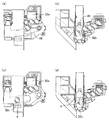
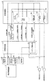
まず、図1を参照して、本実施の形態に係るパチンコ遊技機の構成を説明する。遊技場(ホール)内に複数配置されている各遊技島(図示略)には、遊技機の一例の封入循環式パチンコ遊技機(以下、遊技機、パチンコ機またはP台と略称することもある)2が併設されている。なお、P台2の所定側の側方位置には、該P台2に対して遊技用装置の一例のカードユニット(以下CUと略称することもある)3が1対1に対応設置されている。なお、本実施の形態に係る遊技用装置としてカードユニットを例に以下説明するが、これに限られず、P台2と接続して大当りや異常の報知、入賞回数などの遊技情報の収集などを行う呼出しランプ装置などであってもよい。
<Configuration of pachinko machines>
First, the configuration of the pachinko gaming machine according to the present embodiment will be described with reference to FIG. A plurality of game islands (not shown) arranged in the game hall (hall) may be abbreviated as an enclosed circulation pachinko game machine (hereinafter referred to as a game machine, a pachinko machine, or a P machine) as an example of a game machine. ) 2 is attached. A card unit (which may be abbreviated as CU hereinafter) 3 as an example of a gaming device is installed in a one-to-one correspondence with the P table 2 at a side position on the predetermined side of the P table 2. Yes. Note that the card unit is taken as an example of the gaming device according to the present embodiment, but the present invention is not limited to this, but it is connected to the
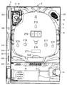
P台2は、内部に遊技媒体の一例の遊技球(パチンコ球)を封入しており(以下、封入球ともいう)、遊技者が打球操作ハンドル25を操作することにより、左上側に設けた発射装置である発射機構30の発射ソレノイドを駆動させて封入球を1発ずつ遊技盤26前面の遊技領域27に打込んで遊技ができるように構成されている。具体的には、打球操作ハンドル25の周囲にタッチセンサが設けられており、遊技者が打球操作ハンドル25を操作している状態でその遊技者の手がタッチセンサに触れ、その遊技者の手の接触をタッチセンサで検知して発射ソレノイドが駆動される。この状態で、遊技者による打球操作ハンドル25の回動操作量に応じて打球発射勢いが調整されて封入球が遊技領域27内に発射される。
The
発射ソレノイドを駆動させて封入球を1発ずつ遊技領域27に打込むと、それに伴い減算機構32で、P台2において遊技可能な遊技球数から1球ずつ減算する。遊技球の発射強度(以下、単に発射強度Tともいう)は、打球操作ハンドル25の回動操作量(以下、単にハンドル操作量ともいう)に応じて調整可能であり、ハンドル操作量を大きくするにしたがって発射強度Tが大きくなる。したがって、遊技者は、ハンドル操作量を調節することによって、自らが狙う領域を遊技球が通過するように発射強度Tを調整することができる。
When the firing solenoid is driven and the encapsulated ball is driven into the
図1に示すP台2は、いわゆる第1種のパチンコ遊技機であって、遊技領域27の中央に可変表示装置(特別図柄とも言う)278が設けられている。また、遊技領域27には、打込まれた封入球が入賞可能な複数種類の入賞口が設けられている。図1に示す遊技領域27には、1つの大入賞口(可変入賞球装置)271と、3つの普通入賞口272,273,274と、3つの始動入賞口275,276,277とが示されている。特に、始動入賞口276は、遊技者にとって有利な第1の状態(たとえば開成状態)と遊技者にとって不利な第2の状態(たとえば閉成状態)とに変化可能な電動チューリップで構成されている。
The P stand 2 shown in FIG. 1 is a so-called first type pachinko gaming machine, and a variable display device (also referred to as a special symbol) 278 is provided in the center of the
可変表示装置278は、複数種類の識別情報(図柄)を可変表示可能な可変表示部を備えており、各始動入賞口275,276,277に入賞した始動入賞球の検出信号に基づいてそれらの複数種類の識別情報の可変表示を開始させる。可変表示装置の表示結果が特定の識別情報の組合せ(たとえばぞろ目)になると、大当り状態(大当り遊技状態ともいう)となり、大入賞口271が開放する。
The
また、可変表示装置278の表示結果が大当り図柄の組合せ(ぞろ目)のうちの予め定められた特別の識別情報の組合せ(たとえば777などの確変図柄の組合せ)となることにより、確変大当り状態が発生し、それに伴う大当り状態の終了後大当りの発生確率が向上した確率変動状態(確変状態)が発生する。
Further, the display result of the
遊技領域27内に打込まれた封入球はいずれかの入賞口に入賞するかあるいは入賞することなくアウト口154に回収される。いずれかの入賞口に入賞した封入球およびアウト口154に回収された封入球は再度P台2内の回収経路を通って打球発射位置にまで還元される。そして、遊技者が打球操作ハンドル25を操作することにより再びその打球発射位置の封入球が遊技領域27内に打込まれる。
The encapsulated ball that has been driven into the
また、P台2の打球操作ハンドル25の上方位置に遊技球数を表示するための遊技球数表示器が設けられている。遊技球数表示器29は、7セグメント式のLEDディスプレイで構成されており、枠制御部171(図4参照)によって制御される。この遊技球数表示器29により、遊技球数や発生したエラーのエラー番号などが表示される。なお、遊技球数表示器29は、7セグメント式のLEDディスプレイに限定されず、液晶表示器や有機EL表示器、その他の表示器で構成してもよい。
In addition, a game ball number display for displaying the number of game balls is provided above the hitting operation handle 25 of the
さらに、P台2における遊技球数表示器29の左方位置には、遊技球から持ち球への計数処理をするための計数ボタン28が設けられている。本実施の形態では、計数ボタン28を押下し続けた時間に応じて計数動作が繰返し実行される(たとえば0.3秒押下状態が継続する度に250球の計数処理が実行される)。なお、押下継続時間に関わらず、1度押下すると、所定数(たとえば250球)だけ遊技球から持ち球への計数が行われるようにしてもよく、あるいは、計数ボタン28を1度押下した場合には、その押下時間にかかわらず(長押しか否かにかかわらず)、現在遊技者が所有している遊技球のすべてが計数されるようにしてもよい。また、計数速度は、カード返却操作を行う場合にさらに向上し、スムーズなカード返却処理を実現している。
Further, a
このように、計数ボタン28をP台2側に設けているため、計数ボタン28をCU3側に設ける場合と比較して、P台2に正対して座っている遊技者の操作性を向上できる。また、P台2は、遊技領域27の右上位置および左上位置に、可変表示装置278で表示される演出にあわせて再生する音楽データを出力するためのスピーカ270が設けられている。なお、スピーカの位置および個数は、図1に示す構成に限定されず、必要に応じて位置および個数を変更してもよい。
Thus, since the
本実施の形態に係るP台2は、遊技盤26とそれ以外の遊技機枠(前枠)5とに分けることができる。特に、遊技盤26は、各社が開発するパチンコ遊技機の機種毎に異なるものである一方、遊技機枠5は、機種に関わらず共通の共通枠とされている。このため、遊技店は新台入れ替えの際には遊技盤26のみの交換で事足りる。
The P stand 2 according to the present embodiment can be divided into a
<カードユニットの構成>
次に、引続き図1を参照して、本実施の形態に係るCU3の構成を説明する。このCU3は、会員登録をしていない一般の遊技者に対して発行される遊技用記憶媒体であるプリペイド機能を備えるビジターカード(一般カードとも言う)や、該遊技場に会員登録した会員遊技者に対して発行される遊技用記憶媒体である会員カードを受付ける。ビジターカードや会員カードはICカードで構成されている。
<Configuration of card unit>
Next, the configuration of the
それらのカードを受付けたCU3は、カードの記憶情報により特定される遊技者所有の遊技価値(たとえばプリペイド残額、持ち球数、あるいは貯玉数など)を“遊技球のデータ”に変換する機能を有する。P台2では、遊技球のデータによって特定される球数相当の弾球遊技が可能とされる。つまり、“遊技球のデータ”とは、発射可能な球の発射残数を示すデータである。以下の説明では、“遊技球のデータ”を貯玉や持ち球と同様に、単に“遊技球”と称する。
The
CU3の前面側には、紙幣を挿入するための紙幣挿入口302、会員カードやビジターカードを挿入するためのカード挿入/排出口309などが設けられている。このカード挿入/排出口309に挿入された会員カードやビジターカードがカードリーダライタ(図示省略)に受付けられ、そのカードに記憶されている情報が読取られる。
On the front side of the
CU3の前面側には、表示器312と、会員カードを受付けた場合において、該会員カードに記憶された会員カードID(単に、カードID、C−IDとも言う)ならびに会員カードIDにより特定される貯玉数を用いた再プレイ遊技を実施するための再プレイボタン319とが設けられている。
The front side of the
表示器312は、挿入された遊技用記憶媒体(カード)に記憶されているプリペイド残額を表示するものであるが、遊技球数やその他の各種情報を表示可能であるとともに、表面が透明タッチパネルで構成されており、表示器312の表示部に表示された各種表示項目を指でタッチすることにより各種操作が入力可能となるように構成されている。
The
再プレイボタン319を操作した場合に、挿入されたカードに遊技者が獲得した持ち球数が記憶されているときにはその持ち球数の一部を引落として遊技球に変換し、変換した遊技球に基づいてP台2による遊技を行うことが可能となる。一方、挿入されたカードが会員カードであり持ち球数が記憶されておらずかつ貯玉がホール用管理コンピュータなどに記憶されている場合には、その貯玉の一部が引落とされて遊技球に変換され、P台2による遊技が可能となる。つまり、挿入されたカードに対応付けて貯玉と持ち球との双方が記憶されている場合には、持ち球が優先的に引落とされる。なお、再プレイボタン319とは別に、持ち球を引落とすための専用の持ち球払出ボタンを設け、再プレイボタン319は貯玉引落とし専用のボタンとしてもよい。
When the
ここで、「貯玉」とは、前日以前に獲得した球でホールに預けている球であり、貯玉払出により遊技球となる。また、貯玉は、遊技場に預入れられた遊技媒体であり、一般的に当該遊技場に設置されたホール用管理コンピュータやその他の管理コンピュータにより管理される。 Here, the “storing ball” is a ball deposited in the hall with a ball acquired before the previous day, and becomes a game ball by paying out the saving ball. The storage ball is a game medium deposited in a game hall, and is generally managed by a hall management computer or other management computer installed in the game hall.
「持ち球」とは、当日獲得した球であり、持ち球払出により遊技球となる。また、持ち球数は、遊技者がP台2により遊技を行った結果遊技者の所有となった遊技球数をカードに記憶したものであって、未だに遊技場に預入れられていない球数のことである。一般的には、遊技場において当日遊技者が獲得した球数を「持ち球」と言い、前日以前に遊技者が獲得した球数であって遊技場に預入れられた球数を「貯玉」と言う。
The “held ball” is a ball acquired on the day and becomes a game ball by paying out the held ball. In addition, the number of possessed balls is the number of game balls owned by the player as a result of the player playing the game with the
「遊技球」とは、P台2で発射可能な球である。遊技球数のデータは、既に説明したとおり、プリペイドカードの残額、持ち球、あるいは貯玉を引落とすことと引き換えにして生成される。
The “game ball” is a ball that can be launched by the
なお、持ち球数を遊技場に設定された持ち球数管理用の管理装置で管理してもよい。要するに、「貯玉」と「持ち球」との違いは、遊技場に預入れるための貯玉操作が行われて遊技場に預入れられた球数であるか、あるいは、未だに遊技場に預入れられていない段階の球数であるかの点である。 Note that the number of balls may be managed by a management device for managing the number of balls set in the game hall. In short, the difference between “storing balls” and “holding balls” is the number of balls that have been deposited in the amusement hall through the operation of storing balls for depositing in the amusement hall, or are still deposited in the amusement park. It is a point whether it is the number of balls of the stage which is not.
本実施形態では、貯玉データは会員カードに直接記憶させずホール用管理コンピュータなどの遊技場に設置されたサーバに会員カード番号と対応付けて記憶させ、会員カード番号に基づいて対応する貯玉を検索できるように構成されている。一方、持ち球は、カードに直接記憶している。しかし、それに限定されるものではなく、両者ともにホールサーバにカード番号と対応付けて記憶させてもよい。ビジターカードの場合も、持ち球は、ビジターカードに直接記憶している。しかし、それに限定されるものではなく、持ち球をホールサーバにカード番号と対応させて記憶させてもよい。このホールサーバにカード番号と対応させて記憶させる際に、ホールサーバに記憶させた時刻を特定できるデータをカード(会員カード、ビジターカード)に書込んで排出してもよい。また、プリペイド残額についてはカード(会員カード、ビジターカード)に直接書込んで排出する。 In this embodiment, the stored ball data is not directly stored in the member card, but is stored in association with the member card number on a server installed in a game hall such as a hall management computer, and the corresponding stored ball is searched based on the member card number. It is configured to be able to. On the other hand, the ball is directly stored in the card. However, the present invention is not limited to this, and both may be stored in the hall server in association with the card number. In the case of a visitor card, the ball is directly stored in the visitor card. However, the present invention is not limited to this, and the possessed ball may be stored in the hall server in association with the card number. When storing in the hall server in association with the card number, data that can specify the time stored in the hall server may be written in the card (member card, visitor card) and discharged. Also, the prepaid balance is written directly on a card (member card, visitor card) and discharged.
なお、持ち球を、カード(会員カード、ビジターカード)、またはホールサーバに記憶させるタイミングは、たとえば、計数ボタン28が操作されて計数処理が行われる度にリアルタイムに記憶させる、一定周期ごとに記憶させる、またはカードを返却するときに一括して記憶させるなどのタイミングとすることが考えられる。
The timing for storing the ball in a card (member card, visitor card) or hall server is stored at regular intervals, for example, in real time whenever the
また、遊技者が遊技を終えてCU3からカードを返却したときには、CU3に記憶していた持ち球が一旦貯玉としてホールサーバに記憶されるようにし、その遊技者がカードの返却を受けた日と同じ日に再び同じまたは別のCU3にカードを挿入したときには、一旦貯玉として記憶された当日分の持ち球のみが再びそのCU3に記憶され、その持ち球の範囲で遊技球を加算し、遊技できるようにしてもよい。 Also, when the player finishes the game and returns the card from CU3, the possessed ball stored in CU3 is temporarily stored in the hall server as a stored ball, and the date when the player receives the card return When a card is inserted into the same or another CU3 again on the same day, only the ball possessed for the day once stored as a storage ball is again stored in the CU3, and a game ball can be added and played within the range of the possessed ball You may do it.
紙幣挿入口302に挿入された紙幣は、貨幣識別器(図示省略)により取込まれてその真贋や紙幣種別の識別がなされる。
The banknote inserted into the
CU3の前面側には、さらに、IR(Infrared)感光ユニット(IR受光ユニットとも言う)320と、球貸ボタン(貸出ボタンとも言う)321と、カード返却ボタン322とが設けられている。IR感光ユニット320は、遊技場の係員が所持するリモコン(図示略)から赤外線信号を受信して電子信号に変換して出力するIR感光ユニット320である。球貸ボタン321は、挿入されたカードに記憶されている残額を引落としてP台2による遊技に用いるための操作(遊技球への変換操作)を行うボタンである。カード返却ボタン322は、遊技者が遊技を終了するときに操作され、挿入されているカードに遊技終了時の確定した持ち球数(カード挿入時の持ち球数−遊技球への変換数+計数操作によって計数された持ち球数)を記憶させて排出するための操作ボタンである。
Further, an IR (Infrared) photosensitive unit (also referred to as an IR light receiving unit) 320, a ball lending button (also referred to as a lending button) 321, and a
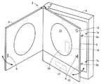
次に、図2を参照して、P台2は、額縁状の外枠4に対して、遊技機枠(以下、セルとも言う)5とガラス扉6とがその左側縁を揺動中心として開閉可能に設けられている。
Next, referring to FIG. 2, the
遊技機枠5における揺動中心とは反対側の端縁付近(遊端側)には、上下1対の係合突起6a、6bが設けられている。この係合突起6a、6bは、図示しないバネによって下方向に押圧されている。一方、係合突起6a、6bに対向する外枠4の位置に、係合受け片7a、7bが設けられている。開放状態の遊技機枠5を外枠4に押付けることにより係合突起6a、6bが係合受け片7a、7bを乗越え、乗越えた状態でバネの付勢力により係合突起6a、6bが下方に移動し、ロック状態となる。
A pair of upper and lower
そして、遊技場の係員が図1に示した鍵穴10に鍵を挿入して解錠操作(たとえば時計回り回転)することにより、バネの付勢力に抗して上下1対の係合突起6a、6bが上方に押上げられ、その結果係合受け片7a、7bに対する係合突起6a、6bの係合が解除されてロック解除状態となり、遊技機枠5が開放される。
Then, a game attendant inserts a key into the
さらに、遊技機枠5にはガラス扉6用の係合突起8も設けられており、その係合突起8に対向するガラス扉6部分には、係合穴9が設けられている。係合突起8は、図示しないバネによって下方に押圧されており、開放状態のガラス扉6を遊技機枠5に押付けることにより係合穴9の下縁部分によって係合突起8が押上げられて乗越えることにより、バネの付勢力により係合突起8が押下げられ、係合突起8と係合穴9とが係合されてロック状態となる。この状態で、遊技場の係員が図1に示した鍵穴10に鍵を挿入して解錠操作(たとえば反時計回り回転)することにより、バネの付勢力に抗して係合突起8が引上げられ、係合突起8と係合穴9との係合が解除されてロック解除状態となり、ガラス扉6が開放される。
Further, the
遊技機枠5の下方部分における外枠4と接触する箇所に裏機構部開放スイッチ13が設けられており、遊技機枠5が開放されたことが検出される。また、遊技機枠5の上方部分におけるガラス扉6との接触部分に前飾り開放スイッチ12が設けられており、ガラス扉6が開放されたことがこの前飾り開放スイッチ12により検出される。
A back mechanism
前飾り開放スイッチ12および裏機構部開放スイッチ13の開放回数は、図示しない計数カウンタにより計数される。計数カウンタは、CPU(Central Processing Unit),ROM(Read Only Memory),RAM(Random Access Memory)などが搭載され、P台2の電源供給が途切れたときでもバックアップ電源により動作可能で、夜間などの電源OFF時でもガラス扉6や遊技機枠5の開放検出回数を計数してその計数値を枠制御部171(図4参照)へ送信することができる。ここで、バックアップ電源は、たとえば、P台2内に設けられたキャパシタや蓄電池である。
The number of times the front
遊技盤26の裏面(ガラス扉6と対向する面とは反対側の面)に、主制御基板16が設けられている。外枠4の裏面は閉じられているため、まず遊技機枠5を開放して遊技機枠5から遊技盤26を取外すことで、主制御基板16が遊技盤26から着脱可能な状態になる。つまり、遊技盤26より主制御基板16を取外す、または主制御基板16に設けた半導体チップを交換する作業を行うためには、遊技機枠5を開放する必要があるため裏機構部開放スイッチ13で当該作業を必ず検出することができる。よって、遊技盤26より主制御基板16を不正に取外す、または主制御基板16に設けた半導体チップを不正に交換すれば、必ず裏機構部開放スイッチ13で検出することができる。
A
さらに、遊技機枠5の裏面に、枠制御基板17が設けられている。枠制御基板17も、まず遊技機枠5を開放してから、遊技機枠5の裏面より取外す必要がある。よって、遊技機枠5の裏面より枠制御基板17を不正に取外す、または枠制御基板17に設けた半導体チップを不正に交換すれば、必ず裏機構部開放スイッチ13で検出することができる。
Further, a
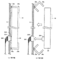
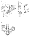
次に、遊技盤26を遊技機枠5に設置する構成について説明する。図3は、遊技盤26が遊技機枠5に取付けられる前と取付けられた後の様子を示す図である。図3に示すように遊技機枠5の裏面には、取付機構34a、34bがそれぞれヒンジ35a、35bを中心に開閉自在に設けられている。取付機構34a、34bは、コの時型をしており、遊技盤26に対応した幅の底を持つ。遊技盤26を遊技機枠5に対して図3(b)の矢印方向に押し込むことで、図3(a)に示すように遊技盤26が取付機構34a、34bにより固定される。遊技盤26が取付機構34a、34bにより固定されるときに、遊技盤26側に設けた凸型ドロアコネクタ33Aが遊技機枠5側に設けた凹型ドロアコネクタ33Bと結合する。ここで、凸型ドロアコネクタ33Aおよび凹型ドロアコネクタ33Bは、位置ずれに対してフレキシブル性を有するフローティングコネクタである。
Next, a configuration in which the
また、遊技盤26を遊技機枠5に設置する際に、凸型ドロアコネクタ33Aが凹型ドロアコネクタ33Bと結合することで、遊技盤26側の主制御基板16と、遊技機枠5側の枠制御基板17とが接続されることになる。さらに、遊技盤26は決まった位置に固定されるとともに、凸型ドロアコネクタ33Aおよび凹型ドロアコネクタ33Bはある程度の位置ずれに対してフレキシブル性を有しているので、凸型ドロアコネクタ33Aと凹型ドロアコネクタ33Bとの位置関係を意識することなくこれらが結合することができる。なお、取付機構34a、34bを設けず、凸型ドロアコネクタ33Aおよび凹型ドロアコネクタ33Bのみで、遊技盤26を遊技機枠5に設置する構成であっても、凸型ドロアコネクタ33Aおよび凹型ドロアコネクタ33B自体がフレキシブル性を有するフローティングコネクタであるため、遊技盤26と遊技機枠5との位置関係を意識することなくこれらが結合することができる。ここで、凸型ドロアコネクタ33Aは、遊技盤26の内部配線(図示せず)を介して主制御基板16に接続され、凹型ドロアコネクタ33Bは、信号ケーブル360を介して、図2に示す枠制御基板17に接続されている。
Further, when the
<カードユニットとパチンコ遊技機との構成>
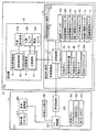
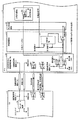
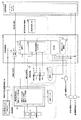
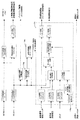
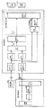
図4は、CU3およびP台2に用いられる制御回路を示すブロック図である。図4を参照して、CU3とP台2との制御回路の概略を説明する。
<Configuration of card unit and pachinko machine>
FIG. 4 is a block diagram showing a control circuit used for the
CU3には、マイクロコンピュータなどから構成されたCU制御部323が設けられている。このCU制御部323は、CU3の主制御機能部であり、制御中枢としてのCPU、CPUが動作するためのプログラムや制御データなどを記憶しているROM、CPUのワークエリアとして機能するRAM、周辺機器との信号の整合性を保つための入出力インターフェイスなどが設けられている。
The
CU制御部323には、ホール用管理コンピュータやセキュリティ上の管理を行うホールサーバと通信を行うための外部出力端子340が設けられている。CU3は、外部出力端子340を介して、CU3の状態や、P台2から受信した遊技機状態情報(性能表示モニタ40で表示する情報を含む)をホール用管理コンピュータ(ホールコン)やセキュリティ上の管理を行うホールサーバなどの外部に送信する。CU制御部323は、通信制御IC325を介してP台2の枠制御基板17と通信を行っている。通信制御IC325と枠制御基板17とは、例えば、非同期シリアル通信ポートで接続されている。CU制御部323と枠制御基板17との通信は、貸出情報(挿入されたカードに記憶されている残額を引落としてP台2による遊技に用いるための操作に関する情報)と貸出応答情報(貸出情報に対する応答情報)とを双方向で行い、それ以外の計数情報(遊技球から持ち球への計数処理に関する情報)、および遊技機情報を、枠制御基板17からCU制御部323への一方向の通信で行っている。そのため、CU3が計数情報および遊技機情報を受信したか否かをP台2側では認識していない。CU3にはP台2側への接続部(図示省略)が設けられており、P台2にはCU3側への接続部(図示省略)が設けられている。これら接続部は、たとえばコネクタなどで構成されている。
The
CU制御部323には、前述した貨幣識別器により紙幣の真贋および種類が識別されて、その識別結果信号が入力される。また、CU制御部323には、遊技場の係員が所持しているリモコンから発せられた赤外線をIR感光ユニット320が受光すれば、その受光信号が入力される。CU制御部323には、挿入されたカードの記憶情報をカードリーダライタが読取って、その読取り情報が入力されるとともに、CU制御部323からカードリーダライタに対し、挿入されているカードに書込むデータが伝送されたときに、カードリーダライタはそのデータを挿入されているカードに書込む。カードの記憶情報には、カードIDが含まれる。CU制御部323は、カードリーダライタが読み取ったカードIDを遊技終了まで記憶する。
To the
CU制御部323は、遊技者が遊技している際、遊技者の持ち球を管理・記憶する。CU制御部323から残額あるいは持ち球数などのデータが表示制御部350に出力され、表示制御部350で表示用データに変換される。CU3の前面に設けられる表示器312に対し、表示制御部350で変換した表示用データが送信される。表示器312には、その表示用データに応じた画像が表示される。また、表示器312の表面に設けられているタッチパネルを遊技者が操作すれば、その操作信号が表示制御部350を介してCU制御部323に入力される。遊技者が球貸ボタン321を操作することにより、その操作信号がCU制御部323に入力される。なお、球貸ボタン321は、CU3に設ける構成に限定されるものではなく、P台2に設けて操作信号をCU制御部323に入力する構成であっても良い。遊技者が再プレイボタン319を操作することによりその操作信号がCU制御部323に入力される。遊技者がカード返却ボタン322を操作することによりその操作信号がCU制御部323に入力される。
The
P台2には、P台2の遊技の進行制御を行う主制御基板16と、遊技球を管理・記憶する枠制御基板17と、枠制御基板17の指令に基づいて発射ソレノイド31aを駆動制御する発射制御基板31と、可変表示装置278と、主制御基板16から送信されてくるコマンドに基づいて可変表示装置278を表示制御する演出制御基板15とが備えられている。
The
主制御基板16および演出制御基板15は、遊技盤26に設けられている。主制御基板16には主制御部161である遊技制御用マイクロコンピュータが搭載されている。主制御部161は、遊技機の主制御機能部である。遊技機制御用マイクロコンピュータは、制御中枢としてのCPU、CPUが動作するためのプログラムや制御データなどを記憶しているROM、CPUのワークエリアとして機能するRAM、周辺機器との信号の整合性を保つための入出力インターフェイスなどが設けられている。主制御部161は、遊技盤26に設けられている入賞センサ162、および電波センサ163に接続されている。
The
主制御部161は、各始動入賞口275,276,277に球が入賞すると、大当り(あるいはさらに小当りを含む)/外れを決定するための乱数を抽選し、その乱数を記憶する。これを保留記憶という。保留記憶数の最大値は、たとえば、「4」である。主制御部161は、可変表示装置278で新たな可変表示を開始できる状態になれば、保留記憶を1つ消化してその保留記憶に基づいた大当り判定を行うとともに可変開始から表示結果の導出に至るまでの可変表示時間を複数種類の中から決定する。また、大当りを決定したときには、確率変動を生じさせるか否かも併せて決定する。主制御部161は、その大当り判定の結果(確変にするか否かを含む)、および可変表示時間に関する情報をコマンドとして演出制御基板15に搭載された演出制御部151へ送信する。
When a ball wins each start winning
主制御部161から演出制御部151へ送信される可変表示に関するコマンドには、可変表示の開始を示す可変開始コマンド、可変表示の結果を示す表示結果コマンド(大当り/外れ)、可変表示パターンを特定可能な可変表示時間コマンド、可変表示結果を導出表示させるタイミングを示す可変停止コマンドなどが含まれる。さらに、主制御部161から演出制御部151へ送信されるコマンドには、大当り中に大当りの進行状況を特定可能なコマンドや、新たな保留記憶の発生を示すコマンド、遊技状態のエラーの発生を示すコマンドなどがある。
The variable display command transmitted from the
演出制御部151は、主制御部161から送信されてくるこれらのコマンドに基づいて可変表示装置278の可変表示内容を決定する。たとえば、演出制御部151は、主制御部161から送信されてくるコマンドに基づいて可変表示結果および可変表示時間を特定し、停止図柄を決定するとともに可変表示パターン(リーチの有無、リーチの種類)を決定し、さらには大当りやリーチに関する予告演出の演出パターンを決定する。演出制御部151は、決定した可変表示内容に従って可変表示装置278を表示制御する。
The
枠制御基板17は、遊技機枠5に設けられている。枠制御基板17には、枠制御部171である払出制御用マイクロコンピュータが搭載されている。枠制御部171は、遊技機の払出制御機能部である。払出制御用マイクロコンピュータは、制御中枢としてのCPU、CPUが動作するためのプログラムや制御データなどを記憶しているROM、CPUのワークエリアとして機能するRAM、周辺機器との信号の整合性を保つための入出力インターフェイスなどが設けられている。
The
また、枠制御基板17に対し、計数ボタン28、性能表示モニタ40、電波センサ173、減算ソレノイド32a、減算機構入口センサ32b、減算機構出口センサ32c、揚上機構出口センサ33、アウト球検出スイッチ701、前飾り開放スイッチ12、および裏機構部開放スイッチ13が電気的に接続された状態で設けられている。アウト球検出スイッチ701から枠制御基板17へアウト球検出信号が入力される。主制御基板16は、後述するようにアウト球検出信号に基づきベース値(単に、ベースともいう)などを算出する。電波センサ173は、電波を不正に発信して主に減算機構入口センサ32bを常時オン状態にする不正行為を検知するためのものである。この電波センサ173の検出信号が枠制御基板17の入力ポート(図示省略)を介して枠制御部171へ入力される。減算機構入口センサ32bは、オフからオンに変化したことにより遊技球の発射を検出し、その検知に基づいて、枠制御部171が、遊技球数を「1」減算する。
Further, with respect to the
したがって、不正電波によりこの減算機構入口センサ32bが常時オフ状態になると、いくら球を発射しても遊技球数が減算されない状態となる。このような電波による不正を電波センサ173により検知する。
Therefore, if the subtraction
枠制御基板17には、性能表示モニタ40が設けられる。性能表示モニタ40は、7セグメント式のLEDディスプレイである。性能表示モニタ40は、枠制御部171によって算出された付与された遊技価値(例えば、賞球など)に関する性能情報、ベース、役物比率、連続役物比率などの所定情報を表示する。なお、性能表示モニタ40で表示する情報を、CU3を介してホールサーバなどに出力することができるが、P台2に外部出力端子を設け、直接ホールサーバなどに出力してもよい。
A performance display monitor 40 is provided on the
ここで、ベースは、P台2の遊技領域27に打ち込まれた遊技球の数に対する、遊技領域27に設けられた大入賞口271、普通入賞口272〜274、および、始動入賞口275〜277などの入賞口への遊技球の入賞に応じて付与された遊技価値に対応する遊技球の数の割合である。また、役物比率(役比ともいう)は、10時間に発射させた遊技球により獲得する遊技球のうち役物の作動によるものの割合をいう。本実施の形態においては、役物比率は、10時間に発射させた遊技球(1分間に100球発射可能であるので、60000球)の全入賞口への入賞によって付与される遊技価値に対応する遊技球の個数のうち、役物の1つである電動チューリップで構成される始動入賞口276、および、役物の1つである可変入賞球装置で構成される大入賞口271への遊技球の入賞によって付与される遊技価値に対応する遊技球の個数の割合をいう。さらに、連続役物比率(連比ともいう)は、10時間に発射させた遊技球により獲得する遊技球の数のうち役物が連続して作動する場合における当該役物の作動によるものの割合をいう。本実施の形態においては、連続役物比率は、10時間に発射させた遊技球(1分間に100球発射可能であるので、60000球)の全入賞口への入賞によって付与される遊技価値に対応する遊技球の個数のうち、役物の1つである可変入賞球装置が設けられた大入賞口271への遊技球の入賞によって付与される遊技価値に対応する遊技球の個数の割合をいう。
Here, the base is a big winning
主制御基板16から枠制御基板17に対し、主制御チップID、入賞口情報、ラウンド情報、入賞検出信号、始動入賞口入賞情報、エラー情報、図柄確定回数、大当り情報の情報が送信される。
From the
主制御チップID(メインチップIDとも言う)は、P台2の主制御基板16に記憶されているチップIDのことであり、P台2の電源投入時に枠制御基板17に対して送信される情報である。入賞口情報は、入賞口の種類(始動入賞口、普通入賞口、大入賞口)と、賞球数(入賞口に遊技球が入ったときの払出球数)とを含む情報であり、P台2の電源投入時に枠制御基板17に対して送信される。ラウンド情報は、大当りしたときのラウンド数の情報であり、P台2の電源投入時に枠制御基板17に対して送信される。
The main control chip ID (also referred to as main chip ID) is a chip ID stored in the
入賞検出信号は、始動入賞口以外の入賞口に入賞した遊技球の検出信号である。この検出信号を受けた枠制御基板17は、その入賞球1個に対して付与すべき球数を、遊技球数と加算球数とに加算する制御を行う。
The winning detection signal is a detection signal of a game ball won in a winning opening other than the starting winning opening. Upon receiving this detection signal, the
始動入賞口入賞情報とは、始動入賞口のいずれかに遊技球が入賞したことを示す情報である。エラー情報とは、主制御基板16が遊技制御を行っている最中にエラーが発生した場合にその旨を枠制御基板17へ通知するための情報である。
The start winning award winning information is information indicating that a game ball has won any of the starting winning awards. The error information is information for notifying the
図柄確定回数とは、各始動入賞口への入賞に対する可変表示装置の表示結果として確定した図柄の情報である。 The symbol determination number of times is information on symbols determined as display results of the variable display device for winnings at each start winning opening.
大当り情報とは、大当りが発生したことを示す情報であり、その内訳は、各メーカ共通の大当りを示す共通大当り情報とメーカ固有の大当りを示すメーカ固有大当り情報とがある。共通大当り情報は、たとえば15ラウンド大当りなどのように、各遊技機メーカが共通に採用している大当りであり、その大当りに伴って確変が発生する場合には確変情報を含み、その大当りに伴って時短状態(可変表示装置の可変表示時間を短縮する制御状態)が発生する場合にはその時短情報を含んでいる。メーカ固有大当りとは、たとえば突然確変(突確)のような、或る遊技機メーカのみが採用している大当り状態のことである。 The jackpot information is information indicating that a jackpot has occurred. The breakdown includes common jackpot information indicating a jackpot common to each manufacturer and manufacturer-specific jackpot information indicating a manufacturer-specific jackpot. The common jackpot information is a jackpot commonly used by each gaming machine maker, such as 15 round jackpots, and includes a probability change information if a probability change occurs with the jackpot. When the time-short state (control state for shortening the variable display time of the variable display device) occurs, the time-shortage information is included. The manufacturer-specific big hit is a big hit state that is adopted only by a certain gaming machine manufacturer, such as sudden probability change (surprise).
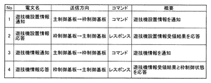
枠制御基板17から主制御基板16へ、遊技機設置情報受領結果、遊技機情報受領結果、および枠制御状態が送信される。遊技機設置情報受領結果および遊技機情報受領結果は、主制御基板16から遊技機設置情報および遊技機情報を受領したことを示すためのコマンドである。枠制御状態は、枠制御基板17の制御状態を通知するコマンドである。
A gaming machine installation information reception result, gaming machine information reception result, and a frame control state are transmitted from the
CU3の通信制御IC325とP台2の枠制御基板17とが電気的に接続されており、通信制御IC325から枠制御基板17へ、後述するように各種コマンドが送信される。逆に、枠制御基板17から通信制御IC325へ、後述するように各種レスポンスが送信される。
The
遊技機枠5には、枠制御基板17の他、発射制御基板31、発射ソレノイド31a、遊技球数表示器29が設けられている。なお、遊技球数表示器29は遊技機枠5に直接取り付けてもよいが、球が払い出される通常のパチンコ遊技機の前面側に設けられた上皿や下皿のように、遊技機枠5に対して回動可能な態様で設けるようにしてもよい。この点は、表示器54についても同様である。枠制御基板17の枠制御部171は遊技球数表示器29に遊技者が現在所有している遊技球数を表示する。
In addition to the
枠制御基板17から発射制御基板31へ、発射許可信号とが出力される。それを受けた発射制御基板31は、発射機構30の発射ソレノイド31aを励磁するための信号を出力する。これにより、遊技球が遊技領域27へ弾発発射される状態となる。発射制御基板31は、遊技者が打球操作ハンドル25に触れていることを検出するタッチリングの入力信号が入力されているときに発射ソレノイド励磁出力を発し、発射ソレノイド31aを駆動させる。
A launch permission signal is output from the
RAMクリアスイッチ293は、P台2のRAMに記憶している遊技機情報や遊技情報を消去するためのスイッチであり、P台がエラー状態となった後当該スイッチを店員が操作することで初期状態に戻すことが可能となる。このRAMクリアスイッチ293は、たとえばカードが排出された後に店員により操作される。
The RAM
<遊技球の循環経路>
ここでは、図1および図4を参照して、P台2における遊技球の循環経路を概説する。遊技者が打球操作ハンドル25を操作すると、発射ソレノイド31aが駆動する。これにより、発射位置にまで供給されてきた1個の遊技球が打球ハンマーにより弾発されてその遊技球が遊技領域27に打込まれる。
<Circulation path of game balls>
Here, with reference to FIG. 1 and FIG. 4, the circulation path of the game ball in the
発射ソレノイド31aが作動して遊技球が発射されたことに連動して減算基準信号が減算機構32に出力される。減算機構32では、出力された減算基準信号を基準に、減算ソレノイド32aが通電して可動片を動かすことで遊技球を発射機構30へ送り出し、遊技球が減算機構入口センサ32bを通過することで遊技球数を減算する。
A subtraction reference signal is output to the
遊技領域27に打込まれた球のうち、アウト口154(図1参照)に進入したアウト球は、アウト球流下経路を流下し、その途中に設けられたアウト球検出スイッチ701によって検出される。
Out balls that have entered the out area 154 (see FIG. 1) among balls that have been thrown into the
入賞口や可変入賞球装置に入賞したすべての入賞球は、遊技機背面で集められて回収球通過経路に誘導される。同様に、アウト球およびファール球も回収球通過経路に誘導される。回収球通過経路には揚上機構出口センサ33が設けられている。このため、入賞球、アウト球、およびファール球のすべてが揚上機構出口センサ33によって検出される。つまり、揚上機構出口センサ33は、弾発された遊技球のすべてを検出するスイッチである。このスイッチの検出数と、発射ソレノイド31aにより弾発された遊技球の弾発数とが等しくなったときに、打込まれた遊技球がすべて回収されたと判定できる。
All winning balls that have won the winning opening and the variable winning ball apparatus are collected on the back of the gaming machine and guided to the collection ball passing path. Similarly, the out sphere and the foul sphere are also guided to the collection sphere passing path. A lifting
そこで、本実施の形態では、揚上機構出口センサ33の検出数と弾発数との差を演算しており、この差数が0でないときには、遊技領域27に打込まれた球の回収が済んでいないと判定している。この判定をすることによって、遊技領域27を転動中であるか、遊技領域の釘などの間に引っ掛かって落下していないような浮遊球が存在していないかどうかを判断できる。
Therefore, in the present embodiment, the difference between the number detected by the lifting
<CUとP台との接続>
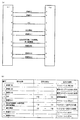
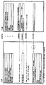
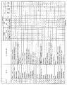
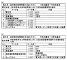
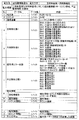
CU3とP台2とは、図4に示す通信制御IC325と枠制御基板17との間をPIF配線で接続している。PIF配線の構成について詳しく説明する。図5は、カードユニットとパチンコ遊技機とを接続するPIF配線の構成を説明するための概略図である。図5(a)には、CU3とP台2とを接続するPIF配線の配線番号と情報名称が図示され、図5(b)には、各情報名称に対する情報の向きおよび情報の説明がそれぞれ図示されている。
<Connection between CU and P stand>
The
具体的に、配線番号1は、情報名称が「絶縁GND」で、アイソレーション用GNDが割り当てられる。配線番号2は、情報名称が「絶縁GND」で、配線番号6のシグナルGNDに使用される。配線番号3は、情報名称が「絶縁GND」で、配線番号7のシグナルGNDに使用される。配線番号4は、情報名称が「PSI」で、P台2からCU3へ接続確認情報を送信するために使用される。なお、P台2は、CU3との接続を検知中(VL=ON)に接続確認用の特殊信号としてPSI信号をCU3に出力し、CU3との接続を未検知中(VL=OFF)にPSI信号をCU3に出力しない。配線番号5は、情報名称が「絶縁GND」で、アイソレーション用GNDが割り当てられる。配線番号6は、情報名称が「貸出応答情報、計数情報、遊技機情報」で、P台2からCU3へそれぞれの情報を送信するために使用される。配線番号7は、情報名称が「貸出情報」で、CU3からP台2へ貸出情報を送信するために使用される。配線番号8,9は、情報名称が「絶縁5V(VL)」で、それぞれアイソレーション用5V(接続確認用の電源VL)の信号ラインとして割り当てられる。
Specifically, the
<CU3とP台2との通信で用いられるフレーム構成>
次に、本実施の形態に係るCU3とP台2との間での通信について、さらに詳しく説明する。当該通信で用いられる電文は、所定のフォーマットからなるフレームで構成されている。送信データ(電文)は、必ず1フレーム単位で送信される。つまり、電文の分割送信は行わない。また、連続で電文を送信する場合は、1ミリ秒以上の間隔をあける。
<Frame configuration used in communication between
Next, communication between the
<CUとP台との間で送受信する情報>
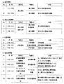
次に図6を参照して、CU3とP台2との間で送受信される情報(電文)の概略を説明する。P台2の枠制御基板17よりCU3に対して、(a)貸出情報、(b)貸出応答情報、(c)計数情報、および(d)遊技機情報をそれぞれ分けた電文で、共通の非同期シリアル通信ポートにて通信を行う。CU3とP台2との間で送受信される(a)〜(d)の4種類の情報(電文)では、それぞれ電文のヘッダーが異なっており、当該ヘッダーにより電文の種別を区別することが可能となっている。
<Information sent and received between CU and P platform>
Next, with reference to FIG. 6, an outline of information (message) transmitted and received between the
なお、(a)貸出情報と(b)貸出応答情報とを共通の非同期シリアル通信ポートにて通信を行っても、(a)貸出情報と(c)計数情報とを共通の非同期シリアル通信ポートにて通信を行っても、(a)貸出情報と(d)遊技機情報とを共通の非同期シリアル通信ポートにて通信を行ってもよい。また、(b)貸出応答情報と(c)計数情報とを共通の非同期シリアル通信ポートにて通信を行っても、(b)貸出応答情報と(d)遊技機情報とを共通の非同期シリアル通信ポートにて通信を行っても、(c)計数情報と(d)遊技機情報とを共通の非同期シリアル通信ポートにて通信を行ってもよい。 Even if (a) the lending information and (b) the lending response information are communicated through the common asynchronous serial communication port, (a) the lending information and (c) the counting information are transferred to the common asynchronous serial communication port. Even if communication is performed, (a) rental information and (d) gaming machine information may be communicated using a common asynchronous serial communication port. Further, even if (b) the lending response information and (c) the counting information are communicated through a common asynchronous serial communication port, (b) the lending response information and (d) the gaming machine information are shared by the same asynchronous serial communication. Even if communication is performed at the port, (c) counting information and (d) gaming machine information may be communicated at a common asynchronous serial communication port.
図6(a)には、貸出情報が記載されている。貸出情報には、CU3がP台2に送信する貸出通知の電文に含まれる情報として貸出球数の情報と、通信管理をするための貸出通番の情報とがある。貸出球数の情報は、貸出に係る遊技球数の情報であり、1回の情報で送信される遊技球数の情報として例えば125球の情報が含まれる。なお、貸出情報は、貸出球数が0(ゼロ)球の場合に貸出球数の情報に0(ゼロ)の情報を含めて送信してもよい。
In FIG. 6A, lending information is described. In the lending information, there are lending ball number information and lending serial number information for communication management as information included in a lending notice message transmitted by the
図6(b)には、貸出応答情報が記載されている。貸出応答情報には、P台2がCU3に送信する貸出受領結果応答の電文に含まれる情報として貸出球数受領結果の情報と、通信管理をするための貸出通番の情報とがある。貸出球数受領結果の情報は、CU3から送信された貸出球数の情報を受領した結果をCU3に知らせる情報である。
In FIG. 6B, the lending response information is described. The lending response information includes lending ball number reception result information and lending serial number information for communication management as information included in the lending receipt result response message transmitted from the
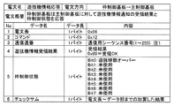
図6(c)には、計数情報が記載されている。計数情報では、P台2が計数球数と、計数累積球数と、通信管理をするための計数通番とを含む計数通知の電文としてCU3へ送信する。なお、P台2は、送信結果を確認するための情報をCU3から受信しない。計数球数、計数累積球数および計数通番は、いずれも遊技球の計数を目的とする情報である。また、1回の情報で送信される計数球数は、例えば250球である。なお、計数情報は、計数球数が0(ゼロ)球の場合に計数球数の情報に0(ゼロ)の情報を入れて送信してもよい。
FIG. 6C shows the counting information. In the count information, the
図6(d)には、遊技機情報が記載されている。遊技機情報では、P台2が遊技機設置情報、遊技機性能情報、ホールコン情報、不正監視情報をCU3へ送信する。なお、P台2は、送信結果を確認するための情報をCU3から受信しない。遊技機設置情報は、機歴管理を目的とする情報で、電源投入後に遊技機設置情報通知の電文としてCU3へ送信される。遊技機設置情報には、主/枠制御CPUのメーカコード、型式コード、チップID番号などの情報を含む。
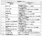
FIG. 6D shows gaming machine information. In the gaming machine information, the
遊技機性能情報は、性能情報の集計を目的とする情報で、遊技機性能情報通知の電文としてCU3へ送信される。遊技機性能情報は、遊技に基づいて算出された結果を出力するもので、総発射遊技球数、総獲得遊技球数、出球率、分間獲得遊技球数(低ベース)、分間獲得遊技球数(高ベース)、特別電動役物による総獲得遊技球数、普通電動役物による総獲得遊技球数、役物連続差動装置による総獲得遊技球、始動口の総獲得遊技球数、普通入賞口の総獲得遊技球数、特別電動役物の総作動回数、普通電動役物の総作動回数、特別図柄表示装置の総作動回数、普通図柄表示装置の総作動回数、役物比率、連続役物比率などの情報を含む。また、枠制御基板17が、遊技機性能情報をCU3に対して通知する条件として、例えば、(1)P台2の電源投入から3分経過後に通知、(2)遊技球を規定発射球数分(例えば、60000球)の発射もしくは規定時間(例えば、10時間)の周期毎に通知、(3)遊技機設置情報通知より優先して通知、(4)ホールコン・不正監視情報通知を通知した次の周期(300ms後)に通知などの条件がある。なお、これらの条件は例示であって他の条件を採用してもよく、また、上記条件のうち、いずれか1つの条件のみを採用したり、複数の条件を組み合わせて採用したりしてもよい。
The gaming machine performance information is information for the purpose of tabulating performance information, and is transmitted to the
ホールコン情報は、ホールコンの情報集計を目的とする情報で、ホールコン・不正監視情報通知の電文としてCU3へ送信される。ホールコン情報は、大当り、確率変動、時間短縮、各入賞口の入賞球数などを含む。不正監視情報は、CU3による不正監視を目的とする情報で、ホールコン・不正監視情報通知の電文としてCU3へ送信される。ホールコン情報は、遊技球数(現在の持ち球数)、遊技球数通番などの情報を含む。
The hall control information is information for the purpose of summing up the hall control information, and is transmitted to the
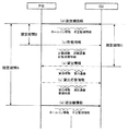
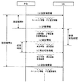
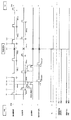
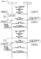
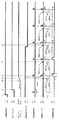
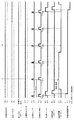
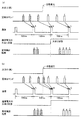
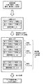
図7は、カードユニットとパチンコ遊技機との間の通信シーケンスを示す図である。図8は、カードユニットとパチンコ遊技機との間で送受信される情報のタイミングを示す図である。図7に示すシーケンスでは、図6に示した(b)貸出応答情報のNo.3〜No.4の情報、(c)計数情報、および(d)遊技機情報が共通の非同期シリアル通信ポートでP台2からCU3に送信されている。逆に、図6に示した(a)貸出情報のNo.1〜No.2の情報が共通の非同期シリアル通信ポートでCU3からP台2に送信されている。
FIG. 7 is a diagram showing a communication sequence between the card unit and the pachinko gaming machine. FIG. 8 is a diagram illustrating timing of information transmitted and received between the card unit and the pachinko gaming machine. In the sequence shown in FIG. 7, the No. of the (b) loan response information shown in FIG. 3-No. Information (4), (c) counting information, and (d) gaming machine information are transmitted from the
なお、図7に示すシーケンスは一例であり、図6に示した(c)計数情報、および(d)遊技機情報が共通の非同期シリアル通信ポートでP台2からCU3に送信されるシーケンスでもよい。このシーケンスの場合、図6に示した(a)貸出情報のNo.1〜No.2の情報が別の非同期シリアル通信ポートでCU3からP台2に送信され、(b)貸出情報のNo.3〜No.4の情報が別の非同期シリアル通信ポートでP台2からCU3に送信される。さらに、図6に示した(a)貸出情報のNo.1〜No.2の情報が共通の非同期シリアル通信ポートでCU3からP台2に送信され、図6に示した(b)貸出情報のNo.3〜No.4の情報、および(c)計数情報が共通の非同期シリアル通信ポートでP台2からCU3に送信されるシーケンスでもよい。このシーケンスの場合、図6に示した(d)遊技機情報が別の非同期シリアル通信ポートでP台2からCU3に送信されるシーケンスでもよい。
The sequence shown in FIG. 7 is an example, and (c) counting information and (d) gaming machine information shown in FIG. 6 may be transmitted from the
P台2からCU3へ送信される情報のうち、(d)遊技機情報は、図8で示すように規定期間Aごとに送信されている。つまり、P台2からCU3への情報の送信から次の情報の送信までの期間が、規定期間A(例えば、300ms=0.3秒)に制御されている。P台2は、CU3での遊技機情報の受信状況に関わらず、規定期間Aごとに遊技機情報をCU3に送信することができる。そのため、P台2において、遊技機情報の再送処理が不要となり、過去の遊技機情報を記憶する必要がなくなり、処理負担を軽減できる。
Of the information transmitted from the
このように、P台2からCU3へ300msの間隔で情報が送信される。一方、P台2は、打球操作ハンドル25を操作することによって、1分間に100発の遊技球が遊技領域27内に打込まれるから、打球発射時間間隔は、0.6秒である。その結果、球を1発発射する間に複数の情報が送受信されることになる。
In this way, information is transmitted from the
遊技機情報は、計数情報と共通の非同期シリアル通信ポートにて通信を行う。そのため、遊技機情報を送信するタイミングに、計数情報を送信しようとした場合、共通の非同期シリアル通信ポート内で情報同士が輻輳し、データの衝突が発生して通信が正しく行われない可能性がある。そこで、P台2では、遊技機情報をCU3へ規定期間Aごとに送信している場合に、情報伝送の最適化を図るため、遊技機情報を送信してから規定期間Aよりも短い規定期間B(例えば、100ms)に対応するタイミングで、計数情報についてCU3との間で通信を行っている。
The gaming machine information communicates with the asynchronous serial communication port that is shared with the counting information. Therefore, if you try to send counting information at the timing of sending gaming machine information, there is a possibility that the information will be congested in the common asynchronous serial communication port, data collision will occur and communication will not be performed correctly is there. Therefore, in the case of the
図8では、遊技機情報としてホールコン情報および不正監視情報をCU3に送信した後、次に遊技機情報を送信するタイミング(規定期間A経過後)の前に、直前に遊技機情報を送信してから規定期間B以内のタイミングで(c)計数情報として計数球数および計数通番をCU3に送信している。なお、遊技者による計数ボタン28の操作は、遊技機情報を送信する前に行われているときには、計数情報の送信は、操作後の遊技機情報を送信するタイミングを待って、当該タイミングから規定期間B以内に行われる。
In FIG. 8, after the hall control information and the fraud monitoring information are transmitted to the
計数情報の送信は、遊技機情報を送信するタイミングから規定期間B以内に行われる場合に限られず、遊技機情報との輻輳が生じないタイミングであればよく、規定期間B経過後から次の遊技機情報が送信されるタイミングまでの間でもよい。 The transmission of the count information is not limited to the case where the count information is transmitted within the specified period B from the timing of transmitting the gaming machine information, and may be any timing that does not cause congestion with the gaming machine information. It may be until the timing when the machine information is transmitted.
(a)貸出情報は、遊技者が球貸ボタン321又は再プレイボタン319を操作することで、CU3からP台2に対して貸出球数および貸出通番の情報が送信される。当該貸出情報は、遊技機情報と別の非同期シリアル通信ポートにて通信を行う。一方、貸出情報に対する(b)貸出応答情報は、遊技機情報と共通の非同期シリアル通信ポートにて通信を行う。そのため、遊技機情報を送信するタイミングに、貸出応答情報を送信しようとした場合、共通の非同期シリアル通信ポート内で情報同士が輻輳し、データの衝突が発生して通信が正しく行われない可能性がある。
(A) As for the lending information, the player operates the
そこで、CU3は、P台2が遊技機情報をCU3へ規定期間Aごとに送信している場合に、計数情報を受信していないことを条件に、遊技機情報を送信してから規定期間Aおよび規定期間Bと異なる規定期間C(例えば、270ms)に対応するタイミングで、貸出情報をP台2に送信している。つまり、P台2では、遊技機情報を送信してから規定期間C経過後のタイミングで、CU3から貸出球数および貸出通番の情報を受信して、当該情報の応答として貸出球数受領結果および貸出通番の貸出応答情報をCU3に送信している。なお、遊技者による球貸ボタン321又は再プレイボタン319の操作が、遊技機情報を送信する前に行われているときには、貸出球数および貸出通番の情報の送信は、操作後、P台2からの遊技機情報を受信するタイミングを待って、当該タイミングから規定期間C経過後に行われる。
Therefore, CU3 transmits the gaming machine information after the gaming machine information is transmitted to the CU3 for each prescribed period A, on condition that the counting information is not received. Lending information is transmitted to the
貸出情報の送信は、遊技機情報を送信するタイミングから規定期間C経過後に行われる場合に限られず、遊技機情報との輻輳が生じないタイミングであればよく、遊技機情報を受信してから規定期間B経過後で規定期間C以内のタイミングまでの間でもよい。なお、規定期間A〜Cについては、各種情報の通信タイミングがずれるように異なる値を適宜設定することができる。 The transmission of the lending information is not limited to the case where it is performed after the lapse of the specified period C from the timing of transmitting the gaming machine information, and may be any timing that does not cause congestion with the gaming machine information. It may be until the timing within the specified period C after the period B elapses. It should be noted that different values can be appropriately set for the specified periods A to C so that the communication timings of various information are shifted.
<カードユニット側とパチンコ遊技機側との送受信態様>
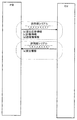
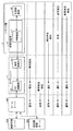
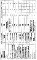
次に、図9は、CU3側とP台2側とのそれぞれで記憶している各種データの内の主なものおよびその送受信態様を示す模式図である。図9を参照して、CU3側とP台2側とのそれぞれで記憶している各種データの内の主なものおよびその送受信態様を説明する。
<Transmission / reception mode between card unit side and pachinko machine side>
Next, FIG. 9 is a schematic diagram showing main data among various data stored on each of the
本実施の形態においては、P台2側において遊技球数の変動を算出して現在の最新の遊技球数を記憶・管理している。CU3側においても現在の遊技球数の算出・記憶を行っているが、その遊技球数はP台2側から送信されてきた情報に基づいたものである。一方、持ち球(カード持ち球数)や貯玉数、プリペイド残額(残額)は、CU3側において管理・記憶している。
In the present embodiment, the variation of the number of game balls is calculated on the P-
図9では、CU3側のCU制御部323に設けられているRAMの記憶データと、P台2側の枠制御基板17に搭載されているRAMの記憶データとを示している。まず、P台2とCU3とが遊技場に設置されて初めて電気的に接続された状態で電源を立上げたときに、P台2側の枠制御基板17は、主制御基板16からメインチップID(主制御チップID)を送信してもらい、そのメインチップIDをCU3側に送信するとともに、枠制御基板17自体が記憶している枠チップID(枠制御チップID)をCU3側へ送信する。
FIG. 9 shows RAM storage data provided in the
CU3側では、それら送信されてきたメインチップIDと枠チップIDとを記憶する。この状態で、メインチップID、枠チップIDの情報がCU3側とP台2側とに記憶されることとなる。それ以降の電源投入時においては、P台2側からCU3側へそれら2つの情報、すなわち、メインチップIDと枠チップIDとが送信される。
On the CU3 side, the transmitted main chip ID and frame chip ID are stored. In this state, information on the main chip ID and the frame chip ID is stored on the CU3 side and the
CU3側では、それら送信されてきたデータと既に記憶しているデータとを照合し、前回と同じP台2が接続されているか否かを判別する。一方、P台2では、電源投入後に設置情報であるメインチップID、枠チップIDの情報などの情報をCU3に送信し、その後、CU3を含む外部へ所定期間ごとに遊技機情報を送信することが可能となる。P台2では、認証処理を経ることなく遊技機情報を出力可能となるため、処理負担を軽減できる。
On the
CU3およびP台2の双方は、電文に「通番」を付加して送信する。また、CU3およびP台2の双方は、相手から受信した「通番」を記憶する。「通番」には、「遊技球数通番」、「計数通番」および「貸出通番」の3種類がある。「通番」は、電文のシーケンス番号を示す。「通番」は、送信側(一次局側)が初期値を「1」として送信時に受信した通番をカウントアップ(+1)して送信する。ただし、再送時は、「通番」をカウントアップしない。受信側(二次局側)は受信した通番をそのまま送信する。なお、通番の連続性が成立しない場合は無応答となる。「遊技球数通番」は、P台2がCU3に対して遊技球数を通知する際に用いられる通番である。「計数通番」は、P台2がCU3に対して遊技球の計数を要求する際に用いられる通番である。「貸出通番」はCU3がP台2に対して遊技球の貸出を要求する際に用いられる通番である。
Both the
P台2側からCU3側へは、最新の遊技機性能情報、ホールコン情報および不正監視情報が送信される。この最新の遊技機性能情報、ホールコン情報および不正監視情報は、P台2側の枠制御部171(図4参照)のRAMに記憶されている。具体的には、計数球数カウンタの情報が含まれる。なお、遊技球数は、不正監視情報として遊技球数カウンタのカウント値をP台2側からCU3側へ送信している。しかし、これに代えて、あるいは遊技球数カウンタに加えて、遊技球数も最新の遊技機性能情報に含めてもよい。
The latest gaming machine performance information, hall control information and fraud monitoring information are transmitted from the
これらのカウンタの情報が、まとめて遊技機情報としてCU3側へ送信される。CU3では、P台2から送信されてくる最新の遊技機性能情報およびホールコン情報から遊技球数の変化を把握している。CU3では、例えば、ホールコン情報に含まれる「賞球球数×入賞個数」に基づき遊技球数を加算し、「発射球数」に基づき遊技球数を減算する。さらに、計数球数カウンタは、計数球数をカウントするカウンタである。計数球数は、「計数操作によって遊技球から持ち球に変換された球数」である。計数累積球数カウンタは、計数累積球数をカウントするカウンタである。計数累積球数は、「計数操作によって遊技球から持ち球に変換された球の累積球数」であり、RAMクリア(初期化操作)から計数された累積球数、またはその日に計数された累積球数である。なお、遊技者が交代しても累積球数は変化しないものとする。また、計数累積球数カウンタには、2バイトのデータ領域が割り当てられており、0球〜65,535球の情報を格納可能である。そのため、計数累積球数カウンタは、計数累積球数を「0xFFFF(65,535球)」までカウントすると、次の値を「0x0000(0球)」に更新する。なお、遊技球の発射中に計数操作を受付けた場合、計数処理の対象となる遊技点の更新処理を優先的に行い、遊技球の発射を停止して発射に対応する遊技点の更新処理については実行を停止する。これにより、計数処理の対象となる遊技点の減算と、発射に対応する遊技点の減算とのタイミングが重なることを回避することができ、遊技点の更新処理をより正確に実現でき、誤った更新処理の発生を防止することができる。また、計数処理の対象となる遊技点の減算と、発射に対応する遊技点の減算とを同時に行ってもよい。これにより、遊技球の発射を停止することがないので、円滑な遊技を実現することができる。ここで、「賞球球」は、入賞口へ球が入賞することにより払出される球であり、セーフ球である。「発射球」は、遊技機が発射した球であり、バック球がある場合はバック球を減算した球数が発射球数となる。
Information on these counters is collectively transmitted to the
枠制御部171は、計数ボタン28の押下により、遊技球数を計数球数としてカウントし、その計数球数カウンタの値(計数球数)をP台2側からCU3側へ送信する。また、枠制御部171は、計数球数カウンタの値(計数球数)がカウントされる毎に計数累積球数カウンタの値が更新され、その計数累積球数カウンタの値(計数累積球数)をP台2側からCU3側へ送信する。
When the
P台2側においては、計数球数カウンタの値をCU3側へ送信する毎に、当該カウント値を前回遊技機情報記憶領域(枠制御部171のRAMなど)にバックアップデータとして記憶(書換え)した後、計数球数カウンタの値を0クリアする(遊技球数カウンタを除く)。なお、本実施の形態において「クリア」とは「初期化」と同じ意味である。
On the
その結果、前回遊技機情報(直前に送信した遊技機情報)の記憶エリアに、直前にCU3側に送信した計数球数のデータがバックアップデータとして記憶される。このバックアップデータは、P台2側からCU3側へ計数球数のデータが送信されなかった場合に、次の送信に際して今回の各カウンタの値ばかりでなくその送信されなかった前回の各カウンタの値をも送信できるようにするためのものである。この前回遊技機情報に、直前に送信した遊技球数をさらに加えて記憶するようにしてもよい。
As a result, the count ball number data transmitted to the
また、枠制御基板17は、入賞の発生、球の発射、および計数球の発生(遊技球から持ち球への変換)に応じて、遊技球数カウンタの値を更新し、その更新後の遊技球数カウンタの値を遊技球数としてCU3側に送信する。
Further, the
CU3側においては、RAM内の累計データ記憶領域に、遊技球数、カード持ち球数(単に、持ち球数とも言う)、貯玉数、残額、およびカード挿入時持ち球数を記憶している。なお、カード持ち球数は、カード挿入時持ち球数から貸出球数(カード持ち球数から遊技球数に変換した球数)を減算し、計数球数を加算した球数である。つまり、カード持ち球数は、現時点で遊技者が所有している持ち球数である。 On the CU3 side, the accumulated data storage area in the RAM stores the number of game balls, the number of card possessions (also simply referred to as the number of possessions), the number of balls, the remaining amount, and the number of possessions at the time of card insertion. The number of cards possessed is the number of balls obtained by subtracting the number of balls lent (the number of balls converted from the number of cards possessed to the number of game balls) from the number of balls possessed at the time of card insertion and adding the number of counted balls. In other words, the card possession number is the number of possession possessed by the player at the present time.
P台2から送信されてきた計数球数カウンタの値に基づいてカード持ち球数を加算し、遊技球数から減算して更新する。このように、CU3は、P台2より逐一送信されてくる最新の遊技機情報によって遊技球数、カード持ち球数を更新することで最新のそれらの情報を管理することが可能となる。
The card holding ball number is added based on the value of the counting ball number counter transmitted from the
CU3は、図示のとおり、遊技球数を記憶する領域を備えているとともに、P台2側から遊技球数カウンタのカウント値(遊技球数または遊技球トータル個数情報とも言う)も受信している。CU3は、遊技球数を記憶する領域を以下の手順で更新する。すなわち、CU3は、P台2側から送信されてきた最新の遊技機性能情報およびホールコン情報から遊技球数の変化を把握するとともに、計数球数カウンタの値および貸出球数の値に基づいて、記憶している遊技球数を更新するとともに、P台2側から送信されてきた遊技球数カウンタのカウント値と、更新後の遊技球数とが一致しているか否かを判定する。一致していれば、遊技の続行を許容するが、一致していなければ、エラー状態に移行する制御を行う。
As shown in the figure, the
その結果、たとえば、異常報知ランプや表示器312によりエラー報知が行われ、あるいは、ホール用管理コンピュータやホールサーバにエラーが発生した旨のエラー通知信号が送信される(この場合、ホール用管理コンピュータやホールサーバによるエラー報知が行われるようにしてもよい)。その結果、係員による人為的な対応を促す所定の報知が行われる。
As a result, for example, an error notification is performed by the abnormality notification lamp or the
なお、エラー状態に移行して遊技を停止させることに代えて、CU3側で記憶している遊技球数をP台2側から送信されてきた遊技球数カウンタのカウント値に置き換えるようにしてもよい。または、それに代えて、CU3側で管理している遊技球数と、P台2側で記憶している遊技球数との平均値に補正してもよい。
Instead of shifting to an error state and stopping the game, the number of game balls stored on the
このように、本実施の形態では、CU3側にも遊技球数を記憶させているが、その遊技球数がP台2側で管理記憶している遊技球数と整合するか否かの判定を行えるようにしている(CU3側機能)。そのため、仮に不正行為その他の事情で、P台2側で記憶している遊技球数がCU3側で記憶している遊技球数と一致しない状況が発生しても、その旨をチェックできる。なお、ここでは、CU3側にその判定機能を設けたが、たとえば、CU3と接続されるホールサーバまたはホール用管理コンピュータによって、CU3側で記憶している遊技球数とP台2側で記憶している遊技球数とを受信し、両者が整合しているか否かの判定を行うものとしてもよい。
As described above, in this embodiment, the number of game balls is also stored on the
また、CU3は、計数情報を受信できなかった場合、CU3側で記憶している遊技球数とP台2側で管理記憶している遊技球数とが一致しなくなるので、特別処理を実行する。当該特別処理として、遊技機情報に基づく遊技球数の補填を行うため遊技機情報の履歴情報を表示させる処理を行ったり、当該履歴情報に基づき遊技球数の補填を行ったり、エラー報知を行ったりする。
In addition, when the count information cannot be received, the
さらに、図9に示すように、CU3は、カード持ち球数、貯玉数を記憶する記憶領域と、受付けた(挿入された)カードのプリペイド残額を記憶する記憶領域と、およびカード挿入時持ち球を記憶する記憶領域とをさらに有する。CU制御部323(図4参照)は、貯玉の使用を要求する入力(たとえば、CU3に設けられた再プレイボタン319の押圧入力(ただし、持ち球無しのとき))に応じて貯玉を記憶する記憶領域から所定数の貯玉を減算する。
Further, as shown in FIG. 9, the
CU制御部323(図4参照)は、持ち球の使用を要求する入力(たとえば、持ち球有のときのCU3に設けられた再プレイボタン319の押圧入力)に応じて持ち球を記憶する記憶領域から所定数の持ち球を減算する。さらに、CU制御部323(図4参照)は、プリペイド残額の使用を要求する入力(たとえば、球貸ボタン321の押圧入力)に応じてプリペイド残額を記憶する記憶領域から所定値を減算する。
The CU control unit 323 (see FIG. 4) stores a ball in response to an input requesting the use of the ball (for example, pressing input of the
遊技者所有の所有価値(たとえば持ち球数、貯玉数、あるいはプリペイド残額)から所定の大きさの価値を貸出して遊技に使用する操作を遊技者が行った場合に、その引落とし分の球数を遊技球数カウンタに加算するための貸出球数がCU3側からP台2側へ送信される。P台2側では、それを受けて、遊技球数カウンタを加算更新する。
If the player performs an operation that lends a value of a certain size from the possession value (for example, the number of possessed balls, the number of stored balls, or the prepaid balance) owned by the player and uses it for the game, the number of balls to be withdrawn Is sent from the CU3 side to the
本実施の形態に係る遊技システムでは、一方、遊技者所有の所有価値を引落としてドリンクなどに交換するといういわゆるワゴンサービスのオーダなどを受付けることが可能である。ただし、遊技球でワゴンサービスを受けることが制限されており、持ち球でしかワゴンサービスを受けることができない。これは、各台計数機が配備された従来の封入循環式パチンコ遊技機において、皿に残っている計数前の球を手で掴み出してワゴンサービスに用いることを禁止するようなイメージである。 On the other hand, in the gaming system according to the present embodiment, it is possible to accept a so-called wagon service order in which the possession value owned by the player is withdrawn and exchanged for a drink or the like. However, receiving wagon services with game balls is restricted, and wagon services can only be received with handballs. This is an image of prohibiting the use of the ball before counting remaining in the dish by hand and using it for the wagon service in the conventional enclosed circulation pachinko gaming machine in which each counter is provided.
このため、本実施の形態では、ワゴンサービスを行う操作が実行されたときに、持ち球数がワゴンサービスの希望メニューに対応する球数に満たない場合、遊技者に計数操作を促すように構成されている。その際に遊技者が計数操作を実行すると、その操作に基づく計数球数がP台2側からCU3側へ送信される。CU3側では、それを受けて、遊技球数を減算し、カード持ち球数を加算して更新する。
For this reason, in the present embodiment, when the operation for performing the wagon service is executed, if the number of possessed balls is less than the number corresponding to the desired menu of the wagon service, the player is prompted to perform the counting operation. Has been. When the player performs a counting operation at that time, the number of counting balls based on the operation is transmitted from the
<CUとP台との通信の変形例1>
図7および図8では、CU3とP台2との通信が、遊技機情報を送信するタイミングを基準に、計数情報および貸出情報を送受信するタイミングが決定される例を説明した。変形例1として、遊技機情報を送信するタイミングを基準に、計数情報を送信するタイミングを決定するが、貸出情報を受信するタイミングは計数情報を送信するタイミングを基準に決定されるCU3とP台2との通信の例を説明する。
<
7 and 8, the example in which the communication between the
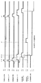
図10は、カードユニットとパチンコ遊技機との間で送受信される情報のタイミングを示す図である。P台2からCU3へ送信される情報のうち、(d)遊技機情報は、図10で示すように規定期間Aごとに送信されている。つまり、P台2からCU3への情報の送信から次の情報の送信までの期間が、規定期間A(例えば、300ms=0.3秒)に制御されている。P台2は、CU3での遊技機情報の受信状況に関わらず、規定期間Aごとに遊技機情報をCU3に送信することができる。そのため、P台2において、遊技機情報の再送処理が不要となり、過去の遊技機情報を記憶する必要がなくなり、処理負担を軽減できる。
FIG. 10 is a diagram illustrating timing of information transmitted and received between the card unit and the pachinko gaming machine. Of the information transmitted from the
遊技機情報は、計数情報と共通の非同期シリアル通信ポートにて通信を行う。そのため、遊技機情報を送信するタイミングに、計数情報を送信しようとした場合、共通の非同期シリアル通信ポート内で情報同士が輻輳し、データの衝突が発生して通信が正しく行われない可能性がある。そこで、P台2では、遊技機情報をCU3へ規定期間Aごとに送信している場合に、情報伝送の最適化を図るため、遊技機情報を送信してから規定期間Aよりも短い規定期間B(例えば、100ms)に対応するタイミングで、(c)計数情報をCU3に送信する。計数情報は、CU3での受信状況に関わらず、規定期間BごとCU3に送信される。なお、遊技者による計数ボタン28の操作が遊技機情報を送信する前に行われている場合、計数球数に例えば250球の情報が含まれ、遊技者による計数ボタン28の操作が遊技機情報を送信する前に行われていない場合、計数球数に0(ゼロ)球の情報が含まれる。
The gaming machine information communicates with the asynchronous serial communication port that is shared with the counting information. Therefore, if you try to send counting information at the timing of sending gaming machine information, there is a possibility that the information will be congested in the common asynchronous serial communication port, data collision will occur and communication will not be performed correctly is there. Therefore, in the case of the
計数情報の送信は、遊技機情報を送信するタイミングから規定期間B以内に行われる場合に限られず、遊技機情報との輻輳が生じないタイミングであればよく、規定期間B経過後から次の遊技機情報が送信されるタイミングまでの間でもよい。 The transmission of the count information is not limited to the case where the count information is transmitted within the specified period B from the timing of transmitting the gaming machine information, and may be any timing that does not cause congestion with the gaming machine information. It may be until the timing when the machine information is transmitted.
図8では、計数情報をCU3に送信した後、受信有効時間(例えば、170ms)の間にCU3から貸出情報を受信する。CU3からP台2に対して送信される貸出情報には、貸出球数および貸出通番の情報が含まれる。なお、遊技者による球貸ボタン321又は再プレイボタン319の操作が遊技機情報を送信する前に行われている場合、貸出球数に例えば125球の情報が含まれ、遊技者による球貸ボタン321又は再プレイボタン319の操作が遊技機情報を送信する前に行われていない場合、貸出球数に0(ゼロ)球の情報が含まれる。
In FIG. 8, after transmitting the count information to CU3, the lending information is received from CU3 during the reception valid time (for example, 170 ms). The lending information transmitted from the
貸出応答情報は、遊技機情報と共通の非同期シリアル通信ポートにて通信を行う。そのため、遊技機情報を送信するタイミングに、CU3から貸出応答情報が送信されて来る場合、共通の非同期シリアル通信ポート内で情報同士が輻輳し、データの衝突が発生して通信が正しく行われない可能性がある。
The lending response information communicates with the asynchronous serial communication port common to the gaming machine information. Therefore, when the loan response information is transmitted from the
そこで、CU3は、計数情報を受信してから受信有効時間の間に貸出情報をP台2に送信している。つまり、P台2では、計数情報を送信してから受信有効時間内のタイミングで、CU3から貸出球数および貸出通番の情報を受信し、その応答時間内に貸出球数受領結果および貸出通番の貸出応答情報をCU3に送信する。
Therefore, the
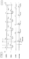
CU3は、計数情報を受信してから受信有効時間内に貸出情報を送信するタイミングについてさらに詳しく説明する。図11は、カードユニットとパチンコ遊技機との間で送受信される情報の変形例1のタイミングチャートである。
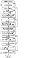
The
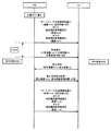
まず、図11に示す(i)において、枠制御基板17は、遊技が可能になると、300ms周期で遊技機情報をCU3に送信する。(ii)において、枠制御基板17は、遊技者による計数ボタン28の操作の有無に関わらず、遊技機情報の送信から100ms経過後に計数情報を送信する。また、300ms周期内に計数ボタン28が押下された場合には、計数球数を250として計数情報を送信する。なお、計数ボタン28の操作がない場合、計数球数に0(ゼロ)の情報を入れて計数情報が送信される。
First, in (i) shown in FIG. 11, the
(iii)において、CU3は、計数情報の受信完了から170ms以内(受信有効時間)に貸出情報を送信する。また、300ms周期内に球貸ボタン321又は再プレイボタン319が押下された場合には、貸出球数を125として貸出情報を送信する。なお、球貸ボタン321又は再プレイボタン319の操作がない場合、貸出球数に0(ゼロ)の情報を入れて貸出情報が送信される。なお、CU3から、計数情報の受信完了から170ms以内に貸出情報が送信されるが、CU3から計数情報に対応した応答情報の送信が行われない。そのため、P台2側で、CU3が計数情報を受信したか否かを認識しない。
In (iii), the
(iv)において、枠制御基板17は、CU3から貸出球数および貸出通番の情報を受信すると、当該情報の受信から10ms以内(応答時間)に貸出球数受領結果および貸出通番の貸出応答情報をCU3に送信する。(v)以後、300msの周期で同じ動作を繰り返す。
In (iv), when the
図11に示すタイミングでは、遊技者による球貸ボタン321又は再プレイボタン319の操作がなくても、CU3とP台2との間で貸出情報および貸出応答情報が送受信されている。しかし、遊技者による球貸ボタン321又は再プレイボタン319の操作がなければ、CU3とP台2との間で貸出情報および貸出応答情報が送受信されることはないとしてもよい。図12は、カードユニットとパチンコ遊技機との間で送受信される貸出情報および貸出応答情報のタイミングの変形例を示す図である。
At the timing shown in FIG. 11, the lending information and the lending response information are transmitted and received between the
まず、図12に示す(i)において、枠制御基板17は、遊技が可能になると、300ms周期で遊技機情報をCU3に送信する。(ii)において、枠制御基板17は、遊技者による計数ボタン28の操作の有無に関わらず、遊技機情報の送信から100ms経過後に計数情報を送信する。また、300ms周期内に計数ボタン28が押下された場合には、計数球数を250として計数情報を送信する。なお、計数ボタン28の操作がない場合、計数球数に0(ゼロ)の情報を入れて計数情報が送信される。(iii)以後、300msの周期で同じ動作を繰り返す。
First, in (i) shown in FIG. 12, when the game becomes possible, the
(iv)において、CU3は、球貸ボタン321又は再プレイボタン319が押下された場合、計数情報の受信完了から170ms以内(受信有効時間)に貸出球数を125として貸出情報を送信する。つまり、遊技者による球貸ボタン321又は再プレイボタン319の操作は、計数情報を送信する前に行われており、当該操作後、P台2からの計数情報を受信するタイミングを待って、170ms以内(受信有効時間)に貸出情報を送信する。一方、CU3は、球貸ボタン321又は再プレイボタン319が押下されていない場合、計数情報の受信を完了しても貸出情報を送信しない。(v)において、枠制御基板17は、CU3から貸出球数および貸出通番の情報を受信すると、当該情報の受信から10ms以内(応答時間)に貸出球数受領結果および貸出通番の貸出応答情報をCU3に送信する。
In (iv), when the
次に、図11に示すタイミングで、カードユニットとパチンコ遊技機との間で情報が送受信される場合に、カードユニットとパチンコ遊技機との間で未接続が発生したときの処理について説明する。図13は、カードユニットとパチンコ遊技機との間で未接続発生となった場合の情報のタイミングを示す図である。図13に示す(i)〜(v)のタイミングにおける処理については、図11に示すタイミングにおける処理と同じであるため、(vi)以降のタイミングでの処理について説明する。 Next, a description will be given of processing when an unconnection occurs between the card unit and the pachinko gaming machine when information is transmitted and received between the card unit and the pachinko gaming machine at the timing shown in FIG. FIG. 13 is a diagram illustrating the timing of information when a connection is not generated between a card unit and a pachinko gaming machine. Since the processing at the timings (i) to (v) shown in FIG. 13 is the same as the processing at the timing shown in FIG. 11, the processing at the timings after (vi) will be described.
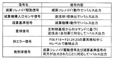
(vi)において、CU3とP台2との間でPIF配線が抜ける等で未接続が発生した場合、配線番号8,9に供給されている接続確認用の電源VLの電圧が5Vから0(ゼロ)Vに変化(VL=ONからOFFへの変化)する。配線番号8,9に供給されている接続確認用の電源VLの電圧が5Vから0Vに変化したことに基づいて、枠制御基板17では発射制御基板31に対して遊技球の発射を停止する信号を出力する。このように、P台2では、図13に示すような処理を行うことで、CU3と認証を行うことなく簡素な構成および処理にて遊技球の発射を停止することができる。また、接続確認用の電源VLの電圧が5Vから0Vに変化したことに基づいて、図23に示す計数スイッチ基板37において計数ボタン28の操作が無効になる。P台2が一次局の場合、PIF配線が抜ける等で未接続が発生したときに、遊技者が計数ボタン28を操作してCU3に対して計数情報を出力してしまうと、CU3からP台2に対して計数情報の受信確認を行っていないためCU3で遊技機情報を用いたリカバリ処理が困難になることがある。このような事象によって遊技者に不利益を生じさせないために、CU3とP台2との間で未接続が発生した場合、計数ボタン28の操作そのものを無効、または計数情報の出力を無効にしている。
In (vi), when unconnected due to the PIF wiring being disconnected between the
CU3とP台2との間で未接続が発生した後も、(vii)において、枠制御基板17は、遊技が可能になると、300ms周期で遊技機情報をCU3に送信する。(viii)において、枠制御基板17は、遊技者による計数ボタン28の操作の有無に関わらず、遊技機情報の送信から100ms経過後に計数情報を送信する。
Even after an unconnection occurs between the
<CUとP台との通信の変形例2>
図7および図8では、共通の非同期シリアル通信ポートで、貸出情報、計数情報、および遊技機情報の通信を行う場合に、遊技機情報を送信する周期を基準に他の情報の周期を決める例を説明した。変形例2では、P台2が周期的に貸出情報をCU3から受信する場合において、当該貸出情報に対する貸出応答情報の送信間隔が、遊技機情報の送信間隔よりも短い例について説明する。そのため、変形例2のタイミングにおいてもP台2とCU3との通信は、遊技機情報を基準に情報を送受信しているものとする。図14は、カードユニットとパチンコ遊技機との間で送受信される情報の変形例2のタイミングを示す図である。ここで、図7および図8では、P台2を1次局、CU3を2次局として説明したが、図14では、CU3を1次局、P台2を2次局として説明する。また、図10および図11で説明したCU3とP台2との間で未接続が発生したときの処理については、図14に示す変形例2の通信にも適用することができる。
<
7 and 8, when communication of lending information, counting information, and gaming machine information is performed using a common asynchronous serial communication port, an example of determining the period of other information based on the period of transmitting gaming machine information Explained. In the second modification, an example will be described in which the transmission interval of the lending response information for the lending information is shorter than the transmission interval of the gaming machine information when the
CU3からP台2へ送信される(a)貸出情報(貸出球数および貸出通番の情報)は、遊技者による球貸ボタン321又は再プレイボタン319の操作に関わらず、図14で示すように規定期間Aごとに送信されている。つまり、CU3からP台2への貸出情報の送信から次の情報の送信までの期間が、規定期間A(例えば、300ms=0.2秒)に制御されている。なお、遊技者による球貸ボタン321又は再プレイボタン319の操作が貸出情報を送信する前に行われている場合、貸出球数に例えば125球の情報が含まれ、遊技者による球貸ボタン321又は再プレイボタン319の操作が貸出情報を送信する前に行われていない場合、貸出球数に0(ゼロ)球の情報が含まれる。
As shown in FIG. 14, the (a) lending information (lending ball number and lending serial number information) transmitted from the
P台2は、CU3から貸出球数および貸出通番の情報を受信すると、応答時間内に貸出球数受領結果および貸出通番の情報を含む貸出応答情報をCU3に送信する。
When receiving information on the number of rented balls and lending serial numbers from the
P台2では、貸出情報をCU3から規定期間Aごとに受信している場合に、貸出応答情報、計数情報および遊技機情報が共通の非同期シリアル通信ポートにて通信を行う。そのため、計数情報は、貸出情報を受信してから規定期間Aよりも短い規定期間B(例えば、100ms)に対応するタイミングで、CU3へ送信される。
In the
図14では、貸出情報として貸出球数および貸出通番の情報をCU3から受信した後、次に貸出情報を受信するタイミング(規定期間A経過後)の前に、情報を受信してから規定期間B以内のタイミングで計数情報として計数球数および計数通番をCU3に送信している。なお、遊技者による計数ボタン28の操作が遊技機情報を送信する前に行われている場合、計数球数に例えば250球の情報が含まれ、遊技者による計数ボタン28の操作が遊技機情報を送信する前に行われていない場合、計数球数に0(ゼロ)球の情報が含まれる。
In FIG. 14, after receiving information on the number of balls and lending serial numbers as rent information from the
計数情報の送信は、貸出情報を受信するタイミングから規定期間B以内に行われる場合に限られず、規定期間B経過後から次の貸出情報を受信するタイミングまでの間でもよい。 The transmission of the count information is not limited to the case where it is performed within the specified period B from the timing of receiving the lending information, but may be from the time after the specified period B has elapsed until the timing of receiving the next lending information.
遊技機情報として、P台2からCU3に対してホールコン情報および不正監視情報が送信される。計数情報を送信するタイミングに、遊技機情報を行う場合、共通の非同期シリアル通信ポート内で情報同士が輻輳し、データの衝突が発生して通信が正しく行われない可能性がある。
As gaming machine information, hall control information and fraud monitoring information are transmitted from the
そこで、P台2は、遊技機情報をCU3へ送信する場合、貸出情報を受信してから規定期間Aおよび規定期間Bと異なる規定期間C(例えば、200ms)に対応するタイミングで行っている。つまり、P台2では、貸出情報を受信してから規定期間C経過後のタイミングで、CU3へホールコン情報および不正監視情報を送信している。
Therefore, when transmitting the gaming machine information to the
遊技機情報は、貸出情報を受信するタイミングから規定期間C経過後に行われる場合に限られず、計数情報との輻輳が生じないタイミングであればよく、貸出情報を受信してから規定期間B経過後で規定期間C以内のタイミングまでの間でもよい。なお、規定期間A〜Cについては、各種情報の通信タイミングがずれるように異なる値を適宜設定することができる。 The gaming machine information is not limited to the timing when the specified period C elapses from the timing of receiving the lending information, and may be any timing that does not cause congestion with the counting information. Or until the timing within the specified period C. It should be noted that different values can be appropriately set for the specified periods A to C so that the communication timings of various information are shifted.
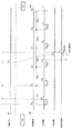
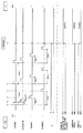
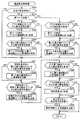
次に、図14に示すタイミングで、カードユニットとパチンコ遊技機との間で情報が送受信される場合に、カードユニットとパチンコ遊技機との間で未接続が発生したときの処理について説明する。図15は、カードユニットとパチンコ遊技機との間で未接続発生となった場合の情報のタイミングを示す図である。図15に示す(i)〜(v)のタイミングにおける処理については、図14に示すタイミングにおける処理と同じであるため、(vi)以降のタイミングでの処理について説明する。 Next, a process when an unconnection occurs between the card unit and the pachinko gaming machine when information is transmitted / received between the card unit and the pachinko gaming machine at the timing shown in FIG. 14 will be described. FIG. 15 is a diagram illustrating the timing of information when a connection is not generated between the card unit and the pachinko gaming machine. Since the processing at the timings (i) to (v) shown in FIG. 15 is the same as the processing at the timing shown in FIG. 14, the processing at the timings after (vi) will be described.
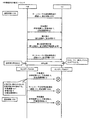
(vi)において、CU3とP台2との間でPIF配線が抜ける等で未接続が発生した場合、配線番号8,9に供給されている接続確認用の電源VLの電圧が5Vから0(ゼロ)Vに変化する。図5に示す配線番号8,9に供給されている接続確認用の電源VLの電圧が5Vから0Vに変化したことに基づいて、枠制御基板17では発射制御基板31に対して遊技球の発射を停止する情報を出力する。このように、P台2では、図15に示すような処理を行うことで、CU3と認証を行うことなく簡素な構成および処理にて遊技球の発射を停止することができる。CU3では、接続確認用の電源VLの電圧が5Vから0Vに変化したことに基づいて、遊技球の貸出を禁止する等の処理を行ってもよい。
In (vi), when unconnected due to the PIF wiring being disconnected between the
発射装置を作動又は停止させるための制御として、図15では、CU3がP台2に接続されていない時、枠制御基板17が、CU3から供給される接続確認用の電源VLを監視し、接続確認用の電源VLが供給されていない場合に、未接続と判断して発射停止制御を行う構成について説明した。しかし、未接続と判断して発射停止制御を行う構成は、当該構成に限定されず、他の構成であってもよい。
As control for operating or stopping the launching device, in FIG. 15, when the
例えば、図16は、カードユニットとパチンコ遊技機との間で未接続発生となった場合の情報のタイミングの別の例1を示す図である。図16に示す(i)〜(v)のタイミングにおける処理については、図14に示すタイミングにおける処理と同じであるため、(vi)以降のタイミングでの処理について説明する。 For example, FIG. 16 is a diagram illustrating another example 1 of the timing of information in the case where disconnection occurs between a card unit and a pachinko gaming machine. Since the processing at the timings (i) to (v) shown in FIG. 16 is the same as the processing at the timing shown in FIG. 14, the processing at the timings after (vi) will be described.
(vi)において、CU3からP台2への受信用の配線(図5に示す配線番号7)で故障断線等が発生し、P台2がCU3から送信される貸出情報が受信できなくなる。なお、接続確認用の電源VLの配線は断線していないため、接続確認用の電源VLの電圧は5Vのまま変化しない。貸出情報は、300ms周期でCU3からP台2に送信されている。そのため、前回受信した貸出情報から300ms後に、新たに貸出情報がP台2から送信されてくる予定である。しかし、CU3からP台2への受信用の配線で故障断線等が発生した場合、貸出情報がP台2から送信されてこない。
In (vi), a disconnection or the like occurs in the receiving wiring (
(vii)において、前回受信した貸出情報から、1200ms経過後も次の貸出情報を受信できない場合に、受信用の配線で故障断線等が発生し、受信信号が通信無応答状態になったと判断して、枠制御基板17では発射制御基板31に対して遊技球の発射を停止する信号を出力する。また、枠制御基板17では、貸出応答情報、計数情報および遊技機情報についても、P台2からCU3への送信を停止する。さらに、接続確認用の電源VLの電圧が5Vから0Vに変化したことに基づいて、図23に示す計数スイッチ基板37において計数ボタン28の操作が無効になる。
In (vii), when the next lending information cannot be received after 1200 ms from the previously received lending information, it is determined that a faulty disconnection or the like has occurred in the receiving wiring, and the received signal is in a communication non-response state. The
つまり、図16では、CU3とP台2との間での通信において、受信信号が無応答状態となった時、枠制御基板17が、CU3から送信される電文(貸出情報)の周期を監視し、一定時間以上受信できない場合、受信信号が通信無応答状態になったと判断して発射停止制御を行う構成である。このように、P台2では、図16に示すような処理を行うことで、CU3と認証を行うことなく簡素な構成および処理にて遊技球の発射を停止することができる。CU3では、P台2に送信した貸出情報に対する応答(例えば、貸出球数受領結果を含む情報)が一定時間経過後も受信できないことに基づいて、遊技球の貸出を禁止する等の処理を行ってもよい。
That is, in FIG. 16, in the communication between the
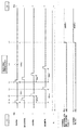
次に、図17は、カードユニットとパチンコ遊技機との間で未接続発生となった場合の情報のタイミングの別の例2を示す図である。図17に示す(i)〜(v)のタイミングにおける処理については、図14に示すタイミングにおける処理と同じであるため、(vi)以降のタイミングでの処理について説明する。 Next, FIG. 17 is a diagram illustrating another example 2 of the timing of information in the case where disconnection occurs between the card unit and the pachinko gaming machine. Since the processing at the timings (i) to (v) shown in FIG. 17 is the same as the processing at the timing shown in FIG. 14, the processing at the timings after (vi) will be described.
(vi)において、P台2からCU3への送信用の配線(図5に示す配線番号6)で故障断線等が発生し、P台2からCU3へ情報が送信できなくなる。なお、接続確認用の電源VLの配線は断線していないため、接続確認用の電源VLの電圧は5Vのまま変化しない。貸出情報は、300ms周期でCU3からP台2に送信され、それの応答として応答時間内に貸出球数受領結果および貸出通番の貸出応答情報がP台2からCU3に送信される。しかし、P台2からCU3への送信用の配線で故障断線等が発生した場合、貸出応答情報がP台2から送信されてこない。
In (vi), a disconnection or the like occurs in the wiring for transmission from the
(vii)において、枠制御基板17から送信される貸出球数受領結果の情報が届かないため、CU3は前回と同じ内容の貸出情報を再送信する。具体的に、CU3は、枠制御基板17から送信される貸出球数受領結果応答の情報が未到達の場合、貸出通番を更新(+1)せず、300ms経過後に貸出情報を再送信する。
In (vii), since the information on the result of receiving the number of lent balls transmitted from the
(viii)において、枠制御基板17は、再送信された貸出情報を受信すると、CU3から再送信された貸出情報の貸出通番が、前回受信した貸出通番と同じなので、前回と同じ内容の貸出球数受領結果応答の情報を再送信する。なお、送信用の配線で発生した故障断線等が復旧していた場合、再送信した貸出球数受領結果応答の情報はCU3に到達するが、復旧していない場合、再送信した貸出球数受領結果応答の情報はCU3に到達しない。
In (viii), when the
(ix)において、枠制御基板17は、前回受信した貸出情報から1200ms経過後も貸出通番が前回と同じ貸出情報を受信した場合、送信信号が通信無応答状態になったと判断して、発射制御基板31に対して遊技球の発射を停止する信号を出力する。また、枠制御基板17では、貸出応答情報、計数情報および遊技機情報についても、P台2からCU3への送信を停止する。
In (ix), the
つまり、図17では、CU3とP台2との間での通信において、送信信号が無応答状態となった時、枠制御基板17が、CU3から送信される電文(貸出情報)の通番を監視し、一定時間以上通番が更新できない場合、送信信号が通信無応答状態になったと判断して発射停止制御を行う構成である。このように、P台2では、図17に示すような処理を行うことで、CU3と認証を行うことなく簡素な構成および処理にて遊技球の発射を停止することができる。CU3では、P台2に送信した貸出応答情報(例えば、貸出球数受領結果の情報)が一定時間経過後も受信できないことに基づいて、遊技球の貸出を禁止する等の処理を行ってもよい。
That is, in FIG. 17, when the transmission signal is in a non-response state in communication between the
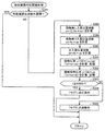
次に、図18は、カードユニットとパチンコ遊技機との間で未接続発生となった場合の情報のタイミングの別の例3を示す図である。図18に示す(i)〜(v)のタイミングにおける処理については、図14に示すタイミングにおける処理と同じであるため、(vi)以降のタイミングでの処理について説明する。 Next, FIG. 18 is a diagram illustrating another example 3 of the timing of information in the case where a disconnection occurs between the card unit and the pachinko gaming machine. Since the processing at the timings (i) to (v) shown in FIG. 18 is the same as the processing at the timing shown in FIG. 14, the processing at the timings after (vi) will be described.
(vi)において、P台2からCU3への送信用の配線(図5に示す配線番号6)またはCU3からP台2への受信用の配線(図5に示す配線番号7)で故障断線等が発生し、P台2とCU3との間で情報が送受信できなくなる。そのため、貸出情報は、300ms周期でCU3からP台2に送信され、それの応答情報として応答時間内に貸出球数受領結果および貸出通番の貸出応答情報がP台2からCU3に送信されているが、いずれの情報も送受信されない。
In (vi), a disconnection or the like is caused by a wiring for transmission from the
(vii)において、CU3は、前回送信した貸出情報から1200ms経過後も何ら情報を送受信できていない場合に、接続確認用の電源VLの電圧を5Vから0V(オフ状態:VL=OFF)に変化させる。枠制御基板17は、接続確認用の電源VLの電圧が5Vから0Vに変化することにより、発射制御基板31に対して遊技球の発射を停止する信号を出力する。また、枠制御基板17では、貸出応答情報、計数情報および遊技機情報についても、P台2からCU3への送信を停止する。さらに、接続確認用の電源VLの電圧が5Vから0Vに変化したことに基づいて、図23に示す計数スイッチ基板37において計数ボタン28の操作が無効になる。
In (vii), the CU3 changes the voltage of the power supply VL for connection confirmation from 5V to 0V (OFF state: VL = OFF) when no information can be transmitted / received after 1200 ms from the previously transmitted lending information. Let The
つまり、図18では、CU3とP台2との間での通信において、受信信号または送信信号が無応答状態となった時、CU3が接続確認用の電源VLの電圧を変化させ、枠制御基板17は、接続確認用の電源VLの電圧を監視することで、受信信号または送信信号が通信無応答状態になったと判断して発射停止制御を行う構成である。このように、P台2では、図18に示すような処理を行うことで、CU3と認証を行うことなく簡素な構成および処理にて遊技球の発射を停止することができる。CU3では、P台2から送信される貸出応答情報が一定時間経過後も受信できないことに基づいて、遊技球の貸出を禁止する等の処理を行ってもよい。
That is, in FIG. 18, when the reception signal or the transmission signal becomes a non-response state in the communication between the
以上において説明したように、CU3とP台2との間で未接続が発生した場合、様々な構成に基づいて未接続と判断して発射停止制御を行っているが、それらの構成を組み合わせて発射停止制御を行ってもよい。もちろん、図15〜図18で示したCU3とP台2との間で未接続の判断に係る処理については、図13で示した遊技機情報を基準にCU3とP台2との間で情報を送信する構成などにも同様に適用することができる。また、遊技機がパチンコ遊技機(P台2)ではなくスロットマシンの場合、図15〜図18で示したようにカードユニットとの間で接続異常が発生し未接続と判断されると、スタートレバーやベットボタンを無効化することなどで変動を開始させないものとする。
As described above, when disconnection occurs between the
<計数通知シーケンス>
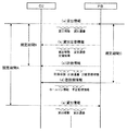
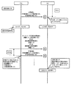
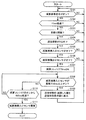
次に、遊技球の一部を計数して減算する計数通知シーケンスについて説明する。図19および図20は、カードユニットとパチンコ遊技機との間の計数通知シーケンスを示す図である。図19および図20では、カード返却の操作が検出されることなく計数ボタンが押下された場合を示している。
<Counting notification sequence>
Next, a count notification sequence for counting and subtracting a part of the game balls will be described. 19 and 20 are diagrams showing a count notification sequence between the card unit and the pachinko gaming machine. 19 and 20 show a case where the counting button is pressed without detecting a card return operation.
また、図19では、挿入された記録媒体(会員用カードまたはビジターカード)により特定される持ち球数が「100」球であり、当初の遊技球数が「1000」球の状態となっている。 In FIG. 19, the number of possessed balls specified by the inserted recording medium (member card or visitor card) is “100” and the initial number of game balls is “1000”. .
なお、ここでは、計数ボタンの操作が検出されている間、250球単位での計数が継続し、計数ボタンの操作が検出されなくなった段階で計数動作が終了する例を説明する。しかし、計数ボタンを長押し操作した時間に応じて計数する遊技球数が多くなるようにしても、また、計数ボタンを一定期間長押し操作した場合、保有している遊技球数をすべて計数してもよい。 Here, an example will be described in which counting in units of 250 balls continues while the operation of the counting button is detected, and the counting operation ends when the operation of the counting button is no longer detected. However, even if the number of game balls to be counted increases according to the time for which the count button is pressed and held for a long time, or when the count button is pressed for a certain period of time, all the number of game balls that are held are counted. May be.
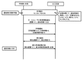
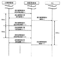
まず、P台は、ホールコン・不正監視情報通知、または遊技機設置情報通知、または遊技機性能情報通知の電文を含む遊技機情報をCU3へ送信する。なお、電文がホールコン・不正監視情報通知であれば、通番=n、遊技球数=1000の情報を含み、電文が遊技機設置情報通知であれば、通番=nの情報を含み、電文が遊技機性能情報通知であれば、通番=nの情報を含む。P台は、遊技機情報をCU3に送信してから100ms以内(図10に示す規定期間B以内)に、計数通知の電文を含む計数情報をCU3へ送信する。
First, the P machines transmit gaming machine information including a message of hall control / illegal monitoring information notification, gaming machine installation information notification, or gaming machine performance information notification to the
P台は、計数情報をCU3へ送信するまでに、遊技者が計数ボタン28を押下していた場合、計数通知の電文に計数通番=m、計数球数=250、計数累積球数=250の情報を含めてCU3に計数情報を通知する。P台は、計数球数=250の情報を含む計数通知の電文をCU3に送信した場合、保有している遊技球数=1000の情報から計数した250球を減算して遊技球数=750の情報に更新する。一方、P台は、計数情報をCU3へ送信するまでに、遊技者が計数ボタン28を押下していない場合、計数通知の電文に計数通番=m、計数球数=0、計数累積球数=0の情報を含めてCU3に計数なしを通知する。
When the player has pressed the
例えば、遊技者が計数ボタンを未操作の場合、CU3に送信する計数通知の電文に含まれる計数球数は0(ゼロ)球の計数データとなる。また、遊技者の計数ボタンの操作に応じて、例えば0.5秒未満の連続操作を検知の場合、CU3に送信する計数通知の電文に含まれる計数球数は1球の計数データとなる。これは、持ち球の端数調整用に用いる操作である。また、0.5秒以上0.8秒未満の連続操作を検知の場合、CU3に送信する計数通知の電文に含まれる計数球数は250球の計数データとなる。0.8秒以上の連続操作を検知の場合、CU3に最初に送信する計数通知の電文に含まれる計数球数が250球の計数データとなり、以後0.3秒ごとにCU3に送信する計数通知の電文に含まれる計数球数が250球の計数データとなる。つまり、遊技者が計数ボタンを連続操作した場合、0.3秒毎に250球分の計数データをCU3に送信することになる。
For example, when the player has not operated the counting button, the counting ball number included in the counting notification message transmitted to the
CU3は、P台2からの計数情報を受信して、保有している持ち球数に計数球数を加算し、持ち球数=100+250=350に更新する。CU3は、P台2からの計数情報を受信してから受信有効期間(図10参照)内に、球貸ボタン321の押下の有無に関わらず貸出通知の電文を含む貸出情報をP台2に送信する。貸出通知の電文には、貸出通番=k、貸出球数=0の情報を含む。
The
P台2は、CU3からの貸出情報を受信して、応答時間(図10参照)内に、貸出受領結果応答の電文を含む貸出応答情報をCU3に送信する。貸出受領結果応答の電文には、貸出通番=k、貸出球数受領結果=正常の情報を含む。
The
P台2は、前回遊技機情報をCU3へ送信してから、規定期間A(図10参照)の経過後に遊技機情報をCU3に送信する。CU3に送信する新たな遊技機情報には、ホールコン・不正監視情報通知、または遊技機設置情報通知、または遊技機性能情報通知の電文を含む。なお、電文がホールコン・不正監視情報通知であれば、更新された通番=n+1、減算した遊技球数=750の情報を含み、電文が遊技機設置情報通知であれば、更新された通番=n+1の情報を含み、電文が遊技機性能情報通知であれば、更新された通番=n+1の情報を含む。
The
P台2は、CU3に新たな遊技機情報を送信する際に、遊技者による計数ボタン28の押下が継続していた場合、計数通知の電文に更新した計数通番=m+1、計数球数=250、計数累積球数=500の情報を含めてCU3に計数情報を通知する。P台は、計数球数=250の情報を含む計数通知の電文をCU3に送信した場合、保有している遊技球数=750の情報から計数した250球を減算して遊技球数=500の情報に更新する。また、P台2は、前回の計数累積球数=250の情報に、今回の数球数=250の情報を加算して、計数累積球数=500の情報に更新している。
When the
CU3は、P台2からの計数情報を受信して、保有している持ち球数に計数球数を加算し、持ち球数=350+250=600に更新する。CU3は、P台2からの計数情報を受信してから受信有効期間内に、球貸ボタン321の押下の有無に関わらず貸出通知の電文を含む貸出情報をP台2に送信する。貸出通知の電文には、更新した貸出通番=k+1、貸出球数=0の情報を含む。
The
P台2は、CU3からの貸出情報を受信して、応答時間内に、貸出受領結果応答の電文を含む貸出応答情報をCU3に送信する。貸出受領結果応答の電文には、更新した貸出通番=k+1、貸出球数受領結果=正常の情報を含む。
The
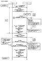
図20示すシーケンスにおいて、P台2は、CU3に新たな遊技機情報を送信する前に遊技者が計数ボタン28の押下を止めた場合、CU3に次回の遊技機情報を送信するタイミング以降、計数を行わない。具体的に、P台2は、CU3に新たな遊技機情報を送信する際に、遊技者が計数ボタン28の押下を止めているので、計数通知の電文に更新した計数通番=m+2、計数球数=0、計数累積球数=500の情報を含めてCU3に計数情報を通知する。
In the sequence shown in FIG. 20, if the player stops pressing the
つまり、P台は、計数を行わず計数球数=0の情報を含む計数通知の電文をCU3に送信し、保有している遊技球数=500の情報のままにして遊技球数の情報を更新しない。また、P台2は、計数累積球数の情報を、前回の計数累積球数=500の情報のままにして情報を更新しない。
In other words, the P platform does not count and sends a count notification message including information on the number of counted balls = 0 to the CU3, and keeps the information on the number of gaming balls = 500 as it is. Do not update. In addition, the
CU3は、P台2からの計数情報を受信しても、計数球数=0の情報なので保有している持ち球数=600を更新しない。CU3は、P台2からの計数情報を受信してから受信有効期間内に、球貸ボタン321の押下の有無に関わらず貸出通知の電文を含む貸出情報をP台2に送信する。貸出通知の電文には、更新した貸出通番=k+2、貸出球数=0の情報を含む。
Even if the CU3 receives the counting information from the
P台2は、CU3からの貸出情報を受信して、応答時間内に、貸出受領結果応答の電文を含む貸出応答情報をCU3に送信する。貸出受領結果応答の電文には、更新した貸出通番=k+2、貸出球数受領結果=正常の情報を含む。P台2は、前回遊技機情報をCU3へ送信してから、規定期間Aの経過後に遊技機情報をCU3に送信する。
The
<PIF断線時の復旧シーケンス>
次に、PIF断線時の復旧シーケンスについて説明する。図21および図22は、カードユニットとパチンコ遊技機との間のPIF断線時の復旧シーケンスを示す図である。図21および図22では、図13で説明した接続確認用の電源VLの電圧が5Vから0V(オフ状態:VL=OFF)に、または接続確認信号PSIの出力がオフ状態(PSI=OFF)に変化することで、PIF断線を検知する場合を例に説明する。なお、図15〜図19に示したように他の方法でPIF断線を検知してもよい。
<Recovery sequence when PIF is disconnected>
Next, a recovery sequence when the PIF is disconnected will be described. FIG. 21 and FIG. 22 are diagrams showing a recovery sequence when the PIF is disconnected between the card unit and the pachinko gaming machine. 21 and 22, the voltage of the connection confirmation power source VL described in FIG. 13 is changed from 5 V to 0 V (off state: VL = OFF), or the connection confirmation signal PSI is turned off (PSI = OFF). A case where a PIF disconnection is detected by changing will be described as an example. In addition, as shown in FIGS. 15-19, you may detect a PIF disconnection by another method.
まず、P台は、ホールコン・不正監視情報通知の電文を含む遊技機情報をCU3へ送信する。なお、ホールコン・不正監視情報通知の電文には、通番=n、遊技球数=1000の情報を含む。P台は、遊技機情報をCU3に送信してから100ms以内(図10に示す規定期間B以内)に、計数通知の電文を含む計数情報をCU3へ送信する。
First, the P machines transmit gaming machine information including a message of hall control / injustice monitoring information notification to the
P台は、計数情報をCU3へ送信するまでに、遊技者が計数ボタン28を押下していないので、計数通知の電文に計数通番=m、計数球数=0、計数累積球数=0の情報を含めてCU3に計数情報を通知する。
Since the player has not pressed the
CU3は、P台2からの計数情報を受信してから受信有効期間(図10参照)内に、球貸ボタン321の押下の有無に関わらず貸出通知の電文を含む貸出情報をP台2に送信する。貸出通知の電文には、貸出通番=k、貸出球数=0の情報を含む。
The
P台2は、CU3からの貸出情報を受信して、応答時間(図10参照)内に、貸出受領結果応答の電文を含む貸出応答情報をCU3に送信する。貸出受領結果応答の電文には、貸出通番=k、貸出球数受領結果=正常の情報を含む。
The
P台2は、前回遊技機情報をCU3へ送信してから、規定期間A(図10参照)の経過後に遊技機情報をCU3に送信する。CU3に送信する新たな遊技機情報のホールコン・不正監視情報通知の電文には、更新された通番=n+1、遊技球数=1000の情報を含む。
The
その後、PIF断線が発生した場合、P台2は、接続確認用の電源VLの電圧が5Vから0V(オフ状態:VL=OFF)に、または接続確認信号PSIの出力がオフ状態(PSI=OFF)に変化したことに基づいてPIF断線を検知して、遊技球の発射を停止する。CU3は、PIF断線を検知した場合、エラー表示を行った後に、図5に示す配線番号8,9に供給している接続確認用の電源VLをオフ状態(VL=OFF)とする。
After that, when a PIF disconnection occurs, the
ここで、CU3とP台2との接続構成を説明する。図23は、カードユニットとパチンコ遊技機との接続構成を説明するためのブロック図である。CU3とP台2との接続は、図5に示したようにPIF配線により接続されている。そのうち、図23では、CU3とP台2とを接続する配線として、接続確認用の電源VLの配線(図5に示す配線番号8,9)、絶縁GNDの配線(図5に示す配線番号1)、貸出情報の配線(図5に示す配線番号7)、および貸出受領結果、計数情報、遊技機情報の配線(図5に示す配線番号6)が図示されている。
Here, a connection configuration between the
図23に示すように、CU3とP台2とが接続確認用の電源VLの配線で接続され、CU3のオンボード電源3aから5Vの電圧が供給されている。P台2では、接続確認用の電源VLの配線が遊技球等貸出装置接続端子板36に設けたフォトカプラ36a,36bに接続されている。遊技球等貸出装置接続端子板36では、接続確認用の電源VLの配線以外に、貸出情報を通信する配線がフォトカプラ36cに、貸出応答情報、計数情報、遊技機情報を通信する配線がフォトカプラ36dにそれぞれ接続されている。CU3とP台2とは、フォトカプラを用いてPIF配線で接続されているので、情報を通信することはできるが、電気的には絶縁されている。CU3では、貸出情報を通信する配線がフォトカプラ3cに、貸出応答情報、計数情報、遊技機情報を通信する配線がフォトカプラ3dにそれぞれ接続されている。
As shown in FIG. 23, the
フォトカプラ36bは、枠制御基板17に設けたNOR回路17aと接続されている。接続確認用の電源VLの配線に5Vの電圧が供給されてフォトカプラ36bがON状態のときは、枠制御基板17において遊技機の5Vの電圧がフォトカプラ36bを介して遊技機のGNDに流れるため、NOR回路17aの入力(遊技球等貸出装置接続端子板36からの信号)がLowレベルとなる。一方、主制御基板から発射停止信号がNOR回路17aに供給されるが、発射許可時にはLowレベルであるので、NOR回路17aから発射制御基板31に出力される発射許可信号はHighレベルとなって、遊技球の発射が可能となる。
The
接続確認用の電源VLの配線が切断されて供給される電圧が0Vになるとフォトカプラ36bがOFF状態となり、枠制御基板17において遊技機の5Vの電圧がフォトカプラ36b側に流れず、NOR回路17aの入力(遊技球等貸出装置接続端子板36からの信号)がHightレベルとなる。そのため、NOR回路17aから発射制御基板31に出力される発射許可信号はLowレベルとなって、遊技球の発射が停止される。なお、主制御基板からNOR回路17aに供給される発射停止信号がHighレベルとなっても、NOR回路17aから発射制御基板31に出力される発射許可信号はLowレベルとなって、遊技球の発射が停止される。
When the power supply VL for connection confirmation is cut and the supplied voltage becomes 0V, the
なお、接続確認用の電源VLの配線に5Vの電圧が供給されてフォトカプラ36aがON状態のときは、遊技機の5Vの電圧がフォトカプラ36aを介して計数スイッチの5Vの電圧として計数スイッチ基板37のフォトカプラ37aに供給される。そのため、接続確認用の電源VLの配線に5Vの電圧が供給されている間は、フォトカプラ37aから枠制御基板17に対して計数スイッチ信号を供給することが可能となる。なお、遊技者が計数ボタン28を操作した場合、枠制御基板17に対して供給される計数スイッチ信号に計数球数の情報を含ませて供給することになる。
When the 5V voltage is supplied to the wiring of the power supply VL for connection confirmation and the
一方、接続確認用の電源VLの配線が切断されて供給される電圧が0Vになるとフォトカプラ36aがOFF状態になり、遊技機の5Vの電圧がフォトカプラ36aを介して計数スイッチの5Vの電圧として計数スイッチ基板37のフォトカプラ37aに供給されなくなる。そのため、接続確認用の電源VLの配線が切断され通信異常となると、フォトカプラ37aから枠制御基板17に対して計数スイッチ信号が供給されなくなる。つまり、CU3とP台2とが未接続で通信異常となった場合、遊技者の計数ボタン28に対する操作が無効となる。
On the other hand, when the power supply VL for connection confirmation is cut and the supplied voltage becomes 0V, the
図21に示すPIF断線時の復旧シーケンスに戻って、PIF断線が発生した場合でも、P台は、遊技機情報をCU3に送信してから100ms以内に、計数通知の電文を含む計数情報をCU3へ送信する。しかし、PIF断線が発生している場合、図23で説明したように、遊技者が計数ボタン28を押下しても計数ボタンが無効となるため、計数球数0球の情報をCU3に通知する。つまり、P台は、計数通知の電文に更新した計数通番=m+1、計数球数=0、計数累積球数=0の情報を含めてCU3に計数情報を通知する。しかし、PIF断線が発生しているのでP台から送信した計数情報はCU3に届かない。そのため、CU3は、P台2からの計数情報を受信していないので貸出情報をP台2に送信しない。
Returning to the recovery sequence at the time of the PIF disconnection shown in FIG. 21, even if a PIF disconnection occurs, the P units send the count information including the count notification message within 100 ms after transmitting the gaming machine information to the CU3. Send to. However, if a PIF disconnection has occurred, as described with reference to FIG. 23, the count button becomes invalid even if the player presses the
P台2は、貸出情報がCU3から送信されなくても、前回遊技機情報をCU3へ送信してから、規定期間Aの経過後に遊技機情報をCU3に送信する。CU3に送信する新たな遊技機情報のホールコン・不正監視情報通知の電文には、更新された通番=n+2、遊技球数=1000の情報を含む。しかし、PIF断線が発生しているのでP台から送信した遊技機情報はCU3に届かない。
Even if the lending information is not transmitted from the
さらに、P台は、遊技機情報をCU3に送信してから100ms以内に、計数通知の電文を含む計数情報をCU3へ送信する。P台は、計数通知の電文に更新した計数通番=m+2、計数球数=0、計数累積球数=0の情報を含めてCU3に計数情報を通知する。しかし、PIF断線が発生しているのでP台から送信した計数情報はCU3に届かない。
Further, the P units transmit the counting information including the count notification message to the
その後、図22に示すようにPIF配線の接続が復旧する。PIF配線の接続が復旧した場合、PIF断線の間にCU3で正常に受信できなかった計数情報については、復旧後または後続の計数累積球数の情報と遊技球数の情報とを用いてCU3側でリカバリ処理を行うことが可能である。また、CU3は、CU3とP台2とが正常に接続された場合、管理装置に対してPIF配線の接続が復旧した旨を通知し、遊技店の店員によって遊技球数を確認し、正常に受信できなかった計数情報による遊技球数の補償を行ってエラーを復旧させる。なお、CU3は、管理装置に対して通信異常を特定することができる情報を出力可能である。 Thereafter, the connection of the PIF wiring is restored as shown in FIG. When the connection of PIF wiring is restored, the CU3 side uses the information of the accumulated cumulative number of balls and the information of the number of game balls after restoration or the information about the number of game balls that has not been successfully received by the CU3 during the PIF disconnection It is possible to perform recovery processing. In addition, when CU3 and P stand 2 are normally connected, CU3 notifies the management device that the connection of the PIF wiring has been restored, and the number of game balls is confirmed by the store clerk of the game store. The error is recovered by compensating the number of game balls based on the count information that could not be received. In addition, CU3 can output the information which can specify communication abnormality with respect to a management apparatus.
CU3は、エラー復旧してから接続確認用の電源VLがON状態(VL=ON)となり、接続確認用の電源VLの電圧が5Vになるので、P台2では遊技球の発射が可能となる。なお、PIF配線の接続が復旧した場合、CU3側への接続確認信号PSIの出力もオン状態(PSI=ON)に変化する。
After the error is recovered, the power supply VL for connection confirmation is turned on (VL = ON), and the voltage of the power supply VL for connection confirmation is 5 V, so that the CU3 can launch a game ball on the
PIF配線の接続が復旧した後に、P台は、ホールコン・不正監視情報通知の電文を含む遊技機情報をCU3へ送信する。なお、ホールコン・不正監視情報通知の電文には、更新した通番=n+3、遊技球数=1000の情報を含む。P台は、遊技機情報をCU3に送信してから100ms以内に、計数通知の電文を含む計数情報をCU3へ送信する。 After the connection of the PIF wiring is restored, the P machines transmit the gaming machine information including the hall control / illegal monitoring information notification message to the CU3. The message of the hall control / injustice monitoring information notification includes the updated serial number = n + 3 and the number of game balls = 1000. The P units transmit count information including a count notification message to CU3 within 100 ms after transmitting the gaming machine information to CU3.
P台は、計数情報をCU3へ送信するまでに、遊技者が計数ボタン28を押下していないので、計数通知の電文に更新した計数通番=m+3、計数球数=0、計数累積球数=0の情報を含めてCU3に計数情報を通知する。
Since the player has not pressed the
CU3は、PIF配線の接続が復旧しているので、P台2からの計数情報を受信してから受信有効期間内に、球貸ボタン321の押下の有無に関わらず貸出通知の電文を含む貸出情報をP台2に送信する。貸出通知の電文には、更新した貸出通番=k+1、貸出球数=0の情報を含む。
Since the connection of the PIF wiring is restored, the
P台2は、CU3からの貸出情報を受信して、応答時間内に、貸出受領結果応答の電文を含む貸出応答情報をCU3に送信する。貸出受領結果応答の電文には、更新した貸出通番=k+1、貸出球数受領結果=正常の情報を含む。
The
<計数中の通信異常シーケンス>
次に、計数中の通信異常シーケンスについて説明する。図24および図25は、カードユニットとパチンコ遊技機との間の計数中の通信異常シーケンスを示す図である。通信異常は、PIF断線だけに限定されるものではなく、何らかの理由でCU3とP台2との通信が正常に行えない場合を含む。図24および図25では、カード返却の操作が検出されることなく計数ボタンが押下された場合を示している。
<Communication abnormality sequence during counting>
Next, a communication abnormality sequence during counting will be described. 24 and 25 are diagrams showing a communication abnormality sequence during counting between the card unit and the pachinko gaming machine. The communication abnormality is not limited to the PIF disconnection, but includes a case where the communication between the
また、図24では、挿入された記録媒体(会員用カードまたはビジターカード)により特定される持ち球数が「100」球であり、当初の遊技球数が「1000」球の状態となっている。 In FIG. 24, the number of possessed balls specified by the inserted recording medium (member card or visitor card) is “100”, and the initial number of game balls is “1000”. .
なお、ここでは、計数ボタンの操作が検出されている間、250球単位での計数が継続し、計数ボタンの操作が検出されなくなった段階で計数動作が終了する例を説明する。しかし、計数ボタンを長押し操作した時間に応じて計数する遊技球数が多くなるようにしても、また、計数ボタンを一定期間長押し操作した場合、保有している遊技球数をすべて計数してもよい。 Here, an example will be described in which counting in units of 250 balls continues while the operation of the counting button is detected, and the counting operation ends when the operation of the counting button is no longer detected. However, even if the number of game balls to be counted increases according to the time for which the count button is pressed and held for a long time, or when the count button is pressed for a certain period of time, all the number of game balls that are held are counted. May be.
まず、P台は、ホールコン・不正監視情報通知、または遊技機設置情報通知、または遊技機性能情報通知の電文を含む遊技機情報をCU3へ送信する。なお、電文がホールコン・不正監視情報通知であれば、通番=n、遊技球数=1000の情報を含み、電文が遊技機設置情報通知であれば、通番=nの情報を含み、電文が遊技機性能情報通知であれば、通番=nの情報を含む。P台は、遊技機情報をCU3に送信してから100ms以内(図10に示す規定期間B以内)に、計数通知の電文を含む計数情報をCU3へ送信する。
First, the P machines transmit gaming machine information including a message of hall control / illegal monitoring information notification, gaming machine installation information notification, or gaming machine performance information notification to the
P台2は、計数情報をCU3へ送信するまでに、遊技者が計数ボタン28を押下しているので、計数通知の電文に計数通番=m、計数球数=250、計数累積球数=250の情報を含めてCU3に計数情報を通知する。P台2は、計数球数=250の情報を含む計数通知の電文をCU3に送信した場合、保有している遊技球数=1000の情報から計数した250球を減算して遊技球数=750の情報に更新する。
Since the player has pressed the
CU3は、P台2からの計数情報を受信して、保有している持ち球数に計数球数を加算し、持ち球数=100+250=350に更新する。CU3は、P台2からの計数情報を受信してから受信有効期間内に、球貸ボタン321の押下の有無に関わらず貸出通知の電文を含む貸出情報をP台2に送信する。貸出通知の電文には、貸出通番=k、貸出球数=0の情報を含む。
The
P台2は、CU3からの貸出情報を受信して、応答時間内に、貸出受領結果応答の電文を含む貸出応答情報をCU3に送信する。貸出受領結果応答の電文には、貸出通番=k、貸出球数受領結果=正常の情報を含む。
The
P台2は、前回遊技機情報をCU3へ送信してから、規定期間Aの経過後に遊技機情報をCU3に送信する。CU3に送信する新たな遊技機情報には、ホールコン・不正監視情報通知、または遊技機設置情報通知、または遊技機性能情報通知の電文を含む。なお、電文がホールコン・不正監視情報通知であれば、更新された通番=n+1、減算した遊技球数=750の情報を含み、電文が遊技機設置情報通知であれば、更新された通番=n+1の情報を含み、電文が遊技機性能情報通知であれば、更新された通番=n+1の情報を含む。
The
P台2は、CU3に新たな遊技機情報を送信する際に、遊技者による計数ボタン28の押下が継続しているので、計数通知の電文に更新した計数通番=m+1、計数球数=250、計数累積球数=500の情報を含めてCU3に計数情報を通知する。P台は、計数球数=250の情報を含む計数通知の電文をCU3に送信した場合、保有している遊技球数=750の情報から計数した250球を減算して遊技球数=500の情報に更新する。また、P台2は、前回の計数累積球数=250の情報に、今回の数球数=250の情報を加算して、計数累積球数=500の情報に更新している。
When the
しかし、P台2から送信した計数情報が通信異常のためCU3に届いておらず、CU3は、P台2からの計数情報を未受信のため、保有している持ち球数に計数球数を加算せず、持ち球数=350のままにする。CU3は、球貸ボタン321の押下の有無に関わらず貸出通知の電文を含む貸出情報をP台2に送信する。貸出通知の電文には、更新した貸出通番=k+1、貸出球数=0の情報を含む。なお、CU3は、P台2からの計数情報を受信していないので、貸出通知の電文を含む貸出情報をP台2に送信いないようにしてもよい。
However, the count information transmitted from the
P台2は、CU3からの貸出情報を受信して、応答時間内に、貸出受領結果応答の電文を含む貸出応答情報をCU3に送信する。貸出受領結果応答の電文には、更新した貸出通番=k+1、貸出球数受領結果=正常の情報を含む。しかし、P台2から送信した貸出情報は、通信異常のためCU3に届いていない。
The
さらに、P台2は、前回遊技機情報をCU3へ送信してから、規定期間Aの経過後に遊技機情報をCU3に送信する。CU3に送信する新たな遊技機情報には、ホールコン・不正監視情報通知、または遊技機設置情報通知、または遊技機性能情報通知の電文を含む。なお、電文がホールコン・不正監視情報通知であれば、更新された通番=n+2、減算した遊技球数=500の情報を含み、電文が遊技機設置情報通知であれば、更新された通番=n+2の情報を含み、電文が遊技機性能情報通知であれば、更新された通番=n+2の情報を含む。しかし、P台2から送信した遊技機情報は、通信異常のためCU3に届いていない。
Further, the
P台2は、CU3に新たな遊技機情報を送信する際に、遊技者による計数ボタン28の押下が継続しているので、計数通知の電文に更新した計数通番=m+2、計数球数=250、計数累積球数=250の情報を含めてCU3に計数情報を通知する。P台は、計数球数=250の情報を含む計数通知の電文をCU3に送信した場合、保有している遊技球数=500の情報から計数した250球を減算して遊技球数=250の情報に更新する。また、P台2は、前回の計数累積球数=500の情報に、今回の数球数=250の情報を加算して、計数累積球数=750の情報に更新している。
When the player P transmits new gaming machine information to the
しかし、P台2から送信した計数情報が通信異常のためCU3に届いておらず、CU3は、P台2からの計数情報を未受信のため、保有している持ち球数に計数球数を加算せず、持ち球数=350のままにする。CU3は、前回の遊技機情報を受信してから700ms経過したので、通信異常であると判断してエラー表示を行ってから接続確認用の電源VLの電圧が5Vから0V(オフ状態:VL=OFF)にする。また、接続確認信号PSIの出力もオフ状態(PSI=OFF)に変化する。P台2は、接続確認用の電源VLの電圧が5Vから0Vに、または接続確認信号PSIの出力がオフ状態に変化したことに基づいて通信異常(例えば、PIF断線)を検知して、遊技球の発射を停止する。
However, the count information transmitted from the
さらに、P台2は、前回遊技機情報をCU3へ送信してから、規定期間Aの経過後に遊技機情報をCU3に送信する。CU3に送信する新たな遊技機情報には、ホールコン・不正監視情報通知、または遊技機設置情報通知、または遊技機性能情報通知の電文を含む。なお、電文がホールコン・不正監視情報通知であれば、更新された通番=n+3、減算した遊技球数=250の情報を含み、電文が遊技機設置情報通知であれば、更新された通番=n+3の情報を含み、電文が遊技機性能情報通知であれば、更新された通番=n+2の情報を含む。しかし、P台2から送信した遊技機情報は、通信異常のためCU3に届いていない。
Further, the
P台2は、遊技機情報をCU3に送信してから100ms以内に、計数通知の電文を含む計数情報をCU3へ送信する。しかし、通信異常が発生している場合、図23で説明したように、遊技者が計数ボタン28を押下しても計数ボタンが無効となるため、計数球数0球の情報をCU3に通知する。つまり、P台は、計数通知の電文に更新した計数通番=m+3、計数球数=0、計数累積球数=750の情報を含めてCU3に計数情報を通知する。しかし、通信異常が発生しているのでP台から送信した計数情報はCU3に届かない。
The
その後、CU3は、エラー復旧待ち状態となる。通信異常が復旧した場合、エラーの間にCU3で正常に受信できなかった計数情報については、復旧後または後続の計数累積球数の情報と遊技球数の情報とを用いてCU3側でリカバリ処理を行うことが可能である。CU3側のリカバリ処理として、計数情報の一回分の電文を取りこぼした場合には、復旧後の計数情報の通番と累積計数の値とに基づいて、自動的にリカバリ処理が可能である。この場合には、ホールコンや持ち玉管理サーバーに対してリカバリ処理を行った旨の報知を行ってもよい。また、復旧後の計数情報の通番により、計数情報の二回分以上の電文を取りこぼした場合には、ホールコンや持ち玉管理サーバーに対してエラーを報知し、CU3側で自動的にリカバリ処理を行わず、店員に対して復旧対応を促す報知を行う。さらに、CU3では、事後的に店員がリカバリ処理を確認することができるように、計数情報の受信履歴(個別の計数値と累積計数値)とリカバリ処理の履歴とをCU3側で保持してもよい。もちろん、計数情報の受信履歴とリカバリ処理の履歴とを、ホールコンや持ち玉管理サーバーで保持し管理してもよい。また、CU3は、エラー復旧した場合、管理装置に対してエラー復旧した旨を通知し、遊技店の店員によって遊技球数および持ち球数を確認し、正常に受信できなかった計数情報による遊技球数および持ち球数の補償を行ってエラーを復旧させる。なお、CU3は、管理装置に対して通信異常を特定することができる情報を出力可能である。
Thereafter, the
CU3は、エラー復旧してから接続確認用の電源VLがON状態(VL=ON)となり、接続確認用の電源VLの電圧が5Vになるので、P台2では遊技球の発射が可能となる。なお、PIF配線の接続が復旧した場合、CU3側への接続確認信号PSIの出力もオン状態(PSI=ON)に変化する。
After the error is recovered, the power supply VL for connection confirmation is turned on (VL = ON), and the voltage of the power supply VL for connection confirmation is 5 V, so that the CU3 can launch a game ball on the
<貸出時の通信異常シーケンス>
次に、貸出時の通信異常シーケンスについて説明する。図26は、カードユニットとパチンコ遊技機との間の貸出時の通信異常シーケンスを示す図である。通信異常は、PIF断線だけに限定されるものではなく、何らかの理由でCU3とP台2との通信が正常に行えない場合を含む。当初の遊技球数が「50」球の状態となっている。
<Communication abnormality sequence during lending>
Next, a communication abnormality sequence at the time of lending will be described. FIG. 26 is a diagram showing a communication abnormality sequence at the time of lending between the card unit and the pachinko gaming machine. The communication abnormality is not limited to the PIF disconnection, but includes a case where the communication between the
まず、P台は、ホールコン・不正監視情報通知の電文を含む遊技機情報をCU3へ送信する。なお、ホールコン・不正監視情報通知の電文には、通番=n、遊技球数=50の情報を含む。P台は、遊技機情報をCU3に送信してから100ms以内に、計数通知の電文を含む計数情報をCU3へ送信する。
First, the P machines transmit gaming machine information including a message of hall control / injustice monitoring information notification to the
P台は、計数情報をCU3へ送信するまでに、遊技者が計数ボタン28を押下していないので、計数通知の電文に計数通番=m、計数球数=0、計数累積球数=0の情報を含めてCU3に計数情報を通知する。CU3は、P台2からの計数情報を受信してから受信有効期間(例えば、170ms)内に、貸出通知の電文を含む貸出情報をP台2に送信する。CU3は、遊技者が球貸ボタン321を押下しているので、貸出通知の電文に貸出通番=k、貸出球数=125の情報を含めてP台2に貸出を通知する。CU3は、貸出単価、貸出金額により1球〜255球の範囲で貸出球数の情報をP台2に送信する。
Since the player has not pressed the
しかし、CU3から送信した貸出情報が通信異常のためP台2に届いておらず、P台2は、CU3からの貸出情報が未受信のため、応答時間(例えば、10ms)内に、貸出受領結果応答の電文を含む貸出応答情報をCU3に送信しない。そのため、CU3では、貸出受領結果応答の電文を応答時間内に未受信のため、貸出処理が未完了であると判断する。
However, the loan information transmitted from CU3 has not arrived at
P台2は、前回遊技機情報をCU3へ送信してから、規定期間A(例えば、300ms)の経過後に遊技機情報をCU3に送信する。CU3に送信する新たな遊技機情報には、ホールコン・不正監視情報通知、または遊技機設置情報通知、または遊技機性能情報通知の電文を含む。なお、電文がホールコン・不正監視情報通知であれば、更新された通番=n+1、遊技球数=50の情報を含み、電文が遊技機設置情報通知であれば、更新された通番=n+1の情報を含み、電文が遊技機性能情報通知であれば、更新された通番=n+1の情報を含む。さらに、P台は、遊技機情報をCU3に送信してから100ms以内に、計数通知の電文を含む計数情報をCU3へ送信する。
The
P台は、計数情報をCU3へ送信するまでに、遊技者が計数ボタン28を押下していないので、計数通知の電文に更新した計数通番=m+1、計数球数=0、計数累積球数=0の情報を含めてCU3に計数情報を通知する。CU3は、P台2からの計数情報を受信してから受信有効期間(例えば、170ms)内に、貸出通知の電文を含む貸出情報をP台2に送信する。CU3は、遊技者が球貸ボタン321を押下していないので、貸出通知の電文に更新した貸出通番=k+1、貸出球数=0の情報を含めてP台2に貸出を通知する。なお、CU3が、未完了となった貸出処理の貸出通知の電文を再送するか否かはCU3の仕様により異なる。CU3が再送する使用の場合、CU3は、貸出受領結果応答の電文に含まれる貸出通番と貸出球数受領結果との情報に基づき貸出処理の完了を判断する。つまり、CU3は、送信した貸出通番とP台2から受信した貸出通番が一致するか否か、貸出球数受領結果が正常か異常かで貸出処理の完了を判断する。
Since the player has not pressed the
P台2は、CU3からの貸出情報を受信して、応答時間内に、貸出受領結果応答の電文を含む貸出応答情報をCU3に送信する。貸出受領結果応答の電文には、貸出通番=k、貸出球数受領結果=異常の情報を含む。P台2の枠制御基板17は、CU3から受信した貸出通知の電文に含まれる貸出通番=k+1と、貸出受領結果応答の電文に含まれる貸出通番=kとの貸出通番の連続性をチェックし、連続していない場合は貸出球数受領結果を異常としてCU3に通知する。
The
貸出処理が未完了のままの場合、P台2は、前回遊技機情報をCU3へ送信してから、規定期間A(例えば、300ms)の経過後に遊技機情報をCU3に送信する。CU3に送信する新たな遊技機情報には、ホールコン・不正監視情報通知、または遊技機設置情報通知、または遊技機性能情報通知の電文を含む。なお、電文がホールコン・不正監視情報通知であれば、更新された通番=n+2、遊技球数=50のままの情報を含み、電文が遊技機設置情報通知であれば、更新された通番=n+2の情報を含み、電文が遊技機性能情報通知であれば、更新された通番=n+2の情報を含む。遊技者が球貸ボタン321を押下したにもかかわらず、当初の遊技球数が「50」球のままの状態となる。
When the lending process is not completed, the
<発射機構>
次に、発射機構30について、より詳細に説明する。図27(a)は、発射機構30の正面図、図27(b)は、発射機構30の右側面図、図27(c)は、発射機構30の裏面図である。図28は、発射機構30の球通路に遊技球が充満した状態を説明するための概略図である。図29は、遊技媒体の発射および遊技球数の減算を説明するためのブロック図である。
<Launch mechanism>
Next, the
図27を参照して、発射機構30は、発射ソレノイド31aと、杵42と、発射台43と、弁44とを主に有している。また発射機構30の近傍(背面側)には減算機構32を有している。減算機構32は、減算ソレノイド32aと、減算機構入口センサ32bと、減算機構出口センサ32cとを主に有している。
Referring to FIG. 27,
発射機構30は、発射制御基板31への発射許可信号と、遊技者の直接操作に伴う打球操作ハンドル25の各状態により、発射ソレノイド31aへの通電が可能となった場合、遊技球pを遊技盤26に発射する。また、発射ソレノイド31aが作動すると、図29に示すように連動する減算基準信号が発射制御基板31から枠制御基板17に出力される。減算基準信号は、減算機構32にある減算ソレノイド32aを通電する基準となる。
When the launching
図23では、主制御基板から供給される発射停止信号がLowレベルで、かつ遊技球等貸出装置接続端子板36からの信号がLowレベルの場合に、NOR回路17aが発射制御基板31に対して遊技球の発射を許可するHighレベルの発射許可信号を出力する構成を説明した。しかし、発射制御基板31に発射許可信号を出力する構成は、図23に示した構成に限定されず、例えば、図29に示すように、CU3が遊技球等貸出装置接続端子板に接続され、かつ主制御基板16から発射許可信号が出力されると、AND回路172が発射制御基板31に対して遊技球の発射を許可する発射許可信号を出力して発射ソレノイド31aへの通電が可能となる構成でもよい。図30は、発射機構での処理を説明するためのブロック図である。図30に示すように、枠制御基板17に設けられたAND回路172は、CU3の接続状態と、主制御基板16から発射許可信号とが入力されると、発射制御基板31に対して発射許可信号を出力する。なお、発射許可信号が出力されていない場合、打球操作ハンドル25の各状態に係わらず、発射ソレノイド31aへの通電は不可となる。なお、主制御基板16は、枠制御基板17から特定のエラー信号を受信した場合に、発射許可信号の出力を停止する。
In FIG. 23, when the firing stop signal supplied from the main control board is at the low level and the signal from the gaming ball lending device
ここで、打球操作ハンドル25の動作原理や各状態について説明する。打球操作ハンドル25には、図示していないが発射停止ボタン、発射停止スイッチ、ハンドルレバー、タッチセンサ、ハンドルボリューム、リングなどにより構成される。遊技者が打球操作ハンドル25を操作すると、発射ソレノイド31aの作動及び停止、発射強度を変化させることができる。また、発射停止ボタンを操作すると遊技球を一発ずつ発射することができる。
Here, an operation principle and each state of the hitting operation handle 25 will be described. Although not shown, the hitting operation handle 25 includes a firing stop button, a firing stop switch, a handle lever, a touch sensor, a handle volume, a ring, and the like. When the player operates the hitting
遊技者が打球操作ハンドル25のリングに触れていると、リングに接続されているタッチセンサは、図30に示すように検知信号を発射制御基板31に出力する。発射制御基板31がこの信号を検知すると、発射許可信号が出力されていることを条件に発射ソレノイド31aへの通電が可能になる。なお、遊技者が打球操作ハンドル25のリングに直接触れていない場合、遊技者が打球操作ハンドル25の各状態に係わらず、発射ソレノイド31aへの通電は不可となる。なお、遊技者が発射停止ボタンを押すことをやめ、発射停止スイッチが開放状態となった場合は、発射ソレノイド31aへの通電が可能になる。
When the player touches the ring of the hitting
遊技者が打球操作ハンドル25のハンドルレバーを回すとハンドルボリュームの検出電圧が変化し、回した角度に応じて、発射ソレノイド31aへの通電電流の強弱を変化させることができる。図30では、動作条件判定部31bにおいて、発射許可信号、タッチセンサの検知信号、ハンドルボリュームからの回転検知信号などに基づいて動作許可信号がパルス・クロック生成部31cに出力されている。パルス・クロック生成部31cは、動作条件判定部31bから動作許可信号に基づき、発射制御基板31の各種パルスおよびクロックを生成している。パルス・クロック生成部31cにおいて各種パルスおよびクロックが生成されることで、定電流制御部31dは、ハンドルボリュームの回した角度に応じたハンドル回転値検出部31eからの検出値に基づいて、発射ソレノイド31aへの通電電流を制御している。その結果、遊技球pの飛距離が変化し、遊技者は遊技盤26上の任意の位置に遊技球pを発射することができる。
When the player turns the handle lever of the hitting
なお、ハンドルレバーが原点位置状態となり、検出電圧が設定電圧以下になった場合は、ハンドルの各状態に係わらず、発射ソレノイド31aへの通電は不可となる。図30に示すハンドル回転値比較部31fにおいて、検出電圧が設定電圧以下の場合、回転検知信号が動作条件判定部31bに出力されない。
When the handle lever is in the origin position state and the detected voltage is equal to or lower than the set voltage, the firing
発射ソレノイド31aを駆動させると、杵42が遊技球pの方向に動作し、発射台43に停止している遊技球pを発射する。発射された遊技球pは、弁44を通過して遊技盤26上に発射される。弁44は遊技球pが通過後に定位置に戻る。そのため、弁44は、発射された遊技球pが発射台43に戻ることを防止している。
When the firing
発射ソレノイド31aが作動すると、図29に示すように連動する減算基準信号が発射制御基板31から枠制御基板17に出力される。枠制御基板17では、枠制御部171のCPUがユーザープログラム領域(使用領域)内にある遊技球数管理プログラムにより減算基準信号が処理される。遊技球数管理プログラムにより減算ソレノイド制御部32dが減算機構32の減算ソレノイド32aを制御する。減算機構32は、減算基準信号を基準として、減算ソレノイド32aを通電し図28に示す可動片45を動かすことにより、電磁的方法によって記録された遊技球pを実球に変換して、発射機構30へ送り出している。遊技球pが減算機構入口センサ32bを通過すると遊技球数を減算し、遊技球数表示器29に表示する。
When the firing
次に、減算機構32の動作の詳細について説明する。まず、減算機構入口センサ32bに遊技球pが有り、減算機構出口センサ32cに遊技球pが無く、かつ遊技球数が有る場合、減算機構32は、減算基準信号が出力されてから16ms後に減算ソレノイド32aを通電する。減算ソレノイド32aが通電されると、可動片45が図28(a)に示す位置に移動する。可動片45が当該位置に移動すると、可動片45の切欠き部に遊技球pが移動する。可動片45の切欠き部に遊技球pが挟まった状態で、減算ソレノイド32aの通電が解除されると、可動片45が図28(c)に示す位置に移動する。可動片45が当該位置に移動すると、可動片45の切欠き部に挟まっていた遊技球pが発射機構30の発射台43に送り出される。
Next, details of the operation of the
減算ソレノイド32aが通電され、遊技球pが可動片の切欠き部に移動した場合、減算機構入口センサ32bは1球の遊技球の通過を検知することになる。減算機構入口センサ32bの検知信号は、枠制御基板17の遊技球数管理プログラムで処理され、遊技球数を1球減算し、遊技球数表示器29に減算した遊技球数を表示する。
When the
減算ソレノイド32aへの通電が停止すると、発射機構に送り出された遊技球pが減算機構出口センサ32cで検知される。減算機構出口センサ32cの検知信号は、枠制御基板17の遊技球数管理プログラムで処理される。
When the energization to the
次に、図を用いて発射機構および減算機構での処理を説明する。図31は、発射機構30での処理、および打球操作ハンドル25の動作を説明するためのタイミングチャートである。図31に示す(i)の状態は、CU3が接続されて、主制御基板16から発射許可信号がオフからオンに変化した状態であり、遊技球pが発射可能な状態である。
Next, processing in the firing mechanism and the subtraction mechanism will be described with reference to the drawings. FIG. 31 is a timing chart for explaining the processing in the
遊技者が遊技を行うために打球操作ハンドル25を握った場合、打球操作ハンドル25のリングに遊技者が直接触れることになり、タッチセンサの検知信号がオフからオンに変化した状態となる(図31に示す(ii)の状態)。
When the player holds the hitting operation handle 25 to play a game, the player directly touches the ring of the hitting
遊技者が遊技を行うために打球操作ハンドル25を時計回りに回した場合、打球操作ハンドル25のハンドルボリュームの検出電圧が弱から強に変化し、設定電圧を超えた状態となる(図31に示す(iii)の状態)。 When the player turns the hitting operation handle 25 clockwise to play a game, the detected voltage of the handle volume of the hitting operation handle 25 changes from weak to strong and exceeds the set voltage (see FIG. 31). State shown in (iii)).
打球操作ハンドル25の発射停止スイッチがオフ状態である(図31に示す(iv)の状態)。発射機構30は、(i)〜(iv)の状態を満たした場合、(iv)の状態から37.5ms後に発射ソレノイド31aをオン状態にする。
The firing stop switch of the hitting operation handle 25 is in an OFF state (state (iv) shown in FIG. 31). When the states (i) to (iv) are satisfied, the
発射機構30は、打球操作ハンドル25の角度に応じた通電電流にて、発射ソレノイド31aを16msの間オン状態とし、発射制御基板31から減算基準信号を37.5msの間出力する(図31に示す(v)の状態)。
The
発射機構30は、発射ソレノイド31aをオン状態にしてから562.5ms後に、(i)〜(iv)の状態を満たした場合、37.5ms後に発射ソレノイド31aを16msの間オン状態とし、発射制御基板31から減算基準信号を37.5msの間出力する(図31に示す(vi)の状態)。発射機構30は、(i)〜(iv)の状態を満たしている限り、以後、約600msの周期で発射ソレノイド31aをオン状態にする。なお、発射基準信号のオン状態となる周期にあわせて、発射ソレノイド31aのオン状態になる。
When the
発射機構30は、発射ソレノイド31aをオン状態にしてから562.5ms後に、(i)〜(iv)の状態を満たさない場合、発射制御基板31から減算基準信号を出力しないことで減算ソレノイド32aをオンさせず、減算機構32を停止する。なお、減算機構32から杵42までの球通路に遊技球p3個分の空間があるため、仮に、当該球通路で球詰りが生じた場合でも、減算機構32を停止して、発射ソレノイド31aのみ3回オン状態とすることで、詰まった遊技球pを排出できる。そのため、(i)〜(iv)の状態を満たさずに減算機構32を停止する場合、球詰りを防止する目的で図31に示すように発射ソレノイド31aのみ3回オン状態とする。発射ソレノイド31aのみオン状態とする回数は、最小3回としているが、球通路の長さや発射の条件に応じて回数を変更してもよい。その後、発射機構30は、(i)〜(iv)の状態を満たした場合、図31に示す(v)の状態に復帰し、遊技球pを発射する。なお、発射ソレノイド31aを3回オン状態としても球詰りが解消していない場合であっても、遊技者による打球操作ハンドル25の操作に応じて、発射ソレノイド31aのみを0.6秒毎にオン状態としてもよい。
When the
次に、図32は、減算機構32、および遊技球数表示器29の動作を説明するためのタイミングチャートである。まず、図31に示した(i)〜(iv)の状態を満たし発射機構30の発射ソレノイド31aがオン状態した場合、発射制御基板31から減算基準信号が37.5ms間出力される(図32に示す(i)の状態)。
Next, FIG. 32 is a timing chart for explaining operations of the
減算機構32は、減算基準信号がオン状態となってから16ms後において、減算機構入口センサ32bがオフ状態で減算機構出口センサ32cのオフ状態となっていることを条件に減算ソレノイド32aを75ms間オン状態にする(図32に示す(ii)の状態)。
The
減算機構32は、減算ソレノイド32aをオン状態にすることで、図28に示す可動片45を駆動して、可動片45の手前で停留している遊技球pを移動させる。遊技球pが移動することで、減算機構入口センサ32bがオン状態となる(図32に示す(iii)の状態)。
The
減算機構32は、減算ソレノイド32aがオフ状態になってから発射ソレノイド31aがオン状態となるまでの約600msの間に減算機構入口センサ32bが連続で10ms以上の間オン状態となり遊技球pを検知した場合、所持している遊技球数を減算する。そして、遊技球数表示器29は、X個の遊技球数の表示から1個減算してX−1の遊技球数の表示に変更する(図32に示す(iv)の状態)。
In the
減算ソレノイド32aがオフ状態になると、遊技球pが減算機構出口センサ32cの位置に移動して減算機構出口センサ32cがオン状態となる(図32に示す(v)の状態)。減算機構32は、発射機構30が、図31に示す(i)〜(v)の状態を満たしている限り、以後、約600msの周期で発射ソレノイド31aをオン状態となり、遊技球数の減算処理を繰り返す。
When the
次に、図33は、減算機構出口センサ32cによって、球詰りを検知した場合の動作を説明するためのタイミングチャートである。まず、枠制御基板17は、減算基準信号がオン状態となってから16ms後において、減算機構出口センサ32cがオン状態となっている場合、球詰りが発生していると判断する(図33に示す(i)の状態)。この場合、枠制御基板17は、減算ソレノイド32aをオン状態にはいない。
Next, FIG. 33 is a timing chart for explaining the operation when the clogging is detected by the subtraction
枠制御基板17は、減算機構出口センサ32cがオフ状態になった場合、球詰りが解消したと判断して、発射ソレノイド31aを2回オン状態にして、正常な状態に復帰させる(図33に示す(ii)の状態)。
When the subtraction
減算機構32、および遊技球数表示器29の動作において、減算機構入口センサ32bの異常を検出する処理について説明する。図34は、減算機構入口センサ異常を検出する処理を説明するためのフローチャートである。まず、減算機構32は、減算基準信号がオン状態か否かを判断する(ステップS101)。減算基準信号がオン状態でない場合(ステップS101でNO)、減算機構32は、減算処理の待ち状態となるため、処理をステップS101に戻す。
In the operation of the
減算基準信号がオン状態である場合(ステップS101でYES)、減算機構32は、減算基準信号のオン状態が16ms経過したか否かを判断する(ステップS102)。減算基準信号のオン状態が16ms経過していない場合(ステップS101でNO)、減算機構32は、期間の経過待ちとなるため、処理をステップS101に戻す。
When the subtraction reference signal is in the on state (YES in step S101), the
減算基準信号のオン状態が16ms経過した場合(ステップS102でYES)、減算機構32は、前飾り開放スイッチ12がオフ状態で前飾りが閉鎖されているか否かを判断する(ステップS103)。前飾りが閉鎖されていない場合(ステップS103でNO)、減算機構32は、遊技中ではないと判断して処理をステップS101に戻す。
When the on state of the subtraction reference signal has elapsed for 16 ms (YES in step S102), the
前飾りが閉鎖されている場合(ステップS103でYES)、減算機構32は、所有している遊技球数が0(ゼロ)球以外か否かを判断する(ステップS104)。遊技球数が0(ゼロ)球の場合(ステップS104でNO)、減算機構32は、遊技中ではないと判断して処理をステップS101に戻す。
If the front decoration is closed (YES in step S103), the
遊技球数が0(ゼロ)球以外の場合(ステップS104でYES)、減算機構32は、減算機構入口センサ32bがオフ状態か否かを判断する(ステップS105)。減算機構入口センサ32bがオフ状態でない(オン状態)場合(ステップS105でNO)、減算機構32は、入口に遊技球がないと判断して減算ソレノイド32aをオン状態としないで処理をステップS101に戻す。
If the number of game balls is other than 0 (zero) (YES in step S104), the
減算機構入口センサ32bがオフ状態である場合(ステップS105でYES)、減算機構32は、減算機構出口センサ32cがオフ状態か否かを判断する(ステップS106)。減算機構出口センサ32cがオフ状態でない(オン状態)場合(ステップS106でNO)、減算機構32は、球詰まりが発生していると判断して減算ソレノイド32aをオン状態としないで処理をステップS101に戻す。
When the subtraction
減算機構出口センサ32cがオフ状態である場合(ステップS106でYES)、減算機構32は、減算ソレノイド32aを75msの間オン状態とする(ステップS107)。さらに、減算機構32は、減算機構入口センサ32bが10ms以上の間オン状態となったか否かを判断する(ステップS108)。減算機構入口センサ32bが10ms以上の間オン状態となった場合(ステップS108でYES)、減算機構32は、遊技球数を1減算した値を遊技球数表示器29に減算した遊技球数を表示する(ステップS109)。
When the subtraction
減算機構入口センサ32bが10ms以上の間オン状態となっていない場合(ステップS108でNO)、減算機構32は、減算ソレノイド32aのオン状態を開始してから600ms経過したか否かを判断する(ステップS110)。減算ソレノイド32aのオン状態を開始してから600ms経過していない場合(ステップS110でNO)、減算機構32は、処理をステップS108に戻す。減算ソレノイド32aのオン状態を開始してから600ms経過した場合(ステップS110でYES)、減算機構32は、減算機構入口センサ32bの異常が発生したと判断する(ステップS111)。なお、減算機構32は、減算ソレノイド32aのオン状態の開始から600ms以内に減算機構入口センサ32bが10ms以上オン状態とならないことが5回連続した場合に減算機構入口センサ32bの異常と判断してもよい。
If the subtraction
P台2は、遊技球pを発射する発射機構30と、発射機構30に遊技球pを搬送する減算機構32(特に、減算ソレノイド32a、可動片45など)と、発射機構30における遊技球pの発射動作に対応した減算基準信号を生成する発射制御基板31と、遊技球数(遊技点)を管理し、減算基準信号に基づいて減算機構32に遊技球pの搬送動作を実行させるとともに、減算基準信号に基づいて遊技球数を減算する枠制御基板17とを備える。これにより、発射機構30の発射動作に対応して適切な遊技球数の減算処理が実現できる。
The
従来、発射部から枠制御基板へ、遊技球が発射されたことを示す発射検出信号が入力され、発射検出信号を受けた枠制御基板が、発射球数1個の検出に対して、減算球数と遊技中球数とを1加算更新するとともに遊技球数を1減算更新する処理を行っていた。つまり、遊技球の発射による遊技球数の減算と、遊技球の搬送とを個別に行っていた。そのため、ファール球検出スイッチでファール球を検出するなど遊技球の搬送に関する不具合が生じた場合、枠制御基板では、一旦減算した遊技球数を加算して戻す処理を行う必要があった。 Conventionally, a launch detection signal indicating that a game ball has been launched is input from the launching unit to the frame control board, and the frame control board that has received the launch detection signal subtracts a ball from the detection of one firing ball. The number and the number of in-game balls are added and updated, and the number of game balls is updated by one. That is, the subtraction of the number of game balls due to the launch of the game balls and the transport of the game balls are individually performed. For this reason, when a problem relating to the transport of a game ball occurs, such as detecting a foul ball with a foul ball detection switch, the frame control board needs to add and return the number of game balls once subtracted.
一方、本実施の形態によれば、発射機構30における遊技球pの発射動作に対応した減算基準信号を生成し、当該減算基準信号に基づいて減算機構32が遊技球pの搬送動作を行うことにより、遊技球数を減算するので、遊技球の搬送に関する不具合が生じても遊技球数が減算されない。そのため、本実施の形態によれば、発射機構30における遊技球pの発射に対応して適切に遊技球数を減算することができる。また、本実施例の構成では、ファール球を検出するファール球検出スイッチ自体が必要なく、ファール球の検出に係る処理も省略できる。
On the other hand, according to the present embodiment, the subtraction reference signal corresponding to the launching operation of the game ball p in the
枠制御基板17は、発射制御基板31からの減算基準信号を受信したことに基づいて、管理している遊技点の減算処理を実行する。具体的に、枠制御基板17は、減算基準信号を受信したことに基づいて、X個の遊技球数から1個減算してX−1の遊技球数を遊技球数表示器29に表示させる。これにより、枠制御基板17は、発射機構30の発射動作に対応して適切な遊技球数の減算処理が実現できる。
Based on the reception of the subtraction reference signal from the
枠制御基板17は、発射制御基板31からの減算基準信号を受信したことに基づいて、減算機構32による遊技球pの搬送動作を実行させる。具体的に、枠制御基板17は、減算基準信号を受信したことに基づいて、減算ソレノイド32aを制御することで可動片45を駆動して遊技球pを搬送する。これにより、枠制御基板17は、発射機構30の発射動作に対応して適切な遊技球pの搬送を実現できる。
The
枠制御基板17は、発射制御基板31からの減算基準信号を受信した後、減算機構入口センサ32bにて遊技球pを検知したことに基づいて、管理している遊技点の減算処理を実行する。具体的に、枠制御基板17は、減算基準信号を受信したことに基づいて、遊技球pが搬送されることで減算機構入口センサ32bがオン状態となり遊技球pを検知すると、X個の遊技球数から1個減算してX−1の遊技球数を遊技球数表示器29に表示させる。これにより、枠制御基板17は、発射機構30の発射動作と搬送機構(例えば、可動片45)の動作とに対応した適切な遊技球数の減算処理が実現できる。
After receiving the subtraction reference signal from the firing
枠制御基板17は、発射制御基板31からの減算基準信号を受信した後の所定期間内における減算機構出口センサ32cの検知状態に基づいて、遊技球pの搬送エラーを判定可能である。具体的に、枠制御基板17は、減算基準信号がオン状態となってから16ms後において、減算機構出口センサ32cがオン状態となっている場合、球詰りが発生していると判断する。これにより、減算ソレノイド32aや可動片45などを含む減算機構32による動作の不具合を検知できる。
The
主制御基板16は、枠制御基板17から特別事象が発生したことを知らせるための所定信号を受信したことに基づいて、発射停止処理を実行する。具体的に、主制御基板16は、枠制御基板17から特定のエラー信号(特別事象が発生したことを知らせるための所定信号)を受信した場合に、発射許可信号の出力を停止する。これにより、枠制御基板17にて検出された特別事象の発生に対応して発射動作を停止できる。
The
<カードユニットおよびパチンコ遊技機に発生した異常の通知処理>
図35は、異常を検知した場合の通知処理を説明するための説明図である。図35を参照して、CU制御部323、通信制御IC325、枠制御部171、あるいは主制御基板16において異常が発生した場合には、図35の矢印で示す方向に対して通知が行われる。ここで言う異常には、CU制御部323、通信制御IC325、枠制御部171、あるいは主制御基板16を、不正に製造された他のものに差し替えるとか、あるいはノイズなどにより誤作動したり故障したりした場合や、断線などによるオフライン状態となる場合などの各種エラー状態が含まれる。図35に示される機歴管理サーバ800は、P台2の製造メーカまたはチップの提供メーカにてP台2に書き込まれるID情報など、及び設備機器メーカにてCU3に書き込まれるID情報などの管理を行うものである。
<Notification processing for abnormalities occurring in card units and pachinko machines>
FIG. 35 is an explanatory diagram for explaining a notification process when an abnormality is detected. Referring to FIG. 35, when an abnormality occurs in
まず、CU3の通信制御IC325により異常が発生した場合には、CU制御部323が異常を検知する。CU制御部323が通信制御IC325の異常を検知した場合、CU制御部323はホールサーバ801にその旨を通知するとともに、CU3の表示制御部350に異常報知コマンドを送信する。CU制御部323は、表示器312に異常発生した旨の表示を行う制御を表示制御部350に行わせるとともに、異常報知ランプ(図示せず)を点灯または点滅させて異常報知を行う。さらに、CU制御部323は、外部通信部からホール用管理コンピュータへ異常が発生した旨の信号を送信する。
First, when an abnormality occurs in the
CU3のCU制御部323により異常が発生した場合には、CU制御部323が異常発生を検知し、その旨を示す信号(異常通知信号)をホールサーバ801に通知する。枠制御部171が枠制御部171の異常を検知した場合には、通信制御IC325を介してCU制御部323へその旨を通知し、CU制御部323がその旨をホールサーバ801へ通知する。なお、通信制御IC325は、パラレルインタフェイス回路であるPIF回路を介してパラレル信号で枠制御部171と接続されている。
When an abnormality occurs in the
主制御基板16に異常が発生した場合、枠制御部171が異常発生を検知し、その旨を示す信号をCU制御部323へ通知し、CU制御部323がその旨をホールサーバ801へ通知する。もちろん、主制御基板16に異常が発生した場合、主制御基板16が異常発生を検知し、その旨を示す信号をCU制御部323へ通知し、CU制御部323がその旨をホールサーバ801へ通知してもよい。
When an abnormality occurs in the
図35に示される遊技機管理サーバ802は、たとえば、複数の遊技機メーカが加盟する団体によって運営される遊技機を管理する組織に設けられ、遊技場に設置された遊技機が設計値と異なる異常な状態となっていないかを確認することによって遊技機を管理するサーバである。遊技機管理サーバ802は、他の組織に設けられるようにしてもよい。遊技機管理サーバ802は、ホールサーバ801、CU3およびP台2と通信可能である。
The gaming
本実施の形態において、遊技機管理サーバ802は、メインチップIDなどの遊技機を各々、識別する情報に対応付けて、遊技機の機種名および遊技機の異常を判断するための遊技機の設計値を記憶する。
In the present embodiment, the gaming
<P台のエラー及び不正検知後の動作>
次に、P台2のエラー及び不正検知後の動作について説明する。図36は、報知可能なエラー及び不正検知の種類を説明するための図である。図36には、26種類のエラーが記載されており、それぞれのエラーの「エラーコード」、「エラー名称」、「エラー及び不正検知内容」、「エラー及び不正検知後の動作」が記載されている。
<Operation after detecting errors and fraud on P units>
Next, the operation after the error and fraud detection of the
例えば、番号3のエラーは、「エラーコード」が「F06」、「エラー名称」が「管理遊技機内通信異常」、「エラー検知内容」が「管理遊技機遊技盤と管理遊技機枠間の通信無応答または未接続を検知した」、「エラー及び不正検知後の動作」が遊技機枠5で異常を検知し、遊技機枠5側の遊技球数表示器29および遊技盤26側の音声出力(第1音声出力手段)、LCD演出、電飾で報知を行い、ホールコンに対してエラー情報を出力する。
For example, for the error of No. 3, the “error code” is “F06”, the “error name” is “communication error in managed gaming machine”, and the “error detection content” is “communication between the managed gaming machine gaming board and the managed gaming machine frame” “No response or no connection detected”, “operation after error and fraud detection” detects an abnormality in the
ここで、遊技機枠5で報知する場合、遊技球数表示器29などの表示装置(例えば、可変表示装置278など)に「エラーコード」を表示して報知する以外に、枠制御基板17に設けた7セグメント式のLEDディスプレイに「エラーコード」を表示して報知を行ってもよい。また、「エラーコード」を表示するのではなく、遊技を停止させてエラーを報知しても、エラーの情報を外部に出力してもよい。
Here, when notifying with the
また例えば、番号23のエラーは、「エラーコード」が「F97」、「エラー名称」が「主制御基板起動異常」、「エラー検知内容」が「主制御基板が規定期間経過しても起動しないことを検知した」、「エラー及び不正検知後の動作」が遊技盤26で異常を検知し、遊技盤26側の音声出力、LCD演出、電飾で報知を行い、発射停止を停止し、ホールコンに対してエラー情報を出力する。
Further, for example, the error of No. 23 does not start even if the “error code” is “F97”, the “error name” is “main control board start error”, and the “error detection content” is “the main control board has passed a specified period. ”And“ operation after error and fraud detection ”detects anomalies on the
報知手段は、エラーの種類によって遊技盤において音声出力したり電飾を点灯させたりすることでエラーの報知を行ってもよい。また、報知手段は、エラーの種類によってホールコンに対してエラー情報出力、または不正情報出力を出力することでエラーを報知してもよい。 The notification means may notify the error by outputting a sound on the game board or lighting an electrical decoration depending on the type of error. The notification means may notify the error by outputting error information output or illegal information output to the hall control depending on the type of error.
次に、図36に示した複数のエラーについてさらに詳しく説明する。図37は、遊技機枠5および遊技盤26で発生するエラー及び不正検知を説明するためのブロック図である。まず、遊技機枠5において、専用ユニット(CU3)と管理遊技機枠(遊技機枠5)間の通信無応答を検知した場合、枠制御基板17は、専用ユニット通信無応答(エラーコード=F05)のエラー報知を行う。具体的に、枠制御基板17は、専用ユニット通信無応答のエラーを検知した場合、遊技球数表示器29にエラーコードを表示するともに、計数ボタン28を操作しても計数処理が機能しないように計数を停止し、図37に示すように主制御基板16に対して専用ユニット通信無応答信号を出力する。主制御基板16では、ユーザープログラム16aのポート信号検知16bで枠制御基板17から送信された専用ユニット通信無応答信号を検知し、演出制御基板15により制御される音声出力(例えば、遊技盤側スピーカ270B)、LCD演出、電飾で当該エラーの報知を行う。さらに、主制御基板16は、発射制御基板31への発射停止信号(例えば、発射許可信号のオフ信号など)を送信し、遊技球の発射機能を停止させる。なお、枠制御基板17は、ホールコンに対してエラー情報出力し、CU3では、球貸ボタン321又は再プレイボタン319の操作が無効となる。
Next, the plurality of errors shown in FIG. 36 will be described in more detail. FIG. 37 is a block diagram for explaining errors and fraud detection that occur in the
次に、遊技機枠5において、減算機構入口センサ32bが球詰まりを検出している時または減算機構入口センサ32bの故障を検知した場合、枠制御基板17は、減算機構入口センサ異常(エラーコード=F14)のエラー報知を行う。具体的に、枠制御基板17は、減算機構入口センサ異常のエラーを検出した場合、遊技球数表示器29にエラーコードを表示するともに、図37に示すように主制御基板16に対して減算機構入口センサ異常信号を出力する。主制御基板16では、ユーザープログラム16aのポート信号検知16bで枠制御基板17から送信された減算機構入口センサ異常信号を検知し、演出制御基板15により制御される音声出力(例えば、遊技盤側スピーカ270B)、LCD演出、電飾で当該エラーの報知を行う。さらに、主制御基板16は、発射制御基板31への発射停止信号(例えば、発射許可信号のオフ信号など)を送信し、遊技球の発射機能を停止させる。なお、枠制御基板17は、ホールコンに対してエラー情報出力を行う。
Next, in the
次に、遊技機枠5において、遊技球数が40000球をオーバーした場合、枠制御基板17は、遊技球数オーバー(エラーコード=F23)のエラー報知を行う。具体的に、枠制御基板17は、遊技球数オーバーのエラーを検出した場合、遊技球数表示器29にエラーコードを表示するともに、図37に示すように主制御基板16に対して遊技球数オーバー信号を出力する。主制御基板16では、ユーザープログラム16aのポート信号検知16bで枠制御基板17から送信された遊技球数オーバー信号を検知し、演出制御基板15により制御される音声出力(例えば、遊技盤側スピーカ270B)、LCD演出、電飾で当該エラーの報知を行う。なお、枠制御基板17は、ホールコンに対してエラー情報出力を行う。
Next, in the
次に、遊技盤26において、管理遊技機遊技盤と管理遊技機枠間の通信無応答または未接続を検知した場合、主制御基板16は、管理遊技機内通信異常(エラーコード=F06)のエラー報知を行う。具体的に、主制御基板16は、図37に示すように管理遊技機内通信異常検知16cにより当該エラーを検知すると、演出制御基板15により制御される音声出力(例えば、遊技盤側スピーカ270B)、LCD演出、電飾で当該エラーの報知を行う。さらに、主制御基板16は、発射制御基板31への発射停止信号(例えば、発射許可信号のオフ信号など)を送信し、遊技球の発射機能を停止させる。なお、枠制御基板17でも、遊技球数表示器29にエラーコードを表示するとともに、ホールコンに対してエラー情報出力を行う。
Next, in the
ここで、遊技機枠5と遊技盤26とは、シリアル通信を行っているため、主制御基板16側で検知したエラー及び不正検知は、当該シリアル通信を介して枠制御基板17に通知される。そのため、枠制御基板17は、主制御基板16側で検知したエラー及び不正検知を把握することができる。例えば、主制御基板16側で管理遊技機内通信異常(エラーコード=F06)を検知し、枠制御基板17側で遊技球循環装置異常(エラーコード=F17)を検知した場合、枠制御基板17は、シリアル通信を介して主制御基板16側でのエラー検知を把握することができる。なお、主制御基板16は、後述する図43に示す遊技機情報通知のコマンドに含まれる「遊技機エラー状態」の情報で、枠制御基板17に対してエラー情報を通知している。「遊技機エラー状態」は、Bit0〜Bit5にエラーコードの情報を、Bit6にエラーを検知したのが枠制御基板17(”0”)か主制御基板16(”1”)かの情報を、Bit7にエラー情報の出力先の情報をそれぞれ含んでいる。「遊技機エラー状態」のBit7が”0”の場合、枠制御基板17側でエラー報知(発報)のみを行う。また、「遊技機エラー状態」のBit7が”1”の場合、枠制御基板17側でのエラー報知(発報)に加え、ホールコンへのエラー情報の出力(HC出力)を行う。つまり、主制御基板16から枠制御基板17にエラー情報が通知されると、枠制御基板17は、図6に示した遊技機情報(例えば、ホールコン情報)に当該エラー情報を含めてCU3に送信する。CU3は、遊技機情報に含まれるエラー情報を外部出力端子340を介してホールコンに出力する。
Here, since the
そのため、枠制御基板17では、主制御基板16側の音声出力(例えば、遊技盤側スピーカ270B)で行われる管理遊技機内通信異常のエラー報知と、枠制御基板17側の音声出力(遊技機枠側スピーカ270A)で行われる遊技球循環装置異常のエラー報知とが重ならないように、遊技球循環装置異常のエラー報知を制限するようにエラーの優先度が定められている。つまり、枠制御基板17は、遊技盤側スピーカ270Bからのエラー報知の方が優先度が高く、当該エラー報知が行われている間、遊技機枠側スピーカ270Aからのエラー報知が制限される。
For this reason, in the
枠制御基板17は、主制御基板16側のエラー(所定事象)と異なるエラー(特定事象)の発生を検知可能であり、エラーの報知(所定報知)が主制御基板16側の音声出力(第1音声出力手段)にて行われていないときに、枠制御基板17によってエラー(特定事象)が検知されたことに基づくエラーの報知(特定報知)が枠制御基板17側の音声出力(第2音声出力手段)にて行われ、エラーの報知(所定報知)が主制御基板16側の音声出力にて行われているときに、エラーの報知(特定報知)が枠制御基板17側の音声出力にて行なわれない。例えば、枠制御基板17側で遊技球循環装置異常(エラーコード=F17)を検知した場合、主制御基板16側でエラーの報知が行われていないときに、遊技球循環装置異常の報知が行われ、主制御基板16側でエラーの報知が行われているときに、遊技球循環装置異常の報知が行われない。このように、報知するエラーの優先度を定めることで、あるメーカの遊技盤26を遊技機枠5に搭載したときであっても、別のメーカの遊技盤26を遊技機枠5に搭載したときであっても統一したエラー報知を行うことができる。
The
また、枠制御基板17は、特定事象と異なる特別事象の発生を検知可能であり、特別事象の発生を検知した場合には、主制御基板16に対して特別事象の検知に関する情報を送信する。例えば、遊技球循環装置異常(エラーコード=F17)のように枠制御基板17側のみで報知を行うエラーと異なり、主制御基板16側でも報知を行う遊技球数オーバー(エラーコード=F23)では、枠制御基板17が、エラー(特別事象)を検知した場合に、主制御基板16に対して当該エラー(特別事象)の検知に関する情報を送信する。具体的に、枠制御基板17は、シリアル通信を介して主制御基板16側に当該エラーの検知に関する情報を送信する。主制御基板16は、当該エラー(特別事象)の検知に関する情報を受信したことに基づいて演出制御基板15により制御される音声出力(例えば、遊技盤側スピーカ270B)、LCD演出、電飾で当該エラーの報知を行う。このようにすることで、枠制御基板17にて検出されたエラー(特別事象)の発生を適切に報知できる。
The
遊技盤26において、前飾り開放を検知(前飾り開放スイッチ12のオン状態を検知)した場合、主制御基板16は、前飾り開放(エラーコード=F64)のエラー報知を行う。具体的に、主制御基板16は、図37に示すように前飾り開放スイッチ開放検知16dにより当該エラーを検知すると、演出制御基板15により制御される音声出力(例えば、遊技盤側スピーカ270B)、LCD演出、電飾で当該エラーの報知を行う。さらに、主制御基板16は、発射制御基板31への発射停止信号(例えば、発射許可信号のオフ信号など)を送信し、遊技球の発射機能を停止させる。なお、枠制御基板17でも、遊技球数表示器29にエラーコードを表示するとともに、ホールコンに対して不正情報出力を行う。
In the
遊技盤26において、裏機構部開放を検知(裏機構部開放スイッチ13のオン状態を検知)した場合、主制御基板16は、裏機構部開放(エラーコード=F65)のエラー報知を行う。具体的に、主制御基板16は、図37に示すように裏機構部開放スイッチ開放検知16eにより当該エラーを検知すると、演出制御基板15により制御される音声出力(例えば、遊技盤側スピーカ270B)、LCD演出、電飾で当該エラーの報知を行う。なお、枠制御基板17でも、遊技球数表示器29にエラーコードを表示するとともに、ホールコンに対して不正情報出力を行う。
In the
ここで、裏機構部開放スイッチ13は、バックアップ電源基板174と接続されており、電源OFF時の夜間においても開放を検知することができる。図38は、バックアップ電源基板174の構成を説明するためのブロック図である。バックアップ電源基板174は、電源回路400と接続されているため、電源ON時において図38に示す電源ラインDC5V−1から電力供給が行われている。また、バックアップ電源基板174は、バックアップ電源II(5V)17cを有している。バックアップ電源II(5V)17cは、電源ON時、電源生成機能の充電回路174aを介して電源ラインDC5V−1からの電力で充電が行われ、電源OFF時、電源選択機能のダイオード回路174bによりバックアップ電源基板174での電力供給に切り替えることができる。
Here, the back mechanism
なお、バックアップ電源基板174は、遊技盤接続確認信号およびクリア信号と、裏機構部開放スイッチ13の検知信号とに基づいて断線開放検知を判断する構成についても電源のバックアップを行っている。
Note that the backup
枠制御基板17は、ユーザープログラムの使用領域内(特定領域内)に主制御基板16との通信制御に用いるプログラムが格納されている。枠制御基板17は、ユーザープログラムの使用領域内で実行される処理と、使用領域外(特定領域外)で実行される処理とで検出可能な事象が異なっている。例えば、ユーザープログラムの使用領域内で遊技球数表示処理が実行されていることから、遊技球数オーバー(エラーコード=F23)のエラーは使用領域内で検出可能であり、ユーザープログラムの使用領域外で遊技球循環処理が実行されていることから、遊技球循環装置異常(エラーコード=F17)のエラーは使用領域外で検出可能である。そのため、ユーザープログラムの使用領域内で実行される処理により検知したエラー(事象)を、プログラム(特に、通信処理)を実行して主制御基板16へ送信可能である。これにより、ユーザープログラムの使用領域内と使用領域外とに跨らずに処理を実行することができる。
The
主制御基板16は、発射機構30の発射動作を制御可能であり、枠制御基板17からエラー(特別事象)の検知に関する情報を受信したことに基づいて発射機構30の発射動作を停止させる。これにより、枠制御基板17にて検出されたエラー(特別事象)の発生に対応して発射動作を停止できる。
The
枠制御基板17は、エラー(特定事象と特別事象とのうちいずれかの事象)の発生を検知した場合に、主制御基板16によるエラー(所定事象)の検知状況に関わらず、遊技球数表示器29に検知したエラーを特定可能な情報(例えば、エラーコードなど)を表示してもよい。これにより、遊技盤26側の制御状態によらずに、検知したエラーを特定可能に表示できる。
When the occurrence of an error (one of a specific event and a special event) is detected, the
<主制御基板と枠制御基板との通信>
次に、P台2内に設けられた主制御基板16(主制御部161)と枠制御基板17(枠制御部171)との間(図4参照)での通信について説明する。まず、図39を参照して、電源投入時、主制御基板16と枠制御基板17との間で処理されるシーケンスを説明する。図39は、主制御基板16と枠制御基板17との間の通信シーケンスを示す図である。
<Communication between main control board and frame control board>
Next, communication between the main control board 16 (main control section 161) and the frame control board 17 (frame control section 171) provided in the
また、主制御基板16と枠制御基板17との通信は、主制御基板16を一次局としたポーリング方式による通信を行ない、ポーリング間隔は例えば、100msである。なお、電源投入通知および電源投入受信の通信については除く。主制御基板16は、通知電文を送信してから100ms間応答を受信できなかった場合、通知電文を再送する。なお、10回連続で応答を受信できなかった場合、通信回線断とする。枠制御基板17は、通知電文を受信してから1000ms間次の通知を受信できなかった場合、通信回線断とする。
The communication between the
さらに、枠制御基板17は正常なデータを受信した場合のみ、主制御基板16へ応答コマンドを送信する。送受信に用いる通番は、主制御基板16、枠制御基板17ともに記憶部に保存しておき、コマンドの正常性確認、電源断復旧時および通信回線断復旧に用いる。
Further, the
具体的に、通信シーケンスを説明すると、まず、電源を投入すると主制御基板16および枠制御基板17の起動を待って、主制御基板16と枠制御基板17との間で通信が開始される。主制御基板16および枠制御基板17の起動には、例えば、最大10000msとする。なお、主制御基板16と枠制御基板17との通信は、平文で行われているが、暗号通信を行ってもよい。
Specifically, the communication sequence will be described. First, when the power is turned on, communication is started between the
まず、主制御基板16は、起動後に遊技機設置情報を枠制御基板17に通知する。具体的に、主制御基板16は、通信通番を「1」として遊技機設置情報通知のコマンドを枠制御基板17に送信する。遊技機設置情報通知のコマンドを受信した枠制御基板17は、カウントアップせずに通信通番を「1」として遊技機設置情報応答のレスポンスを主制御基板16に送信する。
First, the
主制御基板16は、遊技機設置情報を枠制御基板17に通知した後、一定周期(100ms)で遊技機情報を枠制御基板17に通知する。具体的に、主制御基板16は、通信通番を「2」として遊技機情報通知のコマンドを枠制御基板17に送信する。遊技機情報通知のコマンドを受信した枠制御基板17は、カウントアップせずに通信通番を「2」として遊技機情報応答のレスポンスを主制御基板16に送信する。以降、主制御基板16が枠制御基板17にコマンドを送信する際に通信通番をカウントアップしながら、遊技機情報を枠制御基板17に通知する。
After the
ここで、主制御基板16と枠制御基板17との通信タイミングと、枠制御基板17(P台2)とCU3との通信タイミングとの関係を説明する。図40は、通信タイミングを説明するための通信シーケンスを示す図である。図40に示すように、主制御基板16は、一定周期(100ms)で遊技機情報を枠制御基板17に通知している。一方、枠制御基板17は、主制御基板16との通信の一定周期(100ms)より遅い(300ms)の周期で遊技機情報をCU3に送信している。なお、枠制御基板17は、300msではなく200msの周期で遊技機情報をCU3に送信してもよい。
Here, the relationship between the communication timing between the
つまり、枠制御基板17とCU3との通信を1回行っている間に、主制御基板16と枠制御基板17との通信を3回行う通信タイミングである。なお、枠制御基板17とCU3との通信が200msの周期の場合、枠制御基板17とCU3との通信を1回行っている間に、主制御基板16と枠制御基板17との通信を2回行う通信タイミングとなる。そのため、枠制御基板17は、主制御基板16から遊技機の情報を、より頻繁に取得できるので遊技機の変化をより正確に把握することができるとともに、適切な間隔で遊技機の情報をCU3に送信することができる。なお、主制御基板16と枠制御基板17との通信タイミングと、枠制御基板17(P台2)とCU3との通信タイミングとが同じ300msの周期であっても、図40とは異なるタイミングであってもよい。
That is, it is a communication timing at which communication between the
<主制御基板と枠制御基板との間でのコマンド>
次に、主制御基板16と枠制御基板17との間で送受信されるコマンドについて説明する。図41は、主制御基板16と枠制御基板17との間で送受信されるコマンドの一覧を示す図である。
<Command between main control board and frame control board>
Next, commands transmitted and received between the
図41に示すように、主制御基板16から枠制御基板17に送信されるコマンドは、遊技機設置情報通知、遊技機情報通知がある。遊技機設置情報通知のコマンドは、遊技機設置情報を枠制御基板17に通知するためのコマンドである。遊技機情報通知のコマンドは、遊技機情報を枠制御基板17に通知するためのコマンドである。
As shown in FIG. 41, commands transmitted from the
一方、枠制御基板17から主制御基板16に送信されるレスポンスは、遊技機設置情報応答、遊技機情報応答がある。遊技機設置情報応答のレスポンスは、遊技機設置情報受領結果を主制御基板16に応答するためのレスポンスである。遊技機情報応答のレスポンスは、遊技機情報受領結果を主制御基板16に応答するためのレスポンスである。
On the other hand, the response transmitted from the
<遊技機設置情報通知・遊技機設置情報応答>
次に、遊技機設置情報通知のコマンドおよび遊技機設置情報応答のレスポンスについて詳しく説明する。図42は、遊技機設置情報通知のコマンドおよび遊技機設置情報応答のレスポンスを説明するための図である。図42(a)に示す遊技機設置情報通知のコマンドは、主制御基板16が枠制御基板17に対して遊技機設置情報を通知するためのコマンドであり、遊技機設置情報として「主制御チップID番号」、「主制御CPUメーカコード」、「主制御CPU型式コード」を含んでいる。主制御基板16が枠制御基板17に対して遊技機設置情報通知のコマンドを送信する際の通信通番は1を通知する。また、遊技機設置情報通知の電文は、必ず1フレームで完結させ、分割送信しない。さらに、枠制御基板17は、遊技機設置情報通知の電文長を受信後、20ms以内にチェックサムまで受信できなかった場合、それまでの受信データをキャンセルし、再度電文長から受信する。以下のコマンドやレスポンスでも同様に行われる。
<Notice of gaming machine installation information / response of gaming machine installation information>
Next, a gaming machine installation information notification command and a gaming machine installation information response will be described in detail. FIG. 42 is a diagram for explaining a gaming machine installation information notification command and a gaming machine installation information response. The game machine installation information notification command shown in FIG. 42A is a command for the
図42(b)に示す遊技機設置情報応答のレスポンスは、枠制御基板17が主制御基板16に対して遊技機設置情報通知の受領結果を応答するためのレスポンスであり、「遊技機設置情報受領結果」を含んでいる。枠制御基板17は、遊技機設置情報通知で受信した通信通番をそのまま応答する。しかし、枠制御基板17は、1以外の通信通番を受信した場合、無応答とする。
The response of the gaming machine installation information response shown in FIG. 42B is a response for the
<遊技機情報通知>
次に、遊技機情報通知のコマンドについて詳しく説明する。図43は、遊技機情報通知のコマンドを説明するための図である。遊技機情報通知のコマンドは、主制御基板16が枠制御基板17に対して遊技機情報(ホールコン情報、不正監視情報など)を通知するためのコマンドであり、遊技機設置情報として「主制御状態」、「遊技機エラー状態」、「不正検知状態」、「遊技情報」を含んでいる。主制御基板16は、遊技機情報通知時に通信通番を1加算する。なお、通信通番は、255を最大とし、255の次は1にカウントを戻す。また、電文再送時には、通信通番を1加算(更新)しない。
<Notice of gaming machine information>
Next, the gaming machine information notification command will be described in detail. FIG. 43 is a diagram for explaining a command for notifying gaming machine information. The gaming machine information notification command is a command for the
「主制御状態」は、P台2の遊技状態の情報であり「主制御状態1」と「主制御状態2」とを含んでいる。「主制御状態1」は、大当り1(全ての大当り)、大当り2(特定の大当り)、および大当り3(時短の大当り)の情報、遊技機状態信号1〜5の情報を含んでいる。遊技機状態信号1〜5は、CU3の外部出力端子340から状態を出力するために使用され、CU3の外部出力端子から出力される「外部端子状態出力信号1〜5」に対応する。「主制御状態1」は、大当り+時短(変動時間短縮)中、高確率中、および時短(変動時間短縮)中の情報、遊技機状態信号6〜9の情報を含んでいる。遊技機状態信号6〜9は、CU3の外部出力端子340から状態を出力するために使用され、CU3の外部出力端子から出力される「外部端子状態出力信号6〜9」に対応する。
The “main control state” is information on the gaming state of the
「遊技機エラー状態」は、遊技機で発生中のエラーコードの情報を含む。「不正検知状態」は、盤面不正1〜6を検知したことを示す情報を含む。
The “gaming machine error state” includes information on an error code occurring in the gaming machine. The “fraud detection state” includes information indicating that
「遊技情報」は、主制御基板16で発生した始動口入賞、大入賞口入賞、図柄確定回数等を枠制御基板17へ通知する情報を含む。「遊技情報」は、種別情報(上位1バイト)とカウント情報(下位1バイト)の計2バイトで構成される。種別情報は、データ種別とデータ番号で構成され、データ種別毎にデータ番号が設定されている。
The “game information” includes information for notifying the
種別情報についてさらに詳しく説明する。図44は、遊技情報に含まれる種別情報を説明するための図である。種別情報は、データ種別(Bit4〜7)の値ごとに設定されており、例えば、データ種別の値が1の場合、始動口入賞の情報である。また、データ種別ごとに、データ番号(Bit0〜3)が設定されており、例えば、データ番号が1なら始動口1などと始動口番号を示している。
The type information will be described in more detail. FIG. 44 is a diagram for explaining the type information included in the game information. The type information is set for each value of the data type (
データ種別の値が2の場合、大入賞口に入賞したことを通知し、データ番号が1なら大入賞口1などと大入賞口番号を示している。データ種別の値が4の場合、図柄の変動回数を通知し、データ番号が1なら特図1などと特図番号を示している。データ種別の値が8の場合、役物連続作動装置が未作動時の大入賞口の開放を通知し、データ番号が1なら役物1などと役物番号を示している。データ種別の値が13の場合、CU3からパルス出力することを指示し、データ番号でCU3の外部出力端子340の端子を示す。データ種別の値が14の場合、性能情報の演算に必要となる状態を通知し、データ番号が1に固定されている。
When the value of the data type is 2, it is notified that a prize is won in the big prize opening. If the data number is 1, the
カウント情報は、データ種別毎に異なる回数情報が設定される。データ種別が1=始動口入賞、2=大入賞口入賞、3=入賞口入賞、9=役物作動による始動口入賞、10=役物連続作動による大入賞口入賞、11=役物作動による入賞口入賞の場合、カウント情報は、賞球数(上位4Bit)と入賞個数(下位4Bit)で構成される。例えば、3個賞球の始動口1に2個入賞した場合、データ種別(Bit4〜7)が”1=始動口1”、データ番号(Bit0〜3)が”1=始動口1”、賞球数(Bit4〜7)が”3=3個賞球”、入賞個数(Bit0〜3)が”1=1個入賞”の遊技情報(0x1131)が2データとなる。
As the count information, different number of times information is set for each data type. Data type is 1 = start opening prize, 2 = big prize opening prize, 3 = winning prize winning, 9 = start opening prize by actuating action, 10 = big winning prize winning by continuous action, 11 = acting action In the case of winning a prize winning, the count information includes the number of winning balls (upper 4 bits) and the number of winning prizes (lower 4 bits). For example, when two wins are made at the start opening 1 of three prize balls, the data type (
データ種別が4=図柄確定回数の場合、カウント情報は、未使用(上位4Bit)と図柄確定回数(下位4Bit)で構成される。データ種別が5=大当り、6=小当りの場合、カウント情報は、未使用(上位4Bit)と当り回数(下位4Bit)で構成される。データ種別が7=ゲート通過の場合、カウント情報は、未使用(上位4Bit)とゲート通過数(下位4Bit)で構成される。データ種別が8=役物回数(大入賞口開放回数)の場合、カウント情報は、未使用(上位4Bit)と役物回数(下位4Bit)で構成される。データ種別が12=特定領域通過の場合、カウント情報は、未使用(上位4Bit)と特定領域通過数(下位4Bit)で構成される。データ種別が13=パルスカウント数の場合、カウント情報は、未使用(上位4Bit)とパルス出力回数(下位4Bit)で構成される。 When the data type is 4 = the number of symbol determinations, the count information is composed of unused (upper 4 bits) and the number of symbol determinations (lower 4 bits). When the data type is 5 = big hit and 6 = small hit, the count information includes unused (higher 4 bits) and the number of wins (lower 4 bits). When the data type is 7 = gate passage, the count information includes unused (upper 4 bits) and the number of gate passes (lower 4 bits). When the data type is 8 = the number of times of an accessory (the number of times that a big winning opening is opened), the count information includes unused (higher 4 bits) and the number of times of an accessory (lower 4 bits). When the data type is 12 = specific area passing, the count information is composed of unused (higher 4 bits) and specific area passing number (lower 4 bits). When the data type is 13 = pulse count, the count information includes unused (upper 4 bits) and the number of pulse outputs (lower 4 bits).
データ種別が14=性能情報状態通知の場合、カウント情報は、未使用(上位4Bit)と状態フラグ(下位4Bit)で構成される。状態フラグ(Bit0〜3)では、Bit0がベース状態を示し、Bit0が”0”なら低ベース中、”1”なら高ベース中であることを示し、Bit1が大当り中の状態を示し、Bit1が”0”なら通常時、”1”なら大当り中であることを示し、Bit2が高確率中の状態を示し、Bit1が”0”なら低確率、”1”なら高確率であることを示している。
When the data type is 14 = performance information status notification, the count information includes unused (upper 4 bits) and a status flag (lower 4 bits). In the status flag (
<遊技機情報応答>
図45は、遊技機情報応答のコマンドを説明するための図である。図45に示す遊技機情報応答のレスポンスは、枠制御基板17が主制御基板16に対して遊技機情報通知の受領結果を応答するためのレスポンスであり、「遊技機情報受領結果」および「枠制御状態」を含んでいる。枠制御基板17は、遊技機情報通知で受信した通信通番をそのまま応答する。しかし、枠制御基板17は、連続性が成立しない通信通番を受信した場合、無応答とする。
<Amusement machine information response>
FIG. 45 is a diagram for explaining a command for a gaming machine information response. 45 is a response for the
「枠制御状態」は、枠制御基板17の状態情報を含んでおり、具体的にBit0に遊技球数オーバーの情報が含まれる。枠制御基板17は、シリアル通信を介して主制御基板16側に遊技機情報応答を送信することで、図36に示した遊技球数オーバー(エラーコード=F23)のエラーの検知に関する情報を主制御基板16に通知することができる。そのため、主制御基板16側でも遊技球数オーバー(エラーコード=F23)のエラーを報知することができる。
The “frame control state” includes state information of the
<入賞個数の集計>
次に、入賞個数の集計結果について説明する。遊技情報に含まれるデータ種別が14=性能情報状態通知の場合、状態フラグ(Bit0〜3)のBit0がベース状態を示し、Bit1が大当り中の状態を示し、Bit2が高確率中の状態を示している。つまり、遊技情報に含まれるデータ種別の14=性能情報状態通知の情報に基づき、前回の遊技機情報通知から今回の遊技機情報通知までの間で変化した遊技状態を示すことができる。
<Total number of winning prizes>
Next, the total number of winning prizes will be described. When the data type included in the game information is 14 = performance information status notification, Bit0 of the status flag (Bit0 to Bit3) indicates the base status, Bit1 indicates the status of big hit, and Bit2 indicates the status of high probability ing. In other words, based on the
前回の遊技機情報通知から今回の遊技機情報通知までの間で変化した遊技状態の情報を表すことができるようになったことで、前回の遊技機情報通知から遊技状態が変化するまでの入賞個数の累計と、遊技状態が変化してから今回の遊技機情報通知までの入賞個数の累計とを区別して枠制御基板17に通知することが可能となった。なお、遊技機情報通知のコマンドにデータ種別に14=性能情報状態通知を設けて、主制御基板16から枠制御基板17に前回の遊技機情報通知から今回の遊技機情報通知までの間で変化した遊技状態の情報を通知できるようにしたが、当該遊技状態の情報は、遊技用装置であるCU3や、上位サーバであるホールサーバ801、ホールコンピュータなどに通知できるようにしてもよい。
Winning from the previous gaming machine information notification until the gaming state changes by being able to represent the gaming state information changed from the previous gaming machine information notification to the current gaming machine information notification It becomes possible to notify the
具体的に、遊技状態が変化する前後で入賞個数の累計を区別することができる構成について説明する。まず、その前に、遊技状態が変化する前後で入賞個数の累計を区別するできない場合の不具合について説明する。図46は、遊技状態が変化する前後での入賞個数の集計結果を説明するための図である。図46(a)は、従前の遊技状態が変化する前後での入賞個数の集計結果を説明するための図で、図46(b)は、本実施の形態において、遊技状態が変化する前後での入賞個数の集計結果を説明するための図である。図46(a)に示す例では、遊技状態が途中で通常状態から大当り状態に変化し、主制御基板16は、その状態変化の前後において入賞センサ162(図4参照)から賞球コマンドa〜fを受信している。より詳しくは、主制御基板16は、通常状態の期間に賞球コマンドa〜cを受信し、大当りの期間に賞球コマンドd〜fを受信している。
Specifically, a configuration that can distinguish the cumulative number of winnings before and after the gaming state changes will be described. First, before that, there will be described a problem in the case where the total number of winnings cannot be distinguished before and after the gaming state changes. FIG. 46 is a diagram for explaining the result of counting the number of winnings before and after the gaming state changes. FIG. 46 (a) is a diagram for explaining the result of counting the number of winnings before and after the previous game state changes, and FIG. 46 (b) shows the result before and after the game state changes in this embodiment. It is a figure for demonstrating the total result of the number of winning. In the example shown in FIG. 46A, the gaming state changes from the normal state to the big hit state in the middle, and the
しかし、主制御基板16は、受信した賞球コマンドごとに枠制御基板17に入賞個数を通知しているのではなく、100msごとに送信される遊技機情報通知コマンドに累計して送信される。つまり、図46(a)に示す例では、賞球コマンドa,bの入賞個数が累計されて通信コマンドAで枠制御基板17に送信され、賞球コマンドc,dの入賞個数が累計されて通信コマンドBで枠制御基板17に送信され、賞球コマンドe,fの入賞個数が累計されて通信コマンドCで枠制御基板17に送信される。
However, the
一方、遊技状態が変化したことは、図43に示した遊技機情報通知コマンドに含まれる「主制御状態1」で大当りの種類などの遊技状態の情報が主制御基板16から枠制御基板17に送信されている。つまり、図46(a)に示す例では、通常状態から大当り状態に変化した直後の通信コマンドBの「主制御状態1」で大当りの遊技状態に変化したことが枠制御基板17に送信されるので、枠制御基板17側で知り得る遊技状態の変化は、通信電文の大当り状態で示すように通信コマンドBを受信した時からとなる。
On the other hand, the change in the gaming state means that the game state information such as the type of jackpot is transferred from the
そのため、通信電文の大当り状態に基づいて賞球コマンドを区別すると、賞球コマンドa,bが通常状態の入賞個数として累計(賞球集計結果)され、賞球コマンドc〜fが大当り状態の入賞個数として累計(賞球集計結果)されることになる。しかし、実際の遊技状態に基づいて入賞個数を累計した場合、賞球コマンドcは大当りの期間ではなく、通常状態の期間の入賞個数として累計する必要がある。そのため、賞球コマンドcの入賞個数だけ賞球集計結果に誤差が生じ、後述するベースや役物比率、連続役物比率を正確に算出することができない問題があった。 Therefore, if the winning ball command is distinguished based on the big hit state of the communication message, the winning ball commands a and b are accumulated as the number of winnings in the normal state (the winning ball counting result), and the winning ball commands cf are awarded in the big hit state. It will be accumulated as a number (the result of prize ball counting). However, when the number of winnings is accumulated based on the actual gaming state, the winning ball command c needs to be accumulated as the number of winnings in the normal state period, not the big hit period. For this reason, there is an error in the prize ball totaling result by the number of winning balls of the prize ball command c, and there has been a problem that the base, the bonus rate, and the continuous bonus rate described later cannot be calculated accurately.
そこで、本実施の形態に係る主制御基板16では、遊技機情報通知コマンドにデータ種別に14=性能情報状態通知を設けて、前回の遊技機情報通知から今回の遊技機情報通知までの間で遊技状態が変化したことによって賞球コマンドの入賞個数を区別することができる構成を採用している。具体的に、図46(b)に示す例でも、遊技状態が途中で通常状態から大当り状態に変化し、主制御基板16は、その状態変化の前後において入賞センサ162(図4参照)から賞球コマンドa〜fを受信している。より詳しくは、主制御基板16は、通常状態の期間に賞球コマンドa〜cを受信し、大当りの期間に賞球コマンドd〜fを受信している。
Therefore, in the
図46(b)に示す例でも、賞球コマンドa,bの入賞個数が累計されて通信コマンドAで枠制御基板17に送信され、賞球コマンドc,dの入賞個数が累計されて通信コマンドBで枠制御基板17に送信され、賞球コマンドe,fの入賞個数が累計されて通信コマンドCで枠制御基板17に送信される。
Also in the example shown in FIG. 46 (b), the number of winning ball commands a and b are accumulated and transmitted to the
しかし、本実施の形態に係る遊技機情報通知コマンドでは、遊技情報のデータ種別に14=性能情報状態通知を設けて、賞球コマンドcの入賞個数と賞球コマンドdの入賞個数とを区別している。具体的に、通信コマンドBには、賞球コマンドcおよび賞球コマンドdの情報が含まれている以外に、賞球コマンドcと賞球コマンドdとの間で大当りに遊技状態が変化したことを示す状態変化の情報(14=性能情報状態通知)が含まれている。そのため、主制御基板16は、通常状態に受信した賞球コマンドcの入賞個数を種別情報1およびカウント数情報1(図43参照)に、状態変化の情報を種別情報2およびカウント数情報2に、賞球コマンドdの入賞個数を種別情報3およびカウント数情報3にそれぞれ格納して遊技機情報通知コマンドを生成する。そして、主制御基板16は、当該遊技機情報通知コマンドを枠制御基板17に送信することで、種別情報1およびカウント数情報1〜種別情報3およびカウント数情報3の遊技情報を順に枠制御基板17に送ることになる。つまり、主制御基板16は、遊技状態を変化させた場合、当該変化前の賞球コマンドcの入賞個数(種別情報1およびカウント数情報1)を送信した後に当該変化を通知する情報F(種別情報2およびカウント数情報2)を送信した上で、当該変化後の賞球コマンドdの入賞個数(種別情報3およびカウント数情報3)を送信している。
However, in the gaming machine information notification command according to the present embodiment, 14 = performance information status notification is provided in the data type of the game information, and the number of winning of the winning ball command c and the number of winning of the winning ball command d are distinguished. Yes. Specifically, the communication command B includes information on the prize ball command c and the prize ball command d, and the gaming state has changed to a big hit between the prize ball command c and the prize ball command d. (14 = performance information status notification) is included. Therefore, the
そのため、枠制御基板17は、状態変化の情報より先に受信した賞球コマンドcを通常状態の入賞個数、状態変化の情報より後に受信した賞球コマンドdを大当り状態の入賞個数として区別することができ、賞球コマンドa〜cが通常状態の入賞個数として累計(賞球集計結果)され、賞球コマンドd〜fが大当り状態の入賞個数として累計(賞球集計結果)される。よって、賞球集計結果に誤差は生じることがなく、後述するベースや役物比率、連続役物比率を正確に算出することができる。
Therefore, the
<性能表示演算処理>
次に、枠制御基板17において実行される性能表示演算処理についてさらに説明する。図47は、枠制御基板17において実行される性能表示演算処理を説明するためのフローチャートである。図47を参照して、まず、枠制御基板17は、通過数加算処理を実行する(ステップS300)。図48は、枠制御基板17において通過数加算処理を説明するためのフローチャートである。ここで、例えば、役物無しの第n入賞口(大入賞口271以外の入賞口に番号nを付する。たとえば、普通入賞口272〜274をそれぞれ番号1〜3、つまり第1入賞口〜第3入賞口とし、始動入賞口275〜277をそれぞれ番号4〜6、つまり第4入賞口〜第6入賞口とする。このため、役物無しの入賞口は、第1入賞口〜第4入賞口,第6入賞口である。)の1個の入賞に対する賞球数An(たとえば、第1入賞口〜第3入賞口は、3個、第4入賞口,第6入賞口は、5個)と、役物有りの始動入賞口276(ここでは、第5入賞口)の1個の入賞に対する賞球数As(たとえば、5個)と、大入賞口271の1個の入賞に対する賞球数Ab(たとえば、3個)とする。これらの設定は遊技盤26の機種に応じて変更可能である。
<Performance display calculation processing>
Next, the performance display calculation process executed in the
図48を参照して、枠制御基板17は、大当り遊技状態であるか否かを判断する(ステップS351)。大当り遊技状態でない(ステップS351でNO)と判断した場合、枠制御基板17は、高ベース状態であるか否かを判断する(ステップS352)。ここでは、P台2における遊技状態が、高確高ベース状態(以下、単に高ベース状態という)と、低確低ベース状態(以下、単に低ベース状態という)との2種類であるとして以下説明する。高ベース状態でない(ステップS352でNO)と判断した場合、つまり、大当り遊技状態でなく、かつ、低ベース状態である場合、アウト球検出スイッチ701から検出信号を受信したか否かを判断する(ステップS353)。受信した(ステップS353でYES)と判断した場合、低ベース時のアウト口の通過数plを1加算する(ステップS354)。
Referring to FIG. 48,
また、第n入賞口(本実施の形態では第1入賞口から第6入賞口)には、それぞれ、入賞した遊技球を検出する検出スイッチが設けられる。アウト球検出スイッチ701から検出信号を受信していない(ステップS353でNO)と判断した場合、および、ステップS354の後、枠制御基板17は、第n入賞口の検出信号を受信したか否かを判断する(ステップS355)。
Each of the nth winning holes (in the present embodiment, from the first winning port to the sixth winning port) is provided with a detection switch for detecting a winning game ball. If it is determined that no detection signal has been received from the out-ball detection switch 701 (NO in step S353), and after step S354, the
受信した(ステップS355でYES)と判断した場合、低ベース時の第n入賞口の通過数qlnにカウント数(入賞個数)を加算する(ステップS356)。ただし、枠制御基板17は、高ベースに遊技状態が変化した場合、その後の第n入賞口のカウント数(入賞個数)を高ベース時のアウト口の通過数phnに加算する。
If it is determined that it has been received (YES in step S355), the count number (winning number) is added to the number of passes qln of the nth winning opening at the time of low base (step S356). However, when the gaming state changes to the high base, the
一方、高ベース状態である(ステップS352でYES)と判断した場合、つまり、大当り遊技状態でなく、かつ、高ベース状態である場合、アウト球検出スイッチ701から検出信号を受信したか否かを判断する(ステップS357)。受信した(ステップS357でYES)と判断した場合、高ベース時のアウト口の通過数phを1加算する(ステップS358)。 On the other hand, if it is determined that the base state is high (YES in step S352), that is, if it is not the big hit gaming state and the base state is high, whether or not a detection signal is received from the out ball detection switch 701 is determined. Judgment is made (step S357). If it is determined that it has been received (YES in step S357), 1 is added to the number of passages ph of the outlet at the time of high base (step S358).
アウト球検出スイッチ701から検出信号を受信していない(ステップS357でNO)と判断した場合、および、ステップS358の後、枠制御基板17は、第n入賞口の検出信号を受信したか否かを判断する(ステップS359)。受信した(ステップS359でYES)と判断した場合、高ベース時の第n入賞口の通過数qhnにカウント数(入賞個数)を加算する(ステップS360)。ただし、枠制御基板17は、低ベースに遊技状態が変化した場合、その後の第n入賞口のカウント数(入賞個数)を低ベース時のアウト口の通過数plnに加算する。
If it is determined that no detection signal has been received from the out-ball detection switch 701 (NO in step S357), and after step S358, the
大当り遊技状態である(ステップS361でYES)と判断した場合、第n入賞口の検出情報を含むコマンドを受信していない(ステップS355,ステップS359でNO)と判断した場合、ステップS356の後、および、ステップS360の後、枠制御基板17は、役物を有さない第n入賞口(本実施の形態では、第1入賞口〜第4入賞口,第6入賞口)の検出信号を受信したか否かを判断する(ステップS361)。受信した(ステップS361でYES)と判断した場合、枠制御基板17は、第n入賞口の通過数qnにカウント数(入賞個数)を加算する(ステップS362)。
When it is determined that it is a big hit gaming state (YES in step S361), if it is determined that a command including detection information of the n-th winning mouth has not been received (NO in step S355, step S359), after step S356, And after step S360, the
第n入賞口の検出信号を受信していない(ステップS361でNO)と判断した場合、および、ステップS362の後、枠制御基板17は、役物を有する始動入賞口276の検出信号を受信したか否かを判断する(ステップS363)。受信した(ステップS363でYES)と判断した場合、枠制御基板17は、役物を有する始動入賞口276の通過数qsにカウント数(入賞個数)を加算する(ステップS364)。
If it is determined that the detection signal for the nth winning prize opening has not been received (NO in step S361), and after step S362, the
役物を有する始動入賞口276の検出信号を受信していない(ステップS363でNO)と判断した場合、および、ステップS364の後、枠制御基板17は、大入賞口271の検出信号を受信したか否かを判断する(ステップS365)。受信した(ステップS365でYES)と判断した場合、枠制御基板17は、大入賞口271の通過数qbにカウント数(入賞個数)を加算する(ステップS366)。
When it is determined that the detection signal of the
大入賞口271の検出信号を受信していない(ステップS365でNO)と判断した場合、および、ステップS366の後、枠制御基板17は、アウト球検出スイッチ701から検出信号を受信したか否かを判断する(ステップS367)。受信した(ステップS367でYES)と判断した場合、枠制御基板17は、発射球数rを1加算する(ステップS368)。
If it is determined that the detection signal of the special winning
さらに、アウト球検出スイッチ701から検出信号を受信していない(ステップS367でNO)と判断した場合、および、ステップS368の後、枠制御基板17は、全入賞口の検出信号を含むコマンドを受信したか否かを判断する(ステップS369)。受信した(ステップS369でYES)と判断した場合、枠制御基板17は、発射球数rにカウント数(入賞個数)を加算する(ステップS370)。
Further, when it is determined that the detection signal is not received from the out-ball detection switch 701 (NO in step S367), and after step S368, the
枠制御基板17は、全入賞口の検出信号を受信していない(ステップS369でNO)と判断した場合、枠制御基板17は、この通過数加算処理を終了する。
When it is determined that the
図47に戻って、枠制御基板17は、高ベース状態であるか否かを判断する(ステップS301)。高ベース状態でない(ステップS301でNO)と判断した場合、枠制御基板17は、低ベース時のアウト球数rl=pl+Σqlnを計算する(ステップS302)。さらに、枠制御基板17は、低ベース時セーフ球数sl=Σ(An×pln)を計算する(ステップS303)。
Returning to FIG. 47, the
枠制御基板17は、算出した低ベース時のアウト球数rl=100であるか否かを判断する(ステップS304)。低ベース時のアウト球数rl=100である(ステップS304でYES)と判断した場合、枠制御基板17は、低ベース時ベース値bl=100×sl/rlを計算して、RAMに記憶させる(ステップS305)。
The
高ベース状態(ステップS301でYES)と判断した場合、低ベース時のアウト球数rl=100でない(ステップS304でNO)と判断した場合、および、ステップS305の後、枠制御基板17は、高ベース時のアウト球数rh=ph+Σqhnを計算する(ステップS306)。さらに、枠制御基板17は、高ベース時セーフ球数sh=Σ(An×phn)を計算する(ステップS307)。
When it is determined that the base state is high (YES in step S301), when it is determined that the number of out balls rl = 100 is not low (NO in step S304), and after step S305, the
そして、枠制御基板17は、算出した高ベース時のアウト球数rh=100であるか否かを判断する(ステップS308)。高ベース時のアウト球数rh=100である(ステップS308でYES)と判断した場合、枠制御基板17は、高ベース時ベース値bh=100×sh/rhを計算して、RAMに記憶させる(ステップS309)。
Then, the
高ベース時のアウト球数rh=100でない(ステップS308でNO)と判断した場合、および、ステップS309の後、枠制御基板17は、発射球数r=100であるか否かを判断する(ステップS310)。発射球数r=100である(ステップS310でYES)と判断した場合、枠制御基板17は、ベース値b=100×(sl+sh)/rを計算して、RAMに記憶させる(ステップS311)。
When it is determined that the number of out balls rh = 100 is not high (NO in step S308), and after step S309, the
枠制御基板17は、ベース値bなどを計算した後、さらに遊技盤面判定関連処理を実行する(ステップS312)。なお、枠制御基板17は、遊技盤面判定関連処理を行わずに、計算したベース値bなどを性能表示モニタ40に表示するだけでもよい。
After calculating the base value b and the like, the
次に、主制御基板16から遊技盤26の機種に応じた設計値を取得する、または枠制御基板17に記憶してある設定値から、遊技盤26の機種に応じた設計値を選択して、枠制御基板17は、遊技盤面判定関連処理を行う。ここで、設定値には、低ベース時ベース下限値Bll、低ベース時ベース上限値Blu、高ベース時ベース下限値Bhl、高ベース時ベース上限値Bhuなどの値が含まれる。
Next, a design value corresponding to the model of the
図49は、遊技盤面判定関連処理を説明するためのフローチャートである。図49を参照して、枠制御基板17は、判定値算出対象外期間であるか否かを判断する(ステップS381)。判定値算出対象外期間とは、ベース、役物比率および連続役物比率などの判定値の算出の対象から除外する期間のことであり、たとえば、ガラス扉6や遊技機枠5が開放中である期間、遊技球の非発射期間(たとえば、最後に遊技球を発射してから15秒経過後の期間)、および、遊技場の閉店中の期間などの、店員等による不正が可能な期間である。判定値算出対象外期間である(ステップS381でYES)と判断した場合、枠制御基板17は、この遊技盤面判定関連処理を終了し、実行する処理を呼出元に戻す。
FIG. 49 is a flowchart for explaining a game board surface determination-related process. Referring to FIG. 49,
判定値算出対象外期間でない(ステップS381でNO)と判断した場合、枠制御基板17は、役物無しの入賞口(ここでは、第1入賞口〜第4入賞口,第6入賞口)の賞球数sn=Σ(An×qn)を計算し(ステップS388)、役物有りの入賞口(ここでは、第5入賞口)の賞球数ss=As×qsを計算し(ステップS389)、大入賞口271の賞球数sb=Ab×qbを計算する(ステップS390)。
If it is determined that it is not the period for which the determination value is not calculated (NO in step S381), the
次に、枠制御基板17は、役物比率u=100×(ss+sb)/(sn+ss+sb)を計算して、RAMに記憶させ(ステップS391)、連続役物比率v=100×sb/(sn+ss+sb)を計算して、RAMに記憶させる(ステップS392)。
Next, the
次に、発射球数r=60000であるか否かを判断する(ステップS393)。本実施の形態のP台2は、1分で100球の遊技球を遊技領域27に発射することが可能である。このため、60000球は、10時間で発射可能な球数である。発射球数r=60000である(ステップS393でYES)と判断した場合、枠制御基板17は、遊技球数表示器29の7セグメント式のLEDディスプレイに、ステップS164で計算した大入賞口271の賞球数などの情報を点灯して表示する(ステップS394)。
Next, it is determined whether or not the number of shot balls r is 60000 (step S393). The P stand 2 of the present embodiment can launch 100 game balls to the
発射球数r=60000でない(ステップS167でNO)と判断した場合、枠制御基板17は、遊技球数表示器29の7セグメント式のLEDディスプレイに、ステップS390で計算した大入賞口271の賞球数などの情報を点滅して表示する(ステップS395)。
When it is determined that the number of shot balls r is not 60000 (NO in step S167), the
ステップS394の後、および、ステップS395の後、枠制御基板17は、この遊技盤面判定関連処理を終了し、実行する処理を呼出元に戻す。
After step S394 and after step S395, the
図50は、ベース値の算出および表示の状況を説明するための図である。図50を参照して、入賞口種別と入賞口番号と賞球球数と入賞個数とを特定可能な遊技情報が、主制御基板16から受信されると、図47のステップS302からステップS311で示したように演算を行い、加算エリアに記憶されている低ベース時セーフ球数sl,高ベース時セーフ球数sh,発射球数r=(rl+rh)に加算する。
FIG. 50 is a diagram for explaining the state of calculation and display of the base value. Referring to FIG. 50, when game information capable of specifying the winning slot type, winning slot number, winning ball number and winning number is received from
発射球数rが6000球に達するごとに、加算エリアに記憶されている低ベース時セーフ球数sl,高ベース時セーフ球数sh,発射球数r=(rl+rh)が保持エリアに移動される。この移動前に、最も古い保持エリア10の低ベース時セーフ球数sl10,高ベース時セーフ球数sh10,発射球数r10=(rl10+rh10)が消去され、保持エリア1から保持エリア9の低ベース時セーフ球数sl1,高ベース時セーフ球数sh1,発射球数r1=(rl1+rh1)が、それぞれ、保持エリア2から保持エリア10にシフト記憶される。
Each time the number of shot balls r reaches 6000, the low base time safe ball number sl, the high base time safe ball number sh, and the shot ball number r = (rl + rh) stored in the addition area are moved to the holding area. . Prior to this movement, the old
そして、表示処理が行なわれると、ベース値が計算され、7セグメント式の性能表示モニタ40に表示される。 When the display process is performed, a base value is calculated and displayed on the performance display monitor 40 of the 7 segment type.
なお、性能表示モニタ40には、ベース値が表示されないときは、特に何も表示されないようにしてもよいし、役物比率や連続役物比率、発射球数rを表示させるようにしてもよい。
In addition, when the base value is not displayed on the
<性能項目>
次に、P台2で集計している性能項目について説明する。図51は、集計している性能項目の一覧表である。なお、表中の「作動口」とは、役物が作動する始動口のことであり、たとえば2種タイプのおとしなどである。図51に示すように、総発射遊技球数、総獲得遊技球数などの性能項目は、主制御基板16から図43に示す遊技機情報通知のコマンドで枠制御基板17に送信された情報に基づいて、枠制御基板17で集計されている。また、普通電動役物による獲得遊技球数や役物比率などの性能項目は、主制御基板16で収集された情報に基づき、枠制御基板17で集計している。なお、主制御基板16で収集された情報は、図43に示す遊技機情報通知のコマンドで枠制御基板17に送信される。
<Performance items>
Next, the performance items counted by the
ここで、役物比率(役比ともいう)とは、10時間に発射させた遊技球により獲得する遊技球のうち役物の作動によるものの割合をいう。遊技機の認定および型式の認定等に関する規則において、役物比率は70%以下でなければならないことが定められている。本実施の形態においては、役物比率は、10時間に発射させた遊技球(1分間に100球発射可能であるので、60,000球)の全入賞口への入賞によって付与される遊技価値に対応する遊技球の個数のうち、役物の1つである電動チューリップで構成される始動入賞口276、および、役物の1つである可変入賞球装置で構成される大入賞口271への遊技球の入賞によって付与される遊技価値に対応する遊技球の個数の割合をいう。
Here, the role ratio (also referred to as role ratio) refers to the ratio of the game balls acquired by the game balls fired for 10 hours due to the action of the role. The rules regarding the recognition of gaming machines and the type of regulations stipulate that the ratio of bonuses must be 70% or less. In the present embodiment, the prize ratio is a game value that is given by winning a prize in all winning holes of game balls fired in 10 hours (100 balls can be launched in one minute, so 60,000 balls). Among the number of game balls corresponding to, to the start winning
連続役物比率(連比ともいう)とは、10時間に発射させた遊技球により獲得する遊技球の数のうち役物が連続して作動する場合における当該役物の作動によるものの割合をいう。遊技機の認定および型式の認定等に関する規則において、連続役物比率は60%以下でなければならないことが定められている。本実施の形態においては、連続役物比率は、10時間に発射させた遊技球(1分間に100球発射可能であるので、60,000球)の全入賞口への入賞によって付与される遊技価値に対応する遊技球の個数のうち、役物の1つである可変入賞球装置が設けられた大入賞口271への遊技球の入賞によって付与される遊技価値に対応する遊技球の個数の割合をいう。
The ratio of the consecutive bonuses (also referred to as the continuous ratio) refers to the ratio of the number of game balls acquired by the game balls launched in 10 hours when the bonuses are continuously activated, due to the action of the bonuses. . Regulations relating to the recognition of gaming machines and the type of regulations stipulate that the ratio of consecutive objects must be 60% or less. In the present embodiment, the ratio of consecutive bonuses is a game that is given by winning a prize in all winning mouths of game balls fired in 10 hours (60 balls can be launched in one minute, so 60,000 balls). Of the number of game balls corresponding to the value, the number of game balls corresponding to the game value given by winning the game ball to the
性能項目の集計は、図47〜図49で示す計算上必要な情報と計算方法に基づいて行われる。たとえば、総発射遊技球数は、発射球数を累積することで集計することができる。また、役物比率は、賞球数、役物動作賞球数を用いてそれぞれの累積値を求め、役物動作賞球数の累積値を賞球数の累積値で割った値を100倍することで集計することができる。 The aggregation of the performance items is performed based on the information necessary for calculation and the calculation method shown in FIGS. For example, the total number of game balls to be fired can be totaled by accumulating the number of fired balls. In addition, as for the ratio of the prizes, the cumulative value of each of the prize balls and the prize of the action balls is obtained, and the value obtained by dividing the cumulative value of the prizes of action balls by the cumulative value of the prize balls is multiplied by 100. It can be totaled by doing.
性能項目の出力は、CU3へ出力したり、枠制御基板17の性能表示モニタ40や遊技球数表示器29などで表示したり、CU3の表示器312で表示したりすることが可能である。たとえば、総発射遊技球数、総獲得遊技球数などの性能項目は、CU3へ出力し、枠制御基板17の表示器で表示し、CU3の表示器312でも表示する。普通電動役物による獲得遊技球数や役物比率などの性能項目は、CU3へ出力せず、枠制御基板17の表示器に表示せず、CU3の表示器312にも表示しない。なお、枠制御基板17やCU3の表示器での表示方法は、(1)発射開始時より情報を累積する、(2)総発射遊技球数が60,000発未満までは点滅表示、(3)総発射遊技球数が60,000発以上になると点灯表示に切替え、以降は情報を累積して表示する。枠制御基板17やCU3の表示器での表示切替方法は、(1)遊技球クリアスイッチ押下で表示項目選択(たとえば、表示番号で選択)、(2)球抜きスイッチで表示項目を確定して表示する。
The output of the performance item can be output to the
<検査信号出力構成>
次に、遊技機の検査信号を出力する構成について説明する。図52は、枠制御基板の構成を説明するためのブロック図である。図53は、検査信号を説明するための概略図である。P台2は、試験装置900と接続して所定の検査を行い、当該試験装置900に対して検査信号を出力することができるように枠制御基板17に検査用信号出力部80を設けることができる。検査用信号出力部80は、量産される全てのP台2に設けられている訳でなく、検査対象のP台2にのみ設けられている。しかし、枠制御基板17は、量産されるP台2と検査対象のP台2とで共通して使用することができるように、検査用信号出力部80を搭載可能な基板として製造される。そのため、量産されるP台2の枠制御基板17には、検査用信号出力部80を搭載するための回路パターンおよび搭載スペースのみが形成され、検査用信号出力部80自体は搭載されない。つまり、検査対象のP台2に用いる枠制御基板17と、量産されるP台2に用いる枠制御基板17とで部品の共通化を図っている。
<Inspection signal output configuration>
Next, a configuration for outputting the inspection signal of the gaming machine will be described. FIG. 52 is a block diagram for explaining the configuration of the frame control board. FIG. 53 is a schematic diagram for explaining an inspection signal. The P table 2 is provided with an inspection
図52に示す枠制御基板17は、検査対象のP台2に用いるもので、検査用信号出力部80が設けられている。検査用信号出力部80には、枠制御基板17内の反転バッファで反転させた減算機構入口センサ32bからの信号(減算機構入口センサ信号)を再度反転させる反転バッファ81が設けられている。反転バッファ81は、枠制御基板17内の反転バッファで反転させた発射制御基板31の発振回路から出力された減算基準信号を再度反転させる。
The
検査用信号出力部80には、試験装置900と通信するためのI/F基板901と接続するための検査用出力コネクタ82を備えている。検査用出力コネクタ82は、枠制御部171からデータバスを介して出力される信号(例えば、賞球信号や枠エラー信号など)、減算機構入口センサ信号、および減算基準信号に基づく信号をI/F基板901を介して、試験装置900に出力している。具体的に、検査用出力コネクタ82は、減算機構入口センサ32bからの減算機構入口センサ信号と、遊技球が発射されたことに連動して減算基準信号とを遊技球の発射動作を特定可能な信号としてI/F基板901に出力し、I/F基板901にて後述する発射球信号を生成して試験装置900に出力する。もちろん、発射球信号は、I/F基板901で生成するのではなく枠制御部171で生成してもよい。
The inspection
試験装置900に対して出力する信号として、例えば、図53に示した信号がある。具体的に、当該信号には、減算ソレノイド32aが1動作したことを1パルスとして出力する減算ソレノイド駆動信号、減算機構入口センサ32bで遊技球1個検出したことを1パルスとして出力する減算機構入口センサ信号、および減算機構32が1動作したことを1パルスとして出力する減算基準信号が含まれる。また、当該信号には、主制御基板16からのコマンドに基づく遊技点を1点加算したことに対応して1パルスとして出力する賞球信号、図36に示すF06,F16,F21,24,25の異常検知中にH(Hight)レベルで継続出力される枠エラー信号、および減算ソレノイド駆動信号と減算基準信号との両方が出力されたことに対応して1パルスとして出力する発射球信号が含まれる。
As a signal output to the
<実施形態の構成>
(1) 遊技球が封入された封入式遊技機と、当該遊技機と通信可能に接続され、遊技者所有の遊技用価値を用いて遊技機での遊技を可能にするための遊技用装置(ユニット)とを備える遊技用システムが特許文献1(特開2013−042799号公報)に開示されている。特許文献1に開示された遊技用システムでは、遊技機で遊技をするための遊技球数などの情報を、遊技機と遊技用装置(ユニット)との間で、双方向で通信することで伝送している。しかし、特許文献1の遊技用システムでは、遊技機と遊技用装置(ユニット)との間でやり取りされる情報の伝送に改善する余地があった。本発明は、係る実情に鑑み考え出されたものであり、その目的は、遊技機と遊技用装置との間の情報伝送の最適化を図ることができる遊技機および遊技用装置を提供することである。
<Configuration of Embodiment>
(1) An enclosed gaming machine in which a game ball is enclosed, and a gaming device that is connected to be communicable with the gaming machine and enables gaming on the gaming machine using the gaming value owned by the player ( A gaming system including a unit is disclosed in Japanese Patent Application Laid-Open No. 2013-042799. In the gaming system disclosed in
(1−1) 対応する遊技用装置(例えば、CU3)と通信可能な遊技機(例えば、P台2)であって、
前記遊技用装置から送信される情報であって遊技価値に関する特定情報(例えば、貸出情報)を受信可能な受信手段(例えば、CU3とP台2との通信を行う枠制御基板17)と、
遊技の進行状況を示す遊技情報(例えば、遊技機情報)を前記遊技用装置へ送信可能な送信手段(例えば、CU3とP台2との通信を行う枠制御基板17)と、
を備え、
前記送信手段は、特定期間(例えば、規定期間A)毎に前記遊技情報を送信し、前記受信手段が前記特定情報を受信してから前記特定期間よりも短い特別期間(例えば、応答時間)に対応するタイミングで、前記特定情報の応答情報(例えば、貸出応答情報)を前記遊技用装置へ送信する。
(1-1) A gaming machine (for example, P unit 2) capable of communicating with a corresponding gaming device (for example, CU3),
Receiving means (for example, the
A transmission means (for example, a
With
The transmission means transmits the game information every specific period (for example, a specified period A), and in a special period (for example, response time) shorter than the specific period after the reception means receives the specific information. Response information (for example, lending response information) of the specific information is transmitted to the gaming device at a corresponding timing.
このような構成によれば、情報伝送の最適化を図ることができ、遊技情報と応答情報との送信タイミングを分けているため、送信する情報の輻輳を回避することができる。 According to such a configuration, the information transmission can be optimized, and the transmission timing of the game information and the response information is divided, so that congestion of information to be transmitted can be avoided.
(1−2) 対応する遊技機(例えば、P台2)と通信可能な遊技用装置(例えば、CU3)であって、
遊技価値に関する特定情報(例えば、貸出情報)について前記遊技機へ送信可能な送信手段(例えば、通信制御IC325)と、
前記遊技機から送信される情報であって遊技の進行状況を示す遊技情報(例えば、遊技機情報)を受信可能な受信手段(例えば、通信制御IC325)と、
を備え、
前記受信手段は、特定期間(例えば、規定期間A)毎に前記遊技情報を受信可能であり、前記送信手段が前記特定情報を送信してから前記特定期間よりも短い特別期間(例えば、応答時間)に対応するタイミングで、前記特定情報の応答情報(例えば、貸出応答情報)を前記遊技機から受信可能である。
(1-2) A gaming device (for example, CU3) that can communicate with a corresponding gaming machine (for example, P table 2),
Transmission means (for example, communication control IC 325) capable of transmitting to the gaming machine specific information (for example, rental information) related to the gaming value;
Receiving means (for example, communication control IC 325) capable of receiving game information (for example, gaming machine information) that is information transmitted from the gaming machine and indicating the progress of the game;
With
The receiving means can receive the game information every specific period (for example, a specified period A), and a special period (for example, a response time) shorter than the specific period after the transmitting means transmits the specific information. ) At the timing corresponding to the specific information can be received from the gaming machine (for example, lending response information).
このような構成によれば、情報伝送の最適化を図ることができ、遊技情報と応答情報との送信タイミングを分けているため、送信する情報の輻輳を回避することができる。 According to such a configuration, the information transmission can be optimized, and the transmission timing of the game information and the response information is divided, so that congestion of information to be transmitted can be avoided.
(1−3) 上記(1−1)の遊技機において、
前記特定情報には、遊技価値の大きさに関する情報(例えば、貸出球数)が含まれ、所定条件が成立した場合と成立しない場合とで遊技価値の大きさに関する情報が異なる(例えば、球貸ボタン321が押下された場合、125球の情報が貸出球数の情報に含まれ、球貸ボタン321が押下されていない場合、0球の情報が貸出球数の情報に含まれる。)。
(1-3) In the gaming machine of (1-1) above,
The specific information includes information relating to the magnitude of the game value (for example, the number of balls lent out), and information relating to the magnitude of the game value differs depending on whether the predetermined condition is satisfied or not (for example, ball rental) When the
このような構成によれば、所定条件の正否に応じて遊技価値の大きさに関する情報が異なり、定期的に特定情報が送信されるため、遊技用装置と遊技機との間の接続確認に当該特定情報を用いることができる。 According to such a configuration, the information regarding the magnitude of the game value differs depending on whether the predetermined condition is correct or not, and the specific information is periodically transmitted, so that the connection confirmation between the gaming device and the gaming machine Specific information can be used.
(1−4) 上記(1−1)または(1−3)の遊技機において、
遊技媒体を発射する発射手段(例えば、発射機構30)と、
前記発射手段の駆動を制御する発射制御手段(例えば、発射制御基板31)と
をさらに備え、
前記発射制御手段は、
前記遊技機と前記遊技用装置との間の接続端子において特定電圧(例えば、接続確認用の電源VL)が検知されない(例えば、VL=OFF)、又は
前記受信手段での前記特定情報の受信状況(例えば、前回受信した貸出情報から、1200ms経過後も次の貸出情報を受信できない場合など)に基づいて、前記発射手段による発射を停止させる。
(1-4) In the gaming machine of (1-1) or (1-3) above,
Launching means for launching game media (e.g., launching mechanism 30);
Firing control means (for example, launch control board 31) for controlling the driving of the launching means,
The firing control means includes
A specific voltage (for example, power supply VL for connection confirmation) is not detected at the connection terminal between the gaming machine and the gaming device (for example, VL = OFF), or the reception state of the specific information at the receiving unit Based on (for example, when the next lending information cannot be received after 1200 ms has elapsed from the lending information received last time), the launching by the launching means is stopped.
このような構成によれば、遊技用装置との接続に不備が生じている状態において容易に発射を停止できる。 According to such a configuration, the launch can be easily stopped in a state where the connection with the gaming device is deficient.
(2) 遊技機として、遊技球を発射装置によって遊技領域に発射し、遊技領域に設けられている入賞口などの入賞領域に遊技球が入賞すると、所定個の賞球が遊技者に払い出される遊技機がある。遊技球を発射する発射装置は、発射制御基板に設けられている発射制御回路の制御に応じて、打球供給皿からの遊技球を遊技領域に発射する。このような遊技機では、各入賞領域に対する入賞率や賞球獲得率等が設計値通りになっているかどうか確認するために試射試験を行う必要がある(例えば、特許文献1(特開2005−253698号公報))。しかし、特許文献1の遊技機は、打球供給皿からの遊技球を発射装置で発射しているが、遊技球が封入された封入式遊技機では、管理している遊技点に対応して遊技球(遊技媒体)を発射し、その発射動作に対応して、電磁的に管理している遊技点を減算する必要がある。また、封入式遊技機では、発射動作に対応して遊技点を減算したことを外部に出力する必要があった。本発明は、係る実情に鑑み考え出されたものであり、その目的は、遊技媒体の発射に対応して適切な遊技点の減算を行い、遊技媒体の発射に対応した情報を外部に出力することができる遊技機および遊技枠を提供することである。
(2) As a gaming machine, a game ball is launched into a game area by a launching device, and when a game ball is won in a prize area such as a prize opening provided in the game area, a predetermined number of prize balls are paid out to the player. There is a gaming machine. The launching device that launches the game ball launches the game ball from the hitting ball supply tray into the game area in accordance with the control of the launch control circuit provided on the launch control board. In such a gaming machine, it is necessary to perform a test firing test in order to confirm whether the winning rate, the winning ball acquisition rate, etc. for each winning area are as designed (for example, Patent Document 1 (Japanese Patent Laid-Open No. 2005-2005)). No. 253698)). However, the gaming machine of
(2−1) 遊技価値としての遊技点(例えば、遊技球数)に関する情報を管理し、遊技点により遊技が可能な遊技機(例えば、P台2)であって、
遊技点に対応して遊技媒体を発射する発射手段(例えば、発射機構30)と、
前記発射手段における遊技媒体の発射動作に対応して、前記発射手段への遊技媒体の搬送動作を行う搬送手段(例えば、減算ソレノイド32a、可動片45など)と、
前記発射手段における遊技媒体の発射動作に対応して、前記遊技機が管理する遊技点の減算処理を行う減算手段(例えば、減算機構入口センサ32b、減算機構出口センサ32cなど)と、
遊技媒体の発射動作を特定可能な信号(例えば、減算ソレノイド駆動信号、減算基準信号など)を外部へ出力可能な出力手段(例えば、検査用信号出力部80など)とを備える。
(2-1) A gaming machine (for example, P 2) that manages information relating to game points (for example, the number of game balls) as a game value and is capable of playing with the game points,
Launching means (e.g., launching mechanism 30) for launching a game medium corresponding to a game point;
Corresponding to the launch operation of the game medium in the launch means, a transport means (for example, a
Subtracting means (for example, a subtraction
Output means (for example, inspection
このような構成によれば、遊技媒体の発射に対応して適切な遊技点の減算を行うことができるとともに、遊技媒体の発射に対応した情報を外部に出力することができる。 According to such a configuration, it is possible to perform appropriate subtraction of game points corresponding to the launch of the game medium, and to output information corresponding to the launch of the game medium to the outside.
(2−2) 遊技価値としての遊技点(例えば、遊技球数)に関する情報を管理し、遊技点により遊技が可能な遊技機(例えば、P台2)の遊技枠(例えば、遊技機枠5)であって、
遊技点に対応して遊技媒体を発射する発射手段(例えば、発射機構30)と、
前記発射手段における遊技媒体の発射動作に対応して、前記発射手段への遊技媒体の搬送動作を行う搬送手段(例えば、減算ソレノイド32a、可動片45など)と、
前記発射手段における遊技媒体の発射動作に対応して、前記遊技機が管理する遊技点の減算処理を行う減算手段(例えば、減算機構入口センサ32b、減算機構出口センサ32cなど)と、
遊技媒体の発射動作を特定可能な信号(例えば、減算ソレノイド駆動信号、減算基準信号など)を外部へ出力可能な出力手段(例えば、検査用信号出力部80など)とを備える。
(2-2) A game frame (for example, a gaming machine frame 5) of a gaming machine (for example, P 2) that manages information relating to a gaming point (for example, the number of game balls) as a gaming value and is capable of playing with the gaming point. ) And
Launching means (e.g., launching mechanism 30) for launching a game medium corresponding to a game point;
Corresponding to the launch operation of the game medium in the launch means, a transport means (for example, a
Subtracting means (for example, a subtraction
Output means (for example, inspection
このような構成によれば、遊技媒体の発射に対応して適切な遊技点の減算を行うことができるとともに、遊技媒体の発射に対応した情報を外部に出力することができる。 According to such a configuration, it is possible to perform appropriate subtraction of game points corresponding to the launch of the game medium, and to output information corresponding to the launch of the game medium to the outside.
(2−3) 上記(2−1)の遊技機において、
前記出力手段は、前記搬送手段に遊技媒体が進入したことに対応した特別信号(例えば、減算機構入口センサ信号)と、前記発射手段における遊技媒体の発射動作に対応した特定信号(例えば、発射球信号)とを、遊技媒体の発射動作を特定可能な信号として外部へ出力可能である。
(2-3) In the gaming machine of (2-1) above,
The output means includes a special signal (for example, a subtraction mechanism entrance sensor signal) corresponding to the entry of a game medium into the transport means, and a specific signal (for example, a launch ball) corresponding to a launch operation of the game medium in the launch means. Signal) can be output to the outside as a signal that can specify the launch operation of the game medium.
このような構成によれば、発射手段の発射動作と搬送手段の動作との両方に対応して、より正確な遊技媒体の発射を外部に通知できる。 According to such a configuration, it is possible to notify the outside of a more accurate game medium launch corresponding to both the launch operation of the launch means and the operation of the transport means.
(2−4) 上記(2−1)または(2−3)の遊技機において、
前記出力手段は、所定のエラーに関するエラー信号(例えば、枠エラー信号)と、遊技制御手段からの情報に基づく賞球信号(例えば、賞球信号)とを外部に出力可能である。
(2-4) In the gaming machine of (2-1) or (2-3) above,
The output means can output an error signal (for example, a frame error signal) relating to a predetermined error and a prize ball signal (for example, a prize ball signal) based on information from the game control means to the outside.
このような構成によれば、遊技機のエラー状況と賞球状況とを外部に通知できる。 According to such a configuration, it is possible to notify the error situation and prize ball situation of the gaming machine to the outside.
(2−5) 上記(2−1)、(2−3)、(2−4)の遊技機において、
前記遊技機の遊技枠に設けられる枠制御部を搭載する基板(例えば、枠制御基板17)には、試験信号出端子(例えば、検査用出力コネクタ82)を搭載するための搭載領域(例えば、検査用信号出力部80を設ける領域)が予め設けられている。
(2-5) In the gaming machines (2-1), (2-3), and (2-4) above,
A mounting area (for example, an inspection output connector 82) for mounting a test signal output terminal (for example, an inspection output connector 82) on a board (for example, the frame control board 17) on which a frame control unit provided in the gaming frame of the gaming machine is mounted. An area in which the inspection
このような構成によれば、試験用の基板と量産用の基板とで部品の共通化を図ることができる。 According to such a configuration, it is possible to share components between the test substrate and the mass production substrate.
(3) 遊技球が封入された封入式遊技機では、特許文献1(特開2013−248251号公報)に開示されているように遊技用装置との間で情報を双方向で通信を行っている。そのため、遊技機では、計数操作が行われた場合、遊技用装置からの状態情報要求に対する応答として、状態情報応答を遊技用装置に送信する際に計数球数の情報を含めて送信することで遊技球(遊技点)を持ち球(持点)に変換する処理を行っている。しかし、通信異常が発生するなどして、当該状態情報応答を送信後に遊技用装置から状態情報要求を正常に受信できなければ、遊技機は遊技球数の減算を行うことができない。特許文献1の遊技機は、遊技用装置と双方向で情報を通信することが前提であるため、通信異常の発生中に計数操作を受付けた場合、遊技機側で遊技球数を誤って減算することがないように処理することが可能であった。しかし、遊技用装置に対して一方向で情報を通信する遊技機では、同じような処理を行うことができず、遊技球数を誤って減算され遊技球数を含む遊技価値を適切に管理することができない問題があった。本発明は、係る実情に鑑み考え出されたものであり、その目的は、遊技用装置との間で通信異常が発生した場合であっても、遊技価値を適切に管理することができる遊技機を提供することである。
(3) In an enclosed game machine in which game balls are enclosed, information is bidirectionally communicated with a gaming device as disclosed in Patent Document 1 (Japanese Patent Laid-Open No. 2013-248251). Yes. Therefore, in the gaming machine, when a counting operation is performed, when a state information response is transmitted to the gaming device as a response to the state information request from the gaming device, A process of converting a game ball (game point) into a ball (point) is performed. However, the gaming machine cannot subtract the number of game balls unless the status information request can be normally received from the gaming device after the status information response is transmitted due to a communication error or the like. Since the gaming machine of
(3−1) 対応する遊技用装置(例えば、CU3)と通信可能であり、遊技価値(例えば、遊技球数)に関する情報を管理可能な遊技機(例えば、P台2)であって、
遊技価値に関する情報を記憶可能な記憶手段(例えば、遊技球数カウンタなど)と、
遊技者による所定操作を受付可能な受付手段(例えば、計数ボタン28)と、
前記所定操作が受付けられたことに基づいて、遊技価値の大きさを特定することが可能な所定情報(例えば、計数情報)を前記遊技用装置に送信可能な送信手段(例えば、枠制御基板17)と、
前記所定情報の送信の際に、該所定情報により特定される遊技価値の大きさに対応して、前記記憶手段に記憶されている遊技価値を更新する更新手段(例えば、計数した球数を減算して遊技球数の情報に更新する枠制御基板17)とを備え、
前記遊技用装置との間の通信異常に関する所定条件(例えば、接続確認用の電源VLの電圧が5Vから0V(オフ状態:VL=OFF)の変化した場合)が成立したことに基づいて、前記所定操作の受付が無効化される(例えば、計数ボタン28の操作を無効化する)。
(3-1) A gaming machine (for example, P 2) capable of communicating with a corresponding gaming device (for example, CU3) and capable of managing information related to gaming value (for example, the number of game balls),
Storage means (for example, a game ball counter) capable of storing information related to game value;
Accepting means (for example, counting button 28) capable of accepting a predetermined operation by the player;
Based on the acceptance of the predetermined operation, transmission means (for example, the frame control board 17) capable of transmitting predetermined information (for example, counting information) that can specify the magnitude of the gaming value to the gaming device. )When,
Update means for updating the game value stored in the storage means (for example, subtracting the counted number of balls) in correspondence with the magnitude of the game value specified by the predetermined information when transmitting the predetermined information And a frame control board 17) for updating to information on the number of game balls,
Based on the establishment of a predetermined condition relating to an abnormality in communication with the gaming device (for example, when the voltage of the connection confirmation power supply VL changes from 5 V to 0 V (off state: VL = OFF)), The acceptance of the predetermined operation is invalidated (for example, the operation of the
このような構成によれば、通信異常を考慮して遊技価値の管理を適切に行うことができる。 According to such a configuration, it is possible to appropriately manage the game value in consideration of communication abnormality.
(3−2) 上記(3−1)の遊技機において、
前記送信手段は、前記所定条件が成立したか否かに関わらず、前記所定情報を所定の間隔で前記遊技用装置に送信し(例えば、計数情報は、CU3での受信状況に関わらず、規定期間BごとCU3に送信される。)、
前記受付手段で前記所定操作を受付けたか否かで、前記所定情報により特定される遊技価値の大きさに関する情報が異なる(例えば、遊技者による計数ボタン28の操作が遊技機情報を送信する前に行われている場合、計数球数に例えば250球の情報が含まれ、遊技者による計数ボタン28の操作が遊技機情報を送信する前に行われていない場合、計数球数に0(ゼロ)球の情報が含まれる。)。
(3-2) In the gaming machine of (3-1) above,
The transmission means transmits the predetermined information to the gaming device at a predetermined interval regardless of whether or not the predetermined condition is satisfied (for example, the count information is defined regardless of the reception status at the CU3). And transmitted to CU3 every period B).
Depending on whether or not the predetermined operation is accepted by the accepting means, information regarding the magnitude of the game value specified by the predetermined information is different (for example, before the operation of the
このような構成によれば、遊技用装置との間で通信異常に関する所定条件が成立したか否かに関わらず所定情報の送信処理が継続され、所定情報の送信処理の禁則処理が不要となるとともに、所定操作が無効となる点で通信異常を考慮して遊技価値の管理を適切に行うことができる。 According to such a configuration, the transmission process of the predetermined information is continued regardless of whether or not the predetermined condition regarding the communication abnormality with the gaming device is satisfied, and the prohibition process of the transmission process of the predetermined information becomes unnecessary. In addition, the gaming value can be appropriately managed in consideration of communication abnormality in that the predetermined operation becomes invalid.
(3−3) 上記(3−1)または(3−2)の遊技機において、
前記遊技用装置から送信される情報であって遊技価値に関する特定情報(例えば、貸出情報)を受信可能な受信手段(例えば、枠制御基板17)をさらに備え、
前記受信手段に対して、前記遊技用装置から前記所定情報に対応した応答情報の送信が行わず(例えば、計数情報、および遊技機情報は、枠制御基板17からCU制御部323への一方向の通信である)、前記遊技用装置が前記所定情報を受信したか否かを前記遊技機側で認識しない。
(3-3) In the gaming machine of (3-1) or (3-2) above,
Receiving means (for example, frame control board 17) that can receive specific information (for example, lending information) that is information transmitted from the gaming device and that is related to gaming value,
Response information corresponding to the predetermined information is not transmitted from the gaming device to the receiving means (for example, the count information and the gaming machine information are one-way from the
このような構成によれば、所定情報を一方向に出力する構成であり、所定情報が遊技用装置で受信不能な状況下でも遊技価値の変動が生じることを防止でき、遊技者の不利益を防止できる。 According to such a configuration, the predetermined information is output in one direction, and it is possible to prevent the fluctuation of the gaming value even in a situation where the predetermined information cannot be received by the gaming device, thereby reducing the disadvantage of the player. Can be prevented.
(3−4) 上記(3−1)〜(3−3)の遊技機において、
前記遊技用装置との接続を検知中(例えば、VL=ON)に接続確認用の特殊信号(例えば、PSI信号)を前記遊技用装置に出力する特殊信号出力手段(例えば、PIF配線の配線番号4)をさらに備え、
前記特殊信号出力手段は、前記所定条件が成立したことに基づいて、前記遊技用装置への前記特殊信号の出力を停止する(例えば、PSI=OFF)。
(3-4) In the gaming machines (3-1) to (3-3) above,
Special signal output means for outputting a special signal (for example, PSI signal) for connection confirmation to the gaming device while detecting connection with the gaming device (for example, VL = ON) (for example, wiring number of PIF wiring) 4)
The special signal output means stops the output of the special signal to the gaming device based on the establishment of the predetermined condition (for example, PSI = OFF).
このような構成によれば、遊技用装置に対して遊技機側の断線検知状況を適切に通知することができる。 According to such a configuration, it is possible to appropriately notify the gaming machine side of the disconnection detection status on the gaming machine side.
(3−5) 上記(3−1)〜(3−4)の遊技機において、
遊技媒体を発射する発射手段(例えば、発射機構30)と、
前記発射手段の動作を制御する発射制御手段(例えば、発射制御基板31)とをさらに備え、
前記受付手段は、前記所定条件が成立したことに基づいて、前記受付手段の受付を無効化し(例えば、計数ボタン28の操作を無効化する)、
前記発射制御手段は、前記所定条件が成立したことに基づいて、前記発射手段での発射を停止する(例えば、発射制御基板31に対して遊技球の発射を停止する信号を出力する)。
(3-5) In the gaming machines (3-1) to (3-4) above,
Launching means for launching game media (e.g., launching mechanism 30);
Firing control means (for example, launch control board 31) for controlling the operation of the launching means,
The accepting means invalidates the acceptance of the accepting means based on the establishment of the predetermined condition (for example, invalidates the operation of the counting button 28),
The launch control means stops firing by the launch means based on the establishment of the predetermined condition (for example, outputs a signal for stopping the launch of the game ball to the launch control board 31).
このような構成によれば、遊技用装置が接続されていない状況下での遊技を停止することにより、通信異常を考慮して遊技価値の管理を適切に行うことができる。 According to such a configuration, the game value can be appropriately managed in consideration of communication abnormality by stopping the game in a situation where the gaming device is not connected.
(3−6) 上記(3−1)〜(3−5)の遊技機において、
前記所定情報は、前記所定操作に対応した遊技価値の大きさを特定することが可能な第1情報(例えば、計数球数の情報)と、前記第1情報の遊技価値の大きさを累積的に特定可能な第2情報(例えば、計数累積球数の情報)とを含む。
(3-6) In the gaming machines (3-1) to (3-5) above,
The predetermined information includes the first information (for example, information on the number of counting balls) that can specify the magnitude of the game value corresponding to the predetermined operation and the magnitude of the game value of the first information. 2nd information (for example, information on the counted cumulative number of balls).
このような構成によれば、遊技機における遊技価値の管理についての処理負担を軽減できるとともに、一方向通信において、所定情報のリカバリ処理を行うための適切な情報を送信することができる。 According to such a configuration, it is possible to reduce the processing burden on management of the gaming value in the gaming machine, and to transmit appropriate information for performing predetermined information recovery processing in one-way communication.
(4) 遊技球が封入された封入式遊技機では、特許文献1(特開2015−134101号公報)に開示されているように遊技用装置との間で情報を双方向で通信を行っている。そのため、遊技機では、計数操作が行われた場合、遊技用装置からの状態情報要求に対する応答として、状態情報応答を遊技用装置に送信する際に計数球数の情報を含めて送信することで遊技球(遊技点)を持ち球(持点)に変換する処理を行っている。そして、通信異常が発生するなどして計数操作のリカバリ処理を行う場合、計数操作が行われる毎に遊技機側で記憶してある計数履歴を利用してリカバリ処理を行っている。特許文献1の遊技機は、遊技用装置と双方向で情報を通信することが前提であるため、計数操作のリカバリ処理を行う場合、遊技用装置側が遊技機側で記憶している計数履歴の送信を要求することが可能である。しかし、計数操作が行われる毎に遊技機側で記憶してある計数履歴を更新する処理が必要となるため、遊技機側での処理負担が増加する問題があった。また、遊技用装置に対して一方向で情報を通信することが前提の遊技機では、同じような処理を行うことができず、適切に遊技価値のリカバリ処理を行うことができない問題があった。本発明は、係る実情に鑑み考え出されたものであり、その目的は、処理負担を軽減するとともに、適切に遊技価値のリカバリ処理を行うことができる遊技機を提供することである。
(4) In an enclosed game machine in which game balls are enclosed, information is bidirectionally communicated with a gaming device as disclosed in Patent Document 1 (Japanese Patent Laid-Open No. 2015-134101). Yes. Therefore, in the gaming machine, when a counting operation is performed, when a state information response is transmitted to the gaming device as a response to the state information request from the gaming device, A process of converting a game ball (game point) into a ball (point) is performed. When the recovery operation of the counting operation is performed due to a communication abnormality or the like, the recovery processing is performed using the counting history stored on the gaming machine side every time the counting operation is performed. Since the gaming machine of
(4−1) 対応する遊技用装置(例えば、CU3)と通信可能であり、遊技価値(例えば、遊技球数)に関する情報を管理可能な遊技機(例えば、P台2)であって、
遊技価値に関する情報を記憶可能な記憶手段(例えば、遊技球数カウンタなど)と、
遊技者による所定操作を受付可能な受付手段(例えば、計数ボタン28)と、
前記所定操作が受付けられたことに基づいて、遊技価値の大きさを特定することが可能な所定情報(例えば、計数情報)を前記遊技用装置に送信する送信手段(例えば、枠制御基板17)と、
前記所定情報の送信の際に、該所定情報により特定される遊技価値の大きさに対応して、前記記憶手段に記憶されている遊技価値を更新する更新手段(例えば、計数した球数を減算して遊技球数の情報に更新する枠制御基板17)とを備え、
前記所定情報は、前記所定操作に対応した遊技価値の大きさを特定することが可能な第1情報(例えば、計数球数の情報)と、前記第1情報の遊技価値の大きさを累積的に特定可能な第2情報(例えば、計数累積球数の情報)とを含む。
(4-1) A gaming machine (for example, P 2) capable of communicating with a corresponding gaming device (for example, CU3) and capable of managing information on a gaming value (for example, the number of game balls),
Storage means (for example, a game ball counter) capable of storing information related to game value;
Accepting means (for example, counting button 28) capable of accepting a predetermined operation by the player;
Transmitting means (for example, the frame control board 17) that transmits predetermined information (for example, count information) that can specify the magnitude of the gaming value to the gaming device based on the reception of the predetermined operation. When,
Update means for updating the game value stored in the storage means (for example, subtracting the counted number of balls) in correspondence with the magnitude of the game value specified by the predetermined information when transmitting the predetermined information And a frame control board 17) for updating to information on the number of game balls,
The predetermined information includes the first information (for example, information on the number of counting balls) that can specify the magnitude of the game value corresponding to the predetermined operation and the magnitude of the game value of the first information. 2nd information (for example, information on the counted cumulative number of balls).
このような構成によれば、所定操作に関する履歴を記憶する処理負担を軽減するとともに、第1情報の遊技価値の大きさを累積的に特定可能な第2情報を遊技用装置に送信するので、適切に遊技価値のリカバリ処理を行うことができる。 According to such a configuration, the processing load for storing the history regarding the predetermined operation is reduced, and the second information capable of cumulatively specifying the magnitude of the gaming value of the first information is transmitted to the gaming device. The game value recovery process can be performed appropriately.
(4−2) 上記(4−1)の遊技機において、
前記送信手段は、前記遊技用装置との間の通信異常に関する所定条件(例えば、接続確認用の電源VLの電圧が5Vから0V(オフ状態:VL=OFF)の変化した場合)が成立したか否かに関わらず、前記所定情報を所定の間隔で前記遊技用装置に送信し(例えば、計数情報は、CU3での受信状況に関わらず、規定期間BごとCU3に送信される。)、
前記受付手段で前記所定操作を受付けたか否かに応じて、前記所定情報により特定される遊技価値の大きさに関する情報が異なる(例えば、遊技者による計数ボタン28の操作が遊技機情報を送信する前に行われている場合、計数球数に例えば250球の情報が含まれ、遊技者による計数ボタン28の操作が遊技機情報を送信する前に行われていない場合、計数球数に0(ゼロ)球の情報が含まれる。)。
(4-2) In the gaming machine of (4-1) above,
Whether the transmission means satisfies a predetermined condition relating to an abnormality in communication with the gaming device (for example, when the voltage of the connection confirmation power supply VL changes from 5 V to 0 V (off state: VL = OFF)) Regardless of whether or not, the predetermined information is transmitted to the gaming device at a predetermined interval (for example, the count information is transmitted to the CU3 every specified period B regardless of the reception status of the CU3).
Depending on whether or not the predetermined operation is accepted by the accepting means, information regarding the magnitude of the game value specified by the predetermined information is different (for example, an operation of the
このような構成によれば、遊技用装置との間で通信異常に関する所定条件が成立したか否かに関わらず所定情報の送信処理が継続され、所定情報の送信処理の禁則処理が不要となるとともに、所定操作が無効となる点で通信異常を考慮して遊技価値の管理を適切に行うことができる。 According to such a configuration, the transmission process of the predetermined information is continued regardless of whether or not the predetermined condition regarding the communication abnormality with the gaming device is satisfied, and the prohibition process of the transmission process of the predetermined information becomes unnecessary. In addition, the gaming value can be appropriately managed in consideration of communication abnormality in that the predetermined operation becomes invalid.
(4−3) 上記(4−1)または(4−2)の遊技機において、
前記遊技用装置から送信される情報であって遊技価値に関する特定情報(例えば、貸出情報)を受信可能な受信手段(例えば、枠制御基板17)をさらに備え、
前記受信手段に対して、前記遊技用装置から前記所定情報に対応した応答情報の送信が行わず(例えば、計数情報、および遊技機情報は、枠制御基板17からCU制御部323への一方向の通信である)、前記遊技用装置が前記所定情報を受信したか否かを前記遊技機側で認識しない。
(4-3) In the gaming machine of (4-1) or (4-2) above,
Receiving means (for example, frame control board 17) that can receive specific information (for example, lending information) that is information transmitted from the gaming device and that is related to gaming value,
Response information corresponding to the predetermined information is not transmitted from the gaming device to the receiving means (for example, the count information and the gaming machine information are one-way from the
このような構成によれば、所定情報を一方向に出力する構成であり、所定情報が遊技用装置で受信不能な状況下でも遊技価値の変動が生じることを防止でき、遊技者の不利益を防止できる。 According to such a configuration, the predetermined information is output in one direction, and it is possible to prevent the fluctuation of the gaming value even in a situation where the predetermined information cannot be received by the gaming device, thereby reducing the disadvantage of the player. Can be prevented.
(4−4) 上記(4−1)〜(4−3)の遊技機において、
前記遊技用装置との接続を検知中(例えば、VL=ON)に接続確認用の特殊信号(例えば、PSI信号)を前記遊技用装置に出力する特殊信号出力手段(例えば、PIF配線の配線番号4)をさらに備え、
前記特殊信号出力手段は、前記所定条件が成立したことに基づいて、前記遊技用装置への前記特殊信号の出力を停止する(例えば、PSI=OFF)。
(4-4) In the gaming machines (4-1) to (4-3) above,
Special signal output means for outputting a special signal (for example, PSI signal) for connection confirmation to the gaming device while detecting connection with the gaming device (for example, VL = ON) (for example, wiring number of PIF wiring) 4)
The special signal output means stops the output of the special signal to the gaming device based on the establishment of the predetermined condition (for example, PSI = OFF).
このような構成によれば、遊技用装置に対して遊技機側の断線検知状況を適切に通知することができる。 According to such a configuration, it is possible to appropriately notify the gaming machine side of the disconnection detection status on the gaming machine side.
(4−5) 上記(4−1)〜(4−4)の遊技機において、
遊技媒体を発射する発射手段(例えば、発射機構30)と、
前記発射手段の動作を制御する発射制御手段(例えば、発射制御基板31)とをさらに備え、
前記受付手段は、前記所定条件が成立したことに基づいて、前記受付手段の受付を無効化し(例えば、計数ボタン28の操作を無効化する)、
前記発射制御手段は、前記所定条件が成立したことに基づいて、前記発射手段での発射を停止する(例えば、発射制御基板31に対して遊技球の発射を停止する信号を出力する)。
(4-5) In the gaming machines (4-1) to (4-4) above,
Launching means for launching game media (e.g., launching mechanism 30);
Firing control means (for example, launch control board 31) for controlling the operation of the launching means,
The accepting means invalidates the acceptance of the accepting means based on the establishment of the predetermined condition (for example, invalidates the operation of the counting button 28),
The launch control means stops firing by the launch means based on the establishment of the predetermined condition (for example, outputs a signal for stopping the launch of the game ball to the launch control board 31).
このような構成によれば、遊技用装置が接続されていない状況下での遊技を停止することにより、通信異常を考慮して遊技価値の管理を適切に行うことができる。 According to such a configuration, the game value can be appropriately managed in consideration of communication abnormality by stopping the game in a situation where the gaming device is not connected.
(4−6) 上記(4−1)〜(4−5)の遊技機において、
前記送信手段は、遊技の進行状況を示す遊技情報(例えば、遊技機情報)を送信してから所定期間に対応するタイミング(例えば、規定期間B)で前記所定情報を前記遊技用装置へ送信する。
(4-6) In the gaming machines (4-1) to (4-5) above,
The transmission means transmits the predetermined information to the gaming device at a timing corresponding to a predetermined period (for example, a specified period B) after transmitting game information (for example, gaming machine information) indicating the progress of the game. .
このような構成によれば、情報伝送の最適化を図ることができ、遊技情報と所定情報との送信タイミングを分けているため、送信する情報の輻輳を回避することができる。 According to such a configuration, the information transmission can be optimized, and the transmission timing of the game information and the predetermined information is separated, so that congestion of information to be transmitted can be avoided.
<変形例>
(1) 枠制御基板17に設けられた役物比率/連続役物比率を表示させるための操作スイッチが操作されることで、性能表示モニタ40に役物比率/連続役物比率が表示されるようにしてもよい。また、枠制御基板17に設けられた役物比率を表示させるための操作スイッチ(たとえば、エラー解除スイッチ、RAMクリアスイッチ)が操作されることで、役物比率が表示され、枠制御基板17に設けられた連続役物比率を表示させるための操作スイッチ(たとえば、球抜きスイッチ、遊技球クリアスイッチ)が操作されることで、連続役物比率が表示されるようにしてもよい。このときに、遊技機枠5が開放されていることが、表示の条件として加えられてもよい。
<Modification>
(1) By operating an operation switch for displaying an accessory ratio / continuous accessory ratio provided on the
(2) 役物比率uおよび連続役物比率vを、性能表示モニタ40に表示されるようにしてもよい。また、遊技機の性能表示モニタ40以外の部分で表示されるようにしてもよく、たとえば、表示器312で表示されるようにしてもよいし、遊技球数表示器29で表示されるようにしてもよい。これらの性能表示モニタ40以外の部分で表示される場合であっても、所定操作に応じて表示させるようにしてもよい。また、性能表示モニタ40と異なる専用の表示器で表示されるようにしてもよい。たとえば、専用の表示器を、主制御基板16に設けるようにしてもよい。
(2) You may make it display the performance item monitor 40 on the
(3) 役物比率uおよび連続役物比率vは、枠制御部171によって算出され、表示されるようにした。しかし、これに限定されず、遊技機の枠制御部171以外の制御部、たとえば、主制御基板16の主制御部161によって、役物比率uおよび連続役物比率vが算出されたり、表示されたりするようにしてもよい。
(3) The accessory ratio u and the continuous accessory ratio v are calculated by the
(4) 前述した始動入賞口276は、役物が閉じている状態において、遊技球が入賞不能なものであってもよい。始動入賞口276の役物が閉じている状態(役物非作動中の状態)においても開いている状態(役物作動中の状態)においても、遊技球が入賞可能であり、開いている状態の方が閉じている状態よりも入賞し易いものであってもよい。
(4) The
(5) 前述した実施の形態および変形例においては、上述の所定情報は、遊技機または遊技用装置で特定され、送信されるようにした。しかし、これに限定されず、上述の所定情報が、遊技場の内部のサーバ(ホールサーバ801、ホールコンピュータなど)または外部のサーバ(遊技機管理サーバ802、CU3で扱われるカードを管理するカード管理会社のカード管理サーバ)などの管理装置で特定されるようにしてもよい。
(5) In the above-described embodiments and modifications, the predetermined information is specified and transmitted by the gaming machine or the gaming device. However, the present invention is not limited to this, and the above-described predetermined information is a card management for managing cards handled by an internal server (
(6) 所定情報を受信した管理装置または遊技用装置においては、所定情報自体(たとえば、ベース、役物比率または連続役物比率の適否の判定結果)に基づいてベース、役物比率または連続役物比率の異常を監視し、異常と判断した場合に異常を報知するようにしてもよいし、所定情報(たとえば、低ベース時ベース、高ベース時ベース、連続役物比率、役物比率、アウト球数+セーフ球数、アウト球数+入賞口ごとのセーフ球数)から、ベース、役物比率または連続役物比率を計算し、その異常を監視し、異常と判断した場合に異常を報知するようにしてもよい。 (6) In the management device or gaming device that has received the predetermined information, the base, the ratio of the constituents, or the continuous combination based on the predetermined information itself (for example, the determination result of the suitability of the base, the ratio of the bonuses or the continuous bonuses ratio). An abnormality in the object ratio may be monitored, and an abnormality may be notified when it is determined to be abnormal, or predetermined information (for example, low base time base, high base time base, continuous accessory ratio, accessory ratio, out) (Base number + number of safe balls, number of safe balls per number of winning balls + number of safe balls for each winning prize)), calculate base, ratio of consecutive items or ratio of consecutive items, monitor for abnormalities, and report abnormalities when judged abnormal You may make it do.
(7) 前述した実施の形態においては、上述の所定情報は、枠制御基板17の枠制御部171によって特定されるようにした。しかし、これに限定されず、主制御基板16の主制御部161など、遊技機の他の制御部によって特定されるようにしてもよい。
(7) In the above-described embodiment, the predetermined information is specified by the
(8) 前述した実施の形態または変形例において、遊技機または遊技用装置において所定情報を特定した場合、遊技機または遊技用装置において所定情報に基づいて異常を報知するようにしてもよい。 (8) In the above-described embodiment or modification, when the predetermined information is specified in the gaming machine or gaming device, the gaming machine or gaming device may notify the abnormality based on the predetermined information.
(9) 前述した実施の形態において、上述の所定情報を遊技場の外部に送信するときに、通信が不能(オフライン状態)となっている場合は、遊技場側の遊技機、遊技用装置、管理装置に、所定情報を一時的に記憶しておき、通信が復旧した場合に、所定情報を外部の管理装置に送信するようにしてもよい。 (9) In the above-described embodiment, when communication is not possible (offline state) when transmitting the above-described predetermined information to the outside of the game hall, the game machine on the game hall side, the game device, Predetermined information may be temporarily stored in the management apparatus, and the predetermined information may be transmitted to an external management apparatus when communication is restored.
(10) 前述した実施の形態においては、ベース、役物比率および連続役物比率が算出され所定契機ごとに、上述の所定情報が送信されるようにした。しかし、これに限定されず、上述の所定情報は、定期的(たとえば、1時間ごと)に送信されるようにしてもよい。 (10) In the above-described embodiment, the base, the ratio of the actors and the ratio of the consecutive actors are calculated, and the predetermined information described above is transmitted for each predetermined trigger. However, the present invention is not limited to this, and the predetermined information described above may be transmitted periodically (for example, every hour).
(11) 前述した実施の形態においては、ベース、役物比率および連続役物比率が異常であることは、枠制御基板17の7セグメント式のLEDディスプレイである性能表示モニタ40(図4,図42参照)の表示部に表示することで報知されるようにした。この報知が特定操作に応じて行なわれるようにしてもよい。また、ベース、役物比率または連続役物比率の値が枠制御基板17の表示部に表示されるようにしてもよい。また、枠制御基板17の表示部のような遊技者が通常見ることができない表示部とは異なる遊技者が見ることができる表示部、たとえば、表示器312に表示されるようにしてもよい。この場合、表示器312のタッチパネルでの特定操作に応じて表示されるようにしてもよい。また、特定操作が無くても常に表示されるようにしてもよい。また、ベース、役物比率および連続役物比率が異常であること、ならびに、ベース、役物比率および連続役物比率のうちの少なくともいずれか1つまたは複数の情報が表示されるようにしてもよい。また、これらの情報のいずれか1つまたは複数の情報を示唆する情報(たとえば、赤いアイコンを表示する、背景を赤くする)または関連する情報(たとえば、ベース、役物比率または連続役物比率の棒グラフや折線グラフなどのグラフ表示)が表示されるようにしてもよい。
(11) In the above-described embodiment, the abnormal base, accessory ratio, and continuous accessory ratio indicate that the performance display monitor 40 (FIG. 4, FIG. 4) is a 7-segment LED display on the
(12) 前述した実施の形態において、ベース、役物比率および連続役物比率が継続して異常と判定されている場合に、異常が解消したと判断したときに、その旨を示す情報を、遊技場の外部または内部の管理装置に送信するようにしてもよい。 (12) In the above-described embodiment, when it is determined that the base, the accessory ratio, and the continuous accessory ratio are continuously abnormal, it is determined that the abnormality has been resolved. You may make it transmit to the management apparatus of the outside or inside of a game hall.
(13) 前述した実施の形態において、試験装置900に出力される発射球信号のように遊技球の発射動作を特定可能な信号は、減算ソレノイド駆動信号と減算基準信号との両方が出力されたことに対応して1パルスとして出力すると説明した。しかし、これに限定されず、発射機構30の発射ソレノイド31aを駆動する信号を、遊技球の発射動作を特定可能な信号としてもよい。
(13) In the above-described embodiment, both the subtraction solenoid drive signal and the subtraction reference signal are output as the signal that can specify the launch operation of the game ball, such as the launch ball signal output to the
(14) 前述した実施の形態において、試験装置900に対して検査信号を出力するための検査信号を出力すると説明した。しかし、これに限定されず、主制御基板16に試験装置900に対して検査信号を出力するための検査用信号出力部を搭載して、主制御基板16において試験装置900に対して必要な検査信号(例えば、入賞状況を示す信号(賞球信号など)や遊技状態を示す信号など)を出力する処理を実行してもよい。なお、主制御基板16に検査用信号出力部を搭載する場合も、検査対象のP台2の主制御基板16には検査用信号出力部が搭載されるが、量産されるP台2の主制御基板16には、検査用信号出力部を搭載するための回路パターンのみが形成され検査用信号出力部自体は搭載されない。
(14) In the above-described embodiment, it has been described that an inspection signal for outputting an inspection signal is output to the
(15) 前述した実施の形態において、図23で示したようにCU3とP台2とが未接続で通信異常となった場合、計数スイッチ基板37のフォトカプラ37aに5Vの電圧が供給されないようにすることでハードウェア的に計数ボタン28の操作を無効化している。しかし、これに限定されず、CU3とP台2とが未接続で通信異常となった場合、ソフトウェア的に計数ボタン28の操作を無効化してもよい。例えば、CU3とP台2とが未接続で通信異常となった場合、枠制御部171が計数スイッチ信号を処理しないことでソフトウェア的に計数ボタン28の操作を無効化する。また、CU3とP台2とが未接続で通信異常となった場合、遊技者が計数ボタン28を操作しても計数通知の電文に含まれる計数球数を0(ゼロ)とすることで計数ボタン28の操作を無効化する。さらに、CU3とP台2とが未接続で通信異常となった場合、遊技者による計数ボタン28の操作を枠制御部171自体が受付けないようにソフトウェア的に計数ボタン28の操作を無効化したり、枠制御部171が通信異常を検知すると計数スイッチ基板37への電力供給を停止するように制御してソフトウェア的に計数ボタン28の操作を無効化したりしてもよい。
(15) In the above-described embodiment, as shown in FIG. 23, when the
(16) 前述した実施の形態において、発射を停止する条件として、接続確認用の電源VLの電圧が5Vから0Vに変化したことを条件とする場合について説明した。しかし、これに限定されず、特定情報(例えば、貸出情報)が通番情報を含み、受信手段で受信した特定情報に含まれる通番情報の状況(例えば、所定期間経過後も同じ通番)を発射を停止する条件としてもよい。 (16) In the above-described embodiment, the case has been described in which the condition for stopping the launch is that the voltage of the connection confirmation power source VL is changed from 5V to 0V. However, the present invention is not limited to this, and specific information (for example, lending information) includes serial number information, and the status of serial number information included in the specific information received by the receiving means (for example, the same serial number even after a predetermined period has elapsed) It may be a condition for stopping.
今回開示された実施の形態はすべての点で例示であって制限的なものではないと考えられるべきである。本発明の範囲は上記した説明ではなくて特許請求の範囲によって示され、特許請求の範囲と均等の意味および範囲内でのすべての変更が含まれることが意図される。 The embodiment disclosed this time should be considered as illustrative in all points and not restrictive. The scope of the present invention is defined by the terms of the claims, rather than the description above, and is intended to include any modifications within the scope and meaning equivalent to the terms of the claims.
2 パチンコ遊技機、3 カードユニット、16 主制御基板、17 枠制御基板、26 遊技盤、29 遊技球数表示器、171 枠制御部、309 カード挿入/排出口、319 再プレイボタン、320 IR受光ユニット、321 球貸ボタン、322 返却ボタン、323 CU制御部。 2 Pachinko machines, 3 card units, 16 main control board, 17 frame control board, 26 game board, 29 game ball number display, 171 frame control unit, 309 card insertion / discharge port, 319 replay button, 320 IR light reception Unit, 321 ball lending button, 322 return button, 323 CU control unit.
Claims (1)
遊技価値に関する情報を記憶可能な記憶手段と、
遊技者による所定操作を受付可能な受付手段と、
前記所定操作が受付けられたことに基づいて、遊技価値の大きさを特定することが可能な所定情報を前記遊技用装置に送信する送信手段と、
前記所定情報の送信の際に、該所定情報により特定される遊技価値の大きさに対応して、前記記憶手段に記憶されている遊技価値を更新する更新手段とを備え、
前記所定情報は、前記所定操作に対応した遊技価値の大きさを特定することが可能な第1情報と、前記第1情報の遊技価値の大きさを累積的に特定可能な第2情報とを含む、遊技機。 A gaming machine that can communicate with a corresponding gaming device and can manage information on gaming value,
Storage means capable of storing information relating to game values;
An accepting means capable of accepting a predetermined operation by a player;
Transmitting means for transmitting predetermined information capable of specifying the magnitude of the gaming value to the gaming device based on the reception of the predetermined operation;
Updating means for updating the game value stored in the storage means in correspondence with the magnitude of the game value specified by the predetermined information when transmitting the predetermined information;
The predetermined information includes first information that can specify a magnitude of the game value corresponding to the predetermined operation, and second information that can cumulatively specify the magnitude of the game value of the first information. Including gaming machines.
Priority Applications (1)
| Application Number | Priority Date | Filing Date | Title |
|---|---|---|---|
| JP2019103436A JP2019166350A (en) | 2019-06-03 | 2019-06-03 | Game machine |
Applications Claiming Priority (1)
| Application Number | Priority Date | Filing Date | Title |
|---|---|---|---|
| JP2019103436A JP2019166350A (en) | 2019-06-03 | 2019-06-03 | Game machine |
Related Parent Applications (1)
| Application Number | Title | Priority Date | Filing Date |
|---|---|---|---|
| JP2018055877A Division JP6538229B1 (en) | 2018-03-23 | 2018-03-23 | Gaming machine |
Publications (1)
| Publication Number | Publication Date |
|---|---|
| JP2019166350A true JP2019166350A (en) | 2019-10-03 |
Family
ID=68106959
Family Applications (1)
| Application Number | Title | Priority Date | Filing Date |
|---|---|---|---|
| JP2019103436A Pending JP2019166350A (en) | 2019-06-03 | 2019-06-03 | Game machine |
Country Status (1)
| Country | Link |
|---|---|
| JP (1) | JP2019166350A (en) |
Cited By (17)
| Publication number | Priority date | Publication date | Assignee | Title |
|---|---|---|---|---|
| JP2021122589A (en) * | 2020-02-07 | 2021-08-30 | サミー株式会社 | Game machine |
| JP2021122587A (en) * | 2020-02-07 | 2021-08-30 | サミー株式会社 | Game machine |
| JP2021122586A (en) * | 2020-02-07 | 2021-08-30 | サミー株式会社 | Game machine |
| JP2021122591A (en) * | 2020-02-07 | 2021-08-30 | サミー株式会社 | Game machine |
| JP2021122590A (en) * | 2020-02-07 | 2021-08-30 | サミー株式会社 | Game machine |
| JP2021122585A (en) * | 2020-02-07 | 2021-08-30 | サミー株式会社 | Game machine |
| JP2021122588A (en) * | 2020-02-07 | 2021-08-30 | サミー株式会社 | Game machine |
| JP2022053714A (en) * | 2020-09-25 | 2022-04-06 | サミー株式会社 | Game machine |
| JP2022053716A (en) * | 2020-09-25 | 2022-04-06 | サミー株式会社 | Game machine |
| JP2022053712A (en) * | 2020-09-25 | 2022-04-06 | サミー株式会社 | Game machine |
| JP2022053711A (en) * | 2020-09-25 | 2022-04-06 | サミー株式会社 | Game machine |
| JP2022053713A (en) * | 2020-09-25 | 2022-04-06 | サミー株式会社 | Game machine |
| JP2022053709A (en) * | 2020-09-25 | 2022-04-06 | サミー株式会社 | Game machine |
| JP2022053717A (en) * | 2020-09-25 | 2022-04-06 | サミー株式会社 | Game machine |
| JP2022053715A (en) * | 2020-09-25 | 2022-04-06 | サミー株式会社 | Game machine |
| JP2022053710A (en) * | 2020-09-25 | 2022-04-06 | サミー株式会社 | Game machine |
| JP7502853B2 (en) | 2019-11-25 | 2024-06-19 | 株式会社平和 | Gaming Machines |
Citations (3)
| Publication number | Priority date | Publication date | Assignee | Title |
|---|---|---|---|---|
| JP2013034847A (en) * | 2011-07-08 | 2013-02-21 | Sankyo Co Ltd | Game system and game device |
| JP2016144661A (en) * | 2016-03-31 | 2016-08-12 | 株式会社三共 | System for games |
| JP6538229B1 (en) * | 2018-03-23 | 2019-07-03 | 株式会社三共 | Gaming machine |
-
2019
- 2019-06-03 JP JP2019103436A patent/JP2019166350A/en active Pending
Patent Citations (3)
| Publication number | Priority date | Publication date | Assignee | Title |
|---|---|---|---|---|
| JP2013034847A (en) * | 2011-07-08 | 2013-02-21 | Sankyo Co Ltd | Game system and game device |
| JP2016144661A (en) * | 2016-03-31 | 2016-08-12 | 株式会社三共 | System for games |
| JP6538229B1 (en) * | 2018-03-23 | 2019-07-03 | 株式会社三共 | Gaming machine |
Cited By (33)
| Publication number | Priority date | Publication date | Assignee | Title |
|---|---|---|---|---|
| JP7502853B2 (en) | 2019-11-25 | 2024-06-19 | 株式会社平和 | Gaming Machines |
| JP2021122588A (en) * | 2020-02-07 | 2021-08-30 | サミー株式会社 | Game machine |
| JP2021122589A (en) * | 2020-02-07 | 2021-08-30 | サミー株式会社 | Game machine |
| JP2021122591A (en) * | 2020-02-07 | 2021-08-30 | サミー株式会社 | Game machine |
| JP2021122590A (en) * | 2020-02-07 | 2021-08-30 | サミー株式会社 | Game machine |
| JP2021122585A (en) * | 2020-02-07 | 2021-08-30 | サミー株式会社 | Game machine |
| JP7265176B2 (en) | 2020-02-07 | 2023-04-26 | サミー株式会社 | game machine |
| JP2021122587A (en) * | 2020-02-07 | 2021-08-30 | サミー株式会社 | Game machine |
| JP2021122586A (en) * | 2020-02-07 | 2021-08-30 | サミー株式会社 | Game machine |
| JP7265174B2 (en) | 2020-02-07 | 2023-04-26 | サミー株式会社 | game machine |
| JP7265172B2 (en) | 2020-02-07 | 2023-04-26 | サミー株式会社 | game machine |
| JP7265171B2 (en) | 2020-02-07 | 2023-04-26 | サミー株式会社 | game machine |
| JP7265177B2 (en) | 2020-02-07 | 2023-04-26 | サミー株式会社 | game machine |
| JP7265173B2 (en) | 2020-02-07 | 2023-04-26 | サミー株式会社 | game machine |
| JP7265175B2 (en) | 2020-02-07 | 2023-04-26 | サミー株式会社 | game machine |
| JP2022053716A (en) * | 2020-09-25 | 2022-04-06 | サミー株式会社 | Game machine |
| JP7448451B2 (en) | 2020-09-25 | 2024-03-12 | サミー株式会社 | gaming machine |
| JP2022053715A (en) * | 2020-09-25 | 2022-04-06 | サミー株式会社 | Game machine |
| JP2022053717A (en) * | 2020-09-25 | 2022-04-06 | サミー株式会社 | Game machine |
| JP2022053709A (en) * | 2020-09-25 | 2022-04-06 | サミー株式会社 | Game machine |
| JP2022053713A (en) * | 2020-09-25 | 2022-04-06 | サミー株式会社 | Game machine |
| JP2022053711A (en) * | 2020-09-25 | 2022-04-06 | サミー株式会社 | Game machine |
| JP2022053712A (en) * | 2020-09-25 | 2022-04-06 | サミー株式会社 | Game machine |
| JP7448455B2 (en) | 2020-09-25 | 2024-03-12 | サミー株式会社 | gaming machine |
| JP2022053710A (en) * | 2020-09-25 | 2022-04-06 | サミー株式会社 | Game machine |
| JP7448450B2 (en) | 2020-09-25 | 2024-03-12 | サミー株式会社 | gaming machine |
| JP7448453B2 (en) | 2020-09-25 | 2024-03-12 | サミー株式会社 | gaming machine |
| JP7448454B2 (en) | 2020-09-25 | 2024-03-12 | サミー株式会社 | gaming machine |
| JP7448449B2 (en) | 2020-09-25 | 2024-03-12 | サミー株式会社 | gaming machine |
| JP7448452B2 (en) | 2020-09-25 | 2024-03-12 | サミー株式会社 | gaming machine |
| JP7448456B2 (en) | 2020-09-25 | 2024-03-12 | サミー株式会社 | gaming machine |
| JP7448448B2 (en) | 2020-09-25 | 2024-03-12 | サミー株式会社 | gaming machine |
| JP2022053714A (en) * | 2020-09-25 | 2022-04-06 | サミー株式会社 | Game machine |
Similar Documents
| Publication | Publication Date | Title |
|---|---|---|
| JP6538227B1 (en) | Game machine and game apparatus | |
| JP2019166350A (en) | Game machine | |
| JP6674975B2 (en) | Gaming machine | |
| JP7101041B2 (en) | Game equipment | |
| JP6674969B2 (en) | Gaming machines and gaming systems | |
| JP2019122454A (en) | Game machine and play space | |
| JP2019122456A (en) | Game machine | |
| JP2020130881A (en) | Device for game and system for game | |
| JP5369223B2 (en) | GAME SYSTEM AND GAME CONTROL DEVICE | |
| JP7076242B2 (en) | Pachinko machines and game slots | |
| JP2020130880A (en) | Game equipment | |
| JP2017225743A (en) | Game machine, game system, and game device | |
| JP6538229B1 (en) | Gaming machine | |
| JP2017080576A (en) | System for game | |
| JP2018153270A (en) | Game apparatus | |
| JP5940376B2 (en) | GAME SYSTEM AND GAME DEVICE | |
| JP6538228B1 (en) | Gaming machine | |
| JP6800282B2 (en) | Game machine | |
| JP6818974B2 (en) | Game machine | |
| JP6071253B2 (en) | GAME SYSTEM AND GAME CONTROL DEVICE | |
| JP5525009B2 (en) | GAME SYSTEM AND GAME CONTROL DEVICE | |
| JP2019122455A (en) | Game machine and game frame | |
| JP2018153271A (en) | Game equipment | |
| JP2018153272A (en) | Game equipment | |
| JP2020037012A (en) | Game machine |
Legal Events
| Date | Code | Title | Description |
|---|---|---|---|
| A621 | Written request for application examination |
Free format text: JAPANESE INTERMEDIATE CODE: A621 Effective date: 20190603 |
|
| A521 | Request for written amendment filed |
Free format text: JAPANESE INTERMEDIATE CODE: A821 Effective date: 20190607 |
|
| A131 | Notification of reasons for refusal |
Free format text: JAPANESE INTERMEDIATE CODE: A131 Effective date: 20200512 |
|
| A521 | Request for written amendment filed |
Free format text: JAPANESE INTERMEDIATE CODE: A523 Effective date: 20200629 |
|
| A521 | Request for written amendment filed |
Free format text: JAPANESE INTERMEDIATE CODE: A821 Effective date: 20200702 |
|
| A02 | Decision of refusal |
Free format text: JAPANESE INTERMEDIATE CODE: A02 Effective date: 20201117 |