JP7448452B2 - gaming machine - Google Patents
gaming machine Download PDFInfo
- Publication number
- JP7448452B2 JP7448452B2 JP2020160499A JP2020160499A JP7448452B2 JP 7448452 B2 JP7448452 B2 JP 7448452B2 JP 2020160499 A JP2020160499 A JP 2020160499A JP 2020160499 A JP2020160499 A JP 2020160499A JP 7448452 B2 JP7448452 B2 JP 7448452B2
- Authority
- JP
- Japan
- Prior art keywords
- control board
- command
- payout control
- main control
- game
- Prior art date
- Legal status (The legal status is an assumption and is not a legal conclusion. Google has not performed a legal analysis and makes no representation as to the accuracy of the status listed.)
- Active
Links
- 238000000034 method Methods 0.000 claims description 1165
- 230000008569 process Effects 0.000 claims description 1157
- 238000003860 storage Methods 0.000 claims description 448
- 238000012545 processing Methods 0.000 claims description 362
- 238000009434 installation Methods 0.000 claims description 156
- 238000012544 monitoring process Methods 0.000 claims description 140
- 238000007726 management method Methods 0.000 description 299
- 230000004044 response Effects 0.000 description 166
- 230000005540 biological transmission Effects 0.000 description 148
- 230000001186 cumulative effect Effects 0.000 description 132
- 230000008859 change Effects 0.000 description 130
- 238000012360 testing method Methods 0.000 description 87
- 238000010586 diagram Methods 0.000 description 65
- 230000006854 communication Effects 0.000 description 53
- 238000004891 communication Methods 0.000 description 53
- QMBJSIBWORFWQT-DFXBJWIESA-N Chlormadinone acetate Chemical compound C1=C(Cl)C2=CC(=O)CC[C@]2(C)[C@@H]2[C@@H]1[C@@H]1CC[C@@](C(C)=O)(OC(=O)C)[C@@]1(C)CC2 QMBJSIBWORFWQT-DFXBJWIESA-N 0.000 description 46
- 238000012790 confirmation Methods 0.000 description 46
- 230000000694 effects Effects 0.000 description 46
- 230000004397 blinking Effects 0.000 description 37
- 238000003780 insertion Methods 0.000 description 37
- 230000037431 insertion Effects 0.000 description 37
- 230000005856 abnormality Effects 0.000 description 33
- 238000004364 calculation method Methods 0.000 description 33
- 230000006870 function Effects 0.000 description 32
- 230000001276 controlling effect Effects 0.000 description 25
- 239000003990 capacitor Substances 0.000 description 24
- 230000015654 memory Effects 0.000 description 24
- 230000004913 activation Effects 0.000 description 22
- 230000002829 reductive effect Effects 0.000 description 17
- 230000002159 abnormal effect Effects 0.000 description 15
- 238000001514 detection method Methods 0.000 description 11
- 238000003825 pressing Methods 0.000 description 11
- 238000004458 analytical method Methods 0.000 description 10
- 230000002093 peripheral effect Effects 0.000 description 10
- 238000013500 data storage Methods 0.000 description 9
- 238000004519 manufacturing process Methods 0.000 description 9
- 238000012986 modification Methods 0.000 description 8
- 230000004048 modification Effects 0.000 description 8
- FFBHFFJDDLITSX-UHFFFAOYSA-N benzyl N-[2-hydroxy-4-(3-oxomorpholin-4-yl)phenyl]carbamate Chemical compound OC1=C(NC(=O)OCC2=CC=CC=C2)C=CC(=C1)N1CCOCC1=O FFBHFFJDDLITSX-UHFFFAOYSA-N 0.000 description 7
- 238000009825 accumulation Methods 0.000 description 6
- 230000005611 electricity Effects 0.000 description 6
- 230000000873 masking effect Effects 0.000 description 6
- 230000003287 optical effect Effects 0.000 description 6
- 238000000605 extraction Methods 0.000 description 5
- 238000010304 firing Methods 0.000 description 5
- 238000011084 recovery Methods 0.000 description 5
- 101100125350 Candida albicans (strain SC5314 / ATCC MYA-2876) HYR3 gene Proteins 0.000 description 4
- 101100193926 Candida albicans (strain SC5314 / ATCC MYA-2876) RBR3 gene Proteins 0.000 description 4
- 238000005516 engineering process Methods 0.000 description 4
- 230000009191 jumping Effects 0.000 description 4
- 230000007704 transition Effects 0.000 description 4
- 230000003247 decreasing effect Effects 0.000 description 3
- 230000003111 delayed effect Effects 0.000 description 3
- 238000005259 measurement Methods 0.000 description 3
- 241000287531 Psittacidae Species 0.000 description 2
- 230000007175 bidirectional communication Effects 0.000 description 2
- 230000010365 information processing Effects 0.000 description 2
- 230000002427 irreversible effect Effects 0.000 description 2
- 230000007257 malfunction Effects 0.000 description 2
- 239000004576 sand Substances 0.000 description 2
- 101100004297 Caenorhabditis elegans bet-1 gene Proteins 0.000 description 1
- 239000004380 Cholic acid Substances 0.000 description 1
- 230000002776 aggregation Effects 0.000 description 1
- 238000004220 aggregation Methods 0.000 description 1
- 230000001174 ascending effect Effects 0.000 description 1
- 230000008901 benefit Effects 0.000 description 1
- 230000000903 blocking effect Effects 0.000 description 1
- 238000002788 crimping Methods 0.000 description 1
- 230000007547 defect Effects 0.000 description 1
- 238000013461 design Methods 0.000 description 1
- 238000007599 discharging Methods 0.000 description 1
- 239000000284 extract Substances 0.000 description 1
- 238000002347 injection Methods 0.000 description 1
- 239000007924 injection Substances 0.000 description 1
- 239000004973 liquid crystal related substance Substances 0.000 description 1
- 230000036961 partial effect Effects 0.000 description 1
- 230000009467 reduction Effects 0.000 description 1
- 230000001105 regulatory effect Effects 0.000 description 1
- 230000002441 reversible effect Effects 0.000 description 1
- 230000000630 rising effect Effects 0.000 description 1
- 238000007789 sealing Methods 0.000 description 1
- 238000012546 transfer Methods 0.000 description 1
Images


Landscapes
- Slot Machines And Peripheral Devices (AREA)
Description
本発明は、遊技機に関するものである。 The present invention relates to a gaming machine.
従来より、遊技価値(遊技媒体)として、物理的な(有体物としての)メダルを用いずに、電子情報(電子メダル)を用いる遊技機(「メダルレス遊技機」、「管理遊技機」、「封入式遊技機」等と称される。)が知られている(たとえば、特許文献1参照)。 Conventionally, gaming machines that use electronic information (electronic medals) as gaming value (gaming media) without using physical (tangible) medals ("medalless gaming machines", "managed gaming machines", "enclosed gaming machines") ) is known (for example, see Patent Document 1).
本発明が解決しようとする課題は、遊技価値として電子情報を用いる遊技機において、適切な情報処理を実行可能とすることである。 The problem to be solved by the present invention is to enable appropriate information processing to be executed in a gaming machine that uses electronic information as gaming value.
本発明は、以下の解決手段によって上述の課題を解決する(かっこ書きで、対応する実施形態の構成を示す。)。
本発明は、
総得点記憶手段(遊技媒体数記憶手段103a)は、現在の遊技媒体数を示す総得点が記憶可能であるよう構成されており、
遊技媒体に関するベット処理に応じて、総得点記憶手段に記憶されている総得点が更新可能であるよう構成されており、
遊技媒体に関する付与処理に応じて、総得点記憶手段に記憶されている総得点が更新可能であるよう構成されており、
遊技媒体に関する貸出処理に応じて、総得点記憶手段に記憶されている総得点が更新可能であるよう構成されており、
総得点記憶手段に記憶されている総得点が所定値(15000)以上、かつ上限値(16383)未満の値である或る値の場合は、遊技媒体に関する貸出処理が不可である状態とするよう構成されており、
総得点記憶手段に記憶されている総得点が或る値(前記或る値は、所定値(15000)以上、かつ上限値(16383)未満の値)の場合は、遊技媒体に関する貸出処理が不可である状態とするよう構成されており、
総得点記憶手段に記憶されている総得点が前記或る値の場合は、遊技媒体に関するベット処理が可能である状態とするよう構成されており、
総得点記憶手段に記憶されている総得点が前記或る値の場合は、遊技媒体に関する付与処理が可能である状態とするよう構成されており、
遊技機の起動が完了したときからホールコン・不正監視情報が第1の期間(300ms)ごとに貸出ユニット(200)側に出力可能であるように構成されており、
遊技機の起動が完了したときから遊技機設置情報が第2の期間(60秒)ごとに貸出ユニット側に出力可能であるように構成されており、
第1の期間は第2の期間よりも短い期間であるように構成されており、
第2の期間は第1の期間の倍数であり、
遊技機の起動が完了したときから第2の期間が経過した第1タイミング(図35中、「A199」)が遊技機の起動が完了したときから第1の期間がX(199)回経過したタイミングであり、当該第1タイミングで遊技機設置情報を出力するときは、当該第1タイミングから第1の期間が経過したときに(図35中、「A200」のタイミングのときに)ホールコン・不正監視情報が出力可能となるように構成されており、
ホールコン・不正監視情報を貸出ユニット側に出力可能な所定タイミングにて第1遊技状態であり、遊技媒体のベット数が0であり、遊技媒体の付与数が0であった後、当該所定タイミングから第1の期間が経過したタイミングであって遊技機の起動が完了したときから第2の期間が経過した特定タイミングにて第1遊技状態であり、ベット数が0であり、付与数が0であった場合(図63中、ステップS821で「No」、ステップS822で「No」)は、当該特定タイミングにおいて遊技機設置情報を貸出ユニット側に出力可能であるよう構成されており、
ホールコン・不正監視情報を貸出ユニット側に出力可能な所定タイミングにて第1遊技状態であり、遊技媒体のベット数が0であり、遊技媒体の付与数が0であった後、当該所定タイミングから第1の期間が経過したタイミングであって遊技機の起動が完了したときから第2の期間が経過した特定タイミングにて第2遊技状態であり、ベット数が0であり、付与数が0であった場合(図63中、ステップS821で「Yes」)は、当該特定タイミングにおいてホールコン・不正監視情報を貸出ユニット側に出力可能であるよう構成されている
遊技機である。
The present invention solves the above-mentioned problems by the following solving means (the structure of the corresponding embodiment is shown in parentheses).
The present invention
The total score storage means (game media number storage means 103a) is configured to be able to store the total score indicating the current number of game media,
The total score stored in the total score storage means is configured to be able to be updated in accordance with bet processing regarding the game media,
The total score stored in the total score storage means is configured to be able to be updated in accordance with the awarding process regarding the game media,
The total score stored in the total score storage means is configured to be able to be updated in accordance with lending processing regarding the game media,
If the total score stored in the total score storage means is a certain value that is greater than or equal to a predetermined value (15000) and less than the upper limit value (16383) , a state is set in which lending processing regarding game media is not possible. It is configured,
If the total score stored in the total score storage means is a certain value (the certain value is a value that is greater than or equal to a predetermined value (15000) and less than the upper limit value (16383)), lending processing regarding game media is not possible. It is configured to be in a state where
If the total score stored in the total score storage means is the certain value, the system is configured to enable a bet process regarding the game media;
When the total score stored in the total score storage means is the certain value, the system is configured to be in a state where award processing regarding the game media is possible;
The system is configured such that hole control/fraud monitoring information can be output to the lending unit (200) every first period (300 ms) from the time when the startup of the gaming machine is completed.
The gaming machine installation information is configured so that it can be output to the lending unit every second period (60 seconds) from the time when the gaming machine has completed starting up.
the first time period is configured to be a shorter time period than the second time period;
the second period is a multiple of the first period;
The first timing ("A199" in FIG. 35) at which the second period has elapsed since the start-up of the gaming machine was completed is when the first period has passed X (199) times since the start-up of the gaming machine was completed. When the gaming machine installation information is output at the first timing, the hall console It is configured so that fraud monitoring information can be output.
At the predetermined timing when hole con/fraud monitoring information can be output to the rental unit side, the first gaming state is reached, the number of bets on game media is 0, and the number of game media awarded is 0, and then at the predetermined timing At a specific timing when the first period has elapsed from the start of the game machine and the second period has elapsed from when the gaming machine has completed startup, the game is in the first gaming state, the number of bets is 0, and the number of awards is 0. If it is (“No” in step S821 and “No” in step S822 in FIG. 63), the gaming machine installation information is configured to be able to be output to the lending unit at the specific timing,
At the predetermined timing when hole con/fraud monitoring information can be output to the rental unit side, the first gaming state is reached, the number of bets on game media is 0, and the number of game media awarded is 0, and then at the predetermined timing At a specific timing when the first period has elapsed since the start of the gaming machine has been completed and the second period has elapsed, the second gaming state is in the second gaming state, the number of bets is 0, and the number of awards is 0. If it is (“Yes” in step S821 in FIG. 63), the system is configured to be able to output hole control/fraud monitoring information to the lending unit at the specific timing.
It is a gaming machine.
本発明によれば、適切な情報処理を実行可能となる。 According to the present invention, appropriate information processing can be executed.
本明細書において、用語の意味は、以下の通りである。
「遊技価値(遊技媒体)」とは、遊技の用に供する媒体をいい、本実施形態では「電子情報(電子メダル)」である。
また、「電子情報(電子メダル)」とは、管理装置(CRユニット)200に金銭(紙幣)を投入すると、その金額に応じた電子情報に変換され、その電子情報の一部又は全部が遊技機で遊技を行うための遊技価値として遊技機にクレジット可能となるものである。
In this specification, the meanings of the terms are as follows.
"Game value (game media)" refers to media used for games, and in this embodiment, it is "electronic information (electronic medals)."
Furthermore, "electronic information (electronic medals)" means that when money (banknotes) is inserted into the management device (CR unit) 200, it is converted into electronic information corresponding to the amount, and part or all of that electronic information is used for games. Credit can be given to the gaming machine as gaming value for playing games on the machine.
さらにまた、「管理装置(CRユニット)200」とは、遊技価値としての電子情報の貸出し及び払戻しの管理を行うための装置であり、遊技機1台ごとに設けられ、その遊技機に隣接して配置されるものである。ホールでは、管理装置200は、遊技機の間に配置されることから、サンドと称される。また、遊技機と、その遊技機に対応する管理装置200とから、「遊技システム」が構成される。
さらに、「貸出し」とは、管理装置200から遊技機に遊技価値としての電子情報を移し、遊技機の内部にクレジットすることをいう。
Furthermore, the "management device (CR unit) 200" is a device for managing lending and refunding of electronic information as gaming value, and is provided for each gaming machine, and is located adjacent to the gaming machine. It is placed in such a way that In a hall, the management device 200 is called a "sand" because it is placed between gaming machines. Furthermore, a "gaming system" is composed of a gaming machine and a management device 200 corresponding to the gaming machine.
Furthermore, "lending" refers to transferring electronic information as a gaming value from the management device 200 to a gaming machine and crediting it inside the gaming machine.
また、「計数」とは、遊技機の内部にクレジットされている遊技価値としての電子情報を管理装置200に戻すことをいう。計数スイッチ47を操作すると、遊技機の内部にクレジットされている遊技価値としての電子情報が管理装置200に戻される。このとき、クレジット数が「0」になり、その分、管理装置200において管理する電子情報が加算される。
さらにまた、「クレジット」とは、遊技機の内部に遊技価値としての電子情報を貯留することをいう。
さらに、「ベット」とは、遊技を行うために遊技価値としての電子情報を賭けることをいう。ベットスイッチ40を操作すると、クレジットされている遊技価値としての電子情報がベットされる。
Furthermore, "counting" refers to returning electronic information as gaming value credited inside the gaming machine to the management device 200. When the counting switch 47 is operated, electronic information as the gaming value credited inside the gaming machine is returned to the management device 200. At this time, the number of credits becomes "0", and the electronic information managed by the management device 200 is added accordingly.
Furthermore, "credit" refers to storing electronic information as gaming value inside a gaming machine.
Furthermore, "bet" refers to betting electronic information as a gaming value in order to play a game. When the bet switch 40 is operated, electronic information as credited gaming value is bet.
「規定数」とは、当該遊技で遊技を開始(実行)可能なベット数をいう。
また、「払出し」とは、役の入賞に基づき、入賞役の配当に応じた数の遊技価値としての電子情報をクレジット数に加算するこという。
さらにまた、「ベットメダル」とは、遊技を行うためにベットされている遊技価値としての電子情報をいう。
さらに、「貯留メダル」とは、クレジット(貯留)されている遊技価値としての電子情報をいう。
“Regulated number” refers to the number of bets that can be started (executed) in the game.
Furthermore, "payout" means adding electronic information as a gaming value to the number of credits in accordance with the payout of the winning combination based on the winning combination.
Furthermore, the term "bet medal" refers to electronic information as a gaming value betted in order to play a game.
Further, "reserved medals" refers to electronic information as credited (reserved) gaming value.
また、「貯留ベット」とは、ベットスイッチ40を操作することにより、当該遊技でベット可能な範囲内において、遊技機の内部にクレジットされている遊技価値としての電子情報の一部又は全部を、遊技を行うためにベットすることをいう。
さらにまた、「自動ベット」とは、リプレイが入賞したときに、遊技機としてのスロットマシン10の制御処理により、前回遊技でベットされていた数の遊技価値としての電子情報を自動でベットすることをいう。
Furthermore, "storage bet" means that by operating the bet switch 40, part or all of the electronic information as the gaming value credited inside the gaming machine is stored within the range that can be bet on the game. This refers to placing a bet in order to play a game.
Furthermore, "automatic bet" means, when a replay wins, the electronic information as the gaming value of the number betted in the previous game is automatically bet by the control processing of the
さらに、「キャンセル」とは、キャンセルスイッチ46を操作することにより、ベットされている遊技価値としての電子情報(ベットメダル)をクレジットに戻すことをいう。キャンセルスイッチ46を操作すると、ベットされている遊技価値としての電子情報がクレジットに戻される。このとき、ベットメダルの数が「0」になり、その分、クレジット数に加算される。
また、「返却」とは、管理装置200の内部に貯留されている遊技価値としての電子情報をカード(磁気カードやICカード等)に記憶し、そのカードをカードリーダライタ205から排出することをいう。返却スイッチ203を操作すると、電子情報がカードに記憶されてカードリーダライタ205から排出される。
Furthermore, "cancellation" refers to returning electronic information (bet medals) as the betted gaming value to credits by operating the cancellation switch 46. When the cancel switch 46 is operated, the electronic information as the betted gaming value is returned to the credit. At this time, the number of bet medals becomes "0", and that amount is added to the number of credits.
Furthermore, “return” refers to storing electronic information as gaming value stored inside the management device 200 on a card (magnetic card, IC card, etc.) and ejecting the card from the card reader/writer 205. say. When the return switch 203 is operated, electronic information is stored on the card and ejected from the card reader/writer 205.
また、「N-1」遊技目、「N」遊技目、「N+1」遊技目、・・・(「N」は、2以上の整数)と遊技が進行する場合において、現在の遊技が「N」遊技目であるとき、「N」遊技目の遊技を「今回遊技」と称する。また、「N-1」遊技目の遊技を「前回遊技」と称する。さらにまた、「N+1」遊技目の遊技を「次回遊技」と称する。 In addition, when the game progresses from "N-1" game, "N" game, "N+1" game, etc. ("N" is an integer of 2 or more), the current game is "N" ” game, the “N” game is called the “current game”. In addition, the "N-1" game is referred to as the "previous game." Furthermore, the "N+1" game is referred to as the "next game."
本明細書において、数字の末尾(特に、8ビット)に「(B)」を付した数値は、2進数を意味する。同様に、数字の末尾に「(H)」を付した数値は、16進数を意味する。具体的には、たとえば10進数で「16」を示す数値は、2進数では「00010000(B)」と表記し、16進数では「10(H)」と表記する。また、10進数を意味する数値については、必要に応じて「16(D)」と表記する。
ただし、2進数、10進数、及び16進数のいずれであるかが明確であるときは、それぞれ「(B)」、「(D)」、「(H)」の末尾記号を省略する場合がある。
In this specification, a numerical value with "(B)" appended to the end of the number (especially 8 bits) means a binary number. Similarly, numbers with "(H)" appended to the end of the numbers mean hexadecimal numbers. Specifically, for example, a numerical value indicating "16" in decimal notation is written as "00010000 (B)" in binary notation, and "10 (H)" in hexadecimal notation. In addition, a numerical value meaning a decimal number is written as "16 (D)" if necessary.
However, if it is clear whether it is a binary number, decimal number, or hexadecimal number, the final symbols of "(B)", "(D)", and "(H)" may be omitted, respectively. .
以下、図面等を参照して、本発明の一実施形態について説明する。
<第1実施形態>
第1実施形態における遊技機の一例であるスロットマシン10は、遊技価値(遊技媒体)として、物理的な(有体物としての)メダルを使用せずに、電子情報(電子メダル)を使用するものである。このため、本実施形態のスロットマシン10は、メダル投入口、メダルセレクタ、及びメダル払出し装置等を備えていない。
Hereinafter, one embodiment of the present invention will be described with reference to the drawings and the like.
<First embodiment>
The
また、第1実施形態では、スロットマシン10に隣接して、管理装置(CRユニット)200が配置されており、さらに、スロットマシン10と管理装置200とは、双方向で通信可能に接続されている。そして、スロットマシン10と管理装置200との間で通信により電子メダルを移行可能とされており、スロットマシン10においては、管理装置200から移行された電子メダルを使用して遊技を実行可能とされている。
Further, in the first embodiment, a management device (CR unit) 200 is arranged adjacent to the
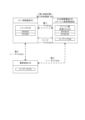
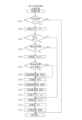
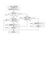
図1は、第1実施形態における遊技機の一例であるスロットマシン10の制御の概略を示すブロック図である。図1では、スロットマシン10とともに、管理装置(CRユニット)200、及びホールコンピュータ300を示している。
図1に示すように、本実施形態では、スロットマシン10は、代表的な制御基板として、メイン制御基板50、サブ制御基板80、及び払出制御基板100(クレジット数管理基板)を備えている。
FIG. 1 is a block diagram schematically showing control of a
As shown in FIG. 1, in this embodiment, the
図1中、実線部がデータのやりとりを示す通信線であり、矢印の向きは、データの流れる方向を示している。たとえば、メイン制御基板50と払出制御基板100とは、双方向で通信可能に形成されている。これに対し、メイン制御基板50とサブ制御基板80とは、メイン制御基板50からサブ制御基板80に対して一方向の通信となっている。
また、図1に示すように、メイン制御基板50は、入力ポート51及び出力ポート52を有し、RWM53、ROM54及びメインCPU55等を備えている(図1で図示したもののみを備える意味ではない)。
In FIG. 1, the solid line portion is a communication line indicating data exchange, and the direction of the arrow indicates the direction in which data flows. For example, the
Further, as shown in FIG. 1, the
さらにまた、図1に示すように、メイン制御基板50と、ベットスイッチ40等の操作スイッチを含む遊技進行用の周辺機器とは、入力ポート51又は出力ポート52を介して電気的に接続されている。
入力ポート51は、操作スイッチ等の信号が入力される接続部であり、出力ポート52は、モータ32等の周辺機器に対して信号を送信する接続部である。
図1中、入力用の周辺機器は、その周辺機器からの信号がメイン制御基板50に向かう矢印で表示しており、出力用の周辺機器は、メイン制御基板50からその周辺機器に向かう矢印で示している(サブ制御基板80も同様である)。
Furthermore, as shown in FIG. 1, the
The input port 51 is a connection section into which signals from operating switches and the like are input, and the output port 52 is a connection section through which signals are sent to peripheral devices such as the motor 32.
In FIG. 1, peripheral devices for input are indicated by arrows that direct signals from the peripheral devices toward the
また、RWM53は、遊技の進行等に基づいた各種データ(変数)を記憶(更新)可能な記憶媒体である。
さらにまた、ROM54は、遊技の進行に必要なプログラムや各種データ(たとえば、データテーブル)等を記憶しておく記憶媒体である。
さらに、メインCPU55は、メイン制御基板50上に設けられたCPU(演算機能を備えるIC)を指し、遊技の進行に必要なプログラムの実行、演算等を行い、具体的には、役の抽選、リール31の駆動制御、及び入賞時の払出し等を実行する。
Further, the RWM 53 is a storage medium that can store (update) various data (variables) based on the progress of the game, etc.
Furthermore, the ROM 54 is a storage medium that stores programs and various data (for example, data tables) necessary for playing the game.
Furthermore, the main CPU 55 refers to a CPU (IC with a calculation function) provided on the
また、メイン制御基板50上には、RWM53、ROM54、メインCPU55及びレジスタを含むMPUが搭載される。なお、RWM53及びROM54は、MPU内部に搭載されるもの以外に、外部に備えていてもよい。
なお、後述するサブ制御基板80上においても、RWM83、ROM84、及びサブCPU85を含むMPUが搭載される。なお、RWM83及びROM84は、MPU内部に搭載されるもの以外に、外部に備えてもよい。
Furthermore, an MPU including an RWM 53, a ROM 54, a main CPU 55, and registers is mounted on the
Note that an MPU including an RWM 83, a ROM 84, and a sub CPU 85 is also mounted on the sub control board 80, which will be described later. Note that the RWM 83 and the ROM 84 may be provided outside the MPU in addition to being mounted inside the MPU.
また、図1に示すように、本実施形態では、スロットマシン10は、遊技者が操作する操作スイッチとして、ベットスイッチ40、スタートスイッチ41、(左、中、右)ストップスイッチ42、キャンセルスイッチ46、及び計数スイッチ47を備えている。
そして、ベットスイッチ40、スタートスイッチ41、(左、中、右)ストップスイッチ42、及びキャンセルスイッチ46については、メイン制御基板50と電気的に接続されており、計数スイッチ47については、メイン制御基板50ではなく、後述する払出制御基板100(クレジット数管理基板)と電気的に接続されている。
Further, as shown in FIG. 1, in the present embodiment, the
The bet switch 40, start switch 41, (left, middle, right) stop switch 42, and cancel switch 46 are electrically connected to the
ここで、「操作スイッチ(又は、単に、「スイッチ」)」とは、遊技者(操作者)による操作体の操作に基づいて(外部からの力を受け)、電気信号のオン/オフを切り替える装置(電気回路及び/又は電気部品を含む)を指し、遊技者が操作する操作体の形状を限定するものではない。
操作スイッチがオフ状態であるときは、たとえば発光素子からの光が受光素子に入射し続けている(受光素子が光を検知し続けているときは、操作スイッチはオフ状態にある。)。そして、遊技者等により操作スイッチ(の操作体)が操作されると、発光素子からの光が受光素子に入射しない状態となる。この状態を検知したときに、操作スイッチがオン状態になったことを示す電気信号をメイン制御基板50に送信する。なお、上記とは逆に、操作スイッチがオフ状態であるときは発光素子からの光が受光素子に入射せず、発光素子からの光が受光素子に入射したときにオン状態となるように構成してもよい。
Here, the "operation switch (or simply, "switch")" is used to turn on/off an electric signal based on the operation of the operating body by the player (operator) (receiving external force). This refers to a device (including an electric circuit and/or electric parts), and does not limit the shape of the operating body operated by the player.
When the operating switch is in the off state, for example, light from the light emitting element continues to enter the light receiving element (when the light receiving element continues to detect light, the operating switch is in the off state). Then, when a player or the like operates the operation switch (the operation body thereof), the light from the light emitting element does not enter the light receiving element. When this state is detected, an electrical signal indicating that the operation switch has been turned on is transmitted to the
本実施形態では、スタートスイッチ41の操作体は、レバー(棒)状であり(このため、「スタートレバー(スイッチ)41」とも称される。)、ベットスイッチ40、ストップスイッチ42、キャンセルスイッチ46、計数スイッチ47の操作体は、押しボタン状である(このため、「ベットボタン(スイッチ)40」、「停止(ストップ)ボタン(スイッチ)42」、「キャンセルボタン(スイッチ)46」、「計数ボタン(スイッチ)47」とも称される)。 In the present embodiment, the operating body of the start switch 41 is lever-shaped (therefore also referred to as a "start lever (switch) 41"), and includes a bet switch 40, a stop switch 42, and a cancel switch 46. , the operating body of the counting switch 47 is push button-shaped (therefore, the "bet button (switch) 40", "stop button (switch) 42", "cancel button (switch) 46", "counting button") button (switch) 47").
また、図1では図示しないが、操作スイッチの操作体及び/又はその周囲若しくは近傍には、LED(発光手段)が設けられている。そして、その操作スイッチの操作受付けが許可状態にあるときは、たとえばその操作スイッチに対応するLED等を青色発光し、その操作スイッチの操作受付けが不許可状態にあるときは、たとえばその操作スイッチのLED等を赤色発光することにより、その操作スイッチの許可/不許可状態を遊技者に示すようにしている。 Although not shown in FIG. 1, an LED (light emitting means) is provided on the operating body of the operating switch and/or around or near the operating body. When the operation acceptance of the operation switch is permitted, for example, the LED corresponding to the operation switch emits blue light, and when the operation reception of the operation switch is not permitted, for example, the LED corresponding to the operation switch is emitted in blue. By emitting red light from an LED or the like, the permission/disapproval state of the operation switch is indicated to the player.
ベットスイッチ40は、スロットマシン10の内部にクレジットされている電子メダルを今回遊技のためにベットするときに遊技者に操作される操作スイッチである。
本実施形態では、ベットスイッチ40として、1回の操作で1枚の電子メダルをベットするための1ベットスイッチ40aと、1回の操作で3枚(最大数、規定数)の電子メダルをベットするための3ベットスイッチ40bとを備えている。
なお、ベットスイッチ40を1個のみ備え、このベットスイッチ40を1回操作することで、クレジットされている電子メダルのうち3枚(最大数、規定数)の電子メダルがベットされるようにしてもよい。
The bet switch 40 is an operation switch operated by the player when betting electronic medals credited inside the
In this embodiment, the bet switch 40 includes a 1-bet switch 40a for betting one electronic medal with one operation, and a 1-bet switch 40a for betting three electronic medals (maximum number, specified number) in one operation. It is equipped with a 3-bet switch 40b for playing.
In addition, only one bet switch 40 is provided, and by operating this bet switch 40 once, three (maximum number, specified number) of electronic medals among the credited electronic medals are bet. Good too.
また、スタートスイッチ41は、(左、中、右のすべての)リール31を始動(リール31の回転を開始)させるときに遊技者に操作される操作スイッチである。
さらにまた、ストップスイッチ42は、3つ(左、中、右)のリール31に対応して3つ設けられており、対応するリール31を停止させるときに遊技者に操作される操作スイッチである。
Further, the start switch 41 is an operation switch operated by the player when starting the reels 31 (all of the left, middle, and right) reels (starting rotation of the reels 31).
Furthermore, three stop switches 42 are provided corresponding to the three (left, middle, right) reels 31, and are operation switches operated by the player to stop the corresponding reels 31. .
さらに、キャンセルスイッチ46は、ベットされている電子メダル(ベットメダル)をクレジットに戻すときに遊技者に操作される操作スイッチである。
キャンセルスイッチ46を操作すると、ベットされている電子メダルがクレジットに戻される。このとき、ベット数が「0」になり、その分、クレジット数に加算される。たとえば、3枚の電子メダルがベットされている状況下で、キャンセルスイッチ46を操作すると、ベット数が「3」から「0」になり、クレジット数に「3」が加算される。
Further, the cancel switch 46 is an operation switch operated by the player when returning betted electronic medals (bet medals) to credits.
When the cancel switch 46 is operated, the betted electronic medals are returned to the credits. At this time, the number of bets becomes "0" and that amount is added to the number of credits. For example, if the cancel switch 46 is operated in a situation where three electronic medals are bet, the number of bets changes from "3" to "0" and "3" is added to the number of credits.
電源スイッチ11は、スロットマシン10の電源のオン/オフを行うときに操作されるスイッチである。
設定キースイッチ12は、設定変更時や設定確認時に操作されるスイッチである。
設定キー挿入口に設定キーを挿入し、時計回りに90度回転させると、設定キースイッチ12がオンになる。
また、電源スイッチ11をオフにした状態(電源断の状態)で、設定キースイッチ12をオンにし、この状態で、電源スイッチ11をオンにすると、設定変更中、すなわち設定変更モードになる。
さらにまた、電源スイッチ11がオンの状態で、設定キースイッチ12をオンにすると、設定確認中、すなわち設定確認モードになる。
The power switch 11 is a switch operated to turn on/off the power of the
The setting
When the setting key is inserted into the setting key insertion slot and rotated 90 degrees clockwise, the setting
Further, when the setting
Furthermore, when the setting
設定スイッチ13は、設定値を変更するときに操作されるスイッチである。
設定変更中に設定スイッチ13を1回操作するごとに、設定値が「1」加算される。
本実施形態では、設定値は、設定1から設定6まで有し、設定変更中は、設定スイッチ13を1回操作するごとに、設定値が、「1」→「2」→・・・→「6」→「1」→・・・と切り替わる。
なお、設定変更中にはいずれかの設定値が所定の表示装置に表示されており、スタートスイッチ41を操作すると、表示されている設定値が確定する。
The setting switch 13 is a switch operated when changing a setting value.
Each time the setting switch 13 is operated during setting change, the set value is incremented by "1".
In this embodiment, the set values include
Note that during the setting change, one of the set values is displayed on a predetermined display device, and when the start switch 41 is operated, the displayed set value is confirmed.
リセットスイッチ14は、RWM53を初期化するときやエラーを解除するときに操作されるスイッチである。
リセットスイッチ14をオンにした状態で電源スイッチ11をオンにすると、初期化処理が行われ、RWM53に記憶されている所定のデータがクリアされる。
また、エラーの原因を除去し、リセットスイッチ14を操作(オン)すると、エラーが解除される。
The reset switch 14 is a switch operated when initializing the RWM 53 or canceling an error.
When the power switch 11 is turned on with the reset switch 14 turned on, initialization processing is performed and predetermined data stored in the RWM 53 is cleared.
Furthermore, when the cause of the error is removed and the reset switch 14 is operated (turned on), the error is canceled.
また、メイン制御基板50は、出力ポート52の一部から、外部集中端子板190に対し、外部信号(外端信号)を出力する。
ここで、「外部信号」とは、外部集中端子板190を介してスロットマシン10の外部(ホールコンピュータ300や、ホールに設置されているデータカウンタ等)に出力するための信号である。
図1に示すように、メイン制御基板50は、外部集中端子板190を介して、ホールコンピュータ300と電気的に接続されている。そして、メイン制御基板50から外部集中端子板190に対して一方向で信号を送信し、外部集中端子板190からホールコンピュータ300に対して一方向で信号を送信する。
Further, the
Here, the "external signal" is a signal to be output to the outside of the slot machine 10 (the
As shown in FIG. 1, the
また、図1に示すように、本実施形態では、スロットマシン10は、枚数表示装置として、獲得数表示LED78、及びクレジット数表示LED76を備えている。
そして、獲得数表示LED78は、メイン制御基板50と電気的に接続されており、クレジット数表示LED76は、メイン制御基板50ではなく、後述する払出制御基板100(クレジット数管理基板)と電気的に接続されている。
獲得数表示LED78は、役の入賞時に、電子メダルの払出し枚数(遊技者の獲得数)を表示するLEDであり、上位桁及び下位桁の2桁から構成されている。
なお、獲得数表示LED78は、払い出される電子メダルがないときは、消灯するように制御してもよい。あるいは、上位桁を消灯し、下位桁のみを「0」表示してもよい。
Further, as shown in FIG. 1, in the present embodiment, the
The acquired number display LED 78 is electrically connected to the
The acquired number display LED 78 is an LED that displays the number of electronic medals paid out (the number acquired by the player) when winning a winning combination, and is composed of two digits, an upper digit and a lower digit.
Note that the acquired number display LED 78 may be controlled to turn off when there are no electronic medals to be paid out. Alternatively, the upper digits may be turned off and only the lower digits may be displayed as "0".
また、獲得数表示LED78は、通常は電子メダルの払出し枚数(獲得数)を表示するが、エラー発生時にはエラーの内容(種類)を表示するLEDとして機能する。
さらにまた、獲得数表示LED78は、AT中に押し順を報知する遊技では、押し順指示情報を表示する(有利な押し順を報知する)LEDとして機能する。
よって、本実施形態における獲得数表示LED78は、払出し枚数(獲得数)、エラー内容、及び押し順指示情報の表示を兼ねるLEDである。ただし、これに限らず、押し順指示情報を表示する専用のLED等を設けてもよいのはもちろんである。
なお、AT中において、有利な押し順の報知は、サブ制御基板80に接続された画像表示装置23によっても実行される。
Further, the acquired number display LED 78 normally displays the number of electronic medals paid out (the acquired number), but when an error occurs, it functions as an LED that displays the content (type) of the error.
Furthermore, the obtained number display LED 78 functions as an LED that displays push order instruction information (notifies an advantageous push order) in a game where the push order is notified during AT.
Therefore, the acquired number display LED 78 in this embodiment is an LED that also displays the number of coins to be paid out (the acquired number), error details, and push order instruction information. However, the present invention is not limited to this, and it goes without saying that a dedicated LED or the like for displaying the push order instruction information may be provided.
Note that during AT, notification of an advantageous pressing order is also performed by the image display device 23 connected to the sub-control board 80.
また、図1に示すように、メイン制御基板50には、図柄表示装置のモータ32(本実施形態ではステッピングモータ)等が電気的に接続されている。
図柄表示装置は、図柄を表示する(本実施形態では3つの)リール31と、各リール31をそれぞれ駆動するモータ32と、リール31の位置を検出するためのリールセンサ33とを含む。
Further, as shown in FIG. 1, the
The symbol display device includes reels 31 (three in this embodiment) that display symbols, a motor 32 that drives each reel 31, and a reel sensor 33 that detects the position of the reel 31.
モータ32は、リール31を回転させるための駆動手段となるものであり、各リール31の回転中心部に連結され、リール制御手段65によって制御される。
ここで、リール31は、左リール31、中リール31、右リール31からなり、左リール31を停止させるときに操作するストップスイッチ42が左ストップスイッチ42であり、中リール31を停止させるときに操作するストップスイッチ42が中ストップスイッチ42であり、右リール31を停止させるときに操作するストップスイッチ42が右ストップスイッチ42である。
The motor 32 serves as a driving means for rotating the reels 31, is connected to the center of rotation of each reel 31, and is controlled by a reel control means 65.
Here, the reel 31 consists of a left reel 31, a middle reel 31, and a right reel 31, and a stop switch 42 that is operated when stopping the left reel 31 is a left stop switch 42. The stop switch 42 to be operated is the middle stop switch 42, and the stop switch 42 to be operated to stop the right reel 31 is the right stop switch 42.
リール31は、リング状のものであって、その外周面には複数種類の図柄(役に対応する図柄組合せを構成している図柄)を印刷したリールテープを貼付したものである。
また、各リール31には、1個(2個以上であってもよい)のインデックスが設けられている。インデックスは、リール31のたとえば周側面に凸状に設けられており、リール31が所定位置を通過したか否かや、1回転したか否か等を検出するときに用いられる。そして、各インデックスは、リールセンサ33によって検知される。
The reel 31 is ring-shaped, and a reel tape on which a plurality of types of symbols (symbols forming symbol combinations corresponding to winning combinations) are printed is attached to the outer peripheral surface of the reel 31.
Further, each reel 31 is provided with one index (two or more indexes may be used). The index is provided in a convex shape, for example, on the circumferential side of the reel 31, and is used to detect whether or not the reel 31 has passed a predetermined position, whether or not it has rotated once. Each index is detected by the reel sensor 33.
リールセンサ33は、メイン制御基板50に電気的に接続されている。そして、リールセンサ33がインデックスを検知すると、その入力信号がメイン制御基板50に入力され、そのリール31が所定位置を通過したことが検知される。
また、リールセンサ33がリール31のインデックスを検知した瞬間の基準位置上の図柄を予めROM54に記憶している。これにより、インデックスを検知した瞬間の基準位置上の図柄を検知することができる。さらに、リールセンサ33がリール31のインデックスを検知した瞬間から、(ステッピング)モータ32を何パルス駆動すれば、前記基準位置上の図柄から数えて何図柄先の図柄を有効ライン上に停止させることができるかを識別可能となる。
The reel sensor 33 is electrically connected to the
Further, the symbol on the reference position at the moment when the reel sensor 33 detects the index of the reel 31 is stored in the ROM 54 in advance. Thereby, the symbol on the reference position at the moment the index is detected can be detected. Furthermore, from the moment when the reel sensor 33 detects the index of the reel 31, how many pulses should the (stepping) motor 32 be driven to stop the symbol at the number of symbols ahead, counting from the symbol on the reference position, on the effective line? It becomes possible to identify whether the
遊技者は、遊技を開始するときは、クレジットされている電子メダルをベットスイッチ40の操作によりベットする。そして、当該遊技の規定数の電子メダルがベットされた状態でスタートスイッチ41が操作されると、そのときに発生する信号がメイン制御基板50に入力される。メイン制御基板50は、この信号を受信すると、役抽選手段61(内部抽せん手段)による抽選を行うとともに、すべてのモータ32を駆動制御して、すべてのリール31を回転させるように制御する。このようにしてリール31がモータ32によって回転されることで、リール31上の図柄は、所定の速度で表示窓内で上下方向に移動表示される。
When starting a game, the player bets the credited electronic medals by operating the bet switch 40. When the start switch 41 is operated with a prescribed number of electronic medals for the game being bet, a signal generated at that time is input to the
そして、遊技者は、ストップスイッチ42を操作することで、そのストップスイッチ42に対応するリール31(たとえば、左ストップスイッチ42に対応する左リール31)の回転を停止させる。
ストップスイッチ42が操作されると、そのときに発生する信号がメイン制御基板50に入力される。メイン制御基板50は、この信号を受信すると、そのストップスイッチ42に対応するモータ32を駆動制御して、役抽選手段61の抽選結果(内部抽せん手段により決定した結果)に対応するように、そのモータ32に係るリール31の停止制御を行う。そして、すべてのリール31の停止時における図柄組合せにより、今回遊技の遊技結果を表示する。さらに、いずれかの役に対応する図柄組合せが有効ラインに停止したとき(その役の入賞となったとき)は、入賞した役に対応する電子メダルの払出し等が行われる。
Then, by operating the stop switch 42, the player stops the rotation of the reel 31 corresponding to the stop switch 42 (for example, the left reel 31 corresponding to the left stop switch 42).
When the stop switch 42 is operated, the signal generated at that time is input to the
次に、メイン制御基板50の具体的構成について説明する。
図1に示すように、メイン制御基板50のメインCPU55は、以下の役抽選手段61等を備える。本実施形態における以下の各手段は例示であり、本実施形態で示した手段に限定されるものではない。
役抽選手段61は、当選番号の抽選(決定、選択)を行う。ここで、「役抽選手段61による当選番号の抽選」は、風営法規則(遊技機の認定及び型式の検定等に関する規則。以下、単に「規則」という。)における「内部抽せん」と同じであり、役抽選手段61による抽選結果は、規則における「内部抽せんにより決定した結果」と同じである。したがって、役抽選手段61を、規則に合わせた表現で、「内部抽せん手段61」とも称する。
Next, a specific configuration of the
As shown in FIG. 1, the main CPU 55 of the
The winning combination lottery means 61 performs lottery (determination, selection) of winning numbers. Here, the "drawing of winning numbers by the prize drawing means 61" is the same as the "internal drawing" in the Entertainment Business Law Regulations (regulations regarding certification of gaming machines and type examination, etc.; hereinafter simply referred to as "Rules"). The lottery result by the winning combination lottery means 61 is the same as the "result determined by internal lottery" in the rules. Therefore, the combination lottery means 61 is also referred to as "internal lottery means 61" in accordance with the rules.
役抽選手段61により当選番号が決定されると、その当選番号に基づいて、入賞及びリプレイ条件装置番号、並びに役物条件装置番号が決定され、当該遊技で作動可能となる入賞及びリプレイ条件装置、並びに役物条件装置が定まることとなる。このため、役抽選手段61は、条件装置番号の決定(抽選又は選択)手段、当選役決定(抽選又は選択)手段等とも称される。
役抽選手段61は、たとえば、抽選用の乱数発生手段(ハードウェア乱数等)と、この乱数発生手段が発生する乱数を抽出する乱数抽出手段と、乱数抽出手段が抽出した乱数値に基づいて、当選番号を決定する当選番号決定手段とを備えている。
When the winning number is determined by the prize lottery means 61, the winning and replay condition device number and the prize condition device number are determined based on the winning number, and the winning and replay condition device becomes operable in the game. In addition, the accessory condition device will be determined. Therefore, the winning combination lottery means 61 is also referred to as a condition device number determination (lottery or selection) means, a winning combination determination (lottery or selection) means, or the like.
The prize lottery means 61 includes, for example, a random number generation means for lottery (hardware random numbers, etc.), a random number extraction means for extracting the random numbers generated by the random number generation means, and a random number extraction means based on the random number extracted by the random number extraction means. and winning number determining means for determining the winning number.
乱数発生手段は、所定の領域(たとえば10進数で「0」~「65535」)の乱数を発生させる。乱数は、たとえば200n(ナノ)secで1カウントを行うカウンターが「0」~「65535」の範囲を1サイクルとしてカウントし続ける乱数であり、スロットマシン10の電源が投入されている間は、乱数をカウントし続ける。
乱数抽出手段は、乱数発生手段によって発生した乱数を、所定の時、本実施形態では遊技者によりスタートスイッチ41が操作(オン)された時に抽出する。
当選番号決定手段は、乱数抽出手段により抽出された乱数値を、抽選テーブルと照合することにより、その乱数値が属する領域に対応する当選番号を決定する。
The random number generation means generates random numbers in a predetermined range (for example, "0" to "65535" in decimal notation). The random number is a random number that continues counting in the range of "0" to "65535" as one cycle by a counter that counts once every 200n (nano) seconds, for example, and while the
The random number extraction means extracts the random number generated by the random number generation means at a predetermined time, in this embodiment, when the start switch 41 is operated (turned on) by the player.
The winning number determining means determines the winning number corresponding to the area to which the random number value belongs by comparing the random number value extracted by the random number extraction means with the lottery table.
当選フラグ制御手段62は、役抽選手段61による抽選結果に基づいて、各役に対応する当選フラグのオン/オフを制御するものである。
本実施形態では、すべての役について、役ごとに当選フラグを備える。そして、役抽選手段61による抽選においていずれかの役の当選となったときは、その役の当選フラグをオンにする(当選フラグを立てる)。なお、役の当選には、当選役が1つである場合(単独当選)と、当選役が複数ある場合(重複当選)とが挙げられる。
The winning flag control means 62 controls ON/OFF of the winning flag corresponding to each winning combination based on the lottery result by the winning combination lottery means 61.
In this embodiment, a winning flag is provided for each role for all roles. When one of the winning combinations is won in the lottery by the winning combination lottery means 61, the winning flag for that winning combination is turned on (the winning flag is set). Note that there are two cases of winning a winning combination: a case where there is only one winning combination (single winning) and a case where there are multiple winning combinations (multiple winning).
リール制御手段65は、リール31の回転開始命令を受けたとき、特に本実施形態ではスタートスイッチ41の操作(オン)を検知したときに、すべて(3つ)のリール31の回転を開始するように制御する。
また、リール制御手段65は、役抽選手段61により当選番号の決定が行われた後、今回遊技における当選フラグのオン/オフを参照して、当選フラグのオン/オフに対応する停止位置決定テーブルを選択するとともに、ストップスイッチ42が操作されたときに、ストップスイッチ42の操作(オン)を検知したときのタイミングに基づいて、そのストップスイッチ42に対応するリール31の停止位置を決定するとともに、モータ32を駆動制御して、その決定した位置にそのリール31を停止させるように制御する。
The reel control means 65 is configured to start the rotation of all (three) reels 31 when receiving a command to start rotating the reels 31, particularly when detecting operation (on) of the start switch 41 in this embodiment. to control.
Further, after the winning numbers are determined by the winning combination lottery means 61, the reel control means 65 refers to the on/off of the winning flag in the current game, and generates a stop position determination table corresponding to the on/off of the winning flag. is selected, and when the stop switch 42 is operated, the stop position of the reel 31 corresponding to the stop switch 42 is determined based on the timing when the operation (on) of the stop switch 42 is detected, and The motor 32 is driven and controlled to stop the reel 31 at the determined position.
たとえば、リール制御手段65は、少なくとも1つの当選フラグがオンである遊技では、リール31の停止制御の範囲内において、当選役(当選フラグがオンになっている役)に対応する図柄組合せを有効ラインに停止可能にリール31を停止制御するとともに、当選役以外の役(当選フラグがオフになっている役)に対応する図柄組合せを有効ラインに停止させないようにリール31を停止制御する。
ここで、「リール31の停止制御の範囲内」とは、ストップスイッチ42が操作された瞬間からリール31が実際に停止するまでの時間又はリール31の回転量(移動図柄(コマ)数)の範囲内を意味する。
For example, in a game where at least one winning flag is on, the reel control means 65 enables the symbol combination corresponding to the winning combination (the winning flag is on) within the range of stop control of the reels 31. The reels 31 are controlled to stop so as to be stopped on the line, and the reels 31 are stopped so as not to stop on the effective line the symbol combinations corresponding to combinations other than winning combinations (winning flags are turned off).
Here, "within the range of stop control of the reels 31" refers to the time from the moment the stop switch 42 is operated until the reels 31 actually stop, or the amount of rotation of the reels 31 (number of moving symbols (frames)). means within range.
本実施形態では、リール31は、定速時は1分間で約80回転する速度で回転される。
そして、ストップスイッチ42が操作されたときは、MB作動中の所定のリール31(たとえば、中リール31)を除き、ストップスイッチ42が操作された瞬間からリール31を停止させるまでの時間が190ms以内に設定されている。これにより、本実施形態では、MB作動中の所定のリール31を除き、ストップスイッチ42が操作された瞬間の図柄からリール31が停止するまでの最大移動図柄数が4図柄に設定されている。
一方、MB作動中の所定のリール31については、ストップスイッチ42が操作された瞬間からリール31を停止させるまでの時間が75ms以内に設定されている。これにより、MB作動中の所定のリール31については、ストップスイッチ42が操作された瞬間の図柄からリール31が停止するまでの最大移動図柄数が1図柄に設定されている。
In this embodiment, the reel 31 is rotated at a speed of about 80 revolutions per minute at constant speed.
When the stop switch 42 is operated, the time from the moment the stop switch 42 is operated until the reel 31 is stopped is within 190 ms, except for a predetermined reel 31 (for example, the middle reel 31) during MB operation. is set to . As a result, in this embodiment, the maximum number of symbols to be moved from the symbol at the moment when the stop switch 42 is operated until the reel 31 stops is set to 4 symbols, excluding a predetermined reel 31 during MB operation.
On the other hand, for a predetermined reel 31 during MB operation, the time from the moment the stop switch 42 is operated until the reel 31 is stopped is set within 75 ms. As a result, for a predetermined reel 31 during MB operation, the maximum number of symbols to be moved from the symbol at the moment the stop switch 42 is operated until the reel 31 stops is set to one symbol.
そして、ストップスイッチ42の操作を検知した瞬間に、リール31の停止制御の範囲内にある図柄のいずれかが所定の有効ラインに停止させるべき図柄であるときは、ストップスイッチ42が操作されたときに、その図柄が所定の有効ラインに停止するように制御される。
すなわち、ストップスイッチ42が操作された瞬間に直ちにリール31を停止させると、当選番号に対応する役の図柄が所定の有効ラインに停止しないときには、リール31を停止させるまでの間に、リール31の停止制御の範囲内においてリール31を回転移動制御することで、当選番号に対応する役の図柄をできる限り所定の有効ラインに停止させるように制御する(引込み停止制御)。
At the moment when the operation of the stop switch 42 is detected, if any of the symbols within the range of stop control of the reels 31 is a symbol that should be stopped on a predetermined active line, when the stop switch 42 is operated. Then, the symbol is controlled to stop at a predetermined valid line.
That is, if the reels 31 are stopped immediately at the moment the stop switch 42 is operated, if the symbol of the combination corresponding to the winning number does not stop on a predetermined active line, the reels 31 will be stopped until the reels 31 are stopped. By controlling the rotational movement of the reel 31 within the range of the stop control, the symbols of the combination corresponding to the winning number are controlled to be stopped on a predetermined valid line as much as possible (pull-in stop control).
また逆に、ストップスイッチ42が操作された瞬間に直ちにリール31を停止させると、当選番号に対応しない役の図柄組合せが有効ラインに停止してしまうときは、リール31の停止時に、リール31の停止制御の範囲内においてリール31を回転移動制御することで、当選番号に対応しない役の図柄組合せを有効ラインに停止させないように制御する(蹴飛ばし停止制御)。
さらに、複数の役に当選している遊技(たとえば、押し順ベル当選時)では、ストップスイッチ42の押し順や、ストップスイッチ42の操作タイミングに応じて、入賞させる役の優先順位が予め定められており、所定の優先順位によって、最も優先する役に係る図柄の引込み停止制御を行う。
Conversely, if the reels 31 are stopped immediately at the moment the stop switch 42 is operated, the symbol combination of the winning combination that does not correspond to the winning number will stop on the active line. By controlling the rotational movement of the reel 31 within the range of the stop control, control is performed so that symbol combinations of winning combinations that do not correspond to the winning numbers are not stopped on the active line (kick-off stop control).
Furthermore, in a game where multiple winning combinations are won (for example, when the push order bell is won), the priority order of winning combinations is determined in advance according to the order in which the stop switches 42 are pressed and the timing at which the stop switches 42 are operated. According to a predetermined priority order, control is performed to stop the drawing of symbols related to the most prioritized winning combination.
入賞判定手段66は、リール31の停止時に、有効ラインに停止したリール31の図柄組合せが、いずれかの役に対応する図柄組合せであるか否かを判断するものである。
ここで、入賞判定手段66は、実際に、役に対応する図柄組合せが有効ラインに停止したか否かを検知することはない。具体的には、当該遊技で作動した条件装置と、ストップスイッチ42の押し順及び/又はストップスイッチ42の操作タイミングとから、リール31が実際に停止する前に有効ラインに停止する図柄組合せを予め判断するか、又はリール31の停止後に有効ラインに停止した図柄組合せを予め判断する。
The winning determination means 66 determines, when the reels 31 are stopped, whether or not the symbol combination of the reels 31 that has stopped on the active line is a symbol combination that corresponds to any winning combination.
Here, the winning determination means 66 does not actually detect whether or not the symbol combination corresponding to the winning combination has stopped on the active line. Specifically, from the condition device activated in the game, the pressing order of the stop switch 42 and/or the operation timing of the stop switch 42, a symbol combination that will stop on the active line before the reel 31 actually stops is determined in advance. Or, after the reels 31 have stopped, the symbol combinations that have stopped on the active line are determined in advance.
払出し手段67は、入賞判定手段66により、リール31の停止時に有効ラインに停止した図柄組合せがいずれかの役に対応する図柄組合せと一致すると判断され、その役の入賞となったときに、その入賞役に応じた枚数の電子メダルをクレジット数に加算する処理を行うものである。
また、払出し手段67は、リプレイの入賞時には、電子メダルをクレジット数に加算することなく、今回遊技で投入された枚数の電子メダルを自動投入(自動ベット)するように制御する。
The payout means 67 determines by the winning determination means 66 that the symbol combination that stopped on the active line when the reels 31 stopped matches the symbol combination corresponding to any of the winning combinations, and when that winning combination results in a winning of that winning combination, This process adds the number of electronic medals according to the winning combination to the number of credits.
Furthermore, when winning a prize in a replay, the payout means 67 controls the electronic medals to be automatically inserted (automatically bet) in the number of electronic medals inserted in the current game, without adding the electronic medals to the number of credits.
メイン制御基板50は、サブ制御基板80に対し、サブ制御基板80で出力する演出に必要な情報(制御コマンド)を送信する。
制御コマンドとしては、たとえば、ベットスイッチ40が操作されたときの情報、スタートスイッチ41が操作されたときの情報、役の抽選結果(内部抽せんにより決定した結果)に関する情報、ストップスイッチ42が操作されたときの情報、入賞した役の情報等が挙げられる。
The
The control commands include, for example, information when the bet switch 40 is operated, information when the start switch 41 is operated, information regarding the winning combination result (result determined by internal lottery), and information when the stop switch 42 is operated. Examples include information on when the player won a prize, information on the winning role, and the like.
サブ制御基板80は、遊技中及び遊技待機中における演出(情報)の選択や出力等を制御するものである。
ここで、メイン制御基板50とサブ制御基板80とは、電気的に接続されており、メイン制御基板50は、シリアル通信によってサブ制御基板80に一方向で、演出の出力に必要な情報(制御コマンド)を送信する。
なお、メイン制御基板50とサブ制御基板80とは、電気的に接続されることに限らず、光通信手段を用いた接続であってもよい。さらに、電気的接続及び光通信接続のいずれにおいても、シリアル通信に限らず、パラレル通信であってもよく、シリアル通信とパラレル通信とを併用してもよい。
The sub-control board 80 controls the selection and output of effects (information) during the game and while waiting for the game.
Here, the
Note that the
サブ制御基板80は、メイン制御基板50と同様に、入力ポート81、出力ポート82、RWM83、ROM84、及びサブCPU85等を備える。
サブ制御基板80には、入力ポート81又は出力ポート82を介して、図1に示すような以下の演出ランプ21等の演出用周辺機器が電気的に接続されている。ただし、演出用の周辺機器は、これらに限られるものではない。
Like the
The sub-control board 80 is electrically connected to peripheral devices for effects such as the following effect lamps 21 as shown in FIG. 1 via an input port 81 or an output port 82. However, peripheral devices for presentation are not limited to these.
RWM83は、サブCPU85が演出を制御するときに取り込んだデータ等を一時的に記憶可能な記憶媒体である。
また、ROM84は、演出用データとして、演出に係る抽選を行うとき等のプログラムや各種データ等を記憶しておく記憶媒体である。
さらに、サブCPU85は、サブ制御基板80上に設けられたCPU(演算機能を備えるIC)を指し、遊技中及び遊技待機中における演出の出力に必要なプログラムの実行、演算等を行う。
The RWM 83 is a storage medium that can temporarily store data etc. taken in when the sub CPU 85 controls the performance.
Further, the ROM 84 is a storage medium that stores programs for holding a lottery related to a performance, various data, etc. as performance data.
Further, the sub-CPU 85 refers to a CPU (IC with a calculation function) provided on the sub-control board 80, and executes programs, calculations, etc. necessary for outputting effects during a game and while waiting for a game.
また、演出ランプ21は、たとえばLED等からなり、所定の条件を満たしたときに、それぞれ所定のパターンで点灯又は点滅する。
なお、演出ランプ21には、各リール31の内周側に配置され、リール31に表示された図柄(表示窓から見える上下に連続する3図柄)を背後から照らすためのバックランプ、リール31の上部からリール31上の図柄を照光する蛍光灯、スロットマシン10のフロントドア前面に配置され、役の入賞時等に点滅する枠ランプ等が含まれる。
さらにまた、スピーカ22は、遊技中に各種の演出を行うべく、所定の条件を満たしたときに、所定のサウンドを出力するものである。
The effect lamps 21 are made of, for example, LEDs, and are lit or blinked in a predetermined pattern when predetermined conditions are met.
Note that the production lamp 21 includes a back lamp that is placed on the inner circumference side of each reel 31 and illuminates the symbols displayed on the reel 31 (three consecutive symbols visible from the display window) from behind. They include a fluorescent light that illuminates the symbols on the reels 31 from above, a frame lamp that is placed in front of the front door of the
Furthermore, the speaker 22 outputs predetermined sounds when predetermined conditions are met in order to perform various effects during the game.
さらに、画像表示装置23は、液晶ディスプレイ、有機ELディスプレイ、ドットディスプレイ等からなるものであり、遊技中に各種の演出画像(正解押し順、当該遊技で作動する条件装置に対応する演出等)や、遊技情報(役物作動時や有利区間(AT)中の遊技回数や獲得枚数等)等を表示するものである。
また、サブ制御基板80のサブCPU85は、演出出力制御手段91を備える。そして、演出出力制御手段91は、メイン制御基板50から送信された制御コマンドに基づいて、どのようなタイミングで、どのような演出を出力するかを決定し、この決定に基づいて、演出用の周辺機器から各種の演出を出力するように制御する。
Furthermore, the image display device 23 is composed of a liquid crystal display, an organic EL display, a dot display, etc., and displays various effect images (correct answer pressing order, effects corresponding to conditional devices activated in the game, etc.) during the game. , game information (such as the number of games played and the number of coins won when the accessory is activated or during the advantageous period (AT)).
Further, the sub CPU 85 of the sub control board 80 includes a production output control means 91. Then, the effect output control means 91 determines what kind of effect to output at what timing based on the control command sent from the
図1に示すように、本実施形態では、スロットマシン10は、払出制御基板100(クレジット数管理基板)を備えている。
また、払出制御基板100は、電子メダルのクレジット数を管理するものである。
ここで、メイン制御基板50と払出制御基板100とは、電気的に接続されており、双方向での通信が可能に形成されている。
なお、メイン制御基板50と払出制御基板100とは、電気的に接続されることに限らず、光通信手段を用いた接続であってもよい。
また、電気的接続及び光通信接続のいずれにおいても、シリアル通信としてもよく、パラレル通信としてもよく、シリアル通信とパラレル通信とを併用してもよい。
As shown in FIG. 1, in this embodiment, the
Further, the payout control board 100 manages the number of credits of electronic medals.
Here, the
Note that the
Further, both electrical connection and optical communication connection may be serial communication, parallel communication, or a combination of serial communication and parallel communication.
払出制御基板100は、メイン制御基板50やサブ制御基板80と同様に、入力ポート101、出力ポート102、RWM103、ROM104、及びクレジット数管理CPU105等を備える。
また、払出制御基板100には、入力ポート101又は出力ポート102を介して、メイン制御基板50、操作スイッチとしての計数スイッチ47、枚数表示装置としてのクレジット数表示LED76、及びスロットマシン10の外部の管理装置(CRユニット)200等が電気的に接続されている。
Like the
The payout control board 100 also has a
RWM103は、クレジット数管理CPU105がクレジット数を管理するときに取り込んだデータ等を一時的に記憶可能な記憶媒体である。
また、ROM104は、クレジット数を管理するときのプログラムや各種データ等を記憶しておく記憶媒体である。
さらに、クレジット数管理CPU105は、払出制御基板100上に設けられたCPU(演算機能を備えるIC)を指し、クレジット数の管理に必要なプログラムの実行、演算等を行う。
The RWM 103 is a storage medium that can temporarily store data etc. taken in when the credit number management CPU 105 manages the number of credits.
Further, the ROM 104 is a storage medium that stores programs and various data for managing the number of credits.
Further, the credit number management CPU 105 refers to a CPU (IC with a calculation function) provided on the payout control board 100, and executes programs, calculations, etc. necessary for managing the number of credits.
また、計数スイッチ47は、スロットマシン10の内部にクレジットされている電子メダルを管理装置200に戻すときに遊技者に操作される操作スイッチである。
計数スイッチ47を操作すると、スロットマシン10の内部にクレジットされている電子メダルが管理装置200に戻される。このとき、クレジット数が「0」になり、その分、管理装置200において管理する電子メダルの枚数が加算される。
たとえば、スロットマシン10の内部に100枚の電子メダルがクレジットされている状況下で、計数スイッチ47を操作すると、クレジット数が「100」から「0」になり、管理装置200において管理する電子メダルの枚数に「100」が加算される。
Further, the counting switch 47 is an operation switch operated by the player when returning the electronic medals credited inside the
When the counting switch 47 is operated, the electronic medals credited inside the
For example, in a situation where 100 electronic medals are credited inside the
また、たとえば、3枚の電子メダルがベットされ、かつ100枚の電子メダルがクレジットされている状況下で、キャンセルスイッチ46を操作すると、ベットされている電子メダルがクレジットに戻される。このとき、ベット数が「3」から「0」になり、クレジット数が「100」から「103」になる。その後、計数スイッチ47を操作すると、クレジット数が「103」から「0」になり、管理装置200において管理する電子メダルの枚数に「103」が加算される。
このように、本実施形態では、遊技者が遊技をやめるときに、ベットされている電子メダルがあれば、まず、キャンセルスイッチ46を操作して、ベットされている電子メダルをクレジットに戻し、その後に、計数スイッチ47を操作して、クレジットされている電子メダルを管理装置200に戻す。
Further, for example, if the cancel switch 46 is operated in a situation where 3 electronic medals have been bet and 100 electronic medals have been credited, the betted electronic medals are returned to the credits. At this time, the number of bets changes from "3" to "0", and the number of credits changes from "100" to "103". Thereafter, when the counting switch 47 is operated, the number of credits changes from "103" to "0", and "103" is added to the number of electronic medals managed by the management device 200.
As described above, in this embodiment, if there are electronic medals that have been bet when the player stops playing, he or she first operates the cancel switch 46 to return the betted electronic medals to credits, and then Then, the counting switch 47 is operated to return the credited electronic medals to the management device 200.
ただし、前回遊技でリプレイが入賞し、前回遊技でベットした枚数の電子メダルが自動ベットされたときは、キャンセルスイッチ46を操作しても、この自動ベットされた電子メダルをクレジットに戻すことができないように設定されている。すなわち、自動ベットされた電子メダルについては、キャンセルスイッチ46を操作しても、クレジットに戻すことができないように設定されている。
なお、ベットスイッチ40の操作に基づきベットされた電子メダル、及びリプレイ入賞に基づき自動ベットされた電子メダルの双方とも、キャンセルスイッチ46の操作によりクレジットに戻すことができるようにしてもよい。
However, if a replay wins in the previous game and the number of electronic medals bet on in the previous game is automatically bet, the automatically bet electronic medals cannot be returned to credits even if the cancel switch 46 is operated. It is set as follows. That is, the electronic medals automatically bet are set so that they cannot be returned to credits even if the cancel switch 46 is operated.
Note that both the electronic medals bet based on the operation of the bet switch 40 and the electronic medals automatically bet based on the replay winnings may be returned to credits by operating the cancel switch 46.
また、計数スイッチ47の操作により、ベットされている電子メダル及びクレジットされている電子メダルが管理装置200に戻されるようにしてもよい。
たとえば、3枚の電子メダルがベットされ、かつ100枚の電子メダルがクレジットされている状況下で、計数スイッチ47を操作すると、ベットされている電子メダル及びクレジットされている電子メダルが管理装置200に戻され、ベット数及びクレジット数が「0」になるとともに、管理装置200において管理する電子メダルの枚数に「103」が加算されるようにしてもよい。
この場合、キャンセルスイッチ46を設けてもよく、設けなくてもよい。
Further, by operating the counting switch 47, the betted electronic medals and the credited electronic medals may be returned to the management device 200.
For example, in a situation where 3 electronic medals are bet and 100 electronic medals are credited, if the counting switch 47 is operated, the betted electronic medals and the credited electronic medals are transferred to the management device 200. , the number of bets and the number of credits become "0", and "103" may be added to the number of electronic medals managed by the management device 200.
In this case, the cancel switch 46 may or may not be provided.
また、クレジット数表示LED76は、スロットマシン10の内部にクレジットされている電子メダルの枚数を表示するLEDである。
本実施形態では、最大で1万枚の電子メダルをクレジット可能とされている。すなわち、クレジット数の上限値は「10000」に設定されている。このため、クレジット数表示LED76は、5桁から構成されている。
なお、クレジット数の上限値は「10000」に限らず、たとえば、「15000」としてもよく、「30000」としてもよく、「50000」としてもよい。
また、クレジット数表示LED76の桁数は、5桁に限らず、クレジット数の上限値にあわせて適宜設定することができる。
Further, the credit number display LED 76 is an LED that displays the number of electronic medals credited inside the
In this embodiment, a maximum of 10,000 electronic medals can be credited. That is, the upper limit value of the number of credits is set to "10000". Therefore, the credit number display LED 76 is composed of five digits.
Note that the upper limit value of the number of credits is not limited to "10,000" but may be, for example, "15,000", "30,000", or "50,000".
Further, the number of digits of the credit number display LED 76 is not limited to five digits, and can be set as appropriate according to the upper limit of the number of credits.
また、払出制御基板100からメイン制御基板50にイネーブル信号を送信可能とされている。そして、メイン制御基板50は、イネーブル信号がオンのときは、各種処理を実行可能とされ、イネーブル信号がオフのときは、所定の処理を実行不可とされるように設定されている。
本実施形態では、クレジット数が上限値に到達すると、すなわち、クレジット数表示LED76の表示が「10000」に到達すると、イネーブル信号をオフにする。そして、イネーブル信号がオフになると、メイン制御基板50は、ベットスイッチ40及びスタートスイッチ41の操作を受付け不可にするように制御する。
なお、クレジット数が「15000」、「30000」又は「50000」に到達したときにイネーブル信号をオフにするようにしてもよい。
Further, an enable signal can be transmitted from the payout control board 100 to the
In this embodiment, when the number of credits reaches the upper limit value, that is, when the display of the number of credits display LED 76 reaches "10000", the enable signal is turned off. Then, when the enable signal is turned off, the
Note that the enable signal may be turned off when the number of credits reaches "15,000,""30,000," or "50,000."
また、たとえば、通常遊技と、通常遊技より遊技者にとって有利となる特別遊技(1BB遊技;第一種ビッグボーナスゲーム;第一種役物連続作動装置の作動)とを実行可能とし、通常遊技から特別遊技に移行したときは、特別遊技の終了時に、打ち止めとなり、遊技を進行させることができなくなるようにしてもよい。すなわち、打ち止め機能を備えてもよい。また、打ち止めとなる条件は、特別遊技の終了時に限らず、適宜設定することができる。そして、打ち止めとなる条件を満たしたときに、イネーブル信号をオフにするようにしてもよい。 In addition, for example, it is possible to perform a normal game and a special game that is more advantageous to the player than the normal game (1BB game; first type big bonus game; operation of the first type accessory continuous operation device), and to When moving to a special game, the game may be discontinued and the game may no longer be allowed to proceed at the end of the special game. That is, it may have a stopping function. Further, the conditions for stopping the game are not limited to the end of the special game, and can be set as appropriate. Then, the enable signal may be turned off when the conditions for discontinuation are met.
この場合、打ち止め機能を有効(打ち止め有り)にするか又は無効(打ち止め無し)にするかを設定する(切り替える)ための打ち止め有無設定スイッチを備えることができる。また、打ち止めを解除するための打ち止め解除スイッチを備えることができる。そして、打ち止めとなる条件を満たしたときは、打ち止め解除スイッチを操作することにより、打ち止めを解除して、遊技を進行可能にするとともに、イネーブル信号をオンにすることができる。また、打ち止め解除スイッチは、たとえば、設定スイッチ13やリセットスイッチ14などの他のスイッチと兼用にすることができる。 In this case, a termination presence/absence setting switch may be provided for setting (switching) whether the termination function is enabled (with termination) or disabled (without termination). Further, a stop release switch for releasing the stop can be provided. When the conditions for stopping the game are met, by operating the stopping cancellation switch, the stopping can be canceled and the game can be continued, and the enable signal can be turned on. Further, the stop release switch can also be used in combination with other switches such as the setting switch 13 and the reset switch 14, for example.
また、払出制御基板100のクレジット数管理CPU105は、クレジット数管理手段111を備える。そして、クレジット数管理手段111は、メイン制御基板50から送信された制御コマンド、管理装置200から送信された制御コマンド、及び計数スイッチ47の操作に基づいて、クレジット数を管理(加算又は減算)するとともに、クレジット数表示LED76におけるクレジット数の表示を制御する。
Further, the credit number management CPU 105 of the payout control board 100 includes a credit number management means 111. The credit number management means 111 manages (adds or subtracts) the number of credits based on the control command transmitted from the
また、管理装置(CRユニット)200は、電子メダルの貸出し及び払戻しの管理を行うための装置である。1台のスロットマシン10につき、1台の管理装置200が設置される。ホールでは、管理装置200は、スロットマシン10の間に配置されることから、サンドと称される。また、スロットマシン10と、そのスロットマシン10に対応する管理装置200とから、1つの遊技システムが構成される。
Further, the management device (CR unit) 200 is a device for managing lending and refunding of electronic medals. One management device 200 is installed for one
図1に示すように、スロットマシン10の払出制御基板100と管理装置200とは、電気的に接続されており、双方向での通信が可能に形成されている。
なお、払出制御基板100と管理装置200とは、遊技球等貸出装置接続端子板を介して接続される。
また、払出制御基板100と管理装置200は、電気的に接続されることに限らず、光通信手段を用いた接続であってもよい。
さらにまた、電気的接続及び光通信接続のいずれにおいても、シリアル通信としてもよく、パラレル通信としてもよく、シリアル通信とパラレル通信とを併用してもよい。
As shown in FIG. 1, the payout control board 100 and the management device 200 of the
Note that the payout control board 100 and the management device 200 are connected via a terminal board for connecting a device for renting game balls, etc.
Moreover, the payout control board 100 and the management device 200 are not limited to being electrically connected, but may be connected using optical communication means.
Furthermore, both the electrical connection and the optical communication connection may be serial communication, parallel communication, or a combination of serial communication and parallel communication.
また、図1に示すように、払出制御基板100は、メイン制御基板50との間で双方向通信が可能とされているとともに、管理装置200との間でも双方向通信が可能とされている。
そして、管理装置200と払出制御基板100との間の通信により、管理装置200から払出制御基板100に電子メダルを移行(貸出し)可能とされ、貸し出された電子メダルを払出制御基板100にクレジット可能とされている。
Further, as shown in FIG. 1, the payout control board 100 is capable of two-way communication with the
Through communication between the management device 200 and the payout control board 100, electronic medals can be transferred (lent) from the management device 200 to the payout control board 100, and the lent electronic medals can be credited to the payout control board 100. It is said that
また、払出制御基板100とメイン制御基板50との間の通信により、払出制御基板100にクレジットされている電子メダルをベットして遊技を実行可能とされ、役の入賞時には、払い出された電子メダルを払出制御基板100にクレジット可能とされている。
さらに、遊技者が遊技をやめるときは、管理装置200と払出制御基板100との間の通信により、払出制御基板100にクレジットされている電子メダルを管理装置200に移行(払戻し)可能とされている。
Furthermore, through communication between the payout control board 100 and the
Furthermore, when the player stops playing, the electronic medals credited to the payout control board 100 can be transferred (refunded) to the management device 200 through communication between the management device 200 and the payout control board 100. There is.
図1に示すように、管理装置200は、紙幣投入口201、貸出スイッチ202、返却スイッチ203、度数表示部204、及びカードリーダライタ205等を備えている。
紙幣投入口201は、電子メダルの貸出しに必要な紙幣(たとえば千円札)を挿入するための投入口である。
紙幣投入口201から管理装置200内に挿入された紙幣が正しく認識されると、投入された紙幣に対応する度数が度数表示部204に表示される。度数表示部204は、たとえば3桁の7セグから構成される。たとえば千円札を投入したときは、度数として「10」と表示され、一万円札を投入したときは、度数として「100」と表示される。
As shown in FIG. 1, the management device 200 includes a bill slot 201, a lending switch 202, a return switch 203, a frequency display section 204, a card reader/writer 205, and the like.
The banknote slot 201 is a slot for inserting banknotes (for example, 1,000 yen bills) necessary for lending electronic medals.
When the bill inserted into the management device 200 from the bill slot 201 is correctly recognized, the frequency corresponding to the inserted bill is displayed on the frequency display section 204. The frequency display section 204 is composed of, for example, 7 segments of 3 digits. For example, when a 1000 yen bill is inserted, the frequency is displayed as "10", and when a 10,000 yen bill is inserted, the frequency is displayed as "100".
貸出スイッチ202は、度数表示部204に残度数が表示されていることを条件として、電子メダルを貸し出すときに遊技者に操作されるスイッチである。
たとえば、貸出スイッチ202が1回押されるごとに、度数「10」に相当する電子メダルの貸出しが行われるようにすることができる。
ここで、たとえば、紙幣投入口201から管理装置200内に千円札を投入したときに度数表示部204に表示される度数が「10」であり、度数「1」あたり貸し出される電子メダルの枚数が5枚であるとする。この場合、度数表示部204の表示が「10」のときに貸出スイッチ202を操作すると、50枚の電子メダルが貸し出される。そして、管理装置200と払出制御基板100との間の通信により、貸し出された50枚の電子メダルが払出制御基板100にクレジットされる。
The lending switch 202 is a switch that is operated by the player when lending out electronic medals on the condition that the remaining number of points is displayed on the number display section 204.
For example, each time the lending switch 202 is pressed, electronic medals corresponding to the number of degrees "10" may be lent out.
Here, for example, when a thousand yen bill is inserted into the management device 200 from the bill slot 201, the frequency displayed on the frequency display section 204 is "10", and the number of electronic medals lent per frequency "1". Assume that there are 5 pieces. In this case, when the lending switch 202 is operated when the display on the frequency display section 204 is "10", 50 electronic medals are lent out. Then, through communication between the management device 200 and the payout control board 100, the 50 lent electronic medals are credited to the payout control board 100.
払出制御基板100にクレジットされている電子メダルの枚数は、クレジット数表示LED76に表示される。たとえば、クレジット数が「0」のときに、50枚の電子メダルが貸し出されると、クレジット数表示LED76の表示が「0」から「50」になる。
このように、本実施形態では、物理的な(有体物としての)メダルが遊技者に貸し出されることはなく、管理装置200と払出制御基板100との間の通信により、貸し出された電子メダルが管理装置200から払出制御基板100に移行してクレジットされる。
The number of electronic medals credited to the payout control board 100 is displayed on the credit number display LED 76. For example, if 50 electronic medals are lent out when the number of credits is "0", the display on the credit number display LED 76 changes from "0" to "50".
In this way, in this embodiment, physical medals (as tangible objects) are not lent to players, but lent electronic medals are managed through communication between the management device 200 and the payout control board 100. The credit is transferred from the device 200 to the payout control board 100.
返却スイッチ203は、遊技をやめるときに遊技者に操作されるスイッチである。
スロットマシン10の計数スイッチ47を操作すると、スロットマシン10から管理装置に電子メダルが戻される。そして、管理装置200の返却スイッチ203を操作すると、スロットマシン10から管理装置200に戻された電子メダルの枚数、及び度数表示部204に表示された度数に相当する電子メダルの枚数が、電子データとしてカード(磁気カードやICカード等)に記憶され、そのカードがカードリーダライタ205の排出口から排出される。
The return switch 203 is a switch operated by the player when quitting the game.
When the counting switch 47 of the
たとえば、管理装置200の度数表示部204に、度数「10」(電子メダル50枚分に相当する。)が表示されているとする。さらに、スロットマシン10の計数スイッチ47を操作することにより、150枚の電子メダルがスロットマシン10から管理装置200に戻されたとする。このとき、管理装置200の返却スイッチ203が操作されると、電子メダル200枚分に相当する電子データがカードに記憶されてカードリーダライタ205の排出口から排出される。
また、図1に示すように、管理装置200は、ホールコンピュータ300と電気的に接続されている。そして、管理装置200からホールコンピュータ300に対して電子メダルの貸出しや払戻し等に関する情報が一方向で送信される。
For example, assume that the frequency display section 204 of the management device 200 displays a frequency of "10" (corresponding to 50 electronic medals). Furthermore, it is assumed that 150 electronic medals are returned from the
Further, as shown in FIG. 1, the management device 200 is electrically connected to the
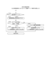
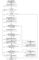
図2は、電力供給経路の例1を示す図である。
図1では図示を省略したが、図2に示すように、スロットマシン10は、電源基板150を備えている。また、電源基板150には、蓄電用のコンデンサ151が搭載されており、払出制御基板100にも、蓄電用のコンデンサ106が搭載されている。
さらにまた、電源基板150とメイン制御基板50とは、ハーネスA161で接続されており、このハーネスA161を通じて、電源基板150からメイン制御基板50に電力を供給可能とされている。
FIG. 2 is a diagram showing an example 1 of the power supply route.
Although not shown in FIG. 1, as shown in FIG. 2, the
Furthermore, the power supply board 150 and the
さらに、電源基板150と払出制御基板100とは、ハーネスC163で接続されており、このハーネスC163を通じて、電源基板150から払出制御基板100に電力を供給可能とされている。
電源基板150には、外部から交流で電力が供給される。そして、電源基板150で交流を直流に変換して、メイン制御基板50及び払出制御基板100に電力を供給する。
また、メイン制御基板50と払出制御基板100とは、ハーネスB162で接続されており、このハーネスB162を通して、メイン制御基板50から払出制御基板100に、又は払出制御基板100からメイン制御基板50に、電力を供給可能とされている。
Further, the power supply board 150 and the payout control board 100 are connected by a harness C163, and power can be supplied from the power supply board 150 to the payout control board 100 through the harness C163.
AC power is supplied to the power supply board 150 from the outside. Then, the power supply board 150 converts the alternating current into direct current, and supplies power to the
Further, the
さらにまた、メイン制御基板50と払出制御基板100とは、ハーネスD164で接続されており、このハーネスD164を通して、メイン制御基板50と払出制御基板100との間で双方向でコマンドの通信が可能とされている。
払出制御基板100は、電子メダルのクレジット数を管理する制御基板であり、その安定性は遊技者の利益に大きくかかわるため、電源基板150からハーネスC163を通じて払出制御基板100に直接電力を供給するようにしている。
Furthermore, the
The payout control board 100 is a control board that manages the number of credits of electronic medals, and its stability greatly affects the interests of the players. I have to.
また、ハーネスC163が切れてしまったときは、電源基板150から、ハーネスA161、メイン制御基板50、及びハーネスB162を介して、払出制御基板100に電力を供給可能とされている。
さらにまた、払出制御基板100には蓄電用のコンデンサ106が搭載されており、電源基板150からの電力供給が途絶えたときは、コンデンサ106から払出制御基板100に電力を供給可能とされている。
Further, when the harness C163 is cut off, power can be supplied from the power supply board 150 to the payout control board 100 via the harness A161, the
Furthermore, a capacitor 106 for storing electricity is mounted on the payout control board 100, and when power supply from the power supply board 150 is interrupted, power can be supplied from the capacitor 106 to the payout control board 100.
さらに、ハーネスA161及びハーネスC163が切れてしまったときは、コンデンサ106から払出制御基板100に電力を供給するとともに、ハーネスB162を通して、払出制御基板100からメイン制御基板50に電力を供給可能とされている。
このように、例1では、払出制御基板100にバックアップ電源用のコンデンサ106を搭載しており、ハーネスA161やハーネスC163の切断等により電源基板150からの電力供給が途絶えてしまったとしても、払出制御基板100やメイン制御基板50が駆動するようにし、電断時の処理を確実に実行できるようにして、遊技者に不利益を及ぼさないようにしている。
Furthermore, when the harness A161 and the harness C163 are cut, power can be supplied from the capacitor 106 to the payout control board 100, and power can also be supplied from the payout control board 100 to the
In this way, in Example 1, the payout control board 100 is equipped with a capacitor 106 for backup power supply, and even if the power supply from the power supply board 150 is cut off due to disconnection of harness A161 or harness C163, etc. The control board 100 and the
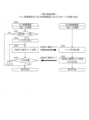
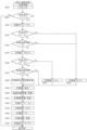
図3は、電力供給経路の例2を示す図である。
図3に示すように、例2では、電源基板150には、コンデンサが搭載されておらず、払出制御基板100には、蓄電用のコンデンサA107及びコンデンサB108が搭載されている。
また、電源基板150とメイン制御基板50とは、ハーネスE165で接続されており、このハーネスE165を通じて、電源基板150からメイン制御基板50に電力を供給可能とされている。
FIG. 3 is a diagram illustrating a second example of a power supply route.
As shown in FIG. 3, in Example 2, no capacitor is mounted on the power supply board 150, and a capacitor A107 and a capacitor B108 for power storage are mounted on the payout control board 100.
Further, the power supply board 150 and the
さらにまた、電源基板150と払出制御基板100とは、ハーネスG167で接続されており、このハーネスG167を通じて、電源基板150から払出制御基板100に電力を供給可能とされている。
さらに、メイン制御基板50と払出制御基板100とは、ハーネスF166で接続されており、このハーネスF166を通して、メイン制御基板50から払出制御基板100に、又は払出制御基板100からメイン制御基板50に、電力を供給可能とされている。
Furthermore, the power supply board 150 and the payout control board 100 are connected by a harness G167, and power can be supplied from the power supply board 150 to the payout control board 100 through the harness G167.
Furthermore, the
また、メイン制御基板50と払出制御基板100とは、ハーネスH168で接続されており、このハーネスH168を通して、メイン制御基板50と払出制御基板100との間で双方向でコマンドの通信が可能とされている。
そして、ハーネスG167が切れてしまったときは、電源基板150から、ハーネスE165、メイン制御基板50、及びハーネスF166を介して、払出制御基板100に電力を供給可能とされている。
Further, the
When the harness G167 is disconnected, power can be supplied from the power supply board 150 to the payout control board 100 via the harness E165, the
また、払出制御基板100には蓄電用のコンデンサA107及びコンデンサB108が搭載されており、電源基板150からの電力供給が途絶えたときは、コンデンサA107及びコンデンサB108から払出制御基板100に電力を供給可能とされている。
さらに、ハーネスE165及びハーネスG167が切れてしまったときは、コンデンサA107及びコンデンサB108から払出制御基板100に電力を供給するとともに、コンデンサA107からハーネスF166を通してメイン制御基板50に電力を供給可能とされている。
Further, the payout control board 100 is equipped with a capacitor A107 and a capacitor B108 for storing electricity, and when power supply from the power supply board 150 is interrupted, power can be supplied to the payout control board 100 from the capacitor A107 and capacitor B108. It is said that
Furthermore, when harness E165 and harness G167 are cut, power can be supplied from capacitor A107 and capacitor B108 to payout control board 100, and power can also be supplied from capacitor A107 to
例2においても、電源基板150からの電力供給が途絶えたときに、払出制御基板100に搭載されたバックアップ電源用のコンデンサから払出制御基板100及びメイン制御基板50に電力を供給することは、例1と同様である。
ただし、例2では、コンデンサB108を、払出制御基板100専用のバックアップ電源としている。これにより、ハーネスE165やハーネスG167の切断等により電源基板150からの電力供給が途絶えてしまったとしても、電子メダルのクレジット数を管理する払出制御基板100が確実に駆動するようにし、電断時の処理を確実に実行できるようにして、遊技者に不利益を及ぼさないようにしている。
Also in Example 2, when the power supply from the power supply board 150 is interrupted, power is supplied to the payout control board 100 and the
However, in Example 2, the capacitor B108 is used as a backup power source exclusively for the payout control board 100. As a result, even if the power supply from the power supply board 150 is cut off due to disconnection of harness E165 or harness G167, etc., the payout control board 100 that manages the number of credits of electronic medals is reliably driven, and when the power is cut off, This ensures that the processing can be executed reliably, so as not to put the player at a disadvantage.
なお、例2では、コンデンサB108の電気容量を、コンデンサA107の電気容量より大きく設定することが好ましい。これにより、遊技者の利益に大きくかかわる払出制御基板100に対してバックアップの電力を確実に供給し、電断時の処理を確実に実行できるようにすることができる。
また、本実施形態では、電源断時には、メイン制御基板50上のプログラムより先に払出制御基板100上のプログラムが停止するように設定されている。
さらに、本実施形態では、電源断からの復帰時には、メイン制御基板50上のプログラムより先に払出制御基板100上のプログラムが起動するように設定されている。
Note that in Example 2, it is preferable to set the capacitance of capacitor B108 to be larger than the capacitance of capacitor A107. This makes it possible to reliably supply backup power to the payout control board 100, which has a large impact on the player's profits, and to reliably execute processing in the event of a power outage.
Further, in this embodiment, when the power is turned off, the program on the payout control board 100 is set to stop before the program on the
Furthermore, in this embodiment, when the power is restored from a power-off, the program on the payout control board 100 is set to start before the program on the
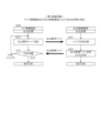
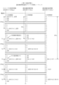
図4~図7は、コマンド一覧を示す図である。
図4は、メイン制御基板50から払出制御基板100に送信されるコマンドの一覧を示す図であり、図5は、払出制御基板100からメイン制御基板50に送信されるコマンドの一覧を示す図である。
また、図6は、管理装置200から払出制御基板100に送信されるコマンドの一覧を示す図であり、図7は、払出制御基板100から管理装置200に送信されるコマンドの一覧を示す図である。
4 to 7 are diagrams showing command lists.
FIG. 4 is a diagram showing a list of commands sent from the
6 is a diagram showing a list of commands sent from the management device 200 to the payout control board 100, and FIG. 7 is a diagram showing a list of commands sent from the payout control board 100 to the management device 200. be.
ここで、メイン制御基板50から払出制御基板100に送信されるコマンドを総称して「メイン制御コマンド」という。
また、払出制御基板100からメイン制御基板50に送信されるコマンドを総称して「払出制御コマンド」という。
さらにまた、払出制御基板100から管理装置200に送信されるコマンドを総称して「遊技機コマンド」という。
さらに、管理装置200から払出制御基板100に送信されるコマンドを総称して「管理装置コマンド」という。
Here, the commands sent from the
Further, commands sent from the payout control board 100 to the
Furthermore, the commands sent from the payout control board 100 to the management device 200 are collectively referred to as "gaming machine commands."
Furthermore, commands sent from the management device 200 to the payout control board 100 are collectively referred to as "management device commands."
本実施形態では、メイン制御コマンド、払出制御コマンド、遊技機コマンド、管理装置コマンドは、いずれも、16ビット(2バイト)のデータで構成されている。
また、メイン制御コマンド、払出制御コマンド、遊技機コマンド、管理装置コマンドは、いずれも、先行コマンド(上位8ビット)及び後続コマンド(下位8ビット)から構成されている。
すなわち、先行コマンド及び後続コマンドからなる16ビット(2バイト)のデータで1つのメイン制御コマンド、払出制御コマンド、遊技機コマンド、管理装置コマンドが構成されている。
また、先行コマンドは、コマンドの種別を示すデータであり、後続コマンドは、パラメータ(変数)を示すデータである。
そして、本実施形態では、メイン制御基板50と払出制御基板100との間、及び払出制御基板100と管理装置200との間では、シリアル通信でコマンドの送受信を行う。
In this embodiment, the main control command, payout control command, gaming machine command, and management device command are all composed of 16 bits (2 bytes) of data.
Further, the main control command, payout control command, gaming machine command, and management device command are all composed of a preceding command (upper 8 bits) and a subsequent command (lower 8 bits).
That is, 16 bits (2 bytes) of data consisting of the preceding command and the succeeding command constitute one main control command, payout control command, gaming machine command, and management device command.
Further, the preceding command is data indicating the type of command, and the subsequent command is data indicating parameters (variables).
In this embodiment, commands are transmitted and received between the
図4~図7中、「先行」の欄のデータは、先行コマンド(上位8ビット)を示しており、「後続」の欄のデータは、後続コマンド(下位8ビット)を示している。また、先行コマンド及び後続コマンドは、いずれも、16進数で表している。
メイン制御コマンドとして、図4中の「内容」の欄に記載されている8種類のコマンドを挙げることができる。また、これら8種類のコマンドのうち、設定変更開始コマンド、設定変更終了コマンド、遊技開始+RT状態コマンド、遊技終了+遊技状態コマンドを総称して「遊技情報コマンド」と称する。さらにまた、投入要求コマンド、払出要求コマンド、返却要求コマンドを総称して「演算要求コマンド」と称する。
In FIGS. 4 to 7, the data in the "preceding" column indicates the preceding command (upper 8 bits), and the data in the "succeeding" column indicates the subsequent command (lower 8 bits). Further, both the preceding command and the succeeding command are expressed in hexadecimal numbers.
As main control commands, there are eight types of commands listed in the "Contents" column in FIG. Furthermore, among these eight types of commands, the setting change start command, setting change end command, game start + RT status command, and game end + game status command are collectively referred to as "gaming information commands." Furthermore, the input request command, the payout request command, and the return request command are collectively referred to as the "calculation request command."
払出制御コマンドとして、図5中の「内容」の欄に記載されている12種類のコマンドを挙げることができる。また、投入要求コマンドのACK応答は「投入復唱コマンド」とも称し、投入要求コマンドのNAK応答は「投入不可コマンド」とも称する。同様に、払出要求コマンドのACK応答、同NAK応答、返却要求コマンドのACK応答、同NAK応答は、それぞれ「払出復唱コマンド」、「払出不可コマンド」、「返却復唱コマンド」、「返却不可コマンド」とも称する。さらにまた、異常時のNAK応答は「エラーコマンド」とも称する。 As the payout control commands, there are 12 types of commands listed in the "Contents" column in FIG. 5. Further, an ACK response to an input request command is also referred to as an "input repeat command," and a NAK response to an input request command is also referred to as an "input impossible command." Similarly, the ACK response to the payout request command, the ACK response to the same NAK response, the ACK response to the return request command, and the same NAK response to the payout request command are respectively "payout repeat command", "payout not allowed command", "return not allowed command", and "return not allowed command". Also called. Furthermore, a NAK response at the time of an abnormality is also referred to as an "error command."
管理装置コマンドとして、図6中の「内容」の欄に記載されている5種類のコマンドを挙げることができる。また、下位計数要求コマンドのACK応答は「下位計数復唱コマンド」とも称し、上位計数要求コマンドのACK応答は「上位計数復唱コマンド」とも称する。
遊技機コマンドとして、図7中の「内容」の欄に記載されている13種類のコマンドを挙げることができる。また、貸出要求コマンドのACK応答は「貸出復唱コマンド」とも称する。
As management device commands, there are five types of commands listed in the "Contents" column in FIG. Further, the ACK response to the lower count request command is also referred to as the "lower count repeat command", and the ACK response to the upper count request command is also referred to as the "upper count repeat command".
As gaming machine commands, there are 13 types of commands listed in the "Contents" column in FIG. Further, the ACK response to the lending request command is also referred to as a "renting repeat command."
図4中、起動確認コマンドは、メイン制御基板50と払出制御基板100との間の通信が正常であるか否かをメイン制御基板50側で確認するためのコマンドであって、電源投入時にメイン制御基板50から払出制御基板100に対して送信されるコマンドである。
メイン制御基板50は、電源投入時に、払出制御基板100に対し、起動確認コマンドを送信する。また、払出制御基板100は、起動確認コマンドを受信すると、これをそのままメイン制御基板50に送り返す(図5に示す起動確認コマンドのACK応答)。
そして、メイン制御基板50側では、送信した起動確認コマンドがそのまま払出制御基板100から送り返されることにより、メイン制御基板50と払出制御基板100との間の通信が正常であると判断することができる。
In FIG. 4, the startup confirmation command is a command for checking on the
The
Then, on the
また、上述したように、電源断時には、メイン制御基板50上のプログラムより先に払出制御基板100上のプログラムが停止し、電源断からの復帰時には、メイン制御基板50上のプログラムより先に払出制御基板100上のプログラムが起動する。
ここで、電源投入時、すなわち、電源断からの復帰時には、メイン制御基板50から払出制御基板100に対し起動確認コマンドを送信するが、払出制御基板100上のプログラムの方が先に起動するため、起動確認コマンドを確実に受信することができる。そして、メイン制御基板50は、送信した起動確認コマンドがそのまま払出制御基板100から送り返されることにより、メイン制御基板50と払出制御基板100との間の通信が正常であると判断すると、その後の処理を進めるように設定されている。
Furthermore, as described above, when the power is turned off, the program on the payout control board 100 is stopped before the program on the
Here, when the power is turned on, that is, when returning from a power-off, a startup confirmation command is sent from the
図4中、設定変更開始コマンドは、設定変更モードに移行したことを払出制御基板100側に伝達するためのコマンドであって、設定変更モードへの移行時にメイン制御基板50から払出制御基板100に対して送信されるコマンドである。また、後続の「01H」は、設定キースイッチ12がオン状態であることを示している。
メイン制御基板50は、設定変更モードへの移行時に、払出制御基板100に対し、設定変更開始コマンドを送信する。また、払出制御基板100は、設定変更開始コマンドを受信すると、これをそのままメイン制御基板50に送り返し(図5に示す設定変更開始コマンドのACK応答)、さらに、管理装置200に対しても設定変更開始コマンドを送信する(図7)。すなわち、払出制御基板100は、メイン制御基板50及び管理装置200の双方に設定変更開始コマンドを送信する。
In FIG. 4, the setting change start command is a command for transmitting to the payout control board 100 side that the setting change mode has been entered. This is the command sent to. Furthermore, the following "01H" indicates that the setting
The
これにより、払出制御基板100側では、設定変更モードに移行したと判断することができる。また、メイン制御基板50側では、送信した設定変更開始コマンドがそのまま払出制御基板100から送り返されることにより、設定変更モードへの移行を払出制御基板100に伝達できたと判断することができる。さらに、管理装置200側でも、設定変更モードに移行したと判断することができる。
Thereby, the payout control board 100 side can determine that the setting change mode has been entered. Further, on the
図4中、設定変更終了コマンドは、設定変更モードが終了したことを払出制御基板100側に伝達するためのコマンドであって、設定変更モードの終了時にメイン制御基板50から払出制御基板100に対して送信されるコマンドである。また、後続の「00H」は、設定キースイッチ12がオフ状態であることを示している。
メイン制御基板50は、設定変更モードの終了時に、払出制御基板100に対し、設定変更終了コマンドを送信する。また、払出制御基板100は、設定変更終了コマンドを受信すると、これをそのままメイン制御基板50に送り返し(図5に示す設定変更終了コマンドのACK応答)、さらに、管理装置200に対しても設定変更終了コマンドを送信する(図7)。すなわち、払出制御基板100は、メイン制御基板50及び管理装置200の双方に設定変更終了コマンドを送信する。
In FIG. 4, the setting change end command is a command for transmitting to the payout control board 100 side that the setting change mode has ended, and is sent from the
The
これにより、払出制御基板100側では、設定変更モードが終了したと判断することができる。また、メイン制御基板50側では、送信した設定変更終了コマンドがそのまま払出制御基板100から送り返されることにより、設定変更モードの終了を払出制御基板100に伝達できたと判断することができる。さらに、管理装置200側でも、設定変更モードが終了したと判断することができる。
Thereby, the payout control board 100 side can determine that the setting change mode has ended. Further, on the
図4中、遊技開始+RT状態コマンドは、遊技が開始したこと及びRT状態を払出制御基板100側に伝達するためのコマンドであって、スタートスイッチ41のオン時にメイン制御基板50から払出制御基板100に送信されるコマンドである。
メイン制御基板50は、スタートスイッチ41のオン時に、払出制御基板100に対し、遊技開始+RT状態コマンドを送信する。また、払出制御基板100は、遊技開始+RT状態コマンドを受信すると、これをそのままメイン制御基板50に送り返し(図5に示す遊技開始+RT状態コマンドのACK応答)、さらに、管理装置200に対しても遊技開始+RT状態コマンドを送信する(図7)。すなわち、払出制御基板100は、メイン制御基板50及び管理装置200の双方に遊技開始+RT状態コマンドを送信する。
In FIG. 4, the game start + RT state command is a command for transmitting the start of the game and the RT state to the payout control board 100 side, and is sent from the
The
これにより、払出制御基板100側では、遊技が開始したこと、及びRT状態を判断することができる。また、メイン制御基板50側では、送信した遊技開始+RT状態コマンドがそのまま払出制御基板100から送り返されることにより、遊技開始及びRT状態を払出制御基板100に伝達できたと判断することができる。さらに、管理装置200側でも、遊技が開始したこと、及びRT状態を判断することができる。
Thereby, on the payout control board 100 side, it is possible to determine that the game has started and the RT state. Further, on the
図4中、遊技終了+遊技状態コマンドは、遊技が終了したこと及び遊技状態を払出制御基板100側に伝達するためのコマンドであって、第3ストップスイッチ42(最後に停止するリール31に対応するストップスイッチ42)がオンからオフになった時にメイン制御基板50から払出制御基板100に送信されるコマンドである。
メイン制御基板50は、第3ストップスイッチ42がオンからオフになった(遊技者が第3ストップスイッチ42から手を離した)時に、払出制御基板100に対し、遊技終了+遊技状態コマンドを送信する。また、払出制御基板100は、遊技終了+遊技状態コマンドを受信すると、これをそのままメイン制御基板50に送り返し(図5に示す遊技終了+遊技状態コマンドのACK応答)、さらに、管理装置200に対しても遊技終了+遊技状態コマンドを送信する(図7)。すなわち、払出制御基板100は、メイン制御基板50及び管理装置200の双方に遊技終了+遊技状態コマンドを送信する。
In FIG. 4, the game end + game state command is a command for transmitting the end of the game and the game state to the payout control board 100, and corresponds to the third stop switch 42 (corresponding to the reel 31 that stops last) This is a command sent from the
The
これにより、払出制御基板100側では、遊技が終了したこと、及び遊技状態を判断することができる。また、メイン制御基板50側では、送信した遊技終了+遊技状態コマンドがそのまま払出制御基板100から送り返されることにより、遊技終了及び遊技状態を払出制御基板100に伝達できたと判断することができる。さらに、管理装置200側でも、遊技が終了したこと、及び遊技状態を判断することができる。
Thereby, on the payout control board 100 side, it is possible to determine that the game has ended and the game status. In addition, on the
図4中、投入要求コマンドは、ベット数をクレジット数から減算することを払出制御基板100に要求するコマンドであって、ベットスイッチ40のオン時にメイン制御基板50から払出制御基板100に送信されるコマンドである。
また、投入要求コマンドの後続コマンドは、ベット数(ベットスイッチ40の操作に基づきクレジット数から減算することを要求する数)を示す。
In FIG. 4, the input request command is a command that requests the payout control board 100 to subtract the number of bets from the number of credits, and is sent from the
Further, a command subsequent to the input request command indicates the number of bets (the number requested to be subtracted from the number of credits based on the operation of the bet switch 40).
本実施形態では、メイン制御基板50は、1ベットスイッチ40aのオン時に、払出制御基板100に対し、投入要求コマンドとして、クレジット数からベット数「1」を減算することを要求する「2001H」(1枚投入要求コマンド)を送信する。
また、メイン制御基板50は、3ベットスイッチ40bのオン時に、払出制御基板100に対し、投入要求コマンドとして、クレジット数からベット数「3」を減算することを要求する「2003H」(3枚投入要求コマンド)を送信する。
なお、3ベットスイッチ40bのオン時に、払出制御基板100に対し、投入要求コマンドとして、1枚投入要求コマンドを3回送信してもよい。
In the present embodiment, when the 1-bet switch 40a is turned on, the
Furthermore, when the 3 bet switch 40b is turned on, the
Incidentally, when the 3-bet switch 40b is turned on, the one-sheet insertion request command may be sent to the payout control board 100 three times as the insertion request command.
また、払出制御基板100は、投入要求コマンドを受信すると、投入要求を受付け可能であるか否か、具体的には、クレジット数がベット数(投入要求コマンドの後続コマンドが示す数)以上であるか否かを判断する。
そして、投入要求を受付け可能であると判断したとき、すなわち、クレジット数がベット数以上であると判断したときは、払出制御基板100は、クレジット数からベット数を減算する処理を実行し、クレジット数表示LED76の表示を更新する処理を実行し、投入復唱コマンドをメイン制御基板50に送信する(受信した投入要求コマンドをそのままメイン制御基板50に送り返す(図5に示す投入要求コマンドのACK応答))。
Further, upon receiving the input request command, the payout control board 100 determines whether or not the input request can be accepted, specifically, if the number of credits is greater than or equal to the number of bets (the number indicated by the subsequent command of the input request command). Determine whether or not.
Then, when it is determined that the input request can be accepted, that is, when it is determined that the number of credits is greater than or equal to the number of bets, the payout control board 100 executes a process of subtracting the number of bets from the number of credits, and Executes the process of updating the display of the number display LED 76, and sends the input repeat command to the main control board 50 (sends the received input request command as is to the main control board 50 (ACK response to input request command shown in FIG. 5) ).
たとえば、クレジット数が「50」のときに、3枚投入要求コマンド「2003H」を受信すると、払出制御基板100は、クレジット数「50」から、3枚投入要求コマンド「2003H」の後続コマンドが示すベット数「3」を減算する処理を実行し、クレジット数表示LED76の表示を「50」から「47」に変更し、投入復唱コマンドをメイン制御基板50に送信する。
これに対し、投入要求を受付け不可であると判断したとき、すなわち、クレジット数がベット数未満であると判断した(たとえば、クレジット数が「2」の状況下で、3枚投入要求コマンド「2003H」を受信した)ときは、払出制御基板100は、クレジット数からベット数を減算する処理は実行せずに、投入不可コマンドをメイン制御基板50に送信する(図5に示す投入要求コマンドのNAK応答)。
For example, when the number of credits is "50" and the command "2003H" is received, the payout control board 100 receives the command "2003H" that requests the input of three coins from the number of credits "50", and the subsequent command of the request command "2003H" indicates that the number of credits is "50". A process of subtracting the number of bets "3" is executed, the display on the credit number display LED 76 is changed from "50" to "47", and an input repeat command is transmitted to the
On the other hand, when it is determined that the input request cannot be accepted, that is, it is determined that the number of credits is less than the number of bets (for example, when the number of credits is "2", the command "2003H ''), the payout control board 100 sends a disallowance command to the
さらに、投入復唱コマンドを受信した(送信した投入要求コマンドがそのまま払出制御基板100から送り返された)ときは、メイン制御基板50は、ベット数をクレジット数から減算する要求が許可されたと判断し、電子メダルのベットに応じた処理(たとえば、1ベット表示LED~3ベット表示LEDを点灯させる処理、及びスタートスイッチ41の操作を受付け可能にする処理)を実行する。
これに対し、投入不可コマンドを受信したときは、メイン制御基板50は、ベット数をクレジット数から減算する要求が許可されなかったと判断し、電子メダルのベットに応じた処理を実行しない。
また、投入要求コマンドを送信した後、所定時間を経過しても、投入復唱コマンド及び投入不可コマンドのいずれも受信しないと、タイムアウトとなり、メイン制御基板50は、払出制御基板100に対し、再度、投入要求コマンドを送信する。
Furthermore, when the input repeat command is received (the transmitted input request command is sent back as is from the payout control board 100), the
On the other hand, when receiving the input prohibition command, the
Further, if neither the input repeat command nor the input disable command is received even after a predetermined period of time has elapsed after transmitting the input request command, a timeout occurs and the
このように、クレジット数からベット数を減算することを払出制御基板100に要求するときは、メイン制御基板50と払出制御基板100との間で一往復のコマンド通信を行う。
これにより、電子メダルのベットに関する処理がメイン制御基板50及び払出制御基板100の双方で確実に実行され、クレジット数の管理が正確に行われるので、遊技者に不利益を与えないようにすることができる。
In this way, when requesting the payout control board 100 to subtract the number of bets from the number of credits, one round-trip command communication is performed between the
As a result, processing related to bets on electronic medals is reliably executed on both the
また、上述したように、電源断時には、メイン制御基板50上のプログラムより先に払出制御基板100上のプログラムが停止し、電源断からの復帰時には、メイン制御基板50上のプログラムより先に払出制御基板100上のプログラムが起動する。
さらにまた、メイン制御基板50は、ベットスイッチ40のオン時に、払出制御基板100に投入要求コマンドを送信し、払出制御基板100は、投入要求コマンドの受信時に、投入要求を受付け可能であれば、メイン制御基板50に投入復唱コマンドを送信し、投入要求を受付け不可であれば、メイン制御基板50に投入不可コマンドを送信する。
Furthermore, as described above, when the power is turned off, the program on the payout control board 100 is stopped before the program on the
Furthermore, when the bet switch 40 is turned on, the
さらに、メイン制御基板50は、投入復唱コマンドを受信したときは、電子メダルのベットに応じた処理を実行し、投入不可コマンドを受信したときは、電子メダルのベットに応じた処理を実行せず、投入復唱コマンド及び投入不可コマンドのいずれも受信しないと、払出制御基板100に対し、再度、投入要求コマンドを送信する。
ここで、メイン制御基板50が払出制御基板100に投入要求コマンドを送信した後、払出制御基板100が投入要求コマンドを受信する前に、電源断が発生し、払出制御基板100上のプログラムが停止したとする。この場合、メイン制御基板50は、投入復唱コマンド及び投入不可コマンドのいずれも受信しないことになり、電源断からの復帰後に、払出制御基板100に対し、再度、投入要求コマンドを送信することになるため、メイン制御基板50と払出制御基板100との間で確実にコマンドを送受信できる。
Furthermore, when the
Here, after the
また、メイン制御基板50が払出制御基板100に投入要求コマンドを送信し、払出制御基板100が投入要求コマンドを受信したが、メイン制御基板50に投入復唱コマンド又は投入不可コマンドを送信する前に、電源断が発生し、払出制御基板100上のプログラムが停止したとする。この場合、電源断からの復帰後に、払出制御基板100は、メイン制御基板50に対し、投入復唱コマンド又は投入不可コマンドを送信するので、メイン制御基板50と払出制御基板100との間で確実にコマンドを送受信できる。
Further, the
なお、電源投入時、すなわち、電源断からの復帰時には、メイン制御基板50は、払出制御基板100に、起動確認コマンドを送信し、払出制御基板100は、起動確認コマンドを受信すると、これをそのままメイン制御基板50に送り返す。そして、メイン制御基板50は、送信した起動確認コマンドがそのまま払出制御基板100から送り返されると、メイン制御基板50と払出制御基板100との間の通信が正常であると判断する。その後、払出制御基板100は、メイン制御基板50に、投入復唱コマンド又は投入不可コマンドを送信する。このため、電源断からの復帰時には、メイン制御基板50上のプログラムより先に払出制御基板100上のプログラムが起動するが、メイン制御基板50は、投入復唱コマンド又は投入不可コマンドを確実に受信することができる。
Note that when the power is turned on, that is, when returning from a power-off, the
また、メイン制御基板50が払出制御基板100に投入要求コマンドを送信し、払出制御基板100が投入要求コマンドを受信して、メイン制御基板50に投入復唱コマンド又は投入不可コマンドを送信した後に、電源断が発生し、払出制御基板100のプログラムが停止したとする。この場合、払出制御基板100上のプログラムが停止した後にメイン制御基板50上のプログラムが停止するため、メイン制御基板50は、払出制御基板100が送信した投入復唱コマンド又は投入不可コマンドを受信することができるので、メイン制御基板50と払出制御基板100との間で確実にコマンドを送受信できる。
In addition, after the
図4中、払出要求コマンドは、払出し枚数をクレジット数に加算することを払出制御基板100に要求するコマンドであって、第3ストップスイッチ42がオンからオフになった時にメイン制御基板50から払出制御基板100に送信されるコマンドである。
また、払出要求コマンドの後続コマンドは、払出し枚数(役の入賞に基づきクレジット数に加算することを要求する数)を示す。
In FIG. 4, the payout request command is a command that requests the payout control board 100 to add the number of payout coins to the number of credits. This is a command sent to the control board 100.
Further, a command subsequent to the payout request command indicates the number of coins to be paid out (the number requested to be added to the number of credits based on the winning combination).
たとえば、10枚役の入賞時には、メイン制御基板50は、第3ストップスイッチ42がオンからオフになった時に、払出制御基板100に対し、払出要求コマンドとして、クレジット数に払出し枚数「10」を加算することを要求する「210AH」を送信する。
なお、役の非入賞時にも、メイン制御基板50は、第3ストップスイッチ42がオンからオフになった時に、払出制御基板100に、払出要求コマンドを送信する。この場合、払出し枚数は「0」であるので、払出要求コマンドは「2100H」となる。
For example, when winning a 10-card winning combination, the
In addition, even when a winning combination is not won, the
また、払出制御基板100は、払出要求コマンドを受信すると、払出し要求を受付け可能であるか否か、具体的には、クレジット数に払出し枚数(払出要求コマンドの後続コマンドが示す数)を加算することによりクレジット数の上限値(本実施形態では「10000」)を超えるか否かを判断する。
そして、払出し要求を受付け可能であると判断したとき、すなわち、クレジット数に払出し枚数を加算してもクレジット数の上限値以下であると判断したときは、払出制御基板100は、クレジット数に払出し枚数を加算する処理を実行し、クレジット数表示LED76の表示を更新する処理を実行し、払出復唱コマンドをメイン制御基板50に送信する(受信した払出要求コマンドをそのままメイン制御基板50に送り返す(図5に示す払出要求コマンドのACK応答))。
Further, upon receiving the payout request command, the payout control board 100 determines whether the payout request can be accepted, specifically, adds the number of payout coins (the number indicated by the command subsequent to the payout request command) to the number of credits. Thus, it is determined whether the upper limit value of the number of credits (in this embodiment, "10000") is exceeded.
Then, when it is determined that the payout request can be accepted, that is, when it is determined that even if the number of payouts is added to the number of credits, it is less than the upper limit value of the number of credits, the payout control board 100 adds the number of credits to the number of payouts. It executes the process of adding up the number of credits, executes the process of updating the display of the credit number display LED 76, and sends a payout repeat command to the main control board 50 (the received payout request command is sent back to the
たとえば、クレジット数が「50」のときに、払出要求コマンド「210AH」(10枚払出し)を受信すると、払出制御基板100は、クレジット数「50」に、払出要求コマンド「210AH」の後続コマンドが示す払出し枚数「10」を加算する処理を実行し、クレジット数表示LEDの表示を「50」から「60」に変更し、払出復唱コマンドをメイン制御基板50に送信する。
For example, when the number of credits is "50" and a payout request command "210AH" (payout of 10 coins) is received, the payout control board 100 sets the number of credits to "50" and the subsequent command of the payout request command "210AH" is A process of adding the payout number "10" shown is executed, the display of the credit number display LED is changed from "50" to "60", and a payout repeat command is transmitted to the
これに対し、払出し要求を受付け不可であると判断したとき、すなわち、クレジット数に払出し枚数を加算するとクレジット数の上限値を超えると判断した(たとえば、クレジット数が「9995」の状況下で、払出要求コマンド「210AH」(10枚払出し)を受信した)ときは、払出制御基板100は、クレジット数に払出し枚数を加算する処理を実行せずに、払出不可コマンドをメイン制御基板50に送信する(図5に示す払出要求コマンドのNAK応答)。
On the other hand, when it is determined that the payout request cannot be accepted, that is, it is determined that adding the payout number to the number of credits exceeds the upper limit of the number of credits (for example, in a situation where the number of credits is "9995", When the payout request command "210AH" (payout of 10 coins) is received, the payout control board 100 sends a payout prohibition command to the
さらに、払出復唱コマンドを受信した(送信した払出要求コマンドがそのまま払出制御基板100から送り返された)ときは、メイン制御基板50は、払出し枚数をクレジット数に加算することの要求が許可されたと判断し、役の入賞に基づく電子メダルの払出しに応じた処理(たとえば、獲得数表示LED78に電子メダルの払出し枚数を表示する処理)を実行する。
これに対し、払出不可コマンドを受信したときは、メイン制御基板50は、払出し枚数をクレジット数に加算することの要求が許可されなかったと判断し、役の入賞に基づく電子メダルの払出しに応じた処理を実行しない。
Furthermore, when the payout repeat command is received (the sent payout request command is sent back as is from the payout control board 100), the
On the other hand, when receiving the payout prohibition command, the
このように、入賞役に応じた払出し枚数をクレジット数に加算することを払出制御基板100に要求するときは、メイン制御基板50と払出制御基板100との間で一往復のコマンド通信を行う。
これにより、役の入賞に基づく電子メダルの払出しに関する処理がメイン制御基板50及び払出制御基板100の双方で確実に実行され、クレジット数の管理が正確に行われるので、遊技者に不利益を与えないようにすることができる。
In this way, when requesting the payout control board 100 to add the number of payout coins corresponding to the winning combination to the number of credits, one round-trip command communication is performed between the
As a result, the processing related to the payout of electronic medals based on winning combinations is reliably executed on both the
図4中、返却要求コマンドは、ベットされた電子メダルをクレジットに戻すことを払出制御基板100に要求するコマンドであって、キャンセルスイッチ46のオン時にメイン制御基板50から払出制御基板100に送信されるコマンドである。
また、返却要求コマンドの後続コマンドは、返却枚数(電子メダルの返却に基づきクレジット数に加算することを要求する数)を示す。
たとえば、3枚の電子メダルがベットされた状態でキャンセルスイッチ46が操作されると、メイン制御基板50は、キャンセルスイッチ46のオン時に、払出制御基板100に対し、返却要求コマンドとして、クレジット数に返却枚数「3」を加算することを要求する「2203H」を送信する。
In FIG. 4, the return request command is a command that requests the payout control board 100 to return the betted electronic medals to credits, and is sent from the
Further, a command subsequent to the return request command indicates the number of returned medals (the number requested to be added to the number of credits based on the return of electronic medals).
For example, if the cancel switch 46 is operated with three electronic medals bet, the
また、払出制御基板100は、返却要求コマンドを受信すると、返却要求を受付け可能であるか否か、具体的には、クレジット数に返却枚数(返却要求コマンドの後続コマンドが示す数)を加算することによりクレジット数の上限値(本実施形態では「10000」)を超えるか否かを判断する。
そして、返却要求を受付け可能であると判断したとき、すなわち、クレジット数に返却枚数を加算してもクレジット数の上限値以下であると判断したときは、払出制御基板100は、クレジット数に返却枚数を加算する処理を実行し、クレジット数表示LED76の表示を更新する処理を実行し、返却復唱コマンドをメイン制御基板50に送信する(受信した返却要求コマンドをそのままメイン制御基板50に送り返す(図5に示す返却要求コマンドのACK応答))。
Further, upon receiving the return request command, the payout control board 100 determines whether the return request can be accepted or not, and specifically adds the number of returned tickets (the number indicated by the command subsequent to the return request command) to the number of credits. Thus, it is determined whether the upper limit of the number of credits (in this embodiment, "10000") is exceeded.
Then, when it is determined that the return request can be accepted, that is, when it is determined that even if the number of returned sheets is added to the number of credits, the number of credits to be returned is less than the upper limit value, the payout control board 100 returns the number of credits to the number of credits. It executes the process of adding up the number of credits, executes the process of updating the display of the credit number display LED 76, and sends a return repeat command to the main control board 50 (the received return request command is sent back to the
たとえば、クレジット数が「100」のときに、返却要求コマンド「2203H」を受信すると、払出制御基板100は、クレジット数「100」に、返却要求コマンド「2203H」の後続コマンドが示す返却枚数「3」を加算する処理を実行し、クレジット数表示LEDの表示を「100」から「103」に変更し、返却復唱コマンドをメイン制御基板50に送信する。
For example, when the number of credits is "100" and a return request command "2203H" is received, the payout control board 100 changes the number of credits to "100" and the number of return sheets "3" indicated by the subsequent command of the return request command "2203H". ”, the display on the credit number display LED is changed from “100” to “103”, and a return repeat command is sent to the
これに対し、返却要求を受付け不可であると判断したとき、すなわち、クレジット数に返却枚数を加算するとクレジット数の上限値を超えると判断した(たとえば、クレジット数が「9999」の状況下で、返却要求コマンド「2203H」を受信した(3枚の電子メダルの返却要求があった))ときは、払出制御基板100は、クレジット数に返却枚数を加算する処理を実行せずに、返却不可コマンドをメイン制御基板50に送信する(図5に示す返却要求コマンドのNAK応答)。 On the other hand, when it is determined that the return request cannot be accepted, that is, it is determined that adding the number of returned tickets to the number of credits exceeds the upper limit of the number of credits (for example, in a situation where the number of credits is "9999", When receiving the return request command "2203H" (there was a request for the return of three electronic medals), the payout control board 100 issues the non-returnable command without executing the process of adding the number of returned medals to the number of credits. is transmitted to the main control board 50 (NAK response to the return request command shown in FIG. 5).
さらに、返却復唱コマンドを受信した(送信した返却要求コマンドがそのまま払出制御基板100から送り返された)ときは、メイン制御基板50は、返却枚数をクレジット数に加算することの要求が許可されたと判断し、電子メダルの返却に応じた処理(たとえば、1ベット表示LED~3ベット表示LEDを消灯させる処理、及びスタートスイッチ41の操作を受付け不可にする処理)を実行する。
これに対し、返却不可コマンドを受信したときは、メイン制御基板50は、返却枚数をクレジット数に加算することの要求が許可されなかったと判断し、電子メダルの返却に応じた処理を実行しない。
Furthermore, when the return repeat command is received (the sent return request command is sent back as is from the payout control board 100), the
On the other hand, when receiving the non-returnable command, the
このように、ベットされた電子メダルをクレジットに戻すことを払出制御基板100に要求するときは、メイン制御基板50と払出制御基板100との間で一往復のコマンド通信を行う。
これにより、電子メダルの返却に関する処理がメイン制御基板50及び払出制御基板100の双方で確実に実行され、クレジット数の管理が正確に行われるので、遊技者に不利益を与えないようにすることができる。
In this manner, when requesting the payout control board 100 to return betted electronic medals to credits, one round trip command communication is performed between the
As a result, the processing related to the return of electronic medals is reliably executed on both the
図6中、貸出要求コマンドは、貸出し枚数をクレジット数に加算することを払出制御基板100に要求するコマンドであって、貸出スイッチ202のオン時に管理装置(CRユニット)200から払出制御基板100に送信されるコマンドである。
また、貸出要求コマンドの後続コマンドは、貸出し枚数(電子メダルの貸出しに基づきクレジット数に加算することを要求する数)を示す。
In FIG. 6, the lending request command is a command that requests the payout control board 100 to add the number of borrowed sheets to the number of credits, and is sent from the management device (CR unit) 200 to the payout control board 100 when the lending switch 202 is turned on. This is the command being sent.
Further, a command subsequent to the lending request command indicates the number of medals to be lent (the number requested to be added to the number of credits based on the lending of electronic medals).
たとえば、管理装置200の紙幣投入口201に千円札が投入されて、度数表示部204に度数「10」が表示された状況下で、貸出スイッチ202が操作されると、管理装置200は、貸出スイッチ202のオン時に、払出制御基板100に対し、貸出要求コマンドとして、クレジット数に貸出し枚数「50」を加算することを要求する「4032H」を送信する。 For example, if a thousand yen bill is inserted into the bill slot 201 of the management device 200 and the lending switch 202 is operated with the frequency “10” displayed on the frequency display section 204, the management device 200 will: When the lending switch 202 is turned on, "4032H" is sent to the payout control board 100 as a lending request command, requesting that the number of lending sheets "50" be added to the number of credits.
また、払出制御基板100は、貸出要求コマンドを受信すると、貸出し要求を受付け可能であるか否か、具体的には、クレジット数に貸出し枚数(貸出要求コマンドの後続コマンドが示す数)を加算することによりクレジット数の上限値(本実施形態では「10000」)を超えるか否かを判断する。
そして、貸出し要求を受付け可能であると判断したとき、すなわち、クレジット数に貸出し枚数を加算してもクレジット数の上限値以下であると判断したときは、払出制御基板100は、管理装置200に対し、貸出復唱コマンドを送信する(受信した貸出要求コマンドをそのまま管理装置200に送り返す(図7に示す貸出要求コマンドのACK応答))。
Further, upon receiving the lending request command, the dispensing control board 100 determines whether or not the lending request can be accepted, specifically, adding the number of lending sheets (the number indicated by the subsequent command of the lending request command) to the number of credits. Thus, it is determined whether the upper limit of the number of credits (in this embodiment, "10000") is exceeded.
When it is determined that the lending request can be accepted, that is, when it is determined that even if the number of lending sheets is added to the number of credits, the number of credits is less than the upper limit value, the dispensing control board 100 sends the management device 200 In response, a lending repeat command is transmitted (the received lending request command is sent back to the management device 200 as is (ACK response to the lending request command shown in FIG. 7)).
これに対し、貸出し要求を受付け不可であると判断したとき、すなわち、クレジット数に貸出し枚数を加算するとクレジット数の上限値を超えると判断した(たとえば、クレジット数が「9955」の状況下で、貸出要求コマンド「4032H」(貸出し枚数「50」)を受信した)ときは、払出制御基板100は、管理装置200に対し、エラーコマンド「E000H」を送信する(図7に示す異常時のNAK応答)。 On the other hand, when it is determined that the loan request cannot be accepted, that is, it is determined that adding the number of loans to the number of credits exceeds the upper limit of the number of credits (for example, in a situation where the number of credits is "9955", When receiving the lending request command "4032H" (the number of borrowed tickets "50"), the dispensing control board 100 transmits the error command "E000H" to the management device 200 (NAK response at the time of abnormality shown in FIG. 7). ).
また、貸出復唱コマンドを受信した(送信した貸出要求コマンドがそのまま払出制御基板100から送り返された)ときは、管理装置200は、払出制御基板100に対し、貸出し要求の実行を指示する貸出指示コマンドを送信し、さらに、貸出し枚数に応じて度数表示部204の表示を更新する処理を実行する。 Further, when receiving the lending repeat command (the transmitted lending request command is sent back as is from the dispensing control board 100), the management device 200 issues a lending instruction command to instruct the dispensing control board 100 to execute the lending request. , and further executes a process of updating the display on the frequency display section 204 according to the number of rental sheets.
たとえば、管理装置200から払出制御基板100に対して貸出要求コマンドとして「4032H」(貸出し枚数「50」)を送信し、その後、払出制御基板100から管理装置200に対して貸出復唱コマンドとして「4032H」(貸出要求コマンドのACK応答)を送信したときは、管理装置200は、払出制御基板100に対し、貸出指示コマンドとして、クレジット数に貸出し枚数「50」を加算することを指示する「4132H」を送信する。さらに、管理装置200は、度数表示部204に表示中の数値から、貸出し枚数「50」に応じた度数「10」を減算する処理を実行する。 For example, the management device 200 transmits "4032H" (the number of rented tickets "50") to the dispensing control board 100 as a lending request command, and then the dispensing control board 100 sends "4032H" as a lending repeat command to the management device 200. ” (ACK response to the lending request command), the management device 200 sends “4132H” to the dispensing control board 100 as a lending instruction command, instructing to add the number of loans “50” to the number of credits. Send. Furthermore, the management device 200 executes a process of subtracting the frequency "10" corresponding to the number of rental sheets "50" from the numerical value displayed on the frequency display section 204.
これに対し、エラーコマンドを受信したときは、管理装置200は、待機状態に戻るように制御する。
また、貸出指示コマンドを受信すると、払出制御基板100は、クレジット数に貸出し枚数を加算する処理を実行し、クレジット数表示LED76の表示を更新する処理を実行する。
たとえば、クレジット数が「50」のときに、貸出指示コマンド「4132H」(貸出し枚数「50」)を受信すると、払出制御基板100は、クレジット数「50」に、貸出指示コマンド「4132H」の後続コマンドが示す貸出し枚数「50」を加算する処理を実行し、クレジット数表示LEDの表示を「50」から「100」に変更する。
On the other hand, when receiving an error command, the management device 200 controls the device to return to the standby state.
Further, upon receiving the lending instruction command, the payout control board 100 executes a process of adding the number of loans to the number of credits, and executes a process of updating the display of the number of credits display LED 76.
For example, when the number of credits is "50" and the lending instruction command "4132H" (the number of loans "50") is received, the dispensing control board 100 changes the number of credits to "50" and the subsequent lending instruction command "4132H". The process of adding the loan number "50" indicated by the command is executed, and the display of the credit number display LED is changed from "50" to "100".
このように、管理装置200からスロットマシン10の払出制御基板100に電子メダルを貸し出すときは、管理装置200と払出制御基板100との間で一往復半のコマンド通信を行う。
これにより、電子メダルの貸出しに関する処理が管理装置200及び払出制御基板100の双方で確実に実行され、クレジット数の管理が正確に行われるので、遊技者に不利益を与えないようにすることができる。
In this manner, when lending electronic medals from the management device 200 to the payout control board 100 of the
As a result, the processing related to the lending of electronic medals is reliably executed by both the management device 200 and the payout control board 100, and the number of credits is managed accurately, so that it is possible to prevent disadvantages to the players. can.
図7中、下位計数要求コマンド及び上位計数要求コマンドは、電子メダルの払戻しを管理装置(CRユニット)200に要求するコマンドであって、計数スイッチ47のオン時に払出制御基板100から管理装置200に送信されるコマンドである。
また、下位計数要求コマンドの後続コマンドは、払戻し枚数(クレジット数)を16ビット(2バイト)で表したときの下位8ビットを示す。
さらにまた、上位計数要求コマンドの後続コマンドは、払戻し枚数(クレジット数)を16ビットで表したときの上位8ビットを示す。
すなわち、下位計数要求コマンドの後続コマンド、及び上位計数要求コマンドの後続コマンドから、払戻し枚数が特定される。
In FIG. 7, the lower counting request command and the upper counting request command are commands that request the management device (CR unit) 200 to refund electronic medals, and are sent from the payout control board 100 to the management device 200 when the counting switch 47 is turned on. This is the command being sent.
Further, a command subsequent to the lower order count request command indicates the lower 8 bits when the number of refunded coins (number of credits) is expressed in 16 bits (2 bytes).
Furthermore, the command subsequent to the upper count request command indicates the upper 8 bits when the number of refunded coins (number of credits) is expressed in 16 bits.
That is, the number of refunded coins is specified from the command subsequent to the lower-order count request command and the command subsequent to the upper-order count request command.
上述したように、本実施形態では、クレジット数の上限値は「10000(D)」に設定されている。また、クレジット数の上限値「10000(D)」は、2進数で表すと「10011100010000(B)」であり、16進数で表すと「2710(H)」である。このように、クレジット数の上限値「10000(D)」は、8ビット(1バイト)で表すことができない。このため、本実施形態では、下位計数要求コマンドの後続コマンド、及び上位計数要求コマンドの後続コマンドの16ビット(2バイト)で、払戻し枚数(クレジット数)を特定するようにしている。 As described above, in this embodiment, the upper limit value of the number of credits is set to "10000 (D)". Further, the upper limit value of the number of credits "10000 (D)" is "10011100010000 (B)" when expressed in binary, and "2710 (H)" when expressed in hexadecimal. In this way, the upper limit value of the number of credits "10000 (D)" cannot be expressed with 8 bits (1 byte). Therefore, in this embodiment, the number of refunded coins (number of credits) is specified using 16 bits (2 bytes) of the command subsequent to the lower count request command and the command subsequent to the upper count request command.
たとえば、払出制御基板100に1000枚の電子メダルがクレジットされている(クレジット数「1000(D)」の)状況下で、計数スイッチ47が操作されたとする。ここで、クレジット数「1000(D)」は、2進数で表すと「1111101000(B)」であり、16進数で表すと「03E8(H)」である。この場合、下位計数要求コマンドは、「50E8(H)」となり、上位計数要求コマンドは、「5103(H)」となる。そして、払出制御基板100は、計数スイッチ47のオン時に、管理装置200に対し、下位計数要求コマンドとして、「50E8(H)」を送信する。 For example, assume that the counting switch 47 is operated in a situation where 1000 electronic medals are credited to the payout control board 100 (the number of credits is "1000 (D)"). Here, the number of credits "1000 (D)" is "1111101000 (B)" when expressed in binary, and "03E8 (H)" when expressed in hexadecimal. In this case, the lower count request command becomes "50E8(H)" and the upper count request command becomes "5103(H)". Then, when the counting switch 47 is turned on, the payout control board 100 transmits "50E8(H)" to the management device 200 as a lower order counting request command.
また、下位計数要求コマンドを受信すると、管理装置200は、払戻し要求を受付け可能であるか否かを判断する。
そして、払戻し要求を受付け可能であると判断したときは、管理装置200は、払出制御基板100に対し、下位計数復唱コマンドを送信する(受信した下位計数要求コマンドをそのまま払出制御基板100に送り返す(図6に示す下位計数要求コマンドのACK応答))。
これに対し、払戻し要求を受付け不可であると判断したときは、管理装置200は、払出制御基板100に対し、エラーコマンド「E000H」を送信する(図6に示す異常時のNAK応答)。この場合、管理装置200は、待機状態に戻るように制御する。
Further, upon receiving the lower order count request command, the management device 200 determines whether a refund request can be accepted.
Then, when it is determined that the refund request can be accepted, the management device 200 transmits a lower-order count repeat command to the payout control board 100 (sends the received lower-order count request command as it is to the payout control board 100). ACK response to the lower count request command shown in FIG. 6)).
On the other hand, when it is determined that the refund request cannot be accepted, the management device 200 transmits an error command "E000H" to the payout control board 100 (NAK response at the time of abnormality shown in FIG. 6). In this case, the management device 200 controls the device to return to the standby state.
また、下位計数復唱コマンドを受信した(送信した下位計数要求コマンドがそのまま管理装置200から送り返された)ときは、払出制御基板100は、管理装置200に対し、上位計数要求コマンドとして、「5103(H)」を送信する。
これに対し、エラーコマンドを受信したときは、払出制御基板100は、上位計数要求コマンドを送信せずに、待機状態に戻るように制御する。
Further, when receiving the lower-order count repeat command (the transmitted lower-order count request command is sent back as is from the management device 200), the payout control board 100 sends the command “5103 (5103)” to the management device 200 as the upper-order count request command. H)” is sent.
On the other hand, when receiving the error command, the payout control board 100 controls the payout control board 100 to return to the standby state without transmitting the upper count request command.
また、上位計数要求コマンドを受信すると、管理装置200は、払出制御基板100に対し、上位計数復唱コマンドを送信する(受信した上位計数要求コマンドをそのまま払出制御基板100に送り返す(図6に示す上位計数要求コマンドのACK応答))。
さらにまた、上位計数復唱コマンドを受信した(送信した上位計数要求コマンドがそのまま管理装置200から送り返された)ときは、払出制御基板100は、管理装置200に対し、計数指示コマンドを送信し、さらに、クレジット数をクリアする(「0」にする)処理を実行し、クレジット数表示LED76の表示を更新する(「0」にする)処理を実行する。
Further, upon receiving the upper order counting request command, the management device 200 transmits an upper order counting replay command to the payout control board 100 (sends the received upper order counting request command as it is to the payout control board 100 (the upper order counting shown in FIG. 6). ACK response to counting request command)).
Furthermore, when receiving the upper-level counting repeat command (the transmitted upper-level counting request command is sent back as is from the management device 200), the payout control board 100 transmits a counting instruction command to the management device 200, and further , executes processing to clear the number of credits (set to "0"), and execute processing to update the display of the number of credits display LED 76 (set to "0").
さらに、計数指示コマンドを受信すると、管理装置200は、下位計数要求コマンド及び上位計数要求コマンドから特定される払戻し枚数を、管理装置200側で管理する電子メダルの枚数に反映させる処理を実行するように制御する。
その後、返却スイッチ203が操作されると、管理装置200は、計数スイッチ47の操作によりスロットマシン10(払出制御基板100)から管理装置200に戻された電子メダルの枚数、及び度数表示部204に表示された度数に相当する電子メダルの枚数を、電子データとしてカード(磁気カードやICカード等)に記憶し、そのカードをカードリーダライタ205の排出口から排出する。
Furthermore, upon receiving the counting instruction command, the management device 200 executes processing to reflect the number of refunded medals specified from the lower-order counting request command and the upper-order counting request command in the number of electronic medals managed on the management device 200 side. to control.
Thereafter, when the return switch 203 is operated, the management device 200 displays the number of electronic medals returned to the management device 200 from the slot machine 10 (payout control board 100) and the frequency display section 204 by operating the counting switch 47. The number of electronic medals corresponding to the displayed degree is stored in a card (magnetic card, IC card, etc.) as electronic data, and the card is ejected from the ejection port of the card reader/writer 205.
このように、スロットマシン10の払出制御基板100から管理装置200に電子メダルを払い戻すときは、払出制御基板100と管理装置200との間で一往復半のコマンド通信を行う。
これにより、電子メダルの払戻しに関する処理が払出制御基板100及び管理装置200の双方で確実に実行され、クレジット数の管理が正確に行われるので、遊技者に不利益を与えないようにすることができる。
In this way, when paying out electronic medals from the payout control board 100 of the
As a result, the processing related to the refund of electronic medals is reliably executed by both the payout control board 100 and the management device 200, and the number of credits is managed accurately, so that it is possible to prevent disadvantages to the players. can.
また、本実施形態では、クレジット数管理CPU105には、4バイトのデータからなる固有のIDが設定されている。そして、図7中、CPU固有ID1バイト目~4バイト目は、クレジット数管理CPU105に固有のIDの1バイト目~4バイト目を管理装置200に伝達するコマンドである。
払出制御基板100は、電源投入時に、管理装置200に対し、CPU固有ID1バイト目~4バイト目を順次送信する。
Further, in this embodiment, a unique ID consisting of 4-byte data is set in the credit number management CPU 105. In FIG. 7, the 1st to 4th bytes of the CPU unique ID are a command to transmit the 1st to 4th bytes of the ID unique to the credit number management CPU 105 to the management device 200.
When the payout control board 100 is powered on, it sequentially transmits the first to fourth bytes of the CPU unique ID to the management device 200.
また、管理装置200は、CPU固有ID1バイト目~4バイト目を受信すると、これらを所定の記憶領域に記憶(保存)し、かつこれらをホールコンピュータ300に順次送信する。
さらにまた、ホールコンピュータ300は、CPU固有ID1バイト目~4バイト目を受信すると、これらを所定の記憶領域に記憶(保存)する。
さらに、管理装置200及びホールコンピュータ300は、記憶したCPU固有ID1バイト目~4バイト目を履歴として残しておくことが可能とされている。
Furthermore, upon receiving the first to fourth bytes of the CPU unique ID, the management device 200 stores (save) them in a predetermined storage area, and sequentially transmits them to the
Furthermore, upon receiving the first to fourth bytes of the CPU unique ID, the
Furthermore, the management device 200 and the
たとえば、払出制御基板100が不正に交換されると、払出制御基板100に搭載されているクレジット数管理CPU105が変わるため、交換を境に、管理装置200及びホールコンピュータ300に記憶されているCPU固有ID1バイト目~4バイト目も変わることになる。
このため、管理装置200及びホールコンピュータ300に記憶されているCPU固有ID1バイト目~4バイト目が途中で変わっていないか否かをチェックすることにより、払出制御基板100が不正に交換されたか否かを判断することができる。
For example, if the payout control board 100 is illegally replaced, the credit number management CPU 105 installed in the payout control board 100 will change, so after the replacement, the CPU-specific information stored in the management device 200 and
Therefore, by checking whether the 1st to 4th bytes of the CPU unique ID stored in the management device 200 and the
図8は、払出制御基板100におけるメインルーチンの処理の流れを示すフローチャートである。
払出制御基板100のメインルーチンでは、ステップS101において入力ポート101にいずれかの信号が入力されると、次のステップS102に進み、払出制御基板100は、入力された信号が計数スイッチ47のオン信号であるか否かの判断処理を実行する。
ここで、計数スイッチ47のオン信号であると判断したときは、次のステップS103に進み、計数要求フラグをオンにする処理を実行する。そして、次のステップS104に進む。
これに対し、計数スイッチ47のオン信号でないと判断したときは、ステップS103をスキップして、ステップS104に進む。
FIG. 8 is a flowchart showing the flow of main routine processing in the payout control board 100.
In the main routine of the payout control board 100, when any signal is input to the input port 101 in step S101, the process advances to the next step S102, and the payout control board 100 determines that the input signal is the ON signal of the counting switch 47. A process for determining whether or not is executed is executed.
Here, if it is determined that the counting switch 47 is on, the process proceeds to the next step S103, and a process of turning on the counting request flag is executed. Then, the process advances to the next step S104.
On the other hand, if it is determined that the ON signal is not from the counting switch 47, step S103 is skipped and the process proceeds to step S104.
ステップS104では、払出制御基板100は、VL信号がオンであるか否かの判断処理を実行する。
ここで、管理装置(CRユニット)200から払出制御基板100にVL信号(直流18Vの信号)が供給されていれば、ステップS104では、VL信号はオンであると判断し、管理装置200と払出制御基板100とが正常に接続されていると判断して、ステップS105に進み、VLエラーフラグをクリアする処理を実行する。そして、ステップS107に進む。
これに対し、管理装置200から払出制御基板100にVL信号が供給されていなければ、ステップS104では、VL信号はオフであると判断し、管理装置200と払出制御基板100とが正常に接続されていないと判断して、ステップS106に進み、VLエラーフラグをセットする処理を実行する。そして、ステップS107に進む。
In step S104, the payout control board 100 executes a process of determining whether the VL signal is on.
Here, if the VL signal (DC 18V signal) is supplied from the management device (CR unit) 200 to the payout control board 100, in step S104, it is determined that the VL signal is on, and the management device 200 and the payout It is determined that the connection with the control board 100 is normal, and the process proceeds to step S105, where a process of clearing the VL error flag is executed. Then, the process advances to step S107.
On the other hand, if the VL signal is not supplied from the management device 200 to the payout control board 100, it is determined in step S104 that the VL signal is off, and the management device 200 and the payout control board 100 are normally connected. It is determined that the VL error flag is not set, and the process proceeds to step S106, where a process of setting a VL error flag is executed. Then, the process advances to step S107.
ステップS107では、払出制御基板100は、入力ポート101に入力された(受信した)信号がメイン制御コマンドであるか否かの判断処理を実行する。
ここで、入力された信号がメイン制御コマンドであると判断したときは、次のステップS108に進み、払出制御基板100は、入力されたメイン制御コマンドをRWM103の所定の記憶領域に記憶(保存)する。そして、次のステップS109に進む。
これに対し、入力された信号がメイン制御コマンドでないと判断したときは、ステップS108をスキップして、ステップS109に進む。
In step S107, the payout control board 100 executes a process of determining whether the signal input (received) to the input port 101 is a main control command.
Here, when it is determined that the input signal is a main control command, the process advances to the next step S108, and the payout control board 100 stores (saves) the input main control command in a predetermined storage area of the RWM 103. do. Then, the process advances to the next step S109.
On the other hand, if it is determined that the input signal is not a main control command, step S108 is skipped and the process proceeds to step S109.
ステップS109では、払出制御基板100は、記憶したコマンドがメイン制御コマンドであるか否かの判断処理を実行する。
ここで、記憶したコマンドがメイン制御コマンドであると判断したときは、次のステップS110に進み、払出制御基板100は、メイン制御コマンド解析処理(図9及び図10)を実行する。メイン制御コマンド解析処理の詳細は後述する。そして、メイン制御コマンド解析処理を実行すると、次のステップS111に進む。
In step S109, the payout control board 100 executes a process of determining whether the stored command is a main control command.
Here, when it is determined that the stored command is the main control command, the process proceeds to the next step S110, and the payout control board 100 executes the main control command analysis process (FIGS. 9 and 10). Details of the main control command analysis process will be described later. After executing the main control command analysis process, the process advances to the next step S111.
ステップS111では、払出制御基板100は、計数処理(図12)を実行中であるか否かの判断処理を実行する。
ここで、計数処理は、後述するステップS116で「Yes」となったときに開始される処理であり、その詳細については後述する。また、計数処理を実行中に、この計数処理と並行して、払出制御基板100のメインルーチンを実行可能とされている。このため、払出制御基板100のメインルーチンのステップS111において、計数処理を実行中であるか否かの判断処理を実行する。
なお、計数処理の開始時に、計数処理中フラグをセットし、計数処理の終了時に、計数処理中フラグをクリアする。これにより、計数処理中フラグのオン/オフをチェックすることで、計数処理を実行中であるか否かを判断することができる。
In step S111, the payout control board 100 executes a process of determining whether the counting process (FIG. 12) is being executed.
Here, the counting process is a process that is started when the answer is "Yes" in step S116, which will be described later, and its details will be described later. Furthermore, while the counting process is being executed, the main routine of the payout control board 100 can be executed in parallel with this counting process. Therefore, in step S111 of the main routine of the payout control board 100, a process of determining whether or not counting process is being executed is executed.
Note that at the start of the counting process, the counting process flag is set, and at the end of the counting process, the counting process flag is cleared. This makes it possible to determine whether or not the counting process is being executed by checking whether the counting process flag is on or off.
そして、ステップS111において、計数処理を実行中であると判断したときは、ステップS113以降の処理を実行することなく、本フローチャートによる処理を終了する。
なお、ステップS111において、計数処理を実行中であると判断したときは、その後、実行中の計数処理を続ける。
これに対し、ステップS111において、計数処理を実行中でないと判断したときは、ステップS113に進み、払出制御基板100は、貸出処理(図11)を実行中であるか否かの判断処理を実行する。
Then, in step S111, when it is determined that the counting process is being executed, the process according to this flowchart is ended without executing the processes after step S113.
Note that when it is determined in step S111 that the counting process is being executed, the counting process that is being executed is continued thereafter.
On the other hand, when it is determined in step S111 that the counting process is not being executed, the process proceeds to step S113, and the dispensing control board 100 executes the process of determining whether or not the lending process (FIG. 11) is being executed. do.
ここで、貸出処理は、後述するステップS118で「Yes」となったときに開始される処理であり、その詳細については後述する。また、貸出処理を実行中に、この貸出処理と並行して、払出制御基板100のメインルーチンを実行可能とされている。このため、払出制御基板100のメインルーチンのステップS113において、貸出処理を実行中であるか否かの判断処理を実行する。
なお、貸出処理の開始時に、貸出処理中フラグをセットし、貸出処理の終了時に、貸出処理中フラグをクリアする。これにより、貸出処理中フラグのオン/オフをチェックすることで、貸出処理を実行中であるか否かを判断することができる。
Here, the lending process is a process that is started when the answer is "Yes" in step S118, which will be described later, and the details thereof will be described later. Furthermore, while the lending process is being executed, the main routine of the payout control board 100 can be executed in parallel with the lending process. Therefore, in step S113 of the main routine of the payout control board 100, a judgment process is performed to determine whether or not the lending process is being executed.
Note that at the start of the lending process, the lending process flag is set, and at the end of the lending process, the lending process flag is cleared. Thereby, by checking whether the lending process flag is on or off, it is possible to determine whether or not the lending process is being executed.
そして、ステップS113において、貸出処理を実行中であると判断したときは、ステップS115以降の処理を実行することなく、本フローチャートによる処理を終了する。
なお、ステップS113において、貸出処理を実行中であると判断したときは、その後、実行中の貸出処理を続ける。
これに対し、ステップS113において、貸出処理を実行中でないと判断したときは、ステップS115に進み、払出制御基板100は、遊技機コマンドを送信中であるか否かの判断処理を実行する。
Then, in step S113, when it is determined that the lending process is being executed, the process according to this flowchart is ended without executing the processes after step S115.
Note that when it is determined in step S113 that the lending process is being executed, the lending process that is currently being executed is continued.
On the other hand, when it is determined in step S113 that the lending process is not being executed, the process proceeds to step S115, and the payout control board 100 executes a process of determining whether or not a gaming machine command is being transmitted.
ここで、遊技機コマンド送信処理は、後述するステップS118で「No」となったときに実行される処理である。また、遊技機コマンド送信処理を実行中に、この遊技機コマンド送信処理と並行して、払出制御基板100のメインルーチンを実行可能とされている。このため、払出制御基板100のメインルーチンのステップS115において、遊技機コマンド送信処理を実行中であるか否かの判断処理を実行する。
そして、ステップS115において、遊技機コマンド送信処理を実行中であると判断したときは、ステップS116以降の処理を実行することなく、本フローチャートによる処理を終了する。
これに対し、ステップS115において、遊技機コマンド送信処理を実行中でないと判断したときは、ステップS116に進み、払出制御基板100は、計数要求フラグがオンであるか否かの判断処理を実行する。
Here, the gaming machine command transmission process is a process that is executed when the answer is "No" in step S118, which will be described later. Furthermore, while the gaming machine command sending process is being executed, the main routine of the payout control board 100 can be executed in parallel with the gaming machine command sending process. Therefore, in step S115 of the main routine of the payout control board 100, a process of determining whether or not the gaming machine command transmission process is being executed is executed.
Then, in step S115, when it is determined that the gaming machine command transmission process is being executed, the process according to this flowchart is ended without executing the process from step S116 onwards.
On the other hand, when it is determined in step S115 that the gaming machine command transmission process is not being executed, the process proceeds to step S116, and the payout control board 100 executes a process to determine whether or not the counting request flag is on. .
また、ステップS116において計数要求フラグがオンであると判断したときは、ステップS117に進み、払出制御基板100は、計数処理(図12)を開始する。そして、本フローチャートによる処理を終了する。
これに対し、ステップS116において計数要求フラグがオフであると判断したときは、ステップS118に進み、払出制御基板100は、入力ポート101に入力された(受信した)信号が貸出要求コマンドであるか否かの判断処理を実行する。
Further, when it is determined in step S116 that the counting request flag is on, the process proceeds to step S117, and the payout control board 100 starts counting processing (FIG. 12). Then, the processing according to this flowchart ends.
On the other hand, when it is determined in step S116 that the counting request flag is off, the process proceeds to step S118, and the dispensing control board 100 determines whether the signal input (received) to the input port 101 is a lending request command. Executes a process to determine whether or not the
ここで、入力された(受信した)信号が貸出要求コマンドであると判断したときは、ステップS119に進み、払出制御基板100は、貸出処理(図11)を開始する。そして、本フローチャートによる処理を終了する。
これに対し、入力された信号が貸出要求コマンドでないと判断したときは、ステップS120に進み、払出制御基板100は、遊技機コマンド送信処理を実行する。この処理は、遊技機コマンドを管理装置200に送信する処理である。そして、本フローチャートによる処理を終了する。
Here, when it is determined that the input (received) signal is a lending request command, the process advances to step S119, and the payout control board 100 starts the lending process (FIG. 11). Then, the processing according to this flowchart ends.
On the other hand, when it is determined that the input signal is not a lending request command, the process advances to step S120, and the payout control board 100 executes a gaming machine command transmission process. This process is a process of transmitting a gaming machine command to the management device 200. Then, the processing according to this flowchart ends.
上述したように、ステップS111において計数処理を実行中であるか否かを判断し、計数処理を実行中であると判断したときは、ステップS113以降の処理を実行することなく、実行中の計数処理を続け、計数処理を実行中でないと判断したときは、ステップS113に進んで貸出処理を実行中であるか否かを判断する。
また、ステップS116において計数要求フラグがオンであるか否かを判断し、計数要求フラグがオンであると判断したときはステップS117に進んで計数処理を開始し、計数要求フラグがオフであると判断したときはステップS118に進んで貸出要求コマンドを受信したか否かを判断する。
As described above, it is determined in step S111 whether or not the counting process is being executed. The process continues, and when it is determined that the counting process is not being executed, the process advances to step S113 and it is determined whether the lending process is being executed.
Further, in step S116, it is determined whether the counting request flag is on, and when it is determined that the counting request flag is on, the process proceeds to step S117 to start counting processing, and if the counting request flag is off, the counting process is started. When it is determined, the process advances to step S118 and it is determined whether or not a lending request command has been received.
このように、払出制御基板100は、計数処理(電子メダルの払戻しに関する処理)及び貸出処理(電子メダルの貸出しに関する処理)を実行可能であり、かつ計数処理を実行中であるか否かの判断処理を、貸出処理を実行中であるか否かの判断処理より先に行うとともに、計数要求フラグがオンであるか否かの判断処理を、貸出要求コマンドを受信したか否かの判断処理より先に行うことにより、計数処理を貸出処理より優先して実行するように設定されている。
ここで、計数スイッチ47が操作されると、払出制御基板100は、計数処理を実行する。
また、貸出スイッチ202が操作され、管理装置200から払出制御基板100に貸出要求コマンドが送信されると、払出制御基板100は、貸出処理を実行する。
In this way, the payout control board 100 is capable of executing counting processing (processing related to refunding electronic medals) and lending processing (processing related to lending electronic medals), and determines whether or not counting processing is being executed. The process is performed before the process of determining whether or not the lending process is being executed, and the process of determining whether the counting request flag is on is performed before the process of determining whether or not the lending request command is received. By performing this first, the counting process is set to be executed with priority over the lending process.
Here, when the counting switch 47 is operated, the payout control board 100 executes counting processing.
Further, when the lending switch 202 is operated and a lending request command is transmitted from the management device 200 to the payout control board 100, the payout control board 100 executes the lending process.
さらにまた、計数スイッチ47と貸出スイッチ202とが同時に操作されると、払出制御基板100は、計数処理を優先するため、計数処理を実行し、貸出処理は実行しない。
一旦貸し出した電子メダルを払い戻すと、電子メダルを貨幣に等価で交換できない場合には、遊技者に不利益を与えてしまうことになるが、計数処理を優先し、貸出処理を実行せずに、計数処理を実行することにより、遊技者に不利益を与えないようにすることができる。
Furthermore, when the counting switch 47 and the lending switch 202 are operated at the same time, the payout control board 100 gives priority to the counting process, so it executes the counting process and does not execute the lending process.
Once the lent electronic medals are refunded, if the electronic medals cannot be exchanged for currency, the player will be disadvantaged. By executing the counting process, it is possible to avoid putting the player at a disadvantage.
さらに、貸出処理を実行中に、計数スイッチ47が操作されると、払出制御基板100は、計数スイッチ47の操作を受け付けるとともに、実行中の貸出処理を継続し、貸出処理が終了すると、計数処理を実行する。
すなわち、払出制御基板100は、貸出処理の実行中やリール31の回転中を含め、いかなるときも、計数スイッチ47の操作を受け付けることができ、そして、計数スイッチ47の操作を受け付けておくことにより、その後の適切なタイミングで計数処理を実行することができる。
これにより、計数スイッチ47を1回操作すれば、電子メダルの払戻しが必ず行われるようにすることができ、計数スイッチ47の再操作を不要にすることができるので、遊技者に煩わしい思いをさせないようにすることができる。
Further, when the counting switch 47 is operated while the lending process is being executed, the payout control board 100 accepts the operation of the counting switch 47, continues the ongoing lending process, and when the lending process is finished, the counting switch 47 is operated. Execute.
That is, the payout control board 100 can accept the operation of the counting switch 47 at any time, including during execution of the lending process and while the reels 31 are rotating, and by accepting the operation of the counting switch 47. , the counting process can be executed at an appropriate timing thereafter.
With this, it is possible to ensure that the electronic medals are paid out by operating the counting switch 47 once, and it is not necessary to operate the counting switch 47 again, so that the player is not inconvenienced. You can do it like this.
図9及び図10は、図8のステップS110におけるメイン制御コマンド解析処理のサブルーチンを示している。図10は、図9に続くフローチャートである。
上述したように、メイン制御基板50から払出制御基板100に送信されるコマンドを総称してメイン制御コマンドという。
また、メイン制御コマンドとして、図4中の「内容」の欄に記載されている8種類のコマンドを挙げることができる。
そして、メイン制御コマンド解析処理では、8種類のコマンドのうち、いずれのコマンドを受信したかを判断し、受信したコマンドに応じた処理を実行する。
9 and 10 show a subroutine of the main control command analysis process in step S110 of FIG. 8. FIG. 10 is a flowchart following FIG. 9.
As described above, the commands sent from the
Further, as main control commands, eight types of commands listed in the "Contents" column in FIG. 4 can be listed.
In the main control command analysis process, it is determined which command has been received among the eight types of commands, and processing is executed in accordance with the received command.
具体的には、メイン制御コマンド解析処理では、ステップS131において、エラーフラグがオンであるか(エラーが発生しているか)否かの判断処理を実行する。
そして、エラーフラグがオンであると判断したときは、ステップS132に進み、払出制御基板100は、メイン制御基板50に対し、エラーコマンドを送信する処理を実行する。そして、本フローチャートによる処理を終了する。
これに対し、エラーフラグがオフであると判断したときは、ステップS133に進む。
Specifically, in the main control command analysis process, in step S131, a process of determining whether an error flag is on (an error has occurred) is executed.
When it is determined that the error flag is on, the process proceeds to step S132, and the payout control board 100 executes a process of transmitting an error command to the
On the other hand, if it is determined that the error flag is off, the process advances to step S133.
ステップS133では、払出制御基板100は、受信したコマンドが起動確認コマンドであるか否かの判断処理を実行する。
そして、受信したコマンドが起動確認コマンドであると判断したときは、ステップS134に進み、払出制御基板100は、受信した起動確認コマンドをそのままメイン制御基板50に送り返す処理を実行する(起動確認コマンドのACK応答)。
これに対し、受信したコマンドが起動確認コマンドでないと判断したときは、ステップS135に進む。
In step S133, the payout control board 100 executes a process of determining whether the received command is a startup confirmation command.
When it is determined that the received command is a startup confirmation command, the process proceeds to step S134, and the payout control board 100 executes a process of sending the received startup confirmation command back to the
On the other hand, if it is determined that the received command is not a startup confirmation command, the process advances to step S135.
ステップS135に進むと、払出制御基板100は、受信したコマンドが投入要求コマンド、返却要求コマンド、又は払出要求コマンドのいずれかであるか否か、すなわち、演算要求コマンドであるか否かの判断処理を実行する。
そして、受信したコマンドが投入要求コマンド、返却要求コマンド、又は払出要求コマンドのいずれかであると判断したとき、すなわち、演算要求コマンドであると判断したときは、図10のステップS138に進む。
これに対し、受信したコマンドが投入要求コマンド、返却要求コマンド、及び払出要求コマンドのいずれでもないと判断したとき、すなわち、演算要求コマンドでないと判断したときは、ステップS136に進む。
Proceeding to step S135, the payout control board 100 determines whether the received command is an input request command, a return request command, or a payout request command, that is, whether it is a calculation request command. Execute.
When it is determined that the received command is an input request command, a return request command, or a payout request command, that is, when it is determined that it is a calculation request command, the process advances to step S138 in FIG. 10.
On the other hand, when it is determined that the received command is neither an input request command, a return request command, nor a payout request command, that is, when it is determined that it is not a calculation request command, the process advances to step S136.
ここで、受信したコマンドが起動確認コマンドであれば、ステップS133で「Yes」となってステップS134に進み、また、受信したコマンドが演算要求コマンド(投入要求コマンド、返却要求コマンド、又は払出要求コマンド)であれば、ステップS135で「Yes」となって図10のステップS138に進む。このため、ステップS135で「No」となってステップS136に進むのは、図4の「内容」の欄に示す8種類のコマンドのうち、設定変更開始コマンド、設定変更終了コマンド、遊技開始+RT状態コマンド、又は遊技終了+遊技状態コマンドを受信したとき、すなわち、遊技情報コマンドを受信したときとなる。 Here, if the received command is a startup confirmation command, the answer is "Yes" in step S133 and the process proceeds to step S134, and the received command is a calculation request command (input request command, return request command, or payout request command). ), the answer is “Yes” in step S135 and the process proceeds to step S138 in FIG. Therefore, among the eight types of commands shown in the "Contents" column of FIG. 4, "No" is returned in step S135 and the process proceeds to step S136. This is when the command or the game end + game status command is received, that is, when the game information command is received.
そして、払出制御基板100は、ステップS136では、受信した遊技情報コマンド(設定変更開始コマンド、設定変更終了コマンド、遊技開始+RT状態コマンド、又は遊技終了+遊技状態コマンド)を管理装置送信用コマンドバッファにセットする処理を実行し、次のステップS137では、受信した遊技情報コマンドをそのままメイン制御基板50に送り返す処理を実行する(遊技情報コマンドのACK応答)。そして、本フローチャートによる処理を終了する。
なお、ステップS136で遊技情報コマンドを管理装置送信用コマンドバッファにセットする処理が実行されると、この処理以降に実行される払出制御基板100上の割込み処理により、管理装置送信用コマンドバッファに記憶されている遊技情報コマンドが管理装置200に送信されることとなる。
Then, in step S136, the payout control board 100 sends the received gaming information command (setting change start command, setting change end command, game start + RT status command, or game end + game status command) to the management device transmission command buffer. The setting process is executed, and in the next step S137, the process of sending the received game information command back to the
Note that when the process of setting the gaming information command in the command buffer for sending to the management device is executed in step S136, the interrupt processing on the payout control board 100 executed after this process causes the command to be stored in the command buffer for sending to the management device. The game information command that has been sent will be sent to the management device 200.
また、図10のステップS138に進むと、払出制御基板100は、受信したコマンドが投入要求コマンドであるか否かの判断処理を実行する。
そして、受信したコマンドが投入要求コマンドであると判断したときは、ステップS139に進み、払出制御基板100は、投入要求コマンドの後続コマンド(下位8ビット)を「03H(00000011B)」でマスクする処理を実行する。
上述したように、投入要求コマンドの後続コマンドは、ベット数を示す。また、ベット数の最大値は「3」に設定されており、3枚投入時には、投入要求コマンドの後続コマンドは「03H(00000011B)」となる。すなわち、ベット数の最大値は、投入要求コマンドの後続コマンドにおけるD0~D1ビットで表すことができる。
Further, when proceeding to step S138 in FIG. 10, the payout control board 100 executes a process of determining whether the received command is an input request command.
When it is determined that the received command is an input request command, the process proceeds to step S139, and the payout control board 100 performs a process of masking the subsequent command (lower 8 bits) of the input request command with "03H (00000011B)". Execute.
As described above, the command subsequent to the input request command indicates the number of bets. Further, the maximum value of the bet number is set to "3", and when three coins are inserted, the subsequent command of the input request command is "03H (00000011B)". That is, the maximum value of the bet number can be expressed by bits D0 to D1 in the command subsequent to the input request command.
このため、ステップS139では、投入要求コマンドの後続コマンドを「03H(00000011B)」でマスクする処理を実行する。すなわち、投入要求コマンドの後続コマンドと「03H(00000011B)」とをAND演算する。
これにより、投入要求コマンドの後続コマンドにおけるD0~D1ビット以外のビットを「0」にすることができ、仮に投入要求コマンドの後続コマンドにおけるD2~D7ビットにノイズで「1」が入っても、これを「0」にすることができるので、投入時にクレジット数から「3」を超える数を誤って減算しないようにすることができる。
Therefore, in step S139, a process of masking the subsequent command of the submission request command with "03H (00000011B)" is executed. That is, the command subsequent to the input request command and "03H (00000011B)" are ANDed.
As a result, bits other than bits D0 to D1 in the command subsequent to the input request command can be set to "0", and even if bits D2 to D7 in the command subsequent to the input request command are set to "1" due to noise, Since this can be set to "0", it is possible to prevent a number exceeding "3" from being erroneously subtracted from the number of credits at the time of input.
また、ステップS139の処理を実行すると、ステップS140に進み、払出制御基板100は、「(クレジット数-ベット数)<0」か否か、すなわち、クレジット数がベット数未満であるか否かの判断処理を実行する。
そして、クレジット数がベット数未満であると判断したときは、ステップS141に進み、払出制御基板100は、投入不可コマンドをメイン制御基板50に送信する処理を実行する(投入要求コマンドのNAK応答)。そして、本フローチャートによる処理を終了する。
Further, when the process of step S139 is executed, the process proceeds to step S140, and the payout control board 100 determines whether "(number of credits - number of bets) <0", that is, whether the number of credits is less than the number of bets. Execute judgment processing.
Then, when it is determined that the number of credits is less than the number of bets, the process proceeds to step S141, and the payout control board 100 executes a process of transmitting a no-input command to the main control board 50 (NAK response to the input request command). . Then, the processing according to this flowchart ends.
これに対し、クレジット数がベット数以上であると判断したときは、払出制御基板100は、ステップS142に進み、クレジット数からベット数を減算する処理を実行し、次のステップS143では、投入復唱コマンドをメイン制御基板50に送信する(受信した投入要求コマンドをそのままメイン制御基板50に送り返す)処理を実行する(投入要求コマンドのACK応答)。そして、本フローチャートによる処理を終了する。
On the other hand, when it is determined that the number of credits is greater than or equal to the number of bets, the payout control board 100 proceeds to step S142 and executes a process of subtracting the number of bets from the number of credits. A process of transmitting the command to the main control board 50 (sending the received submission request command back to the
また、ステップS138において、受信したコマンドが投入要求コマンドでないと判断したときは、ステップS144に進み、払出制御基板100は、受信したコマンドが払出要求コマンドであるか否かの判断処理を実行する。
そして、受信したコマンドが払出要求コマンドであると判断したときは、ステップS145に進み、払出制御基板100は、払出要求コマンドの後続コマンド(下位8ビット)を「0FH(00001111B)」でマスクする処理を実行する。
上述したように、払出要求コマンドの後続コマンドは、払出し枚数を示す。また、払出し枚数の最大値は「15」に設定されており、15枚払出し時には、払出要求コマンドの後続コマンドは「0EH(00001110B)」となる。すなわち、払出し枚数の最大値は、払出要求コマンドの後続コマンドにおけるD0~D3ビットで表すことができる。
Further, in step S138, when it is determined that the received command is not a payout request command, the process proceeds to step S144, and the payout control board 100 executes a process of determining whether the received command is a payout request command.
When it is determined that the received command is a payout request command, the process proceeds to step S145, and the payout control board 100 performs a process of masking the subsequent command (lower 8 bits) of the payout request command with "0FH (00001111B)". Execute.
As described above, the command subsequent to the payout request command indicates the number of coins to be paid out. Further, the maximum value of the number of coins to be paid out is set to "15", and when 15 coins are paid out, the subsequent command of the payout request command is "0EH (00001110B)". That is, the maximum value of the number of coins to be paid out can be expressed by bits D0 to D3 in the command subsequent to the payout request command.
このため、ステップS145では、払出要求コマンドの後続コマンドを「0FH(00001111B)」でマスクする処理を実行する。すなわち、払出要求コマンドの後続コマンドと「0FH(00001111B)」とをAND演算する。これにより、払出要求コマンドの後続コマンドにおけるD0~D3ビット以外のビットを「0」にすることができ、仮に払出要求コマンドの後続コマンドにおけるD4~D7ビットにノイズで「1」が入っても、これを「0」にすることができるので、払出し時にクレジット数に「15」を超える数を誤って加算しないようにすることができる。 Therefore, in step S145, a process of masking the subsequent command of the payout request command with "0FH (00001111B)" is executed. That is, the subsequent command of the payout request command and "0FH (00001111B)" are ANDed. As a result, bits other than bits D0 to D3 in the command subsequent to the payout request command can be set to "0", and even if bits D4 to D7 in the command subsequent to the payout request command are set to "1" due to noise, Since this can be set to "0", it is possible to prevent a number exceeding "15" from being erroneously added to the number of credits at the time of payout.
また、ステップS145の処理を実行すると、ステップS146に進み、払出制御基板100は、「(クレジット数+払出し枚数)>上限値」か否か、すなわち、クレジット数に払出し枚数を加算するとクレジット数の上限値(本実施形態では「10000」)を超えるか否かの判断処理を実行する。
そして、クレジット数に払出し枚数を加算するとクレジット数の上限値を超えると判断したときは、ステップS147に進み、払出制御基板100は、払出不可コマンドをメイン制御基板50に送信する処理を実行する(払出要求コマンドのNAK応答)。そして、本フローチャートによる処理を終了する。
Further, when the process of step S145 is executed, the process proceeds to step S146, and the payout control board 100 determines whether "(number of credits + number of payouts)>upper limit" or not, that is, if the number of payouts is added to the number of credits, the number of credits increases. A process of determining whether or not the upper limit value (in this embodiment, "10000") is exceeded is executed.
If it is determined that adding the payout number to the credit number exceeds the upper limit of the credit number, the process proceeds to step S147, and the payout control board 100 executes a process of transmitting a payout prohibition command to the main control board 50 ( (NAK response to payout request command). Then, the processing according to this flowchart ends.
これに対し、クレジット数に払出し枚数を加算してもクレジット数の上限値を超えないと判断したときは、払出制御基板100は、ステップS148に進み、クレジット数に払出し枚数を加算する処理を実行し、次のステップS149では、払出復唱コマンドをメイン制御基板50に送信する(受信した払出要求コマンドをそのままメイン制御基板50に送り返す)処理を実行する(払出要求コマンドのACK応答)。そして、本フローチャートによる処理を終了する。
On the other hand, when it is determined that the upper limit value of the number of credits is not exceeded even if the number of payouts is added to the number of credits, the payout control board 100 proceeds to step S148 and executes a process of adding the number of payouts to the number of credits. However, in the next step S149, a process of transmitting a payout repeat command to the main control board 50 (sending the received payout request command back to the
また、ステップS144において、受信したコマンドが払出要求コマンドでないと判断したときは、ステップS150に進み、払出制御基板100は、受信したコマンドが返却要求コマンドであるか否かの判断処理を実行する。
そして、受信したコマンドが返却要求コマンドであると判断したときは、ステップS151に進み、払出制御基板100は、返却要求コマンドの後続コマンド(下位8ビット)を「03H(00000011B)」でマスクする処理を実行する。
上述したように、返却要求コマンドの後続コマンドは、返却枚数を示す。また、ベット数の最大値は「3」であるから、返却枚数の最大値も「3」となる。そして、3枚返却時には、返却要求コマンドの後続コマンドは「03H(00000011B)」となる。すなわち、返却枚数の最大値は、ベット数の最大値と同様に、返却要求コマンドの後続コマンドにおけるD0~D1ビットで表すことができる。
Further, in step S144, when it is determined that the received command is not a payout request command, the process proceeds to step S150, and the payout control board 100 executes a process of determining whether the received command is a return request command.
When it is determined that the received command is a return request command, the process proceeds to step S151, and the payout control board 100 performs a process of masking the subsequent command (lower 8 bits) of the return request command with "03H (00000011B)". Execute.
As described above, the command subsequent to the return request command indicates the number of returned sheets. Further, since the maximum value of the number of bets is "3", the maximum value of the number of returned coins is also "3". When three sheets are returned, the subsequent command of the return request command becomes "03H (00000011B)". That is, the maximum value of the number of returned coins can be expressed by bits D0 to D1 in the command subsequent to the return request command, similar to the maximum value of the number of bets.
このため、ステップS151では、返却要求コマンドの後続コマンドを「03H(00000011B)」でマスクする処理を実行する。すなわち、返却要求コマンドの後続コマンドと「03H(00000011B)」とをAND演算する。これにより、返却要求コマンドの後続コマンドにおけるD0~D1ビット以外のビットを「0」にすることができ、仮に返却要求コマンドの後続コマンドにおけるD2~D7ビットにノイズで「1」が入っても、これを「0」にすることができるので、返却時にクレジット数に「3」を超える数を誤って加算しないようにすることができる。 Therefore, in step S151, a process of masking the subsequent command of the return request command with "03H (00000011B)" is executed. That is, the command subsequent to the return request command and "03H (00000011B)" are ANDed. As a result, bits other than the D0 to D1 bits in the subsequent command of the return request command can be set to "0", and even if the D2 to D7 bits in the subsequent command of the return request command are set to "1" due to noise, Since this can be set to "0", it is possible to prevent a number exceeding "3" from being erroneously added to the number of credits at the time of return.
また、ステップS151の処理を実行すると、ステップS152に進み、払出制御基板100は、「(クレジット数+返却枚数)>上限値」か否か、すなわち、クレジット数に返却枚数を加算するとクレジット数の上限値(本実施形態では「10000」)を超えるか否かの判断処理を実行する。
そして、クレジット数に返却枚数を加算するとクレジット数の上限値を超えると判断したときは、ステップS153に進み、払出制御基板100は、返却不可コマンドをメイン制御基板50に送信する処理を実行する(返却要求コマンドのNAK応答)。そして、本フローチャートによる処理を終了する。
Further, when the process of step S151 is executed, the process proceeds to step S152, and the payout control board 100 determines whether "(number of credits + number of returned cards)>upper limit" or not, that is, if the number of returned cards is added to the number of credits, the number of credits increases. A process of determining whether or not the upper limit value (in this embodiment, "10000") is exceeded is executed.
If it is determined that adding the number of returned tickets to the number of credits exceeds the upper limit of the number of credits, the process proceeds to step S153, and the payout control board 100 executes a process of transmitting a non-returnable command to the main control board 50 ( (NAK response to return request command). Then, the processing according to this flowchart ends.
これに対し、クレジット数に返却枚数を加算してもクレジット数の上限値を超えないと判断したときは、払出制御基板100は、ステップS154に進み、クレジット数に返却枚数を加算する処理を実行し、次のステップS155では、返却復唱コマンドをメイン制御基板50に送信する(受信した返却要求コマンドをそのままメイン制御基板50に送り返す)処理を実行する(返却要求コマンドのACK応答)。そして、本フローチャートによる処理を終了する。
なお、本フローチャートによる処理を終了すると、図8に示すステップS111の処理に進む。
On the other hand, when it is determined that adding the number of returned cards to the number of credits does not exceed the upper limit of the number of credits, the payout control board 100 proceeds to step S154 and executes a process of adding the number of returned cards to the number of credits. However, in the next step S155, a process of transmitting a return repeat command to the main control board 50 (sending the received return request command back to the
Note that when the process according to this flowchart is completed, the process proceeds to step S111 shown in FIG. 8.
図11は、図8のステップS119における貸出処理のサブルーチンを示している。なお、図11において「貸出処理1」としているのは、図8のステップS119における貸出処理の一部の処理であることを示している。当該貸出処理の他の一部については、後述する図23(「貸出処理2」と称する。)で図示している。
図8のステップS118で貸出要求コマンドを受信したと判断すると、図8のステップS119に進む。これにより、図11の貸出処理を開始する。また、貸出処理では、ステップS161において、払出制御基板100は、貸出復唱コマンドを管理装置200に送信する(受信した貸出要求コマンドをそのまま管理装置200に送り返す)処理を実行する(貸出要求コマンドのACK応答)。そして、次のステップS162に進む。
FIG. 11 shows the lending processing subroutine in step S119 of FIG. Note that "
If it is determined in step S118 of FIG. 8 that a lending request command has been received, the process advances to step S119 of FIG. As a result, the lending process shown in FIG. 11 is started. In the lending process, in step S161, the dispensing control board 100 executes a process of transmitting a lending recitation command to the management device 200 (sending the received lending request command back to the management device 200 as is) (ACKing the lending request command). response). Then, the process advances to the next step S162.
ステップS162では、払出制御基板100は、貸出復唱コマンドの送信を完了したか否かの判断処理を「Yes」となるまで繰り返し実行し、ステップS162で「Yes」となると、ステップS163に進む。
ステップS163に進むと、払出制御基板100は、管理装置コマンドを受信したか否かの判断処理を実行する。上述したように、管理装置コマンドは、管理装置200から払出制御基板100に送信されるコマンドの総称である。
そして、ステップS163において、管理装置コマンドを受信したと判断したときは、ステップS164に進み、受信した管理装置コマンドが貸出指示コマンドであるか否かの判断処理を実行する。
In step S162, the payout control board 100 repeatedly executes the process of determining whether or not the transmission of the lending repeat command is completed until it becomes "Yes", and when it becomes "Yes" in step S162, the process proceeds to step S163.
Proceeding to step S163, the payout control board 100 executes a process of determining whether or not a management device command has been received. As described above, the management device command is a general term for commands sent from the management device 200 to the payout control board 100.
If it is determined in step S163 that a management device command has been received, the process proceeds to step S164, and a process of determining whether the received management device command is a rental instruction command is executed.
これに対し、ステップS163において、管理装置コマンドを受信していないと判断したときは、ステップS168に進み、払出制御基板100は、タイムアウト(貸出復唱コマンドを送信してから所定時間が経過した)か否かの判断処理を実行する。
ここで、ステップS168において、タイムアウトであると判断したときは、ステップS169に進み、払出制御基板100は、エラーフラグをセットする。そして、本フローチャートによる処理を終了する。
これに対し、ステップS168において、タイムアウトでないと判断したときは、再度、ステップS163の処理を実行する。
On the other hand, if it is determined in step S163 that the management device command has not been received, the process proceeds to step S168, and the dispensing control board 100 determines whether a timeout has occurred (a predetermined period of time has elapsed since sending the lending repeat command). Executes a process to determine whether or not the
Here, when it is determined in step S168 that the timeout has occurred, the process proceeds to step S169, and the payout control board 100 sets an error flag. Then, the processing according to this flowchart ends.
On the other hand, if it is determined in step S168 that there is no timeout, the process in step S163 is executed again.
また、ステップS164において、受信した管理装置コマンドが貸出指示コマンドであると判断したときは、ステップS165に進み、払出制御基板100は、貸出し枚数(貸出要求コマンドの後続コマンド(下位8ビット)と貸出指示コマンドの後続コマンド(下位8ビット)とが一致するか否かの判断処理を実行する。
ここで、ステップS165において、一致しないと判断したときは、次のステップS166に進み、払出制御基板100は、貸出指示コマンドの後続コマンド(下位8ビット)を払出し枚数としてRWM103の所定の記憶領域に記憶(保存)する。そして、次のステップS167に進む。
これに対し、ステップS165において、一致すると判断したときは、ステップS166をスキップして、ステップS167に進む。
Further, in step S164, when it is determined that the received management device command is a lending instruction command, the process advances to step S165, and the dispensing control board 100 determines the number of borrowed tickets (the subsequent command (lower 8 bits) of the lending request command) and the lending instruction command. A judgment process is executed to determine whether or not the command following the instruction command (lower 8 bits) matches.
Here, when it is determined in step S165 that they do not match, the process proceeds to the next step S166, and the payout control board 100 stores the subsequent command (lower 8 bits) of the lending instruction command as the number of coins to be paid out in a predetermined storage area of the RWM 103. To remember (save). Then, the process advances to the next step S167.
On the other hand, if it is determined in step S165 that they match, step S166 is skipped and the process proceeds to step S167.
ステップS167に進むと、払出制御基板100は、クレジット数に貸出し枚数を加算する処理を実行する。そして、本フローチャートによる処理を終了する。
また、ステップS164において、受信した管理装置コマンドが貸出指示コマンドでないと判断したときは、ステップS169に進み、払出制御基板100は、エラーフラグをセットする。そして、本フローチャートによる処理を終了する。
なお、ステップS169でエラーフラグがセットされると、この処理以降に実行される図9のメイン制御コマンド解析処理のステップS131で「Yes」と判断されて、ステップS132に進む。そして、メイン制御基板50にエラーコマンドが送信される。
Proceeding to step S167, the payout control board 100 executes a process of adding the number of loans to the number of credits. Then, the processing according to this flowchart ends.
Further, in step S164, when it is determined that the received management device command is not a lending instruction command, the process advances to step S169, and the payout control board 100 sets an error flag. Then, the processing according to this flowchart ends.
Note that when the error flag is set in step S169, a determination of "Yes" is made in step S131 of the main control command analysis process in FIG. 9 that is executed after this process, and the process proceeds to step S132. Then, an error command is sent to the
図12は、図8のステップS117における計数処理のサブルーチンを示している。なお、図12において「計数処理1」としているのは、図8のステップS117における計数処理の一部の処理であることを示している。当該計数処理の他の一部については、後述する図24(「計数処理2」と称する。)で図示している。
図8のステップS116で計数要求フラグがオンであると判断すると、図8のステップS117に進む。これにより、図12の計数処理を開始する。また、計数処理では、ステップS181において、払出制御基板100は、下位計数要求コマンドを管理装置200に送信する処理を実行する。そして、次のステップS182に進む。
FIG. 12 shows a subroutine of the counting process in step S117 of FIG. Note that "
If it is determined in step S116 of FIG. 8 that the counting request flag is on, the process advances to step S117 of FIG. Thereby, the counting process shown in FIG. 12 is started. Further, in the counting process, in step S181, the payout control board 100 executes a process of transmitting a lower order counting request command to the management device 200. Then, the process advances to the next step S182.
ステップS182では、払出制御基板100は、下位計数要求コマンドの送信を完了したか否かの判断処理を「Yes」となるまで繰り返し実行し、ステップS182で「Yes」となると、ステップS183に進む。
ステップS183に進むと、払出制御基板100は、管理装置コマンドを受信したか否かの判断処理を実行する。
そして、ステップS183において、管理装置コマンドを受信したと判断したときは、ステップS184に進み、受信したコマンドと送信したコマンドとが一致するか否かの判断処理を実行する。すなわち、送信した下位計数要求コマンドがそのまま管理装置200から送り返された(下位計数復唱コマンドを受信した)か否かの判断処理を実行する。
In step S182, the payout control board 100 repeatedly executes the process of determining whether the transmission of the lower order counting request command is completed until it becomes "Yes", and when it becomes "Yes" in step S182, the process proceeds to step S183.
Proceeding to step S183, the payout control board 100 executes a process of determining whether or not a management device command has been received.
If it is determined in step S183 that a management device command has been received, the process proceeds to step S184, and a determination process is performed to determine whether the received command and the transmitted command match. That is, a process is executed to determine whether the transmitted lower-order count request command has been returned as is from the management device 200 (a lower-order count repeat command has been received).
これに対し、ステップS183において、管理装置コマンドを受信していないと判断したときは、ステップS192に進み、払出制御基板100は、タイムアウト(下位計数要求コマンドを送信してから所定時間が経過した)か否かの判断処理を実行する。
ここで、ステップS192において、タイムアウトであると判断したときは、ステップS194に進み、払出制御基板100は、エラーフラグをセットする。そして、本フローチャートによる処理を終了する。
これに対し、ステップS192において、タイムアウトでないと判断したときは、再度、ステップS183の処理を実行する。
On the other hand, if it is determined in step S183 that the management device command has not been received, the process proceeds to step S192, and the payout control board 100 issues a timeout (a predetermined period of time has elapsed since transmitting the lower order counting request command). Executes the process of determining whether or not the
Here, in step S192, when it is determined that the timeout has occurred, the process proceeds to step S194, and the payout control board 100 sets an error flag. Then, the processing according to this flowchart ends.
On the other hand, if it is determined in step S192 that there is no timeout, the process in step S183 is executed again.
また、ステップS184において、受信したコマンドと送信したコマンドとが一致する(送信した下位計数要求コマンドがそのまま管理装置200から送り返された)と判断したときは、ステップS185に進み、払出制御基板100は、上位計数要求コマンドを管理装置200に送信する処理を実行する。そして、次のステップS186に進む。
これに対し、ステップS184において、受信したコマンドと送信したコマンドとが一致しないと判断したときは、ステップS194に進み、払出制御基板100は、エラーフラグをセットする。そして、本フローチャートによる処理を終了する。
Further, in step S184, when it is determined that the received command and the transmitted command match (the transmitted lower order counting request command was sent back as is from the management device 200), the process advances to step S185, and the payout control board 100 , executes a process of transmitting an upper count request command to the management device 200. Then, the process advances to the next step S186.
On the other hand, when it is determined in step S184 that the received command and the transmitted command do not match, the process proceeds to step S194, and the payout control board 100 sets an error flag. Then, the processing according to this flowchart ends.
ステップS186に進むと、払出制御基板100は、上位計数要求コマンドの送信を完了したか否かの判断処理を「Yes」となるまで繰り返し実行し、ステップS186で「Yes」となると、ステップS187に進む。
ステップS187に進むと、払出制御基板100は、管理装置コマンドを受信したか否かの判断処理を実行する。
そして、ステップS187において、管理装置コマンドを受信したと判断したときは、ステップS188に進み、受信したコマンドと送信したコマンドとが一致するか否かの判断処理を実行する。すなわち、送信した上位計数要求コマンドがそのまま管理装置200から送り返された(上位計数復唱コマンドを受信した)か否かの判断処理を実行する。
Proceeding to step S186, the payout control board 100 repeatedly executes the process of determining whether transmission of the upper order counting request command is completed until it becomes "Yes", and when it becomes "Yes" in step S186, the process proceeds to step S187. move on.
Proceeding to step S187, the payout control board 100 executes a process of determining whether or not a management device command has been received.
If it is determined in step S187 that a management device command has been received, the process proceeds to step S188, and a determination process is performed to determine whether the received command and the transmitted command match. In other words, a process is executed to determine whether or not the transmitted upper-level count request command has been returned as is from the management device 200 (an upper-level count repeat command has been received).
これに対し、ステップS187において、管理装置コマンドを受信していないと判断したときは、ステップS193に進み、払出制御基板100は、タイムアウト(上位計数要求コマンドを送信してから所定時間が経過した)か否かの判断処理を実行する。
ここで、ステップS193において、タイムアウトであると判断したときは、ステップS194に進み、払出制御基板100は、エラーフラグをセットする。そして、本フローチャートによる処理を終了する。
これに対し、ステップS193において、タイムアウトでないと判断したときは、再度、ステップS187の処理を実行する。
On the other hand, if it is determined in step S187 that the management device command has not been received, the process proceeds to step S193, and the payout control board 100 issues a timeout (a predetermined period of time has passed since transmitting the upper order counting request command). A process for determining whether or not is executed is executed.
Here, when it is determined in step S193 that the timeout has occurred, the process proceeds to step S194, and the payout control board 100 sets an error flag. Then, the processing according to this flowchart ends.
On the other hand, if it is determined in step S193 that there is no timeout, the process in step S187 is executed again.
また、ステップS188において、受信したコマンドと送信したコマンドとが一致する(送信した上位計数要求コマンドがそのまま管理装置200から送り返された)と判断したときは、ステップS189に進み、払出制御基板100は、計数指示コマンドを管理装置200に送信する処理を実行する。そして、次のステップS190に進む。
これに対し、ステップS188において、受信したコマンドと送信したコマンドとが一致しないと判断したときは、ステップS194に進み、払出制御基板100は、エラーフラグをセットする。そして、本フローチャートによる処理を終了する。
Further, in step S188, when it is determined that the received command and the transmitted command match (the transmitted upper order counting request command was sent back as is from the management device 200), the process advances to step S189, and the payout control board 100 , executes a process of transmitting a counting instruction command to the management device 200. Then, the process advances to the next step S190.
On the other hand, when it is determined in step S188 that the received command and the transmitted command do not match, the process proceeds to step S194, and the payout control board 100 sets an error flag. Then, the processing according to this flowchart ends.
ステップS190に進むと、払出制御基板100は、計数指示コマンドの送信を完了したか否かの判断処理を「Yes」となるまで繰り返し実行し、ステップS190で「Yes」となると、ステップS191に進む。
ステップS191に進むと、払出制御基板100は、クレジット数をクリアする(「0」にする)処理を実行する。そして、本フローチャートによる処理を終了する。
なお、ステップS194でエラーフラグがセットされると、この処理以降に実行される図9のメイン制御コマンド解析処理のステップS131で「Yes」と判断されて、ステップS132に進む。そして、メイン制御基板50にエラーコマンドが送信される。
Proceeding to step S190, the payout control board 100 repeatedly executes the process of determining whether or not the transmission of the counting instruction command is completed until the result is "Yes", and when the result is "Yes" in step S190, the process advances to step S191. .
Proceeding to step S191, the payout control board 100 executes a process of clearing the number of credits (setting it to "0"). Then, the processing according to this flowchart ends.
Note that when the error flag is set in step S194, a determination of "Yes" is made in step S131 of the main control command analysis process in FIG. 9 that is executed after this process, and the process proceeds to step S132. Then, an error command is sent to the
図13は、メイン制御基板50におけるメインルーチンの処理の流れを示すフローチャートである。
メイン制御基板50においては、電源が投入されると、ステップS201において、電源投入処理が行われる。そして、次のステップS202に進む。
ステップS202に進むと、設定キースイッチ12がオンであるか否かの判断処理を実行する。
FIG. 13 is a flowchart showing the flow of main routine processing in the
In the
Proceeding to step S202, a process of determining whether the setting
ここで、ステップS202において、設定キースイッチ12がオンであると判断したときは、ステップS203に進み、設定変更処理を実行する。そして、設定変更処理が終了すると、ステップS211に進む。
これに対し、ステップS202において、設定キースイッチ12がオフであると判断したときは、ステップS204に進み、遊技復帰処理を実行する。そして、遊技復帰処理が終了すると、ステップS211に進む。
ステップS211に進むと、3枚ベット又は1枚ベットの判断処理を実行する。そして、3枚ベットと判断したときは、ステップS205に進み、1枚ベットと判断したときは、ステップS206に進む。
Here, when it is determined in step S202 that the setting
On the other hand, when it is determined in step S202 that the setting
Proceeding to step S211, a process for determining whether to bet 3 coins or bet 1 coin is executed. If it is determined that the bet is 3 coins, the process advances to step S205, and if it is determined that the bet is 1 coin, the process advances to step S206.
ステップS205に進むと、3枚ベット処理(図16)を実行する。この処理は、3ベットスイッチ40bの操作に基づいて、クレジットされている電子メダルを3枚ベットする処理である。3枚ベット処理の詳細は後述する。そして、3枚ベット処理が終了すると、ステップS212に進む。
ステップS206に進むと、1枚ベット処理(図17)を実行する。この処理は、1ベットスイッチ40aの操作に基づいて、クレジットされている電子メダルを1枚ベットする処理である。1枚ベット処理の詳細は後述する。そして、1枚ベット処理が終了すると、ステップS212に進む。
Proceeding to step S205, a 3-card bet process (FIG. 16) is executed. This process is a process in which three credited electronic medals are bet based on the operation of the 3-bet switch 40b. Details of the 3-card bet process will be described later. When the three-coin bet process is completed, the process advances to step S212.
Proceeding to step S206, a one-coin bet process (FIG. 17) is executed. This process is a process of betting one credited electronic medal based on the operation of the one bet switch 40a. Details of the one-coin bet process will be described later. When the one-coin bet process is completed, the process advances to step S212.
ステップS212に進むと、スタート又はキャンセルの判断処理を実行する。そして、スタートと判断したときは、ステップS207に進み、キャンセルと判断したときは、ステップS210に進む。
ステップS207に進むと、遊技開始処理(図18)を実行する。この処理は、スタートスイッチ41の操作に基づいて、遊技を開始する処理である。遊技開始処理の詳細は後述する。そして、遊技開始処理が終了すると、次のステップS208に進む。
Proceeding to step S212, a process for determining whether to start or cancel is executed. If it is determined to be a start, the process proceeds to step S207, and if it is determined to be cancelled, the process proceeds to step S210.
Proceeding to step S207, a game start process (FIG. 18) is executed. This process is a process for starting a game based on the operation of the start switch 41. Details of the game start process will be described later. When the game start process ends, the process advances to the next step S208.
ステップS208では、遊技終了処理(図19)を実行する。この処理は、ストップスイッチ42が操作され、すべてのリール31の回転が停止したことに基づいて、遊技を終了する処理である。遊技終了処理の詳細は後述する。そして、遊技終了処理が終了すると、次のステップS209に進み、払出処理(図20)を実行する。この処理は、役の入賞に基づいて、電子メダルを払い出す処理である。そして、払出処理が終了すると、ステップS211に戻る。
ステップS210に進むと、返却処理(図21)を実行する。この処理は、キャンセルスイッチ46の操作に基づいて、ベットされた電子メダルをクレジットに戻す処理である。そして、返却処理が終了すると、ステップS211に戻る。
In step S208, a game end process (FIG. 19) is executed. This process is a process for ending the game based on the stop switch 42 being operated and the rotation of all reels 31 being stopped. Details of the game ending process will be described later. When the game end process is completed, the process advances to the next step S209, and a payout process (FIG. 20) is executed. This process is a process of paying out electronic medals based on winning combinations. Then, when the payout process ends, the process returns to step S211.
Proceeding to step S210, return processing (FIG. 21) is executed. This process is a process in which the betted electronic medals are returned to credits based on the operation of the cancel switch 46. When the return process is completed, the process returns to step S211.
図14は、メイン制御基板50及び払出制御基板100における電源投入処理の流れを示すフローチャートである。
図14中、左側のフローチャートは、メイン制御基板50における電源投入処理の流れを示し、右側のフローチャートは、払出制御基板100における電源投入処理1の流れを示す。なお、「電源投入処理1」としているのは、図14では、払出制御基板100における電源投入処理の一部の処理であることを示している。当該電源投入処理の他の一部については、後述する図22(「電源投入処理2」と称する。)で図示している。また、図14中、左右のフローチャートの間の矢印は、電源投入処理時にメイン制御基板50と払出制御基板100との間で送受信されるコマンドの送信方向を示す。
そして、この図14及び後述する図15~図21は、メイン制御基板50と払出制御基板100との間のコマンド送受信状況を示すものである。
また、後述する図23~図25は、払出制御基板100と管理装置200との間のコマンド送受信状況を示すものである。
FIG. 14 is a flowchart showing the flow of power-on processing in the
In FIG. 14, the flowchart on the left side shows the flow of power-on processing in the
14 and FIGS. 15 to 21, which will be described later, show the command transmission/reception status between the
Further, FIGS. 23 to 25, which will be described later, show the status of command transmission and reception between the payout control board 100 and the management device 200.
スロットマシン10の電源が投入されると、電源基板150からメイン制御基板50及び払出制御基板100に電力が供給される。そして、メイン制御基板50上のプログラムが起動するとともに、払出制御基板100上のプログラムが起動する。このとき、メイン制御基板50において電源投入処理が実行されるとともに、払出制御基板100において電源投入処理1が実行される。
When the
まず、図14中の左側に示すメイン制御基板50における電源投入処理について説明する。図14中の左側に示すフローチャートは、図13のステップS201における電源投入処理のサブルーチンを示している。
ステップS301において、メイン制御基板50は、初期化処理を実行する。そして、初期化処理が終了すると、次のステップS302に進む。
ステップS302に進むと、メイン制御基板50は、起動確認コマンドを払出制御基板100に送信する処理を実行する。そして、次のステップS303に進む。
ステップS303では、メイン制御基板50は、応答待機処理を実行する。この処理は、払出制御基板100による起動確認コマンドのACK応答を待つ処理である。
First, a power-on process in the
In step S301, the
Proceeding to step S302, the
In step S303, the
そして、送信した起動確認コマンドがそのまま払出制御基板100から送り返される(ACK応答がある)と、本フローチャートによる処理を終了する。なお、本フローチャートによる処理を終了すると、図13に示すステップS202の処理に進む。
これに対し、起動確認コマンドを送信してから所定時間が経過しても起動確認コマンドのACK応答がない(タイムアウトとなる)か、又は払出制御基板100からエラーコマンドが送信される(NAK応答がある)と、ステップS304に進み、メイン制御基板50は、再送カウンタを減算する処理を実行する。
再送カウンタは、起動確認コマンドの再送回数をカウントするためのカウンタであり、起動確認コマンドの最初の送信時に初期値として「2」が設定される。
なお、再送カウンタの初期値は「2」に限らず、たとえば「3」としてもよい。
Then, when the transmitted activation confirmation command is sent back as is from the payout control board 100 (there is an ACK response), the process according to this flowchart is ended. Note that when the process according to this flowchart is completed, the process proceeds to step S202 shown in FIG. 13.
On the other hand, there is no ACK response to the startup confirmation command even after a predetermined period of time has passed since the startup confirmation command was sent (timeout occurs), or an error command is sent from the payout control board 100 (NAK response is not received). Yes), the process advances to step S304, and the
The retransmission counter is a counter for counting the number of times the activation confirmation command is retransmitted, and is set to "2" as an initial value when the activation confirmation command is first transmitted.
Note that the initial value of the retransmission counter is not limited to "2" and may be, for example, "3".
また、再送カウンタの減算処理が終了すると、次のステップS305に進み、メイン制御基板50は、再送カウンタが「0」か否かの判断処理を実行する。
ここで、再送カウンタが「0」であると判断したときは、次のステップS306に進み、メイン制御基板50は、エラー処理を実行する。
これに対し、再送カウンタが「0」でないと判断したときは、再度、ステップS302を実行する。
Further, when the retransmission counter subtraction process is completed, the process advances to the next step S305, and the
Here, when it is determined that the retransmission counter is "0", the process advances to the next step S306, and the
On the other hand, when it is determined that the retransmission counter is not "0", step S302 is executed again.
次に、図14中の右側に示す払出制御基板100における電源投入処理1について説明する。
ステップS401において、払出制御基板100は、初期化処理を実行する。そして、初期化処理が終了すると、次のステップS402に進む。
ステップS402では、払出制御基板100は、コマンド受信処理を実行する。この処理は、メイン制御基板50から送信される起動確認コマンドを受信する処理である。そして、起動確認コマンドを受信すると、次のステップS403に進み、払出制御基板100は、受信した起動確認コマンドをそのままメイン制御基板50に送り返す処理を実行する(起動確認コマンドのACK応答)。そして、受信した起動確認コマンドをそのままメイン制御基板50に送り返すと、本フローチャートによる処理を終了する。
Next, power-on
In step S401, the payout control board 100 executes initialization processing. When the initialization process is completed, the process advances to the next step S402.
In step S402, the payout control board 100 executes command reception processing. This process is a process of receiving an activation confirmation command transmitted from the
図15は、メイン制御基板50及び払出制御基板100における設定変更処理の流れを示すフローチャートである。
図15中、左側のフローチャートは、メイン制御基板50における設定変更処理の流れを示し、右側のフローチャートは、払出制御基板100における設定変更処理の流れを示す。また、図15中、左右のフローチャートの間の矢印は、設定変更処理時にメイン制御基板50と払出制御基板100との間で送受信されるコマンドの送信方向を示す。
FIG. 15 is a flowchart showing the flow of setting change processing in the
In FIG. 15, the flowchart on the left side shows the flow of the setting change process in the
まず、図15中の左側に示すメイン制御基板50における設定変更処理について説明する。図15中の左側に示すフローチャートは、図13のステップS203における設定変更処理のサブルーチンを示している。
電源投入時に設定キースイッチ12がオンであると、メイン制御基板50は、設定変更処理を実行する。この設定変更処理では、ステップS311において、設定変更開始コマンドを払出制御基板100に送信する処理を実行する。そして、次のステップS312に進む。
ステップS312では、メイン制御基板50は、応答待機処理を実行する。この処理は、払出制御基板100による設定変更開始コマンドのACK応答を待つ処理である。
ここで、送信した設定変更開始コマンドがそのまま払出制御基板100から送り返されると、メイン制御基板50は、払出制御基板100による設定変更開始コマンドのACK応答があったと判断し、ステップS203の設定値変更中処理に進む。この処理は、設定スイッチ13が操作されるごとに、設定値の表示を「1」→「2」→・・・→「6」→「1」→・・・と切り替えていき、スタートスイッチ41が操作されると、表示中の設定値で確定させる処理である。そして、設定値変更中処理が終了すると、ステップS313に進む。
First, a setting change process in the
If the setting
In step S312, the
Here, when the transmitted settings change start command is sent back as is from the payout control board 100, the
これに対し、設定変更開始コマンドを送信してから所定時間が経過しても設定変更開始コマンドのACK応答がない(タイムアウトとなる)か、又は払出制御基板100からエラーコマンドが送信される(NAK応答がある)と、ステップS311に戻り、メイン制御基板50は、再度、設定変更開始コマンドを払出制御基板100に送信する処理を実行する。
また、ステップS313に進むと、メイン制御基板50は、設定変更終了コマンドを払出制御基板100に送信する処理を実行する。そして、次のステップS314に進む。
On the other hand, there is no ACK response to the settings change start command even after a predetermined period of time has passed since the settings change start command was sent (timeout occurs), or an error command is sent from the payout control board 100 (NAK). If there is a response), the process returns to step S311, and the
Further, when proceeding to step S313, the
ステップS314では、メイン制御基板50は、応答待機処理を実行する。この処理は、払出制御基板100による設定変更終了コマンドのACK応答を待つ処理である。
ここで、送信した設定変更終了コマンドがそのまま払出制御基板100から送り返されると、メイン制御基板50は、払出制御基板100による設定変更終了コマンドのACK応答があったと判断し、本フローチャートによる処理を終了する。なお、本フローチャートによる処理を終了すると、図13に示すステップS211の処理に進む。
これに対し、設定変更終了コマンドを送信してから所定時間が経過しても設定変更終了コマンドのACK応答がない(タイムアウトとなる)か、又は払出制御基板100からエラーコマンドが送信される(NAK応答がある)と、ステップS313に戻り、メイン制御基板50は、再度、設定変更終了コマンドを払出制御基板100に送信する処理を実行する。
In step S314, the
Here, when the transmitted settings change end command is sent back as is from the payout control board 100, the
On the other hand, there is no ACK response to the setting change end command even after a predetermined period of time has passed since the setting change end command was sent (timeout occurs), or an error command is sent from the payout control board 100 (NAK). If there is a response), the process returns to step S313, and the
次に、図15中の右側に示す払出制御基板100における設定変更処理の流れについて説明する。
ステップS411において、払出制御基板100は、コマンド受信処理を実行する。この処理は、メイン制御基板50から送信される設定変更開始コマンドを受信する処理である。そして、設定変更開始コマンドを受信すると、次のステップS412に進み、払出制御基板100は、受信した設定変更開始コマンドをそのままメイン制御基板50に送り返す処理を実行する(設定変更開始コマンドのACK応答)。そして、次のステップS413に進む。
Next, the flow of the setting change process in the payout control board 100 shown on the right side of FIG. 15 will be explained.
In step S411, the payout control board 100 executes command reception processing. This process is a process of receiving a setting change start command transmitted from the
ステップS413に進むと、払出制御基板100は、コマンド受信処理を実行する。この処理は、メイン制御基板50から送信される設定変更終了コマンドを受信する処理である。そして、設定変更終了コマンドを受信すると、次のステップS414に進み、払出制御基板100は、受信した設定変更終了コマンドをそのままメイン制御基板50に送り返す処理を実行する(設定変更終了コマンドのACK応答)。そして、受信した設定変更終了コマンドをそのままメイン制御基板50に送り返すと、本フローチャートによる処理を終了する。
Proceeding to step S413, the payout control board 100 executes command reception processing. This process is a process of receiving a setting change end command transmitted from the
図16は、メイン制御基板50及び払出制御基板100における3枚ベット処理の流れを示すフローチャートである。
図16中、左側のフローチャートは、メイン制御基板50における3枚ベット処理の流れを示し、右側のフローチャートは、払出制御基板100における3枚ベット処理の流れを示す。また、図16中、左右のフローチャートの間の矢印は、3枚ベット処理時にメイン制御基板50と払出制御基板100との間で送受信されるコマンドの送信方向を示す。
FIG. 16 is a flowchart showing the flow of 3-bet bet processing in the
In FIG. 16, the flowchart on the left side shows the flow of the 3-piece bet process in the
また、図16では、3枚ベット処理時に、投入要求コマンドとして、クレジット数からベット数「1」を減算することを要求する1枚投入要求コマンド(「2001H」)を3回送信する例を示している。
なお、3枚ベット処理時に、1枚投入要求コマンドを3回送信することに限らず、クレジット数からベット数「3」を減算することを要求する3枚投入要求コマンド(「2003H」)を1回送信してもよい。
In addition, FIG. 16 shows an example in which a 1-card insertion request command ("2001H") requesting to subtract the number of bets "1" from the number of credits is sent three times as the insertion request command during 3-card bet processing. ing.
In addition, when processing a 3-card bet, the 1-card insertion request command is not limited to being sent three times, but the 3-card insertion request command ("2003H") that requests the number of bets "3" to be subtracted from the number of credits is sent once. It may be sent twice.
まず、図16中の左側に示すメイン制御基板50における3枚ベット処理について説明する。図16中の左側に示すフローチャートは、図13のステップS205における3枚ベット処理のサブルーチンを示している。
ステップS321において、メイン制御基板50は、規定数の電子メダルがベット済であるか否かの判断処理を実行する。そして、規定数の電子メダルがベット済であると判断したときは、本フローチャートによる処理を終了する。これに対し、規定数の電子メダルがベット済でないと判断したときは、次のステップS322で3ベットスイッチ40bの操作(オン)が検知されると、その次のステップS323に進む。
ステップS323では、メイン制御基板50は、投入要求コマンドとして、1枚投入要求コマンドを払出制御基板100に送信する処理を実行する。そして、次のステップS324に進む。
First, a three-card bet process on the
In step S321, the
In step S323, the
ステップS324では、メイン制御基板50は、応答待機処理を実行する。この処理は、払出制御基板100から1枚投入復唱コマンドが送信されること(1枚投入要求コマンドのACK応答)を待つ処理である。
そして、1枚投入復唱コマンドを受信する(送信した1枚投入要求コマンドがそのまま払出制御基板100から送り返される)と、メイン制御基板50は、払出制御基板100による1枚投入要求コマンドのACK応答があったと判断し、ステップS325に進む。
In step S324, the
Then, when receiving the one-sheet insertion repeat command (the sent one-sheet insertion request command is sent back as is from the payout control board 100), the
これに対し、ステップS323で1枚投入要求コマンドを送信してから所定時間が経過しても1枚投入復唱コマンドを受信しない(タイムアウトとなる)か、又は払出制御基板100からエラーコマンドが送信される(NAK応答がある)と、ステップS323に戻り、メイン制御基板50は、再度、1枚投入要求コマンドを払出制御基板100に送信する処理を実行する。
その後、メイン制御基板50は、ステップS325及びS326、並びにステップS327及びS328において、ステップS323及びS324と同様の処理を実行する。すなわち、ステップS323及びS324と同様の処理を3回繰り返し実行する。そして、本フローチャートによる処理を終了する。なお、本フローチャートによる処理を終了すると、図13に示すステップS212の処理に進む。
On the other hand, the one-sheet insertion repeat command is not received even after a predetermined period of time has elapsed since the one-sheet insertion request command was sent in step S323 (timeout occurs), or an error command is sent from the payout control board 100. (there is a NAK response), the process returns to step S323, and the
After that, the
次に、図16中の右側に示す払出制御基板100における3枚ベット処理について説明する。
ステップS421において、払出制御基板100は、コマンド受信処理を実行する。この処理は、メイン制御基板50から送信される1枚投入要求コマンドを受信する処理である。そして、1枚投入要求コマンドを受信すると、次のステップS422に進み、払出制御基板100は、1枚投入復唱コマンドをメイン制御基板50に送信する(受信した1枚投入要求コマンドをそのままメイン制御基板50に送り返す)処理を実行する(1枚投入要求コマンドのACK応答)。そして、次のステップS423に進む。
その後、払出制御基板100は、ステップS423及びS424、並びにステップS425及びS426において、ステップS421及びS422と同様の処理を実行する。すなわち、ステップS421及びS422と同様の処理を3回繰り返し実行する。そして、本フローチャートによる処理を終了する。
Next, a three-card bet process on the payout control board 100 shown on the right side of FIG. 16 will be described.
In step S421, the payout control board 100 executes command reception processing. This process is a process of receiving a one-sheet input request command sent from the
After that, the payout control board 100 executes the same processing as steps S421 and S422 in steps S423 and S424, and steps S425 and S426. That is, the same processes as steps S421 and S422 are repeatedly executed three times. Then, the processing according to this flowchart ends.
図17は、メイン制御基板50及び払出制御基板100における1枚ベット処理の流れを示すフローチャートである。
図17中、左側のフローチャートは、メイン制御基板50における1枚ベット処理の流れを示し、右側のフローチャートは、払出制御基板100における1枚ベット処理の流れを示す。また、図17中、左右のフローチャートの間の矢印は、1枚ベット処理時にメイン制御基板50と払出制御基板100との間で送受信されるコマンドの送信方向を示す。
FIG. 17 is a flowchart showing the flow of one-coin bet processing in the
In FIG. 17, the flowchart on the left side shows the flow of one-coin bet processing in the
まず、図17中の左側に示すメイン制御基板50における1枚ベット処理について説明する。図17中の左側に示すフローチャートは、図13のステップS206における1枚ベット処理のサブルーチンを示している。
ステップS331において、メイン制御基板50は、規定数の電子メダルがベット済であるか否かの判断処理を実行する。そして、規定数の電子メダルがベット済であると判断したときは、本フローチャートによる処理を終了する。これに対し、規定数の電子メダルがベット済でないと判断したときは、次のステップS332で1ベットスイッチ40aの操作(オン)が検知されると、その次のステップS333に進む。
ステップS333では、メイン制御基板50は、投入要求コマンドとして、1枚投入要求コマンドを払出制御基板100に送信する処理を実行する。そして、次のステップS334に進む。
First, a one-coin bet process on the
In step S331, the
In step S333, the
ステップS334では、メイン制御基板50は、応答待機処理を実行する。この処理は、払出制御基板100から1枚投入復唱コマンドが送信されること(1枚投入要求コマンドのACK応答)を待つ処理である。
そして、1枚投入復唱コマンドを受信する(送信した1枚投入要求コマンドがそのまま払出制御基板100から送り返される)と、メイン制御基板50は、払出制御基板100による1枚投入要求コマンドのACK応答があったと判断し、本フローチャートによる処理を終了する。なお、本フローチャートによる処理を終了すると、図13に示すステップS212の処理に進む。
In step S334, the
Then, upon receiving the one-sheet insertion repeat command (the transmitted one-sheet insertion request command is sent back as is from the payout control board 100), the
これに対し、ステップS333で1枚投入要求コマンドを送信してから所定時間が経過しても1枚投入復唱コマンドを受信しない(タイムアウトとなる)か、又は払出制御基板100からエラーコマンドが送信される(NAK応答がある)と、ステップS333に戻り、メイン制御基板50は、再度、1枚投入要求コマンドを払出制御基板100に送信する処理を実行する。
On the other hand, the one-sheet insertion repeat command is not received even after a predetermined period of time has elapsed since the one-sheet insertion request command was sent in step S333 (timeout occurs), or an error command is sent from the payout control board 100. (there is a NAK response), the process returns to step S333, and the
次に、図17中の右側に示す払出制御基板100における1枚ベット処理について説明する。
ステップS431において、払出制御基板100は、コマンド受信処理を実行する。この処理は、メイン制御基板50から送信される1枚投入要求コマンドを受信する処理である。そして、1枚投入要求コマンドを受信すると、次のステップS432に進み、払出制御基板100は、1枚投入復唱コマンドをメイン制御基板50に送信する(受信した1枚投入要求コマンドをそのままメイン制御基板50に送り返す)処理を実行する(1枚投入要求コマンドのACK応答)。そして、本フローチャートによる処理を終了する。
Next, a one-copy bet process in the payout control board 100 shown on the right side of FIG. 17 will be described.
In step S431, the payout control board 100 executes command reception processing. This process is a process of receiving a one-sheet input request command sent from the
図18は、メイン制御基板50及び払出制御基板100における遊技開始処理の流れを示すフローチャートである。
図18中、左側のフローチャートは、メイン制御基板50における遊技開始処理の流れを示し、右側のフローチャートは、払出制御基板100における遊技開始処理の流れを示す。また、図18中、左右のフローチャートの間の矢印は、遊技開始処理時にメイン制御基板50と払出制御基板100との間で送受信されるコマンドの送信方向を示す。
FIG. 18 is a flowchart showing the flow of game start processing in the
In FIG. 18, the flowchart on the left side shows the flow of the game start process in the
まず、図18中の左側に示すメイン制御基板50における遊技開始処理について説明する。図18中の左側に示すフローチャートは、図13のステップS207における遊技開始処理のサブルーチンを示している。
ステップS351において、メイン制御基板50は、規定数の電子メダルがベット済であるか否かの判断処理を実行する。そして、規定数の電子メダルがベット済でないと判断したときは、本フローチャートによる処理を終了する。これに対し、規定数の電子メダルがベット済であると判断したときは、次のステップS352でスタートスイッチ41の操作(オン)が検知されると、その次のステップS353に進む。
ステップS353では、メイン制御基板50は、遊技開始+RT状態コマンドを払出制御基板100に送信する処理を実行する。そして、次のステップS354に進む。
ステップS354では、メイン制御基板50は、応答待機処理を実行する。この処理は、払出制御基板100から遊技開始+RT状態コマンドが送り返されること(ACK応答)を待つ処理である。
First, a game start process in the
In step S351, the
In step S353, the
In step S354, the
そして、送信した遊技開始+RT状態コマンドがそのまま払出制御基板100から送り返される)と、メイン制御基板50は、払出制御基板100によるACK応答があったと判断し、本フローチャートによる処理を終了する。なお、本フローチャートによる処理を終了すると、図13に示すステップS208の処理に進む。
これに対し、ステップS353で遊技開始+RT状態コマンドを送信してから所定時間が経過してもACK応答がない(タイムアウトとなる)か、又は払出制御基板100からエラーコマンドが送信される(NAK応答がある)と、ステップS353に戻り、メイン制御基板50は、再度、遊技開始+RT状態コマンドを払出制御基板100に送信する処理を実行する。
Then, the transmitted game start + RT status command is sent back as is from the payout control board 100), the
On the other hand, there is no ACK response even after a predetermined period of time has elapsed since the game start + RT status command was sent in step S353 (timeout occurs), or an error command is sent from the payout control board 100 (NAK response). ), the
次に、図18中の右側に示す払出制御基板100における遊技開始処理について説明する。
ステップS451において、払出制御基板100は、コマンド受信処理を実行する。この処理は、メイン制御基板50から送信される遊技開始+RT状態コマンドを受信する処理である。そして、遊技開始+RT状態コマンドを受信すると、次のステップS452に進み、払出制御基板100は、受信した遊技開始+RT状態コマンドをそのままメイン制御基板50に送り返す処理を実行する(ACK応答)。そして、本フローチャートによる処理を終了する。
Next, a game start process in the payout control board 100 shown on the right side of FIG. 18 will be explained.
In step S451, the payout control board 100 executes command reception processing. This process is a process of receiving a game start + RT status command transmitted from the
図19は、メイン制御基板50及び払出制御基板100における遊技終了処理の流れを示すフローチャートである。
図19中、左側のフローチャートは、メイン制御基板50における遊技終了処理の流れを示し、右側のフローチャートは、払出制御基板100における遊技終了処理の流れを示す。また、図19中、左右のフローチャートの間の矢印は、遊技終了処理時にメイン制御基板50と払出制御基板100との間で送受信されるコマンドの送信方向を示す。
FIG. 19 is a flowchart showing the flow of game end processing in the
In FIG. 19, the flowchart on the left side shows the flow of the game end process in the
まず、図19中の左側に示すメイン制御基板50における遊技終了処理について説明する。図19中の左側に示すフローチャートは、図13のステップS208における遊技終了処理のサブルーチンを示している。
ステップS361において、メイン制御基板50は、第3ストップスイッチ42(最後に停止するリール31に対応するストップスイッチ42)がオンからオフになったか否かの判断処理を実行する。そして、第3ストップスイッチ42がオフになっていないと判断したときは、本フローチャートによる処理を終了する。これに対し、第3ストップスイッチ42がオフになったと判断したときは、ステップS362に進む。
ステップS362に進むと、メイン制御基板50は、遊技終了+遊技状態コマンドを払出制御基板100に送信する処理を実行する。そして、次のステップS363に進む。
ステップS363では、メイン制御基板50は、応答待機処理を実行する。この処理は、払出制御基板100から遊技終了+遊技状態コマンドが送り返されること(ACK応答)を待つ処理である。
First, the game ending process in the
In step S361, the
Proceeding to step S362, the
In step S363, the
そして、送信した遊技終了+遊技状態コマンドがそのまま払出制御基板100から送り返される)と、メイン制御基板50は、払出制御基板100によるACK応答があったと判断し、本フローチャートによる処理を終了する。なお、本フローチャートによる処理を終了すると、図13に示すステップS209の処理に進む。
これに対し、ステップS362で遊技終了+遊技状態コマンドを送信してから所定時間が経過してもACK応答がない(タイムアウトとなる)か、又は払出制御基板100からエラーコマンドが送信される(NAK応答がある)と、ステップS362に戻り、メイン制御基板50は、再度、遊技終了+遊技状態コマンドを払出制御基板100に送信する処理を実行する。
Then, the transmitted game end + game status command is sent back as is from the payout control board 100), the
On the other hand, there is no ACK response even after a predetermined period of time has passed after transmitting the game end + game status command in step S362 (timeout occurs), or an error command is transmitted from the payout control board 100 (NAK If there is a response), the process returns to step S362, and the
次に、図19中の右側に示す払出制御基板100における遊技終了処理について説明する。
ステップS461において、払出制御基板100は、コマンド受信処理を実行する。この処理は、メイン制御基板50から送信される遊技終了+遊技状態コマンドを受信する処理である。そして、遊技終了+遊技状態コマンドを受信すると、次のステップS462に進み、払出制御基板100は、受信した遊技終了+遊技状態コマンドをそのままメイン制御基板50に送り返す処理を実行する(ACK応答)。そして、本フローチャートによる処理を終了する。
Next, the game ending process in the payout control board 100 shown on the right side of FIG. 19 will be explained.
In step S461, the payout control board 100 executes command reception processing. This process is a process of receiving a game end + game status command transmitted from the
図20は、メイン制御基板50及び払出制御基板100における払出処理の流れを示すフローチャートである。
図20中、左側のフローチャートは、メイン制御基板50における払出処理の流れを示し、右側のフローチャートは、払出制御基板100における払出処理の流れを示す。また、図20中、左右のフローチャートの間の矢印は、払出処理時にメイン制御基板50と払出制御基板100との間で送受信されるコマンドの送信方向を示す。
FIG. 20 is a flowchart showing the flow of payout processing in the
In FIG. 20, the flowchart on the left side shows the flow of the payout process in the
まず、図20中の左側に示すメイン制御基板50における払出処理について説明する。図20中の左側に示すフローチャートは、図13のステップS209における払出処理のサブルーチンを示している。
ステップS371において、メイン制御基板50は、払出要求コマンドを払出制御基板100に送信する処理を実行する。そして、次のステップS372に進む。
ステップS372では、メイン制御基板50は、応答待機処理を実行する。この処理は、払出制御基板100から払出復唱コマンドが送信されること(払出要求コマンドのACK応答)を待つ処理である。
First, the payout process in the
In step S371, the
In step S372, the
そして、払出復唱コマンドを受信する(送信した払出要求コマンドがそのまま払出制御基板100から送り返される)と、メイン制御基板50は、払出制御基板100による払出要求コマンドのACK応答があったと判断し、本フローチャートによる処理を終了する。なお、本フローチャートによる処理を終了すると、図13に示すステップS211の処理に戻る。
これに対し、ステップS371で払出要求コマンドを送信してから所定時間が経過しても払出復唱コマンドを受信しない(タイムアウトとなる)か、又は払出制御基板100からエラーコマンドが送信される(NAK応答がある)と、ステップS371に戻り、メイン制御基板50は、再度、払出要求コマンドを払出制御基板100に送信する処理を実行する。
When the payout repeat command is received (the sent payout request command is sent back as is from the payout control board 100), the
In contrast, either the payout repeat command is not received even after a predetermined period of time has passed since the payout request command was sent in step S371 (timeout occurs), or an error command is sent from the payout control board 100 (NAK response). ), the process returns to step S371, and the
次に、図20中の右側に示す払出制御基板100における払出処理について説明する。
ステップS471において、払出制御基板100は、コマンド受信処理を実行する。この処理は、メイン制御基板50から送信される払出要求コマンドを受信する処理である。そして、払出要求コマンドを受信すると、次のステップS472に進み、払出制御基板100は、払出復唱コマンドをメイン制御基板50に送信する(受信した払出要求コマンドをそのままメイン制御基板50に送り返す)処理を実行する(払出要求コマンドのACK応答)。そして、本フローチャートによる処理を終了する。
Next, the payout process in the payout control board 100 shown on the right side of FIG. 20 will be described.
In step S471, the payout control board 100 executes command reception processing. This process is a process of receiving a payout request command transmitted from the
図21は、メイン制御基板50及び払出制御基板100における返却処理の流れを示すフローチャートである。
図21中、左側のフローチャートは、メイン制御基板50における返却処理の流れを示し、右側のフローチャートは、払出制御基板100における返却処理の流れを示す。また、図21中、左右のフローチャートの間の矢印は、返却処理時にメイン制御基板50と払出制御基板100との間で送受信されるコマンドの送信方向を示す。
FIG. 21 is a flowchart showing the flow of return processing in the
In FIG. 21, the flowchart on the left side shows the flow of the return process in the
まず、図21中の左側に示すメイン制御基板50における返却処理について説明する。図20中の左側に示すフローチャートは、図13のステップS210における返却処理のサブルーチンを示している。
ステップS341において、メイン制御基板50は、ベットされている電子メダルがあるか否かの判断処理を実行する。そして、ベットされている電子メダルがないと判断したときは、本フローチャートによる処理を終了する。これに対し、ベットされている電子メダルがあると判断したときは、次のステップS342でキャンセルスイッチ46の操作(オン)が検知されると、その次のステップS343に進む。
ステップS343では、メイン制御基板50は、返却要求コマンドを払出制御基板100に送信する処理を実行する。そして、次のステップS344に進む。
ステップS344では、メイン制御基板50は、応答待機処理を実行する。この処理は、払出制御基板100から返却復唱コマンドが送信されること(返却要求コマンドのACK応答)を待つ処理である。
First, the return process in the
In step S341, the
In step S343, the
In step S344, the
そして、返却復唱コマンドを受信する(送信した返却要求コマンドがそのまま払出制御基板100から送り返される)と、メイン制御基板50は、払出制御基板100による返却要求コマンドのACK応答があったと判断し、本フローチャートによる処理を終了する。なお、本フローチャートによる処理を終了すると、図13に示すステップS211の処理に戻る。
これに対し、ステップS343で返却要求コマンドを送信してから所定時間が経過しても返却復唱コマンドを受信しない(タイムアウトとなる)か、又は払出制御基板100からエラーコマンドが送信される(NAK応答がある)と、ステップS343に戻り、メイン制御基板50は、再度、返却要求コマンドを払出制御基板100に送信する処理を実行する。
Then, upon receiving the return repeat command (the transmitted return request command is sent back as is from the payout control board 100), the
In contrast, either the return repeat command is not received even after a predetermined period of time has passed since the return request command was sent in step S343 (timeout occurs), or an error command is sent from the payout control board 100 (NAK response). ), the process returns to step S343, and the
次に、図21中の右側に示す払出制御基板100における返却処理について説明する。
ステップS441において、払出制御基板100は、コマンド受信処理を実行する。この処理は、メイン制御基板50から送信される返却要求コマンドを受信する処理である。そして、返却要求コマンドを受信すると、次のステップS442に進み、払出制御基板100は、返却復唱コマンドをメイン制御基板50に送信する(受信した返却要求コマンドをそのままメイン制御基板50に送り返す)処理を実行する(返却要求コマンドのACK応答)。そして、本フローチャートによる処理を終了する。
Next, the return process in the payout control board 100 shown on the right side of FIG. 21 will be explained.
In step S441, the payout control board 100 executes command reception processing. This process is a process of receiving a return request command sent from the
図22は、払出制御基板100及び管理装置200における電源投入処理の流れを示すフローチャートである。
図22中、左側のフローチャートは、払出制御基板100における電源投入処理2の流れを示し、右側のフローチャートは、管理装置200における電源投入処理の流れを示す。また、図22中、左右のフローチャートの間の矢印は、電源投入処理時に払出制御基板100と管理装置200との間で送受信されるコマンドの送信方向を示す。
スロットマシン10及び管理装置200の電源が投入されると、スロットマシン10の払出制御基板100上のプログラムが起動するとともに、管理装置200上のプログラムが起動する。このとき、スロットマシン10の払出制御基板100において電源投入処理が実行されるとともに、管理装置200において電源投入処理が実行される。
FIG. 22 is a flowchart showing the flow of power-on processing in the payout control board 100 and the management device 200.
In FIG. 22, the flowchart on the left side shows the flow of power-on
When the
ここで、図14中の右側に示す払出制御基板100における電源投入処理1、及び図22中の左側に示す払出制御基板100における電源投入処理2は、いずれも、電源投入時に払出制御基板100において実行される処理であり、一部の処理が重複している。そして、同一の内容の処理には、同一のステップ番号を付している。
ただし、図14中の右側に示す払出制御基板100における電源投入処理1では、メイン制御基板50と払出制御基板100との間におけるコマンドの送受信を説明するために必要な処理を抽出して図示し、それ以外の処理の図示を省略している。
これに対し、図22中の左側に示す払出制御基板100における電源投入処理2では、払出制御基板100と管理装置200との間におけるコマンドの送受信を説明するために必要な処理を抽出して図示し、それ以外の処理の図示を省略している。
Here, the power-on
However, in the power-on
On the other hand, in the power-on
まず、図22中の左側に示す払出制御基板100における電源投入処理2について説明する。
ステップS401において、払出制御基板100は、初期化処理を実行する。そして、初期化処理が終了すると、次のステップS502に進む。なお、図22中のステップS401と、図14中のステップS401とは、同一の内容の処理である。
ステップS502に進むと、払出制御基板100は、CPU固有ID1バイト目~4バイト目を払出制御基板100に順次送信する処理を実行する。そして、次のステップS503に進む。
ステップS503では、メイン制御基板50は、CPU固有ID4バイト目の送信を完了したか否かの判断処理を実行する。そして、CPU固有ID4バイト目の送信を完了したと判断すると、本フローチャートによる処理を終了する。これに対し、CPU固有ID4バイト目の送信を完了していないと判断したときは、ステップS502に戻り、払出制御基板100は、再度、CPU固有ID1バイト目~4バイト目を払出制御基板100に順次送信する処理を実行する。
First, power-on
In step S401, the payout control board 100 executes initialization processing. When the initialization process is completed, the process advances to the next step S502. Note that step S401 in FIG. 22 and step S401 in FIG. 14 are processes with the same content.
Proceeding to step S502, the payout control board 100 executes a process of sequentially transmitting the first to fourth bytes of the CPU unique ID to the payout control board 100. Then, the process advances to the next step S503.
In step S503, the
次に、図22中の右側に示す管理装置200における電源投入処理について説明する。
ステップS601において、管理装置200は、初期化処理を実行する。そして、初期化処理が終了すると、次のステップS602に進む。
ステップS602では、管理装置200は、コマンド受信処理を実行する。この処理は、払出制御基板100から送信されるCPU固有ID1バイト目~4バイト目を受信する処理である。そして、CPU固有ID1バイト目~4バイト目を受信すると、次のステップS603に進み、管理装置200は、受信したコマンドがCPU固有IDであるか否かの判断処理を実行する。
Next, a power-on process in the management device 200 shown on the right side of FIG. 22 will be described.
In step S601, the management device 200 executes initialization processing. When the initialization process is completed, the process advances to the next step S602.
In step S602, the management device 200 executes command reception processing. This process is a process of receiving the first to fourth bytes of the CPU unique ID transmitted from the payout control board 100. When the first to fourth bytes of the CPU-specific ID are received, the management device 200 proceeds to the next step S603 and executes a process of determining whether the received command is a CPU-specific ID.
ここで、ステップS603において、受信したコマンドがCPU固有IDであると判断したときは、次のステップS604に進み、管理装置200は、受信したCPU固有ID1バイト目~4バイト目を所定の記憶領域に記憶(保存)する処理を実行する。そして、次のステップS605に進む。
これに対し、ステップS603において、受信したコマンドがCPU固有IDでないと判断すると、本フローチャートによる処理を終了する。
Here, if it is determined in step S603 that the received command is a CPU-specific ID, the process proceeds to the next step S604, and the management device 200 stores the first to fourth bytes of the received CPU-specific ID in a predetermined storage area. Execute processing to store (save) the Then, the process advances to the next step S605.
On the other hand, if it is determined in step S603 that the received command is not a CPU-specific ID, the process according to this flowchart is ended.
ステップS605に進むと、管理装置200は、CPU固有ID4バイト目の受信を完了したか否かの判断処理を実行する。
そして、ステップS605において、CPU固有ID4バイト目の受信を完了したと判断したときは、次のステップS606に進み、管理装置200は、CPU固有ID1バイト目~4バイト目をホールコンピュータ300に送信する処理を実行する。そして、本フローチャートによる処理を終了する。
これに対し、ステップS605において、CPU固有ID4バイト目の受信を完了していないと判断したときは、ステップS606をスキップして、本フローチャートによる処理を終了する。
Proceeding to step S605, the management device 200 executes a process of determining whether reception of the fourth byte of the CPU-specific ID has been completed.
If it is determined in step S605 that the reception of the 4th byte of the CPU unique ID is completed, the process proceeds to the next step S606, and the management device 200 transmits the 1st to 4th bytes of the CPU unique ID to the
On the other hand, if it is determined in step S605 that reception of the fourth byte of the CPU unique ID has not been completed, step S606 is skipped and the process according to this flowchart is ended.
図23は、払出制御基板100及び管理装置200における貸出処理の流れを示すフローチャートである。
図23中、左側のフローチャートは、払出制御基板100における貸出処理2の流れを示し、右側のフローチャートは、管理装置200における貸出処理の流れを示す。また、図23中、左右のフローチャートの間の矢印は、貸出処理時に払出制御基板100と管理装置200との間で送受信されるコマンドの送信方向を示す。
FIG. 23 is a flowchart showing the flow of lending processing in the payout control board 100 and the management device 200.
In FIG. 23, the flowchart on the left side shows the flow of the
ここで、図11に示す払出制御基板100における貸出処理1、及び図23中の左側に示す払出制御基板100における貸出処理2は、いずれも、図8のステップS119における貸出処理のサブルーチンを示しており、一部の処理が重複している。そして、同一の内容の処理には、同一のステップ番号を付している。
ただし、図11に示す払出制御基板100における貸出処理1では、貸出処理時の処理を詳細に図示している。
これに対し、図23中の左側に示す払出制御基板100における貸出処理2では、払出制御基板100と管理装置200との間におけるコマンドの送受信を説明するために必要な処理を抽出して図示し、それ以外の処理の図示を省略している。
Here, the
However, in the
On the other hand, in the
まず、図23中の右側に示す管理装置200における貸出処理について説明する。
ステップS611において、貸出スイッチ202の操作(オン)が検知されると、次のステップS612に進み、管理装置200は、貸出可LEDを消灯させる処理、貸出スイッチ202の操作を無効(受付け不可)にする処理、及び返却スイッチ203の操作を無効(受付け不可)にする処理を実行する。そして、次のステップS613に進む。
なお、貸出可LEDは、電子メダルの貸出しが可能であるか否かを示すLEDであって、点灯時には電子メダルの貸出しが可能であることを示し、消灯時には電子メダルの貸出しが不可であることを示すものである。
First, the lending process in the management device 200 shown on the right side of FIG. 23 will be described.
In step S611, when the operation (on) of the lending switch 202 is detected, the process proceeds to the next step S612, and the management device 200 performs a process of turning off the lending permission LED, and disabling the operation of the lending switch 202 (not accepting it). and processing to invalidate (disable acceptance) the operation of the return switch 203. Then, the process advances to the next step S613.
Note that the loanable LED is an LED that indicates whether or not it is possible to lend out electronic medals, and when it is lit, it indicates that it is possible to lend out electronic medals, and when it is turned off, it is not possible to lend out electronic medals. This shows that.
ステップS613に進むと、管理装置200は、貸出要求コマンドを払出制御基板100に送信する。そして、次のステップS614に進む。
ステップS614では、管理装置200は、応答待機処理を実行する。この処理は、払出制御基板100から貸出復唱コマンドが送信されること(貸出要求コマンドのACK応答)を待つ処理である。
Proceeding to step S613, the management device 200 transmits a lending request command to the payout control board 100. Then, the process advances to the next step S614.
In step S614, the management device 200 executes response waiting processing. This process is a process of waiting for the lending repeat command to be transmitted from the payout control board 100 (ACK response to the lending request command).
そして、貸出復唱コマンドを受信する(送信した貸出要求コマンドがそのまま払出制御基板100から送り返される)と、管理装置200は、払出制御基板100による貸出要求コマンドのACK応答があったと判断し、次のステップS615に進む。
また、払出制御基板100からエラーコマンドが送信される(NAK応答がある)と、ステップS617に進む。
さらにまた、ステップS613で貸出要求コマンドを送信してから所定時間が経過しても貸出復唱コマンドを受信しない(タイムアウトとなる)と、ステップS618に進み、管理装置200は、エラー処理を実行する。
Then, upon receiving the lending repeat command (the transmitted lending request command is sent back as is from the dispensing control board 100), the management device 200 determines that there has been an ACK response to the lending request command from the dispensing control board 100, and the next The process advances to step S615.
Further, when an error command is transmitted from the payout control board 100 (there is a NAK response), the process advances to step S617.
Furthermore, if the lending repeat command is not received even after a predetermined period of time has elapsed since the lending request command was sent in step S613 (timeout occurs), the process proceeds to step S618, and the management device 200 executes error processing.
ステップS615に進むと、管理装置200は、貸出指示コマンドを払出制御基板100に送信する。そして、次のステップ616に進む。
ステップS616では、管理装置200は、貸出し枚数を減算する処理を実行する。そして、次のステップS617に進む。
ステップS617に進むと、管理装置200は、貸出可LEDを点灯させる処理、貸出スイッチ202の操作を有効(受付け可能)にする処理、及び返却スイッチ203の操作を有効(受付け可能)にする処理を実行する。そして、本フローチャートによる処理を終了する。
Proceeding to step S615, the management device 200 transmits a lending instruction command to the payout control board 100. Then, the process advances to the next step 616.
In step S616, the management device 200 executes a process of subtracting the number of rental sheets. Then, the process advances to the next step S617.
Proceeding to step S617, the management device 200 performs a process of turning on the lending permission LED, a process of enabling operation of the lending switch 202 (enabling acceptance), and a process of enabling operation of the return switch 203 (enabling acceptance). Execute. Then, the processing according to this flowchart ends.
次に、図23中の左側に示す払出制御基板100における貸出処理2について説明する。
ステップS511において、払出制御基板100は、コマンド受信処理を実行する。この処理は、管理装置200から送信される貸出要求コマンドを受信する処理である。そして、貸出要求コマンドを受信すると、ステップS118に進む。
Next,
In step S511, the payout control board 100 executes command reception processing. This process is a process of receiving a lending request command sent from the management device 200. When the lending request command is received, the process advances to step S118.
ステップS118に進むと、払出制御基板100は、受信したコマンドが貸出要求コマンドであるか否かの判断処理を実行する。なお、図23中のステップS118と、図8中のステップS118とは、同一の内容の処理である。
ここで、受信したコマンドが貸出要求コマンドであると判断したときは、ステップS513に進み、払出制御基板100は、受信した貸出要求コマンドをRWM103の所定の記憶領域に記憶(保存)する処理を実行する。そして、次のステップS514に進む。
これに対し、受信したコマンドが貸出要求コマンドでないと判断したときは、本フローチャートによる処理を終了する。
Proceeding to step S118, the payout control board 100 executes a process of determining whether the received command is a lending request command. Note that step S118 in FIG. 23 and step S118 in FIG. 8 are processes with the same content.
Here, when it is determined that the received command is a lending request command, the process advances to step S513, and the dispensing control board 100 executes a process of storing (saving) the received lending request command in a predetermined storage area of the RWM 103. do. Then, the process advances to the next step S514.
On the other hand, when it is determined that the received command is not a lending request command, the process according to this flowchart is ended.
ステップS514に進むと、払出制御基板100は、貸出し要求を受付け可能であるか否か、具体的には、クレジット数に貸出し枚数(貸出要求コマンドの後続コマンドが示す数)を加算することによりクレジット数の上限値を超えるか否かの判断処理を実行する。
ここで、ステップS514において、貸出し要求を受付け可能であると判断したとき、すなわち、クレジット数に貸出し枚数を加算してもクレジット数の上限値以下であると判断したときは、ステップS161に進み、払出制御基板100は、貸出復唱コマンドを管理装置200に送信する(受信した貸出要求コマンドをそのまま管理装置200に送り返す)処理を実行する(貸出要求コマンドのACK応答)。そして、ステップS164に進む。
Proceeding to step S514, the dispensing control board 100 determines whether or not it is possible to accept a lending request. Specifically, the dispensing control board 100 determines whether a lending request can be accepted or not by adding the number of lending sheets (the number indicated by the subsequent command of the lending request command) to the number of credits. A process of determining whether or not the upper limit of the number is exceeded is executed.
Here, in step S514, when it is determined that the lending request can be accepted, that is, when it is determined that even if the number of lending sheets is added to the number of credits, it is less than the upper limit of the number of credits, the process advances to step S161, The payout control board 100 executes a process of transmitting a lending repeat command to the management device 200 (sending the received lending request command back to the management device 200 as it is) (ACK response to the lending request command). Then, the process advances to step S164.
これに対し、ステップS514において、貸出し要求を受付け不可であると判断したとき、すなわち、クレジット数に貸出し枚数を加算するとクレジット数の上限値を超えると判断したときは、ステップS515に進み、払出制御基板100は、エラーコマンドを管理装置200に送信する(NAK応答)。そして、ステップS169に進み、払出制御基板100は、エラーフラグをセットする処理を実行する。そして、本フローチャートによる処理を終了する。 On the other hand, when it is determined in step S514 that the lending request cannot be accepted, that is, when it is determined that adding the number of lending sheets to the number of credits exceeds the upper limit value of the number of credits, the process advances to step S515, and the dispensing control is performed. The board 100 transmits an error command to the management device 200 (NAK response). Then, the process advances to step S169, and the payout control board 100 executes a process of setting an error flag. Then, the processing according to this flowchart ends.
ステップS164に進むと、払出制御基板100は、貸出指示コマンドを受信したか否かの判断処理を実行する。
ここで、ステップS164において、貸出指示コマンドを受信したと判断したときは、ステップS167に進み、払出制御基板100は、クレジット数に貸出し枚数を加算する処理を実行する。そして、本フローチャートによる処理を終了する。
Proceeding to step S164, the payout control board 100 executes a process of determining whether or not a lending instruction command has been received.
Here, when it is determined in step S164 that the lending instruction command has been received, the process proceeds to step S167, and the payout control board 100 executes a process of adding the number of lending sheets to the number of credits. Then, the processing according to this flowchart ends.
これに対し、ステップS164において、貸出指示コマンドを受信していないと判断したときは、ステップS169に進み、払出制御基板100は、エラーフラグをセットする処理を実行する。そして、本フローチャートによる処理を終了する。
なお、図23中のステップS161、S164、S167及びS169と、図11中のステップS161、S164、S167及びS169とは、それぞれ同一の内容の処理である。
On the other hand, if it is determined in step S164 that the lending instruction command has not been received, the process proceeds to step S169, and the payout control board 100 executes a process of setting an error flag. Then, the processing according to this flowchart ends.
Note that steps S161, S164, S167, and S169 in FIG. 23 and steps S161, S164, S167, and S169 in FIG. 11 have the same contents.
図24及び図25は、払出制御基板100及び管理装置200における計数処理の流れを示すフローチャートである。図25は、図24に続くフローチャートである。
図24及び図25中、左側のフローチャートは、払出制御基板100における計数処理の流れを示し、右側のフローチャートは、管理装置200における計数処理の流れを示す。また、図24及び図25中、左右のフローチャートの間の矢印は、計数処理時に払出制御基板100と管理装置200との間で送受信されるコマンドの送信方向を示す。
24 and 25 are flowcharts showing the flow of counting processing in the payout control board 100 and the management device 200. FIG. 25 is a flowchart following FIG. 24.
In FIGS. 24 and 25, the flowchart on the left side shows the flow of the counting process in the payout control board 100, and the flowchart on the right side shows the flow of the counting process in the management device 200. Further, in FIGS. 24 and 25, the arrows between the left and right flowcharts indicate the direction in which commands are transmitted and received between the payout control board 100 and the management device 200 during counting processing.
ここで、図12に示す払出制御基板100における計数処理1、並びに図24及び図25中の左側に示す払出制御基板100における計数処理2は、いずれも、図8のステップS117における計数処理のサブルーチンを示しており、一部の処理が重複している。そして、同一の内容の処理には、同一のステップ番号を付している。
ただし、図12に示す払出制御基板100における計数処理1では、計数処理時の処理を詳細に図示している。
これに対し、図24及び図25中の左側に示す払出制御基板100における計数処理2では、払出制御基板100と管理装置200との間におけるコマンドの送受信を説明するために必要な処理を抽出して図示し、それ以外の処理の図示を省略している。
Here, the
However, in the
On the other hand, in the
まず、図24及び図25中の左側に示す払出制御基板100における計数処理について説明する。
ステップS181において、払出制御基板100は、下位計数要求コマンドを管理装置200に送信する。そして、ステップS533に進む。
ステップS533では、払出制御基板100は、応答待機処理を実行する。この処理は、管理装置200から下位計数復唱コマンドが送信されること(下位計数要求コマンドのACK応答)を待つ処理である。
First, the counting process in the payout control board 100 shown on the left side of FIGS. 24 and 25 will be described.
In step S181, the payout control board 100 transmits a lower count request command to the management device 200. Then, the process advances to step S533.
In step S533, the payout control board 100 executes a response standby process. This process is a process of waiting for the management device 200 to transmit the lower-order count repeat command (ACK response to the lower-order count request command).
そして、下位計数復唱コマンドを受信する(送信した下位計数要求コマンドがそのまま管理装置200から送り返される)と、払出制御基板100は、管理装置200による下位計数要求コマンドのACK応答があったと判断し、ステップS185に進む。
また、管理装置200からエラーコマンドが送信される(NAK応答がある)と、本フローチャートによる処理を終了する。
さらにまた、ステップS181で下位計数要求コマンドを送信してから所定時間が経過しても下位計数復唱コマンドを受信しない(タイムアウトとなる)と、ステップS194に進み、払出制御基板100は、エラーフラグをセットする処理を実行する。そして、本フローチャートによる処理を終了する。
Then, upon receiving the lower order counting repeat command (the transmitted lower order counting request command is sent back as is from the management device 200), the payout control board 100 determines that there has been an ACK response to the lower order counting request command from the management device 200, The process advances to step S185.
Further, when an error command is transmitted from the management device 200 (there is a NAK response), the processing according to this flowchart ends.
Furthermore, if the lower count repeat command is not received even after a predetermined period of time has passed after transmitting the lower count request command in step S181 (timeout occurs), the process proceeds to step S194, and the payout control board 100 sets the error flag. Execute the processing to set. Then, the processing according to this flowchart ends.
ステップS185に進むと、払出制御基板100は、上位計数要求コマンドを管理装置200に送信する。そして、図25のステップS535に進む。
ステップS535では、払出制御基板100は、応答待機処理を実行する。この処理は、管理装置200から上位計数復唱コマンドが送信されること(上位計数要求コマンドのACK応答)を待つ処理である。
Proceeding to step S185, the payout control board 100 transmits an upper order counting request command to the management device 200. Then, the process advances to step S535 in FIG. 25.
In step S535, the payout control board 100 executes a response standby process. This process is a process of waiting for the management device 200 to send an upper count repeat command (an ACK response to the upper count request command).
そして、上位計数復唱コマンドを受信する(送信した上位計数要求コマンドがそのまま管理装置200から送り返される)と、払出制御基板100は、管理装置200による上位計数要求コマンドのACK応答があったと判断し、ステップS189に進む。
これに対し、管理装置200からエラーコマンドが送信される(NAK応答がある)か、又は図24のステップS185で上位計数要求コマンドを送信してから所定時間が経過しても上位計数復唱コマンドを受信しない(タイムアウトとなる)と、ステップS194に進み、払出制御基板100は、エラーフラグをセットする処理を実行する。そして、本フローチャートによる処理を終了する。
なお、図24のステップS538のエラー処理と、図25のステップS538のエラー処理とは、同一の処理である。
Then, upon receiving the upper order counting repeat command (the transmitted upper order counting request command is sent back as is from the management device 200), the payout control board 100 determines that there has been an ACK response to the upper order counting request command from the management device 200, The process advances to step S189.
In response to this, either an error command is sent from the management device 200 (there is a NAK response), or the upper count repeat command is not sent even after a predetermined period of time has passed since the upper count request command was sent in step S185 in FIG. If it is not received (timeout occurs), the process proceeds to step S194, and the payout control board 100 executes processing to set an error flag. Then, the processing according to this flowchart ends.
Note that the error processing in step S538 in FIG. 24 and the error processing in step S538 in FIG. 25 are the same processing.
ステップS189に進むと、払出制御基板100は、計数指示コマンドを管理装置200に送信し、ステップS191に進む。
ステップS191では、クレジット数をクリアする(「0」にする)処理を実行する。そして、本フローチャートによる処理を終了する。
なお、図24及び図25中のステップS181、S185、S189、S191及びS194と、図12中のステップS181、S185、S189、S191及びS194とは、それぞれ同一の内容の処理である。
Proceeding to step S189, the payout control board 100 transmits a counting instruction command to the management device 200, and the process proceeds to step S191.
In step S191, a process of clearing the number of credits (setting it to "0") is executed. Then, the processing according to this flowchart ends.
Note that steps S181, S185, S189, S191, and S194 in FIGS. 24 and 25 and steps S181, S185, S189, S191, and S194 in FIG. 12 have the same contents, respectively.
次に、図24及び図25中の右側に示す管理装置200における計数処理について説明する。
ステップS631において、管理装置200は、コマンド受信処理を実行する。この処理は、払出制御基板100から送信される下位計数要求コマンドを受信する処理である。そして、下位計数要求コマンドを受信すると、次のステップS632に進む。
Next, the counting process in the management device 200 shown on the right side of FIGS. 24 and 25 will be described.
In step S631, the management device 200 executes command reception processing. This process is a process of receiving a lower order counting request command transmitted from the payout control board 100. When the lower count request command is received, the process advances to the next step S632.
ステップS632に進むと、管理装置200は、受信したコマンドが下位計数要求コマンドであるか否かの判断処理を実行する。
ここで、ステップS632において、受信したコマンドが下位計数要求コマンドであると判断したときは、次のステップS633に進み、管理装置200は、受信した下位計数要求コマンドを所定の記憶領域に記憶(保存)する処理を実行する。そして、次のステップS634に進む。
これに対し、ステップS632において、受信したコマンドが下位計数要求コマンドでないと判断したときは、本フローチャートによる処理を終了する。
Proceeding to step S632, the management device 200 executes a process of determining whether the received command is a lower count request command.
Here, when it is determined in step S632 that the received command is a lower order counting request command, the process proceeds to the next step S633, where the management device 200 stores (saves) the received lower order counting request command in a predetermined storage area. ). Then, the process advances to the next step S634.
On the other hand, if it is determined in step S632 that the received command is not a lower order count request command, the process according to this flowchart is ended.
ステップS634に進むと、管理装置200は、計数(払戻し)要求を受付け可能であるか否かの判断処理を実行する。
ここで、ステップS634において、計数(払戻し)要求を受付け可能であると判断したときは、ステップS636に進み、管理装置200は、貸出可LEDを消灯させる処理、貸出スイッチ202の操作を無効(受付け不可)にする処理、及び返却スイッチ203の操作を無効(受付け不可)にする処理を実行する。そして、次のステップS637に進む。
これに対し、ステップS634において、計数(払戻し)要求を受付け不可であると判断したときは、ステップS635に進み、管理装置200は、エラーコマンドを払出制御基板100に送信する(NAK応答)。そして、本フローチャートによる処理を終了する。
Proceeding to step S634, the management device 200 executes a process of determining whether a counting (refund) request can be accepted.
Here, when it is determined in step S634 that the counting (refund) request can be accepted, the process proceeds to step S636, where the management device 200 performs a process of turning off the lending permission LED, disabling the operation of the lending switch 202 (receiving processing to disable the operation of the return switch 203 (disable the return). Then, the process advances to the next step S637.
On the other hand, when it is determined in step S634 that the counting (refund) request cannot be accepted, the process proceeds to step S635, and the management device 200 transmits an error command to the payout control board 100 (NAK response). Then, the processing according to this flowchart ends.
ステップS637に進むと、管理装置200は、下位計数復唱コマンドを払出制御基板100に送信する(受信した下位計数要求コマンドをそのまま払出制御基板100に送り返す)処理を実行する(下位計数要求コマンドのACK応答)。そして、次のステップS638に進む。
ステップS638では、管理装置200は、コマンド受信処理を実行する。この処理は、払出制御基板100から送信される上位計数要求コマンドを受信する処理である。そして、上位計数要求コマンドを受信すると、図25のステップS639に進む。
Proceeding to step S637, the management device 200 executes a process of transmitting a lower-order count replay command to the payout control board 100 (sending the received lower-order count request command back to the payout control board 100 as it is) (ACK of the lower-order count request command) response). Then, the process advances to the next step S638.
In step S638, the management device 200 executes command reception processing. This process is a process of receiving an upper order counting request command transmitted from the payout control board 100. When the upper count request command is received, the process advances to step S639 in FIG. 25.
ステップS639に進むと、管理装置200は、受信したコマンドが上位計数要求コマンドであるか否かの判断処理を実行する。
ここで、ステップS639において、受信したコマンドが上位計数要求コマンドであると判断したときは、ステップS641に進み、管理装置200は、受信した上位計数要求コマンドを所定の記憶領域に記憶(保存)する処理を実行する。そして、ステップS642に進む。
これに対し、ステップS639において、受信したコマンドが上位計数要求コマンドでないと判断したときは、ステップS640に進み、管理装置200は、エラーコマンドを払出制御基板100に送信する(NAK応答)。そして、ステップS647に進み、管理装置200は、エラー処理を実行する。
Proceeding to step S639, the management device 200 executes a process of determining whether the received command is an upper count request command.
Here, when it is determined in step S639 that the received command is an upper order counting request command, the process proceeds to step S641, and the management device 200 stores (saves) the received upper order counting request command in a predetermined storage area. Execute processing. Then, the process advances to step S642.
On the other hand, when it is determined in step S639 that the received command is not a higher order count request command, the process proceeds to step S640, and the management device 200 transmits an error command to the payout control board 100 (NAK response). Then, the process advances to step S647, and the management device 200 executes error processing.
ステップS642に進むと、管理装置200は、上位計数復唱コマンドを払出制御基板100に送信する(受信した上位計数要求コマンドをそのまま払出制御基板100に送り返す)処理を実行する(ACK応答)。そして、次のステップS643に進む。
ステップS643では、管理装置200は、コマンド受信処理を実行する。この処理は、払出制御基板100から送信される計数指示コマンドを受信する処理である。そして、計数指示コマンドを受信すると、次のステップS644に進む。
Proceeding to step S642, the management device 200 executes a process of transmitting a higher order count replay command to the payout control board 100 (sending the received higher order count request command back to the payout control board 100 as is) (ACK response). Then, the process advances to the next step S643.
In step S643, the management device 200 executes command reception processing. This process is a process of receiving a counting instruction command transmitted from the payout control board 100. When the counting instruction command is received, the process advances to the next step S644.
ステップS644に進むと、管理装置200は、受信したコマンドが計数指示コマンドであるか否かの判断処理を実行する。
ここで、受信したコマンドが計数指示コマンドであると判断したときは、次のステップS645に進み、管理装置200は、下位計数要求コマンド及び上位計数要求コマンドから特定される払戻し枚数を、管理装置200側で管理する電子メダルの枚数に反映させる処理を実行する。そして、次のステップS646に進む。
これに対し、受信したコマンドが計数指示コマンドでないと判断したときは、ステップS647に進み、管理装置200は、エラー処理を実行する。
Proceeding to step S644, the management device 200 executes a process of determining whether the received command is a counting instruction command.
Here, when it is determined that the received command is a counting instruction command, the process advances to the next step S645, and the management device 200 calculates the number of refunded tickets specified from the lower-order counting request command and the upper-order counting request command. Executes processing to reflect the number of electronic medals managed on the side. Then, the process advances to the next step S646.
On the other hand, if it is determined that the received command is not a count instruction command, the process advances to step S647, and the management device 200 executes error processing.
ステップS646に進むと、管理装置200は、貸出可LEDを点灯させる処理、貸出スイッチ202の操作を有効(受付け可能)にする処理、及び返却スイッチ203の操作を有効(受付け可能)にする処理を実行する。そして、本フローチャートによる処理を終了する。 Proceeding to step S646, the management device 200 performs a process of turning on the lending permission LED, a process of enabling operation of the lending switch 202 (enabling acceptance), and a process of enabling operation of the return switch 203 (enabling acceptance). Execute. Then, the processing according to this flowchart ends.
図26は、払出制御基板100と管理装置200との間におけるシリアル通信のデータ信号及びストローブ信号の波形を示す図である。
図23~図25では、払出制御基板100と管理装置200との間で送受信されるコマンドとして、貸出要求コマンド、下位計数要求コマンド、上位計数要求コマンド等を示したが、これらのコマンドは、上述したように、先行コマンド(上位8ビット)及び後続コマンド(下位8ビット)から構成されている。
FIG. 26 is a diagram showing waveforms of data signals and strobe signals of serial communication between the payout control board 100 and the management device 200.
In FIGS. 23 to 25, the lending request command, lower order counting request command, upper order counting request command, etc. are shown as commands sent and received between the payout control board 100 and the management device 200, but these commands are similar to those described above. As shown above, it consists of a preceding command (upper 8 bits) and a subsequent command (lower 8 bits).
そして、図26では、これらのコマンドを構成する先行コマンドや後続コマンドを1つの単位とし、そのデータ信号及びストローブ信号の波形を示している。
図26に示すように、払出制御基板100と管理装置200との間では、データ信号をD0ビット(DB0)からD7ビット(DB7)まで1ビットずつ送信するとともに、これらをストローブ信号がオンのタイミングで1ビットずつ読み取らせるようにしている。
FIG. 26 shows the waveforms of the data signal and strobe signal, with the preceding command and subsequent command constituting these commands being treated as one unit.
As shown in FIG. 26, between the payout control board 100 and the management device 200, data signals are transmitted bit by bit from D0 bit (DB0) to D7 bit (DB7), and these signals are transmitted at the timing when the strobe signal is turned on. I am trying to read it one bit at a time.
図27は、電子メダル貸出し時における各信号のオン/オフを示すタイミングチャートである。
図23では、電子メダル貸出し時に払出制御基板100と管理装置200との間で送受信されるコマンドを示したが、図27は、電子メダル貸出し時における払出制御基板100及び管理装置200の各信号のオン/オフのタイミングを示している。
FIG. 27 is a timing chart showing on/off of each signal when lending electronic medals.
Although FIG. 23 shows the commands sent and received between the payout control board 100 and the management device 200 when lending out electronic medals, FIG. Indicates on/off timing.
図27に示すように、スロットマシン10及び管理装置200の電源がオンになると、その後、管理装置200の返却スイッチ203の操作が受付け可能になる。
その後、スロットマシン10の払出制御基板100及び管理装置200のデータ信号が「0」になり、スロットマシン10の払出制御基板100及び管理装置200のストローブ信号がオフになる。
その後、管理装置200の貸出スイッチ202の操作が受付け可能になり、動作状態が待機状態から通常状態となる。なお、通常状態は、管理装置200による電子メダルの貸出しが可能であり、スロットマシン10での遊技の進行が可能な状態を意味する。
As shown in FIG. 27, when the
Thereafter, the data signals of the payout control board 100 and the management device 200 of the
Thereafter, the rental switch 202 of the management device 200 can be operated, and the operating state changes from the standby state to the normal state. Note that the normal state means a state in which electronic medals can be lent out by the management device 200 and games in the
そして、管理装置200の貸出スイッチ202の操作(オン)が検知されると、まず、管理装置200の貸出スイッチ202及び返却スイッチ203の操作が受付け不可になり、その後、管理装置200からスロットマシン10の払出制御基板100に貸出要求コマンドの先行コマンド及び後続コマンドが順次送信される。
その後、スロットマシン10の払出制御基板100から管理装置200に貸出復唱コマンドの先行コマンド及び後続コマンドが順次送信される。
その後、管理装置200からスロットマシン10の払出制御基板100に貸出指示コマンドの先行コマンド及び後続コマンドが順次送信される。
そして、貸出指示コマンドの送信が完了すると、管理装置200の貸出スイッチ202及び返却スイッチ203の操作が受付け可能になる。
When the operation (on) of the lending switch 202 of the management device 200 is detected, first, the operations of the lending switch 202 and the return switch 203 of the management device 200 are not accepted. The preceding command and the subsequent command of the lending request command are sequentially transmitted to the dispensing control board 100 of.
Thereafter, the preceding command and the subsequent command of the loan replay command are sequentially transmitted from the payout control board 100 of the
Thereafter, the preceding and succeeding commands of the lending instruction command are sequentially transmitted from the management device 200 to the payout control board 100 of the
When the transmission of the lending instruction command is completed, operations of the lending switch 202 and the return switch 203 of the management device 200 can be accepted.
図28は、電子メダル計数(払戻し)時における各信号のオン/オフを示すタイミングチャートである。
図24及び図25では、電子メダル計数時に払出制御基板100と管理装置200との間で送受信されるコマンドを示したが、図28は、電子メダル計数時における払出制御基板100及び管理装置200の各信号のオン/オフのタイミングを示している。
FIG. 28 is a timing chart showing on/off of each signal during electronic medal counting (refunding).
Although FIGS. 24 and 25 show commands sent and received between the payout control board 100 and the management device 200 when counting electronic medals, FIG. The on/off timing of each signal is shown.
図28に示すように、スロットマシン10及び管理装置200の電源がオンになると、その後、管理装置200の返却スイッチ203の操作が受付け可能になる。
その後、スロットマシン10の払出制御基板100及び管理装置200のデータ信号が「0」になり、スロットマシン10の払出制御基板100及び管理装置200のストローブ信号がオフになる。
その後、管理装置200の貸出スイッチ202の操作が受付け可能になり、動作状態が待機状態から通常状態となる。ここまでは、図27と同様である。
As shown in FIG. 28, when the
Thereafter, the data signals of the payout control board 100 and the management device 200 of the
Thereafter, the rental switch 202 of the management device 200 can be operated, and the operating state changes from the standby state to the normal state. The process up to this point is the same as in FIG. 27.
そして、スロットマシン10の計数スイッチ47の操作(オン)が検知されると、まず、管理装置200の貸出スイッチ202及び返却スイッチ203の操作が受付け不可になり、その後、スロットマシン10の払出制御基板100から管理装置200に下位計数要求コマンドの先行コマンド及び後続コマンドが順次送信される。
その後、管理装置200からスロットマシン10の払出制御基板100に下位計数復唱コマンドの先行コマンド及び後続コマンドが順次送信される。
When the operation (on) of the counting switch 47 of the
Thereafter, the preceding and succeeding commands of the lower count repeat command are sequentially transmitted from the management device 200 to the payout control board 100 of the
その後、スロットマシン10の払出制御基板100から管理装置200に上位計数要求コマンドの先行コマンド及び後続コマンドが順次送信される。
その後、管理装置200からスロットマシン10の払出制御基板100に上位計数復唱コマンドの先行コマンド及び後続コマンドが順次送信される。
その後、スロットマシン10の払出制御基板100から管理装置200に計数指示コマンドの先行コマンド及び後続コマンドが順次送信される。
そして、計数指示コマンドの送信が完了すると、管理装置200の貸出スイッチ202及び返却スイッチ203の操作が受付け可能になる。
Thereafter, the preceding command and subsequent command of the upper order count request command are sequentially transmitted from the payout control board 100 of the
Thereafter, the preceding and succeeding commands of the upper count replay command are sequentially transmitted from the management device 200 to the payout control board 100 of the
Thereafter, the preceding command and subsequent command of the counting instruction command are sequentially transmitted from the payout control board 100 of the
When the transmission of the counting instruction command is completed, operations of the lending switch 202 and the return switch 203 of the management device 200 can be accepted.
以上、本発明の第1実施形態について説明したが、本発明は、上述した内容に限定されるものではなく、たとえば以下のような種々の変形が可能である。
(1)本実施形態では、図4~図7に示す各種コマンドは、先行コマンド(上位8ビット)及び後続コマンド(下位8ビット)からなる16ビットのデータで構成されるとしたが、これに限らず、たとえば、8ビットとしてもよく、32ビットとしてもよい。
Although the first embodiment of the present invention has been described above, the present invention is not limited to the content described above, and various modifications such as those described below are possible.
(1) In this embodiment, the various commands shown in FIGS. 4 to 7 are composed of 16-bit data consisting of a preceding command (upper 8 bits) and a subsequent command (lower 8 bits). For example, it may be 8 bits or 32 bits.
(2)本実施形態では、メイン制御基板50と払出制御基板100との間、及び払出制御基板100と管理装置200との間では、シリアル通信でコマンドの送受信を行うとしたが、これに限らず、パラレル通信としてもよく、シリアル通信とパラレル通信とを併用してもよい。
(3)本実施形態では、メイン制御基板50は、3ベットスイッチ40bのオン時に、払出制御基板100に対し、1枚投入要求コマンドを3回送信する例を示したが、これに限らず、3枚投入要求コマンドを1回送信してもよい。
(2) In the present embodiment, commands are transmitted and received by serial communication between the
(3) In the present embodiment, an example has been shown in which the
(4)本実施形態では、メイン制御基板50は、第3ストップスイッチ42がオンからオフになった時に、払出制御基板100に対し、払出要求コマンドを送信したが、これに限らず、全リール31停止時に、払出要求コマンドを送信してもよい。
(5)本実施形態では、メイン制御基板50は、役の非入賞時にも、第3ストップスイッチ42がオンからオフになった時に、払出制御基板100に対し、払出し枚数が「0」である払出要求コマンドを送信したが、これに限らず、役の非入賞時には、払出要求コマンドを送信しなくてもよい。
(4) In the present embodiment, the
(5) In the present embodiment, the
(6)本実施形態では、遊技機の1つとしてスロットマシン10を例に挙げたが、スロットマシン10は、風営法の適用を受ける第4号営業店に設置される「回胴式遊技機」(いわゆる「パチスロ遊技機」)に限られるものではなく、たとえばカジノマシンにも適用することができる。また、本発明をぱちんこ遊技機に適用してもよい。
(7)本明細書に記載のすべての実施形態及び各種の変形例は、単独で実施されることに限らず、適宜組み合わせて実施することが可能である。
(6) In this embodiment, the
(7) All the embodiments and various modifications described in this specification are not limited to being implemented alone, but can be implemented in appropriate combinations.
<第2実施形態>
第2実施形態の遊技機10は、第1実施形態と同様に、有体物としてのメダルを用いないメダルレス遊技機である。
ここで、「メダルレス遊技機」の称呼における「メダルレス」とは、有体物としてのメダルを用いないことを意味する。
このため、「メダルレス遊技機」であっても、遊技の用に供する遊技媒体(遊技価値)を用いることは従来の遊技機と同様であり、メダルレス遊技機における遊技の用に供する遊技媒体についても単に「メダル」と称する場合がある。
したがって、「メダル」と称するときは、有体物としてのメダルだけに限らず、無体物としてのメダル(たとえば、電子データ)を指す場合もある。
また、無体物としてのメダルは、遊技媒体、遊技価値、得点(又は単に「点」)、電子メダル、電子データ、電子情報、電子遊技媒体、電子遊技価値等と称する場合がある。以下の第2実施形態の説明では、遊技機10(メダルレス遊技機)に用いられる無体物としての「メダル」を「遊技媒体」と称する。
<Second embodiment>
The
Here, "medalless" in the name "medalless gaming machine" means that it does not use medals as tangible objects.
For this reason, even if it is a "medalless gaming machine", the use of gaming media (gaming value) used for gaming is the same as in conventional gaming machines, and the gaming media used for gaming in medalless gaming machines are also Sometimes simply referred to as a "medal."
Therefore, when the term "medal" is used, it may refer not only to a medal as a tangible object but also as a medal as an intangible object (for example, electronic data).
Further, medals as intangible objects may be referred to as game media, game value, points (or simply "points"), electronic medals, electronic data, electronic information, electronic game media, electronic game value, etc. In the following description of the second embodiment, "medals" as intangible objects used in the gaming machine 10 (medalless gaming machine) will be referred to as "gaming media."
「貸出し」とは、遊技に必要な遊技媒体を、貸出ユニット200から遊技機10に送信することをいう。
「クレジット」とは、遊技機10に遊技媒体を記憶(貯留、クレジット)することをいう。「クレジットされている遊技媒体」とは、遊技媒体数制御基板100のRWM103に記憶されているデータに相当する。
「ベット」とは、遊技を行うために遊技媒体を賭けることをいう。ベットスイッチ40(1ベットスイッチ40a又は3ベットスイッチ40b)を操作すると、遊技媒体数制御基板100のRWM103に記憶されているデータに相当する遊技媒体から、所定数の遊技媒体がベットされる。
「ベット」は、「投入」とも称される。なお、「投入」とは、実際のメダルをメダル投入口から遊技機内に入れることのみを指すのではなく、ベットスイッチ40の操作により、遊技媒体(電子メダル)をベットすることも含まれる。
“Lending” refers to transmitting game media necessary for a game from the lending unit 200 to the
"Credit" refers to storing (storing, crediting) game media in the
“Bet” refers to betting game media in order to play a game. When the bet switch 40 (1-bet switch 40a or 3-bet switch 40b) is operated, a predetermined number of gaming media is bet from the gaming media corresponding to the data stored in the RWM 103 of the gaming media number control board 100.
A "bet" is also referred to as an "injection." Note that "insertion" does not only refer to inserting actual medals into the gaming machine from the medal slot, but also includes betting gaming media (electronic medals) by operating the bet switch 40.
「精算」とは、ベットされている遊技媒体を遊技媒体数制御基板100のRWM103に(クレジットに)戻すことをいい、精算スイッチ46を操作することにより行う。「精算」は、「返却」や「キャンセル」と称される場合がある。したがって、「精算スイッチ46」を「返却スイッチ46」や「キャンセルスイッチ46」と称する場合がある。
遊技媒体が遊技媒体数制御基板100のRWM103内にデータとして記憶(クレジット)されている状況下で、ベットスイッチ40が操作されると、所定数の遊技媒体がベットされ(ベット数として加算され)、ベットされた数だけ遊技媒体数制御基板100のRWM103のデータ(クレジット数)が減算される。一方、遊技媒体がベットされている状況下において精算スイッチ46が操作されると、それまでのベット数(遊技媒体数)が「0」になり、かつ、それまでのベット数が遊技媒体数制御基板100のRWM103に加算される(クレジットに戻される)。
“Settlement” refers to returning the betted game media to the RWM 103 (into credits) of the game media number control board 100, and is performed by operating the settlement switch 46. "Payment" is sometimes referred to as "return" or "cancellation." Therefore, the "accounting switch 46" may be referred to as the "return switch 46" or the "cancel switch 46."
When the bet switch 40 is operated in a situation where the game media is stored (credited) as data in the RWM 103 of the game media number control board 100, a predetermined number of game media is bet (added as the number of bets). , the data (number of credits) of the RWM 103 of the game media number control board 100 is subtracted by the number of bets. On the other hand, if the settlement switch 46 is operated in a situation where game media are being bet, the number of bets up to that point (number of game media) becomes "0" and the number of bets up to that point is controlled by the number of game media control. It is added to the RWM 103 of the board 100 (returned to credits).
「付与」とは、役の入賞に基づき、入賞役の配当に対応する数の遊技媒体を遊技機10に記憶されているクレジット数に加算するこという。
「付与」は、「払出し」とも称する。なお、「払出し」とは、実際のメダルをメダル返却口から排出することのみを指すのではなく、小役の入賞時に、遊技媒体数制御基板100のRWM103に記憶された遊技媒体数に、当該小役の入賞に対応する数の遊技媒体数を加算する処理も、「払出し(処理)」に含まれる。
第2実施形態では、第1実施形態における「払出し手段67」を、「付与数制御手段67」と称する。
「計数」とは、遊技機10(遊技媒体数制御基板100のRWM103)に記憶されている(クレジットされている)遊技媒体を、貸出ユニット200に戻すことをいい、計数スイッチ47の操作によって行われる。計数スイッチ47が操作されると、遊技機10に記憶された所定数の遊技媒体が減算されるとともに、減算された分の遊技媒体が貸出ユニット300側に加算される。
"Giving" means adding the number of game media corresponding to the payout of the winning combination to the number of credits stored in the
“Grant” is also referred to as “payout.” Note that "payout" does not only refer to discharging actual medals from the medal return slot, but also refers to the number of gaming media stored in the RWM 103 of the gaming media number control board 100 when winning a small prize. The process of adding up the number of game media corresponding to the winning of the small winning combination is also included in the "payout (processing)".
In the second embodiment, the "payout means 67" in the first embodiment is referred to as the "grant number control means 67."
“Counting” refers to returning the gaming media stored (credited) in the gaming machine 10 (RWM 103 of the gaming media number control board 100) to the lending unit 200, and is performed by operating the counting switch 47. be exposed. When the counting switch 47 is operated, a predetermined number of gaming media stored in the
貸出ユニット200からの遊技媒体の「返却」とは、貸出ユニット200に記憶されている遊技媒体数を、遊技媒体数記憶媒体(磁気カード、ICカード、ICコイン等)に記憶して、外部(遊技者)に排出することをいう。貸出ユニット200に記憶されている遊技媒体数を遊技媒体数記憶媒体に記憶する場合には、リーダライタが用いられる(貸出ユニット200には、リーダライタが内蔵されている)。
なお、上述したように、「精算」を「返却」と称する場合があると説明したが、第2実施形態において「返却」というときは、貸出ユニット200に記憶されている遊技媒体数を、遊技媒体数記憶媒体に記憶して、外部(遊技者)に排出することをいうものとする。
"Returning" the gaming media from the lending unit 200 means storing the number of gaming media stored in the lending unit 200 in a gaming media number storage medium (magnetic card, IC card, IC coin, etc.) and returning it to an external device ( (player). When storing the number of gaming media stored in the lending unit 200 in the gaming media number storage medium, a reader/writer is used (the lending unit 200 has a built-in reader/writer).
As mentioned above, it has been explained that "payment" is sometimes referred to as "return", but in the second embodiment, when "return" is used, the number of game media stored in the rental unit 200 is referred to as "return". The number of media is stored in a storage medium and discharged to the outside (player).
第2実施形態で用いられる設定値表示手段73や役比モニタ113等のLEDは、各桁が7セグメントから構成されている。そして、「7セグメント」とは、7つのセグメント素子に加え、DP(デシマルポイント)セグメントを有するものである。 Each digit of the LEDs used in the setting value display means 73, role ratio monitor 113, etc. used in the second embodiment is composed of seven segments. And, "7 segments" has a DP (decimal point) segment in addition to seven segment elements.
「通知」とは、遊技機10から貸出ユニット200に対して、又は貸出ユニット200から遊技機10に対して電文を送信(出力)することに相当し、「送信」、「出力」と同義である。
以下では、たとえば遊技機情報通知を「送信する」と称する場合もあり、あるいは、たとえば遊技機情報を「通知する」と称する場合もある。
"Notification" corresponds to transmitting (outputting) a message from the
Below, for example, gaming machine information notification may be referred to as "sending", or gaming machine information may be referred to as "notifying", for example.
RWMやROMの記憶域の少なくとも一部を、「記憶領域」と称する場合と「記憶手段」と称する場合とがあり、両者は、同義である。
また、(主、副等の)制御基板を「制御手段」と称する場合もある。さらに、CPUを「制御手段」と称する場合もある。
At least a part of the storage area of the RWM or ROM is sometimes referred to as a "storage area" and sometimes as a "storage means," and both terms have the same meaning.
Further, the control boards (main, sub, etc.) may also be referred to as "control means." Furthermore, the CPU may also be referred to as "control means".
図29は、第2実施形態における遊技機10(スロットマシン)のブロック図を示す図である。なお、第1実施形態では「スロットマシン10」と称したが、第2実施形態では「遊技機10」と称する。
また、第1実施形態では「メイン制御基板50」と称したが、第2実施形態では「主制御基板50」と称する。同様に、第1実施形態では「サブ制御基板80」と称したが、第2実施形態では「副制御基板80」と称する。ただし、主制御基板をメイン制御基板と称してもよく、副制御基板をサブ制御基板と称してもよい(いずれも同じ意味である)。
また、第1実施形態では「払出制御基板100」と称したが、第2実施形態では「遊技媒体数制御基板100」と称する。ただし、遊技媒体数制御基板を払出制御基板と称してもよく、両者は同じ意味である。
FIG. 29 is a diagram showing a block diagram of the gaming machine 10 (slot machine) in the second embodiment. Note that in the first embodiment, it was called a "
Further, in the first embodiment, it was called the "
Further, in the first embodiment, it was called a "payout control board 100", but in the second embodiment, it is called a "gaming medium number control board 100". However, the game medium number control board may also be referred to as a payout control board, and the two terms have the same meaning.
さらにまた、第1実施形態では「クレジット数表示LED76」と称したが、第2実施形態では「遊技媒体数表示部121」と称する。両者は同じ機能を有し、たとえば5桁のLEDから構成されている。
さらに、第1実施形態では「獲得数表示LED78」と称したが、第2実施形態では「付与数表示部78」と称する。両者は同じ機能を有し、たとえば2桁のLEDから構成されている。
Furthermore, in the first embodiment, it was called "credit number display LED 76", but in the second embodiment, it is called "game media number display section 121". Both have the same function and are composed of, for example, 5-digit LEDs.
Further, in the first embodiment, it was referred to as the "obtained number display LED 78", but in the second embodiment, it is referred to as the "granted number display section 78". Both have the same function and are composed of, for example, two-digit LEDs.
主制御基板50を主制御基板の1つと見たとき、遊技媒体数制御基板100は、主制御基板の他の1つである。このため、主制御基板50のRWM53、ROM54、CPU55は、それぞれ第1主制御RWM53、第1主制御ROM54、第1主制御CPU55と称される場合がある。
また、遊技媒体数制御基板100のRWM103、ROM104、CPU105は、それぞれ第2主制御RWM103、第2主制御ROM14、第2主制御CPU105と称される場合がある。
When the
Furthermore, the RWM 103, ROM 104, and CPU 105 of the game media number control board 100 may be referred to as a second main control RWM 103, a second main control ROM 14, and a second main control CPU 105, respectively.
さらにまた、第1実施形態では「管理装置(CRユニット)200」と称したが、第2実施形態では「貸出ユニット200」と称する。両者は同じ機能を有する。また、貸出ユニット200は「専用ユニット200」と称される場合もある。
1つの遊技機10に対して1つの貸出ユニット200が設けられている。換言すれば、1つの貸出ユニット200は、1つの遊技機10専用の装置である。
これに対し、貸出ユニット200と電気的に接続されているホールコンピュータ300は、貸出ユニット200ごとに設けられていてもよく、あるいは複数の貸出ユニット200あたり1つのホールコンピュータ300が設けられていてもよい。
同様に、貸出ユニット200と電気的に接続されている管理コンピュータ400は、貸出ユニット200ごとに設けられていてもよく(貸出ユニット200と管理コンピュータ400とが一対一接続であってもよく)、あるいは複数の貸出ユニット200あたり1つの管理コンピュータ400が設けられていてもよい。
Furthermore, in the first embodiment, it was called a "management device (CR unit) 200," but in the second embodiment, it is called a "rental unit 200." Both have the same functionality. Furthermore, the rental unit 200 may also be referred to as a "dedicated unit 200."
One lending unit 200 is provided for one
On the other hand, the
Similarly, the management computer 400 electrically connected to the lending unit 200 may be provided for each lending unit 200 (the lending unit 200 and the management computer 400 may be connected one-to-one), Alternatively, one management computer 400 may be provided for each of the plurality of lending units 200.
ホールコンピュータ300は、ホール営業のためのデータ収集用のコンピュータである。たとえば当日の遊技回数、イン(投入)数、アウト(付与)数、MY(差数、差枚数)、役物作動回数、貸出数等を集計する。
管理コンピュータ400は、外部(ホール外のたとえば外部センタ)に情報を送信するためのコンピュータである。なお、管理コンピュータ400についても、ホールコンピュータ300と同様に、ホール内に設置されている。
図29では、ホールコンピュータ300と管理コンピュータ400とを別に設けているが、これらが1つになったコンピュータとしてもよい。
The management computer 400 is a computer for transmitting information to the outside (outside the hall, for example, to an external center). Note that the management computer 400 is also installed in the hall, similar to the
In FIG. 29, the
主制御基板50において、RWM53の記憶領域の一部として、ベット数記憶手段53a及び付与数記憶手段53bが設けられている。
ベット数記憶手段53aは、現時点でのベット数を記憶するものである。
一方、主制御基板50には、ベット数表示部77が接続されている。ベット数表示部77は、ベット数記憶手段53aに記憶されているベット数を表示する装置であり、たとえば2桁のLEDから構成されている。
また、付与数記憶手段53bは、小役の入賞に基づき所定数の遊技媒体が付与されたときに、遊技媒体の付与数を記憶するものである。
一方、主制御基板50には、付与数表示部78が接続されている。付与数表示部78は、付与数記憶手段53bに記憶されている付与数を表示する装置であり、たとえば2桁のLEDから構成されている。
In the
The bet number storage means 53a stores the current bet number.
On the other hand, a bet number display section 77 is connected to the
Further, the awarded number storage means 53b is for storing the awarded number of game media when a predetermined number of game media are awarded based on the winning of a small winning combination.
On the other hand, a grant number display section 78 is connected to the
さらにまた、第1実施形態(図1)では図示していないが、主制御基板50上には、設定値表示手段73が搭載されている。設定値表示手段73はたとえば1桁のLEDから構成され、設定変更状態や設定確認状態において、現設定値を表示可能とする。一方、後述する役比モニタ113は、主制御基板50ではなく遊技媒体数制御基板100上に搭載されている。ただし、これに限らず、主制御基板50上に役比モニタ113を搭載してもよい。
Furthermore, although not shown in the first embodiment (FIG. 1), a set value display means 73 is mounted on the
遊技媒体数制御基板100は、第2主制御基板(手段)、払出制御基板(手段)、メダル数制御基板(手段)、メダル数表示制御基板(手段)、又は遊技媒体数表示制御基板(手段)等とも称される。遊技媒体数制御基板100は、主制御基板50と同様に、不正防止のためのセキュリティ性が求められるため、基板ケース内に収容され、カシメ(封印部材)により封印することによって、基板ケースの開放(遊技媒体数制御基板100内へのアクセス)が困難となるように構成されている。
The game media number control board 100 includes a second main control board (means), a payout control board (means), a medal number control board (means), a medal number display control board (means), or a game media number display control board (means). ) etc. Like the
遊技媒体数制御基板100は、主制御基板50と同様に、独立したRWM103、ROM104、CPU105を備える。これらのRWM103、ROM104、CPU105は、1つのチップ内に内蔵されていてもよい。遊技媒体数制御基板100は、遊技媒体数表示部121の表示制御や、接続端子板130を介して貸出ユニット200に対して情報を送信したり、接続端子板130を介して貸出ユニット200から情報を受信可能となるように構成されている。また、主制御基板50に対して情報を送信したり、主制御基板50から情報を受信可能となるように構成されている。図29中、各基板間の矢印の向きが情報の送受信方向を示している。したがって、主制御基板50と遊技媒体数制御基板100とは双方向通信が可能に構成されている。
Similar to the
なお、図29では、主制御基板50と遊技媒体数制御基板100とを別体から構成しているが、1つの主制御基板から構成することも可能である。ただし、この場合も、1基板上に、第1主制御RWM53、第1主制御ROM54、第1主制御CPU55、第2主制御RWM103、第2主制御ROM104、第2主制御CPU105が設けられることになる。
In addition, in FIG. 29, the
遊技媒体数制御基板100のRWM103には、遊技媒体数(クレジット数)を記憶する遊技媒体数記憶手段103a(「遊技媒体数記憶領域(_NB_MEDAL )」とも称する。)を備える。小役の入賞により遊技媒体が付与されるときには、遊技媒体数記憶手段103aの遊技媒体数(データ)が更新(加算)される。
また、遊技を開始するために遊技媒体がベットされると、ベット数に対応する遊技媒体数だけ、遊技媒体数記憶手段103aの遊技媒体(データ)が更新(減算)される。
The RWM 103 of the gaming media number control board 100 includes a gaming media number storage means 103a (also referred to as a "gaming media number storage area (_NB_MEDAL)") that stores the number of gaming media (number of credits). When a game medium is awarded by winning a small prize, the number of game media (data) in the game medium number storage means 103a is updated (added).
Further, when a game medium is betted to start a game, the game medium (data) in the game medium number storage means 103a is updated (subtracted) by the number of game media corresponding to the number of bets.
また、遊技媒体数制御基板100には、遊技媒体数表示基板120が電気的に接続されている。この遊技媒体数表示基板120上には、遊技媒体数表示部121が搭載されている。遊技媒体数表示部121は、遊技媒体数記憶手段103aに記憶されている遊技媒体数を表示するものであり、たとえば5桁のLEDから構成される。
たとえば、遊技媒体数記憶手段103aに遊技媒体数として「100」が記憶されていると仮定する。この場合に、遊技媒体数表示部121には「100」と表示される。
Further, a game media number display board 120 is electrically connected to the game media number control board 100. On this game media number display board 120, a game media number display section 121 is mounted. The game media number display section 121 displays the number of game media stored in the game media number storage means 103a, and is composed of, for example, a 5-digit LED.
For example, it is assumed that "100" is stored as the number of game media in the game media number storage means 103a. In this case, "100" is displayed on the game media number display section 121.
遊技を開始するために3ベットスイッチ40bが操作されると、そのベット操作信号が主制御基板50から遊技媒体数制御基板100に送信される。遊技媒体数制御基板100は、遊技媒体数記憶手段103aに記憶された遊技媒体数に基づいて、当該ベットが可能であるか否かを判断し、ベット可能であると判断したときは、主制御基板50に対してベット信号を送信する。主制御基板50は、当該ベット信号を受信すると、ベット処理を実行し、ベット数記憶手段53aにベット数を記憶する。ベット数記憶手段53aに記憶されたベット数が「0」から「3」に更新されると、ベット数表示部77の表示(下一桁)も「0」から「3」に更新される。
When the 3-bet switch 40b is operated to start a game, the bet operation signal is transmitted from the
また、遊技媒体数制御基板100は、上記のように主制御基板50に対してベット信号を送信すると、遊技媒体数記憶手段103aに記憶された遊技媒体数を更新する。この例では、遊技媒体数を「100」から「97」に更新する。遊技媒体数記憶手段103aに記憶された遊技媒体数が「100」から「97」に更新されると、遊技媒体数表示部121の表示も「100」から「97」に更新される。
Further, when the gaming media number control board 100 transmits a bet signal to the
主制御基板50には、精算スイッチ46が接続されている。精算スイッチ46は、ベットされている遊技媒体を戻す(換言すれば、ベット数を「0」にする)ときに操作されるスイッチである。
ベット数記憶手段53aにベット数が記憶され、ベット数表示部77にベット数が表示されている状況下において、スタートスイッチ41を操作する前(遊技を開始する前)に精算スイッチ46が操作されたときは、ベット数を返却する(元に戻す)。
たとえば上記例のように、ベット数記憶手段53aに「3」が記憶され、かつ、遊技媒体数記憶手段103aに「97」が記憶されている状況下において、精算スイッチ46が操作されると、ベット数記憶手段53aに記憶されているベット数は「3」から「0」に更新される。これにより、ベット数表示部77の表示は「3」から「0」に更新される。
A payment switch 46 is connected to the
In a situation where the number of bets is stored in the number of bets storage means 53a and the number of bets is displayed on the number of bets display section 77, the settlement switch 46 is operated before operating the start switch 41 (before starting the game). , the number of bets is returned (restored).
For example, as in the above example, when the settlement switch 46 is operated in a situation where "3" is stored in the bet number storage means 53a and "97" is stored in the game media number storage means 103a, The number of bets stored in the bet number storage means 53a is updated from "3" to "0". As a result, the display on the bet number display section 77 is updated from "3" to "0".
また、精算スイッチ46が操作されたことに基づいて、精算信号(ベット数「3」を戻すことに相当する信号)が主制御基板50から遊技媒体数制御基板100に送信される。遊技媒体数制御基板100は、この精算信号を受信すると、遊技媒体数記憶手段103aに記憶されている遊技媒体数を「97」から「100」に更新する。これにより、遊技媒体数表示部121の表示は「97」から「100」に更新される。
Further, based on the operation of the settlement switch 46, a settlement signal (a signal corresponding to returning the number of bets to "3") is transmitted from the
このように、精算スイッチ46は、ベットされた遊技媒体を元に戻す(ベット数を「0」にする)ときに使用される。したがって、精算スイッチ46が操作されても、遊技媒体数記憶手段103aに記憶されている遊技媒体数が減算されることはない。
また、ベット数記憶手段53aにベット数が記憶されていない状況において精算スイッチ46が操作されても、ベット数記憶手段53aに記憶されているベット数は「0」のままであり、かつ、遊技媒体数記憶手段103aに記憶されている遊技媒体数もそのままである。
このような精算処理を開始するために、精算スイッチ46が操作されているか否かを判断し、精算スイッチ46が操作されていない場合は精算処理を開始せず、精算スイッチ46が操作されている場合は、ベット数記憶手段53aに記憶されているベット数が「0」であるか否かを判断する。さらに、ベット数記憶手段53aに記憶されているベット数が「0」である場合は精算処理を開始せず、ベット数記憶手段53aに記憶されているベット数が「0」でない場合は精算処理を開始するように構成されている。
これにより、精算スイッチ46が操作されている状況とベット数記憶手段53aに記憶されているベット数が「0」である状況とを比較したときに、精算スイッチ46が操作されている状況の方が相対的に少ないため、精算スイッチ46が操作されているか否かを先に判断することで、処理負担を軽減することが可能となる。
In this way, the settlement switch 46 is used when restoring the betted game media (setting the number of bets to "0"). Therefore, even if the settlement switch 46 is operated, the number of gaming media stored in the gaming media number storage means 103a will not be subtracted.
Further, even if the settlement switch 46 is operated in a situation where the bet number is not stored in the bet number storage means 53a, the bet number stored in the bet number storage means 53a remains "0" and the game The number of game media stored in the number of media storage means 103a also remains unchanged.
In order to start such a payment process, it is determined whether the payment switch 46 is operated or not, and if the payment switch 46 is not operated, the payment process is not started and the payment switch 46 is operated. If so, it is determined whether the number of bets stored in the bet number storage means 53a is "0". Furthermore, if the number of bets stored in the bet number storage means 53a is "0", the settlement process is not started, and if the number of bets stored in the bet number storage means 53a is not "0", the settlement process is performed. is configured to start.
As a result, when comparing the situation where the settlement switch 46 is operated and the situation where the number of bets stored in the bet number storage means 53a is "0", the situation where the settlement switch 46 is operated is Since the amount of processing is relatively small, it is possible to reduce the processing load by first determining whether or not the payment switch 46 is operated.
ベット数が「3」である状況下でスタートスイッチ41が操作されると、当該遊技でのベット数が確定するとともに、遊技が開始される(リール31の回転が開始する)。この場合、ベット数記憶手段53aに記憶されているベット数は、スタートスイッチ41の操作時(遊技の開始時)にクリアしてもよく、あるいは、全リール31の停止時にクリアしてもよい。ベット数記憶手段53aに記憶されているベット数がクリアされると、ベット数表示部77の表示も「0」に更新される。 When the start switch 41 is operated in a situation where the number of bets is "3", the number of bets for the game is determined and the game is started (rotation of the reels 31 starts). In this case, the bet number stored in the bet number storage means 53a may be cleared when the start switch 41 is operated (when the game starts), or when all the reels 31 are stopped. When the bet number stored in the bet number storage means 53a is cleared, the display on the bet number display section 77 is also updated to "0".
当該遊技において、たとえば付与数「8」の小役が入賞したときには、主制御基板50は、付与数記憶手段53bに「8」を記憶する。付与数記憶手段53bに記憶された値が「8」に更新されると、付与数表示部78の表示(下一桁)も「0」から「8」に更新される。
また、遊技媒体が付与されると、付与(払出し)信号が主制御基板50から遊技媒体数制御基板100に送信される。遊技媒体数制御基板100は、付与信号を受信したときは、付与信号に対応する遊技媒体数だけ、遊技媒体数記憶手段103aに記憶されている遊技媒体数に加算する。本例では、遊技媒体数記憶手段103aに記憶されている遊技媒体数は、「97」から「105」に更新される。遊技媒体数記憶手段103aに記憶されている遊技媒体数が「97」から「105」に更新されると、遊技媒体数表示部121の表示も「97」から「105」に更新される。
In the game, for example, when a small winning combination with an award number of "8" is won, the
Furthermore, when game media are awarded, a grant (payout) signal is transmitted from the
また、付与数記憶手段53bに付与数が記憶された後は、次回遊技のスタートスイッチ41の操作時(遊技の開始時)や、次回遊技の全リール31の停止時等に、付与数記憶手段53bに記憶された付与数をクリアする。付与数記憶手段53bに記憶されている付与数がクリアされると、付与数表示部78の表示も「0」に更新される。 Further, after the awarded number is stored in the awarded number storage means 53b, the awarded number storage means The number of grants stored in 53b is cleared. When the grant number stored in the grant number storage means 53b is cleared, the display on the grant number display section 78 is also updated to "0".
なお、遊技媒体数表示部121に、発生したエラーに対応するエラー情報を表示するように構成されている。
この場合、遊技媒体数表示部121に表示されている遊技媒体数に替えてエラー情報を表示してもよいが、遊技媒体数とエラー情報とを交互に表示してもよい。たとえば、遊技媒体数を「3」秒表示→エラー情報を「3」秒表示→遊技媒体数を「3」秒表示→・・・のようにしてもよい。なお、遊技媒体数表示部121が5桁のLEDから構成される場合において、表示するエラー情報がたとえば「E1」であるときは、「000E1」、「---E1」、「E1000」、「E1---」等と表示することが挙げられる。
Note that the game media number display section 121 is configured to display error information corresponding to the error that has occurred.
In this case, error information may be displayed instead of the number of game media displayed on the number of game media display section 121, or the number of game media and error information may be displayed alternately. For example, the number of game media may be displayed for "3" seconds → the error information may be displayed for "3" seconds → the number of game media may be displayed for "3" seconds, and so on. In addition, in the case where the game media number display section 121 is composed of 5-digit LEDs, when the error information to be displayed is "E1", for example, "000E1", "---E1", "E1000", " For example, it may be displayed as "E1---" or the like.
ここで、遊技媒体数表示部121に、発生したエラーに対応するエラー情報を表示させない場合には、付与数表示部78に、発生したエラーに対応するエラー情報を表示してもよい。この場合、付与数表示部78には、付与した遊技媒体数の表示後に、エラー情報を表示するようにしてもよい。たとえば、上記のように、付与数が「8」である場合、付与数表示部78に、「00」→「01」→「02」→・・・「07」→「08」と表示(カウントアップ)した後、「E1」(エラーコードの一例)と表示する態様が挙げられる。 Here, if error information corresponding to the error that has occurred is not to be displayed on the number display section 121 of game media, error information corresponding to the error that has occurred may be displayed on the number display section 78. In this case, error information may be displayed on the awarded number display section 78 after displaying the number of awarded game media. For example, as mentioned above, when the number of grants is "8", the number of grants display section 78 displays "00" → "01" → "02" → ... "07" → "08" (count After uploading), "E1" (an example of an error code) is displayed.
計数スイッチ47は、遊技媒体数制御基板100と電気的に接続されている。図示しないが、計数スイッチ47は、たとえばベットスイッチ40等と同様に、遊技機10のコントロールパネル上等に設けられている。
計数スイッチ47が操作されると、遊技媒体数記憶手段103aに記憶されている遊技媒体(情報)を、接続端子板130を介して貸出ユニット200に送信可能に構成されている。たとえば、遊技媒体数記憶手段103aに遊技媒体数「200」が記憶されている状況下において、計数スイッチ47が操作されると、計数値として「200」という情報が接続端子板130に送信され、その後、貸出ユニット200に計数値として「200」という情報が送信され得るように構成されている。そして、計数スイッチ47が操作され、計数値を送信した後の遊技媒体数記憶手段103aには「0」が記憶されるように構成されている。
The counting switch 47 is electrically connected to the game medium number control board 100. Although not shown, the counting switch 47 is provided, for example, on the control panel of the
When the counting switch 47 is operated, the game media (information) stored in the game media number storage means 103a can be transmitted to the rental unit 200 via the connection terminal board 130. For example, when the counting switch 47 is operated in a situation where the number of gaming media "200" is stored in the gaming media number storage means 103a, the information "200" is transmitted as the counted value to the connection terminal board 130, After that, the configuration is such that information "200" can be transmitted to the rental unit 200 as the count value. Then, after the count switch 47 is operated and the count value is transmitted, "0" is stored in the game media number storage means 103a.
また、計数スイッチ47が操作される前の遊技媒体数表示部121には「200」と表示されている状況下において、計数スイッチ47が操作され、貸出ユニット200に計数値として「200」という情報が送信されると、遊技媒体数表示部121の表示は「0」に更新される。 In addition, in a situation where "200" is displayed on the game media number display section 121 before the counting switch 47 is operated, when the counting switch 47 is operated, the lending unit 200 displays the information "200" as the counted value. When the number of game media is transmitted, the display on the game media number display section 121 is updated to "0".
遊技媒体数制御基板100には、総遊技媒体数クリアスイッチ112が設けられている。総遊技媒体数クリアスイッチ112が操作されると、遊技媒体数制御基板100の遊技媒体数記憶手段103aに記憶されている(総)遊技媒体数をクリア可能としている(「0」を記憶する)。遊技媒体数記憶手段103aに記憶されている遊技媒体数がクリアされると、遊技媒体数表示部121に表示されている遊技媒体数も「0」に更新される。
なお、総遊技媒体数クリアスイッチ112の操作によりクリアされる情報は、遊技媒体数記憶手段103aに記憶されている総遊技媒体数のみであり、他の情報はクリアされない。
The game media number control board 100 is provided with a total number of game media clear switch 112. When the total number of gaming media clear switch 112 is operated, the (total) number of gaming media stored in the gaming media number storage means 103a of the gaming media number control board 100 can be cleared ("0" is stored). . When the number of game media stored in the number of game media storage means 103a is cleared, the number of game media displayed on the number of game media display section 121 is also updated to "0".
Note that the information that is cleared by operating the total number of game media clear switch 112 is only the total number of game media stored in the number of game media storage means 103a, and other information is not cleared.
たとえば、ベット数記憶手段53aに記憶されているベット数が「3」であり、遊技媒体数記憶手段103aに記憶されている遊技媒体数が「1000」であるときに、総遊技媒体数クリアスイッチ112が操作されると、ベット数記憶手段53aに記憶されているベット数は「3」のままであるが、遊技媒体数記憶手段103aに記憶されている遊技媒体数は「0」となる。換言すると、総遊技媒体数クリアスイッチ112が操作されたことにより、ベット数記憶手段53aに記憶されているベット数はクリアされない。
同様に、貸出ユニット200の貸出可能遊技媒体数記憶手段206に、貸出可能遊技媒体数として「50」が記憶されており、かつ、遊技媒体数記憶手段103aに記憶されている遊技媒体数が「1000」であるときに、総遊技媒体数クリアスイッチ112が操作されると、貸出可能遊技媒体数記憶手段206に記憶されている貸出可能遊技媒体数は「50」のままであるが、遊技媒体数記憶手段103aに記憶されている遊技媒体数は「0」となる。換言すると、総遊技媒体数クリアスイッチ112が操作されたことにより、貸出可能遊技媒体数記憶手段206に記憶されている貸出可能遊技媒体数はクリアされない。
For example, when the number of bets stored in the bet number storage means 53a is "3" and the number of game media stored in the number of game media storage means 103a is "1000", the total number of game media clear switch 112 is operated, the number of bets stored in the bet number storage means 53a remains "3", but the number of gaming media stored in the gaming media number storage means 103a becomes "0". In other words, by operating the total number of game media clear switch 112, the number of bets stored in the number of bets storage means 53a is not cleared.
Similarly, “50” is stored as the number of game media that can be rented in the storage unit 206 for the number of game media that can be rented out in the lending unit 200, and the number of game media stored in the number storage unit 103a for game media is “50”. 1000'', if the total number of gaming media clear switch 112 is operated, the number of lentable gaming media stored in the lentable gaming media number storage means 206 remains at ``50'', but the total number of gaming media The number of game media stored in the number storage means 103a is "0". In other words, when the total number of game media clear switch 112 is operated, the number of loanable game media stored in the loanable game media number storage means 206 is not cleared.
総遊技媒体数クリアスイッチ112の操作方法は、1回押すことでもよいし、所定時間長押しすることでもよいし、押下されている状況下で電源を投入することでもよい。なお、総遊技媒体数クリアスイッチ112は、遊技者が操作できない位置、たとえば遊技媒体数制御基板100上や、遊技機10の筐体内部や、遊技機10のフロントドアの背面部等に配置されている。
総遊技媒体数クリアスイッチ112が操作されたことにより遊技媒体数がクリアされた場合は、総遊技媒体数クリアステータスをオンにし、1遊技が終了するまで総遊技媒体数クリアステータスのオンを維持し、当該1遊技の終了後に総遊技媒体数クリアステータスをオフにする。
総遊技媒体数クリアステータスの情報は、貸出ユニット200に送信してもよい。貸出ユニット200が総遊技媒体数クリアステータスがオンである情報を受信した場合は、貸出ユニット200で記憶している総遊技媒体数をクリアする。また、遊技機10において総遊技媒体数クリアステータスがオンの状況下で、貸出ユニット200から貸出遊技媒体が付与された場合、総遊技媒体数クリアステータスはオンのまま、新たに遊技媒体数記憶手段103aに、貸出遊技媒体数を加算する。
The total number of game media clear switch 112 may be operated by pressing it once, holding it down for a predetermined period of time, or turning on the power while it is being pressed. The total number of game media clear switch 112 is placed in a position where the player cannot operate, for example, on the number of game media control board 100, inside the casing of the
When the number of game media is cleared by operating the total number of game media number clear switch 112, the total number of game media number clear status is turned on and the total number of game media number clear status is kept on until one game is completed. , after the completion of the one game, the total number of game media clear status is turned off.
Information on the total number of game media clear status may be transmitted to the lending unit 200. When the lending unit 200 receives information indicating that the total number of game media clear status is on, the total number of game media stored in the lending unit 200 is cleared. In addition, if the lending unit 200 provides rental game media while the total number of game media clear status is on in the
また、総遊技媒体数クリアスイッチ112は、遊技中に操作されても無効であり、遊技待機中(遊技開始前や遊技終了後)に総遊技媒体数クリアスイッチ112が操作されることにより有効となる。この場合、遊技媒体数制御基板100は、主制御基板50から送信された遊技開始情報と遊技終了情報とに基づいて遊技中であるか否かを判定し、遊技中であるときの総遊技媒体数クリアスイッチ112の操作を無効にする。
In addition, the total number of game media clear switch 112 is disabled even if operated during a game, and becomes valid when the total number of game media clear switch 112 is operated while waiting for a game (before the start of the game or after the end of the game). Become. In this case, the game media number control board 100 determines whether or not a game is in progress based on the game start information and game end information transmitted from the
ただし、総遊技媒体数クリアスイッチ112は、遊技中の操作で有効となるようにしてもよい。この場合は、総遊技媒体数クリアステータスは、総遊技媒体数クリアスイッチ112が操作された遊技の次回遊技の終了に基づいてオンからオフにする。換言すると、総遊技媒体数クリアスイッチ112が操作された当該遊技の終了では総遊技媒体数クリアステータスのオンを維持し、その次回遊技が終了すると総遊技媒体数クリアステータスをオフにする。これにより総遊技媒体数クリアステータスが短時間だけオンとなるようなタイミング(遊技終了直前に総遊技媒体数クリアスイッチ112が操作されたタイミング)であっても次回遊技に総遊技媒体数クリアステータスのオンを維持できるので、総遊技媒体数をクリアするような不正を抑制できる。 However, the total number of game media clear switch 112 may be activated by operation during the game. In this case, the total number of game media clear status is turned from on to off based on the end of the next game in which the total number of game media clear switch 112 was operated. In other words, when the game in which the total number of game media clear switch 112 is operated ends, the total number of game media clear status is kept on, and when the next game ends, the total number of game media clear status is turned off. As a result, even if the total number of game media clear status is ON for a short period of time (timing when the total number of game media clear switch 112 is operated just before the end of the game), the total number of game media clear status will not be displayed in the next game. Since it can be kept on, fraud such as clearing the total number of game media can be suppressed.
なお、総遊技媒体数クリアスイッチ112が操作された遊技の終了後に総遊技媒体数クリアステータスをオフにしてもよく、この場合は、総遊技媒体数クリアステータスを更新するプログラムを共通化することによる容量削減が可能となる。 Note that the total number of game media clear status may be turned off after the end of the game in which the total number of game media clear switch 112 was operated, and in this case, the total number of game media clear status may be Capacity can be reduced.
役比モニタ113は、所定の比率を表示するものであり、たとえば4桁のLED(7セグメント(DPセグメントあり))から構成されている。第2実施形態において、遊技媒体数制御基板100の割込み周期は「1」msに設定されている。なお、主制御基板50の割込み周期は「2.235」msである。
そして、4割込みが1周期となって、役比モニタ113の4桁のLEDをダイナミック点灯させる。具体的には、たとえばLED表示カウンタを設け、割込みごとに、
「00000001(B)」
「00000010(B)」
「00000100(B)」
「00001000(B)」
を循環するように構成する。
The role ratio monitor 113 displays a predetermined ratio, and is composed of, for example, a 4-digit LED (7 segments (with DP segment)). In the second embodiment, the interrupt period of the game medium number control board 100 is set to "1" ms. Note that the interrupt cycle of the
Then, four interrupts constitute one cycle, and the four-digit LED of the role ratio monitor 113 is dynamically lit. Specifically, for example, an LED display counter is provided, and for each interrupt,
"00000001(B)"
"00000010(B)"
"00000100(B)"
"00001000(B)"
Configure it to cycle.
そして、LED表示カウンタが「00000001(B)」のときは役比モニタ113の一の位のLEDを点灯可能(他のLEDは消灯)とし、LED表示カウンタが「00000010(B)」のときは役比モニタ113の十の位のLEDを点灯可能(他のLEDは消灯)とし、LED表示カウンタが「00000100(B)」のときは役比モニタ113の百の位のLEDを点灯可能(他のLEDは消灯)とし、LED表示カウンタが「00001000(B)」のときは役比モニタ113の千の位のLEDを点灯可能(他のLEDは消灯)とする。 When the LED display counter is "00000001 (B)", the one's LED of the role ratio monitor 113 can be lit (other LEDs are off), and when the LED display counter is "00000010 (B)" The LED in the tens place of the role ratio monitor 113 can be turned on (the other LEDs are off), and when the LED display counter is "00000100 (B)", the LED in the hundreds place of the role ratio monitor 113 can be turned on (other LEDs are turned off). When the LED display counter is "00001000 (B)", the LED in the thousandth place of the role ratio monitor 113 can be turned on (the other LEDs are turned off).
役比モニタ113を構成する4個のLEDのうち、左側(千及び百の位)の2個のLEDは、「識別セグ」と称するものであり、情報種別を表示する。また、右側(十及び一の位)の2個のLEDは、「比率セグ」と称するものであり、算出した比率を表示する。
そして、第2実施形態では、役比モニタ113には、比率として、以下の(1)~(6)の6項目の情報を所定時間ごとに繰り返し表示する。
(1)指示込役物比率(累計)(7P.)、又は有利区間比率(累計)(7U.)
(2)連続役物比率(6000遊技)(6y.)
(3)役物比率(6000遊技)(7y.)
(4)連続役物比率(累計)(6A.)
(5)役物比率(累計)(7A.)
(6)役物等状態比率(累計)(5H.)
Of the four LEDs that make up the hand ratio monitor 113, the two LEDs on the left side (thousands and hundreds) are called "identification segments" and display information types. Furthermore, the two LEDs on the right side (tens and ones digits) are called "ratio segments" and display the calculated ratio.
In the second embodiment, the following six items of information (1) to (6) are repeatedly displayed as ratios at predetermined time intervals on the role ratio monitor 113.
(1) Ratio of designated accessories (cumulative) (7P.) or advantageous section ratio (cumulative) (7U.)
(2) Continuous role ratio (6000 games) (6y.)
(3) Accessory ratio (6000 games) (7y.)
(4) Continuous role ratio (cumulative) (6A.)
(5) Accessory ratio (cumulative) (7A.)
(6) Condition ratio of accessories, etc. (cumulative total) (5H.)
なお、識別セグ及び比率セグによりいずれかの比率を表示する場合には、識別セグの一の位のDPセグメントを点灯させ、識別セグと比率セグとの境目を明確にする。このときには、識別セグの十の位、比率セグの十の位及び一の位の各DPセグメントは点灯させない。
上記の表記中、たとえば「P.」とは、識別セグの一の位の7セグメントにより「P」を表示し、かつ、当該7セグメントのDPセグメントを点灯させることを意味する。
In addition, when displaying any ratio using the identification segment and the ratio segment, the 1's DP segment of the identification segment is lit to clarify the boundary between the identification segment and the ratio segment. At this time, the DP segments of the tens digit of the identification segment and the tens digit and ones digit of the ratio segment are not lit.
In the above notation, for example, "P." means that "P" is displayed by the seven segments in the one's digit of the identification segment, and the DP segment of the seven segments is lit.
たとえば、指示込役物比率(累計)を表示する場合において、その比率が「50」%であるときは、指示込役物比率(累計)を示す記号「7P.」を識別セグに表示し、「50」を比率セグに表示する。
ここで、「累計」とは、それまでにカウントし続けた数値の総和を指し、本実施形態では、少なくとも「175000」遊技回数以上になるまではカウントする。
なお、「175000」遊技回数以上となった後も、RWM103の所定アドレスの記憶領域に記憶可能な値(上限値)に到達するまで加算し続ける。
また、「6000遊技」とは、1セットを「400」遊技回数とし、その15セットを合計した遊技回数である。
For example, when displaying the ratio of accessories including instructions (cumulative total), if the ratio is "50"%, the symbol "7P." indicating the ratio of accessories including instructions (cumulative) is displayed in the identification segment, Display "50" in the ratio segment.
Here, the "cumulative total" refers to the total sum of numerical values that have been counted up to that point, and in this embodiment, counting is continued until the number of games has reached at least "175,000".
Note that even after the number of games has exceeded "175,000", the addition continues until the value (upper limit) that can be stored in the storage area of a predetermined address of the RWM 103 is reached.
Furthermore, "6000 games" is the total number of games played for 15 sets, where one set is "400" times.
以下に、上記の6項目の比率について説明する。
(1)指示込役物比率(累計)
「指示込役物比率(累計)」とは、累計付与数(「付与数」とは、遊技媒体の付与数を指す。以下同じ。)を分母とし、役物(RB、CB、SB)の作動により付与された累計の役物作動時付与数と指示機能の作動により付与された累計の指示付与数の合算を分子とした比率である。
なお、上記の「合算」とは、第1に、役物作動時の付与数を記憶する記憶領域と、指示付与数を記憶する記憶領域とを別個に設けた場合には、双方の記憶領域に記憶された値の合計値に相当する。また第2に、役物作動時の付与数と指示機能の作動時の付与数との双方(以下、「指示込役物付与数」と称する。)を記憶する一記憶領域(指示込役物カウンタ)を設けた場合には、当該一記憶領域の値に相当する。
The ratios of the above six items will be explained below.
(1) Ratio of accessories including instructions (cumulative total)
"Instruction-inclusive accessories ratio (cumulative)" is the cumulative number of accessories (RB, CB, SB) given, with the denominator being the cumulative number of accessories given (the "number given" refers to the number of game media given. The same applies hereinafter). It is a ratio with the numerator being the sum of the cumulative number of accesories given by activation and the cumulative number of instructions given by operation of the instruction function.
In addition, the above-mentioned "total" means that, firstly, if a storage area for storing the number given when the accessory is activated and a storage area for storing the number of instructions given are provided separately, the storage areas of both corresponds to the total value of the values stored in . Second, there is one storage area (instruction-inclusive accessory object If a counter) is provided, it corresponds to the value of the one storage area.
たとえば、遊技回数が「175000」回以上であって、累計付与数が「200000」、累計の指示込役物付与数が「100000」の場合には、指示込役物比率は「50」と算出される。なお、「累計」とは、必ずしも全遊技の累計とは限らない。たとえば、累計の付与数が予め定められた上限値(たとえば「1677215」)に達した場合や、累計の遊技回数に今回遊技の遊技回数を加算した結果、上限値を超えてしまう場合には、それ以降の遊技では、累計の付与数、及び累計の役物作動時付与数と累計の指示付与数の合算が更新されないように構成されている。 For example, if the number of games is "175,000" or more, the cumulative number of grants is "200,000", and the cumulative number of instructions-inclusive accessories is "100,000", the instruction-inclusive accessory ratio is calculated as "50". be done. Note that the "cumulative total" does not necessarily mean the cumulative total of all games. For example, if the cumulative number of grants reaches a predetermined upper limit (for example, "1677215"), or if the result of adding the number of games played this time to the total number of games played exceeds the upper limit, In subsequent games, the total number of awards given and the sum of the total number of awards given when the accessory is activated and the total number of instructions given are configured not to be updated.
また、「指示機能の作動」とは、ストップスイッチ42の操作態様に応じて遊技結果に有利/不利が生じる役(当選番号)の抽選結果となった遊技において、有利な遊技結果を得るためのストップスイッチ42の操作態様を報知(指示)した遊技に相当する。たとえばいわゆる押し順ベル当選時に正解押し順を報知した遊技に相当する。
なお、役物を搭載していない遊技機10では、「指示込役物比率」は、指示機能の作動により付与された累計の指示付与数を総付与数で割った値となる。
In addition, "activation of the instruction function" refers to the activation of the instruction function in order to obtain an advantageous game result in a game where the lottery result is a combination (winning number) that gives an advantage/disadvantage to the game result depending on the operation mode of the stop switch 42. This corresponds to a game in which the operation mode of the stop switch 42 is notified (instructed). For example, this corresponds to a game in which the correct pressing order is announced when the so-called pressing order bell is won.
In addition, in the
「指示機能を作動させた遊技での付与数」については、指示機能を作動させた遊技において、表示した押し順でストップスイッチ42が操作されたことに基づいて、たとえば付与数「15」の小役が入賞したときは、指示込役物付与数及び総付与数に「15」を加算する。
これに対し、指示機能を作動させた遊技において、表示した押し順と異なる押し順でストップスイッチ42が操作されたために、たとえば付与数「3」の小役が入賞したときは、指示込役物付与数及び総付与数に「3」を加算する。
また、指示機能を作動させた遊技において、表示した押し順と異なる押し順でストップスイッチ42が操作されたために、当選役を取りこぼしたとき(役の非入賞時)には、指示込役物付与数及び総付与数は、前回遊技と同じ値となる。
Regarding the "number of awards given in the game where the instruction function was activated", based on the fact that the stop switches 42 were operated in the displayed pressing order in the game where the instruction function was activated, for example, the number of awards given is "15". When a prize is won, "15" is added to the number of bonuses awarded including instructions and the total number of bonuses awarded.
On the other hand, in a game where the instruction function is activated, if the stop switch 42 is operated in a different push order from the displayed push order, and a small win with the award number of "3" is won, for example, the instruction-inclusive role Add “3” to the number of grants and the total number of grants.
In addition, in a game where the instruction function is activated, if the stop switch 42 is operated in a different push order from the displayed push order and the winning combination is missed (when the winning combination is not won), the instruction-inclusive accessory is given. The number and total number awarded will be the same values as the previous game.
なお、指示機能を作動させた遊技において、表示した押し順と異なる押し順でストップスイッチ42が操作されたために、当選役を取りこぼしたときは、指示込役物付与数及び総付与数に「0」を加算する処理を実行することにより、両付与数(カウンタ)の値が前回遊技と同じ値になるようにしてもよい。 In addition, in a game where the instruction function is activated, if the winning combination is missed because the stop switch 42 was operated in a different pressing order from the displayed pressing order, the number of bonuses awarded including instructions and the total number awarded will be set to ``0''. By executing the process of adding ``, the value of the number of both awards (counter) may be made to be the same value as the previous game.
(2)有利区間比率(累計)
「有利区間比率(累計)」とは、累計の遊技回数を分母とし、累計の有利区間遊技回数を分子とした比率である。たとえば、累計の遊技回数が「20000」、累計の有利区間遊技回数が「18000」の場合には、有利区間比率は「90」と算出される。
なお、「累計」とは、必ずしも全遊技の累計とは限らない。たとえば、累計の遊技回数が予め定められた上限値(たとえば「65535」)に達した場合には、それ以降の遊技では、累計の遊技回数、及び有利区間遊技回数が更新されないように構成されている。
上記の「指示込役物比率(累計)」又は「有利区間比率(累計)」は、遊技機10の仕様に応じていずれか一方を表示する。具体的には、指示機能を搭載した遊技機では「指示込役物比率(累計)」を表示し、「有利区間比率(累計)」の表示は不要である。これに対し、指示機能非搭載の遊技機では「有利区間比率(累計)」を表示し、「指示込役物比率(累計)」は表示しない。
(2) Advantageous section ratio (cumulative)
"Advantageous section ratio (cumulative total)" is a ratio with the cumulative number of games played as the denominator and the cumulative number of games played in the advantageous section as the numerator. For example, when the cumulative number of games played is "20,000" and the cumulative number of games played in the advantageous section is "18,000," the advantageous section ratio is calculated as "90."
Note that the "cumulative total" does not necessarily mean the cumulative total of all games. For example, if the cumulative number of games has reached a predetermined upper limit (for example, "65535"), the system is configured such that the total number of games and the number of advantageous section games are not updated in subsequent games. There is.
Either of the above-mentioned "instruction-included accessories ratio (cumulative total)" or "advantageous section ratio (cumulative total)" is displayed depending on the specifications of the
(3)連続役物比率(6000遊技)、連続役物比率(累計)
「連続役物比率(6000遊技)」とは、遊技回数「6000」での付与数を分母とし、遊技回数「6000」中、連続役物(RB)作動時の付与数を分子とした比率である。
また、「連続役物比率(累計)」とは、累計の遊技回数における付与数を分母とし、累計の遊技回数において、連続役物(RB)作動時の付与数を分子とした比率である。たとえば、累計の遊技回数が所定回数(たとえば、17500回)以上であって、累計の遊技回数における付与数が「20000」、累計の連続役物作動時の付与数が「10000」の場合には、連続役物比率(累計)は「50」と算出される。
なお、「累計」とは、必ずしも全遊技の累計とは限らない。たとえば、累計の付与数が予め定められた上限値(たとえば「65535」)に達した場合や、累計の付与数に今回遊技の付与数を加算した結果、上限値を超えてしまう場合には、それ以降の遊技では、累計の付与数、及び累計の連続役物作動時の遊技媒体の付与数は更新されないように構成されている。
(3) Continuous role model ratio (6000 games), continuous role model ratio (cumulative total)
"Continuous accessory ratio (6000 games)" is the ratio where the denominator is the number of bonuses given at the number of games "6000" and the number of grants when the continuous bonus (RB) is activated during the number of games "6000" is the numerator. be.
In addition, the "continuous accessory ratio (cumulative total)" is a ratio in which the denominator is the number of bonuses awarded in the cumulative number of games played, and the numerator is the number of bonuses awarded when the continuous bonus item (RB) is activated in the cumulative number of games. For example, if the total number of games played is a predetermined number (for example, 17,500 times) or more, the number of awards given in the total number of games played is "20,000", and the number of awards given when the continuous accessory is activated is "10,000", , the continuous accessory ratio (cumulative total) is calculated as "50".
Note that the "cumulative total" does not necessarily mean the cumulative total of all games. For example, if the cumulative number of grants reaches a predetermined upper limit (for example, "65535"), or if the result of adding the number of grants for the current game to the cumulative number of grants exceeds the upper limit, In subsequent games, the cumulative number of awarded game media and the cumulative number of game media awarded when consecutive accessory objects are activated are configured not to be updated.
(4)役物比率(6000遊技)、役物比率(累計)
「役物比率(6000遊技)」とは、遊技回数「6000」での付与数を分母とし、遊技回数「6000」中、役物(RB、CB、SB)作動時の付与数を分子とした比率である。
また、「役物比率(累計)」とは、累計の遊技回数における付与数を分母とし、累計の遊技回数において、役物(RB、CB、SB)作動時の付与数を分子とした比率である。たとえば、累計の遊技回数が所定回数(たとえば、17500回)以上であって、累計の付与数が「20000」、累計の役物作動時の付与数が「10000」の場合には、役物比率(累計)は「50」と算出される。
なお、「累計」とは、必ずしも全遊技の累計とは限らない。たとえば、累計の付与数が予め定められた上限値(たとえば「65535」)に達した場合や、累計の付与数に今回遊技の付与数を加算した結果、上限値を超えてしまう場合には、それ以降の遊技では、累計の付与数、及び、累計の役物作動時の遊技媒体の付与数は更新されないように構成されている。
(4) Accessory ratio (6000 games), Accessory ratio (cumulative)
"Accessory object ratio (6000 games)" is the denominator of the number of awards given in the number of games "6000", and the number of awards given when the accessory objects (RB, CB, SB) are activated during the number of games "6000" is the numerator. It is a ratio.
In addition, "accessory object ratio (cumulative)" is the ratio where the denominator is the number of bonuses given in the cumulative number of games played, and the numerator is the number of bonuses given when the accessory objects (RB, CB, SB) are activated in the cumulative number of games played. be. For example, if the cumulative number of games played is a predetermined number (for example, 17,500 times) or more, the cumulative number of grants is "20,000", and the cumulative number of grants when the accessory is activated is "10,000", the accessory ratio (cumulative total) is calculated as "50".
Note that the "cumulative total" does not necessarily mean the cumulative total of all games. For example, if the cumulative number of grants reaches a predetermined upper limit (for example, "65535"), or if the result of adding the number of grants for the current game to the cumulative number of grants exceeds the upper limit, In subsequent games, the total number of awarded game media and the cumulative number of game media awarded when the accessory is activated are configured not to be updated.
(5)役物等状態比率(累計)
「役物等状態比率(累計)」とは、累計の遊技回数を分母とし、役物(RB、CB、SB)が作動している遊技回数、又は連続役物(1BB、2BB)が作動している遊技回数を分子とした比率である。たとえば、累計の遊技回数が「20000」、累計の役物作動時又は連続役物作動時の遊技回数が「5000」の場合には、役物等状態比率(累計)は「25」と算出される。
なお、累計とは、必ずしも全遊技の累計とは限らない。たとえば、累計の遊技回数が予め定められた上限値(たとえば「175000」)に達した場合には、それ以降の遊技では、累計の遊技回数、並びに役物作動時及び連続役物作動時の遊技回数は更新されないように構成されている。
(5) Condition ratio of accessories, etc. (cumulative total)
"Accessory object status ratio (cumulative total)" refers to the number of games in which the accessory objects (RB, CB, SB) are activated, or the consecutive accessory objects (1BB, 2BB) are activated, with the cumulative number of games played as the denominator. This is a ratio with the number of games played as the numerator. For example, if the cumulative number of games played is "20,000" and the cumulative number of games played when the accessory is activated or when the accessory is activated continuously is "5,000," the accessory state ratio (cumulative) is calculated as "25." Ru.
Note that the cumulative total does not necessarily mean the cumulative total of all games. For example, if the cumulative number of games has reached a predetermined upper limit (for example, "175,000"), in subsequent games, the total number of games, the number of games when the accessory is activated, and the game when the accessory is activated continuously. The count is configured not to be updated.
また、上記6項目において、その項目に該当する機能を備えていない遊技機では、比率セグを「--」と点灯表示する。
たとえば、「RB(第1種特別役物)」を備えていない場合には、連続役物比率は存在しないので、「連続役物比率(6000遊技)」及び「連続役物比率(累計)」の表示時には、比率セグを「--」と点灯表示する。
Furthermore, in the above six items, if a gaming machine is not equipped with a function corresponding to that item, the ratio segment is displayed as "--" by lighting up.
For example, if you do not have "RB (
さらにまた、比率を計算した結果、小数点以下が存在する場合には小数点以下を切り捨てて表示する。たとえば比率を計算した結果、「49.99」であるときは、「49」と表示する。
さらに、比率を計算した結果、「100」であったときは「99」と表示する。
また、比率を計算した結果、「10」未満の場合には、十の位には「0」を表示する。具体的には、比率を計算した結果、「9」%であったときは、「09」と表示する。
Furthermore, if a decimal point exists as a result of calculating the ratio, the decimal point is rounded down and displayed. For example, if the calculated ratio is "49.99", it is displayed as "49".
Further, when the ratio is calculated and the result is "100", "99" is displayed.
Further, if the calculated ratio is less than "10", "0" is displayed in the tens place. Specifically, when the calculated ratio is "9"%, "09" is displayed.
役比モニタ113の識別セグや比率セグを点滅表示する場合がある。
第1に、比率が閾値以上の場合には、比率セグを点滅表示する。
各比率の閾値(%)は、以下の通りである。
(1)指示込役物比率(累計)又は有利区間比率(累計):70
(2)連続役物比率(6000遊技):60
(3)役物比率(6000遊技):70
(4)連続役物比率(累計):60
(5)役物比率(累計):70
(6)役物等状態比率(累計):50
したがって、たとえば指示込役物比率(累計)が「69」であるときは指示込役物比率(累計)の表示時に比率セグの「69」は点灯表示されるが、「70」であるときは点滅表示される。
The identification segment and ratio segment of the role ratio monitor 113 may be displayed blinking.
First, when the ratio is equal to or greater than the threshold, the ratio segment is displayed blinking.
The threshold value (%) of each ratio is as follows.
(1) Instruction-inclusive accessory ratio (cumulative total) or advantageous section ratio (cumulative total): 70
(2) Continuous role ratio (6000 games): 60
(3) Accessory ratio (6000 games): 70
(4) Continuous role ratio (cumulative): 60
(5) Accessory ratio (cumulative total): 70
(6) Condition ratio of accessories, etc. (cumulative total): 50
Therefore, for example, if the designated accessory ratio (cumulative) is "69", the ratio segment "69" will be lit up when the designated accessory ratio (cumulative) is displayed, but if it is "70", then Displayed blinking.
また第2に、累計遊技数が基準遊技数に満たない場合には、識別セグを点滅表示する。
各比率の基準遊技数は、以下の通りである。
(1)指示込役物比率(累計)又は有利区間比率(累計):175000
(2)連続役物比率(6000遊技):6000
(3)役物比率(6000遊技):6000
(4)連続役物比率(累計):17500
(5)役物比率(累計):17500
(6)役物等状態比率(累計):175000
Second, if the cumulative number of games is less than the standard number of games, the identification segment is displayed blinking.
The standard number of games for each ratio is as follows.
(1) Indicative accessories ratio (cumulative total) or advantageous section ratio (cumulative total): 175,000
(2) Continuous role ratio (6000 games): 6000
(3) Accessory ratio (6000 games): 6000
(4) Continuous role ratio (cumulative): 17500
(5) Accessory ratio (cumulative total): 17500
(6) Condition ratio of accessories, etc. (cumulative total): 175,000
したがって、たとえば累積遊技数が「6000」であるときは、連続役物比率(6000遊技)の表示時に識別セグ(6y.)は点灯表示される。これに対し、たとえば累積遊技数が「5999」であるときは、連続役物比率(6000遊技)の表示時に識別セグ(6y.)は点滅表示される。
また、累計遊技数が集計単位1セットあたりの遊技回数「400」に満たない場合には、比率セグには「00」を表示する。
Therefore, for example, when the cumulative number of games is "6000", the identification segment (6y.) is displayed lit when the continuous role object ratio (6000 games) is displayed. On the other hand, for example, when the cumulative number of games is "5999", the identification segment (6y.) is displayed blinking when the continuous role object ratio (6000 games) is displayed.
Furthermore, if the cumulative number of games is less than "400" the number of games per set of aggregation units, "00" is displayed in the ratio segment.
さらにまた、識別セグや比率セグを点滅表示する場合には、点灯時間「0.3」秒と消灯時間「0.3」秒からなる点滅1周期を「0.6」秒とし、許容差を±10%とすることが好ましい。
第2実施形態では、点滅表示における点灯と消灯との切替えを以下のように管理(制御)する。
まず、点滅切替え時間を管理するタイマ領域として、RWM103に「点滅切替え時間(_TM_CHG_FLS )」(2バイト)を備える。
Furthermore, when displaying the identification segment or ratio segment by blinking, one blinking period consisting of a lighting time of ``0.3'' seconds and a light-off time of ``0.3'' seconds is set to ``0.6'' seconds, and a tolerance is set. It is preferable to set it to ±10%.
In the second embodiment, switching between lighting and turning off in the blinking display is managed (controlled) as follows.
First, the RWM 103 is provided with a "blinking switching time (_TM_CHG_FLS)" (2 bytes) as a timer area for managing the blinking switching time.
点滅切替え時間は、遊技機10の電源投入時に初期化され(「0」が記憶され)、1割込みごとに「1」ずつ加算される。上述したように、1割込み時間は「1」msである。さらに、点滅切替え時間は、「0」~「299」を循環するように構成されている。
また、点灯であるか消灯であるかを判断するためのフラグとして、RWM103に「点滅切替えフラグ(_FL_CHG_FLS )」(1バイト)を備える。
点滅切替えフラグは、電源投入時に初期化され(「0」が記憶され)、その後、「300」msごとに、「0」と「1」とが切り替わる。「0」の場合は点灯を指し、「1」の場合は「消灯」を指す。
The blinking switching time is initialized ("0" is stored) when the
The RWM 103 also includes a "blinking switching flag (_FL_CHG_FLS)" (1 byte) as a flag for determining whether the light is on or off.
The blinking switching flag is initialized (“0” is stored) when the power is turned on, and thereafter switches between “0” and “1” every “300” ms. "0" indicates lighting, and "1" indicates "lighting out".
点滅切替え時間の更新では、現タイマ値から「299」を減算する処理を行う。具体的には、以下のようになる。
例1)初期値「0」であるときに更新処理を行うと、「0-299=298」となる。このとき、桁下がりが発生するために、キャリーフラグが「1」となる。
例2)点滅切替え時間が「298」のときに更新処理を行うと、「298-299=1」となる。このとき、桁下がりが発生するために、キャリーフラグが「1」となる。
例3)点滅切替え時間が「299」のときに更新処理を行うと、「299-299=0」となる。このとき、桁下がりが発生しないために、キャリーフラグは「0」となる。
In updating the blinking switching time, a process of subtracting "299" from the current timer value is performed. Specifically, it is as follows.
Example 1) If the update process is performed when the initial value is "0", the value becomes "0-299=298". At this time, the carry flag becomes "1" because a carry down occurs.
Example 2) If the update process is performed when the blinking switching time is "298", "298-299=1" will be obtained. At this time, the carry flag becomes "1" because a carry down occurs.
Example 3) If the update process is performed when the blinking switching time is "299", "299-299=0" will be obtained. At this time, the carry flag becomes "0" because no underflow occurs.
そして、点滅切替え時間を更新した結果、キャリーフラグが「1」であるときは点滅切替えフラグを更新せず、キャリーフラグが「0」であるときは点滅切替えフラグを更新する。これにより、「300」msごとに、点滅切替えフラグが切り替わる。具体的には、以下のようになる。
例1)点滅切替えフラグが「0」(点灯)であるとき、更新処理を行うと「1」(消灯)になる。
例2)点滅切替えフラグが「1」(消灯)であるとき、更新処理を行うと「0」(点灯)になる。
As a result of updating the blinking switching time, when the carry flag is "1", the blinking switching flag is not updated, and when the carry flag is "0", the blinking switching flag is updated. As a result, the blinking switching flag is switched every "300" ms. Specifically, it is as follows.
Example 1) When the blinking switching flag is "0" (lit), when the update process is performed, it becomes "1" (lit).
Example 2) When the blinking switching flag is "1" (lights out), when the update process is performed, it becomes "0" (lights on).
さらにまた、役比モニタ113は、各LEDのセグメント素子が正常に作動するか否かを確認できるようにするために、テストパターンを表示する。
テストパターンは、電源を投入にした後、上記のキャリーフラグが「0」となった回数が「16」になるまで、すなわち「300ms×16回=4800ms」を経過するまで、「8.8.8.8.」(全LEDの全セグメント素子(セグメントDPを含む))を表示する。
なお、役比モニタ113の4桁の各LEDは、1割込みごと(1ms)ごとにダイナミック点灯されるので、厳密には4個のすべてのLEDが同時に点灯しているわけではない。
Furthermore, the role ratio monitor 113 displays a test pattern in order to confirm whether the segment elements of each LED operate normally.
The test pattern is "8.8. 8.8.'' (all segment elements of all LEDs (including segment DP)).
Note that each of the four-digit LEDs of the role ratio monitor 113 is dynamically lit for each interrupt (1 ms), so strictly speaking, all four LEDs are not lit at the same time.
テストパターンを「4800」ms間表示した後は、上述の(1)有利区間比率(累計)又は指示込役物比率(累計)~(6)役物等状態比率(累計)の表示に移行し、(1)~(6)は、それぞれ「4800」ms間表示し、それを繰り返す。
よって、
電源投入
↓
(0)テストパターン表示(4800ms)
↓
(1)指示込役物比率(累計)又は有利区間比率(累計)表示(4800ms)
↓
(2)連続役物比率(6000遊技)表示(4800ms)
↓
(3)役物比率(6000遊技)表示(4800ms)
↓
(4)連続役物比率(累計)表示(4800ms)
↓
(5)役物比率(累計)表示(4800ms)
↓
(6)役物等状態比率(累計)表示(4800ms)
↓
(1)指示込役物比率(累計)又は有利区間比率(累計)表示(4800ms)
↓
:
となる。
なお、上記(1)~(6)の各比率についても、テストパターンと同様に、上記キャリーフラグが「0」となった回数が「16」になるまで(300ms×16回=4800ms)表示する。
After displaying the test pattern for 4800 ms, the display shifts to the above-mentioned (1) advantageous section ratio (cumulative total) or instructional accessory ratio (cumulative) to (6) accessory condition ratio (cumulative). , (1) to (6) are each displayed for "4800" ms and repeated.
Therefore,
Power on ↓
(0) Test pattern display (4800ms)
↓
(1) Display of instruction-inclusive accessory ratio (cumulative) or advantageous section ratio (cumulative) (4800ms)
↓
(2) Continuous role ratio (6000 games) display (4800ms)
↓
(3) Accessory ratio (6000 games) display (4800ms)
↓
(4) Continuous accessory ratio (cumulative) display (4800ms)
↓
(5) Accessory ratio (cumulative) display (4800ms)
↓
(6) Display of condition ratio (cumulative total) of accessories etc. (4800ms)
↓
(1) Display of instruction-inclusive accessory ratio (cumulative) or advantageous section ratio (cumulative) (4800ms)
↓
:
becomes.
In addition, for each ratio of (1) to (6) above, similarly to the test pattern, the display is performed until the number of times the carry flag becomes "0" becomes "16" (300ms x 16 times = 4800ms). .
ここで、上述したように、識別セグや比率セグを点滅表示する場合には、「300」msの点灯と「300」msの消灯を繰り返す(1周期「600」ms)。
そして、点灯又は消灯時間をT1とし、テストパターン又は比率の表示時間をT2としたとき、
T2=T1×2×n(nは、自然数)
に設定すれば、点灯と消灯との切替えタイミングと、テストパターン表示又は比率表示の切替えタイミングとを一致させることができ、見栄えのよい表示を行うことができ、役比モニタ113を見る人に対して故障しているかもしれないと誤認させないようにすることができる。
上記において、「T1」を「300」msに設定したとき、「T2」は、「600」msの倍数となるが、各比率表示時間を「5000ms±10%」にするためには、「T2」を「4800」msとすればよい。
Here, as described above, when displaying the identification segment and the ratio segment in a blinking manner, lighting for "300" ms and turning off for "300" ms are repeated (one cycle is "600" ms).
Then, when the lighting or extinguishing time is T1, and the test pattern or ratio display time is T2,
T2=T1×2×n (n is a natural number)
If set to , it is possible to match the switching timing between turning on and off and the switching timing of the test pattern display or ratio display, and it is possible to perform a good-looking display, and it is possible to make the display more appealing to the person viewing the role ratio monitor 113. This can prevent the user from mistakenly thinking that the device may be malfunctioning.
In the above, when "T1" is set to "300" ms, "T2" is a multiple of "600" ms, but in order to set each ratio display time to "5000ms ± 10%", "T2" is a multiple of "600" ms. ” may be set to “4800” ms.
たとえば、テストパターンを点滅表示後、有利区間比率を点滅表示する場合には、
テストパターン(300ms間点灯。累計300ms。)
↓
テストパターン(300ms間消灯。累計600ms。)
↓
:
↓
テストパターン(300ms間点灯。累計4500ms。)
↓
テストパターン(300ms間消灯。累計4800ms。テストパターン表示終了。)
↓
有利区間比率(300ms間点灯)
↓
有利区間比率(300ms間消灯)
↓
:
となる。
For example, if you want to display the test pattern blinking and then display the advantageous section ratio blinking,
Test pattern (lights on for 300ms. Total 300ms)
↓
Test pattern (light off for 300ms. Total 600ms)
↓
:
↓
Test pattern (lights on for 300ms. Total 4500ms.)
↓
Test pattern (Turns off for 300ms. Total time is 4800ms. Test pattern display ends.)
↓
Advantageous section ratio (lit for 300ms)
↓
Advantageous section ratio (light off for 300ms)
↓
:
becomes.
このようにすれば、何らかの情報の点灯表示を行うときは、「300」ms間、点灯状態を維持することができる。換言すれば、何らかの情報の点灯表示を開始した後、「300」msを経過する前に消灯してしまうことをなくすことができる。さらにいえば、何らかの情報の点灯表示を開始した後、当該情報がすぐに消えてしまうこと(故障しているかもしれないと誤認させること)をなくすことができる。 In this way, when performing a lighting display of some information, the lighting state can be maintained for "300" ms. In other words, it is possible to prevent the light from turning off before "300" ms have elapsed after starting the lighting display of some information. Furthermore, it is possible to prevent the information from disappearing immediately after the lighting display of some information has started (causing the user to misunderstand that there may be a malfunction).
説明を図29のブロック図に戻す。
副制御基板80は、第1実施形態(図1)のサブ制御基板80と同様であるので説明を省略する。ただし、副制御基板80のRWM83、ROM84、CPU85を、それぞれ副制御RWM83、副制御ROM84、副制御CPU85と称する場合がある。
副制御基板80に電気的に接続されている演出ランプ21、スピーカ22、画像表示装置23についても第1実施形態と同様である。
接続端子板(「遊技球等貸出装置接続端子板」とも称される。)130は、遊技機10と貸出ユニット200との間での双方向通信を行うための中継基板としての役割を有する。
The explanation will be returned to the block diagram of FIG. 29.
The sub-control board 80 is the same as the sub-control board 80 of the first embodiment (FIG. 1), so a description thereof will be omitted. However, RWM83, ROM84, and CPU85 of sub-control board 80 may be called sub-control RWM83, sub-control ROM84, and sub-control CPU85, respectively.
The effect lamp 21, speaker 22, and image display device 23 electrically connected to the sub-control board 80 are also the same as in the first embodiment.
The connection terminal board (also referred to as "game ball lending device connection terminal board") 130 has a role as a relay board for performing bidirectional communication between the
貸出ユニット200は、第1実施形態(図1)における管理装置200に相当する。第1実施形態と同様に、貸出スイッチ202、及び返却スイッチ203等が設けられている。
また、貸出可能遊技媒体数表示部204は、第1実施形態における度数表示部204に相当し、貸出ユニット200から遊技機10に対して貸し出すことが可能な遊技媒体数の最大値を表示するものであり、たとえば3桁のLEDから構成されている。
The lending unit 200 corresponds to the management device 200 in the first embodiment (FIG. 1). As in the first embodiment, a lending switch 202, a return switch 203, etc. are provided.
Further, the loanable game media number display section 204 corresponds to the frequency display section 204 in the first embodiment, and displays the maximum number of game media that can be loaned from the lending unit 200 to the
さらにまた、貸出可能遊技媒体数記憶手段206は、貸出ユニット200から遊技機10に対して貸し出すことができる遊技媒体数の最大値を記憶しておくものであり、たとえば貸出ユニット200の内部に備えるRWMから構成されている。貸出可能遊技媒体数記憶手段206に記憶されている貸出可能遊技媒体数が貸出可能遊技媒体数表示部204に表示される。
Furthermore, the storage unit 206 for the number of game media that can be lent out stores the maximum number of game media that can be lent out to the
貸出可能遊技媒体数記憶手段206に貸出可能遊技媒体数「400」が記憶されている状況下において、貸出スイッチ202が操作され、1回の貸出スイッチ202の操作により遊技媒体数「50」を貸出ユニット200から遊技機10に貸し出す仕様の場合には、貸出通知が送信された後、遊技媒体数記憶手段103aに記憶されている遊技媒体数に「50」が加算される。一方、貸出可能遊技媒体数記憶手段206の貸出可能遊技媒体数は、「400」から「350」に更新される。
In a situation where the number of lentable game media "400" is stored in the lentable gaming media number storage means 206, the lending switch 202 is operated, and the number of gaming media "50" is lent by one operation of the lending switch 202. If the unit 200 is lent to the
また、返却スイッチ203が操作されると、貸出ユニット200の貸出可能遊技媒体数記憶手段206に記憶されている遊技媒体数を、遊技媒体数記憶媒体(磁気カード、ICカード、ICコイン等)に記憶し、当該遊技媒体数記憶媒体を貸出ユニット200から排出する。
なお、遊技媒体数制御基板100の遊技媒体数記憶手段103aに「0」を超える遊技媒体数が記憶されており、かつ、貸出ユニット200の貸出可能遊技媒体数記憶手段206には遊技媒体数が記憶されていない状況下では、返却スイッチ203を操作しても遊技媒体数記憶媒体は排出されない。換言すれば、遊技媒体数制御基板100の遊技媒体数記憶手段103aに遊技媒体数が記憶されている場合であっても、貸出ユニット200の貸出可能遊技媒体数記憶手段206に遊技媒体数が記憶されていなければ、返却スイッチ203を操作しても、遊技媒体数記憶媒体は排出されない。
Further, when the return switch 203 is operated, the number of game media stored in the storage unit 206 for the number of game media that can be lent out in the lending unit 200 is transferred to the number storage medium (magnetic card, IC card, IC coin, etc.). Then, the game media number storage medium is ejected from the lending unit 200.
In addition, the number of game media exceeding "0" is stored in the number of game media storage means 103a of the number of game media control board 100, and the number of game media is stored in the number of game media storage means 206 that can be lent out in the lending unit 200. In a situation where the number of game media is not stored, even if the return switch 203 is operated, the game media number storage medium will not be ejected. In other words, even if the number of game media is stored in the game media number storage means 103a of the game media number control board 100, the number of game media is stored in the rentable game media number storage means 206 of the lending unit 200. If not, the game media number storage medium will not be ejected even if the return switch 203 is operated.
したがって、上記の場合には、計数スイッチ47を操作することにより、遊技媒体数記憶手段103aに記憶された遊技媒体数を貸出ユニット200に送信し、貸出可能遊技媒体数記憶手段206に遊技媒体数を記憶する。その後、返却スイッチ203を操作すれば、貸出可能遊技媒体数記憶手段206に記憶された遊技媒体数が遊技媒体数記憶媒体に記憶され、貸出ユニット200から排出される。貸出可能遊技媒体数記憶手段206に記憶された遊技媒体数が遊技媒体数記憶媒体に記憶されると、貸出可能遊技媒体数記憶手段206に記憶された貸出可能遊技媒体数は「0」に更新される。 Therefore, in the above case, by operating the counting switch 47, the number of game media stored in the number of game media storage means 103a is transmitted to the lending unit 200, and the number of game media is stored in the number of rentable game media number storage means 206. remember. Thereafter, when the return switch 203 is operated, the number of game media stored in the storage means 206 for the number of game media that can be rented is stored in the storage medium for the number of game media, and is ejected from the rental unit 200. When the number of game media stored in the number storage unit 206 of rentable game media is stored in the number storage medium 206, the number of game media stored in the number storage unit 206 of rentable game media is updated to “0”. be done.
図30は、遊技機10と貸出ユニット200との間の通信に用いられる電文を説明する図である。
電文の種類としては、図30に示すように、
1.遊技機情報通知
2.計数通知
3.貸出通知
4.貸出受領結果応答
が設けられている。
これらの電文のうち、遊技機情報通知、計数通知、貸出受領結果応答は、遊技機10から貸出ユニット200に送信される電文である。
一方、貸出通知は、貸出ユニット200から遊技機10に送信される電文である。
FIG. 30 is a diagram illustrating a message used for communication between the
As shown in Figure 30, the types of messages are as follows:
1. Game
Among these messages, the gaming machine information notification, the counting notification, and the lending reception result response are messages sent from the
On the other hand, the lending notification is a message sent from the lending unit 200 to the
また、各電文は、下記の5つのデータから構成されている。
(1)電文長
(2)コマンド
(3)通番、計数通番、又は貸出通番
(4)データ部
(5)チェックサム
上記5つからなるデータ群を「電文」と称し、1回の送信によって送信される。すなわち、分割送信は行わない。
Furthermore, each message is composed of the following five data.
(1) Message length (2) Command (3) Serial number, counting serial number, or lending serial number (4) Data section (5) Checksum The data group consisting of the above five items is called a "telegram" and is sent in one transmission. be done. That is, divided transmission is not performed.
(1)電文長
「電文長」とは、電文長、コマンド、通番(通番、計数通番、又は貸出通番)、データ部、チェックサムの5つからなるデータのデータ長の長さを示したものであり、1バイトデータで構成される。たとえば、電文長が1バイト、コマンドが1バイト、通番が1バイト、データ部が14バイト、チェックサムが1バイトの場合、電文は18バイトとなり、電文長は18バイトに対応したデータ(12h)となる。
(1) Message length "Message length" indicates the length of the data consisting of the following five elements: message length, command, serial number (serial number, counting serial number, or lending serial number), data section, and checksum. , and consists of 1 byte data. For example, if the message length is 1 byte, the command is 1 byte, the serial number is 1 byte, the data part is 14 bytes, and the checksum is 1 byte, the message will be 18 bytes, and the message length will be the data corresponding to 18 bytes (12h). becomes.
(2)コマンド
「コマンド」とは、遊技機情報通知、計数通知、貸出通知、貸出受領結果応答のうち、どの電文であるかの種別を通知するためのデータであり、1バイトデータで構成される。
たとえば、図30に示すように、遊技機情報通知のコマンドは「01h」、計数通知のコマンドは「02h」、貸出通知のコマンドは「13h」、貸出受領結果応答のコマンドは「03h」に設定されている。
電文の受信側は、コマンドの値を判定すれば、電文の種類を識別することができる。
(2) Command A “command” is data for notifying the type of message among gaming machine information notification, counting notification, lending notification, and lending reception result response, and is composed of 1-byte data. Ru.
For example, as shown in Figure 30, the gaming machine information notification command is set to "01h," the count notification command is set to "02h," the lending notification command is set to "13h," and the lending reception result response command is set to "03h." has been done.
The receiving side of the message can identify the type of message by determining the value of the command.
(3)通番
「通番」とは、遊技機情報通知、計数通知、貸出通知、貸出受領結果応答に含まれる番号を指すデータである。遊技機情報通知に含まれる通番を「通番」、計数通知に含まれる通番を「計数通番」、貸出通知に含まれる通番を「貸出通番」、貸出受領結果応答に含まれる通番を「貸出通番」と称する。これらの各種の通番は、「0」~「FFh」の範囲内の数値であり、1バイトデータで構成される。
通番は、遊技機10の電源投入時は、「00h」を通知するように制御する。
また、電源投入以降は、通知するごとに通番を更新(+1)する。
通番が「FFh」の次の値は、「01h」に更新(+1を2回)する(「0」にはならない)。
(3) Serial number “Serial number” is data that refers to the number included in gaming machine information notifications, count notifications, lending notifications, and lending reception result responses. The serial number included in the gaming machine information notification is the "serial number", the serial number included in the counting notification is the "counting serial number", the serial number included in the lending notice is the "loaning serial number", and the serial number included in the lending receipt result response is the "loaning serial number". It is called. These various serial numbers are numerical values within the range of "0" to "FFh" and are composed of 1-byte data.
The serial number is controlled to notify "00h" when the
Furthermore, after the power is turned on, the serial number is updated (+1) every time a notification is sent.
The next value whose serial number is "FFh" is updated to "01h" (+1 twice) (does not become "0").
(4)データ部
「データ部」とは、遊技機情報通知、計数通知、貸出通知、貸出受領結果応答に対応したデータに相当する。各電文のデータ部の詳細については、後述する。
(5)チェックサム
「チェックサム」とは、電文長、コマンド、通番、データ部、チェックサムの5つからなるデータを加算し、総計の下位1バイトを示す値である。このチェックサムを用いて、受信側は、通信中のデータの破損等を把握することができ、たとえばチェックサムが一致しなかった電文の数を遊技機10や貸出ユニット200がカウントして、通信の不具合状況等を確認することができる。たとえば遊技機10においては、チェックサムが一致しなかった電文の数を、所定の状況(設定値を確認可能な設定確認モード中や設定値を変更可能な設定変更モード中)に画像表示装置23等で表示可能としてもよい。
(4) Data Division The "data division" corresponds to data corresponding to gaming machine information notifications, count notifications, lending notifications, and lending reception result responses. Details of the data portion of each message will be described later.
(5) Checksum A “checksum” is a value that indicates the lower 1 byte of the total, which is obtained by adding up data consisting of five items: message length, command, serial number, data part, and checksum. Using this checksum, the receiving side can determine whether data is corrupted during communication, etc. For example, the
続いて、遊技機情報通知、計数通知、貸出通知、貸出受領結果応答の各データ部について、それぞれ説明する。
1.遊技機情報通知のデータ部
遊技機情報通知のデータ部は、図30に示すように、遊技機種類、遊技機情報種別、遊技機情報から構成される。
a)遊技機種類
「遊技機種類」とは、遊技機10の種類等を識別するための情報である。この情報は、たとえば管理媒体、団体区分、遊技機種類等を通知するデータである。
Next, each data section of the gaming machine information notification, count notification, lending notification, and lending reception result response will be explained.
1. Data Section of Gaming Machine Information Notification The data section of gaming machine information notification, as shown in FIG. 30, is composed of gaming machine type, gaming machine information type, and gaming machine information.
a) Gaming Machine Type The “gaming machine type” is information for identifying the type of
b)遊技機情報種別
「遊技機情報種別」とは、今回通知する遊技機情報通知の遊技機情報が、遊技機性能情報、遊技機設置情報、又はホールコン・不正監視情報のいずれであるかを識別するための情報である。遊技機性能情報を通知する場合には「00h」、遊技機設置情報を通知する場合には「01h」、ホールコン・不正監視情報を通知する場合には「02h」を通知する。
b) Gaming machine information type The “gaming machine information type” refers to whether the gaming machine information of the gaming machine information notification to be notified this time is gaming machine performance information, gaming machine installation information, or hole control/fraud monitoring information. This is information for identifying. When notifying gaming machine performance information, "00h" is notified, when notifying gaming machine installation information, "01h", and when notifying hall console/fraud monitoring information, "02h" is notified.
c)遊技機情報
「遊技機情報」は、遊技機性能情報、遊技機設置情報、ホールコン・不正監視情報から構成される。遊技機情報としては、遊技機性能情報、遊技機設置情報、ホールコン・不正監視情報のうち、いずれか1つを送信する。
ここで、ホールコン・不正監視情報は、原則として「300」msごと(遊技機情報通知の送信ごと)に送信する。
また、遊技機設置情報は、「60」秒ごとに送信する。
さらにまた、遊技機性能情報は、原則として「180」秒ごとに送信する。
上記において、「原則として」とは、複数の遊技機情報の送信タイミングが重なった場合には、優先順位の高い方の遊技機情報を送信することを意味する。換言すれば、遊技機性能情報、遊技機設置情報、及びホールコン・不正監視情報の送信タイミングが重なった場合には、優先度に応じていずれか1つを送信する。図30に示すように、「60」秒ごとに送信する遊技機設置情報が第1優先であり、「180」秒ごとに送信する遊技機性能情報が第2優先である。
c) Gaming machine information “gaming machine information” consists of gaming machine performance information, gaming machine installation information, hole control/fraud monitoring information. As the gaming machine information, any one of gaming machine performance information, gaming machine installation information, and hole control/fraud monitoring information is transmitted.
Here, the hole con/fraud monitoring information is, in principle, transmitted every "300" ms (every time a gaming machine information notification is transmitted).
Furthermore, the gaming machine installation information is transmitted every "60" seconds.
Furthermore, the gaming machine performance information is, in principle, transmitted every "180" seconds.
In the above, "as a general rule" means that if the transmission timings of multiple gaming machine information overlap, the gaming machine information with a higher priority will be transmitted. In other words, if the transmission timings of gaming machine performance information, gaming machine installation information, and hall con/fraud monitoring information overlap, any one of them is transmitted according to the priority. As shown in FIG. 30, the gaming machine installation information transmitted every "60" seconds has the first priority, and the gaming machine performance information transmitted every "180" seconds has the second priority.
さらに、ホールコン・不正監視情報の送信周期である「300」msは、「300」~「310」msの範囲内であればよい。
同様に、遊技機設置情報の送信周期である「60」秒は、「60」~「62」秒の範囲内であればよい。
さらに同様に、遊技機性能情報の送信周期である「180」秒は、「180」~「186」秒の範囲内であればよい。
ただし、上述した送信周期の範囲は、毎回ランダムな値をとるわけではなく、あらかじめ定められた値で送信する。
Furthermore, "300" ms, which is the transmission cycle of the hole control/fraud monitoring information, may be within the range of "300" to "310" ms.
Similarly, "60" seconds, which is the transmission cycle of gaming machine installation information, may be within the range of "60" to "62" seconds.
Furthermore, similarly, "180" seconds, which is the transmission cycle of gaming machine performance information, may be within the range of "180" to "186" seconds.
However, the range of the transmission period described above does not take a random value each time, but is transmitted using a predetermined value.
図31は、遊技機情報通知の遊技機情報である遊技機性能情報、遊技機設置情報、及びホールコン・不正監視情報の具体的構成を説明する図である。
(ア)遊技機性能情報
遊技機性能情報は、以下の総投入数等の情報から構成されている。
a)総投入数
「総投入数」とは、電源が投入されてから累積した遊技媒体の投入数である。なお、電源断が発生し、その後、電源が投入された場合には、総投入数として「0」が出力され得る。たとえば、累計「1000」回の遊技において、遊技媒体の累計投入数が「2000」であった場合には、総投入数は「2000」となり、総投入数として「2000」が出力され得る。そして、電源断が発生し、その後、電源が投入された場合には総投入数として「0」が出力され得る。なお、役抽選によりリプレイに当選し、リプレイに対応した図柄組合せが停止表示した場合には、その遊技の次回遊技のベット数は総投入数には含めない。
FIG. 31 is a diagram illustrating a specific configuration of gaming machine performance information, gaming machine installation information, and hole control/fraud monitoring information that are the gaming machine information of the gaming machine information notification.
(A) Gaming machine performance information Gaming machine performance information consists of the following information such as the total number of inputs.
a) Total number of inputs The "total number of inputs" is the cumulative number of game media inputs since the power was turned on. Note that when the power is turned on after a power-off occurs, "0" may be output as the total number of power-on operations. For example, if the cumulative number of game media inserted is "2000" in a total of "1000" games, the total number of inserted games is "2000", and "2000" can be output as the total number of inserted games. Then, when the power is turned on after a power-off occurs, "0" can be output as the total number of power-on operations. In addition, if a replay is won in the lottery and the symbol combination corresponding to the replay is stopped and displayed, the number of bets for the next game of that game is not included in the total number of bets.
b)総付与数
「総付与数」とは、電源が投入されてから累積した遊技媒体の付与数である。電源断が発生し、その後、電源が投入された場合には、総付与数として「0」が出力され得る。たとえば、累計「1000」回の遊技において、付与された遊技媒体の累計数が「2000」であった場合には、総付与数は「2000」となり、総付与数として「2000」が出力され得る。そして、電源断が発生し、その後、電源が投入された場合には、総付与数として「0」が出力され得る。
なお、リプレイに対応する図柄組合せが停止表示したことに基づいて、当該遊技におけるベット数の遊技媒体が自動ベットされた場合には、その自動ベットされた遊技媒体は「付与数」には含めない。
b) Total Number of Grants The “Total Number of Grants” is the number of game media awarded since the power was turned on. If a power outage occurs and then the power is turned on, "0" may be output as the total number of grants. For example, if the cumulative number of awarded game media is "2000" in a total of "1000" games, the total number of awarded games will be "2000", and "2000" may be output as the total number of awarded games. . Then, when the power is turned off after the power is turned off, "0" may be output as the total number of grants.
In addition, if the game media corresponding to the number of bets in the game is automatically bet based on the symbol combination corresponding to the replay being stopped and displayed, the automatically betted game media will not be included in the "number awarded". .
c)MY(差数)
「MY」は、「差数」、「差枚数」とも称される。
「MY」とは、電源が投入されてからの遊技媒体の付与数と投入数とから算出可能な最大差数の情報である。電源断が発生し、その後、電源が投入された場合には、MYとして「0」が出力され得る。具体的には、遊技の結果が得られたときの遊技媒体数が最も減少したときを基準として、当該基準からの遊技媒体数の増加数(総付与数から総投入数を引いた数)である最大差数を「MY」と称する。たとえば、累計「1000」回の遊技において、「100」回目の遊技が最も遊技媒体数の差数が少なく、そのときの遊技媒体数が「-200」であり、その時点から「800」回目の遊技が最も遊技媒体数の差数が多く、そのときの遊技媒体数が「+800」であるときには、MYは「+1000」となり、MYとして「1000」が出力され得る。そして、電源断が発生し、その後、電源が投入された場合には、MYとして「0」が出力され得る。
c) MY (number of differences)
"MY" is also referred to as "difference number" or "difference number of sheets."
"MY" is information about the maximum number of differences that can be calculated from the number of game media given and the number of game media inserted after the power is turned on. When power is turned off after power is turned on, "0" may be output as MY. Specifically, based on the time when the number of gaming media decreased the most when the game result was obtained, the increase in the number of gaming media from that standard (total number of grants minus total number of inputs) A certain maximum difference number is called "MY". For example, in a total of "1000" games, the "100" game has the smallest difference in the number of game media, the number of game media at that time is "-200", and from that point on, the "800" game When the game has the largest difference in the number of game media and the number of game media at that time is "+800", MY becomes "+1000", and "1000" can be output as MY. Then, when the power is turned on after a power-off occurs, "0" can be output as MY.
d)役物総付与数
「役物総付与数」とは、電源が投入されてからの役物(シングルボーナス(SB)、レギュラーボーナス(RB)、及びチャレンジボーナス(CB))の作動により付与された遊技媒体の総数(累積数)である。電源断が発生し、その後、電源が投入された場合には、役物総付与数として「0」が出力され得る。たとえば、累計「1000」回の遊技において、役物の作動により得られた総遊技媒体数が「100」であった場合には、役物総付与数は「100」となり、役物総付与数として「100」が出力され得る。そして、電源断が発生し、その後、電源が投入された場合には役物総付与数として「0」が出力され得る。
d) Total number of accessory items awarded “Total number of accessory items” refers to the number of accessory items awarded by the activation of accessory items (Single Bonus (SB), Regular Bonus (RB), and Challenge Bonus (CB)) after the power is turned on. This is the total number of game media played (cumulative number). When the power is turned on after a power outage occurs, "0" may be output as the total number of accessory objects. For example, in a cumulative total of "1000" games, if the total number of game media obtained by operating the accessory is "100", the total number of accessory items awarded will be "100", and the total number of accessory items awarded will be "100". ``100'' may be output. Then, when the power is turned on after a power outage occurs, "0" may be output as the total number of accessories provided.
e)連続役物総付与数
「連続役物総付与数」とは、電源が投入されてからの連続役物(第一種特別役物。レギュラーボーナス(RB)とも称する。)の作動により付与された遊技媒体の総数(累積数)である。電源断が発生し、その後、電源が投入された場合には、連続役物総付与数として「0」が出力され得る。たとえば、累計「1000」回の遊技において、連続役物の作動により得られた総遊技媒体数が「100」であった場合には、連続役物総付与数は「100」となり、連続役物総付与数として「100」が出力され得る。そして、電源断が発生し、その後、電源が投入された場合には連続役物総付与数として「0」が出力され得る。
なお、第一種特別役物連続作動装置(「1種BB」とも称される。)による第一種特別役物の作動により付与される遊技媒体の付与数も、連続役物総付与数として累積される。
e) Total number of consecutive accessory items awarded “Total number of consecutive accessory items” refers to the number of consecutive accessory items awarded by the operation of consecutive accessory items (
Furthermore, the number of game media awarded by the operation of the first-class special accessory by the first-class special accessory continuous operation device (also referred to as "first-class BB") is also counted as the total number of consecutive bonuses awarded. Accumulated.
f)役物比率
上述したように、役比モニタ113によって表示される役物比率(累計)の値である。累計の遊技回数が所定回数(たとえば、17500回)未満であるときは、役物比率(累計)として「FFh」を出力するように構成されている。
g)連続役物比率
上述したように、役比モニタ113によって表示される連続役物比率(累計)の値である。累計の遊技回数が所定回数(たとえば、17500回)未満であるときは、連続役物比率(累計)として「FFh」を出力するように構成されている。
f) Accessory object ratio As described above, this is the value of the accessory ratio (cumulative total) displayed by the role ratio monitor 113. When the cumulative number of games is less than a predetermined number (for example, 17,500 times), it is configured to output "FFh" as the accessory ratio (cumulative total).
g) Continuous accessory ratio As mentioned above, this is the value of the continuous accessory ratio (cumulative total) displayed by the winning ratio monitor 113. When the cumulative number of games is less than a predetermined number (for example, 17,500 times), it is configured to output "FFh" as the continuous accessory ratio (cumulative total).
h)有利区間比率
上述したように、役比モニタ113によって表示される有利区間比率(累計)の値である。累計の遊技回数が所定回数(たとえば、175000回)未満においては、有利区間比率として「FFh」を出力するように構成されている。また、有利区間を備えていない遊技機においても、「FFh」を出力するように構成されている。
i)指示込役物比率
上述したように、役比モニタ113によって表示される指示込役物比率(累計)の値である。累計の遊技回数が所定回数(たとえば、175000回)未満においては、指示込役物比率として「FFh」を出力するように構成されている。また、役物や指示機能を備えていない遊技機においても、「FFh」を出力するように構成されている。
h) Advantageous section ratio As mentioned above, this is the value of the advantageous section ratio (cumulative total) displayed by the winning ratio monitor 113. When the total number of games played is less than a predetermined number (for example, 175,000 times), "FFh" is output as the advantageous section ratio. Furthermore, even gaming machines that are not equipped with advantageous sections are configured to output "FFh".
i) Instruction-inclusive accessory ratio As described above, this is the value of the instruction-inclusive accessory ratio (cumulative) displayed by the winning ratio monitor 113. When the total number of games is less than a predetermined number (for example, 175,000 times), it is configured to output "FFh" as the instruction-included accessory ratio. Furthermore, even gaming machines that are not equipped with accessories or instruction functions are configured to output "FFh".
j)役物等状態比率
上述したように、役比モニタ113によって表示される役物等状態比率(累計)の値である。累計の遊技回数が所定回数(たとえば、175000回)未満においては、役物等状態比率として「FFh」を出力するように構成されている。また、役物を備えていない遊技機においても、「FFh」を出力するように構成されている。
k)遊技回数
「遊技回数」とは、遊技機10の電源が投入されてからの累積した遊技回数である。遊技機10の電源が投入されたときにクリアされる(「0」が記憶される)。
l)その他
上記以外の情報として、貸出ユニット200で使用される情報等、複数種類の情報が挙げられるが、本実施形態では説明を割愛する。
j) Accessory object status ratio As described above, this is the value of the accessory state ratio (cumulative total) displayed by the role ratio monitor 113. When the total number of games is less than a predetermined number (for example, 175,000 times), "FFh" is output as the accessory state ratio. Furthermore, even gaming machines that are not equipped with accessories are configured to output "FFh".
k) Number of games played The "number of games played" is the cumulative number of games played since the
l) Others As information other than the above, there are multiple types of information such as information used in the lending unit 200, but explanations are omitted in this embodiment.
(イ)遊技機設置情報
遊技機設置情報は、以下の主制御チップID番号等の情報から構成されている。
a)主制御チップID番号
「主制御チップID番号」とは、主制御基板50に設けられたCPU55、RWM53、及びROM54が一体となった主制御チップを識別するためのチップ個別ナンバーを含む情報であり、同一機種であっても遊技機10ごとに異なる情報となる。
b)主制御チップメーカコード
「主制御チップメーカコード」とは、主制御チップの内蔵メモリに記憶した遊技機メーカを示す情報である。
(B) Gaming machine installation information The gaming machine installation information consists of the following information such as the main control chip ID number.
a) Main control chip ID number "Main control chip ID number" is information including a chip individual number for identifying the main control chip that is integrated with the CPU 55, RWM 53, and ROM 54 provided on the
b) Main Control Chip Manufacturer Code The "main control chip manufacturer code" is information indicating the gaming machine manufacturer stored in the built-in memory of the main control chip.
c)主制御チップ製品コード
「主制御チップ製品コード」とは、主制御チップの内蔵メモリに記憶した遊技機10の機種名を示す情報である。
上述した主制御チップID番号、主制御チップメーカコード、及び主制御チップ製品コードは、遊技機10の電源が投入されたときの電源投入処理において、主制御基板50から遊技媒体数制御基板100に送信されるように構成されている。そして、遊技媒体数制御基板100のRWM103に、それぞれ、主制御チップID番号、主制御チップメーカコード、及び主制御チップ製品コードを記憶するように構成されている。
c) Main Control Chip Product Code The "main control chip product code" is information indicating the model name of the
The above-mentioned main control chip ID number, main control chip manufacturer code, and main control chip product code are transferred from the
d)遊技媒体数制御チップID番号
「遊技媒体数制御チップID番号」とは、遊技媒体数制御基板100に設けられたCPU105、RWM103、及びROM104が一体となった遊技媒体数制御チップを識別するためのチップ個別ナンバーを含む情報であり、同一機種であっても遊技機10ごとに異なる情報となる。
なお、遊技媒体数制御基板100を搭載していない遊技機の場合には、遊技媒体数制御チップID番号として「000000000000000000h」を貸出ユニット200に出力可能とする。
d) Game media number control chip ID number "Game media number control chip ID number" identifies the game media number control chip that is integrated with the CPU 105, RWM 103, and ROM 104 provided on the game media number control board 100. This information includes individual chip numbers for each
In the case of a gaming machine not equipped with the gaming media number control board 100, "000000000000000000h" can be output to the rental unit 200 as the gaming media number control chip ID number.
e)遊技媒体数制御チップメーカコード
「遊技媒体数制御チップメーカコード」とは、遊技媒体数制御チップの内蔵メモリ(ROM54)に記憶した遊技機メーカを示す情報である。
なお、遊技媒体数制御基板100を搭載していない遊技機の場合には、遊技媒体数制御チップメーカコードとして「000000h」を貸出ユニット200に出力可能とする。
f)遊技媒体数制御チップ製品コード
「遊技媒体数制御チップ製品コード」とは、主制御チップの内蔵メモリ(ROM54)に記憶した遊技機10の機種名を示す情報である。
なお、遊技媒体数制御基板100を搭載していない遊技機の場合には、遊技媒体数制御チップ製品コードとして「0000000000000000h」を貸出ユニットに向けて出力可能とする。
e) Game media number control chip maker code "Game media number control chip maker code" is information indicating the gaming machine manufacturer stored in the built-in memory (ROM 54) of the game media number control chip.
In the case of a gaming machine not equipped with the gaming media number control board 100, "000000h" can be output to the lending unit 200 as the gaming media number control chip manufacturer code.
f) Game media number control chip product code "Game media number control chip product code" is information indicating the model name of the
In the case of a gaming machine not equipped with the gaming media number control board 100, "0000000000000000h" can be output to the rental unit as the gaming media number control chip product code.
(ウ)ホールコン・不正監視情報
ホールコン・不正監視情報は、以下の遊技媒体数等の情報から構成されている。
a)遊技媒体数
「遊技媒体数」とは、遊技媒体数制御基板100に記憶されている現在の遊技媒体数(総数)を示す情報であり、遊技媒体の投入(ベット)により減じられ、小役の入賞に基づく遊技媒体の付与により加算される。現在の遊技媒体数は、遊技媒体数記憶手段103aに記憶されており、遊技媒体数表示部121に表示される。遊技媒体数としてたとえば「2000」を記憶している場合には、遊技媒体数として「0007D0h」を貸出ユニット200に出力可能とする。なお、遊技媒体数制御基板100で記憶可能な遊技媒体数の上限値は「16383(D)」としている。
なお、現在の遊技媒体数を(「300」msごとに)貸出ユニット200に送信することで、貸出ユニット200側でも遊技媒体数を管理することが可能となる。これにより、セキュリティ性をより強化することができる。
(c) Hole con/fraud monitoring information Hole con/fraud monitoring information consists of the following information such as the number of gaming media.
a) Number of gaming media The “number of gaming media” is information indicating the current number of gaming media (total number) stored in the gaming media number control board 100, and is decreased by inserting (bet) gaming media. It is added by awarding gaming media based on winning combinations. The current number of gaming media is stored in the gaming media number storage means 103a and displayed on the gaming media number display section 121. For example, if "2000" is stored as the number of game media, "0007D0h" can be output to the rental unit 200 as the number of game media. Note that the upper limit of the number of game media that can be stored in the game media number control board 100 is "16383 (D)".
Note that by transmitting the current number of gaming media to the lending unit 200 (every "300" ms), it becomes possible to manage the number of gaming media on the lending unit 200 side as well. Thereby, security can be further strengthened.
b)投入数
「投入数」とは、投入(ベット)されている遊技媒体数を示す情報である。たとえば遊技媒体数「3」を投入(ベット)した場合には、「03h」を貸出ユニット200に出力可能とする。また、「3」を投入した状況から遊技を開始する前に(スタートスイッチ41が操作される前に)精算スイッチ46の操作により投入数「3」を遊技媒体数制御基板100に戻す場合には、「-3」に相当する「FDh」を貸出ユニット200に出力可能とする。換言すると、「-3」(FDh)~+3(03h)の情報を貸出ユニット200に出力可能とする。
b) Number of inputs The “number of inputs” is information indicating the number of game media that have been input (bet). For example, when the number of game media "3" is inserted (bet), "03h" can be output to the lending unit 200. In addition, when the number of inputs "3" is returned to the game media number control board 100 by operating the settlement switch 46 before starting the game (before the start switch 41 is operated) from the situation where "3" has been inserted, , "FDh" corresponding to "-3" can be output to the rental unit 200. In other words, information from "-3" (FDh) to +3 (03h) can be output to the rental unit 200.
c)付与数
「付与数」とは、すべてのリール31が停止した後、有効ライン上に停止した(入賞した)図柄組合せの態様によって、付与された遊技媒体数(配当)を示す情報である。たとえば、遊技媒体数「8」が付与された場合には「08h」の情報を出力可能とし、「15」が付与され場合には「0Fh」を貸出ユニット200に出力可能とする。
このように、遊技機10は、上述した「遊技媒体数」、「投入数」、「付与数」を貸出ユニット200に送信することで、貸出ユニット200側では、遊技媒体数の異常を検知可能となっている。
c) Number of awards “Number of awards” is information that indicates the number of gaming media (payouts) awarded according to the form of symbol combinations that stop on the active line (winning) after all the reels 31 stop. . For example, when the number of game media is given as "8", it is possible to output the information "08h", and when "15" is given, it is possible to output "0Fh" to the rental unit 200.
In this way, the
d)主制御状態1
「主制御状態1」とは、遊技状態に関する状態を示す情報である。具体的には、1バイトのデータのうち、ビットごとにどの遊技状態であるかを割り当てられている。たとえば、D0ビットが「1」のときにはRB状態であることをし、また、たとえばD1ビットが「1」のときにはBB状態であることを示し、さらにまた、たとえばD2ビットが「1」であるときはAT状態であることを示す。そして、遊技機10は、これらの情報を貸出ユニット200に出力可能とする。
d)
"
D3~D6ビットは、遊技機状態信号1~4に対応している。遊技機状態信号1~4は、遊技機10の種類に応じて使用用途を変更したり、使用しなかったりすることができる。たとえばATで付与した遊技媒体数が「100」に達するごとに、遊技機状態信号1を出力可能とすることが挙げられる。D7ビットは未使用であり、遊技機10の種類にかかわらず「0」が出力可能となるように構成されている。このように構成することによって、たとえば、AT状態であることを報知する場合には、「00000100B」を貸出ユニット200に出力可能とする。
Bits D3 to D6 correspond to gaming machine status signals 1 to 4. The usage of gaming machine status signals 1 to 4 can be changed or not used depending on the type of
e)主制御状態2
「主制御状態2」とは、主制御状態1と同様に、遊技状態に関する状態を示す情報である。D0ビットからD2ビットは、遊技機状態信号5~7に対応している。遊技状態信号5~7は、遊技機10の種類に応じて使用用途を変更したり、使用しなかったりすることができる。たとえば、特定のRT状態(再遊技確率変動(高確率)状態)に移行した場合に、遊技状態信号5を出力することなどが挙げられる。D3~D7ビットは未使用であり、遊技機10の種類にかかわらず「0」が出力可能となるように構成されている。このように構成することによって、たとえば特定のRT状態へ移行した際には、「00000001B」を貸出ユニット200に出力可能とする。
e)
“
f)遊技機エラー状態
「遊技機エラー状態」とは、遊技機10で発生中のエラーを示すエラーコード等を含む情報である。
具体的には、D0~D5ビットでエラーコードを示す。D6ビットで遊技媒体数制御基板100のエラー(この場合には、D6ビットは「0」)であるか、又は主制御基板50のエラー(この場合にはD6ビットは「1」)であるかを示す。D7ビットで貸出ユニット200にてエラー報知のみを行うもの(この場合にはD7ビットは「0」)であるか、又は貸出ユニット200にてエラー報知を行うとともに、貸出ユニット200を通じてホールコンピュータ300にもエラーコードを通知するもの(この場合にはD7ビットが「1」)であるかを示す。
f) Gaming machine error state The “gaming machine error state” is information including an error code and the like indicating an error occurring in the
Specifically, the D0 to D5 bits indicate the error code. Is the D6 bit an error in the game media number control board 100 (in this case, the D6 bit is "0"), or is it an error in the main control board 50 (in this case, the D6 bit is "1")? shows. Either the D7 bit only notifies the error in the rental unit 200 (in this case, the D7 bit is "0"), or the error is notified in the rental unit 200 and the error is notified to the
たとえば、エラーの種類として乱数異常エラーと、電波異常エラーとを検出可能な遊技機10であるとする。このとき、エラーコードとして、乱数異常エラーを「00001B」とし、電波異常エラーを「00010B」と定め、このエラーコードを含む情報を出力することが可能となる。具体的には、乱数異常エラーは、主制御基板50のエラーであって、貸出ユニット200でエラー報知のみを行う場合には、「01000001B」を貸出ユニット200に出力可能とする。また、電波異常エラーは、遊技媒体数制御基板100のエラーであって、貸出ユニット200でエラー報知を行い、さらにホールコンピュータ300にもエラーコードを通知する場合には、「10000010B」を貸出ユニット200に出力可能とする。なお、エラーが未発生の場合や、エラーコードを有していない遊技機の場合には、「00000000B」を貸出ユニット200に出力可能とする。
For example, assume that the
g)遊技機不正1(主制御)
「遊技機不正1(主制御)」とは、主制御基板50に係る不正の検知や主制御基板50に係る状態に関する情報である。なお、遊技機不正1(主制御)の信号は、ホールコンピュータ300用の信号として扱う。換言すると、遊技機10から出力された遊技機不正1(主制御)の各信号は、貸出ユニット200を通じて、ホールコンピュータ300へ出力されるようになっている。
g) Gaming machine fraud 1 (main control)
“Game machine fraud 1 (main control)” is information regarding the detection of fraud related to the
遊技機不正1(主制御)を構成する各信号は、以下の通りである。
まず、D0ビットには設定変更中信号が割り当てられている。D0ビットが「1」であるときは、設定変更中(設定変更モード中)及び設定変更が行われたことを示す。設定変更中信号は、設定変更中~設定変更後の1遊技終了時(たとえば、全リール31が停止し、遊技媒体の付与処理が終了したとき)まではD0ビットが「1」となる。設定変更中~設定変更後の1遊技終了時以外の状況では、D0ビットは「0」となる。
D1ビットには設定確認中信号が割り当てられている。設定確認中(設定確認モード中)のときはD1ビットが「1」となり、設定確認中以外の状況ではD1ビットが「0」となる。
The signals constituting gaming machine fraud 1 (main control) are as follows.
First, a setting change in progress signal is assigned to the D0 bit. When the D0 bit is "1", it indicates that the settings are being changed (in the settings change mode) and that the settings have been changed. In the setting change signal, the D0 bit is "1" during the setting change until the end of one game after the setting change (for example, when all the reels 31 stop and the game media awarding process ends). The D0 bit becomes "0" in situations other than during the setting change and at the end of one game after the setting change.
A setting confirmation signal is assigned to the D1 bit. The D1 bit is "1" when the settings are being confirmed (in the settings confirmation mode), and the D1 bit is "0" when the settings are not being confirmed.
D2ビットには不正検知信号1、D3ビットには不正検知信号2、D4ビットには不正検知信号3がそれぞれ割り当てられている。たえとば、乱数異常を不正とした遊技機10において、乱数異常の検知を不正検知信号1に割り当てた場合に、乱数異常を検知した場合にはD2ビットが「1」となり、乱数異常を検知していない場合にはD2ビットが「0」となる。
D5ビットにはセキュリティ信号が割り当てられている。具体的には、不正検知信号を出力しているとき、設定変更中信号を出力しているとき、設定確認中信号を出力しているときのいずれかの状況下でD5ビットが「1」となり、それ以外の状況ではD5ビットは「0」となる。
D6及びD7ビットは未使用であり、いずれの「0」となる。
A security signal is assigned to the D5 bit. Specifically, the D5 bit becomes "1" under any of the following situations: when a fraud detection signal is output, when a setting change signal is output, or when a setting confirmation signal is output. , in other situations, the D5 bit is "0".
The D6 and D7 bits are unused and will be either "0".
h)遊技機不正2(主制御又は遊技媒体数制御)
「遊技機不正2(主制御又は遊技媒体数制御)」とは、主制御基板50又は遊技媒体数制御基板100に係る不正の検知や主制御基板50又は遊技媒体数制御基板100に係る状態を示す情報である。なお、遊技機不正2(主制御又は遊技媒体数制御)の信号は、ホールコンピュータ300用の信号として扱う。換言すると、遊技機10から出力された遊技機不正2(主制御又は遊技媒体数制御)の各信号は、貸出ユニット200を通じて、ホールコンピュータ300へ出力されるようになっている。
h) Game machine fraud 2 (main control or control of number of game media)
“Game machine fraud 2 (main control or game media number control)” refers to the detection of fraud related to the
遊技機不正2(主制御又は遊技媒体数制御)を構成する各信号は、以下の通りである。
D0ビットには、設定ドアオープン信号が割り当てられている。「設定ドアオープン信号」とは、設定変更を行うための設定キースイッチ12をカバーする設定キースイッチカバーが開放しているか否かを示す信号である。設定キースイッチカバーが開放しているときにはD0ビットが「1」となり、設定キースイッチカバーが閉鎖しているときにはD0ビットが「0」となる。なお、設定キースイッチカバーを設けていない遊技機や、設定キースイッチカバーの開放を検知する機能を有していない遊技機においては、D0ビットが「0」となる。
The signals constituting gaming machine fraud 2 (main control or game medium number control) are as follows.
A set door open signal is assigned to the D0 bit. The "setting door open signal" is a signal indicating whether or not the setting key switch cover that covers the setting
D1ビットには、ドアオープン信号が割り当てられている。「ドアオープン信号」とは、遊技機10の扉(「前扉」、「フロントドア」とも称される。)が開放しているか否かを示す情報である。遊技機10の扉が開放しているときにはD1ビットが「1」となり、遊技機10の扉が閉鎖しているときにはD1ビットが「0」となる。
D2ビットは未使用であり、「0」である。
D3ビットには、遊技媒体数クリア検知が割り当てられている。「遊技媒体数クリア検知」とは、遊技媒体数制御基板100に設けられた総遊技媒体数クリアスイッチ112が操作された(総遊技媒体数がクリアされた)ことの検知である。
総遊技媒体数クリアスイッチ112の操作を検出した場合にはD3ビットが「1」となり、総遊技媒体数クリアスイッチ112の操作を検出していない場合にはD3ビットが「0」となる。なお、総遊技媒体数クリアスイッチ112を備えていない遊技機の場合には、D3ビットは「0」となる。
D4~D7ビットは未使用であり、これらのビットは「0」となる。
A door open signal is assigned to the D1 bit. The "door open signal" is information indicating whether or not the door (also referred to as "front door" or "front door") of the
The D2 bit is unused and is "0".
The D3 bit is assigned to detect the number of game media cleared. "Game media number clear detection" is a detection that the total number of game media number clear switch 112 provided on the game media number control board 100 has been operated (the total number of game media has been cleared).
When the operation of the total number of game media clear switch 112 is detected, the D3 bit becomes "1", and when the operation of the total number of game media clear switch 112 is not detected, the D3 bit becomes "0". Note that in the case of a gaming machine that is not equipped with the total number of gaming media clear switch 112, the D3 bit becomes "0".
Bits D4 to D7 are unused, and these bits are "0".
i)遊技機不正3(主制御又は遊技媒体数制御)
「遊技機不正3」とは、予備として設けられ、主制御基板50又は遊技媒体数制御基板100に係る不正の検知や、主制御基板50又は遊技媒体数制御基板100に係る状態の情報を示す。
本実施形態の遊技機10においては、遊技機不正3(主制御又は遊技媒体数制御)は未使用であり、D0~D7ビットは「0」となる。
さらに、図31では図示していないが、ホールコン・不正監視情報として、他にも情報が設けられているが、本実施形態では説明を割愛する。
i) Gaming machine fraud 3 (main control or control of number of gaming media)
“Game machine fraud 3” is provided as a backup and indicates the detection of fraud related to the
In the
Further, although not shown in FIG. 31, other information is provided as hall con/fraud monitoring information, but the description thereof will be omitted in this embodiment.
説明を図30に戻す。
2.計数通知のデータ部
計数通知のデータ部は、計数遊技媒体数と、計数累積遊技媒体数とから構成される。
a)計数遊技媒体数
「計数遊技媒体数」は、計数スイッチ47が操作されたことに基づいて遊技機10から貸出ユニット200に送信する(戻す)遊技媒体数である。計数遊技媒体数は、「0x00h」から「0x32h」までの範囲となっており、1回の計数通知では最大「50(D)」を貸出ユニット200に送信可能となっている。また、遊技媒体数制御基板100が記憶している遊技媒体数が「50」以上である場合は、「50」を示す「0x32h」のデータが送信されるが、遊技媒体数制御基板100が記憶している遊技媒体数が「50」未満である場合は遊技媒体数制御基板100が記憶している現在の遊技媒体数に応じたデータが送信される。たとえば、遊技媒体数制御基板100が記憶している遊技媒体数が「30(D)」である場合には、「0x1Eh」のデータが送信される。
The explanation returns to FIG. 30.
2. Data part of count notification The data part of count notification is composed of the counted number of game media and the counted cumulative number of game media.
a) Number of counted gaming media The “number of gaming media counted” is the number of gaming media transmitted (returned) from the
なお、上述した計数遊技媒体数の例は、計数スイッチ47の操作を1回のみ受け付けた(以下、「短押し操作」と称する場合がある。)ときに「50」を通知する場合の例であるが、計数スイッチ47の短押し操作を受け付けた場合は計数遊技媒体数として「1」を通知し、計数スイッチ47の長押し操作を受け付けた場合は計数遊技媒体数として「50」を通知してもよい。
ここで、「計数スイッチ47の短押し操作を受け付けた」とは、たとえば、遊技媒体数制御基板100が計数スイッチ47の操作受け付けに関するレベルデータがオンを示す値となっている期間(割込み処理で計数スイッチ47の操作受付がオンを示す値となっている期間)が所定期間未満(たとえば「1」秒未満)である場合が挙げられる。すなわち、前記所定期間未満の時間で計数スイッチ47の操作が受け付けられた場合には、計数スイッチ47の短押し操作を受け付けたと判断し、計数遊技媒体数を「1」とする。
The above-mentioned example of the number of game media counted is an example where "50" is notified when the counting switch 47 is operated only once (hereinafter sometimes referred to as "short press operation"). However, when a short press operation of the counting switch 47 is accepted, "1" is notified as the number of game media to be counted, and when a long press operation of the counting switch 47 is received, "50" is notified as the number of game media to be counted. It's okay.
Here, "receiving a short press operation of the counting switch 47" means, for example, a period during which the level data regarding acceptance of the operation of the counting switch 47 in the game medium number control board 100 is a value indicating ON (in interrupt processing). For example, the period during which the operation reception of the counting switch 47 has a value indicating ON is less than a predetermined period (for example, less than "1" second). That is, if the operation of the counting switch 47 is accepted for a time shorter than the predetermined period, it is determined that the short press operation of the counting switch 47 has been accepted, and the number of gaming media to be counted is set to "1".
計数スイッチ47が1回操作されたときに、一律に遊技媒体数「50」を計数すると、遊技者の意思で遊技媒体数「50」未満、たとえば遊技媒体数「1」を取り出すことができなくなる。したがって、計数スイッチ47のたとえば短押し操作により、最小単位の遊技媒体数「1」を取り出すことができれば、「遊技媒体を自由に取り出すことができる性能を有する」という計数スイッチ47の趣旨に合致するものとなる。 If the number of game media is uniformly counted as "50" when the counting switch 47 is operated once, the player will not be able to take out the number of game media less than "50", for example, the number of game media "1". . Therefore, if the minimum unit number of game media "1" can be taken out by, for example, a short press operation of the counting switch 47, it will meet the purpose of the counting switch 47 that "it has the ability to freely take out game media". Become something.
一方、「計数スイッチ47の長押し操作を受け付けた」とは、たとえば、遊技媒体数制御基板100が計数スイッチ47の操作受付けに関するレベルデータがオンを示す値となっている期間(割込み処理で計数スイッチ47の操作受付がオンを示す値となっている期間)が所定期間以上(たとえば「1」秒以上)である場合が挙げられる。すなわち、所定期間以上の時間、計数スイッチ47の操作が受け付けられた場合に、計数スイッチ47の長押し操作を受け付けたとして、計数遊技媒体数を「50」とする。 On the other hand, "receiving a long press operation of the counting switch 47" means, for example, a period during which the level data regarding acceptance of the operation of the counting switch 47 is on, during which the game media number control board 100 is counting For example, the period during which the operation acceptance of the switch 47 has a value indicating ON is longer than a predetermined period (for example, "1" second or longer). That is, when the operation of the counting switch 47 is accepted for a predetermined period or more, it is assumed that the long press operation of the counting switch 47 is accepted, and the counted number of game media is set to "50".
なお、計数通知において計数遊技媒体数「50」を貸出ユニット200に送信した後、次に計数通知を送信するタイミングにおいて計数スイッチ47が未だ長押しされている場合は、計数通知として計数遊技媒体数「50」を貸出ユニット200に送信する。すなわち、一度長押し判定した後は、計数スイッチ47の操作がなくなるまで(計数スイッチ47の操作受付けに関するレベルデータがオフを示す値となるまで)計数通知において計数遊技媒体数「50」を貸出ユニット200に送信し続ける。この場合、計数スイッチ47が長押し操作されていると判断するまでの間(たとえば「1」秒間)は計数されないことになる。 Furthermore, after transmitting the counted number of gaming media "50" to the rental unit 200 in the counting notification, if the counting switch 47 is still pressed for a long time at the timing of transmitting the next counting notification, the counted number of gaming media will be sent as the counting notification. “50” is transmitted to the lending unit 200. That is, once the long press is determined, the number of game media counted "50" is sent to the rental unit in the count notification until the count switch 47 is no longer operated (until the level data regarding the operation acceptance of the count switch 47 becomes a value indicating OFF). Continue sending to 200. In this case, counting will not be performed until it is determined that the counting switch 47 has been pressed for a long time (for example, for "1" second).
b)計数累積遊技媒体数
「計数累積遊技媒体数」とは、遊技機10の電源投入時からの計数遊技媒体数の累積値である。計数累積遊技媒体数は、「0x0000h」から「0xFFFFh」までの範囲であり、計数が行われるごとにその計数遊技媒体数を加算する。なお、計数累積遊技媒体数が「0xFFFFh」を超える場合は「0xFFFFh」の次の値を「0x0000h」とする。また、遊技機10の電源投入があった場合は、計数累積遊技媒体数をクリアする(「0」にする)。
b) Cumulative number of game media counted The “cumulative number of game media counted” is the cumulative value of the number of game media counted since the
3.貸出通知のデータ部
貸出通知のデータ部である「貸出遊技媒体数」は、貸出ユニット200の貸出スイッチ202が操作されることで、貸出ユニット200から遊技機10に送信される貸出しに関する遊技媒体数である。貸出遊技媒体数は、「0x00h」から「0x32h」までの範囲であり、1回の貸出通知では最大「50(D)」を遊技機10に送信可能となっている。また、貸出ユニット200側に記憶されている貸出可能遊技媒体数が「50」以上である場合は、「50」を示す「0x32h」のデータが遊技機10に送信される。これに対し、貸出ユニット200側に記憶されている貸出可能遊技媒体数が「50」未満である場合は、貸出ユニット200側に記憶されている現在の貸出可能遊技媒体数に応じたデータが送信される。たとえば、貸出可能遊技媒体数が「20」の場合は「20」を示す「0x14h」のデータが送信される。
3. Data Division of Rental Notification The “Number of Rental Gaming Media” which is the data division of the rental notification indicates the number of gaming media related to rental that is transmitted from the rental unit 200 to the
4.貸出受領結果応答のデータ部
貸出受領結果応答のデータ部である「貸出遊技媒体数受領結果」は、貸出ユニット200から遊技機10に送信される貸出遊技媒体数のデータを受信したことに基づいて、遊技機10から貸出ユニット200に送信されるデータである。貸出ユニット200から受信したデータが正常であるときは「0x00h」となり、異常であるときは「0x01h」となる。
異常となる場合としては、たとえば、
a)貸出ユニット200から通知された貸出通番が連続していない場合、
b)遊技媒体数制御基板100のRWM103の異常等により遊技機10側が貸出不可能な状態である場合、
c)遊技媒体数制御基板100が記憶している総遊技媒体数と貸出遊技媒体数とを加算した値が遊技媒体数制御基板100が記憶する遊技媒体数の記憶上限値を超える場合
等が挙げられる。
また、その他の要因で「0x00h」、「0x01h」以外の値となったときも貸出ユニット200は異常と判断する。
4. Data Division of Rental Receipt Result Response The data division of the rental reception result response, ``Rental Game Media Number Receipt Result,'' is based on the reception of the data on the number of rental gaming media sent from the rental unit 200 to the
Examples of abnormalities include:
a) If the lending serial numbers notified from the lending unit 200 are not consecutive,
b) If the
c) A case where the sum of the total number of gaming media stored in the gaming media number control board 100 and the number of loaned gaming media exceeds the storage upper limit for the number of gaming media stored in the gaming media number control board 100. It will be done.
Furthermore, the rental unit 200 also determines that there is an abnormality when the value becomes a value other than "0x00h" or "0x01h" due to other factors.
続いて、遊技機10と貸出ユニット200との間の通信について説明する。
図32は、遊技機10と貸出ユニット200との間の基本通信シーケンスを示すタイムチャートである。
遊技機10は、遊技機10の起動が完了したときから、貸出ユニット200に対し、遊技機情報通知を「300」msごとに送信する。図32の例では、通番「n」の遊技機情報通知を送信した後、「300」ms経過後に、通番「n+1」の遊技機情報通知を送信している。
なお、遊技機情報通知の遊技機情報中、図30に示したように、遊技機性能情報は「180」秒ごとに送信し、遊技機設置情報は「60」秒ごとに送信し、ホールコン・不正監視情報は「300」msごとに送信するが、その点については、後述する。
Next, communication between the
FIG. 32 is a time chart showing the basic communication sequence between the
The
As shown in Figure 30, among the gaming machine information in the gaming machine information notification, gaming machine performance information is sent every 180 seconds, gaming machine installation information is sent every 60 seconds, and the whole console - Fraud monitoring information is transmitted every "300" ms, but this point will be described later.
さらに、遊技機10は、貸出ユニット200に対し、遊技機情報通知を送信した後、「100」ms後に計数通知を送信する。
また、貸出ユニット200は、計数通知を受信した後、「170」ms以内に、遊技機10に対して貸出通知を送信する。そして、遊技機10は、貸出通知を受信した後、「10」ms以内に貸出受領結果応答を貸出ユニット200に送信する。
遊技機10は、遊技機情報通知を送信してから「300」ms後に次の遊技機情報通知を送信するため、貸出受領結果応答を送信してから次の遊技機情報通知を送信するまでの間は、「20」ms以上となる。
Furthermore, the
Further, the lending unit 200 transmits a lending notification to the
Since the
図33は、遊技機10と貸出ユニット200との起動シーケンスの例1を説明するタイムチャートであり、遊技機10が先に起動した場合を示す。
遊技機10、及び貸出ユニット200の双方の電源がオフ(「電源断」と同義である。以下同じ。)の場合は、遊技機10と貸出ユニット200とのVL信号及びPSI信号はオフとなっている。
VL信号は、遊技機10が遊技可能(遊技媒体をベット可能)となったときにオンになる信号であり、貸出ユニット200が起動するまでオフとなっている信号である。
また、PSI信号は、遊技機10と貸出ユニット200との接続信号であり、貸出ユニット200が起動するまでオフとなっている信号である。
FIG. 33 is a time chart illustrating example 1 of the activation sequence of the
When the power of both the
The VL signal is a signal that is turned on when the
Further, the PSI signal is a connection signal between the
電源がオンにされた後、遊技機10の起動が完了した時点で、貸出ユニット200の起動は未だ完了していない。
この状況下において、遊技機10は、電文通知のプログラムに従って、最初の電文、すなわち遊技機情報通知を貸出ユニット200に送信し、さらに上述したように、遊技機情報通知の送信から「100」ms後に計数通知を送信する。しかし、遊技機情報通知及び計数通知の送信時には、貸出ユニット200の起動がまだ完了していないので、貸出ユニット200は、この遊技機情報通知及び計数通知を受信できない。図中、「?」印は、遊技機10が遊技機情報通知及び計数通知を送信したものの、貸出ユニット200がこれらの通知を受信できないことを示している。
さらに、貸出ユニット200が未だ起動しておらず、かつ計数通知を受信していないので、貸出ユニット200から遊技機10に対して貸出通知が送信されることもない。よって、遊技機10は、貸出受領結果応答を送信することもない。
After the power is turned on, when the startup of the
Under this situation, the
Further, since the lending unit 200 has not yet started and has not received the counting notification, no lending notification is sent from the lending unit 200 to the
遊技機10の起動が完了した後、最初に送信する遊技機情報通知の通番と計数通知の計数通番は、「0x00h」を送信する。また、通番や計数通番は、遊技機10と貸出ユニット200とが接続されているか否かにかかわらず更新されるため、次に送信するタイミング(遊技機10の起動完了後、最初に送信した遊技機情報通知の「300」ms後に送信するタイミング)では、通番及び計数通番として「0x01h」を送信する。
After the startup of the
その後、貸出ユニット200の起動が完了すると、VL信号及びPSI信号がオンになり、遊技機10のベットスイッチ40の操作及び計数スイッチ47の操作が有効になる。また、遊技機10から送信した情報を貸出ユニット200が受信可能となる。貸出ユニット200は、その起動後は、計数通知の受信に基づいて貸出通知を遊技機10に送信可能となる。図33の例では、計数通番「m」の計数通知を遊技機10が貸出ユニット200に送信し、貸出ユニット200が当該通知を受信すると、貸出通番「k」の貸出通知を遊技機10に送信する例を示している。
さらに、遊技機10は、受信した貸出通知に基づいて貸出受領結果応答を貸出ユニット200に送信可能となる。図33の例では、遊技機10は、貸出通番「k」の貸出通知を受信したことに基づいて、貸出通番「k」の貸出受領結果応答を貸出ユニット200に送信した例を示している。
Thereafter, when the activation of the lending unit 200 is completed, the VL signal and the PSI signal are turned on, and the operation of the bet switch 40 and the counting switch 47 of the
Furthermore, the
上述したように、遊技機10は、貸出ユニット200が起動しているか否かにかかわらず、遊技機情報通知や計数通知を送信するため、貸出ユニット200は、貸出ユニット200の起動が完了した後に遊技機10から送信された遊技機情報通知の通番、及び計数通知の計数通番から管理する。このように構成することで、遊技機10は、貸出ユニット200の状況を判断することなく電文を送信できるため、貸出ユニット200の状況を判断するためのプログラム容量を削減することができる。
As described above, the
図34は、遊技機10と貸出ユニット200との起動シーケンスの例2を説明するタイムチャートであり、貸出ユニット200が先に起動した場合を示す。
遊技機10の電源がオフの状態において、貸出ユニット200の電源のみがオンにされると、貸出ユニット200のみが起動を開始する。貸出ユニット200の起動中は、VL信号及びPSI信号はオフである。
そして、貸出ユニット200の起動が完了すると、貸出ユニット200のVL信号及びPSI信号がオンになる。
FIG. 34 is a time chart illustrating a second example of the activation sequence between the
When only the lending unit 200 is powered on while the
When the activation of the lending unit 200 is completed, the VL signal and PSI signal of the lending unit 200 are turned on.
図34では、貸出ユニット200のVL信号及びPSI信号がオンになった後に、遊技機10の電源がオンにされた例を示している。
そして、遊技機10の起動が完了すると、遊技機10及び貸出ユニット200双方のVL信号及びPSI信号がオンになり、遊技機10のベットスイッチ40の操作及び計数スイッチ47の操作が有効になる。
FIG. 34 shows an example in which the
When the startup of the
そして、図33の例と同様に、遊技機10は、電文通知のプログラムに従って、最初の電文、すなわち遊技機情報通知を貸出ユニット200に送信し、さらに、遊技機情報通知の送信から「100」ms後に計数通知を送信する。この時点で貸出ユニット200の起動は完了しているので、貸出ユニット200は、最初の遊技機情報通知及び計数通知を受信可能である。
貸出ユニット200は、計数通知を受信したときは、「170」ms以内に貸出通知を遊技機10に送信する。さらに、遊技機10は、貸出通知を受信すると、「10」ms以内に、貸出受領結果応答を貸出ユニット200に送信する。
以上のようにして、遊技機10の起動完了時にすでに貸出ユニット200の起動が完了している場合には、貸出ユニット200は、遊技機10から送信される最初の電文(通番「0」の遊技機情報通知)から受信することができる。
Then, similarly to the example of FIG. 33, the
When the lending unit 200 receives the counting notification, it transmits the lending notification to the
As described above, if the lending unit 200 has already started up when the
図35は、遊技機情報通知の基本シーケンスを説明するタイムチャートである。
図35中、遊技機10の起動完了後、最初の遊技機情報通知を「A0」とし、それ以降の遊技機情報通知を、「A1」、「A2」、・・・と称する。
同様に、計数通知を「B0」、「B1」、「B2」、・・・と称し、貸出通知を「C0」、「C1」、「C2」、・・・と称し、貸出受領結果応答を「D0」、「D1」、「D2」、・・・と称する。
図32で示したように、遊技機10は、貸出ユニット200に対し、「300」msごとに、遊技機情報通知を送信する。
ここで、図30に示したように、
(1)遊技機性能情報:180秒ごと(第2優先)
(2)遊技機設置情報:60秒ごと(第1優先)
(3)ホールコン・不正監視情報:300msごと
に、いずれかの遊技機情報を含む遊技機情報通知を送信する。
FIG. 35 is a time chart illustrating the basic sequence of gaming machine information notification.
In FIG. 35, after the
Similarly, counting notifications are referred to as "B0", "B1", "B2", etc., lending notices are referred to as "C0", "C1", "C2", etc., and lending reception result responses are referred to as "B0", "B1", "B2", etc. They are called "D0", "D1", "D2", . . .
As shown in FIG. 32, the
Here, as shown in FIG.
(1) Gaming machine performance information: Every 180 seconds (second priority)
(2) Gaming machine installation information: Every 60 seconds (first priority)
(3) Hole con/fraud monitoring information: A gaming machine information notification containing information about any gaming machine is sent every 300ms.
ホールコン・不正監視情報は、原則として「300」msごとに送信するが、「60」秒ごとに送信する遊技機設置情報の送信周期と重なり、かつ「180」秒ごとに送信する遊技機性能情報の送信周期と重ならない場合には、当該送信タイミングでは、遊技機設置情報を優先して送信し、遊技機設置情報の送信後の次の送信タイミング(「300」ms後)に、ホールコン・不正監視情報を送信する。
図35において、遊技機10の起動後、「200」回目の遊技機情報通知(図中、「A199」)の送信は、最初の遊技機情報通知の送信時から「60」秒経過時となる(300ms×200=60000ms)。
したがって、「A199」の遊技機情報通知の送信タイミングでは、ホールコン・不正監視情報よりも優先して、遊技機設置情報を含む遊技機情報通知を送信する。そして、その送信から「300」ms後の「A200」の遊技機情報通知の送信タイミングでは、ホールコン・不正監視情報を含む遊技機情報通知を送信する。
In principle, hole control/fraud monitoring information is sent every 300 ms, but this overlaps with the transmission cycle of gaming machine installation information, which is sent every 60 seconds, and the gaming machine performance is such that it is sent every 180 seconds. If it does not overlap with the information transmission cycle, the gaming machine installation information is transmitted with priority at the relevant transmission timing, and the hall controller is transmitted at the next transmission timing (after 300 ms) after the transmission of the gaming machine installation information.・Send fraud monitoring information.
In FIG. 35, after the
Therefore, at the transmission timing of the gaming machine information notification of "A199", the gaming machine information notification including the gaming machine installation information is transmitted with priority over the hole con/fraud monitoring information. Then, at the transmission timing of the gaming machine information notification "A200" which is "300" ms after the transmission, the gaming machine information notification including the hall con/fraud monitoring information is transmitted.
さらに、「60」秒周期である遊技機設置情報の送信周期と重なり、かつ「180」秒周期である遊技機性能情報の送信周期と重なる場合には、第1優先として、遊技機設置情報を送信し、その次の送信周期(遊技機設置情報の送信から「300」ms後)に、第2優先として遊技機性能情報を送信する。さらに、その次の送信周期(遊技機性能情報の送信から「300」ms後)に、ホールコン・不正監視情報を送信する。
図35において、「A599」の遊技機情報通知の送信タイミングは、最初の遊技機情報通知の送信時から、「60」秒経過時かつ「180」秒経過時である(300ms×600=180000ms)。なお、「180」秒経過時は、常に「60」秒経過時に相当する。
Furthermore, if the transmission cycle of gaming machine installation information overlaps with the transmission cycle of gaming machine installation information, which has a cycle of "60" seconds, and also overlaps with the transmission cycle of gaming machine performance information, which has a cycle of "180" seconds, the gaming machine installation information will be given first priority. Then, at the next transmission cycle (300 ms after the transmission of the gaming machine installation information), the gaming machine performance information is transmitted as second priority. Further, in the next transmission cycle (300 ms after the transmission of the gaming machine performance information), the hole control/fraud monitoring information is transmitted.
In FIG. 35, the transmission timing of the gaming machine information notification of "A599" is when "60" seconds and "180" seconds have elapsed from the transmission of the first gaming machine information notification (300ms x 600 = 180000ms). . Note that the time when "180" seconds have elapsed always corresponds to the time when "60" seconds have elapsed.
したがって、「A599」の遊技機情報通知の送信タイミングでは、第1優先として、遊技機設置情報を送信する。さらに、その時点から「300」ms経過後の「A600」の遊技機情報通知の送信タイミングでは、第2優先として、遊技機性能情報を送信する。さらに、その時点から「300」ms経過後の「A601」の遊技機情報通知の送信タイミングでは、ホールコン・不正監視情報を送信する。 Therefore, at the transmission timing of the gaming machine information notification of "A599", gaming machine installation information is transmitted as the first priority. Furthermore, at the transmission timing of the gaming machine information notification of "A600" after "300" ms have elapsed from that point, gaming machine performance information is transmitted as second priority. Furthermore, at the transmission timing of the gaming machine information notification of "A601" after "300" ms has elapsed from that point, the hole con/fraud monitoring information is transmitted.
遊技機情報通知を送信するときは、遊技機情報(ホールコン・不正監視情報、遊技機設置情報、遊技機性能情報)を取得し(RWMやROM等から読込み)、送信用レジスタに記憶し、所定の出力ポートから送信する。
したがって、ホールコン・不正監視情報、遊技機設置情報、遊技機性能情報は、いずれも、送信する直前の最新の情報を送信する。
遊技機情報通知のうち、遊技機設置情報は、主制御チップID番号等であるため、時間の経過(遊技の進行)とともに変化する情報ではなく、固定的情報である。
一方、ホールコン・不正監視情報は、図31に示したように、遊技媒体数、投入数、付与数等を含む情報であるから、遊技の進行(時間経過)によって変化する情報である。
When transmitting a gaming machine information notification, acquire the gaming machine information (hole control/fraud monitoring information, gaming machine installation information, gaming machine performance information) (read from RWM, ROM, etc.), store it in the transmission register, Send from the specified output port.
Therefore, the latest information immediately before being transmitted is transmitted for all of the hall console/fraud monitoring information, gaming machine installation information, and gaming machine performance information.
Of the gaming machine information notifications, the gaming machine installation information is the main control chip ID number, etc., and therefore is not information that changes with the passage of time (progress of the game), but is fixed information.
On the other hand, the hole con/fraud monitoring information, as shown in FIG. 31, is information that includes the number of game media, the number of inputs, the number of grants, etc., and therefore changes as the game progresses (time passes).
そして、遊技機設置情報、遊技機性能情報、ホールコン・不正監視情報の送信周期がすべて重なったときは、遊技機設置情報、遊技機性能情報、ホールコン・不正監視情報の優先順位で送信されるため、遊技機情報通知の送信周期(「300」ms)が到来した時から、最長で、「600」ms、ホールコン・不正監視情報の送信が遅れる。 When the transmission cycles of gaming machine installation information, gaming machine performance information, and hole control/fraud monitoring information all overlap, the gaming machine installation information, gaming machine performance information, and hole control/fraud monitoring information are sent in priority order. Therefore, the transmission of the hall console/fraud monitoring information is delayed by up to 600 ms from the time when the gaming machine information notification transmission cycle (300 ms) arrives.
この場合、遊技機設置情報の送信タイミングの時点でホールコン・不正監視情報を取得しておき、遊技機設置情報の送信タイミングから「600」ms経過後(遊技機設置情報の送信後、かつ遊技機性能情報の送信後)にホールコン・不正監視情報を送信すると、「600」ms前のホールコン・不正監視情報を送信することになってしまう。
そこで、ホールコン・不正監視情報の送信時には、実際に送信する直前に、ホールコン・不正監視情報を取得し、送信用レジスタに記憶するようにしている。
In this case, the hole control/fraud monitoring information is acquired at the timing of transmitting the gaming machine installation information, and after 600 ms has passed from the timing of transmitting the gaming machine installation information (after the transmission of the gaming machine installation information and If the hall control/fraud monitoring information is transmitted after transmitting the machine performance information), the hall control/fraud monitoring information 600 ms earlier will be transmitted.
Therefore, when transmitting the hole control/fraud monitoring information, the hole control/fraud monitoring information is acquired and stored in the transmission register immediately before the actual transmission.
以上は、遊技機設置情報とホールコン・不正監視情報の送信周期が重なったときも同様である。この場合には、遊技機情報通知の送信周期(「300」ms)が到来したときから、「300」ms後に、ホールコン・不正監視情報が送信される。
ここで、遊技機設置情報の送信タイミングの時点でホールコン・不正監視情報を取得しておき、遊技機設置情報の送信タイミングから「300」ms経過後にホールコン・不正監視情報を送信すると、「300」ms前のホールコン・不正監視情報を送信することになってしまう。
そこで、ホールコン・不正監視情報の送信時には、実際に送信する直前に、ホールコン・不正監視情報を取得し、送信用レジスタに記憶するようにしている。
The above also applies when the transmission cycle of the gaming machine installation information and the hall con/fraud monitoring information overlap. In this case, the hall console/fraud monitoring information is transmitted "300" ms after the gaming machine information notification transmission cycle ("300" ms) arrives.
Here, if the hole control/fraud monitoring information is acquired at the timing of transmitting the gaming machine installation information, and the hole control/fraud monitoring information is transmitted after "300" ms have elapsed from the timing of transmitting the gaming machine installation information, " The hole control/fraud monitoring information sent 300"ms ago ends up being sent.
Therefore, when transmitting the hole control/fraud monitoring information, the hole control/fraud monitoring information is acquired and stored in the transmission register immediately before the actual transmission.
また、遊技機性能情報は、図31に示したように、総投入数、総付与数、MY等を含む情報であるから、遊技の進行(時間経過)によって変化する。
そして、遊技機設置情報と遊技機性能情報との送信周期が重なったときは、遊技機設置情報が遊技機性能情報よりも優先して送信されるため、遊技機情報通知の送信周期(「300」ms)が到来したときから、「300」ms経過後に、遊技機性能情報が送信される。
この場合、遊技機設置情報の送信タイミングの時点で遊技機性能情報を取得しておき、遊技機設置情報の送信タイミングから「300」ms経過後に遊技機性能情報を送信すると、「300」ms前の遊技機性能情報を送信することになってしまう。
そこで、遊技機性能情報の送信時には、実際に送信する直前に遊技機性能情報を取得し、送信用レジスタに記憶するようにしている。
換言すると、「300」msごとの遊技機情報通知の送信タイミングでは、今回の割込み処理で送信する遊技機情報通知の遊技機情報(ホールコン・不正監視情報、遊技機設置情報、又は遊技機性能情報のいずれか)のみを、送信用レジスタに記憶する。
Furthermore, as shown in FIG. 31, the gaming machine performance information includes the total number of inputs, the total number of grants, MY, etc., so it changes as the game progresses (time passes).
When the transmission cycles of the gaming machine installation information and gaming machine performance information overlap, the gaming machine installation information is transmitted with priority over the gaming machine performance information. ms), the gaming machine performance information is transmitted after 300 ms has passed.
In this case, if the gaming machine performance information is acquired at the timing of transmitting the gaming machine installation information, and the gaming machine performance information is transmitted after "300" ms have elapsed from the timing of transmitting the gaming machine installation information, then "300" ms before the gaming machine performance information is transmitted. This results in the transmission of gaming machine performance information.
Therefore, when transmitting the gaming machine performance information, the gaming machine performance information is acquired immediately before the actual transmission and is stored in the transmission register.
In other words, at the transmission timing of the gaming machine information notification every "300" ms, the gaming machine information (hole console/fraud monitoring information, gaming machine installation information, or gaming machine performance) of the gaming machine information notification sent in the current interrupt processing is (any of the information) is stored in the transmission register.
図36は、計数通知シーケンスを説明するタイムチャートである。
遊技者が遊技を終了するとき等に、計数スイッチ47が操作されると、遊技機10側の遊技媒体を貸出ユニット200に送信する(戻す、返却する)処理を実行する。
なお、計数処理は、遊技機10側の遊技媒体データを貸出ユニット200に実際に伝送ないし転送処理を実行するわけではなく、遊技機10の遊技媒体数記憶手段103aに記憶された遊技媒体数の減算処理を実行し、かつ、貸出ユニット200の貸出可能遊技媒体数記憶手段206に記憶された遊技媒体数の加算処理を実行するものである。
図36の例では、計数スイッチ47の操作を受け付ける前の状況として、遊技媒体数制御基板100(遊技媒体数記憶手段103a)に記憶されている(総)遊技媒体数が「200」であり、貸出ユニット200に記憶されている貸出可能遊技媒体数は「20」であるものとする。
FIG. 36 is a time chart illustrating the count notification sequence.
When the counting switch 47 is operated when the player ends the game, etc., a process of transmitting (returning, returning) the game media on the
Note that the counting process does not actually transmit or transfer the gaming media data on the
In the example of FIG. 36, as a situation before accepting the operation of the counting switch 47, the (total) number of game media stored in the game media number control board 100 (game media number storage means 103a) is "200", It is assumed that the number of loanable game media stored in the lending unit 200 is "20".
遊技機10及び貸出ユニット200の起動が完了しており、遊技機10と貸出ユニット200との通信が可能な状況下において、計数スイッチ47の操作(オン)を検知した後の最初の遊技機情報通知を貸出ユニット200に送信するタイミングでは、遊技機情報通知の通番は「n」であるものとする。また、この時点で遊技媒体数制御基板100に記憶されている遊技媒体数は「200」であるので、遊技媒体数「200」を貸出ユニット200に送信する。
さらに、遊技機10は、計数通知を貸出ユニット200に更新する。このときの計数通知の計数通番は「m」であるものとする。また、このときの計数通知における計数遊技媒体数は「50」である。この例では、計数スイッチ47の操作が検知されると、1回の計数通知の送信で計数遊技媒体数「50」を送信するものとする。
The first gaming machine information after the operation (on) of the counting switch 47 is detected in a situation where the
Furthermore, the
また、当該計数に係る処理が遊技機10の起動が完了してから初めての計数に係る処理であるとすると、計数通知として計数累積遊技媒体数「50」を送信する。なお、遊技機10は、計数通知を送信する処理を実行する前に、遊技媒体数から計数遊技媒体数を減算する。したがって、計数通知を送信する処理を実行する前に、遊技媒体数制御基板100に記憶されている遊技媒体数は、「200」から「150」に更新される。また、貸出ユニット200は、計数通知を受信すると、貸出ユニット200の貸出可能遊技媒体数記憶手段206に記憶されている貸出可能遊技媒体数に、計数遊技媒体を加算する。したがって、図36の例では、貸出可能遊技媒体数は、「20」から「70」に更新される。
続いて、貸出ユニット200は、貸出通知を遊技機10に送信する。この貸出通知の貸出通番は「k」であるものとする。また、この貸出通知における貸出遊技媒体数は「0」である。ここで、貸出遊技媒体数「0」を送信するのは、貸出スイッチ202が操作されていないためである。
Furthermore, if the processing related to counting is the first processing related to counting after the startup of the
Subsequently, the lending unit 200 transmits a lending notification to the
また、遊技機10は、貸出ユニット200から貸出通知を受信したときは、貸出通知が示す情報と前回の貸出通知が示す情報との整合性をチェックする。
そして、貸出通知が示す情報と前回の貸出通知が示す情報との整合性をチェックした結果、正常であると判断したときは、遊技機10は、貸出通番を「k」、貸出点受領結果を「正常」とする貸出受領結果応答を貸出ユニット200に送信する。
Further, when the
Then, as a result of checking the consistency between the information indicated by the lending notice and the information indicated by the previous lending notice, if it is determined that the information is normal, the
次の通番「n+1」の遊技機情報通知の送信時には、通番「n+1」、遊技媒体数「150」を送信する。
図36は、通番「n」の遊技機情報通知が送信された後、「300」msを経過して、次の通番「n+1」の遊技機情報通知が送信される際にも、計数スイッチ47のオン状態が維持されている(計数スイッチ47が長押しされている)例である。したがって、計数通知として、計数通番「m+1」、計数遊技媒体数「50」、計数累積遊技媒体数「100」を送信する。これにより、貸出ユニット200側では、貸出可能遊技媒体数は「120」に更新される。
また、貸出ユニット200から遊技機10に対し、貸出通知として、貸出通番「k+1」、貸出遊技媒体数「0」を遊技機10に送信する。さらに、遊技機10は、当該貸出通知を受信すると、貸出ユニット200に対し、貸出受領結果応答として、貸出通番「k+1」、貸出点受領結果「正常」を送信する。
When transmitting the next gaming machine information notification with the serial number "n+1", the serial number "n+1" and the number of gaming media "150" are transmitted.
FIG. 36 shows that even when the next gaming machine information notification with the serial number "n+1" is transmitted after "300" ms has passed after the gaming machine information notification with the serial number "n" is transmitted, the counting switch 47 This is an example in which the on state is maintained (the counting switch 47 is pressed for a long time). Therefore, as the counting notification, the counting serial number "m+1", the counted number of gaming media "50", and the counted cumulative number of gaming media "100" are transmitted. As a result, on the lending unit 200 side, the number of game media that can be lent out is updated to "120".
Further, the lending unit 200 transmits the lending serial number "k+1" and the number of lending game media "0" to the
このように、遊技機10に遊技媒体が記憶されている状況下において、計数スイッチ47のオンを検知してからオフを検知するまでの間(計数スイッチ47が長押しされている間)は、「300」msごとに、遊技機10から貸出ユニット200に対して、所定数の計数遊技媒体を含む計数通知を送信し続ける。このように構成することにより、複雑な操作をさせることなく(長押しするのみ)、「300」msごとに一定量(本例では「50」)の計数遊技媒体数を貸出ユニット200に送信可能となるため、計数操作の負担を軽減することができる。
なお、計数スイッチ47は、遊技媒体数制御基板100と接続されているため、遊技媒体数制御基板100の割込み処理ごとに入力ポート101をチェックし、計数スイッチ47を示す入力ポート101にオンを示す情報が入力されていた場合は、計数スイッチ47の操作を受け付ける。その後、計数スイッチ47を示す入力ポート101にオフを示す情報が入力されていた場合は、計数スイッチ47の操作受付けを終了する。
In this way, under the situation where game media are stored in the
Note that since the counting switch 47 is connected to the gaming media number control board 100, the input port 101 is checked every time the gaming media number control board 100 processes an interrupt, and the input port 101 indicating the counting switch 47 is shown to be on. If the information has been input, the operation of the counting switch 47 is accepted. Thereafter, if information indicating OFF has been input to the input port 101 indicating the counting switch 47, the operation acceptance of the counting switch 47 is terminated.
図36の例では、通番「n+1」の遊技機情報通知が送信された後、通番「n+2」の遊技機情報通知が送信される前に、計数スイッチ47のオフを検知した例を示している。
この場合、遊技機10は、通番「n+2」の遊技機情報通知の送信時には、遊技媒体数「100」を送信する。
また、計数通知として、計数通番「m+2」、計数遊技媒体数「0」、計数累積遊技媒体数「100」を送信する。さらにまた、貸出ユニット200から遊技機10に対する貸出通知として、貸出通番「k+2」、貸出遊技媒体数「0」を遊技機10に送信する。さらに、遊技機10から貸出ユニット200に対する貸出受領結果応答として、貸出通番「k+2」、貸出点受領結果「正常」を送信する。
The example in FIG. 36 shows an example in which turning off of the counting switch 47 is detected after the gaming machine information notification with the serial number "n+1" is transmitted but before the gaming machine information notification with the serial number "n+2" is transmitted. .
In this case, the
Further, as a counting notification, the counting serial number "m+2", the counted number of gaming media "0", and the counted cumulative number of gaming media "100" are transmitted. Furthermore, the lending unit 200 transmits the lending serial number "k+2" and the number of lending gaming media "0" to the
なお、計数通知は、遊技機情報通知の送信後、「100」ms後に送信されるものである。換言すれば、計数通知は「300」msごとに送信される。このため、計数スイッチ47が操作されていない状況下においても、計数遊技媒体数が「0」である計数通知が「300」msごとに送信される。
また、遊技機10の遊技媒体数記憶手段103aに遊技媒体が記憶されていない状況下では、計数スイッチ47が操作されても、計数遊技媒体数が「0」である計数通知が「300」msごとに送信される。
Note that the count notification is sent 100 ms after the gaming machine information notification is sent. In other words, a count notification is sent every "300" ms. Therefore, even in a situation where the counting switch 47 is not operated, a counting notification in which the counted number of gaming media is "0" is transmitted every "300" ms.
Furthermore, in a situation where no game media is stored in the game media number storage means 103a of the
次に、計数処理を、フローチャートを用いて説明する。
図37は、第2実施形態における計数処理を示すフローチャートである。
なお、図29では図示していないが、遊技媒体数制御基板100のRWM103には、以下の記憶領域を備える。
計数中フラグ(_FL_CAL_EXE )は、計数中であるか否かを示すデータを記憶する記憶領域である。
計数値記憶領域(_CT_CAL_VAL )は、計数通知時に送信する計数値(計数遊技媒体数)を記憶する記憶領域である。
計数累積値記憶領域(_CT_CAL_ALL )は、計数累積値(計数累積遊技媒体数)を記憶する記憶領域である。
計数通番記憶領域(_NB_CAL_NUM)は、計数通番を記憶する記憶領域である。
なお、遊技媒体数制御基板100を備えていない遊技機の場合には、主制御基板50のRWM53に上記各記憶領域を備えるようにしてもよい。
Next, the counting process will be explained using a flowchart.
FIG. 37 is a flowchart showing counting processing in the second embodiment.
Although not shown in FIG. 29, the RWM 103 of the gaming medium number control board 100 includes the following storage areas.
The counting flag (_FL_CAL_EXE) is a storage area that stores data indicating whether or not counting is in progress.
The count value storage area (_CT_CAL_VAL) is a storage area that stores the count value (counted number of game media) transmitted at the time of count notification.
The cumulative count value storage area (_CT_CAL_ALL) is a storage area that stores the cumulative count value (the cumulative number of game media counted).
The counting serial number storage area (_NB_CAL_NUM) is a storage area that stores counting serial numbers.
Note that in the case of a gaming machine that does not include the gaming media number control board 100, the RWM 53 of the
まず、ステップS701では、計数通知タイミングであるか否かが判断される。ここで、「計数通知タイミング」とは、遊技機情報通知を送信した後から「100」ms経過後であるタイミングを指す。なお、「100」ms経過後とは、「90」ms~「100」msの範囲内であればよい。
計数通知タイミングであると判断されたときはステップS702に進み、計数通知タイミングでないと判断されたときは本フローチャートによる処理を終了する。
First, in step S701, it is determined whether it is time to notify the count. Here, the "count notification timing" refers to the timing after "100" ms have elapsed since the gaming machine information notification was transmitted. Note that "after 100 ms" may be within the range of "90" ms to "100" ms.
When it is determined that it is the count notification timing, the process proceeds to step S702, and when it is determined that it is not the count notification timing, the process according to this flowchart is ended.
計数通知タイミングであると判断され、ステップS702に進むと、遊技媒体数制御基板100は、計数中フラグをクリア(「0」に)する。次にステップS703に進み、計数を実行するか否かを判断する。ここでは、計数スイッチ47が操作されたか否かを判断する。
なお、計数スイッチ47が操作された場合には、遊技媒体数制御基板100の入力ポート101に計数スイッチ信号がオンとなって入力される。そして、入力ポート101に計数スイッチ信号がオンとなって入力された場合には、計数スイッチ信号がオンとなって入力された(計数スイッチ47が操作された)ことを示す情報(操作された場合には「1」、操作されていない場合には「0」)を遊技媒体数制御基板100のRWM103内の所定記憶領域に記憶する。なお、入力ポート101に入力された信号をRWM103に記憶するのは、1msごとのタイマ割込み処理で実行している。
ステップS703において計数スイッチ47が操作されたと判断したときはステップS704に進み、計数スイッチ47が操作されていないと判断したときはステップS712に進む。
When it is determined that it is the counting notification timing and the process proceeds to step S702, the game media number control board 100 clears the counting flag (to "0"). Next, the process advances to step S703, and it is determined whether or not to perform counting. Here, it is determined whether the counting switch 47 has been operated.
Note that when the counting switch 47 is operated, a counting switch signal is turned on and input to the input port 101 of the gaming medium number control board 100. When the counting switch signal is turned on and input to the input port 101, information indicating that the counting switch signal is turned on and input (the counting switch 47 is operated) (if operated) (“1” if the game medium is not operated, “0” if the game medium number control board 100 is not operated) is stored in a predetermined storage area in the RWM 103 of the game media number control board 100. Note that the signal input to the input port 101 is stored in the RWM 103 by a timer interrupt process every 1 ms.
If it is determined in step S703 that the counting switch 47 has been operated, the process advances to step S704, and if it is determined that the counting switch 47 has not been operated, the process advances to step S712.
ステップS704では、遊技媒体数制御基板100の遊技媒体数記憶手段103aに記憶された(総)遊技媒体数が「0」であるか否かを判断する。遊技媒体数が「0」でないと判断したときはステップS705に進み、「0」であると判断したときはステップS712に進む。
このように、最初に計数スイッチ47が操作されたか否かを判断し、計数スイッチ47が操作されていない場合は計数処理を開始せず、計数スイッチ47が操作されている場合には、遊技媒体数記憶手段103aに記憶された(総)遊技媒体数が「0」であるか否かを判断する。そして、遊技媒体数記憶手段103aに記憶された(総)遊技媒体数が「0」である場合は計数処理を開始せず、(総)遊技媒体数が「0」でない場合は計数処理を開始するように構成されている。
これにより、計数スイッチ47が操作されている状況と遊技媒体数記憶手段103aに記憶された(総)遊技媒体数が「0」である状況とを比較したときに、計数スイッチ47が操作されている状況の方が相対的に少ないため、計数スイッチ47が操作されているか否かを先に判断することで、計数処理での処理負担を軽減することが可能となる。
In step S704, it is determined whether the (total) number of gaming media stored in the gaming media number storage means 103a of the gaming media number control board 100 is "0". If it is determined that the number of game media is not "0", the process advances to step S705, and if it is determined that it is "0", the process advances to step S712.
In this way, it is first determined whether or not the counting switch 47 has been operated, and if the counting switch 47 has not been operated, the counting process is not started, and if the counting switch 47 has been operated, the game media It is determined whether the (total) number of game media stored in the number storage means 103a is "0". Then, if the (total) number of game media stored in the game media number storage means 103a is "0", the counting process is not started, and if the (total) number of game media is not "0", the counting process is started. is configured to do so.
As a result, when comparing the situation where the counting switch 47 is operated and the situation where the (total) number of gaming media stored in the gaming media number storage means 103a is "0", it is determined that the counting switch 47 is operated. Since there are relatively fewer cases where the counting switch 47 is operated, it is possible to reduce the processing load in the counting process by first determining whether or not the counting switch 47 is operated.
ステップS705では、計数値(計数遊技媒体数)として「50」をセットする。
次にステップS706に進み、遊技媒体数記憶手段103aに記憶された遊技媒体数と計数値「50」とを比較する演算処理(減算する演算処理)を実行する。この演算処理の結果、遊技媒体数記憶手段103aに記憶された遊技媒体数が計数値以上であると判断したときはステップS708に進み、遊技媒体数記憶手段103aに記憶された遊技媒体数が計数値未満であると判断したときはステップS707に進む。
ステップS707では、遊技媒体数記憶手段103aに記憶された遊技媒体数を取得する。
次のステップS708では、計数値を保存する。この処理は、ステップS706で「Yes」と判断された(遊技媒体数が計数値以上であると判断された)ときは、ステップS705でセットした計数値「50」を計数値記憶領域に保存する。一方、ステップS706で「No」と判断されたとき(遊技媒体数が計数値未満であるとき)は、ステップS707で取得した、遊技媒体数記憶手段103aに記憶された遊技媒体数を計数値として計数値記憶領域に保存する。
In step S705, "50" is set as a count value (counted number of game media).
Next, the process advances to step S706, and arithmetic processing (arithmetic processing for subtraction) is performed to compare the number of gaming media stored in the gaming media number storage means 103a and the count value "50". As a result of this arithmetic processing, when it is determined that the number of game media stored in the number of game media storage means 103a is greater than or equal to the count value, the process advances to step S708, and the number of game media stored in the number of game media storage means 103a is counted. If it is determined that it is less than the numerical value, the process advances to step S707.
In step S707, the number of gaming media stored in the gaming media number storage means 103a is acquired.
In the next step S708, the count value is saved. In this process, when it is determined "Yes" in step S706 (it is determined that the number of game media is greater than or equal to the count value), the count value "50" set in step S705 is saved in the count value storage area. . On the other hand, when it is determined "No" in step S706 (when the number of gaming media is less than the counted value), the number of gaming media stored in the gaming media number storage means 103a obtained in step S707 is used as the counted value. Save in count value storage area.
次のステップS709では、遊技媒体数記憶手段103aに記憶された(総)遊技媒体数を更新する。この処理は、遊技媒体数記憶手段103aに記憶された遊技媒体数から、計数値記憶領域に保存された計数値を減算する処理である。したがって、遊技媒体数記憶手段103aに記憶された遊技媒体数が「50」以上であると判断され、計数値記憶領域に「50」が記憶されているときは、遊技媒体数記憶手段103aに記憶された遊技媒体数から「50」を減算し、遊技媒体数を更新する。一方、遊技媒体数記憶手段103aに記憶された遊技媒体数が「50」未満であり、計数値記憶領域に、遊技媒体数記憶手段103aに記憶された遊技媒体数が記憶されているときは、遊技媒体数記憶手段103aに記憶された遊技媒体数は「0」に更新される。
次にステップS710に進み、計数累積値記憶領域に、計数値記憶領域に記憶されている計数値を加算して、計数累積値記憶領域に記憶された値を更新する。
次にステップS711に進み、計数を行うことが決まっているので、計数中フラグをセット(「FFh」を記憶)する。
In the next step S709, the (total) number of game media stored in the game media number storage means 103a is updated. This processing is a process of subtracting the count value stored in the count value storage area from the number of game media stored in the game media number storage means 103a. Therefore, when it is determined that the number of game media stored in the number of game media storage means 103a is "50" or more, and "50" is stored in the count value storage area, the number of game media stored in the number of game media storage means 103a is "50" is subtracted from the number of game media, and the number of game media is updated. On the other hand, when the number of game media stored in the number of game media storage means 103a is less than "50" and the number of game media stored in the number of game media storage means 103a is stored in the count value storage area, The number of game media stored in the game media number storage means 103a is updated to "0".
Next, the process advances to step S710, and the count value stored in the count value storage area is added to the count value storage area to update the value stored in the count value storage area.
Next, the process advances to step S711, and since it has been decided to perform counting, a counting flag is set ("FFh" is stored).
そして、ステップS712に進んで計数通知を出力する。具体的には、電文長として「0x07h」を出力し、コマンドとして「0x02h」を出力し、計数通番として、計数通番記憶領域に記憶されている計数通番を出力し、計数値として、計数値記憶領域に記憶されている計数値を出力し、計数累積値として、計数累積値記憶領域に記憶されている計数累積値を出力し、出力した各種データのチェックサム値(1バイト)を出力する。
その後、ステップS713に進み、計数値記憶領域に記憶されている計数値をクリアする。なお、計数累積値記憶領域に記憶されている値は、計数通知を出力する(した)タイミングではクリアしない。
Then, the process advances to step S712 and a count notification is output. Specifically, it outputs "0x07h" as the message length, "0x02h" as the command, outputs the counting sequence number stored in the counting sequence number storage area as the counting sequence number, and outputs the counting sequence number stored in the counting sequence number storage area as the counting value. The count value stored in the area is output, the count accumulation value stored in the count accumulation value storage area is output as the count accumulation value, and the checksum value (1 byte) of the output various data is output.
After that, the process advances to step S713, and the count value stored in the count value storage area is cleared. Note that the value stored in the count cumulative value storage area is not cleared at the timing at which the count notification is outputted.
次にステップS714に進み、計数通番を更新する処理(「+1」にする処理)を実行する。なお、計数通番が「255(D)」であるときに「+1」をした結果は「0」となるため、「0」となった場合には、再度、計数通番を更新する処理(「+1」する処理)を実行する。換言すると、計数通番が「255」であるときは、計数通番を更新する処理を2回実行することにより、計数通番を「1」に更新する。また、計数通番が「255」未満の値(たとえば「10」)であるときには、計数通番を更新する処理(「+1」する処理)を実行した結果が「0」とならないため、計数通番を更新する処理は1回だけ実行する。上記例では、計数通番は「11」に更新される。 Next, the process advances to step S714, and processing for updating the counting serial number (processing for setting it to "+1") is executed. Note that when the counting sequence number is ``255 (D)'', the result of adding ``+1'' is ``0'', so if it becomes ``0'', the process of updating the counting sequence number again (``+1 ”). In other words, when the counting sequence number is "255", the counting sequence number is updated to "1" by executing the process of updating the counting sequence number twice. Also, if the counting sequence number is a value less than "255" (for example, "10"), the result of executing the process of updating the counting sequence number (the process of adding "+1") will not be "0", so the counting sequence number will be updated. This process is executed only once. In the above example, the counting sequence number is updated to "11".
また、計数中フラグに基づいた情報を主制御基板50に送信する。これにより、主制御基板50は、計数中であることを判断することができる。また、たとえば主制御基板50から副制御基板80に対して計数中であることを示す情報を送信することにより、副制御基板80により、計数中に対応した演出を行うことができる。
Additionally, information based on the counting flag is transmitted to the
なお、本実施形態では、設定変更モード中や設定確認モード中においても、計数スイッチ47の操作に基づく計数が可能である。
しかし、遊技媒体をベット可能な状況下で計数スイッチ47が操作された場合には、計数スイッチ47の操作に基づいた演出を実行するが、設定変更モード中や設定確認モード中に計数スイッチ47が操作された場合には、計数スイッチ47の操作に基づく演出を実行しないようにしてもよい。このように構成にするのは、設定変更モード中や設定確認モード中に計数スイッチ47が操作されるような場合には、ホール店員が計数している可能性が高いため(遊技者ではない可能性が高いため)である。
Note that in this embodiment, counting based on the operation of the counting switch 47 is possible even during the setting change mode or setting confirmation mode.
However, if the counting switch 47 is operated in a situation where game media can be bet, an effect based on the operation of the counting switch 47 will be executed, but if the counting switch 47 is operated during the setting change mode or setting confirmation mode. If the counting switch 47 is operated, the effect based on the operation of the counting switch 47 may not be executed. The reason for this configuration is that if the counting switch 47 is operated during the setting change mode or setting confirmation mode, there is a high possibility that the hall clerk is counting (it is possible that the counter is not the player). ).
一方、設定変更モード中や設定確認モード中に計数スイッチ47が操作された場合には、設定変更モード中や設定確認モード中の専用の画面を画像表示装置23に表示したり、音声を出力してもよい。このようにすれば、ホール店員に、必要な情報を提供することができる。さらに、設定変更モード中や設定確認モード中の専用の画面を表示しつつ、計数中であることを示す報知(たとえば「計数中です」と画面に表示すること)を行ってもよい。この場合の報知は、上述した(遊技者に対する)計数中の演出とは異なるように構成されている。このような報知により、注意喚起を行うことができる。 On the other hand, when the counting switch 47 is operated during the setting change mode or setting confirmation mode, a screen dedicated to the setting change mode or setting confirmation mode is displayed on the image display device 23, or a sound is output. You can. In this way, necessary information can be provided to the hall clerk. Further, while displaying a dedicated screen during the setting change mode or setting confirmation mode, notification indicating that counting is in progress (for example, displaying "Counting in progress" on the screen) may be performed. The notification in this case is configured to be different from the performance during counting (to the player) described above. This kind of notification can call attention to the situation.
また、本実施形態では、エラー中(予め定められた一部の(所定の)エラーでもよく、すべてのエラーでもよい。)であっても、計数スイッチ47の操作に基づく計数が可能である。
しかし、遊技媒体をベット可能な状況下で計数スイッチ47が操作された場合には、計数スイッチ47の操作に基づいた演出を実行するが、エラー中に計数スイッチ47が操作された場合には、計数スイッチ47の操作に基づく演出を実行しないようにしてもよい。このように構成にするのは、エラー中に計数スイッチ47が操作されるような場合には、不正行為が行われているおそれがあるためである。
なお、エラーには、復帰不可能エラー(たとえば、RWM異常エラーや乱数更新エラーなどの設定値の再設定(電源のオン/オフを含む)を必要とするエラー。)と復帰可能エラー(たとえば、フロントドアのドアオープンエラーなど)とが挙げられるが、エラーの種類に応じて計数処理が不可能な状況と可能な状況とを設けてもよい。たとえば、復帰不可能エラーの発生中は計数処理を不可能とし、復帰可能エラーの発生中は計数処理を可能とすることが挙げられる。
Further, in this embodiment, even if there is an error (a predetermined part (predetermined) error may be sufficient, or all errors may be sufficient), counting based on the operation of the counting switch 47 is possible.
However, if the counting switch 47 is operated in a situation where game media can be bet, a performance based on the operation of the counting switch 47 will be executed, but if the counting switch 47 is operated during an error, The effect based on the operation of the counting switch 47 may not be performed. The reason for this configuration is that if the counting switch 47 is operated during an error, there is a possibility that an illegal act is being committed.
Note that errors include unrecoverable errors (for example, errors that require resetting of setting values (including turning the power on and off), such as RWM abnormal errors and random number update errors) and recoverable errors (for example, (front door open error, etc.); however, depending on the type of error, there may be situations in which counting is not possible and situations in which counting is possible. For example, counting may be disabled during the occurrence of an irreversible error, and enabled during the occurrence of a recoverable error.
一方、エラー中に計数スイッチ47が操作された場合には、エラー中の専用の画面を画像表示装置23で表示することや、音声を出力してもよい。このようにすれば、ホール店員に、必要な情報を提供することができる。さらに、エラー中の専用の画面を表示しつつ計数中であることを示す報知(たとえば「計数中です」と画面に表示すること)を行ってもよい。この場合の報知は、上述した(遊技者に対する)計数中の演出とは異なるように構成されている。このような報知により、注意喚起を行うことができる。なお、このときに、精算スイッチ46によるベット数の返却はできないように構成されていてもよい。 On the other hand, if the counting switch 47 is operated during an error, a dedicated screen for the error may be displayed on the image display device 23, or a sound may be output. In this way, necessary information can be provided to the hall clerk. Furthermore, a notification indicating that counting is in progress may be performed while displaying a dedicated error screen (for example, displaying "Counting in progress" on the screen). The notification in this case is configured to be different from the performance during counting (to the player) described above. This kind of notification can call attention to the situation. Note that, at this time, the configuration may be such that the number of bets cannot be returned using the settlement switch 46.
また、本実施形態では、遊技中(たとえばリール31が回転している状況下)においても計数スイッチ47の操作に基づく計数が可能である。
しかし、遊技媒体をベット可能な状況下で計数スイッチ47が操作された場合には、計数スイッチ47の操作に基づいた演出を実行するが、遊技中に計数スイッチ47が操作された場合には、計数スイッチ47の操作に基づく演出を実行しないようにしてもよい。このように構成にするのは、遊技中に計数スイッチ47が操作されるような場合には、不正行為が行われているおそれがあるためである。
Further, in this embodiment, counting based on the operation of the counting switch 47 is possible even during a game (for example, under a situation where the reels 31 are rotating).
However, if the counting switch 47 is operated in a situation where game media can be bet, an effect based on the operation of the counting switch 47 will be executed, but if the counting switch 47 is operated during the game, The effect based on the operation of the counting switch 47 may not be performed. The reason for this configuration is that if the counting switch 47 is operated during a game, there is a possibility that a fraudulent act is being committed.
図38は、遊技機10と貸出ユニット200との貸出通知シーケンスを説明するタイムチャートである。
図38の例では、貸出スイッチ202のオンを検知する前(貸出スイッチ202の操作を受け付ける前)の状況として、遊技媒体数制御基板100の遊技媒体数記憶手段103aには遊技媒体数「10」が記憶され、貸出ユニット200の貸出可能遊技媒体数記憶手段206には貸出可能遊技媒体数「120」が記憶されている状況下であるものとする。なお、遊技媒体数制御基板100の遊技媒体数記憶手段103aに記憶された遊技媒体数が「50」未満であるため、計数スイッチ47が操作されると「10」が計数される状況でもある。
FIG. 38 is a time chart illustrating a lending notification sequence between the
In the example of FIG. 38, as the situation before detecting that the lending switch 202 is turned on (before accepting the operation of the lending switch 202), the number of gaming media is "10" in the gaming media number storage means 103a of the gaming media number control board 100. is stored, and the number of lentable gaming media "120" is stored in the lentable gaming media number storage means 206 of the lending unit 200. Note that since the number of game media stored in the game media number storage means 103a of the game media number control board 100 is less than "50", the situation is such that "10" is counted when the counting switch 47 is operated.
遊技機10と貸出ユニット200の起動が完了しており、遊技機10と貸出ユニット200との通信が可能な状況下において、貸出ユニット200の貸出スイッチ202のオンを検知した後(操作を受け付けた後)に、遊技機10から、遊技機情報通知として通番「n」、遊技媒体数「10」の遊技機情報通知が送信された例を示している。
次に、計数通知として計数通番「m」、計数遊技媒体数「0」を送信する。この計数通知を受信した後、貸出通知として貸出通番「k」、貸出遊技媒体数「50」を送信する。貸出ユニット200は、貸出遊技媒体数「50」を送信した後は、貸出可能遊技媒体数を「120-50=70」に更新する。なお、貸出ユニット200が貸出可能遊技媒体数を更新するタイミングは、貸出受領結果応答を受信したタイミングであってもよい。
After the startup of the
Next, the counting serial number "m" and the counted number of game media "0" are transmitted as a counting notification. After receiving this count notification, the rental serial number "k" and the number of rental game media "50" are transmitted as a rental notification. After transmitting the number of rental game media "50", the lending unit 200 updates the number of rentable game media to "120-50=70". Note that the timing at which the lending unit 200 updates the number of game media that can be lent may be the timing at which the lending reception result response is received.
遊技機10は、貸出通知を受信すると、貸出通知が示す情報と前回の貸出通知が示す情報との整合性をチェックし、チェック結果が正常の場合には(この例では正常であるものとする)、貸出受領結果応答として貸出通番「k」、貸出点受領結果「正常」を貸出ユニット200に送信する。
次に、遊技機10は、貸出通知を受信してから貸出受領結果応答を送信するまでの間に遊技媒体数を「10+50=60」に更新する。
遊技機10が次に貸出ユニット200に対して遊技機情報通知を送信するタイミングでは、遊技機情報通知として通番「n+1」、遊技媒体数「60」を貸出ユニット200に送信する。さらに、計数通知として、計数通番「m+1」、計数遊技媒体数「0」、計数累積遊技媒体数「0」を送信する。
When the
Next, the
At the next timing when the
この時点において、貸出ユニット200の貸出スイッチ202のオンが継続して検知されているときは、貸出ユニット200から遊技機10に対する貸出通知として貸出通番「k+1」、貸出遊技媒体数「50」を遊技機10に送信する(図中、「*1」)。そして、貸出可能遊技媒体数を「70-50=20」に更新する。さらに、遊技機10から貸出ユニット200に対する貸出受領結果応答として貸出通番「k+1」、貸出点受領結果「正常」(チェック結果は正常であったものとする)を送信する。また、遊技機10は、当該貸出通知を受信してから貸出受領結果応答を送信するまでの間に遊技媒体数を「60+50=110」に更新する。
一方、貸出ユニット200から遊技機10に対し、貸出通番「k+1」の貸出通知を送信するタイミングで、貸出スイッチ202のオフが検知されているときは、貸出遊技媒体数「0」の貸出通知を遊技機10に送信する(図中、「*2」)。この場合は、貸出可能遊技媒体数は「70」のままである。また、遊技機10の遊技媒体数も「60」のままである。
At this point, if the rental switch 202 of the rental unit 200 is continuously detected to be on, the rental unit 200 sends the rental serial number "k+1" and the number of rental gaming media "50" to the
On the other hand, if the lending switch 202 is detected to be off at the timing when the lending unit 200 sends the lending notification with the lending serial number "k+1" to the
なお、貸出ユニット200は、貸出スイッチ202がオフからオンになったことを検知する方法として、貸出通知を送信するごと(すなわち、「300」msごと)に貸出スイッチ202のレベルデータのオン/オフを判断してもよい。これに対し、本実施形態では、貸出通知を送信するごとに、貸出スイッチ202の立ち上がりデータのオン/オフを判断する。したがって、この場合は、貸出スイッチ202が継続してオンにされているときであっても最初に操作されたタイミングでのみ貸出操作を受け付けることになるため、貸出スイッチ202が継続してオンにされていても、2回目以降の貸出通知を送信するタイミングでは貸出遊技媒体数を「0」として送信する。よって、図38の例では、貸出通番「k+1」の貸出通知が送信されるタイミングで貸出スイッチ202のオンが継続して検知されている場合であっても、貸出遊技媒体数「0」の貸出通知を遊技機10に送信する。
Note that the lending unit 200 turns on/off the level data of the lending switch 202 every time it sends a lending notification (that is, every "300" ms) as a method for detecting that the lending switch 202 is turned on from off. may be judged. In contrast, in this embodiment, each time a lending notification is transmitted, it is determined whether the rising data of the lending switch 202 is turned on or off. Therefore, in this case, even if the lending switch 202 is continuously turned on, the lending operation will be accepted only at the timing of the first operation. Even if the number of rental game media is ``0'', the number of rental game media is sent as "0" at the timing of transmitting the second and subsequent rental notifications. Therefore, in the example of FIG. 38, even if the lending switch 202 is continuously detected to be on at the timing when the lending notification with the lending serial number "k+1" is sent, the number of gaming media to be lent out is "0". A notification is sent to the
また、貸出スイッチ202のオンを検知したときの遊技機10から送信される計数通知として計数遊技媒体数が「1」以上であるとき(すなわち、貸出スイッチ202と計数スイッチ47との双方が操作されたとき)は、貸出ユニット200は、当該計数通知の直後に送信する貸出通知の貸出遊技媒体数を「0」とする。このときに受け付けた貸出スイッチ202については無効としてもよく、あるいは、貸出ユニット200が貸出スイッチ202の操作受付フラグを記憶しておき、計数通知の計数遊技媒体数が「0」となった後に送信する貸出通知において貸出遊技媒体数を「50」として送信してもよい。
さらにまた、貸出ユニット200が貸出スイッチ202の操作受付けフラグを記憶する場合に、貸出スイッチ202の操作受付けに関するフラグが記憶されているときに再度貸出スイッチ202が操作されたときは2回操作されたフラグに書き換えてもよいし、2回目以降の操作を無効にしてもよい。
In addition, when the counting notification sent from the
Furthermore, when the lending unit 200 stores the operation acceptance flag of the lending switch 202, if the lending switch 202 is operated again while the flag related to the operation acceptance of the lending switch 202 is stored, it is assumed that the lending switch 202 has been operated twice. It may be rewritten to a flag, or the second and subsequent operations may be invalidated.
また、貸出ユニット200が貸出通知を遊技機10に送信し、遊技機10が貸出通知を受信したときは、遊技媒体数制御基板100のRWM103に設けられた貸出通知情報記憶領域に貸出通知の情報をすべて記憶する。これにより、遊技機10が貸出受領結果応答を送信する際に貸出点受領結果の情報を「正常」とするか「異常」とするかを判断することができる。
具体的には、貸出通知情報記憶領域に貸出通番として「k」を記憶しており、貸出ユニット200から送信された貸出通知の貸出通番が「k+1」である場合に、記憶している「k」をインクリメントして「k+1」を生成し、受信した貸出通番「k+1」と比較する。この場合、生成した貸出通番と受信した貸出通番とが一致しているので、受信した貸出通番「k+1」を貸出通知情報記憶領域に記憶する。
Further, when the lending unit 200 transmits a lending notification to the
Specifically, "k" is stored as the rental serial number in the rental notification information storage area, and when the rental serial number of the rental notification sent from the rental unit 200 is "k+1", the stored "k" is stored as the rental serial number. " is incremented to generate "k+1", and compared with the received lending serial number "k+1". In this case, since the generated rental serial number and the received rental serial number match, the received rental serial number "k+1" is stored in the rental notification information storage area.
また、貸出通知情報記憶領域に貸出通番として「k」を記憶しており、貸出ユニット200から送信された貸出通知の貸出通番が「k+2」である場合、記憶している「k」をインクリメントして「k+1」を生成し、受信した貸出通番「k+2」と比較する。この場合、生成した貸出通番と受信した貸出通番とが一致しないので、受信した貸出通番「k+2」を記憶しない(貸出通知情報記憶領域の貸出通番は「k」のままである。)。
また、貸出通番の上限は「255」であるため、貸出通番が「255」である状況でインクリメントすると、貸出通番は「0」となる。ただし、貸出通番「0」は貸出ユニット200の起動直後にのみ遊技機10に送信され得る貸出通番であるため、再度インクリメントして貸出通番を「1」とする。換言すれば、貸出通番が「255」の状況下で貸出通番を更新する際は、インクリメントを2回行うことにより、次の貸出通番を「1」にする。
In addition, if "k" is stored as a rental serial number in the rental notification information storage area, and the rental serial number of the rental notification sent from the rental unit 200 is "k+2", the stored "k" is incremented. ``k+1'' is generated and compared with the received rental serial number ``k+2''. In this case, since the generated lending serial number and the received lending serial number do not match, the received lending serial number "k+2" is not stored (the lending serial number in the lending notification information storage area remains "k").
Furthermore, since the upper limit of the lending serial number is "255", if the lending serial number is incremented in a situation where the lending serial number is "255", the lending serial number becomes "0". However, since the lending serial number "0" is a lending serial number that can be sent to the
なお、上述した例では、遊技機10に記憶された貸出通番と受信した貸出通知の貸出通番とを比較する手法として、遊技機10に記憶された貸出通番をインクリメントしてから、貸出ユニット200から受信した貸出通番と一致するか否かを判断した。しかし、これに限らず、貸出ユニット200から受信した貸出通番をデクリメントしてから遊技機10が記憶している貸出通番と一致するか否かを比較してもよい。
また、貸出ユニット200から受信した貸出通番から遊技機10が記憶している貸出通番を減算し、結果が「1」となるか否かで判断してもよい。
In the above example, as a method of comparing the lending serial number stored in the
Alternatively, the lending serial number stored in the
続いて、遊技機情報通知を送信するためのタイマ(以下、「遊技機情報通知タイマ」と称する。)について説明する。
図39は、遊技機情報通知タイマ及び遊技機情報通知要求フラグを示す図である。
遊技機情報通知タイマは、遊技機情報通知タイマA(_TM_INF_CTL_A )、遊技機情報通知タイマB(_TM_INF_CTL_B )、及び遊技機情報通知タイマC(_TM_INF_CTL_C )を備える。
遊技機情報通知タイマAは、ホールコン・不正監視情報を「300」msごとに送信するタイミングを判断するためのタイマである。
遊技機情報通知タイマBは、遊技機設置情報を「60」秒ごとに送信するタイミングを判断するためのタイマである。
遊技機情報通知タイマCは、遊技機性能情報を「180」秒ごとに送信するタイミングを判断するためのタイマである。
Next, a timer for transmitting gaming machine information notification (hereinafter referred to as "gaming machine information notification timer") will be explained.
FIG. 39 is a diagram showing a gaming machine information notification timer and a gaming machine information notification request flag.
The gaming machine information notification timer includes a gaming machine information notification timer A (_TM_INF_CTL_A), a gaming machine information notification timer B (_TM_INF_CTL_B), and a gaming machine information notification timer C (_TM_INF_CTL_C).
The gaming machine information notification timer A is a timer for determining the timing to transmit the hole con/fraud monitoring information every "300" ms.
The gaming machine information notification timer B is a timer for determining the timing to transmit gaming machine installation information every "60" seconds.
The gaming machine information notification timer C is a timer for determining the timing to transmit gaming machine performance information every "180" seconds.
遊技媒体数制御基板100のRWM103に、遊技機情報通知タイマA~Cの各記憶領域が設けられ、各記憶領域にはタイマ値が記憶される。
遊技機情報通知タイマAの記憶領域は「2」バイトからなり、遊技機情報通知タイマB及びCは「1」バイトからなる。
遊技機情報通知タイマA~Cの各記憶領域は、電源投入時に初期化(クリア、「0」が記憶)される。
なお、上述したように、役比モニタ113の点滅切替え周期は「300」msであり、点滅切替え時間を管理するタイマ領域として、RWM103に「点滅切替え時間(_TM_CHG_FLS )」を備え、さらに、点灯であるか消灯であるかを判断するためのフラグとして、RWM103に「点滅切替えフラグ(_FL_CHG_FLS )」を備えている。
一方、遊技機情報通知タイマAは、点滅切替え周期と同じ「300」msを計測するものの、点滅切替え時間とは別個のタイマ領域となっている。
The RWM 103 of the game media number control board 100 is provided with storage areas for gaming machine information notification timers A to C, and each storage area stores a timer value.
The storage area of gaming machine information notification timer A consists of "2" bytes, and the storage area of gaming machine information notification timers B and C consists of "1" byte.
Each storage area of the gaming machine information notification timers A to C is initialized (cleared, "0" is stored) when the power is turned on.
As mentioned above, the blinking switching period of the role ratio monitor 113 is "300" ms, and the RWM 103 is equipped with a "flashing switching time (_TM_CHG_FLS)" as a timer area for managing the blinking switching time, and furthermore, The RWM 103 is equipped with a "blinking switching flag (_FL_CHG_FLS)" as a flag for determining whether the light is on or off.
On the other hand, although the gaming machine information notification timer A measures "300" ms, which is the same as the blinking switching period, it has a timer area separate from the blinking switching time.
以下の説明では、遊技機情報通知タイマAの記憶領域、遊技機情報通知タイマBの記憶領域、遊技機情報通知タイマCの記憶領域を、それぞれ単に遊技機情報通知タイマA、遊技機情報通知タイマB、遊技機情報通知タイマCと略称する。
さらに、遊技機情報通知タイマAの記憶領域に記憶された値、遊技機情報通知タイマBの記憶領域に記憶された値、遊技機情報通知タイマCの記憶領域に記憶された値を、それぞれ単に遊技機情報通知タイマAの値、遊技機情報通知タイマBの値、遊技機情報通知タイマCの値と略称する。
In the following explanation, the storage area of gaming machine information notification timer A, the storage area of gaming machine information notification timer B, and the storage area of gaming machine information notification timer C will be simply referred to as gaming machine information notification timer A, gaming machine information notification timer C, respectively. B is abbreviated as gaming machine information notification timer C.
Furthermore, the values stored in the storage area of gaming machine information notification timer A, the values stored in the storage area of gaming machine information notification timer B, and the values stored in the storage area of gaming machine information notification timer C are simply These are abbreviated as the value of the gaming machine information notification timer A, the value of the gaming machine information notification timer B, and the value of the gaming machine information notification timer C.
第2実施形態では、遊技媒体数制御基板100のCPU105は、「1」msごとにタイマ割込み処理を実行する。そして、このタイマ割込みが行われるごと(「1」msごと)に遊技機情報通知タイマAの値が更新される。
遊技機情報通知タイマAは、デクリメントタイマであり、上述のように電源投入時にはその値として「0」が記憶される。遊技機情報通知タイマAの値は、「0」~「300(D)」の範囲を循環する。
したがって、遊技機情報通知タイマAの値は、電源投入時は「0」にされ、最初のタイマ割込みが実行されると、「300」に更新され、さらに次のタイマ割込みが実行されると「299」に更新される。
さらに、電源投入時のように更新前の値が「0」である状況下の割込み処理において「1」減算されると「300」に更新され、次の割込み処理で「1」減算されると「299」に更新される。
これに対し、更新前の値が「1」である割込み処理において、「1」減算されると減算結果は「0」になるが、この場合には当該割込み処理ですぐに「300」が記憶される。
したがって、
「0」→「300」→「299」→・・・→「2」→「1」→(「0」→)「300」→「299」→・・・
のように更新される。
In the second embodiment, the CPU 105 of the game medium number control board 100 executes timer interrupt processing every "1" ms. The value of the gaming machine information notification timer A is updated every time this timer interrupt is performed (every "1" ms).
The gaming machine information notification timer A is a decrement timer, and as described above, when the power is turned on, "0" is stored as its value. The value of the gaming machine information notification timer A cycles through the range of "0" to "300(D)".
Therefore, the value of gaming machine information notification timer A is set to "0" when the power is turned on, and when the first timer interrupt is executed, it is updated to "300", and when the next timer interrupt is executed, it is "0". 299”.
Furthermore, if the value is subtracted by 1 in an interrupt process where the value before updating is 0, such as when the power is turned on, it will be updated to 300, and if it is subtracted by 1 in the next interrupt process, then It is updated to "299".
On the other hand, in an interrupt process where the value before update is ``1'', if ``1'' is subtracted, the subtraction result becomes ``0'', but in this case, ``300'' is immediately stored in the interrupt process. be done.
therefore,
"0" → "300" → "299" → ... → "2" → "1" → ("0" →) "300" → "299" → ...
will be updated as follows.
遊技機情報通知タイマBは、インクリメントタイマであり、上述のように電源投入時にはその値として「0」が記憶される。遊技機情報通知タイマBの値は、「0」~「199(D)」の範囲を循環する。
したがって、
「0」→「1」→「2」→・・・→「198」→「199」→「0」→「1」→・・・
のように更新される。
遊技機情報通知タイマBの値は、遊技機情報通知タイマAの値が「300」となったときに「+1」される。ただし、電源投入時に遊技機情報通知タイマAの値が初期化されることにより「0」が記憶され、最初のタイマ割込み処理で遊技機情報通知タイマAの値が「300」になったときは、遊技機情報通知タイマBの値は更新されずに「0」のままである。この制御については後述する。
The gaming machine information notification timer B is an increment timer, and as described above, when the power is turned on, "0" is stored as its value. The value of gaming machine information notification timer B cycles through the range of "0" to "199(D)".
therefore,
"0" → "1" → "2" → ... → "198" → "199" → "0" → "1" → ...
will be updated as follows.
The value of gaming machine information notification timer B is incremented by "+1" when the value of gaming machine information notification timer A reaches "300". However, when the power is turned on, the value of the gaming machine information notification timer A is initialized to "0", and when the value of the gaming machine information notification timer A becomes "300" in the first timer interrupt processing. , the value of gaming machine information notification timer B remains at "0" without being updated. This control will be described later.
遊技機情報通知タイマCは、インクリメントタイマであり、上述のように電源投入時にはその値として「0」が記憶される。遊技機情報通知タイマCの値は、「0」~「2(D)」の範囲を循環する。
したがって、
「0」→「1」→「2」→「0」→「1」→・・・
のように更新される。
遊技機情報通知タイマCの値は、遊技機情報通知タイマBの値が「0」になったときに「+1」される。ただし、電源投入時に遊技機情報通知タイマBの値が初期化されることにより「0」が記憶されたときは、遊技機情報通知タイマCの値についても初期化された「0」のままであり、この時点では「1」に更新されることはない。
The gaming machine information notification timer C is an increment timer, and as described above, when the power is turned on, "0" is stored as its value. The value of the gaming machine information notification timer C cycles through the range of "0" to "2(D)".
therefore,
"0" → "1" → "2" → "0" → "1" →...
will be updated as follows.
The value of the gaming machine information notification timer C is incremented by "+1" when the value of the gaming machine information notification timer B reaches "0". However, if the value of the gaming machine information notification timer B is initialized and stored as "0" when the power is turned on, the value of the gaming machine information notification timer C also remains the initialized "0". Yes, and will not be updated to "1" at this point.
遊技機情報通知要求フラグ(_FL_INF_CTL )とは、遊技機性能情報を通知するタイミング(180秒ごとのタイミング)であるか否か、及び遊技機設置情報を通知するタイミング(60秒ごとのタイミング)であるか否かを示すフラグであり、遊技媒体数制御基板100のRWM103において1バイトの記憶領域として設けられている。
遊技機情報通知要求フラグは、電源が投入されたときの初期化処理によって、初期値(全ビット「0」)が記憶される。
遊技機情報通知要求フラグとして、遊技機性能情報通知要求フラグと、遊技機設置情報通知要求フラグとを備える。
The gaming machine information notification request flag (_FL_INF_CTL) indicates whether the timing to notify gaming machine performance information (timing every 180 seconds) and the timing to notify gaming machine installation information (timing every 60 seconds). This is a flag indicating whether or not there is a flag, and is provided as a 1-byte storage area in the RWM 103 of the game media number control board 100.
The initial value (all bits "0") of the gaming machine information notification request flag is stored in the initialization process when the power is turned on.
The gaming machine information notification request flag includes a gaming machine performance information notification request flag and a gaming machine installation information notification request flag.
遊技機性能情報通知要求フラグとは、遊技機情報通知のうち遊技機性能情報を送信する周期(タイミング)が到来したときに「0」から「1」となるフラグであり、遊技機情報通知要求フラグの「D0」ビットを使用する。「D0」ビットが「1」であるときは遊技機性能情報を送信する周期が到来していることを示し、「0」であるときは遊技機性能情報を送信する周期が到来していないことを示す。また、遊技機性能情報通知が送信されたときは、「1」から「0」に更新される。
また、遊技機設置情報通知要求フラグとは、遊技機情報通知のうち遊技機設置情報を送信する周期(タイミング)が到来したときに「0」から「1」となるフラグであり、遊技機情報通知要求フラグの「D1」ビットを使用する。「D0」ビットが「1」であるときは遊技機設置情報を送信する周期が到来していることを示し、「0」であるときは遊技機設置情報を送信する周期が到来していないことを示す。また、遊技機設置情報通知が送信されたときは、「1」から「0」に更新される。
なお、遊技機性能情報通知要求フラグを1バイトの記憶領域とし、遊技機設置情報通知要求フラグを他の1バイトの記憶領域とすることも可能である。ただし、本実施形態のように遊技機情報通知要求フラグを1バイトの記憶領域として設け、この1バイト記憶領域のビットに遊技機性能情報通知要求フラグと遊技機設置情報通知要求フラグとを割り当てれば、記憶容量を削減することができる。
The gaming machine performance information notification request flag is a flag that changes from "0" to "1" when the cycle (timing) for transmitting gaming machine performance information among gaming machine information notifications arrives, and is a flag that changes from "0" to "1" when the gaming machine information notification request comes. Use the "D0" bit of the flag. When the "D0" bit is "1", it indicates that the cycle for transmitting gaming machine performance information has arrived, and when it is "0", it indicates that the cycle for transmitting gaming machine performance information has not arrived. shows. Furthermore, when a gaming machine performance information notification is sent, it is updated from "1" to "0".
Furthermore, the gaming machine installation information notification request flag is a flag that changes from "0" to "1" when the cycle (timing) for transmitting the gaming machine installation information among the gaming machine information notifications arrives. The "D1" bit of the notification request flag is used. When the "D0" bit is "1", it indicates that the cycle for transmitting gaming machine installation information has arrived, and when it is "0", it indicates that the cycle for transmitting gaming machine installation information has not arrived. shows. Furthermore, when a gaming machine installation information notification is sent, it is updated from "1" to "0".
It is also possible to set the gaming machine performance information notification request flag to a 1-byte storage area and to set the gaming machine installation information notification request flag to another 1-byte storage area. However, as in this embodiment, the gaming machine information notification request flag is provided as a 1-byte storage area, and the gaming machine performance information notification request flag and the gaming machine installation information notification request flag are assigned to the bits of this 1-byte storage area. For example, storage capacity can be reduced.
図40は、遊技機情報通知タイマA、B、及びCの各値の更新シーケンスを示すタイムチャートである。
図40中、遊技機情報通知タイマAの値に基づくホールコン・不正監視情報を含む遊技機情報通知を「通知A」と称し、遊技機情報通知タイマBの値に基づく遊技機設置情報を含む遊技機情報通知を「通知B」と称し、遊技機情報通知タイマCの値に基づく遊技機性能情報を含む遊技機情報通知を「通知C」と称する。
まず、遊技機10の電源が投入されると、遊技媒体数制御基板100のRWM103の初期化処理が実行され、これによって遊技機情報通知タイマA、B、及びCの各値がクリアされる(「0」が記憶される)。
FIG. 40 is a time chart showing the update sequence of each value of gaming machine information notification timers A, B, and C.
In FIG. 40, a gaming machine information notification that includes hole control/fraud monitoring information based on the value of gaming machine information notification timer A is referred to as "notification A," and includes gaming machine installation information based on the value of gaming machine information notification timer B. The gaming machine information notification will be referred to as "notification B", and the gaming machine information notification including gaming machine performance information based on the value of gaming machine information notification timer C will be referred to as "notification C".
First, when the
遊技媒体数制御基板100のCPU105は、フラグレジスタ(Fレジスタ)を備える。フラグレジスタには、キャリーフラグ(CY)及びゼロフラグ(Z)を備える。なお、フラグレジスタには、これらのフラグ以外のフラグも備えているが、本実施形態では説明を省略する。
キャリーフラグは、演算処理の結果、「0」未満となったとき、換言すれば桁下がりが生じたときに「1」になるフラグである。
また、ゼロフラグは、演算処理の結果、「0」となったときに「1」になるフラグである。
The CPU 105 of the game medium number control board 100 includes a flag register (F register). The flag register includes a carry flag (CY) and a zero flag (Z). Note that the flag register includes flags other than these flags, but their description will be omitted in this embodiment.
The carry flag is a flag that becomes "1" when the result of arithmetic processing is less than "0", in other words, when a downgrade occurs.
Further, the zero flag is a flag that becomes "1" when the result of arithmetic processing becomes "0".
キャリーフラグ及びゼロフラグについて、具体例を挙げると、以下の通りである。
例1)遊技機情報通知タイマAの値が「10」であるときに「1」減算されると、遊技機情報通知タイマAの値は「9」に更新される。このとき、ゼロフラグ及びキャリーフラグは変化しない(「0」のままである)。
例2)遊技機情報通知タイマAの値が「1」であるときに「1」減算されると、遊技機情報通知タイマAの値は「0」に更新される。これにより、ゼロフラグは「1」となる。一方、キャリーフラグは変化しない(「0」のままである)。ここで、本実施形態の演算処理では、遊技機情報通知タイマAの値が「1」から「0」に更新され、ゼロフラグが「1」となったときは、その直後に(「1」を減算した結果、「0」に更新された割込み処理中に)「300」に更新される。
Specific examples of the carry flag and zero flag are as follows.
Example 1) When the value of gaming machine information notification timer A is "10" and "1" is subtracted, the value of gaming machine information notification timer A is updated to "9". At this time, the zero flag and carry flag do not change (remain at "0").
Example 2) When the value of the gaming machine information notification timer A is "1" and "1" is subtracted, the value of the gaming machine information notification timer A is updated to "0". As a result, the zero flag becomes "1". On the other hand, the carry flag does not change (remains "0"). Here, in the calculation process of this embodiment, when the value of the gaming machine information notification timer A is updated from "1" to "0" and the zero flag becomes "1", immediately after that ("1" As a result of the subtraction, it is updated to "300" (during interrupt processing).
例3)遊技機情報通知タイマAの値が「0」であるときに「1」減算されると、遊技機情報通知タイマAの値は「300」に更新される。このとき、ゼロフラグは変化しない(「0」のままである)。一方、キャリーフラグは「1」となる。
なお、減算前の遊技機情報通知タイマAの値が「0」であるのは、電源投入後に初期化されたときのみである。したがって、電源投入後の最初の割込み処理において遊技機情報通知タイマAの値が「0」から「300」に更新されたときにキャリーフラグが「1」になる。
Example 3) When the value of the gaming machine information notification timer A is "0" and "1" is subtracted, the value of the gaming machine information notification timer A is updated to "300". At this time, the zero flag does not change (remains "0"). On the other hand, the carry flag becomes "1".
Note that the value of the gaming machine information notification timer A before subtraction is "0" only when it is initialized after the power is turned on. Therefore, when the value of the gaming machine information notification timer A is updated from "0" to "300" in the first interrupt processing after the power is turned on, the carry flag becomes "1".
遊技機情報通知タイマAの値を更新した結果、キャリーフラグ又はゼロフラグのいずれかが「1」となったときは、通知Aの送信タイミングが到来したと判断する。これにより、遊技機10は、貸出ユニット200に対し、通知Aを送信可能とする。図40では、電源のオンにより遊技機情報通知タイマAが初期化されて「0」になった後、最初の割込み処理により遊技機情報通知タイマAの値が「0」から「300」に更新され、キャリーフラグ(CY)が「1」となったときに通知Aが送信されることを示している(図中、「*1」)。
When either the carry flag or the zero flag becomes "1" as a result of updating the value of the gaming machine information notification timer A, it is determined that the timing for transmitting the notification A has arrived. This enables the
次に、「1」msごとに割込みが実行され、遊技機情報通知タイマAの値が「299」、「298」、・・・と更新されていくが、キャリーフラグ又はゼロフラグのいずれかが「1」にならなければ、通知Aの送信タイミングが到来したと判断されないので、通知Aは送信されない。「60」秒及び「180」秒も「300」msの倍数であるから、当然に、通知Bや通知Cも送信されない。
なお、上述したように、電源投入後の最初の割込み処理でのみ、遊技機情報通知タイマAの値の更新によりキャリーフラグが「1」となるが、その後に、遊技機情報通知タイマAの値の更新によりキャリーフラグが「1」になることはない。
Next, an interrupt is executed every "1" ms, and the value of the gaming machine information notification timer A is updated as "299", "298", etc., but either the carry flag or the zero flag is "1'', it is not determined that the timing to send notification A has arrived, and therefore notification A is not sent. Since "60" seconds and "180" seconds are also multiples of "300" ms, naturally neither notification B nor notification C is sent.
As mentioned above, only in the first interrupt processing after the power is turned on, the carry flag becomes "1" due to the update of the value of the gaming machine information notification timer A, but after that, the value of the gaming machine information notification timer A is updated. The carry flag will not become "1" due to the update of .
最初の通知Aが送信されたとき(図中、「*1」)から割込み回数が「300」回に到達すると(すなわち、「300」msを経過すると)、遊技機情報通知タイマAの値は、「1」から「0」に更新され(さらに「300」に更新され)、ゼロフラグ(Z)が「1」になる。したがって、通知Aの送信タイミングが到来したと判断する。これにより、遊技機10は、貸出ユニット200に対し、通知Aを送信する(図中、「*2」)。
When the number of interruptions reaches "300" from when the first notification A was sent ("*1" in the figure) (that is, after "300" ms has elapsed), the value of the gaming machine information notification timer A is , is updated from "1" to "0" (further updated to "300"), and the zero flag (Z) becomes "1". Therefore, it is determined that the timing to send notification A has arrived. As a result, the
次に、最初の通知Aの送信時(図中「*1」)から割込み回数が「6000」回となったとき、すなわち「60」秒経過時には、以下のようにタイマ値等が更新される。
第1に、遊技機情報通知タイマAの値が「1」から「0」に更新され(さらに「300」に更新され)、ゼロフラグ(Z)が「1」になる(図中、「*3」)。したがって、通知Aの送信タイミングが到来したと判断する。
第2に、遊技機情報通知タイマBが「199」から「0」に更新される。遊技機情報通知タイマBの値が更新された結果、「0」となったときは、通知Bの送信タイミングが到来したと判断し、遊技機設置情報通知要求フラグ(D1ビット)は「1」に更新される。
Next, when the number of interrupts reaches "6000" from the time of sending the first notification A ("*1" in the figure), that is, when "60" seconds have elapsed, the timer values etc. are updated as follows. .
First, the value of gaming machine information notification timer A is updated from "1" to "0" (further updated to "300"), and the zero flag (Z) becomes "1" (in the figure, "*3"). ”). Therefore, it is determined that the timing for sending notification A has arrived.
Second, gaming machine information notification timer B is updated from "199" to "0". When the value of gaming machine information notification timer B is updated and becomes "0", it is determined that the timing to send notification B has arrived, and the gaming machine installation information notification request flag (D1 bit) is set to "1". will be updated to.
この時点では、通知Aの送信タイミングが到来し、かつ、通知Bの送信タイミングが到来している。したがって、通知Bが通知Aよりも優先して送信されることから、このタイミングでは通知Bが送信される(図中、「*4」)。通知Bが送信されると、遊技機設置情報通知要求フラグ(D1ビット)は「0」に更新される。
そして、そのタイミングから「300」ms経過後に、遊技機情報通知タイマAの値が再度「1」から「0」に更新され(さらに「300」に更新され)、ゼロフラグ(Z)が「1」になる。ゼロフラグ(Z)が「1」になったことに基づいて、通知Aの送信タイミングが到来したと判断し、通知Aが送信される(図中、「*5」)。
At this point, the timing to send notification A has arrived, and the timing to send notification B has also arrived. Therefore, since notification B is sent with priority over notification A, notification B is sent at this timing ("*4" in the figure). When notification B is sent, the gaming machine installation information notification request flag (D1 bit) is updated to "0".
Then, after "300" ms have passed from that timing, the value of the gaming machine information notification timer A is updated from "1" to "0" again (further updated to "300"), and the zero flag (Z) is set to "1". become. Based on the fact that the zero flag (Z) has become "1", it is determined that the timing to send the notification A has arrived, and the notification A is sent ("*5" in the figure).
このように、図中「*3」の送信タイミングにおいて、通知Bの送信が優先されるときは、そのタイミングでは通知Aが送信されず、そのタイミングから「300」ms経過後の「*5」のタイミングで通知Aが送信される。
ここで、図中「*5」のタイミングで通知Aが送信されるときは、その送信直前に取得されたホールコン・不正監視情報が所定の送信用レジスタに記憶され、そのホールコン・不正監視情報を含む遊技機情報通知が送信される。
換言すれば、図中「*3」の送信タイミングでホールコン・不正監視情報が取得され、所定の送信用レジスタに記憶された後、図中「*5」のタイミングで当該ホールコン・不正監視情報が送信されるのではない。
In this way, when notification B is given priority at the transmission timing "*3" in the figure, notification A is not sent at that timing, and "*5" is sent after "300" ms have elapsed from that timing. Notification A is sent at the timing of .
Here, when notification A is sent at the timing of "*5" in the figure, the hole con/fraud monitoring information acquired immediately before the transmission is stored in a predetermined transmission register, and the hole con/fraud monitoring information is stored in a predetermined transmission register. A gaming machine information notification containing the information is sent.
In other words, after the hole-con/fraud monitoring information is acquired at the transmission timing of "*3" in the diagram and stored in a predetermined transmission register, the hole-con/fraud monitoring information is acquired at the timing of "*5" in the diagram. Information is not sent.
図中「*3」の送信タイミングで通知Aが送信されないと判断されたときは、その時点でのホールコン・不正監視情報を所定の送信用レジスタに記憶しないように構成してもよい。ただし、処理の簡素化から、通知Aの送信タイミングが到来したときは、一律、その時点でのホールコン・不正監視情報を所定の送信用レジスタに記憶する。そして、「300」msごとに、換言すればゼロフラグ(Z)が「1」になるごとに、その時点でのホールコン・不正監視情報を所定の送信用レジスタに記憶(上書き)すればよい。 When it is determined that the notification A is not transmitted at the transmission timing "*3" in the figure, the hole control/fraud monitoring information at that time may not be stored in the predetermined transmission register. However, in order to simplify the process, when the timing to send the notification A arrives, the hole control/fraud monitoring information at that time is uniformly stored in a predetermined sending register. Then, every "300" ms, in other words, every time the zero flag (Z) becomes "1", the hole control/fraud monitoring information at that time may be stored (overwritten) in a predetermined transmission register.
次に、最初の通知Aの送信時(図中「*1」)から割込み回数が「18000」回となったとき、すなわち「180」秒経過時には、以下のようにタイマ値等が更新される。
第1に、遊技機情報通知タイマAの値が「1」から「0」に更新され(さらに「300」に更新され)、ゼロフラグ(Z)が「1」になる(図中「*6」)。ゼロフラグ(Z)が「1」になったことに基づいて、通知Aの送信タイミングが到来したと判断する。
Next, when the number of interrupts reaches "18000" from the time of sending the first notification A ("*1" in the figure), that is, when "180" seconds have elapsed, the timer value etc. is updated as follows. .
First, the value of gaming machine information notification timer A is updated from "1" to "0" (further updated to "300"), and the zero flag (Z) becomes "1"("*6" in the figure). ). Based on the fact that the zero flag (Z) has become "1", it is determined that the timing to send the notification A has arrived.
第2に、遊技機情報通知タイマBが「199」から「0」に更新される。遊技機情報通知タイマBの値が更新された結果、「0」となったときは、通知Bの送信タイミングが到来したと判断し、遊技機設置情報通知要求フラグ(D1ビット)は「1」に更新される(図中「*7」)。
第3に、遊技機情報通知タイマCが「2」から「0」に更新される。遊技機情報通知タイマCの値が更新された結果、「0」となったときは、通知Cの送信タイミングが到来したと判断し、遊技機性能情報通知要求フラグ(D0ビット)は「1」に更新される(図中「*8」)。
Second, gaming machine information notification timer B is updated from "199" to "0". When the value of gaming machine information notification timer B is updated and becomes "0", it is determined that the timing to send notification B has arrived, and the gaming machine installation information notification request flag (D1 bit) is set to "1". (*7 in the figure).
Third, the gaming machine information notification timer C is updated from "2" to "0". When the value of the gaming machine information notification timer C is updated and becomes "0", it is determined that the timing to send the notification C has arrived, and the gaming machine performance information notification request flag (D0 bit) is set to "1". (*8 in the figure).
この時点では、通知Aの送信タイミングが到来し、通知Bの送信タイミングが到来し、かつ、通知Cの送信タイミングが到来している。したがって、通知A、通知B、及び通知Cの送信タイミングがすべて重なっている。この場合には、通知Bが第1優先で送信されることから、このタイミングでは通知Bが送信される(図中「*7」)。換言すれば、当該タイミングでは通知A及び通知Cは送信されない。通知Bが送信されると、遊技機設置情報通知要求フラグ(D1ビット)は「0」に更新される。なお、この時点では通知Cは送信されていないので、遊技機性能情報通知要求フラグ(D0ビット)は「1」のままである。 At this point, the timing to send notification A has arrived, the timing to send notification B has arrived, and the timing to send notification C has arrived. Therefore, the transmission timings of notification A, notification B, and notification C all overlap. In this case, since notification B is transmitted with first priority, notification B is transmitted at this timing ("*7" in the figure). In other words, notification A and notification C are not transmitted at this timing. When notification B is sent, the gaming machine installation information notification request flag (D1 bit) is updated to "0". Note that since the notification C has not been sent at this point, the gaming machine performance information notification request flag (D0 bit) remains at "1".
このタイミングから「300」msが経過し、遊技機情報通知の送信タイミングが到来すると、遊技機情報通知タイマAの値が「1」から「0」に更新され(さらに「300」に更新され)、ゼロフラグ(Z)が「1」になる(図中、「*9」)。ゼロフラグ(Z)が「1」になったことに基づいて、通知Aの送信タイミングが到来したと判断される。
また、このタイミングでは、遊技機性能情報通知要求フラグ(D0ビット)は「1」となっている。よって、通知Cの送信タイミングが到来している。そして、通知Aと通知Cの送信タイミングが重なったときは、通知Cの送信が優先されるので、通知Cが送信される(図中「*10」)。換言すれば、当該タイミングでは通知Aは送信されない。通知Cが送信されると、遊技機性能情報通知要求フラグ(D0ビット)は「0」に更新される。
When "300" ms has passed from this timing and the transmission timing of the gaming machine information notification has arrived, the value of the gaming machine information notification timer A is updated from "1" to "0" (further updated to "300"). , the zero flag (Z) becomes "1"("*9" in the figure). Based on the fact that the zero flag (Z) has become "1", it is determined that the timing to send the notification A has arrived.
Furthermore, at this timing, the gaming machine performance information notification request flag (D0 bit) is "1". Therefore, the timing for sending notification C has arrived. When the transmission timings of notification A and notification C overlap, priority is given to transmission of notification C, so notification C is transmitted ("*10" in the figure). In other words, notification A is not sent at this timing. When the notification C is sent, the gaming machine performance information notification request flag (D0 bit) is updated to "0".
この時点から「300」msを経過すると、遊技機情報通知タイマAの値が「1」から「0」に更新され(さらに「300」に更新され)、ゼロフラグ(Z)が「1」になる(図中「*11」)。ゼロフラグ(Z)が「1」になったことに基づいて、通知Aの送信タイミングが到来したと判断される。さらに、この時点では、遊技機設置情報通知要求フラグ(D1ビット)及び遊技機性能情報通知要求フラグ(D0ビット)はいずれも「0」であるので、通知Bの送信タイミングでなく、かつ、通知Cの送信タイミングでもない。したがって、このタイミングでは、通知Aが送信される(図中「*11」)。 When "300" ms passes from this point, the value of gaming machine information notification timer A is updated from "1" to "0" (further updated to "300"), and the zero flag (Z) becomes "1". ("*11" in the figure). Based on the fact that the zero flag (Z) has become "1", it is determined that the timing to send the notification A has arrived. Furthermore, at this point, the gaming machine installation information notification request flag (D1 bit) and the gaming machine performance information notification request flag (D0 bit) are both "0", so it is not the timing to send notification B, and the notification It's also not the timing to send C. Therefore, at this timing, notification A is transmitted ("*11" in the figure).
図中「*11」のタイミングで通知Aが送信されるときは、その送信直前に取得されたホールコン・不正監視情報が所定の送信用レジスタに記憶され、そのホールコン・不正監視情報を含む遊技機情報通知が送信される。換言すれば、図中「*6」や「*9」のタイミングで取得されたホールコン・不正監視情報ではない。 When notification A is sent at the timing of "*11" in the diagram, the hole con/fraud monitoring information acquired immediately before the transmission is stored in a predetermined transmission register, and the hole con/fraud monitoring information is included. A gaming machine information notification is sent. In other words, this is not the hole control/fraud monitoring information acquired at the timings "*6" and "*9" in the diagram.
以上のように、キャリーフラグ又はゼロフラグのいずれか一方が「1」になったときに、通知Aの送信タイミングが到来したと判断する。
したがって、上述した役比モニタ113において、点滅切替え時間を更新した結果、キャリーフラグが「0」になったときに点灯と消灯とを切り替える制御とは相違する。
As described above, when either the carry flag or the zero flag becomes "1", it is determined that the timing to send notification A has arrived.
Therefore, in the role ratio monitor 113 described above, as a result of updating the flashing switching time, the control is different from the control that switches between lighting and extinguishing when the carry flag becomes "0".
図41は、遊技機情報管理を示すフローチャートである。
ここで、「遊技機情報管理」とは、遊技機10から遊技機情報通知を貸出ユニット200に送信するための制御処理である。図41の処理は、遊技媒体数制御基板100によって実行されるタイマ割込み処理内の1つのサブルーチンである。換言すると、タイマ割込み処理が実行されるごとに(「1」msの周期で)、遊技機情報管理が実行される。
まず、ステップS721では、遊技機情報通知タイマAから「1」を減算する(遊技機情報通知タイマAを更新する)。次にステップS722に進み、更新前の遊技機情報通知タイマAの値が「0」であるか否かを判断する。ステップS721の減算処理においてキャリーフラグが「1」となったときは、更新前の遊技機情報通知タイマAの値が「0」であると判断する。なお、更新前の遊技機情報通知タイマAの値が「0」であったためにキャリーフラグが「1」となるのは、電源投入時に遊技機情報通知タイマAの値が「0」にされた(初期化された)後に「1」減算された場合に相当する。更新前の遊技機情報通知タイマAが「0」であると判断したときはステップS733に進み、「0」でないと判断したときはステップS723に進む。
FIG. 41 is a flowchart showing gaming machine information management.
Here, "gaming machine information management" is a control process for transmitting a gaming machine information notification from the
First, in step S721, "1" is subtracted from the gaming machine information notification timer A (gaming machine information notification timer A is updated). Next, the process advances to step S722, and it is determined whether the value of gaming machine information notification timer A before update is "0". When the carry flag becomes "1" in the subtraction process of step S721, it is determined that the value of the gaming machine information notification timer A before updating is "0". Note that the carry flag becomes ``1'' because the value of the gaming machine information notification timer A before the update was ``0'', because the value of the gaming machine information notification timer A was set to ``0'' when the power was turned on. This corresponds to the case where "1" is subtracted after (initialized). When it is determined that the gaming machine information notification timer A before update is "0", the process advances to step S733, and when it is determined that it is not "0", the process advances to step S723.
ステップS723では、更新前の遊技機情報通知タイマAの値が「1」であるか否かを判断する。換言すれば、更新によって遊技機情報通知タイマAの値が「0」なったか否か、さらに換言すれば、更新によってゼロフラグが「1」となったか否かを判断する。更新前の遊技機情報通知タイマAの値が「1」であると判断したときはステップS724に進み、「0」でないと判断したときは本フローチャートによる処理を終了する。
更新前の遊技機情報通知タイマAの値が「1」であるときは、「300」ms周期のタイミング、すなわちホールコン・不正監視情報を含む遊技機情報通知の送信タイミングであることを意味する。
In step S723, it is determined whether the value of gaming machine information notification timer A before update is "1". In other words, it is determined whether or not the value of the gaming machine information notification timer A becomes "0" due to the update, or in other words, whether or not the zero flag becomes "1" due to the update. If it is determined that the value of the game machine information notification timer A before the update is "1", the process proceeds to step S724, and if it is determined that the value is not "0", the process according to this flowchart is ended.
When the value of the gaming machine information notification timer A before the update is "1", it means that it is the timing of the "300" ms cycle, that is, the timing of transmitting the gaming machine information notification including hole con/fraud monitoring information. .
一方、通知Aの送信タイミングでないときは、「300」ms周期のタイミングではないので、「60」秒周期の送信タイミングでもなく、かつ、「180」秒周期の送信タイミングでもない。換言すれば、遊技機設置情報を含む遊技機情報通知の送信タイミングでもなく、かつ、遊技機性能情報を含む遊技機設置情報の送信タイミングでもない。したがって、ホールコン・不正監視情報を含む遊技機設置情報の送信タイミングでないと判断したときは、遊技機設置情報を含む遊技機情報通知の送信タイミングであるか否かや、遊技機性能情報を含む遊技機設置情報の送信タイミングであるか否かを判断することなく、遊技機情報管理を終了するようにしている。これにより、プログラム処理を簡素化できるとともに、遊技機情報管理の高速化を図ることができる。 On the other hand, when it is not the transmission timing of notification A, it is not the timing of the "300" ms period, so it is not the transmission timing of the "60" second period, nor is it the transmission timing of the "180" second period. In other words, it is neither the timing for transmitting gaming machine information notification including gaming machine installation information, nor the timing for transmitting gaming machine installation information including gaming machine performance information. Therefore, when it is determined that it is not the timing to send the gaming machine installation information including the hole con/fraud monitoring information, it is determined whether it is the timing to send the gaming machine information notification including the gaming machine installation information, and whether it is the timing to send the gaming machine information notification including the gaming machine performance information. The game machine information management is ended without determining whether it is time to transmit the game machine installation information. This makes it possible to simplify program processing and speed up gaming machine information management.
ステップS724では、遊技機情報通知タイマAの値に初期値を保存する。ここで、初期値は「300(D)」である。本実施形態における遊技媒体数制御基板100のタイマ割込みの周期は「1」msであるため、遊技機情報通知タイマAの値として「300(D)」を記憶することで、「300」msのカウントが可能となっている。したがって、ステップS721における減算で演算結果が「0」になったときは、すぐにステップS724で「300」が記憶される。
なお、たとえば遊技媒体数制御基板100のタイマ割込みの周期が「2」msである場合には、遊技機情報通知タイマAに「150(D)」を記憶すればよい。
また、たとえば遊技媒体数制御基板100のタイマ割り込みの周期を「2.235」msとした場合は、遊技機情報通知タイマAに「135」~「138」の範囲のいずれかの値を記憶すればよい。このように、「遊技機情報通知の送信周期/タイマ割込み周期」が整数にならない場合(割り切れない場合)は、遊技機情報通知の送信タイミングが「300」ms~「310」msの間となる任意の値を初期値に設定することができる。
In step S724, the initial value is saved as the value of gaming machine information notification timer A. Here, the initial value is "300 (D)". Since the timer interrupt period of the gaming media number control board 100 in this embodiment is "1" ms, by storing "300 (D)" as the value of the gaming machine information notification timer A, the period of "300" ms is Counting is possible. Therefore, when the calculation result in the subtraction in step S721 becomes "0", "300" is immediately stored in step S724.
For example, if the timer interrupt period of the gaming medium number control board 100 is "2" ms, "150 (D)" may be stored in the gaming machine information notification timer A.
For example, if the timer interrupt cycle of the gaming media number control board 100 is set to "2.235 ms", any value in the range of "135" to "138" should be stored in the gaming machine information notification timer A. Bye. In this way, if the "gaming machine information notification transmission cycle/timer interrupt cycle" is not an integer (not divisible), the gaming machine information notification transmission timing will be between "300" ms and "310" ms. Any value can be set as the initial value.
なお、上述したステップS721の演算命令としては、DCPWLD命令が挙げられる。DCPWLD命令は、「1」減算した結果としてキャリーフラグが「1」となった場合に、所定値を記憶する命令である。本実施形態における所定値は「300」としている。したがって、電源投入後、遊技機情報通知タイマAが初期化されて「0」にされた後、最初の割込み処理における遊技機情報管理処理において、ステップS721で「1」が減算されると、キャリーフラグが「1」となり、所定値「300」が記憶される。
このように、電源投入時の初期化処理により、遊技機情報通知タイマAの値が「0」にされるが、それ以外は、ステップS721の処理後からステップS724の処理前の期間を除き、遊技機情報通知タイマAの値が「0」になることはない(異常時を除く)。
Note that the arithmetic instruction in step S721 mentioned above includes the DCPWLD instruction. The DCPWLD instruction is an instruction that stores a predetermined value when the carry flag becomes "1" as a result of subtracting "1". The predetermined value in this embodiment is "300". Therefore, after the power is turned on, after the game machine information notification timer A is initialized to "0", in the game machine information management process in the first interrupt process, when "1" is subtracted in step S721, the carry The flag becomes "1" and the predetermined value "300" is stored.
In this way, the value of the gaming machine information notification timer A is set to "0" by the initialization process when the power is turned on, but other than that, except for the period from after the process of step S721 to before the process of step S724, The value of gaming machine information notification timer A never becomes "0" (except in abnormal situations).
次のステップS725では、遊技機情報通知タイマBの値を「1」加算する処理を実行する。ここでの加算処理は、特殊加算命令が用いられる。具体的には、遊技機情報通知タイマBに「199」未満の値が記憶されているときは遊技機情報通知タイマBの値に「1」を加算し、遊技機情報通知タイマBの値が「199」未満でないとき(すなわち、正常動作状況下において「199」が記憶されているとき)は、遊技機情報通知タイマBに「0」を記憶する演算処理である。 In the next step S725, a process of adding "1" to the value of gaming machine information notification timer B is executed. A special addition instruction is used for the addition process here. Specifically, when a value less than "199" is stored in gaming machine information notification timer B, "1" is added to the value of gaming machine information notification timer B, and the value of gaming machine information notification timer B is When it is not less than "199" (that is, when "199" is stored under normal operating conditions), the calculation process is to store "0" in gaming machine information notification timer B.
具体例を挙げると、以下の通りである。
例1)遊技機情報通知タイマBに「0」が記憶されている場合において、「1」を加算する特殊加算命令を用いた演算処理を行うと、「1」となる。
例2)遊技機情報通知タイマBに「100」が記憶されている場合において、「1」を加算する特殊加算命令を用いた演算処理を行うと、遊技機情報通知タイマBは「101」となる。
例3)遊技機情報通知タイマBに「199」が記憶されている場合において、「1」を加算する特殊加算命令を用いた演算処理を行うと、遊技機情報通知タイマBの値は「200」にならずに「0」になる。たとえば、上述した図40中、「*4」のタイミングにおける演算に相当する。
Specific examples are as follows.
Example 1) When "0" is stored in the gaming machine information notification timer B, when arithmetic processing using a special addition instruction to add "1" is performed, the value becomes "1".
Example 2) When "100" is stored in the gaming machine information notification timer B, if arithmetic processing using a special addition instruction to add "1" is performed, the gaming machine information notification timer B becomes "101". Become.
Example 3) When "199" is stored in the gaming machine information notification timer B, when arithmetic processing using a special addition instruction to add "1" is performed, the value of the gaming machine information notification timer B becomes "200". ” instead of becoming “0”. For example, this corresponds to the calculation at the timing "*4" in FIG. 40 described above.
このように、遊技機情報通知タイマBに「1」を加算する特殊加算命令を用いた演算処理を行うと、遊技機情報通知タイマBの値として「0」~「199」を循環させることができる。
また、遊技機情報通知タイマBに「199」が記憶されているときに「1」を加算する状況とは、遊技機情報通知タイマAが「0」となった契機が「200」回到来した状況に相当する。換言すれば、割込み処理が「300」回実行されるごとに遊技機情報通知タイマBが「1」ずつ加算されるため、「300回×200回=60000回」の割込み処理が実行された(「60」秒が経過した)状況である。
In this way, by performing arithmetic processing using a special addition instruction that adds "1" to the gaming machine information notification timer B, it is possible to cycle through "0" to "199" as the value of the gaming machine information notification timer B. can.
Furthermore, the situation in which "1" is added when "199" is stored in the gaming machine information notification timer B means that the opportunity for the gaming machine information notification timer A to become "0" has occurred "200" times. Corresponds to the situation. In other words, the gaming machine information notification timer B is incremented by 1 every time the interrupt process is executed 300 times, so the interrupt process is executed 300 times x 200 times = 60,000 times ( 60 seconds have elapsed).
そして、本来であれば、「60000」回の割込み処理が実行されたか否かを計測するためには「2」バイトの記憶領域を設けなければならない。しかし、遊技機情報通知タイマAの値に基づいて遊技機情報通知タイマBを更新することにより、遊技機情報通知タイマBの記憶領域を「1」バイトとすることができ、RWM103の記憶容量を削減することができる。
また、遊技機情報通知タイマBに「1」加算する演算命令としては、ICPLD命令が挙げられる。
なお、上記例では遊技機情報通知タイマBに「1」加算する命令を実行しているが、「1」減算する命令としてもよい。減算命令の場合は、電源投入時に遊技機情報通知タイマBに初期値として「200」を記憶し、その後「0」となったときに「200」を記憶してもよい。あるいは、電源投入時に遊技機情報通知タイマBに初期値として「199」を記憶し、その後、キャリーフラグが「1」となったときに「200」を記憶してもよい。
Normally, a storage area of "2" bytes must be provided in order to measure whether or not interrupt processing has been executed "60,000" times. However, by updating the gaming machine information notification timer B based on the value of the gaming machine information notification timer A, the storage area of the gaming machine information notification timer B can be set to "1" byte, and the storage capacity of the RWM 103 can be reduced. can be reduced.
Furthermore, an example of an arithmetic instruction for adding "1" to the gaming machine information notification timer B is an ICPLD instruction.
In the above example, an instruction to add "1" to the gaming machine information notification timer B is executed, but an instruction to subtract "1" may also be executed. In the case of a subtraction command, "200" may be stored as an initial value in gaming machine information notification timer B when the power is turned on, and "200" may be stored when the timer B becomes "0" thereafter. Alternatively, "199" may be stored as an initial value in gaming machine information notification timer B when the power is turned on, and "200" may be stored thereafter when the carry flag becomes "1".
また、遊技機情報通知タイマBの更新を加算命令としているため、減算命令にした場合と比べて、初期値をセットする処理を省略できる(電源投入時の初期化処理により初期値は「0」となる)分、処理速度の向上やプログラム容量を削減することができる。 In addition, since the update of the gaming machine information notification timer B is performed as an addition command, the process of setting the initial value can be omitted compared to the case where the update is performed as a subtraction command (the initial value is set to "0" by the initialization process when the power is turned on). ), it is possible to improve processing speed and reduce program capacity.
ステップS726では、遊技機情報通知タイマBの時間が経過したか否かを判断する。ここでは、遊技機情報通知タイマBの値が「1」加算により「0」となったときは、遊技機情報通知タイマBの時間が経過したと判断する。一方、遊技機情報通知タイマBの値が「1」加算により「0」にならなかったときは、遊技機情報通知タイマBの時間が経過していないと判断する。
遊技機情報通知タイマBの時間が経過したと判断したときはステップS727に進み、経過していないと判断したときはステップS731に進む。
ステップS727では、遊技機情報通知タイマCに「1」加算する処理を実行する。
ここでの加算処理は、特殊加算命令が用いられる。具体的には、遊技機情報通知タイマBに「2」未満の値が記憶されているときは遊技機情報通知タイマCの値に「1」を加算し、遊技機情報通知タイマCの値が「2」未満でないとき(すなわち、正常動作状況下において「3」が記憶されているとき)は、遊技機情報通知タイマCに「0」を記憶する演算処理である。
In step S726, it is determined whether or not the time of gaming machine information notification timer B has elapsed. Here, when the value of the gaming machine information notification timer B becomes "0" by adding "1", it is determined that the time of the gaming machine information notification timer B has elapsed. On the other hand, if the value of the gaming machine information notification timer B does not become "0" by adding "1", it is determined that the time of the gaming machine information notification timer B has not elapsed.
When it is determined that the time set by the gaming machine information notification timer B has elapsed, the process proceeds to step S727, and when it is determined that the time has not elapsed, the process proceeds to step S731.
In step S727, a process of adding "1" to the gaming machine information notification timer C is executed.
A special addition instruction is used for the addition process here. Specifically, when a value less than "2" is stored in gaming machine information notification timer B, "1" is added to the value of gaming machine information notification timer C, and the value of gaming machine information notification timer C is When it is not less than "2" (that is, when "3" is stored under normal operating conditions), the calculation process is to store "0" in the gaming machine information notification timer C.
具体例を挙げると、以下の通りである。
例1)遊技機情報通知タイマCに「0」が記憶されている場合において、「1」を加算する特殊加算命令を用いた演算処理を行うと、「1」となる。
例2)遊技機情報通知タイマCに「1」が記憶されている場合において、「1」を加算する特殊加算命令を用いた演算処理を行うと、遊技機情報通知タイマCは「2」となる。
例3)遊技機情報通知タイマCに「2」が記憶されている場合において、「1」を加算する特殊加算命令を用いた演算処理を行うと、遊技機情報通知タイマBの値は「3」にならずに「0」になる。たとえば、上述した図40中、「*8」のタイミングにおける演算に相当する。
Specific examples are as follows.
Example 1) When "0" is stored in the gaming machine information notification timer C, when arithmetic processing using a special addition instruction to add "1" is performed, the value becomes "1".
Example 2) When "1" is stored in the gaming machine information notification timer C, when arithmetic processing using a special addition instruction to add "1" is performed, the gaming machine information notification timer C becomes "2". Become.
Example 3) When "2" is stored in the gaming machine information notification timer C, when arithmetic processing using a special addition instruction to add "1" is performed, the value of the gaming machine information notification timer B becomes "3". ” instead of becoming “0”. For example, this corresponds to the calculation at the timing "*8" in FIG. 40 described above.
このように、遊技機情報通知タイマCに「1」を加算する特殊加算命令を用いた演算処理を行うと、遊技機情報通知タイマCの値として「0」~「2」を循環させることができる。
また、遊技機情報通知タイマCに「2」が記憶されているときに「1」を加算する状況とは、遊技機情報通知タイマBが「0」となった契機が「3」回到来した状況に相当する。換言すれば、割込み処理が「300」回実行されるごとに遊技機情報通知タイマBが「1」加算され、遊技機情報通知タイマBが「200」回更新されるごとに遊技機情報通知タイマCに「1」が加算されることから、「300回×200回×3回=180000回」の割込み処理が実行された(「180」秒が経過した)状況である。
In this way, by performing arithmetic processing using a special addition instruction that adds "1" to the gaming machine information notification timer C, it is possible to cycle through "0" to "2" as the value of the gaming machine information notification timer C. can.
In addition, the situation in which "1" is added when "2" is stored in the gaming machine information notification timer C means that the timing for the gaming machine information notification timer B to become "0" has occurred "3" times. Corresponds to the situation. In other words, every time the interrupt process is executed 300 times, the gaming machine information notification timer B is incremented by 1, and every time the gaming machine information notification timer B is updated 200 times, the gaming machine information notification timer B is incremented by 1. Since "1" is added to C, the situation is such that "300 times x 200 times x 3 times = 180,000" interrupt processes have been executed ("180" seconds have elapsed).
そして、本来であれば、「180000」回の割込み処理が実行されたか否かを計測するためには「3」バイトの記憶領域を設けなければならないが、遊技機情報通知タイマAの値に基づいて遊技機情報通知タイマBの値を更新し、さらに遊技機情報通知タイマBの値に基づいて遊技機情報通知タイマCの値を更新するので、遊技機情報通知タイマCの記憶領域を「1」バイトとすることができ、RWM103の記憶容量を削減することができる。
また、遊技機情報通知タイマCに「1」加算する演算命令としては、上述したICPLD命令が挙げられる。
なお、上記例では遊技機情報通知タイマCに「1」加算する命令を実行しているが、減算命令としてもよい。減算命令の場合は、電源投入時に遊技機情報通知タイマCの値として初期値「3」を記憶し、その後「0」となったときに「3」を記憶してもよい。あるいは、電源投入時に遊技機情報通知タイマCの値として初期値「2」を記憶し、その後、キャリーフラグが「1」となったときに「3」を記憶してもよい。
Normally, in order to measure whether or not interrupt processing has been executed 180,000 times, a storage area of 3 bytes must be provided, but based on the value of gaming machine information notification timer A, Since the value of the gaming machine information notification timer B is updated based on the value of the gaming machine information notification timer B, and the value of the gaming machine information notification timer C is updated based on the value of the gaming machine information notification timer B, the storage area of the gaming machine information notification timer C is reduced to "1". '' byte, and the storage capacity of the RWM 103 can be reduced.
Further, as an arithmetic instruction to add "1" to the gaming machine information notification timer C, the above-mentioned ICPLD instruction can be cited.
In the above example, an instruction to add "1" to the gaming machine information notification timer C is executed, but a subtraction instruction may also be executed. In the case of a subtraction command, an initial value "3" may be stored as the value of the gaming machine information notification timer C when the power is turned on, and "3" may be stored when the value becomes "0" thereafter. Alternatively, the initial value "2" may be stored as the value of the gaming machine information notification timer C when the power is turned on, and then "3" may be stored when the carry flag becomes "1".
ただし、本実施形態のように、遊技機情報通知タイマCの更新を加算命令とすれば、減算命令にした場合と比べて、初期値をセットする処理を省略できる(電源投入時の初期化処理により初期値は「0」となる)分、処理速度の向上やプログラム容量を削減することができる。 However, if the update of the gaming machine information notification timer C is an addition instruction as in this embodiment, the process of setting the initial value can be omitted compared to the case where the update of the gaming machine information notification timer C is a subtraction instruction (initialization process at power-on). (the initial value becomes "0"), it is possible to improve the processing speed and reduce the program capacity.
ステップS728では、遊技機情報通知タイマCの時間が経過したか否かを判断する。ここでは、遊技機情報通知タイマCの値が「1」加算により「0」となったときは、遊技機情報通知タイマCの時間が経過したと判断する。一方、遊技機情報通知タイマCの値が「1」加算により「0」にならなかったときは、遊技機情報通知タイマCの時間が経過していないと判断する。
遊技機情報通知タイマCの時間が経過したと判断したときはステップS729に進み、経過していないと判断したときはステップS730に進む。
In step S728, it is determined whether the time set by the gaming machine information notification timer C has elapsed. Here, when the value of the gaming machine information notification timer C becomes "0" by adding "1", it is determined that the time of the gaming machine information notification timer C has elapsed. On the other hand, if the value of the gaming machine information notification timer C does not become "0" by adding "1", it is determined that the time of the gaming machine information notification timer C has not elapsed.
When it is determined that the time set by the gaming machine information notification timer C has elapsed, the process proceeds to step S729, and when it is determined that the time has not elapsed, the process proceeds to step S730.
なお、ステップS726で「Yes」と判断されたときに限り、ステップS727の処理を実行するようにしている。遊技機情報通知タイマCを更新するタイミングは、遊技機情報通知タイマBが「0」になったときに限られるからである。さらに、その次のステップS728において遊技機情報通知タイマCの時間が経過したか否かを判断するのは、ステップS726で「Yes」と判断された場合に限られる。遊技機情報通知タイマCの時間が経過したか否かは、「180」秒の周期が到来したか否かであり、「180」秒の周期が到来するのは、必ず「60」秒の周期が到来している(遊技機情報通知タイマBの時間が経過している)からである。 Note that only when the determination in step S726 is "Yes", the process in step S727 is executed. This is because the timing to update the gaming machine information notification timer C is limited to when the gaming machine information notification timer B reaches "0". Furthermore, in the next step S728, it is determined whether or not the time set by the gaming machine information notification timer C has elapsed only if it is determined "Yes" in step S726. Whether or not the time of gaming machine information notification timer C has elapsed depends on whether or not a period of "180" seconds has arrived, and a period of "180" seconds has always arrived at a period of "60" seconds. This is because the time has come (the time set by the gaming machine information notification timer B has elapsed).
ステップS729では、遊技機性能情報通知要求フラグをセットする。この処理は、遊技機情報通知要求フラグの「D0」ビットに「1」を記憶する処理である。次のステップS730では、遊技機設置情報通知要求フラグをセットする。この処理は、遊技機情報通知要求フラグの「D1」ビットに「1」を記憶する処理である。
すなわち、遊技機情報通知タイマCの時間が経過したと判断されたときは、「180」秒の周期が到来したときであり、「180」秒の周期には「60」秒の周期が含まれるため、遊技機性能情報を通知するタイミングが到来し、かつ遊技機設置情報を通知するタイミングが到来したときである。したがって、遊技機情報通知要求フラグの「D0」及び「D1」ビットの双方を「1」にする。
In step S729, a gaming machine performance information notification request flag is set. This process is a process of storing "1" in the "D0" bit of the gaming machine information notification request flag. In the next step S730, a gaming machine installation information notification request flag is set. This process is a process of storing "1" in the "D1" bit of the gaming machine information notification request flag.
In other words, when it is determined that the time of the gaming machine information notification timer C has elapsed, it is when the period of "180" seconds has arrived, and the period of "180" seconds includes the period of "60" seconds. Therefore, the timing to notify the gaming machine performance information has arrived, and the timing has arrived to notify the gaming machine installation information. Therefore, both the "D0" and "D1" bits of the gaming machine information notification request flag are set to "1".
これに対し、ステップS726において遊技機情報通知タイマBの時間が経過したと判断され、かつ、遊技機情報通知タイマCの時間が経過していないと判断されたときは、「60」秒の周期(遊技機設置情報を通知するタイミング)が到来しているが、「180」秒の周期(遊技機性能情報を通知するタイミング)が到来していないときである。したがって、この場合には、ステップS729の処理を実行せず、ステップS730の処理のみを実行し、遊技機情報通知要求フラグの「D1」ビットだけを「1」にする。 On the other hand, if it is determined in step S726 that the time of the gaming machine information notification timer B has elapsed, and it is determined that the time of the gaming machine information notification timer C has not elapsed, the cycle is "60" seconds. (timing for notifying gaming machine installation information) has arrived, but the period of "180" seconds (timing for notifying gaming machine performance information) has not arrived. Therefore, in this case, the process of step S729 is not executed, only the process of step S730 is executed, and only the "D1" bit of the gaming machine information notification request flag is set to "1".
このように、遊技機設置情報を送信するタイミング、及び遊技機性能情報を送信するタイミングをフラグで管理するため、ホールコン・不正監視情報と、遊技機設置情報と、遊技機性能情報とを送信する処理を簡略化できる。換言すれば、各種情報に対応したタイマを連動させることで、個別に管理することなく送信することが可能となる。さらに、ホールコン・不正監視情報と、遊技機設置情報と、遊技機性能情報とを送信するためのタイマの計測開始タイミングがずれることがないため、正確に送信することが可能となる。 In this way, in order to manage the timing of transmitting gaming machine installation information and the timing of transmitting gaming machine performance information using flags, hole control/fraud monitoring information, gaming machine installation information, and gaming machine performance information are transmitted. You can simplify the process of In other words, by interlocking timers corresponding to various types of information, it is possible to transmit the information without having to manage it individually. Further, since the measurement start timings of the timers for transmitting the hall con/fraud monitoring information, the gaming machine installation information, and the gaming machine performance information do not deviate, it is possible to transmit them accurately.
次のステップS731では、遊技機設置情報の通知要求があるか否かを判断する。ここでは、遊技機設置情報通知要求フラグがセットされているか否かを判断する。したがって、遊技機情報通知要求フラグの「D1」ビットが「1」であれば遊技機設置情報の通知要求があると判断し、遊技機情報通知要求フラグの「D1」ビットが「1」でなければ遊技機設置情報の通知要求がないと判断する。
遊技機設置情報の通知要求があると判断したときはステップS734に進み、遊技機設置情報の通知要求がないと判断したときはステップS732に進む。
ステップS732では、遊技機性能情報の通知要求があるか否かを判断する。ここでは、遊技機性能情報通知要求フラグがセットされているか否かを判断する。したがって、遊技機情報通知要求フラグの「D0」ビットが「1」であれば遊技機性能情報の通知要求があると判断し、遊技機情報通知要求フラグの「D0」ビットが「1」でなければ遊技機性能情報の通知要求がないと判断する。
遊技機性能情報の通知要求があると判断したときはステップS736に進み、遊技機性能情報の通知要求がないと判断したときはステップS733に進む。
In the next step S731, it is determined whether there is a request for notification of gaming machine installation information. Here, it is determined whether the gaming machine installation information notification request flag is set. Therefore, if the "D1" bit of the gaming machine information notification request flag is "1", it is determined that there is a notification request for gaming machine installation information, and the "D1" bit of the gaming machine information notification request flag must be "1". In this case, it is determined that there is no request for notification of gaming machine installation information.
When it is determined that there is a request for notification of gaming machine installation information, the process proceeds to step S734, and when it is determined that there is no notification request for gaming machine installation information, the process proceeds to step S732.
In step S732, it is determined whether there is a request for notification of gaming machine performance information. Here, it is determined whether the gaming machine performance information notification request flag is set. Therefore, if the "D0" bit of the gaming machine information notification request flag is "1", it is determined that there is a notification request for gaming machine performance information, and the "D0" bit of the gaming machine information notification request flag must be "1". In this case, it is determined that there is no request for notification of gaming machine performance information.
When it is determined that there is a request for notification of gaming machine performance information, the process proceeds to step S736, and when it is determined that there is no request for notification of gaming machine performance information, the process proceeds to step S733.
ステップS733では、ホールコン・不正監視情報の送信処理を実行する。ここでは、遊技媒体数制御基板100のRWM103に記憶されているホールコン・不正監視情報を取得し、当該情報を送信用レジスタに記憶し、当該情報を送信する。そして、送信後、本フローチャートによる処理を終了する。
なお、ステップS722において、遊技機情報通知タイマAの更新前の値が「0」であると判断したときは、遊技機情報通知タイマBや遊技機情報通知タイマCの時間が経過したか否かの判断(ステップS726やステップS728の処理)を実行することなく、ホールコン・不正監視情報の送信処理を実行する。その理由は、遊技機情報通知タイマAの更新前の値が「0」であるのは、電源投入直後の最初の割込み処理での減算処理時に限られるからである。換言すれば、電源投入直後の最初の割込み処理での減算処理時に、「60」秒や「180」秒が経過していることはあり得ないからである。このような場合には、遊技機情報通知タイマBや遊技機情報通知タイマCの時間が経過したか否かの判断を実行することなくホールコン・不正監視情報の送信処理を実行することで、処理の迅速化(送信処理の高速化)を図ることができる。
In step S733, a process for transmitting hall contact/fraud monitoring information is executed. Here, the hole control/fraud monitoring information stored in the RWM 103 of the gaming media number control board 100 is acquired, the information is stored in the transmission register, and the information is transmitted. After the transmission, the process according to this flowchart ends.
Note that when it is determined in step S722 that the value of gaming machine information notification timer A before updating is "0", it is determined whether the time of gaming machine information notification timer B or gaming machine information notification timer C has elapsed. The process of transmitting the hall con/fraud monitoring information is executed without executing the determination (processing of step S726 or step S728). The reason for this is that the value of the game machine information notification timer A before updating is "0" only during the subtraction process in the first interrupt process immediately after power-on. In other words, it is impossible for "60" seconds or "180" seconds to have elapsed during the subtraction process in the first interrupt process immediately after the power is turned on. In such a case, by executing the process of transmitting hole control/fraud monitoring information without determining whether or not the time of gaming machine information notification timer B and gaming machine information notification timer C has elapsed, It is possible to speed up processing (speed up transmission processing).
また、ステップS731で遊技機設置情報の通知要求があるか否かを判断し、遊技機設置情報の通知要求がないと判断したときは、ステップS732に進んで遊技機性能情報の通知要求があるか否かを判断する処理順序となっている。このような処理順序にすることにより、遊技機設置情報通知要求フラグと遊技機性能情報通知要求フラグの両方がセットされている状況(「180」秒周期が到来した状況)においては、先に、遊技機設置情報の通知要求があるか否かを判断することにより、遊技機性能情報の送信処理よりも先に遊技機設置情報の送信処理を実行できる(優先できる)ように構成している。 Further, in step S731, it is determined whether or not there is a request for notification of gaming machine installation information, and when it is determined that there is no notification request of gaming machine installation information, the process proceeds to step S732, where there is a request for notification of gaming machine performance information. This is the processing order for determining whether or not. By using this processing order, in a situation where both the gaming machine installation information notification request flag and the gaming machine performance information notification request flag are set (a situation where the "180" second cycle has arrived), the processing is performed first. By determining whether or not there is a request for notification of gaming machine installation information, it is configured such that transmission processing of gaming machine installation information can be executed (prioritized) before transmission processing of gaming machine performance information.
さらにまた、上述したように、ステップS733におけるホールコン・不正監視情報の送信では、その時点での最新の情報が送信される。
たとえば、ホールコン・不正監視情報に含まれる(総)遊技媒体数は、送信時点における遊技媒体数記憶手段103a(_NB_MEDAL )に記憶されている情報を送信する。換言すれば、ホールコン・不正監視情報の送信タイミングである「300」msごとの送信タイミングにおいて遊技機設置情報や遊技機性能情報の送信タイミングと重なった場合には、遊技機設置情報や遊技機性能情報の送信が優先されるため、当該タイミングではホールコン・不正監視情報を送信せず、次の「300」ms経過後(遊技機設置情報の送信タイミングと重なった場合)又は「600」ms経過後(遊技機設置情報及び遊技機性能情報の送信タイミングと重なった場合)にホールコン・不正監視情報を送信する。この「「300」ms経過後又は「600」ms経過後に送信するホールコン・不正監視情報」については、遊技機設置情報の送信タイミングと重なった時点でのホールコン・不正監視情報ではなく、「300」ms経過後又は「600」ms経過後にホールコン・不正監視情報を送信するタイミングで取得したホールコン・不正監視情報である。したがって、ホールコン・不正監視情報の送信タイミングが遅れても、最新の情報を送信することが可能となる。
Furthermore, as described above, when transmitting the hole control/fraud monitoring information in step S733, the latest information at that time is transmitted.
For example, for the (total) number of gaming media included in the hole con/fraud monitoring information, the information stored in the gaming media number storage unit 103a (_NB_MEDAL) at the time of transmission is transmitted. In other words, if the transmission timing of hole con/fraud monitoring information every 300 ms overlaps with the transmission timing of gaming machine installation information and gaming machine performance information, the gaming machine installation information and gaming machine Since the transmission of performance information is given priority, hole control/fraud monitoring information is not transmitted at that timing, but after the next 300 ms (if it overlaps with the transmission timing of gaming machine installation information) or 600 ms. After the time has elapsed (when the timing overlaps with the transmission timing of gaming machine installation information and gaming machine performance information), hole control/fraud monitoring information is transmitted. This "hole control/fraud monitoring information sent after 300 ms or 600 ms" is not the hole control/fraud monitoring information sent at the same time as the transmission of gaming machine installation information. This is hole-con/fraud monitoring information acquired at the timing of transmitting the hole-con/fraud monitoring information after 300" ms or 600" ms have elapsed. Therefore, even if the transmission timing of the Hall Con/fraud monitoring information is delayed, it is possible to transmit the latest information.
また、ホールコン・不正監視情報の送信処理が終了した後は、通番を更新(「1」加算)する。当該通番も、計数通番等と同様に、電源復帰直後の送信時には通番として「0」を送信し、それ以降は、「1」~「255」のいずれかを送信できるように(「1」~「255」を循環するように)更新している。この通番は、ホールコン・不正監視情報、遊技機設置情報、遊技機性能情報の3つの情報のうちいずれかを送信したときに更新される通番である。換言すれば、ホールコン・不正監視情報、遊技機設置情報、遊技機性能情報で同じ通番を用いているため、電源が投入されている状況下においては、「300」msの周期で通番が更新されるように構成されている。 Furthermore, after the transmission process of the hall con/fraud monitoring information is completed, the serial number is updated (adding "1"). Similar to the counting serial number, the serial number will be "0" when it is sent immediately after the power is restored, and after that, any one of "1" to "255" can be sent ("1" to "255"). ``255'' is updated). This serial number is updated when any one of the following three pieces of information is transmitted: Hall con/fraud monitoring information, gaming machine installation information, and gaming machine performance information. In other words, since the same serial number is used for hall console/fraud monitoring information, gaming machine installation information, and gaming machine performance information, the serial number is updated every 300 ms while the power is turned on. is configured to be
ステップS731からステップS734に進むと、遊技機設置情報の送信処理を実行する。このときに送信する内容は、このタイミングで取得した遊技媒体数制御基板100に記憶されている情報である。次にステップS735に進み、遊技機設置情報通知要求フラグをクリアする。具体的には、遊技機情報通知要求フラグの「D1」ビットを「0」にする。また、遊技機設置情報の送信処理が終了した後には、通番を更新(「1」加算)する。そして本フローチャートによる処理を終了する。
一方、ステップS732からステップS736に進むと、遊技機性能情報の送信処理を実行する。このときに送信する内容は、このタイミングで取得した遊技媒体数制御基板100に記憶されている情報である。次にステップS735に進み、遊技機性能情報通知要求フラグをクリアする。具体的には、遊技機情報通知要求フラグの「D0」ビットを「0」にする。また、遊技機性能情報の送信処理が終了した後には、通番を更新(「1」加算)する。そして本フローチャートによる処理を終了する。
When the process advances from step S731 to step S734, a process for transmitting gaming machine installation information is executed. The content transmitted at this time is the information stored in the game media number control board 100 acquired at this timing. Next, the process advances to step S735, and the gaming machine installation information notification request flag is cleared. Specifically, the "D1" bit of the gaming machine information notification request flag is set to "0". Further, after the transmission process of the gaming machine installation information is completed, the serial number is updated (adding "1"). Then, the process according to this flowchart ends.
On the other hand, when the process advances from step S732 to step S736, a process for transmitting gaming machine performance information is executed. The content transmitted at this time is the information stored in the game media number control board 100 acquired at this timing. Next, the process advances to step S735, and the gaming machine performance information notification request flag is cleared. Specifically, the "D0" bit of the gaming machine information notification request flag is set to "0". Furthermore, after the transmission process of gaming machine performance information is completed, the serial number is updated (adding "1"). Then, the process according to this flowchart ends.
続いて、遊技機情報通知タイマA~Cと、主制御基板50のRWM53に記憶された情報との関係について説明する。
遊技機情報通知タイマA~Cの各記憶領域は、上述したように、遊技媒体数制御基板100のRWM103に設けられている。そして、電源投入時の初期化処理により、これらの記憶領域はクリア(「0」が記憶)される。
一方、遊技媒体数制御基板100のRWM103には、役比モニタ113の点灯制御に必要なデータ記憶領域として、上記で説明したデータ記憶領域以外に、たとえば以下のようなデータ記憶領域が設けられている。
「400」遊技回数カウンタ(「400」遊技をカウントするためのカウンタ)
総付与数リングバッファ「0」~「14」(それぞれ、「400」遊技間の総付与数をカウントするバッファ)
連続役物付与数リングバッファ「0」~「14」(それぞれ、「400」遊技間の連続役物付与数をカウントするバッファ)
役物付与数リングバッファ「0」~「14」(それぞれ、「400」遊技間の役物付与数をカウントするバッファ)
総遊技回数カウンタ(総遊技回数のカウント値の記憶領域)
有利区間遊技回数カウンタ(有利区間の遊技回数の記憶領域)
総付与数カウンタ(総付与数のカウント値の記憶領域)
指示付与数カウンタ(指示機能作動時における付与数の記憶領域)
連続役物付与数カウンタ(連続役物作動時における付与数の記憶領域)
役物付与数カウンタ(役物作動時における付与数の記憶領域)
指示込役物比率データ(算出した指示込役物比率の記憶領域)
有利区間比率データ(算出した有利区間比率の記憶領域)
連続役物比率データ(算出した連続役物比率の記憶領域)
役物比率データ(算出した役物比率の記憶領域)
役物等状態比率データ(算出した役物等状態比率の記憶領域)
点滅切替え時間(点滅切替え時間に係るカウント値の記憶領域)(上述)
点滅切替えフラグ(点灯又は消灯を判断するフラグの記憶領域)(上述)
なお、上記のデータ記憶領域は、役比モニタ113の点灯制御に必要なデータ記憶領域の一部であり、上記に限定されるものではない。
Next, the relationship between the gaming machine information notification timers A to C and the information stored in the RWM 53 of the
Each storage area of the gaming machine information notification timers A to C is provided in the RWM 103 of the gaming media number control board 100, as described above. These storage areas are cleared ("0" is stored) by the initialization process when the power is turned on.
On the other hand, the RWM 103 of the gaming medium number control board 100 is provided with, for example, the following data storage area in addition to the data storage area described above as a data storage area necessary for lighting control of the winning ratio monitor 113. There is.
"400" game count counter (counter for counting "400" games)
Total award number ring buffer “0” to “14” (each buffer counts the total number of awards between “400” games)
Ring buffer for the number of consecutive accessory items awarded "0" to "14" (each buffer counts the number of consecutive accessory items awarded between "400" games)
Ring buffer for the number of accessories given "0" to "14" (each buffer counts the number of accessories given between "400" games)
Total number of games counter (storage area for count value of total number of games)
Advantageous section game count counter (storage area for the number of games in advantageous section)
Total number of grants counter (storage area for count value of total number of grants)
Instruction grant number counter (storage area for the number of instructions given when the instruction function is activated)
Continuous accessory grant number counter (storage area for the number of grants when consecutive accessory objects are activated)
Accessory item number counter (storage area for the number of items provided when the accessory is activated)
Instruction-included accessory ratio data (storage area for calculated instruction-included accessory ratio)
Advantageous section ratio data (storage area for calculated advantageous section ratio)
Continuous role object ratio data (storage area for calculated continuous role object ratio)
Accessory ratio data (storage area for calculated accessory ratios)
Accessory object condition ratio data (storage area for calculated accessory object condition ratio)
Blinking switching time (storage area for count values related to blinking switching time) (described above)
Blinking switching flag (storage area for flags that determine whether to turn on or off) (described above)
Note that the above data storage area is a part of the data storage area necessary for lighting control of the winning ratio monitor 113, and is not limited to the above.
上記の各記憶領域のうち、リングバッファ、遊技回数カウンタ、付与数カウンタ、比率データの各記憶領域は、電源のオン/オフや、設定変更処理では初期化されない。電源のオン/オフや、設定変更処理が行われたとしても、過去の遊技履歴を反映させた正しい比率表示を行うためである。
ただし、RWM異常エラーのような復帰不可能エラーが発生した場合には、上記の記憶領域をすべて初期化する。復帰後に不正なデータを残さないようにするためである。
一方、点滅切替え時間及び点滅切替えフラグは、電源のオン/オフや設定変更処理により初期化(クリア)する。これにより、電源投入時は、毎回、テストパターンの表示を「4800」ms実行することができる。また、電源投入後において、点滅表示を行う場合でも、最初の点灯「3」秒間から開始することができる。
Among the above storage areas, the ring buffer, game count counter, grant number counter, and ratio data storage areas are not initialized by power on/off or setting change processing. This is to display the correct ratio that reflects the past game history even if the power is turned on/off or a setting change process is performed.
However, if an unrecoverable error such as an RWM abnormal error occurs, all of the above storage areas are initialized. This is to prevent incorrect data from remaining after recovery.
On the other hand, the blinking switching time and the blinking switching flag are initialized (cleared) by turning the power on/off or changing settings. As a result, the test pattern can be displayed for 4800 ms each time the power is turned on. Furthermore, even if a blinking display is to be performed after the power is turned on, it can be started from the first 3 seconds of lighting.
また、主制御基板50のRWM53には、図29で示したベット数記憶手段53a、付与数記憶手段53b以外に、たとえば以下のようなデータの記憶領域が設けられている。
入力ポートレベルデータ(各スイッチが操作されている状態であるか否かを判断するデータの記憶領域)
入力ポート立ち上がりデータ(各スイッチが操作されたか否かを判断するデータの記憶領域)
区間種別番号(有利区間を管理するための番号の記憶領域)
MYカウンタ(差数の記憶領域)
入賞及びリプレイ条件装置番号(当該遊技で作動する賞及びリプレイ条件装置の番号の記憶領域)
役物条件装置番号(当該遊技で作動する役物条件装置の番号の記憶領域)
最小遊技期間(1遊技の最小遊技期間(「4.1」秒)を監視するためのタイマ値の記憶領域)
遊技待機表示時間(遊技待機に移行するまでの時間を計測するタイマ値の記憶領域)
なお、上記のデータ記憶領域は、RWM53のデータ記憶領域の一部であり、上記に限定されるものではない。
Further, the RWM 53 of the
Input port level data (storage area for data that determines whether each switch is being operated)
Input port rise data (storage area for data that determines whether each switch has been operated)
Section type number (storage area for numbers to manage advantageous sections)
MY counter (storage area for difference number)
Winning and replay condition device number (storage area for the number of the prize and replay condition device that operates in the game)
Accessory condition device number (storage area for the number of the accessory condition device that operates in the game)
Minimum gaming period (storage area for timer value for monitoring the minimum gaming period (4.1 seconds) for one game)
Game standby display time (storage area for timer value that measures the time until transition to game standby)
Note that the above data storage area is a part of the data storage area of the RWM 53, and is not limited to the above.
また、第2実施形態の遊技機10は、メダルレス遊技機であるので、有体物としてのメダルを用いる遊技機で設けられていた、たとえば以下の記憶領域は、設けられていない。
ブロッカ信号(ブロッカのオン/オフの記憶領域)
ホッパーモータ駆動信号(ホッパーモータのオン/オフの記憶領域)
払出しセンサチェック時間(メダル詰まりを検出するタイマ値の記憶領域)
ブロッカ監視時間(ブロッカのオン/オフの待機時間を示すタイマ値の記憶領域)
メダル払出し制御時間(メダル払出し装置の制御時間を示すタイマ値の記憶領域)
Furthermore, since the
Blocker signal (blocker on/off storage area)
Hopper motor drive signal (hopper motor on/off storage area)
Dispensing sensor check time (storage area for timer value to detect medal jams)
Blocker monitoring time (storage area for timer value indicating blocker on/off wait time)
Medal payout control time (storage area for timer value indicating control time of medal payout device)
以上のRWM53の記憶領域において、たとえば、最小遊技時間は、電源のオン/オフにより初期化されない。したがって、最初遊技時間の計測途中で電源がオフにされたときは、その後に電源が投入されると、最小遊技時間の計測を再開し、最小遊技時間を経過したと判断したときは、遊技の開始(リール31の回転開始)を許可する。
このため、最小遊技時間と、遊技機情報通知タイマA~Cとは、いずれも時間を計測するためのタイマ値を記憶する点で共通するが、電源のオン/オフにより初期化されるか否かは、相違する。
In the storage area of the RWM 53, for example, the minimum gaming time is not initialized by turning the power on/off. Therefore, if the power is turned off in the middle of measuring the playing time, when the power is turned on again, the measurement of the minimum playing time will be restarted, and when it is determined that the minimum playing time has elapsed, the playing time will be restarted. The start (start of rotation of the reels 31) is permitted.
Therefore, the minimum gaming time and the gaming machine information notification timers A to C are common in that they all store a timer value for measuring time, but they may or may not be initialized by turning the power on or off. There is a difference.
以上、本発明の第2実施形態について説明したが、本発明は、上述した内容に限定されるものではなく、たとえば以下のような種々の変形が可能である。
(1)第2実施形態において、遊技媒体数制御基板100と接続端子板130を介して遊技機10と貸出ユニット200とを通信可能としているがこれに限らず、主制御基板50と接続端子板130とを接続し、主制御基板50と接続端子板130を介して遊技機10と貸出ユニット200とを通信可能としてもよい。上記のように構成し、遊技媒体数制御基板100を搭載しなければ、生産コストを下げることができる。
なお、この場合には、遊技媒体数制御基板100が制御する処理はすべて主制御基板50が行うこととなる。また、主制御基板50の機能と遊技媒体数制御基板100の機能とを同一の基板で実現する場合は、主制御基板50の機能を制御するCPU55と遊技媒体数制御基板100の機能を制御するCPU105とを別個に備えることで、上述した実施形態と同様な処理を実現することが可能となる。
Although the second embodiment of the present invention has been described above, the present invention is not limited to the content described above, and various modifications such as those described below are possible.
(1) In the second embodiment, the
In this case, all the processes controlled by the game media number control board 100 will be performed by the
(2)上記実施形態では、「60」秒ごとに送信する遊技機設置情報を第1優先とし、次に、「180」秒ごとに送信する遊技機性能情報を第2優先とした。しかし、これは例示であり、たとえば「T1」秒ごとに送信する遊技機情報通知1と、「T2」秒(T2>T1)ごとに送信する遊技機情報通知2とを有する場合に、遊技機情報通知2を遊技機情報通知1よりも優先して送信する仕様であってもよい。
(2) In the above embodiment, first priority was given to gaming machine installation information transmitted every "60" seconds, and second priority was given to gaming machine performance information transmitted every "180" seconds. However, this is just an example; for example, if the gaming
(3)主制御基板50のRWM53や、遊技媒体数制御基板100のRWM103の記憶領域は、一般に、使用領域内と使用領域外とに分けられている。
ここで、「使用領域内」とは、RWMの記憶領域中、遊技の進行に関係するデータを記憶するための領域を指す。
一方、「使用領域外」とは、RWMの記憶領域中、遊技の進行に関係しないデータを記憶するための領域を指す。
したがって、役比モニタ113の表示制御に関するデータは、遊技の進行に関係しないデータであることから、RWMの使用領域外に記憶されるのが一般的である。
たとえば、主制御基板50で役比モニタの表示制御を実行する場合には、RWM53の使用領域外に、役比モニタの表示制御に関するデータが記憶される。これにより、RWM53の使用領域内の記憶容量を圧迫しようにすることができる。
(3) The storage areas of the RWM 53 of the
Here, "within the used area" refers to an area in the storage area of the RWM for storing data related to the progress of the game.
On the other hand, "outside the used area" refers to an area in the RWM storage area for storing data unrelated to the progress of the game.
Therefore, the data related to the display control of the winning ratio monitor 113 is data that is not related to the progress of the game, so it is generally stored outside the RWM usage area.
For example, when the
しかし、これに限らず、遊技媒体数制御基板100で役比モニタ113の表示制御を実行する場合には、役比モニタ113の表示制御に関するデータによってRWM103の使用領域内の記憶容量を圧迫するおそれが少ないことから、役比モニタ113の表示制御に関するデータ記憶領域を、RWM103の使用領域内に設けることも可能である。
(4)上記実施形態では、遊技機10として、スロットマシン(回胴式遊技機)の例をしめしたが、これに限らず、カジノマシン等の様々な遊技用の機種に適用することが可能である。
However, the present invention is not limited to this, and if the display control of the winning ratio monitor 113 is executed by the gaming media number control board 100, there is a risk that the storage capacity in the used area of the RWM 103 will be compressed by data related to the display control of the winning ratio monitor 113. Since the amount of data is small, it is also possible to provide a data storage area for display control of the winning ratio monitor 113 within the area used by the RWM 103.
(4) In the above embodiment, the
<第3実施形態>
第3実施形態は、メインCPU55の構造、及び命令に関するものである。第3実施形態では、第1実施形態と同様に、メイン制御基板50上に、RWM53、ROM54、メインCPU55を備える。
図42は、第3実施形態におけるメインCPU55の内蔵メモリを示す図である。図中、(A)は内蔵メモリの概要を示す図であり、(B)は内蔵メモリ内の記憶領域のうち内蔵レジスタ領域を示す図である。図42では、内蔵メモリのうち、本実施形態に係る部分のみを示しており、内蔵メモリのすべてを示しているわけではない。
ROM54の領域中、第1プログラム領域及び第1データ領域は、使用領域内(遊技の進行に関係するプログラム及びデータを記憶するための領域)に相当し、第2プログラム領域及び第2データ領域は、使用領域外(遊技の進行に関係しないプログラム及びデータを記憶するための領域。たとえば、役比モニタの表示制御に関するプログラム及びデータや、試験信号の出力制御に関するプログラム及びデータを記憶するための領域。)に相当する。
なお、「プログラム領域」は「制御領域」とも称される。
<Third embodiment>
The third embodiment relates to the structure and instructions of the main CPU 55. In the third embodiment, similarly to the first embodiment, the
FIG. 42 is a diagram showing the built-in memory of the main CPU 55 in the third embodiment. In the figure, (A) is a diagram showing an overview of the built-in memory, and (B) is a diagram showing a built-in register area among the storage areas in the built-in memory. In FIG. 42, only a portion of the built-in memory according to this embodiment is shown, and not all of the built-in memory is shown.
Among the areas of the ROM 54, the first program area and the first data area correspond to the use area (area for storing programs and data related to the progress of the game), and the second program area and the second data area correspond to the area used for storing programs and data related to the progress of the game. , outside the used area (area for storing programs and data unrelated to the progress of the game. For example, an area for storing programs and data related to display control of a winning ratio monitor, and programs and data related to output control of test signals) ).
Note that the "program area" is also referred to as a "control area."
ROM54は、アドレス「0000h」~「2FFFh」の範囲を有し、「12K」バイトの記憶領域を有する。この記憶領域中、第1プログラム領域は「4.5K」バイト、第1データ領域は「3.0K」バイトに設定されている。
さらに、RWM53中、第1作業領域及び第1スタック領域は、第1プログラム領域に記憶された第1プログラム(遊技の進行に関係するプログラム)の実行中に使用される(更新される、参照される)記憶領域である。同様に、第2作業領域及び第2スタック領域は、第2プログラム領域に記憶された第2プログラム(遊技の進行に関係しないプログラム。たとえば、役比モニタの表示に関するプログラム。)の実行中に使用される(更新される、参照される)記憶領域である。
また、第1プログラム領域に記憶された第1プログラムでは、第2作業領域及び第2スタック領域のデータを更新できないが、第2作業領域及び第2スタック領域のデータを参照することは可能である。
同様に、第2プログラム領域に記憶された第2プログラムでは、第1作業領域及び第1スタック領域のデータを更新できないが、第1作業領域及び第1スタック領域のデータを参照することは可能である。
The ROM 54 has an address range of "0000h" to "2FFFh" and a storage area of "12K" bytes. In this storage area, the first program area is set to "4.5K" bytes, and the first data area is set to "3.0K" bytes.
Furthermore, during the RWM 53, the first work area and the first stack area are used (updated, referenced) during the execution of the first program (program related to the progress of the game) stored in the first program area. ) storage area. Similarly, the second work area and the second stack area are used during the execution of a second program (a program unrelated to the progress of the game; for example, a program related to the display of the winning ratio monitor) stored in the second program area. This is a storage area that is updated (updated, referenced).
Further, the first program stored in the first program area cannot update the data in the second work area and the second stack area, but it is possible to refer to the data in the second work area and the second stack area. .
Similarly, in the second program stored in the second program area, data in the first work area and first stack area cannot be updated, but data in the first work area and first stack area can be referenced. be.
また、内蔵レジスタ領域(内蔵レジスタエリアと同義)には、レジスタバンク0とレジスタバンク1とを備える。そして、各レジスタバンク内に、メインレジスタ(表レジスタ)とサブレジスタ(裏レジスタ)とを備えている。メインレジスタは、いわゆる汎用レジスタを含むものである。
以下の説明では、サブレジスタについては割愛し、「レジスタ」と称するときはメインレジスタを指すものとする。
Further, the built-in register area (synonymous with built-in register area) includes
In the following description, sub-registers will be omitted, and the term "register" refers to the main register.
レジスタバンク0の各レジスタは、第1プログラム領域に記憶されたプログラムを実行しているときに使用されるレジスタである。同様に、レジスタバンク1の各レジスタは、第2プログラム領域に記憶されたプログラムを実行しているときに使用されるレジスタである。たとえば、Aレジスタ、Fレジスタ等は、それぞれ、レジスタバンク0及びレジスタバンク1の双方に設けられている。換言すれば、レジスタバンク0のAレジスタと、レジスタバンク1のAレジスタは、異なるレジスタである。
Each register in
Aレジスタは、アキュムレータである。
Fレジスタは、フラグレジスタであり、その構造については後述する。
B、C、D、E、H、及びLレジスタは、汎用レジスタである。
IX及びIYレジスタは、インデックスレジスタであり、たとえばアドレスを指定するとき等に使用される。
SPレジスタは、スタックポインタレジスタである。SPレジスタは、データをスタック領域に退避させるときにどのアドレスに退避させるかを指定し、かつ、データをスタック領域から復帰させるときにどのアドレスのデータを復帰させるかを指定するレジスタである。
具体的には、レジスタバンク0のSPレジスタは、第1スタック領域(「F1D0h」~「F1FFh」の範囲)のアドレスを指定する。同様に、レジスタバンク1のSPレジスタは、第2スタック領域(「F3E8h」~「F3FFh」の範囲)のアドレスを指定する。
The A register is an accumulator.
The F register is a flag register, and its structure will be described later.
The B, C, D, E, H, and L registers are general purpose registers.
The IX and IY registers are index registers and are used, for example, when specifying an address.
The SP register is a stack pointer register. The SP register is a register that specifies to which address data is to be saved when saving it to the stack area, and also specifies which address data is to be restored to when restoring data from the stack area.
Specifically, the SP register of
レジスタバンク0及び1の外には、I、R、PC、IFFレジスタを備える。
Iレジスタは、インタラプトレジストであり、割込み処理を実行するときに使用される。
Rレジスタは、リフレッシュレジスタであり、RWM53のリフレッシュに使用される。
PCレジスタは、プログラムカウンタであり、メモリ上の現在実行中のアドレスを保持するレジスタである。
The I register is an interrupt register and is used when executing interrupt processing.
The R register is a refresh register and is used to refresh the RWM 53.
The PC register is a program counter and is a register that holds the currently executing address in memory.
IFFレジスタは、割込み許可レジスタである。IFFレジスタには、マスカブル割込み(INT)の許可及び禁止を決定するIFF1レジスタと、ノンマスカブル割込み(NMI)の処理後にIFF1を復帰させるためのIFF2レジスタとから構成されている。IFF2レジスタは、ノンマスカブル割込み処理からの復帰以外に、CALLEX命令(後述)の実行後のRETEX命令(後述)による復帰にも使用される。
また、ノンマルカブル割込み受付け時、又はCALLEX命令の実行時に、IFF1レジスタはクリア(割込み処理を禁止する値(「0」)に設定)され、マスカブル割込みは禁止され、IFF2レジスタはこのときの状態(ノンマルカブル割込み受付け時、又はCALLEX命令の実行時において割込み禁止状態であったか割込み許可状態であったか)を保持する。また、RET命令又はRETEX命令の実行により、IFF2レジスタ値がIFF1レジスタに移され、マスカブル割込みの受付け状態を以前の状態に復帰する。
The IFF register is an interrupt enable register. The IFF register includes an IFF1 register that determines whether to enable or disable a maskable interrupt (INT), and an IFF2 register that restores IFF1 after processing a non-maskable interrupt (NMI). The IFF2 register is used not only for return from non-maskable interrupt processing but also for return by a RETEX instruction (described later) after execution of a CALLEX instruction (described later).
Also, when a non-markable interrupt is accepted or a CALLEX instruction is executed, the IFF1 register is cleared (set to a value (“0”) that disables interrupt processing), maskable interrupts are prohibited, and the IFF2 register is set to the state at this time (non-markable (Whether interrupts were disabled or enabled when an interrupt was accepted or when a CALLEX instruction was executed) is held. Further, by executing the RET instruction or the RETEX instruction, the IFF2 register value is moved to the IFF1 register, and the maskable interrupt acceptance state is restored to the previous state.
図43は、Fレジスタの詳細な構成を示す図である。Fレジスタは、1バイト(8ビット。図中、「D0」~「D7」で示す。)から構成されている。Fレジスタの構造は、以下の通りである。
(1)D0ビット:キャリーフラグ(C)
キャリーフラグは、演算の結果、桁上がり、又は桁下がりが発生すれば「1」になり、桁上がり、又は桁下がりが発生しなければ「0」になるフラグである。
(2)D1ビット:減算フラグ(N)
減算フラグは、サブトラクトフラグとも称する。直前に実行された命令が減算命令であれば「1」になり、減算命令でなければ「0」になるフラグである。
FIG. 43 is a diagram showing the detailed configuration of the F register. The F register consists of 1 byte (8 bits, indicated by "D0" to "D7" in the figure). The structure of the F register is as follows.
(1) D0 bit: Carry flag (C)
The carry flag is a flag that becomes "1" if a carry or a carry-down occurs as a result of an operation, and becomes "0" if a carry-out or a carry-down does not occur.
(2) D1 bit: Subtraction flag (N)
The subtraction flag is also referred to as a subtract flag. This flag is set to "1" if the instruction executed immediately before is a subtraction instruction, and becomes "0" if it is not a subtraction instruction.
(3)D2ビット:パリティ/オーバーフローフラグ(P/V)
パリティ/オーバーフローフラグは、演算結果中、「1」のビットの数(パリティ)が偶数であれば「1」になり、奇数であれば「0」になるフラグである。また、演算の結果、オーバーフローが生じたときは「1」になり、オーバーフローが生じなければ「0」になるフラグである。
(4)D3ビット:レジスタバンクモニタ(RB)
レジスタバンクモニタは、レジスタバンク0の使用中は「0」になり、レジスタバンク1の使用中は「1」になるフラグである。したがって、FレジスタのD3ビットを参照することにより、使用中のレジスタバンクが0又は1のいずれであるかを判断可能となる。
(3) D2 bit: Parity/overflow flag (P/V)
The parity/overflow flag is a flag that becomes "1" if the number of "1" bits (parity) in the calculation result is even, and becomes "0" if it is odd. This flag is set to "1" when an overflow occurs as a result of the calculation, and becomes "0" when no overflow occurs.
(4) D3 bit: Register bank monitor (RB)
The register bank monitor is a flag that becomes "0" when
(5)D4ビット:ハーフキャリーフラグ(H)
ハーフキャリーフラグは、演算時、下位4ビットから上位4ビットに桁上がりがあったときは「1」になり、桁上がりがないときは「0」になるフラグである。
(6)D5ビット:第2ゼロフラグ(TZ)
第2ゼロフラグは、演算結果が「0」であるときは「1」になり、演算結果が「0」でなければ「0」になるフラグである。
(7)D6ビット:ゼロフラグ(Z)
ゼロフラグは、上記と同様に、演算結果が「0」であるときは「1」になり、演算結果が「0」でなければ「0」になるフラグである。
(8)D7ビット:サインフラグ(S)
サインフラグは、演算結果が正(プラス)であれば「0」になり、負(マイナス)であれば「1」になるフラグである。
(5) D4 bit: Half carry flag (H)
The half carry flag is a flag that becomes "1" when there is a carry from the lower 4 bits to the upper 4 bits during an operation, and becomes "0" when there is no carry.
(6) D5 bit: Second zero flag (TZ)
The second zero flag is a flag that becomes "1" when the calculation result is "0", and becomes "0" if the calculation result is not "0".
(7) D6 bit: Zero flag (Z)
Similarly to the above, the zero flag is a flag that becomes "1" when the calculation result is "0", and becomes "0" if the calculation result is not "0".
(8) D7 bit: Sign flag (S)
The sine flag is a flag that becomes "0" if the calculation result is positive (plus), and becomes "1" if the calculation result is negative (minus).
図44は、第3実施形態におけるスタック領域を示す図である。図42に示すように、RWM53には、第1プログラム用の第1スタック領域(「F1D0h」~「F1FFh」)と、第2プログラム用の第2スタック領域(「F3E8h」~「F3FFh」)とを備える。
上述したように、第1スタック領域にデータを記憶する(積む、退避する、スタックする等とも称する。)場合には、最終アドレスから昇順(逆順)に積んでいく。たとえば、第1スタック領域に、最初に2バイトのデータを積む場合には、「F1FFh」及び「F1FEh」にデータを記憶する。
第2スタック領域についても上記と同様であり、最終アドレス(F3FFh)から順に積んでいく。
FIG. 44 is a diagram showing a stack area in the third embodiment. As shown in FIG. 42, the RWM 53 includes a first stack area (“F1D0h” to “F1FFh”) for the first program, and a second stack area (“F3E8h” to “F3FFh”) for the second program. Equipped with.
As described above, when storing data in the first stack area (also referred to as stacking, saving, stacking, etc.), data is stacked in ascending order (reverse order) starting from the final address. For example, when 2 bytes of data are first stacked in the first stack area, the data is stored in "F1FFh" and "F1FEh".
The second stack area is also stacked in the same manner as above, starting from the final address (F3FFh).
また、スタック領域のうち、どのアドレスにデータを積むかを示す値を記憶しておくものが、SPレジスタである。SPレジスタは、図42に示すように、レジスタバンク0及び1の双方に設けられ、レジスタバンク0内のSPレジスタが、第1スタック領域のどのアドレスにデータを積むかを記憶する。同様に、レジスタバンク1内のSPレジスタが、第2スタック領域のどのアドレスにデータを積むかを記憶する。
Furthermore, the SP register stores a value indicating at which address in the stack area data is to be stacked. As shown in FIG. 42, the SP register is provided in both register
図44に示すように、レジスタバンク0のSPレジスタには、電源投入時に、「LD SP,F200h」の命令により、初期値「F200h」が記憶される。
次に、何らかのプログラム(CALL命令(「第1の呼出し命令」とも称する。)、CALLEX命令(「第2の呼出し命令」とも称する。)、PUSH命令(「レジスタの退避命令」とも称する。)等)が実行されて、第1スタック領域の「F1FFh」及び「F1FEh」の2バイト領域にデータを積んだ場合には、レジスタバンク0のSPレジスタ値は「F1FEh」に更新される。なお、図44の例では、「CALL mn」が実行された例を示している。
次に、第1スタック領域の「F1FFh」及び「F1FEh」に記憶されたデータを呼び出す場合には、何らかのプログラム(RET命令(「第1の戻り命令」とも称する。)、RETEX命令(「第2の戻り命令」とも称する。)、POP命令(「レジスタの復帰命令」とも称する。)等)を実行する。そして、当該命令により、「F1FEh」及び「F1FFh」の2バイト記憶領域に記憶されたデータが呼び出される。たとえば、RET命令(図44の例)によりCALL後の命令に戻る(スタック領域に保存されているプログラムカウンタのプログラムに戻る(戻り番地のプログラムに戻る))とともに、レジスタバンク0のSPレジスタ値は「F1FEh」から「F200h」に更新される。
As shown in FIG. 44, the initial value "F200h" is stored in the SP register of
Next, some program (CALL instruction (also referred to as "first call instruction"), CALLEX instruction (also referred to as "second call instruction"), PUSH instruction (also referred to as "register save instruction"), etc. ) is executed and data is stacked in the 2-byte areas "F1FFh" and "F1FEh" of the first stack area, the SP register value of
Next, when calling the data stored in "F1FFh" and "F1FEh" of the first stack area, some program (RET instruction (also referred to as "first return instruction"), RETEX instruction ("second return instruction"), ), POP instruction (also referred to as "register return instruction"), etc. Then, this command calls data stored in the 2-byte storage areas "F1FEh" and "F1FFh". For example, when the RET instruction (example in Figure 44) returns to the instruction after the CALL (returns to the program counter program saved in the stack area (returns to the program at the return address)), the SP register value of
第2スタック領域についても上記と同様である。
レジスタバンク1のSPレジスタには、電源投入時に、「LD SP,F400h」の命令により、初期値「F400h」が記憶される。
次に、何らかのプログラム(CALL命令、PUSH命令等)が実行されて、第2スタック領域の「F3FFh」にデータを積んだ場合には、レジスタバンク1のSPレジスタ値は「F1FFh」に更新される。
次に、第2スタック領域の「F3FFh」に記憶されたデータを呼び出す場合には、何らかのプログラム(RET命令、RETEX命令、POP命令等)を実行する。そして、当該命令により、「F3FFh」の1バイト記憶領域に記憶されたデータが呼び出され、RET命令又はRETEX命令によりCALL後の命令に戻るとともに、レジスタバンク1のSPレジスタ値は「F3FFh」から「F400h」に更新される。
The same applies to the second stack area.
The initial value "F400h" is stored in the SP register of
Next, when some program (CALL instruction, PUSH instruction, etc.) is executed and data is loaded into "F3FFh" in the second stack area, the SP register value of
Next, when calling the data stored in "F3FFh" of the second stack area, some program (RET instruction, RETEX instruction, POP instruction, etc.) is executed. Then, the data stored in the 1-byte storage area of "F3FFh" is called by this instruction, and the RET or RETEX instruction returns to the instruction after the CALL, and the SP register value of
ここで、命令の詳細は後述するが、本実施形態においては、CALLEX命令は、第1プログラム(レジスタバンク0のとき)には有する命令であり、第2プログラム(レジスタバンク1のとき)には有さない命令である。
また、RETEX命令は、第1プログラム(レジスタバンク0のとき)には有さない命令であり、第2プログラム(レジスタバンク1のとき)には有する命令である。
The details of the instruction will be described later, but in this embodiment, the CALLEX instruction is an instruction that is included in the first program (when register bank 0), and is included in the second program (when register bank 1). This is an instruction that does not have.
Further, the RETEX instruction is an instruction that is not included in the first program (when
図45は、第3実施形態における主要な命令を示す図である。第3実施形態において、命令の種類は数千にも及ぶが、このうち、図45では、代表的な3種類を示している。
図中(A)は、LDF命令を示す。
図45において、まず、命令文におけるオペコードとオペランドについて説明する。
図中(A)に示すように、命令が「LDF HL,mn」であるとき、前半の「LDF」をオペコード(関数)と称し、後半の「HL,mn」をオペランド(引数)と称する場合がある。LDF命令は、LD(ロード)命令の一態様(特殊形。なぜ特殊であるかについては後述する。)である。また、「HL」は、HLレジスタを示し、「mn」は、アドレスを示す。そして、「LDF HL,mn」の命令は、アドレス「mn」値をHLレジスタに記憶することを指示する命令である。
なお、後述するように、LDF命令は、アドレス値を所定のレジスタに記憶することを指示する命令に限らず、所定値(ただし、「所定値」は、所定の範囲内に限られる(後述)。)を所定のレジスタに記憶することを指示する命令の場合もある。
FIG. 45 is a diagram showing main instructions in the third embodiment. In the third embodiment, there are thousands of types of instructions, among which three representative types are shown in FIG.
(A) in the figure shows an LDF command.
In FIG. 45, first, the operation code and operand in the instruction statement will be explained.
As shown in (A) in the figure, when the instruction is "LDF HL, mn", the first half "LDF" is called the opcode (function) and the second half "HL, mn" is called the operand (argument). There is. The LDF instruction is a form (a special form of the LD (load) instruction. The reason why it is special will be explained later). Further, "HL" indicates the HL register, and "mn" indicates the address. The instruction "LDF HL, mn" is an instruction to store the address "mn" value in the HL register.
Note that, as described later, the LDF instruction is not limited to an instruction to store an address value in a predetermined register, but also a predetermined value (however, "predetermined value" is limited to within a predetermined range (described later). ) in a predetermined register.
具体的には、たとえば「LDF HL,1200h」が実行されると、
1200h=0001/0010/0000/0000(4ビットごとに「/」を入れている。以下同じ。)
であるので、
Hレジスタ値=0001/0010
Lレジスタ値=0000/0000
となる。
Specifically, for example, when "LDF HL, 1200h" is executed,
1200h=0001/0010/0000/0000 (“/” is inserted every 4 bits. The same applies below.)
So,
H register value = 0001/0010
L register value = 0000/0000
becomes.
さらにまた、LDF命令は、「1200h」~「1DFF」の範囲の値をレジスタ(この例ではHLレジスタ)に記憶する命令に限られる。それ以外のロード命令のオペコードは、「LDF」ではなく「LD」を用いる。
すなわち、
LDF HL,mn (mn=1200h~1DFFh)
LD HL,mn (mn≠1200h~1DFFh)
である。
Furthermore, the LDF instruction is limited to an instruction that stores a value in the range of "1200h" to "1DFF" in a register (HL register in this example). For the operation code of other load instructions, "LD" is used instead of "LDF".
That is,
LDF HL, mn (mn=1200h~1DFFh)
LD HL, mn (mn≠1200h~1DFFh)
It is.
図46は、LDF命令及びLD命令の態様を示す図である。図42に示すように、第1データ領域の範囲は、アドレス「1200h」~「1DF3h」である。したがって、第1データ領域のアドレスを指定するロード命令の場合には、すべてLDF命令で実行可能である。
これに対し、第2データ領域は、アドレス「2600h」~「2FBEh」の範囲である。したがって、第2データ領域のアドレスを指定するロード命令の場合には、オペコード「LDF」を使用することができず、オペコード「LD」を使用する。
図46中、(A)は、アドレス「1200h」~「1DF3h」の範囲(第1データ領域)を指定するLDF命令を示し、(B)は、アドレス「2600h」~「2FBEh」の範囲(第2データ領域)を指定するLD命令を示す。
FIG. 46 is a diagram showing aspects of the LDF command and the LD command. As shown in FIG. 42, the range of the first data area is addresses "1200h" to "1DF3h". Therefore, all load instructions that specify the address of the first data area can be executed using the LDF instruction.
On the other hand, the second data area is in the range of addresses "2600h" to "2FBEh". Therefore, in the case of a load instruction that specifies the address of the second data area, the operation code "LDF" cannot be used, and the operation code "LD" is used.
In FIG. 46, (A) shows an LDF instruction that specifies the range of addresses “1200h” to “1DF3h” (first data area), and (B) shows the range of addresses “2600h” to “2FBEh” (first data area). 2 data area).
また、ロード命令は、所定のアドレス値を所定のレジスタに記憶する命令に限らず、たとえばいずれかのレジスタ値を他のいずれかのレジスタに記憶する命令にも用いられる。
図46(C)は、LDF命令を用いて所定値「xy」(「1200h」~「1DFFh」の範囲内)をHLレジスタに記憶する命令である「LDF HL,xy」を示している。このように、「xy」の値が「1200h」~「1DFFh」の範囲内であるときは、当該値を所定レジスタに記憶する命令についても、LDF命令を用いることができる。
たとえば、タイマ値「5000(D)」(1388h)をHLレジスタに記憶する命令の場合には、「LDF HL,1388h」となる。
さらにまた、図46(D)は、LD命令を用いて所定のレジスタ値(この例ではHLレジスタ値)を他の所定のレジスタ(この例ではAレジスタ)に記憶する命令である「LD A,(HL)」を示している。所定のレジスタ値を他の所定のレジスタにコピーするような命令において、コピー元の所定のレジスタ値又は所定値が「1200h」~「1DFFh」の範囲外であるような場合には、(LDF命令ではなく)LD命令が用いられる。
Furthermore, the load instruction is not limited to an instruction to store a predetermined address value in a predetermined register, but can also be used, for example, to an instruction to store any register value in any other register.
FIG. 46(C) shows "LDF HL, xy" which is an instruction to store a predetermined value "xy" (within the range of "1200h" to "1DFFh") in the HL register using the LDF instruction. In this way, when the value of "xy" is within the range of "1200h" to "1DFFh", the LDF instruction can also be used for the instruction to store the value in a predetermined register.
For example, in the case of an instruction to store the timer value "5000 (D)" (1388h) in the HL register, it becomes "LDF HL, 1388h".
Furthermore, FIG. 46(D) shows "LD A, (HL)" is shown. In an instruction that copies a predetermined register value to another predetermined register, if the copy source predetermined register value or predetermined value is outside the range of "1200h" to "1DFFh", (LDF instruction LD instructions are used instead.
また、「LDF HL,mn」や「LD HL,mn」のようなすべての命令は、実際には符号化されてROM54のプログラム領域に記憶される。
ここで、第3実施形態では、「LDF HL,mn」のコードサイズは2バイトであり、「LD HL,mn」のコードサイズは3バイトである。
まず、「LDF HL,mn」の命令の場合には、「mn」の範囲は、「1200h」~「1DFFh」であるが、「1200h」及び「1DFFh」(いずれも16進数)を、それぞれ10進数及び2進数で表すと、
1200h=4608(D)=0001/0010/0000/0000(B)
1DFFh=7679(D)=0001/1101/1111/1111(B)
となる。
Furthermore, all instructions such as "LDF HL, mn" and "LD HL, mn" are actually encoded and stored in the program area of the ROM 54.
Here, in the third embodiment, the code size of "LDF HL, mn" is 2 bytes, and the code size of "LD HL, mn" is 3 bytes.
First, in the case of the instruction "LDF HL, mn", the range of "mn" is "1200h" to "1DFFh", but "1200h" and "1DFFh" (both hexadecimal numbers) are each converted to 10 Expressed in base and binary numbers,
1200h=4608(D)=0001/0010/0000/0000(B)
1DFFh=7679(D)=0001/1101/1111/1111(B)
becomes.
そして、「1200h」を基準値「0」としたとき、「1DFFh」は、「3070(D)」又は「1011/1111/1110(B)」(12ビット)となる。
そこで、LDF命令において、アドレス値を指定するためのオペコードでは、「1200h」を値「0」とする。これにより、アドレス値「mn」(mn=「1200h」~「1DFFh」)を指定するためには、12ビットで足りることとなる。
Then, when "1200h" is the reference value "0", "1DFFh" becomes "3070 (D)" or "1011/1111/1110 (B)" (12 bits).
Therefore, in the LDF instruction, in the operation code for specifying the address value, "1200h" is set to the value "0". As a result, 12 bits are sufficient to specify the address value "mn"(mn="1200h" to "1DFFh").
また、命令のすべての数がたとえば「3000」であると仮定し、各命令ごとに固有の値を割り当てると仮定する。
この場合、
3000(D)=1011/1011/1000(B)(12ビット)
であるので、「0000/0000/0000(B)」~「1011/1011/1000(B)」に割り当てることができる。
そして、特に重要な命令、具体的にはたとえば使用頻度の高い命令の場合には、小さい値を割り当てる。本実施形態では、「LDF HL」のコード値を「1101」に割り当てる(4ビット)。
よって、「LDF HL」が4ビットであり、「mn」が12ビットであるので、合計で16ビットすなわち2バイトとなる。よって、「LDF HL,mn(mn=1200h~1DFFh)」のコードサイズは、2バイトとなる。
Also assume that the total number of instructions is, for example, "3000" and that each instruction is assigned a unique value.
in this case,
3000 (D) = 1011/1011/1000 (B) (12 bits)
Therefore, it can be assigned to "0000/0000/0000(B)" to "1011/1011/1000(B)".
Then, a small value is assigned to a particularly important instruction, specifically, a frequently used instruction. In this embodiment, the code value of "LDF HL" is assigned to "1101" (4 bits).
Therefore, since "LDF HL" is 4 bits and "mn" is 12 bits, the total is 16 bits, or 2 bytes. Therefore, the code size of "LDF HL, mn (mn=1200h to 1DFFh)" is 2 bytes.
一方、ロード命令のうち、「mn」の範囲が「1200h」~「1DFFh」の範囲外である場合、特に、第2データ領域の範囲「2600h」~「2FBEh」を指定する場合には、以下のようになる。
第2データ領域の範囲のうち、アドレス値が最も大きいのは、「2FBEh」であるので、
「2FBEh」-「1200h」
=1DBEh
=1/1101/1011/1110(B)
となり、13ビットとなる。
すなわち、上記のように「1200h」を基準値「0」としたとき、「2FBEh」は13ビットで表すことができる。
そこで、「LD HL」をコード化したときには、上記「LDF HL」と同様に4ビットとし、「LD HL,mn」(mn≠1200h~1DFFh)については、「4+13=17ビット(3バイト)」で表す。
On the other hand, if the range of "mn" in the load instruction is outside the range of "1200h" to "1DFFh", especially if the range of the second data area is specified as "2600h" to "2FBEh", the following become that way.
Among the range of the second data area, the largest address value is "2FBEh", so
"2FBEh" - "1200h"
=1DBEh
=1/1101/1011/1110(B)
Therefore, it is 13 bits.
That is, when "1200h" is set as the reference value "0" as described above, "2FBEh" can be represented by 13 bits.
Therefore, when "LD HL" is coded, it is 4 bits like the above "LDF HL", and "LD HL, mn" (mn≠1200h to 1DFFh) is "4+13=17 bits (3 bytes)". Expressed as
また、上述の他のロード命令、たとえば「LD A,(HL)」等のような場合でも、上記と同様に、コードサイズは3バイトとする。
なお、「LD HL,mn」のコードサイズが3バイトとするのであれば、「LD HL」については、必ずしも4ビットである必要はなく、11ビット以下であれば、「mn」(mn≠1200h~1DFFh)が13ビットであるから、これらの合計で24ビット(3バイト)以内に収めることが可能となる。
Furthermore, even in the case of the other load commands mentioned above, such as "LD A, (HL)", the code size is assumed to be 3 bytes in the same way as above.
Note that if the code size of "LD HL, mn" is 3 bytes, "LD HL" does not necessarily have to be 4 bits, but if it is 11 bits or less, "mn" (mn≠1200h 1DFFh) is 13 bits, the total can be kept within 24 bits (3 bytes).
以上より、第3実施形態において、ロード命令のコードサイズは、
LDF HL,mn(mn=1200h~1DFFh):2バイト(16ビット)
LD HL,mn(mn≠1200h~1DFFh):3バイト(17ビット)
LD A,(HL)(「A」や「HL」は任意):3バイト
となる。
これにより、第1データ領域のアドレスを指定してHLレジスタに記憶する「LDF HL,mn(mn=1200h~1DFFh)」のコードサイズは、他のロード命令のコードサイズよりも1バイト少なくて済むので、第1プログラム領域の記憶容量を節約することが可能となる。
From the above, in the third embodiment, the code size of the load instruction is
LDF HL, mn (mn=1200h to 1DFFh): 2 bytes (16 bits)
LD HL, mn (mn≠1200h to 1DFFh): 3 bytes (17 bits)
LD A, (HL) (“A” and “HL” are arbitrary): 3 bytes.
As a result, the code size of "LDF HL, mn (mn = 1200h to 1DFFh)", which specifies the address of the first data area and stores it in the HL register, is 1 byte smaller than the code size of other load instructions. Therefore, it is possible to save the storage capacity of the first program area.
特に、第1プログラム領域には、遊技の進行に関係するプログラムを記憶するので、第2プログラム領域に記憶するプログラム、換言すれば遊技の進行に関係しないプログラム(役比モニタに関するプログラム)よりも容量が増大しやすい。たとえば、遊技に関する抽選処理や、遊技状態を移行するための処理、リールを駆動するための処理、遊技の結果(停止表示した図柄組合せ)に応じて遊技価値(遊技媒体)を付与する処理などは、第1プログラムで実行している。そこで、第1プログラム領域に記憶するロード命令のうち、アドレス「1200h」~「1DFFh」を呼び出すロード命令のコードサイズを小さくすることによって、第1プログラム領域に、より多くのプログラムを記憶することが可能となる。
一方、第2プログラム領域に記憶されるプログラムのうち、第2データ領域内のアドレスを指定するロード命令のオペコードは、すべて「LD」で統一される。これにより、第2プログラム領域に記憶されるプログラムでは、プログラムソースの正当性の確認をより容易に行うことができる。換言すれば、プログラム容量(コードサイズ)の削減よりも、プログラムの見やすさを重視した設計とすることが可能となる。
In particular, since the first program area stores programs related to the progress of the game, it has a larger capacity than programs stored in the second program area, in other words, programs not related to the progress of the game (programs related to the role ratio monitor). tends to increase. For example, the lottery process related to games, the process to change the game state, the process to drive the reels, the process to give game value (game media) according to the game result (symbol combination that is stopped and displayed), etc. , is executed in the first program. Therefore, by reducing the code size of the load instructions that call addresses "1200h" to "1DFFh" among the load instructions stored in the first program area, more programs can be stored in the first program area. It becomes possible.
On the other hand, among the programs stored in the second program area, the operation codes of load instructions specifying addresses in the second data area are all unified to "LD". Thereby, in the program stored in the second program area, the validity of the program source can be more easily confirmed. In other words, it is possible to design a program that emphasizes program readability rather than reducing program capacity (code size).
第2プログラムで参照するROM54のデータ領域は、「1200h」~「1DFFh」の範囲外である。したがって、第2プログラムで参照するROM54のデータ領域のアドレスを指定する際には、「LD HL,mn」(mn≠1200h~1DFF)を使用する。 The data area of the ROM 54 referenced by the second program is outside the range of "1200h" to "1DFFh". Therefore, when specifying the address of the data area of the ROM 54 to be referenced by the second program, "LD HL, mn" (mn≠1200h to 1DFF) is used.
LD命令(LDをオペコードとした命令。「第1のロード命令」とも称する。)は、第1プログラムを構成する命令として複数有し、第2プログラムを構成する命令としても複数有する。しかし、LDF命令(LDFをオペコードとした命令。「第2のロード命令」又は「特殊ロード命令」とも称する。)は、第1プログラムを構成する命令として複数有するが、第2プログラムを構成する命令としては有さない。
また、LD命令であっても、2バイトデータをHLレジスタに記憶する命令とすることができる。しかし、LDF命令で2バイトデータをHLレジスタに記憶する方がコードサイズを小さくすることができる。ただし、LDF命令の場合には、2バイトデータの範囲に制限がある。
There are a plurality of LD instructions (instructions with LD as an operation code, also referred to as "first load instructions") as instructions constituting the first program, and a plurality as instructions constituting the second program. However, although there are multiple LDF instructions (instructions with LDF as an operation code; also referred to as "second load instructions" or "special load instructions") as instructions that make up the first program, the instructions that make up the second program It does not have.
Further, even the LD instruction can be an instruction for storing 2-byte data in the HL register. However, the code size can be reduced by storing 2-byte data in the HL register using the LDF instruction. However, in the case of the LDF instruction, there is a limit to the range of 2-byte data.
上述したLDF命令及びLD命令は、スロットマシン(たとえば風営法上の回胴式遊技機)における各種処理でのみ適用される命令ではなく、ぱちんこ遊技機における汎用的な各種処理においても問題なく適用可能である。
ぱちんこ遊技機においても、スロットマシンと同様に、第1プログラム領域と第2プログラム領域を備えており、第1プログラム領域には遊技の進行に関係するプログラムを記憶し、第2プログラム領域には遊技の進行に関係しないプログラム(たとえば、ベース(通常時において「賞球払出数/総排出数×100」で算出される値を指す。以下同じ。)を表示するベースモニタに関するプログラム。)を記憶する。このため、第1プログラム領域の方が第2プログラム領域よりも容量が増大しやすい傾向にある。したがって、第1プログラム領域に記憶するプログラムにLDF命令を採用することによる容量圧縮効果が期待できる。
The above-mentioned LDF command and LD command are not commands that are applied only to various processes in slot machines (for example, reel-type gaming machines under the Entertainment Business Act), but can also be applied without problems to various general-purpose processes in pachinko gaming machines. be.
Similar to slot machines, pachinko gaming machines also have a first program area and a second program area.The first program area stores programs related to the progress of the game, and the second program area stores the games. Programs that are not related to the progress of the game (for example, a program related to the base monitor that displays the base (referring to the value calculated by "number of prize balls paid out / total number of balls released x 100" in normal times; the same applies hereinafter)). . Therefore, the capacity of the first program area tends to increase more easily than that of the second program area. Therefore, a capacity reduction effect can be expected by employing the LDF instruction in the program stored in the first program area.
また、ぱちんこ遊技機において第1プログラム領域に記憶されるプログラムとしては、たとえば、当否抽選に係る処理、特別図柄の変動停止制御に係る処理、特別図柄又は普通図柄の表示に係る処理、遊技情報(遊技状態、エラー状態、ベース等)の表示に係る処理、大当り制御に係る処理、各種可動物(大入賞口、開放延長機能を作動させる電動役物等)の可動制御に係る処理、払出制御に係る処理等が挙げられる。これらのプログラムに対して、LDF命令を使用することができる。
特に、ぱちんこ遊技機のベースモニタの表示制御と、スロットマシンの役比モニタの表示制御とでは、表示内容を算出する過程において違いはあるが、最終的に遊技情報をデータとして表示する点において類似する表示制御が行われる。
なお、上記に限らず、スロットマシン及びぱちんこ遊技のいずれにおいても、メインCPUで制御されるその他の処理でLDF命令を使用することは、もちろん可能である。
In addition, the programs stored in the first program area of the pachinko gaming machine include, for example, processing related to winning/failure lottery, processing related to special symbol fluctuation stop control, processing related to display of special symbols or normal symbols, and game information ( Processing related to the display of game status, error status, base, etc.), processing related to jackpot control, processing related to movable control of various movable objects (big prize opening, electric accessory that activates the opening extension function, etc.), and payout control. Examples include such processing. LDF instructions can be used for these programs.
In particular, the display control of the base monitor of a pachinko gaming machine and the display control of the role ratio monitor of a slot machine are different in the process of calculating the display contents, but they are similar in that they ultimately display gaming information as data. Display control is performed.
Note that the LDF command is not limited to the above, and it is of course possible to use the LDF command in other processes controlled by the main CPU in both slot machines and pachinko games.
説明を図45に戻す。
図45(B)は、CALLEX命令を示す。CALLEX命令は、コール(CALL、呼出し)命令の1つである。
「CALLEX mn」の命令が実行されると、
(1)その時点において割込み許可状態であるか割込み禁止状態であるかにかかわらず、ノンマスカブル割込み(NMI)及びマスカブル割込み(INT)を禁止し、
(2)レジスタバンクを「1」に切り替え、
(3)mnで指定されるアドレスにコールする(呼び出す)
ことを実行する。
本実施形態では、第1プログラム領域内のプログラムから第2プログラム領域内のプログラムを実行する際に、CALLEX命令を実行することによって、第2プログラム領域内のプログラムを実行可能とする。
The explanation returns to FIG. 45.
FIG. 45(B) shows the CALLEX command. The CALLEX instruction is one of the CALL instructions.
When the “CALLEX mn” command is executed,
(1) Disable non-maskable interrupts (NMI) and maskable interrupts (INT) regardless of whether interrupts are enabled or disabled at that time;
(2) Switch the register bank to "1",
(3) Call (call) the address specified by mn
do something.
In this embodiment, when executing a program in the second program area from a program in the first program area, the program in the second program area can be executed by executing a CALLEX instruction.
上述したロード命令では、mnの範囲に応じて、LDF命令又はLD命令のいずれかとしたが、第3実施形態のコール命令では、mnの範囲にかかわらず、CALLEX命令を使用する。CALLEX命令は、第1プログラムから第2プログラムを読み出すときに用いられる。
ここで、第2プログラム領域は、図42に示すように、アドレス「2000h」~「25FFh」の範囲である。そして、CALLEX命令では、アドレス「2000h」~「25FFh」のうち、アドレス「2000h」~「20FFh」の範囲を呼び出す場合の「CALLEX mn」のコードサイズは2バイトとなり、アドレス「2000h」~「20FFh」以外の範囲を呼び出す場合の「CALLEX mn」のコードサイズは、4バイトとなるように構成されている。
In the load instruction described above, either the LDF instruction or the LD instruction is used depending on the range of mn, but in the call instruction of the third embodiment, the CALLEX instruction is used regardless of the range of mn. The CALLEX instruction is used when reading the second program from the first program.
Here, the second program area is in the range of addresses "2000h" to "25FFh", as shown in FIG. In the CALLEX instruction, when calling the range of addresses "2000h" to "20FFh" among addresses "2000h" to "25FFh", the code size of "CALLEX mn" is 2 bytes, and the code size of "CALLEX mn" is 2 bytes. The code size of "CALLEX mn" when calling a range other than "" is configured to be 4 bytes.
ここで、アドレス「2000h」~「20FFh」の範囲は、「FFh」、すなわち1バイトである。この場合に、アドレス値「2000h」のコード値を「0h」にする。これにより、アドレス値「20FFh」を呼び出すときのコード値を「FFh」にすることができるので、アドレス「2000h」~「20FFh」の範囲のいずれを呼び出す場合であっても、「mn」のコードサイズを1バイトに設定することができる。
また、「CALLEX」のオペコードをコード化する場合に、第3実施形態では、当該コードを「0100/1000」すなわち1バイトに設定する。これにより、「CALLEX mn」(mn=2000h~20FFh)のコードサイズを2バイトに設定することができる。
Here, the range of addresses "2000h" to "20FFh" is "FFh", that is, 1 byte. In this case, the code value of the address value "2000h" is set to "0h". With this, the code value when calling the address value "20FFh" can be set to "FFh", so no matter when calling any address in the range of "2000h" to "20FFh", the code value of "mn" The size can be set to 1 byte.
Further, when encoding the operation code of "CALLEX", in the third embodiment, the code is set to "0100/1000", that is, 1 byte. This allows the code size of "CALLEX mn" (mn=2000h to 20FFh) to be set to 2 bytes.
図47は、CALLEX命令の態様を示す図である。
図中(A)は、「CALLEX 2000h」を示す。この場合の「2000h」に対応するコード値は、上述したように「0000/0000」である。また、「mn」の範囲が「2000h」~「20FFh」である場合の「CALLEX」のコード値は、「0100/1000」である。したがって、「CALLEX 2000h」のコードは、
0100/1000/0000/0000
となる。
この命令が実行されると、第2プログラム領域のアドレス「2000h」の命令を呼び出す。
FIG. 47 is a diagram showing an aspect of the CALLEX command.
In the figure, (A) indicates "
0100/1000/0000/0000
becomes.
When this instruction is executed, the instruction at address "2000h" in the second program area is called.
また、図中(B)は、「CALLEX 20FFh」を示す。この場合の「20FFh」に対応するコード値は、「1111/1111」である。また、上述と同様に、「mn」の範囲が「2000h」~「20FFh」である場合の「CALLEX」のコード値は、「0100/1000」である。したがって、「CALLEX 20FFh」のコードは、
0100/1000/1111/1111
となる。
この命令が実行されると、第2プログラム領域のアドレス「20FFh」の命令を呼び出す。
Moreover, (B) in the figure shows "CALLEX 20FFh". The code value corresponding to "20FFh" in this case is "1111/1111". Further, as described above, when the range of "mn" is "2000h" to "20FFh", the code value of "CALLEX" is "0100/1000". Therefore, the code for "CALLEX 20FFh" is
0100/1000/1111/1111
becomes.
When this instruction is executed, the instruction at address "20FFh" in the second program area is called.
さらにまた、図中(C)は、「CALLEX 2100h」を示す。ここで、「mn」が「20FFh」から「2100h」になると、桁上がりが生じ、「mn」を1バイトで表すことができなくなり、「mn」のコードサイズは2バイトとなる。「mn」=「2100h」の場合には、「mn」のコードは、
0000/0001/0000/0000
となる。
Furthermore, (C) in the figure indicates "
0000/0001/0000/0000
becomes.
さらに、この場合の「CALLEX」のコードも異なる。「mn」の範囲が「2000h」~「20FFh」である場合の「CALLEX」のコードを1バイトとしたが、「mn」の範囲が「2100h」~「25FFh」であるときには、「CALLEX」のコードとして1バイトを用いずに2バイトとする。上述したように、オペコードを1バイトから構成する場合には、数千の命令のうち、256個に限られるため、「mn」の範囲が「2000h」~「20FFh」である場合の「CALLEX」のコードとして1バイトのコードを割り当てたが、「mn」の範囲が「2000h」~「20FFh」でない場合には、「CALLEX」のコードとして2バイトのコードを割り当てている。図47の例では、この場合の「CALLEX」のコードを、
1010/0000/1000/0000
としている。
よって、「mn」=「2100h」であるときの「CALLEX mn」のコードは、
1010/0000/1000/0000/0000/0001/0000/0000
となる。
この命令が実行されると、第2プログラム領域のアドレス「2100h」の命令を呼び出す。
Furthermore, the code of "CALLEX" in this case is also different. When the range of "mn" is "2000h" to "20FFh", the code of "CALLEX" is set to 1 byte, but when the range of "mn" is "2100h" to "25FFh", the code of "CALLEX" is set to 1 byte. Instead of using 1 byte as the code, use 2 bytes. As mentioned above, when an opcode consists of one byte, it is limited to 256 instructions out of thousands of instructions, so "CALLEX" when the range of "mn" is "2000h" to "20FFh" A 1-byte code is assigned as the code for "CALLEX", but if the range of "mn" is not "2000h" to "20FFh", a 2-byte code is assigned as the code for "CALLEX". In the example of FIG. 47, the code for "CALLEX" in this case is
1010/0000/1000/0000
It is said that
Therefore, the code for "CALLEX mn" when "mn" = "2100h" is
1010/0000/1000/0000/0000/0001/0000/0000
becomes.
When this instruction is executed, the instruction at address "2100h" in the second program area is called.
さらに、図中(D)は、「CALLEX 25FFh」(第2プログラム領域の最後のアドレスを指定する命令)を示す。第2プログラム領域のアドレスを指定するときの最大値が「25FFh」となる。
「2000h」のコードを「0」としたとき、「25FFh」は、
0000/0101/1111/1111
となる。
よって、「CALLEX 25FFh」のコードは、
1010/0000/1000/0000/0000/0101/1111/1111
となる。
この命令が実行されると、第2プログラム領域のアドレス「25FFh」の命令を呼び出す。
Further, (D) in the figure shows "CALLEX 25FFh" (instruction for specifying the last address of the second program area). The maximum value when specifying the address of the second program area is "25FFh".
When the code of “2000h” is “0”, “25FFh” is
0000/0101/1111/1111
becomes.
Therefore, the code for "CALLEX 25FFh" is
1010/0000/1000/0000/0000/0101/1111/1111
becomes.
When this instruction is executed, the instruction at address "25FFh" in the second program area is called.
以上のように、第3実施形態の「CALLEX mn」命令では、「mn」の範囲が「2000h」~「20FFh」の範囲内であればコードサイズが2バイトの命令となり、「mn」の範囲が上記範囲以外であればコードサイズが4バイトの命令となる。
よって、呼び出す回数が多い命令ほど、アドレス「2000h」~「20FFh」の範囲内に集約しておけば、それだけ、コードサイズが2バイトで済む命令が多くなる。これにより、命令を記憶するROM54の記憶容量を節約することが可能となる。
また、第2プログラム領域のアドレス「2000h」~「25FFh」の範囲のうち、アドレス「2000h」~「20FFh」の範囲に、第1プログラムから第2プログラムを呼び出す際のアドレスを収めておくことによって、第2プログラムを確認するときに、第1プログラムから呼び出されるプログラムであることを容易に把握することができる。
As described above, in the "CALLEX mn" instruction of the third embodiment, if the range of "mn" is within the range of "2000h" to "20FFh", the code size becomes an instruction of 2 bytes; If it is outside the above range, the code size becomes an instruction of 4 bytes.
Therefore, if the instructions that are called more frequently are aggregated within the range of addresses "2000h" to "20FFh", the number of instructions that require a code size of 2 bytes increases accordingly. This makes it possible to save the storage capacity of the ROM 54 that stores instructions.
Also, by storing the address when calling the second program from the first program in the range of addresses "2000h" to "20FFh" of the range of addresses "2000h" to "25FFh" in the second program area, , when checking the second program, it can be easily recognized that the second program is called by the first program.
説明を図45に戻す。
図45(C)は、RETEX命令を示す。このRETEX命令は、従来のリターン命令に対応する命令である。
RETEX命令は、
(1)ノンマスカブル割込み(NMI)、及びマスカブル割込み(INT)をCALLEX命令前の状態にし、
(2)レジスタバンクを「0」に切り替え、
(3)リターン(RET)する(CALLEX前の状態(CALLEXの次の命令(戻り番地のプログラム))に戻る)
ことを実行する。
これにより、第1プログラム領域内のプログラムを実行可能とする。
なお、CALLEX命令時の状態が割込み許可状態であるときは、RETEX命令によって割込み許可状態にする。一方、CALLEX命令時の状態が割込み禁止状態であるときは、RETEX命令によって割込み禁止状態にする。
The explanation returns to FIG. 45.
FIG. 45(C) shows the RETEX command. This RETEX instruction is an instruction corresponding to a conventional return instruction.
The RETEX command is
(1) Set the non-maskable interrupt (NMI) and maskable interrupt (INT) to the state before the CALLEX instruction,
(2) Switch the register bank to "0",
(3) Return (RET) (return to the state before CALLEX (the next instruction after CALLEX (program at the return address))
do something.
This makes the program in the first program area executable.
Note that if the state at the time of the CALLEX command is an interrupt enabled state, the RETEX command is used to change the state to an interrupt enabled state. On the other hand, if the state at the time of the CALLEX command is an interrupt-disabled state, the RETEX command sets the interrupt-disabled state.
従来の一般的なコール(CALL)/リターン(RET)命令では、コール命令によってプログラムを呼び出し、当該プログラムを実行した後、リターン命令によって当該コール命令後に戻るものである。
これに対し、本実施形態では、CALLEX命令においてプログラムを呼び出し、当該プログラムを実行した後、RETEX命令によって当該CALLEX命令後に戻るものである。
以上の点について、より詳しく説明する。
In a conventional general call (CALL)/return (RET) instruction, a program is called by a call instruction, the program is executed, and then the program returns after the call instruction by a return instruction.
In contrast, in this embodiment, a program is called with a CALLEX command, the program is executed, and then the program returns after the CALLEX command with a RETEX command.
The above points will be explained in more detail.
図48は、従来のCALL命令及びRET命令の一例を示す図である。
この例では、第1プログラムの実行中に、第2プログラムを呼び出す例を示している。
第1プログラムの実行中に第2プログラムを呼び出す場合には、少なくとも、以下の処理を実行する必要がある。
「1」割込み管理処理
処理の煩雑化を防ぐため、第2プログラムの実行中は、割込み処理が実行されないようにする。
「2」SPレジスタ切替え処理
第2プログラムで用いるスタック領域は、第1プログラムで用いるスタック領域と異なるため、SPレジスタを切り替える必要がある。
「3」レジスタ管理処理
第2プログラムの実行中にレジスタを使用したときは、そのレジスタ値を引き継いで第1プログラムに戻らないようにする必要がある。
FIG. 48 is a diagram illustrating an example of a conventional CALL instruction and RET instruction.
In this example, the second program is called while the first program is being executed.
When calling the second program while the first program is being executed, at least the following processes need to be executed.
"1" Interrupt management processing To prevent processing from becoming complicated, interrupt processing is not executed while the second program is being executed.
"2" SP register switching process Since the stack area used in the second program is different from the stack area used in the first program, it is necessary to switch the SP register.
"3" Register management process When a register is used during execution of the second program, it is necessary to take over the register value and prevent the return to the first program.
以上を遵守するため、図48で例示したプログラムには、以下に示す命令が含まれる。
まず、第1プログラムの実行中に第2プログラムを実行するときは、割込み処理を禁止する。割込み禁止命令は、図中、DI命令である。これが、上記「1」に対応する命令である。なお、割込み禁止命令であるDI命令と対をなすのが、割込み許可命令であるEI命令である。なお、DI命令ではマスカブル割込み処理を禁止することはできるが、ノンマスカブル割込み処理(NMI)を禁止することはできない。
In order to comply with the above, the program illustrated in FIG. 48 includes the following instructions.
First, when the second program is executed while the first program is being executed, interrupt processing is prohibited. The interrupt disabling instruction is a DI instruction in the figure. This is the command corresponding to "1" above. Note that the EI instruction, which is an interrupt-enabled instruction, is paired with the DI instruction, which is an interrupt-disabled instruction. Note that although the DI instruction can inhibit maskable interrupt processing, it cannot inhibit non-maskable interrupt processing (NMI).
DI命令の実行後、AFレジスタを退避するため、「PUSH AF」を実行する。この命令は、上記「3」に対応する命令である。なお、PUSH命令とは、スタック領域にデータを格納する命令である。すなわち、Aレジスタ値及びFレジスタ値をスタック領域に記憶する命令を実行する。
次の「CALL S_CHERR_CHK」命令は、第2プログラムの1つである「S_CHERR_CHK」(投入・払出しセンサ異常管理)を呼び出す命令である。この例では、第2プログラムとして「S_CHERR_CHK」を挙げている。
この「S_CHERR_CHK」(第2プログラム)を終了すると、「POP AF」命令により、退避していたAFレジスタを復帰させる。この命令は、スタック領域のデータを呼び出す命令であり、上記「3」に対応する命令である。次に、EI命令により、割込み処理を許可する(上記「1」に対応する命令)。
After executing the DI instruction, execute "PUSH AF" to save the AF register. This command corresponds to "3" above. Note that the PUSH instruction is an instruction for storing data in the stack area. That is, an instruction to store the A register value and the F register value in the stack area is executed.
The next "CALL S_CHERR_CHK" command is a command to call "S_CHERR_CHK" (loading/dispensing sensor abnormality management), which is one of the second programs. In this example, "S_CHERR_CHK" is listed as the second program.
When this "S_CHERR_CHK" (second program) is finished, the saved AF register is restored by the "POP AF" command. This instruction is an instruction to call data in the stack area, and corresponds to "3" above. Next, an EI instruction is used to permit interrupt processing (instruction corresponding to the above "1").
「S_CHERR_CHK」(第2プログラム)において、「LD (_SB_STACK2),SP」は、第1プログラム用のSPレジスタ値を第2スタック領域の所定の番地に退避(記憶)する命令(上記「2」に対応する命令)である。
次の「LD SP,@STACK2」は、第2プログラム用のSPレジスタをセットする命令(上記「2」に対応する命令)である。
次に、「PUSH GPR」及び「PUSH QI」をそれぞれ実行し、レジスタを退避させる。ここで、「GPR」は、退避するレジスタの種類を示し、A、F、B、C、D、E、H、及びLレジスタに相当する。また、「GPR」には、Q及びIレジスタが含まれないため、「PUSH GPR」に加えて「PUSH QI」を実行し、Q及びIレジスタを退避させる(上記「3」に対応する命令)。
In "S_CHERR_CHK" (second program), "LD (_SB_STACK2), SP" is an instruction (in "2" above) to save (store) the SP register value for the first program to a predetermined address in the second stack area. corresponding command).
The next "LD SP, @STACK2" is an instruction (corresponding to the above "2") that sets the SP register for the second program.
Next, "PUSH GPR" and "PUSH QI" are respectively executed to save the registers. Here, "GPR" indicates the type of register to be saved, and corresponds to A, F, B, C, D, E, H, and L registers. Also, since "GPR" does not include the Q and I registers, "PUSH QI" is executed in addition to "PUSH GPR" to save the Q and I registers (instruction corresponding to "3" above). .
そして、当該第2プログラムの実行後、レジスタ及びSPレジスタを復帰させる。「POP QI」により、Q及びIレジスタを復帰させる。さらに、「POP GPR」により、A、F、B、C、D、E、H、及びLレジスタを復帰させる(これらは、上記「3」に対応する命令)。
次に、「LD SP,(_SB_STACK2)」により、SPレジスタを復帰させる(上記「2」に対応する命令)。
そして、RETにより、CALL命令前の状態に戻す。
Then, after executing the second program, the register and the SP register are restored. "POP QI" restores the Q and I registers. Furthermore, "POP GPR" restores the A, F, B, C, D, E, H, and L registers (these are the instructions corresponding to "3" above).
Next, the SP register is restored by "LD SP, (_SB_STACK2)" (instruction corresponding to "2" above).
Then, by RET, the state is returned to the state before the CALL instruction.
以上のようにして、一般的なコール/リターン命令では、上記「1」~「3」に対応する命令として、第1プログラムでは、
DI
PUSH AF
POP AF
EI
を実行する必要がある。
また、第2プログラムでは、
LD (),SP
PUSH GPR
PUSH QI
POP QI
POP GPR
LD SP,()
を実行する必要がある。
As described above, in the general call/return instruction, in the first program, as the instructions corresponding to "1" to "3" above,
D.I.
PUSH AF
POP AF
E.I.
need to be executed.
Also, in the second program,
LD (),SP
PUSH GPR
PUSH QI
POP QI
POP GPR
LD SP, ()
need to be executed.
これに対し、本実施形態におけるCALLEX命令では、上述したように、割込みを禁止する処理と、レジスタバンクを0から1に切り替える処理とを含んでいる。したがって、CALLEX命令(1命令)によって第2プログラム領域内のプログラムを実行でき、割込み禁止命令(DI命令)やレジスタの退避命令(PUSH命令)を独立して設ける必要がない。
また、RETEX命令では、割込みをCALLEX命令前の状態にする処理と、レジスタバンクを1から0に切り替える処理とを含んでいる。したがって、RETEX命令(1命令)によって第1プログラム領域内のプログラムに戻ることができ、割込みを元に戻すための割込み許可命令(EI命令)や、レジスタを復帰させる命令(POP命令)を独立して設ける必要がない。
よって、プログラム容量を削減することが可能となる。
On the other hand, the CALLEX instruction in this embodiment includes processing for disabling interrupts and switching the register bank from 0 to 1, as described above. Therefore, the program in the second program area can be executed by the CALLEX instruction (one instruction), and there is no need to independently provide an interrupt disabling instruction (DI instruction) or a register saving instruction (PUSH instruction).
Furthermore, the RETEX instruction includes processing to set the interrupt to the state before the CALLEX instruction, and processing to switch the register bank from 1 to 0. Therefore, it is possible to return to the program in the first program area with the RETEX instruction (1 instruction), and the interrupt enable instruction (EI instruction) to restore the interrupt and the instruction to restore the register (POP instruction) can be independently executed. There is no need to set it up.
Therefore, it is possible to reduce the program capacity.
さらにまた、CALLEX命令及びRETEX命令により、第2プログラムを実行する直前の第1プログラムの割込み状態に戻ることができる。
したがって、CALLEX命令直前の状態が割込み許可状態であれば、第2プログラムの実行後、RETEX命令により、割込み許可状態の第1プログラムに戻ることができる。
一方、CALLEX命令直前の状態が割込み禁止状態であれば、第2プログラムの実行後、RETEX命令により、割込み禁止状態の第1プログラムに戻ることができる。
Furthermore, the CALLEX instruction and the RETEX instruction can return to the interrupt state of the first program immediately before executing the second program.
Therefore, if the state immediately before the CALLEX command is the interrupt enabled state, after the second program is executed, the RETEX command can return to the first program in the interrupt enabled state.
On the other hand, if the state immediately before the CALLEX instruction is an interrupt-disabled state, after execution of the second program, the RETEX command can return to the first program in the interrupt-disabled state.
また、CALLEX命令が実行されると、レジスタバンクが0から1に切り替えられる。さらに、RETEX命令が実行されると、レジスタバンクが1から0に切り替えられる。
このため、CALLEX命令が実行されると、レジスタバンク0及び1のFレジスタのD3ビットは「0」から「1」に更新される。また、RETEX命令が実行されると、レジスタバンク0及び1のFレジスタのD3ビットは「1」から「0」に更新される。
なお、CALLEX命令が実行されたときは、レジスタバンク0又は1のいずれか一方のFレジスタのD3ビットが「0」から「1」に更新されるようにしてもよい。
Furthermore, when the CALLEX instruction is executed, the register bank is switched from 0 to 1. Furthermore, when the RETEX instruction is executed, the register bank is switched from 1 to 0.
Therefore, when the CALLEX instruction is executed, the D3 bit of the F register of
Note that when the CALLEX instruction is executed, the D3 bit of the F register in either register
また、レジスタバンク0及び1の各レジスタに記憶されているデータは、FレジスタのD3ビットを除き、CALLEX命令及びRETEX命令自体によって更新されることはない。
この点を具体例を挙げて説明する。
以下の説明において、レジスタバンク0のA、B、H、及びLレジスタを、それぞれ、0A、0B、0H、0Lレジスタと称する。
また、レジスタバンク1のA、B、H、及びLレジスタを、それぞれ、1A、1B、1H、1Lレジスタと称する。
現時点で、レジスタバンク0及び1の各レジスタには、以下のデータが記憶されているものとする。
0Aレジスタ:00000001(B)
0Bレジスタ:00000000(B)
0Hレジスタ:11110001(B)
0Lレジスタ:00000001(B)
1Aレジスタ:00000000(B)
1Bレジスタ:00000011(B)
1Hレジスタ:11110010(B)
1Lレジスタ:00000001(B)
Further, the data stored in each register of
This point will be explained using a specific example.
In the following description, the A, B, H, and L registers of
Further, the A, B, H, and L registers of
It is assumed that the following data is currently stored in each register of
0A register: 00000001 (B)
0B register: 00000000 (B)
0H register: 11110001 (B)
0L register: 00000001 (B)
1A register: 00000000 (B)
1B register: 00000011 (B)
1H register: 11110010 (B)
1L register: 00000001 (B)
この状態において、CALLEX命令が実行されると、それまでの0A、0B、0H、0Lレジスタを使用する状態から、1A、1B、1H、1Lレジスタを使用する状態に切り替わる。そして、CALLEX命令の直前及び直後で、0A、0B、0H、0L、1A、1B、1H、1Lレジスタの各レジスタ値は変化しない。上述したように、更新されるのはFレジスタのD3ビットだけである。
次に、第2プログラムの実行により、1A、1H、1Lレジスタが使用され、たとえば、
1Aレジスタ:00000011(B)
1Bレジスタ:00000011(B)
1Hレジスタ:11110001(B)
1Lレジスタ:00000000(B)
となったと仮定する。
In this state, when the CALLEX instruction is executed, the state changes from the previous state of using the 0A, 0B, 0H, and 0L registers to the state of using the 1A, 1B, 1H, and 1L registers. Immediately before and after the CALLEX instruction, the values of the 0A, 0B, 0H, 0L, 1A, 1B, 1H, and 1L registers do not change. As mentioned above, only the D3 bit of the F register is updated.
Next, by executing the second program, the 1A, 1H, and 1L registers are used, and for example,
1A register: 00000011 (B)
1B register: 00000011 (B)
1H register: 11110001 (B)
1L register: 00000000 (B)
Assume that
そして、第2プログラムの終了に基づいてRETEX命令が実行されると、上記の1A、1B、1H、1Lレジスタの各値はそのままで、0A、0B、0H、0Lレジスタを使用する状態に切り替わる。この時点での0A、0B、0H、0Lレジスタの各値は、CALLEX命令直前の値、すなわち、
0Aレジスタ:00000001(B)
0Bレジスタ:00000000(B)
0Hレジスタ:11110001(B)
0Lレジスタ:00000001(B)
である。
なお、0Hレジスタ値は、CALLEX命令直前の値が維持されているものであり、1Hレジスタ値と入れ替わったわけではない。
そして、第1プログラムの実行により、たとえば0Aレジスタ値の「1」加算処理が実行されると、
0Aレジスタ:00000010(B)
となる。
Then, when the RETEX instruction is executed based on the end of the second program, the values of the 1A, 1B, 1H, and 1L registers remain as they are, and the state is switched to using the 0A, 0B, 0H, and 0L registers. The values of the 0A, 0B, 0H, and 0L registers at this point are the values immediately before the CALLEX instruction, that is,
0A register: 00000001 (B)
0B register: 00000000 (B)
0H register: 11110001 (B)
0L register: 00000001 (B)
It is.
Note that the 0H register value maintains the value immediately before the CALLEX instruction, and has not been replaced with the 1H register value.
Then, when the first program is executed to add "1" to the 0A register value, for example,
0A register: 00000010 (B)
becomes.
以上より、特定レジスタ(たとえばAレジスタ)に着目すると、CALLEX命令直前の特定レジスタ値が「x」である場合、CALLEX命令の実行によって特定レジスタ値は「y」となる。これは、CALLEX命令によって特定レジスタ値が変化したわけではなく、使用する特定レジスタが、レジスタバンク0の特定レジスタからレジスタバンク1の特定レジスタに変わったためである。
From the above, focusing on a specific register (for example, the A register), if the specific register value immediately before the CALLEX instruction is "x", the specific register value becomes "y" by execution of the CALLEX instruction. This is not because the specific register value has changed due to the CALLEX instruction, but because the specific register used has changed from the specific register in
そして、第2プログラム領域のプログラムが実行されることにより、特定レジスタが使用され、特定レジスタ値が「y」から「y’」に更新されたと仮定する。その後、RETEX命令が実行されると、使用する特定レジスタは、レジスタバンク1の特定レジスタからレジスタバンク0の特定レジスタに切り替わる。よって、RETEX命令直後の特定レジスタ値は、CALLEX命令直前の値、すなわち「x」になる。なお、RETEX命令の直後も、レジスタバンク1の特定レジスタ値は「y’」のままである。
Assume that the specific register is used and the specific register value is updated from "y" to "y'" by executing the program in the second program area. Thereafter, when the RETEX instruction is executed, the specific register to be used is switched from the specific register in
上述したCALLEX命令及びRETEX命令は、具体的には、たとえば以下のように使用される。
図49は、第3実施形態におけるプログラム開始(M_PRG_START )を示すフローチャートである。図49中、第3実施形態特有のステップ番号にはアンダーラインを付している。
プログラム開始(M_PRG_START )は、電源投入後に最初に実行されるメイン制御基板50のプログラムであり、設定変更モードへの移行条件を満たすか否か、電源断復帰異常がないか否か等が判断される。
電源断復帰異常があると判断されたときは、ステップS2801の復帰不可能エラー処理(C_ERROR_STOP)又はステップS2731の初期化処理(M_INI_SET )に移行する。
また、設定変更モードへの移行が可能であると判断されたときはステップS2731の初期化処理に移行し、この初期化処理後、設定変更モードに移行可能となる。
一方、設定変更モードに移行せず、かつ電源断復帰異常がないと判断されたときはステップS2721の電源復帰処理(M_POWER_ON)に移行する。
Specifically, the above-mentioned CALLEX command and RETEX command are used, for example, as follows.
FIG. 49 is a flowchart showing program start (M_PRG_START) in the third embodiment. In FIG. 49, step numbers specific to the third embodiment are underlined.
The program start (M_PRG_START) is a program of the
When it is determined that there is a power-off recovery abnormality, the process moves to unrecoverable error processing (C_ERROR_STOP) in step S2801 or initialization processing (M_INI_SET) in step S2731.
Further, when it is determined that it is possible to shift to the setting change mode, the process moves to initialization processing in step S2731, and after this initialization processing, it becomes possible to shift to the setting change mode.
On the other hand, if the mode does not shift to the setting change mode and it is determined that there is no power-off recovery abnormality, the process shifts to power recovery processing (M_POWER_ON) in step S2721.
図49において、プログラム開始(M_PRG_START )処理が開始されると、まず、ステップS2851において、第1に、レジスタバンク0のSPレジスタに初期値をセットする。電源投入時は、レジスタバンク0のSPレジスタ値は「0」である。ここでは、「LD SP,F200h」の命令により、レジスタバンク0のSPレジスタに「F200h」を記憶する。
In FIG. 49, when the program start (M_PRG_START) process is started, first, in step S2851, an initial value is set in the SP register of
ここで記憶される値「F200h」は、図44で示したように、第1スタック領域の最後のアドレスに「1」を加算した値となる。そして、レジスタバンク0のSPレジスタ値が「F200h」であるときは、「F1FFh」にデータを記憶する(積む)ことを示すものとなる。
また、ステップS2851では、第2に、「CALLEX 2000h」を実行する。なお、この例では、ステップS2852におけるRWMチェックサム算出命令の開始アドレスが「2000h」であるものとする。
次にステップS2852に進み、「CALLEX 2000h」に基づき第2プログラム(RWMチェックサム算出)を開始する。電源投入後に第2プログラムを最初に開始するときには、レジスタバンク1のSPレジスタに初期値をセットする。電源投入時は、レジスタバンク1のSPレジスタ値は「0」である。ここでは、「LD SP,F400h」の命令により、レジスタバンク1のSPレジスタに「F400h」を記憶する。
The value "F200h" stored here is the value obtained by adding "1" to the last address of the first stack area, as shown in FIG. When the SP register value of
Further, in step S2851, secondly, "
Next, the process advances to step S2852, and a second program (RWM checksum calculation) is started based on "
ここで記憶される値「F400h」は、図44で示したように、第2スタック領域の最後のアドレス「F3FFh」に「1」を加算した値となる。そして、レジスタバンク1のSPレジスタ値が「F400h」であるときは、「F3FFh」にデータを記憶する(積む)ことを示すものとなる。
さらに、RWMチェックサム算出を終了すると、RETEXを実行し、第1プログラム内のプログラム(命令)であって、ステップS2851のCALLEX後のプログラム(S2705)に戻る。そして、ステップS2075以降の処理に進む。ステップS2705以降の処理は、説明を省略する。
上記のように、第3実施形態では、CALLEX命令がレジスタ退避を含む命令であるので、別途、レジスタ退避命令(「PUSH AF」、「PUSH GPR」、及び「PUSH QI」)を定める必要がない。同様に、RETEX命令がレジスタ復帰を含む命令であるので、別途、レジスタ復帰命令(「POP AF」、「POP GPR」、及び「POP QI」)を定める必要がない。
The value "F400h" stored here is the value obtained by adding "1" to the last address "F3FFh" of the second stack area, as shown in FIG. When the SP register value of
Furthermore, when the RWM checksum calculation is completed, RETEX is executed and the program (instructions) in the first program returns to the program after CALLEX in step S2851 (S2705). The process then proceeds to step S2075 and subsequent steps. The description of the processing after step S2705 will be omitted.
As described above, in the third embodiment, since the CALLEX instruction is an instruction that includes register saving, there is no need to separately define register saving instructions ("PUSH AF", "PUSH GPR", and "PUSH QI"). . Similarly, since the RETEX instruction is an instruction that includes register restoration, there is no need to separately define register restoration instructions ("POP AF", "POP GPR", and "POP QI").
また、電源投入後の最初の第2プログラムの実行時(ステップS2852)に、レジスタバンク1のSPレジスタに初期値「F400h」を記憶した後は、その後に第1プログラムに戻り、再度、第2プログラムを実行する際には、改めてレジスタバンク1のSPレジスタに初期値「F400h」を記憶する必要がない。
換言すると、電源投入時を起点として、第2プログラムの最初の実行時にはレジスタバンク1のSPレジスタに初期値「F400h」を記憶する処理(命令)を実行するが、それ以降の第2プログラムの実行時にはレジスタバンク1のSPレジスタに初期値「F400h」を記憶する処理(命令)を実行しなくてよい。これにより、第2プログラムの容量を削減することが可能となる。
Furthermore, when the second program is executed for the first time after the power is turned on (step S2852), after storing the initial value "F400h" in the SP register of
In other words, starting from power-on, when the second program is first executed, a process (instruction) is executed to store the initial value "F400h" in the SP register of
ただし、これに限らず、第2プログラムの実行時ごとに、レジスタバンク1のSPレジスタに初期値「F400h」を記憶する処理(命令)を実行してもよい。あるいは、第2プログラムの実行時であって特定の条件を満たすときに、レジスタバンク1のSPレジスタに初期値「F400h」を記憶する処理(命令)を実行してもよい。
電源投入後の最初の第2プログラムの実行時に、レジスタバンク1のSPレジスタに初期値「F400h」を記憶し、第2プログラムを実行すると仮定する。そして、第2プログラムの実行中に、第2スタック領域にデータを記憶する場合、レジスタバンク1のSPレジスタ値が更新される。
However, the present invention is not limited to this, and a process (instruction) for storing the initial value "F400h" in the SP register of
Assume that when the second program is executed for the first time after the power is turned on, an initial value "F400h" is stored in the SP register of
上述したように、たとえば最初に2バイトのデータを第2スタック領域に記憶した場合には、レジスタバンク1のSPレジスタ値は「F400h」から「F3FEh」に更新される。その後、第2プログラムを終了するまでに第2スタック領域からデータが戻されるのが通常である。したがって、第2プログラムの終了時には、通常、レジスタバンク1のSPレジスタ値は「F400h」になっている。
第2プログラムが終了し、第1プログラムに戻ると、レジスタバンク0のSPレジスタが使用される。レジスタバンク0のSPレジスタ値は、第2プログラムに移行する直前の値を維持している。たとえば、第2プログラムに移行する直前のレジスタバンク0のSPレジスタ値が「F1FDh」であれば、第2プログラムを終了して第1プログラムに戻ると、レジスタバンク0のSPレジスタ値は「F1FDh」となる。
As described above, for example, when 2 bytes of data are first stored in the second stack area, the SP register value of
When the second program ends and returns to the first program, the SP register in
次に、CALLEX命令の利用方法(応用例)について説明する。
図50は、CALLEX命令及びJR命令(ジャンプ命令)を使用した例を示す図である。
上述したように、CALLEX命令は、呼び出すアドレスの範囲が「2000h」~「20FFh」であれば2バイトの命令とすることができるので、第1プログラムから第2プログラムを呼び出す際には、CALLEX命令をできるだけ多く使用すれば、それだけ、命令に係る記憶容量を節約することができる。
Next, a method of using the CALLEX command (an application example) will be described.
FIG. 50 is a diagram showing an example using the CALLEX instruction and the JR instruction (jump instruction).
As mentioned above, the CALLEX instruction can be a 2-byte instruction if the calling address range is from "2000h" to "20FFh", so when calling the second program from the first program, the CALLEX instruction By using as many as possible, the storage capacity associated with the instructions can be saved.
たとえば、「CALLEX 2000h」の命令を設け、この命令が実行されると、アドレス「2000h」に記憶されたプログラムが呼び出されるが、アドレス「2000h」からそのプログラムの記述(記憶)が開始され、そのプログラムがアドレス「2000h」~「20FDh」の多くを占めてしまうと、CALLEX命令を多く設けることができない。極論すれば、アドレス「2000h」からプログラムが開始され、当該プログラムがアドレス「20FFh」まで続くような場合、換言すればアドレス「2000h」~「20FFh」の範囲に1プログラムしか有さないときには、2バイトのCALLEX命令は1つしか設けることができなくなる。
For example, if an instruction "
そこで、図50の例では、アドレス「2000h」~「20FFh」の範囲には、JR(ジャンプ)命令を配置し、そのJR命令の飛ぶ先をアドレス「2000h」~「20FFh」の範囲外に指定し、かつ、JR命令の飛ぶ先に実際のプログラムを記憶するようにした。
たとえば、アドレス「2000h」には、「JR 2200h」を記憶しておく。なお、「JR 2200h」の命令である場合、アドレス「2200h」に飛ぶ(ジャンプする)ことを意味する。これにより、「CALLEX 2000h」が実行されると、アドレス「2000h」が呼び出されるが、アドレス「2000h」には「JR 2200h」が記憶されているので、さらにアドレス「2200h」にジャンプすることになる。そして、アドレス「2200h」以降に実際のプログラム(図50中、「プログラムA」)を記憶しておけば、実際のプログラム(プログラムA)をアドレス「2000h」~「20FFh」の範囲外に置くことができる。
Therefore, in the example of FIG. 50, a JR (jump) instruction is placed in the range of addresses "2000h" to "20FFh", and the destination of the JR instruction is specified outside the range of addresses "2000h" to "20FFh". Moreover, the actual program is stored at the destination of the JR command.
For example, "
なお、本実施形態では、「JR mn(mn=2000h~20FFh)」命令に要するコードサイズは3バイトである。このため、図50に示すように、
2000h JR mn1(図50の例では、mn1=2200h)
2003h JR mn2(図50の例では、mn2=2250h)
2006h JR mn3(図50の例では、mn3=22A0h)
:
のように、3バイト刻みでJR命令を配置している。
In this embodiment, the code size required for the "JR mn (mn=2000h to 20FFh)" instruction is 3 bytes. Therefore, as shown in FIG.
2000h JR mn1 (in the example in Figure 50, mn1=2200h)
2003h JR mn2 (in the example in Figure 50, mn2=2250h)
2006h JR mn3 (in the example in Figure 50, mn3=22A0h)
:
JR instructions are arranged in 3-byte increments, as shown in the following.
ただし、これに限らず、「JR mn(mn=2000h~20FFh)」命令に要するコードサイズが2バイトから構成可能である場合には、
2000h JR mn1
2002h JR mn2
2004h JR mn3
:
となる。
また、「JR mn(mn=2000h~20FFh)」命令に要するコードサイズが4バイトとなるような場合には、
2000h JR mn1
2004h JR mn2
2008h JR mn3
:
となる。
However, this is not limited to this, and if the code size required for the "JR mn (mn = 2000h to 20FFh)" instruction can be configured from 2 bytes,
2000h JR mn1
2002h JR mn2
2004h JR mn3
:
becomes.
Also, if the code size required for the "JR mn (mn = 2000h to 20FFh)" instruction is 4 bytes,
2000h JR mn1
2004h JR mn2
2008h JR mn3
:
becomes.
図50の例において、極論すれば、アドレス「2000h」~「20FFh」の範囲には、すべてJR命令を置くことも可能である。この場合には、
(1)2000h JR mn1
(2)2003h JR mn2
(3)2006h JR mn3
:
(84)20F9h JR mn84
(85)20FCh JR mn85
(86)20FFh JR mn86
とすることができる。したがって、アドレス「2000h」~「20FFh」の範囲内に、3バイトからなるJR命令を合計で86個記憶することが可能となる。
In the example of FIG. 50, if taken to an extreme, it is possible to place all JR instructions in the range of addresses "2000h" to "20FFh". In this case,
(1) 2000h JR mn1
(2) 2003h JR mn2
(3) 2006h JR mn3
:
(84)20F9h JR mn84
(85) 20FCh JR mn85
(86)20FFh JR mn86
It can be done. Therefore, it is possible to store a total of 86 3-byte JR instructions within the range of addresses "2000h" to "20FFh".
図50の例では、
2000h JR 2200h
とし、アドレス「2000h」の実際のプログラム(プログラムA)をアドレス「2200h」~「224Fh」の範囲内に記憶した。
また、
2003h JR 2250h
とし、アドレス「2003h」の実際のプログラム(プログラムB)をアドレス「2250h」~「229Fh」の範囲内に記憶した。
In the example of FIG.
2000h
The actual program (program A) at address "2000h" was stored within the range of addresses "2200h" to "224Fh".
Also,
2003h
The actual program (program B) at address "2003h" was stored within the range of addresses "2250h" to "229Fh".
さらにまた、
2006h JR 22A0h
とし、アドレス「2006h」の実際のプログラム(プログラムC)をアドレス「22A0h」以降に記憶した。
このように、コードサイズが2バイトで可能となるCALLEX命令のアドレス範囲「2000h」~「20FFh」にはCALLEX命令で実行したい実際のプログラムは、ほとんど記憶しないことが望ましい。換言すると、CALLEX命令で呼び出される第2プログラムのアドレスは、アドレス範囲「2000h」~「20FFh」に収めている。ただし、後述するように、CALLEX命令で呼び出される第2プログラムであって、アドレス範囲「2000h」~「20FFh」のうちアドレス「20FFh」に最も近いプログラムに関しては、JR命令を使用しなくてもよい。このように、CALLEX命令で呼び出される第2プログラムの命令のうち過半数(「ほとんど」又は「すべて」を含む。)はJR命令を使用し、実際のプログラムをアドレス「2100h」以降に記憶すれば、第2プログラム領域を効率よく使用することができる。
Furthermore,
2006h JR 22A0h
The actual program (program C) at address "2006h" was stored after address "22A0h".
In this way, it is desirable that almost no actual program to be executed by the CALLEX instruction is stored in the address range "2000h" to "20FFh" of the CALLEX instruction, which can be executed with a code size of 2 bytes. In other words, the address of the second program called by the CALLEX instruction is within the address range "2000h" to "20FFh". However, as described later, the JR instruction does not need to be used for the second program called by the CALLEX instruction, which is the closest to the address "20FFh" in the address range "2000h" to "20FFh". . In this way, if the majority (including "most" or "all") of the instructions of the second program called by the CALLEX instruction use the JR instruction, and the actual program is stored after address "2100h", The second program area can be used efficiently.
なお、たとえばCALLEX命令が10個しかないような場合には、1~9個目のCALLEX命令に対応するアドレスにはJR命令を記憶しておくが、10個目のCALLEX命令に対応するアドレスには、JR命令を使用せずに実際のプログラムを直接記憶しておいてもよい。
一方、CALLEX命令の数にかかわらず、アドレス範囲「2000h」~「20FFh」にはJR命令しか記憶しないように定め、JR命令(CALLEX命令)が上限の86個を大幅に下回っていても、アドレス「20FFh」より前の記憶領域は予備として空けておくようにしてもよい。
For example, if there are only 10 CALLEX instructions, the JR instruction is stored at the addresses corresponding to the 1st to 9th CALLEX instructions, but the JR instruction is stored at the address corresponding to the 10th CALLEX instruction. The actual program may be directly stored without using the JR instruction.
On the other hand, regardless of the number of CALLEX instructions, only JR instructions are stored in the address range "2000h" to "20FFh", and even if the number of JR instructions (CALLEX instructions) is significantly less than the upper limit of 86, The storage area before "20FFh" may be kept vacant as a spare.
なお、上述したように、CALLEX命令では、アドレス「2000h」~「20FFh」の範囲内の呼び出しの場合はコードサイズが2バイトであり、アドレス「2000h」~「20FFh」の範囲外の呼び出しの場合はコードサイズが4バイトである。
したがって、「CALLEX命令2バイト+JR命令3バイト」であるので、合計5バイトとなり、アドレス「2000h」~「20FFh」の範囲外を呼び出すCALLEX命令のコードサイズ(4バイト)よりも大きくなる。
As mentioned above, in the CALLEX instruction, the code size is 2 bytes for calls within the range of addresses "2000h" to "20FFh", and for calls outside the range of addresses "2000h" to "20FFh". The code size is 4 bytes.
Therefore, since it is "2 bytes of CALLEX instruction + 3 bytes of JR instruction", the total is 5 bytes, which is larger than the code size (4 bytes) of the CALLEX instruction that calls outside the range of addresses "2000h" to "20FFh".
しかし、風営法規則に従う遊技機(回胴式遊技機やぱちんこ遊技機等)のチップにおいては、第1プログラム領域の記憶容量には余裕がなく、第2プログラム領域の記憶容量には余裕があるのが実情である。
したがって、第2プログラム領域に記憶するJR命令の3バイト分が増加しても、第1プログラム領域に記憶するCALLEX命令のコードサイズを2バイトにする方が、第1プログラム領域の効率的な使用の点では有利となる。
However, in chips for gaming machines that comply with the regulations of the Entertainment Business Law (recycled gaming machines, pachinko gaming machines, etc.), there is not enough storage capacity in the first program area, but there is plenty of storage capacity in the second program area. is the reality.
Therefore, even if the number of JR instructions stored in the second program area increases by 3 bytes, it is more efficient to use the first program area if the code size of the CALLEX instruction stored in the first program area is 2 bytes. This is advantageous in terms of.
また、アドレス「20FFh」に近づく最後の方では、JR命令を設けることなく、プログラムそのものを記憶してもよい。
上述のように、アドレス「2000h」以降に3バイトのJR命令を順次配置した場合には、アドレス「20FFh」に「JR mn86」の命令を記憶することになる。なお、この場合には、アドレス「20FFh」~「2101h」の3バイト記憶領域に「JR mn86」の命令が記憶される。
Further, at the end nearing the address "20FFh", the program itself may be stored without providing the JR instruction.
As described above, if 3-byte JR instructions are sequentially placed after address "2000h", the instruction "JR mn86" will be stored at address "20FFh". In this case, the instruction "JR mn86" is stored in the 3-byte storage area from addresses "20FFh" to "2101h".
しかし、アドレス「20FFh」以降の3バイト記憶領域にJR命令を記憶し、他の記憶領域に当該命令に対する実際のプログラムを記憶するよりも、アドレス「20FFh」から直接プログラムを記憶する方が、記憶容量の節約になる。
このため、図50に示す例では、アドレス「20FFh」にはJR命令を置かず、アドレス「20FFh」からプログラム(プログラムD)が記憶されるようにしている。
これにより、「CALLEX 20FFh」が実行されると、アドレス「20FFh」以降に記憶されているプログラムDが実行されることとなる。
However, it is better to store the program directly from address "20FFh" than to store the JR instruction in the 3-byte storage area after address "20FFh" and store the actual program for the instruction in another storage area. This saves capacity.
Therefore, in the example shown in FIG. 50, the JR instruction is not placed at address "20FFh", and the program (program D) is stored from address "20FFh".
As a result, when "CALLEX 20FFh" is executed, program D stored after address "20FFh" will be executed.
なお、上記は、アドレス「20FFh」を例に挙げたが、アドレス「20FDh」や「20FEh」にJR命令を配置するようなケースについても当てはまる。
具体的には、アドレス「20FDh」~「20FFh」の3バイト記憶領域にJR命令を記憶し、かつ他の記憶領域にプログラムを記憶するよりも、アドレス「20FDh」以降に直接プログラムを記憶した方が記憶容量の節約の点で好ましいといえる。
同様に、アドレス「20FEh」~「2100h」の3バイト記憶領域にJR命令を記憶し、かつ他の記憶領域にプログラムを記憶するよりも、アドレス「20FEh」以降に直接プログラムを記憶した方が記憶容量の節約の点で好ましいといえる。
Although the above example uses address "20FFh", it also applies to cases where a JR instruction is placed at addresses "20FDh" and "20FEh".
Specifically, rather than storing the JR instruction in the 3-byte storage area from addresses ``20FDh'' to ``20FFh'' and storing the program in other storage areas, it is better to store the program directly after address ``20FDh''. is preferable in terms of saving storage capacity.
Similarly, it is better to store the program directly after address "20FEh" than to store the JR instruction in the 3-byte storage area from address "20FEh" to "2100h" and store the program in another storage area. This can be said to be preferable in terms of saving capacity.
以上、本発明の第3実施形態について説明したが、本発明は、上記実施形態に限定されるものではなく、たとえば以下のような種々の変形が可能である。
(1)図42において、ROM54にはプログラム管理領域や未使用領域を備えたが、これに限らず、ROM54内には、少なくとも、第1プログラム領域、第1データ領域、第2プログラム領域、第2データ領域を備えるものであればよい。また、これらの各記憶領域に対し、図42では、先頭アドレス及び末尾アドレスを示したが、図42で示す記憶容量は一例であり、これに限られるものではない。したがって、図42で示した各記憶領域の先頭アドレス及び末尾アドレスも一例にすぎず、任意に設定可能である。
Although the third embodiment of the present invention has been described above, the present invention is not limited to the above embodiment, and various modifications such as those described below are possible.
(1) In FIG. 42, the ROM 54 includes a program management area and an unused area; however, the ROM 54 is not limited to this, and the ROM 54 includes at least a first program area, a first data area, a second program area, and It is sufficient if it has two data areas. Further, although FIG. 42 shows the start address and end address for each of these storage areas, the storage capacity shown in FIG. 42 is an example and is not limited to this. Therefore, the start address and end address of each storage area shown in FIG. 42 are only examples, and can be set arbitrarily.
したがって、図42の例では、第2プログラム領域のアドレス範囲は「2000h」~「25FFh」であることから、CALLEX命令のコードサイズを2バイトとすることが可能なアドレス範囲として、「2000h」~20FFh」を例示したが、第2プログラム領域のアドレス範囲が変われば、CALLEX命令のコードサイズを2バイトとすることが可能なアドレス範囲も変わる。
たとえば、第2プログラム領域のアドレス範囲が「2150h」~「264Fh」である場合、CALLEX命令のコードサイズを2バイトとすることが可能なアドレス範囲は、「2150h」~224Fh」となる。
Therefore, in the example of FIG. 42, since the address range of the second program area is "2000h" to "25FFh", the address range that allows the code size of the CALLEX instruction to be 2 bytes is "2000h" to "25FFh". 20FFh'' is shown as an example, but if the address range of the second program area changes, the address range in which the code size of the CALLEX instruction can be set to 2 bytes also changes.
For example, if the address range of the second program area is "2150h" to "264Fh", the address range in which the code size of the CALLEX instruction can be set to 2 bytes is "2150h" to "224Fh".
(2)図42の例では、ROM54内において、第1プログラム領域、第1データ領域、第2プログラム領域、第2データ領域の順に配置したが、これに限られるものではなく、たとえば第2プログラム領域及び第2データ領域が第1プログラム領域及び第1データ領域よりも先に配置されていてもよい。また、ROM54の先頭アドレス(図42中、第1プログラム領域の前)に、所定の管理領域等が配置されていてもよい。
RWM53についても同様に、作業領域及びスタック領域の順に配置されていることに限らず、スタック領域及び作業領域の順に配置されていてもよい。また、第1作業領域、第1スタック領域、第2作業領域、第2スタック領域の順に配置したが、これに限られるものではなく、たとえば第2作業領域及び第2スタック領域が第1作業領域及び第1スタック領域よりも先に配置されていてもよい。さらにまた、RWM53の先頭アドレス(図42中、第1作業領域の前)に、所定の管理領域等が配置されていてもよい。
(2) In the example of FIG. 42, the first program area, first data area, second program area, and second data area are arranged in this order in the ROM 54, but the arrangement is not limited to this. For example, the second program area The area and the second data area may be arranged before the first program area and the first data area. Further, a predetermined management area or the like may be arranged at the top address of the ROM 54 (in front of the first program area in FIG. 42).
Similarly, the RWM 53 is not limited to being arranged in the order of the work area and the stack area, but may be arranged in the order of the stack area and the work area. Further, although the first work area, the first stack area, the second work area, and the second stack area are arranged in this order, the arrangement is not limited to this. For example, the second work area and the second stack area are arranged in the first work area. and may be placed before the first stack area. Furthermore, a predetermined management area or the like may be arranged at the top address of the RWM 53 (in front of the first work area in FIG. 42).
(3)内蔵レジスタ領域において、各レジスタバンクには、それぞれメインレジスタとサブレジスタとを設けたが、これに限らず、少なくともメインレジスタを備えるものであればよい。
(4)図43において、FレジスタのD3ビットにレジスタバンクモニタを割り当てたが、これに限られるものではなく、どのビットに割り当ててもよい。たとえば第2ゼロフラグを使用しない場合には、D5ビットでもよい。
また、Fレジスタ内の特定ビットにレジスタバンクモニタを割り当てるのではなく、レジスタバンクモニタ専用のレジスタを設けることも可能である。
(3) In the built-in register area, each register bank is provided with a main register and a sub-register, but the present invention is not limited to this, and any structure may be used as long as it includes at least a main register.
(4) In FIG. 43, the register bank monitor is assigned to the D3 bit of the F register, but the register bank monitor is not limited to this and may be assigned to any bit. For example, if the second zero flag is not used, the D5 bit may be used.
Further, instead of assigning the register bank monitor to a specific bit in the F register, it is also possible to provide a register dedicated to the register bank monitor.
(5)図42の例では、第1データ領域のアドレス範囲を「1200h」~「1DF3h」とし、当該範囲内であれば「mn」の範囲を12ビットで表すことができると説明した。
ここで、
1200h=0000/0000/0000(B)
としたとき、
1111/1111/1111(B)=FFFh
である。
そして、
1200h+FFFh=21FFh
である。
このため、第1データ領域の範囲が「1200h」~「21FFh」の範囲内であれば、「mn」の範囲を12ビットで表すことができ、「LDF HL,mn」のコードサイズを2バイトで構成可能となる。
(5) In the example of FIG. 42, it has been explained that the address range of the first data area is "1200h" to "1DF3h", and within this range, the range "mn" can be expressed with 12 bits.
here,
1200h=0000/0000/0000(B)
When
1111/1111/1111(B)=FFFh
It is.
and,
1200h+FFFh=21FFh
It is.
Therefore, if the range of the first data area is within the range of "1200h" to "21FFh", the range of "mn" can be expressed with 12 bits, and the code size of "LDF HL, mn" can be expressed as 2 bytes. It can be configured with
(6)図42に示す第1スタック領域、及び第2スタック領域のアドレス範囲及び大きさは一例であり、これに限られるものではない。たとえば第1スタック領域の範囲がアドレス「F1D0h」~「F2FFh」である場合には、図49のステップS2851では、「LD SP,F300h」となる。 (6) The address ranges and sizes of the first stack area and second stack area shown in FIG. 42 are merely examples, and are not limited thereto. For example, if the range of the first stack area is the address "F1D0h" to "F2FFh", the address becomes "LD SP, F300h" in step S2851 of FIG.
(7)第3実施形態は、メダルレス遊技機に限らず、風営法上の回胴式遊技機や、ぱちんこ遊技機にも適用することができる。さらには、遊技球を用いるパロット、カジノマシンにも適用することができる。
(8)第1~第3実施形態、及び第1~第3実施形態で示した各種の変形例は、単独で実施されることに限らず、適宜組み合わせて実施することが可能である。
(7) The third embodiment is applicable not only to medalless gaming machines but also to reel-type gaming machines under the Entertainment Business Act and Pachinko gaming machines. Furthermore, it can be applied to parrot and casino machines that use game balls.
(8) The first to third embodiments and the various modifications shown in the first to third embodiments are not limited to being implemented alone, but can be implemented in appropriate combinations.
<第4実施形態>
第4実施形態における遊技機10は、第1及び第2実施形態と同様に、メダルレス遊技機(管理遊技機、封入式遊技機)である。
第4実施形態では、主制御基板50に設けられた1チップマイクロプロセッサ500が遊技媒体数制御を含む制御を実行するものである。
また、第4実施形態では、第3実施形態で説明したCALLEX命令、RETEX命令、及びレジスタバンク等を使用する。
図51は、第4実施形態における遊技機10を示すブロック図であり、図29(第2実施形態)に対応する図である。
第2実施形態の遊技機10では、図29で示したように、主制御基板50に加え、遊技媒体数制御基板100を備えていた。これに対し、第4実施形態の遊技機10は、遊技媒体数制御基板100を備えていない。
<Fourth embodiment>
The
In the fourth embodiment, a one-chip microprocessor 500 provided on the
Further, in the fourth embodiment, the CALLEX instruction, RETEX instruction, register bank, etc. described in the third embodiment are used.
FIG. 51 is a block diagram showing the
As shown in FIG. 29, the
図51において、主制御基板50には、1チップマイクロプロセッサ500が設けられている。1チップマイクロプロセッサ500は、CPU(マイクロプロセッサ。図51では「主CPU501」と称する。)、ROM(リードオンメモリ)、及びRWM(リードライトメモリ)を1チップ化することにより外部からの不正なアクセスを遮断し、高いセキュリティ性を確保したものである。
In FIG. 51, the
図51において、主CPU501は、図29(第2実施形態)の「第1主制御CPU55」に相当する。ここで、図29における第1主制御CPU55は、遊技媒体数に関する制御を実行しなかった。第2実施形態において、遊技媒体数に関する制御は、遊技媒体数制御基板100に設けられた第2主制御CPU105によって実行した。 In FIG. 51, the main CPU 501 corresponds to the "first main control CPU 55" in FIG. 29 (second embodiment). Here, the first main control CPU 55 in FIG. 29 did not execute control regarding the number of game media. In the second embodiment, control regarding the number of game media is executed by the second main control CPU 105 provided in the number of game media control board 100.
これに対し、第4実施形態では、上述したように遊技媒体数制御基板100、すなわち第2主制御CPU105は設けられていない。このため、第4実施形態では、主CPU501が遊技媒体数に関する制御を実行する。なお、主CPU501は、他の実施形態におけるメイン制御基板50上のCPU55(第1実施形態におけるメインCPU55、第2実施形態における第1主制御CPU55)と同様に、遊技の進行に関する制御(リールの駆動制御、役抽選等)、その他の制御(試験機に対する試験信号の出力制御、役比モニタ113の表示制御等)を行うことはもちろんである。
In contrast, in the fourth embodiment, as described above, the game medium number control board 100, that is, the second main control CPU 105 is not provided. Therefore, in the fourth embodiment, the main CPU 501 executes control regarding the number of game media. Note that the main CPU 501 is similar to the CPU 55 on the
図51において、主制御ROM502は、遊技の進行に関する制御を行うためのプログラムやデータを記憶する記憶手段であり、主制御RWM503は、遊技の進行に関する制御を行う際にデータを一時的に記憶しておくための記憶手段である。
さらにまた、遊技媒体数制御ROM502は、遊技媒体数に関する制御(遊技媒体の付与数の算出、遊技媒体の付与処理等)を行うためのプログラムやデータを記憶する記憶手段であり、遊技媒体数制御RWM503は、遊技媒体数に関する制御を行う際にデータを一時的に記憶しておくための記憶手段である。
In FIG. 51, a main control ROM 502 is a storage means for storing programs and data for controlling the progress of the game, and a main control RWM 503 temporarily stores data when controlling the progress of the game. It is a storage device for storing information.
Furthermore, the game media number control ROM 502 is a storage means for storing programs and data for controlling the number of game media (calculation of the number of game media provided, processing of providing game media, etc.), and is a storage device that stores programs and data for controlling the number of game media. The RWM 503 is a storage means for temporarily storing data when controlling the number of game media.
「遊技媒体数制御」とは、
(1)貸し出され若しくは入賞により獲得された遊技媒体(メダル等)を受け皿に送出するための制御(遊技媒体(メダル)が有体物である場合)、
又は、
(2)貸し出され若しくは入賞により獲得された遊技媒体数を示す信号を遊技媒体数表示装置(遊技球数表示装置又はメダル数表示装置)に送信するための制御(遊技媒体(メダル)が無体物である場合)
をいう。
遊技媒体数制御ROM504に記憶されているプログラム、並びに遊技媒体数制御ROM504及び遊技媒体数制御RWM505に記憶されているデータについては、遊技媒体数制御のみを行うために設けられており、遊技媒体数制御以外の制御を行うことはない。
What is “gaming media number control”?
(1) Control for sending gaming media (medals, etc.) lent or won by winning to a receiving tray (if the gaming media (medals) are tangible objects);
Or
(2) Control for transmitting a signal indicating the number of game media lent or won by winning to the game media number display device (game ball number display device or medal number display device) (game media (medals) are intangible If it is)
means.
The program stored in the game media number control ROM 504 and the data stored in the game media number control ROM 504 and the game media number control RWM 505 are provided only to control the number of game media. No other control is performed.
なお、「遊技媒体数制御」は、「メダル数制御」と称する場合もある。この場合には「メダル数制御ROM」、「メダル数制御RWM」等と称される。ただし、第2実施形態でも説明したように、メダルレス遊技機は、有体物としてのメダルを用いない。このため、メダルレス遊技機における「メダル」とは、遊技の用に供する遊技媒体(遊技価値)を指す。したがって、「メダル」と称するときは、現行風営法上の回胴式遊技機で用いられるメダル(遊技メダル)を指す場合と、無体物としてのメダル(たとえば、電子データ)を指す場合とを有する。なお、無体物としてのメダルは、遊技媒体、遊技価値、得点(又は単に「点」)、電子メダル、電子データ、電子情報、電子遊技媒体、電子遊技価値等と称する場合がある。 Note that "control of the number of game media" may also be referred to as "control of the number of medals." In this case, they are called "medal number control ROM", "medal number control RWM", etc. However, as explained in the second embodiment, the medalless gaming machine does not use medals as tangible objects. Therefore, "medals" in a medalless gaming machine refer to gaming media (gaming value) used for gaming. Therefore, the term "medals" may refer to medals used in drum-type gaming machines under the current Entertainment Business Act (gaming medals), or may refer to medals as intangible objects (for example, electronic data). Note that medals as intangible objects may be referred to as game media, game value, points (or simply "points"), electronic medals, electronic data, electronic information, electronic game media, electronic game value, etc.
さらに、「遊技媒体数制御」における「遊技媒体」は、風営法上のぱちんこ遊技機で用いられる遊技媒体(遊技球)を含むものである。換言すれば、第4実施形態における「遊技媒体数制御」は、ぱちんこ遊技機に適用可能であることはもちろんである。 Furthermore, "gaming media" in "gaming media number control" includes gaming media (gaming balls) used in pachinko gaming machines under the Entertainment Business Act. In other words, the "game medium number control" in the fourth embodiment is of course applicable to the pachinko game machine.
現行の風営法規則では、「主制御基板50に装着されるROM及びRWMの総数は、すべての主基板を通じてそれぞれ1個を超えるものでないこと(ただし、遊技媒体数制御に規定するものを除く。)」と規定されている。
さらに、「主制御基板50に装着されるROM及びRWMであって、遊技媒体数制御のためのものの総数は、すべての主基板を通じてそれぞれ1個を超えるものでないこと」と規定されている。
よって、
主制御ROM502:1個
主制御RWM503:1個
遊技媒体数制御ROM504:1個
遊技媒体数制御RWM505:1個
と定められる。
なお、上記4個の記憶手段は、物理的に分離していることを意味するものではなく、後述するように、1つの内蔵メモリ内に設けられている。
The current Entertainment Business Law regulations state that ``The total number of ROMs and RWMs installed on the
Furthermore, it is stipulated that "the total number of ROMs and RWMs installed on the
Therefore,
Main control ROM 502: 1 Main control RWM 503: 1 Game media number control ROM 504: 1 Game media number control RWM 505: 1.
Note that the four storage means described above do not mean that they are physically separate, but are provided within one built-in memory, as will be described later.
使用領域外ROM506は、使用領域内ROMに記憶されるプログラム又はデータ以外の記憶手段であり、使用領域外RWM507は、使用領域内RWMに記憶されるデータ以外を記憶する記憶手段である。
ここで、「使用領域外」とは、遊技機10の試験に必要な信号の出力制御及び不正防止を目的として使用される記憶領域をいう。さらに、「不正防止を目的として使用される」プログラム及びデータとは、たとえば役比モニタ113の表示制御に必要なプログラム及びデータが挙げられる。使用領域外のROMやRWMに配置するプログラム及びデータは、遊技の公正を害さないものであることが必要である。
なお、「使用領域」以外の領域が「使用領域外」となり、「使用領域」は「使用領域内」とも称される。
したがって、主制御ROM502及び遊技媒体数制御ROM504は、使用領域内ROMである。
また、主制御RWM503及び遊技媒体数制御RWM505は、使用領域内RWMである。
The out-of-use area ROM 506 is a storage means for programs or data other than those stored in the in-use area ROM, and the out-of-use area RWM 507 is a storage means for storing data other than the data stored in the in-use area RWM.
Here, "outside the used area" refers to a storage area used for the purpose of controlling the output of signals necessary for testing the
Note that areas other than the "used area" are "outside the used area", and the "used area" is also referred to as "inside the used area".
Therefore, the main control ROM 502 and the game media number control ROM 504 are ROMs within the usage area.
Furthermore, the main control RWM 503 and the game media number control RWM 505 are in-use area RWMs.
以上の主制御ROM502、主制御RWM503、遊技媒体数制御ROM504、遊技媒体数制御RWM505、使用領域外ROM506、及び使用領域外RWM507は、1チップマイクロプロセッサ500内部の内蔵メモリとして設けられている。詳細は後述するが、これらのROM及びRWMは、アドレス順に所定の順序で並べられている。
換言すると、当該内蔵メモリ内に、主制御ROM502、主制御RWM503、遊技媒体数制御ROM504、遊技媒体数制御RWM505、使用領域外ROM506、及び使用領域外RWM507がそれぞれ分割して配置されている。
ただし、主制御ROM502、遊技媒体数制御ROM504、使用領域外ROM506については、それぞれが明示的に区分された領域に配置されている。
同様に、主制御RWM503、遊技媒体数制御RWM505、使用領域外RWM507についても、それぞれが明示的に区分された領域に配置されている。
The main control ROM 502, main control RWM 503, game media number control ROM 504, game media number control RWM 505, out-of-use area ROM 506, and out-of-use area RWM 507 are provided as built-in memories inside the 1-chip microprocessor 500. Although details will be described later, these ROMs and RWMs are arranged in a predetermined order in the order of addresses.
In other words, within the built-in memory, a main control ROM 502, a main control RWM 503, a game media number control ROM 504, a game media number control RWM 505, an outside use area ROM 506, and an outside use area RWM 507 are arranged separately.
However, the main control ROM 502, the game media number control ROM 504, and the out-of-use area ROM 506 are each arranged in explicitly divided areas.
Similarly, the main control RWM 503, the game media number control RWM 505, and the out-of-use area RWM 507 are each arranged in explicitly divided areas.
第4実施形態では、第2実施形態のように遊技媒体数制御基板100が設けられていないことから、第2実施形態における遊技媒体数制御基板100に設けられていた総遊技媒体数クリアスイッチ112及び役比モニタ113は、主制御基板50に設けられている。なお、上述したように、役比モニタ113に所定の比率を表示するための制御は、使用領域外ROM506及び使用領域外RWM507に記憶されたプログラム及びデータに基づいて実行される。なお、総遊技媒体数クリアスイッチ112は、主制御基板50に直接設けられている場合だけでなく、主制御基板50と電気的に接続されている(たとえば、総遊技媒体数クリアスイッチ112を搭載した基板と主制御基板50とが電気的に接続されている)ように構成されていてもよい。
また、遊技媒体数表示基板(遊技媒体数表示装置)120は、第2実施形態では遊技媒体数制御基板100と電気的に接続されているが、第4実施形態では主制御基板50と電気的に接続されている。遊技媒体数表示部121に遊技媒体数を表示するための制御は、遊技媒体数制御ROM504及び遊技媒体数制御RWM505に記憶されたプログラム及びデータに基づいて実行される。
In the fourth embodiment, since the game media number control board 100 is not provided as in the second embodiment, the total number of game media clear switch 112 provided in the game media number control board 100 in the second embodiment The role ratio monitor 113 is provided on the
Further, the game media number display board (game media number display device) 120 is electrically connected to the game media number control board 100 in the second embodiment, but is electrically connected to the
計数スイッチ47は、第2実施形態では遊技媒体数制御基板100と電気的に接続されているが、第4実施形態では主制御基板50と電気的に接続されている。
接続端子板130は、第2実施形態では遊技媒体数制御基板100と電気的に接続されているが、第4実施形態では主制御基板50と電気的に接続されている。
なお、第2実施形態の図29では、副制御基板80の副制御RWM83、副制御ROM84、及び副制御CPU85を図示しているが、これらは主制御基板50と同様に副制御基板80の1チップマイクロプロセッサに内蔵されているものである。このため、図51では、主制御基板50の1チップマイクロプロセッサ500と同様に、副制御基板80の1チップマイクロプロセッサ80aを図示している。
The counting switch 47 is electrically connected to the game medium number control board 100 in the second embodiment, but is electrically connected to the
The connection terminal board 130 is electrically connected to the game medium number control board 100 in the second embodiment, but is electrically connected to the
In addition, in FIG. 29 of the second embodiment, the sub-control RWM 83, sub-control ROM 84, and sub-control CPU 85 of the sub-control board 80 are illustrated, but these are the same as the
図52は、主制御基板50の1チップマイクロプロセッサ500内に設けられた内蔵メモリ(ROM及びRWM等)のメモリマップを示す図である。図52では、内蔵メモリのうち、本実施形態に係る部分のみを示しており、内蔵メモリのすべてを示しているわけではない。
なお、第3実施形態の図42中、「プログラム領域」と、図52等における「制御領域」は、称呼が異なるが、機能は同一である。
FIG. 52 is a diagram showing a memory map of built-in memories (ROM, RWM, etc.) provided in the one-chip microprocessor 500 of the
Note that the "program area" in FIG. 42 of the third embodiment and the "control area" in FIG. 52 and the like have different names, but have the same function.
また、記憶領域の区分については後述するが、図52において、主制御ROM502及び遊技媒体数制御ROM504は使用領域のROMとし、これら以外に、使用領域外ROM506を設けている。同様に、主制御RWM503及び遊技媒体数制御RWM505は使用領域のRWMとし、これら以外に、使用領域外RWM507を設けている。
主制御ROM502及び遊技媒体数制御ROM504は、使用領域のROMであるので、遊技の進行に関係する(遊技媒体数の制御を含む)プログラム及びデータを記憶するための領域に相当する。これに対し、使用領域外ROM506は、使用領域外のROMであるので、遊技の進行に関係しないプログラム及びデータを記憶するための領域に相当する。特に本実施形態では、使用領域外ROM506は、役比モニタ113の表示制御に関するプログラム及びデータを記憶するための記憶領域、並びに試験信号の出力制御に関するプログラム及びデータを記憶するための記憶領域に相当する。
Furthermore, although the division of storage areas will be described later, in FIG. 52, the main control ROM 502 and the game media number control ROM 504 are used as ROMs in the used area, and in addition to these, a non-used area ROM 506 is provided. Similarly, the main control RWM 503 and the game media number control RWM 505 are RWMs in the used area, and in addition to these, an RWM 507 outside the used area is provided.
The main control ROM 502 and the game media number control ROM 504 are used area ROMs, and therefore correspond to areas for storing programs and data related to the progress of the game (including control of the number of game media). On the other hand, the non-use area ROM 506 is a ROM outside the use area, and therefore corresponds to an area for storing programs and data that are not related to the progress of the game. In particular, in this embodiment, the out-of-use area ROM 506 corresponds to a storage area for storing programs and data related to display control of the role ratio monitor 113, and a storage area for storing programs and data related to output control of test signals. do.
主制御ROM502、遊技媒体数制御ROM504、及び使用領域外ROM506の各記憶領域は、いずれも、制御領域とデータ領域とを備える。
ここで、「データ領域」とは、プログラム以外の情報のみが記憶され、又は記憶されることとなる記憶領域をいう。
第4実施形態では、主制御に関する記憶領域を「領域1」とし、遊技媒体数制御に関する記憶領域を「領域2」とし、使用領域外の記憶領域を「領域3」と称する。
Each storage area of the main control ROM 502, the game media number control ROM 504, and the outside-of-use area ROM 506 includes a control area and a data area.
Here, the "data area" refers to a storage area where only information other than programs is stored or will be stored.
In the fourth embodiment, the storage area related to main control is referred to as "
ROMは、アドレス「0000h」~「2FFFh」の範囲を少なくとも有し、「16K」バイト以下の記憶領域を有する。この記憶領域中、主制御ROM502の制御領域1は「4.5K」バイト以下、データ領域1は「3.0K」バイト以下に設定されている。
また、遊技媒体数制御ROM504の記憶領域は、制御領域2及びデータ領域2の合計で「2.5K」バイト以下に設定されている。
The ROM has at least a range of addresses from "0000h" to "2FFFh" and has a storage area of "16K" bytes or less. Among these storage areas, the
Furthermore, the storage area of the game media number control ROM 504 is set to be less than 2.5K bytes in total including the
さらに、RWM中、主制御RWM503の記憶領域であるRWM領域1は、制御領域1に記憶されたプログラム(遊技の進行に関するプログラム)の実行中に使用される(更新される、参照される)記憶領域である。同様に、遊技媒体数制御RWM505の記憶領域であるRWM領域2は、制御領域2に記憶されたプログラム(遊技媒体数の制御に関するプログラム)の実行中に使用される(更新される、参照される)記憶領域である。さらに、使用領域外RWM507の記憶領域であるRWM領域3は、制御領域3に記憶されたプログラムの実行中に使用される(更新される、参照される)記憶領域である。
RWMの領域は、全体として「1024K」バイト以下に設定されている。さらに、RWM領域1及びRWM領域2は、それぞれ「512K」バイト以下に設定されている。
Furthermore, during RWM, the
The RWM area as a whole is set to be less than "1024K" bytes. Furthermore,
主制御ROM502、遊技媒体数制御ROM504、及び使用領域外ROM506の各間には、未使用領域が介在していてもよく(図52の例)、あるいは主制御ROM502、遊技媒体数制御ROM504、及び使用領域外ROM506が連続するアドレスで配置されていてもよい。
同様に、主制御RWM503、遊技媒体数制御RWM505、及び使用領域外RWM507は連続するアドレスで配置されていてもよく(図52の例)、あるいは主制御RWM503、遊技媒体数制御RWM505、及び使用領域外RWM507の各間に未使用領域等が介在していてもよい。
There may be an unused area between the main control ROM 502, the game media number control ROM 504, and the outside-of-use area ROM 506 (as in the example of FIG. 52), or the main control ROM 502, the game media number control ROM 504, and The out-of-use area ROM 506 may be arranged at consecutive addresses.
Similarly, the main control RWM 503, the gaming media number control RWM 505, and the out-of-use area RWM 507 may be arranged at consecutive addresses (as in the example of FIG. 52), or the main control RWM 503, the gaming media number control RWM 505, and the usage area An unused area or the like may be interposed between each of the outer RWMs 507.
また、内蔵メモリ内には、1つの内蔵レジスタ領域を備えている。さらにこの内蔵レジスタ領域には、レジスタバンク0とレジスタバンク1とを備える。レジスタバンク0及びレジスタバンク1は、図42(第3実施形態)で説明したレジスタバンク0及びレジスタバンク1と同様のものであり、それぞれのレジスタバンクには各種のレジスタ(図42(B)参照)を備える。
Furthermore, the built-in memory includes one built-in register area. Furthermore, this built-in register area includes
詳細は後述するが、レジスタバンク0又はレジスタバンク1の各レジスタは、制御領域1、制御領域2、又は制御領域3のいずれかに記憶されたプログラムを実行しているときに使用される。
具体的には、たとえば以下のように振り分けることが挙げられる。
(1)パターン1
レジスタバンク0:制御領域1に記憶されたプログラムを実行しているときに使用
レジスタバンク1:制御領域2及び制御領域3に記憶されたプログラムを実行しているときに使用
(2)パターン2
レジスタバンク0:制御領域1及び制御領域2に記憶されたプログラムを実行しているときに使用
レジスタバンク1:制御領域3に記憶されたプログラムを実行しているときに使用
Although details will be described later, each register in
Specifically, for example, it may be distributed as follows.
(1)
Register bank 0: Used when executing the program stored in
Register bank 0: Used when executing the program stored in
(3)パターン3
レジスタバンク0:制御領域1及び制御領域3に記憶されたプログラムを実行しているときに使用
レジスタバンク1:制御領域2に記憶されたプログラムを実行しているときに使用
(4)その他のパターン
本実施形態では2つのレジスタバンクを設けているが、たとえばレジスタバンクを3つ(制御領域ごとに)設け、
レジスタバンク0:制御領域1に記憶されたプログラムを実行しているときに使用
レジスタバンク1:制御領域2に記憶されたプログラムを実行しているときに使用
レジスタバンク2:制御領域3に記憶されたプログラムを実行しているときに使用
とすることも可能である。
(3) Pattern 3
Register bank 0: Used when executing programs stored in
Register bank 0: Used when executing the program stored in
また、図52に示すように、RWM領域1、RWM領域2、RWM領域3には、それぞれ固有のスタック領域1、スタック領域2、スタック領域3が設けられている。主制御ROM502のプログラムはスタック領域1を利用し、遊技媒体数制御ROM504のプログラムはスタック領域2を利用し、使用領域外ROM506のプログラムはスタック領域3を利用する。そして、主制御ROM502のプログラム、遊技媒体数制御ROM504のプログラム、及び使用領域外ROM506のプログラムは、それぞれ、スタック領域を共用しないように構成されている。具体的には、たとえば主制御ROM502のプログラムと遊技媒体数制御ROM504のプログラムとでスタック領域1を共用するようなことはしない。
さらに、主制御ROM502のプログラム、遊技媒体数制御ROM504のプログラム、及び使用領域外ROM506のプログラムは、いずれも、対応するスタック領域(たとえば主制御ROM502のプログラムではスタック領域1)以外のスタック領域を使用しないように構成されている。具体的には、たとえば主制御ROM502のプログラムがスタック領域3を使用するようなことはしない。
Further, as shown in FIG. 52,
Further, the program in the main control ROM 502, the program in the game media number control ROM 504, and the program in the out-of-use area ROM 506 all use a stack area other than the corresponding stack area (for example, stack
以上説明したように、第4実施形態では、
(1)「制御領域1」、「データ領域1」とは、主制御ROM502(使用領域)の記憶領域を指し、
(2)「制御領域2」、「データ領域2」とは、遊技媒体数制御ROM504(使用領域)の記憶領域を指し、
(3)「制御領域3」、「データ領域3」とは、使用領域外ROM506の記憶領域を指し、
(4)「RWM領域1」とは主制御RWM503(使用領域)の記憶領域を指し、「スタック領域1」とはRWM領域1のスタック領域を指し、
(5)「RWM領域2」とは、遊技媒体数制御RWM505(使用領域)の記憶領域を指し、「スタック領域2」とはRWM領域2のスタック領域を指し、
(6)「RWM領域3」とは、使用領域外RWM507の記憶領域を指し、「スタック領域3」とはRWM領域3のスタック領域を指す
ものとする。
As explained above, in the fourth embodiment,
(1) “
(2) "
(3) "Control area 3" and "Data area 3" refer to storage areas of the ROM 506 outside the used area,
(4) "
(5) "
(6) "RWM area 3" refers to the storage area of the RWM 507 outside the used area, and "stack area 3" refers to the stack area of the RWM area 3.
図53は、主制御領域、遊技媒体数制御領域、使用領域外領域の区分例を示す図であり、(A)は例1を示し、(B)は例2を示す。
図中(A)の例1では、主制御領域内には使用領域外を設けないようにしたものである。換言すれば、主制御領域及び遊技媒体数制御領域の外部に使用領域外を設けたものである。
この場合には、
(1)主制御領域
遊技の進行に関するプログラム及びデータを記憶するための記憶領域(主制御ROM502及び主制御RWM503)を含み、遊技機10の試験に必要な信号の出力制御及び不正防止を目的として使用される記憶領域(使用領域外ROM506及び使用領域外RWM507)を含まない。
(2)遊技媒体数制御領域
遊技媒体数の制御に係るプログラム及びデータを記憶するための記憶領域(遊技媒体数制御ROM504、遊技媒体数制御RWM505)
(3)使用領域外領域
遊技機10の試験に必要な信号の出力制御及び不正防止を目的として使用される記憶領域(使用領域外ROM506及び使用領域外RWM507)
となる。
FIG. 53 is a diagram showing an example of classification of the main control area, the number of game media control area, and the area outside the usage area, in which (A) shows example 1 and (B) shows example 2.
In example 1 shown in (A) in the figure, no area outside the use area is provided within the main control area. In other words, an outside use area is provided outside the main control area and the game medium number control area.
In this case,
(1) Main control area Contains a storage area (main control ROM 502 and main control RWM 503) for storing programs and data related to the progress of the game, and is used for the purpose of controlling the output of signals necessary for testing the
(2) Game media number control area Storage area for storing programs and data related to control of the number of game media (game media number control ROM 504, game media number control RWM 505)
(3) Area outside the usage area Storage area used for the purpose of controlling the output of signals necessary for testing the
becomes.
また、図中(B)の例2では、主制御領域に、使用領域及び使用領域外を設けたものである。なお、遊技媒体数制御領域は、使用領域のみであり、使用領域外を有さない。上述したように、遊技媒体数制御領域は、遊技媒体数に係る制御のみを実行するためのプログラム及びデータを記憶する記憶領域であるためである。さらに、主制御領域及び遊技媒体数制御領域の外部に使用領域外を有さない。
この場合には、
(1)主制御領域
遊技の進行に関するプログラム及びデータを記憶するための記憶領域(主制御ROM502及び主制御RWM503)、及び遊技機10の試験に必要な信号の出力制御及び不正防止を目的として使用される記憶領域(使用領域外ROM506及び使用領域外RWM507)
(2)遊技媒体数制御領域
遊技媒体数の制御に係るプログラム及びデータを記憶するための記憶領域(遊技媒体数制御ROM504、遊技媒体数制御RWM505)
となる。
Furthermore, in Example 2 shown in FIG. 2(B), the main control area is provided with a use area and an outside use area. Note that the game media number control area is only a usage area and does not include anything outside the usage area. This is because, as described above, the game media number control area is a storage area that stores programs and data for only executing control related to the number of game media. Furthermore, there is no unusable area outside the main control area and the game media number control area.
In this case,
(1) Main control area A storage area for storing programs and data related to the progress of the game (main control ROM 502 and main control RWM 503), and used for the purpose of controlling the output of signals necessary for testing the
(2) Game media number control area Storage area for storing programs and data related to control of the number of game media (game media number control ROM 504, game media number control RWM 505)
becomes.
図54は、主制御領域(使用領域、使用領域外)及び遊技媒体数制御領域間における通信を示す図である。図54の例では、図53(B)の例2による記憶領域の区分をしている。すなわち、主制御領域内に使用領域と使用領域外とを備える。
主制御基板50に搭載される1チップマイクロプロセッサ500の1個の主CPU501におけるプログラムの実行は、主制御ROM502の制御領域1のプログラムを主とする。また、遊技媒体数制御ROM504の使用領域のプログラム及び使用領域外ROM506の領域のプログラムは、主制御ROM502の制御領域1のプログラムから、予め定められたアドレスを(換言すれば、「静的に」)呼び出された上で実行される。その際のプログラムリストにおいては、呼出し先アドレスが明らかに記載されているように構成されている。
また、遊技媒体数制御ROM504のプログラム及び使用領域外ROM506のプログラムは、機能ごとにモジュール化されており、主制御ROM502のプログラムによって呼び出された際には、主制御ROM502のプログラムで利用している全レジスタ(「全レジスタ」とは、複数のレジスタを指すため、「複数のレジスタ」とも称する。以下同じ。)が保護されるように構成されている。全レジスタを保護する場合には、以下の方法が挙げられる。
FIG. 54 is a diagram showing communication between the main control area (used area, outside used area) and the game media number control area. In the example of FIG. 54, the storage area is divided according to example 2 of FIG. 53(B). That is, the main control area includes a used area and an outside used area.
Program execution in one main CPU 501 of the one-chip microprocessor 500 mounted on the
Furthermore, the program in the game media number control ROM 504 and the program in the out-of-use area ROM 506 are modularized for each function, and when called by the program in the main control ROM 502, they are used by the program in the main control ROM 502. The configuration is such that all registers ("all registers" refers to a plurality of registers, so are also referred to as "a plurality of registers"; the same applies hereinafter) are protected. The following methods can be used to protect all registers.
(1)第1の方法
主制御ROM502のプログラムで使用するレジスタバンクと、遊技媒体数制御ROM504のプログラム及び使用領域外ROM506のプログラムで使用するレジスタバンクとを異ならせる。換言すれば、主制御ROM502のプログラムから、遊技媒体数制御ROM504のプログラム又は使用領域外ROM506のプログラムを呼び出し、遊技媒体数制御ROM504のプログラム又は使用領域外ROM506のプログラムを実行する場合には、レジスタバンクを切り替える。
(1) First method The register bank used in the program of the main control ROM 502 is made different from the register bank used in the program of the game medium number control ROM 504 and the program of the out-of-use area ROM 506. In other words, when calling the program in the game media number control ROM 504 or the program in the outside area ROM 506 from the program in the main control ROM 502 and executing the program in the game media number control ROM 504 or the program in the outside area ROM 506, the register Switch banks.
(2)第2の方法
主制御ROM502のプログラムで使用するレジスタバンクと、遊技媒体数制御ROM504のプログラム又は使用領域外ROM506のプログラムで使用するレジスタバンクとを同一にする。この場合には、主制御ROM502のプログラムから遊技媒体数制御ROM504のプログラム又は使用領域外ROM506のプログラムを呼出して実行する際に、全レジスタの退避命令を実行する。
全レジスタを保護するプログラムについては後述する。
(2) Second method The register bank used in the program of the main control ROM 502 is made the same as the register bank used in the program of the game medium number control ROM 504 or the program of the outside-of-use area ROM 506. In this case, when the program in the game medium number control ROM 504 or the program in the out-of-use area ROM 506 is called and executed from the program in the main control ROM 502, an instruction to save all registers is executed.
A program that protects all registers will be described later.
主制御領域の使用領域において、制御領域1に記憶されたプログラムは、データ領域1に記憶されたデータを参照可能である。また、制御領域1に記憶されたプログラムは、RWM領域1に記憶されたデータを参照・更新可能である。
同様に、制御領域2に記憶されたプログラムは、データ領域2に記憶されたデータを参照可能であり、RWM領域2に記憶されたデータを参照・更新可能である。
さらに、制御領域3に記憶されたプログラムは、データ領域3に記憶されたデータを参照可能であり、RWM領域3に記憶されたデータを参照・更新可能である。
In the used area of the main control area, the program stored in the
Similarly, the program stored in the
Further, the program stored in the control area 3 can refer to the data stored in the data area 3, and can refer to and update the data stored in the RWM area 3.
一方、制御領域1のプログラムは、制御領域2のプログラムを呼び出すことが可能であり、制御領域3のプログラムを呼び出すことが可能である。具体的には、制御領域1のプログラムのCALLEX命令又はCALL命令に基づいて、制御領域2のプログラムを呼び出し、実行することが可能である。また、制御領域2のプログラムのRETEX命令又はRET命令に基づいて、制御領域2の当該プログラムの実行後に、制御領域1のプログラムの当該CALLEX命令又はCALL命令直後に復帰することが可能である。
同様に、制御領域1のプログラムのCALLEX命令又はCALL命令に基づいて、制御領域3のプログラムを呼び出し、実行することが可能である。また、制御領域3のプログラムのRETEX命令又はRET命令に基づいて、制御領域3の当該プログラムの実行後に、制御領域1のプログラムの当該CALLEX命令又はCALL命令直後に復帰することが可能である。
On the other hand, a program in
Similarly, it is possible to call and execute the program in the control area 3 based on the CALLEX instruction or CALL instruction of the program in the
これに対し、制御領域2のプログラムから制御領域1のプログラム(サブルーチン)を呼び出したり、制御領域2のプログラムから制御領域3のプログラム(サブルーチン)を呼び出すことはできないように構成されている。仮に、制御領域2のプログラムから制御領域1又は制御領域3のプログラム(サブルーチン)の呼出しを可能にすると、プログラムの構成が煩雑になるためである。また、主制御ROM502及び遊技媒体数制御ROM504の記憶容量に上限を設けた趣旨から逸脱するおそれがあるためである。
On the other hand, the configuration is such that a program (subroutine) in
同様に、制御領域3のプログラムから制御領域1のプログラム(サブルーチン)を呼び出したり、制御領域3のプログラムから制御領域2のプログラム(サブルーチン)を呼び出すことはできないように構成されている。仮に、制御領域3のプログラムから、制御領域1又は制御領域2のプログラム(サブルーチン)の呼出しを可能にすると、プログラムの構成が煩雑になるためである。また、主制御ROM502及び遊技媒体数制御ROM504の記憶容量に上限を設けた趣旨から逸脱するおそれがあるためである。
Similarly, the configuration is such that a program in control area 3 cannot call a program (subroutine) in
さらにまた、制御領域1のプログラムにより、データ領域2のデータを直接参照することはできない。この場合には、制御領域1のプログラムから制御領域2のプログラムを呼び出し、制御領域2のプログラムによってデータ領域2のデータを参照する。
同様に、制御領域1のプログラムにより、データ領域3のデータを直接参照することはできない。この場合には、制御領域1のプログラムから制御領域3のプログラムを呼び出し、制御領域3のプログラムによってデータ領域3のデータを参照する。
Furthermore, the data in the
Similarly, data in the data area 3 cannot be directly referenced by the program in the
さらに、制御領域1のプログラムにより、RWM領域2のデータを更新することはできないが、RWM領域2のデータを参照することは可能であるように構成されている。
同様に、制御領域2のプログラムにより、RWM領域1のデータを更新することはできないが、RWM領域1のデータを参照することは可能であるように構成されている。
また、制御領域1のプログラムにより、RWM領域3のデータを更新することはできないが、RWM領域3のデータを参照することは可能であるように構成されている。
同様に、制御領域3のプログラムにより、RWM領域1のデータを更新することはできないが、RWM領域1のデータを参照することは可能であるように構成されている。
Furthermore, although the data in the
Similarly, the data in the
Further, although the data in the RWM area 3 cannot be updated by the program in the
Similarly, the data in the
さらにまた、制御領域2のプログラムにより、RWM領域3のデータを更新することはできないが、RWM領域3のデータを参照することは可能であるように構成されている。
同様に、制御領域3のプログラムにより、RWM領域2のデータを更新することはできないが、RWM領域2のデータを参照することは可能であるように構成されている。
Furthermore, although the data in the RWM area 3 cannot be updated by the program in the
Similarly, although the data in the
以上のように、制御領域「N」(「N」は、「1」、「2」、又は「3」のいずれか)のプログラムにより、RWM領域「M」(「M」は、「N」以外とする。)のデータを更新することができないように(参照は可能に)構成されている。
仮に、制御領域「N」のプログラムにより、RWM領域「M」のデータを更新可能とすると、図52に示すように、RWM領域1及びRWM領域2の容量の上限を「512K」バイトと定めた趣旨から逸脱してしまうことになるためである。
As described above, by the program of the control area "N"("N" is either "1", "2", or "3"), the RWM region "M"("M" is "N") It is configured so that the data cannot be updated (but can be referenced).
Assuming that the data in RWM area "M" can be updated by the program in control area "N", the upper limit of the capacity of
また、制御領域1のプログラムの使用量削減のため、制御領域2又は制御領域3に、共通の汎用サブルーチンを設けないように構成されている。制御領域1のプログラムで使用可能な汎用サブルーチンを制御領域2又は制御領域3に設けると、制御領域1に記憶されるべきプログラムを実質的に制御領域2又は制御領域3に記憶可能となってしまい、制御領域1の記憶容量に上限(「4.5K」バイト以下)を設けた趣旨から逸脱してしまうおそれがあるためである。
Further, in order to reduce the amount of programs used in the
さらにまた、制御領域1、制御領域2、及び制御領域3の各プログラムのモジュールは、必ずサブルーチン形式で呼び出し、サブルーチン終了後はRETEX命令又はRET命令により呼出し直後に戻るように構成されている。さらに、モジュールは、目的ごとに1つ設けられる。このように構成することにより、プログラムの構成の明確化を図ることができる。
なお、「モジュール」とは、目的ごとのプログラムのまとまりを指す。
また、「サブルーチン」とは、CALLEX命令やCALL命令等によりメインルーチンから呼び出され、RETEX命令又はRET命令等により必ず呼出し直後に戻るプログラムのまとまりを指す。したがって、サブルーチンは、モジュールの下位概念であるといえる。
Furthermore, the modules of each program in
Note that a "module" refers to a group of programs for each purpose.
Further, the term "subroutine" refers to a group of programs that are called from the main routine by a CALLEX command, a CALL command, or the like, and always return immediately after the call by a RETEX command, a RET command, or the like. Therefore, a subroutine can be said to be a subordinate concept of a module.
続いて、制御領域1、制御領域2、及び制御領域3のプログラムの具体例を説明する。
以下の図55~図57の例では、
制御領域1:主制御領域の使用領域
制御領域2:遊技媒体数制御領域(使用領域)
制御領域3:主制御領域の使用領域外
とする。
図55は、制御領域1、制御領域2、及び制御領域3のプログラムの例1を示す図である。例1では、制御領域1のプログラムはレジスタバンク0を使用し、制御領域2及び制御領域3のプログラムはレジスタバンク1を使用する。したがって、制御領域1のプログラムから制御領域2又は制御領域3のプログラムを呼び出し、制御領域2又は制御領域3のプログラムを実行する場合には、レジスタバンクをレジスタバンク0からレジスタバンク1に切り替える必要がある。
さらに、制御領域2又は制御領域3のプログラムを終了し、制御領域1のプログラムに復帰する場合には、レジスタバンクをレジスタバンク1からレジスタバンク0に切り替える(戻す)必要がある。
Next, specific examples of programs for
In the examples in Figures 55 to 57 below,
Control area 1: Main control area usage area Control area 2: Game media number control area (usage area)
Control area 3: Outside the area used by the main control area.
FIG. 55 is a diagram showing example 1 of programs for
Furthermore, when ending the program in
なお、制御領域1のプログラム以外のプログラム(制御領域2のプログラムや制御領域3のプログラム)の実行中は、割込み処理が入ることにより他の領域のRWM領域のデータが更新されないように、割込み処理が禁止される。
また、禁止することができない割込み(NMI)は使用しないように構成されている。
Note that while a program other than the program in control area 1 (program in
Further, the configuration is such that an interrupt (NMI) that cannot be prohibited is not used.
図55において、制御領域1のプログラムは、以下の通りである。
最初の「ORG 0000h」は、制御領域1の先頭アドレスが「0000h」であることを示す。
次の「M1_aaaaa」は、制御領域1の最初のプログラムを示す。
このプログラムにおいて、最初の「LD SP,@STACK1」は、SPレジスタ(スタックポインタレジスタ。ここでは、レジスタバンク0のSPレジスタを指す。)にスタック1をセットすることを示す。スタック1の初期値(@STACK1)は、図55に示すように「F200h」であり、この値をレジスタバンク0のSPレジスタに書き込む。
In FIG. 55, the program of
The first "
The next “M1_aaaaa” indicates the first program of
In this program, the first "LD SP, @STACK1" indicates that
「CALLEX M2_nnnnn」は、プログラム「M2_nnnnn」を呼び出す命令である。この例では、プログラム「M2_nnnnn」は、制御領域2に記憶されている。
「CALLEX mn」の命令が実行されると、
(1)その時点において割込み許可状態であるか割込み禁止状態であるかにかかわらず、割込みを禁止し、
(2)レジスタバンクをレジスタバンク0からレジスタバンク1に切り替え、
(3)指定されるアドレスにコールする(呼び出す)
ことを実行する。
このように、第1制御領域のプログラムから第2制御領域又は第3制御領域のプログラムを実行する際に、CALLEX命令を実行することによって、第2制御領域又は第3制御領域のプログラムを実行可能とする。
"CALLEX M2_nnnnn" is an instruction to call the program "M2_nnnnn". In this example, the program “M2_nnnnn” is stored in the
When the “CALLEX mn” command is executed,
(1) Disable interrupts regardless of whether interrupts are enabled or disabled at that time;
(2) Switch the register bank from
(3) Call the specified address (call)
do something.
In this way, when executing a program in the second or third control area from a program in the first control area, the program in the second or third control area can be executed by executing the CALLEX instruction. shall be.
ここで、一般的なCALL命令を用いるのではなくCALLEX命令を用いているのは、制御領域1のプログラム「M1_aaaaa」から制御領域2のプログラム「M2_nnnnn」を呼び出す(実行する)ので、レジスタバンクを切り替える必要があるためである。
換言すると、制御領域1のプログラムの実行時と制御領域2のプログラムの実行時とで、異なるレジスタバンク(異なるレジスタ)を用いることにより、制御領域2のプログラムの終了後、制御領域1のプログラムに復帰したときに、制御領域2のプログラムの呼出し直前のレジスタ値に戻すことができる。
Here, the reason why the CALLEX instruction is used instead of the general CALL instruction is because the program "M2_nnnnn" in the
In other words, by using different register banks (different registers) when executing the program in
また、CALLEX命令は、上述したように、対象となるプログラムを呼び出す前に割込みが禁止されることから、DI(割込み禁止)命令を設けていない。
また、CALLEX命令により他のプログラムが実行され、当該他のプログラムの終了時に実行されるRETEX命令には割込みを許可する命令を含むので、当該他のプログラムの終了時にはEI(割込み許可)命令を設けていない。
Further, as described above, the CALLEX instruction does not include a DI (interrupt disable) instruction because interrupts are disabled before calling the target program.
Also, since another program is executed by the CALLEX instruction and the RETEX instruction executed when the other program ends includes an instruction to enable interrupts, an EI (interrupt enable) instruction is provided when the other program ends. Not yet.
「CALLEX M2_nnnnn」の実行により、制御領域2の「M2_nnnnn」の先頭アドレスに飛ぶ。なお、制御領域2のプログラムの冒頭にある「ORG 2000h」は、制御領域2の先頭アドレスが「2000h」であることを示す。
制御領域2のプログラム「M2_nnnnn」において、先頭アドレスの「LD SP,@STACK2」は、SPレジスタ(ここでは、レジスタバンクが切り替えられた後、すなわちレジスタバンク1のSPレジスタを意味する。)にスタック2をセットすることを示す。スタック2の初期値(@STACK2)は、図55に示すように「F300h」であり、この値をレジスタバンク1のSPレジスタに書き込む。
By executing "CALLEX M2_nnnnn", the program jumps to the start address of "M2_nnnnn" in
In the program "M2_nnnnn" of
次の「CALL M2_ooooo」は、プログラム「M2_ooooo」を呼び出す命令である。プログラム「M2_ooooo」は、制御領域2(同一領域)に記憶されている。ここで、同一の制御領域2内のプログラム「M2_ooooo」の呼出しであることから、レジスタバンクを切り替える必要はない。このため、CALLEX命令ではなくCALL命令を用いている(CALL命令では、CALLEX命令と異なり、レジスタバンクは切り替わらない。)。図55の例1では、制御領域2及び制御領域3のプログラムを実行する場合には、いずれもレジスタバンク1を使用する。そして、レジスタバンク0からレジスタバンク1への切替えは、上述した「CALLEX M2_nnnnn」によって実行済みである。
The next "CALL M2_ooooo" is an instruction to call the program "M2_ooooo". The program "M2_ooooo" is stored in control area 2 (same area). Here, since the program "M2_ooooo" in the
プログラム「M2_ooooo」を終了(RET命令)した後にRETEX命令を実行する。このRETEX命令は、制御領域1のプログラムで実行された「CALLEX M2_nnnnn」に対応する命令である。
RETEX命令は、
(1)割込み状態をCALLEX命令前の状態にし、
(2)レジスタバンクをレジスタバンク1からレジスタバンク0に切り替え、
(3)リターン(RET)する(「CALLEX M2_nnnnn」の次の命令(戻り番地のプログラム))に戻る)
ことを実行する。
一方、RET命令は、RETEX命令とは異なり、割込み状態を変化させない。また、レジスタバンクの切替えを行わない。
After the program "M2_ooooo" is finished (RET command), the RETEX command is executed. This RETEX instruction is an instruction corresponding to "CALLEX M2_nnnnn" executed by the program in
The RETEX command is
(1) Set the interrupt state to the state before the CALLEX instruction,
(2) Switch the register bank from
(3) Return (RET) (return to the next instruction (program at return address) of “CALLEX M2_nnnnn”)
do something.
On the other hand, unlike the RETEX instruction, the RET instruction does not change the interrupt state. Also, register banks are not switched.
これにより、再度、制御領域1のプログラムに戻る。
なお、CALLEX命令時の状態が割込み許可状態であるときは、RETEX命令によって割込み許可状態となる。一方、CALLEX命令時の状態が割込み禁止状態であるときは、RETEX命令によって割込み禁止状態となる。
As a result, the program returns to the
Note that if the state at the time of the CALLEX command is an interrupt enabled state, the RETEX command changes the state to an interrupt enabled state. On the other hand, if the state at the time of the CALLEX command is an interrupt disabled state, the RETEX command causes the interrupt to be disabled.
以上のプログラムの流れにおいて、たとえばレジスタバンク0及びレジスタバンク1のSPレジスタは、以下のようになる。
制御領域1のプログラム「M1_aaaaa」において、「LD SP,@STACK1」により、
SP=F200h(レジスタバンク0)
となる。
In the above program flow, for example, the SP registers of
In the program "M1_aaaaa" of
SP=F200h (register bank 0)
becomes.
次に何らかのプログラムが実行され、スタック領域1にたとえば2バイトデータが積まれると、
SP=F1FEh(レジスタバンク0)
に更新される。
このSPレジスタ値の状態で「CALLEX M2_nnnnn」が実行されると、制御領域2におけるプログラム「M2_nnnnn」の「LD SP,@STACK2」により、
SP=F300h(レジスタバンク1)
となる。
Next, when some program is executed and, for example, 2-byte data is stacked in
SP=F1FEh (register bank 0)
will be updated to.
When "CALLEX M2_nnnnn" is executed in the state of this SP register value, "LD SP, @STACK2" of program "M2_nnnnn" in
SP=F300h (register bank 1)
becomes.
そして、制御領域2のプログラム「M2_ooooo」の実行により、スタック領域2にたとえば4バイトのスタックが詰まれると、
SP=F2FCh(レジスタバンク1)
に更新される。
このSPレジスタ値の状態でプログラム「M2_ooooo」が終了し、RETEX命令により制御領域1のプログラムに戻ると、制御領域1のプログラムで使用するレジスタバンクはレジスタバンク0となり、その時点におけるSPレジスタ値は「F1FEh」となる。
なお、制御領域2のプログラム「M2_ooooo」が終了し、RETEX命令により制御領域1のプログラムに戻ったときでも、レジスタバンク1のSPレジスタ値は「F2FCh」のままである。
Then, when the
SP=F2FCh (register bank 1)
will be updated to.
When the program "M2_ooooo" ends with this SP register value and returns to the program in
Note that even when the program "M2_ooooo" in the
次に、制御領域1におけるプログラム「M1_aaaaa」において、「CALLEX M3_xxxxx」は、プログラム「M3_xxxxx」を呼び出す命令である。この例では、プログラム「M3_xxxxx」は、制御領域3に記憶されている。
なお、この「CALLEX M3_xxxxx」により、再度、レジスタバンクは、レジスタバンク0からレジスタバンク1に切り替えられる。
「CALLEX M3_xxxxx」の実行により、制御領域3の「M3_xxxxx」の先頭アドレスに飛ぶ。なお、制御領域3の冒頭にある「ORG 2A00h」は、制御領域3の先頭アドレスが「2A00h」であることを示す。
Next, in the program "M1_aaaaa" in the
Note that by this "CALLEX M3_xxxxxx", the register bank is switched from
By executing “CALLEX M3_xxxxx”, the program jumps to the start address of “M3_xxxxx” in control area 3. Note that "ORG 2A00h" at the beginning of the control area 3 indicates that the start address of the control area 3 is "2A00h".
制御領域3のプログラム「M3_xxxxx」において、「LD SP,@STACK3」は、SPレジスタ(ここでは、レジスタバンク1のSPレジスタを意味する。)にスタック3をセットすることを示す。スタック3の初期値(@STACK3)は、図55に示すように「F400h」であり、この値をレジスタバンク1のSPレジスタに書き込む。よって、上述したように、「LD SP,@STACK3」の直前におけるレジスタバンク1のSPレジスタ値は「F2FCh」であるが、この値が「F400h」に上書きされる。
次の「CALL M3_yyyyy」は、プログラム「M3_yyyyy」を呼び出す命令である。プログラム「M3_yyyyy」は、制御領域3に記憶されている。上記と同様に、このCALL命令では、レジスタバンクは切り替わらない。
In the program "M3_xxxxx" of control area 3, "LD SP, @STACK3" indicates that stack 3 is set in the SP register (here, it means the SP register of register bank 1). The initial value of stack 3 (@STACK3) is "F400h" as shown in FIG. 55, and this value is written to the SP register of
The next "CALL M3_yyyyy" is an instruction to call the program "M3_yyyyy". The program “M3_yyyyy” is stored in the control area 3. Similar to the above, this CALL instruction does not switch register banks.
そして、プログラム「M3_yyyyy」が終了(RET命令)した後にRETEX命令により、割込み状態を「CALLEX M3_xxxxx」命令前の状態にし、レジスタバンクをレジスタバンク1からレジスタバンク0に切り替え、リターン(RET)する。これにより、「CALLEX M3_xxxxx」の次の命令(戻り番地のプログラム)に戻る。
After the program "M3_yyyyy" ends (RET command), the RETEX command sets the interrupt state to the state before the "CALLEX M3_xxxxx" command, switches the register bank from
以上のようにして、制御領域1のプログラムから制御領域2又は制御領域3のプログラムに飛ぶときは、CALLEX命令によってレジスタバンクが切り替えられる。これにより、制御領域1のプログラムで使用していたレジスタバンク0の各レジスタは保護される。
一方、例1では、制御領域2のプログラム「M2_nnnnn」が実行された後、制御領域3のプログラム「M3_xxxxx」が実行される。そして、制御領域2のプログラムと制御領域3のプログラムでは、いずれも、レジスタバンク1が使用される。このため、制御領域2のプログラムで使用されたレジスタ値が、制御領域3のプログラムの実行により変わるおそれがある。
As described above, when jumping from a program in
On the other hand, in Example 1, after the program "M2_nnnnn" in the
制御領域2のプログラムと制御領域3のプログラムとの往来で、レジスタ値を保護する必要がない場合には、レジスタ値を保護するための命令は不要である。これに対し、制御領域2のプログラムの実行後に制御領域3のプログラムを実行したとき、あるいは制御領域3のプログラムの実行後に制御領域2のプログラムを実行したときに、レジスタ値が変化しないようにレジスタを保護する場合には、制御領域2におけるプログラム「CALL M2_ooooo」の前後、あるいは制御領域3におけるプログラム「CALL M3_yyyyy」の前後に、レジスタを保護する命令を加える。
If there is no need to protect register values during the exchange between the program in
具体的には、
制御領域2のプログラムにおいて、
PUSH ALL
CALL M2_ooooo
POP ALL
とするか、又は、
制御領域3のプログラムにおいて、
PUSH ALL
CALL M3_yyyyy
POP ALL
とする。
ここで、第3実施形態と同様に、「PUSH ALL」は全レジスタをスタック領域に退避させる命令文であり、「POP ALL」は退避した全レジスタをスタック領域から復帰させる命令文である。
また、後述する「PUSH AF」はAFレジスタをスタック領域に退避させる命令文であり、「POP AF」は退避したAFレジスタをスタック領域から復帰させる命令文である。
なお、スタック領域に退避させたり、スタック領域から復帰させたりする場合のスタック領域とは、制御領域1の命令として「PUSH ALL」、「POP ALL」、「PUSH AF」、「POP AF」を行った場合には、図52で示したスタック領域1が該当し、制御領域2の命令として「PUSH ALL」、「POP ALL」、「PUSH AF」、「POP AF」を行った場合には、図52で示したスタック領域2が該当し、制御領域3の命令として「PUSH ALL」、「POP ALL」、「PUSH AF」、「POP AF」を行った場合には、図52で示したスタック領域3が該当する。
in particular,
In the
PUSH ALL
CALL M2_ooooo
POP ALL
or,
In the control area 3 program,
PUSH ALL
CALL M3_yyyyy
POP ALL
shall be.
Here, as in the third embodiment, "PUSH ALL" is an instruction statement for saving all registers to the stack area, and "POP ALL" is an instruction statement for restoring all saved registers from the stack area.
Further, "PUSH AF", which will be described later, is an instruction statement for saving the AF register to the stack area, and "POP AF" is an instruction statement for restoring the saved AF register from the stack area.
Note that when saving to or returning from the stack area, the stack area refers to the commands in
図56は、制御領域1、制御領域2、及び制御領域3のプログラムの例2を示す図である。例2では、制御領域1及び制御領域2のプログラムはレジスタバンク0を使用し、制御領域3のプログラムはレジスタバンク1を使用する。したがって、制御領域1のプログラムから制御領域2のプログラムを呼び出して実行する場合には、レジスタバンク0のままである。これに対し、制御領域1のプログラムから制御領域3のプログラムを呼び出して実行する場合にはレジスタバンクをレジスタバンク0からレジスタバンク1に切り替える。そして、制御領域3のプログラムを終了し、制御領域1のプログラムに復帰する場合には、レジスタバンクをレジスタバンク1からレジスタバンク0に切り替える(戻す)。
FIG. 56 is a diagram showing example 2 of a program for
図56において、制御領域1のプログラムは、以下の通りである。
最初の「ORG 0000h」は、例1と同様である。
「M1_aaaaa」は、制御領域1の先頭アドレスのプログラムを示す。
このプログラムにおいて、「LD SP,@STACK1」は、例1と同様に、SPレジスタにスタック1をセットする命令である。
その後、制御領域2のプログラム「M2_nnnnn」を実行するが、制御領域1のプログラムと制御領域2のプログラムとはいずれもレジスタバンク0を使用するので、レジスタバンクの切替えを伴うCALLEX命令は用いない。換言すると、この場合にはCALL命令を用いる。CALL命令ではレジスタバンクの切替えは行われない。
In FIG. 56, the program of
The first "
“M1_aaaaa” indicates the program at the start address of
In this program, "LD SP, @STACK1" is an instruction to set
After that, the program "M2_nnnnn" in
制御領域1のプログラムの実行中に制御領域2のプログラムを実行するときは、割込み処理を禁止する。割込み禁止命令は、図中、DI命令である。
DI命令の実行後、AFレジスタを退避する(スタック領域に格納する)ため、「PUSH AF」を実行する。その後、「CALL M2_nnnnn」により、制御領域2のプログラム「M2_nnnnn」を実行する。
ここで、AFレジスタを退避させる理由は、以下の通りである。制御領域2のプログラム「M2_nnnnn」に飛ぶと、後述するように、スタックポインタをセットする命令「LD SP,@STACK2」が実行される。このLD命令が実行されると、フラグ(F)レジスタの第2ゼロフラグ(図43参照)の値が変化してしまうか、変化してしまうおそれがある。そこで、制御領域2のプログラムに飛ぶ前に、AFレジスタを退避させている。
When a program in
After executing the DI instruction, "PUSH AF" is executed to save the AF register (store it in the stack area). After that, the program "M2_nnnnn" in the
Here, the reason for saving the AF register is as follows. When the program jumps to the program "M2_nnnnn" in the
制御領域2の冒頭の「ORG 2000h」は、例1と同様である。
制御領域2の「M2_nnnnn」において、「LD (BF_STACK),SP」は、スタックポインタを退避する命令である。この処理は、現在のSPレジスタ値を、図52に示すRWM領域2の所定の記憶領域(BF_STACK)に記憶する処理に相当する。制御領域1のプログラムと制御領域2のプログラムとで同一のレジスタバンク0を使用するため、制御領域1のプログラムから制御領域2のプログラムに飛んだときに、制御領域1のプログラムを実行していたときのスタックポインタを退避させ、かつ、制御領域2のプログラムのためのスタックポインタをセットするためである。
“
In "M2_nnnnn" of
換言すると、CALL命令によってレジスタバンクの切替えが行われず、制御領域1のプログラムと制御領域2のプログラムとで同一のレジスタバンクのレジスタ(たとえばSPレジスタ)を使用することになるため、「LD (BF_STACK),SP」によってレジスタを退避させないと、制御領域1のプログラムで使用していたレジスタポインタが、制御領域2のプログラムの実行によって書き換えられてしまい、制御領域2のプログラムの終了後に制御領域1のプログラムに復帰したときに、制御領域1のプログラムでの正しいスタックポインタを指定できなくなってしまうからである。
In other words, the register bank is not switched by the CALL instruction, and the program in
次の「LD SP,@STACK2」は、上記例1と同様に、SPレジスタにスタック2(F300h)をセットすることを示す。
「PUSH ALL」は、上述のように、全レジスタを退避する命令である。
次の「CALL M2_ooooo」は、プログラム「M2_ooooo」を呼び出す命令である。プログラム「M2_ooooo」は、制御領域2に記憶されている。通常のCALL命令では、レジスタバンクは切り替わらないので、プログラム「M2_ooooo」の実行中もレジスタバンク0のままである。
プログラム「M2_ooooo」を終了すると、「POP ALL」により、退避していた全レジスタを復帰させる。
The next "LD SP, @STACK2" indicates that stack 2 (F300h) is set in the SP register, as in Example 1 above.
"PUSH ALL" is an instruction to save all registers, as described above.
The next "CALL M2_ooooo" is an instruction to call the program "M2_ooooo". The program “M2_ooooo” is stored in the
When the program "M2_ooooo" is finished, all the registers that were saved are restored by "POP ALL".
次の「LD SP,(BF_STACK)」は、退避していたスタックポインタを復帰する命令である。この処理は、図52に示すRWM領域2の所定の記憶領域(BF_STACK)に記憶していたデータをSPレジスタに記憶する(SPレジスタ値にする)処理に相当する。これにより、スタックポインタは、「LD (BF_STACK),SP」の命令前の値、換言すれば、制御領域1のプログラムが実行されていたときの値に戻る。
その後、RET命令により、制御領域1のプログラムに戻る。
制御領域1のプログラムに戻ると、「POP AF」により、退避させていたAFレジスタを復帰させる。これにより、プログラム「M2_nnnnn」が実行される前の値にAFレジスタが戻る。
次に、EI命令により、禁止していた割込みを再開する。
The next "LD SP, (BF_STACK)" is an instruction to restore the saved stack pointer. This process corresponds to the process of storing the data stored in the predetermined storage area (BF_STACK) of the
Thereafter, the program returns to the
Returning to the program in
Next, the EI instruction restarts the inhibited interrupts.
以上のスタックポインタのセット、退避、復帰について具体例を挙げて説明する。
まず、制御領域1のプログラム「M1_aaaaa」において、「LD SP,@STACK1」により、
SP=F200h(レジスタバンク0)
となる。
次に何らかのプログラムが実行され、「F200h」にたとえば1バイトデータが積まれると、
SP=F1FFh(レジスタバンク0)
に更新される。
このSPレジスタ値の状態で「CALL M2_nnnnn」が実行され、制御領域2のプログラム「M2_nnnnn」が実行されると、「LD (BF_STACK),SP」によって、制御領域1のプログラムでのスタックポインタ「F1FFh」を退避させる。この場合、RWM領域2の所定の記憶領域に「F1FFh」を記憶する。
The above-described setting, saving, and restoring of the stack pointer will be explained using a specific example.
First, in the program "M1_aaaaa" of
SP=F200h (register bank 0)
becomes.
Next, when some program is executed and, for example, 1 byte data is loaded into "F200h",
SP=F1FFh (register bank 0)
will be updated to.
When "CALL M2_nnnnn" is executed in the state of this SP register value and the program "M2_nnnnn" in
次に、「LD SP,@STACK2」により、
SP=F300h(レジスタバンク0)
となる。
よって、SPがそれまでの「F1FFh」から「F300h」に更新される。
そして、プログラム「M2_ooooo」の実行により、たとえば2バイトのスタックが積まれると、
SP=F2FEh(レジスタバンク0)
に更新される。
Next, by “LD SP, @STACK2”,
SP=F300h (register bank 0)
becomes.
Therefore, the SP is updated from "F1FFh" to "F300h".
For example, when a 2-byte stack is accumulated by executing the program "M2_ooooo",
SP=F2FEh (register bank 0)
will be updated to.
次に、プログラム「M2_ooooo」を終了し、「LD SP,(BF_STACK)」が実行されると、上記所定の記憶領域に記憶されている「F1FFh」を読み込み、SPに記憶(上書き)する。換言すると、SPはそれまでの「F2FEh」から「F1FFh」に更新される。
よって、
SP=F1FFh(レジスタバンク0)
となる。
Next, when the program "M2_ooooo" is finished and "LD SP, (BF_STACK)" is executed, "F1FFh" stored in the above-mentioned predetermined storage area is read and stored (overwritten) in SP. In other words, the SP is updated from "F2FEh" to "F1FFh".
Therefore,
SP=F1FFh (register bank 0)
becomes.
次に、制御領域1のプログラムにおいて、「CALLEX M3_xxxxx」の実行により、制御領域3の「M3_xxxxx」に飛ぶ。また、このCALLEX命令により、割込みが禁止されるとともに、レジスタバンクがレジスタバンク0からレジスタバンク1に切り替えられる。
制御領域3の冒頭にある「ORG 2A00h」は、例1と同じである。
制御領域3の「M3_xxxxx」において、「LD SP,@STACK3」では、SPレジスタ(レジスタバンク1のSPレジスタ)にスタック3(F400h)をセットする。
次の「CALL M3_yyyyy」は、プログラム「M3_yyyyy」を呼び出す命令である。プログラム「M3_yyyyy」は、制御領域3に記憶されている。上記と同様に、このCALL命令では、レジスタバンクは切り替わらない。
Next, in the program of
“ORG 2A00h” at the beginning of control area 3 is the same as in example 1.
In "M3_xxxxxx" of control area 3, "LD SP, @STACK3" sets stack 3 (F400h) in the SP register (SP register of register bank 1).
The next "CALL M3_yyyyy" is an instruction to call the program "M3_yyyyy". The program “M3_yyyyy” is stored in the control area 3. Similar to the above, this CALL instruction does not switch register banks.
そして、プログラム「M3_yyyyy」が終了(RET命令)した後にRETEX命令により、割込み状態を「CALLEX M3_xxxxx」命令前の状態にし、レジスタバンクをレジスタバンク1からレジスタバンク0に切り替え、リターン(RET)する。これにより、「CALLEX M3_xxxxx」の次の命令(戻り番地のプログラム)に戻る。
After the program "M3_yyyyy" ends (RET command), the RETEX command sets the interrupt state to the state before the "CALLEX M3_xxxxx" command, switches the register bank from
図57は、制御領域1、制御領域2、及び制御領域3のプログラムの例3を示す図である。例3では、制御領域1及び制御領域3のプログラムはレジスタバンク0を使用し、制御領域2のプログラムはレジスタバンク1を使用する。したがって、制御領域1のプログラムから制御領域3のプログラムを呼び出して実行する場合にはレジスタバンク0のままである。これに対し、制御領域1のプログラムから制御領域2のプログラムを呼び出して実行する場合にはレジスタバンクをレジスタバンク0からレジスタバンク1に切り替える。そして、制御領域2のプログラムを終了し、制御領域1のプログラムに復帰する場合には、レジスタバンクをレジスタバンク1からレジスタバンク0に切り替える(戻す)。
FIG. 57 is a diagram showing example 3 of programs for
図56において、制御領域1のプログラムは、以下の通りである。
最初の「ORG 0000h」は、例1と同様である。
次の「M1_aaaaa」において、「LD SP,@STACK1」は、例1と同様に、SPレジスタにスタック1(F200h)をセットする命令である。
次の「CALLEX M2_nnnnn」は、制御領域2のプログラム「M2_nnnnn」を呼び出す命令である。このCALLEX命令により、割込みを禁止し、レジスタバンクをレジスタバンク0からレジスタバンク1に切り替える。
「CALLEX M2_nnnnn」の実行により、制御領域2のプログラム「M2_nnnnn」に飛ぶ。なお、制御領域2の冒頭にある「ORG 2000h」は、例1と同じである。
制御領域2の「M2_nnnnn」において、「LD SP,@STACK2」は、例1と同様に、SPレジスタ(レジスタバンク1のSPレジスタ)にスタック2(F300h)をセットする命令である。
In FIG. 56, the program of
The first "
In the next "M1_aaaaa", "LD SP, @STACK1" is an instruction to set stack 1 (F200h) in the SP register, as in Example 1.
The next “CALLEX M2_nnnnn” is an instruction to call the program “M2_nnnnn” in the
Execution of "CALLEX M2_nnnnn" jumps to program "M2_nnnnn" in
In "M2_nnnnn" of
次の「CALL M2_ooooo」は、プログラム「M2_ooooo」を呼び出す命令である。プログラム「M2_ooooo」は、制御領域2に記憶されている。CALL命令では、レジスタバンクは切り替わらない。
プログラム「M2_ooooo」を終了(RET命令)した後にRETEX命令を実行する。RETEX命令により、割込み状態をCALLEX命令前の状態にし、レジスタバンクをレジスタバンク1からレジスタバンク0に切り替え、リターン(RET)する。これにより、制御領域1の「CALLEX M2_nnnnn」の次の命令(戻り番地のプログラム)に戻る。そして、再度、第1制御領域内のプログラムを実行可能とする。
The next "CALL M2_ooooo" is an instruction to call the program "M2_ooooo". The program “M2_ooooo” is stored in the
After the program "M2_ooooo" is finished (RET command), the RETEX command is executed. The RETEX instruction sets the interrupt state to the state before the CALLEX instruction, switches the register bank from
制御領域1において、プログラム「M2_nnnnn」の実行後、制御領域3のプログラム「M3_xxxxx」を実行する。
制御領域1のプログラムと制御領域3のプログラムとはいずれもレジスタバンク0を使用するので、レジスタバンクの切替えを伴うCALLEX命令は用いない。
制御領域1のプログラムの実行中に制御領域3のプログラムを実行するときは、まず、DI命令により割込み処理を禁止する。
DI命令の実行後、「PUSH AF」命令によりAFレジスタを退避する(スタック領域に格納する)。その後、「CALL M3_xxxxx」により、制御領域3のプログラム「M3_xxxxx」を実行する。
After the program "M2_nnnnn" is executed in the
Since both the program in
When executing a program in control area 3 while a program in
After executing the DI instruction, the AF register is saved (stored in the stack area) by the "PUSH AF" instruction. Thereafter, the program "M3_xxxxx" in the control area 3 is executed by "CALL M3_xxxxx".
制御領域3の冒頭にある「ORG 2A00h」は、例1と同じである。
制御領域3の「M3_xxxxx」において、「LD (BF_STACK),SP」は、スタックポインタを退避する命令である。この処理は、現在のSPレジスタ値を、図52に示すRWM領域3の所定の記憶領域(BF_STACK)に記憶する処理に相当する。制御領域1のプログラムと制御領域3のプログラムとで同一のレジスタバンク0を使用するため、制御領域1のプログラムから制御領域3のプログラムに飛んだときに、制御領域1のプログラムを実行していたときのスタックポインタを退避させ、かつ、制御領域3のプログラムのためのスタックポインタをセットするためである。
“ORG 2A00h” at the beginning of control area 3 is the same as in example 1.
In "M3_xxxxxx" of control area 3, "LD (BF_STACK), SP" is an instruction to save the stack pointer. This process corresponds to the process of storing the current SP register value in a predetermined storage area (BF_STACK) of the RWM area 3 shown in FIG. Because the program in
「LD SP,@STACK3」は、上記例1と同様に、SPレジスタにスタック3(F400h)をセットすることを示す。
次に、「PUSH ALL」により、全レジスタを退避する。
次の「CALL M3_yyyyy」は、プログラム「M3_yyyyy」を呼び出す命令である。プログラム「M3_yyyyy」は、制御領域3に記憶されている。CALL命令では、レジスタバンクは切り替わらないので、プログラム「M3_yyyyy」の実行中もレジスタバンク0のままである。
プログラム「M3_yyyyy」を終了すると、「POP ALL」により、退避していた全レジスタを復帰させる。
"LD SP, @STACK3" indicates that stack 3 (F400h) is set in the SP register, as in Example 1 above.
Next, all registers are saved by "PUSH ALL".
The next "CALL M3_yyyyy" is an instruction to call the program "M3_yyyyy". The program “M3_yyyyy” is stored in the control area 3. Since the register bank is not switched by the CALL instruction, the register bank remains in
When the program "M3_yyyyy" is finished, all the registers that were saved are restored by "POP ALL".
次の「LD SP,(BF_STACK)」は、退避していたスタックポインタを復帰する命令である。この処理は、図52に示すRWM領域3の所定の記憶領域(BF_STACK)に記憶していたデータをSPレジスタに記憶する(SPレジスタ値にする)処理に相当する。これにより、スタックポインタは、「LD (BF_STACK),SP」の命令前の値、換言すれば、制御領域1のプログラムが実行されていたときの値に戻る。
その後、RET命令により、制御領域1のプログラムに戻る。
制御領域1のプログラムに戻ると、「POP AF」により、退避させていたAFレジスタを復帰させる。これにより、AFレジスタがプログラム「M2_nnnnn」が実行される前の値に戻る。
そして、EI命令により、禁止していた割込みを再開する。
The next "LD SP, (BF_STACK)" is an instruction to restore the saved stack pointer. This process corresponds to the process of storing the data stored in the predetermined storage area (BF_STACK) of the RWM area 3 in the SP register (setting it to the SP register value) shown in FIG. 52. As a result, the stack pointer returns to the value before the instruction "LD (BF_STACK), SP", in other words, the value when the program in
Thereafter, the program returns to the
Returning to the program in
Then, the EI instruction restarts the inhibited interrupt.
次に、プログラムのコードサイズについて説明する、
第4実施形態において、各命令のコードサーズは、以下の通りである。
CALLEX mn(mn=2000h~20FFh):2バイト
CALLEX mn(mn≠2000h~20FFh):4バイト
RETEX:2バイト
CALL mn:3バイト
RET:1バイト
DI:1バイト
EI:1バイト
PUSH AF:1バイト
POP AF:1バイト
Next, we will explain the code size of the program.
In the fourth embodiment, the code thirds of each instruction are as follows.
CALLEX mn (mn=2000h to 20FFh): 2 bytes CALLEX mn (mn≠2000h to 20FFh): 4 bytes RETEX: 2 bytes CALL mn: 3 bytes RET: 1 byte DI: 1 byte EI: 1 byte PUSH AF: 1 byte POP AF: 1 byte
CALLEX命令のコードサイズは、第3実施形態と同じであるが、改めて説明する。
CALLEX命令において、アドレス「2000h」~「20FFh」の範囲を呼び出す場合の「CALLEX mn」のコードサイズは2バイトとなり、アドレス「2000h」~「20FFh」以外の範囲を呼び出す場合の「CALLEX mn」のコードサイズは、4バイトとなるように構成されている。
The code size of the CALLEX instruction is the same as in the third embodiment, but will be explained again.
In the CALLEX instruction, the code size of "CALLEX mn" when calling a range from addresses "2000h" to "20FFh" is 2 bytes, and the code size of "CALLEX mn" when calling a range other than addresses "2000h" to "20FFh". The code size is configured to be 4 bytes.
アドレス「2000h」~「20FFh」の範囲は、「FFh」、すなわち1バイトである。この場合に、アドレス値「2000h」のコード値を「0h」にする。これにより、アドレス値「20FFh」を呼び出すときのコード値を「FFh」にすることができるので、アドレス「2000h」~「20FFh」の範囲のいずれを呼び出す場合であっても、「mn」のコードサイズを1バイトに設定することができる。
また、「CALLEX」のオペコードをコード化する場合に、当該コードを1バイトに設定する。これにより、「CALLEX mn」(mn=2000h~20FFh)のコードサイズを2バイトに設定することができる。
The range of addresses "2000h" to "20FFh" is "FFh", that is, 1 byte. In this case, the code value of the address value "2000h" is set to "0h". With this, the code value when calling the address value "20FFh" can be set to "FFh", so no matter when calling any address in the range of "2000h" to "20FFh", the code value of "mn" The size can be set to 1 byte.
Further, when encoding the operation code of "CALLEX", the code is set to 1 byte. This allows the code size of "CALLEX mn" (mn=2000h to 20FFh) to be set to 2 bytes.
一方、「mn」が「2100h」以上になると、「mn」のコードサイズは2バイトとなる。さらに、「mn」の範囲が「2000h」~「20FFh」でない場合には、「CALLEX」のコードを2バイトから構成する。オペコードを1バイトから構成する場合には、数千の命令のうち、256個に限られるため、「mn」の範囲が「2000h」~「20FFh」である場合の「CALLEX」のコードとして1バイトのコードを割り当てたが、「mn」の範囲が「2000h」~「20FFh」でない場合には、「CALLEX」のコードとして2バイトのコードを割り当てている。 On the other hand, when "mn" becomes "2100h" or more, the code size of "mn" becomes 2 bytes. Further, if the range of "mn" is not "2000h" to "20FFh", the code of "CALLEX" is composed of 2 bytes. When an opcode consists of 1 byte, it is limited to 256 out of thousands of instructions, so 1 byte is used as the code for "CALLEX" when the range of "mn" is "2000h" to "20FFh". However, if the range of "mn" is not "2000h" to "20FFh", a 2-byte code is assigned as the "CALLEX" code.
以上のように、「CALLEX mn」命令では、「mn」の範囲が「2000h」~「20FFh」の範囲内であればコードサイズが2バイトの命令となり、「mn」の範囲が上記範囲以外であればコードサイズが4バイトの命令となる。
よって、呼び出す回数が多い命令ほど、制御領域2のアドレス「2000h」~「20FFh」の範囲内に集約しておけば、それだけ、コードサイズが2バイトで済む命令が多くなる。これにより、制御領域1の記憶容量を節約することが可能となる。
また、第2制御領域のアドレス「2000h」~「25FFh」の範囲のうち、アドレス「2000h」~「20FFh」の範囲に、制御領域1のプログラムから制御領域2のプログラムを呼び出す際のアドレスをできるだけ多く収めておくことによって、制御領域2を確認するときに、制御領域1のプログラムから呼び出されるプログラムであることを容易に把握することができる。
As mentioned above, in the "CALLEX mn" instruction, if the range of "mn" is within the range of "2000h" to "20FFh", the code size becomes an instruction of 2 bytes, and if the range of "mn" is outside the above range, the code size is 2 bytes. If so, the code size becomes an instruction of 4 bytes.
Therefore, if the instructions that are called more frequently are aggregated within the range of addresses "2000h" to "20FFh" in the
Also, among the range of addresses "2000h" to "25FFh" in the second control area, set the address when calling the program in
図55(例1)を例に挙げて具体的に説明する。
図55に示すように、制御領域2の先頭アドレスは「2000h」である。また、制御領域3の先頭アドレスは「2A00h」である。よって、たとえば制御領域2のプログラム「M2_nnnnn」を、アドレス「2000h」~「20FFh」の範囲内に配置しておけば、制御領域1のプログラム「CALLEX M2_nnnnn」を2バイトから構成することができる。
また、制御領域2のプログラム「M2_nnnnn」では、「LD SP,@STACK2」の後、「CALL M2_ooooo」を実行することにより、制御領域2のプログラム「M2_ooooo」を呼び出している。なお、プログラム「M2_ooooo」は、アドレス「2000h」~「20FFh」の範囲内である必要はない。
This will be specifically explained using FIG. 55 (Example 1) as an example.
As shown in FIG. 55, the start address of
Further, in the program "M2_nnnnn" of the
ここで、制御領域1のプログラムにおいて、「CALLEX M2_nnnnn」ではなく、直接、「CALLEX M2_ooooo」とすることも考えられる。
しかし、制御領域2のプログラムにおいて、実際に実行するプログラム「M2_ooooo」をアドレス「2100h」以降に配置し、アドレス「2000h」~「20FFh」の範囲には、制御領域1のCALLEX命令によって呼び出されるプログラムの先頭プログラムを多く配置しておけば、それだけ、制御領域1のプログラムで2バイトのCALLEX命令を多く設けることが可能となる。よって、制御領域1のプログラム容量を節約することが可能となる。換言すると、制御領域1のプログラムから制御領域2のプログラムを呼び出すのは、1回に限られるものではなく、複数回呼び出されるように構成されていてもよい。
Here, in the program of
However, in the program in
また、制御領域3のプログラムの先頭アドレスは「2A00h」であり、「20FFh」以降である。したがって、制御領域3のプログラム「M3_xxxxx」は、アドレス「20FFh」以降に配置されている。このため、制御領域1のプログラム「CALLEX M3_xxxxx」は4バイトとなる。換言すると、制御領域3のアドレスには「2000h」~「20FFh」の範囲が存在しないので、制御領域1のプログラムから制御領域3のプログラムを呼び出す場合のCALLEX命令のコードサイズは、すべて4バイトとなる。なお、制御領域1のプログラムから制御領域3のプログラムを呼び出すのは、1回に限られるものではなく、複数回呼び出されるように構成されていてもよい。
Further, the start address of the program in the control area 3 is "2A00h" and is after "20FFh". Therefore, the program "M3_xxxxxx" in the control area 3 is located after the address "20FFh". Therefore, the program "CALLEX M3_xxxxxx" in
ここで、通常のCALL命令によりプログラム「M3_xxxxx」を呼び出す場合には、
DI(1バイト)
PUSH AF(1バイト)
CALL M3_xxxxx(3バイト)
POP AF(1バイト)
EI(1バイト)
となり、合計7バイトとなり、4バイトのCALLEX命令よりも大きくなる。よって、制御領域1のプログラムから制御領域3のプログラムを呼び出す場合であっても、CALL命令ではなくCALLEX命令を用いた方が容量を少なくすることができる。
Here, when calling the program "M3_xxxxxx" with a normal CALL command,
DI (1 byte)
PUSH AF (1 byte)
CALL M3_xxxxxx (3 bytes)
POP AF (1 byte)
EI (1 byte)
This results in a total of 7 bytes, which is larger than the 4-byte CALLEX instruction. Therefore, even when calling a program in control area 3 from a program in
以上、本発明の第4実施形態について説明したが、本発明は、上記実施形態に限定されるものではなく、たとえば以下のような種々の変形が可能である。
(1)制御領域1のプログラムにおいて、2バイトからなる「CALLEX mn(mn=2000h~20FFh)」をより多く設けるために、第3実施形態の図50で示したJR(ジャンプ)命令を用いてもよい。
図58は、この場合のプログラム例を示す図である。JR命令のコードサイズは、第3実施形態と同様に3バイトであるものとする。
Although the fourth embodiment of the present invention has been described above, the present invention is not limited to the above embodiment, and various modifications such as those described below are possible.
(1) In the program of
FIG. 58 is a diagram showing a program example in this case. It is assumed that the code size of the JR instruction is 3 bytes as in the third embodiment.
そして、制御領域1のCALLEX命令で指定した制御領域2のアドレスには、JR命令を配置する。たとえば制御領域1のプログラムにおいて「CALLEX 2000h」とした場合には、制御領域2のアドレス「2000h」には、「JR 2100h」を置く。すなわち、ジャンプ先アドレスは「2100h」以降に設定されている。
「JR mn」命令は3バイト要するため、制御領域2のアドレス「2000h」以降では、3バイト刻みで「JR mn」を配置している。
そして、制御領域2のアドレス「2100h」以降に、実際のプログラムを配置すればよい。
このように設定すれば、制御領域1のプログラムにおいて、2バイトのCALLEX命令をできるだけ多く設けることができる。
Then, the JR instruction is placed at the address in the
Since the "JR mn" instruction requires 3 bytes, after the address "2000h" in the
Then, the actual program may be placed after the address "2100h" in the
With this setting, it is possible to provide as many 2-byte CALLEX instructions as possible in the program of
(2)図55の例1~図57の例3は、制御領域1において、制御領域2のプログラム「M2_nnnnn」を呼び出し、この「M2_nnnnn」を終了してから制御領域3のプログラム「M3_xxxxx」を呼び出し、この「M3_xxxxx」を実行したが、制御領域2のプログラムや、制御領域3のプログラムを実行する処理の順序や処理のタイミングは、適宜、設計変更することが可能である。
たとえば、制御領域2のプログラムを実行した後、制御領域1のプログラムを実行し、ある処理タイミングで制御領域3のプログラムを実行することや、制御領域3のプログラムを実行した後、制御領域1のプログラムを実行し、ある処理タイミングで制御領域2のプログラムを実行すること等が挙げられる。
また、上述したように、制御領域1のプログラムから制御領域2のプログラムを呼出す回数は、1回に限らず、複数回でもよい。同様に、制御領域1のプログラムから制御領域3のプログラムを呼出す回数は、1回に限らず、複数回でもよい。
(2) Example 1 in FIG. 55 to Example 3 in FIG. 57 call the program “M2_nnnnn” in
For example, after executing the program in
Further, as described above, the number of times that the program in the
(3)第4実施形態は、メダルレス遊技機に限らず、風営法上の回胴式遊技機やぱちんこ遊技機にも適用することができる。さらには、遊技球を用いるパロットや、カジノマシンにも適用することができる。
(4)第1~第4実施形態、及び第1~第4実施形態で示した各種の変形例は、単独で実施されることに限らず、適宜組み合わせて実施することが可能である。
(3) The fourth embodiment is applicable not only to medalless gaming machines but also to reel-type gaming machines and pachinko gaming machines under the Entertainment Business Law. Furthermore, it can be applied to a parrot game using game balls and a casino machine.
(4) The first to fourth embodiments and the various modifications shown in the first to fourth embodiments are not limited to being implemented alone, but can be implemented in appropriate combinations.
<第5実施形態>
続いて、本発明の第5実施形態について説明する。第5実施形態では、「主制御手段」と「遊技媒体数制御手段」という用語を用いる。
第5実施形態において、主制御基板(たとえば図29中、「主制御基板50」)、遊技媒体数制御基板(たとえば、図29中、「遊技媒体数制御基板100」)、及びこれらの制御基板に搭載されるCPUと、その場合の主制御手段及び遊技媒体数制御手段としては、以下の第1例~第3例が挙げられる。
(1)第1例
図29(第2実施形態)で示したように、主制御基板50と遊技媒体数制御基板100とに分けられ、主制御基板50上には主制御CPU(図29中、「第1主制御CPU55」に相当)が搭載され、遊技媒体数制御基板100には遊技媒体数制御CPU(図29中、「第2主制御CPU105」に相当)が搭載されたものが挙げられる。
この場合には、主制御CPUが本実施形態における「主制御手段」に相当し、遊技媒体数制御CPUが「遊技媒体数制御手段」に相当する。
<Fifth embodiment>
Next, a fifth embodiment of the present invention will be described. In the fifth embodiment, the terms "main control means" and "game medium number control means" are used.
In the fifth embodiment, a main control board (for example, "
(1) First example As shown in FIG. 29 (second embodiment), it is divided into a
In this case, the main control CPU corresponds to the "main control means" in this embodiment, and the game medium number control CPU corresponds to the "game medium number control means".
(2)第2例
図51(第4実施形態)で示したように、遊技媒体数制御基板は設けられておらず、主制御基板50が設けられており、さらに、図51の構成とは異なるが、主制御基板50上に主制御CPUと遊技媒体数制御CPUとを別体で搭載することが挙げられる。
この場合には、主制御CPUが本実施形態の「主制御手段」に相当し、遊技媒体数制御CPUが本実施形態の「遊技媒体数制御手段」に相当する。
(2) Second example As shown in FIG. 51 (fourth embodiment), a game medium number control board is not provided, but a
In this case, the main control CPU corresponds to the "main control means" of this embodiment, and the game media number control CPU corresponds to the "game media number control means" of this embodiment.
(3)第3例
図51(第4実施形態)で示したように、遊技媒体数制御基板は設けられておらず、主制御基板50が設けられており、さらに図51に示すように、主制御基板50上に1つのCPU(図51中、「主CPU501」に相当)のみが搭載されている(遊技媒体数制御CPUは搭載されていない)ものが挙げられる。
この場合には、主CPU501が有する手段のうち、遊技の進行を制御する手段が本実施形態における「主制御手段」に相当する。また、主CPU501が有する手段のうち、遊技媒体を制御する手段が本実施形態における「遊技媒体数制御手段」に相当する。
(3) Third example As shown in FIG. 51 (fourth embodiment), a game medium number control board is not provided, but a
In this case, among the means included in the main CPU 501, the means for controlling the progress of the game corresponds to the "main control means" in this embodiment. Among the means included in the main CPU 501, the means for controlling game media corresponds to the "game media number control means" in this embodiment.
さらにまた、「主制御RWM」とは、主制御に係るデータを記憶しており、主制御手段によってアクセス可能なRWMを指し、たとえば図51中、主制御RWM503に相当する。また、「主制御ROM」とは、主制御に係るデータやプログラムを記憶しており、主制御手段によってアクセス可能なROMを指し、たとえば図51中、主制御ROM502に相当する。
さらに、「遊技媒体数制御RWM」とは、遊技媒体数の制御に係るデータを記憶しており、遊技媒体数制御手段によってアクセス可能なRWMを指し、たとえば図29中、第2主制御RWM103や、図51中、遊技媒体数制御RWM505に相当する。
また、「遊技媒体数制御ROM」とは、遊技媒体数の制御に係るデータやプログラムを記憶しており、遊技媒体数制御手段によってアクセス可能なROMを指し、たとえば、図29中、第2主制御ROM104や、図51中、遊技媒体数制御ROM504に相当する。
Furthermore, the "main control RWM" refers to an RWM that stores data related to main control and is accessible by the main control means, and corresponds to the main control RWM 503 in FIG. 51, for example. Further, the "main control ROM" refers to a ROM that stores data and programs related to main control and is accessible by the main control means, and corresponds to the main control ROM 502 in FIG. 51, for example.
Furthermore, the "gaming media number control RWM" refers to an RWM that stores data related to controlling the number of gaming media and is accessible by the gaming media number control means. For example, in FIG. 29, the second main control RWM 103 and , corresponds to the game media number control RWM 505 in FIG.
Furthermore, the "gaming media number control ROM" refers to a ROM that stores data and programs related to controlling the number of gaming media and is accessible by the gaming media number control means. This corresponds to the control ROM 104 or the game media number control ROM 504 in FIG.
さらに、第5実施形態の説明では、図29や図51における副制御CPU85(演出を制御する手段)を「副制御手段」と称する。また、「副制御RWM」は、副制御(演出)に係るデータを記憶しており、副制御手段によってアクセス可能なRWMを指し、たとえば図51の副制御RWM83に相当する。
さらにまた、「副制御ROM」とは、副制御(演出)に係るデータやプログラムを記憶しており、副制御手段によってアクセス可能なROMを指し、たとえば図51の副制御ROM84に相当する。
Furthermore, in the description of the fifth embodiment, the sub-control CPU 85 (means for controlling effects) in FIGS. 29 and 51 will be referred to as "sub-control means." Further, the "sub-control RWM" refers to an RWM that stores data related to sub-control (performance) and is accessible by the sub-control means, and corresponds to, for example, the sub-control RWM 83 in FIG. 51.
Furthermore, the "sub-control ROM" refers to a ROM that stores data and programs related to sub-control (performance) and is accessible by the sub-control means, and corresponds to, for example, the sub-control ROM 84 in FIG. 51.
遊技媒体数制御手段は、(クレジット(貯留)されている)総遊技媒体数を管理する。
第5実施形態においては、遊技媒体数制御手段は、総遊技媒体数が上限値を超えたか否か、及び閾値に到達したか否かを判断し、その判断結果に基づいて所定の処理を実行する。換言すれば、遊技媒体数制御手段は、総遊技媒体数が上限値を下回ったか否か、及び閾値を下回ったか否かを判断し、その判断結果に基づいて所定の処理を実行する。
遊技媒体数制御手段は、総遊技媒体数に所定数の遊技媒体を加算するときに、上限値に到達したか否か及び閾値に到達したか否かを判断する。
ここで、「総遊技媒体数の加算」は、第1に、入賞した小役に対応する遊技媒体を付与するときに実行される。また第2に、遊技媒体がベットされている場合において精算スイッチ46が操作されたときに実行される。さらにまた第3に、貸出しユニット200から遊技媒体が貸し出されるときに実行される。ここで、上限値に到達したか否か及び閾値に到達したか否かの判断は、遊技媒体の「1」加算時でもよく、所定数の遊技媒体の加算処理が終了したときでもよい。
また、「総遊技媒体数の減算」は、第1に、ベット処理に基づいて実行される。また第2に、計数処理に基づいて実行される。さらに、上限値を下回ったか否か及び閾値を下回ったか否かの判断は、遊技媒体の「1」減算時でもよく、所定数の遊技媒体のベット処理又は計数処理が終了したときでもよい。
The game media number control means manages the total number of game media (credited (reserved)).
In the fifth embodiment, the game media number control means determines whether the total number of game media exceeds the upper limit value and whether or not the threshold value is reached, and executes a predetermined process based on the determination result. do. In other words, the game media number control means determines whether the total number of game media is less than the upper limit value and whether it is less than the threshold value, and executes a predetermined process based on the determination result.
The game media number control means determines whether an upper limit value has been reached and whether a threshold value has been reached when adding a predetermined number of game media to the total number of game media.
Here, the "addition of the total number of game media" is first performed when giving game media corresponding to the winning small combination. Second, it is executed when the settlement switch 46 is operated when game media have been bet. Furthermore, thirdly, it is executed when game media are lent out from the lending unit 200. Here, the determination as to whether the upper limit value has been reached and whether the threshold value has been reached may be made at the time of adding "1" to the game media, or when the addition process for a predetermined number of game media has been completed.
Further, "subtraction of the total number of game media" is first performed based on bet processing. Second, it is executed based on a counting process. Further, the determination as to whether the value has fallen below the upper limit value and whether it has fallen below the threshold value may be made when the number of game media is subtracted by "1", or when the betting process or counting process for a predetermined number of game media is completed.
以下の説明では、上限値は「16383」とする。ただし、上限値「16383」は例示であり、これに限られない。たとえば「32767」でもよいし、「65535」でもよい。
さらにまた、以下の説明では、閾値は「15000」とする。ただし、閾値「15000」は例示であり、上記の上限値未満の値であれば、任意に設定可能である。たとえば、閾値は、「上限値(16383)-1回分の計数値(50)」未満(「16333」未満)の値であれば任意に設定可能である。
In the following explanation, the upper limit value is "16383". However, the upper limit value "16383" is an example and is not limited to this. For example, it may be "32767" or "65535".
Furthermore, in the following explanation, the threshold value is assumed to be "15000". However, the threshold value "15000" is an example, and any value less than the above upper limit can be set. For example, the threshold value can be arbitrarily set as long as it is less than "upper limit value (16383) - one count value (50)" (less than "16333").
第5実施形態では、総遊技媒体数が上限値に到達したときは、総遊技媒体数のさらなる加算を行わない。具体的には、遊技媒体の付与処理中に総遊技媒体数が上限値に到達したときは、総遊技媒体数が上限値未満になるまで付与処理を中断する。さらに、総遊技媒体数が上限値に到達したときは、総遊技媒体数が上限値未満になるまで遊技媒体の貸出し処理を行わない。
たとえば、遊技媒体の「1」加算前の総遊技媒体数が「16382」であるときは、遊技媒体を「1」加算して総遊技媒体数を「16383(上限値)」に更新することは可能である。これに対し、遊技媒体の「1」加算前の総遊技媒体数が「16383(上限値)」であるときは、遊技媒体の「1」加算処理を行わない。
また、第5実施形態では、総遊技媒体数が閾値「15000」に到達したときは、所定の制御処理(たとえば報知処理や、遊技媒体の貸出し禁止処理)を実行可能とし、総遊技媒体数が閾値未満になったときは、前記所定の制御処理を終了可能とする。
In the fifth embodiment, when the total number of game media reaches the upper limit value, the total number of game media is not further added. Specifically, when the total number of game media reaches the upper limit during the game media granting process, the granting process is interrupted until the total number of game media becomes less than the upper limit. Furthermore, when the total number of game media reaches the upper limit, the game media lending process is not performed until the total number of game media becomes less than the upper limit.
For example, if the total number of game media before adding "1" to the game media is "16382", it is not possible to add "1" to the game media and update the total number of game media to "16383 (upper limit)". It is possible. On the other hand, when the total number of game media before adding "1" to the game media is "16383 (upper limit)", the process of adding "1" to the game media is not performed.
In addition, in the fifth embodiment, when the total number of game media reaches the threshold value "15000", predetermined control processing (for example, notification processing and game media lending prohibition processing) can be executed, and the total number of game media is When it becomes less than the threshold value, the predetermined control process can be terminated.
次に、遊技媒体数の上限値に対する具体的な制御処理について説明する。
主制御手段及び遊技媒体数制御手段は、総遊技媒体数が上限値に到達しているか(上限値以上であるか)否かを判断するための上限値到達フラグをそれぞれ有している。上限値到達フラグは、主制御RWM、及び遊技媒体数制御RWMの所定記憶領域にそれぞれ設けられている。
遊技媒体数制御手段は、総遊技媒体数に「1」を加算した結果、上限値に到達したと判断したときは、上限値到達フラグを「1」にする。遊技媒体数制御手段は、上限値到達フラグを「1」にしたときは、主制御手段に対し、上限値到達情報を送信する。
Next, specific control processing for the upper limit value of the number of game media will be explained.
The main control means and the number of game media control means each have an upper limit reaching flag for determining whether the total number of game media has reached the upper limit (or is greater than or equal to the upper limit). The upper limit reaching flag is provided in a predetermined storage area of the main control RWM and the game media number control RWM, respectively.
When the gaming media number control means adds "1" to the total number of gaming media and determines that the upper limit has been reached, it sets the upper limit reaching flag to "1". When the game media number control means sets the upper limit value attainment flag to "1", it transmits upper limit value attainment information to the main control means.
主制御手段は、上限値到達情報を遊技媒体数制御手段から受信したときは、上限値到達フラグを「1」にする。主制御手段は、上限値到達フラグを「1」にしたときは、副制御手段に対し、上限値到達情報(「報知要求情報」ともいう。以下同じ。)を送信する。
副制御手段は、上限値報知フラグを有している。上限値報知フラグは、副制御RWMの所定記憶領域に設けられている。副制御手段は、主制御手段から上限値到達情報を受信したときは、上限値報知フラグを「1」にする。
副制御手段は、上限値報知フラグが「1」であるときは、演出ランプ21、スピーカ22、又は画像表示装置23の少なくとも1つによって、総遊技媒体数が上限値に到達した旨の報知(以下、「上限値到達報知」という。また、「エラー報知」ともいう。)を実行する。
The main control means sets the upper limit value attainment flag to "1" when receiving the upper limit value attainment information from the game medium number control means. When the main control means sets the upper limit reaching flag to "1", it transmits upper limit reaching information (also referred to as "notification request information"; the same applies hereinafter) to the sub-control means.
The sub-control means has an upper limit notification flag. The upper limit notification flag is provided in a predetermined storage area of the sub-control RWM. When the sub-control means receives the upper limit reaching information from the main control means, it sets the upper limit notification flag to "1".
When the upper limit notification flag is "1", the sub-control means notifies the effect that the total number of game media has reached the upper limit by at least one of the production lamp 21, the speaker 22, or the image display device 23 ( Hereinafter, this will be referred to as "upper limit reaching notification" (also referred to as "error notification").
一方、遊技媒体数制御手段は、計数スイッチ47の操作を検知すると、計数スイッチ47の操作に対応する遊技媒体数を、総遊技媒体数から減算する。
遊技媒体数制御手段は、計数スイッチ47の操作に基づいて総遊技媒体数から「1」を減算した結果、総遊技媒体数が上限値未満になったと判断したときは、上限値到達フラグを「0」にする。遊技媒体数制御手段は、上限値到達フラグを「0」にしたときは、主制御手段に対し、上限値未到達情報を送信する。
主制御手段は、上限値未到達情報を遊技媒体数制御手段から受信したときは、上限値到達フラグを「0」にする。主制御手段は、上限値到達フラグを「0」にしたときは、副制御手段に対し、上限値未到達情報を送信する。
On the other hand, when the gaming media number control means detects the operation of the counting switch 47, it subtracts the number of gaming media corresponding to the operation of the counting switch 47 from the total number of gaming media.
When the game media number control means subtracts "1" from the total number of game media based on the operation of the counting switch 47 and determines that the total number of game media is less than the upper limit, it sets the upper limit reached flag to "0". When the game media number control means sets the upper limit value reaching flag to "0", it transmits upper limit value unreached information to the main control means.
When the main control means receives the upper limit value unreached information from the game medium number control means, it sets the upper limit value attainment flag to "0". When the main control means sets the upper limit reached flag to "0", it transmits upper limit unreached information to the sub control means.
副制御手段は、上限値未到達情報を主制御手段から受信したときは、上限値報知フラグを「0」にする。副制御手段は、上限値報知フラグが「0」であるときは、上限値到達報知(エラー報知)を行わなくてもよい。したがって、副制御手段は、上限値報知フラグが「1」から「0」に変化したときは、上限値到達報知を終了可能とする。
副制御手段は、上限値報知フラグが「1」から「0」になったときは、直ちに上限値到達報知を終了してもよいが、上限値報知フラグが「1」から「0」になった直後は上限値到達報知を継続し、上限値報知フラグが「1」から「0」になってから所定期間を経過した後等、所定の条件を満たしたときに、上限値到達報知を終了してもよい。
The sub-control means sets the upper limit notification flag to "0" when receiving the upper limit unreached information from the main control means. When the upper limit notification flag is "0", the sub-control means does not need to perform upper limit reaching notification (error notification). Therefore, when the upper limit notification flag changes from "1" to "0", the sub-control means can end the upper limit reaching notification.
The sub-control means may immediately terminate the upper limit reaching notification when the upper limit notification flag changes from "1" to "0"; however, when the upper limit notification flag changes from "1" to "0", Immediately after the upper limit value reaching notification is reached, the upper limit value reaching notification continues, and the upper limit reaching notification ends when a predetermined condition is met, such as after a predetermined period of time has passed since the upper limit value notification flag changed from "1" to "0". You may.
具体的な処理としては、副制御手段は、上限値報知フラグが「1」から「0」になったと判断したときは、副制御RWMに設けられた所定タイマ値記憶領域に所定値を記憶し、副制御手段における割込み処理ごと(たとえば「1」msごと)に「1」を減算する処理を実行する。
副制御手段は、前記所定タイマ値記憶領域の値が「0」でないときは、上限値到達報知を継続する。副制御手段は、前記所定タイマ値記憶領域の値が「0」になったときは、上限値到達報知の前記所定の終了条件を満たすと判断し、上限値到達報知を終了する。
Specifically, when the sub-control means determines that the upper limit notification flag has changed from "1" to "0", it stores a predetermined value in a predetermined timer value storage area provided in the sub-control RWM. , executes a process of subtracting "1" every interrupt processing (for example, every "1" ms) in the sub-control means.
The sub-control means continues the upper limit reaching notification when the value in the predetermined timer value storage area is not "0". When the value of the predetermined timer value storage area becomes "0", the sub-control means determines that the predetermined termination condition for the upper limit reaching notification is satisfied, and ends the upper limit reaching notification.
次に、遊技媒体の付与処理について説明する。
図59は、主制御手段による遊技媒体付与処理を示すフローチャートである。
この遊技媒体付与処理は、有効ライン上に停止した図柄組合せを判断し、その判断結果に基づいて付与する遊技媒体数が決定された後に実行される処理である。たとえば、有効ライン上に、遊技媒体数「8」を付与可能な所定(小役)の図柄組合せが停止表示したと判断したときは、後述する付与遊技媒体数記憶領域に「8」が記憶され、その後、この遊技媒体付与処理が実行される。
Next, the process of awarding game media will be explained.
FIG. 59 is a flowchart showing the game media granting process by the main control means.
This game media awarding process is a process that is executed after determining the symbol combinations that have stopped on the active line and determining the number of game media to be awarded based on the determination result. For example, when it is determined that a predetermined (minor role) symbol combination that can award the number of gaming media "8" is stopped and displayed on the active line, "8" is stored in the number of awarded gaming media storage area, which will be described later. , After that, this game media granting process is executed.
図59において、ステップS741では、主制御手段は、付与する遊技媒体があるか否か(遊技媒体を付与可能な図柄組合せが停止表示したか否か)を判断し、付与する遊技媒体がないと判断した場合には、本フローチャートによる処理を終了する。具体的には、主制御RWMは、付与数が決定されたときに付与数が記憶される付与数記憶領域を有しており、この付与数記憶領域の値が「0」であるか否かを判断する。付与数記憶領域の値が「0」であると判断したときは、本フローチャートによる処理を終了する。一方、付与数記憶領域の値が「0」でないと判断したときは、ステップS742に進む。 In FIG. 59, in step S741, the main control means determines whether there is any game media to be awarded (whether or not a symbol combination to which game media can be awarded is stopped and displayed), and if there is no game media to be awarded. If it is determined, the process according to this flowchart ends. Specifically, the main control RWM has a grant number storage area in which the grant number is stored when the grant number is determined, and determines whether the value of this grant number storage area is "0" or not. to judge. When it is determined that the value of the number storage area of allocation is "0", the process according to this flowchart is ended. On the other hand, if it is determined that the value of the grant number storage area is not "0", the process advances to step S742.
ステップS742では、遊技媒体付与タイマ値が「0」であるか否かを判断する。遊技媒体付与タイマは、主制御RWMの所定記憶領域に設けられている。
遊技媒体付与タイマ値が「0」でないときは「0」になるまでステップS742における判断をループし、「0」であると判断したときはステップS743に進む。換言すると、ステップS742の処理は、ステップS743以降に進むこと(後述するステップS744の付与要求コマンドセット)を遅延させる処理となる。
In step S742, it is determined whether the game media provision timer value is "0". The game media provision timer is provided in a predetermined storage area of the main control RWM.
If the game media provision timer value is not "0", the determination in step S742 is looped until it becomes "0", and if it is determined to be "0", the process proceeds to step S743. In other words, the process of step S742 is a process of delaying proceeding to step S743 and subsequent steps (the grant request command set of step S744, which will be described later).
遊技媒体付与タイマ値が「0」であると判断され、ステップS743に進むと、主制御手段は、遊技媒体付与タイマ値として初期値「27」を記憶する。遊技媒体付与タイマ値は、主制御手段のタイマ割込み処理の実行に応じて更新可能に構成されている(たとえば、1回のタイマ割込処理が実行されたときに、「1」減算するように構成されている)。なお、主制御手段でのタイマ割込みは、約「2.235」msの周期で実行可能に構成されている。そのため、遊技媒体付与タイマ値として「27」を記憶することは、約「60」msに対応する時間を保存することと同義である。また、遊技媒体付与タイマ値が「0」であるときにタイマ割込み処理が実行されたとしても、遊技媒体付与タイマ値は「0」を維持する。 When it is determined that the game media grant timer value is "0" and the process proceeds to step S743, the main control means stores an initial value "27" as the game media grant timer value. The game media provision timer value is configured to be updatable in accordance with the execution of timer interrupt processing by the main control means (for example, when one timer interrupt processing is executed, "1" is subtracted from the gaming media provision timer value). It is configured). Note that the timer interrupt in the main control means is configured to be executable at a cycle of approximately "2.235" ms. Therefore, storing "27" as the game media provision timer value is equivalent to storing a time corresponding to approximately "60" ms. Further, even if the timer interrupt process is executed when the game media grant timer value is "0", the game media grant timer value remains "0".
このように、ステップS742における遊技媒体付与時間を経過したか否かの後に、ステップS743における遊技媒体付与時間の保存処理を実行することにより、複数の遊技媒体数を付与する場合において、後述するステップS744の付与要求コマンドセット処理が、所定期間間隔(上記例では、約「60」ms間隔)で実行されることとなる。
たとえば、遊技媒体の付与数が「8」の場合において、最初の遊技媒体「1」を付与するときは、遊技媒体付与タイマ値に基づく待機処理は実行されない。図59のフローチャートの処理に移行した時点では、遊技媒体付与タイマ値は「0」であり、ステップS742において「Yes」と判断されるので、すぐに最初の遊技媒体「1」の付与処理が実行されるためである。これにより、主制御手段は、遊技媒体数制御手段に最初の遊技媒体「1」を総遊技媒体数に加算させるための処理を迅速に実行させることができる。
In this way, in the case where a plurality of numbers of game media are awarded by executing the storage process of the game media grant time in step S743 after determining whether the game media grant time has elapsed in step S742, the step described below The grant request command set process in S744 is executed at predetermined time intervals (in the above example, approximately "60" ms intervals).
For example, when the number of game media to be given is "8" and the first game medium "1" is to be given, the standby process based on the game media provision timer value is not executed. At the time of transitioning to the process of the flowchart in FIG. 59, the game media provision timer value is "0", and it is determined as "Yes" in step S742, so the first game media provision process of "1" is immediately executed. This is to be done. Thereby, the main control means can quickly cause the game medium number control means to execute a process for adding the first game medium "1" to the total number of game media.
一方、最初の遊技媒体「1」を付与するときに、ステップS743において遊技媒体付与タイマ値として「27」が記憶されるので、遊技媒体の「2」から「8」に対応する各付与要求コマンドセットは、遊技媒体付与タイマ値が「27」から「0」になった後に実行可能となっている。換言すると、遊技媒体の「2」から「8」の付与に対応する各付与要求コマンドセット(ステップS744)は、約「60」msに1回の間隔で実行可能となる。つまり、付与要求コマンドセットに基づいた遊技媒体数制御手段による総遊技媒体の更新は、約「60」msごとに実行可能となり、総遊技媒体数を表示可能な遊技媒体数表示部121の表示更新も、約「60」msごとに更新可能となる。このように構成することによって、遊技媒体数表示部121に表示されている総遊技媒体数が「1」ずつ更新されていく(カウントアップする)様子を遊技者に視認可能とすることができる。 On the other hand, when giving the first game medium "1", "27" is stored as the game media giving timer value in step S743, so each giving request command corresponding to the game media "2" to "8" The setting can be executed after the game media provision timer value changes from "27" to "0". In other words, each grant request command set (step S744) corresponding to the grant of game media "2" to "8" can be executed at an interval of about once every "60" ms. In other words, updating of the total gaming media by the gaming media number control means based on the grant request command set can be executed approximately every 60 ms, and the display of the gaming media number display section 121 that can display the total number of gaming media is updated. can also be updated approximately every "60" ms. With this configuration, the player can visually see how the total number of game media displayed on the game media number display section 121 is updated (counted up) by "1".
なお、図59の例とは異なり、ステップS743の遊技媒体付与時間保存の後に、ステップS742の遊技媒体付与時間が経過したかの処理を実行してもよい。この場合には、複数の遊技媒体を付与する場合における最初の遊技媒体の付与についても、主制御手段は遊技媒体付与時間(遊技媒体付与タイマ値)に対応した待機処理を実行した後に遊技媒体数制御手段が総遊技媒体数に「1」を加算することになる。
また、上記例では、ステップS743の処理において遊技媒体付与タイマ値として「27」を記憶したが、遊技媒体数表示部121に表示されている総遊技媒体が「1」ずつ更新されていく様子を遊技者に視認可能となる任意の数値(たとえば、「10」~「200」程度の範囲内の数値)を記憶してもよい。
Note that, unlike the example in FIG. 59, after saving the game media grant time in step S743, the process to determine whether the game media grant time has elapsed in step S742 may be executed. In this case, even when giving a plurality of game media, the main control means executes a standby process corresponding to the game media giving time (game media giving timer value), and then the first game media is given. The control means adds "1" to the total number of game media.
Further, in the above example, "27" is stored as the game media provision timer value in the process of step S743, but the total game media displayed in the game media number display section 121 is updated by "1". Any numerical value (for example, a numerical value within a range of about "10" to "200") that can be visually recognized by the player may be stored.
次のステップS744では、主制御手段は、遊技媒体数「1」を付与することを示す付与要求コマンドを、主制御手段のコマンドバッファに記憶する。主制御手段のコマンドバッファに記憶したコマンドは、主制御手段側でのタイマ割込み処理によって、遊技媒体数制御手段に送信されるように構成されている。そのため、ステップS744の処理は、主制御手段から遊技媒体数制御手段に対して、遊技媒体数「1」を付与することを示す付与要求コマンドを送信することと同義である。 In the next step S744, the main control means stores in the command buffer of the main control means a grant request command indicating that the number of game media is to be given as "1". The commands stored in the command buffer of the main control means are configured to be transmitted to the game medium number control means by timer interrupt processing on the main control means side. Therefore, the process of step S744 is equivalent to transmitting a grant request command from the main control means to the game medium number control means indicating that the number of game media is to be given as "1".
たとえば、遊技媒体数「8」を付与可能な図柄組合せが停止表示した場合には、遊技媒体数制御手段に対して、遊技媒体数「1」を付与することを示す付与要求コマンドを8回送信することにより、総遊技媒体数の更新を行うように構成している。このように、総遊技媒体数を「1」ずつ更新するように構成することにより、付与する遊技媒体数をすべて総遊技媒体数に加算すると総遊技媒体数の上限値(16383)を超えてしまう場合であっても、総遊技媒体数が上限値に到達するまでは遊技媒体を付与可能となる。 For example, when a symbol combination that can give the number of game media "8" is displayed in a stopped state, a grant request command indicating that the number of game media "1" is to be given is sent eight times to the game media number control means. By doing so, the total number of game media is updated. In this way, by configuring the total number of game media to be updated in increments of "1", adding all the number of game media to be given to the total number of game media will exceed the upper limit value (16383) of the total number of game media. Even in this case, game media can be provided until the total number of game media reaches the upper limit.
次のステップS745では、主制御手段は、応答コマンドを受信する。ステップS744において付与要求コマンドを遊技媒体数制御手段に送信し、遊技媒体数制御手段が当該コマンドを受信すると、主制御手段に対し、付与要求コマンドに対応する応答コマンドを送信する。
ここで、第5実施形態では、遊技媒体数制御手段からの応答コマンドとして、少なくとも以下の2つを有する。
1)付与許可コマンド
付与許可コマンドは、遊技媒体数「1」を加算することを示す(許可する)コマンドである。
具体的には、遊技媒体数制御手段は、遊技媒体数「1」を付与することを示す付与要求コマンドを受信した後、総遊技媒体数に「1」を加算する場合に、加算前の総遊技媒体数が上限値に達していないと判断した場合には、主制御手段に対し、総遊技媒体数に「1」を加算することを示す付与許可コマンドを送信する。
In the next step S745, the main control means receives the response command. In step S744, the grant request command is transmitted to the game media number control means, and when the game media number control means receives the command, it transmits a response command corresponding to the grant request command to the main control means.
Here, in the fifth embodiment, there are at least the following two response commands from the game medium number control means.
1) Grant permission command The grant permission command is a command that indicates (permits) adding the number of game media "1".
Specifically, when adding "1" to the total number of game media after receiving a grant request command indicating that the number of game media is to be given as "1", the control means for controlling the number of game media may add "1" to the total number of game media. If it is determined that the number of gaming media has not reached the upper limit, it transmits a grant permission command indicating that "1" is to be added to the total number of gaming media to the main control means.
2)付与拒否コマンド
付与拒否コマンドは、遊技媒体数「1」を加算しない(加算を許可しない、加算を禁止する)ことを示すコマンドである。
具体的には、遊技媒体数制御手段は、遊技媒体数「1」を付与することを示す付与要求コマンドを受信した後、総遊技媒体数に「1」を加算する場合に、加算前の総遊技媒体数が上限値に達していると判断した場合には、主制御手段に対し、総遊技媒体数に「1」を加算できないことを示す付与拒否コマンドを送信する。ここで、遊技媒体数制御手段は、付与要求コマンドを受信した場合において、加算前の総遊技媒体数が上限値に達していると判断したときは、総遊技媒体数に「1」を加算することなく、付与拒否コマンドを主制御手段に送信する。
2) Grant Rejection Command The grant refusal command is a command indicating that the number of game media "1" is not added (addition is not permitted, addition is prohibited).
Specifically, when adding "1" to the total number of game media after receiving a grant request command indicating that the number of game media is to be given as "1", the control means for controlling the number of game media controls the total number of game media before the addition. If it is determined that the number of gaming media has reached the upper limit, a grant refusal command is sent to the main control means indicating that "1" cannot be added to the total number of gaming media. Here, when the game media number control means receives the grant request command and determines that the total number of game media before addition has reached the upper limit, it adds "1" to the total number of game media. A grant refusal command is sent to the main control means without any notification.
次のステップS746では、主制御手段は、遊技媒体数制御手段から受信したコマンドが、付与拒否コマンドであるか否かを判断し、付与拒否コマンドであったときはステップS742に進み、付与拒否コマンドでないときはステップS747に進む。なお、ステップS746では、主制御手段は、遊技媒体数制御手段から受信したコマンドが付与許可コマンドであるか否かを判断し、付与許可コマンドでなかったときはステップS742に進み、付与許可コマンドであるときはステップS747に進むようにしてもよい。 In the next step S746, the main control means determines whether or not the command received from the game media number control means is a grant refusal command. If it is a grant refusal command, the process proceeds to step S742, and the grant refusal command If not, the process advances to step S747. In step S746, the main control means determines whether or not the command received from the game medium number control means is a grant permission command. If it is not a grant permission command, the process proceeds to step S742, In some cases, the process may proceed to step S747.
このように構成することにより、主制御手段は、ステップS746において遊技媒体の付与不可であると判断したときは、遊技媒体数制御手段による計数処理が実行され(総遊技媒体数の一部又は全部が計数され)、総遊技媒体数が上限値未満になるまで、ステップS742からステップS746の間をループする。その結果、次回遊技を開始するためのベット処理に進行しない(ベット処理を行うことができない)ようにしている。なお、このようなループ状況が発生した場合であっても、遊技媒体数制御手段による計数処理が実行され、総遊技媒体数が上限値未満になった場合には、遊技媒体数制御手段は、主制御手段に対して付与許可コマンドを送信するので、ステップS746の判断で「No」となり、ステップS747の処理に進行することが可能となる。 With this configuration, when the main control means determines in step S746 that no game media can be provided, the game medium number control means executes counting processing (partial or all of the total number of game media). is counted), and the process loops from step S742 to step S746 until the total number of game media becomes less than the upper limit value. As a result, the player does not proceed to the bet process for starting the next game (bet process cannot be performed). Note that even if such a loop situation occurs, if the counting process is executed by the game media number control means and the total number of game media becomes less than the upper limit value, the game media number control means Since the grant permission command is transmitted to the main control means, the determination in step S746 becomes "No", and it becomes possible to proceed to the process in step S747.
換言すれば、遊技媒体付与処理の途中(付与する遊技媒体の一部がまだ残っている状況)で総遊技媒体数が上限値「16383」に達した状況下においても、遊技媒体付与処理は終了せずにループ状況が発生することになる。また、このループ状況においても、遊技者による計数スイッチ47の操作により計数処理が実行されることにより、総遊技媒体数を上限値「16383」未満にすることが可能となる。つまり、総遊技媒体数が上限値「16383」未満になった場合には、遊技媒体付与処理のループ状況を脱することができ(ステップS746の判断で「No」となり)、遊技媒体付与処理を進行できるようになる。このような構成とすることにより、遊技媒体付与処理の途中で総遊技媒体数が上限値「16383」に達した場合であっても、付与する遊技媒体を破棄することがないため、遊技者に不利益を与えることを防止することができる。 In other words, even in a situation where the total number of game media reaches the upper limit "16383" in the middle of the game media granting process (a situation where some of the game media to be given still remain), the game media granting process ends. Without this, a loop situation will occur. Furthermore, even in this loop situation, the total number of game media can be made less than the upper limit "16383" by executing the counting process by the player's operation of the counting switch 47. In other words, when the total number of game media becomes less than the upper limit value "16383", it is possible to escape from the loop situation of the game media granting process ("No" is determined in step S746), and the game media granting process is resumed. You will be able to proceed. With this configuration, even if the total number of game media reaches the upper limit "16383" during the game media granting process, the game media to be awarded will not be discarded, so it will be easier for the player to Disadvantages can be prevented.
なお、上述したループ状況は、本例に限らず、たとえばステップS746において「Yes」と判断した場合には、ステップS744(付与要求コマンドセット)、ステップS745(コマンド受信)、及びステップS746(付与不可であるか否かの判断)をループしてもよい。 Note that the above-mentioned loop situation is not limited to this example. For example, if it is determined "Yes" in step S746, step S744 (grant request command set), step S745 (command reception), and step S746 (grant not possible) ) may be looped.
ステップS747では、主制御手段は、付与数記憶領域の値を「1」減算する。たとえば、付与数記憶領域の値として「8」が記憶されていた場合には、当該処理によって、付与数記憶領域の値が「7」となる。また、付与数記憶領域の値が「1」が記憶されていた場合には、当該処理によって、付与数記憶領域の値が「0」となる。 In step S747, the main control means subtracts "1" from the value of the grant number storage area. For example, if "8" is stored as the value of the grant number storage area, the value of the grant number storage area becomes "7" by this process. Further, if the value of the grant number storage area is "1", the value of the grant number storage area becomes "0" by this process.
次にステップS748に進み、主制御手段は、付与数記憶領域の値が「0」であるか否かを判断する。付与数記憶領域の値が「0」でない場合には、ステップS742に戻る。一方、ステップS748において付与数記憶領域の値が「0」であると判断したときは本フローチャートによる処理を終了する。 Next, the process advances to step S748, and the main control means determines whether the value of the grant number storage area is "0". If the value of the grant number storage area is not "0", the process returns to step S742. On the other hand, when it is determined in step S748 that the value of the grant number storage area is "0", the process according to this flowchart is ended.
以上のような遊技媒体付与処理を実行することにより、総遊技媒体数を上限値以下に制御することができる。
また、「1」ずつ遊技媒体を付与する処理が高速で行われると、遊技者は、遊技媒体が「1」ずつ付与されたことを認識できなくなってしまう。このため、遊技媒体を「1」付与した後に遊技媒体付与タイマ値として「60.35」ms分(割込み処理「27」回分)をセットし、遊技媒体を「1」付与するごとに遊技媒体付与タイマ値を更新し、「60.35」msを経過した後に再度遊技媒体を「1」付与するようにしている。このように構成することにより、遊技者は、遊技媒体が「1」ずつ付与されたことを認識することができ、遊技の興趣を向上させることが可能となる。
By executing the game media provision process as described above, the total number of game media can be controlled to be below the upper limit value.
Further, if the process of awarding game media in units of "1" is performed at high speed, the player will not be able to recognize that the game media is awarded in units of "1". Therefore, after giving "1" game media, the game media giving timer value is set to "60.35" ms (27 interrupt processing times), and every time "1" game media is given, game media is given. The timer value is updated, and after "60.35" ms has elapsed, "1" of game media is given again. By configuring in this way, the player can recognize that the game medium is given in increments of "1", and it becomes possible to improve the interest of the game.
図60は、遊技媒体数制御手段の遊技媒体付与処理を示すフローチャートである。
まず、ステップS751において、遊技媒体数制御手段は、主制御手段から送信されてくる付与要求コマンドを受信したか否かを判断する。図59中、ステップS744において付与要求コマンドが送信されると、遊技媒体数制御手段は、ステップS751において付与要求コマンドを受信する。
付与要求コマンドを受信したときはステップS752に進む。ステップS752では、遊技媒体数制御手段は、遊技媒体数に「1」を加算する前の総遊技媒体数が上限値であるか否かを判断する。上限値でないと判断したときはステップS753に進み、すでに上限値であると判断したときはステップS755に進む。
FIG. 60 is a flowchart showing the game media provisioning process of the game media number control means.
First, in step S751, the game medium number control means determines whether or not the grant request command transmitted from the main control means has been received. In FIG. 59, when the grant request command is transmitted in step S744, the game media number control means receives the grant request command in step S751.
When the grant request command is received, the process advances to step S752. In step S752, the game media number control means determines whether the total number of game media before adding "1" to the number of game media is the upper limit. When it is determined that it is not the upper limit value, the process advances to step S753, and when it is determined that the upper limit value has already been reached, the process advances to step S755.
ステップS753では、遊技媒体数制御手段は、付与許可コマンドを主制御手段に送信する。次にステップS754に進み、総遊技媒体数に「1」を加算し、総遊技媒体数を更新する。そして本フローチャートによる処理を終了する。なお、ステップS753とステップS754の処理は、逆であってもよい。
一方、ステップS755に進んだときは、遊技媒体数制御手段は、付与拒否コマンドを主制御手段に送信する。そして本フローチャートによる処理を終了する。したがって、この場合には、総遊技媒体数の更新(「1」加算処理)は行われない。
In step S753, the game medium number control means transmits a provision permission command to the main control means. Next, the process advances to step S754, where "1" is added to the total number of game media to update the total number of game media. Then, the process according to this flowchart ends. Note that the processes in step S753 and step S754 may be reversed.
On the other hand, when the process proceeds to step S755, the game medium number control means transmits a provision refusal command to the main control means. Then, the process according to this flowchart ends. Therefore, in this case, the total number of game media is not updated ("1" addition process).
なお、上述の例では遊技媒体数を「1」ずつ加算しているが、これに限らず、「2」以上(複数)の遊技媒体をまとめて加算してもよい。
たとえば、主制御手段が遊技媒体数「8」を付与する場合に、遊技媒体数制御手段に対し、遊技媒体数「8」を総遊技媒体数に加算可能であるか否かの付与要求コマンドを送信する。遊技媒体数制御手段は、当該付与要求コマンドを受信すると、総遊技媒体数に「8」を加算すると上限値を超えるか否かを判断し(「総遊技媒体数+付与数>16383」が「Yes」となるか否かを判断し)、上限値を超える場合(「Yes」と判断した場合)は、総遊技媒体数に「8」を加算不可能である旨のコマンド(付与拒否コマンド)を主制御手段に送信する。主制御手段は、当該付与拒否コマンドを受信したときは、再度、遊技媒体数制御手段に対し、総遊技媒体数に「8」を加算可能であるか否かの付与要求コマンドを送信する。
Note that in the above example, the number of game media is added in increments of "1", but the invention is not limited to this, and "2" or more (plurality) of game media may be added together.
For example, when the main control means allocates the number of game media "8", it sends a command to the game media number control means to request that the number of game media "8" be added to the total number of game media. Send. Upon receiving the grant request command, the game media number control means determines whether adding "8" to the total number of game media exceeds the upper limit ("total number of game media + number of grants>16383" is " If the upper limit is exceeded (if determined as "Yes"), a command indicating that "8" cannot be added to the total number of game media (grant refusal command) is transmitted to the main control means. When the main control means receives the grant refusal command, it again transmits a grant request command to the game medium number control means to determine whether "8" can be added to the total number of game media.
ここで、計数処理がなされていない場合は総遊技媒体数が減少していないので、遊技媒体数制御手段は、再度、総遊技媒体数に「8」を加算不可能である旨のコマンドを主制御手段に送信することになり、主制御手段と遊技媒体数制御手段との間で遊技媒体付与処理がループすることになる。つまり、遊技媒体数「8」を加算するまでループするように構成している。このような構成とすることにより、付与する遊技媒体を破棄することがないため、遊技者に不利益を与えることを防止することができる。
一方、上限値を超えないと判断した場合は、総遊技媒体数に「8」を加算可能である旨の付与許可コマンドを主制御手段に送信する。そして、遊技媒体数制御手段は、総遊技媒体数に「8」を加算して、遊技媒体付与処理を終了する。
Here, if the counting process has not been performed, the total number of game media has not decreased, so the game media number control means again issues a command to the effect that "8" cannot be added to the total number of game media. The information is transmitted to the control means, and the game medium provisioning process is looped between the main control means and the game medium number control means. In other words, it is configured to loop until the number of game media "8" is added. With such a configuration, the awarded game media will not be discarded, so it is possible to prevent disadvantages to the player.
On the other hand, if it is determined that the upper limit is not exceeded, a grant permission command is sent to the main control means to the effect that "8" can be added to the total number of game media. Then, the game media number control means adds "8" to the total number of game media, and ends the game media granting process.
次に、遊技媒体数の閾値(15000)について説明する。
遊技媒体数制御手段及び主制御手段は、それぞれ、総遊技媒体数が閾値に到達しているか否かを判断するための閾値到達フラグを有している。主制御手段の閾値到達フラグは主制御RWMに設けられ、遊技媒体数制御手段の閾値到達フラグは遊技媒体数制御RWMに設けられている。
遊技媒体数制御手段は、総遊技媒体数に「1」を加算した結果、閾値に到達したと判断したときは、閾値到達フラグを「1」にする。
遊技媒体数制御手段は、閾値到達フラグを「1」にしたときは、主制御手段に対し、閾値到達情報(コマンド)を送信する。
主制御手段は、閾値到達情報を遊技媒体数制御手段から受信したときは、閾値到達フラグを「1」にする。
主制御手段は、閾値到達フラグを「1」にしたときは、副制御手段に対し、閾値到達情報(コマンド)を送信する。なお、ここでの「閾値到達情報」は、換言すれば、報知要求情報である。
Next, the threshold value (15000) for the number of game media will be explained.
The game media number control means and the main control means each have a threshold reaching flag for determining whether the total number of game media has reached the threshold. The threshold reaching flag of the main control means is provided in the main control RWM, and the threshold reaching flag of the gaming medium number controlling means is provided in the gaming media number controlling RWM.
When the game media number control means determines that the threshold value has been reached as a result of adding "1" to the total number of game media, it sets the threshold value reaching flag to "1".
When the game media number control means sets the threshold reaching flag to "1", it transmits threshold reaching information (command) to the main control means.
When the main control means receives the threshold reaching information from the game medium number controlling means, it sets the threshold reaching flag to "1".
When the main control means sets the threshold reaching flag to "1", it transmits threshold reaching information (command) to the sub controlling means. Note that the "threshold reaching information" here is, in other words, notification request information.
一方、副制御手段は、閾値報知フラグを有している。副制御手段の閾値報知フラグは、、副制御RWMに設けられている。
副制御手段は、主制御手段から閾値到達情報を受信したときは、閾値報知フラグを「1」にする。
副制御手段は、閾値報知フラグが「1」であるときは、演出ランプ21、スピーカ22、画像表示装置23の少なくとも1つによって、閾値到達報知を行うことを可能とする。ここでの「閾値到達報知」は、換言すれば、注意喚起報知である。
また、遊技媒体数制御手段は、総遊技媒体数が閾値に到達しているときは、貸出ユニット200に送信する貸出受領結果応答として、異常を送信する。
On the other hand, the sub-control means has a threshold notification flag. The threshold notification flag of the sub-control means is provided in the sub-control RWM.
The sub-control means sets the threshold notification flag to "1" when receiving the threshold reaching information from the main control means.
When the threshold notification flag is "1", the sub-control means allows at least one of the production lamp 21, the speaker 22, and the image display device 23 to perform threshold reaching notification. In other words, the "threshold reaching notification" here is a warning notification.
Furthermore, when the total number of game media has reached the threshold value, the game media number control means transmits an abnormality as a lending reception result response to the lending unit 200.
遊技媒体数制御手段は、計数スイッチ47の操作を検知すると、計数スイッチ47の操作に対応する遊技媒体数を、総遊技媒体数から減算する。
遊技媒体数制御手段は、総遊技媒体数から「1」を減算した結果、閾値未満になったと判断したときは、閾値到達フラグを「0」にする。
遊技媒体数制御手段は、閾値到達フラグが「0」であるときは、主制御手段に対し、閾値未到達情報を送信する。
主制御手段は、閾値未到達情報を遊技媒体数制御手段から受信したときは、閾値到達フラグを「0」にする。
主制御手段は、閾値到達フラグが「0」であるときは、副制御手段に対し、閾値未到達情報を送信する。
副制御手段は、閾値未到達情報を主制御手段から受信したときは、閾値報知フラグを「0」にする。
副制御手段は、閾値報知フラグが「0」であるときは、閾値到達報知行わなくてもよい。
When the gaming media number control means detects the operation of the counting switch 47, it subtracts the number of gaming media corresponding to the operation of the counting switch 47 from the total number of gaming media.
When the game medium number control means determines that the result of subtracting "1" from the total number of game media is less than the threshold, it sets the threshold reaching flag to "0".
The game media number control means transmits threshold unreached information to the main control means when the threshold reaching flag is "0".
When the main control means receives the threshold value unreached information from the game medium number control means, it sets the threshold value reaching flag to "0".
When the threshold reached flag is "0", the main control means transmits threshold unreached information to the sub control means.
The sub control means sets the threshold notification flag to "0" when receiving the threshold unreached information from the main control means.
The sub-control means does not need to perform threshold reaching notification when the threshold notification flag is "0".
なお、副制御手段は、閾値報知フラグが「1」から「0」になったときは、直ちに閾値到達報知を終了してもよいが、閾値報知フラグが「1」から「0」になった後、所定期間の経過後に閾値到達報知を終了してもよい。したがって、閾値報知フラグが「0」になってから前記所定期間を経過するまでは閾値到達報知が継続される。
この場合、副制御手段は、閾値報知フラグが「1」から「0」になったと判断したときは、副制御RWMに設けた所定のタイマ値記憶領域に所定値を記憶し、副制御手段における割込み処理ごと(たとえば「1」msごと)に「1」を減算する処理を実行する。
副制御手段は、当該所定のタイマ値が「0」でないときは、閾値到達報知を継続する。
副制御手段は、当該所定のタイマ値が「0」になったときは、閾値到達報知の終了条件を満たすと判断して閾値到達報知を終了可能とする。
Note that the sub-control means may immediately terminate the threshold reaching notification when the threshold notification flag changes from "1" to "0", but when the threshold notification flag changes from "1" to "0". After that, the threshold reaching notification may be terminated after a predetermined period of time has elapsed. Therefore, the threshold reaching notification continues until the predetermined period elapses after the threshold notification flag becomes "0".
In this case, when the sub-control means determines that the threshold notification flag has changed from "1" to "0", the sub-control means stores a predetermined value in a predetermined timer value storage area provided in the sub-control RWM, and A process of subtracting "1" is executed every interrupt processing (for example, every "1" ms).
The sub-control means continues the threshold reaching notification when the predetermined timer value is not "0".
When the predetermined timer value becomes "0", the sub-control means determines that the condition for ending the threshold reaching notification is satisfied, and enables the threshold reaching notification to end.
主制御手段から副制御手段に対して送信する上限値到達情報及び閾値到達情報は、たとえば1バイトの到達情報(コマンド)として送信し、到達情報のうちの特定ビットを上限値到達情報とし、他の特定ビットを閾値到達情報とすることが挙げられる。
たとえば、到達情報のうち、閾値到達情報をD0ビットとし、「1」であるときは閾値に到達していることを示す情報とする。また、上限値到達情報をD1ビットとし、「1」であるときは上限値に到達していることを示す情報とする。
この場合、到達情報が「00000001(B)」であるときは、閾値到達情報が「1」、上限値到達情報が「0」であるので、閾値には到達しているが上限値には到達していないことを示す情報となる。
また、到達情報が「00000011(B)」であるときは、閾値到達情報が「1」、かつ上限値到達情報が「1」であるので、閾値及び上限値に到達していることを示す情報となる。
なお、上限値に到達しているときは閾値に到達していることは明らかであるから、上限値(及び閾値)に到達しているときの到達情報を「00000010(B)」としてもよい。
The upper limit attainment information and threshold attainment information transmitted from the main control means to the sub-control means are, for example, transmitted as 1-byte attainment information (command), and a specific bit of the attainment information is used as the upper limit attainment information, and other An example of this is to use a specific bit as threshold reaching information.
For example, among the attainment information, the threshold attainment information is the D0 bit, and when it is "1", it is information indicating that the threshold has been reached. Further, the upper limit value reaching information is set to the D1 bit, and when it is "1", it is information indicating that the upper limit value has been reached.
In this case, when the attainment information is "00000001(B)", the threshold attainment information is "1" and the upper limit attainment information is "0", so the threshold has been reached but the upper limit has not been reached. This is information that shows that you have not done so.
Furthermore, when the arrival information is "00000011 (B)", the threshold reaching information is "1" and the upper limit reaching information is "1", so information indicating that the threshold and upper limit have been reached becomes.
Note that when the upper limit value has been reached, it is clear that the threshold value has been reached, so the arrival information when the upper limit value (and threshold value) has been reached may be set to "00000010 (B)".
このように、上限値到達情報に対応するビットと、閾値到達情報に対応するビットとを異ならせれば、副制御手段は、到達情報の値に基づいて異なる報知を行うことが可能となる。たとえば、副制御手段は、閾値到達情報が「1」、かつ上限値到達情報が「0」である到達情報を受信したときは、「あと○○で上限値に到達します。計数スイッチを操作してください。」と画像表示装置23に表示することが可能となる。また、副制御手段は、閾値到達情報が「1」、かつ上限値到達情報が「1」である到達情報を受信したときは、「上限値に到達しましたので遊技を中断します。計数スイッチを操作してください。」と画像表示装置23に表示可能となる。 In this way, by making the bits corresponding to the upper limit reaching information different from the bits corresponding to the threshold reaching information, the sub-control means can make different notifications based on the value of the reaching information. For example, when the sub-control means receives arrival information in which the threshold reaching information is "1" and the upper limit reaching information is "0", it may say, "The upper limit will be reached in XX time. Operate the counting switch. Please do so.” can be displayed on the image display device 23. In addition, when the sub-control means receives arrival information in which the threshold reaching information is "1" and the upper limit reaching information is "1", the sub-control means displays the message "The upper limit has been reached, so the game will be interrupted. Counting switch" Please operate.'' can be displayed on the image display device 23.
また、閾値到達時と上限値到達時とで異なる報知を行う場合において、副制御手段は、上限値に到達するまでの残り遊技媒体数を画像表示することも可能である。
たとえば、主制御手段は、「上限値(16383)-現在の総遊技媒体数=余裕数」を演算し、余裕数を副制御手段に送信する。副制御手段は、受信した余裕数を画像表示する。あるいは、主制御手段は、副制御手段に対して、現在の総遊技媒体数の情報のみを送信する。副制御手段は、主制御手段から送信されてきた現在の総遊技媒体数を受信した場合において、閾値到達情報が「1」であるときは、「上限値(16383)-現在の総遊技媒体数=余裕数」を演算し、演算結果(余裕数)を画像表示することが挙げられる。
ただし、これに限らず、副制御手段は、主制御手段から送信されてきた到達情報が「0」であるか否かを判断し、「0」でないと判断したときは、計数スイッチを促す旨の報知を行ってもよい。この場合には、上限値に到達したか否かは判断せず、少なくとも閾値に到達していると判断する。
Furthermore, in the case where different notifications are made when the threshold value is reached and when the upper limit value is reached, the sub-control means can also display an image of the number of game media remaining until the upper limit value is reached.
For example, the main control means calculates "upper limit value (16383) - current total number of game media = surplus number" and transmits the surplus number to the sub control means. The sub-control means displays an image of the received margin number. Alternatively, the main control means only transmits information on the current total number of game media to the sub control means. When the sub control means receives the current total number of game media transmitted from the main control means and the threshold reaching information is "1", the sub control means calculates "upper limit value (16383) - current total number of game media". = margin number" and displaying the calculation result (margin number) as an image.
However, the invention is not limited to this, and the sub-control means determines whether or not the arrival information transmitted from the main control means is "0", and when it is determined that it is not "0", it prompts the counting switch. may be notified. In this case, it is not determined whether the upper limit value has been reached, but it is determined that at least the threshold value has been reached.
さらに、主制御手段は、副制御手段に対し、「1」又は「0」の到達情報を送信してもよい。閾値に到達していないときは「0」の到達情報を送信し、閾値に到達しているとき(上限値に到達しているか否かは不問)は「1」の到達情報を送信する。
この場合、副制御手段は、到達情報を受信しても、閾値に到達したことは判断できるが、上限値に到達しているか否かは判断できない。このため、副制御手段は、閾値到達時と上限値到達時とで、報知演出(報知内容)を異ならせることはできない。したがって、副制御手段は、「1」の到達情報を受信したときは、閾値に到達したとき及び上限値に到達したときとで共通する報知を行う。この場合には、副制御手段は、単に「計数スイッチを操作してください。」と画像表示装置23に表示することが挙げられる。このようにすれば、主制御手段が副制御手段に送信するコマンドの容量を小さくできるため、プログラム容量を削減することが可能となる。
Furthermore, the main control means may transmit arrival information of "1" or "0" to the sub-control means. When the threshold value has not been reached, reaching information of "0" is transmitted, and when the threshold value has been reached (regardless of whether the upper limit value has been reached), reaching information of "1" is transmitted.
In this case, even if the sub-control means receives the arrival information, it can determine that the threshold value has been reached, but it cannot determine whether or not the upper limit value has been reached. Therefore, the sub-control means cannot make the notification effect (notification content) different between when the threshold value is reached and when the upper limit value is reached. Therefore, when receiving the arrival information of "1", the sub-control means performs the same notification both when the threshold value is reached and when the upper limit value is reached. In this case, the sub-control means may simply display on the image display device 23, "Please operate the counting switch." In this way, the capacity of the commands that the main control means sends to the sub-control means can be reduced, making it possible to reduce the program capacity.
副制御手段は、閾値到達時と上限値到達時とで同一の報知演出を行う場合には、閾値に到達したことに基づいて報知演出を行った後、上限値に到達したときに突然報知演出の態様が変化したりすることはない。これにより、小役の入賞の結果、遊技媒体が付与され、上限値を超えたとしても、上限値を超えた分の遊技媒体を失ったと遊技者に誤解させないようにすることができる(緊急性がないように見せることができる)。 When performing the same notification effect when the threshold value is reached and when the upper limit value is reached, the sub-control means performs the notification effect based on reaching the threshold value, and then suddenly performs the notification effect when the upper limit value is reached. There is no change in the aspect of As a result, even if game media is awarded as a result of winning a small prize and exceeds the upper limit, it is possible to prevent players from misunderstanding that they have lost the amount of game media that exceeds the upper limit (due to urgency). ).
次に、オーバーフロー信号及びオーバーフロー試験信号について説明する。
遊技媒体数制御手段は、総遊技媒体数が閾値に到達したと判断したときは、オーバーフロー信号をオンにする(オーバーフロー信号を立ち上げる)。オーバーフロー信号のオン状態は、総遊技媒体数が閾値未満になるまで維持される。遊技媒体数制御手段は、総遊技媒体数が閾値未満になったと判断したときは、オーバーフロー信号をオフにする(オーバーフロー信号を立ち下げる)。
遊技媒体数制御手段は、オーバーフロー信号を主制御手段に送信する。主制御手段は、オーバーフロー信号がオンになっていると判断したときは、試験用IF(インタフェース)基板にオーバーフロー試験信号を出力するための処理を行う。
Next, the overflow signal and overflow test signal will be explained.
The game media number control means turns on the overflow signal (raises the overflow signal) when determining that the total number of game media has reached the threshold value. The on state of the overflow signal is maintained until the total number of game media becomes less than the threshold value. The game media number control means turns off the overflow signal (lowers the overflow signal) when determining that the total number of game media has become less than the threshold value.
The game medium number control means transmits an overflow signal to the main control means. When the main control means determines that the overflow signal is on, it performs processing for outputting the overflow test signal to a test IF (interface) board.
試射試験では、総遊技媒体数が閾値に到達したときは、閾値未満となるように制御する。なお、試験用IF基板は、計数スイッチ47と接続されている。
そして、試験用IF基板にオーバーフロー試験信号を出力するための処理が実行されているときは、計数スイッチ47が操作されたものとみなし、計数処理が実行される。
主制御手段は、オーバーフロー試験信号を出力するための処理を開始するとき、換言すれば、オーバーフロー試験信号をオンにするときは、オーバーフロー試験信号タイマ値を記憶する。オーバーフロー試験信号タイマ値は、オーバーフロー試験信号をオンにする時間を管理するためのものであり、主制御RWMに設けられている。オーバーフロー試験信号を出力するための処理は、オーバーフロー試験信号タイマ値が「0」であると判断されるまで実行される。
In the test shooting test, when the total number of game media reaches a threshold value, control is performed so that it becomes less than the threshold value. Note that the test IF board is connected to the counting switch 47.
When the process for outputting the overflow test signal to the test IF board is being executed, it is assumed that the counting switch 47 has been operated, and the counting process is executed.
The main control means stores the overflow test signal timer value when starting processing for outputting the overflow test signal, in other words, when turning on the overflow test signal. The overflow test signal timer value is for managing the time during which the overflow test signal is turned on, and is provided in the main control RWM. The process for outputting the overflow test signal is executed until it is determined that the overflow test signal timer value is "0".
主制御手段は、オーバーフロー試験信号を出力するための処理を開始するときは、オーバーフロー試験信号タイマ値として初期値を記憶した後、オーバーフロー試験信号がオフになったと判断するまでは、オーバーフロー試験信号タイマ値を減算しない。試射試験中にオーバーフロー信号が出力されている間は、計数スイッチ信号がオフになることはない。
遊技媒体数制御手段は、総遊技媒体数が閾値未満になったと判断したときは、主制御手段へのオーバーフロー信号の送信処理を終了する。
主制御手段は、オーバーフロー信号がオフになったと判断したとき(オーバーフロー信号の立ち下がりを検出したとき)は、オーバーフロー試験信号タイマ値の減算を開始する。オーバーフロー試験信号は、オーバーフロー信号がオフになった後もオーバーフロー試験信号タイマ値が「0」になるまで、オンの状態が維持され、オーバーフロー試験信号タイマ値が「0」となったときにオフになる。オーバーフロー試験信号タイマ値の減算は、たとえば主制御手段において割込み処理ごと(「2.235」msごと)に「1」減算することが挙げられる。
When starting the process for outputting the overflow test signal, the main control means stores an initial value as the overflow test signal timer value, and then stores the overflow test signal timer value until it determines that the overflow test signal is turned off. Do not subtract values. While the overflow signal is being output during the sight test, the counting switch signal will not be turned off.
When the game media number control means determines that the total number of game media has become less than the threshold value, it ends the process of transmitting the overflow signal to the main control means.
When the main control means determines that the overflow signal is turned off (when it detects the fall of the overflow signal), it starts subtracting the overflow test signal timer value. The overflow test signal remains on until the overflow test signal timer value reaches "0" even after the overflow signal is turned off, and turns off when the overflow test signal timer value reaches "0". Become. An example of the subtraction of the overflow test signal timer value is to subtract "1" every interrupt processing (every "2.235" ms) in the main control means.
主制御手段は、減算前のオーバーフロー試験信号タイマ値が「0」であるか否かを判断し、減算前のオーバーフロー試験信号タイマ値が「0」でないと判断したときはオーバーフロー試験信号をオンにし、減算前のオーバーフロー試験信号タイマ値が「0」であると判断したときはオーバーフロー試験信号をオフにする。
上述した例では、主制御手段が、減算前のオーバーフロー試験信号タイマ値が「0」であるか否かを判断し、減算前のオーバーフロー試験信号タイマ値が「0」でないと判断したときはオーバーフロー試験信号をオンにしている例を説明した。しかし、これに限らず、減算後のオーバーフロー試験信号タイマ値が「0」であるか否かを判断し、減算後のオーバーフロー試験信号タイマ値が「0」でないと判断したときはオーバーフロー試験信号をオンにしてもよい。
The main control means determines whether the overflow test signal timer value before subtraction is "0" or not, and turns on the overflow test signal when determining that the overflow test signal timer value before subtraction is not "0". , when it is determined that the overflow test signal timer value before subtraction is "0", the overflow test signal is turned off.
In the above example, the main control means determines whether or not the overflow test signal timer value before subtraction is "0", and if it is determined that the overflow test signal timer value before subtraction is not "0", an overflow occurs. An example in which the test signal is turned on was explained. However, the present invention is not limited to this. It is determined whether the overflow test signal timer value after subtraction is "0" or not, and when it is determined that the overflow test signal timer value after subtraction is not "0", the overflow test signal is You can turn it on.
オーバーフロー試験信号をオンにしたときに記憶するオーバーフロー試験信号タイマ値の初期値としては、たとえば「1209」にすることが挙げられる。主制御手段の割込み時間間隔が「2.235」msであるため、割込み処理を「1209」回実行すると、「2702.115」msが経過する。したがって、オーバーフロー信号がオフになった後、オーバーフロー試験信号が「2702.115」ms間、出力されることとなる。 An example of the initial value of the overflow test signal timer value stored when the overflow test signal is turned on is "1209". Since the interrupt time interval of the main control means is "2.235" ms, if the interrupt processing is executed "1209" times, "2702.115" ms will elapse. Therefore, after the overflow signal is turned off, the overflow test signal is output for "2702.115" ms.
遊技媒体数制御手段が貸出ユニット200に向けて送信する遊技機情報通知の送信間隔は、「300」msである。このため、「2702.115」ms間に、遊技機情報通知が9回送信される。
つまり、遊技媒体数制御手段がオーバーフロー信号をオンにして主制御手段がオーバーフロー試験信号をオンにしたときに計数スイッチ信号がオンになり、計数遊技媒体数として「50」が計数され、その後、遊技媒体数制御手段による計数処理が実行されたことにより総遊技媒体数が閾値である「15000」を下回る。
さらに、遊技媒体数制御手段がオーバーフロー信号をオフにした後も主制御手段の割込み処理「1209」回にわたってオーバーフロー試験信号のオンが維持されるため、計数スイッチ47が「2702.115」ms間、オンになっている疑似状態とすることできる。これにより、遊技機情報通知の9回分の計数遊技媒体数として「450」が計数されることになる。
The transmission interval of gaming machine information notifications transmitted by the gaming medium number control means to the lending unit 200 is "300" ms. Therefore, gaming machine information notifications are transmitted nine times during "2702.115" ms.
In other words, when the game media number control means turns on the overflow signal and the main control means turns on the overflow test signal, the counting switch signal is turned on, "50" is counted as the number of game media, and then the game As a result of the counting process performed by the medium number control means, the total number of game media falls below the threshold value of "15,000".
Furthermore, even after the game medium number control means turns off the overflow signal, the overflow test signal remains on for "1209" interrupt processing times of the main control means, so that the counting switch 47 remains on for "2702.115" ms. It can be set to a pseudo state where it is turned on. As a result, "450" is counted as the number of gaming media counted for nine gaming machine information notifications.
よって、試験用IF基板と主制御手段が接続されている場合(試射試験が実行されている場合)には、遊技媒体数制御手段が一度オーバーフロー信号をオンにしたときに、計数スイッチ信号もオンになることで、オーバーフロー信号がオンになったとき実行される計数処理1回分(計数遊技媒体数「50」)に加えて、オーバーフロー信号がオフになった後も計数処理を9回実行できるため、計数遊技媒体数として「500」が計数されることになる。
これにより、試射試験中に総遊技媒体数が閾値「15000」以上となった後に、計数遊技媒体数「500」を総遊技媒体数から減算できるため、オーバーフロー信号がオフになった後にすぐにオーバーフロー信号がオンになってしまうこと(総遊技媒体数が閾値未満になった後、すぐにまた閾値に到達してしまうこと)を防止でき、試射試験中の遊技機10がATや役物作動時等の有利な状態であっても総遊技媒体数が閾値「15000」以上となったことによる計数処理の実施頻度を少なくできるので、遊技機10の誤作動や試射機試験中のエラー音の出力頻度を少なくすることができる。
Therefore, when the test IF board and the main control means are connected (when a test firing test is being performed), when the gaming media number control means turns on the overflow signal, the counting switch signal also turns on. By doing so, in addition to the one counting process executed when the overflow signal turns on (the number of game media counted is "50"), the counting process can be executed nine times even after the overflow signal turns off. , "500" will be counted as the number of game media.
As a result, after the total number of game media reaches the threshold value ``15,000'' or more during the test firing test, the counted number of game media ``500'' can be subtracted from the total number of game media, so the overflow occurs immediately after the overflow signal turns off. It is possible to prevent the signal from turning on (the total number of gaming media reaching the threshold again immediately after falling below the threshold), and prevent the signal from turning on when the AT or accessory is activated during the test firing test. Even under advantageous conditions such as, the frequency of counting processing when the total number of gaming media exceeds the threshold value "15000" can be reduced, which prevents malfunctions of the
なお、オーバーフロー試験信号タイマ値は、上述した値に限られず、遊技機情報通知を1回送信するための時間(300ms)以上の値であれば、任意に設定できる。つまり、割込み処理ごとにオーバーフロー試験信号タイマ値を更新(減算)する場合は、オーバーフロー試験信号タイマ値として「135」(2.235ms×135=301.725ms)以上の任意の値を設定できる。
また、上述した例では、主制御手段は、毎割込み処理ごとにオーバーフロー試験信号タイマ値を更新する例を説明したが、これに限らず、2割込みに1回や3割込みに1回の頻度でオーバーフロー試験信号タイマ値を更新してもよい。この場合には、オーバーフロー試験信号タイマ値を小さい値にすることができる。たとえば主制御手段が5割込みに1回オーバーフロー試験信号タイマ値を更新する場合、オーバーフロー試験信号タイマ値として、上記例「1209」に代えて、「242」にすることが可能となる。このようにすれば、オーバーフロー試験信号タイマ値を1バイト以内にすることができ(主制御RWMの容量を節約でき)、かつ、オーバーフロー試験信号をオンにする時間を「2704.35」msとすることができる。
Note that the overflow test signal timer value is not limited to the above-mentioned value, but can be arbitrarily set as long as it is longer than the time (300 ms) required to transmit one gaming machine information notification. That is, when updating (subtracting) the overflow test signal timer value for each interrupt process, any value greater than or equal to "135" (2.235 ms x 135 = 301.725 ms) can be set as the overflow test signal timer value.
Further, in the above example, the main control means updates the overflow test signal timer value for each interrupt processing, but the main control means is not limited to this, and updates the overflow test signal timer value once every two interrupts or once every three interrupts. The overflow test signal timer value may be updated. In this case, the overflow test signal timer value can be set to a small value. For example, when the main control means updates the overflow test signal timer value once every five interrupts, it is possible to set the overflow test signal timer value to "242" instead of "1209" in the above example. In this way, the overflow test signal timer value can be kept within 1 byte (the capacity of the main control RWM can be saved), and the time to turn on the overflow test signal can be set to "2704.35" ms. be able to.
また、遊技機10は、計数処理中であっても遊技の進行(ベット処理、スタートスイッチ41の操作に基づく抽選処理及び遊技の開始、ストップスイッチ42の操作によるリール31の停止制御処理等)が可能であるため、試射機試験中に総遊技媒体数が閾値に到達して計数処理が実行されても、試射試験を中断することがない。このため、試射試験をスムーズに実行させることができる。
In addition, the
次に、遊技媒体数制御手段の(タイマ)割込み処理について説明する。
遊技媒体数制御手段は、「1」msごとに割込み処理を実行する。ただし、これに限らず、主制御手段と同じ「2.235」msごとに実行してもよい。
図61は、遊技媒体数制御手段の割込み処理(I_INTR)を示すフローチャートである。なお、図61では、第5実施形態に関係する処理を抜粋して示したものであり、図61に記載された処理に限られるものではない。
図61において、ステップS801では、遊技媒体数制御手段は、入力ポート読込み処理(I_IN_READ )を実行する。この処理は、後述する図62に示す処理であり、特に第5実施形態では、計数スイッチ47が操作されたか否かを検知し、計数スイッチ47の操作態様に応じた処理を実行する。
Next, the (timer) interrupt processing of the game media number control means will be explained.
The game media number control means executes interrupt processing every "1" ms. However, the present invention is not limited to this, and may be executed every "2.235" ms, which is the same as the main control means.
FIG. 61 is a flowchart showing the interrupt processing (I_INTR) of the game medium number control means. Note that FIG. 61 shows an excerpt of the processing related to the fifth embodiment, and is not limited to the processing described in FIG. 61.
In FIG. 61, in step S801, the game medium number control means executes input port reading processing (I_IN_READ). This process is a process shown in FIG. 62, which will be described later. Particularly in the fifth embodiment, it is detected whether or not the counting switch 47 has been operated, and processing according to the operating mode of the counting switch 47 is executed.
次のステップS802では、遊技媒体数制御手段は、遊技機情報管理(I_INF_CTL )を実行する。この処理は、後述する図63に示す処理であり、第2実施形態の図41に相当する処理である。この処理は、遊技機情報通知を送信するタイミングが到来したか否かを判断し、遊技機情報通知を送信するタイミングが到来したと判断したときは遊技機情報通知の送信処理等を実行するものである。
次のステップS803では、遊技媒体数制御手段は、計数制御(I_CAL_CTL )を実行する。この処理は、後述する図68に示す処理であり、計数通知を送信するタイミングが到来したか否かを判断し、計数通知を送信するタイミングが到来したと判断したときは、計数通知を送信する処理を実行するものである。
In the next step S802, the gaming medium number control means executes gaming machine information management (I_INF_CTL). This process is the process shown in FIG. 63, which will be described later, and corresponds to FIG. 41 of the second embodiment. This process determines whether or not the timing to send a gaming machine information notification has arrived, and when it is determined that the timing to send a gaming machine information notification has arrived, it executes processing to send the gaming machine information notification, etc. It is.
In the next step S803, the game media number control means executes counting control (I_CAL_CTL). This process is the process shown in FIG. 68, which will be described later, and it is determined whether or not the timing to send a counting notification has arrived, and when it is determined that the timing to send a counting notification has arrived, the counting notification is sent. It executes processing.
次のステップS804では、遊技媒体数制御手段は、貸出通知を受信する。ステップS803で計数通知を送信すると、図32に示すように、「170」ms以内に貸出しユニット200から貸出通知が送信されてくるので、それを受信する処理を実行する。
次のステップS805では、遊技媒体数制御手段は、貸出制御(I_LEN_CTL )を実行する。この処理は、後述する図69(例1)~図72(例4)のいずれか1つに相当する処理であり、受信した貸出通知に基づいて、総遊技媒体数の更新処理や貸出受領結果応答の送信処理等を実行するものである。
In the next step S804, the game media number control means receives the rental notification. When the counting notification is sent in step S803, the lending unit 200 sends the lending notification within "170" ms as shown in FIG. 32, so a process for receiving it is executed.
In the next step S805, the game medium number control means executes lending control (I_LEN_CTL). This process corresponds to any one of FIG. 69 (Example 1) to FIG. 72 (Example 4), which will be described later, and is based on the received lending notification, updating the total number of gaming media, and the lending reception result. It executes response transmission processing, etc.
図62は、図61のステップS801における入力ポート読込み(I_IN_READ )を示すフローチャートである。ここで、図61に示す処理は、入力ポート読込み処理のうち、計数に係る主たる部分を抜粋したものである。したがって、入力ポート読込み処理では、図62に示す処理以外も種々の処理が実行される。さらに、入力ポート読込み処理のうちの計数に係る処理についても、図62に示した処理に限定されるものではない。
図62において、ステップS811では、遊技媒体数制御手段は、計数スイッチ47が操作されたか否かを判断する。ここでは、計数スイッチ47が操作されたときにオンになるレベルデータ(計数スイッチ信号)が「1」であるか否かを判断する。計数スイッチ47が操作されていないと判断したときはステップS812に進み、計数スイッチ47が操作されていると判断したときはステップS816に進む。
FIG. 62 is a flowchart showing input port reading (I_IN_READ) in step S801 of FIG. Here, the process shown in FIG. 61 is an excerpt of the main part related to counting from the input port reading process. Therefore, in the input port reading process, various processes other than the process shown in FIG. 62 are executed. Furthermore, the processing related to counting in the input port reading processing is not limited to the processing shown in FIG. 62.
In FIG. 62, in step S811, the game medium number control means determines whether the counting switch 47 has been operated. Here, it is determined whether the level data (counting switch signal) that is turned on when the counting switch 47 is operated is "1". If it is determined that the counting switch 47 has not been operated, the process advances to step S812, and if it is determined that the counting switch 47 has been operated, the process advances to step S816.
ステップS812では、遊技媒体数制御手段は、計数実行タイマ値が「0」であるか否かを判断する。計数実行タイマは、遊技媒体数制御RWMに設けられており、計数実行タイマ値が「0」であるか否かを判断する。計数スイッチ47が操作されていないときは計数実行タイマ値は「0」であり、計数スイッチ47が操作されていると判断されたときは、計数実行タイマ値に「1」が加算される。そして、計数実行タイマ値が「500」になるまで計数実行タイマ値が加算される。
ステップS812において計数実行タイマ値が「0」であると判断したときはステップS815に進み、計数実行タイマ値が「0」でないと判断したときはステップS813に進む。
In step S812, the game medium number control means determines whether the counting execution timer value is "0". The counting execution timer is provided in the game medium number control RWM, and determines whether the counting execution timer value is "0" or not. When the counting switch 47 is not operated, the counting execution timer value is "0", and when it is determined that the counting switch 47 is being operated, "1" is added to the counting execution timer value. Then, the count execution timer value is added until the count execution timer value reaches "500".
When it is determined in step S812 that the count execution timer value is "0", the process advances to step S815, and when it is determined that the count execution timer value is not "0", the process advances to step S813.
ステップS813では、遊技媒体数制御手段は、計数実行フラグが「0」であるか否かを判断する。ここで、計数実行フラグは、遊技媒体数制御RWMに設けられており、計数実行フラグの値が「0」であるか否かを判断する。計数実行フラグは、計数スイッチ47が操作されていないときは「0」となり、短押し(約「500」ms以下)されたときは「1」となり、長押し(約「500」ms以上)されたときは「2」になるフラグである。
具体的に説明すると、計数スイッチ47が操作された(オンにされた)後、計数実行タイマ値が「500」に到達する前に計数スイッチ47がオフにされたときは、ステップS814において計数実行フラグが「1」になる。なお、遊技媒体数制御手段によるタイマ割込み処理ごと(「1」msごと)に計数実行タイマ値がステップS817で「1」加算されるので、計数スイッチ47がオンにされた後、計数実行タイマ値が「500」に到達するのは、約「500」ms後である。
In step S813, the game medium number control means determines whether or not the counting execution flag is "0". Here, the counting execution flag is provided in the game medium number control RWM, and it is determined whether the value of the counting execution flag is "0" or not. The counting execution flag becomes "0" when the counting switch 47 is not operated, becomes "1" when it is pressed briefly (approximately "500" ms or less), and becomes "1" when it is pressed for a long time (approximately "500" ms or more). This is a flag that becomes "2" when the
Specifically, if the counting switch 47 is operated (turned on) and then turned off before the counting execution timer value reaches "500", counting is executed in step S814. The flag becomes "1". Note that the counting execution timer value is incremented by "1" in step S817 every time the game media number control means performs a timer interrupt process (every "1" ms), so after the counting switch 47 is turned on, the counting execution timer value is reaches "500" after approximately "500" ms.
ステップS813において計数実行フラグが「0」でないと判断したときはステップS815に進み、計数実行フラグが「0」であると判断したときはステップS814に進む。
ステップS814では、遊技媒体数制御手段は、計数実行フラグに「1」を保存する。換言すれば、計数スイッチ47が(オンから)オフになり、計数実行タイマ値が「0」でなく、かつ、計数実行フラグが「0」であるときは、計数スイッチ47が短押しされたことを意味するので、計数実行フラグを「1」にする。次にステップS815に進み、計数実行タイマをクリアする。そして本フローチャートによる処理を終了する。
なお、後述する計数処理が実行されると、計数実行フラグがクリアされる(図68のステップS846)。
If it is determined in step S813 that the counting execution flag is not "0", the process advances to step S815, and if it is determined that the counting execution flag is "0", the process advances to step S814.
In step S814, the game medium number control means stores "1" in the counting execution flag. In other words, when the counting switch 47 is turned off (from on), the counting execution timer value is not "0", and the counting execution flag is "0", it means that the counting switch 47 has been pressed briefly. Therefore, the counting execution flag is set to "1". Next, the process advances to step S815, and the counting execution timer is cleared. Then, the process according to this flowchart ends.
Note that when the counting process described later is executed, the counting execution flag is cleared (step S846 in FIG. 68).
これに対し、ステップS811において計数スイッチ47がオンであると判断され、ステップS816に進むと、遊技媒体数制御手段は、計数実行タイマ値が「500」に到達したか否かを判断する。計数実行タイマ値が「500」に到達していないと判断したときはステップS817に進み、計数実行タイマ値が「500」に到達したと判断したときはステップS819に進む。
ステップS817では、遊技媒体数制御手段は、計数実行タイマ値に「1」を加算する。次にステップS818に進み、遊技媒体数制御手段は、計数実行タイマ値(ステップS817で「1」加算後の値)を保存する。そして本フローチャートによる処理を終了する。
一方、ステップS816において計数実行タイマ値が「500」に到達したと判断され、ステップS819に進むと、遊技媒体数制御手段は、計数実行フラグに「2」を保存する。そして本フローチャートによる処理を終了する。
On the other hand, it is determined in step S811 that the counting switch 47 is on, and when the process proceeds to step S816, the game medium number control means determines whether the counting execution timer value has reached "500". If it is determined that the count execution timer value has not reached "500", the process advances to step S817, and if it is determined that the count execution timer value has reached "500", the process advances to step S819.
In step S817, the game medium number control means adds "1" to the counting execution timer value. Next, the process proceeds to step S818, and the game medium number control means stores the counting execution timer value (the value after adding "1" in step S817). Then, the process according to this flowchart ends.
On the other hand, in step S816, it is determined that the count execution timer value has reached "500", and when the process proceeds to step S819, the game media number control means stores "2" in the count execution flag. Then, the process according to this flowchart ends.
以上より、計数スイッチ信号がオンの(計数スイッチ47のオンが検知されている)状況下で、計数実行タイマ値が「500」に到達するまでは、計数実行フラグは変更されず、計数実行タイマ値が更新され続ける。そして、計数スイッチ47のオンが検知されている状況下で、計数実行タイマ値が「500」に到達すると、計数実行フラグが「2」になり、その後は計数実行タイマ値は更新されない。その後、計数スイッチ47がオフにされると、ステップS811で「No」、ステップS812で「No」、ステップS813で「Yes]と判断され、ステップS815に進んで計数実行タイマ値がクリアされる。
一方、計数スイッチ信号がオンになった後、計数実行タイマ値が「500」に到達する前に計数スイッチ信号がオフになったときは、計数実行フラグが「1」になる。そして、その後は計数実行タイマ値は更新されない。
From the above, under the situation where the counting switch signal is on (on of the counting switch 47 is detected), the counting execution flag is not changed until the counting execution timer value reaches "500", and the counting execution timer The value keeps updating. When the counting execution timer value reaches "500" under the condition that the counting switch 47 is detected to be on, the counting execution flag becomes "2" and the counting execution timer value is not updated thereafter. Thereafter, when the counting switch 47 is turned off, it is determined "No" in step S811, "No" in step S812, and "Yes" in step S813, and the process advances to step S815, where the counting execution timer value is cleared.
On the other hand, if the counting switch signal is turned off after the counting switch signal is turned on but before the counting execution timer value reaches "500", the counting execution flag becomes "1". After that, the counting execution timer value is not updated.
図63は、図61のステップS802に示す遊技機情報管理(I_INF_CTL )を示すフローチャートである。
ここで、第2実施形態における遊技機情報管理(図41)と第5実施形態における遊技機情報管理(図631)との相違点について説明する。
第2実施形態では、遊技機情報通知の遊技機情報の優先度は、例外なく、第1優先が遊技機設置情報(「60」秒ごと)、第2優先が遊技機性能情報(「180」秒ごと)、最後にホールコン・不正監視情報(「300」msごと)であった。
これに対し、第5実施形態では、
(a)主制御状態に変化がなく、遊技媒体のベット(投入)がなく、かつ、遊技媒体の付与(払出し)がない場合には、
第1優先:遊技機設置情報
第2優先:遊技機性能情報
最後:ホールコン・不正監視情報
である(第2実施形態と同じ)。
(b)主制御状態に変化があった場合、遊技媒体のベット(投入)があった場合、又は遊技媒体の付与(払出し)があった場合のいずれかである場合には、
第1優先:ホールコン・不正監視情報
第2優先:遊技機設置情報
最後:遊技機性能情報
である。
FIG. 63 is a flowchart showing gaming machine information management (I_INF_CTL) shown in step S802 of FIG.
Here, differences between gaming machine information management in the second embodiment (FIG. 41) and gaming machine information management in the fifth embodiment (FIG. 631) will be explained.
In the second embodiment, the priority of gaming machine information in gaming machine information notifications is such that, without exception, the first priority is gaming machine installation information (every "60" seconds), and the second priority is gaming machine performance information (every "180" seconds). (every 300 ms), and finally hole control/fraud monitoring information (every 300 ms).
On the other hand, in the fifth embodiment,
(a) If there is no change in the main control state, there is no bet (insertion) of gaming media, and there is no provision (payout) of gaming media,
First priority: Gaming machine installation information Second priority: Gaming machine performance information Last: Hole console/fraud monitoring information (same as the second embodiment).
(b) If there is a change in the main control state, if there is a bet (insertion) of gaming media, or if there is a grant (payout) of gaming media,
First priority: Hole console/fraud monitoring information Second priority: Gaming machine installation information Last: Gaming machine performance information.
図63において、図41と同一処理については同一ステップ番号を付しており、図41と相違するステップ番号にはアンダーラインを引いている。
以下、図63の遊技機情報管理について、第2実施形態(図41)と重複する部分も含めて改めて説明する。
まず、ステップS721では、遊技機情報通知タイマAから「1」を減算する(遊技機情報通知タイマAを更新する)。次にステップS722に進み、更新前の遊技機情報通知タイマAの値が「0」であるか否かを判断する。ステップS721の減算処理においてキャリーフラグが「1」となったときは、更新前の遊技機情報通知タイマAの値が「0」であると判断する。なお、更新前の遊技機情報通知タイマAの値が「0」であったためにキャリーフラグが「1」となるのは、電源投入時に遊技機情報通知タイマAの値が「0」にされた(初期化された)後に「1」減算された場合に相当する。更新前の遊技機情報通知タイマAが「0」であると判断したときはステップS823に進み、「0」でないと判断したときはステップS723に進む。
In FIG. 63, the same step numbers are assigned to the same processes as in FIG. 41, and step numbers different from those in FIG. 41 are underlined.
The gaming machine information management in FIG. 63 will be explained below, including the parts that overlap with the second embodiment (FIG. 41).
First, in step S721, "1" is subtracted from the gaming machine information notification timer A (gaming machine information notification timer A is updated). Next, the process advances to step S722, and it is determined whether the value of the gaming machine information notification timer A before the update is "0". When the carry flag becomes "1" in the subtraction process of step S721, it is determined that the value of the gaming machine information notification timer A before updating is "0". Note that the carry flag becomes ``1'' because the value of the gaming machine information notification timer A before the update was ``0'', because the value of the gaming machine information notification timer A was set to ``0'' when the power was turned on. This corresponds to the case where "1" is subtracted after (initialized). When it is determined that the gaming machine information notification timer A before update is "0", the process advances to step S823, and when it is determined that it is not "0", the process advances to step S723.
ステップS723では、更新前の遊技機情報通知タイマAの値が「1」であるか否かを判断する。換言すれば、更新によって遊技機情報通知タイマAの値が「0」なったか否か、さらに換言すれば、更新によってゼロフラグが「1」となったか否かを判断する。更新前の遊技機情報通知タイマAの値が「1」であると判断したときはステップS724に進み、「0」でないと判断したときは本フローチャートによる処理を終了する。
更新前の遊技機情報通知タイマAの値が「1」であるときは、「300」ms周期のタイミング、すなわちホールコン・不正監視情報を含む遊技機情報通知の送信タイミングであることを意味する。
In step S723, it is determined whether the value of gaming machine information notification timer A before update is "1". In other words, it is determined whether or not the value of the gaming machine information notification timer A becomes "0" due to the update, or in other words, whether or not the zero flag becomes "1" due to the update. When it is determined that the value of the gaming machine information notification timer A before the update is "1", the process advances to step S724, and when it is determined that the value is not "0", the process according to this flowchart is ended.
When the value of the gaming machine information notification timer A before the update is "1", it means that it is the timing of the "300" ms cycle, that is, the timing of transmitting the gaming machine information notification including the hole con/fraud monitoring information. .
一方、通知Aの送信タイミングでないときは、「300」ms周期のタイミングではないので、「60」秒周期の送信タイミングでもなく、かつ、「180」秒周期の送信タイミングでもない。換言すれば、遊技機設置情報を含む遊技機情報通知の送信タイミングでもなく、かつ、遊技機性能情報を含む遊技機設置情報の送信タイミングでもない。したがって、ホールコン・不正監視情報を含む遊技機設置情報の送信タイミングでないと判断したときは、遊技機設置情報を含む遊技機情報通知の送信タイミングであるか否かや、遊技機性能情報を含む遊技機設置情報の送信タイミングであるか否かを判断することなく、遊技機情報管理を終了するようにしている。これにより、プログラム処理を簡素化できるとともに、遊技機情報管理の高速化を図ることができる。 On the other hand, when it is not the transmission timing of notification A, it is not the timing of the "300" ms period, so it is not the transmission timing of the "60" second period, nor is it the transmission timing of the "180" second period. In other words, it is neither the timing for transmitting gaming machine information notification including gaming machine installation information, nor the timing for transmitting gaming machine installation information including gaming machine performance information. Therefore, when it is determined that it is not the timing to send the gaming machine installation information including the hole con/fraud monitoring information, it is determined whether it is the timing to send the gaming machine information notification including the gaming machine installation information, and whether it is the timing to send the gaming machine information notification including the gaming machine performance information. The game machine information management is ended without determining whether it is time to transmit the game machine installation information. This makes it possible to simplify program processing and speed up gaming machine information management.
ステップS724では、遊技機情報通知タイマAの値に初期値を保存する。ここで、初期値は「300」である。遊技媒体数制御手段のタイマ割込みの周期は「1」msであるため、遊技機情報通知タイマAの値として「300」を記憶することで、「300」msのカウントが可能となっている。したがって、ステップS721における減算で演算結果が「0」になったときは、すぐにステップS724で「300」が記憶される。 In step S724, the initial value is saved as the value of gaming machine information notification timer A. Here, the initial value is "300". Since the timer interrupt period of the game medium number control means is "1" ms, by storing "300" as the value of the gaming machine information notification timer A, it is possible to count "300" ms. Therefore, when the calculation result in the subtraction in step S721 becomes "0", "300" is immediately stored in step S724.
なお、上述したステップS721の演算命令としては、DCPWLD命令が挙げられる。DCPWLD命令は、「1」減算した結果としてキャリーフラグが「1」となった場合に、所定値を記憶する命令である。本実施形態における所定値は「300」としている。したがって、電源投入後、遊技機情報通知タイマAが初期化されて「0」にされた後、最初の割込み処理における遊技機情報管理処理において、ステップS721で「1」が減算されると、キャリーフラグが「1」となり、所定値「300」が記憶される。
このように、電源投入時の初期化処理により、遊技機情報通知タイマAの値が「0」にされるが、それ以外は、ステップS721の処理後からステップS724の処理前の期間を除き、遊技機情報通知タイマAの値が「0」になることはない(異常時を除く)。
Note that the arithmetic instruction in step S721 mentioned above includes the DCPWLD instruction. The DCPWLD instruction is an instruction that stores a predetermined value when the carry flag becomes "1" as a result of subtracting "1". The predetermined value in this embodiment is "300". Therefore, after the power is turned on, after the game machine information notification timer A is initialized to "0", in the game machine information management process in the first interrupt process, when "1" is subtracted in step S721, the carry The flag becomes "1" and the predetermined value "300" is stored.
In this way, the value of the gaming machine information notification timer A is set to "0" by the initialization process when the power is turned on, but other than that, except for the period from after the process of step S721 to before the process of step S724, The value of gaming machine information notification timer A never becomes "0" (except in abnormal situations).
次のステップS725では、遊技機情報通知タイマBの値を「1」加算する処理を実行する。ここでの加算処理は、特殊加算命令が用いられる。具体的には、遊技機情報通知タイマBに「199」未満の値が記憶されているときは遊技機情報通知タイマBの値に「1」を加算し、遊技機情報通知タイマBの値が「199」未満でないとき(すなわち、正常動作状況下において「199」が記憶されているとき)は、遊技機情報通知タイマBに「0」を記憶する演算処理である。 In the next step S725, a process of adding "1" to the value of gaming machine information notification timer B is executed. A special addition instruction is used for the addition process here. Specifically, when a value less than "199" is stored in gaming machine information notification timer B, "1" is added to the value of gaming machine information notification timer B, and the value of gaming machine information notification timer B is When it is not less than "199" (that is, when "199" is stored under normal operating conditions), the calculation process is to store "0" in gaming machine information notification timer B.
遊技機情報通知タイマBに「1」を加算する特殊加算命令を用いた演算処理を行うと、遊技機情報通知タイマBの値として「0」~「199」を循環させることができる。
また、遊技機情報通知タイマBに「199」が記憶されているときに「1」を加算する状況とは、遊技機情報通知タイマAが「0」となった契機が「200」回到来した状況に相当する。換言すれば、割込み処理が「300」回実行されるごとに遊技機情報通知タイマBが「1」ずつ加算されるため、「300回×200回=60000回」の割込み処理が実行された(「60」秒が経過した)状況である。
By performing arithmetic processing using a special addition instruction to add "1" to the gaming machine information notification timer B, the value of the gaming machine information notification timer B can be cycled from "0" to "199".
Furthermore, the situation in which "1" is added when "199" is stored in the gaming machine information notification timer B means that the opportunity for the gaming machine information notification timer A to become "0" has occurred "200" times. Corresponds to the situation. In other words, the gaming machine information notification timer B is incremented by 1 every time the interrupt process is executed 300 times, so the interrupt process is executed 300 times x 200 times = 60,000 times ( 60 seconds have elapsed).
そして、本来であれば、「60000」回の割込み処理が実行されたか否かを計測するためには「2」バイトの記憶領域を設けなければならない。しかし、遊技機情報通知タイマAの値に基づいて遊技機情報通知タイマBを更新することにより、遊技機情報通知タイマBの記憶領域を「1」バイトとすることができ、遊技媒体数制御RWMの容量を削減することができる。
また、遊技機情報通知タイマBに「1」加算する演算命令としては、ICPLD命令が挙げられる。
なお、上記例では遊技機情報通知タイマBに「1」加算する命令を実行しているが、「1」減算する命令としてもよい。減算命令の場合は、電源投入時に遊技機情報通知タイマBに初期値として「200」を記憶し、その後「0」となったときに「200」を記憶してもよい。あるいは、電源投入時に遊技機情報通知タイマBに初期値として「199」を記憶し、その後、キャリーフラグが「1」となったときに「200」を記憶してもよい。
Normally, a storage area of "2" bytes must be provided in order to measure whether or not interrupt processing has been executed "60,000" times. However, by updating the gaming machine information notification timer B based on the value of the gaming machine information notification timer A, the storage area of the gaming machine information notification timer B can be set to "1" byte, and the number of gaming media control RWM capacity can be reduced.
Furthermore, an example of an arithmetic instruction for adding "1" to the gaming machine information notification timer B is an ICPLD instruction.
In the above example, an instruction to add "1" to the gaming machine information notification timer B is executed, but an instruction to subtract "1" may also be executed. In the case of a subtraction command, "200" may be stored as an initial value in gaming machine information notification timer B when the power is turned on, and "200" may be stored when the timer B becomes "0" thereafter. Alternatively, "199" may be stored as an initial value in gaming machine information notification timer B when the power is turned on, and "200" may be stored thereafter when the carry flag becomes "1".
また、遊技機情報通知タイマBの更新を加算命令としているため、減算命令にした場合と比べて、初期値をセットする処理を省略できる(電源投入時の初期化処理により初期値は「0」となる)分、処理速度の向上やプログラム容量を削減することができる。 In addition, since the update of the gaming machine information notification timer B is performed as an addition command, the process of setting the initial value can be omitted compared to the case where the update is performed as a subtraction command (the initial value is set to "0" by the initialization process when the power is turned on). ), it is possible to improve processing speed and reduce program capacity.
ステップS726では、遊技機情報通知タイマBの時間が経過したか否かを判断する。ここでは、遊技機情報通知タイマBの値が「1」加算により「0」となったときは、遊技機情報通知タイマBの時間が経過したと判断する。一方、遊技機情報通知タイマBの値が「1」加算により「0」にならなかったときは、遊技機情報通知タイマBの時間が経過していないと判断する。
遊技機情報通知タイマBの時間が経過したと判断したときはステップS727に進み、経過していないと判断したときはステップS821に進む。
ステップS727では、遊技機情報通知タイマCに「1」加算する処理を実行する。
ここでの加算処理は、特殊加算命令が用いられる。具体的には、遊技機情報通知タイマBに「2」未満の値が記憶されているときは遊技機情報通知タイマCの値に「1」を加算し、遊技機情報通知タイマCの値が「2」未満でないとき(すなわち、正常動作状況下において「3」が記憶されているとき)は、遊技機情報通知タイマCに「0」を記憶する演算処理である。
In step S726, it is determined whether or not the gaming machine information notification timer B time has elapsed. Here, when the value of the gaming machine information notification timer B becomes "0" by adding "1", it is determined that the time of the gaming machine information notification timer B has elapsed. On the other hand, if the value of the gaming machine information notification timer B does not become "0" by adding "1", it is determined that the time of the gaming machine information notification timer B has not elapsed.
When it is determined that the time set by the gaming machine information notification timer B has elapsed, the process proceeds to step S727, and when it is determined that the time has not elapsed, the process proceeds to step S821.
In step S727, a process of adding "1" to the gaming machine information notification timer C is executed.
A special addition instruction is used for the addition process here. Specifically, when a value less than "2" is stored in gaming machine information notification timer B, "1" is added to the value of gaming machine information notification timer C, and the value of gaming machine information notification timer C is When it is not less than "2" (that is, when "3" is stored under normal operating conditions), the calculation process is to store "0" in the gaming machine information notification timer C.
遊技機情報通知タイマCに「1」を加算する特殊加算命令を用いた演算処理を行うと、遊技機情報通知タイマCの値として「0」~「2」を循環させることができる。
また、遊技機情報通知タイマCに「2」が記憶されているときに「1」を加算する状況とは、遊技機情報通知タイマBが「0」となった契機が「3」回到来した状況に相当する。換言すれば、割込み処理が「300」回実行されるごとに遊技機情報通知タイマBが「1」加算され、遊技機情報通知タイマBが「200」回更新されるごとに遊技機情報通知タイマCに「1」が加算されることから、「300回×200回×3回=180000回」の割込み処理が実行された(「180」秒が経過した)状況である。
By performing arithmetic processing using a special addition instruction to add "1" to the gaming machine information notification timer C, it is possible to cycle through "0" to "2" as the value of the gaming machine information notification timer C.
Furthermore, the situation in which "1" is added when "2" is stored in the gaming machine information notification timer C means that the timing for the gaming machine information notification timer B to become "0" has occurred "3" times. Corresponds to the situation. In other words, every time the interrupt processing is executed 300 times, the gaming machine information notification timer B is incremented by 1, and every time the gaming machine information notification timer B is updated 200 times, the gaming machine information notification timer B is incremented by 1. Since "1" is added to C, the situation is such that "300 times x 200 times x 3 times = 180,000" interrupt processes have been executed ("180" seconds have elapsed).
そして、本来であれば、「180000」回の割込み処理が実行されたか否かを計測するためには「3」バイトの記憶領域を設けなければならないが、遊技機情報通知タイマAの値に基づいて遊技機情報通知タイマBの値を更新し、さらに遊技機情報通知タイマBの値に基づいて遊技機情報通知タイマCの値を更新するので、遊技機情報通知タイマCの記憶領域を「1」バイトとすることができ、RWM103の記憶容量を削減することができる。
また、遊技機情報通知タイマCに「1」加算する演算命令としては、上述したICPLD命令が挙げられる。
なお、上記例では遊技機情報通知タイマCに「1」加算する命令を実行しているが、減算命令としてもよい。減算命令の場合は、電源投入時に遊技機情報通知タイマCの値として初期値「3」を記憶し、その後「0」となったときに「3」を記憶してもよい。あるいは、電源投入時に遊技機情報通知タイマCの値として初期値「2」を記憶し、その後、キャリーフラグが「1」となったときに「3」を記憶してもよい。
Normally, in order to measure whether or not interrupt processing has been executed 180,000 times, a storage area of 3 bytes must be provided, but based on the value of the gaming machine information notification timer A, Since the value of the gaming machine information notification timer B is updated based on the value of the gaming machine information notification timer B, and the value of the gaming machine information notification timer C is updated based on the value of the gaming machine information notification timer B, the storage area of the gaming machine information notification timer C is reduced to "1". '' byte, and the storage capacity of the RWM 103 can be reduced.
Further, as an arithmetic instruction for adding "1" to the gaming machine information notification timer C, the above-mentioned ICPLD instruction can be cited.
In the above example, an instruction to add "1" to the gaming machine information notification timer C is executed, but a subtraction instruction may also be executed. In the case of a subtraction command, an initial value "3" may be stored as the value of the gaming machine information notification timer C when the power is turned on, and "3" may be stored when the value becomes "0" thereafter. Alternatively, the initial value "2" may be stored as the value of the gaming machine information notification timer C when the power is turned on, and then "3" may be stored when the carry flag becomes "1".
ただし、本実施形態のように、遊技機情報通知タイマCの更新を加算命令とすれば、減算命令にした場合と比べて、初期値をセットする処理を省略できる(電源投入時の初期化処理により初期値は「0」となる)分、処理速度の向上やプログラム容量を削減することができる。 However, if the update of the gaming machine information notification timer C is an addition instruction as in this embodiment, the process of setting the initial value can be omitted compared to the case where the update of the gaming machine information notification timer C is a subtraction instruction (initialization process at power-on). (the initial value becomes "0"), it is possible to improve the processing speed and reduce the program capacity.
ステップS728では、遊技機情報通知タイマCの時間が経過したか否かを判断する。ここでは、遊技機情報通知タイマCの値が「1」加算により「0」となったときは、遊技機情報通知タイマCの時間が経過したと判断する。一方、遊技機情報通知タイマCの値が「1」加算により「0」にならなかったときは、遊技機情報通知タイマCの時間が経過していないと判断する。
遊技機情報通知タイマCの時間が経過したと判断したときはステップS729に進み、経過していないと判断したときはステップS730に進む。
In step S728, it is determined whether the time set by the gaming machine information notification timer C has elapsed. Here, when the value of the gaming machine information notification timer C becomes "0" by adding "1", it is determined that the time of the gaming machine information notification timer C has elapsed. On the other hand, if the value of the gaming machine information notification timer C does not become "0" by adding "1", it is determined that the time of the gaming machine information notification timer C has not elapsed.
When it is determined that the time set by the gaming machine information notification timer C has elapsed, the process proceeds to step S729, and when it is determined that the time has not elapsed, the process proceeds to step S730.
なお、ステップS726で「Yes」と判断されたときに限り、ステップS727の処理を実行するようにしている。遊技機情報通知タイマCを更新するタイミングは、遊技機情報通知タイマBが「0」になったときに限られるからである。さらに、その次のステップS728において遊技機情報通知タイマCの時間が経過したか否かを判断するのは、ステップS726で「Yes」と判断された場合に限られる。遊技機情報通知タイマCの時間が経過したか否かは、「180」秒の周期が到来したか否かであり、「180」秒の周期が到来するのは、必ず「60」秒の周期が到来している(遊技機情報通知タイマBの時間が経過している)からである。 Note that only when the determination in step S726 is "Yes", the process in step S727 is executed. This is because the timing to update the gaming machine information notification timer C is limited to when the gaming machine information notification timer B reaches "0". Furthermore, in the next step S728, it is determined whether or not the time set by the gaming machine information notification timer C has elapsed only if it is determined "Yes" in step S726. Whether or not the time of gaming machine information notification timer C has elapsed depends on whether or not a period of "180" seconds has arrived, and a period of "180" seconds has always arrived at a period of "60" seconds. This is because the time has come (the time set by the gaming machine information notification timer B has elapsed).
ステップS729では、遊技機性能情報通知要求フラグをセットする。この処理は、遊技機情報通知要求フラグの「D0」ビットに「1」を記憶する処理である。次のステップS730では、遊技機設置情報通知要求フラグをセットする。この処理は、遊技機情報通知要求フラグの「D1」ビットに「1」を記憶する処理である。
すなわち、遊技機情報通知タイマCの時間が経過したと判断されたときは、「180」秒の周期が到来したときであり、「180」秒の周期には「60」秒の周期が含まれるため、遊技機性能情報を通知するタイミングが到来し、かつ遊技機設置情報を通知するタイミングが到来したときである。したがって、遊技機情報通知要求フラグの「D0」及び「D1」ビットの双方を「1」にする。
In step S729, a gaming machine performance information notification request flag is set. This process is a process of storing "1" in the "D0" bit of the gaming machine information notification request flag. In the next step S730, a gaming machine installation information notification request flag is set. This process is a process of storing "1" in the "D1" bit of the gaming machine information notification request flag.
In other words, when it is determined that the time of the gaming machine information notification timer C has elapsed, it is when the period of "180" seconds has arrived, and the period of "180" seconds includes the period of "60" seconds. Therefore, the timing to notify the gaming machine performance information has arrived, and the timing has arrived to notify the gaming machine installation information. Therefore, both the "D0" and "D1" bits of the gaming machine information notification request flag are set to "1".
これに対し、ステップS726において遊技機情報通知タイマBの時間が経過したと判断され、かつ、遊技機情報通知タイマCの時間が経過していないと判断されたときは、「60」秒の周期(遊技機設置情報を通知するタイミング)が到来しているが、「180」秒の周期(遊技機性能情報を通知するタイミング)が到来していないときである。したがって、この場合には、ステップS729の処理を実行せず、ステップS730の処理のみを実行し、遊技機情報通知要求フラグの「D1」ビットだけを「1」にする。 On the other hand, if it is determined in step S726 that the time of the gaming machine information notification timer B has elapsed, and it is determined that the time of the gaming machine information notification timer C has not elapsed, the cycle is "60" seconds. (timing for notifying gaming machine installation information) has arrived, but the period of "180" seconds (timing for notifying gaming machine performance information) has not arrived. Therefore, in this case, the process of step S729 is not executed, only the process of step S730 is executed, and only the "D1" bit of the gaming machine information notification request flag is set to "1".
このように、遊技機設置情報を送信するタイミング、及び遊技機性能情報を送信するタイミングをフラグで管理するため、ホールコン・不正監視情報と、遊技機設置情報と、遊技機性能情報とを送信する処理を簡略化できる。換言すれば、各種情報に対応したタイマを連動させることで、個別に管理することなく送信することが可能となる。さらに、ホールコン・不正監視情報と、遊技機設置情報と、遊技機性能情報とを送信するためのタイマの計測開始タイミングがずれることがないため、正確に送信することが可能となる。 In this way, in order to manage the timing of transmitting gaming machine installation information and the timing of transmitting gaming machine performance information using flags, hole control/fraud monitoring information, gaming machine installation information, and gaming machine performance information are transmitted. You can simplify the process of In other words, by interlocking timers corresponding to various types of information, it is possible to transmit the information without having to manage it individually. Further, since the measurement start timings of the timers for transmitting the hall con/fraud monitoring information, the gaming machine installation information, and the gaming machine performance information do not deviate, it is possible to transmit them accurately.
ステップS821では、遊技媒体数制御手段は、主制御状態に変化があったか否かを判断する。ここで、「主制御状態」とは、本実施形態では役物非作動時(非特別(BB、RB、CB等)遊技)や役物作動時(特別遊技)が挙げられる。さらには、非ATやATを含めてもよい。
主制御手段は、遊技媒体数制御手段に対し、主制御状態の送信タイミングが到来するごと(たとえばタイマ割込み処理ごと)に、主制御状態の情報を送信する。
一方、遊技媒体数制御手段は、新主制御状態記憶領域と、旧主制御状態記憶領域とを有している。遊技媒体数制御手段は、主制御手段から主制御状態の情報を受信したときは、新主制御状態記憶領域に受信した主制御状態の情報を記憶する。一方、後述するホールコン・不正監視情報セットが実行されると、遊技媒体数制御手段は、新主制御状態記憶領域に記憶されている主制御状態の情報を、旧主制御状態記憶領域に記憶する(後述する図64のステップS953及びS954)。このため、ステップS821の判断時には、新主制御状態記憶領域と旧主制御状態記憶領域の双方に、主制御状態の情報が記憶されている。
このように、主制御手段から受信した主制御状態の情報を、新主制御状態記憶領域と旧主制御状態記憶領域とに分けて記憶しておくことにより、主制御手段から主制御状態の情報を受信していなくても、主制御状態に変化がないことを判断することができ、遊技機情報の優先度を把握することができる。
In step S821, the game medium number control means determines whether or not there has been a change in the main control state. Here, in this embodiment, the "main control state" includes when the accessory is not activated (non-special (BB, RB, CB, etc.) game) and when the accessory is activated (special game). Furthermore, non-ATs and ATs may also be included.
The main control means transmits main control state information to the game medium number control means each time the main control state transmission timing arrives (for example, every timer interrupt processing).
On the other hand, the game media number control means has a new master control state storage area and an old master control state storage area. When the game medium number control means receives the main control state information from the main control means, it stores the received main control state information in the new main control state storage area. On the other hand, when the hole control/fraud monitoring information set described later is executed, the gaming media number control means stores the main control state information stored in the new main control state storage area in the old main control state storage area. (Steps S953 and S954 in FIG. 64, which will be described later). Therefore, at the time of determination in step S821, information on the main control state is stored in both the new main control state storage area and the old main control state storage area.
In this way, by storing the main control state information received from the main control means in the new main control state storage area and the old main control state storage area, the main control state information can be transmitted from the main control means. Even if the game machine information is not received, it can be determined that there is no change in the main control state, and the priority of the gaming machine information can be grasped.
そして、ステップS821では、遊技媒体数制御手段は、新主制御状態記憶領域に記憶された主制御状態の情報と旧主制御状態記憶領域に記憶された主制御状態の情報とを対比し、両者が同一であるときは主制御状態に変化なしと判断し、両者が異なるときは主制御状態に変化ありと判断する。主制御状態に変化があると判断したときはステップS823に進み、変化がないと判断したときはステップS822に進む。 Then, in step S821, the game medium number control means compares the main control state information stored in the new main control state storage area and the main control state information stored in the old main control state storage area, and compares the main control state information stored in the new main control state storage area and When they are the same, it is determined that there is no change in the main control state, and when they are different, it is determined that there has been a change in the main control state. When it is determined that there is a change in the main control state, the process advances to step S823, and when it is determined that there is no change, the process advances to step S822.
ここで、主制御状態に応じた処理を具体的に説明する。
たとえば新主制御状態記憶領域に「0」が記憶され、旧主制御状態記憶領域に「0」が記憶されているとする。
この状態において、ステップS821の判断タイミングが到来すると、新主制御状態記憶領域の値(「0」)と旧主制御状態記憶領域の値(「0」)は同一であるので、主制御状態に変化はないと判断される。
また、ホールコン・不正監視情報セットが実行されると、新主制御状態記憶領域の値「0」が取得され、旧主制御状態記憶領域に保存される。ただし、この処理が実行されても、新主制御状態記憶領域の値及び旧主制御状態記憶領域の値は「0」のままである。
Here, processing according to the main control state will be specifically explained.
For example, assume that "0" is stored in the new master control state storage area and "0" is stored in the old master control state storage area.
In this state, when the judgment timing of step S821 arrives, the value of the new main control state storage area ("0") and the value of the old main control state storage area ("0") are the same, so the main control state is changed. It is determined that there is no change.
Furthermore, when the hole control/fraud monitoring information set is executed, the value "0" of the new master control state storage area is acquired and saved in the old master control state storage area. However, even if this process is executed, the value of the new master control state storage area and the value of the old master control state storage area remain "0".
主制御手段は、主制御状態が変化すると(ここでは、「0」の状態から「1」の状態に変化したものとする)、遊技媒体数制御手段に対し、主制御状態の情報「1」を送信する。遊技媒体数制御手段は、主制御状態の情報「1」を受信すると、新主制御状態記憶領域に保存する。これにより、新主制御状態記憶領域の値は、「0」から「1」に更新される。
この状態において、ステップS821の判断タイミングが到来すると、新主制御状態記憶領域の値(「1」)と旧主制御状態記憶領域の値(「0」)は異なるので、主制御状態に変化があると判断される。
When the main control state changes (here, it is assumed that the state changes from "0" to "1"), the main control means transmits information of the main control state "1" to the game medium number control means. Send. When the game media number control means receives the main control state information "1", it stores it in the new main control state storage area. As a result, the value of the new master control state storage area is updated from "0" to "1".
In this state, when the judgment timing of step S821 arrives, the value of the new main control state storage area ("1") and the value of the old main control state storage area ("0") are different, so there is no change in the main control state. It is determined that there is.
また、ホールコン・不正監視情報セットが実行されると、新主制御状態記憶領域の値「1」が取得され、旧主制御状態記憶領域に保存される。これにより、新主制御状態記憶領域の値及び旧主制御状態記憶領域の値はいずれも「1」となる。
したがって、「300」ms経過後に再度遊技機情報管理が実行されると、ステップS821では、新主制御状態記憶領域の値及び旧主制御状態記憶領域の値はいずれも「1」であるから主制御状態に変化はないと判断される。
このように、主制御状態に変化があったときは、主制御状態に変化ありと判断されるのは1回だけとなる。
Furthermore, when the hole control/fraud monitoring information set is executed, the value "1" of the new master control state storage area is acquired and saved in the old master control state storage area. As a result, both the value of the new master control state storage area and the value of the old master control state storage area become "1".
Therefore, when gaming machine information management is executed again after "300" ms have elapsed, in step S821, the value of the new master control state storage area and the value of the old master control state storage area are both "1", so the master It is determined that there is no change in the control state.
In this way, when there is a change in the main control state, it is determined that there is a change in the main control state only once.
次のステップS822では、遊技媒体数制御手段は、遊技媒体のベット数情報が「0」でないか否か、及び遊技媒体の付与数情報が「0」でないか否かを判断する。
第5実施形態では、遊技媒体数制御RWMには、今回遊技のベット数情報を記憶するベット数情報記憶領域と、今回遊技の遊技媒体の付与数情報を記憶する付与数情報記憶領域とを有している。これらのベット数情報記憶領域や付与数情報記憶領域は、ベット処理や付与処理で用いられる記憶領域や、役比モニタで用いられるベット数や付与数の記憶領域とは異なる記憶領域であり、遊技機情報管理で用いられるための記憶領域である。
In the next step S822, the game media number control means determines whether the bet number information on the game media is not "0" and whether the game media award number information is not "0".
In the fifth embodiment, the game media number control RWM has a bet number information storage area that stores bet number information for the current game, and an award number information storage area that stores information about the number of game media awarded for the current game. are doing. These bet number information storage areas and award number information storage areas are different storage areas from the storage areas used in bet processing and award processing, and the storage areas for bet numbers and award numbers used in the role ratio monitor. This is a storage area used for machine information management.
遊技媒体数制御手段は、遊技媒体がベットされただけではベット数情報記憶領域にベット数情報を記憶しない。主制御手段は、遊技が開始されると、スタートスイッチ受付けコマンドを遊技媒体数制御手段に送信する。遊技媒体数制御制御手段は、スタートスイッチ受付けコマンドを受信したとき(ベット数が確定したとき)にベット数を生成し、ベット数情報記憶領域にベット数情報を記憶する。
また、主制御手段は、全リールが停止したと判断したときは、全リール停止コマンドを遊技媒体数制御手段に送信する。遊技媒体数制御手段は、全リール停止コマンドを受信したときに、遊技媒体の付与数を生成して付与数情報記憶領域に付与数情報を記憶する。
The game media number control means does not store bet number information in the bet number information storage area only when game media are bet. When the game is started, the main control means transmits a start switch acceptance command to the game medium number control means. The game media number control control means generates the bet number when receiving the start switch acceptance command (when the bet number is determined) and stores the bet number information in the bet number information storage area.
Further, when the main control means determines that all reels have stopped, it transmits an all reel stop command to the game medium number control means. When receiving the all reel stop command, the game media number control means generates the number of game media given and stores the given number information in the given number information storage area.
そして、ステップS822のタイミングにおいて、遊技媒体数制御手段は、ベット数情報記憶領域に記憶された値が「0」でないか否か、及び付与数情報記憶領域に記憶された値が「0」でないか否かを判断する。ベット数情報記憶領域に記憶された値が「0」でないとき、又は付与数情報記憶領域に記憶された値が「0」でないときは、ステップS823に進む。これに対し、ベット数情報記憶領域に記憶された値が「0」であり、かつ、付与数情報記憶領域に記憶された値が「0」である場合には、ステップS731に進む。 Then, at the timing of step S822, the game medium number control means determines whether the value stored in the bet number information storage area is not "0" and the value stored in the awarded number information storage area is not "0". Determine whether or not. If the value stored in the bet number information storage area is not "0" or if the value stored in the awarded number information storage area is not "0", the process advances to step S823. On the other hand, if the value stored in the bet number information storage area is "0" and the value stored in the award number information storage area is "0", the process advances to step S731.
なお、ホールコン・不正監視情報セットが実行されると、後述する図64のステップS952において、ベット数情報記憶領域に記憶されているベット数情報及び付与数情報記憶領域に記憶されている付与数情報がクリアされる。このため、ステップS822においてベット数情報又は付与数情報が「0」でないと判断された後、「300」ms経過後に再度遊技機情報管理が実行されると、ステップS822では、ベット数情報及び付与数情報はいずれも「0」であるから「No」と判断される。
なお、遊技媒体が付与されてから「300」ms以内に次回遊技が開始されたり、遊技が開始されてから「300」ms以内に遊技媒体が付与されたりすれば、次回の遊技機情報管理においてもステップS822で「Yes」と判断されることになるが、そのような事象は稀であると考えられる。
Note that when the hole con/fraud monitoring information set is executed, in step S952 of FIG. 64, which will be described later, the number of bets information stored in the number of bets information storage area and the number of awards stored in the number of awards information storage area are set. Information is cleared. Therefore, after it is determined in step S822 that the bet number information or award number information is not "0", if gaming machine information management is executed again after "300" ms have elapsed, in step S822, bet number information and award number information are Since the numerical information is all "0", it is determined as "No".
Furthermore, if the next game is started within "300" ms after the game media are given, or if the game media is given within "300" ms after the start of the game, the next game machine information management Although the determination in step S822 is "Yes", such an event is considered to be rare.
ステップS731では、遊技媒体数制御手段は、遊技機設置情報の通知要求があるか否かを判断する。ここでは、遊技機設置情報通知要求フラグがセットされているか否かを判断する。したがって、遊技機情報通知要求フラグの「D1」ビットが「1」であれば遊技機設置情報の通知要求があると判断し、遊技機情報通知要求フラグの「D1」ビットが「1」でなければ遊技機設置情報の通知要求がないと判断する。
遊技機設置情報の通知要求があると判断したときはステップS825に進み、遊技機設置情報の通知要求がないと判断したときはステップS732に進む。
In step S731, the gaming medium number control means determines whether there is a request for notification of gaming machine installation information. Here, it is determined whether the gaming machine installation information notification request flag is set. Therefore, if the "D1" bit of the gaming machine information notification request flag is "1", it is determined that there is a notification request for gaming machine installation information, and the "D1" bit of the gaming machine information notification request flag must be "1". In this case, it is determined that there is no request for notification of gaming machine installation information.
When it is determined that there is a request for notification of gaming machine installation information, the process proceeds to step S825, and when it is determined that there is no notification request for gaming machine installation information, the process proceeds to step S732.
ステップS732では、遊技媒体数制御手段は、遊技機性能情報の通知要求があるか否かを判断する。ここでは、遊技機性能情報通知要求フラグがセットされているか否かを判断する。したがって、遊技機情報通知要求フラグの「D0」ビットが「1」であれば遊技機性能情報の通知要求があると判断し、遊技機情報通知要求フラグの「D0」ビットが「1」でなければ遊技機性能情報の通知要求がないと判断する。
遊技機性能情報の通知要求があると判断したときはステップS824に進み、遊技機性能情報の通知要求がないと判断したときはステップS823に進む。
In step S732, the gaming medium number control means determines whether there is a request for notification of gaming machine performance information. Here, it is determined whether the gaming machine performance information notification request flag is set. Therefore, if the "D0" bit of the gaming machine information notification request flag is "1", it is determined that there is a notification request for gaming machine performance information, and the "D0" bit of the gaming machine information notification request flag must be "1". In this case, it is determined that there is no request for notification of gaming machine performance information.
When it is determined that there is a request for notification of gaming machine performance information, the process advances to step S824, and when it is determined that there is no notification request for gaming machine performance information, the process advances to step S823.
ステップS823では、遊技媒体数制御手段は、ホールコン・不正監視情報セット(I_INF_INJ )を実行する。この処理は、後述する図64に示す処理であり、ホールコン・不正監視情報を含む遊技機情報通知を出力する処理である。
なお、ステップS722において、遊技媒体数制御手段は、遊技機情報通知タイマAの更新前の値が「0」であると判断したときは、遊技機情報通知タイマBや遊技機情報通知タイマCの時間が経過したか否かの判断(ステップS726やステップS728の処理)を実行することなく、ホールコン・不正監視情報セットを実行する。その理由は、遊技機情報通知タイマAの更新前の値が「0」であるのは、電源投入直後の最初の割込み処理での減算処理時に限られるからである。換言すれば、電源投入直後の最初の割込み処理での減算処理時に、「60」秒や「180」秒が経過していることはあり得ないからである。このような場合には、遊技機情報通知タイマBや遊技機情報通知タイマCの時間が経過したか否かの判断を実行することなくホールコン・不正監視情報セットを実行することで、処理の迅速化(送信処理の高速化)を図ることができる。
In step S823, the game medium number control means executes the hole con/fraud monitoring information set (I_INF_INJ). This process is a process shown in FIG. 64, which will be described later, and is a process for outputting a gaming machine information notification including hall con/fraud monitoring information.
In addition, in step S722, when the gaming medium number control means determines that the value of the gaming machine information notification timer A before updating is "0", the gaming medium information notification timer B and the gaming machine information notification timer C are The hole control/fraud monitoring information set is executed without determining whether or not time has elapsed (processing in step S726 and step S728). The reason for this is that the value of the game machine information notification timer A before updating is "0" only during the subtraction process in the first interrupt process immediately after power is turned on. In other words, it is impossible for "60" seconds or "180" seconds to have elapsed during the subtraction process in the first interrupt process immediately after the power is turned on. In such a case, the process can be speeded up by executing the hole control/fraud monitoring information set without determining whether the time of gaming machine information notification timer B or gaming machine information notification timer C has elapsed. Speeding up (speeding up transmission processing) can be achieved.
また、ステップS731で遊技機設置情報の通知要求があるか否かを判断し、遊技機設置情報の通知要求がないと判断したときは、ステップS732に進んで遊技機性能情報の通知要求があるか否かを判断する処理順序となっている。このような処理順序にすることにより、遊技機設置情報通知要求フラグと遊技機性能情報通知要求フラグの両方がセットされている状況(「180」秒周期が到来した状況)においては、先に、遊技機設置情報の通知要求があるか否かを判断することにより、遊技機性能情報の送信処理よりも先に遊技機設置情報の送信処理を実行できる(優先できる)ように構成している。 Further, in step S731, it is determined whether or not there is a request for notification of gaming machine installation information, and when it is determined that there is no notification request of gaming machine installation information, the process proceeds to step S732, where there is a request for notification of gaming machine performance information. This is the processing order for determining whether or not. By using such a processing order, in a situation where both the gaming machine installation information notification request flag and the gaming machine performance information notification request flag are set (a situation where the "180" second cycle has arrived), the processing is performed first. By determining whether or not there is a request for notification of gaming machine installation information, it is configured such that transmission processing of gaming machine installation information can be executed (prioritized) before transmission processing of gaming machine performance information.
さらにまた、ステップS823におけるホールコン・不正監視情報セットでは、その時点での最新の情報が送信される。
たとえば、ホールコン・不正監視情報に含まれる総遊技媒体数は、送信時点における遊技媒体数記憶手段103a(_NB_MEDAL )に記憶されている情報を送信する。換言すれば、ホールコン・不正監視情報の送信タイミングである「300」msごとの送信タイミングにおいて遊技機設置情報や遊技機性能情報の送信タイミングと重なった場合には、ステップS821又はステップS822で「Yes」と判断される場合を除き、遊技機設置情報や遊技機性能情報の送信が優先されるため、当該タイミングではホールコン・不正監視情報を送信せず、次の「300」ms経過後(遊技機設置情報の送信タイミングと重なった場合)又は「600」ms経過後(遊技機設置情報及び遊技機性能情報の送信タイミングと重なった場合)にホールコン・不正監視情報を送信する。
この「「300」ms経過後又は「600」ms経過後に送信するホールコン・不正監視情報」については、遊技機設置情報の送信タイミングと重なった時点でのホールコン・不正監視情報ではなく、「300」ms経過後又は「600」ms経過後にホールコン・不正監視情報を送信するタイミングで取得したホールコン・不正監視情報である。したがって、ホールコン・不正監視情報の送信タイミングが遅れても、最新の情報を送信することが可能となる。
Furthermore, in the hole control/fraud monitoring information set in step S823, the latest information at that time is transmitted.
For example, for the total number of gaming media included in the hole con/fraud monitoring information, the information stored in the gaming media number storage means 103a (_NB_MEDAL) at the time of transmission is transmitted. In other words, if the transmission timing of hole con/fraud monitoring information every "300" ms overlaps with the transmission timing of gaming machine installation information and gaming machine performance information, " Unless the judgment is "Yes", transmission of gaming machine installation information and gaming machine performance information takes priority, so hole control/fraud monitoring information is not transmitted at that timing, and after the next 300 ms ( The hole control/fraud monitoring information is transmitted after 600 ms (if the timing overlaps with the transmission timing of the gaming machine installation information and the gaming machine performance information).
This "hole control/fraud monitoring information sent after 300 ms or 600 ms" is not the hole control/fraud monitoring information sent at the same time as the transmission of gaming machine installation information. This is hole-con/fraud monitoring information acquired at the timing of transmitting the hole-con/fraud monitoring information after 300" ms or 600" ms have elapsed. Therefore, even if the transmission timing of the Hall Con/fraud monitoring information is delayed, it is possible to transmit the latest information.
ステップS731からステップS825に進むと、遊技媒体数制御手段は、遊技機設置情報セット(I_INF_INS )を実行する。この処理は、後述する図66に示す処理であり、遊技機設置情報を含む遊技機情報通知を出力する処理である。また、このときに送信する内容は、このタイミングで取得した遊技媒体数制御ROM等に記憶されている情報である。
一方、ステップS732からステップS824に進むと、遊技媒体数制御手段は、遊技機性能情報セット(I_INF_INJ )を実行する。この処理は、後述する図65に示す処理であり、遊技機性能情報を含む遊技機情報通知を出力する処理である。また、このときに送信する内容は、このタイミングで取得した遊技媒体数制御RWM等に記憶されている情報である。
Proceeding from step S731 to step S825, the game medium number control means executes the game machine installation information set (I_INF_INS). This process is a process shown in FIG. 66, which will be described later, and is a process for outputting a gaming machine information notification including gaming machine installation information. Further, the content to be transmitted at this time is information stored in the game media number control ROM etc. acquired at this timing.
On the other hand, when the process proceeds from step S732 to step S824, the gaming medium number control means executes the gaming machine performance information set (I_INF_INJ). This process is a process shown in FIG. 65, which will be described later, and is a process for outputting a gaming machine information notification including gaming machine performance information. Further, the content to be transmitted at this time is information stored in the game media number control RWM etc. acquired at this timing.
以上のようにして、ステップS821及びS822の判断タイミングで、主制御状態に変化がなく、かつ遊技媒体のベット数情報が「0」及び付与数情報が「0」であるときは、遊技機設置情報及び遊技機性能情報がホールコン・不正監視情報より優先して送信される。
これに対し、ステップS821及びS822の判断タイミングで、主制御状態に変化がある場合、又は遊技媒体のベット数情報が「0」でない場合若しくは付与数情報が「0」でない場合は、ホールコン・不正監視情報が、遊技機設置情報及び遊技機性能情報より優先して送信される。
As described above, if there is no change in the main control state and the bet number information of the game media is "0" and the award number information is "0" at the judgment timing of steps S821 and S822, the gaming machine is installed. Information and gaming machine performance information are transmitted with priority over hole control/fraud monitoring information.
On the other hand, if there is a change in the main control state at the judgment timing of steps S821 and S822, or if the bet number information of the game medium is not "0" or if the award number information is not "0", the hole con Fraud monitoring information is transmitted with priority over gaming machine installation information and gaming machine performance information.
図63に示す処理を実行することにより、遊技機情報通知では、優先度の高い遊技機情報を送信することが可能となる。そして、優先度の高い遊技機情報を送信できるようにしつつ、プログラムを複雑にすることなく(プログラム容量を大きくすることなく)、処理の高速化を図ることができる。 By executing the process shown in FIG. 63, it becomes possible to transmit gaming machine information with a high priority in the gaming machine information notification. Then, it is possible to speed up the processing without complicating the program (without increasing the program capacity) while making it possible to transmit gaming machine information with a high priority.
図64は、図63のステップS823におけるホールコン・不正監視情報セット(I_INF_INJ )を示すフローチャートである。
まず、ステップS951では、遊技媒体数制御手段は、ホールコン・不正監視情報をセットする。この処理は、ホールコン・不正監視情報を含む遊技機情報通知を送信する処理である。
次のステップS952では、遊技媒体数制御手段は、ベット数情報及び付与数情報をクリアする。この処理は、上述したベット数情報記憶領域に記憶されているベット数情報及び付与数情報記憶領域に記憶されている付与数情報を「0」にする処理である。
FIG. 64 is a flowchart showing the hole control/fraud monitoring information set (I_INF_INJ) in step S823 of FIG.
First, in step S951, the game medium number control means sets hole con/fraud monitoring information. This process is a process of transmitting gaming machine information notification including hole con/fraud monitoring information.
In the next step S952, the game medium number control means clears the bet number information and the award number information. This process is a process of setting the bet number information stored in the bet number information storage area and the award number information stored in the award number information storage area to "0".
このように、ホールコン・不正監視情報セットが実行されるごとにベット数情報がクリアされるので、次の遊技情報通知を送信するタイミングでは、ベット数情報が「0」でないことに基づいてホールコン・不正監視情報の送信が優先されることはない。
同様に、ホールコン・不正監視情報セットが実行されるごとに付与数情報がクリアされるので、次の遊技情報通知を送信するタイミングでは、付与数情報が「0」でないことに基づいてホールコン・不正監視情報の送信が優先されることはない。
In this way, the bet number information is cleared every time the hole con/fraud monitoring information set is executed, so when the next gaming information notification is sent, the hole number information is cleared based on the fact that the bet number information is not "0". Transmission of control/fraud monitoring information is not prioritized.
Similarly, each time the hole con/fraud monitoring information set is executed, the award number information is cleared, so at the timing of transmitting the next game information notification, the hole award number information is not "0". - Transmission of fraud monitoring information is not prioritized.
次のステップS953では、遊技媒体数制御手段は、新主制御状態記憶領域に記憶されている主制御状態を取得する。そして、次のステップS954に進み、ステップS953で取得した主制御状態を、旧主制御状態記憶領域に保存する。これらのステップS953及びS954の処理により、旧主制御状態記憶領域に記憶される主制御状態が更新される。換言すれば、ホールコン・不正監視情報が実行されるごとに、旧主制御状態記憶領域に記憶される主制御状態が更新される。 In the next step S953, the game medium number control means obtains the main control state stored in the new main control state storage area. Then, the process advances to the next step S954, and the main control state acquired in step S953 is saved in the old main control state storage area. Through the processing in steps S953 and S954, the main control state stored in the old main control state storage area is updated. In other words, each time the hole control/fraud monitoring information is executed, the main control state stored in the old main control state storage area is updated.
次にステップS955に進み、遊技媒体数制御手段は、通番を更新(「1」加算)する。当該通番も、計数通番等と同様に、電源復帰直後の送信時には通番として「0」を送信し、それ以降は、「1」~「255」のいずれかを送信できるように(「1」~「255」を循環するように)更新している。この通番は、ホールコン・不正監視情報、遊技機設置情報、遊技機性能情報の3つの情報のうちいずれかを送信したときに更新される通番である。換言すれば、ホールコン・不正監視情報、遊技機設置情報、遊技機性能情報で同じ通番を用いているため、電源が投入されている状況下においては、「300」msの周期で通番が更新されるように構成されている。そして本フローチャートによる処理を終了する。 Next, the process proceeds to step S955, and the game media number control means updates the serial number (adds "1"). Similar to the counting serial number, the serial number will be "0" when it is sent immediately after the power is restored, and after that, any one of "1" to "255" can be sent ("1" to "255"). ``255'' is updated). This serial number is updated when any one of the following three pieces of information is transmitted: Hall con/fraud monitoring information, gaming machine installation information, and gaming machine performance information. In other words, since the same serial number is used for hall console/fraud monitoring information, gaming machine installation information, and gaming machine performance information, the serial number is updated every 300 ms while the power is turned on. is configured to be Then, the process according to this flowchart ends.
図65は、図63のステップS824における遊技機性能情報セット(I_INF_ABI )を示すフローチャートである。
まず、ステップS971では、遊技媒体数制御手段は、遊技機性能情報をセットする。この処理は、遊技機能性情報を含む遊技機情報通知を送信する処理である。次にステップS972に進み、遊技媒体数制御手段は、遊技機性能情報通知要求フラグをクリアする。具体的には、遊技機情報通知要求フラグの「D0」ビットを「0」にする。この処理は、図41のステップS737の処理と同じである。その後、ステップS973に進み、遊技媒体数制御手段は、通番を更新(「1」加算)する。そして本フローチャートによる処理を終了する。
FIG. 65 is a flowchart showing the gaming machine performance information set (I_INF_ABI) in step S824 of FIG.
First, in step S971, the gaming medium number control means sets gaming machine performance information. This process is a process of transmitting a gaming machine information notification including gaming functionality information. Next, the process advances to step S972, and the gaming medium number control means clears the gaming machine performance information notification request flag. Specifically, the "D0" bit of the gaming machine information notification request flag is set to "0". This process is the same as the process in step S737 in FIG. Thereafter, the process advances to step S973, and the game media number control means updates the serial number (adds "1"). Then, the process according to this flowchart ends.
図66は、図63のステップS825における遊技機設置情報セット(I_INF_INS )を示すフローチャートである。
まず、ステップS981では、遊技媒体数制御手段は、遊技機設置情報をセットする。この処理は、遊技機設置情報を含む遊技機情報通知を送信する処理である。次にステップS982に進み、遊技媒体数制御手段は、遊技機設置情報通知要求フラグをクリアする。具体的には、遊技機情報通知要求フラグの「D1」ビットを「0」にする。この処理は、図41のステップS735の処理と同じである。その後、ステップS983に進み、遊技媒体数制御手段は、通番を更新(「1」加算)する。そして本フローチャートによる処理を終了する。
FIG. 66 is a flowchart showing the gaming machine installation information set (I_INF_INS) in step S825 of FIG.
First, in step S981, the gaming medium number control means sets gaming machine installation information. This process is a process of transmitting a gaming machine information notification including gaming machine installation information. Next, the process advances to step S982, and the gaming medium number control means clears the gaming machine installation information notification request flag. Specifically, the "D1" bit of the gaming machine information notification request flag is set to "0". This process is the same as the process in step S735 in FIG. Thereafter, the process advances to step S983, and the game medium number control means updates the serial number (adds "1"). Then, the process according to this flowchart ends.
続いて、第5実施形態における遊技機情報通知の送信を時系列で説明する。
図67は、第5実施形態における遊技機情報通知タイマの更新シーケンスを示す図(タイムチャート)であり、第2実施形態の図40に相当する図である。図63中、ステップS821で「No」と判断され、かつステップS822で「No」と判断される場合は、遊技機情報通知の優先度は第2実施形態と同じであり、図40に示す更新シーケンスと同じである。
これに対し、図67では、ホールコン・不正監視情報が遊技機設置情報や遊技機性能情報よりも優先される場合の例を示している。
図67において、「T1」のタイミングで、ホールコン・不正監視情報送信用タイマ値が「1」から「300」になった例を示しており、さらにこのタイミングにおいて、主制御状態が変化していたものとする。さらに「T1」のタイミングでは、遊技機設置情報送信用タイマ値が「199」から「0」になり、遊技機設置情報通知要求フラグ(D1ビット)が「1」になった例を示している(図中「*2」)。換言すれば、「T1」のタイミングでは、ホールコン・不正監視情報及び遊技機設置情報の送信タイミングが重複して到来している例である。
Next, transmission of gaming machine information notification in the fifth embodiment will be explained in chronological order.
FIG. 67 is a diagram (time chart) showing an update sequence of the gaming machine information notification timer in the fifth embodiment, and corresponds to FIG. 40 in the second embodiment. In FIG. 63, if it is determined "No" in step S821 and "No" in step S822, the priority of gaming machine information notification is the same as in the second embodiment, and the update shown in FIG. Same as sequence.
On the other hand, FIG. 67 shows an example where hall console/fraud monitoring information is given priority over gaming machine installation information and gaming machine performance information.
FIG. 67 shows an example in which the hall control/fraud monitoring information transmission timer value changes from "1" to "300" at timing "T1", and furthermore, at this timing, the main control state changes. shall be Furthermore, at timing "T1", the timer value for transmitting gaming machine installation information changes from "199" to "0", and the gaming machine installation information notification request flag (D1 bit) becomes "1". ("*2" in the figure). In other words, at the timing of "T1", the transmission timings of the hall con/fraud monitoring information and the gaming machine installation information are overlapped.
そして、主制御状態が変化しているホールコン・不正監視情報と遊技機設置情報とでは、主制御状態が変化しているホールコン・不正監視情報の送信が優先される。したがって、「T1」のタイミングでは、ホールコン・不正監視情報が送信される(図中「*1」)。このため、「T1」のタイミングでは、遊技機設置情報通知要求フラグ(D1ビット)が「1」になるものの、遊技機設置情報は送信されない(図中「*2」)。 Then, between the hall console/fraud monitoring information and gaming machine installation information whose main control state has changed, priority is given to the transmission of the hall console/fraud monitoring information whose main control state has changed. Therefore, at the timing of "T1", hole control/fraud monitoring information is transmitted ("*1" in the figure). Therefore, at the timing of "T1", although the gaming machine installation information notification request flag (D1 bit) becomes "1", the gaming machine installation information is not transmitted ("*2" in the figure).
次に、「T1」のタイミングから「300」msを経過し、「T2」のタイミングになったときは、主制御状態に変化はなく、かつベット数情報及び付与数情報のいずれも「0」であるものとする。この場合、ホールコン・不正監視情報と遊技機設置情報とでは、遊技機設置情報の送信が優先される。このため、「T2」のタイミングでは、ホールコン・不正監視情報は送信されず(図中「*3」)、遊技機設置情報が送信される(図中「*4」)。そして、この送信後に遊技機設置情報通知要求フラグ(D1ビット)が「0」になる。 Next, when "300 ms" has passed from the timing of "T1" and the timing of "T2" has arrived, there is no change in the main control state, and both the bet number information and the award number information are "0". shall be. In this case, transmission of the gaming machine installation information is prioritized between the hall console/fraud monitoring information and the gaming machine installation information. Therefore, at the timing of "T2", hole control/fraud monitoring information is not transmitted ("*3" in the figure), but gaming machine installation information is transmitted ("*4" in the figure). After this transmission, the gaming machine installation information notification request flag (D1 bit) becomes "0".
次に、「T3」のタイミングで、ホールコン・不正監視情報送信用タイマ値が「1」から「300」になった例を示しており、さらにこのタイミングにおいて付与数情報が「0」でないものとする。また、「T3」のタイミングでは、遊技機設置情報送信用タイマ値が「199」から「0」になり、遊技機設置情報通知要求フラグ(D1ビット)が「1」になった例を示している(図中「*6」)。さらに「T3」のタイミングでは、遊技機性能情報送信用タイマ値が「2」から「0」になり、遊技機性能情報通知要求フラグ(D0ビット)が「1」になった例を示している(図中「*7」)。換言すれば、「T3」のタイミングでは、ホールコン・不正監視情報、遊技機設置情報、及び遊技機性能情報の送信タイミングが重複して到来している例である。 Next, an example is shown in which the timer value for transmitting hole con/fraud monitoring information changes from "1" to "300" at timing "T3", and furthermore, the number of grants information is not "0" at this timing. shall be. Also, at the timing of "T3", an example is shown in which the timer value for transmitting gaming machine installation information changes from "199" to "0" and the gaming machine installation information notification request flag (D1 bit) becomes "1". (*6 in the figure). Furthermore, at the timing of "T3", the timer value for transmitting gaming machine performance information changes from "2" to "0", and the gaming machine performance information notification request flag (D0 bit) becomes "1". ("*7" in the figure). In other words, the timing "T3" is an example in which the transmission timings of the hall console/fraud monitoring information, the gaming machine installation information, and the gaming machine performance information arrive at the same time.
そして、付与数情報が「0」でないホールコン・不正監視情報、遊技機設置情報、及び遊技機性能情報では、付与数情報が「0」でないホールコン・不正監視情報の送信が優先される。したがって、「T3」のタイミングでは、ホールコン・不正監視情報が送信される(図中「*5」)。このため、「T3」のタイミングでは、遊技機設置情報通知要求フラグ(D1ビット)が「1」になるものの、遊技機設置情報は送信されない(図中「*6」)。
同様に、「T3」のタイミングでは、遊技機性能情報通知要求フラグ(D0ビット)が「1」になるものの、遊技機性能情報は送信されない(図中「*7」)。
Then, in the hole con/fraud monitoring information, gaming machine installation information, and gaming machine performance information where the award number information is not "0", priority is given to transmission of the hole con/fraud monitoring information where the award number information is not "0". Therefore, at the timing of "T3", hole control/fraud monitoring information is transmitted ("*5" in the figure). Therefore, at the timing of "T3", although the gaming machine installation information notification request flag (D1 bit) becomes "1", the gaming machine installation information is not transmitted ("*6" in the figure).
Similarly, at timing "T3", the gaming machine performance information notification request flag (D0 bit) becomes "1", but gaming machine performance information is not transmitted ("*7" in the figure).
次に、「T3」のタイミングから「300」msを経過し、「T4」のタイミングになったときは、主制御状態に変化はなく、かつベット数情報及び付与数情報のいずれも「0」であるものとする。この場合、当該ホールコン・不正監視情報、遊技機設置情報、及び遊技機性能情報では、遊技機設置情報の送信が優先される。このため、「T4」のタイミングでは、ホールコン・不正監視情報は送信されず(図中「*8」)、かつ遊技機性能情報は送信されず(図中「*10」)、遊技機設置情報が送信される(図中「*9」)。そして、この送信後に遊技機設置情報通知要求フラグ(D1ビット)が「0」になる。 Next, when "300 ms" has passed from the timing of "T3" and the timing of "T4" has arrived, there is no change in the main control state, and both the bet number information and the award number information are "0". shall be. In this case, transmission of the gaming machine installation information is prioritized among the hall console/fraud monitoring information, gaming machine installation information, and gaming machine performance information. Therefore, at the timing of "T4", hole control/fraud monitoring information is not transmitted ("*8" in the diagram), gaming machine performance information is not transmitted ("*10" in the diagram), and gaming machine installation Information is transmitted ("*9" in the figure). After this transmission, the gaming machine installation information notification request flag (D1 bit) becomes "0".
さらに「T4」のタイミングから「300」msを経過し、「T5」のタイミングになったときは、主制御状態に変化はなく、かつベット数情報及び付与数情報のいずれも「0」であるものとする。なお、「T5」のタイミングでは、遊技機設置情報通知要求フラグ(D1ビット)は「0」であるので、遊技機設置情報の送信タイミングではない。一方、「T5」のタイミングでは、遊技機性能情報通知要求フラグ(D0ビット)は「1」であるので、遊技機性能情報の送信タイミングである。
この場合、当該ホールコン・不正監視情報と遊技機性能情報とでは、遊技機性能情報の送信が優先される。このため、「T5」のタイミングでは、ホールコン・不正監視情報は送信されず(図中「*11」)、遊技機性能情報が送信される(図中「*12」)。そして、この送信後に遊技機性能情報通知要求フラグ(D0ビット)が「0」になる。
Furthermore, when ``300'' ms has passed from the timing of ``T4'' and the timing of ``T5'' has arrived, there is no change in the main control state, and both the number of bets information and the number of grants information are ``0''. shall be taken as a thing. Note that at timing "T5", the gaming machine installation information notification request flag (D1 bit) is "0", so it is not the timing for transmitting gaming machine installation information. On the other hand, at timing "T5", the gaming machine performance information notification request flag (D0 bit) is "1", so this is the timing for transmitting gaming machine performance information.
In this case, transmission of the gaming machine performance information is prioritized between the hole con/fraud monitoring information and the gaming machine performance information. Therefore, at the timing of "T5", hole control/fraud monitoring information is not transmitted ("*11" in the figure), but gaming machine performance information is transmitted ("*12" in the figure). After this transmission, the gaming machine performance information notification request flag (D0 bit) becomes "0".
図68は、図61のステップS803における計数制御(I_CAL_CTL )を示すフローチャートである。この処理は、第2実施形態の図37に相当する処理である。以下、第5実施形態の計数処理について、改めて説明する。
なお、第2実施形態と同様に、第5実施形態においても、遊技媒体数制御RWMには以下の記憶領域を備える。
(a)計数中フラグ(_FL_CAL_EXE )
計数中であるか否かを示すデータを記憶する記憶領域である。
(b)計数値記憶領域(_CT_CAL_VAL )
計数通知時に送信する計数値(計数遊技媒体数)を記憶する記憶領域である。
(c)計数累積値記憶領域(_CT_CAL_ALL )
計数累積値(計数累積遊技媒体数)を記憶する記憶領域である。
(d)計数通番記憶領域(_NB_CAL_NUM)
計数通番を記憶する記憶領域である。
FIG. 68 is a flowchart showing the counting control (I_CAL_CTL) in step S803 of FIG. This process corresponds to the process shown in FIG. 37 of the second embodiment. Hereinafter, the counting process of the fifth embodiment will be explained again.
Note that, similarly to the second embodiment, also in the fifth embodiment, the game medium number control RWM includes the following storage areas.
(a) Counting flag (_FL_CAL_EXE)
This is a storage area that stores data indicating whether or not counting is in progress.
(b) Count value storage area (_CT_CAL_VAL)
This is a storage area that stores the count value (counted number of game media) transmitted at the time of count notification.
(c) Count cumulative value storage area (_CT_CAL_ALL)
This is a storage area that stores a cumulative count value (accumulated number of game media counted).
(d) Counting serial number storage area (_NB_CAL_NUM)
This is a storage area that stores counting sequence numbers.
まず、ステップS831では、遊技媒体数制御手段は、計数通知タイミングであるか否かを判断する。「計数通知タイミング」とは、図32に示すように、遊技機情報通知を送信した後から「100」ms経過後であるタイミングを指す。
計数通知タイミングであると判断されたときはステップS832に進み、計数通知タイミングでないと判断されたときは本フローチャートによる処理を終了する。
First, in step S831, the game medium number control means determines whether or not it is the count notification timing. As shown in FIG. 32, the "count notification timing" refers to the timing after "100" ms have elapsed since the gaming machine information notification was transmitted.
When it is determined that it is the count notification timing, the process proceeds to step S832, and when it is determined that it is not the count notification timing, the process according to this flowchart is ended.
計数通知タイミングであると判断され、ステップS832に進むと、遊技媒体数制御手段は、計数中フラグをクリア(「0」に)する。次にステップS833に進み、遊技媒体数制御手段は、計数実行フラグが「0」であるか否かを判断する。計数実行フラグが「0」でないと判断されたときはステップS834に進み、計数実行フラグが「0」であると判断されたときはステップS848に進む。なお、計数実行フラグが「0」であるというのは、計数スイッチ47が操作されていないことを意味する。
ステップS834では、遊技媒体数制御手段は、総遊技媒体数が「0」であるか否かを判断する。総遊技媒体数が「0」でないと判断したときはステップS835に進み、総遊技媒体数が「0」であると判断したときはステップS848に進む。
When it is determined that it is the counting notification timing and the process proceeds to step S832, the game media number control means clears the counting flag (to "0"). Next, the process proceeds to step S833, and the game medium number control means determines whether the counting execution flag is "0" or not. When it is determined that the counting execution flag is not "0", the process advances to step S834, and when it is determined that the counting execution flag is "0", the process advances to step S848. Note that the counting execution flag being "0" means that the counting switch 47 is not operated.
In step S834, the game media number control means determines whether the total number of game media is "0". If it is determined that the total number of game media is not "0", the process advances to step S835, and if it is determined that the total number of game media is "0", the process advances to step S848.
ステップS835では、計数値(計数遊技媒体数)として「50」をセットする。
次にステップS836に進み、遊技媒体数制御手段は、計数実行フラグが「2」であるか否かを判断する。なお、計数実行フラグが「2」であるというのは、計数スイッチ47が長押しされたことを意味する。計数実行フラグが「2」であると判断されたときはステップS837に進み、計数実行フラグが「2」でないと判断されたときはステップS847に進む。
In step S835, "50" is set as the count value (counted number of game media).
Next, the process advances to step S836, and the game medium number control means determines whether the counting execution flag is "2" or not. Note that the counting execution flag being "2" means that the counting switch 47 has been pressed for a long time. When it is determined that the counting execution flag is "2", the process advances to step S837, and when it is determined that the counting execution flag is not "2", the process advances to step S847.
ステップS837では、遊技媒体数制御手段は、総遊技媒体数が「50」以上であるか否かを判断する。総遊技媒体数が「50」以上であると判断したときはステップS839に進み、総遊技媒体数が「50」以上でないと判断したときはステップS838に進む。
ステップS838では、総遊技媒体数を計数値としてセットする。そして次のステップS839に進んで計数値を保存する。
一方、ステップS833において計数実行フラグが「0」である(計数スイッチ47が操作されていない)と判断され、ステップS848に進むと、遊技媒体数制御手段は、計数値として「0」をセットする。そしてステップS839に進んで計数値「0」を保存する。
In step S837, the game media number control means determines whether the total number of game media is "50" or more. When it is determined that the total number of game media is "50" or more, the process advances to step S839, and when it is determined that the total number of game media is not "50" or more, the process advances to step S838.
In step S838, the total number of game media is set as a count value. The process then proceeds to the next step S839 and stores the counted value.
On the other hand, when it is determined in step S833 that the counting execution flag is "0" (the counting switch 47 is not operated) and the process proceeds to step S848, the game media number control means sets "0" as the counted value. . Then, the process advances to step S839 and the count value "0" is saved.
また、ステップS836において計数実行フラグが「2」でないと判断したときはステップS847に進み、計数値「1」をセットする。そしてステップS839に進んで計数値「1」を保存する。ここで、ステップS833で「No」と判断され、かつステップS836で「No」と判断されるのは、計数実行フラグが「1」のときであるので、計数スイッチ47が短押しされたことを意味する。
なお、本処理が開始される前は、計数値は「0」であるので(前回処理のステップS844で計数値がクリアされているため)、ステップS848の処理はなくてもよい。したがって、ステップS833で「Yes」と判断されたときは、ステップS839に進むようにしてもよい。
Further, when it is determined in step S836 that the counting execution flag is not "2", the process proceeds to step S847, and the counted value "1" is set. The process then proceeds to step S839 and stores the count value "1". Here, the determination of "No" in step S833 and the determination of "No" in step S836 is when the counting execution flag is "1", so it is determined that the counting switch 47 has been pressed briefly. means.
Note that before this process is started, the count value is "0" (because the count value was cleared in step S844 of the previous process), so the process of step S848 may not be necessary. Therefore, when it is determined "Yes" in step S833, the process may proceed to step S839.
以上より、
(1)計数スイッチ47が操作されていないときは、計数値「0」がセットされる。
(2)計数スイッチ47が操作された場合であっても、総遊技媒体数が「0」であるときは、計数値「0」がセットされる。
(3)計数スイッチ47が短押しされた場合において、総遊技媒体数が「0」でないときは、計数値「1」がセットされる。
(4)計数スイッチ47が長押しされた場合において、総遊技媒体数が「50」以上であるときは、計数値「50」がセットされる。
(5)計数スイッチ47が長押しされた場合において、総遊技媒体数が「50」未満であるときは、総遊技媒体数が計数値としてセットされる。
こととなる。
From the above,
(1) When the count switch 47 is not operated, the count value "0" is set.
(2) Even if the count switch 47 is operated, if the total number of game media is "0", the count value "0" is set.
(3) When the count switch 47 is pressed briefly, if the total number of game media is not "0", the count value "1" is set.
(4) When the count switch 47 is held down and the total number of game media is ``50'' or more, the count value ``50'' is set.
(5) When the count switch 47 is held down and the total number of game media is less than "50", the total number of game media is set as the count value.
That will happen.
次のステップS840では、遊技媒体数制御手段は、総遊技媒体数を更新する。この処理は、総遊技媒体数から計数値を減算する処理である。
次にステップS841に進み、遊技媒体数制御手段は、計数累積値記憶領域の値に計数値を加算して、計数累積値記憶領域の値を更新する。
次にステップS842に進み、遊技媒体数制御手段は、計数中フラグをセット(「FFh」を記憶)する。
In the next step S840, the game media number control means updates the total number of game media. This process is a process of subtracting a count value from the total number of game media.
Next, the process proceeds to step S841, and the game medium number control means adds the count value to the value in the cumulative count value storage area to update the value in the cumulative count value storage area.
Next, the process advances to step S842, and the game media number control means sets a counting flag (memorizes "FFh").
そして、ステップS843に進んで、遊技媒体数制御手段は、計数通知を出力する。具体的には、電文長として「0x07h」を出力し、コマンドとして「0x02h」を出力し、計数通番として、計数通番記憶領域に記憶されている計数通番を出力し、計数値として、計数値記憶領域に記憶されている計数値を出力し、計数累積値として、計数累積値記憶領域に記憶されている計数累積値を出力し、出力した各種データのチェックサム値(1バイト)を出力する(図30参照)。
次のステップS844では、遊技媒体数制御手段は、計数値をクリアする。なお、計数累積値記憶領域に記憶されている値は、計数通知を出力する(した)タイミングではクリアしない。
Then, the process proceeds to step S843, and the game media number control means outputs a count notification. Specifically, it outputs "0x07h" as the message length, "0x02h" as the command, outputs the counting sequence number stored in the counting sequence number storage area as the counting sequence number, and outputs the counting sequence number stored in the counting sequence number storage area as the counting value. Outputs the count value stored in the area, outputs the count accumulation value stored in the count accumulation value storage area as the count accumulation value, and outputs the checksum value (1 byte) of the output various data ( (See Figure 30).
In the next step S844, the game medium number control means clears the count value. Note that the value stored in the count cumulative value storage area is not cleared at the timing at which the count notification is outputted.
次にステップS845に進み、遊技媒体数制御手段は、計数通番を更新する処理(「+1」にする処理)を実行する。なお、計数通番が「255(D)」であるときに「+1」をした結果は「0」となるため、「0」となった場合には、再度、計数通番を更新する処理(「+1」する処理)を実行する。
また、遊技媒体数制御手段は、計数中フラグに基づいた情報を主制御手段に送信する。これにより、主制御手段は、計数中であることを判断することができる。また、たとえば主制御手段から副制御手段に対して計数中であることを示す情報を送信することにより、副制御手段は、計数中に対応した演出を行うことができる。
次にステップS846に進み、計数実行フラグをクリアする(「0」にする)。そして本フローチャートによる処理を終了する。
Next, the process proceeds to step S845, and the game medium number control means executes processing for updating the counted serial number (processing for setting it to "+1"). Note that when the counting sequence number is ``255 (D)'', the result of adding ``+1'' is ``0'', so if it becomes ``0'', the process of updating the counting sequence number again (``+1 ”).
Further, the game media number control means transmits information based on the counting flag to the main control means. This allows the main control means to determine that counting is in progress. Further, for example, by transmitting information indicating that counting is in progress from the main control means to the sub-control means, the sub-control means can perform a performance corresponding to the counting.
Next, the process advances to step S846, and the counting execution flag is cleared (set to "0"). Then, the process according to this flowchart ends.
なお、第5実施形態においても、第2実施形態と同様に、設定変更モード中や設定確認モード中においても、計数スイッチ47の操作に基づく計数が可能である。
しかし、遊技媒体をベット可能な状況下で計数スイッチ47が操作された場合には、計数スイッチ47の操作に基づいた演出を実行するが、設定変更モード中や設定確認モード中に計数スイッチ47が操作された場合には、計数スイッチ47の操作に基づく演出を実行しないようにしてもよい。このように構成にするのは、設定変更モード中や設定確認モード中に計数スイッチ47が操作されるような場合には、ホール店員が計数している可能性が高いため(遊技者ではない可能性が高いため)である。
In addition, in the fifth embodiment as well as in the second embodiment, counting based on the operation of the counting switch 47 is possible even during the setting change mode or the setting confirmation mode.
However, if the counting switch 47 is operated in a situation where game media can be bet, an effect based on the operation of the counting switch 47 will be executed. If the counting switch 47 is operated, the effect based on the operation of the counting switch 47 may not be performed. The reason for this configuration is that if the counting switch 47 is operated during the setting change mode or setting confirmation mode, there is a high possibility that the hall clerk is counting (it is possible that the counter is not the player). (because of its high quality).
一方、設定変更モード中や設定確認モード中に計数スイッチ47が操作された場合には、設定変更モード中や設定確認モード中の専用の画面を画像表示装置23に表示したり、音声を出力してもよい。このようにすれば、ホール店員に、必要な情報を提供することができる。さらに、設定変更モード中や設定確認モード中の専用の画面を表示しつつ、計数中であることを示す報知(たとえば「計数中です」と画面に表示すること)を行ってもよい。この場合の報知は、上述した(遊技者に対する)計数中の演出とは異なるように構成されている。このような報知により、注意喚起を行うことができる。 On the other hand, when the counting switch 47 is operated during the setting change mode or setting confirmation mode, a screen dedicated to the setting change mode or setting confirmation mode is displayed on the image display device 23, or a sound is output. You can. In this way, necessary information can be provided to the hall clerk. Further, while displaying a dedicated screen during the setting change mode or setting confirmation mode, notification indicating that counting is in progress (for example, displaying "Counting in progress" on the screen) may be performed. The notification in this case is configured to be different from the performance during counting (to the player) described above. This kind of notification can call attention to the situation.
また、本実施形態では、エラー中(予め定められた一部の(所定の)エラーでもよく、すべてのエラーでもよい。)であっても、計数スイッチ47の操作に基づく計数が可能である。
しかし、遊技媒体をベット可能な状況下で計数スイッチ47が操作された場合には、計数スイッチ47の操作に基づいた演出を実行するが、エラー中に計数スイッチ47が操作された場合には、計数スイッチ47の操作に基づく演出を実行しないようにしてもよい。このように構成にするのは、エラー中に計数スイッチ47が操作されるような場合には、不正行為が行われているおそれがあるためである。
さらに、エラーの種類に応じて計数処理が不可能な状況と可能な状況とを設けてもよい。たとえば、復帰不可能エラーの発生中は計数処理を不可能とし、復帰可能エラーの発生中は計数処理を可能とすることが挙げられる。
Further, in this embodiment, even if there is an error (a predetermined part (predetermined) error may be sufficient, or all errors may be sufficient), counting based on the operation of the counting switch 47 is possible.
However, if the counting switch 47 is operated in a situation where game media can be bet, a performance based on the operation of the counting switch 47 will be executed, but if the counting switch 47 is operated during an error, The effect based on the operation of the counting switch 47 may not be performed. The reason for this configuration is that if the counting switch 47 is operated during an error, there is a possibility that an illegal act is being committed.
Furthermore, depending on the type of error, there may be situations in which the counting process is impossible and situations in which it is possible. For example, counting may be disabled during the occurrence of an irreversible error, and enabled during the occurrence of a recoverable error.
一方、エラー中に計数スイッチ47が操作された場合には、エラー中の専用の画面を画像表示装置23で表示することや、音声を出力してもよい。このようにすれば、ホール店員に、必要な情報を提供することができる。さらに、エラー中の専用の画面を表示しつつ計数中であることを示す報知(たとえば「計数中です」と画面に表示すること)を行ってもよい。この場合の報知は、上述した(遊技者に対する)計数中の演出とは異なるように構成されている。このような報知により、注意喚起を行うことができる。なお、このときに、精算スイッチ46によるベット数の返却はできないように構成されていてもよい。 On the other hand, if the counting switch 47 is operated during an error, a dedicated screen for the error may be displayed on the image display device 23, or a sound may be output. In this way, necessary information can be provided to the hall clerk. Furthermore, a notification indicating that counting is in progress may be performed while displaying a dedicated error screen (eg, displaying "Counting in progress" on the screen). The notification in this case is configured to be different from the performance during counting (to the player) described above. This kind of notification can call attention to the situation. Note that, at this time, it may be configured such that the number of bets cannot be returned using the settlement switch 46.
また、第5実施形態においても、第2実施形態と同様に、遊技中(たとえばリール31が回転している状況下)であっても計数スイッチ47の操作に基づく計数が可能である。
しかし、遊技媒体をベット可能な状況下で計数スイッチ47が操作された場合には、計数スイッチ47の操作に基づいた演出を実行するが、遊技中に計数スイッチ47が操作された場合には、計数スイッチ47の操作に基づく演出を実行しないようにしてもよい。このように構成にするのは、遊技中に計数スイッチ47が操作されるような場合には、不正行為が行われているおそれがあるためである。
Also, in the fifth embodiment, as in the second embodiment, counting based on the operation of the counting switch 47 is possible even during the game (for example, under a situation where the reels 31 are rotating).
However, if the counting switch 47 is operated in a situation where game media can be bet, an effect based on the operation of the counting switch 47 will be executed, but if the counting switch 47 is operated during the game, The effect based on the operation of the counting switch 47 may not be performed. The reason for this configuration is that if the counting switch 47 is operated during a game, there is a possibility that a fraudulent act is being committed.
図69~図72は、それぞれ、図61のステップS805における貸出制御(I_LEN_CTL )の例1、例2、例3、及び例4を示すフローチャートである。すなわち、第5実施形態の貸出制御として4つを例示する。図69~図72において、同一の処理には同一ステップ番号を付している。
第5実施形態では、総遊技媒体が閾値「15000」に到達したときは、貸出しユニット200による遊技媒体の貸出しを新規又は制限し、総遊技媒体が閾値「15000」未満になったことに基づいて、再度、貸出しユニット200による遊技媒体の貸出しを許可可能とする。
遊技媒体数制御手段は、総遊技媒体数が閾値「15000」に到達したことに基づいて、貸出ユニット200からの貸出通知に対応する貸出受領結果応答として、「異常」を送信可能とする。図30に示すように、貸出遊技媒体数受領結果が正常であるときは貸出受領結果応答として「0」を送信し、貸出遊技媒体数受領結果が異常であるときは貸出し領結果応答として「1」を送信する。
69 to 72 are flowcharts showing examples 1, 2, 3, and 4 of the lending control (I_LEN_CTL) in step S805 in FIG. 61, respectively. That is, four examples will be given as examples of lending control in the fifth embodiment. In FIGS. 69 to 72, the same steps are given the same step numbers.
In the fifth embodiment, when the total game media reaches the threshold value "15000", the lending unit 200 newly or restricts the lending of game media, and based on the fact that the total game media has become less than the threshold value "15000", , the lending unit 200 can again permit lending of game media.
Based on the fact that the total number of game media has reached the threshold value "15000", the game media number control means can transmit "abnormality" as a lending reception result response corresponding to the lending notification from the lending unit 200. As shown in FIG. 30, when the result of receiving the number of loaned game media is normal, "0" is sent as a response to the loan receipt result, and when the result of receiving the number of loan game media is abnormal, "1" is sent as the response to the loan result. ”.
貸出ユニット200は、貸出受領結果応答が異常であるときは、貸出しスイッチ202の操作を無効にする。具体的には、貸出スイッチ202が操作され、貸出し可能な遊技媒体を有する場合であっても、遊技媒体の貸出しを行わないようにする(貸出しを禁止する)。
遊技が消化され、総遊技媒体数が閾値「15000」未満になったときは、遊技媒体数制御手段は、貸出ユニット200からの貸出通知に対応する貸出受領結果応答として、正常を送信する。
貸出ユニット200は、貸出受領結果応答が正常であるときは、貸出しスイッチ202の操作を有効にする。
The lending unit 200 disables the operation of the lending switch 202 when the lending reception result response is abnormal. Specifically, even if the lending switch 202 is operated and there are gaming media that can be lent out, the lending of gaming media is prohibited (lending is prohibited).
When the game is played and the total number of game media becomes less than the threshold value "15000", the game media number control means transmits normal as a lending reception result response corresponding to the lending notification from the lending unit 200.
The lending unit 200 enables operation of the lending switch 202 when the lending reception result response is normal.
まず、図69の例1について説明する。
ステップS861では、遊技媒体数制御手段は、貸出通番を取得する。この処理は、遊技媒体数制御RWMに記憶している貸出通番(前回の貸出受領結果応答で送信した貸出通番)を読み込む処理である。次にステップS862に進み、読み込んだ貸出通番に「1」を加算する。次のステップS863では、「1」加算した貸出通番が「0」であるか否かを判断し、「0」でなければステップS864に進み、「0」であればステップS862に戻って再度「1」を加算してステップS863の処理を実行する。貸出通番は、電源投入直後のみが「0」であり、それ以外は「1」以上の値をとるためである。
First, Example 1 in FIG. 69 will be explained.
In step S861, the game media number control means acquires the lending serial number. This process is a process of reading the lending serial number (the lending serial number sent in the previous lending reception result response) stored in the game media number control RWM. Next, the process advances to step S862, and "1" is added to the read rental serial number. In the next step S863, it is determined whether the lending serial number added by "1" is "0" or not. If it is not "0", the process proceeds to step S864, and if it is "0", the process returns to step S862 and again "1'' is added and the process of step S863 is executed. This is because the lending serial number is "0" only immediately after the power is turned on, and takes a value of "1" or more at other times.
ステップS864では、貸出通番が正常であるか否かを判断する。この処理は、貸出ユニット200から送信されてきた貸出通知中の貸出通番と、ステップS862で「1」加算した貸出通番とが一致するか否かを確認する処理である。貸出通番が正常であると判断したときはステップS865に進み、正常でないと判断したときはステップS873に進む。 In step S864, it is determined whether the lending serial number is normal. This process is a process of checking whether the lending serial number in the lending notification sent from the lending unit 200 matches the lending serial number added by "1" in step S862. When it is determined that the rental serial number is normal, the process advances to step S865, and when it is determined that the rental serial number is not normal, the process advances to step S873.
ステップS865では、通番異常フラグをクリアする。貸出通番が正常でないと判断されたときは、遊技媒体数制御RWMに設けられた通番異常フラグの記憶領域に通番異常フラグ「1」をセットする(後述するステップS873)ので、すでに「1」が記憶されているか否かにかかわらず通番異常フラグをクリアする処理を実行する。
次のステップS866では、遊技媒体数制御手段は、貸出遊技媒体数が「0」であるか否かを判断する。貸出遊技媒体数は、貸出しユニット200から送信されてくる貸出通知中に含まれる(図30)。貸出遊技媒体数が「0」であると判断したときはステップS871に進み、貸出遊技媒体数が「0」でないと判断したときはステップS8671に進む。
ステップS867では、遊技媒体数制御手段は、総遊技媒体数を取得する。そして次のステップS868において、取得した総遊技媒体数が閾値「15000」以上であるか否かを判断する。閾値「15000」以上でないと判断したときはステップS869に進み、閾値「15000」以上であると判断したときはステップS874に進む。
In step S865, the serial number abnormality flag is cleared. When it is determined that the rental serial number is not normal, a serial number abnormality flag "1" is set in the storage area of the serial number abnormality flag provided in the gaming media number control RWM (step S873 to be described later), so that "1" is already set. Execute processing to clear the serial number abnormality flag regardless of whether it is stored or not.
In the next step S866, the game media number control means determines whether the number of loaned game media is "0". The number of rental game media is included in the rental notification sent from the rental unit 200 (FIG. 30). When it is determined that the number of loaned game media is "0", the process advances to step S871, and when it is determined that the number of loaned game media is not "0", the process advances to step S8671.
In step S867, the game media number control means obtains the total number of game media. Then, in the next step S868, it is determined whether the total number of game media acquired is equal to or greater than the threshold value "15,000". If it is determined that it is not the threshold value "15,000" or more, the process advances to step S869, and if it is determined that the threshold value is "15,000" or more, the process advances to step S874.
ステップS869では、総遊技媒体数に貸出遊技媒体数を加算する。次のステップS870では、ステップS869で算出した総遊技媒体数を保存する。次のステップS871では、ステップS862で更新した貸出通番を保存する。さらに次のステップS872では、貸出遊技媒体数受領結果として、正常(「0」)を保存する。ステップS871で保存した貸出通番及びステップS872で保存した貸出遊技媒体数受領結果は、貸出受領結果応答に用いられる。 In step S869, the number of loaned game media is added to the total number of game media. In the next step S870, the total number of game media calculated in step S869 is saved. In the next step S871, the lending serial number updated in step S862 is saved. Furthermore, in the next step S872, normality ("0") is saved as the result of receiving the number of loaned game media. The rental serial number saved in step S871 and the receipt result of the number of loaned gaming media saved in step S872 are used in the loan receipt result response.
次にステップS875に進み、次に送信する貸出受領結果応答の電文長をセットする。そして次のステップS876において貸出受領結果応答をセットする。貸出受領結果応答は、図30に示したデータ構造を有する。そしてステップS877に進み、貸出制御コマンドセット処理を行う。この処理により、遊技媒体数制御手段は、図32に示すように、貸出しユニット200から貸出通知を受領したときは、「10」ms以内に、貸出受領結果応答を貸出しユニット200に送信する。
一方、ステップS864において貸出通番が正常でないと判断したときは、ステップS873に進んで通番異常フラグをセットする。さらに次のステップS874において、貸出遊技媒体数受領結果として、異常(「1」)を保存する。したがって、総遊技媒体数にかかわらず、貸出通番が異常であったときは、貸出遊技媒体数受領結果として異常をセットする。
Next, the process advances to step S875, and the message length of the loan receipt result response to be transmitted next is set. Then, in the next step S876, a lending reception result response is set. The loan receipt result response has the data structure shown in FIG. 30. Then, the process advances to step S877, and rental control command set processing is performed. Through this process, as shown in FIG. 32, when the game medium number control means receives a lending notification from the lending unit 200, it transmits a lending reception result response to the lending unit 200 within "10" ms.
On the other hand, if it is determined in step S864 that the rental serial number is not normal, the process advances to step S873 and a serial number abnormality flag is set. Furthermore, in the next step S874, an abnormality ("1") is saved as the result of receiving the number of loaned game media. Therefore, regardless of the total number of game media, if the rental serial number is abnormal, abnormality is set as the result of receiving the number of rental game media.
また、ステップS868において、総遊技媒体数が閾値「15000」以上であると判断されたときも、ステップS874に進んで貸出遊技媒体数受領結果として異常をセットする。ステップS868において総遊技媒体数が閾値「15000」以上であると判断されたときは、ステップS869以降の処理には進まないので、総遊技媒体数に貸出遊技媒体数は加算されない。したがって、たとえば、貸出しユニット200から貸出遊技媒体数として「50」を示す貸出通知を受信した場合であっても、その時点で総遊技媒体数が閾値以上であるときは、総遊技媒体数に貸出遊技媒体数を加算する処理(総遊技媒体数を更新する処理)を行わない。 Further, when it is determined in step S868 that the total number of game media is equal to or greater than the threshold value "15000", the process proceeds to step S874 and an abnormality is set as the result of receiving the number of loaned game media. If it is determined in step S868 that the total number of game media is equal to or greater than the threshold value "15,000", the process does not proceed to step S869 and subsequent steps, so the number of loaned game media is not added to the total number of game media. Therefore, for example, even if a lending notification indicating "50" as the number of gaming media to be lent is received from the lending unit 200, if the total number of gaming media is equal to or greater than the threshold at that time, the total number of gaming media will be The process of adding up the number of game media (the process of updating the total number of game media) is not performed.
また、遊技媒体数制御手段から貸出しユニット200に対し、貸出遊技媒体数受領結果が異常である旨の貸出受領結果応答が送信され、貸出しユニット200がこれを受信したときは、貸出しユニット200は、貸出通知で送信した貸出遊技媒体数を減算しない。
以下に、具体例を挙げて説明する。
貸出しユニット200のその時点における貸出可能遊技媒体数が「N」であり、貸出しユニット200が貸出遊技媒体数「50」のデータを含む貸出通知を送信した場合に、遊技媒体数制御手段は、貸出通番が正常であり、かつ総遊技媒体数(この時点における総遊技媒体数を「M」とする。)が閾値未満であると判断したときは、総遊技媒体数を「M+50」に更新し、貸出遊技媒体数受領結果が正常である旨の貸出受領結果応答を貸出しユニット200に送信する。貸出しユニット200は、当該貸出受領結果応答を受信したときは、貸出可能遊技媒体数を「N-50」に更新する。
In addition, when the rental unit 200 receives a rental reception result response indicating that the number of rental game media is abnormal, the rental unit 200 receives the response from the gaming media number control means. Do not subtract the number of rental game media sent in the rental notification.
A specific example will be described below.
When the number of game media that can be rented out at that time of the lending unit 200 is "N" and the lending unit 200 transmits a lending notification including data of the number of lending game media "50", the game media number control means controls the number of gaming media that can be lent out. When it is determined that the serial number is normal and the total number of gaming media (the total number of gaming media at this point is "M") is less than the threshold, the total number of gaming media is updated to "M+50", A rental reception result response indicating that the reception result of the number of rental game media is normal is transmitted to the rental unit 200. When the rental unit 200 receives the rental receipt result response, it updates the number of game media that can be rented to "N-50".
これに対し、貸出しユニット200のその時点における貸出可能遊技媒体数が「N」であり、貸出しユニット200が貸出遊技媒体数「50」のデータを含む貸出通知を送信した場合に、遊技媒体数制御手段は、総遊技媒体数「M」が閾値以上であると判断したときは、総遊技媒体数「M」を更新せず、かつ、貸出遊技媒体数受領結果が異常である旨の貸出受領結果応答を貸出しユニット200に送信する。貸出しユニット200は、当該貸出受領結果応答を受信したときは、貸出可能遊技媒体数「N」を維持する。 On the other hand, if the number of gaming media that can be lent out at that point in the lending unit 200 is "N" and the lending unit 200 transmits a lending notification that includes data indicating the number of gaming media to be lent out is "50", the number of gaming media is controlled. When the means determines that the total number of gaming media "M" is equal to or greater than the threshold value, the means does not update the total number of gaming media "M" and provides a rental reception result indicating that the reception result of the number of rental gaming media is abnormal. A response is sent to the rental unit 200. When the lending unit 200 receives the lending reception result response, the lending unit 200 maintains the number of lendingable game media "N".
次に、図70(例2)について説明する。図70において、図69と異なる処理については、ステップ番号にアンダーラインを付している。以下、図69と異なる点について説明する。
図70において、ステップS868で総遊技媒体数が閾値「15000」以上でないと判断したときはステップS881に進む。ステップS881では、遊技媒体数制御手段は、ベット処理中であるか否かを判断する。遊技媒体数制御手段は、ベット処理を開始したときは、ベット処理中フラグ(遊技媒体数制御RWMに設けられている)をオンにし、ベット処理を終了したときは、ベット処理中フラグをオフにする。
Next, FIG. 70 (Example 2) will be described. In FIG. 70, step numbers for processes different from those in FIG. 69 are underlined. Hereinafter, points different from FIG. 69 will be explained.
In FIG. 70, if it is determined in step S868 that the total number of game media is not equal to or greater than the threshold value "15,000", the process advances to step S881. In step S881, the game medium number control means determines whether or not bet processing is in progress. The game media number control means turns on a bet processing flag (provided in the game media number control RWM) when starting bet processing, and turns off the bet processing flag when finishing bet processing. do.
そして、ステップS881では、遊技媒体数制御手段は、ベット処理中フラグがオンであるか否かを判断する。ベット処理中でないと判断したときはステップS869に進み、ベット処理中であると判断したときはステップS882に進む。
ステップS882では、ベット前の総遊技媒体数を取得する。ここでは、たとえば第1に、ベット処理を開始する前に、ベット処理直前の総遊技媒体数を記憶しておくことが挙げられる。あるいは第2に、その時点でのベット数を取得し、総遊技媒体数に当該ベット数を加算することにより、ベット前の総遊技媒体数を算出することが挙げられる。
Then, in step S881, the game medium number control means determines whether the bet processing flag is on. If it is determined that the bet process is not in progress, the process advances to step S869, and if it is determined that the bet process is in progress, the process advances to step S882.
In step S882, the total number of game media before the bet is acquired. Here, for example, firstly, before starting the bet process, the total number of game media immediately before the bet process is stored. Alternatively, the second method is to obtain the number of bets at that time and add the number of bets to the total number of gaming media to calculate the total number of gaming media before the bet.
次にステップS883に進み、ベット前の総遊技媒体数が閾値「15000」以上であるか否かを判断する。ベット前の総遊技媒体数が閾値「15000」以上であると判断したときはステップS874に進み、ベット前の総遊技媒体数が閾値「15000」以上でないと判断したときはステップS869に進む。
以上の処理により、ステップS868において総遊技媒体数が閾値「15000」以上でないと判断された場合であっても、ベット処理中であって、ベット前の総遊技媒体数が閾値「15000」以上である場合には、総遊技媒体数に貸出遊技媒体数は加算されず、貸出遊技媒体数受領結果として異常が保存され、貸出しユニット200に送信される。このため、貸出しユニット200側では、貸出しスイッチ202の操作が無効になり、遊技媒体の貸出しは禁止される。また、貸出通知にて送信された貸出遊技媒体は遊技機10に保存されないので、貸出しユニット200側でも貸出可能遊技媒体数は更新されない。
一方、ベット処理が終了したときは、ステップS881で「No」となるので、ベット処理後の総遊技媒体数が閾値「15000」未満であれば、総遊技媒体数は更新される(貸出遊技媒体数がそれまでの総遊技媒体数に加算される)。
Next, the process advances to step S883, and it is determined whether the total number of game media before the bet is equal to or greater than the threshold value "15,000". When it is determined that the total number of game media before the bet is equal to or greater than the threshold value "15,000", the process advances to step S874, and when it is determined that the total number of game media before the bet is not equal to or greater than the threshold value "15,000", the process advances to step S869.
Through the above processing, even if it is determined in step S868 that the total number of game media is not equal to or greater than the threshold value "15000", even if the bet process is in progress and the total number of game media before the bet is equal to or greater than the threshold value "15000". In some cases, the number of loaned game media is not added to the total number of game media, and an abnormality is stored as a result of receiving the number of loaned game media and transmitted to the lending unit 200. Therefore, on the lending unit 200 side, the operation of the lending switch 202 is disabled, and lending of game media is prohibited. Further, since the rental game media transmitted in the rental notification is not stored in the
On the other hand, when the bet process is completed, "No" is returned in step S881, so if the total number of game media after the bet process is less than the threshold "15000", the total number of game media is updated (rented game media number will be added to the total number of gaming media up to that point).
以下に、具体例を挙げて説明する。
たとえばベット前の総遊技媒体数が「15001」であり、ベット処理により遊技媒体数「3」がベットされる場合において、遊技媒体数「2」のベット処理の実行後、最後の「1」ベット処理前に図70の処理が実行されたと仮定する。
この場合、総遊技媒体数「15001」からベット数「2」が減算されているので、ステップS868の判断時点における総遊技媒体数は「14999」となり、ステップS868では「No」と判断される。次にステップS881に進むと、ベット処理中であるので「Yes」と判断される。次のステップS882では、ベット前総遊技媒体数として「15001」が取得されるので、ステップS883では「Yes」と判断される。これにより、貸出しユニット200に対し、貸出受領結果応答として貸出遊技媒体数受領結果が異常である旨のデータが送信されるので、貸出しユニット200は、遊技媒体の貸出しを許可しない(貸出しスイッチ202を無効にする)。
このように処理すれば、ベット処理中に、貸出し許可/不許可が切り替えられることを防止し、貸出し数を正確に把握することができる。
A specific example will be described below.
For example, if the total number of game media before the bet is "15001" and the number of game media is "3" is bet in the bet process, after the bet process for the number of game media is "2", the last "1" bet is Assume that the process in FIG. 70 is executed before the process.
In this case, since the number of bets "2" has been subtracted from the total number of gaming media "15001", the total number of gaming media at the time of determination in step S868 is "14999", and the determination in step S868 is "No". Next, when the process advances to step S881, since the bet process is in progress, it is determined as "Yes". In the next step S882, "15001" is acquired as the total number of game media before bet, so in step S883 it is determined as "Yes". As a result, the lending unit 200 receives data indicating that the result of receiving the number of loaned game media is abnormal as a response to the lending reception result, so the lending unit 200 does not permit the lending of game media (the lending switch 202 To disable).
By processing in this manner, it is possible to prevent lending permission/non-permission from being switched during the bet process and to accurately grasp the number of loans.
一方、ベット前の総遊技媒体数が「15001」であり、ベット処理により遊技媒体数「3」がベットされる場合において、遊技媒体数「3」のベット処理後に、図70の処理が実行されたと仮定する。
この場合、総遊技媒体数「15001」からベット数「3」が減算されているので、ステップS868の判断時点における総遊技媒体数は「14998」となり、ステップS868では「No」と判断される。次にステップS881に進むと、ベット処理中でないので「No」と判断される。これにより、貸出しユニット200に対し、貸出受領結果応答として貸出遊技媒体数受領結果が正常である旨のデータが送信されるので、貸出しユニット200は、遊技媒体の貸出しを許可する。
On the other hand, in the case where the total number of game media before the bet is "15001" and the number of game media "3" is bet by the bet process, the process in FIG. 70 is executed after the bet process for the number of game media "3". Assume that
In this case, since the number of bets "3" has been subtracted from the total number of gaming media "15001", the total number of gaming media at the time of determination in step S868 is "14998", and the determination in step S868 is "No". Next, when the process advances to step S881, the determination is "No" because the bet process is not in progress. As a result, the lending unit 200 receives data indicating that the result of receiving the number of loaned gaming media is normal as a response to the lending reception result, so the lending unit 200 allows the lending of the gaming media.
これに対し、図69の例では、図70と異なり、ステップS881~S883の処理を有さない。このため、ベット処理中であっても、総遊技媒体数が閾値「15000」未満となった時点で、ステップS868で「No」と判断されるので、貸出しユニット200に対し、貸出受領結果応答として貸出遊技媒体数受領結果が正常である旨のデータが送信される。これにより、貸出しユニット200は、遊技媒体の貸出しを許可する。
たとえば、総遊技媒体数「15000」の状態において「3」ベット処理が開始された場合において、最初の「1」ベット処理後に総遊技媒体数は「14999」となり、閾値を下回る。その結果、図69中、ステップS868で「No」と判断される。したがって、ベット処理中であっても総遊技媒体数が閾値を下回った時点で貸出しユニット200に対し、貸出受領結果応答として貸出遊技媒体数受領結果が正常である旨のデータが送信される。これにより、貸出しユニット200は、遊技媒体の貸出しを許可する。
このように処理すれば、いち早く、遊技媒体の貸出し許可を行うことができる。
On the other hand, the example in FIG. 69 differs from FIG. 70 in that it does not include the processing in steps S881 to S883. Therefore, even during bet processing, when the total number of gaming media becomes less than the threshold value "15000", it is determined "No" in step S868, and therefore, the loan receipt result response is sent to the lending unit 200. Data indicating that the result of receiving the number of loaned game media is normal is transmitted. Thereby, the lending unit 200 permits lending of the game media.
For example, when a "3" bet process is started in a state where the total number of game media is "15,000", the total number of game media becomes "14,999" after the first "1" bet process, which is below the threshold value. As a result, "No" is determined in step S868 in FIG. 69. Therefore, even during bet processing, when the total number of game media falls below the threshold, data indicating that the result of receiving the number of rented game media is normal is transmitted to the lending unit 200 as a response to the result of receiving the loaned game media. Thereby, the lending unit 200 permits lending of the game media.
By processing in this way, it is possible to quickly grant permission to lend out the game media.
次に、図71(例3)について説明する。図71において、図69と異なる処理については、ステップ番号にアンダーラインを付している。以下、図69と異なる点について説明する。
図71において、ステップS868で総遊技媒体数が閾値「15000」以上でないと判断したときはステップS884に進む。ステップS884では、遊技媒体数制御手段は、ベットされている遊技媒体を有するか否か(ベット数が「0」であるか否か)を判断する。ここで、遊技媒体がベットされたときは、遊技媒体数制御RWMのベット数記憶手段(たとえば図29中、ベット数記憶手段53a)に記憶されるので、このベット数記憶手段の値により、ベットされている遊技媒体を有するか否かを判断する。
ベットされている遊技媒体があると判断したときはステップS885に進み、ベットされている遊技媒体がないと判断したときはステップS869に進む。
ステップS885では、ベット数と総遊技媒体数とを加算した値を取得する。
Next, FIG. 71 (Example 3) will be explained. In FIG. 71, step numbers for processes different from those in FIG. 69 are underlined. Hereinafter, points different from FIG. 69 will be explained.
In FIG. 71, if it is determined in step S868 that the total number of game media is not equal to or greater than the threshold value "15,000", the process advances to step S884. In step S884, the game media number control means determines whether or not there are game media that have been bet (whether or not the number of bets is "0"). Here, when a game medium is bet, it is stored in the bet number storage means (for example, the bet number storage means 53a in FIG. 29) of the game media number control RWM, so the bet is made according to the value of this bet number storage means. It is determined whether or not the player has game media.
When it is determined that there is game media that has been bet, the process advances to step S885, and when it is determined that there is no game media that has been bet, the process advances to step S869.
In step S885, a value obtained by adding the number of bets and the total number of gaming media is obtained.
次にステップS886に進み、ベット数と総遊技媒体数とを加算した値が閾値「15000」以上であるか否かを判断する。当該値が閾値「15000」以上であると判断したときはステップS874に進み、当該値が閾値「15000」以上でないと判断したときはステップS869に進む。
以上の処理により、ステップS868において総遊技媒体数が閾値「15000」以上でないと判断された場合であっても、ベット数と総遊技媒体数との合計が閾値「15000」以上である場合には、総遊技媒体数に貸出遊技媒体数は加算されず、貸出遊技媒体数受領結果として異常が保存され、貸出しユニット200に送信される。このため、貸出しユニット200側では、貸出しスイッチ202の操作が無効になり、遊技媒体の貸出しは禁止される。また、貸出通知にて送信された貸出遊技媒体は遊技機10に保存されないので、貸出しユニット200側でも貸出可能遊技媒体数は更新されない。
Next, the process proceeds to step S886, and it is determined whether the sum of the number of bets and the total number of game media is equal to or greater than the threshold value "15,000". When it is determined that the value is equal to or greater than the threshold value "15000", the process proceeds to step S874, and when it is determined that the value is not equal to or greater than the threshold value "15000", the process proceeds to step S869.
Through the above processing, even if it is determined in step S868 that the total number of gaming media is not equal to or greater than the threshold value "15000", if the sum of the number of bets and the total number of gaming media is equal to or greater than the threshold value "15000", , the number of loaned game media is not added to the total number of game media, and the abnormality is stored as a result of receiving the number of loaned game media and transmitted to the lending unit 200. Therefore, on the lending unit 200 side, the operation of the lending switch 202 is disabled, and lending of game media is prohibited. Further, since the rental game media transmitted in the rental notification is not stored in the
以下に具体例を挙げて説明する。
たとえば総遊技媒体数が「14999」であり、ベット数が「3」である場合には、ステップS868では「No」と判断される。次にステップS884に進むと、ベット数を有するので「Yes」と判断される。次のステップS885では、「14999+3=15002」が取得され、次のステップS886では「Yes」と判断される。これにより、貸出しユニット200に対し、貸出受領結果応答として貸出遊技媒体数受領結果が異常である旨のデータが送信されるので、貸出しユニット200は、遊技媒体の貸出しを禁止する(貸出しスイッチ202を無効にする)。
このように処理すれば、精算処理(ベットされている遊技媒体を総遊技媒体に戻す処理)とベット処理とを繰り返すことにより、貸出し許可と貸出し禁止とを繰り返してしまうことを防止できる。
A specific example will be given and explained below.
For example, if the total number of game media is "14999" and the number of bets is "3", the determination in step S868 is "No". Next, when the process advances to step S884, it is determined as "Yes" since there is a bet number. In the next step S885, "14999+3=15002" is obtained, and in the next step S886, it is determined as "Yes". As a result, the lending unit 200 is sent data indicating that the result of receiving the number of loaned gaming media is abnormal as a response to the lending reception result, so the lending unit 200 prohibits the lending of gaming media (by pressing the lending switch 202). To disable).
By processing in this way, by repeating the settlement process (processing to return betted game media to the total game media) and bet process, it is possible to prevent lending permission and lending prohibition from being repeated.
一方、図69の例では、図71と異なり、ステップS884~S886の処理を有さない。このため、総遊技媒体数が「14999」であり、かつベット数が「3」である場合には、図69中、ステップS868で「No」と判断されるので、貸出しユニット200に対し、貸出受領結果応答として貸出遊技媒体数受領結果が正常である旨のデータが送信される。これにより、貸出しユニット200は、遊技媒体の貸出しを許可する。
このように処理すれば、遊技媒体の貸出しを可能な限り認めることができる。
On the other hand, the example in FIG. 69 differs from FIG. 71 in that it does not include the processes of steps S884 to S886. Therefore, when the total number of game media is "14999" and the number of bets is "3", it is determined "No" in step S868 in FIG. As a reception result response, data indicating that the reception result of the number of loaned game media is normal is transmitted. Thereby, the lending unit 200 permits lending of the game media.
By processing in this manner, lending of game media can be permitted as much as possible.
次に、図72(例4)について説明する。図72において、図69と異なる処理については、ステップ番号にアンダーラインを付している。以下、図69と異なる点について説明する。
図72において、ステップS868で総遊技媒体数が閾値「15000」以上でないと判断したときはステップS891に進む。
ステップS891では、付与中フラグが「1」であるか否かを判断する。遊技媒体数制御RWMには、付与中フラグが設けられている。付与中フラグは、遊技媒体の付与処理が開始されたときにオンになり、付与処理が終了したときにオフになるフラグである。
したがって、小役が入賞し、遊技媒体が付与されるときは、付与中フラグが「1」にされた後、遊技媒体の付与処理が実行される。
ステップS891において、付与中フラグが「1」であると判断したときはステップS892に進み、付与中フラグが「1」でないと判断したときはステップS874に進む。
ステップS892では、遊技媒体数制御手段は、今回遊技で遊技媒体が付与される前の総遊技媒体数が閾値「15000」未満であったか否かを判断する。「Yes」と判断したときはステップS869に進み、「No」と判断したときはステップS874に進む。
Next, FIG. 72 (Example 4) will be explained. In FIG. 72, step numbers are underlined for processes different from those in FIG. 69. Hereinafter, points different from FIG. 69 will be explained.
In FIG. 72, if it is determined in step S868 that the total number of game media is not equal to or greater than the threshold value "15,000", the process advances to step S891.
In step S891, it is determined whether the granting flag is "1". The game media number control RWM is provided with a granting flag. The granting flag is a flag that is turned on when the game media granting process is started, and is turned off when the granting process is completed.
Therefore, when a small winning combination is won and game media are awarded, the awarding flag is set to "1" and then the game media awarding process is executed.
In step S891, when it is determined that the flag under provision is "1", the process advances to step S892, and when it is determined that the flag under provision is not "1", the process advances to step S874.
In step S892, the game media number control means determines whether the total number of game media before game media are awarded in the current game is less than the threshold value "15,000". When the determination is "Yes", the process advances to step S869, and when the determination is "No", the process advances to step S874.
これにより、総遊技媒体数が閾値「15000」以上である場合において、遊技媒体の付与中でないとき、又は遊技媒体の付与中であっても付与前の総遊技媒体数が既に閾値「15000」以上であるときは、総遊技媒体数に貸出遊技媒体数は加算されず、貸出しユニット200に対し、貸出受領結果応答として貸出遊技媒体数受領結果が異常である旨のデータが送信される。これにより、貸出しユニット200は、遊技媒体の貸出しを禁止する。
これに対し、総遊技媒体数が閾値「15000」以上である場合であっても、遊技媒体の付与中であり、今回遊技の遊技媒体の付与により総遊技媒体数が閾値「15000」以上になったときは、総遊技媒体数に貸出遊技媒体数が加算され、貸出しユニット200に対し、貸出受領結果応答として貸出遊技媒体数受領結果が正常である旨のデータが送信される。これにより、貸出しユニット200は、遊技媒体の貸出しを許可する。
As a result, when the total number of game media is equal to or higher than the threshold value "15,000", when the game media are not being distributed, or even if the game media are being distributed, the total number of game media before being distributed is already equal to or higher than the threshold value "15,000". When this is the case, the number of loaned game media is not added to the total number of game media, and data indicating that the result of receiving the number of loaned game media is abnormal is transmitted to the lending unit 200 as a response to the loan reception result. As a result, the lending unit 200 prohibits lending of game media.
On the other hand, even if the total number of game media is more than the threshold value "15,000", the game media are being provided, and the total number of game media will be more than the threshold value "15,000" due to the provision of game media for this game. In this case, the number of loaned game media is added to the total number of game media, and data indicating that the result of receiving the number of loaned game media is normal is transmitted to the lending unit 200 as a response to the loan reception result. Thereby, the lending unit 200 permits lending of the game media.
以下に具体例を挙げて説明する。
たとえば今回遊技の遊技開始時における総遊技媒体数が「14998」であり、遊技媒体数「5」に対応する小役が入賞したと仮定する。そして、遊技媒体の付与処理が実行され、付与される遊技媒体数「5」のうち、「2」の遊技媒体の付与処理まで終了し、総遊技媒体数が「15000」に到達したとする。この時点において、総遊技媒体数が閾値「15000」以上になり、図72中、ステップS868では「Yes」と判断される。次にステップS891に進むと、遊技媒体の付与処理中であるので、「Yes」と判断される。さらに次のステップS892に進むと、今回遊技での遊技媒体の付与前の総遊技媒体数は「14998」であり、閾値未満であるから、ステップS892では「Yes」と判断される。これにより、貸出しユニット200に対し、貸出受領結果応答として貸出遊技媒体数受領結果が正常である旨のデータが送信されるので、貸出しユニット200は、遊技媒体の貸出しを許可する。
このように処理すれば、遊技媒体の付与処理中に遊技媒体の貸出し許可/禁止が切り替わらないようにすることができる。また、遊技媒体の付与処理中に貸出しが許可から禁止に切り替わると、遊技機10や貸出しユニット200が故障したのではないかと遊技者に誤解を与えるおそれがあるが、そのような誤解が生じることをなくすことができる。
A specific example will be given and explained below.
For example, it is assumed that the total number of game media at the start of the current game is "14998" and a small winning combination corresponding to the number of game media "5" is won. Then, it is assumed that the game media granting process is executed and ends up to the game media granting process of "2" out of the "5" number of game media to be awarded, and the total number of game media reaches "15,000". At this point, the total number of game media exceeds the threshold value "15000", and in step S868 in FIG. 72, it is determined "Yes". Next, when the process advances to step S891, since the game media provision process is in progress, the answer is "Yes". Further, when the process proceeds to the next step S892, the total number of game media before the provision of game media in the current game is "14998", which is less than the threshold value, so it is determined "Yes" in step S892. As a result, data indicating that the result of receiving the number of loaned game media is normal is transmitted to the lending unit 200 as a response to the lending reception result, so the lending unit 200 allows the lending of the game media.
By processing in this way, it is possible to prevent the lending permission/prohibition of game media from being switched during the game media provision process. Additionally, if lending is switched from permitted to prohibited during the game media provision process, there is a risk that the player may be misled into thinking that the
一方、図69の例では、図72と異なり、ステップS891及びS892の処理を有さない。このため、今回遊技の遊技開始時(遊技媒体の付与処理前)の総遊技媒体数が「14998」であり、遊技媒体数「5」に対応する小役が入賞した場合において、「2」の遊技媒体が付与された時点で総遊技媒体数が閾値「15000」以上となり、ステップS868からステップS874に進む。したがって、貸出しユニット200に対し、貸出受領結果応答として貸出遊技媒体数受領結果が異常である旨のデータが送信される。これにより、貸出しユニット200は、遊技媒体の貸出しを禁止する。
このように処理すれば、貸出しにより総遊技媒体数が閾値以上になることを防止することができる。また、総遊技媒体数が閾値以上になったときに、迅速に遊技媒体の貸出しを禁止にすることができる。
On the other hand, the example in FIG. 69 differs from FIG. 72 in that it does not include the processing in steps S891 and S892. Therefore, if the total number of game media at the start of the current game (before the game media allocation process) is "14998" and a small winning combination corresponding to the number of game media "5" is won, the number of "2" When the game media are awarded, the total number of game media becomes equal to or greater than the threshold value "15000", and the process advances from step S868 to step S874. Therefore, data indicating that the result of receiving the number of loaned game media is abnormal is transmitted to the lending unit 200 as a response to the result of receiving the loaned game media. As a result, the lending unit 200 prohibits lending of game media.
By processing in this manner, it is possible to prevent the total number of gaming media from exceeding a threshold value due to lending. Further, when the total number of game media exceeds a threshold value, lending of game media can be quickly prohibited.
続いて、副制御手段による閾値報知について説明する。
第5実施形態では、副制御手段は、総遊技媒体数が閾値に到達したことに基づいて、所定の報知を実行可能とする。
図73及び図74は、主制御手段による閾値処理を示すフローであり、図73は例1を示し、図74は例2を示す。図74では、図73と異なるステップ番号にアンダーラインを付している。
図73の例1において、ステップS901では、主制御手段は、総遊技媒体数が閾値「15000」に達したか否かを判断する。総遊技媒体数が閾値「15000」に達していないと判断したときはステップS902に進み、総遊技媒体数が閾値「15000」に達していると判断したときはステップS904に進む。
Next, threshold notification by the sub-control means will be explained.
In the fifth embodiment, the sub-control means makes it possible to execute a predetermined notification based on the fact that the total number of game media has reached a threshold value.
73 and 74 are flows showing threshold processing by the main control means, with FIG. 73 showing example 1 and FIG. 74 showing example 2. In FIG. 74, step numbers different from those in FIG. 73 are underlined.
In Example 1 of FIG. 73, in step S901, the main control means determines whether the total number of game media has reached the threshold value "15000". If it is determined that the total number of game media has not reached the threshold value "15,000", the process advances to step S902, and if it is determined that the total number of game media has reached the threshold value "15,000", the process advances to step S904.
ステップS902では、主制御手段は、閾値到達フラグを「0」にする。閾値到達フラグは、主制御RWMに設けられており、閾値に到達していないときは「0」を記憶し、閾値に到達しているときは「1」を記憶する。次にステップS903に進み、閾値未到達情報をセットする。
これに対し、ステップS901において総遊技媒体数が閾値に到達していると判断されてステップS904に進むと、主制御手段は、閾値到達フラグを「1」にする。次にステップS905に進み、閾値到達情報をセットする。
主制御手段は、副制御手段に対し、閾値未到達情報(閾値到達フラグが「0」であるとき)又は閾値到達情報(閾値到達フラグが「1」であるとき)を送信する。ステップS903及びステップS905において閾値(未到達、到達)情報がセットされると、所定のタイミングで、主制御手段は、副制御手段に対し、閾値(未到達、到達)情報を送信する。そして本フローチャートによる処理を終了する。
In step S902, the main control means sets the threshold reaching flag to "0". The threshold reaching flag is provided in the main control RWM, and stores "0" when the threshold has not been reached, and stores "1" when the threshold has been reached. Next, the process advances to step S903, and threshold unreached information is set.
On the other hand, when it is determined in step S901 that the total number of game media has reached the threshold and the process proceeds to step S904, the main control means sets the threshold reaching flag to "1". Next, the process advances to step S905, and threshold attainment information is set.
The main control means transmits threshold unreached information (when the threshold reached flag is "0") or threshold reached information (when the threshold reached flag is "1") to the sub-control means. When the threshold value (unreached, reached) information is set in step S903 and step S905, the main control means transmits the threshold value (unreached, reached) information to the sub control means at a predetermined timing. Then, the process according to this flowchart ends.
また、図74の例2では、ステップS901において、主制御手段は、総遊技媒体数が閾値「15000」に達したか否かを判断する。総遊技媒体数が閾値「15000」に達していないと判断したときはステップS911に進み、総遊技媒体数が閾値「15000」に達していると判断したときはステップS904に進む。ステップS904に進んだ後の処理は図73(例1)と同様であるので説明を省略する。 Further, in Example 2 of FIG. 74, in step S901, the main control means determines whether the total number of game media has reached the threshold value "15000". If it is determined that the total number of game media has not reached the threshold value "15,000", the process advances to step S911, and if it is determined that the total number of game media has reached the threshold value "15,000", the process advances to step S904. The processing after proceeding to step S904 is the same as that in FIG. 73 (Example 1), so a description thereof will be omitted.
ステップS911では、主制御手段は、遊技媒体がベットされているか否かを判断する。遊技媒体がベットされていると判断したときはステップS912に進み、ベットされていないと判断したときはステップS902に進む。
ステップS912では、主制御手段は、ベット数と総遊技媒体数とを加算した値を取得する。次にステップS913に進み、主制御手段は、ベット数と総遊技媒体数とを加算した値が閾値「15000」以上であるか否かを判断する。ベット数と総遊技媒体数とを加算した値が閾値「15000」以上でないと判断したときはステップS902に進む。ステップS902以降の処理は図73(例1)と同様であるので説明を省略する。
これに対し、ステップS913においてベット数と総遊技媒体数とを加算した値が閾値「15000」以上であると判断したときはステップS904に進む。
In step S911, the main control means determines whether or not gaming media is bet. When it is determined that the game media have been bet, the process advances to step S912, and when it is determined that the game media have not been bet, the process advances to step S902.
In step S912, the main control means obtains the sum of the number of bets and the total number of gaming media. Next, the process proceeds to step S913, and the main control means determines whether the sum of the number of bets and the total number of gaming media is equal to or greater than the threshold value "15000". If it is determined that the sum of the number of bets and the total number of game media is not equal to or greater than the threshold value "15000", the process advances to step S902. The processing from step S902 onwards is the same as that in FIG. 73 (Example 1), so the explanation will be omitted.
On the other hand, if it is determined in step S913 that the sum of the number of bets and the total number of game media is equal to or greater than the threshold value "15000", the process advances to step S904.
以上の処理により、図73の例1では、総遊技媒体数が閾値「15000」未満では閾値到達情報が副制御手段に送信されることはない。したがって、たとえばベット数が「3」であり、総遊技媒体数が「14999」である場合には、閾値未到達情報が副制御手段に送信される。
これに対し、図74の例2では、総遊技媒体数が閾値「15000」未満であっても、ベット数が「3」であるときは、双方の合計が閾値「15000」以上となるので、閾値到達情報が副制御手段に送信される。
詳細は後述するが、閾値到達情報が副制御手段に送信されると、副制御手段は、総遊技媒体数が閾値に到達していることを示す報知を実行可能とする。したがって、図73の例1では、ベット数が「3」であり、総遊技媒体数が「14999」である場合には、総遊技媒体数が閾値に到達していることを示す報知は実行されない。これに対し、図74の例2では、ベット数が「3」であり、総遊技媒体数が「14999」である場合には、総遊技媒体数が閾値に到達していることを示す報知を実行可能とする。
As a result of the above processing, in Example 1 of FIG. 73, threshold reaching information is not transmitted to the sub-control means when the total number of gaming media is less than the threshold "15,000". Therefore, for example, when the number of bets is "3" and the total number of game media is "14999", threshold unreached information is transmitted to the sub-control means.
On the other hand, in Example 2 of FIG. 74, even if the total number of game media is less than the threshold "15,000", when the number of bets is "3", the total of both will be equal to or more than the threshold "15,000". Threshold reaching information is transmitted to the sub-control means.
Although the details will be described later, when the threshold reaching information is sent to the sub-control means, the sub-control means can issue a notification indicating that the total number of game media has reached the threshold. Therefore, in example 1 of FIG. 73, if the number of bets is "3" and the total number of gaming media is "14999", the notification indicating that the total number of gaming media has reached the threshold is not executed. . On the other hand, in Example 2 of FIG. 74, when the number of bets is "3" and the total number of gaming media is "14999", a notification indicating that the total number of gaming media has reached the threshold is sent. Make it executable.
図75及び図76は、副制御手段による閾値報知処理を示すフローチャートであり、図75は例1を示し、図76は例2を示す。図76では、図75と異なるステップ番号にアンダーラインを付している。
ここで、「閾値報知」とは、総遊技媒体数が閾値に到達したことを遊技者に知らせる(注意喚起)報知や、総遊技媒体数が閾値に到達しているので計数スイッチ47の操作を遊技者に対して促す報知に相当する。
図75の例1において、ステップS921では、副制御手段は、閾値報知フラグが「1」であるか否かを判断する。ここで、副制御RWMには、閾値報知フラグが設けられている。閾値報知フラグは、「1」であるときは閾値に到達していることを示し、「0」であるときは閾値に到達していないことを示すフラグである。閾値報知フラグが「1」であるときは、閾値に到達していることを示す報知を実行可能とする。
75 and 76 are flowcharts showing threshold notification processing by the sub-control means, with FIG. 75 showing example 1 and FIG. 76 showing example 2. In FIG. 76, step numbers different from those in FIG. 75 are underlined.
Here, "threshold notification" refers to a notification to notify the player that the total number of gaming media has reached the threshold, or a notification to notify the player that the total number of gaming media has reached the threshold, so that the player cannot operate the counting switch 47 because the total number of gaming media has reached the threshold. This corresponds to a notification to prompt the player.
In example 1 of FIG. 75, in step S921, the sub-control means determines whether the threshold notification flag is "1". Here, the sub-control RWM is provided with a threshold notification flag. The threshold notification flag is a flag that indicates that the threshold has been reached when it is "1" and that the threshold has not been reached when it is "0". When the threshold notification flag is "1", notification indicating that the threshold has been reached can be executed.
ステップS921において閾値報知フラグが「1」でないと判断したときはステップS922に進み、「1」であると判断したときはステップS925に進む。
ステップS922では、副制御手段は、主制御手段から閾値到達情報を受信したか否かを判断する。閾値到達情報を受信していないときは(報知を行うことなく)本フローチャートによる処理を終了する。閾値到達情報を受信したと判断したときはステップS923に進む。ステップS923では、副制御手段は、閾値報知フラグを「1」にする。そしてステップS924に進み、総遊技媒体数が閾値に到達していることを示す報知を出力し、本フローチャートによる処理を終了する。
If it is determined in step S921 that the threshold notification flag is not "1", the process proceeds to step S922, and if it is determined that it is "1", the process proceeds to step S925.
In step S922, the sub control means determines whether threshold reaching information has been received from the main control means. When threshold attainment information is not received, the process according to this flowchart is ended (without notification). If it is determined that the threshold reaching information has been received, the process advances to step S923. In step S923, the sub-control means sets the threshold notification flag to "1". Then, the process proceeds to step S924, where a notification indicating that the total number of game media has reached the threshold is output, and the processing according to this flowchart ends.
これに対し、ステップS921において閾値到達フラグが「1」であると判断され、ステップS925に進むと、副制御手段は、主制御手段から閾値未到達情報を受信したか否かを判断する。閾値未到達情報を受信していないと判断したときはステップS924に進み、閾値未到達情報を受信したと判断したときはステップS926に進む。ステップS926では、副制御手段は、閾値報知フラグを「0」にする。そしてステップS927に進み、出力中の報知を終了し、本フローチャートによる処理を終了する。
以上のようにして、例1では、総遊技媒体数が閾値未満になると、直ちに報知を終了する。
On the other hand, in step S921, it is determined that the threshold value attainment flag is "1", and when the process proceeds to step S925, the sub control means determines whether or not threshold value unreached information has been received from the main control means. When it is determined that the threshold value unreached information has not been received, the process advances to step S924, and when it is determined that the threshold value unreached information has been received, the process advances to step S926. In step S926, the sub-control means sets the threshold notification flag to "0". The process then proceeds to step S927, where the notification being output is ended, and the processing according to this flowchart is ended.
As described above, in Example 1, the notification ends immediately when the total number of game media becomes less than the threshold value.
これに対し、図76の例2では、ステップS925において閾値未到達情報を受信したと判断したときはステップS928に進む。ステップS928では、副制御手段は、所定条件を満たすか否かを判断し、所定条件を満たすと判断したときはステップS926に進んで報知を終了する。これに対し、所定条件を満たしていないと判断したときはステップS924に進んで報知を継続する。
したがって、例2では、副制御手段は、主制御手段から閾値未到達情報を受信し、総遊技媒体数が閾値未満になったと判断したときであっても報知を継続し、その後、所定条件を満たしたときに当該報知を終了する。
On the other hand, in Example 2 of FIG. 76, when it is determined in step S925 that the threshold value unreached information has been received, the process proceeds to step S928. In step S928, the sub-control means determines whether or not a predetermined condition is satisfied, and when it is determined that the predetermined condition is satisfied, the process proceeds to step S926 and ends the notification. On the other hand, if it is determined that the predetermined condition is not satisfied, the process advances to step S924 and continues notification.
Therefore, in Example 2, the sub-control means receives the threshold unreached information from the main control means, continues the notification even when it is determined that the total number of gaming media has become less than the threshold, and then satisfies the predetermined condition. The notification ends when the conditions are met.
ここで、ステップS928における「所定条件」としては、たとえば以下の条件が挙げられる。
(1)所定数(たとえば「50」)の遊技媒体が計数されたとき
主制御手段は、遊技者により計数スイッチ47が操作され、所定数の遊技媒体が計数されたと判断したときは、その旨のコマンドを副制御手段に送信する。副制御手段は、閾値報知フラグが「1」であり、閾値未到達情報を受信した後は、所定数の遊技媒体が計数された旨のコマンドを受信したときに、所定条件を満たすと判断してステップS926に進む。これにより、報知が終了する。
このようにすれば、総遊技媒体数が閾値からある程度の数だけ下回らないと、報知が終了しない。これにより、総遊技媒体数が閾値を一旦下回った後、すぐに閾値に到達して再度報知が行われてしまうことを防止することができる。換言すれば、報知有り/無しが短時間に繰り返されてしまうことを抑制することができる。
Here, the "predetermined conditions" in step S928 include, for example, the following conditions.
(1) When a predetermined number (for example, "50") of game media has been counted When the main control means determines that the counting switch 47 has been operated by the player and a predetermined number of game media have been counted, command to the sub-control means. The sub control means determines that the predetermined condition is satisfied when the threshold notification flag is "1" and after receiving the threshold unreached information, the sub control means receives a command indicating that a predetermined number of game media have been counted. The process then proceeds to step S926. This ends the notification.
In this way, the notification will not end unless the total number of game media falls below the threshold by a certain number. With this, it is possible to prevent the total number of game media from reaching the threshold immediately after once falling below the threshold and causing notification to be performed again. In other words, it is possible to prevent the presence/absence of notification from being repeated in a short period of time.
(2)総遊技媒体数が所定値(たとえば「14500」)を下回ったとき
副制御手段は、主制御手段から送信されてくる総遊技媒体数の情報を受信し、総遊技媒体数を更新し続ける。そして、副制御手段は、閾値報知フラグが「1」であり、閾値未到達情報を受信した後は、総遊技媒体数が所定値を下回ったときに所定条件を満たすと判断してステップS926以降の処理に進む。これにより、報知が終了する。
このようにすれば、総遊技媒体数が所定値を下回り、一旦報知が終了したときは、すぐに報知が再開されてしまうことを防止することができる。換言すれば、報知有り/無しが短時間に繰り返されてしまうことを防止することができる。さらに、遊技者に対し、計数スイッチ47の操作を促すことも可能となる。
(2) When the total number of gaming media falls below a predetermined value (for example, "14,500"), the sub-control means receives information on the total number of gaming media sent from the main control means, and updates the total number of gaming media. continue. Then, after the threshold notification flag is "1" and the sub-control means receives the threshold value unreached information, the sub-control means determines that the predetermined condition is satisfied when the total number of game media falls below the predetermined value, and from step S926 onwards. Proceed to processing. This ends the notification.
In this way, once the total number of game media falls below a predetermined value and the notification ends, it is possible to prevent the notification from being restarted immediately. In other words, it is possible to prevent the presence/absence of notification from being repeated in a short period of time. Furthermore, it is also possible to prompt the player to operate the counting switch 47.
(3)1遊技が終了したとき
主制御手段は、1遊技を終了したとき(全リール31が停止し、遊技媒体を付与する場合には遊技媒体の付与処理が終了したとき)は、副制御手段に対し、遊技終了コマンドを送信する。副制御手段は、閾値報知フラグが「1」であり、閾値未到達情報を受信した後は、遊技終了コマンドを受信したときに、所定条件を満たすと判断してステップS926以降の処理に進む。これにより、報知が終了する。
このようにすれば、遊技をしていないとき(遊技待機中)にも報知され続けることを防止できる。
(3) When one game is finished When one game is finished (when all reels 31 are stopped and the game media awarding process is finished when awarding game media), the main control means controls the sub-control unit. A game end command is sent to the means. After the threshold notification flag is "1" and the sub-control means receives the threshold unreached information, when the game end command is received, the sub-control means determines that the predetermined condition is satisfied and proceeds to the processing from step S926 onwards. This ends the notification.
In this way, it is possible to prevent continuous notification even when the player is not playing a game (while waiting for a game).
以上、本発明の第5実施形態について説明したが、本発明は、上述した実施形態に限定されることなく、たとえば以下のような種々の変形が可能である。
(1)上記実施形態では、閾値「15000」に到達したか否か(閾値「15000」を下回ったか否か)を判断した。しかし、これに限らず、閾値「15000」を上回ったか否か(閾値「15000」以下になったか否か)を判断してもよい。
同様に、本実施形態では、上限値「16383」に到達したか否かを判断した。しかし、これに限らず、上限値「16383」を上回ったか否かを判断するようにしてもよい。
なお、閾値「15000」や上限値「16383」は一例であり、この値に限られるものではないことは、上述した通りである。
Although the fifth embodiment of the present invention has been described above, the present invention is not limited to the above-described embodiment, and various modifications such as those described below are possible.
(1) In the above embodiment, it is determined whether the threshold value "15000" has been reached (or whether the threshold value "15000" has been lowered). However, the present invention is not limited to this, and it may be determined whether or not the threshold value "15000" is exceeded (whether or not the threshold value "15000" or less is lowered).
Similarly, in this embodiment, it is determined whether the upper limit value "16383" has been reached. However, the present invention is not limited to this, and it may be determined whether or not the upper limit value "16383" has been exceeded.
Note that the threshold value "15000" and the upper limit value "16383" are just examples, and as described above, the present invention is not limited to these values.
(2)総遊技媒体数が閾値に到達したときは、遊技媒体の貸出しを禁止したが、これに限らず、遊技媒体の貸出しを禁止しないが制限するようにしてもよい。たとえば、総遊技媒体数が閾値に到達するまでは貸出しスイッチ202の長押しにより一度に「50」の遊技媒体を貸し出すように制御するが、総遊技媒体数が閾値に到達した後は、貸出しスイッチ202が長押しされたときに一度に貸し出す遊技媒体数をたとえば「10」(本来の数「50」よりも少ない数)に制限することも可能である。
あるいは、総遊技媒体数が閾値に到達した後であっても、貸出しスイッチ202が長押しされると一度に遊技媒体数「50」を貸し出すが、閾値に到達した後に一旦遊技媒体数「50」を貸し出した後は、所定時間(たとえば300秒)を経過しないと再度の貸出しを行わないように制御することも可能である。
(2) When the total number of game media reaches a threshold value, lending of game media is prohibited, but the present invention is not limited to this, and lending of game media may be restricted, but not prohibited. For example, until the total number of game media reaches the threshold value, control is performed such that "50" game media are lent out at a time by pressing and holding the rental switch 202, but after the total number of game media reaches the threshold value, the rental switch 202 is controlled to be lent out. It is also possible to limit the number of game media lent out at one time when 202 is held down to, for example, "10" (a number smaller than the original number "50").
Alternatively, even after the total number of game media reaches the threshold value, if the lending switch 202 is pressed and held, the number of game media "50" will be lent out at once, but after reaching the threshold value, the number of game media "50" will be lent out once. It is also possible to perform control so that, after being lent out, the loan will not be lent again until a predetermined period of time (for example, 300 seconds) has elapsed.
(3)役物作動時(特別遊技中)やAT中に総遊技媒体数が閾値に到達し、閾値に到達したことの報知が行われると、役物作動やATに係る演出と、閾値に到達したことの報知(演出)とが被る。この場合、役物作動やATに係る画像表示(レイヤー)を前側に配置し、閾値に到達した旨の画像表示(レイヤー)を後側に配置すれば、役物作動やATに係る画像表示が閾値に到達した旨の画像表示に遮らないようにすることができる。
これとは逆に、役物作動やATに係る画像表示(レイヤー)を後側に配置し、閾値に到達した旨の画像表示(レイヤー)を前側に配置すれば、閾値に到達した旨の注意喚起を確実に遊技者に知らせることができる。ただし、この場合であっても、獲得数の表示領域や残り遊技回数の表示領域については、閾値に到達した旨の表示領域と被らないことが好ましい。
(3) When the total number of game media reaches the threshold when the accessory is activated (during a special game) or during AT, and a notification that the threshold has been reached is issued, the performance related to the accessory activation or AT and the threshold value This overlaps with the notification (direction) of the arrival. In this case, if the image display (layer) related to the actuation of the accessory object or AT is placed on the front side, and the image display (layer) indicating that the threshold has been reached is placed on the back side, the image display related to the actuation of the accessory object or AT is placed on the back side. It is possible to avoid blocking the image display indicating that the threshold value has been reached.
On the contrary, if the image display (layer) related to the actuation of the accessory or AT is placed at the back, and the image display (layer) indicating that the threshold has been reached is placed at the front, a warning that the threshold has been reached will be displayed. It is possible to reliably inform the player of the invitation. However, even in this case, it is preferable that the display area for the number of acquisitions and the display area for the remaining number of games not overlap with the display area for indicating that the threshold has been reached.
(4)総遊技媒体数が閾値に到達したときや上限値に到達したときに実行する報知において、画像表示や音声の内容を異ならせるだけでなく、音量を異ならせてもよい。たとえば閾値に到達したときの報知音量を「N1」デシベルとし、上限値に到達したときの報知音量を「N2」(N2>N1)デシベルとすることが挙げられる。
また、上限値に到達したとき専用の演出出力装置(たとえば回転灯(パトランプ))を設け、閾値に到達したときは当該演出出力装置を作動させないが、上限値に到達したときは当該演出出力装置を作動させることも可能である。
(4) In the notification performed when the total number of game media reaches a threshold value or an upper limit value, not only the image display and audio content may be varied, but also the volume may be varied. For example, the notification volume when the threshold is reached is set to "N1" decibels, and the notification volume when the upper limit is reached is set to "N2"(N2>N1) decibels.
In addition, when the upper limit is reached, a special effect output device (for example, a rotating light (patrol lamp)) is provided, and when the threshold is reached, the effect output device is not activated, but when the upper limit is reached, the effect output device is It is also possible to operate
<付記>
本願の当初明細書等に記載した発明(当初発明)は、たとえば以下の当初発明1~11を挙げることができ、それぞれ、当初発明が解決しようとする課題、当初発明に係る課題を解決するための手段及び当初発明の効果は、以下の通りである。ただし、本明細書に記載した発明は、当初発明1~11に限ることを意味するものではない。
<Additional notes>
The inventions stated in the original specification etc. of the present application (original inventions) include, for example, the following
1.当初発明1
(a)当初発明1が解決しようとする課題
当初発明は、メダルレス遊技機(「管理遊技機」、「封入式遊技機」等とも称する。)に関するものである。
従来より、貸出しユニットから遊技機に対して遊技媒体を貸し出すことを可能としたメダルレス遊技機が知られている(たとえば、特開2019-198565号公報参照)。
しかし、前述の従来の技術において、必要以上に遊技媒体の貸出しができるため、遊技機側の総遊技媒体数が過度になる場合があった。
当初発明が解決しようとする課題は、遊技媒体の貸出しを適切に制御することである。
1.
(a) Problems to be Solved by
BACKGROUND ART Conventionally, medalless gaming machines have been known that allow gaming media to be lent to the gaming machine from a lending unit (for example, see Japanese Patent Application Publication No. 2019-198565).
However, in the above-mentioned conventional technology, it is possible to lend more game media than necessary, so that the total number of game media on the gaming machine side may become excessive.
The problem that the invention originally seeks to solve is to appropriately control the lending of game media.
(b)当初発明1の課題を解決するための手段(なお、かっこ書きで、対応する実施形態を記載する。)
当初発明(第5実施形態)は、
遊技媒体数制御手段(たとえば図29中、第2主制御CPU105)と、
総遊技媒体数を記憶可能な総遊技媒体数記憶手段(たとえば図29中、遊技媒体数記憶手段103a)と
を備え、
前記遊技媒体数制御手段は、総遊技媒体数が閾値(15000)に到達した状況下になったときは、遊技媒体の貸出しを禁止又は制限するための処理を実行可能とし(図69中、ステップS868、S874)、
前記遊技媒体数制御手段は、総遊技媒体数が閾値に到達した状況下において遊技媒体がベットされたことにより総遊技媒体数が閾値に到達していない状況下になったとき(図69中、ステップS868で「No」)は、遊技媒体の貸出しを許可するための処理(ステップS869、S870、S872)を実行可能とする
ことを特徴とする。
(b) Means for solving the problem of original invention 1 (corresponding embodiments are described in parentheses).
The original invention (fifth embodiment) is
Game media number control means (for example, second main control CPU 105 in FIG. 29),
Total number of game media storage means (for example, number of game media storage means 103a in FIG. 29) capable of storing the total number of game media;
When the total number of game media reaches a threshold value (15,000), the game media number control means can execute processing for prohibiting or restricting lending of game media (step 69 in FIG. 69). S868, S874),
The number of game media control means controls the number of game media when the total number of game media does not reach the threshold due to betting of game media in a situation where the total number of game media reaches the threshold (in FIG. 69, If "No" in step S868), processing for permitting lending of game media (steps S869, S870, S872) is enabled.
(c)当初発明1の効果
当初発明によれば、総遊技媒体数が閾値に到達したか否かに基づいて遊技媒体の貸出しを禁止又は制限するので、遊技機側の総遊技媒体数が過度になることを防止することができる。また、ベットされることにより総遊技媒体数が閾値に到達していない状況下になったときは遊技媒体の貸出しを許可するので、遊技媒体の貸出しをできる限り認めることができる。
(c) Effects of
2.当初発明2
(a)当初発明2が解決しようとする課題
当初発明1と同じ。
(b)当初発明2の課題を解決するための手段(なお、かっこ書きで、対応する実施形態を記載する。)
当初発明(第5実施形態)は、
遊技媒体数制御手段(たとえば図29中、第2主制御CPU105)と、
総遊技媒体数を記憶可能な総遊技媒体数記憶手段(たとえば図29中、遊技媒体数記憶手段103a)と
を備え、
前記遊技媒体数制御手段は、総遊技媒体数が閾値(15000)に到達した状況下になったときは、遊技媒体の貸出しを禁止又は制限するための処理を実行可能とし(図71中、ステップS868、S874)、
前記遊技媒体数制御手段は、総遊技媒体数が閾値に到達した状況下において遊技媒体がベットされたことにより総遊技媒体数が閾値に到達していない状況下になっても、遊技媒体の貸出しを禁止又は制限するための処理を維持する(図71中、ステップS884、S885、S886、S874)
ことを特徴とする。
(c)当初発明2の効果
当初発明によれば、総遊技媒体数が閾値に到達したか否かに基づいて遊技媒体の貸出しを禁止又は制限するので、遊技機側の総遊技媒体数が過度になることを防止することができる。また、ベットされることにより総遊技媒体数が閾値に到達していない状況下になっても遊技媒体の貸出しの禁止又は制限を維持するので、遊技媒体の貸出しの禁止又は制限と、貸出しの許可とが短期間で繰り返されることを防止することができる。
2.
(a) Problem to be solved by
(b) Means for solving the problem of original invention 2 (corresponding embodiments are described in parentheses).
The initial invention (fifth embodiment) is
Game media number control means (for example, second main control CPU 105 in FIG. 29),
Total number of game media storage means (for example, number of game media storage means 103a in FIG. 29) capable of storing the total number of game media;
When the total number of game media reaches a threshold value (15,000), the game media number control means can execute a process for prohibiting or restricting lending of game media (step 71 in FIG. 71). S868, S874),
The game media number control means is configured to control the lending of game media even if the total number of game media has not reached the threshold due to a bet being placed on the game media in a situation where the total number of game media has reached the threshold. (Steps S884, S885, S886, S874 in FIG. 71)
It is characterized by
(c) Effect of
3.当初発明3
(a)当初発明3が解決しようとする課題
当初発明1と同じ。
(b)当初発明3の課題を解決するための手段(なお、かっこ書きで、対応する実施形態を記載する。)
当初発明(第5実施形態)は、
遊技媒体数制御手段(たとえば図29中、第2主制御CPU105)と、
総遊技媒体数を記憶可能な総遊技媒体数記憶手段(たとえば図29中、遊技媒体数記憶手段103a)と、
前記総遊技媒体数記憶手段に記憶されている遊技媒体を払い戻すときに操作される計数スイッチ(たとえば図29中、計数スイッチ47)と、
報知手段(たとえば図29中、演出ランプ21、スピーカ22、画像表示装置23)と
を備え、
前記遊技媒体数制御手段は、前記計数スイッチの操作に基づいて、総遊技媒体数を減算するための計数処理を実行可能とし(図68)、
前記報知手段は、総遊技媒体数が閾値に到達した状況下になったときは、前記計数スイッチの操作を促す報知を実行可能とし(図75)、
前記報知手段は、総遊技媒体数が閾値に到達した状況下において遊技媒体がベットされたことにより総遊技媒体数が閾値に到達していない状況下になったとき(図75中、ステップS925で「Yes」)は、前記計数スイッチの操作を促す報知を終了可能とする
ことを特徴とする。
3. Original invention 3
(a) Problem to be solved by original invention 3 Same as
(b) Means for solving the problem of original invention 3 (corresponding embodiments are described in parentheses).
The initial invention (fifth embodiment) is
Game media number control means (for example, second main control CPU 105 in FIG. 29),
A total number of game media storage means (for example, the number of game media storage means 103a in FIG. 29) capable of storing the total number of game media;
a counting switch (for example, counting switch 47 in FIG. 29) that is operated when paying out the gaming media stored in the total number of gaming media storage means;
Notifying means (for example, in FIG. 29, a production lamp 21, a speaker 22, an image display device 23),
The game media number control means is capable of executing a counting process for subtracting the total number of game media based on the operation of the counting switch (FIG. 68);
When the total number of game media reaches a threshold, the notification means can issue a notification prompting the operator to operate the counting switch (FIG. 75);
The notification means is configured to notify the user when the total number of gaming media has not reached the threshold (in step S925 in FIG. "Yes") is characterized in that it is possible to end the notification prompting the operation of the counting switch.
(c)当初発明3の効果
当初発明によれば、総遊技媒体数が閾値に到達したことを遊技者に確実に知らせることができる。また、当該報知を最小限にすることができる。
(c) Effect of Original Invention 3 According to the original invention, it is possible to reliably notify the player that the total number of game media has reached the threshold value. Further, the notification can be minimized.
4.当初発明4
(a)当初発明4が解決しようとする課題
当初発明1と同じ。
(b)当初発明4の課題を解決するための手段(なお、かっこ書きで、対応する実施形態を記載する。)
当初発明(第5実施形態)は、
遊技媒体数制御手段(たとえば図29中、第2主制御CPU105)と、
総遊技媒体数を記憶可能な総遊技媒体数記憶手段(たとえば図29中、遊技媒体数記憶手段103a)と、
前記総遊技媒体数記憶手段に記憶されている遊技媒体を払い戻すときに操作される計数スイッチ(たとえば図29中、計数スイッチ47)と、
報知手段(たとえば図29中、演出ランプ21、スピーカ22、画像表示装置23)と
を備え、
前記遊技媒体数制御手段は、前記計数スイッチの操作に基づいて、総遊技媒体数を減算するための計数処理を実行可能とし(図68)、
前記報知手段は、総遊技媒体数が閾値に到達した状況下になったときは、前記計数スイッチの操作を促す報知を実行可能とし(図75)、
前記報知手段は、総遊技媒体数が閾値に到達した状況下において遊技媒体がベットされたことにより総遊技媒体数が閾値に到達していない状況下になっても、前記計数スイッチの操作を促す報知を維持する(図74のステップS911、S913、S905)
ことを特徴とする。
4.
(a) Problem to be solved by
(b) Means for solving the problem of original invention 4 (corresponding embodiments are described in parentheses).
The initial invention (fifth embodiment) is
Game media number control means (for example, second main control CPU 105 in FIG. 29),
A total number of game media storage means (for example, the number of game media storage means 103a in FIG. 29) capable of storing the total number of game media;
a counting switch (for example, counting switch 47 in FIG. 29) that is operated when paying out the gaming media stored in the total number of gaming media storage means;
Notifying means (for example, in FIG. 29, a production lamp 21, a speaker 22, an image display device 23),
The game media number control means is capable of executing a counting process for subtracting the total number of game media based on the operation of the counting switch (FIG. 68);
When the total number of game media reaches a threshold, the notification means can issue a notification prompting the operator to operate the counting switch (FIG. 75);
The notification means prompts the operation of the counting switch even if the total number of gaming media has not reached the threshold due to a bet being placed on gaming media in a situation where the total number of gaming media has reached the threshold. Maintain notification (steps S911, S913, S905 in FIG. 74)
It is characterized by
(c)当初発明4の効果
当初発明によれば、総遊技媒体数が閾値に到達したことを遊技者に確実に知らせることができる。また、ベットされたことにより総遊技媒体数が閾値を下回っただけでは報知を終了しないので、報知/非報知が短期間に繰り返されてしまうことを防止することができる。
(c) Effects of
5.当初発明5
(a)当初発明5が解決しようとする課題
当初発明1と同じ。
(b)当初発明5の課題を解決するための手段(なお、かっこ書きで、対応する実施形態を記載する。)
当初発明(第5実施形態)は、
遊技媒体数制御手段(たとえば図29中、第2主制御CPU105)と、
総遊技媒体数を記憶可能な総遊技媒体数記憶手段(たとえば図29中、遊技媒体数記憶手段103a)と
を備え、
前記遊技媒体数制御手段は、総遊技媒体数が閾値に到達した状況下になったときは、遊技媒体の貸出しを禁止又は制限するための処理を実行可能とし(図70のステップS868、S874)、
前記遊技媒体数制御手段は、総遊技媒体数が閾値に到達した状況下において遊技媒体のベット操作が行われ、ベット処理の途中で総遊技媒体数が閾値に到達していない状況下になったときは、当該ベット処理の終了後に遊技媒体の貸出しを許可するための処理を実行可能とする(図70のステップS881、S883)
ことを特徴とする。
5. Original invention 5
(a) Problem to be solved by original invention 5 Same as
(b) Means for solving the problem of original invention 5 (corresponding embodiments are described in parentheses).
The initial invention (fifth embodiment) is
Game media number control means (for example, second main control CPU 105 in FIG. 29),
Total number of game media storage means (for example, number of game media storage means 103a in FIG. 29) capable of storing the total number of game media;
When the total number of game media reaches a threshold value, the game media number control means can execute processing for prohibiting or restricting lending of game media (steps S868 and S874 in FIG. 70). ,
The gaming media number control means is configured to perform a betting operation on gaming media under a situation where the total number of gaming media has reached a threshold value, and a situation where the total number of gaming media has not reached the threshold value in the middle of the bet processing. In this case, processing for permitting lending of gaming media can be executed after the end of the bet processing (steps S881 and S883 in FIG. 70).
It is characterized by
(c)当初発明5の効果
当初発明によれば、総遊技媒体数が閾値に到達したか否かに基づいて遊技媒体の貸出しを禁止又は制限するので、遊技機側の総遊技媒体数が過度になることを防止することができる。また、ベット処理の途中で遊技媒体の貸出し禁止又は制限から貸出し許可に切り変わることを防止することができる。
(c) Effect of original invention 5 According to the original invention, lending of gaming media is prohibited or restricted based on whether the total number of gaming media has reached a threshold value, so the total number of gaming media on the gaming machine side is excessive. can be prevented from becoming. Further, it is possible to prevent a switch from prohibiting or restricting lending of gaming media to allowing lending during the bet process.
6.当初発明6
(a)当初発明6が解決しようとする課題
当初発明1と同じ。
(b)当初発明6の課題を解決するための手段(なお、かっこ書きで、対応する実施形態を記載する。)
当初発明(第5実施形態)は、
遊技媒体数制御手段(たとえば図29中、第2主制御CPU105)と、
総遊技媒体数を記憶可能な総遊技媒体数記憶手段(たとえば図29中、遊技媒体数記憶手段103a)と
を備え、
前記遊技媒体数制御手段は、総遊技媒体数が閾値に到達した状況下になったときは、遊技媒体の貸出しを禁止又は制限するための処理を実行可能とし(図69のステップS868、S874)、
前記遊技媒体数制御手段は、総遊技媒体数が閾値に到達した状況下において遊技媒体のベット操作が行われ、ベット処理の途中で総遊技媒体数が閾値に到達していない状況下になったときは、当該ベット処理が終了する前に遊技媒体の貸出しを許可するための処理を実行可能とする(図69のステップS868、S872)
ことを特徴とする。
6. Original invention 6
(a) Problem to be solved by original invention 6 Same as
(b) Means for solving the problem of original invention 6 (corresponding embodiments are described in parentheses).
The initial invention (fifth embodiment) is
Game media number control means (for example, second main control CPU 105 in FIG. 29),
Total number of game media storage means (for example, number of game media storage means 103a in FIG. 29) capable of storing the total number of game media;
When the total number of game media reaches a threshold value, the game media number control means can execute processing for prohibiting or restricting lending of game media (steps S868 and S874 in FIG. 69). ,
The gaming media number control means is configured to perform a betting operation on gaming media under a situation where the total number of gaming media has reached a threshold value, and a situation where the total number of gaming media has not reached the threshold value in the middle of the bet processing. If so, it is possible to execute a process for permitting lending of gaming media before the end of the bet process (steps S868 and S872 in FIG. 69).
It is characterized by
(c)当初発明6の効果
当初発明によれば、総遊技媒体数が閾値に到達したか否かに基づいて遊技媒体の貸出しを禁止又は制限するので、遊技機側の総遊技媒体数が過度になることを防止することができる。また、ベット処理の途中で総遊技媒体数が閾値に到達していない状況下になったときは遊技媒体の貸出しを許可することで、遊技媒体の貸出し禁止又は制限の期間を最小限にすることができる。
(c) Effect of Original Invention 6 According to the original invention, lending of gaming media is prohibited or restricted based on whether the total number of gaming media has reached a threshold value, so the total number of gaming media on the gaming machine side is excessive. can be prevented from becoming. In addition, when the total number of gaming media does not reach the threshold during bet processing, lending of gaming media is permitted, thereby minimizing the period of prohibition or restriction on lending of gaming media. Can be done.
7.当初発明7
(a)当初発明7が解決しようとする課題
当初発明1と同じ。
(b)当初発明7の課題を解決するための手段(なお、かっこ書きで、対応する実施形態を記載する。)
当初発明(第5実施形態)は、
遊技媒体数制御手段(たとえば図29中、第2主制御CPU105)と、
総遊技媒体数を記憶可能な総遊技媒体数記憶手段(たとえば図29中、遊技媒体数記憶手段103a)と
を備え、
前記遊技媒体数制御手段は、総遊技媒体数が閾値に到達した状況下になったときは、遊技媒体の貸出しを禁止又は制限するための処理を実行可能とし(図72のステップS868、S874)、
前記遊技媒体数制御手段は、総遊技媒体数が閾値に到達していない状況下において遊技媒体の付与処理が行われ、付与処理の途中で総遊技媒体数が閾値に到達した状況下になったときは、当該付与処理の終了後に遊技媒体の貸出しを禁止又は制限するための処理を実行可能とする(図72のステップS891、S892)
ことを特徴とする。
7.
(a) Problem to be solved by
(b) Means for solving the problem of original invention 7 (corresponding embodiments are described in parentheses).
The original invention (fifth embodiment) is
Game media number control means (for example, second main control CPU 105 in FIG. 29),
Total number of game media storage means (for example, number of game media storage means 103a in FIG. 29) capable of storing the total number of game media;
When the total number of game media reaches a threshold value, the game media number control means can execute processing for prohibiting or restricting lending of game media (steps S868 and S874 in FIG. 72). ,
The game media number control means is configured to perform a game media granting process under a situation where the total number of game media has not reached a threshold value, and a situation where the total number of game media has reached the threshold value in the middle of the granting process. In this case, processing for prohibiting or restricting lending of gaming media can be executed after the end of the provision processing (steps S891 and S892 in FIG. 72).
It is characterized by
(c)当初発明7の効果
当初発明によれば、総遊技媒体数が閾値に到達したか否かに基づいて遊技媒体の貸出しを禁止又は制限するので、遊技機側の総遊技媒体数が過度になることを防止することができる。また、遊技媒体の付与処理の途中で遊技媒体の貸出し許可から貸出し禁止又は制限に切り変わることを防止することができる。
(c) Effect of
8.当初発明8
(a)当初発明8が解決しようとする課題
当初発明1と同じ。
(b)当初発明8の課題を解決するための手段(なお、かっこ書きで、対応する実施形態を記載する。)
当初発明(第5実施形態)は、
遊技媒体数制御手段(たとえば図29中、第2主制御CPU105)と、
総遊技媒体数を記憶可能な総遊技媒体数記憶手段(たとえば図29中、遊技媒体数記憶手段103a)と
を備え、
前記遊技媒体数制御手段は、総遊技媒体数が閾値に到達した状況下になったときは、遊技媒体の貸出しを禁止又は制限するための処理を実行可能とし(図69のステップS868、S874)、
前記遊技媒体数制御手段は、総遊技媒体数が閾値に到達していない状況下において遊技媒体の付与処理が行われ、付与処理の途中で総遊技媒体数が閾値に到達した状況下になったときは、当該付与処理が終了する前に遊技媒体の貸出しを禁止又は制限するための処理を実行可能とする(図69のステップS868、S874)
ことを特徴とする。
8.
(a) Problem to be solved by
(b) Means for solving the problem of original invention 8 (corresponding embodiments are described in parentheses).
The initial invention (fifth embodiment) is
Game media number control means (for example, second main control CPU 105 in FIG. 29),
Total number of game media storage means (for example, number of game media storage means 103a in FIG. 29) capable of storing the total number of game media;
When the total number of game media reaches a threshold value, the game media number control means can execute processing for prohibiting or restricting lending of game media (steps S868 and S874 in FIG. 69). ,
The game media number control means is configured to perform a game media granting process under a situation where the total number of game media has not reached a threshold value, and a situation where the total number of game media has reached the threshold value in the middle of the granting process. If so, it is possible to execute a process for prohibiting or restricting lending of game media before the end of the granting process (steps S868 and S874 in FIG. 69).
It is characterized by
(c)当初発明8の効果
当初発明によれば、総遊技媒体数が閾値に到達したか否かに基づいて遊技媒体の貸出しを禁止又は制限するので、遊技機側の総遊技媒体数が過度になることを防止することができる。また、総遊技媒体数が閾値に到達したときは、遊技媒体の貸出し禁止又は制限を直ちに実行することができる。
(c) Effect of
9.当初発明9
(a)当初発明9が解決しようとする課題
当初発明は、メダルレス遊技機(「管理遊技機」、「封入式遊技機」等とも称する。)に関するものである。
従来より、計数スイッチの操作により遊技機に記憶された遊技媒体数を払い戻す(計数処理をする)ことを可能としたメダルレス遊技機が知られている(たとえば、特開2019-198565号公報参照)。
しかし、前述の従来の技術では、遊技者が希望する遊技媒体数の計数処理を簡素な方法で行うことができない。
当初発明が解決しようとする課題は、遊技者が希望する遊技媒体数の計数処理を簡素な方法で実行可能にすることである。
9.
(a) Problem to be solved by
Conventionally, medalless gaming machines have been known that make it possible to pay out (count processing) the number of game media stored in the gaming machine by operating a counting switch (for example, see Japanese Patent Application Laid-Open No. 2019-198565). .
However, with the above-mentioned conventional technology, it is not possible to count the number of game media desired by the player in a simple manner.
The problem that the invention is originally intended to solve is to enable a player to carry out a process of counting the number of game media desired by a simple method.
(b)当初発明9の課題を解決するための手段(なお、かっこ書きで、対応する実施形態を記載する。)
当初発明(第5実施形態)は、
遊技媒体数制御手段(たとえば図29中、第2主制御CPU105)と、
総遊技媒体数を記憶可能な総遊技媒体数記憶手段(たとえば図29中、遊技媒体数記憶手段103a)と、
前記総遊技媒体数記憶手段に記憶されている遊技媒体を払い戻すときに操作される計数スイッチ(たとえば図29中、計数スイッチ47)と
を備え、
前記遊技媒体数制御手段は、前記計数スイッチがオンにされてからオフにされるまでの期間を計測可能とし(図62のステップS811、S817)、
前記遊技媒体数制御手段は、前記計数スイッチがオンにされてからオフにされるまでの期間に応じた計数値を導出し(図68のステップS835、S838、S847、S848)、
前記遊技媒体数制御手段は、総遊技媒体数から、導出した計数値を減算する計数処理を実行可能とする(図68のステップS839、S840、S841等)
ことを特徴とする。
(b) Means for solving the problem of original invention 9 (corresponding embodiments are described in parentheses).
The initial invention (fifth embodiment) is
Game media number control means (for example, second main control CPU 105 in FIG. 29),
A total number of game media storage means (for example, the number of game media storage means 103a in FIG. 29) capable of storing the total number of game media;
and a counting switch (for example, counting switch 47 in FIG. 29) that is operated when paying out the gaming media stored in the total number of gaming media storage means,
The game medium number control means is capable of measuring a period from when the counting switch is turned on until it is turned off (steps S811 and S817 in FIG. 62),
The game medium number control means derives a count value corresponding to the period from when the counting switch is turned on until it is turned off (steps S835, S838, S847, and S848 in FIG. 68),
The game media number control means is capable of executing a counting process of subtracting the derived count value from the total number of game media (steps S839, S840, S841, etc. in FIG. 68).
It is characterized by
(c)当初発明9の効果
当初発明によれば、計数スイッチがオンにされてからオフにされるまでの期間に応じた計数値の計数処理を実行可能となるので、遊技者が希望する遊技媒体数の計数処理を簡素な方法で実行することが可能となる。
(c) Effect of
10.当初発明10
(a)当初発明10が解決しようとする課題
当初発明は、メダルレス遊技機(「管理遊技機」、「封入式遊技機」等とも称する。)に関するものである。
従来より、メダルレス遊技機において、「300」ms、「60」秒、及び「180」秒ごとに、遊技機から貸出ユニットに対して遊技機情報を送信することが知られている(たとえば、特開2019-198565号公報参照)。
また、これらの遊技機情報の送信タイミングが重なったときは、優先度に応じて送信することも知られている。
しかし、前述の従来の技術において、送信する遊技機情報の優先度は、遊技状況等に応じて異なる場合があり、一律に定めると本来であれば優先度が高いにもかかわらず送信が後回しとなってしまうおそれがある。
当初発明が解決しようとする課題は、送信する遊技機情報の優先度に応じて適切な送信処理を実行することである。
10.
(a) Problem to be solved by
Conventionally, in medalless gaming machines, it has been known that gaming machine information is transmitted from the gaming machine to the rental unit every "300" ms, "60" seconds, and "180" seconds (for example, (Refer to Publication No. 2019-198565).
It is also known that when the transmission timings of these pieces of gaming machine information overlap, the information is transmitted in accordance with the priority.
However, in the conventional technology described above, the priority of the gaming machine information to be transmitted may differ depending on the gaming situation, etc., and if it is set uniformly, the transmission may be postponed even though the priority is originally high. There is a risk that it will become.
The problem that the invention originally aims to solve is to execute appropriate transmission processing according to the priority of gaming machine information to be transmitted.
(b)当初発明10の課題を解決するための手段(なお、かっこ書きで、対応する実施形態を記載する。)
当初発明(第5実施形態)は、
少なくとも第1の遊技機情報(ホールコン・不正監視情報)と第2の遊技機情報(たとえば遊技機設置情報)とを送信可能とし、
第1の遊技機情報の送信タイミング(「300」msごと)と第2の遊技機情報の送信タイミング(「60」秒ごと)とが重なる場合を有し、
第1の遊技機情報の送信タイミングと第2の遊技機情報の送信タイミングとが重なった場合において、前回の第1の遊技機情報の送信後、遊技媒体に関する所定の情報が変化していないとき(図63中、ステップS822で「No」のとき)は、第2の遊技機情報を送信可能とし(図63中、ステップS825)、第2の遊技機情報を送信した後、次回の第1の遊技機情報の送信タイミングが到来したときに第1の遊技機情報を送信可能とし(図63中、ステップS823)、
第1の遊技機情報の送信タイミングと第2の遊技機情報の送信タイミングとが重なった場合において、前回の第1の遊技機情報の送信後、遊技媒体に関する所定の情報が変化しているとき(図63中、ステップS822で「Yes」のとき)は、第1の遊技機情報を送信可能とし(図63中、ステップS823)、第1の遊技機情報を送信した後、次回の第1の遊技機情報の送信タイミングが到来したときに第2の遊技機情報を送信可能とする(図63中、ステップS825)
ことを特徴とする。
(b) Means for solving the problem of original invention 10 (corresponding embodiments are described in parentheses).
The initial invention (fifth embodiment) is
At least first gaming machine information (hole console/fraud monitoring information) and second gaming machine information (for example, gaming machine installation information) can be transmitted;
The transmission timing of the first gaming machine information (every "300" ms) and the transmission timing of the second gaming machine information (every "60" seconds) may overlap;
When the transmission timing of the first gaming machine information and the transmission timing of the second gaming machine information overlap, and the predetermined information regarding the gaming medium has not changed after the previous transmission of the first gaming machine information. (When "No" in step S822 in FIG. 63), the second gaming machine information can be transmitted (step S825 in FIG. 63), and after transmitting the second gaming machine information, the next first When the transmission timing of the gaming machine information arrives, the first gaming machine information can be transmitted (step S823 in FIG. 63),
When the transmission timing of the first gaming machine information and the transmission timing of the second gaming machine information overlap, and the predetermined information regarding the gaming medium has changed after the previous transmission of the first gaming machine information. (When "Yes" in step S822 in FIG. 63), the first gaming machine information can be transmitted (step S823 in FIG. 63), and after transmitting the first gaming machine information, the next first When the transmission timing of the gaming machine information arrives, the second gaming machine information can be transmitted (step S825 in FIG. 63).
It is characterized by
(c)当初発明10の効果
当初発明によれば、遊技媒体に関する情報が変化したか否かに応じて、第1の遊技機情報の優先度を変更することができるので、送信する遊技機情報の優先度に応じて適切な送信処理を実行することができる。
(c) Effects of
11.当初発明11
(a)当初発明11が解決しようとする課題
当初発明は、メダルレス遊技機(「管理遊技機」、「封入式遊技機」等とも称する。)に関するものである。
従来より、メダルレス遊技機が知られている(たとえば、特開2019-198565号公報参照)。
しかし、前述の従来の技術において、遊技媒体数制御手段が主制御状態の変化をどのように把握するかが問題となる。
当初発明が解決しようとする課題は、遊技媒体数制御手段が主制御状態の変化を正しく判断可能とすることである。
11. Original invention 11
(a) Problem to be solved by original invention 11 The original invention relates to a medalless gaming machine (also referred to as a "managed gaming machine", "enclosed gaming machine", etc.).
Conventionally, medalless gaming machines have been known (for example, see Japanese Patent Application Laid-Open No. 2019-198565).
However, in the above-mentioned conventional technology, the problem is how the game medium number control means grasps the change in the main control state.
The problem originally intended to be solved by the invention is to enable the game medium number control means to correctly determine changes in the main control state.
(b)当初発明11の課題を解決するための手段(なお、かっこ書きで、対応する実施形態を記載する。)
当初発明(第5実施形態)は、
主制御状態を制御する主制御手段(たとえば、図29中、第1主制御CPU55)と、
遊技媒体数を制御する遊技媒体数制御手段(たとえば図29中、第2主制御CPU105)と
を備え、
主制御手段は、主制御状態に関する情報を遊技媒体数制御手段に送信可能とし、
遊技媒体数制御手段は、主制御状態に関する情報を受信したときは、第1の記憶領域(新主制御状態記憶領域)に記憶可能とし(図64中、ステップS953)、
遊技媒体数制御手段は、所定の遊技機情報を送信したときは、第1の記憶領域に記憶されている主制御状態に関する情報を第2の記憶領域(旧主制御状態記憶領域)に記憶可能とする(図64中、ステップS954)
ことを特徴とする。
(b) Means for solving the problem of original invention 11 (corresponding embodiments are described in parentheses).
The initial invention (fifth embodiment) is
A main control means (for example, the first main control CPU 55 in FIG. 29) that controls the main control state;
A game media number control means (for example, second main control CPU 105 in FIG. 29) for controlling the number of game media;
The main control means is capable of transmitting information regarding the main control state to the game medium number control means,
When the game media number control means receives information regarding the main control state, it can be stored in the first storage area (new main control state storage area) (step S953 in FIG. 64);
When the gaming medium number control means transmits predetermined gaming machine information, it is possible to store information regarding the main control state stored in the first storage area in the second storage area (former main control state storage area). (Step S954 in FIG. 64)
It is characterized by
(c)当初発明11の効果
当初発明によれば、第1の記憶領域の情報と第2の記憶領域の情報とを対比することにより、主制御状態の変化を正しく判断することができる。
(c) Effects of Original Invention 11 According to the original invention, by comparing the information in the first storage area and the information in the second storage area, it is possible to correctly determine a change in the main control state.
10 スロットマシン、遊技機
11 電源スイッチ
12 設定キースイッチ
13 設定スイッチ
14 リセットスイッチ
21 演出ランプ
22 スピーカ
23 画像表示装置
31 リール
32 モータ
33 リールセンサ
40a 1ベットスイッチ
40b 3ベットスイッチ
41 スタートスイッチ
42 ストップスイッチ
46 キャンセルスイッチ、精算スイッチ
47 計数スイッチ
50 メイン制御基板(メイン制御手段)、主制御基板(主制御手段)
51 入力ポート
52 出力ポート
53 (第1主制御)RWM
53a ベット数記憶手段
53b 付与数記憶手段
54 (第1主制御)ROM
55 メインCPU、(第1主制御)CPU
61 役抽選手段
62 当選フラグ制御手段
65 リール制御手段
66 入賞判定手段
67 付与手段
73 設定値表示手段
76 クレジット数表示LED
77 ベット数表示部
78 獲得数表示LED、付与数表示部
80 サブ制御基板(サブ制御手段)、副制御基板(副制御手段)
80a 1チップマイクロプロセッサ
81 入力ポート
82 出力ポート
83 (副制御)RWM
84 (副制御)ROM
85 サブCPU、(副制御)CPU
91 演出出力制御手段
100 払出制御基板(クレジット数管理基板)、遊技媒体数制御基板
101 入力ポート
102 出力ポート
103 (第2主制御)RWM
103a 遊技媒体数記憶手段
104 (第2主制御)ROM
105 クレジット数管理CPU、(第2主制御)CPU
106 コンデンサ
107 コンデンサA
108 コンデンサB
111 クレジット数管理手段
112 総遊技媒体数クリアスイッチ
113 役比モニタ
120 遊技媒体数表示基板(遊技媒体数表示装置)
121 遊技媒体数表示部
130 接続端子板
150 電源基板
151 コンデンサ
161 ハーネスA
162 ハーネスB
163 ハーネスC
164 ハーネスD
165 ハーネスE
166 ハーネスF
167 ハーネスG
168 ハーネスH
190 外部集中端子板
200 管理装置(CRユニット)、貸出ユニット
201 紙幣投入口
202 貸出スイッチ
203 返却スイッチ
204 度数表示部
205 カードリーダライタ
300 ホールコンピュータ
400 管理コンピュータ
500 1チップマイクロプロセッサ
501 主CPU
502 主制御ROM
503 主制御RWM
504 遊技媒体数制御ROM
505 遊技媒体数制御RWM
506 使用領域外ROM
507 使用領域外RWM
10 Slot machine, gaming machine 11
51 Input port 52 Output port 53 (1st main control) RWM
53a Bet number storage means 53b Awarded number storage means 54 (first main control) ROM
55 Main CPU, (first main control) CPU
61 Role lottery means 62 Winning flag control means 65 Reel control means 66 Prize determination means 67 Awarding means 73 Set value display means 76 Credit number display LED
77 Bet number display section 78 Obtained number display LED, awarded number display section 80 Sub control board (sub control means), sub control board (sub control means)
80a 1-chip microprocessor 81 Input port 82 Output port 83 (Sub control) RWM
84 (Sub-control) ROM
85 Sub CPU, (sub control) CPU
91 Production output control means 100 Payout control board (credit number management board), gaming media number control board 101 Input port 102 Output port 103 (Second main control) RWM
103a Game media number storage means 104 (second main control) ROM
105 Credit number management CPU, (second main control) CPU
106 Capacitor 107 Capacitor A
108 Capacitor B
111 Credit number management means 112 Total number of game media clear switch 113 Role ratio monitor 120 Number of game media display board (number of game media display device)
121 Game media number display section 130 Connection terminal board 150 Power supply board 151 Capacitor 161 Harness A
162 Harness B
163 Harness C
164 Harness D
165 Harness E
166 Harness F
167 Harness G
168 Harness H
190 External centralized terminal board 200 Management device (CR unit), lending unit 201 Bill slot 202 lending switch 203 Return switch 204 Frequency display section 205 Card reader/
502 Main control ROM
503 Main control RWM
504 Game media number control ROM
505 Game media number control RWM
506 ROM outside the usage area
507 RWM outside usage area
Claims (1)
遊技媒体に関するベット処理に応じて、総得点記憶手段に記憶されている総得点が更新可能であるよう構成されており、
遊技媒体に関する付与処理に応じて、総得点記憶手段に記憶されている総得点が更新可能であるよう構成されており、
遊技媒体に関する貸出処理に応じて、総得点記憶手段に記憶されている総得点が更新可能であるよう構成されており、
総得点記憶手段に記憶されている総得点が所定値以上、かつ上限値未満の値である或る値の場合は、遊技媒体に関する貸出処理が不可である状態とするよう構成されており、
総得点記憶手段に記憶されている総得点が前記或る値の場合は、遊技媒体に関するベット処理が可能である状態とするよう構成されており、
総得点記憶手段に記憶されている総得点が前記或る値の場合は、遊技媒体に関する付与処理が可能である状態とするよう構成されており、
遊技機の起動が完了したときからホールコン・不正監視情報が第1の期間ごとに貸出ユニット側に出力可能であるように構成されており、
遊技機の起動が完了したときから遊技機設置情報が第2の期間ごとに貸出ユニット側に出力可能であるように構成されており、
第1の期間は第2の期間よりも短い期間であるように構成されており、
第2の期間は第1の期間の倍数であり、
遊技機の起動が完了したときから第2の期間が経過した第1タイミングが遊技機の起動が完了したときから第1の期間がX回経過したタイミングであり、当該第1タイミングで遊技機設置情報を出力するときは、当該第1タイミングから第1の期間が経過したときにホールコン・不正監視情報が出力可能となるように構成されており、
ホールコン・不正監視情報を貸出ユニット側に出力可能な所定タイミングにて第1遊技状態であり、遊技媒体のベット数が0であり、遊技媒体の付与数が0であった後、当該所定タイミングから第1の期間が経過したタイミングであって遊技機の起動が完了したときから第2の期間が経過した特定タイミングにて第1遊技状態であり、ベット数が0であり、付与数が0であった場合は、当該特定タイミングにおいて遊技機設置情報を貸出ユニット側に出力可能であるよう構成されており、
ホールコン・不正監視情報を貸出ユニット側に出力可能な所定タイミングにて第1遊技状態であり、遊技媒体のベット数が0であり、遊技媒体の付与数が0であった後、当該所定タイミングから第1の期間が経過したタイミングであって遊技機の起動が完了したときから第2の期間が経過した特定タイミングにて第2遊技状態であり、ベット数が0であり、付与数が0であった場合は、当該特定タイミングにおいてホールコン・不正監視情報を貸出ユニット側に出力可能であるよう構成されている
遊技機。 The total score storage means is configured to be able to store the total score indicating the current number of game media,
The total score stored in the total score storage means is configured to be able to be updated in accordance with bet processing regarding the game media,
The total score stored in the total score storage means is configured to be able to be updated in accordance with the awarding process regarding the game media,
The total score stored in the total score storage means is configured to be able to be updated in accordance with lending processing regarding the game media,
If the total score stored in the total score storage means is a certain value that is greater than or equal to a predetermined value and less than an upper limit value , the system is configured to disable lending processing regarding the game media;
If the total score stored in the total score storage means is the certain value, the system is configured to enable a bet process regarding the game media;
When the total score stored in the total score storage means is the certain value, the system is configured to be in a state where award processing regarding the game media is possible;
The system is configured such that hole control/fraud monitoring information can be output to the lending unit every first period from the time when the start-up of the gaming machine is completed;
The gaming machine installation information is configured to be able to be output to the lending unit every second period from the time when the gaming machine has been started up,
the first time period is configured to be a shorter time period than the second time period;
the second period is a multiple of the first period;
The first timing when the second period has elapsed since the startup of the gaming machine was completed is the timing when the first period has passed X times since the startup of the gaming machine was completed, and the gaming machine is installed at the first timing. When outputting information, the configuration is such that the hole con/fraud monitoring information can be output when a first period has elapsed from the first timing ,
At the predetermined timing when hole con/fraud monitoring information can be output to the rental unit side, the first gaming state is reached, the number of bets on game media is 0, and the number of game media awarded is 0, and then at the predetermined timing At a specific timing when the first period has elapsed from the start of the game machine and the second period has elapsed from when the gaming machine has completed startup, the game is in the first gaming state, the number of bets is 0, and the number of awards is 0. If so, the system is configured so that the gaming machine installation information can be output to the lending unit at the specific timing.
At the predetermined timing when hole con/fraud monitoring information can be output to the rental unit side, the first gaming state is reached, the number of bets on game media is 0, and the number of game media awarded is 0, and then at the predetermined timing At a specific timing when the first period has elapsed since the start of the gaming machine has been completed and the second period has elapsed, the second gaming state is in the second gaming state, the number of bets is 0, and the number of awards is 0. If so, the system is configured so that hole control/fraud monitoring information can be output to the rental unit at the specified timing.
Game machine.
Priority Applications (1)
| Application Number | Priority Date | Filing Date | Title |
|---|---|---|---|
| JP2020160499A JP7448452B2 (en) | 2020-09-25 | 2020-09-25 | gaming machine |
Applications Claiming Priority (1)
| Application Number | Priority Date | Filing Date | Title |
|---|---|---|---|
| JP2020160499A JP7448452B2 (en) | 2020-09-25 | 2020-09-25 | gaming machine |
Publications (3)
| Publication Number | Publication Date |
|---|---|
| JP2022053713A JP2022053713A (en) | 2022-04-06 |
| JP2022053713A5 JP2022053713A5 (en) | 2023-08-24 |
| JP7448452B2 true JP7448452B2 (en) | 2024-03-12 |
Family
ID=80994111
Family Applications (1)
| Application Number | Title | Priority Date | Filing Date |
|---|---|---|---|
| JP2020160499A Active JP7448452B2 (en) | 2020-09-25 | 2020-09-25 | gaming machine |
Country Status (1)
| Country | Link |
|---|---|
| JP (1) | JP7448452B2 (en) |
Citations (8)
| Publication number | Priority date | Publication date | Assignee | Title |
|---|---|---|---|---|
| JP2019122456A (en) | 2018-01-12 | 2019-07-25 | 株式会社三共 | Game machine |
| JP2019166350A (en) | 2019-06-03 | 2019-10-03 | 株式会社三共 | Game machine |
| JP2019195517A (en) | 2018-05-10 | 2019-11-14 | 株式会社三共 | Game machine |
| JP2019198564A (en) | 2018-05-18 | 2019-11-21 | 株式会社三共 | Game machine |
| JP2019198565A (en) | 2018-05-18 | 2019-11-21 | 株式会社三共 | Device for games |
| JP2020065706A (en) | 2018-10-24 | 2020-04-30 | サミー株式会社 | Game machine |
| JP2021058364A (en) | 2019-10-04 | 2021-04-15 | 株式会社平和 | Game machine |
| JP2021104099A (en) | 2019-12-26 | 2021-07-26 | 株式会社三洋物産 | Game machine |
-
2020
- 2020-09-25 JP JP2020160499A patent/JP7448452B2/en active Active
Patent Citations (8)
| Publication number | Priority date | Publication date | Assignee | Title |
|---|---|---|---|---|
| JP2019122456A (en) | 2018-01-12 | 2019-07-25 | 株式会社三共 | Game machine |
| JP2019195517A (en) | 2018-05-10 | 2019-11-14 | 株式会社三共 | Game machine |
| JP2019198564A (en) | 2018-05-18 | 2019-11-21 | 株式会社三共 | Game machine |
| JP2019198565A (en) | 2018-05-18 | 2019-11-21 | 株式会社三共 | Device for games |
| JP2020065706A (en) | 2018-10-24 | 2020-04-30 | サミー株式会社 | Game machine |
| JP2019166350A (en) | 2019-06-03 | 2019-10-03 | 株式会社三共 | Game machine |
| JP2021058364A (en) | 2019-10-04 | 2021-04-15 | 株式会社平和 | Game machine |
| JP2021104099A (en) | 2019-12-26 | 2021-07-26 | 株式会社三洋物産 | Game machine |
Also Published As
| Publication number | Publication date |
|---|---|
| JP2022053713A (en) | 2022-04-06 |
Similar Documents
| Publication | Publication Date | Title |
|---|---|---|
| JP7071663B2 (en) | Pachinko machine | |
| JP2021141974A (en) | Game machine | |
| JP6989803B2 (en) | Pachinko machine | |
| JP7415175B2 (en) | gaming machine | |
| JP6826298B1 (en) | Game machine | |
| JP6898573B1 (en) | Pachinko machine | |
| JP2021141979A (en) | Game machine | |
| JP7448452B2 (en) | gaming machine | |
| JP7448456B2 (en) | gaming machine | |
| JP7415174B2 (en) | gaming machine | |
| JP7448449B2 (en) | gaming machine | |
| JP7448451B2 (en) | gaming machine | |
| JP7448454B2 (en) | gaming machine | |
| JP7448455B2 (en) | gaming machine | |
| JP7448448B2 (en) | gaming machine | |
| JP7448453B2 (en) | gaming machine | |
| JP7448450B2 (en) | gaming machine | |
| JP2022001222A (en) | Game machine | |
| JP2022001223A (en) | Game machine | |
| JP2024060355A (en) | Gaming Machines | |
| JP2024060357A (en) | Gaming Machines | |
| JP6993592B2 (en) | Pachinko machine | |
| JP2024060358A (en) | Gaming Machines | |
| JP2024060359A (en) | Gaming Machines | |
| JP2024060352A (en) | Gaming Machines |
Legal Events
| Date | Code | Title | Description |
|---|---|---|---|
| A621 | Written request for application examination |
Free format text: JAPANESE INTERMEDIATE CODE: A621 Effective date: 20230720 |
|
| A521 | Request for written amendment filed |
Free format text: JAPANESE INTERMEDIATE CODE: A523 Effective date: 20230816 |
|
| A871 | Explanation of circumstances concerning accelerated examination |
Free format text: JAPANESE INTERMEDIATE CODE: A871 Effective date: 20230908 |
|
| A131 | Notification of reasons for refusal |
Free format text: JAPANESE INTERMEDIATE CODE: A131 Effective date: 20231121 |
|
| A521 | Request for written amendment filed |
Free format text: JAPANESE INTERMEDIATE CODE: A523 Effective date: 20240109 |
|
| TRDD | Decision of grant or rejection written | ||
| A01 | Written decision to grant a patent or to grant a registration (utility model) |
Free format text: JAPANESE INTERMEDIATE CODE: A01 Effective date: 20240227 |
|
| A61 | First payment of annual fees (during grant procedure) |
Free format text: JAPANESE INTERMEDIATE CODE: A61 Effective date: 20240229 |
|
| R150 | Certificate of patent or registration of utility model |
Ref document number: 7448452 Country of ref document: JP Free format text: JAPANESE INTERMEDIATE CODE: R150 |