JP2019143381A - Rainwater drainage system - Google Patents

Rainwater drainage system Download PDF

Info

Publication number
JP2019143381A
JP2019143381A JP2018028871A JP2018028871A JP2019143381A JP 2019143381 A JP2019143381 A JP 2019143381A JP 2018028871 A JP2018028871 A JP 2018028871A JP 2018028871 A JP2018028871 A JP 2018028871A JP 2019143381 A JP2019143381 A JP 2019143381A
Authority
JP
Japan
Prior art keywords
drainage
water
groove
pipe
rainwater
Prior art date
Legal status (The legal status is an assumption and is not a legal conclusion. Google has not performed a legal analysis and makes no representation as to the accuracy of the status listed.)
Granted
Application number
JP2018028871A
Other languages
Japanese (ja)
Other versions
JP7000199B2 (en
Inventor
公彦 宮川
Kimihiko Miyagawa
公彦 宮川
志村 吏士
Satoshi Shimura
吏士 志村
Current Assignee (The listed assignees may be inaccurate. Google has not performed a legal analysis and makes no representation or warranty as to the accuracy of the list.)
Sekisui Chemical Co Ltd
Original Assignee
Sekisui Chemical Co Ltd
Priority date (The priority date is an assumption and is not a legal conclusion. Google has not performed a legal analysis and makes no representation as to the accuracy of the date listed.)
Filing date
Publication date
Application filed by Sekisui Chemical Co Ltd filed Critical Sekisui Chemical Co Ltd
Priority to JP2018028871A priority Critical patent/JP7000199B2/en
Publication of JP2019143381A publication Critical patent/JP2019143381A/en
Application granted granted Critical
Publication of JP7000199B2 publication Critical patent/JP7000199B2/en
Active legal-status Critical Current
Anticipated expiration legal-status Critical

Links

Images

Classifications

    • YGENERAL TAGGING OF NEW TECHNOLOGICAL DEVELOPMENTS; GENERAL TAGGING OF CROSS-SECTIONAL TECHNOLOGIES SPANNING OVER SEVERAL SECTIONS OF THE IPC; TECHNICAL SUBJECTS COVERED BY FORMER USPC CROSS-REFERENCE ART COLLECTIONS [XRACs] AND DIGESTS
    • Y02TECHNOLOGIES OR APPLICATIONS FOR MITIGATION OR ADAPTATION AGAINST CLIMATE CHANGE
    • Y02ATECHNOLOGIES FOR ADAPTATION TO CLIMATE CHANGE
    • Y02A30/00Adapting or protecting infrastructure or their operation
    • Y02A30/60Planning or developing urban green infrastructure

Abstract

To provide means to enhance a drain treatment capability by efficiently bypassing an entire slope surface with a simple structure.SOLUTION: A rainwater drainage system of this invention for draining drain water on a road surface C being on an upper part of a slope surface 2 to a slope bottom drain gutter 22 which is a discharge-side facility includes: a water collecting box 23 disposed on the road surface C; a drain duct 10 that drains from the water collecting box 23 to the slope bottom drain gutter 22; and a water conveyance gutter 30 connected to the drain duct 10 for conveying the water in the water collecting box 23 to the drain duct 10.SELECTED DRAWING: Figure 1

Description

本発明は、のり面における雨水を排水する雨水排水システムに関する。   The present invention relates to a rainwater drainage system that drains rainwater on a slope.

従来、のり面として、のり面の高さ方向をほぼ水平に区分する小段部が設けられるとともに、その小段部には横排水溝が設けられ、さらに、その横排水溝に交差するように縦排水溝が設けられた構成が知られている。この場合には、横排水溝よりも上方に位置するのり面に降り注いだ雨水はその横排水溝に受け入れられ、受け入れられた雨水が縦排水溝に導かれてのり面の下方に位置するのり尻の側溝に排出される。
このようなのり面の上部にある路面排水やのり面排水は、開水路(U字溝等)で排水する排水設備であることが多く、とくに集水マス部分で大雨時の跳水や溢水により土壌崩壊を引き起こすおそれがある。このような問題に対応するために、例えば特許文献1に示されるような雨水からのり面を保護するための雨水排水システムが知られている。
Conventionally, as a slope, there is provided a small step portion that divides the height direction of the slope surface almost horizontally, a horizontal drainage groove is provided at the small step portion, and further, vertical drainage is performed so as to intersect the horizontal drainage groove. A configuration in which a groove is provided is known. In this case, rainwater that has poured onto the slope located above the horizontal drainage ditch is received by the horizontal drainage ditch, and the accepted rainwater is guided to the vertical drainage ditch and located below the slope. It is discharged into the side groove.
Road drainage and slope drainage at the top of such slopes are often drainage facilities that drain in open water channels (U-shaped grooves, etc.), and soil collapse due to jumping and overflowing during heavy rain, especially in the collecting mass area May cause. In order to cope with such a problem, for example, a rainwater drainage system for protecting a slope from rainwater as shown in Patent Document 1 is known.

特許文献1には、縦排水溝において1箇所の集水マスの上流から下流にバイパスするバイパス排水溝を設けることで、集水マスの跳水や溢水が生じることを抑制することを可能とした構成について記載されている。   Patent Document 1 includes a bypass drainage groove that bypasses from one upstream of the water collection mass to the downstream in the vertical drainage groove, thereby making it possible to suppress the occurrence of water jumping or overflowing of the water collection mass. Is described.

特開2016−156270号公報JP-A-2006-156270

しかしながら、上述した特許文献1に示される従来ののり面排水システムでは、1箇所の集水マス毎にバイパス排水溝を設ける構成であり、例えばのり面に小段部が設けられ、様々な箇所に集水マスや縦排水溝、横排水溝が設けられるようなのり面全体に対応できる構成にはなっていない。そのため、前述のバイパス排水溝を使用してのり面全体に対応した設備を構築する場合には、構成が複雑となり、のり面の排水処理能力を管理することが難しくなることから、その点で改善の余地があった。   However, the conventional slope drainage system disclosed in Patent Document 1 described above has a configuration in which a bypass drainage groove is provided for each water collection mass. For example, a small step portion is provided on the slope and collected at various locations. It is not the structure which can respond to the whole slope surface where a water mass, a vertical drainage groove, and a horizontal drainage groove are provided. Therefore, when constructing equipment for the entire slope using the above-mentioned bypass drainage groove, the configuration becomes complicated and it becomes difficult to manage the wastewater treatment capacity of the slope. There was room for.

そこで、本発明は、上記問題点に鑑みてなされたもので、簡単な構造で、のり面全体を効率よくバイパスすることにより排水処理能力を向上させることができる雨水排水システムを提供することを目的としている。   Therefore, the present invention has been made in view of the above problems, and an object thereof is to provide a rainwater drainage system capable of improving drainage treatment capacity by efficiently bypassing the entire slope surface with a simple structure. It is said.

本発明に係る雨水排水システムは、上記目的を達成するために、のり面の上部にある路面排水又はのり面の排水を、放流側施設であるのり尻側の側溝に排水する雨水排水システムであって、集水マス、横排水溝、及び縦排水溝のうち少なくとも1つが設けられた排水設備と、前記排水設備から前記のり尻側の側溝へ排水する管状の排水管路と、前記排水管路に接続され、前記排水設備の排水を前記排水管路に導水するための導水部と、を備えていることを特徴としている。   In order to achieve the above object, a rainwater drainage system according to the present invention is a rainwater drainage system that drains road drainage or slope drainage at the top of a slope into a gutter on the bottom edge of a drainage facility. A drainage facility provided with at least one of a water collecting mass, a horizontal drainage groove, and a vertical drainage groove, a tubular drainage pipe for draining from the drainage equipment to the side groove on the glue butt side, and the drainage pipe And a water guide part for guiding the drainage of the drainage facility to the drainage pipe.

本発明に係る雨水排水システムでは、のり面の上部にある路面排水又はのり面の排水を導水部で排水設備から導水し、その排水を排水管路を通過させて、導水部からのり尻側の側溝へ直接、排水することができる。このように、本発明では、導水する箇所に導水部を設けるといった簡単な構造により、のり面全体を効率よくバイパスすることができ、排水処理能力を向上させることができる。
そして、本発明では、排水管路が管状であるので、のり面内における例えば縦排水溝に沿わない方向等の様々な方向で、かつ長距離で排水管路を設置することができる。そのため、集水マスの設置箇所に制限されることがなく、のり面全体としてバイパスでき、跳水や溢水を防ぐことが可能となり、土壌崩壊を引き起こす要因を小さく軽減することができる。
In the rainwater drainage system according to the present invention, the road surface drainage or the slope drainage at the upper part of the slope surface is led from the drainage facility by the water guide section, and the drainage is passed through the drain pipe, Can drain directly into the gutter. Thus, in this invention, the whole slope can be bypassed efficiently with the simple structure of providing a water conveyance part in the location which introduces water, and waste water treatment capacity can be improved.
In the present invention, since the drainage pipe is tubular, the drainage pipe can be installed in various directions such as a direction not along the vertical drainage groove in the slope surface and at a long distance. Therefore, it is not limited to the installation location of the water collecting mass, can be bypassed as a whole slope surface, it becomes possible to prevent jumping and flooding, and the factors causing soil collapse can be reduced to a small extent.

また、本発明に係る雨水排水システムでは、既存の排水設備に導水部を介して排水管路が設けられる構成であり、既存の排水設備に管状の排水部を直接、取り付ける場合に比べて接続が簡単である。
さらに、本発明では、導水部の長さを短くすることが可能なため、その排水断面積を排水設備の断面積と排水管路の断面積の中間程に設定することで導水がし易くなる。
Moreover, in the rainwater drainage system according to the present invention, the drainage pipeline is provided in the existing drainage equipment via the water conduit, and the connection is more than that in the case where the tubular drainage is directly attached to the existing drainage equipment. Simple.
Furthermore, in the present invention, since the length of the water conveyance section can be shortened, it is easy to conduct water by setting the cross-sectional area of the drainage to the middle of the cross-sectional area of the drainage facility and the cross-sectional area of the drainage pipe. .

また、本発明に係る雨水排水システムは、前記導水部及び前記排水管路の少なくとも一方にサイフォン誘発部が設けられていることが好ましい。   Moreover, it is preferable that the rainwater drainage system which concerns on this invention is provided with the siphon induction part in at least one of the said water conveyance part and the said drainage pipe line.

このような構成とすることで、路面やのり面の排水をサイフォン誘発部を接続した導水部や排水管路を用いてサイフォン作用により効率よくのり尻側の側溝に排水することができる。つまり、本発明では、サイフォン誘発部として、例えば排水管路の内面に突起を設けたり、内面を縮径することや導水部の開口穴の上方に所定の間隔をあけて蓋部材を配置する等によってサイフォン現象を起こすものを採用でき、このようなサイフォン式の排水管路内でサイフォン現象を発生させることにより、管内を自然流下させて排水するときよりも高流速にでき、排水処理能力を増加させて効率よく排水することができる。これにより、豪雨の場合であっても集水マスから雨水が溢れ出ることがなく、雨水がのり面に浸透することを効果的に抑制することができる。
さらに、本発明では、サイフォン現象を発生させることで、排水を高流速化し、排水管路の口径を小さくしても排水処理量を得ることができる利点もある。
By setting it as such a structure, the drainage of a road surface or a slope surface can be efficiently drained by the siphon effect | action to the side groove | channel on the glue buttocks side using the water guide part and drainage pipe line which connected the siphon induction part. In other words, in the present invention, as the siphon inducing portion, for example, a protrusion is provided on the inner surface of the drain pipe, the inner surface is reduced in diameter, or a lid member is disposed above the opening hole of the water guiding portion with a predetermined interval. Can cause a siphon phenomenon to occur, and by generating a siphon phenomenon in such a siphon-type drainage pipe, it is possible to achieve a higher flow rate than when draining by naturally flowing down the pipe, increasing the wastewater treatment capacity. Can be drained efficiently. Thereby, even if it is a case of heavy rain, rainwater does not overflow from a water collection mass, and it can suppress effectively that rainwater penetrate | invades into a slope surface.
Furthermore, in the present invention, by generating a siphon phenomenon, there is also an advantage that the wastewater treatment amount can be obtained even if the drainage has a high flow velocity and the diameter of the drainage pipe is reduced.

また、本発明に係る雨水排水システムは、前記導水部の上流端側の底部は、前記排水設備の底部との間に上下方向の隙間をあけて配置されていることが好ましい。   In the rainwater drainage system according to the present invention, it is preferable that the bottom portion on the upstream end side of the water guide portion is disposed with a vertical gap between the bottom portion of the drainage facility.

この場合には、導水部の上流端側の底部と排水設備の底部との間の隙間量を変更することで、導水部への流入量を調整することができる。   In this case, the amount of inflow into the water guide section can be adjusted by changing the gap amount between the bottom section on the upstream end side of the water guide section and the bottom section of the drainage facility.

また、本発明に係る雨水排水システムは、前記排水管路の少なくとも一部が地中に埋設されていることを特徴としてもよい。   The rainwater drainage system according to the present invention may be characterized in that at least a part of the drainage pipe is buried in the ground.

本発明に係る雨水排水システムでは、排水管路のうち地上に配置される部分を少なくすることができるため、地上で排水管路を支持する支持具やこの支持具を固定する基礎等の支持構造を簡単にすることができ、あるいは省略することができる。
さらに、本発明では、地中に埋設される部分の排水管路を紫外線から保護することでき、排水管路の耐久性を向上させることが可能となる。
In the rainwater drainage system according to the present invention, since the portion of the drainage pipe disposed on the ground can be reduced, the support structure for supporting the drainage pipe on the ground and the support structure such as the foundation for fixing the support tool. Can be simplified or omitted.
Furthermore, in the present invention, the drainage pipe in the portion buried in the ground can be protected from ultraviolet rays, and the durability of the drainage pipe can be improved.

また、本発明に係る雨水排水システムは、前記排水管路は、耐光性を有する樹脂で構成されることが好ましい。   In the rainwater drainage system according to the present invention, it is preferable that the drainage pipe is made of resin having light resistance.

本発明に係る雨水排水システムでは、排水管路を屋外で長期にわたって使用することが可能となり、排水管路を地表面に設置することができる。そのため、地中に埋設する場合に比べてのり面における掘削作業を減らすことができ、施工を容易に行うことができる。   In the rainwater drainage system according to the present invention, the drainage pipe can be used outdoors for a long time, and the drainage pipe can be installed on the ground surface. Therefore, the excavation work on the slope can be reduced compared with the case where it is buried in the ground, and the construction can be easily performed.

本発明の雨水排水システムによれば、簡単な構造で、のり面全体を効率よくバイパスすることにより排水処理能力を向上させることができる。   According to the rainwater drainage system of the present invention, the wastewater treatment capacity can be improved by efficiently bypassing the entire slope surface with a simple structure.

本発明の第1の実施の形態による雨水排水システムを模式的に示した斜視図である。It is the perspective view which showed typically the rainwater drainage system by the 1st Embodiment of this invention. 図1に示す雨水排水システムの要部を示す縦断面図である。It is a longitudinal cross-sectional view which shows the principal part of the rainwater drainage system shown in FIG. 導水溝の取付け構成を示す図であって、(a)は拡大斜視図、(b)は縦断面図である。It is a figure which shows the attachment structure of a water guide groove, Comprising: (a) is an expansion perspective view, (b) is a longitudinal cross-sectional view. 導水溝に設けられるサイフォン誘発部の構成を示す図であって、(a)は上方から見た図、(b)は側面図、(c)は下流側から見た図である。It is a figure which shows the structure of the siphon induction part provided in a water conduit, Comprising: (a) is the figure seen from upper direction, (b) is a side view, (c) is the figure seen from the downstream. 他のサイフォン誘発部の構成を示す図であって、(a)は上方から見た図、(b)は側面図、(c)は下流側から見た図である。It is a figure which shows the structure of another siphon induction part, Comprising: (a) is the figure seen from upper direction, (b) is a side view, (c) is the figure seen from the downstream. 他のサイフォン誘発部の構成を示す図であって、(a)は上方から見た図、(b)は側面図、(c)は下流側から見た図である。It is a figure which shows the structure of another siphon induction part, Comprising: (a) is the figure seen from upper direction, (b) is a side view, (c) is the figure seen from the downstream. 本発明の第2の実施の形態による雨水排水システムを模式的に示した斜視図である。It is the perspective view which showed typically the rainwater drainage system by the 2nd Embodiment of this invention. 図7に示す雨水排水システムの要部を示す縦断面図である。It is a longitudinal cross-sectional view which shows the principal part of the rainwater drainage system shown in FIG. 本発明の第3の実施の形態による雨水排水システムを模式的に示した斜視図である。It is the perspective view which showed typically the rainwater drainage system by the 3rd Embodiment of this invention. 本発明の第4の実施の形態による雨水排水システムを模式的に示した斜視図である。It is the perspective view which showed typically the rainwater drainage system by the 4th Embodiment of this invention. 本発明の第5の実施の形態による雨水排水システムを模式的に示した斜視図である。It is the perspective view which showed typically the rainwater drainage system by the 5th Embodiment of this invention. 本発明の第6の実施の形態による雨水排水システムを模式的に示した斜視図である。It is the perspective view which showed typically the rainwater drainage system by the 6th Embodiment of this invention. 本発明の第7の実施の形態による雨水排水システムを模式的に示した斜視図である。It is the perspective view which showed typically the rainwater drainage system by the 7th Embodiment of this invention. 本発明の第8の実施の形態による雨水排水システムを模式的に示した斜視図である。It is the perspective view which showed typically the rainwater drainage system by the 8th Embodiment of this invention. 本発明の第9の実施の形態による雨水排水システムを模式的に示した斜視図である。It is the perspective view which showed typically the rainwater drainage system by the 9th Embodiment of this invention. 図15に示す縮径管の縦断面図である。It is a longitudinal cross-sectional view of the reduced diameter tube shown in FIG. 第1実施例による比較例の試験体を示す図であって、(a)、(b)は側面図、(c)は開口穴の吸込み状態を示す図である。It is a figure which shows the test body of the comparative example by 1st Example, Comprising: (a), (b) is a side view, (c) is a figure which shows the suction state of an opening hole. 第1実施例による実施例1、2の試験体を示す図であって、(a)は上流側から見た図、(b)は側面図、(c)は開口穴の吸込み状態を示す図である。It is a figure which shows the test body of Example 1, 2 by 1st Example, Comprising: (a) is the figure seen from the upstream, (b) is a side view, (c) is a figure which shows the suction state of an opening hole It is. 第2実施例による実施例3の試験体を示す図であって、(a)は上流側から見た図、(b)は側面図、(c)は開口穴の吸込み状態を示す図である。It is a figure which shows the test body of Example 3 by 2nd Example, Comprising: (a) is the figure seen from the upstream, (b) is a side view, (c) is a figure which shows the suction state of an opening hole. .

以下、本発明による実施の形態の雨水排水システムについて、図面に基づいて詳細に説明する。   Hereinafter, a rainwater drainage system according to an embodiment of the present invention will be described in detail with reference to the drawings.

(第1の実施の形態)
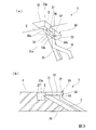
図1に示すように、第1の実施の形態による雨水排水システム1は、盛土して上方に道路を設ける際に形成されるのり面2に設置されている。ここで、本実施の形態では、排水設備を備えた既設ののり面2に対して雨水排水システム1を設ける場合に適用される。
本実施の形態では、のり面2が高さ方向を複数段(図1では三段)に区分され、各段ののり面2同士の間の段状部分には略水平方向に延びる小段部Bが形成されている。また、のり面2の最上部には路面Cが設けられており、のり尻には側道Dが設けられている。
(First embodiment)
As shown in FIG. 1, the rainwater drainage system 1 by 1st Embodiment is installed in the slope 2 formed when banking and providing a road upward. Here, in this Embodiment, it applies when providing the rainwater drainage system 1 with respect to the existing slope 2 provided with the drainage facility.
In the present embodiment, the slope surface 2 is divided into a plurality of steps in the height direction (three steps in FIG. 1), and a step portion B between the slope surfaces 2 of each step extends in a substantially horizontal direction. Is formed. Further, a road surface C is provided at the uppermost portion of the glue surface 2, and a side road D is provided at the glue butt.

のり面2における既設の排水設備としては、コンクリート製のU字溝からなり小段部Bにおける延長方向に沿って設けられた横排水溝21と、のり面2の上下方向に沿って配置され各横排水溝21に対して接続するとともに、のり尻排水溝22に接続するコンクリート製のU字溝からなる縦排水溝25と、集水マス24と、を有している。小段部Bに流入する雨水は、横排水溝21に受け入れられて一方側(図1で紙面右側)に向けて流れて排出される。   The existing drainage facilities on the slope surface 2 include a horizontal drainage groove 21 made of a concrete U-shaped groove and provided along the extending direction of the small step portion B, and the horizontal drainage grooves 21 arranged along the vertical direction of the slope surface 2. A vertical drainage groove 25 made of a concrete U-shaped groove connected to the drainage drainage groove 22 and a water collecting mass 24 are connected to the drainage groove 21. The rainwater flowing into the small step portion B is received by the horizontal drainage groove 21 and flows toward one side (the right side in FIG. 1) and is discharged.

側道Dには、排水設備としてコンクリート製のU字溝からなるのり尻排水溝22(のり尻側の側溝)がのり尻に沿って設けられている。側道Dの路肩部分は、のり尻排水溝22に雨水が流れ込むようにのり尻排水溝22側に向けて下り傾斜となっている。側道Dにおける既設の排水設備では、側道D及び最下部に位置するのり面2から流入する雨水がのり尻排水溝22に受け入れられて一方側(図1で紙面右側)に向けて流れて排出される。   The side road D is provided with a glue butt drainage groove 22 (a side groove on the glue butt side) made of a concrete U-shaped groove as a drainage facility along the glue butt. The shoulder portion of the side road D is inclined downward toward the glue butt drainage groove 22 so that rainwater flows into the glue butt drainage groove 22. In the existing drainage facility on the side road D, rainwater flowing in from the side road D and the slope surface 2 located at the lowermost part is received by the glue bottom drainage groove 22 and flows toward one side (right side in FIG. 1). Discharged.

最上部に位置する路面Cには、のり面2との路肩部分に集水マス23が設けられている。路面Cの路肩部分は、集水マス23に雨水が流れ込むように集水マス23側に向けて下り傾斜となっている。   On the road surface C located at the uppermost part, a water collecting mass 23 is provided on the road shoulder portion with the slope 2. The shoulder portion of the road surface C is inclined downward toward the water collecting mass 23 so that rainwater flows into the water collecting mass 23.

集水マス23には、流入する雨水に混じる不要物を取り除くためのフィルタ(図示省略)が設けられている。このフィルタは、バースクリーン等の透水性部材からなり、落ち葉等の固形物を分離できるように構成され、路面Cの集水マス23の上流側に設けられている。   The water collecting mass 23 is provided with a filter (not shown) for removing unnecessary materials mixed in the flowing rainwater. This filter is made of a water-permeable member such as a bar screen, and is configured to separate solid matter such as fallen leaves, and is provided on the upstream side of the water collection mass 23 on the road surface C.

小段部Bに設けられる集水マス24は、底面が横排水溝21の底面の位置よりも低く設定されている。また、集水マス24は、横排水溝21の内部、及び縦排水溝25の内部と連通している。
小段部Bに設けられる集水マス24に雨水を流入させる上流側の横排水溝21に対して集水マス24を挟んで反対側に設けられる下流側の横排水溝21は、当該集水マス24から離れる方向に下り勾配となっており、当該集水マス24に雨水が流れ込まないようになっている。この下流側の横排水溝21の内面には、集水マス24寄りの位置において集水マス24内の水位を高めるための堰(図示省略)が設けられている。
The bottom surface of the water collecting mass 24 provided in the small step portion B is set lower than the position of the bottom surface of the horizontal drainage groove 21. Further, the water collecting mass 24 communicates with the inside of the horizontal drainage groove 21 and the inside of the vertical drainage groove 25.
The downstream side drainage groove 21 provided on the opposite side of the upstream side drainage groove 21 with the rainwater flowing into the catchment mass 24 provided in the small step portion B across the water collection mass 24 is The slope is descending in a direction away from 24, and rainwater does not flow into the water collecting mass 24. A weir (not shown) for increasing the water level in the water collecting mass 24 is provided on the inner surface of the downstream horizontal drainage groove 21 at a position near the water collecting mass 24.

雨水排水システム1は、路面Cの排水を上下方向に延在する排水管路10を使用してのり尻排水溝22に排水する構成である。排水管路10には、のり尻排水溝22に合流する排水の合流部に合流用管路11が配設されている。   The rainwater drainage system 1 is configured to drain the drainage of the road surface C into the glue bottom drainage groove 22 using a drainage pipe line 10 extending in the vertical direction. In the drainage pipe 10, a junction pipe 11 is arranged at a junction of drainage that joins the glue butt drainage groove 22.

排水管路10は、耐光性の樹脂管からなり、上端10aが路面Cの集水マス23に導水溝30(導水部)を介して接続され、下端10bが合流用管路11に接続されている。排水管路10は、のり面2及び小段部Bの表面に沿うようにして地上部分に配設されている。なお、排水管路10の下端10bの位置は、本実施の形態では上面視で排水管路10の管軸方向C1が変わる最下端の位置とされる。排水管路10の上端10aは、図2及び図3に示すように、上向きに延びて導水溝30の底面31aに接続されている。   The drainage pipe 10 is made of a light-resistant resin pipe, the upper end 10a is connected to the water collecting mass 23 of the road surface C via the water guide groove 30 (water guide part), and the lower end 10b is connected to the joining pipe 11. Yes. The drainage pipe 10 is disposed on the ground portion so as to be along the slope surface 2 and the surface of the small step portion B. In the present embodiment, the position of the lower end 10b of the drain pipe 10 is the lowest position where the pipe axis direction C1 of the drain pipe 10 changes when viewed from above. As shown in FIGS. 2 and 3, the upper end 10 a of the drain pipe 10 extends upward and is connected to the bottom surface 31 a of the water guide groove 30.

耐光性の排水管路10として、例えば、耐光性塩ビ管、黒顔料を配合したPE樹脂管等や、耐光性樹脂を外層に被覆した樹脂管路を使用できる。
また、排水管路10に耐光性樹脂を外層に被覆した樹脂管路として、例えば、AESを被覆した塩ビ管、耐光性塩ビを被覆した塩ビ管、耐光性塗料を塗布した塩ビ管、黒顔料を配合したPE樹脂を被覆したPE管、耐光性塗料を塗布した強化プラスチック管等が挙げられる。
As the light-resistant drainage pipe 10, for example, a light-resistant PVC pipe, a PE resin pipe blended with a black pigment, or a resin pipe having an outer layer coated with a light-resistant resin can be used.
Further, as a resin pipe having an outer layer coated with a light resistant resin on the drain pipe 10, for example, a PVC pipe coated with AES, a PVC pipe coated with a light resistant PVC, a PVC pipe coated with a light resistant paint, or a black pigment Examples thereof include a PE pipe coated with a blended PE resin, a reinforced plastic pipe coated with a light-resistant paint, and the like.

このように、本実施の形態の雨水排水システム1は、図1に示すように、集水マス23に流入した雨水の一部を排水管路10内で流通させてのり尻排水溝22に排水するシステムであって、小段部Bに設けられる横排水溝21内の雨水の排水系統とは別系統により排水される。   Thus, as shown in FIG. 1, the rainwater drainage system 1 of the present embodiment allows a part of the rainwater flowing into the water collecting mass 23 to flow in the drainage pipe 10 and drain into the glue butt drainage groove 22. The drainage system is drained by a separate system from the rainwater drainage system in the lateral drainage groove 21 provided in the small step portion B.

また、豪雨の場合であっても路面C上の雨水が流入される集水マス23が溢れることがなく、路面Cの雨水がのり面2を伝って下方に流出することを抑えることができる。そのため、小段部Bの横排水溝21は直上ののり面2と当該小段部Bの雨水のみを処理することができ、小段部Bに設けられる集水マス24において排水が溢れにくくなる。   Further, even in the case of heavy rain, the collecting mass 23 into which rainwater on the road surface C flows is not overflowed, and rainwater on the road surface C can be prevented from flowing down along the slope surface 2. Therefore, the lateral drainage groove 21 of the small step portion B can treat only the slope 2 immediately above and the rainwater of the small step portion B, and the drainage is unlikely to overflow in the water collecting mass 24 provided in the small step portion B.

各小段部Bに位置する集水マス24には、路面Cにある集水マス23内の排水の一部が縦排水溝25を通じて流入するとともに、最上段の小段部Bに設けられる横排水溝21内の排水が流入し、さらに縦排水溝25により下方の集水マス24又はのり尻排水溝22に排水される。
また、最上段の小段部Bに位置する集水マス24内に流入する雨水の多くは排水管路10によりのり尻排水溝22まで排水される。そのため、縦排水溝25内の排水量は大幅に減少することになる。つまり、集水マス24に縦排水溝25から合流する排水量が減少され、集水マス24が溢れにくくなる。
A part of the drainage in the catchment mass 23 on the road surface C flows into the catchment mass 24 located in each small step portion B through the vertical drainage groove 25 and the horizontal drainage groove provided in the uppermost small step portion B. The wastewater in 21 flows in and is further drained by the vertical drainage groove 25 to the lower water collecting mass 24 or the glue bottom drainage groove 22.
Further, most of the rainwater flowing into the water collecting mass 24 located in the uppermost small step portion B is drained to the glue butt drainage groove 22 by the drainage pipe 10. Therefore, the amount of drainage in the vertical drainage groove 25 is greatly reduced. That is, the amount of drainage that joins the water collection mass 24 from the vertical drainage groove 25 is reduced, and the water collection mass 24 is less likely to overflow.

導水溝30は、図3(a)、(b)に示すように、一方向に延びる溝形状をなし、その長手方向を集水マス23ののり面側開口から略水平方向に外方に張り出した状態で設けられている。ここで、導水溝30の張り出す方向において、張り出し端側(集水マス23から離間した側)を下流側とし、導水側(集水マス23側)の基端側を上流側とする。   As shown in FIGS. 3A and 3B, the water guide groove 30 has a groove shape extending in one direction, and its longitudinal direction projects outward in a substantially horizontal direction from the opening on the slope surface side of the water collecting mass 23. It is provided in the state. Here, in the direction in which the water guide groove 30 projects, the projecting end side (the side away from the water collecting mass 23) is the downstream side, and the base end side of the water conducting side (the water collecting mass 23 side) is the upstream side.

導水溝30の上流端30a側の底部は、集水マス23の底部23aとの間に上下方向の隙間Sをあけて配置されている。
すなわち、導水溝30の上流端30a側の底部形状が集水マス23の底部形状と同形状の場合は、隙間Sをゼロ(隙間なし)とすると、呑込み量は100%となる。また、隙間Sをあけることで、導水溝30の呑込み量を減らした設定にすることができる。
The bottom portion on the upstream end 30 a side of the water guide groove 30 is disposed with a gap S in the vertical direction between the bottom portion 23 a of the water collecting mass 23.
That is, when the shape of the bottom portion on the upstream end 30a side of the water guide groove 30 is the same shape as the shape of the bottom portion of the water collecting mass 23, if the gap S is zero (no gap), the amount of dripping is 100%. Moreover, by setting the clearance S, it is possible to make a setting in which the amount of penetration of the water guide groove 30 is reduced.

導水溝30は、底板31と、長手方向から見て底板31の両端から上方に延びる側板32、32と、底板31および側板32の下流側の端部を閉塞する端板33と、を備えている。底板31の端板33側の近傍には、開口穴34が形成されており、この開口穴34には排水管路10の上端10aが接続されている。導水溝30としては、排水管路10と同様に、例えば耐光性塩ビ管、黒顔料を配合したPE樹脂管等や、耐光性樹脂を外層に被覆した樹脂管路を使用できる。   The water guide groove 30 includes a bottom plate 31, side plates 32 and 32 extending upward from both ends of the bottom plate 31 when viewed from the longitudinal direction, and an end plate 33 that closes the bottom plate 31 and the downstream end of the side plate 32. Yes. An opening hole 34 is formed in the vicinity of the end plate 33 side of the bottom plate 31, and the upper end 10 a of the drain pipe 10 is connected to the opening hole 34. As the water guide groove 30, similarly to the drain pipe 10, for example, a light-resistant PVC pipe, a PE resin pipe blended with a black pigment, or a resin pipe with a light-resistant resin coated on the outer layer can be used.

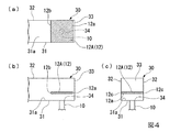
導水溝30には、サイフォン誘発部が設けられ、路面C上を流れる雨水は、集水マス23を介して導水溝30のサイフォン誘発部のサイフォン作用により効率よく排水管路を通過してのり尻排水溝22に排水される。サイフォン誘発部として、例えば図4〜図6に示すようなものを採用することができる。   The water guide groove 30 is provided with a siphon inducing portion, and rainwater flowing on the road surface C efficiently passes through the drainage pipe by the siphon action of the siphon inducing portion of the water guide groove 30 through the collecting mass 23. It is drained into the drain groove 22. As a siphon induction part, what is shown, for example in FIGS. 4-6 is employable.

図4〜図6に示すサイフォン誘発部12は、底板31の開口穴34の上方を塞ぐように設けた板状の蓋部材12A、12B、12C、12Dである。導水溝30に流入する排水は、底板31と蓋部材12A,12B、12C、12Dとの間に流れ込んで、開口穴34から排水管路10へ流れるようになっている。   4 to 6 are plate-like lid members 12A, 12B, 12C, and 12D that are provided so as to block the upper portion of the opening hole 34 of the bottom plate 31. As shown in FIG. The waste water flowing into the water guide groove 30 flows between the bottom plate 31 and the cover members 12A, 12B, 12C, and 12D, and flows from the opening hole 34 to the drain pipe 10.

図4(a)〜(c)に示す蓋部材12Aは、平面視で四角形状をなし、底面31aに対して平行に、かつ底面31aから上方に所定の間隔をあけて配置されている。蓋部材12Aは、両側端12c、12cがそれぞれ側板32に接着手段等により固定されている。蓋部材12Aの後端12bは、上面視で開口穴34よりも後方に位置するように設けられている。   The lid member 12A shown in FIGS. 4A to 4C has a quadrangular shape in plan view, and is arranged in parallel to the bottom surface 31a and at a predetermined interval upward from the bottom surface 31a. The lid member 12A has both side ends 12c, 12c fixed to the side plate 32 by an adhesive means or the like. The rear end 12b of the lid member 12A is provided so as to be located behind the opening hole 34 in a top view.

図5(a)〜(c)に示す平板状の蓋部材12Bは、平面視で四角形状をなし、後端12bから前方に向かうに従い漸次、下方となるように傾斜させて配置されている。蓋部材12Bの両側端12c、12cは、それぞれ側板32に接着手段等により固定されている。蓋部材12Bの後端12bは、上面視で開口穴34よりも後方に位置するように設けられている。
この斜めに配置された蓋部材12Bは、下流側の壁としての機能と、サイフォン作用を発生させる蓋の機能と、を有している。そして、サイフォン作用が生じ易くなる角度の設定条件として、例えば排水配管径(排水管路10の管径)、導水溝30の幅D、上面視で開口穴34から端板33までの距離、排水量、排水流速等に応じて選定することができ、例えば45度の角度に設定することができる。
The flat lid member 12B shown in FIGS. 5A to 5C has a quadrangular shape in a plan view, and is disposed so as to be gradually inclined downward toward the front from the rear end 12b. Both side ends 12c, 12c of the lid member 12B are fixed to the side plate 32 by an adhesive means or the like. The rear end 12b of the lid member 12B is provided so as to be located behind the opening hole 34 in a top view.
The lid member 12B disposed obliquely has a function as a wall on the downstream side and a function of a lid for generating a siphon action. And as conditions for setting the angle at which siphoning is likely to occur, for example, the drainage pipe diameter (the pipe diameter of the drainage pipe 10), the width D of the water guide groove 30, the distance from the opening hole 34 to the end plate 33 in top view, the amount of drainage The drainage flow rate can be selected, for example, an angle of 45 degrees can be set.

ここで、上述した蓋部材12A、12Bの前端12aは、端板33に対して隙間をあけた位置に配置されていてもよい。
また、蓋部材12A、12Bは、水流で蓋の機能を有すればよいので、メッシュやスリットが形成された部材を採用することも可能である。
Here, the front ends 12 a of the lid members 12 </ b> A and 12 </ b> B described above may be arranged at a position with a gap with respect to the end plate 33.
In addition, since the lid members 12A and 12B only need to have a lid function with a water flow, it is also possible to employ a member in which a mesh or a slit is formed.

図6に示すサイフォン誘発部12は、底板31の開口穴34の上方を塞ぐように設けた蓋部材12C、12Dである。導水溝30に流入する排水は、底板31と蓋部材12C,12Dとの間に流れ込んで、開口穴34から排水管路10へ流れるようになっている。
図6(a)〜(c)に示す蓋部材12Cは、円板状に形成され、底面31aに対して平行に、かつ底面31aから上方に所定の間隔をあけて配置されている。蓋部材12Cは、開口穴34よりも大径で開口穴34と略同軸上に設けられ、開口穴34の開口縁から上方に延びる複数(ここでは4つ)の柱材121によって下方から支持されている。つまり、開口穴34は、上面視で蓋部材12Cによって覆われた状態となっている。
The siphon induction part 12 shown in FIG. 6 is lid members 12 </ b> C and 12 </ b> D provided so as to close the upper part of the opening hole 34 of the bottom plate 31. The waste water flowing into the water guide groove 30 flows between the bottom plate 31 and the lid members 12C and 12D, and flows from the opening hole 34 to the drain pipe 10.
The lid member 12C shown in FIGS. 6A to 6C is formed in a disc shape, and is arranged in parallel to the bottom surface 31a and at a predetermined interval upward from the bottom surface 31a. The lid member 12 </ b> C has a larger diameter than the opening hole 34 and is provided substantially coaxially with the opening hole 34, and is supported from below by a plurality of (four in this case) column members 121 extending upward from the opening edge of the opening hole 34. ing. That is, the opening hole 34 is covered with the lid member 12C in a top view.

図1に示すように、合流用管路11は、一端が排水管路10の下端10bに接続され、他端の排水端がのり尻排水溝22内に位置するように配置されている。合流用管路11の管軸方向は、のり尻排水溝22の流れ方向と同じ方向となっている。
なお、合流用管路11は、排水管路10と別体であっても一体に設けられていてもよい。
As shown in FIG. 1, the merging pipeline 11 is arranged so that one end is connected to the lower end 10 b of the drainage pipeline 10 and the drainage end of the other end is located in the glue butt drainage groove 22. The tube axis direction of the merging conduit 11 is the same as the flow direction of the glue tail drain groove 22.
Note that the merging pipeline 11 may be provided separately or integrally with the drainage pipeline 10.

次に、上述した雨水排水システム1の作用について図面を用いて詳細に説明する。
本実施の形態による雨水排水システム1では、図1に示すように、のり面2の上部にある路面排水を導水溝30で集水マス23から導水し、その排水を排水管路10に通過させて、導水溝30からのり尻排水溝22へ直接、排水することができる。
このように、本実施の形態では、導水する箇所に導水溝30を設けるといった簡単な構造により、のり面全体を効率よくバイパスすることができ、排水処理能力を向上させることができる。
Next, the effect | action of the rainwater drainage system 1 mentioned above is demonstrated in detail using drawing.
In the rainwater drainage system 1 according to the present embodiment, as shown in FIG. 1, the road drainage at the top of the slope surface 2 is led from the water collecting mass 23 through the water guide groove 30, and the drainage is passed through the drainage pipe 10. Thus, the water can be drained directly from the water guide groove 30 to the glue bottom drain groove 22.
Thus, in this Embodiment, the whole slope can be bypassed efficiently by the simple structure of providing the water guide groove | channel 30 in the location which introduces water, and wastewater treatment capacity can be improved.

そして、本実施の形態では、排水管路10が管状であるので、のり面2内における例えば縦排水溝25に沿わない方向等の様々な方向で、かつ長距離で排水管路10を設置することができる。そのため、集水マス23の設置箇所に制限されることがなく、のり面2全体としてバイパスでき、跳水や溢水を防ぐことが可能となり、土壌崩壊を引き起こす要因を小さく軽減することができる。   In this embodiment, since the drainage pipe 10 is tubular, the drainage pipe 10 is installed in various directions such as a direction not along the vertical drainage groove 25 in the slope surface 2 and at a long distance. be able to. Therefore, it is not restricted to the installation location of the water collecting mass 23, can be bypassed as the entire slope surface 2, it becomes possible to prevent jumping and flooding, and the factor causing the soil collapse can be reduced to a small extent.

また、本実施の形態による雨水排水システムでは、既存の排水設備(ここでは集水マス23)に導水溝30を介して排水管路10が設けられる構成であり、既存の排水設備に管状の排水部を直接、取り付ける場合に比べて接続が簡単である。
さらに、本実施の形態では、導水溝30の排水断面積は集水マス23の断面積と排水管路10の断面積の中間程に設定することで導水がし易くなる。
Moreover, in the rainwater drainage system by this Embodiment, it is the structure by which the drainage pipe line 10 is provided through the ditch | groove 30 in the existing drainage facility (here water collection mass 23), and tubular drainage is provided in the existing drainage facility. The connection is simple compared to the case of attaching the part directly.
Furthermore, in the present embodiment, the water discharge cross-sectional area of the water guide groove 30 is set to an intermediate position between the cross-sectional area of the water collecting mass 23 and the cross-sectional area of the drain pipe 10 to facilitate water introduction.

また、本実施の形態では、路面やのり面の排水を、サイフォン誘発部を接続した導水溝30や排水管路10を用いてサイフォン作用により効率よくのり尻側の側溝に排水することができる。つまり、本実施の形態では、サイフォン誘発部として、例えば上述した導水溝30のサイフォン誘発部12や、排水管路10の内面に突起を設けたり、内面を縮径することや導水部30の開口穴34の上方に所定の間隔をあけて蓋部材を配置する等によってサイフォン現象を起こすものを採用でき、このようなサイフォン式の排水管路10内でサイフォン現象を発生させることにより、管内を自然流下させて排水するときよりも高流速にでき、排水処理能力を増加させて効率よく排水することができる。これにより、豪雨の場合であっても集水マスから雨水が溢れ出ることがなく、雨水がのり面2に浸透することを効果的に抑制することができる。
さらに、本実施の形態では、サイフォン現象を発生させることで、排水を高流速化し、排水管路10の口径を小さくしても排水処理量を得ることができる利点もある。
Moreover, in this Embodiment, the drainage of a road surface or a slope surface can be efficiently drained by the sift action to the side groove | channel on a glue buttocks side using the water guide groove 30 and the drainage pipe line 10 which connected the siphon induction part. In other words, in the present embodiment, as the siphon inducing portion, for example, the siphon inducing portion 12 of the above-described water guiding groove 30 or the inner surface of the drain pipe 10 is provided with a protrusion, the inner surface is reduced in diameter, or the water guiding portion 30 is opened. What causes a siphon phenomenon by arranging a lid member at a predetermined interval above the hole 34 can be adopted, and by generating the siphon phenomenon in such a siphon-type drain pipe 10, The flow rate can be made higher than that when draining and draining, and drainage can be efficiently drained by increasing the wastewater treatment capacity. Thereby, even if it is a case of heavy rain, rainwater does not overflow from a water collection mass, and it can suppress effectively that rainwater penetrate | infiltrates into the slope surface 2. FIG.
Furthermore, in the present embodiment, by generating a siphon phenomenon, there is also an advantage that the waste water treatment amount can be obtained even if the drainage water is increased in flow rate and the diameter of the drain pipe 10 is reduced.

また、本実施の形態の雨水排水システム1では、導水溝30の上流端30a側の底部と集水マス23の底部23aとの間の隙間量を変更することで、導水溝30への流入量を調整することができる。   Further, in the rainwater drainage system 1 of the present embodiment, the amount of inflow into the water guide groove 30 is changed by changing the gap amount between the bottom portion on the upstream end 30 a side of the water guide groove 30 and the bottom portion 23 a of the water collecting mass 23. Can be adjusted.

また、本実施の形態では、排水管路10は、耐光性を有する樹脂で構成されているので、排水管路10を屋外で長期にわたって使用することが可能となり、排水管路10を地表面に設置することができる。そのため、地中に埋設する場合に比べてのり面2における掘削作業を減らすことができ、施工を容易に行うことができる。   Moreover, in this Embodiment, since the drainage pipe 10 is comprised with resin which has light resistance, it becomes possible to use the drainage pipe 10 outdoors for a long term, and the drainage pipe 10 is made into the ground surface. Can be installed. Therefore, excavation work on the slope surface 2 can be reduced as compared with the case where it is buried in the ground, and construction can be easily performed.

また、本実施の形態の雨水排水システム1は、簡単な構造で、のり面2全体を効率よくバイパスすることにより排水処理能力を向上させることができる。   Moreover, the rainwater drainage system 1 of this Embodiment is simple structure, and can improve wastewater treatment capacity by bypassing the whole slope 2 efficiently.

(第2の実施の形態)
次に、図7及び図8に示すように、本発明の第2の実施の形態による雨水排水システム1Aについて、図面を用いて説明する。
第2の実施の形態による雨水排水システム1Aは、導水溝30を縦排水溝25に設けた構成となっている。導水溝30は、上述した第1の実施の形態と同様の構成であるので、ここでは詳しい説明は省略する。
導水溝30の上流端30aが、最上段の縦排水溝25の凹溝内に配置されている。導水溝30の底板31と、縦排水溝25の底面25aとの間には隙間Sが設けられている。すなわち、導水溝30の位置は、路面Cの集水マス23の近傍であり、集水マス23から縦排水溝25に流出した直後に、その排水の一部が導水溝30に流れ込むように配置されている。
(Second Embodiment)
Next, as shown in FIGS. 7 and 8, a rainwater drainage system 1A according to a second embodiment of the present invention will be described with reference to the drawings.
The rainwater drainage system 1 </ b> A according to the second embodiment has a configuration in which the water guide groove 30 is provided in the vertical drainage groove 25. Since the water guide groove 30 has the same configuration as that of the first embodiment described above, detailed description thereof is omitted here.
The upstream end 30 a of the water guide groove 30 is disposed in the concave groove of the uppermost vertical drainage groove 25. A gap S is provided between the bottom plate 31 of the water guide groove 30 and the bottom surface 25 a of the vertical drainage groove 25. That is, the position of the water guiding groove 30 is in the vicinity of the water collecting mass 23 on the road surface C, and is arranged so that a part of the drainage flows into the water guiding groove 30 immediately after flowing out from the water collecting mass 23 into the vertical draining groove 25. Has been.

(第3の実施の形態)
次に、図9に示すように、本発明の第3の実施の形態による雨水排水システム1Bについて、図面を用いて説明する。
第3の実施の形態による雨水排水システム1Bは、導水溝30を最上段(1段目)の小段部Bの横排水溝21に設けた構成となっている。すなわち、雨水排水システム1Bでは、横排水溝21に流入した排水の一部を上下方向に延在する排水管路10を使用して、のり尻排水溝22に排水する構成である。排水管路10には、上述した第1の実施の形態と同様にのり尻排水溝22に合流する排水の合流部に合流用管路11が配設されている。
本実施の形態では、排水管路10を有する雨水排水システム1Bと、排水管路10とは別系統となる後述する縦排水溝25と、の2系統によりのり尻排水溝22に排水する構成となっている。
(Third embodiment)
Next, as shown in FIG. 9, a rainwater drainage system 1B according to a third embodiment of the present invention will be described with reference to the drawings.
The rainwater drainage system 1B according to the third embodiment has a structure in which the water guide groove 30 is provided in the horizontal drainage groove 21 of the uppermost (first) sub-stage B. That is, the rainwater drainage system 1B is configured to drain part of the drainage flowing into the lateral drainage groove 21 into the glue butt drainage groove 22 using the drainage pipe 10 extending in the vertical direction. In the drainage pipe 10, a merging pipe 11 is disposed at the junction of drainage that joins the glue butt drainage groove 22 as in the first embodiment described above.
In the present embodiment, the rainwater drainage system 1 </ b> B having the drainage pipe 10 and the vertical drainage groove 25, which will be described later, which is a separate system from the drainage pipe 10, are drained into the glue bottom drainage groove 22. It has become.

(第4の実施の形態)
次に、図10に示すように、本発明の第4の実施の形態による雨水排水システム1Cは、既存の縦排水溝25と横排水溝21による排水機能をそのまま残した状態で、既存の集水マス23、23同士の間の略中間部分に新たに路面Cに集水マス23Aを新設するとともに、その新設した集水マス23Aに対して導水溝30を設けた構成である。本実施の形態の雨水排水システム1Cは、上述した図1に示す第1の実施の形態の雨水排水システム1と同様である。
(Fourth embodiment)
Next, as shown in FIG. 10, the rainwater drainage system 1C according to the fourth embodiment of the present invention leaves the existing drainage function by the existing vertical drainage groove 25 and the horizontal drainage groove 21 as it is. A water collection mass 23A is newly provided on the road surface C at a substantially intermediate portion between the water masses 23, 23, and a water guide groove 30 is provided for the newly established water collection mass 23A. The rainwater drainage system 1C of the present embodiment is the same as the rainwater drainage system 1 of the first embodiment shown in FIG. 1 described above.

(第5の実施の形態)
次に、図11及び図12に示すように、本発明の第5の実施の形態による雨水排水システム1Dについて、図面を用いて説明する。
第5の実施の形態による雨水排水システム1D、1Eは、路面Cの集水マス23から最上段の小段部Bまでのみに配置された縦排水溝25に対して導水溝30を設けた構成となっている。ここで、本実施の形態の雨水排水システム1D、1Eは、最上段の小段部Bの集水マス24では路面排水が流入するが、排水できる縦排水溝25がなく、横排水溝21への排水となるため、流れが悪く集水マス24において逸水が起こり易いものを適用対象としている。
(Fifth embodiment)
Next, as shown in FIGS. 11 and 12, a rainwater drainage system 1D according to a fifth embodiment of the present invention will be described with reference to the drawings.
The rainwater drainage system 1D, 1E according to the fifth embodiment has a configuration in which a water guide groove 30 is provided for a vertical drainage groove 25 disposed only from the water collecting mass 23 of the road surface C to the uppermost small step portion B. It has become. Here, in the rainwater drainage systems 1D and 1E of the present embodiment, road surface drainage flows in the water collecting mass 24 of the uppermost small step portion B, but there is no vertical drainage groove 25 that can drain, and the drainage to the horizontal drainage groove 21 is achieved. Since it becomes drainage, what has a bad flow and is likely to cause water loss in the water collecting mass 24 is applied.

図11に示す雨水排水システム1Dは、排水管路10がのり尻排水溝22まで延ばされている。
図12に示す雨水排水システム1Eは、のり尻排水溝22に直接排水できない場合の一例であって、排水管路10が上から2段目の小段部Bの横排水溝21まで延ばされている。
本実施の形態の雨水排水システム1D、1Eの基本的な構成は、上述した図7及び図8に示す第2の実施の形態の雨水排水システム1Aと同様である。
In the rainwater drainage system 1 </ b> D shown in FIG. 11, the drainage pipe 10 is extended to the glue bottom drainage groove 22.
The rainwater drainage system 1E shown in FIG. 12 is an example in the case where the drainage drainage channel 22 cannot be drained directly, and the drainage pipe 10 is extended from the top to the horizontal drainage channel 21 of the second small step portion B. Yes.
The basic configuration of the rainwater drainage systems 1D and 1E of the present embodiment is the same as that of the rainwater drainage system 1A of the second embodiment shown in FIGS. 7 and 8 described above.

雨水排水システム1D、1Eでは、管路のため、のり尻排水溝22の流れ方向に合わせて合流でき、合流箇所も増えることから、溢れにくくなる利点がある。
なお、図12に示す雨水排水システム1Eでは、排水管路10がのり尻排水溝22まで延ばされていないが、前述したような集水マス24における逸水のリスクを減らすことができる。
Since the rainwater drainage systems 1D and 1E are pipes, the rainwater drainage systems 1D and 1E can be merged in accordance with the flow direction of the glue bottom drainage groove 22, and the number of merge points is increased.
In the rainwater drainage system 1E shown in FIG. 12, the drainage pipe 10 is not extended to the glue bottom drainage groove 22, but the risk of water loss in the water collecting mass 24 as described above can be reduced.

(第6の実施の形態)
次に、図13に示すように、本発明の第6の実施の形態による雨水排水システム1Fについて、図面に用いて説明する。
第6の実施の形態による雨水排水システム1Fは、最上段の小段部Bの横排水溝21の延長方向の途中に窪み部21cが生じた場合に導水溝30を適用した構成となっている。のり面の新設時には、窪み部21cはなく、横排水溝21の上流側の集水マス24(上流部21a)から下流側の集水マス24が位置する下流部21bに向けて流れていたが、時間と共に横排水溝21の途中に窪み部21cが生じた例である。
(Sixth embodiment)
Next, as shown in FIG. 13, a rainwater drainage system 1F according to a sixth embodiment of the present invention will be described with reference to the drawings.
The rainwater drainage system 1F according to the sixth embodiment has a configuration in which the water guide groove 30 is applied when a recessed portion 21c is generated in the middle of the extending direction of the horizontal drainage groove 21 of the uppermost small step portion B. At the time of newly installing the slope surface, there was no hollow portion 21c, and it flowed from the upstream water collection mass 24 (upstream portion 21a) of the lateral drainage groove 21 toward the downstream portion 21b where the downstream water collection mass 24 is located. This is an example in which a recess 21c is generated in the middle of the horizontal drainage groove 21 with time.

すなわち、横排水溝21は、集水マス24が位置する上流部21aから窪み部21cに向けて下り傾斜(矢印E1方向)となっており、窪み部21cを挟んで集水マス24と反対側の下流部21bも窪み部21cに向けて下り傾斜(矢印E2方向)となっている。この小段部Bには、窪み部21cのある横排水溝21に連通するとともに、当該小段部Bよりも下方に位置するのり面2側に開口する溝状の凹溝部2aが切り欠かれ、その凹溝部2aに導水溝30が嵌合された状態で設けられている。雨水排水システム1Fでは、導水溝30に流入した排水が排水管路10を通過してのり尻排水溝22に排水される構成となっている。   That is, the horizontal drainage groove 21 is inclined downward (in the direction of arrow E1) from the upstream portion 21a where the water collecting mass 24 is located toward the hollow portion 21c, and is opposite to the water collecting mass 24 across the hollow portion 21c. The downstream portion 21b is also inclined downward (in the direction of arrow E2) toward the hollow portion 21c. In this small step portion B, a groove-shaped concave groove portion 2a that communicates with the lateral drainage groove 21 having the hollow portion 21c and opens on the side of the slope surface 2 positioned below the small step portion B is cut out. It is provided in a state where the water guide groove 30 is fitted in the concave groove portion 2a. In the rainwater drainage system 1 </ b> F, the drainage that has flowed into the water guide groove 30 passes through the drainage pipe 10 and is drained into the glue bottom drainage groove 22.

(第7の実施の形態)
次に、図14に示すように、本発明の第7の実施の形態による雨水排水システム1Gについて、図面に用いて説明する。
第7の実施の形態による雨水排水システム1Gは、上述したように小段部B、横排水溝21、縦排水溝25が設けられていないのり面2において、路面Cの集水溝23に導水溝30が設けられ、排水管路10が直接、のり尻排水溝22まで配設された構成となっている。
排水管路10は、導水溝30から下方に向けて延ばされて地中に入り、埋設された部分(符号10A)がのり面2に沿って埋設されている。埋設された排水管路10Aは、のり尻排水溝22の内側壁から側溝内に突出する合流用管路11に接続されている。
(Seventh embodiment)
Next, as shown in FIG. 14, a rainwater drainage system 1G according to a seventh embodiment of the present invention will be described with reference to the drawings.
As described above, the rainwater drainage system 1G according to the seventh embodiment has a water guide groove in the water collecting groove 23 of the road surface C on the slope surface 2 where the small step portion B, the horizontal drainage groove 21 and the vertical drainage groove 25 are not provided. 30 is provided, and the drainage pipe 10 is directly arranged up to the glue bottom drainage groove 22.
The drainage pipe 10 extends downward from the water guide groove 30 and enters the ground, and an embedded part (reference numeral 10 </ b> A) is embedded along the slope 2. The buried drainage pipe 10 </ b> A is connected to the joining pipe 11 that protrudes from the inner wall of the glue bottom drainage groove 22 into the side groove.

本実施の形態では、排水管路10のうち地上に配置される部分を少なくすることができるため、地上で排水管路10を支持する支持具やこの支持具を固定する基礎等の支持構造を簡単にすることができ、あるいは省略することができる。
さらに、この場合には、地中に埋設される部分の排水管路10Aを紫外線から保護することでき、排水管路10の耐久性を向上させることが可能となる。
In this Embodiment, since the part arrange | positioned on the ground among the drainage pipes 10 can be decreased, support structures, such as a support which supports the drainage pipes 10 on the ground, and a foundation which fixes this support tool, are provided. It can be simplified or omitted.
Furthermore, in this case, it is possible to protect the drainage pipe line 10A embedded in the ground from ultraviolet rays and improve the durability of the drainage pipe line 10.

(第8の実施の形態)
次に、図15及び図16に示すように、本発明の第8の実施の形態による雨水排水システム1Hについて、図面に用いて説明する。
第8の実施の形態による雨水排水システム1Hは、上述した第1の実施の形態における排水管路10に縮径管12E(12)(サイフォン誘発部)を設けた構成となっている。縮径管12Eは、排水管路10の適宜な位置の一部に、排水管路10の内径よりも小さな内径を有する配管であり、本実施の形態ではのり面2の傾斜に沿う斜め部10Bの長さ方向の略中央部分に配置されている。縮径管12Eは、内径を絞る効果によりサイフォン現象を発生させる構成となっている。
(Eighth embodiment)
Next, as shown in FIGS. 15 and 16, a rainwater drainage system 1H according to an eighth embodiment of the present invention will be described with reference to the drawings.
The rainwater drainage system 1H according to the eighth embodiment has a configuration in which the reduced diameter pipe 12E (12) (siphon inducing portion) is provided in the drainage pipe line 10 in the first embodiment described above. The reduced-diameter pipe 12E is a pipe having an inner diameter smaller than the inner diameter of the drainage pipe 10 at a part of an appropriate position of the drainage pipe 10, and in this embodiment, an inclined portion 10B along the slope of the slope 2 It is arrange | positioned in the approximate center part of the length direction. The reduced diameter tube 12E is configured to generate a siphon phenomenon by the effect of reducing the inner diameter.

このような縮径管12Eを備えたサイフォン式の排水管路10においては、管内でサイフォン現象を発生させることにより、管内を自然流下させて排水するときよりも高流速にでき、排水処理能力を増加させて効率よくのり尻排水溝22に排水することができる。
なお、縮径管12Eに代えて、内径を絞る突起やリング状のプレートによる縮径等の効果を有するサイフォン誘発部を設けでもよく、このような構成であっても縮径管12Eと同様のサイフォン作用を生じさせることができる。そして、縮径管12Eを複数箇所に使用することで、サイフォン現象が途切れることがなく連続的に発生しやすくなる。
In the siphon-type drainage pipe 10 having such a reduced diameter pipe 12E, by generating a siphon phenomenon in the pipe, the flow rate can be made higher than that when the pipe is naturally flowed down and drained, and the drainage treatment capacity is improved. It can be increased and drained efficiently into the glue bottom drainage groove 22.
Note that, instead of the reduced diameter tube 12E, a siphon inducing portion having an effect such as a reduced diameter by a projection or a ring-shaped plate that narrows the inner diameter may be provided. Even in such a configuration, the same as the reduced diameter tube 12E may be provided. Siphon action can be produced. And it becomes easy to generate | occur | produce continuously, without using the reduced diameter pipe | tube 12E in several places, without a siphon phenomenon interrupting.

次に、上述した実施の形態による雨水排水システムの効果を裏付けるために行った実施例について以下説明する。   Next, examples carried out to support the effects of the rainwater drainage system according to the above-described embodiment will be described below.

(第1実施例)
本第1実施例は、図17及び図18に示すように、上述の実施の形態の導水溝30(導水部)を模擬した試験体4A、4Bを用い、導水部の有無と、導水部の壁(端板)の排水に及ぼす影響について開口穴41からの排水状況より確認した。
(First embodiment)
As shown in FIGS. 17 and 18, this first example uses test bodies 4A and 4B simulating the water guide groove 30 (water guide part) of the above-described embodiment, the presence or absence of the water guide part, The effect of the wall (end plate) on drainage was confirmed from the drainage situation from the opening hole 41.

図17(a)〜(c)は、導水部を備えない比較例による第1試験体4Aを示している。すなわち、比較例は、上述した実施の形態において、集水マスに直接、排水管路を接続した構成に相当している。第1試験体4Aは、平面視で縦横寸法(縦寸法D1、横寸法D2)がそれぞれ60cmに設定された角水槽40の底面40aの中央に75A(内径略8cm)の排水管42を接続させた構成とした。   FIGS. 17A to 17C show a first test body 4A according to a comparative example that does not include a water guiding portion. That is, the comparative example corresponds to a configuration in which the drain pipe is directly connected to the water collecting mass in the above-described embodiment. In the first test body 4A, a 75A (inner diameter of about 8 cm) drain pipe 42 is connected to the center of the bottom surface 40a of the square water tank 40 in which the vertical and horizontal dimensions (vertical dimension D1, horizontal dimension D2) are set to 60 cm in plan view. The configuration was as follows.

図18(a)〜(c)は、導水部を有する第1実施例及び第2実施例による第2試験体4Bを示している。第2試験体4Bは、導水部44を模擬した樋を使用し、第1実施例で溝幅Dが40cmのものであり、第2実施例で溝幅Dが20cmのものを採用している。また、それぞれの実施例において、底板における端板43から後方(図18(b)で紙面左側)に向けた距離(壁距離L)で12cmの位置に開口穴41の中心軸を一致させたものと、壁距離Lで8cmの位置に開口穴41の中心軸を一致させたものと、の2パターンにおいて75A(内径略8cm)の塩ビ管からなる排水管42を接続させた構成とした。   18 (a) to 18 (c) show a second test body 4B according to the first embodiment and the second embodiment having a water guiding portion. The second test body 4B uses a kite that simulates the water guide portion 44, and has a groove width D of 40 cm in the first embodiment and a groove width D of 20 cm in the second embodiment. . In each of the embodiments, the center axis of the opening hole 41 is aligned with a position of 12 cm at a distance (wall distance L) from the end plate 43 on the bottom plate to the rear (left side of the drawing in FIG. 18B). In addition, a drain pipe 42 made of a 75A (inner diameter of about 8 cm) PVC pipe is connected in two patterns: a wall distance L and a position where the center axis of the opening hole 41 is aligned at a position of 8 cm.

試験では、第1試験体4A及び第2試験体4Bのそれぞれにおいて、開口側(後側)から約15リットル/秒の水を供給して、開口穴41の手前の位置における最大水位を計測するとともに、水の吸い込み状態を目視により確認した。表1には、試験結果を示している。   In the test, in each of the first test body 4A and the second test body 4B, about 15 liters / second of water is supplied from the opening side (rear side), and the maximum water level at the position before the opening hole 41 is measured. At the same time, the state of inhalation of water was confirmed visually. Table 1 shows the test results.

Figure 2019143381
Figure 2019143381

表1及び図17(c)に示すように、導水部を有しない比較例のケースでは、開口穴41付近において、渦Uが発生するとともに水位H1が14〜22cmで後述する実施例1、2の水位H2(図18(c)参照)に比べて高くなった。
表1及び図18(c)に示すように、導水部44を有する実施例1のケースでは、壁距離Lが12cmの場合において、開口穴41付近の水位H2が12〜22cmとやや高くなり、渦Uが形成されるとともに水面が暴れた状態(以下、水面暴れと表現する)となった。また、実施例1で壁距離Lが8cmの場合において、開口穴41付近の水位H2が9〜13cmとなり、壁距離Lが12cmの場合に比べると水位が低く、渦Uは発生していないが、水面暴れは大きい状態であった。
As shown in Table 1 and FIG. 17 (c), in the case of the comparative example that does not have the water guiding portion, the vortex U is generated in the vicinity of the opening hole 41 and the water level H1 is 14 to 22 cm, which will be described later. The water level was higher than that of H2 (see FIG. 18C).
As shown in Table 1 and FIG. 18 (c), in the case of Example 1 having the water guide portion 44, when the wall distance L is 12 cm, the water level H2 in the vicinity of the opening hole 41 is slightly higher as 12 to 22 cm, The vortex U was formed and the water surface was in a state of violence (hereinafter referred to as water surface violence). Moreover, in Example 1, when the wall distance L is 8 cm, the water level H2 near the opening hole 41 is 9 to 13 cm, and the water level is lower than in the case where the wall distance L is 12 cm, and the vortex U is not generated. The water rampage was in great condition.

導水部44を有する実施例2のケースでは、壁距離Lが12cmの場合において、開口穴41付近の水位H2が8〜13cmとなり、実施例1の壁距離Lが12cmの場合に比べると水位が低く、渦は発生していないが、水面暴れは大きい状態であった。また、実施例2で壁距離Lが8cmの場合において、開口穴41付近の水位H2が7〜9cmとなり、実施例1の壁距離Lが8cmの場合に比べてさらに水位が低くなり、水面暴れも小さいことが確認された。   In the case of Example 2 having the water guide portion 44, when the wall distance L is 12 cm, the water level H2 near the opening hole 41 is 8 to 13 cm, and the water level is lower than that in the case of the wall distance L of Example 1 being 12 cm. It was low and no vortex was generated, but the water surface was in a large state. Further, when the wall distance L is 8 cm in Example 2, the water level H2 in the vicinity of the opening hole 41 is 7 to 9 cm, and the water level is lower than that in Example 1 when the wall distance L is 8 cm. Was also confirmed to be small.

試験結果により、導水部44を有する実施例1、2が導水部の無い比較例よりも水位が低くなることが確認された。また、溝幅Dが40cmの実施例1が20cmの実施例2よりも水位が低くなっていた。さらに、壁距離Lが8cmの方が12cmに比べて開口穴41付近の水面暴れが小さく、開口穴41への水の流れ込み状態が安定かつ良好な状態となった。   From the test results, it was confirmed that the water levels of Examples 1 and 2 having the water guide portion 44 were lower than those of the comparative example having no water guide portion. In addition, the water level was lower in Example 1 where the groove width D was 40 cm than in Example 2 where the groove width D was 20 cm. Further, when the wall distance L was 8 cm, the water surface fluctuation in the vicinity of the opening hole 41 was smaller than that of 12 cm, and the water flow state into the opening hole 41 became stable and good.

したがって、導水部44を有する場合(実施例1、2)のうち渦ができない状態では、サイフォン現象が起きていると考えられる。さらに、実施例2の溝幅Dが20cmのケースでは、実施例1の溝幅Dが40cmのケースよりも水位も低く、水面暴れも小さくなることから、サイフォン現象の発生率も高くなることがいえる。
また、導水部44を有する実施例1、2において、壁距離が8cmのケースでは排水管42の内壁と導水部44の端板43との距離が近く、排水が排水管42に流れ込み易く、水面暴れが程よく封水状態を作りサイフォン現象になっている。
Therefore, it is considered that the siphon phenomenon occurs in the state where the vortex is not generated in the case where the water guide portion 44 is provided (Examples 1 and 2). Furthermore, in the case where the groove width D of Example 2 is 20 cm, the water level is lower than in the case of Example 1 where the groove width D is 40 cm, and the water surface turbulence is reduced. I can say that.
In the first and second embodiments having the water guide portion 44, in the case where the wall distance is 8 cm, the distance between the inner wall of the drain pipe 42 and the end plate 43 of the water guide section 44 is short, and the drainage easily flows into the drain pipe 42. The rampage moderately creates a water-sealed state and is a siphon phenomenon.

さらに、導水部44の溝幅Dを小さくすることで、排水管42へさらにスムーズに排水できることも考えられるが、導水部44自体の最大流量が減る。そのため流量計算(Manningの公式など)で求めるとよい。導水部44と排水管42の接続部の構造上や作業上も溝幅Dが必要な場合もある。
以上のことから、導水部44の排水管42(開口穴41)との接続部分の溝幅Dが排水管42の径の好ましくは1〜5倍であり、略2.5倍であることが好適である。また、排水管42の内径が80mmのときに、導水部44の溝幅Dは20〜40cmが好ましい。
Furthermore, it is conceivable that the drainage pipe 42 can be drained more smoothly by reducing the groove width D of the water guide portion 44, but the maximum flow rate of the water guide portion 44 itself is reduced. Therefore, the flow rate calculation (Manning formula, etc.) may be obtained. In some cases, the groove width D is also necessary in terms of the structure and operation of the connecting portion between the water guide portion 44 and the drain pipe 42.
From the above, the groove width D of the connection portion of the water guide portion 44 with the drain pipe 42 (opening hole 41) is preferably 1 to 5 times the diameter of the drain pipe 42, and is approximately 2.5 times. Is preferred. Moreover, when the inner diameter of the drain pipe 42 is 80 mm, the groove width D of the water guide portion 44 is preferably 20 to 40 cm.

(第2実施例)
第2実施例は、図19(a)〜(c)に示すように、上述した第1実施例の実施例2における壁距離Lが8cmの試験体4Bにおいて排水管42の底板との接続部に曲線部45が形成されたものを使用し、曲線部45の曲率Rを変化させて第1実施例と同様の試験(実施例3)を行った。試験は、曲線部45の曲率RはR0が0mm(直角)、R5が5mm、R15が15mmの3ケースで行った。表2は、実施例3の試験結果を示している。
(Second embodiment)
In the second embodiment, as shown in FIGS. 19A to 19C, in the test body 4B having the wall distance L of 8 cm in the above-described second embodiment of the first embodiment, the connection portion with the bottom plate of the drain pipe 42. The same test as in the first example (Example 3) was performed by changing the curvature R of the curve part 45 using the one having the curve part 45 formed thereon. The test was performed in three cases where the curvature R of the curved portion 45 is 0 mm (right angle) R0, 5 mm R5, and 15 mm R15. Table 2 shows the test results of Example 3.

Figure 2019143381
Figure 2019143381

実施例3の試験結果により、排水管42に曲線部45(曲率R)が形成されているR5、R15の場合、曲線部45のないR0に比べて開口穴41付近の水位H2が小さく、かつ水面暴れも小さいことが確認された。これは、導水部44の水が排水管42に滑らかに導水され、サイフォン現象が安定しているためと考えられる。   According to the test result of Example 3, in the case of R5 and R15 in which the curved portion 45 (curvature R) is formed in the drain pipe 42, the water level H2 near the opening hole 41 is smaller than R0 without the curved portion 45, and It was confirmed that the water rampage was small. This is presumably because the water in the water guiding portion 44 is smoothly guided to the drain pipe 42 and the siphon phenomenon is stable.

以上、本発明による雨水排水システムの実施の形態について説明したが、本発明は上記の実施の形態に限定されるものではなく、その趣旨を逸脱しない範囲で適宜変更可能である。
例えば、本実施の形態の雨水排水システム1、1A〜1Gでは、導水溝30(導水部)、又は排水管路10にサイフォン誘発部を備えた構成としているが、サイフォン誘発部を設ける構成であることに限定されることはなく、サイフォン誘発部を省略することも可能である。
As mentioned above, although embodiment of the rainwater drainage system by this invention was described, this invention is not limited to said embodiment, In the range which does not deviate from the meaning, it can change suitably.
For example, in the rainwater drainage system 1, 1 </ b> A to 1 </ b> G according to the present embodiment, a siphon inducing portion is provided in the water guide groove 30 (water guide portion) or the drain pipe 10, but a siphon inducing portion is provided. There is no particular limitation, and the siphon induction part can be omitted.

また、本実施の形態では、導水部として底板31、側板32、及び端板33からなる導水溝30を採用しているが、このような構成であることに限定されることはなく、排水量が得られるのであれば管状の部材からなる導水部を採用することが可能である。さらに、導水部の開口穴の位置や形状等の構成についても、上述した実施の形態に限定されることはない。   Moreover, in this Embodiment, although the water guide groove | channel 30 which consists of the bottom plate 31, the side plate 32, and the end plate 33 is employ | adopted as a water guide part, it is not limited to such a structure, The amount of drainage is If it can be obtained, it is possible to employ a water guide portion made of a tubular member. Furthermore, the configuration such as the position and shape of the opening hole of the water guide portion is not limited to the above-described embodiment.

さらに、本実施の形態では、排水管路10が耐光性を有する樹脂により形成されるものを対象としているが、このような耐光性の樹脂であることに限定されることはない。   Furthermore, in this Embodiment, although the drain pipe 10 is made into what is formed with resin which has light resistance, it is not limited to such light resistance resin.

その他、本発明の趣旨を逸脱しない範囲で、上記した実施の形態における構成要素を周知の構成要素に置き換えることは適宜可能である。   In addition, it is possible to appropriately replace the components in the above-described embodiments with known components without departing from the spirit of the present invention.

1、1A〜1H 雨水排水システム
2 のり面
10、10A 排水管路
11 合流用管路
12、12A、12B、12C サイフォン誘発部
21 横排水溝
22 のり尻排水溝(のり尻側の側溝)
23、24 集水マス
25 縦排水溝
30 導水溝(導水部)
31 底板
32 側板
33 端板
34 開口穴
B 小段部
C 路面
D 側道
S 隙間
DESCRIPTION OF SYMBOLS 1, 1A-1H Rainwater drainage system 2 Slope 10, 10A Drain pipe 11 Merge pipe 12, 12A, 12B, 12C Siphon induction part 21 Side drain ditch 22 Nori bottom drain ditch (side gutter side gutter)
23, 24 Water collection mass 25 Vertical drainage groove 30 Water conveyance groove (water conveyance part)
31 Bottom plate 32 Side plate 33 End plate 34 Open hole B Small step C Road surface D Side road S Gap

Claims (5)

のり面の上部にある路面排水又はのり面の排水を、放流側施設であるのり尻側の側溝に排水する雨水排水システムであって、
集水マス、横排水溝、及び縦排水溝のうち少なくとも1つが設けられた排水設備と、
前記排水設備から前記のり尻側の側溝へ排水する管状の排水管路と、
前記排水管路に接続され、前記排水設備の排水を前記排水管路に導水するための導水部と、
を備えていることを特徴とする雨水排水システム。
A drainage drainage system that drains road drainage or slope drainage at the top of a slope into a gutter on the bottom side of the glue bottom, which is a discharge facility,
A drainage facility provided with at least one of a water collecting mass, a horizontal drainage channel, and a vertical drainage channel;
A tubular drainage pipe for draining from the drainage facility to the gutter on the glue butt side;
A water guide section connected to the drain pipe for guiding the drainage of the drainage facility to the drain pipe;
A rainwater drainage system characterized by comprising:
前記導水部及び前記排水管路の少なくとも一方にサイフォン誘発部が設けられていることを特徴とする請求項1に記載の雨水排水システム。   The rainwater drainage system according to claim 1, wherein a siphon inducing portion is provided in at least one of the water guiding portion and the drainage pipe. 前記導水部の上流端側の底部は、前記排水設備の底部との間に上下方向の隙間をあけて配置されていることを特徴とする請求項1又は2に記載の雨水排水システム。   The rainwater drainage system according to claim 1 or 2, wherein a bottom portion on the upstream end side of the water guide portion is disposed with a vertical gap between the bottom portion and the bottom portion of the drainage facility. 前記排水管路の少なくとも一部が地中に埋設されていることを特徴とする請求項1乃至3のいずれか1項に記載の雨水排水システム。   The rainwater drainage system according to any one of claims 1 to 3, wherein at least a part of the drainage pipe is buried in the ground. 前記排水管路は、耐光性を有する樹脂で構成されることを特徴とする請求項1乃至4のいずれか1項に記載の雨水排水システム。   The rainwater drainage system according to any one of claims 1 to 4, wherein the drainage pipe is made of light-resistant resin.
JP2018028871A 2018-02-21 2018-02-21 Stormwater drainage system Active JP7000199B2 (en)

Priority Applications (1)

Application Number Priority Date Filing Date Title
JP2018028871A JP7000199B2 (en) 2018-02-21 2018-02-21 Stormwater drainage system

Applications Claiming Priority (1)

Application Number Priority Date Filing Date Title
JP2018028871A JP7000199B2 (en) 2018-02-21 2018-02-21 Stormwater drainage system

Publications (2)

Publication Number Publication Date
JP2019143381A true JP2019143381A (en) 2019-08-29
JP7000199B2 JP7000199B2 (en) 2022-01-19

Family

ID=67771962

Family Applications (1)

Application Number Title Priority Date Filing Date
JP2018028871A Active JP7000199B2 (en) 2018-02-21 2018-02-21 Stormwater drainage system

Country Status (1)

Country Link
JP (1) JP7000199B2 (en)

Cited By (7)

* Cited by examiner, † Cited by third party
Publication number Priority date Publication date Assignee Title
CN111622239A (en) * 2020-05-28 2020-09-04 机械工业勘察设计研究院有限公司 Loess high fill slope drainage method
CN113136835A (en) * 2021-03-15 2021-07-20 中国一冶集团有限公司 Protective structure and protective method for road slope soil body
CN113502890A (en) * 2021-07-08 2021-10-15 金埔园林股份有限公司 Water and soil conservation ecological restoration system for catchment area
CN114016525A (en) * 2021-11-18 2022-02-08 山西农业大学 Highway rock matter side slope afforestation ecological structure
CN114351531A (en) * 2022-01-14 2022-04-15 中国五冶集团有限公司 Pavement drainage construction process and expansion joint drainage combined device
CN114837130A (en) * 2022-05-26 2022-08-02 阜阳市颍泉水利建筑有限公司 Ecological river channel slope protection structure and construction method thereof
CN114960704A (en) * 2022-06-28 2022-08-30 江西师范高等专科学校 Geotechnical engineering design's slope prevention of seepage water equipment

Citations (3)

* Cited by examiner, † Cited by third party
Publication number Priority date Publication date Assignee Title
JPS6294125U (en) * 1986-11-13 1987-06-16
JPH09111972A (en) * 1995-10-16 1997-04-28 Shimizu Corp Structure of gutter
JP2013113010A (en) * 2011-11-29 2013-06-10 On Kosho Kk Connecting fitting for u-shaped groove and pipe, and vertical drainage method for slope using the same

Family Cites Families (5)

* Cited by examiner, † Cited by third party
Publication number Priority date Publication date Assignee Title
JP2002317487A (en) 2001-04-19 2002-10-31 Sekisui Chem Co Ltd Branch unit
JP2008223451A (en) 2007-03-09 2008-09-25 Kenichi Kai Structure of downspout
US9222248B2 (en) 2012-03-28 2015-12-29 Jensen Enterprises, Inc. Stormwater treatment device
JP2015068103A (en) 2013-09-30 2015-04-13 パナソニック株式会社 Down-pipe joint
JP5950886B2 (en) 2013-11-05 2016-07-13 ケイコン株式会社 Improved slope drainage mechanism consisting of bypass drainage of longitudinal drainage installed on a stepped slope on the side of a motorway

Patent Citations (3)

* Cited by examiner, † Cited by third party
Publication number Priority date Publication date Assignee Title
JPS6294125U (en) * 1986-11-13 1987-06-16
JPH09111972A (en) * 1995-10-16 1997-04-28 Shimizu Corp Structure of gutter
JP2013113010A (en) * 2011-11-29 2013-06-10 On Kosho Kk Connecting fitting for u-shaped groove and pipe, and vertical drainage method for slope using the same

Cited By (7)

* Cited by examiner, † Cited by third party
Publication number Priority date Publication date Assignee Title
CN111622239A (en) * 2020-05-28 2020-09-04 机械工业勘察设计研究院有限公司 Loess high fill slope drainage method
CN113136835A (en) * 2021-03-15 2021-07-20 中国一冶集团有限公司 Protective structure and protective method for road slope soil body
CN113502890A (en) * 2021-07-08 2021-10-15 金埔园林股份有限公司 Water and soil conservation ecological restoration system for catchment area
CN114016525A (en) * 2021-11-18 2022-02-08 山西农业大学 Highway rock matter side slope afforestation ecological structure
CN114351531A (en) * 2022-01-14 2022-04-15 中国五冶集团有限公司 Pavement drainage construction process and expansion joint drainage combined device
CN114837130A (en) * 2022-05-26 2022-08-02 阜阳市颍泉水利建筑有限公司 Ecological river channel slope protection structure and construction method thereof
CN114960704A (en) * 2022-06-28 2022-08-30 江西师范高等专科学校 Geotechnical engineering design's slope prevention of seepage water equipment

Also Published As

Publication number Publication date
JP7000199B2 (en) 2022-01-19

Similar Documents

Publication Publication Date Title
JP2019143381A (en) Rainwater drainage system
JP6966287B2 (en) Stormwater drainage system
US7473373B1 (en) Stormwater pollution management apparatus and method of using same
US6919033B2 (en) Stormwater treatment system for eliminating solid debris
JPH06510097A (en) Method and device for delayed drainage of precipitation or rainwater from roofs and surfaces with damming capacity
JP7164303B2 (en) drainage system
WO2006013634A1 (en) Vortex flow type water surface control device for drainage system
KR101215995B1 (en) Drain system for rainwater and polluted water
US6460574B2 (en) Sewer pipe structures and their method of construction
US10060117B1 (en) Stormwater runoff separator and collector for curb inlet type catch basins
KR100529500B1 (en) Method for drainage of road
US7066195B2 (en) Two-way trap
CN103526718A (en) River flow-separating purification beautification treatment system and method
JP3814803B2 (en) Eddy current water surface controller for drainage equipment
JP5967681B1 (en) Oil / water separation road drainage treatment tank
CN109629410A (en) A kind of hydrocone type rain drainage system for overpass
KR200476485Y1 (en) Drainage structure
KR20180135293A (en) Water purifying apparatus for river and water purifying using the same
JP2004360296A (en) Flood-control branch pipe
KR102019151B1 (en) Trash separating system
JP6619842B2 (en) Waste separation system
KR101050233B1 (en) Drainage pipe of bank using river
CN101688387A (en) Junction device and system for fluid drainage
KR20160149029A (en) Decline connection type drain apparatus for bridge
KR101783386B1 (en) Collecting well for preventing overflow

Legal Events

Date Code Title Description
A621 Written request for application examination

Free format text: JAPANESE INTERMEDIATE CODE: A621

Effective date: 20201124

A977 Report on retrieval

Free format text: JAPANESE INTERMEDIATE CODE: A971007

Effective date: 20210916

A131 Notification of reasons for refusal

Free format text: JAPANESE INTERMEDIATE CODE: A131

Effective date: 20211005

A521 Request for written amendment filed

Free format text: JAPANESE INTERMEDIATE CODE: A523

Effective date: 20211108

TRDD Decision of grant or rejection written
A01 Written decision to grant a patent or to grant a registration (utility model)

Free format text: JAPANESE INTERMEDIATE CODE: A01

Effective date: 20211207

A61 First payment of annual fees (during grant procedure)

Free format text: JAPANESE INTERMEDIATE CODE: A61

Effective date: 20211223

R151 Written notification of patent or utility model registration

Ref document number: 7000199

Country of ref document: JP

Free format text: JAPANESE INTERMEDIATE CODE: R151