JP2019117776A - Terminal device and power conversion apparatus with the same - Google Patents

Terminal device and power conversion apparatus with the same Download PDF

Info

Publication number
JP2019117776A
JP2019117776A JP2017252583A JP2017252583A JP2019117776A JP 2019117776 A JP2019117776 A JP 2019117776A JP 2017252583 A JP2017252583 A JP 2017252583A JP 2017252583 A JP2017252583 A JP 2017252583A JP 2019117776 A JP2019117776 A JP 2019117776A
Authority
JP
Japan
Prior art keywords
terminal device
hole
display member
housing
axis direction
Prior art date
Legal status (The legal status is an assumption and is not a legal conclusion. Google has not performed a legal analysis and makes no representation as to the accuracy of the status listed.)
Granted
Application number
JP2017252583A
Other languages
Japanese (ja)
Other versions
JP6970611B2 (en
Inventor
篤志 中本
Atsushi Nakamoto
篤志 中本
剛 神村
Takeshi Kamimura
剛 神村
Current Assignee (The listed assignees may be inaccurate. Google has not performed a legal analysis and makes no representation or warranty as to the accuracy of the list.)
Panasonic Intellectual Property Management Co Ltd
Original Assignee
Panasonic Intellectual Property Management Co Ltd
Priority date (The priority date is an assumption and is not a legal conclusion. Google has not performed a legal analysis and makes no representation as to the accuracy of the date listed.)
Filing date
Publication date
Application filed by Panasonic Intellectual Property Management Co Ltd filed Critical Panasonic Intellectual Property Management Co Ltd
Priority to JP2017252583A priority Critical patent/JP6970611B2/en
Priority to EP18214405.5A priority patent/EP3506432B1/en
Priority to CN201811593014.3A priority patent/CN109994868B/en
Publication of JP2019117776A publication Critical patent/JP2019117776A/en
Application granted granted Critical
Publication of JP6970611B2 publication Critical patent/JP6970611B2/en
Active legal-status Critical Current
Anticipated expiration legal-status Critical

Links

Images

Classifications

    • HELECTRICITY
    • H01ELECTRIC ELEMENTS
    • H01RELECTRICALLY-CONDUCTIVE CONNECTIONS; STRUCTURAL ASSOCIATIONS OF A PLURALITY OF MUTUALLY-INSULATED ELECTRICAL CONNECTING ELEMENTS; COUPLING DEVICES; CURRENT COLLECTORS
    • H01R4/00Electrically-conductive connections between two or more conductive members in direct contact, i.e. touching one another; Means for effecting or maintaining such contact; Electrically-conductive connections having two or more spaced connecting locations for conductors and using contact members penetrating insulation
    • H01R4/28Clamped connections, spring connections
    • H01R4/48Clamped connections, spring connections utilising a spring, clip, or other resilient member
    • H01R4/4809Clamped connections, spring connections utilising a spring, clip, or other resilient member using a leaf spring to bias the conductor toward the busbar
    • H01R4/48185Clamped connections, spring connections utilising a spring, clip, or other resilient member using a leaf spring to bias the conductor toward the busbar adapted for axial insertion of a wire end
    • HELECTRICITY
    • H01ELECTRIC ELEMENTS
    • H01RELECTRICALLY-CONDUCTIVE CONNECTIONS; STRUCTURAL ASSOCIATIONS OF A PLURALITY OF MUTUALLY-INSULATED ELECTRICAL CONNECTING ELEMENTS; COUPLING DEVICES; CURRENT COLLECTORS
    • H01R4/00Electrically-conductive connections between two or more conductive members in direct contact, i.e. touching one another; Means for effecting or maintaining such contact; Electrically-conductive connections having two or more spaced connecting locations for conductors and using contact members penetrating insulation
    • H01R4/28Clamped connections, spring connections
    • H01R4/48Clamped connections, spring connections utilising a spring, clip, or other resilient member
    • HELECTRICITY
    • H01ELECTRIC ELEMENTS
    • H01RELECTRICALLY-CONDUCTIVE CONNECTIONS; STRUCTURAL ASSOCIATIONS OF A PLURALITY OF MUTUALLY-INSULATED ELECTRICAL CONNECTING ELEMENTS; COUPLING DEVICES; CURRENT COLLECTORS
    • H01R13/00Details of coupling devices of the kinds covered by groups H01R12/70 or H01R24/00 - H01R33/00
    • H01R13/02Contact members
    • H01R13/15Pins, blades or sockets having separate spring member for producing or increasing contact pressure
    • H01R13/187Pins, blades or sockets having separate spring member for producing or increasing contact pressure with spring member in the socket
    • HELECTRICITY
    • H01ELECTRIC ELEMENTS
    • H01RELECTRICALLY-CONDUCTIVE CONNECTIONS; STRUCTURAL ASSOCIATIONS OF A PLURALITY OF MUTUALLY-INSULATED ELECTRICAL CONNECTING ELEMENTS; COUPLING DEVICES; CURRENT COLLECTORS
    • H01R13/00Details of coupling devices of the kinds covered by groups H01R12/70 or H01R24/00 - H01R33/00
    • H01R13/46Bases; Cases
    • H01R13/465Identification means, e.g. labels, tags, markings
    • HELECTRICITY
    • H01ELECTRIC ELEMENTS
    • H01RELECTRICALLY-CONDUCTIVE CONNECTIONS; STRUCTURAL ASSOCIATIONS OF A PLURALITY OF MUTUALLY-INSULATED ELECTRICAL CONNECTING ELEMENTS; COUPLING DEVICES; CURRENT COLLECTORS
    • H01R13/00Details of coupling devices of the kinds covered by groups H01R12/70 or H01R24/00 - H01R33/00
    • H01R13/64Means for preventing incorrect coupling
    • H01R13/641Means for preventing incorrect coupling by indicating incorrect coupling; by indicating correct or full engagement
    • HELECTRICITY
    • H02GENERATION; CONVERSION OR DISTRIBUTION OF ELECTRIC POWER
    • H02MAPPARATUS FOR CONVERSION BETWEEN AC AND AC, BETWEEN AC AND DC, OR BETWEEN DC AND DC, AND FOR USE WITH MAINS OR SIMILAR POWER SUPPLY SYSTEMS; CONVERSION OF DC OR AC INPUT POWER INTO SURGE OUTPUT POWER; CONTROL OR REGULATION THEREOF
    • H02M1/00Details of apparatus for conversion
    • HELECTRICITY
    • H02GENERATION; CONVERSION OR DISTRIBUTION OF ELECTRIC POWER
    • H02MAPPARATUS FOR CONVERSION BETWEEN AC AND AC, BETWEEN AC AND DC, OR BETWEEN DC AND DC, AND FOR USE WITH MAINS OR SIMILAR POWER SUPPLY SYSTEMS; CONVERSION OF DC OR AC INPUT POWER INTO SURGE OUTPUT POWER; CONTROL OR REGULATION THEREOF
    • H02M7/00Conversion of ac power input into dc power output; Conversion of dc power input into ac power output
    • H02M7/003Constructional details, e.g. physical layout, assembly, wiring or busbar connections

Abstract

To provide a terminal device capable of viewing a connection object inserted to a predetermined position in the terminal device, and a power conversion apparatus with the same.SOLUTION: A terminal device 1 comprises a housing 3, a lock part 4 and a display member 5. The housing 3 accommodates a conductor 2 therein and includes a through-hole 6. The lock part 4 holds a connection object 100 which is inserted into the housing 3 via the through-hole 6, with the conductor 2, thereby regulating movement of the connection object 100 in a direction opposite to an insertion direction. The display member 5 is accommodated in the housing 3 and positioned at an opposite side of the through-hole 6 with respect to the lock part 4 in the insertion direction. The display member 5 is pushed by the connection object 100, thereby moving from a first position to a second position in a mode including rectilinear propagation movement. The housing 3 further includes a display part 7. The display member 5 is partially displayed outside of the housing 3 through the display part 7. A display mode of the display part 7 is changed between when the display member 5 is located at the first position and when located at the second position.SELECTED DRAWING: Figure 1

Description

本発明は、端子装置及びこれを備えた電力変換装置に関し、より詳細には、接続対象が挿入されることにより接続対象との接続が行われる端子装置及びこれを備えた電力変換装置に関する。   The present invention relates to a terminal device and a power conversion device including the same, and more particularly, to a terminal device that is connected to the connection target by inserting the connection target and a power conversion device including the terminal device.

従来、ねじによらずに接続可能な、いわゆる速結構造の端子装置が知られている(例えば特許文献1参照)。   Conventionally, there is known a so-called quick connect terminal device which can be connected without using a screw (see, for example, Patent Document 1).

特許文献1に記載の端子装置では、電線が電線挿入孔から挿入されると、錠ばねと、導電材料からなる端子部との間に、電線が弾性挟持される。   In the terminal device described in Patent Document 1, when the wire is inserted from the wire insertion hole, the wire is elastically held between the lock spring and the terminal portion made of a conductive material.

特開2002−151172号公報JP, 2002-151172, A

ところで、こうした端子装置では、電線を端子装置内の所定の位置まで挿入しないと、電線と端子部とが適切に接続されないおそれがある。電線が所定の位置まで挿入されたか否かを挿入時の手応えによって判断することも可能ではあるが、電線の先端が、挿入途中で引っ掛かることもあり、このような判断方法は不確実である。   By the way, in such a terminal device, if the electric wire is not inserted to a predetermined position in the terminal device, the electric wire and the terminal portion may not be properly connected. Although it is possible to judge whether or not the electric wire is inserted to a predetermined position by a response at the time of insertion, the tip of the electric wire may be caught during the insertion, and such a judgment method is uncertain.

上記事情に鑑みて、本発明は、接続対象が端子装置内の所定の位置まで挿入されたことが視認可能である端子装置及びこれを備えた電力変換装置を提供することを、目的とする。   In view of the above circumstances, the present invention has an object to provide a terminal device capable of visually recognizing that a connection target has been inserted to a predetermined position in the terminal device, and a power conversion device including the same.

本発明に係る一態様の端子装置は、筐体と、鎖錠部と、表示部材とを備える。前記筐体は、導体を収容し、接続対象が通される通し孔を有する。前記鎖錠部は、前記通し孔を通じて前記筐体内に挿入された接続対象を、前記導体との間で挟むことで前記接続対象の挿入向きとは反対の向きの移動を規制する。前記表示部材は、前記筐体に収容され、前記挿入向きにおいて前記鎖錠部に対して前記通し孔とは反対側に位置し、前記接続対象に押されることで第一位置から第二位置へ直進移動を含む態様で移動する。前記筐体は、表示部を更に有する。前記表示部材の一部は、前記表示部を通じて前記筐体の外側に表示可能である。前記表示部材が前記第一位置にあるときと前記第二位置にあるときとで、前記表示部の表示態様が変化する。   The terminal device of one mode concerning the present invention is provided with a case, a locking part, and a display member. The housing contains a conductor and has a through hole through which a connection target passes. The locking portion restricts movement of the connection target inserted in the housing through the through hole between the conductor and the conductor in a direction opposite to the insertion direction of the connection target. The display member is accommodated in the housing, is positioned on the opposite side to the through hole with respect to the locking portion in the insertion direction, and is pushed by the connection target from the first position to the second position Move in a manner that includes straight movement. The housing further includes a display unit. A part of the display member can be displayed outside the housing through the display unit. The display mode of the display unit changes between when the display member is at the first position and when it is at the second position.

また、本発明に係る一態様の電力変換装置は、前記端子装置と、前記端子装置の前記導体に対して電気的に接続される電力変換回路と、を備える。   Moreover, the power converter device of the aspect which concerns on this invention is equipped with the said terminal device and the power converter circuit electrically connected with respect to the said conductor of the said terminal device.

本発明は、接続対象が端子装置内の所定の位置まで挿入されたことが視認可能である端子装置及びこれを備えた電力変換装置を提供することができる。   According to the present invention, it is possible to provide a terminal device and a power converter including the same, in which the connection object can be visually recognized as being inserted to a predetermined position in the terminal device.

図1Aは、本発明に係る実施形態1の端子装置を概略的に示す正面断面図であり、図1Bは、同上の端子装置に接続対象を挿入した状態を示す正面断面図である。FIG. 1A is a front cross-sectional view schematically showing a terminal device according to Embodiment 1 of the present invention, and FIG. 1B is a front cross-sectional view showing a state in which a connection target is inserted into the above-described terminal device. 図2Aは、実施形態1の変形例1の端子装置を概略的に示す正面断面図であり、図2Bは、同上の端子装置に接続対象を挿入した状態を示す正面断面図である。FIG. 2A is a front cross-sectional view schematically showing the terminal device of Modification 1 of Embodiment 1. FIG. 2B is a front cross-sectional view showing a state in which the connection target is inserted into the above-described terminal device. 図3Aは、実施形態1の変形例2の端子装置を概略的に示す正面断面図であり、図3Bは、同上の端子装置に接続対象を挿入した状態を示す正面断面図である。FIG. 3A is a front cross-sectional view schematically showing a terminal device of Modification 2 of Embodiment 1, and FIG. 3B is a front cross-sectional view showing a state in which a connection target is inserted into the above-described terminal device. 図4Aは、実施形態1の変形例3の端子装置を概略的に示す正面断面図であり、図4Bは、同上の端子装置に接続対象を挿入した状態を示す正面断面図である。FIG. 4A is a front cross-sectional view schematically showing a terminal device according to a third modification of the first embodiment, and FIG. 4B is a front cross-sectional view showing a state in which the connection target is inserted into the above terminal device. 図5Aは、本発明に係る実施形態2の端子装置を概略的に示す正面断面図であり、図5Bは、同上の端子装置に接続対象を挿入した状態を示す正面断面図である。FIG. 5A is a front cross-sectional view schematically showing a terminal device according to a second embodiment of the present invention, and FIG. 5B is a front cross-sectional view showing a state in which a connection target is inserted into the above terminal device. 図6Aは、実施形態2の変形例1の端子装置を概略的に示す正面断面図であり、図6Bは、同上の端子装置に接続対象を挿入した状態を示す正面断面図である。6A is a front cross-sectional view schematically showing a terminal device of Modification 1 of Embodiment 2. FIG. 6B is a front cross-sectional view showing a state in which a connection target is inserted into the above-described terminal device. 図7Aは、実施形態2の変形例2の端子装置を概略的に示す正面断面図であり、図7Bは、同上の端子装置に接続対象を挿入した状態を示す正面断面図である。FIG. 7A is a front cross-sectional view schematically showing a terminal device of Modification 2 of the second embodiment, and FIG. 7B is a front cross-sectional view showing a state in which a connection target is inserted into the above terminal device. 図8Aは、本発明に係る実施形態3の端子装置を概略的に示す正面断面図であり、図8Bは、同上の端子装置に接続対象を挿入した状態を示す正面断面図である。FIG. 8A is a front cross-sectional view schematically showing a terminal device according to a third embodiment of the present invention, and FIG. 8B is a front cross-sectional view showing a state in which a connection target is inserted into the above terminal device. 図9Aは、実施形態3の変形例1の端子装置を概略的に示す正面断面図であり、図9Bは、同上の端子装置に接続対象を挿入した状態を示す正面断面図である。FIG. 9A is a front cross-sectional view schematically showing a terminal device of Modification 1 of the third embodiment, and FIG. 9B is a front cross-sectional view showing a state in which a connection target is inserted into the above terminal device. 図10は、本発明に係る実施形態の端子装置を備えた電力変換装置を概略的に示すブロック図である。FIG. 10 is a block diagram schematically showing a power conversion device provided with a terminal device according to an embodiment of the present invention.

[端子装置]
(実施形態1)
(1)概要
実施形態1の端子装置1は、図1A及び図1Bに示すように、接続対象100が挿入されることにより接続対象100との接続が行われる、いわゆる速結端子である。端子装置1は、導体2と、筐体3と、鎖錠部4と、表示部材5とを備える。
[Terminal device]
(Embodiment 1)
(1) Overview As shown in FIGS. 1A and 1B, the terminal device 1 according to the first embodiment is a so-called quick-connection terminal in which connection with the connection target 100 is performed by inserting the connection target 100. The terminal device 1 includes a conductor 2, a housing 3, a lock 4, and a display member 5.

接続対象100は、本実施形態では電線である。電線は、導電性を有する心線を絶縁体で覆った絶縁電線であり、電線の先端部(接続対象100の先端部101)では、心線が露出している。心線は、1本の導線からなる単線であってもよいし、複数本の導線からなる撚り線であってもよい。また、接続対象100は、心線の先端に端子を取り付けたものであってもよい。   The connection target 100 is an electric wire in the present embodiment. The electric wire is an insulated electric wire in which a conductive core wire is covered with an insulator, and the core wire is exposed at the tip of the wire (the tip 101 of the connection target 100). The core wire may be a single wire consisting of one conducting wire or may be a stranded wire consisting of a plurality of conducting wires. Further, the connection target 100 may have a terminal attached to the tip of the core wire.

導体2と鎖錠部4と表示部材5は、筐体3に収容されている。筐体3は、接続対象100が通される通し孔6と、表示部7とを有する。鎖錠部4は、通し孔6を通じて筐体3内に挿入された接続対象100を、導体2との間で挟むことで接続対象100の挿入向きとは反対の向きの移動を規制する。   The conductor 2, the lock 4 and the display member 5 are accommodated in the housing 3. The housing 3 has a through hole 6 through which the connection target 100 is passed, and a display unit 7. The locking unit 4 restricts movement of the connection target 100 in the opposite direction to the insertion direction of the connection target 100 by sandwiching the connection target 100 inserted into the housing 3 through the through hole 6 with the conductor 2.

表示部材5は、前記挿入向きにおいて鎖錠部4に対して通し孔6とは反対側に位置する。表示部材5は、接続対象100に押されることで第一位置から第二位置へ直進移動を含む態様で移動する。   The display member 5 is located on the opposite side to the through hole 6 with respect to the locking part 4 in the insertion direction. When the display member 5 is pushed by the connection target 100, the display member 5 moves in a mode including straight movement from the first position to the second position.

表示部材5の一部は、表示部7を通じて筐体3の外側に表示可能である。表示部7は、表示部材5が第一位置にあるときと第二位置にあるときとで、表示部7の表示態様(表示部材5の見え方)が変化する。   A portion of the display member 5 can be displayed outside the housing 3 through the display unit 7. The display mode of the display unit 7 (the appearance of the display member 5) changes between when the display member 5 is at the first position and when it is at the second position.

表示部7は、接続対象100の挿入向きに対して交差する向き(本実施形態では直交する向き)に開口するように、筐体3を貫通した貫通孔70である。   The display unit 7 is a through hole 70 that penetrates the housing 3 so as to open in a direction (direction orthogonal to the present embodiment) intersecting the insertion direction of the connection target 100.

以下では、接続対象100の挿入向きを、X軸方向の正の向きとし、その反対の向きを、X軸方向の負の向きと定義する。また、X軸方向に対して直交する方向のうち、貫通孔70が開口した向き(貫通孔70の貫通方向のうち筐体3の外側へ向かう向き)をY軸方向の正の向きと定義し、その反対の向きを、Y軸方向の負の向きと定義する。X軸方向及びY軸方向に対して直交する方向をZ軸方向と定義する。なお、図における寸法及び各構成の位置関係は、必ずしも実際の寸法及び各構成の位置関係とは一致しない。   Hereinafter, the insertion direction of the connection target 100 is defined as a positive direction in the X-axis direction, and the opposite direction is defined as a negative direction in the X-axis direction. Further, among the directions orthogonal to the X axis direction, the direction in which the through hole 70 is opened (the direction toward the outside of the housing 3 in the penetrating direction of the through hole 70) is defined as the positive direction of the Y axis direction The opposite direction is defined as the negative direction in the Y-axis direction. A direction orthogonal to the X-axis direction and the Y-axis direction is defined as the Z-axis direction. The dimensions in the drawing and the positional relationship between the components do not necessarily match the actual dimensions and the positional relationship between the components.

(2)詳細
以下、端子装置1の各構成について詳しく説明する。
(2) Details Each configuration of the terminal device 1 will be described in detail below.

端子装置1は、導体2、筐体3、表示部材5の他に、一部が鎖錠部4を構成する第一ばね8と、表示部材5に弾性力を加える第二ばね9とを備える。   The terminal device 1 includes, in addition to the conductor 2, the housing 3, and the display member 5, a first spring 8 which partially constitutes the lock 4 and a second spring 9 which applies an elastic force to the display member 5. .

(2−1)筐体
筐体3は、電気絶縁性を有する材料、例えば合成樹脂にて構成されている。筐体3は、導体2と、第一ばね8と、表示部材5と、第二ばね9とを収容するスペースを有する箱状に形成されている。
(2-1) Case The case 3 is made of a material having electrical insulation, such as a synthetic resin. The housing 3 is formed in a box shape having a space for housing the conductor 2, the first spring 8, the display member 5, and the second spring 9.

筐体3は、X軸方向に対向する一対の壁30,31と、Y軸方向に対向する一対の壁32,33と、Z軸方向に対向する一対の壁とを一体に備える。一対の壁32,33のX軸方向の負側の端部間に壁30が位置し、一対の壁32,33のX軸方向の正側の端部間に、壁31が位置する。一対の壁32,33のZ軸方向の負側の端部間に、Z軸方向に対向する一対の壁のうちの一方が位置し、一対の壁32,33のZ軸方向の正側の端部間に、Z軸方向に対向する一対の壁のうちの他方が位置する。   The housing 3 integrally includes a pair of walls 30 and 31 facing each other in the X axis direction, a pair of walls 32 and 33 facing each other in the Y axis direction, and a pair of walls facing each other in the Z axis direction. The wall 30 is located between the negative end of the pair of walls 32 and 33 in the X-axis direction, and the wall 31 is located between the positive end of the pair of walls 32 and 33 in the X-axis direction. One of a pair of walls facing in the Z-axis direction is located between the negative end of the pair of walls 32 and 33 in the Z-axis direction, and the positive side of the walls 32 and 33 in the Z-axis direction Between the ends, the other of the pair of walls facing in the Z-axis direction is located.

筐体3は、第一ばね8及び導体2を収容する第一スペースS1と、表示部材5及び第二ばね9を収容する第二スペースS2とを有する。第一スペースS1と第二スペースS2は連通している。第二スペースS2は、筐体3の壁32から壁31に亘るように形成されている。   The housing 3 has a first space S1 for housing the first spring 8 and the conductor 2 and a second space S2 for housing the display member 5 and the second spring 9. The first space S1 and the second space S2 communicate with each other. The second space S 2 is formed to extend from the wall 32 to the wall 31 of the housing 3.

通し孔6は、第一スペースS1に直接連通する孔である。通し孔6は、筐体3の壁30を、X軸方向に貫通している。通し孔6は、第一スペースS1のうち、Y軸方向の正側の領域に直接連通している。通し孔6は、第二スペースS2のうちのY軸方向の負側の領域に対して、X軸方向において対向して位置する。   The through hole 6 is a hole that directly communicates with the first space S1. The through hole 6 penetrates the wall 30 of the housing 3 in the X-axis direction. The through hole 6 directly communicates with the region on the positive side in the Y-axis direction of the first space S1. The through hole 6 is positioned opposite to the region on the negative side in the Y-axis direction of the second space S2 in the X-axis direction.

貫通孔70は、第二スペースS2に直接連通する孔である。貫通孔70と第二スペースS2は、筐体3の壁32をY軸方向に貫通している。貫通孔70と通し孔6とは、例えばZ軸方向における位置が互いに同じである。   The through hole 70 is a hole that directly communicates with the second space S2. The through hole 70 and the second space S2 pass through the wall 32 of the housing 3 in the Y-axis direction. The through holes 70 and the through holes 6 have, for example, the same position in the Z-axis direction.

第一スペースS1のY軸方向の両端部の領域とZ軸方向の一端部の領域に導体2が収容され、第一スペースS1のうち導体2によって囲まれる領域に、第一ばね8が収容される。第二スペースS2には、表示部材5及び第二ばね9が、X軸方向の正の向きと負の向きの両方に直進移動可能に収容される。   The conductor 2 is accommodated in the area of both ends of the first space S1 in the Y axis direction and the area of one end in the Z axis direction, and the first spring 8 is accommodated in the area surrounded by the conductor 2 in the first space S1. Ru. In the second space S2, the display member 5 and the second spring 9 are accommodated so as to be linearly movable in both the positive direction and the negative direction in the X-axis direction.

(2−2)導体
導体2は、導電性を有する金属板(例えば銅)で形成されている。導体2は、X軸方向に見て、C字状の形状を有する。導体2は、第一スペースS1のうち、Y軸方向の正側の端部領域に配される第一導体部20と、Y軸方向の負側の領域に配される第二導体部21と、Z軸方向の正側または負側の端部領域に配される第三導体部22とを含む。第一導体部20と第二導体部21とは、第三導体部22を介して連続している。導体2は、第一ばね8とは別体である。
(2-2) Conductor The conductor 2 is formed of a conductive metal plate (for example, copper). The conductor 2 has a C-like shape as viewed in the X-axis direction. The conductor 2 includes a first conductor portion 20 disposed in an end region on the positive side in the Y-axis direction and a second conductor portion 21 disposed in the region on the negative side in the Y-axis direction of the first space S1. , And a third conductor portion 22 disposed in a positive or negative end region in the Z-axis direction. The first conductor portion 20 and the second conductor portion 21 are continuous via the third conductor portion 22. The conductor 2 is separate from the first spring 8.

(2−3)第一ばね
第一ばね8は、弾性を有する金属板、例えばステンレス鋼で形成されている。第一ばね8は、導体2の内側に組み合わされる。第一ばね8は、鎖錠部4と押圧部10を含む。
(2-3) First Spring The first spring 8 is formed of an elastic metal plate, such as stainless steel. The first spring 8 is combined inside the conductor 2. The first spring 8 includes a locking part 4 and a pressing part 10.

押圧部10は、鎖錠部4と表示部材5との間に位置する。押圧部10は、接続対象100を導体2に押し当てることで、接続対象100の挿入向きと交差する方向への移動を規制するように設けられている。   The pressing unit 10 is located between the locking unit 4 and the display member 5. The pressing unit 10 is provided to restrict movement of the connection target 100 in the direction intersecting with the insertion direction by pressing the connection target 100 against the conductor 2.

Y軸方向の正の向き(貫通孔70の開口する第一の向き)において、鎖錠部4と導体2(第一導体部20)と貫通孔70とはこの順に位置している。   The lock 4, the conductor 2 (first conductor 20), and the through hole 70 are located in this order in the positive direction of the Y-axis (the first direction in which the through hole 70 is opened).

詳しくは、第一ばね8は、平板状の本体80と、本体80のX軸方向の負側の端部に円弧状の連結部81を介して連続した平板状の鎖錠片82と、本体80のX軸方向の正側の端部に円弧状の連結部83を介して連続した押圧片84とを含む。本体80は、導体2のうち第二導体部21に重ねられる。鎖錠片82が鎖錠部4を構成し、押圧片84が押圧部10を構成する。   Specifically, the first spring 8 has a flat plate-like body 80, a flat plate-like lock piece 82 continuous to the negative-side end of the body 80 in the X-axis direction via an arc-like connecting portion 81, and the body And 80 includes a pressing piece 84 continuous to the end on the positive side in the X-axis direction via an arc-shaped connecting portion 83. The main body 80 is superimposed on the second conductor portion 21 of the conductor 2. The locking piece 82 constitutes the locking part 4, and the pressing piece 84 constitutes the pressing part 10.

鎖錠片82は、第一導体部20に最も近い先端縁820が、接続対象100を第一導体部20との間に挟み込むことで、先端縁820が接続対象100に食い込んで、接続対象100のX軸方向の負の向き(挿入向きと反対の向き)の移動を規制する。   The distal end edge 820 of the locking piece 82 closest to the first conductor portion 20 sandwiches the connection object 100 between the first conductor portion 20, so that the tip edge 820 bites into the connection object 100, and the connection object 100 is connected. Regulate the movement in the negative direction (in the direction opposite to the insertion direction) of the X axis direction.

押圧片84は、第一導体部20に近い先端部分に、接続対象100に接する接触面840を有する。接触面840は、本実施形態では、円弧状の湾曲面であるが、平面であってもよい。押圧片84(押圧部10)は、接触面840が接続対象100を押圧して接続対象100を第一導体部20に押し当てることで、接続対象100のY軸方向(Y軸方向の負の向き)の移動を規制する。   The pressing piece 84 has a contact surface 840 in contact with the connection target 100 at a tip end portion close to the first conductor portion 20. The contact surface 840 is an arc-shaped curved surface in the present embodiment, but may be a flat surface. When the contact piece 840 presses the connection target 100 and presses the connection target 100 against the first conductor portion 20, the pressing piece 84 (the pressing portion 10) makes the Y-axis direction (the Y axis direction negative) of the connection target 100. Control movement).

(2−4)表示部材
表示部材5は、通し孔6を通じて挿入された接続対象100の先端部101が、筐体3内の所定の位置まで挿入されたことを、筐体3の外側に表示するための部材である。表示部材5は、例えば合成樹脂で形成されている。表示部材5は、接続対象100の先端部101の先端面102で押されることで、第一位置から第二位置へと直進移動する。
(2-4) Display Member The display member 5 displays on the outside of the housing 3 that the tip end portion 101 of the connection object 100 inserted through the through hole 6 has been inserted to a predetermined position in the housing 3 It is a member to do. The display member 5 is formed of, for example, a synthetic resin. The display member 5 is moved straight from the first position to the second position by being pushed by the front end surface 102 of the front end portion 101 of the connection target 100.

表示部材5は、表示マーク50を有する。本実施形態では、表示部材5は、Z軸方向に見て矩形状の本体部51と、本体部51のY軸方向の正側の端部からX軸方向の負の向きに突出した凸部52とで構成される。凸部52と本体部51とは外観が異なる。凸部52は、例えばその表面に、本体部51とは異なる色が塗装されている。凸部52が、表示マーク50を構成している。   The display member 5 has a display mark 50. In the present embodiment, the display member 5 has a rectangular main portion 51 when viewed in the Z-axis direction, and a convex portion projecting in the negative direction of the X-axis direction from the end on the positive side of the Y-axis direction of the main portion 51 And 52. The convex portion 52 and the main body portion 51 have different appearances. The convex portion 52 is, for example, coated with a color different from that of the main body portion 51 on the surface thereof. The convex portion 52 constitutes the display mark 50.

表示部材5は、第二スペースS2にX軸方向の正の向きと負の向きの両方に直進移動可能に配される。第二スペースS2を囲むY軸方向に対向する一対の壁320,310、または、第二スペースS2を囲むZ軸方向に対向する一対の壁、またはその両方が、表示部材5のX軸方向の移動をガイドするガイド部を構成している。   The display member 5 is disposed in the second space S2 so as to be linearly movable in both the positive direction and the negative direction in the X-axis direction. A pair of walls 320 and 310 opposite to each other in the Y-axis direction surrounding the second space S2 or a pair of walls opposite to each other in the Z-axis direction surrounding the second space S2 or both It constitutes a guide unit for guiding the movement.

表示部材5は、本体部51のうちY軸方向の負側の端部が、X軸方向において通し孔6に対向する(通し孔6に対して一直線上に並ぶ)。凸部52は、Z軸方向における位置が、貫通孔70と同じである。   In the display member 5, the end on the negative side in the Y-axis direction of the main body 51 faces the through hole 6 in the X-axis direction (aligned on a straight line with the through hole 6). The position of the convex portion 52 in the Z-axis direction is the same as that of the through hole 70.

本実施形態では、表示部材5が第二位置にあるとき、凸部52が貫通孔70に対してY軸方向の負側に並び、これにより、凸部52が貫通孔70を通じて筐体3の外側に表示される(図1B参照)。表示部材5が第一位置にあるとき、本体部51が貫通孔70に対してY軸方向の負側に並び、これにより、凸部52が貫通孔70を通じて筐体3の外側に表示されない(図1A参照)。   In the present embodiment, when the display member 5 is in the second position, the convex portions 52 are arranged on the negative side in the Y-axis direction with respect to the through holes 70, whereby the convex portions 52 are through the through holes 70 of the housing 3. Displayed on the outside (see FIG. 1B). When the display member 5 is at the first position, the main body 51 is aligned with the through hole 70 on the negative side in the Y-axis direction, whereby the protrusion 52 is not displayed on the outside of the housing 3 through the through hole 70 ( See FIG. 1A).

(2−5)第二ばね
第二ばね9は、第二位置にある表示部材5に対して第一方向に移動する向きに弾性力を加えるように構成されている。
(2-5) Second Spring The second spring 9 is configured to apply an elastic force in the direction of movement in the first direction with respect to the display member 5 in the second position.

第二ばね9は、本実施形態ではコイルばねである。第二ばね9は、コイルの軸方向がX軸方向に沿うように、第二スペースS2に配される。   The second spring 9 is a coil spring in the present embodiment. The second spring 9 is disposed in the second space S2 such that the axial direction of the coil is along the X-axis direction.

第二ばね9は、本体部51よりもX軸方向の正側(挿入向きにおいて表示部材5に対して通し孔6とは反対側)に配される。第二ばね9は、例えば、X軸方向において通し孔6に対向するように配される。   The second spring 9 is disposed on the positive side in the X-axis direction relative to the main body 51 (the side opposite to the through hole 6 with respect to the display member 5 in the insertion direction). The second spring 9 is disposed, for example, to face the through hole 6 in the X-axis direction.

第二ばね9は、例えば、X軸方向に圧縮された状態で、本体部51よりもX軸方向の正側に配される。第二ばね9は、表示部材5を第二ばね9の弾性力によってX軸方向の正の向きに押す。これにより、表示部材5は、第二スペースS2に対してX軸方向の負側に対向する壁321に押し当てられ、第二スペースS2のうちのX軸方向の負側の領域(つまり第一位置)に配される。接続対象100によって押されていない状態では、表示部材5は、第一位置に位置する。   The second spring 9 is, for example, disposed on the positive side in the X axis direction with respect to the main body 51 in a state of being compressed in the X axis direction. The second spring 9 pushes the display member 5 in the positive direction of the X-axis direction by the elastic force of the second spring 9. Thereby, the display member 5 is pressed against the wall 321 facing the negative side in the X axis direction with respect to the second space S2, and the negative side area in the X axis direction of the second space S2 (that is, the first space Position). In a state in which the connection target 100 is not pressed, the display member 5 is located at the first position.

接続対象100によって押されることで、表示部材5は、第二ばね9の弾性力に抗してX軸方向の正側に直進移動される。表示部材5は、第二ばね9によって第二スペースS2に対してX軸方向の正側に対向する壁322,311に押し当てられて、第二スペースS2のうちのX軸方向の正側の領域(つまり第二位置)に配される。   By being pushed by the connection target 100, the display member 5 is moved straight on the positive side in the X-axis direction against the elastic force of the second spring 9. The display member 5 is pressed by the second spring 9 against the walls 322 and 311 opposite to the second space S2 on the positive side in the X-axis direction, and the display member 5 is on the positive side in the X-axis direction of the second space S2. It is disposed in the area (ie, the second position).

接続対象100によって押された状態が解除される(接続対象100が表示部材5から離れる)ことで、表示部材5は、第二ばね9の弾性復帰力によってX軸方向の正の向きに押され、第一位置に戻る。   The display member 5 is pushed in the positive direction of the X-axis direction by the elastic return force of the second spring 9 by releasing the pressed state by the connection object 100 (the connection object 100 is separated from the display member 5) , Return to the first position.

(3)接続対象の接続方法
次に、上述した端子装置1に対して接続対象100を接続する方法について、説明する。
(3) Connection Method of Connection Target Next, a method of connecting the connection target 100 to the above-described terminal device 1 will be described.

作業者は、接続対象100の先端部101を、端子装置1に対して通し孔6からX軸の正の向きに挿入する。先端部101が挿入されると、先端部101は、まず、鎖錠片82(鎖錠部4)と導体2の第一導体部20との間に導入される。このとき、鎖錠片82が先端部101の先端面102に押されて、鎖錠片82の先端縁820が、第一導体部20から離れる向きに変位し、鎖錠片82と本体80との間隔が狭まるように第一ばね8が弾性変形する。これにより、接続対象100の先端部101に対しては、鎖錠片82の先端縁820から、先端部101を第一導体部20に押し付ける向きの力が作用し、先端部101のY軸方向の負の向きへの移動が規制される。またこのとき、鎖錠片82の先端縁820が先端部101に食い込むことで、先端部101のX軸方向の負の向きへの移動が規制される。   The operator inserts the tip end portion 101 of the connection target 100 into the terminal device 1 from the through hole 6 in the positive direction of the X axis. When the distal end portion 101 is inserted, the distal end portion 101 is first introduced between the locking piece 82 (the locking portion 4) and the first conductor portion 20 of the conductor 2. At this time, the locking piece 82 is pushed by the distal end surface 102 of the distal end portion 101, and the leading edge 820 of the locking piece 82 is displaced in the direction away from the first conductor portion 20, and the locking piece 82 and the main body 80 The first spring 8 elastically deforms so as to narrow the distance between the two. Thus, a force in the direction of pressing the tip portion 101 against the first conductor portion 20 acts on the tip portion 101 of the connection object 100 from the tip edge 820 of the locking piece 82, and the Y axis direction of the tip portion 101 Movement in the negative direction is restricted. At this time, the tip edge 820 of the locking piece 82 bites into the tip portion 101, whereby the movement of the tip portion 101 in the negative direction of the X-axis direction is restricted.

この状態から接続対象100の先端部101が更に挿入されると、先端部101は、押圧片84(押圧部10)と第一導体部20との間に導入される。このとき、押圧片84の接触面840が先端部101に押されて、押圧片84が本体80に対して弾性変形する。これにより、接続対象100の先端部101に対しては、押圧片84の接触面840から、先端部101を第一導体部20に押し付ける向きに力が作用し、先端部101のY軸方向の負の向きへの移動が規制される。   When the tip end portion 101 of the connection target 100 is further inserted from this state, the tip end portion 101 is introduced between the pressing piece 84 (the pressing portion 10) and the first conductor portion 20. At this time, the contact surface 840 of the pressing piece 84 is pressed by the tip portion 101, and the pressing piece 84 is elastically deformed with respect to the main body 80. As a result, a force acts on the tip end portion 101 of the connection target 100 from the contact surface 840 of the pressing piece 84 in a direction to press the tip end portion 101 against the first conductor portion 20. Movement in the negative direction is restricted.

この状態から接続対象100の先端部101が更に挿入されると、先端部101の先端面102は、第一位置にある表示部材5の本体部51を押圧して、表示部材5を第一位置から第二位置へと直進移動させる。接続対象100は、表示部材5が第二位置へ移動した状態で、それ以上の挿入(X軸方向の正の向きへの移動)が不可となる。つまり、接続対象100の先端部101は、表示部材5が第二位置に位置する所定の位置まで、挿入可能である。   When the distal end portion 101 of the connection object 100 is further inserted from this state, the distal end surface 102 of the distal end portion 101 presses the main body portion 51 of the display member 5 at the first position, and the display member 5 is Move straight from the to the second position. With the display object 5 moved to the second position, the connection target 100 can not be inserted further (movement in the positive direction along the X-axis). That is, the tip end portion 101 of the connection target 100 can be inserted to a predetermined position where the display member 5 is located at the second position.

図1Bに示すように、表示部材5が第二位置に位置した状態では、表示部材5の凸部52(表示マーク50)は、貫通孔70に対してY軸方向の負側に並ぶ。これにより、凸部52(表示マーク50)は、貫通孔70を通じて筐体3の外側に表示され、筐体3の外側から視認可能となる。   As shown in FIG. 1B, in the state where the display member 5 is positioned at the second position, the convex portion 52 (display mark 50) of the display member 5 is arranged on the negative side in the Y axis direction with respect to the through hole 70. Thereby, the convex portion 52 (the display mark 50) is displayed on the outside of the housing 3 through the through hole 70, and can be viewed from the outside of the housing 3.

そのため、作業者は、貫通孔70を見ることで、接続対象100の先端部101が、筐体3に対して所定の位置まで挿入されたことが確認できる。接続対象100の先端部101が、筐体3に対して所定の位置まで挿入されていない状態では、表示部材5の本体部51または、本体部51と表示マーク50の両方が貫通孔70を通じて表示される。そのため、作業者は、貫通孔70を見ることで、接続対象100の挿入量が不十分であることを確認できる。   Therefore, the worker can confirm that the tip end portion 101 of the connection target 100 has been inserted to the predetermined position with respect to the housing 3 by looking at the through hole 70. When the tip end portion 101 of the connection target 100 is not inserted into the housing 3 to a predetermined position, the main body 51 of the display member 5 or both the main body 51 and the display mark 50 are displayed through the through hole 70 Be done. Therefore, the worker can confirm that the insertion amount of the connection target 100 is insufficient by looking at the through hole 70.

このように本実施形態の端子装置1では、作業者は、通し孔6から筐体3内に挿入した接続対象100の先端部101が、筐体3内の所定の位置まで挿入されたことが、貫通孔70を通じて視認できる。そのため、本実施形態の端子装置1では、接続対象100が筐体3内の所定の位置まで挿入されなくて、接続不良が生じることを抑えることができる。   As described above, in the terminal device 1 according to the present embodiment, the operator inserts the tip end portion 101 of the connection target 100 inserted into the housing 3 from the through hole 6 to a predetermined position in the housing 3. , And visible through the through hole 70. Therefore, in the terminal device 1 of the present embodiment, the connection target 100 is not inserted to a predetermined position in the housing 3, and the occurrence of connection failure can be suppressed.

加えて、本実施形態の端子装置1では、表示部材5が鎖錠片82(鎖錠部4)よりもX軸方向の正側に位置するため、例えば表示部材5が壁30まで延びる片を有する場合に比べて、筐体3内における表示部材5の配置スペースを抑えることができる。   In addition, in the terminal device 1 of the present embodiment, since the display member 5 is positioned on the positive side in the X-axis direction with respect to the locking piece 82 (locking portion 4), for example, a piece extending to the wall 30 The arrangement space of the display member 5 in the housing 3 can be reduced as compared to the case where it is provided.

また、本実施形態の端子装置1では、表示部材5が直進移動するため、回転移動する場合に比べて、表示部材5とその周囲を覆う壁との間の隙間を小さくでき、この点でも、筐体3内における表示部材5の配置スペースを抑えることができる。   Further, in the terminal device 1 of the present embodiment, since the display member 5 moves rectilinearly, the gap between the display member 5 and the wall covering the periphery can be made smaller than in the case of rotational movement. The arrangement space of the display member 5 in the housing 3 can be reduced.

そのため、本実施形態の端子装置1では、筐体3内における表示部材5の配置スペースを抑えることで、筐体3内のスペースを別の用途に有効に活用することができ、また、筐体3の小型化も可能である。   Therefore, in the terminal device 1 of the present embodiment, the space in the housing 3 can be effectively utilized for another application by reducing the arrangement space of the display member 5 in the housing 3 and the housing Miniaturization of 3 is also possible.

(4)変形例
次に、実施形態1の端子装置1の変形例について説明する。以下では、端子装置1の変形例について、実施形態1の端子装置1と異なる構成について詳しく説明する。
(4) Modifications Next, modifications of the terminal device 1 according to the first embodiment will be described. Below, about a modification of terminal device 1, the composition different from terminal device 1 of Embodiment 1 is explained in detail.

(4−1)変形例1
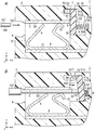
図2A及び図2Bには、変形例1の端子装置1が示されている。変形例1の端子装置1では、貫通孔70は、導体2の第一導体部20のX軸方向の正側の端部に対して、Y軸方向の正側に並ぶ位置に設けられている。貫通孔70は、筐体3のY軸方向の正側を向く外面から第一導体部20へとわたっている。貫通孔70と第二スペースS2とはX軸方向に並んでいる。
(4-1) Modified Example 1
The terminal device 1 of the modification 1 is shown by FIG. 2A and 2B. In the terminal device 1 of the first modification, the through hole 70 is provided at a position on the positive side in the Y-axis direction with respect to the positive-side end of the first conductor portion 20 of the conductor 2 in the X-axis direction. . The through hole 70 extends from the outer surface facing the positive side in the Y-axis direction of the housing 3 to the first conductor portion 20. The through hole 70 and the second space S2 are aligned in the X axis direction.

変形例1の端子装置1では、表示部材5が第一位置にあるときに、貫通孔70に表示マーク50(凸部52)が表示される。表示部材5が第二位置にあるときに、貫通孔70には表示マーク50が表示されない。   In the terminal device 1 of the modification 1, when the display member 5 is at the first position, the display mark 50 (convex portion 52) is displayed in the through hole 70. When the display member 5 is in the second position, the display mark 50 is not displayed in the through hole 70.

変形例1の端子装置1では、表示部材5が第二位置にあるときに、貫通孔70を通じて導体2の第一導体部20(つまり、導体2と同電位の導電部)が露出する。そのため、変形例1の端子装置1では、通電検査用の測定器の検査棒を貫通孔70に挿入して導電部(第一導体部20)に接触させることで、通電検査を行うことができ、貫通孔70を検査用開口としても利用することができる。   In the terminal device 1 of the first modification, when the display member 5 is at the second position, the first conductor portion 20 of the conductor 2 (that is, the conductive portion having the same potential as the conductor 2) is exposed through the through hole 70. Therefore, in the terminal device 1 of the modified example 1, the conduction inspection can be performed by inserting the inspection rod of the measuring device for the conduction inspection into the through hole 70 and bringing the inspection rod into contact with the conductive portion (first conductor portion 20). The through hole 70 can also be used as an inspection opening.

(4−2)変形例2
図3A及び図3Bには、変形例2の端子装置1が示されている。変形例2の端子装置1では、貫通孔70は、導体2の第一導体部20のX軸方向の正側の端部に対して、Y軸方向に並ぶ位置に設けられている。貫通孔70は、筐体3のY軸方向の正側を向く外面から第一導体部20へとわたっている。貫通孔70と第二スペースS2とはX軸方向に並んでいる。
(4-2) Modification 2
The terminal device 1 of the modification 2 is shown by FIG. 3A and 3B. In the terminal device 1 of the second modification, the through hole 70 is provided at a position aligned in the Y-axis direction with respect to the end on the positive side in the X-axis direction of the first conductor portion 20 of the conductor 2. The through hole 70 extends from the outer surface facing the positive side in the Y-axis direction of the housing 3 to the first conductor portion 20. The through hole 70 and the second space S2 are aligned in the X axis direction.

変形例2の端子装置1では、通し孔6が、第一スペースS1のうち、Y軸方向の負側の領域に直接連通している。変形例2の端子装置1では、Y軸方向の正の向きにおいて、接続対象100の先端部101が押し当てられる導体2(第二導体部21)と、鎖錠部4(第一ばね8)と、貫通孔70が、この順に並んでいる。第一ばね8は、本体80よりもY軸方向の負側に、鎖錠片82と押圧片84が位置している。接続対象100の先端部101には、第一ばね8からY軸方向の負の向きに、弾性力が加えられる。表示部材5は、Y軸方向の負側の端部が、導体2の第二導体部21に接するか、もしくは近接する長さを有する。   In the terminal device 1 of the second modification, the through hole 6 directly communicates with the region of the first space S1 on the negative side in the Y-axis direction. In the terminal device 1 of the second modification, the conductor 2 (second conductor portion 21) with which the tip end portion 101 of the connection target 100 is pressed in the positive direction of the Y-axis direction, and the lock portion 4 (first spring 8) The through holes 70 are arranged in this order. In the first spring 8, the locking piece 82 and the pressing piece 84 are located on the negative side in the Y-axis direction relative to the main body 80. An elastic force is applied to the tip end portion 101 of the connection target 100 in the negative direction of the Y-axis direction from the first spring 8. The display member 5 has a length such that the negative end in the Y-axis direction is in contact with or in proximity to the second conductor portion 21 of the conductor 2.

変形例2の端子装置1では、変形例1の端子装置1と同様に、表示部材5が第一位置にあるときに、貫通孔70に表示マーク50が表示され、表示部材5が第二位置にあるときに、貫通孔70に表示マーク50が表示されない。変形例2の端子装置1では、表示部材5が第二位置にあるときに、貫通孔70を通じて導体2の第一導体部20が露出し、貫通孔70を、導電部(第一導体部20)の通電状態を検査するための検査用開口としても利用することができる。   In the terminal device 1 of the second modification, as with the terminal device 1 of the first modification, when the display member 5 is at the first position, the display mark 50 is displayed in the through hole 70, and the display member 5 is at the second position. , The display mark 50 is not displayed in the through hole 70. In the terminal device 1 of the second modification, when the display member 5 is at the second position, the first conductor portion 20 of the conductor 2 is exposed through the through hole 70, and the through hole 70 is formed as a conductive portion (first conductor portion 20). It can also be used as an inspection opening for inspecting the conduction state of.

(4−3)変形例3
図4A及び図4Bには、変形例3の端子装置1が示されている。変形例3の端子装置1では、導体2は板状である。導体2は、Y軸方向に沿った厚み方向を有する。導体2には、Y軸方向に貫通した孔23が設けられている。
(4-3) Modification 3
The terminal device 1 of the modification 3 is shown by FIG. 4A and 4B. In the terminal device 1 of the third modification, the conductor 2 has a plate shape. The conductor 2 has a thickness direction along the Y-axis direction. The conductor 2 is provided with a hole 23 penetrating in the Y-axis direction.

第一ばね8は、導体2のうちY軸方向の負側を向く面に重ねられた平板状の本体80と、円弧状の連結部85と、平板状の傾斜部86と、円弧状の連結部87と、鎖錠片88とをこの順に連続して有する。連結部85は、本体80のX軸方向の正側の端部に連続している。   The first spring 8 has a flat body 80 superimposed on a surface of the conductor 2 facing the negative side in the Y-axis direction, an arc-shaped connecting portion 85, a flat sloped portion 86, and an arc-shaped connection It has the part 87 and the locking piece 88 continuously in this order. The connecting portion 85 is continuous with the positive end of the main body 80 in the X-axis direction.

鎖錠片88は、Z軸方向に見て、本体80に対して交差している。鎖錠片88と本体80とは、Z軸方向の位置が互いに異なる。鎖錠片88は、導体2の孔23を通って、導体2よりもY軸方向の正側に突出している。   The locking piece 88 intersects the main body 80 as viewed in the Z-axis direction. The locking piece 88 and the main body 80 are different in position in the Z-axis direction. The locking piece 88 protrudes through the hole 23 of the conductor 2 to the positive side in the Y-axis direction more than the conductor 2.

鎖錠片88には、X軸方向に貫通する挿入孔880が設けられている。挿入孔880に接続対象100の先端部101が挿入されていない状態では、挿入孔880の一部は、導体2よりもY軸方向の正の向きに突出している。この状態では、挿入孔880の内周面のうち、Y軸方向の負側を向く面881と導体2のY軸方向の正側を向く面との間には、接続対象100の先端部101のY軸方向の長さよりも短い隙間が形成されている。   The locking piece 88 is provided with an insertion hole 880 penetrating in the X-axis direction. In a state in which the distal end portion 101 of the connection target 100 is not inserted into the insertion hole 880, a part of the insertion hole 880 protrudes in the positive direction of the Y-axis direction relative to the conductor 2. In this state, the tip portion 101 of the connection target 100 is provided between the surface 881 facing the negative side in the Y-axis direction and the surface facing the positive side in the Y-axis direction of the conductor 2 among the inner peripheral surfaces of the insertion holes 880. A gap shorter than the length in the Y-axis direction is formed.

変形例3の端子装置1では、作業者が、接続対象100の先端部101を、端子装置1に対して通し孔6からX軸の正の向きに挿入すると、先端部101は、鎖錠片88の挿入孔880に導入される。このとき、先端部101の先端面102に押されることで、鎖錠片88がY軸方向の正の向きに変位し、傾斜部86と本体80との間隔が狭まるように弾性変形する。これにより、接続対象100の先端部101に対しては、鎖錠片88の面881のY軸方向の負側の先端縁882から、先端部101を導体2に押し付ける向きの力が作用し、先端部101のX軸方向の負の向きへの移動が規制される。   In the terminal device 1 of the third modification, when the operator inserts the distal end portion 101 of the connection target 100 into the terminal device 1 from the through hole 6 in the positive direction of the X axis, the distal end portion 101 is a locking piece It is introduced into the 88 insertion holes 880. At this time, the locking piece 88 is displaced in the positive direction of the Y-axis direction by being pushed by the distal end surface 102 of the distal end portion 101, and is elastically deformed so as to narrow the distance between the inclined portion 86 and the main body 80. Thus, a force in the direction of pressing the tip portion 101 against the conductor 2 acts on the tip portion 101 of the connection target 100 from the tip edge 882 on the negative side of the surface 881 of the locking piece 88 in the Y axis direction. The movement of the tip portion 101 in the negative direction of the X-axis direction is restricted.

変形例3の端子装置1においても、実施形態1の端子装置1と同様に、通し孔6から筐体3内に挿入した接続対象100の先端部101が、筐体3内の所定の位置まで挿入されたことを、貫通孔70を通じて視認でき、接続不良の発生を抑えることができる。   Also in the terminal device 1 of the third modification, similarly to the terminal device 1 of the first embodiment, the tip end portion 101 of the connection target 100 inserted into the housing 3 from the through hole 6 reaches a predetermined position in the housing 3 The insertion can be visually recognized through the through hole 70, and the occurrence of connection failure can be suppressed.

(4−4)その他
実施形態1及びその変形例1から3の端子装置1において、第一ばね8の形状は、図に示す形状に限らず、その他の形状であってもよい。実施形態1及び変形例1,2の第一ばね8は、鎖錠部4を有すればよく、押圧部10を有さなくてもよい。また、実施形態1及び変形例1,2の端子装置1は、押圧部10が第一ばね8とは別のばねで構成されてもよい。
(4-4) Others In the terminal device 1 of the first embodiment and its first to third modifications, the shape of the first spring 8 is not limited to the shape shown in the drawing, and may be another shape. The first spring 8 of Embodiment 1 and Modifications 1 and 2 may have the lock portion 4 and may not have the pressing portion 10. Further, in the terminal device 1 of the first embodiment and the first and second modifications, the pressing portion 10 may be configured by a spring different from the first spring 8.

実施形態1及びその変形例1〜3の端子装置1において、第二ばね9は、コイルばねに限らず、その他のばねであってもよい。また、実施形態1及びその変形例1〜3の端子装置1は、第二ばね9を複数備えてもよい。   In the terminal device 1 according to the first embodiment and the first to third modifications, the second spring 9 is not limited to a coil spring, and may be another spring. Moreover, the terminal device 1 of Embodiment 1 and its modifications 1-3 may be equipped with two or more 2nd springs 9. FIG.

実施形態1及び変形例3の端子装置1では、表示部7は、表示部材5の一部を筐体3の外側に表示可能な構造であればよく、表示部7は、貫通孔70と、貫通孔70を閉塞する透光部材とで構成されてもよい。   In the terminal device 1 according to the first embodiment and the third modification, the display unit 7 may have a structure capable of displaying a part of the display member 5 on the outside of the housing 3. You may be comprised by the translucent member which obstruct | occludes the through-hole 70. As shown in FIG.

実施形態1及びその変形例1〜3の端子装置1は、鎖錠部4による鎖錠を解除する解除レバーを備えてもよい。この場合、作業者は、解除レバーを操作することで、鎖錠部4による鎖錠を解除して、端子装置1から接続対象100を引き抜くことができる。なお、端子装置1は、解除レバーを備えなくてもよく、この場合、第一スペースS1に工具等を差し込むことで、鎖錠部4による鎖錠を解除することが可能であってもよい。   The terminal device 1 according to the first embodiment and the first to third modifications may include a release lever that releases the lock by the lock unit 4. In this case, the operator can release the lock by the lock unit 4 by operating the release lever, and pull out the connection target 100 from the terminal device 1. The terminal device 1 may not be provided with the release lever, and in this case, it may be possible to release the lock by the lock 4 by inserting a tool or the like into the first space S1.

実施形態1及び変形例3の端子装置1では、表示部材5は、凸部52を有さなくてもよく、本体部51のみで構成され、本体部51が表示マーク50を構成してもよい。   In the terminal device 1 of the first embodiment and the third modification, the display member 5 may not have the convex portion 52, and may be configured only by the main body 51, and the main body 51 may constitute the display mark 50. .

実施形態1及び変形例3の端子装置1では、表示部材5が、導電性を有する金属で形成されてもよく、第二位置にあるときの表示部材5を、導体2と同電位の導電部として利用してもよい。この場合、貫通孔70を、導電部の通電状態を検査するための検査用開口としても利用することができる。   In the terminal device 1 according to the first embodiment and the third modification, the display member 5 may be formed of a metal having conductivity, and the display member 5 in the second position is a conductive portion having the same potential as the conductor 2 You may use as. In this case, the through hole 70 can also be used as an inspection opening for inspecting the conductive state of the conductive portion.

また、実施形態1及びその変形例1〜3の端子装置1では、第二位置にあるときの表示部材5に接した状態の接続対象100の先端部101が、貫通孔70を通じて露出してもよい。この場合、先端部101を、導体2と同電位の導電部として利用でき、貫通孔70を、導電部の通電状態を検査するための検査用開口としても利用することができる。   Further, in the terminal device 1 according to the first embodiment and the first to third modifications, even if the tip end portion 101 of the connection target 100 in the state in contact with the display member 5 at the second position is exposed through the through hole 70 Good. In this case, the tip end portion 101 can be used as a conductive portion having the same potential as the conductor 2, and the through hole 70 can also be used as an inspection opening for testing the conductive state of the conductive portion.

(実施形態2)
次に、実施形態2の端子装置1について説明する。以下では、実施形態1の端子装置1とは異なる構成について詳しく説明し、実施形態1の端子装置1と同様の構成については、図中に同一の符号を付けて詳しい説明を省略する。
Second Embodiment
Next, the terminal device 1 of the second embodiment will be described. Below, the structure different from the terminal device 1 of Embodiment 1 is demonstrated in detail, about the structure similar to the terminal device 1 of Embodiment 1, the code | symbol same in a figure is attached and detailed description is abbreviate | omitted.

(1)概要
実施形態2の端子装置1では、表示部材5は、第一位置にあるときと第二位置にあるときとで、貫通孔70からの突出量が変化する。
(1) Overview In the terminal device 1 of the second embodiment, the amount of protrusion from the through hole 70 changes between the first position and the second position of the display member 5.

(2)詳細
詳しくは、本実施形態の端子装置1では、第二スペースS2には、表示部材5がY軸方向に直進移動可能に収容される。
(2) Details In detail, in the terminal device 1 of the present embodiment, the display member 5 is accommodated in the second space S2 so as to be linearly movable in the Y-axis direction.

表示部材5は、傾斜面510を有する本体部51と、本体部51からY軸方向の正の向きに突出した突出部53を備える。傾斜面510は、通し孔6から遠い部分ほど貫通孔70から離れて位置するように傾斜している。   The display member 5 includes a main body 51 having an inclined surface 510, and a protrusion 53 projecting from the main body 51 in the positive direction of the Y-axis. The inclined surface 510 is inclined such that a portion farther from the through hole 6 is located away from the through hole 70.

本体部51は、傾斜面510に対してX軸方向の正側に連続する平坦な先端面511をさらに有する。先端面511は、X軸方向に対して平行である。突出部53は、貫通孔70から突出可能なように、その形状及び寸法が設定されている。第二ばね9は、その内側に突出部53が位置するように、第二スペースS2に配される。   The main body portion 51 further includes a flat front end surface 511 which is continuous with the inclined surface 510 on the positive side in the X-axis direction. The tip end surface 511 is parallel to the X-axis direction. The shape and size of the protrusion 53 are set so as to be able to protrude from the through hole 70. The second spring 9 is disposed in the second space S2 such that the protrusion 53 is located inside.

表示部材5は、第一位置にあるときに、先端面511が、第二スペースS2に対してY軸方向の負側に対向する壁310に接する。表示部材5は、第二ばね9によってY軸方向の負の向きに押されることで、第一位置に位置する。表示部材5が第一位置にあるとき、X軸方向において傾斜面510が通し孔6に対向する。またこのとき、突出部53のY軸方向の正側の先端面530が、筐体3のうち、貫通孔70の周囲の外面(Y軸方向の正側を向く外面)と面一に位置する。   When the display member 5 is in the first position, the tip end surface 511 contacts the wall 310 facing the negative side in the Y-axis direction with respect to the second space S2. The display member 5 is positioned at the first position by being pushed in the negative direction of the Y-axis direction by the second spring 9. When the display member 5 is in the first position, the inclined surface 510 faces the through hole 6 in the X-axis direction. At this time, the front end surface 530 on the positive side in the Y-axis direction of the protrusion 53 is flush with the outer surface (the outer surface facing the positive side in the Y-axis direction) of the housing 3 around the through hole 70. .

表示部材5は、傾斜面510が接続対象100の先端部101の先端面102によって押されることで、Y軸方向の正の向きとX軸方向の正の向きの力の成分のうちのY軸方向の正の向きの成分によってY軸方向の正の向きに直進移動し、第二位置に位置する。表示部材5が第二位置にあるときに、表示部材5の本体部51の先端面511が先端部101のY軸方向の正側を向く面に接する。表示部材5が第二位置にあるとき、突出部53は、そのY軸方向の正側の端部が、貫通孔70からY軸方向の正側に突出する。   In the display member 5, when the inclined surface 510 is pushed by the tip surface 102 of the tip portion 101 of the connection target 100, the Y axis among the components of force in the positive direction along the Y axis and the positive direction along the X axis. The component moves linearly in the positive direction of the Y-axis direction by the component of the positive direction of the direction, and is positioned at the second position. When the display member 5 is in the second position, the front end surface 511 of the main body 51 of the display member 5 is in contact with the surface of the front end 101 facing the positive side in the Y-axis direction. When the display member 5 is in the second position, the end of the protrusion 53 on the positive side in the Y-axis direction protrudes from the through hole 70 to the positive side in the Y-axis direction.

以上説明した実施形態2の端子装置1では、通し孔6から筐体3内に挿入した接続対象100の先端部101を、筐体3内の所定の位置(第二位置にある表示部材5に接する位置)まで挿入することで、貫通孔70から表示部材5の突出部53が突出する。そのため、作業者は、貫通孔70を見ることで、接続対象100の先端部101が、筐体3に対して所定の位置まで挿入されたことが確認できる。これにより、実施形態2の端子装置1では、接続対象100が筐体3内の所定の位置まで挿入されなくて、接続不良が生じることを抑えることができる。   In the terminal device 1 of the second embodiment described above, the front end portion 101 of the connection target 100 inserted into the housing 3 from the through hole 6 is at a predetermined position in the housing 3 (in the display member 5 at the second position). The projection 53 of the display member 5 is projected from the through hole 70 by inserting it to a position where the contact portion contacts). Therefore, the worker can confirm that the tip end portion 101 of the connection target 100 has been inserted to the predetermined position with respect to the housing 3 by looking at the through hole 70. As a result, in the terminal device 1 of the second embodiment, the connection target 100 is not inserted to a predetermined position in the housing 3, and the occurrence of connection failure can be suppressed.

加えて、本実施形態の端子装置1では、表示部材5がY軸方向にのみ直進移動するため、筐体3内における表示部材5のX軸方向の配置スペースを効果的に抑えることができる。   In addition, in the terminal device 1 of the present embodiment, since the display member 5 linearly moves only in the Y-axis direction, the arrangement space of the display member 5 in the X-axis direction in the housing 3 can be effectively suppressed.

なお、貫通孔70から突出した表示部材5の突出部53は、施工の示唆等に利用してもよい。例えば、端子装置1を収容するケースの扉に、貫通孔70から突出した突出部53に当たることで扉を閉じる動作を可能とする構造を設けて、接続対象100を適切に接続した状態でだけ、ケースの扉を閉じることができるようにしてもよい。   In addition, you may utilize the protrusion part 53 of the display member 5 which protruded from the through-hole 70 for the suggestion etc. of construction. For example, the door of the case that accommodates the terminal device 1 is provided with a structure that enables the operation of closing the door by contacting the protrusion 53 that protrudes from the through hole 70, and only when the connection target 100 is properly connected. It may be possible to close the door of the case.

(3)変形例
次に、実施形態2の端子装置1の変形例について説明する。以下では、端子装置1の変形例について、実施形態2の端子装置1と異なる構成について詳しく説明する。
(3) Modifications Next, modifications of the terminal device 1 of the second embodiment will be described. Below, about a modification of terminal device 1, a different composition from terminal device 1 of Embodiment 2 is explained in detail.

(3−1)変形例1
図6A及び図6Bには、変形例1の端子装置1が示されている。変形例1の端子装置1は、X軸方向の正の向き(挿入向き)において、押圧部10と表示部材5の間に位置する中間部材11をさらに備える。
(3-1) Modification 1
The terminal device 1 of the modification 1 is shown by FIG. 6A and 6B. The terminal device 1 of the modification 1 further includes an intermediate member 11 positioned between the pressing portion 10 and the display member 5 in the positive direction (insertion direction) in the X-axis direction.

中間部材11は、表示部材5の傾斜面510に当たる押し当て面110を有する。押し当て面110は、Y軸方向の長さが、接続対象100の先端部101の先端面102のY軸方向の長さよりも大きい。押し当て面110は、通し孔6から離れた部分ほど貫通孔70から離れて位置するように傾斜している。押し当て面110のX軸方向に対する傾斜角度と、傾斜面510のX軸方向に対する傾斜角度は同じである。押し当て面110は、傾斜面510よりもY軸方向の長さが長い。中間部材11は、X軸方向の負側を向く面111が、Y軸方向に対して平行である。   The intermediate member 11 has a pressing surface 110 that abuts on the inclined surface 510 of the display member 5. The pressing surface 110 has a length in the Y-axis direction larger than the length in the Y-axis direction of the tip surface 102 of the tip portion 101 of the connection target 100. The pressing surface 110 is inclined so as to be spaced apart from the through hole 70 as it goes away from the through hole 6. The inclination angle of the pressing surface 110 with respect to the X-axis direction is the same as the inclination angle of the inclined surface 510 with respect to the X-axis direction. The pressing surface 110 is longer than the inclined surface 510 in the Y-axis direction. In the intermediate member 11, the surface 111 facing the negative side in the X-axis direction is parallel to the Y-axis direction.

筐体3は、中間部材11のZ軸方向の両端部が収容される支持溝34を有する。支持溝34は、筐体3のZ軸方向に対向する一対の壁のそれぞれに設けられている。中間部材11は、一対の支持溝34によってY軸方向及びZ軸方向の移動が規制され、X軸方向の正の向きと負の向きの両方にのみ移動可能である。   The housing 3 has a support groove 34 in which both ends in the Z-axis direction of the intermediate member 11 are accommodated. The support grooves 34 are provided in each of a pair of walls opposed in the Z-axis direction of the housing 3. The intermediate member 11 is restricted in movement in the Y-axis direction and the Z-axis direction by the pair of support grooves 34, and can move only in both the positive direction and the negative direction in the X-axis direction.

変形例1の端子装置1では、通し孔6から筐体3内に接続対象100の先端部101を挿入すると、先端部101の先端面102が中間部材11の面111に当たる。そして、中間部材11の押し当て面110が、第一位置にある表示部材5の傾斜面510をX軸方向の正の向きに押す。これにより、Y軸方向の正の向きの力の成分によって、表示部材5は第二位置に直進移動し、貫通孔70から表示部材5の突出部53が突出する。   In the terminal device 1 of the first modification, when the distal end portion 101 of the connection target 100 is inserted into the housing 3 from the through hole 6, the distal end surface 102 of the distal end portion 101 abuts the surface 111 of the intermediate member 11. Then, the pressing surface 110 of the intermediate member 11 pushes the inclined surface 510 of the display member 5 at the first position in the positive direction of the X-axis direction. As a result, the display member 5 is moved straight to the second position by the component of the force in the positive Y-axis direction, and the projection 53 of the display member 5 protrudes from the through hole 70.

変形例1の端子装置1では、接続対象100の先端面102が、中間部材11のうちY軸方向に対して平行な面111に当たるため、先端部101がY軸方向に変形しにくく、表示部材5を押しやすい。   In the terminal device 1 of the first modification, the tip end surface 102 of the connection target 100 is in contact with the surface 111 of the intermediate member 11 parallel to the Y axis direction, so the tip end portion 101 is unlikely to be deformed in the Y axis direction. Easy to press 5

また、変形例1の端子装置1では、実施形態2の端子装置1に比べて、第二スペースS2をY軸方向の負側に配置することができ、筐体3のY軸方向の長さを抑えることができる。   Moreover, in the terminal device 1 of the modification 1, compared with the terminal device 1 of the second embodiment, the second space S2 can be arranged on the negative side in the Y-axis direction, and the length of the housing 3 in the Y-axis direction Can be reduced.

また、変形例1の端子装置1では、接続対象100の先端部101よりもY軸方向に長い押し当て面110で傾斜面510を押すことで、第二位置にあるときの表示部材5の貫通孔70からの突出量をさらに増やすことも可能である。   Moreover, in the terminal device 1 of the modification 1, the penetration of the display member 5 in the second position is achieved by pressing the inclined surface 510 with the pressing surface 110 which is longer in the Y-axis direction than the tip portion 101 of the connection target 100. It is also possible to further increase the amount of protrusion from the hole 70.

(3−2)変形例2
図7A及び図7Bには、変形例2の端子装置1が示されている。変形例2の端子装置1は、第一ばね8の形状が、実施形態2の端子装置1の第一ばね8とは異なる。変形例2の端子装置1の第一ばね8、導体2、及び第一スペースS1は、実施形態1の変形例3の端子装置1の第一ばね8、導体2、及び第一スペースS1と同様の構造である。
(3-2) Modification 2
The terminal device 1 of the modification 2 is shown by FIG. 7A and 7B. The terminal device 1 of the second modification differs from the first spring 8 of the terminal device 1 of the second embodiment in the shape of the first spring 8. The first spring 8, the conductor 2, and the first space S1 of the terminal device 1 of the second modification are the same as the first spring 8, the conductor 2, and the first space S1 of the terminal device 1 of the third modification of the first embodiment. Is the structure of

変形例2の端子装置1においても、通し孔6から筐体3内に挿入した接続対象100の先端部101を、筐体3内の所定の位置まで挿入することで、貫通孔70から表示部材5の突出部53が突出し、作業者が視認可能である。そのため、変形例2の端子装置1では、接続対象100が筐体3内の所定の位置まで挿入されなくて、接続不良が生じることを抑えることができる。   Also in the terminal device 1 of the second modification, the distal end portion 101 of the connection target 100 inserted into the housing 3 from the through hole 6 is inserted to a predetermined position in the housing 3 to display the display member from the through hole 70 The protrusion 53 of 5 protrudes and is visible to the operator. Therefore, in the terminal device 1 of the second modification, the connection target 100 is not inserted to a predetermined position in the housing 3, and the occurrence of connection failure can be suppressed.

(3−3)その他
実施形態2及び変形例1,2の端子装置1において、第一ばね8の形状は、その他の形状であってもよく、また、第一ばね8は、鎖錠部4を有すればよく、押圧部10を有さなくてもよい。また、実施形態2及び変形例1の端子装置1は、押圧部10が、第一ばね8とは別のばねで構成されてもよい。
(3-3) Others In the terminal device 1 according to the second embodiment and the first and second modifications, the shape of the first spring 8 may be another shape, and the first spring 8 may be a lock 4 It is not necessary to have the pressing portion 10. Moreover, as for the terminal device 1 of Embodiment 2 and the modification 1, the press part 10 may be comprised with a spring different from the 1st spring 8. FIG.

実施形態2及び変形例1,2の端子装置1において、第二ばね9は、コイルばねに限らず、その他のばねであってもよい。また、実施形態2及び変形例1,2の端子装置1は、第二ばね9を複数備えてもよい。   In the terminal device 1 of the second embodiment and the first and second modifications, the second spring 9 is not limited to a coil spring, and may be another spring. Moreover, the terminal device 1 of Embodiment 2 and Modified Examples 1 and 2 may include a plurality of second springs 9.

実施形態2及び変形例1,2の端子装置1は、鎖錠部4による鎖錠を解除する解除レバーを備えてもよい。   The terminal device 1 according to the second embodiment and the first and second modifications may include a release lever that releases the lock by the lock unit 4.

変形例1,2の端子装置1においても、第二位置にあるときに貫通孔70から突出する突出部53を、施工の示唆等に利用してもよい。   Also in the terminal device 1 of the modified examples 1 and 2, the projecting portion 53 which protrudes from the through hole 70 when in the second position may be used for the suggestion or the like of the construction.

実施形態2及び変形例1,2の端子装置1は、表示部材5が第一位置にあるときに、突出部53が貫通孔70から突出し、表示部材5が第二位置にあるときに、突出部53が貫通孔70から突出しないように設けてもよい。   In the terminal device 1 of the second embodiment and the first and second modifications, the protrusion 53 protrudes from the through hole 70 when the display member 5 is at the first position, and the terminal device 1 protrudes when the display member 5 is at the second position. The portion 53 may be provided so as not to protrude from the through hole 70.

また、実施形態2及び変形例1,2の端子装置1は、表示部材5が第一位置にあるときと第二位置にあるときの両方において、突出部53が貫通孔70から突出してもよく、その突出長さが、第一位置にあるときと第二位置にあるときとで、互いに異なってもよい。   In the terminal device 1 of the second embodiment and the first and second modifications, the protrusion 53 may protrude from the through hole 70 both when the display member 5 is at the first position and when the display member 5 is at the second position. The protruding lengths may be different from each other when in the first position and when in the second position.

(実施形態3)
次に、実施形態3の端子装置1について説明する。以下では、実施形態1の端子装置1とは異なる構成について詳しく説明し、実施形態1の端子装置1と同様の構成については、図中に同一の符号を付けて詳しい説明を省略する。
(Embodiment 3)
Next, the terminal device 1 of the third embodiment will be described. Below, the structure different from the terminal device 1 of Embodiment 1 is demonstrated in detail, about the structure similar to the terminal device 1 of Embodiment 1, the code | symbol same in a figure is attached and detailed description is abbreviate | omitted.

(1)概要
実施形態3の端子装置1では、表示部材5は、接続対象100に押されることで、第一位置から第二位置へ直進移動と回転移動の両方を含む態様で移動する。
(1) Overview In the terminal device 1 of the third embodiment, the display member 5 is moved by the connection target 100 from the first position to the second position in a mode including both linear movement and rotational movement.

(2)詳細
本実施形態の端子装置1では、筐体3は、第二位置にあるときの表示部材5が接する傾斜面35を有する。傾斜面35は、第二スペースS2に対してX軸方向の正側に対向する面である。傾斜面35は、通し孔6から遠い部分ほど貫通孔70から離れて位置するように傾斜している。
(2) Details In the terminal device 1 of the present embodiment, the housing 3 has an inclined surface 35 with which the display member 5 is in contact when in the second position. The inclined surface 35 is a surface opposite to the second space S2 on the positive side in the X-axis direction. The inclined surface 35 is inclined such that a portion farther from the through hole 6 is located away from the through hole 70.

表示部材5は、本体部51からZ軸方向の両側にそれぞれ突出する突部54を有する。突部54は、Z軸方向に見て、矩形状である。筐体3のZ軸方向に対向する一対の壁のそれぞれには、突部54が収容されるガイド溝36が設けられている。   The display member 5 has protrusions 54 respectively projecting from both sides of the main body 51 in the Z-axis direction. The protrusion 54 is rectangular when viewed in the Z-axis direction. The guide groove 36 in which the protrusion 54 is accommodated is provided in each of a pair of wall which opposes to Z-axis direction of the housing | casing 3. As shown in FIG.

ガイド溝36は、直進ガイド部360と、直進ガイド部360のX軸方向の正側に連続する回転ガイド部361とを含む。回転ガイド部361は、直進ガイド部360よりもX軸方向の正側に位置する。直進ガイド部360は、Y軸方向の長さが突部54のY軸方向の長さと略同じであり、回転ガイド部361は、直進ガイド部360よりもY軸方向に広い。   The guide groove 36 includes a rectilinear guide portion 360 and a rotation guide portion 361 continuous with the rectilinear side of the rectilinear guide portion 360 in the X-axis direction. The rotation guide portion 361 is positioned on the positive side in the X-axis direction relative to the rectilinear guide portion 360. The length of the rectilinear guide portion 360 in the y-axis direction is substantially the same as the length of the protrusion 54 in the y-axis direction, and the rotation guide portion 361 is wider in the y-axis direction than the rectilinear guide portion 360.

表示部材5は、直進ガイド部360に沿って直進移動し、回転ガイド部361において回転移動する。   The display member 5 moves rectilinearly along the rectilinear guide portion 360 and rotationally moves in the rotation guide portion 361.

本実施形態の端子装置1では、接続対象100の先端部101の先端面102で第一位置にある表示部材5がX軸方向の正の向きに押されることで、第一位置にある表示部材5は、X軸方向の正の向きに直進移動する。表示部材5は、本体部51のX軸方向の正側を向く面512のうち、Y軸方向の正側の端縁513が傾斜面35に当たるまで、直進移動する。その後、表示部材5は、端縁513を中心にして、本体部51の面512が傾斜面35に全体的に接触する位置(つまり第二位置)まで、回転移動する。   In the terminal device 1 of the present embodiment, the display member 5 at the first position on the tip surface 102 of the tip portion 101 of the connection target 100 is pushed in the positive direction of the X-axis direction, and the display member at the first position 5 moves straight in the positive direction along the X-axis. The display member 5 moves rectilinearly until the edge 513 on the positive side in the Y-axis direction of the surface 512 facing the positive side in the X-axis direction of the main body 51 hits the inclined surface 35. Thereafter, the display member 5 is rotationally moved about the edge 513 to a position where the surface 512 of the main body 51 entirely contacts the inclined surface 35 (that is, the second position).

本実施形態の端子装置1では、表示部材5が第一位置から第二位置へ移動する際、表示部材5の一対の突部54が収容された筐体3の一対のガイド溝36の直進ガイド部360によってガイドされ、表示部材5が第二位置の手前まで直進移動する。これにより、本実施形態の端子装置1では、表示部材5が接続対象100の先端面102に対して傾くことが抑制され、第一位置から第二位置への移動の態様に回転移動を含むものの、接続対象100の先端面102で表示部材5が押しやすい。   In the terminal device 1 of the present embodiment, when the display member 5 moves from the first position to the second position, the straight advance guides of the pair of guide grooves 36 of the housing 3 in which the pair of protrusions 54 of the display member 5 is accommodated. Guided by the part 360, the display member 5 moves straight to the front of the second position. Thereby, in the terminal device 1 of the present embodiment, the display member 5 is suppressed from being inclined with respect to the distal end surface 102 of the connection target 100, and the movement from the first position to the second position includes rotational movement. The display member 5 can be easily pushed by the front end surface 102 of the connection target 100.

以上説明した実施形態3の端子装置1においても、通し孔6から筐体3内に挿入した接続対象100の先端部101を、筐体3内の所定の位置まで挿入することで、貫通孔70に凸部52(表示マーク50)が表示され、作業者が視認可能である。そのため、実施形態3の端子装置1では、接続対象100が筐体3内の所定の位置まで挿入されなくて、接続不良が生じることを抑えることができる。   Also in the terminal device 1 of the third embodiment described above, the through hole 70 is obtained by inserting the tip portion 101 of the connection target 100 inserted into the housing 3 from the through hole 6 to a predetermined position in the housing 3. The convex portion 52 (display mark 50) is displayed on the screen, and can be visually recognized by the operator. Therefore, in the terminal device 1 according to the third embodiment, the connection target 100 is not inserted to a predetermined position in the housing 3, and the occurrence of connection failure can be suppressed.

(3)変形例
次に、実施形態3の端子装置1の変形例について説明する。以下では、端子装置1の変形例について、実施形態3の端子装置1と異なる構成について詳しく説明する。
(3) Modified Example Next, a modified example of the terminal device 1 of the third embodiment will be described. Below, about a modification of terminal device 1, the composition different from terminal device 1 of Embodiment 3 is explained in detail.

(3−1)変形例1
変形例1の端子装置1では、傾斜面35が、通し孔6に近い部分ほど貫通孔70から離れて位置するように傾斜している。
(3-1) Modification 1
In the terminal device 1 of the first modification, the inclined surface 35 is inclined such that a portion closer to the through hole 6 is located away from the through hole 70.

変形例1の端子装置1では、接続対象100の先端部101の先端面102で第一位置にある表示部材5がX軸方向の正の向きに押されることで、第一位置にある表示部材5がX軸方向の正の向きに直進移動する。表示部材5は、本体部51のX軸方向の正側を向く面512のうち、Y軸方向の負側の端縁514が傾斜面35に当たるまで、直進移動する。その後、表示部材5は、端縁514を中心にして、本体部51の面512が傾斜面35に全体的に接触する位置(つまり第二位置)まで、回転移動する。   In the terminal device 1 of the modified example 1, the display member 5 at the first position is pushed in the positive direction of the X-axis direction by the front end surface 102 of the front end portion 101 of the connection target 100, whereby the display member at the first position 5 moves straight in the positive direction along the X-axis. The display member 5 moves rectilinearly until the edge 514 on the negative side in the Y-axis direction of the surface 512 facing the positive side in the X-axis direction of the main body 51 hits the inclined surface 35. Thereafter, the display member 5 is rotationally moved about the edge 514 to a position where the surface 512 of the main body 51 entirely contacts the inclined surface 35 (that is, the second position).

変形例1の端子装置1においても、筐体3の一対のガイド溝36の直進ガイド部360によって、表示部材5が傾くことを抑制でき、接続対象100の先端面102で表示部材5が押しやすい。   Also in the terminal device 1 of the first modification, the rectilinear guide portions 360 of the pair of guide grooves 36 of the housing 3 can suppress the display member 5 from being inclined, and the display member 5 is easily pushed by the tip surface 102 of the connection target 100 .

以上説明した変形例1の端子装置1においても、通し孔6から筐体3内に挿入した接続対象100の先端部101を、筐体3内の所定の位置まで挿入することで、貫通孔70に凸部52(表示マーク50)が表示され、作業者が視認可能である。そのため、変形例1の端子装置1では、接続対象100が筐体3内の所定の位置まで挿入されなくて、接続不良が生じることを抑えることができる。   Also in the terminal device 1 of the first modification described above, the through hole 70 is obtained by inserting the tip end portion 101 of the connection target 100 inserted into the housing 3 from the through hole 6 to a predetermined position in the housing 3. The convex portion 52 (display mark 50) is displayed on the screen, and can be visually recognized by the operator. Therefore, in the terminal device 1 of the first modification, the connection target 100 is not inserted to a predetermined position in the housing 3 and it is possible to suppress the occurrence of connection failure.

(3−2)その他
実施形態3及び変形例1の端子装置1において、第一ばね8の形状は、その他の形状であってもよく、また、第一ばね8は、鎖錠部4を有すればよく、押圧部10を有さなくてもよい。また、実施形態3及び変形例1の端子装置1は、押圧部10が、第一ばね8とは別のばねで構成されてもよい。
(3-2) Others In the terminal device 1 of the third embodiment and the first modification, the shape of the first spring 8 may be another shape, and the first spring 8 has the lock 4. It suffices to do not have the pressing portion 10. Moreover, as for the terminal device 1 of Embodiment 3 and the modification 1, the press part 10 may be comprised with a spring different from the 1st spring 8. FIG.

実施形態3及び変形例1の端子装置1において、コイルばねに限らず、その他のばねであってもよい。また、実施形態3及び変形例1の端子装置1は、第二ばね9を複数備えてもよい。   In the terminal device 1 of the third embodiment and the first modification, not only the coil spring but also another spring may be used. Moreover, the terminal device 1 of Embodiment 3 and the modification 1 may be equipped with two or more 2nd springs 9. As shown in FIG.

実施形態3及び変形例1の端子装置1において、表示部7は、貫通孔70と、貫通孔70を塞ぐ透光部材とで構成されてもよい。   In the terminal device 1 of the third embodiment and the first modification, the display unit 7 may be configured of the through hole 70 and the light transmitting member closing the through hole 70.

実施形態3及び変形例1の端子装置1は、鎖錠部4による鎖錠を解除する解除レバーを備えてもよい。   The terminal device 1 of Embodiment 3 and Modification 1 may include a release lever that releases the lock by the lock unit 4.

実施形態3及び変形例1の端子装置1は、第二位置の直前で表示部材5を回転移動させる構造を、傾斜面35以外で構成してもよい。   In the terminal device 1 of the third embodiment and the first modification, the structure for rotationally moving the display member 5 immediately before the second position may be configured other than the inclined surface 35.

実施形態3及び変形例1の端子装置1では、表示部材5が、導電性を有する金属で形成されてもよく、第二位置にあるときの表示部材5を、導体2と同電位の導電部として利用してもよい。この場合、貫通孔70を、導電部の通電状態を検査するための検査用開口としても利用することができる。   In the terminal device 1 of the third embodiment and the first modification, the display member 5 may be formed of a metal having conductivity, and the display member 5 in the second position is a conductive portion having the same potential as the conductor 2 You may use as. In this case, the through hole 70 can also be used as an inspection opening for inspecting the conductive state of the conductive portion.

[電力変換装置]
次に、電力変換装置200について説明する。電力変換装置200は、上述した実施形態1〜3及びその変形例のいずれかの端子装置1と、端子装置1の導体2に対して電気的に接続される電力変換回路12と、を備える。
[Power converter]
Next, power converter 200 will be described. The power conversion device 200 includes the terminal device 1 according to any of the first to third embodiments and the modifications thereof, and the power conversion circuit 12 electrically connected to the conductor 2 of the terminal device 1.

図10には、電力変換装置200の使用例が示されている。電力変換装置200は、例えば、電力変換回路12が太陽電池13に電気的に接続される。   FIG. 10 shows an example of use of the power conversion device 200. In the power conversion device 200, for example, the power conversion circuit 12 is electrically connected to the solar cell 13.

電力変換装置200は、電力変換回路12に接続される端子装置1を複数有する。複数の端子装置1は、互いに同じ構造の端子装置であってもよいし、互いに異なる構造の端子装置の組み合わせであってもよい。つまり、複数の端子装置1は、実施形態1〜3及びその変形例のいずれか一種類の端子装置1、または、その組み合わせで構成される。   Power converter 200 has a plurality of terminal devices 1 connected to power converter circuit 12. The plurality of terminal devices 1 may be terminal devices having the same structure as each other, or may be a combination of terminal devices having different structures. That is, the plurality of terminal devices 1 are configured by any one of the terminal devices 1 of the first to third embodiments and the modifications thereof, or a combination thereof.

電力変換回路12は、例えば直流電力を交流電力に変換するインバーター回路である。なお、電力変換回路12は、直流電力を電圧を昇降した直流電力に変換する回路であってもよい。   The power conversion circuit 12 is, for example, an inverter circuit that converts DC power into AC power. The power conversion circuit 12 may be a circuit that converts DC power into DC power obtained by raising and lowering the voltage.

電力変換装置200を用いることで、作業者は、各端子装置1と接続対象100とが適切に接続されていることを視認でき、太陽電池13で発電された電気を、屋内等の電気機器に適切に供給することができる。   By using the power conversion device 200, the worker can visually recognize that each terminal device 1 and the connection target 100 are properly connected, and the electricity generated by the solar cell 13 can be used as an electrical device such as indoors. It can be supplied properly.

[まとめ]
以上説明した実施形態1〜3及びその変形例の端子装置1のように、第一態様の端子装置1は、下記の構成を備える。
[Summary]
The terminal device 1 according to the first aspect has the following configuration as in the terminal device 1 according to the first to third embodiments and the modifications thereof described above.

すなわち、第一態様の端子装置1は、筐体3と、鎖錠部4と、表示部材5とを備える。筐体3は、導体2を収容し、接続対象が通される通し孔6を有する。鎖錠部4は、通し孔6を通じて筐体3内に挿入された接続対象100を、導体2との間で挟むことで接続対象100の挿入向きとは反対の向きの移動を規制する。表示部材5は、筐体3に収容され、前記挿入向きにおいて鎖錠部4に対して通し孔6とは反対側に位置する。表示部材5は、接続対象100に押されることで第一位置から第二位置へ直進移動を含む態様で移動する。筐体3は、表示部7を更に有する。表示部材5の一部は、表示部7を通じて筐体3の外側に表示可能である。表示部材5が第一位置にあるときと第二位置にあるときとで、表示部7の表示態様が変化する。   That is, the terminal device 1 of the first aspect includes the housing 3, the lock 4, and the display member 5. The housing 3 accommodates the conductor 2 and has a through hole 6 through which the connection target passes. The locking unit 4 restricts movement of the connection target 100 in the opposite direction to the insertion direction of the connection target 100 by sandwiching the connection target 100 inserted into the housing 3 through the through hole 6 with the conductor 2. The display member 5 is accommodated in the housing 3 and is located on the opposite side to the through hole 6 with respect to the locking part 4 in the insertion direction. When the display member 5 is pushed by the connection target 100, the display member 5 moves in a mode including straight movement from the first position to the second position. The housing 3 further includes a display unit 7. A portion of the display member 5 can be displayed outside the housing 3 through the display unit 7. The display mode of the display unit 7 changes between when the display member 5 is at the first position and when it is at the second position.

上記構成を備えることで、第一態様の端子装置1では、通し孔6を通じて筐体3内に接続対象100を挿入した際に、表示部材5を押して第二位置まで移動させることができ、表示部材5の一部を表示可能な表示部7の表示態様を変化させることができる。   With the above configuration, in the terminal device 1 of the first aspect, when the connection target 100 is inserted into the housing 3 through the through hole 6, the display member 5 can be pushed and moved to the second position, and display The display mode of the display unit 7 capable of displaying a part of the member 5 can be changed.

そのため、第一態様の端子装置1では、作業者は、表示部7の表示態様を見ることで、接続対象100が筐体3内の所定位置(第二位置にある表示部材5に接する位置)まで挿入されたか否かを確認することができる。   Therefore, in the terminal device 1 according to the first aspect, the worker looks at the display mode of the display unit 7 and the connection target 100 is in a predetermined position in the housing 3 (a position where the connection object 100 contacts the display member 5 in the second position). It can be checked whether or not it has been inserted.

また、実施形態1、3及びその変形例の端子装置1のように、第二態様の端子装置1は、第一態様の端子装置1の構成に加えて、下記の構成を備える。   Moreover, in addition to the structure of the terminal device 1 of a 1st aspect, the terminal device 1 of a 2nd aspect is equipped with the following structure like the terminal device 1 of Embodiment 1, 3 and its modification.

すなわち、第二態様の端子装置1では、表示部7は、筐体3を貫通する貫通孔70を有する。表示部材5は、表示マーク50を有する。表示マーク50は、表示部材5が第一位置と第二位置とのうちの一方にあるときに、貫通孔70を通じて筐体3の外側に表示され、かつ表示部材5が第一位置と第二位置とのうちの他方にあるときに、貫通孔70を通じて筐体3の外側に表示されない。   That is, in the terminal device 1 of the second aspect, the display unit 7 has a through hole 70 that penetrates the housing 3. The display member 5 has a display mark 50. The display mark 50 is displayed on the outside of the housing 3 through the through hole 70 when the display member 5 is at one of the first position and the second position, and the display member 5 has the first position and the second position. When in the other of the positions, they are not displayed on the outside of the housing 3 through the through holes 70.

上記構成を備えることで、第二態様の端子装置1では、貫通孔70を通じて表示部材5の表示マーク50を確認することで、接続対象100の接続状態を確認することができる。第二態様の端子装置1では、表示部材5の一部が筐体3の外側に突出しないため、この突出した部分が邪魔にならない。   By providing the above configuration, in the terminal device 1 of the second aspect, the connection mark of the display object 5 can be confirmed through the through hole 70, so that the connection state of the connection object 100 can be confirmed. In the terminal device 1 of the second aspect, since a part of the display member 5 does not protrude to the outside of the housing 3, the protruding part does not interfere.

また、実施形態2及びその変形例の端子装置1のように、第三態様の端子装置1は、第一態様の端子装置1の構成に加えて、下記の構成を備える。   Moreover, in addition to the structure of the terminal device 1 of a 1st aspect, the terminal device 1 of a 3rd aspect is equipped with the following structure like the terminal device 1 of Embodiment 2 and its modification.

すなわち、第三態様の端子装置1では、表示部7は、筐体3を貫通する貫通孔70である。表示部材5は、第一位置にあるときと第二位置にあるときとで、貫通孔70からの突出量が変化する。   That is, in the terminal device 1 of the third aspect, the display unit 7 is the through hole 70 penetrating the housing 3. The amount of protrusion of the display member 5 from the through hole 70 changes between the first position and the second position.

上記構成を備えることで、第三態様の端子装置1では、作業者は、貫通孔70の開口した方向に限らずその他の方向から貫通孔70を見ても、表示部7の表示態様の変化を確認することができる。   In the terminal device 1 according to the third aspect, the worker changes the display mode of the display 7 even if the operator views the through hole 70 from other directions as well as the direction in which the through hole 70 is opened. Can be confirmed.

また、実施形態1、3の変形例の端子装置1のように、第三四態様の端子装置1は、第一態様の端子装置1の構成に加えて、下記の構成を備える。   In addition to the configuration of the terminal device 1 according to the first aspect, the terminal device 1 according to the third aspect has the following configuration as in the terminal device 1 according to the modification of the first and third embodiments.

すなわち、第四態様の端子装置1では、表示部7は、筐体3を貫通する貫通孔70である。表示部材5が第二位置にあるときに、導体2と同電位の導電部(導体2、導電性の表示部材5、または接続対象100の先端部101)が、貫通孔70から露出する。   That is, in the terminal device 1 of the fourth aspect, the display unit 7 is the through hole 70 which penetrates the housing 3. When the display member 5 is in the second position, a conductive portion (conductor 2, conductive display member 5 or tip portion 101 of the connection target 100) having the same potential as the conductor 2 is exposed from the through hole 70.

上記構成を備えることで、第四態様の端子装置1では、通電検査用の測定器の検査棒を貫通孔70に挿入して導電部に接触させることで、通電検査を行うことができ、貫通孔70を検査用開口としても利用することができる。   With the above-described configuration, in the terminal device 1 of the fourth aspect, by inserting the inspection rod of the measuring instrument for the conduction inspection into the through hole 70 and bringing it into contact with the conductive portion, the conduction inspection can be performed. The holes 70 can also be used as inspection openings.

また、実施形態1〜3及びその変形例の端子装置1のように、第五態様の端子装置1は、第一〜第四態様のいずれかの端子装置1の構成に加えて、下記の構成を備える。   In addition to the configuration of the terminal device 1 according to any one of the first to fourth aspects, the terminal device 1 according to the fifth aspect has the following configuration, as in the terminal devices 1 according to the first to third embodiments and the modifications thereof. Equipped with

すなわち、第五態様の端子装置1は、第二位置にある表示部材5に対して第一位置へ移動する向きに弾性力を加えるばね(第二ばね9)を更に備える。   That is, the terminal device 1 of the fifth aspect further includes a spring (second spring 9) that applies an elastic force in a direction to move to the first position with respect to the display member 5 in the second position.

上記構成を備えることで、第五態様の端子装置1では、接続対象100が筐体3内の所定位置まで挿入されていないにもかかわらず、表示部材5が第二位置に位置することを防ぐことができる。   With the above configuration, in the terminal device 1 of the fifth aspect, the display member 5 is prevented from being positioned at the second position although the connection target 100 is not inserted to the predetermined position in the housing 3 be able to.

また、実施形態1、3及びその変形例の端子装置1のように、第六態様の端子装置1は、第一、第二、第四態様のいずれかの端子装置1の構成に加えて、下記の構成を備える。   In addition to the terminal device 1 of the sixth aspect, in addition to the configuration of the terminal device 1 of any one of the first, second, and fourth aspects, as in the terminal devices 1 of Embodiments 1 and 3 and the modifications thereof, It has the following configuration.

すなわち、第六態様の端子装置1は、前記挿入向きにおいて表示部材5に対して通し孔6とは反対側に位置するばね(第二ばね9)を更に備える。   That is, the terminal device 1 of the sixth aspect further includes a spring (second spring 9) located on the opposite side of the display member 5 with respect to the through hole 6 in the insertion direction.

上記構成を備えることで、第六態様の端子装置1では、接続対象100によって第一位置にある表示部材5を第二位置へ押し込むときに、押し込む向きとは反対の向きに作用するばねの弾性力に抗して表示部材5を押し込めばよく、押し込み作業がしやすい。   With the above configuration, in the terminal device 1 of the sixth aspect, when the display object 5 in the first position is pushed by the connection object 100 to the second position, the elasticity of the spring acting in the opposite direction to the pushing direction. It suffices to press the display member 5 against the force, and the pressing operation is easy.

また、実施形態1、実施形態1の変形例1,2、実施形態2、実施形態2の変形例1、実施形態3、及び実施形態3の変形例1の端子装置1のように、第七態様の端子装置1は、第一〜第六態様のいずれかの端子装置1の構成に加えて、下記の構成を備える。   As in the terminal device 1 of the first embodiment, the first and second modifications of the first embodiment, the second embodiment, the first modification of the second embodiment, the third embodiment, and the first modification of the third embodiment, The terminal device 1 of the aspect has the following configuration in addition to the configuration of the terminal device 1 of any of the first to sixth aspects.

すなわち、第七態様の端子装置1は、前記挿入向きにおいて鎖錠部4と表示部材5との間に位置し、接続対象100を導体2へ押し当てることで、接続対象100の前記挿入向きと交差する方向への移動を規制する押圧部10を更に備える。   That is, the terminal device 1 of the seventh aspect is located between the lock 4 and the display member 5 in the insertion direction, and pressing the connection object 100 against the conductor 2 causes the insertion direction of the connection object 100 to be inserted. It further includes a pressing unit 10 that restricts movement in the intersecting direction.

上記構成を備えることで、第七態様の端子装置1では、接続対象100の挿入向きにおいて、鎖錠部4よりも先まで導入された接続対象100の先端部101が、前記挿入向きに対して交差する方向への移動(変形)することを、押圧部10によって抑制できる。これにより、第七態様の端子装置1では、接続対象100の先端部101で表示部材5を適切に押せなくなることを、抑制することができる。   With the above configuration, in the terminal device 1 of the seventh aspect, in the insertion direction of the connection object 100, the tip end portion 101 of the connection object 100 introduced up to the end of the lock 4 with respect to the insertion direction. The pressing unit 10 can suppress movement (deformation) in the intersecting direction. Thereby, in the terminal device 1 of a 7th aspect, it can suppress that the front-end | tip part 101 of the connection object 100 can not press the display member 5 appropriately.

また、実施形態1、実施形態の変形例1、実施形態2、実施形態2の変形例1、実施形態3、及び実施形態3の変形例1のように、第八態様の端子装置1は、第一〜第七態様のいずれかの端子装置1の構成に加えて、下記の構成を備える。   Further, as in the first embodiment, the first modification of the embodiment, the second embodiment, the first modification of the second embodiment, the third embodiment, and the first modification of the third embodiment, the terminal device 1 of the eighth aspect is In addition to the configuration of the terminal device 1 of any of the first to seventh aspects, the following configuration is provided.

すなわち、第八態様の端子装置1では、表示部7は、前記挿入向きと交差する第一の向き(Y軸方向の正の向き)に開口する貫通孔70である。前記第一の向きにおいて、鎖錠部4と導体2と貫通孔70とはこの順に位置する。   That is, in the terminal device 1 of the eighth embodiment, the display unit 7 is the through hole 70 which opens in a first direction (positive direction in the Y-axis direction) intersecting the insertion direction. In the first direction, the lock 4, the conductor 2 and the through hole 70 are located in this order.

上記構成を備えることで、第八態様の端子装置1では、鎖錠部4と導体2との間に配される接続対象100から、貫通孔70までの距離を抑えることができる。そのため、第八態様の端子装置1では、接続対象100に押される部分と、貫通孔70を通じて表示される部分とを有する表示部材5の第一の向きの長さを抑えることができる。これにより、第八態様の端子装置1では、筐体3内の表示部材5の配置スペースを抑えることができ、筐体3内のスペースを有効に利用することができる。   With the above-described configuration, in the terminal device 1 of the eighth aspect, the distance from the connection target 100 disposed between the lock 4 and the conductor 2 to the through hole 70 can be suppressed. Therefore, in the terminal device 1 of the eighth aspect, it is possible to suppress the length in the first direction of the display member 5 having the portion pressed by the connection target 100 and the portion displayed through the through hole 70. Thereby, in the terminal device 1 of the eighth aspect, the arrangement space of the display member 5 in the housing 3 can be reduced, and the space in the housing 3 can be effectively used.

また、実施形態1の変形例2のように、第九態様の端子装置1は、第一〜第七態様のいずれかの端子装置1の構成に加えて、下記の構成を備える。   As in the second modification of the first embodiment, the terminal device 1 of the ninth aspect has the following configuration in addition to the configuration of the terminal device 1 of any of the first to seventh aspects.

すなわち、第九態様の端子装置1では、表示部7は、前記挿入向きと交差する第一の向き(Y軸方向の正の向き)に開口する貫通孔70である。前記第一の向きにおいて、導体2(第二導体部21)と鎖錠部4と貫通孔70とはこの順に位置する。   That is, in the terminal device 1 of the ninth aspect, the display unit 7 is the through hole 70 that opens in a first direction (positive direction in the Y-axis direction) intersecting the insertion direction. In the first direction, the conductor 2 (the second conductor portion 21), the locking portion 4 and the through hole 70 are located in this order.

上記構成を備えることで、第九態様の端子装置1では、導体2と鎖錠部4との間に配される接続対象100から、貫通孔70までの距離を長くすることができ、接続対象100が通される通し孔6を、貫通孔70から離れた位置に設けることができる。   By providing the above configuration, in the terminal device 1 of the ninth aspect, the distance from the connection target 100 disposed between the conductor 2 and the lock 4 to the through hole 70 can be increased, and the connection target A through hole 6 through which 100 can be passed can be provided at a position away from the through hole 70.

また、実施形態の電力変換装置200のように、第一態様の電力変換装置200は、第一〜第九態様のいずれかの端子装置1と、端子装置1の導体2に対して電気的に接続される電力変換回路12と、を備える。   Further, like the power conversion device 200 of the embodiment, the power conversion device 200 of the first aspect is electrically connected to the terminal device 1 of any of the first to ninth aspects and the conductor 2 of the terminal device 1. And a power conversion circuit 12 connected.

上記構成を備えることで、第一態様の電力変換装置200では、作業者は、電力変換回路12への接続対象100の電気的な接続を、端子装置1を利用して簡単に行え、接続状態も視認可能であるため、結線不良の発生を抑えることができる。   With the above configuration, in the power conversion device 200 according to the first aspect, the worker can easily electrically connect the connection target 100 to the power conversion circuit 12 using the terminal device 1 and the connection state Since it is also visually recognizable, the occurrence of connection failure can be suppressed.

以上、本発明を添付図面に示す実施形態に基づいて説明したが、本発明は上記の実施形態に限定されるものではなく、本発明の意図する範囲内であれば、適宜の設計変更が可能である。   As mentioned above, although this invention was demonstrated based on embodiment shown to an attached drawing, this invention is not limited to said embodiment, As long as it is in the range which this invention intends, a design change is possible suitably. It is.

1 端子装置
2 導体
3 筐体
4 鎖錠部
5 表示部材
50 表示マーク
6 通し孔
7 表示部
70 貫通孔
9 ばね(第二ばね)
10 押圧部
12 電力変換回路
100 接続対象
200 電力変換装置
REFERENCE SIGNS LIST 1 terminal device 2 conductor 3 housing 4 lock 5 display member 50 display mark 6 through hole 7 display 70 through hole 9 spring (second spring)
DESCRIPTION OF REFERENCE NUMERALS 10 pressing portion 12 power conversion circuit 100 connection target 200 power conversion device

Claims (10)

導体を収容し、接続対象が通される通し孔を有する筐体と、
前記通し孔を通じて前記筐体内に挿入された接続対象を、前記導体との間で挟むことで前記接続対象の挿入向きとは反対の向きの移動を規制する鎖錠部と、
前記筐体に収容され、前記挿入向きにおいて前記鎖錠部に対して前記通し孔とは反対側に位置し、前記接続対象に押されることで第一位置から第二位置へ直進移動を含む態様で移動する表示部材と、を備え、
前記筐体は、表示部を更に有し、
前記表示部材の一部は、前記表示部を通じて前記筐体の外側に表示可能であり、
前記表示部材が前記第一位置にあるときと前記第二位置にあるときとで、前記表示部の表示態様が変化する端子装置。
A housing that accommodates the conductor and has a through hole through which the connection target passes;
A locking portion that restricts movement of the connection target in the direction opposite to the insertion direction by sandwiching the connection target inserted into the housing through the through hole with the conductor;
A mode including rectilinear movement from a first position to a second position by being accommodated in the housing and located on the opposite side to the through hole with respect to the locking part in the insertion direction and being pushed by the connection target And a display member that moves with
The housing further includes a display unit.
A part of the display member can be displayed on the outside of the housing through the display unit,
The terminal device from which the display mode of the said display part changes with the time when the said display member exists in the said 1st position, and when it exists in the said 2nd position.
前記表示部は、前記筐体を貫通する貫通孔を有し、
前記表示部材は、表示マークを有し、
前記表示マークは、前記表示部材が前記第一位置と前記第二位置とのうちの一方にあるときに、前記貫通孔を通じて前記筐体の外側に表示され、かつ前記表示部材が前記第一位置と前記第二位置とのうちの他方にあるときに、前記貫通孔を通じて前記筐体の外側に表示されない請求項1に記載の端子装置。
The display unit has a through hole that passes through the housing.
The display member has a display mark,
The display mark is displayed on the outside of the housing through the through hole when the display member is at one of the first position and the second position, and the display member is at the first position. The terminal device according to claim 1, wherein the terminal device is not displayed on the outside of the housing through the through hole when in the other of the second position and the second position.
前記表示部は、前記筐体を貫通する貫通孔であり、
前記表示部材は、前記第一位置にあるときと前記第二位置にあるときとで、前記貫通孔からの突出量が変化する請求項1に記載の端子装置。
The display unit is a through hole penetrating the housing,
2. The terminal device according to claim 1, wherein an amount of projection of the display member from the through hole changes between when the display member is at the first position and when the display member is at the second position.
前記表示部は、前記筐体を貫通する貫通孔であり、
前記表示部材が前記第二位置にあるときに、前記導体と同電位の導電部が、前記貫通孔から露出する請求項1に記載の端子装置。
The display unit is a through hole penetrating the housing,
The terminal device according to claim 1, wherein when the display member is in the second position, a conductive portion having the same potential as the conductor is exposed from the through hole.
前記第二位置にある前記表示部材に対して前記第一位置へ移動する向きに弾性力を加えるばねを更に備える請求項1〜4のいずれか一項に記載の端子装置。   The terminal device according to any one of claims 1 to 4, further comprising a spring that applies an elastic force in a direction in which the display member in the second position moves to the first position. 前記挿入向きにおいて前記表示部材に対して前記通し孔とは反対側に位置するばねを更に備える請求項1、2、4のいずれか一項に記載の端子装置。   The terminal device according to any one of claims 1, 2 and 4, further comprising a spring located on the opposite side to the through hole with respect to the display member in the insertion direction. 前記挿入向きにおいて前記鎖錠部と前記表示部材との間に位置し、前記接続対象を前記導体へ押し当てることで、前記接続対象の前記挿入向きと交差する方向への移動を規制する押圧部を更に備える請求項1〜6のいずれか一項に記載の端子装置。   A pressing portion located between the locking portion and the display member in the insertion direction, and pressing the connection target against the conductor restricts movement of the connection target in a direction intersecting the insertion direction. The terminal device according to any one of claims 1 to 6, further comprising: 前記表示部は、前記挿入向きと交差する第一の向きに開口する貫通孔であり、
前記第一の向きにおいて、前記鎖錠部と前記導体と前記貫通孔とはこの順に位置する請求項1〜7のいずれか一項に記載の端子装置。
The display unit is a through hole that opens in a first direction intersecting the insertion direction,
The terminal device according to any one of claims 1 to 7, wherein in the first direction, the locking portion, the conductor, and the through hole are positioned in this order.
前記表示部は、前記挿入向きと交差する第一の向きに開口する貫通孔であり、
前記第一の向きにおいて、前記導体と前記鎖錠部と前記貫通孔とはこの順に位置する請求項1〜7のいずれか一項に記載の端子装置。
The display unit is a through hole that opens in a first direction intersecting the insertion direction,
The terminal device according to any one of claims 1 to 7, wherein in the first direction, the conductor, the locking portion, and the through hole are located in this order.
請求項1〜9のいずれか一項に記載の端子装置と、
前記端子装置の前記導体に対して電気的に接続される電力変換回路と、を備える電力変換装置。
The terminal device according to any one of claims 1 to 9,
And a power conversion circuit electrically connected to the conductor of the terminal device.
JP2017252583A 2017-12-27 2017-12-27 Terminal device and power conversion device equipped with it Active JP6970611B2 (en)

Priority Applications (3)

Application Number Priority Date Filing Date Title
JP2017252583A JP6970611B2 (en) 2017-12-27 2017-12-27 Terminal device and power conversion device equipped with it
EP18214405.5A EP3506432B1 (en) 2017-12-27 2018-12-20 Terminal device and power converter including the same
CN201811593014.3A CN109994868B (en) 2017-12-27 2018-12-25 Terminal device and power converter including the same

Applications Claiming Priority (1)

Application Number Priority Date Filing Date Title
JP2017252583A JP6970611B2 (en) 2017-12-27 2017-12-27 Terminal device and power conversion device equipped with it

Publications (2)

Publication Number Publication Date
JP2019117776A true JP2019117776A (en) 2019-07-18
JP6970611B2 JP6970611B2 (en) 2021-11-24

Family

ID=64746340

Family Applications (1)

Application Number Title Priority Date Filing Date
JP2017252583A Active JP6970611B2 (en) 2017-12-27 2017-12-27 Terminal device and power conversion device equipped with it

Country Status (3)

Country Link
EP (1) EP3506432B1 (en)
JP (1) JP6970611B2 (en)
CN (1) CN109994868B (en)

Cited By (2)

* Cited by examiner, † Cited by third party
Publication number Priority date Publication date Assignee Title
WO2021059640A1 (en) * 2019-09-25 2021-04-01 Idec株式会社 Connection device
CN112825402A (en) * 2019-11-19 2021-05-21 菲尼克斯电气公司 Connecting device for connecting electrical lines

Families Citing this family (2)

* Cited by examiner, † Cited by third party
Publication number Priority date Publication date Assignee Title
DE202020100088U1 (en) * 2020-01-09 2021-04-12 Wago Verwaltungsgesellschaft Mbh Conductor connection terminal
CN113112747B (en) * 2021-04-01 2023-05-02 呼伦贝尔安泰热电有限责任公司扎兰屯热电厂 Modularized near-electricity early warning system

Family Cites Families (8)

* Cited by examiner, † Cited by third party
Publication number Priority date Publication date Assignee Title
JPS6016069B2 (en) * 1976-05-31 1985-04-23 松下電工株式会社 Wire connection confirmation device for screwless terminals
JPS5831675U (en) * 1981-08-27 1983-03-01 松下電工株式会社 wiring equipment
JP3188805B2 (en) * 1994-03-25 2001-07-16 松下電工株式会社 Quick connection terminal block
JPH09283192A (en) * 1996-04-12 1997-10-31 Endo Shomei:Kk Terminal board with connection confirming indication
JP4303413B2 (en) 2000-11-15 2009-07-29 パナソニック電工株式会社 Terminal equipment
JP4013048B2 (en) * 2002-08-27 2007-11-28 松下電工株式会社 Remote monitoring and control system terminal
JP4293068B2 (en) * 2004-06-25 2009-07-08 パナソニック電工株式会社 Fast connection terminal device
JP6801516B2 (en) * 2017-02-28 2020-12-16 オムロン株式会社 Terminal block

Cited By (3)

* Cited by examiner, † Cited by third party
Publication number Priority date Publication date Assignee Title
WO2021059640A1 (en) * 2019-09-25 2021-04-01 Idec株式会社 Connection device
JP7386656B2 (en) 2019-09-25 2023-11-27 Idec株式会社 connection device
CN112825402A (en) * 2019-11-19 2021-05-21 菲尼克斯电气公司 Connecting device for connecting electrical lines

Also Published As

Publication number Publication date
CN109994868B (en) 2021-05-07
CN109994868A (en) 2019-07-09
JP6970611B2 (en) 2021-11-24
EP3506432A2 (en) 2019-07-03
EP3506432A3 (en) 2019-09-11
EP3506432B1 (en) 2022-08-03

Similar Documents

Publication Publication Date Title
JP2019117776A (en) Terminal device and power conversion apparatus with the same
US20180233854A1 (en) Connector
JP5650105B2 (en) Through guide terminal
US10096918B1 (en) Connector
US7168990B2 (en) Female side connector for high current
US11101583B2 (en) Terminal block displaying connection state
CN105103377B (en) Plug-in device
JP2009520333A (en) Contacting plug-in connection device
EP3367509B1 (en) Terminal block
WO2018116964A1 (en) Terminal module and connector
JP2013187155A (en) Terminals and connection structure of the same
US10074917B1 (en) Terminal block
EP3264532A1 (en) Terminal connecting mechanism and switch
WO2019176661A1 (en) Terminal block
US10944188B2 (en) Terminal block
JP5203273B2 (en) Plug-in equipment
EP3226351B1 (en) Terminal device and wiring apparatus with same
WO2018074537A1 (en) Terminal device and wiring fixture equipped with same
JP6309788B2 (en) connector
WO2017195750A1 (en) Terminal device and wiring device with same
JP7126936B2 (en) Metal terminals and wires with terminals
JP2019216032A (en) Connection instrument for wiring, electric apparatus and circuit breaker
JP2022131162A (en) Screw holding structure, terminal block, and electrical device
JP2017183211A (en) Connection structure of ground terminal
JP2023139572A (en) Cable with sensor

Legal Events

Date Code Title Description
A621 Written request for application examination

Free format text: JAPANESE INTERMEDIATE CODE: A621

Effective date: 20200907

A977 Report on retrieval

Free format text: JAPANESE INTERMEDIATE CODE: A971007

Effective date: 20210712

A131 Notification of reasons for refusal

Free format text: JAPANESE INTERMEDIATE CODE: A131

Effective date: 20210720

A521 Request for written amendment filed

Free format text: JAPANESE INTERMEDIATE CODE: A523

Effective date: 20210913

TRDD Decision of grant or rejection written
A01 Written decision to grant a patent or to grant a registration (utility model)

Free format text: JAPANESE INTERMEDIATE CODE: A01

Effective date: 20211005

A61 First payment of annual fees (during grant procedure)

Free format text: JAPANESE INTERMEDIATE CODE: A61

Effective date: 20211029

R151 Written notification of patent or utility model registration

Ref document number: 6970611

Country of ref document: JP

Free format text: JAPANESE INTERMEDIATE CODE: R151