EP3506432A2 - Terminal device and power converter including the same - Google Patents
Terminal device and power converter including the same Download PDFInfo
- Publication number
- EP3506432A2 EP3506432A2 EP18214405.5A EP18214405A EP3506432A2 EP 3506432 A2 EP3506432 A2 EP 3506432A2 EP 18214405 A EP18214405 A EP 18214405A EP 3506432 A2 EP3506432 A2 EP 3506432A2
- Authority
- EP
- European Patent Office
- Prior art keywords
- terminal device
- indicator
- hole
- housing
- connection target
- Prior art date
- Legal status (The legal status is an assumption and is not a legal conclusion. Google has not performed a legal analysis and makes no representation as to the accuracy of the status listed.)
- Granted
Links
- 239000004020 conductor Substances 0.000 claims abstract description 100
- 238000003780 insertion Methods 0.000 claims abstract description 85
- 230000037431 insertion Effects 0.000 claims abstract description 85
- 238000006243 chemical reaction Methods 0.000 claims description 10
- 230000000149 penetrating effect Effects 0.000 claims description 9
- 238000012790 confirmation Methods 0.000 abstract description 3
- 230000000007 visual effect Effects 0.000 abstract description 3
- 238000012360 testing method Methods 0.000 description 14
- 230000002950 deficient Effects 0.000 description 6
- 238000004891 communication Methods 0.000 description 5
- 239000002184 metal Substances 0.000 description 4
- 229910052751 metal Inorganic materials 0.000 description 4
- 238000000034 method Methods 0.000 description 3
- 238000010276 construction Methods 0.000 description 2
- 229920003002 synthetic resin Polymers 0.000 description 2
- 239000000057 synthetic resin Substances 0.000 description 2
- RYGMFSIKBFXOCR-UHFFFAOYSA-N Copper Chemical compound [Cu] RYGMFSIKBFXOCR-UHFFFAOYSA-N 0.000 description 1
- 229910052802 copper Inorganic materials 0.000 description 1
- 239000010949 copper Substances 0.000 description 1
- 230000007423 decrease Effects 0.000 description 1
- 230000007547 defect Effects 0.000 description 1
- 238000010586 diagram Methods 0.000 description 1
- 230000005611 electricity Effects 0.000 description 1
- 239000012212 insulator Substances 0.000 description 1
- 239000000463 material Substances 0.000 description 1
- 230000035515 penetration Effects 0.000 description 1
- 229910001220 stainless steel Inorganic materials 0.000 description 1
- 239000010935 stainless steel Substances 0.000 description 1
Images


Classifications
-
- H—ELECTRICITY
- H01—ELECTRIC ELEMENTS
- H01R—ELECTRICALLY-CONDUCTIVE CONNECTIONS; STRUCTURAL ASSOCIATIONS OF A PLURALITY OF MUTUALLY-INSULATED ELECTRICAL CONNECTING ELEMENTS; COUPLING DEVICES; CURRENT COLLECTORS
- H01R4/00—Electrically-conductive connections between two or more conductive members in direct contact, i.e. touching one another; Means for effecting or maintaining such contact; Electrically-conductive connections having two or more spaced connecting locations for conductors and using contact members penetrating insulation
- H01R4/28—Clamped connections, spring connections
- H01R4/48—Clamped connections, spring connections utilising a spring, clip, or other resilient member
- H01R4/4809—Clamped connections, spring connections utilising a spring, clip, or other resilient member using a leaf spring to bias the conductor toward the busbar
- H01R4/48185—Clamped connections, spring connections utilising a spring, clip, or other resilient member using a leaf spring to bias the conductor toward the busbar adapted for axial insertion of a wire end
-
- H—ELECTRICITY
- H01—ELECTRIC ELEMENTS
- H01R—ELECTRICALLY-CONDUCTIVE CONNECTIONS; STRUCTURAL ASSOCIATIONS OF A PLURALITY OF MUTUALLY-INSULATED ELECTRICAL CONNECTING ELEMENTS; COUPLING DEVICES; CURRENT COLLECTORS
- H01R4/00—Electrically-conductive connections between two or more conductive members in direct contact, i.e. touching one another; Means for effecting or maintaining such contact; Electrically-conductive connections having two or more spaced connecting locations for conductors and using contact members penetrating insulation
- H01R4/28—Clamped connections, spring connections
- H01R4/48—Clamped connections, spring connections utilising a spring, clip, or other resilient member
-
- H—ELECTRICITY
- H01—ELECTRIC ELEMENTS
- H01R—ELECTRICALLY-CONDUCTIVE CONNECTIONS; STRUCTURAL ASSOCIATIONS OF A PLURALITY OF MUTUALLY-INSULATED ELECTRICAL CONNECTING ELEMENTS; COUPLING DEVICES; CURRENT COLLECTORS
- H01R13/00—Details of coupling devices of the kinds covered by groups H01R12/70 or H01R24/00 - H01R33/00
- H01R13/02—Contact members
- H01R13/15—Pins, blades or sockets having separate spring member for producing or increasing contact pressure
- H01R13/187—Pins, blades or sockets having separate spring member for producing or increasing contact pressure with spring member in the socket
-
- H—ELECTRICITY
- H01—ELECTRIC ELEMENTS
- H01R—ELECTRICALLY-CONDUCTIVE CONNECTIONS; STRUCTURAL ASSOCIATIONS OF A PLURALITY OF MUTUALLY-INSULATED ELECTRICAL CONNECTING ELEMENTS; COUPLING DEVICES; CURRENT COLLECTORS
- H01R13/00—Details of coupling devices of the kinds covered by groups H01R12/70 or H01R24/00 - H01R33/00
- H01R13/46—Bases; Cases
- H01R13/465—Identification means, e.g. labels, tags, markings
-
- H—ELECTRICITY
- H01—ELECTRIC ELEMENTS
- H01R—ELECTRICALLY-CONDUCTIVE CONNECTIONS; STRUCTURAL ASSOCIATIONS OF A PLURALITY OF MUTUALLY-INSULATED ELECTRICAL CONNECTING ELEMENTS; COUPLING DEVICES; CURRENT COLLECTORS
- H01R13/00—Details of coupling devices of the kinds covered by groups H01R12/70 or H01R24/00 - H01R33/00
- H01R13/64—Means for preventing incorrect coupling
- H01R13/641—Means for preventing incorrect coupling by indicating incorrect coupling; by indicating correct or full engagement
-
- H—ELECTRICITY
- H02—GENERATION; CONVERSION OR DISTRIBUTION OF ELECTRIC POWER
- H02M—APPARATUS FOR CONVERSION BETWEEN AC AND AC, BETWEEN AC AND DC, OR BETWEEN DC AND DC, AND FOR USE WITH MAINS OR SIMILAR POWER SUPPLY SYSTEMS; CONVERSION OF DC OR AC INPUT POWER INTO SURGE OUTPUT POWER; CONTROL OR REGULATION THEREOF
- H02M1/00—Details of apparatus for conversion
-
- H—ELECTRICITY
- H02—GENERATION; CONVERSION OR DISTRIBUTION OF ELECTRIC POWER
- H02M—APPARATUS FOR CONVERSION BETWEEN AC AND AC, BETWEEN AC AND DC, OR BETWEEN DC AND DC, AND FOR USE WITH MAINS OR SIMILAR POWER SUPPLY SYSTEMS; CONVERSION OF DC OR AC INPUT POWER INTO SURGE OUTPUT POWER; CONTROL OR REGULATION THEREOF
- H02M7/00—Conversion of ac power input into dc power output; Conversion of dc power input into ac power output
- H02M7/003—Constructional details, e.g. physical layout, assembly, wiring or busbar connections
Definitions
- the present disclosure relates to a terminal device and a power converter including the terminal device.
- a known terminal device has a quick connection structure which enables connection without using a screw.
- JP 2002-151172 A describes a terminal device in which an electric wire inserted through an electric wire insertion hole is elastically held and supported between a lock spring and a terminal which is an electrically conductive member.
- the electric wire and the terminal may not be appropriately connected to each other. It is possible to determine whether or not the electric wire is inserted to reach the prescribed location based on a response felt by a hand at the time of the insertion, but a tip of the electric wire may be caught on the way of the insertion, and therefore, such a method is unreliable.
- An object of the present disclosure is to provide a terminal device which enables visual confirmation of insertion of a connection target to reach a prescribed location in the terminal device and a power converter including the terminal device.
- a terminal device of one aspect according to the present disclosure includes a housing, a lock portion, and an indicator.
- the housing accommodates a conductor.
- the housing has an insertion hole through which a connection target is to be inserted.
- the lock portion is configured to hold the connection target inserted through the insertion hole into the housing between the lock portion and the conductor to restrict movement of the connection target in a direction opposite to an insertion direction of the connection target.
- the indicator is accommodated in the housing and is located on an opposite side of the lock portion from the insertion hole in the insertion direction.
- the indicator is configured to be pushed by the connection target to move in a mode including linear movement from a first position to a second position.
- the housing further includes a display section. Part of the indicator is displayable through the display section to an outer side of the housing. A display mode of the display section is different between a case where the indicator is in the first position and a case where the indicator is in the second position.
- a power converter of one aspect according to the present disclosure includes the terminal device and a power conversion circuit electrically connected to the conductor of the terminal device.
- the present disclosure relates to terminal devices and power converters including the terminal devices and, more specifically, to a terminal device connectable to a connection target through insertion of the connection target thereinto and a power converter including the terminal device.
- a terminal device 1 of a first embodiment is a quick connection terminal connectable to a connection target 100 through insertion of the connection target 100 thereinto.
- the terminal device 1 includes a conductor 2, a housing 3, a lock portion 4, and an indicator 5.
- the connection target 100 is an electric wire.
- the electric wire is an insulated electric wire including a core wire and an insulator covering the core wire.
- the core wire is conductive.
- the core wire is exposed at a tip portion of the electric wire, that is, a tip portion 101 of the connection target 100.
- the core wire may be a single wire including one conductor wire or a twisted cable including a plurality of conductor wires.
- the connection target 100 may include a terminal attached to a tip of a core wire.
- the conductor 2, the lock portion 4, and the indicator 5 are accommodated in the housing 3.
- the housing 3 has an insertion hole 6 and a display section 7.
- the connection target 100 is to be inserted through the insertion hole 6.
- the lock portion 4 is configured to hold the connection target 100 inserted through the insertion hole 6 into the housing 3 between the lock portion 4 and the conductor 2 to restrict movement in a direction opposite to an insertion direction of the connection target 100.
- the indicator 5 is located on an opposite side of the lock portion 4 from the insertion hole 6 in the insertion direction.
- the indicator 5 is configured to be pushed by the connection target 100 to move in a mode including linear movement from a first position to a second position.
- Part of the indicator 5 is displayable through the display section 7 to an outer side of the housing 3.
- a display mode of the display section 7, that is, how the indicator 5 appears through the display section 7, is different between a case where the indicator 5 is in the first position and a case where the indicator 5 is in the second position.
- the display section 7 is a through hole 70 penetrating through the housing 3 to be open in a direction traverse to the insertion direction of the connection target 100.
- a direction traverse to the insertion direction of the connection target 100 is a direction orthogonal to the insertion direction of the connection target 100.
- the insertion direction of the connection target 100 is defined as a positive direction of the X axis and a direction opposite to the positive direction is defined as a negative direction of the X axis.
- a direction in which the through hole 70 is open that is, of penetration directions of the through hole 70, a direction toward the outer side of the housing 3
- a direction opposite to the positive direction is defined as a negative direction of the Y axis.
- a direction orthogonal to both the X-axis direction and the Y-axis direction is defined as the Z-axis direction. Note that dimensions and a positional relationship of components in the drawings do not necessarily match actual dimensions and an actual positional relationship of the components.
- the terminal device 1 includes a first spring 8 and a second spring 9 in addition to the conductor 2, the housing 3, and the indicator 5. Part of the first spring 8 is the lock portion 4. The second spring 9 is configured to apply elastic force to the indicator 5.
- the housing 3 is made of an electrically insulative material.
- the housing 3 is made of, for example, a synthetic resin.
- the housing 3 has a box-like shape and has a space therein, and in the space, the conductor 2, the first spring 8, the indicator 5, and the second spring 9 are accommodated.
- the housing 3 integrally includes two walls 30 and 31 facing each other in the X-axis direction, two walls 32 and 33 facing each other in the Y-axis direction, and two walls facing each other in the Z-axis direction.
- the wall 30 is located between negative-side ends of the two walls 32 and 33 in the X-axis direction
- the wall 31 is located between positive-side ends of the two walls 32 and 33 in the X-axis direction.
- One of the two walls facing each other in the Z-axis direction is located between negative-side ends of the two walls 32 and 33 in the Z-axis direction
- the other of the two walls facing each other in the Z-axis direction is located between positive-side ends of the two walls 32 and 33 in the Z-axis direction.
- the housing 3 has a first space S1 and a second space S2 therein.
- the first spring 8 and the conductor 2 are accommodated in the first space S1.
- the indicator 5 and the second spring 9 are accommodated in the second space S2.
- the first space S1 is in communication with the second space S2.
- the second space S2 extends to the wall 32 and the wall 31 of the housing 3.
- the insertion hole 6 is a hole directly in communication with the first space S1.
- the insertion hole 6 penetrates through the wall 30 of the housing 3 in the X-axis direction.
- the insertion hole 6 is directly in communication with a positive-side area of the first space S1 in the Y-axis direction.
- the insertion hole 6 is, in the X-axis direction, located to face a negative-side area of the second space S2 in the Y-axis direction.
- the through hole 70 is a hole directly in communication with the second space S2.
- the through hole 70 and the second space S2 penetrate through the wall 32 of the housing 3 in the Y-axis direction.
- the location of the through hole 70 in the Z-axis direction is, in the present embodiment, the same as the position of the insertion hole 6 in the Z-axis direction.
- the conductor 2 is accommodated in areas at both ends in the Y-axis direction and in an area at one end in the Z-axis direction.
- the first spring 8 is accommodated in an area surrounded by the conductor 2.
- the second space S2 accommodates the indicator 5 and the second spring 9 linearly movably in both the positive and negative directions of the X axis.
- the conductor 2 is formed of a conductive metal plate.
- the conductor 2 is made of, for example, copper.
- the conductor 2 is C-shaped when viewed in the X-axis direction.
- the conductor 2 includes a first conductor portion 20, a second conductor portion 21, and a third conductor portion 22.
- the first conductor portion 20 is disposed in a positive-side end area of the first space S1 in the Y-axis direction.
- the second conductor portion 21 is disposed in a negative-side area of the first space S1 in the Y-axis direction.
- the third conductor portion 22 is disposed in a positive-side end area of the first space S1 in the Z-axis direction or a negative-side end area of the first space S1 in the Z-axis direction.
- the first conductor portion 20 and the second conductor portion 21 are connected to each other by the third conductor portion 22.
- the conductor 2 is separate from the first spring 8.
- the first spring 8 is formed of an elastic metal plate.
- the first spring 8 is made of, for example, stainless steel.
- the first spring 8 is combined with an inner side of the conductor 2.
- the first spring 8 includes the lock portion 4 and a pressing portion 10.
- the pressing portion 10 is located between the lock portion 4 and the indicator 5.
- the pressing portion 10 is configured to press the connection target 100 against the conductor 2 to restrict movement of the connection target 100 in a direction traverse to the insertion direction.
- the lock portion 4 In the positive direction of the Y axis, that is, in a first direction in which the through hole 70 is open, the lock portion 4, the first conductor portion 20 of the conductor 2, and the through hole 70 are aligned in this order.
- the first spring 8 includes a body 80, a lock section 82, and a pressing section 84.
- the body 80 has a flat-plate shape.
- the lock section 82 has a flat-plate shape.
- the lock section 82 is connected via an arc-like connection section 81 to a negative-side end of the body 80 in the X-axis direction.
- the pressing section 84 is connected via an arc-like connection section 83 to a positive-side end of the body 80 in the X-axis direction.
- the body 80 lies on the second conductor portion 21 of the conductor 2.
- the lock section 82 is the lock portion 4.
- the pressing section 84 is the pressing portion 10.
- the lock section 82 has a tip edge 820 which is closest to the first conductor portion 20.
- the tip edge 820 holds the connection target 100 between the tip edge 820 and the first conductor portion 20, the tip edge 820 bites into the connection target 100, thereby restricting movement of the connection target 100 in the negative direction of the X axis, that is, in a direction opposite to the insertion direction.
- the pressing section 84 has a tip portion which is close to the first conductor portion 20, and the tip portion is provided with a contact surface 840 which is to be in contact with the connection target 100.
- the contact surface 840 is an arc-like curved surface in the present embodiment but may be a flat surface. In the pressing section 84, i.e., in the pressing portion 10, the contact surface 840 presses the connection target 100 against the first conductor portion 20, thereby restricting movement of the connection target 100 in the negative direction of the Y axis.
- the indicator 5 is a member which is displayed to the outer side of the housing 3 to show that the tip portion 101 of the connection target 100 inserted through the insertion hole 6 reaches a prescribed location in the housing 3.
- the indicator 5 is made of, for example, a synthetic resin.
- the indicator 5 is configured to be pushed by a tip surface 102 of the tip portion 101 of the connection target 100 to linearly move from the first position to the second position.
- the indicator 5 has a display mark 50.
- the indicator 5 includes a body section 51 and a projection section 52.
- the body section 51 is rectangular when viewed in the Z-axis direction.
- the projection section 52 protrudes in the negative direction of the X axis from a positive-side end of the body section 51 in the Y-axis direction.
- the projection section 52 and the body section 51 are different from each other in appearance.
- the projection section 52 has, for example, a surface painted in a color different from a color of the body section 51.
- the projection section 52 is the display mark 50.
- the indicator 5 is disposed in the second space S2 to be able to move linearly in both the positive direction of the X axis and the negative direction of the X axis.
- Two walls 320 and 310 surrounding the second space S2 and facing each other in the Y-axis direction, two walls surrounding the second space S2 and facing each other in the Z-axis direction, or all of these four walls are guide sections for guiding movement of the indicator 5 in the X-axis direction.
- a negative-side end of the body section 51 in the Y-axis direction faces the insertion hole 6 in the X-axis direction. That is, the negative-side end of the body section 51 in the Y-axis direction is aligned with the insertion hole 6 in a straight line.
- the location of the projection section 52 in the Z-axis direction is the same as the location of the through hole 70 in the Z-axis direction.
- the projection section 52 when the indicator 5 is in the second position, the projection section 52 is aligned with the through hole 70 on the negative side in the Y-axis direction. Thus, the projection section 52 is displayed through the through hole 70 to the outer side of the housing 3.
- the body section 51 when the indicator 5 is in the first position, the body section 51 is aligned with the through hole 70 on the negative side in the Y-axis direction. Thus, the projection section 52 is not displayed through the through hole 70 to the outer side of the housing 3.
- the second spring 9 applies elastic force in a direction in which the indicator 5 in the second position moves in the first direction.
- the second spring 9 is a coil spring.
- the second spring 9 is disposed in the second space S2 such that the axis of the coil is parallel to the X axis.
- the second spring 9 is disposed on the positive side of the body section 51 in the X-axis direction. That is, the second spring 9 is disposed on an opposite side of the indicator 5 from the insertion hole 6 in the insertion direction.
- the second spring 9 is, for example, disposed to face the insertion hole 6 in the X-axis direction.
- the second spring 9 is disposed on the positive side of the body section 51 in the X-axis direction, for example, in a state where the second spring 9 is compressed in the X-axis direction.
- the second spring 9 pushes the indicator 5 by elastic force of the second spring 9 in the negative direction of the X axis.
- the indicator 5 is pushed against the wall 321 on the negative side of the second space S2 in the X-axis direction and is disposed in a negative-side area of the second space S2 in the X-axis direction (i.e., the first position).
- the indicator 5 In a state where the indicator 5 is not pushed by the connection target 100, the indicator 5 is in the first position.
- the indicator 5 When pushed by the connection target 100, the indicator 5 is linearly moved against the elastic force of the second spring 9 to the positive side in the X-axis direction.
- the indicator 5 is pushed by the connection target 100 against walls 322 and 311 on the positive side of the second space S2 in the X-axis direction and is disposed in a positive-side area of the second space S2 in the X-axis direction, that is, in the second position.
- the indicator 5 When the indicator 5 is released from being pushed by the connection target 100, that is, the connection target 100 leaves the indicator 5, the indicator 5 is pushed by the elastic return force of the second spring 9 in the negative direction of the X axis and returns to the first position.
- a worker inserts the tip portion 101 of the connection target 100 into the insertion hole 6 in the housing 3 in the positive orientation of the X-axis.
- the tip portion 101 which is inserted into the housing 3 is first introduced into a space between the lock section 82, i.e., the lock portion 4, and the first conductor portion 20 of the conductor 2.
- the tip surface 102 of the tip portion 101 pushes the lock section 82 to displace the tip edge 820 of the lock section 82 in a direction away from the first conductor portion 20, thereby elastically deforming the first spring 8 to reduce the space between the lock section 82 and the body 80.
- the tip portion 101 of the connection target 100 receives, from the tip edge 820 of the lock section 82, force in a direction in which the tip portion 101 is pressed against the first conductor portion 20, so that movement of the tip portion 101 in the negative direction of the Y axis is restricted. Moreover, at this time, the tip edge 820 of the lock section 82 bites in the tip portion 101, thereby restricting movement of the tip portion 101 in the negative direction of the X axis.
- the tip portion 101 of the connection target 100 is inserted further into the housing 3, the tip portion 101 is introduced into a space between the pressing section 84, i.e., the pressing portion 10, and the first conductor portion 20. At this time, the tip portion 101 presses the contact surface 840 of the pressing section 84 to elastically deform the pressing section 84 with respect to the body 80.
- the tip portion 101 of the connection target 100 receives, from the contact surface 840 of the pressing section 84, force in a direction in which the tip portion 101 is pressed against the first conductor portion 20, so that movement of the tip portion 101 in the negative direction of the Y axis is restricted.
- the tip portion 101 of the connection target 100 is inserted further into the housing 3 and thereby the tip surface 102 of the tip portion 101 pushes the body section 51 of the indicator 5 in the first position to linearly move the indicator 5 from the first position to the second position.
- the indicator 5 reaches the second position, further insertion of the connection target 100 into the housing 3, that is, movement in the positive direction of the X axis becomes no longer possible. That is, the tip portion 101 of the connection target 100 is insertable into the housing 3 to a prescribed location where the indicator 5 is in the second position.
- the projection section 52 i.e., the display mark 50 of the indicator 5 is aligned with the through hole 70 on the negative side in the Y-axis direction.
- the projection section 52 i.e., the display mark 50 is displayed through the through hole 70 to the outer side of the housing 3 and is visually perceivable from the outer side of the housing 3.
- the terminal device 1 of the present embodiment a worker can visually confirm, through the through hole 70, that the tip portion 101 of the connection target 100 inserted through the insertion hole 6 into the housing 3 reaches the prescribed location in the housing 3.
- the indicator 5 is located on the positive side of the lock section 82, i.e., the lock portion 4 in the X-axis direction. Therefore, it is possible to reduce the disposition space of the indicator 5 in the housing 3 as compared to, for example, a case where the indicator 5 has a piece extending to the wall 30.
- the indicator 5 moves linearly, and therefore, it is possible to reduce a gap between the indicator 5 and a wall surrounding the indicator 5 as compared to the case of rotational movement. Also in this regard, it is possible to reduce the disposition space of the indicator 5 in the housing 3.
- reducing the disposition space of the indicator 5 in the housing 3 enables the space in the housing 3 to be effectively applied to other applications, and the housing 3 can be downsized.
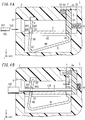
- FIGS. 2A and 2B show a terminal device 1 of a first variation.
- the terminal device 1 of the first variation has a through hole 70 provided in a location in which on the positive side in the Y-axis direction, the through hole 70 is aligned with positive-side end of a first conductor portion 20 of a conductor 2 in the X-axis direction.
- the through hole 70 extends from an outer surface of a housing 3 to the first conductor portion 20, and the outer surface of the housing 3 is oriented in the positive direction of the Y-axis.
- the through hole 70 and a second space S2 are aligned with each other in the X-axis direction.
- a display mark 50 i.e., a projection section 52 is displayed through the through hole 70.
- the display mark 50 is not displayed through the through hole 70.
- the first conductor portion 20 of the conductor i.e., a conductive portion whose electric potential is equal to an electric potential of the conductor 2 is exposed through the through hole 70.
- an electrical current test can be performed by inserting a test rod of a measuring instrument for the electrical current test into the through hole 70 to bring the test rod into contact with the conductive portion, i.e., the first conductor portion 20 in the present embodiment, and thus, the through hole 70 can be used also as an opening for tests.
- FIGS. 3A and 3B show a terminal device 1 of a second variation.
- the terminal device 1 of the second variation has a through hole 70 provided in a location in which on the positive side in the Y-axis direction, the through hole 70 is aligned with positive-side end of a first conductor portion 20 of a conductor 2 in the X-axis direction.
- the through hole 70 extends from an outer surface of a housing 3 to the first conductor portion 20, and the outer surface of the housing 3 is oriented in the positive direction of the Y-axis.
- the through hole 70 and a second space S2 are aligned with each other in the X-axis direction.
- an insertion hole 6 is directly in communication with a negative-side area of a first space S1 in the Y-axis direction.
- a second conductor portion 21 of the conductor 2 in the positive direction of the Y axis, a second conductor portion 21 of the conductor 2, a lock portion 4 of a first spring 8, and the through hole 70 are aligned in this order.
- a tip portion 101 of a connection target 100 is pressed against the second conductor portion 21 of the conductor 2.
- the first spring 8 includes a lock section 82 and a pressing section 84 which are located on the negative side of a body 80 in the Y-axis direction.
- the first spring 8 applies elastic force in the negative direction of the Y axis to the tip portion 101 of the connection target 100.
- An indicator 5 has such a length that a negative-side end thereof in the Y-axis direction comes into contact with or comes close to the second conductor portion 21 of the conductor 2.
- the terminal device 1 of the second variation when the indicator 5 is in the first position as illustrated in FIG. 3A , a display mark 50 is displayed through the through hole 70, and when the indicator 5 is in the second position as illustrated in FIG. 3B , the display mark 50 is not displayed through the through hole 70.
- the first conductor portion 20 of the conductor 2 when the indicator 5 is in the second position, the first conductor portion 20 of the conductor 2 is exposed through the through hole 70, and the through hole 70 may be used as an opening for testing a current-carrying state of a conductive portion (first conductor portion 20).
- FIGS. 4A and 4B show a terminal device 1 of a third variation.
- the terminal device 1 of the third variation includes a conductor 2 having a plate-like shape.
- the conductor 2 has a thickness in a direction along the Y-axis direction.
- the conductor 2 has a hole 23 penetrating therethrough in the Y-axis direction.
- a first spring 8 includes a body 80 having a flat-plate shape, a connection section 85 having an arc shape, a slope section 86 having a flat-plate shape, a connection section 87 having an arc shape, and a lock section 88 sequentially in this order.
- the body 80 is stacked on a surface of the conductor 2 which is oriented in the negative direction of the Y axis.
- the connection section 85 is connected to a positive-side end of the body 80 in the X-axis direction.
- the lock section 88 intersects with the body 80 when viewed in the Z-axis direction.
- the lock section 88 and the body 80 are located at different locations in the Z-axis direction.
- the lock section 88 passes through the hole 23 in the conductor 2 and protrudes beyond the conductor 2 on the positive side in the Y-axis direction.
- the lock section 88 has an insertion hole 880 penetrating therethrough in the X-axis direction.
- part of the insertion hole 880 protrudes beyond the conductor 2 in the positive direction of the Y axis.
- a gap is formed between a surface 881 oriented in the negative direction of the Y axis and a surface of the conductor 2.
- the surface of the conductor 2 is oriented in the positive direction of the Y axis.
- the surface 881 is part of an inner surface of the insertion hole 880.
- the gap has a shorter length than the tip portion 101 of the connection target 100 in the Y-axis direction.
- the tip portion 101 of the connection target 100 when a worker inserts the tip portion 101 of the connection target 100 through an insertion hole 6 of a housing 3 in the positive orientation of the X axis, the tip portion 101 is introduced into the insertion hole 880 in the lock section 88.
- the surface 881 of the lock section 88 is pressed by a tip surface 102 of the tip portion 101, the lock section 88 is displaced in the positive direction of the Y axis and elastically deforms to reduce the gap between the slope section 86 and the body 80.
- the tip portion 101 of the connection target 100 receives, from a negative-side tip edge 882 of the surface 881 of the lock section 88 in the Y-axis direction, force in a direction in which the tip portion 101 is pressed against the conductor 2, so that movement of the tip portion 101 in the negative direction of the X axis is restricted.
- the terminal device 1 of the third variation also enables visual confirmation, through a through hole 70, that the tip portion 101 of the connection target 100 inserted through the insertion hole 6 into a housing 3 reaches a prescribed location in the housing 3.
- the terminal device 1 of the third variation enables the occurrence of defective connection to be reduced.
- the shape of the first spring 8 is not limited to the shape shown in the figures, but the first spring 8 may have other shapes. It is required only that the first spring 8 of the first embodiment and the first and second variations includes the lock portion 4. The first spring 8 does not have to include the pressing portion 10. Moreover, in the terminal device 1 of the first embodiment and the first and second variations, the pressing portion 10 may be a spring other than the first spring 8.
- the second spring 9 may be, but not limited to, the coil spring. Moreover, the terminal device 1 of the first embodiment and first to third variations thereof may include a plurality of second springs 9.
- the display section 7 may include a through hole 70 and a light-transmitting member closing the through hole 70.
- the terminal device 1 of the first embodiment and first to third variations thereof may include a release lever configured to release a lock realized by the lock portion 4.
- a worker operates the release lever so as to release the lock realized by the lock portion 4, which allows the connection target 100 to be pulled out of the terminal device 1.
- the terminal device 1 does not have to include the release lever, and in that case, the terminal device 1 may be configured such that the lock realized by the lock portion 4 is released by inserting a tool or the like into the first space S1.
- the indicator 5 does not have to include the projection section 52 but may include only the body section 51, and the body section 51 may also serve as the display mark 50.
- the indicator 5 may be made of conductive metal, and the indicator 5 in the second position may be used as a conductive portion whose electric potential is equal to an electric potential of the conductor 2.
- the through hole 70 may be used as an opening for testing a current-carrying state of the conductive portion.
- the tip portion 101 of the connection target 100 in contact with the indicator 5 in the second position may be exposed through the through hole 70.
- the tip portion 101 may be used as a conductive portion whose electric potential is equal to an electric potential of the conductor 2, and the through hole 70 may be used as an opening for testing a current-carrying state of the conductive portion.
- FIGS. 5A and 5B a terminal device 1 of a second embodiment illustrated in FIGS. 5A and 5B will be described.
- the terminal device 1 of the second embodiment components different from those of the terminal device 1 of the first embodiment will be described in detail below. Components similar to those of the terminal device 1 of the first embodiment are denoted by the same reference signs in the figure, and detailed description thereof will be omitted.
- an amount of projection of an indicator 5 from a through hole 70 is different between a case where the indicator 5 is in the first position and in a case where the indicator 5 is in the second position.
- the indicator 5 is accommodated in a second space S2 to be linearly movable in the Y-axis direction.
- the indicator 5 includes a body section 51 and a projection 53.
- the body section 51 includes an inclined surface 510.
- the projection 53 protrudes from the body section 51 in the positive direction of the Y axis.
- the inclined surface 510 is inclined to be located farther away from the through hole 70 as the distance from an insertion hole 6 increases.
- the body section 51 further includes a tip surface 511 which is flat.
- the tip surface 511 continues to the inclined surface 510 on the positive side in the X-axis direction.
- the tip surface 511 is parallel to the X axis.
- the projection 53 is shaped and dimensioned so as to be protrudable through the through hole 70.
- a second spring 9 is disposed in the second space S2 such that the projection 53 is located on an inner side of the second spring 9.
- the tip surface 511 is in contact with a wall 310 on the negative side of the second space S2 in the Y-axis direction.
- the indicator 5 is pushed by the second spring 9 in the negative direction of the Y axis to reach the first position.
- the inclined surface 510 faces the insertion hole 6 in the X-axis direction.
- a positive-side tip surface 530 of the projection 53 in the Y-axis direction is flush with an outer surface of a housing 3 around the through hole 70, that is, an outer surface oriented in the positive direction of the Y-axis.
- the indicator 5 linearly moves in the positive direction of the Y axis to reach the second position.
- the tip surface 511 of the body section 51 of the indicator 5 is in contact with a surface of the tip portion 101, and the surface of the tip portion 101 is oriented in the positive direction of the Y axis.
- a positive-side end of the projection 53 in the Y-axis direction projects through the through hole 70 on the positive side in the Y-axis direction.
- the tip portion 101 of the connection target 100 inserted through the insertion hole 6 into the housing 3 is guided to a prescribed location in the housing 3, that is, a location where the tip portion 101 is in contact with the tip surface 511 of the indicator 5, so that the projection 53 of the indicator 5 protrudes through the through hole 70.
- a prescribed location in the housing 3 that is, a location where the tip portion 101 is in contact with the tip surface 511 of the indicator 5, so that the projection 53 of the indicator 5 protrudes through the through hole 70.
- the indicator 5 linearly moves in only the Y-axis direction, and therefore, it is possible to effectively reduce a disposition space of the indicator 5 in the housing 3 in the X-axis direction.
- the projection 53 of the indicator 5 which protrudes through the through hole 70 may be used as an indicator or the like during construction.
- a door of a case accommodating the terminal device 1 may have a structure which allows the door to be closed when the door hits the projection 53 protruding through the through hole 70. In this case, the door of the case is closed only when the connection target 100 is appropriately connected.
- FIGS. 6A and 6B show a terminal device 1 of a first variation.
- the terminal device 1 of the first variation further includes an intermediate portion 11 located between a pressing portion 10 and an indicator 5 in the positive direction of the X axis, that is, the insertion direction.
- the intermediate portion 11 includes a push surface 110 which is pushed against an inclined surface 510 of the indicator 5.
- the length of the push surface 110 in the Y-axis direction is greater than that of a tip surface 102 of a tip portion 101 of a connection target 100 in the Y-axis direction.
- the push surface 110 is inclined to be located farther away from a through hole 70 as the distance from an insertion hole 6 increases.
- the angle of inclination of the push surface 110 to the X axis is equal to the angle of inclination of the inclined surface 510 to the X axis.
- the length of the push surface 110 is greater than that of the inclined surface 510 in the Y-axis direction.
- the intermediate portion 11 has a surface 111 being oriented in the negative direction of the X axis and being parallel to the Y axis.
- a housing 3 has support grooves 34 in which both ends of the intermediate portion 11 in the Z-axis direction are fit.
- the support groove 34 is provided to each of two walls of the housing 3 which face each other in the Z-axis direction.
- the pair of support grooves 34 restricts movement of the intermediate portion 11 in the Y-axis direction and the Z-axis direction.
- the intermediate portion 11 is movable in only positive and negative directions of the X axis.
- the tip portion 101 of the connection target 100 when the tip portion 101 of the connection target 100 is inserted through the insertion hole 6 into the housing 3, the tip surface 102 of the tip portion 101 comes into contact with the surface 111 of the intermediate portion 11.
- the push surface 110 of the intermediate portion 11 pushes the inclined surface 510 of the indicator 5 in the first position in the positive direction of the X axis.
- the indicator 5 is pushed by the intermediate portion 11 in the positive direction of the Y axis, so that the indicator 5 linearly moves to reach the second position, and thereby, a projection 53 of the indicator 5 protrudes through the through hole 70.
- the tip surface 102 of the connection target 100 comes into contact with the surface 111 which is part of the intermediate portion 11 and which is parallel to the Y axis. Therefore, the tip portion 101 hardly deforms in the Y-axis direction and easily pushes the indicator 5.
- a second space S2 may be disposed on the negative side in the Y-axis direction as compared to that in the terminal device 1 of the second embodiment.
- the push surface 110 which is longer than the tip portion 101 of the connection target 100 in the Y-axis direction pushes the inclined surface 510.
- the push surface 110 which is longer than the tip portion 101 of the connection target 100 in the Y-axis direction pushes the inclined surface 510.
- FIGS. 7A and 7B show a terminal device 1 of a second variation.
- the terminal device 1 of the second variation has a first spring 8 whose shape is different from the shape of the first spring 8 of the terminal device 1 in the second embodiment.
- the first spring 8, a conductor 2, and a first space S1 of the terminal device 1 of the second variation have similar structures to the structures of the first spring 8, the conductor 2, and the first space S1 of the terminal device 1 of the third variation in the first embodiment.
- a tip portion 101 of a connection target 100 inserted through an insertion hole 6 into a housing 3 is guided to reach a prescribed location in the housing 3, so that a projection 53 of an indicator 5 protrudes through a through hole 70 and becomes visually perceivable by a worker.
- the shape of the first spring 8 may be other shapes. It is required only that the first spring 8 includes the lock portion 4. The first spring 8 does not have to include the pressing portion 10. Moreover, in the terminal device 1 of the second embodiment and the first variation of the second embodiment, the pressing portion 10 may be a spring other than the first spring 8.
- the second spring 9 may be, but not limited to, the coil spring. Moreover, the terminal device 1 of the second embodiment and the first and second variations of the second embodiment may include a plurality of second springs 9.
- the terminal device 1 of the second embodiment and the first and second variations of the second embodiment may include a release lever configured to release a lock realized by the lock portion 4.
- the projection 53 configured to protrude through the through hole 70 when being in the second position may be used as, for example, an indicator during construction.
- the terminal device 1 of the second embodiment and the first and second variations of the second embodiment may be configured such that when the indicator 5 is in the first position, the projection 53 protrudes through the through hole 70, and when the indicator 5 is in the second position, the projection 53 does not protrude through the through hole 70.
- the projection 53 may protrude through the through hole 70 both in a case where the indicator 5 is in the first position and in a case where the indicator 5 is in the second position, and the length of protrusion may be different between the case where the indicator 5 is in the first position and the case where the indicator 5 is in the second position.
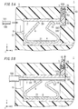
- FIGS. 8A and 8B a terminal device 1 of a third embodiment illustrated in FIGS. 8A and 8B will be described.
- the terminal device 1 of the third embodiment components different from those of the terminal device 1 of the first embodiment will be described in detail below. Components similar to those of the terminal device 1 of the first embodiment are denoted by the same reference signs in the figure, and detailed description thereof will be omitted.
- an indicator 5 is pushed by a connection target 100 to move from the first position to the second position in a mode including both linear movement and rotational movement.
- a housing 3 includes an inclined surface 35 with which the indicator 5 in the second position is in contact.
- the inclined surface 35 is a surface facing a second space S2 on the positive side in the X-axis direction.
- the inclined surface 35 is inclined to be located farther away from an insertion hole 6 as the distance from a through hole 70 increases.
- the indicator 5 includes projections 54 protruding on both sides from a body section 51 in the Z-axis direction.
- Each projection 54 has a rectangular shape when viewed in the Z-axis direction.
- the housing 3 has two walls facing each other in the Z direction, and each wall has a guide groove 36 in which a corresponding one of the projections 54 is fit.
- the guide groove 36 includes a linear guide section 360 and a rotation guide section 361 which continues to the linear guide section 360 on the positive side in the X-axis direction.
- the length of the linear guide section 360 in the Y-axis direction is substantially the same as the length of the projection 54 in the Y-axis direction.
- the rotation guide section 361 is wider than the linear guide section 360 in the Y-axis direction.
- the indicator 5 linearly moves along the linear guide sections 360 and rotationally moves at the rotation guide sections 361.
- a tip surface 102 of a tip portion 101 of the connection target 100 pushes the indicator 5 in the first position in the positive direction of the X axis to linearly move the indicator 5 in the first position in the positive direction of the X axis.
- the indicator 5 linearly moves until an edge 513 which is part of a surface 512 of the body section 51 and which is located on the positive side in the Y-axis direction comes into contact with the inclined surface 35.
- the surface 512 is oriented in the positive direction of the X axis.
- the indicator 5 rotationally moves, with the edge 513 as the center, to a location where the surface 512 of the body section 51 comes into contact with the inclined surface 35, that is, to reach the second position.
- the indicator 5 when the indicator 5 moves from the first position to the second position, the indicator 5 is guided by the linear guide sections 360 of the pair of guide grooves 36, in which the projections 54 of the indicator 5 are fit and which are formed in the housing 3, so that the indicator 5 is linearly moved to reach a position immediately before the second position.
- inclination of the indicator 5 to the tip surface 102 of the connection target 100 is reduced, and the indicator 5 is easily pushed by the tip surface 102 of the connection target 100 although the movement mode from the first position to the second position includes rotational movement.
- a tip portion 101 of a connection target 100 inserted through an insertion hole 6 into a housing 3 is guided to reach a prescribed location in the housing 3, and thereby, a projection section 52, that is, the display mark 50, is displayed through the through hole 70 and is visually perceivable by a worker.
- a projection section 52 that is, the display mark 50
- an inclined surface 35 is inclined to be located farther away from an insertion hole 6 as the distance from a through hole 70 decreases.
- a tip surface 102 of a tip portion 101 of a connection target 100 pushes an indicator 5 in the first position in the positive direction of the X axis to linearly move the indicator 5 in the first position in the positive direction of the X axis.
- the indicator 5 linearly moves until an edge 514 which is part of a surface 512 of a body section 51 and which is located on the negative side in the Y-axis direction comes into contact with the inclined surface 35.
- the surface 512 is oriented in the positive direction of the X axis.
- the indicator 5 rotationally moves, with the edge 514 as the center, to a location where the surface 512 of the body section 51 comes into contact with the inclined surface 35, that is, to reach the second position.
- linear guide sections 360 of a pair of guide grooves 36 in a housing 3 reduces inclination of the indicator 5, so that the indicator 5 is easily pushed by the tip surface 102 of the connection target 100.
- the tip portion 101 of the connection target 100 inserted through the insertion hole 6 into the housing 3 is guided to reach a prescribed location in the housing 3, and thereby, a projection section 52, that is, a display mark 50, is displayed through the through hole 70 and is visually perceivable by a worker.
- a projection section 52 that is, a display mark 50
- the shape of the first spring 8 may be other shapes. It is required only that the first spring 8 includes the lock portion 4. The first spring 8 does not have to include the pressing portion 10. Moreover, the terminal device 1 of the third embodiment and the first variation of the third embodiment, the pressing portion 10 may be a spring other than the first spring 8.
- the second spring 9 may be, but is not limited to, the coil spring. Moreover, the terminal device 1 of the third embodiment and the first variation of the third embodiment may include a plurality of second springs 9.
- the display section 7 may include the through hole 70 and a light-transmitting member closing the through hole 70.
- the terminal device 1 of the third embodiment and the first variation of the third embodiment may include a release lever configured to release a lock realized by the lock portion 4.
- a structure configured to rotationally move the indicator 5 in a position immediately before the second position may be a configuration other than the inclined surface 35.
- the indicator 5 may be made of conductive metal, and the indicator 5 in the second position may be used as a conductive portion whose electric potential is equal to an electric potential of the conductor 2.
- the through hole 70 may be used as an opening for testing a current-carrying state of the conductive portion.
- the power converter 200 includes: the terminal device 1 according to any one of the first to third embodiments and variations thereof; and a power conversion circuit 12 electrically connected to the conductor 2 of the terminal device 1.
- FIG. 10 shows an example of use of the power converter 200.
- the power conversion circuit 12 is electrically connected to a photovoltaic cell 13.
- the power converter 200 includes a plurality of terminal devices 1 connected to the power conversion circuit 12.
- the plurality of terminal devices 1 may be terminal devices having the same structure or terminal devices having different structures in combination. That is, the plurality of terminal devices 1 are terminal devices 1 of one type of any one of the first to third embodiments and variations thereof or are terminal devices 1 of combination of types of the first to third embodiments and variation thereof.
- the power conversion circuit 12 is, for example, an inverter circuit configured to convert direct-current power into alternating-current power.
- the power conversion circuit 12 may be a circuit configured to convert direct-current power into step-up or step-down direct-current power.
- the power converter 200 allows a worker to visually confirm that each terminal device 1 is appropriately connected to the connection target 100, so that it is possible to appropriately supply electricity generated by the photovoltaic cell 13 to electric appliances indoors or the like.
- a terminal device (1) of a first aspect includes the following configurations.
- the terminal device (1) of the first aspect includes a housing (3), a lock portion (4), and an indicator (5).
- the housing (3) accommodates a conductor (2).
- the housing (3) has an insertion hole (6) through which a connection target (100) is to be inserted.
- the lock portion (4) is configured to hold the connection target (100) inserted through the insertion hole (6) into the housing (3) between the lock portion (4) and the conductor (2) to restrict movement of the connection target (100) in a direction opposite to an insertion direction of the connection target (100).
- the indicator (5) is accommodated in the housing (3) and is located on an opposite side of the lock portion (4) from the insertion hole (6) in the insertion direction.
- the indicator (5) is configured to be pushed by the connection target (100) to move in a mode including linear movement from a first position to a second position.
- the housing (3) further includes a display section (7). Part of the indicator (5) is displayable through the display section (7) to an outer side of the housing (3). A display mode of the display section (7) is different between a case where the indicator (5) is in the first position and a case where the indicator (5) is in the second position.
- the connection target (100) when the connection target (100) is inserted through the insertion hole (6) into the housing (3), the connection target (100) pushes the indicator (5) so that the indicator (5) moves to reach the second position.
- the display mode of the display section (7) configured to display part of the indicator (5) can be changed.
- a worker watches the display mode of the display section (7) to check whether or not the connection target (100) is inserted to reach a prescribed location in the housing (3), that is, a location where the connection target (100) comes into contact with the indicator (5) in the second position.
- a terminal device (1) of a second aspect includes the following configuration in addition to the configuration of the terminal device (1) of the first aspect.
- the display section (7) has a through hole (70) penetrating through the housing (3).
- the indicator (5) includes a display mark (50). When the indicator (5) is in one of the first position and the second position, the display mark (50) is displayed through the through hole (70) to the outer side of the housing (3). When the indicator (5) is in the other of the first position and the second position, the display mark (50) is not displayed through the through hole (70) to the outer side of the housing (3).
- a worker can confirm a connection state of the connection target (100) by checking the display mark (50) of the indicator (5) through the through hole (70).
- part of the indicator (5) does not protrude to the outer side of the housing (3), and therefore, the part is not a hindrance.
- a terminal device (1) of a third aspect includes the following configuration in addition to the configuration of the terminal device (1) of the first aspect.
- the display section (7) is a through hole (70) penetrating through the housing (3). An amount of projection of the indicator (5) from the through hole (70) is different between a case where the indicator (5) is in the first position and in a case where the indicator (5) is in the second position.
- a worker can confirm a change of the display mode of the display section (7) by watching the through hole (70) not only in a direction in which the through hole (70) opens but also in other directions.
- a terminal device (1) of a fourth aspect includes the following configuration in addition to the configuration of the terminal device (1) of the first aspect.
- the display section (7) is a through hole (70) penetrating through the housing (3).
- a conductive portion whose electric potential is equal to an electric potential of the conductor (2), i.e., the conductor (2), the indicator (5) which is electrically conductive, or a tip portion (101) of the connection target (100) is exposed through the through hole (70).
- an electrical current test can be performed by inserting a test rod of a measuring instrument for the electrical current test into the through hole (70) to bring the test rod into contact with the conductive portion, and thus, the through hole (70) can be used also as an opening for tests.
- a terminal device (1) of a fifth aspect includes the following configuration in addition to the configuration of the terminal device (1) of any one of the first to fourth aspects.
- the terminal device (1) of the fifth aspect further includes a spring, i.e., the second spring (9) configured to apply elastic force to the indicator (5) in the second position in a direction in which the indicator (5) moves to the first position.
- a spring i.e., the second spring (9) configured to apply elastic force to the indicator (5) in the second position in a direction in which the indicator (5) moves to the first position.
- a terminal device (1) of a sixth aspect includes the following configuration in addition to the configuration of the terminal device (1) of any one of the first, second, and fourth aspects.
- the terminal device (1) of the sixth aspect further includes a spring, i.e., a second spring (9) located on an opposite side of the indicator (5) from the insertion hole (6) in the insertion direction.
- a spring i.e., a second spring (9) located on an opposite side of the indicator (5) from the insertion hole (6) in the insertion direction.
- a terminal device (1) of a seventh aspect includes the following configuration in addition to the configuration of the terminal device (1) of any one of the first to sixth aspects.
- the terminal device (1) of the seventh aspect further includes a pressing portion (10) located between the lock portion (4) and the indicator (5) in the insertion direction and configured to press the connection target (100) against the conductor (2) to restrict movement of the connection target (100) in a direction traverse to the insertion direction.
- the pressing portion (10) reduces movement of the tip portion (101) of the connection target (100) guided to beyond the lock portion (4) in a direction traverse to the insertion direction, that is, deformation of the tip portion (101).
- the terminal device (1) of the seventh aspect enables to reduce cases where the tip portion (101) of the connection target (100) can no longer appropriately push the indicator (5).
- a terminal device (1) of an eighth aspect includes the following configuration in addition to the configuration of the terminal device (1) of any one of the first to seventh aspects.
- the display section (7) is a through hole (70) which is open in a first direction traverse to the insertion direction, that is, the positive direction of the Y axis.
- the lock portion (4), the conductor (2), and the through hole (70) are located in this order.
- the distance from the connection target (100) disposed between the lock portion (4) and the conductor (2) to the through hole (70) can be reduced.
- a terminal device (1) of a ninth aspect includes the following configuration in addition to the configuration of the terminal device (1) of any one of the first to seventh aspects.
- the display section (7) is a through hole (70) which is open in a first direction traverse to the insertion direction, that is, the positive direction of the Y axis.
- the conductor (2) i.e., second conductor portion (21), the lock portion (4), and the through hole (70) are located in this order.
- the distance from the connection target (100) disposed between the conductor (2) and the lock portion (4) to the through hole (70) can be increased.
- the insertion hole (6) through which the connection target (100) is to be inserted can be disposed at a location away from the through hole (70).
- a power converter (200) of a tenth aspect includes the terminal device (1) of any one of the first to ninth aspects, and a power conversion circuit (12) electrically connected to the conductor (2) of the terminal device (1).
- the power converter (200) of the tenth aspect allows a worker to easily electrically connect the connection target (100) to the power conversion circuit (12) by using the terminal device (1) and to visually check a connection state, and therefore, it is possible to reduce the occurrence of connection defect.
Abstract
Description
- The present disclosure relates to a terminal device and a power converter including the terminal device.
- A known terminal device has a quick connection structure which enables connection without using a screw.
-
JP 2002-151172 A - In such a terminal device, however, if the electric wire is not inserted to reach a prescribed location in the terminal device, the electric wire and the terminal may not be appropriately connected to each other. It is possible to determine whether or not the electric wire is inserted to reach the prescribed location based on a response felt by a hand at the time of the insertion, but a tip of the electric wire may be caught on the way of the insertion, and therefore, such a method is unreliable.
- An object of the present disclosure is to provide a terminal device which enables visual confirmation of insertion of a connection target to reach a prescribed location in the terminal device and a power converter including the terminal device.
- A terminal device of one aspect according to the present disclosure includes a housing, a lock portion, and an indicator. The housing accommodates a conductor. The housing has an insertion hole through which a connection target is to be inserted. The lock portion is configured to hold the connection target inserted through the insertion hole into the housing between the lock portion and the conductor to restrict movement of the connection target in a direction opposite to an insertion direction of the connection target. The indicator is accommodated in the housing and is located on an opposite side of the lock portion from the insertion hole in the insertion direction. The indicator is configured to be pushed by the connection target to move in a mode including linear movement from a first position to a second position. The housing further includes a display section. Part of the indicator is displayable through the display section to an outer side of the housing. A display mode of the display section is different between a case where the indicator is in the first position and a case where the indicator is in the second position.
- Moreover, a power converter of one aspect according to the present disclosure includes the terminal device and a power conversion circuit electrically connected to the conductor of the terminal device.
-
-
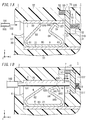
FIG. 1A is a front sectional view schematically illustrating a terminal device of a first embodiment according to the present disclosure; -
FIG. 1B is a front sectional view illustrating the terminal device in which a connection target is inserted; -
FIG. 2A is a front sectional view schematically illustrating a terminal device of a first variation of the first embodiment; -
FIG. 2B is a front sectional view illustrating the terminal device ofFIG. 2A in which a connection target is inserted; -
FIG. 3A is a front sectional view schematically illustrating a terminal device of a second variation of the first embodiment; -
FIG. 3B is a front sectional view illustrating the terminal device ofFIG. 3A in which a connection target is inserted; -
FIG. 4A is a front sectional view schematically illustrating a terminal device of a third variation of the first embodiment; -
FIG. 4B is a front sectional view illustrating the terminal device ofFIG. 4A in which a connection target is inserted; -
FIG. 5A is a front sectional view schematically illustrating a terminal device of a second embodiment according to the present disclosure; -
FIG. 5B is a front sectional view illustrating the terminal device ofFIG. 5A in which a connection target is inserted; -
FIG. 6A is a front sectional view schematically illustrating a terminal device of a first variation of the second embodiment; -
FIG. 6B is a front sectional view illustrating the terminal device ofFIG. 6A in which a connection target is inserted; -
FIG. 7A is a front sectional view schematically illustrating a terminal device of a second variation of the second embodiment; -
FIG. 7B is a front sectional view illustrating the terminal device ofFIG. 7A in which a connection target is inserted; -
FIG. 8A is a front sectional view schematically illustrating a terminal device of a third embodiment according to the present disclosure; -
FIG. 8B is a front sectional view illustrating the terminal device ofFIG. 8A in which a connection target is inserted; -
FIG. 9A is a front sectional view schematically illustrating a terminal device of a first variation of the third embodiment; -
FIG. 9B is a front sectional view illustrating the terminal device ofFIG. 9A in which a connection target is inserted; and -
FIG. 10 is a block diagram schematically illustrating a power converter including terminal devices of any one of the first to third embodiments and their variations according to the present disclosure. - The present disclosure relates to terminal devices and power converters including the terminal devices and, more specifically, to a terminal device connectable to a connection target through insertion of the connection target thereinto and a power converter including the terminal device.
- As illustrated in
FIGS. 1A and 1B , aterminal device 1 of a first embodiment is a quick connection terminal connectable to aconnection target 100 through insertion of theconnection target 100 thereinto. Theterminal device 1 includes aconductor 2, ahousing 3, alock portion 4, and anindicator 5. - In the present embodiment, the
connection target 100 is an electric wire. The electric wire is an insulated electric wire including a core wire and an insulator covering the core wire. The core wire is conductive. The core wire is exposed at a tip portion of the electric wire, that is, atip portion 101 of theconnection target 100. The core wire may be a single wire including one conductor wire or a twisted cable including a plurality of conductor wires. Alternatively, theconnection target 100 may include a terminal attached to a tip of a core wire. - The
conductor 2, thelock portion 4, and theindicator 5 are accommodated in thehousing 3. Thehousing 3 has aninsertion hole 6 and adisplay section 7. Theconnection target 100 is to be inserted through theinsertion hole 6. Thelock portion 4 is configured to hold theconnection target 100 inserted through theinsertion hole 6 into thehousing 3 between thelock portion 4 and theconductor 2 to restrict movement in a direction opposite to an insertion direction of theconnection target 100. - The
indicator 5 is located on an opposite side of thelock portion 4 from theinsertion hole 6 in the insertion direction. Theindicator 5 is configured to be pushed by theconnection target 100 to move in a mode including linear movement from a first position to a second position. - Part of the
indicator 5 is displayable through thedisplay section 7 to an outer side of thehousing 3. A display mode of thedisplay section 7, that is, how theindicator 5 appears through thedisplay section 7, is different between a case where theindicator 5 is in the first position and a case where theindicator 5 is in the second position. - The
display section 7 is a throughhole 70 penetrating through thehousing 3 to be open in a direction traverse to the insertion direction of theconnection target 100. In the present embodiment, "a direction traverse to the insertion direction of theconnection target 100" is a direction orthogonal to the insertion direction of theconnection target 100. - In the following description, the insertion direction of the
connection target 100 is defined as a positive direction of the X axis and a direction opposite to the positive direction is defined as a negative direction of the X axis. Moreover, of directions orthogonal to the X axis direction, a direction in which the throughhole 70 is open, that is, of penetration directions of the throughhole 70, a direction toward the outer side of thehousing 3, is defined as a positive direction of the Y axis, and a direction opposite to the positive direction is defined as a negative direction of the Y axis. A direction orthogonal to both the X-axis direction and the Y-axis direction is defined as the Z-axis direction. Note that dimensions and a positional relationship of components in the drawings do not necessarily match actual dimensions and an actual positional relationship of the components. - Configurations of the
terminal device 1 will be described in detail below. - The
terminal device 1 includes afirst spring 8 and asecond spring 9 in addition to theconductor 2, thehousing 3, and theindicator 5. Part of thefirst spring 8 is thelock portion 4. Thesecond spring 9 is configured to apply elastic force to theindicator 5. - The
housing 3 is made of an electrically insulative material. Thehousing 3 is made of, for example, a synthetic resin. Thehousing 3 has a box-like shape and has a space therein, and in the space, theconductor 2, thefirst spring 8, theindicator 5, and thesecond spring 9 are accommodated. - The
housing 3 integrally includes twowalls walls wall 30 is located between negative-side ends of the twowalls wall 31 is located between positive-side ends of the twowalls walls walls - The
housing 3 has a first space S1 and a second space S2 therein. Thefirst spring 8 and theconductor 2 are accommodated in the first space S1. Theindicator 5 and thesecond spring 9 are accommodated in the second space S2. The first space S1 is in communication with the second space S2. The second space S2 extends to thewall 32 and thewall 31 of thehousing 3. - The
insertion hole 6 is a hole directly in communication with the first space S1. Theinsertion hole 6 penetrates through thewall 30 of thehousing 3 in the X-axis direction. Theinsertion hole 6 is directly in communication with a positive-side area of the first space S1 in the Y-axis direction. Theinsertion hole 6 is, in the X-axis direction, located to face a negative-side area of the second space S2 in the Y-axis direction. - The through
hole 70 is a hole directly in communication with the second space S2. The throughhole 70 and the second space S2 penetrate through thewall 32 of thehousing 3 in the Y-axis direction. The location of the throughhole 70 in the Z-axis direction is, in the present embodiment, the same as the position of theinsertion hole 6 in the Z-axis direction. - In the first space S1, the
conductor 2 is accommodated in areas at both ends in the Y-axis direction and in an area at one end in the Z-axis direction. In the first space S1, thefirst spring 8 is accommodated in an area surrounded by theconductor 2. The second space S2 accommodates theindicator 5 and thesecond spring 9 linearly movably in both the positive and negative directions of the X axis. - The
conductor 2 is formed of a conductive metal plate. Theconductor 2 is made of, for example, copper. Theconductor 2 is C-shaped when viewed in the X-axis direction. Theconductor 2 includes afirst conductor portion 20, asecond conductor portion 21, and athird conductor portion 22. Thefirst conductor portion 20 is disposed in a positive-side end area of the first space S1 in the Y-axis direction. Thesecond conductor portion 21 is disposed in a negative-side area of the first space S1 in the Y-axis direction. Thethird conductor portion 22 is disposed in a positive-side end area of the first space S1 in the Z-axis direction or a negative-side end area of the first space S1 in the Z-axis direction. Thefirst conductor portion 20 and thesecond conductor portion 21 are connected to each other by thethird conductor portion 22. Theconductor 2 is separate from thefirst spring 8. - The
first spring 8 is formed of an elastic metal plate. Thefirst spring 8 is made of, for example, stainless steel. Thefirst spring 8 is combined with an inner side of theconductor 2. Thefirst spring 8 includes thelock portion 4 and apressing portion 10. - The
pressing portion 10 is located between thelock portion 4 and theindicator 5. Thepressing portion 10 is configured to press theconnection target 100 against theconductor 2 to restrict movement of theconnection target 100 in a direction traverse to the insertion direction. - In the positive direction of the Y axis, that is, in a first direction in which the through
hole 70 is open, thelock portion 4, thefirst conductor portion 20 of theconductor 2, and the throughhole 70 are aligned in this order. - The
first spring 8 includes abody 80, alock section 82, and apressing section 84. Thebody 80 has a flat-plate shape. Thelock section 82 has a flat-plate shape. Thelock section 82 is connected via an arc-like connection section 81 to a negative-side end of thebody 80 in the X-axis direction. Thepressing section 84 is connected via an arc-like connection section 83 to a positive-side end of thebody 80 in the X-axis direction. Thebody 80 lies on thesecond conductor portion 21 of theconductor 2. Thelock section 82 is thelock portion 4. Thepressing section 84 is thepressing portion 10. - The
lock section 82 has atip edge 820 which is closest to thefirst conductor portion 20. When thetip edge 820 holds theconnection target 100 between thetip edge 820 and thefirst conductor portion 20, thetip edge 820 bites into theconnection target 100, thereby restricting movement of theconnection target 100 in the negative direction of the X axis, that is, in a direction opposite to the insertion direction. - The
pressing section 84 has a tip portion which is close to thefirst conductor portion 20, and the tip portion is provided with acontact surface 840 which is to be in contact with theconnection target 100. Thecontact surface 840 is an arc-like curved surface in the present embodiment but may be a flat surface. In thepressing section 84, i.e., in thepressing portion 10, thecontact surface 840 presses theconnection target 100 against thefirst conductor portion 20, thereby restricting movement of theconnection target 100 in the negative direction of the Y axis. - The
indicator 5 is a member which is displayed to the outer side of thehousing 3 to show that thetip portion 101 of theconnection target 100 inserted through theinsertion hole 6 reaches a prescribed location in thehousing 3. Theindicator 5 is made of, for example, a synthetic resin. Theindicator 5 is configured to be pushed by atip surface 102 of thetip portion 101 of theconnection target 100 to linearly move from the first position to the second position. - The
indicator 5 has adisplay mark 50. In the present embodiment, theindicator 5 includes abody section 51 and aprojection section 52. Thebody section 51 is rectangular when viewed in the Z-axis direction. Theprojection section 52 protrudes in the negative direction of the X axis from a positive-side end of thebody section 51 in the Y-axis direction. Theprojection section 52 and thebody section 51 are different from each other in appearance. Theprojection section 52 has, for example, a surface painted in a color different from a color of thebody section 51. Theprojection section 52 is thedisplay mark 50. - The
indicator 5 is disposed in the second space S2 to be able to move linearly in both the positive direction of the X axis and the negative direction of the X axis. Twowalls indicator 5 in the X-axis direction. - In the
indicator 5, a negative-side end of thebody section 51 in the Y-axis direction faces theinsertion hole 6 in the X-axis direction. That is, the negative-side end of thebody section 51 in the Y-axis direction is aligned with theinsertion hole 6 in a straight line. The location of theprojection section 52 in the Z-axis direction is the same as the location of the throughhole 70 in the Z-axis direction. - In the present embodiment, as illustrated in
FIG. 1B , when theindicator 5 is in the second position, theprojection section 52 is aligned with the throughhole 70 on the negative side in the Y-axis direction. Thus, theprojection section 52 is displayed through the throughhole 70 to the outer side of thehousing 3. As illustrated inFIG. 1A , when theindicator 5 is in the first position, thebody section 51 is aligned with the throughhole 70 on the negative side in the Y-axis direction. Thus, theprojection section 52 is not displayed through the throughhole 70 to the outer side of thehousing 3. - The
second spring 9 applies elastic force in a direction in which theindicator 5 in the second position moves in the first direction. - In the present embodiment, the
second spring 9 is a coil spring. Thesecond spring 9 is disposed in the second space S2 such that the axis of the coil is parallel to the X axis. - The
second spring 9 is disposed on the positive side of thebody section 51 in the X-axis direction. That is, thesecond spring 9 is disposed on an opposite side of theindicator 5 from theinsertion hole 6 in the insertion direction. Thesecond spring 9 is, for example, disposed to face theinsertion hole 6 in the X-axis direction. - The
second spring 9 is disposed on the positive side of thebody section 51 in the X-axis direction, for example, in a state where thesecond spring 9 is compressed in the X-axis direction. Thesecond spring 9 pushes theindicator 5 by elastic force of thesecond spring 9 in the negative direction of the X axis. Thus, theindicator 5 is pushed against thewall 321 on the negative side of the second space S2 in the X-axis direction and is disposed in a negative-side area of the second space S2 in the X-axis direction (i.e., the first position). In a state where theindicator 5 is not pushed by theconnection target 100, theindicator 5 is in the first position. - When pushed by the
connection target 100, theindicator 5 is linearly moved against the elastic force of thesecond spring 9 to the positive side in the X-axis direction. Theindicator 5 is pushed by theconnection target 100 againstwalls - When the
indicator 5 is released from being pushed by theconnection target 100, that is, theconnection target 100 leaves theindicator 5, theindicator 5 is pushed by the elastic return force of thesecond spring 9 in the negative direction of the X axis and returns to the first position. - Next, a method for connecting the
connection target 100 to theterminal device 1 will be described. - A worker inserts the
tip portion 101 of theconnection target 100 into theinsertion hole 6 in thehousing 3 in the positive orientation of the X-axis. Thetip portion 101 which is inserted into thehousing 3 is first introduced into a space between thelock section 82, i.e., thelock portion 4, and thefirst conductor portion 20 of theconductor 2. At this time, thetip surface 102 of thetip portion 101 pushes thelock section 82 to displace thetip edge 820 of thelock section 82 in a direction away from thefirst conductor portion 20, thereby elastically deforming thefirst spring 8 to reduce the space between thelock section 82 and thebody 80. Thus, thetip portion 101 of theconnection target 100 receives, from thetip edge 820 of thelock section 82, force in a direction in which thetip portion 101 is pressed against thefirst conductor portion 20, so that movement of thetip portion 101 in the negative direction of the Y axis is restricted. Moreover, at this time, thetip edge 820 of thelock section 82 bites in thetip portion 101, thereby restricting movement of thetip portion 101 in the negative direction of the X axis. - From this state, when the
tip portion 101 of theconnection target 100 is inserted further into thehousing 3, thetip portion 101 is introduced into a space between thepressing section 84, i.e., thepressing portion 10, and thefirst conductor portion 20. At this time, thetip portion 101 presses thecontact surface 840 of thepressing section 84 to elastically deform thepressing section 84 with respect to thebody 80. Thus, thetip portion 101 of theconnection target 100 receives, from thecontact surface 840 of thepressing section 84, force in a direction in which thetip portion 101 is pressed against thefirst conductor portion 20, so that movement of thetip portion 101 in the negative direction of the Y axis is restricted. - From this state, the
tip portion 101 of theconnection target 100 is inserted further into thehousing 3 and thereby thetip surface 102 of thetip portion 101 pushes thebody section 51 of theindicator 5 in the first position to linearly move theindicator 5 from the first position to the second position. After theindicator 5 reaches the second position, further insertion of theconnection target 100 into thehousing 3, that is, movement in the positive direction of the X axis becomes no longer possible. That is, thetip portion 101 of theconnection target 100 is insertable into thehousing 3 to a prescribed location where theindicator 5 is in the second position. - As illustrated in
FIG. 1B , in a state where theindicator 5 is in the second position, theprojection section 52, i.e., thedisplay mark 50 of theindicator 5 is aligned with the throughhole 70 on the negative side in the Y-axis direction. Thus, theprojection section 52, i.e., thedisplay mark 50 is displayed through the throughhole 70 to the outer side of thehousing 3 and is visually perceivable from the outer side of thehousing 3. - This allows a worker to confirm that the
tip portion 101 of theconnection target 100 is inserted to reach the prescribed location in thehousing 3 by watching the throughhole 70. In a state where thetip portion 101 of theconnection target 100 is not inserted to reach the prescribed location in thehousing 3, thebody section 51 of theindicator 5 or both thebody section 51 and theprojection section 52, i.e., thedisplay mark 50 are displayed through the throughhole 70. This allows a worker to confirm an insufficient amount of insertion of theconnection target 100 by watching the throughhole 70. - Thus, in the case of the
terminal device 1 of the present embodiment, a worker can visually confirm, through the throughhole 70, that thetip portion 101 of theconnection target 100 inserted through theinsertion hole 6 into thehousing 3 reaches the prescribed location in thehousing 3. Thus, in theterminal device 1 of the present embodiment, it is possible to reduce the occurrence of a defective connection caused due to theconnection target 100 which is not inserted to reach the prescribed location in thehousing 3. - In addition, in the
terminal device 1 of the present embodiment, theindicator 5 is located on the positive side of thelock section 82, i.e., thelock portion 4 in the X-axis direction. Therefore, it is possible to reduce the disposition space of theindicator 5 in thehousing 3 as compared to, for example, a case where theindicator 5 has a piece extending to thewall 30. - Moreover, in the
terminal device 1 of the present embodiment, theindicator 5 moves linearly, and therefore, it is possible to reduce a gap between theindicator 5 and a wall surrounding theindicator 5 as compared to the case of rotational movement. Also in this regard, it is possible to reduce the disposition space of theindicator 5 in thehousing 3. - Thus, in the
terminal device 1 of the present embodiment, reducing the disposition space of theindicator 5 in thehousing 3 enables the space in thehousing 3 to be effectively applied to other applications, and thehousing 3 can be downsized. - Next, variations of the
terminal device 1 of the first embodiment will be described. For the variation of theterminal device 1, components different from those in theterminal device 1 of the first embodiment will be described in detail below. -
FIGS. 2A and 2B show aterminal device 1 of a first variation. Theterminal device 1 of the first variation has a throughhole 70 provided in a location in which on the positive side in the Y-axis direction, the throughhole 70 is aligned with positive-side end of afirst conductor portion 20 of aconductor 2 in the X-axis direction. The throughhole 70 extends from an outer surface of ahousing 3 to thefirst conductor portion 20, and the outer surface of thehousing 3 is oriented in the positive direction of the Y-axis. The throughhole 70 and a second space S2 are aligned with each other in the X-axis direction. - In the
terminal device 1 of the first variation, as illustrated inFIG. 2A , when anindicator 5 is in a first position, adisplay mark 50, i.e., aprojection section 52 is displayed through the throughhole 70. As illustrated inFIG. 2B , when theindicator 5 is in a second position, thedisplay mark 50 is not displayed through the throughhole 70. - In the
terminal device 1 of the first variation, when theindicator 5 is in the second position, thefirst conductor portion 20 of theconductor 2, i.e., a conductive portion whose electric potential is equal to an electric potential of theconductor 2 is exposed through the throughhole 70. Thus, in theterminal device 1 of the first variation, an electrical current test can be performed by inserting a test rod of a measuring instrument for the electrical current test into the throughhole 70 to bring the test rod into contact with the conductive portion, i.e., thefirst conductor portion 20 in the present embodiment, and thus, the throughhole 70 can be used also as an opening for tests. -
FIGS. 3A and 3B show aterminal device 1 of a second variation. Theterminal device 1 of the second variation has a throughhole 70 provided in a location in which on the positive side in the Y-axis direction, the throughhole 70 is aligned with positive-side end of afirst conductor portion 20 of aconductor 2 in the X-axis direction. The throughhole 70 extends from an outer surface of ahousing 3 to thefirst conductor portion 20, and the outer surface of thehousing 3 is oriented in the positive direction of the Y-axis. The throughhole 70 and a second space S2 are aligned with each other in the X-axis direction. - In the
terminal device 1 of the second variation, aninsertion hole 6 is directly in communication with a negative-side area of a first space S1 in the Y-axis direction. In theterminal device 1 of the second variation, in the positive direction of the Y axis, asecond conductor portion 21 of theconductor 2, alock portion 4 of afirst spring 8, and the throughhole 70 are aligned in this order. Atip portion 101 of aconnection target 100 is pressed against thesecond conductor portion 21 of theconductor 2. Thefirst spring 8 includes alock section 82 and apressing section 84 which are located on the negative side of abody 80 in the Y-axis direction. Thefirst spring 8 applies elastic force in the negative direction of the Y axis to thetip portion 101 of theconnection target 100. Anindicator 5 has such a length that a negative-side end thereof in the Y-axis direction comes into contact with or comes close to thesecond conductor portion 21 of theconductor 2. - Similarly to the
terminal device 1 of the first variation, in theterminal device 1 of the second variation, when theindicator 5 is in the first position as illustrated inFIG. 3A , adisplay mark 50 is displayed through the throughhole 70, and when theindicator 5 is in the second position as illustrated inFIG. 3B , thedisplay mark 50 is not displayed through the throughhole 70. In theterminal device 1 of the second variation, when theindicator 5 is in the second position, thefirst conductor portion 20 of theconductor 2 is exposed through the throughhole 70, and the throughhole 70 may be used as an opening for testing a current-carrying state of a conductive portion (first conductor portion 20). -
FIGS. 4A and 4B show aterminal device 1 of a third variation. Theterminal device 1 of the third variation includes aconductor 2 having a plate-like shape. Theconductor 2 has a thickness in a direction along the Y-axis direction. Theconductor 2 has ahole 23 penetrating therethrough in the Y-axis direction. - A
first spring 8 includes abody 80 having a flat-plate shape, aconnection section 85 having an arc shape, aslope section 86 having a flat-plate shape, aconnection section 87 having an arc shape, and alock section 88 sequentially in this order. Thebody 80 is stacked on a surface of theconductor 2 which is oriented in the negative direction of the Y axis. Theconnection section 85 is connected to a positive-side end of thebody 80 in the X-axis direction. - The
lock section 88 intersects with thebody 80 when viewed in the Z-axis direction. Thelock section 88 and thebody 80 are located at different locations in the Z-axis direction. Thelock section 88 passes through thehole 23 in theconductor 2 and protrudes beyond theconductor 2 on the positive side in the Y-axis direction. - The
lock section 88 has aninsertion hole 880 penetrating therethrough in the X-axis direction. In a state where atip portion 101 of aconnection target 100 is not inserted in theinsertion hole 880, part of theinsertion hole 880 protrudes beyond theconductor 2 in the positive direction of the Y axis. In this state, a gap is formed between asurface 881 oriented in the negative direction of the Y axis and a surface of theconductor 2. The surface of theconductor 2 is oriented in the positive direction of the Y axis. Thesurface 881 is part of an inner surface of theinsertion hole 880. The gap has a shorter length than thetip portion 101 of theconnection target 100 in the Y-axis direction. - In the case of the
terminal device 1 of the third variation, when a worker inserts thetip portion 101 of theconnection target 100 through aninsertion hole 6 of ahousing 3 in the positive orientation of the X axis, thetip portion 101 is introduced into theinsertion hole 880 in thelock section 88. At this time, thesurface 881 of thelock section 88 is pressed by atip surface 102 of thetip portion 101, thelock section 88 is displaced in the positive direction of the Y axis and elastically deforms to reduce the gap between theslope section 86 and thebody 80. Thus, thetip portion 101 of theconnection target 100 receives, from a negative-side tip edge 882 of thesurface 881 of thelock section 88 in the Y-axis direction, force in a direction in which thetip portion 101 is pressed against theconductor 2, so that movement of thetip portion 101 in the negative direction of the X axis is restricted. - Similarly to the
terminal device 1 of the first embodiment, theterminal device 1 of the third variation also enables visual confirmation, through a throughhole 70, that thetip portion 101 of theconnection target 100 inserted through theinsertion hole 6 into ahousing 3 reaches a prescribed location in thehousing 3. Thus, theterminal device 1 of the third variation enables the occurrence of defective connection to be reduced. - In the
terminal device 1 of the first embodiment and the first to third variations thereof, the shape of thefirst spring 8 is not limited to the shape shown in the figures, but thefirst spring 8 may have other shapes. It is required only that thefirst spring 8 of the first embodiment and the first and second variations includes thelock portion 4. Thefirst spring 8 does not have to include thepressing portion 10. Moreover, in theterminal device 1 of the first embodiment and the first and second variations, thepressing portion 10 may be a spring other than thefirst spring 8. - In the
terminal device 1 of the first embodiment and first to third variations thereof, thesecond spring 9 may be, but not limited to, the coil spring. Moreover, theterminal device 1 of the first embodiment and first to third variations thereof may include a plurality ofsecond springs 9. - In the
terminal device 1 of the first embodiment and the third variation, as long as thedisplay section 7 is configured to display part of theindicator 5 to the outer side of thehousing 3, thedisplay section 7 may include a throughhole 70 and a light-transmitting member closing the throughhole 70. - The
terminal device 1 of the first embodiment and first to third variations thereof may include a release lever configured to release a lock realized by thelock portion 4. In this case, a worker operates the release lever so as to release the lock realized by thelock portion 4, which allows theconnection target 100 to be pulled out of theterminal device 1. Theterminal device 1 does not have to include the release lever, and in that case, theterminal device 1 may be configured such that the lock realized by thelock portion 4 is released by inserting a tool or the like into the first space S1. - In the
terminal device 1 of the first embodiment and the third variation, theindicator 5 does not have to include theprojection section 52 but may include only thebody section 51, and thebody section 51 may also serve as thedisplay mark 50. - In the
terminal device 1 of the first embodiment and the third variation, theindicator 5 may be made of conductive metal, and theindicator 5 in the second position may be used as a conductive portion whose electric potential is equal to an electric potential of theconductor 2. In this case, the throughhole 70 may be used as an opening for testing a current-carrying state of the conductive portion. - Moreover, in the
terminal device 1 of the first embodiment and its first to third variations, thetip portion 101 of theconnection target 100 in contact with theindicator 5 in the second position may be exposed through the throughhole 70. In this case, thetip portion 101 may be used as a conductive portion whose electric potential is equal to an electric potential of theconductor 2, and the throughhole 70 may be used as an opening for testing a current-carrying state of the conductive portion. - Next, a
terminal device 1 of a second embodiment illustrated inFIGS. 5A and 5B will be described. For theterminal device 1 of the second embodiment, components different from those of theterminal device 1 of the first embodiment will be described in detail below. Components similar to those of theterminal device 1 of the first embodiment are denoted by the same reference signs in the figure, and detailed description thereof will be omitted. - In the
terminal device 1 of the second embodiment, an amount of projection of anindicator 5 from a throughhole 70 is different between a case where theindicator 5 is in the first position and in a case where theindicator 5 is in the second position. - In the
terminal device 1 of the present embodiment, theindicator 5 is accommodated in a second space S2 to be linearly movable in the Y-axis direction. - The
indicator 5 includes abody section 51 and aprojection 53. Thebody section 51 includes aninclined surface 510. Theprojection 53 protrudes from thebody section 51 in the positive direction of the Y axis. Theinclined surface 510 is inclined to be located farther away from the throughhole 70 as the distance from aninsertion hole 6 increases. - The
body section 51 further includes atip surface 511 which is flat. Thetip surface 511 continues to theinclined surface 510 on the positive side in the X-axis direction. Thetip surface 511 is parallel to the X axis. Theprojection 53 is shaped and dimensioned so as to be protrudable through the throughhole 70. Asecond spring 9 is disposed in the second space S2 such that theprojection 53 is located on an inner side of thesecond spring 9. - As illustrated in
FIG. 5A , when theindicator 5 is in the first position, thetip surface 511 is in contact with awall 310 on the negative side of the second space S2 in the Y-axis direction. Theindicator 5 is pushed by thesecond spring 9 in the negative direction of the Y axis to reach the first position. When theindicator 5 is in the first position, theinclined surface 510 faces theinsertion hole 6 in the X-axis direction. Moreover, at this time, a positive-side tip surface 530 of theprojection 53 in the Y-axis direction is flush with an outer surface of ahousing 3 around the throughhole 70, that is, an outer surface oriented in the positive direction of the Y-axis. - When the
inclined surface 510 is pushed by atip surface 102 of atip portion 101 of aconnection target 100, theindicator 5 linearly moves in the positive direction of the Y axis to reach the second position. As illustrated inFIG. 5B , when theindicator 5 is in the second position, thetip surface 511 of thebody section 51 of theindicator 5 is in contact with a surface of thetip portion 101, and the surface of thetip portion 101 is oriented in the positive direction of the Y axis. When theindicator 5 is in the second position, a positive-side end of theprojection 53 in the Y-axis direction projects through the throughhole 70 on the positive side in the Y-axis direction. - In the
terminal device 1 of the second embodiment, thetip portion 101 of theconnection target 100 inserted through theinsertion hole 6 into thehousing 3 is guided to a prescribed location in thehousing 3, that is, a location where thetip portion 101 is in contact with thetip surface 511 of theindicator 5, so that theprojection 53 of theindicator 5 protrudes through the throughhole 70. This allows a worker to confirm that thetip portion 101 of theconnection target 100 is inserted to reach the prescribed location in thehousing 3 by watching the throughhole 70. Thus, in theterminal device 1 of the second embodiment, it is possible to reduce the occurrence of a defective connection caused due to theconnection target 100 which is not inserted to reach the prescribed location in thehousing 3. - In addition, in the
terminal device 1 of the present embodiment, theindicator 5 linearly moves in only the Y-axis direction, and therefore, it is possible to effectively reduce a disposition space of theindicator 5 in thehousing 3 in the X-axis direction. - The
projection 53 of theindicator 5 which protrudes through the throughhole 70 may be used as an indicator or the like during construction. For example, a door of a case accommodating theterminal device 1 may have a structure which allows the door to be closed when the door hits theprojection 53 protruding through the throughhole 70. In this case, the door of the case is closed only when theconnection target 100 is appropriately connected. - Next, variations of the
terminal device 1 of the second embodiment will be described. For the variations of theterminal device 1, components different from those in theterminal device 1 of the second embodiment will be described in detail below. -
FIGS. 6A and 6B show aterminal device 1 of a first variation. Theterminal device 1 of the first variation further includes anintermediate portion 11 located between apressing portion 10 and anindicator 5 in the positive direction of the X axis, that is, the insertion direction. - The
intermediate portion 11 includes apush surface 110 which is pushed against aninclined surface 510 of theindicator 5. The length of thepush surface 110 in the Y-axis direction is greater than that of atip surface 102 of atip portion 101 of aconnection target 100 in the Y-axis direction. Thepush surface 110 is inclined to be located farther away from a throughhole 70 as the distance from aninsertion hole 6 increases. The angle of inclination of thepush surface 110 to the X axis is equal to the angle of inclination of theinclined surface 510 to the X axis. The length of thepush surface 110 is greater than that of theinclined surface 510 in the Y-axis direction. Theintermediate portion 11 has asurface 111 being oriented in the negative direction of the X axis and being parallel to the Y axis. - A
housing 3 hassupport grooves 34 in which both ends of theintermediate portion 11 in the Z-axis direction are fit. Thesupport groove 34 is provided to each of two walls of thehousing 3 which face each other in the Z-axis direction. The pair ofsupport grooves 34 restricts movement of theintermediate portion 11 in the Y-axis direction and the Z-axis direction. Thus, theintermediate portion 11 is movable in only positive and negative directions of the X axis. - In the
terminal device 1 of the first variation, when thetip portion 101 of theconnection target 100 is inserted through theinsertion hole 6 into thehousing 3, thetip surface 102 of thetip portion 101 comes into contact with thesurface 111 of theintermediate portion 11. Thepush surface 110 of theintermediate portion 11 pushes theinclined surface 510 of theindicator 5 in the first position in the positive direction of the X axis. Thus, theindicator 5 is pushed by theintermediate portion 11 in the positive direction of the Y axis, so that theindicator 5 linearly moves to reach the second position, and thereby, aprojection 53 of theindicator 5 protrudes through the throughhole 70. - In the
terminal device 1 of the first variation, thetip surface 102 of theconnection target 100 comes into contact with thesurface 111 which is part of theintermediate portion 11 and which is parallel to the Y axis. Therefore, thetip portion 101 hardly deforms in the Y-axis direction and easily pushes theindicator 5. - Moreover, in the
terminal device 1 of the first variation, a second space S2 may be disposed on the negative side in the Y-axis direction as compared to that in theterminal device 1 of the second embodiment. Thus, it is possible to reduce the length of thehousing 3 in the Y-axis direction. - Moreover, in the
terminal device 1 of the first variation, thepush surface 110 which is longer than thetip portion 101 of theconnection target 100 in the Y-axis direction pushes theinclined surface 510. Thus, it is possible to further increase the amount of projection of theindicator 5 from the throughhole 70 when theindicator 5 is in the second position. -
FIGS. 7A and 7B show aterminal device 1 of a second variation. Theterminal device 1 of the second variation has afirst spring 8 whose shape is different from the shape of thefirst spring 8 of theterminal device 1 in the second embodiment. Thefirst spring 8, aconductor 2, and a first space S1 of theterminal device 1 of the second variation have similar structures to the structures of thefirst spring 8, theconductor 2, and the first space S1 of theterminal device 1 of the third variation in the first embodiment. - Also in the case of the
terminal device 1 of the second variation, atip portion 101 of aconnection target 100 inserted through aninsertion hole 6 into ahousing 3 is guided to reach a prescribed location in thehousing 3, so that aprojection 53 of anindicator 5 protrudes through a throughhole 70 and becomes visually perceivable by a worker. Thus, in theterminal device 1 of the second variation, it is possible to reduce the occurrence of a defective connection caused due to theconnection target 100 which is not inserted to reach the prescribed location in thehousing 3. - In the
terminal device 1 of the second embodiment and the first and second variations of the second embodiment, the shape of thefirst spring 8 may be other shapes. It is required only that thefirst spring 8 includes thelock portion 4. Thefirst spring 8 does not have to include thepressing portion 10. Moreover, in theterminal device 1 of the second embodiment and the first variation of the second embodiment, thepressing portion 10 may be a spring other than thefirst spring 8. - In the
terminal device 1 of the second embodiment and the first and second variations of the second embodiment, thesecond spring 9 may be, but not limited to, the coil spring. Moreover, theterminal device 1 of the second embodiment and the first and second variations of the second embodiment may include a plurality ofsecond springs 9. - The
terminal device 1 of the second embodiment and the first and second variations of the second embodiment may include a release lever configured to release a lock realized by thelock portion 4. - Also in the
terminal device 1 of the first and second variations of the second embodiment, theprojection 53 configured to protrude through the throughhole 70 when being in the second position may be used as, for example, an indicator during construction. - The
terminal device 1 of the second embodiment and the first and second variations of the second embodiment may be configured such that when theindicator 5 is in the first position, theprojection 53 protrudes through the throughhole 70, and when theindicator 5 is in the second position, theprojection 53 does not protrude through the throughhole 70. - Alternatively, in the
terminal device 1 of the second embodiment and the first and second variations of the second embodiment, theprojection 53 may protrude through the throughhole 70 both in a case where theindicator 5 is in the first position and in a case where theindicator 5 is in the second position, and the length of protrusion may be different between the case where theindicator 5 is in the first position and the case where theindicator 5 is in the second position. - Next, a
terminal device 1 of a third embodiment illustrated inFIGS. 8A and 8B will be described. For theterminal device 1 of the third embodiment, components different from those of theterminal device 1 of the first embodiment will be described in detail below. Components similar to those of theterminal device 1 of the first embodiment are denoted by the same reference signs in the figure, and detailed description thereof will be omitted. - In the
terminal device 1 of the third embodiment, anindicator 5 is pushed by aconnection target 100 to move from the first position to the second position in a mode including both linear movement and rotational movement. - In the
terminal device 1 of the present embodiment, ahousing 3 includes aninclined surface 35 with which theindicator 5 in the second position is in contact. Theinclined surface 35 is a surface facing a second space S2 on the positive side in the X-axis direction. Theinclined surface 35 is inclined to be located farther away from aninsertion hole 6 as the distance from a throughhole 70 increases. - The
indicator 5 includesprojections 54 protruding on both sides from abody section 51 in the Z-axis direction. Eachprojection 54 has a rectangular shape when viewed in the Z-axis direction. Thehousing 3 has two walls facing each other in the Z direction, and each wall has aguide groove 36 in which a corresponding one of theprojections 54 is fit. - The
guide groove 36 includes alinear guide section 360 and arotation guide section 361 which continues to thelinear guide section 360 on the positive side in the X-axis direction. The length of thelinear guide section 360 in the Y-axis direction is substantially the same as the length of theprojection 54 in the Y-axis direction. Therotation guide section 361 is wider than thelinear guide section 360 in the Y-axis direction. - The
indicator 5 linearly moves along thelinear guide sections 360 and rotationally moves at therotation guide sections 361. - In the
terminal device 1 of the present embodiment, atip surface 102 of atip portion 101 of theconnection target 100 pushes theindicator 5 in the first position in the positive direction of the X axis to linearly move theindicator 5 in the first position in the positive direction of the X axis. Theindicator 5 linearly moves until anedge 513 which is part of asurface 512 of thebody section 51 and which is located on the positive side in the Y-axis direction comes into contact with theinclined surface 35. Thesurface 512 is oriented in the positive direction of the X axis. Thereafter, theindicator 5 rotationally moves, with theedge 513 as the center, to a location where thesurface 512 of thebody section 51 comes into contact with theinclined surface 35, that is, to reach the second position. - In the
terminal device 1 of the present embodiment, when theindicator 5 moves from the first position to the second position, theindicator 5 is guided by thelinear guide sections 360 of the pair ofguide grooves 36, in which theprojections 54 of theindicator 5 are fit and which are formed in thehousing 3, so that theindicator 5 is linearly moved to reach a position immediately before the second position. Thus, in theterminal device 1 of the present embodiment, inclination of theindicator 5 to thetip surface 102 of theconnection target 100 is reduced, and theindicator 5 is easily pushed by thetip surface 102 of theconnection target 100 although the movement mode from the first position to the second position includes rotational movement. - Also in the case of the
terminal device 1 of the above-described third embodiment, atip portion 101 of aconnection target 100 inserted through aninsertion hole 6 into ahousing 3 is guided to reach a prescribed location in thehousing 3, and thereby, aprojection section 52, that is, thedisplay mark 50, is displayed through the throughhole 70 and is visually perceivable by a worker. Thus, in theterminal device 1 of the third embodiment, it is possible to reduce the occurrence of a defective connection caused due to theconnection target 100 which is not inserted to reach the prescribed location in thehousing 3. - Next, variations of the
terminal device 1 of the third embodiment illustrated inFIGS. 9A and 9B will be described. For the variations of theterminal device 1, components different from those in theterminal device 1 of the third embodiment will be described in detail below. - In a
terminal device 1 of a first variation, aninclined surface 35 is inclined to be located farther away from aninsertion hole 6 as the distance from a throughhole 70 decreases. - In the
terminal device 1 of the first variation, atip surface 102 of atip portion 101 of aconnection target 100 pushes anindicator 5 in the first position in the positive direction of the X axis to linearly move theindicator 5 in the first position in the positive direction of the X axis. Theindicator 5 linearly moves until anedge 514 which is part of asurface 512 of abody section 51 and which is located on the negative side in the Y-axis direction comes into contact with theinclined surface 35. Thesurface 512 is oriented in the positive direction of the X axis. Thereafter, theindicator 5 rotationally moves, with theedge 514 as the center, to a location where thesurface 512 of thebody section 51 comes into contact with theinclined surface 35, that is, to reach the second position. - Also in the
terminal device 1 of the first variation,linear guide sections 360 of a pair ofguide grooves 36 in ahousing 3 reduces inclination of theindicator 5, so that theindicator 5 is easily pushed by thetip surface 102 of theconnection target 100. - Also in the case of the
terminal device 1 of the above-described first variation, thetip portion 101 of theconnection target 100 inserted through theinsertion hole 6 into thehousing 3 is guided to reach a prescribed location in thehousing 3, and thereby, aprojection section 52, that is, adisplay mark 50, is displayed through the throughhole 70 and is visually perceivable by a worker. Thus, in theterminal device 1 of the first variation, it is possible to reduce the occurrence of a defective connection caused due to theconnection target 100 which is not inserted to reach the prescribed location in thehousing 3. - In the
terminal device 1 of the third embodiment and the first variation of the third embodiment, the shape of thefirst spring 8 may be other shapes. It is required only that thefirst spring 8 includes thelock portion 4. Thefirst spring 8 does not have to include thepressing portion 10. Moreover, theterminal device 1 of the third embodiment and the first variation of the third embodiment, thepressing portion 10 may be a spring other than thefirst spring 8. - In the
terminal device 1 of the third embodiment and the first variation of the third embodiment, thesecond spring 9 may be, but is not limited to, the coil spring. Moreover, theterminal device 1 of the third embodiment and the first variation of the third embodiment may include a plurality ofsecond springs 9. - In the
terminal device 1 of the third embodiment and the first variation of the third embodiment, thedisplay section 7 may include the throughhole 70 and a light-transmitting member closing the throughhole 70. - The
terminal device 1 of the third embodiment and the first variation of the third embodiment may include a release lever configured to release a lock realized by thelock portion 4. - In the
terminal device 1 of the third embodiment and the first variation of the third embodiment, a structure configured to rotationally move theindicator 5 in a position immediately before the second position may be a configuration other than theinclined surface 35. - In the
terminal device 1 of the third embodiment and the first variation of the third embodiment, theindicator 5 may be made of conductive metal, and theindicator 5 in the second position may be used as a conductive portion whose electric potential is equal to an electric potential of theconductor 2. In this case, the throughhole 70 may be used as an opening for testing a current-carrying state of the conductive portion. - Next, a
power converter 200 will be described. Thepower converter 200 includes: theterminal device 1 according to any one of the first to third embodiments and variations thereof; and apower conversion circuit 12 electrically connected to theconductor 2 of theterminal device 1. -
FIG. 10 shows an example of use of thepower converter 200. In thepower converter 200, for example, thepower conversion circuit 12 is electrically connected to aphotovoltaic cell 13. - The
power converter 200 includes a plurality ofterminal devices 1 connected to thepower conversion circuit 12. The plurality ofterminal devices 1 may be terminal devices having the same structure or terminal devices having different structures in combination. That is, the plurality ofterminal devices 1 areterminal devices 1 of one type of any one of the first to third embodiments and variations thereof or areterminal devices 1 of combination of types of the first to third embodiments and variation thereof. - The
power conversion circuit 12 is, for example, an inverter circuit configured to convert direct-current power into alternating-current power. Thepower conversion circuit 12 may be a circuit configured to convert direct-current power into step-up or step-down direct-current power. - The
power converter 200 allows a worker to visually confirm that eachterminal device 1 is appropriately connected to theconnection target 100, so that it is possible to appropriately supply electricity generated by thephotovoltaic cell 13 to electric appliances indoors or the like. - As the
terminal device 1 of the first to third embodiments and variations thereof described above, a terminal device (1) of a first aspect includes the following configurations. - The terminal device (1) of the first aspect includes a housing (3), a lock portion (4), and an indicator (5). The housing (3) accommodates a conductor (2). The housing (3) has an insertion hole (6) through which a connection target (100) is to be inserted. The lock portion (4) is configured to hold the connection target (100) inserted through the insertion hole (6) into the housing (3) between the lock portion (4) and the conductor (2) to restrict movement of the connection target (100) in a direction opposite to an insertion direction of the connection target (100). The indicator (5) is accommodated in the housing (3) and is located on an opposite side of the lock portion (4) from the insertion hole (6) in the insertion direction. The indicator (5) is configured to be pushed by the connection target (100) to move in a mode including linear movement from a first position to a second position. The housing (3) further includes a display section (7). Part of the indicator (5) is displayable through the display section (7) to an outer side of the housing (3). A display mode of the display section (7) is different between a case where the indicator (5) is in the first position and a case where the indicator (5) is in the second position.
- With this configuration, in the terminal device (1) of the first aspect, when the connection target (100) is inserted through the insertion hole (6) into the housing (3), the connection target (100) pushes the indicator (5) so that the indicator (5) moves to reach the second position. Thus, in the terminal device (1) of the first aspect, the display mode of the display section (7) configured to display part of the indicator (5) can be changed.
- Thus, in the case of the terminal device (1) of the first aspect, a worker watches the display mode of the display section (7) to check whether or not the connection target (100) is inserted to reach a prescribed location in the housing (3), that is, a location where the connection target (100) comes into contact with the indicator (5) in the second position.
- Moreover, as the
terminal device 1 of the first and third embodiments and the variations thereof, a terminal device (1) of a second aspect includes the following configuration in addition to the configuration of the terminal device (1) of the first aspect. - In the terminal device (1) of the second aspect, the display section (7) has a through hole (70) penetrating through the housing (3). The indicator (5) includes a display mark (50). When the indicator (5) is in one of the first position and the second position, the display mark (50) is displayed through the through hole (70) to the outer side of the housing (3). When the indicator (5) is in the other of the first position and the second position, the display mark (50) is not displayed through the through hole (70) to the outer side of the housing (3).
- With this configuration, in the terminal device (1) of the second aspect, a worker can confirm a connection state of the connection target (100) by checking the display mark (50) of the indicator (5) through the through hole (70). In the terminal device (1) of the second aspect, part of the indicator (5) does not protrude to the outer side of the housing (3), and therefore, the part is not a hindrance.
- Moreover, as the terminal device (1) of the second embodiment and the variations thereof, a terminal device (1) of a third aspect includes the following configuration in addition to the configuration of the terminal device (1) of the first aspect.
- In the terminal device (1) of the third aspect, the display section (7) is a through hole (70) penetrating through the housing (3). An amount of projection of the indicator (5) from the through hole (70) is different between a case where the indicator (5) is in the first position and in a case where the indicator (5) is in the second position.
- With this configuration, in the case of the terminal device (1) of the third aspect, a worker can confirm a change of the display mode of the display section (7) by watching the through hole (70) not only in a direction in which the through hole (70) opens but also in other directions.
- Moreover, as the terminal device (1) of the variations of the first and third embodiments, a terminal device (1) of a fourth aspect includes the following configuration in addition to the configuration of the terminal device (1) of the first aspect.
- That is, in the terminal device (1) of the fourth aspect, the display section (7) is a through hole (70) penetrating through the housing (3). When the indicator (5) is in the second position, a conductive portion whose electric potential is equal to an electric potential of the conductor (2), i.e., the conductor (2), the indicator (5) which is electrically conductive, or a tip portion (101) of the connection target (100) is exposed through the through hole (70).
- With this configuration, in the terminal device (1) of the fourth aspect, an electrical current test can be performed by inserting a test rod of a measuring instrument for the electrical current test into the through hole (70) to bring the test rod into contact with the conductive portion, and thus, the through hole (70) can be used also as an opening for tests.
- Moreover, as the terminal device (1) of any one of the first to third embodiments and the variations thereof, a terminal device (1) of a fifth aspect includes the following configuration in addition to the configuration of the terminal device (1) of any one of the first to fourth aspects.
- The terminal device (1) of the fifth aspect further includes a spring, i.e., the second spring (9) configured to apply elastic force to the indicator (5) in the second position in a direction in which the indicator (5) moves to the first position.
- With this configuration, in the terminal device (1) of the fifth aspect, it is possible to prevent the indicator (5) from being located in the second position when the connection target (100) is not inserted to reach the prescribed location in the housing (3).
- Moreover, as the terminal device (1) of the first and third embodiments and the variations thereof, a terminal device (1) of a sixth aspect includes the following configuration in addition to the configuration of the terminal device (1) of any one of the first, second, and fourth aspects.
- The terminal device (1) of the sixth aspect further includes a spring, i.e., a second spring (9) located on an opposite side of the indicator (5) from the insertion hole (6) in the insertion direction.
- With this configuration, in the terminal device (1) of the sixth aspect, when the connection target (100) pushes the indicator (5) in the first position to the second position, it is required only that the indicator (5) is pushed against elastic force of the spring (9) acting in a direction opposite to a direction in which the indicator (5) is pushed. Thus, in the terminal device (1) of the sixth aspect, a pushing operation of the indicator (5) is easily performed.
- Moreover, as the terminal device (1) of the first embodiment, the first and second variations of the first embodiment, the second embodiment, the first variation of the second embodiment, the third embodiment, and the first variation of the third embodiment, a terminal device (1) of a seventh aspect includes the following configuration in addition to the configuration of the terminal device (1) of any one of the first to sixth aspects.
- The terminal device (1) of the seventh aspect further includes a pressing portion (10) located between the lock portion (4) and the indicator (5) in the insertion direction and configured to press the connection target (100) against the conductor (2) to restrict movement of the connection target (100) in a direction traverse to the insertion direction.
- With this configuration, in the terminal device (1) of the seventh aspect, the pressing portion (10) reduces movement of the tip portion (101) of the connection target (100) guided to beyond the lock portion (4) in a direction traverse to the insertion direction, that is, deformation of the tip portion (101). Thus, the terminal device (1) of the seventh aspect enables to reduce cases where the tip portion (101) of the connection target (100) can no longer appropriately push the indicator (5).
- Moreover, as the first embodiment, the first variation of the first embodiment, the second embodiment, the first variation of the second embodiment, the third embodiment, and the first variation of the third embodiment, a terminal device (1) of an eighth aspect includes the following configuration in addition to the configuration of the terminal device (1) of any one of the first to seventh aspects.
- In the terminal device (1) of the eighth aspect, the display section (7) is a through hole (70) which is open in a first direction traverse to the insertion direction, that is, the positive direction of the Y axis. In the first direction, the lock portion (4), the conductor (2), and the through hole (70) are located in this order.
- With this configuration, in the terminal device (1) of the eighth aspect, the distance from the connection target (100) disposed between the lock portion (4) and the conductor (2) to the through hole (70) can be reduced. Thus, in the terminal device (1) of the eighth aspect, it is possible to reduce the length in the first direction of the indicator (5) including part to be pushed by the connection target (100) and part to be displayed through the through hole (70). Thus, in the terminal device (1) of the eighth aspect, it is possible to reduce a disposition space of the indicator (5) in the housing (3), and the space in the housing (3) can be effectively used.
- Moreover, as the second variation of the first embodiment, a terminal device (1) of a ninth aspect includes the following configuration in addition to the configuration of the terminal device (1) of any one of the first to seventh aspects.
- In the terminal device (1) of the ninth aspect, the display section (7) is a through hole (70) which is open in a first direction traverse to the insertion direction, that is, the positive direction of the Y axis. In the first direction, the conductor (2), i.e., second conductor portion (21), the lock portion (4), and the through hole (70) are located in this order.
- With this configuration, in the terminal device (1) of the ninth aspect, the distance from the connection target (100) disposed between the conductor (2) and the lock portion (4) to the through hole (70) can be increased. Thus, in the terminal device (1) of the ninth aspect, the insertion hole (6) through which the connection target (100) is to be inserted can be disposed at a location away from the through hole (70).
- Moreover, as the
power converter 200 of the embodiment, a power converter (200) of a tenth aspect includes the terminal device (1) of any one of the first to ninth aspects, and a power conversion circuit (12) electrically connected to the conductor (2) of the terminal device (1). - With this configuration, the power converter (200) of the tenth aspect allows a worker to easily electrically connect the connection target (100) to the power conversion circuit (12) by using the terminal device (1) and to visually check a connection state, and therefore, it is possible to reduce the occurrence of connection defect.
- The present disclosure has been described with reference to the embodiments illustrated in the attached drawings but is not limited to the embodiments. Without departing from the intended scope of the present disclosure, the configurations of the respective embodiments may be accordingly modified.
-
- 1
- Terminal Device
- 2
- Conductor
- 3
- Housing
- 4
- Lock Portion
- 5
- Indicator
- 50
- Display Mark
- 6
- Insertion Hole
- 7
- Display Section
- 70
- Through Hole
- 9
- Second Spring
- 10
- Pressing Portion
- 12
- Power Conversion Circuit
- 100
- Connection Target
- 200
- Power Converter
Claims (10)
- A terminal device (1), comprising:a housing (3) accommodating a conductor (2) and having an insertion hole (6) through which a connection target (100) is to be inserted;a lock portion (4) configured to hold the connection target (100) inserted through the insertion hole (6) into the housing (3) between the lock portion (4) and the conductor (2) to restrict movement of the connection target (100) in a direction opposite to an insertion direction of the connection target (100); andan indicator (5) accommodated in the housing (3), located on an opposite side of the lock portion (4) from the insertion hole (6) in the insertion direction, and configured to be pushed by the connection target (100) to move in a mode including linear movement from a first position to a second position,the housing (3) further including a display section (7),part of the indicator (5) being displayable through the display section (7) to an outer side of the housing (3),a display mode of the display section (7) being different between a case where the indicator (5) is in the first position and a case where the indicator (5) is in the second position.
- The terminal device (1) according to claim 1, wherein
the display section (7) has a through hole (70) penetrating through the housing (3),
the indicator (5) includes a display mark (50),
when the indicator (5) is in one of the first position and the second position, the display mark (50) is displayed through the through hole (70) to the outer side of the housing (3), and when the indicator (5) is in the other of the first position and the second position, the display mark (50) is not displayed through the through hole (70) to the outer side of the housing (3). - The terminal device (1) according to claim 1, wherein
the display section (7) is a through hole (70) penetrating through the housing (3), and
an amount of projection of the indicator (5) from the through hole (70) is different between a case where the indicator (5) is in the first position and in a case where the indicator (5) is in the second position. - The terminal device (1) according to claim 1, wherein
the display section (7) is a through hole (70) penetrating through the housing (3), and
when the indicator (5) is in the second position, a conductive portion whose electric potential is equal to an electric potential of the conductor (2) is exposed through the through hole (70). - The terminal device (1) according to any one of claims 1 to 4, further comprising a spring (9) configured to apply elastic force to the indicator (5) in the second position in a direction in which the indicator (5) moves to the first position.
- The terminal device (1) according to claim 1, 2, or 4 further comprising a spring (9) located on an opposite side of the indicator (5) from the insertion hole (6) in the insertion direction.
- The terminal device (1) according to any one of claims 1 to 6, further comprising a pressing portion (10) located between the lock portion (4) and the indicator (5) in the insertion direction and configured to press the connection target (100) against the conductor (2) to restrict movement of the connection target (100) in a direction traverse to the insertion direction.
- The terminal device (1) according to any one of claims 1 to 7, wherein
the display section (7) is a through hole (70) which is open in a first direction traverse to the insertion direction, and
in the first direction, the lock portion (4), the conductor (2), and the through hole (70) are located in this order. - The terminal device (1) according to any one of claims 1 to 7, wherein
the display section (7) is a through hole (70) which is open in a first direction traverse to the insertion direction, and
in the first direction, the conductor (2), the lock portion (4), and the through hole (70) are located in this order. - A power converter (200), comprising:the terminal device (1) of any one of claims 1 to 9; anda power conversion circuit (12) electrically connected to the conductor (2) of the terminal device (1).
Applications Claiming Priority (1)
| Application Number | Priority Date | Filing Date | Title |
|---|---|---|---|
| JP2017252583A JP6970611B2 (en) | 2017-12-27 | 2017-12-27 | Terminal device and power conversion device equipped with it |
Publications (3)
| Publication Number | Publication Date |
|---|---|
| EP3506432A2 true EP3506432A2 (en) | 2019-07-03 |
| EP3506432A3 EP3506432A3 (en) | 2019-09-11 |
| EP3506432B1 EP3506432B1 (en) | 2022-08-03 |
Family
ID=64746340
Family Applications (1)
| Application Number | Title | Priority Date | Filing Date |
|---|---|---|---|
| EP18214405.5A Active EP3506432B1 (en) | 2017-12-27 | 2018-12-20 | Terminal device and power converter including the same |
Country Status (3)
| Country | Link |
|---|---|
| EP (1) | EP3506432B1 (en) |
| JP (1) | JP6970611B2 (en) |
| CN (1) | CN109994868B (en) |
Cited By (3)
| Publication number | Priority date | Publication date | Assignee | Title |
|---|---|---|---|---|
| DE202020100088U1 (en) * | 2020-01-09 | 2021-04-12 | Wago Verwaltungsgesellschaft Mbh | Conductor connection terminal |
| CN112825402A (en) * | 2019-11-19 | 2021-05-21 | 菲尼克斯电气公司 | Connecting device for connecting electrical lines |
| CN113112747A (en) * | 2021-04-01 | 2021-07-13 | 呼伦贝尔安泰热电有限责任公司扎兰屯热电厂 | Near electric early warning system of modularization |
Families Citing this family (1)
| Publication number | Priority date | Publication date | Assignee | Title |
|---|---|---|---|---|
| JP7386656B2 (en) | 2019-09-25 | 2023-11-27 | Idec株式会社 | connection device |
Citations (1)
| Publication number | Priority date | Publication date | Assignee | Title |
|---|---|---|---|---|
| JP2002151172A (en) | 2000-11-15 | 2002-05-24 | Matsushita Electric Works Ltd | Terminal device |
Family Cites Families (7)
| Publication number | Priority date | Publication date | Assignee | Title |
|---|---|---|---|---|
| JPS6016069B2 (en) * | 1976-05-31 | 1985-04-23 | 松下電工株式会社 | Wire connection confirmation device for screwless terminals |
| JPS5831675U (en) * | 1981-08-27 | 1983-03-01 | 松下電工株式会社 | wiring equipment |
| JP3188805B2 (en) * | 1994-03-25 | 2001-07-16 | 松下電工株式会社 | Quick connection terminal block |
| JPH09283192A (en) * | 1996-04-12 | 1997-10-31 | Endo Shomei:Kk | Terminal board with connection confirming indication |
| JP4013048B2 (en) * | 2002-08-27 | 2007-11-28 | 松下電工株式会社 | Remote monitoring and control system terminal |
| JP4293068B2 (en) * | 2004-06-25 | 2009-07-08 | パナソニック電工株式会社 | Fast connection terminal device |
| JP6801516B2 (en) * | 2017-02-28 | 2020-12-16 | オムロン株式会社 | Terminal block |
-
2017
- 2017-12-27 JP JP2017252583A patent/JP6970611B2/en active Active
-
2018
- 2018-12-20 EP EP18214405.5A patent/EP3506432B1/en active Active
- 2018-12-25 CN CN201811593014.3A patent/CN109994868B/en active Active
Patent Citations (1)
| Publication number | Priority date | Publication date | Assignee | Title |
|---|---|---|---|---|
| JP2002151172A (en) | 2000-11-15 | 2002-05-24 | Matsushita Electric Works Ltd | Terminal device |
Cited By (6)
| Publication number | Priority date | Publication date | Assignee | Title |
|---|---|---|---|---|
| CN112825402A (en) * | 2019-11-19 | 2021-05-21 | 菲尼克斯电气公司 | Connecting device for connecting electrical lines |
| CN112825402B (en) * | 2019-11-19 | 2023-06-20 | 菲尼克斯电气公司 | Connection device for connecting electrical conductors |
| DE202020100088U1 (en) * | 2020-01-09 | 2021-04-12 | Wago Verwaltungsgesellschaft Mbh | Conductor connection terminal |
| EP3849019A1 (en) * | 2020-01-09 | 2021-07-14 | Wago Verwaltungsgesellschaft mbH | Conductor connecting terminal |
| CN113112747A (en) * | 2021-04-01 | 2021-07-13 | 呼伦贝尔安泰热电有限责任公司扎兰屯热电厂 | Near electric early warning system of modularization |
| CN113112747B (en) * | 2021-04-01 | 2023-05-02 | 呼伦贝尔安泰热电有限责任公司扎兰屯热电厂 | Modularized near-electricity early warning system |
Also Published As
| Publication number | Publication date |
|---|---|
| JP6970611B2 (en) | 2021-11-24 |
| EP3506432A3 (en) | 2019-09-11 |
| JP2019117776A (en) | 2019-07-18 |
| CN109994868A (en) | 2019-07-09 |
| EP3506432B1 (en) | 2022-08-03 |
| CN109994868B (en) | 2021-05-07 |
Similar Documents
| Publication | Publication Date | Title |
|---|---|---|
| EP3506432A2 (en) | Terminal device and power converter including the same | |
| JP2014103115A (en) | Improved multipolar electrical connector equipped with spring contact | |
| US9806442B2 (en) | Plug connection device | |
| US20090170379A1 (en) | Clip for connection to a stab terminal of an electrical buss and associated methods | |
| EP2757641B1 (en) | Plug structure of a power device | |
| JP4831508B2 (en) | Deferred terminal block and uninterruptible instrument replacement work method and transmission stoppage work method | |
| US20160218447A1 (en) | Cable lug device having a current bar, and connection terminal | |
| EP3226352A1 (en) | Terminal device and wiring apparatus with same | |
| JP5235830B2 (en) | Low voltage electrical instrument cable connector | |
| US20200366005A1 (en) | Connection device and method for an electronic housing for connecting a conductor, particularly a shield conductor | |
| JP2012001095A (en) | Connector | |
| CN107389997A (en) | A kind of plug-in type docking apparatus | |
| CN2772073Y (en) | Adapting terminal for convenient test | |
| EP0646247A1 (en) | Terminal for connecting live conductors | |
| US20080268722A1 (en) | Screw terminal and service device | |
| JP2008180680A (en) | Adapter for measurement | |
| JP6522459B2 (en) | Jig for voltage measurement | |
| GB2561219A (en) | Electrical Terminal | |
| CN102590567B (en) | Voltage sampler | |
| DE102017101194B4 (en) | Fastening device for fixing an electricity meter | |
| EP3226351B1 (en) | Terminal device and wiring apparatus with same | |
| CN110600329A (en) | Connection structure for electronic device, wiring connector, and circuit breaker | |
| JP6697733B2 (en) | Current sensor and distribution board equipped with the same | |
| CN220509051U (en) | Auxiliary jig for testing performance of transformer reactor | |
| JPH058537Y2 (en) |
Legal Events
| Date | Code | Title | Description |
|---|---|---|---|
| PUAI | Public reference made under article 153(3) epc to a published international application that has entered the european phase |
Free format text: ORIGINAL CODE: 0009012 |
|
| STAA | Information on the status of an ep patent application or granted ep patent |
Free format text: STATUS: REQUEST FOR EXAMINATION WAS MADE |
|
| 17P | Request for examination filed |
Effective date: 20181220 |
|
| AK | Designated contracting states |
Kind code of ref document: A2 Designated state(s): AL AT BE BG CH CY CZ DE DK EE ES FI FR GB GR HR HU IE IS IT LI LT LU LV MC MK MT NL NO PL PT RO RS SE SI SK SM TR |
|
| AX | Request for extension of the european patent |
Extension state: BA ME |
|
| PUAL | Search report despatched |
Free format text: ORIGINAL CODE: 0009013 |
|
| AK | Designated contracting states |
Kind code of ref document: A3 Designated state(s): AL AT BE BG CH CY CZ DE DK EE ES FI FR GB GR HR HU IE IS IT LI LT LU LV MC MK MT NL NO PL PT RO RS SE SI SK SM TR |
|
| AX | Request for extension of the european patent |
Extension state: BA ME |
|
| RIC1 | Information provided on ipc code assigned before grant |
Ipc: H01R 13/641 20060101ALI20190806BHEP Ipc: H01R 4/48 20060101AFI20190806BHEP |
|
| STAA | Information on the status of an ep patent application or granted ep patent |
Free format text: STATUS: EXAMINATION IS IN PROGRESS |
|
| STAA | Information on the status of an ep patent application or granted ep patent |
Free format text: STATUS: EXAMINATION IS IN PROGRESS |
|
| 17Q | First examination report despatched |
Effective date: 20210112 |
|
| STAA | Information on the status of an ep patent application or granted ep patent |
Free format text: STATUS: EXAMINATION IS IN PROGRESS |
|
| GRAP | Despatch of communication of intention to grant a patent |
Free format text: ORIGINAL CODE: EPIDOSNIGR1 |
|
| STAA | Information on the status of an ep patent application or granted ep patent |
Free format text: STATUS: GRANT OF PATENT IS INTENDED |
|
| RIC1 | Information provided on ipc code assigned before grant |
Ipc: H02M 7/00 20060101ALN20220211BHEP Ipc: H01R 13/641 20060101ALI20220211BHEP Ipc: H01R 4/48 20060101AFI20220211BHEP |
|
| INTG | Intention to grant announced |
Effective date: 20220302 |
|
| GRAS | Grant fee paid |
Free format text: ORIGINAL CODE: EPIDOSNIGR3 |
|
| GRAA | (expected) grant |
Free format text: ORIGINAL CODE: 0009210 |
|
| STAA | Information on the status of an ep patent application or granted ep patent |
Free format text: STATUS: THE PATENT HAS BEEN GRANTED |
|
| AK | Designated contracting states |
Kind code of ref document: B1 Designated state(s): AL AT BE BG CH CY CZ DE DK EE ES FI FR GB GR HR HU IE IS IT LI LT LU LV MC MK MT NL NO PL PT RO RS SE SI SK SM TR |
|
| REG | Reference to a national code |
Ref country code: AT Ref legal event code: REF Ref document number: 1509503 Country of ref document: AT Kind code of ref document: T Effective date: 20220815 Ref country code: CH Ref legal event code: EP |
|
| REG | Reference to a national code |
Ref country code: DE Ref legal event code: R096 Ref document number: 602018038963 Country of ref document: DE |
|
| REG | Reference to a national code |
Ref country code: IE Ref legal event code: FG4D |
|
| REG | Reference to a national code |
Ref country code: LT Ref legal event code: MG9D |
|
| REG | Reference to a national code |
Ref country code: NL Ref legal event code: MP Effective date: 20220803 |
|
| PG25 | Lapsed in a contracting state [announced via postgrant information from national office to epo] |
Ref country code: SE Free format text: LAPSE BECAUSE OF FAILURE TO SUBMIT A TRANSLATION OF THE DESCRIPTION OR TO PAY THE FEE WITHIN THE PRESCRIBED TIME-LIMIT Effective date: 20220803 Ref country code: RS Free format text: LAPSE BECAUSE OF FAILURE TO SUBMIT A TRANSLATION OF THE DESCRIPTION OR TO PAY THE FEE WITHIN THE PRESCRIBED TIME-LIMIT Effective date: 20220803 Ref country code: PT Free format text: LAPSE BECAUSE OF FAILURE TO SUBMIT A TRANSLATION OF THE DESCRIPTION OR TO PAY THE FEE WITHIN THE PRESCRIBED TIME-LIMIT Effective date: 20221205 Ref country code: NO Free format text: LAPSE BECAUSE OF FAILURE TO SUBMIT A TRANSLATION OF THE DESCRIPTION OR TO PAY THE FEE WITHIN THE PRESCRIBED TIME-LIMIT Effective date: 20221103 Ref country code: NL Free format text: LAPSE BECAUSE OF FAILURE TO SUBMIT A TRANSLATION OF THE DESCRIPTION OR TO PAY THE FEE WITHIN THE PRESCRIBED TIME-LIMIT Effective date: 20220803 Ref country code: LV Free format text: LAPSE BECAUSE OF FAILURE TO SUBMIT A TRANSLATION OF THE DESCRIPTION OR TO PAY THE FEE WITHIN THE PRESCRIBED TIME-LIMIT Effective date: 20220803 Ref country code: LT Free format text: LAPSE BECAUSE OF FAILURE TO SUBMIT A TRANSLATION OF THE DESCRIPTION OR TO PAY THE FEE WITHIN THE PRESCRIBED TIME-LIMIT Effective date: 20220803 Ref country code: FI Free format text: LAPSE BECAUSE OF FAILURE TO SUBMIT A TRANSLATION OF THE DESCRIPTION OR TO PAY THE FEE WITHIN THE PRESCRIBED TIME-LIMIT Effective date: 20220803 Ref country code: ES Free format text: LAPSE BECAUSE OF FAILURE TO SUBMIT A TRANSLATION OF THE DESCRIPTION OR TO PAY THE FEE WITHIN THE PRESCRIBED TIME-LIMIT Effective date: 20220803 |
|
| PGFP | Annual fee paid to national office [announced via postgrant information from national office to epo] |
Ref country code: DE Payment date: 20221213 Year of fee payment: 5 |
|
| REG | Reference to a national code |
Ref country code: AT Ref legal event code: MK05 Ref document number: 1509503 Country of ref document: AT Kind code of ref document: T Effective date: 20220803 |
|
| PG25 | Lapsed in a contracting state [announced via postgrant information from national office to epo] |
Ref country code: PL Free format text: LAPSE BECAUSE OF FAILURE TO SUBMIT A TRANSLATION OF THE DESCRIPTION OR TO PAY THE FEE WITHIN THE PRESCRIBED TIME-LIMIT Effective date: 20220803 Ref country code: IS Free format text: LAPSE BECAUSE OF FAILURE TO SUBMIT A TRANSLATION OF THE DESCRIPTION OR TO PAY THE FEE WITHIN THE PRESCRIBED TIME-LIMIT Effective date: 20221203 Ref country code: HR Free format text: LAPSE BECAUSE OF FAILURE TO SUBMIT A TRANSLATION OF THE DESCRIPTION OR TO PAY THE FEE WITHIN THE PRESCRIBED TIME-LIMIT Effective date: 20220803 Ref country code: GR Free format text: LAPSE BECAUSE OF FAILURE TO SUBMIT A TRANSLATION OF THE DESCRIPTION OR TO PAY THE FEE WITHIN THE PRESCRIBED TIME-LIMIT Effective date: 20221104 |
|
| PG25 | Lapsed in a contracting state [announced via postgrant information from national office to epo] |
Ref country code: SM Free format text: LAPSE BECAUSE OF FAILURE TO SUBMIT A TRANSLATION OF THE DESCRIPTION OR TO PAY THE FEE WITHIN THE PRESCRIBED TIME-LIMIT Effective date: 20220803 Ref country code: RO Free format text: LAPSE BECAUSE OF FAILURE TO SUBMIT A TRANSLATION OF THE DESCRIPTION OR TO PAY THE FEE WITHIN THE PRESCRIBED TIME-LIMIT Effective date: 20220803 Ref country code: DK Free format text: LAPSE BECAUSE OF FAILURE TO SUBMIT A TRANSLATION OF THE DESCRIPTION OR TO PAY THE FEE WITHIN THE PRESCRIBED TIME-LIMIT Effective date: 20220803 Ref country code: CZ Free format text: LAPSE BECAUSE OF FAILURE TO SUBMIT A TRANSLATION OF THE DESCRIPTION OR TO PAY THE FEE WITHIN THE PRESCRIBED TIME-LIMIT Effective date: 20220803 Ref country code: AT Free format text: LAPSE BECAUSE OF FAILURE TO SUBMIT A TRANSLATION OF THE DESCRIPTION OR TO PAY THE FEE WITHIN THE PRESCRIBED TIME-LIMIT Effective date: 20220803 |
|
| REG | Reference to a national code |
Ref country code: DE Ref legal event code: R097 Ref document number: 602018038963 Country of ref document: DE |
|
| PG25 | Lapsed in a contracting state [announced via postgrant information from national office to epo] |
Ref country code: SK Free format text: LAPSE BECAUSE OF FAILURE TO SUBMIT A TRANSLATION OF THE DESCRIPTION OR TO PAY THE FEE WITHIN THE PRESCRIBED TIME-LIMIT Effective date: 20220803 Ref country code: EE Free format text: LAPSE BECAUSE OF FAILURE TO SUBMIT A TRANSLATION OF THE DESCRIPTION OR TO PAY THE FEE WITHIN THE PRESCRIBED TIME-LIMIT Effective date: 20220803 |
|
| PLBE | No opposition filed within time limit |
Free format text: ORIGINAL CODE: 0009261 |
|
| STAA | Information on the status of an ep patent application or granted ep patent |
Free format text: STATUS: NO OPPOSITION FILED WITHIN TIME LIMIT |
|
| PG25 | Lapsed in a contracting state [announced via postgrant information from national office to epo] |
Ref country code: AL Free format text: LAPSE BECAUSE OF FAILURE TO SUBMIT A TRANSLATION OF THE DESCRIPTION OR TO PAY THE FEE WITHIN THE PRESCRIBED TIME-LIMIT Effective date: 20220803 |
|
| 26N | No opposition filed |
Effective date: 20230504 |
|
| REG | Reference to a national code |
Ref country code: CH Ref legal event code: PL |
|
| GBPC | Gb: european patent ceased through non-payment of renewal fee |
Effective date: 20221220 |
|
| REG | Reference to a national code |
Ref country code: BE Ref legal event code: MM Effective date: 20221231 |
|
| PG25 | Lapsed in a contracting state [announced via postgrant information from national office to epo] |
Ref country code: SI Free format text: LAPSE BECAUSE OF FAILURE TO SUBMIT A TRANSLATION OF THE DESCRIPTION OR TO PAY THE FEE WITHIN THE PRESCRIBED TIME-LIMIT Effective date: 20220803 Ref country code: LU Free format text: LAPSE BECAUSE OF NON-PAYMENT OF DUE FEES Effective date: 20221220 |
|
| PG25 | Lapsed in a contracting state [announced via postgrant information from national office to epo] |
Ref country code: LI Free format text: LAPSE BECAUSE OF NON-PAYMENT OF DUE FEES Effective date: 20221231 Ref country code: IE Free format text: LAPSE BECAUSE OF NON-PAYMENT OF DUE FEES Effective date: 20221220 Ref country code: GB Free format text: LAPSE BECAUSE OF NON-PAYMENT OF DUE FEES Effective date: 20221220 Ref country code: CH Free format text: LAPSE BECAUSE OF NON-PAYMENT OF DUE FEES Effective date: 20221231 |
|
| PG25 | Lapsed in a contracting state [announced via postgrant information from national office to epo] |
Ref country code: FR Free format text: LAPSE BECAUSE OF NON-PAYMENT OF DUE FEES Effective date: 20221231 Ref country code: BE Free format text: LAPSE BECAUSE OF NON-PAYMENT OF DUE FEES Effective date: 20221231 |
|
| PG25 | Lapsed in a contracting state [announced via postgrant information from national office to epo] |
Ref country code: HU Free format text: LAPSE BECAUSE OF FAILURE TO SUBMIT A TRANSLATION OF THE DESCRIPTION OR TO PAY THE FEE WITHIN THE PRESCRIBED TIME-LIMIT; INVALID AB INITIO Effective date: 20181220 |