JP2019110220A5 - - Google Patents

Download PDF

Info

Publication number
JP2019110220A5
JP2019110220A5 JP2017242446A JP2017242446A JP2019110220A5 JP 2019110220 A5 JP2019110220 A5 JP 2019110220A5 JP 2017242446 A JP2017242446 A JP 2017242446A JP 2017242446 A JP2017242446 A JP 2017242446A JP 2019110220 A5 JP2019110220 A5 JP 2019110220A5
Authority
JP
Japan
Prior art keywords
heat radiation
cover member
frame
radiation fins
plate portion
Prior art date
Legal status (The legal status is an assumption and is not a legal conclusion. Google has not performed a legal analysis and makes no representation as to the accuracy of the status listed.)
Ceased
Application number
JP2017242446A
Other languages
Japanese (ja)
Other versions
JP2019110220A (en
Filing date
Publication date
Application filed filed Critical
Priority to JP2017242446A priority Critical patent/JP2019110220A/en
Priority claimed from JP2017242446A external-priority patent/JP2019110220A/en
Priority to CN201811554661.3A priority patent/CN109936967B/en
Publication of JP2019110220A publication Critical patent/JP2019110220A/en
Publication of JP2019110220A5 publication Critical patent/JP2019110220A5/ja
Ceased legal-status Critical Current

Links

Images

Description

図1、図2に示すように、上フレーム14には、Z方向に離間した3箇所にフック19が形成されている。第1カバー部材21の上板部212は、中央のフック19が係合する係合穴214を備えている。また、第2カバー部材22の上板部222は、中央のフック19を除く他の2箇所のフック19が係合する係合穴224を備えている。同様のフック機構は、下フレーム15と、第1カバー部材21の底板部(図示省略)および第2カバー部材22の底板部223との間にも形成されている。これらのフック機構により、第1カバー部材21および第2カバー部材22がフレーム10に固定される。 As shown in FIGS. 1 and 2, hooks 19 are formed on the upper frame 14 at three positions separated in the Z direction. The upper plate portion 212 of the first cover member 21 is provided with an engaging hole 214 with which the central hook 19 is engaged. Further, the upper plate portion 222 of the second cover member 22 is provided with engaging holes 224 in which hooks 19 at two other locations except the central hook 19 are engaged. A similar hook mechanism is also formed between the lower frame 15 and the bottom plate portion (not shown) of the first cover member 21 and the bottom plate portion 223 of the second cover member 22. By these hook mechanisms, the first cover member 21 and the second cover member 22 are fixed to the frame 10.

(回生抵抗の取付構造)
図6はフレームに対する回生抵抗およびファンの取付構造の説明図である。図5に示すように、放熱フィン30は、前後方向Zに複数配列されており、上下方向Yに延在する。
各放熱フィン30の下端(−Y方向の端部)は、枠部16から+X方向に突出しており、枠部16の下端よりも上方に位置する。枠部16の+X方向の側面と各放熱フィン30の下端面によって、背面板12の側に向かうに従って高さが増大する凹部32が構成されている。複数の放熱フィン30において、隣り合う放熱フィン30の間には、上下方向Yに延在する送風路である第1流路33が形成されている。本形態では、複数の放熱フィン30の板厚は同一であり、隣り合う放熱フィン30の間の第1流路33の幅も同一である。
各放熱フィン30は、+Z方向および−Z方向を向く放熱面34を備える。
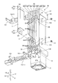
(Regenerative resistor mounting structure)
FIG. 6 is an explanatory view of the regenerative resistance to the frame and the mounting structure of the fan. As shown in FIG. 5, a plurality of heat radiation fins 30 are arranged in the front-rear direction Z and extend in the vertical direction Y.
The lower end (end portion in the −Y direction) of each heat radiation fin 30 projects from the frame portion 16 in the + X direction, and is located above the lower end portion of the frame portion 16. The side surface of the frame portion 16 in the + X direction and the lower end surface of each heat radiation fin 30 form a recess 32 whose height increases toward the side of the back plate 12. In the plurality of heat radiation fins 30, a first flow path 33, which is an air passage extending in the vertical direction Y, is formed between the adjacent heat radiation fins 30. In this embodiment, the plate thicknesses of the plurality of heat radiation fins 30 are the same, and the width of the first flow path 33 between the adjacent heat radiation fins 30 is also the same.
Each heat radiating fin 30 includes a heat radiating surface 34 facing the + Z direction and the −Z direction.

JP2017242446A 2017-12-19 2017-12-19 Motor control device Ceased JP2019110220A (en)

Priority Applications (2)

Application Number Priority Date Filing Date Title
JP2017242446A JP2019110220A (en) 2017-12-19 2017-12-19 Motor control device
CN201811554661.3A CN109936967B (en) 2017-12-19 2018-12-19 Motor control device

Applications Claiming Priority (1)

Application Number Priority Date Filing Date Title
JP2017242446A JP2019110220A (en) 2017-12-19 2017-12-19 Motor control device

Publications (2)

Publication Number Publication Date
JP2019110220A JP2019110220A (en) 2019-07-04
JP2019110220A5 true JP2019110220A5 (en) 2020-12-24

Family

ID=66984839

Family Applications (1)

Application Number Title Priority Date Filing Date
JP2017242446A Ceased JP2019110220A (en) 2017-12-19 2017-12-19 Motor control device

Country Status (2)

Country Link
JP (1) JP2019110220A (en)
CN (1) CN109936967B (en)

Families Citing this family (3)

* Cited by examiner, † Cited by third party
Publication number Priority date Publication date Assignee Title
CN113484471B (en) * 2021-07-05 2023-02-03 郑州水伟环境科技有限公司 Air exhaust chamber structure of micro thermal power pump of gas sensor
JP2023111738A (en) * 2022-01-31 2023-08-10 セイコーエプソン株式会社 Robot controller and robot system
DE102022205720A1 (en) 2022-06-03 2023-12-14 Lenze Se Frequency converter kit

Family Cites Families (6)

* Cited by examiner, † Cited by third party
Publication number Priority date Publication date Assignee Title
JPH07147492A (en) * 1993-11-26 1995-06-06 Hitachi Ltd Heat dissipating structure of electronic device
JP3237609B2 (en) * 1998-05-11 2001-12-10 株式会社日立製作所 Inverter device
JP2008103576A (en) * 2006-10-20 2008-05-01 Yaskawa Electric Corp Motor controller
TW200919165A (en) * 2007-10-17 2009-05-01 liang-he Chen Turbo-guiding type cooling apparatus
JP4792482B2 (en) * 2008-04-10 2011-10-12 オリエンタルモーター株式会社 Fixing structure between radiator of motor control device and assembly parts
CN106507637B (en) * 2016-09-20 2018-08-31 青岛海信电器股份有限公司 A kind of media data processing terminal

Similar Documents

Publication Publication Date Title
JP2019110220A5 (en)
JP2018114941A5 (en)
EP3700314B1 (en) Heat dissipation apparatus
CN109716512B (en) Heat radiator
JP2002344185A5 (en)
JP2013162052A5 (en)
TW201913282A (en) Heat sink
TWM479361U (en) Linen pad heat dissipation structure improvement
TW201350683A (en) Heat dissipation structure with double wind directions
JP2014002228A5 (en)
WO2016177040A1 (en) Heat sink
JP2005303063A5 (en)
JP2014093338A (en) Cooling fin
JP4788718B2 (en) Heat dissipation device for electronic equipment
JP5556093B2 (en) COOLING DEVICE AND ELECTRONIC DEVICE USING THE SAME
TW201502459A (en) Heat sink
JP3203510U (en) Net type heat dissipation structure and heat dissipation device having net type heat dissipation structure
CN101621906B (en) Radiating device
TWI581087B (en) Heat sink with a load spreading bar
TWI610611B (en) Combined cooling module
JP2005180906A (en) Heat exchanging device
CN203597007U (en) Low-thermal-resistance capacitor electronic switching switch
RU160226U1 (en) AIR RADIATOR
JP5859374B2 (en) Radiator duct
TWI556088B (en) Radiator structure