CN109936967B - Motor control device - Google Patents
Motor control device Download PDFInfo
- Publication number
- CN109936967B CN109936967B CN201811554661.3A CN201811554661A CN109936967B CN 109936967 B CN109936967 B CN 109936967B CN 201811554661 A CN201811554661 A CN 201811554661A CN 109936967 B CN109936967 B CN 109936967B
- Authority
- CN
- China
- Prior art keywords
- heat
- heat dissipation
- motor control
- flow path
- control device
- Prior art date
- Legal status (The legal status is an assumption and is not a legal conclusion. Google has not performed a legal analysis and makes no representation as to the accuracy of the status listed.)
- Active
Links
Images


Abstract
The invention provides a motor control device with a heat sink, which can prevent the high temperature of the components arranged around the heat sink. A motor control device (1) is provided with a heat dissipation part (2) formed on a frame (10) to which a first substrate (40) and a second substrate (50) are fixed, wherein the heat dissipation part (2) is provided with a plurality of heat dissipation fins (30), a first flow path (33) formed between adjacent heat dissipation fins (30) and extending in the vertical direction (Y), and a second flow path (60) intersecting the first flow path (33). The second flow path (60) is a flow path along a guide plate (62), and the guide plate (62) is disposed in a notch (61) formed in the heat sink (30) and extends in a direction intersecting the first flow path (33). The air guide plate (62) is formed on a first cover member (21) fixed to the frame (10). The second flow path (60) communicates with a space (S) located on one side (+ Z direction) of the arrangement direction (Z direction) of the heat dissipation sections (2) and blows cooling air to the first heat generator (5) disposed in the space (S).
Description
Technical Field
The present invention relates to a motor control device including a heat sink for cooling a heat generating body.
Background
Electronic devices such as an inverter device and a servo amplifier include a heat generating element that becomes high in temperature when a current is applied thereto, and therefore include a heat dissipating structure for cooling. Patent document 1 discloses a servo amplifier including a heat sink and a cooling fan. In patent document 1, heat of the regenerative resistor is transferred to the heat sink to be radiated. The air sucked into the fan flows through the heat sinks and is discharged to the upper and lower sides of the servo amplifier.
Documents of the prior art
Patent document
Patent document 1: japanese patent laid-open No. 2012-138485
Disclosure of Invention
Technical problem to be solved by the invention
The cooling structure of the heat radiating fin transfers heat generated by the heating element to the heat radiating fin, and blows air along the heat radiating fin to radiate the heat. Therefore, there is a problem that the components disposed around the heat sink are exposed to the heat of the heat sink. In particular, when a heating element is disposed around the heat sink, there is a problem that the heat from the heat sink is transferred to the heating element, which tends to become a high temperature.
In view of the above problems, the present invention is directed to suppressing a high temperature of components disposed around a heat sink.
Technical scheme for solving problems
In order to solve the above-described problems, the present invention provides a motor control device including: the motor control device is characterized in that the heat dissipation part is provided with a first flow path formed between adjacent heat dissipation fins and a second flow path crossed with the first flow path, the second flow path is a flow path along an air deflector, the air deflector is arranged at a notch formed on the heat dissipation fins or connected with the edge of the notch and extends along the direction crossed with the first flow path, and the second flow path is communicated with a space positioned at one side of the arrangement direction of the heat dissipation fins relative to the heat dissipation part.
According to the present invention, the air guide plate is disposed at or connected to the notch formed in the heat dissipating fins, and a second flow path is formed along the air guide plate, the second flow path intersecting the first flow path for air blowing formed between the heat dissipating fins. By providing such an air guide plate, the direction of the cooling air fed into the first flow path is changed by the air guide plate, and the cooling air flows in a direction intersecting the first flow path and is sent out to a space located on one side of the heat dissipation portion in the arrangement direction of the fins. Therefore, since a part of the cooling air blown to the first flow path can be directed to the components around the heat dissipation portion, the cooling air can be directly cooled by colliding with the components around the heat dissipation portion, and therefore, the components around the heat dissipation portion can be prevented from becoming high in temperature. This can suppress the shortening of the product life due to heat, and can set the upper limit of the use environment temperature to a high value.
In the present invention, it is preferable that the heat dissipating unit includes a first heat generating element mounted on the circuit board, and the second flow path communicates with a side of the heat dissipating unit where the first heat generating element is located. In this way, since a part of the air sent into the first flow path can be sent to the first heat generator, the first heat generator can be suppressed from becoming high in temperature.
In the present invention, it is preferable that the notch is formed by cutting a part of the heat sink in the height direction. Thus, the air guide plate is disposed only in a part of the first flow path in the height direction. Therefore, the cooling air flowing through the remaining portion in the height direction can be suppressed from diffusing from the first flow channel, and therefore, a decrease in cooling efficiency can be suppressed, and cooling can be performed efficiently. In addition, the flow rate of the cooling air in the first flow path and the second flow path can be adjusted by adjusting the depth of the notch and the height of the air guide plate.
In the present invention, it is preferable that the cutout is formed in at least two of the plurality of heat radiating fins including the heat radiating fin located on the side closest to the one side, the at least two cutouts are arranged in a direction toward a downstream side in an air blowing direction of the fan as the heat radiating fins face the one side, and the air guide plate extends obliquely in a direction toward the downstream side as the air guide plate faces the one side within a range in which the at least two cutouts are arranged. Thus, the notches are arranged in the direction in which the air guide plate extends, and thus the notches do not need to be enlarged. Therefore, a reduction in the surface area of the heat sink can be suppressed, and a reduction in cooling efficiency can be suppressed.
In this case, it is preferable that a first imaginary line connecting the downstream-side edges of the two or more notches and a second imaginary line connecting the upstream-side edges of the two or more notches in the air blowing direction are substantially parallel to each other, and the air deflector extends substantially parallel to the first imaginary line and the second imaginary line. Thus, the notch can be minimized in size. Therefore, a reduction in the surface area of the heat sink can be suppressed, and a reduction in cooling efficiency can be suppressed.
In the present invention, it is preferable that the cover member is fixed to the frame, the cover member includes a plate-shaped portion facing the heat radiating fins in a height direction orthogonal to an extending direction and an arrangement direction of the heat radiating fins, and the air guide plate protrudes from the plate-shaped portion toward the heat radiating fins. In this way, the cooling air can be suppressed from spreading from the first flow path by the plate-shaped portion of the cover member. Therefore, the cooling efficiency can be improved. Further, since the air guide plate can be disposed at an appropriate position by attaching the cover member to the frame, the air guide plate can be easily disposed. In addition, since the fixing member is not required, the number of parts can be suppressed from increasing.
In the present invention, it is preferable that the fan is disposed on one side in an extending direction of the first flow path with respect to the heat sink, and the notch is formed on the one side of the fan with respect to a center in the extending direction of the heat sink. In this way, since air can be sent to the second flow path on the side close to the fan, the cooling air can be turned by the air guide plate before the cooling air is diffused from the first flow path. Therefore, even if the area of the air guide plate is small, the flow rate of the second flow path can be ensured. Further, the cooling air can be introduced into the second flow path and sent to the target site before being diffused.
In the present invention, it is preferable that the heat radiating portion includes a plate-shaped heat radiating fin forming portion and a plurality of heat radiating fins protruding from the heat radiating fin forming portion, and the second heat generating element is disposed on a side opposite to a side on which the heat radiating fins protrude with respect to the heat radiating fin forming portion. Thus, the second heat generating element can be efficiently cooled by the heat radiating fins.
In the present invention, it is preferable that a regenerative resistor connected to the circuit board is provided, and the regenerative resistor is located on the opposite side of the heat dissipation portion from the one side. In this way, since the regenerative resistor is disposed at a position away from the first heat generator, heat is not easily transferred between the first heat generator and the regenerative resistor. Therefore, the temperature rise of the first heat generator due to the heat generation of the regenerative resistor and the temperature rise of the regenerative resistor due to the heat generation of the first heat generator can be suppressed.
In the present invention, it is preferable that the frame includes a back plate facing the heat radiating surface of the heat sink with a gap therebetween, and the regenerative resistor is disposed in the gap between the back plate and the heat radiating surface and is disposed with a gap therebetween. In this way, the regenerative resistor can be disposed at a position not interfering with the second flow path, and heat transfer from the regenerative resistor to the cooling air passing through the second flow path can be suppressed. In addition, a reduction in heat radiation area due to the arrangement of the regenerative resistor can be suppressed, and a reduction in cooling efficiency can be suppressed. Further, since heat is not easily transferred between the heat sink forming portion and the regeneration resistor, it is possible to suppress a temperature increase of the second heat generating element due to heat generation of the regeneration resistor and a temperature increase of the regeneration resistor due to heat generation of the second heat generating element.
Effects of the invention
According to the present invention, the air guide plate is disposed in the notch formed in the heat radiating fins, and the second flow path intersecting the first flow path for air blowing formed between the heat radiating fins is formed along the air guide plate. By providing such an air guide plate, the air introduced into the first flow path can be converted in direction by the air guide plate, and can be discharged to a space on one side of the heat dissipation portion in the arrangement direction of the heat dissipation fins while flowing in a direction intersecting the first flow path. Therefore, since a part of the air blown to the first flow path can be blown toward the components around the heat dissipation portion, the cooling air can be directly cooled by hitting the components around the heat dissipation portion, and thus the components around the heat dissipation portion can be prevented from becoming high in temperature. Therefore, the upper limit of the use environment temperature can be set high while suppressing the shortening of the product life due to heat.
Drawings
Fig. 1 is a perspective view of a motor control device to which the present invention is applied, as viewed from diagonally behind.
Fig. 2 is an exploded perspective view of the motor control device of fig. 1.
Fig. 3 is a perspective view of the frame to which the regenerative resistor, the first substrate, and the second substrate are fixed, as viewed from diagonally front.
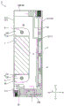
Fig. 4 is a sectional view of the motor control device of fig. 1 (sectional view a-a of fig. 1).
Fig. 5 is a perspective view of the first cover member as viewed from the inside.
Fig. 6 is an explanatory diagram of a mounting structure of the regenerative resistor and the fan to the frame.
Fig. 7 is a side view of a frame to which the regenerative resistor, the first substrate, and the second substrate are fixed.
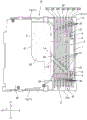
Fig. 8 is a sectional view of the motor control device of fig. 1 (sectional view B-B of fig. 1).
Description of the reference numerals
1 … motor control device, 2 … heat radiating portion, 3 … fan, 5 … first heat generating body, 6 … second heat generating body, 7 … regenerative resistor, 8 … fixing member, 9 … fixing screw, 10 … frame, 11 … frame body, 12 … back panel, 13 … heat sink forming portion, 14 … upper frame, 15 … lower frame, 16 … frame portion, 19 … hook, 20 … cover member, 21 … first cover member, 22 … second cover member, 23 … third cover member, 26 … heat radiating hole, 30 … heat sink, 30a … first heat sink, 30B … second heat sink, 30C … third heat sink, 30D … fourth heat radiating piece, 30E … fifth heat sink, 30F … sixth heat sink, 30G … seventh heat sink, 30 3632 concave portion, 33 … first heat radiating notch portion, 34 … heat radiating notch portion, 35 wiring notch portion …, thick portion 3639 notch portion …, 3639 notch portion, 40 … a first substrate, a 41 … notch, a 50 … second substrate, a 60 … second flow channel, a 61 … notch, a 62 … air guide plate, an 81 … first fixing portion, an 82 … second fixing portion, an 83 … fixing hole, a 121 … fixing hole, a 122 … notch, a 123 … through hole, 141, 151 … boss portion, a 211 … right side plate portion, a 212 … upper plate portion, a 213 … bottom plate portion, 214, 215 … engaging holes, a 216 … plate portion, an 219 … recess, a 221 … left side plate portion, a 222 … upper plate portion, a 223 … bottom plate portion, 224, 225 … engaging holes, a 228 … air inlet forming portion, a 229 recess, a 231 … front plate portion, a 232 … upper plate portion, 233 … bottom plate portion, a 234 … right side plate portion, a 235 … left side plate portion, 236 hook, a D … gap, a LA … first imaginary line, LB …, a S … second imaginary line, a front space of the S …, a heat dissipating portion in the front-back direction, a Y direction, a heat dissipating portion 72
Detailed Description
Hereinafter, an embodiment of a motor control device to which the present invention is applied will be described with reference to the drawings. The motor control device of the present embodiment is a servo amplifier for controlling a servo motor.
Fig. 1 is a perspective view of a motor control device 1 to which the present invention is applied, as viewed obliquely from the rear, and fig. 2 is an exploded perspective view of the motor control device 1 of fig. 1. In the present specification, the three directions XYZ are mutually orthogonal directions. Hereinafter, in the present specification, an example will be described in which the motor control device 1 is installed with the Y direction as the vertical direction, but the motor control device 1 of the present invention is not limited to use in an installation posture in which the Y direction is set as the vertical direction.
In this specification, the X direction is a width direction (left-right direction) of the motor control device 1, the Y direction is an up-down direction of the motor control device 1, and the Z direction is a front-rear direction of the motor control device 1. In addition, "left" and "right" in the left-right direction are "left" and "right" when the motor control device 1 is viewed from the front surface side. One side (right side) in the X direction is represented by + X, the other side (left side) is represented by-X, one side (upper side) in the Y direction is represented by + Y, the other side (lower side) is represented by-Y, one side (front side) in the Z direction is represented by + Z, and the other side (rear side) is represented by-Z.
As shown in fig. 1, the motor control device 1 has a rectangular parallelepiped shape as a whole. The motor control device 1 includes a frame 10 disposed at a substantially center in the width direction X, and a cover member 20 fixed to the frame 10. The cover member 20 includes a first cover member 21 disposed on the right side (+ X direction) of the frame 10, a second cover member 22 disposed on the left side (-X direction) of the frame 10, and a third cover member 23 disposed on the front side (+ Z direction) of the frame 10. As shown in fig. 2, the motor control device 1 includes a first base plate 40 disposed inside the first cover member 21 and a second base plate 50 disposed inside the second cover member 22. The first substrate 40 and the second substrate 50 are fixed to the frame 10.
(frame)
Fig. 3 is a perspective view of the frame 10 to which the regenerative resistor 7, the first substrate 40, and the second substrate 50 are fixed, as viewed from diagonally front side. As shown in fig. 2 and 3, the frame 10 includes a plate-shaped frame body 11 disposed substantially at the center in the width direction X of the motor control device 1, and a rectangular back panel 12 provided at the rear end (end in the (-Z direction) of the frame body 11. The frame body 11 includes a fin forming portion 13 connected to the back panel 12, and an upper frame 14 and a lower frame 15 (see fig. 6) extending forward (+ Z direction) from an upper end (+ Y direction end) and a lower end (-Y direction end) of the fin forming portion 13, respectively.
The frame body 11 is integrally formed with a heat sink 30 extending in the vertical direction Y. The frame 10 of the present embodiment is made of a metal having good thermal conductivity, such as aluminum. Therefore, the heat radiation effect of the heat radiation fins 30 can be improved. Further, since aluminum workability is good, the heat sink 30 is easily formed. A plurality of fins 30 are arranged at a substantially constant pitch in the Z direction on the front side (+ Z direction) of the back panel 12. The heat sink 30 protrudes rightward (+ X direction) from the heat sink forming portion 13 of the frame body 11. The heat sink 30 and the heat sink forming portion 13 constitute a heat radiating portion 2 for efficiently dissipating heat generated in the motor control device 1.
A cooling fan 3 is disposed below the heat radiating portion 2 (in the (-Y direction). A frame portion 16 (see fig. 4 and 6) for mounting the fan 3 is formed on the frame body 11. The frame 16 is provided below the heat radiating unit 2 (in the (-Y direction). The fan 3 sucks air from the lower side (-Y direction) and blows cooling air toward the heat dissipation portion 2. In the heat dissipation portion 2, a first flow path 33 is formed between adjacent fins 30. The first flow path 33 extends linearly in the vertical direction Y. The lower end of the first flow path 33 communicates with the side where the fan 3 is disposed. The upper end of the first flow path 33 is open to the upper end surface of the motor control device 1 (see fig. 1). Therefore, the cooling air sent from the fan 3 to the heat radiating unit 2 is discharged to the upper side (+ Y direction) of the motor control device 1 through the first flow path 33.
The first substrate 40 is screwed to boss portions 141 and 151 (see fig. 5) protruding in the + X direction from the upper frame 14 and the lower frame 15, respectively. Similarly, the second substrate 50 is screwed to boss portions protruding in the-X direction from the upper frame 14 and the lower frame 15, respectively. Fig. 4 is a cross-sectional view of the motor control device of fig. 1 (a cross-sectional perspective view at a position a-a in fig. 1). As shown in fig. 4, the second substrate 50 abuts against the heat sink forming portion 13 from the-X direction side, and is screwed to the heat sink forming portion 13.
As shown in fig. 1, the back plate 12 has fixing holes 121 formed in one of the corners located at opposite corners and notches 122 formed in the other corner. The fixing hole 121 is formed in a corner portion on the left side (-X direction) of the upper (+ Y direction) edge of the back panel 12. The notch 122 is formed in a corner portion on the right side (+ X direction) of the lower (-Y direction) edge of the back panel 12. By fastening the fixing screws to the fixing holes 121 and the notches 122, the back panel 12 can be fixed to the support member at two diagonal positions. Thereby, the motor control device 1 can be fixed to the support member via the back panel 12.
(cover means)
The front surface of the motor control device 1 is constituted by the third cover member 23. A connector portion and a terminal portion for input/output, which are not shown, are provided on the front surface of the motor control device 1. The third cover member 23 includes a front plate 231 provided with an opening for disposing the connector portion or an opening/closing cover for covering the terminal portion, an upper plate 232 connected to the + Y-direction edge of the front plate 231, a bottom plate 233 connected to the-Y-direction edge of the front plate 231, a right plate 234 connected to the + X-direction edge of the front plate 231, and a left plate 235 connected to the-X-direction edge of the front plate 231.
Fig. 5 is a perspective view of the first cover member 21 as viewed from the inside (the (-X direction). As shown in fig. 2 and 5, the first cover member 21 includes a right side plate portion 211 constituting a side surface of the motor control device 1 on the right side (+ X direction), an upper plate portion 212 connected to an upper end edge (+ Y direction edge) of the right side plate portion 211, and a bottom plate portion 213 connected to a lower end edge (-Y direction edge) of the right side plate portion 211 (see fig. 5). As shown in fig. 5, the upper plate portion 212 and the bottom plate portion 213 are provided at a portion from the front end of the first cover member 21 to a halfway position in the front-rear direction Z. A portion of the right side plate portion 211 of the first cover member 21 on the rear side (-Z direction) of the upper plate portion 212 and the bottom plate portion 213 constitutes a plate-shaped portion 216 covering the heat sink 30 from the right side (+ X direction). As shown in fig. 4, the heat sink 30 protrudes to a position where it abuts against the plate-like portion 216. Therefore, the plate-like portion 216 closes the + X direction side of the first flow path 33 formed between the adjacent heat dissipation fins 30 in the heat dissipation portion 2.
As shown in fig. 5, the air guide plate 62 protruding toward the side where the fins 30 are arranged (in the (-X direction) is formed in the plate-shaped portion 216. The air guide plate 62 extends linearly in a direction inclined with respect to the vertical direction Y and the front-rear direction Z. The function of the air deflector 62 will be described later.
As shown in fig. 2, the second cover member 22 includes a left side plate portion 221 constituting a left side surface (-X direction) of the motor control device 1, an upper plate portion 222 connected to an upper end edge (+ Y direction edge) of the left side plate portion 221, and a bottom plate portion 223 connected to a lower end edge (-Y direction edge) of the left side plate portion 221. An air inlet forming portion 228 is formed at a rear portion of the bottom plate portion 223 so as to cover a lower side of the fan 3.
The top surface (the surface in the + Y direction) of the motor control device 1 is constituted by the frame 10, the upper plate portion 212 of the first cover member 21, the upper plate portion 222 of the second cover member 22, and the upper plate portion 232 of the third cover member 23. The heat radiation holes 26 are formed in the upper plate portions 212 and 222. The heat radiation holes 26 are long holes that are long in the width direction X and are arranged in the front-rear direction Z. The bottom surface of the motor control device 1 is constituted by the frame 10, the bottom plate portion 213 of the first cover member 21, the bottom plate portion 223 of the second cover member 22, and the bottom plate portion 233 of the third cover member 23. Heat radiation holes 26 are formed in the bottom plate portions 213 and 223 in the same manner as the upper plate portions 212 and 222. The internal space of the motor control device 1 communicates with the outside via heat radiation holes 26 formed in the first cover member 21 and the second cover member 22.
As shown in fig. 1 and 2, the upper frame 14 has three hooks 19 formed at three positions separated in the Z direction. The upper plate portion 212 of the first cover member 21 includes an engagement hole 214 for engaging the central hook 19. The upper plate portion 222 of the second cover member 22 includes engagement holes 224 into which the hooks 19 at two locations other than the center hook 19 are engaged. Similar hook mechanisms are formed between the lower frame 15 and a bottom plate portion (not shown) of the first cover member 21, and between the lower frame 15 and a bottom plate portion 223 of the second cover member 22. The first cover member 21 and the second cover member 22 are fixed to the frame 10 by these hook mechanisms.
The third cover member 23 is provided with a hook 236 projecting rearward (in the (-Z direction) from the right side plate 234 and the left side plate 235. The hook 236 engages with the engagement hole 215 formed in the right plate portion 211 of the first cover member 21 and the engagement hole 225 formed in the left plate portion 221 of the second cover member 22. The third cover member 23 is fixed to the first cover member 21 and the second cover member 22 by the hook mechanism. The fixing structure of the cover member 20 may be a structure other than the hook mechanism.
The upper plate portion 222 of the second cover member 22 has a recess 229 having an inclined surface inclined downward (in the Y direction) toward the rear side (in the Z direction). Since the fixing hole 121 formed in the back plate 12 is disposed inside the recess 229, a tool for screwing can be inserted into the recess 229, and a fixing screw inserted into the fixing hole 121 can be screwed from the front side (+ Z direction) of the back plate 12. Similarly, a recess 32 is formed on the front side (+ Z direction) of the notch 122 of the back panel 12, and the recess 32 is formed by the end surface of the lower side (-Y direction) of the heat sink 30 and the side surface of the frame 16 (see fig. 6). The recess 32 formed in the heat sink 30 is continuous with the recess 219 (see fig. 5) formed in the bottom plate 213 of the first cover member 21. Therefore, a tool for screwing can be inserted into the recess 219 and the recess 32, and the fixing screw inserted into the notch 122 of the back panel 12 can be screwed from the front side (+ Z direction) of the back panel 12.
(Heat-generating body)
The first substrate 40 and the second substrate 50 are circuit substrates on which electronic components are mounted. The first substrate 40 is a control substrate, and supplies a drive signal to the second substrate 50 based on a control command input from the outside via a connector portion provided in the third cover member 23 and a signal from an encoder mounted on the servo motor. The second substrate 50 is a driver substrate. On the second substrate 50, circuit patterns and electronic components constituting a servo motor control circuit for generating and supplying U-phase, V-phase, and W-phase alternating currents from a power supply current to the servo motor in response to a drive signal from the first substrate 40 are mounted.
The motor control device 1 includes a first heating element 5 and a second heating element 6 disposed inside the cover member 20. The first heating element 5 and the second heating element 6 are electronic components constituting a servo motor control circuit. The servo motor control circuit includes a rectifier circuit for rectifying a power supply current supplied from an AC power supply, a capacitor connected to the rectifier circuit, and an inverter circuit connected to the capacitor. The first heat generator 5 is a capacitor and is mounted on the second substrate 50. As shown in fig. 2, a notch 41 is formed in the first substrate 40 disposed on the front side (+ Z direction) of the heat sink 30, the notch cutting the end portion on the side of the heat sink 30 (Z direction). The first heat generator 5 is disposed on the front side (+ Z direction) of the heat sink 30 and in the notch 41 of the first substrate 40.
The second heating element 6 is an IGBT transistor constituting an inverter circuit. The second heat generating element 6 may be an IPM (intelligent power module) in which the inverter circuit is modularized. As shown in fig. 4, the second substrate 50 is in contact with the surface of the side (in the (-X direction)) of the heat sink forming portion 13 of the frame body 11 opposite to the side from which the heat sink 30 protrudes, and the second heat generating element 6 is fixed to the portion of the second substrate 50 in contact with the heat sink forming portion 13. The second heating element 6 is disposed in the gap between the second substrate 50 and the second cover member 22. The heat generated from the second heat generating element 6 is transmitted to the heat sink 30 via the heat sink forming portion 13, and is released from the surface of the heat sink 30. The second heat generating element 6 may be fixed to the fin forming portion 13 directly or via an insulator.
The motor control device 1 includes a regenerative resistor 7 connected to a servo motor control circuit mounted on the second substrate 50. The regenerative resistor 7 is a heating element that converts regenerative energy generated at the time of deceleration or the like of the servo motor connected to the servo motor control circuit into heat. In the present embodiment, the regenerative resistor 7 is disposed in the gap between the back plate 12 and the heat sink 30, and is fixed to the heat sink 30.
(mounting structure of regenerative resistor)
Fig. 6 is an explanatory diagram of a mounting structure of the regenerative resistor and the fan to the frame 10. As shown in fig. 5, a plurality of fins 30 are arranged in the front-rear direction Z and extend in the vertical direction Y. The lower end (end in the Y direction) of each fin 30 protrudes from the frame 16 in the + X direction, and is located above the lower end of the frame 16. The side surface of the frame 16 in the + X direction and the lower end surface of each fin 30 form a recess 32 whose height increases toward the back panel 12. In the plurality of fins 30, a first flow path 33, which is an air blowing path extending in the vertical direction Y, is formed between adjacent fins 30. In the present embodiment, the plurality of fins 30 have the same plate thickness, and the width of the first flow path 33 between adjacent fins 30 is also the same. Each fin 30 has a heat radiating surface 34 facing in the + Z direction and the-Z direction.
Hereinafter, the heat sink 30 closest to the back panel 12 among the plurality of heat sinks 30 is referred to as a first heat sink 30A. In the present embodiment, 6 fins 30 are provided, and the second fin 30B, the third fin 30C, the fourth fin 30D, the fifth fin 30E, the sixth fin 30F, and the seventh fin 30G are provided in this order from the first fin 30A toward the front side (-Z direction). The first heat sink 30A is a heat sink farthest from the first heat generator 5 mounted on the second substrate 50. The second heat sink 30B is a heat sink second distant from the first heat generator 5.
The first heat sink 30A is disposed closest to the back panel 12. The first fin 30A is formed with a notch 35 cut from the + X-direction edge toward the-X direction. The regenerative resistor 7 is disposed in the notch 35. When the regenerative resistor 7 is removed, the heat radiation surface 34 of the second heat radiation fin 30B located near the first heat radiation fin 30A and the back surface plate 12 face each other with a predetermined gap in the range where the notch 35 is formed. The regenerative resistor 7 is disposed between the rear plate 12 and the heat radiation surface 34 of the second fin 30B facing the-X direction, and is fixed to the heat radiation surface 34 of the second fin 30B.
As shown in fig. 4, the notches 35 formed in the first fin 30A are formed by cutting the first fin 30A to a position halfway in the X direction. Therefore, a gap D in the X direction is formed between the regenerative resistor 7 disposed in the notch 35 and the fin forming portion 13. The second heating element 6 is fixed to the side of the heat sink formation 13 opposite to the side on which the heat sink 30 is formed, via the second substrate 50. That is, the regenerative resistor 7 is disposed so as to form an air layer between the regenerative resistor and the portion (the fin forming portion 13) to which the second heat generating element 6 is fixed.
The regenerative resistor 7 is fixed to the heat radiation surface 34 of the second heat radiation fin 30B via the fixing member 8. The fixing members 8 are disposed one at each end of the regenerative resistor 7 in the Y direction. Each fixing member 8 is a bent member including a plate-shaped first fixing portion 81 and a plate-shaped second fixing portion 82 connected to the first fixing portion 81 at a substantially right angle. The first fixing portion 81 is in contact with a side surface of the regenerative resistor 7 and fixed to the regenerative resistor 7. The second fixing portion 82 abuts against the heat radiating surface 34 and is screwed to the second heat sink 30B by the fixing screw 9. As shown in fig. 5, a fixing hole 83 is formed in the second fixing portion 82, and a screw hole 36 is formed in the second fin 30B at a position overlapping the fixing hole 83. The portion of second fin 30B where screw hole 36 is formed is a thick portion 37 having a plate thickness larger than the plate thickness of the other portions. Through-holes 123 are formed in back plate 12 at positions overlapping with screw holes 36 of second heat sink 30B. The through hole 123 is a hole for inserting a tool for screwing the fixing screw 9.
In each of the plurality of heat sinks 30, a wiring cutout 39 is formed below (in the Y direction) the mounting position of the regenerative resistor 7. The wiring notches 39 formed in the 7 heat sinks 30 are arranged in the longitudinal direction Z, which is the arrangement direction of the heat sinks 30, and constitute wiring notches 38 extending in the longitudinal direction Z. Wiring, not shown, connected to the regenerative resistor 7 is disposed in the wiring cutout groove 38.
(Cooling Structure of second channel)
In the heat radiating portion 2, a second flow path 60 is formed at a halfway position in the vertical direction Y of the heat radiating fin 30. The second flow path is a flow path that converts the direction of the cooling air directed upward (+ Y direction) along the first flow path 33 extending in the vertical direction Y into a direction intersecting the first flow path 33, and discharges the cooling air in a direction different from the first flow path 33. The second flow path 60 is constituted by a notch 61 formed in the plurality of fins 30 and an air guide plate 62 (see fig. 5 and 8) disposed in the notch 61.
Fig. 7 is a side view of the frame 10 to which the regenerative resistor 7, the first substrate 40, and the second substrate 50 are fixed. Fig. 8 is a cross-sectional view (cross-sectional view B-B in fig. 1) of the motor control device 1 in fig. 1, showing a cross-sectional structure of the heat dissipation portion 2 at a position where the air guide plate 62 and the notch 61 are provided. As shown in fig. 5, the air guide plate 62 protrudes from the plate-like portion 216 of the first cover member 21 toward the heat sink 30. When the first cover member 21 is attached to the frame 10, the air guide plate 62 is disposed in the notch 61 as shown in fig. 8. Thereby, the second flow path 60 through which the cooling air flows along the air guide plate 62 is formed inside the notch 61. The second flow path 60 is configured to blow cooling air toward the first heat generating body 5 located on the front side (+ Z direction) with respect to the heat radiating portion 2. The side (+ Z direction) of the heat dissipation portion 2 where the first heat generator 5 is located is one side in the front-rear direction Z, which is the arrangement direction of the heat dissipation fins 30 of the heat dissipation portion 2.
As shown in fig. 3 and 7, among the plurality of fins 30, 5 fins 30 from the seventh fin 30G located on the most front side (+ Z direction) to the third fin 30C are each formed with one notch 61 for forming the second flow path 60. The five notches 61 are arranged obliquely in a direction toward the upper side (+ Y direction) as facing the side on which the first heat generating element 5 is disposed (i.e., + Z direction). In the first flow path 33, the cooling air supplied from the fan 3 flows upward (+ Y direction). That is, the arrangement direction of the five notches 61 is a direction toward the downstream side (+ Y direction) of the air blowing direction of the fan 3 as it goes toward the side (+ Z direction) where the first heat generator 5 is arranged.
The five notches 61 have the same shape, and are cut at the same height (the same depth) from the front end of the heat sink 30 in the-X direction. The five notches 61 have the same notch width in the vertical direction Y and are arranged offset from each other in the vertical direction Y. As shown in fig. 3, the depth of the notch 61 in the-X direction is smaller than the protrusion height of the heat sink 30 in the + X direction. That is, the notch 61 is formed by cutting a part of the front end side, not all of the heat sink 30 in the height direction. Therefore, the air guide plate 62 blocks a part of the cooling air in the height direction (X direction) of the first flow path 33 and switches the direction thereof, but a flow path space in which the cooling air flows in the vertical direction Y is left in the bottom portion (region on the base end portion side of the heat sink 30) of the first flow path 33.
As shown in fig. 7, the five notches 61 are arranged linearly in a direction inclined with respect to the vertical direction Y and the front-rear direction Z. A first imaginary line LA connecting the downstream side (i.e., the + Y direction) edges of the notches 61 and a second imaginary line LB connecting the upstream side (i.e., the-Y direction) edges of the notches 61 are parallel to each other and inclined with respect to the vertical direction Y and the front-rear direction Z. As shown in fig. 8, the air guide plate 62 is disposed parallel to the first imaginary line LA and the second imaginary line LB. The air guide plate 62 is disposed close to the downstream side (+ Y direction) edge of each notch 61, and forms a gap with the upstream side (-Y direction) edge. Thereby, a second flow path 60 for allowing the cooling air to flow along the air guide plate 62 is formed on the upstream side (the (-Y direction) of the air guide plate 62.
Since the second flow path 60 is inclined in a direction toward the downstream side (+ Y direction) of the air blowing direction as it goes toward the front side (+ Z direction), the cooling air flowing through the second flow path 60 is discharged toward the upper (+ Y direction) region of the space S on the front side (+ Z direction) of the heat radiating portion 2. Among the notches 61 constituting the second flow path 60, the notch 61 formed in the seventh fin 30G positioned on the most front side (+ Z direction) serves as a cooling air discharge port of the second flow path 60 and faces the space S on the front side (+ Z direction) of the heat dissipation portion 2. The space S on the front side of the heat dissipation portion 2 is a space on one side in the arrangement direction of the heat dissipation fins 30, and is a space in which the first heat generator 5 is disposed. That is, the second flow path 60 includes a cooling air discharge port that communicates with the space in which the first heat generator 5 is disposed. The cooling air discharge port (the notch 61 formed in the seventh fin 30G) is opened at a position lower than the first heat generator 5 (-Y direction). Therefore, the cooling air discharged from the second flow channel 60 is discharged from the obliquely lower side of the first heat generator 5 toward the first heat generator 5.
The fan 3 for blowing cooling air to the heat radiating portion 2 is disposed below the heat radiating fin 30 (in the (-Y direction). In the present embodiment, the second channel 60 is formed below the center in the vertical direction Y of the first channel 33 (in the (-Y direction). That is, the second flow path 60 is formed at a position on the upstream side of the first flow path 33 in the blowing direction of the cooling air, that is, on the fan 3 side. Therefore, the notch 61 constituting the second flow path 60 is formed at a position closer to the fan 3 side (i.e., in the-Y direction) than the center of the heat sink 30 in the vertical direction Y. In the present embodiment, the five notches 61 are arranged in a direction inclined with respect to the vertical direction Y and the front-rear direction Z, but all are formed below the center of the heat sink 30 in the vertical direction Y (-Y direction). Therefore, the second flow path 60 can change the direction of the cooling air on the upstream side of the first flow path 33 and send the cooling air to the space S on the front side of the heat radiating portion 2.
(main effect of the present embodiment)
As described above, the motor control device 1 of the present embodiment has the heat dissipation portion 2 formed in the frame 10, and the heat dissipation portion 2 includes the first flow path 33 formed between the adjacent heat dissipation fins 30 and extending in the vertical direction Y and the second flow path 60 intersecting the first flow path 33. The second flow path 60 is a flow path along the air guide plate 62, the air guide plate 62 is disposed in the notch 61 formed in the heat dissipating fin 30 and extends in a direction intersecting the first flow path 33, and the second flow path 60 communicates with the space S located on one side (+ Z direction) of the arrangement direction (Z direction) of the heat dissipating fin 30 with respect to the heat dissipating portion 2. By providing such an air guide plate 62, the cooling air introduced into the first flow path 33 can be converted in direction by the air guide plate 62 so as to flow in a direction intersecting the first flow path 33, and can be discharged to the space S located on one side (+ Z direction) of the arrangement direction (Z direction) of the heat dissipation portion 2 of the heat dissipation fins 30. Therefore, since a part of the cooling air blown to the first flow path 33 can be blown toward the components around the heat dissipation portion 2, the cooling air can be directly made to collide with the components around the heat dissipation portion 2 to cool the components. Therefore, the components around the heat dissipation portion 2 can be prevented from becoming high in temperature. As a result, the product life of the motor control device 1 can be prevented from being shortened by heat, and the upper limit of the usage environment temperature of the motor control device 1 can be set high.
In the present embodiment, the first heat-generating elements 5 mounted on the second substrate 50 are disposed in the space S where the cooling air is discharged from the second flow channels 60, so that the cooling air can be blown toward the first heat-generating elements 5 to directly cool the first heat-generating elements 5. Therefore, the first heat generator 5 can be suppressed from becoming high in temperature. In addition, since the heat accumulated in the frame 10 can be reduced by directly lowering the temperature of the first heat generator 5 in this manner, the temperature of the entire motor control device 1 can be lowered.
In the present embodiment, the notch 61 constituting the second flow path 60 is formed by cutting a part of the heat sink 30 in the height direction (X direction). Therefore, the air guide plate 62 is disposed only in a part of the first flow path 33 in the height direction (X direction), and therefore, a flow path space not shielded by the air guide plate 62 is left in the first flow path 33 so as to send the cooling air to the upper side of the air guide plate 62. Therefore, a decrease in cooling efficiency due to the fins 30 can be suppressed. Further, since the cooling air flowing through the first flow path 33 flows through the bottom of the first flow path 33, the cooling air can be prevented from diffusing from the first flow path 33. Therefore, a decrease in cooling efficiency can be suppressed, and cooling can be performed efficiently. Further, by adjusting the depth of the notch 61 and the height of the air guide plate 62, the flow rate of the cooling air in the first flow path 33 and the second flow path 60 can be adjusted.
In the present embodiment, the notches 61 are formed in 5 fins 30 including the seventh fin 30G located at the forefront side (+ Z direction) among the plurality of fins 30, and the second flow passages 60 are formed in the range of the 5 fins 30. In this configuration, the five notches 61 forming the space in which the air deflector 62 is disposed are arranged obliquely in the flow path direction of the second flow path 60, so that the size of the notches 61 is not unnecessarily increased. Therefore, a reduction in the surface area of the heat sink 30 can be suppressed, and a reduction in cooling efficiency can be suppressed. In particular, in the present embodiment, a configuration is adopted in which a first virtual line LA connecting the edges on the downstream side (+ Y direction) of the five notches 61 and a second virtual line LB connecting the edges on the upstream side (-Y direction) of the five notches 61 are substantially parallel, and the air guide plate 62 extends substantially parallel to the first virtual line LA and the second virtual line LB. Therefore, since the width of the notch 61 in the X direction can be minimized, a reduction in the surface area of the heat sink can be suppressed, and a reduction in cooling efficiency can be suppressed.
In the present embodiment, the first cover member 21 fixed to the frame 10 includes a plate-like portion 216 covering the heat dissipation portion 2. The plate-like portion 216 faces the heat sink 30 in the height direction (X direction) orthogonal to the extending direction (Y direction) and the arrangement direction (Z direction) of the heat sink 30. Since the plate-like portion 216 abuts on the front end of the heat sink 30, the cooling air can be suppressed from diffusing from the first flow path 33. Therefore, the cooling efficiency can be improved. Further, a gap may be formed between the plate-like portion 216 and the distal end of the heat sink 30. The air guide plate 62 constituting the second flow path 60 is formed integrally with the first cover member 21 and projects from the plate-like portion 216 toward the heat sink 30. Therefore, the air guide plate 62 can be disposed at an appropriate position in the notch 61 of the heat sink 30 by attaching the first cover member 21 to the frame 10, and thus the air guide plate 62 can be easily disposed. In addition, since it is not necessary to use a separate fixing member as in the case of using the air guide plate 62 as another member, an increase in the number of parts can be suppressed.
In the present embodiment, since the second flow path 60 is provided at the position on the fan 3 side in the first flow path 33, the notch 61 is formed at a position lower than the center in the vertical direction Y of the heat sink 30 (-Y direction). By providing the second flow path 60 on the side close to the fan 3 in this manner, the cooling air can be turned by the air guide plate 62 before the cooling air is diffused from the first flow path 33. Therefore, even if the area of the air guide plate is small, the flow rate of the second flow path 60 can be ensured. Further, the cooling air can be introduced into the second flow path 60 and sent to the target site before being diffused.
The heat radiating portion 2 of the present embodiment includes a plate-shaped heat radiating fin forming portion 13 and a plurality of heat radiating fins 30 protruding from the heat radiating fin forming portion 13, and the second heat generating element 6 is disposed on the side opposite to the side where the heat radiating fins 30 protrude (in the (-X direction) with respect to the heat radiating fin forming portion 13. Therefore, the heat of the second heat generating element 6 can be efficiently released by the heat radiating fins 30, and therefore the second heat generating element 6 can be efficiently cooled.
In the present embodiment, the regenerative resistor 7 connected to the second substrate 50 is provided, and the regenerative resistor 7 is disposed on the side (Z direction) of the heat dissipation portion 2 opposite to the side (+ Z direction) on which the first heat generator 5 is disposed. By disposing the regeneration resistor 7 as a heating element at a position distant from the first heating element 5 in this manner, heat is not easily transferred between the first heating element 5 and the regeneration resistor 7. Therefore, the temperature increase of the first heat generator 5 due to the heat generation of the regenerative resistor 7 and the temperature increase of the regenerative resistor 7 due to the heat generation of the first heat generator 5 can be suppressed.
In the present embodiment, a rear plate 12 is formed on a frame 10 in which the heat dissipation portion 2 is integrally formed. The regenerative resistor 7 is disposed in a gap between the back plate 12 and the heat sink 30. Therefore, the regenerative resistor 7 can be disposed so as not to interfere with the second flow channel 60, and therefore the heat of the regenerative resistor 7 is less likely to be transferred to the cooling air introduced into the second flow channel 60. Therefore, a decrease in cooling efficiency due to the cooling wind discharged from the second flow path 60 can be suppressed. Further, since the gap D is provided between the fin forming portion 13 and the regeneration resistor 7, it is possible to suppress a temperature increase of the second heating element 6 due to heat generation of the regeneration resistor 7 and a temperature increase of the regeneration resistor 7 due to heat generation of the second heating element 6.
In addition, in the arrangement of the regenerative resistor 7 as in the present embodiment, it is possible to suppress an increase in the size of the motor control device 1 in the width direction (X direction) as compared with the case where the regenerative resistor 7 is arranged on the distal end side of the heat sink 30. Further, compared to the case where a plurality of fins 30 are cut and regenerative resistors 7 are disposed so as to contact the tips of fins 30, the reduction in the surface area of fins 30 is small, and therefore, the reduction in the heat radiation effect can be suppressed. In addition, as compared with the case where the regenerative resistor is disposed by cutting the back plate, a decrease in strength of the frame 10 can be suppressed. The regenerative resistor 7 may be fixed to either the heat sink 30 or the back plate 12, but in the present embodiment, the regenerative resistor 7 is fixed to the heat sink 30 side. In this case, the regenerative resistor 7 can be attached and detached from the back plate 12 side. That is, the through-hole 123 is formed in the back plate 12, so that the regenerative resistor 7 can be attached and detached from the outside of the back plate 12. This improves workability in attaching and detaching the regenerative resistor 7, and improves maintainability.
The regenerative resistor 7 of the present embodiment is fixed to the heat radiating surface 34 of the second fin 30B via the fixing member 8. The fixing member 8 includes a first fixing portion 81 abutting against the regenerative resistor 7 and a second fixing portion 82 abutting against the heat radiation surface. Therefore, since the transfer path via the fixing member 8 is added as a path for transferring the heat of the regenerative resistor 7 to the second heat dissipation fins 30B, the cooling efficiency of the regenerative resistor 7 can be improved. The shape of the fixing member 8 is not limited to the shape of the present embodiment. For example, the regenerative resistor 7 may be fixed by a fixing member covering the entire regenerative resistor. Instead of using the fixing member 8, the regenerative resistor 7 may be fixed by providing a fixing hole. Alternatively, the regenerative resistor 7 may be fixed to the heat dissipation surface 34 by using an adhesive.
In the present embodiment, the plurality of fins 30 are formed with wiring notches 39, and wiring notches 38 extending in the longitudinal direction Z, which is the arrangement direction of the fins 30, are provided. Therefore, the wiring connecting the second substrate 50 and the regenerative resistor 7 can be accommodated and routed to the wiring cutout groove 38. Thus, the wiring does not pass through the outside of the frame 10, and therefore, disconnection of the wiring connecting the second substrate 50 and the regenerative resistor 7 can be suppressed.
(other embodiments)
(1) The air guide plate 62 may be formed on the heat sink 30 instead of the first cover member 21. For example, with respect to each of the five notches 61 formed on the heat sink 30, an air guide plate connected to the edge on the downstream side (+ Y direction) of each notch 61 at the same angle as the air guide plate 62 can be provided.
(2) The air guide plate 62 may be a member different from the first cover member 21 and the frame 10.
(3) In the above embodiment, the five notches 61 are arranged at the same angle as the orientation of the air guide plate 62, but the arrangement and size of the notches 61 are not limited to this embodiment.
(4) In the above embodiment, the first heating element 5 is a capacitor, the second heating element 6 is an IGBT transistor, and the regenerative resistor 7 is provided separately from these two heating elements, but the heating elements are not limited to this combination. The regeneration resistor 7 may be disposed at the position of the second heating element 6.
Claims (15)
1. A motor control device includes: a circuit board having a motor control circuit, a frame having a heat dissipation portion formed by arranging a plurality of heat dissipation fins, and a fan for blowing air toward the heat dissipation fins,
the heat dissipation portion includes first flow paths formed between adjacent heat dissipation fins and second flow paths intersecting the first flow paths,
the second flow path is a flow path along a wind guide plate, the wind guide plate is disposed in a notch formed in the heat dissipating fin or is connected to an edge of the notch, and extends in a direction intersecting the first flow path, and the second flow path is communicated with a space located on one side of the heat dissipating portion in the arrangement direction of the heat dissipating fins.
2. The motor control device according to claim 1,
comprises a first heat generator mounted on the circuit board,
the second flow path communicates with a side of the heat sink where the first heat generating body is located.
3. The motor control device according to claim 1,
the notch is formed by cutting a part of the heat sink in the height direction.
4. The motor control device according to any one of claims 1 to 3,
the notches are formed in at least two of the plurality of heat radiating fins including the heat radiating fin located on the side closest to the one side,
two or more of the notches are arranged in a direction toward a downstream side in an air blowing direction of the fan as facing the one side,
the air guide plate extends obliquely in a direction toward the downstream side as it goes toward the one side within a range in which the two or more notches are arranged.
5. The motor control device according to claim 4,
a first imaginary line connecting the edges on the downstream side of the two or more notches and a second imaginary line connecting the edges on the upstream side of the two or more notches in the air blowing direction are substantially parallel to each other,
the air deflector extends substantially parallel to the first imaginary line and the second imaginary line.
6. The motor control device according to claim 1,
comprises a cover member fixed to the frame,
the cover member includes a plate-shaped portion facing the heat dissipation fins in a height direction orthogonal to an extending direction and an arrangement direction of the heat dissipation fins,
the air guide plate protrudes from the plate-shaped portion toward the heat radiating fin.
7. The motor control device according to claim 1,
the fan is disposed on one side of the heat sink in the extending direction of the first flow path, and the notch is formed on the fan side of the center of the heat sink in the extending direction.
8. The motor control device according to claim 1,
the heat dissipation portion includes a plate-shaped heat dissipation fin forming portion and a plurality of heat dissipation fins protruding from the heat dissipation fin forming portion,
the second heat generating element is disposed on the opposite side of the heat sink forming portion from the side from which the heat sink protrudes.
9. The motor control device according to claim 8,
a regenerative resistor connected to the circuit board,
the regenerative resistor is located on the side opposite to the one side with respect to the heat dissipation portion.
10. The motor control device according to claim 9,
the frame is provided with a back plate facing the heat dissipation surface of the heat dissipation fin with a gap,
the regenerative resistor is disposed in a gap between the back surface plate and the heat dissipation surface, and is disposed so as to form a gap between the regenerative resistor and the heat dissipation fin forming portion.
11. The motor control device according to claim 5,
comprises a cover member fixed to the frame,
the cover member includes a plate-shaped portion facing the heat dissipation fins in a height direction orthogonal to an extending direction and an arrangement direction of the heat dissipation fins,
the air guide plate protrudes from the plate-shaped portion toward the heat radiating fin.
12. The motor control device according to claim 11,
the fan is disposed on one side of the heat sink in the extending direction of the first flow path, and the notch is formed closer to the fan than the center of the heat sink in the extending direction.
13. The motor control device according to claim 12,
the heat dissipation portion includes a plate-shaped heat dissipation fin forming portion and a plurality of heat dissipation fins protruding from the heat dissipation fin forming portion,
the second heat generating element is disposed on the opposite side of the heat sink forming portion from the side from which the heat sink protrudes.
14. The motor control device according to claim 13,
a regenerative resistor connected to the circuit board,
the regenerative resistor is located on the side opposite to the one side with respect to the heat dissipation portion.
15. The motor control device according to claim 14,
the frame is provided with a back plate facing the heat dissipation surface of the heat dissipation fin with a gap,
the regenerative resistor is disposed in a gap between the back surface plate and the heat dissipation surface, and is disposed so as to form a gap between the regenerative resistor and the heat dissipation fin forming portion.
Applications Claiming Priority (2)
| Application Number | Priority Date | Filing Date | Title |
|---|---|---|---|
| JP2017-242446 | 2017-12-19 | ||
| JP2017242446A JP2019110220A (en) | 2017-12-19 | 2017-12-19 | Motor control device |
Publications (2)
| Publication Number | Publication Date |
|---|---|
| CN109936967A CN109936967A (en) | 2019-06-25 |
| CN109936967B true CN109936967B (en) | 2021-04-06 |
Family
ID=66984839
Family Applications (1)
| Application Number | Title | Priority Date | Filing Date |
|---|---|---|---|
| CN201811554661.3A Active CN109936967B (en) | 2017-12-19 | 2018-12-19 | Motor control device |
Country Status (2)
| Country | Link |
|---|---|
| JP (1) | JP2019110220A (en) |
| CN (1) | CN109936967B (en) |
Families Citing this family (2)
| Publication number | Priority date | Publication date | Assignee | Title |
|---|---|---|---|---|
| CN113484471B (en) * | 2021-07-05 | 2023-02-03 | 郑州水伟环境科技有限公司 | Air exhaust chamber structure of micro thermal power pump of gas sensor |
| DE102022205720A1 (en) | 2022-06-03 | 2023-12-14 | Lenze Se | Frequency converter kit |
Family Cites Families (6)
| Publication number | Priority date | Publication date | Assignee | Title |
|---|---|---|---|---|
| JPH07147492A (en) * | 1993-11-26 | 1995-06-06 | Hitachi Ltd | Heat dissipating structure of electronic device |
| JP3237609B2 (en) * | 1998-05-11 | 2001-12-10 | 株式会社日立製作所 | Inverter device |
| JP2008103576A (en) * | 2006-10-20 | 2008-05-01 | Yaskawa Electric Corp | Motor controller |
| TW200919165A (en) * | 2007-10-17 | 2009-05-01 | liang-he Chen | Turbo-guiding type cooling apparatus |
| JP4792482B2 (en) * | 2008-04-10 | 2011-10-12 | オリエンタルモーター株式会社 | Fixing structure between radiator of motor control device and assembly parts |
| CN106507637B (en) * | 2016-09-20 | 2018-08-31 | 青岛海信电器股份有限公司 | A kind of media data processing terminal |
-
2017
- 2017-12-19 JP JP2017242446A patent/JP2019110220A/en not_active Ceased
-
2018
- 2018-12-19 CN CN201811554661.3A patent/CN109936967B/en active Active
Also Published As
| Publication number | Publication date |
|---|---|
| CN109936967A (en) | 2019-06-25 |
| JP2019110220A (en) | 2019-07-04 |
Similar Documents
| Publication | Publication Date | Title |
|---|---|---|
| US6002586A (en) | Apparatus for adjustable mounting a cooling device to a computer enclosure | |
| CN109936967B (en) | Motor control device | |
| CN100586263C (en) | Power supply with improved cooling | |
| JP2006319142A5 (en) | ||
| JP2006210516A (en) | Cooling structure of electronic equipment | |
| WO2020174934A1 (en) | Electronic control device | |
| US9706681B2 (en) | Modular electronic system | |
| CN100470777C (en) | Heat sink | |
| KR101482102B1 (en) | Heat dissipation structure of a controller of an air conditioner | |
| CN214586772U (en) | Server | |
| CN109951133B (en) | Motor control device | |
| JP2006119234A (en) | Electrical apparatus and image forming apparatus | |
| KR101718201B1 (en) | Motor driving apparatus | |
| JP7396132B2 (en) | power converter | |
| JP4403753B2 (en) | Power converter | |
| CN109219312B (en) | Motor control device | |
| JP2018032806A (en) | Electronic apparatus heat dissipation structure | |
| JPH0611585Y2 (en) | Wind direction adjustment tool | |
| CN112243334A (en) | Heat radiation structure of heating component | |
| CN220292443U (en) | Electric control box and air conditioner external unit | |
| KR20080079476A (en) | Radiator module of air conditioner | |
| CN218630660U (en) | Server | |
| JPH11118203A (en) | Inverter electric part of air conditioner | |
| JP7002339B2 (en) | Electrical equipment | |
| JP2017204588A (en) | Circuit board |
Legal Events
| Date | Code | Title | Description |
|---|---|---|---|
| PB01 | Publication | ||
| PB01 | Publication | ||
| SE01 | Entry into force of request for substantive examination | ||
| SE01 | Entry into force of request for substantive examination | ||
| GR01 | Patent grant | ||
| GR01 | Patent grant |