JP2019060831A - Laser induced analyzer and laser induced analytical method - Google Patents
Laser induced analyzer and laser induced analytical method Download PDFInfo
- Publication number
- JP2019060831A JP2019060831A JP2017188050A JP2017188050A JP2019060831A JP 2019060831 A JP2019060831 A JP 2019060831A JP 2017188050 A JP2017188050 A JP 2017188050A JP 2017188050 A JP2017188050 A JP 2017188050A JP 2019060831 A JP2019060831 A JP 2019060831A
- Authority
- JP
- Japan
- Prior art keywords
- stage
- laser induced
- analyzer
- laser
- sample
- Prior art date
- Legal status (The legal status is an assumption and is not a legal conclusion. Google has not performed a legal analysis and makes no representation as to the accuracy of the status listed.)
- Pending
Links
Images


Landscapes
- Investigating, Analyzing Materials By Fluorescence Or Luminescence (AREA)
Abstract
Description
本発明は、分析対象物をレーザ誘起プラズマ分光法(Laser-Induced Plasma Spectroscopy: LIPS)により分析する技術に関する。 The present invention relates to a technique for analyzing an analyte by laser-induced plasma spectroscopy (LIPS).
特許文献1には、液体状態から蒸発乾固によって固体化された物質を、レーザ誘起プラズマ分光法を用いて分析する装置が記載されている。ここでは、まず、液体状態の物質を定形のプレート上に微量滴下し、これを加熱して溶媒を蒸発させる。そして、プレート上に残された物質(乾固物質)をレーザ誘起プラズマ分光法により分析して、該物質に含まれる元素の種類および量(濃度)を特定する。
ここで、レーザ誘起プラズマ分光法について説明する。この分析手法では、レーザ装置から短パルスのレーザ光を出射し、レンズで集光(フォーカシング)してサンプル表面に照射する。このとき、レーザ光が集光されたスポット(集光点)において高温高密度のプラズマ(破壊プラズマ)が生成され、該スポットにおいてサンプル表面にある原子が励起される。励起された原子は固有の波長の光を放射して状態遷移する。したがって、このときに発生した光の発光スペクトルを分光器で取得し、該発光スペクトルに現れるピークの位置(波長)および強度を特定することで、サンプルに含まれる元素の種類および量(濃度)を特定することができる。
なお、この手法でガス中に含まれる物質を特定する場合は、レーザ誘起ブレイクダウン分光法(Laser-Induced Breakdown Spectroscopy: LIBS)と呼ばれることもある。
Here, laser induced plasma spectroscopy will be described. In this analysis method, a short pulse laser beam is emitted from a laser device, condensed (focused) by a lens, and irradiated onto a sample surface. At this time, a high-temperature high-density plasma (breakdown plasma) is generated at a spot (focusing point) at which the laser light is focused, and atoms on the sample surface are excited at the spot. The excited atoms emit light of a specific wavelength and undergo state transition. Therefore, by acquiring the emission spectrum of the light generated at this time with a spectrometer and specifying the position (wavelength) and the intensity of the peak appearing in the emission spectrum, the type and amount (concentration) of the element contained in the sample can be obtained. It can be identified.
In addition, when the substance contained in gas is pinpointed by this method, it may be called laser-induced breakdown spectroscopy (LIBS).
上記の通り、従来は、サンプルを得る手法として、分析すべき液体を所定の定形プレート(典型的には、矩形平板状のシリコンチップ)上に微量滴下して蒸発乾固させる、というものが一般的であった。 As described above, conventionally, as a method for obtaining a sample, generally, a small amount of liquid to be analyzed is dropped on a predetermined shaped plate (typically, a rectangular flat silicon chip) and evaporated to dryness. It was
近年、このような手法とは異なる手法でサンプルを得ることも考えられている。例えば、分析すべき液体が流れる配管の端にサンプル捕獲用のチューブ(例えば樹脂チューブ)を予め連設しておく。配管内に該液体が流れない時間帯があると、このチューブの内壁に該液体が蒸発乾固した物質(乾固物質)が付着する。そこで、このチューブの一部を切り取ることにより、チューブ片の内面に乾固物質が付着したサンプルを得ることができる。 In recent years, it has been considered to obtain samples by a method different from such a method. For example, a tube for capturing a sample (for example, a resin tube) is connected in advance to an end of a pipe through which a liquid to be analyzed flows. When there is a time zone in which the liquid does not flow in the pipe, a substance (dried substance) obtained by evaporation of the liquid adheres to the inner wall of the tube. Therefore, by cutting off a part of the tube, it is possible to obtain a sample in which the dried solid matter adheres to the inner surface of the tube piece.
分析装置に搬入されたサンプルは、所定のステージ上に載置されて、レーザ光の照射を受ける。従来の分析装置では、定形プレート上に乾固物質が付着したものがサンプルとして搬入されてくることが前提とされており、このようなサンプルがステージに載置されたときに、レーザ光の集光点が該サンプルの表面と一致するように、レーザ装置やレンズ等の光学調整がなされていた。 The sample carried into the analyzer is placed on a predetermined stage to be irradiated with laser light. In the conventional analyzer, it is assumed that the dried material adhered on the fixed plate is carried as a sample, and when such a sample is placed on the stage, collection of the laser light is performed. Optical adjustment of the laser device, the lens, etc. was made such that the light spot coincides with the surface of the sample.
このため、例えば、チューブ片の内面に乾固物質が付着したサンプルのように表面が非平坦なサンプル、表面が平坦であっても厚みが定形プレートとは異なるサンプル、等が、ステージ上に載置された場合、該サンプルの表面がレーザ光の集光点と一致することが保証されない。サンプルの表面がレーザ光の集光点からずれた位置にくると、レーザ光がサンプルの表面に十分に集光されず、十分なエネルギー密度が得られない。その結果、サンプルの表面にある原子が十分に励起されず、十分な発光強度が得られない。これにより、分析精度が低化してしまう。 Therefore, for example, a sample having a non-flat surface, such as a sample having a dry solid attached to the inner surface of a tube piece, a sample having a flat surface even if the surface is flat, and the like, and which has a different thickness than the shaped plate, etc. When placed, it is not guaranteed that the surface of the sample coincides with the focal point of the laser light. When the surface of the sample comes to a position deviated from the focusing point of the laser beam, the laser beam is not sufficiently focused on the surface of the sample, and a sufficient energy density can not be obtained. As a result, atoms on the surface of the sample are not sufficiently excited, and sufficient emission intensity can not be obtained. This lowers the analysis accuracy.
本発明は、上記の課題に鑑みてなされたものであり、サンプルの形状がどのようなものであっても、精度の高い分析精度を得ることができる技術の提供を目的としている。 The present invention has been made in view of the above problems, and an object of the present invention is to provide a technique capable of obtaining high analysis accuracy regardless of the shape of a sample.
上記課題を解決するために成された本発明は、
レーザ光を集光してサンプルの表面に照射し、該照射により発生した光の発光スペクトルに基づいて該サンプルの分析を行うレーザ誘起分析装置であって、
前記サンプルが載置されるステージと、
前記ステージを、その上面と交差する所定の移動方向に移動させる駆動機構と、
前記レーザ光の集光点を通り前記移動方向と平行な線上にある表面の位置を測定する表面センサと、
前記表面センサが測定した位置が前記集光点の位置に一致するように前記駆動機構を制御する合焦部と、
を備える。
The present invention made to solve the above problems is
A laser induced analyzer which collects laser light and irradiates the surface of a sample, and analyzes the sample based on an emission spectrum of light generated by the irradiation,
A stage on which the sample is placed;
A drive mechanism for moving the stage in a predetermined movement direction intersecting the upper surface thereof;
A surface sensor that measures the position of the surface on a line parallel to the moving direction through the focusing point of the laser light;
A focusing unit that controls the drive mechanism such that the position measured by the surface sensor coincides with the position of the focusing point;
Equipped with
この構成によると、ステージ上にサンプルが載置された状態において、表面センサは、レーザ光の集光点を通りステージの移動方向と平行な線上にあるサンプルの表面の位置を測定することになり、該位置が集光点の位置と一致するようにステージが移動される。すなわち、ステージが、これに載置されたサンプルの表面内にレーザ光の焦点位置が含まれるように移動される。したがって、サンプルの形状がどのようなものであっても、その表面にレーザ光を十分に集光することができる。ひいては、精度の高い分析精度を得ることができる。 According to this configuration, with the sample mounted on the stage, the surface sensor measures the position of the surface of the sample on a line parallel to the moving direction of the stage through the focusing point of the laser light. The stage is moved such that the position coincides with the position of the focusing point. That is, the stage is moved so that the focal position of the laser light is included in the surface of the sample mounted thereon. Therefore, regardless of the shape of the sample, the laser light can be sufficiently focused on the surface. As a result, high analysis accuracy can be obtained.
好ましくは、前記レーザ誘起分析装置は、
前記ステージを、その上面と平行な面内で移動させる面内駆動機構、
をさらに備える。
Preferably, the laser induced analyzer comprises
An in-plane drive mechanism for moving the stage in a plane parallel to the upper surface thereof;
Further comprising
この構成によると、ステージをその上面と平行な面内で移動させることによって、ステージ上のサンプルの表面内における適宜の位置にレーザ光を照射することができる。 According to this configuration, by moving the stage in a plane parallel to the top surface, it is possible to irradiate the laser light to an appropriate position in the surface of the sample on the stage.
上記の面内駆動機構は、ステージを、その上面と直交する回転軸の周りに回転させる回動機構を備えてもよい。あるいは、該面内駆動機構は、ステージを、その上面と平行であり互いに非平行な2本の直線軸の各々に沿って移動させる直動機構を備えてもよい。あるいは、該面内駆動機構は、該回動機構と該直動機構の両方を備えてもよい。 The in-plane drive mechanism described above may include a pivot mechanism that rotates the stage about a rotation axis orthogonal to the top surface thereof. Alternatively, the in-plane drive mechanism may include a translation mechanism that moves the stage along each of two linear axes parallel to the top surface and nonparallel to each other. Alternatively, the in-plane drive mechanism may include both the pivot mechanism and the linear motion mechanism.
好ましくは、前記レーザ誘起分析装置は、
前記面内駆動機構を制御して前記ステージを移動させつつ、レーザ光を複数回出射させる照射制御部、
をさらに備える。
Preferably, the laser induced analyzer comprises
An irradiation control unit that emits a laser beam a plurality of times while moving the stage by controlling the in-plane drive mechanism;
Further comprising
この構成によると、サンプル表面における互いに異なる複数の位置の各々にレーザ光を照射して複数の発光スペクトルを得ることができる。これら複数の発光スペクトルを例えば積算あるいは平均することで、ノイズの影響を低減してS/N比を大きくすることができる。 According to this configuration, a plurality of emission spectra can be obtained by irradiating each of a plurality of different positions on the sample surface with a laser beam. By integrating or averaging these plural emission spectra, for example, the influence of noise can be reduced and the S / N ratio can be increased.
また、別の態様に係る本発明は、
レーザ光を集光してサンプルの表面に照射し、該照射により発生した光の発光スペクトルに基づいて該サンプルの分析を行うレーザ誘起分析方法であって、
前記サンプルをステージに載置する載置工程と、
前記レーザ光の集光点を通り、前記ステージの上面と交差する所定方向と平行な線上にある表面の位置を測定する表面測定工程と、
前記ステージを前記所定方向に移動させて、前記表面測定工程で測定された位置を前記集光点の位置と一致させる合焦工程と、
を備える。
Moreover, the present invention according to another aspect is
A laser induced analysis method of collecting laser light and irradiating the surface of a sample, and analyzing the sample based on an emission spectrum of light generated by the irradiation,
Placing the sample on a stage;
Measuring a position of a surface on a line parallel to a predetermined direction crossing the top surface of the stage, passing through the focusing point of the laser light;
A focusing step of moving the stage in the predetermined direction to align the position measured in the surface measurement step with the position of the focusing point;
Equipped with
好ましくは、前記レーザ誘起分析方法は、
前記ステージをその上面と平行な面内に規定される所定軌道に沿って移動させつつ、レーザ光を複数回出射させる繰り返し照射工程、
をさらに備える。
Preferably, the laser induced analysis method comprises
Repeatedly irradiating the laser beam a plurality of times while moving the stage along a predetermined trajectory defined in a plane parallel to the upper surface of the stage;
Further comprising
前記レーザ誘起分析方法において、
前記繰り返し照射工程が行われる間、レーザ光の出射と交互に繰り返して前記表面測定工程を行うことが好ましい。
In the laser induced analysis method,
It is preferable to perform the surface measurement step repeatedly alternately with the emission of the laser beam while the repeated irradiation step is performed.
この構成によると、ステージをその上面と平行な面内で所定軌道に沿って移動させる回数が1回で済むので、レーザ光の照射回数が比較的少ない場合に、繰り返し照射工程および表面測定工程に要する総時間を短く抑えることができる。 According to this configuration, the stage can be moved along the predetermined trajectory in a plane parallel to the upper surface only once, so if the number of laser beam irradiations is relatively small, it is necessary to repeat the irradiation process and the surface measurement process. The total time required can be kept short.
あるいは、前記レーザ誘起分析方法において、
前記繰り返し照射工程の前に、前記ステージを前記所定軌道に沿って移動させつつ前記表面測定工程を複数回繰り返し行うことも好ましい。
Alternatively, in the laser induced analysis method,
It is also preferable to repeat the surface measurement process a plurality of times while moving the stage along the predetermined trajectory before the repetitive irradiation process.
この構成によると、繰り返し照射工程に要する時間を短く抑えることができるので、レーザ光の照射回数が比較的多い場合に、繰り返し照射工程および表面測定工程に要する総時間を短く抑えることができる。 According to this configuration, since the time required for the repeated irradiation process can be kept short, the total time required for the repeated irradiation process and the surface measurement process can be kept short when the number of times of laser beam irradiation is relatively large.
本発明によると、サンプルの形状がどのようなものであっても、その表面にレーザ光を十分に集光することができる。ひいては、精度の高い分析精度を得ることができる。 According to the present invention, regardless of the shape of the sample, the laser light can be sufficiently focused on the surface. As a result, high analysis accuracy can be obtained.
以下、本発明の実施形態について図面を用いて説明する。なお、本発明は、以下に説明する実施形態に限定されるものではなく、本発明の趣旨を逸脱しない範囲で種々の態様が含まれることはいうまでもない。 Hereinafter, embodiments of the present invention will be described with reference to the drawings. The present invention is not limited to the embodiments described below, and it goes without saying that various aspects are included without departing from the scope of the present invention.
<0.サンプル>
実施形態に係るレーザ誘起分析装置について具体的に説明する前に、該レーザ誘起分析装置で分析対象とされるサンプルについて、図1を参照しながら説明する。
<0. Sample>
Before specifically describing the laser induced analyzer according to the embodiment, a sample to be analyzed by the laser induced analyzer will be described with reference to FIG.
レーザ誘起分析装置10は、例えば、脱イオン水や薬液等の各種の洗浄液を用いて半導体基板等を洗浄する洗浄装置20において洗浄に使用された洗浄液の分析に用いられる。
The laser induced
この場合、サンプル9は例えば次のようにして得られる。すなわち、洗浄装置20から例えば定期的に所定量の洗浄液を採取し、該採取した洗浄液を保持部材90(典型的には、シリコンウェハを切断して得られる矩形のシリコンチップ、あるいは、該シリコンチップの表面に液滴を保持するための凹部が形成されたもの)上に滴下する。そして、洗浄液の液滴を保持した保持部材90を、例えば、ヒータ、ホットプレート等から構成される加熱処理部30で加熱して、該保持部材90上の液滴を蒸発乾固させる。これにより、保持部材90の上面に、洗浄液が蒸発乾固して固体化した物質(乾固物質)が付着したものが得られることとなり、これをサンプル9とする。
In this case, the
あるいは、サンプル9は、次のようにして得ることもできる。すなわち、洗浄装置20の配管(例えば、廃液配管)の端部に、サンプル捕獲用のチューブ(例えば樹脂チューブ)を予め連設しておく。そして、該配管内に液体が流れない時間帯(例えば、装置の定期メンテナンスの際)に、該チューブの一部を切り取る。これにより、チューブ片の内面に、廃液配管を流れる液体が蒸発乾固した物質(乾固物質)が付着したものが得られることとなり、これをサンプル9とする。
Alternatively, the
なお、サンプル9を得るための一連の処理は、機械的な機構により自動で行われてもよいし、分析者によって手動で行われてもよい。また、図の例では、レーザ誘起分析装置10が加熱処理部30を備えるものとしているが、加熱処理部30は、レーザ誘起分析装置10において必須の要素ではない。
The series of processes for obtaining the
<1.第1実施形態>
<1−1.装置構成>
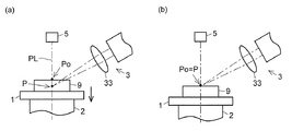
第1実施形態に係るレーザ誘起分析装置について、図1、図2を参照しながら説明する。図1は、レーザ誘起分析装置10の構成例を模式的に示す図である。図2は、レーザ誘起分析装置10で実行される合焦動作を説明するための図である。
<1. First embodiment>
<1-1. Device configuration>
The laser induced analyzer according to the first embodiment will be described with reference to FIGS. 1 and 2. FIG. 1 is a view schematically showing a configuration example of a laser induced
レーザ誘起分析装置10は、レーザ誘起プラズマ分光法によりサンプル9を分析する装置であり、レーザ光を集光してサンプル9の表面に照射し、該照射により発生した光の発光スペクトルに基づいて該サンプル9の分析を行う。
The laser induced
レーザ誘起分析装置10は、サンプル9が載置されるステージ1、ステージ1を昇降させる昇降機構2、ステージ1上のサンプル9にレーザ光を照射する光源ユニット3、サンプル9にレーザ光が照射されることにより発生した光を受光してその発光スペクトルを取得する分析器4、ステージ1の上方に配置された表面センサ5、および、これらの各要素を制御して一連の動作を実行させる制御部6、を主として備える。
The laser induced
ステージ1は、上面に平坦かつ水平な載置面が形成された部材であり、サンプル9は該載置面上に載置される。
The
昇降機構2は、ステージ1を、その表面と交差する所定の方向(ここでは鉛直方向)に移動させる機構である。昇降機構2は、具体的には例えば、鉛直方向に延在するねじ軸、これを回転させる駆動モータ、ねじ軸に平行に延在するガイド軸、等を含んで構成することができる。駆動モータは、数値制御可能なモータ(具体的には例えば、パルスモータ、ステッピングモータ、サーボモータ、超音波モータ、等)により構成され、該駆動モータが、制御部6から指示された回転角度だけ回転する(すなわち、数値制御される)ことにより、ステージ1が該指示された距離だけ鉛直方向に移動する。
The elevating
光源ユニット3は、レーザ光を出射する光源(レーザ装置)31を備える。光源31として、例えばYAGレーザを用いることができる。光源ユニット3はさらに、光源31から出射されるレーザ光を導く照射光学系32と、照射光学系32から導出されるレーザ光を集光するためのレンズ33とを備える。レーザ誘起分析装置10は、その背が低いほど安定感が増すため、光源ユニット3は、図示されるように、ここから出射されるレーザ光の光軸がステージ1の載置面に対して斜めに交わるような位置および姿勢で配置されることが好ましい。
The
光源ユニット3は、レンズ33の焦点、すなわち、レーザ光がレンズ33により集光される位置(集光点)P(図2参照)が、所定の位置にくるように予め位置調整されており、集光点Pの位置情報(集光点位置情報601)は、制御部6が備える記憶装置60に予め格納される。ただし、集光点Pの位置は、昇降機構2によるステージ1の移動方向(ここでは鉛直方向)から見て、ステージ1の載置面内の所定の位置(例えば載置面の中央位置)と重なる位置に規定される。
The
分析器4は、ステージ1上のサンプル9にレーザ光が照射されることにより発生した光を受光してその発光スペクトルを取得する。分析器4は、例えば、ファイバ40等を介して導入された光を波長毎に分解(分光)する回折格子(分光手段)41と、分光された光を受光して発光スペクトルを取得する撮像素子42とを含んで構成される。ファイバ40の先端位置および角度は、光源ユニット3から出射されるレーザ光の光軸方向および集光点Pの位置に対して厳密に調整されており、レーザ光の照射により生じた発光を十分に受光できるようになっている。
The
表面センサ5は、例えば、光学式変位センサ(光学式距離センサ)により構成され、その光軸上にある表面の位置を測定する。ここで、表面センサ5は、その光軸が、昇降機構2によるステージ1の移動方向(ここでは鉛直方向)と平行であって集光点Pを通る仮想線(集光点通過線)PL(図2参照)と一致するように配置される。したがって、ステージ1にサンプル9が載置された状態において、表面センサ5は、集光点通過線PL上にあるサンプル9表面の位置(すなわち、集光点通過線PLとサンプル9の表面が交わるポイント(線上点)Poの位置)(図2参照)を測定する。
The
制御部6は、レーザ誘起分析装置10が備える各部と電気的に接続されて、これら各部の動作を制御する。制御部6は、記憶装置60を備える。記憶装置60には、上述した集光点位置情報601等が格納されている。また、制御部6には、機能ブロックとして、表面測定部61、合焦部62、照射制御部63、等が実現される。制御部6の実体は、所要のオペレーティングソフトウェア(OS)等がインストールされたパーソナルコンピュータであり、入力部と表示部が接続されている(いずれも図示省略)。
The control unit 6 is electrically connected to each unit included in the laser induced
表面測定部61は、ステージ1にサンプル9が載置された状態において、表面センサ5に、集光点通過線PL上にあるサンプル9表面の位置(すなわち、線上点Poの位置)を測定させ、測定により得られた線上点Poの位置情報を合焦部62に通知する。
The
合焦部62は、表面測定部61より通知された線上点Poの位置情報に基づいて昇降機構2を制御して、線上点Poの位置を集光点Pの位置に一致させる。具体的には、合焦部62は、まず、線上点Poの位置情報と、集光点Pの位置情報(記憶装置60に格納されている集光点位置情報601)との差分を算出する。線上点Poと集光点Pはいずれも集光点通過線PL上にあり、該差分は集光点通過線PL上における両点Po,Pの離間距離である(図2(a))。そこで、合焦部62は、該差分だけステージ1を昇降させるように昇降機構2に指示を与える。集光点通過線PLに沿って該差分だけステージ1が移動されることによって、線上点Poの位置が、集光点Pの位置に3次元的に一致した状態となる(図2(b))。いうまでもなく、ステージ1の移動方向は差分の正負から規定される。
The focusing
照射制御部63は、線上点Poと集光点Pが一致した状態において、光源ユニット3からレーザ光を出射させる。集光点Pが、サンプル9の表面内の位置である線上点Poと一致していると、該出射されたレーザ光はサンプル9の表面に十分に集光され、これによりサンプル9の表面にある原子が十分に励起される。ひいては、十分な強度の発光が生じる。該発光はファイバ40を介して分析器4に導入され、ここで発光スペクトルが取得される。
The
<1−2.処理の流れ>
レーザ誘起分析装置10において実行される処理の流れを、図1、図2に加えて図3を参照しながら説明する。図3は、該一連の流れを示す図である。
<1-2. Flow of processing>
The flow of processing performed in the laser induced
まず、適宜の方法でサンプル9が準備されて、ステージ1に載置される(ステップS11)。
First, the
次に、表面測定部61が、表面センサ5に、ステージ1上のサンプル9表面における線上点Poの位置を測定させる(図2(a))(ステップS12)。測定により線上点Poの位置情報が得られると、表面測定部61は該位置情報を合焦部62に通知する。
Next, the
次に、合焦部62が、記憶装置60に格納されている集光点位置情報601を読み出し、これと、ステップS12の測定で得られた線上点Poの位置情報との差分を算出し、該差分だけステージ1を昇降させるように昇降機構2に指示を与える。指示に従って昇降機構2がステージ1を昇降させることによって、線上点Poの位置と集光点Pの位置が一致する(図2(b))(ステップS13)。
Next, the focusing
その後、照射制御部63が、光源ユニット3からレーザ光を出射させる(ステップS14)。ステップS13により、ステージ1上のサンプル9の表面内の位置である線上点Poと集光点Pが一致するようにステージ1の位置が調整されているため、該出射されたレーザ光はサンプル9の表面に十分に集光される。これにより、高温高密度のプラズマが生成されて、レーザ光が集光されたスポットにおいてサンプル9の表面にある原子が十分に励起される。励起された各原子は固有の波長の光を放射しながら状態遷移する。このときに発生した光は、ファイバ40を介して分析器4に導入される。分析器4では、導入された光が回折格子41で分光されて撮像素子42で検出されることにより、発光スペクトルが取得される。
Thereafter, the
分析器4が取得した発光スペクトルは制御部6に送られ、ここで必要に応じて所定の演算処理を施された上で、記憶装置60に格納される。また、必要に応じて表示部に表示される。分析者は、例えば、該発光スペクトルに現れるピークの位置(波長)および強度を特定することで、サンプル9に含まれる元素の種類および量を特定することができる。
The emission spectrum acquired by the
<2.第2実施形態>
<2−1.装置構成>
第2実施形態に係るレーザ誘起分析装置について、図4、図5を参照しながら説明する。図4は、レーザ誘起分析装置10aの構成例を模式的に示す図である。図5は、レーザ誘起分析装置10aで実行される合焦動作を説明するための図である。なお、以下においては、第1実施形態と相違する点のみを説明する。第1実施形態に係るレーザ誘起分析装置10と同じ要素については同じ符号を付すとともにその説明を省略する。
<2. Second embodiment>
<2-1. Device configuration>
The laser induced analyzer according to the second embodiment will be described with reference to FIGS. 4 and 5. FIG. 4 is a view schematically showing a configuration example of the laser induced
レーザ誘起分析装置10aは、第1実施形態に係るレーザ誘起分析装置10と同様の要素(ステージ1、昇降機構2、光源ユニット3、分析器4、表面センサ5、および、制御部6a)に加えて、回動機構7を備える。
The laser induced
回動機構7は、ステージ1をその上面と直交する(すなわち、鉛直な)回転軸70の周りで回転させる機構である。ただし、回転軸70は、集光点通過線PLから離間した位置に規定される(図5(a)参照)。回動機構7は、具体的には例えば、上端がステージ1の下面に固定されて鉛直方向に延在する回転軸部、これを回転させる駆動モータ、等を含んで構成することができる。ここでも、駆動モータは数値制御可能なモータにより構成され、該駆動モータが、制御部6aから指示された回転角度だけ回転する(すなわち、数値制御される)ことにより、ステージ1が該指示された角度だけ回転する。
The
照射制御部63aは、回動機構7を制御してステージ1を回転させつつ、光源ユニット3から間欠的に(典型的には、一定周期で)、レーザ光を複数回出射させることによって、回転軸70を中心とした円周上に並ぶ複数の点(照射点K1,K2,・・・)の各々に、レーザ光を照射する。例えば、照射制御部63aが、ステージ1を等角速度で、20秒間で1回転させつつ、レーザ光を1秒間隔で20回出射させる場合、回転軸70を中心とした円周上に18°の角度間隔で並ぶ20個の点(照射点K1,K2,・・・,K20)の各々に、レーザ光が照射されることになる。
The
表面測定部61aは、表面センサ5に、サンプル9表面における複数の照射点K1,K2,・・・各々の位置を測定させる。具体的には、表面測定部61aは、回動機構7を制御してステージ1を回転させつつ、表面センサ5に間欠的に線上点Poの位置を測定させることによって、回転軸70を中心とした円周上に並ぶ複数の照射点K1,K2,・・・各々の位置情報を取得する。表面測定部61aは、取得された複数個の位置情報を、例えばテーブル(位置情報テーブル)602の形にまとめて記憶装置60aに格納する。図6には、位置情報テーブル602の構成例が示されている。ここでは、各照射点Ki(i=1,2,・・)の位置情報が、該照射点Kiの照射順位、1番目の照射点K1を基準とした照射タイミング、1番目の照射点K1を基準とした角度位置、等と対応付けて格納されている。
The
<2−2.処理の流れ>
レーザ誘起分析装置10aにおいて実行される処理の流れを、図4〜図6に加えて図7を参照しながら説明する。図7は、該一連の流れを示す図である。
2-2. Flow of processing>
The flow of processing executed in the laser induced
まず、適宜の方法でサンプル9が準備されて、ステージ1に載置される(ステップS21)。
First, the
次に、表面測定部61aが、表面センサ5に、サンプル9表面における複数の照射点K1,K2,・・・各々の位置を測定させる(ステップS22)。
Next, the
具体的には、表面測定部61aは、まず、ステージ1が所定の初期回転位置に配置されている状態で、表面センサ5に線上点Poの位置を測定させる(ステップS221)。ここでは、ステージ1が初期回転位置に配置されているときの線上点Poが、1番目の照射点K1とされる。そこで、表面測定部61aは、測定により得られた位置情報を、1番目の照射点K1の位置情報として位置情報テーブル602に記述する。
Specifically, the
続いて、表面測定部61aは、回動機構7を制御してステージ1を所定角度(次の照射点K2までの角度間隔であり、図6の例の場合、18°)だけ回転させる(回転速度は例えば3rpm)(ステップS222)。これにより、2番目の照射点K2が線上点Poと一致した状態となる。この状態で、表面測定部61aは、再び表面センサ5に線上点Poの位置を測定させる(ステップS221)。そして測定により得られた位置情報を、2番目の照射点K2の位置情報として位置情報テーブル602に記述する。
Subsequently, the
ステップS221〜ステップS222の処理が所定回数(図6の例の場合、20回)、繰り返されることによって所定数個の位置情報が取得されると(すなわち、位置情報テーブル602に、全ての照射点Ki(i=1,2,・・)各々の位置情報が記述されると)(ステップS223でYES)、ステップS23の処理に進む。 When the predetermined number of pieces of position information are acquired by repeating the processing of step S221 to step S222 a predetermined number of times (20 times in the case of the example of FIG. 6) (that is, all irradiation points in position information table 602). When positional information of each Ki (i = 1, 2,...) Is described (YES in step S223), the process proceeds to step S23.
ステップS23では、照射制御部63aが、回動機構7を制御してステージ1を回転させつつ、光源ユニット3から間欠的にレーザ光を複数回出射させることによって、複数の照射点K1,K2,・・・の各々に、レーザ光を照射する。
In step S23, the
具体的には、照射制御部63aは、まず、必要に応じて回動機構7を制御してステージ1を適宜回転させて、ステージ1を所定の初期回転位置に配置する。これにより、1番目の照射点K1が線上点Poと一致した状態となる(図5(a))。また、これと並行して、合焦部62aが、記憶装置60aに格納されている集光点位置情報601を読み出すとともに、位置情報テーブル602から1番目の照射点K1の位置情報を読み出し、両者の差分を算出し、昇降機構2を制御して該差分だけステージ1を昇降させる(図5(b))。これにより、照射点K1の位置と集光点Pの位置が一致した状態となる。つまり、照射制御部63aおよび合焦部62aの制御下で、ステージ1が回転されつつ昇降されることにより、1番目の照射点K1の位置と集光点Pの位置が一致した状態となる(ステップS231)。
Specifically, the
その後、照射制御部63aが、光源ユニット3からレーザ光を出射させる(ステップS233)。該出射されたレーザ光は1番目の照射点K1に集光され、このときに発生した光の発光スペクトルが分析器4で取得される。
Thereafter, the
続いて、照射制御部63aが、回動機構7を制御してステージ1を所定角度(次の照射点K2までの角度間隔であり、図6の例の場合、18°)だけ回転させて、2番目の照射点K2が線上点Poと一致した状態とする。また、これと並行して、合焦部62aが、位置情報テーブル602から2番目の照射点K2の位置情報を読み出し、これと1番目の照射点K1の位置情報の差分を算出し、昇降機構2を制御して該差分だけステージ1を昇降させる。これにより、照射点K2の位置と集光点Pの位置が一致する。つまり、ステージ1が回転されつつ昇降されることにより、2番目の照射点K2の位置と集光点Pの位置が一致した状態となる(図5(c))(ステップS231)。
Subsequently, the
その後、再び、照射制御部63aが、光源ユニット3からレーザ光を出射させる(ステップS233)。該出射されたレーザ光は2番目の照射点K2に集光され、このときに発生した光の発光スペクトルが分析器4で取得される。
Thereafter, the
ステップS231〜ステップS232の処理が所定回数(図6の例の場合、20回)、繰り返されることによって、全ての照射点Ki(i=1,2,・・)各々の発光スペクトルが取得されると(ステップS233でYES)、ステップS24の処理に進む。 By repeating the process of steps S231 to S232 a predetermined number of times (20 times in the case of the example of FIG. 6), the emission spectra of all the irradiation points Ki (i = 1, 2,...) Are acquired And (YES in step S233), the process proceeds to step S24.
ステップS24では、制御部6aが、ステップS23で得られた複数の発光スペクトルに所定の演算処理を施す。具体的には例えば、該複数の発光スペクトルを積算(あるいは平均)する。複数の発光スペクトルを積算あるいは平均することで、ノイズの影響を低減してS/N比を大きくすることができる。該演算により得られたデータは、記憶装置60aに格納される。また、必要に応じて表示部に表示される。分析者は、例えば、該データに現れるピークの位置(波長)および強度を特定することで、サンプル9に含まれる元素の種類および量を特定することができる。
In step S24, the
<3.第3実施形態>
<3−1.装置構成>
第3実施形態に係るレーザ誘起分析装置について、図8を参照しながら説明する。図8は、レーザ誘起分析装置10bの構成例を模式的に示す図である。なお、以下においては、上記の各実施形態と相違する点のみを説明する。上記の各実施形態に係るレーザ誘起分析装置10,10aと同じ要素については同じ符号を付すとともにその説明を省略する。
<3. Third embodiment>
<3-1. Device configuration>
The laser induced analyzer according to the third embodiment will be described with reference to FIG. FIG. 8 is a view schematically showing a configuration example of the laser induced
レーザ誘起分析装置10bは、第2実施形態に係るレーザ誘起分析装置10と同様の要素(ステージ1、昇降機構2、光源ユニット3、分析器4、表面センサ5、制御部6b、および、回動機構7)を備える。
The laser induced
照射制御部63bは、第2実施形態に係る照射制御部63aと同様、回動機構7を制御してステージ1を回転させつつ、光源ユニット3から間欠的にレーザ光を複数回出射させることによって、回転軸70を中心とした円周上に並ぶ複数の照射点K1,K2,・・・の各々に、レーザ光を照射する。
The
表面測定部61bは、表面センサ5に、サンプル9表面における複数の照射点K1,K2,・・・各々の位置を測定させる。具体的には、表面測定部61bは、照射制御部63bの制御下でレーザ光が出射されるタイミングと交互のタイミングで、表面センサ5に線上点Poの位置を測定させることによって、複数の照射点K1,K2,・・・各々の位置情報を取得する。
The
<3−2.処理の流れ>
レーザ誘起分析装置10bにおいて実行される処理の流れを、図8に加えて、図5、図9を参照しながら説明する。図9は、該一連の流れを示す図である。
<3-2. Flow of processing>
The flow of processing performed in the laser induced
まず、適宜の方法でサンプル9が準備されて、ステージ1に載置される(ステップS31)。
First, the
次に、表面測定部61bが、ステージ1が所定の初期回転位置に配置されている状態で、表面センサ5に線上点Poの位置を測定させる(図5(a))(ステップS32)。そして、測定により得られた位置情報を、1番目の照射点K1の位置情報として合焦部62bに通知する。
Next, the
続いて、合焦部62bが、記憶装置60bに格納されている集光点位置情報601を読み出し、これとステップS32で取得された1番目の照射点K1の位置情報の差分を算出し、昇降機構2を制御して該差分だけステージ1を昇降させる(図5(b))(ステップS33)。これにより、照射点K1の位置と集光点Pの位置が一致した状態となる。
Subsequently, the focusing
続いて、照射制御部63bが、光源ユニット3からレーザ光を出射させる(ステップS34)。該出射されたレーザ光は1番目の照射点K1に集光され、このときに発生した光の発光スペクトルが分析器4で取得される。
Subsequently, the
その後、照射制御部63bが、回動機構7を制御してステージ1を所定角度(次の照射点K2までの角度間隔)だけ回転させて、2番目の照射点K2が線上点Poと一致した状態とする(ステップS35)。
After that, the
そして、再びステップS32〜S35の処理が行われる。すなわち、表面測定部61bが、表面センサ5に線上点Poの位置を測定させて、該測定により得られた位置情報を、2番目の照射点K2の位置情報として合焦部62bに通知し(ステップS32)、合焦部62bが、2番目の照射点K2の位置情報と集光点位置情報601の差分に基づいて昇降機構2を制御してステージ1を昇降させて、照射点K2の位置と集光点Pの位置を一致させる(図5(c))(ステップS33)。そして、照射制御部63bが、光源ユニット3からレーザ光を出射させる(ステップS34)。該出射されたレーザ光は2番目の照射点K2に集光され、このときに発生した光の発光スペクトルが分析器4で取得される。その後、照射制御部63bが、回動機構7を制御してステージ1を所定角度(次の照射点K3までの角度間隔)だけ回転させて、3番目の照射点K3が線上点Poと一致した状態とする(ステップS35)。
Then, the processes of steps S32 to S35 are performed again. That is, the
ステップS32〜ステップS35の処理が所定回数繰り返されることによって、全ての照射点Ki(i=1,2,・・)各々の発光スペクトルが取得されると(ステップS36でYES)、ステップS37の処理に進む。ステップS37の処理は、第2実施形態に係るステップS24の処理と同様である。 When the emission spectrum of each of all the irradiation points Ki (i = 1, 2,...) Is acquired by repeating the processing of steps S32 to S35 a predetermined number of times (YES in step S36), the processing of step S37 Go to The process of step S37 is the same as the process of step S24 according to the second embodiment.
<4.第4実施形態>
<4−1.装置構成>
第4実施形態に係るレーザ誘起分析装置について、図10、図11を参照しながら説明する。図10は、レーザ誘起分析装置10cの構成例を模式的に示す図である。図11は、レーザ誘起分析装置10cで実行される合焦動作を説明するための図である。なお、以下においては、上記の各実施形態と相違する点のみを説明する。上記の各実施形態に係るレーザ誘起分析装置10,10a,10bと同じ要素については同じ符号を付すとともにその説明を省略する。
<4. Fourth embodiment>
<4-1. Device configuration>
The laser induced analyzer according to the fourth embodiment will be described with reference to FIGS. 10 and 11. FIG. FIG. 10 is a view schematically showing a configuration example of the laser induced
レーザ誘起分析装置10cは、第1実施形態に係るレーザ誘起分析装置10と同様の要素(ステージ1c、昇降機構2、光源ユニット3、分析器4、表面センサ5、および、制御部6c)に加えて、直動機構8を備える。また、制御部6cには、機能ブロックとして、照射希望位置受付部64cが実現される。
The laser induced
直動機構8は、ステージ1cを、その上面(ここでは、水平な載置面)と平行であり互いに直交する2本の直線軸の各々に沿って移動させる機構である。いま、ステージ1cのいずれかの辺に平行な水平軸を「X軸」とした場合、直動機構8は、ステージ1cをX軸およびこれと直交する水平軸であるY軸に沿って各々移動させる駆動機構(X駆動機構81およびY駆動機構82)を備える。
The linear movement mechanism 8 is a mechanism for moving the
X駆動機構81は、具体的には例えば、X方向に延在するねじ軸、これを回転させる駆動モータ、X方向に平行に延在するガイド軸、等を含んで構成することができる。同様に、Y駆動機構82は、Y方向に延在するねじ軸、これを回転させる駆動モータ、Y方向に平行に延在するガイド軸、等を含んで構成することができる。いずれの駆動機構81,82においても、駆動モータは数値制御可能なモータにより構成され、該駆動モータが、制御部6cから指示された回転角度だけ回転する(すなわち、数値制御される)ことにより、ステージ1cが該指示された距離だけX方向あるいはY方向に移動する。
Specifically, the X drive mechanism 81 can be configured to include, for example, a screw shaft extending in the X direction, a drive motor for rotating the same, a guide shaft extending parallel to the X direction, and the like. Similarly, the
ステージ1cの付近には、そのX位置およびY位置を各々検出するセンサ(Xセンサ801およびYセンサ802)が配置される(図11(a)参照)。各センサ801,802は、例えば、光学式変位センサにより構成され、その光軸上にある表面の位置を測定する。Xセンサ801は例えば、その光軸が、X軸と平行であって集光点Pを通る仮想線と一致するように配置される。同様に、Yセンサ802は、例えば、その光軸が、Y軸と平行であって集光点Pを通る仮想線と一致するように配置される。
In the vicinity of the
ステージ1cは、上面に平坦かつ水平な載置面が形成された部材であり、サンプル9は該載置面上に載置される。ステージ1cの側面には目盛り11が設けられており、ステージ1cの載置面内における任意の位置を、目盛り11で規定されるXY座標系内で指定できるようになっている。したがって、例えば分析者は、この目盛り11を読むことによって、ステージ1cに載置されたサンプル9内におけるレーザ光を照射したいポイント(照射希望点)Dの位置を、該XY座標系内で指定することができる。
The
照射希望位置受付部64cは、レーザ光の照射に先立って、分析者から照射希望点Dの位置情報の入力を受け付け、該入力された位置情報に基づいて直動機構8を制御してステージ1cを移動させて、照射希望点Dを線上点Poと一致させる。
The irradiation desired position reception unit 64c receives an input of positional information of the irradiation desired point D from the analyst prior to the irradiation of the laser light, and controls the linear motion mechanism 8 based on the input positional information to thereby perform the
<4−2.処理の流れ>
レーザ誘起分析装置10cにおいて実行される処理の流れを、図10、図11に加えて図12を参照しながら説明する。図12は、該一連の流れを示す図である。
<4-2. Flow of processing>
The flow of processing executed in the laser induced
まず、適宜の方法でサンプル9が準備されて、ステージ1cに載置される(ステップS41)。
First, the
続いて、分析者が、例えばステージ1cの目盛り11を読むことによって、ステージ1cに載置されたサンプル9内における照射希望点Dの位置情報を特定し、これを入力部を介して入力する。分析者から照射希望点Dの位置情報が入力されると、照射希望位置受付部64cは該入力を受け付け、これに基づいて直動機構8を制御して、集光点通過線PLが照射希望点Dを通過するような位置にステージ1cを移動させる(ステップS42)。すなわち、照射希望点Dを線上点Poと一致させる。
Subsequently, the analyst specifies the position information of the irradiation desired point D in the
具体的には、照射希望位置受付部64cは、まず、直動機構8を制御して、所定の初期位置(例えば、集光点通過線PLが、目盛り11により規定されるXY座標の原点を通過するような位置)にステージ1cを移動させる(図11(b))。すなわち、照射希望位置受付部64cは、Xセンサ801でステージ1cのX位置を検出しつつX駆動機構81を制御してステージ1cを所定の初期X位置まで移動させるとともに、Yセンサ802でステージ1cのY位置を検出しつつY駆動機構82を制御してステージ1cを所定の初期Y位置まで移動させる。その後、照射希望位置受付部64cは、分析者から受け付けた照射希望点Dの位置情報に応じてステージ1cをX方向およびY方向のそれぞれにさらに移動させて、集光点通過線PLが照射希望点Dを通過するような位置にステージ1cを移動させる(図11(c))。
Specifically, the desired radiation position receiving unit 64c first controls the linear motion mechanism 8 to set a predetermined initial position (for example, the origin of XY coordinates defined by the
その後、第1実施形態におけるステップS12〜ステップS14と同様の処理が行われる(ステップS43〜ステップS45)。すなわち、照射希望点Dが線上点Poと一致している状態で、表面測定部61cが、表面センサ5に、ステージ1c上のサンプル9表面における線上点Poの位置を測定させる(ステップS43)。続いて、合焦部62cが、記憶装置60cに格納されている集光点位置情報601を読み出し、これとステップS43で取得された線上点Poの位置情報の差分を算出し、昇降機構2を制御して該差分だけステージ1cを昇降させる(ステップS44)。これにより、照射希望点Dである線上点Poの照射点K1の位置と集光点Pの位置が一致する(図11(d))。その後、照射制御部63cは、光源ユニット3からレーザ光を出射させる(ステップS45)。該出射されたレーザ光は照射希望点Dに集光され、このときに発生した光の発光スペクトルが分析器4で取得される。
Thereafter, processing similar to that of step S12 to step S14 in the first embodiment is performed (step S43 to step S45). That is, the
<5.他の実施形態>
上記の各実施形態では、昇降機構2はステージ1,1cを鉛直方向に移動(昇降)させるものであったが、昇降機構2は、ステージ1,1cを、その表面と交差する任意の方向に移動させるものであればよい。
<5. Other Embodiments>
In each of the above-described embodiments, the elevating
第2,第3実施形態に係るレーザ誘起分析装置10a,10bにおいて、直動機構8が設けられてもよく、第4実施形態に係るレーザ誘起分析装置10cにおいて、回動機構7が設けられてもよい。すなわち、レーザ誘起分析装置は、回動機構7と直動機構8の両方を備えてもよい。
In the laser induced
第4実施形態において、照射制御部63cが、直動機構8を制御してステージ1cをXY面内に規定される所定軌道に沿って移動させつつ(例えば、X方向の主走査とY方向の複走査を交互に行いながら)、光源ユニット3から間欠的に(典型的には、一定周期で)レーザ光を複数回出射させて、該所定軌道上に並ぶ複数の照射点K1,K2,・・・の各々に、レーザ光を照射してもよい。この場合、表面測定部61cは、第2実施形態のように、複数回のレーザ光の出射が行われる前に、ステージ1cを該所定軌道に沿って移動させつつ表面センサ5に線上点Poの位置を複数回間欠的に測定させて、該複数の照射点K1,K2,・・・各々の位置情報を取得してもよい。あるいは、表面測定部61cは、第3実施形態のように、複数回のレーザ光の出射が行われる間に、レーザ光の出射と交互に繰り返して表面センサ5に線上点Poの位置を測定させることによって、該複数の照射点K1,K2,・・・各々の位置情報を取得してもよい。
In the fourth embodiment, the irradiation control unit 63c controls the linear motion mechanism 8 to move the
第2〜第4の実施形態においては、複数の発光スペクトルから積算データあるいは平均データあるいはこれらの両方を取得する構成であったが、必ずしもこれらのデータを取得する必要はない。例えば、該複数の発光スペクトルのうち、所定の波長において最も大きなピークを検出しているものを選択して、該1個の発光スペクトルから物質の含有量等を特定してもよい。 In the second to fourth embodiments, although integrated data and / or average data are acquired from a plurality of emission spectra, it is not necessary to acquire these data. For example, among the plurality of emission spectra, the one which detects the largest peak at a predetermined wavelength may be selected, and the content of the substance or the like may be specified from the single emission spectrum.
10,10a,10b,10c…レーザ誘起分析装置
1,1c…ステージ
2…昇降機構
3…光源ユニット
4…分析器
5…表面センサ
6,6a,6b,6c…制御部
601…集光点位置情報
602…位置情報テーブル
61,61a,61b,61c…表面測定部
62,62a,62b,62c…合焦部
63,63a,63b,63c…照射制御部
64c…照射希望位置受付部
7…回動機構
8…直動機構
801…Xセンサ
802…Yセンサ
81…X駆動機構
82…Y駆動機構
9…サンプル
D…照射希望点
K1,K2,・・…照射点
P…集光点
PL…集光点通過線
Po…線上点
DESCRIPTION OF
Claims (9)
前記サンプルが載置されるステージと、
前記ステージを、その上面と交差する所定の移動方向に移動させる駆動機構と、
前記レーザ光の集光点を通り前記移動方向と平行な線上にある表面の位置を測定する表面センサと、
前記表面センサが測定した位置が前記集光点の位置に一致するように前記駆動機構を制御する合焦部と、
を備える、レーザ誘起分析装置。 A laser induced analyzer which collects laser light and irradiates the surface of a sample, and analyzes the sample based on an emission spectrum of light generated by the irradiation,
A stage on which the sample is placed;
A drive mechanism for moving the stage in a predetermined movement direction intersecting the upper surface thereof;
A surface sensor that measures the position of the surface on a line parallel to the moving direction through the focusing point of the laser light;
A focusing unit that controls the drive mechanism such that the position measured by the surface sensor coincides with the position of the focusing point;
, A laser induced analyzer.
前記ステージを、その上面と平行な面内で移動させる面内駆動機構、
をさらに備える、レーザ誘起分析装置。 The laser induced analyzer according to claim 1, wherein
An in-plane drive mechanism for moving the stage in a plane parallel to the upper surface thereof;
The laser induced analyzer further comprising
前記面内駆動機構が、
前記ステージを、その上面と直交する回転軸の周りに回転させる回動機構、
を備える、レーザ誘起分析装置。 The laser induced analyzer according to claim 2, wherein
The in-plane drive mechanism is
A rotation mechanism for rotating the stage around a rotation axis orthogonal to the upper surface thereof;
, A laser induced analyzer.
前記面内駆動機構が、
前記ステージを、その上面と平行であり互いに非平行な2本の直線軸の各々に沿って移動させる直動機構、
を備える、レーザ誘起分析装置。 The laser induced analyzer according to claim 2 or 3, wherein
The in-plane drive mechanism is
A translation mechanism for moving the stage along each of two linear axes parallel to the upper surface and nonparallel to each other;
, A laser induced analyzer.
前記面内駆動機構を制御して前記ステージを移動させつつ、レーザ光を複数回出射させる照射制御部、
をさらに備える、レーザ誘起分析装置。 The laser induced analyzer according to any one of claims 2 to 4, wherein
An irradiation control unit that emits a laser beam a plurality of times while moving the stage by controlling the in-plane drive mechanism;
The laser induced analyzer further comprising
前記サンプルをステージに載置する載置工程と、
前記レーザ光の集光点を通り、前記ステージの上面と交差する所定方向と平行な線上にある表面の位置を測定する表面測定工程と、
前記ステージを前記所定方向に移動させて、前記表面測定工程で測定された位置を前記集光点の位置と一致させる合焦工程と、
を備える、レーザ誘起分析方法。 A laser induced analysis method of collecting laser light and irradiating the surface of a sample, and analyzing the sample based on an emission spectrum of light generated by the irradiation,
Placing the sample on a stage;
Measuring a position of a surface on a line parallel to a predetermined direction crossing the top surface of the stage, passing through the focusing point of the laser light;
A focusing step of moving the stage in the predetermined direction to align the position measured in the surface measurement step with the position of the focusing point;
Laser induced analysis method.
前記ステージをその上面と平行な面内に規定される所定軌道に沿って移動させつつ、レーザ光を複数回出射させる繰り返し照射工程、
をさらに備える、レーザ誘起分析方法。 The laser induced analysis method according to claim 6, wherein
Repeatedly irradiating the laser beam a plurality of times while moving the stage along a predetermined trajectory defined in a plane parallel to the upper surface of the stage;
The laser induced analysis method, further comprising
前記繰り返し照射工程が行われる間、レーザ光の出射と交互に繰り返して前記表面測定工程を行う、
レーザ誘起分析方法。 The laser induced analysis method according to claim 7, wherein
While the repeated irradiation process is performed, the surface measurement process is repeated alternately with the emission of the laser light.
Laser induced analysis method.
前記繰り返し照射工程の前に、前記ステージを前記所定軌道に沿って移動させつつ前記表面測定工程を複数回繰り返し行う、
レーザ誘起分析方法。 The laser induced analysis method according to claim 7, wherein
Before the repetitive irradiation process, the surface measurement process is repeated several times while moving the stage along the predetermined trajectory.
Laser induced analysis method.
Priority Applications (1)
| Application Number | Priority Date | Filing Date | Title |
|---|---|---|---|
| JP2017188050A JP2019060831A (en) | 2017-09-28 | 2017-09-28 | Laser induced analyzer and laser induced analytical method |
Applications Claiming Priority (1)
| Application Number | Priority Date | Filing Date | Title |
|---|---|---|---|
| JP2017188050A JP2019060831A (en) | 2017-09-28 | 2017-09-28 | Laser induced analyzer and laser induced analytical method |
Publications (2)
| Publication Number | Publication Date |
|---|---|
| JP2019060831A true JP2019060831A (en) | 2019-04-18 |
| JP2019060831A5 JP2019060831A5 (en) | 2020-02-27 |
Family
ID=66178213
Family Applications (1)
| Application Number | Title | Priority Date | Filing Date |
|---|---|---|---|
| JP2017188050A Pending JP2019060831A (en) | 2017-09-28 | 2017-09-28 | Laser induced analyzer and laser induced analytical method |
Country Status (1)
| Country | Link |
|---|---|
| JP (1) | JP2019060831A (en) |
Citations (8)
| Publication number | Priority date | Publication date | Assignee | Title |
|---|---|---|---|---|
| JPH0815153A (en) * | 1994-06-24 | 1996-01-19 | Kawasaki Steel Corp | Method and apparatus for laser emission spectroscopic analysis |
| JP2000121558A (en) * | 1998-10-16 | 2000-04-28 | Mitsubishi Heavy Ind Ltd | Measuring device |
| JP2005233802A (en) * | 2004-02-20 | 2005-09-02 | Yokogawa Electric Corp | Physical quantity measuring instrument and physical quantity calibration method using it |
| JP2007003510A (en) * | 2005-05-26 | 2007-01-11 | Toshiba Corp | Element analysis method and apparatus, and analysis sample producing method |
| US20090273782A1 (en) * | 2008-05-05 | 2009-11-05 | Applied Spectra, Inc. | Laser ablation apparatus and method |
| US20130271761A1 (en) * | 2010-10-01 | 2013-10-17 | Technological Resources Pty. Limited | Laser induced breakdown spectroscopy analyser |
| JP2014526148A (en) * | 2011-07-25 | 2014-10-02 | エレクトロ サイエンティフィック インダストリーズ インコーポレーテッド | Method and apparatus for characterizing an object and monitoring a manufacturing process |
| JP2016522416A (en) * | 2013-07-15 | 2016-07-28 | 中国科学院瀋陽自動化研究所 | Field on-line detection apparatus and method for long-range metallurgical liquid metal components |
-
2017
- 2017-09-28 JP JP2017188050A patent/JP2019060831A/en active Pending
Patent Citations (8)
| Publication number | Priority date | Publication date | Assignee | Title |
|---|---|---|---|---|
| JPH0815153A (en) * | 1994-06-24 | 1996-01-19 | Kawasaki Steel Corp | Method and apparatus for laser emission spectroscopic analysis |
| JP2000121558A (en) * | 1998-10-16 | 2000-04-28 | Mitsubishi Heavy Ind Ltd | Measuring device |
| JP2005233802A (en) * | 2004-02-20 | 2005-09-02 | Yokogawa Electric Corp | Physical quantity measuring instrument and physical quantity calibration method using it |
| JP2007003510A (en) * | 2005-05-26 | 2007-01-11 | Toshiba Corp | Element analysis method and apparatus, and analysis sample producing method |
| US20090273782A1 (en) * | 2008-05-05 | 2009-11-05 | Applied Spectra, Inc. | Laser ablation apparatus and method |
| US20130271761A1 (en) * | 2010-10-01 | 2013-10-17 | Technological Resources Pty. Limited | Laser induced breakdown spectroscopy analyser |
| JP2014526148A (en) * | 2011-07-25 | 2014-10-02 | エレクトロ サイエンティフィック インダストリーズ インコーポレーテッド | Method and apparatus for characterizing an object and monitoring a manufacturing process |
| JP2016522416A (en) * | 2013-07-15 | 2016-07-28 | 中国科学院瀋陽自動化研究所 | Field on-line detection apparatus and method for long-range metallurgical liquid metal components |
Similar Documents
| Publication | Publication Date | Title |
|---|---|---|
| TWI816669B (en) | Laser processing method | |
| CN112240883B (en) | LIBS system capable of automatically aligning and focusing | |
| CN1377460A (en) | Method and apparatus for characterization of microelectronic feature quality | |
| TWI609732B (en) | Laser processing device | |
| CN102364329A (en) | Automatic collection system of laser-induced breakdown spectroscopy | |
| JP2023040301A (en) | Crack detection device and crack detection metho | |
| US7342995B2 (en) | Apparatus for estimating specific polymer crystal | |
| CN116773507B (en) | Three-dimensional laser ablation mass spectrometer, combined detection system and detection method | |
| JP2019060831A (en) | Laser induced analyzer and laser induced analytical method | |
| JPH05332934A (en) | Spectroscope | |
| JP4494606B2 (en) | Liquid-containing substance analysis apparatus and liquid-containing substance analysis method | |
| US20230358684A1 (en) | Kinematics path method for laser-induced breakdown spectroscopy | |
| CN114324302A (en) | Automatic positioning method and system for laser focusing position | |
| JP4656009B2 (en) | X-ray analyzer | |
| JP2001041931A (en) | Laser mass spectrometer | |
| JP4628127B2 (en) | Sample surface measurement method and analysis method, and electron beam apparatus | |
| JP4881307B2 (en) | X-ray fluorescence analysis method | |
| JP2000193434A (en) | Foreign substance inspecting device | |
| WO2022185740A1 (en) | Workpiece shape measurement device, workpiece shape measurement system, workpiece shape measurement method, and workpiece shape measurement program | |
| CN109580571B (en) | Detection device and detection method for potential fingerprints | |
| WO2022185741A1 (en) | Workpiece shape measurement system, workpiece shape measurement method, and workpiece shape measurement program | |
| CN108709898A (en) | MICRO-BEAM XRF ANALYSIS system based on combination X-ray capillary | |
| JP2007278783A (en) | Fluorescence detection device and fluorescence detection processing method | |
| JP6702228B2 (en) | Laser-induced analysis device, sample plate used therein, and laser-induced analysis method | |
| JP2007163262A (en) | X-ray analyzer |
Legal Events
| Date | Code | Title | Description |
|---|---|---|---|
| A521 | Request for written amendment filed |
Free format text: JAPANESE INTERMEDIATE CODE: A523 Effective date: 20200110 |
|
| A621 | Written request for application examination |
Free format text: JAPANESE INTERMEDIATE CODE: A621 Effective date: 20200110 |
|
| A977 | Report on retrieval |
Free format text: JAPANESE INTERMEDIATE CODE: A971007 Effective date: 20200715 |
|
| A131 | Notification of reasons for refusal |
Free format text: JAPANESE INTERMEDIATE CODE: A131 Effective date: 20200804 |
|
| A02 | Decision of refusal |
Free format text: JAPANESE INTERMEDIATE CODE: A02 Effective date: 20210224 |