JP2019059581A - Printer - Google Patents
Printer Download PDFInfo
- Publication number
- JP2019059581A JP2019059581A JP2017185377A JP2017185377A JP2019059581A JP 2019059581 A JP2019059581 A JP 2019059581A JP 2017185377 A JP2017185377 A JP 2017185377A JP 2017185377 A JP2017185377 A JP 2017185377A JP 2019059581 A JP2019059581 A JP 2019059581A
- Authority
- JP
- Japan
- Prior art keywords
- printing
- printer
- unit
- print medium
- reflection sensor
- Prior art date
- Legal status (The legal status is an assumption and is not a legal conclusion. Google has not performed a legal analysis and makes no representation as to the accuracy of the status listed.)
- Pending
Links
- 238000005192 partition Methods 0.000 claims abstract description 36
- 230000005540 biological transmission Effects 0.000 claims description 13
- 238000001514 detection method Methods 0.000 abstract description 7
- 238000000638 solvent extraction Methods 0.000 abstract description 4
- 230000000087 stabilizing effect Effects 0.000 abstract 1
- 238000010438 heat treatment Methods 0.000 description 4
- 238000004804 winding Methods 0.000 description 4
- 230000003287 optical effect Effects 0.000 description 3
- 238000004891 communication Methods 0.000 description 1
- 238000010586 diagram Methods 0.000 description 1
- 238000012423 maintenance Methods 0.000 description 1
Images


Abstract
Description
本発明は、プリンタに関する。 The present invention relates to a printer.
特許文献1には、搬送方向における印字媒体の位置を検出する反射センサを備えたプリンタが開示されている。 Patent Document 1 discloses a printer provided with a reflection sensor that detects the position of a print medium in the transport direction.
上記のプリンタでは、搬送中の印字媒体に弛みやうねりが発生すると、反射センサと印字媒体との距離が大きくなって反射センサの検出精度が低下するおそれがある。 In the above-described printer, when slack or waviness occurs in the print medium being conveyed, the distance between the reflection sensor and the print medium may be increased, and the detection accuracy of the reflection sensor may be reduced.
本発明は、このような技術的課題に鑑みてなされたもので、反射センサの検出精度を安定させることを目的とする。 The present invention has been made in view of such technical problems, and it is an object of the present invention to stabilize the detection accuracy of a reflection sensor.
本発明のある態様によれば、印字媒体に印字を行う印字部と、前記印字部に供給される前記印字媒体とインクリボンとの間を仕切る仕切部材と、搬送方向における前記印字媒体の位置を検出する反射センサと、を備え、前記仕切部材は、前記反射センサと対向して前記反射センサとの間に前記印字媒体の搬送路を形成する搬送ガイド部を有する、プリンタが提供される。 According to an embodiment of the present invention, a printing unit for printing on a printing medium, a partition member for partitioning the printing medium and the ink ribbon supplied to the printing unit, and the position of the printing medium in the transport direction There is provided a printer comprising: a reflection sensor for detecting, wherein the partition member has a conveyance guide portion which forms a conveyance path of the printing medium between the reflection sensor and the reflection sensor.
これによれば、仕切部材の搬送ガイド部が反射センサとの間に搬送路を形成するので、搬送ガイド部によって印字媒体がガイドされ、反射センサから一定の距離内で印字媒体が搬送される。よって、印字媒体の弛みやうねりによって反射センサと印字媒体との距離が大きくなることを防止でき、反射センサの検出精度を安定させることができる。 According to this, since the conveyance guide portion of the partition member forms a conveyance path with the reflection sensor, the printing medium is guided by the conveyance guide portion, and the printing medium is conveyed within a certain distance from the reflection sensor. Therefore, it is possible to prevent the distance between the reflection sensor and the printing medium from being increased due to the slack or waviness of the printing medium, and the detection accuracy of the reflection sensor can be stabilized.
以下、添付図面を参照しながら本発明の実施形態に係るプリンタ100について説明する。
Hereinafter, a
プリンタ100は、インクリボンRを熱してインクリボンRのインクを印字媒体Mに転写することで印字を行う熱転写方式のプリンタである。印字媒体Mは、例えば、帯状の台紙に複数のラベルが所定の間隔で連続して仮着されたラベル連続体である。
The
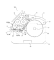
プリンタ100は、図1、図2に示すように、筐体10と、筐体10の開口部を覆うカバー11と、を備える。
As shown in FIGS. 1 and 2, the
印字媒体Mは、図2に示すように、ロール状に巻き回された状態で媒体供給軸12に保持される。なお、印字媒体Mとして、台紙なしラベルやファンフォールド型媒体を使用することもできる。
As shown in FIG. 2, the print medium M is held by the
カバー11は、筐体10に設けられた支持軸13により一端側の端部が揺動自在に支持される。カバー11は、支持軸13を支点として揺動させることで、筐体10の開口部を開放する開放状態(図4参照)と、閉止する閉止状態(図2参照)と、を切り替えることができる。
The
筐体10には、カバー11を閉止状態に維持するロック機構(図示せず)が設けられる。ロック機構は、図1に示すレバー14を操作することで解除される。
The
カバー11の他端側の端部と筐体10との間には、図2に示す印字部15で印字された印字媒体Mがプリンタ100から排出される排出口16が形成される。
Between the end on the other end side of the
カバー11には、排出口16に臨むカッタ17が取り付けられる。これにより、排出口16から排出された印字済の印字媒体Mを切断することができる。なお、カバー11には、カッタ17に代えて他の様々なユニットを取り付けることができる。
A
排出口16と印字部15との間には、印字媒体Mの有無を検出する透過センサ18が設けられる。
A
透過センサ18は、所定の光を出射する発光ユニット18aと、発光ユニット18aから出射された光を受光し、受光した光の強度に対応する電気信号を出力する受光ユニット18bと、を有する光学センサである。
The
印字媒体Mが発光ユニット18aと受光ユニット18bとの間に存在すると、発光ユニット18aから出射された光が遮られ、受光ユニット18bが受光する光の強度が低下する。
When the print medium M exists between the
これにより、透過センサ18は、印字媒体Mの有無を検出することができる。なお、発光ユニット18aと受光ユニット18bとの位置を入れ替えてもよい。
Thus, the
また、カバー11には、プリンタ100を操作するための操作ユニット19が設けられる。操作ユニット19は、各種操作ボタン、ディスプレイ、近距離無線通信モジュール、LED等を有する。ディスプレイは、タッチパネルであってもよい。
In addition, the
プリンタ100の内部には、図2に示すように、印字媒体Mに印字を行うための印字ユニット30、プリンタ100の動作を制御するコントローラ40等が収容される。
Inside the
印字ユニット30は、一端側が支持軸13に揺動自在に支持される本体部31と、本体部31に取り付けられるサーマルヘッド32と、を備える。
The
サーマルヘッド32は、筐体10側に設けられたプラテンローラ20と共に、印字媒体Mに印字を行う印字部15を構成する。
The
印字ユニット30は、サーマルヘッド32とプラテンローラ20との間に印字媒体Mが挟持される印字位置(図2参照)と、サーマルヘッド32がプラテンローラ20から離間する非印字位置(図4、図5参照)と、の間で揺動自在とされる。
The
また、印字ユニット30は、印字部15に供給されるインクリボンRをロール状に保持するリボン供給軸33と、使用済のインクリボンRを巻き取るリボン巻取軸34と、インクリボンRと印字媒体Mとの間を仕切る仕切部材35と、リボン供給軸33から印字部15へのインクリボンRの搬送路を規定するガイド軸36と、印字部15からリボン巻取軸34へのインクリボンRの搬送路を規定するガイド軸37と、を備える。リボン供給軸33は、仕切部材35に着脱可能に取り付けられている。
The
印字媒体Mは、媒体供給軸12から印字部15に供給され、サーマルヘッド32とプラテンローラ20との間にインクリボンRと共に挟持される。
The print medium M is supplied from the
印字媒体M及びインクリボンRがサーマルヘッド32とプラテンローラ20との間に挟持された状態、すなわち、印字ユニット30が印字位置にある状態でサーマルヘッド32の発熱素子への通電が行われると、発熱素子の熱によってインクリボンRのインクが印字媒体Mに転写され、印字媒体Mへの印字が行われる。
When the heating elements of the
また、プラテン駆動モータ(図示せず)によってプラテンローラ20を正回転させると、印字媒体M及びインクリボンRが搬送方向下流側へと搬送されて印字媒体Mが排出口16からプリンタ100の外部に排出される。
When the
また、リボン供給軸33及びリボン巻取軸34も、それぞれ駆動モータ(図示せず)によって回転駆動される。
The
仕切部材35は、図3に示すように、ベース部35aと、ベース部35aの一端側に設けられた軸部35bと、リボン供給軸33を軸部35bと平行且つ回動自在に支持する支持部35c、35dと、軸部35bの中央部に形成された係合部35eと、を有する。
As shown in FIG. 3, the
仕切部材35は、軸部35bにより本体部31に揺動自在に支持される。
The
係合部35eは、図2に示すように、カバー11に設けられた被係合部11aと係合するように構成される。仕切部材35を係合部35eが被係合部11aと係合する位置(閉止位置)にすると、リボン供給軸33が本体部31内に収容される。これにより、リボン供給軸33が、印字部15にインクリボンRを供給するリボン供給位置になる。
The
このように、係合部35eと被係合部11aとが係合することで、リボン供給軸33がリボン供給位置になる閉止位置に仕切部材35が維持される。また、印字ユニット30とカバー11とが結合された状態となる。
Thus, the
プリンタ100による印字を行う際は、カバー11は閉止状態とされ、且つ、仕切部材35の係合部35eとカバー11の被係合部11aとが係合した状態とされる。
When printing is performed by the
よって、カバー11を閉止状態から開放状態にすると、印字ユニット30がカバー11と一体となって揺動し、図4に示すように、筐体10の開口部が開放される。
Therefore, when the
これにより、プリンタ100への印字媒体Mのセットや筐体10内の各部のメンテナンスを行うことができる。
Thereby, the setting of the print medium M to the
さらに、図4に示す状態から係合部35eと被係合部11aとの係合を解除して仕切部材35を筐体10側に向けて揺動させると、仕切部材35が図5に示す開放位置になる。
Furthermore, when the engagement between the
仕切部材35が開放位置になるのに伴い、リボン供給軸33及びリボン供給軸33に保持されたロール状のインクリボンRがリボン巻取軸34に対して相対的に移動し、印字媒体Mの排出口16側に露出する。
As the
これにより、リボン供給軸33がプリンタ100から着脱可能なリボン交換位置となり、インクリボンRの交換作業を行うことができる。
As a result, the
係合部35eと被係合部11aとの係合は、仕切部材35を所定トルク以上のトルクで筐体10側に揺動させると、係合部35e及び被係合部11aが弾性変形して解除される。
The engagement between the
なお、係合部35eと被係合部11aとの係合が解除されることで、印字ユニット30自体も、筐体10側に向けて所定の位置まで揺動する。所定の位置は、筐体10における支持軸13の近傍に設けられた揺動規制部(図示せず)と本体部31とが当接する位置である。
The
揺動規制部による印字ユニット30の位置決めは、印字ユニット30を所定トルク以上のトルクで筐体10側に揺動させると、揺動規制部が弾性変形して本体部31が揺動規制部を乗り越えて解除される。
When positioning the
また、図2、図3に示すように、仕切部材35におけるベース部35aの他端側には、搬送ガイド部35fが設けられる。搬送ガイド部35fは、図2に示すように、印字ユニット30が印字位置にある場合に、反射センサ21と対向して反射センサ21との間に印字媒体Mの搬送路を形成する。
Further, as shown in FIG. 2 and FIG. 3, a
反射センサ21は、所定の光を出射する発光部と、発光部から出射された光の印字媒体Mからの反射光を受光し、受光した光の強度に対応する電気信号を出力する受光部と、を有する光学センサである。
The
反射センサ21は、印字媒体Mの印字が施される面とは反対側の面に所定の間隔で予め印刷されているアイマークを検出する。
The
これにより、反射センサ21は、搬送方向における印字媒体Mの位置を検出することができる。
Thus, the
ここで、搬送中の印字媒体Mに弛みやうねりが発生すると、反射センサ21と印字媒体Mとの距離が大きくなって反射センサ21の検出精度が低下するおそれがある。
Here, when slack or waviness occurs in the print medium M being conveyed, the distance between the
これに対して、本実施形態では、印字ユニット30が印字位置にある場合、つまり、図2に示す状態では、仕切部材35の搬送ガイド部35fが反射センサ21との間に搬送路を形成するので、搬送ガイド部35fによって印字媒体Mがガイドされ、反射センサ21から一定の距離内で印字媒体Mが搬送される。よって、印字媒体Mの弛みやうねりによって反射センサ21と印字媒体Mとの距離が大きくなることを防止でき、反射センサ21の検出精度を安定させることができる。
On the other hand, in the present embodiment, when the
また、仕切部材35に設けられた搬送ガイド部35fによって印字媒体Mの搬送路が形成されるので、反射センサ21から一定の距離内で印字媒体Mが搬送されるようにする部材を別途設ける必要がなく、当該部材に印字媒体Mを挿通する作業も不要となる。
Further, since the conveyance path of the print medium M is formed by the
また、仕切部材35は印字ユニット30に設けられるので、印字ユニット30を非印字位置にすると、印字媒体Mの搬送路全体を露出させることができる。よって、仕切部材35に搬送ガイド部35fを設けることで反射センサ21から一定の距離内で印字媒体Mが搬送されるようにしても、印字媒体Mをプリンタ100にセットする作業を容易に行うことができる。
Further, since the
また、図2に示すように、プリンタ100は、搬送方向における印字媒体Mの位置を検出する透過センサ22を備える。
Further, as shown in FIG. 2, the
透過センサ22は、所定の光を出射する発光部としての発光ユニット22aと、発光ユニット22aから出射された光を受光し、受光した光の強度に対応する電気信号を出力する受光部としての受光ユニット22bと、を有する光学センサである。
The
例えば、印字媒体Mが、帯状の台紙に複数のラベルが所定の間隔で連続して仮着されたラベル連続体である場合は、隣り合う2つのラベルの間には、台紙のみの部分が存在する。 For example, in the case where the print medium M is a label continuum in which a plurality of labels are temporarily attached to a band-like backing at a predetermined interval, only a part of the backing is present between two adjacent labels. Do.
ラベルが存在する部分と台紙のみの部分とでは、発光ユニット22aから出射された光の透過量が異なるので、受光ユニット22bが受光する光の強度が変化する。これにより、反射センサ21は、搬送方向における印字媒体Mの位置を検出することができる。
The transmission amount of the light emitted from the
本実施形態では、図2、図3に示すように、発光ユニット22aは、搬送ガイド部35fにおける印字媒体Mの搬送路とは反対側、つまり、搬送ガイド部35fの上面側に設けられる。また、搬送ガイド部35fには、発光ユニット22aから出射された光を通す貫通孔35gが形成されている。一方、受光ユニット22bは、図2に示すように、搬送路を挟んで筐体10側に設けられる。
In the present embodiment, as shown in FIGS. 2 and 3, the
上述したように、印字媒体Mをプリンタ100にセットする作業は、印字ユニット30を非印字位置にして筐体10の開口部を開放した状態で行われる。
As described above, the work of setting the print medium M in the
つまり、本実施形態では、発光ユニット22aと受光ユニット22bとの間が大きく開放された状態で印字媒体Mをプリンタ100にセットできるので、印字媒体Mをプリンタ100にセットする作業を容易に行うことができる。なお、発光ユニット22aと受光ユニット22bとの位置を入れ替えてもよい。
That is, in the present embodiment, since the print medium M can be set in the
プリンタ100は、使用する印字媒体Mの態様に応じて、反射センサ21と透過センサ22とのいずれか作動させて搬送方向における印字媒体Mの位置を検出するようになっている。
The
例えば、アイマークが設けられていない印字媒体Mを使用する場合は、プリンタ100は、透過センサ22によって印字媒体Mの位置を検出する。
For example, when using the print medium M in which the eye mark is not provided, the
コントローラ40は、マイクロプロセッサ、ROMやRAM等の記憶装置、入出力インターフェース、これらを接続するバス等で構成される。コントローラ40には、入出力インターフェースを介して、外部コンピュータからの印字データ、透過センサ18、22からの信号、反射センサ21からの信号等が入力される。
The
コントローラ40は、記憶装置に格納されている印字制御プログラムをマイクロプロセッサによって実行し、サーマルヘッド32の発熱素子への通電、各駆動モータへの通電等を制御する。
The
以上述べたように、本実施形態によれば、プリンタ100は、印字媒体Mに印字を行う印字部15と、印字部15に供給される印字媒体MとインクリボンRとの間を仕切る仕切部材35と、搬送方向における印字媒体Mの位置を検出する反射センサ21と、を備え、仕切部材35は、反射センサ21と対向して反射センサ21との間に印字媒体Mの搬送路を形成する搬送ガイド部35fを有する。
As described above, according to the present embodiment, the
また、搬送ガイド部35fは、印字媒体Mの上面をガイドする。
Further, the
これによれば、仕切部材35の搬送ガイド部35fが反射センサ21との間に搬送路を形成するので、搬送ガイド部35fによって印字媒体Mがガイドされ、反射センサ21から一定の距離内で印字媒体Mが搬送される。よって、印字媒体Mの弛みやうねりによって反射センサ21と印字媒体Mとの距離が大きくなることを防止でき、反射センサ21の検出精度を安定させることができる。
According to this, since the
また、プリンタ100は、印字部15を構成するサーマルヘッド32を有し、サーマルヘッド32がプラテンローラ20との間に印字媒体Mを挟持する印字位置と、サーマルヘッド32がプラテンローラ20から離間する非印字位置と、の間で揺動自在に設けられる印字ユニット30を備え、仕切部材35は、印字ユニット30に設けられる。
The
また、搬送ガイド部35fは、印字ユニット30が印字位置にある場合に、反射センサ21と対向して搬送路を形成する。
Further, when the
これによれば、印字ユニット30を非印字位置にすると、印字媒体Mの搬送路全体を露出させることができる。よって、仕切部材35に搬送ガイド部35fを設けることで反射センサ21から一定の距離内で印字媒体Mが搬送されるようにしても、印字媒体Mをプリンタ100にセットする作業を容易に行うことができる。
According to this, when the
また、プリンタ100は、発光部としての発光ユニット22aと受光部としての受光ユニット22bとを有し、搬送方向における印字媒体Mの位置を検出する透過センサ22を備え、発光ユニット22aと受光ユニット22bとの一方が仕切部材35に設けられ、他方が搬送路を挟んでプリンタ100の筐体10側に設けられる。
The
これによれば、発光ユニット22aと受光ユニット22bとの間が大きく開放された状態で印字媒体Mをプリンタ100にセットできるので、印字媒体Mをプリンタ100にセットする作業を容易に行うことができる。
According to this, since the print medium M can be set to the
以上、本発明の実施形態について説明したが、上記実施形態は本発明の適用例の一つを示したものに過ぎず、本発明の技術的範囲を上記実施形態の具体的構成に限定する趣旨ではない。 As mentioned above, although embodiment of this invention was described, the said embodiment is only what showed one of the application examples of this invention, and the meaning which limits the technical scope of this invention to the specific structure of the said embodiment is not.
例えば、上記実施形態では、プリンタ100がカバー11を備えているが、カバー11を備えずに、印字ユニット30がカバーとして機能するように構成してもよい。この場合は、仕切部材35の係合部35eと係合する被係合部は、印字ユニット30の本体部31等に設けられる。
For example, although the
100 プリンタ
10 筐体
11 カバー
11a 被係合部
12 媒体供給軸
13 支持軸
14 レバー
15 印字部
16 排出口
17 カッタ
18 透過センサ
18a 発光ユニット
18b 受光ユニット
19 操作ユニット
20 プラテンローラ
21 反射センサ
22 透過センサ
22a 発光ユニット(発光部)
22b 受光ユニット(受光部)
30 印字ユニット
31 本体部
32 サーマルヘッド
33 リボン供給軸
34 リボン巻取軸
35 仕切部材
35a ベース部
35b 軸部
35c 支持部
35d 支持部
35e 係合部
35f 搬送ガイド部
35g 貫通孔
36 ガイド軸
37 ガイド軸
40 コントローラ
50 印字ユニット
55 仕切部材
M 印字媒体
R インクリボン
22b Light receiving unit (light receiving unit)
Claims (5)
前記印字部に供給される前記印字媒体とインクリボンとの間を仕切る仕切部材と、
搬送方向における前記印字媒体の位置を検出する反射センサと、
を備え、
前記仕切部材は、前記反射センサと対向して前記反射センサとの間に前記印字媒体の搬送路を形成する搬送ガイド部を有する、
プリンタ。 A printing unit for printing on a printing medium;
A partition member that partitions between the printing medium supplied to the printing unit and the ink ribbon;
A reflection sensor for detecting the position of the print medium in the transport direction;
Equipped with
The partition member has a conveyance guide portion that faces the reflection sensor and forms a conveyance path of the print medium between the reflection sensor and the conveyance sensor.
Printer.
前記搬送ガイド部は、前記印字媒体の上面をガイドする、
プリンタ。 The printer according to claim 1, wherein
The transport guide unit guides the upper surface of the print medium.
Printer.
前記印字部を構成するサーマルヘッドを有し、前記サーマルヘッドがプラテンローラとの間に前記印字媒体を挟持する印字位置と、前記サーマルヘッドが前記プラテンローラから離間する非印字位置と、の間で揺動自在に設けられる印字ユニットを備え、
前記仕切部材は、前記印字ユニットに設けられる、
プリンタ。 The printer according to claim 1 or 2,
Between the printing position where it has the thermal head which constitutes the printing section, the thermal head sandwiches the printing medium with the platen roller, and the non-printing position where the thermal head separates from the platen roller It has a printing unit that can be pivoted,
The partition member is provided in the printing unit.
Printer.
前記搬送ガイド部は、前記印字ユニットが前記印字位置にある場合に、前記反射センサと対向して前記搬送路を形成する、
プリンタ。 The printer according to claim 3, wherein
The conveyance guide unit faces the reflection sensor to form the conveyance path when the printing unit is in the printing position.
Printer.
発光部と受光部とを有し、前記搬送方向における前記印字媒体の位置を検出する透過センサを備え、
前記発光部と前記受光部との一方が前記仕切部材に設けられ、他方が前記搬送路を挟んで前記プリンタの筐体側に設けられる、
プリンタ。 The printer according to any one of claims 1 to 4, wherein
A transmission sensor that has a light emitting unit and a light receiving unit and detects the position of the print medium in the transport direction;
One of the light emitting unit and the light receiving unit is provided on the partition member, and the other is provided on the housing side of the printer with the transport path interposed therebetween.
Printer.
Priority Applications (2)
| Application Number | Priority Date | Filing Date | Title |
|---|---|---|---|
| JP2017185377A JP2019059581A (en) | 2017-09-26 | 2017-09-26 | Printer |
| JP2022062775A JP7235910B2 (en) | 2017-09-26 | 2022-04-05 | printer |
Applications Claiming Priority (1)
| Application Number | Priority Date | Filing Date | Title |
|---|---|---|---|
| JP2017185377A JP2019059581A (en) | 2017-09-26 | 2017-09-26 | Printer |
Related Child Applications (1)
| Application Number | Title | Priority Date | Filing Date |
|---|---|---|---|
| JP2022062775A Division JP7235910B2 (en) | 2017-09-26 | 2022-04-05 | printer |
Publications (1)
| Publication Number | Publication Date |
|---|---|
| JP2019059581A true JP2019059581A (en) | 2019-04-18 |
Family
ID=66177067
Family Applications (1)
| Application Number | Title | Priority Date | Filing Date |
|---|---|---|---|
| JP2017185377A Pending JP2019059581A (en) | 2017-09-26 | 2017-09-26 | Printer |
Country Status (1)
| Country | Link |
|---|---|
| JP (1) | JP2019059581A (en) |
Citations (5)
| Publication number | Priority date | Publication date | Assignee | Title |
|---|---|---|---|---|
| JPH05116407A (en) * | 1991-10-25 | 1993-05-14 | Tokyo Electric Co Ltd | Label printer |
| JP2009234120A (en) * | 2008-03-27 | 2009-10-15 | Sato Knowledge & Intellectual Property Institute | Thermal printer |
| JP2013107340A (en) * | 2011-11-22 | 2013-06-06 | Canon Inc | Printing apparatus |
| JP2014012574A (en) * | 2012-07-04 | 2014-01-23 | Sato Holdings Corp | Printer |
| JP2016060555A (en) * | 2014-09-16 | 2016-04-25 | セイコーエプソン株式会社 | Medium transportation unit and printer |
-
2017
- 2017-09-26 JP JP2017185377A patent/JP2019059581A/en active Pending
Patent Citations (5)
| Publication number | Priority date | Publication date | Assignee | Title |
|---|---|---|---|---|
| JPH05116407A (en) * | 1991-10-25 | 1993-05-14 | Tokyo Electric Co Ltd | Label printer |
| JP2009234120A (en) * | 2008-03-27 | 2009-10-15 | Sato Knowledge & Intellectual Property Institute | Thermal printer |
| JP2013107340A (en) * | 2011-11-22 | 2013-06-06 | Canon Inc | Printing apparatus |
| JP2014012574A (en) * | 2012-07-04 | 2014-01-23 | Sato Holdings Corp | Printer |
| JP2016060555A (en) * | 2014-09-16 | 2016-04-25 | セイコーエプソン株式会社 | Medium transportation unit and printer |
Similar Documents
| Publication | Publication Date | Title |
|---|---|---|
| JP7121025B2 (en) | printer | |
| JP7064503B2 (en) | Printer | |
| JPWO2019187230A1 (en) | Printer | |
| JP7197740B2 (en) | printer | |
| CN110896618B (en) | Printer with a movable platen | |
| JPWO2020012670A1 (en) | Printer | |
| JP2007039140A (en) | Printer | |
| JP7067988B2 (en) | Printer | |
| JP2019059581A (en) | Printer | |
| JPWO2020012673A1 (en) | Printer | |
| JP7235910B2 (en) | printer | |
| CN110573348B (en) | Printer with a movable platen | |
| JP7043309B2 (en) | Printer | |
| JP7144198B2 (en) | printer | |
| JP7011430B2 (en) | Printer | |
| JP7039228B2 (en) | Printer | |
| JP7161860B2 (en) | printer | |
| JP7076240B2 (en) | Printer | |
| JPWO2020012671A1 (en) | Printer | |
| JP2019177984A (en) | Printer | |
| JP2000191179A (en) | Printer | |
| JP2011207073A (en) | Recording device, recording system and method of controlling the recording device |
Legal Events
| Date | Code | Title | Description |
|---|---|---|---|
| RD02 | Notification of acceptance of power of attorney |
Free format text: JAPANESE INTERMEDIATE CODE: A7422 Effective date: 20200305 |
|
| A621 | Written request for application examination |
Free format text: JAPANESE INTERMEDIATE CODE: A621 Effective date: 20200813 |
|
| A977 | Report on retrieval |
Free format text: JAPANESE INTERMEDIATE CODE: A971007 Effective date: 20210622 |
|
| A131 | Notification of reasons for refusal |
Free format text: JAPANESE INTERMEDIATE CODE: A131 Effective date: 20210706 |
|
| A521 | Request for written amendment filed |
Free format text: JAPANESE INTERMEDIATE CODE: A523 Effective date: 20210826 |
|
| A131 | Notification of reasons for refusal |
Free format text: JAPANESE INTERMEDIATE CODE: A131 Effective date: 20211019 |
|
| A521 | Request for written amendment filed |
Free format text: JAPANESE INTERMEDIATE CODE: A523 Effective date: 20211209 |
|
| A02 | Decision of refusal |
Free format text: JAPANESE INTERMEDIATE CODE: A02 Effective date: 20220111 |