JP2019059149A - Inkjet recording device - Google Patents
Inkjet recording device Download PDFInfo
- Publication number
- JP2019059149A JP2019059149A JP2017186177A JP2017186177A JP2019059149A JP 2019059149 A JP2019059149 A JP 2019059149A JP 2017186177 A JP2017186177 A JP 2017186177A JP 2017186177 A JP2017186177 A JP 2017186177A JP 2019059149 A JP2019059149 A JP 2019059149A
- Authority
- JP
- Japan
- Prior art keywords
- cleaning liquid
- ink
- cleaning
- unit
- supply
- Prior art date
- Legal status (The legal status is an assumption and is not a legal conclusion. Google has not performed a legal analysis and makes no representation as to the accuracy of the status listed.)
- Granted
Links
Images


Classifications
-
- B—PERFORMING OPERATIONS; TRANSPORTING
- B41—PRINTING; LINING MACHINES; TYPEWRITERS; STAMPS
- B41J—TYPEWRITERS; SELECTIVE PRINTING MECHANISMS, i.e. MECHANISMS PRINTING OTHERWISE THAN FROM A FORME; CORRECTION OF TYPOGRAPHICAL ERRORS
- B41J2/00—Typewriters or selective printing mechanisms characterised by the printing or marking process for which they are designed
- B41J2/005—Typewriters or selective printing mechanisms characterised by the printing or marking process for which they are designed characterised by bringing liquid or particles selectively into contact with a printing material
- B41J2/01—Ink jet
- B41J2/135—Nozzles
- B41J2/165—Preventing or detecting of nozzle clogging, e.g. cleaning, capping or moistening for nozzles
- B41J2/16517—Cleaning of print head nozzles
- B41J2/16552—Cleaning of print head nozzles using cleaning fluids
-
- B—PERFORMING OPERATIONS; TRANSPORTING
- B41—PRINTING; LINING MACHINES; TYPEWRITERS; STAMPS
- B41J—TYPEWRITERS; SELECTIVE PRINTING MECHANISMS, i.e. MECHANISMS PRINTING OTHERWISE THAN FROM A FORME; CORRECTION OF TYPOGRAPHICAL ERRORS
- B41J2/00—Typewriters or selective printing mechanisms characterised by the printing or marking process for which they are designed
- B41J2/005—Typewriters or selective printing mechanisms characterised by the printing or marking process for which they are designed characterised by bringing liquid or particles selectively into contact with a printing material
- B41J2/01—Ink jet
- B41J2/135—Nozzles
- B41J2/165—Preventing or detecting of nozzle clogging, e.g. cleaning, capping or moistening for nozzles
- B41J2/16505—Caps, spittoons or covers for cleaning or preventing drying out
- B41J2/16508—Caps, spittoons or covers for cleaning or preventing drying out connected with the printer frame
- B41J2/16511—Constructions for cap positioning
-
- B—PERFORMING OPERATIONS; TRANSPORTING
- B41—PRINTING; LINING MACHINES; TYPEWRITERS; STAMPS
- B41J—TYPEWRITERS; SELECTIVE PRINTING MECHANISMS, i.e. MECHANISMS PRINTING OTHERWISE THAN FROM A FORME; CORRECTION OF TYPOGRAPHICAL ERRORS
- B41J2/00—Typewriters or selective printing mechanisms characterised by the printing or marking process for which they are designed
- B41J2/005—Typewriters or selective printing mechanisms characterised by the printing or marking process for which they are designed characterised by bringing liquid or particles selectively into contact with a printing material
- B41J2/01—Ink jet
- B41J2/135—Nozzles
- B41J2/165—Preventing or detecting of nozzle clogging, e.g. cleaning, capping or moistening for nozzles
- B41J2/16517—Cleaning of print head nozzles
- B41J2/16535—Cleaning of print head nozzles using wiping constructions
- B41J2/16538—Cleaning of print head nozzles using wiping constructions with brushes or wiper blades perpendicular to the nozzle plate
-
- B—PERFORMING OPERATIONS; TRANSPORTING
- B41—PRINTING; LINING MACHINES; TYPEWRITERS; STAMPS
- B41J—TYPEWRITERS; SELECTIVE PRINTING MECHANISMS, i.e. MECHANISMS PRINTING OTHERWISE THAN FROM A FORME; CORRECTION OF TYPOGRAPHICAL ERRORS
- B41J2/00—Typewriters or selective printing mechanisms characterised by the printing or marking process for which they are designed
- B41J2/005—Typewriters or selective printing mechanisms characterised by the printing or marking process for which they are designed characterised by bringing liquid or particles selectively into contact with a printing material
- B41J2/01—Ink jet
- B41J2/135—Nozzles
- B41J2/165—Preventing or detecting of nozzle clogging, e.g. cleaning, capping or moistening for nozzles
- B41J2/16517—Cleaning of print head nozzles
- B41J2/16535—Cleaning of print head nozzles using wiping constructions
- B41J2/16544—Constructions for the positioning of wipers
-
- B—PERFORMING OPERATIONS; TRANSPORTING
- B41—PRINTING; LINING MACHINES; TYPEWRITERS; STAMPS
- B41J—TYPEWRITERS; SELECTIVE PRINTING MECHANISMS, i.e. MECHANISMS PRINTING OTHERWISE THAN FROM A FORME; CORRECTION OF TYPOGRAPHICAL ERRORS
- B41J2/00—Typewriters or selective printing mechanisms characterised by the printing or marking process for which they are designed
- B41J2/005—Typewriters or selective printing mechanisms characterised by the printing or marking process for which they are designed characterised by bringing liquid or particles selectively into contact with a printing material
- B41J2/01—Ink jet
- B41J2/135—Nozzles
- B41J2/165—Preventing or detecting of nozzle clogging, e.g. cleaning, capping or moistening for nozzles
- B41J2/16585—Preventing or detecting of nozzle clogging, e.g. cleaning, capping or moistening for nozzles for paper-width or non-reciprocating print heads
-
- B—PERFORMING OPERATIONS; TRANSPORTING
- B41—PRINTING; LINING MACHINES; TYPEWRITERS; STAMPS
- B41J—TYPEWRITERS; SELECTIVE PRINTING MECHANISMS, i.e. MECHANISMS PRINTING OTHERWISE THAN FROM A FORME; CORRECTION OF TYPOGRAPHICAL ERRORS
- B41J2/00—Typewriters or selective printing mechanisms characterised by the printing or marking process for which they are designed
- B41J2/005—Typewriters or selective printing mechanisms characterised by the printing or marking process for which they are designed characterised by bringing liquid or particles selectively into contact with a printing material
- B41J2/01—Ink jet
- B41J2/135—Nozzles
- B41J2/165—Preventing or detecting of nozzle clogging, e.g. cleaning, capping or moistening for nozzles
- B41J2/16517—Cleaning of print head nozzles
- B41J2002/1657—Cleaning of only nozzles or print head parts being selected
-
- B—PERFORMING OPERATIONS; TRANSPORTING
- B41—PRINTING; LINING MACHINES; TYPEWRITERS; STAMPS
- B41J—TYPEWRITERS; SELECTIVE PRINTING MECHANISMS, i.e. MECHANISMS PRINTING OTHERWISE THAN FROM A FORME; CORRECTION OF TYPOGRAPHICAL ERRORS
- B41J2/00—Typewriters or selective printing mechanisms characterised by the printing or marking process for which they are designed
- B41J2/005—Typewriters or selective printing mechanisms characterised by the printing or marking process for which they are designed characterised by bringing liquid or particles selectively into contact with a printing material
- B41J2/01—Ink jet
- B41J2/135—Nozzles
- B41J2/165—Preventing or detecting of nozzle clogging, e.g. cleaning, capping or moistening for nozzles
- B41J2/16585—Preventing or detecting of nozzle clogging, e.g. cleaning, capping or moistening for nozzles for paper-width or non-reciprocating print heads
- B41J2002/16591—Preventing or detecting of nozzle clogging, e.g. cleaning, capping or moistening for nozzles for paper-width or non-reciprocating print heads for line print heads above an endless belt
Abstract
Description
本発明は、記録ヘッドから記録媒体にインクを吐出して記録媒体に画像を記録するインクジェット記録装置に関し、特に、記録ヘッドのインク吐出面を洗浄可能なインクジェット記録装置に関する。 The present invention relates to an inkjet recording apparatus that ejects ink from a recording head to a recording medium to record an image on the recording medium, and more particularly to an inkjet recording apparatus capable of cleaning the ink ejection surface of the recording head.
一般に、記録ヘッドのノズルから用紙などの記録媒体にインクを吐出して、記録媒体に画像を記録するインクジェット記録装置が知られている。このインクジェット記録装置では、ノズルからインク滴が吐出されると、ノズル周辺に飛び散ったインクや、ノズルから溢れ出したインクがインク吐出面に付着することがある。この場合、ノズル周辺に付着したインクによってインクの吐出方向が目的方向からずれること、又はインクの吐出量が目的量とは異なることで、画像記録不良を生じることがある。 In general, there is known an inkjet recording apparatus which ejects ink from a nozzle of a recording head to a recording medium such as a sheet to record an image on the recording medium. In this inkjet recording apparatus, when ink droplets are ejected from the nozzles, the ink scattered around the nozzles or the ink overflowing from the nozzles may adhere to the ink ejection surface. In this case, the ink adhering to the periphery of the nozzle may cause the ink discharge direction to deviate from the target direction, or the ink discharge amount may differ from the target amount, which may cause an image recording failure.
一方、ノズル周辺に付着したインクを洗浄するために記録ヘッドのインク吐出面をワイパー部材によってワイピングするインクジェット記録装置が知られている。また、インク吐出面に複数の洗浄液供給口を設け、複数の洗浄液供給口からインク吐出面に洗浄液を供給してワイピングを行うインクジェット記録装置も知られている(例えば特許文献1参照)。 On the other hand, there is known an ink jet recording apparatus in which an ink ejection surface of a recording head is wiped by a wiper member in order to clean ink attached to the periphery of the nozzle. There is also known an inkjet recording apparatus in which a plurality of cleaning liquid supply ports are provided on the ink ejection surface, and the cleaning liquid is supplied from the plurality of cleaning liquid supply ports to the ink ejection surface to perform wiping (see, for example, Patent Document 1).
しかしながら、インク吐出面に洗浄液供給口を設ける場合、洗浄液を収容したタンクにおける洗浄液の液面が変動すると、洗浄液供給口における洗浄液のメニスカスを安定させることができなくなる。例えば、洗浄液の液面が高い場合には、洗浄液供給口の洗浄液に正圧が作用し、洗浄液供給口における洗浄液のメニスカスが崩壊する。この場合、記録媒体に対する画像の記録時に洗浄液が洗浄液供給口から突出し、又は吐出され、記録媒体に洗浄液が付着することがある。逆に、洗浄液の液面が低くなると、インク吐出面を洗浄するのに十分な量の洗浄液をインク吐出面に供給するのが困難になることがある。洗浄液供給口における前記メニスカスを安定化させるために、前記タンク内の液面を一定にする機構を別途設けることも考えられるが、この場合、インクジェット記録装置の構成が複雑化する。 However, when the cleaning liquid supply port is provided on the ink ejection surface, if the liquid level of the cleaning liquid in the tank containing the cleaning liquid fluctuates, the meniscus of the cleaning liquid in the cleaning liquid supply port can not be stabilized. For example, when the liquid level of the cleaning liquid is high, positive pressure acts on the cleaning liquid at the cleaning liquid supply port, and the meniscus of the cleaning liquid at the cleaning liquid supply port collapses. In this case, the cleaning liquid may protrude or be ejected from the cleaning liquid supply port during recording of an image on the recording medium, and the cleaning liquid may adhere to the recording medium. Conversely, when the level of the cleaning liquid is low, it may be difficult to supply an amount of the cleaning liquid sufficient to clean the ink ejection surface to the ink ejection surface. In order to stabilize the meniscus in the cleaning liquid supply port, it is also conceivable to separately provide a mechanism for making the liquid level in the tank constant, but in this case, the configuration of the ink jet recording apparatus becomes complicated.
本発明は、簡易な構成によって洗浄液のメニスカスを安定化させるとともに、洗浄液の供給量を一定に維持することが可能なインクジェット記録装置を提供することを目的とする。 An object of the present invention is to provide an inkjet recording apparatus capable of stabilizing the meniscus of the cleaning liquid with a simple configuration and maintaining the supply amount of the cleaning liquid constant.
本発明の一の局面に係るインクジェット記録装置は、インク吐出面と、収容部と、洗浄液ノズルと、金属製のメッシュシートと、スポンジ部材と、を備える。前記インク吐出面は、インクが吐出されるインク吐出口を有する。前記収容部は、前記インク吐出面に隣接する供給面を有し、前記インク吐出面を洗浄するための洗浄液を収容する。前記洗浄液ノズルは、前記収容部の前記供給面に形成された供給口から前記収容部の内部に連通する連通孔を有し、前記連通孔の内部に前記洗浄液の表面による凹状のメニスカスを形成する。前記メッシュシートは、前記収容部において前記供給面の裏面に密着して設けられ、前記連通孔の内径よりも小さいサイズの開口を有する。前記スポンジ部材は、前記収容部の内部に圧縮状態で設けられ、前記洗浄液を吸収して保持するとともに前記メッシュシートを前記供給面の裏面へ向けて押圧する。 An ink jet recording apparatus according to one aspect of the present invention includes an ink ejection surface, an accommodation portion, a cleaning liquid nozzle, a metal mesh sheet, and a sponge member. The ink discharge surface has an ink discharge port from which the ink is discharged. The storage portion has a supply surface adjacent to the ink ejection surface, and accommodates a cleaning liquid for cleaning the ink ejection surface. The cleaning solution nozzle has a communication hole communicating with the inside of the storage unit from a supply port formed on the supply surface of the storage unit, and forms a concave meniscus with the surface of the cleaning solution in the communication hole. . The mesh sheet is provided in close contact with the back surface of the supply surface in the housing portion, and has an opening having a size smaller than the inner diameter of the communication hole. The sponge member is provided in a compressed state inside the accommodation portion, absorbs and holds the cleaning solution, and presses the mesh sheet toward the back surface of the supply surface.
本発明によれば、簡易な構成によって洗浄液のメニスカスを安定させるとともに、洗浄液の供給量を一定に維持することが可能である。 According to the present invention, it is possible to stabilize the meniscus of the cleaning liquid with a simple configuration and to maintain the supply amount of the cleaning liquid constant.
以下、図面を参照しながら、本発明の実施形態について説明する。なお、以下に説明される実施形態は本発明を具体化した一例にすぎず、本発明の技術的範囲を限定するものではない。 Hereinafter, embodiments of the present invention will be described with reference to the drawings. The embodiments described below are merely examples embodying the present invention, and do not limit the technical scope of the present invention.
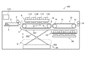
図1に示すように、本発明の一実施形態のインクジェット記録装置100の左側部には用紙S(記録媒体)を収容する給紙トレイ2が設けられている。この給紙トレイ2の一端部には、給紙ローラー3及び従動ローラー4が設けられている。給紙ローラー3は、給紙トレイ2に収容された用紙Sを、最上位の用紙Sから順に一枚ずつ後述する第1搬送ユニット5へ搬送する。従動ローラー4は給紙ローラー3の回転に従動して回転する。
As shown in FIG. 1, on the left side of an
給紙ローラー3及び従動ローラー4に対する用紙搬送方向Xの下流側(図1の右側)には、第1搬送ユニット5及び記録部9が配置されている。第1搬送ユニット5は、第1駆動ローラー6と、第1従動ローラー7と、第1駆動ローラー6及び第1従動ローラー7に掛け渡された第1搬送ベルト8とを有する。第1搬送ユニット5は、インクジェット記録装置100の制御部110からの制御信号によって第1駆動ローラー6が図1の時計回り方向に回転駆動されることで、第1搬送ベルト8に保持された用紙Sを用紙搬送方向Xに沿って搬送する。
The
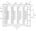
記録部9は、ヘッドフレーム10、及びヘッドフレーム10に保持されたラインヘッド11C,11M,11Y,11Kを備えている。ヘッドフレーム10は、インクジェット記録装置100の本体フレーム(不図示)に支持されている。これらのラインヘッド11C〜11Kそれぞれは、用紙搬送方向Xに沿って所定間隔を隔てられて、ヘッドフレーム10に固定されている。また、ラインヘッド11C〜11Kは、第1搬送ベルト8の搬送面に対して所定の間隔(例えば1mm)だけ離間する高さに支持される。ラインヘッド11C〜11Kは、それぞれ、記録ヘッド17a〜17c(図2参照)を有する。ラインヘッド11C〜11Kそれぞれの記録ヘッド17a〜17cには、それぞれインクタンク(不図示)に貯留されている4色(シアン、マゼンタ、イエロー及びブラック)のインクがインクチューブ(不図示)によってラインヘッド11C〜11Kの色毎に供給される。
The
図2に示すように、ラインヘッド11C〜11Kは、それぞれ複数(ここでは3個)の記録ヘッド17a〜17cを有する。記録ヘッド17a〜17cは、それぞれヘッド部18を有する。各ラインヘッド11C〜11Kにおいて、ヘッド部18は、用紙搬送方向Xと直交する用紙幅方向A(図2の上下方向)に沿って千鳥状に配列されている。
As shown in FIG. 2, each of the line heads 11C to 11K has a plurality of (here, three)
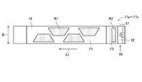
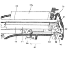
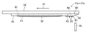
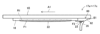
図3及び図4に示すように、ヘッド部18は、複数のインク吐出ノズル18a(図2参照)が配列されたインク吐出領域R1を含むインク吐出面F1を有する。インク吐出ノズル18aは、下部開口を有する。この下部開口は、用紙Sにインクを吐出するインク吐出口である。また、インク吐出面F1は、ワイピング面を構成する。なお、記録ヘッド17a〜17cは同一の形状及び構成であるため、図3及び図4では記録ヘッド17a〜17cを一つの図で示している。
As shown in FIGS. 3 and 4, the
各記録ヘッド17a〜17cは、制御部110(図1参照)からの制御信号により外部コンピューターから受信した画像データに応じて、第1搬送ベルト8の搬送面に吸着保持されて搬送される用紙Sに向かってインク吐出ノズル18aからインクを吐出する。これにより、第1搬送ベルト8上の用紙Sにはシアン、マゼンタ、イエロー及びブラックの4色のインクが重ね合わされたカラー画像が形成される。なお、制御部110は、後述の送液ポンプ72及び開閉弁73(図3参照)を制御する。制御部110による送液ポンプ72及び開閉弁73を制御については後述する。
Each of the
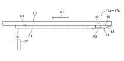
また、記録ヘッド17a〜17cそれぞれには、インク吐出領域R1のワイピングに用いる洗浄液23(図10参照)を供給する洗浄液供給部60が設けられている。洗浄液供給部60は、ヘッド部18に対して後述するワイパー部材35(図10参照)のワイピング方向A1(本発明の移動方向の一例)の上流側(図3及び図4の右側)に隣接して配置されている。ここで、ワイピング方向A1は、インク吐出面F1を洗浄するときに、移動開始位置P1(図11参照)から移動停止位置P2(図13参照)に向けてワイパー部材35がインク吐出面F1に接触して移動する方向である(図11〜図13参照)。なお、洗浄液供給部60の構成については後述する。
Further, each of the
図3、図5及び図6に示すように、洗浄液供給部60にはチューブ70が接続されている。なお、図3、図5及び図6では、理解を容易にするために、一部の記録ヘッド17a〜17cのみを示している。
As shown in FIGS. 3, 5 and 6, a
チューブ70は、洗浄液を移動させる内部空間701を有する。また、チューブ70は、複数の分岐部を有する。本実施形態では、チューブ70は、12個の分岐部を有し、各分岐部が記録ヘッド17a〜17cの洗浄液供給部60に接続されている。チューブ70は、洗浄液タンク71に接続されている。洗浄液タンク71は、洗浄液供給部60に供給する洗浄液を収容する。また、チューブ70には、送液ポンプ72(図3参照)及び開閉弁73(図3参照)が設けられている。なお、洗浄液としては、例えばインクから色材を除いたものを使用できる。即ち、洗浄液としては、溶剤及び水を主成分とするものを使用できる。また、洗浄液には、必要に応じて界面活性剤、防腐防かび剤などが添加される。
The
送液ポンプ72は、チューブ70の内部空間701において洗浄液を移動させる動力を付与する。送液ポンプ72としては、公知のものを使用でき、微量な液体を後述の洗浄液ノズル63(図7参照)から定量で供給できる容積式ポンプが好ましい。この容積式ポンプとしては、例えばシリンジポンプ、ピストンポンプ、プランジャーポンプ、ギアポンプを使用できる。
The
開閉弁73は、送液ポンプ72と洗浄液供給部60との間に設けられている。開閉弁73は、チューブ70の内部空間701が開放した開放状態と、チューブ70の内部空間701が閉鎖した閉鎖状態とを切り替える。開閉弁73としては、制御部110による開閉制御が可能であれば特に制限はなく、公知のものを使用できる。
The on-off
送液ポンプ72及び開閉弁73は、制御部110によって動作が制御される。制御部110は、送液ポンプ72の動作制御を行う。具体的には、制御部110は、洗浄液供給部60に洗浄液を供給するときには、チューブ70の内部空間701において洗浄液を移動させる駆動状態に送液ポンプ72の動作制御を行う。一方、制御部110は、洗浄液供給部60に洗浄液を供給しないときには、チューブ70の内部空間701の洗浄液の移動を停止する駆動停止状態に送液ポンプ72の動作制御を行う。
Operations of the
また、制御部110は、チューブ70の内部空間701の開放状態及び閉鎖状態のいずれかの状態を開閉弁73に選択させる動作制御を行う。具体的には、制御部110は、送液ポンプ72が駆動状態にされて洗浄液供給部60に洗浄液を供給するときには、チューブ70の内部空間701を開放状態にする動作制御を行う。また、制御部110は、送液ポンプ72が駆動停止状態にされて送液ポンプ72が洗浄液供給部60に洗浄液を供給しない駆動停止期間のうちのワイパー部材35によるワイピング(図10〜図14参照)を実行する期間において、チューブ70の内部空間701が閉鎖状態になるように開閉弁73を制御する。一方、制御部110は、前記駆動停止期間のうちのワイピングを実行しない期間では、チューブ70の内部空間701が開放状態になるように開閉弁73を制御する。
The
インクジェット記録装置100では、制御部110によって送液ポンプ72及び開閉弁73の動作制御を行うことで、全ての記録ヘッド17a〜17cに対して洗浄液供給部60の洗浄液ノズル63(図7参照)から洗浄液23(図10参照)を供給する。また、インクジェット記録装置100では、後述する洗浄液23を用いてワイパー部材35によりインク吐出面F1を拭き取ることで、インク吐出領域R1の洗浄を行う(図10〜図14参照)。インク吐出領域R1の洗浄は、例えば長期間におけるインクジェット記録装置100の停止後の印字開始時、印字動作間(例えばシート間、ジョブ間)に実行される。
In the ink
図1に戻って、第1搬送ユニット5に対する用紙搬送方向Xの下流側(図1の右側)には第2搬送ユニット12が配置されている。第2搬送ユニット12は、第2駆動ローラー13と、第2従動ローラー14と、第2駆動ローラー13及び第2従動ローラー14に掛け渡された第2搬送ベルト15とを有する。第2搬送ユニット12は、第2駆動ローラー13が図1の時計回り方向に回転駆動されることにより、第2搬送ベルト15に保持された用紙Sが用紙搬送方向Xに沿って搬送される。
Returning to FIG. 1, the
記録部9によってインクによる画像が記録された用紙Sは第2搬送ユニット12へ向けて送られる。用紙Sの表面のインクは、第2搬送ユニット12を通過する間に乾燥される。
The sheet S on which the image by the ink is recorded by the
また、第2搬送ユニット12に対する用紙搬送方向Xの下流側には、画像が記録された用紙Sを装置外へと排出する排出ローラー対16が設けられている。排出ローラー対16の下流側には、装置外へと排出された用紙Sが積載される排出トレイ(不図示)が設けられている。
Further, on the downstream side of the
第1搬送ユニット5の下方には、昇降機構20が配置されている。昇降機構20は、第1搬送ユニット5を下方から支持しており、第1搬送ユニット5をラインヘッド11C〜11Kに対して上下に昇降させる。即ち、昇降機構20は、第1搬送ユニット5をラインヘッド11C〜11Kに相対的に移動させることにより、第1搬送ユニット5とラインヘッド11C〜11Kとを離間又は接近させる。具体的には、昇降機構20は、記録部9による印刷が可能な記録位置(図1に実線で示す位置)と、前記記録位置から下方へ所定距離を隔てたメンテナンス位置(図1に破線で示す位置)との間で第1搬送ユニット5を移動させる。
A
昇降機構20は、例えば、第1搬送ユニット5を支持するリフト板201と、リフト板201に取り付けられたリンクアーム202と、リンクアーム202を上下に移動させる動力を伝達する本体部203とにより構成することができる。なお、昇降機構20はこのような構成に限られず、第1搬送ユニット5を昇降させる機構であれば如何なる構成のものでも適用可能である。
The elevating
第2搬送ユニット12の下方にはメンテナンスユニット19及びキャップユニット90が配置されている。
The
メンテナンスユニット19は、インク吐出面F1を拭き取ることで、インク吐出領域R1の洗浄を行うワイピング動作を行うものである。メンテナンスユニット19は、ワイピング動作を実行する際に記録部9の下方に移動する。具体的には、昇降機構20により第1搬送ユニット5が前記メンテナンス位置に移動されることで、ラインヘッド11C〜11Kの対向箇所にスペースが生じ、このスペースにメンテナンスユニット19が不図示の水平移動機構によって水平移動される。そして、メンテナンスユニット19がラインヘッド11C〜11Kの下方に移動すると、昇降機構20により第1搬送ユニット5が前記メンテナンス位置から所定距離だけ上昇させられる。これにより、メンテナンスユニット19が記録部9の直下に移動される。
The
メンテナンスユニット19は、インク吐出面F1に沿って移動可能な複数のワイパー部材35(本発明のクリーニング部材の一例、図10〜図14参照)と、複数のワイパー部材35が固定された略矩形状のキャリッジ(不図示)と、キャリッジを支持する支持フレーム(不図示)とを備える。前記キャリッジは前記支持フレームに対し用紙幅方向A(図2参照)に摺動可能に支持される。
The
ワイパー部材35は、各記録ヘッド17a〜17cの洗浄液供給部60の洗浄液ノズル63から供給された洗浄液23(図7及び図10参照)をインク吐出面F1に塗布しつつ拭き取るための弾性部材(例えばEPDMからなるゴム製の部材)である。ワイパー部材35は、洗浄液供給部60の洗浄液供給領域R2に対してワイピング方向A1の上流側の傾斜面62に圧接され、前記キャリッジの移動により洗浄液供給面F2及びインク吐出面F1に沿って、インク吐出面F1に密着した状態で移動する。これにより、ワイパー部材35によってインク吐出面F1が清掃される。
The
また、メンテナンスユニット19は、洗浄液供給部60の洗浄液ノズル63から供給された洗浄液23(図7及び図10参照)をインク吐出面F1に塗布しつつ拭き取り、拭き取られた洗浄液を回収する。回収した洗浄液は、前記キャリッジに設けられた不図示のインクトレイに貯留されてから、廃インクタンク(不図示)へ送られる。
Further, the
キャップユニット90は、記録ヘッド17a〜17cのインク吐出面F1(図3参照)をキャッピングする際に記録部9の下方に水平移動する。さらに、キャップユニット90は、記録部9の下方から上方に移動することで、記録ヘッド17a〜17cの下面を被覆する。
The
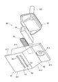
以下、図7〜図9を参照して、洗浄液供給部60の構成について説明する。洗浄液供給部60は、上述したように、ヘッド部18に対してワイパー部材35のワイピング方向A1の上流側(図3及び図4の右側)に隣接して配置されている。洗浄液供給部60は、洗浄液を供給する複数の洗浄液ノズル63(図7参照)が列状に配列された洗浄液供給領域R2を含む洗浄液供給面F2を有する。また、洗浄液供給面F2は、インク吐出面F1と共に、前記ワイピング面を構成する。なお、ワイピング面は、インク吐出面F1を洗浄するときにワイパー部材35の移動時にワイパー部材35が接触する面である。
Hereinafter, the configuration of the cleaning
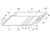
図7〜図9に示すように、洗浄液供給部60は、基体81(本発明の収容部の一例)、インナーケース82、メッシュシート83、スポンジ部材84により構成されている。なお、図9では、インナーケース82は破線で示されている。
As shown in FIGS. 7 to 9, the cleaning
基体81は、洗浄液供給面F2を含む平坦部811と、傾斜面62を含む傾斜部812と、水平端部813とを有しており、これらが一体に形成されている。したがって、基体81の表面は、平坦部811の洗浄液供給面F2から傾斜部812の傾斜面62に至って連続している。基体81の内部には空洞が形成されており、また、基体81の上面814(図8参照)は閉塞されておらず開放された開口である。基体81の内部にインナーケース82が収容される。インナーケース82は、平坦部811及び傾斜部812の形状に対応した形状に形成されており、下面に開口を有する箱形状に形成されている。このインナーケース82が基体81の内部に収容されることによって、基体81とインナーケース82とによって密閉された収容空間86(図9参照)が形成される。収容空間86に洗浄剤が収容される。つまり、基体81は、インナーケース82とともに、インク吐出面F1を洗浄するための洗浄液を収容する収容部である。インナーケース82の上面には、貫通孔を有するジョイント821が設けられており、このジョイント821にチューブ70が取り付けられる。これにより、チューブ70を介して収容空間86の内部に洗浄剤が供給可能となる。
The
また、基体81には、傾斜部812と水平端部813との間に貫通孔815が形成されている。貫通孔815は、ネジやビスなどの固定部材816によって基体81をヘッドフレーム10に固定するときに利用される。
Further, a through
基体81の平坦部811に複数の洗浄液ノズル63が形成されている。洗浄液ノズル63は、平坦部811の洗浄液供給面F2から基体81の内部の収容空間86に連通する連通孔を含んでおり、この連通孔の内部に洗浄液の表面による凹状のメニスカスを形成する。言い換えると、洗浄液ノズル63は、その内部に作用する洗浄液の毛細管力によって洗浄液の凹状メニスカスを形成することができる。なお、洗浄液供給面F2に現れる洗浄液ノズル63の下部開口が、洗浄液が洗浄液供給領域R2に供給される供給口である。
A plurality of
基体81は、合成樹脂で形成されている。洗浄液ノズル63に凹状メニスカスを形成するためには、洗浄液ノズル63の内径は小さいほうが好ましい。しかしながら、合成樹脂製の基体81においては、洗浄液ノズル63の形成加工の困難性に鑑みて、洗浄液ノズル63の内径は約0.5mmに形成されている。即ち、合成樹脂製の基体81においては、内径が0.5mmを下回ると、洗浄液ノズル63の加工が困難になる。
The
また、基体81には、平坦部811の側端部(図9の左側の端部)からワイピング方向A1の下流側へ突出する突出部817が設けられている。突出部817は、肉厚が薄く形成された庇状の部材であり、隣接するインク吐出面F1を覆うようにインク吐出面F1側へ突出している。つまり、突出部817は、記録部9と基体81の平坦部811との間の部分を覆っている。
Further, the
ところで、洗浄液ノズル63が設けられた構成においては、洗浄液を収容した洗浄液タンク71における洗浄液の液面が変動すると、洗浄液ノズル63における洗浄液のメニスカスを安定させることができなくなる。例えば、洗浄液タンク71の液面が高い場合には、洗浄液ノズル63の洗浄液に正圧が作用し、洗浄液ノズル63における洗浄液のメニスカスが崩壊する。この場合、用紙Sに対する画像の記録時に洗浄液が洗浄液ノズル63から突出し、又は吐出され、用紙Sに洗浄液が付着することがある。逆に、洗浄液の液面が低くなると、インク吐出面F1を洗浄するのに十分な量の洗浄液をインク吐出面F1に供給するのが困難になることがある。洗浄液ノズル63における前記メニスカスを安定させるために、洗浄液タンク71の液面を一定にする機構を別途設けることも考えられるが、この場合、インクジェット記録装置100の構成が複雑化する。このような問題に鑑みて、本実施形態では、メッシュシート83及びスポンジ部材84を収容空間86に設けることにより、簡易な構成によって洗浄液のメニスカスを安定化させるとともに、洗浄液の供給量を一定に維持することを実現している。
By the way, in the configuration in which the cleaning
収容空間86の内部に金属製のメッシュシート83が設けられている。メッシュシート83は、その開口のサイズを示す所謂目開きが洗浄液ノズル63の内径よりも小さく形成されたものである。例えば、メッシュシート83は、編み目が635メッシュであり、線径が0.02mmのステンレスワイヤーで形成されたステンレス製の綾織金網である。この場合、メッシュシート83の目開きは0.02mmであり、空間率は25%となる。なお、メッシュシート83の目開きは0.02mmに限られず、洗浄液ノズル63の内径よりも小さいものであればよい。本実施形態では、図9に示すように、メッシュシート83は、収容空間86において、平坦部811の裏面F3(図9参照)、つまり、洗浄液供給面F2とは反対側の内面に密着して設けられている。このようなメッシュシート83が設けられているため、メッシュシート83の毛細管力によって洗浄液ノズル63の内部に負圧を作用させることができる。その結果、洗浄液ノズル63の内部に凹状のメニスカスを好適に形成できる。
A
なお、本実施形態では、1枚のメッシュシート83が収容空間86に設けられた構成を例示するが、メッシュシート83の枚数は複数枚であってもよい。
In the present embodiment, a configuration in which one
また、収容空間86の内部にスポンジ部材84が設けられている。スポンジ部材84は、多孔質部材の一例であり、メッシュシート83の目開きよりも大きく、洗浄液ノズル63の内径よりも小さく形成された内孔を多数含む部材である。このため、スポンジ部材84は、洗浄液を吸収して保持することができ、更に、毛細管力によって、メッシュシート83を介して、洗浄液ノズル63の内部に負圧を作用させることができる。スポンジ部材84は、収容空間86内において、メッシュシート83の上側に圧縮状態で設けられている。このため、メッシュシート83は、スポンジ部材84の復元力によって、平坦部811の裏面F3(図9参照)へ向けて適度の力で押圧される。これにより、接着剤などの固定手段を用いることなく、メッシュシート83が平坦部811の裏面F3に密着する。
In addition, a
以下、図10〜図14を参照して、本実施形態のインクジェット記録装置100でのメンテナンスユニット19を用いた記録ヘッド17a〜17cの回復動作について説明する。なお、以下で説明する記録ヘッド17a〜17cの回復動作は、制御部110(図1参照)からの制御信号に基づいて記録ヘッド17a〜17c、メンテナンスユニット19などの動作を制御することによって実行される。
Hereinafter, with reference to FIGS. 10 to 14, the recovery operation of the recording heads 17a to 17c using the
記録ヘッド17a〜17cの回復動作を行う場合、先ず、制御部110(図1参照)は記録部9の下方に位置する第1搬送ユニット5を、昇降機構20を駆動制御することにより下降させる。そして、制御部110は第2搬送ユニット12の下方に配置されたメンテナンスユニット19を水平移動させて記録部9と第1搬送ユニット5との間に配置する。この状態では、メンテナンスユニット19のワイパー部材35は記録ヘッド17a〜17cのインク吐出面F1及び洗浄液供給面F2よりも下方に配置されている(図10参照)。このとき、送液ポンプ72が制御部110によって駆動停止状態に制御され、開閉弁73が制御部110によってチューブ70の内部空間701が開放状態になるように制御されている。
When the recovery operation of the recording heads 17a to 17c is performed, first, the control unit 110 (see FIG. 1) lowers the
(洗浄液供給動作)
図10に示すように、後述のワイピング動作に先立って、制御部110が送液ポンプ72を駆動状態に制御することで、洗浄液23が洗浄液供給部60に供給される。供給された洗浄液23は洗浄液ノズル63から所定量だけ洗浄液供給領域R2に供給される。なお、ワイピング動作を実行する期間以外では、洗浄液供給動作を実行する期間を含めて、チューブ70の内部空間701が、制御部110による開閉弁73の制御によって開放状態に維持されている。そのため、制御部110によって送液ポンプ72を駆動状態に制御することで、開閉弁73を開放状態にするまでもなく、洗浄液供給部60に洗浄液23を供給することができる。また、洗浄液供給領域R2に所定量の洗浄液が供給された場合には、制御部110が送液ポンプ72を駆動停止状態に制御することで、洗浄液供給部60への洗浄液23の供給が停止される。
(Cleaning fluid supply operation)
As shown in FIG. 10, the cleaning
(パージ動作)
また、後述のワイピング動作に先立って、制御部110によってインク22が記録ヘッド17a〜17cに供給される。供給されたインク22はインク吐出ノズル18aから強制的にパージされる。このパージ動作により、インク吐出ノズル18a内の増粘インク、異物や気泡がインク吐出ノズル18aから排出される。このとき、パージされたインク22はインク吐出ノズル18aの存在するインク吐出領域R1の形状に沿ってインク吐出面F1に押し出される。
(Purge operation)
Further, prior to the later-described wiping operation, the
(ワイピング動作)
図11に示すように、制御部110は、ワイパー部材35を上昇させて記録ヘッド17a〜17cの洗浄液供給部60の傾斜面62に所定の圧力で接触させる。傾斜面62にワイパー部材35が接触し、ワイパー部材35がワイピング方向A1に移動する前の位置は、ワイピング動作時のワイパー部材35の移動開始位置P1である。つまり、移動開始位置P1は、ワイパー部材35の上端が傾斜面62に当接した位置である。また、制御部110は、送液ポンプ72が駆動停止状態にされて洗浄液供給領域R2への所定量の洗浄液の供給が終了してから、ワイパー部材35のワイピング方向A1への移動が開始するまでの間に、チューブ70の内部空間701が閉鎖状態になるように開閉弁73を制御する。
(Wiping operation)
As shown in FIG. 11, the
図12に示すように、制御部110は、ワイパー部材35の先端が洗浄液供給部60の傾斜面62に圧接した状態から、ワイパー部材35を洗浄液供給面F2に沿ってインク吐出領域R1に向けてワイピング方向A1に沿って移動させる。このとき、制御部110によって送液ポンプ72が駆動停止状態に維持され、制御部110によってチューブ70の内部空間701が閉鎖状態になるように開閉弁73が制御されている。
As shown in FIG. 12, from the state in which the tip of the
そして、図13に示すように、ワイパー部材35は、洗浄液23を保持した状態を維持しながらインク吐出面F1をワイピング方向A1に沿って移動する。このとき、洗浄液23及びパージされたインク22(図11参照)によって、インク吐出面F1に付着して固化したインク滴(廃インク)が溶解し、ワイパー部材35によって拭き取られる。そして、ワイパー部材35は、さらにワイピング方向A1に沿って移動し、インク吐出領域R1に対して洗浄液供給領域R2とは反対側の移動停止位置P2に到達すると、ワイピング方向A1への移動が停止される。なお、ワイパー部材35によって拭き取られた洗浄液23、廃インク及びパージされたインク22は、メンテナンスユニット19に設けられたインクトレイ(不図示)に回収される。
Then, as shown in FIG. 13, the
(離間動作)
ワイピング動作の実行後、図14に示すように、制御部110はワイパー部材35を下降させてインク吐出面F1から離間させる。また、ワイピング動作の実行後、制御部110は、チューブ70の内部空間701が開放状態になるように開閉弁73を制御する。このとき、制御部110は、送液ポンプ72の駆動停止状態を維持する。
(Separation operation)
After execution of the wiping operation, as shown in FIG. 14, the
最後に、制御部110は、記録部9と第1搬送ユニット5との間に配置されたメンテナンスユニット19を水平移動させて第2搬送ユニット12の下方に配置し、第1搬送ユニット5を所定の位置まで上昇させる。このようにして、記録ヘッド17a〜17cの回復動作を終了する。
Finally, the
本実施形態では、インク吐出領域R1に対してワイピング方向A1の上流側に洗浄液23を供給する複数の洗浄液ノズル63が設けられている。これにより、洗浄液ノズル63から洗浄液23を供給した後、ワイパー部材35を洗浄液ノズル63よりもワイピング方向A1の上流側からインク吐出面F1に沿って移動させることによって、ワイパー部材35で洗浄液23を保持しながらインク吐出面F1を拭くことができる。このため、インク吐出面F1を清浄化することができる。
In the present embodiment, a plurality of
なお、上述の実施形態では、洗浄液供給領域R2を有する洗浄液供給部60をヘッド部18とは別体で設けた例について示した。しかしながら、本発明は、これに限らず、洗浄液供給部60を設けず、洗浄液ノズル63をヘッド部18に設けてもよい。
In the above embodiment, an example in which the cleaning
100:インクジェット記録装置
17a〜17c:記録ヘッド
18a:インク吐出ノズル
23:洗浄液
35:ワイパー部材
60:洗浄液供給部
62:傾斜面
63:洗浄液ノズル
81:基体
82:インナーケース
83:メッシュシート
84:スポンジ部材
86:収容空間
811:平坦部
812:傾斜部
813:水平端部
814:上面
815:貫通孔
816:固定部材
817:突出部
821:ジョイント
F1:インク吐出面
R1:インク吐出領域
F2:洗浄液供給面
R2:洗浄液供給領域
A1:ワイピング方向
100:
Claims (3)
前記インク吐出面に隣接する供給面を有し、前記インク吐出面を洗浄するための洗浄液を収容する収容部と、
前記収容部の前記供給面に形成された供給口から前記収容部の内部に連通する連通孔を有し、前記連通孔の内部に前記洗浄液の表面による凹状のメニスカスを形成する洗浄液ノズルと、
前記収容部において前記供給面の裏面に密着して設けられ、前記連通孔の内径よりも小さいサイズの開口を有する金属製のメッシュシートと、
前記収容部の内部に圧縮状態で設けられ、前記洗浄液を吸収して保持するとともに前記メッシュシートを前記供給面の裏面へ向けて押圧するスポンジ部材と、を備えるインクジェット記録装置。 An ink discharge surface having an ink discharge port from which the ink is discharged;
A storage unit having a supply surface adjacent to the ink discharge surface, and containing a cleaning liquid for cleaning the ink discharge surface;
A cleaning solution nozzle having a communication hole communicating with the inside of the storage unit from a supply port formed in the supply surface of the storage unit, and forming a concave meniscus with the surface of the cleaning solution inside the communication hole;
A metal mesh sheet provided in close contact with the back surface of the supply surface in the housing portion and having an opening smaller than the inner diameter of the communication hole;
An ink jet recording apparatus, comprising: a sponge member provided in a compressed state inside the storage portion to absorb and hold the cleaning solution and to press the mesh sheet toward the back surface of the supply surface.
前記インク吐出面に接触して移動することにより前記洗浄液によって前記インク吐出面を洗浄するクリーニング部材と、
前記供給面に連続して前記クリーニング部材の移動方向の上流側に設けられ、前記供給面に対して上方側に傾斜した傾斜面と、を更に備え、
前記クリーニング部材は、前記移動方向に沿った移動の開始時に、前記クリーニング部材の先端が前記傾斜面に当接した移動開始位置に配置される請求項1に記載のインクジェット記録装置。 A recording head having the ink ejection surface;
A cleaning member that cleans the ink discharge surface with the cleaning liquid by moving in contact with the ink discharge surface;
And an inclined surface which is provided on the upstream side in the moving direction of the cleaning member continuously to the supply surface, and which is inclined upward with respect to the supply surface,
2. The inkjet recording apparatus according to claim 1, wherein the cleaning member is disposed at a movement start position where the front end of the cleaning member abuts on the inclined surface at the start of movement in the movement direction.
Priority Applications (2)
| Application Number | Priority Date | Filing Date | Title |
|---|---|---|---|
| JP2017186177A JP6922611B2 (en) | 2017-09-27 | 2017-09-27 | Inkjet recording device |
| US16/141,850 US10556434B2 (en) | 2017-09-27 | 2018-09-25 | Inkjet recording apparatus |
Applications Claiming Priority (1)
| Application Number | Priority Date | Filing Date | Title |
|---|---|---|---|
| JP2017186177A JP6922611B2 (en) | 2017-09-27 | 2017-09-27 | Inkjet recording device |
Publications (2)
| Publication Number | Publication Date |
|---|---|
| JP2019059149A true JP2019059149A (en) | 2019-04-18 |
| JP6922611B2 JP6922611B2 (en) | 2021-08-18 |
Family
ID=65807119
Family Applications (1)
| Application Number | Title | Priority Date | Filing Date |
|---|---|---|---|
| JP2017186177A Active JP6922611B2 (en) | 2017-09-27 | 2017-09-27 | Inkjet recording device |
Country Status (2)
| Country | Link |
|---|---|
| US (1) | US10556434B2 (en) |
| JP (1) | JP6922611B2 (en) |
Families Citing this family (2)
| Publication number | Priority date | Publication date | Assignee | Title |
|---|---|---|---|---|
| JP7318313B2 (en) * | 2019-05-30 | 2023-08-01 | 京セラドキュメントソリューションズ株式会社 | image forming device |
| JP2022163743A (en) * | 2021-04-15 | 2022-10-27 | 京セラドキュメントソリューションズ株式会社 | Recording head and inkjet recording device |
Citations (8)
| Publication number | Priority date | Publication date | Assignee | Title |
|---|---|---|---|---|
| JPH08224884A (en) * | 1995-02-21 | 1996-09-03 | Fuji Xerox Co Ltd | Ink supply unit and recorder |
| JP2002166562A (en) * | 2000-11-30 | 2002-06-11 | Sharp Corp | Ink jet recorder |
| JP2006088617A (en) * | 2004-09-27 | 2006-04-06 | Brother Ind Ltd | Inkjet recorder |
| JP2007083496A (en) * | 2005-09-21 | 2007-04-05 | Fuji Xerox Co Ltd | Liquid droplet delivering head, liquid droplet delivering apparatus and method for cleaning liquid droplet delivering head |
| US20090303279A1 (en) * | 2008-06-10 | 2009-12-10 | Samsung Electronics Co., Ltd. | Nozzle wetting apparatus and inkjet image forming apparatus having the same |
| JP2014051028A (en) * | 2012-09-07 | 2014-03-20 | Fujifilm Corp | Droplet discharge head, and maintenance system of nozzle surface |
| JP2016022721A (en) * | 2014-07-24 | 2016-02-08 | 京セラドキュメントソリューションズ株式会社 | Ink jet recording device |
| JP2018089829A (en) * | 2016-12-01 | 2018-06-14 | 京セラドキュメントソリューションズ株式会社 | Inkjet recording device |
Family Cites Families (2)
| Publication number | Priority date | Publication date | Assignee | Title |
|---|---|---|---|---|
| US20090030279A1 (en) * | 2007-07-27 | 2009-01-29 | Zander Dennis R | Method and system for managing power consumption in a compact diagnostic capsule |
| JP6204323B2 (en) * | 2014-10-27 | 2017-09-27 | 京セラドキュメントソリューションズ株式会社 | Inkjet recording device |
-
2017
- 2017-09-27 JP JP2017186177A patent/JP6922611B2/en active Active
-
2018
- 2018-09-25 US US16/141,850 patent/US10556434B2/en active Active
Patent Citations (8)
| Publication number | Priority date | Publication date | Assignee | Title |
|---|---|---|---|---|
| JPH08224884A (en) * | 1995-02-21 | 1996-09-03 | Fuji Xerox Co Ltd | Ink supply unit and recorder |
| JP2002166562A (en) * | 2000-11-30 | 2002-06-11 | Sharp Corp | Ink jet recorder |
| JP2006088617A (en) * | 2004-09-27 | 2006-04-06 | Brother Ind Ltd | Inkjet recorder |
| JP2007083496A (en) * | 2005-09-21 | 2007-04-05 | Fuji Xerox Co Ltd | Liquid droplet delivering head, liquid droplet delivering apparatus and method for cleaning liquid droplet delivering head |
| US20090303279A1 (en) * | 2008-06-10 | 2009-12-10 | Samsung Electronics Co., Ltd. | Nozzle wetting apparatus and inkjet image forming apparatus having the same |
| JP2014051028A (en) * | 2012-09-07 | 2014-03-20 | Fujifilm Corp | Droplet discharge head, and maintenance system of nozzle surface |
| JP2016022721A (en) * | 2014-07-24 | 2016-02-08 | 京セラドキュメントソリューションズ株式会社 | Ink jet recording device |
| JP2018089829A (en) * | 2016-12-01 | 2018-06-14 | 京セラドキュメントソリューションズ株式会社 | Inkjet recording device |
Also Published As
| Publication number | Publication date |
|---|---|
| US10556434B2 (en) | 2020-02-11 |
| JP6922611B2 (en) | 2021-08-18 |
| US20190092024A1 (en) | 2019-03-28 |
Similar Documents
| Publication | Publication Date | Title |
|---|---|---|
| JP5088083B2 (en) | Fluid ejection device | |
| JP5493944B2 (en) | Cleaning method and fluid ejecting apparatus | |
| JP4349411B2 (en) | Liquid ejection device | |
| JP6155948B2 (en) | Liquid ejector | |
| JP2015085601A (en) | Inkjet recording apparatus | |
| JP2007144634A (en) | Inkjet recording device | |
| JP2018114660A (en) | Ink jet recording device | |
| JP5239693B2 (en) | Head cap | |
| JP6922611B2 (en) | Inkjet recording device | |
| JP2012061785A (en) | Liquid jetting device | |
| JP2007223266A (en) | Liquid injection device and its cleaning method | |
| JP2012106429A (en) | Liquid jet apparatus | |
| JP6579090B2 (en) | Recording head and ink jet recording apparatus provided with the same | |
| JP6589891B2 (en) | Head cleaning mechanism and ink jet recording apparatus having the same | |
| JP2019069540A (en) | Inkjet recording device | |
| JP5730486B2 (en) | Head cleaning device, head cleaning method, and ink jet printer | |
| JP2008254188A (en) | Printer | |
| JP2008149483A (en) | Method for cleaning recorder, and recorder | |
| JP2019025740A (en) | Recording head and inkjet recording apparatus including the same | |
| JPWO2018159044A1 (en) | RECOVERY SYSTEM OF PRINT HEAD, INKJET RECORDING DEVICE EQUIPPED WITH THE SAME, AND RECOVERY METHOD OF RECORD HEAD | |
| JP7323029B2 (en) | LIQUID EJECTING DEVICE, MAINTENANCE METHOD OF LIQUID EJECTING DEVICE | |
| JP2019018355A (en) | Recording head and inkjet recording device including the same | |
| JP5180878B2 (en) | Fluid ejection device and fluid ejection device cleaning method | |
| JP2018114666A (en) | Head cleaning mechanism and ink jet recording device including the same | |
| JP6702439B2 (en) | Recording head and ink jet recording apparatus including the same |
Legal Events
| Date | Code | Title | Description |
|---|---|---|---|
| A621 | Written request for application examination |
Free format text: JAPANESE INTERMEDIATE CODE: A621 Effective date: 20200825 |
|
| A977 | Report on retrieval |
Free format text: JAPANESE INTERMEDIATE CODE: A971007 Effective date: 20210616 |
|
| TRDD | Decision of grant or rejection written | ||
| A01 | Written decision to grant a patent or to grant a registration (utility model) |
Free format text: JAPANESE INTERMEDIATE CODE: A01 Effective date: 20210629 |
|
| A61 | First payment of annual fees (during grant procedure) |
Free format text: JAPANESE INTERMEDIATE CODE: A61 Effective date: 20210712 |
|
| R150 | Certificate of patent or registration of utility model |
Ref document number: 6922611 Country of ref document: JP Free format text: JAPANESE INTERMEDIATE CODE: R150 |