JP2019055090A - Method for manufacturing disposable wearing article and disposable wearing article - Google Patents
Method for manufacturing disposable wearing article and disposable wearing article Download PDFInfo
- Publication number
- JP2019055090A JP2019055090A JP2017182120A JP2017182120A JP2019055090A JP 2019055090 A JP2019055090 A JP 2019055090A JP 2017182120 A JP2017182120 A JP 2017182120A JP 2017182120 A JP2017182120 A JP 2017182120A JP 2019055090 A JP2019055090 A JP 2019055090A
- Authority
- JP
- Japan
- Prior art keywords
- width direction
- folded
- rising
- disposable wearing
- lodging
- Prior art date
- Legal status (The legal status is an assumption and is not a legal conclusion. Google has not performed a legal analysis and makes no representation as to the accuracy of the status listed.)
- Pending
Links
Images


Abstract
Description
本発明は、幅方向の両側に、表面から起き上がる起き上がりギャザーを備えた使い捨て着用物品に関する。 The present invention relates to a disposable wearing article having rising gathers that rise from the surface on both sides in the width direction.
使い捨ておむつや生理用ナプキン等の使い捨て着用物品においては、いわゆる横漏れを防止するために、幅方向の両側に表面から起き上がる起き上がりギャザーを設けることが一般的となっている。起き上がりギャザーには種々の構造のものが存在するが、基本的な構造のものとしては、使い捨て着用物品に固定された付根部分と、この付根部分より延び出る本体部分と、本体部分の前端部が倒伏状態に固定されて形成された前倒伏部分及び本体部分の後端部が倒伏状態に固定されて形成された後倒伏部分と、本体部分における前倒伏部分及び後倒伏部分の間に位置する非固定の起き上がり部分と、起き上がり部分の少なくとも先端部に前後方向に沿って取り付けられたギャザー弾性部材とを有するものが知られている。 In disposable wearing articles such as disposable diapers and sanitary napkins, it is common to provide rising gathers that rise from the surface on both sides in the width direction in order to prevent so-called side leakage. There are various types of rising gathers, but the basic structure includes a root portion fixed to the disposable wearing article, a body portion extending from the root portion, and a front end portion of the body portion. The front lodging part formed by being fixed in a lying state and the rear end part of the main body part being fixed in the lying state, and the non-positioning located between the front and rear lodging parts in the main body part. One having a fixed rising portion and a gather elastic member attached to at least a tip portion of the rising portion along the front-rear direction is known.
これに対し、フィット性や漏れ防止効果等を向上させる観点から、種々の構造が提案されている。例えば、特許文献1記載の起き上がりギャザーは、前倒伏部分では、本体部分が、付根部分との境界から幅方向内側に延びるとともに、その裏側に隣接する部材に固定されており、後倒伏部分では、本体部分が、付根部分との境界から幅方向外側に折り返されるとともに、その裏側に隣接する部材に固定されているものである。この起き上がりギャザーは、展開状態で起き上がり部分に側方に捲り返る力が作用するため、起き上がりギャザーが確実に起き上がるとともに、後側に向かうにつれて側方に広がりながら起き上がり高さが低くなる、後方拡幅タイプともいうべきものである。この後方拡幅タイプの起き上がりギャザーは、鼠径部から臀部まで全体にわたりフィット性が高く、特に臀部を包み込むようにフィットする利点を有するものである。
On the other hand, various structures have been proposed from the viewpoint of improving fit and leakage prevention effect. For example, the rising gather described in
他方、製造ラインで起き上がりギャザーを取り付ける場合、起き上がりギャザーの前後方向が連続方向となるように個々の起き上がりギャザーとなる部分が連続方向に繰り返す連続帯を、製造ラインのMD方向に沿って連続的に供給するとともに、その連続状態のままMD方向に連続する組付け対象に対して完全に組付けた後、個々の起き上がりギャザーの境界で組付け対象とともに切断することが一般的である。 On the other hand, when attaching gathering gathers on the production line, a continuous band in which the parts that become the gathering gathers are repeated in a continuous direction so that the front-rear direction of the gathering gathers is a continuous direction, along the MD direction of the production line. In general, after being supplied and completely assembled with respect to the assembly target continuous in the MD direction in the continuous state, it is cut along with the assembly target at the boundary of each rising gather.
しかしながら、この一般的な方法では、前述した後方拡幅タイプの起き上がりギャザーは、前端の幅方向の位置と後端の幅方向の位置とが同じにならざるを得ないため、特許文献1記載の起き上がりギャザーのように、前端の幅方向の位置と後端の幅方向の位置とが異なる構造のものを製造することができなかった。 However, in this general method, the above-described rear widening type rising gather has to have the same position in the width direction of the front end and the position in the width direction of the rear end. As in the case of gathers, it was impossible to manufacture a structure in which the front end width direction position and the rear end width direction position were different.
そこで、本発明の主たる課題は、後方拡幅タイプの起き上がりギャザーを有する使い捨て着用物品を製造ラインで連続的に製造可能とすることにある。 Then, the main subject of this invention is enabling it to manufacture continuously the disposable wearing article which has a back widening type rising gather, and a manufacturing line.
上記課題を解決した使い捨て着用物品の製造方法は、以下のとおりである。
<第1の態様>
幅方向の両側に、表面から起き上がる起き上がりギャザーをそれぞれ備え、
前記起き上がりギャザーは、使い捨て着用物品に固定された付根部分と、この付根部分より延び出る本体部分と、前記本体部分の前端部が倒伏状態に固定されて形成された前倒伏部分及び前記本体部分の後端部が倒伏状態に固定されて形成された後倒伏部分と、前記本体部分における前記前倒伏部分及び後倒伏部分の間に位置する非固定の起き上がり部分と、前記起き上がり部分の少なくとも先端部に前後方向に沿って取り付けられたギャザー弾性部材とを有し、
前記前倒伏部分は、前記付根部分との境界から幅方向内側に延びる部分を有するとともに、倒伏状態で裏側に隣接する部材に固定されており、
前記後倒伏部分は、前記前倒伏部分の幅方向内側の縁部より幅方向外側を通る前後方向仮想線又は前記付根部分との境界を折り位置として幅方向外側に折り返された後折り返し部分を有するとともに、前記後折り返し部分はその裏側に隣接する部材に固定されている、
使い捨て着用物品の製造方法において、
前記起き上がりギャザーの取り付けに際し、
前記本体部分を、前後方向全体にわたり前倒伏部分と同じ倒伏状態としつつ、前記後倒伏部分の固定を行わずに、前記付根部分の固定及び前倒伏部分の固定を行う、第1工程と、
前記折り位置よりも幅方向外側の部分を幅方向内側に折り返し、この折り返した部分と前記後倒伏部分となる部分との重なり部分を接合する、第2工程とを行う、
ことを特徴とする、使い捨て着用物品の製造方法。
The manufacturing method of the disposable wearing article which solved the above-mentioned subject is as follows.
<First aspect>
Both sides of the width direction are each equipped with rising gathers that rise from the surface,
The rising gather includes a root portion fixed to the disposable wearing article, a main body portion extending from the root portion, a front lodging portion formed by fixing a front end portion of the main body portion in a lying state, and the main body portion. A rear lodging portion formed with a rear end portion fixed in a lying state, a non-fixed rising portion located between the front and rear falling portions in the main body portion, and at least a tip portion of the rising portion A gathered elastic member attached along the front-rear direction,
The front lodging portion has a portion extending inward in the width direction from the boundary with the root portion, and is fixed to a member adjacent to the back side in a lying state,
The rear lodging portion has a rear folded portion that is folded back outward in the width direction with a boundary with the front-rear direction imaginary line passing through the width direction outer side or the root portion as a folding position from the inner edge in the width direction of the front lodging portion. And the rear folded portion is fixed to a member adjacent to the back side thereof,
In the method for producing disposable wearing articles,
When installing the rising gather,
A first step of fixing the base portion and fixing the front lodging portion without fixing the rear falling portion while keeping the main body portion in the same lying state as the front falling portion over the entire front-rear direction,
A second step is performed in which a portion on the outer side in the width direction than the folding position is folded back inward in the width direction, and an overlapping portion between the folded portion and the portion that becomes the rearward lying portion is joined.
The manufacturing method of the disposable wearing article characterized by the above-mentioned.
(作用効果)
本態様のように、第1工程では後倒伏部分を固定せずにおき、第2工程で、後倒伏部分の折り位置よりも幅方向外側の部分を幅方向内側に折り返し、この折り返した部分と後倒伏部分となる部分との重なり部分を接合すると、その後に折り返した部分を展開するだけで、後方拡幅タイプの起き上がりギャザーを有するものとなる。しかも、製造過程では、起き上がりギャザーの後倒伏部分を幅方向外側に折り返さなくてよいため、起き上がりギャザーの前端の幅方向の位置と後端の幅方向の位置とが同じになる。この結果、上記第1工程及び第2工程を行うだけで、それ以外は従来と同様の製造方法により製造ラインで連続的に製造することができる。
(Function and effect)
As in this aspect, the rear fall portion is not fixed in the first step, and in the second step, the portion outside the width direction from the folding position of the rear fall portion is folded back inward in the width direction. When the overlapping portion with the portion that becomes the rearward lying portion is joined, it is possible to have a rear widening type rising gather only by developing the folded portion after that. In addition, in the manufacturing process, it is not necessary to fold back the rear gathering portion of the rising gather to the outside in the width direction, so that the position in the width direction of the front end of the rising gather and the position in the width direction of the rear end are the same. As a result, only the first step and the second step are performed, and the rest can be continuously manufactured on the manufacturing line by the same manufacturing method as the conventional one.
<第2の態様>
少なくとも前記第2工程における折り返しの前の状態で、
一方の前記起き上がりギャザーにおける前記折り位置よりも幅方向外側の部分の幅方向寸法と、他方の前記起き上がりギャザーにおける前記折り位置よりも幅方向外側の部分の幅方向寸法との和が、
一方の前記起き上がりギャザーにおける前記折り位置と、他方の前記起き上がりギャザーにおける前記折り位置との、幅方向間隔以下である、
第1の態様の使い捨て着用物品の製造方法。
<Second aspect>
At least in a state before the folding in the second step,
The sum of the width direction dimension of the portion outside in the width direction from the folding position in the one rising gather and the width direction dimension of the portion outside in the width direction from the folding position in the other rising gather,
The folding position in one rising gather and the folding position in the other rising gather are equal to or less than the width direction interval.
The manufacturing method of the disposable wearing article of a 1st aspect.
(作用効果)
本態様のような寸法関係にあると、第2工程での折り返しの際、折り返した部分同士が重なることがなく、接合が容易となる。
(Function and effect)
When the dimensional relationship is as in this aspect, the folded portions do not overlap each other when folded in the second step, and joining becomes easy.
<第3の態様>
前記第2工程で、前記折り返しに先立ち、前記付根部分における前記後倒伏部分となる部分と重なる部位に接着剤を塗布した後、前記折り返しを行うことにより、折り返した部分と前記後倒伏部分となる部分との重なり部分を接合する、
第1又は2の態様の使い捨て着用物品の製造方法。
<Third Aspect>
In the second step, prior to the folding, after applying an adhesive to a portion of the root portion that overlaps with the portion that becomes the rearwardly lying portion, the folded portion is performed to become the folded portion and the rearwardly lying portion. Join the overlapping part with the part,
The manufacturing method of the disposable wearing article of the 1st or 2nd aspect.
(作用効果)
ホットメルト接着剤等の接着剤により第2工程における接合を行う場合、本態様のように折り返し前に接着剤を塗布し、折り返しを利用して接合を行うことが望ましく、この際、付根部分における後倒伏部分となる部分と重なる部位に接着剤を塗布することにより、接着剤の塗布位置が多少ずれても、起き上がりギャザーより幅方向内側に塗布してしまうことがない。
(Function and effect)
When joining in the second step with an adhesive such as a hot melt adhesive, it is desirable to apply the adhesive before folding as in this embodiment, and to join using folding, and at this time, in the root portion By applying the adhesive to the portion that overlaps with the portion that will become the back-falling portion, even if the application position of the adhesive is slightly deviated, it will not rise and be applied to the inside in the width direction from the gather.
<第4の態様>
前記第2工程での前記接合の後、前記折り返した部分を展開せずに、前後方向に折り畳む、
第1〜3の態様のいずれか1つの使い捨て着用物品の製造方法。
<Fourth aspect>
After the joining in the second step, fold in the front-rear direction without unfolding the folded portion,
The manufacturing method of the disposable wearing article of any one of the 1st-3rd aspect.
(作用効果)
例えばテープタイプ使い捨ておむつやパッドタイプ使い捨ておむつ等の使い捨て着用物品では、幅方向両端部を折り返した後に前後方向に折り畳んだ状態で製品を包装し、販売することが一般的である。よって、第2工程での折り返しを、販売形態への折り畳みを兼ねて行うことで、製造工程を簡素化することができる。
(Function and effect)
For example, in a disposable wearing article such as a tape-type disposable diaper or a pad-type disposable diaper, it is common to wrap and sell a product in a state where the both ends in the width direction are folded and folded in the front-rear direction. Therefore, the manufacturing process can be simplified by performing the folding in the second process also as the folding into the sales form.
<第5の態様>
幅方向の両側に、表面から起き上がる起き上がりギャザーをそれぞれ備え、
前記起き上がりギャザーは、使い捨て着用物品に固定された付根部分と、この付根部分より延び出る本体部分と、前記本体部分の前端部が倒伏状態に固定されて形成された前倒伏部分及び前記本体部分の後端部が倒伏状態に固定されて形成された後倒伏部分と、前記本体部分における前記前倒伏部分及び後倒伏部分の間に位置する非固定の起き上がり部分と、前記起き上がり部分の少なくとも先端部に前後方向に沿って取り付けられたギャザー弾性部材とを有し、
前記前倒伏部分は、前記付根部分との境界から幅方向内側に延びる部分を有するとともに、倒伏状態で裏側に隣接する部材に固定されており、
前記後倒伏部分は、前記付根部分との境界又は前記前倒伏部分の幅方向内側の縁部より幅方向外側を通る前後方向仮想線を折り位置として幅方向外側に折り返された後折り返し部分を有するとともに、前記後折り返し部分はその裏側に隣接する部材に固定されている、
使い捨て着用物品において、
製品状態では、前記折り位置で、それよりも幅方向外側の部分が幅方向内側に折り返されている、
ことを特徴とする、使い捨て着用物品。
<Fifth aspect>
Both sides of the width direction are each equipped with rising gathers that rise from the surface,
The rising gather includes a root portion fixed to the disposable wearing article, a main body portion extending from the root portion, a front lodging portion formed by fixing a front end portion of the main body portion in a lying state, and the main body portion. A rear lodging portion formed with a rear end portion fixed in a lying state, a non-fixed rising portion located between the front and rear falling portions in the main body portion, and at least a tip portion of the rising portion A gathered elastic member attached along the front-rear direction,
The front lodging portion has a portion extending inward in the width direction from the boundary with the root portion, and is fixed to a member adjacent to the back side in a lying state,
The rear lodging portion includes a rear folded portion that is folded back outward in the width direction with a front-rear direction imaginary line passing through the outer side in the width direction from the boundary with the root portion or the inner edge in the width direction of the front lodging portion. And the rear folded portion is fixed to a member adjacent to the back side thereof,
In disposable wearing articles,
In the product state, at the folding position, the outer portion in the width direction is folded back inward in the width direction.
A disposable wearing article characterized by the above.
(作用効果)
第1の態様の製造方法により製造できるものであり、第1の態様と同様の利点を有するものである。
(Function and effect)
It can be manufactured by the manufacturing method of the first aspect, and has the same advantages as the first aspect.
<第6の態様>
前記前倒伏部分は、前記付根部分との境界から幅方向内側に延びる第1部分と、この第1部分の先端で幅方向外側に折り返された第2部分とを有するとともに、第1部分及び第2部分が倒伏状態で裏側に隣接する部材に対して固定されており、
前記後倒伏部分は、前記第1部分と対応する第3部分及び前記第2部分と対応する第4部分を有しているとともに、前記第3部分及び第4部分が折り畳まれた状態で前記折り位置で幅方向外側に折り返されて、前記後折り返し部分が形成されている、
第5の態様の使い捨て着用物品。
<Sixth aspect>
The forward lodging portion includes a first portion extending inward in the width direction from the boundary with the root portion, and a second portion folded back outward in the width direction at the tip of the first portion, and the first portion and the first portion Two parts are fixed to the member adjacent to the back side in the lying state,
The rear-falling part has a third part corresponding to the first part and a fourth part corresponding to the second part, and the folding part in a state where the third part and the fourth part are folded. Folded back outward in the width direction at the position, the rear folded portion is formed,
The disposable wearing article of the fifth aspect.
(作用効果)
本態様の起き上がりギャザーでは、前倒伏部分は第1部分及び第2部分を有する屈曲形態となっており、後倒伏部分は第1部分と対応する第3部分及び第2部分と対応する第4部分が折り畳まれた状態で折り返されているため、前後方向の中間で起き上がり部分の先端がねじれる(起き上がり方向が内側から外側に変化する)ことがなく、装着感の悪化のおそれがないものとなる。
(Function and effect)
In the rising gather according to this aspect, the forward lodging portion has a bent form having a first portion and a second portion, and the rear falling portion is a third portion corresponding to the first portion and a fourth portion corresponding to the second portion. Since it is folded in the folded state, the tip of the rising part is not twisted in the middle in the front-rear direction (the rising direction changes from the inside to the outside), and there is no fear of deterioration of the wearing feeling.
本発明によれば、後方拡幅タイプの起き上がりギャザーを有する使い捨て着用物品が製造ラインで連続的に製造可能となる、等の利点がもたらされる。 Advantageous Effects of Invention According to the present invention, there are advantages that a disposable wearing article having a rear widening type rising gather can be continuously manufactured on a manufacturing line.
図1〜図7はテープタイプ使い捨ておむつの一例を示しており、図中の符号Xは連結テープを除いたおむつの全幅を示しており、符号Lはおむつの全長を示しており、符号Fは前後方向中央より前側に位置する腹側部分を示し、符号Bは前後方向中央より後側に位置する背側部分を示している。また、断面図における点模様部分はその表側及び裏側に位置する各構成部材を接合する接合手段としての接着剤を示しており、ホットメルト接着剤のベタ、ビード、カーテン、サミット若しくはスパイラル塗布、又はパターンコート(凸版方式でのホットメルト接着剤の転写)などにより、あるいは弾性部材の固定部分はこれに代えて又はこれとともにコームガンやシュアラップ塗布などの弾性部材の外周面への塗布により形成されるものである。ホットメルト接着剤としては、例えばEVA系、粘着ゴム系(エラストマー系)、オレフィン系、ポリエステル・ポリアミド系などの種類のものが存在するが、特に限定無く使用できる。各構成部材を接合する接合手段としてはヒートシールや超音波シール等の素材溶着による手段を用いることもできる。 1-7 has shown an example of the tape type disposable diaper, the code | symbol X in a figure has shown the full width of the diaper except a connection tape, the code | symbol L has shown the full length of the diaper, and the code | symbol F has shown. A ventral portion located on the front side from the center in the front-rear direction is shown, and a symbol B denotes a back side portion located on the rear side from the center in the front-rear direction. In addition, the dotted pattern portion in the cross-sectional view shows an adhesive as a joining means for joining the constituent members located on the front side and the back side, and a solid, bead, curtain, summit or spiral application of hot melt adhesive, or The fixed part of the elastic member is formed by coating on the outer peripheral surface of the elastic member such as comb gun or shear wrap coating by pattern coating (transfer of the hot melt adhesive in a relief printing method) or the like. Is. Examples of hot melt adhesives include EVA, adhesive rubber (elastomer), olefin, and polyester / polyamide types, which can be used without any particular limitation. As a joining means for joining the constituent members, means by material welding such as heat sealing or ultrasonic sealing can be used.
このテープタイプ使い捨ておむつは、吸収体56と、吸収体56の表側を覆う液透過性のトップシート30と、吸収体56の裏側を覆う液不透過性シート11と、液不透過性シートの裏側を覆い、製品外面を構成する外装不織布12とを有するものである。外装不織布12は省略したり、他の素材に変更したりすることができる。
This tape-type disposable diaper includes an
また、図示例のテープタイプ使い捨ておむつは、吸収体56の前側及び後側にそれぞれ延出する、吸収体56を有しない一対のエンドフラップ部EFと、吸収体56の両側縁よりも側方にそれぞれ延出する、吸収体56を有しない一対のサイドフラップ部SFとを有している。
Moreover, the tape type disposable diaper of the example of illustration extends to the side rather than a pair of end flap part EF which does not have the
以下、各部の詳細について順に説明する。 Hereinafter, details of each unit will be described in order.
(連結テープ)
背側部分Bにおけるサイドフラップ部SFには、腹側部分Fの外面に対して着脱可能に連結される連結テープ13がそれぞれ設けられている。おむつ10の装着に際しては、連結テープ13を腰の両側から腹側部分Fの外面に回して、連結テープ13の連結部13Aを腹側部分F外面の適所に連結する。
(Connecting tape)
In the side flap part SF in the back side part B, the
連結テープ13の構造は特に限定されないが、図示例では、サイドフラップ部SFに固定されたテープ取付部13C、及びこのテープ取付部13Cから突出するテープ本体部13Bをなすシート基材と、このシート基材におけるテープ本体部13Bの幅方向中間部に設けられた、腹側に対する連結部13Aとを有し、この連結部13Aより先端側が摘み部となっている。
Although the structure of the connecting
連結部13Aとしては、メカニカルファスナー(面ファスナー)のフック材(雄材)を設ける他、粘着剤層を設けてもよい。フック材は、その連結面に多数の係合突起を有するものであり、係合突起の形状としては、(A)レ字状、(B)J字状、(C)マッシュルーム状、(D)T字状、(E)ダブルJ字状(J字状のものを背合わせに結合した形状のもの)等が存在するが、いずれの形状であっても良い。
As
また、テープ取付部13Cからテープ本体部13Bまでを形成するシート基材としては、不織布、プラスチックフィルム、ポリラミ不織布、紙やこれらの複合素材を用いることができるが、繊度1.0〜3.5dtex、目付け20〜100g/m2、厚み1mm以下のスパンボンド不織布、エアスルー不織布、又はスパンレース不織布が好ましい。
Moreover, as a sheet | seat base material which forms from 13 C of tape attaching parts to the tape main-
(ターゲットシート)
腹側部分Fにおける連結テープ13の連結箇所には、連結を容易にするためのターゲットを有するターゲットシート20を設けるのが好ましい。ターゲットシート20は、連結部13Aがフック材の場合、フック材の係合突起が絡まるようなループ糸がプラスチックフィルムや不織布からなるシート基材の表面に多数設けられたものを用いることができ、また粘着材層の場合には粘着性に富むような表面が平滑なプラスチックフィルムからなるシート基材の表面に剥離処理を施したものを用いることができる。また、腹側部分Fにおける連結テープ13の連結箇所が不織布からなる場合、例えば図示形態のように外装不織布12を有する場合には、ターゲットシート20を省略し、フック材を外装不織布12の繊維に絡ませて連結することもできる。この場合、目印としてのターゲットシート20を外装不織布12と液不透過性シート11との間に設けてもよい。
(Target sheet)
It is preferable to provide a
(吸収体)
吸収体56は、排泄液を吸収し、保持する部分であり、繊維の集合体により形成することができる。この繊維集合体としては、綿状パルプや合成繊維等の短繊維を積繊したものの他、セルロースアセテート等の合成繊維のトウ(繊維束)を必要に応じて開繊して得られるフィラメント集合体も使用できる。繊維目付けとしては、綿状パルプや短繊維を積繊する場合は、例えば100〜300g/m2程度とすることができ、フィラメント集合体の場合は、例えば30〜120g/m2程度とすることができる。合成繊維の場合の繊度は、例えば、1〜16dtex、好ましくは1〜10dtex、さらに好ましくは1〜5dtexである。フィラメント集合体の場合、フィラメントは、非捲縮繊維であってもよいが、捲縮繊維であるのが好ましい。捲縮繊維の捲縮度は、例えば、2.54cm当たり5〜75個、好ましくは10〜50個、さらに好ましくは15〜50個程度とすることができる。また、均一に捲縮した捲縮繊維を用いることができる。
(Absorber)
The
(高吸収性ポリマー粒子)
吸収体56には、少なくとも一部に高吸収性ポリマー粒子を含むことが好ましい。高吸収性ポリマー粒子とは、「粒子」以外に「粉体」も含む。高吸収性ポリマー粒子の粒径は、この種の吸収性物品に使用されるものをそのまま使用でき、1000μm以下、特に150〜400μmのものが望ましい。高吸収性ポリマー粒子の材料としては、特に限定無く用いることができるが、吸水量が40g/g以上のものが好適である。高吸収性ポリマー粒子としては、でんぷん系、セルロース系や合成ポリマー系などのものがあり、でんぷん−アクリル酸(塩)グラフト共重合体、でんぷん−アクリロニトリル共重合体のケン化物、ナトリウムカルボキシメチルセルロースの架橋物やアクリル酸(塩)重合体などのものを用いることができる。高吸収性ポリマー粒子の形状としては、通常用いられる粉粒体状のものが好適であるが、他の形状のものも用いることができる。
(Superabsorbent polymer particles)
The
高吸収性ポリマー粒子としては、吸水速度が70秒以下、特に40秒以下のものが好適に用いられる。吸水速度が遅すぎると、吸収体56内に供給された液が吸収体56外に戻り出てしまう所謂逆戻りを発生し易くなる。
As the superabsorbent polymer particles, those having a water absorption rate of 70 seconds or less, particularly 40 seconds or less are preferably used. If the water absorption speed is too slow, the liquid supplied into the
高吸収性ポリマー粒子の目付け量は、当該吸収体56の用途で要求される吸収量に応じて適宜定めることができる。したがって一概には言えないが、50〜350g/m2とすることができる。ポリマーの目付け量が50g/m2未満では、吸収量を確保し難くなる。350g/m2を超えると、効果が飽和するばかりでなく、高吸収性ポリマー粒子の過剰によりジャリジャリした違和感を与えるようになる。
The basis weight of the superabsorbent polymer particles can be appropriately determined according to the amount of absorption required for the use of the
(包装シート)
高吸収性ポリマー粒子の抜け出しを防止するため、あるいは吸収体56の形状維持性を高めるために、吸収体56は包装シート58で包んでなる吸収要素50として内蔵させることができる。包装シート58としては、ティッシュペーパ、特にクレープ紙、不織布、ポリラミ不織布、小孔が開いたシート等を用いることができる。ただし、高吸収性ポリマー粒子が抜け出ないシートであるのが望ましい。クレープ紙に換えて不織布を使用する場合、親水性のSMMS(スパンボンド/メルトブローン/メルトブローン/スパンボンド)不織布が特に好適であり、その材質はポリプロピレン、ポリエチレン/ポリプロピレンなどを使用できる。繊維目付けは、5〜40g/m2、特に10〜30g/m2のものが望ましい。
(Packaging sheet)
In order to prevent the superabsorbent polymer particles from slipping out or to improve the shape maintaining property of the
この包装シート58は、図3及び図4に示すように、一枚で吸収体56の全体を包む形態とするほか、上下2枚等の複数枚のシートで吸収体56の全体を包むようにしてもよい包装シート58は省略することもできる。
As shown in FIGS. 3 and 4, the
(トップシート)
トップシート30は液透過性を有するものであり、例えば、有孔又は無孔の不織布や、多孔性プラスチックシートなどを用いることができる。また、このうち不織布は、その原料繊維が何であるかは、特に限定されない。例えば、ポリエチレンやポリプロピレン等のオレフィン系、ポリエステル系、ポリアミド系等の合成繊維、レーヨンやキュプラ等の再生繊維、綿等の天然繊維などや、これらから二種以上が使用された混合繊維、複合繊維などを例示することができる。さらに、不織布は、どのような加工によって製造されたものであってもよい。加工方法としては、公知の方法、例えば、スパンレース法、スパンボンド法、サーマルボンド法、メルトブローン法、ニードルパンチ法、エアスルー法、ポイントボンド法等を例示することができる。例えば、柔軟性、ドレープ性を求めるのであれば、スパンレース法が、嵩高性、ソフト性を求めるのであれば、サーマルボンド法が、好ましい加工方法となる。
(Top sheet)
The
トップシート30は、前後方向では製品前端から後端まで延び、幅方向WDでは吸収体56よりも側方に延びているが、例えば後述する起き上がりギャザー60の起点が吸収体56の側縁よりも幅方向中央側に位置する場合等、必要に応じて、トップシート30の幅を吸収体56の全幅より短くする等、適宜の変形が可能である。
The
(中間シート)
トップシート30を透過した液を速やかに吸収体へ移行させるために、トップシート30より液の透過速度が速い、中間シート(「セカンドシート」とも呼ばれている)40を設けることができる。この中間シート40は、液を速やかに吸収体へ移行させて吸収体による吸収性能を高め、吸収した液の吸収体からの「逆戻り」現象を防止するためのものである。中間シート40は省略することもできる。
(Intermediate sheet)
An intermediate sheet (also referred to as “second sheet”) 40 having a higher liquid permeation rate than the
中間シート40としては、トップシート30と同様の素材や、スパンレース不織布、スパンボンド不織布、SMS不織布、パルプ不織布、パルプとレーヨンとの混合シート、ポイントボンド不織布又はクレープ紙を例示できる。特にエアスルー不織布が嵩高であるため好ましい。エアスルー不織布には芯鞘構造の複合繊維を用いるのが好ましく、この場合芯に用いる樹脂はポリプロピレン(PP)でも良いが剛性の高いポリエステル(PET)が好ましい。目付けは17〜80g/m2が好ましく、25〜60g/m2がより好ましい。不織布の原料繊維の太さは2.0〜10dtexであるのが好ましい。不織布を嵩高にするために、原料繊維の全部又は一部の混合繊維として、芯が中央にない偏芯の繊維や中空の繊維、偏芯且つ中空の繊維を用いるのも好ましい。
Examples of the
図示例の中間シート40は、吸収体56の幅より短く中央に配置されているが、全幅にわたって設けてもよい。また、中間シート40は、おむつの全長にわたり設けてもよいが、図示例のように排泄位置を含む中間部分にのみ設けてもよい。
The
(液不透過性シート)
液不透過性シート11は、透湿性を有する限り特に限定されるものではないが、例えば、ポリエチレンやポリプロピレン等のオレフィン系樹脂中に無機充填剤を混練して、シートを成形した後、一軸又は二軸方向に延伸して得られた微多孔性シートを好適に用いることができる。また、マイクロデニール繊維を用いた不織布、熱や圧力をかけることで繊維の空隙を小さくすることによる防漏性強化、高吸水性樹脂又は疎水性樹脂や撥水剤の塗工といった方法により、防水フィルムを用いずに液不透過性としたシートも、液不透過性シート11として用いることができる。
(Liquid impervious sheet)
The liquid-
液不透過性シート11は、前後方向LD及び幅方向WDにおいて吸収体56と同じか又はより広範囲にわたり延びていることが望ましいが、他の遮水手段が存在する場合等、必要に応じて、前後方向LD及び幅方向WDにおいて吸収体56の端部を覆わない形態とすることもできる。図示例では、外装不織布12等の他の部材が製品側縁まで延びているため、液不透過性シート11は製品側縁まで延びていないが、製品側縁まで延びていてもよい。
The liquid-
(外装不織布)
外装不織布12は液不透過性シート11の裏側全体を覆い、製品外面を布のような外観とするものである。外装不織布12としては特に限定されず、素材繊維としては、例えばポリエチレン又はポリプロピレン等のオレフィン系、ポリエステル系、ポリアミド系等の合成繊維の他、レーヨンやキュプラ等の再生繊維、綿等の天然繊維を用いることができ、加工法としてはスパンレース法、スパンボンド法、サーマルボンド法、エアスルー法、ニードルパンチ法等を用いることができる。ただし、肌触り及び強度を両立できる点でスパンボンド不織布やSMS不織布、SMMS不織布等の長繊維不織布が好適である。不織布は一枚で使用する他、複数枚重ねて使用することもできる。後者の場合、不織布相互をホットメルト接着剤等により接着するのが好ましい。不織布を用いる場合、その繊維目付けは10〜50g/m2、特に15〜30g/m2のものが望ましい。
(Exterior nonwoven fabric)
The
(平面ギャザー)
各サイドフラップ部SFには、糸ゴム等の細長状弾性部材からなるサイド弾性部材64が前後方向LDに沿って伸長された状態で固定されており、これにより各サイドフラップ部SFの脚周り部分が平面ギャザーとして構成されている。脚周り弾性部材64は、図示例のように、ギャザーシート62の接合部分のうち接合始端近傍の幅方向外側において、ギャザーシート62と液不透過性シート11との間に設けるほか、サイドフラップ部SFにおける液不透過性シート11と外装不織布12との間に設けることもできる。脚周り弾性部材64は、図示例のように各側で複数本設ける他、各側に1本のみ設けることもできる。
(Plane gathering)
A side
(起き上がりギャザー)
トップシート30上を伝わって横方向に移動する排泄物を阻止し、いわゆる横漏れを防止するために、表面の幅方向WDの両側には、装着者の肌側に立ち上がる起き上がりギャザー60が設けられている。
(Get up gather)
In order to prevent excrement that travels in the lateral direction along the
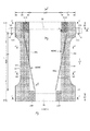
起き上がりギャザー60は、両側部に固定された付根部分65と、この付根部分65より延び出る本体部分66と、本体部分66の前端部が倒伏状態に固定されて形成された前倒伏部分67F及び本体部分66の後端部が倒伏状態に固定されて形成された後倒伏部分67Bと、本体部分66における前倒伏部分67F及び後倒伏部分67Bの間に位置する非固定の起き上がり部分68と、起き上がり部分68の少なくとも先端部に前後方向LDに沿って取り付けられたギャザー弾性部材63とを有するものである。図示例の起き上がりギャザー60は、先端で二つ折りされるとともに、表側の層が付根部分65(図示例では製品側縁)まで延び、裏側の層が本体部分66と付根部分65との境界近傍まで延びるギャザーシート62により形成されている。ギャザー弾性部材63は、このギャザーシート62における表側の層と裏側の層との間に挟まれている。なお、前倒伏部分67F及び後倒伏部分67Bは、図中の斜め格子模様を付した部分である。
The rising gather 60 includes a
ギャザーシート62としてはスパンボンド不織布(SS、SSS等)やSMS不織布(SMS、SSMMS等)、メルトブロー不織布等の柔軟で均一性・隠蔽性に優れた不織布に、必要に応じてシリコンなどにより撥水処理を施したものを好適に用いることができ、繊維目付けは10〜30g/m2程度とするのが好ましい。
The gather
ギャザー弾性部材63としては糸ゴム等の細長状の弾性部材を用いることができる。合成糸ゴムを用いる場合は、太さは470〜1240dtexが好ましく、620〜940dtexがより好ましい。固定時の伸長率は、150〜350%が好ましく、200〜300%がより好ましい。ギャザー弾性部材63は、図示例のように幅方向WDに間隔を空けて複数本設ける他、先端部に1本のみ設けることもできる。
As the gather
また、図示しないが、ギャザーシート62における表側の層と裏側の層との間に防水フィルムを介在させることもできる。
Although not shown, a waterproof film can be interposed between the front layer and the back layer of the gather
前倒伏部分67F及び後倒伏部分67Bは、ホットメルト接着剤、又はこれに代えて若しくはこれとともにヒートシールや超音波シール等の素材溶着による固定手段を用い、倒伏状態に固定することができる。同様に、付根部分65も、ホットメルト接着剤、又はこれに代えて若しくはこれとともにヒートシールや超音波シール等の素材溶着により固定することができる。
The front and
このような、起き上がりギャザー60では、付根部分65から延びる本体部分66は、前倒伏部分67F及び後倒伏部分67Bでは倒伏状態に固定されているものの、その間の部分は非固定の起き上がり部分68であり、この起き上がり部分68が弾性部材63の収縮力により収縮して起き上がり、身体表面に密着する。
In such a rising gather 60, the
特徴的には、前倒伏部分67Fは、付根部分65との境界から幅方向内側に延びる部分を有するとともに、倒伏状態で裏側に隣接する部材(図示例ではトップシート30)に固定されている。また、後倒伏部分67Bは、付根部分65との境界を折り位置60eとして幅方向外側に折り返されるとともに、裏側に隣接する部材(図示例では付根部分65のギャザーシート62)に固定されている。したがって、展開状態で起き上がり部分68に側方に捲り返る力が作用するため、図3及び図4に示すように、起き上がりギャザー60が確実に起き上がるとともに、図3及び図4と図5との関係からも分かるように、後側に向かうにつれて側方に広がりながら起き上がり高さが低くなる。この後方拡幅タイプの起き上がりギャザー60は、鼠径部から臀部まで全体にわたりフィット性が高く、特に臀部を包み込むようにフィットする利点を有する。後倒伏部分67Bは、前倒伏部分67Fの幅方向内側の縁部より幅方向外側を通る前後方向仮想線を折り位置として幅方向外側に折り返された後折り返し部分を有するとともに、この後折り返し部分が裏側に隣接する部材に固定されていてもよい。
Characteristically, the
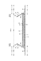
このような後方拡幅タイプの起き上がりギャザー60は、次のような製造方法により、製造ラインで連続的に製造できるようになる。すなわち、ギャザーシート62をCD方向に二つ折りするとともに、その間にギャザー弾性部材63を取り付けた起き上がりギャザー60(図3、図4参照)を形成した後、裏側の部材(図示例では、トップシート30の幅方向両端部、液不透過性シート11の幅方向両端部、外装不織布12の幅方向両端部)に取付けるに際し、図8に示すように、本体部分66を、前後方向全体にわたり前倒伏部分67Fと同じ倒伏状態としつつ(つまり、図示例では、前後方向LD全体にわたり付根部分65との境界から幅方向内側に延ばした状態で)、後倒伏部分67Bの固定を行わずに、付根部分65の固定及び前倒伏部分67Fの固定を行う(第1工程)。その後、折り位置60eよりも幅方向外側の部分70(図示例の場合、折り位置60eは本体部分66及び付根部分65の境界となるため、サイドフラップ部SFとほぼ同じ)を幅方向内側に折り返し、この折り返した部分70と後倒伏部分67Bとなる部分との重なり部分を接合する(第2工程)。なお、図8では図面を分かりやすくするために連結テープ13の図示を省略している。また、図8では、理解を容易にするために、個々の使い捨ておむつの部分の変化を示しているが、実際の製造ラインでは、使い捨ておむつの前後方向がMD方向となるように個々の使い捨ておむつとなる部分がMD方向に繰り返し連続する連続体の状態で、各工程が行われた後、個々の使い捨ておむつの境界となる部分で切断され、個々の使い捨ておむつが製造される。
Such a rear widening type rising gather 60 can be continuously manufactured on a manufacturing line by the following manufacturing method. That is, the gather
このように、第1工程では後倒伏部分67Bを固定せずにおき、第2工程で、後倒伏部分67Bの折り位置60eよりも幅方向外側の部分を幅方向内側に折り返し、この折り返した部分70と後倒伏部分67Bとなる部分との重なり部分を接合すると、図9に示すように、その後に折り返した部分70を展開するだけで、後方拡幅タイプの起き上がりギャザー60を有するものとなる。しかも、製造過程では、起き上がりギャザー60の後倒伏部分67Bを幅方向外側に折り返さなくてよいため、起き上がりギャザー60の前端の幅方向WDの位置と後端の幅方向WDの位置とが同じになる。この結果、上記第1工程及び第2工程を行うだけで、それ以外は従来と同様の製造方法により製造ラインで連続的に製造することができる。
In this way, in the first step, the rear-falling
第2工程における折り返しを容易にするために、折り位置60eはサイドフラップ部SFに位置していることが好ましく、特にサイドフラップ部SFの幅方向WD内側の端部に位置していることが好ましい。
In order to facilitate the folding in the second step, the
折り位置60eよりも幅方向外側の部分の幅方向寸法70Wは適宜定めればよいが、少なくとも第2工程における折り返しの前の状態で、一方の起き上がりギャザー60における折り位置60eよりも幅方向外側の部分の幅方向寸法70Wと、他方の起き上がりギャザー60における折り位置60eよりも幅方向外側の部分の幅方向寸法70Wとの和が、一方の起き上がりギャザー60における折り位置60eと、他方の起き上がりギャザー60における折り位置60eとの、幅方向間隔70D以下であると、第2工程での折り返しの際、折り返した部分同士が重なることがなく、接合が容易となるため好ましい。なお、図示例のようなテープタイプ使い捨ておむつの場合、第2工程における折り返しの前の状態で連結テープ13のテープ本体部13Bがテープ取付部13C側に折り畳まれているか否かで、起き上がりギャザー60における折り位置60eよりも幅方向外側の部分の幅方向寸法70Wは変化する。よって、第2工程における折り返しに先立って連結テープ13がテープ取付部13C側に折り畳まれていることが望ましい。
The
ホットメルト接着剤等の接着剤により第2工程における接合を行う場合、図示例のように折り返しに先立ち、付根部分65における後倒伏部分67Bとなる部分と重なる部位にホットメルト接着剤等の接着剤HMを塗布した後、折り返しを行うことにより(折り返しを利用して)、折り返した部分70と後倒伏部分67Bとなる部分との重なり部分を接合すると、接着剤HMの塗布位置が多少ずれても、起き上がりギャザー60より幅方向内側に塗布してしまうことがない。
When joining in the second step with an adhesive such as a hot melt adhesive, an adhesive such as a hot melt adhesive is overlapped with a portion of the
例えばテープタイプ使い捨ておむつやパッドタイプ使い捨ておむつ等の使い捨て着用物品では、幅方向両端部を折り返した後に、必要に応じて前後方向LDに2つ折り、3つ折り、4つ折り等した状態で製品を包装し、販売することが一般的である。よって、図9に示すように、第2工程での接合の後、折り返した部分70を展開せずに、前後方向LDに折り畳むことにより、第2工程での折り返しを、販売形態への折り畳みを兼ねて行うことができ、製造工程を簡素化することができる。このようにして製造される製品は、後倒伏部分67Bの折り位置60eで、それよりも幅方向外側の部分70が幅方向内側に折り返されたものとなる。
For example, in disposable wearing articles such as tape-type disposable diapers and pad-type disposable diapers, after folding both ends in the width direction, the product is packaged in a folded state in the front-rear direction LD as necessary, folded in three, folded in four, etc. It is common to sell. Therefore, as shown in FIG. 9, after joining in the second step, the folded
他方、上記例では、前後方向LDの中間で起き上がり部分68の先端がねじれる(起き上がり方向が内側から外側に変化する)ため、装着者によっては装着感が悪いと感じるおそれがある。そこで、図10〜図13に示す例も提案する。すなわち、この例では、前倒伏部分67Fは、付根部分65との境界から幅方向WD内側に延びる第1部分60Aと、この第1部分60Aの先端で幅方向外側に折り返された第2部分60Bとを有するとともに、第1部分60A及び第2部分60Bが倒伏状態で裏側に隣接する部材(図示例ではトップシート30)に対して固定されている。一方、後倒伏部分67Bは、第1部分60Aと対応する第3部分60C及び第2部分60Bと対応する第4部分60Dを有しているとともに、第3部分60C及び第4部分60Dが折り畳まれた状態で折り位置60eで幅方向外側に折り返されて、付根部分65のギャザーシート62に固定されることにより、後折り返し部分が形成されている。
On the other hand, in the above example, the tip of the rising
この起き上がりギャザー60では、前倒伏部分67Fは第1部分60A及び第2部分60Bを有する屈曲形態となっており、後倒伏部分67Bは第3部分60C及び第4部分60Dが折り畳まれた状態で折り返されているため、前後方向LDの中間で起き上がり部分68の先端がねじれる(起き上がり方向が内側から外側に変化する)ことがなく、装着感の悪化のおそれがないものとなる。
In the rising gather 60, the forward-falling
<明細書中の用語の説明>
明細書中の以下の用語は、明細書中に特に記載が無い限り、以下の意味を有するものである。
・「前後(縦)方向LD」とは腹側(前側)と背側(後側)を結ぶ方向を意味し、「幅方向WD」とは前後方向と直交する方向(左右方向)を意味する。
<Explanation of terms in the specification>
The following terms in the specification have the following meanings unless otherwise specified in the specification.
The “front / rear (vertical) direction LD” means a direction connecting the ventral side (front side) and the back side (rear side), and the “width direction WD” means a direction (left / right direction) orthogonal to the front / rear direction. .
・「MD方向」及び「CD方向」とは、製造ラインにおける流れ方向(MD方向)及びこれと直交する横方向(CD方向)を意味する。 “MD direction” and “CD direction” mean a flow direction (MD direction) in a production line and a transverse direction (CD direction) perpendicular thereto.
・「展開状態」とは、収縮や弛み無く平坦に展開した状態を意味する。 -"Developed state" means a state where the plate is flattened without contraction or slack.
・「伸長率」は、自然長を100%としたときの値を意味する。 “Elongation rate” means a value when the natural length is 100%.
・「ゲル強度」は次のようにして測定されるものである。人工尿(尿素:2wt%、塩化ナトリウム:0.8wt%、塩化カルシウム二水和物:0.03wt%、硫酸マグネシウム七水和物:0.08wt%、及びイオン交換水:97.09wt%)49.0gに、高吸収性ポリマーを1.0g加え、スターラーで攪拌させる。生成したゲルを40℃×60%RHの恒温恒湿槽内に3時間放置したあと常温にもどし、カードメーター(I.techno Engineering社製:Curdmeter−MAX ME−500)でゲル強度を測定する。 -"Gel strength" is measured as follows. Artificial urine (urea: 2 wt%, sodium chloride: 0.8 wt%, calcium chloride dihydrate: 0.03 wt%, magnesium sulfate heptahydrate: 0.08 wt%, and ion-exchanged water: 97.09 wt%) To 49.0 g, 1.0 g of a superabsorbent polymer is added and stirred with a stirrer. The produced gel is left in a constant temperature and humidity chamber of 40 ° C. × 60% RH for 3 hours and then returned to room temperature, and the gel strength is measured with a card meter (Curdmeter-MAX ME-500, manufactured by I.techno Engineering).
・「目付け」は次のようにして測定されるものである。試料又は試験片を予備乾燥した後、標準状態(試験場所は、温度23±1℃、相対湿度50±2%)の試験室又は装置内に放置し、恒量になった状態にする。予備乾燥は、試料又は試験片を温度100℃の環境で恒量にすることをいう。なお、公定水分率が0.0%の繊維については、予備乾燥を行わなくてもよい。恒量になった状態の試験片から、試料採取用の型板(100mm×100mm)を使用し、100mm×100mmの寸法の試料を切り取る。試料の重量を測定し、10倍して1平米あたりの重さを算出し、目付けとする。
・ "Weight" is measured as follows. After the sample or test piece has been pre-dried, it is left in a test room or apparatus in a standard state (test location is temperature 23 ± 1 ° C.,
・「厚み」は、自動厚み測定器(KES−G5 ハンディー圧縮試験機)を用い、荷重:0.098N/cm2、及び加圧面積:2cm2の条件下で自動測定する。 -"Thickness" is automatically measured using an automatic thickness measuring instrument (KES-G5 handy compression tester) under conditions of load: 0.098 N / cm 2 and pressure area: 2 cm 2 .
・「吸水量」は、JIS K7223−1996「高吸水性樹脂の吸水量試験方法」によって測定する。 -"Water absorption" is measured by JIS K7223-1996 "Test method for water absorption of superabsorbent resin".
・「吸水速度」は、2gの高吸収性ポリマー及び50gの生理食塩水を使用して、JIS K7224‐1996「高吸水性樹脂の吸水速度試験法」を行ったときの「終点までの時間」とする。 ・ "Water absorption rate" is "Time to end point" when JIS K7224-1996 "Water absorption rate test method for superabsorbent resin" is performed using 2 g of superabsorbent polymer and 50 g of physiological saline. And
・試験や測定における環境条件についての記載が無い場合、その試験や測定は、標準状態(試験場所は、温度23±1℃、相対湿度50±2%)の試験室又は装置内で行うものとする。
・ If there is no description about the environmental conditions in the test and measurement, the test and measurement shall be performed in a test room or equipment in the standard state (test location: temperature 23 ± 1 ° C,
・各部の寸法は、特に記載が無い限り、自然長状態ではなく展開状態における寸法を意味する。 -Unless otherwise specified, the dimensions of each part mean dimensions in a deployed state, not a natural length state.
本発明は、上記例のようなテープタイプ使い捨ておむつの他、パンツタイプ使い捨ておむつやパッドタイプ使い捨ておむつ等、使い捨ておむつ全般に適用できるものであり、また、生理用ナプキン等の他の吸収性物品にも適用できることはいうまでもない。 The present invention is applicable to general disposable diapers such as pants-type disposable diapers and pad-type disposable diapers in addition to tape-type disposable diapers as in the above examples, and also to other absorbent articles such as sanitary napkins. It goes without saying that can also be applied.
11…液不透過性シート、12…外装不織布、13…連結テープ、13A…連結部、13B…テープ本体部、13C…テープ取付部、20…ターゲットシート、30…トップシート、40間シート、50…吸収要素、56…吸収体、58…包装シート、60…起き上がりギャザー、60e…折り位置、62…ギャザーシート、63…ギャザー弾性部材、65…付根部分、66…本体部分、67F…前倒伏部分、67B…後倒伏部分、68…起き上がり部分、B…背側部分、F…腹側部分、WD…幅方向、LD…前後方向、SF…サイドフラップ部、60A…第1部分、60B…第2部分、60C…第3部分、60D…第4部分。
DESCRIPTION OF
Claims (6)
前記起き上がりギャザーは、使い捨て着用物品に固定された付根部分と、この付根部分より延び出る本体部分と、前記本体部分の前端部が倒伏状態に固定されて形成された前倒伏部分及び前記本体部分の後端部が倒伏状態に固定されて形成された後倒伏部分と、前記本体部分における前記前倒伏部分及び後倒伏部分の間に位置する非固定の起き上がり部分と、前記起き上がり部分の少なくとも先端部に前後方向に沿って取り付けられたギャザー弾性部材とを有し、
前記前倒伏部分は、前記付根部分との境界から幅方向内側に延びる部分を有するとともに、倒伏状態で裏側に隣接する部材に固定されており、
前記後倒伏部分は、前記前倒伏部分の幅方向内側の縁部より幅方向外側を通る前後方向仮想線又は前記付根部分との境界を折り位置として幅方向外側に折り返された後折り返し部分を有するとともに、前記後折り返し部分はその裏側に隣接する部材に固定されている、
使い捨て着用物品の製造方法において、
前記起き上がりギャザーの取り付けに際し、
前記本体部分を、前後方向全体にわたり前倒伏部分と同じ倒伏状態としつつ、前記後倒伏部分の固定を行わずに、前記付根部分の固定及び前倒伏部分の固定を行う、第1工程と、
前記折り位置よりも幅方向外側の部分を幅方向内側に折り返し、この折り返した部分と前記後倒伏部分となる部分との重なり部分を接合する、第2工程とを行う、
ことを特徴とする、使い捨て着用物品の製造方法。 Both sides of the width direction are each equipped with rising gathers that rise from the surface,
The rising gather includes a root portion fixed to the disposable wearing article, a main body portion extending from the root portion, a front lodging portion formed by fixing a front end portion of the main body portion in a lying state, and the main body portion. A rear lodging portion formed with a rear end portion fixed in a lying state, a non-fixed rising portion located between the front and rear falling portions in the main body portion, and at least a tip portion of the rising portion A gathered elastic member attached along the front-rear direction,
The front lodging portion has a portion extending inward in the width direction from the boundary with the root portion, and is fixed to a member adjacent to the back side in a lying state,
The rear lodging portion has a rear folded portion that is folded back outward in the width direction with a boundary with the front-rear direction imaginary line passing through the width direction outer side or the root portion as a folding position from the inner edge in the width direction of the front lodging portion. And the rear folded portion is fixed to a member adjacent to the back side thereof,
In the method for producing disposable wearing articles,
When installing the rising gather,
A first step of fixing the base portion and fixing the front lodging portion without fixing the rear falling portion while keeping the main body portion in the same lying state as the front falling portion over the entire front-rear direction,
A second step is performed in which a portion on the outer side in the width direction than the folding position is folded back inward in the width direction, and an overlapping portion between the folded portion and the portion that becomes the rearward lying portion is joined.
The manufacturing method of the disposable wearing article characterized by the above-mentioned.
一方の前記起き上がりギャザーにおける前記折り位置よりも幅方向外側の部分の幅方向寸法と、他方の前記起き上がりギャザーにおける前記折り位置よりも幅方向外側の部分の幅方向寸法との和が、
一方の前記起き上がりギャザーにおける前記折り位置と、他方の前記起き上がりギャザーにおける前記折り位置との、幅方向間隔以下である、
請求項1記載の使い捨て着用物品の製造方法。 At least in a state before the folding in the second step,
The sum of the width direction dimension of the portion outside in the width direction from the folding position in the one rising gather and the width direction dimension of the portion outside in the width direction from the folding position in the other rising gather,
The folding position in one rising gather and the folding position in the other rising gather are equal to or less than the width direction interval.
The manufacturing method of the disposable wearing article of Claim 1.
請求項1又は2記載の使い捨て着用物品の製造方法。 In the second step, prior to the folding, after applying an adhesive to a portion of the root portion that overlaps with the portion that becomes the rearwardly lying portion, the folded portion is performed to become the folded portion and the rearwardly lying portion. Join the overlapping part with the part,
The manufacturing method of the disposable wearing article of Claim 1 or 2.
請求項1〜3のいずれか1項に記載の使い捨て着用物品の製造方法。 After the joining in the second step, fold in the front-rear direction without unfolding the folded portion,
The manufacturing method of the disposable wearing article of any one of Claims 1-3.
前記起き上がりギャザーは、使い捨て着用物品に固定された付根部分と、この付根部分より延び出る本体部分と、前記本体部分の前端部が倒伏状態に固定されて形成された前倒伏部分及び前記本体部分の後端部が倒伏状態に固定されて形成された後倒伏部分と、前記本体部分における前記前倒伏部分及び後倒伏部分の間に位置する非固定の起き上がり部分と、前記起き上がり部分の少なくとも先端部に前後方向に沿って取り付けられたギャザー弾性部材とを有し、
前記前倒伏部分は、前記付根部分との境界から幅方向内側に延びる部分を有するとともに、倒伏状態で裏側に隣接する部材に固定されており、
前記後倒伏部分は、前記付根部分との境界又は前記前倒伏部分の幅方向内側の縁部より幅方向外側を通る前後方向仮想線を折り位置として幅方向外側に折り返された後折り返し部分を有するとともに、前記後折り返し部分はその裏側に隣接する部材に固定されている、
使い捨て着用物品において、
製品状態では、前記折り位置で、それよりも幅方向外側の部分が幅方向内側に折り返されている、
ことを特徴とする、使い捨て着用物品。 Both sides of the width direction are each equipped with rising gathers that rise from the surface,
The rising gather includes a root portion fixed to the disposable wearing article, a main body portion extending from the root portion, a front lodging portion formed by fixing a front end portion of the main body portion in a lying state, and the main body portion. A rear lodging portion formed with a rear end portion fixed in a lying state, a non-fixed rising portion located between the front and rear falling portions in the main body portion, and at least a tip portion of the rising portion A gathered elastic member attached along the front-rear direction,
The front lodging portion has a portion extending inward in the width direction from the boundary with the root portion, and is fixed to a member adjacent to the back side in a lying state,
The rear lodging portion includes a rear folded portion that is folded back outward in the width direction with a front-rear direction imaginary line passing through the outer side in the width direction from the boundary with the root portion or the inner edge in the width direction of the front lodging portion. And the rear folded portion is fixed to a member adjacent to the back side thereof,
In disposable wearing articles,
In the product state, at the folding position, the outer portion in the width direction is folded back inward in the width direction.
A disposable wearing article characterized by the above.
前記後倒伏部分は、前記第1部分と対応する第3部分及び前記第2部分と対応する第4部分を有しているとともに、前記第3部分及び第4部分が折り畳まれた状態で前記折り位置で幅方向外側に折り返されて、前記後折り返し部分が形成されている、
請求項5記載の使い捨て着用物品。 The forward lodging portion includes a first portion extending inward in the width direction from the boundary with the root portion, and a second portion folded back outward in the width direction at the tip of the first portion, and the first portion and the first portion Two parts are fixed to the member adjacent to the back side in the lying state,
The rear-falling part has a third part corresponding to the first part and a fourth part corresponding to the second part, and the folding part in a state where the third part and the fourth part are folded. Folded back outward in the width direction at the position, the rear folded portion is formed,
The disposable wearing article according to claim 5.
Priority Applications (1)
| Application Number | Priority Date | Filing Date | Title |
|---|---|---|---|
| JP2017182120A JP2019055090A (en) | 2017-09-22 | 2017-09-22 | Method for manufacturing disposable wearing article and disposable wearing article |
Applications Claiming Priority (1)
| Application Number | Priority Date | Filing Date | Title |
|---|---|---|---|
| JP2017182120A JP2019055090A (en) | 2017-09-22 | 2017-09-22 | Method for manufacturing disposable wearing article and disposable wearing article |
Publications (2)
| Publication Number | Publication Date |
|---|---|
| JP2019055090A true JP2019055090A (en) | 2019-04-11 |
| JP2019055090A5 JP2019055090A5 (en) | 2020-09-10 |
Family
ID=66106417
Family Applications (1)
| Application Number | Title | Priority Date | Filing Date |
|---|---|---|---|
| JP2017182120A Pending JP2019055090A (en) | 2017-09-22 | 2017-09-22 | Method for manufacturing disposable wearing article and disposable wearing article |
Country Status (1)
| Country | Link |
|---|---|
| JP (1) | JP2019055090A (en) |
Citations (3)
| Publication number | Priority date | Publication date | Assignee | Title |
|---|---|---|---|---|
| JPH10501715A (en) * | 1994-06-16 | 1998-02-17 | ザ、プロクター、エンド、ギャンブル、カンパニー | Manufacturing method for manufacturing an absorbent product having a folded barrier leg cuff |
| JP2009056141A (en) * | 2007-08-31 | 2009-03-19 | Daio Paper Corp | Disposable paper diaper and manufacturing method thereof |
| JP2014147424A (en) * | 2013-01-31 | 2014-08-21 | Daio Paper Corp | Absorbent article |
-
2017
- 2017-09-22 JP JP2017182120A patent/JP2019055090A/en active Pending
Patent Citations (3)
| Publication number | Priority date | Publication date | Assignee | Title |
|---|---|---|---|---|
| JPH10501715A (en) * | 1994-06-16 | 1998-02-17 | ザ、プロクター、エンド、ギャンブル、カンパニー | Manufacturing method for manufacturing an absorbent product having a folded barrier leg cuff |
| JP2009056141A (en) * | 2007-08-31 | 2009-03-19 | Daio Paper Corp | Disposable paper diaper and manufacturing method thereof |
| JP2014147424A (en) * | 2013-01-31 | 2014-08-21 | Daio Paper Corp | Absorbent article |
Similar Documents
| Publication | Publication Date | Title |
|---|---|---|
| JP6065290B2 (en) | Method for forming stretchable structure of absorbent article, and stretchable structure of absorbent article | |
| JP6362250B2 (en) | Absorbent articles | |
| JP6449500B1 (en) | Stretch structure of disposable wearing article, and pants-type disposable wearing article having this stretchable structure | |
| WO2019188565A1 (en) | Stretchable structure for disposable wearable article and underpants-type disposable wearable article having stretchable structure | |
| WO2019188562A1 (en) | Stretchable structure for disposable wearable article and underpants-type disposable wearable article having stretchable structure | |
| JP2017164034A (en) | Stretching structure of absorbent article, and pants-type disposable diaper | |
| JP2019170730A (en) | Underpants type disposable clothing article | |
| JP2019146918A (en) | Disposable wearing article | |
| JP6495506B1 (en) | Stretch structure of disposable wearing article, and pants-type disposable wearing article having this stretchable structure | |
| JP6654671B2 (en) | Elastic structure of disposable wearing article, and pants-type disposable wearing article having this elastic structure | |
| JP6332752B2 (en) | Tape type disposable diaper | |
| JP2016067501A5 (en) | ||
| JP6488040B1 (en) | Tape type disposable diaper | |
| WO2019188564A1 (en) | Stretchable structure for disposable wearable article and underpants-type disposable wearable article having stretchable structure | |
| JP2019055090A (en) | Method for manufacturing disposable wearing article and disposable wearing article | |
| JP6452777B1 (en) | Absorbent article and manufacturing method thereof | |
| JP2019058547A (en) | Underpants type disposable diaper and manufacturing method for the same | |
| JP2019054939A (en) | Underpants type disposable diaper | |
| JP6633729B2 (en) | Tape type disposable diapers | |
| JP7129179B2 (en) | Elastic structure of absorbent article | |
| JP6910912B2 (en) | Tape type disposable diapers and their manufacturing methods | |
| JP2019150404A (en) | Tape type disposable diaper | |
| WO2019188560A1 (en) | Stretchable structure for disposable wearable article and underpants-type disposable wearable article having stretchable structure | |
| JP2019162363A (en) | Tape type disposable diaper | |
| JP6601795B2 (en) | Disposable diapers |
Legal Events
| Date | Code | Title | Description |
|---|---|---|---|
| A521 | Request for written amendment filed |
Free format text: JAPANESE INTERMEDIATE CODE: A523 Effective date: 20200728 |
|
| A621 | Written request for application examination |
Free format text: JAPANESE INTERMEDIATE CODE: A621 Effective date: 20200728 |
|
| A977 | Report on retrieval |
Free format text: JAPANESE INTERMEDIATE CODE: A971007 Effective date: 20210720 |
|
| A131 | Notification of reasons for refusal |
Free format text: JAPANESE INTERMEDIATE CODE: A131 Effective date: 20210827 |
|
| A521 | Request for written amendment filed |
Free format text: JAPANESE INTERMEDIATE CODE: A523 Effective date: 20210927 |
|
| A02 | Decision of refusal |
Free format text: JAPANESE INTERMEDIATE CODE: A02 Effective date: 20220218 |