JP2019015520A - 電流測定装置 - Google Patents
電流測定装置 Download PDFInfo
- Publication number
- JP2019015520A JP2019015520A JP2017130591A JP2017130591A JP2019015520A JP 2019015520 A JP2019015520 A JP 2019015520A JP 2017130591 A JP2017130591 A JP 2017130591A JP 2017130591 A JP2017130591 A JP 2017130591A JP 2019015520 A JP2019015520 A JP 2019015520A
- Authority
- JP
- Japan
- Prior art keywords
- circuit board
- case
- shunt resistor
- current
- conductor
- Prior art date
- Legal status (The legal status is an assumption and is not a legal conclusion. Google has not performed a legal analysis and makes no representation as to the accuracy of the status listed.)
- Granted
Links
- 239000004020 conductor Substances 0.000 claims abstract description 25
- 238000005259 measurement Methods 0.000 claims description 2
- 238000001514 detection method Methods 0.000 description 36
- 238000010586 diagram Methods 0.000 description 6
- 238000000034 method Methods 0.000 description 5
- 239000010949 copper Substances 0.000 description 2
- 238000003780 insertion Methods 0.000 description 2
- 230000037431 insertion Effects 0.000 description 2
- 239000000463 material Substances 0.000 description 2
- 239000002184 metal Substances 0.000 description 2
- 229910052751 metal Inorganic materials 0.000 description 2
- 239000011347 resin Substances 0.000 description 2
- 229920005989 resin Polymers 0.000 description 2
- 238000003466 welding Methods 0.000 description 2
- RYGMFSIKBFXOCR-UHFFFAOYSA-N Copper Chemical compound [Cu] RYGMFSIKBFXOCR-UHFFFAOYSA-N 0.000 description 1
- 229910017566 Cu-Mn Inorganic materials 0.000 description 1
- 229910002482 Cu–Ni Inorganic materials 0.000 description 1
- 229910017871 Cu—Mn Inorganic materials 0.000 description 1
- 229910018487 Ni—Cr Inorganic materials 0.000 description 1
- 230000004308 accommodation Effects 0.000 description 1
- 238000005219 brazing Methods 0.000 description 1
- 229910052802 copper Inorganic materials 0.000 description 1
- 238000012937 correction Methods 0.000 description 1
- 230000000694 effects Effects 0.000 description 1
- 238000010894 electron beam technology Methods 0.000 description 1
- 230000020169 heat generation Effects 0.000 description 1
- 238000002347 injection Methods 0.000 description 1
- 239000007924 injection Substances 0.000 description 1
- 238000009434 installation Methods 0.000 description 1
- 238000005304 joining Methods 0.000 description 1
- 239000000203 mixture Substances 0.000 description 1
- 238000012986 modification Methods 0.000 description 1
- 230000004048 modification Effects 0.000 description 1
- 238000012545 processing Methods 0.000 description 1
- 238000007789 sealing Methods 0.000 description 1
Images


Classifications
-
- G—PHYSICS
- G01—MEASURING; TESTING
- G01R—MEASURING ELECTRIC VARIABLES; MEASURING MAGNETIC VARIABLES
- G01R19/00—Arrangements for measuring currents or voltages or for indicating presence or sign thereof
- G01R19/145—Indicating the presence of current or voltage
- G01R19/155—Indicating the presence of voltage
-
- G—PHYSICS
- G01—MEASURING; TESTING
- G01R—MEASURING ELECTRIC VARIABLES; MEASURING MAGNETIC VARIABLES
- G01R1/00—Details of instruments or arrangements of the types included in groups G01R5/00 - G01R13/00 and G01R31/00
- G01R1/20—Modifications of basic electric elements for use in electric measuring instruments; Structural combinations of such elements with such instruments
-
- G—PHYSICS
- G01—MEASURING; TESTING
- G01R—MEASURING ELECTRIC VARIABLES; MEASURING MAGNETIC VARIABLES
- G01R19/00—Arrangements for measuring currents or voltages or for indicating presence or sign thereof
- G01R19/0046—Arrangements for measuring currents or voltages or for indicating presence or sign thereof characterised by a specific application or detail not covered by any other subgroup of G01R19/00
- G01R19/0053—Noise discrimination; Analog sampling; Measuring transients
-
- G—PHYSICS
- G01—MEASURING; TESTING
- G01R—MEASURING ELECTRIC VARIABLES; MEASURING MAGNETIC VARIABLES
- G01R31/00—Arrangements for testing electric properties; Arrangements for locating electric faults; Arrangements for electrical testing characterised by what is being tested not provided for elsewhere
- G01R31/36—Arrangements for testing, measuring or monitoring the electrical condition of accumulators or electric batteries, e.g. capacity or state of charge [SoC]
- G01R31/364—Battery terminal connectors with integrated measuring arrangements
-
- G—PHYSICS
- G01—MEASURING; TESTING
- G01R—MEASURING ELECTRIC VARIABLES; MEASURING MAGNETIC VARIABLES
- G01R1/00—Details of instruments or arrangements of the types included in groups G01R5/00 - G01R13/00 and G01R31/00
- G01R1/20—Modifications of basic electric elements for use in electric measuring instruments; Structural combinations of such elements with such instruments
- G01R1/203—Resistors used for electric measuring, e.g. decade resistors standards, resistors for comparators, series resistors, shunts
Landscapes
- Physics & Mathematics (AREA)
- General Physics & Mathematics (AREA)
- Measuring Instrument Details And Bridges, And Automatic Balancing Devices (AREA)
- Measurement Of Current Or Voltage (AREA)
Abstract
Description
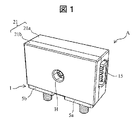
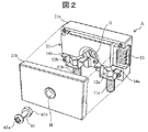
図1は、本実施の形態による電流測定装置の外観構成例を示す斜視図である。図2は、図1の電流測定装置において、回路基板を収容するケース(カバー部材、モジュールボックス)21のうち、裏面側ケース21aから表面側ケース21bを取り外して回路基板を含む内部構造を見えるようにした状態の外観構成例を示す斜視図である。図3は、図2において、回路基板31を取り外した際の裏面側ケース21aを含む外観構成例を示す斜視図である。
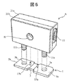
接続構造については、図5も参照して後述する。
第1および第2の電極5a,5b部分には、それぞれ孔7a,7bが形成されている。そして、ネジ11a,11bが孔7a,7bに挿通される。ネジ11a,11bのシャント抵抗器1への固定方法は、圧入であったり、溶接であったりしても良い。
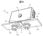
図9は、本実施の形態による電流検出装置の外観構成例を示す斜視図である。図10は、図9に示す電流検出装置をバスバーに実装した外観構成例を示す斜視図である。図11は、図10の構造を底面側から見た斜視図である。図12は、本実施の形態による電流測定装置の斜視図であり、表面側ケース21bを本体部から取り外して回路基板を含む内部構造を見えるようにした外観構成例を示す斜視図である。
1…抵抗器(導体)
3…抵抗体
5a、5b…第1および第2の電極(一対の端子部)
11a、11b…ネジ(ボルト)
17a、17b…電圧検出端子
21…ケース(カバー部材)
31…回路基板
41…温度検出素子
45、47…配線
53、55、57…電子部品
Claims (5)
- 電流を測定するための電流測定装置であって、
電流を流す導体と、
前記導体から電圧信号を取り出すための配線を備えた回路基板と、
前記回路基板を収容するカバー部材と、
前記カバー部材に設けられた第1固定手段と、
前記第1固定手段と組み合わせ固定される第2固定手段と、を備え、
前記導体は、前記第1固定手段と前記第2固定手段との間に装着された、
電流測定装置。 - 前記回路基板は、前記導体に対して立設されている
請求項1に記載の電流測定装置。 - 前記回路基板は、前記導体の面内に収まっている
請求項1又は2に記載の電流測定装置。 - 前記導体には一対の端子が立設されており、
前記回路基板の配線と、前記一対の端子とが接続されている
請求項1から3までのいずれか1項に記載の電流測定装置。 - 前記第1固定手段と前記第2固定手段との間には、バスバーを介在させる
請求項1から4までのいずれか1項に記載の電流測定装置。
Priority Applications (5)
| Application Number | Priority Date | Filing Date | Title |
|---|---|---|---|
| JP2017130591A JP7082459B2 (ja) | 2017-07-03 | 2017-07-03 | 電流測定装置 |
| CN201880043191.6A CN110799845B (zh) | 2017-07-03 | 2018-06-25 | 电流测定装置 |
| PCT/JP2018/023931 WO2019009112A1 (ja) | 2017-07-03 | 2018-06-25 | 電流測定装置 |
| DE112018003411.9T DE112018003411T5 (de) | 2017-07-03 | 2018-06-25 | Strommessvorrichtung |
| US16/624,640 US11061054B2 (en) | 2017-07-03 | 2018-06-25 | Current measuring device |
Applications Claiming Priority (1)
| Application Number | Priority Date | Filing Date | Title |
|---|---|---|---|
| JP2017130591A JP7082459B2 (ja) | 2017-07-03 | 2017-07-03 | 電流測定装置 |
Publications (2)
| Publication Number | Publication Date |
|---|---|
| JP2019015520A true JP2019015520A (ja) | 2019-01-31 |
| JP7082459B2 JP7082459B2 (ja) | 2022-06-08 |
Family
ID=64950890
Family Applications (1)
| Application Number | Title | Priority Date | Filing Date |
|---|---|---|---|
| JP2017130591A Active JP7082459B2 (ja) | 2017-07-03 | 2017-07-03 | 電流測定装置 |
Country Status (5)
| Country | Link |
|---|---|
| US (1) | US11061054B2 (ja) |
| JP (1) | JP7082459B2 (ja) |
| CN (1) | CN110799845B (ja) |
| DE (1) | DE112018003411T5 (ja) |
| WO (1) | WO2019009112A1 (ja) |
Families Citing this family (3)
| Publication number | Priority date | Publication date | Assignee | Title |
|---|---|---|---|---|
| KR102312332B1 (ko) * | 2018-12-18 | 2021-10-12 | 주식회사 엘지에너지솔루션 | 나사 체결 구조를 갖는 션트 저항 모듈 |
| DE102021104163A1 (de) | 2021-02-22 | 2022-08-25 | HELLA GmbH & Co. KGaA | Anschlusselement und Verfahren zur Herstellung eines Anschlusselementes, Batterie und Fahrzeug |
| EP4231023A1 (en) * | 2022-02-17 | 2023-08-23 | Fico Triad, S.A. | Current sensor for motor vehicles, power supply system comprising the current sensor and assembly method of the current sensor |
Citations (6)
| Publication number | Priority date | Publication date | Assignee | Title |
|---|---|---|---|---|
| US20050057865A1 (en) * | 2003-07-25 | 2005-03-17 | Midtronics, Inc. | Shunt connection to a PCB of an energy management system employed in an automotive vehicle |
| JP2005127832A (ja) * | 2003-10-23 | 2005-05-19 | Auto Network Gijutsu Kenkyusho:Kk | 電圧降下式電流計測装置 |
| JP2005188935A (ja) * | 2003-12-24 | 2005-07-14 | Auto Network Gijutsu Kenkyusho:Kk | 電圧降下式電流計測装置 |
| JP2010236981A (ja) * | 2009-03-31 | 2010-10-21 | Furukawa Electric Co Ltd:The | バッテリ状態検知センサ装置 |
| JP2013174555A (ja) * | 2012-02-27 | 2013-09-05 | Furukawa Electric Co Ltd:The | 電池状態検出装置 |
| JP2015017832A (ja) * | 2013-07-09 | 2015-01-29 | コーア株式会社 | 電流検出装置 |
Family Cites Families (7)
| Publication number | Priority date | Publication date | Assignee | Title |
|---|---|---|---|---|
| DE102004049251A1 (de) * | 2004-09-30 | 2006-04-06 | Robert Bosch Gmbh | Gerät zum Ermitteln von elektrischen Größen |
| US7381101B2 (en) * | 2006-08-25 | 2008-06-03 | Lear Corporation | Battery post connector |
| JP2013015425A (ja) * | 2011-07-05 | 2013-01-24 | Sumitomo Wiring Syst Ltd | 電流検出装置 |
| WO2013015219A1 (ja) * | 2011-07-22 | 2013-01-31 | コーア株式会社 | シャント抵抗装置 |
| KR101890618B1 (ko) * | 2012-07-09 | 2018-08-22 | 현대모비스 주식회사 | 클램프 터미널 및 클램프 터미널을 구비한 배터리 센서 모듈 |
| EP2942631B1 (en) * | 2014-04-28 | 2024-03-06 | TYCO ELECTRONICS AMP KOREA Co., Ltd. | Hybrid current sensor assembly |
| CN204330860U (zh) * | 2014-12-08 | 2015-05-13 | 北京柏艾斯科技有限公司 | 一种应用于电焊机的单电源asic电流传感器 |
-
2017
- 2017-07-03 JP JP2017130591A patent/JP7082459B2/ja active Active
-
2018
- 2018-06-25 WO PCT/JP2018/023931 patent/WO2019009112A1/ja active Application Filing
- 2018-06-25 US US16/624,640 patent/US11061054B2/en active Active
- 2018-06-25 CN CN201880043191.6A patent/CN110799845B/zh active Active
- 2018-06-25 DE DE112018003411.9T patent/DE112018003411T5/de active Pending
Patent Citations (6)
| Publication number | Priority date | Publication date | Assignee | Title |
|---|---|---|---|---|
| US20050057865A1 (en) * | 2003-07-25 | 2005-03-17 | Midtronics, Inc. | Shunt connection to a PCB of an energy management system employed in an automotive vehicle |
| JP2005127832A (ja) * | 2003-10-23 | 2005-05-19 | Auto Network Gijutsu Kenkyusho:Kk | 電圧降下式電流計測装置 |
| JP2005188935A (ja) * | 2003-12-24 | 2005-07-14 | Auto Network Gijutsu Kenkyusho:Kk | 電圧降下式電流計測装置 |
| JP2010236981A (ja) * | 2009-03-31 | 2010-10-21 | Furukawa Electric Co Ltd:The | バッテリ状態検知センサ装置 |
| JP2013174555A (ja) * | 2012-02-27 | 2013-09-05 | Furukawa Electric Co Ltd:The | 電池状態検出装置 |
| JP2015017832A (ja) * | 2013-07-09 | 2015-01-29 | コーア株式会社 | 電流検出装置 |
Also Published As
| Publication number | Publication date |
|---|---|
| CN110799845A (zh) | 2020-02-14 |
| DE112018003411T5 (de) | 2020-03-12 |
| WO2019009112A1 (ja) | 2019-01-10 |
| US11061054B2 (en) | 2021-07-13 |
| JP7082459B2 (ja) | 2022-06-08 |
| CN110799845B (zh) | 2022-02-22 |
| US20200182914A1 (en) | 2020-06-11 |
Similar Documents
| Publication | Publication Date | Title |
|---|---|---|
| JP6982728B2 (ja) | バッテリーセンサー装置 | |
| US10969408B2 (en) | Current measuring device | |
| JP5817508B2 (ja) | 電流検出装置 | |
| US9086440B2 (en) | Current sensor | |
| JP4381845B2 (ja) | ヒューズモジュール | |
| US10641798B2 (en) | Current detection device having a fixing portion formed in a wiring member | |
| JP2019015520A (ja) | 電流測定装置 | |
| CN107534123B (zh) | 电池状态探测装置及其制造方法 | |
| WO2014203492A1 (ja) | バッテリー状態検知装置 | |
| KR20160026818A (ko) | 배터리 상태 검지 장치 및, 그의 제조 방법 | |
| WO2014129349A1 (ja) | ヒュージブルリンク | |
| JP5859814B2 (ja) | 電流検出装置 | |
| WO2018055958A1 (ja) | 電流測定装置 | |
| JP5144577B2 (ja) | シャント抵抗装置 | |
| JP5590699B2 (ja) | 電流検出装置の組付け構造 | |
| JP5174071B2 (ja) | 電子機器装置 | |
| WO2021210202A1 (ja) | 電力制御装置及び電流検出用基板 | |
| JP5532843B2 (ja) | 電流検出装置 | |
| JP5608454B2 (ja) | 基板の部品固定構造 | |
| JP2024007201A (ja) | 電流センサ | |
| JP2022034844A (ja) | 電流検出器及び電子回路装置 | |
| JP2019207783A (ja) | 車載機器の電源接続構造 | |
| JP2004104911A (ja) | 電気接続箱 | |
| JP2003142869A (ja) | 電子機器 |
Legal Events
| Date | Code | Title | Description |
|---|---|---|---|
| A621 | Written request for application examination |
Free format text: JAPANESE INTERMEDIATE CODE: A621 Effective date: 20200629 |
|
| A131 | Notification of reasons for refusal |
Free format text: JAPANESE INTERMEDIATE CODE: A131 Effective date: 20210406 |
|
| A521 | Request for written amendment filed |
Free format text: JAPANESE INTERMEDIATE CODE: A523 Effective date: 20210603 |
|
| A131 | Notification of reasons for refusal |
Free format text: JAPANESE INTERMEDIATE CODE: A131 Effective date: 20210810 |
|
| A521 | Request for written amendment filed |
Free format text: JAPANESE INTERMEDIATE CODE: A523 Effective date: 20211006 |
|
| A02 | Decision of refusal |
Free format text: JAPANESE INTERMEDIATE CODE: A02 Effective date: 20220104 |
|
| A521 | Request for written amendment filed |
Free format text: JAPANESE INTERMEDIATE CODE: A523 Effective date: 20220404 |
|
| C60 | Trial request (containing other claim documents, opposition documents) |
Free format text: JAPANESE INTERMEDIATE CODE: C60 Effective date: 20220404 |
|
| A911 | Transfer to examiner for re-examination before appeal (zenchi) |
Free format text: JAPANESE INTERMEDIATE CODE: A911 Effective date: 20220411 |
|
| C21 | Notice of transfer of a case for reconsideration by examiners before appeal proceedings |
Free format text: JAPANESE INTERMEDIATE CODE: C21 Effective date: 20220412 |
|
| TRDD | Decision of grant or rejection written | ||
| A01 | Written decision to grant a patent or to grant a registration (utility model) |
Free format text: JAPANESE INTERMEDIATE CODE: A01 Effective date: 20220517 |
|
| A61 | First payment of annual fees (during grant procedure) |
Free format text: JAPANESE INTERMEDIATE CODE: A61 Effective date: 20220527 |
|
| R150 | Certificate of patent or registration of utility model |
Ref document number: 7082459 Country of ref document: JP Free format text: JAPANESE INTERMEDIATE CODE: R150 |