JP2018535013A - Self-balancing board with main wheel and distal auxiliary wheel - Google Patents
Self-balancing board with main wheel and distal auxiliary wheel Download PDFInfo
- Publication number
- JP2018535013A JP2018535013A JP2018524830A JP2018524830A JP2018535013A JP 2018535013 A JP2018535013 A JP 2018535013A JP 2018524830 A JP2018524830 A JP 2018524830A JP 2018524830 A JP2018524830 A JP 2018524830A JP 2018535013 A JP2018535013 A JP 2018535013A
- Authority
- JP
- Japan
- Prior art keywords
- wheel assembly
- auxiliary wheel
- self
- scaffold
- balancing board
- Prior art date
- Legal status (The legal status is an assumption and is not a legal conclusion. Google has not performed a legal analysis and makes no representation as to the accuracy of the status listed.)
- Pending
Links
Images


Classifications
-
- A—HUMAN NECESSITIES
- A63—SPORTS; GAMES; AMUSEMENTS
- A63C—SKATES; SKIS; ROLLER SKATES; DESIGN OR LAYOUT OF COURTS, RINKS OR THE LIKE
- A63C17/00—Roller skates; Skate-boards
- A63C17/01—Skateboards
-
- A—HUMAN NECESSITIES
- A63—SPORTS; GAMES; AMUSEMENTS
- A63C—SKATES; SKIS; ROLLER SKATES; DESIGN OR LAYOUT OF COURTS, RINKS OR THE LIKE
- A63C17/00—Roller skates; Skate-boards
- A63C17/004—Roller skates; Skate-boards with auxiliary wheels not contacting the riding surface during steady riding
-
- A—HUMAN NECESSITIES
- A63—SPORTS; GAMES; AMUSEMENTS
- A63C—SKATES; SKIS; ROLLER SKATES; DESIGN OR LAYOUT OF COURTS, RINKS OR THE LIKE
- A63C17/00—Roller skates; Skate-boards
- A63C17/01—Skateboards
- A63C17/014—Wheel arrangements
-
- A—HUMAN NECESSITIES
- A63—SPORTS; GAMES; AMUSEMENTS
- A63C—SKATES; SKIS; ROLLER SKATES; DESIGN OR LAYOUT OF COURTS, RINKS OR THE LIKE
- A63C17/00—Roller skates; Skate-boards
- A63C17/04—Roller skates; Skate-boards with wheels arranged otherwise than in two pairs
- A63C17/06—Roller skates; Skate-boards with wheels arranged otherwise than in two pairs single-track type
- A63C17/08—Roller skates; Skate-boards with wheels arranged otherwise than in two pairs single-track type single-wheel type with single axis
-
- A—HUMAN NECESSITIES
- A63—SPORTS; GAMES; AMUSEMENTS
- A63C—SKATES; SKIS; ROLLER SKATES; DESIGN OR LAYOUT OF COURTS, RINKS OR THE LIKE
- A63C17/00—Roller skates; Skate-boards
- A63C17/12—Roller skates; Skate-boards with driving mechanisms
-
- A—HUMAN NECESSITIES
- A63—SPORTS; GAMES; AMUSEMENTS
- A63C—SKATES; SKIS; ROLLER SKATES; DESIGN OR LAYOUT OF COURTS, RINKS OR THE LIKE
- A63C17/00—Roller skates; Skate-boards
- A63C17/14—Roller skates; Skate-boards with brakes, e.g. toe stoppers, freewheel roller clutches
-
- A—HUMAN NECESSITIES
- A63—SPORTS; GAMES; AMUSEMENTS
- A63C—SKATES; SKIS; ROLLER SKATES; DESIGN OR LAYOUT OF COURTS, RINKS OR THE LIKE
- A63C17/00—Roller skates; Skate-boards
- A63C17/14—Roller skates; Skate-boards with brakes, e.g. toe stoppers, freewheel roller clutches
- A63C17/1409—Roller skates; Skate-boards with brakes, e.g. toe stoppers, freewheel roller clutches contacting one or more of the wheels
- A63C17/1418—Roller skates; Skate-boards with brakes, e.g. toe stoppers, freewheel roller clutches contacting one or more of the wheels with radial movement against the roll surface of the wheel
-
- A—HUMAN NECESSITIES
- A63—SPORTS; GAMES; AMUSEMENTS
- A63C—SKATES; SKIS; ROLLER SKATES; DESIGN OR LAYOUT OF COURTS, RINKS OR THE LIKE
- A63C17/00—Roller skates; Skate-boards
- A63C17/26—Roller skates; Skate-boards with special auxiliary arrangements, e.g. illuminating, marking, or push-off devices
- A63C17/265—Roller skates; Skate-boards with special auxiliary arrangements, e.g. illuminating, marking, or push-off devices with handles or hand supports
-
- B—PERFORMING OPERATIONS; TRANSPORTING
- B62—LAND VEHICLES FOR TRAVELLING OTHERWISE THAN ON RAILS
- B62H—CYCLE STANDS; SUPPORTS OR HOLDERS FOR PARKING OR STORING CYCLES; APPLIANCES PREVENTING OR INDICATING UNAUTHORIZED USE OR THEFT OF CYCLES; LOCKS INTEGRAL WITH CYCLES; DEVICES FOR LEARNING TO RIDE CYCLES
- B62H1/00—Supports or stands forming part of or attached to cycles
- B62H1/10—Supports or stands forming part of or attached to cycles involving means providing for a stabilised ride
- B62H1/12—Supports or stands forming part of or attached to cycles involving means providing for a stabilised ride using additional wheels
-
- B—PERFORMING OPERATIONS; TRANSPORTING
- B62—LAND VEHICLES FOR TRAVELLING OTHERWISE THAN ON RAILS
- B62K—CYCLES; CYCLE FRAMES; CYCLE STEERING DEVICES; RIDER-OPERATED TERMINAL CONTROLS SPECIALLY ADAPTED FOR CYCLES; CYCLE AXLE SUSPENSIONS; CYCLE SIDE-CARS, FORECARS, OR THE LIKE
- B62K1/00—Unicycles
-
- B—PERFORMING OPERATIONS; TRANSPORTING
- B62—LAND VEHICLES FOR TRAVELLING OTHERWISE THAN ON RAILS
- B62K—CYCLES; CYCLE FRAMES; CYCLE STEERING DEVICES; RIDER-OPERATED TERMINAL CONTROLS SPECIALLY ADAPTED FOR CYCLES; CYCLE AXLE SUSPENSIONS; CYCLE SIDE-CARS, FORECARS, OR THE LIKE
- B62K11/00—Motorcycles, engine-assisted cycles or motor scooters with one or two wheels
- B62K11/007—Automatic balancing machines with single main ground engaging wheel or coaxial wheels supporting a rider
-
- B—PERFORMING OPERATIONS; TRANSPORTING
- B62—LAND VEHICLES FOR TRAVELLING OTHERWISE THAN ON RAILS
- B62K—CYCLES; CYCLE FRAMES; CYCLE STEERING DEVICES; RIDER-OPERATED TERMINAL CONTROLS SPECIALLY ADAPTED FOR CYCLES; CYCLE AXLE SUSPENSIONS; CYCLE SIDE-CARS, FORECARS, OR THE LIKE
- B62K3/00—Bicycles
- B62K3/002—Bicycles without a seat, i.e. the rider operating the vehicle in a standing position, e.g. non-motorized scooters; non-motorized scooters with skis or runners
-
- B—PERFORMING OPERATIONS; TRANSPORTING
- B62—LAND VEHICLES FOR TRAVELLING OTHERWISE THAN ON RAILS
- B62L—BRAKES SPECIALLY ADAPTED FOR CYCLES
- B62L1/00—Brakes; Arrangements thereof
- B62L1/02—Brakes; Arrangements thereof in which cycle wheels are engaged by brake elements
- B62L1/04—Brakes; Arrangements thereof in which cycle wheels are engaged by brake elements the tyre surfaces being engaged
-
- A—HUMAN NECESSITIES
- A63—SPORTS; GAMES; AMUSEMENTS
- A63C—SKATES; SKIS; ROLLER SKATES; DESIGN OR LAYOUT OF COURTS, RINKS OR THE LIKE
- A63C17/00—Roller skates; Skate-boards
- A63C17/14—Roller skates; Skate-boards with brakes, e.g. toe stoppers, freewheel roller clutches
- A63C17/1409—Roller skates; Skate-boards with brakes, e.g. toe stoppers, freewheel roller clutches contacting one or more of the wheels
-
- A—HUMAN NECESSITIES
- A63—SPORTS; GAMES; AMUSEMENTS
- A63C—SKATES; SKIS; ROLLER SKATES; DESIGN OR LAYOUT OF COURTS, RINKS OR THE LIKE
- A63C17/00—Roller skates; Skate-boards
- A63C17/14—Roller skates; Skate-boards with brakes, e.g. toe stoppers, freewheel roller clutches
- A63C2017/1463—Foot or toe operated
-
- A—HUMAN NECESSITIES
- A63—SPORTS; GAMES; AMUSEMENTS
- A63C—SKATES; SKIS; ROLLER SKATES; DESIGN OR LAYOUT OF COURTS, RINKS OR THE LIKE
- A63C2203/00—Special features of skates, skis, roller-skates, snowboards and courts
- A63C2203/12—Electrically powered or heated
-
- A—HUMAN NECESSITIES
- A63—SPORTS; GAMES; AMUSEMENTS
- A63C—SKATES; SKIS; ROLLER SKATES; DESIGN OR LAYOUT OF COURTS, RINKS OR THE LIKE
- A63C2203/00—Special features of skates, skis, roller-skates, snowboards and courts
- A63C2203/18—Measuring a physical parameter, e.g. speed, distance
-
- A—HUMAN NECESSITIES
- A63—SPORTS; GAMES; AMUSEMENTS
- A63C—SKATES; SKIS; ROLLER SKATES; DESIGN OR LAYOUT OF COURTS, RINKS OR THE LIKE
- A63C2203/00—Special features of skates, skis, roller-skates, snowboards and courts
- A63C2203/24—Processing or storing data, e.g. with electronic chip
-
- A—HUMAN NECESSITIES
- A63—SPORTS; GAMES; AMUSEMENTS
- A63C—SKATES; SKIS; ROLLER SKATES; DESIGN OR LAYOUT OF COURTS, RINKS OR THE LIKE
- A63C2203/00—Special features of skates, skis, roller-skates, snowboards and courts
- A63C2203/42—Details of chassis of ice or roller skates, of decks of skateboards
-
- B—PERFORMING OPERATIONS; TRANSPORTING
- B62—LAND VEHICLES FOR TRAVELLING OTHERWISE THAN ON RAILS
- B62K—CYCLES; CYCLE FRAMES; CYCLE STEERING DEVICES; RIDER-OPERATED TERMINAL CONTROLS SPECIALLY ADAPTED FOR CYCLES; CYCLE AXLE SUSPENSIONS; CYCLE SIDE-CARS, FORECARS, OR THE LIKE
- B62K2202/00—Motorised scooters
Abstract
自己平衡ボードが提供されており、主車輪アセンブリ、足場、少なくとも1つのセンサー、コントローラー、第1の補助車輪アセンブリ、及び第1のブレーキ要素を備えている。主車輪アセンブリは、主車輪、及び主車輪を駆動するモーターを備える。足場は、主車輪アセンブリに取り付けられており、足用デッキを備えている。少なくとも1つのセンサーは、足場の方向を検出する。コントローラーは、少なくとも1つのセンサーからデータを受信し、受信したデータに応じてモーターを制御する。第1の補助車輪アセンブリは、主車輪アセンブリの遠位の足場に取り付けられており、足用デッキが平面に平行である時に、主車輪が設けられる平面への接触から持ち上げられている。第1のブレーキエレメントは、第1の補助車輪アセンブリの回転への抵抗を提供するべく、第1の補助車輪アセンブリと係合するために、第1の補助車輪アセンブリに対してマニュアル的に移動可能である。
【選択図】図1A self-balancing board is provided and includes a main wheel assembly, a scaffold, at least one sensor, a controller, a first auxiliary wheel assembly, and a first brake element. The main wheel assembly includes a main wheel and a motor that drives the main wheel. The scaffold is attached to the main wheel assembly and includes a foot deck. At least one sensor detects the direction of the scaffold. The controller receives data from at least one sensor and controls the motor according to the received data. The first auxiliary wheel assembly is attached to a scaffold distal to the main wheel assembly and is lifted from contact with the plane in which the main wheel is provided when the foot deck is parallel to the plane. The first brake element is manually movable relative to the first auxiliary wheel assembly to engage the first auxiliary wheel assembly to provide resistance to rotation of the first auxiliary wheel assembly. It is.
[Selection] Figure 1
Description
関連出願への相互参照
本願は、全体の参照によって本願に援用される2015年11月15日付け出願のPCT/IB2015/058821のPCT特許出願の利益を主張する。
CROSS REFERENCE TO RELATED APPLICATION This application claims the benefit of PCT / IB2015 / 058821 PCT patent application filed November 15, 2015, which is incorporated herein by reference in its entirety.
発明の技術分野
本願は、個人用の運搬用車両に関し、特に、モーターの付いた主車輪を備える1つの車輪スケートボードとして知られる装置のような、自己平衡ボードに関する。
TECHNICAL FIELD OF THE INVENTION This application relates to personal transport vehicles, and more particularly to self-balancing boards, such as devices known as single wheel skateboards with motorized main wheels.
発明の背景技術
個人の運搬用の自己平衡車両は、技術分野において知られている。米国特許第6302230号明細書及びオーストリア特許第299826号明細書(カーメン)において記載されているように、このような車両は、典型的には、相互に離れており、間に足場を備える2個の同軸の個別回転車輪を備えており、車両の乗り手が、予定された動きの正方向に対向して立つことが可能となる。ジャイロスコープ及び加速度計センサーは、足場の方向における変化を検出し、モーター制御システムに情報を送る。モーターシステムは、いくつかの方向において車輪を回転させることにより、ある範囲内で足場の方向を水平に維持するようにプログラムされており、車両が一定速度を有している間に、車両及び乗り手の重心を調整する効果を有する。いくつかの種類において、足場に接続される直立ハンドルが存在し、横に傾けることにより、車両を更に制御する能力を乗り手に与え、車輪が異なる速度及び/又は方向において回転し車両が曲がる。
BACKGROUND OF THE INVENTION Self-balancing vehicles for personal transportation are known in the art. As described in US Pat. No. 6,302,230 and Austrian Patent No. 299826 (Carmen), such vehicles are typically separated from each other with two scaffolds in between. The coaxial individual rotating wheels are provided so that the vehicle rider can stand facing the positive direction of the scheduled movement. The gyroscope and accelerometer sensor detect changes in the direction of the scaffold and send information to the motor control system. The motor system is programmed to keep the direction of the scaffold horizontal within a certain range by rotating the wheels in several directions, while the vehicle and rider while the vehicle has a constant speed. Has the effect of adjusting the center of gravity. In some types, there is an upright handle connected to the scaffold, and tilting to the side gives the rider the ability to further control the vehicle, turning the wheels at different speeds and / or directions and turning the vehicle.
上述の自己平衡車両の他の変形例は、米国特許第8738278号明細書(チェン)によって教示され、車両が、間に両半分に分割された足場を有する、モーター制御システムによって制御される2個の離れた個別動力付きの車輪を備える。半分の足場各々は、1つの車輪及びそのモーター制御システムと関係しており、車両の乗り手の左右の足の位置に対応している。両半分は、相互に枢支連結され、乗り手は、2個の足場部分を傾けるために個別に足を使って、2個の車輪の相対的な速度及び回転方向を制御することができる。この種類の自己平衡車両の1個の利点は、直立ハンドルの必要性が無いことであり、ユニットを、ハンドルを用いること無く、より小さく機動的にする。 Another variation of the self-balancing vehicle described above is taught by U.S. Pat. No. 8,738,278 (Chen), where the vehicle is controlled by a motor control system having a scaffold split in half. With separate powered wheels. Each of the half scaffolds is associated with one wheel and its motor control system and corresponds to the position of the left and right feet of the vehicle rider. Both halves are pivotally connected to each other and the rider can control the relative speed and direction of rotation of the two wheels, using the feet individually to tilt the two scaffold sections. One advantage of this type of self-balancing vehicle is that there is no need for an upright handle, making the unit smaller and more agile without the use of a handle.
自己平衡車両の第3の種類は、米国公開公報第2011220427号(チェン)によって開示されており、1個の大型車輪及び車輪の両側の足のせ台である。各足のせ台から上向きに延在している摩擦パッドは、乗り手に対して、乗り手のふくらはぎの内側への支持を提供することにより、より良い安定性及び快適性を提供するように設計されている。 A third type of self-balancing vehicle is disclosed by US Publication No. 201102427 (Chen), which is a large wheel and a footrest on both sides of the wheel. The friction pads that extend upward from each footrest are designed to provide better stability and comfort to the rider by providing support to the inside of the rider's calf Yes.
自己平衡車両の第4の種類は、単一の車輪と、スケートボードの足場のような形状の足場とを備える。乗り手は、中央に設けられた単一の車輪の各側に1つの足をおいて、意図されている移動方向は、乗り手の向きに対して横である。米国特許第910817号明細書は、このような車両を開示する。この種類の車両の安全面に関して、技術分野において開示されている進展も存在する。電気DCモーターの特質は、ブレーキとして反対に利用されることもできることであるが、モーターは、発電機として用いられ、電気エネルギーが生成され、より大きな制動力が要求されるかもしれない。カナダ公開公報第103191558号(チュー)は、単一の中心車輪において作動する、分離ブレーキ機構を有する同様な自己平衡ボードを開示し、これによって制動力を増大させる。米国特許第7811217号明細書(オーディエン)は、2個の中心に設けられた車輪を有する自己平衡ボードを開示しており、各々は関連するブレーキを有している。米国特許第7424927号明細書(ヒラマツ)は、また、単一の中心車輪を有する自己平衡ボードを開示しており、前後に補助車輪を備えている。補助車輪は、地上との接触を介して、ボードの角度を検出するために用いられ、各補助車輪は、足場装置が、ある最大傾斜角度において費やされた時間を判定して、モーターの、従って中心車輪の制御された減速を開始するために、モーターコントローラーに情報を送るためのセンサーを有している。 A fourth type of self-balancing vehicle comprises a single wheel and a scaffold shaped like a skateboard scaffold. The rider places one foot on each side of a single central wheel and the intended direction of travel is transverse to the rider's orientation. U.S. Pat. No. 910817 discloses such a vehicle. There are also developments disclosed in the technical field regarding the safety aspects of this type of vehicle. A characteristic of an electric DC motor is that it can also be used as a brake, but the motor can be used as a generator to generate electrical energy and require more braking force. Canadian Patent Publication No. 10319558 (Chu) discloses a similar self-balancing board with a separate brake mechanism that operates on a single central wheel, thereby increasing braking force. U.S. Pat. No. 7,811,217 (Audien) discloses a self-balancing board having two centrally mounted wheels, each having an associated brake. U.S. Pat. No. 7,424,927 (Hiramatsu) also discloses a self-balancing board with a single central wheel, with auxiliary wheels in the front and rear. Auxiliary wheels are used to detect the angle of the board via contact with the ground, and each auxiliary wheel determines the time spent by the scaffold device at a certain maximum tilt angle, Therefore, it has a sensor for sending information to the motor controller to initiate controlled deceleration of the central wheel.
1つの側面によると、主車輪及び主車輪を駆動するモーターを有している主車輪アセンブリを備えている、自己平衡ボードが提供されている。ボードは、更に、主車輪アセンブリに取り付けられており、足用デッキを備えている足場と、足場の方向を検出している少なくとも1つのセンサーと、少なくとも1つのセンサーからデータを受信し、受信したデータに応じてモーターを制御するコントローラーと、主車輪アセンブリの遠位の足場に連結される第1の補助車輪アセンブリであって、第1の補助車輪アセンブリは、足用デッキが平面に平行である時に、主車輪が設けられる平面への接触から持ち上げられている、第1の補助車輪アセンブリと、第1の補助車輪アセンブリの回転への抵抗を提供するべく、第1の補助車輪アセンブリに係合するために、第1の補助車輪アセンブリに対してマニュアルで移動可能である第1のブレーキ要素と、を備える。 According to one aspect, a self-balancing board is provided that includes a main wheel assembly having a main wheel and a motor that drives the main wheel. The board is further attached to the main wheel assembly and receives and receives data from a scaffold comprising a foot deck, at least one sensor detecting the direction of the scaffold, and at least one sensor. A controller for controlling the motor in response to data and a first auxiliary wheel assembly coupled to a scaffolding distal to the main wheel assembly, the first auxiliary wheel assembly having a foot deck parallel to the plane Sometimes engaged with the first auxiliary wheel assembly to provide resistance to rotation of the first auxiliary wheel assembly and the first auxiliary wheel assembly being lifted from contact with the plane in which the main wheel is provided. And a first brake element that is manually movable relative to the first auxiliary wheel assembly.
自己平衡ボードは、非係合位置に付勢されており、第1のブレーキ要素が第1の補助車輪アセンブリに接触する係合位置に、移動可能である第1のブレーキペダル、を更に備え得る。 The self-balancing board may further comprise a first brake pedal that is biased to a non-engaged position and is movable to an engaged position where the first brake element contacts the first auxiliary wheel assembly. .
第1のブレーキペダルは、機械的ヒンジによって足場に連結され得る。 The first brake pedal can be connected to the scaffold by a mechanical hinge.
第1のブレーキペダルは、一体ヒンジによって足場に連結され得る。 The first brake pedal can be connected to the scaffold by an integral hinge.
第1のブレーキ要素は、第1のブレーキパッドを備えることができ、ブレーキ要素は、第1の車輪アセンブリから直線的に離れており、第1のブレーキパッドを、第1の補助車輪アセンブリと接触させるために、第1のブレーキ要素は、第1の補助車輪アセンブリに対して、マニュアルで動かされ得る。 The first brake element can comprise a first brake pad, the brake element being linearly spaced from the first wheel assembly and contacting the first brake pad with the first auxiliary wheel assembly. To do so, the first brake element can be moved manually relative to the first auxiliary wheel assembly.
第1の補助車輪アセンブリは足場から離されて付勢されることができ、第1の補助車輪アセンブリが、第1のブレーキ要素と接触する第1の補助車輪アセンブリに促すときに、第1の補助車輪アセンブリに近位の足場に圧力が適用される。 The first auxiliary wheel assembly can be biased away from the scaffold and when the first auxiliary wheel assembly prompts the first auxiliary wheel assembly in contact with the first brake element, the first auxiliary wheel assembly Pressure is applied to the scaffold proximal to the auxiliary wheel assembly.
第1の補助車輪アセンブリは、第1の補助車輪、及び第1の制動面を備え得る。 The first auxiliary wheel assembly may comprise a first auxiliary wheel and a first braking surface.
第1のブレーキ要素は、第1の補助車輪アセンブリの回転への抵抗を提供するために、第1の制動面に係合し得る。 The first brake element may engage the first braking surface to provide resistance to rotation of the first auxiliary wheel assembly.
自己平衡ボードは、主車輪アセンブリの遠位の足場に連結される第2の補助車輪アセンブリであって、第2の補助車輪アセンブリは、足用デッキが平面に平行である時に、主車輪が設けられる平面への接触から持ち上げられている、第2の補助車輪アセンブリと、第2の補助車輪アセンブリの回転への抵抗を提供するべく、第2の補助車輪アセンブリに係合するために、第2の補助車輪アセンブリに対してマニュアルで移動可能である第2のブレーキ要素と、を更に備え得る。 The self-balancing board is a second auxiliary wheel assembly coupled to a scaffolding distal to the main wheel assembly, wherein the second auxiliary wheel assembly is provided with the main wheel when the foot deck is parallel to the plane. A second auxiliary wheel assembly that is lifted from contact with the plane to be moved and a second auxiliary wheel assembly to engage the second auxiliary wheel assembly to provide resistance to rotation of the second auxiliary wheel assembly. And a second brake element that is manually movable relative to the auxiliary wheel assembly.
自己平衡ボードは、非係合位置に付勢されており、第2のブレーキ要素が第2の補助車輪アセンブリに接触する係合位置に、移動可能である第2のブレーキペダル、を更に備え得る。 The self-balancing board may further comprise a second brake pedal that is biased to a non-engaged position and is movable to an engaged position where the second brake element contacts the second auxiliary wheel assembly. .
第2のブレーキペダルは、機械的ヒンジによって足場に連結され得る。 The second brake pedal can be connected to the scaffold by a mechanical hinge.
第2のブレーキペダルは、一体ヒンジによって足場に連結され得る。 The second brake pedal can be connected to the scaffold by an integral hinge.
第2のブレーキ要素は、第2のブレーキパッドを備えることができ、第2のブレーキ要素は、第2の車輪アセンブリから直線的に離れており、第2のブレーキパッドを、第2の補助車輪アセンブリと接触させるために、第2のブレーキ要素は、第2の補助車輪アセンブリに対して、マニュアルで促され得る。 The second brake element may comprise a second brake pad, the second brake element being linearly separated from the second wheel assembly, and the second brake pad is connected to the second auxiliary wheel. To contact the assembly, the second brake element can be manually prompted with respect to the second auxiliary wheel assembly.
第2の補助車輪アセンブリは足場から離されて付勢されることができ、第2の補助車輪アセンブリが、第2のブレーキ要素と接触する第2の補助車輪アセンブリに促すときに、第2の補助車輪アセンブリに近位の足場に圧力が適用される。 The second auxiliary wheel assembly can be biased away from the scaffold, and when the second auxiliary wheel assembly prompts the second auxiliary wheel assembly in contact with the second brake element, the second auxiliary wheel assembly Pressure is applied to the scaffold proximal to the auxiliary wheel assembly.
自己平衡ボードは、足場に取り付けられているハンドルバー、を更に備え得る。 The self balancing board may further comprise a handlebar attached to the scaffold.
実施の形態は、ここでは、添付の図面を参照して、例示の目的のためにのみ記載されている。 The embodiments are described herein for illustrative purposes only with reference to the accompanying drawings.
図1、2、3a、3b、3c、及び3dは、本実施の形態に係る自己平衡ボード100を示す。自己平衡ボード100は、略延在しており略中心開口を備える足場1を備え、主車輪アセンブリ2が取り付けられている。足場1は、乗り手7が立つ主車輪アセンブリ2の各側における、2個の足のせ台9を備える上面8を備える。足のせ台9を介して略延在する平面は、本実施の形態においては、期せずして上面8と同一平面上である足用デッキを画定する。
1, 2, 3a, 3b, 3c and 3d show a self-balancing
主車輪アセンブリ2は、足場1の下側及び上側の両方において、略中心開口の外に突出している主車輪2aを備える。乗り手7の足と主車輪アセンブリ2との間の偶然の接触は、足場1の上面8から延在しているフェンダー6a及び6bと、主車輪アセンブリ2上のフェンダー6a、6bにかかっている車輪カバー5とによって、概ね防止される。主車輪アセンブリ2の車輪の回転の軸は、z軸を画定する。x軸は、z軸に直行しており、車輪が設けられている平面に平行である。当業者に理解されるように、自己平衡ボード100は、x軸の各方向において、主車輪アセンブリ2によって駆動される。
The
第1の補助車輪アセンブリ3aは、足場1の第1の端部に回転可能に連結され、第1のブレーキペダル4aは、第1の補助車輪アセンブリ3aを制動するために、足場1に機械的ヒンジを介して連結されている。第1の補助車輪アセンブリ3aと同様な第2の補助車輪アセンブリ3bは、足場1の第2の端部に回転可能に連結され、第2のブレーキペダル4bは、第2の補助車輪アセンブリ3bを制動するために、足場1に機械的ヒンジを介して連結されている。
The first
図2に図示されているように、自己平衡ボード100は、彼又は彼女の足で、中心及び対称の設けられている車輪をまたいで、人が立つことが可能にする。自己平衡ボード100の加速及び減速は、他の足に対して1つの足により多くの体重をかけることにより制御することができ、従って、自己平衡ボード100を傾けることができる。自己平衡ボード100におけるセンサーは、足場1の方向を検出し、略水平方向に足場1を維持するために、必要に応じて加速又は減速を行うべく、車輪を駆動するモーターを制御する。
As illustrated in FIG. 2, the self-balancing
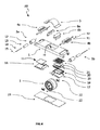
図4は、自己平衡ボード100の様々な要素をより詳細に図示している。車輪カバー5は、足場1の裏面に設けられており、開口10内において上側に延在しており、この後に、主車輪アセンブリ2が、車輪シャフトブラケット22を介して、開口10内に設けられる。フェンダー6a、6bは、足場1の固定される離れた要素である。
FIG. 4 illustrates various elements of the self-balancing
コントローラー及び方向センサーを備える制御ボード11は、PCBトレー16によって提供される位置において、足場1の下に設けられる。バッテリートレー17は、下側バッテリーカバー18、バッテリー19、バッテリーPCB20、及び上側バッテリーカバー21を備えるバッテリーアセンブリのための位置を提供する。バッテリー19は、自己平衡ボード100に電力を提供するために、一緒に連結される1つ以上のバッテリーであり得る。バッテリーPCB20は、充電を制御し、バッテリー19によって提供される電力の流れを制御する。下側及び上側バッテリーカバー18及び21は、物理的損傷及び電気的干渉から、バッテリー19及びバッテリーPCB20を防護して絶縁する。PCBトレー16、バッテリートレー17、及び主車輪アセンブリ2が足場1に取り付けられると、ボタンカバー23が、足場1の底に設けられる。
A
補助車輪アセンブリ3a及び3bは、足場1の端部に取り付けられる。補助車輪アセンブリ3a及び補助車輪アセンブリ3bの各々は、延在した補助車輪12、補助車輪ベアリング部材13、補助車輪シャフト14、及び車輪ナット15を備える。延在した補助車輪12は、好ましくは、ゴムのような弾性材にて生成される。補助車輪ベアリング部材13は、ブッシング又はベアリングであってよい。補助車輪ベアリング部材13がブッシングである実施の形態においては、ある選択された種類のプラスチックのような、好ましくはブッシングとして適切な変形抵抗材料にて生成されている。補助車輪シャフト14は、好ましくは適切な金属から構成されている。補助車輪アセンブリ3a及び3bの補助車輪シャフト14は、両端の車輪ナット15にて足場1に取り付けられる。補助車輪12の外形は、足場1が前方又は後方に傾けられる時に足場1が地面に接触する前に、補助車輪12が地面に接触するようになっている。
The
足場1に関連し補助車輪アセンブリ3a及び3bに近い枢軸にて連結されるのは、ブレーキペダル4a及び4bである。各ブレーキペダル4a、4bは、ヒンジポスト31にて足場1に機械的に取り付けられる。付勢部材32(例えば、トーションばね)は、ヒンジポスト31に設けられ、ブレーキペダル4a、4b及び足場1の間に設けられる。
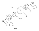
図5は、主車輪アセンブリ2の様々な要素をより詳細に図示している。主車輪アセンブリ2は、適切なゴムで生成されるタイヤ24を備える。モーター25は、タイヤ24の内部に設けられており、摩擦接合にて、あるいは、いくつかの他の適切な接続構造によって、タイヤ24の内部に固く取り付けられるように寸法される2個の車輪ハブ部分26、27の間に取り付けられる。モーター25は、各端部にて、シャフトナット28にて車輪シャフトブラケット22に取り付けられる軸を備える。主車輪アセンブリ2は、この後に、車輪シャフトブラケット22にて、足場1に取り付けられる。電力は、バッテリー19から、足場1における車輪アセンブリ2を支持している中空シャフトを介して、モーター25に伝達され得る。モーター25は、ステーターである中心部分と、ローターであってステーターに対して回転する放射状外側部分とを備えるハブモーターであり得る。
FIG. 5 illustrates various elements of the
図4及び図5をここで参照して、コントローラーは、足場1のための方向センサーによって提供される方向データを使用し、方向データに基づいてモーター24を制御する。乗り手が、足場1の一方の端部に体重を移す時、これによって、z軸周りに足場1が傾き、コントローラーは、体重が移された方向に自己平衡ボード100を加速するように、モーター24を制御する。
Referring now to FIGS. 4 and 5, the controller uses the direction data provided by the direction sensor for the
図6aは、非係合位置において、自己平衡ボード100の足場1の両端における、ブレーキペダル4を図示する。ブレーキペダル4のフランジ部29は、孔を介して補助車輪シャフト14を受け、ブレーキペダル4の端部30が周りで回動し得る。ブレーキペダル4は、下方向へ回動するために促されない時に(すなわち、非係合位置において)、ばね32は、ブレーキペダル4の端部30及びブレーキパッド31を付勢して、補助車輪12から離す。図6bにおいて図示されているように、ブレーキペダル4の端部30及びブレーキパッド31は、係合位置への、端部30の反対面への力Pのマニュアル行使により、補助車輪12へ回動するように促される時、ブレーキパッド31が補助車輪12に係合して、ブレーキパッド31及び補助車輪12の間の摩擦力は、補助車輪12を制動するように作動する。力Pが終了すると、ブレーキペダル4の端部30は、ばね32によって、図6aにおいて図示されている位置に、促されて戻される。
FIG. 6 a illustrates the
図7aに図示されているように、足場1の何れかの端部において補助車輪12が、自己平衡ボード100が載っている平面に接触する前に、自己平衡ボード100は、(主車輪の)z軸周りに約プラス又はマイナス8度の移動の自由Fを有する。角度は、ボードの直感的な使用に適するように見いだされるが、ボードの性能に関係する他の要素に依存して変わり得る。
As shown in FIG. 7a, before the
例示のために進行Tの単一の方向を想定すると、3通りの主なユーザ状況をとり得る。自己平衡ボード100は、速度がゼロ又は非ゼロで一定である間、図7aに図示されているように、釣り合いがとられ得る。加えて、補助車輪アセンブリ3aは、段差32のような平坦でない地形を進む時、スムーズな進行を可能にする。
Assuming a single direction of travel T for illustration, three main user situations can be taken. The self-balancing
図7bに図示されているように、自己平衡ボード100が進行する地面に対して8度を上回って、足場1の先端を下側に傾けるために、乗り手によって体重が前方に移され得る。コントローラーが、この位置において制御ボード11における方向センサーから、方向データを受ける時、コントローラーは、方向Tにおける全出力にて自己平衡ボード100を加速するように、モーター25に指示し、補助車輪アセンブリ3aは、自己平衡ボード100の前方への移動を促進する。ブレーキペダル4b及びブレーキパッド31は、ばね32によって補助車輪3bから、非係合位置に付勢される。
As shown in FIG. 7b, the weight can be moved forward by the rider to tilt the tip of the
あるいは、図7cに図示されているように、自己平衡ボード100が進行する地面に対して8度、足場1の終端を下側に傾けるために、乗り手によって体重が後方に移され得る。コントローラーが、この位置において制御ボード11における方向センサーから、方向データを受ける時、コントローラーが、Tの反対方向における全出力にて、ブレーキとしてモーターを用いて、自己平衡ボード100を減速するように、モーター25に指示することが、自己平衡ボード100にて行われる。
Alternatively, as illustrated in FIG. 7c, the weight can be moved backward by the rider to tilt the end of the
乗り手は、補助車輪アセンブリ3bと係合するように、係合位置にブレーキペダル4b及びブレーキパッド30を促すためにブレーキペダル4bにて、足で下にマニュアルにて押すことにより、自己平衡ボード100の減速を更に増大させ得る。ブレーキパッド30及び補助車輪アセンブリ3bの間の制動力は、ブレーキペダル4bに適用されるマニュアル力に比例しており、自己平衡ボード100は、モーター25によって提供されるモーターブレーキに頼るだけである場合よりも、より迅速に静止され得る。
The rider manually pushes down with his foot at the
当業者に理解されるように、自己平衡ボード100のモーター24は、時計回り又は反時計回りの両方に動作させることができ、これによって、自己平衡ボード100は、Tの反対方向いおいて進行し得る。この逆方向において、同様な原則が、自己平衡ボード100によって適用される。地面に対して足場1の先端が傾くことにより、コントローラーは、この方向において加速するように、モーター24に指示する。同様に、地面に対して足場1の終端が傾くことにより、コントローラーは、減速するように、モーターに指示する。乗り手7は、補助車輪アセンブリ3aを係合するために、ブレーキペダル4a及び接続されるブレーキパッド30を、マニュアルの付勢により、Tの反対方向において自己平衡ボード100の原則を更に増大させることができ、これによって、補助車輪アセンブリ3aに機械的制動力が適用される。
As will be appreciated by those skilled in the art, the motor 24 of the self-balancing
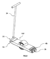
図8は、自己平衡ボード100’のための代替の構成を示す。自己平衡ボード100’は、ブレーキペダル4aが取り除かれて、ハンドルバー34が取り付けられるハンドルブラケット35と交換されていることを除いて、自己平衡ボード100と同様である。ブレーキペダル4bは、左の決まった場所にあり、自己平衡ボード100’を制動するために、乗り手によって操作され得る。この代替的な構成において、第1の補助車輪アセンブリ3aは、また、取り除かれてもよい。
FIG. 8 shows an alternative configuration for the self-balancing board 100 '. The self-balancing board 100 'is similar to the self-balancing
上述の実施の形態において、機械的ヒンジによって足場に連結される移動可能ブレーキペダルは、補助車輪アセンブリの回転への抵抗を提供するために、補助車輪アセンブリを係合するために用いられるが、他の種類のブレーキ要素が、補助車輪アセンブリを係合するために採用され得る。例えば、ブレーキペダルは、足場の一体ヒンジ部分にて提供されることができ、足場の各部分は、非係合位置及び係合位置の間の、ブレーキペダルの手動の付勢を可能にするために好適に柔軟である。 In the embodiments described above, a movable brake pedal connected to the scaffold by a mechanical hinge is used to engage the auxiliary wheel assembly to provide resistance to rotation of the auxiliary wheel assembly, but others Types of brake elements may be employed to engage the auxiliary wheel assembly. For example, the brake pedal can be provided in an integral hinge portion of the scaffold, each portion of the scaffold to allow manual biasing of the brake pedal between the disengaged position and the engaged position. It is preferably flexible.
図9において図示されている他の代替の実施の形態において、ブレーキ要素は、足場204の穴を介して略直線的に進行し、ブレーキパッド208に取り付けられているブレーキアクチュエーター200である。ブレーキアクチュエーター200は、ばね212のような付勢機構を介して非係合位置に付勢され、ブレーキパッド208は、補助車輪アセンブリ216に接しない。ブレーキアクチュエーター200は、ブレーキパッド208を、補助車輪アセンブリ216に係合させるために、穴を介して手動にて付勢されてよい。補助車輪アセンブリを係合するために手動に移動可能となる他の種類のブレーキ要素は、当業者に自明である。
In another alternative embodiment illustrated in FIG. 9, the brake element is a
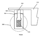
補助車輪アセンブリは、ブレーキパッドが固定されてよい足場に対して移動可能であることができる。例えば、図10は、更なる代替の実施の形態を示しており、補助車輪アセンブリ300が、足場312に取り付けられるポスト308を摺動可能に受け付けるシリンダー304に設けられる。シリンダー304は、ばね316又はその他を介して、足場312から付勢して離されている。ブレーキパッド320は、足場312に取り付けられる。体重のマニュアル移転により、補助車輪アセンブリ300が地面に接するとき、ばね316が圧縮され、補助車輪アセンブリ300がブレーキパッド320に係合する。従って、この例において、補助車輪アセンブリ300の近接の足場312は、ブレーキ要素として動作する。
The auxiliary wheel assembly can be movable relative to a scaffold to which the brake pads can be secured. For example, FIG. 10 shows a further alternative embodiment where an
図11は、更に他の実施の形態を示しており、補助車輪アセンブリ400は、足場408に枢支連結されている補助車輪サポート404に接続されており、補助車輪アセンブリ400は、軸412について回転することができる。補助車輪サポート404の方向は、足場408に取り付けられているブレーキパッド416から補助車輪アセンブリ400が離れることを促すように付勢される。体重のマニュアル移転により、補助車輪アセンブリ400が地面に接するとき、相互から離れている補助車輪アセンブリ400及びブレーキパッド416を促している付勢力が圧倒されて、補助車輪アセンブリ400が、ブレーキパッド416に係合する。従って、この例において、補助車輪アセンブリ400の近接の足場408は、ブレーキ要素として動作する。
FIG. 11 illustrates yet another embodiment where the
主車輪アセンブリが図示されており、単一の主車輪を備えているが、主車輪アセンブリが、代替的に共通軸において回転する2個以上の主車輪を有し得ることについて、当業者に理解され得る。2個以上の主車輪は、単一のモーターによって、あるいは、個別のモーターによって駆動され得る。 Although the main wheel assembly is illustrated and comprises a single main wheel, those skilled in the art will appreciate that the main wheel assembly may alternatively have two or more main wheels rotating about a common axis. Can be done. The two or more main wheels can be driven by a single motor or by individual motors.
補助車輪アセンブリは、上述の実施の形態においては単一の延在している車輪を有するものとして図示されているが、補助車輪アセンブリが、相互に側方に離されている2個以上の補助車輪を備えることができることについて、理解されるであろう。また、補助車輪アセンブリは、補助車輪よりも小径の1個以上の円筒ブレーキドラムを備えており、ブレーキパッドが、当該ブレーキドラムに対して、補助車輪アセンブリの回転への抵抗を提供するために促されてもよい。 Although the auxiliary wheel assembly is illustrated in the above embodiments as having a single extending wheel, the auxiliary wheel assembly is more than one auxiliary that is laterally spaced from one another. It will be appreciated that wheels can be provided. The auxiliary wheel assembly also includes one or more cylindrical brake drums having a smaller diameter than the auxiliary wheel, and a brake pad is urged against the brake drum to provide resistance to rotation of the auxiliary wheel assembly. May be.
上述の実施の形態は、本願の例であることを意図しており、添付の請求項によって単独で定義される発明の範囲から逸脱しない範囲で、当業者によって、改変及び変更が効果を奏することができる。 The above-described embodiments are intended to be examples of the present application, and modifications and changes will be effective by those skilled in the art without departing from the scope of the invention defined solely by the appended claims. Can do.
Claims (15)
主車輪アセンブリであって、
主車輪と、
前記主車輪を駆動するモーターと、を備える前記主車輪アセンブリと、
前記主車輪アセンブリに取り付けられており、足用デッキを備えている足場と、
前記足場の前記方向を検出している少なくとも1つのセンサーと、
前記少なくとも1つのセンサーからデータを受信し、前記受信したデータに応じて前記モーターを制御するコントローラーと、
前記主車輪アセンブリの遠位の前記足場に連結される第1の補助車輪アセンブリであって、前記第1の補助車輪アセンブリは、前記足用デッキが平面に平行である時に、前記主車輪が設けられる前記平面への接触から持ち上げられている、前記第1の補助車輪アセンブリと、
前記第1の補助車輪アセンブリの回転への抵抗を提供するべく、前記第1の補助車輪アセンブリに係合するために、前記第1の補助車輪アセンブリに対してマニュアルで移動可能である第1のブレーキ要素と、
を備える自己平衡ボード。 A self-balancing board, wherein the self-balancing board is
A main wheel assembly,
The main wheel,
A motor for driving the main wheel, the main wheel assembly comprising:
A scaffold attached to the main wheel assembly and comprising a foot deck;
At least one sensor detecting the direction of the scaffold;
A controller that receives data from the at least one sensor and controls the motor in response to the received data;
A first auxiliary wheel assembly coupled to the scaffolding distal of the main wheel assembly, wherein the first auxiliary wheel assembly is provided when the main wheel is provided when the foot deck is parallel to a plane; Said first auxiliary wheel assembly being lifted from contact with said flat surface
A first manually moveable relative to the first auxiliary wheel assembly to engage the first auxiliary wheel assembly to provide resistance to rotation of the first auxiliary wheel assembly; A brake element;
With self-balancing board.
請求項1に記載の自己平衡ボード。 A first brake pedal biased to a disengaged position and movable to an engaged position where the first brake element contacts the first auxiliary wheel assembly;
The self-balancing board according to claim 1.
請求項2に記載の自己平衡ボード。 The first brake pedal is connected to the scaffold by a mechanical hinge;
The self-balancing board according to claim 2.
請求項2に記載の自己平衡ボード。 The first brake pedal is connected to the scaffold by an integral hinge;
The self-balancing board according to claim 2.
請求項1に記載の自己平衡ボード。 The first brake element includes a first brake pad, the first brake element is linearly separated from the first auxiliary wheel assembly, and the first brake pad is For contact with a first auxiliary wheel assembly, the first brake element may be manually urged with respect to the first auxiliary wheel assembly;
The self-balancing board according to claim 1.
請求項1に記載の自己平衡ボード。 The first auxiliary wheel assembly is biased away from the scaffold, and the first auxiliary wheel assembly prompts the first auxiliary wheel assembly in contact with the first brake element; Pressure is applied to the scaffold proximal to the first auxiliary wheel assembly;
The self-balancing board according to claim 1.
第1の補助車輪と、
第1の制動面と、備える、
請求項1に記載の自己平衡ボード。 The first auxiliary wheel assembly includes:
A first auxiliary wheel;
A first braking surface;
The self-balancing board according to claim 1.
請求項7に記載の自己平衡ボード。 The first brake element engages the first braking surface to provide resistance to rotation of the first auxiliary wheel assembly;
The self-balancing board according to claim 7.
前記第2の補助車輪アセンブリの回転への抵抗を提供するべく、前記第2の補助車輪アセンブリに係合するために、前記第2の補助車輪アセンブリに対してマニュアルで移動可能である第2のブレーキ要素と、を更に備える、
請求項1に記載の自己平衡ボード。 A second auxiliary wheel assembly coupled to the scaffold distal to the main wheel assembly, wherein the second auxiliary wheel assembly is provided with the main wheel when the foot deck is parallel to a plane. Said second auxiliary wheel assembly being lifted from contact with said plane
A second manually movable relative to the second auxiliary wheel assembly to engage the second auxiliary wheel assembly to provide resistance to rotation of the second auxiliary wheel assembly; A brake element,
The self-balancing board according to claim 1.
請求項9に記載の自己平衡ボード。 A second brake pedal biased to a disengaged position and movable to an engaged position where the second brake element contacts the second auxiliary wheel assembly;
The self-balancing board according to claim 9.
請求項10に記載の自己平衡ボード。 The second brake pedal is connected to the scaffold by a mechanical hinge;
The self-balancing board according to claim 10.
請求項10に記載の自己平衡ボード。 The second brake pedal is connected to the scaffold by an integral hinge;
The self-balancing board according to claim 10.
請求項8に記載の自己平衡ボード。 The second brake element includes a second brake pad, the second brake element is linearly separated from the second auxiliary wheel assembly, and the second brake pad is For contact with a second auxiliary wheel assembly, the second brake element can be manually urged relative to the second auxiliary wheel assembly;
The self-balancing board according to claim 8.
請求項8に記載の自己平衡ボード。 The second auxiliary wheel assembly is biased away from the scaffold and when the second auxiliary wheel assembly prompts the second auxiliary wheel assembly in contact with the second brake element; Pressure is applied to the scaffold proximal to the second auxiliary wheel assembly;
The self-balancing board according to claim 8.
請求項1に記載の自己平衡ボード。 A handlebar attached to the scaffold,
The self-balancing board according to claim 1.
Applications Claiming Priority (3)
| Application Number | Priority Date | Filing Date | Title |
|---|---|---|---|
| PCT/IB2015/058821 WO2017081523A1 (en) | 2015-11-15 | 2015-11-15 | Self-balancing single wheel board with anti-fall and brake safety systems |
| IBPCT/IB2015/058821 | 2015-11-15 | ||
| PCT/CN2016/105834 WO2017080530A1 (en) | 2015-11-15 | 2016-11-15 | Self-balancing board with primary wheel and distal auxiliary wheel |
Publications (2)
| Publication Number | Publication Date |
|---|---|
| JP2018535013A true JP2018535013A (en) | 2018-11-29 |
| JP2018535013A5 JP2018535013A5 (en) | 2019-12-26 |
Family
ID=58694542
Family Applications (1)
| Application Number | Title | Priority Date | Filing Date |
|---|---|---|---|
| JP2018524830A Pending JP2018535013A (en) | 2015-11-15 | 2016-11-15 | Self-balancing board with main wheel and distal auxiliary wheel |
Country Status (10)
| Country | Link |
|---|---|
| US (3) | US10058765B2 (en) |
| EP (1) | EP3374045A4 (en) |
| JP (1) | JP2018535013A (en) |
| KR (1) | KR20180082481A (en) |
| CN (2) | CN206358276U (en) |
| AU (1) | AU2016353893A1 (en) |
| CA (1) | CA3004935A1 (en) |
| RU (1) | RU2018121438A (en) |
| SG (1) | SG11201803861WA (en) |
| WO (2) | WO2017081523A1 (en) |
Families Citing this family (39)
| Publication number | Priority date | Publication date | Assignee | Title |
|---|---|---|---|---|
| US10369453B2 (en) * | 2013-10-21 | 2019-08-06 | Equalia LLC | Pitch-propelled vehicle |
| US9211470B2 (en) | 2013-10-21 | 2015-12-15 | Equalia LLC. | Pitch-propelled vehicle |
| WO2017081523A1 (en) * | 2015-11-15 | 2017-05-18 | Koofy Development Limited | Self-balancing single wheel board with anti-fall and brake safety systems |
| GB2547260B (en) * | 2016-02-12 | 2019-05-15 | Artemev Timur | Motorized footwear |
| US20190256163A1 (en) * | 2017-07-27 | 2019-08-22 | Ninebot (Beijing) Tech Co., Ltd. | Roller-skating device and electric balance vehicle |
| US10682565B1 (en) * | 2017-12-04 | 2020-06-16 | Flight Fins Llc | Foot lift attachments for skateboards and combinations thereof |
| US11433294B2 (en) | 2017-12-04 | 2022-09-06 | Flight Fins Llc | Foot lift attachments for skateboards and combinations thereof |
| WO2019116277A1 (en) * | 2017-12-12 | 2019-06-20 | Koofy Innovation Limited | Self-balancing board with powered auxiliary wheels |
| US20190299082A1 (en) * | 2018-03-29 | 2019-10-03 | Matthew Brett Hoover | Apparatus and method for reducing the incidence of sudden stoppage with self balancing skateboards |
| CN108974212A (en) * | 2018-04-29 | 2018-12-11 | 周峰 | A kind of moving device and its control method on robot chassis |
| CN108609098B (en) * | 2018-04-29 | 2019-12-27 | 周一峰 | Traveling device with dual operation modes and control method thereof |
| WO2020142055A1 (en) * | 2019-01-02 | 2020-07-09 | Александр Владимирович ВЛАЩИНСКИЙ | Self-balancing electric skateboard |
| US11230341B2 (en) * | 2019-01-22 | 2022-01-25 | Antoine M. Njeim | Nose-dive prevention device for a one-wheeled transporation device |
| US10456658B1 (en) * | 2019-02-11 | 2019-10-29 | Future Motion, Inc. | Self-stabilizing skateboard |
| US11420676B2 (en) * | 2019-03-04 | 2022-08-23 | Sk8Dogltd, Llc | Sliding kingpin assembly for use in vehicles |
| USD890280S1 (en) * | 2019-03-11 | 2020-07-14 | Future Motion, Inc. | Rider detection sensor for electric vehicle |
| US11045712B1 (en) * | 2019-04-04 | 2021-06-29 | Paul Orehek | Cushioned concave pads for self-balancing vehicles |
| US10421006B1 (en) * | 2019-05-01 | 2019-09-24 | Bowen Li | Self-balancing vehicle and structural support therein |
| KR102214780B1 (en) * | 2019-11-07 | 2021-02-10 | 김항래 | One-wheel Board |
| US11794090B2 (en) * | 2020-01-08 | 2023-10-24 | Acme Land Surf Co., LLC | Wheeled vehicle and deck for wheeled vehicle |
| US11547901B2 (en) * | 2020-07-18 | 2023-01-10 | Kazumine Kumada | Sliding balance board |
| WO2022261558A1 (en) * | 2021-06-11 | 2022-12-15 | Future Motion, Inc. | Composite fender for electric vehicle |
| USD999859S1 (en) * | 2021-06-11 | 2023-09-26 | Future Motion, Inc. | Fender for electric vehicle |
| US11840303B2 (en) * | 2021-06-11 | 2023-12-12 | Future Motion, Inc. | Suspension system for a one-wheeled vehicle |
| CN113212622A (en) * | 2021-06-24 | 2021-08-06 | 深圳百客电子商务有限公司 | Balance car, control method thereof and kart taking balance car as power |
| US11273364B1 (en) * | 2021-06-30 | 2022-03-15 | Future Motion, Inc. | Self-stabilizing skateboard |
| US20230054949A1 (en) * | 2021-08-20 | 2023-02-23 | Nicholas John Vitale | Cushioned footpad with reinforcing support structure |
| USD1001939S1 (en) * | 2021-10-15 | 2023-10-17 | Future Motion, Inc. | Fender for electric vehicle |
| USD1001943S1 (en) * | 2021-10-15 | 2023-10-17 | Future Motion, Inc. | Electric vehicle |
| USD1008392S1 (en) * | 2021-10-15 | 2023-12-19 | Future Motion, Inc. | Electric vehicle |
| USD1001938S1 (en) * | 2021-10-15 | 2023-10-17 | Future Motion, Inc. | Electric vehicle with fender |
| USD1001944S1 (en) * | 2021-10-15 | 2023-10-17 | Future Motion, Inc. | Electric vehicle front |
| USD1001942S1 (en) * | 2021-10-15 | 2023-10-17 | Future Motion, Inc. | Electric vehicle with fender |
| USD1001941S1 (en) * | 2021-10-15 | 2023-10-17 | Future Motion, Inc. | Rear bumper for electric vehicle |
| USD1001940S1 (en) * | 2021-10-15 | 2023-10-17 | Future Motion, Inc. | Fender for electric vehicle |
| US11299059B1 (en) | 2021-10-20 | 2022-04-12 | Future Motion, Inc. | Self-stabilizing skateboard |
| CN114715316A (en) * | 2022-04-15 | 2022-07-08 | 安徽小龙仔儿童用品有限公司 | Child scooter with protection function |
| US11890528B1 (en) | 2022-11-17 | 2024-02-06 | Future Motion, Inc. | Concave side rails for one-wheeled vehicles |
| US11890527B1 (en) * | 2023-06-28 | 2024-02-06 | Future Motion, Inc. | Latching fender for electric vehicle |
Citations (11)
| Publication number | Priority date | Publication date | Assignee | Title |
|---|---|---|---|---|
| US4088334A (en) * | 1977-03-25 | 1978-05-09 | Johnson Elmer E | Skateboard brake |
| JPS55104472U (en) * | 1979-01-13 | 1980-07-21 | ||
| JP2001293126A (en) * | 2000-04-13 | 2001-10-23 | Yoshikata Rokusha | Skater |
| JP2003502002A (en) * | 1999-06-04 | 2003-01-14 | デカ・プロダクツ・リミテッド・パートナーシップ | Personal mobile vehicle and method |
| GB2407780A (en) * | 2003-11-07 | 2005-05-11 | Alan Ramsay | Exercise board or skateboard |
| CN1689894A (en) * | 2004-04-28 | 2005-11-02 | 雅马哈发动机株式会社 | Vehicle, vehicle control device and vehicle control method |
| JP2005335677A (en) * | 2004-04-28 | 2005-12-08 | Yamaha Motor Co Ltd | Vehicle, vehicle control device and vehicle control method |
| JP2006001384A (en) * | 2004-06-16 | 2006-01-05 | Sony Corp | Unstable running gear |
| JP2007161198A (en) * | 2005-12-16 | 2007-06-28 | Sony Corp | Traveling device and its control method |
| US20080242515A1 (en) * | 2006-04-28 | 2008-10-02 | Larry Richard Odien | Motorized apparatus and method for dynamic balancing exercise |
| CN202641989U (en) * | 2012-06-29 | 2013-01-02 | 宁波小星星车业有限公司 | Scooter |
Family Cites Families (26)
| Publication number | Priority date | Publication date | Assignee | Title |
|---|---|---|---|---|
| AT299826B (en) | 1970-01-28 | 1972-07-10 | Franz Dorner | Air chamber flushing device |
| US4084832A (en) | 1976-08-05 | 1978-04-18 | Unarco Industries, Inc. | Shopping cart with anti-pilferage character |
| US4084831A (en) * | 1976-08-09 | 1978-04-18 | Ayola Ngwa Akonteh | Skateboard with control unit |
| US6543564B1 (en) | 1994-05-27 | 2003-04-08 | Deka Products Limited Partnership | Balancing personal vehicle |
| US6050357A (en) * | 1995-05-31 | 2000-04-18 | Empower Corporation | Powered skateboard |
| DE29822628U1 (en) * | 1998-12-20 | 1999-03-04 | Kemmelmeier Ludwig | Roller skate |
| CN2566908Y (en) * | 2002-08-23 | 2003-08-20 | 陈金益 | Electric bellyboard scooter |
| FR2845009B1 (en) * | 2002-10-01 | 2004-11-19 | Alain Bouvet | PROPULSION WHEEL BOARD |
| US6848527B2 (en) * | 2002-10-08 | 2005-02-01 | Lucas J. Nelson | Motorized skateboard-type vehicle |
| ES2221795B1 (en) * | 2003-05-12 | 2007-07-01 | Ignacio Gomez Avila | SCOOTER. |
| US8562386B2 (en) * | 2008-10-10 | 2013-10-22 | Jakks Pacific, Inc. | Mobile skateboard-shaped toy with a flywheel |
| US8807250B2 (en) | 2010-03-09 | 2014-08-19 | Shane Chen | Powered single-wheeled self-balancing vehicle for standing user |
| CN102309846A (en) * | 2010-07-11 | 2012-01-11 | 林妙妙 | Self-sliding plate capable of exercising balance |
| CN102179039A (en) | 2011-04-20 | 2011-09-14 | 路海燕 | Electric one-wheel scooter |
| CN202179842U (en) | 2011-08-12 | 2012-04-04 | 路海燕 | Electric single-wheel scooter |
| US8738278B2 (en) | 2012-02-12 | 2014-05-27 | Shane Chen | Two-wheel, self-balancing vehicle with independently movable foot placement sections |
| CN103191558A (en) * | 2013-04-11 | 2013-07-10 | 何志波 | Motor-driven self-balancing single-wheel scooter |
| CN203244743U (en) | 2013-04-11 | 2013-10-23 | 何志波 | Electric self-balancing one-wheel scooter |
| CN203244742U (en) | 2013-04-11 | 2013-10-23 | 何志波 | Electric self-balancing double-wheel scooter |
| WO2014182527A1 (en) | 2013-05-06 | 2014-11-13 | Future Motion, Inc. | Self-stabilizing skateboard |
| US10369453B2 (en) * | 2013-10-21 | 2019-08-06 | Equalia LLC | Pitch-propelled vehicle |
| US9776068B2 (en) * | 2013-12-06 | 2017-10-03 | Innovated Transport Systems Ug (Haftungsbeschränkt) | Vehicle for the movement of a driver comprising a ball rolling on a ground surface and in any desired direction |
| CN204017335U (en) * | 2014-05-07 | 2014-12-17 | 翁林华 | Single-wheel balancing skateboard car |
| CN204473001U (en) * | 2015-02-14 | 2015-07-15 | 常州千代车业有限公司 | Slide type balance truck |
| WO2017081523A1 (en) * | 2015-11-15 | 2017-05-18 | Koofy Development Limited | Self-balancing single wheel board with anti-fall and brake safety systems |
| US9908580B2 (en) * | 2016-06-02 | 2018-03-06 | Future Motion, Inc. | Vehicle rider detection using strain gauges |
-
2015
- 2015-11-15 WO PCT/IB2015/058821 patent/WO2017081523A1/en active Application Filing
-
2016
- 2016-11-15 CN CN201621240409.1U patent/CN206358276U/en not_active Expired - Fee Related
- 2016-11-15 WO PCT/CN2016/105834 patent/WO2017080530A1/en active Application Filing
- 2016-11-15 CA CA3004935A patent/CA3004935A1/en not_active Abandoned
- 2016-11-15 EP EP16863706.4A patent/EP3374045A4/en not_active Withdrawn
- 2016-11-15 KR KR1020187015282A patent/KR20180082481A/en unknown
- 2016-11-15 RU RU2018121438A patent/RU2018121438A/en unknown
- 2016-11-15 AU AU2016353893A patent/AU2016353893A1/en not_active Abandoned
- 2016-11-15 JP JP2018524830A patent/JP2018535013A/en active Pending
- 2016-11-15 CN CN201611019577.2A patent/CN107019900A/en active Pending
- 2016-11-15 SG SG11201803861WA patent/SG11201803861WA/en unknown
-
2018
- 2018-02-12 US US15/894,112 patent/US10058765B2/en active Active
- 2018-08-28 US US16/115,534 patent/US10335669B2/en active Active
-
2019
- 2019-07-01 US US16/459,597 patent/US11148037B2/en active Active
Patent Citations (12)
| Publication number | Priority date | Publication date | Assignee | Title |
|---|---|---|---|---|
| US4088334A (en) * | 1977-03-25 | 1978-05-09 | Johnson Elmer E | Skateboard brake |
| JPS55104472U (en) * | 1979-01-13 | 1980-07-21 | ||
| JP2003502002A (en) * | 1999-06-04 | 2003-01-14 | デカ・プロダクツ・リミテッド・パートナーシップ | Personal mobile vehicle and method |
| JP2001293126A (en) * | 2000-04-13 | 2001-10-23 | Yoshikata Rokusha | Skater |
| GB2407780A (en) * | 2003-11-07 | 2005-05-11 | Alan Ramsay | Exercise board or skateboard |
| CN1689894A (en) * | 2004-04-28 | 2005-11-02 | 雅马哈发动机株式会社 | Vehicle, vehicle control device and vehicle control method |
| US20050241864A1 (en) * | 2004-04-28 | 2005-11-03 | Yuji Hiramatsu | Vehicle, vehicle control device and vehicle control method |
| JP2005335677A (en) * | 2004-04-28 | 2005-12-08 | Yamaha Motor Co Ltd | Vehicle, vehicle control device and vehicle control method |
| JP2006001384A (en) * | 2004-06-16 | 2006-01-05 | Sony Corp | Unstable running gear |
| JP2007161198A (en) * | 2005-12-16 | 2007-06-28 | Sony Corp | Traveling device and its control method |
| US20080242515A1 (en) * | 2006-04-28 | 2008-10-02 | Larry Richard Odien | Motorized apparatus and method for dynamic balancing exercise |
| CN202641989U (en) * | 2012-06-29 | 2013-01-02 | 宁波小星星车业有限公司 | Scooter |
Also Published As
| Publication number | Publication date |
|---|---|
| RU2018121438A (en) | 2019-12-16 |
| WO2017081523A1 (en) | 2017-05-18 |
| WO2017080530A1 (en) | 2017-05-18 |
| EP3374045A4 (en) | 2019-08-21 |
| KR20180082481A (en) | 2018-07-18 |
| EP3374045A1 (en) | 2018-09-19 |
| US10058765B2 (en) | 2018-08-28 |
| RU2018121438A3 (en) | 2020-02-12 |
| SG11201803861WA (en) | 2018-06-28 |
| AU2016353893A1 (en) | 2018-05-31 |
| CN107019900A (en) | 2017-08-08 |
| CN206358276U (en) | 2017-07-28 |
| US20180369685A1 (en) | 2018-12-27 |
| US20180161661A1 (en) | 2018-06-14 |
| US10335669B2 (en) | 2019-07-02 |
| US20190321712A1 (en) | 2019-10-24 |
| US11148037B2 (en) | 2021-10-19 |
| CA3004935A1 (en) | 2017-05-18 |
Similar Documents
| Publication | Publication Date | Title |
|---|---|---|
| JP2018535013A (en) | Self-balancing board with main wheel and distal auxiliary wheel | |
| JP4691912B2 (en) | Unstable traveling device | |
| US9499228B2 (en) | Self-balancing vehicle frame | |
| JP4710934B2 (en) | Body structure and coaxial motorcycle | |
| JP5292286B2 (en) | Vehicles that can move in all directions | |
| US20140008138A1 (en) | Electric Vehicle Driven with Interaction with Rider | |
| KR20160117568A (en) | Powered unicycle device | |
| KR100857507B1 (en) | Step board | |
| KR20180068090A (en) | Three-wheeled boarding apparatus capable of tilting | |
| KR101935858B1 (en) | A stable two-wheeled electric vehicle | |
| JP2006151032A (en) | Standing ride type small vehicle | |
| JP6739395B2 (en) | Travel support equipment and travel equipment | |
| WO2019122930A1 (en) | Load balancing transportation device | |
| US9308968B2 (en) | Leg type traveling apparatus | |
| JP2008136567A (en) | Self-propel roller board | |
| KR101417466B1 (en) | Hemisphere transfer device capable of controlling velocity and direction | |
| JP6567753B1 (en) | Electric motorcycle | |
| JP2011079422A (en) | Power assisted wheel and cart with the same | |
| GB2597737A (en) | Motorized kick scooter | |
| JP5203368B6 (en) | Speed limit for electric vehicles | |
| JP5203368B2 (en) | Speed limit for electric vehicles | |
| JP2021132759A (en) | Chair transfer device | |
| JP2019142343A (en) | Electric drive vehicle | |
| GB2569806A (en) | Support framework for a self-balancing transportation device | |
| TWM553292U (en) | Electric scooter |
Legal Events
| Date | Code | Title | Description |
|---|---|---|---|
| A521 | Request for written amendment filed |
Free format text: JAPANESE INTERMEDIATE CODE: A523 Effective date: 20191114 |
|
| A621 | Written request for application examination |
Free format text: JAPANESE INTERMEDIATE CODE: A621 Effective date: 20191114 |
|
| A977 | Report on retrieval |
Free format text: JAPANESE INTERMEDIATE CODE: A971007 Effective date: 20200915 |
|
| A131 | Notification of reasons for refusal |
Free format text: JAPANESE INTERMEDIATE CODE: A131 Effective date: 20200929 |
|
| A02 | Decision of refusal |
Free format text: JAPANESE INTERMEDIATE CODE: A02 Effective date: 20210518 |