JP2018533034A - Coating with adhesive layer for UV optics - Google Patents
Coating with adhesive layer for UV optics Download PDFInfo
- Publication number
- JP2018533034A JP2018533034A JP2018507668A JP2018507668A JP2018533034A JP 2018533034 A JP2018533034 A JP 2018533034A JP 2018507668 A JP2018507668 A JP 2018507668A JP 2018507668 A JP2018507668 A JP 2018507668A JP 2018533034 A JP2018533034 A JP 2018533034A
- Authority
- JP
- Japan
- Prior art keywords
- lens
- adhesive
- light
- optical
- light absorber
- Prior art date
- Legal status (The legal status is an assumption and is not a legal conclusion. Google has not performed a legal analysis and makes no representation as to the accuracy of the status listed.)
- Pending
Links
- 238000000576 coating method Methods 0.000 title claims abstract description 71
- 239000011248 coating agent Substances 0.000 title claims abstract description 70
- 239000012790 adhesive layer Substances 0.000 title 1
- 230000003287 optical effect Effects 0.000 claims abstract description 210
- 239000006096 absorbing agent Substances 0.000 claims abstract description 120
- 239000000853 adhesive Substances 0.000 claims abstract description 106
- 230000001070 adhesive effect Effects 0.000 claims abstract description 106
- 239000002318 adhesion promoter Substances 0.000 claims abstract description 63
- 230000004888 barrier function Effects 0.000 claims abstract description 63
- 239000000463 material Substances 0.000 claims description 49
- 230000003667 anti-reflective effect Effects 0.000 claims description 26
- 238000000034 method Methods 0.000 claims description 18
- KRHYYFGTRYWZRS-UHFFFAOYSA-M Fluoride anion Chemical compound [F-] KRHYYFGTRYWZRS-UHFFFAOYSA-M 0.000 claims description 17
- 229910004261 CaF 2 Inorganic materials 0.000 claims description 15
- 150000004767 nitrides Chemical class 0.000 claims description 15
- XEEYBQQBJWHFJM-UHFFFAOYSA-N Iron Chemical compound [Fe] XEEYBQQBJWHFJM-UHFFFAOYSA-N 0.000 claims description 14
- PXHVJJICTQNCMI-UHFFFAOYSA-N Nickel Chemical compound [Ni] PXHVJJICTQNCMI-UHFFFAOYSA-N 0.000 claims description 14
- 239000011651 chromium Substances 0.000 claims description 14
- 230000015556 catabolic process Effects 0.000 claims description 11
- 238000006731 degradation reaction Methods 0.000 claims description 11
- VYZAMTAEIAYCRO-UHFFFAOYSA-N Chromium Chemical group [Cr] VYZAMTAEIAYCRO-UHFFFAOYSA-N 0.000 claims description 9
- 229910052804 chromium Inorganic materials 0.000 claims description 9
- 150000001247 metal acetylides Chemical class 0.000 claims description 9
- BQCADISMDOOEFD-UHFFFAOYSA-N Silver Chemical compound [Ag] BQCADISMDOOEFD-UHFFFAOYSA-N 0.000 claims description 7
- RTAQQCXQSZGOHL-UHFFFAOYSA-N Titanium Chemical compound [Ti] RTAQQCXQSZGOHL-UHFFFAOYSA-N 0.000 claims description 7
- HCHKCACWOHOZIP-UHFFFAOYSA-N Zinc Chemical compound [Zn] HCHKCACWOHOZIP-UHFFFAOYSA-N 0.000 claims description 7
- 229910052782 aluminium Inorganic materials 0.000 claims description 7
- XAGFODPZIPBFFR-UHFFFAOYSA-N aluminium Chemical compound [Al] XAGFODPZIPBFFR-UHFFFAOYSA-N 0.000 claims description 7
- PCHJSUWPFVWCPO-UHFFFAOYSA-N gold Chemical compound [Au] PCHJSUWPFVWCPO-UHFFFAOYSA-N 0.000 claims description 7
- 229910052737 gold Inorganic materials 0.000 claims description 7
- 239000010931 gold Substances 0.000 claims description 7
- 229910052735 hafnium Inorganic materials 0.000 claims description 7
- VBJZVLUMGGDVMO-UHFFFAOYSA-N hafnium atom Chemical compound [Hf] VBJZVLUMGGDVMO-UHFFFAOYSA-N 0.000 claims description 7
- 229910052742 iron Inorganic materials 0.000 claims description 7
- WPBNNNQJVZRUHP-UHFFFAOYSA-L manganese(2+);methyl n-[[2-(methoxycarbonylcarbamothioylamino)phenyl]carbamothioyl]carbamate;n-[2-(sulfidocarbothioylamino)ethyl]carbamodithioate Chemical compound [Mn+2].[S-]C(=S)NCCNC([S-])=S.COC(=O)NC(=S)NC1=CC=CC=C1NC(=S)NC(=O)OC WPBNNNQJVZRUHP-UHFFFAOYSA-L 0.000 claims description 7
- 229910052759 nickel Inorganic materials 0.000 claims description 7
- 229910052758 niobium Inorganic materials 0.000 claims description 7
- 239000010955 niobium Substances 0.000 claims description 7
- GUCVJGMIXFAOAE-UHFFFAOYSA-N niobium atom Chemical compound [Nb] GUCVJGMIXFAOAE-UHFFFAOYSA-N 0.000 claims description 7
- 229910052709 silver Inorganic materials 0.000 claims description 7
- 239000004332 silver Substances 0.000 claims description 7
- 229910052715 tantalum Inorganic materials 0.000 claims description 7
- GUVRBAGPIYLISA-UHFFFAOYSA-N tantalum atom Chemical compound [Ta] GUVRBAGPIYLISA-UHFFFAOYSA-N 0.000 claims description 7
- 229910052719 titanium Inorganic materials 0.000 claims description 7
- 239000010936 titanium Substances 0.000 claims description 7
- 229910052725 zinc Inorganic materials 0.000 claims description 7
- 239000011701 zinc Substances 0.000 claims description 7
- 238000004140 cleaning Methods 0.000 abstract description 5
- 230000032798 delamination Effects 0.000 abstract description 2
- 238000004519 manufacturing process Methods 0.000 abstract description 2
- 239000010410 layer Substances 0.000 description 108
- 229910052751 metal Inorganic materials 0.000 description 36
- 239000002184 metal Substances 0.000 description 36
- 229910044991 metal oxide Inorganic materials 0.000 description 14
- 150000004706 metal oxides Chemical class 0.000 description 14
- 239000000203 mixture Substances 0.000 description 12
- 238000000151 deposition Methods 0.000 description 7
- 230000002093 peripheral effect Effects 0.000 description 6
- QDOXWKRWXJOMAK-UHFFFAOYSA-N dichromium trioxide Chemical compound O=[Cr]O[Cr]=O QDOXWKRWXJOMAK-UHFFFAOYSA-N 0.000 description 4
- 238000012545 processing Methods 0.000 description 4
- OKKJLVBELUTLKV-UHFFFAOYSA-N Methanol Chemical compound OC OKKJLVBELUTLKV-UHFFFAOYSA-N 0.000 description 3
- 229910004298 SiO 2 Inorganic materials 0.000 description 3
- 230000006866 deterioration Effects 0.000 description 3
- 238000012360 testing method Methods 0.000 description 3
- WGLPBDUCMAPZCE-UHFFFAOYSA-N Trioxochromium Chemical compound O=[Cr](=O)=O WGLPBDUCMAPZCE-UHFFFAOYSA-N 0.000 description 2
- 230000008901 benefit Effects 0.000 description 2
- 230000005540 biological transmission Effects 0.000 description 2
- 230000000903 blocking effect Effects 0.000 description 2
- 230000008859 change Effects 0.000 description 2
- 229910000423 chromium oxide Inorganic materials 0.000 description 2
- 239000000356 contaminant Substances 0.000 description 2
- 230000008021 deposition Effects 0.000 description 2
- 238000013461 design Methods 0.000 description 2
- 239000012530 fluid Substances 0.000 description 2
- 238000001459 lithography Methods 0.000 description 2
- 150000002739 metals Chemical class 0.000 description 2
- 238000012986 modification Methods 0.000 description 2
- 230000004048 modification Effects 0.000 description 2
- 230000008569 process Effects 0.000 description 2
- 238000007493 shaping process Methods 0.000 description 2
- 238000004544 sputter deposition Methods 0.000 description 2
- 238000002834 transmittance Methods 0.000 description 2
- 238000007738 vacuum evaporation Methods 0.000 description 2
- 229910016569 AlF 3 Inorganic materials 0.000 description 1
- 229910016036 BaF 2 Inorganic materials 0.000 description 1
- 229910005690 GdF 3 Inorganic materials 0.000 description 1
- 229910017768 LaF 3 Inorganic materials 0.000 description 1
- 230000002411 adverse Effects 0.000 description 1
- 239000004568 cement Substances 0.000 description 1
- 239000003795 chemical substances by application Substances 0.000 description 1
- 238000005229 chemical vapour deposition Methods 0.000 description 1
- 230000008878 coupling Effects 0.000 description 1
- 238000010168 coupling process Methods 0.000 description 1
- 238000005859 coupling reaction Methods 0.000 description 1
- 230000002542 deteriorative effect Effects 0.000 description 1
- 238000005566 electron beam evaporation Methods 0.000 description 1
- 150000002222 fluorine compounds Chemical class 0.000 description 1
- 238000007641 inkjet printing Methods 0.000 description 1
- 238000007689 inspection Methods 0.000 description 1
- 238000001540 jet deposition Methods 0.000 description 1
- 230000031700 light absorption Effects 0.000 description 1
- 238000005259 measurement Methods 0.000 description 1
- 238000010943 off-gassing Methods 0.000 description 1
- 238000005240 physical vapour deposition Methods 0.000 description 1
- 230000002265 prevention Effects 0.000 description 1
- 239000011253 protective coating Substances 0.000 description 1
- 239000011241 protective layer Substances 0.000 description 1
- 230000005855 radiation Effects 0.000 description 1
- -1 rare earth fluorides Chemical class 0.000 description 1
- 229910052761 rare earth metal Inorganic materials 0.000 description 1
- 238000006748 scratching Methods 0.000 description 1
- 230000002393 scratching effect Effects 0.000 description 1
- 239000004065 semiconductor Substances 0.000 description 1
- 238000005507 spraying Methods 0.000 description 1
- 229910052723 transition metal Inorganic materials 0.000 description 1
- 229910021561 transition metal fluoride Inorganic materials 0.000 description 1
- 150000003624 transition metals Chemical class 0.000 description 1
- 238000001771 vacuum deposition Methods 0.000 description 1
Images


Classifications
-
- G—PHYSICS
- G02—OPTICS
- G02B—OPTICAL ELEMENTS, SYSTEMS OR APPARATUS
- G02B5/00—Optical elements other than lenses
- G02B5/20—Filters
- G02B5/208—Filters for use with infrared or ultraviolet radiation, e.g. for separating visible light from infrared and/or ultraviolet radiation
-
- B—PERFORMING OPERATIONS; TRANSPORTING
- B29—WORKING OF PLASTICS; WORKING OF SUBSTANCES IN A PLASTIC STATE IN GENERAL
- B29D—PRODUCING PARTICULAR ARTICLES FROM PLASTICS OR FROM SUBSTANCES IN A PLASTIC STATE
- B29D11/00—Producing optical elements, e.g. lenses or prisms
- B29D11/00009—Production of simple or compound lenses
-
- C—CHEMISTRY; METALLURGY
- C09—DYES; PAINTS; POLISHES; NATURAL RESINS; ADHESIVES; COMPOSITIONS NOT OTHERWISE PROVIDED FOR; APPLICATIONS OF MATERIALS NOT OTHERWISE PROVIDED FOR
- C09J—ADHESIVES; NON-MECHANICAL ASPECTS OF ADHESIVE PROCESSES IN GENERAL; ADHESIVE PROCESSES NOT PROVIDED FOR ELSEWHERE; USE OF MATERIALS AS ADHESIVES
- C09J5/00—Adhesive processes in general; Adhesive processes not provided for elsewhere, e.g. relating to primers
- C09J5/02—Adhesive processes in general; Adhesive processes not provided for elsewhere, e.g. relating to primers involving pretreatment of the surfaces to be joined
-
- G—PHYSICS
- G02—OPTICS
- G02B—OPTICAL ELEMENTS, SYSTEMS OR APPARATUS
- G02B1/00—Optical elements characterised by the material of which they are made; Optical coatings for optical elements
- G02B1/10—Optical coatings produced by application to, or surface treatment of, optical elements
- G02B1/11—Anti-reflection coatings
-
- G—PHYSICS
- G02—OPTICS
- G02B—OPTICAL ELEMENTS, SYSTEMS OR APPARATUS
- G02B1/00—Optical elements characterised by the material of which they are made; Optical coatings for optical elements
- G02B1/10—Optical coatings produced by application to, or surface treatment of, optical elements
- G02B1/14—Protective coatings, e.g. hard coatings
-
- G—PHYSICS
- G02—OPTICS
- G02B—OPTICAL ELEMENTS, SYSTEMS OR APPARATUS
- G02B7/00—Mountings, adjusting means, or light-tight connections, for optical elements
- G02B7/02—Mountings, adjusting means, or light-tight connections, for optical elements for lenses
- G02B7/025—Mountings, adjusting means, or light-tight connections, for optical elements for lenses using glue
-
- C—CHEMISTRY; METALLURGY
- C09—DYES; PAINTS; POLISHES; NATURAL RESINS; ADHESIVES; COMPOSITIONS NOT OTHERWISE PROVIDED FOR; APPLICATIONS OF MATERIALS NOT OTHERWISE PROVIDED FOR
- C09J—ADHESIVES; NON-MECHANICAL ASPECTS OF ADHESIVE PROCESSES IN GENERAL; ADHESIVE PROCESSES NOT PROVIDED FOR ELSEWHERE; USE OF MATERIALS AS ADHESIVES
- C09J2400/00—Presence of inorganic and organic materials
- C09J2400/10—Presence of inorganic materials
-
- G—PHYSICS
- G02—OPTICS
- G02B—OPTICAL ELEMENTS, SYSTEMS OR APPARATUS
- G02B13/00—Optical objectives specially designed for the purposes specified below
- G02B13/14—Optical objectives specially designed for the purposes specified below for use with infrared or ultraviolet radiation
- G02B13/143—Optical objectives specially designed for the purposes specified below for use with infrared or ultraviolet radiation for use with ultraviolet radiation
-
- G—PHYSICS
- G02—OPTICS
- G02B—OPTICAL ELEMENTS, SYSTEMS OR APPARATUS
- G02B5/00—Optical elements other than lenses
- G02B5/20—Filters
- G02B5/22—Absorbing filters
Landscapes
- Physics & Mathematics (AREA)
- General Physics & Mathematics (AREA)
- Optics & Photonics (AREA)
- Health & Medical Sciences (AREA)
- Engineering & Computer Science (AREA)
- Toxicology (AREA)
- Manufacturing & Machinery (AREA)
- Organic Chemistry (AREA)
- Chemical & Material Sciences (AREA)
- Ophthalmology & Optometry (AREA)
- Mechanical Engineering (AREA)
- Lens Barrels (AREA)
- Paints Or Removers (AREA)
- Blocking Light For Cameras (AREA)
- Optical Filters (AREA)
- Exposure And Positioning Against Photoresist Photosensitive Materials (AREA)
- Surface Treatment Of Optical Elements (AREA)
- Laminated Bodies (AREA)
Abstract
光学アセンブリおよびその光学アセンブリを製造する方法が開示されている。その光学アセンブリは、光学素子、接着促進剤、遮断コーティング、ホルダ、およびその光学素子をそのホルダに接着するように構成された接着剤を備える。この遮断コーティングは、約250nm以上から約400nm以下の波長を有する光を透過させない光吸収体を含む。その光吸収体は、約190nm以上から約500nm以下の波長を有する光が接着剤に入射しないように配置されている。その接着促進剤は、その光学素子に対するその遮断コーティングの接着を改善し、その光学アセンブリの取扱い、操作、または洗浄中の剥離の傾向を低下させる。An optical assembly and a method of manufacturing the optical assembly are disclosed. The optical assembly includes an optical element, an adhesion promoter, a barrier coating, a holder, and an adhesive configured to adhere the optical element to the holder. The barrier coating includes a light absorber that does not transmit light having a wavelength between about 250 nm and about 400 nm. The light absorber is arranged so that light having a wavelength of about 190 nm to about 500 nm does not enter the adhesive. The adhesion promoter improves the adhesion of the barrier coating to the optical element and reduces the tendency for delamination during handling, operation, or cleaning of the optical assembly.
Description
本出願は、その内容が依拠され、ここに全て引用される、2015年8月18日に出願された米国仮特許出願第62/206521号の米国法典第35編第119条の下での優先権の恩恵を主張するものである。 This application is prioritized under 35 USC §35, US Provisional Patent Application No. 62/206521, filed Aug. 18, 2015, which is hereby incorporated by reference in its entirety. Insist on the benefits of rights.
本明細書は、広く、光学素子用のコーティング、および光学素子を光学系に接着する方法に関する。より詳しくは、本明細書は、紫外線により生じる劣化から、光学系内に光学素子を取り付けるために使用される接着剤を保護する、光学素子上のコーティングに関する。最も詳しくは、本明細書は、光学素子に対する接着が強力な紫外線保護コーティングに関する。 This specification relates generally to coatings for optical elements and methods for bonding optical elements to optical systems. More particularly, this specification relates to a coating on an optical element that protects the adhesive used to mount the optical element in the optical system from degradation caused by ultraviolet light. Most particularly, this specification relates to UV protective coatings with strong adhesion to optical elements.
リソグラフィーおよび半導体検査装置内を含む、試料を紫外線で処理または分析する様々なエンドユーザー用途において、光学系が使用されている。これらの系において、光学系に導入された紫外線を方向付け、集めて、その試料に対する操作を実行するために、紫外線透過率の高い光学素子が1つ以上、アライメントされている。光学素子としては、レンズ、プリズム、ビームスプリッタなどが挙げられる。その光学素子は、典型的に、ホルダ内に取り付けられ、接着剤で適所に固定される。光学系を確実かつ正確に操作するには、アライメントの一貫性を保証するために、光学素子の位置が、ある期間の間に固定されたままである必要がある。しかしながら、多くの一般的な接着剤は、紫外線に対して敏感であり、光学系内に存在する迷光紫外線に暴露されたときに、劣化を受ける。接着剤の劣化により、光学素子がそのホルダ内で滑り、光学系のずれをもたらすことがある。 Optical systems are used in various end-user applications that process or analyze samples with ultraviolet light, including in lithography and semiconductor inspection equipment. In these systems, one or more optical elements with high UV transmittance are aligned to direct, collect and perform operations on the sample with UV introduced into the optical system. Examples of the optical element include a lens, a prism, and a beam splitter. The optical element is typically mounted in a holder and secured in place with an adhesive. To reliably and accurately operate the optical system, the position of the optical element needs to remain fixed for a period of time to ensure alignment consistency. However, many common adhesives are sensitive to ultraviolet light and are subject to degradation when exposed to stray light ultraviolet light present in the optical system. Due to the deterioration of the adhesive, the optical element may slide within the holder, resulting in a shift of the optical system.
したがって、紫外光源光を利用する光学系に光学部品を取り付けるために使用される接着剤の劣化を防ぐ必要がある。 Therefore, it is necessary to prevent deterioration of the adhesive used for attaching the optical component to the optical system using the ultraviolet light source light.
1つの実施の形態によれば、光学素子;その光学素子のホルダ;その光学素子をそのホルダに取り付けるように構成された接着剤;その光学素子とその接着剤との間の遮断コーティング;およびその遮断コーティングと光学素子との間の接着促進剤を備えた光学アセンブリが記載される。その遮断コーティングは、約250nm以上から約400nm以下の波長を有する光を透過させない光吸収体を含む。その光吸収体は、約190nm以上から約500nm以下の波長を有する光が前記接着剤に入射しないように配置されることがある。 According to one embodiment, an optical element; a holder for the optical element; an adhesive configured to attach the optical element to the holder; a barrier coating between the optical element and the adhesive; and An optical assembly with an adhesion promoter between the barrier coating and the optical element is described. The barrier coating includes a light absorber that does not transmit light having a wavelength between about 250 nm and about 400 nm. The light absorber may be arranged such that light having a wavelength of about 190 nm or more and about 500 nm or less does not enter the adhesive.
別の実施の形態において、光学素子;その光学素子上の接着促進剤;およびその接着促進剤上の遮断コーティングであって、約190nm以上から約500nm以下の波長を有する光を透過させない光吸収体を含む遮断コーティングを備えた光学アセンブリが記載される。 In another embodiment, an optical element; an adhesion promoter on the optical element; and a barrier coating on the adhesion promoter, wherein the light absorber does not transmit light having a wavelength of about 190 nm to about 500 nm An optical assembly with a barrier coating comprising is described.
さらに別の実施の形態において、光学アセンブリ内の接着剤の劣化を低減する方法であって、光学素子に接着促進剤を施す工程;光学素子に、約190nm以上から約500nm以下の波長を有する光を透過させない光吸収体を施す工程;および約190nm以上から約500nm以下の波長を有する光がその接着剤に入射しないように、その光学素子をホルダに配置するために使用される接着剤に対してその光吸収体を構成する工程を有してなる方法が記載される。 In yet another embodiment, a method for reducing degradation of an adhesive in an optical assembly, the method comprising applying an adhesion promoter to the optical element; light having a wavelength from about 190 nm to about 500 nm. Applying an optical absorber that does not transmit light; and for the adhesive used to place the optical element in the holder so that light having a wavelength of about 190 nm to about 500 nm is not incident on the adhesive. And a method comprising the step of constructing the light absorber.
光学素子は、レンズ、プリズム、およびビームスプリッタなどの透過または屈折素子を含む。 Optical elements include transmissive or refractive elements such as lenses, prisms, and beam splitters.
前記接着促進剤は、フッ化物または酸化物材料であることがある。1つの実施の形態において、その接着促進剤はフッ化物材料を含み、前記光学素子はフッ化物材料を含む。そのフッ化物材料は、アルカリ土類フッ化物であることがある。別の実施の形態において、その光学素子はCaF2を含み、その接着促進剤はMgF2を含む。 The adhesion promoter may be a fluoride or an oxide material. In one embodiment, the adhesion promoter includes a fluoride material and the optical element includes a fluoride material. The fluoride material may be an alkaline earth fluoride. In another embodiment, the optical element comprises CaF 2 and the adhesion promoter comprises MgF 2 .
前記遮断コーティングは、光吸収体を含んでおり、反射防止層および/または引掻き防止層も含むことがある。その遮断コーティングは、複数の光吸収体を、または複数の反射防止層および/または保護層と共に複数の光吸収体を含むことがある。 The barrier coating includes a light absorber and may also include an antireflection layer and / or an anti-scratch layer. The barrier coating may comprise a plurality of light absorbers or a plurality of light absorbers together with a plurality of antireflection layers and / or protective layers.
その光吸収体は、金属、金属酸化物、金属窒化物、金属炭化物、またはその組合せであることがある。その反射防止層は、金属酸化物、金属窒化物、金属炭化物、またはその組合せであることがある。その引掻き防止層は、金属酸化物、金属窒化物、金属炭化物、またはその組合せであることがある。その光吸収体中に存在する金属は、その反射防止層中に存在する金属と同じであっても、異なってもよい。二種類以上の光吸収体を有する実施の形態において、一方の光吸収体中に存在する金属は、他方の光吸収体中に存在する金属と同じであっても、異なってもよい。二種類以上の反射防止層を有する実施の形態において、一方の反射防止層中に存在する金属は、他方の反射防止層中に存在する金属と同じであっても、異なってもよい。 The light absorber may be a metal, metal oxide, metal nitride, metal carbide, or a combination thereof. The antireflective layer may be a metal oxide, metal nitride, metal carbide, or a combination thereof. The anti-scratch layer may be a metal oxide, metal nitride, metal carbide, or a combination thereof. The metal present in the light absorber may be the same as or different from the metal present in the antireflection layer. In an embodiment having two or more types of light absorbers, the metal present in one light absorber may be the same as or different from the metal present in the other light absorber. In an embodiment having two or more types of antireflection layers, the metal present in one antireflection layer may be the same as or different from the metal present in the other antireflection layer.
本記載は、
光学アセンブリにおいて、
光学素子;
その光学素子のホルダ;
その光学素子とそのホルダとの間に配置された遮断コーティングであって、約190nm以上から約500nm以下の波長を有する光を透過させない光吸収体を含む遮断コーティング;
その光吸収体とその光学素子との間に配置された接着促進剤;および
その光学素子をそのホルダに接着させるように構成された接着剤;
を備え、
その光吸収体が、約190nm以上から約500nm以下の波長を有する光が前記接着剤に入射しないように配置されている、光学アセンブリにまで及ぶ。
This description
In the optical assembly,
Optical elements;
A holder for the optical element;
A barrier coating disposed between the optical element and the holder, the barrier coating comprising a light absorber that does not transmit light having a wavelength of about 190 nm to about 500 nm;
An adhesion promoter disposed between the light absorber and the optical element; and an adhesive configured to adhere the optical element to the holder;
With
The light absorber extends to an optical assembly in which light having a wavelength greater than or equal to about 190 nm and less than or equal to about 500 nm is arranged to prevent incidence on the adhesive.
本記載は、
光学アセンブリにおいて、
光学素子;
約190nm以上から約500nm以下の波長を有する光を透過させない光吸収体を含む遮断コーティング;および
その光吸収体とその光学素子との間に配置された接着促進剤;
を備えた、光学アセンブリにまで及ぶ。
This description
In the optical assembly,
Optical elements;
A barrier coating comprising a light absorber that does not transmit light having a wavelength of about 190 nm to about 500 nm; and an adhesion promoter disposed between the light absorber and the optical element;
To the optical assembly.
本記載は、
光学アセンブリ内の接着剤の劣化を低減する方法であって、
光学素子に、フッ化物材料から作られた接着促進剤を施す工程;
その接着促進剤に、約190nm以上から約500nm以下の波長を有する光を透過させない光吸収体を含む遮断コーティングを施す工程;
その遮断コーティングに接着剤を施す工程;および
約190nm以上から約500nm以下の波長を有する光がその接着剤に入射しないように、その光吸収体およびその接着剤を構成する工程;
を有してなる方法にまで及ぶ。
This description
A method for reducing adhesive degradation in an optical assembly comprising:
Applying an adhesion promoter made of a fluoride material to the optical element;
Applying to the adhesion promoter a barrier coating comprising a light absorber that does not transmit light having a wavelength of about 190 nm to about 500 nm;
Applying an adhesive to the barrier coating; and configuring the light absorber and the adhesive such that light having a wavelength of about 190 nm to about 500 nm is not incident on the adhesive;
Extending to a method comprising
追加の特徴および利点は、以下の詳細な説明に述べられており、一部は、その説明から当業者に容易に明白となるか、または以下の記載された説明、特許請求の範囲、並びに添付図面を含む、ここに記載された実施の形態を実施することによって認識されるであろう。 Additional features and advantages are set forth in the following detailed description, some of which will be readily apparent to those skilled in the art from the description, or set forth in the following description, claims, and appended claims. It will be appreciated by implementing the embodiments described herein, including the drawings.
先の一般的な説明および以下の詳細な説明の両方とも、様々な実施の形態を記載しており、請求項の主題の性質および特徴を理解するための概要または骨子を提供する目的であることが理解されよう。添付図面は、様々な実施の形態のさらなる理解を与えるために含まれ、本明細書に包含され、その一部を構成する。図面は、ここに記載された様々な実施の形態を示しており、説明と共に、請求項の主題の原理および作動を説明する働きをする。 Both the foregoing general description and the following detailed description set forth various embodiments and are intended to provide an overview or outline for understanding the nature and characteristics of the claimed subject matter. Will be understood. The accompanying drawings are included to provide a further understanding of the various embodiments, and are incorporated in and constitute a part of this specification. The drawings illustrate various embodiments described herein, and together with the description serve to explain the principles and operation of the claimed subject matter.
図面に述べられた実施の形態は、事実上、実例と例示であり、請求項により定義される主題を制限する意図はない。実例となる実施の形態の以下の詳細な説明は、同様の構造が同様の参照番号により示されている以下の図面と共に読んだときに、理解することができる。 The embodiments set forth in the drawings are illustrative and exemplary in nature and are not intended to limit the subject matter defined by the claims. The following detailed description of illustrative embodiments can be understood when read in conjunction with the following drawings, wherein like structure is indicated by like reference numerals and in which:
「実質的に」という用語は、任意の定量比較、値、測定、または他の表現に寄与するかもしれない固有の不確実性の度合いを表すためにここに使用されることがあることを留意のこと。この用語は、それによって、問題の主題の基本機能に変化をもたらさずに、定量的表現が表示のものから変動するかもしれない程度を表すためにもここに使用される。 Note that the term “substantially” may be used herein to represent a degree of inherent uncertainty that may contribute to any quantitative comparison, value, measurement, or other representation. That. This term is also used herein to describe the extent to which the quantitative representation may vary from that of the display without causing a change in the basic function of the subject matter in question.
ここに用いたように、接触は、直接的接触または間接的接触を称する。直接的接触は、介在する構成要素がない場合の接触を称し、間接的接触は、一種類以上の介在する構成要素を通じての接触を称する。直接的接触における複数の素子は、互いに触れる。間接的接触における複数の素子は、互いに触れないが、それらの素子の間接的接触を確立する一種類以上の介在する構成要素とは触れる。接触における複数の素子は、強固にまたは非強固に接合されてよい。互いに隣接する構成要素または層は接触している。互いに直接隣接する構成要素または層は、直接的に接触している。 As used herein, contact refers to direct contact or indirect contact. Direct contact refers to contact when there are no intervening components, and indirect contact refers to contact through one or more intervening components. Multiple elements in direct contact touch each other. Elements in indirect contact do not touch each other, but do touch one or more intervening components that establish indirect contact of those elements. The plurality of elements in contact may be joined firmly or non-solidly. Adjacent components or layers are in contact. Components or layers that are directly adjacent to each other are in direct contact.
ここで、光学素子および光学素子のホルダを有する光学アセンブリの実施の形態、並びに光学素子を光学アセンブリに接着する方法を詳しく参照する。光学アセンブリの実施の形態は、光学素子およびその光学素子のホルダを備えることがある。その光学素子は、接着剤によりそのホルダに固定されることがある。その接着剤は、光学素子がホルダに接触するように構成されている位置で多数の構成で配置されることがある。実施の形態において、光学素子およびホルダを含む光学アセンブリは、その光学素子に光を与える光源を備えた光学系に組み込まれることがある。その光源は、接着剤がその光源からの光に暴露された場合、その接着剤を劣化させ得る波長を有することがある。例えば、迷光が、光学系中にしばしば存在する。多くの接着剤の劣化の可能性は、その光源からの光が紫外線波長を含む場合、特に問題である。接着剤の劣化を防ぐために、その光学アセンブリは、光に対する接着剤の暴露を防ぐように配置された光吸収体を含む。 Reference will now be made in detail to an embodiment of an optical assembly having an optical element and a holder for the optical element, and a method for bonding the optical element to the optical assembly. Embodiments of the optical assembly may comprise an optical element and a holder for the optical element. The optical element may be fixed to the holder with an adhesive. The adhesive may be arranged in a number of configurations where the optical element is configured to contact the holder. In an embodiment, an optical assembly that includes an optical element and a holder may be incorporated into an optical system that includes a light source that provides light to the optical element. The light source may have a wavelength that can degrade the adhesive when the adhesive is exposed to light from the light source. For example, stray light is often present in optical systems. The potential for many adhesive degradations is particularly problematic when the light from the light source contains ultraviolet wavelengths. In order to prevent adhesive degradation, the optical assembly includes a light absorber arranged to prevent exposure of the adhesive to light.
以下の説明において、議論は、光学素子の実施の形態としてのレンズに言及する。しかしながら、光学素子は、一般に、透過または屈折光学部品を含むことが理解されよう。代表的な光学素子としては、レンズ、プリズムおよびビームスプリッタが挙げられる。 In the following description, the discussion refers to a lens as an embodiment of the optical element. However, it will be appreciated that optical elements generally include transmissive or refractive optical components. Typical optical elements include lenses, prisms, and beam splitters.
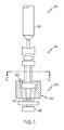
図1を参照すると、光学系90の一部が、明確にするために特定の部材が切り取られて図示されている。図示された実施の形態において、光学系90は、光源92、少なくとも1つのビーム整形素子94、光学アセンブリ100、および部品キャリア96を備える。光学アセンブリ100はレンズホルダ110およびレンズ130を備える。光源92により提供される光は、光学アセンブリ100のレンズ130を通して向けられ、このレンズは、部品キャリア96上に支持されている加工対象物80に向けて、その光を透過させ、屈折させる。光学系90は、加工対象物80に対して製造操作を行うため、例えば、リソグラフィー過程などにおいて、加工対象物80を検査する、または加工対象物80を変更するために使用することができる。
Referring to FIG. 1, a portion of
ここで、図2を参照すると、光学アセンブリ100の1つの実施の形態が示されている。この実施の形態において、光学アセンブリ100はレンズホルダ110およびレンズ130を備える。図3に断面で示されているこのレンズホルダ110は、締結部分112およびレンズ支持部分118を備える。締結部分112は、前記光学系内にレンズホルダ110を、および/または前記光学系の内部に他のレンズホルダを締結するための固定位置を提供する複数の取付要素114を備える。図2に示された実施の形態において、貫通孔が締結部分112を貫通している。締結部分112は、クロック要素116、例えば、鍵および/または鍵穴も備えることがある。クロック要素116は、光学系90の構成部材のアライメントを維持できるように、光学系90の隣接する構成部材の間の方位基準を与えることができる。
Referring now to FIG. 2, one embodiment of the
図示された実施の形態において、レンズ支持部分118は、締結部分112から半径方向内向きに延在している。レンズ支持部分118は、図4に詳しく示されるように、平面部分124および輪郭部分126を備えることがある。この実施の形態において、輪郭部分126は、平面部分124から半径方向内側の位置に位置している。輪郭部分126は、接着剤140によってレンズ130がレンズ支持部分118に結合される位置で、レンズ130の一般的形状に一致するように成形されることがある。
In the illustrated embodiment, the
図4を参照すると、レンズ130の取付部分134が、接着剤140によってレンズ支持部分118に結合されている。いくつかの実施の形態において、接着剤140は、レンズ130の周りの周縁方位に配列された複数の位置に配置されている。接着剤140の領域は、接着剤140の複数の領域間の中間の周縁位置で互いから隔てられることがあり、よって光学アセンブリ100は、接着剤140の領域間の周縁位置で接着剤140を概して含まない。
Referring to FIG. 4, the
接着剤140に適した材料としては、セメントおよび接着剤を含む市販の材料が挙げられ、その例が、ここに全てが引用される、米国特許第7232595号および同第7256221号の各明細書に述べられている。光学アセンブリ100を組み立てるときに、接着剤140は、レンズホルダ110のレンズ支持部分118に沿った所望の位置に配置してよい。レンズ130は、クロック要素116を含むレンズホルダ110のデータ特徴に対して適所に挿入し、保持することができる。レンズ130は、接着剤140が乾燥または硬化する機会を持つまで適所に保持され、それによって、レンズ130の位置をレンズホルダ110のデータ特徴に対して維持することができる。これらの接着剤の材料は、典型的に、弾性率および熱膨張係数の操作上の必要条件を満たし、ここに記載された光学系90に使用するのに適している。
Suitable materials for adhesive 140 include commercially available materials including cement and adhesives, examples of which are described in US Pat. Nos. 7,232,595 and 7,256,221, all of which are hereby incorporated by reference. It is stated. When assembling the
しかしながら、接着剤140として使用される材料は、特定の波長を持つ光源により照射されたときに、劣化する傾向があるであろう。光源が短波長、例えば、深紫外線および極紫外線波長に対応する波長で発光する場合、劣化は特に深刻であろう。光源からのエネルギーは、短波長では、接着剤140の材料を分解する傾向にある。その劣化は、接着剤140のガス放出をもたらすことがあり、これにより、光学系90が汚染されることがある。接着剤140の劣化は、接着剤140の引張強度および/または弾性にも悪影響を与えるであろうし、これにより、レンズホルダ110のデータ特徴に対するレンズ130の位置を維持する接着剤140の能力も低下するであろう。レンズ130とレンズホルダ110のデータ特徴との間のずれにより、光学系90の性能特徴が低下するであろう。
However, the material used as adhesive 140 will tend to degrade when irradiated by a light source having a particular wavelength. Deterioration will be particularly severe when the light source emits light at wavelengths corresponding to short wavelengths, such as deep and extreme ultraviolet wavelengths. The energy from the light source tends to decompose the material of the adhesive 140 at short wavelengths. The degradation can result in outgassing of the adhesive 140, which can contaminate the
図2および3に示される実施の形態において、レンズ支持部分118は、レンズ支持部分118の周りの周縁方位に配置されている複数の支持パッド120を備える。この複数の支持パッド120の各々は、レンズ130の光軸132に対応する方向に支持パッド120から間隔が置かれたリリーフ通路122によって互いにから隔てられている。支持パッド120およびリリーフ通路122は、レンズ130が結合されるレンズ支持部分118に沿って断続取付面を提供する。この実施の形態において、レンズ130に接触するように、支持パッド120に沿って接着剤140が配置されている。接着剤140は、概して、リリーフ通路122に最も近い位置には配置されず、よって、レンズ130は、リリーフ通路122に最も近い位置でレンズホルダ110から隔てられている。レンズ130とレンズホルダ110のリリーフ通路122との間の間隔が、流体が移動できる間隙を与える。光学系90の特定の実施の形態において、バージガスを光学アセンブリ100に導入し、リリーフ通路122とレンズ130との間に生じた間隙に流して、どのような汚染物質も流し出すことができる。
In the embodiment shown in FIGS. 2 and 3, the
図2および3の実施の形態は、3つの支持パッド120と、したがって3つのリリーフ通路122と、接着剤140の3つの領域とを含むレンズホルダ110を示しているが、レンズホルダ110は、光学系90の設計および要件により必然的に決まるように、いくつの支持パッド120、リリーフ通路122、および接着剤140の領域を含んでもよいことが理解されよう。
While the embodiment of FIGS. 2 and 3 shows a
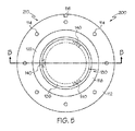
ここで、図5および6を参照すると、レンズホルダ210およびレンズ130を含む光学アセンブリ200の別の実施の形態が示されている。この実施の形態において、レンズホルダ210は、締結部分112およびレンズ支持部分118を備える。締結部分112は、その光学系内にレンズホルダ210を結合させる固定位置を与える複数の取付要素114、ここでは、締結部分112を貫通する貫通孔を備える。締結部分112は、クロック要素116、例えば、鍵および/または鍵穴も備えることがある。クロック要素116は、光学系90の構成部材の径方向アライメントを維持できるように、光学系90の隣接する構成部材の間の方位基準を与えることができる。
Referring now to FIGS. 5 and 6, another embodiment of an
この実施の形態において、レンズ支持部分118は、外周136の周りで形状が連続的であることがあり、よって、レンズ支持部分118は周縁方位で途切れていない。レンズ130は、レンズ130の外周136に最も近い位置に配置された別個の領域に配置された接着剤140によって、レンズ支持部分118に結合されている。接着剤140は、概して、別個の領域内のみに配置されることがあり、よって、接着剤140は、隣接する領域の間の位置には配置されていない。
In this embodiment, the
接着剤140はレンズホルダ210のレンズ支持部分118とレンズ130との間の別個の領域に配置されているので、また接着剤140は厚さを有するであろうから、レンズ130は、接着剤140の分だけレンズ支持部分118の上に配置されるであろう。これらの実施の形態において、接着剤140の別個の領域間の位置で、レンズ支持部分118とレンズ130との間の間隔が、流体が移動できる間隙を与えるであろう。光学系90の特定の実施の形態において、バージガスを光学アセンブリ200に導入し、接着剤140の別個の領域から間隔が置かれた位置でレンズ支持部分118とレンズ130との間に生じた間隙に流して、どのような汚染物質も流し出すことができる。
Since the adhesive 140 is disposed in a separate region between the
図2〜6を参照して先に述べられた実施の形態は、その接着剤を別個の領域に配置してよいと記載しているが、他の実施の形態において、その接着剤は、レンズをレンズホルダに接着させるのに適したどの構成でレンズに施されてもよい。例えば、いくつかの実施の形態において、その接着剤は、レンズの外周の周りに連続的に施されてもよい。 Although the embodiments described above with reference to FIGS. 2-6 describe that the adhesive may be placed in a separate region, in other embodiments, the adhesive may be a lens. May be applied to the lens in any configuration suitable for adhering to the lens holder. For example, in some embodiments, the adhesive may be applied continuously around the outer periphery of the lens.
前記光学系において紫外線により生じる劣化または損傷から接着剤を保護するために、本明細書は、レンズに遮断コーティングを与える。その遮断コーティングは、レンズと接着剤との間に配置され、接着剤への紫外線を遮断するように構成されている。先に述べたように、レンズは、接着剤でホルダに取り付けられることがある。その接着剤は、レンズの1つ以上の外半径または周辺部分とアライメントされたホルダの1つ以上の位置に配置されている。その遮断コーティングは、光学素子がホルダに取り付けられたときに、接着剤の位置と略一致する位置でレンズに施される。レンズの内側径方向または中央部分は、光学系の設計にしたがって光を透過させるために使用され、遮断コーティングがレンズの透過を損なわないことを保証するために遮断コーティングがないレンズの作用部分である。遮断コーティングは、接着剤と直接的または間接的に接触していてよい。遮断コーティングは、レンズと直接的または間接的に接触していてよい。実施の形態が以下に示されている。 In order to protect the adhesive from degradation or damage caused by ultraviolet light in the optical system, the present specification provides a barrier coating on the lens. The barrier coating is disposed between the lens and the adhesive and is configured to block ultraviolet light to the adhesive. As previously mentioned, the lens may be attached to the holder with an adhesive. The adhesive is disposed at one or more locations on the holder that are aligned with one or more outer radii or peripheral portions of the lens. The barrier coating is applied to the lens at a position that substantially coincides with the position of the adhesive when the optical element is attached to the holder. The inner radial or central part of the lens is the working part of the lens that is used to transmit light according to the design of the optical system and has no blocking coating to ensure that the blocking coating does not impair the transmission of the lens . The barrier coating may be in direct or indirect contact with the adhesive. The barrier coating may be in direct or indirect contact with the lens. Embodiments are shown below.
ここで、図7に示された実施の形態を参照すると、光学アセンブリは、レンズ130と接着剤140との間に配置された光吸収体190を含む遮断コーティングを備える層状構造900を備えることがある。光吸収体190は、接着剤140を劣化させるかもしれない、光源910から発せられる光の波長を吸収および/または反射するように構成されている。実施の形態において、光吸収体190は、吸収および/または反射された波長内の光が接着剤140に入射するのを防ぐために、例えば、図7に示されるように、光源910と接着剤140との間に配置されることがある。図7は層状構造900の水平配向を示しているが、垂直配向などの層状構造の他の配向が、図7に示された実施の形態、並びにここに開示された層状構造の全ての実施の形態に関して、本開示の範囲内にあることを理解すべきである。
Referring now to the embodiment shown in FIG. 7, the optical assembly comprises a
光吸収体190は、紫外線の幅広いスペクトルを吸収するどの材料から作られていてもよい。実施の形態において、光吸収体190は、接着剤140を硬化させるために使用される主硬化波長および化学線波長の両方を吸収する材料から作られている。いくつかの実施の形態において、光吸収体190は、約220nm以上から約480nm以下などの、約190nm以上から約500nm以下の波長を持つ光を吸収する。他の実施の形態において、光吸収体190は、約240nm以上から約440nm以下などの約230nm以上から約460nm以下の波長を持つ光を吸収する。さらに他の実施の形態において、光吸収体190は、約260nm以上から約375nm以下などの約250nm以上から約400nm以下の波長を持つ光を吸収する。また他の実施の形態において、光吸収体190は、約265nm以上から約365nm以下の波長を持つ光を吸収する。光吸収体190の厚さおよび組成は、先に示されたいずれの範囲内の波長を有する放射線の少なくとも90%、または少なくとも95%、または少なくとも99%を吸収および/または反射するように選択されることがある。
The
光吸収体190を構成する材料は、上述したように、紫外線の少なくとも一部を吸収および/または反射することができる。いくつかの実施の形態において、光吸収体190を構成する材料は、紫外線を吸収および/または反射することができる一種類以上の金属であることがある。他の実施の形態において、光吸収体190を構成する材料は、一種類以上の遷移金属であることがある。さらに他の実施の形態において、光吸収体190を構成する材料は、クロム、チタン、亜鉛、ニッケル、マンガン、鉄、ニオブ、銀、金、ハフニウム、アルミニウム、タンタル、およびそれらの混合物から選択されることがある。実施の形態において、前記金属は、実質的に純粋な金属として、または金属酸化物、金属窒化物、金属炭化物、またはそれらの混合物として存在してもよい。光吸収体として使用できる様々な材料は、以前は入手できなかった層状構造の異なる構成を可能にする。例えば、いくつかの実施の形態において、光吸収体の材料は、その光吸収体が、光源に面さないレンズ130の表面に施されるように選択されることがある。しかしながら、いくつかの実施の形態において、光吸収体の材料は、その光吸収体が、光源に面するレンズ130の表面に施されるように選択されることがある。
As described above, the material constituting the
図7は、同じ近似厚を有する層状構造900の層を示しているが、実施の形態において、層状構造900の各層は、どのような適切な厚さを有してもよい。光吸収体190は、化学線波長の光の透過率が約5%以下、またさらには約4%以下となるような厚さを有することがある。いくつかの実施の形態において、前記光吸収体の厚さは、化学線波長の光の透過率が約3%以下、またさらには約2%以下となるようなものである。その上、その光吸収体は、接着剤を硬化させる波長の光を透過させない。したがって、実施の形態において、その光吸収体の厚さは、硬化波長の光を透過させるように調節する必要はない。したがって、光吸収体の厚さは、硬化波長の光を透過させるように調整されていなかったであろうから以前は望ましくなかった光学アセンブリの構成が、いくつかの実施の形態において利用されることがある。その光吸収体の厚さは、25nm〜500nmの範囲、または50nnm〜400nmの範囲、または100nm〜300nmの範囲にあることがある。
FIG. 7 shows layers of
いくつかの実施の形態において、層状構造900は、前記光学アセンブリに他の特性を与えるように構成されることがある。実施の形態において、層状構造900は、光吸収体190、接着剤140、および/またはレンズホルダ310からの光の反射がその光学装置の様々な構成部材中に散乱する(その光学装置の作動を不完全にすることがある)のを減少させるように構成されることがある。その反射防止特性は、光をわずかしかまたは全く反射しない光吸収体190を選択することによって与えられるであろう。しかしながら、いくつかの実施の形態において、反射防止特性は、層状構造900にある層を加えることによって与えてもよい。いくつかの実施の形態において、ある層の別の層への接着を促進するために、および/または層状構造900の層を保護するために、層状構造900に層を加えてもよい。
In some embodiments, the
ここで、図8に示された実施の形態を参照すると、層状構造900は、レンズ130、光吸収体190、接着剤140、およびレンズホルダ310に加えて、層を備えることがある。いくつかの実施の形態において、層状構造900は、光吸収体190と、反射防止層1100および引掻き防止層1200の1つ以上とを有する遮断コーティングを備えることがある。反射防止層1100は、レンズ130と光吸収体190との間に配置されることがある。反射防止層1100は、内部反射防止層として働く材料から作られることがある。反射防止層1100を構成する材料は、層状構造900に反射防止特性を与えるどのような材料であってもよい。いくつかの実施の形態において、反射防止層1100は、金属酸化物、金属炭化物、金属窒化物、またはそれらの混合物からなることがある。いくつかの実施の形態において、反射防止層1100は、クロム、チタン、亜鉛、ニッケル、マンガン、鉄、ニオブ、銀、金、ハフニウム、アルミニウム、タンタル、およびそれらの混合物の酸化物を含むことがある。いくつかの実施の形態において、反射防止層1100は、光吸収体190を構成する金属の酸化物を含むことがある。例えば、光吸収体190がクロムからなる場合、反射防止層1100は、酸化クロム(III)などの酸化クロムからなることがある。しかしながら、他の実施の形態において、反射防止層1100は、光吸収体190の金属とは異なる金属を有する金属酸化物からなってもよい。いくつかの実施の形態において、反射防止層1100を有する層状構造は、約18%以下、またさらには約16%以下などの約20%以下の、190nmから500nmの波長範囲内の任意の波長での反射率を有してもよい。その反射防止層の厚さは、10nm〜100nmの範囲、または20nm〜80nmの範囲、または30nm〜60nmの範囲内にあることがある。
Referring now to the embodiment shown in FIG. 8, the
層状構造900の遮断コーティングは、引掻き防止層1200も含むことがある。実施の形態において、その引掻き防止層は、光吸収体190と接着剤140との間に施されることがある。引掻き防止層1200は、光吸収体190が、加工中に損傷を受けるのを防ぐ。例えば、光吸収体190が引っ掻かれた場合、光源910からの光が、光吸収体190の引掻き傷を通って接着剤140に透過されることがあり、それにより接着剤140が劣化し、レンズ130がずれるかもしれない。引掻き防止層1200を与えることによって、引掻きなどによって、光吸収体190が損傷を受けることが少なくなる。引掻き防止層1200は、光吸収体190に耐引掻性を与えることができ、また光吸収体190および接着剤140に適合もするどの材料からなってもよい。いくつかの実施の形態において、引掻き防止層1200は、金属酸化物、金属窒化物、金属炭化物、またはそれらの混合物からなることがある。いくつかの実施の形態において、引掻き防止層1200は、クロム、チタン、亜鉛、ニッケル、マンガン、鉄、ニオブ、銀、金、ハフニウム、アルミニウム、タンタル、およびそれらの混合物の酸化物からなることがある。いくつかの実施の形態において、引掻き防止層1200は、光吸収体190を構成する金属の酸化物からなることがある。例えば、光吸収体190がクロムからなる場合、引掻き防止層1200は、酸化クロム(III)などの酸化クロムからなることがある。しかしながら、他の実施の形態において、引掻き防止層1200は、光吸収体190の金属とは異なる金属を有する金属酸化物からなってもよい。その引掻き防止層の厚さは、50nm〜400nmの範囲、または75nnm〜300nmの範囲、または100nm〜200nmの範囲にあることがある。
The barrier coating of the
ここで図9を参照すると、層状構造900は、多数の光吸収体190および多数の反射防止層1100を有する遮断コーティングを備えることがある。光吸収体190および反射防止層1100の数は、光学装置の物理的制約条件により制限される。実施の形態において、各光吸収体190は、レンズ130に最も近い側に配置された反射防止層1100を有する。いくつかの実施の形態において、2つの光吸収体190および2つの反射防止層1100、またさらには3つの光吸収体190および3つの反射防止層1100があることがある。他の実施の形態において、4つの光吸収体190および4つの反射防止層1100、またさらには5つの光吸収体190および5つの反射防止層1100があることがある。
Referring now to FIG. 9, the
ここで、図10に示された実施の形態を参照すると、光学アセンブリは、レンズ130と接着剤140との間に配置された接着促進剤1300を含む層状構造900を備えることがある。接着促進剤1300は、レンズ130に直接隣接するように優先的に配置されている。接着促進剤1300は、レンズ130に対する光吸収体190の接着を改善し、遮断コーティングが剥離する可能性を最小にする。
Referring now to the embodiment shown in FIG. 10, the optical assembly may comprise a
ここで、図11に示された実施の形態を参照すると、層状構造900は、レンズ130、光吸収体190、反射防止層1100と引掻き防止層1200の1つ以上、接着剤140、およびレンズホルダ310に加え、接着促進剤1300を備えることがある。接着促進剤1300は、レンズ130に優先的に直接隣接しており、レンズ130に対する反射防止層1100の接着を改善する。
Referring now to the embodiment shown in FIG. 11, the
ここで図12を参照すると、層状構造900は、レンズ130、多数の光吸収体190と多数の反射防止層1100、随意的な引掻き防止層1200、接着剤140、およびレンズホルダ310に加え、接着促進剤1300を備えることがある。接着促進剤1300は、多周期層状積重体において、レンズ130に優先的に直接隣接しており、レンズ130に対する反射防止層1100の接着を改善する。
Referring now to FIG. 12, the
接着促進剤1300は、レンズ130に対する光吸収体190または反射防止層1100の接着を改善するどのような材料であってもよい。1つの実施の形態において、接着促進剤1300はフッ化物材料である。フッ化物材料としては、アルカリ土類フッ化物、遷移金属フッ化物、希土類フッ化物、またはそれらの組合せが挙げられる。代表的なフッ化物材料としては、AlF3、BaF2、CaF2、GdF3、LaF3、MgF2、NdF3、TbF3、YbF3、およびYF3が挙げられる。1つの実施の形態において、レンズ130はフッ化物材料を含み、接着促進剤1300はフッ化物材料である。別の実施の形態において、レンズ130はCaF2を含み、接着促進剤1300はMgF2またはCaxMg1-xF2を含む。1つの実施の形態において、接着促進剤1300はレンズ130に直接隣接している。別の実施の形態において、接着促進剤1300は、二種類以上の材料または2つ以上の層を含む。さらに別の実施の形態において、接着促進剤1300は、反射防止性であり、層状積重体900における反射防止層として機能する。その接着促進剤の厚さは、1nm〜50nmの範囲、または3nm〜30nmの範囲、または5nm〜20nmの範囲にあることがある。
図7〜12は、レンズの一方の側に位置する層状構造の構成部材の全てを示しているが、いくつかの実施の形態において、その層状構造の他の構成部材が、紫外線が接着剤に入射するのを防ぐ限り、接着剤が、層状構造の他の構成部材からレンズの反対側に配置されていてもよい。例えば、実施の形態において、前記吸収体(および必要に応じて、接着促進剤、反射防止層、引掻き防止層、およびキャッピング層)は、光源が入射するレンズの側に位置していてもよい。前記接着剤は、レンズの反対の非入射側に配置されることがあるが、前記吸収体は、それでも、接着剤が適切に構成された場合、紫外線が接着剤に入射するのを防ぐであろう。 FIGS. 7-12 show all of the layered structure components located on one side of the lens, but in some embodiments, the other layered structure components have UV light on the adhesive. An adhesive may be arranged on the opposite side of the lens from other components of the layered structure as long as it is prevented from entering. For example, in the embodiment, the absorber (and an adhesion promoter, an antireflection layer, an anti-scratch layer, and a capping layer as necessary) may be located on the lens side on which the light source is incident. The adhesive may be placed on the opposite non-incident side of the lens, but the absorber will still prevent UV light from entering the adhesive if the adhesive is properly configured. Let's go.
前記層状構造は、どの適切な方法によってレンズに施されてもよい。例えば、いくつかの実施の形態において、その層状構造は、真空蒸着、スパッタリング、噴霧被覆、インクジェット印刷などによって施されてもよい。層状構造が、例えば、真空蒸着またはスパッタリングにより施される実施の形態において、施用中にレンズの光学面を保護するために、マスクが使用されることがある。そのマスクは、レンズの外周のみと直接接触するように構成され、蒸着方法からの保護を与えながら、レンズの光学面を引っ掻かないかまたは他に損傷しないように、レンズの光学面と直接接触しない。そのマスクは、レンズホルダに接着される目的のレンズの所定の部分を覆わない。マスクが一旦適所に配置されたら、その層状構造を、レンズの所定の部分に施してよい。 The layered structure may be applied to the lens by any suitable method. For example, in some embodiments, the layered structure may be applied by vacuum deposition, sputtering, spray coating, ink jet printing, and the like. In embodiments where the layered structure is applied, for example, by vacuum evaporation or sputtering, a mask may be used to protect the optical surface of the lens during application. The mask is configured to be in direct contact only with the outer periphery of the lens, providing direct contact with the lens optical surface so as not to scratch or otherwise damage the lens optical surface while providing protection from the deposition method. do not do. The mask does not cover certain portions of the target lens that are bonded to the lens holder. Once the mask is in place, the layered structure may be applied to a predetermined portion of the lens.
図13は、レンズに遮断コーティング、接着促進剤、および/またはキャッピング層を施すための材料固定具を示す。材料固定具200は、レンズ130をその外周で支持するためのマスク210およびレンズ130の中央部分へのコーティングの堆積を防ぐためのカバー220を備える。外半径または周辺領域230は、遮断コーティング、接着促進剤、および/またはキャッピング層が堆積される表面を提供するために露出されたままである。その堆積領域は、レンズが取り付けられるホルダ上またはその中の接着剤の位置と揃っている、または略一致する。
FIG. 13 shows a material fixture for applying a barrier coating, adhesion promoter, and / or capping layer to a lens. The
光学装置内の接着剤を保護する方法も開示されている。実施の形態において、その方法は、少なくとも、ここに記載されたような遮断コーティングおよび接着促進剤を光学素子に施す工程を有してなる。その方法は、その光学素子をホルダに接着剤で取り付ける工程も含むことがある。その遮断コーティングは、接着促進剤に直接隣接して施されることがあり、その接着促進剤は、その光学素子に直接隣接して施されることがある。その遮断コーティングは、光学素子が光学装置内に取り付けられたときに、紫外線が接着剤に入射しないように接着剤を遮蔽するように光吸収体が配置されるように構成された光吸収体を含む。その光吸収体は、光源からの紫外線(接着剤を劣化させ得る)を透過させない。その光吸収体は、接着促進剤に直接隣接して施されることがある。実施の形態において、遮断コーティングを施す工程は、記載されたような反射防止層を施す工程をさらに含むことがあり、その反射防止層は光学素子と光吸収体との間に配置される。その反射防止層は、接着促進剤に直接隣接して配置されることがある。いくつかの実施の形態において、遮断コーティングを施す工程は、光学装置への取付け中などの取扱い中に光学素子を保護するために、光学素子と反対の光吸収体の表面に、ここに記載されたような引掻き防止層を施す工程を含むことがある。 A method for protecting adhesive in an optical device is also disclosed. In an embodiment, the method comprises at least the step of applying a barrier coating and adhesion promoter as described herein to the optical element. The method may also include attaching the optical element to the holder with an adhesive. The barrier coating may be applied directly adjacent to the adhesion promoter, and the adhesion promoter may be applied directly adjacent to the optical element. The barrier coating comprises a light absorber configured such that when the optical element is mounted in an optical device, the light absorber is arranged to shield the adhesive so that ultraviolet rays do not enter the adhesive. Including. The light absorber does not transmit ultraviolet rays (which can degrade the adhesive) from the light source. The light absorber may be applied directly adjacent to the adhesion promoter. In embodiments, the step of applying a barrier coating may further include the step of applying an antireflection layer as described, the antireflection layer being disposed between the optical element and the light absorber. The antireflective layer may be placed directly adjacent to the adhesion promoter. In some embodiments, the step of applying a barrier coating is described herein on the surface of the light absorber opposite the optical element to protect the optical element during handling, such as during attachment to an optical device. A step of applying such a scratch-preventing layer.
前記層状構造の各層は、真空蒸着、スピン・オン・コーティング、ゾルゲル堆積、インクジェット堆積、化学蒸着、物理的気相堆積、および電子ビーム蒸着などのどの適切な堆積方法によって施されてもよい。いくつかの実施の形態において、その層状構造の各層は、同じ堆積方法によって施されることがある。しかしながら、他の実施の形態において、その層状構造の1つ以上の層は、他の層とは異なる堆積方法よって施されることがある。いくつかの実施の形態は、その光吸収体または引掻き防止層の一方を、光学素子をホルダに接着させるように構成された接着剤と接触させる工程を含む。 Each layer of the layered structure may be applied by any suitable deposition method such as vacuum evaporation, spin-on coating, sol-gel deposition, ink jet deposition, chemical vapor deposition, physical vapor deposition, and electron beam evaporation. In some embodiments, each layer of the layered structure may be applied by the same deposition method. However, in other embodiments, one or more layers of the layered structure may be applied by a different deposition method than the other layers. Some embodiments include contacting one of the light absorber or anti-scratch layer with an adhesive configured to adhere the optical element to the holder.
実施の形態を、以下の実施例によってさらに明らかにする。 The embodiment will be further clarified by the following examples.
以下の実施例は、遮断コーティングとレンズとの間に接着促進剤を含んだ場合の、レンズに対する遮断コーティングの接着の改善を示す。その遮断コーティングは、取扱いおよび洗浄中に剥離する傾向にあることが、実際に観察されてきた。ここに記載されたような接着促進剤を含むことは、剥離を防ぐまたは最小にすることを目的とする。 The following examples show the improved adhesion of the barrier coating to the lens when an adhesion promoter is included between the barrier coating and the lens. It has been observed in practice that the barrier coating tends to delaminate during handling and cleaning. Inclusion of an adhesion promoter as described herein aims to prevent or minimize delamination.
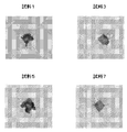
いくつかの試料を調製した。各試料は、CaF2から作られた光学素子と、Cr2O3の40nm厚の層(反射防止層)、40nm厚のCr層(光吸収体層)、160nm厚のCr2O3層(引掻き防止層)、および上部の10nm厚のSiO2層を含む遮断コーティングとを含んだ。試料1において、接着促進剤は含まれず、遮断コーティングはCaF2光学素子に直接施された。試料3において、CaF2光学素子と遮断コーティングとの間に二重層の接着促進剤が含まれた。この二重層の接着促進剤は、MgF2の10nm厚の層、およびSiO2の10nm厚の層を含んだ。試料5において、SiO2の10nm厚の層が、CaF2光学素子と遮断コーティングとの間の接着促進剤として含まれた。試料7において、MgF2の10nm厚の層が、CaF2光学素子と遮断コーティングとの間の接着促進剤として含まれた。これらの試料の層状構造が、下記に纏められている:
Several samples were prepared. Each sample consists of an optical element made of CaF 2 , a 40 nm thick layer of Cr 2 O 3 (antireflection layer), a 40 nm thick Cr layer (light absorber layer), a 160 nm thick Cr 2 O 3 layer ( Anti-scratch layer) and a barrier coating comprising an upper 10 nm thick SiO 2 layer. In

レンズに対する遮断コーティングの接着強度を評価するために、典型的な取扱いおよび洗浄の条件をシミュレートするように設計された試験を各試料に行った。遮断コーティングの露出(上)面に、0.5Nの力の圧入を施し、そのコーティングをメタノールで拭いた。試験後、表面の画像を得て、表面の状況を検査した。それらの画像が図14に示されている。 In order to evaluate the adhesion strength of the barrier coating to the lens, each sample was subjected to a test designed to simulate typical handling and cleaning conditions. The exposed (top) surface of the barrier coating was press-fitted with a force of 0.5 N and the coating was wiped with methanol. After the test, an image of the surface was obtained and the surface condition was inspected. Those images are shown in FIG.
接着強度は、圧入および洗浄試験により生じた表面損傷のレベルによって測ることができる。接着が良好な遮断コーティングは、接着が不十分な遮断コーティングよりも少ない表面損傷を示すと予測される。接着が不十分な遮断コーティングは、CaF2レンズから分離する、亀裂を生じる、および/または剥離する可能性が高い。図14に示された結果は、試料7が最小の損傷を示し、一方で、最大の損傷が試料1および5に観察されたことを示す。中間の損傷が試料3に観察された。この結果は、フッ化物材料を含む接着促進剤が層状積重体に含まれると、CaF2レンズに対する遮断コーティングの接着が改善されることを示す。
Adhesive strength can be measured by the level of surface damage caused by the press fit and cleaning tests. A barrier coating with good adhesion is expected to exhibit less surface damage than a barrier coating with poor adhesion. A barrier coating with poor adhesion is likely to separate, crack and / or peel from the CaF 2 lens. The results shown in FIG. 14 indicate that sample 7 showed minimal damage while maximum damage was observed in
特定の実施の形態をここに説明し、記載してきたが、請求項の主題の精神および範囲から逸脱せずに、様々な他の変更および改変を行えることが理解されよう。さらに、請求項の主題の様々な態様をここに記載してきたが、そのような態様は、組合せで利用される必要はない。したがって、付随の特許請求の範囲は、請求項の主題の範囲内にあるそのような変更および改変の全てを含むことが意図されている。 While particular embodiments have been illustrated and described herein, it will be appreciated that various other changes and modifications can be made without departing from the spirit and scope of the claimed subject matter. Moreover, although various aspects of the claimed subject matter have been described herein, such aspects need not be utilized in combination. Accordingly, the appended claims are intended to cover all such changes and modifications that are within the scope of the claimed subject matter.
以下、本発明の好ましい実施形態を項分け記載する。 Hereinafter, preferable embodiments of the present invention will be described in terms of items.
実施形態1
光学アセンブリにおいて、
光学素子、
前記光学素子のホルダ、
前記光学素子と前記ホルダとの間に配置された遮断コーティングであって、約190nm以上から約500nm以下の波長を有する光を透過させない光吸収体を含む遮断コーティング、
前記光吸収体と前記光学素子との間に配置された接着促進剤、および
前記光学素子を前記ホルダに接着させるように構成された接着剤、
を備え、
前記光吸収体が、約190nm以上から約500nm以下の波長を有する光が前記接着剤に入射しないように配置されている、光学アセンブリ。
In the optical assembly,
Optical elements,
A holder for the optical element,
A barrier coating disposed between the optical element and the holder, the barrier coating including a light absorber that does not transmit light having a wavelength of about 190 nm to about 500 nm;
An adhesion promoter disposed between the light absorber and the optical element; and an adhesive configured to adhere the optical element to the holder;
With
An optical assembly, wherein the light absorber is arranged so that light having a wavelength of about 190 nm to about 500 nm is not incident on the adhesive.
実施形態2
前記光学素子がレンズである、実施形態1に記載の光学アセンブリ。
The optical assembly of
実施形態3
前記遮断コーティングが、前記光吸収体と前記光学素子との間に配置された反射防止層をさらに含む、実施形態1または2に記載の光学アセンブリ。
Embodiment 3
3. The optical assembly according to
実施形態4
前記反射防止層が、金属酸化物、金属窒化物、金属炭化物、およびそれらの混合物からなる群より選択される材料から作られている、実施形態3に記載の光学アセンブリ。
4. The optical assembly of embodiment 3, wherein the antireflective layer is made from a material selected from the group consisting of metal oxides, metal nitrides, metal carbides, and mixtures thereof.
実施形態5
前記反射防止層が、約190nm以上から約500nm以下の波長を有する光について約20%以下の反射率を有する、実施形態3または4に記載の光学アセンブリ。
Embodiment 5
5. The optical assembly according to
実施形態6
前記遮断コーティングが、前記反射防止層の反対の前記光吸収体の表面に配置された引掻き防止層をさらに含む、実施形態3から5いずれか1つに記載の光学アセンブリ。
Embodiment 6
6. The optical assembly according to any one of embodiments 3-5, wherein the barrier coating further comprises an anti-scratch layer disposed on the surface of the light absorber opposite the anti-reflective layer.
実施形態7
前記引掻き防止層が、金属酸化物、金属窒化物、金属炭化物、およびそれらの混合物からなる群より選択される材料から作られている、実施形態6に記載の光学アセンブリ。
Embodiment 7
The optical assembly of embodiment 6, wherein the anti-scratch layer is made from a material selected from the group consisting of metal oxides, metal nitrides, metal carbides, and mixtures thereof.
実施形態8
前記遮断コーティングが、
前記光学素子の反対の前記光吸収体の表面に配置された第二の反射防止層、および
前記光吸収体の反対の側の前記第二の反射防止層上に配置された第二の光吸収体、
をさらに含む、実施形態3から7いずれか1つに記載の光学アセンブリ。
Embodiment 8
The barrier coating is
A second anti-reflection layer disposed on the surface of the light absorber opposite the optical element; and a second light absorption disposed on the second anti-reflection layer on the opposite side of the light absorber. body,
The optical assembly according to any one of embodiments 3 to 7, further comprising:
実施形態9
前記光吸収体が、金属、金属酸化物、金属窒化物、金属炭化物、およびそれらの混合物からなる群より選択される材料から作られている、実施形態1から8いずれか1つに記載の光学アセンブリ。
Embodiment 9
The optical of any one of embodiments 1-8, wherein the light absorber is made from a material selected from the group consisting of metals, metal oxides, metal nitrides, metal carbides, and mixtures thereof. assembly.
実施形態10
前記光吸収体が、クロム、チタン、亜鉛、ニッケル、マンガン、鉄、ニオブ、銀、金、ハフニウム、アルミニウム、タンタル、それらの酸化物、それらの窒化物、およびそれらの炭化物からなる群より選択される一種類以上の材料から作られている、実施形態1から8いずれか1つに記載の光学アセンブリ。
Embodiment 10
The light absorber is selected from the group consisting of chromium, titanium, zinc, nickel, manganese, iron, niobium, silver, gold, hafnium, aluminum, tantalum, oxides thereof, nitrides thereof, and carbides thereof. Embodiment 9. The optical assembly according to any one of the preceding embodiments, wherein the optical assembly is made from one or more materials.
実施形態11
前記接着促進剤がフッ化物材料から作られている、実施形態1から10いずれか1つに記載の光学アセンブリ。
Embodiment 11
Embodiment 11. The optical assembly according to any one of embodiments 1-10, wherein the adhesion promoter is made from a fluoride material.
実施形態12
前記接着促進剤がMgF2から作られている、実施形態1から10いずれか1つに記載の光学アセンブリ。
Embodiment 11. The optical assembly according to any one of embodiments 1-10, wherein the adhesion promoter is made from MgF 2 .
実施形態13
前記光学素子がCaF2から作られている、実施形態12に記載の光学アセンブリ。
Embodiment 13
The optical element is made of CaF 2, the optical assembly according to
実施形態14
前記光吸収体がCrから作られている、実施形態13に記載の光学アセンブリ。
Embodiment 14
The optical assembly according to embodiment 13, wherein the light absorber is made of Cr.
実施形態15
前記接着促進剤が前記光学素子に直接隣接している、実施形態1から14いずれか1つに記載の光学アセンブリ。
Embodiment 15
The optical assembly according to any one of embodiments 1-14, wherein the adhesion promoter is directly adjacent to the optical element.
実施形態16
前記遮断コーティングが前記接着促進剤に直接隣接している、実施形態15に記載の光学アセンブリ。
The optical assembly according to embodiment 15, wherein the barrier coating is directly adjacent to the adhesion promoter.
実施形態17
前記光吸収体が前記接着促進剤に直接隣接している、実施形態15に記載の光学アセンブリ。
Embodiment 17
The optical assembly according to embodiment 15, wherein the light absorber is directly adjacent to the adhesion promoter.
実施形態18
光学アセンブリにおいて、
光学素子、
約190nm以上から約500nm以下の波長を有する光を透過させない光吸収体を含む遮断コーティング、および
前記光吸収体と前記光学素子との間に配置された接着促進剤、
を備えた、光学アセンブリ。
Embodiment 18
In the optical assembly,
Optical elements,
A barrier coating comprising a light absorber that does not transmit light having a wavelength of about 190 nm or more to about 500 nm or less, and an adhesion promoter disposed between the light absorber and the optical element,
An optical assembly comprising:
実施形態19
前記遮断コーティングが、前記光学素子と前記光吸収体との間に配置された反射防止層をさらに含む、実施形態18に記載の光学アセンブリ。
Embodiment 19
The optical assembly according to embodiment 18, wherein the barrier coating further comprises an anti-reflective layer disposed between the optical element and the light absorber.
実施形態20
前記反射防止層が、金属酸化物、金属窒化物、金属炭化物、およびそれらの混合物からなる群より選択される材料から作られている、実施形態19に記載の光学アセンブリ。
Embodiment 20.
20. The optical assembly of embodiment 19, wherein the anti-reflective layer is made from a material selected from the group consisting of metal oxides, metal nitrides, metal carbides, and mixtures thereof.
実施形態21
前記遮断コーティングが、前記反射防止層の反対の前記光吸収体の表面に配置された引掻き防止層をさらに含む、実施形態18から20いずれか1つに記載の光学アセンブリ。
Embodiment 21.
21. The optical assembly according to any one of embodiments 18-20, wherein the barrier coating further comprises an anti-scratch layer disposed on the surface of the light absorber opposite the anti-reflective layer.
実施形態22
前記引掻き防止層が、金属酸化物、金属窒化物、金属炭化物、およびそれらの混合物からなる群より選択される材料から作られている、実施形態21に記載の光学アセンブリ。
Embodiment 22
The optical assembly according to embodiment 21, wherein the anti-scratch layer is made of a material selected from the group consisting of metal oxides, metal nitrides, metal carbides, and mixtures thereof.
実施形態23
前記光吸収体が、クロム、チタン、亜鉛、ニッケル、マンガン、鉄、ニオブ、銀、金、ハフニウム、アルミニウム、タンタル、それらの酸化物、それらの窒化物、およびそれらの炭化物からなる群より選択される一種類以上の材料から作られている、実施形態18から22いずれか1つに記載の光学アセンブリ。
Embodiment 23
The light absorber is selected from the group consisting of chromium, titanium, zinc, nickel, manganese, iron, niobium, silver, gold, hafnium, aluminum, tantalum, oxides thereof, nitrides thereof, and carbides thereof. Embodiment 23. The optical assembly according to any one of embodiments 18-22, wherein the optical assembly is made from one or more materials.
実施形態24
前記接着促進剤がフッ化物材料から作られている、実施形態18から23いずれか1つに記載の光学アセンブリ。
実施形態25
前記接着促進剤がMgF2から作られている、実施形態18から23いずれか1つに記載の光学アセンブリ。
Embodiment 25
The adhesion promoter is made from MgF 2, the optical assembly according to 23 any one of embodiments 18.
実施形態26
前記光学素子がCaF2から作られている、実施形態25に記載の光学アセンブリ。
Embodiment 26.
The optical element is made of CaF 2, the optical assembly of embodiment 25.
実施形態27
光学アセンブリ内の接着剤の劣化を低減する方法であって、
光学素子に、フッ化物材料から作られた接着促進剤を施す工程;
前記接着促進剤に、約190nm以上から約500nm以下の波長を有する光を透過させない光吸収体を含む遮断コーティングを施す工程;
前記遮断コーティングに接着剤を施す工程;および
約190nm以上から約500nm以下の波長を有する光が前記接着剤に入射しないように、前記光吸収体および該接着剤を構成する工程;
を有してなる方法。
Embodiment 27.
A method for reducing adhesive degradation in an optical assembly comprising:
Applying an adhesion promoter made of a fluoride material to the optical element;
Applying to the adhesion promoter a barrier coating comprising a light absorber that does not transmit light having a wavelength of about 190 nm to about 500 nm;
Applying an adhesive to the barrier coating; and configuring the light absorber and the adhesive so that light having a wavelength of about 190 nm to about 500 nm is not incident on the adhesive;
A method comprising:
実施形態28
前記光学素子と前記光吸収体との間に反射防止層を施す工程をさらに含む、実施形態27に記載の方法。
Embodiment 28.
28. The method of embodiment 27, further comprising applying an antireflection layer between the optical element and the light absorber.
80 加工対象物
90 光学系
92、910 光源
94 ビーム整形素子
96 部品キャリア
100、200 光学アセンブリ
110、210、310 レンズホルダ
112 締結部分
114 取付要素
116 クロック要素
118 レンズ支持部分
120 支持パッド
130 レンズ
140 接着剤
190 光吸収体
220 カバー
900 層状構造
1100 反射防止層
1200 引掻き防止層
1300 接着促進剤
80
Claims (10)
光学素子、
前記光学素子のホルダ、
前記光学素子と前記ホルダとの間に配置された遮断コーティングであって、約190nm以上から約500nm以下の波長を有する光を透過させない光吸収体を含む遮断コーティング、
前記光吸収体と前記光学素子との間に配置された接着促進剤、および
前記光学素子を前記ホルダに接着させるように構成された接着剤、
を備え、
前記光吸収体が、約190nm以上から約500nm以下の波長を有する光が前記接着剤に入射しないように配置されている、光学アセンブリ。 In the optical assembly,
Optical elements,
A holder for the optical element,
A barrier coating disposed between the optical element and the holder, the barrier coating including a light absorber that does not transmit light having a wavelength of about 190 nm to about 500 nm;
An adhesion promoter disposed between the light absorber and the optical element; and an adhesive configured to adhere the optical element to the holder;
With
An optical assembly, wherein the light absorber is arranged so that light having a wavelength of about 190 nm to about 500 nm is not incident on the adhesive.
光学素子、
約190nm以上から約500nm以下の波長を有する光を透過させない光吸収体を含む遮断コーティング、および
前記光吸収体と前記光学素子との間に配置された接着促進剤、
を備えた、光学アセンブリ。 In the optical assembly,
Optical elements,
A barrier coating comprising a light absorber that does not transmit light having a wavelength of about 190 nm or more to about 500 nm or less, and an adhesion promoter disposed between the light absorber and the optical element,
An optical assembly comprising:
光学素子に、フッ化物材料から作られた接着促進剤を施す工程;
前記接着促進剤に、約190nm以上から約500nm以下の波長を有する光を透過させない光吸収体を含む遮断コーティングを施す工程;
前記遮断コーティングに接着剤を施す工程;および
約190nm以上から約500nm以下の波長を有する光が前記接着剤に入射しないように、前記光吸収体および該接着剤を構成する工程;
を有してなる方法。 A method for reducing adhesive degradation in an optical assembly comprising:
Applying an adhesion promoter made of a fluoride material to the optical element;
Applying to the adhesion promoter a barrier coating comprising a light absorber that does not transmit light having a wavelength of about 190 nm to about 500 nm;
Applying an adhesive to the barrier coating; and configuring the light absorber and the adhesive so that light having a wavelength of about 190 nm to about 500 nm is not incident on the adhesive;
A method comprising:
Applications Claiming Priority (3)
| Application Number | Priority Date | Filing Date | Title |
|---|---|---|---|
| US201562206521P | 2015-08-18 | 2015-08-18 | |
| US62/206,521 | 2015-08-18 | ||
| PCT/US2016/047298 WO2017031179A1 (en) | 2015-08-18 | 2016-08-17 | Coating with adhesion layer for uv optics |
Publications (2)
| Publication Number | Publication Date |
|---|---|
| JP2018533034A true JP2018533034A (en) | 2018-11-08 |
| JP2018533034A5 JP2018533034A5 (en) | 2019-09-26 |
Family
ID=56801828
Family Applications (1)
| Application Number | Title | Priority Date | Filing Date |
|---|---|---|---|
| JP2018507668A Pending JP2018533034A (en) | 2015-08-18 | 2016-08-17 | Coating with adhesive layer for UV optics |
Country Status (4)
| Country | Link |
|---|---|
| US (1) | US10578785B2 (en) |
| EP (1) | EP3338127A1 (en) |
| JP (1) | JP2018533034A (en) |
| WO (1) | WO2017031179A1 (en) |
Families Citing this family (3)
| Publication number | Priority date | Publication date | Assignee | Title |
|---|---|---|---|---|
| DE102017213065B3 (en) * | 2017-04-13 | 2018-07-05 | Christian-Albrechts-Universität Zu Kiel | A process for the production of plano-convex lens elements and for the production of a packaged device at the wafer level |
| TWI676852B (en) * | 2018-10-31 | 2019-11-11 | 白金科技股份有限公司 | Light shielding sheet |
| WO2022203861A1 (en) * | 2021-03-23 | 2022-09-29 | Corning Incorporated | Capped blocking coating for laser optics |
Citations (2)
| Publication number | Priority date | Publication date | Assignee | Title |
|---|---|---|---|---|
| US20060033984A1 (en) * | 2004-08-10 | 2006-02-16 | Carl Zeiss Smt Ag | Optical mount with UV adhesive and protective layer |
| WO2015034813A1 (en) * | 2013-09-06 | 2015-03-12 | Corning Incorporated | Uv protective coating for lens assemblies |
Family Cites Families (12)
| Publication number | Priority date | Publication date | Assignee | Title |
|---|---|---|---|---|
| JP2996502B2 (en) | 1990-10-01 | 2000-01-11 | キヤノン株式会社 | Developer amount detecting method and image forming apparatus |
| US5593852A (en) * | 1993-12-02 | 1997-01-14 | Heller; Adam | Subcutaneous glucose electrode |
| DE19733490C1 (en) | 1997-08-01 | 1999-02-25 | Zeiss Carl Fa | Optical frame with UV glue and protective layer |
| US7081278B2 (en) | 2002-09-25 | 2006-07-25 | Asml Holdings N.V. | Method for protection of adhesives used to secure optics from ultra-violet light |
| NL1024722C2 (en) | 2002-11-07 | 2005-12-23 | Corning Inc | Low outgassing rubbery polymeric material that can be cured by a light or electron beam, as well as the preparation and use thereof. |
| US7232595B2 (en) | 2002-11-07 | 2007-06-19 | Corning Incorporated | Device comprising low outgassing photo or electron beam cured rubbery polymer material |
| KR101240775B1 (en) * | 2006-09-12 | 2013-03-07 | 칼 짜이스 에스엠테 게엠베하 | Optical arrangement for immersion lithography with a hydrophobic coating, and projection exposure apparatus comprising the same |
| US8335045B2 (en) | 2010-02-24 | 2012-12-18 | Corning Incorporated | Extending the stability of UV curable adhesives in 193NM laser systems |
| DE102014108058A1 (en) * | 2014-06-06 | 2015-12-17 | Schott Ag | Optical element with high scratch resistance |
| WO2013105163A1 (en) * | 2012-01-13 | 2013-07-18 | 日本化薬株式会社 | Optical members and ultraviolet curable adhesive used in manufacturing same |
| JP6060636B2 (en) * | 2012-01-30 | 2017-01-18 | 旭硝子株式会社 | Reflective mask blank for EUV lithography and reflective mask for EUV lithography |
| US9144938B2 (en) * | 2012-08-06 | 2015-09-29 | Apple Inc. | Methods for attaching structures using ultraviolet and visible light curing adhesive |
-
2016
- 2016-08-05 US US15/229,779 patent/US10578785B2/en active Active
- 2016-08-17 WO PCT/US2016/047298 patent/WO2017031179A1/en unknown
- 2016-08-17 JP JP2018507668A patent/JP2018533034A/en active Pending
- 2016-08-17 EP EP16757442.5A patent/EP3338127A1/en not_active Withdrawn
Patent Citations (2)
| Publication number | Priority date | Publication date | Assignee | Title |
|---|---|---|---|---|
| US20060033984A1 (en) * | 2004-08-10 | 2006-02-16 | Carl Zeiss Smt Ag | Optical mount with UV adhesive and protective layer |
| WO2015034813A1 (en) * | 2013-09-06 | 2015-03-12 | Corning Incorporated | Uv protective coating for lens assemblies |
Also Published As
| Publication number | Publication date |
|---|---|
| WO2017031179A1 (en) | 2017-02-23 |
| US10578785B2 (en) | 2020-03-03 |
| US20170052293A1 (en) | 2017-02-23 |
| EP3338127A1 (en) | 2018-06-27 |
Similar Documents
| Publication | Publication Date | Title |
|---|---|---|
| KR101764084B1 (en) | Near-infrared cut filter and solid-state imaging device | |
| CA2633665C (en) | Radiation image converting panel, scintillator panel and radiation image sensor | |
| JP6862509B2 (en) | UV protective coating for lens assembly | |
| JP2018525676A (en) | UV blocking coating with capping layer for optical elements | |
| JP2018533034A (en) | Coating with adhesive layer for UV optics | |
| KR102104081B1 (en) | Camera structure, information and communication equipment | |
| KR102380961B1 (en) | Mirror for a microlithographic projection exposure apparatus | |
| JP6625207B2 (en) | Optical parts and laser processing machines | |
| IL127867A (en) | Environmentally resistant, infrared-transparent window structure | |
| US8152316B2 (en) | Imaging device | |
| JP2007271504A (en) | Scintillator panel, planar detector and imaging apparatus | |
| KR101985813B1 (en) | Optical element | |
| JPH08271701A (en) | Environmental resistant infrared ray transmissive structural body suing zinc sulfide as substrate | |
| JP3394821B2 (en) | Explosion-proof protective glass for temperature camera | |
| US20220278154A1 (en) | Sensor unit | |
| JP4074217B2 (en) | Lens protection member for laser processing machine and method for manufacturing the same | |
| KR101766392B1 (en) | Reflective mirror and Method for manufacturing the same | |
| Sulzbach | Infrared antireflection coatings without thorium fluoride | |
| JP2024512543A (en) | Covered blocking coating for laser optics | |
| KR20200076521A (en) | Lens for camera module | |
| JP2022142660A (en) | Semiconductor substrate and manufacturing method thereof | |
| JP2020149060A (en) | Infrared cut filter | |
| JP2009098545A (en) | Optical member and optical system having the same | |
| WO2009016656A1 (en) | Thin-film multilayer treatment for bidirectional attenuation of stray light |
Legal Events
| Date | Code | Title | Description |
|---|---|---|---|
| A521 | Request for written amendment filed |
Free format text: JAPANESE INTERMEDIATE CODE: A523 Effective date: 20190815 |
|
| A621 | Written request for application examination |
Free format text: JAPANESE INTERMEDIATE CODE: A621 Effective date: 20190815 |
|
| A977 | Report on retrieval |
Free format text: JAPANESE INTERMEDIATE CODE: A971007 Effective date: 20200527 |
|
| A131 | Notification of reasons for refusal |
Free format text: JAPANESE INTERMEDIATE CODE: A131 Effective date: 20200610 |
|
| A601 | Written request for extension of time |
Free format text: JAPANESE INTERMEDIATE CODE: A601 Effective date: 20200910 |
|
| A521 | Request for written amendment filed |
Free format text: JAPANESE INTERMEDIATE CODE: A523 Effective date: 20201109 |
|
| A02 | Decision of refusal |
Free format text: JAPANESE INTERMEDIATE CODE: A02 Effective date: 20210106 |