JP2018530768A - Applications, methods, and systems for laser delivery addressable arrays - Google Patents
Applications, methods, and systems for laser delivery addressable arrays Download PDFInfo
- Publication number
- JP2018530768A JP2018530768A JP2018501225A JP2018501225A JP2018530768A JP 2018530768 A JP2018530768 A JP 2018530768A JP 2018501225 A JP2018501225 A JP 2018501225A JP 2018501225 A JP2018501225 A JP 2018501225A JP 2018530768 A JP2018530768 A JP 2018530768A
- Authority
- JP
- Japan
- Prior art keywords
- laser
- laser beam
- array
- combined
- brightness
- Prior art date
- Legal status (The legal status is an assumption and is not a legal conclusion. Google has not performed a legal analysis and makes no representation as to the accuracy of the status listed.)
- Pending
Links
Images


Classifications
-
- H—ELECTRICITY
- H01—ELECTRIC ELEMENTS
- H01S—DEVICES USING THE PROCESS OF LIGHT AMPLIFICATION BY STIMULATED EMISSION OF RADIATION [LASER] TO AMPLIFY OR GENERATE LIGHT; DEVICES USING STIMULATED EMISSION OF ELECTROMAGNETIC RADIATION IN WAVE RANGES OTHER THAN OPTICAL
- H01S5/00—Semiconductor lasers
- H01S5/40—Arrangement of two or more semiconductor lasers, not provided for in groups H01S5/02 - H01S5/30
- H01S5/4025—Array arrangements, e.g. constituted by discrete laser diodes or laser bar
- H01S5/4031—Edge-emitting structures
- H01S5/4062—Edge-emitting structures with an external cavity or using internal filters, e.g. Talbot filters
-
- H—ELECTRICITY
- H01—ELECTRIC ELEMENTS
- H01S—DEVICES USING THE PROCESS OF LIGHT AMPLIFICATION BY STIMULATED EMISSION OF RADIATION [LASER] TO AMPLIFY OR GENERATE LIGHT; DEVICES USING STIMULATED EMISSION OF ELECTROMAGNETIC RADIATION IN WAVE RANGES OTHER THAN OPTICAL
- H01S5/00—Semiconductor lasers
- H01S5/40—Arrangement of two or more semiconductor lasers, not provided for in groups H01S5/02 - H01S5/30
- H01S5/4012—Beam combining, e.g. by the use of fibres, gratings, polarisers, prisms
-
- G—PHYSICS
- G02—OPTICS
- G02B—OPTICAL ELEMENTS, SYSTEMS OR APPARATUS
- G02B27/00—Optical systems or apparatus not provided for by any of the groups G02B1/00 - G02B26/00, G02B30/00
- G02B27/09—Beam shaping, e.g. changing the cross-sectional area, not otherwise provided for
- G02B27/0905—Dividing and/or superposing multiple light beams
-
- G—PHYSICS
- G02—OPTICS
- G02B—OPTICAL ELEMENTS, SYSTEMS OR APPARATUS
- G02B27/00—Optical systems or apparatus not provided for by any of the groups G02B1/00 - G02B26/00, G02B30/00
- G02B27/09—Beam shaping, e.g. changing the cross-sectional area, not otherwise provided for
- G02B27/0916—Adapting the beam shape of a semiconductor light source such as a laser diode or an LED, e.g. for efficiently coupling into optical fibers
- G02B27/0922—Adapting the beam shape of a semiconductor light source such as a laser diode or an LED, e.g. for efficiently coupling into optical fibers the semiconductor light source comprising an array of light emitters
-
- G—PHYSICS
- G02—OPTICS
- G02B—OPTICAL ELEMENTS, SYSTEMS OR APPARATUS
- G02B27/00—Optical systems or apparatus not provided for by any of the groups G02B1/00 - G02B26/00, G02B30/00
- G02B27/09—Beam shaping, e.g. changing the cross-sectional area, not otherwise provided for
- G02B27/0938—Using specific optical elements
- G02B27/0977—Reflective elements
-
- G—PHYSICS
- G02—OPTICS
- G02B—OPTICAL ELEMENTS, SYSTEMS OR APPARATUS
- G02B27/00—Optical systems or apparatus not provided for by any of the groups G02B1/00 - G02B26/00, G02B30/00
- G02B27/10—Beam splitting or combining systems
- G02B27/108—Beam splitting or combining systems for sampling a portion of a beam or combining a small beam in a larger one, e.g. wherein the area ratio or power ratio of the divided beams significantly differs from unity, without spectral selectivity
-
- G—PHYSICS
- G02—OPTICS
- G02B—OPTICAL ELEMENTS, SYSTEMS OR APPARATUS
- G02B6/00—Light guides; Structural details of arrangements comprising light guides and other optical elements, e.g. couplings
- G02B6/04—Light guides; Structural details of arrangements comprising light guides and other optical elements, e.g. couplings formed by bundles of fibres
-
- H—ELECTRICITY
- H01—ELECTRIC ELEMENTS
- H01S—DEVICES USING THE PROCESS OF LIGHT AMPLIFICATION BY STIMULATED EMISSION OF RADIATION [LASER] TO AMPLIFY OR GENERATE LIGHT; DEVICES USING STIMULATED EMISSION OF ELECTROMAGNETIC RADIATION IN WAVE RANGES OTHER THAN OPTICAL
- H01S5/00—Semiconductor lasers
- H01S5/02—Structural details or components not essential to laser action
- H01S5/022—Mountings; Housings
- H01S5/0225—Out-coupling of light
-
- H—ELECTRICITY
- H01—ELECTRIC ELEMENTS
- H01S—DEVICES USING THE PROCESS OF LIGHT AMPLIFICATION BY STIMULATED EMISSION OF RADIATION [LASER] TO AMPLIFY OR GENERATE LIGHT; DEVICES USING STIMULATED EMISSION OF ELECTROMAGNETIC RADIATION IN WAVE RANGES OTHER THAN OPTICAL
- H01S5/00—Semiconductor lasers
- H01S5/02—Structural details or components not essential to laser action
- H01S5/022—Mountings; Housings
- H01S5/023—Mount members, e.g. sub-mount members
- H01S5/02325—Mechanically integrated components on mount members or optical micro-benches
-
- H—ELECTRICITY
- H01—ELECTRIC ELEMENTS
- H01S—DEVICES USING THE PROCESS OF LIGHT AMPLIFICATION BY STIMULATED EMISSION OF RADIATION [LASER] TO AMPLIFY OR GENERATE LIGHT; DEVICES USING STIMULATED EMISSION OF ELECTROMAGNETIC RADIATION IN WAVE RANGES OTHER THAN OPTICAL
- H01S5/00—Semiconductor lasers
- H01S5/02—Structural details or components not essential to laser action
- H01S5/024—Arrangements for thermal management
- H01S5/02407—Active cooling, e.g. the laser temperature is controlled by a thermo-electric cooler or water cooling
- H01S5/02423—Liquid cooling, e.g. a liquid cools a mount of the laser
-
- H—ELECTRICITY
- H01—ELECTRIC ELEMENTS
- H01S—DEVICES USING THE PROCESS OF LIGHT AMPLIFICATION BY STIMULATED EMISSION OF RADIATION [LASER] TO AMPLIFY OR GENERATE LIGHT; DEVICES USING STIMULATED EMISSION OF ELECTROMAGNETIC RADIATION IN WAVE RANGES OTHER THAN OPTICAL
- H01S5/00—Semiconductor lasers
- H01S5/30—Structure or shape of the active region; Materials used for the active region
- H01S5/32—Structure or shape of the active region; Materials used for the active region comprising PN junctions, e.g. hetero- or double- heterostructures
- H01S5/323—Structure or shape of the active region; Materials used for the active region comprising PN junctions, e.g. hetero- or double- heterostructures in AIIIBV compounds, e.g. AlGaAs-laser, InP-based laser
- H01S5/32308—Structure or shape of the active region; Materials used for the active region comprising PN junctions, e.g. hetero- or double- heterostructures in AIIIBV compounds, e.g. AlGaAs-laser, InP-based laser emitting light at a wavelength less than 900 nm
- H01S5/32341—Structure or shape of the active region; Materials used for the active region comprising PN junctions, e.g. hetero- or double- heterostructures in AIIIBV compounds, e.g. AlGaAs-laser, InP-based laser emitting light at a wavelength less than 900 nm blue laser based on GaN or GaP
-
- G—PHYSICS
- G02—OPTICS
- G02B—OPTICAL ELEMENTS, SYSTEMS OR APPARATUS
- G02B6/00—Light guides; Structural details of arrangements comprising light guides and other optical elements, e.g. couplings
- G02B6/02—Optical fibres with cladding with or without a coating
- G02B6/02042—Multicore optical fibres
-
- H—ELECTRICITY
- H01—ELECTRIC ELEMENTS
- H01S—DEVICES USING THE PROCESS OF LIGHT AMPLIFICATION BY STIMULATED EMISSION OF RADIATION [LASER] TO AMPLIFY OR GENERATE LIGHT; DEVICES USING STIMULATED EMISSION OF ELECTROMAGNETIC RADIATION IN WAVE RANGES OTHER THAN OPTICAL
- H01S3/00—Lasers, i.e. devices using stimulated emission of electromagnetic radiation in the infrared, visible or ultraviolet wave range
- H01S3/30—Lasers, i.e. devices using stimulated emission of electromagnetic radiation in the infrared, visible or ultraviolet wave range using scattering effects, e.g. stimulated Brillouin or Raman effects
- H01S3/302—Lasers, i.e. devices using stimulated emission of electromagnetic radiation in the infrared, visible or ultraviolet wave range using scattering effects, e.g. stimulated Brillouin or Raman effects in an optical fibre
-
- H—ELECTRICITY
- H01—ELECTRIC ELEMENTS
- H01S—DEVICES USING THE PROCESS OF LIGHT AMPLIFICATION BY STIMULATED EMISSION OF RADIATION [LASER] TO AMPLIFY OR GENERATE LIGHT; DEVICES USING STIMULATED EMISSION OF ELECTROMAGNETIC RADIATION IN WAVE RANGES OTHER THAN OPTICAL
- H01S5/00—Semiconductor lasers
- H01S5/005—Optical components external to the laser cavity, specially adapted therefor, e.g. for homogenisation or merging of the beams or for manipulating laser pulses, e.g. pulse shaping
-
- H—ELECTRICITY
- H01—ELECTRIC ELEMENTS
- H01S—DEVICES USING THE PROCESS OF LIGHT AMPLIFICATION BY STIMULATED EMISSION OF RADIATION [LASER] TO AMPLIFY OR GENERATE LIGHT; DEVICES USING STIMULATED EMISSION OF ELECTROMAGNETIC RADIATION IN WAVE RANGES OTHER THAN OPTICAL
- H01S5/00—Semiconductor lasers
- H01S5/02—Structural details or components not essential to laser action
- H01S5/022—Mountings; Housings
- H01S5/02208—Mountings; Housings characterised by the shape of the housings
-
- H—ELECTRICITY
- H01—ELECTRIC ELEMENTS
- H01S—DEVICES USING THE PROCESS OF LIGHT AMPLIFICATION BY STIMULATED EMISSION OF RADIATION [LASER] TO AMPLIFY OR GENERATE LIGHT; DEVICES USING STIMULATED EMISSION OF ELECTROMAGNETIC RADIATION IN WAVE RANGES OTHER THAN OPTICAL
- H01S5/00—Semiconductor lasers
- H01S5/02—Structural details or components not essential to laser action
- H01S5/022—Mountings; Housings
- H01S5/0225—Out-coupling of light
- H01S5/02251—Out-coupling of light using optical fibres
-
- H—ELECTRICITY
- H01—ELECTRIC ELEMENTS
- H01S—DEVICES USING THE PROCESS OF LIGHT AMPLIFICATION BY STIMULATED EMISSION OF RADIATION [LASER] TO AMPLIFY OR GENERATE LIGHT; DEVICES USING STIMULATED EMISSION OF ELECTROMAGNETIC RADIATION IN WAVE RANGES OTHER THAN OPTICAL
- H01S5/00—Semiconductor lasers
- H01S5/02—Structural details or components not essential to laser action
- H01S5/022—Mountings; Housings
- H01S5/0225—Out-coupling of light
- H01S5/02255—Out-coupling of light using beam deflecting elements
-
- H—ELECTRICITY
- H01—ELECTRIC ELEMENTS
- H01S—DEVICES USING THE PROCESS OF LIGHT AMPLIFICATION BY STIMULATED EMISSION OF RADIATION [LASER] TO AMPLIFY OR GENERATE LIGHT; DEVICES USING STIMULATED EMISSION OF ELECTROMAGNETIC RADIATION IN WAVE RANGES OTHER THAN OPTICAL
- H01S5/00—Semiconductor lasers
- H01S5/40—Arrangement of two or more semiconductor lasers, not provided for in groups H01S5/02 - H01S5/30
- H01S5/4025—Array arrangements, e.g. constituted by discrete laser diodes or laser bar
- H01S5/4031—Edge-emitting structures
- H01S5/4043—Edge-emitting structures with vertically stacked active layers
- H01S5/405—Two-dimensional arrays
-
- H—ELECTRICITY
- H01—ELECTRIC ELEMENTS
- H01S—DEVICES USING THE PROCESS OF LIGHT AMPLIFICATION BY STIMULATED EMISSION OF RADIATION [LASER] TO AMPLIFY OR GENERATE LIGHT; DEVICES USING STIMULATED EMISSION OF ELECTROMAGNETIC RADIATION IN WAVE RANGES OTHER THAN OPTICAL
- H01S5/00—Semiconductor lasers
- H01S5/40—Arrangement of two or more semiconductor lasers, not provided for in groups H01S5/02 - H01S5/30
- H01S5/4025—Array arrangements, e.g. constituted by discrete laser diodes or laser bar
- H01S5/4087—Array arrangements, e.g. constituted by discrete laser diodes or laser bar emitting more than one wavelength
-
- Y—GENERAL TAGGING OF NEW TECHNOLOGICAL DEVELOPMENTS; GENERAL TAGGING OF CROSS-SECTIONAL TECHNOLOGIES SPANNING OVER SEVERAL SECTIONS OF THE IPC; TECHNICAL SUBJECTS COVERED BY FORMER USPC CROSS-REFERENCE ART COLLECTIONS [XRACs] AND DIGESTS
- Y02—TECHNOLOGIES OR APPLICATIONS FOR MITIGATION OR ADAPTATION AGAINST CLIMATE CHANGE
- Y02P—CLIMATE CHANGE MITIGATION TECHNOLOGIES IN THE PRODUCTION OR PROCESSING OF GOODS
- Y02P10/00—Technologies related to metal processing
- Y02P10/25—Process efficiency
Abstract
一群のレーザー光源を結合レーザービームへと結合するための組立体が提供されている。更に、青色レーザーダイオードの組立体からのレーザービームを結合する青色ダイオードレーザーアレイが提供されている。レーザーダイオードアレイ及びモジュールからの組み合わされた青色レーザービームを使用するレーザー加工動作及び用途が提供されている。【選択図】図1An assembly for coupling a group of laser light sources into a combined laser beam is provided. In addition, a blue diode laser array is provided that combines laser beams from a blue laser diode assembly. Laser machining operations and applications using a combined blue laser beam from laser diode arrays and modules are provided. [Selection] Figure 1
Description
本願は、
(i)合衆国法典第35巻、第119条(e)(1)の下に、米国仮特許出願第62/193,047号、出願日2015年7月15日の恩典を主張するものであり、その各々の開示全体をここに参考文献として援用する。
This application
(I) claims the benefit of US Provisional Patent Application No. 62 / 193,047, filing date of July 15, 2015 under 35 USC 119 (e) (1) The entire disclosures of each of which are incorporated herein by reference.
本発明は、レーザービームを結合するためのアレイ組立体に関するものであり、具体的には、製造、製作、娯楽、グラフィックス、画像化、分析、監視、組立、歯科、及び医療の諸分野でのシステム及び用途に使用するための高輝度レーザービームを提供することのできるアレイ組立体に関する。 The present invention relates to an array assembly for combining laser beams, specifically in the fields of manufacturing, fabrication, entertainment, graphics, imaging, analysis, monitoring, assembly, dentistry, and medicine. The present invention relates to an array assembly that can provide a high-intensity laser beam for use in the present systems and applications.
多くのレーザー、特にレーザーダイオードの様な半導体レーザーは、極めて望ましい波長と、輝度を含む極めて望ましいビーム品質とを有するレーザービームを提供する。これらのレーザーは、可視範囲の波長、UV範囲の波長、IR範囲の波長、及びこれらの結合を有することができ、また更には、より高い波長及びより低い波長を有することもできる。半導体レーザー、及びファイバーレーザーのような他のレーザー光源の技術は急激に進化してきており、新たなレーザー光源が絶えず開発され既存のレーザー波長と新たなレーザー波長を提供している。これらのレーザーの多くは、望ましいビーム品質を有してはいるものの、特定の用途にとって望ましい又は必要とされるレーザーパワーよりも低いレーザーパワーを有している。かくして、これらの低いパワーは、これらのレーザー光源がより有用で商業的な用途を見出すことを妨げてきた。 Many lasers, particularly semiconductor lasers such as laser diodes, provide laser beams with highly desirable wavelengths and highly desirable beam qualities including brightness. These lasers can have wavelengths in the visible range, wavelengths in the UV range, wavelengths in the IR range, and combinations thereof, and can even have higher and lower wavelengths. Other laser light source technologies such as semiconductor lasers and fiber lasers are rapidly evolving and new laser light sources are constantly being developed to provide existing and new laser wavelengths. Many of these lasers have a laser power that is lower than the desired or required laser power for a particular application, while having the desired beam quality. Thus, these low powers have prevented these laser light sources from finding more useful and commercial applications.
加えて、これらの型式のレーザーを組み合わせようとするこれまでの努力は、他にも理由はあるが幾つか例を挙げると、ビーム整列の難しさ、適用の間ずっとビームが整列された状態に保つことの難しさ、ビーム品質の損失、レーザー光源の特別な設置の難しさ、サイズの考慮、及びパワー管理のせいで、概して不十分であった。 In addition, previous efforts to combine these types of lasers, for some other reasons, can be difficult to align the beam, keeping the beam aligned throughout the application. Due to the difficulty of maintaining, loss of beam quality, difficulty of special installation of the laser light source, size considerations, and power management were generally inadequate.
ここでの使用に際し、別途明示的に表明されていない限り、「青色レーザービーム」、「青色レーザー」、及び「青色」という用語は、それらの最も広義な意味を与えられるべきであり、概して、レーザービームを提供するシステム、レーザービーム、レーザー光源、例えばレーザー及びダイオードレーザーであって、約400nmから約500nmの波長を有するレーザービーム又は光を提供するもの、例えば伝播させるもの、をいう。 As used herein, unless explicitly stated otherwise, the terms “blue laser beam”, “blue laser”, and “blue” should be given their broadest meaning, and in general, A system that provides a laser beam, a laser beam, a laser light source, such as a laser and a diode laser, that provides a laser beam or light having a wavelength of about 400 nm to about 500 nm, such as a propagating one.
概して、ここでの使用に際し、別途明示されていない限り、「約」という用語は、±10%の分散又は範囲、表明されている値を得ることに関連付けられる実験誤差又は計器誤差、及び望ましくはこれらのうちのより大きい方、を網羅するものとする。 In general, unless otherwise specified, as used herein, the term “about” means ± 10% variance or range, experimental or instrumental error associated with obtaining the stated value, and preferably The larger of these shall be covered.
発明の背景技術の項は、本発明の実施形態と関連付けられ得る当技術の様々な態様を紹介することを意図している。従って、本項での上記論考は、本発明をより深く理解するための枠組みを提供しており、先行技術の是認と見なされてはならない。 The background section of the invention is intended to introduce various aspects of the technology that may be associated with embodiments of the present invention. Accordingly, the above discussion in this section provides a framework for a deeper understanding of the present invention and should not be regarded as an admission of the prior art.
他にもあるが中でも特に、多様なレーザービーム光源を、輝度及びパワーの様な所望のビーム品質を維持及び強化しながら、単一又は複数のレーザービームに結合する組立体及びシステムに対する必要性が長年存在しており未だ成就されていない。本発明は、他にもあるが中でも特に、ここに教示され開示されている製造物品、装置、及びプロセスを提供することによって、これらの必要性を解決する。 Among other things, there is a need for an assembly and system for combining a variety of laser beam sources into a single or multiple laser beams while maintaining and enhancing desired beam quality such as brightness and power. It has existed for many years and has not yet been fulfilled. The present invention solves these needs by providing, among other things, manufactured articles, devices, and processes taught and disclosed herein.
而して、レーザー動作を実行するためのレーザーシステムが提供されており、当該システムは、複数のレーザーダイオード組立体であって;各レーザーダイオード組立体が、個別青色レーザービームをレーザービーム経路に沿って発生させることのできる複数のレーザーダイオードを有している、複数のレーザーダイオード組立体と;個別青色レーザービームを空間的に結合する手段であって、ファーフィールドに単一スポットを有し標的材料への送達のために光ファイバーへ結合させることのできる結合レーザービームを作り出す手段と;を備え、空間的に結合する手段は、個別青色レーザービームをレーザービーム経路上で空間的に結合し、各レーザーダイオードと光学的に関連付けられている。 Thus, a laser system is provided for performing laser operations, the system comprising a plurality of laser diode assemblies; each laser diode assembly directs an individual blue laser beam along the laser beam path. A plurality of laser diode assemblies having a plurality of laser diodes that can be generated; means for spatially combining individual blue laser beams, having a single spot in the far field and a target material Means for producing a combined laser beam that can be coupled to an optical fiber for delivery to the laser, wherein the means for spatially coupling spatially couples the individual blue laser beams on the laser beam path, each laser Optically associated with the diode.
更に、次の特徴のうちの1つ又はそれ以上を有している方法及びシステムを提供する。即ち、少なくとも3つのレーザーダイオード組立体を有している;各レーザーダイオード組立体が少なくとも30のレーザーダイオードを有している;レーザーダイオード組立体は、少なくとも約30ワットの総パワー及び20mm mrad未満のビームパラメータ特性を有するレーザービームを伝幡させることができる;ビームパラメータ特性は15mm mrad未満である;ビームパラメータ特性は10mm mrad未満である;空間的に結合する手段は、個別レーザービームのN倍の輝度の結合レーザービームを発生させる;ここに、Nはレーザーダイオード組立体のレーザーダイオードの数である;空間的に結合する手段は、結合レーザービームの輝度を維持しながらレーザービームのパワーを増加させる;結合レーザービームは個別レーザービームのパワーの少なくとも50倍のパワーを有し、結合レーザービームのビームパラメータ積は個別レーザービームのビームパラメータ積の2倍以下である;結合レーザービームのビームパラメータ積は個別レーザービームのビームパラメータ積の1.5倍以下である;結合レーザービームのビームパラメータ積は個別レーザービームのビームパラメータ積の1倍以下である;空間的に結合する手段は、個別レーザービームの輝度を維持しながらレーザービームのパワーを増加させる;結合レーザービームは、個別レーザービームのパワーの少なくとも100倍のパワーを有し、結合レーザービームのビームパラメータ積は個別レーザービームのビームパラメータ積の2倍以下である;結合レーザービームのビームパラメータ積は個別レーザービームのビームパラメータ積の1.5倍以下である;結合レーザービームのビームパラメータ積は個別レーザービームのビームパラメータ積の1倍以下である;光ファイバーは耐ソラリゼーションである;空間的に結合する手段は、レーザーダイオードの位置誤差又は照準誤差のうちの少なくとも1つを補正するための、整列平面平行板とウェッジから成る群より選択されている組立体を有している;空間的に結合する手段は、結合レーザービームの有効輝度を個別レーザービームに勝って増加させることのできる偏光ビームコンバイナを有している;レーザーダイオード組立体は、個別レーザービーム経路を各経路の間に空間を設けて画定しており、それにより個別レーザービームは各ビームの間に空間を有している;空間的に結合する手段は、個別レーザービームをレーザーダイオードの速軸でコリメートするためのコリメータと、コリメートされたレーザービームを結合するための周期ミラーと、を有し、周期ミラーは、レーザーダイオード組立体内の第1ダイオードからの第1レーザービームを反射し、レーザーダイオード組立体内の第2ダイオードからの第2レーザービームを透過させ、それにより、個別レーザービームの間の速軸方向の空間が充填される;空間的に結合する手段は、ガラス基板上のパターン化されたミラーを有している;ガラス基板は、レーザーダイオードからのレーザービームの垂直方向位置をシフトさせてレーザーダイオードの間の空間を満たすのに充分な厚さである;段状ヒートシンク有している;のうちの1つ又はそれ以上を有している方法及びシステムを提供する。 Furthermore, methods and systems are provided that have one or more of the following features. That is, it has at least three laser diode assemblies; each laser diode assembly has at least 30 laser diodes; the laser diode assemblies have a total power of at least about 30 watts and less than 20 mm mrad A laser beam having a beam parameter characteristic can be propagated; the beam parameter characteristic is less than 15 mm mrad; the beam parameter characteristic is less than 10 mm mrad; the means for spatially combining is N times that of the individual laser beam Generating a combined laser beam of intensity; where N is the number of laser diodes in the laser diode assembly; means for spatially combining increases the power of the laser beam while maintaining the intensity of the combined laser beam ; Combined laser beam The power of the individual laser beam is at least 50 times the power of the individual laser beam, and the beam parameter product of the combined laser beam is less than or equal to twice the beam parameter product of the individual laser beam; Less than 1.5 times the parameter product; the beam parameter product of the combined laser beam is less than one time the beam parameter product of the individual laser beam; Increasing the power of the laser beam; the combined laser beam has a power at least 100 times that of the individual laser beam, and the beam parameter product of the combined laser beam is less than or equal to twice the beam parameter product of the individual laser beam; Beam parameters of combined laser beam The product is less than 1.5 times the beam parameter product of the individual laser beam; the beam parameter product of the combined laser beam is less than one time the beam parameter product of the individual laser beam; the optical fiber is solarization resistant; The means for combining comprises an assembly selected from the group consisting of aligned planar parallel plates and wedges for correcting at least one of laser diode position error or aiming error; spatially The means for combining has a polarization beam combiner that can increase the effective brightness of the combined laser beam over the individual laser beams; the laser diode assembly provides a space between the individual laser beam paths between each path. Provided and defined so that the individual laser beams have a space between each beam; The means for intercoupling includes a collimator for collimating the individual laser beams at the fast axis of the laser diode and a periodic mirror for combining the collimated laser beams, the periodic mirror comprising a laser diode assembly. Reflects the first laser beam from the first diode in the body and transmits the second laser beam from the second diode in the laser diode assembly, thereby filling the space in the fast axis direction between the individual laser beams. The means for spatially coupling comprises a patterned mirror on the glass substrate; the glass substrate shifts the vertical position of the laser beam from the laser diode to create a space between the laser diodes. Is thick enough to fill; has a stepped heat sink; one or more of To provide a method and system having.
また更に、高輝度高パワーレーザービームを提供するためのレーザーシステムが提供されており、当該システムは、複数のレーザーダイオード組立体であって;各レーザーだオードが初期輝度を有する青色レーザービームを発生させることのできる複数のレーザーダイオードを有している、複数のレーザーダイオード組立体;及び、青色レーザービームを空間的に結合して、最終輝度を有しファーフィールドに単一スポットを形成し、光ファイバーへ結合させることのできる結合レーザービームを作り出すための手段;を有しており、各レーザーダイオードは、外部キャビティによって、結合レーザービームの輝度を実質的に増加させるように異なる波長にロックされ、それにより、結合レーザービームの最終輝度はレーザーダイオードからのレーザービームの初期輝度とほぼ同じである。 Still further, a laser system is provided for providing a high brightness, high power laser beam, the system being a plurality of laser diode assemblies; each laser diode generates a blue laser beam having an initial brightness. A plurality of laser diode assemblies having a plurality of laser diodes that can be coupled; and a blue laser beam spatially combined to form a single spot in the far field with final brightness and optical fiber Each laser diode is locked to a different wavelength by the external cavity so as to substantially increase the brightness of the combined laser beam; Due to the final brightness of the combined laser beam from the laser diode It is substantially the same as the initial brightness of the laser beam.
更に、次の特徴のうちの1つ又はそれ以上を有している方法及びシステムを提供する。即ち、各レーザーダイオードは回折格子に基づく外部キャビティビティを使用して単一波長へロックされ、レーザーダイオード組立体のそれぞれは、狭い間隔の光学フィルタと回折格子から成る群より選択されている結合する手段を使用して結合ビームへ結合される;ラマン変換器は、より高い輝度の光源を現出させるための純粋な溶融石英のコアと、青色ポンプ光を収容するためのフッ素化された外側コアと、を有する光ファイバーである;ラマン変換器は、より高い輝度の光源を現出させるためのGeO2ドープされた中心コア及び外側コアと、青色ポンプ光を収容するための、中心コアより大きい外側コアと、を有する光ファイバーの様なラマン変換器をポンプするのに使用される;ラマン変換器は、より高い輝度の光源を現出させるためのP2O5ドープされたコアと、青色ポンプ光を収容するための、中心コアより大きい外側コアと、を有する光ファイバーである;ラマン変換器は、より高い輝度の光源を現出させるためのグレーデッドインデックス型のコアと、青色ポンプ光を収容するための、中心コアより大きい外側コアと、を有する光ファイバーである;ラマン変換器は、グレーデッドインデックス型のGeO2ドープされたコア及び外側のステップインデックス型コアである;ラマン変換器は、グレーデッドインデックス型のP2O5ドープされたコア及び外側のステップインデックス型コアであるラマン変換器ファイバーをポンプするのに使用される;ラマン変換器は、グレーデッドインデックス型のGeO2ドープされたコアであるラマン変換器ファイバーをポンプするのに使用される;ラマン変換器は、グレーデッドインデックス型のP2O5ドープされたコア及び外側のステップインデックス型コアである;ラマン変換器は、より高い輝度のレーザー光源を現出させるためのダイヤモンドである;ラマン変換器は、より高い輝度のレーザー光源を現出させるためのKGWである;ラマン変換器は、より高い輝度のレーザー光源を現出させるためのYVO4である;ラマン変換器は、より高い輝度のレーザー光源を現出させるためのBa(NO3)2である;及び、ラマン変換器は、より高い輝度のレーザー光源を現出させるための高圧ガスである;のうちの1つ又はそれ以上を有している方法及びシステムを提供する。 Furthermore, methods and systems are provided that have one or more of the following features. That is, each laser diode is locked to a single wavelength using a grating-based external cavity, and each of the laser diode assemblies couples selected from the group consisting of closely spaced optical filters and gratings. Coupled to the combined beam using a means; a Raman converter consists of a pure fused silica core to reveal a higher brightness light source and a fluorinated outer core to accommodate blue pump light A Raman converter is a GeO2-doped central and outer core for revealing a higher brightness light source and an outer core larger than the central core for accommodating blue pump light And is used to pump a Raman converter such as an optical fiber; the Raman converter reveals a light source of higher brightness An optical fiber having a P2O5-doped core for the purpose and an outer core that is larger than the central core to accommodate the blue pump light; the Raman converter is graded to reveal a higher brightness light source An optical fiber having an index-type core and an outer core larger than the central core for receiving blue pump light; a Raman converter is a graded-index GeO2 doped core and an outer step-index type The Raman converter is used to pump the graded index P2O5-doped core and the outer step index core Raman converter fiber; the Raman converter is a graded index type Raman converter fiber that is a GeO2-doped core Used to pump; Raman converter is graded index P2O5 doped core and outer step index core; Raman converter is used to reveal a higher brightness laser source The Raman converter is KGW for developing a higher brightness laser light source; the Raman converter is YVO4 for displaying a higher brightness laser light source; One of the following: Ba (NO3) 2 for revealing a higher brightness laser light source; and the Raman converter is a high pressure gas for revealing a higher brightness laser light source; Methods and systems having or more are provided.
また更に、レーザー動作を実行するためのレーザーシステムが提供されており、当該システムは、複数のレーザーダイオード組立体であって;各レーザーダイオード組立体が青色レーザービームをレーザービーム経路に沿って発生させることのできる複数のレーザーダイオードを有している、複数のレーザーダイオード組立体;青色レーザービームを空間的に結合して、ファーフィールドに単一スポットを有しラマン変換器へ光学的に結合させることのできる結合レーザービームを作り出し、ラマン変換器をポンプして、当該結合レーザービームの輝度を増加させるための手段、を有している。 Still further, a laser system is provided for performing laser operations, the system comprising a plurality of laser diode assemblies; each laser diode assembly generates a blue laser beam along the laser beam path. A plurality of laser diode assemblies having a plurality of laser diodes capable of spatially coupling the blue laser beam into a single spot in the far field and optically coupling to a Raman converter And a means for pumping the Raman converter to increase the brightness of the combined laser beam.
加えて、結合レーザービームを提供する方法が提供されており、当該方法は、ラマン変換式レーザーのアレイを動作させて個別の異なる波長の青色レーザービームを生成する段階、及び、それらレーザービームを結合して、元の光源の空間輝度を維持しながらより高いパワーの光源を現出させる段階、を有している。 In addition, a method is provided for providing a combined laser beam, the method comprising operating an array of Raman-converted lasers to generate individual and different wavelength blue laser beams, and combining the laser beams. A higher power light source appears while maintaining the spatial brightness of the original light source.
その上更に、レーザー動作を実行するためのレーザーシステムが提供されており、当該システムは、複数のレーザーダイオード組立体であって;各レーザーダイオード組立体が、青色レーザービームをレーザービーム経路に沿って発生させることのできる複数のレーザーダイオードを有している、複数のレーザーダイオード組立体;レーザービーム経路に沿ってビームをコリメート及び結合する光学素子であって、結合レーザービームを提供させることのできる光学素子;及び、結合レーザービームを受け入れるための光ファイバー;を有している。 Still further, a laser system is provided for performing laser operations, the system comprising a plurality of laser diode assemblies; each laser diode assembly directs a blue laser beam along the laser beam path. A plurality of laser diode assemblies having a plurality of laser diodes that can be generated; an optical element for collimating and combining the beams along the laser beam path, the optics capable of providing a combined laser beam And an optical fiber for receiving the combined laser beam.
更に、次の特徴のうちの1つ又はそれ以上を有している方法及びシステム、即ち、光ファイバーは、希土類ドープされたファイバーと光学的に連通しており、それにより、結合レーザービームが希土類ドープされたファイバーをポンプして、より高い輝度のレーザー光源を現出させることができる;及び、光ファイバーは、輝度変換器の外側コアと光学的に連通しており、それにより、結合レーザービームは、輝度変換器の外側コアをポンプして、より高い輝度強化比を現出させることができる;のうちの1つ又はそれ以上を有している方法及びシステムが提供されている。 Further, a method and system having one or more of the following features: an optical fiber is in optical communication with a rare earth doped fiber so that the coupled laser beam is rare earth doped. And the optical fiber is in optical communication with the outer core of the luminance converter so that the combined laser beam is Methods and systems are provided having one or more of the following: the outer core of the luminance converter can be pumped to reveal a higher luminance enhancement ratio;
また更に、ラマンファイバーが提供されており、当該ラマンファイバーは、デュアルコアにおいて、そのうちの一方は高輝度の中心コアあるデュアルコア;及び、高輝度の中心コアでの2次ラマン信号を抑制するための、フィルタ、ファイバーブラッググレーティング、1次及び2次のラマン信号についてのV数の差、及びマイクロベンド損失の差、から成る群より選択されている手段;を有している。 Still further, a Raman fiber is provided, wherein the Raman fiber is a dual core, one of which is a dual core with a high brightness central core; and a second order Raman signal in the high brightness central core is suppressed. Means selected from the group consisting of: a filter, a fiber Bragg grating, a difference in V number for first and second order Raman signals, and a difference in microbend loss.
加えて、第2高調波生成システムが提供されており、当該システムは、第1波長にあって当該第1波長の半分の波長の光を生成するためのラマン変換器;及び、半分の波長の光が光ファイバーを通って伝幡するのを防ぐように構成されている外部共振二倍化結晶;を有している。 In addition, a second harmonic generation system is provided, the system comprising a Raman converter for generating light at a first wavelength and half the wavelength of the first wavelength; and half the wavelength An external resonant doubling crystal configured to prevent light from propagating through the optical fiber.
更に、次の特徴のうちの1つ又はそれ以上を有している方法及びシステム、即ち、第1波長は約460nmであ;外部共振二倍化結晶はKTPである;ラマン変換器はラマン変換効率を改善する構造の非円形外側コアを有している;のうちの1つ又はそれ以上を有している方法及びシステムが提供されている。 Further, a method and system having one or more of the following features: the first wavelength is about 460 nm; the external resonant doubling crystal is KTP; the Raman converter is a Raman converter Methods and systems are provided having one or more of a non-circular outer core structured to improve efficiency.
更に、第3高調波生成システムが提供されており、当該システムは、第1波長にあって当該第1波長より低い第2波長の光を生成するためのラマン変換器;及び、より低い波長の光が光ファイバーを通って伝幡するのを防ぐように構成されている外部共振二倍化結晶;を有している。 Further, a third harmonic generation system is provided, the system comprising a Raman converter for generating light at a first wavelength and a second wavelength lower than the first wavelength; and a lower wavelength An external resonant doubling crystal configured to prevent light from propagating through the optical fiber.
更に、第4高調波生成システムが提供されており、当該システムは、57.5nmの光を、当該57.5nm波長の光が光ファイバーを通って伝幡するのを防ぐように構成されている外部共振二倍化結晶を使用して生成するラマン変換器、を有している。 In addition, a fourth harmonic generation system is provided, the system being configured to prevent 57.5 nm light from propagating through the optical fiber through the 57.5 nm wavelength light. A Raman converter produced using a resonant doubling crystal.
更に、第2高調波生成システムが提供されており、当該システムは、450nmの青色レーザーダイオードのアレイによってポンプされると473nmのレーザーを発して、外部共振二倍化結晶を使用して光源レーザーの半分の波長即ち236.5nmの光を生成し、短い波長の光が光ファイバーを通って伝幡するのは許容しない、ツリウムを有する希土類ドープされた輝度変換器、を有している。 In addition, a second harmonic generation system is provided that emits a 473 nm laser when pumped by an array of 450 nm blue laser diodes and uses an external resonant doubling crystal to provide a source laser. It has a rare earth doped luminance converter with thulium that produces half-wavelength light, ie 236.5 nm, and does not allow short wavelength light to travel through the optical fiber.
更に、第3高調波生成システムが提供されており、当該システムは、450nmの青色レーザーダイオードのアレイによってポンプされると473nmのレーザーを発して、外部共振二倍化結晶を使用して118.25nmの光を生成し、短い波長の光が光ファイバーを通って伝幡するのは許容しない、ツリウムを有する希土類ドープされた輝度変換器、を有している。 In addition, a third harmonic generation system is provided that emits a 473 nm laser when pumped by an array of 450 nm blue laser diodes and uses an external resonant doubling crystal to 118.25 nm. And a rare earth-doped luminance converter with thulium that does not allow short wavelength light to propagate through the optical fiber.
更に、第4高調波生成システムが提供されており、当該システムは、450nmの青色レーザーダイオードのアレイによってポンプされると473nmのレーザーを発して、外部共振二倍化結晶を使用して59.1nmの光を生成し、短い波長の光が光ファイバーを通って伝幡するのは許容しない、ツリウムを有する希土類ドープされた輝度変換器、を有している。 In addition, a fourth harmonic generation system is provided, which emits a 473 nm laser when pumped by an array of 450 nm blue laser diodes and uses an external resonant doubling crystal, 59.1 nm. And a rare earth-doped luminance converter with thulium that does not allow short wavelength light to propagate through the optical fiber.
更に加えて、レーザー動作を実行するためのレーザーシステムが提供されており、当該システムは、少なくとも3つのレーザーダイオード組立体であって;当該少なくとも3つのレーザーダイオード組立体の各々が、少なくとも10のレーザーダイオードを有しており、当該少なくとも10のレーザーダイオードの各々は、少なくとも約2ワットのパワー及び8mm−mrad未満のビームパラメータ積を有する青色レーザービームをレーザービーム経路に沿って発生させることができ、各レーザービーム経路は本質的に平行であり、それにより、レーザービーム経路に沿って進むレーザービームの間に空間が画定される、少なくとも3つのレーザーダイオード組立体;少なくとも30のレーザービーム経路の全てに配置されている、青色レーザービームを空間的に結合して輝度を維持するための手段であって、レーザービームの第1軸のためのコリメート用光学素子と、レーザービームの第2軸のための垂直方向プリズムアレイと、テレスコープと、を有している手段;を有しており、それにより、空間的に結合して輝度を維持するための手段は、レーザービームの間の空間をレーザーエネルギーで満たして、少なくとも約600ワットのパワーと40mm−mrad未満のビームパラメータ積の結合レーザービームを提供する。 In addition, a laser system is provided for performing laser operations, the system comprising at least three laser diode assemblies; each of the at least three laser diode assemblies being at least ten lasers. Each of the at least 10 laser diodes can generate a blue laser beam along the laser beam path having a power of at least about 2 watts and a beam parameter product of less than 8 mm-mrad; Each laser beam path is essentially parallel, thereby defining a space between the laser beams traveling along the laser beam path; at least three laser diode assemblies; all at least 30 laser beam paths Blue Means for spatially combining the beam to maintain brightness, a collimating optic for the first axis of the laser beam, a vertical prism array for the second axis of the laser beam, and a telescope. And means for spatially coupling and maintaining brightness so that the space between the laser beams is filled with laser energy and is at least about 600. A combined laser beam with a watt power and a beam parameter product of less than 40 mm-mrad is provided.
その上更に、アドレス指定可能アレイレーザー加工システムが提供されいる。当該アドレス指定可能アレイレーザー加工システムは、目下説明されている型式の少なくとも3つのレーザーシステムであって;当該少なくとも3つのレーザーシステムの各々が各自の結合レーザービームを単一の光ファイバーへ結合するように構成されており;それにより、当該少なくとも3つの結合レーザービームの各々は各自の結合された光ファイバーに沿って透過でき;当該少なくとも3つの光ファイバーはレーザーヘッドと光学的に関係付けられている、少なくとも3つのレーザーシステム;及び、制御システムであって;結合レーザービームの各々を標的材料上の既定位置に送達するための既定シーケンスを有するプログラムを有している制御システム;を有している。 Furthermore, an addressable array laser processing system is provided. The addressable array laser processing system is at least three laser systems of the type currently described; such that each of the at least three laser systems couples a respective combined laser beam to a single optical fiber. Each of the at least three coupled laser beams can be transmitted along a respective coupled optical fiber; the at least three optical fibers are optically associated with the laser head, at least three Two laser systems; and a control system; a control system having a program with a predetermined sequence for delivering each of the combined laser beams to a predetermined location on the target material.
更に、次の特徴のうちの1つ又はそれ以上を有しているアドレス指定可能アレイのための方法及びシステムを提供する。即ち、送達するための既定シーケンスは、レーザーヘッドからのレーザービームを個別にオン及びオフし、それにより粉末床上に結像させて、粉末を有する標的材料を融解させ部品へと融合させる段階を有している;レーザーヘッド内のファイバーは、線形、非線形、円形、菱形、方形、三角形、及び六角形から成る群より選択されている配列で構成されている;レーザーヘッド内のファイバーは、2x5、5x2、4x5、少なくとも5x少なくとも5、10x5、5x10、及び3x4から成る群より選択されている配列で構成されている;標的材料は、粉末床を有している;且つ、粉末床を横切ってレーザーヘッドを移動させ、それにより粉末床を融解させ融合させることのできるx−yモーションシステムと;融合された層の後ろに追加の粉末層を提供するようにレーザー光源の後ろに位置付けられている粉末送達システムと、を有している;レーザーヘッドを移動させて粉末床の表面より上のレーザーヘッドの高さを増加及び減少させることのできるzモーションシステムを有している;送達されたレーザービームが正x方向又は負x方向に進む際に当該レーザービームの真後ろに粉末を置くことのできる2方向粉末設置装置を有している;複数のレーザービーム経路と同軸である粉末給送システムを有している;重力粉末給送システムを有している;粉末が不活性ガスの流れに同伴される粉末給送システムを有している;Nのレーザービームに対し横断方向の粉末給送システムであって、ここにN≧1であり、粉末は重力によりレーザービームの前方に置かれる、粉末給送システムを有している;及び、Nのレーザービームに対し横断方向の粉末給送システムであって、ここにN≧1であり、粉末はレーザービームに交わる不活性ガスの流れに同伴される、粉末給送システムを有している;のうちの1つ又はそれ以上を有するアドレス指定可能アレイのための方法及びシステムが提供されている。 In addition, methods and systems are provided for addressable arrays having one or more of the following features. That is, the predetermined sequence for delivery comprises the steps of individually turning on and off the laser beam from the laser head, thereby imaging on the powder bed, melting the target material with the powder and fusing it into the part. The fibers in the laser head are composed of an array selected from the group consisting of linear, non-linear, circular, diamond, square, triangle, and hexagon; the fibers in the laser head are 2 × 5, Composed of an array selected from the group consisting of 5x2, 4x5, at least 5x at least 5, 10x5, 5x10, and 3x4; the target material has a powder bed; and a laser across the powder bed An xy motion system that can move the head and thereby melt and fuse the powder bed; behind the fused layer A powder delivery system positioned behind the laser light source to provide an additional powder layer; moving the laser head to increase the height of the laser head above the surface of the powder bed; Has a z-motion system that can be reduced; has a bi-directional powder placement device that can place powder directly behind the delivered laser beam as it travels in the positive or negative x direction A powder delivery system that is coaxial with a plurality of laser beam paths; a gravity powder delivery system; a powder delivery system in which the powder is entrained in an inert gas flow A powder feeding system transverse to N laser beams, where N ≧ 1, and the powder is placed in front of the laser beam by gravity And a powder delivery system transverse to N laser beams, where N ≧ 1, and the powder is entrained in the flow of inert gas crossing the laser beam A method and system for an addressable array having one or more of: a powder delivery system;
更にまた、高輝度を有する結合青色レーザービームを提供する方法が提供されており、当該方法は、複数のラマン変換式レーザーを動作させて複数の個別青色レーザービームを提供する段階;及び、個別青色レーザービームを結合して、元の光源の空間輝度を維持しながらより高いパワー光源を現出させる段階;を有しており、ここに、複数のレーザービームの個別レーザービームは異なる波長を有している。 Furthermore, a method is provided for providing a combined blue laser beam having high brightness, the method comprising operating a plurality of Raman conversion lasers to provide a plurality of individual blue laser beams; Combining the laser beams to reveal a higher power light source while maintaining the spatial brightness of the original light source, wherein the individual laser beams of the plurality of laser beams have different wavelengths ing.
また、標的材料をレーザー加工する方法が提供されており、当該方法は、目下説明されているシステムの型式の少なくとも3つのレーザーシステムを有するアドレス指定可能アレイレーザー加工システムを動作させて、3つの個別の結合レーザービームを3本の個別の光ファイバーの中へ生成する段階;各結合レーザービームを各自の光ファイバーに沿ってレーザーヘッドへ透過させる段階;及び、レーザーヘッドからの当該3つの個別の結合レーザービームを既定シーケンスで標的材料上の既定位置に方向決めする段階;を有している。 Also provided is a method of laser processing a target material, the method operating an addressable array laser processing system having at least three laser systems of the type of system currently described to provide three individual Generating a combined laser beam into three separate optical fibers; transmitting each combined laser beam along a respective optical fiber to a laser head; and the three separate combined laser beams from the laser head Directing to a predetermined position on the target material in a predetermined sequence.
概して、本発明は、レーザービームを結合すること、これらの結合を作り出すためのシステム、及び組み合わされたビームを利用するプロセスに関する。特に、本発明は、幾つかのレーザービーム光源からのレーザービームを1つ又はそれ以上の結合レーザービームへと結合するためのアレイ、組立体、及び装置に関する。これらの結合レーザービームは、望ましいことに、個別光源からのレーザービームの維持された、強化された、又は維持され且つ強化された、様々な態様及び特性を有している。 In general, the present invention relates to combining laser beams, systems for creating these combinations, and processes utilizing combined beams. In particular, the present invention relates to arrays, assemblies, and apparatus for combining laser beams from several laser beam sources into one or more combined laser beams. These combined laser beams desirably have various aspects and characteristics that are maintained, enhanced, or maintained and enhanced of laser beams from individual light sources.
本アレイ組立体の実施形態及びそれらが提供する結合レーザービームは、広範な適用可能性を見出すことができる。本アレイ組立体の実施形態はコンパクトで堅牢である。本アレイ組立体は、利用可能性として幾つか例を挙げるなら、溶接、3D印刷を含む積層造形;積層造形−フライス加工システム、例えば積層除去的製造;天文学;気象学;画像化;娯楽を含む映写;及び歯科を含む医用;に適用可能性を有する。 Embodiments of the present array assemblies and the combined laser beams they provide can find a wide range of applicability. Embodiments of the array assembly are compact and robust. The array assembly includes welding, 3D printing including additive manufacturing; additive manufacturing-milling systems such as delamination manufacturing; astronomy; meteorology; imaging; entertainment, to name a few examples of availability Applicable to projection; and medical use including dentistry.
この明細書は青色レーザーダイオードアレイに主眼を置いているが、この実施形態は本発明によって構想されるアレイ組立体、システム、プロセス、及び結合レーザービームの諸型式を例示しているに過ぎないことを理解されたい。而して、本発明の実施形態は、固体レーザー、ファイバーレーザー、半導体レーザー、並びに他の型式のレーザー、及びこれらの結合及び変形型の様な、様々なレーザービーム光源からのレーザービームを結合するためのアレイ組立体を含む。本発明の実施形態は、全波長に亘ってレーザービームを結合すること、例えば、約380nmから800nmまで(例えば可視光線)、約400nmから約880nmまで、約100nmから400nmまで、約700nmから1mmまでの波長、及びこれらの様々な範囲内の特定の波長の結合及び変形型、を有するレーザービームを結合することを含んでいる。本アレイの実施形態は、マイクロ波コヒーレント放射(例えば、約1mmより大きい波長)にも適用可能性を見出すことであろう。本アレイの実施形態は、1つ、2つ、3つ、数十、又は数百のレーザー光源からのビームを結合することができる。これらのレーザービームは、数ミルワットから、数ワット、数キロワットまでを有することができる。 Although this specification focuses on blue laser diode arrays, this embodiment is merely illustrative of the array assemblies, systems, processes, and combined laser beam types envisioned by the present invention. I want you to understand. Thus, embodiments of the present invention combine laser beams from various laser beam sources, such as solid state lasers, fiber lasers, semiconductor lasers, and other types of lasers, and combinations and variations thereof. Including an array assembly. Embodiments of the present invention combine laser beams across all wavelengths, for example, from about 380 nm to 800 nm (eg, visible light), from about 400 nm to about 880 nm, from about 100 nm to 400 nm, from about 700 nm to 1 mm. And combining laser beams having specific wavelength combinations and variations within these various ranges. Embodiments of the present array will find applicability for microwave coherent radiation (eg, wavelengths greater than about 1 mm). Embodiments of the array can combine beams from one, two, three, tens or hundreds of laser sources. These laser beams can have from a few milwatts to a few watts to a few kilowatts.
本発明の実施形態は、望ましくは高輝度レーザー光源を現出させる構成で組み合わされている青色レーザーダイオードのアレイから成る。この高輝度レーザー光源は、材料を直接的に加工する、即ち、刻印、切削、溶接、ろう付け、熱処理、焼き鈍し、をするのに使用することができるだろう。加工される材料、例えば出発材料又は標的材料は、何れの材料又は成分又は組成物を含んでいてもよく、幾つか例を挙げると、限定するわけではないがTFT(薄膜トランジスタ)の様な半導体素子、3D印刷出発材料、金、銀、プラチナ、アルミニウム、及び銅を含む金属、プラスチック、組織、及び半導体ウェーハ、を含めることができる。直接的な加工には、幾つか例を挙げるなら、例えば、電子機器からの金の融除、映写ディスプレイ、及びレーザー光のショーを含めることができる。 Embodiments of the present invention preferably comprise an array of blue laser diodes combined in a configuration that reveals a high intensity laser source. This high-intensity laser light source could be used to directly process materials, ie, stamp, cut, weld, braze, heat treat, anneal. The material to be processed, such as the starting material or target material, may include any material or component or composition, including, but not limited to, a semiconductor device such as a TFT (Thin Film Transistor), to name a few. 3D printing starting materials, metals including gold, silver, platinum, aluminum, and copper, plastics, structures, and semiconductor wafers can be included. Direct processing can include, for example, gold ablation from electronic equipment, projection displays, and laser light shows, to name a few.
本高輝度レーザー光源の実施形態は、また、ラマンレーザー又はアンチストークスレーザーをポンプするのに使用することもできる。ラマン媒質は、ファイバー光学素子であってもよいし、又はダイヤモンド、KGW(タングステン酸カリウムガドリニウム、KGd(W04)2)、YVO4、及びBa(NO3)2の様な結晶であってもよい。或る実施形態では、高輝度レーザー光源は青色レーザーダイオード光源であって、400nmから500nmの波長範囲で動作する半導体デバイスである。ラマン媒質は、輝度変換器であり、青色レーザーダイオード光源の輝度を増加させることができる。輝度強化は単一モードの回折制限された光源を現出させるまでに及び、即ち、ビームは、約1及び1.5のM2値を有することになり、ビームパラメータ積は、波長に依存して1mm-mrad未満、0.7mm-mrad未満、0.5mm-mrad未満、0.2mm-mrad未満、及び0.13mm-mrad未満となる。 This embodiment of the high-intensity laser light source can also be used to pump a Raman laser or an anti-Stokes laser. The Raman medium may be a fiber optic element or a crystal such as diamond, KGW (potassium gadolinium tungstate, KGd (W04) 2), YVO4, and Ba (NO3) 2. In some embodiments, the high intensity laser light source is a blue laser diode light source, which is a semiconductor device operating in the wavelength range of 400 nm to 500 nm. The Raman medium is a luminance converter and can increase the luminance of the blue laser diode light source. The brightness enhancement extends to reveal a single mode diffraction limited light source, i.e. the beam will have M2 values of about 1 and 1.5, and the beam parameter product depends on the wavelength. Less than 1 mm-mrad, less than 0.7 mm-mrad, less than 0.5 mm-mrad, less than 0.2 mm-mrad, and less than 0.13 mm-mrad.
或る実施形態では、「n」又は「N」(例えば、2つ、3つ、4つなど、数十、数百、又はそれ以上)のレーザーダイオード光源を光ファイバーの束に構成することができ、そうすれば、レーザー動作及び処置手順の2〜3の例として、材料の刻印、融解、溶接、融除、焼き鈍し、熱処理、切削、及びこれらの結合及び変形型、を行うのに使用することのできるアドレス指定可能な光源が可能になる。 In some embodiments, “n” or “N” (eg, two, three, four, tens, hundreds, or more) laser diode light sources can be configured in a bundle of optical fibers. And then, as a few examples of laser operation and treatment procedures, used to perform material stamping, melting, welding, ablation, annealing, heat treatment, cutting, and their coupling and deformation molds An addressable light source is possible.
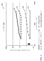
青色レーザーダイオードのアレイを光学組立体と組み合わせ、高輝度結合レーザービームを提供することのできる高輝度ダイレクトダイオードレーザーシステムを現出させることもできる。図1は、200ワットでの8mm−mradから4000ワットでの45mm−mradの範囲に及ぶ輝度を有するファイバーコンバイナ技法を使用した場合のビームパラメータ積の範囲の実施形態のレーザー性能(ビームパラメータ積対レーザーパワーW(ワット))についての表100を示している。線101は、レーザーダイオードアレイの或る実施形態についての性能を描いている。線102は、稠密波長ビーム結合アレイの性能を描いている。線103は、ファイバーコンバイナ技法を使用してスケールした場合の輝度変換技術の性能を描いている。線104は、輝度変換器の出力の稠密波長結合を使用した場合の輝度変換技術の性能を描いている。これは、パワーレベルがスケールされた際に、結合ビームが単一空間モード又はほぼ単一空間モードに留まれるようにする。稠密波長を結合する段階は、回折格子を使用して各個々の輝度変換式レーザーの波長を制御し、続いて回折格子によってそれらビームを単一ビームへ結合する。回折格子は、刻線回折格子、ホログラフィック回折格子、ファイバーブラッグ回折格子(FBG)、又は体積ブラッグ回折格子(VBG)とすることができる。更に、好適な実施形態は回折格子を使用するものとされてはいるが、プリズムを使用することも実現可能である。
An array of blue laser diodes may be combined with the optical assembly to reveal a high brightness direct diode laser system that can provide a high brightness coupled laser beam. FIG. 1 illustrates the laser performance (beam parameter product vs. beam parameter product range) when using a fiber combiner technique with brightness ranging from 8 mm-mrad at 200 watts to 45 mm-mrad at 4000 watts. A table 100 for laser power W (watts) is shown.
図2Aは、レーザービームをレーザービーム経路に沿って速軸コリメートレンズ201(FAC)へ伝幡させているレーザーダイオード200の概略図である。速軸パワーを捕捉し、輝度を維持し且つ光学チェーンへ至るビームの結合を可能にさせる的確な高さを有する回折制限されたビームを速軸に現出させるために、1.1mm、1.2mm、1.5mm、2mmの、又は4mmもの円筒形非球面レンズが使用されている。コリメートレンズ202は、レーザーダイオードの遅軸(発散角度がより小さい軸、典型的にはx軸)のコリメート用である。15mm、16mm、17mm、18mm、又は21mmの焦点距離の円筒形非球面レンズが、遅軸パワーを捕捉し、レーザー光源の輝度を維持するように遅軸をコリメートする。遅軸コリメータの焦点距離は、光学システムによって目標ファイバー直径にされるレーザービームレットの最適化された結合をもたらす。アレイの好適な実施形態では、遅軸コリメートレンズと速軸コリメートレンズはどちらも各レーザービーム経路に沿って配置されていて、個別レーザービームを成形するのに使用されている。
FIG. 2A is a schematic view of a
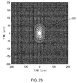
図2Bは、レーザーダイオードからのレーザービームが速軸集束レンズ及び遅軸集束レンズの両方を通過することによって形成されたレーザービームスポット203の概略図である。このシミュレーションは、光源の完全開口を横切る光源の最大発散を勘案している。方形、矩形、円形、楕円形、線形、及び、これら及び他の形状の結合及び変形型の様な、多くの異なる形状のレーザービームスポットを現出させることができるものと理解している。例えば、結合レーザービームは、青色レーザー光を用いて、100mmの焦点距離のレンズ、0.18のNAで、100μmのスポットサイズへ集束されたスポット203を現出させる。
FIG. 2B is a schematic view of a
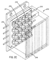
図2C及び図2Dを見ると、レーザーダイオード部分組立体210(例えば、ダイオードモジュール、バー、プレート、マルチダイパッケージ)及び4つのレーザーダイオード組立体210、210a、210b、210cを有するレーザーダイオードモジュール220の実施形態が示されている。
2C and 2D, a
図2Eには、レーザービーム250a、251a、252aの一部の各自のレーザービーム経路250、251、252に沿った部分を示す詳細図が示されている。図2Fは、図2Eのレーザービームの断面図であり、開放空間の水平方向260及び垂直方向261(図の向きに基づく)を示している。ビーム結合光学素子は、最終スポット203(図2B)での開放空間例えば260、261を排除するようにビームを空間的に閉じて一体にする。
FIG. 2E shows a detailed view of the portions of the
レーザーダイオードモジュール220は、結合レーザービームを発生させることができ、望ましくは図1の曲線101の性能を有する結合青色レーザービームを発生させることができる。レーザーダイオード組立体210は、熱伝導性材料例えば銅であるベースプレート211を有しており、ベースプレートは、ダイオード例えば213へ電気パワーを提供するために進入するパワーリード(一例としてワイヤ)例えば212を有している。このマルチダイパッケージの実施形態では、20のレーザーダイオード例えば213がカバープレートの後ろに5x4構成で配列されている。組立体内にnxnのダイオードを提供するのに他の構成、例えば、4x4、4x6、5x6、10x20、30x5、及び今日開発中の構成など、及びこれらの組み合せ及び変形型も構想される。各ダイオードは、複数の行例えば216を横切って単一の遅軸コリメート(SAC)レンズを使用する場合に、遅軸例えば214でのビームの位置を平行移動させるための平面平行板を有していてもよい。好適実施形態がそうであるように各レーザーダイオードのために個別遅軸レンズを使用している場合には、平面平行板は必要でない。組立体のプロセスの結果として、レーザービーム経路が個別レーザーダイオードの各々から伝幡してゆく際に、平面平行板が遅軸でのレーザービーム経路の位置を補正する。各レーザーダイオードのために個別FAC/SACレンズ対が使用されている場合は平面平行板は不要である。SAC位置はパッケージ内の何らかの組立体誤差を補償する。これらの手法の両方の結果は、個別レンズ対(FAC/SAC)を使用している場合か又は個別FAC/平面平行板の後に共用SACレンズを使用している場合に、ビームレットを整列させて平行にする、というものであり、平行で離間されたレーザービーム例えば251a、252a、250a及びビーム経路例えば251、252、250がもたらされる。
The
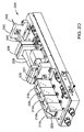
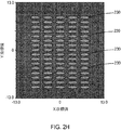
レーザーダイオード部分組立体、例えば210、210a、210b、210cの各々からの合成ビームは、4つのレーザーダイオード部分組立体からのビームを向け直して図2Gに示されている様に単一のビームへ結合するのに使用されるパターン化されたミラー例えば225へ伝搬する。4行のコリメートレーザーダイオードが他の3つのパッケージの4行と交錯され、合成ビームを現出させる。図2Hは、レーザー部分組立体210からのビーム例えば230の位置を示している。開口絞り235が、結合ビームレットからの何らかの不要な散乱光を削ぎ取り、ファイバー入力面への熱負荷を軽減する。偏光ビーム折り重ね組立体227が、ビームを遅軸で半分に折り重ねて、合成レーザーダイオードビームの輝度を二倍化する(図2I)。ビームは、どちらかのやり方として、中央の中央エミッタをスプリットすることによって折り重ねられて図21に示されているパターンがもたらされるようにしてもよく、その場合、ビーム231は偏光による遅軸方向への2つのビームレットの重なりであり、ビーム232は何れの他のエミッタにも重ならないスプリットビームレットである。ビームが第2ビームレットと第3ビームレットの間でスプリットされる場合(図2J)、ビーム折り重ね部は更に効率的であり、ビーム例えば233の列の2つが重ね合わされ、一方でビームの第3列例えば234は単にそのまま通過してゆく。テレスコープ組立体228は、結合ビームの遅軸を拡張するか又は速軸を圧縮してより小さいレンズの使用を可能にする。この実施例(図2G)に示されているテレスコープ228は、ビームを2.6倍の倍率で拡張し、そのサイズを11mmから28.6mmに増加させ、尚且つ同じ2.6倍の倍率で遅軸の発散を縮小させている。テレスコープ組立体が速軸を圧縮するのであれば、その場合、それは速軸を22mmの高さ(総合成ビーム)から11mmの高さに引き下げて11mmx11mmの合成ビームを与える2倍テレスコープということになる。これは、低コスト故に好適な実施形態である。非球面レンズ229は、合成ビームを、少なくとも50μm、100μm、150μm、又は200μmの直径の光ファイバー245の中へ集束させる。多重レーザーダイオードモジュール220のファイバー出力は、ファイバーコンバイナを用いて組み合わされて、図1(線101)による更に高い出力パワーレベルのレーザーを発生させる。レーザーダイオードモジュールは、非球面レンズ229とファイバーコンバイナ240が剪断ミラーのセットで置き換えられ、当該剪断ミラーが次いで非球面レンズへ結合し、合成ビームを光ファイバーの端の中へ射出させる、という光学的組み合わせ方法を使用して組み合わされる。このやり方では、1つ、2つ、3つ、数十、及び数百のレーザーダイオードモジュールを光学的に関連付け、それら各自のレーザービームを結合することができる。このやり方で、結合レーザービームそれ自体を更に又は積層に結合して、多重結合レーザービームを形成させることもできる。
The combined beam from each of the laser diode subassemblies, eg 210, 210a, 210b, 210c, redirects the beams from the four laser diode subassemblies into a single beam as shown in FIG. 2G. Propagate to a patterned mirror, such as 225, used to combine. Four rows of collimated laser diodes are interlaced with four rows of the other three packages to reveal a combined beam. FIG. 2H shows the position of the beam, eg 230, from the
図2C及び図2Dの実施形態では、構成は、例えば200ワットに上るレーザービームパワーを単一の50μm、100μm、150μm、又は200μmのコアの光ファイバーの中へ射出することを実現可能にしている。図2C及び図2Dの実施形態は、50ワットの個別ダイオード組立体例えば50ワットモジュールを4つまで使用する200Wダイオードアレイ組立体例えば200Wの結合モジュールを作り出すための典型的な構成要素を示している。 In the embodiment of FIGS. 2C and 2D, the configuration makes it feasible to emit, for example, 200 watts of laser beam power into a single 50 μm, 100 μm, 150 μm, or 200 μm core optical fiber. The embodiment of FIGS. 2C and 2D shows exemplary components for creating a 200 W diode array assembly, such as a 200 W coupling module, using up to four 50 watt individual diode assemblies, such as 50 watt modules. .
複数の構成、パワー、及び結合ビーム数が実現可能であるものと理解している。図2C及び図2Dの実施形態は、パワー供給からレーザーダイオードへの電気接続を最小限にする。 It is understood that multiple configurations, powers, and number of combined beams are feasible. The embodiment of FIGS. 2C and 2D minimizes the electrical connection from the power supply to the laser diode.
而して、個別モジュール、組み合わせモジュール、及びそれら両方は、単一の結合レーザービームを提供するように構成されることもできれば、複数の結合レーザービーム、例えば2、3、4、数十、数百、又はそれ以上の結合レーザービームを提供するように構成されることもできる。これらのレーザービームは、それぞれ、単一ファイバーに射出されてもよいし、又はそれらはより少数のファイバーの中へ射出されるように更に組み合わされてもよい。従って、例示として、12の結合レーザービームを12本のファイバーの中へ射出させることもできるし、12のビームを組み合わせ、12本より少ないファイバー例えば10本、8本、6本、4本、又は3本のファイバーの中へ射出させることもできる。この結合する段階は、個別ファイバーの間でのパワー分配の釣り合いを図るか又は不釣り合いを図るために異なるパワーのビームとすることができ、また、異なる波長又は同じ波長を有するビームとすることができるものと理解されたい。
Thus, individual modules, combination modules, and both can be configured to provide a single combined laser beam, or multiple combined laser beams,
或る実施形態では、レーザーダイオードのアレイの輝度は、各アレイを異なる波長で動作させ、次いでそれらを回折格子か又は一連の狭帯域ダイクロイックフィルタを用いて結合することによって、改善することができる。この技術の輝度スケーリングは図1には直線に近い線102として示されている。出発点は、単一モジュールによって実現され得るものと同じ輝度であり、各モジュールが先のモジュールに線形様式で空間的に重ね合わされることから、ファイバー直径は変わらないが、射出されるパワーは、実際に、波長ビーム結合モジュールからのより高い輝度をもたらす。 In some embodiments, the brightness of the array of laser diodes can be improved by operating each array at a different wavelength and then combining them using a diffraction grating or a series of narrowband dichroic filters. The luminance scaling of this technique is shown in FIG. The starting point is the same brightness that can be achieved with a single module, and since each module is spatially superimposed on the previous module in a linear fashion, the fiber diameter does not change, but the emitted power is In fact, it results in higher brightness from the wavelength beam combining module.
或る実施形態では、青色レーザーダイオードのアレイを、輝度変換器の助けを借りてほぼ単一モード又は単一モードの出力へ変換することができる。輝度変換器は、光ファイバー、結晶、又はガスとすることができる。変換プロセスは、青色レーザーダイオードのアレイからの出力を、共振器キャビティを用いて、光ファイバー、結晶、又はガスの中へ射出させることによって実現される誘導ラマン散乱を介して進行する。青色レーザーダイオードのパワーは誘導ラマン散乱を介して利得へ変換され、レーザー共振器はポンプ波長からストークスシフトだけオフセットされている第1ストークスラマン線上で発振する。例えば、米国特許出願第14/787,393号の明細書の図3及び関連付けられる開示に示されている実施形態は、国際公開第2014/179345号に基づくものであって、その開示全体をここに参考文献として援用する。この技術の性能の特徴は図1の線103に示されており、ファイバーコンバイナを使用して複数の高輝度レーザービームを結合する場合に、輝度は、200Wレーザーについては0.3mm−mradにて、また4000Wレーザーについては2mm−mradにて始まっている。
In some embodiments, an array of blue laser diodes can be converted to a nearly single mode or single mode output with the help of a luminance converter. The brightness converter can be an optical fiber, a crystal, or a gas. The conversion process proceeds via stimulated Raman scattering realized by emitting the output from the array of blue laser diodes into an optical fiber, crystal, or gas using a resonator cavity. The blue laser diode power is converted to gain via stimulated Raman scattering, and the laser resonator oscillates on a first Stokes Raman line that is offset by a Stokes shift from the pump wavelength. For example, the embodiment shown in FIG. 3 of the specification of US patent application No. 14 / 787,393 and the associated disclosure is based on WO 2014/179345, the entire disclosure of which is hereby incorporated by reference herein. As a reference. The performance characteristics of this technology are illustrated by
青色レーザー光源の輝度は、輝度変換された光源の出力を結合することによって更に高めることができる。この型式の実施形態の性能は図1の線104によって示されている。ここでは輝度は出発モジュールによって0.3mm−mradに画定されている。ラマン線の利得−帯域幅はレーザーダイオードのそれより実質的に広く、従ってレーザーダイオード技術単独の場合より多くのレーザーを、波長を介して結合することができる。結果は、200Wのレーザーと同じ輝度、即ち0.3mm−mradを有する4kWレーザーである。これは、図1に平坦な線104によって示されている。
The brightness of the blue laser light source can be further increased by combining the output of the brightness converted light sources. The performance of this type of embodiment is illustrated by
本明細書に記載されている本発明の技術は、溶接から、切削、ろう付け、熱処理、彫刻、成形、形成、接合、焼き鈍し、及び融除、並びにこれら及び様々な他の材料加工動作の組み合わせに及ぶ広い範囲の用途のためのレーザーシステムを構成するのに使用することができる。好適なレーザー光源は相対的に高輝度であるが、本発明は、より低い輝度要件に合致するシステムを構成する能力も提供する。また、これらのレーザーの群を長いラインへと結合することができ、それを使用すれば、例えば、フラットパネルディスプレイのTFTの様な広い面積の半導体デバイスを焼き鈍す場合の様に、標的材料のより広い面積へレーザー動作を実行することができるようになる。 The techniques of the invention described herein include welding, cutting, brazing, heat treatment, engraving, forming, forming, joining, annealing, and ablation, and combinations of these and various other material processing operations. It can be used to construct laser systems for a wide range of applications ranging from Although the preferred laser source is relatively bright, the present invention also provides the ability to construct a system that meets lower brightness requirements. These groups of lasers can also be combined into long lines that can be used to target the material, for example, when annealing large area semiconductor devices such as TFTs in flat panel displays. Laser operation can be performed over a larger area.
レーザーダイオード、レーザーダイオードアレイ、波長結合式レーザーダイオードアレイ、輝度変換式レーザーダイオードアレイ、及び波長結合式レーザーダイオードアレイのどれかの出力を使用して、独自の個別にアドレス指定可能な印刷機械を創出することもできる。各モジュールからのレーザーパワーはプラスチックの他に金属粉末も融解及び融合させるのに十分であるので、これらの光源は、積層造形用途はもとより積層−除去的製造用途(即ち、本レーザーの積層造形システムを、CNC機械又は他の型式のフライス加工機械並びにレーザー除去又は融除の様な伝統的除去製造技術と組み合わせる)にとっても理想的である。本システム及びレーザー構成は、小スポットサイズ、精密さ、及び他の因子を提供することのできる能力を有しているので、ミクロ及びナノスケールの積層的、除去的、及び積層−除去的製造技術にも用途を見出すことができるだろう。個別に接続されているレーザーのアレイを粉末表面へ結像させれば、単一の走査式レーザー光源のn倍の速さでオブジェクトを作成することができる。速さは、nスポットの各々についてより高いパワーのレーザーを使用することによって更に高めることができる。輝度変換式レーザーを使用した場合、ほぼ回折制限されたスポットをnスポットの各々について実現することができ、その結果、青色高輝度レーザー光源を用いて形成される個別スポットのサブミクロン性質のおかげで、より高い解像度の部品を作成することが実現可能になる。本構成及びシステムのこのより小さいスポットサイズは、先行技術の3D印刷技術に比べ、加工速度及び印刷プロセスの解像度における実質的改善をもたらす。本システムの実施形態が可搬式粉末給送装置と組み合わされれば、先行技術の積層造形機械の印刷速度の100倍を超える速さで層を次々と継続的に印刷することができる。位置決め装置がレーザー融合スポットの直後ろで正又は負の方向のどちらかに動いてゆく際にシステムが粉末を堆積させられるようにする(例えば、図5、粉末装置508、粉末装置508b)ことによって、システムは次層にとって必要な粉末を塗布する又は水平にするのに停止する必要無しに継続的に印刷することができる。
Use your laser diode, laser diode array, wavelength-coupled laser diode array, intensity-converted laser diode array, or wavelength-coupled laser diode array output to create your own individually addressable printing machine You can also Since the laser power from each module is sufficient to melt and fuse metal powders as well as plastics, these light sources can be used for additive manufacturing as well as additive manufacturing applications (ie, additive manufacturing systems for this laser). In combination with CNC machines or other types of milling machines as well as traditional removal manufacturing techniques such as laser removal or ablation). Since the system and laser configuration have the ability to provide small spot size, precision, and other factors, micro and nanoscale stacked, ablation, and stack-removal manufacturing techniques You will also find uses. If an array of individually connected lasers is imaged onto the powder surface, objects can be created n times faster than a single scanning laser source. The speed can be further increased by using a higher power laser for each of the n spots. When using a brightness-converting laser, a nearly diffraction limited spot can be realized for each of the n spots, and as a result, thanks to the sub-micron nature of the individual spots formed using a blue high-intensity laser source It becomes feasible to create parts with higher resolution. This smaller spot size of the present configuration and system provides a substantial improvement in processing speed and resolution of the printing process compared to prior art 3D printing techniques. When embodiments of the present system are combined with a portable powder feeder, layers can be continuously printed one after another at a speed exceeding 100 times the printing speed of prior art additive manufacturing machines. By allowing the system to deposit powder as the positioning device moves directly behind the laser fusion spot in either the positive or negative direction (eg, FIG. 5,
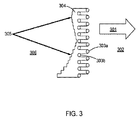
図3を見ると、2列の段違いのスポット例えばスポット303aと例えばスポット303bを有するレーザーシステムの場合のレーザープロセスの概略図が示されている。レーザースポット例えば303a、303bは、標的材料を横切って矢印301の方向に動かされ、例えば走査される。標的材料が粉末形態302であるとして、すると材料はレーザースポット304によって融解され、次いで転移線305にほぼ沿って固化して融合材料306としての形になる。ビームのパワー、ビームの照射時間、運動速度、及びこれらの組合せは、融解転移線305の既定形状をもたらす既定の方式で変えることができる。ビームを段違いにさせることのできる距離は、ファイバー及びそれらの光学構成要素を保持するのに要求される固定具によって必要とされる通りに、0mm、0.1mm、0.5mm、1mm、2mm離間させることができる。段違いは、更に、設定された段違いの段サイズで単調的に増加及び減少する位置であってもよいし、又は可変段サイズで増加及び減少する位置であってもよい。正確な速度という利点は製造される部品の標的材料及び構成に依存するであろう。
Referring to FIG. 3, there is shown a schematic diagram of the laser process in the case of a laser system having two rows of uneven spots, for example spots 303a and spots 303b. Laser spots, eg 303a, 303b, are moved in the direction of
図4は、図5−図7で20ビームシステムについて描かれている様なレーザーシステム及び構成の実施形態について実現され得る性能を要約しており、速度は、追加のビームがシステムへ加えられる毎に増加する。 FIG. 4 summarizes the performance that can be achieved for an embodiment of a laser system and configuration as depicted for a 20 beam system in FIGS. 5-7, where the speed is as each additional beam is added to the system. To increase.
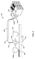
図5を見ると、アドレス指定可能レーザー送達構成を有するレーザーシステムの或る実施形態の概略図が提供されている。システムはアドレス指定可能レーザーダイオードシステム501を有している。システム501は、アドレス指定可能レーザービームを複数のファイバー502a、502b、502cへ独立に提供する(より大きい数又はより小さい数のファイバー及びレーザービームも構想される)。ファイバー502a、502b、502cは、保護管503又はカバーに収容されるファイバー束504へ組み合わされている。ファイバー束504のファイバー502a、502b、502cは、一体に融合されて印刷ヘッド505を形成しており、印刷ヘッド505は、レーザービームをビーム経路に沿って集束させ標的材料507へ方向決めする光学素子組立体506を含んでいる。印刷ヘッド及び粉末ホッパは、印刷ヘッドが510に従って正方向に動くのと共に一体に動く。追加の材料509が、印刷ヘッド又はホッパの通過の度に融合材料507の上に置かれてゆく。印刷ヘッドは、二方向性であり、印刷ヘッドが動く際に材料を両方向に融合させてゆき、従って粉末ホッパは印刷ヘッドの後ろで動作してレーザー印刷ヘッドの次の通過時に融合されることになる積層材料を提供する。
Turning to FIG. 5, a schematic diagram of an embodiment of a laser system having an addressable laser delivery configuration is provided. The system has an addressable
「アドレス指定可能アレイ」とは、パワー;照射の持続時間;照射のシーケンス;照射の位置;ビームのパワー;ビームスポットの形状、並びに焦点距離、例えばz方向の浸透深度;のうちの1つ又はそれ以上を、独立に変更、制御、及び予め既定できること、又は、各ファイバーの各レーザービームに、標的材料から高精密最終製品(例えば造形材料)を現出させることのできる精密で既定された送達パターンを提供させることができること、を意味する。アドレス指定可能アレイの実施形態は、更に、個別ビーム及びそれらのビームによって現出されるレーザースポットに、焼き鈍し、融除、及び融解の様な、可変、既定、及び精密なレーザー動作を実行させる能力を有することができる。 An “addressable array” is one of: power; duration of irradiation; sequence of irradiation; position of irradiation; beam power; beam spot shape, and focal length, eg depth of penetration in the z direction; More can be independently changed, controlled and pre-defined, or precise and predetermined delivery that allows each laser beam of each fiber to reveal a high precision end product (eg build material) from the target material It means that a pattern can be provided. The addressable array embodiments further have the ability to perform variable, predefined, and precise laser operations such as annealing, ablation, and melting on individual beams and the laser spots exposed by those beams. Can have.
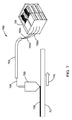
図6を見ると、アドレス指定可能レーザー送達構成を有するレーザーシステムの或る実施形態の概略図が提供されている。レーザーシステムは、レーザーダイオードアレイシステム、輝度変換式システム、又は高パワーファイバーレーザーシステムとすることができる。本システムは、アドレス指定可能レーザーシステム601を有している。本システム601は、アドレス指定可能レーザービームを複数のファイバー602a、602b、602cへ独立に提供する(より大きい数又はより小さい数のファイバー及びレーザービームも構想される)。ファイバー602a、602b、602cは、保護管603又はカバーに収容されるファイバー束604へと組み合わされている。ファイバー束604のファイバー602a、602b、602cは、一体に融合されて印刷ヘッド605を形成しており、印刷ヘッド605は、レーザービームをビーム経路に沿って集束させ標的材料607へ方向決めする光学素子組立体606を含んでいる。標的材料607は焼き鈍されて焼き鈍し材料609を形成することができる。レーザーヘッドの運動方向は矢印610で示されている。
Turning to FIG. 6, a schematic diagram of an embodiment of a laser system having an addressable laser delivery configuration is provided. The laser system can be a laser diode array system, a brightness conversion system, or a high power fiber laser system. The system includes an
図7を見ると、アドレス指定可能レーザー送達構成を有するレーザーシステムの或る実施形態の概略図が提供されている。システムはアドレス指定可能レーザーダイオードシステム701を有している。システム701は、アドレス指定可能レーザービームを複数のファイバー702a、702b、702cへ独立に提供する(より大きい数又はより小さい数のファイバー及びレーザービームも構想される)。ファイバー702a、702b、702cは、保護管703又はカバーに収容されるファイバー束704へと組み合わされている。ファイバー束704のファイバー702a、702b、702cは、一体に融合されて印刷ヘッド部粉末分配ヘッド720を形成している。粉末分配ヘッド720は、粉末をレーザービームと同軸に又はレーザービームを横断する向きに送達させることができる。粉末分配ヘッド720が追加材料の層709を提供すると、当該層は標的材料707へ及び標的材料の上に融合される。レーザーヘッドの運動方向は矢印710で示されている。
Turning to FIG. 7, a schematic diagram of an embodiment of a laser system having an addressable laser delivery configuration is provided. The system has an addressable
図8は、一体に融合されていて図5−図7に示されているシステムの様なシステムのレーザーヘッド内に使用されるファイバー例えば801の束800の構成を示している。当該構成はファイバー配列と同様の構成のレーザースポットを送達することになる。この実施形態では、単一の線形行に5本のファイバーがある1x5線形構成である。ファイバーの1xn線形行は、究極的なレーザー印刷ヘッドであり、ここにnは印刷される製品の物理的広がりに依存する。
FIG. 8 shows the configuration of a
図9は、一体に融合されていて図5−図8に示されているシステムの様なシステムのレーザーヘッド内に使用されるファイバー例えば901の束900の構成を示している。当該構成は、ファイバーの2つの線形行902、903を段違いにして菱形配列に配して有している。ファイバーは、ファイバー配列と同様の構成のレーザースポットを送達することになる。この実施形態では、各行5本のファイバーから成る線形行が2つある2x5線形構成である。
FIG. 9 shows the configuration of a
図10は、一体に融合されていて図5−図8に示されているシステムの様なシステムのヘッド内に使用されるファイバー例えば1001の束(1000)の構成を示している。当該構成は、ファイバーの3つの線形行1002、1003、1004を段違いにして菱形配列に配して有している。ファイバーは、ファイバー配列と同様の構成のレーザースポットを送達することになる。この実施形態では、各行5本のファイバーから成る線形行が3つある3x5線形構成である。
FIG. 10 shows the configuration of a bundle of fibers, for example 1001, (1000) that is fused together and used in the head of a system such as the system shown in FIGS. The configuration has three
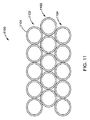
図11は、一体に融合されていて図5−図8に示されているシステムの様なシステムのヘッド内に使用されるファイバー例えば1101の束1100の構成を示している。当該構成は、ファイバーの3つの線形行1102、1103、1104を段違いにして三角形配列に配して有している。ファイバーは、ファイバー配列と同様の構成のレーザースポットを送達することになる。この実施形態では、各行5本のファイバーから成る線形行が3つある3x5線形構成である。
FIG. 11 shows the configuration of a
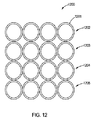
図12は、一体に融合されていて図5−図8に示されているシステムの様なシステムのヘッド内に使用されるファイバー例えば1201の束1200の構成を示している。当該構成は、ファイバーの4つの線形行1202、1203、1204、1205を段違いにせず方形配列に配して有している。ファイバーは、ファイバー配列と同様の構成のレーザースポットを送達することになる。この実施形態では、各行4本のファイバーから成る線形行が4つある4x4線形構成である。
FIG. 12 shows the configuration of a
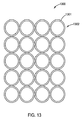
図13は、一体に融合されていて図5−図8に示されているシステムの様なシステムのヘッド内に使用されるファイバー例えば1301の束1300の構成を示している。当該構成は、ファイバーの5つの線形行1302を有している。ファイバーは段違いにはなっておらず、方形配列に配されている。ファイバーは、ファイバー配列と同様の構成のレーザースポットを送達することになる。この実施形態では、各行4本のファイバーから成る線形行が5つある5x4線形構成である。
FIG. 13 shows the configuration of a
図14Aは、円形構成で配列された5本(n=5)のファイバー例えば1401aから成る束1401の構成を示している。
FIG. 14A shows the configuration of a
図14Bは、円形構成で配列されたファイバー例えば1402aと円の中心に位置するファイバー1402bの9本(n=9)のファイバーから成る束1402の構成を示している。中心のファイバー1402bは、媒質又は保持装置によってその場に保持されるか又は他のやり方で融合されることになろう。
FIG. 14B shows the configuration of a
図14Cは、内側の円のファイバー1405と中心のファイバー1403bとを有する19本(n=19)のファイバー例えば1403aから成る束1403の構成を示している。
FIG. 14C shows a configuration of a
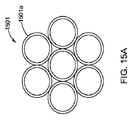
図15Aは、三角形の空間のある六角形配列を有している7本(n=7)のファイバー例えば1501aから成る束1501を示している。
FIG. 15A shows a
図15Bは、三角形の空間のある六角形配列を有している19本(n=19)のファイバー例えば1502aから成る束1502を示している。
FIG. 15B shows a
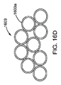
図16A、図16B、及び図16Cは、任意の幾何学配列に配されたファイバー束の諸構成を示している。これらの構成は、構成内のファイバーの密度の様々なレベルを提供している。図16Aは、4分の1円構成のファイバー例えば1601aのn=16本の束1601である。図16Bは、方形構成のファイバー例えば1602bのn=8本の束1602である。図16Cは、三角形構成のファイバー例えば1604aのn=6本の束1604である。図16Dは、半円形構成のファイバー例えば1603aのn=9本の束1603である。
FIGS. 16A, 16B, and 16C show configurations of fiber bundles arranged in an arbitrary geometric arrangement. These configurations provide various levels of fiber density within the configuration. FIG. 16A is a
次の実施例は、本発明のレーザーアレイ、システム、装置、及び方法の様々な実施形態を例示するために提供されている。これらの実施例は、例示目的であり、本発明の範囲を限定するものと見なされてはならず、また他の形で本発明の範囲を限定するものでもない。 The following examples are provided to illustrate various embodiments of the laser array, system, apparatus, and method of the present invention. These examples are for illustrative purposes and should not be considered as limiting the scope of the invention, nor are they intended to limit the scope of the invention in other ways.
実施例1
ファーフィールドに単一スポットを形成するように空間的に結合され、工作片への送達のために耐ソラリゼーション光ファイバーの中へ結合させることのできるように青色レーザーダイオードのアレイ。
Example 1
An array of blue laser diodes that are spatially coupled to form a single spot in the far field and can be coupled into a solarized optical fiber for delivery to the workpiece.
実施例2
実施例1に記載されている青色レーザーダイオードのアレイであって、レーザービームの有効輝度を増加させるように結合された偏光ビームである青色レーザーダイオードのアレイ。
Example 2
An array of blue laser diodes as described in Example 1, wherein the laser beams are polarized beams combined to increase the effective brightness of the laser beam.
実施例3
レーザーダイオードの速軸でのコリメートされたビームのそれぞれの間に空間を有する青色レーザーダイオードのアレイであって、第1の(単数又は複数の)レーザーダイオードを反射し第2の(単数又は複数の)レーザーダイオードを透過させて第1のアレイの速軸方向のレーザーダイオードの間の空間を充填するための周期板と組み合わされている、青色レーザーダイオードのアレイ。
Example 3
An array of blue laser diodes having a space between each of the collimated beams at the fast axis of the laser diode, reflecting the first (s) laser diode and reflecting the second (s) ) An array of blue laser diodes combined with a periodic plate for transmitting the laser diodes to fill the space between the laser diodes in the fast axis direction of the first array.
実施例4
実施例3の空間充填を達成するために使用されるガラス基板上のパターン化されたミラー。
Example 4
A patterned mirror on a glass substrate used to achieve the space filling of Example 3.
実施例5
実施例3の空間充填を達成するためのガラス基板の一方の面上のパターン化されたミラーであって、ガラス基板は各レーザーダイオードの垂直方向位置をシフトさせて個別レーザーダイオードの間の空いた空間を充填するのに十分な厚さである、パターン化されたミラー。
Example 5
FIG. 5 is a patterned mirror on one side of a glass substrate to achieve the space filling of Example 3, wherein the glass substrate is spaced between individual laser diodes by shifting the vertical position of each laser diode. A patterned mirror that is thick enough to fill the space.
実施例6
実施例3の空間充填を達成し、実施例4に記載されているパターン化されたミラーである段状ヒートシンク。
Example 6
A stepped heat sink that achieves the space filling of Example 3 and is a patterned mirror as described in Example 4.
実施例7
実施例1に記載されている青色レーザーダイオードのアレイにおいて、個別レーザーの各々は、外部キャビティによって、アレイの輝度を単一のレーザーダイオード光源と同等の輝度まで実質的に増加させるように異なる波長へロックされる、青色レーザーダイオードのアレイ。
Example 7
In the array of blue laser diodes described in Example 1, each individual laser is driven to a different wavelength by an external cavity so that the brightness of the array is substantially increased to that of a single laser diode light source. An array of blue laser diodes to be locked.
実施例8
実施例1に記載されている青色レーザーダイオードのアレイにおいて、レーザーダイオードの個別アレイは、回折格子に基づく外部キャビティを使用して単一の波長へロックされ、レーザーダイオードアレイの各々は狭い間隔の光学フィルタか又は回折格子のどちらかを使用して単一ビームへと組み合わされる、青色レーザーダイオードのアレイ。
Example 8
In the array of blue laser diodes described in Example 1, the individual arrays of laser diodes are locked to a single wavelength using an external cavity based on a diffraction grating, each of the laser diode arrays being a closely spaced optical An array of blue laser diodes combined into a single beam using either a filter or a diffraction grating.
実施例9
実施例1に記載されている青色レーザーダイオードのアレイであって、より高い輝度の光源を現出させる純粋溶融石英のコアと、青色ポンプ光を収容するためのフッ素化された外側コアと、を有する光ファイバーの様なラマン変換器をポンプするのに使用される青色レーザーダイオードのアレイ。
Example 9
An array of blue laser diodes as described in Example 1, comprising a core of pure fused silica that reveals a higher brightness light source, and a fluorinated outer core for receiving blue pump light. An array of blue laser diodes used to pump a Raman transducer such as an optical fiber.
実施例10
実施例1に記載されている青色レーザーダイオードのアレイであって、より高い輝度の光源を現出させるためのGeO2ドープされた中心コア及び外側コアと、青色ポンプ光を収容するための、中心コアより大きい外側コアと、を有する光ファイバーの様なラマン変換器をポンプするのに使用される青色レーザーダイオードのアレイ。
Example 10
An array of blue laser diodes as described in Example 1, GeO2 doped central and outer cores for revealing a higher brightness light source, and a central core for accommodating blue pump light An array of blue laser diodes used to pump a Raman transducer such as an optical fiber having a larger outer core.
実施例11
実施例1に記載されている青色レーザーダイオードのアレイであって、より高い輝度の光源を現出させるためのP2O5ドープされたコアと、青色ポンプ光を収容するための、中心コアより大きい外側コアと、を有する光ファイバーの様なラマン変換器をポンプするのに使用される青色レーザーダイオードのアレイ。
Example 11
An array of blue laser diodes as described in Example 1 with a P2O5-doped core for revealing a higher brightness light source and an outer core larger than the central core for accommodating blue pump light And an array of blue laser diodes used to pump a Raman converter such as an optical fiber.
実施例12
実施例1に記載されている青色レーザーダイオードのアレイであって、より高い輝度の光源を現出させるためのグレーデッドインデックス型コアと、青色ポンプ光を収容するための、中心コアより大きい外側コアと、を有する光ファイバーの様なラマン変換器をポンプするのに使用される青色レーザーダイオードのアレイ。
Example 12
An array of blue laser diodes as described in Example 1, a graded index core for revealing a higher brightness light source and an outer core larger than the central core for accommodating blue pump light And an array of blue laser diodes used to pump a Raman converter such as an optical fiber.
実施例13
実施例1に記載されている青色レーザーダイオードのアレイであって、グレーデッドインデックス型のGeO2ドープされたコア及び外側のステップインデックス型コアであるラマン変換器ファイバーをポンプするのに使用される青色レーザーダイオードのアレイ。
Example 13
An array of blue laser diodes as described in Example 1, used to pump a Raman converter fiber that is a graded index GeO2-doped core and an outer step index core An array of diodes.
実施例14
実施例1に記載されている青色レーザーダイオードのアレイであって、グレーデッドインデックス型のP2O5ドープされたコア及び外側のステップインデックス型コアであるラマン変換器ファイバーをポンプするのに使用される青色レーザーダイオードのアレイ。
Example 14
An array of blue laser diodes as described in Example 1, used to pump a Raman converter fiber that is a graded index P2O5 doped core and an outer step index core An array of diodes.
実施例15
実施例1に記載されている青色レーザーダイオードのアレイであって、グレーデッドインデックス型のGeO2ドープされたコアであるラマン変換器ファイバーをポンプするのに使用される青色レーザーダイオードのアレイ。
Example 15
An array of blue laser diodes as described in Example 1 used to pump a Raman converter fiber that is a graded index GeO2 doped core.
実施例16
実施例1に記載されている青色レーザーダイオードのアレイであって、グレーデッドインデックス型のP2O5ドープされたコア及び外側のステップインデックス型コアであるラマン変換器ファイバーをポンプするのに使用される青色レーザーダイオードのアレイ。
Example 16
An array of blue laser diodes as described in Example 1, used to pump a Raman converter fiber that is a graded index P2O5 doped core and an outer step index core An array of diodes.
実施例17
実施例1の他の実施形態及び実施例1の実施形態の変形型が構想される。実施例1に記載されている青色レーザーダイオードのアレイであって、より高い輝度のレーザー光源を現出させるためのダイヤモンドの様なラマン変換器をポンプするのに使用される青色レーザーダイオードのアレイ。実施例1に記載されている青色レーザーダイオードのアレイであって、より高い輝度のレーザー光源を現出させるためのKGWの様なラマン変換器をポンプするのに使用される青色レーザーダイオードのアレイ。実施例1に記載されている青色レーザーダイオードのアレイであって、より高い輝度のレーザー光源を現出させるためのYVO4の様なラマン変換器をポンプするのに使用される青色レーザーダイオードのアレイ。実施例1に記載されている青色レーザーダイオードのアレイであって、より高い輝度のレーザー光源を現出させるためのBa(NO3)2の様なラマン変換器をポンプするのに使用される青色レーザーダイオードのアレイ。実施例1に記載されている青色レーザーダイオードのアレイであって、より高い輝度のレーザー光源を現出させるための高圧ガスであるラマン変換器をポンプするのに使用される青色レーザーダイオードのアレイ。実施例1に記載されている青色レーザーダイオードのアレイであって、より高い輝度のレーザー光源を現出させるための希土類ドープされた結晶をポンプするのに使用される青色レーザーダイオードのアレイ。実施例1に記載されている青色レーザーダイオードのアレイであって、より高い輝度のレーザー光源を現出させるための希土類ドープされたファイバーをポンプするのに使用される青色レーザーダイオードのアレイ。実施例1に記載されている青色レーザーダイオードのアレイであって、より高い輝度強化比を現出させるための輝度変換器の外側コアをポンプするのに使用される青色レーザーダイオードのアレイ。
Example 17
Other embodiments of Example 1 and variations of the embodiment of Example 1 are envisioned. An array of blue laser diodes as described in Example 1, used to pump a diamond-like Raman converter to reveal a higher brightness laser source. An array of blue laser diodes as described in Example 1, used to pump a Raman converter such as KGW to reveal a higher brightness laser source. An array of blue laser diodes as described in Example 1, used to pump a Raman converter such as YVO4 to reveal a higher intensity laser source. An array of blue laser diodes as described in Example 1, used to pump a Raman converter such as Ba (NO3) 2 to reveal a higher brightness laser source An array of diodes. An array of blue laser diodes as described in Example 1, used to pump a Raman converter, which is a high pressure gas to reveal a higher intensity laser source. An array of blue laser diodes as described in Example 1, used to pump a rare earth doped crystal to reveal a higher brightness laser source. An array of blue laser diodes as described in Example 1 and used to pump a rare earth doped fiber to reveal a higher brightness laser source. An array of blue laser diodes as described in Example 1 used to pump the outer core of a luminance converter to reveal a higher luminance enhancement ratio.
実施例18
ラマン変換式レーザーのアレイであって、個別波長で動作し、元の光源の空間輝度を維持しながらより高いパワーの光源を現出させるように組み合わされるラマン変換式レーザーのアレイ。
Example 18
An array of Raman-converted lasers that are combined to produce a higher power light source that operates at individual wavelengths and maintains the spatial brightness of the original light source.
実施例19
ラマンファイバーであって、デュアルコアと、高輝度の中心コアの2次ラマン信号を抑制するための、フィルタ、ファイバーブラッググレーティング、1次及び2次のラマン信号についてのV数の差、又はマイクロベンド損失の差、を使用している手段と、を有しているラマンファイバー。
Example 19
Raman fiber, filter, fiber Bragg grating, difference in V number for first and second order Raman signals, or microbend to suppress second order Raman signal of dual core and high intensity central core A means of using a difference in loss, and having a Raman fiber.
実施例20
N≧1として、Nのレーザーダイオードであって、個別にオン及びオフさせることができ、粉末床上へ結像させて粉末を融解させ固有部品へと融合させることのできるNのレーザーダイオード。
Example 20
N laser diodes with N ≧ 1, which can be turned on and off individually, and can be imaged onto the powder bed to melt the powder and fuse it into a unique part.
実施例21
N≧1として実施例1のNのレーザーダイオードアレイであって、その出力はファイバー結合されることができ、各ファイバーは、粉末上へ結像させ又は集束させて粉末を固有形状の積層へと融解させ又は融合させることのできる高パワーレーザービームのアドレス指定可能アレイを現出させるように線形様式又は非線形様式に配列されることができる、レーザーダイオードアレイ。
Example 21
The N laser diode array of Example 1 with N ≧ 1, the output of which can be fiber coupled, and each fiber is imaged or focused onto the powder into a stack of uniquely shaped powders. A laser diode array that can be arranged in a linear or non-linear fashion to reveal an addressable array of high power laser beams that can be melted or fused.
実施例22
ラマン変換器を介して組み合わされた1つ又はそれ以上のレーザーダイオードアレイであって、その出力はファイバー結合されることができ、各ファイバーは、粉末上へ結像させ又は集束させて粉末を固有形状の積層へと融解させ又は融合させることのできるアドレス指定可能なNのアレイ、ここにN≧1である、を現出させるように線形様式又は非線形様式に配列されることができる、1つ又はそれ以上のレーザーダイオードアレイ。
Example 22
One or more laser diode arrays combined via Raman converters, the output of which can be fiber coupled, each fiber imaged or focused onto the powder to uniquely identify the powder One that can be arranged in a linear or non-linear fashion to reveal an addressable array of N that can be melted or fused into a stack of shapes, where N ≧ 1 Or more laser diode array.
実施例23
N≧1として、Nの青色レーザー光源を粉末床を横切って移動させながら粉末床を融解及び融合させることのできるx−yモーションシステムであって、融合された層の後ろに追加の粉末層を提供するようにレーザー光源の後ろに位置付けられている粉末送達システムを有するx−yモーションシステム。
Example 23
An xy motion system capable of melting and fusing a powder bed while moving N blue laser light sources across the powder bed, where N ≧ 1, with an additional powder layer behind the fused layer An xy motion system having a powder delivery system positioned behind the laser light source to provide.
実施例24
新しい粉末層が置かれた後に、実施例20の部品/粉末床の高さを増加/減少させることのできるzモーションシステム。
Example 24
A z-motion system that can increase / decrease the height of the part / powder bed of Example 20 after a new powder layer is placed.
実施例25
粉末層がレーザー光源によって融合された後に、実施例20の部品/粉末の高さを増加/減少させることのできるzモーションシステム。
Example 25
A z-motion system capable of increasing / decreasing the part / powder height of Example 20 after the powder layer is fused by a laser light source.
実施例26
実施例20のための二方向粉末設置能力において、(単数又は複数の)レーザースポットが正x方向又は負x方向に進む際に当該レーザースポットの真後ろに粉末が置かれる、二方向粉末設置能力。
Example 26
The bidirectional powder placement capability for Example 20, wherein the powder is placed directly behind the laser spot (s) as the laser spot (s) travel in the positive x or negative x direction.
実施例27
実施例20のための二方向粉末設置能力において、(単数又は複数の)レーザースポットが正y方向又は負y方向に進む際に当該レーザースポットの真後ろに粉末が置かれる、二方向粉末設置能力。
Example 27
In the bidirectional powder placement capacity for Example 20, the powder is placed directly behind the laser spot (s) as the laser spot (s) travels in the positive y direction or the negative y direction.
実施例28
N≧1としてNのレーザービームと同軸である粉末給送システム。
Example 28
Powder feeding system that is coaxial with the N laser beam, where N ≧ 1.
実施例29
粉末給送システムにおいて、粉末は重力により給送される、粉末給送システム。
Example 29
In a powder feeding system, the powder is fed by gravity.
実施例30
粉末給送システムにおいて、粉末は不活性ガスの流れに同伴される、粉末給送システム。
Example 30
In a powder feed system, the powder is entrained in a flow of inert gas.
実施例31
粉末給送システムであって、N≧1としてNのレーザービームに横断方向にあり、粉末は重力によってレーザービームの直ぐ前方に置かれる、粉末給送システム。
Example 31
A powder delivery system, wherein N ≧ 1 is transverse to the N laser beams and the powder is placed directly in front of the laser beams by gravity.
実施例32
粉末給送システムであって、N≧1としてNのレーザービームに横断方向にあり、粉末はレーザービームに交わる不活性ガスの流れに同伴される、粉末給送システム。
Example 32
A powder delivery system, wherein N ≧ 1 is transverse to the N laser beam and the powder is entrained in a flow of inert gas intersecting the laser beam.
実施例33
例えば460nmのラマン変換器の出力を使用して光源レーザーの半分の波長即ち230nmの光を生成する第2高調波生成システムであって、KTPの様な外部共振二倍化結晶から成っているが短い波長の光が光ファイバーを通って伝幡することを許容しない第2高調波生成システム。
Example 33
For example, it is a second harmonic generation system that uses the output of a 460 nm Raman converter to generate light having a wavelength half that of a light source laser, that is, 230 nm, and is composed of an external resonance double crystal such as KTP. A second harmonic generation system that does not allow short wavelength light to travel through the optical fiber.
実施例34
第3高調波生成システムであって、例えば460nmのラマン変換器の出力を使用して、115nmの光を外部共振二倍化結晶を使用して生成するが、短い波長の光が光ファイバーを通って伝幡することを許容しない第3高調波生成システム。
Example 34
A third harmonic generation system, for example, using the output of a 460 nm Raman converter to generate 115 nm light using an external resonant doubling crystal, but with shorter wavelengths passing through the optical fiber A third harmonic generation system that does not allow transmission.
実施例35
第4高調波生成システムであって、例えば460nmのラマン変換器の出力を使用して、57.5nmの光を外部共振二倍化結晶を使用して生成するが、短い波長の光が光ファイバーを通って伝幡することを許容しない第4高調波生成システム。
Example 35
A fourth harmonic generation system, for example using the output of a 460 nm Raman converter to generate 57.5 nm light using an external resonant doubling crystal, but the short wavelength light is transmitted through the optical fiber A fourth harmonic generation system that does not allow propagation through.
実施例36
第2高調波生成システムであって、450nmの青色レーザーダイオードのアレイによってポンプされると473nmのレーザーを発するツリウムの様な希土類ドープされた輝度変換器の出力を使用して、光源レーザーの半分の波長即ち236.5nmの光を外部共振二倍化結晶を使用して生成するが、短い波長の光が光ファイバーを通って伝幡するのを許容しない、第2高調波生成システム。
Example 36
A second harmonic generation system using the output of a rare earth doped brightness converter such as thulium that emits a 473 nm laser when pumped by an array of 450 nm blue laser diodes, half the source laser A second harmonic generation system that generates light at a wavelength or 236.5 nm using an external resonant doubling crystal, but does not allow short wavelength light to propagate through the optical fiber.
実施例37
第3高調波生成システムであって、450nmの青色レーザーダイオードのアレイによってポンプされると473nmのレーザーを発するツリウムの様な希土類ドープされた輝度変換器の出力を使用して、118.25nmの光を外部共振二倍化結晶を使用して生成するが、短い波長の光が光ファイバーを通って伝幡するのを許容しない、第3高調波生成システム。
Example 37
A third harmonic generation system using the output of a rare earth-doped luminance converter such as thulium that emits a 473 nm laser when pumped by an array of 450 nm blue laser diodes. Is generated using an external resonant doubling crystal, but does not allow short wavelength light to propagate through the optical fiber.
実施例38
第4高調波生成システムであって、450nmの青色レーザーダイオードのアレイによってポンプされると473nmのレーザーを発するツリウムの様な希土類ドープされた輝度変換器の出力を使用して、59.1nmの光を外部共振二倍化結晶を使用して生成するが、短い波長の光が光ファイバーを通って伝幡するのを許容しない、第4高調波生成システム。
Example 38
A fourth harmonic generation system, using the output of a rare earth doped luminance converter such as thulium that emits a 473 nm laser when pumped by an array of 450 nm blue laser diodes, Is generated using an external resonant doubling crystal, but does not allow short wavelength light to propagate through the optical fiber.
実施例39
高パワー450nm光源によってポンプされて可視又はほぼ可視の出力を生成することのできる全ての他の希土類ドープされたファイバー及び結晶が実施例34−実施例38で使用され得る。
Example 39
All other rare earth doped fibers and crystals that can be pumped by a high power 450 nm light source to produce a visible or near visible output can be used in Examples 34-38.
実施例40
ラマン又は希土類ドープされたコアファイバーの内側コアをポンプするための、非円形外側コア又はクラッドの中への高パワー可視光の射出。
Example 40
High power visible light emission into a non-circular outer core or cladding to pump the inner core of a Raman or rare earth doped core fiber.
実施例41
ポンプの偏光をラマン発振器の偏光と整列させることによってラマンファイバーの利得を強化するための偏光持続ファイバーの使用。
Example 41
Use of polarization-maintaining fiber to enhance Raman fiber gain by aligning pump polarization with Raman oscillator polarization.
実施例42
実施例1に記載されている青色レーザーダイオードのアレイであって、特定の偏光のより高い輝度の光源を現出させる構造の光ファイバーの様なラマン変換器をポンプするのに使用される青色レーザーダイオードのアレイ。
Example 42
An array of blue laser diodes as described in Example 1 and used to pump a Raman converter such as an optical fiber structured to reveal a higher intensity light source of a particular polarization Array.
実施例43
実施例1に記載されている青色レーザーダイオードのアレイであって、特定の偏光のより高い輝度の光源を現出させる及びポンプ光源の偏光状態を持続させる構造の光ファイバーの様なラマン変換器をポンプするのに使用される青色レーザーダイオードのアレイ。
Example 43
An array of blue laser diodes as described in Example 1, pumping a Raman converter, such as an optical fiber, that is structured to reveal a higher intensity light source of a particular polarization and to maintain the polarization state of the pump light source An array of blue laser diodes used to do.
実施例44
実施例1に記載されている青色レーザーダイオードのアレイであって、ラマン変換効率を改善する構造の非円形外側コアを有する高輝度光源を現出させるための光ファイバーの様なラマン変換器をポンプするのに使用される青色レーザーダイオードのアレイ。
Example 44
An array of blue laser diodes as described in Example 1 pumping a Raman converter such as an optical fiber to reveal a high intensity light source having a non-circular outer core structured to improve Raman conversion efficiency. Array of blue laser diodes used for the.
実施例45
実施例1から実施例44までの実施形態は、更に、次の構成要素又は組立体のうちの1つ又はそれ以上、即ち、レーザーが粉末床に亘って走査する段階に先んじて各通過終了時に粉末を水平化するための装置;複数の低パワーレーザーモジュールをファイバーコンバイナを介して組み合わせることによってレーザーの出力パワーをスケールして、より高パワー出力のビームを現出させるための装置;複数の低パワーレーザーモジュールを自由空間を介して組み合わせることによって青色レーザーモジュールの出力パワーをスケールして、より高いパワー出力のビームを現出させるための装置;埋め込み型冷却付き単一ベースプレート上の、複数のレーザーモジュールを組み合わせるための装置;のうちの1つ又はそれ以上を含んでいてもよい。
Example 45
The embodiments of Examples 1 through 44 further include one or more of the following components or assemblies, i.e., at the end of each pass prior to the stage where the laser scans across the powder bed. A device for leveling powder; a device for scaling the output power of a laser by combining multiple low power laser modules via a fiber combiner to produce a higher power output beam; A device for scaling the output power of a blue laser module by combining power laser modules through free space to reveal a higher power output beam; multiple lasers on a single base plate with embedded cooling May include one or more of devices for combining modules;
本発明の実施形態の主題である又は本発明の実施形態と関連付けられる新規で画期的な性能又は他の有益な特徴及び特性の根底にある理論を提供する又は当該理論に取り組むうえで必要条件はないことを指摘しておく。それでもなお、本明細書にはこの重要分野、具体的には、レーザー、レーザー加工、及びレーザー用途の重要分野の技術を更に進展させるための様々な理論が提供されている。本明細書に提言されているこれらの理論は、別途明示的に表明されていない限り、断じて、保護を与えられるべき特許請求の範囲に記載の発明の範囲を限定、制限、又は狭小化するものではない。本発明を利用するうえでこれらの理論は必要とならないかもしれないし又は実践されないかもしれない。更に理解しておきたいこととして、本発明は、本発明の方法、物品、材料、装置、及びシステムの実施形態の動作、機能、特徴を解説するための新しい理論及びこれまで知られていない理論へとつながる可能性があり、その様な後発理論は保護を与えられるべき本発明の範囲を限定するものではない。 Providing a theory underlying or addressing the novel and innovative performance or other beneficial features and characteristics that are the subject of or associated with embodiments of the present invention Point out that there is no. Nonetheless, the present specification provides various theories to further advance the technology in this important area, specifically in the important areas of lasers, laser processing, and laser applications. These theories proposed herein, unless expressly stated otherwise, are not intended to limit, limit, or narrow the scope of the claimed invention that is to be protected. is not. These theories may not be necessary or practiced in utilizing the present invention. It is further to be understood that the present invention includes new and previously unknown theories to illustrate the operation, function, and features of the method, article, material, apparatus, and system embodiments of the present invention. Such a late theory is not intended to limit the scope of the invention to be protected.
本明細書に示されているレーザー、ダイオード、アレイ、モジュール、組立体、活動、及び動作の様々な実施形態は、以上に特定されている分野及び様々な他の分野で使用することができる。加えて、これらの実施形態は、例えば、既存のレーザー、積層造形システム、動作、及び活動、並びに他の既存の機器;将来のレーザー、積層造形システム、動作、及び活動;及び、本明細書の教示に基づき部分的に修正の施されたその様な品目;と共に使用することもできる。更に、本明細書に示されている様々な実施形態は互いと一体に異なる様々な組合せで使用されてもよい。而して、例えば、本明細書の様々な実施形態に提供されている構成は互いと一体に使用されてもよく、保護を与えられるべき本発明の範囲は、特定の実施形態、特定の実施例、又は特定の図にある実施形態に示されている特定の具現化、構成、又は配列に限定されてはならない。 The various embodiments of lasers, diodes, arrays, modules, assemblies, activities, and operations shown herein can be used in the fields identified above and in various other fields. In addition, these embodiments include, for example, existing lasers, additive manufacturing systems, operations, and activities, and other existing equipment; future lasers, additive manufacturing systems, operations, and activities; and It can also be used with such items that have been partially modified based on the teachings. Further, the various embodiments shown herein may be used in various combinations that differ integrally with one another. Thus, for example, the configurations provided in the various embodiments herein may be used together with each other, and the scope of the invention to be protected dictates the particular embodiment, particular implementation. It should not be limited to the specific implementations, configurations, or arrangements shown in the examples or embodiments shown in the specific figures.
本発明は、その精神又は本質的な特性から逸脱することなく、ここに具体的に開示されている以外の他の形態に具現化することもできる。説明されている実施形態は、あらゆる点で、例示にすぎず制限を課すものではないと考えられるべきである。 The present invention may be embodied in other forms than those specifically disclosed herein without departing from its spirit or essential characteristics. The described embodiments are to be considered in all respects only as illustrative and not restrictive.
100 レーザー性能のグラフ
101 レーザーダイオードアレイの一実施形態の性能
102 稠密波長ビーム結合アレイの性能
103 ファイバーコンバイナ技法を使用してスケールした場合の輝度変換技術の性能
104 輝度変換器のパワーの稠密波長結合を使用した場合の輝度変換技術の性能
200 レーザーダイオード
201 速軸コリメートレンズ
202 コリメートレンズ
203 レーザービームスポット
210、210a、210b、210c レーザーダイオード部分組立体
211 ベースプレート
212 パワーリード
213 ダイオード
214 遅軸
216 行
220 レーザーダイオードモジュール
225 パターン化されたミラー
227 偏光ビーム折り重ね組立体
228 テレスコープ組立体
229 非球面レンズ
230、231、232、233、234 ビーム
235 開口絞り
240 ファイバーコンバイナ
245 光ファイバー
250a、251a、252a レーザービーム
250、251、252 レーザービーム経路
260 開放空間の水平方向
261 開放空間の垂直方向
301 レーザースポットの動く方向
303a、303b、304 レーザースポット
305 融解転移線
306 融合材料
500 レーザーシステム
501 アドレス指定可能レーザーダイオードシステム
502a、502b、502c ファイバー
503 保護管
504 ファイバー束
505 印刷ヘッド
506 光学素子組立体
507 標的材料
508、508b 粉末装置
509 追加の材料
510 印刷ヘッドの動く方向
600 レーザーシステム
601 アドレス指定可能レーザーシステム
602a、602b、602c ファイバー
603 保護管
604 ファイバー束
605 印刷ヘッド
606 光学素子組立体
607 標的材料
609 焼き鈍し材料
610 印刷ヘッドの動く方向
700 レーザーシステム
701 アドレス指定可能レーザーダイオードシステム
702a、702b、702c ファイバー
704 ファイバー束
707 標的材料
709 追加材料の層
710 印刷ヘッドの動く方向
720 粉末分配ヘッド
800 ファイバー束
801 ファイバー
900 ファイバー束
901 ファイバー
902、903 線形行
801 ファイバー
1000 ファイバー束
1002、1003、1004 線形行
1100 ファイバー束
1101 ファイバー
1102、1103、1104 線形行
1200 ファイバー束
1201 ファイバー
1202、1203、1204、1205 線形行
1300 ファイバー束
1301 ファイバー
1302 線形行
1401 ファイバー束
1401a ファイバー
1402 ファイバー束
1402a、1402b ファイバー
1403 ファイバー束
1403a、1403b、1405 ファイバー
1501 ファイバー束
1501a ファイバー
1502 ファイバー束
1502a ファイバー
1601 ファイバー束
1601a ファイバー
1602 ファイバー束
1602a ファイバー
1603 ファイバー束
1603a ファイバー
1604 ファイバー束
1604a ファイバー
100 Laser performance graph 101 Performance of one embodiment of laser diode array 102 Performance of dense wavelength beam combining array 103 Performance of luminance conversion technology when scaled using fiber combiner technique 104 Dense wavelength coupling of power of luminance converter 200 Laser diode 201 Fast axis collimating lens 202 Collimating lens 203 Laser beam spot 210, 210a, 210b, 210c Laser diode subassembly 211 Base plate 212 Power lead 213 Diode 214 Slow axis 216 Line 220 Laser diode module 225 Patterned mirror 227 Polarized beam folding assembly 228 Telescope assembly 229 Aspheric lenses 230, 23 1, 232, 233, 234 Beam 235 Aperture stop 240 Fiber combiner 245 Optical fiber 250a, 251a, 252a Laser beam 250, 251, 252 Laser beam path 260 Horizontal direction of open space 261 Vertical direction of open space 301 Laser spot moving direction 303a , 303b, 304 Laser spot 305 Melting transition line 306 Fusion material 500 Laser system 501 Addressable laser diode system 502a, 502b, 502c Fiber 503 Protective tube 504 Fiber bundle 505 Print head 506 Optical element assembly 507 Target material 508, 508b Powder Equipment 509 Additional material 510 Direction of print head movement 600 Laser system 601 Addressable laser system 602a, 602b, 602c Fiber 603 Protective tube 604 Fiber bundle 605 Print head 606 Optical element assembly 607 Target material 609 Annealing material 610 Direction of print head movement 700 Laser system 701 Addressable laser diode system 702a, 702b, 702c Fiber 704 Fiber bundle 707 Target material 709 Layer of additional material 710 Direction of print head movement 720 Powder distribution head 800 Fiber bundle 801 Fiber 900 Fiber bundle 901 Fiber 902, 903 Linear row 801 Fiber 1000 Fiber bundle 1002, 1003, 1004 Linear row 1100 Fiber bundle 1101 Fiber 1102, 1103, 1104 Linear row 1200 Fiber bundle 1201 Fiber 1202, 1203, 1204, 1205 Linear row 1300 Fiber bundle 1301 Fiber 1302 Linear row 1401 Fiber bundle 1401a Fiber 1402 Fiber bundle 1402a, 1402b Fiber 1403 Fiber bundle 1403a, 1403b, 1405 Fiber 1501 Fiber bundle 1501a Fiber 1602 Fiber bundle 1502 Fiber bundle 1601a Fiber 1602 Fiber bundle 1602a Fiber 1603 Fiber bundle 1603a Fiber 1604 Fiber bundle 1604a Fiber
Claims (62)
a.複数のレーザーダイオード組立体であって、
b.各レーザーダイオード組立体が、個別青色レーザービームをレーザービーム経路に沿って発生させることのできる複数のレーザーダイオードを備えている、複数のレーザーダイオード組立体と、
c.前記個別青色レーザービームを空間的に結合する手段であって、ファーフィールドに単一スポットを有し、標的材料への送達のために光ファイバーへ結合させることのできる結合レーザービームを作り出す手段と、を備え、
d.前記空間的に結合する手段は、前記個別青色レーザービームを前記レーザービーム経路上で空間的に結合し、各レーザーダイオードと光学的に関連付けられている、レーザーシステム。 A laser system for performing a laser operation,
a. A plurality of laser diode assemblies,
b. A plurality of laser diode assemblies, each laser diode assembly comprising a plurality of laser diodes capable of generating individual blue laser beams along a laser beam path;
c. Means for spatially combining the individual blue laser beams to produce a combined laser beam having a single spot in the far field and capable of being coupled to an optical fiber for delivery to a target material; Prepared,
d. The laser system wherein the means for spatially coupling spatially couples the individual blue laser beams on the laser beam path and is optically associated with each laser diode.
a.複数のレーザーダイオード組立体であって;
b.各レーザーダイオード組立体が、初期輝度を有する青色レーザービームを発生させることのできる複数のレーザーダイオードを備えている複数のレーザーダイオード組立体と;
c.前記青色レーザービームを空間的に結合する手段であって、最終輝度を有しファーフィールドに単一スポットを形成しており光ファイバーへ結合させることのできる結合レーザービームを作り出す、手段と;を備え、
d.各レーザーダイオードは、外部キャビティによって、前記結合レーザービームの前記輝度を実質的に増加させるように異なる波長にロックされ、それにより、前記結合レーザービームの前記最終輝度は前記レーザーダイオードからの前記レーザービームの前記初期輝度とほぼ同じであるようにされた、
レーザーシステム。 A laser system for providing a high brightness and high power laser beam,
a. A plurality of laser diode assemblies;
b. A plurality of laser diode assemblies, each laser diode assembly comprising a plurality of laser diodes capable of generating a blue laser beam having an initial brightness;
c. Means for spatially combining the blue laser beam to produce a combined laser beam having a final brightness, forming a single spot in the far field and capable of being coupled to an optical fiber;
d. Each laser diode is locked to a different wavelength by an external cavity to substantially increase the brightness of the combined laser beam so that the final brightness of the combined laser beam is the laser beam from the laser diode. It was made to be almost the same as the initial brightness of
Laser system.
a.複数のレーザーダイオード組立体であって;
b.各レーザーダイオード組立体が、青色レーザービームをレーザービーム経路に沿って発生させることのできる複数のレーザーダイオードを備えている、複数のレーザーダイオード組立体と;
c.前記青色レーザービームを空間的に結合する手段であって、ファーフィールドに単一スポットを有し、ラマン変換器へ光学的に結合させることのできる結合レーザービームを作り出し、前記ラマン変換器をポンプして、前記結合レーザービームの前記輝度を増加させるようにされた、手段と;
を備えているレーザーシステム。 A laser system for performing a laser operation,
a. A plurality of laser diode assemblies;
b. A plurality of laser diode assemblies, each laser diode assembly comprising a plurality of laser diodes capable of generating a blue laser beam along the laser beam path;
c. Means for spatially combining the blue laser beam, producing a combined laser beam having a single spot in the far field and optically coupled to a Raman converter, and pumping the Raman converter; Means for increasing the brightness of the combined laser beam;
Equipped with laser system.
a.複数のレーザーダイオード組立体であって;
b.各レーザーダイオード組立体が、青色レーザービームをレーザービーム経路に沿って発生させることのできる複数のレーザーダイオードを備えている、複数のレーザーダイオード組立体と;
c.前記レーザービーム経路に沿ってビームをコリメート及び結合する光学素子であって、結合レーザービームを提供することのできる光学素子と;
d.前記結合レーザービームを受け入れるための光ファイバーと;
を備えているシステム。 A laser system for performing a laser operation,
a. A plurality of laser diode assemblies;
b. A plurality of laser diode assemblies, each laser diode assembly comprising a plurality of laser diodes capable of generating a blue laser beam along the laser beam path;
c. An optical element for collimating and combining the beams along the laser beam path, the optical element capable of providing a combined laser beam;
d. An optical fiber for receiving the combined laser beam;
System with.
前記高輝度の中心コアでの2次ラマン信号を抑制するための手段であって、フィルタ、ファイバーブラッググレーティング、1次及び2次のラマン信号についてのV数の差、及びマイクロベンド損失の差、から成る群より選択されている手段;
を備えているラマンファイバー。 A dual core with one of the dual cores as the central core of high brightness; and
Means for suppressing the secondary Raman signal in the high-intensity central core, comprising a filter, a fiber Bragg grating, a difference in V number for the primary and secondary Raman signals, and a difference in microbend loss; Means selected from the group consisting of:
Raman fiber equipped with.
第1波長にあって前記第1波長の半分の波長の光を生成するためのラマン変換器;及び
前記半分の波長の光が前記光ファイバーを通って伝幡するのを防ぐように構成されている外部共振二倍化結晶;を備えているシステム。 A second harmonic generation system,
A Raman converter for generating light at a first wavelength and half the wavelength of the first wavelength; and configured to prevent light of the half wavelength from propagating through the optical fiber. An external resonant doubling crystal.
第1波長にあって前記第1波長より低い第2波長の光を生成するためのラマン変換器;及び
前記より低い波長の光が前記光ファイバーを通って伝幡するのを防ぐように構成されている外部共振二倍化結晶;を備えているシステム。 A third harmonic generation system,
A Raman converter for generating light at a first wavelength and a second wavelength lower than the first wavelength; and configured to prevent the light at the lower wavelength from propagating through the optical fiber. An external resonant doubling crystal.
a.少なくとも3つのレーザーダイオード組立体であって;
b.当該少なくとも3つのレーザーダイオード組立体の各々が、少なくとも10のレーザーダイオードを備え、前記少なくとも10のレーザーダイオードの各々が、少なくとも約2ワットのパワー及び8mm−mrad未満のビームパラメータ積を有する青色レーザービームをレーザービーム経路に沿って発生させることができ、各レーザービーム経路は実質的に平行であり、前記レーザービーム経路に沿って進む前記レーザービームの間に空間が画定されるようにされた、少なくとも3つのレーザーダイオード組立体と;
c.少なくとも30の前記レーザービーム経路の全てに配置され、前記青色レーザービームを空間的に結合して輝度を維持するための手段であって、レーザービームの第1軸のためのコリメート用光学素子と、前記レーザービームの第2軸のための垂直方向プリズムアレイと、テレスコープと、を備えており;前記レーザービームの間の前記空間をレーザーエネルギーで満たして、少なくとも約600ワットのパワーと40mm−mrad未満のビームパラメータ積の結合レーザービームをもたらす、空間的に結合して輝度を維持するための手段と;
を備えているシステム。 A laser system for performing a laser operation,
a. At least three laser diode assemblies;
b. Each of the at least three laser diode assemblies comprises at least 10 laser diodes, each of the at least 10 laser diodes having a power of at least about 2 watts and a beam parameter product of less than 8 mm-mrad. Can be generated along the laser beam path, each laser beam path being substantially parallel, wherein a space is defined between the laser beams traveling along the laser beam path, at least Three laser diode assemblies;
c. Means for spatially combining the blue laser beam to maintain brightness disposed in all of at least 30 of the laser beam paths, the collimating optical element for a first axis of the laser beam; A vertical prism array for the second axis of the laser beam and a telescope; filling the space between the laser beams with laser energy to provide at least about 600 watts of power and 40 mm-mrad Means for spatially combining and maintaining brightness, resulting in a combined laser beam with a beam parameter product of less than;
System with.
請求項67に記載の少なくとも3つのレーザーシステムであって;当該少なくとも3つのレーザーシステムの各々は各自の結合レーザービームを単一の光ファイバーへ結合するように構成され;前記少なくとも3つの結合レーザービームの各々は各自の結合された光ファイバーに沿って透過可能とされ;前記少なくとも3つの光ファイバーはレーザーヘッドに光学的に関係付けられている;少なくとも3つのレーザーシステムと;
前記結合レーザービームの各々を標的材料上の既定位置に送達するための既定シーケンスを有するプログラムを備えている制御システムと;
を備えている、アドレス指定可能アレイレーザー加工システム。 An addressable array laser processing system,
68. At least three laser systems according to claim 67, wherein each of the at least three laser systems is configured to couple a respective combined laser beam into a single optical fiber; Each is transmissive along its respective coupled optical fiber; said at least three optical fibers are optically associated with a laser head; with at least three laser systems;
A control system comprising a program having a predetermined sequence for delivering each of the combined laser beams to a predetermined position on the target material;
An addressable array laser processing system.
A method of laser processing a target material, wherein an addressable array laser processing system comprising at least three laser systems according to claim 1 is operated to generate three separate combined laser beams into three separate optical fibers. Generating each combined laser beam along its own optical fiber to a laser head; and predetermined positions on the target material for the three individual combined laser beams from the laser head in a predetermined sequence A method comprising: directing to a direction.
Applications Claiming Priority (3)
| Application Number | Priority Date | Filing Date | Title |
|---|---|---|---|
| US201562193047P | 2015-07-15 | 2015-07-15 | |
| US62/193,047 | 2015-07-15 | ||
| PCT/US2016/042363 WO2017011706A1 (en) | 2015-07-15 | 2016-07-14 | Applications, methods and systems for a laser deliver addressable array |
Related Child Applications (1)
| Application Number | Title | Priority Date | Filing Date |
|---|---|---|---|
| JP2020209313A Division JP2021073681A (en) | 2015-07-15 | 2020-12-17 | Applications, methods and systems for laser deliver addressable array |
Publications (2)
| Publication Number | Publication Date |
|---|---|
| JP2018530768A true JP2018530768A (en) | 2018-10-18 |
| JP2018530768A5 JP2018530768A5 (en) | 2021-02-04 |
Family
ID=57757621
Family Applications (3)
| Application Number | Title | Priority Date | Filing Date |
|---|---|---|---|
| JP2018501225A Pending JP2018530768A (en) | 2015-07-15 | 2016-07-14 | Applications, methods, and systems for laser delivery addressable arrays |
| JP2020209313A Pending JP2021073681A (en) | 2015-07-15 | 2020-12-17 | Applications, methods and systems for laser deliver addressable array |
| JP2023192275A Pending JP2024020355A (en) | 2015-07-15 | 2023-11-10 | Applications, methods, and systems for laser-delivered addressable arrays |
Family Applications After (2)
| Application Number | Title | Priority Date | Filing Date |
|---|---|---|---|
| JP2020209313A Pending JP2021073681A (en) | 2015-07-15 | 2020-12-17 | Applications, methods and systems for laser deliver addressable array |
| JP2023192275A Pending JP2024020355A (en) | 2015-07-15 | 2023-11-10 | Applications, methods, and systems for laser-delivered addressable arrays |
Country Status (7)
| Country | Link |
|---|---|
| EP (1) | EP3323179A4 (en) |
| JP (3) | JP2018530768A (en) |
| KR (3) | KR102370083B1 (en) |
| CN (2) | CN107851970B (en) |
| CA (1) | CA2992464A1 (en) |
| RU (2) | RU2719337C2 (en) |
| WO (1) | WO2017011706A1 (en) |
Cited By (1)
| Publication number | Priority date | Publication date | Assignee | Title |
|---|---|---|---|---|
| WO2021024890A1 (en) * | 2019-08-02 | 2021-02-11 | ウシオ電機株式会社 | Broadband pulsed light source device, spectrometry device, spectrometry method, and spectroscopic analysis method |
Families Citing this family (7)
| Publication number | Priority date | Publication date | Assignee | Title |
|---|---|---|---|---|
| JP2020523793A (en) * | 2017-06-13 | 2020-08-06 | ヌブル インク | Ultra-dense wavelength beam-coupled laser system |
| IT201800010009A1 (en) * | 2018-11-02 | 2020-05-02 | Quanta System Spa | TRANSPORT SYSTEM OF A LASER BEAM |
| CN111694160A (en) * | 2019-03-13 | 2020-09-22 | 深圳市联赢激光股份有限公司 | Laser light source device |
| CN113391266B (en) * | 2021-05-28 | 2023-04-18 | 南京航空航天大学 | Direct positioning method based on non-circular multi-nested array dimensionality reduction subspace data fusion |
| WO2023009324A1 (en) * | 2021-07-26 | 2023-02-02 | Daylight Solutions, Inc. | High power laser assembly with accurate pointing in the far field |
| WO2023146431A1 (en) * | 2022-01-28 | 2023-08-03 | Федеральное Государственное Унитарное Предприятие "Российский Федеральный Ядерный Центр - Всероссийский Научно - Исследовательский Институт Технической Физики Имени Академика Е.И. Забабахина" | Fibre laser for medicine |
| CN114888303B (en) * | 2022-05-09 | 2024-03-15 | 广东粤港澳大湾区硬科技创新研究院 | Blue laser additive manufacturing device |
Citations (12)
| Publication number | Priority date | Publication date | Assignee | Title |
|---|---|---|---|---|
| JPH1172743A (en) * | 1997-08-27 | 1999-03-16 | Hamamatsu Photonics Kk | Converging device |
| JPH1172629A (en) * | 1997-07-21 | 1999-03-16 | Lucent Technol Inc | Graded fiber bundle for inputting, outputting and coupling light to clad pumping fiber device |
| JP2003158332A (en) * | 2001-09-10 | 2003-05-30 | Fuji Photo Film Co Ltd | Laser diode array, laser apparatus, synthesized wave laser light source, and light exposure apparatus |
| US20040252743A1 (en) * | 2003-06-11 | 2004-12-16 | Anikitchev Serguei G. | Apparatus for reducing spacing of beams delivered by stacked diode-laser bars |
| JP2007103704A (en) * | 2005-10-05 | 2007-04-19 | Nichia Chem Ind Ltd | Light emitting device, laser display and endoscope |
| JP2007317871A (en) * | 2006-05-25 | 2007-12-06 | Sony Corp | Laser apparatus |
| US20090122272A1 (en) * | 2007-11-09 | 2009-05-14 | Silverstein Barry D | Projection apparatus using solid-state light source array |
| JP2011102901A (en) * | 2009-11-11 | 2011-05-26 | Konica Minolta Opto Inc | Integrated light source, projector device, and mobile equipment |
| JP2012508453A (en) * | 2008-11-04 | 2012-04-05 | マサチューセッツ インスティテュート オブ テクノロジー | Two-dimensional laser device external cavity one-dimensional multi-wavelength beam coupling |
| CN102468602A (en) * | 2010-11-17 | 2012-05-23 | 北京中视中科光电技术有限公司 | Semiconductor laser source |
| JP2014154851A (en) * | 2013-02-13 | 2014-08-25 | Fujikura Ltd | Semiconductor laser device |
| JP2015508385A (en) * | 2012-01-12 | 2015-03-19 | ショット・アーゲー | Highly permeable glasses with high solarization resistance, their use and methods for their production |
Family Cites Families (24)
| Publication number | Priority date | Publication date | Assignee | Title |
|---|---|---|---|---|
| US5729568A (en) * | 1993-01-22 | 1998-03-17 | Deutsche Forschungsanstalt Fuer Luft-Und Raumfahrt E.V. | Power-controlled, fractal laser system |
| WO1997031284A1 (en) * | 1996-02-23 | 1997-08-28 | Fraunhofer-Gesellschaft zur Förderung der angewandten Forschung e.V. | Arrangement for shaping the geometrical cross-section of a plurality of solid and/or semiconductor lasers |
| US5987043A (en) * | 1997-11-12 | 1999-11-16 | Opto Power Corp. | Laser diode arrays with offset components |
| US6222973B1 (en) * | 1999-01-15 | 2001-04-24 | D-Star Technologies, Inc. | Fabrication of refractive index patterns in optical fibers having protective optical coatings |
| US6975659B2 (en) * | 2001-09-10 | 2005-12-13 | Fuji Photo Film Co., Ltd. | Laser diode array, laser device, wave-coupling laser source, and exposure device |
| JP2003080604A (en) * | 2001-09-10 | 2003-03-19 | Fuji Photo Film Co Ltd | Laminate shaping apparatus |
| US6714581B2 (en) * | 2001-10-01 | 2004-03-30 | Christopher J. Corcoran | Compact phase locked laser array and related techniques |
| US7830945B2 (en) * | 2002-07-10 | 2010-11-09 | Fujifilm Corporation | Laser apparatus in which laser diodes and corresponding collimator lenses are fixed to block, and fiber module in which laser apparatus is coupled to optical fiber |
| US20080063017A1 (en) * | 2004-06-01 | 2008-03-13 | Trumpf Photonics Inc. | Laser Diode Array Mounting |
| FR2893872B1 (en) * | 2005-11-25 | 2008-10-17 | Air Liquide | CUTTING PROCESS WITH FIBER STEEL LASER C-MN |
| US7515346B2 (en) * | 2006-07-18 | 2009-04-07 | Coherent, Inc. | High power and high brightness diode-laser array for material processing applications |
| US7948680B2 (en) * | 2007-12-12 | 2011-05-24 | Northrop Grumman Systems Corporation | Spectral beam combination using broad bandwidth lasers |
| US8428409B2 (en) * | 2009-05-11 | 2013-04-23 | Ofs Fitel, Llc | Filter fiber for use in Raman lasing applications and techniques for manufacturing same |
| US20110305256A1 (en) * | 2010-03-05 | 2011-12-15 | TeraDiode, Inc. | Wavelength beam combining based laser pumps |
| DE112011100812T5 (en) * | 2010-03-05 | 2013-03-07 | TeraDiode, Inc. | System and method for wavelength beam combination |
| US8724222B2 (en) * | 2010-10-31 | 2014-05-13 | TeraDiode, Inc. | Compact interdependent optical element wavelength beam combining laser system and method |
| US20130162952A1 (en) * | 2010-12-07 | 2013-06-27 | Laser Light Engines, Inc. | Multiple Laser Projection System |
| US9025635B2 (en) * | 2011-01-24 | 2015-05-05 | Soraa Laser Diode, Inc. | Laser package having multiple emitters configured on a support member |
| US9595813B2 (en) * | 2011-01-24 | 2017-03-14 | Soraa Laser Diode, Inc. | Laser package having multiple emitters configured on a substrate member |
| US9014220B2 (en) * | 2011-03-10 | 2015-04-21 | Coherent, Inc. | High-power CW fiber-laser |
| US8824513B2 (en) * | 2011-06-14 | 2014-09-02 | Bae Systems Information And Electronic Systems Integration Inc. | Method for beam combination by seeding stimulated brillouin scattering in optical fiber |
| JP6036479B2 (en) * | 2013-03-28 | 2016-11-30 | ウシオ電機株式会社 | Semiconductor laser device |
| EP3363579B1 (en) * | 2013-04-29 | 2021-11-17 | Nuburu, Inc. | System for printing to form a three-dimensional object with an optical fibeer |
| US9306369B2 (en) * | 2013-11-22 | 2016-04-05 | Trumpf Laser Gmbh | Wavelength selective external resonator and beam combining system for dense wavelength beam combining laser |
-
2016
- 2016-07-14 RU RU2018105599A patent/RU2719337C2/en active
- 2016-07-14 KR KR1020187003763A patent/KR102370083B1/en active IP Right Grant
- 2016-07-14 WO PCT/US2016/042363 patent/WO2017011706A1/en active Application Filing
- 2016-07-14 JP JP2018501225A patent/JP2018530768A/en active Pending
- 2016-07-14 CA CA2992464A patent/CA2992464A1/en active Pending
- 2016-07-14 KR KR1020227006597A patent/KR102513216B1/en active IP Right Grant
- 2016-07-14 RU RU2020111447A patent/RU2735581C2/en active
- 2016-07-14 KR KR1020237009474A patent/KR20230042412A/en not_active Application Discontinuation
- 2016-07-14 CN CN201680041725.2A patent/CN107851970B/en active Active
- 2016-07-14 EP EP16825215.3A patent/EP3323179A4/en active Pending
- 2016-07-14 CN CN202110334054.1A patent/CN113067252A/en active Pending
-
2020
- 2020-12-17 JP JP2020209313A patent/JP2021073681A/en active Pending
-
2023
- 2023-11-10 JP JP2023192275A patent/JP2024020355A/en active Pending
Patent Citations (12)
| Publication number | Priority date | Publication date | Assignee | Title |
|---|---|---|---|---|
| JPH1172629A (en) * | 1997-07-21 | 1999-03-16 | Lucent Technol Inc | Graded fiber bundle for inputting, outputting and coupling light to clad pumping fiber device |
| JPH1172743A (en) * | 1997-08-27 | 1999-03-16 | Hamamatsu Photonics Kk | Converging device |
| JP2003158332A (en) * | 2001-09-10 | 2003-05-30 | Fuji Photo Film Co Ltd | Laser diode array, laser apparatus, synthesized wave laser light source, and light exposure apparatus |
| US20040252743A1 (en) * | 2003-06-11 | 2004-12-16 | Anikitchev Serguei G. | Apparatus for reducing spacing of beams delivered by stacked diode-laser bars |
| JP2007103704A (en) * | 2005-10-05 | 2007-04-19 | Nichia Chem Ind Ltd | Light emitting device, laser display and endoscope |
| JP2007317871A (en) * | 2006-05-25 | 2007-12-06 | Sony Corp | Laser apparatus |
| US20090122272A1 (en) * | 2007-11-09 | 2009-05-14 | Silverstein Barry D | Projection apparatus using solid-state light source array |
| JP2012508453A (en) * | 2008-11-04 | 2012-04-05 | マサチューセッツ インスティテュート オブ テクノロジー | Two-dimensional laser device external cavity one-dimensional multi-wavelength beam coupling |
| JP2011102901A (en) * | 2009-11-11 | 2011-05-26 | Konica Minolta Opto Inc | Integrated light source, projector device, and mobile equipment |
| CN102468602A (en) * | 2010-11-17 | 2012-05-23 | 北京中视中科光电技术有限公司 | Semiconductor laser source |
| JP2015508385A (en) * | 2012-01-12 | 2015-03-19 | ショット・アーゲー | Highly permeable glasses with high solarization resistance, their use and methods for their production |
| JP2014154851A (en) * | 2013-02-13 | 2014-08-25 | Fujikura Ltd | Semiconductor laser device |
Non-Patent Citations (1)
| Title |
|---|
| SCUSSAT, M. ET AL.: "An innovative flexible and accurate packaging technique suited to fabricate low cost micro optoelect", 2000 PROCEEDINGS. 50TH ELECTRONIC COMPONENTS AND TECHNOLOGY CONFERENCE, JPN6019026464, 21 May 2000 (2000-05-21), pages 26 - 32, XP001054537, ISSN: 0004072938, DOI: 10.1109/ECTC.2000.853111 * |
Cited By (1)
| Publication number | Priority date | Publication date | Assignee | Title |
|---|---|---|---|---|
| WO2021024890A1 (en) * | 2019-08-02 | 2021-02-11 | ウシオ電機株式会社 | Broadband pulsed light source device, spectrometry device, spectrometry method, and spectroscopic analysis method |
Also Published As
| Publication number | Publication date |
|---|---|
| KR102513216B1 (en) | 2023-03-22 |
| EP3323179A4 (en) | 2019-06-19 |
| RU2018105599A3 (en) | 2019-08-15 |
| WO2017011706A1 (en) | 2017-01-19 |
| CN107851970B (en) | 2021-04-27 |
| KR102370083B1 (en) | 2022-03-03 |
| CA2992464A1 (en) | 2017-01-19 |
| RU2735581C2 (en) | 2020-11-03 |
| CN113067252A (en) | 2021-07-02 |
| RU2018105599A (en) | 2019-08-15 |
| KR20230042412A (en) | 2023-03-28 |
| RU2719337C2 (en) | 2020-04-17 |
| KR20220029781A (en) | 2022-03-08 |
| JP2024020355A (en) | 2024-02-14 |
| KR20180030588A (en) | 2018-03-23 |
| CN107851970A (en) | 2018-03-27 |
| JP2021073681A (en) | 2021-05-13 |
| EP3323179A1 (en) | 2018-05-23 |
| RU2020111447A3 (en) | 2020-10-02 |
| RU2020111447A (en) | 2020-04-22 |
Similar Documents
| Publication | Publication Date | Title |
|---|---|---|
| US11811196B2 (en) | Applications, methods and systems for a laser deliver addressable array | |
| JP2018530768A (en) | Applications, methods, and systems for laser delivery addressable arrays | |
| US10418774B2 (en) | Spectrally multiplexing diode pump modules to improve brightness | |
| KR100825701B1 (en) | Laser annealing apparatus | |
| KR101676499B1 (en) | Device and method for beam forming | |
| US20200086388A1 (en) | Additive Manufacturing System with Addressable Array of Lasers and Real Time Feedback Control of each Source | |
| CN105340140B (en) | Laser aid | |
| US20070291373A1 (en) | Coupling devices and methods for laser emitters | |
| JP2022503614A (en) | Stacked modeling system with an array of addressable lasers and real-time feedback control of each light source | |
| JP6143940B2 (en) | Apparatus for generating a laser beam having a linear intensity distribution | |
| JPWO2018051450A1 (en) | Laser device | |
| JPH1123878A (en) | Laser device and laser machining device | |
| US20170292679A1 (en) | Light-emitting device | |
| KR101868295B1 (en) | Apparatus and Method for amplifying maximum output of laser | |
| US20110116523A1 (en) | Method of beam formatting se-dfb laser array | |
| WO2023046222A2 (en) | A thin disk laser system homogenizing an optical pump source | |
| JP2006024860A (en) | Laser irradiation apparatus and method of adjusting lens during laser irradiation | |
| JP2020068351A (en) | Laser processing device | |
| JP2019029435A (en) | Laser beam irradiation device and laser beam irradiation system |
Legal Events
| Date | Code | Title | Description |
|---|---|---|---|
| A521 | Request for written amendment filed |
Free format text: JAPANESE INTERMEDIATE CODE: A523 Effective date: 20180710 |
|
| A621 | Written request for application examination |
Free format text: JAPANESE INTERMEDIATE CODE: A621 Effective date: 20180710 |
|
| A977 | Report on retrieval |
Free format text: JAPANESE INTERMEDIATE CODE: A971007 Effective date: 20190627 |
|
| A131 | Notification of reasons for refusal |
Free format text: JAPANESE INTERMEDIATE CODE: A131 Effective date: 20190709 |
|
| A601 | Written request for extension of time |
Free format text: JAPANESE INTERMEDIATE CODE: A601 Effective date: 20191009 |
|
| A601 | Written request for extension of time |
Free format text: JAPANESE INTERMEDIATE CODE: A601 Effective date: 20191209 |
|
| A521 | Request for written amendment filed |
Free format text: JAPANESE INTERMEDIATE CODE: A523 Effective date: 20200109 |
|
| A131 | Notification of reasons for refusal |
Free format text: JAPANESE INTERMEDIATE CODE: A131 Effective date: 20200617 |
|
| A601 | Written request for extension of time |
Free format text: JAPANESE INTERMEDIATE CODE: A601 Effective date: 20200917 |
|
| A601 | Written request for extension of time |
Free format text: JAPANESE INTERMEDIATE CODE: A601 Effective date: 20201116 |
|
| A524 | Written submission of copy of amendment under article 19 pct |
Free format text: JAPANESE INTERMEDIATE CODE: A524 Effective date: 20201217 |
|
| A02 | Decision of refusal |
Free format text: JAPANESE INTERMEDIATE CODE: A02 Effective date: 20210302 |