JP2018179556A - Water quality monitoring device and water treatment system - Google Patents
Water quality monitoring device and water treatment system Download PDFInfo
- Publication number
- JP2018179556A JP2018179556A JP2017074611A JP2017074611A JP2018179556A JP 2018179556 A JP2018179556 A JP 2018179556A JP 2017074611 A JP2017074611 A JP 2017074611A JP 2017074611 A JP2017074611 A JP 2017074611A JP 2018179556 A JP2018179556 A JP 2018179556A
- Authority
- JP
- Japan
- Prior art keywords
- water
- raw water
- storage unit
- standard solution
- line
- Prior art date
- Legal status (The legal status is an assumption and is not a legal conclusion. Google has not performed a legal analysis and makes no representation as to the accuracy of the status listed.)
- Pending
Links
Images

Classifications
-
- Y—GENERAL TAGGING OF NEW TECHNOLOGICAL DEVELOPMENTS; GENERAL TAGGING OF CROSS-SECTIONAL TECHNOLOGIES SPANNING OVER SEVERAL SECTIONS OF THE IPC; TECHNICAL SUBJECTS COVERED BY FORMER USPC CROSS-REFERENCE ART COLLECTIONS [XRACs] AND DIGESTS
- Y02—TECHNOLOGIES OR APPLICATIONS FOR MITIGATION OR ADAPTATION AGAINST CLIMATE CHANGE
- Y02A—TECHNOLOGIES FOR ADAPTATION TO CLIMATE CHANGE
- Y02A20/00—Water conservation; Efficient water supply; Efficient water use
- Y02A20/20—Controlling water pollution; Waste water treatment
Landscapes
- Investigating, Analyzing Materials By Fluorescence Or Luminescence (AREA)
- Optical Measuring Cells (AREA)
- Separation Using Semi-Permeable Membranes (AREA)
Abstract
【課題】原水中の蛍光物質の含有量の測定精度を向上させられる水質監視装置を提供すること。【解決手段】原水を収容すると共に光を透過する光透過壁141及び142を有する原水収容部140と、原水収容部140に原水を供給する給水バルブ130と、原水収容部140に励起光を照射する照射部170と、励起光の照射により原水に含まれる蛍光物質が放出する蛍光の強度を測定する蛍光強度測定部180と、校正用の標準液を収容する標準液収容部161と、標準液収容部161から原水収容部140に標準液を供給する供給手段164と、通常動作時には給水バルブ130を開いて原水収容部140に原水を供給させ、蛍光強度に基づいて原水に含まれる蛍光物質の含有量を算出すると共に、校正時には給水バルブ130を止めた後、供給手段164を制御することにより原水収容部140を標準液で満たし、校正を実施する制御部150とを備える。【選択図】図1PROBLEM TO BE SOLVED: To provide a water quality monitoring device capable of improving the measurement accuracy of the content of a fluorescent substance in raw water. Kind Code: A1 A raw water storage unit 140 having light transmission walls 141 and 142 that stores raw water and transmits light, a water supply valve 130 that supplies the raw water to the raw water storage unit 140, and an excitation light is irradiated to the raw water storage unit 140. Irradiating section 170, fluorescent intensity measuring section 180 for measuring the intensity of fluorescence emitted by the fluorescent substance contained in the raw water upon irradiation with excitation light, standard solution accommodating section 161 for accommodating the standard solution for calibration, and standard solution The supply means 164 for supplying the standard solution from the storage unit 161 to the raw water storage unit 140, and the water supply valve 130 is opened during normal operation to supply the raw water to the raw water storage unit 140, and the fluorescent substance contained in the raw water is supplied based on the fluorescence intensity. In addition to calculating the content and stopping the water supply valve 130 at the time of calibration, by controlling the supply means 164, the raw water container 140 is filled with the standard liquid, and the controller 150 is provided for performing the calibration. [Selection diagram] Figure 1
Description
本発明は、水質監視装置及び水処理システムに関する。 The present invention relates to a water quality monitoring device and a water treatment system.
食品工場、機械工場、化学工場等の洗浄工程等においては、不純物を含まない高純度の純水が使用される。この種の純水を製造するため、水処理システムにおいて、逆浸透膜(以下、「RO膜」ともいう)を用いることにより、供給水から、塩分、重金属イオン、溶解シリカ、硝酸性窒素、細菌類、変異原性物質、有機塩素化合物等を取り除くことができる。 In the cleaning process of a food factory, a machine factory, a chemical factory, etc., pure water of high purity containing no impurities is used. By using a reverse osmosis membrane (hereinafter also referred to as "RO membrane") in a water treatment system to produce this kind of pure water, salt water, heavy metal ions, dissolved silica, nitrate nitrogen, bacteria from feed water can be used. Species, mutagenic substances, organochlorine compounds, etc. can be removed.
逆浸透膜を用いる水処理システムの安定運用のためには、スライム傾向やファウリング傾向を自動監視した上で、スライムコントローラやファウリング抑制剤の種類を選定し、その濃度を調整する工程が重要なものとなる。このスライム傾向やファウリング傾向を監視する手段の一つとして、例えば、特許文献1は、原水に励起光を照射し、原水中の蛍光物質から放射される蛍光の強度を測定することにより、ファウリングの生成を予測する技術を開示している。 For stable operation of water treatment systems using reverse osmosis membranes, it is important to automatically monitor slime and fouling tendency, select the type of slime controller and fouling inhibitor, and adjust the concentration. It becomes a thing. As one of the means to monitor the slime tendency and the fouling tendency, for example, Patent Document 1 irradiates the raw water with excitation light and measures the intensity of the fluorescence emitted from the fluorescent substance in the raw water. Disclosed are techniques for predicting ring formation.
ところで、蛍光強度の測定は、光を透過するセルの内部に測定対象物(原水)を供給し、このセルに励起光を照射することで行われる。そのため、水処理システムにおいて、所定の時間間隔で長期間に亘って蛍光強度の測定を行った場合には、原水に含まれる物質によりセルが汚れ、蛍光強度を正確に測定できなくなってしまう場合があった。 By the way, the measurement of fluorescence intensity is performed by supplying a measurement target (raw water) to the inside of a cell that transmits light, and irradiating the cell with excitation light. Therefore, in the water treatment system, when the fluorescence intensity is measured for a long time at a predetermined time interval, the cell may be stained by the substance contained in the raw water, and the fluorescence intensity may not be accurately measured. there were.
従って、本発明は、原水中の蛍光物質の含有量の測定精度を向上させられる水質監視装置を提供することを目的とする。 Therefore, an object of the present invention is to provide a water quality monitoring device capable of improving the measurement accuracy of the content of the fluorescent substance in the raw water.
本発明は、原水を収容すると共に、光を透過する光透過壁を有する原水収容部と、前記原水収容部に原水を供給する給水バルブと、前記原水収容部から原水を排出する排水口と、前記原水収容部に励起光を照射する照射部と、前記励起光の照射により、前記原水に含まれる蛍光物質が放出する蛍光の強度を測定する蛍光強度測定部と、校正用の標準液を収容する標準液収容部と、前記標準液収容部から前記原水収容部に標準液を供給する供給手段と、通常動作時には、前記給水バルブを開いて前記原水収容部に原水を供給させ、前記蛍光の強度に基づいて、前記原水に含まれる前記蛍光物質の含有量を算出すると共に、校正時には、前記給水バルブを止めた後、前記供給手段を制御することにより、前記原水収容部を前記標準液で満たし、校正を実施する制御部と、を備える水質監視装置に関する。 The present invention contains a raw water, and a raw water storage unit having a light transmitting wall for transmitting light, a water supply valve for supplying the raw water to the raw water storage unit, and a drainage port for discharging the raw water from the raw water storage unit. The irradiation unit for irradiating the raw water storage unit with excitation light, the fluorescence intensity measurement unit for measuring the intensity of the fluorescence emitted by the fluorescent substance contained in the raw water by the irradiation of the excitation light, and the standard solution for calibration A standard solution storage unit, a supply means for supplying a standard solution from the standard solution storage unit to the raw water storage unit, and in normal operation, the water supply valve is opened to supply the raw water to the raw water storage unit; Based on the strength, the content of the fluorescent substance contained in the raw water is calculated, and at the time of calibration, after stopping the water supply valve and controlling the supply means, the raw water storage portion is treated with the standard solution. Meet, school Water Quality Monitoring device and a control unit for carrying out.
また、前記励起光が複数個数の波長範囲の励起光であることにより、前記制御部は、複数の蛍光物質の含有量を測定することが好ましい。 Moreover, it is preferable that the said control part measures content of several fluorescent substance because the said excitation light is excitation light of a several wavelength range.
また、前記標準液は、複数の蛍光物質を含むことが好ましい。 Preferably, the standard solution contains a plurality of fluorescent substances.
また、前記励起光は、265nm〜285nmの波長を有することが好ましい。 Moreover, it is preferable that the said excitation light has a wavelength of 265 nm-285 nm.
また、前記励起光は、330nm〜350nmの波長を有することが好ましい。 Moreover, it is preferable that the said excitation light has a wavelength of 330 nm-350 nm.
また、前記原水収容部は、中央に遮光用の柱を備えると共に、ドーナツ型の撹拌子を備えることが好ましい。 Further, it is preferable that the raw water storage portion includes a light shielding post at the center and a donut shaped stirrer.
また、前記原水収容部には、光触媒が塗布されていることが好ましい。 Preferably, a photocatalyst is applied to the raw water storage unit.
また、本発明は、供給水から処理水を製造する水処理システムであって、供給水を透過水と濃縮水とに分離する逆浸透膜モジュールと、供給水を前記逆浸透膜モジュールに向けて供給する供給水ラインと、前記逆浸透膜モジュールで分離された濃縮水が流通する濃縮水ラインと、前記濃縮水ラインに接続され、濃縮排水としての濃縮水を系外へ排出する濃縮排水ラインと、前記供給水ライン又は前記濃縮排水ラインにおける蛍光物質の含有量を測定する、上記の水質監視装置と、を備える水処理システムに関する。 Further, the present invention is a water treatment system for producing treated water from feed water, comprising: a reverse osmosis membrane module for separating feed water into permeate water and concentrated water; and directing feed water to the reverse osmosis membrane module A supply water line to be supplied, a concentrated water line through which concentrated water separated by the reverse osmosis membrane module flows, and a concentrated drainage line connected to the concentrated water line and discharging concentrated water as concentrated drainage out of the system A water treatment system comprising: the above water quality monitor for measuring the content of a fluorescent substance in the feed water line or the concentrated drainage line.
本発明によれば、原水中に含まれる蛍光物質が放出する蛍光の強度を測定することにより、感度良く原水の水質を判定することが可能となる。更に、通常の三次元蛍光測定装置と異なり、校正用の標準液を収容する標準液収容部を備えることにより、簡易に校正をすることができ、これにより、蛍光物質の含有量の測定精度を高めることができる。 According to the present invention, it is possible to determine the water quality of the raw water with high sensitivity by measuring the intensity of the fluorescence emitted by the fluorescent substance contained in the raw water. Furthermore, unlike a normal three-dimensional fluorescence measurement apparatus, calibration can be easily performed by providing a standard liquid storage unit that stores a standard liquid for calibration, whereby the measurement accuracy of the content of the fluorescent material can be obtained. It can be enhanced.
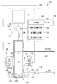
以下、本発明の実施形態である水質監視装置100及び水処理システム1について、図面を参照しながら説明する。図1は、水質監視装置100の全体構成図である。
Hereinafter, a water
図1に示すように、水質監視装置100は、主として、給水バルブ130と、測定セル140と、センサ制御部150と、センサ表示部159と、標準液注入部160と、照射部170と、蛍光強度測定部180と、攪拌部190と、検査水導入ラインである給水ラインL51と、検査水排出ラインである排水ラインL52と、を備える。
As shown in FIG. 1, the water
測定セル140は、蛍光物質の含有量を測定する検査水W1を収容する容器である。測定セル140は、不透明の樹脂材料により形成されている。測定セル140は、その側壁に一対の光透過壁141,142を有する。光透過壁141,142には、透明な板材141a,142aが嵌め込まれている。なお、ここでは、測定セル140を「原水収容部」とも呼称する。
The
給水ラインL51は、測定セル140への検査水W1の導入を行う。給水ラインL51には、給水バルブ130が設けられている。給水バルブ130は、検査水W1を採取する際に開かれる弁である。給水バルブ130の開閉は、センサ制御部150から出力される駆動信号により制御される。
The water supply line L51 introduces the test water W1 to the
排水ラインL52は、蛍光物質の含有量の測定が済んだ後に、測定セル140からの検査水W1及び標準液W2の排出を行うラインである。
The drainage line L52 is a line for discharging the test water W1 and the standard solution W2 from the
標準液注入部160は、標準液カートリッジ161と、ローラポンプ機構162と、を備える。標準液カートリッジ161は、標準液W2が充填された標準液パック(不図示)と、標準液パックに一端側が接続され且つ他端にノズルを有する弾性チューブとからなる注入体(不図示)とが収納された容器である。標準液は、所定濃度の蛍光物質を含んでもよく、複数の種類の蛍光物質を含んでもよい。なお、ここでは、標準液カートリッジ161のことを、「標準液収容部」とも呼称する。
The standard
ローラポンプ機構162の上部には、カートリッジ差込口163が設けられている。標準液カートリッジ161は、カートリッジ差込口163に着脱自在に装着される。
A
ローラポンプ機構162は、ローラポンプ164を備える。ローラポンプ164を駆動して、標準液カートリッジ161に収納された注入体の弾性チューブをしごくことにより、標準液パック内の標準液W2をノズルから測定セル140に向けて注入することができる。ローラポンプ164の駆動は、センサ制御部150から出力される駆動信号により制御される。なお、ここでは、ローラポンプ164のことを「供給手段」とも呼称する。
The
照射部170は、検査水W1に励起光を照射する設備である。照射部170は、図1に示すように、第1発光素子171と、第2発光素子172と、発光基板173を備える。
The
第1発光素子171及び第2発光素子172は、発光基板173に実装されている。第1発光素子171及び第2発光素子172は、測定セル140の光透過壁141に向けて光を照射する素子である。本実施形態においては、第1発光素子171は、タンパク質様の濃度を測定するための励起光を照射可能な深紫外線LEDである。より具体的には、第1発光素子171は、275±10nmの波長の深紫外線の励起光を照射可能である。第2発光素子172は、フミン質様の濃度を測定するための励起光を照射可能な近紫外線LEDである。より具体的には、第2発光素子172は、340±10nmの波長の近紫外線の励起光を照射可能である。
第1発光素子171及び第2発光素子172の点灯/消灯は、センサ制御部150から出力される駆動信号により制御される。
The first
Turning on / off of the first
蛍光強度測定部180は、検査水W1及び標準液W2に含まれる蛍光物質への、励起光の照射による蛍光の強度を測定する設備である。蛍光強度測定部180は、第1受光素子181と、第2受光素子182と、受光基板183と、第1バンドパスフィルタ184と、第2バンドパスフィルタ185とを備える。
The fluorescence
第1受光素子181及び第2受光素子182は、受光基板183に実装されている。第1受光素子181及び第2受光素子182は、励起光の照射により、検査水W1及び標準液W2に含まれる蛍光物質が放出する蛍光を受光する素子である。第1受光素子181及び第2受光素子182は、受光した蛍光の強度に対応した検出値信号をセンサ制御部150に出力する。
The first
第1バンドパスフィルタ184及び第2バンドパスフィルタ185は、測定セル140の側壁である光透過壁142の表面に実装されている。第1バンドパスフィルタ184により、第1発光素子171による励起光の蛍光物質への照射による蛍光のうち、320±20nmの波長の蛍光のみ透過させ、透過した蛍光は、第1受光素子181で受光する。この320±20nmという波長は、タンパク質様の分光波長に対応するとともに、水のラマン散乱を回避するために、320±20nmの波長の光のみ透過させる。一方、第2バンドパスフィルタ185により、第2発光素子172による励起光の蛍光物質への照射による蛍光のうち、420±20nmの波長の蛍光のみ透過させ、透過した蛍光は、第2受光素子182で受光する。この420±20nmという波長は、フミン質様の分光波長に対応する。
The first band pass filter 184 and the second band pass filter 185 are mounted on the surface of the
攪拌部190は、測定セル140の内部に収容される検査水W1及び標準液W2を攪拌する設備である。攪拌部190は、攪拌子191と、ステータコイル192と、を備える。攪拌子191は、測定セル140の底部に、回転可能に配置されている。ステータコイル192は、測定セル140の周囲を囲むようにリング状に形成された電磁誘導コイルである。ステータコイル192に駆動電流を供給すると、電磁誘導の作用により、測定セル140の底部に配置された攪拌子191が非接触で回転する。ステータコイル192の動作は、センサ制御部150から供給される駆動電流により制御される。
The stirring
センサ表示部159は、測定した検査水W1のタンパク質様やフミン質様の濃度の測定値や水質監視装置100の動作状況等を表示する装置である。
The
センサ制御部150は、水質監視装置100の動作を制御する装置である。センサ制御部150は、第1発光素子171、第2発光素子172を制御する。センサ制御部150は、蛍光強度測定部180から受信する検出値信号に基づいて、単位体積当たりの検査水W1に含まれるタンパク質様やフミン質様の含有量を測定する。センサ制御部150は、単位体積当たりの検査水W1中のタンパク質様やフミン質様の含有量の測定値をセンサ表示部159に表示させる。
The
センサ制御部150は、計時部151と、蛍光強度算出部152と、含有量算出部153と、変化量算出部154を有する。
The
計時部151は、前回タンパク質様、及び/又はフミン質様の濃度を測定してからの時間である第1時間t1、及び、前回校正を実施してからの時間である第2時間t2を計時する。例えば、t1が1時間となった段階で、センサ制御部150は、タンパク質様、及び/又はフミン質様の含有量の測定開始に伴う駆動信号を発すると共に、t1の計時をリセットしてもよい。また、例えば、t2が2週間となった段階で、センサ制御部150は、校正開始に伴う駆動信号を発すると共に、t2の計時をリセットしてもよい。
The
蛍光強度算出部152は、蛍光強度測定部180から受信した蛍光の検出値信号に基づいて、検査水W1及び標準液W2の蛍光強度を算出する。
The
含有量算出部153は、蛍光強度算出部152により算出された蛍光強度に基づいて、単位体積当たりの検査水W1及び標準液W2中のタンパク質様、及び/又はフミン質様の含有量を算出する。
The
変化量算出部154は、後述のように、水質監視装置100の校正方法として、検査水に濃縮蛍光物質を滴下する方法を用いる場合に、濃縮蛍光物質を滴下する前の検査水の蛍光強度と、濃縮蛍光物質を滴下した後の検査水の蛍光強度との変化量を算出する。この変化量は、校正に用いる標準濃縮蛍光物質に由来する。
As described later, when using the method of dropping the concentrated fluorescent substance into the test water as the calibration method of the water
水質監視装置100は、第2時間t2が所定値に達すると、水質監視装置100の校正を実施する。校正を実施する理由は、以下の通りである。検査水W1には、ある程度以上、外気から混入した砂塵やスライム等による汚れが存在するため、測定セル140の光透過壁141及び142に汚れが付着する。これにより、蛍光強度の測定精度が低下する。校正を実施することにより、汚れの付着による蛍光強度の測定精度の低下を抑制することができる。具体的には、センサ制御部150の制御により、給水バルブ130を閉めた後、ローラポンプ164を駆動して、標準液カートリッジ161に収納された注入体の弾性チューブをしごくことにより、所定濃度の蛍光物質を含む標準液W2で測定セル140を満たし、標準液W2の蛍光強度を測定することにより、今回の測定値とイニシャルの測定値とのずれに基づいて校正する。
The water
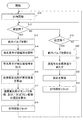
続いて、図2のフローチャートを参照しながら、本発明の実施形態に係る水質監視装置100の動作について説明する。図2は、本発明の実施形態に係る水質監視装置100の第1の動作例を示すフローチャートである。
Subsequently, the operation of the water
ステップS11において、計時部151が計時を開始する。
ステップS12において、計時部151が計測する第1時間t1が所定値に達し、タンパク質様、及び/又はフミン質様の濃度の測定時刻となった場合(S12:YES)には、処理はステップS13に移行する。タンパク質様、及び/又はフミン質様の濃度の測定時刻でない場合(S12:NO)には、処理は、ステップS19に移行する。
In step S11, the
In step S12, when the first time t1 measured by the
ステップS13において、センサ制御部150の制御により、給水バルブ130を開く。
In step S13, the
ステップS14において、第1発光素子171、及び/又は第2発光素子172は、測定セル140の内部に収容された検査水W1に対し、励起光を照射する。なお、水質監視装置100がタンパク質様の濃度のみを測定する場合には、第1発光素子171のみが励起光を照射し、フミン質様の濃度のみを測定する場合には、第2発光素子172のみが励起光を照射する。水質監視装置100がタンパク質様及びフミン質様の双方の濃度を測定する場合には、第1発光素子171及び第2発光素子172の双方が励起光を照射する。
In step S14, the first
ステップS15において、第1受光素子181、及び/又は第2受光素子182は、励起光の照射により、検査水W1に含まれる蛍光物質が放出する蛍光を受光する。更に、第1受光素子181、及び/又は第2受光素子182は、受光した蛍光の強度に対応した検出値信号をセンサ制御部150に出力する。なお、水質監視装置100がタンパク質様の濃度のみを測定する場合には、第1受光素子181のみが、検出値信号をセンサ制御部150に出力し、フミン質様の濃度のみを測定する場合には、第2受光素子182のみが、検出値信号をセンサ制御部150に出力する。水質監視装置100がタンパク質様とフミン質様の双方の濃度を測定する場合には、第1受光素子181及び第2受光素子182の双方が、検出値信号をセンサ制御部150に出力する。
In step S15, the first
ステップS16において、蛍光強度算出部152は、蛍光強度測定部180の第1受光素子181、及び/又は第2受光素子182から受信した蛍光強度の検出値信号に基づいて、検査水W1の蛍光強度を算出する。
In step S16, the fluorescence
ステップS17において、含有量算出部153は、蛍光強度算出部152により算出された蛍光強度に基づいて、単位体積当たりの検査水W1中のタンパク質様、及び/又はフミン質様の含有量を検出する。
In step S17, the
ステップS18において、計時部151をリセットする。より具体的には、第1時間t1を0とする。その後、処理はステップS11に戻る。
In step S18, the
ステップS19において、計時部151が計測する第2時間t2が所定値に達し、校正時となった場合(S18:YES)には、処理はステップS20に移行する。校正時でない場合(S18:NO)には、処理は、ステップS12に戻る。
In step S19, when the second time t2 measured by the
ステップS20において、センサ制御部150の制御により、給水バルブ130を閉める。
In step S20, the
ステップS21において、センサ制御部150は、ローラポンプ164を駆動して、標準液カートリッジ161に収納された注入体の弾性チューブをしごくことにより、所定濃度の蛍光物質を含む標準液W2で測定セル140を満たす。標準液W2が測定セル140に供給される以前に測定セル140に収容されていた検査水W1は、オーバーフローにより、排水ラインL52から排出される。
In step S21, the
ステップS22において、センサ制御部150は、校正を実施する。具体的には、照射部170が標準液W2に励起光を照射し、標準液W2に含まれる蛍光物質による蛍光強度を、蛍光強度測定部180が測定後、今回の測定値とイニシャルの測定値とのずれを算出し、このずれに基づいて校正を実施する。
In step S22, the
ステップS23において、計時部151をリセットする。より具体的には、第2時間t2を0とする。その後、処理はステップS11に戻る。
In step S23, the
続いて、図3を参照しながら、本発明の実施形態に係る水処理システム1における、水質監視装置100の設置箇所について説明する。図3は、本発明の水処理システム1の全体構成図である。
Then, the installation location of the water
図3に示すように、水処理システム1は、前処理装置3と、加圧ポンプ4と、インバータ5と、逆浸透膜モジュール6と、定流量弁7と、比例制御排水弁8と、流量センサFMと、制御部30と、を備える。更に、図3は、水質監視装置100A〜100Cを示すが、水処理システム1は、これらの水質監視装置100の全てを備えてもよく、一部のみ備えてもよい。なお、制御部30と被制御対象機器との電気的接続線の図示については、省略している。
As shown in FIG. 3, the water treatment system 1 includes a
水処理システム1は、ラインとして、供給水ラインL1と、透過水ラインL2と、濃縮水ラインL3と、循環水ラインL4と、濃縮排水ラインL5と、を備える。「ライン」とは、流路、経路、管路等の流体の流通が可能なラインの総称である。また、その由来(出所)やその水質によらず、供給水ラインL1、濃縮水ラインL3又は循環水ラインL4を流通する水を、「供給水」ともいい、濃縮水ラインL3、循環水ラインL4又は濃縮排水ラインL5を流通する水を、「濃縮水」ともいう。 The water treatment system 1 includes, as lines, a feed water line L1, a permeate water line L2, a concentrate water line L3, a circulating water line L4, and a concentrate drainage line L5. "Line" is a general term for lines such as flow paths, paths, and conduits that allow fluid flow. In addition, regardless of the origin (source) and its water quality, the water flowing through the feed water line L1, the concentrated water line L3 or the circulating water line L4 is also referred to as "supply water", the concentrated water line L3, the circulating water line L4. Alternatively, the water flowing through the concentrated drainage line L5 is also referred to as "concentrated water".
供給水ラインL1は、原水W11及び供給水W12を逆浸透膜モジュール6に向けて供給するラインである。供給水ラインL1は、上流側から下流側に向けて、第1供給水ラインL11と、第2供給水ラインL12とを有する。 The feed water line L 1 is a line for supplying the raw water W 11 and the feed water W 12 toward the reverse osmosis membrane module 6. The feed water line L1 has a first feed water line L11 and a second feed water line L12 from the upstream side toward the downstream side.
第1供給水ラインL11の上流側の端部は、原水W11の水源2に接続されている。第1供給水ラインL11の下流側の端部は、接続部J1において、第2供給水ラインL12及び循環水ラインL4に接続されている。なお、第1供給水ラインL11を流通する原水W11を「供給水W11」ともいう。第1供給水ラインL11には、前処理装置3が設けられる。
The upstream end of the first water supply line L11 is connected to the
前処理装置3は、供給水W11を前処理する装置であり、たとえば供給水W11をろ過するろ過装置であってもよい。
The
第2供給水ラインL12の上流側の端部は、接続部J1に接続されている。第2供給水ラインL12の下流側の端部は、逆浸透膜モジュール6の一次側入口ポートに接続されている。なお、第2供給水ラインL12を流通する水を「供給水W12」ともいう。第2供給水ラインL12には、加圧ポンプ4が設けられる。 The upstream end of the second water supply line L12 is connected to the connection J1. The downstream end of the second feed water line L12 is connected to the primary inlet port of the reverse osmosis membrane module 6. In addition, the water which distribute | circulates the 2nd water supply line L12 is also called "supply water W12." The pressurizing pump 4 is provided in the second water supply line L12.
加圧ポンプ4は、供給水W12を吸入し、逆浸透膜モジュール6に向けて圧送(吐出)する装置である。加圧ポンプ4には、インバータ5から周波数が変換された駆動電力が供給される。加圧ポンプ4は、供給(入力)された駆動電力の周波数(以下、「駆動周波数」ともいう)に応じた回転速度で駆動される。
The pressurizing pump 4 is a device that sucks in the supply water W12 and pumps (discharges) it to the reverse osmosis membrane module 6. The pressure pump 4 is supplied with drive power whose frequency has been converted from the
インバータ5は、加圧ポンプ4に、周波数が変換された駆動電力を供給する電気回路(又はその回路を持つ装置)である。インバータ5は、制御部30と電気的に接続されている。インバータ5には、制御部30から指令信号が入力される。インバータ5は、制御部30により入力された指令信号(電流値信号又は電圧値信号)に対応する駆動周波数の駆動電力を加圧ポンプ4に出力する。
The
供給水W12は、加圧ポンプ4を介して逆浸透膜モジュール6に供給される。また、供給水W12は、供給水W11及び循環水W40(後述)からなる。 The feed water W12 is supplied to the reverse osmosis membrane module 6 via the pressure pump 4. Further, the feed water W12 is composed of feed water W11 and circulating water W40 (described later).
逆浸透膜モジュール6は、供給水W12を透過水W20と濃縮水W30とに分離する設備である。詳細には、逆浸透膜モジュール6は、加圧ポンプ4から吐出された供給水W12を、溶存塩類が除去された透過水W20と、溶存塩類が濃縮された濃縮水W30とに膜分離処理する設備である。逆浸透膜モジュール6は、単一又は複数の逆浸透膜エレメント(図示せず)を備える。逆浸透膜モジュール6は、これら逆浸透膜エレメントにより供給水W12を膜分離処理し、透過水W20と濃縮水W30とを製造する。 The reverse osmosis membrane module 6 is a facility for separating the feed water W12 into the permeate water W20 and the concentrated water W30. Specifically, the reverse osmosis membrane module 6 separates the feed water W12 discharged from the pressure pump 4 into the permeate water W20 from which the dissolved salts are removed and the concentrated water W30 from which the dissolved salts are concentrated. It is an equipment. The reverse osmosis membrane module 6 comprises one or more reverse osmosis membrane elements (not shown). The reverse osmosis membrane module 6 separates the feed water W12 by the reverse osmosis membrane element to produce a permeate water W20 and a concentrated water W30.
透過水ラインL2は、逆浸透膜モジュール6で分離された透過水W20を送出するラインである。透過水ラインL2の上流側の端部は、逆浸透膜モジュール6の二次側ポートに接続されている。透過水ラインL2の下流側の端部は、貯留タンク(図示せず)に接続されている。透過水ラインL2には、流量センサFMが設けられる。
The permeate
流量センサFMは、透過水ラインL2を流通する透過水W20の流量を検出する機器である。流量センサFMは、制御部30と電気的に接続されている。流量センサFMで検出された透過水W20の流量(以下、「検出流量値」ともいう)は、制御部30にパルス信号として送信される。
The flow rate sensor FM is a device that detects the flow rate of the permeate water W20 flowing through the permeate water line L2. The flow rate sensor FM is electrically connected to the
濃縮水ラインL3は、逆浸透膜モジュール6で分離された濃縮水W30が流通するラインである。濃縮水ラインL3の上流側の端部は、逆浸透膜モジュール6の一次側出口ポートに接続されている。また、濃縮水ラインL3の下流側は、接続部J2において、循環水ラインL4及び濃縮排水ラインL5に分岐している。 The concentrated water line L3 is a line through which the concentrated water W30 separated by the reverse osmosis membrane module 6 flows. The upstream end of the concentrated water line L3 is connected to the primary outlet port of the reverse osmosis membrane module 6. Further, the downstream side of the concentrated water line L3 is branched into the circulating water line L4 and the concentrated drainage line L5 at the connection portion J2.
循環水ラインL4は、濃縮水ラインL3に接続され、供給水としての濃縮水(循環水W40)を供給水ラインL1に返送するラインである。本実施形態においては、循環水ラインL4は、濃縮水ラインL3を流通する濃縮水W30を循環水W40として、供給水ラインL1における加圧ポンプ4よりも上流側に返送(循環)させるラインである。循環水ラインL4の上流側の端部は、接続部J2において濃縮水ラインL3に接続されている。また、循環水ラインL4の下流側の端部は、接続部J1において、供給水ラインL1に接続されている。循環水ラインL4には、定流量弁7が設けられる。 The circulating water line L4 is a line that is connected to the concentrated water line L3 and returns concentrated water (circulating water W40) as feed water to the feed water line L1. In the present embodiment, the circulating water line L4 is a line for returning (circulating) the concentrated water W30 flowing through the concentrated water line L3 as the circulating water W40 to the upstream side of the pressurizing pump 4 in the feed water line L1. . The upstream end of the circulating water line L4 is connected to the concentrated water line L3 at a connection J2. Further, the downstream end of the circulating water line L4 is connected to the water supply line L1 at the connection portion J1. A constant flow rate valve 7 is provided in the circulating water line L4.
定流量弁7は、循環水ラインL4を流通する循環水W40の流量を所定の一定流量値に保持するように調節する機器である。定流量弁7において保持される「一定流量値」とは、一定流量値に幅がある概念であり、定流量弁における目標流量値のみに限られない。例えば、定流量機構の特性(例えば、材質や構造に起因する温度特性等)を考慮して、定流量弁における目標流量値に対して、±10%程度の調節誤差を有するものを含む。定流量弁7は、補助動力や外部操作を必要とせずに一定流量値を保持するものであり、例えば、水ガバナの名称で呼ばれるものが挙げられる。なお、定流量弁7は、補助動力や外部操作により動作して、一定流量値を保持するものでもよい。 The constant flow valve 7 is a device for adjusting the flow rate of the circulating water W 40 flowing through the circulating water line L 4 so as to maintain the flow rate at a predetermined constant flow value. The “constant flow rate value” held in the constant flow rate valve 7 is a concept having a range of constant flow rate values, and is not limited to only the target flow rate value in the constant flow rate valve. For example, it includes one having an adjustment error of about ± 10% with respect to the target flow rate value of the constant flow rate valve in consideration of the characteristics of the constant flow rate mechanism (for example, temperature characteristics due to material and structure). The constant flow valve 7 holds a constant flow value without the need for auxiliary power or external operation, and examples thereof include those called by the name of water governor. The constant flow valve 7 may be operated by the auxiliary power or an external operation to hold a constant flow value.
濃縮排水ラインL5は、濃縮水ラインL3に接続され、濃縮排水W50としての濃縮水を系外へ排出するラインである。本実施形態においては、濃縮排水ラインL5は、接続部J2において濃縮水ラインL3に接続され、逆浸透膜モジュール6で分離された濃縮水W30を、濃縮排水W50として装置外(系外)に排出するラインである。濃縮排水ラインL5には、比例制御排水弁8が設けられる。
The concentrated drainage line L5 is a line connected to the concentrated water line L3 and discharging the concentrated water as the concentrated drainage W50 out of the system. In the present embodiment, the concentrated drainage line L5 is connected to the concentrated water line L3 at the connection J2, and the concentrated water W30 separated by the reverse osmosis membrane module 6 is discharged to the outside (outside the system) as concentrated drainage W50. Line. A proportional
比例制御排水弁8は、濃縮排水ラインL5から装置外に排出される濃縮排水W50の流量を調節する弁である。比例制御排水弁8は、制御部30と電気的に接続されている。比例制御排水弁8の弁開度は、制御部30から送信される駆動信号により制御される。制御部30から電流値信号(例えば、4〜20mA)を比例制御排水弁8に送信して、弁開度を制御することにより、濃縮排水W50の排水流量を調節することができる。
The proportional
制御部30は、CPU及びメモリを含むマイクロプロセッサ(図示せず)により構成される。制御部30において、マイクロプロセッサのCPUは、メモリから読み出した所定のプログラムに従って、水処理システム1に係る各種の制御を実行する。以下、制御部30の機能の一部について説明する。
The
制御部30は、透過水W20の流量が予め設定された目標流量値となるように、透過水W20の検出流量値(系内の物理量)をフィードバック値として、加圧ポンプ4を駆動するための駆動周波数を演算し、駆動周波数の演算値に対応する指令信号(電流値信号又は電圧値信号)をインバータ5に出力する(以下、「流量フィードバック水量制御」ともいう)流量制御部として機能する。なお、流量フィードバック水量制御における駆動周波数の演算には、例えば、速度形デジタルPIDアルゴリズムを用いることができる。
The
上記のように、水処理システム1は、水質監視装置100を備え、水質監視装置100のセンサ制御部150は、制御部30に接続され、制御部30により制御される。ここで、本発明の水質監視装置100は、図3における100A〜100Cによって示されるように、前処理装置3の前段に設置することも可能であり(100A)、前処理装置3の後段に設置することも可能であり(100B)、濃縮排水ラインL5中に設置することも可能である(100C)。また、これらのうち1つの箇所に設置することも、2つの箇所に設置することも、3つ全ての箇所に設置することも可能である。更に、1台の水質監視装置100で、上記の3箇所のうち複数箇所から取水することも可能である。
As described above, the water treatment system 1 includes the water
水質監視装置100Aは、前処理装置3の前段における、単位体積の供給水W11当たりのタンパク質様、及び/又はフミン質様の含有量を測定することが可能である。更に、制御部30は、この含有量を用いて、BFP(バイオファウリングポテンシャル)を監視することが可能である。
The water
水質監視装置100Bは、前処理装置3の後段における、単位体積の供給水W11当たりのタンパク質様、及び/又はフミン質様の含有量を測定することが可能である。更に、制御部30は、この含有量を用いて、BFP(バイオファウリングポテンシャル)を監視することが可能である。
The water
水質監視装置100Cは、濃縮排水ラインL5における、単位体積の濃縮排水W50当たりのタンパク質様、及び/又はフミン質様の濃度を測定することが可能である。更に、制御部30は、この含有量を用いて、BFP(バイオファウリングポテンシャル)を監視することが可能である。更に、制御部30は、濃縮排水ラインL5における、バイオフィルムの発生度合いも監視することが可能である。
The water
更に、制御部30は、水質監視装置100A、100B、100C、各々で測定されたタンパク質様、及び/又はフミン質様の含有量の比率を算出することにより、水処理システム1のいずれの箇所で問題が発生しているか推定することも可能である。
Furthermore, the
〔実施形態の効果〕
上述した水質監視装置100によれば、例えば、以下のような効果が奏される。
本発明の水質監視装置100は、原水W1を収容すると共に、光を透過する光透過壁141及び142を有する原水収容部140と、原水収容部140に原水W1を供給する給水バルブ130と、原水収容部140に励起光を照射する照射部170と、励起光の照射により、原水W1に含まれる蛍光物質が放出する蛍光の強度を測定する蛍光強度測定部180と、校正用の標準液W2を収容する標準液収容部161と、標準液収容部161から原水収容部140に標準液W2を供給する供給手段164と、通常動作時には、給水バルブ130を開いて原水収容部140に原水W1を供給させ、蛍光の強度に基づいて、原水W1に含まれる蛍光物質の含有量を算出すると共に、校正時には、給水バルブ130を止めた後、供給手段164を制御することにより、原水収容部140を標準液W2で満たし、校正を実施する制御部150と、を備える。
[Effect of the embodiment]
According to the water
The water
そのため、原水中に含まれる蛍光物質が放出する蛍光の強度を測定することにより、感度良く原水の水質を判定することが可能となる。更に、通常の三次元蛍光測定装置と異なり、校正用の標準液を収容する標準液収容部を備えることにより、簡易に校正をすることができ、これにより、蛍光物質の含有量の測定精度を高めることができる。 Therefore, by measuring the intensity of the fluorescence emitted by the fluorescent substance contained in the raw water, it is possible to determine the water quality of the raw water with high sensitivity. Furthermore, unlike a normal three-dimensional fluorescence measurement apparatus, calibration can be easily performed by providing a standard liquid storage unit that stores a standard liquid for calibration, whereby the measurement accuracy of the content of the fluorescent material can be obtained. It can be enhanced.
また、励起光が複数個数の波長範囲の励起光であることにより、制御部は、複数の蛍光物質の含有量を測定する。
そのため、複数種類の励起光を同時に用いることにより、1台の水質監視装置で、複数種類の蛍光物質を同時に検出することが可能となる。
Further, when the excitation light is excitation light of a plurality of wavelength ranges, the control unit measures the content of the plurality of fluorescent substances.
Therefore, by simultaneously using a plurality of types of excitation light, it becomes possible to simultaneously detect a plurality of types of fluorescent substances with one water quality monitoring device.
また、標準液は、複数の蛍光物質を含む。
そのため、複数種類の波長の励起光を用いる水質監視装置でも、一種類の標準液で校正を実施することが可能となる。
Also, the standard solution contains a plurality of fluorescent substances.
Therefore, even with a water quality monitoring device using excitation light of a plurality of types of wavelengths, calibration can be performed with one type of standard solution.
また、励起光は、265nm〜285nmの波長を有する。
そのため、原水中のタンパク質様物質の含有量を検知することが可能となる。
Moreover, excitation light has a wavelength of 265 nm-285 nm.
Therefore, it becomes possible to detect the content of the proteinaceous substance in the raw water.
また、励起光は、330nm〜350nmの波長を有する。
そのため、原水中のフミン質様物質の含有量を検知することが可能となる。
Moreover, excitation light has a wavelength of 330 nm-350 nm.
Therefore, it becomes possible to detect the content of humic substances in raw water.
また、上述した水処理システム1によれば、例えば、以下のような効果が奏される。
本発明の水処理システム1は、供給水から処理水を製造する水処理システム1であって、供給水W12を透過水W20と濃縮水W30とに分離する逆浸透膜モジュール6と、供給水を逆浸透膜モジュール6に向けて供給する供給水ラインL1と、逆浸透膜モジュール6で分離された濃縮水W30が流通する濃縮水ラインL3と、濃縮水ラインL3に接続され、濃縮排水としての濃縮水W50を系外へ排出する濃縮排水ラインL5と、供給水ラインL1又は濃縮排水ラインL5における蛍光物質の含有量を測定する、水質監視装置100と、を備える。
Moreover, according to the water treatment system 1 mentioned above, the following effects are show | played, for example.
The water treatment system 1 of the present invention is a water treatment system 1 for producing treated water from feed water, and comprises a reverse osmosis membrane module 6 for separating feed water W12 into permeate water W20 and concentrated water W30, and feed water. A feed water line L1 supplied toward the reverse osmosis membrane module 6, a concentrate water line L3 through which concentrated water W30 separated by the reverse osmosis membrane module 6 flows, and a concentrate water line L3 are connected and concentrated as concentrated drainage The system includes a concentrated drainage line L5 for discharging the water W50 out of the system, and a water
そのため、水処理システム1において、逆浸透膜モジュール6の前後に、本発明の水質監視装置100を備えることにより、バイオファウリングの監視に役立てることができる。
Therefore, by providing the water
〔変形例〕
以上、本発明の好適な実施形態について説明したが、本発明は、上述した実施形態に限定されることなく、種々の形態で実施することができる。
[Modification]
As mentioned above, although the suitable embodiment of the present invention was described, the present invention can be carried out in various forms, without being limited to the embodiment mentioned above.
例えば、測定セル(原水収容部)140は、中央に遮光用の柱を備えると共に、ドーナツ型の撹拌子を備えてもよい。これにより、蛍光強度測定部180は、励起光の反射光を受けることがなく、散乱光である蛍光のみを受光することができる。更に、これにより、蛍光強度の測定精度が上昇する。また、このほか、蛍光強度測定部180は90°散乱光のみを受光する構成としてもよい。
For example, the measurement cell (raw water storage portion) 140 may be provided with a light shielding post at the center and a toroidal stirrer. Thereby, the fluorescence
また、測定セル(原水収容部)140には、光触媒が塗布されていてもよい。原水収容部に光触媒が塗布されていることにより、原水収容部を自動的に洗浄することが可能となる。 Further, a photocatalyst may be applied to the measurement cell (raw water storage unit) 140. By applying the photocatalyst to the raw water storage unit, the raw water storage unit can be cleaned automatically.
また、上記の実施形態では、単位体積当たりの検査水W1に含まれる、タンパク質様やフミン質様の含有量を測定するとしたが、これは一例であって、これには限定されない。その他の蛍光物質の含有量を測定することも可能である。 In the above embodiment, the content of protein-like and humic-like substances contained in the test water W1 per unit volume is measured, but this is an example, and the present invention is not limited thereto. It is also possible to measure the content of other fluorescent substances.
また、上記の実施形態では、測定セル140に標準液W2を供給する供給手段が、ローラポンプ164であるとしたが、これには限定されない。例えば、モータ等を用いてもよい。
In the above embodiment, the supply means for supplying the standard solution W2 to the
また、上記の実施形態では、水質監視装置100の校正の際、標準液W2が測定セル140に供給される以前に測定セル140に収容されていた検査水W1は、オーバーフローにより、排水ラインL52から排出されるとしたが、これには限定されない。例えば、測定セル(原水収容部)140の底部に、センサ制御部150によって制御可能な排出口を設け、校正に先立って、この排出口を制御することにより、測定セル140に収容されていた検査水W1を排出してもよい。
In the above embodiment, when the water
また、標準液カートリッジ161に収納された標準液W2で、測定セル140を満たすことにより校正するとしたが、これには限定されない。例えば、測定セル140を純水で満たした後、標準液カートリッジ161に収納される、濃縮された蛍光物質を滴下してから、蛍光物質の含有量を測定することにより、校正を実施してもよい。
あるいは、測定セル140を検査水W1で満たして、単位体積の検査水W1の蛍光強度を測定した後、標準液カートリッジ161に収納される濃縮された蛍光物質を滴下してから、再度、検査水W1の蛍光強度を測定し、変化量算出部154が、蛍光強度の変化量を算出することにより、校正を実施してもよい。
Further, although the calibration is performed by filling the
Alternatively, after the
また、測定セル140の形状を、正面から見た場合には、三角型(Δ型)となるようにしてもよい。とりわけ、蛍光物質が高濃度の場合、励起光や傾向が蛍光物質によって遮られてしまうため、測定セルの形状を三角型にして光路長を短くすることにより、その影響を低減することが可能となる。
The shape of the
また、測定セル140内にガラスビーズを予め入れておいてもよい。これにより、水流によってビーズが踊り、測定セル140内の汚れを掻き取ることが可能となる。
Alternatively, glass beads may be placed in advance in the measuring
また、水質監視装置100は、蛍光物質を濃縮する濃縮機構を備えてもよい。
Further, the water
また、水処理システム1において、前処理装置3は、ろ過装置に限定されず、例えば活性炭処理装置でもよい。
Moreover, in the water treatment system 1, the
1 水処理システム
3 前処理装置
4 加圧ポンプ
6 逆浸透膜モジュール
30 制御部
100 100A 100B 100C 水質監視装置
130 給水バルブ
140 測定セル(原水収容部)
141 142 光透過壁
150 センサ制御部
161 標準液カートリッジ(標準液収容部)
164 ローラポンプ(供給手段)
170 照射部
180 蛍光強度測定部
L1 供給水ライン
L2 透過水ライン
L3 濃縮水ライン
L4 循環水ライン
L5 濃縮排水ライン
L51 給水ライン
L52 排水ライン
DESCRIPTION OF SYMBOLS 1
141 142
164 Roller pump (supply means)
170
Claims (8)
前記原水収容部に原水を供給する給水バルブと、
前記原水収容部に励起光を照射する照射部と、
前記励起光の照射により、前記原水に含まれる蛍光物質が放出する蛍光の強度を測定する蛍光強度測定部と、
校正用の標準液を収容する標準液収容部と、
前記標準液収容部から前記原水収容部に標準液を供給する供給手段と、
通常動作時には、前記給水バルブを開いて前記原水収容部に原水を供給させ、前記蛍光の強度に基づいて、前記原水に含まれる前記蛍光物質の含有量を算出すると共に、校正時には、前記給水バルブを止めた後、前記供給手段を制御することにより、前記原水収容部を前記標準液で満たし、校正を実施する制御部と、を備える水質監視装置。 A raw water storage unit that contains raw water and has a light transmission wall that transmits light;
A water supply valve for supplying raw water to the raw water storage unit;
An irradiation unit for irradiating the raw water storage unit with excitation light;
A fluorescence intensity measurement unit that measures the intensity of fluorescence emitted from the fluorescent substance contained in the raw water upon irradiation of the excitation light;
A standard solution storage unit for storing a standard solution for calibration;
Supply means for supplying a standard solution from the standard solution storage unit to the raw water storage unit;
During normal operation, the water supply valve is opened to supply the raw water to the raw water storage unit, the content of the fluorescent material contained in the raw water is calculated based on the intensity of the fluorescence, and at the time of calibration, the water supply valve And a control unit for filling the raw water storage unit with the standard solution by controlling the supply means and performing calibration.
供給水を透過水と濃縮水とに分離する逆浸透膜モジュールと、
供給水を前記逆浸透膜モジュールに向けて供給する供給水ラインと、
前記逆浸透膜モジュールで分離された濃縮水が流通する濃縮水ラインと、
前記濃縮水ラインに接続され、濃縮排水としての濃縮水を系外へ排出する濃縮排水ラインと、
前記供給水ライン又は前記濃縮排水ラインにおける蛍光物質の含有量を測定する、請求項1〜7のいずれか1項の水質監視装置と、を備える水処理システム。
A water treatment system for producing treated water from feed water, comprising
A reverse osmosis membrane module that separates feed water into permeate and concentrated water;
A feed water line for feeding feed water to the reverse osmosis membrane module;
A concentrated water line through which concentrated water separated by the reverse osmosis membrane module flows;
A concentrated drainage line connected to the concentrated water line and discharging concentrated water as concentrated drainage out of the system;
The water quality monitoring device according to any one of claims 1 to 7, wherein the content of the fluorescent material in the feed water line or the concentrated drainage line is measured.
Priority Applications (1)
| Application Number | Priority Date | Filing Date | Title |
|---|---|---|---|
| JP2017074611A JP2018179556A (en) | 2017-04-04 | 2017-04-04 | Water quality monitoring device and water treatment system |
Applications Claiming Priority (1)
| Application Number | Priority Date | Filing Date | Title |
|---|---|---|---|
| JP2017074611A JP2018179556A (en) | 2017-04-04 | 2017-04-04 | Water quality monitoring device and water treatment system |
Publications (1)
| Publication Number | Publication Date |
|---|---|
| JP2018179556A true JP2018179556A (en) | 2018-11-15 |
Family
ID=64274940
Family Applications (1)
| Application Number | Title | Priority Date | Filing Date |
|---|---|---|---|
| JP2017074611A Pending JP2018179556A (en) | 2017-04-04 | 2017-04-04 | Water quality monitoring device and water treatment system |
Country Status (1)
| Country | Link |
|---|---|
| JP (1) | JP2018179556A (en) |
Cited By (4)
| Publication number | Priority date | Publication date | Assignee | Title |
|---|---|---|---|---|
| JP2021513083A (en) * | 2018-04-23 | 2021-05-20 | ノリア ウォーター テクノロジーズ,インコーポレイテッド | Real-time film surface monitoring method and equipment |
| CN114923862A (en) * | 2021-03-15 | 2022-08-19 | 武汉圣禹排水系统有限公司 | Indirect monitoring device and reposition of redundant personnel facility |
| JP2023020634A (en) * | 2021-07-30 | 2023-02-09 | 三浦工業株式会社 | Optical water quality measuring device |
| JP2023020633A (en) * | 2021-07-30 | 2023-02-09 | 三浦工業株式会社 | Fluorescence measuring device |
Citations (11)
| Publication number | Priority date | Publication date | Assignee | Title |
|---|---|---|---|---|
| JPS48105587U (en) * | 1972-03-07 | 1973-12-08 | ||
| JPH05273118A (en) * | 1992-03-24 | 1993-10-22 | Hitachi Ltd | Method and apparatus for analyzing concentration or composition of test sample liquid |
| JP2000214080A (en) * | 1999-01-26 | 2000-08-04 | Yokogawa Electric Corp | Analysis equipment |
| JP2001083095A (en) * | 1999-09-13 | 2001-03-30 | Toshiba Eng Co Ltd | Water quality measurement device |
| JP2008064612A (en) * | 2006-09-07 | 2008-03-21 | Kurita Water Ind Ltd | Water quality measuring method and water quality measuring device |
| JP2008518222A (en) * | 2004-10-26 | 2008-05-29 | コミツサリア タ レネルジー アトミーク | Relative method for measuring the fluorescence quantum yield of dyes in solution. |
| JP2008194560A (en) * | 2007-02-08 | 2008-08-28 | Kurita Water Ind Ltd | Membrane separator evaluation method, water treatment method, and water treatment apparatus |
| JP2012168044A (en) * | 2011-02-15 | 2012-09-06 | Yokogawa Electric Corp | Turbidimeter/colorimeter |
| WO2012124538A1 (en) * | 2011-03-15 | 2012-09-20 | 株式会社 東芝 | Fouling prediction method, and membrane filtration system |
| JP2014083524A (en) * | 2012-10-26 | 2014-05-12 | Aquas Corp | Monitoring method of microorganism activity in waste water, monitoring apparatus of microorganism activity in waste water, and control method of waste water treatment |
| US8969093B1 (en) * | 2013-03-15 | 2015-03-03 | University Of Memphis Research Foundation | Calibration method and device for remote location testing instruments |
-
2017
- 2017-04-04 JP JP2017074611A patent/JP2018179556A/en active Pending
Patent Citations (12)
| Publication number | Priority date | Publication date | Assignee | Title |
|---|---|---|---|---|
| JPS48105587U (en) * | 1972-03-07 | 1973-12-08 | ||
| JPH05273118A (en) * | 1992-03-24 | 1993-10-22 | Hitachi Ltd | Method and apparatus for analyzing concentration or composition of test sample liquid |
| JP2000214080A (en) * | 1999-01-26 | 2000-08-04 | Yokogawa Electric Corp | Analysis equipment |
| JP2001083095A (en) * | 1999-09-13 | 2001-03-30 | Toshiba Eng Co Ltd | Water quality measurement device |
| JP2008518222A (en) * | 2004-10-26 | 2008-05-29 | コミツサリア タ レネルジー アトミーク | Relative method for measuring the fluorescence quantum yield of dyes in solution. |
| JP2008064612A (en) * | 2006-09-07 | 2008-03-21 | Kurita Water Ind Ltd | Water quality measuring method and water quality measuring device |
| JP2008194560A (en) * | 2007-02-08 | 2008-08-28 | Kurita Water Ind Ltd | Membrane separator evaluation method, water treatment method, and water treatment apparatus |
| JP2012168044A (en) * | 2011-02-15 | 2012-09-06 | Yokogawa Electric Corp | Turbidimeter/colorimeter |
| WO2012124538A1 (en) * | 2011-03-15 | 2012-09-20 | 株式会社 東芝 | Fouling prediction method, and membrane filtration system |
| JP2012192315A (en) * | 2011-03-15 | 2012-10-11 | Toshiba Corp | Fouling prediction method, and membrane filtration system |
| JP2014083524A (en) * | 2012-10-26 | 2014-05-12 | Aquas Corp | Monitoring method of microorganism activity in waste water, monitoring apparatus of microorganism activity in waste water, and control method of waste water treatment |
| US8969093B1 (en) * | 2013-03-15 | 2015-03-03 | University Of Memphis Research Foundation | Calibration method and device for remote location testing instruments |
Cited By (6)
| Publication number | Priority date | Publication date | Assignee | Title |
|---|---|---|---|---|
| JP2021513083A (en) * | 2018-04-23 | 2021-05-20 | ノリア ウォーター テクノロジーズ,インコーポレイテッド | Real-time film surface monitoring method and equipment |
| CN114923862A (en) * | 2021-03-15 | 2022-08-19 | 武汉圣禹排水系统有限公司 | Indirect monitoring device and reposition of redundant personnel facility |
| JP2023020634A (en) * | 2021-07-30 | 2023-02-09 | 三浦工業株式会社 | Optical water quality measuring device |
| JP2023020633A (en) * | 2021-07-30 | 2023-02-09 | 三浦工業株式会社 | Fluorescence measuring device |
| JP7586022B2 (en) | 2021-07-30 | 2024-11-19 | 三浦工業株式会社 | Optical water quality measuring device |
| JP7760853B2 (en) | 2021-07-30 | 2025-10-28 | 三浦工業株式会社 | Fluorescence measurement equipment |
Similar Documents
| Publication | Publication Date | Title |
|---|---|---|
| JP2018179556A (en) | Water quality monitoring device and water treatment system | |
| JP5292923B2 (en) | Microorganism detection method, microorganism detection apparatus, and slurry supply apparatus using the same | |
| AU2014324844B2 (en) | Multi-channel fluorometric sensor and method of using same | |
| EP4075120B1 (en) | Method using a multichannel fluorometric sensor | |
| RU2017116984A (en) | Apparatus and method for measuring the concentration of a disinfectant in a reprocessing system of a medical device | |
| JP2002154056A (en) | Polishing liquid manufacturing equipment | |
| RU2495496C2 (en) | Water vending machine | |
| EP2342558B1 (en) | Method of toc monitoring | |
| CN107771279B (en) | Calibration method for water hardness measurement | |
| EP3959177A1 (en) | Coated substrate and process of preparation | |
| KR101302734B1 (en) | Tro sensor with quantity of flow and fluid pressure buffer chamber | |
| US11670522B2 (en) | Processing liquid generator and substrate processing apparatus using the same | |
| JP6167939B2 (en) | Water treatment equipment | |
| JP6225522B2 (en) | Water quality measuring device | |
| JP2018167207A (en) | Biofilm amount monitoring method and water treatment system | |
| WO2020201728A1 (en) | Apparatus and method for providing purified water | |
| US20250208081A1 (en) | Measuring device comprising a fitting with a flow channel and a method for its operation | |
| JP2015166068A (en) | Water treatment equipment | |
| KR100850090B1 (en) | Electroless plating solution regeneration device and method | |
| JP2001153828A (en) | Method and apparatus for measuring organic carbon content | |
| KR20170057541A (en) | Total residual oxidant measuring device of ballast water and measuring method thereof | |
| CN207623217U (en) | A kind of water quality automatic checkout equipment | |
| JP2023112489A (en) | Component measuring device and method for dialysis effluent | |
| JP2008082934A (en) | Measuring method of test component concentration in water to be measured | |
| JP7754735B2 (en) | Dialysis effluent component measuring device and method |
Legal Events
| Date | Code | Title | Description |
|---|---|---|---|
| A621 | Written request for application examination |
Free format text: JAPANESE INTERMEDIATE CODE: A621 Effective date: 20200120 |
|
| A977 | Report on retrieval |
Free format text: JAPANESE INTERMEDIATE CODE: A971007 Effective date: 20200812 |
|
| A131 | Notification of reasons for refusal |
Free format text: JAPANESE INTERMEDIATE CODE: A131 Effective date: 20200915 |
|
| A02 | Decision of refusal |
Free format text: JAPANESE INTERMEDIATE CODE: A02 Effective date: 20210316 |