JP2018166350A - Drive unit for induction motor - Google Patents
Drive unit for induction motor Download PDFInfo
- Publication number
- JP2018166350A JP2018166350A JP2017062050A JP2017062050A JP2018166350A JP 2018166350 A JP2018166350 A JP 2018166350A JP 2017062050 A JP2017062050 A JP 2017062050A JP 2017062050 A JP2017062050 A JP 2017062050A JP 2018166350 A JP2018166350 A JP 2018166350A
- Authority
- JP
- Japan
- Prior art keywords
- induction motor
- initial speed
- speed estimation
- value
- speed
- Prior art date
- Legal status (The legal status is an assumption and is not a legal conclusion. Google has not performed a legal analysis and makes no representation as to the accuracy of the status listed.)
- Pending
Links
Images
Classifications
-
- H—ELECTRICITY
- H02—GENERATION; CONVERSION OR DISTRIBUTION OF ELECTRIC POWER
- H02P—CONTROL OR REGULATION OF ELECTRIC MOTORS, ELECTRIC GENERATORS OR DYNAMO-ELECTRIC CONVERTERS; CONTROLLING TRANSFORMERS, REACTORS OR CHOKE COILS
- H02P21/00—Arrangements or methods for the control of electric machines by vector control, e.g. by control of field orientation
- H02P21/14—Estimation or adaptation of machine parameters, e.g. flux, current or voltage
- H02P21/18—Estimation of position or speed
-
- H—ELECTRICITY
- H02—GENERATION; CONVERSION OR DISTRIBUTION OF ELECTRIC POWER
- H02P—CONTROL OR REGULATION OF ELECTRIC MOTORS, ELECTRIC GENERATORS OR DYNAMO-ELECTRIC CONVERTERS; CONTROLLING TRANSFORMERS, REACTORS OR CHOKE COILS
- H02P21/00—Arrangements or methods for the control of electric machines by vector control, e.g. by control of field orientation
- H02P21/34—Arrangements for starting
Landscapes
- Engineering & Computer Science (AREA)
- Power Engineering (AREA)
- Control Of Ac Motors In General (AREA)
Abstract
【課題】本発明の目的は、誘導電動機のセンサレスベクトル制御における初期速度推定方式を改善し、推定に必要とする時間を短縮し、かつ、起動におけるトルクショックを大幅に低減することに関する。【解決手段】本発明は、誘導電動機の初期速度を推定する際、誘導電動機への通電開始と同時に、通電する交流周波数を流れた電流値に応じて修正し、当該電流値に応じて交流周波数の変化率を調整することに関する。本発明によれば、センサレスベクトル制御で駆動される誘導電動機の停止や、フリーラン状態からの再起動において、高速かつ、低トルクショックに初期速度を推定できる。【選択図】図1An object of the present invention is to improve an initial speed estimation method in sensorless vector control of an induction motor, to reduce the time required for estimation, and to greatly reduce torque shock at start-up. When estimating the initial speed of an induction motor, the present invention corrects an AC frequency to be energized according to the value of the flowing current simultaneously with the start of energization of the induction motor, and changes the AC frequency according to the current value. It is related to adjusting the rate of change. According to the present invention, the initial speed can be estimated at high speed and low torque shock when the induction motor driven by sensorless vector control is stopped or restarted from the free-run state. [Selection] Figure 1
Description
本発明は誘導電動機の駆動装置または鉄道車両にかかり、特に、鉄道車両の停車時や惰行時からの再起動時における車体振動を低減可能な制御装置を備えた誘導電動機の駆動装置に関する。 The present invention relates to an induction motor drive device or a railway vehicle, and more particularly to an induction motor drive device including a control device capable of reducing vehicle body vibration when the railway vehicle is stopped or restarted from coasting.
産業機器類の多くはモータによって駆動しており、モータが占める国内の電力消費量割合は約50%にも上り、この電力消費量低減のため、高効率なモータの開発が進められてきた。また、インバータ等の電力変換装置を用いたモータの可変速駆動によっても大きな省エネ効果を得ることができることから、電力変換装置の普及が進んでいる。 Most industrial equipment is driven by motors, and the percentage of domestic power consumption occupied by motors has reached about 50%. To reduce this power consumption, development of highly efficient motors has been underway. Further, since a large energy saving effect can be obtained by variable speed driving of a motor using a power conversion device such as an inverter, the power conversion device has been widely used.
電力変換装置内にはモータ制御ソフトが搭載され、制御手法として高精度にモータを制御可能なベクトル制御が主流となっている。このベクトル制御では、モータの速度情報を必要とするが、近年、省保守化や信頼性向上、モータ容量を増加による出力向上を目的として、速度センサによる検出に替えて推定速度を用いることにより速度センサを不要とした速度センサレスベクトル制御が開発された。 Motor control software is installed in the power converter, and vector control that can control the motor with high accuracy is the mainstream as a control method. This vector control requires motor speed information. However, in recent years, the estimated speed is used in place of detection by the speed sensor for the purpose of saving power, improving reliability, and improving output by increasing the motor capacity. Speed sensorless vector control has been developed that eliminates the need for sensors.
本願発明者が、誘導電動機のセンサレスベクトル制御における初期速度推定に必要とする時間を短縮し、かつ、起動におけるトルクショックを大幅に低減することについて鋭意検討した結果、次の知見を得るに至った。 The inventor of the present application diligently studied to reduce the time required for initial speed estimation in sensorless vector control of an induction motor and to greatly reduce torque shock at start-up. As a result, the following knowledge was obtained. .
速度センサレスベクトル制御では、制御ソフト内に速度推定のアルゴリズムを持たせ、モータの回転速度を推定している。仮に、この推定速度が、実際の速度に対して誤差を持ってしまうと、ベクトル制御が認識する制御軸(dq軸)が、実際のモータのdq軸とずれた状態となり、トルク偏差やトルクショックを引き起こしてしまう。 In speed sensorless vector control, a speed estimation algorithm is provided in the control software to estimate the rotational speed of the motor. If the estimated speed has an error with respect to the actual speed, the control axis (dq axis) recognized by the vector control is shifted from the dq axis of the actual motor, and torque deviation or torque shock is detected. Will cause.
電力変換装置によって駆動していないモータの停止時や、フリーラン状態から再起動する際には、通電開始と同時に速度を推定する初期速度推定が行われる。ここでは、初期速度の推定を失敗せずに確実に推定することに加え、モータが接続される負荷側にトルクショックを与えないことが求められており、初期速度の推定にかかる時間を短縮し、トルクショックを低減することが課題となる。 When the motor not driven by the power converter is stopped or restarted from the free-run state, initial speed estimation is performed to estimate the speed simultaneously with the start of energization. Here, in addition to reliably estimating the initial speed without failing, it is required not to give a torque shock to the load side to which the motor is connected, reducing the time taken to estimate the initial speed. Reducing torque shock is an issue.
初期速度推定方式については、永久磁石同期電動機や誘導電動機といったモータの種類によって回転力を得る原理が異なるため、モータ毎に異なる課題を持つ。 The initial speed estimation method has different problems for each motor because the principle of obtaining the rotational force differs depending on the type of motor such as a permanent magnet synchronous motor or an induction motor.
永久磁石同期電動機のように、常時、磁石磁束を有するモータであれば、電力変換装置のゲートONと同時に、磁石磁束が固定子コイルに鎖交することにより誘起電圧が発生し、固定子コイルに電流が流れる。この誘起電圧が過度に生じることを抑制するために様々な技術が検討されているが、通電開始直後から誘起電圧を利用できるため、初期速度推定は比較的短時間で行うことができる。 If it is a motor that always has a magnetic flux, such as a permanent magnet synchronous motor, an induced voltage is generated when the magnetic flux is linked to the stator coil at the same time as the gate of the power converter is turned on, and the stator coil Current flows. Various techniques have been studied in order to suppress excessive generation of the induced voltage. However, since the induced voltage can be used immediately after the start of energization, the initial speed estimation can be performed in a relatively short time.
一方、誘導電動機においては、界磁源が二次側に流れる誘導電流であるため、通電開始直後は磁束が確立されていない状態から速度を推定する必要があり、永久磁石同期電動機よりも初期速度推定に時間を要する課題がある。初期速度推定に時間が掛かると、制御軸が誤差を持っている時間も長くなるため、軸誤差がない状態ではゼロとなるq軸側二次磁束が発生し、q軸側二次磁束とd軸電流の積に比例したトルクショックの発生に繋がってしまう。 On the other hand, in an induction motor, since the field source is an induced current that flows to the secondary side, it is necessary to estimate the speed from the state where the magnetic flux is not established immediately after the start of energization, and the initial speed is higher than the permanent magnet synchronous motor. There is a problem that takes time to estimate. If it takes time to estimate the initial speed, the time during which the control axis has an error also becomes longer. Therefore, when there is no axis error, a q-axis side secondary magnetic flux that becomes zero is generated, and the q-axis side secondary magnetic flux and d A torque shock proportional to the product of the shaft current is generated.
特開2013−106461号公報(特許文献1)には、速度センサレスベクトル制御のフリーラン状態の電動機の回転速度を精度良く同定するために、電動機制御部が、速度サーチを実施する際に周波数掃引を行う周波数掃引手段を有し、周波数掃引中に検出q軸電流Iqの極性が反転した場合、検出d軸電流Idの値が所定の判定閾値以下であれば、電動機の回転速度(実速度)と指令回転速度(掃引周波数)とが一致したと判断する機能を備えることが開示されている。また、特許文献1の〔0041〕から〔0043〕には、周波数掃引のレートを高くし過ぎると不安定化するため、ティーチング機能で最適レートに設定することが開示されている。
Japanese Patent Laid-Open No. 2013-106461 (Patent Document 1) discloses a frequency sweep when a motor control unit performs a speed search in order to accurately identify the rotational speed of a free-running motor in speed sensorless vector control. When the polarity of the detected q-axis current Iq is reversed during the frequency sweep, if the value of the detected d-axis current Id is equal to or less than a predetermined determination threshold, the rotational speed (actual speed) of the motor And the command rotational speed (sweep frequency) are disclosed to have a function of determining that they match. [0041] From [0041] to [0043] of
しかし、特許文献1では、初期速度推定の成否は、制御応答のみならず、モータの時定数にも大きく影響を受けるため、特定の条件で最適レートを決めてティーチングしたとしても、ダイナミックに変化するモータの温度条件、磁束密度条件が変化した場合、時定数も変化するため、不安定化する可能性が考えられる。
However, in
国際公開第2010/125637号(特許文献2)には、フリーラン状態の交流回転機の再起動時におけるトルクショックの更なる低減を目的に、フリーラン速度を演算する第1の演算部と、第1の演算部で算出した速度、または磁束の少なくとも1つを初期値として、電圧指令と駆動速度を演算出力する第2の演算部を備えることが開示されている。この第1の演算部においては、電圧方程式をもとにしたオブザーバ方式が適用されている。また、特許文献2の〔図2〕では、推定初期値が0Hzとなっているため、低速域(0Hz付近)の推定は高速かつ低トルクショックに推定が可能である。
International Publication No. 2010/125637 (Patent Document 2) includes a first calculation unit that calculates a free-run speed for the purpose of further reducing torque shock at the time of restarting an AC rotary machine in a free-run state, It is disclosed that a second calculation unit is provided that calculates and outputs a voltage command and a drive speed, with at least one of the speed calculated by the first calculation unit or the magnetic flux as an initial value. In the first calculation unit, an observer method based on a voltage equation is applied. Further, in [FIG. 2] of
しかし、特許文献2では、実際の初期速度が高くなる程、磁束の立ち上がりが遅れ、初期速度推定の所要時間が長くなり、トルクショックが発生することが予想される。
However, in
本発明の目的は、誘導電動機のセンサレスベクトル制御における初期速度推定方式を改善し、推定に必要とする時間を短縮し、かつ、起動におけるトルクショックを大幅に低減することに関する。 An object of the present invention relates to improving an initial speed estimation method in sensorless vector control of an induction motor, shortening a time required for estimation, and greatly reducing torque shock at start-up.
本発明は、誘導電動機の初期速度を推定する際、誘導電動機への通電開始と同時に、通電する交流周波数を流れた電流値に応じて修正し、当該電流値に応じて交流周波数の変化率を調整することに関する。 When estimating the initial speed of the induction motor, the present invention corrects the AC frequency to be energized according to the value of the flowing AC current simultaneously with the start of energization of the induction motor, and changes the rate of change of the AC frequency according to the current value. Relating to adjusting.
本発明によれば、センサレスベクトル制御で駆動される誘導電動機の停止や、フリーラン状態からの再起動において、高速かつ、低トルクショックに初期速度を推定できる。 According to the present invention, the initial speed can be estimated at high speed and low torque shock when the induction motor driven by sensorless vector control is stopped or restarted from the free-run state.
例えば、本発明によれば、特許文献1と異なり、駆動周波数の変化率を、通電電流の値に応じて変化させるため、推定速度が実速度と大きく乖離している条件では速度推定を高速化し、推定速度が実速度に近付いた条件になると、速度推定ゲインは小さくすることができ、自然に安定化する。強制的に一定レートで周波数掃引しているわけではなく、モータの状態変化が含まれた検出情報(電流検出値)に基づき、速度推定応答を可変にする制御系にしているため、モータの温度条件や磁束密度条件が変化した場合においても、初期速度の推定を失敗することなく安定した初期速度推定を実現できる。
For example, according to the present invention, unlike in
また、本発明によれば、特許文献2と異なり、速度推定値と実際の速度の差に応じて、誘導電動機の電流検出値が大きくなる性質を利用し、駆動周波数の変化率を通電電流の値に応じて変化させ、速度推定応答を可変にして高速化しているため、初期速度推定値と実際の速度が大きく離れている場合でも高速に初期速度を推定し、低トルクショック化を実現できる。
In addition, according to the present invention, unlike
実施例では、誘導電動機をセンサレスベクトル制御で駆動する誘導電動機の駆動装置であって、外部からの指令に基づき誘導電動機を制御する制御装置が、誘導電動機への通電開始時の駆動周波数を、誘導電動機の電流検出手段によって検出した電流値により修正して初期速度を推定し、更に、当該修正時における駆動周波数の変化率を、検出された電流値に応じて変化させる初期速度推定部を有するものを開示する。 In the embodiment, the induction motor drive device drives the induction motor by sensorless vector control, and the control device that controls the induction motor based on a command from the outside induces the drive frequency at the start of energization to the induction motor. Having an initial speed estimating section for correcting the current speed detected by the current detection means of the motor to estimate the initial speed, and further changing the change rate of the driving frequency at the time of the correction according to the detected current value Is disclosed.
また、実施例では、誘導電動機のセンサレスベクトル制御における初期速度推定方法であって、誘導電動機の制御装置が、誘導電動機への通電開始時の駆動周波数を、誘導電動機に流れる電流値により修正し、更に、修正時における駆動周波数の変化率を、電流値に応じて変化させるものを開示する。 Further, in the embodiment, the method of estimating the initial speed in the sensorless vector control of the induction motor, the control device of the induction motor corrects the drive frequency at the start of energization of the induction motor by the value of the current flowing through the induction motor, Furthermore, the thing which changes the change rate of the drive frequency at the time of correction according to an electric current value is disclosed.
また、実施例では、q軸電流指令値とq軸電流検出値の偏差をゼロとなるように制御することを開示する。 In addition, the embodiment discloses that the deviation between the q-axis current command value and the q-axis current detection value is controlled to be zero.
また、実施例では、初期速度の推定時における通電開始時のd軸電流検出値が、d軸電流指令値に対して大きくなるに従って、駆動周波数の変化率を、通電開始時よりも高くすることを開示する。 Further, in the embodiment, as the d-axis current detection value at the start of energization at the time of estimating the initial speed becomes larger than the d-axis current command value, the change rate of the drive frequency is made higher than at the start of energization. Is disclosed.
また、実施例では、推定した初期速度が、所定の閾値以下になった際に、第1のd軸電流指令値にd軸電流補償量を加算することにより、第2のd軸電流指令値を演算することを開示する。 In the embodiment, the second d-axis current command value is added by adding the d-axis current compensation amount to the first d-axis current command value when the estimated initial speed is equal to or lower than a predetermined threshold value. Is disclosed.
また、実施例では、初期速度推定部の制御ゲインが、d軸二次磁束指令値を含み、当該d軸二次磁束指令値として、d軸電流指令の波形または印加時間に応じて過渡的に変化するd軸二次磁束の演算指令値が用いられることを開示する。また、誘導電動機の制御装置が、制御ゲインとして、d軸二次磁束指令値を含み、当該d軸二次磁束指令値として、d軸電流指令の波形または印加時間に応じて過渡的に変化するd軸二次磁束の演算指令値を用いることを開示する。 In the embodiment, the control gain of the initial speed estimation unit includes the d-axis secondary magnetic flux command value, and the d-axis secondary magnetic flux command value is transiently changed according to the waveform or application time of the d-axis current command. It is disclosed that a calculation command value of a changing d-axis secondary magnetic flux is used. The induction motor control device includes a d-axis secondary magnetic flux command value as a control gain, and changes transiently according to the waveform or application time of the d-axis current command as the d-axis secondary magnetic flux command value. The use of the calculation command value of the d-axis secondary magnetic flux is disclosed.
また、実施例では、推定初期値が、制御装置の外部から入力される速度情報に基づいて設定されることを開示する。 In addition, the embodiment discloses that the estimated initial value is set based on speed information input from the outside of the control device.
また、実施例では、誘導電動機を駆動する電力変換器が、SiCインバータであることを開示する。また、誘導電動機の制御装置が、SiCインバータを制御することを開示する。 Moreover, in an Example, it discloses that the power converter which drives an induction motor is a SiC inverter. Moreover, it discloses that the control apparatus of an induction motor controls a SiC inverter.
また、実施例では、誘導電動機の駆動装置を搭載した電気車を開示する。また、初期速度推定方法を用いることにより電気車の誘導電動機を駆動する方法を開示する。 In the embodiment, an electric vehicle equipped with an induction motor drive device is disclosed. Also disclosed is a method of driving an induction motor of an electric vehicle by using an initial speed estimation method.
以下、上記およびその他の本発明の新規な特徴と効果について図面参酌して説明する。なお、実施例および図面は専ら発明の理解のために用いるものであり、権利範囲を限縮するものではない。 The above and other novel features and effects of the present invention will be described below with reference to the drawings. It should be noted that the examples and the drawings are used exclusively for understanding the invention and do not limit the scope of rights.
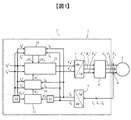
図1は、本実施例にかかる誘導電動機の駆動装置の機能ブロック図であり、本実施例による誘導電動機をセンサレスベクトル制御で駆動する誘導電動機の駆動装置の構成を機能ブロックにより示したものである。 FIG. 1 is a functional block diagram of the induction motor drive device according to the present embodiment, and shows the configuration of the drive device of the induction motor that drives the induction motor according to the present embodiment by sensorless vector control. .
図1に示す誘導電動機の駆動装置1には、誘導電動機3が接続されている。誘導電動機の駆動装置1には、制御装置2と電力変換器(主回路)が組み込まれている。電力変換器は、IGBT(Insulated Gate Bipora Transistor)等のトランジスタや、ダイオードから成るパワーデバイスから構成されており、直流電圧または交流電圧を任意の交流電圧に変換し、電力変換器に接続されている誘導電動機を駆動する。制御装置2には、誘導電動機3を速度センサレスでベクトル制御するための制御プログラムが実装されている。なお、図1において、電力変換器は図示を省略している。
An
誘導電動機3は、固定子巻線に3相交流電圧を印加して発生した回転磁界が、回転子にすべりが生じたときに回転子導体に流れる誘導電流との相互作用により回転トルクを発生させる。
The
電圧指令演算部11には、励磁軸(磁束軸)であるd軸のd軸電圧指令Vd*と、d軸と電気的に直行する方向のq軸電圧指令Vq*を出力している。d軸電圧指令Vd*、q軸電圧指令Vq*から、座標変換器7が3相電圧指令Vu*、Vv*、Vw*を生成し、PWM演算部6(Pulse Width Moduration)がPWM制御することにより、誘導電動機の駆動装置1から誘導電動機3に3相電圧Vu、Vv、Vwが出力される。座標変換器5および座標変換器7において、座標変換する際には周波数ω1を積分した位相θが必要となるが、図1では図示を省略している。実際には、ωは角周波数であるが、本実施例では簡略化して速度や周波数として用いる。
The voltage command calculation unit 11 outputs a d-axis voltage command Vd * for the d-axis that is an excitation axis (magnetic flux axis) and a q-axis voltage command Vq * in a direction that is electrically orthogonal to the d-axis. The coordinate converter 7 generates three-phase voltage commands Vu * , Vv * , Vw * from the d-axis voltage command Vd * and the q-axis voltage command Vq * , and the PWM calculation unit 6 (Pulse Width Modulation) performs PWM control. Thus, the three-phase voltages Vu, Vv, and Vw are output from the induction
誘導電動機3に流れる電流は、電流検出器4によって検出している。電流検出器4は、ホールCT(Current Transformer)等から成り、U相、V相、W相の3相の電流Iu、Iv、Iwを検出している。ただし、電流検出器4によって必ずしも3相全ての電流を検出する必要はなく、いずれかの2相を検出し、3相電流が平衡状態であると仮定して他の1相を演算により求める構成でも良い。
The current flowing through the
検出電流は、座標変換器5によって、3相からベクトル制御のdq座標に変換され、Id、Iqとして誘導電動機の駆動装置1に取り込まれる。
The detected current is converted from the three phases to the vector-controlled dq coordinate by the coordinate
電流制御器15では、電流検出値が、d軸電流指令値Id*、q軸電流指令値Iq*に対して偏差量をゼロとするようにフィードバック制御する。
The
初期速度推定演算部10では、電流検出値が取り込まれ、誘導電動機3の等価回路定数などの情報を基にした速度推定モデルによって速度推定値ωr^を演算する。この速度推定モデルは、q軸電流偏差量をゼロに制御する方式や、モデルベースによるオブザーバ方式等でもよく、必ずしもここに記載された方式に限定されるわけではない。
The initial speed
また、各フィードバック制御系における制御方式においては、PI制御(比例・積分型制御)や、PII制御(比例・二重積分型制御)等が適宜用いられるものとする。 In the control method in each feedback control system, PI control (proportional / integral control), PII control (proportional / double integral control), etc. are used as appropriate.
速度推定変化率演算部12について説明する。本実施例では、誘導電動機3が、誘導電動機3に印加する駆動電圧の周波数と、ロータ周波数の差分である「すべり周波数」に応じて、誘導電動機3のインピーダンスが変化する性質を利用し、初期速度推定を高速化している。これは、二次側に誘導電流を流して回転力を得る誘導電動機3の性質に着目したものであるため、二次側に導体を配置するリニアインダクタションモータ等に好適である。
The speed estimation change
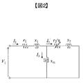
図2は、本実施例にかかる誘導電動機のT型等価回路図であり、誘導電動機3のT型等価回路を示す。相電圧ベクトルV1と相電流ベクトルI1を式(1)、(2)のように定義すると、合成インピーダンスZは式(6)で表わされる。
FIG. 2 is a T-type equivalent circuit diagram of the induction motor according to the present embodiment, and shows a T-type equivalent circuit of the

ここで、r1は一次抵抗、r2は二次抵抗、x1は一次漏れリアクタンス、x2は二次漏れリアクタンス、sはすべり、Z1は一次側インピーダンス、Z2は二次側インピーダンス、Y0は励磁アドミタンス、Xmは励磁リアクタンスとする。誘導電動機3の電流ベクトルI1は式(7)となる。
Here, r1 is the primary resistance, r2 is the secondary resistance, x1 is the primary leakage reactance, x2 secondary leakage reactance, s is slip, Z1 primary side impedance, Z2 is the secondary side impedance, Y 0 is the excitation admittance, Xm is an excitation reactance. The current vector I1 of the
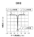
図3は、誘導電動機におけるすべり周波数と相電流の関係を示す図であり、式(7)によるすべり周波数fs(=速度推定誤差)と、相電流ベクトルI1の絶対値|I1|の関係を示す。速度推定値と実際の速度が一致する条件では、すべり周波数がゼロとなって、二次側インピーダンスZ2が無限大となるため、相電流は最小となる。 FIG. 3 is a diagram showing the relationship between the slip frequency and the phase current in the induction motor, and shows the relationship between the slip frequency fs (= speed estimation error) according to the equation (7) and the absolute value | I1 | of the phase current vector I1. . Under the condition that the estimated speed value matches the actual speed, the slip frequency is zero and the secondary impedance Z2 is infinite, so the phase current is minimized.
逆に、すべりが正もしくは負に過大の条件では、二次側インピーダンスZ2が小さくなり、すべりがゼロの条件と比べて電流は大きくなる。言い換えれば、推定速度が実際の速度と一致している条件で電流が最小となり、推定速度が実際の速度と大きく乖離している条件では相電流の検出値|I|は大きくなる。 On the contrary, when the slip is excessively positive or negative, the secondary impedance Z2 is small, and the current is large compared with the condition where the slip is zero. In other words, the current is minimized under conditions where the estimated speed matches the actual speed, and the detected value | I | of the phase current is large under conditions where the estimated speed is significantly different from the actual speed.
図1に示す本実施例では、相電流指令値|I*|と相電流検出値|I|を速度推定変化率演算部12に入力し、相電流指令値|I*|に対して相電流検出値|I|が大きくなるに従って、可変ゲインKxを大きくする演算を行う。速度推定変化率演算部12により演算された可変ゲインKxは、初期速度推定演算部10の制御ゲインに積算され、初期速度推定演算部10の速度推定応答を速度推定偏差量が大きい場合に高速化する役割を果たす。
In the present embodiment shown in FIG. 1, the phase current command value | I * | and the phase current detection value | I | are input to the speed estimation change
すなわち、初期速度推定演算部10による速度推定値ωr^が実際の速度ωrに対して大きく乖離している場合には、可変ゲインKxが大きくなり、速度推定を高応答化することにより、推定速度ωr^を実速度ωrに高速に収束させることができる。
That is, when the estimated speed value ωr ^ by the initial speed
速度推定ゲインをハイゲイン化することにより、速度推定系が不安定になることが考えられるが、図3に示したように、速度推定値ωr^と実際の速度ωrが近づいた場合には、相電流指令|I*|と相電流検出値|I|の差も図3に示すように小さくなるため、可変ゲインKxは自然に小さくなり速度推定系は安定化する。 It is conceivable that the speed estimation system becomes unstable by increasing the speed estimation gain, but when the speed estimation value ωr ^ approaches the actual speed ωr as shown in FIG. Since the difference between the current command | I * | and the phase current detection value | I | is also small as shown in FIG. 3, the variable gain Kx is naturally reduced and the speed estimation system is stabilized.
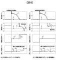
図4は、本実施例による初期速度推定期間の速度推定結果の比較図であり、本実施例適用の有無を比較した計算結果の一例を示す。図4は、ロータ周波数fr=30Hzのフリーラン状態において、初期速度推定の開始と同時に、所定の電流指令を与え、誘導電動機3に流れる電流検出値の情報をもとに、推定初期値を200Hzとして初期速度を推定した結果である。
FIG. 4 is a comparison diagram of speed estimation results in the initial speed estimation period according to the present embodiment, and shows an example of calculation results comparing the presence / absence of application of the present embodiment. FIG. 4 shows that in the free-run state of the rotor frequency fr = 30 Hz, a predetermined current command is given simultaneously with the start of the initial speed estimation, and the estimated initial value is set to 200 Hz based on the information of the detected current value flowing through the
図4(a)は、本実施例適用時の初期速度推定結果を示しており、初期速度推定の開始後に電流検出値が増加し、速度推定変化率演算部12の出力である可変ゲインKxが増加していることがわかる。可変ゲインKxは、速度推定ゲインに積算されるため、速度推定値fr^の変化率はKxに応じて変化している。これによって、速度推定値fr^は実際の速度frに向かって高速に収束させることができる。
FIG. 4A shows the initial speed estimation result when the present embodiment is applied. The detected current value increases after the start of the initial speed estimation, and the variable gain Kx that is the output of the speed estimation change
図4(b)は、従来技術(特許文献1)によって初期速度推定した結果を示している。特許文献1の〔0015〕に記載の通り、速度サーチを実施する際の周波数掃引は最高周波数から一定レートで変化させており、電流検出値によらず、駆動周波数は一定の変化率(Kx=1)となる。この場合、速度推定値fr^は実際の速度frに対して収束方向に向かってはいるものの、推定初期値(200Hz)と実際の速度(30Hz)といったように初期速度推定開始時点での速度推定偏差が大きい条件では、膨大な時間を要する。
FIG. 4B shows the result of initial speed estimation performed by the prior art (Patent Document 1). As described in [0015] of
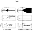
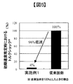
図5は、本実施例による初期速度推定期間のトルクショック低減効果の比較図であり、初期速度推定時における本実施例と従来技術(特許文献1)でのトルクショックの比較を示す。従来技術(特許文献1)におけるトルクショックを100%とした際の割合で比較している。本実施例によれば、初期速度推定を高速化できるため、従来技術と比較してトルクショックを96%低減することが可能である。 FIG. 5 is a comparison diagram of the torque shock reduction effect during the initial speed estimation period according to the present embodiment, and shows a comparison between the present embodiment and the prior art (Patent Document 1) when the initial speed is estimated. Comparison is made at a ratio when the torque shock in the prior art (Patent Document 1) is 100%. According to the present embodiment, since the initial speed estimation can be speeded up, it is possible to reduce the torque shock by 96% compared to the prior art.
仮に、推定速度が実際の速度と一致していない状態では、大電流が流れることによりq軸二次磁束Φ2qが生じ、トルクショックにつながる。本実施例では、図4で比較したように、大電流が流れる前に、速度推定値ωr^を実速度ωrに高速に収束させるため、このq軸二次磁束Φ2qの発生を抑制し、トルクショックを大幅に低減できる。 If the estimated speed does not match the actual speed, a large current flows to generate a q-axis secondary magnetic flux Φ2q, which leads to a torque shock. In the present embodiment, as compared in FIG. 4, in order to converge the speed estimation value ωr ^ to the actual speed ωr at a high speed before a large current flows, the generation of the q-axis secondary magnetic flux Φ2q is suppressed, and the torque Shock can be greatly reduced.
更に、近年の誘導電動機3は電力消費量低減の要求に応え、従来よりも更に回転子の二次抵抗r2を小さく(低すべり化)することにより、高効率化している。低すべりになる程、電気的、磁気的な時定数は長くなり、応答が鈍くなるため、初期速度の推定に時間を要するようになる。本実施例では、速度推定変化率演算部12によって、速度推定を高速化できるため、定格すべりが1%以下となる高効率な誘導電動機3に対しても、短時間かつ低トルクショックに初期速度を推定できる。
Furthermore, in recent years, the
以上のように、本実施例によると、誘導電動機3のすべり周波数に応じたインピーダンス変化を利用し、電流検出値をもとに速度推定応答を可変にすることにより、初期速度推定の高速化・低トルクショック化を実現する誘導電動機の駆動装置を提供できる。
As described above, according to this embodiment, by using the impedance change according to the slip frequency of the
本実施例では、実施例1と異なり、速度推定系と電流制御系を一体化するものである。以下、実施例1との相違点を中心に説明する。 In this embodiment, unlike the first embodiment, the speed estimation system and the current control system are integrated. Hereinafter, the difference from the first embodiment will be mainly described.
図6は、本実施例にかかる誘導電動機の駆動装置の機能ブロック図であり、誘導電動機をセンサレスベクトル制御で駆動する誘導電動機の駆動装置の構成を機能ブロックにより示したものである。 FIG. 6 is a functional block diagram of the induction motor driving apparatus according to the present embodiment, and shows the configuration of the induction motor driving apparatus for driving the induction motor by sensorless vector control.
本実施例では、モータ定数の変動に対するロバスト性を高めることを目的に、初期速度推定演算部10がq軸電流偏差量をもとに速度推定演算を行い、d軸電流指令Id*がフィードフォワードで電圧指令演算部11に入力される点で実施例1と異なる。
In this embodiment, for the purpose of improving robustness against fluctuations in motor constants, the initial speed
初期速度推定演算部10では、q軸電流偏差量に、比例ゲインKP8、積分ゲインKI9を積算して、両者を加算することにより速度推定値ωr^を演算する。初期速度推定演算部10により算出した速度推定値ωr^にすべり周波数指令値ωs*を加算することにより、一次周波数指令ω1*が算出される。ただし、本実施例においては、トルク電流であるq軸電流指令Iq*をゼロに制御するため、すべり周波数指令ωs*もゼロであり、速度推定値ωr^は一次周波数指令値ω1*と同一値となる。
The initial speed
以下、本実施例における比例ゲインKP8と積分ゲインKI9の導出について示す。誘導電動機の電圧方程式は式(8)で表わされる。 Hereinafter, derivation of the proportional gain KP8 and the integral gain KI9 in this embodiment will be described. The voltage equation of the induction motor is expressed by equation (8).
ただし、r1は一次抵抗、r2’は一次換算された二次抵抗、Lσは一次換算された漏れインダクタンス、Mは相互インダクタンス、L2は二次自己インダクタンス、T2は二次時定数、Φ2dはd軸二次磁束、Φ2qはq軸二次磁束、sはラプラス演算子である。ここで、一次自己インダクタンスL1、二次自己インダクタンスL2、一次換算漏れインダクタンスLσ、二次時定数T2、一次換算した二次抵抗r2’は以下の通りとする。 Where r1 is a primary resistance, r2 ′ is a primary converted secondary resistance, Lσ is a primary converted leakage inductance, M is a mutual inductance, L2 is a secondary self-inductance, T2 is a secondary time constant, and Φ2d is a d-axis. Secondary magnetic flux, Φ2q is a q-axis secondary magnetic flux, and s is a Laplace operator. Here, the primary self-inductance L1, the secondary self-inductance L2, the primary conversion leakage inductance Lσ, the secondary time constant T2, and the primary conversion secondary resistance r2 ′ are as follows.
式(8)における第2行目のVqに関する式を展開すると、誘導電動機3と誘導電動機の駆動装置1におけるq軸電流Iq、Iq*はそれぞれ次式で表わされる。
When the expression relating to Vq in the second row in Expression (8) is expanded, the q-axis currents Iq and Iq * in the
ここで、誘導電動機3の定数と、制御装置2の定数が一致しているとし、Id、Φ2d、Φ2qは指令値と一致していると仮定すると、次式となる。
Here, assuming that the constant of the
すなわち、q軸電流の偏差からロータ周波数の偏差を表わす伝達関数は次式となる。 That is, the transfer function representing the deviation of the rotor frequency from the deviation of the q-axis current is as follows.
よって、q軸電流の偏差量から、誘導電動機3の速度を1次遅れ系で推定する制御式は次式となる。ただし、ωacrは電流制御の応答周波数とする。
Therefore, the control equation for estimating the speed of the
以上より、図6における比例ゲインKP8、積分ゲインKI9は次式となる。 From the above, the proportional gain KP8 and the integral gain KI9 in FIG.
そして、本実施例の最終的な速度推定式について、速度推定変化率演算部12の出力Kxが積算され、次式となる。
And about the final speed estimation formula of a present Example, the output Kx of the speed estimation change
以上のように、本実施例では、図1に示したように電流制御器15と初期速度推定演算部10を別々に設けず、q軸電流偏差量をゼロにするように速度推定値ωr^を制御する構成とすることにより、速度推定系と電流制御系を一体化した構成としている。
As described above, in this embodiment, as shown in FIG. 1, the
また、定数変動に対するロバスト性に関しても、本実施例では、誘導電動機3の温度上昇等によって定数変動が生じた場合、初期速度推定時間は変わってしまうものの、q軸電流偏差をゼロ(すべり周波数をゼロ)にするようにフィードバック制御しているため、速度推定精度については高精度に初期速度を推定できる。
In addition, regarding the robustness against the constant fluctuation, in this embodiment, when the constant fluctuation occurs due to the temperature rise of the
他の方式について例を挙げると、誘導電動機3の電圧方程式に基づくオブザーバ方式では、定数変動の影響を受け易いことが考えられる。例えば、特許文献2の第1の演算部では、初期速度を(Vq*−R1・Iq)/Φ1の数式から演算している。特に低速域においては、Vq*が小さくなるので、モータの温度変動でR1の定数誤差が生じた際、R1の誤差が与える影響が相対的に大きくなるため、速度推定偏差によってトルクショックの発生に繋がってしまうことが考えられる。
Taking other examples as examples, the observer method based on the voltage equation of the
本実施例では、q軸電流偏差をゼロに制御するように速度を推定する構成にして、速度推定系と電流制御系を一体化することにより、速度推定応答を電流制御応答と同一にでき、速度推定が高速なことに加え、定数変動が生じた場合でも、Iq偏差量がゼロになるようにフィードバック制御する構成であるため、定数変動に対するロバスト性も高い特徴を持つ。 In this embodiment, the speed estimation response can be made the same as the current control response by integrating the speed estimation system and the current control system with a configuration that estimates the speed so as to control the q-axis current deviation to zero. In addition to high speed estimation, even when constant fluctuation occurs, the feedback control is performed so that the Iq deviation amount becomes zero, so that the robustness against the constant fluctuation is also high.
前述した定数変動時の初期速度推定時間の変動については、誘導電動機3の抵抗値が最小となる条件(モータ温度範囲の下限値)においても、初期速度推定を完了できるように予めマージンを持たせ制御装置2を設計する。
Regarding the fluctuation of the initial speed estimation time at the time of the constant fluctuation described above, a margin is provided in advance so that the initial speed estimation can be completed even under the condition that the resistance value of the
本実施例では、実施例1よりも、初期速度推定の更なる高速化・低トルクショック化を実現し、定数変動に対するロバスト性を更に高めた誘導電動機の駆動装置を提供できる。
In this embodiment, it is possible to provide a drive apparatus for an induction motor that realizes further higher speed and lower torque shock for initial speed estimation than in
本実施例は、実施例1乃至2よりも速度推定変化率の演算を簡素化したものである。以下、実施例1乃至2との相違点を中心に説明する。 In this embodiment, the calculation of the speed estimation change rate is simplified as compared with the first and second embodiments. Hereinafter, the difference from the first and second embodiments will be mainly described.
図7は、本実施例にかかる誘導電動機の駆動装置の機能ブロック図であり、誘導電動機をセンサレスベクトル制御で駆動する誘導電動機の駆動装置の構成を機能ブロックにより示したものである。 FIG. 7 is a functional block diagram of the induction motor driving apparatus according to the present embodiment, and shows the configuration of the induction motor driving apparatus for driving the induction motor by sensorless vector control using functional blocks.
本実施例では、速度推定変化率演算部12の演算を簡素化し、制御装置2における演算負荷を低減することを目的に、速度推定変化率演算部12において、d軸電流指令値Id*とd軸電流検出値Idを入力して可変ゲインKxを演算している。
In the present embodiment, for the purpose of simplifying the calculation of the speed estimation change
q軸は電流偏差をゼロにするように制御し、d軸はフィードフォワード制御にする構成にしているため、Iq=Iq*と仮定すると、速度推定偏差はd軸電流に現れることになる。すなわち、|I|≒Idと見なせるため、d軸電流偏差量のみから速度推定偏差量の大小を判別でき、速度推定変化率演算部12の入力をId*、Idとできる。
Since the q-axis is controlled to make the current deviation zero, and the d-axis is configured to be feedforward control, assuming that Iq = Iq * , the speed estimation deviation appears in the d-axis current. That is, since | I | ≈Id can be considered, the magnitude of the speed estimation deviation amount can be determined only from the d-axis current deviation amount, and the input of the speed estimation change
実施例2では、電流検出値Id、Iqの絶対値を演算する処理を行っていたが、本実施例ではこの演算処理が不要になり、演算処理を簡素化し、制御装置2の演算の負荷率を低減できる。
In the second embodiment, the process of calculating the absolute values of the current detection values Id and Iq is performed. However, in this embodiment, this calculation process is not required, the calculation process is simplified, and the load factor of the calculation of the
速度推定変化率演算部12における演算処理G14は、Id/Id*のように単純な比でも良いが、事前にd軸電流偏差量に対する可変ゲインテーブルを準備し、d軸偏差量を入力とする可変ゲインの演算方法としても良い。実施例1のように、誘導電動機3がすべり周波数に応じて電流変化する性質を利用し、速度推定応答を可変にすれば良い。
The calculation process G14 in the speed estimation change
本実施例では、実施例2よりも、速度推定変化率演算部12の演算を簡素化でき、演算負荷を更に低減した誘導電動機の駆動装置を提供できる。
In the present embodiment, the calculation of the speed estimation change
本実施例は、低速域でd軸電流指令Id*を増加させるものである。以下、実施例1乃至3との相違点を中心に説明する。 In this embodiment, the d-axis current command Id * is increased in the low speed range. Hereinafter, the difference from the first to third embodiments will be mainly described.
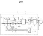
図8は、本実施例にかかる誘導電動機の駆動装置の機能ブロック図であり、誘導電動機をセンサレスベクトル制御で駆動する誘導電動機の駆動装置の構成を機能ブロックにより示したものである。 FIG. 8 is a functional block diagram of the induction motor driving apparatus according to the present embodiment, and shows the configuration of the induction motor driving apparatus for driving the induction motor by sensorless vector control.
本実施例では、低速域における初期速度推定の失敗の防止を目的に、速度推定値ωr^が所定の判定閾値以下となった際に、d軸電流指令Id*にΔId*を加算するd軸ブースト制御演算部13を備える。
In this embodiment, for the purpose of preventing failure of initial speed estimation in a low speed range, d-axis that adds ΔId * to d-axis current command Id * when speed estimated value ωr ^ is equal to or less than a predetermined determination threshold value. A boost
式(16)に示した通り、実施例2等の初期速度推定方式は、速度起電力とq軸電流偏差量の関係を線形化したものである。式(16)から明らかであるように、式(16)右辺の速度起電力がゼロになってしまうと、本速度推定方式は成立しなくなる。式(16)右辺は、誘導電動機3のロータの速度ωrとd軸二次磁束Φ2dの積に比例しているため、速度が低下する程、小さくなる。つまり、低速域において、速度推定が破綻しないようにするために、d軸二次磁束指令Φ2d*を増加させ、誘導電動機3におけるd軸二次磁束Φ2dを増やすことにより、低速域においても速度起電力の低下を抑えることができる。
As shown in Expression (16), the initial speed estimation method of the second embodiment and the like linearizes the relationship between the speed electromotive force and the q-axis current deviation amount. As is clear from Expression (16), when the speed electromotive force on the right side of Expression (16) becomes zero, this speed estimation method is not established. Since the right side of the equation (16) is proportional to the product of the rotor speed ωr of the
本実施例のd軸ブースト制御演算部13は、速度推定値ωr^をもとに低速域と判断した場合には、適切な大きさのd軸電流指令補償量ΔId*を出力し、第1の電流指令Id*にΔId*を加算して、第2の電流指令Id**を演算する。
When the d-axis boost
これによって、低速域と判断した場合のみ、速度起電力を増加させ、速度推定失敗を防止できる。なお、d軸電流指令補償量ΔId*は、誘導電動機3の回路定数や、制御装置2の仕様に応じて適切に設計する。
As a result, only when it is determined that the speed is low, the speed electromotive force can be increased and speed estimation failure can be prevented. The d-axis current command compensation amount ΔId * is appropriately designed according to the circuit constants of the
また、本実施例では推定の初期値を200Hz(駆動周波数の上限値)に設定しているが、この値に限定されるものではない。必ずしも上限値とする必要はないが、駆動速度範囲の中央値よりも高い値に設定することが望ましい。仮に、推定初期値を低速域に設定して高速域の推定を行う場合、推定開始直後にd軸ブースト制御演算部13が動作し、不要なトルクショックを発生させる可能性がある。
In this embodiment, the initial value for estimation is set to 200 Hz (upper limit value of the driving frequency), but is not limited to this value. Although it is not always necessary to set the upper limit value, it is desirable to set a value higher than the median value of the driving speed range. If the estimation initial value is set to the low speed range and the high speed range is estimated, the d-axis boost
本実施例の制御構成では、速度起電力が大きく、初期速度推定が容易な高速域を最初にサーチし、その後、低速域と判断した場合のみd軸ブースト制御演算部13を動作させ、d軸二次磁束Φ2dを増加させる。本制御構成では、速度起電力が過小になることを防止するために、必要な速度域で必要な大きさの電流指令を与える方式としている。これによって、全速度域に対して、推定失敗することなく、低トルクショックに推定ができる。
In the control configuration of the present embodiment, the d-axis boost
図9は、本実施例による初期速度推定結果を示す図であり、d軸ブースト制御演算部の有無での、速度推定結果の比較を示す。図9では、初期速度の推定が特に難しいロータ周波数fr=−10Hz(逆回転時)における初期速度推定結果を比較している。本比較においては、一例として、速度推定値fr^が3Hz以下となった時点で、d軸ブースト制御演算部13を動作させている。この速度推定値の判定値は、誘導電動機3の諸元に合わせ、適切に設定されるものとする。図9(a)では、推定周波数fr^が3Hz以下になった時点で、d軸ブースト制御が動作し、第2のd軸電流指令Id**がステップ状に大きくなり、d軸二次磁束Φ2dが立ち上がり、所定の速度起電力を確保することで、速度推定値fr^が実際の速度frに収束する。一方、図9(b)では、推定周波数fr^が実際の周波数fr(−10Hz)へ向かうものの、d軸二次磁束Φ2dが立ち上がらず、fr^がゼロに収束し(速度起電力がゼロに収束)、初期速度推定を失敗する結果となる。この速度起電力がゼロになる現象は、誘導電動機3の原理上、低速域になる程、q軸二次磁束Φ2qが発生し易く、d軸に影響を及ぼし易くなることに起因する。本実施例では、d軸二次磁束Φ2dを増加させて、q軸二次磁束Φ2qの干渉によってd軸二次磁束Φ2dがゼロになることを防ぐことにより解決している。d軸電流指令補償量ΔId*はステップ状に加算しているが、d軸電流を増加させるものであれば、どのような形状でも良い。
FIG. 9 is a diagram showing an initial speed estimation result according to the present embodiment, and shows a comparison of speed estimation results with and without a d-axis boost control calculation unit. FIG. 9 compares the initial speed estimation results at the rotor frequency fr = −10 Hz (during reverse rotation), which is particularly difficult to estimate the initial speed. In this comparison, as an example, the d-axis boost
また、高効率な誘導電動機3は、低すべりであることから、二次時定数T2(二次磁束の時定数)が長く、d軸二次磁束の確立が難しく、初期速度の推定失敗が発生し易い傾向にある。このような、低すべりな誘導電動機3に対しても、本実施例を適用することにより、速度推定失敗を発生することなく、初期速度を推定できる。
In addition, since the highly
以上より、本実施例では、低速域でd軸電流指令Id*を増加させるd軸ブースト制御を備えることにより、実施例3よりも、低速域における初期速度推定の精度を更に高めた誘導電動機の駆動装置を提供できる。 As described above, in this embodiment, the d-axis boost control for increasing the d-axis current command Id * in the low speed range is provided, so that the accuracy of the initial speed estimation in the low speed range is further improved than in the third embodiment. A drive device can be provided.
本実施例は、d軸二次磁束指令Φ2d*に過渡値を用いるものである。以下、実施例1乃至4との相違点を中心に説明する。 In this embodiment, a transient value is used for the d-axis secondary magnetic flux command Φ2d * . Hereinafter, the difference from the first to fourth embodiments will be mainly described.
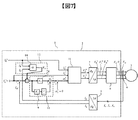
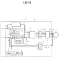
図10は、本実施例にかかる誘導電動機の駆動装置の機能ブロック図であり、誘導電動機をセンサレスベクトル制御で駆動する誘導電動機の駆動装置の構成を機能ブロックにより示したものである。 FIG. 10 is a functional block diagram of the induction motor driving apparatus according to the present embodiment. The configuration of the induction motor driving apparatus for driving the induction motor by sensorless vector control is shown by functional blocks.
本実施例では、初期速度推定の更なる時間短縮および低トルクショック化を目的に、初期速度推定演算部10に用いるd軸二次磁束指令Φ2d*に、定常値ではなく、過渡値を用いる。
In this embodiment, for the purpose of further shortening the initial speed estimation and reducing the torque shock, a transient value is used instead of a steady value for the d-axis secondary magnetic flux command Φ2d * used in the initial speed
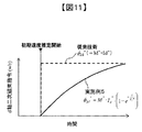
図11は、本実施例にかかるd軸二次磁束指令演算を示す概略説明図であり、本実施例と従来技術におけるd軸二次磁束指令Φ2d*の比較したものである。従来技術では、d軸電流指令Id*に基づき、初期速度推定の開始と同時に定常値のd軸二次磁束指令Φ2d*を出力する。一方、本実施例では、d軸電流指令Id*に基づき、二次時定数T2のLPF(Low Pass Filter)を通過させることにより、d軸二次指令Φ2d*は、次式で示すように、初期速度推定開始からの経過時間tに応じた過渡的な値を出力する。ただし、式(23)はd軸電流指令Id*をステップ入力した際の、d軸二次磁束Φ2dの過渡値を示す式であるが、d軸電流指令Id*はステップ形状、フィルタを通した一次遅れ形状、通電開始直後に急激に流して徐々に減衰させるフォーシング形状でも良く、限定されるものではない。 FIG. 11 is a schematic explanatory diagram showing the d-axis secondary magnetic flux command calculation according to the present embodiment, and is a comparison between the present embodiment and the d-axis secondary magnetic flux command Φ2d * in the prior art. In the prior art, based on the d-axis current command Id * , the steady-state d-axis secondary magnetic flux command Φ2d * is output simultaneously with the start of the initial speed estimation. On the other hand, in the present embodiment, by passing an LPF (Low Pass Filter) having a secondary time constant T2 based on the d-axis current command Id * , the d-axis secondary command Φ2d * is expressed by the following equation: A transient value corresponding to the elapsed time t from the start of initial speed estimation is output. However, the equation (23) is an equation indicating a transient value of the d-axis secondary magnetic flux Φ2d when the d-axis current command Id * is step-inputted. However, the d-axis current command Id * is a step shape and is filtered. The first-order lag shape or a forcing shape that flows rapidly and immediately attenuates immediately after the start of energization may be used, and is not limited.
初期速度推定の開始直後は、速度推定値が一致しておらず、制御軸が一致していない状態であるため、図9に示したように、誘導電動機3に実際に発生しているd軸二次磁束Φ2dは、ほぼゼロに近い値である。即ち、初期速度推定演算部10における制御ゲインのd軸二次磁束指令Φ2d*に定常値を考慮した場合、式(22)に示すように速度推定系のゲインが不足することとなる。本実施例では、速度推定系ゲインのd軸二次磁束指令Φ2d*に、d軸電流指令Id*の波形や印加時間に応じて過渡的に変化するd軸二次磁束指令の演算指令値を用いることにより、誘導電動機3の実際のΦ2dにより近い値とすることができ、推定モデルを高精度化し、このゲイン不足を解消できる。
Immediately after the start of the initial speed estimation, since the speed estimation values do not match and the control axes do not match, the d axis actually generated in the
また、低すべりな誘導電動機においては、二次時定数T2も長くなり、d軸二次磁束指令Φ2d*の立ち上がりも緩やかになるが、本実施例では、誘導電動機3が低すべりになる程、初期速度推定系のゲインを高める方向に作用する。
In addition, in the low slip induction motor, the secondary time constant T2 becomes longer and the rise of the d-axis secondary magnetic flux command Φ2d * becomes gentler. However, in this embodiment, as the
本実施例では、初期速度推定演算部10に用いるd軸二次磁束指令Φ2d*に、d軸電流指令Id*の波形や印加時間に応じて過渡的に変化する演算指令値を用いることにより、実施例4よりも更に高速に初期速度を推定でき、トルクショックを低減できる。
In the present embodiment, the d-axis secondary magnetic flux command Φ2d * used in the initial speed
本実施例は、駆動システムの速度情報を初期値に用いるものである。以下、実施例1乃至5との相違点を中心に説明する。 In this embodiment, the speed information of the drive system is used as an initial value. Hereinafter, the difference from the first to fifth embodiments will be mainly described.
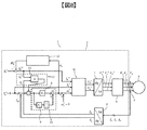
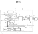
図12は、本実施例にかかる誘導電動機の駆動装置の機能ブロック図であり、誘導電動機をセンサレスベクトル制御で駆動する誘導電動機の駆動装置の構成を機能ブロックにより示したものである。 FIG. 12 is a functional block diagram of the induction motor driving apparatus according to the present embodiment, and shows the configuration of the induction motor driving apparatus for driving the induction motor by sensorless vector control.
本実施例では、初期速度推定の更なる時間短縮および低トルクショック化を目的に、鉄道車両等の駆動システムの速度情報を制御装置2に取り込み、初期速度推定演算部10の積分器の初期値に設定する。
In this embodiment, for the purpose of further shortening the initial speed estimation and lowering the torque shock, the speed information of the drive system such as a railway vehicle is taken into the
駆動システムの速度情報Vcarを制御装置2へ取込み、電気角周波数換算部15によって、電気角周波数ωrini^に換算し、初期速度推定演算部10の推定初期値として用いる。速度情報Vcarは、必ずしも正確な値でなくても良く、鉄道車両で用いられる速度段のリレー信号等のような概算値でも良い。駆動周波数の概算値を初期値として、実施例1乃至5にかかる構成を適用することにより、更に高速かつ低トルクショックの初期速度推定を実現できる。本実施例は、駆動システムの速度情報を誘導電動機の駆動装置1に取り込めるシステムに適用できる。
The speed information Vcar of the drive system is taken into the
本実施例では、初期速度推定演算部10に用いる推定初期値を実速度に近付けることができるため、実施例5よりも更に高速かつ、低トルクショックな初期速度推定を実現できる。
In the present embodiment, since the estimated initial value used for the initial speed
本実施例は、スイッチング素子やダイオードにSiC素子を用いるものである。以下、実施例1乃至6との相違点を中心に説明する。 In this embodiment, a SiC element is used as a switching element or a diode. Hereinafter, the difference from the first to sixth embodiments will be mainly described.
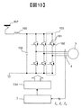
図13は、本実施例にかかる誘導電動機の駆動装置の一部を示す概略構成図であり、誘導電動機をセンサレスベクトル制御で駆動する誘導電動機の駆動装置の一部を示す概略構成図である。 FIG. 13: is a schematic block diagram which shows a part of drive device of the induction motor concerning a present Example, and is a schematic block diagram which shows a part of drive device of the induction motor which drives an induction motor by sensorless vector control.
図13では、鉄道車両の駆動システムの一部を例として記載している。制御装置2のベクトル制御演算に基づき、ゲートドライバ104が、半導体モジュール103のスイッチング動作を制御している。また、入力側においてはフィルタリアクトル105とフィルタコンデンサ106によりLCフィルタ回路を構成しており、架線107に流れるノイズをカットする構成となっている。
FIG. 13 shows an example of a part of a railway vehicle drive system. Based on the vector control calculation of the
本実施例では、初期速度推定の更なる時間短縮および低トルクショック化を目的に、誘導電動機の駆動装置1の半導体モジュール103において、スイッチング素子101とダイオード102の一方もしくは両者にSiC素子を使用する。
In the present embodiment, for the purpose of further shortening the initial speed estimation and lowering the torque shock, in the
本実施例では、低損失で高速スイッチングが可能なSiCインバータを用いることにより、キャリア周波数を向上でき、制御装置2における電流制御応答ωacrを向上できる。実施例2に記載した通り、電流制御系と速度推定系が一体化されているため、電流制御応答ωacrを向上すると、速度推定系も同一の推定応答を得ることができる。
In the present embodiment, the carrier frequency can be improved and the current control response ωacr in the
本実施例によれば、SiCインバータとの相乗効果により、実施例6よりも更に高速かつ、低トルクショックの初期速度推定を実現できる。 According to the present embodiment, due to the synergistic effect with the SiC inverter, it is possible to realize the initial speed estimation of a higher speed and lower torque shock than in the sixth embodiment.
本実施例は、誘導電動機の駆動装置を鉄道車両に用いたものである。以下、実施例1乃至7との相違点を中心に説明する。 In this embodiment, an induction motor drive device is used in a railway vehicle. Hereinafter, the difference from the first to seventh embodiments will be mainly described.
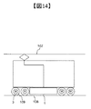
図14は、本実施例にかかる誘導電動機の駆動装置を有する鉄道車両の一部を示す概略構成図である。 FIG. 14: is a schematic block diagram which shows a part of railway vehicle which has a drive device of the induction motor concerning a present Example.
鉄道車両の駆動装置には、架線107から集電装置を介して電力が供給され、誘導電動機の駆動装置1を経由して交流電力が誘導電動機3に供給されることにより、誘導電動機3は駆動する。誘導電動機3は、減速ギアを介して、鉄道車両の車軸と連結されており、車軸に接続された車輪109とレール108間に生じる接線力により鉄道車両は走行する。
Electric power is supplied to the drive device of the railway vehicle from the
実施例1乃至7の誘導電動機の駆動装置1を鉄道車両に適用すれば、初期速度推定時間を短縮し、トルクショックを大幅に低減できるため、鉄道車両の停車や惰行時からの再起動時において、鉄道車両の車体振動を低減し、乗客の乗り心地を改善できる。
When the induction
1…誘導電動機の駆動装置、2…制御装置、3…誘導電動機、4…電流検出器、5…座標変換器、6…PWM演算部、7…座標変換器、8…比例ゲイン、9…積分ゲイン、10…初期速度推定演算部、11…電圧指令演算部、12…速度推定変化率演算部、13…d軸ブースト制御演算部、14…ゲイン、15…電流制御器、16…d軸二次磁束指令演算部、100…電力変換器、101…スイッチング素子、102…ダイオード、103…半導体モジュール、104…ゲートドライバ、105…フィルタリアクトル、106…フィルタコンデンサ、107…架線、108…レール、109…車輪
DESCRIPTION OF
Claims (16)
外部からの指令に基づき前記誘導電動機を制御する制御装置が、前記誘導電動機への通電開始時の駆動周波数を、前記誘導電動機の電流検出手段によって検出した電流値により修正して初期速度を推定し、更に、当該修正時における前記駆動周波数の変化率を、検出された前記電流値に応じて変化させる初期速度推定部を有することを特徴とする誘導電動機の駆動装置。 A drive device for an induction motor that drives the induction motor by sensorless vector control,
A control device that controls the induction motor based on a command from the outside estimates the initial speed by correcting the drive frequency at the start of energization of the induction motor with the current value detected by the current detection means of the induction motor. Further, the induction motor drive device further comprises an initial speed estimation unit that changes the rate of change of the drive frequency at the time of the correction in accordance with the detected current value.
前記初期速度推定部が、q軸電流指令値とq軸電流検出値の偏差をゼロとなるように制御することを特徴とする誘導電動機の駆動装置。 In the induction motor drive device according to claim 1,
The induction motor drive device, wherein the initial speed estimation unit controls the deviation between the q-axis current command value and the q-axis current detection value to be zero.
前記初期速度推定部が、初期速度の推定時における通電開始時のd軸電流検出値が、d軸電流指令値に対して大きくなるに従って、前記駆動周波数の変化率を、通電開始時よりも高くすることを特徴とする誘導電動機の駆動装置。 In the drive device of the induction motor according to any one of claims 1 to 2,
The initial speed estimator increases the rate of change of the drive frequency higher than that at the start of energization as the d-axis current detection value at the start of energization at the time of initial speed estimation becomes larger than the d-axis current command value. A drive device for an induction motor.
前記初期速度推定部が、推定した初期速度が、所定の閾値以下になった際に、第1のd軸電流指令値にd軸電流補償量を加算することにより、第2のd軸電流指令値を演算することを特徴とする誘導電動機の駆動装置。 In the induction motor drive device according to any one of claims 1 to 3,
The initial speed estimation unit adds a d-axis current compensation amount to the first d-axis current command value when the estimated initial speed is equal to or less than a predetermined threshold value, thereby generating a second d-axis current command. An induction motor drive device characterized by calculating a value.
前記初期速度推定部の制御ゲインが、d軸二次磁束指令値を含み、当該d軸二次磁束指令値として、d軸電流指令の波形または印加時間に応じて過渡的に変化するd軸二次磁束の演算指令値が用いられることを特徴とする誘導電動機の駆動装置。 In the induction motor drive device according to any one of claims 1 to 4,
The control gain of the initial speed estimator includes a d-axis secondary magnetic flux command value, and the d-axis secondary magnetic flux command value changes transiently according to the waveform or application time of the d-axis current command. A drive device for an induction motor, wherein a calculation command value of a secondary magnetic flux is used.
前記初期速度推定部の推定初期値が、前記制御装置の外部から入力される速度情報に基づいて設定されることを特徴とする誘導電動機の駆動装置。 In the induction motor drive device according to any one of claims 1 to 5,
An induction motor drive device, wherein an estimated initial value of the initial speed estimator is set based on speed information input from the outside of the control device.
前記誘導電動機を駆動する電力変換器が、SiCインバータであることを特徴とする誘導電動機の駆動装置。 In the induction motor drive device according to any one of claims 1 to 6,
The induction motor drive device, wherein the power converter for driving the induction motor is a SiC inverter.
誘導電動機の制御装置が、前記誘導電動機への通電開始時の駆動周波数を、前記誘導電動機に流れる電流値により修正し、更に、修正時における前記駆動周波数の変化率を、前記電流値に応じて変化させることを特徴とする初期速度推定方法。 An initial speed estimation method in sensorless vector control of an induction motor,
The control device for the induction motor corrects the drive frequency at the start of energization of the induction motor based on the current value flowing through the induction motor, and further changes the rate of change of the drive frequency at the time of correction according to the current value. An initial speed estimation method characterized by changing.
前記誘導電動機の制御装置が、q軸電流指令値とq軸電流検出値の偏差をゼロとなるように制御することを特徴とする初期速度推定方法。 The initial speed estimation method according to claim 9,
An initial speed estimation method, wherein the induction motor control device controls the deviation between the q-axis current command value and the q-axis current detection value to be zero.
前記誘導電動機の制御装置が、初期速度の推定時における通電開始時のd軸電流検出値が、d軸電流指令値に対して大きくなるに従って、前記駆動周波数の変化率を、通電開始時よりも高くすることを特徴とする初期速度の推定方法。 The initial speed estimation method according to any one of claims 9 to 10,
As the d-axis current detection value at the start of energization at the time of estimating the initial speed increases with respect to the d-axis current command value, the control device for the induction motor increases the rate of change in the drive frequency from that at the start of energization. An initial speed estimation method characterized by increasing the speed.
前記誘導電動機の制御装置が、推定した初期速度が、所定の閾値以下になった際に、第1のd軸電流指令値にd軸電流補償量を加算することにより、第2のd軸電流指令値を演算することを特徴とする初期速度推定方法。 The initial speed estimation method according to any one of claims 9 to 11,
When the estimated initial speed falls below a predetermined threshold, the control device for the induction motor adds a d-axis current compensation amount to the first d-axis current command value, thereby obtaining a second d-axis current. An initial speed estimation method characterized by calculating a command value.
前記誘導電動機の制御装置が、制御ゲインとして、d軸二次磁束指令値を含み、当該d軸二次磁束指令値として、d軸電流指令の波形または印加時間に応じて過渡的に変化するd軸二次磁束の演算指令値を用いることを特徴とする初期速度推定方法。 The initial speed estimation method according to any one of claims 9 to 12,
The induction motor control device includes a d-axis secondary magnetic flux command value as a control gain, and the d-axis secondary magnetic flux command value changes transiently according to the waveform or application time of the d-axis current command. An initial speed estimation method using an operation command value of a shaft secondary magnetic flux.
推定初期値が、前記誘導電動機の制御装置の外部から入力される速度情報に基づいて設定されることを特徴とする初期速度推定方法。 The initial speed estimation method according to any one of claims 9 to 13,
An initial speed estimation method, wherein an estimated initial value is set based on speed information input from outside the control device for the induction motor.
前記誘導電動機の制御装置が、SiCインバータを制御することを特徴とする初期速度推定方法。 The initial speed estimation method according to any one of claims 9 to 14,
An initial speed estimation method, wherein the induction motor control device controls a SiC inverter.
Priority Applications (2)
| Application Number | Priority Date | Filing Date | Title |
|---|---|---|---|
| JP2017062050A JP2018166350A (en) | 2017-03-28 | 2017-03-28 | Drive unit for induction motor |
| PCT/JP2018/003473 WO2018179822A1 (en) | 2017-03-28 | 2018-02-01 | Induction motor drive device |
Applications Claiming Priority (1)
| Application Number | Priority Date | Filing Date | Title |
|---|---|---|---|
| JP2017062050A JP2018166350A (en) | 2017-03-28 | 2017-03-28 | Drive unit for induction motor |
Publications (1)
| Publication Number | Publication Date |
|---|---|
| JP2018166350A true JP2018166350A (en) | 2018-10-25 |
Family
ID=63674747
Family Applications (1)
| Application Number | Title | Priority Date | Filing Date |
|---|---|---|---|
| JP2017062050A Pending JP2018166350A (en) | 2017-03-28 | 2017-03-28 | Drive unit for induction motor |
Country Status (2)
| Country | Link |
|---|---|
| JP (1) | JP2018166350A (en) |
| WO (1) | WO2018179822A1 (en) |
Cited By (3)
| Publication number | Priority date | Publication date | Assignee | Title |
|---|---|---|---|---|
| JP2022061581A (en) * | 2020-10-07 | 2022-04-19 | 株式会社日立製作所 | Load drive system and its method, railroad vehicle and its operation method |
| JP2023006200A (en) * | 2021-06-30 | 2023-01-18 | 株式会社日立製作所 | Inverter drive control device and inverter drive control method |
| JP7517939B2 (en) | 2020-10-05 | 2024-07-17 | 株式会社日立製作所 | Drive control device and drive control method for induction motor |
Family Cites Families (4)
| Publication number | Priority date | Publication date | Assignee | Title |
|---|---|---|---|---|
| US6316904B1 (en) * | 2000-06-27 | 2001-11-13 | Ford Global Technologies, Inc. | Speed and rotor time constant estimation for torque control of an induction motor |
| JP4120503B2 (en) * | 2003-07-22 | 2008-07-16 | 株式会社日立製作所 | Induction motor control method |
| US20150084576A1 (en) * | 2013-05-03 | 2015-03-26 | Texas Instruments Incorporated | Low Speed and High Speed Controller Architecture for Electric Motors |
| JP6431788B2 (en) * | 2015-03-05 | 2018-11-28 | 株式会社日立産機システム | Power converter and control method thereof |
-
2017
- 2017-03-28 JP JP2017062050A patent/JP2018166350A/en active Pending
-
2018
- 2018-02-01 WO PCT/JP2018/003473 patent/WO2018179822A1/en not_active Ceased
Cited By (5)
| Publication number | Priority date | Publication date | Assignee | Title |
|---|---|---|---|---|
| JP7517939B2 (en) | 2020-10-05 | 2024-07-17 | 株式会社日立製作所 | Drive control device and drive control method for induction motor |
| JP2022061581A (en) * | 2020-10-07 | 2022-04-19 | 株式会社日立製作所 | Load drive system and its method, railroad vehicle and its operation method |
| JP7500382B2 (en) | 2020-10-07 | 2024-06-17 | 株式会社日立製作所 | Load drive system and method thereof, railway vehicle and operation method thereof |
| JP2023006200A (en) * | 2021-06-30 | 2023-01-18 | 株式会社日立製作所 | Inverter drive control device and inverter drive control method |
| JP7636279B2 (en) | 2021-06-30 | 2025-02-26 | 株式会社日立製作所 | Inverter drive control device and inverter drive control method |
Also Published As
| Publication number | Publication date |
|---|---|
| WO2018179822A1 (en) | 2018-10-04 |
Similar Documents
| Publication | Publication Date | Title |
|---|---|---|
| US7595600B2 (en) | Method and system for torque control in permanent magnet machines | |
| JP4082444B1 (en) | Vector controller for permanent magnet synchronous motor | |
| JP5781235B2 (en) | Synchronous machine controller | |
| JP6580899B2 (en) | Drive system and inverter device | |
| JP5550672B2 (en) | Motor control device | |
| JPWO2019239657A1 (en) | Permanent magnet synchronous motor drive, drive system and drive method | |
| JP2010200430A (en) | Drive controller for motors | |
| CN103368477B (en) | The drive unit of synchronous motor and use the air-supply arrangement of this drive unit | |
| JP2016189698A (en) | Controller and control method of dynamo-electric machine for vehicle | |
| JP6396869B2 (en) | Motor control device | |
| JP6762825B2 (en) | Motor controller and drive system | |
| JP6449129B2 (en) | Power converter | |
| WO2018179822A1 (en) | Induction motor drive device | |
| JP4596906B2 (en) | Electric motor control device | |
| JP4581739B2 (en) | Electric motor drive | |
| JP2015165757A (en) | Inverter controller and control method | |
| JP5361452B2 (en) | Sensorless control device for synchronous motor | |
| KR101979999B1 (en) | Constant determination device and method of permanent magnet synchronization motor | |
| WO2019093064A1 (en) | Induction electric motor drive device and drive method | |
| JP2012175776A (en) | Motor controller and motor drive system | |
| CN105830336B (en) | The control device of motor | |
| JP2019213247A (en) | Control device of rotary electric machine | |
| JP2005192295A (en) | Induction motor control device | |
| JP7517939B2 (en) | Drive control device and drive control method for induction motor | |
| JP2021022965A (en) | Driving device of induction motor, driving method, and electric vehicle |