JP2018094853A - Portable Cutting Machine - Google Patents
Portable Cutting Machine Download PDFInfo
- Publication number
- JP2018094853A JP2018094853A JP2016243629A JP2016243629A JP2018094853A JP 2018094853 A JP2018094853 A JP 2018094853A JP 2016243629 A JP2016243629 A JP 2016243629A JP 2016243629 A JP2016243629 A JP 2016243629A JP 2018094853 A JP2018094853 A JP 2018094853A
- Authority
- JP
- Japan
- Prior art keywords
- base
- cutting machine
- circular saw
- electric motor
- blower
- Prior art date
- Legal status (The legal status is an assumption and is not a legal conclusion. Google has not performed a legal analysis and makes no representation as to the accuracy of the status listed.)
- Granted
Links
Images


Classifications
-
- B—PERFORMING OPERATIONS; TRANSPORTING
- B26—HAND CUTTING TOOLS; CUTTING; SEVERING
- B26D—CUTTING; DETAILS COMMON TO MACHINES FOR PERFORATING, PUNCHING, CUTTING-OUT, STAMPING-OUT OR SEVERING
- B26D7/00—Details of apparatus for cutting, cutting-out, stamping-out, punching, perforating, or severing by means other than cutting
- B26D7/18—Means for removing cut-out material or waste
- B26D7/1845—Means for removing cut-out material or waste by non mechanical means
- B26D7/1854—Means for removing cut-out material or waste by non mechanical means by air under pressure
-
- B—PERFORMING OPERATIONS; TRANSPORTING
- B23—MACHINE TOOLS; METAL-WORKING NOT OTHERWISE PROVIDED FOR
- B23D—PLANING; SLOTTING; SHEARING; BROACHING; SAWING; FILING; SCRAPING; LIKE OPERATIONS FOR WORKING METAL BY REMOVING MATERIAL, NOT OTHERWISE PROVIDED FOR
- B23D45/00—Sawing machines or sawing devices with circular saw blades or with friction saw discs
- B23D45/16—Hand-held sawing devices with circular saw blades
-
- B—PERFORMING OPERATIONS; TRANSPORTING
- B23—MACHINE TOOLS; METAL-WORKING NOT OTHERWISE PROVIDED FOR
- B23D—PLANING; SLOTTING; SHEARING; BROACHING; SAWING; FILING; SCRAPING; LIKE OPERATIONS FOR WORKING METAL BY REMOVING MATERIAL, NOT OTHERWISE PROVIDED FOR
- B23D47/00—Sawing machines or sawing devices working with circular saw blades, characterised only by constructional features of particular parts
-
- B—PERFORMING OPERATIONS; TRANSPORTING
- B23—MACHINE TOOLS; METAL-WORKING NOT OTHERWISE PROVIDED FOR
- B23D—PLANING; SLOTTING; SHEARING; BROACHING; SAWING; FILING; SCRAPING; LIKE OPERATIONS FOR WORKING METAL BY REMOVING MATERIAL, NOT OTHERWISE PROVIDED FOR
- B23D59/00—Accessories specially designed for sawing machines or sawing devices
- B23D59/006—Accessories specially designed for sawing machines or sawing devices for removing or collecting chips
-
- B—PERFORMING OPERATIONS; TRANSPORTING
- B23—MACHINE TOOLS; METAL-WORKING NOT OTHERWISE PROVIDED FOR
- B23Q—DETAILS, COMPONENTS, OR ACCESSORIES FOR MACHINE TOOLS, e.g. ARRANGEMENTS FOR COPYING OR CONTROLLING; MACHINE TOOLS IN GENERAL CHARACTERISED BY THE CONSTRUCTION OF PARTICULAR DETAILS OR COMPONENTS; COMBINATIONS OR ASSOCIATIONS OF METAL-WORKING MACHINES, NOT DIRECTED TO A PARTICULAR RESULT
- B23Q11/00—Accessories fitted to machine tools for keeping tools or parts of the machine in good working condition or for cooling work; Safety devices specially combined with or arranged in, or specially adapted for use in connection with, machine tools
- B23Q11/0042—Devices for removing chips
- B23Q11/005—Devices for removing chips by blowing
-
- B—PERFORMING OPERATIONS; TRANSPORTING
- B25—HAND TOOLS; PORTABLE POWER-DRIVEN TOOLS; MANIPULATORS
- B25F—COMBINATION OR MULTI-PURPOSE TOOLS NOT OTHERWISE PROVIDED FOR; DETAILS OR COMPONENTS OF PORTABLE POWER-DRIVEN TOOLS NOT PARTICULARLY RELATED TO THE OPERATIONS PERFORMED AND NOT OTHERWISE PROVIDED FOR
- B25F5/00—Details or components of portable power-driven tools not particularly related to the operations performed and not otherwise provided for
-
- B—PERFORMING OPERATIONS; TRANSPORTING
- B26—HAND CUTTING TOOLS; CUTTING; SEVERING
- B26D—CUTTING; DETAILS COMMON TO MACHINES FOR PERFORATING, PUNCHING, CUTTING-OUT, STAMPING-OUT OR SEVERING
- B26D1/00—Cutting through work characterised by the nature or movement of the cutting member or particular materials not otherwise provided for; Apparatus or machines therefor; Cutting members therefor
- B26D1/01—Cutting through work characterised by the nature or movement of the cutting member or particular materials not otherwise provided for; Apparatus or machines therefor; Cutting members therefor involving a cutting member which does not travel with the work
- B26D1/12—Cutting through work characterised by the nature or movement of the cutting member or particular materials not otherwise provided for; Apparatus or machines therefor; Cutting members therefor involving a cutting member which does not travel with the work having a cutting member moving about an axis
- B26D1/14—Cutting through work characterised by the nature or movement of the cutting member or particular materials not otherwise provided for; Apparatus or machines therefor; Cutting members therefor involving a cutting member which does not travel with the work having a cutting member moving about an axis with a circular cutting member, e.g. disc cutter
-
- B—PERFORMING OPERATIONS; TRANSPORTING
- B27—WORKING OR PRESERVING WOOD OR SIMILAR MATERIAL; NAILING OR STAPLING MACHINES IN GENERAL
- B27B—SAWS FOR WOOD OR SIMILAR MATERIAL; COMPONENTS OR ACCESSORIES THEREFOR
- B27B9/00—Portable power-driven circular saws for manual operation
-
- B—PERFORMING OPERATIONS; TRANSPORTING
- B27—WORKING OR PRESERVING WOOD OR SIMILAR MATERIAL; NAILING OR STAPLING MACHINES IN GENERAL
- B27G—ACCESSORY MACHINES OR APPARATUS FOR WORKING WOOD OR SIMILAR MATERIALS; TOOLS FOR WORKING WOOD OR SIMILAR MATERIALS; SAFETY DEVICES FOR WOOD WORKING MACHINES OR TOOLS
- B27G19/00—Safety guards or devices specially adapted for wood saws; Auxiliary devices facilitating proper operation of wood saws
- B27G19/02—Safety guards or devices specially adapted for wood saws; Auxiliary devices facilitating proper operation of wood saws for circular saws
- B27G19/04—Safety guards or devices specially adapted for wood saws; Auxiliary devices facilitating proper operation of wood saws for circular saws for manually-operated power-driven circular saws
Landscapes
- Engineering & Computer Science (AREA)
- Mechanical Engineering (AREA)
- Life Sciences & Earth Sciences (AREA)
- Forests & Forestry (AREA)
- Wood Science & Technology (AREA)
- Sawing (AREA)
- Processing Of Stones Or Stones Resemblance Materials (AREA)
Abstract
Description
本発明は、携帯丸鋸等の携帯用切断機に関し、例えば切粉を収容するダストボックスを備える防塵丸鋸に関する。 The present invention relates to a portable cutting machine such as a portable circular saw, for example, a dustproof circular saw provided with a dust box for storing chips.
特許文献1〜3に開示された携帯丸鋸は、被切断材の上に載置されるベースと、ベースの上面側に支持されかつ電動モータを具備する切断機本体を有する。電動モータによって駆動される刃具をベースの下方に突き出すことで被切断材を切断することができる。切断機本体は、電動モータによって駆動されて電動モータに風を送って電動モータを冷却するファンと、ファンによって生じた風を切断機本体から吹出すブロワ機構を有する。
The portable circular saw disclosed in
特許文献1の携帯丸鋸は、ベースの前端にスミ線ガイドを有する。スミ線ガイドを墨線に沿って移動させることで、墨線に沿って刃具が移動し、被切断材を墨線に沿って切断できる。ブロワ機構は、前方のスミ線ガイドに向くノズルを有する。そのためノズルから吹出された風によって墨線上の切粉を吹き飛ばすことができる。これにより墨線が視認しやすくなり、墨線に沿ってベースを移動させやすい。
The portable circular saw of
特許文献2のブロワ機構は、刃具の刃先に向けて横方向に噴射するダクトを有する。ダクトから吹出された風によって刃具の側方に切粉を吹き飛ばす。これにより吹き飛ばされた切粉が再び切断部位に積もることを避けることができる。
The blower mechanism of
特許文献3の携帯丸鋸は、切断機本体をベースに対して左右方向に所定の角度に保持するアンギュラーガイドを有する。アンギュラーガイドに孔と溝が設けられる。ブロワ機構は、前方のスミ線ガイドに向くノズルを有する。ノズルから吹出された風は、アンギュラーガイドの孔または溝を通って、墨線上の切粉を吹き飛ばすことができる。 The portable circular saw of Patent Document 3 has an angular guide that holds the cutting machine main body at a predetermined angle in the left-right direction with respect to the base. The angular guide is provided with a hole and a groove. The blower mechanism has a nozzle facing the front smear line guide. The wind blown from the nozzle can blow off the chips on the black line through the hole or groove of the angular guide.
上述するように携帯用切断機の従来のブロワ機構は、所定の角度に固定される。あるいは墨線上あるいは切断領域に風が当たるようにブロワ機構のノズルが固定される。そのため他の用途に風を利用し得るブロワ機構を備える携帯用切断機が従来必要とされている。 As described above, the conventional blower mechanism of the portable cutting machine is fixed at a predetermined angle. Alternatively, the nozzle of the blower mechanism is fixed so that the wind hits the black line or the cutting area. Therefore, a portable cutting machine having a blower mechanism that can use wind for other purposes has been conventionally required.
1つの特徴において本発明に係る携帯用切断機は、被切断材の上に載置されるベースと、ベースの上面側に支持されかつ電動モータを具備する切断機本体と、電動モータによって駆動されかつベースの下方に突き出される刃具を有する。さらに携帯用切断機は、電動モータによって駆動されて電動モータに風を送って電動モータを冷却するファンと、ファンによって生じた風を切断機本体から吹出して切粉を吹き飛ばすブロワ機構を有する。ブロワ機構は、風を吹き出す吹出口と、吹出口の向きを変更できる向き変更機構を有する。 In one aspect, a portable cutting machine according to the present invention is driven by a base placed on a material to be cut, a cutting machine body supported on the upper surface side of the base and provided with an electric motor, and the electric motor. And it has a blade tool projected below the base. Further, the portable cutting machine has a fan that is driven by an electric motor to send wind to the electric motor to cool the electric motor, and a blower mechanism that blows air generated by the fan from the cutting machine body and blows off chips. A blower mechanism has a blower outlet which blows off wind, and a direction change mechanism which can change the direction of a blower outlet.
したがってブロワ機構から吹出される風の向きを作業状況等に応じて所望の角度に設定できる。例えば、風の向きを除去したい切粉の位置に合わせることができる。あるいは風の向きを水平方向あるいは上方にすることで作業者の目の前に浮遊する切粉を飛ばすことができる。この構成は、サイディングや石工ボードなど細かい切粉が舞う場合に効果的であって、作業現場で舞う細かい切粉を作業に邪魔にならない方向に吹き飛ばすことができる。これにより切断機が操作しやすくなったり作業現場の環境が改善したりする。 Therefore, the direction of the wind blown from the blower mechanism can be set to a desired angle in accordance with the work situation. For example, the direction of the wind can be adjusted to the position of the chip to be removed. Alternatively, the chips floating in front of the operator's eyes can be blown by setting the direction of the wind in the horizontal direction or upward. This configuration is effective when fine chips such as siding and masonry boards are flying, and the fine chips flying at the work site can be blown away in a direction that does not interfere with the work. This makes it easier to operate the cutting machine and improves the work site environment.
他の1つの特徴において本発明に係る携帯用切断機は、ブロワ機構を有する。ブロワ機構は、風の吹出口を有しかつ吹出口が切断機本体の前方の空中に舞う切粉を吹き飛ばすことのできる向きに設定される。これにより作業者の目の前に浮遊する切粉を作業に邪魔にならない方向に吹き飛ばすことができる。 In another aspect, the portable cutting machine according to the present invention has a blower mechanism. The blower mechanism has a wind outlet and is set in a direction in which the blower outlet can blow away the chips flying in the air in front of the cutting machine body. Thereby, the chips floating in front of the operator's eyes can be blown away in a direction that does not interfere with the work.
図面を用いて本発明の1つの実施の形態を説明する。図1,4には、使用者が手に持って移動操作する携帯用切断機の1例である防塵丸鋸(携帯丸鋸)1が示される。この製品は、主としてサイディングや石工ボードなどを切断するために用いられ、集塵丸鋸とも呼ばれている。以下に、前後方向、左右方向、上下方向を使用して防塵丸鋸1について説明する。前方は、防塵丸鋸1によって被切断材Wを切断する際に防塵丸鋸1を進行させる方向に対応する。使用者は、防塵丸鋸1の後方に位置し、左右方向は、その使用者を基準に決定する。
An embodiment of the present invention will be described with reference to the drawings. 1 and 4 show a dust-proof circular saw (portable circular saw) 1 which is an example of a portable cutting machine that is moved and operated by a user. This product is mainly used for cutting siding and masonry boards, and is also called a dust collection circular saw. Below, the dustproof
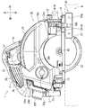
図1に示すように防塵丸鋸1は、丸鋸本体(切断機本体)20と、丸鋸本体20を角度調整可能に支持するベース10を有する。図4,5に示すように丸鋸本体20は、円盤状の刃具(鋸刃)22を回転させる電動モータ30と、電動モータ30に電力を供給するバッテリ2を有する。
As shown in FIG. 1, the dustproof
図4,5に示すように電動モータ30は、ブラシレスモータであって、モータハウジング4に収容される。電動モータ30は、モータハウジング4の内周面に固定される固定子30aと、固定子30aの内周側で回転自在に支持される回転子30bを有する。固定子30aの右側(図5の下側)には、回転子30bの回転位置を検知する磁気センサを備えるセンサ基板34が取付けられる。回転子30bにモータ軸30cが挿通され、回転子30bがモータ軸30cに固定される。モータ軸30cの左端は、軸受33によってモータハウジング4に軸回りに回転可能に支持される。モータ軸30cの右端は、軸受32によってギヤハウジング5に軸回りに回転可能に支持される。
As shown in FIGS. 4 and 5, the
図5に示すようにギヤハウジング5は、モータハウジング4の右側に設けられる。ギヤハウジング5内には、電動モータ30の回転出力を減速する減速ギヤ機構40が設けられる。減速ギヤ機構40は、モータ軸30cの端部に取付けられるピニオンギヤ40a、ピニオンギヤ40aに噛み合う中間ギヤ40bと、中間ギヤ40bに噛み合うスピンドル41を有する。スピンドル41は、モータ軸30cの下方に位置し、ギヤハウジング5に軸回りに回転可能に支持される。スピンドル41の先端は、ギヤハウジング5から突出しており、該先端に刃具22が取付けられる。
As shown in FIG. 5, the
図1,5に示すように刃具22は、取付体42によってスピンドル41の先端に固定される。取付体42は、刃具22を左側から保持するインナフランジ42aと、右側から保持するアウタフランジ42bを有する。刃具22の外周は、カバー体(9,21,23)によって覆われる。カバー体は、刃具22の外周上側略半分を覆う固定カバー21と、固定カバー21の後部において移動可能な可動カバー23と、固定カバー21の前部において移動可能な補助カバー9を有する。固定カバー21の上部には、切粉を収容するダストボックス28が連結される。
As shown in FIGS. 1 and 5, the cutting
図5に示すように固定カバー21は、ギヤハウジング5の右側に設けられ、ギヤハウジング5から延出する。図1,2に示すように固定カバー21は、刃具22の左側に位置して丸鋸本体20に固定される左側面21aと、刃具22の外周上領域の右側面を覆う右側面21bと、左側面21aと右側面21bの上端を連結する周壁21cを有する。周壁21cは、円弧状であって刃具22の外周上領域を覆う。固定カバー21の前部には、上方に延出する排出管21dが形成され、排出管21dにダストボックス28の開口部28bが連結される。
As shown in FIG. 5, the fixed
図1,2に示すようにダストボックス28は、固定カバー21の上側外周縁に沿って延出するボックス本体28aを有する。ボックス本体28aの前部には、固定カバー21の排出管21dに連結される開口部28bが形成される。刃具22がダストボックス28の右側面に表示された矢印28hの方向に回転し、刃具22が被切断材Wを切断する。この時に生じた切粉は、刃具22の前側において上方に吹き上げられる。吹き上げられた切粉は、固定カバー21からボックス本体28a内に導入され、ボックス本体28aに蓄積される。
As shown in FIGS. 1 and 2, the
図1,2に示すようにダストボックス28は、右側面にレバー28gを有する。レバー28gに一体となった雄ねじを利用してダストボックス28が丸鋸本体20に着脱可能に取付けられる。ボックス本体28aの後部に排出孔28cが形成される。排出孔28cを開閉するための蓋28dがピン28eによってボックス本体28aに回転可能に取付けられる。ボックス本体28a内に蓄積された切粉を排出する場合は、先ずボックス本体28aを丸鋸本体20から取外す。次に蓋28dを回転させて排出孔28cを開け、ボックス本体28a内から切粉を外へ排出する。
As shown in FIGS. 1 and 2, the
図1に示すように蓋28dの後部に栓28fによって塞がれる貫通孔が形成される。栓28fを蓋28dから取外し、蓋28dの貫通孔にパイプを経由してバキューム装置と連結することができる。これによりダストボックス28内の切粉がパイプを経由してバキューム装置に吸引され得る。
As shown in FIG. 1, a through hole is formed in the rear portion of the
図1,2に示すように可動カバー23は、固定カバー21の後下側に位置し、刃具22の外周後領域を覆う。可動カバー23は、円弧状であって、刃具22の回転中心と同軸中心に回転する。可動カバー23は、引っ張りばねによって刃具22を覆う方向すなわち前方に向けて付勢される。被切断材Wを切断する場合、可動カバー23の先端(前端)が被切断材Wに当たり、可動カバー23が後方に回転して被切断材Wの上方に移動する。
As shown in FIGS. 1 and 2, the
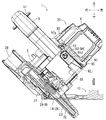
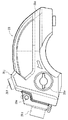
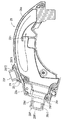
図2,3に示すように補助カバー9は、固定カバー21の前下側に位置する。補助カバー9は、刃具22の外周前領域に位置し、固定カバー21の前端とベース10の間の隙間Sを覆う。隙間Sは、丸鋸本体20のベース10に対する角度に応じて変化する。これに対して補助カバー9は、丸鋸本体20の角度に応じて固定カバー21あるいはベース10に対して移動する。したがって補助カバー9は、隙間Sから切粉が前方に飛散することを効果的に抑制する。補助カバー9は、ダストカバー29と、ダストカバー29をベース10に連結するアンギュラーガイド14を有する。
As shown in FIGS. 2 and 3, the
図12〜15に示すようにダストカバー29は、上下方向に長い第1側壁29aと、第1側壁29aに対向する第2側壁29cと、第1側壁29aと第2側壁29cの前端を連結する前壁29bを有する。第1側壁29aの上下中央領域に孔29gが形成される。孔29gには図2に示す軸部材27Aが挿通され、軸部材27Aはアンギュラーガイド14の孔14kに挿通される。これによりダストカバー29がアンギュラーガイド14に対して回転可能に連結される。
As shown in FIGS. 12 to 15, the
図12,13に示すように第1側壁29aにはカム面29d,29eが形成される。カム面29dは、第1側壁29aの後縁上領域に位置し、例えば孔29gよりも上方に位置する。カム面29eは、第1側壁29aの後縁下領域に位置し、例えば孔29gよりも下方に位置する。カム面29d,29eは、それぞれ前方に凹んでおり、カム面29d,29eの間には後方へ突出する凸部29fが形成される。
As shown in FIGS. 12 and 13, cam surfaces 29d and 29e are formed on the
図13に示すように第2側壁29cの上下長さは、第1側壁29aよりも短い。第2側壁29cの上端は、第1側壁29aの上端よりも下方に位置し、第2側壁29cの下端は、第1側壁29aの下端よりも上方に位置する。第2側壁29cの幅は、第1側壁29aよりも狭く、第2側壁29cの後縁は、第1側壁29aの後縁よりも前側に位置する。第2側壁29cの後縁は、円弧状であって、図2に示すように刃具22の外周縁に沿って延出する。
As shown in FIG. 13, the vertical length of the
図12,15に示すように前壁29bは、第1側壁29aの前縁と第2側壁29cの前縁を連結し、図5に示すように刃具22の外周縁に対面する。刃具22の外周縁は、第1側壁29aと第2側壁29cと前壁29bによって形成された溝29f内あるいは溝29fの近傍に位置する。したがって加工時に刃具22によって生じる切粉は、溝29fに沿って吹き上げられる。
12 and 15, the
図12〜15に示すようにアンギュラーガイド14は、前壁14aと前壁14aから後方に延出する第1ブラケット14jと第2ブラケット14gを有する。前壁14aの一端部(右端部)に孔14cが形成され、前壁14aの他端部(左端部)に長孔14dが形成される。孔14cは、円形であって図6に示す左右傾動支軸13が貫通される。これによりアンギュラーガイド14が左右傾動支軸13を中心にベース10に対して傾動する。
As shown in FIGS. 12 to 15, the
図14に示すように長孔14dは、前壁14aの端縁に沿って円弧状に延出する。長孔14dには、図6に示す摘みねじ16の軸部が挿通される。摘みねじ16の軸部は、ベース10の前端に起立する前側支持部11の長孔11aにも挿通される。長孔11aも長孔14dと同様に円弧状に形成される。摘みねじ16は、回転されることで、アンギュラーガイド14を前側支持部11に解除可能にロックする。アンギュラーガイド14は、ロックが解除されることで前側支持部11に対して左右傾動支軸13を中心に回転可能になる。図6〜9に示すように丸鋸本体20は、アンギュラーガイド14とともにベース10に対して左右方向に傾けられ、摘みねじ16によってベース10に対して所定の傾斜角度で保持され得る。
As shown in FIG. 14, the
図12,14に示すようにアンギュラーガイド14は、孔14cと対向する位置に外方(左方)に延出する指示部14iを有する。指示部14iは、図6に示す前側支持部11の外縁を超えて外方に突出して前方から視認できる。前側支持部11の外縁に目盛り11bが表示される。指示部14iの位置する目盛り11bを読むことでアンギュラーガイド14のベース10に対する左右方向の傾斜角度を知ることができる。後述するようにアンギュラーガイド14に丸鋸本体20が取付けられる。そのため目盛り11bを利用して指示部14iの位置を見ることで丸鋸本体20の左右方向の傾斜角度を知ることができる。
As shown in FIGS. 12 and 14, the
図4,6に示すように左右傾動支軸13は、前側支持部11の右下部に位置して前後方向に延出する。左右傾動支軸13が前側支持部11とアンギュラーガイド14の孔14cに挿通される。アンギュラーガイド14に丸鋸本体20が取り付けられる。したがって図6,8に示すように丸鋸本体20は、アンギュラーガイド14とともに左右傾動支軸13を中心に左右方向に角度調整され得る。
As shown in FIGS. 4 and 6, the left / right tilting
図10に示すようにベース10の後領域に後側支持部12が設けられる。後側支持部12は、ベース10に対して起立し、後側支持部12に左右傾動支軸17を介して傾動板18が取付けられる。傾動板18は、上方に延出するデプスガイド71を有し、デプスガイド71に丸鋸本体20が連結される。左右傾動支軸17は、図6に示す左右傾動支軸13と同軸上に位置する。したがって丸鋸本体20は、左右傾動支軸13,17を中心に左右方向に角度調整される。かくして図6,8に示すように刃具22の被切断材Wに対する切込み角度を調整して、いわゆる傾斜切りを行うことができる。
As shown in FIG. 10, a
図12〜15に示すように第1ブラケット14jが前壁14aの一端部から後方に延出し、第2ブラケット14gが前壁14aの中央領域から後方に延出する。第1ブラケット14jと第2ブラケット14gは、平行に延出する。第1ブラケット14jの前部に孔14eが形成され、第2ブラケット14gに孔14hが形成される。孔14e,14hは、同軸上に位置し、孔14e,14hに上下揺動支軸15が挿通される。図4,5に示すように上下揺動支軸15に丸鋸本体20の前部が回転可能に連結される。したがって図2,3に示すように丸鋸本体20は、上下揺動支軸15を中心としてベース10に対して上下方向に揺動する。これにより刃具22のベース10からの下方への突出量が調整され得る。
As shown in FIGS. 12 to 15, the
図1に示すように被切断材Wを刃具22で切断する場合、ベース10を被切断材Wの上でスライドさせる。刃具22は、ベース10から下方へ突出しており、その突出量によって被切断材Wの切込み深さが決定される。切り込み深さを調整するための切り込み深さ調整機構70がベース10の後部に設けられる。切り込み深さ調整機構70は、図10に示すようにベース10に回転可能に取付けられた傾動板18に設けられたデプスガイド71を有する。
As shown in FIG. 1, when cutting the workpiece W with the
図4,10に示すようにデプスガイド71は、傾動板18の端部に形成され、傾動板18から上前方に円弧状に延出する。デプスガイド71には円弧状のガイド溝孔71aが形成される。ガイド溝孔71aに固定ねじ72が挿通され、固定ねじ72の先端が固定カバー21の左側面に螺合される。固定ねじ72の頭部に操作部である固定レバー73が取付けられる。固定レバー73を上方に操作することで固定ねじ72がデプスガイド71に対して緩められ、固定ねじ72とともに丸鋸本体20がデプスガイド71に対して上下に移動する。これにより刃具22のベース10からの突出量(切り込み深さ)が調整される。
As shown in FIGS. 4 and 10, the
図4,10に示すようにデプスガイド71の外周面に目盛りが表示される。目盛りを利用して固定ねじ72の位置を得ることで、刃具22のベース10からの突出量を得る。突出量が所定量となる位置で固定レバー73を下方に操作して、固定ねじ72によって丸鋸本体20をデプスガイド71に対して固定する。かくして刃具22の被切断材Wに対する切り込み深さが固定される。
A scale is displayed on the outer peripheral surface of the
図2,3に示すように補助カバー9は、補助カバー傾動機構25Aによって丸鋸本体20に対して傾動する。例えば丸鋸本体20を図2に示す下位置から図3に示す上位置に回転させることで、補助カバー9の1部品であるダストカバー29が丸鋸本体20に対して前方に傾く。補助カバー傾動機構25Aは、ダストカバー29のカム面29d,29eと、カム面29d,29eに当接するピン(カムフォロワ)19A,19Bを有する。
As shown in FIGS. 2 and 3, the
図2,3に示すようにピン19A,19Bは、丸鋸本体20に設けられる。例えばピン19A,19Bは、固定カバー21に設けられ、固定カバー21の左側面21aから右方向に突出する。ピン19A,19Bは、円柱状であって外周面がカム面29d,29eに当接する。丸鋸本体20を図2に示す下位置にすることで、ピン19A,19Bがそれぞれカム面29d,29eの下領域に当接する。丸鋸本体20を図3に示す上位置にすることで、ピン19A,19Bがそれぞれカム面29d,29eの上領域に当接する。
As shown in FIGS. 2 and 3, the pins 19 </ b> A and 19 </ b> B are provided on the
図2,3に示すように丸鋸本体20をベース10に対して上下揺動支軸15を中心に上方に移動させる際、ピン19Aが上方に移動しかつカム面29dを前方に押す。これによりダストカバー29が軸部材27Aを中心に時計回りに回転する。丸鋸本体20をベース10に対して上下揺動支軸15を中心に下方に移動させる際、ピン19Bが下方に移動しつつカム面29eを前方に押す。これによりダストカバー29が軸部材27Aを中心に反時計回りに回転する。
As shown in FIGS. 2 and 3, when the
図13に示すようにアンギュラーガイド14の第1ブラケット14jの後ろ領域に孔14kが形成される。孔14kには、ダストカバー29の孔29gを貫通した軸部材27Aが挿入される。したがってダストカバー29は、軸部材27Aを中心に回転可能であり、アンギュラーガイド14を介してベース10に回転可能に連結される。
As shown in FIG. 13, a
図2に示すように丸鋸本体20が下位置に位置する際、ダストカバー29の下端は、ベース10に近接する。これによりダストカバー29は、ベース10と固定カバー21の前端との間の隙間Sを覆う。丸鋸本体20を図2に示す下位置から図3に示す上位置に回転させることで、刃具22とベース10の交点に対応する刃具22の前端の位置が後方に移動する。
As shown in FIG. 2, when the
これに対応してダストカバー29の下端部もベース10に対して後方へ移動する。したがってダストカバー29の下端部は、丸鋸本体20の上下方向の揺動角度に応じて前後方向に移動し、常に刃具22の近傍に位置する。したがってダストカバー29は、ベース10と固定カバー21の前端との間の隙間Sを効果的に覆う。
Correspondingly, the lower end portion of the
図6〜9に示すように丸鋸本体20を左右方向に傾動させると、丸鋸本体20とともにアンギュラーガイド14が左右傾動支軸13を中心に傾動する。丸鋸本体20の1部品である固定カバー21とともにダストカバー29も左右傾動支軸13を中心に傾動する。丸鋸本体20を左右方向に傾動させると、固定カバー21の前端とベース10の間の隙間Sも左右方向に移動する。したがってダストカバー29は、丸鋸本体20の左右方向の傾動角度に応じて左右方向に傾動する。これにより固定カバー21の前端とベース10の間の隙間Sがダストカバー29によって常に好適に覆われる。例えばダストカバー29の先端とベース10の間の隙間Sが常に1mm以下、好ましくは0.5mm以下になるようにダストカバー29が移動する。
As shown in FIGS. 6 to 9, when the
図6〜9に示すように補助カバー9は、連動機構26(アンギュラーガイド14)を利用して丸鋸本体20の左右方向の角度に応じてベース10に対して左右方向に傾動する。すなわちアンギュラーガイド14がベース10に対して左右傾動支軸13を中心に回転可能に連結される。アンギュラーガイド14の孔14kに挿入された軸部材27Aを介して補助カバー9がアンギュラーガイド14に連結される。したがって丸鋸本体20をアンギュラーガイド14ととともにベース10に対して左右方向に傾動させると、補助カバー9もアンギュラーガイド14とともにベース10に対して左右方向に傾動する。
As shown in FIGS. 6 to 9, the
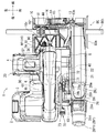
図4,10に示すように丸鋸本体20は、バッテリ2が取付けられるバッテリ取付部3を有する。バッテリ取付部3は、丸鋸本体20の後部左側に位置する。バッテリ取付部3は、モータハウジング4と同様に固定カバー21の左側面から左方向に延出する。バッテリ取付部3は、概ね平板状であって、バッテリ取付部3の下面にレールを有する。レールは、例えば左右方向に延出しており、レールを利用してバッテリ2がバッテリ取付部3の下面に取外し可能に取付けられる。バッテリ2は、電動工具用のバッテリであって、ねじ締め機等の他の電動工具に取付けられる。バッテリ2は、例えば18V出力のリチウムイオンバッテリであって、別途用意した充電器で充電可能である。したがってバッテリ2は、防塵丸鋸1等の電源として繰り返し利用され得る。バッテリ2は、図5に示すコントローラ61に電気的に接続されて、コントローラ61を経由して電動モータ30に電力を供給する。
As shown in FIGS. 4 and 10, the
図4,5に示すようにコントローラ61は、バッテリ取付部3とモータハウジング4の間に設けられたコントローラハウジング7に収容される。コントローラ61に種々な電気部品が電気的に接続され、例えば電動モータ30、回転子30bの位置を検知するセンサ基板34、ハンドル6に設けられたスイッチ53(図1参照)等が接続される。コントローラ61は、センサ基板34で検知された回転子30bの位置情報に基づいて制御信号を送信する制御回路を備える。さらにコントローラ61は、制御回路から受信した制御信号に基づいて電動モータ30の電流をスイッチングするFETからなる駆動回路、バッテリ2の状態の検出結果に応じて過放電又は過電流状態とならないように電動モータ30への電力供給を遮断するオートストップ回路等を備える。
As shown in FIGS. 4 and 5, the
図1,4に示すようにハンドル6は、山形であって、モータハウジング4から起立する起立部6aと、起立部6aの上部から後方へかつバッテリ取付部3に向けて傾斜するグリップ部6bを有する。グリップ部6bの上部の下面にトリガ形式のスイッチ53が設けられる。スイッチ53は、支軸を介してグリップ部6bに上下に傾動操作可能に支持され、圧縮ばね等の付勢部材によって下方へ付勢される。使用者は、グリップ部6bを把持した手の指先で付勢部材の付勢力に抗してスイッチ53を上方へ引き操作できる。スイッチ53は、引き操作されることでコントローラ61(図5参照)に信号を発信し、コントローラ61がバッテリ2からの電力を電動モータ30に供給する。これにより電動モータ30が起動し、刃具22が矢印28h方向に回転する。
As shown in FIGS. 1 and 4, the
図1,6に示すようにハンドル6にロックオンボタン57が設けられる。ロックオンボタン57は、スイッチ53の上側に位置し、ハンドル6を左右方向に貫通する。ロックオンボタン57は、ハンドル6に対して上下方向に傾動可能に設けられる。スイッチ53を上方へ引き操作した状態でロックオンボタン57を下方に傾動させることで、電動モータ30が起動状態にロックされる。これによりスイッチ53を引き続けることなく、電動モータ30を駆動させることができる。かくして作業者は、長時間の作業を楽に行うことができる。ロックオン状態を解除する場合は、再度スイッチ53を上方へ引き操作する。これによりロックオンボタン57が元の位置へ戻る。
As shown in FIGS. 1 and 6, the
図5に示すように電動モータ30のモータ軸30cに冷却ファン36が装着される。冷却ファン36は、回転子30bと軸受32の間に位置し、モータ軸30cとともに回転する。冷却ファン36がモータ軸30cとともに回転することで、外気がモータハウジング4の左面に形成された通気口4aからモータハウジング4内に導入される。導入された空気は、電動モータ30を冷却した後にモータハウジング4の後部に形成された通気口4bを経てコントローラハウジング7へ流れる。空気は、FET(電界効果トランジスタ)やマイコン等の発熱源を有するコントローラ61を冷却した後に、コントローラハウジング7の右面に形成された排気口7aから排出される。
As shown in FIG. 5, a cooling
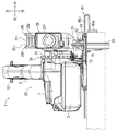
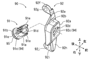
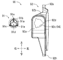
図5,6に示すように丸鋸本体20には、モータハウジング4内の空気を前方に吹出すブロワ機構90が設けられる。ブロワ機構90は、モータハウジング4に装着されるブロワベース92と、ブロワベース92に装着される回転ノズル91を有する。ブロワベース92は、モータハウジング4の開口部4dを覆うようにモータハウジング4に装着される。開口部4dは、冷却ファン36の径方向外側すなわち冷却ファン36の風の直下領域に位置する。開口部4dは、前方に向いており、ブロワベース92によって覆われる。
As shown in FIGS. 5 and 6, the
図16〜19に示すようにブロワベース92は、前壁92aと前壁92aの外周から後方に起立する周壁92bを有する。周壁92bの上部から上アーム92eが上方に延出する。上アーム92eの上端から後方に上取付部92fが延出する。上取付部92fには左右方向貫通する取付孔92gが形成される。周壁92bの下部から下アーム92hが下方に延出する。下アーム92hの下端から下取付部92iが後方に延出する。下取付部92iには左右方向に貫通する取付孔92jが形成される。
As shown in FIGS. 16 to 19, the
図9に示すように取付孔92g,92jに挿入されたねじ93によってブロワベース92がモータハウジング4の前面に取付けられる。図17に示すように前壁92aには円形状の開口部92cと複数の延出溝92dが形成される。複数の延出溝92dは、例えば3つであって、開口部92cから径方向外方に延出する。複数の延出溝92dは、等間隔に位置し、例えば120°間隔で位置する。開口部92cに回転ノズル91が貫通されて、回転ノズル91がブロワベース92に装着される。
As shown in FIG. 9, the
図16〜19に示すように回転ノズル91は、同軸上に設けられる円筒状の本体ノズル91aと首部91cとストッパ部91bを有する。本体ノズル91aの外周面には複数の凸部91eが形成される。複数の凸部91eは、本体ノズル91aから径方向に突出し、周方向に等間隔で配される。例えば3つの凸部91eが120°の間隔で配される。凸部91eは、本体ノズル91aの外周面において軸方向に所定の長さを有する。凸部91eが延出溝92dを貫通するように回転ノズル91がブロワベース92の開口部92cに後方から挿入される。
As shown in FIGS. 16-19, the
図16〜19に示すようにストッパ部91bは、本体ノズル91aとブロワベース92の開口部92cよりも大きい径を有する。そのためストッパ部91bは、回転ノズル91が開口部92cに挿入されることで、ブロワベース92の前壁92aの後面に当接する。これにより回転ノズル91がブロワベース92に対して前方に抜けることが防止される。
As shown in FIGS. 16 to 19, the
図16〜19に示すように本体ノズル91aの凸部91eをブロワベース92の延出溝92dに後方から貫通させる。そして本体ノズル91aをブロワベース92に対して軸中心に回転させる。これにより凸部91eがブロワベース92の前壁92aの前面に位置し、回転ノズル91がブロワベース92に対して後方に抜けることが防止される。回転ノズル91をブロワベース92に装着することで、首部91cが開口部92cに位置する。
As shown in FIGS. 16 to 19, the
回転ノズル91は、向き変更機構94によってブロワベース92に対して軸中心に回転可能である。図16,18に示すように向き変更機構94は、ブロワベース92の開口部92cと回転ノズル91の首部91cを有する。首部91cは、本体ノズル91aと同等の径を有し、凸部91eを有していない。首部91cが円筒状であり、開口部92cが円形状である。そのため首部91cが開口部92cに対して回転可能でかつ安定良く支持され得る。かくして回転ノズル91がブロワベース92に対して軸中心に回転可能に連結される。
The
図16〜19に示すように向き変更機構94は、さらにストッパ部91bと凸部91eを有し、回転ノズル91がブロワベース92から抜けることを防止する。回転ノズル91の首部91cには、Oリング95が設けられる。Oリング95は、ストッパ部91bとブロワベース92の前壁92aの間に位置して回転ノズル91とブロワベース92の間の隙間を塞ぐ。
As shown in FIGS. 16 to 19, the
図16,18に示すように回転ノズル91は、軸線に対して傾斜角度を有する前面91fと吹出口91dを有する。吹出口91dは、回転ノズル91の先端において軸線に対して傾斜して延出する。吹出口91dは、前面91fと同様に軸線に対して傾斜しており、吹出口91dから吹出される風は、軸線に対して所定の角度を有する。
As shown in FIGS. 16 and 18, the
図5,6に示すようにブロワ機構90は、丸鋸本体20の前面に位置する。冷却ファン36によって生じた風は、モータハウジング4の開口部4dを経てブロワベース92内に導入される。ブロワベース92内の空気は、回転ノズル91の軸中心の貫通孔を通過する。回転ノズル91の吹出口91dは、前方に開口しており、風が吹出口91dを経て丸鋸本体20の前方に吹出される。
As shown in FIGS. 5 and 6, the
図6を参照するように回転ノズル91は、前後方向に延出する軸線を中心に所定の角度に設定される。回転ノズル91を軸中心に回転させることで、吹出口91dは、左右方向および上下方向に向く。そのため吹出口91dから吹出される風は、左右方向および上下方向に調整され得る。
As shown in FIG. 6, the
図5,6に示すようにブロワ機構90は、冷却ファン36の回転径方向外方に位置し、冷却ファン36によって生じる風の直下に位置する。そのため冷却ファン36から吹出口91dまでの距離が短く、この間を流れる風が受ける摩擦抵抗が小さい。そのため吹出口91dから吹出される風の速度は、比較的速い。吹出口91dから吹出される風の向きは、回転ノズル91によって決定される。例えば回転ノズル91がベース10のスミ線ガイド10cに向けられ、風がスミ線ガイド10cに向けて流れる。
As shown in FIGS. 5 and 6, the
図5,6に示すようにスミ線ガイド10cは、ベース10の前端に設けられており、スミ線ガイド10cの左右両側が切り掛れることで形成される。スミ線ガイド10cを被切断材Wに付した墨線に位置させつつベース10を前方に移動させることで、刃具22を精度良く移動させ得る。ブロワ機構90の吹出口91dをスミ線ガイド10cに向けた場合は、吹出口91dから吹出された風によってスミ線ガイド10cの近傍に堆積する切粉等を吹き飛ばすことができる。これによりスミ線ガイド10cの視認性が高まり、加工作業を精確かつ迅速に行うことができる。
As shown in FIGS. 5 and 6, the
図5に示すようにギヤハウジング5の前部に、ロックレバー44が上下方向に傾動可能に連結される。ロックレバー44は、スピンドル41を回転不能にロックするロック部材に連結されており、ロックレバー44を操作することでスピンドル41を回転不能にロックできる。これにより刃具22をスピンドル41に対して着脱することができる。
As shown in FIG. 5, a
図1,11に示すようにベース10は、略平板状である。ベース10の上方に丸鋸本体20が上下方向に角度を調整可能に支持され、かつ左右方向に角度調整可能に支持される。ベース10には、概ね矩形状の窓部10aが形成され、窓部10aに刃具22が挿通される。ベース10の前部に平行定規80が左右方向に位置調整可能に取付けられる。
As shown in FIGS. 1 and 11, the
図4,6に示すように平行定規80は、ベース10に取付けられる連結バー80bと、連結バー80bの端部に設けられる定規本体80aを備える。定規本体80aは、ベース10の右側に位置する。被切断材Wを加工する際、ベース10を被切断材Wの上に設置し、定規本体80aを被切断材Wの側面に当接させる。定規本体80aを被切断材Wの側面に当接させつつ防塵丸鋸1を前方に移動させる。これにより防塵丸鋸1を被切断材Wの側面に平行に移動させることができ、被切断材Wを所定の幅で切断できる。
As shown in FIGS. 4 and 6, the
図4,6に示すように連結バー80bは、板状であって左右方向に長く、ベース10の左右幅を超えて延出する。連結バー80bの一端部は、下方に折り返してベース10より下側において折り返して延出する。定規本体80aは、連結バー80bの折り返した端部に設けられる。定規本体80aは、前後方向に長く、ベース10の下側において左右方向に向く。したがって定規本体80aは、被切断材Wの端縁に当接され得る。
As shown in FIGS. 4 and 6, the connecting
図4に示すようにベース10には、連結バー80bを移動可能に収容する定規保持溝10eが形成されている。定規保持溝10eの左右両端は、ベース10の左右両側部に開口している。連結バー80bを定規保持溝10eに沿って左右方向に移動させることで、定規本体80aの左右方向の位置を調整できる。連結バー80bは、定規固定装置81によってベース10に対して固定される。
As shown in FIG. 4, the
図20〜22に示すようにダストボックス28は、蓋28dから外された栓28fを一時的に保持する仮保持機構28jを有する。仮保持機構28jは、一対のレール28kと、一対のレール28kの後端を連結する橋部28lを有する。一対のレール28kは、ボックス本体28aの外周面に沿って前後方向に延出する。橋部28lは、ボックス本体28aの外周面との間に隙間を形成する。栓28fは、蓋28dの開口部28d1に挿入される筒部28f2と、開口部28d1を覆う覆い部28f1を有する。覆い部28f1は、円形であって、筒部28f2の径よりも大きく、筒部28f2の一端から径方向外方に突出する。
As shown in FIGS. 20 to 22, the
図21,22に示すように栓28fの覆い部28f1をレール28kの下方に挿入しつつ、栓28fをレール28kに沿って後方に移動させる。これにより覆い部28f1が橋部28lとレール28kの下方に位置する。筒部28f2は、レール28kの間から上方に突出する。栓28fを仮保持機構28jから取外す場合は、栓28fをレール28kに沿って前方に移動させる。ダストボックス28内における切粉および空気は、前方から後方に流れて、切粉のみが後部に堆積する。一方、空気は、前方から後方に流れた後、下降しつつ反転して前方に流れ、逃がし用孔28mからダストボックス28の外に排出される。続いて空気は、例えば固定カバー21内において右方に曲がって流れ、固定カバー21の外に排出される。
As shown in FIGS. 21 and 22, the
上述する防塵丸鋸(携帯用切断機)1は、図6に示すように被切断材Wの上に載置されるベース10と、ベース10の上面側に支持されかつ電動モータ30を具備する丸鋸本体(切断機本体)20と、電動モータ30によって駆動されかつベース10の下方に突き出される刃具22を有する。さらに防塵丸鋸1は、電動モータ30によって駆動されて電動モータ30に風を送って電動モータ30を冷却するファン36と、ファン36によって生じた風を丸鋸本体(切断機本体)20から吹出して切粉を吹き飛ばすブロワ機構90を有する。ブロワ機構90は、風を吹き出す吹出口91dと、吹出口91dの向きを変更できる向き変更機構94を有する。
The dust-proof circular saw (portable cutting machine) 1 described above includes a base 10 placed on a workpiece W as shown in FIG. 6, and an
したがってブロワ機構90から吹出される風の向きを作業状況等に応じて所望の角度に設定できる。例えば、風の向きを除去したい切粉の位置に合わせることができる。あるいは風の向きを水平方向あるいは上方にすることで作業者の目の前に浮遊する切粉を飛ばすことができる。このような構成は、サイディングや石工ボードなど細かい切粉が生じる場合に効果的であって、作業現場で舞う細かい切粉を作業に邪魔にならない方向に吹き飛ばすことができる。これにより切断機が操作しやすくなったり作業現場の環境が改善したりする。
Therefore, the direction of the wind blown from the
あるいはブロワ機構90から吹出される風の通り道に物が位置しないように風の向きを所定の方向に設定することができる。あるいはブロワ機構90から吹出される風の向きを切断機本体(丸鋸本体20)の前面中央あるいは左側から右斜め前方に向ける。これにより風は、作業者側から切断箇所を通って、その延長線上に流れる。かくして切粉を作業者の邪魔にならない方向に吹き飛ばすことができる。あるいは風の向きを前方にすることで、切断機から比較的遠い位置の被切断材上に積もった切粉を飛ばすことができる。
Alternatively, the direction of the wind can be set to a predetermined direction so that no object is positioned on the path of the wind blown from the
上述する防塵丸鋸(携帯用切断機)1は、図6に示すようにブロワ機構90を有する。ブロワ機構90は、風の吹出口91dを有しかつ吹出口91dが丸鋸本体(切断機本体)20の前方の空中に舞う切粉を吹き飛ばすことのできる向きに設定される。これにより作業者の目の前に浮遊する切粉を飛ばすことができる。
The dust-proof circular saw (portable cutting machine) 1 described above has a
図6,16に示すようにブロワ機構90は、吹出口91dの向きを変更できる向き変更機構94を有する。したがってブロワ機構90によって吹出される風を所望の角度に設定することができる。
As shown in FIGS. 6 and 16, the
図6,16に示すようにブロワ機構90の向き変更機構94は、吹出口91dを左右方向と上下方向の両方向に変更できる。したがってブロワ機構90は、上方、下方、左側、右側のいずれの位置に浮遊する切粉または積もった切粉を吹き飛ばすことができる。風向きを下方向に向けることで、ベース10の上面またはベース10の近傍の被切断材の上面に積もった切粉を吹き飛ばすことができる。風向きを上方向に向けることで、空中に舞う切粉を作業者の目の前から除くことができる。
As shown in FIGS. 6 and 16, the
図6,16に示すようにブロワ機構90の向き変更機構94は、丸鋸本体(切断機本体)20に対して回転可能に連結される回転ノズル91を有する。したがって回転ノズル91を丸鋸本体20に対して回転させることで吹出口91dの向きを変更できる。
As shown in FIGS. 6 and 16, the
図5に示すようにブロワ機構90は、冷却ファン36の径方向外方に位置し、冷却ファン36が発生する場所の近傍に位置する。ブロワ機構90は、ブロワ機構90から吹出す風の向きを変更し得る。そのため配管を設けることなく、所望の場所に風を向けることができる。しかも配管を設けないことで、配管内を通る際の摩擦損失が小さくなり、風速が遅くなることを防止できる。
As shown in FIG. 5, the
携帯用切断機の1例として防塵丸鋸1を上述した。これに代えて携帯用切断機は、円形の刃具としてダイヤモンドホイールを回転させるカッタ等であっても良い。あるいは携帯用切断機は、往復動する刃具を有し、例えばジグソーであっても良い。ジグソーは、電動モータからの回転運動を往復運動に変換する往復動変換機構と、往復動変換機構によって上下に往復動する出力軸と、出力軸に装着される鋸刃(刃具)を有する。
The dustproof
上述した携帯用切断機は、いわゆる充電式であってバッテリ2を有する。これに代えて携帯用切断機は、商用電源から電力を受けるためのコードを有していても良い。
The portable cutting machine described above is a so-called rechargeable type and has a
上述したブロワ機構90は、ファン36の径方向外周に位置している。これに代えてブロワ機構90は、工具本体(丸鋸本体20)の他の場所に設けられ、該場所から風を吹き出しても良い。
The
上述した回転ノズル91は、工具本体(丸鋸本体20)に対して前後方向に延出する軸線回りに回転可能に取付けられる。これによりブロワ機構90から吹出される風の向きは、略水平の軸線を中心に360°の範囲で設定される。これに代えて回転ノズル91が前後方向に延出する軸線回りに所定の角度範囲で回転可能に取付けられ、風の向きが略水平の軸線を中心に所定の角度範囲で設定されても良い。
The
あるいは回転ノズル91が工具本体(丸鋸本体20)に対して略垂直の軸線回りに回転可能に取付けられても良い。これによりブロワ機構90から吹出される風の向きが左右方向に変更可能であっても良い。あるいは回転ノズル91が工具本体(丸鋸本体20)に対して左右方向に延出する軸線回りに回転可能に取付けられても良い。これによりブロワ機構90から吹出される風の向きが上下方向に変更可能であっても良い。
Alternatively, the
あるいは回転ノズル91は、工具本体(丸鋸本体20)に対してボールジョイントによって取付けられても良い。ボールジョイントは、回転ノズル91に設けられる球面部と、球面部を回転可能に保持する保持部を有し、保持部が工具本体またはブロワベース92に設けられる。これにより回転ノズル91の角度が種々の方向に変更され、ブロワ機構90から吹出される風の向きが種々の方向に変更され得る。
Alternatively, the
切粉は、被切断材を切断する際に生じる比較的径の小さい粉である。径が小さいほど、あるいは軽量であるほど、空中に舞い上がりやすい。被切断材の1つであるサイディング等は、比重が小さく、空中に舞い上がりやすい。 Chip is a powder having a relatively small diameter that is generated when a material to be cut is cut. The smaller the diameter or the lighter the light, the easier it will rise into the air. Siding or the like, which is one of the materials to be cut, has a small specific gravity and easily rises into the air.
添付の図面を参照して詳細に上述した種々の実施例は、本発明の代表例であって本発明を限定するものではありません。詳細な説明は、本教示の様々な態様を作成、使用および/または実施するために、当業者に教示するものであって、本発明の範囲を限定するものではありません。更に、上述した各付加的な特徴および教示は、改良された携帯用切断機および/またはその製造方法と使用方法を提供するため、別々にまたは他の特徴および教示と一緒に適用および/または使用され得るものです。 The various embodiments described above in detail with reference to the accompanying drawings are exemplary of the present invention and are not intended to limit the present invention. The detailed description teaches those skilled in the art to make, use, and / or practice various aspects of the present teachings and is not intended to limit the scope of the invention. Moreover, each additional feature and teaching described above may be applied and / or used separately or in conjunction with other features and teachings to provide an improved portable cutting machine and / or method of making and using the same. Is what can be done.
1 防塵丸鋸(携帯用切断機)
2 バッテリ
3 バッテリ取付部
4 モータハウジング
4d 開口部
5 ギヤハウジング
6 ハンドル
7 コントローラハウジング
9 補助カバー
10 ベース
11 前側支持部
12 後側支持部
13,17 左右傾動支軸
14 アンギュラーガイド
15 上下揺動支軸
20 丸鋸本体(切断機本体)
21 固定カバー
22 刃具
23 可動カバー
25A 補助カバー傾動機構
26 連動機構
27A 軸部材
28 ダストボックス
28f 栓
28j 仮保持機構
29 ダストカバー
29d,29e カム面
30 電動モータ
36 冷却ファン(ファン)
40 減速ギヤ機構
41 スピンドル
61 コントローラ
80 平行定規
90 ブロワ機構
91 回転ノズル
91a 本体ノズル
91b ストッパ部
91c 首部
91d 吹出口
92 ブロワベース
94 向き変更機構
W 被切断材
1 Dust-proof circular saw (portable cutting machine)
2 Battery 3
21 fixed
40
Claims (5)
被切断材の上に載置されるベースと、
前記ベースの上面側に支持されかつ電動モータを具備する切断機本体と、
前記電動モータによって駆動されかつ前記ベースの下方に突き出される刃具と、
前記電動モータによって駆動されて前記電動モータに風を送って前記電動モータを冷却するファンと、
前記ファンによって生じた風を前記切断機本体から吹出して切粉を吹き飛ばすブロワ機構を有し、
前記ブロワ機構は、前記風を吹き出す吹出口と、前記吹出口の向きを変更できる向き変更機構を有する携帯用切断機。 A portable cutting machine,
A base placed on the material to be cut;
A cutting machine body supported on the upper surface side of the base and including an electric motor;
A cutting tool driven by the electric motor and protruding below the base;
A fan driven by the electric motor to send wind to the electric motor to cool the electric motor;
A blower mechanism that blows out the wind generated by the fan from the cutting machine body and blows off the chips;
The blower mechanism is a portable cutting machine having a blow-out port that blows out the wind and a direction changing mechanism that can change the direction of the blow-out port.
被切断材の上に載置されるベースと、
前記ベースの上面側に支持されかつ電動モータを具備する切断機本体と、
前記電動モータによって駆動されかつ前記ベースの下方に突き出される刃具と、
前記電動モータによって駆動されて前記電動モータに風を送って前記電動モータを冷却するファンと、
前記ファンによって生じた風を前記切断機本体から吹出して切粉を吹き飛ばすブロワ機構を有し、
前記ブロワ機構は、前記風の吹出口を有しかつ前記吹出口が前記切断機本体の前方の空中に舞う切粉を吹き飛ばすことのできる向きに設定される携帯用切断機。 A portable cutting machine,
A base placed on the material to be cut;
A cutting machine body supported on the upper surface side of the base and including an electric motor;
A cutting tool driven by the electric motor and protruding below the base;
A fan driven by the electric motor to send wind to the electric motor to cool the electric motor;
A blower mechanism that blows out the wind generated by the fan from the cutting machine body and blows off the chips;
The blower mechanism is a portable cutting machine that has the air outlet and is set in an orientation in which the air outlet can blow away chips that float in the air in front of the cutting machine body.
前記ブロワ機構は、前記吹出口の向きを変更できる向き変更機構を有する携帯用切断機。 The portable cutting machine according to claim 2,
The blower mechanism is a portable cutting machine having a direction changing mechanism that can change the direction of the blower outlet.
前記ブロワ機構の前記向き変更機構は、前記吹出口を左右方向と上下方向の両方向に変更できる構成になっている携帯用切断機。 The portable cutting machine according to claim 1 or 3,
The direction changing mechanism of the blower mechanism is a portable cutting machine configured to be able to change the outlet in both the left and right directions and the up and down direction.
前記ブロワ機構の前記向き変更機構は、前記切断機本体に対して回転可能に連結される回転ノズルを有する携帯用切断機。 A portable cutting machine according to any one of claims 1, 3 and 4,
The orientation changing mechanism of the blower mechanism is a portable cutting machine having a rotating nozzle that is rotatably connected to the cutting machine body.
Priority Applications (4)
| Application Number | Priority Date | Filing Date | Title |
|---|---|---|---|
| JP2016243629A JP6890965B2 (en) | 2016-12-15 | 2016-12-15 | Portable cutting machine |
| CN201711104672.7A CN108213573B (en) | 2016-12-15 | 2017-11-10 | Portable cutting machine |
| US15/824,585 US11639009B2 (en) | 2016-12-15 | 2017-11-28 | Portable cutting devices |
| DE102017129495.3A DE102017129495A1 (en) | 2016-12-15 | 2017-12-11 | Portable cutting devices |
Applications Claiming Priority (1)
| Application Number | Priority Date | Filing Date | Title |
|---|---|---|---|
| JP2016243629A JP6890965B2 (en) | 2016-12-15 | 2016-12-15 | Portable cutting machine |
Publications (2)
| Publication Number | Publication Date |
|---|---|
| JP2018094853A true JP2018094853A (en) | 2018-06-21 |
| JP6890965B2 JP6890965B2 (en) | 2021-06-18 |
Family
ID=62251852
Family Applications (1)
| Application Number | Title | Priority Date | Filing Date |
|---|---|---|---|
| JP2016243629A Active JP6890965B2 (en) | 2016-12-15 | 2016-12-15 | Portable cutting machine |
Country Status (4)
| Country | Link |
|---|---|
| US (1) | US11639009B2 (en) |
| JP (1) | JP6890965B2 (en) |
| CN (1) | CN108213573B (en) |
| DE (1) | DE102017129495A1 (en) |
Cited By (2)
| Publication number | Priority date | Publication date | Assignee | Title |
|---|---|---|---|---|
| WO2021021534A1 (en) * | 2019-07-26 | 2021-02-04 | Milwaukee Electric Tool Corporation | Circular saw |
| JP7459315B2 (en) | 2019-01-24 | 2024-04-01 | 株式会社マキタ | portable cutting machine |
Families Citing this family (13)
| Publication number | Priority date | Publication date | Assignee | Title |
|---|---|---|---|---|
| WO2017148340A1 (en) * | 2016-02-29 | 2017-09-08 | 张成峰 | Dust collecting cover and dust collecting method for electric circular saw |
| JP6890965B2 (en) * | 2016-12-15 | 2021-06-18 | 株式会社マキタ | Portable cutting machine |
| JP7035335B2 (en) | 2017-05-01 | 2022-03-15 | マックス株式会社 | Portable cutting machine |
| CN108705145A (en) * | 2018-07-18 | 2018-10-26 | 重庆旺豹商贸有限公司 | Motorcycle accessories processing unit (plant) |
| USD908149S1 (en) | 2018-10-23 | 2021-01-19 | Dustless Depot Llc | Angle grinder dust shroud with variable position slots for mounting brackets |
| US11123839B2 (en) | 2018-10-23 | 2021-09-21 | Dustless Depot Llc | Grinder dust shroud with input shaft gasket and adjustable mounting mechanism |
| DE102018222400A1 (en) * | 2018-12-20 | 2020-06-25 | Robert Bosch Gmbh | Hand tool with at least one safety brake device |
| JP7249797B2 (en) * | 2019-02-08 | 2023-03-31 | 株式会社マキタ | portable processing machine |
| US11273505B2 (en) | 2019-03-27 | 2022-03-15 | Dustless Depot, Llc | Circular saw dust collection shroud |
| CN112223431B (en) * | 2019-07-15 | 2022-09-13 | 株式会社牧田 | Automatic planer |
| US20210205905A1 (en) * | 2020-01-02 | 2021-07-08 | Techtronic Cordless Gp | Circular saw |
| USD951051S1 (en) | 2020-01-02 | 2022-05-10 | Techtronic Cordless Gp | Circular saw |
| CN114012493B (en) * | 2021-11-18 | 2022-12-20 | 正阳科技股份有限公司 | Sweep-saw with blow and inhale dirt function |
Citations (8)
| Publication number | Priority date | Publication date | Assignee | Title |
|---|---|---|---|---|
| JPH03117528U (en) * | 1990-03-15 | 1991-12-04 | ||
| JPH10225927A (en) * | 1997-02-14 | 1998-08-25 | Kioritz Corp | Power-driven cutter |
| US6219922B1 (en) * | 1997-06-04 | 2001-04-24 | Black & Decker, Inc. | Nozzle assembly for a power tool |
| US20040149352A1 (en) * | 2002-12-09 | 2004-08-05 | Roger Thomas | Debris collection system for a planer |
| US20060065097A1 (en) * | 2004-09-24 | 2006-03-30 | Makita Corporation | Cutting tool |
| WO2007055096A1 (en) * | 2005-11-08 | 2007-05-18 | Ryobi Ltd. | Electric cutting tool |
| US20090007441A1 (en) * | 2003-10-31 | 2009-01-08 | Schnell John W | Variable dust chute for circular saws |
| JP2010052117A (en) * | 2008-08-29 | 2010-03-11 | Hitachi Koki Co Ltd | Power tool |
Family Cites Families (87)
| Publication number | Priority date | Publication date | Assignee | Title |
|---|---|---|---|---|
| US1708345A (en) * | 1929-04-09 | Portable power-driven tool | ||
| US1623290A (en) * | 1926-07-26 | 1927-04-05 | Fred W Wappat | Portable saw |
| GB468920A (en) * | 1935-11-26 | 1937-07-15 | Electrolux Ltd | Improvements in nozzles for vacuum cleaners |
| US2103050A (en) * | 1936-02-26 | 1937-12-21 | Hoover Co | Dusting tool for suction cleaners |
| US2395237A (en) * | 1943-03-12 | 1946-02-19 | Harvey F Swenson | Control of saw-blade tension in band-saw machines |
| NL77734C (en) * | 1949-06-04 | |||
| US3565464A (en) * | 1969-04-15 | 1971-02-23 | Haley Corp | Swivel coupling assembly for vacuum cleaner |
| US3873862A (en) * | 1970-05-13 | 1975-03-25 | Murphy Ind Inc G W | Rotary saw |
| US3662796A (en) * | 1970-11-06 | 1972-05-16 | Nello Batistelli | Sawdust deflector for portable saw |
| US3882598A (en) * | 1974-06-17 | 1975-05-13 | Johns Manville | Dust control cutting assembly for cutting sheet material |
| US4192104A (en) * | 1978-10-10 | 1980-03-11 | Wilderness Mold, Inc. | Dust shroud |
| DE3525402A1 (en) * | 1985-07-16 | 1987-01-29 | Thyssen Plastik Anger Kg | QUICK CONNECTOR |
| USD315854S (en) * | 1987-04-02 | 1991-04-02 | Ryobi Ltd. | Electric saw |
| JP2514706B2 (en) * | 1988-12-29 | 1996-07-10 | 株式会社日立製作所 | Electric vacuum cleaner |
| US5084971A (en) * | 1990-09-12 | 1992-02-04 | Remington Mark A | Sawdust blower attachment for power saws |
| JPH085765Y2 (en) * | 1990-11-22 | 1996-02-21 | 日立工機株式会社 | Portable electric circular saw dust discharge structure |
| US5074044A (en) * | 1991-04-26 | 1991-12-24 | Duncan C Warren | Dust disposal attachment for a rotary element of a power tool |
| JP3289123B2 (en) * | 1995-05-09 | 2002-06-04 | 株式会社マキタ | Cutting machine |
| JP3431347B2 (en) * | 1995-06-05 | 2003-07-28 | 株式会社マキタ | Tabletop circular saw machine |
| DE19540279A1 (en) * | 1995-10-28 | 1997-04-30 | Balfo Verwaltungs Anstalt | Connection piece for profile pipes, profile sockets, corrugated hoses or similar strands |
| US5692856A (en) * | 1996-03-14 | 1997-12-02 | Robert D. Newman, Sr. | Lock assembly for extension handle |
| US5822864A (en) * | 1996-05-31 | 1998-10-20 | Black & Decker, Inc. | Viewing window for circular saw guard |
| DE19630022B4 (en) * | 1996-07-25 | 2007-12-20 | Fa. Andreas Stihl | Hand-guided implement with a protective cover |
| US5737843A (en) * | 1996-10-03 | 1998-04-14 | Fringer; Morris A. | Universal devices for protecting the user of a circular saw from flying debris |
| US6272960B1 (en) * | 1998-06-03 | 2001-08-14 | Black & Decker Inc. | Chop saw |
| USD415001S (en) * | 1999-02-01 | 1999-10-12 | Black & Decker Inc. | Chop saw |
| US10022811B2 (en) * | 2009-07-31 | 2018-07-17 | Sawstop Holding Llc | Dust collection system for a table saw |
| JP3468289B2 (en) * | 2000-01-18 | 2003-11-17 | 東拓工業株式会社 | Pipe connection structure |
| DE10005976A1 (en) * | 2000-02-10 | 2001-08-16 | Bosch Gmbh Robert | Machine for set of tools has inside of inlet union, pair of sealing lips arranged as separate part, connected in one-piece fashion with closing flaps |
| US20020053757A1 (en) * | 2001-01-11 | 2002-05-09 | Andersen Per Just | Methods and systems for removing flashing and other irregularities from molded starch-bound articles |
| JP3748073B2 (en) * | 2002-10-22 | 2006-02-22 | 日立工機株式会社 | Electric cutting machine |
| US7103979B2 (en) * | 2001-04-20 | 2006-09-12 | Hitachi Koki Co., Ltd. | Portable electric cutting device with blower mechanism |
| US6557261B1 (en) * | 2001-08-21 | 2003-05-06 | John P. Buser | Dust-capturing adaptor for a saw |
| DE10153939A1 (en) * | 2001-11-06 | 2003-05-22 | Hilti Ag | Hand machine tool has fan wheel between suction pipe and separator and extending at least in part into duct collecting space |
| US6748660B2 (en) * | 2002-05-15 | 2004-06-15 | John P. Buser | Debris-collection device for a power saw |
| DE10224837A1 (en) * | 2002-06-05 | 2004-01-08 | Robert Bosch Gmbh | machine tool |
| JP4656806B2 (en) * | 2002-11-01 | 2011-03-23 | 株式会社マキタ | Electric tool |
| US6857191B2 (en) * | 2002-11-07 | 2005-02-22 | Bettcher Industries, Inc. | Rotary knife having vacuum attachment |
| ES2286373T3 (en) * | 2002-12-09 | 2007-12-01 | Black & Decker Inc. | BRUSHING MACHINE. |
| US7776778B2 (en) | 2003-01-31 | 2010-08-17 | Sergey Dmitrievich Kusch | Hydrocarbon conversion catalyst and methods for making and using it |
| USD525503S1 (en) * | 2004-02-03 | 2006-07-25 | Gmca Pty Ltd. | Circular laser saw |
| ITMI20040471A1 (en) * | 2004-03-12 | 2004-06-12 | Guido Valentini | DEVICE FOR THE ADJUSTMENT OF THE SUCTION FLOW IN A FLEXIBLE HOSE FOR CONNECTION BETWEEN A TOOL FOR SURFACE PROCESSING AND A GOD SUCTION UNIT FOR WORKING DUST |
| JP4176055B2 (en) | 2004-06-24 | 2008-11-05 | 株式会社カネボウ化粧品 | Cosmetics |
| US7328512B2 (en) * | 2004-09-14 | 2008-02-12 | Martin Charles B | Self-contained vacuum saw |
| JP4957078B2 (en) * | 2005-06-30 | 2012-06-20 | 日立工機株式会社 | Dust collecting cover and cutter provided with the same |
| US7465328B2 (en) * | 2005-07-22 | 2008-12-16 | Black & Decker Inc. | Dust collector for a power tool |
| US20070044609A1 (en) * | 2005-08-30 | 2007-03-01 | Brazell Kenneth M | Motor driven wood working tool with vacuum feature |
| DE102005062886A1 (en) * | 2005-12-29 | 2007-07-05 | Robert Bosch Gmbh | Processing residues e.g. dust, collecting box for e.g. grinder, has container comprising variation unit that varies size of collecting volumes, where container and variation unit are formed as single unit |
| JP4929864B2 (en) * | 2006-06-15 | 2012-05-09 | 株式会社デンソー | Piping joint device |
| US7721370B2 (en) * | 2006-06-19 | 2010-05-25 | Pentair Water Pool And Spa, Inc. | Adjustable hose clip |
| CA2639930A1 (en) * | 2006-07-13 | 2008-01-17 | Eastway Fair Company Limited | Portable power tool for cutting concrete board and other substrates |
| US8661692B2 (en) * | 2006-10-27 | 2014-03-04 | Bettcher Industries, Inc. | Split blade housing for power operated rotary knife |
| US8061044B2 (en) * | 2007-02-15 | 2011-11-22 | Hitachi Koki Co., Ltd. | Power tool with chips ejecting mechanism |
| CN101332599B (en) * | 2007-06-30 | 2011-03-30 | 苏州宝时得电动工具有限公司 | Power tool |
| US20090074411A1 (en) | 2007-09-19 | 2009-03-19 | Tellabs Vienna, Inc. | System, methods, apparatuses, and program code for capturing, storing, and retrieving information communicated in a network |
| DE102007056381A1 (en) * | 2007-11-22 | 2009-05-28 | Hilti Aktiengesellschaft | Hand tool |
| US7980163B2 (en) * | 2008-05-20 | 2011-07-19 | Black & Decker Inc. | Air deflector assemblies for miter saws |
| US8230548B2 (en) * | 2008-05-23 | 2012-07-31 | General Electric Company | Apparatus for removing a waste product |
| US8113543B1 (en) * | 2008-09-02 | 2012-02-14 | M.D.C. Romani, Inc. | Hose adapter and assembly incorporating the same |
| US8037610B2 (en) * | 2008-12-30 | 2011-10-18 | Crain Cutter Co., Inc. | Powered groover with airflow fin |
| WO2010124293A1 (en) * | 2009-04-24 | 2010-10-28 | Martin Charles B | Portable cutting device with on-board debris collection |
| US20100269654A1 (en) * | 2009-04-28 | 2010-10-28 | Needel Gregory E | Dust Collection System for a Power Tool |
| US20110079125A1 (en) * | 2009-10-01 | 2011-04-07 | Hsin-Cheng Kuo | Circular Saw |
| US9221110B2 (en) * | 2009-10-02 | 2015-12-29 | JPL Global, LLC | Power saw apparatus with integrated dust collector |
| JP5649834B2 (en) | 2010-03-04 | 2015-01-07 | 株式会社マキタ | Hand-held cutting tool |
| JP5490572B2 (en) * | 2010-03-04 | 2014-05-14 | 株式会社マキタ | Hand-held cutting tool |
| US20120192440A1 (en) * | 2011-01-27 | 2012-08-02 | Jerabek Jesse J | Power tool with reciprocating blade |
| US8782906B2 (en) * | 2011-09-30 | 2014-07-22 | Robert Bosch Gmbh | Saw assembly with pivot hinge dust port |
| JP5775795B2 (en) * | 2011-11-08 | 2015-09-09 | 株式会社マキタ | Dust collection attachment for electric tools and electric tools |
| US9844176B2 (en) * | 2012-10-22 | 2017-12-19 | Fournier And Grande Trust | Weed trimmer extension device |
| US9908193B2 (en) * | 2013-02-12 | 2018-03-06 | JPL Global, LLC | Dust guard for circular saws |
| CA2904426C (en) * | 2013-03-11 | 2021-04-20 | James Hardie Technology Limited | A cutting apparatus |
| WO2014164276A1 (en) * | 2013-03-12 | 2014-10-09 | Robert Bosch Gmbh | Removable dust compartment for power tool |
| US9523453B2 (en) * | 2013-03-20 | 2016-12-20 | Miniature Precision Components, Inc. | Locking quick connect assembly |
| JP2014217921A (en) * | 2013-05-09 | 2014-11-20 | 株式会社マキタ | Cutting tool |
| US20140366383A1 (en) * | 2013-06-13 | 2014-12-18 | Black & Decker Inc. | Blower for circular saw |
| US9821389B2 (en) * | 2013-08-28 | 2017-11-21 | Shave Away Europe, Inc. | Dust capturing device for reciprocating saws |
| WO2015102906A1 (en) * | 2013-12-30 | 2015-07-09 | Robert Bosch Gmbh | Airflow managemnet system for a power tool |
| US20150359171A1 (en) * | 2014-06-17 | 2015-12-17 | Walter Butler | Auxiliary mulching mower blade |
| US9999986B2 (en) * | 2014-07-29 | 2018-06-19 | Bettcher Industries, Inc. | Power operated rotary knife with vacuum attachment assembly |
| US9579810B2 (en) * | 2014-07-29 | 2017-02-28 | Bettcher Industries, Inc. | Power operated rotary knife with vacuum attachment assembly |
| CN204622226U (en) * | 2015-04-27 | 2015-09-09 | 宁波良业电器有限公司 | Can the electric circular saw of drifting dust |
| US10502353B2 (en) * | 2016-05-27 | 2019-12-10 | Kohler Co. | Quick connect release system for a fluid coupling |
| US10295181B2 (en) * | 2016-10-28 | 2019-05-21 | Noritz Corporation | Exhaust connection structure and combustion apparatus with exhaust connection structure |
| JP6890965B2 (en) * | 2016-12-15 | 2021-06-18 | 株式会社マキタ | Portable cutting machine |
| US11123839B2 (en) * | 2018-10-23 | 2021-09-21 | Dustless Depot Llc | Grinder dust shroud with input shaft gasket and adjustable mounting mechanism |
| US10443768B1 (en) * | 2019-04-26 | 2019-10-15 | 1Nv3Nt Llc | Vacuum hose-pipe adapter |
-
2016
- 2016-12-15 JP JP2016243629A patent/JP6890965B2/en active Active
-
2017
- 2017-11-10 CN CN201711104672.7A patent/CN108213573B/en active Active
- 2017-11-28 US US15/824,585 patent/US11639009B2/en active Active
- 2017-12-11 DE DE102017129495.3A patent/DE102017129495A1/en active Pending
Patent Citations (9)
| Publication number | Priority date | Publication date | Assignee | Title |
|---|---|---|---|---|
| JPH03117528U (en) * | 1990-03-15 | 1991-12-04 | ||
| JPH10225927A (en) * | 1997-02-14 | 1998-08-25 | Kioritz Corp | Power-driven cutter |
| US6219922B1 (en) * | 1997-06-04 | 2001-04-24 | Black & Decker, Inc. | Nozzle assembly for a power tool |
| US20040149352A1 (en) * | 2002-12-09 | 2004-08-05 | Roger Thomas | Debris collection system for a planer |
| US20090007441A1 (en) * | 2003-10-31 | 2009-01-08 | Schnell John W | Variable dust chute for circular saws |
| US20060065097A1 (en) * | 2004-09-24 | 2006-03-30 | Makita Corporation | Cutting tool |
| JP2006088559A (en) * | 2004-09-24 | 2006-04-06 | Makita Corp | Cutting machine |
| WO2007055096A1 (en) * | 2005-11-08 | 2007-05-18 | Ryobi Ltd. | Electric cutting tool |
| JP2010052117A (en) * | 2008-08-29 | 2010-03-11 | Hitachi Koki Co Ltd | Power tool |
Cited By (2)
| Publication number | Priority date | Publication date | Assignee | Title |
|---|---|---|---|---|
| JP7459315B2 (en) | 2019-01-24 | 2024-04-01 | 株式会社マキタ | portable cutting machine |
| WO2021021534A1 (en) * | 2019-07-26 | 2021-02-04 | Milwaukee Electric Tool Corporation | Circular saw |
Also Published As
| Publication number | Publication date |
|---|---|
| US20180169885A1 (en) | 2018-06-21 |
| US11639009B2 (en) | 2023-05-02 |
| JP6890965B2 (en) | 2021-06-18 |
| CN108213573B (en) | 2020-09-22 |
| DE102017129495A1 (en) | 2018-06-21 |
| CN108213573A (en) | 2018-06-29 |
Similar Documents
| Publication | Publication Date | Title |
|---|---|---|
| JP6890965B2 (en) | Portable cutting machine | |
| EP3385044B1 (en) | Portable machining device | |
| US20080302226A1 (en) | Power tool having imaging device and display device | |
| US20150266201A1 (en) | Portable cutting devices | |
| JP6878168B2 (en) | Portable processing machine | |
| US8037614B2 (en) | Cutting machine | |
| JP6847651B2 (en) | Portable cutting machine | |
| US20140331505A1 (en) | Cutting device | |
| JP5061807B2 (en) | Electric cutter | |
| WO2009047629A1 (en) | Visual display means for a power tool | |
| EP2535154A1 (en) | Covering device for cutting machine and cutting machine having the same | |
| JP6824639B2 (en) | Desktop cutting machine | |
| US10668644B2 (en) | Portable cutting devices | |
| JP2009143129A (en) | Bench cutting machine and dust collector for bench cutting machine | |
| JP2011101929A (en) | Dust collector for cutter | |
| JP4864420B2 (en) | Electric cutting tool | |
| JP6736434B2 (en) | Portable processing machine | |
| GB2399314A (en) | Tool having rotatable adjustment means for power working member | |
| US20110179924A1 (en) | Bench Cutting Machine | |
| JP2021030395A (en) | Cutting machine | |
| JP5240671B2 (en) | Cutting tool | |
| JP2010214536A (en) | Cutting tool | |
| US11541496B2 (en) | Portable machining apparatus | |
| JP6252970B2 (en) | Electric tool | |
| JP6862868B2 (en) | Portable cutting machine using a base |
Legal Events
| Date | Code | Title | Description |
|---|---|---|---|
| A621 | Written request for application examination |
Free format text: JAPANESE INTERMEDIATE CODE: A621 Effective date: 20190904 |
|
| A977 | Report on retrieval |
Free format text: JAPANESE INTERMEDIATE CODE: A971007 Effective date: 20200826 |
|
| A131 | Notification of reasons for refusal |
Free format text: JAPANESE INTERMEDIATE CODE: A131 Effective date: 20200901 |
|
| A521 | Request for written amendment filed |
Free format text: JAPANESE INTERMEDIATE CODE: A523 Effective date: 20201020 |
|
| A131 | Notification of reasons for refusal |
Free format text: JAPANESE INTERMEDIATE CODE: A131 Effective date: 20201222 |
|
| A521 | Request for written amendment filed |
Free format text: JAPANESE INTERMEDIATE CODE: A523 Effective date: 20210212 |
|
| TRDD | Decision of grant or rejection written | ||
| A01 | Written decision to grant a patent or to grant a registration (utility model) |
Free format text: JAPANESE INTERMEDIATE CODE: A01 Effective date: 20210518 |
|
| A61 | First payment of annual fees (during grant procedure) |
Free format text: JAPANESE INTERMEDIATE CODE: A61 Effective date: 20210526 |
|
| R150 | Certificate of patent or registration of utility model |
Ref document number: 6890965 Country of ref document: JP Free format text: JAPANESE INTERMEDIATE CODE: R150 |