US11273505B2 - Circular saw dust collection shroud - Google Patents
Circular saw dust collection shroud Download PDFInfo
- Publication number
- US11273505B2 US11273505B2 US16/829,860 US202016829860A US11273505B2 US 11273505 B2 US11273505 B2 US 11273505B2 US 202016829860 A US202016829860 A US 202016829860A US 11273505 B2 US11273505 B2 US 11273505B2
- Authority
- US
- United States
- Prior art keywords
- dust collection
- saw blade
- hood
- shroud
- saw
- Prior art date
- Legal status (The legal status is an assumption and is not a legal conclusion. Google has not performed a legal analysis and makes no representation as to the accuracy of the status listed.)
- Active
Links
Images


Classifications
-
- B—PERFORMING OPERATIONS; TRANSPORTING
- B23—MACHINE TOOLS; METAL-WORKING NOT OTHERWISE PROVIDED FOR
- B23D—PLANING; SLOTTING; SHEARING; BROACHING; SAWING; FILING; SCRAPING; LIKE OPERATIONS FOR WORKING METAL BY REMOVING MATERIAL, NOT OTHERWISE PROVIDED FOR
- B23D59/00—Accessories specially designed for sawing machines or sawing devices
- B23D59/006—Accessories specially designed for sawing machines or sawing devices for removing or collecting chips
-
- B—PERFORMING OPERATIONS; TRANSPORTING
- B23—MACHINE TOOLS; METAL-WORKING NOT OTHERWISE PROVIDED FOR
- B23D—PLANING; SLOTTING; SHEARING; BROACHING; SAWING; FILING; SCRAPING; LIKE OPERATIONS FOR WORKING METAL BY REMOVING MATERIAL, NOT OTHERWISE PROVIDED FOR
- B23D45/00—Sawing machines or sawing devices with circular saw blades or with friction saw discs
- B23D45/16—Hand-held sawing devices with circular saw blades
Definitions
- the present invention relates to dust collection.
- examples of the present invention relates to a dust collection shroud for collecting dust during use of a circular saw.
- Dust collection has become increasingly important both for commercial use and construction as well as for consumer or hobbyist use of power tools. Without adequate dust collection while working, dust and debris is typically scattered over a wide area. It is desirable to contain the dust and debris which is created while using power tools for several reasons. It is desirable to contain the dust and debris to keep the workplace cleaner and to minimize the time necessary to clean up afterwards. For example, circular saws are often used to cut wood, plastics, or masonry products. Cutting these materials creates fine dust which is spread over a large distance and which can be difficult and time consuming to clean up afterwards. It is also desirable to contain the dust and debris to keep the debris from getting into the tool itself, as the fine dust often causes premature failure of the tool bearings, motor, etc. Additionally, dust poses a health risk to the machine operator and others who may breathe it. It is thus desirable to collect the dust to minimize exposure to the dust.
- FIG. 1 is a drawing which shows an isometric view of the dust shroud.
- FIG. 2A is a drawing which shows an isometric view of the dust shroud mounted to a circular saw.
- FIG. 2B is a drawing which shows an isometric view of the dust shroud mounted to a circular saw.
- FIG. 2C is a drawing which shows an isometric view of the dust shroud mounted to a circular saw.
- FIG. 3 is a drawing which shows an isometric view of the shroud body.
- FIG. 4 is a drawing which shows an isometric view of the shroud body.
- FIG. 5 is a drawing which shows an isometric view of the saw blade hood.
- FIG. 6 is a drawing which shows an isometric view of the mounting bar and bolt.
- FIG. 7 is a drawing which shows a side view of the dust shroud.
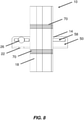
- FIG. 8 is a drawing which shows a side view of the dust shroud.
- FIG. 9 is a drawing which shows a front view of the dust shroud.
- FIG. 10 is a drawing which shows a rear view of the dust shroud.
- FIG. 11 is a drawing which shows a top view of the dust shroud.
- FIG. 12 is a drawing which shows a bottom view of the dust shroud.
- FIG. 13 is a drawing which shows a perspective view of the dust shroud.
- FIG. 14 is a drawing which shows a perspective view of the dust shroud attached to a circular saw.
- FIG. 15 is a drawing which shows a side view of the dust shroud attached to the circular saw.
- FIG. 16 is a drawing which shows a perspective view of the dust shroud and the circular saw blade.
- FIG. 17 is a drawing which shows a perspective view of the dust shroud.
- FIG. 18 is a drawing which shows a perspective view of the dust shroud.
- FIG. 19 is a drawing which shows a perspective view of the dust shroud.
- FIG. 20 is a drawing which shows a perspective view of the dust shroud.
- FIG. 21 is a drawing which shows a perspective view of the dust shroud.
- FIG. 22 is a drawing which shows a left side view of the dust shroud.
- FIG. 23 is a drawing which shows a right side view of the dust shroud.
- FIG. 24 is a drawing which shows a top view of the dust shroud.
- FIG. 25 is a drawing which shows a bottom view of the dust shroud
- FIG. 26 is a drawing which shows a front view of the dust shroud.
- FIG. 27 is a drawing which shows a back view of the dust shroud.
- FIG. 28 is a drawing which shows a perspective view of the dust shroud.
- FIG. 29 is a drawing which shows a perspective view of the dust shroud.
- adjacent refers to near or close sufficient to achieve a desired effect. Although direct contact is common, adjacent can broadly allow for spaced apart features.
- the term “substantially” refers to the complete or nearly complete extent or degree of an action, characteristic, property, state, structure, item, or result.
- an object that is “substantially” enclosed would mean that the object is either completely enclosed or nearly completely enclosed.
- the exact allowable degree of deviation from absolute completeness may in some cases depend on the specific context. However, generally speaking the nearness of completion will be such as to have the same overall result as if absolute and total completion were obtained.
- the use of “substantially” is equally applicable when used in a negative connotation to refer to the complete or near complete lack of an action, characteristic, property, state, structure, item, or result.
- compositions that is “substantially free of” particles would either completely lack particles, or so nearly completely lack particles that the effect would be the same as if it completely lacked particles.
- a composition that is “substantially free of” an ingredient or element may still actually contain such item as long as there is no measurable effect thereof.
- the term “about” is used to provide flexibility to a number or numerical range endpoint by providing that a given value may be “a little above” or “a little below” the number or endpoint.
- the disclosure particularly describes a dust collection shroud for a circular saw.
- a dust collection shroud which may be universally adapted to fit many different circular saws.
- the dust collection shroud attaches to or adjacent to the base of the circular saw and provides a dust collection chamber which extends around the front of the circular saw blade within the blade guard.
- the dust collection shroud may be attached to both left and right handed saws.
- the shroud includes a hood which extends around the saw blade. The hood forms much of the dust collection chamber around the blade. In some cases, the hood may be trimmed to better fit individual saws.
- the dust collection chamber collects dust at the dust creation point of the saw. A majority of the dust is collected before it escapes the saw or migrates to other areas.
- a vacuum hose port and a vacuum hose are used to connect the dust collection shroud to a vacuum and draw air from around the front of the blade and from the dust collection chamber.
- the shroud 10 includes a shroud body 14 , a saw blade hood 18 , a mounting bar 22 , a bolt 26 , and a thumb nut 30 .
- the shroud body 14 includes a vacuum port 34 which extends upwardly from a base of the shroud body 14 and generally outwardly from the shroud body 14 . This orientation may be varied somewhat.
- the vacuum port 34 provides an opening which receives a standard 1.25 or 1.5 inch vacuum hose to thereby connect the dust collection shroud 10 to a vacuum such as a shop canister vacuum.
- the vacuum port 34 may include an extended hose which extends further upwardly from the dust collection shroud 10 and provides an opening to receive the vacuum hose.
- the lumen of the vacuum port 34 is pneumatically connected to a dust collection chamber/passage 38 which is formed by the shroud body 14 .
- the dust collection chamber 38 receives dust from the circular saw and transmits the dust through the vacuum port to be collected by a vacuum.
- the dust collection chamber 38 includes an opening, indicated at 42 , which interfaces with the saw blade hood 18 .
- the saw blade hood 18 attaches to the shroud body 14 and extends around the circular saw blade. Accordingly, the saw blade hood 18 forms a portion of the dust collection chamber 38 .
- the shroud body 14 also includes a mounting flange 46 which extends generally horizontally from the shroud body 14 .
- the mounting flange 46 is used to attach the dust collection shroud 10 to a circular saw via the rip slot on the circular saw.
- the mounting flange 46 is designed to allow for left or right mounting of the dust collection shroud 10 to a left or right handed circular saw. This increases the ability to mount a single dust collection shroud 10 to many different circular saws.
- the mounting flange includes mirrored mounting portions 50 which extend both forwards and backwards from the center of the shroud body 14 .
- a single mounting portion 50 is generally used to attach the dust collection shroud 10 to a circular saw.
- Each mounting portion 50 includes a slot 54 which can receive a mounting bar 22 .
- the mounting bar 22 is an elongate rectangular bar with an upturned end; forming an “L” shape.
- the upturned end of the mounting bar 22 includes a hole which receives the mounting bolt 26 .
- Each mounting portion 50 of the shroud body mounting flange 46 has a bolt slot 58 formed therethrough which also receives the mounting bolt 26 . As the bolt slot 58 intersects the mounting bar slot 54 , the bolt slot 58 is formed with a rear bolt slot portion 58 A and a front bolt slot portion 58 B.
- the rear bolt slot portion 58 A is formed with square ends to receive the squared shoulder of a carriage bolt.
- the front bolt slot portion 58 B is formed with rounded ends to receive the carriage bolt shank.
- the upturned “L” shaped end of the mounting bar 22 is placed into the mounting bar slot 54 and the mounting carriage bolt 26 is passed through the rear bolt slot 58 A, the bolt hole in the mounting bar 22 , and through the front bolt slot 58 B.
- the thumb nut 30 is then secured on the threaded end of the bolt 26 to fix the mounting bar 22 in a desired position on the mounting flange 46 .
- the dust collection shroud 10 is shown ready for attachment to a right handed circular saw. Generally, the dust collection shroud 10 may be attached to a left handed circular saw with the mounting bar 22 attached to the other mounting portion 50 of the mounting flange 46 .
- the saw blade hood 18 is also made for use with a left or right handed circular saw.
- the saw blade hood 18 includes a central opening 62 which attaches to the shroud body 14 and includes upper and lower portions 64 which define an open channel 66 for the saw blade.
- the example upper and lower portions 64 are symmetrical and they extend upwardly and downwardly from the opening 62 .
- the assembly shown is configured for a right handed circular saw.
- the saw blade hood 18 would be inverted to place the central opening on the opposite side of the hood 18 and the shroud body 14 would be rotated 180 degrees about a vertical axis.
- the mounting bar would be attached to the other mounting portion 50 .
- the upwardly extending end of the saw blade hood 64 will extend into the blade guard of the circular saw.
- the downwardly extending end 64 of the saw blade hood 66 will extend downwardly past the bottom of the saw base plate.
- the saw blade hood 18 includes molded-in cut lines 70 on both upper/lower ends 64 of the blade hood 18 which guide a user in cutting off the excess downwardly extending portion of the saw blade end 64 while initially installing the dust collection shroud on a circular saw.
- the saw blade hood end portions 64 are formed with a blade slot 74 that extends vertically along the rear of the blade channel 66 .
- the saw blade hood end portions 64 are also formed with a compression/flexibility slot 78 along the front side of the upwardly and downwardly extending ends 64 of the hood 18 .
- This compression slot 78 helps the upwardly extending end 64 of the hood 18 to conform to the saw blade shroud.
- the saw blade hood 18 is molded from a flexible material which is still somewhat rigid to allow conformation to the saw blade guard.
- the saw blade hood 18 may be molded from a clear plastic material, such as clear vinyl, to improve visibility of the saw blade when the circular saw is in use.
- the shroud body 14 may be molded from a clear plastic such as acrylic or polycarbonate to further increase the visibility of the saw blade.
- FIG. 2A shows a drawing of the dust collection shroud 10 attached to a circular saw 82 .
- the circular saw 82 includes a base plate 86 which contacts a material being cut by the saw.
- the saw 82 also includes a motor 90 , hand grip 94 , upper blade guard 98 , lower movable blade guard 102 , and blade 106 .
- Other parts of the circular saw 82 which do not directly interface with the dust collection shroud 10 are not individually numbered.
- the saw base plate 86 includes mounting bosses 110 which may be used to attach a rip fence to the saw 82 .
- Circular saws 82 often have similarly situated mounting bosses 110 for using a rip cutting guide.
- the mounting bosses 110 may be channels, brackets, or openings which are used to receive the mounting bar 22 .
- the rip fence is not commonly used and is not used while the dust collection shroud 10 is used.
- the mounting bosses 110 extend upwardly from the base plate 86 and form openings oriented laterally across the saw base plate 86 .
- the dust shroud mounting bar 22 is placed through the mounting bosses 110 and a screw, such as thumb screw 114 , is used to secure the mounting bar 22 to the saw base plate 86 .
- the mounting bar 22 is moveable laterally in the mounting bosses 110 ; allowing the lateral position of the dust collection shroud 10 to be adjusted to properly position the saw blade hood 18 in the upper blade guard 98 and around the saw blade 106 .
- the shroud body 14 is movable forwards and backwards relative to the mounting bar 22 via the slot 54 , bolt slots 58 , bolt 26 , and nut 30 in order to properly position the shroud 10 relative to the front of the blade 106 and the upper blade guard 98 .
- the downwardly extending portion of the blade channel 66 has been cut so that it does not extend down below the base plate 86 and the upwardly extending portion of the blade channel 66 is positioned inside of the upper blade guard 98 .
- the shroud body 14 is formed with a straight vertical outer edge 118 along the outside of the mounting flange 46 .
- This straight outer edge 118 may be used as a cutting guide by positioning the outer edge 118 against a fence which has been clamped to a material for cutting along a line in that material.
- the dust collection chamber 38 When the dust collection shroud is installed on a circular saw as shown in FIG. 2 , the dust collection chamber 38 is positioned adjacent the front of the saw blade 106 and adjacent the saw base plate 86 . This positions the dust collection chamber 38 adjacent the point where dust is generated while cutting.
- the saw blade hood 18 extends around the front of the saw blade 106 and is positioned close to the front of the upper blade guard 98 .
- the dust collection shroud 10 both collects a majority of dust near the point of dust generation and keeps dust contained within the saw upper blade guard 98 ; reducing the amount of dust which is spread into the environment during use of the circular saw 82 .
- FIG. 2B shows how a vacuum hose 32 (dashed lines) may be attached to the dust collection shroud 10 to collect the dust produced while using the circular saw 82 .
- FIG. 2C shows how a vacuum hose adapter 36 (dashed lines) may be used to connect a vacuum hose 32 (dashed lines) to the dust collection shroud 10 .
- the vacuum hose adapter 36 may be used to connect a different diameter of vacuum hose 32 or to provide a more rigid section of the vacuum conduit adjacent to the saw body if this makes it easier to use the circular saw 82 .
- FIGS. 3 and 4 show drawings of the shroud body 14 .
- FIG. 3 shows an isometric view of the shroud body 14 from the position shown in FIGS. 1 and 2 .
- FIG. 4 shows a view of the shroud body 14 from the opposite side to better illustrate the interior of the dust collection chamber 38 .
- FIG. 4 better illustrates how the vacuum port 34 is connected to the dust collection chamber.
- the vacuum port 34 may include external ribs that may serve to strengthen the vacuum port or to allow attachment of an intermediate hose between the vacuum port 34 and the vacuum hose.
- the external ribs may allow the vacuum port to accept an adapter for a 1.5 inch vacuum hose, or to alternately receive a 1.5 inch vacuum hose directly.
- the external ribs may be sized so that a 1.5 inch vacuum hose fits snugly over the ribs.
- a lower rib may be larger and provide a depth stop which keeps a 1.5 inch vacuum hose from sliding too far over the vacuum port 34 .
- the vacuum port 34 generally extends upwardly from a base of the shroud body 14 and generally outwardly from the shroud body 14 away from the saw blade 106 . This orientation is generally suitable for connection to a vacuum hose while preserving ease of operation for the circular saw 82 .
- the dust collection chamber 38 extends generally inwardly from the shroud body towards the saw blade 106 and is connected to the vacuum port 34 so that a continuous pneumatic conduit is formed to transport dust from the dust collection chamber 38 , through the vacuum port 34 , and into a vacuum hose.
- the opening 42 of the dust collection chamber 38 at the inward side is rectangular in shape and the pneumatic conduit between the opening of the vacuum port 34 and the opening 42 of the dust collection chamber transitions between a round opening to a rectangular opening.
- the rectangular opening 42 of the dust collection chamber 38 helps to align the saw blade hood 18 and prevent rotation of the saw blade hood 18 .
- a saw blade hood mounting flange 122 corresponding to the dust collection chamber 38 is formed around the opening 42 .
- the mounting flange 122 accepts the saw blade hood 18 and attaches the saw blade hood 18 to the shroud body 14 .
- the mounting flange 122 includes a wall 126 which functions as a depth stop for the saw blade hood 18 .
- the mounting flange 122 also includes two ramp shaped retaining tabs 130 which engage corresponding shaped and positioned recesses/openings in the saw blade hood 18 .
- the saw blade hood 18 is held in position by the wall 126 and retaining tabs 130 and is held securely relative to the shroud body 14 in a desired position relative to the circular saw blade 106 .
- the saw mounting flange 46 extends generally horizontally from the shroud body 14 a sufficient distance to allow some forwards and backwards positioning of the dust collection shroud 10 relative to the circular saw 82 .
- Each of the mirrored mounting portions 50 extends either forwards or backwards from the center of the shroud body 14 and one of these mounting portions 50 may be used to mount the dust collection shroud to a circular saw, depending on the saw configuration; e.g. left or right handed.
- a single mounting portion 50 is generally used to attach the dust collection shroud 10 to a circular saw via the mounting bar 22 .
- the slot 54 extends vertically through the mounting portion 50 since the corresponding end of the mounting bar 22 is bent upwardly in an “L” shape. If the mating end of the mounting bar 22 was left flat, the slot 54 may be omitted and the bolt slot 58 may be oriented vertically through a bottom flange of the mounting portion 50 .
- the example configuration fixes the shroud body 10 in rotation about a horizontal plane as the end of the mounting bar 22 is held against the sides of the slot 54 .
- FIG. 4 shows how the rear bolt slot portion 58 A of the bolt slot 58 is formed with square ends to receive the squared shoulder of a carriage bolt. Alternatively, the rear bolt slot portion 58 A may be formed with rounded ends and the slot may be longer so that the bolt shoulder does not contact the slot ends.
- FIG. 5 shows the saw blade hood 18 .
- the central opening 62 is defined by a peripheral wall 134 which is sized and shaped so that the opening 62 fits closely over the mounting flange 122 on the shroud body 14 .
- the outward face of the peripheral wall 134 contacts the shroud body wall 126 when installed.
- the hood peripheral wall 134 may be formed with recesses 138 which receive the retaining tabs 130 and keep the saw blade hood 18 attached to the shroud body 14 .
- the opening 62 extends the pneumatic conduit through the shroud body 14 and also extends the dust collection chamber.
- the upper and lower portions 64 of the saw blade hood 18 define an open channel 66 which receives a portion of the saw blade 106 .
- the blade channel 66 extends both upwardly and downwardly from the opening 62 and extends vertically through the hood 18 .
- the saw blade hood 18 defines an internal pneumatic conduit which is “T” shaped when accounting for the opening 62 and the blade channel 66 .
- the lower end of the blade channel 66 is largely blocked off by the material being cut by the saw 82 and the upper end of the blade channel 66 is nested inside of the upper blade guard 98 .
- the outer side of the hood ends 64 (the side opposite the inlet opening 62 ) has a rounded wall extending vertically across that face coupled with a flat wall in order to better interface with the circular saw upper blade guard 98 .
- the compression slots 78 also help the upwardly extending end 64 of the hood 18 to conform to the saw blade guard 98 .
- FIG. 5 better illustrates the molded in cut lines 70 which are provided to assist a user in cutting off the excess portion of the downwardly extending end 64 of the saw blade hood 18 .
- Several different parallel cut lines 70 are provided on both ends 64 of the blade hood 18 . These are generally perpendicular to the saw blade hood 18 so that they are parallel to the base 86 of the circular saw 82 .
- the saw blade channel 66 extends vertically through the hood 18 and is open to the rear side of the saw blade hood 18 via a blade slot 74 .
- the blade slot 74 is sized to closely fit a saw blade (e.g. approximately 0.25 inches wide) and allow the saw blade 106 to extend into the blade channel 66 . If a saw blade 106 is slightly misaligned with the blade slot 74 , it will cut and enlarge the blade slot 74 during use of the saw 82 .
- the ends 64 of the hood 18 are oriented along a vertical axis.
- the mounting flange 46 is oriented generally along a horizontal axis which is parallel to the saw blade 106 (when the shroud 10 is installed).
- the vacuum port is oriented generally vertically and somewhat away from the saw blade 106 .
- FIG. 6 shows the mounting bar 22 and mounting bolt 26 .
- the mounting bar 22 has a width and thickness which are compatible with the mounting bosses 110 on the saw base plate 86 .
- the flat, horizontal part of the mounting bar 22 is sufficiently long to extend through the mounting bosses 110 and also provide for lateral adjustment of the position of the dust collection shroud 10 relative to the circular saw 82 .
- the end 142 of the mounting bar 22 which is attached to the shroud body 14 is upturned at a 90 degree angle and has a hole 146 formed therethrough. The hole is sized to receive the mounting bolt 26 .
- the use of a carriage bolt 26 and thumb nut 30 ( FIG. 1 ) eliminates the need for tools in securing the mounting bar 22 to the shroud body 14 .
- FIG. 7 shows a side view of the dust collection shroud 10 as it would be seen looking towards the outboard side of the saw blade 106 .
- the vacuum port 34 is neither leaning forwards or backwards relative to the circular saw 82 . This provides for a position which is equally suited for mounting to a left or a right handed circular saw 82 .
- FIG. 8 shows a side view of the dust collection shroud 10 as it would be seen looking towards the inboard side of the saw blade 106 .
- FIG. 9 shows a front view of the dust collection shroud 10 .
- FIG. 9 illustrates how the vacuum port 34 is angled away from the saw blade hood 18 and the saw blade 106 . This positions the vacuum hose in a position where it does not interfere with the use of the circular saw 82 .
- FIG. 9 also illustrates how the upturned end 142 of the mounting bar fits snugly into the slot 54 in the mounting portion 50 of the shroud body 14 .
- the mounting bolt 26 and thumb nut 30 compress the mounting flange 46 against the mounting bar end 142 .
- the compression slots 78 are also visible.
- the compression slots 78 are formed in the front side of the upper and lower portions 64 of the hood 18 .
- the lower compression slot 78 is typically removed when the bottom of the saw blade hood 18 is trimmed to fit the circular saw 82 .
- the upper compression slot 78 allows the width of the upper end 64 of the saw blade hood 18 to compress and fit snugly into the upper blade guard 98 .
- FIG. 10 shows a back view of the dust collection shroud 10 .
- FIG. 10 shows the blade slot 74 .
- the blade slot 74 is usually between about 0.1 inches wide and about 0.5 inches wide, and it is typically about 0.25 inches wide.
- the blade slot 74 extends vertically along the entire height of the front of the saw blade hood 18 .
- FIG. 11 shows a top view of the dust collection shroud 10 .
- FIG. 12 shows a bottom view of the dust collection shroud 10 .
- the saw blade channel 66 extends vertically through the saw blade hood 18 and allows dust to move from any location in the hood 18 towards the opening 62 and out of the vacuum port 34 .
- the bottom of the saw blade channel 66 (after trimming the lower portion 64 of the hood 18 ) is disposed adjacent the saw base plate 86 and is mostly closed by the material being cut by the saw 82 .
- the upper portion 64 of the saw blade channel 66 is disposed in the upper blade guard 98 .
- Much of the dust created by the blade 106 is ejected from the blade teeth inside of the bottom of the blade channel 66 and is carried out of the vacuum port 34 by the airflow generated by a vacuum.
- the vacuum hose would typically be inserted into the vacuum port 34 and would extend upwardly and curve backwards as indicated generally at 150 in FIG. 2 .
- the shroud 10 includes a shroud body 14 , a saw blade hood 18 , and a vacuum port 34 .
- the vacuum port 34 is pneumatically connected to the saw blade hood 18 via a dust collection chamber/passage 38 which extends through the shroud body 14 .
- the vacuum port 34 extends forwards and upwards from the shroud body 14 .
- the vacuum port 34 provides an opening which receives a standard 1.25 or 1.5 inch vacuum hose to thereby connect the dust collection shroud 10 to a vacuum such as a shop canister vacuum.
- the example vacuum port 34 includes an internal thread or ridges 154 which engage the exterior of the vacuum hose.
- Many vacuum hoses are formed with a ribbed exterior to prevent collapse and may have a helical rib which threads into threads/ribs 154 in the vacuum port to retain the vacuum hose in the vacuum port 34 .
- the bore of the vacuum port 34 is pneumatically connected to a dust collection passage 38 which is formed by the shroud body 14 and passes through the shroud body 14 .
- the dust collection passage 38 receives dust from the circular saw and transmits the dust through the vacuum port 34 to be collected by a vacuum.
- the dust collection passage 38 includes an opening, indicated at 42 , which interfaces with the saw blade hood 18 .
- the saw blade hood 18 is attached to the shroud body 14 and is typically formed as a single piece with the shroud body 14 .
- the saw blade hood 18 defines a vertical channel which extends around the circular saw blade when the dust collection shroud 10 is in use.
- the shroud body 14 also includes a mounting flange 158 which extends generally vertically from the shroud body 14 and is used to attach the dust shroud 10 to a circular saw.
- the shroud body including the saw blade hood 18 , vacuum port 34 , and mounting flange 158 , is made from plastic.
- a metal mounting bracket 162 and a screw 166 are used in combination with the mounting flange 158 to attach the dust collection shroud 10 to the circular saw.
- the metal mounting bracket 162 is generally “U” shaped and extends through a slot 170 in the saw blade hood 18 .
- the metal mounting bracket 162 includes a first vertical leg which extends parallel to the mounting flange 158 and contacts the mounting flange 158 .
- the first vertical leg is attached to a generally horizontal portion of the metal mounting bracket 162 which extends to the saw blade hood and passes through the slot 170 .
- the generally horizontal portion of the metal mounting bracket 162 may be curved (such as arching upwardly as shown) if needed to accommodate a desired shape of the shroud body 14 .
- a curved horizontal portion of the mounting bracket 162 may also provide some horizontal spring and flexibility and may help provide a secure connection between the shroud 10 and the stationary blade guard 98 .
- a second vertical leg is attached to the generally horizontal portion of the metal mounting bracket 162 and extends upwardly inside of the saw blade hood 18 against the wall of the saw blade hood 18 .
- the first vertical leg and the second vertical leg of the metal mounting bracket are generally parallel to each other and extend upwardly from the horizontal portion of the metal mounting bracket.
- the metal mounting bracket 162 includes a threaded boss 174 which provides additional threads and strength for the screw 166 .
- the threaded boss 174 is attached to or part of the first vertical leg and the screw 166 passes through the mounting flange 158 and the metal mounting bracket 162 .
- the mounting flange 158 , metal mounting bracket 162 , and screw 166 are used to attach the dust collection shroud 10 to a circular saw via the blade guard of the circular saw.
- the screw 166 presses the outer side of the dust collection shroud 10 against the adjacent wall of the upper blade guard 98 to thereby secure the dust collection shroud 10 to the circular saw.
- the upwardly extending end of the saw blade hood 18 will extend upwardly into the blade guard of a circular saw.
- the downwardly extending end of the saw blade hood 18 will extend downwardly towards the bottom of the saw base plate.
- the saw blade hood 18 is oriented vertically in the plane of the saw blade and the saw blade extends into a saw blade channel 66 formed through the center of the saw blade hood 18 .
- the saw blade channel 66 extends vertically through the saw blade hood 18 .
- the saw blade hood 18 includes a blade slot 74 that extends through the saw blade hood 18 vertically along the rear of the saw blade hood 18 .
- the blade slot 74 is generally aligned with the middle of the saw blade channel 66 .
- the saw blade hood 18 includes a plurality of inner fingers 178 which extend inward from the inner side of the saw blade hood and outer fingers 178 which extend inwardly from the outer side of the saw blade hood 18 .
- the example fingers 178 are oriented generally perpendicular to the plane of a saw blade and extend inwardly towards the center of the saw blade channel 66 .
- the fingers may also be disposed at an angle to the plane of the saw blade 106 .
- the fingers 178 stop short of the center of the blade channel 66 and create a planar gap between ends of the fingers 178 which is generally aligned with the saw blade slot 74 .
- the saw blade passes between the ends of the fingers 178 and the fingers 178 extend towards the saw blade on both sides of the saw blade.
- the fingers 178 are typically distributed across the entire interior of the saw blade channel 66 .
- the example fingers 178 are approximately 0.2 inches wide and approximately 0.1 inches thick and sufficiently long to extend to a position adjacent the saw blade.
- the fingers 178 are distributed across the interior of the saw blade channel 66 so that there is a gap between rows and columns of fingers which is approximately equal to the width of the fingers. That is to say that there is a gap of approximately 0.2 inches horizontally between adjacent fingers and a similar gap vertically between adjacent fingers. Rows of fingers 178 are typically offset so that a finger 178 is positioned in vertical alignment with the gap between fingers in the rows of fingers above and below that finger.
- the fingers 178 block high velocity cutting debris and stop the debris so that it can be entrained into the airflow and be captured by the vacuum.
- the debris created from the cut is carried by the teeth of the saw blade at a high velocity and is thrown from the teeth.
- debris strikes the fingers 178 ; losing a significant amount of energy and speed.
- the lower velocity debris is then more easily entrained into the vacuum created airflow through the dust shroud 10 and is collected by the vacuum.
- the fingers 178 thus increase the collection efficiency of the shroud 10 .
- the upper and lower ends of the saw blade hood 18 are formed with a compression/flexibility slot 78 along the front side (away from the blade) of the saw blade hood 18 .
- This compression slot 78 helps the upwardly extending end 64 of the hood 18 to conform to the saw blade guard.
- the circular saw dust shroud 10 is typically molded from a mildly flexible material which is still relatively rigid to provide necessary strength allow conformation to the saw blade guard.
- the saw blade hood 18 may contact the inside of the saw blade guard once it is installed and the slots 78 allow the saw blade hood to bend slightly and adjust to the particular saw blade guard.
- the saw blade hood 18 may include a hinge 180 which allows the inside half/section 18 A of the saw blade hood to pivot away from the outside half/section 18 B of the saw blade hood.
- the hinge 180 may be useful in allowing easier manufacturing of the shroud 10 , such as by injection molding.
- the hinge 180 may also simplify installation of the shroud 10 in some circular saws 82 .
- the dust collection shroud 10 may also be manufactured via additive manufacturing and a hinge 180 may not be necessary in such a situation.
- FIG. 14 shows a perspective drawing of the dust collection shroud 10 attached to a circular saw 82 .
- the circular saw 82 includes a base plate 86 which contacts a material being cut by the saw.
- the saw 82 also includes a motor 90 , hand grip 94 , upper blade guard 98 , lower movable blade guard 102 , and blade 106 .
- Other parts of the circular saw 82 which do not directly interface with the dust collection shroud 10 are not individually numbered.
- the dust collection shroud 10 has been attached to the upper blade guard 98 .
- the screw 166 has been advanced towards the upper blade guard 98 so that the upper blade guard 98 is held between the saw blade hood 18 and the screw 166 .
- the far side of the saw blade hood is disposed on the far side of the saw blade 106 and the near side of the saw blade hood 18 is disposed on the near side of the saw blade 106 ; with the blade 106 passing into the channel 66 in the saw blade hood 18 .
- the bottom of the dust collection passage 38 is positioned adjacent the saw base plate 86 .
- the vacuum port 34 is positioned adjacent the front of the circular saw 82 and is angled forwards and upwards.
- the saw blade hood 18 extends downwardly past the base plate 86 of the circular saw 82 . If the dust collection shroud 10 is made of a sufficiently flexible material, the lower end of the saw blade hood will bend rearwardly into a blade slot on the saw base plate when the circular saw is moved forwards across a workpiece which is being cut. If the dust collection shroud 10 is made of a more rigid material, the lower end of the saw blade hood 18 may be cut with a hand saw or utility knife to remove the portion of the hood 18 which extends downwardly past the saw base plate 86 .
- the dust collection passage 38 is extends from the front of the blade to a position adjacent the side of the base plate 86 and to a position adjacent the front of the saw base plate 86 . This positions the dust collection chamber adjacent the point where dust is generated while cutting.
- the saw blade hood 18 extends around the front of the saw blade 106 and is positioned close to the front of the upper blade guard 98 .
- the dust collection shroud 10 both collects a majority of dust near the point of dust generation and keeps dust contained within the saw upper blade guard 98 ; reducing the amount of dust which is spread into the environment during use of the circular saw 82 .
- FIG. 15 shows a side view of the dust collection shroud 10 and the circular saw 82 . It can be seen how the dust collection shroud 10 is compact and does not extend significantly beyond the original size of the circular saw 82 . It can also be seen how the dust collection shroud 10 may be used with a hose anchor 182 .
- the hose anchor includes a base which is attached to the circular saw 82 with a hook and loop cinch strap, a zip tie, double sided tape, or adhesive and an upper hose loop which receives a vacuum hose 32 .
- the vacuum hose 32 is passed through the hose anchor 182 and is attached to the dust collection shroud 10 .
- a vacuum (such as a canister vacuum, not shown) is used to draw air through the shroud 10 to collect dust and debris. Air flows from an area around the front of the saw blade 106 , into the saw blade hood 18 , through an opening 42 between the saw blade hood 18 and the dust collection passage 38 , through the dust collection passage, through the bore of the vacuum port 34 , through a vacuum hose 32 , and into the vacuum or dust collector.
- FIG. 16 shows a drawing of the dust collection shroud 10 and the saw blade 106 and illustrates the position of the dust collection shroud 10 relative to the saw blade 106 .
- This drawing better illustrates how the finger 178 extend inwardly from left and right sides of the saw blade hood 18 and terminate adjacent left and right faces of the saw blade 106 .
- the saw blade 106 passes through the blade slot 74 and between the fingers 178 .
- the saw blade teeth are positioned towards the front of the saw blade channel 66 but is spaced away from the front of the saw blade hood 18 .
- FIG. 17 shows another perspective view of the front of the dust collection shroud 10 .
- This drawing shows the right side of the shroud 10 as viewed from the front.
- the bottom of the saw blade hood 18 includes a shoulder 186 and a lower section 190 of reduced size and thickness.
- the lower section 190 fits through the blade slot in the circular saw base plate 86 .
- the shoulder 186 rests against the base plate.
- the upper portion of the saw blade hood 18 and the lower shoulder 186 are held between the fixed upper blade guard 98 and the base plate 86 and help to stabilize the shroud 10 .
- the thinner lower section 190 of the saw blade hood 18 allows flexibility as discussed above when the dust collection shroud 10 is made from a more flexible material. If the dust collection shroud 10 is made from a more rigid material, a user may more easily trim the bottom of the saw blade hood 18 to length.
- FIG. 18 shows a perspective view of the dust collection shroud 10 from the rear left of the shroud 10 .
- the back of the inside side of the saw blade hood 18 (which is positioned on the inside of the saw blade 106 ) is straight from top to bottom.
- the back of the outside side of the saw blade hood 18 (which is positioned on the outside of the saw blade 106 ) includes a rearward bulge 194 which extends rearwardly and provides a wider lower inlet opening on the outside side of the saw blade hood 18 .
- FIG. 19 shows a rear perspective view of the dust collection shroud 10 with the inside half 18 A of the saw blade hood 18 pivoted away from the outside half 18 B of the saw blade hood 18 at the hinge 180 .
- the internal features of the dust collection shroud 10 are more readily observed.
- the fingers 178 may be positioned in the interior of the saw blade channel 66 so that there is less space between the fingers 178 in an upper section of fingers 178 adjacent the top of the saw blade hood and so that there is more space between fingers 178 in a lower section of fingers 178 adjacent the opening 42 between the saw blade channel 66 and the dust collection passage 38 .
- the upper section of fingers 178 are spaced apart from adjacent fingers a distance which is approximately equal to the width of the fingers 178 .
- the lower section of fingers 178 are spaced apart a distance which is approximately equal to twice the width of the fingers 178 .
- the second vertical leg of the metal mounting bracket 162 is also visible inside of the outside half 18 B of the saw blade hood 18 .
- the second vertical leg of the metal mounting bracket 162 extends into the saw blade channel 66 via slot 170 and extends upwardly along the side wall of the saw blade hood 18 .
- FIG. 20 shows a perspective view of a portion of the shroud 10 with the inner half 18 A of the saw blade hood 18 not shown.
- FIG. 20 shows how the side wall of the saw blade hood 18 may be formed with retaining tabs 198 which engage the metal mounting bracket 162 to secure the mounting bracket 162 in position on the shroud 10 .
- the mounting bracket 162 supports the saw blade hood 18 and allows the shroud 10 to be securely attached to a circular saw blade guard 98 by holding the blade guard 98 between the saw blade hood 18 and the screw 166 .
- FIG. 21 shows a rear perspective view of the dust collection shroud 10 . It can be seen how the inside side 18 A of the saw blade hood 18 is generally straight along its rear edge while the outside side 18 B of the saw blade hood 18 includes a rearwardly extending bulge 194 which creates a larger lower opening.
- FIG. 22 shows a left side view of the dust collection shroud 10 . It can be seen how the dust collection passage 38 extends forwards and upwards from a position near the bottom of the saw blade hood 18 .
- the vacuum port 34 extends forwards and upwards at an angle of approximately 45 degrees relative to the base plate 86 of the circular saw 82 .
- the rear edge of the outside side 18 B of the saw blade hood 18 curves rearwardly to the bulge 194 .
- the lower section 190 of the saw blade hood 18 is angled such that the front of the saw blade hood 18 is lower than the rear of the saw blade hood 18 .
- the outside half 18 B of the saw blade hood 18 may include an upper notch 202 which removes an upper rear portion of the outside half 18 B of the saw blade hood 18 .
- FIG. 23 shows a right side view of the dust collection shroud 10 .
- the inside side of the lower portion 190 of the saw blade hood may include a rear notch 206 which removes a lower rear portion of the lower portion 190 of the saw blade hood 18 .
- FIG. 24 shows a top view of the dust collection shroud 10 .
- the generally horizontal middle portion of the metal mounting bracket 162 is more easily seen.
- This drawing also illustrates how the fingers 178 extend laterally inwardly towards the center of the saw blade channel 66 and create a gap which is aligned with the saw blade slot 74 .
- FIG. 25 shows a bottom view of the dust collection shroud 10 .
- FIG. 26 shows a front view of the dust collection shroud 10 .
- the compression slots 78 formed in the top and in the bottom of the saw blade hood 18 allow the top portion and the bottom portion of the saw blade hood 18 to bend more easily and conform to the inside shape of the stationary upper blade guard 98 and the saw base plate 86 .
- FIG. 27 shows a back view of the dust collection shroud 10 .
- the saw blade hood 18 does not include fingers 178 on the bottom portion of the hood 18 below the dust collection passage 38 and includes fingers 178 on the upper portion of the hood 18 above the dust collection passage 38 .
- FIG. 28 shows a rear perspective view of another embodiment of the dust collection shroud 10 .
- FIG. 29 shows a left side view of the dust collection shroud.
- This embodiment is similar to the shroud 10 shown in FIGS. 13 through 27 and includes similar features unless otherwise noted.
- This dust collection shroud 10 includes a few modifications to allow for easier manufacture by conventional plastic molding.
- the vacuum port 34 has been molded as a separate piece.
- the separate vacuum port 34 is angled downwardly towards the saw base plate 86 as shown before and includes a portion of the dust collection passage 38 which directs the dust collection passage 38 horizontally backwards.
- the vacuum port 34 includes a flange 210 which is captured in a mating groove 214 in the body 14 of the dust collection shroud 10 .
- the dust collection shroud body 14 is formed with a hatch 218 which is attached to the body 14 by a flexible hinge 222 .
- the hatch 218 also includes a portion of the groove 214 and the vacuum port flange 210 is captured between the hatch 218 and body 14 when the hatch is closed.
- the hatch 218 also forms part of the dust collection passage 38 .
- the hatch 218 includes two latching fingers 226 with retaining barbs that engage a slot 230 formed in the body 14 to hold the hatch 218 closed.
- the mounting flange 158 is formed on top of the hatch 218 .
- the shroud 10 includes a mounting bracket 162 , screw 166 , and threaded boss 174 .
- the slot 170 which allows the mounting bracket 162 to pass into the interior of the saw blade hood 18 is more easily seen without the mounting bracket 162 shown.
- the assembled shroud 10 is similarly configured and functions the same as the embodiment shown in FIGS. 13 through 27 .
- the dust collection shroud 10 is advantageous as it can be easily attached to many different brands and models of circular saws 82 .
- the shroud 10 is secure while being easy to attach to the saw 82 .
- the dust collection shroud 10 allows most of the dust and debris generated while using the saw to be collected and minimal debris escapes into the surrounding environment.
- the compact design of the dust collection shroud 10 provides little if any inconvenience to a person using the circular saw 82 and increases worker compliance in using the dust collection shroud.
Abstract
Description
Claims (20)
Priority Applications (1)
| Application Number | Priority Date | Filing Date | Title |
|---|---|---|---|
| US16/829,860 US11273505B2 (en) | 2019-03-27 | 2020-03-25 | Circular saw dust collection shroud |
Applications Claiming Priority (2)
| Application Number | Priority Date | Filing Date | Title |
|---|---|---|---|
| US201962824406P | 2019-03-27 | 2019-03-27 | |
| US16/829,860 US11273505B2 (en) | 2019-03-27 | 2020-03-25 | Circular saw dust collection shroud |
Publications (2)
| Publication Number | Publication Date |
|---|---|
| US20200306849A1 US20200306849A1 (en) | 2020-10-01 |
| US11273505B2 true US11273505B2 (en) | 2022-03-15 |
Family
ID=72606621
Family Applications (1)
| Application Number | Title | Priority Date | Filing Date |
|---|---|---|---|
| US16/829,860 Active US11273505B2 (en) | 2019-03-27 | 2020-03-25 | Circular saw dust collection shroud |
Country Status (1)
| Country | Link |
|---|---|
| US (1) | US11273505B2 (en) |
Cited By (1)
| Publication number | Priority date | Publication date | Assignee | Title |
|---|---|---|---|---|
| US20220388082A1 (en) * | 2021-06-07 | 2022-12-08 | Yongkang Congzhen Tools Co., Ltd. | Self-dust extraction dustless table saw |
Families Citing this family (1)
| Publication number | Priority date | Publication date | Assignee | Title |
|---|---|---|---|---|
| US11370044B2 (en) * | 2019-03-22 | 2022-06-28 | Hubbell Incorporated | Chain guard with chip deflector |
Citations (348)
| Publication number | Priority date | Publication date | Assignee | Title |
|---|---|---|---|---|
| US437004A (en) | 1890-09-23 | Alfred j | ||
| US907734A (en) | 1908-02-20 | 1908-12-29 | James H Butterfield | Guard and work-holder for shaping-machines. |
| US1123562A (en) | 1914-03-27 | 1915-01-05 | Valley City Machine Works | Guard for grinding-machines. |
| US1197967A (en) | 1916-04-26 | 1916-09-12 | Arnold C Messler | Ball-and-socket fastener. |
| US1302263A (en) | 1919-02-13 | 1919-04-29 | James H Devereux | Fastener. |
| USRE15262E (en) | 1922-01-10 | Sawdust-conveying attachment | ||
| US1432660A (en) | 1921-04-15 | 1922-10-17 | G W J Murphy Company | Snap-fastener socket |
| US1643882A (en) | 1926-10-09 | 1927-09-27 | Marshall A Faiver | Meat-block cleaner |
| US1779031A (en) | 1925-09-25 | 1930-10-21 | William P Casey | Electric handsaw |
| US1830151A (en) * | 1928-05-17 | 1931-11-03 | Clinton G Wilderson | Dust collector and guard for saws |
| US1833785A (en) * | 1931-01-15 | 1931-11-24 | George F Krieger | Portable power saw |
| US1850504A (en) | 1930-11-19 | 1932-03-22 | Scovill Manufacturing Co | Separable fastener |
| US2032382A (en) | 1934-11-27 | 1936-03-03 | Edward L Torrison | Rubbing machine |
| US2041689A (en) | 1933-07-05 | 1936-05-26 | Arthur A Johnson Corp | Dust remover for drills and the like |
| US2212361A (en) | 1938-07-14 | 1940-08-20 | Rau Fastener Company | Method of making a resilient stud engaging member |
| US2279186A (en) | 1941-01-10 | 1942-04-07 | Terry Warren Franklin | Combined dust collector and drill hole cleaner |
| US2291269A (en) | 1942-07-28 | Headstock for grinding machines | ||
| US2294272A (en) | 1939-03-17 | 1942-08-25 | William B Boice | Woodworking machine |
| US2312443A (en) | 1941-07-05 | 1943-03-02 | Harold J Reiter | Snap fastener |
| US2339324A (en) | 1941-12-09 | 1944-01-18 | Chicago Pneumatic Tool Co | Hold-down and chip collecting attachment for drills |
| US2384688A (en) | 1945-05-23 | 1945-09-11 | Litman Morris | Dust collecting apparatus |
| US2440684A (en) | 1944-09-28 | 1948-05-04 | Scovill Manufacturing Co | Socket for snap fasteners |
| US2440685A (en) | 1944-09-28 | 1948-05-04 | Scovill Manufacturing Co | Socket for snap fasteners |
| US2503854A (en) | 1947-05-15 | 1950-04-11 | Disto Corp | Snap action clamping device |
| US2520725A (en) | 1946-08-26 | 1950-08-29 | Tinnerman Products Inc | Support construction and fastening device therefor |
| US2676624A (en) | 1951-07-28 | 1954-04-27 | Arthur C Gecmen | Guide carriage for power-driven hand tools |
| US2803098A (en) | 1954-06-15 | 1957-08-20 | Holman Brothers Ltd | Grinding wheels |
| US2817134A (en) | 1953-08-17 | 1957-12-24 | Scovill Manufacturing Co | Snap fastener |
| US2819571A (en) | 1955-08-29 | 1958-01-14 | Holman Brothers Ltd | Dust extraction systems for grinding wheels |
| US2819570A (en) | 1957-01-10 | 1958-01-14 | Berne Tocci Guilbert | Safety device for grinding machines |
| US2994995A (en) | 1959-05-27 | 1961-08-08 | Heald Machine Co | High-speed wheelhead |
| US3091851A (en) * | 1962-05-28 | 1963-06-04 | Thomas B Dempsey | Cast cutter |
| US3166877A (en) | 1963-02-18 | 1965-01-26 | Edward J Sopcak | Abrasive sheet support system |
| US3256648A (en) | 1963-07-17 | 1966-06-21 | Douglas A Rice | Particle removal device for portable power grinders and the like |
| US3339435A (en) | 1964-10-13 | 1967-09-05 | Heitz Walter-Helmut | Device for drilling machines for collecting chipped material |
| US3468076A (en) | 1966-10-10 | 1969-09-23 | Robert J Jones | Dust collector for grinders |
| US3511322A (en) | 1967-09-14 | 1970-05-12 | Phillips Drill Co | Percussive hammer with vacuum system for cleaning debris from workpiece |
| US3667170A (en) | 1969-03-11 | 1972-06-06 | Norton Co | Finishing article and support member therefor |
| US3673744A (en) | 1971-02-12 | 1972-07-04 | Anders Oimoen | Portable grinder |
| US3826045A (en) | 1973-09-14 | 1974-07-30 | Nat Detroit Inc | Abrading machine with dust collecting unit |
| US3835543A (en) | 1971-11-08 | 1974-09-17 | Enm Co | Measuring instrument |
| US3848686A (en) | 1972-06-14 | 1974-11-19 | Ilmeg Ab | Device for collecting drill dust and a sealing member intended for said device |
| US3862521A (en) | 1972-04-14 | 1975-01-28 | Teda Lab I Eskilstuna Ab | Abrasive grit exhaust system in grinding machines |
| US3882644A (en) | 1973-06-08 | 1975-05-13 | Clarkson Ind Inc | Dust collector for portable rotary disc grinder |
| US3882598A (en) | 1974-06-17 | 1975-05-13 | Johns Manville | Dust control cutting assembly for cutting sheet material |
| US3945281A (en) | 1974-08-05 | 1976-03-23 | Kreitz Lloyd D | Dust collector for radial arm saws |
| US3987589A (en) | 1972-08-02 | 1976-10-26 | Miksa Marton | Vacuum attachment for abrading machine |
| US4011792A (en) | 1975-11-07 | 1977-03-15 | Davis Wallace J | Rotary tool exhaust hood |
| US4016649A (en) | 1976-06-11 | 1977-04-12 | Kloster Pattern Company | Circular saw guide |
| US4033035A (en) | 1976-08-03 | 1977-07-05 | Trimmer David G | Beam cutting and mitering device |
| US4063478A (en) | 1976-10-20 | 1977-12-20 | Diebold Incorporated | Saw enclosure construction |
| US4090297A (en) | 1975-10-17 | 1978-05-23 | Robert Bosch Gmbh | Power tool with dust collecting arrangement |
| US4135334A (en) | 1976-09-27 | 1979-01-23 | Firma Robert Bosch Gmbh | Dust exhaust hood |
| US4160319A (en) | 1978-04-25 | 1979-07-10 | Patsy Caruso | Circular to chain saw conversion apparatus |
| US4201256A (en) | 1979-01-10 | 1980-05-06 | Andrew Truhan | Sawdust collector |
| US4241505A (en) | 1979-05-21 | 1980-12-30 | Johns-Manville Corporation | Dust shroud for portable circular saw |
| US4253362A (en) | 1979-08-13 | 1981-03-03 | Olson Larry E | Apparatus for collecting sawdust produced by a circular power saw |
| US4296572A (en) | 1978-03-17 | 1981-10-27 | Pedro Quintana | Dust removing attachment device for automatic air files |
| US4300426A (en) | 1979-04-16 | 1981-11-17 | Weaver Paul L | Power miter saw |
| US4326864A (en) | 1980-08-08 | 1982-04-27 | Sittler Werner G | Apparatus for and method of collecting sawdust particles |
| US4367665A (en) | 1980-12-19 | 1983-01-11 | Emerson Electric Co. | Sawdust collection system |
| US4381628A (en) | 1981-07-20 | 1983-05-03 | The Singer Company | Dust control system for surface treating machine |
| US4400995A (en) | 1981-09-23 | 1983-08-30 | Milwaukee Electric Tool Corporation | Spindle lock with impacting capability |
| US4456303A (en) | 1982-04-05 | 1984-06-26 | Due Joseph E | Machine and method for grooving pavement |
| US4515504A (en) | 1983-05-12 | 1985-05-07 | Moore Sr Ted E | Debris collector |
| US4566511A (en) | 1984-05-11 | 1986-01-28 | Robinson James L | Sander attachment for rotary power saw |
| US4574532A (en) | 1983-10-27 | 1986-03-11 | C. & E. Fein Gmbh & Co. | Protective-hood fastening for portable angled grinders |
| US4576072A (en) | 1981-10-16 | 1986-03-18 | Emerson Electric Co. | Sawdust collection apparatus for a table saw |
| US4622782A (en) | 1985-08-09 | 1986-11-18 | Roestenberg Jerome R | Sander shield |
| US4641401A (en) | 1983-05-09 | 1987-02-10 | Scovill Japan Kabushiki Kaisha | Socket for snap fastener |
| US4646480A (en) | 1985-10-23 | 1987-03-03 | Inventive Machine Corporation | Pressurized abrasive cleaning device for use with plastic abrasive particles |
| US4697389A (en) | 1986-05-13 | 1987-10-06 | Romine Richard A | Dust-confining vacuum sander |
| US4761877A (en) | 1985-08-31 | 1988-08-09 | Gebruder Honsberg Gmbh | Tool changer for machine tool |
| US4765099A (en) | 1986-12-11 | 1988-08-23 | Tanner John G | Sanding and dust collecting apparatus |
| US4782632A (en) | 1987-10-01 | 1988-11-08 | William Matechuk | Drywall sander |
| US4868949A (en) | 1988-11-25 | 1989-09-26 | Loveless Michael L | Ash vacuum adapter |
| DE3811197A1 (en) | 1988-04-01 | 1989-10-26 | Paul Heinrich Bunse | Adaptor device for a machine tool guided by hand |
| US4891915A (en) | 1987-11-11 | 1990-01-09 | Nitto Kohki Co., Ltd. | Disk grinder |
| US4905420A (en) | 1987-07-25 | 1990-03-06 | C. & E. Fein Gmbh & Co. | Grinder with dust exhaust means |
| US4921308A (en) | 1988-04-25 | 1990-05-01 | Target Products Inc. | Mobile machine suspension system |
| US4921375A (en) | 1987-06-12 | 1990-05-01 | Tiziana Lenarduzzi | Antiscattering device for the collection of waste material produced in the course of drilling, milling and similar operations, to be fitted on the relevant machine tools |
| JPH02122755A (en) | 1988-10-31 | 1990-05-10 | Nec Corp | Communication line switching system |
| US4930264A (en) | 1989-09-26 | 1990-06-05 | Huang Kan Chi | Polishing device |
| US4932163A (en) | 1989-08-29 | 1990-06-12 | Chilton Douglas L | Dust control system for an abrasive grinder |
| US4932164A (en) | 1988-07-13 | 1990-06-12 | Sullivan Glenn F | Counterbalance safety guard for a dual action sander |
| US5033552A (en) | 1990-07-24 | 1991-07-23 | Hu Cheng Te | Multi-function electric tool |
| US5034041A (en) | 1990-06-26 | 1991-07-23 | Tennessee Valley Authority | Tent-free apparatus for particulate contamination control |
| US5061123A (en) | 1986-12-05 | 1991-10-29 | Alphe Broussard | Dust collector adaptor for electric drills |
| US5069695A (en) | 1990-06-26 | 1991-12-03 | Tennessee Valley Authority | Tent-free apparatus for particulate contamination control |
| US5074044A (en) | 1991-04-26 | 1991-12-24 | Duncan C Warren | Dust disposal attachment for a rotary element of a power tool |
| US5084972A (en) | 1991-01-25 | 1992-02-04 | Waugh Ricky L | Device for collecting dust from a portable circular saw |
| US5105585A (en) | 1991-04-26 | 1992-04-21 | The United States Of America As Represented By The Department Of Health And Human Services | Dust emissions control mechanism for hand sanders |
| US5125190A (en) | 1990-05-16 | 1992-06-30 | Buser John P | Dust collector and shield for rotary grinder |
| US5131192A (en) | 1991-11-18 | 1992-07-21 | Cheng Mau Nan | Dust arrester for a sanding machine |
| US5163252A (en) | 1990-11-05 | 1992-11-17 | Northwestern Equipment & Supply Co. | Adjustable shield for a dynamic tool |
| US5167215A (en) | 1991-10-11 | 1992-12-01 | Equipment Development Co., Inc. | Dust removal apparatus for a concrete saw |
| US5170588A (en) | 1988-03-24 | 1992-12-15 | Robert Bosch Gmbh | Eccentric grinding machine |
| US5176408A (en) | 1987-06-04 | 1993-01-05 | Pedersen Raymond J | Seal device for pipes passing through roof structures |
| US5201785A (en) | 1991-05-10 | 1993-04-13 | Minnesota Mining & Manufacturing Company | Disc-holder assembly |
| GB2260721A (en) | 1991-10-24 | 1993-04-28 | Stevens Fibreglass Limited | Sanding tool with dust collector |
| GB2262159A (en) | 1991-12-06 | 1993-06-09 | Kontor Moulding Systems Ltd | Thrust-applying drill hood |
| US5237781A (en) | 1992-03-23 | 1993-08-24 | Kris Demetrius | Hand held disc type surfacing machine |
| EP0556713A2 (en) | 1992-02-21 | 1993-08-25 | ATLAS COPCO ELEKTROWERKZEUGE GmbH | Tool change device on a hand-held machine-tool |
| US5259087A (en) | 1991-12-27 | 1993-11-09 | Loveless Michael L | Ash vacuum |
| EP0579964A1 (en) | 1992-07-22 | 1994-01-26 | Robert Bosch Gmbh | Portable saw with suction device |
| US5305729A (en) | 1992-02-14 | 1994-04-26 | Chiuminatta Edward R | Method and apparatus for cutting wet concrete |
| US5319889A (en) | 1991-08-03 | 1994-06-14 | C. & E. Fein Gmbh & Co. | Grinder with dust exhaust means |
| US5327649A (en) | 1993-02-11 | 1994-07-12 | Skinner Christopher L | Circular saw with dust collector |
| US5339571A (en) | 1991-05-17 | 1994-08-23 | Black & Decker Inc. | Tool element subassembly |
| JPH06278103A (en) | 1993-03-26 | 1994-10-04 | Matsushita Electric Works Ltd | Electric circular saw |
| US5381780A (en) | 1992-04-16 | 1995-01-17 | Diamant Boart, Inc. | Green and cured concrete |
| US5411433A (en) | 1994-06-13 | 1995-05-02 | Dynabrade, Inc. | Dust-collecting apparatus |
| US5435066A (en) | 1993-02-18 | 1995-07-25 | M-Pact Corporation | Cutting device and assembly |
| US5440809A (en) | 1993-10-06 | 1995-08-15 | Padilla; Daniel G. | Dust collector for hand-held power tool |
| US5445056A (en) | 1992-12-04 | 1995-08-29 | Black & Decker Inc. | Saw |
| US5527207A (en) | 1994-06-27 | 1996-06-18 | Azar; John C. | Dust collection shroud for hand held power tools |
| US5545082A (en) | 1994-05-02 | 1996-08-13 | Courson; Michael W. | Dust control system for rotary hand tools |
| US5558571A (en) | 1993-09-03 | 1996-09-24 | Hitachi Koki Company Limited | Portable grinder |
| US5564408A (en) | 1993-12-20 | 1996-10-15 | Bassols; Luis | Pavement treatment method and apparatus |
| US5566457A (en) | 1992-03-03 | 1996-10-22 | Batschari; Constantin | Joint cutter |
| US5575035A (en) | 1996-01-24 | 1996-11-19 | Northrop Grumman Corporation | Environmentally sound and safe apparatus for removing coatings |
| US5582225A (en) | 1995-05-22 | 1996-12-10 | Schank; Earle | Dust free work bench |
| USD376526S (en) | 1995-03-17 | 1996-12-17 | Hepburn Edward W | Dust collection housing for a power tool |
| US5588213A (en) | 1995-03-07 | 1996-12-31 | Swanberg; Alan M. | Circular saw with dust trapper |
| US5609516A (en) | 1995-09-25 | 1997-03-11 | Courson; Michael W. | Rotating abrader with polygonal pad and dust evacuation |
| US5637034A (en) | 1993-08-13 | 1997-06-10 | Ryobi North America, Inc. | Detail sander |
| US5653561A (en) | 1993-07-23 | 1997-08-05 | May; Robert | Swarf boot |
| US5662440A (en) | 1996-08-08 | 1997-09-02 | Ryobi North America | Router attachment |
| US5675895A (en) | 1995-05-12 | 1997-10-14 | Hitachi Koki Co., Ltd. | Portable circular saw having a dust collecting function |
| US5680704A (en) | 1995-03-10 | 1997-10-28 | Makita Corporation | Cutting chip suction device for use with cutting tool |
| US5688082A (en) | 1995-01-19 | 1997-11-18 | Richardson; Owen Lewis | Dust extractor |
| US5704956A (en) | 1996-02-26 | 1998-01-06 | Loveless; Michael L. | Filter cleaning system for an ash vacuum |
| JPH10559A (en) | 1996-04-10 | 1998-01-06 | Katsuyuki Hashimoto | Grinding device, dust collector fixture for grinding device, cutting device and dust collector fixture for cutting device |
| JPH1015717A (en) | 1996-07-03 | 1998-01-20 | Hitachi Chem Co Ltd | Drilling device |
| US5713785A (en) | 1997-01-17 | 1998-02-03 | Linax Co., Ltd. | Vacuum type portable sander |
| USD392531S (en) | 1996-07-24 | 1998-03-24 | Owen Lewis Richardson | Attachment for power tool (dust suppression housing) |
| US5774992A (en) | 1997-02-26 | 1998-07-07 | Lindenmuth; Steve D. | Dust shroud for power saw |
| US5791979A (en) | 1997-03-17 | 1998-08-11 | Duncan; C. Warren | Grinding vacuum shroud |
| US5816733A (en) | 1995-11-29 | 1998-10-06 | Yazaki Corporation | Rotary member having a cover securing structure |
| US5815933A (en) | 1997-01-29 | 1998-10-06 | Staniszewski; Tadeusz | Guiding means, for a circular saw base plate |
| US5819619A (en) | 1991-10-09 | 1998-10-13 | Black & Decker Inc. | Dust collection system for compound miter saw |
| US5833524A (en) | 1994-08-22 | 1998-11-10 | Ryobi Limited | Dust collection system for a power tool |
| US5931072A (en) | 1996-07-23 | 1999-08-03 | Makita Corporation | Circular saw with an improved dust collector |
| US5941765A (en) | 1996-11-19 | 1999-08-24 | Porter Cable Corporation | Sander |
| WO1999044786A1 (en) | 1998-03-04 | 1999-09-10 | Alouette Innovation Limited | Dust collection device |
| US5954863A (en) | 1996-11-18 | 1999-09-21 | Loveless; Michael L. | Wet and dry vacuum with float valve system |
| US6019433A (en) | 1997-10-24 | 2000-02-01 | Allen Engineering Corporation | Concrete saw with stabilized carriage and blade control |
| US6027399A (en) | 1998-02-27 | 2000-02-22 | Stewart; Kerry | Clean grinding system |
| US6053674A (en) | 1999-03-04 | 2000-04-25 | Thompson; John Eugene | Dust collector assembly for drilling tools |
| US6108912A (en) | 1998-12-23 | 2000-08-29 | Radigan; Michael C. | Dust collecting shield for power tools |
| US6112736A (en) | 1991-12-06 | 2000-09-05 | Bearden; Martin A. | Portable saw with improved disconnectable platform for cutting concrete for controlling cracks |
| US6138317A (en) | 1997-01-13 | 2000-10-31 | 3M Innovative Properties Company | Rotary surface treatment tool |
| US6167626B1 (en) | 1999-07-30 | 2001-01-02 | S-B Power Tool Company | Dust collection port for use with a saw |
| US6183527B1 (en) | 1998-02-02 | 2001-02-06 | Black & Decker Inc. | Dust collector with work surface |
| JP2001096525A (en) | 1999-09-28 | 2001-04-10 | Takasago Thermal Eng Co Ltd | Dry drill |
| US6219922B1 (en) | 1997-06-04 | 2001-04-24 | Black & Decker, Inc. | Nozzle assembly for a power tool |
| US6230411B1 (en) | 1998-07-10 | 2001-05-15 | Porter-Cable Corporation | Blade guide system for a jigsaw |
| US6273081B1 (en) | 1999-01-08 | 2001-08-14 | Paul Gorgol | Portable gasoline masonry saw with dust removal system |
| US20010023168A1 (en) | 2000-03-14 | 2001-09-20 | Steffen Wuensch | Electric hand power grinder, in particular eccentric grinder |
| US6318352B1 (en) | 2000-05-15 | 2001-11-20 | Michael Gnazzo | Dust and particle control attachment for a saw |
| US20020002774A1 (en) * | 2000-07-07 | 2002-01-10 | Hitachi Koki Co., Ltd. | Portable circular saw |
| US6347985B1 (en) | 2000-06-22 | 2002-02-19 | Michael Loveless | Low profile vacuum driven sander |
| US6349712B1 (en) | 2001-01-19 | 2002-02-26 | David Halstead | Saw extension |
| USD456234S1 (en) | 2000-06-30 | 2002-04-30 | Porter-Cable Corporation | Knurled collar attachment system |
| USD456685S1 (en) | 2000-06-30 | 2002-05-07 | Porter-Cable Corporation | Knurled collar guard |
| USD458825S1 (en) | 2000-06-30 | 2002-06-18 | Porter-Cable Corporation | Tuck-pointing system |
| US6412179B1 (en) | 2000-08-22 | 2002-07-02 | Mathias Am Ende | Cutting guide apparatus for guiding portable power cutting tools |
| KR20020056086A (en) | 2000-12-29 | 2002-07-10 | 박치성 | cover for vacuum type surface grinding apparatus |
| US20020104416A1 (en) * | 1999-07-26 | 2002-08-08 | Brickner Louis C. | Dust collection system |
| US20020144405A1 (en) * | 2001-04-06 | 2002-10-10 | Keith Moore | Metal cutting circular saw with integral sight window |
| US6471574B1 (en) | 1999-08-03 | 2002-10-29 | Hilti Aktiengesellschaft | Dust protection cover for a rotary grinding tool |
| US6470778B1 (en) | 1998-05-20 | 2002-10-29 | Black & Decker Inc. | Dust collector for a power tool |
| US20020189415A1 (en) * | 2001-06-14 | 2002-12-19 | Oktavec Craig A. | Dust collector |
| US20030032381A1 (en) | 2001-08-10 | 2003-02-13 | Dutterer David Eric | Orbital sander |
| US6557261B1 (en) | 2001-08-21 | 2003-05-06 | John P. Buser | Dust-capturing adaptor for a saw |
| US6568088B1 (en) | 2002-03-07 | 2003-05-27 | Mathias Am Ende | Wheel attachment for portable power cutting tools |
| US20030104767A1 (en) | 2001-11-30 | 2003-06-05 | Doug Chilton | Extensible dust-collecting shroud for grinders |
| US20030127904A1 (en) | 2002-01-07 | 2003-07-10 | Due Joseph E. | Concrete grinder apparatus |
| US6648742B1 (en) | 2002-06-04 | 2003-11-18 | Theodore R. Segiel Jr. | Dust director portable vacuum guard |
| US20030213482A1 (en) * | 2002-05-15 | 2003-11-20 | John P. Buser | Debris-collection device for a power saw |
| US6651343B2 (en) | 2002-01-14 | 2003-11-25 | Charles Laren | Clippings catcher attachment for combined trimmer and vacuum apparatus |
| US20030220060A1 (en) | 2002-03-01 | 2003-11-27 | Steve Bures | Portable dust collection system |
| US6678960B2 (en) | 2001-05-10 | 2004-01-20 | Dan Williams | Undercut saw with central height adjustment |
| US6679145B1 (en) | 2003-02-07 | 2004-01-20 | Oav Equipment Tools, Inc. | Dust collector for band sawing machine |
| US6699114B1 (en) | 2002-04-26 | 2004-03-02 | Benedict Engineering Company, Inc. | Pivotal guards for power hand tools with rotating discs |
| US6726554B1 (en) | 2002-11-11 | 2004-04-27 | Nanya Technology Corporation | Guide ring removal device |
| US20040107584A1 (en) * | 2001-04-20 | 2004-06-10 | Kenichirou Yoshida | Portable electric cutting device with blower mechanism |
| US6796208B1 (en) | 1999-02-19 | 2004-09-28 | Matthew Roy Jorgensen | Sawdust collection hood for table saw |
| US20040206220A1 (en) | 2003-03-31 | 2004-10-21 | Keenan Richard Francis | Sawdust collector for table saws |
| US6811476B2 (en) | 2001-12-20 | 2004-11-02 | Hilti Aktiengesellschaft | Grinding device with a suction hood |
| US6823907B2 (en) | 2002-05-21 | 2004-11-30 | Meng-Chieh Cheng | Work table with a sawdust collecting mechanism |
| US6830113B2 (en) | 2002-07-17 | 2004-12-14 | Ohio State Home Services | Dust suppression guard |
| USD499946S1 (en) | 2003-03-28 | 2004-12-21 | Black & Decker Inc. | Dust extractor |
| US6860799B2 (en) | 2003-03-11 | 2005-03-01 | Michael L. Loveless | Vacuum driven sander |
| US6878050B2 (en) | 2001-06-29 | 2005-04-12 | Robert Bosch Gmbh | Protective device for a hand machine tool |
| US20050088866A1 (en) | 2003-08-29 | 2005-04-28 | Team Products International, Inc. | Portable power supply |
| US6887146B2 (en) | 2003-03-14 | 2005-05-03 | Black & Decker Inc. | Dust extraction shroud for a power tool |
| US6886441B2 (en) | 2001-10-30 | 2005-05-03 | Micron Technology, Inc. | Blade assembly cover |
| US20050103172A1 (en) * | 2002-06-05 | 2005-05-19 | Ulrich Bohne | Adjustable chip guide for removing part of the chips of a machine tool |
| US6896604B1 (en) | 2004-04-27 | 2005-05-24 | Precision Concrete Cutting, Inc. | Handheld flush-cutting concrete saw having a dust abatement vacuum hood |
| US6896605B2 (en) | 2001-12-20 | 2005-05-24 | Hilti Aktiengesellschaft | Grinding tool with extraction hood |
| US6902594B2 (en) | 2003-10-14 | 2005-06-07 | Kuo-Chin Cho | Industrial dust-collector |
| US20050155233A1 (en) | 2004-01-20 | 2005-07-21 | Yuehting Chen | Hand-operated circular saw having blade cutting depth adjustment device |
| US6948412B2 (en) | 2003-06-05 | 2005-09-27 | One World Technologies Ltd. | Motor driven wood working tool with vacuum feature |
| US6960124B2 (en) | 2003-01-31 | 2005-11-01 | Wy Peron Lee | Cutting machine with environment control arrangement |
| USD513161S1 (en) | 2004-07-09 | 2005-12-27 | Chilton Douglas L | Dust collector for power tool |
| US20050287938A1 (en) | 2004-06-29 | 2005-12-29 | Goei Co. Ltd. | Cutting apparatus with dust discharging |
| US20060005681A1 (en) | 2004-07-07 | 2006-01-12 | Lambert Torrey R | Blade guard assembly for saws |
| US6988939B2 (en) | 2001-05-18 | 2006-01-24 | Robert Bosch Gmbh | Hand-guided electric tool comprising a guard |
| US20060019585A1 (en) | 2004-07-26 | 2006-01-26 | Zayat Charles D | Device for circular grinding, sanding and stripping tools to attach to any power drive |
| US6997653B2 (en) | 2000-01-20 | 2006-02-14 | Dustbubble Limited | Debris collection device and method |
| US7000605B2 (en) | 2004-01-20 | 2006-02-21 | Due Joseph E | Engraver apparatus and method |
| US7013884B2 (en) | 2004-03-17 | 2006-03-21 | Masonry Technology Incorporated | Dust collection system for a masonry saw |
| US7014547B2 (en) | 2003-04-09 | 2006-03-21 | Robert Bosch Gmbh | Portable grinding machine with protective cover |
| US20060067798A1 (en) * | 2004-09-29 | 2006-03-30 | Hilti Aktiengesellschaft | Cover device for a power tool |
| US7044843B1 (en) | 2005-05-09 | 2006-05-16 | Kun Yi Lin | Sander device having vacuuming structure |
| US7044039B2 (en) | 2004-08-31 | 2006-05-16 | Powell Michael S | Radial arm saw safety top |
| US7047647B1 (en) | 2001-11-06 | 2006-05-23 | Hilti Aktiengesellschaft | Hand-held power tool with a suction device |
| US20060107810A1 (en) * | 2004-11-25 | 2006-05-25 | Rexon Industrial Corp., Ltd. | Mitre saw |
| US7069831B2 (en) | 2004-08-18 | 2006-07-04 | Chin-Chin Chang | Sawdust collection system for a circular saw |
| US20060147266A1 (en) | 2005-01-04 | 2006-07-06 | Due Joseph E | Scraper apparatus and method |
| US20060266184A1 (en) | 2004-04-15 | 2006-11-30 | Hetcher Jason D | Power tool having an elastomeric material |
| US7159323B2 (en) | 2004-01-23 | 2007-01-09 | Alex Petrenko | Circular saw for facilitating straight cuts and/or cuts at a desired angle relative to a workpiece edge |
| US20070017191A1 (en) * | 2005-07-22 | 2007-01-25 | Miller Philip T | Dust collector for a power tool |
| US20070017197A1 (en) | 2003-10-10 | 2007-01-25 | Olde Weghuis Marinus H | Device for winding an elongate, threadlike element on a winding element |
| JP3128896U (en) | 2006-06-26 | 2007-02-01 | 博康 関口 | Automatic dust collection device |
| US7171880B2 (en) | 2004-11-19 | 2007-02-06 | Powell Michael S | Dust collection for panel saw |
| USD537692S1 (en) | 2005-09-30 | 2007-03-06 | Robert Bosch Gmbh | Protective hood for an angle grinder |
| USD537691S1 (en) | 2005-10-05 | 2007-03-06 | Robert Bosch Gmbh | Protective hood for an angle grinder |
| US7195429B2 (en) | 2003-10-20 | 2007-03-27 | The Boeing Company | Drill template with integral vacuum attach |
| US7197826B2 (en) | 2003-12-11 | 2007-04-03 | Hilti Aktiengesellschaft | Compass saw with a suction connection arrangement |
| US7198559B2 (en) | 2004-12-23 | 2007-04-03 | Black & Decker, Inc. | Modular sander-casing architecture |
| US20070079589A1 (en) | 2005-10-11 | 2007-04-12 | Black & Decker Inc. | Gas concrete saw filtration system |
| US7204178B2 (en) | 2004-01-22 | 2007-04-17 | Metabowerke Gmbh | Power cutting saw with dust catching device |
| US7222560B2 (en) | 2002-09-17 | 2007-05-29 | Black & Decker Inc. | Dust collection arrangement for a miter saw |
| US20070155296A1 (en) | 2005-12-30 | 2007-07-05 | Albrecht Hofmann | Handheld power tool with a guard hood |
| US20070178815A1 (en) | 2006-01-27 | 2007-08-02 | John Buser | Dust shield and adapter device |
| US20070193759A1 (en) | 2006-02-21 | 2007-08-23 | Sweig Brian M | Dust suppression boot for a power tool |
| US20070226948A1 (en) | 2006-03-31 | 2007-10-04 | Due Joseph E | Canister vacuum arrangement |
| US20070228805A1 (en) | 2006-03-31 | 2007-10-04 | Due Joseph E | Power driven hammer |
| USD553933S1 (en) | 2006-10-18 | 2007-10-30 | Robert Bosch Gmbh | Safety guard for a hand tool |
| US20070251104A1 (en) | 2006-04-27 | 2007-11-01 | Viktor Heinrichs | Electrical hand-held saw with suction device |
| US7296356B2 (en) | 2004-04-14 | 2007-11-20 | Eastway Fair Company Limited | Toolless adjustable base for a portable saw |
| US7300337B1 (en) | 2006-10-25 | 2007-11-27 | Storm Pneumtic Tool Co., Ltd. | Grinding machine with a dust collector |
| US7322429B2 (en) | 2004-12-30 | 2008-01-29 | Jong Oh Kim | Portable drilling machine |
| US20080053282A1 (en) | 2006-08-29 | 2008-03-06 | Rexon Industrial Corp., Ltd. | Miter saw |
| US20080060631A1 (en) | 2006-09-11 | 2008-03-13 | Darren Dofher | Slab saw with dust collector and method of dry-cutting pavement |
| US20080099053A1 (en) | 2006-10-31 | 2008-05-01 | Michael Loveless | Wet/dry vacuum bag |
| US20080104936A1 (en) | 2006-02-13 | 2008-05-08 | Dolmar Gmbh | Suction device |
| US20080109986A1 (en) | 2006-11-13 | 2008-05-15 | Michael Loveless | Vacuum Assisted Scraper |
| US20080110527A1 (en) | 2006-11-13 | 2008-05-15 | Hsin-Cheng Kuo | Circular Saw with a Dust-Collecting Hood |
| US20080146125A1 (en) | 2006-12-14 | 2008-06-19 | Michael Loveless | Turbine for vacuum driven tools |
| US20080163492A1 (en) | 2005-02-18 | 2008-07-10 | Mats Johansson | Cutting and Dust Collecting Assembly and Working Machine with Such Assembly |
| US20080200103A1 (en) | 2006-05-12 | 2008-08-21 | Florian Esenwein | Guard For A Hand-Held Power Tool And Hand-Held Power Tool With A Guard |
| US20080244910A1 (en) | 2004-05-28 | 2008-10-09 | Scientific Molding Corporation Ltd. | Hand-Held Circular Saw, In Particular Plunge-Cut Saw |
| US7438633B2 (en) | 2005-01-21 | 2008-10-21 | Flex Trim A/S | Apparatus for grinding a surface comprising two movably arranged hoods |
| US7438629B2 (en) | 1995-02-09 | 2008-10-21 | Black & Decker Inc. | In-line sander |
| US20080271323A1 (en) | 2007-05-01 | 2008-11-06 | Thomas Perlmutter | Cutting tool |
| US20080276776A1 (en) * | 2007-05-08 | 2008-11-13 | Makita Corporation | Dust collecting devices for machining apparatus |
| USD593389S1 (en) | 2008-06-10 | 2009-06-02 | Brad Smythe Clayton | Dust shroud |
| US20090181606A1 (en) | 2008-01-15 | 2009-07-16 | Michael Loveless | Vacuum shroud for use with drilling tools |
| US20090181604A1 (en) | 2008-01-15 | 2009-07-16 | Michael Loveless | Dust shroud for rotary tools |
| US20090181605A1 (en) | 2008-01-15 | 2009-07-16 | Michael Loveless | Dust shroud with adjustable mounting mechanism |
| US20090183377A1 (en) * | 2008-01-21 | 2009-07-23 | Michael Loveless | Dust shroud for circular saws |
| US20090183800A1 (en) | 2008-01-22 | 2009-07-23 | Michael Loveless | Dust shroud for gas powered circular saws |
| US20090186559A1 (en) | 2008-01-21 | 2009-07-23 | Michael Loveless | Dust shroud with access hatch retention mechanism |
| US7578063B2 (en) | 2004-09-14 | 2009-08-25 | Martin Charles B | Self-contained vacuum saw |
| US20090241283A1 (en) | 2008-01-21 | 2009-10-01 | Michael Loveless | Tool operated switch for vacuums |
| US7625265B2 (en) | 2007-01-12 | 2009-12-01 | I.T., Inc. | Hood plates for handheld grinding tools |
| US20090298403A1 (en) | 2008-05-29 | 2009-12-03 | Makita Corporation | Dust box and electric tool with the dust box |
| US7628682B2 (en) | 2005-12-23 | 2009-12-08 | Robert Bosch Gmbh | Safety guard with clamping device |
| US20090311953A1 (en) | 2008-06-17 | 2009-12-17 | Joerg Maute | Power tool, in particular handheld power tool |
| US7635293B2 (en) | 2008-02-26 | 2009-12-22 | Storm Pneumtic Tool Co., Ltd. | Grinding machine with a length-adjustable dust collecting structure |
| US7661194B1 (en) | 2006-04-28 | 2010-02-16 | K & E Enterprises, Inc. | Rolling plate assembly attachment for portable power cutting tools |
| US7661195B1 (en) | 2006-10-06 | 2010-02-16 | Wood Billy R | Tool coupling and dust collection system |
| US20100058911A1 (en) | 2008-09-11 | 2010-03-11 | Jay Aaron Goddard | Blade Guard for Power Tool Having an Evacuation System |
| USD614678S1 (en) | 2009-03-04 | 2010-04-27 | Rockler Companies, Inc. | Dust collection fitting |
| US7740086B2 (en) | 2006-05-08 | 2010-06-22 | Hilti Aktiengesellschaft | Suction device for a pick power tool |
| US20100170538A1 (en) | 2008-12-09 | 2010-07-08 | Credo Technology Corporation | Debris removal system for power tool |
| US7797794B2 (en) | 2006-05-08 | 2010-09-21 | Hilti Aktiengesellschaft | Suction device for pick power tool |
| US20100242209A1 (en) * | 2006-04-10 | 2010-09-30 | Ab Electrolux | Handheld Vacuum Unit Retention Features |
| US20100269353A1 (en) | 2009-04-24 | 2010-10-28 | Martin Charles B | Portable cutting device with on-board debris collection |
| US20100285729A1 (en) | 2009-05-08 | 2010-11-11 | Michael Loveless | Angle grinder dust shroud with unitary adjustable mounting collar |
| US20100313867A1 (en) | 2009-06-16 | 2010-12-16 | Spencer Loveless | Universal dust collection shroud for high speed gas powered saws |
| US20110021121A1 (en) | 2009-07-21 | 2011-01-27 | Spencer Loveless | Angle grinder dust shroud with slideable access hatch |
| US7892075B2 (en) | 2006-11-13 | 2011-02-22 | Robert Bosch Gmbh | Hand-held power tool for a rotating tool with guard |
| US7958641B1 (en) | 2007-05-09 | 2011-06-14 | Woodman Tools, Llc | Rolling plate assembly attachment for portable power cutting tools including an improved structural design and manufactured out of improved materials, an improved wheel configuration, and an adjustable bevel gear and a cutting guide |
| US7985042B1 (en) | 2008-10-31 | 2011-07-26 | Fourslides Inc. | Thread cage retainer |
| US20110185581A1 (en) | 2010-01-29 | 2011-08-04 | Chervon Limited | Compact circular saw |
| US20110192262A1 (en) | 2009-08-18 | 2011-08-11 | Spencer Loveless | Cutoff saw and stand with integrated dust filtration system |
| US20120084986A1 (en) | 2010-10-07 | 2012-04-12 | Klawitter Gary A | Dust collecting vacuum hose attachment |
| US20120121354A1 (en) | 2010-11-12 | 2012-05-17 | Cory Dickey | Fastening nut and tool bit holding system |
| US8209872B1 (en) | 2007-05-09 | 2012-07-03 | Woodman Tools, Llc | Rolling plate assembly attachment for portable power cutting tools including an improved structural design and manufactured out of improved materials, an improved wheel configuration, and an adjustable bevel gear and a cutting guide |
| US20120184193A1 (en) | 2009-09-14 | 2012-07-19 | Makita Corporation | Dust collection cover of disk grinder |
| US20120186520A1 (en) | 2009-08-04 | 2012-07-26 | Andrew Hill | Portable containment device |
| USD677139S1 (en) | 2011-03-16 | 2013-03-05 | Makita Corporation | Attachment for portable hammer drill |
| USD677545S1 (en) | 2010-08-26 | 2013-03-12 | Black & Decker Inc. | Dust extractor |
| USD677548S1 (en) | 2011-01-12 | 2013-03-12 | Black & Decker Inc. | Dust extractor |
| USD677547S1 (en) | 2011-01-12 | 2013-03-12 | Black & Decker Inc. | Dust extractor |
| USD678028S1 (en) | 2011-01-12 | 2013-03-19 | Black & Decker Inc. | Dust extractor |
| US8409310B2 (en) | 2009-12-18 | 2013-04-02 | Hilti Aktiengesellschaft | Dust extraction device |
| US20130104714A1 (en) | 2011-10-31 | 2013-05-02 | Robert Bosch Gmbh | Table saw dust extraction assembly |
| USD687195S1 (en) | 2010-08-27 | 2013-07-30 | Black & Decker Inc. | Dust extractor |
| US20130198996A1 (en) | 2011-04-13 | 2013-08-08 | Skitter & Squirt Adventures, Llc | System and method for capturing dust created by rotary tool attachments |
| US8662964B2 (en) | 2009-04-11 | 2014-03-04 | Metabowerke Gmbh | Protective hood for portable electric power tools, and portable electric power tools |
| US20140215752A1 (en) | 2012-12-31 | 2014-08-07 | Spencer Loveless | Ash vacuum and separator with filter cleaning device |
| USD711717S1 (en) | 2011-05-11 | 2014-08-26 | Hilti Aktiengesellschaft | Rotary hammer with dust reduction system |
| US20140260848A1 (en) | 2013-03-15 | 2014-09-18 | Robert Bosch Gmbh | Dust Collection System for a Circular Saw |
| US20140329447A1 (en) | 2013-05-02 | 2014-11-06 | Black & Decker Inc. | Hinge Assembly for an Angle Grinder Dust Shroud |
| USD717844S1 (en) | 2014-04-28 | 2014-11-18 | Louis W Cappuccio | Power saw dust collector |
| US20140352106A1 (en) | 2011-04-13 | 2014-12-04 | Skitter & Squirt Adventures, Llc | System and method for a shield for use with a rotary tool |
| USD719806S1 (en) | 2013-06-27 | 2014-12-23 | Robert Bosch Gmbh | Hammer drill accessory |
| US8967922B2 (en) | 2009-07-10 | 2015-03-03 | Makita Corporation | Dust collecting attachment |
| US8978781B2 (en) | 2010-12-07 | 2015-03-17 | Robert Bosch Gmbh | Dust shroud for power tools |
| US9027542B2 (en) | 2013-02-14 | 2015-05-12 | Perfect Trac Opco, Llc | Powered saw including dust capture apparatus |
| US9038275B2 (en) | 2011-09-07 | 2015-05-26 | Dustless Depot, Llc | Reciprocating saw dust shroud |
| US9073228B2 (en) * | 2010-03-04 | 2015-07-07 | Makita Corporation | Cutting tools |
| US9101993B2 (en) | 2007-07-17 | 2015-08-11 | Hitachi Koki Co., Ltd. | Portable cutter |
| USD736582S1 (en) | 2014-03-28 | 2015-08-18 | Robert Bosch Gmbh | Hammer drill dust extractor |
| USD741557S1 (en) | 2014-01-15 | 2015-10-20 | Milwaukee Electric Tool Corporation | Dust collector |
| USD742081S1 (en) | 2014-01-15 | 2015-10-27 | Milwaukee Electric Tool Corporation | Dust collector |
| USD742710S1 (en) | 2013-06-27 | 2015-11-10 | Robert Bosch Gmbh | Hammer drill |
| USD743230S1 (en) | 2013-06-27 | 2015-11-17 | Robert Bosch Gmbh | Hammer drill |
| US20160031054A1 (en) | 2014-07-31 | 2016-02-04 | Lee-Cheng Chang | Dust collector for collecting sawdust and wood chips |
| US20160184963A1 (en) | 2014-12-16 | 2016-06-30 | Dustless Depot, Llc | Dust shroud with internal impeller and adjustable mounting mechanism |
| US9440344B2 (en) | 2010-07-08 | 2016-09-13 | Makita Corporation | Dust collecting device and impact tool |
| US20160368166A1 (en) | 2015-06-18 | 2016-12-22 | Makita Corporation | Dust collection cover for cutting devices |
| USD774865S1 (en) | 2014-06-12 | 2016-12-27 | Chao-Yang Chen | Dust collector of drill machine |
| US9555554B2 (en) | 2013-05-06 | 2017-01-31 | Milwaukee Electric Tool Corporation | Oscillating multi-tool system |
| US20170144096A1 (en) | 2015-11-25 | 2017-05-25 | Dustless Depot, Llc | Fire resistant vacuum filter |
| USD793456S1 (en) | 2015-12-02 | 2017-08-01 | Hunan Lindsay | Dust collection drill and vacuum attachment |
| US20170225358A1 (en) | 2011-01-18 | 2017-08-10 | Husqvarna Ab | Cutting and dust or slurry collecting assembly and working machine |
| US9776296B2 (en) | 2008-05-09 | 2017-10-03 | Milwaukee Electric Tool Corporation | Power tool dust collector |
| USD800804S1 (en) | 2015-12-29 | 2017-10-24 | Cappuccio Enterprises, Inc. | Power saw dust collector |
| US20180009132A1 (en) * | 2013-02-14 | 2018-01-11 | Perfect Trac Opco, Llc | Powered saw including dust capture apparatus |
| US20180071845A1 (en) * | 2016-09-15 | 2018-03-15 | Dustless Depot, Llc | Circular saw dust collection shroud |
| US9937638B2 (en) | 2015-06-18 | 2018-04-10 | Makita Corporation | Dust collection cover for cutting devices |
| USD816453S1 (en) | 2016-09-15 | 2018-05-01 | Dustless Depot, Llc | Circular saw dust shroud |
| US20180169885A1 (en) | 2016-12-15 | 2018-06-21 | Makita Corporation | Portable cutting devices |
| US10035240B2 (en) | 2015-12-15 | 2018-07-31 | Shave Away Europe, Inc. | Adaptive dust shield device having zero standoff capability |
| US10045671B2 (en) | 2013-08-09 | 2018-08-14 | Robert Bosch Gmbh | Hand-held power tool suction extractor apparatus |
| US20180236574A1 (en) * | 2017-02-22 | 2018-08-23 | Makita Corporation | Cutting device |
| JP2018187768A (en) * | 2015-10-01 | 2018-11-29 | 株式会社マキタ | Dust collection cover of cutting machine |
| US20190125153A1 (en) | 2017-10-30 | 2019-05-02 | Dustless Depot, Llc | Vacuum with integrated filter cleaning device |
| USD853814S1 (en) | 2016-03-07 | 2019-07-16 | Hilti Aktiengesellschaft | Dust reduction unit for a cordless rotary hammer |
| US20200122294A1 (en) | 2018-10-23 | 2020-04-23 | Dustless Depot, Llc | Grinder dust shroud with input shaft gasket and adjustable mounting mechanism |
| US20200139508A1 (en) | 2016-07-15 | 2020-05-07 | Hilti Aktiengesellschaft | Suction hood for a power tool |
| US10800003B2 (en) | 2017-05-09 | 2020-10-13 | Dust Away LLC | Dust shroud |
-
2020
- 2020-03-25 US US16/829,860 patent/US11273505B2/en active Active
Patent Citations (373)
| Publication number | Priority date | Publication date | Assignee | Title |
|---|---|---|---|---|
| US2291269A (en) | 1942-07-28 | Headstock for grinding machines | ||
| USRE15262E (en) | 1922-01-10 | Sawdust-conveying attachment | ||
| US437004A (en) | 1890-09-23 | Alfred j | ||
| US907734A (en) | 1908-02-20 | 1908-12-29 | James H Butterfield | Guard and work-holder for shaping-machines. |
| US1123562A (en) | 1914-03-27 | 1915-01-05 | Valley City Machine Works | Guard for grinding-machines. |
| US1197967A (en) | 1916-04-26 | 1916-09-12 | Arnold C Messler | Ball-and-socket fastener. |
| US1302263A (en) | 1919-02-13 | 1919-04-29 | James H Devereux | Fastener. |
| US1432660A (en) | 1921-04-15 | 1922-10-17 | G W J Murphy Company | Snap-fastener socket |
| US1779031A (en) | 1925-09-25 | 1930-10-21 | William P Casey | Electric handsaw |
| US1643882A (en) | 1926-10-09 | 1927-09-27 | Marshall A Faiver | Meat-block cleaner |
| US1830151A (en) * | 1928-05-17 | 1931-11-03 | Clinton G Wilderson | Dust collector and guard for saws |
| US1850504A (en) | 1930-11-19 | 1932-03-22 | Scovill Manufacturing Co | Separable fastener |
| US1833785A (en) * | 1931-01-15 | 1931-11-24 | George F Krieger | Portable power saw |
| US2041689A (en) | 1933-07-05 | 1936-05-26 | Arthur A Johnson Corp | Dust remover for drills and the like |
| US2032382A (en) | 1934-11-27 | 1936-03-03 | Edward L Torrison | Rubbing machine |
| US2212361A (en) | 1938-07-14 | 1940-08-20 | Rau Fastener Company | Method of making a resilient stud engaging member |
| US2294272A (en) | 1939-03-17 | 1942-08-25 | William B Boice | Woodworking machine |
| US2279186A (en) | 1941-01-10 | 1942-04-07 | Terry Warren Franklin | Combined dust collector and drill hole cleaner |
| US2312443A (en) | 1941-07-05 | 1943-03-02 | Harold J Reiter | Snap fastener |
| US2339324A (en) | 1941-12-09 | 1944-01-18 | Chicago Pneumatic Tool Co | Hold-down and chip collecting attachment for drills |
| US2440685A (en) | 1944-09-28 | 1948-05-04 | Scovill Manufacturing Co | Socket for snap fasteners |
| US2440684A (en) | 1944-09-28 | 1948-05-04 | Scovill Manufacturing Co | Socket for snap fasteners |
| US2384688A (en) | 1945-05-23 | 1945-09-11 | Litman Morris | Dust collecting apparatus |
| US2520725A (en) | 1946-08-26 | 1950-08-29 | Tinnerman Products Inc | Support construction and fastening device therefor |
| US2503854A (en) | 1947-05-15 | 1950-04-11 | Disto Corp | Snap action clamping device |
| US2676624A (en) | 1951-07-28 | 1954-04-27 | Arthur C Gecmen | Guide carriage for power-driven hand tools |
| US2817134A (en) | 1953-08-17 | 1957-12-24 | Scovill Manufacturing Co | Snap fastener |
| US2803098A (en) | 1954-06-15 | 1957-08-20 | Holman Brothers Ltd | Grinding wheels |
| US2819571A (en) | 1955-08-29 | 1958-01-14 | Holman Brothers Ltd | Dust extraction systems for grinding wheels |
| US2819570A (en) | 1957-01-10 | 1958-01-14 | Berne Tocci Guilbert | Safety device for grinding machines |
| US2994995A (en) | 1959-05-27 | 1961-08-08 | Heald Machine Co | High-speed wheelhead |
| US3091851A (en) * | 1962-05-28 | 1963-06-04 | Thomas B Dempsey | Cast cutter |
| US3166877A (en) | 1963-02-18 | 1965-01-26 | Edward J Sopcak | Abrasive sheet support system |
| US3256648A (en) | 1963-07-17 | 1966-06-21 | Douglas A Rice | Particle removal device for portable power grinders and the like |
| US3339435A (en) | 1964-10-13 | 1967-09-05 | Heitz Walter-Helmut | Device for drilling machines for collecting chipped material |
| US3468076A (en) | 1966-10-10 | 1969-09-23 | Robert J Jones | Dust collector for grinders |
| US3511322A (en) | 1967-09-14 | 1970-05-12 | Phillips Drill Co | Percussive hammer with vacuum system for cleaning debris from workpiece |
| US3667170A (en) | 1969-03-11 | 1972-06-06 | Norton Co | Finishing article and support member therefor |
| US3673744A (en) | 1971-02-12 | 1972-07-04 | Anders Oimoen | Portable grinder |
| US3835543A (en) | 1971-11-08 | 1974-09-17 | Enm Co | Measuring instrument |
| US3862521A (en) | 1972-04-14 | 1975-01-28 | Teda Lab I Eskilstuna Ab | Abrasive grit exhaust system in grinding machines |
| US3848686A (en) | 1972-06-14 | 1974-11-19 | Ilmeg Ab | Device for collecting drill dust and a sealing member intended for said device |
| US3987589A (en) | 1972-08-02 | 1976-10-26 | Miksa Marton | Vacuum attachment for abrading machine |
| US3882644A (en) | 1973-06-08 | 1975-05-13 | Clarkson Ind Inc | Dust collector for portable rotary disc grinder |
| US3826045A (en) | 1973-09-14 | 1974-07-30 | Nat Detroit Inc | Abrading machine with dust collecting unit |
| US3882598A (en) | 1974-06-17 | 1975-05-13 | Johns Manville | Dust control cutting assembly for cutting sheet material |
| US3945281A (en) | 1974-08-05 | 1976-03-23 | Kreitz Lloyd D | Dust collector for radial arm saws |
| US4090297A (en) | 1975-10-17 | 1978-05-23 | Robert Bosch Gmbh | Power tool with dust collecting arrangement |
| US4011792A (en) | 1975-11-07 | 1977-03-15 | Davis Wallace J | Rotary tool exhaust hood |
| US4016649A (en) | 1976-06-11 | 1977-04-12 | Kloster Pattern Company | Circular saw guide |
| US4033035A (en) | 1976-08-03 | 1977-07-05 | Trimmer David G | Beam cutting and mitering device |
| US4135334A (en) | 1976-09-27 | 1979-01-23 | Firma Robert Bosch Gmbh | Dust exhaust hood |
| US4063478A (en) | 1976-10-20 | 1977-12-20 | Diebold Incorporated | Saw enclosure construction |
| US4296572A (en) | 1978-03-17 | 1981-10-27 | Pedro Quintana | Dust removing attachment device for automatic air files |
| US4160319A (en) | 1978-04-25 | 1979-07-10 | Patsy Caruso | Circular to chain saw conversion apparatus |
| US4201256A (en) | 1979-01-10 | 1980-05-06 | Andrew Truhan | Sawdust collector |
| US4300426A (en) | 1979-04-16 | 1981-11-17 | Weaver Paul L | Power miter saw |
| US4241505A (en) | 1979-05-21 | 1980-12-30 | Johns-Manville Corporation | Dust shroud for portable circular saw |
| US4253362A (en) | 1979-08-13 | 1981-03-03 | Olson Larry E | Apparatus for collecting sawdust produced by a circular power saw |
| US4326864A (en) | 1980-08-08 | 1982-04-27 | Sittler Werner G | Apparatus for and method of collecting sawdust particles |
| US4367665A (en) | 1980-12-19 | 1983-01-11 | Emerson Electric Co. | Sawdust collection system |
| US4381628A (en) | 1981-07-20 | 1983-05-03 | The Singer Company | Dust control system for surface treating machine |
| US4400995A (en) | 1981-09-23 | 1983-08-30 | Milwaukee Electric Tool Corporation | Spindle lock with impacting capability |
| US4576072A (en) | 1981-10-16 | 1986-03-18 | Emerson Electric Co. | Sawdust collection apparatus for a table saw |
| US4456303A (en) | 1982-04-05 | 1984-06-26 | Due Joseph E | Machine and method for grooving pavement |
| US4641401A (en) | 1983-05-09 | 1987-02-10 | Scovill Japan Kabushiki Kaisha | Socket for snap fastener |
| US4515504A (en) | 1983-05-12 | 1985-05-07 | Moore Sr Ted E | Debris collector |
| US4574532A (en) | 1983-10-27 | 1986-03-11 | C. & E. Fein Gmbh & Co. | Protective-hood fastening for portable angled grinders |
| US4566511A (en) | 1984-05-11 | 1986-01-28 | Robinson James L | Sander attachment for rotary power saw |
| US4622782A (en) | 1985-08-09 | 1986-11-18 | Roestenberg Jerome R | Sander shield |
| US4761877A (en) | 1985-08-31 | 1988-08-09 | Gebruder Honsberg Gmbh | Tool changer for machine tool |
| US4646480A (en) | 1985-10-23 | 1987-03-03 | Inventive Machine Corporation | Pressurized abrasive cleaning device for use with plastic abrasive particles |
| US4697389A (en) | 1986-05-13 | 1987-10-06 | Romine Richard A | Dust-confining vacuum sander |
| US5061123A (en) | 1986-12-05 | 1991-10-29 | Alphe Broussard | Dust collector adaptor for electric drills |
| US4765099A (en) | 1986-12-11 | 1988-08-23 | Tanner John G | Sanding and dust collecting apparatus |
| US5176408A (en) | 1987-06-04 | 1993-01-05 | Pedersen Raymond J | Seal device for pipes passing through roof structures |
| US4921375A (en) | 1987-06-12 | 1990-05-01 | Tiziana Lenarduzzi | Antiscattering device for the collection of waste material produced in the course of drilling, milling and similar operations, to be fitted on the relevant machine tools |
| US4905420A (en) | 1987-07-25 | 1990-03-06 | C. & E. Fein Gmbh & Co. | Grinder with dust exhaust means |
| US4782632A (en) | 1987-10-01 | 1988-11-08 | William Matechuk | Drywall sander |
| US4891915A (en) | 1987-11-11 | 1990-01-09 | Nitto Kohki Co., Ltd. | Disk grinder |
| US5170588A (en) | 1988-03-24 | 1992-12-15 | Robert Bosch Gmbh | Eccentric grinding machine |
| DE3811197A1 (en) | 1988-04-01 | 1989-10-26 | Paul Heinrich Bunse | Adaptor device for a machine tool guided by hand |
| US4921308A (en) | 1988-04-25 | 1990-05-01 | Target Products Inc. | Mobile machine suspension system |
| US4932164A (en) | 1988-07-13 | 1990-06-12 | Sullivan Glenn F | Counterbalance safety guard for a dual action sander |
| JPH02122755A (en) | 1988-10-31 | 1990-05-10 | Nec Corp | Communication line switching system |
| US4868949A (en) | 1988-11-25 | 1989-09-26 | Loveless Michael L | Ash vacuum adapter |
| US4932163A (en) | 1989-08-29 | 1990-06-12 | Chilton Douglas L | Dust control system for an abrasive grinder |
| US4930264A (en) | 1989-09-26 | 1990-06-05 | Huang Kan Chi | Polishing device |
| US5125190A (en) | 1990-05-16 | 1992-06-30 | Buser John P | Dust collector and shield for rotary grinder |
| US5034041A (en) | 1990-06-26 | 1991-07-23 | Tennessee Valley Authority | Tent-free apparatus for particulate contamination control |
| US5069695A (en) | 1990-06-26 | 1991-12-03 | Tennessee Valley Authority | Tent-free apparatus for particulate contamination control |
| US5033552A (en) | 1990-07-24 | 1991-07-23 | Hu Cheng Te | Multi-function electric tool |
| US5163252A (en) | 1990-11-05 | 1992-11-17 | Northwestern Equipment & Supply Co. | Adjustable shield for a dynamic tool |
| US5084972A (en) | 1991-01-25 | 1992-02-04 | Waugh Ricky L | Device for collecting dust from a portable circular saw |
| US5074044A (en) | 1991-04-26 | 1991-12-24 | Duncan C Warren | Dust disposal attachment for a rotary element of a power tool |
| US5105585A (en) | 1991-04-26 | 1992-04-21 | The United States Of America As Represented By The Department Of Health And Human Services | Dust emissions control mechanism for hand sanders |
| US5201785A (en) | 1991-05-10 | 1993-04-13 | Minnesota Mining & Manufacturing Company | Disc-holder assembly |
| US5339571A (en) | 1991-05-17 | 1994-08-23 | Black & Decker Inc. | Tool element subassembly |
| US5319889A (en) | 1991-08-03 | 1994-06-14 | C. & E. Fein Gmbh & Co. | Grinder with dust exhaust means |
| US5819619A (en) | 1991-10-09 | 1998-10-13 | Black & Decker Inc. | Dust collection system for compound miter saw |
| US5167215A (en) | 1991-10-11 | 1992-12-01 | Equipment Development Co., Inc. | Dust removal apparatus for a concrete saw |
| GB2260721A (en) | 1991-10-24 | 1993-04-28 | Stevens Fibreglass Limited | Sanding tool with dust collector |
| US5131192A (en) | 1991-11-18 | 1992-07-21 | Cheng Mau Nan | Dust arrester for a sanding machine |
| GB2262159A (en) | 1991-12-06 | 1993-06-09 | Kontor Moulding Systems Ltd | Thrust-applying drill hood |
| US6112736A (en) | 1991-12-06 | 2000-09-05 | Bearden; Martin A. | Portable saw with improved disconnectable platform for cutting concrete for controlling cracks |
| US5259087A (en) | 1991-12-27 | 1993-11-09 | Loveless Michael L | Ash vacuum |
| US5305729A (en) | 1992-02-14 | 1994-04-26 | Chiuminatta Edward R | Method and apparatus for cutting wet concrete |
| EP0556713A2 (en) | 1992-02-21 | 1993-08-25 | ATLAS COPCO ELEKTROWERKZEUGE GmbH | Tool change device on a hand-held machine-tool |
| US5566457A (en) | 1992-03-03 | 1996-10-22 | Batschari; Constantin | Joint cutter |
| US5237781A (en) | 1992-03-23 | 1993-08-24 | Kris Demetrius | Hand held disc type surfacing machine |
| US5381780A (en) | 1992-04-16 | 1995-01-17 | Diamant Boart, Inc. | Green and cured concrete |
| EP0579964A1 (en) | 1992-07-22 | 1994-01-26 | Robert Bosch Gmbh | Portable saw with suction device |
| US5445056A (en) | 1992-12-04 | 1995-08-29 | Black & Decker Inc. | Saw |
| US5327649A (en) | 1993-02-11 | 1994-07-12 | Skinner Christopher L | Circular saw with dust collector |
| US5435066A (en) | 1993-02-18 | 1995-07-25 | M-Pact Corporation | Cutting device and assembly |
| JPH06278103A (en) | 1993-03-26 | 1994-10-04 | Matsushita Electric Works Ltd | Electric circular saw |
| US5653561A (en) | 1993-07-23 | 1997-08-05 | May; Robert | Swarf boot |
| US5637034A (en) | 1993-08-13 | 1997-06-10 | Ryobi North America, Inc. | Detail sander |
| US5558571A (en) | 1993-09-03 | 1996-09-24 | Hitachi Koki Company Limited | Portable grinder |
| US5440809A (en) | 1993-10-06 | 1995-08-15 | Padilla; Daniel G. | Dust collector for hand-held power tool |
| US5564408A (en) | 1993-12-20 | 1996-10-15 | Bassols; Luis | Pavement treatment method and apparatus |
| US5545082A (en) | 1994-05-02 | 1996-08-13 | Courson; Michael W. | Dust control system for rotary hand tools |
| US5411433A (en) | 1994-06-13 | 1995-05-02 | Dynabrade, Inc. | Dust-collecting apparatus |
| US5527207A (en) | 1994-06-27 | 1996-06-18 | Azar; John C. | Dust collection shroud for hand held power tools |
| US5833524A (en) | 1994-08-22 | 1998-11-10 | Ryobi Limited | Dust collection system for a power tool |
| US5688082A (en) | 1995-01-19 | 1997-11-18 | Richardson; Owen Lewis | Dust extractor |
| US7438629B2 (en) | 1995-02-09 | 2008-10-21 | Black & Decker Inc. | In-line sander |
| US5588213A (en) | 1995-03-07 | 1996-12-31 | Swanberg; Alan M. | Circular saw with dust trapper |
| US5680704A (en) | 1995-03-10 | 1997-10-28 | Makita Corporation | Cutting chip suction device for use with cutting tool |
| USD376526S (en) | 1995-03-17 | 1996-12-17 | Hepburn Edward W | Dust collection housing for a power tool |
| US5675895A (en) | 1995-05-12 | 1997-10-14 | Hitachi Koki Co., Ltd. | Portable circular saw having a dust collecting function |
| US5582225A (en) | 1995-05-22 | 1996-12-10 | Schank; Earle | Dust free work bench |
| US5609516A (en) | 1995-09-25 | 1997-03-11 | Courson; Michael W. | Rotating abrader with polygonal pad and dust evacuation |
| US5816733A (en) | 1995-11-29 | 1998-10-06 | Yazaki Corporation | Rotary member having a cover securing structure |
| US5575035A (en) | 1996-01-24 | 1996-11-19 | Northrop Grumman Corporation | Environmentally sound and safe apparatus for removing coatings |
| US5704956A (en) | 1996-02-26 | 1998-01-06 | Loveless; Michael L. | Filter cleaning system for an ash vacuum |
| JPH10559A (en) | 1996-04-10 | 1998-01-06 | Katsuyuki Hashimoto | Grinding device, dust collector fixture for grinding device, cutting device and dust collector fixture for cutting device |
| JPH1015717A (en) | 1996-07-03 | 1998-01-20 | Hitachi Chem Co Ltd | Drilling device |
| US5931072A (en) | 1996-07-23 | 1999-08-03 | Makita Corporation | Circular saw with an improved dust collector |
| USD392531S (en) | 1996-07-24 | 1998-03-24 | Owen Lewis Richardson | Attachment for power tool (dust suppression housing) |
| US5662440A (en) | 1996-08-08 | 1997-09-02 | Ryobi North America | Router attachment |
| US5954863A (en) | 1996-11-18 | 1999-09-21 | Loveless; Michael L. | Wet and dry vacuum with float valve system |
| US5941765A (en) | 1996-11-19 | 1999-08-24 | Porter Cable Corporation | Sander |
| US6138317A (en) | 1997-01-13 | 2000-10-31 | 3M Innovative Properties Company | Rotary surface treatment tool |
| US5713785A (en) | 1997-01-17 | 1998-02-03 | Linax Co., Ltd. | Vacuum type portable sander |
| US5815933A (en) | 1997-01-29 | 1998-10-06 | Staniszewski; Tadeusz | Guiding means, for a circular saw base plate |
| US5774992A (en) | 1997-02-26 | 1998-07-07 | Lindenmuth; Steve D. | Dust shroud for power saw |
| US5791979A (en) | 1997-03-17 | 1998-08-11 | Duncan; C. Warren | Grinding vacuum shroud |
| US6219922B1 (en) | 1997-06-04 | 2001-04-24 | Black & Decker, Inc. | Nozzle assembly for a power tool |
| US6019433A (en) | 1997-10-24 | 2000-02-01 | Allen Engineering Corporation | Concrete saw with stabilized carriage and blade control |
| US6183527B1 (en) | 1998-02-02 | 2001-02-06 | Black & Decker Inc. | Dust collector with work surface |
| US6027399A (en) | 1998-02-27 | 2000-02-22 | Stewart; Kerry | Clean grinding system |
| WO1999044786A1 (en) | 1998-03-04 | 1999-09-10 | Alouette Innovation Limited | Dust collection device |
| US6470778B1 (en) | 1998-05-20 | 2002-10-29 | Black & Decker Inc. | Dust collector for a power tool |
| US6230411B1 (en) | 1998-07-10 | 2001-05-15 | Porter-Cable Corporation | Blade guide system for a jigsaw |
| US6108912A (en) | 1998-12-23 | 2000-08-29 | Radigan; Michael C. | Dust collecting shield for power tools |
| US6273081B1 (en) | 1999-01-08 | 2001-08-14 | Paul Gorgol | Portable gasoline masonry saw with dust removal system |
| US6796208B1 (en) | 1999-02-19 | 2004-09-28 | Matthew Roy Jorgensen | Sawdust collection hood for table saw |
| US6053674A (en) | 1999-03-04 | 2000-04-25 | Thompson; John Eugene | Dust collector assembly for drilling tools |
| US20020104416A1 (en) * | 1999-07-26 | 2002-08-08 | Brickner Louis C. | Dust collection system |
| US6167626B1 (en) | 1999-07-30 | 2001-01-02 | S-B Power Tool Company | Dust collection port for use with a saw |
| US6471574B1 (en) | 1999-08-03 | 2002-10-29 | Hilti Aktiengesellschaft | Dust protection cover for a rotary grinding tool |
| JP2001096525A (en) | 1999-09-28 | 2001-04-10 | Takasago Thermal Eng Co Ltd | Dry drill |
| US6997653B2 (en) | 2000-01-20 | 2006-02-14 | Dustbubble Limited | Debris collection device and method |
| US20010023168A1 (en) | 2000-03-14 | 2001-09-20 | Steffen Wuensch | Electric hand power grinder, in particular eccentric grinder |
| US6318352B1 (en) | 2000-05-15 | 2001-11-20 | Michael Gnazzo | Dust and particle control attachment for a saw |
| US6347985B1 (en) | 2000-06-22 | 2002-02-19 | Michael Loveless | Low profile vacuum driven sander |
| USD458825S1 (en) | 2000-06-30 | 2002-06-18 | Porter-Cable Corporation | Tuck-pointing system |
| USD456685S1 (en) | 2000-06-30 | 2002-05-07 | Porter-Cable Corporation | Knurled collar guard |
| USD456234S1 (en) | 2000-06-30 | 2002-04-30 | Porter-Cable Corporation | Knurled collar attachment system |
| US20020002774A1 (en) * | 2000-07-07 | 2002-01-10 | Hitachi Koki Co., Ltd. | Portable circular saw |
| US6412179B1 (en) | 2000-08-22 | 2002-07-02 | Mathias Am Ende | Cutting guide apparatus for guiding portable power cutting tools |
| KR20020056086A (en) | 2000-12-29 | 2002-07-10 | 박치성 | cover for vacuum type surface grinding apparatus |
| US6349712B1 (en) | 2001-01-19 | 2002-02-26 | David Halstead | Saw extension |
| US20020144405A1 (en) * | 2001-04-06 | 2002-10-10 | Keith Moore | Metal cutting circular saw with integral sight window |
| US20040107584A1 (en) * | 2001-04-20 | 2004-06-10 | Kenichirou Yoshida | Portable electric cutting device with blower mechanism |
| US6678960B2 (en) | 2001-05-10 | 2004-01-20 | Dan Williams | Undercut saw with central height adjustment |
| US6988939B2 (en) | 2001-05-18 | 2006-01-24 | Robert Bosch Gmbh | Hand-guided electric tool comprising a guard |
| US20020189415A1 (en) * | 2001-06-14 | 2002-12-19 | Oktavec Craig A. | Dust collector |
| US6878050B2 (en) | 2001-06-29 | 2005-04-12 | Robert Bosch Gmbh | Protective device for a hand machine tool |
| US20030032381A1 (en) | 2001-08-10 | 2003-02-13 | Dutterer David Eric | Orbital sander |
| US6557261B1 (en) | 2001-08-21 | 2003-05-06 | John P. Buser | Dust-capturing adaptor for a saw |
| US6886441B2 (en) | 2001-10-30 | 2005-05-03 | Micron Technology, Inc. | Blade assembly cover |
| US7047647B1 (en) | 2001-11-06 | 2006-05-23 | Hilti Aktiengesellschaft | Hand-held power tool with a suction device |
| US20030104767A1 (en) | 2001-11-30 | 2003-06-05 | Doug Chilton | Extensible dust-collecting shroud for grinders |
| US6811476B2 (en) | 2001-12-20 | 2004-11-02 | Hilti Aktiengesellschaft | Grinding device with a suction hood |
| US6896605B2 (en) | 2001-12-20 | 2005-05-24 | Hilti Aktiengesellschaft | Grinding tool with extraction hood |
| US20030127904A1 (en) | 2002-01-07 | 2003-07-10 | Due Joseph E. | Concrete grinder apparatus |
| US6786556B2 (en) | 2002-01-07 | 2004-09-07 | Joseph E. Due | Concrete grinder apparatus |
| US6651343B2 (en) | 2002-01-14 | 2003-11-25 | Charles Laren | Clippings catcher attachment for combined trimmer and vacuum apparatus |
| US20030220060A1 (en) | 2002-03-01 | 2003-11-27 | Steve Bures | Portable dust collection system |
| US6827640B2 (en) | 2002-03-01 | 2004-12-07 | S&G Company, Llc | Portable dust collection system |
| US6568088B1 (en) | 2002-03-07 | 2003-05-27 | Mathias Am Ende | Wheel attachment for portable power cutting tools |
| US6699114B1 (en) | 2002-04-26 | 2004-03-02 | Benedict Engineering Company, Inc. | Pivotal guards for power hand tools with rotating discs |
| US6748660B2 (en) | 2002-05-15 | 2004-06-15 | John P. Buser | Debris-collection device for a power saw |
| US20030213482A1 (en) * | 2002-05-15 | 2003-11-20 | John P. Buser | Debris-collection device for a power saw |
| US6935939B1 (en) | 2002-05-15 | 2005-08-30 | John P. Buser | Dust-capturing device for a saw |
| US6823907B2 (en) | 2002-05-21 | 2004-11-30 | Meng-Chieh Cheng | Work table with a sawdust collecting mechanism |
| US6648742B1 (en) | 2002-06-04 | 2003-11-18 | Theodore R. Segiel Jr. | Dust director portable vacuum guard |
| US20050103172A1 (en) * | 2002-06-05 | 2005-05-19 | Ulrich Bohne | Adjustable chip guide for removing part of the chips of a machine tool |
| US6830113B2 (en) | 2002-07-17 | 2004-12-14 | Ohio State Home Services | Dust suppression guard |
| US7222560B2 (en) | 2002-09-17 | 2007-05-29 | Black & Decker Inc. | Dust collection arrangement for a miter saw |
| US6726554B1 (en) | 2002-11-11 | 2004-04-27 | Nanya Technology Corporation | Guide ring removal device |
| US6960124B2 (en) | 2003-01-31 | 2005-11-01 | Wy Peron Lee | Cutting machine with environment control arrangement |
| US6679145B1 (en) | 2003-02-07 | 2004-01-20 | Oav Equipment Tools, Inc. | Dust collector for band sawing machine |
| US6860799B2 (en) | 2003-03-11 | 2005-03-01 | Michael L. Loveless | Vacuum driven sander |
| US6887146B2 (en) | 2003-03-14 | 2005-05-03 | Black & Decker Inc. | Dust extraction shroud for a power tool |
| USD499946S1 (en) | 2003-03-28 | 2004-12-21 | Black & Decker Inc. | Dust extractor |
| US7216572B2 (en) | 2003-03-31 | 2007-05-15 | Richard Francis Keenan | Sawdust collector for table saws |
| US20040206220A1 (en) | 2003-03-31 | 2004-10-21 | Keenan Richard Francis | Sawdust collector for table saws |
| US7014547B2 (en) | 2003-04-09 | 2006-03-21 | Robert Bosch Gmbh | Portable grinding machine with protective cover |
| US6948412B2 (en) | 2003-06-05 | 2005-09-27 | One World Technologies Ltd. | Motor driven wood working tool with vacuum feature |
| US20050088866A1 (en) | 2003-08-29 | 2005-04-28 | Team Products International, Inc. | Portable power supply |
| US20070017197A1 (en) | 2003-10-10 | 2007-01-25 | Olde Weghuis Marinus H | Device for winding an elongate, threadlike element on a winding element |
| US6902594B2 (en) | 2003-10-14 | 2005-06-07 | Kuo-Chin Cho | Industrial dust-collector |
| US7195429B2 (en) | 2003-10-20 | 2007-03-27 | The Boeing Company | Drill template with integral vacuum attach |
| US7197826B2 (en) | 2003-12-11 | 2007-04-03 | Hilti Aktiengesellschaft | Compass saw with a suction connection arrangement |
| US7047650B2 (en) | 2004-01-20 | 2006-05-23 | Yuehting Chen | Hand-operated circular saw having blade cutting depth adjustment device |
| US20060086350A1 (en) | 2004-01-20 | 2006-04-27 | Due Joseph E | Engraver apparatus and method |
| US7000605B2 (en) | 2004-01-20 | 2006-02-21 | Due Joseph E | Engraver apparatus and method |
| US20050155233A1 (en) | 2004-01-20 | 2005-07-21 | Yuehting Chen | Hand-operated circular saw having blade cutting depth adjustment device |
| US7204178B2 (en) | 2004-01-22 | 2007-04-17 | Metabowerke Gmbh | Power cutting saw with dust catching device |
| US7159323B2 (en) | 2004-01-23 | 2007-01-09 | Alex Petrenko | Circular saw for facilitating straight cuts and/or cuts at a desired angle relative to a workpiece edge |
| US7013884B2 (en) | 2004-03-17 | 2006-03-21 | Masonry Technology Incorporated | Dust collection system for a masonry saw |
| US7296356B2 (en) | 2004-04-14 | 2007-11-20 | Eastway Fair Company Limited | Toolless adjustable base for a portable saw |
| US20060266184A1 (en) | 2004-04-15 | 2006-11-30 | Hetcher Jason D | Power tool having an elastomeric material |
| US6896604B1 (en) | 2004-04-27 | 2005-05-24 | Precision Concrete Cutting, Inc. | Handheld flush-cutting concrete saw having a dust abatement vacuum hood |
| US20080244910A1 (en) | 2004-05-28 | 2008-10-09 | Scientific Molding Corporation Ltd. | Hand-Held Circular Saw, In Particular Plunge-Cut Saw |
| US20050287938A1 (en) | 2004-06-29 | 2005-12-29 | Goei Co. Ltd. | Cutting apparatus with dust discharging |
| US7223161B2 (en) | 2004-06-29 | 2007-05-29 | Goei Co., Ltd. | Cutting apparatus with dust discharging |
| US20060005681A1 (en) | 2004-07-07 | 2006-01-12 | Lambert Torrey R | Blade guard assembly for saws |
| USD513161S1 (en) | 2004-07-09 | 2005-12-27 | Chilton Douglas L | Dust collector for power tool |
| US20060019585A1 (en) | 2004-07-26 | 2006-01-26 | Zayat Charles D | Device for circular grinding, sanding and stripping tools to attach to any power drive |
| US7069831B2 (en) | 2004-08-18 | 2006-07-04 | Chin-Chin Chang | Sawdust collection system for a circular saw |
| US7044039B2 (en) | 2004-08-31 | 2006-05-16 | Powell Michael S | Radial arm saw safety top |
| US7578063B2 (en) | 2004-09-14 | 2009-08-25 | Martin Charles B | Self-contained vacuum saw |
| US20060067798A1 (en) * | 2004-09-29 | 2006-03-30 | Hilti Aktiengesellschaft | Cover device for a power tool |
| US7171880B2 (en) | 2004-11-19 | 2007-02-06 | Powell Michael S | Dust collection for panel saw |
| US20060107810A1 (en) * | 2004-11-25 | 2006-05-25 | Rexon Industrial Corp., Ltd. | Mitre saw |
| US7198559B2 (en) | 2004-12-23 | 2007-04-03 | Black & Decker, Inc. | Modular sander-casing architecture |
| US7322429B2 (en) | 2004-12-30 | 2008-01-29 | Jong Oh Kim | Portable drilling machine |
| US7112005B2 (en) | 2005-01-04 | 2006-09-26 | Due Joseph E | Scraper apparatus and method |
| US20060147266A1 (en) | 2005-01-04 | 2006-07-06 | Due Joseph E | Scraper apparatus and method |
| US7249914B2 (en) | 2005-01-04 | 2007-07-31 | Due Joseph E | Scraper apparatus and method |
| US7438633B2 (en) | 2005-01-21 | 2008-10-21 | Flex Trim A/S | Apparatus for grinding a surface comprising two movably arranged hoods |
| US20080163492A1 (en) | 2005-02-18 | 2008-07-10 | Mats Johansson | Cutting and Dust Collecting Assembly and Working Machine with Such Assembly |
| US7044843B1 (en) | 2005-05-09 | 2006-05-16 | Kun Yi Lin | Sander device having vacuuming structure |
| US20070017191A1 (en) * | 2005-07-22 | 2007-01-25 | Miller Philip T | Dust collector for a power tool |
| USD537692S1 (en) | 2005-09-30 | 2007-03-06 | Robert Bosch Gmbh | Protective hood for an angle grinder |
| USD537691S1 (en) | 2005-10-05 | 2007-03-06 | Robert Bosch Gmbh | Protective hood for an angle grinder |
| US7887624B2 (en) | 2005-10-11 | 2011-02-15 | Black & Decker Inc. | Gas concrete saw filtration system |
| US20070079589A1 (en) | 2005-10-11 | 2007-04-12 | Black & Decker Inc. | Gas concrete saw filtration system |
| US7628682B2 (en) | 2005-12-23 | 2009-12-08 | Robert Bosch Gmbh | Safety guard with clamping device |
| US20070155296A1 (en) | 2005-12-30 | 2007-07-05 | Albrecht Hofmann | Handheld power tool with a guard hood |
| US20070178815A1 (en) | 2006-01-27 | 2007-08-02 | John Buser | Dust shield and adapter device |
| US20080104936A1 (en) | 2006-02-13 | 2008-05-08 | Dolmar Gmbh | Suction device |
| US20070193759A1 (en) | 2006-02-21 | 2007-08-23 | Sweig Brian M | Dust suppression boot for a power tool |
| US20070228805A1 (en) | 2006-03-31 | 2007-10-04 | Due Joseph E | Power driven hammer |
| US20070226948A1 (en) | 2006-03-31 | 2007-10-04 | Due Joseph E | Canister vacuum arrangement |
| US20100242209A1 (en) * | 2006-04-10 | 2010-09-30 | Ab Electrolux | Handheld Vacuum Unit Retention Features |
| US20070251104A1 (en) | 2006-04-27 | 2007-11-01 | Viktor Heinrichs | Electrical hand-held saw with suction device |
| US7661194B1 (en) | 2006-04-28 | 2010-02-16 | K & E Enterprises, Inc. | Rolling plate assembly attachment for portable power cutting tools |
| US7740086B2 (en) | 2006-05-08 | 2010-06-22 | Hilti Aktiengesellschaft | Suction device for a pick power tool |
| US7797794B2 (en) | 2006-05-08 | 2010-09-21 | Hilti Aktiengesellschaft | Suction device for pick power tool |
| US20080200103A1 (en) | 2006-05-12 | 2008-08-21 | Florian Esenwein | Guard For A Hand-Held Power Tool And Hand-Held Power Tool With A Guard |
| US8740674B2 (en) | 2006-05-12 | 2014-06-03 | Robert Bosch Gmbh | Guard for a hand-held power tool and hand-held power tool with a guard |
| JP3128896U (en) | 2006-06-26 | 2007-02-01 | 博康 関口 | Automatic dust collection device |
| US20080053282A1 (en) | 2006-08-29 | 2008-03-06 | Rexon Industrial Corp., Ltd. | Miter saw |
| US20080060631A1 (en) | 2006-09-11 | 2008-03-13 | Darren Dofher | Slab saw with dust collector and method of dry-cutting pavement |
| US8061344B2 (en) * | 2006-09-11 | 2011-11-22 | Teraspan Networks Inc. | Slab saw with dust collector and method of dry-cutting pavement |
| US7661195B1 (en) | 2006-10-06 | 2010-02-16 | Wood Billy R | Tool coupling and dust collection system |
| USD553933S1 (en) | 2006-10-18 | 2007-10-30 | Robert Bosch Gmbh | Safety guard for a hand tool |
| US7300337B1 (en) | 2006-10-25 | 2007-11-27 | Storm Pneumtic Tool Co., Ltd. | Grinding machine with a dust collector |
| US20080099053A1 (en) | 2006-10-31 | 2008-05-01 | Michael Loveless | Wet/dry vacuum bag |
| US20100005619A1 (en) | 2006-11-13 | 2010-01-14 | Michael Loveless | Vacuum assisted scraper |
| US20080109986A1 (en) | 2006-11-13 | 2008-05-15 | Michael Loveless | Vacuum Assisted Scraper |
| US20080110527A1 (en) | 2006-11-13 | 2008-05-15 | Hsin-Cheng Kuo | Circular Saw with a Dust-Collecting Hood |
| US7892075B2 (en) | 2006-11-13 | 2011-02-22 | Robert Bosch Gmbh | Hand-held power tool for a rotating tool with guard |
| US7805805B2 (en) | 2006-11-13 | 2010-10-05 | Loveless Ash Company, Inc. | Vacuum assisted scraper |
| US20080146125A1 (en) | 2006-12-14 | 2008-06-19 | Michael Loveless | Turbine for vacuum driven tools |
| US7625265B2 (en) | 2007-01-12 | 2009-12-01 | I.T., Inc. | Hood plates for handheld grinding tools |
| US20080271323A1 (en) | 2007-05-01 | 2008-11-06 | Thomas Perlmutter | Cutting tool |
| US20080276776A1 (en) * | 2007-05-08 | 2008-11-13 | Makita Corporation | Dust collecting devices for machining apparatus |
| US8209872B1 (en) | 2007-05-09 | 2012-07-03 | Woodman Tools, Llc | Rolling plate assembly attachment for portable power cutting tools including an improved structural design and manufactured out of improved materials, an improved wheel configuration, and an adjustable bevel gear and a cutting guide |
| US8181559B1 (en) | 2007-05-09 | 2012-05-22 | Woodman Tools, Llc | Rolling plate assembly attachment for portable power cutting tools including an improved structural design and manufactured out of improved materials, an improved wheel configuration, and an adjustable bevel gear and a cutting guide |
| US7958641B1 (en) | 2007-05-09 | 2011-06-14 | Woodman Tools, Llc | Rolling plate assembly attachment for portable power cutting tools including an improved structural design and manufactured out of improved materials, an improved wheel configuration, and an adjustable bevel gear and a cutting guide |
| US9101993B2 (en) | 2007-07-17 | 2015-08-11 | Hitachi Koki Co., Ltd. | Portable cutter |
| US20090181605A1 (en) | 2008-01-15 | 2009-07-16 | Michael Loveless | Dust shroud with adjustable mounting mechanism |
| US8177606B2 (en) | 2008-01-15 | 2012-05-15 | Dustless Depot, Llc | Dust shroud for rotary tools |
| US8137165B2 (en) | 2008-01-15 | 2012-03-20 | Dust Collection Products, Llc | Dust shroud with adjustable mounting mechanism |
| US20090181604A1 (en) | 2008-01-15 | 2009-07-16 | Michael Loveless | Dust shroud for rotary tools |
| US20090181606A1 (en) | 2008-01-15 | 2009-07-16 | Michael Loveless | Vacuum shroud for use with drilling tools |
| US8133094B2 (en) | 2008-01-21 | 2012-03-13 | Dust Collection Products, Llc | Dust shroud with access hatch retention mechanism |
| US20090241283A1 (en) | 2008-01-21 | 2009-10-01 | Michael Loveless | Tool operated switch for vacuums |
| US20090186559A1 (en) | 2008-01-21 | 2009-07-23 | Michael Loveless | Dust shroud with access hatch retention mechanism |
| US20090183377A1 (en) * | 2008-01-21 | 2009-07-23 | Michael Loveless | Dust shroud for circular saws |
| US20090183800A1 (en) | 2008-01-22 | 2009-07-23 | Michael Loveless | Dust shroud for gas powered circular saws |
| US8011398B2 (en) | 2008-01-22 | 2011-09-06 | Dustless Depot, Llc | Dust shroud for gas powered circular saws |
| US7635293B2 (en) | 2008-02-26 | 2009-12-22 | Storm Pneumtic Tool Co., Ltd. | Grinding machine with a length-adjustable dust collecting structure |
| US9776296B2 (en) | 2008-05-09 | 2017-10-03 | Milwaukee Electric Tool Corporation | Power tool dust collector |
| US20090298403A1 (en) | 2008-05-29 | 2009-12-03 | Makita Corporation | Dust box and electric tool with the dust box |
| USD593389S1 (en) | 2008-06-10 | 2009-06-02 | Brad Smythe Clayton | Dust shroud |
| US20090311953A1 (en) | 2008-06-17 | 2009-12-17 | Joerg Maute | Power tool, in particular handheld power tool |
| US20100058911A1 (en) | 2008-09-11 | 2010-03-11 | Jay Aaron Goddard | Blade Guard for Power Tool Having an Evacuation System |
| US7985042B1 (en) | 2008-10-31 | 2011-07-26 | Fourslides Inc. | Thread cage retainer |
| US20100170538A1 (en) | 2008-12-09 | 2010-07-08 | Credo Technology Corporation | Debris removal system for power tool |
| USD614678S1 (en) | 2009-03-04 | 2010-04-27 | Rockler Companies, Inc. | Dust collection fitting |
| US8662964B2 (en) | 2009-04-11 | 2014-03-04 | Metabowerke Gmbh | Protective hood for portable electric power tools, and portable electric power tools |
| US20100269353A1 (en) | 2009-04-24 | 2010-10-28 | Martin Charles B | Portable cutting device with on-board debris collection |
| US20100285729A1 (en) | 2009-05-08 | 2010-11-11 | Michael Loveless | Angle grinder dust shroud with unitary adjustable mounting collar |
| US8702478B2 (en) | 2009-05-08 | 2014-04-22 | Michael Loveless | Angle grinder dust shroud with unitary adjustable mounting collar |
| US8381711B2 (en) * | 2009-06-16 | 2013-02-26 | Dustless Depot, Llc | Universal dust collection shroud for high speed gas powered saws |
| US20100313867A1 (en) | 2009-06-16 | 2010-12-16 | Spencer Loveless | Universal dust collection shroud for high speed gas powered saws |
| US8967922B2 (en) | 2009-07-10 | 2015-03-03 | Makita Corporation | Dust collecting attachment |
| US8523637B2 (en) | 2009-07-21 | 2013-09-03 | Dustless Depot, Llc | Angle grinder dust shroud with slideable access hatch |
| US20110021121A1 (en) | 2009-07-21 | 2011-01-27 | Spencer Loveless | Angle grinder dust shroud with slideable access hatch |
| US20120186520A1 (en) | 2009-08-04 | 2012-07-26 | Andrew Hill | Portable containment device |
| US8561512B2 (en) | 2009-08-18 | 2013-10-22 | Dustless Depot Llc | Cutoff saw and stand with integrated dust filtration system |
| US20110192262A1 (en) | 2009-08-18 | 2011-08-11 | Spencer Loveless | Cutoff saw and stand with integrated dust filtration system |
| US20120184193A1 (en) | 2009-09-14 | 2012-07-19 | Makita Corporation | Dust collection cover of disk grinder |
| US8409310B2 (en) | 2009-12-18 | 2013-04-02 | Hilti Aktiengesellschaft | Dust extraction device |
| US20110185581A1 (en) | 2010-01-29 | 2011-08-04 | Chervon Limited | Compact circular saw |
| US9073228B2 (en) * | 2010-03-04 | 2015-07-07 | Makita Corporation | Cutting tools |
| US9440344B2 (en) | 2010-07-08 | 2016-09-13 | Makita Corporation | Dust collecting device and impact tool |
| USD677545S1 (en) | 2010-08-26 | 2013-03-12 | Black & Decker Inc. | Dust extractor |
| USD687195S1 (en) | 2010-08-27 | 2013-07-30 | Black & Decker Inc. | Dust extractor |
| US20120084986A1 (en) | 2010-10-07 | 2012-04-12 | Klawitter Gary A | Dust collecting vacuum hose attachment |
| US20120121354A1 (en) | 2010-11-12 | 2012-05-17 | Cory Dickey | Fastening nut and tool bit holding system |
| US8978781B2 (en) | 2010-12-07 | 2015-03-17 | Robert Bosch Gmbh | Dust shroud for power tools |
| USD678028S1 (en) | 2011-01-12 | 2013-03-19 | Black & Decker Inc. | Dust extractor |
| USD677548S1 (en) | 2011-01-12 | 2013-03-12 | Black & Decker Inc. | Dust extractor |
| USD677547S1 (en) | 2011-01-12 | 2013-03-12 | Black & Decker Inc. | Dust extractor |
| US20170225358A1 (en) | 2011-01-18 | 2017-08-10 | Husqvarna Ab | Cutting and dust or slurry collecting assembly and working machine |
| USD677139S1 (en) | 2011-03-16 | 2013-03-05 | Makita Corporation | Attachment for portable hammer drill |
| US20130198996A1 (en) | 2011-04-13 | 2013-08-08 | Skitter & Squirt Adventures, Llc | System and method for capturing dust created by rotary tool attachments |
| US20140352106A1 (en) | 2011-04-13 | 2014-12-04 | Skitter & Squirt Adventures, Llc | System and method for a shield for use with a rotary tool |
| USD711717S1 (en) | 2011-05-11 | 2014-08-26 | Hilti Aktiengesellschaft | Rotary hammer with dust reduction system |
| US9038275B2 (en) | 2011-09-07 | 2015-05-26 | Dustless Depot, Llc | Reciprocating saw dust shroud |
| US20130104714A1 (en) | 2011-10-31 | 2013-05-02 | Robert Bosch Gmbh | Table saw dust extraction assembly |
| US20140215752A1 (en) | 2012-12-31 | 2014-08-07 | Spencer Loveless | Ash vacuum and separator with filter cleaning device |
| US20180009132A1 (en) * | 2013-02-14 | 2018-01-11 | Perfect Trac Opco, Llc | Powered saw including dust capture apparatus |
| US9027542B2 (en) | 2013-02-14 | 2015-05-12 | Perfect Trac Opco, Llc | Powered saw including dust capture apparatus |
| US20140260848A1 (en) | 2013-03-15 | 2014-09-18 | Robert Bosch Gmbh | Dust Collection System for a Circular Saw |
| US9573286B2 (en) * | 2013-03-15 | 2017-02-21 | Robert Bosch Tool Corporation | Dust collection system for a circular saw |
| US20140329447A1 (en) | 2013-05-02 | 2014-11-06 | Black & Decker Inc. | Hinge Assembly for an Angle Grinder Dust Shroud |
| US9555554B2 (en) | 2013-05-06 | 2017-01-31 | Milwaukee Electric Tool Corporation | Oscillating multi-tool system |
| USD719806S1 (en) | 2013-06-27 | 2014-12-23 | Robert Bosch Gmbh | Hammer drill accessory |
| USD742710S1 (en) | 2013-06-27 | 2015-11-10 | Robert Bosch Gmbh | Hammer drill |
| USD743230S1 (en) | 2013-06-27 | 2015-11-17 | Robert Bosch Gmbh | Hammer drill |
| US10045671B2 (en) | 2013-08-09 | 2018-08-14 | Robert Bosch Gmbh | Hand-held power tool suction extractor apparatus |
| USD742081S1 (en) | 2014-01-15 | 2015-10-27 | Milwaukee Electric Tool Corporation | Dust collector |
| USD741557S1 (en) | 2014-01-15 | 2015-10-20 | Milwaukee Electric Tool Corporation | Dust collector |
| USD736582S1 (en) | 2014-03-28 | 2015-08-18 | Robert Bosch Gmbh | Hammer drill dust extractor |
| USD717844S1 (en) | 2014-04-28 | 2014-11-18 | Louis W Cappuccio | Power saw dust collector |
| USD774865S1 (en) | 2014-06-12 | 2016-12-27 | Chao-Yang Chen | Dust collector of drill machine |
| US20160031054A1 (en) | 2014-07-31 | 2016-02-04 | Lee-Cheng Chang | Dust collector for collecting sawdust and wood chips |
| US20160184963A1 (en) | 2014-12-16 | 2016-06-30 | Dustless Depot, Llc | Dust shroud with internal impeller and adjustable mounting mechanism |
| US9937638B2 (en) | 2015-06-18 | 2018-04-10 | Makita Corporation | Dust collection cover for cutting devices |
| US20160368166A1 (en) | 2015-06-18 | 2016-12-22 | Makita Corporation | Dust collection cover for cutting devices |
| JP2018187768A (en) * | 2015-10-01 | 2018-11-29 | 株式会社マキタ | Dust collection cover of cutting machine |
| US20170144096A1 (en) | 2015-11-25 | 2017-05-25 | Dustless Depot, Llc | Fire resistant vacuum filter |
| USD793456S1 (en) | 2015-12-02 | 2017-08-01 | Hunan Lindsay | Dust collection drill and vacuum attachment |
| US10035240B2 (en) | 2015-12-15 | 2018-07-31 | Shave Away Europe, Inc. | Adaptive dust shield device having zero standoff capability |
| USD800804S1 (en) | 2015-12-29 | 2017-10-24 | Cappuccio Enterprises, Inc. | Power saw dust collector |
| USD853814S1 (en) | 2016-03-07 | 2019-07-16 | Hilti Aktiengesellschaft | Dust reduction unit for a cordless rotary hammer |
| US20200139508A1 (en) | 2016-07-15 | 2020-05-07 | Hilti Aktiengesellschaft | Suction hood for a power tool |
| USD816453S1 (en) | 2016-09-15 | 2018-05-01 | Dustless Depot, Llc | Circular saw dust shroud |
| US20180071845A1 (en) * | 2016-09-15 | 2018-03-15 | Dustless Depot, Llc | Circular saw dust collection shroud |
| US20180169885A1 (en) | 2016-12-15 | 2018-06-21 | Makita Corporation | Portable cutting devices |
| US20180236574A1 (en) * | 2017-02-22 | 2018-08-23 | Makita Corporation | Cutting device |
| US10800003B2 (en) | 2017-05-09 | 2020-10-13 | Dust Away LLC | Dust shroud |
| US20190125153A1 (en) | 2017-10-30 | 2019-05-02 | Dustless Depot, Llc | Vacuum with integrated filter cleaning device |
| US20200122294A1 (en) | 2018-10-23 | 2020-04-23 | Dustless Depot, Llc | Grinder dust shroud with input shaft gasket and adjustable mounting mechanism |
Non-Patent Citations (1)
| Title |
|---|
| Bosch TG502 Tuck pointing grinder guard, accessed 2018, from Amazon.ca. |
Cited By (2)
| Publication number | Priority date | Publication date | Assignee | Title |
|---|---|---|---|---|
| US20220388082A1 (en) * | 2021-06-07 | 2022-12-08 | Yongkang Congzhen Tools Co., Ltd. | Self-dust extraction dustless table saw |
| US11648617B2 (en) * | 2021-06-07 | 2023-05-16 | Yongkang Congzhen Tools Co., Ltd. | Self-dust extraction dustless table saw |
Also Published As
| Publication number | Publication date |
|---|---|
| US20200306849A1 (en) | 2020-10-01 |
Similar Documents
| Publication | Publication Date | Title |
|---|---|---|
| US10293421B2 (en) | Circular saw dust collection shroud | |
| US11273505B2 (en) | Circular saw dust collection shroud | |
| JP2839519B2 (en) | Milling saw | |
| US6854937B1 (en) | Dust collector attachment for a spiral power tool | |
| US8011398B2 (en) | Dust shroud for gas powered circular saws | |
| US7775143B2 (en) | Work table having adjustable hose support | |
| US9586335B2 (en) | Blade guard with dust collection | |
| US20070074613A1 (en) | Worktable having adjustable shield | |
| US8857067B2 (en) | Saw assembly with floating bearing for worm drive and motor shaft | |
| US9156182B2 (en) | Spring biased base with offset pivot point | |
| GB2393419A (en) | Sawdust collection device | |
| US8782906B2 (en) | Saw assembly with pivot hinge dust port | |
| US9038275B2 (en) | Reciprocating saw dust shroud | |
| US20060230898A1 (en) | Dust collector | |
| CA2790968C (en) | Circular saw guard system | |
| CA2790992C (en) | Base lever with release stop and lock stop | |
| US8640345B2 (en) | Lockout forward flip lever for power saw | |
| US4742743A (en) | Radial saw accessory for preventing sawdust buildup | |
| EP2929969B1 (en) | Saw assembly with bevel gear drivetrain | |
| US6532643B2 (en) | Table tool having a movable shield | |
| US20220134502A1 (en) | Dust collection and debris removal device | |
| US9527143B2 (en) | Base with beveled lateral side surface | |
| US10071498B2 (en) | Power saw crown molding cutting guide | |
| US10173341B2 (en) | Power saw miter cutting guide | |
| US20220281068A1 (en) | Oscillating tool dust collection shroud |
Legal Events
| Date | Code | Title | Description |
|---|---|---|---|
| FEPP | Fee payment procedure |
Free format text: ENTITY STATUS SET TO UNDISCOUNTED (ORIGINAL EVENT CODE: BIG.); ENTITY STATUS OF PATENT OWNER: SMALL ENTITY |
|
| FEPP | Fee payment procedure |
Free format text: ENTITY STATUS SET TO SMALL (ORIGINAL EVENT CODE: SMAL); ENTITY STATUS OF PATENT OWNER: SMALL ENTITY |
|
| STPP | Information on status: patent application and granting procedure in general |
Free format text: APPLICATION DISPATCHED FROM PREEXAM, NOT YET DOCKETED |
|
| AS | Assignment |
Owner name: DUSTLESS DEPOT, LLC, UTAH Free format text: ASSIGNMENT OF ASSIGNORS INTEREST;ASSIGNORS:HANSEN, KENDALL;BJORK, KYLE;REEL/FRAME:052692/0157 Effective date: 20200331 |
|
| STPP | Information on status: patent application and granting procedure in general |
Free format text: DOCKETED NEW CASE - READY FOR EXAMINATION |
|
| STPP | Information on status: patent application and granting procedure in general |
Free format text: NON FINAL ACTION MAILED |
|
| STPP | Information on status: patent application and granting procedure in general |
Free format text: RESPONSE TO NON-FINAL OFFICE ACTION ENTERED AND FORWARDED TO EXAMINER |
|
| STPP | Information on status: patent application and granting procedure in general |
Free format text: NOTICE OF ALLOWANCE MAILED -- APPLICATION RECEIVED IN OFFICE OF PUBLICATIONS |
|
| STCF | Information on status: patent grant |
Free format text: PATENTED CASE |