JP2018091640A - Apparatus inspection device and apparatus inspection method - Google Patents

Apparatus inspection device and apparatus inspection method Download PDF

Info

Publication number
JP2018091640A
JP2018091640A JP2016232774A JP2016232774A JP2018091640A JP 2018091640 A JP2018091640 A JP 2018091640A JP 2016232774 A JP2016232774 A JP 2016232774A JP 2016232774 A JP2016232774 A JP 2016232774A JP 2018091640 A JP2018091640 A JP 2018091640A
Authority
JP
Japan
Prior art keywords
deep learning
correlation diagram
unit
physical quantity
correlation
Prior art date
Legal status (The legal status is an assumption and is not a legal conclusion. Google has not performed a legal analysis and makes no representation as to the accuracy of the status listed.)
Pending
Application number
JP2016232774A
Other languages
Japanese (ja)
Inventor
室崎 隆
Takashi Murozaki
隆 室崎
木村 一郎
Ichiro Kimura
一郎 木村
政博 西脇
Masahiro Nishiwaki
政博 西脇
昭弘 大東
Akihiro Daito
昭弘 大東
Current Assignee (The listed assignees may be inaccurate. Google has not performed a legal analysis and makes no representation or warranty as to the accuracy of the list.)
Denso Corp
Original Assignee
Denso Corp
Priority date (The priority date is an assumption and is not a legal conclusion. Google has not performed a legal analysis and makes no representation as to the accuracy of the date listed.)
Filing date
Publication date
Application filed by Denso Corp filed Critical Denso Corp
Priority to JP2016232774A priority Critical patent/JP2018091640A/en
Publication of JP2018091640A publication Critical patent/JP2018091640A/en
Pending legal-status Critical Current

Links

Images

Abstract

PROBLEM TO BE SOLVED: To provide an apparatus inspection device which can detect an abnormality of a variety of apparatuses different in configuration.SOLUTION: An abnormality diagnostic device 10 comprises vibration sensors 11 and 12, a correlation diagram generation unit 14, a deep learning unit 15, and a determination unit 16. The vibration sensors 11 and 12 can output an acceleration signal from the acceleration of a bearing 91 indicating the vibration state of the bearing 91 of a rotating apparatus 5 in operation. The correlation diagram generation unit 14 generates a correlation diagram showing the correlation between a plurality of the acceleration signals output by the vibration sensors 11 and 12. The deep learning unit 15 performs deep learning based on the correlation diagram generated by the correlation diagram generation unit 14. The determination unit 16 determines the state of the rotating apparatus 5 on the basis of the result of the deep learning in the deep learning unit 15.SELECTED DRAWING: Figure 1

Description

本発明は、稼働している装置の異常を検出可能な装置の検査装置、および、装置の検査方法に関する。   The present invention relates to an apparatus inspection apparatus capable of detecting an abnormality of an operating apparatus, and an apparatus inspection method.

従来、稼働している装置の異常を検出可能な装置の検査装置が知られている。例えば、特許文献1には、二つのセンサの検出信号に基づいてアクチュエータの両端の間を移動するピストンの移動時間を算出する検出時間演算部、移動時間に対して所定の統計演算を行う統計処理部、および、統計処理部の処理結果に基づいてアクチュエータに異常が発生しているか否かを判定する判定部を備えるアクチュエータの検査装置が記載されている。   2. Description of the Related Art Conventionally, an inspection apparatus for an apparatus capable of detecting an abnormality of an operating apparatus is known. For example, Patent Document 1 discloses a detection time calculation unit that calculates a movement time of a piston that moves between both ends of an actuator based on detection signals of two sensors, and a statistical process that performs a predetermined statistical calculation on the movement time. And an inspection apparatus for an actuator including a determination unit that determines whether or not an abnormality has occurred in the actuator based on the processing result of the statistical processing unit.

特開2015−14990号公報JP 2015-14990 A

しかしながら、特許文献1に記載のアクチュエータの検査装置は、ピストンの移動時間に対する所定の統計演算処理によってアクチュエータの異常を検出するため、ピストンが往復移動するアクチュエータにのみ適用される。このため、特許文献1に記載のアクチュエータの検査装置と同じ原理の検査装置を構成が異なる装置に適用する場合、当該構成が異なる装置に適合した統計演算処理を行う必要があり、特許文献1に記載のアクチュエータの検査装置は、汎用性が低い。   However, the actuator inspection apparatus described in Patent Document 1 is applied only to an actuator in which the piston reciprocates because the actuator abnormality is detected by a predetermined statistical calculation process with respect to the movement time of the piston. For this reason, when an inspection device having the same principle as the actuator inspection device described in Patent Document 1 is applied to a device having a different configuration, it is necessary to perform statistical calculation processing suitable for a device having a different configuration. The described actuator inspection apparatus has low versatility.

本発明は、上述の点を鑑みてなされたものであり、構成が異なる種々の装置の異常を検出可能な装置の検査装置を提供することにある。   The present invention has been made in view of the above points, and it is an object of the present invention to provide an apparatus inspection apparatus capable of detecting abnormalities in various apparatuses having different configurations.

本発明は、稼働している装置(5)における異常を検出可能な装置の検査装置であって、複数の物理量検出部(11,12,21,22,23)、相関図生成部(14,24,34)、深層学習部(15,25,35)および、判定部(16,26,36)を備える。
複数の物理量検出部は、装置の状態に相関する複数の物理量を検出可能に設けられ、複数の物理量に応じた物理量信号を出力可能である。
相関図生成部は、複数の物理量検出部が出力する複数の物理量信号の相関を示す相関図を生成する。
深層学習部は、相関図生成部が生成する相関図に基づく深層学習を行う。
判定部は、深層学習部における深層学習の結果に基づいて装置の状態を判定する。
The present invention is an inspection apparatus for an apparatus capable of detecting an abnormality in an operating apparatus (5), and includes a plurality of physical quantity detection units (11, 12, 21, 22, 23), a correlation diagram generation unit (14, 24, 34), a deep learning unit (15, 25, 35), and a determination unit (16, 26, 36).
The plurality of physical quantity detection units are provided so as to be able to detect a plurality of physical quantities correlated to the state of the apparatus, and can output a physical quantity signal corresponding to the plurality of physical quantities.
The correlation diagram generation unit generates a correlation diagram indicating the correlation of the plurality of physical quantity signals output from the plurality of physical quantity detection units.
The deep learning unit performs deep learning based on the correlation diagram generated by the correlation diagram generation unit.
The determination unit determines the state of the device based on the result of deep learning in the deep learning unit.

本発明の装置の検査装置では、相関図生成部は、装置の状態に相関する複数の物理量に基づいて当該複数の物理量の相関を示す相関図を生成する。相関図には、装置の状態に相関する物理量であって一つの物理量検出部では検出不可能な物理量が含まれる。深層学習部では、相関図に基づく深層学習によって検査対象とする装置の状態を判定するための情報を蓄積する。判定部は、深層学習部に蓄積された情報に基づいて装置の状態を判定する。これにより、本発明の装置の検査装置は、深層学習部における相関図に基づく深層学習によって検査対象とする装置に特化した情報を蓄積することができるため、装置の種類に関わらず異常を検出することができる。   In the inspection apparatus for an apparatus according to the present invention, the correlation diagram generation unit generates a correlation diagram indicating the correlation between the plurality of physical quantities based on the plurality of physical quantities correlated with the state of the apparatus. The correlation diagram includes physical quantities that correlate with the state of the apparatus and that cannot be detected by one physical quantity detector. The deep learning unit accumulates information for determining the state of the device to be inspected by deep learning based on the correlation diagram. The determination unit determines the state of the device based on the information accumulated in the deep learning unit. Thereby, the inspection device of the device of the present invention can accumulate information specialized for the device to be inspected by deep learning based on the correlation diagram in the deep learning unit, so that an abnormality is detected regardless of the type of device. can do.

また、本発明は、稼働している装置の異常を検出可能な装置の検査方法であって、信号取得段階、相関図生成段階、深層学習段階、および、判定段階を含む。
信号取得段階では、当該装置の状態に相関する複数の物理量に応じた物理量信号を取得する。
相関図生成段階では、複数の物理量信号の相関を示す相関図を生成する。
深層学習段階では、相関図生成段階において生成される相関図に基づく深層学習を行う。
判定段階では、深層学習段階における深層学習の結果に基づいて装置の状態を判定する。
In addition, the present invention is an apparatus inspection method capable of detecting an abnormality of an operating apparatus, and includes a signal acquisition stage, a correlation diagram generation stage, a deep learning stage, and a determination stage.
In the signal acquisition stage, a physical quantity signal corresponding to a plurality of physical quantities correlated with the state of the device is acquired.
In the correlation diagram generation stage, a correlation diagram showing the correlation of a plurality of physical quantity signals is generated.
In the deep learning stage, deep learning is performed based on the correlation diagram generated in the correlation diagram generation stage.
In the determination stage, the state of the apparatus is determined based on the result of deep learning in the deep learning stage.

本発明の装置の検査方法では、信号取得段階において取得された複数の物理量信号の相関を示す相関図を相関図生成段階において生成する。深層学習段階では、相関図に基づく深層学習によって検査対象とする装置に状態を判定するための情報を蓄積する。判定段階では、深層学習段階に蓄積された情報に基づいて装置の状態を判定する。これにより、本発明の装置の検査方法は、深層学習段階における相関図に基づく深層学習によって検査対象とする装置に特化した情報を蓄積することができるため、装置の種類に関わらず異常を検出することができる。   In the apparatus inspection method of the present invention, a correlation diagram showing a correlation of a plurality of physical quantity signals acquired in the signal acquisition stage is generated in the correlation diagram generation stage. In the deep learning stage, information for determining the state is accumulated in a device to be inspected by deep learning based on the correlation diagram. In the determination stage, the state of the apparatus is determined based on the information accumulated in the deep learning stage. As a result, the apparatus inspection method of the present invention can accumulate information specialized for the apparatus to be inspected by deep learning based on the correlation diagram in the deep learning stage, so that an abnormality can be detected regardless of the type of apparatus. can do.

本発明の第一実施形態による異常診断装置が適用される装置の模式図である。It is a schematic diagram of the apparatus with which the abnormality diagnosis apparatus by 1st embodiment of this invention is applied. 本発明の第一実施形態による異常診断プロセスのフローチャートである。It is a flowchart of the abnormality diagnosis process by 1st embodiment of this invention. 本発明の第一実施形態による異常診断プロセスにおける相関図生成段階の内容を説明する模式図である。It is a schematic diagram explaining the content of the correlation diagram production | generation stage in the abnormality diagnosis process by 1st embodiment of this invention. 本発明の第一実施形態による異常診断プロセスにおける深層学習段階の内容を説明する模式図である。It is a schematic diagram explaining the content of the deep learning stage in the abnormality diagnosis process by 1st embodiment of this invention. 本発明の第二実施形態による異常診断装置が適用される装置の模式図である。It is a schematic diagram of the apparatus with which the abnormality diagnosis apparatus by 2nd embodiment of this invention is applied. 本発明の第二実施形態による異常診断プロセスのフローチャートである。It is a flowchart of the abnormality diagnosis process by 2nd embodiment of this invention. 本発明の第二実施形態による異常診断プロセスにおける相関図生成段階の内容を説明する模式図である。It is a schematic diagram explaining the content of the correlation diagram production | generation stage in the abnormality diagnosis process by 2nd embodiment of this invention. 本発明の第二実施形態による異常診断プロセスにおける深層学習段階の内容を説明する模式図である。It is a schematic diagram explaining the content of the deep learning stage in the abnormality diagnosis process by 2nd embodiment of this invention. 本発明の第三実施形態による異常診断装置が適用される装置の模式図である。It is a schematic diagram of the apparatus with which the abnormality diagnosis apparatus by 3rd embodiment of this invention is applied. 本発明の第三実施形態による異常診断プロセスのフローチャートである。It is a flowchart of the abnormality diagnosis process by 3rd embodiment of this invention.

以下、本発明の複数の実施形態について図面に基づいて説明する。   Hereinafter, a plurality of embodiments of the present invention will be described with reference to the drawings.

(第一実施形態)
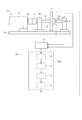
本発明の第一実施形態による「装置の検査装置」としての異常診断装置10、および、「装置の検査方法」としての異常診断プロセスを図1〜4に基づいて説明する。異常診断装置10は、回転体3を回転可能に支持する回転装置5の状態を診断可能な装置である。
(First embodiment)
An abnormality diagnosis apparatus 10 as an “apparatus inspection apparatus” and an abnormality diagnosis process as an “apparatus inspection method” according to the first embodiment of the present invention will be described with reference to FIGS. The abnormality diagnosis device 10 is a device that can diagnose the state of the rotating device 5 that rotatably supports the rotating body 3.

最初に、異常診断装置10が適用される回転装置5の構成を説明する。回転装置5は、モータ6、カップリング7、回転軸8、ベアリング91,92、および、回転体3を有する。回転装置5は、図示しない制御部からの指令に基づいて回転体3を回転する装置であって、回転体3の回転によって回転装置5の外部に仕事を行う装置である。   First, the configuration of the rotating device 5 to which the abnormality diagnosis device 10 is applied will be described. The rotating device 5 includes a motor 6, a coupling 7, a rotating shaft 8, bearings 91 and 92, and a rotating body 3. The rotating device 5 is a device that rotates the rotating body 3 based on a command from a control unit (not shown), and is a device that performs work outside the rotating device 5 by the rotation of the rotating body 3.

モータ6は、回転装置5のベース50上に固定されている。モータ6は、制御部からの指令に基づいて回転体3の回転駆動を制御可能である。
カップリング7は、モータ6の出力軸61と回転軸8とを連結可能に設けられている。カップリング7は、出力軸61と回転軸8との芯ずれを許容するよう設けられている。
回転軸8は、二つのベアリング91,92によって回転可能に支持されている。ベアリング91とベアリング92との間の回転軸8に回転体3が設けられている。
The motor 6 is fixed on the base 50 of the rotating device 5. The motor 6 can control the rotational drive of the rotating body 3 based on a command from the control unit.
The coupling 7 is provided so that the output shaft 61 of the motor 6 and the rotating shaft 8 can be connected. The coupling 7 is provided to allow misalignment between the output shaft 61 and the rotating shaft 8.
The rotating shaft 8 is rotatably supported by two bearings 91 and 92. The rotating body 3 is provided on the rotating shaft 8 between the bearing 91 and the bearing 92.

回転体3は、回転軸8と一体に回転可能に設けられている。回転体3は、図示しないベルトなどの連結部材を介して自身の回転トルクを回転装置5の外部の装置に伝達可能である。   The rotating body 3 is provided so as to be rotatable integrally with the rotating shaft 8. The rotating body 3 can transmit its rotational torque to a device outside the rotating device 5 via a connecting member such as a belt (not shown).

次に、異常診断装置10の構成について説明する。異常診断装置10は、「物理量検出部」としての振動センサ11,12、AD変換部13、および、診断部100を備える。   Next, the configuration of the abnormality diagnosis apparatus 10 will be described. The abnormality diagnosis apparatus 10 includes vibration sensors 11 and 12 as “physical quantity detection units”, an AD conversion unit 13, and a diagnosis unit 100.

振動センサ11は、加速度を検出可能なセンサであって、ベアリング91の側壁に設けられている。振動センサ11は、ベアリング91における回転体3の回転に伴う振動の状態を検出可能である。振動センサ11は、ベアリング91の振動の状態をベース50の上面51に略平行な方向の「物理量」としての加速度で示した「物理量信号」としての加速度信号を電気的に接続しているAD変換部13に出力する。   The vibration sensor 11 is a sensor capable of detecting acceleration, and is provided on the side wall of the bearing 91. The vibration sensor 11 can detect the state of vibration associated with the rotation of the rotating body 3 in the bearing 91. The vibration sensor 11 is an AD converter that electrically connects an acceleration signal as a “physical quantity signal” indicating the vibration state of the bearing 91 as an acceleration as a “physical quantity” in a direction substantially parallel to the upper surface 51 of the base 50. To the unit 13.

振動センサ12は、加速度を検出可能なセンサであって、ベアリング91の中心から見て振動センサ11と略90度の角度をなすベアリング91の側壁に設けられている。振動センサ12は、ベアリング91における回転体3の回転に伴う振動の状態を検出可能である。振動センサ12は、ベアリング91の振動の状態をベース50の上面51に対して略垂直な方向の「物理量」としての加速度で示した「物理量信号」としての加速度信号を電気的に接続しているAD変換部13に出力する。   The vibration sensor 12 is a sensor that can detect acceleration, and is provided on a side wall of the bearing 91 that forms an angle of approximately 90 degrees with the vibration sensor 11 when viewed from the center of the bearing 91. The vibration sensor 12 can detect the state of vibration associated with the rotation of the rotating body 3 in the bearing 91. The vibration sensor 12 is electrically connected to an acceleration signal as a “physical quantity signal” indicating the vibration state of the bearing 91 as an acceleration as a “physical quantity” in a direction substantially perpendicular to the upper surface 51 of the base 50. The data is output to the AD conversion unit 13.

AD変換部13は、振動センサ11,12が出力する加速度信号をアナログ信号からデジタル信号に変換する。AD変換部13は、デジタル信号に変換された振動センサ11,12が出力する加速度信号を診断部100に出力する。   The AD converter 13 converts the acceleration signal output from the vibration sensors 11 and 12 from an analog signal to a digital signal. The AD conversion unit 13 outputs an acceleration signal output from the vibration sensors 11 and 12 converted into a digital signal to the diagnosis unit 100.

診断部100は、内部にCPU、ROM、RAM、I/O、および、これらの構成を接続するバスラインなどを備える。診断部100における後述する処理は、予め記憶されたプログラムをCPUで実行することによるソフトウェア処理であってもよいし、専用の電子回路によるハードウェア処理であってもよい。診断部100は、相関図生成部14、深層学習部15、判定部16、および、出力部17を有する。   The diagnosis unit 100 includes a CPU, a ROM, a RAM, an I / O, a bus line that connects these components, and the like. Processing described later in the diagnosis unit 100 may be software processing by executing a program stored in advance by the CPU, or may be hardware processing by a dedicated electronic circuit. The diagnosis unit 100 includes a correlation diagram generation unit 14, a deep learning unit 15, a determination unit 16, and an output unit 17.

相関図生成部14は、AD変換部13と電気的に接続している。相関図生成部14は、AD変換部13が出力するデジタル信号に変換された加速度信号に基づいて相関図を生成する。相関図生成部14において生成される相関図の詳細は、後述する。   The correlation diagram generation unit 14 is electrically connected to the AD conversion unit 13. The correlation diagram generation unit 14 generates a correlation diagram based on the acceleration signal converted into the digital signal output from the AD conversion unit 13. Details of the correlation diagram generated in the correlation diagram generation unit 14 will be described later.

深層学習部15は、相関図生成部14と電気的に接続している。深層学習部15には、相関図生成部14で生成される相関図が有する特徴と回転装置5の状態を示すクラスとの組み合わせが事前に入力されている。深層学習部15は、当該組み合わせおよび相関図の画像解析の結果に基づく深層学習によって回転装置5に特化した情報を深層学習の結果として蓄積する。深層学習部15における深層学習の詳細は、後述する。   The deep learning unit 15 is electrically connected to the correlation diagram generation unit 14. In the deep learning unit 15, a combination of the characteristics of the correlation diagram generated by the correlation diagram generation unit 14 and the class indicating the state of the rotating device 5 is input in advance. The deep learning unit 15 accumulates information specialized for the rotation device 5 as a result of deep learning by deep learning based on the result of image analysis of the combination and the correlation diagram. Details of the deep learning in the deep learning unit 15 will be described later.

判定部16は、深層学習部15と電気的に接続している。判定部16は、深層学習部15が蓄積している情報および相関図の画像解析の結果に基づいて回転装置5の状態を判定する。判定部16は、判定結果を出力部17に出力する。   The determination unit 16 is electrically connected to the deep learning unit 15. The determination unit 16 determines the state of the rotating device 5 based on the information accumulated in the deep learning unit 15 and the result of image analysis of the correlation diagram. The determination unit 16 outputs the determination result to the output unit 17.

出力部17は、判定部16と電気的に接続している。出力部17は、判定部16が判定した回転装置5の状態についての判定結果を外部に出力する。   The output unit 17 is electrically connected to the determination unit 16. The output unit 17 outputs a determination result about the state of the rotating device 5 determined by the determination unit 16 to the outside.

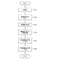
次に、異常診断装置10による回転装置5の診断プロセスについて図2〜4に基づいて説明する。図2に回転装置5の診断プロセスのフローチャートを示す。図2に示すフローチャートは、回転装置5が稼働している間、常時実行される。   Next, a diagnosis process of the rotating device 5 by the abnormality diagnosis device 10 will be described with reference to FIGS. FIG. 2 shows a flowchart of the diagnostic process of the rotating device 5. The flowchart shown in FIG. 2 is always executed while the rotating device 5 is operating.

最初に、ステップ(以下、単に「S」という)101において、診断部100を初期化する。S101では、診断部100は、自身のROM、RAMなどに残っている前回の情報を消去し初期化する。   First, in step (hereinafter simply referred to as “S”) 101, the diagnosis unit 100 is initialized. In S101, the diagnosis unit 100 erases and initializes the previous information remaining in its own ROM, RAM, and the like.

次に、「信号取得段階」としてのS102において、診断部100に加速度信号を入力する。S102では、相関図生成部14にAD変換部13が出力するデジタル信号に変換された加速度信号を入力する。   Next, in S <b> 102 as a “signal acquisition stage”, an acceleration signal is input to the diagnosis unit 100. In S102, the acceleration signal converted into the digital signal output from the AD conversion unit 13 is input to the correlation diagram generation unit 14.

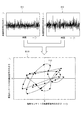
次に、「相関図生成段階」としてのS103において、入力されたデジタル信号に変換された加速度信号に基づいて相関図を生成する。S103では、相関図生成部14に入力された二つの加速度信号に基づいて相関図を生成する。このとき生成される相関図について図3に基づいて説明する。   Next, in S103 as a “correlation diagram generation stage”, a correlation diagram is generated based on the acceleration signal converted into the input digital signal. In S103, a correlation diagram is generated based on the two acceleration signals input to the correlation diagram generation unit. The correlation diagram generated at this time will be described with reference to FIG.

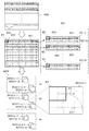
図3に、振動センサ11の加速度信号の時間変化を示す信号情報S11、および、振動センサ12の加速度信号の時間変化を示す信号情報S12を示す。信号情報S11,S12では、横軸に時間が示され、縦軸に加速度信号の大きさが示されている。
相関図生成部14では、信号情報S11と信号情報S12とを組み合わせた相関図DC10を生成する。相関図DC10は、いわゆる、リサージュ曲線といわれるものであって、横軸の値が振動センサ11の加速度信号の大きさを示し、縦軸の値が振動センサ12の加速度信号の大きさを示す。相関図DC10では、同時刻における振動センサ11の加速度信号の大きさと振動センサ12の加速度信号の大きさとを示す点(例えば、相関図DC10に示す点P10)の時間の経過に伴う軌跡が示される。
FIG. 3 shows signal information S11 indicating the time change of the acceleration signal of the vibration sensor 11 and signal information S12 indicating the time change of the acceleration signal of the vibration sensor 12. In the signal information S11 and S12, time is shown on the horizontal axis, and the magnitude of the acceleration signal is shown on the vertical axis.
The correlation diagram generation unit 14 generates a correlation diagram DC10 obtained by combining the signal information S11 and the signal information S12. The correlation diagram DC10 is a so-called Lissajous curve, and the value on the horizontal axis indicates the magnitude of the acceleration signal of the vibration sensor 11, and the value on the vertical axis indicates the magnitude of the acceleration signal of the vibration sensor 12. In correlation diagram DC10, a trajectory with the passage of time of a point indicating the magnitude of the acceleration signal of vibration sensor 11 and the magnitude of the acceleration signal of vibration sensor 12 at the same time (for example, point P10 shown in correlation diagram DC10) is shown. .

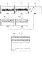
次に、「深層学習段階」としてのS104において、相関図に基づく深層学習を行う。S104では、深層学習部15は、S103において生成された相関図DC10に対して畳み込みニューラルネットワーク(CNN;Convolutional Neural Network)を利用した深層学習を行う。深層学習部15における深層学習の内容について図4に基づいて説明する。   Next, in S104 as the “deep learning stage”, deep learning based on the correlation diagram is performed. In S104, the deep learning unit 15 performs deep learning using a convolutional neural network (CNN) on the correlation diagram DC10 generated in S103. The contents of the deep learning in the deep learning unit 15 will be described with reference to FIG.

最初に、深層学習部15は、相関図DC10に対して畳み込み処理を行う。具体的には、S103において生成された相関図DC10の全面をマトリックス状に分割し、相関図DC11(図4参照)を生成する。例えば、第一実施形態では、相関図DC10が40×40ピクセルの画像となるよう分割する。   First, the deep learning unit 15 performs a convolution process on the correlation diagram DC10. Specifically, the entire correlation diagram DC10 generated in S103 is divided into a matrix to generate a correlation diagram DC11 (see FIG. 4). For example, in the first embodiment, the correlation diagram DC10 is divided into an image of 40 × 40 pixels.

次に、深層学習部15は、相関図DC11上に所定のサイズの設定窓W11を設定する。例えば、第一実施形態では、深層学習部15は、設定窓W11を4×4ピクセルに設定する。深層学習部15は、設定窓W11を図4の相関図DC11上に示されている一点鎖線矢印A111、A112に示すように、相関図DC11上を移動することによって、相関図DC11の局所における画像データに対して所定のフィルタ処理を施す。これにより、相関図DC11の局所における特徴、具体的には、相関図DC10の局所の形状が強調された複数の画像(以下、「特徴マップ」という)DC12(n)(nは、2以上の整数)が生成される。第一実施形態では、フィルタ係数が異なる複数の設定窓W11を設定し、それぞれの設定窓W11によって相関図DC11にフィルタ処理を施す。これにより、複数の特徴マップDC12(n)の組み合わせは、設定窓W11の数と同じ数だけ生成される。図4の二点鎖線の枠Im11には、一つの設定窓W11によってフィルタ処理された複数の特徴マップDC12(n)の集合を示す。   Next, the deep learning unit 15 sets a setting window W11 having a predetermined size on the correlation diagram DC11. For example, in the first embodiment, the deep learning unit 15 sets the setting window W11 to 4 × 4 pixels. The deep learning unit 15 moves the setting window W11 on the correlation diagram DC11 as indicated by alternate long and short dashed arrows A111 and A112 shown on the correlation diagram DC11 in FIG. A predetermined filtering process is performed on the data. Thus, a plurality of images (hereinafter referred to as “feature map”) DC12 (n) (n is 2 or more) in which the local feature of the correlation diagram DC11, specifically, the local shape of the correlation diagram DC10 is emphasized. Integer) is generated. In the first embodiment, a plurality of setting windows W11 having different filter coefficients are set, and the correlation diagram DC11 is filtered by each setting window W11. Thereby, the same number of combinations of the plurality of feature maps DC12 (n) is generated as the number of setting windows W11. A two-dot chain line frame Im11 in FIG. 4 shows a set of a plurality of feature maps DC12 (n) filtered by one setting window W11.

次に、深層学習部15は、活性化関数を利用して複数の特徴マップDC12(n)のそれぞれのコントラストを強調し、複数の特徴マップDC12(n)のそれぞれが有する特徴をさらに強調する。   Next, the deep learning unit 15 enhances the contrast of each of the plurality of feature maps DC12 (n) using the activation function, and further enhances the features of each of the plurality of feature maps DC12 (n).

次に、深層学習部15は、活性化関数によってコントラストが強調された特徴マップDC12(n)に対してプーリング処理を行う。具体的には、活性化関数によってコントラストが強調された複数の特徴マップDC12(n)のそれぞれに所定のサイズの設定窓W12を設定する。例えば、第一実施形態では、設定窓W12は、2×2ピクセルに設定する。深層学習部15は、設定窓W12を複数の特徴マップDC12(n)のそれぞれ、例えば、図4では、特徴マップDC12(m)(mは、1以上n以下の整数)において、一点鎖線矢印A121、A122に示すように、特徴マップDC12(m)上を移動することによって、特徴マップDC12(m)上の設定窓W12内の最大値を抽出する。なお、特徴マップDC12(m)の曲線は、相関図DC10上のリサージュ曲線の一部を示している。   Next, the deep learning unit 15 performs a pooling process on the feature map DC12 (n) whose contrast is enhanced by the activation function. Specifically, a setting window W12 having a predetermined size is set in each of the plurality of feature maps DC12 (n) whose contrast is enhanced by the activation function. For example, in the first embodiment, the setting window W12 is set to 2 × 2 pixels. The deep learning unit 15 sets the setting window W12 in each of the plurality of feature maps DC12 (n), for example, in the feature map DC12 (m) (m is an integer of 1 to n) in FIG. As shown in A122, the maximum value in the setting window W12 on the feature map DC12 (m) is extracted by moving on the feature map DC12 (m). Note that the curve of the feature map DC12 (m) shows a part of the Lissajous curve on the correlation diagram DC10.

次に、深層学習部15は、プーリング処理された複数の特徴マップDC12(n)を結合した画像(以下、「生成結合画像」という)を生成する。このとき、生成結合画像は、畳み込み処理において設定された設定窓W11の数と同じ数だけ生成される。
深層学習部15は、事前に入力されている装置の状態に関する情報と生成結合画像とを比較し、回転装置5の状態に関する情報を蓄積する。ここで、装置の状態に関する情報とは、回転装置5の状態を示すクラスと回転装置5の状態が当該クラスであるときの生成結合画像に相当する画像との組み合わせの情報であって、当該画像からクラスを導くことが可能となっている。例えば、クラスの名称として、ベアリングについては、内輪損傷、外輪損傷、保持器損傷などであったり、シャフトについては、芯ずれ、アンバランスなどであったりする。
深層学習部15では、このような回転装置5の状態に関する情報と相関図DC10とに基づいて、回転装置5の状態を判定するための情報、例えば、畳み込み処理におけるフィルタの値など相関図DC10の解析の方法や生成結合画像とクラスとの組み合わせの関係などを学習し、蓄積する。
Next, the deep learning unit 15 generates an image obtained by combining a plurality of pooled feature maps DC12 (n) (hereinafter referred to as “generated combined image”). At this time, the same number of generated combined images are generated as the number of setting windows W11 set in the convolution process.
The deep learning unit 15 compares information relating to the state of the device input in advance with the generated combined image, and accumulates information relating to the state of the rotating device 5. Here, the information on the state of the device is information on a combination of a class indicating the state of the rotating device 5 and an image corresponding to the generated combined image when the state of the rotating device 5 is the class. It is possible to guide classes from. For example, as the name of the class, the bearing may be inner ring damage, outer ring damage, cage damage, or the shaft may be misaligned or unbalanced.
In the deep learning unit 15, information for determining the state of the rotating device 5 based on such information on the state of the rotating device 5 and the correlation diagram DC10, for example, a filter value such as a filter value in the convolution process, Learning and accumulating the analysis method and the relationship between the generated combined image and the class.

次に、「判定段階」としてのS105において、回転装置5の状態を判定する。S105では、判定部16は、深層学習部15における深層学習、具体的には、相関図DC10の画像解析の結果および深層学習部15が蓄積している情報に基づいて、回転装置5の状態を判定する。具体的には、深層学習部15が蓄積している情報におけるクラスに対応する相関図が有する特徴と、相関図DC10の画像解析の結果とが一致するとき、判定部16は、回転装置5は、当該クラスの故障を抱えていると判定する。また、深層学習部15が蓄積している情報におけるクラスに対応する相関図が有する特徴と、相関図DC10の画像解析の結果とが一致しないとき、判定部16は、回転装置5は、異常を抱えておらず正常であると判定する。   Next, in S105 as the “determination stage”, the state of the rotating device 5 is determined. In S <b> 105, the determination unit 16 determines the state of the rotating device 5 based on the deep learning in the deep learning unit 15, specifically, the result of the image analysis of the correlation diagram DC <b> 10 and the information accumulated in the deep learning unit 15. judge. Specifically, when the feature of the correlation diagram corresponding to the class in the information accumulated in the deep learning unit 15 matches the result of the image analysis of the correlation diagram DC10, the determination unit 16 determines that the rotation device 5 It is determined that the class has a failure. When the feature of the correlation diagram corresponding to the class in the information accumulated by the deep learning unit 15 does not match the result of the image analysis of the correlation diagram DC10, the determination unit 16 determines that the rotating device 5 It is determined that it is normal and not held.

次に、S106において、判定結果を出力する。S106では、出力部17は、判定部16における回転装置5の状態についての判定結果を外部に出力する。
異常診断装置10は、このようにして、回転装置5の状態を判定し、外部に通知する。
Next, in S106, the determination result is output. In S106, the output part 17 outputs the determination result about the state of the rotating device 5 in the determination part 16 to the outside.
In this way, the abnormality diagnosis device 10 determines the state of the rotating device 5 and notifies the outside.

(a)第一実施形態による異常診断装置10では、相関図生成部14は、S103において、二つの振動センサ11,12が検出した回転装置5の状態に相関する複数の加速度信号に基づいて当該複数の加速度信号の相関を示す相関図を生成する。相関図には、回転装置5の状態に相関する物理量であって、振動センサ11,12のそれぞれでは検出不可能な物理量が含まれている。深層学習部15では、S104において、事前に入力されているクラスと回転装置5の状態が当該クラスであるときの生成結合画像に相当する画像との組み合わせの情報、および、相関図DC10に基づく深層学習によって、回転装置5の状態を判定するための情報を蓄積する。すなわち、相関図DC10を一つの画像として認識し、相関図DC10に含まれる一画素を一つのニューロンとする深層学習によって回転装置5に特化した画像解析の手法などを学習する。判定部16は、S105において、深層学習部15に蓄積されている回転装置5の状態を判定するための情報および相関図DC10に基づいて回転装置5の状態を判定する。これにより、第一実施形態は、装置の種類に関わらず異常を検出することができる。   (A) In the abnormality diagnosis apparatus 10 according to the first embodiment, the correlation diagram generation unit 14 is based on a plurality of acceleration signals correlated with the state of the rotating device 5 detected by the two vibration sensors 11 and 12 in S103. A correlation diagram showing a correlation between a plurality of acceleration signals is generated. The correlation diagram includes physical quantities that are correlated with the state of the rotating device 5 and that cannot be detected by each of the vibration sensors 11 and 12. In the deep learning unit 15, in S <b> 104, information on the combination of the class input in advance and the image corresponding to the generated combined image when the state of the rotation device 5 is the class, and the deep layer based on the correlation diagram DC <b> 10. Information for determining the state of the rotating device 5 is accumulated by learning. That is, the correlation diagram DC10 is recognized as one image, and an image analysis method specialized for the rotation device 5 is learned by deep learning using one pixel included in the correlation diagram DC10 as one neuron. In S105, the determination unit 16 determines the state of the rotation device 5 based on the information for determining the state of the rotation device 5 accumulated in the deep learning unit 15 and the correlation diagram DC10. Thereby, 1st embodiment can detect abnormality irrespective of the kind of apparatus.

(b)また、第一実施形態による異常診断装置10では、畳み込みニューラルネットワークを利用した深層学習によって回転装置5の状態を判定する。これにより、相関図DC10の特徴を人的に抽出することが不要となるため、回転装置5を検査する検査者の作業負担を軽減することができる。また、畳み込み処理およびプーリング処理による相関図DC10の解析において、相関図DC10の解像度は比較的低くても畳み込み処理およびプーリング処理によって相関図DC10の特徴を抽出することができるため、実用性に優れ、かつ、高精度の判定を行うことができる。   (B) Moreover, in the abnormality diagnosis apparatus 10 by 1st embodiment, the state of the rotation apparatus 5 is determined by the deep learning using a convolution neural network. As a result, it is not necessary to manually extract the features of the correlation diagram DC10, and the work burden on the inspector who inspects the rotating device 5 can be reduced. Further, in the analysis of the correlation diagram DC10 by the convolution process and the pooling process, the features of the correlation diagram DC10 can be extracted by the convolution process and the pooling process even if the resolution of the correlation diagram DC10 is relatively low, so that the practicality is excellent. In addition, highly accurate determination can be performed.

(第二実施形態)
次に、本発明の第二実施形態による装置の検査装置、および、装置の検査方法を図5〜8に基づいて説明する。第二実施形態は、装置の検査装置の構成が第一実施形態と異なる。また、第二実施形態は、装置の検査方法のプロセスの一部が第一実施形態と異なる。なお、第一実施形態と実質的に同一の部位には同一の符号を付し、説明を省略する。
(Second embodiment)
Next, an apparatus inspection apparatus and apparatus inspection method according to a second embodiment of the present invention will be described with reference to FIGS. The second embodiment is different from the first embodiment in the configuration of the apparatus inspection apparatus. The second embodiment differs from the first embodiment in part of the process of the apparatus inspection method. In addition, the same code | symbol is attached | subjected to the site | part substantially the same as 1st embodiment, and description is abbreviate | omitted.

第二実施形態による異常診断装置20は、振動センサ11,12,21,22、モータセンサ23、AD変換部13、および、診断部200を備える。振動センサ21,22、および、モータセンサ23は、特許請求の範囲に記載の「物理量検出部」に相当する。   The abnormality diagnosis device 20 according to the second embodiment includes vibration sensors 11, 12, 21, 22, a motor sensor 23, an AD conversion unit 13, and a diagnosis unit 200. The vibration sensors 21 and 22 and the motor sensor 23 correspond to a “physical quantity detection unit” recited in the claims.

振動センサ21は、加速度を検出可能なセンサであって、ベアリング92の側壁に設けられている。振動センサ21は、ベアリング92における回転体3の回転に伴う振動の状態を検出可能である。振動センサ21は、ベアリング92の振動の状態をベース50の上面51に略平行な方向の「物理量」としての加速度で示した「物理量信号」としての加速度信号を電気的に接続しているAD変換部13に出力する。   The vibration sensor 21 is a sensor capable of detecting acceleration, and is provided on the side wall of the bearing 92. The vibration sensor 21 can detect the state of vibration associated with the rotation of the rotating body 3 in the bearing 92. The vibration sensor 21 is an AD converter that electrically connects an acceleration signal as a “physical quantity signal” indicating the vibration state of the bearing 92 as an acceleration as a “physical quantity” in a direction substantially parallel to the upper surface 51 of the base 50. To the unit 13.

振動センサ22は、加速度を検出可能なセンサであって、ベアリング92の中心から見て振動センサ21と略90度の角度をなすベアリング92の側壁に設けられている。振動センサ22は、ベアリング92における回転体3の回転に伴う振動の状態を検出可能である。振動センサ22は、ベアリング92の振動の状態をベース50の上面51に対して略垂直な方向の「物理量」としての加速度で示した「物理量信号」としての加速度信号を電気的に接続しているAD変換部13に出力する。   The vibration sensor 22 is a sensor capable of detecting acceleration, and is provided on a side wall of the bearing 92 that forms an angle of approximately 90 degrees with the vibration sensor 21 when viewed from the center of the bearing 92. The vibration sensor 22 can detect the state of vibration associated with the rotation of the rotating body 3 in the bearing 92. The vibration sensor 22 is electrically connected with an acceleration signal as a “physical quantity signal” indicating the vibration state of the bearing 92 as an acceleration as a “physical quantity” in a direction substantially perpendicular to the upper surface 51 of the base 50. The data is output to the AD conversion unit 13.

モータセンサ23は、モータ6に設けられている。モータセンサ23は、モータ6における出力軸61の「物理量」としての回転速度や回転トルクなどに応じた「物理量信号」としてのモータ信号を電気的に接続しているAD変換部13に出力する。   The motor sensor 23 is provided in the motor 6. The motor sensor 23 outputs a motor signal as a “physical quantity signal” corresponding to a rotation speed, a rotational torque, and the like of the output shaft 61 of the motor 6 to the AD converter 13 that is electrically connected.

AD変換部13は、振動センサ11,12,21,22が出力する加速度信号およびモータセンサ23が出力するモータ信号をアナログ信号からデジタル信号に変換する。AD変換部13は、デジタル信号に変換された加速度信号およびモータ信号を診断部200に出力する。   The AD converter 13 converts the acceleration signal output from the vibration sensors 11, 12, 21, and 22 and the motor signal output from the motor sensor 23 from an analog signal to a digital signal. The AD conversion unit 13 outputs the acceleration signal and the motor signal converted into digital signals to the diagnosis unit 200.

診断部200は、内部にCPU、ROM、RAM、I/O、および、これらの構成を接続するバスラインなどを備える。診断部200における後述する処理は、予め記憶されたプログラムをCPUで実行することによるソフトウェア処理であってもよいし、専用の電子回路によるハードウェア処理であってもよい。診断部200は、相関図生成部24、深層学習部25、判定部26、および、出力部17を有する。   The diagnosis unit 200 includes a CPU, a ROM, a RAM, an I / O, a bus line that connects these components, and the like. Processing described later in the diagnosis unit 200 may be software processing by executing a program stored in advance by the CPU, or may be hardware processing by a dedicated electronic circuit. The diagnosis unit 200 includes a correlation diagram generation unit 24, a deep learning unit 25, a determination unit 26, and an output unit 17.

相関図生成部24は、AD変換部13と電気的に接続している。相関図生成部24は、第一生成部241および第二生成部242を有する。
第一生成部241は、AD変換部13を介して振動センサ11,12,21,22と電気的に接続している。第一生成部241は、振動センサ11,12が出力する加速信号に基づく第一相関図、および、振動センサ21,22が出力する加速信号に基づく第二相関図を生成する。第一相関図および第二相関図は、いわゆる、二つの加速度信号の相関を示すリサージュ曲線であって、第一実施形態のS103において生成される相関図と同じ方法によって生成される。
The correlation diagram generation unit 24 is electrically connected to the AD conversion unit 13. The correlation diagram generation unit 24 includes a first generation unit 241 and a second generation unit 242.
The first generation unit 241 is electrically connected to the vibration sensors 11, 12, 21, and 22 via the AD conversion unit 13. The first generation unit 241 generates a first correlation diagram based on the acceleration signals output from the vibration sensors 11, 12 and a second correlation diagram based on the acceleration signals output from the vibration sensors 21, 22. The first correlation diagram and the second correlation diagram are so-called Lissajous curves indicating the correlation between two acceleration signals, and are generated by the same method as the correlation diagram generated in S103 of the first embodiment.

第二生成部242は、AD変換部13を介して振動センサ11,12,21,22およびモータセンサ23と電気的に接続している。第二生成部242は、振動センサ11,12,21,22が出力する加速度信号およびモータセンサ23が出力する回転速度および回転トルクに応じたモータ信号に基づく第三相関図を生成する。第二生成部242において生成される第三相関図の詳細は、後述する。   The second generation unit 242 is electrically connected to the vibration sensors 11, 12, 21, 22 and the motor sensor 23 via the AD conversion unit 13. The second generation unit 242 generates a third correlation diagram based on the acceleration signal output from the vibration sensors 11, 12, 21, and 22 and the motor signal corresponding to the rotation speed and rotation torque output from the motor sensor 23. Details of the third correlation diagram generated by the second generation unit 242 will be described later.

深層学習部25は、相関図生成部14と電気的に接続している。深層学習部25は、第一学習部251、第二学習部252、および、正規化部254を有する。
第一学習部251は、第一生成部241と電気的に接続している。第一学習部251には、第一生成部241で生成される第一相関図および第二相関図が有する特徴と回転装置5のクラスとの組み合わせが事前に入力されている。第一学習部251は、当該組み合わせおよび第一相関図および第二相関図の画像解析の結果に基づく深層学習によって回転装置5に特化した情報を深層学習の結果として蓄積する。
The deep learning unit 25 is electrically connected to the correlation diagram generation unit 14. The deep learning unit 25 includes a first learning unit 251, a second learning unit 252, and a normalization unit 254.
The first learning unit 251 is electrically connected to the first generation unit 241. In the first learning unit 251, a combination of the characteristics of the first correlation diagram and the second correlation diagram generated by the first generation unit 241 and the class of the rotation device 5 is input in advance. The first learning unit 251 accumulates information specialized for the rotation device 5 as a result of deep learning by deep learning based on the combination and the image analysis results of the first correlation diagram and the second correlation diagram.

第二学習部252は、第二生成部242と電気的に接続している。第二学習部252には、第二生成部242で生成される第三相関図が有する特徴と回転装置5のクラスとの組み合わせが事前に入力されている。第二学習部252は、当該組み合わせおよび相関図の画像解析の結果に基づく深層学習によって回転装置5に特化した情報を深層学習の結果として蓄積する。深層学習部25における深層学習の詳細は、後述する。   The second learning unit 252 is electrically connected to the second generation unit 242. In the second learning unit 252, a combination of the characteristics of the third correlation diagram generated by the second generation unit 242 and the class of the rotation device 5 is input in advance. The second learning unit 252 accumulates information specialized for the rotation device 5 as a result of deep learning by deep learning based on the result of image analysis of the combination and correlation diagram. Details of the deep learning in the deep learning unit 25 will be described later.

正規化部254は、第一学習部251および第二学習部252と電気的に接続している。正規化部254は、第一学習部251における深層学習の結果と第二学習部252における深層学習の結果に対して重み付けをした後に正規化する。   The normalization unit 254 is electrically connected to the first learning unit 251 and the second learning unit 252. The normalizing unit 254 performs normalization after weighting the result of the deep learning in the first learning unit 251 and the result of the deep learning in the second learning unit 252.

判定部26は、正規化部254と電気的に接続されている。判定部26は、深層学習部25が蓄積している情報、正規化部254において正規化された深層学習の結果および相関図の画像解析の結果に基づいて回転装置5の状態を判定する。判定部26は、判定結果を出力部17に出力する。   The determination unit 26 is electrically connected to the normalization unit 254. The determination unit 26 determines the state of the rotating device 5 based on the information accumulated in the deep learning unit 25, the result of deep learning normalized by the normalization unit 254, and the result of image analysis of the correlation diagram. The determination unit 26 outputs the determination result to the output unit 17.

次に、異常診断装置20による回転装置5の診断プロセスについて図6〜8に基づいて説明する。図6に回転装置5の診断プロセスのフローチャートを示す。図6に示すフローチャートは、回転装置5が稼働している間、常時実行される。   Next, the diagnosis process of the rotating device 5 by the abnormality diagnosis device 20 will be described with reference to FIGS. FIG. 6 shows a flowchart of the diagnostic process of the rotating device 5. The flowchart shown in FIG. 6 is always executed while the rotating device 5 is operating.

最初に、S201において、第一実施形態のS101と同様に、診断部200を初期化する。
次に、「信号取得段階」としてのS202において、診断部200に加速度信号およびモータ信号を入力する。S202では、第一生成部241にデジタル信号に変換された加速度信号を入力する。また、第二生成部242にデジタル信号に変換された加速度信号およびモータ信号を入力する。
First, in S201, the diagnosis unit 200 is initialized as in S101 of the first embodiment.
Next, in S <b> 202 as a “signal acquisition stage”, an acceleration signal and a motor signal are input to the diagnosis unit 200. In S202, an acceleration signal converted into a digital signal is input to the first generation unit 241. Further, the acceleration signal and the motor signal converted into digital signals are input to the second generation unit 242.

次に、「相関図生成段階」としてのS203において、デジタル信号に変換された加速度信号に基づいて第一相関図および第二相関図を生成する。   Next, in S203 as a “correlation diagram generation stage”, a first correlation diagram and a second correlation diagram are generated based on the acceleration signal converted into the digital signal.

次に、「深層学習段階」としてのS204において、第一相関図および第二相関図に基づく深層学習を行う。S204では、第一学習部251は、第一相関図および第二相関図に対して、第一実施形態のS104における深層学習と同じ畳み込みニューラルネットワークを利用した深層学習を行う。これにより、第一学習部251は、第一相関図および第二相関図に基づいて生成される生成結合画像と回転装置5の状態に関する情報とに基づいて回転装置5の状態を判定するための情報を学習し、蓄積する。   Next, in S204 as the “deep learning stage”, deep learning based on the first correlation diagram and the second correlation diagram is performed. In S204, the first learning unit 251 performs deep learning using the same convolutional neural network as the deep learning in S104 of the first embodiment on the first correlation diagram and the second correlation diagram. Accordingly, the first learning unit 251 determines the state of the rotation device 5 based on the generated combined image generated based on the first correlation diagram and the second correlation diagram and information on the state of the rotation device 5. Learn and accumulate information.

また、S202の次に、「相関図生成段階」としてのS205において、デジタル信号に変換された加速度信号およびモータ信号に基づいて第三相関図を生成する。S205では、第二生成部242に入力された四つの加速度信号およびモータ信号に基づいて第三相関図を生成する。このとき生成される第三相関図について図7に基づいて説明する。   Further, after S202, in S205 as a “correlation diagram generation stage”, a third correlation diagram is generated based on the acceleration signal and the motor signal converted into digital signals. In S205, a third correlation diagram is generated based on the four acceleration signals and motor signals input to the second generation unit 242. A third correlation diagram generated at this time will be described with reference to FIG.

図7に、振動センサ11の加速度信号の時間変化を示す信号情報S11、振動センサ21の加速度信号の時間変化を示す信号情報S21、および、モータ信号に含まれる回転トルクの時間変化を示す信号情報S23を示す。信号情報S11,S21では、横軸に時間が示され、縦軸に加速度の大きさが示されている。信号情報S23では、横軸に時間が示され、縦軸に回転トルクの差分が示されている。   FIG. 7 shows signal information S11 indicating time variation of the acceleration signal of the vibration sensor 11, signal information S21 indicating time variation of the acceleration signal of the vibration sensor 21, and signal information indicating time variation of the rotational torque included in the motor signal. S23 is shown. In the signal information S11 and S21, the horizontal axis indicates time, and the vertical axis indicates the magnitude of acceleration. In the signal information S23, time is shown on the horizontal axis and the difference in rotational torque is shown on the vertical axis.

S205では、最初に、第二生成部242は、信号情報S11,S21をwavelet変換による時間軸上の周波数解析を行う。その解析結果を画像D11,D21とする。図示していないが、このとき、振動センサ12,22の加速度信号の時間変化を示す信号情報も、信号情報S11,S21と同様にwavelet変換による時間軸上の周波数解析を行う。   In S205, first, the second generation unit 242 performs frequency analysis on the time axis of the signal information S11 and S21 by wavelet transform. The analysis results are set as images D11 and D21. Although not shown in the drawing, at this time, the signal information indicating the time change of the acceleration signals of the vibration sensors 12 and 22 is also subjected to frequency analysis on the time axis by wavelet transform, similarly to the signal information S11 and S21.

次に、第二生成部242は、画像DC11,D21、信号情報S23などを一つに結合した第三相関図DC20を生成する。第三相関図DC20では、図7に示すように、画像D11,D21、信号情報S23などが層状に配列される。このとき、振動センサ12,22の加速度信号のwavelet変換による時間軸上の周波数解析の結果や、モータ信号に含まれる回転速度の時間変化を示す信号情報も含まれるよう第三相関図DC20を生成する。   Next, the second generation unit 242 generates a third correlation diagram DC20 that combines the images DC11 and D21, the signal information S23, and the like. In the third correlation diagram DC20, as shown in FIG. 7, images D11 and D21, signal information S23, and the like are arranged in layers. At this time, the third correlation diagram DC20 is generated so that the result of frequency analysis on the time axis by wavelet transform of the acceleration signals of the vibration sensors 12 and 22 and the signal information indicating the time change of the rotation speed included in the motor signal are also included. To do.

次に、「深層学習段階」としてのS206において、第三相関図DC20に基づく深層学習を行う。S206では、第二学習部252は、S205において生成された第三相関図DC20に対して畳み込みニューラルネットワークを利用した深層学習を行う。   Next, in S206 as the “deep learning stage”, deep learning based on the third correlation diagram DC20 is performed. In S206, the second learning unit 252 performs deep learning using a convolutional neural network on the third correlation diagram DC20 generated in S205.

第二学習部252における深層学習の内容について図8に基づいて説明する。
最初に、第二学習部252は、第三相関図DC20に対して畳み込み処理を行う。具体的には、第三相関図DC20をマトリックス状に分割し、相関図DC21(図8参照)を生成する。例えば、第二学習部252では、第三相関図DC20が40×8×pピクセルの画像となるよう分割する。ここで、pは、複数であって第三相関図DC20に含まれる信号情報単位の数を表す。すなわち、第三相関図DC20および第三相関図DC20をマトリックス状に分割した相関図DC21は、p個の信号情報を含んだ相関図となっている。
The contents of the deep learning in the second learning unit 252 will be described based on FIG.
First, the second learning unit 252 performs a convolution process on the third correlation diagram DC20. Specifically, the third correlation diagram DC20 is divided into a matrix, and a correlation diagram DC21 (see FIG. 8) is generated. For example, the second learning unit 252 divides the third correlation diagram DC20 into an image of 40 × 8 × p pixels. Here, p represents the number of signal information units that are plural and included in the third correlation diagram DC20. That is, the correlation diagram DC21 obtained by dividing the third correlation diagram DC20 and the third correlation diagram DC20 into a matrix is a correlation diagram including p pieces of signal information.

次に、第二学習部252は、相関図DC21上に所定のサイズの設定窓W21を設定する。例えば、第二実施形態では、第二学習部252は、設定窓W21を4×4ピクセルに設定する。第二学習部252は、設定窓W21を図8の相関図DC21上に示されている一点鎖線矢印A211、A212に示すように、相関図DC21上を移動することによって、相関図DC21の局所における画像データに対して所定のフィルタ処理を施す。このとき、第二学習部252は、設定窓W21を画像D11,D21、信号情報S23などのそれぞれの信号情報単位ごと移動し、それぞれの信号情報単位ごとに畳み込み処理を行う。   Next, the second learning unit 252 sets a setting window W21 having a predetermined size on the correlation diagram DC21. For example, in the second embodiment, the second learning unit 252 sets the setting window W21 to 4 × 4 pixels. The second learning unit 252 moves the setting window W21 on the correlation diagram DC21 by moving the setting window W21 on the correlation diagram DC21 as indicated by alternate long and short dashed arrows A211 and A212 shown on the correlation diagram DC21 of FIG. A predetermined filter process is performed on the image data. At this time, the second learning unit 252 moves the setting window W21 for each signal information unit such as the images D11 and D21 and the signal information S23, and performs a convolution process for each signal information unit.

ここで、第二学習部252における畳み込み処理を、相関図DC21を画像D11,D21、信号情報S23などのそれぞれの信号情報単位に沿って分割して示した二点鎖線の枠Im21内の模式図を使って説明する。枠Im21内には、信号情報S11に対応する画像DC21(1)、信号情報S21に対応する画像DC21(2)、信号情報S23に対応する画像DC21(p)などを示す。   Here, the convolution processing in the second learning unit 252 is a schematic diagram in the frame Im21 of a two-dot chain line showing the correlation diagram DC21 divided along each signal information unit such as the images D11 and D21 and the signal information S23. To explain. In the frame Im21, an image DC21 (1) corresponding to the signal information S11, an image DC21 (2) corresponding to the signal information S21, an image DC21 (p) corresponding to the signal information S23, and the like are shown.

第二学習部252における相関図DC21の畳み込み処理は、設定窓W21が、一点鎖線矢印A211、A212に示すように、画像DC21(1)上のみを移動することによって画像DC21(1)のみに対して行われると、次に、設定窓W21が、一点鎖線矢印A221、A222に示すように、画像DC21(2)上のみを移動することによって画像DC21(2)のみに対して行われる。その後、相関図DC21を構成する信号情報単位ごとに畳み込み処理が行われ、最後に、設定窓W21が画像DC21(p)上のみを移動することによって画像DC21(p)のみに対して行われ、第二学習部252における畳み込み処理が終了する。このように、第二学習部252における相関図DC21の畳み込み処理では、隣り合う信号情報の境界における畳み込み処理は行われないか、または、行われても該当する情報は排除される。これにより、相関図DC21は、p個の信号情報単位のそれぞれにおいてq個の特徴マップDC222が生成される。すなわち、q個の特徴マップDC222を有するグループがp個ある集合体Gp222が生成される。なお、図8では、一つの信号情報単位における複数の特徴マップD222のグループをGs(sは、p以下の整数)として示している。すなわち、グループG1からグループGpの集合体Gp222が、相関図DC21を一つの設定窓W21によって畳み込み処理のためのフィルタ処理が施された処理結果となる。   The convolution processing of the correlation diagram DC21 in the second learning unit 252 is performed only on the image DC21 (1) by moving the setting window W21 only on the image DC21 (1), as indicated by alternate long and short dashed arrows A211 and A212. Then, the setting window W21 is performed only on the image DC21 (2) by moving only on the image DC21 (2), as indicated by alternate long and short dashed arrows A221 and A222. Thereafter, a convolution process is performed for each signal information unit constituting the correlation diagram DC21. Finally, the setting window W21 is performed only on the image DC21 (p) by moving only on the image DC21 (p). The convolution process in the second learning unit 252 ends. Thus, in the convolution processing of the correlation diagram DC21 in the second learning unit 252, the convolution processing at the boundary of adjacent signal information is not performed, or even if it is performed, the corresponding information is excluded. Thereby, in the correlation diagram DC21, q feature maps DC222 are generated in each of the p signal information units. That is, an aggregate Gp222 having p groups having q feature maps DC222 is generated. In FIG. 8, a group of a plurality of feature maps D222 in one signal information unit is indicated as Gs (s is an integer equal to or less than p). That is, the aggregate Gp222 of the groups G1 to Gp becomes a processing result in which the correlation diagram DC21 is subjected to the filter processing for convolution processing by the single setting window W21.

第二実施形態では、フィルタ係数が異なる複数の設定窓W21を設定し、それぞれの設定窓W21によってフィルタ処理を施す。これにより、グループGp222は、畳み込み処理において設定された設定窓W21の数と同じ数だけ生成される。   In the second embodiment, a plurality of setting windows W21 having different filter coefficients are set, and filter processing is performed by each setting window W21. Thereby, as many groups Gp222 as the number of setting windows W21 set in the convolution process are generated.

次に、第二学習部252は、第一実施形態と同様に、活性化関数を利用して特徴マップDC222のそれぞれが有する特徴をさらに強調した後、活性化関数によってコントラストが強調された特徴マップDC222のそれぞれに対してプーリング処理を行う。具体的には、例えば、図8に示す特徴マップDC222(2:r)上において、一点鎖線矢印A221、A222に沿って、例えば、2×2ピクセルの設定窓W22を移動し、特徴マップDC222(2:r)上の設定窓W22内の最大値を抽出する。なお、rは、1以上q以下の整数である。   Next, as in the first embodiment, the second learning unit 252 further emphasizes the features of each of the feature maps DC222 using the activation function, and then the feature map with the contrast enhanced by the activation function. A pooling process is performed for each DC 222. Specifically, for example, on the feature map DC222 (2: r) shown in FIG. 8, the setting window W22 of 2 × 2 pixels is moved along the alternate long and short dash arrows A221 and A222, and the feature map DC222 ( 2: r) The maximum value in the setting window W22 is extracted. R is an integer of 1 to q.

次に、第二学習部252は、プーリング処理された複数の特徴マップDC222を結合した生成結合画像を生成する。このとき、生成結合画像は、畳み込み処理において設定された設定窓W21の数と同じ数だけ生成される。
例えば、第二実施形態では、第三相関図DC20における一つの信号情報単位は40×8ピクセルの画像となるよう形成されていることから、一つの信号情報単位は、設定窓W21が1ピクセルごとに移動する場合、畳み込み処理によって37×5ピクセルの画像となる。さらに、設定窓W22が1ピクセルごとに移動する場合、プーリング処理によって、一つの信号情報単位に基づく生成結合画像は、19×3ピクセルの画像となる。
Next, the second learning unit 252 generates a generated combined image obtained by combining the plurality of pooled feature maps DC222. At this time, the same number of generated combined images are generated as the number of setting windows W21 set in the convolution process.
For example, in the second embodiment, since one signal information unit in the third correlation diagram DC20 is formed to be an image of 40 × 8 pixels, one signal information unit has a setting window W21 for each pixel. When moving to, an image of 37 × 5 pixels is obtained by the convolution process. Further, when the setting window W22 moves for each pixel, the generated combined image based on one signal information unit becomes an image of 19 × 3 pixels by the pooling process.

第二学習部252は、事前に入力されている装置の状態に関する情報と生成結合画像とを比較し、回転装置5の状態に関する情報を蓄積する。ここで、S206での深層学習における装置の状態に関する情報を、ベアリングに関する既知の故障判別周波数の計算式に基づく情報とする。具体的には、第二学習部252は、第三相間図から導出された生成結合画像とベアリングに関して理論的に導出されている故障判別周波数の計算式に基づく画像情報とを比較し、回転装置5の状態を判定するための情報としてベアリング単独の状態を判定する情報を学習し、蓄積する。   The second learning unit 252 compares information relating to the state of the device input in advance with the generated combined image, and accumulates information relating to the state of the rotating device 5. Here, the information related to the state of the apparatus in the deep learning in S206 is information based on the calculation formula of the known failure determination frequency related to the bearing. Specifically, the second learning unit 252 compares the generated combined image derived from the third interphase diagram with the image information based on the calculation formula of the failure determination frequency theoretically derived with respect to the bearing, Information for determining the state of the bearing alone is learned and stored as information for determining the state of No. 5.

次に、「正規化段階」として、S207において、深層学習部25の深層学習の結果を正規化する。S207では、正規化部254は、第一学習部251における深層学習の結果と第二学習部252における深層学習の結果とに対して重み付けをする。正規化部254は、重み付けにしたがって深層学習の結果の合算が1となるよう処理する。第二実施形態では、第二学習部252における深層学習の結果を第一学習部251における深層学習の結果に比べ重くする。   Next, as a “normalization stage”, the deep learning result of the deep learning unit 25 is normalized in S207. In S207, the normalization unit 254 weights the result of the deep learning in the first learning unit 251 and the result of the deep learning in the second learning unit 252. The normalization unit 254 performs processing so that the sum of the deep learning results is 1 according to the weighting. In the second embodiment, the result of deep learning in the second learning unit 252 is made heavier than the result of deep learning in the first learning unit 251.

次に、「判定段階」としてのS208において、第一実施形態のS105と同様に、回転装置5の状態を判定する。S208では、判定部26は、正規化部254における深層学習部25の複数の深層学習の結果に対する正規化の結果および相関図の画像解析の結果に基づいて、回転装置5の状態を判定する。   Next, in S208 as a “determination stage”, the state of the rotating device 5 is determined as in S105 of the first embodiment. In S <b> 208, the determination unit 26 determines the state of the rotating device 5 based on the result of normalization and the result of image analysis of the correlation diagram for the plurality of deep learning results of the deep learning unit 25 in the normalization unit 254.

次に、S209において、第一実施形態のS106と同様に、判定結果を出力する。S209では、出力部17は、判定部26における回転装置5の状態についての判定結果を外部に出力する。
異常診断装置20は、このようにして、回転装置5の状態を判定し、外部に通知する。
Next, in S209, the determination result is output as in S106 of the first embodiment. In S209, the output unit 17 outputs a determination result regarding the state of the rotating device 5 in the determination unit 26 to the outside.
In this way, the abnormality diagnosis device 20 determines the state of the rotating device 5 and notifies the outside.

(c)第二実施形態による異常診断装置20では、第二学習部252には、ベアリングに関して理論的に導出されている故障判別周波数の計算式が事前に入力されている。また、第二生成部242は、S205において、振動センサ11,12,21,22の加速度信号の周波数解析の結果などから第三相関図DC20を生成する。これにより、第二学習部252は、S206において、ベアリングに関して理論的に導出されている故障判別周波数の計算式を当てはめることができるため、ベアリング91,92のそれぞれの状態を高精度に判定を行うことができる。したがって、第二実施形態では、第一実施形態の効果(a)、(b)を奏するとともに、ベアリング91,92の異常を高精度に検出することができる。   (C) In the abnormality diagnosis device 20 according to the second embodiment, the second learning unit 252 is input in advance with a calculation formula for a failure determination frequency that is theoretically derived with respect to the bearing. In S205, the second generation unit 242 generates the third correlation diagram DC20 from the result of the frequency analysis of the acceleration signals of the vibration sensors 11, 12, 21, 22 and the like. As a result, the second learning unit 252 can apply the calculation formula of the failure determination frequency theoretically derived for the bearing in S206, so that each state of the bearings 91 and 92 is determined with high accuracy. be able to. Therefore, in the second embodiment, the effects (a) and (b) of the first embodiment can be achieved, and the abnormality of the bearings 91 and 92 can be detected with high accuracy.

(d)また、第二実施形態では、正規化部254は、S207において、第一学習部251における深層学習の結果および第二学習部252における深層学習の結果に対して正規化する。このとき、正規化部254は、ベアリングに関する故障判別周波数の計算式による判定が比較的重くなるよう重み付けした後、正規化する。これにより、回転装置5の状態を判定する際、事前に入力されている装置の状態に関する情報と実データに基づいて生成された生成結合画像との比較に比べ、ベアリング91,92の状態を理論的に判定可能な故障判別周波数の計算式に重点を置くこととなり、より理論的な診断を行うことができる。したがって、回転装置5の異常を高精度に検出することができる。   (D) In the second embodiment, the normalization unit 254 normalizes the result of the deep learning in the first learning unit 251 and the result of the deep learning in the second learning unit 252 in S207. At this time, the normalization unit 254 performs normalization after weighting so that the determination by the calculation formula of the failure determination frequency related to the bearing becomes relatively heavy. Thereby, when determining the state of the rotating device 5, the state of the bearings 91 and 92 is theoretically compared with the comparison between the information on the state of the device inputted in advance and the generated combined image generated based on the actual data. Therefore, a more theoretical diagnosis can be performed with an emphasis on the calculation formula of the failure determination frequency that can be determined automatically. Therefore, the abnormality of the rotating device 5 can be detected with high accuracy.

(e)また、第二実施形態では、第二生成部242は、S205において、加速度を検出可能な振動センサ11,12,21,22が出力する加速度信号をwavelet変換による時間軸上の周波数解析を行う。これにより、第三実施形態は、ベアリング91,92の加速度信号の周波数解析の結果と故障モードとに因果関係がある回転装置5について特に高精度に検出することができる。   (E) In the second embodiment, the second generation unit 242 performs frequency analysis on the time axis by wavelet transform of the acceleration signal output from the vibration sensors 11, 12, 21, and 22 that can detect acceleration in S <b> 205. I do. Thereby, the third embodiment can detect the rotating device 5 having a causal relationship between the result of the frequency analysis of the acceleration signals of the bearings 91 and 92 and the failure mode with particularly high accuracy.

(第三実施形態)
次に、本発明の第三実施形態による回転診断装置を図9,10に基づいて説明する。第三実施形態は、診断プロセスの一部が第二実施形態と異なる。なお、第二実施形態と実質的に同一の部位には同一の符号を付し、説明を省略する。
(Third embodiment)
Next, a rotation diagnosis apparatus according to a third embodiment of the present invention will be described with reference to FIGS. The third embodiment differs from the second embodiment in part of the diagnostic process. In addition, the same code | symbol is attached | subjected to the site | part substantially the same as 2nd embodiment, and description is abbreviate | omitted.

第三実施形態による異常診断装置30は、振動センサ11,12,21,22、モータセンサ23、AD変換部13、および、診断部300を備える。   The abnormality diagnosis device 30 according to the third embodiment includes vibration sensors 11, 12, 21, 22, a motor sensor 23, an AD conversion unit 13, and a diagnosis unit 300.

診断部300は、内部にCPU、ROM、RAM、I/O、および、これらの構成を接続するバスラインなどを備える。診断部300における後述する処理は、予め記憶されたプログラムをCPUで実行することによるソフトウェア処理であってもよいし、専用の電子回路によるハードウェア処理であってもよい。診断部300は、相関図生成部34、深層学習部35、判定部36、および、出力部17を有する。   The diagnosis unit 300 includes a CPU, a ROM, a RAM, an I / O, a bus line that connects these components, and the like. Processing described later in the diagnosis unit 300 may be software processing by executing a program stored in advance by the CPU, or may be hardware processing by a dedicated electronic circuit. The diagnosis unit 300 includes a correlation diagram generation unit 34, a deep learning unit 35, a determination unit 36, and an output unit 17.

相関図生成部34は、AD変換部13と電気的に接続している。相関図生成部34は、第一生成部241、第二生成部242、および、第三生成部343を有する。
第三生成部343は、AD変換部13を介して振動センサ11,12,21,22およびモータセンサ23と電気的に接続している。第三生成部343は、振動センサ11,12,21,22が出力する加速度信号の時間変化を示す図、および、モータセンサ23が出力する回転速度および回転トルクに応じたモータ信号の時間変化を示す図を生成する。
The correlation diagram generation unit 34 is electrically connected to the AD conversion unit 13. The correlation diagram generation unit 34 includes a first generation unit 241, a second generation unit 242, and a third generation unit 343.
The third generation unit 343 is electrically connected to the vibration sensors 11, 12, 21, 22 and the motor sensor 23 via the AD conversion unit 13. The third generation unit 343 shows the time change of the acceleration signal output from the vibration sensors 11, 12, 21, and 22, and the time change of the motor signal corresponding to the rotation speed and rotation torque output from the motor sensor 23. Generate the figure shown.

深層学習部35は、相関図生成部14と電気的に接続している。深層学習部35は、第一学習部251、第二学習部252、第三学習部353、および、正規化部354を有する。
第三学習部353は、第三生成部343と電気的に接続している。第三学習部353には、第三生成部343で生成される加速度信号の時間変化を示す図およびモータ信号の時間変化を示す図が有する特徴と回転装置5のクラスとの組み合わせが事前に入力されている。第三学習部353は、当該組み合わせおよび加速度信号およびモータ信号の時間変化を示す図の画像解析の結果に基づく深層学習によって回転装置5に特化した情報を深層学習の結果として蓄積する。
The deep learning unit 35 is electrically connected to the correlation diagram generation unit 14. The deep learning unit 35 includes a first learning unit 251, a second learning unit 252, a third learning unit 353, and a normalization unit 354.
The third learning unit 353 is electrically connected to the third generation unit 343. The third learning unit 353 is previously input with a combination of the characteristics of the diagram showing the time change of the acceleration signal generated by the third generation unit 343 and the diagram showing the time change of the motor signal and the class of the rotating device 5. Has been. The third learning unit 353 accumulates information specialized for the rotating device 5 as a result of the deep learning by the deep learning based on the image analysis result of the diagram showing the time variation of the combination and the acceleration signal and the motor signal.

正規化部354は、第一学習部251、第二学習部252および第三学習部353と電気的に接続している。正規化部354は、第一学習部251における深層学習の結果、第二学習部252における深層学習の結果および第三学習部353における深層学習の結果に対して重み付けをした後に正規化する。   The normalization unit 354 is electrically connected to the first learning unit 251, the second learning unit 252, and the third learning unit 353. The normalizing unit 354 normalizes the weighted result of the deep learning in the first learning unit 251, the result of the deep learning in the second learning unit 252, and the result of the deep learning in the third learning unit 353.

判定部36は、正規化部354と電気的に接続されている。判定部36は、深層学習部35が蓄積している情報、正規化部354において正規化された深層学習の結果および相関図の画像解析の結果に基づいて回転装置5の状態を判定する。判定部36は、判定結果を出力部17に出力する。   The determination unit 36 is electrically connected to the normalization unit 354. The determination unit 36 determines the state of the rotating device 5 based on the information accumulated in the deep learning unit 35, the result of deep learning normalized by the normalization unit 354, and the result of image analysis of the correlation diagram. The determination unit 36 outputs the determination result to the output unit 17.

次に、異常診断装置30による回転装置5の診断プロセスについて図10に基づいて説明する。図10に回転装置5の診断プロセスのフローチャートを示す。図10に示すフローチャートは、回転装置5が稼働している間、常時実行される。   Next, the diagnosis process of the rotating device 5 by the abnormality diagnosis device 30 will be described with reference to FIG. FIG. 10 shows a flowchart of the diagnostic process of the rotating device 5. The flowchart shown in FIG. 10 is always executed while the rotating device 5 is operating.

最初に、S301において、第二実施形態のS201と同様に、診断部300を初期化する。
次に、「信号取得段階」としてのS302において、第二実施形態のS202と同様に、診断部300に加速度信号およびモータ信号を入力する。
First, in S301, the diagnosis unit 300 is initialized as in S201 of the second embodiment.
Next, in S302 as the “signal acquisition stage”, an acceleration signal and a motor signal are input to the diagnosis unit 300 as in S202 of the second embodiment.

次に、「相関図生成段階」としてのS303において、第二実施形態のS203と同様に、デジタル信号に変換された加速度信号に基づいて第一相関図および第二相関図を生成する。
次に、「深層学習段階」としてのS304において、第二実施形態のS204と同様に、第一相関図および第二相関図に基づく深層学習を行う。S304では、第一学習部251は、第一相関図および第二相関図に対して、第二実施形態のS204における深層学習と同じ畳み込みニューラルネットワークを利用した深層学習を行う。
Next, in S303 as a “correlation diagram generation stage”, a first correlation diagram and a second correlation diagram are generated based on the acceleration signal converted into a digital signal, as in S203 of the second embodiment.
Next, in S304 as the “deep learning stage”, deep learning based on the first correlation diagram and the second correlation diagram is performed as in S204 of the second embodiment. In S304, the first learning unit 251 performs deep learning using the same convolutional neural network as the deep learning in S204 of the second embodiment on the first correlation diagram and the second correlation diagram.

また、S302の次に、「相関図生成段階」としてのS305において、第二実施形態のS205と同様に、デジタル信号に変換された加速度信号およびモータ信号に基づいて第三相関図を生成する。
次に、「深層学習段階」としてのS306において、S304と同様に、第三相関図に基づく深層学習を行う。
Further, after S302, in S305 as a “correlation diagram generation stage”, a third correlation diagram is generated based on the acceleration signal and the motor signal converted into digital signals, as in S205 of the second embodiment.
Next, in S306 as the “deep learning stage”, deep learning based on the third correlation diagram is performed as in S304.

また、S302の次のS307において、入力信号の時間変化を示す図を生成する。S307では、第三生成部343は、振動センサ11,12,21,22の加速度信号の時間変化を示す図、および、モータ信号の時間変化を示す図を生成する。   Further, in S307 subsequent to S302, a diagram showing the time change of the input signal is generated. In S307, the third generation unit 343 generates a diagram showing the time change of the acceleration signals of the vibration sensors 11, 12, 21, 22 and a diagram showing the time change of the motor signal.

次に、S308において、加速度信号の時間変化を示す図およびモータ信号の時間変化を示す図に基づく深層学習を行う。S308では、第三学習部353は、S304およびS306と同様に、加速度信号の時間変化を示す図およびモータ信号の時間変化を示す図に対して畳み込みニューラルネットワークを利用した深層学習を行う。   Next, in S308, deep learning is performed based on the diagram showing the time change of the acceleration signal and the diagram showing the time change of the motor signal. In S308, as in S304 and S306, the third learning unit 353 performs deep learning using a convolutional neural network on the diagram showing the time change of the acceleration signal and the diagram showing the time change of the motor signal.

S308では、第三学習部353は、加速度信号の時間変化を示す図およびモータ信号の時間変化を示す図をマトリックス状に分割した図において畳み込み処理を行い、それぞれの図の特徴マップを生成する。第三学習部353は、活性化関数の利用およびプーリング処理した複数の特徴マップを結合した生成結合画像を事前に入力されている装置の状態に関する情報と比較し、回転装置5の状態に関する情報を蓄積する。   In S308, the third learning unit 353 performs a convolution process on the diagram showing the time change of the acceleration signal and the diagram showing the time change of the motor signal in a matrix form, and generates a feature map of each figure. The third learning unit 353 compares the generated combined image obtained by combining the plurality of feature maps subjected to the use of the activation function and the pooling process with the information regarding the state of the device that has been input in advance, and determines the information regarding the state of the rotating device 5. accumulate.

S308での深層学習における装置の状態に関する情報は、これまでの回転装置5の使用において発生した想定外の異常に基づく情報(以下、「想定外情報」という)とする。この想定外情報とは、回転装置5を利用する上で想定外の要因によって起きる異常に基づく情報であって、回転装置5の長時間の使用や使用されている回転装置5の台数の増加などによって蓄積される情報である。具体的には、回転装置5を利用した加工装置における加工条件の変更や被加工部材の材料の変化、ロット違いなど、回転装置5を一定の条件下で使用している限りは発生しない異常であるものの、回転装置5の実使用に即して発生する異常に関する情報である。第三実施形態では、この想定外情報を回転装置5の状態に関する情報として、第三学習部353に事前に入力しておく。第三学習部353は、想定外情報と生成結合画像とを比較し、回転装置5の状態を判定するための情報を学習し、蓄積する。   The information regarding the state of the device in the deep learning in S308 is information based on an unexpected abnormality that has occurred in the use of the rotating device 5 so far (hereinafter referred to as “unexpected information”). This unexpected information is information based on an abnormality caused by an unexpected factor when using the rotating device 5, such as long-time use of the rotating device 5 or an increase in the number of rotating devices 5 being used. It is the information accumulated by. Specifically, abnormalities that do not occur as long as the rotating device 5 is used under certain conditions, such as changes in processing conditions in the processing device using the rotating device 5, changes in the material of the workpiece, and lot differences. Although there is information regarding an abnormality that occurs in accordance with actual use of the rotating device 5. In the third embodiment, this unexpected information is input to the third learning unit 353 as information related to the state of the rotating device 5 in advance. The third learning unit 353 learns and accumulates information for determining the state of the rotating device 5 by comparing the unexpected information and the generated combined image.

次に、「正規化段階」として、S309において、深層学習部35の深層学習の結果を正規化する。S309では、正規化部354は、第一学習部251における深層学習の結果、第二学習部252における深層学習の結果および第三学習部353における深層学習の結果に対して重み付けをする。正規化部354は、重み付けにしたがって深層学習の結果の合算が1となるよう処理する。第三実施形態では、第三学習部353における深層学習の結果を第二学習部252における深層学習の結果に比べ重くする。   Next, as a “normalization stage”, the deep learning result of the deep learning unit 35 is normalized in S309. In S309, the normalization unit 354 weights the result of the deep learning in the first learning unit 251, the result of the deep learning in the second learning unit 252, and the result of the deep learning in the third learning unit 353. The normalization unit 354 performs processing so that the sum of the deep learning results becomes 1 according to the weighting. In the third embodiment, the result of deep learning in the third learning unit 353 is made heavier than the result of deep learning in the second learning unit 252.

次に、「判定段階」としてのS310において、第二実施形態のS208と同様に、回転装置5の状態を判定する。S310では、判定部36は、正規化部354における深層学習部35の複数の深層学習の結果に対する正規化の結果および相関図の画像解析の結果に基づいて、回転装置5の状態を判定する。   Next, in S310 as a “determination stage”, the state of the rotating device 5 is determined as in S208 of the second embodiment. In S <b> 310, the determination unit 36 determines the state of the rotating device 5 based on the normalization result and the image analysis result of the correlation diagram with respect to the plurality of deep learning results of the deep learning unit 35 in the normalization unit 354.

次に、S311において、第二実施形態のS209と同様に、判定結果を出力する。S311では、出力部17は、判定部36における回転装置5の状態についての判定結果を外部に出力する。
異常診断装置30は、このようにして、回転装置5の状態を判定し、外部に通知する。
Next, in S311, the determination result is output as in S209 of the second embodiment. In S <b> 311, the output unit 17 outputs a determination result regarding the state of the rotating device 5 in the determination unit 36 to the outside.
In this way, the abnormality diagnosis device 30 determines the state of the rotating device 5 and notifies the outside.

第三実施形態による異常診断装置30では、S308において、第三学習部353には、想定外情報が事前に入力されている。想定外情報は、実際に発生した異常に基づく情報であるが、一回の実データに基づく深層学習を行う第一学習部251、および、理論的に導出されている故障判別周波数の計算式に基づく深層学習を行う第二学習部252においては、情報が蓄積されない。そこで、第三実施形態では、第三学習部353は、S308において、事前に入力した想定外情報と生成結合画像とを比較し、回転装置5の状態を判定するための情報を蓄積するとともに、回転装置5の状態の判定に利用する。これにより、第三実施形態は、第一実施形態の効果(a),(b)、および、第二実施形態の効果(c),(e)を奏するとともに、回転装置5の異常をさらに高精度に検出することができる。   In the abnormality diagnosis apparatus 30 according to the third embodiment, unexpected information is input to the third learning unit 353 in advance in S308. The unexpected information is information based on the abnormality that has actually occurred, but the first learning unit 251 that performs deep learning based on a single actual data, and the calculation formula for the failure determination frequency that is theoretically derived. In the second learning unit 252 that performs the deep learning based on, information is not accumulated. Therefore, in the third embodiment, in S308, the third learning unit 353 compares the unexpected information input in advance with the generated combined image and accumulates information for determining the state of the rotation device 5, This is used for determining the state of the rotating device 5. Thus, the third embodiment achieves the effects (a) and (b) of the first embodiment and the effects (c) and (e) of the second embodiment, and further increases the abnormality of the rotating device 5. It can be detected with accuracy.

また、第三実施形態では、正規化部354は、S309において、第一学習部251における深層学習の結果、第二学習部252における深層学習の結果および第三学習部353における深層学習の結果を正規化する。このとき、正規化部354は、想定外情報に基づく判定が比較的重くなるよう重み付けした後、正規化する。これにより、事前に入力されている装置の状態に関する情報と実データに基づいて生成された生成結合画像との比較やベアリング91,92の状態を理論的に判定可能な故障判別周波数の計算式に比べ、回転装置5のこれまでの使用によって現場で取得された情報に重点を置くこととなる。したがって、回転装置5の異常をさらに高精度に検出することができる。   In the third embodiment, the normalization unit 354 displays the result of the deep learning in the first learning unit 251, the result of the deep learning in the second learning unit 252, and the result of the deep learning in the third learning unit 353 in S 309. Normalize. At this time, the normalizing unit 354 performs normalization after weighting so that the determination based on the unexpected information becomes relatively heavy. This makes it possible to compare the information relating to the state of the device input in advance with the generated combined image generated based on the actual data and to calculate the failure determination frequency that can theoretically determine the state of the bearings 91 and 92. In comparison, emphasis will be placed on information acquired in the field by the use of the rotating device 5 so far. Therefore, the abnormality of the rotating device 5 can be detected with higher accuracy.

(他の実施形態)
第一実施形態では、異常診断装置および異常診断プロセスは、回転体を回転可能に支持する回転装置に適用されるとした。しかしながら、異常診断装置および異常診断プロセスが適用される装置は、これに限定されない。稼働しているときに複数の「物理量検出部」によって自身の状態に相関する複数の物理量が検出可能な装置であればよい。
(Other embodiments)
In the first embodiment, the abnormality diagnosis device and the abnormality diagnosis process are applied to a rotating device that rotatably supports a rotating body. However, the abnormality diagnosis apparatus and the apparatus to which the abnormality diagnosis process is applied are not limited to this. Any device that can detect a plurality of physical quantities correlated to its own state by a plurality of “physical quantity detection units” when operating is acceptable.

上述の実施形態では、深層学習部は、畳み込みニューラルネットワークを利用した深層学習を行うとした。しかしながら、深層学習の内容は、これに限定されない。
また、畳み込みニューラルネットワークを利用した深層学習において、特徴マップのコントラストを強調するため、活性化関数を利用するとした。しかしながら、活性化関数は利用しなくてもよい。
また、畳み込みニューラルネットワークを利用した深層学習において、畳み込み処理およびプーリング処理は、それぞれ一回ずつ行うとしたが、それぞれ複数回行ってもよいし、畳み込み処理の回数とプーリング処理の回数とが異なってもよい。
In the above-described embodiment, the deep learning unit performs deep learning using a convolutional neural network. However, the contents of deep learning are not limited to this.
Also, in deep learning using convolutional neural networks, an activation function is used to enhance the contrast of feature maps. However, the activation function may not be used.
In deep learning using a convolutional neural network, the convolution process and the pooling process are each performed once, but each may be performed multiple times. Also good.

上述の実施形態では、プーリング処理は、特徴マップ上の設定窓内の最大値を抽出するとした。しかしながら、プーリング処理は、これに限定されない。特徴マップ上の設定窓内の平均値を演算してもよい。   In the above-described embodiment, the pooling process extracts the maximum value in the setting window on the feature map. However, the pooling process is not limited to this. An average value in the setting window on the feature map may be calculated.

上述の実施形態では、畳み込み処理における設定窓は、複数設定されるとした。しかしながら、設定窓は、一つであってもよい。複数設定することによって深層学習の精度は向上するが、一つの設定窓であっても、フィルタ処理が的確な処理内容であれば深層学習は可能である。   In the above-described embodiment, a plurality of setting windows in the convolution process are set. However, there may be one setting window. Although the accuracy of deep learning is improved by setting a plurality, deep learning is possible even if only one setting window is used as long as the filtering process is accurate.

第一実施形態では、診断部には加速度信号が入力されるとした。しかしながら、診断部に入力される信号の種類はこれに限定されない。   In the first embodiment, an acceleration signal is input to the diagnosis unit. However, the type of signal input to the diagnosis unit is not limited to this.

第一実施形態では、「相関図」として二つの加速度信号によるリサージュ曲線を生成するとした。第二、三実施形態では、「相関図」として加速度信号の周波数解析の結果とモータ信号の時間変化を示す図とからなる相関図を生成するとした。しかしながら、「相関図」は、これに限定されない。「相関図」は、回転装置の状態に相関する複数の物理量信号の相関を示すよう形成されていればよい。例えば、加速度信号の周波数解析の結果を「相関図」としてもよい。   In the first embodiment, a Lissajous curve using two acceleration signals is generated as a “correlation diagram”. In the second and third embodiments, as the “correlation diagram”, a correlation diagram including a result of frequency analysis of the acceleration signal and a diagram showing a time change of the motor signal is generated. However, the “correlation diagram” is not limited to this. The “correlation diagram” may be formed so as to show the correlation of a plurality of physical quantity signals correlated with the state of the rotating device. For example, the result of frequency analysis of the acceleration signal may be a “correlation diagram”.

第二実施形態では、ベアリングに関する故障判別周波数の計算式の重み付けを比較的高くするとした。また、第三実施形態では、想定外情報の重み付けを比較的高くするとした。しかしながら、重み付けは、任意に設定することが可能である。   In the second embodiment, the weight of the calculation formula for the failure determination frequency related to the bearing is set to be relatively high. In the third embodiment, the weighting of unexpected information is relatively high. However, the weighting can be arbitrarily set.

以上、本発明はこのような実施形態に限定されるものではなく、その要旨を逸脱しない範囲で種々の形態で実施可能である。   As mentioned above, this invention is not limited to such embodiment, It can implement with a various form in the range which does not deviate from the summary.

5・・・回転装置(装置)
10,20,30・・・異常診断装置(装置の検査装置)
11,12,21,22・・・振動センサ(物理量検出部)
23・・・モータセンサ(物理量検出部)
14,24,34・・・相関図生成部
15,25,35・・・深層学習部
16,26,36・・・判定部
5 ... Rotating device (device)
10, 20, 30 ... Abnormality diagnosis device (device inspection device)
11, 12, 21, 22,... Vibration sensor (physical quantity detector)
23 ... Motor sensor (physical quantity detector)
14, 24, 34 ... correlation diagram generation unit 15, 25, 35 ... deep learning unit 16, 26, 36 ... determination unit

Claims (10)

稼働している装置(5)の異常を検出可能な装置の検査装置であって、
前記装置の状態に相関する複数の物理量を検出可能に設けられ、複数の物理量に応じた物理量信号を出力可能な複数の物理量検出部(11,12,21,22,23)と、
複数の前記物理量検出部が出力する複数の物理量信号の相関を示す相関図を生成する相関図生成部(14,24,34)と、
前記相関図生成部が生成する相関図に基づく深層学習を行う深層学習部(15,25,35)と、
前記深層学習部における深層学習の結果に基づいて前記装置の状態を判定する判定部(16,26,36)と、
を備える装置の検査装置。
An inspection apparatus for an apparatus capable of detecting an abnormality of the operating apparatus (5),
A plurality of physical quantity detectors (11, 12, 21, 22, 23) capable of detecting a plurality of physical quantities correlated with the state of the device and capable of outputting a physical quantity signal corresponding to the plurality of physical quantities;
A correlation diagram generation unit (14, 24, 34) for generating a correlation diagram indicating a correlation of a plurality of physical quantity signals output by the plurality of physical quantity detection units;
A deep learning unit (15, 25, 35) for performing deep learning based on the correlation diagram generated by the correlation diagram generation unit;
A determination unit (16, 26, 36) for determining a state of the device based on a result of deep learning in the deep learning unit;
A device inspection apparatus comprising:
前記深層学習部は、相関図に対する畳み込みニューラルネットワークによる深層学習を行う請求項1に記載の装置の検査装置。   The apparatus for inspecting an apparatus according to claim 1, wherein the deep learning unit performs deep learning using a convolutional neural network with respect to a correlation diagram. 前記深層学習部は、複数の物理量信号が層状に配列されている相関図に対する畳み込み処理およびプーリング処理を行うとき、当該相関図に含まれる複数の物理量信号のそれぞれに対して畳み込み処理およびプーリング処理を行う請求項2に記載の装置の検査装置。   When the deep learning unit performs convolution processing and pooling processing on a correlation diagram in which a plurality of physical quantity signals are arranged in layers, the deep learning section performs convolution processing and pooling processing on each of the plurality of physical quantity signals included in the correlation diagram. The inspection apparatus for an apparatus according to claim 2 to be performed. 前記相関図生成部は、複数の前記物理量検出部が出力する物理量信号をwavelet変換による時間軸上の周波数解析の結果に基づいて相関図を生成する請求項1〜3のいずれか一項に記載の装置の検査装置。   The said correlation diagram production | generation part produces | generates a correlation diagram based on the result of the frequency analysis on the time-axis by wavelet transform for the physical quantity signal which the said some physical quantity detection part outputs. Equipment inspection equipment. 前記深層学習部は、複数の前記相関図生成部のそれぞれにおいて生成される複数の相関図のそれぞれに基づく深層学習を行う複数の学習部(251,252)、および、複数の前記学習部のそれぞれにおける複数の深層学習の結果に対して重み付けした後に正規化する正規化部(254,354)を有する請求項1〜4のいずれか一項に記載の装置の検査装置。   The deep learning unit includes a plurality of learning units (251, 252) that perform deep learning based on each of a plurality of correlation diagrams generated in each of the plurality of correlation diagram generation units, and each of the plurality of learning units. The inspection apparatus for an apparatus according to any one of claims 1 to 4, further comprising a normalization unit (254, 354) that performs normalization after weighting a plurality of deep learning results. 稼働している装置(5)の異常を検出可能な装置の検査方法であって、
当該装置の状態に相関する複数の物理量に応じた物理量信号を取得する信号取得段階と、
複数の物理量信号の相関を示す相関図を生成する相関図生成段階と、
前記相関図生成段階において生成される相関図に基づく深層学習を行う深層学習段階と、
前記深層学習段階における深層学習の結果に基づいて前記装置の状態を判定する判定段階と、
含む装置の検査方法。
A method for inspecting a device capable of detecting an abnormality in a device (5) in operation,
A signal acquisition step of acquiring a physical quantity signal corresponding to a plurality of physical quantities correlated to the state of the device;
A correlation diagram generation stage for generating a correlation diagram showing a correlation between a plurality of physical quantity signals;
A deep learning step for performing deep learning based on the correlation diagram generated in the correlation diagram generation step;
A determination step of determining a state of the device based on a result of deep learning in the deep learning step;
A method for inspecting a device including the same.
前記深層学習段階における深層学習は、相関図に対する畳み込みニューラルネットワークによるものである請求項6に記載の装置の検査方法。   The apparatus inspection method according to claim 6, wherein the deep learning in the deep learning stage is performed by a convolutional neural network for a correlation diagram. 相関図が層状に配列されている複数の物理量信号から形成されているとき、前記深層学習段階における深層学習は、当該相関図に含まれる複数の物理量信号のそれぞれに対して畳み込み処理およびプーリング処理を行う請求項7に記載の装置の検査方法。   When the correlation diagram is formed from a plurality of physical quantity signals arranged in layers, deep learning in the deep learning stage performs convolution processing and pooling processing on each of the plurality of physical quantity signals included in the correlation diagram. The method for inspecting an apparatus according to claim 7 to be performed. 前記相関図生成段階において、物理量信号をwavelet変換による時間軸上の周波数解析の結果に基づいて相関図を生成する請求項6〜8のいずれか一項に記載の装置の検査方法。   The apparatus inspection method according to claim 6, wherein, in the correlation diagram generation step, a correlation diagram is generated based on a result of frequency analysis on a time axis of a physical quantity signal by wavelet transform. 複数の前記深層学習段階の後であって、かつ、前記判定段階の前に、複数の前記深層学習段階における複数の深層学習の結果に対して重み付けした後に正規化する正規化段階をさらに含む請求項6〜9のいずれか一項に記載の装置の検査方法。   And further comprising a normalization step of normalizing after weighting a plurality of deep learning results in the plurality of deep learning steps after the plurality of deep learning steps and before the determining step. Item 10. The method for inspecting an apparatus according to any one of Items 6 to 9.
JP2016232774A 2016-11-30 2016-11-30 Apparatus inspection device and apparatus inspection method Pending JP2018091640A (en)

Priority Applications (1)

Application Number Priority Date Filing Date Title
JP2016232774A JP2018091640A (en) 2016-11-30 2016-11-30 Apparatus inspection device and apparatus inspection method

Applications Claiming Priority (1)

Application Number Priority Date Filing Date Title
JP2016232774A JP2018091640A (en) 2016-11-30 2016-11-30 Apparatus inspection device and apparatus inspection method

Publications (1)

Publication Number Publication Date
JP2018091640A true JP2018091640A (en) 2018-06-14

Family

ID=62565512

Family Applications (1)

Application Number Title Priority Date Filing Date
JP2016232774A Pending JP2018091640A (en) 2016-11-30 2016-11-30 Apparatus inspection device and apparatus inspection method

Country Status (1)

Country Link
JP (1) JP2018091640A (en)

Cited By (7)

* Cited by examiner, † Cited by third party
Publication number Priority date Publication date Assignee Title
CN109932174A (en) * 2018-12-28 2019-06-25 南京信息工程大学 A kind of Fault Diagnosis of Gear Case method based on multitask deep learning
CN110068760A (en) * 2019-04-23 2019-07-30 哈尔滨理工大学 A kind of Induction Motor Fault Diagnosis based on deep learning
KR102189269B1 (en) * 2019-10-22 2020-12-09 경북대학교 산학협력단 Fault Diagnosis method and system for induction motor using convolutional neural network
JP2021018148A (en) * 2019-07-19 2021-02-15 株式会社ミツバ Abnormality detection system
JP2021032822A (en) * 2019-08-28 2021-03-01 カヤバ システム マシナリー株式会社 Inspection device irregularity part evaluation system and inspection device irregularity part evaluation method
WO2023276895A1 (en) 2021-06-30 2023-01-05 株式会社デンソー Facility state monitoring system
JP7349339B2 (en) 2019-12-04 2023-09-22 株式会社日立製作所 Abnormality diagnosis device and abnormality diagnosis method for vibrating machines

Citations (3)

* Cited by examiner, † Cited by third party
Publication number Priority date Publication date Assignee Title
JPH11241945A (en) * 1998-02-25 1999-09-07 Mitsubishi Electric Corp Foreign sound inspecting device
JP2016168046A (en) * 2015-03-09 2016-09-23 学校法人法政大学 Plant disease diagnostic system, plant disease diagnostic method, and program
US20160307071A1 (en) * 2015-04-20 2016-10-20 Xerox Corporation Fisher vectors meet neural networks: a hybrid visual classification architecture

Patent Citations (3)

* Cited by examiner, † Cited by third party
Publication number Priority date Publication date Assignee Title
JPH11241945A (en) * 1998-02-25 1999-09-07 Mitsubishi Electric Corp Foreign sound inspecting device
JP2016168046A (en) * 2015-03-09 2016-09-23 学校法人法政大学 Plant disease diagnostic system, plant disease diagnostic method, and program
US20160307071A1 (en) * 2015-04-20 2016-10-20 Xerox Corporation Fisher vectors meet neural networks: a hybrid visual classification architecture

Cited By (8)

* Cited by examiner, † Cited by third party
Publication number Priority date Publication date Assignee Title
CN109932174A (en) * 2018-12-28 2019-06-25 南京信息工程大学 A kind of Fault Diagnosis of Gear Case method based on multitask deep learning
CN110068760A (en) * 2019-04-23 2019-07-30 哈尔滨理工大学 A kind of Induction Motor Fault Diagnosis based on deep learning
JP2021018148A (en) * 2019-07-19 2021-02-15 株式会社ミツバ Abnormality detection system
JP2021032822A (en) * 2019-08-28 2021-03-01 カヤバ システム マシナリー株式会社 Inspection device irregularity part evaluation system and inspection device irregularity part evaluation method
JP7252863B2 (en) 2019-08-28 2023-04-05 Kyb株式会社 Abnormal location evaluation system for inspection device and method for evaluating abnormal location of inspection device
KR102189269B1 (en) * 2019-10-22 2020-12-09 경북대학교 산학협력단 Fault Diagnosis method and system for induction motor using convolutional neural network
JP7349339B2 (en) 2019-12-04 2023-09-22 株式会社日立製作所 Abnormality diagnosis device and abnormality diagnosis method for vibrating machines
WO2023276895A1 (en) 2021-06-30 2023-01-05 株式会社デンソー Facility state monitoring system

Similar Documents

Publication Publication Date Title
JP2018091640A (en) Apparatus inspection device and apparatus inspection method
Hasan et al. Acoustic spectral imaging and transfer learning for reliable bearing fault diagnosis under variable speed conditions
KR101998559B1 (en) Fault Diagnosis System For Rotating Device Using Deep Learning and Wavelet Transform
JP7270773B2 (en) Method for Estimating Bearing Fault Severity in Induction Motors
Khan et al. Automated bearing fault diagnosis using 2D analysis of vibration acceleration signals under variable speed conditions
Jiménez-Guarneros et al. Diagnostic of combined mechanical and electrical faults in ASD-powered induction motor using MODWT and a lightweight 1-D CNN
JP6120720B2 (en) Frequency analysis method and diagnostic method for rotating equipment using this frequency analysis method
CA2874991A1 (en) Methods and apparatuses for defect diagnosis in a mechanical system
KR101967301B1 (en) Fault Diagnosis System For Rotating Device Using Convergence of Learning Data
Immovilli et al. Experimental investigation of shaft radial load effect on bearing fault signatures detection
JP5765881B2 (en) Equipment diagnostic equipment
Hizarci et al. Vibration region analysis for condition monitoring of gearboxes using image processing and neural networks
JP2020183939A (en) Method for detecting abnormality of gear box and information processing device
Piltan et al. Fault Diagnosis of Bearings Using an Intelligence-Based Autoregressive Learning Lyapunov Algorithm.
Han et al. A novel intelligent fault diagnosis method based on dual convolutional neural network with multi-level information fusion
Irfan et al. Analysis of distributed faults in inner and outer race of bearing via Park vector analysis method
Abed et al. Diagnosis of bearing fault of brushless DC motor based on dynamic neural network and orthogonal fuzzy neighborhood discriminant analysis
JP6733838B1 (en) Rolling bearing abnormality diagnosis method and abnormality diagnosis device
Moghadasian et al. Induction motor fault diagnosis using ANFIS based on vibration signal spectrum analysis
Ribeiro et al. Mechanical fault detection in electric motors measured by a digital signal processing device in an optical mouse
EP3953580B1 (en) A method for computer-implemented monitoring of a component of a wind turbine
JP7349339B2 (en) Abnormality diagnosis device and abnormality diagnosis method for vibrating machines
JP5321646B2 (en) Abnormality inspection method and abnormality inspection device
Talib et al. Classification of machine fault using principle component analysis, general regression neural network and probabilistic neural network
JP7201413B2 (en) Analyzer and analysis program

Legal Events

Date Code Title Description
A621 Written request for application examination

Free format text: JAPANESE INTERMEDIATE CODE: A621

Effective date: 20190122

A131 Notification of reasons for refusal

Free format text: JAPANESE INTERMEDIATE CODE: A131

Effective date: 20190716

A977 Report on retrieval

Free format text: JAPANESE INTERMEDIATE CODE: A971007

Effective date: 20190717

A02 Decision of refusal

Free format text: JAPANESE INTERMEDIATE CODE: A02

Effective date: 20200204