JP2018090961A - Door handle device - Google Patents

Door handle device Download PDF

Info

Publication number
JP2018090961A
JP2018090961A JP2016232629A JP2016232629A JP2018090961A JP 2018090961 A JP2018090961 A JP 2018090961A JP 2016232629 A JP2016232629 A JP 2016232629A JP 2016232629 A JP2016232629 A JP 2016232629A JP 2018090961 A JP2018090961 A JP 2018090961A
Authority
JP
Japan
Prior art keywords
door
screw portion
female screw
male screw
handle grip
Prior art date
Legal status (The legal status is an assumption and is not a legal conclusion. Google has not performed a legal analysis and makes no representation as to the accuracy of the status listed.)
Granted
Application number
JP2016232629A
Other languages
Japanese (ja)
Other versions
JP6769005B2 (en
Inventor
彰仁 齋藤
Akihito Saito
彰仁 齋藤
Current Assignee (The listed assignees may be inaccurate. Google has not performed a legal analysis and makes no representation or warranty as to the accuracy of the list.)
U Shin Ltd
Original Assignee
Yuhshin Co Ltd
Yuhshin Seiki Kogyo KK
Priority date (The priority date is an assumption and is not a legal conclusion. Google has not performed a legal analysis and makes no representation as to the accuracy of the date listed.)
Filing date
Publication date
Application filed by Yuhshin Co Ltd, Yuhshin Seiki Kogyo KK filed Critical Yuhshin Co Ltd
Priority to JP2016232629A priority Critical patent/JP6769005B2/en
Publication of JP2018090961A publication Critical patent/JP2018090961A/en
Application granted granted Critical
Publication of JP6769005B2 publication Critical patent/JP6769005B2/en
Active legal-status Critical Current
Anticipated expiration legal-status Critical

Links

Images

Abstract

PROBLEM TO BE SOLVED: To provide a door handle device which can eliminates a switch or the like which detects the position of a handle grip.SOLUTION: A door handle device 1 of the present invention includes a base member 20 provided on a door of a vehicle body, a handle grip 10 which can pivot such that it is retracted so as to be in coplanar with an outer surface of the door at a stored position, it protrudes from the outer surface of the door at a deployed position and it protrudes from the deployed position, an operating member 30 for operating the handle grip 10, a driving unit 40 for driving the operating member 30, and a transmission mechanism 50 that transmits a driving force from the driving unit 40 to operate the operating member 30. The transmission mechanism 50 has a male threaded portion 53 and a female threaded portion 54 which can be screwed into the male threaded portion 53 and is configured such that when the handle grip 10 causes the operating member to pivot from the stored position to the deployed position, the male screw portion 53 and the female screw portion 54 are disengaged from each other.SELECTED DRAWING: Figure 3

Description

本発明は、ドアハンドル装置に関するものである。   The present invention relates to a door handle device.

従来、車両用のドアハンドルをドアのアウターパネルの外表面に面一で収納するフラッシュサーフェスドアハンドル装置がある(特許文献1参照)。
従来のドアハンドル装置では、アウターハンドルの一端部がベース部材に支持されたピボットによって軸支されている。アウターハンドルにおけるピボットから他端部までは、ユーザが把持するための把持部となっている。
また、従来のドアハンドル装置は、アウターハンドルに設けられた作動部材の一方側に位置して駆動機構によって操作されるレバーアームと、作動部材の他方側に位置してラッチ機構に連結された第2レバーアームとを備える。
そして、駆動機構が作動するとレバーアームが揺動し、アウターハンドルの一端部に設けられた作動部材を一方側から他方側に向けて押すことで、アウターハンドルが格納位置から配置位置に揺動する。また、ユーザがアウターハンドルを配置位置から作動位置まで操作すると、作動部材が第2レバーアームに係合し、第2レバーアームを介してラッチ機構が操作され、ドアが開放可能となる。
2. Description of the Related Art Conventionally, there is a flash surface door handle device that stores a vehicle door handle flush with an outer surface of an outer panel of a door (see Patent Document 1).
In a conventional door handle device, one end of the outer handle is pivotally supported by a pivot supported by a base member. From the pivot to the other end of the outer handle is a gripping part for the user to grip.
Further, the conventional door handle device includes a lever arm that is located on one side of the operating member provided on the outer handle and is operated by the drive mechanism, and a second arm that is connected to the latch mechanism on the other side of the operating member. 2 lever arms.
When the drive mechanism operates, the lever arm swings, and the outer handle swings from the retracted position to the disposition position by pushing the operating member provided at one end of the outer handle from one side to the other side. . Further, when the user operates the outer handle from the arrangement position to the operating position, the operating member engages with the second lever arm, the latch mechanism is operated via the second lever arm, and the door can be opened.

特表2015−534615号公報Special table 2015-534615 gazette

しかしながら、従来のドアハンドル装置では、アウターハンドルが格納位置から配置位置に移動した時点で駆動機構の作動を停止する必要があるため、アウターハンドル、または、レバーアームの位置を検出するためのスイッチを設ける必要があった。このように、スイッチを設けると製造コストが上昇し、また、スイッチが故障した場合、アウターハンドルが配置位置に移動したにもかかわらず、駆動機構は停止しないため、駆動機構に過負荷がかかり、駆動機構のモータの低寿命化や故障につながる恐れがある。
本発明は、上記事情に鑑みてなされたものであり、アウターハンドルの位置を検出するスイッチを削減できるドアハンドル装置を提供することを課題とする。
However, in the conventional door handle device, since it is necessary to stop the operation of the drive mechanism when the outer handle moves from the storage position to the arrangement position, a switch for detecting the position of the outer handle or the lever arm is not provided. It was necessary to install. In this way, when the switch is provided, the manufacturing cost increases, and when the switch breaks down, the drive mechanism does not stop even though the outer handle is moved to the arrangement position, so the drive mechanism is overloaded, There is a risk of shortening the life or failure of the motor of the drive mechanism.
This invention is made | formed in view of the said situation, and makes it a subject to provide the door handle apparatus which can reduce the switch which detects the position of an outer handle.

上記目的を達成するために、以下の構成によって把握される。
(1)本発明のドアハンドル装置は、車体のドアに設けられたベース部材と、前記ドアの外面に略同一面をなすように没入した収納位置と、前記ドアの外面から突出した展開位置と、前記展開位置から突出した操作位置とに揺動可能なハンドルグリップと、前記ハンドルグリップを操作する操作部材と、前記操作部材を駆動する駆動部と、前記駆動部からの駆動力を伝達して前記操作部材を作動させる伝達機構と、を備え、前記伝達機構は、雄ネジ部と、前記雄ネジ部に対して螺合自在な雌ネジ部とを有し、前記ハンドルグリップが前記収納位置から前記展開位置まで揺動するように前記操作部材を作動させたときに、前記雄ネジ部と前記雌ネジ部との噛み合いが外れるように構成したことを特徴とするドアハンドル装置。
(2)上記(1)の構成において、前記雌ネジ部は、前記操作部材と一体となって作動する。
(3)上記(1)又は(2)の構成において、前記雌ネジ部は、雌ネジが設けられた螺合部と、前記螺合部に隣接し、前記雄ネジ部の外径よりも大きい内径を有し、前記雄ネジ部を支持するガイド部と、を有する。
(4)上記(1)から(3)のいずれかの構成において、前記噛み合いが外れた状態から前記噛み合いが再開するように、前記雌ネジ部と前記雄ネジ部とが互いに近接する方向に付勢する付勢部材を備える。
(5)上記(4)の構成において、前記付勢部材は、前記ハンドルグリップを、操作位置から収納位置に向けて付勢する。
In order to achieve the above object, the following configuration is used.
(1) A door handle device of the present invention includes a base member provided on a door of a vehicle body, a storage position immersed so as to be substantially flush with an outer surface of the door, and a deployed position protruding from the outer surface of the door. A handle grip that can swing to an operation position that protrudes from the deployed position, an operation member that operates the handle grip, a drive unit that drives the operation member, and a drive force from the drive unit. A transmission mechanism that operates the operation member, the transmission mechanism having a male screw portion and a female screw portion that can be screwed to the male screw portion, and the handle grip is moved from the storage position. A door handle device characterized in that when the operating member is operated so as to swing to the unfolded position, the male screw portion and the female screw portion are disengaged.
(2) In the configuration of (1), the female screw portion operates integrally with the operation member.
(3) In the configuration of (1) or (2), the female screw portion is adjacent to the screwed portion provided with the female screw and the screwed portion, and is larger than the outer diameter of the male screw portion. A guide portion having an inner diameter and supporting the male screw portion.
(4) In any one of the configurations (1) to (3), the female screw portion and the male screw portion are attached in a direction in which the female screw portion and the male screw portion are close to each other so that the meshing is resumed from the state where the meshing is disengaged. An urging member is provided.
(5) In the configuration of (4), the biasing member biases the handle grip from the operation position toward the storage position.

本発明によれば、小型化されたドアハンドル装置を提供できる。   According to the present invention, a downsized door handle device can be provided.

収納位置におけるドアハンドル装置の正面図である。It is a front view of the door handle apparatus in a storage position. 収納位置におけるドアハンドル装置の背面図である。It is a rear view of the door handle device in the storage position. 収納位置におけるドアハンドル装置の背面図である。It is a rear view of the door handle device in the storage position. 図3のA矢視断面図である。FIG. 4 is a cross-sectional view taken along arrow A in FIG. 3. 展開位置におけるドアハンドル装置の背面図である。It is a rear view of the door handle device in the unfolded position. 図5のB矢視断面図である。It is B arrow sectional drawing of FIG. 操作位置におけるドアハンドル装置の背面図である。It is a rear view of the door handle apparatus in the operation position. 図7のC矢視断面図である。FIG. 8 is a cross-sectional view taken along arrow C in FIG. 7.

(実施形態)
以下、図面を参照して本発明を実施するための形態(以下、実施形態)について詳細に説明する。なお、実施形態の説明の全体を通して同じ要素には同じ番号を付している。また、以下では、特に説明がない限り、ドアハンドル装置1が車体のドアに取り付けられた状態で、車体の進行方向を前方とし、その反対方向を後方とする。また、車体の外側から内側に向けた方向を表裏方向と呼ぶ場合がある。実施形態は車体の進行方向左側に設けられたドアハンドル装置1を代表として示すが、車体の進行方向右側に設けられたドアハンドル装置1は、左側に設けられたドアハンドル装置1を左右反転したものである。
(Embodiment)
DESCRIPTION OF EMBODIMENTS Hereinafter, embodiments for carrying out the present invention (hereinafter referred to as embodiments) will be described in detail with reference to the drawings. Note that the same number is assigned to the same element throughout the description of the embodiment. Hereinafter, unless otherwise specified, in the state where the door handle device 1 is attached to the door of the vehicle body, the traveling direction of the vehicle body is defined as the forward direction, and the opposite direction is defined as the backward direction. In addition, the direction from the outside to the inside of the vehicle body may be referred to as the front / back direction. Although the embodiment shows the door handle device 1 provided on the left side in the traveling direction of the vehicle body as a representative, the door handle device 1 provided on the right side in the traveling direction of the vehicle body is reversed left and right with respect to the door handle device 1 provided on the left side. Is.

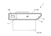
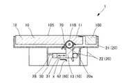
図1は、収納位置におけるドアハンドル装置1の正面図である。図2は、収納位置におけるドアハンドル装置1の背面図である。図3は、収納位置におけるドアハンドル装置1の背面図であり、雌ネジ部54の断面が示されている。図4は、図3のA矢視断面図である。図5は、展開位置におけるドアハンドル装置1の背面図である。図6は、図5のB矢視断面図である。図7は、操作位置におけるドアハンドル装置1の背面図である。図8は、図7のC矢視断面図である。なお、図2から図8において、ベース部材20の裏側の開口部を覆うカバーは図示が省略されている。   FIG. 1 is a front view of the door handle device 1 in the storage position. FIG. 2 is a rear view of the door handle device 1 in the storage position. FIG. 3 is a rear view of the door handle device 1 in the storage position, and shows a cross section of the female screw portion 54. 4 is a cross-sectional view taken along arrow A in FIG. FIG. 5 is a rear view of the door handle device 1 in the deployed position. 6 is a cross-sectional view taken along arrow B in FIG. FIG. 7 is a rear view of the door handle device 1 in the operation position. 8 is a cross-sectional view taken along arrow C in FIG. 2 to 8, the cover that covers the opening on the back side of the base member 20 is not shown.

ドアハンドル装置1は、空気抵抗を減らすために車体のドア(不図示)の外面から極力段差をなくすようにデザインされたフラッシュサーフェスドアハンドルである。
そして、ドアハンドル装置1のハンドルグリップ10が収納位置にある状態において、ハンドルグリップ10は、ハンドルグリップ10の外面10Sがドアの外面に略同一面をなすようにして、ドアの内部に没入している。
The door handle device 1 is a flush surface door handle designed to eliminate a step as much as possible from the outer surface of a door (not shown) of a vehicle body in order to reduce air resistance.
When the handle grip 10 of the door handle device 1 is in the storage position, the handle grip 10 is immersed in the door so that the outer surface 10S of the handle grip 10 is substantially flush with the outer surface of the door. Yes.

ドアハンドル装置1は、車体のドアに設けられたベース部材20と、ドアの外面に略同一面をなすように没入した収納位置(図4参照)と、ドアの外面から突出した展開位置(図6参照)と、展開位置から更に突出した操作位置(図8参照)とに揺動可能なハンドルグリップ10と、を備える。   The door handle device 1 includes a base member 20 provided on a door of a vehicle body, a storage position (see FIG. 4) that is immersed so as to be substantially flush with the outer surface of the door, and a deployed position that protrudes from the outer surface of the door (see FIG. 6) and a handle grip 10 that can swing between an operation position (see FIG. 8) further protruding from the deployed position.

図4に示すように、ハンドルグリップ10は、ベース部材20に軸支される被軸支部11Bが設けられた軸支端部11と、軸支端部11とは反対側に操作端部12と、ドアの内面側に突出する突出部13と、を有する。これにより、ハンドルグリップ10は、ベース部材20に対して被軸支部11Bを中心として、収納位置と、展開位置と、操作位置とに揺動可能となっている。   As shown in FIG. 4, the handle grip 10 includes a shaft support end portion 11 provided with a supported shaft support portion 11 </ b> B supported by the base member 20, and an operation end portion 12 on the opposite side of the shaft support end portion 11. And a protruding portion 13 protruding to the inner surface side of the door. As a result, the handle grip 10 can swing with respect to the base member 20 around the pivoted support portion 11B between the storage position, the unfolded position, and the operation position.

また、図3に示すように、ドアハンドル装置1は、突出部13の軸支端部11側に係合してハンドルグリップ10が収納位置から展開位置まで揺動するように突出部13を操作する操作部材30と、操作部材30を駆動する駆動部40と、駆動部40からの駆動力を伝達して操作部材30を作動させる伝達機構50と、ドアを車体に対して閉鎖状態に保持可能なラッチ機構(不図示)に連結される出力部材60であって、突出部13の操作端部12側に係合可能な出力部材60と、を備える。   Further, as shown in FIG. 3, the door handle device 1 operates the protrusion 13 so that the handle grip 10 swings from the storage position to the deployed position by engaging with the shaft support end 11 side of the protrusion 13. Operating member 30, driving unit 40 that drives the operating member 30, transmission mechanism 50 that transmits the driving force from the driving unit 40 to operate the operating member 30, and the door can be held in a closed state with respect to the vehicle body The output member 60 is connected to a latch mechanism (not shown), and can be engaged with the operation end 12 side of the protrusion 13.

操作部材30は、突出部13の揺動の接線方向X(図2から図8における左右方向を示す矢印参照)に沿って進退作動するものである。このように、操作部材30を突出部13の揺動の接線方向Xに沿って進退作動するようにしたので、操作部材30はハンドルグリップ10が揺動する接線方向Xに作動し、操作部材30の移動範囲を最小限にでき、ドアハンドル装置1全体の寸法、特に、前後方向の寸法を小さくできる。   The operation member 30 moves forward and backward along the tangential direction X of the swing of the protrusion 13 (see the arrows indicating the left and right directions in FIGS. 2 to 8). As described above, since the operation member 30 is moved forward and backward along the tangential direction X of the swing of the protruding portion 13, the operation member 30 operates in the tangential direction X where the handlebar grip 10 swings. Can be minimized, and the overall size of the door handle device 1, particularly the size in the front-rear direction can be reduced.

駆動部40は、接線方向Xにおいて突出部13よりも操作端部12側に配置されていることが好ましい。このように、駆動部40を配置することで、駆動部40を、操作端部12寄りに配置できる。よって、ドアハンドル装置1全体の寸法、特に、前後方向の寸法をより小さくできる。   The drive unit 40 is preferably disposed closer to the operation end 12 than the protrusion 13 in the tangential direction X. Thus, by arranging the drive unit 40, the drive unit 40 can be arranged closer to the operation end 12. Therefore, the dimension of the whole door handle apparatus 1, especially the dimension of the front-back direction can be made smaller.

次に、ドアハンドル装置1を構成する各部を詳細に説明する。
(ベース部材)
ベース部材20は、ドアに設けられた開口に取り付けられる。
図1から図4に示すように、ベース部材20は、表側に開口する表ケース21と、裏側に開口する裏ケース22とを備える。
Next, each part which comprises the door handle apparatus 1 is demonstrated in detail.
(Base member)
The base member 20 is attached to an opening provided in the door.
As shown in FIGS. 1 to 4, the base member 20 includes a front case 21 that opens to the front side, and a back case 22 that opens to the back side.

表ケース21は、ベース部材20の上部に配置され、表側に開口を有し、全体が箱状であり、内側の空間にハンドルグリップ10を収納できるようになっている。   The front case 21 is arranged on the upper part of the base member 20, has an opening on the front side, has a box shape as a whole, and can accommodate the handle grip 10 in an inner space.

表ケース21は、ハンドルグリップ10を軸支する軸支部(不図示)と、突出部13及びハンドルグリップ10が収納位置から展開位置を経て操作位置に至るまで揺動する際に、ハンドルグリップ10との干渉を避けるための逃げ穴20aとを、それぞれ有する。   The front case 21 includes a shaft support (not shown) that pivotally supports the handle grip 10, and the protrusion 13 and the handle grip 10 when the handle grip 10 is swung from the retracted position to the operating position through the deployed position. And a clearance hole 20a for avoiding the interference.

裏ケース22は、ベース部材20の下部に配置され、裏側に開口を有し、全体が箱状であり、内側の空間に駆動部40、伝達機構50及び操作部材30を収納できるようになっている。そして、ベース部材20は、裏側の開口を覆うカバー(不図示)を有するので、カバーにより、駆動部40、伝達機構50及び操作部材30の脱落が阻止されている。   The back case 22 is disposed at the lower part of the base member 20, has an opening on the back side, has a box shape as a whole, and can accommodate the drive unit 40, the transmission mechanism 50 and the operation member 30 in the inner space. Yes. Since the base member 20 has a cover (not shown) that covers the opening on the back side, the drive unit 40, the transmission mechanism 50, and the operation member 30 are prevented from falling off by the cover.

裏ケース22には、裏側に駆動部40及び伝達機構50が取り付けられる。   A drive unit 40 and a transmission mechanism 50 are attached to the back case 22 on the back side.

ベース部材20は、ハンドルグリップ10、操作部材30、駆動部40及び伝達機構50の自重や、ハンドルグリップ10、操作部材30、駆動部40及び伝達機構50からの反力等に耐え得る所望の剛性を有する。   The base member 20 has a desired rigidity capable of withstanding the own weight of the handle grip 10, the operation member 30, the drive unit 40, and the transmission mechanism 50, the reaction force from the handle grip 10, the operation member 30, the drive unit 40, and the transmission mechanism 50, and the like. Have

(ハンドルグリップ)
図1から図4に示すように、ハンドルグリップ10は、ベース部材20に軸支される被軸支部11Bが設けられた軸支端部11と、軸支端部11とは反対側に操作端部12と、ドアの内面側に突出する突出部13と、を有する。
(Handle grip)
As shown in FIGS. 1 to 4, the handle grip 10 includes a shaft support end portion 11 provided with a supported shaft support portion 11 </ b> B that is supported by a base member 20, and an operation end on the opposite side of the shaft support end portion 11. It has the part 12 and the protrusion part 13 which protrudes in the inner surface side of a door.

ハンドルグリップ10は、棒状又は長板状であり、車体に対して、ベース部材20を介して前後方向に長い状態で取り付けられる。   The handle grip 10 has a rod shape or a long plate shape, and is attached to the vehicle body in a long state in the front-rear direction via the base member 20.

ハンドルグリップ10における被軸支部11Bから操作端部12までの部分は、ユーザが手を掛けた状態で表側に向けて加える力を受ける把持部である。   A portion of the handlebar grip 10 from the pivoted support portion 11B to the operation end portion 12 is a grip portion that receives a force applied toward the front side in a state where the user puts a hand.

ハンドルグリップ10の軸支端部11が、ベース部材20の軸支部に軸支された状態で、ハンドルグリップ10は、ベース部材20に対して揺動可能に軸支される。   The handlebar grip 10 is pivotally supported with respect to the base member 20 in a state where the shaft support end portion 11 of the handlebar grip 10 is pivotally supported by the shaft support portion of the base member 20.

ハンドルグリップ10がベース部材20に軸支された状態において、図4、図6及び図8に示すように、突出部13は、ベース部材20の逃げ穴20aに挿通され、更に、操作部材30に設けられた切欠部31に挿通される。   In a state in which the handle grip 10 is pivotally supported by the base member 20, as shown in FIGS. 4, 6, and 8, the protruding portion 13 is inserted into the escape hole 20 a of the base member 20, and is further attached to the operation member 30. It is inserted through the notch 31 provided.

(駆動部、伝達機構及び操作部材)
図2、図3、図5及び図7に示すように、駆動部40、伝達機構50及び操作部材30は、ベース部材20の裏側に配置される。
駆動部40は、モータ41と、モータ出力軸42と、モータ制御部(不図示)と、電源部(不図示)と、を備える。
(Driver, transmission mechanism and operation member)
As shown in FIGS. 2, 3, 5, and 7, the drive unit 40, the transmission mechanism 50, and the operation member 30 are disposed on the back side of the base member 20.
The drive unit 40 includes a motor 41, a motor output shaft 42, a motor control unit (not shown), and a power supply unit (not shown).

モータ41は、例えば、DCモータが用いられ、電源部から電源が供給され、モータ制御部によって回転が制御される。モータ41は、モータ出力軸42が前方に突出するような姿勢で、ベース部材20の裏面に固定される。   For example, a DC motor is used as the motor 41. Power is supplied from the power supply unit, and rotation is controlled by the motor control unit. The motor 41 is fixed to the back surface of the base member 20 in such a posture that the motor output shaft 42 projects forward.

モータ出力軸42は、図3に示すように、モータ出力軸42の回転軸が操作部材30の作動方向である、突出部13の揺動の接線方向Xと平行となるように設けられる。モータ出力軸42の先端部は、ベース部材20に設けられた軸受により軸支される。   As shown in FIG. 3, the motor output shaft 42 is provided so that the rotation shaft of the motor output shaft 42 is parallel to the tangential direction X of the swing of the protruding portion 13, which is the operation direction of the operation member 30. The front end portion of the motor output shaft 42 is pivotally supported by a bearing provided on the base member 20.

伝達機構50は、雄ネジ部53と、雄ネジ部53に対して螺合自在であり、操作部材30と一体となって作動する雌ネジ部54とを有する。そして、伝達機構50は、駆動部40がハンドルグリップ10を収納位置から展開位置まで揺動するように操作部材30を作動させたときに、雄ネジ部53と雌ネジ部54との噛み合いが外れるように構成されている。   The transmission mechanism 50 includes a male screw portion 53 and a female screw portion 54 that can be screwed to the male screw portion 53 and operate integrally with the operation member 30. The transmission mechanism 50 disengages the male screw portion 53 and the female screw portion 54 when the operating member 30 is operated so that the drive portion 40 swings the handle grip 10 from the storage position to the deployed position. It is configured as follows.

具体的には、伝達機構50は、モータ出力軸42と一体となって回転する第1ギヤ51と、第1ギヤ51と噛み合って回転し、第1ギヤ51とは歯数の異なる第2ギヤ52と、第2ギヤ52と一体となって回転する雄ネジ部53と、雄ネジ部53に対して螺合自在な雌ネジ部54とを有する。   Specifically, the transmission mechanism 50 rotates with the first gear 51 rotating integrally with the motor output shaft 42 and the second gear having a different number of teeth from the first gear 51. 52, a male screw part 53 that rotates integrally with the second gear 52, and a female screw part 54 that can be screwed into the male screw part 53.

雄ネジ部53は、ベース部材20に設けられた軸受により両端部が軸支される。雄ネジ部53は、全体が棒状であり、第2ギヤ52が一体に設けられる後部と、雄ネジ53pが略中央に設けられる前部とを備える。雄ネジ53pには、雌ネジ部54の螺合部54qに設けられた雌ネジが螺着自在に螺合する。   Both ends of the male screw portion 53 are pivotally supported by a bearing provided on the base member 20. The male screw portion 53 is entirely rod-shaped, and includes a rear portion in which the second gear 52 is provided integrally and a front portion in which the male screw 53p is provided substantially at the center. A female screw provided in a screwing portion 54q of the female screw portion 54 is screwed into the male screw 53p so as to be freely screwed.

雌ネジ部54は、雌ネジが設けられた螺合部54qと、螺合部54qに隣接し、雄ネジ部53の外径よりも大きい内径を有し、雄ネジ部53を支持するガイド部54gと、を有する。雌ネジ部54は、ガイド部54gを有するので、ハンドルグリップ10を収納位置から展開位置まで揺動するように操作部材30を作動させたときに、雄ネジ部53と雌ネジ部54との噛み合いが外れても、ガイド部54gが操作部材30の姿勢を保持し、操作部材30をガタつくことなく支持できる。   The female screw portion 54 has a threaded portion 54q provided with a female screw and a guide portion that is adjacent to the threaded portion 54q and has an inner diameter larger than the outer diameter of the male screw portion 53 and supports the male screw portion 53. 54g. Since the female screw portion 54 has a guide portion 54g, when the operating member 30 is operated so as to swing the handle grip 10 from the storage position to the deployed position, the male screw portion 53 and the female screw portion 54 are engaged with each other. Even if the guide member 54 comes off, the guide portion 54g maintains the posture of the operation member 30 and can support the operation member 30 without rattling.

操作部材30は、ハンドルグリップ10に設けられた突出部13に係合する係合部32と、ハンドルグリップ10が収納位置から操作位置まで揺動する際に、突出部13の移動を許容する切欠部31と、雌ネジ部54に連結される連結部35とを備える。   The operating member 30 includes an engaging portion 32 that engages with the protruding portion 13 provided on the handle grip 10 and a notch that allows the protruding portion 13 to move when the handle grip 10 swings from the storage position to the operating position. A portion 31 and a connecting portion 35 connected to the female screw portion 54 are provided.

操作部材30は、切欠部31に突出部13を挿通した状態で、ベース部材20の上部に配置される。操作部材30は、操作部材30の外周に設けられた角部(不図示)と、ベース部材20の裏面に設けられた段部28とが雄ネジ部53を中心とする回転方向に係合することで、雄ネジ部53を中心として回転移動することが規制され、接線方向Xに作動できるようにガイドされる。   The operating member 30 is disposed on the upper portion of the base member 20 with the protruding portion 13 inserted through the cutout portion 31. In the operation member 30, a corner portion (not shown) provided on the outer periphery of the operation member 30 and a step portion 28 provided on the back surface of the base member 20 are engaged in a rotation direction around the male screw portion 53. Thus, the rotational movement about the male screw portion 53 is restricted, and the guide is guided so as to be operable in the tangential direction X.

操作部材30は、連結部35によって雌ネジ部54と一体となっているので、駆動部40からの動力を受け、並進運動をしながら、突出部13の揺動の接線方向Xに沿って進退作動する。操作部材30が突出部13の揺動の接線方向Xに沿って進退作動することで、進退作動する方向がハンドルグリップ10の揺動方向の接線方向となり、ハンドルグリップ10に設けられた突出部13を、最小限の移動量で移動させることができる。よって、操作部材30及び駆動部40を配置するスペースを小さくまとめることができる。   Since the operating member 30 is integrated with the female screw portion 54 by the connecting portion 35, the operating member 30 advances and retreats along the tangential direction X of the swing of the protruding portion 13 while receiving the power from the driving portion 40 and performing translational motion. Operate. When the operating member 30 moves forward and backward along the tangential direction X of the swing of the protrusion 13, the direction of forward and backward operation becomes the tangential direction of the swing direction of the handle grip 10, and the protrusion 13 provided on the handle grip 10. Can be moved with a minimum amount of movement. Therefore, the space for arranging the operation member 30 and the drive unit 40 can be reduced.

操作部材30は、図2及び図4に示すように、出力部材60と表裏方向に重なる位置に配置される。これにより、ドアハンドル装置1の上下方向及び前後方向の大きさを小さくでき、ドアの内部空間の省スペース化を図れる。   As shown in FIGS. 2 and 4, the operation member 30 is disposed at a position overlapping the output member 60 in the front and back direction. Thereby, the magnitude | size of the up-down direction and the front-back direction of the door handle apparatus 1 can be made small, and space saving of the internal space of a door can be achieved.

(付勢部材)
ドアハンドル装置1は、雄ネジ部53と雌ネジ部54とが噛み合っている状態から噛み合いが外れ、噛み合いが再開する(再び雄ネジ部53と雌ネジ部54とが噛み合っている状態に戻る)ように、雌ネジ部54と雄ネジ部53とが互いに近接する方向に付勢する付勢部材70(図4参照)を備える。
(Biasing member)
The door handle device 1 is disengaged from the state where the male screw portion 53 and the female screw portion 54 are engaged with each other, and the engagement is resumed (returns to the state where the male screw portion 53 and the female screw portion 54 are engaged again). Thus, the urging member 70 (see FIG. 4) that urges the female screw portion 54 and the male screw portion 53 in a direction in which they are close to each other is provided.

付勢部材70は、図4に示すように、被軸支部11Bに巻回され、一端部がベース部材20に係合し、他端部がハンドルグリップ10に係合し、ハンドルグリップ10を操作位置から収納位置に向けて付勢している。   As shown in FIG. 4, the urging member 70 is wound around the pivoted support portion 11 </ b> B, and has one end engaged with the base member 20 and the other end engaged with the handle grip 10, thereby operating the handle grip 10. It is biased from the position toward the storage position.

付勢部材70は、このように構成されるので、ハンドルグリップ10が収納位置から展開位置に揺動することにより、雄ネジ部53と雌ネジ部54との噛み合いが外れた状態から、ハンドルグリップ10が展開位置から操作位置の間にあるときにユーザが手を離すと、ハンドルグリップ10は展開位置となり(図5及び図6参照)、付勢部材70がハンドルグリップ10を収納位置へ向けて押し、ハンドルグリップ10の突出部13が操作部材30を前方(図5における右側)に押し、操作部材30と一体となった雌ネジ部54が前方に押され、雌ネジ部54の雌ネジの側面が雄ネジ部53の雄ネジ53pの側面を押した状態が維持される。
この状態で、モータ41の回転が伝達された雄ネジ部53は、雄ネジ部53と雌ネジ部54とが噛み合う方向に回転しているので、雄ネジ部53と雌ネジ部54とが噛み合い、螺合が進行し、雌ネジ部54とともに操作部材30が前方に移動し、操作部材30に係合している突出部13が前方に揺動できるようになり、ハンドルグリップ10が付勢部材70の付勢力によって収納位置(図3及び図4参照)に戻る。
Since the urging member 70 is configured as described above, the handle grip 10 is moved from the state where the male screw portion 53 and the female screw portion 54 are disengaged by swinging the handle grip 10 from the storage position to the deployed position. When the user releases the hand while 10 is between the deployed position and the operating position, the handle grip 10 is in the deployed position (see FIGS. 5 and 6), and the biasing member 70 directs the handle grip 10 toward the storage position. The protrusion 13 of the handle grip 10 pushes the operation member 30 forward (right side in FIG. 5), the female screw portion 54 integrated with the operation member 30 is pushed forward, and the female screw portion 54 of the female screw portion 54 The state in which the side surface presses the side surface of the male screw 53p of the male screw portion 53 is maintained.
In this state, the male screw portion 53 to which the rotation of the motor 41 is transmitted rotates in a direction in which the male screw portion 53 and the female screw portion 54 are engaged with each other, so that the male screw portion 53 and the female screw portion 54 are engaged with each other. Then, the screwing proceeds, the operation member 30 moves forward together with the female screw portion 54, the protrusion 13 engaged with the operation member 30 can swing forward, and the handle grip 10 is urged. The urging force of 70 returns to the storage position (see FIGS. 3 and 4).

なお、付勢部材70は、操作部材30、連結部35又は雌ネジ部54を直接付勢するものでもよく、操作部材30、連結部35又は雌ネジ部54を、直接、後方から前方に向けて付勢する付勢部材を別途設けてもよい。   The urging member 70 may directly urge the operating member 30, the connecting portion 35, or the female screw portion 54, and the operating member 30, the connecting portion 35, or the female screw portion 54 is directly directed from the rear to the front. A biasing member for biasing may be provided separately.

(出力部材)
出力部材60は、略中央の軸支部が車体のドアに軸支され、表裏方向の軸を中心として揺動自在となっている。
また、出力部材60は、一端に、突出部13の操作端部12側が係合する係合部62を備え、他端に、ドアを車体に対して閉鎖状態に保持可能なラッチ機構(不図示)に連結される連結部と、を備える。
出力部材60の係合部62は、ハンドルグリップ10が収納位置から展開位置までにある状態で、突出部13と対向し、突出部13の揺動範囲における後方に位置する。
(Output member)
The output member 60 has a substantially central shaft support portion pivotally supported by the door of the vehicle body, and can swing about the front and back axis.
Further, the output member 60 includes an engaging portion 62 that engages with the operation end 12 side of the protruding portion 13 at one end, and a latch mechanism (not shown) that can hold the door in a closed state with respect to the vehicle body at the other end. And a connecting portion connected to the head.
The engaging portion 62 of the output member 60 faces the protruding portion 13 and is located rearward in the swing range of the protruding portion 13 in a state where the handle grip 10 is located from the storage position to the deployed position.

操作部材30によりハンドルグリップ10が収納位置から展開位置まで揺動するように突出部13が操作された後、ユーザがハンドルグリップ10を展開位置から作動位置まで表側に向けて揺動するように引くと、ハンドルグリップ10の揺動と連動して突出部13が後方に移動する。そして、突出部13が出力部材60の係合部62に係合し、更にハンドルグリップ10を引くと、突出部13が係合部62と接触しながら後方に移動し、軸支部を中心として出力部材60は、図2において反時計回りに揺動する。
出力部材60が揺動すると、連結部に連結されたラッチ機構が作動し、ドアの閉鎖状態を解除する。
After the protrusion 13 is operated so that the handle grip 10 swings from the storage position to the deployed position by the operating member 30, the user pulls the handle grip 10 so as to swing from the deployed position to the operating position toward the front side. Then, the protrusion 13 moves backward in conjunction with the swinging of the handle grip 10. When the protruding portion 13 engages with the engaging portion 62 of the output member 60 and further pulls the handle grip 10, the protruding portion 13 moves rearward while contacting the engaging portion 62, and outputs around the shaft support portion. The member 60 swings counterclockwise in FIG.
When the output member 60 swings, the latch mechanism connected to the connecting portion operates to release the door closed state.

(動作)
以下、ドアハンドル装置1の動作の概要を、実施形態に基づいて、図1から図8を用いて説明する。
(Operation)
Hereinafter, an outline of the operation of the door handle device 1 will be described with reference to FIGS. 1 to 8 based on the embodiment.

初めに、前提として、ドアハンドル装置1は収納位置(図3及び図4参照)にある。   First, as a premise, the door handle device 1 is in the storage position (see FIGS. 3 and 4).

(1)ドアを閉鎖状態から解除するため、ユーザはドアハンドル装置1に近づき、スイッチ100(図1参照)に接触する。なお、スイッチ100は、例えば、ドアに設けられるものであり、接触式でも非接触式でもよい。 (1) In order to release the door from the closed state, the user approaches the door handle device 1 and contacts the switch 100 (see FIG. 1). Note that the switch 100 is provided on a door, for example, and may be a contact type or a non-contact type.

(2)スイッチ100が接触を検知すると、モータ制御部は、タイマを作動させるとともに、駆動部40を駆動する。詳細には、モータ41によりモータ出力軸42が回転し、第1ギヤ51及び第2ギヤ52を介して、雄ネジ部53が、前方から後方を見たときに反時計回りに回転する。 (2) When the switch 100 detects contact, the motor control unit activates the timer and drives the drive unit 40. Specifically, the motor output shaft 42 is rotated by the motor 41, and the male screw portion 53 rotates counterclockwise when viewed from the front to the rear via the first gear 51 and the second gear 52.

(3)雄ネジ部53が反時計回りに回転すると、雄ネジ部53の雄ネジ53pは右ねじであるので、雄ネジ53pと噛み合って螺合している螺合部54qを設けた雌ネジ部54は、後方(図3において左)に移動する。 (3) When the male screw portion 53 rotates counterclockwise, the male screw 53p of the male screw portion 53 is a right-hand screw, and therefore, a female screw provided with a screwing portion 54q that meshes with and engages with the male screw 53p. The part 54 moves backward (left in FIG. 3).

(4)雌ネジ部54が後方に移動すると、雌ネジ部54と一体となった操作部材30が後方に移動する。 (4) When the female screw portion 54 moves rearward, the operation member 30 integrated with the female screw portion 54 moves rearward.

(5)操作部材30が後方に移動すると、操作部材30が突出部13に係合して、突出部13が後方に移動する。そして、突出部13と一体となったハンドルグリップ10は、付勢部材70の付勢力に抗して、収納位置(図3及び図4参照)から展開位置(図5及び図6参照)に揺動する。 (5) When the operation member 30 moves rearward, the operation member 30 engages with the protrusion 13 and the protrusion 13 moves rearward. The handle grip 10 integrated with the projecting portion 13 swings from the storage position (see FIGS. 3 and 4) to the deployed position (see FIGS. 5 and 6) against the biasing force of the biasing member 70. Move.

(6)ハンドルグリップ10が展開位置となるまで操作部材30が移動すると、雄ネジ53pと螺合部54qの噛み合いが外れ、雄ネジ53pの外径部が雌ネジ部54のガイド部54gに支持された状態となる(図5参照)。雄ネジ53pと螺合部54qの噛み合いが外れてからは、モータ41の回転はしばらく維持されるので、雄ネジ部53はガイド部54gに支持された状態で雌ネジ部54に対して空転することになるが、操作部材30は、それ以上後方に移動しなくなり、展開位置に留まる。 (6) When the operating member 30 moves until the handle grip 10 is in the unfolded position, the male screw 53p and the threaded portion 54q are disengaged, and the outer diameter portion of the male screw 53p is supported by the guide portion 54g of the female screw portion 54. (See FIG. 5). Since the rotation of the motor 41 is maintained for a while after the engagement between the male screw 53p and the screwing portion 54q is disengaged, the male screw portion 53 idles with respect to the female screw portion 54 while being supported by the guide portion 54g. However, the operation member 30 does not move backward anymore and remains in the deployed position.

(7)モータ制御部は、駆動部40を駆動したときに作動させたタイマがあらかじめ設定した時間になると、モータ41の駆動を停止し、タイマをリセットする。
また、展開位置において、突出部13は出力部材60の係合部62に近接又は当接する(図6参照)。
(7) When the timer activated when the drive unit 40 is driven reaches a preset time, the motor control unit stops driving the motor 41 and resets the timer.
Moreover, the protrusion part 13 adjoins or contacts the engaging part 62 of the output member 60 in a deployment position (refer FIG. 6).

(8)図6に示すように、ハンドルグリップ10が展開位置となると、ユーザが直接、ハンドルグリップ10の操作端部12を操作できるようになる。 (8) As shown in FIG. 6, when the handle grip 10 is in the deployed position, the user can directly operate the operation end 12 of the handle grip 10.

(9)ユーザが展開位置にあるハンドルグリップ10を揺動させ、操作位置(図7及び図8参照)まで操作すると、ハンドルグリップ10の突出部13が更に揺動して、出力部材60の係合部62を押すことで出力部材60を操作し、出力部材60に連結されたロッド(不図示)がラッチ機構(不図示)を操作して、ドアの閉鎖状態が開錠され、ドアが開放可能となる。 (9) When the user swings the handle grip 10 in the unfolded position and operates it to the operation position (see FIGS. 7 and 8), the protrusion 13 of the handle grip 10 further swings, and the engagement of the output member 60 By pressing the joint 62, the output member 60 is operated, and a rod (not shown) connected to the output member 60 operates a latch mechanism (not shown) to unlock the door and open the door. It becomes possible.

(10)ハンドルグリップ10が操作位置にあるときに、ユーザがハンドルグリップ10から手を離すと、ハンドルグリップ10は付勢部材70の付勢力により展開位置まで移動し、突出部13が操作部材30の係合部32に係合することで停止する。 (10) When the handle grip 10 is in the operating position and the user releases his / her hand from the handle grip 10, the handle grip 10 is moved to the deployed position by the urging force of the urging member 70, and the protruding portion 13 is moved to the operating member 30. It stops by engaging with the engaging part 32.

(11)モータ制御部は、ドアが再び閉じられたこと、あるいは、ラッチ機構が閉鎖状態となったことを検知すると、モータ制御部は、タイマを作動させるとともに、駆動部40を駆動して、モータ41を逆転(図5において前方から後方に見て時計回りに回転)させる。すると、付勢部材70によって、雌ネジ部54と雄ネジ部53との噛み合いが再開するように、雌ネジ部54と雄ネジ部53とが互いに近接する方向に付勢されているので、雌ネジ部54と雄ネジ部53とが噛み合う。 (11) When the motor control unit detects that the door is closed again or the latch mechanism is closed, the motor control unit activates the timer and drives the drive unit 40, The motor 41 is rotated in the reverse direction (rotated clockwise as viewed from the front to the rear in FIG. 5). Then, since the female screw portion 54 and the male screw portion 53 are urged by the urging member 70 so as to resume the engagement of the female screw portion 54 and the male screw portion 53, the female screw portion 54 and the male screw portion 53 are urged. The screw portion 54 and the male screw portion 53 are engaged with each other.

(12)雌ネジ部54と雄ネジ部53とが噛み合うと、雄ネジ部53が回転するのに伴い、雌ネジ部54が前方に移動する。そして、雌ネジ部54と一体となった操作部材30が前方(図3及び図4参照)に移動して元の収納位置に戻る。また、ハンドルグリップ10は、付勢部材70の付勢力によって収納位置まで移動する。 (12) When the female screw portion 54 and the male screw portion 53 are engaged with each other, the female screw portion 54 moves forward as the male screw portion 53 rotates. Then, the operation member 30 integrated with the female screw portion 54 moves forward (see FIGS. 3 and 4) and returns to the original storage position. Further, the handle grip 10 is moved to the storage position by the urging force of the urging member 70.

(13)操作部材30は段部28の端部に設けられたスライダストッパ27で移動が規制され、ハンドルグリップ10はベース部材20に設けられたハンドルストッパ(不図示)で移動が規制され、収納位置に保持される。そして、モータ制御部は、駆動部40を駆動したときに作動させたタイマがあらかじめ設定した時間になると、モータ41の駆動を停止し、タイマをリセットする。 (13) The movement of the operation member 30 is restricted by the slider stopper 27 provided at the end of the step portion 28, and the movement of the handle grip 10 is restricted by the handle stopper (not shown) provided in the base member 20 and stored. Held in position. The motor control unit stops driving the motor 41 and resets the timer when the timer that is activated when the driving unit 40 is driven reaches a preset time.

(14)モータ41が何らかの理由で作動しない場合には、手動にてハンドルグリップ10を収納位置から展開位置、展開位置から操作位置まで操作することで、出力部材60を操作でき、ラッチ機構を操作できる。このとき、操作部材30には切欠部31が設けられているので、ハンドルグリップ10の突出部13が操作部材30に干渉することなく、操作できる。 (14) When the motor 41 does not operate for some reason, the output member 60 can be operated by manually operating the handle grip 10 from the retracted position to the deployed position and from the deployed position to the operating position, and the latch mechanism is operated. it can. At this time, since the operation member 30 is provided with the notch 31, the protrusion 13 of the handle grip 10 can be operated without interfering with the operation member 30.

このように、ドアハンドル装置1は、収納位置で空気抵抗を小さくでき、見た目もすっきりとし、ユーザがドアの閉鎖状態を解除する際は、駆動部40の駆動により展開位置までハンドルグリップ10を展開するので、空力性と意匠性と利便性を達成できる。   As described above, the door handle device 1 can reduce the air resistance at the storage position, has a clean appearance, and when the user releases the closed state of the door, the drive handle 40 drives the handle grip 10 to the deployment position. Therefore, aerodynamics, design and convenience can be achieved.

また、ドアハンドル装置1は、雄ネジ部53と雌ネジ部54との噛み合いが外れて空転することにより、モータ41の回転を停止しなくても、操作部材30を所定の移動量だけ移動させて停止する制御ができるように構成されているので、操作部材30を所定の移動量だけ移動させて停止するためのセンサを別途設ける必要がなく、部品数を削減でき、コストを低減できる。   Further, the door handle device 1 moves the operation member 30 by a predetermined amount of movement without stopping the rotation of the motor 41 by disengagement between the male screw portion 53 and the female screw portion 54 and idling. Therefore, it is not necessary to separately provide a sensor for moving and stopping the operation member 30 by a predetermined movement amount, and the number of parts can be reduced and the cost can be reduced.

以上、本発明の好ましい実施形態について詳述したが、本発明に係るドアハンドル装置1は上述した実施形態に限定されるものではなく、特許請求の範囲に記載された本発明の要旨の範囲内において、種々の変形、変化が可能である。   Although the preferred embodiment of the present invention has been described in detail above, the door handle device 1 according to the present invention is not limited to the above-described embodiment, and is within the scope of the gist of the present invention described in the claims. Various modifications and changes are possible.

例えば、上記実施形態においては、伝達機構50が、モータ41の回転に伴い回転する雄ネジ部53と、操作部材30と一体となった雌ネジ部54を備えるものであったが、伝達機構50が、モータ41の回転に伴い回転する雌ネジ部と、操作部材30と一体となった雄ネジ部を備えるものであってもよい。   For example, in the above embodiment, the transmission mechanism 50 includes the male screw portion 53 that rotates with the rotation of the motor 41 and the female screw portion 54 that is integrated with the operation member 30. However, a female screw portion that rotates as the motor 41 rotates and a male screw portion integrated with the operation member 30 may be provided.

例えば、上記実施形態においては、伝達機構50が、第1ギヤ51及び第2ギヤ52を備えるものであったが、これに限らず、モータ41の性能に応じてギヤを設けない機構としてもよく、ギヤの種類や向きや数を変えてもよい。   For example, in the above embodiment, the transmission mechanism 50 includes the first gear 51 and the second gear 52. However, the present invention is not limited to this, and a mechanism that does not provide a gear according to the performance of the motor 41 may be used. The type, direction and number of gears may be changed.

本発明のドアハンドル装置1によれば、車体のドアに設けられたベース部材20と、ドアの外面に略同一面をなすように没入した収納位置と、ドアの外面から突出した展開位置と、展開位置から突出した操作位置とに揺動可能なハンドルグリップ10と、ハンドルグリップ10を操作する操作部材30と、操作部材30を駆動する駆動部40と、駆動部40からの駆動力を伝達して操作部材30を作動させる伝達機構50と、を備え、伝達機構50は、雄ネジ部53と、雄ネジ部53に対して螺合自在な雌ネジ部54とを有し、ハンドルグリップ10が収納位置から展開位置まで揺動するように操作部材30を作動させたときに、雄ネジ部53と雌ネジ部54との噛み合いが外れるように構成したので、ハンドルグリップ10や操作部材30の位置を検知するスイッチ等が不要となり、部品数を削減でき、コストを低減できる。   According to the door handle device 1 of the present invention, the base member 20 provided on the door of the vehicle body, the storage position immersed so as to be substantially flush with the outer surface of the door, the deployed position protruding from the outer surface of the door, The handle grip 10 that can swing to the operation position protruding from the unfolded position, the operation member 30 that operates the handle grip 10, the drive unit 40 that drives the operation member 30, and the driving force from the drive unit 40 are transmitted. A transmission mechanism 50 that operates the operation member 30. The transmission mechanism 50 includes a male screw portion 53 and a female screw portion 54 that can be screwed into the male screw portion 53. Since the male screw portion 53 and the female screw portion 54 are disengaged when the operation member 30 is operated so as to swing from the storage position to the deployed position, the handle grip 10 and the operation member 30 are configured. Position switch that detects becomes unnecessary, can reduce the number of parts, the cost can be reduced.

本発明のドアハンドル装置1によれば、雌ネジ部54は、操作部材30と一体となって作動するので、簡素な構造で雌ネジ部54と操作部材30とを連動させることができる。   According to the door handle device 1 of the present invention, since the female screw portion 54 operates integrally with the operation member 30, the female screw portion 54 and the operation member 30 can be interlocked with a simple structure.

本発明のドアハンドル装置1によれば、雌ネジ部54は、雌ネジが設けられた螺合部54qと、螺合部54qに隣接し、雄ネジ部53の外径よりも大きい内径を有し、雄ネジ部53を支持するガイド部54gと、を有するので、ハンドルグリップ10を収納位置から展開位置まで揺動するように操作部材30を作動させたときに、雄ネジ部53と雌ネジ部54との噛み合いが外れても、ガイド部54gが雄ネジ部53(雄ネジ53p)を螺合部54qと再び噛み合い可能な位置に保持する。また、ガイド部54gが操作部材30の姿勢を保持し、操作部材30をガタつくことなく支持できる。   According to the door handle device 1 of the present invention, the female screw portion 54 has a screwed portion 54q provided with a female screw, and an inner diameter that is adjacent to the screwed portion 54q and larger than the outer diameter of the male screw portion 53. And the guide portion 54g for supporting the male screw portion 53, the male screw portion 53 and the female screw when the operating member 30 is operated so as to swing the handle grip 10 from the storage position to the deployed position. Even if the engagement with the portion 54 is released, the guide portion 54g holds the male screw portion 53 (the male screw 53p) at a position where it can be engaged with the screwing portion 54q again. Further, the guide portion 54g holds the posture of the operation member 30, and can support the operation member 30 without rattling.

本発明のドアハンドル装置1によれば、噛み合いが外れた状態から噛み合いが再開するように、雌ネジ部54と雄ネジ部53とが互いに近接する方向に付勢する付勢部材70を備えるので、雌ネジ部54と雄ネジ部53との噛み合いが外れた状態から、再び、両者を噛み合わせることができる。   According to the door handle device 1 of the present invention, since the female screw portion 54 and the male screw portion 53 are urged in a direction close to each other so that the meshing is resumed from the state where the meshing is released, the biasing member 70 is provided. From the state where the engagement between the female screw portion 54 and the male screw portion 53 is released, both can be engaged again.

本発明のドアハンドル装置1によれば、付勢部材70は、ハンドルグリップ10を、操作位置から収納位置に向けて付勢するので、付勢部材70が、雌ネジ部54と雄ネジ部53との噛み合いが外れた状態から、再び、両者を噛み合わせる機能と、ハンドルグリップ10を操作位置から収納位置に戻す機能と、を兼ねることができる。   According to the door handle device 1 of the present invention, the urging member 70 urges the handle grip 10 from the operation position toward the storage position, so that the urging member 70 includes the female screw portion 54 and the male screw portion 53. From the state of disengagement, the function of meshing the two again and the function of returning the handle grip 10 from the operation position to the storage position can be combined.

1 ドアハンドル装置
10 ハンドルグリップ
11 軸支端部
12 操作端部
13 突出部
20 ベース部材
20a 逃げ穴
27 スライダストッパ
28 段部
30 操作部材
31 切欠部
32 係合部
35 連結部
40 駆動部
41 モータ
42 モータ出力軸
50 伝達機構
51 第1ギヤ
52 第2ギヤ
53 雄ネジ部
53p 雄ネジ
54 雌ネジ部
54q 螺合部
54g ガイド部
60 出力部材
62 係合部
100 スイッチ
X 接線方向
DESCRIPTION OF SYMBOLS 1 Door handle apparatus 10 Handle grip 11 Shaft support end part 12 Operation end part 13 Protrusion part 20 Base member 20a Escape hole 27 Slider stopper 28 Step part 30 Operation member 31 Notch part 32 Engagement part 35 Connection part 40 Drive part 41 Motor 42 Motor output shaft 50 Transmission mechanism 51 First gear 52 Second gear 53 Male thread part 53p Male thread 54 Female thread part 54q Screw part 54g Guide part 60 Output member 62 Engagement part 100 Switch X Tangent direction

Claims (5)

車体のドアに設けられたベース部材と、
前記ドアの外面に略同一面をなすように没入した収納位置と、前記ドアの外面から突出した展開位置と、前記展開位置から突出した操作位置とに揺動可能なハンドルグリップと、
前記ハンドルグリップを操作する操作部材と、
前記操作部材を駆動する駆動部と、
前記駆動部からの駆動力を伝達して前記操作部材を作動させる伝達機構と、を備え、
前記伝達機構は、雄ネジ部と、前記雄ネジ部に対して螺合自在な雌ネジ部とを有し、
前記ハンドルグリップが前記収納位置から前記展開位置まで揺動するように前記操作部材を作動させたときに、前記雄ネジ部と前記雌ネジ部との噛み合いが外れるように構成したことを特徴とするドアハンドル装置。
A base member provided on the door of the vehicle body;
A handle grip that is swingable between a storage position that is immersed so as to be substantially flush with the outer surface of the door, a deployed position that projects from the outer surface of the door, and an operating position that projects from the deployed position;
An operating member for operating the handle grip;
A drive unit for driving the operation member;
A transmission mechanism for transmitting a driving force from the driving unit to operate the operation member,
The transmission mechanism has a male screw part and a female screw part that can be screwed to the male screw part,
The male screw portion and the female screw portion are disengaged when the operation member is operated so that the handle grip swings from the stowed position to the deployed position. Door handle device.
前記雌ネジ部は、前記操作部材と一体となって作動する
ことを特徴とする請求項1に記載のドアハンドル装置。
The door handle device according to claim 1, wherein the female screw portion operates integrally with the operation member.
前記雌ネジ部は、
雌ネジが設けられた螺合部と、
前記螺合部に隣接し、前記雄ネジ部の外径よりも大きい内径を有し、前記雄ネジ部を支持するガイド部と、を有する
ことを特徴とする請求項1又は請求項2に記載のドアハンドル装置。
The female thread portion is
A threaded portion provided with a female screw;
The guide part which adjoins the said screwing part and has an internal diameter larger than the outer diameter of the said external thread part, and supports the external thread part, It is characterized by the above-mentioned. Door handle device.
前記噛み合いが外れた状態から前記噛み合いが再開するように、前記雌ネジ部と前記雄ネジ部とが互いに近接する方向に付勢する付勢部材を備える
ことを特徴とする請求項1から請求項3のいずれか1項に記載のドアハンドル装置。
The urging member for urging the female screw part and the male screw part in a direction approaching each other is provided so that the meshing is resumed from the state where the meshing is disengaged. 4. The door handle device according to any one of items 3.
前記付勢部材は、前記ハンドルグリップを、操作位置から収納位置に向けて付勢する
ことを特徴とする請求項4に記載のドアハンドル装置。
The door handle device according to claim 4, wherein the biasing member biases the handle grip from the operation position toward the storage position.
JP2016232629A 2016-11-30 2016-11-30 Door handle device Active JP6769005B2 (en)

Priority Applications (1)

Application Number Priority Date Filing Date Title
JP2016232629A JP6769005B2 (en) 2016-11-30 2016-11-30 Door handle device

Applications Claiming Priority (1)

Application Number Priority Date Filing Date Title
JP2016232629A JP6769005B2 (en) 2016-11-30 2016-11-30 Door handle device

Publications (2)

Publication Number Publication Date
JP2018090961A true JP2018090961A (en) 2018-06-14
JP6769005B2 JP6769005B2 (en) 2020-10-14

Family

ID=62563888

Family Applications (1)

Application Number Title Priority Date Filing Date
JP2016232629A Active JP6769005B2 (en) 2016-11-30 2016-11-30 Door handle device

Country Status (1)

Country Link
JP (1) JP6769005B2 (en)

Cited By (1)

* Cited by examiner, † Cited by third party
Publication number Priority date Publication date Assignee Title
JP2020020186A (en) * 2018-08-02 2020-02-06 本田技研工業株式会社 Vehicle door structure

Citations (9)

* Cited by examiner, † Cited by third party
Publication number Priority date Publication date Assignee Title
JPS61261587A (en) * 1985-05-16 1986-11-19 株式会社アルファ Motor type door lock system
JPS63187562U (en) * 1987-05-19 1988-12-01
JPH01295978A (en) * 1988-05-23 1989-11-29 Oi Seisakusho Co Ltd Actuator for vehicle
JPH02161086A (en) * 1988-08-23 1990-06-20 Rockwell Automotive Body Systems Uk Ltd Latch of vehicle door and its
JPH0329670U (en) * 1989-07-31 1991-03-25
JPH05214867A (en) * 1991-03-16 1993-08-24 Kiekert Gmbh & Co Kg Motor driving device for central locking device of automobile
JPH0782933A (en) * 1993-09-17 1995-03-28 Honda Motor Co Ltd Door opening device of car
JP2001509559A (en) * 1997-07-11 2001-07-24 メリトール ライト ビークル システムズ−フランス Security latch and latch release actuator and lock adapted to the actuator
JP2015534615A (en) * 2012-09-25 2015-12-03 ジャガー・ランド・ローバー・リミテッドJaguar Land Rover Limited Retractable handle structure

Patent Citations (9)

* Cited by examiner, † Cited by third party
Publication number Priority date Publication date Assignee Title
JPS61261587A (en) * 1985-05-16 1986-11-19 株式会社アルファ Motor type door lock system
JPS63187562U (en) * 1987-05-19 1988-12-01
JPH01295978A (en) * 1988-05-23 1989-11-29 Oi Seisakusho Co Ltd Actuator for vehicle
JPH02161086A (en) * 1988-08-23 1990-06-20 Rockwell Automotive Body Systems Uk Ltd Latch of vehicle door and its
JPH0329670U (en) * 1989-07-31 1991-03-25
JPH05214867A (en) * 1991-03-16 1993-08-24 Kiekert Gmbh & Co Kg Motor driving device for central locking device of automobile
JPH0782933A (en) * 1993-09-17 1995-03-28 Honda Motor Co Ltd Door opening device of car
JP2001509559A (en) * 1997-07-11 2001-07-24 メリトール ライト ビークル システムズ−フランス Security latch and latch release actuator and lock adapted to the actuator
JP2015534615A (en) * 2012-09-25 2015-12-03 ジャガー・ランド・ローバー・リミテッドJaguar Land Rover Limited Retractable handle structure

Cited By (1)

* Cited by examiner, † Cited by third party
Publication number Priority date Publication date Assignee Title
JP2020020186A (en) * 2018-08-02 2020-02-06 本田技研工業株式会社 Vehicle door structure

Also Published As

Publication number Publication date
JP6769005B2 (en) 2020-10-14

Similar Documents

Publication Publication Date Title
JP6009325B2 (en) Door handle device
JP5242977B2 (en) Assist grip
JP6007745B2 (en) Door drive device
US9103143B2 (en) Door handle apparatus for vehicles
JP6427803B2 (en) Door latch device for automobile
JP4720395B2 (en) Vehicle door handle device
KR101988953B1 (en) Apparatus for power sliding door
JP2012107489A (en) Tailgate outside handle assembly
JP6125223B2 (en) Lock structure
JP2008101336A (en) Latch device
JP2018090961A (en) Door handle device
JP6878753B2 (en) Door handle device
JP5912777B2 (en) Webbing take-up device
JP6769006B2 (en) Door handle device
JP2013238040A (en) Inside handle assembling structure
WO2016084292A1 (en) Popup device
JP6104752B2 (en) Door handle device with pop-up function
JP6503576B2 (en) Latch device
JP4778857B2 (en) Electric lid mechanism
JP2001240263A5 (en)
JP3904904B2 (en) Container holder
JP5041251B2 (en) Vehicle storage device
JP6912355B2 (en) Door closer device and door opening / closing system equipped with it
JP2007211506A (en) Actuator for door latch
JP6393926B2 (en) Vehicle door operation device

Legal Events

Date Code Title Description
A621 Written request for application examination

Free format text: JAPANESE INTERMEDIATE CODE: A621

Effective date: 20191115

A977 Report on retrieval

Free format text: JAPANESE INTERMEDIATE CODE: A971007

Effective date: 20200722

TRDD Decision of grant or rejection written
A01 Written decision to grant a patent or to grant a registration (utility model)

Free format text: JAPANESE INTERMEDIATE CODE: A01

Effective date: 20200825

A61 First payment of annual fees (during grant procedure)

Free format text: JAPANESE INTERMEDIATE CODE: A61

Effective date: 20200902

R150 Certificate of patent or registration of utility model

Ref document number: 6769005

Country of ref document: JP

Free format text: JAPANESE INTERMEDIATE CODE: R150

R250 Receipt of annual fees

Free format text: JAPANESE INTERMEDIATE CODE: R250