JP2018071874A - refrigerator - Google Patents
refrigerator Download PDFInfo
- Publication number
- JP2018071874A JP2018071874A JP2016211203A JP2016211203A JP2018071874A JP 2018071874 A JP2018071874 A JP 2018071874A JP 2016211203 A JP2016211203 A JP 2016211203A JP 2016211203 A JP2016211203 A JP 2016211203A JP 2018071874 A JP2018071874 A JP 2018071874A
- Authority
- JP
- Japan
- Prior art keywords
- cooler
- refrigerator
- storage chamber
- temperature
- temperature sensor
- Prior art date
- Legal status (The legal status is an assumption and is not a legal conclusion. Google has not performed a legal analysis and makes no representation as to the accuracy of the status listed.)
- Granted
Links
Images


Abstract
Description
本発明は,冷蔵庫に関する。 The present invention relates to a refrigerator.
本技術分野の背景技術として,例えば特開2006−266617号公報(特許文献1)及び特開2012―255572号公報(特許文献2)がある。 As background arts in this technical field, there are, for example, Japanese Unexamined Patent Application Publication No. 2006-266617 (Patent Document 1) and Japanese Unexamined Patent Application Publication No. 2012-255572 (Patent Document 2).
一般に冷蔵庫は、氷点以下の冷却器と庫内の空気が熱交換することで,貯蔵室を所望の温度に冷却する機器であり,冷却器の表面には霜が成長する。霜の成長は熱抵抗や通風抵抗の増加をもたらすため,霜が成長するにつれて冷却器における熱交換性能が低下する。よって,熱交換性能を回復するために霜を融解して除去する除霜運転が行われる。除霜運転は除霜ヒータによる加熱によって行われ,温度センサにより除霜の完了が判定される。 Generally, a refrigerator is a device that cools a storage room to a desired temperature by heat exchange between a cooler below freezing point and air in the cabinet, and frost grows on the surface of the cooler. The growth of frost causes an increase in thermal resistance and ventilation resistance, so the heat exchange performance in the cooler decreases as the frost grows. Therefore, a defrosting operation is performed in which frost is melted and removed in order to recover the heat exchange performance. The defrosting operation is performed by heating with a defrosting heater, and the completion of defrosting is determined by a temperature sensor.
特許文献1に記載の冷蔵庫は,冷蔵庫の本体庫内において、内箱の冷却器後方の箇所に、温度センサである除霜判定センサを設けている。除霜動作の終了のタイミングは、除霜判定センサにより決定される。すなわち、除霜判定センサにより、その周囲が所定の温度まで上昇した時点で除霜が完了したと判定し、除霜ヒータへの通電を止めて除霜動作を終了する。
The refrigerator described in
また,特許文献2に記載の冷蔵庫は,冷気を生成する冷却器と、冷却器を配して冷気が流通する冷気ダクトと、冷気ダクト内で冷却器の下方に配して冷却器を除霜する除霜ヒータと、冷却器の上方で,冷気ダクト内で冷却器の前後方向の略中央部に配置され,温度検知して除霜ヒータの停止時期を検出する温度センサと、冷気ダクトの前壁に設けられるとともに、温度センサを保持する保持部とを備え、保持部によって温度センサの上方を覆っている。除霜ヒータは温度センサの検知温度が所定温度になると停止される。
In addition, the refrigerator described in
霜は,冷却器だけでなく,周辺の壁面にも成長することがある。特許文献1あるいは特許文献2に記載の従来技術では,冷却器や冷却器の周辺の壁面に成長した霜の融解状態を的確に検知できず,信頼性を確保するためには除霜の完了判定を霜(氷)の融点よりも十分高い温度に設定する必要があった。そのため,省エネルギー性能を十分高くできていなかった。
Frost may grow not only on the cooler but also on the surrounding walls. In the prior art described in
本発明は上記課題に鑑みてなされたものであり,冷却器や冷却器の周辺の壁面に成長した霜の融解状態を的確に検知することにより,信頼性を確保しつつ過熱を抑えた省エネルギー性能が高い冷蔵庫を提供することを目的とする。 The present invention has been made in view of the above problems, and by accurately detecting the melting state of the frost grown on the cooler and the wall surface around the cooler, energy saving performance that suppresses overheating while ensuring reliability. The purpose is to provide a high refrigerator.
上記課題を解決するために,例えば特許請求の範囲に記載の構成を採用する。 In order to solve the above problems, for example, the configuration described in the claims is adopted.
本願は上記課題を解決する手段を複数含んでいるが,その一例を挙げるならば,食品貯蔵室と,圧縮機と,該圧縮機で圧縮された冷媒と庫外の空気と熱交換する放熱器と,前記冷媒を減圧する減圧手段と,減圧された前記冷媒と前記食品貯蔵室内の空気と熱交換する冷却器と,該冷却器を収納する冷却器収納室と,該冷却器収納室から前記食品貯蔵室に至る送風路と,前記食品貯蔵室から前記冷却器収納室に至る戻り風路と,前記冷却器で熱交換した空気を前記食品貯蔵室に送風する庫内送風機とを備え,前記冷却器の温度を検知する第一の温度センサと,前記冷却器より下流側の前記冷却器収納室または前記送風路に第二の温度センサを配設したことを特徴とする。 The present application includes a plurality of means for solving the above-mentioned problems. For example, a food storage room, a compressor, a refrigerant compressed by the compressor, and a radiator that exchanges heat with air outside the warehouse. A decompression means for decompressing the refrigerant, a cooler for exchanging heat with the decompressed refrigerant and air in the food storage chamber, a cooler storage chamber for storing the cooler, and the cooler storage chamber from the cooler storage chamber An air passage leading to the food storage chamber, a return air passage extending from the food storage chamber to the cooler storage chamber, and an internal fan for blowing air exchanged with the cooler to the food storage chamber, A first temperature sensor for detecting the temperature of the cooler and a second temperature sensor are disposed in the cooler housing chamber or the air passage downstream of the cooler.
本発明によれば,冷却器や冷却器の周辺の壁面に成長した霜の融解状態を的確に検知することにより,信頼性を確保しつつ過熱を抑えることで省エネルギー性能が高い冷蔵庫を提供することができる。 According to the present invention, it is possible to provide a refrigerator with high energy saving performance by suppressing overheating while ensuring reliability by accurately detecting the melting state of the frost grown on the cooler and the wall surface around the cooler. Can do.
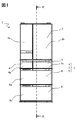
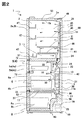
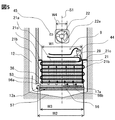
本発明に係る冷蔵庫の実施形態例を,図1〜図8を参照しながら説明する。まず,本実施形態例の冷蔵庫の構成を,図1〜図5を参照しながら説明する。図1は本実施形態例の冷蔵庫の正面外形図,図2は本実施形態例の冷蔵庫の庫内の構成を表す断面図であり,図1中に示すA−A断面を矢視方向に見た図である。図3は本実施形態例の冷蔵庫の冷凍サイクル構成を表す図である。図4は本実施形態例の冷蔵庫の冷却器付近の構成を表す拡大断面図,図5は本実施形態例の冷蔵庫の冷却器付近の構成を表す拡大断面図であり,図4中に示すB−B断面を矢視方向に見た図である。 An embodiment of a refrigerator according to the present invention will be described with reference to FIGS. First, the structure of the refrigerator of the present embodiment will be described with reference to FIGS. FIG. 1 is a front outline view of a refrigerator according to the present embodiment, and FIG. 2 is a cross-sectional view illustrating a configuration inside the refrigerator of the present embodiment. A cross section AA shown in FIG. It is a figure. FIG. 3 is a diagram showing the refrigeration cycle configuration of the refrigerator of this embodiment. FIG. 4 is an enlarged cross-sectional view showing the configuration of the vicinity of the refrigerator cooler of the embodiment, and FIG. 5 is an enlarged cross-sectional view of the configuration of the vicinity of the refrigerator cooler of the embodiment, which is shown in FIG. It is the figure which looked at -B cross section in the arrow direction.
図1に示すように本実施形態例の冷蔵庫は、冷蔵庫本体1に上方から,冷蔵室2,製氷室4及び上段冷凍室5,下段冷凍室6,野菜室8を備えている。製氷室4と上段冷凍室5は,冷蔵室2と下段冷凍室6との間に左右に並べて設けられている。冷蔵室2及び野菜室8は,4℃程度の冷蔵温度帯の貯蔵室である。また,製氷室4,上段冷凍室5及び下段冷凍室6は,−18℃程度の冷凍温度帯の貯蔵室である(以下,製氷室4,上段冷凍室5,下段冷凍室6の総称を冷凍室7とする)。
As shown in FIG. 1, the refrigerator according to this embodiment includes a
冷蔵室2には,前方に左右に分割された観音開き型の冷蔵室扉2a,2bが備えられている。製氷室4,上段冷凍室5,下段冷凍室6,野菜室8には,それぞれ引き出し式の製氷室扉4a,上段冷凍室扉5a,下段冷凍室扉6a,野菜室扉8aが備えられている。
The refrigerating
図2に示すように,本実施形態例の冷蔵庫の庫外と庫内は,外箱1aと内箱1bとの間に発泡断熱材(発泡ポリウレタン)を充填することにより形成される断熱箱体50により隔てられている。また,本実施形態例の冷蔵庫には,背面,両側面に真空断熱材60が実装されている(両側面は不図示)。
As shown in FIG. 2, the outside of the refrigerator and the inside of the refrigerator of this embodiment are insulated by filling a foam insulation (foamed polyurethane) between the outer box 1a and the inner box 1b. 50. Moreover, the refrigerator of this embodiment is mounted with a vacuum
冷蔵室扉2a,2bの貯蔵室内側には,複数の扉ポケット47,冷蔵室2内には複数の棚46が備えられている。また,製氷室4,上段冷凍室5,下段冷凍室6及び野菜室8は,それぞれの貯蔵室の前方に備えられた扉4a,5a,6a,8aと一体に前後方向に移動する収納容器4b,5b,6b,8bが備えられている。扉4a,5a,6a,8aは,それぞれ図示しない取手部に手を掛けて手前側に引き出すことにより,収納容器4b,5b,6b,8bが引き出せるようになっている。
A plurality of
図2に示すように本実施形態例の冷蔵庫では,冷蔵室2と,上段冷凍室5及び製氷室4(図1参照)とが上部断熱仕切壁51によって隔てられ,下段冷凍室6と野菜室8とが下部断熱仕切壁52によって断熱的に隔てられている。なお,冷蔵室2の最下段(上側断熱仕切り壁51の上部)には,−1〜+1℃程度に維持されるチルド室3が備えられている。また、冷凍室7の背部に冷却器収納室9を備え,冷却器収納室9内には冷却手段として冷却器21を備えている。また,冷却器21の上方には,送風手段として庫内送風機22を備えている。冷蔵室2,冷凍室7,野菜室8への送風経路には,それぞれ冷蔵室ダンパ24,冷凍室ダンパ26,野菜室ダンパ(不図示)を備えており,各室への送風が制御される。
As shown in FIG. 2, in the refrigerator of this embodiment, the
冷蔵室ダンパ24が開放状態の場合,庫内送風機22により昇圧された冷気は,冷蔵室送風ダクト11を流れ,冷蔵室吐出口31から冷蔵室2に吹き出す。冷蔵室2を冷却して温度が上昇した冷気は,冷蔵室戻り口(不図示),冷蔵室戻りダクト12(図5参照)を介して冷却器収納室9に戻り,冷却器21と熱交換して再び低温冷気となる。
When the
冷凍室ダンパ26が開放状態の場合,庫内送風機22により昇圧された低温冷気は,冷凍室送風ダクト13を流れ,冷凍室吐出口33から冷凍室7に吹き出す。冷凍室7を冷却して温度が上昇した冷気は,冷凍室戻り口36を介して冷却器収納室9に戻り,冷却器21と熱交換して再び低温冷気となる。
When the
野菜室ダンパ(不図示)が開放状態の場合,庫内送風機22により昇圧された低温冷気は,野菜室送風ダクト(不図示)を流れ,野菜室吐出口(不図示)から野菜室8に吹き出す。野菜室8を冷却して温度が上昇した冷気は,野菜室戻り口37,野菜室戻りダクト17を介して冷却器収納室9に戻り,冷却器21と熱交換して再び低温冷気となる。
When the vegetable room damper (not shown) is in an open state, the low temperature cold air pressurized by the
冷蔵室2の背部,冷凍室7の背部,野菜室8の背部には,それぞれ冷蔵室温度センサ41,冷凍室温度センサ42,野菜室温度センサ43が備えられており,各室の温度を検知できるようになっている。断熱箱体50の天井面前方には,庫外の温湿度を検知する庫外温湿度センサ(不図示)が備えられている。また,冷蔵室扉2a,2b,製氷室扉4a,上段冷凍室扉5a,下段冷凍室扉6a,野菜室扉8の各扉の開閉状態は,冷蔵室扉センサ(不図示),製氷室扉センサ(不図示),上段冷凍室扉センサ(不図示),下段冷凍室扉センサ(不図示),野菜室扉センサ(不図示)により検知できるようになっている。
The back of the
なお,上部断熱仕切壁51により区画された領域の左端には,製氷用の水を貯留する製氷水タンク(不図示)が備えられている。製氷水タンク内の水は,ポンプ(不図示)を駆動することにより,配管(不図示)を介して製氷室4内に備えられた製氷皿(図示せず)に供給される。
An ice making water tank (not shown) for storing ice making water is provided at the left end of the area partitioned by the upper heat insulating
図3に示すように,本実施形態例の冷蔵庫の冷凍サイクルは,圧縮機23,放熱器70(フィンチューブ型熱交換器),放熱パイプ71,結露抑制パイプ72,キャピラリチューブ74(以下,放熱器70,放熱パイプ71,結露防止パイプ72の総称として放熱手段73と呼ぶことがある),冷却器21が冷媒配管77で接続されることで構成される。冷却器21出口から圧縮機23に向かう配管の一部77aはキャピラリチューブ74と接触させて熱交換するようにしている。なお,放熱パイプ71とは,外箱1aと内箱1bの間であって外箱1a面に接するように備えられた冷媒管(図2中に不図示)である。また,結露抑制パイプ72とは,断熱箱体10の上部断熱仕切壁51の前面や下部断熱仕切壁52の前面等に配設された冷媒管(図2参照)であり,管内を流れる高温冷媒による加熱作用で結露を抑制するために配設されるものである。
As shown in FIG. 3, the refrigeration cycle of the refrigerator of this embodiment includes a
圧縮機23により昇圧された高温高圧冷媒は,放熱手段73を流れて放熱し,減圧手段であるキャピラリチューブで減圧されることで低温低圧冷媒となる。低温低圧冷媒が冷却器21に流れ,空気と熱交換して各貯蔵室を冷却するための低温冷気が生成される。なお,冷媒はイソブタンを例にして説明する。
The high-temperature and high-pressure refrigerant pressurized by the
図4に示すように,冷却器収納室9は,背面側の内箱1b,前面側の前面仕切壁27の間に形成される。冷却器収納室9に収納されている冷却器21は流れ方向に7段で,高さ寸法Hより,奥行き寸法Dが小さいフィンチューブ型熱交換器である(本実施形態例の冷蔵庫ではH=210mm、D=77mm)。このように高さ寸法Hより奥行き寸法Dを小さくすることで,冷却器収納室9の前方の貯蔵室(本実施形態例の冷蔵庫では冷凍室7)の有効内容積を大きくできる。
As shown in FIG. 4, the
冷却器21下部の前面側には前面仕切壁27と冷却器21の間にバイパス流路55aが,背面側には内箱1bと冷却器21の間にバイパス流路55bがそれぞれ設けられている。なお,本実施形態例の冷蔵庫1では,バイパス流路55aの流路幅L1=5mm,バイパス流路56bの流路幅L2=7mmである。このようにバイパス流路の流路幅を冷却器の奥行き寸法D(=77mm)の10%以下の寸法にしているので、冷却器21への着霜量が少ない状態において,多くの気流が冷却器21をバイパスして流れることによる冷却効率低下を抑えられる。
A
図5に示すように,本実施形態例の冷蔵庫1は,冷却器21の下方に除霜ヒータ56を備えている。ここで,除霜ヒータ56の幅寸法W2を,冷却器21のフィン設置部21aの幅寸法W1より長くしている(W2>W1)。これにより冷却器21の全体を効率良く加熱できるようにしている。なお,本実施形態の冷蔵庫1では,W1=335mm,W2=350mmである。
As shown in FIG. 5, the
除霜ヒータ56は,抵抗線をガラス管56aで覆い,さらにガラス管56aの外周にアルミニウム製の放熱フィン56bを配設することにより,除霜ヒータ通電中にガラス管表面温度がイソブタンの発火温度(約460℃)より低い温度に抑えるようにしている。
The defrosting
霜が融解することで生じた除霜水は,冷却器収納室9の下部に備えられた樋57に流れ落ち,排水管58(図2参照)を介して機械室10(図2参照)に備えられた蒸発皿59(図2参照)に達する。蒸発皿59内の除霜水は,機械室10内に備えられた圧縮機23(図2参照)及び放熱器70(図3参照)の放熱と,機械室10内に備えられた庫外送風機(不図示)による通風作用により蒸発する。なお,除霜ヒータ56の上部には上部カバー53が備えられており,融解水や冷却器21から離脱した霜が除霜ヒータ56のガラス管56aに当たることを防いでいる。
The defrost water generated by the melting of the frost flows down to the
冷却器21の1段目(最上流の段)のフィンピッチは,2段目以降の段(2〜7段)のフィンピッチより大きくしている(本実施形態例の冷蔵庫1では1段目のフィンピッチは10mm,2〜7段目のフィンピッチは5mm)。冷却器21の1段目は,物質伝達率が高く,高湿な空気が流入することから霜が成長しやすいので,フィン間の隙間を2段目以降より大きくすることでフィン間の流路が閉塞し難くして,熱交換性能をより長い時間維持できるようにしている。なお,フィン間の流路が閉塞し難くするには,少なくとも,最上流の段(1段目)のフィンピッチを,最下流の段(本実施形態例の冷蔵庫1では7段目)のフィンピッチ以上とすれば良く,本実施形態例の構成に限定されるものではない。
キャピラリチューブ74(図3参照)により減圧された低温低圧冷媒は,冷却器21の背面側上部の配管から入り,冷却器21の背面側に左右にわたって設けられた配管を上方から下方に順次流れ,1段目(最下段)において冷却器21の前面側の配管に移る。続いて,冷却器21の前面側に左右にわたって設けられた配管を下方から上方に順次流れて冷却器21の前面側上部から流れ出る。なお,冷却器21の出口配管には気液分離器28が備えられており,液冷媒が圧縮機23に吸い込まれて圧縮されることを防いでいる。
The fin pitch of the first stage (uppermost stage) of the cooler 21 is larger than the fin pitch of the second stage and subsequent stages (2 to 7 stages) (in the
The low-temperature and low-pressure refrigerant depressurized by the capillary tube 74 (see FIG. 3) enters from the upper pipe on the back side of the cooler 21 and sequentially flows from the upper side to the lower side on the rear side of the cooler 21. The first stage (bottom stage) moves to the pipe on the front side of the cooler 21. Subsequently, the pipes provided on the left and right sides on the front side of the cooler 21 sequentially flow from the bottom to the top and flow out from the front side upper part of the cooler 21. The outlet pipe of the cooler 21 is provided with a gas-
冷蔵室2からの戻り空気は,冷蔵室戻りダクト12を流れ,冷蔵室戻りダクト開口12aを介して,冷却器21の下部側方から冷却器収納室9に流入する。冷凍室7からの戻り空気は,冷却器21の下部前方の冷凍室戻り口36(図4参照)から冷却器収納室9に流入する。また,野菜室8からの戻り空気は野菜室戻りダクト17(図2参照)を介して冷却器21の下部前方右側(正面から見た場合は左側)の野菜室戻りダクト開口17aから冷却器収納室9に流入する。
The return air from the
本実施形態例の冷蔵庫1は,冷蔵温度帯の冷蔵室2と野菜室8への送風量と,冷凍温度帯の冷凍室7への送風量の比率は約3:7であり,低温に維持される冷凍室7への送風量が多くなるようにしている。また,冷凍室戻り口36の開口幅寸法W3を,冷却器21のフィン設置部21aの幅寸法W1よりも大きくすることで(W3>W1),特に送風量が多い冷凍室7からの戻り空気が効率良く冷却器7で熱交換できるようにしている。
In the
また,本実施形態例の冷蔵庫1は,冷蔵室戻りダクト開口12aを,冷却器21の幅W1(フィン設置部幅)の中心面S1より右(正面から見た場合は左)に設け,野菜室戻りダクト開口17aを中心面S1より左(正面から見た場合は右)に設けている。これにより,冷却器21に偏った着霜が生じることを抑制している。
Moreover, the
冷却器21上方には庫内送風機22が設置され,その設置位置は,中心面S1に略一致するようにしている。具体的には冷却器の中心面S1が庫内送風機22の翼幅W4の範囲を通過するようにしている。これにより,冷却器21における冷気流れの偏りが生じ難くなる。
An
冷却器21の両側には,戻り空気が冷却器21のフィン設置部21aに流入せずに,冷却器21の両側の配管ターン部21bを流れたり,フィン設置部21aに流入した空気が配管ターン部21bに漏れることを抑制するための冷却器流路仕切部材21c(アルミニウム製)を備えている。これにより,冷却器21と空気の間の熱交換効率を高めている。
On both sides of the cooler 21, the return air does not flow into the
中心面S1より右側の冷却器21の上部の吸込配管(正面から見た場合は左側)には冷却器温度センサ44(第一除霜完了検知手段)が備えられており,冷却器の温度を検知できるようになっている。また,冷却器21の下流の中心面S1より左側(正面から見た場合は右側)の前面仕切壁27表面には,庫内送風機22近傍の前面仕切壁の温度を検知する前面仕切壁温度センサ45(第二除霜完了検知手段)が備えられている。なお,本実施形態例の冷蔵庫1では,後述する除霜完了(ヒータ通電終了)時の前面仕切壁温度センサ45の検知温度と,庫内送風機22のマウスリング22aの表面温度が3℃以内で一致する位置に前面仕切壁温度センサ45を設けている。
A suction pipe (on the left side when viewed from the front) of the upper side of the cooler 21 on the right side of the center plane S1 is provided with a cooler temperature sensor 44 (first defrosting completion detecting means), which controls the temperature of the cooler. It can be detected. Further, a front partition wall temperature sensor for detecting the temperature of the front partition wall in the vicinity of the
本実施形態例の冷蔵庫1は,冷蔵室ダンパ24(図2参照),野菜室ダンパ(不図示),冷凍室ダンパ26(図2参照)の開閉状態によって冷蔵室2,野菜室8,冷凍室7への送風が制御され,冷蔵室のみに送風する「冷蔵室単独運転」,野菜室のみに送風する「野菜室単独運転」,冷凍室のみに送風する「冷凍室単独運転」,冷蔵室と野菜室に送風する「冷蔵野菜運転」,冷蔵室,野菜室,冷凍室の全てに送風する「冷蔵野菜冷凍運転」の5種類の冷却運転モードを備えている。冷蔵室2,野菜室8,冷凍室7の各室は,これらの5つの冷却運転モードを,冷蔵室温度センサ41,野菜室温度センサ43,冷凍室温度センサ42の検知情報に基づいて適宜切り替えることで所望の温度帯に維持される。
The
本実施形態例の冷蔵庫は,冷蔵室2,チルド室3,冷凍室7や野菜室8の温度設定をする温度設定器等(図示せず)を備えている。
The refrigerator according to this embodiment includes a temperature setting device (not shown) for setting the temperatures of the
また冷蔵庫本体1の天井壁上面側にはCPU,ROMやRAM等のメモリ,インターフェース回路等を搭載した制御基板49が配置されている(図2参照)。制御基板49は,前記した冷蔵室温度センサ41,冷凍室温度センサ42,野菜室温度センサ43,庫外温湿度センサ,冷却器温度センサ44,前面仕切壁温度センサ45,及び,各扉センサ、冷蔵室扉2aaに設けられた温度設定器等と接続される。圧縮機23のON/OFFや回転速度制御,冷蔵室ダンパ24,冷凍室ダンパ26,及び,野菜室ダンパ27を個別に駆動するアクチュエータ(不図示)の制御,庫内送風機22のON/OFF制御や回転速度制御,前記した扉開放状態を報知するアラームのON/OFF等の制御は,前記ROMに予め搭載されたプログラムにより行われる。
A
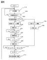
次に,本実施形態例の冷蔵庫の制御について図6〜図8を参照しながら説明する。図6は本実施形態例の冷蔵庫の制御を表すフローチャート,図7は本実施形態例の冷蔵庫の制御を表すタイムチャートである。図8は除霜開始条件が成立する条件を示す表である。 Next, control of the refrigerator according to the present embodiment will be described with reference to FIGS. FIG. 6 is a flowchart showing the control of the refrigerator of this embodiment, and FIG. 7 is a time chart showing the control of the refrigerator of this embodiment. FIG. 8 is a table showing conditions for satisfying the defrosting start condition.
図6に示すように,本実施形態例の冷蔵庫は,電源の投入により(スタート),圧縮機23が駆動して冷却運転を開始する(ステップS101)。
As shown in FIG. 6, the refrigerator of the present embodiment starts the cooling operation by driving the
本実施形態例の冷蔵庫の冷却運転は,冷蔵室温度センサ41,冷凍室温度センサ42,野菜室温度センサ43及び庫外温湿度センサの検知情報に基づいて圧縮機23,庫内送風機22,庫外送風機のオン/オフ制御や回転速度制御と,冷蔵室ダンパ24,冷凍室ダンパ26,野菜室ダンパの開閉状態の制御によって,各室を設定温度(例えば,冷蔵室,野菜室は4℃程度,冷凍室は−18℃程度)に維持する運転が行われる。
The cooling operation of the refrigerator according to the present embodiment is performed by the
冷却運転中には,除霜開始条件の判別が行われる(ステップS102)。本実施形態例の冷蔵庫1では,図8に示す条件が満たされた場合に除霜開始条件が成立する(ステップS102がYes)。ステップS102が不成立の場合,冷却運転が継続される(ステップS101に戻る)。
During the cooling operation, the defrosting start condition is determined (step S102). In the
例えば,(a)庫外温度(Tout)がTout>35℃,庫外湿度(相対湿度)(RHout)がRHout≦50%において,扉開閉累積時間(t1)がt1≧20分且つ冷却運転継続時間(t2)(前回の除霜完了後からの経過時間,または,除霜運転未実施の場合の電源投入後からの経過時間)がt2≧12時間の場合,または,冷却運転継続時間(t2)がt2≧48時間の何れかが満足された場合に除霜開始条件が成立する。他の成立条件は,(b)Tout>35℃,50<RHout≦80%において,t1≧15分且つt2≧12時間,または,t2≧48時間の何れかが満足された場合,(c)Tout>35℃,RHout>80%において,t1≧10分且つt3≧12時間,または,t2≧48時間の何れかが満足された場合,(d)20℃<Tout≦35℃,RHout≦50%において,t1≧25分且つt2≧12時間,または,t2≧72時間の何れかが満足された場合,(e)20℃<Tout≦35℃,50<RHout≦80%において,t1≧20分且つt3≧12時間,または,t2≧72時間の何れかが満足された場合,(f)20℃<Tout≦35℃,RHout>80%において,t1≧15分且つt3≧12時間,または,t2≧72時間の何れかが満足された場合,(g)Tout≦20℃,RHout≦50%において,t1≧50分且つt3≧12時間,または,t2≧96時間の何れかが満足された場合,(h)Tout≦20℃,50<RHout≦80%において,t1≧40分且つt3≧12時間,または,t2≧96時間の何れかが満足された場合,(i)Tout≦20℃,RHout>80%において,t1≧30分且つt3≧12時間,または,t2≧96時間の何れかが満足された場合である。 For example, (a) When the outside temperature (Tout) is Tout> 35 ° C., the outside humidity (relative humidity) (RHout) is RHout ≦ 50%, the door opening / closing cumulative time (t1) is t1 ≧ 20 minutes, and the cooling operation is continued. When the time (t2) (elapsed time since the completion of the previous defrosting, or the elapsed time since the power was turned on when the defrosting operation has not been performed) is t2 ≧ 12 hours, or the cooling operation duration (t2 ) Is satisfied when any of t2 ≧ 48 hours is satisfied. The other conditions are as follows: (b) When Tout> 35 ° C. and 50 <RHout ≦ 80%, when either t1 ≧ 15 minutes and t2 ≧ 12 hours or t2 ≧ 48 hours is satisfied, (c) When either T1 ≧ 10 minutes and t3 ≧ 12 hours or t2 ≧ 48 hours is satisfied at Tout> 35 ° C. and RHout> 80%, (d) 20 ° C. <Tout ≦ 35 ° C., RHout ≦ 50 %, When either t1 ≧ 25 minutes and t2 ≧ 12 hours or t2 ≧ 72 hours are satisfied, (e) at 20 ° C. <Tout ≦ 35 ° C., 50 <RHout ≦ 80%, t1 ≧ 20 Minutes and t3 ≧ 12 hours, or t2 ≧ 72 hours, (f) t1 ≧ 15 minutes and t3 ≧ 12 hours at 20 ° C. <Tout ≦ 35 ° C. and RHout> 80%. If any of t2 ≧ 72 hours is satisfied, (g) At Tout ≦ 20 ° C. and RHout ≦ 50%, either t1 ≧ 50 minutes and t3 ≧ 12 hours or t2 ≧ 96 hours is satisfied When (h) Tout ≦ 20 ° C. and 50 <RHout ≦ 80%, either t1 ≧ 40 minutes and t3 ≧ 12 hours or t2 ≧ 96 hours are satisfied, (i) Tout ≦ This is a case where t1 ≧ 30 minutes and t3 ≧ 12 hours or t2 ≧ 96 hours are satisfied at 20 ° C. and RHout> 80%.
本実施形態例の冷蔵庫1は,3つの除霜手段(除霜手段1、除霜手段2、除霜手段3)を備えている。1つ目の除霜手段(除霜手段1)は、庫内送風機22を駆動することによって冷蔵室と野菜室を冷却しながら除霜するものであり、「圧縮機停止状態、庫内送風機駆動状態,除霜ヒータ停止状態、冷蔵室ダンパ開放状態、野菜室ダンパ開放状態,冷凍室ダンパ閉鎖状態」にて霜を解かすものである。2つ目の除霜手段(除霜手段2)は、除霜ヒータ56通電状態で庫内送風機22を駆動し,冷蔵室と野菜室を冷却しながら除霜するものであり、「圧縮機停止状態、庫内送風機駆動状態,除霜ヒータ通電状態、冷蔵室ダンパ開放状態、野菜室ダンパ開放状態,冷凍温室ダンパ閉鎖状態」にて霜を解かすものである。3つ目の除霜手段(除霜手段3)は、除霜ヒータ22の通電のみによって除霜するものであり、「圧縮機停止状態、庫内送風機停止状態,除霜ヒータ通電状態、冷蔵室ダンパ閉鎖状態、冷凍室ダンパ開放状態」にて霜を解かすものである。
The
本実施形態例の冷蔵庫1は,上記除霜手段1〜3を順次切り替える「省エネ除霜モード」と,除霜手段3のみによる「高信頼性除霜モード」の2つの除霜モードを備えており,図8の(d)(e)(g)(h)(i)が成立した場合には「省エネルギー除霜モード」,(a)(b)(c)(f)が成立した場合には「高信頼性除霜モード」が選択される。
The
「省エネ除霜モード」の場合(ステップS103がNo),続いて「圧縮機駆動状態、庫内送風機駆動状態,除霜ヒータ停止状態、冷蔵室ダンパ閉鎖状態、野菜室ダンパ閉鎖状態,冷凍室ダンパ開放状態」で冷凍室プリクール運転が実施される(ステップS104)。これにより除霜中に冷却されない冷凍室7を事前に十分冷却することができ,除霜中に冷凍食品や氷が解けるといった不具合が生じ難くなる。
In the case of “energy saving defrost mode” (No in step S103), then “compressor driving state, internal fan driving state, defrosting heater stopped state, refrigerator compartment damper closed state, vegetable compartment damper closed state, freezer compartment damper The freezer compartment pre-cooling operation is performed in the “open state” (step S104). As a result, the
冷凍室プリクール運転を所定時間(本実施形態例の冷蔵庫1では30分)実施後,続いて除霜手段1(圧縮機停止状態、庫内送風機駆動状態,除霜ヒータ停止状態、冷蔵室ダンパ開放状態、野菜室ダンパ開放状態,冷凍室ダンパ閉鎖状態)による除霜運転が実施される(ステップS105)。冷却器温度センサ44の検知温度TD1が−3℃に到達すると(ステップS106),除霜手段2(圧縮機停止状態、庫内送風機駆動状態,除霜ヒータ通電状態、冷蔵室ダンパ開放状態、野菜室ダンパ開放状態,冷凍温室ダンパ閉鎖状態)による除霜運転に移行する(ステップS107)。冷却器温度センサ44の検知温度TD1が+2℃に到達すると(ステップS108),さらに除霜手段3(圧縮機停止状態、庫内送風機停止状態,除霜ヒータ通電状態、冷蔵室ダンパ閉鎖状態、冷凍室ダンパ開放状態)に移行する(ステップS109)。除霜手段3による除霜は,冷却器温度センサ44の検知温度TD1が+5℃以上,且つ,前面仕切壁温度センサ45の検知温度TD2が+3℃以上になった場合に除霜完了と判定し(ステップS110),冷却器収納室9内の融解水の排水を促すために「圧縮機停止状態、庫内送風機停止状態,除霜ヒータ停止状態、冷蔵室ダンパ開放状態、野菜室ダンパ開放状態,冷凍室ダンパ開放状態」とする「オフタイム」を所定時間(本実施形態例の冷蔵庫1では3分間)確保する(ステップS111)。なお,除霜完了の判定は,「冷却器温度センサ44の検知温度TD1と,前面仕切壁温度センサ45の検知温度TD2の両者が0℃より高い」という条件を満足していれば良く,本実施形態例の冷蔵庫1とは異なる温度であっても良い。ただし,除霜ヒータ56からの距離が遠い前面仕切壁温度センサ45TD2の判定基準温度を,冷却器温度センサ44の検知温度TD1より低くすることで,過熱を抑えることができ,省エネルギー性能を高くすることができる。
After the freezer compartment pre-cooling operation is performed for a predetermined time (30 minutes in the
続いて貯蔵室に高温空気が送風されることを避けるために,庫内送風機22停止状態で圧縮機を駆動し,「圧縮機停止駆動状態、庫内送風機停止状態,除霜ヒータ停止状態、冷蔵室ダンパ開放状態、野菜室ダンパ開放状態,冷凍室ダンパ開放状態」とすることで冷却器収納室9内の冷却を行う「庫内送風機停止運転」を所定時間(本実施形態例の冷蔵庫1では2分間)(ステップS112)実施後,冷却運転を再開する(ステップS101)。
Subsequently, in order to avoid high temperature air being blown into the storage room, the compressor is driven while the
ステップS103において「高信頼性除霜モード」が成立した場合(ステップS103がYes),続いて,「圧縮機駆動状態、庫内送風機駆動状態,除霜ヒータ停止状態、冷蔵室ダンパ開放状態、野菜室ダンパ開放状態,冷凍室ダンパ開放状態」で全室プリクール運転が実施される(ステップS201)。「高信頼性除霜モード」では,除霜運転中に貯蔵室の冷却は行われないが,全室プリクールにより除霜中に冷却されない冷凍室7を事前に十分冷却することができ,除霜中に各貯蔵室の温度が過度に上昇することを防ぐことができる。
When “high reliability defrosting mode” is established in step S103 (Yes in step S103), “compressor driving state, internal fan driving state, defrosting heater stopped state, refrigerator freezer state, vegetable All-room precooling operation is performed in the “room damper open state, freezer compartment damper open state” (step S201). In the “high reliability defrosting mode”, the storage room is not cooled during the defrosting operation, but the freezing
全室プリクール運転を所定時間(本実施形態例の冷蔵庫1では30分)実施後,ステップS109に移行し,除霜手段3(圧縮機停止状態、庫内送風機停止状態,除霜ヒータ通電状態、冷蔵室ダンパ開放状態、野菜室ダンパ開放状態,冷凍室ダンパ開放状態)による除霜運転が実施される。以後は「省エネ除霜モード」と同様の制御ステップとなる。
After performing the all-room precool operation for a predetermined time (30 minutes in the
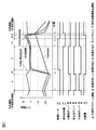
図7は,冷蔵庫を32℃,相対湿度70%の室内に設置した際の制御状態と庫内要部の温度変化を表すタイムチャートである。 FIG. 7 is a time chart showing the control state and the temperature change in the main part of the refrigerator when the refrigerator is installed in a room at 32 ° C. and a relative humidity of 70%.
図7に示すように,経過時間taにおいて除霜開始条件が満足され(ここでは冷却運転継続時間t2が48hに達し,除霜運転開始条件が成立している(図8の(e)の条件により図5のステップ102がYes)。図8の(d)(e)(g)(h)(i)が成立した場合には「省エネルギー除霜モード」が選択されるので(図6ステップS103がNo),続いて「圧縮機駆動状態、庫内送風機駆動状態,除霜ヒータ停止状態、冷蔵室ダンパ閉鎖状態、野菜室ダンパ閉鎖状態,冷凍室ダンパ開放状態」で冷凍室プリクール運転が実施される(図6のステップS104)。これにより冷凍室7が冷却されて温度が下がり,冷却されない冷蔵室2,野菜室8の温度が上昇する。
As shown in FIG. 7, is satisfied defrosting start condition is at the elapsed time t a (cooling operation continuation time t2 reaches 48h here, defrosting operation start conditions are satisfied (in FIG. 8 (e) 5 is Yes depending on the conditions.) When (d), (e), (g), (h), and (i) in FIG.8 are established, the “energy saving defrosting mode” is selected (step in FIG. 6). S103 is No), followed by freezer compartment precool operation in "compressor drive state, internal fan drive state, defrost heater stop state, refrigerator compartment damper closed state, vegetable compartment damper closed state, freezer compartment damper open state" 6 (step S104 in FIG. 6), the
経過時間tbにおいて冷凍室プリクール運転継続時間(30分)が経過し,除霜手段1(圧縮機停止状態、庫内送風機駆動状態,除霜ヒータ停止状態、冷蔵室ダンパ開放状態、野菜室ダンパ開放状態,冷凍室ダンパ閉鎖状態)による除霜運転が実施される(図6のステップS105)。除霜手段1による除霜では,主に霜の顕熱と熱交換した空気で冷蔵室2,野菜室8を冷却するように庫内送風機22を制御(具体的には1500min-1で駆動)するので,除霜手段1による除霜中の冷蔵室2,野菜室8の温度は低下している。これは,ヒータを用いずに庫内の熱負荷で霜を加熱している状態となるため省エネルギー性能が高い除霜となる。
In the elapsed time tb, the freezer compartment precooling operation continuation time (30 minutes) has elapsed, and the defrosting means 1 (compressor stopped state, internal fan drive state, defrost heater stopped state, refrigerator compartment damper open state, vegetable compartment damper open) The defrosting operation is performed according to the state (freezer compartment damper closed state) (step S105 in FIG. 6). In the defrosting by the defrosting means 1, the
経過時間tcにおいて,冷却器温度センサ44の検知温度TD1が−3℃に到達し(図6のステップS106がYes),除霜手段2(圧縮機停止状態、庫内送風機駆動状態,除霜ヒータ通電状態、冷蔵室ダンパ開放状態、野菜室ダンパ開放状態,冷凍温室ダンパ閉鎖状態)による除霜に移行している(図6のステップS107)。除霜手段2による除霜では,除霜ヒータ56に通電することにより除霜を加速しつつ,主に霜の潜熱(冷却器温度(霜温度)が0℃でほぼ一定)と熱交換した空気で冷蔵室2,野菜室8を冷却するように除霜ヒータと庫内送風機22を制御(具体的には除霜ヒータ通電量を150W,庫内送風機回転数を1200min-1で駆動)するので,除霜手段2による除霜中の冷蔵室2,野菜室8の温度は維持されている。除霜手段2による除霜中の冷蔵室2,野菜室8は冷却されることで維持されている。これは,ヒータに通電しながら庫内の熱負荷も利用して霜を加熱している状態となるため省エネルギー性能が高く,また,比較的短い時間で霜の融解に必要な熱量を与えることが可能となる。
At the elapsed time tc, the detection temperature TD1 of the
経過時間tdにおいて,冷却器温度センサ44の検知温度TD1が+2℃に到達し(図6のステップS108がYes),除霜手段3(圧縮機停止状態、庫内送風機停止状態,除霜ヒータ通電状態、冷蔵室ダンパ閉鎖状態、冷凍室ダンパ開放状態)による除霜に移行している(図6のステップS109)。除霜手段2は除霜ヒータ56への通電のみによる除霜となるため,冷蔵室2,野菜室8,冷凍室7は冷却されず温度は上昇する。また,冷却器温度は除霜ヒータ56により加熱されるので温度が上昇する。また,前面仕切壁温度センサ45の検知温度TD2は,経過時間tdにおいては約0℃となっているが,除霜手段3による除霜運転中にプラス温度に上昇しはじめている。
At the elapsed time td, the detected temperature TD1 of the
経過時間teにおいて,冷却器温度センサ44の検知温度TD1が+6℃,前面仕切壁温度センサ45の検知温度TD2が+3℃に到達し(図6のステップS110がYes),除霜ヒータ56への通電が停止され,「オフタイム(圧縮機停止状態、庫内送風機停止状態,除霜ヒータ停止状態、冷蔵室ダンパ開放状態、野菜室ダンパ開放状態,冷凍室ダンパ開放状態)」に移行している(図6のステップS111)。
At the elapsed time te, the detection temperature TD1 of the
さらに経過時間tfにおいて,「オフタイム」の設定時間(3分)が経過したことにより,庫内送風機22停止状態で圧縮機23が駆動される「庫内送風機停止運転(圧縮機停止駆動状態、庫内送風機停止状態,除霜ヒータ停止状態、冷蔵室ダンパ開放状態、野菜室ダンパ開放状態,冷凍室ダンパ開放状態)」に移行している(図6のステップS112)。
Further, at the elapsed time tf, when the set time (3 minutes) of “off time” has elapsed, the
冷蔵室2,野菜室8,冷凍室7は「オフタイム」から「庫内送風機停止運転」の間は,冷却されないため温度が上昇している。一方,冷却器温度と前面仕切壁表面温度は「オフタイム」中に上昇するが,「庫内送風機停止運転」では,冷却器に低温冷媒が流れるため,冷却器温度や前面仕切壁表面温度は低下している。
Since the
経過時間tgにおいて,「庫内送風機停止運転」の設定時間(2分)が経過したことにより,庫内送風機22が駆動され,冷却運転(冷凍運転)が再開されている(図6のステップS101)。
When the set time (2 minutes) of “internal fan stop operation” has elapsed at the elapsed time tg, the
以上のように本実施形態例の冷蔵庫では,冷却器21の下流流路の庫内側の仕切壁表面の温度を検知する温度センサ(前面仕切壁温度センサ45)を備えており,その検知情報に基づいて除霜完了の判定を行っている。冷気流路を形成する壁面のうち庫外側に位置する壁面(例えば本実施形態例の冷蔵庫1における冷却器収納室9の背面)は,除霜運転中に庫外からの熱侵入により温度上昇しやすいが,庫内側に位置する壁面(貯蔵室や風路との境界を形成する壁面)は,低温の貯蔵室の影響で温度が上昇し難い。一般に冷蔵庫における除霜運転では,冷却器及びその周辺部の霜が融解したと推定される場合に除霜完了と判定されるため,除霜完了検知手段(温度センサ)の設置位置は,霜が解け難い箇所に設置することが望ましい。本実施形態例の冷蔵庫では,温度が上昇し難い冷却器21の下流の庫内側の仕切壁表面の温度を検知する温度センサ(前面仕切壁温度センサ45)を備え,その検知情報に基づいて除霜完了の判定を行う。これにより,霜が解け難い箇所の温度を検知できるので,過度に余裕度を持った除霜完了判定基準温度にすることなく,除霜運転を行うことができる。したがって,省エネルギー性能と信頼性がともに高い冷蔵庫を提供することができる。
As described above, the refrigerator of the present embodiment includes the temperature sensor (front partition wall temperature sensor 45) that detects the temperature of the partition wall surface inside the warehouse of the downstream flow path of the cooler 21, and the detection information includes Based on this, the defrosting completion is determined. Among the wall surfaces forming the cool air flow path, the wall surface located outside the refrigerator (for example, the back surface of the
本実施形態例の冷蔵庫では,冷却器温度を検知する温度センサ(冷却器温度センサ44)と,冷却器21の下流流路の温度を検知する温度センサ(前面仕切壁温度センサ45)を備えており,これらのセンサの検知情報に基づいて除霜完了の判定を行っている。具体的には,冷却器温度センサ44の検知温度TD1と,前面仕切壁温度センサ45の検知温度TD2の両者が0℃より高い所定温度に到達した場合に,除霜完了と判定する。なお,冷却器温度センサ44(第一除霜完了検知手段)と,前面仕切壁温度センサ45(第二除霜完了検知手段)を備えており,第一除霜完了検知手段の表面温度と,第二除霜完了検知手段の表面温度がともに0℃より高い所定温度になった場合に除霜運転(ヒータ通電)を終了すれば,第一除霜完了検知手段の検知温度と,第二除霜完了検知手段の検知温度の検知情報に基づく制御とみなすことができる。
The refrigerator of this embodiment includes a temperature sensor (cooler temperature sensor 44) that detects the cooler temperature and a temperature sensor (front partition wall temperature sensor 45) that detects the temperature of the downstream flow path of the cooler 21. The defrosting completion is determined based on the detection information of these sensors. Specifically, it is determined that the defrosting is completed when both the detection temperature TD1 of the
これにより,霜が成長しやすい冷却器と,温度が上昇し難い冷却器の下流流路の両方について,除霜完了判定基準値に過度な余裕度を持つ必要がなくなり,過熱を抑えることができる。よって,省エネルギー性能と信頼性がともに高い冷蔵庫を提供することができる。 As a result, it is not necessary to have an excessive margin in the defrosting completion criterion value for both the cooler in which frost easily grows and the downstream flow path of the cooler in which the temperature does not easily rise, and overheating can be suppressed. . Therefore, it is possible to provide a refrigerator with high energy saving performance and high reliability.
一般に,冷蔵庫の冷却器や冷却器の周辺への着霜の状態は,冷蔵庫の運転履歴,庫内に収納される食品の種類や量,扉開閉頻度等により多様に変化するため,冷却器への着霜量の多少,冷却器下流流路への着霜量の多少は一定にはならない。よって,従来の冷蔵庫では,冷却器の除霜状態を検知する単一の除霜完了検知手段で除霜完了を判定するために,信頼性上で最も厳しい条件,すなわち,冷却器の温度が上昇しやすく,冷却器下流流路に霜が残りやすい条件を想定して判定基準値を定めることが必要になっていた。 Generally, the state of frost formation on the refrigerator cooler and the surroundings of the refrigerator varies depending on the operation history of the refrigerator, the type and amount of food stored in the refrigerator, the frequency of opening and closing the door, and so on. The amount of frost formed on the cooler and the amount of frost formed on the downstream of the cooler are not constant. Therefore, in the conventional refrigerator, since the defrost completion is judged by the single defrost completion detection means for detecting the defrost state of the cooler, the most severe condition in reliability, that is, the temperature of the cooler is increased. Therefore, it was necessary to set a judgment reference value assuming a condition in which frost is likely to remain in the cooler downstream flow path.
冷却器の温度が上昇しやすく,冷却器下流流路に霜が残りやすいのは,冷却器への着霜が比較的少なくて,冷却器下流流路に多くの着霜が生じている場合であり,冷却器温度センサ44のみによって除霜完了を判定する場合は,冷却器の下流流路に多量の着霜が生じていても十分に融解させることができる判定基準値として,例えば10℃程度とする必要があった。一方で,本実施形態例の冷蔵庫では,第一除霜完了検知手段の検知温度と,第二除霜完了検知手段の検知温度の検知情報に基づいて除霜完了を判定するので,冷却器への着霜が比較的少なくて,冷却器下流流路に多くの着霜が生じている最も厳しい条件以外の条件,例えば,冷却器への着霜が多く,冷却器下流流路への着霜が少ない,あるいは,冷却器と冷却器下流流路への着霜がともに少ない条件等で冷却器の過熱が抑えられる。例えば,本実施形態例の冷蔵庫では,冷却器下流流路の除霜が完了したと判定していた時点(前面仕切壁温度センサ45の検知温度が3℃)で,冷却器温度(冷却器温度センサ44の検知温度)は6℃であり,冷却器の過熱が抑えられていることがわかる。本実施形態例の冷蔵庫では,冷却器温度を検知する温度センサ(冷却器温度センサ44)と,冷却器21の下流流路の温度を検知する温度センサ(前面仕切壁温度センサ45)を備えており,冷却器21の幅方向の中心面を基準に分けられる領域の双方に少なくとも1つの温度検知手段を配設している。
The temperature of the cooler tends to rise, and frost tends to remain in the cooler downstream flow path when there is relatively little frost formation on the cooler and there is a lot of frost formation in the cooler downstream flow path. Yes, when the defrosting completion is determined only by the
これにより,冷却器収納室9内において,霜が成長しやすい冷却器と,温度が上昇し難い冷却器の下流流路の双方の除霜状態を効率良く検知することができる。
Thereby, in the
本実施形態例の冷蔵庫では,冷却器21の下流流路の中に設置されている可動部品(庫内送風機22)の近傍温度を仕切壁表面の温度を検知する温度センサ(前面仕切壁温度センサ45)により検知している。これにより,温度が上昇し難い冷却器の下流流路の特に可動部品(庫内送風機22)の近傍に霜の解け残りが生じるリスクを抑えることができるので,除霜完了判定基準値に過度な余裕度を持つ必要がなくなり,過熱を抑えることができる。 In the refrigerator of the present embodiment, a temperature sensor (front partition wall temperature sensor) detects the temperature of the partition wall surface using the temperature in the vicinity of the movable part (internal fan 22) installed in the downstream flow path of the cooler 21. 45). As a result, it is possible to suppress the risk of frost remaining undissolved in the vicinity of the movable part (internal fan 22) in the downstream flow path of the cooler, where the temperature does not easily rise. It is not necessary to have a margin, and overheating can be suppressed.
よって,省エネルギー性と信頼性がともに高い冷蔵庫を提供することができる。 Therefore, it is possible to provide a refrigerator that has both high energy saving and high reliability.
なお,本発明は上記した各実施例に限定されるものではなく,様々な変形例が含まれる。例えば,冷却器21の温度を検知する温度センサや,冷却器21の下流流路の温度を検知する温度センサを複数配設しても良い。また,本実施形態例の冷蔵庫1では、冷却器21の下流流路における可動部品として庫内送風機22の温度を検知しているが、冷却器21の下流流路にある他の可動部品として例えばダンパ温度(ダンパの近傍温度)を検知する温度センサを配設しても良い。さらに,冷却器21の下流流路の庫内側に位置する壁面に保持される稼働部品に直接温度センサを配設して可動部品の温度を測定する構成としたり、可動部品や、温度が上昇し難い箇所に補助ヒータを配設して,除霜運転時に加熱するようにしても良い。また,本実施形態例の冷蔵庫1は「冷蔵室単独運転」,「野菜室単独運転」,「冷凍室単独運転」,「冷蔵野菜運転」,「冷蔵野菜冷凍運転」の5種類の冷却運転モードを備えた冷蔵庫だが,これら全てを備えていなくてもよい。
In addition, this invention is not limited to each above-mentioned Example, Various modifications are included. For example, a plurality of temperature sensors that detect the temperature of the cooler 21 and a plurality of temperature sensors that detect the temperature of the downstream flow path of the cooler 21 may be provided. Moreover, in the
すなわち,上記した実施例は本発明を分かりやすく説明するために詳細に説明したものであり,必ずしも説明した全ての構成を備えるものに限定されるものではない。 That is, the above-described embodiment has been described in detail for easy understanding of the present invention, and is not necessarily limited to one having all the configurations described.
1 冷蔵庫本体
2 冷蔵室
3 チルド室
4 製氷室
5 上段冷凍室
6 下段冷凍室
7 冷凍室
8 野菜室
9 冷却器収納室
10 機械室
11 冷蔵室送風ダクト
12 冷蔵室戻りダクト
13 冷凍室送風ダクト
17 野菜室戻りダクト
21 冷却器
22 庫内送風機
23 圧縮機
24 冷蔵室ダンパ
26 冷凍室ダンパ
27 前面仕切壁
28 気液分離器
31 冷蔵室吹き出し口
33 冷凍室吹き出し口
36 冷凍室戻り口
37 野菜室戻り口
41 冷蔵室温度センサ
42 冷凍室温度センサ
43 野菜室温度センサ
44 冷却器温度センサ
45 前面仕切壁温度センサ
46 棚
47 扉ポケット
49 制御基板
50 断熱箱体
51 上部断熱仕切壁(仕切部)
52 下部断熱仕切壁(仕切部)
55aa,55b バイパス流路
56 除霜ヒータ
57 樋
58 排水管
59 蒸発皿
60 真空断熱材
70 放熱手段
71 放熱器
72 放熱パイプ
73 結露抑制パイプ
74 キャピラリチューブ
77 冷媒配管
DESCRIPTION OF
33
52 Lower heat insulation partition wall (partition)
55aa,
Claims (5)
Priority Applications (1)
| Application Number | Priority Date | Filing Date | Title |
|---|---|---|---|
| JP2016211203A JP6752107B2 (en) | 2016-10-28 | 2016-10-28 | refrigerator |
Applications Claiming Priority (1)
| Application Number | Priority Date | Filing Date | Title |
|---|---|---|---|
| JP2016211203A JP6752107B2 (en) | 2016-10-28 | 2016-10-28 | refrigerator |
Publications (2)
| Publication Number | Publication Date |
|---|---|
| JP2018071874A true JP2018071874A (en) | 2018-05-10 |
| JP6752107B2 JP6752107B2 (en) | 2020-09-09 |
Family
ID=62114700
Family Applications (1)
| Application Number | Title | Priority Date | Filing Date |
|---|---|---|---|
| JP2016211203A Active JP6752107B2 (en) | 2016-10-28 | 2016-10-28 | refrigerator |
Country Status (1)
| Country | Link |
|---|---|
| JP (1) | JP6752107B2 (en) |
Cited By (5)
| Publication number | Priority date | Publication date | Assignee | Title |
|---|---|---|---|---|
| JP2020101299A (en) * | 2018-12-20 | 2020-07-02 | 日立グローバルライフソリューションズ株式会社 | refrigerator |
| CN112696862A (en) * | 2020-12-18 | 2021-04-23 | 合肥朗驰工业设计有限公司 | Intermittent defrosting control method for refrigerator and air-cooled refrigerator |
| WO2024024018A1 (en) * | 2022-07-28 | 2024-02-01 | 三菱電機株式会社 | Refrigerator |
| JP7465135B2 (en) | 2020-04-03 | 2024-04-10 | ホシザキ株式会社 | Cooling Storage |
| JP7473390B2 (en) | 2020-05-15 | 2024-04-23 | 日立グローバルライフソリューションズ株式会社 | refrigerator |
Citations (5)
| Publication number | Priority date | Publication date | Assignee | Title |
|---|---|---|---|---|
| JPS4879379U (en) * | 1971-12-28 | 1973-09-29 | ||
| JPH0566076A (en) * | 1991-09-05 | 1993-03-19 | Toshiba Corp | Cooling apparatus |
| JP2004144364A (en) * | 2002-10-23 | 2004-05-20 | Matsushita Refrig Co Ltd | Refrigerator |
| US20130081416A1 (en) * | 2011-09-29 | 2013-04-04 | Lg Electronics Inc. | Refrigerator |
| JP2015117850A (en) * | 2013-12-17 | 2015-06-25 | 株式会社東芝 | Refrigerator |
-
2016
- 2016-10-28 JP JP2016211203A patent/JP6752107B2/en active Active
Patent Citations (5)
| Publication number | Priority date | Publication date | Assignee | Title |
|---|---|---|---|---|
| JPS4879379U (en) * | 1971-12-28 | 1973-09-29 | ||
| JPH0566076A (en) * | 1991-09-05 | 1993-03-19 | Toshiba Corp | Cooling apparatus |
| JP2004144364A (en) * | 2002-10-23 | 2004-05-20 | Matsushita Refrig Co Ltd | Refrigerator |
| US20130081416A1 (en) * | 2011-09-29 | 2013-04-04 | Lg Electronics Inc. | Refrigerator |
| JP2015117850A (en) * | 2013-12-17 | 2015-06-25 | 株式会社東芝 | Refrigerator |
Cited By (5)
| Publication number | Priority date | Publication date | Assignee | Title |
|---|---|---|---|---|
| JP2020101299A (en) * | 2018-12-20 | 2020-07-02 | 日立グローバルライフソリューションズ株式会社 | refrigerator |
| JP7465135B2 (en) | 2020-04-03 | 2024-04-10 | ホシザキ株式会社 | Cooling Storage |
| JP7473390B2 (en) | 2020-05-15 | 2024-04-23 | 日立グローバルライフソリューションズ株式会社 | refrigerator |
| CN112696862A (en) * | 2020-12-18 | 2021-04-23 | 合肥朗驰工业设计有限公司 | Intermittent defrosting control method for refrigerator and air-cooled refrigerator |
| WO2024024018A1 (en) * | 2022-07-28 | 2024-02-01 | 三菱電機株式会社 | Refrigerator |
Also Published As
| Publication number | Publication date |
|---|---|
| JP6752107B2 (en) | 2020-09-09 |
Similar Documents
| Publication | Publication Date | Title |
|---|---|---|
| CN101619916B (en) | Ice refrigerator | |
| JP5017340B2 (en) | refrigerator | |
| JP5530852B2 (en) | refrigerator | |
| JP5178642B2 (en) | refrigerator | |
| CN101929779B (en) | Refrigerator | |
| WO2012157263A1 (en) | Refrigerator | |
| JP5507511B2 (en) | refrigerator | |
| JP6752107B2 (en) | refrigerator | |
| JP5622758B2 (en) | refrigerator | |
| JP5260416B2 (en) | refrigerator | |
| JP2013061089A (en) | Refrigerator | |
| JP2012007760A (en) | Refrigerator | |
| JP4982537B2 (en) | refrigerator | |
| JP5838238B2 (en) | refrigerator | |
| JP6890502B2 (en) | refrigerator | |
| JP2012042140A (en) | Refrigerator | |
| JP2011038714A (en) | Refrigerator | |
| JP6837423B2 (en) | refrigerator | |
| JP2012063026A (en) | Refrigerator | |
| JP2019027649A (en) | refrigerator | |
| CN112378146B (en) | Refrigerator with a door | |
| JP5376796B2 (en) | refrigerator | |
| JP2017187246A (en) | refrigerator | |
| US20220146154A1 (en) | Refrigerator control method | |
| JP2013108707A (en) | Refrigerator |
Legal Events
| Date | Code | Title | Description |
|---|---|---|---|
| A521 | Request for written amendment filed |
Free format text: JAPANESE INTERMEDIATE CODE: A523 Effective date: 20161031 |
|
| RD04 | Notification of resignation of power of attorney |
Free format text: JAPANESE INTERMEDIATE CODE: A7424 Effective date: 20170126 |
|
| A621 | Written request for application examination |
Free format text: JAPANESE INTERMEDIATE CODE: A621 Effective date: 20190807 |
|
| A521 | Request for written amendment filed |
Free format text: JAPANESE INTERMEDIATE CODE: A523 Effective date: 20190808 |
|
| A977 | Report on retrieval |
Free format text: JAPANESE INTERMEDIATE CODE: A971007 Effective date: 20200424 |
|
| A131 | Notification of reasons for refusal |
Free format text: JAPANESE INTERMEDIATE CODE: A131 Effective date: 20200519 |
|
| A521 | Request for written amendment filed |
Free format text: JAPANESE INTERMEDIATE CODE: A523 Effective date: 20200619 |
|
| TRDD | Decision of grant or rejection written | ||
| A01 | Written decision to grant a patent or to grant a registration (utility model) |
Free format text: JAPANESE INTERMEDIATE CODE: A01 Effective date: 20200721 |
|
| A61 | First payment of annual fees (during grant procedure) |
Free format text: JAPANESE INTERMEDIATE CODE: A61 Effective date: 20200818 |
|
| R150 | Certificate of patent or registration of utility model |
Ref document number: 6752107 Country of ref document: JP Free format text: JAPANESE INTERMEDIATE CODE: R150 |