WO2012157263A1 - Refrigerator - Google Patents
Refrigerator Download PDFInfo
- Publication number
- WO2012157263A1 WO2012157263A1 PCT/JP2012/003181 JP2012003181W WO2012157263A1 WO 2012157263 A1 WO2012157263 A1 WO 2012157263A1 JP 2012003181 W JP2012003181 W JP 2012003181W WO 2012157263 A1 WO2012157263 A1 WO 2012157263A1
- Authority
- WO
- WIPO (PCT)
- Prior art keywords
- cooling
- refrigerator
- temperature
- evaporator
- refrigerator compartment
- Prior art date
Links
Images


Classifications
-
- F—MECHANICAL ENGINEERING; LIGHTING; HEATING; WEAPONS; BLASTING
- F25—REFRIGERATION OR COOLING; COMBINED HEATING AND REFRIGERATION SYSTEMS; HEAT PUMP SYSTEMS; MANUFACTURE OR STORAGE OF ICE; LIQUEFACTION SOLIDIFICATION OF GASES
- F25D—REFRIGERATORS; COLD ROOMS; ICE-BOXES; COOLING OR FREEZING APPARATUS NOT OTHERWISE PROVIDED FOR
- F25D21/00—Defrosting; Preventing frosting; Removing condensed or defrost water
- F25D21/04—Preventing the formation of frost or condensate
-
- F—MECHANICAL ENGINEERING; LIGHTING; HEATING; WEAPONS; BLASTING
- F25—REFRIGERATION OR COOLING; COMBINED HEATING AND REFRIGERATION SYSTEMS; HEAT PUMP SYSTEMS; MANUFACTURE OR STORAGE OF ICE; LIQUEFACTION SOLIDIFICATION OF GASES
- F25B—REFRIGERATION MACHINES, PLANTS OR SYSTEMS; COMBINED HEATING AND REFRIGERATION SYSTEMS; HEAT PUMP SYSTEMS
- F25B6/00—Compression machines, plants or systems, with several condenser circuits
-
- F—MECHANICAL ENGINEERING; LIGHTING; HEATING; WEAPONS; BLASTING
- F25—REFRIGERATION OR COOLING; COMBINED HEATING AND REFRIGERATION SYSTEMS; HEAT PUMP SYSTEMS; MANUFACTURE OR STORAGE OF ICE; LIQUEFACTION SOLIDIFICATION OF GASES
- F25D—REFRIGERATORS; COLD ROOMS; ICE-BOXES; COOLING OR FREEZING APPARATUS NOT OTHERWISE PROVIDED FOR
- F25D21/00—Defrosting; Preventing frosting; Removing condensed or defrost water
- F25D21/002—Defroster control
- F25D21/006—Defroster control with electronic control circuits
-
- F—MECHANICAL ENGINEERING; LIGHTING; HEATING; WEAPONS; BLASTING
- F25—REFRIGERATION OR COOLING; COMBINED HEATING AND REFRIGERATION SYSTEMS; HEAT PUMP SYSTEMS; MANUFACTURE OR STORAGE OF ICE; LIQUEFACTION SOLIDIFICATION OF GASES
- F25B—REFRIGERATION MACHINES, PLANTS OR SYSTEMS; COMBINED HEATING AND REFRIGERATION SYSTEMS; HEAT PUMP SYSTEMS
- F25B2400/00—General features or devices for refrigeration machines, plants or systems, combined heating and refrigeration systems or heat-pump systems, i.e. not limited to a particular subgroup of F25B
- F25B2400/04—Refrigeration circuit bypassing means
- F25B2400/0403—Refrigeration circuit bypassing means for the condenser
-
- F—MECHANICAL ENGINEERING; LIGHTING; HEATING; WEAPONS; BLASTING
- F25—REFRIGERATION OR COOLING; COMBINED HEATING AND REFRIGERATION SYSTEMS; HEAT PUMP SYSTEMS; MANUFACTURE OR STORAGE OF ICE; LIQUEFACTION SOLIDIFICATION OF GASES
- F25B—REFRIGERATION MACHINES, PLANTS OR SYSTEMS; COMBINED HEATING AND REFRIGERATION SYSTEMS; HEAT PUMP SYSTEMS
- F25B2500/00—Problems to be solved
- F25B2500/01—Geometry problems, e.g. for reducing size
-
- F—MECHANICAL ENGINEERING; LIGHTING; HEATING; WEAPONS; BLASTING
- F25—REFRIGERATION OR COOLING; COMBINED HEATING AND REFRIGERATION SYSTEMS; HEAT PUMP SYSTEMS; MANUFACTURE OR STORAGE OF ICE; LIQUEFACTION SOLIDIFICATION OF GASES
- F25B—REFRIGERATION MACHINES, PLANTS OR SYSTEMS; COMBINED HEATING AND REFRIGERATION SYSTEMS; HEAT PUMP SYSTEMS
- F25B2700/00—Sensing or detecting of parameters; Sensors therefor
- F25B2700/02—Humidity
-
- F—MECHANICAL ENGINEERING; LIGHTING; HEATING; WEAPONS; BLASTING
- F25—REFRIGERATION OR COOLING; COMBINED HEATING AND REFRIGERATION SYSTEMS; HEAT PUMP SYSTEMS; MANUFACTURE OR STORAGE OF ICE; LIQUEFACTION SOLIDIFICATION OF GASES
- F25D—REFRIGERATORS; COLD ROOMS; ICE-BOXES; COOLING OR FREEZING APPARATUS NOT OTHERWISE PROVIDED FOR
- F25D2323/00—General constructional features not provided for in other groups of this subclass
- F25D2323/002—Details for cooling refrigerating machinery
- F25D2323/0026—Details for cooling refrigerating machinery characterised by the incoming air flow
- F25D2323/00266—Details for cooling refrigerating machinery characterised by the incoming air flow through the bottom
-
- F—MECHANICAL ENGINEERING; LIGHTING; HEATING; WEAPONS; BLASTING
- F25—REFRIGERATION OR COOLING; COMBINED HEATING AND REFRIGERATION SYSTEMS; HEAT PUMP SYSTEMS; MANUFACTURE OR STORAGE OF ICE; LIQUEFACTION SOLIDIFICATION OF GASES
- F25D—REFRIGERATORS; COLD ROOMS; ICE-BOXES; COOLING OR FREEZING APPARATUS NOT OTHERWISE PROVIDED FOR
- F25D2323/00—General constructional features not provided for in other groups of this subclass
- F25D2323/002—Details for cooling refrigerating machinery
- F25D2323/0027—Details for cooling refrigerating machinery characterised by the out-flowing air
- F25D2323/00272—Details for cooling refrigerating machinery characterised by the out-flowing air from the back top
-
- F—MECHANICAL ENGINEERING; LIGHTING; HEATING; WEAPONS; BLASTING
- F25—REFRIGERATION OR COOLING; COMBINED HEATING AND REFRIGERATION SYSTEMS; HEAT PUMP SYSTEMS; MANUFACTURE OR STORAGE OF ICE; LIQUEFACTION SOLIDIFICATION OF GASES
- F25D—REFRIGERATORS; COLD ROOMS; ICE-BOXES; COOLING OR FREEZING APPARATUS NOT OTHERWISE PROVIDED FOR
- F25D2700/00—Means for sensing or measuring; Sensors therefor
- F25D2700/02—Sensors detecting door opening
Definitions
- the present invention relates to a refrigerator that has a condenser pipe (hereinafter referred to as “dew-proof pipe”) that prevents condensation on the wall surface and that suppresses pressure loss caused by the dew-proof pipe.
- dew-proof pipe a condenser pipe
- the present invention has dampers that block cold air in the freezing room and the refrigerating room, respectively, and uses a single evaporator to individually cool the freezing room and the refrigerating room, thereby improving the efficiency of the refrigerating cycle. It relates to the refrigerator.
- the present invention relates to a refrigerator, and more particularly, to a control that suppresses temperature rise in a refrigerator during defrosting by a heater in a refrigerator that cools a storage room by latent heat and sensible heat of frost attached to a cooler.
- a dew-proof pipe that is attached to the inside of the outer casing and prevents condensation on the wall surface is used in combination.
- the refrigerator for home uses a flammable refrigerant from the viewpoint of preventing global warming, and a dew-proof pipe having a small pipe inner diameter is used for the purpose of reducing the amount of the enclosed refrigerant.
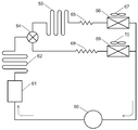
- FIG. 21 is a configuration diagram of a refrigeration cycle of a conventional refrigerator.
- this refrigeration cycle includes a compressor 60, a main condenser 61, a dew-proof pipe 62 for a freezer compartment, a dew-proof pipe 63 for a refrigerator compartment, and a flow path switching valve 64. Further, this refrigeration cycle includes a refrigeration throttle 65, a refrigeration room evaporator 66, a refrigeration room fan 67, a refrigeration throttle 68, a freezing room evaporator 69, and a freezing room fan 70.
- the conventional refrigerator cools the refrigerator compartment (not shown) using the refrigerator compartment evaporator 66 and cools the refrigerator compartment (not shown) using the freezer evaporator 69.
- the dew-proof pipe 63 for the refrigerating room is installed at the opening of the refrigerating room (not shown) to prevent condensation on the wall surface
- the dew-proof pipe 62 for the freezer room is provided in the freezer room (not shown). It is installed in the opening to prevent condensation on the wall surface.
- the refrigerant discharged from the compressor 60 is radiated and liquefied by the main condenser 61 and the dew-proofing pipe 62 for the freezer, and then supplied to the flow path switching valve 64.
- the flow path switching valve 64 is switched to dissipate heat through the refrigerator compartment dew-proof pipe 63, and then the pressure is reduced by the refrigerator refrigerator 65 to the refrigerator compartment evaporator 66. Supply refrigerant and evaporate.
- the refrigerator compartment (not shown) is cooled by driving the refrigerator compartment fan 67.
- the flow path switching valve 64 is switched, the pressure is reduced by the freezing restrictor 68, and the refrigerant is supplied to the freezing room evaporator 69 for evaporation. At this time, the freezer compartment fan 70 is driven to cool the freezer compartment (not shown).
- the freezer compartment (not shown) when the freezer compartment (not shown) is cooled, it can be operated without flowing the refrigerant through the refrigerating room dew-proof pipe 63, and the pressure loss caused by the refrigerating room dew-proof pipe 63 is reduced. Can be suppressed. Further, it is possible to prevent a part of the heat radiated by flowing a refrigerant through the dew-proof pipe 63 for the refrigerating room from entering the refrigerating room (not shown) and becoming a heat load.
- the present invention solves the conventional problem, and by connecting a plurality of dew-proof pipes in parallel via a flow path switching valve on the downstream side of the main condenser, it can be prevented according to the installation environment and operating state of the refrigerator.
- the purpose is to regulate and control the pressure loss and heat load caused by the dew pipe.
- FIG. 22 is a longitudinal sectional view of a conventional refrigerator
- FIG. 23 is a configuration diagram of a refrigeration cycle of a conventional refrigerator
- FIG. 23 is a waveform diagram of the temperature behavior of the conventional refrigerator temperature sensor and the refrigerator compartment
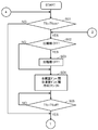
- FIG. It is a flowchart which shows the control at the time of defrosting.
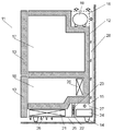
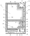
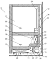
- the refrigerator 11 includes a housing 12, a door 13, legs 14 that support the housing 12, a lower machine room 15 provided in a lower portion of the housing 12, and a refrigeration disposed in an upper portion of the housing 12. It has the freezer compartment 18 arrange
- a compressor 56 housed in the lower machine chamber 15, an evaporator 20 housed on the back side of the freezer room 18, and a main condenser 21 housed in the lower machine room 15 are provided. Have.
- the refrigerator 11 includes a partition wall 22 that partitions the lower machine room 15, a condenser fan 23 that is attached to the partition wall 22 to air-cool the main condenser 21, an evaporating dish 57 that is installed above the compressor 56, and the lower machine room 15.
- a bottom plate 25 is provided.
- the refrigerator 11 includes a plurality of air inlets 26 provided on the bottom plate 25, an outlet 27 provided on the back side of the lower machine room 15, and a connection connecting the outlet 27 of the lower machine room 15 and the upper part of the housing 12.
- a ventilation path 28 is provided.
- the lower machine chamber 15 is divided into two chambers by the partition wall 22, and the main condenser 21 is housed on the windward side of the condenser fan 23, and the compressor 56 and the evaporating dish 57 are housed on the leeward side.
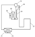
- the refrigerator 11 is located on the downstream side of the main condenser 21 as components constituting the refrigeration cycle, and includes a dew-proof pipe 37 that is thermally coupled to the outer surface of the housing 12 around the opening of the freezer compartment 18. It is located downstream of the dew pipe 37 and has a dryer 38 for drying the circulating refrigerant, a throttle 38 for connecting the dryer 38 and the evaporator 20 and depressurizing the circulating refrigerant.
- the refrigerator 11 supplies the cooler air generated in the evaporator 20 to the refrigerator compartment 17 and the freezer compartment 18, the evaporator fan 50 that supplies the refrigerator compartment 18, and the refrigerator compartment damper 51 that shuts off the cold air supplied to the refrigerator compartment 18 and the refrigerator compartment 17.
- the freezer damper 51 When the temperature detected by the PCC temperature sensor 55 rises to a predetermined ON temperature, the freezer damper 51 is closed while the compressor 56 is stopped, the refrigerator compartment damper 52 is opened, and the evaporator fan 50 is driven. Thereby, the refrigerator compartment 17 is cooled using the evaporator 20 and the low-temperature sensible heat of the frost adhering to the evaporator 20 and the latent heat of fusion of the frost (hereinafter, this operation is referred to as “off-cycle cooling”).
- the freezer damper 51 is closed, the refrigerator compartment damper 52 is opened, and the compressor 56, the condenser fan 23, and the evaporator fan 50 are driven.
- the condenser fan 23 By driving the condenser fan 23, the main condenser 21 side of the lower machine chamber 15 partitioned by the partition wall 22 becomes negative pressure, and external air is sucked from the plurality of intake ports 26, and the compressor 56 and the evaporating dish 57 side are positive pressure. Then, the air in the lower machine chamber 15 is discharged to the outside from the plurality of discharge ports 27.
- the refrigerant discharged from the compressor 56 is condensed while leaving a part of the gas while exchanging heat with the outside air in the main condenser 21 and then supplied to the dewproof pipe 37.
- the refrigerant that has passed through the dew-proof pipe 37 radiates heat through the housing 12 and condenses while warming the opening of the freezer compartment 18.
- the liquid refrigerant that has passed through the dew-proof pipe 37 is dehydrated by the dryer 38, depressurized by the throttle 39, and is evaporated by the evaporator 20, while exchanging heat with the air in the refrigerator compartment 17 and cooling the refrigerator compartment 17.
- PC cooling gaseous refrigerant
- the freezer damper 51 is opened and refrigerated.
- the chamber damper 52 is closed, and the compressor 56, the condenser fan 23, and the evaporator fan 50 are driven.
- the freezer compartment 18 is cooled by exchanging heat between the inside air of the freezer compartment 18 and the evaporator 20 (hereinafter, this operation is referred to as “FC cooling”).
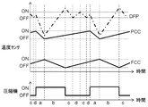
- section e corresponds to off-cycle cooling
- section f corresponds to PC cooling
- section g corresponds to FC cooling
- section h corresponds to cooling stop operation.
- the compressor 56 is driven between the section f and the section g, and is stopped between the section h and the section e.
- the freezer compartment 18 is cooled during the section g, and the refrigerator compartment 17 is cooled between the section e and the section f.
- the reason why the temperature change in the upper part of the refrigerating chamber 17 is large is that the upper part is adjacent to the high temperature outside air, while the lower part is adjacent to the low temperature freezing room 18, so during the non-cooling period. This is because the temperature difference between the upper and lower sides becomes larger and the air volume at the upper part is increased during cooling to quickly cool the upper part at a high temperature.
- cooling stop when the temperature detected by the FCC temperature sensor 54 falls to a predetermined OFF temperature, the freezer damper 51 and the refrigerator compartment damper 52 are closed, and the compressor 56, the condenser fan 23, and the evaporator fan 50 are stopped.
- this operation is referred to as “cooling stop”.
- a series of operations of off-cycle cooling, PC cooling, FC cooling, and cooling stop are repeated in order.
- off-cycle cooling is performed for a relatively long time (hereinafter, this operation is referred to as “off-cycle differential”).
- FIG. 25 is a flowchart showing control of off-cycle differential from “defrost start” to “defrost end determination”.
- “defrosting start” that is, the start of off-cycle differential. This is aimed at the timing when the temperature in the refrigerator compartment 17 is relatively high and the amount of heat is large in order to melt and remove the frost attached to the evaporator 20 using the amount of heat in the refrigerator compartment 17.
- the freezer damper 51 is closed, the refrigerating room damper 52 is opened, and the evaporator fan 50 is driven. Implement frost.
- the temperature of the evaporator 20 during PC cooling is kept higher than that during FC cooling, so that the efficiency of the refrigeration cycle can be increased and frost adhering to the evaporator 20 by off-cycle cooling.
- energy can be saved by reducing the capacity of the refrigeration cycle necessary for cooling the refrigerator compartment 17 while reducing heater power (not shown) during defrosting.
- the conventional refrigerator configuration has a problem that the time required for off-cycle differential changes greatly depending on the amount of food stored in the refrigerator compartment 17. This is because the amount of heat for melting the frost adhering to the evaporator 20 depends on the amount of heat of the food stored in the refrigerator compartment 17. There is also concern that the frost will not melt completely and the off-cycle differential will not end.
- the frost adhering to the evaporator 20 can be melt
- the present invention solves the conventional problem by determining in advance the amount of heat of the off-cycle differential supplied to the evaporator 20 and appropriately adjusting the output of the auxiliary heating heater.
- the purpose is to properly control the time required for off-cycle differential.
- This invention solves the conventional subject, and aims at suppressing the temperature change of a refrigerator compartment while ensuring the operating time of PC cooling appropriately.
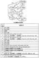
- arrows M1 to M11 indicate mode switching in the conventional refrigerator cooling control.
- the temperature detected by the FCC temperature sensor 54 is a predetermined value of FCC_ON temperature.
- the temperature detected by the PCC temperature sensor 55 rises to a predetermined PCC_ON temperature (that is, the condition of the arrow M1 is satisfied)
- the freezer damper 51 is closed and the refrigerator compartment damper 52 is
- PC cooling mode the operation is referred to as “PC cooling mode”.
- the refrigerant discharged from the compressor 56 is condensed while leaving a part of the gas while exchanging heat with the outside air in the main condenser 21 and then supplied to the dewproof pipe 37.
- the refrigerant that has passed through the dew-proof pipe 37 radiates heat through the housing 12 and condenses while warming the opening of the freezer compartment 18.
- the liquid refrigerant that has passed through the dew-proof pipe 37 is dehydrated by the dryer 38, depressurized by the throttle 39, and is evaporated by the evaporator 20, while exchanging heat with the air in the refrigerator compartment 17 and cooling the refrigerator compartment 17. Then, it returns to the compressor 56 as a gaseous refrigerant.
- the temperature detected by the FCC temperature sensor 54 decreases to a predetermined FCC_OFF temperature
- the temperature detected by the PCC temperature sensor 55 decreases to a predetermined PCC_OFF temperature (that is, the condition of the arrow M2). If the condition is satisfied, the transition is made to the OFF mode.
- the temperature detected by the FCC temperature sensor 54 is higher than a predetermined FCC_OFF temperature, and the temperature detected by the PCC temperature sensor 55 is lowered to the predetermined PCC_OFF temperature (ie, the arrow).
- the freezer damper 51 is opened, the refrigerator compartment damper 52 is closed, and the compressor 56, the condenser fan 23, and the evaporator fan 50 are driven.
- the freezer compartment 18 is heat-exchanged with the inside air of the freezer compartment 18 and the evaporator 20 to cool the freezer compartment 18 (this operation is hereinafter referred to as “FC cooling mode”).
- the temperature detected by the FCC temperature sensor 54 falls to a predetermined FCC_OFF temperature, and the temperature detected by the PCC temperature sensor 55 is equal to or higher than the predetermined PCC_ON temperature (that is, the condition of the arrow M6 is changed). If satisfied, the PC cooling mode is entered.
- the temperature detected by the FCC temperature sensor 54 falls to a predetermined FCC_OFF temperature, and the temperature detected by the PCC temperature sensor 55 indicates a temperature lower than the predetermined PCC_ON temperature (that is, an arrow).
- the mode transits to the OFF mode.
- the defrosting heater (not shown) installed near the evaporator 20 is energized, the compressor 56 is stopped, the freezer compartment damper 51 is closed, the refrigerator compartment damper 52 is opened, and the evaporator fan 50 is driven. (Hereinafter, this operation is referred to as “defrost mode”), the frost adhering to the evaporator 20 is melted and removed, and the refrigerator compartment 17 is cooled using the sublimation heat or heat of fusion of the frost being removed.
- the compressor 56 is stopped, the freezer compartment damper 51 is closed, the refrigerator compartment damper 52 is opened, and the evaporator fan 50 is opened.
- this operation is referred to as “off-cycle cooling mode”
- the refrigerator 20 uses the low-temperature sensible heat of the frost and the sublimation heat or melting heat of the frost adhering to the evaporator 20. 17 is cooled. At this time, the frost attached to the evaporator 20 is not completely thawed and removed, but by reusing the frost attached to the evaporator 20, the power of the heater (not shown) in the defrost mode is reduced. However, the refrigerator compartment 17 can be cooled.
- precool mode In order to cool the freezer compartment 18 to a temperature lower than usual when the predetermined time Tx2 elapses (ie, the condition of the arrow M7 is satisfied) when the power is turned on or when the previous defrost ends during the FC cooling mode. FC cooling is continued for a predetermined time (hereinafter, this operation is referred to as “precool mode”).
- precool mode this operation is referred to as “precool mode”.
- the temperature detected by a DEF temperature sensor (not shown) attached to the evaporator 20 is higher than a predetermined DEF_OFF temperature, or a predetermined time Tx4 elapses from the start of defrosting (ie, When the condition of the arrow M9 is satisfied), a transition to the off-cycle cooling mode is made.
- the state transits to the off-cycle cooling mode.
- the mode transits to the OFF mode.
- the temperature of the evaporator 20 in the PC cooling mode is kept higher than that in the FC cooling mode, so that the efficiency of the refrigeration cycle can be increased and the evaporator 20 is attached to the evaporator 20 by the off-cycle cooling mode.
- energy saving can be achieved by reducing the capacity of the refrigeration cycle necessary for cooling the refrigerator compartment 17 while reducing heater power (not shown) during defrosting. it can.
- the present invention solves the conventional problem, and while maintaining a highly efficient PC cooling mode as much as possible, the temperature rises by appropriately adjusting the cooling amount according to the load balance of the refrigerator compartment or the freezer compartment under an overload condition. It aims at suppressing.
- FIG. 27 is a longitudinal sectional view of a conventional refrigerator
- FIGS. 28 to 31 are flowcharts showing the control of the conventional refrigerator.
- a refrigerator 101 having a freezer compartment 102 and a refrigerator compartment 103 constitutes a refrigeration cycle together with a compressor 104, a condenser (not shown), and a decompression means (not shown), and generates cold air.
- a cooler 105 is included.
- the refrigerator 101 also has a cooling fan 106 that sucks the air in the freezer compartment 102 and the refrigerator compartment 103 into the cooler 105 and re-airs the air to the refrigerator compartment 102 and the refrigerator compartment 103.
- the refrigerator 101 adjusts the communication of the cold air forcedly blown into the freezer compartment 102 by the cooling fan 106 and is forced into the refrigerator compartment 103 by the freezer damper 107 that independently cools the freezer compartment 102 and the cooling fan 106.
- a cold room damper 108 for independently cooling the cold room 103 by adjusting the communication of the cool air to be blown is provided.
- the refrigerator 101 has a freezer compartment sensor 109 that detects the temperature in the freezer compartment 102 and a refrigerator compartment sensor 110 that detects the temperature in the refrigerator compartment 103.
- a defrost heater 111 for defrosting the frost attached to the cooler 105 is provided below the cooler 105, and a cooler sensor 112 that detects the temperature of the cooler 105 is provided in the cooler 105. I have.
- Step S03 if the detected temperature Tfc of the freezer sensor 109 is higher than a reference temperature Tfcon in step S01, the compressor 104 is started if the compressor 104 is not moving in step S02. (Step S03), the freezer compartment damper 107 is opened, the refrigerator compartment damper 108 is closed, and the cooling fan 106 is operated to cool the freezer compartment 102 (Step S04).
- step S05 when the detection temperature Tfc of the freezer compartment sensor 109 is equal to or lower than a reference temperature Tfcoff, the process proceeds to step S06 and the refrigerator compartment cooling mode is set.
- step S06 If the detected temperature Tpc of the refrigerator compartment sensor 110 is higher than a certain reference temperature Tpcon in step S06, the compressor 104 is started if the compressor 104 is not moving in step S07 (step S08), and the freezer damper 107 is closed. Then, the refrigerator compartment damper 108 is opened and the cooling fan 106 is operated to cool the refrigerator compartment 103 (step S09).
- step S10 when the detected temperature Tpc of the refrigerator compartment sensor 110 is equal to or lower than a reference temperature Tpcoff, it is determined whether or not the cooling operation is continued in step S11.
- step S11 if the temperature Tfc detected by the freezer sensor 109 is higher than a certain reference value Tfcon, the process returns to step S02 to enter the freezer cooling mode, and if it is equal to or lower than Tfcon, the process proceeds to step S12 to enter the off-cycle cooling mode. .
- step S12 the compressor 104 is first stopped.
- step S13 when the operation time tcomp of the compressor 104 is shorter than a certain reference value tdefrost, the process proceeds to step S14, and the detection temperature Tpc of the refrigerator compartment sensor 110 is set.
- Tpcoff2 When the value is higher than a certain reference value Tpcoff2, the freezer damper 107 is closed, the refrigerating room damper 108 is opened, and the cooling fan 106 is operated to cool the refrigerating room 103.
- step S13 when the operation time tcomp of the compressor 104 is equal to or greater than a certain reference value tdefrost, the process proceeds to step S18 and the defrosting mode is set.
- step S18 the freezer damper 107 is closed in step S18, the refrigerator compartment damper 108 is closed, the cooling fan 106 is stopped, the defrost heater 111 is energized, and the frost adhering to the cooler 105 is released.
- step S19 when the temperature Tdf detected by the cooler sensor 112 becomes equal to or lower than a certain reference value Tdoff, the power supply to the defrost heater is cut off, the defrost mode is terminated, and normal cooling is performed again from step S1.
- the refrigerating chamber 103 can be cooled using latent heat or sensible heat of frost adhering to the cooler 105, and the energy when defrosting in the defrost mode is reduced.
- a refrigerator that can reduce power consumption by shortening the defrosting time has been proposed (see, for example, Patent Document 3).
- the next defrost mode is started at the same time interval regardless of whether the time of the off cycle cooling mode is long or short after the fully opened defrost mode ends.
- the time is long, the amount of frost adhering to the cooler 105 decreases.
- the refrigerator provided with the freezer damper 107 according to the present invention, it is possible to suppress the wasteful temperature rise of the storage room by predicting the amount of frost attached to the cooler 105 from the operating state and controlling the interval of the defrost mode.
- the object is to provide a refrigerator.
- the refrigerator of the present invention is characterized in that a plurality of dew prevention pipes are connected in parallel via a flow path switching valve on the downstream side of the main condenser.
- the refrigerator of the present invention detects the amount of food stored in the refrigeration room before performing the off-cycle differential, and selects the output of the heater for auxiliary use, and then performs the off-cycle differential. It is a feature. As a result, it is possible to appropriately control the time required for off-cycle differential while suppressing the output of the heater for heating, and to suppress the temperature rise of the refrigerator compartment and freezer compartment during off-cycle differential. The energy consumption of the refrigerator can be reduced by reducing the amount of electric power of the heating heater necessary for defrosting.
- the refrigerator of the present invention is installed above the PCC temperature sensor, the FCC temperature sensor for detecting the temperature of the freezer room, the PCC temperature sensor for detecting the temperature of the refrigerator compartment, and detects the temperature of the upper part of the refrigerator compartment. And a DFP temperature sensor.
- the refrigerator of the present invention opens the freezer damper, closes the cold room damper, closes the freezer damper while operating the freezing cycle, closes the freezer damper, and closes the cold room damper. Open the PC cooling mode to cool the refrigeration room while operating the refrigeration cycle, close the refrigeration room damper, open the refrigeration room damper, and operate the evaporator fan while stopping the refrigeration cycle.
- the time for off-cycle cooling can be adjusted appropriately to ensure sufficient PC cooling time, and the temperature change in the upper part of the refrigerator compartment can be suppressed.
- the energy saving of the refrigerator can be achieved by obtaining.
- the refrigerator of the present invention is characterized by cooling by combining the FC cooling mode, the PC cooling mode, and the off-cycle cooling mode under normal conditions, and cooling by combining the simultaneous cooling mode and the FC cooling mode under overload conditions. To do.
- the refrigerator of the present invention is characterized by cooling by combining the FC cooling mode, the PC cooling mode, and the off-cycle cooling mode under normal conditions, and cooling by combining the simultaneous cooling mode and the FC cooling mode under overload conditions.
- the refrigerator of the present invention includes a first storage chamber having an opening on the front surface, a second storage chamber having an opening on the front surface, a refrigeration cycle including a cooler that generates cold air, and cooling A cooling fan that circulates the cool air generated in the container to the first storage chamber and the second storage chamber, a first damper that selectively flows the cool air from the cooling fan to the first storage chamber, and the cool air from the cooling fan And a defrost heater for removing frost attached to the cooler by heat.
- the refrigerator of the present invention operates the cooling fan when the refrigeration cycle is stopped, and opens the first damper or the second damper to cool the first storage chamber or the second storage chamber.
- the configuration is characterized by controlling the interval from the end of the defrosting mode to the next defrosting mode. Yes.
- FIG. 1 is a longitudinal sectional view of a refrigerator in the first embodiment of the present invention.
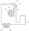
- FIG. 2 is a cycle configuration diagram of the refrigerator in the first embodiment of the present invention.
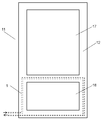
- FIG. 3 is a front view of the refrigerator according to the first embodiment of the present invention.
- FIG. 4 is a configuration diagram of the back surface of the refrigerator in the first embodiment of the present invention.
- FIG. 5 is a schematic diagram of the control pattern of the refrigerator in the first embodiment of the present invention.
- FIG. 6 is a longitudinal sectional view of the refrigerator in the second embodiment of the present invention.
- FIG. 7 is a cycle configuration diagram of the refrigerator in the second embodiment of the present invention.
- FIG. 8 is a waveform diagram of the temperature sensor behavior of the refrigerator in the second embodiment of the present invention.
- FIG. 1 is a longitudinal sectional view of a refrigerator in the first embodiment of the present invention.
- FIG. 2 is a cycle configuration diagram of the refrigerator in the first embodiment of the present invention.
- FIG. 3 is a front view
- FIG. 9 is a flowchart showing control during defrosting of the refrigerator according to the second embodiment of the present invention.
- FIG. 10 is a longitudinal sectional view of a refrigerator in the third embodiment of the present invention.
- FIG. 11 is a cycle configuration diagram of the refrigerator in the third embodiment of the present invention.
- FIG. 12 is a waveform diagram of the temperature sensor behavior of the refrigerator in the third embodiment of the present invention.
- FIG. 13 is a longitudinal sectional view of a refrigerator in the fourth embodiment of the present invention.
- FIG. 14 is a cycle configuration diagram of the refrigerator in the fourth embodiment of the present invention.
- FIG. 15 is a diagram showing state transitions and switching conditions in the cooling control of the refrigerator in the fourth embodiment of the present invention.
- FIG. 10 is a longitudinal sectional view of a refrigerator in the third embodiment of the present invention.
- FIG. 11 is a cycle configuration diagram of the refrigerator in the third embodiment of the present invention.
- FIG. 12 is a waveform diagram of the temperature sensor behavior of the refrigerator in the third
- FIG. 16 is a longitudinal sectional view of a refrigerator in the fifth embodiment of the present invention.
- FIG. 17 is a diagram illustrating the relationship between the interval between the defrost modes of the refrigerator and the accumulated time in the off-cycle cooling mode according to the fifth embodiment of the present invention.
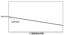
- FIG. 18 is a diagram showing the relationship between the interval of the defrosting mode of the refrigerator and the door integrated opening time in the fifth embodiment of the present invention.
- FIG. 19 is a diagram showing the relationship between the interval of the defrosting mode of the refrigerator and the outside air humidity in the fifth embodiment of the present invention.
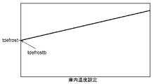
- FIG. 20 is a diagram illustrating the relationship between the interval of the defrosting mode of the refrigerator and the internal temperature setting in the fifth embodiment of the present invention.
- FIG. 21 is a cycle configuration diagram of a conventional refrigerator.
- FIG. 22 is a longitudinal sectional view of a conventional refrigerator.
- FIG. 23 is a cycle configuration diagram of a conventional refrigerator.
- FIG. 24 is a waveform diagram of the temperature behavior of the temperature sensor and the upper part of the refrigerator in the conventional refrigerator.
- FIG. 25 is a flowchart showing control during defrosting of a conventional refrigerator.
- FIG. 26 is a diagram showing state transitions and switching conditions in cooling control of a conventional refrigerator.
- FIG. 27 is a longitudinal sectional view of a conventional refrigerator.
- FIG. 28 is a flowchart showing control of a conventional refrigerator.
- FIG. 29 is a flowchart showing control of a conventional refrigerator.
- FIG. 30 is a flowchart showing control of a conventional refrigerator.
- FIG. 31 is a flowchart showing control of a conventional refrigerator.
- FIG. 1 is a longitudinal sectional view of a refrigerator according to the first embodiment of the present invention
- FIG. 2 is a cycle configuration diagram of the refrigerator according to the first embodiment of the present invention
- FIG. 3 is a first embodiment of the present invention.
- 4 is a schematic diagram of the front of the refrigerator in FIG. 4
- FIG. 4 is a schematic diagram of the back of the refrigerator in the first embodiment of the present invention
- FIG. 5 is a schematic diagram of the control pattern of the refrigerator in the first embodiment of the present invention. .
- the refrigerator 11 includes a housing 12, a door 13, and legs 14 that support the housing 12.
- the refrigerator 11 is provided in a lower machine room 15 provided in a lower portion of the housing 12 and an upper rear portion of the housing 12.
- An upper machine room 16, a refrigerating room 17 that is a storage room arranged at the upper part of the housing 12, and a freezer room 18 arranged at the lower part of the housing 12 are formed.
- the refrigeration cycle includes a compressor 19 housed in the upper machine room 16, an evaporator 20 housed in the back side of the freezer room 18, and a main condenser having a large heat dissipation among the condensers housed in the lower machine room 15. 21.
- the main condenser 21 is composed of a spiral fin tube in which a strip-shaped fin is wound around a refrigerant pipe having an inner diameter of about 4.5 mm.
- the lower machine chamber 15 includes a plurality of intake ports 26 provided in the bottom plate 25, a discharge port 27 provided on the back side of the lower machine chamber 15, a discharge port 27 of the lower machine chamber 15, and the upper machine chamber 16.
- a connecting air passage 28 is provided.
- the lower machine chamber 15 is divided into two chambers by a partition wall 22, and a main condenser 21 is housed on the windward side of the condenser fan 23 and an evaporating dish 24 is housed on the leeward side.
- a condenser in addition to the main condenser 21, a first condenser disposed in the opening of the freezing chamber 18, which is a sub-condenser that dissipates high-temperature heat in the refrigeration cycle.
- a dew-proof pipe 1 and a second dew-proof pipe 2 disposed on the back side of the housing 12 are provided.
- a flow path switching valve 3 that connects the downstream side of the main condenser 21 and the first and second dew-proof pipes 1 and 2 that are sub-condensers, the downstream side of the first dew-proof pipe 1 and the second dew-proofing.
- a junction 4 connecting the downstream sides of the pipe 2, a dryer 5 installed downstream of the junction 4, and a throttle 6 installed downstream of the dryer 5 are provided.
- the first dew-proof pipe 1 and the second dew-proof pipe 2 are made of refrigerant pipes having an inner diameter of about 3.2 mm, and are thermally coupled to the outer surface of the housing 12.
- the flow path switching valve 3 is switched to open the connection to the first dew-proof pipe 1 and open the connection to the second dew-proof pipe 2, and in conjunction with the operation of the compressor 19,
- the condenser fan 23 is driven.
- the main condenser 21 side of the lower machine chamber 15 partitioned by the partition wall 22 has a negative pressure, and external air is sucked from the plurality of intake ports 26, and the evaporating dish 24 side has a positive pressure.
- the air in 15 is discharged to the outside through a plurality of discharge ports 27.
- the refrigerant discharged from the compressor 19 is condensed while leaving a part of the gas while exchanging heat with the outside air in the main condenser 21, and is then connected to the first dew-proof pipe 1 and the first through the flow path switching valve 3. 2 Supplied to the dew proof pipe 2.
- the pipe of the main condenser 21 is in the initial stage where the refrigerant condenses, and there is more gaseous refrigerant than the first dew-proof pipe 1 and the second dew-proof pipe 2 and the flow rate is relatively fast.
- a pipe having an inner diameter larger than that of the first dew-proof pipe 1 and the second dew-proof pipe 2, preferably a pipe having an inner diameter of 4 mm or more is preferably used.
- the refrigerant that has passed through the first dew-proof pipe 1 dissipates heat and condenses outside through the housing 12 while warming the opening of the freezer compartment 18, and the refrigerant that has passed through the second dew-proof pipe 2 While the back surface of the body 12 is warmed, heat is radiated to the outside through the housing 12 and condensed.
- the liquid refrigerant that has passed through the first dew-proof pipe 1 and the second dew-proof pipe 2 is water-removed by the dryer 5, depressurized by the throttle 6, and evaporated in the evaporator 20 while being stored in the refrigerator compartment 17 and the freezer compartment 18. After exchanging heat with air, it is returned to the compressor 19 as a gaseous refrigerant.
- the flow path switching valve 3 is switched to close the connection to the first dew prevention pipe 1 and open the connection to the second dew prevention pipe 2.
- the refrigerant discharged from the compressor 19 is condensed while leaving a part of the gas while exchanging heat with the outside air in the main condenser 21, and then the second refrigerant as a sub-condenser via the flow path switching valve 3.
- coolant which passed the 2nd dew prevention pipe 2 is thermally radiated and condensed through the housing
- the first dew-proof pipe 1 in which the refrigerant does not flow from the flow path switching valve 3 does not radiate heat and eliminates the temperature difference from the surroundings.
- the high-pressure refrigerant flows from the junction 4 and the first dew prevention pipe 1 is almost filled with the liquid refrigerant.
- the liquid refrigerant does not move while staying in the piping of the first dew prevention pipe 1 that is not used on the high pressure side of the refrigeration cycle, and the total amount of refrigerant circulating in the refrigeration cycle is reduced.
- a pipe having an inner diameter smaller than that of the main condenser 21 is used in order to suppress a decrease in the amount of refrigerant circulating in the refrigeration cycle. It is desirable to use a pipe having an inner diameter of less than 4 mm.
- the liquid refrigerant that has passed through the second dew-proof pipe 2 is moisture-removed by the dryer 5, depressurized by the throttle 6, and exchanged heat with the air in the refrigerator compartment 17 and the freezer compartment 18 while evaporating in the evaporator 20. Then, it returns to the compressor 19 as a gaseous refrigerant.
- the first dew prevention pipe 1 is not used, and the refrigerant flows through the second dew prevention pipe 2 to reduce the heat load caused by the first dew prevention pipe 1.
- the first dew-proof pipe 1 is not used on the assumption that the humidity of the outside air is low and it is not necessary to prevent condensation around the opening of the freezer compartment 18. If there is no need to prevent dew condensation in an open space and the humidity of the outside air is relatively high, it may be selected that the second dew prevention pipe 2 is not used and the refrigerant flows through the first dew prevention pipe 1.
- the user can select and use the first dew-proof pipe 1 and the second dew-proof pipe 2 in accordance with the dew condensation condition around the casing 12, so that the selection can be more suitable for the installation environment.
- the heat load can be reduced more efficiently while avoiding the problem of occurrence.
- the condenser fan 23 is stopped and the flow path switching valve 3 is switched to open the connection to the first dew prevention pipe 1 and open the connection to the second dew prevention pipe 2.
- the refrigerant discharged from the compressor 19 passes through the main condenser 21 with little heat exchange with the outside air, and then passes through the flow path switching valve 3 to the first dew-proof pipe 1 and the second dew-proof pipe. 2 is supplied.
- the reason for stopping the condenser fan 23 is to avoid a slow cooling state.
- the condenser fan 23 is driven under a low outside air temperature condition, all the refrigerant is condensed in the main condenser 21, and the amount of the refrigerant supplied to the evaporator 20 is insufficient, so that the cooling of the freezer compartment 18 becomes dull. Is likely to occur.
- the main condenser 21 uses a pipe having a larger inner diameter than the first dew-proof pipe 1 and the second dew-proof pipe 2 which are sub-condensers from the viewpoint of suppressing pressure loss under high load conditions and normal load conditions. Therefore, when the liquid refrigerant stays, the refrigerant amount is likely to be insufficient.
- the condenser fan 23 is stopped, and the refrigerant is allowed to flow in parallel to the first dew-proof pipe 1 and the second dew-proof pipe 2, thereby ensuring the condensing capacity of the refrigeration cycle while suppressing pressure loss.
- the refrigerant that has passed through the first dew-proof pipe 1 dissipates heat and condenses outside through the housing 12 while warming the opening of the freezer compartment 18, and the refrigerant that has passed through the second dew-proof pipe 2 While the back surface of the body 12 is warmed, heat is radiated to the outside through the housing 12 and condensed.
- the liquid refrigerant that has passed through the first dew-proof pipe 1 and the second dew-proof pipe 2 is water-removed by the dryer 5, depressurized by the throttle 6, and evaporated in the evaporator 20 while being stored in the refrigerator compartment 17 and the freezer compartment 18. After exchanging heat with air, it is returned to the compressor 19 as a gaseous refrigerant.
- the condenser fan 23 is stopped, and the coolant is caused to flow in parallel through the first dew-proof pipe 1 and the second dew-proof pipe 2 so that the cooling state is insufficient due to insufficient refrigerant amount.
- the pressure loss caused by the dew-proof pipe can be suppressed while avoiding the above.
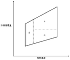
- the horizontal axis represents the ambient temperature around the refrigerator 11
- the vertical axis represents the refrigerant circulation amount of the refrigeration cycle
- the range enclosed by a frame schematically represents the operating range of the refrigeration cycle.
- the operating ranges indicated by P, Q, and R indicate ranges of high load conditions, normal conditions, and low outside air temperature conditions, respectively.
- the operating range R including at least the range where the outside air temperature is 10 ° C. or less is set as the range of the low outside air temperature condition. Is desirable. Further, an operating range P in which the outside air temperature is higher than the operating range R and the refrigerant circulation amount is a predetermined value or more is set as a high load condition range, the outside air temperature is higher than the operating range R, and the refrigerant circulation amount is predetermined. The operating range Q less than the value is set as the normal condition range.
- the rotation speed of the compressor is 42 r / s or more and the refrigerant circulation rate exceeds 1.5 kg / hour under normal use conditions, the rotation speed is at least 42 r.
- the same effect can be expected even if it is defined as being in the operating range P when it is at least / s.
- the rotation speed of the compressor is 30 r / s or less and the refrigerant circulation rate is less than 1.5 kg / hour under normal use conditions.
- the operating range Q is defined as being at least 30 r / s or less.
- the refrigerator in the present embodiment is arbitrarily selected by connecting the first dew-proof pipe 1 and the second dew-proof pipe 2 in parallel via the flow path switching valve 3 on the downstream side of the main condenser 21.
- the pressure loss and heat load resulting from the 1st dew-proof pipe 1 and the 2nd dew-proof pipe 2 are adjusted and controlled by the installation environment and operation state of the refrigerator.
- the first dew-proof pipe 1 and the second dew-proof pipe 2 can be simultaneously used in parallel at the time of a high load with a large refrigerant circulation amount to reduce the refrigerant circulation amount and suppress the pressure loss.
- the first dew-proof pipe 1 is not used, and the heat load caused by the first dew-proof pipe 1 can be suppressed.
- FIG. 6 is a longitudinal sectional view of a refrigerator according to the second embodiment of the present invention
- FIG. 7 is a cycle configuration diagram of the refrigerator according to the second embodiment of the present invention
- FIG. 8 is a second embodiment of the present invention.
- FIG. 9 is a flowchart showing the control during defrosting of the refrigerator in the second embodiment of the present invention.
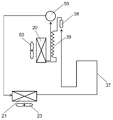
- the refrigerator 11 includes a housing 12, a door 13, a leg 14 that supports the housing 12, a lower machine room 15 provided in a lower portion of the housing 12, and an upper portion provided in an upper portion of the housing 12. It has a machine room 16, a refrigeration room 17 disposed at the upper part of the casing 12, and a freezing room 18 disposed at the lower part of the casing 12.
- a compressor 19 housed in the upper machine room 16 an evaporator 20 housed in the back side of the freezer room 18, and a main condenser 21 housed in the lower machine room 15 are provided.
- partition wall 22 that partitions the lower machine chamber 15, a condenser fan 23 that is attached to the partition wall 22 to air-cool the main condenser 21, an evaporating dish 24 installed on the leeward side of the partition wall 22, and a bottom plate 25 of the lower machine chamber 15. is doing.
- a plurality of air intakes 26 provided in the bottom plate 25, an exhaust port 27 provided on the back side of the lower machine room 15, and a communication air passage 28 connecting the exhaust port 27 of the lower machine room 15 and the upper machine room 16 are provided.
- the lower machine chamber 15 is divided into two chambers by a partition wall 22, and a main condenser 21 is housed on the windward side of the condenser fan 23 and an evaporating dish 24 is housed on the leeward side.
- the dew-proof pipe 41 and the dew-proof pipe 41 which are located on the downstream side of the main condenser 21 and are thermally coupled to the outer surface of the housing 12 around the opening of the freezer compartment 18 are provided. It is located downstream, and has a dryer 42 that dries the circulating refrigerant, a throttle 42 that combines the dryer 42 and the evaporator 20 and depressurizes the circulating refrigerant.
- an evaporator fan 30 that supplies cold air generated in the evaporator 20 to the refrigerator compartment 17 and the freezer compartment 18, a freezer damper 31 that blocks cold air supplied to the freezer compartment 18, and cold air supplied to the refrigerator compartment 17
- the refrigerator compartment damper 32 to be shut off, the duct 33 for supplying cold air to the refrigerator compartment 17, the FCC temperature sensor 34 for detecting the temperature of the freezer compartment 18, the PCC temperature sensor 35 for detecting the temperature of the refrigerator compartment 17, and the upper part of the refrigerator compartment 17 It has a DFP temperature sensor 36 that is located and detects the temperature of the refrigerator compartment 17 above the PCC temperature sensor 35, and a heater 44 that is installed below the evaporator 20 and serves as an auxiliary heat source during defrosting. .
- the duct 33 is formed along a wall surface where the refrigerator compartment 17 and the upper machine room 16 are adjacent to each other, and a part of the cold air passing through the duct 33 is discharged from the vicinity of the center of the refrigerator compartment, and most of the cold air is in the upper machine. After passing through the wall 16 while cooling the adjacent wall surface, it is discharged from the upper part of the refrigerator compartment 17.
- the freezer damper 31 When the temperature detected by the DFP temperature sensor 36 rises to a predetermined ON temperature, the freezer damper 31 is closed with the compressor 19 stopped, the refrigerator damper 32 is opened, and the evaporator fan 30 is driven.
- the refrigerator compartment 17 is cooled by utilizing the low-temperature sensible heat of the evaporator 20 and the frost adhering to the evaporator 20 and the latent heat of melting of the frost (this operation is hereinafter referred to as “off-cycle cooling”).
- this operation is hereinafter referred to as “off-cycle cooling”.
- the freezer damper 31 When the temperature detected by the PCC temperature sensor 35 rises to a predetermined ON temperature during off-cycle cooling or cooling stop, the freezer damper 31 is closed, the refrigerator compartment damper 32 is opened, and the compressor 19 and the condenser fan 23 are opened. The evaporator fan 30 is driven.
- the main condenser 21 side of the lower machine chamber 15 partitioned by the partition wall 22 has a negative pressure, and external air is sucked from the plurality of intake ports 26, and the evaporating dish 24 side has a positive pressure.
- the air in 15 is discharged to the outside through a plurality of discharge ports 27.
- the air discharged from the lower machine room 15 is sent to the upper machine room 16 via the communication air passage 28 to cool the compressor 19.
- the refrigerant discharged from the compressor 19 is condensed while leaving a part of the gas while exchanging heat with the outside air in the main condenser 21 and then supplied to the dewproof pipe 41.
- the refrigerant that has passed through the dewproof pipe 41 dissipates heat through the housing 12 and condenses while warming the opening of the freezer compartment 18.
- the liquid refrigerant that has passed through the dew-proof pipe 41 is moisture-removed by the dryer 42, depressurized by the throttle 43, and evaporated by the evaporator 20, while exchanging heat with the air in the refrigerator compartment 17 and cooling the refrigerator compartment 17. Then, it returns to the compressor 19 as a gaseous refrigerant (hereinafter, this operation is referred to as “PC cooling”).
- PC cooling a gaseous refrigerant
- the freezer damper 31 is opened and refrigerated.
- the chamber damper 32 is closed, and the compressor 19, the condenser fan 23, and the evaporator fan 30 are driven.
- the freezer compartment 18 is heat-exchanged with the inside air of the freezer compartment 18 and the evaporator 20 to cool the freezer compartment 18 (this operation is hereinafter referred to as “FC cooling”).
- FC cooling this operation is hereinafter referred to as “FC cooling”.
- off-cycle cooling operates prior to cooling stop during cooling stop, and does not operate during PC cooling or FC cooling.
- PC cooling and FC cooling are operated with priority over off-cycle cooling.
- the OFF temperature at which off-cycle cooling is stopped is set higher than the ON temperature at which PC cooling is started.
- the basic operation is to repeat a series of operations of PC cooling, FC cooling, and cooling stop in order, and while the PC cooling and FC cooling operations are not performed, the cooling stop and off-cycle cooling are performed several times. Repeat repeatedly.
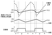
- section a corresponds to PC cooling
- section b corresponds to FC cooling
- section c corresponds to off-cycle cooling
- section d corresponds to cooling stop operation.
- the off-cooling is performed several times while the PC cooling operation and the FC cooling operation are not performed. Since the ratio between the off-cycle cooling and the PC cooling for cooling 17 can be accurately adjusted, the PC cooling operation time can be appropriately ensured.
- the temperature of the DFP temperature sensor 36 provided in the upper part of the refrigerating chamber 17 having a relatively high temperature is set as the PCC temperature sensor.
- the OFF temperature at which off-cycle cooling is stopped is set higher than the ON temperature at which PC cooling is started, but the OFF temperature at which off-cycle cooling is stopped is the OFF temperature at which PC cooling is stopped. The same effect can be obtained even if the value is set higher than the above value.
- the duct 33 is formed on the wall surface of the refrigerating room 17 adjacent to the upper machine room 16 that is hotter than the outside air, thereby cooling the refrigerating room 17 during off-cycle cooling and PC cooling, particularly the refrigerating room 17.
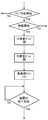
- off-cycle differential the control flow of the off-cycle differential is from “freezer compartment damper close” to “defrost completion determination”.
- the amount of food stored in the refrigerator compartment 17 is determined.
- the heating heater 44 is not energized, and when the amount of food is small, the heating heater 44 is energized. Thereafter, as a series of operations of the off-cycle differential, the freezer compartment damper 31 is closed with the compressor 19 stopped, the refrigerator compartment damper 32 is opened, and the evaporator fan 30 is driven to defrost the evaporator 20. To implement.
- the DFP temperature sensor 36 for detecting the temperature of the upper part of the refrigerator compartment 17 is relatively higher than the PCC temperature sensor 35 in the modes (b, c, d) other than the PC cooling. Cooling (a) tends to approach the PCC temperature sensor 35. This is because cold air is mainly supplied from the upper part of the refrigerator compartment 17 through the duct 33.
- the DFP temperature sensor 36 The temperature to be detected decreases to a temperature that is about the same as or lower than that of the PCC temperature sensor 35.
- the temperature detected by the DFP temperature sensor 36 is lowered only to a temperature relatively higher than the PCC temperature sensor 35. do not do.
- the food stored in the refrigerator compartment 17 It can be determined that the amount is large. Similarly, the amount of food stored in the refrigerator compartment 17 can be determined from the difference in temperature behavior during off-cycle cooling, but the detection accuracy is excellent because the temperature change during PC cooling is greater.
- the refrigerator in the present embodiment estimates the amount of food stored in the refrigerator compartment 17 based on the difference in temperature behavior during the PC cooling between the DFP temperature sensor 36 and the PCC temperature sensor 35. It is possible to directly estimate the amount of heat of the food stored in the container, and to adjust the output of the heating heater 44 with high accuracy.
- the off-cycle differential especially when the amount of food stored in the refrigerator compartment 17 is large, the heating heater 44 is not used, and at the same time, the capacity of the refrigerating cycle necessary for cooling the refrigerator compartment 17 is reduced. Can save energy. At this time, since the amount of food stored in the refrigerator compartment 17 is large and the amount of heat necessary for defrosting the evaporator 20 can be ensured, the off-cycle differential can be completed in an appropriate time.
- the heater 44 is used for heating, and the amount of food stored in the refrigerator compartment 17 and the power output from the heater 44 for heating are used.
- the off-cycle differential can be terminated.
- the refrigerator in the present embodiment switches the heating heater 44 ON / OFF to adjust the heat source of the off-cycle differential, but when the amount of food stored in the refrigerator compartment 17 is large, the output is increased, If the amount of food stored in the refrigerator compartment 17 is small, the same effect can be expected even if the output is reduced and the output of the heating heater 44 is selected.
- the refrigerator in the present embodiment is before the off-cycle differential is performed. After detecting the amount of food stored in the refrigerated room and selecting the output of the heater for auxiliary use, the time required for the off-cycle differential can be appropriately controlled by performing the off-cycle differential. .
- the refrigerator in the present embodiment suppresses the temperature increase in the refrigerator compartment and the freezer compartment during off-cycle differential, and reduces the amount of power of the heating heater necessary for defrosting. Energy saving can be achieved.
- FIG. 10 is a longitudinal sectional view of a refrigerator according to the third embodiment of the present invention
- FIG. 11 is a cycle configuration diagram of the refrigerator according to the third embodiment of the present invention
- FIG. 12 is a third embodiment of the present invention. It is a wave form diagram of the temperature sensor behavior of the refrigerator.
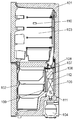
- the refrigerator 11 includes a housing 12, a door 13, legs 14 that support the housing 12, a lower machine room 15 provided in the lower portion of the housing 12, and an upper portion provided in the upper portion of the housing 12. It has a machine room 16, a refrigeration room 17 disposed at the upper part of the casing 12, and a freezing room 18 disposed at the lower part of the casing 12.
- a compressor 19 housed in the upper machine room 16 an evaporator 20 housed in the back side of the freezer room 18, and a main condenser 21 housed in the lower machine room 15 are provided.
- partition wall 22 that partitions the lower machine chamber 15, a condenser fan 23 that is attached to the partition wall 22 to air-cool the main condenser 21, an evaporating dish 24 installed on the leeward side of the partition wall 22, and a bottom plate 25 of the lower machine chamber 15. is doing.
- a plurality of air intakes 26 provided in the bottom plate 25, an exhaust port 27 provided on the back side of the lower machine room 15, and a communication air passage 28 connecting the exhaust port 27 of the lower machine room 15 and the upper machine room 16 are provided.
- the lower machine chamber 15 is divided into two chambers by a partition wall 22, and a main condenser 21 is housed on the windward side of the condenser fan 23 and an evaporating dish 24 is housed on the leeward side.
- a dew-proof pipe 37 and a dew-proof pipe 37 which are located on the downstream side of the main condenser 21 and are thermally coupled to the outer surface of the housing 12 around the opening of the freezer compartment 18. It is located downstream, and has a dryer 38 that dries the circulating refrigerant, a throttle 38 that combines the dryer 38 and the evaporator 20 and depressurizes the circulating refrigerant.
- an evaporator fan 30 that supplies cold air generated in the evaporator 20 to the refrigerator compartment 17 and the freezer compartment 18, a freezer damper 31 that blocks cold air supplied to the freezer compartment 18, and cold air supplied to the refrigerator compartment 17
- the refrigerator compartment damper 32 to be shut off, the duct 33 for supplying cold air to the refrigerator compartment 17, the FCC temperature sensor 34 for detecting the temperature of the freezer compartment 18, the PCC temperature sensor 35 for detecting the temperature of the refrigerator compartment 17, the upper part of the refrigerator compartment 17,
- a DFP temperature sensor 36 for detecting the temperature of the refrigerator compartment 17 above the PCC temperature sensor 35 is provided.
- the duct 33 is formed along a wall surface where the refrigerator compartment 17 and the upper machine room 16 are adjacent to each other, and a part of the cold air passing through the duct 33 is discharged from the vicinity of the center of the refrigerator compartment, and most of the cold air is in the upper machine. After passing through the wall 16 while cooling the adjacent wall surface, it is discharged from the upper part of the refrigerator compartment 17.
- the freezer damper 31 When the temperature detected by the DFP temperature sensor 36 rises to a predetermined ON temperature, the freezer damper 31 is closed with the compressor 19 stopped, the refrigerator damper 32 is opened, and the evaporator fan 30 is driven.
- the refrigerator compartment 17 is cooled by utilizing the low-temperature sensible heat of the evaporator 20 and the frost adhering to the evaporator 20 and the latent heat of melting of the frost (this operation is hereinafter referred to as “off-cycle cooling”).
- this operation is hereinafter referred to as “off-cycle cooling”.
- the freezer damper 31 When the temperature detected by the PCC temperature sensor 35 rises to a predetermined ON temperature during off-cycle cooling or cooling stop, the freezer damper 31 is closed, the refrigerator compartment damper 32 is opened, and the compressor 19 and the condenser fan 23 are opened. Drive.
- the condenser fan 23 When the condenser fan 23 is driven, the main condenser 21 side of the lower machine chamber 15 partitioned by the partition wall 22 has a negative pressure, and external air is sucked from the plurality of intake ports 26, and the evaporating dish 24 side has a positive pressure.
- the air in 15 is discharged to the outside through a plurality of discharge ports 27.
- the air discharged from the lower machine room 15 is sent to the upper machine room 16 via the communication air passage 28 to cool the compressor 19.
- the refrigerant discharged from the compressor 19 is condensed while leaving a part of the gas while exchanging heat with the outside air in the main condenser 21 and then supplied to the dewproof pipe 37.
- the refrigerant that has passed through the dew-proof pipe 37 radiates heat through the housing 12 and condenses while warming the opening of the freezer compartment 18.
- the liquid refrigerant that has passed through the dew-proof pipe 37 is dehydrated by the dryer 38, depressurized by the throttle 39, and is evaporated by the evaporator 20, while exchanging heat with the air in the refrigerator compartment 17 and cooling the refrigerator compartment 17. Then, it returns to the compressor 19 as a gaseous refrigerant (hereinafter, this operation is referred to as “PC cooling”).
- the freezer damper 31 is opened and refrigerated.
- the chamber damper 32 is closed, and the compressor 19, the condenser fan 23, and the evaporator fan 30 are driven.
- the freezer compartment 18 is cooled by exchanging heat between the inside air of the freezer compartment 18 and the evaporator 20 (hereinafter, this operation is referred to as “FC cooling”).
- FC cooling this operation is referred to as “FC cooling”.
- off-cycle cooling operates prior to cooling stop during cooling stop, and does not operate during PC cooling or FC cooling.
- PC cooling and FC cooling are operated with priority over off-cycle cooling.
- the OFF temperature at which the off-cycle cooling is stopped is set higher than the ON temperature at which the PC cooling is started.
- section a corresponds to PC cooling
- section b to FC cooling
- section c to off-cycle cooling
- section d to cooling stop operation.
- the off-cooling is performed several times while the PC cooling operation and the FC cooling operation are not performed. Since the ratio between the off-cycle cooling and the PC cooling for cooling 17 can be accurately adjusted, the PC cooling operation time can be appropriately ensured.
- the temperature of the DFP temperature sensor 36 provided in the upper part of the refrigerating chamber 17 having a relatively high temperature is set as the PCC temperature sensor
- the OFF temperature at which off-cycle cooling is stopped is set higher than the ON temperature at which PC cooling is started, but the OFF temperature at which off-cycle cooling is stopped is the OFF temperature at which PC cooling is stopped. The same effect can be obtained even if the value is set higher than the above value.
- the duct 33 is formed on the wall surface of the refrigerating room 17 adjacent to the upper machine room 16 that is hotter than the outside air, thereby cooling the refrigerating room 17 during off-cycle cooling and PC cooling, particularly the refrigerating room 17.
- the duct 33 is formed on the wall surface of the refrigerating room 17 adjacent to the upper machine room 16 that is hotter than the outside air, thereby cooling the refrigerating room 17 during off-cycle cooling and PC cooling, particularly the refrigerating room 17.
- the refrigerator in the present embodiment has an off-cycle cooling mode (c) for cooling the refrigerator compartment 17 during the refrigeration cycle stop in addition to the FC cooling mode (b) and the PC cooling mode (a).
- the DFP temperature is installed above the PCC temperature sensor 35 that controls the PC cooling and has a temperature change larger than that of the PCC temperature sensor 35.
- FIG. 13 is a longitudinal sectional view of a refrigerator according to the fourth embodiment of the present invention
- FIG. 14 is a cycle configuration diagram of the refrigerator according to the fourth embodiment of the present invention
- FIG. 15 is a fourth embodiment of the present invention. It is the figure which showed the state transition in the cooling control of the refrigerator, and its switching condition.
- the refrigerator 11 includes a housing 12, a door 13, legs 14 that support the housing 12, a lower machine room 15 provided in the lower portion of the housing 12, and an upper portion provided in the upper portion of the housing 12. It has a machine room 16, a refrigeration room 17 disposed at the upper part of the casing 12, and a freezing room 18 disposed at the lower part of the casing 12.
- a compressor 19 housed in the upper machine room 16, an evaporator 20 housed in the back side of the freezer room 18, and a main condenser 21 housed in the lower machine room 15 are provided.
- the compressor 19 is a variable speed compressor and uses six stages of rotation speed selected from 20 to 80 r / s. This is because the refrigerating capacity is adjusted by switching the rotational speed of the compressor 19 to six stages from low speed to high speed while avoiding resonance of piping and the like.
- the compressor 19 operates at a low speed at the time of start-up, and increases as the operation time for cooling the refrigerator compartment 17 or the freezer compartment 18 becomes longer.
- the rotation speed of the compressor 19 is controlled independently of the cooling operation mode of the refrigerator 11, but the rotation speed at the start of the PC cooling mode with a high evaporation temperature and a relatively large refrigerating capacity is set to be higher than that in the FC cooling mode. It may be set low. Further, the refrigeration capacity may be adjusted while decelerating the compressor 19 as the temperature of the refrigerator compartment 17 or the freezer compartment 18 decreases.
- a plurality of air intakes 26 provided in the bottom plate 25, an exhaust port 27 provided on the back side of the lower machine room 15, and a communication air passage 28 connecting the exhaust port 27 of the lower machine room 15 and the upper machine room 16 are provided.
- the lower machine chamber 15 is divided into two chambers by a partition wall 22, and a main condenser 21 is housed on the windward side of the condenser fan 23 and an evaporating dish 24 is housed on the leeward side.
- a dew-proof pipe 37 and a dew-proof pipe 37 which are located on the downstream side of the main condenser 21 and are thermally coupled to the outer surface of the housing 12 around the opening of the freezer compartment 18. It is located downstream, and has a dryer 38 that dries the circulating refrigerant, a throttle 38 that combines the dryer 38 and the evaporator 20 and depressurizes the circulating refrigerant.
- an evaporator fan 30 that supplies cold air generated in the evaporator 20 to the refrigerator compartment 17 and the freezer compartment 18, a freezer damper 31 that blocks cold air supplied to the freezer compartment 18, and cold air supplied to the refrigerator compartment 17
- the duct 33 for supplying cold air to the refrigerator compartment 17, the FCC temperature sensor 34 for detecting the temperature of the freezer compartment 18, the PCC temperature sensor 35 for detecting the temperature of the refrigerator compartment 17, and the upper part of the refrigerator compartment 17
- a DFP temperature sensor 36 for detecting the temperature of the refrigerator compartment 17 above the PCC temperature sensor 35 is provided.
- the duct 33 is formed along a wall surface where the refrigerator compartment 17 and the upper machine room 16 are adjacent to each other, and a part of the cold air passing through the duct 33 is discharged from the vicinity of the center of the refrigerator compartment, and most of the cold air is in the upper machine. After passing through the wall 16 while cooling the adjacent wall surface, it is discharged from the upper part of the refrigerator compartment 17.
- arrows L1 to L15 indicate mode switching in the cooling control of the refrigerator in the fourth embodiment of the present invention.
- the detailed description of the same cooling operation mode and mode switching conditions as those of the conventional refrigerator shown in FIG. 26 is omitted.
- the condition of the arrow L1 (that is, the condition of the arrow M1) is satisfied, or the temperature detected by the DFP temperature sensor 36 rises to a predetermined DFP_ON temperature (that is, the condition of the arrow L10 is satisfied) To transition to the off-cycle cooling mode.
- the mode transits to the OFF mode. Further, when the condition of the arrow L1 (that is, the condition of the arrow M1) is satisfied during the off-cycle cooling mode, the PC cooling mode is transitioned to.
- the time in the off-cycle cooling mode can be appropriately adjusted using the DFP temperature sensor 36 installed in the upper part of the refrigerator compartment 17. Since the conventional refrigerator always performs off-cycle cooling for a certain time Td, there is a concern that the temperature of the refrigerator compartment 17 is unnecessarily lowered.
- the temperature detected by the FCC temperature sensor 34 is higher than the predetermined FCC_OFF temperature, and the temperature detected by the PCC temperature sensor 35 falls to the predetermined PCC_OFF temperature (that is, the arrow L5 If the condition is satisfied), transition to the FC cooling mode.
- the difference between the temperature detected by the FCC temperature sensor 34 and the FCC_OFF temperature of the predetermined value is detected by the PCC temperature sensor 35 after the predetermined time Tx1 has elapsed during the PC cooling mode.
- the transition to the FC cooling mode is made.
- the temperature detected by the FCC temperature sensor 34 falls to a predetermined FCC_OFF temperature, and the temperature detected by the PCC temperature sensor 35 is equal to or higher than the predetermined PCC_ON temperature (that is, the condition indicated by the arrow L6). If satisfied, the PC cooling mode is entered.
- the difference between the temperature detected by the FCC temperature sensor 34 and the FCC_OFF temperature of the predetermined value is detected by the PCC temperature sensor 35 after the predetermined time Tx1 has elapsed during the FC cooling mode.
- the PC cooling mode is entered.
- the PC cooling mode and the FC cooling mode are alternately switched every predetermined time Tx1, and the cooling is ended. It is possible to preferentially cool the one having a larger deviation from the OFF temperature. As a result, the cooling operation time can be distributed more flexibly than the time-fixed alternating cooling performed in the conventional refrigerator.
- the compressor 19, the condenser fan 23, and the evaporator fan 30 are driven by opening the freezer damper 31 and the refrigerator compartment damper 32.
- the condenser fan 23 when the condenser fan 23 is driven, the main condenser 21 side of the lower machine chamber 15 partitioned by the partition wall 22 has a negative pressure, and external air is sucked from the plurality of intake ports 26, and the compressor 19 The evaporating dish 57 side becomes positive pressure, and the air in the lower machine chamber 15 is discharged to the outside from the plurality of discharge ports 27.
- the refrigerant discharged from the compressor 19 is condensed while leaving a part of the gas while exchanging heat with the outside air in the main condenser 21 and then supplied to the dewproof pipe 37.
- the refrigerant that has passed through the dew-proof pipe 37 radiates heat through the housing 12 and condenses while warming the opening of the freezer compartment 18.
- the liquid refrigerant that has passed through the dew-proof pipe 37 is water-removed by the dryer 38, depressurized by the throttle 39, and heat-exchanged with the air in the refrigerator compartment 17 and the freezer compartment 18 while being evaporated by the evaporator 20, and the refrigerator compartment 17 And while cooling the freezer compartment 18, it recirculate
- the evaporator fan 30 is rotated at a high speed to secure an air volume necessary for cooling the refrigerator compartment 17 and the freezer compartment 18 in parallel.
- air that has a high wind speed at a high temperature flows into the evaporator 20, so that the temperature of the blown air from the evaporator 20 tends to rise. It is desirable to ensure proper refrigeration capacity by operating When the compressor 19 is operated at a low speed in the simultaneous cooling mode, there is a concern that the temperature of the air blown from the evaporator 20 increases and the freezer compartment 18 cannot be cooled to a low temperature.
- the mode is changed to the simultaneous cooling mode and the compressor is moved during the simultaneous cooling mode.
- the rotational speed of 19 is less than the predetermined rotational speed (that is, the condition of the arrow L13 is satisfied)
- the PC cooling mode is entered.
- the mode switching between the arrow L12 and the arrow L13 is performed with priority over other state transitions. This is because the rotation speed of the compressor 19 is increased to a predetermined rotation speed or more, so that it is detected that the refrigerator 11 is in an overload condition and the mode is changed to the simultaneous cooling mode. This is to avoid that the temperature of the air blown from the evaporator 20 rises and the freezer compartment 18 cannot be cooled to a low temperature when the rotation speed is less than the predetermined number of revolutions.
- the mode is changed to the FC cooling mode. This is to continue the simultaneous cooling mode up to the upper temperature limit at which the freezer compartment 18 is allowed in order to suppress the temperature rise of the refrigerator compartment 17 that is not cooled during the FC cooling mode.
- the FCC_LIM temperature detected by the FCC temperature sensor 34 is a predetermined value corresponding to weak cooling that is 2 to 5 ° C. higher than the FCC_ON temperature, which is the upper limit temperature during normal cooling.
- condition of the arrow L12 for transitioning to the simultaneous cooling mode corresponding to the overload condition is defined by the number of revolutions of the compressor 19.
- the power is turned on at high outside air temperature and the door is frequently opened and closed. May be detected and a transition to the simultaneous cooling mode may be made.
- condition of the arrow L13 may be changed so that the simultaneous cooling mode is canceled by detecting that the temperature of the refrigerator compartment 17 or the freezer compartment 18 is lowered to some extent.
- the most efficient PC cooling mode can be used for a longer time.
- the temperature detected by the FCC temperature sensor 34 indicates a temperature lower than the predetermined FCC_LIM temperature
- the temperature detected by the PCC temperature sensor 35 indicates a temperature higher than the predetermined PCC_OFF temperature.
- the evaporator fan 30 is rotated at a high speed to secure the amount of air sent in parallel to both the refrigerator compartment 17 and the freezer compartment 18, but when a large amount of frost is formed in the evaporator 20.
- the sufficient air volume cannot be secured.
- the air volume in the refrigerator compartment 17 having a relatively long path for blowing air from the evaporator 20 is greatly reduced, and the cold air in the upper part of the refrigerator compartment 17 is reduced.
- the temperature difference between the DFP temperature sensor 36 that is relatively close to the blowing position and the PCC temperature sensor 35 near the center of the refrigerator compartment 17 becomes smaller than the predetermined value ⁇ .
- the cooling state of the refrigerator compartment 17 in the simultaneous cooling mode is normal or the evaporator 20 is attached. It can be detected whether the refrigeration room 17 has a slow cooling tendency due to frost, and when the refrigeration room 17 has a slow cooling tendency, the cooling capacity of the refrigeration room 17 is quickly recovered by reducing the defrosting interval of the evaporator 20. can do.
- the refrigerator in the present embodiment is a refrigerator having an off-cycle cooling mode that cools the refrigerator compartment while the refrigeration cycle is stopped in addition to the FC cooling mode and the PC cooling mode.
- the amount of cooling in the freezer and freezer compartments can be adjusted automatically and appropriately under overload conditions, thereby increasing the temperature of the refrigerator compartment and freezer compartment. Can be suppressed.
- FIG. 16 is a longitudinal sectional view of a refrigerator in the fifth embodiment of the present invention.
- FIG. 17 is a diagram showing the relationship between the interval of the defrosting mode of the refrigerator and the accumulated time of the off-cycle cooling mode in the fifth embodiment of the present invention.
- FIG. 18 is a diagram showing the relationship between the interval of the defrosting mode of the refrigerator and the integrated door opening time in the fifth embodiment of the present invention.
- FIG. 19 is a diagram showing the relationship between the interval of the defrosting mode of the refrigerator and the outside air humidity in the fifth embodiment of the present invention.
- FIG. 20 is a diagram showing the relationship between the interval of the defrosting mode of the refrigerator and the internal temperature setting in the fifth embodiment of the present invention.
- the refrigerator in the present embodiment has a freezer compartment door 113 that seals the opening of the freezer compartment 102 so that it can be opened and closed, and a refrigerator compartment door 114 that seals the opening of the refrigerator compartment 103 so that it can be opened and closed.
- the opening and closing of the freezer compartment door 113 and the refrigerator compartment door 114 are detected, for example, a freezer compartment door sensor 115 composed of a Hall IC and a magnet and the refrigerator compartment.
- a door sensor 116 is provided.
- a humidity sensor 117 for detecting the humidity of the outside air is provided on the outer wall side of the refrigerator 101, and the operation of the refrigeration cycle is controlled inside, the control state of the refrigeration cycle, the freezer compartment door sensor 115, the refrigerator compartment.
- a control unit 118 that performs operation control of the refrigeration cycle based on the outputs of the door sensor 116 and the humidity sensor 117 is provided.
- step S12 when the compressor 104 is stopped in step S12 shown in FIG. 30, if the operation time tcomp of the compressor 104 is tdefrost or more in step S13, the process proceeds to step S18 shown in FIG.
- Tdefrost has a certain initial value tdefrostb and fluctuates depending on the off-cycle cooling time, door opening / closing time, outside air humidity, and internal temperature setting.
- the refrigerator compartment 107 is closed, the refrigerator compartment damper 108 is opened, and the cooling fan 106 is operated to cool the refrigerator compartment 103 using latent heat or sensible heat of frost attached to the cooler 105.
- the cooling fan 106 is operated to cool the refrigerator compartment 103 using latent heat or sensible heat of frost attached to the cooler 105.
- heat is taken away from the frost adhering to the cooler 105. For this reason, the amount of heat necessary for defrosting the cooler 105 decreases as the off-cycle cooling time increases.
- the integration time of off-cycle cooling is counted by the control unit 118, and is controlled by the control unit 118 so that tdefrost becomes longer as the integration time becomes longer.
- tdefrost can be changed according to the degree of frost formation on the cooler 105 due to the accumulated time of off-cycle cooling, the number of operations in the defrosting mode can be optimized, and the temperature rise in the warehouse is appropriately prevented. be able to.
- the freezer compartment door 113 or the refrigerator compartment door 114 is opened and closed to take out food in the storage compartment.
- high-temperature and high-humidity outside air flows into the storage chamber as compared to the storage chamber air dehumidified and circulated by the cooler 105.
- frost formation on the cooler 105 occurs. Therefore, if the door opening / closing time is long, the amount of frost formation on the cooler 105 increases, and conversely, if the door opening / closing time is short, the amount of frost formation decreases.
- the door opening integration time is counted by the freezer compartment door sensor 115 and the refrigerator compartment door sensor 116, and is output to the control unit 118.
- the longer the door opening / closing integration time the shorter the tdefrost becomes. I have control.
- tdefrost can be changed in accordance with the degree of frost formation on the cooler 105 based on the door opening / closing integrated time, the number of operations in the defrosting mode can be optimized, and the temperature rise in the warehouse can be appropriately prevented. it can.
- the freezer compartment 102 and the refrigerator compartment 103 are hermetically sealed by the freezer compartment door 113 and the refrigerator compartment door 114, but are not completely sealed, and have a minute gap from which indoor and outdoor air can flow.
- the humidity of the outside air flows into the cabinet.
- the humidity of the outside air flows into the room when the door is opened and closed. Therefore, when the outside air humidity is high, the humidity entering the compartment is also high, and the amount of frost formation on the cooler 105 is increased. Conversely, when the outside air humidity is low, the amount of frost formation is reduced.
- the outside air humidity is measured by the humidity sensor 117, and the average humidity from the fully-open defrost mode is calculated and output to the control unit 118.
- the control is performed so that the higher the outside air humidity is, the shorter the tdefrost becomes. This is controlled by the unit 118.
- tdefrost can be changed according to the degree of frost formation on the cooler 105 due to the outside air humidity, the number of operations in the defrost mode can be optimized, and the temperature rise in the warehouse can be appropriately prevented.
- the internal temperature setting is detected by the control unit 118, and is controlled by the control unit 118 so that the higher the internal temperature setting, the longer tdefrost becomes.
- tdefrost can be changed according to the degree of frost formation on the cooler 105 by the internal temperature setting, the number of operations in the defrosting mode can be optimized, and the internal temperature can be prevented appropriately. it can.
- the refrigerator in the present embodiment can prevent a temperature rise in the refrigerator, and thus can be a refrigerator with high cooling performance.
- tdefrost is described as a control method in which proportional control is performed with respect to the increase / decrease of each control factor. The effect is obtained, and there is an advantage that the control becomes simple.
- the off-cycle cooling is controlled to be terminated by the temperature detected by the cold room sensor 110.
- the off-cycle cooling may be controlled by, for example, determining the off-cycle cooling time or by other control factors. Similar effects can be obtained.
- the refrigerator is described as two refrigerators, a freezer compartment 102 and a refrigerator compartment 103, but the same control is performed regardless of the number of storage compartments, such as a three-room refrigerator equipped with a vegetable compartment. Similar effects can be obtained.
- control for detecting the outside air humidity has been described.
- more optimal control can be performed. It can be carried out.
- the refrigerator in this Embodiment demonstrated by the specification which produces
- the present invention includes a forced air-cooled main condenser, a flow path switching valve connected to the downstream side of the main condenser, and a plurality of parallel connection downstream of the flow path switching valve.
- the refrigerator has a dew-proof pipe and flows a refrigerant in parallel to the plurality of dew-proof pipes at high load.
- the present invention is a refrigerator characterized in that when the refrigeration cycle is operated under normal conditions, the number of dew-proof pipes used is smaller than that under high load.
- the normal load is assumed to be when the door is not opened and closed for a long time, for example, in the autumn to spring when the temperature and humidity of the outside air are relatively low.
- the operating rate of the refrigeration cycle decreases.
- the circulation rate of the refrigerant decreases, and it is almost unnecessary to prevent condensation around the refrigerator housing in which the dew-proof pipe is provided.
- the heat load caused by the dew proof pipe can be suppressed.
- the humidity of the outside air is low and it is not necessary to prevent condensation around the opening of the refrigerator, condensation is likely to occur in the gap with the surrounding wall like the back of the refrigerator, and the heat in the cabinet is relatively high in heat insulation.
- the thermal load can be more efficiently suppressed.
- the present invention is a refrigerator characterized in that the inner diameter of the pipe of the main condenser is 4 mm or more and the inner diameter of the dew proof pipe is less than 4 mm.
- the pressure loss can be reduced by increasing the pipe inner diameter of the condenser to 4 mm or more, and the refrigerant volume can be suppressed by reducing the internal volume by reducing the inner diameter of the dew-proof pipe having a high ratio of liquid refrigerant to less than 4 mm. .
- the present invention is a refrigerator characterized in that the user manually selects a dew-proof pipe to be used when operated under normal conditions.
- the heat load caused by the dew-proof pipe can be arbitrarily adjusted and suppressed more efficiently.
- the present invention is a refrigerator characterized by stopping the air cooling fan of the main condenser when operated under a low outside air temperature condition and using a plurality of dew pipes. The problem of insufficient circulating refrigerant amount in the refrigeration cycle due to excessive refrigerant retention can be avoided.
- the present invention includes a refrigerator compartment, a freezer compartment, a refrigeration cycle, an evaporator that is a component of the refrigeration cycle, and cool air generated in the evaporator to the refrigerator compartment and the refrigerator.
- An evaporator fan to be supplied to the room, a heater for defrosting the evaporator, a refrigerating room damper for shutting off cool air supplied from the evaporator to the refrigerating room, and a freezer from the evaporator
- the freezer damper is opened, the refrigerating room damper is closed, and the cold air generated in the evaporator is operated while operating the refrigerating cycle.
- FC cooling mode for supplying and cooling the freezer compartment, closing the freezer compartment damper, opening the refrigerating compartment damper, supplying cold air generated in the evaporator while operating the refrigerating cycle PC cooling mode for cooling the refrigerator compartment, closing the freezer damper, opening the refrigerator compartment damper, and operating the evaporator fan while stopping the refrigeration cycle, thereby the evaporator and the refrigerator
- the off-cycle cooling mode for exchanging heat of indoor air, the evaporator while closing the freezer compartment damper and opening the refrigerating compartment damper while energizing the heater for heating, and stopping the refrigerating cycle
- the fan has an off-cycle differential mode that melts and removes frost attached to the evaporator, and after selecting the output of the heater for heating based on the amount of food stored in the refrigerator compartment Since the refrigerator is characterized by performing the off-cycle differential mode, the time required for the off-cycle differential can be properly controlled, and the off-cycle differential is being performed. It suppresses that built chamber and the freezing chamber is increased temperatures,
- the present invention is a refrigerator characterized by determining whether or not the off-cycle differential mode can be performed immediately before the start of the PC cooling mode. Therefore, the refrigerator is turned off at a relatively high temperature immediately before the refrigerator compartment is cooled.
- the cycle differential mode can be carried out, and the amount of heat of the off-cycle differential supplied to the evaporator can be increased to further reduce the electric energy of the heating heater necessary for defrosting.
- the present invention also includes a PCC temperature sensor that detects the temperature of the refrigerator compartment, and a DFP temperature sensor that is installed above the PCC temperature sensor and detects the temperature of the upper portion of the refrigerator compartment.
- the refrigerator is characterized by detecting the amount of food stored in the refrigeration room based on the difference in temperature change between the PCC temperature sensor and the DFP temperature sensor in the cycle cooling mode. The amount of heat of the heated food can be directly estimated, and the power of the heating heater necessary for defrosting can be further reduced by accurately adjusting the output of the heating heater.
- the present invention includes a refrigerator compartment, a freezer compartment, a refrigeration cycle, an evaporator that is a component of the refrigeration cycle, and cool air generated in the evaporator to the refrigerator compartment and the refrigerator.
- An evaporator fan supplied to the chamber a refrigerator compartment damper for shutting off cool air supplied from the evaporator to the refrigerator compartment, a freezer compartment damper for shutting off cool air supplied from the evaporator to the freezer compartment,
- An FCC temperature sensor that detects the temperature of the freezer
- PCC temperature sensor that detects the temperature of the refrigerator compartment
- DFP temperature sensor that is installed above the PCC temperature sensor and detects the temperature of the upper portion of the refrigerator compartment.
- the freezer damper In the refrigerator, the freezer damper is opened, the refrigerator compartment damper is closed, and the freezer generated by the evaporator is supplied to cool the freezer while operating the refrigerating cycle.
- FC cooling mode PC cooling mode in which the freezer compartment damper is closed, the refrigerating compartment damper is opened, and cold air generated in the evaporator is supplied while the refrigerating cycle is operated to cool the refrigerating compartment
- closing the freezer damper opening the refrigerator compartment damper, and operating the evaporator fan while stopping the refrigeration cycle, thereby exchanging heat between the evaporator and the air in the refrigerator compartment.
- a cycle cooling mode, and on / off of the FC cooling mode and the PC cooling mode is determined based on the detected temperature of the FCC temperature sensor or the PCC temperature sensor, and based on the detected temperature of the DFP temperature sensor. Since the refrigerator is characterized by determining whether the off-cycle cooling mode is on or off, the PC cooling operation time can be appropriately confirmed. It can be.
- the off-cycle cooling operation time is controlled based on the DFP temperature sensor provided in the upper part of the refrigerating room where the temperature change is relatively large, thereby accurately adjusting the ratio of off-cycle cooling to cool the refrigerating room and PC cooling Therefore, the PC cooling operation time can be appropriately secured.
- the FC cooling mode and the PC cooling mode are prioritized over the off-cycle cooling mode when the temperature detected by the FCC temperature sensor or the PCC temperature sensor rises. Therefore, it is possible to suppress a decrease in the operation time of PC cooling and FC cooling due to off-cycle cooling, and it is possible to suppress temperature changes in the refrigerator compartment and the freezer compartment. This is because the PCC temperature sensor or FCC temperature sensor operation is stopped by switching to PC cooling or FC cooling by preferentially switching to PC cooling or FC cooling even if it is off-cycle cooling as the temperature detected by the PCC temperature sensor or FCC temperature sensor rises. Time can be secured appropriately and temperature changes in the refrigerator compartment and the freezer compartment can be suppressed.
- the present invention sets the OFF temperature of the DFP temperature sensor that detects the end of the off-cycle cooling mode to a temperature higher than the ON temperature of the PCC temperature sensor that detects the start of the PC cooling mode. Therefore, the overcooling of the upper part of the refrigerator compartment due to off-cycle cooling can be suppressed, and the temperature change of the upper part of the refrigerator compartment can be suppressed. This suppresses the temperature change of the upper part of the refrigerator compartment by controlling off-cycle cooling while keeping the temperature of the DFP temperature sensor provided in the upper part of the refrigerator compartment having a relatively high temperature relatively higher than that of the PCC temperature sensor. It is something that can be done.
- the present invention provides a compressor that is a component of a refrigeration cycle, an upper machine room that houses the compressor, and is disposed above the refrigeration room, and is adjacent to the upper machine room and cools the refrigeration room. Since the refrigerator has a duct through which the cool air flows, the temperature of the cool air for cooling the refrigerating room can be increased, and temperature fluctuations in the upper part of the refrigerating room can be further suppressed. This is because a duct is formed on the wall of the refrigeration room adjacent to the upper machine room that is hotter than the outside air, thereby cooling the refrigeration room, especially the upper part of the refrigeration room, during off-cycle cooling and PC cooling.
- the present invention includes a refrigerator compartment, a freezer compartment, a refrigeration cycle, an evaporator that is a component of the refrigeration cycle, and cool air generated in the evaporator to the refrigerator compartment and the refrigerator.
- An evaporator fan supplied to the chamber a refrigerator compartment damper for shutting off cool air supplied from the evaporator to the refrigerator compartment, a freezer compartment damper for shutting off cool air supplied from the evaporator to the freezer compartment,
- An FCC temperature sensor that detects the temperature of the freezer
- PCC temperature sensor that detects the temperature of the refrigerator compartment
- DFP temperature sensor that is installed above the PCC temperature sensor and detects the temperature of the upper portion of the refrigerator compartment.
- the freezer damper In the refrigerator, the freezer damper is opened, the refrigerator compartment damper is closed, and the freezer generated by the evaporator is supplied to cool the freezer while operating the refrigerating cycle.
- FC cooling mode PC cooling mode in which the freezer compartment damper is closed, the refrigerating compartment damper is opened, and cold air generated in the evaporator is supplied while the refrigerating cycle is operated to cool the refrigerating compartment
- a simultaneous cooling mode in which the freezer compartment damper is opened, the refrigerator compartment damper is opened, and cold air generated in the evaporator is supplied while the refrigerating cycle is operated to cool the freezer compartment and the refrigerator compartment at the same time.
- Cycle cooling mode In normal conditions, FC cooling mode, PC cooling mode, and off-cycle cooling mode are combined for cooling, and in overload conditions, simultaneous cooling mode is used. This is a combination of FC cooling mode. In normal conditions, the highly efficient PC cooling mode is maintained as much as possible. In overload conditions, the freezer compartment and the refrigerator compartment are automatically cooled while continuing to cool down. Therefore, the temperature can be adjusted appropriately and the temperature increase in the refrigerator compartment and the freezer compartment can be suppressed.
- the present invention also includes a variable speed compressor, and when the compressor is less than a predetermined number of revolutions, cooling is performed by combining an FC cooling mode, a PC cooling mode, and an off-cycle cooling mode, and the compressor is at least a predetermined number of revolutions. Then, the cooling is performed by combining the simultaneous cooling mode and the FC cooling mode, and the temperature rise of the evaporator in the simultaneous cooling mode can be suppressed, so that the cooling capacity shortage of the freezer can be suppressed.
- the present invention sets the reference temperature of the FCC temperature sensor when switching from the simultaneous cooling mode to the FC cooling mode higher than the reference temperature of the FCC temperature sensor when starting the cooling operation.
- the simultaneous cooling mode can be maintained as much as possible to the upper limit of the allowable temperature, and insufficient cooling capacity of the refrigerator compartment can be suppressed.
- the present invention detects the slowing of the cooling rate of the refrigerator compartment from the temperature behavior of the PCC temperature sensor and the DFP temperature sensor, and shortens the defrosting interval of the evaporator. It is possible to recover the decrease in the air volume of the refrigerator in the mode at an early stage, and it is possible to suppress an insufficient cooling capacity of the refrigerator.
- the refrigerator of the present invention includes a first storage chamber having an opening on the front surface, a second storage chamber having an opening on the front surface, and a cooler that generates cold air.
- a refrigeration cycle a cooling fan that circulates the cool air generated by the cooler to the first storage chamber and the second storage chamber, and a first damper that selectively flows the cool air from the cooling fan to the first storage chamber And a second damper for selectively flowing cool air from the cooling fan to the second storage chamber, and a defrost heater for defrosting the frost adhering to the cooler by heat.
- the cooling fan When the refrigeration cycle is stopped, the cooling fan is Operates and releases the first damper or the second damper to cool the first storage chamber or the second storage chamber, and the defrost heater defrosts the frost attached to the cooler.
- the end of the defrost mode It has a configuration which is characterized by controlling the interval until the next defrosting mode from.
- This configuration makes it possible to adjust the defrosting interval by predicting the amount of frost attached to the cooler in a refrigerator equipped with a freezer damper. Thereby, the useless temperature rise of a storage room can be prevented.
- the refrigerator of the present invention is characterized in that the interval until the next defrost mode is controlled by the number of off-cycle cooling modes from the end of the defrost mode.
- This configuration makes it possible to adjust the defrost interval by predicting the amount of frost formation based on the number of off-cycle cooling modes. Thereby, the useless temperature rise of a storage room can be prevented.
- the refrigerator of the present invention is characterized in that the interval until the next defrost mode is controlled by the accumulated time of the off-cycle cooling mode from the end of the defrost mode.
- This configuration makes it possible to adjust the defrost interval by predicting the amount of frost formation based on the accumulated time in the off-cycle cooling mode. Thereby, the useless temperature rise of a storage room can be prevented.
- the refrigerator of the present invention includes a first door and a second door, and an opening of the first storage chamber and the second storage chamber.
- a door opening / closing detection means for detecting opening and closing, and the interval until the next defrosting mode is controlled by the number of times the first door and the second door are opened after the defrosting mode ends. It is said.
- This configuration makes it possible to adjust the defrosting interval by predicting the amount of frost formation based on the combination of the number of times of opening and closing the door and the number of times of the off cycle cooling mode or the time. Thereby, while being able to prevent the frost residue of a cooler, the useless temperature rise of a storage chamber can be prevented.
- the refrigerator of the present invention includes a first door and a second door, and an opening of the first storage chamber and the second storage chamber. And a door opening / closing detection means for detecting opening and closing, and the interval until the next defrosting mode is controlled by the integrated opening time of the first door and the second door from the end of the defrosting mode. It is configured.
- This configuration makes it possible to adjust the defrost interval by predicting the amount of frost formation based on the combination of the door opening time and the number of off-cycle cooling modes or the time. Thereby, while being able to prevent the frost residue of a cooler, the useless temperature rise of a storage chamber can be prevented.
- the refrigerator of the present invention is configured to include humidity detection means for detecting the humidity around the refrigerator, and to control the interval until the next defrosting mode according to the humidity detected by the humidity detection means. .
- This configuration makes it possible to adjust the defrosting interval by predicting the amount of frost formation based on the combination of the humidity around the refrigerator, the number or time of the off-cycle cooling mode, the number of times the door is opened and closed, or the total opening time. Thereby, while being able to prevent the frost residue of a cooler, the useless temperature rise of a storage chamber can be prevented.
- the refrigerator of the present invention is provided with first temperature adjusting means and second temperature adjusting means for setting the temperatures of the first storage chamber and the second storage chamber, and the first temperature adjusting means and the second temperature adjusting means. The interval until the next defrosting mode is controlled by the set temperature of the temperature adjusting means.
- the defrosting interval can be adjusted by predicting the amount of frost formation by a combination of the temperature setting of the refrigerator, the humidity around the refrigerator, the number or time of the off-cycle cooling mode, and the number of times the door is opened or closed or the total opening time. .
- the frost residue of a cooler the useless temperature rise of a storage chamber can be prevented.
- the refrigerator according to the present invention has a plurality of dew-proof pipes connected in parallel to the downstream side of the main condenser via the flow path switching valve, so that the dew-proof pipes can be used depending on the installation environment and operation state of the refrigerator. Since the resulting pressure loss and thermal load can be adjusted arbitrarily, it can be applied to other refrigeration application products such as commercial refrigerators.
- the refrigerator according to the present invention is housed in the refrigerator compartment in the refrigerator having the off-cycle cooling mode and the off-cycle differential mode in which the refrigerator compartment is cooled while the refrigeration cycle is stopped in addition to the FC cooling mode and the PC cooling mode.
- the off-cycle differential time can be adjusted appropriately, so that it can also be applied to other refrigerated products such as commercial refrigerators.
- the refrigerator according to the present invention in addition to the FC cooling mode and the PC cooling mode, appropriately secures the PC cooling operation time in the refrigerator having the off-cycle cooling mode for cooling the refrigerator compartment while the refrigeration cycle is stopped. Since the temperature change in the refrigerator compartment can be suppressed, it can be applied to other refrigerator-freezer products such as commercial refrigerators.
- the refrigerator according to the present invention realizes the simultaneous cooling mode only in an overload condition in a refrigerator having an off-cycle cooling mode for cooling the refrigerator compartment while the refrigeration cycle is stopped.
- the temperature rise of the refrigerator compartment or freezer compartment under overload conditions can be suppressed, so that it can be applied to other refrigerator-freezer application products such as commercial refrigerators.
- this invention can provide the refrigerator which cools a storage room efficiently by changing the space
Abstract
A refrigeration cycle comprising at least a compressor (19), an evaporator (20) and a condenser is provided inside a casing. The condenser comprises a forced-air-cooling main condenser (21), a flow passage switching valve (3) connected to the downstream side of the main condenser (21), and an auxiliary condenser connected to the downstream side of the flow passage switching valve (3). The auxiliary condenser comprises a plurality of anti-condensation pipes (1, 2) connected in parallel, and refrigerant flows in parallel to the plurality of anti-condensation pipes (1, 2) when the refrigeration cycle is operated under high load conditions.
Description
本発明は、壁面の結露を防止する凝縮器配管(以下「防露パイプ」という)を有する冷蔵庫において、防露パイプに起因する圧力損失を抑制する冷蔵庫に関するものである。
The present invention relates to a refrigerator that has a condenser pipe (hereinafter referred to as “dew-proof pipe”) that prevents condensation on the wall surface and that suppresses pressure loss caused by the dew-proof pipe.
また、本発明は、冷凍室と冷蔵室にそれぞれ冷気を遮断するダンパを有し、1個の蒸発器を用いて冷凍室と冷蔵室それぞれを単独で冷却することにより、冷凍サイクルの効率を高めた冷蔵庫に関するものである。
In addition, the present invention has dampers that block cold air in the freezing room and the refrigerating room, respectively, and uses a single evaporator to individually cool the freezing room and the refrigerating room, thereby improving the efficiency of the refrigerating cycle. It relates to the refrigerator.
また、本発明は、冷蔵庫に関し、特に、冷却器に付着した霜の潜熱及び顕熱によって貯蔵室を冷却する冷蔵庫において、ヒータによる除霜時の庫内昇温を抑制する制御に関する。
Also, the present invention relates to a refrigerator, and more particularly, to a control that suppresses temperature rise in a refrigerator during defrosting by a heater in a refrigerator that cools a storage room by latent heat and sensible heat of frost attached to a cooler.
省エネルギーの観点から、家庭用冷蔵庫においては、ファンによって空冷する凝縮器に加えて、筐体外郭の内側に貼り付けられて壁面の結露を防止する防露パイプが併用される。この場合、家庭用冷蔵庫では地球温暖化防止の観点から可燃性冷媒を使用しており、封入冷媒量を削減する目的で配管内径が小さい防露パイプが利用されている。
From the standpoint of energy saving, in home refrigerators, in addition to a condenser that is air-cooled by a fan, a dew-proof pipe that is attached to the inside of the outer casing and prevents condensation on the wall surface is used in combination. In this case, the refrigerator for home uses a flammable refrigerant from the viewpoint of preventing global warming, and a dew-proof pipe having a small pipe inner diameter is used for the purpose of reducing the amount of the enclosed refrigerant.
そこで、防露パイプに起因する圧力損失を抑制するために、必要に応じて防露パイプの構成を変更する冷蔵庫が提案されている(例えば、特許文献1参照)。
Therefore, in order to suppress the pressure loss caused by the dew proof pipe, a refrigerator that changes the configuration of the dew proof pipe as necessary has been proposed (for example, see Patent Document 1).
以下、図面を参照しながら従来の冷蔵庫を説明する。
Hereinafter, a conventional refrigerator will be described with reference to the drawings.
図21は従来の冷蔵庫の冷凍サイクル構成図である。
FIG. 21 is a configuration diagram of a refrigeration cycle of a conventional refrigerator.
図21に示すように、この冷凍サイクルは、圧縮機60、主凝縮器61、冷凍室用防露パイプ62、冷蔵室用防露パイプ63、流路切換バルブ64を有する。さらに、この冷凍サイクルは、冷蔵用絞り65、冷蔵室蒸発器66、冷蔵室ファン67、冷凍用絞り68、冷凍室蒸発器69、および冷凍室ファン70を有する。
21, this refrigeration cycle includes a compressor 60, a main condenser 61, a dew-proof pipe 62 for a freezer compartment, a dew-proof pipe 63 for a refrigerator compartment, and a flow path switching valve 64. Further, this refrigeration cycle includes a refrigeration throttle 65, a refrigeration room evaporator 66, a refrigeration room fan 67, a refrigeration throttle 68, a freezing room evaporator 69, and a freezing room fan 70.
ここで、従来の冷蔵庫は、冷蔵室蒸発器66を用いて冷蔵室(図示せず)を冷却し、冷凍室蒸発器69を用いて冷凍室(図示せず)を冷却するものである。また、冷蔵室用防露パイプ63は冷蔵室(図示せず)の開口部に設置されて壁面の結露を防止するものであり、冷凍室用防露パイプ62は冷凍室(図示せず)の開口部に設置されて壁面の結露を防止するものである。
Here, the conventional refrigerator cools the refrigerator compartment (not shown) using the refrigerator compartment evaporator 66 and cools the refrigerator compartment (not shown) using the freezer evaporator 69. The dew-proof pipe 63 for the refrigerating room is installed at the opening of the refrigerating room (not shown) to prevent condensation on the wall surface, and the dew-proof pipe 62 for the freezer room is provided in the freezer room (not shown). It is installed in the opening to prevent condensation on the wall surface.
以上のように構成された従来の冷蔵庫について以下にその動作を説明する。
The operation of the conventional refrigerator configured as described above will be described below.
圧縮機60から吐出された冷媒は主凝縮器61と冷凍室用防露パイプ62で放熱されて液化した後、流路切換バルブ64に供給される。冷蔵室(図示せず)の冷却が必要な場合は、流路切換バルブ64を切り換えて冷蔵室用防露パイプ63で放熱させた後、冷蔵用絞り65で減圧して冷蔵室蒸発器66に冷媒を供給して蒸発させる。このとき、冷蔵室ファン67を駆動することで冷蔵室(図示せず)の冷却を行う。
The refrigerant discharged from the compressor 60 is radiated and liquefied by the main condenser 61 and the dew-proofing pipe 62 for the freezer, and then supplied to the flow path switching valve 64. When the refrigerator compartment (not shown) needs to be cooled, the flow path switching valve 64 is switched to dissipate heat through the refrigerator compartment dew-proof pipe 63, and then the pressure is reduced by the refrigerator refrigerator 65 to the refrigerator compartment evaporator 66. Supply refrigerant and evaporate. At this time, the refrigerator compartment (not shown) is cooled by driving the refrigerator compartment fan 67.
一方、冷凍室(図示せず)の冷却が必要な場合は、流路切換バルブ64を切り換えて、冷凍用絞り68で減圧して冷凍室蒸発器69に冷媒を供給して蒸発させる。このとき、冷凍室ファン70を駆動することで冷凍室(図示せず)の冷却を行う。
On the other hand, when the freezing room (not shown) needs to be cooled, the flow path switching valve 64 is switched, the pressure is reduced by the freezing restrictor 68, and the refrigerant is supplied to the freezing room evaporator 69 for evaporation. At this time, the freezer compartment fan 70 is driven to cool the freezer compartment (not shown).
この結果、冷凍室(図示せず)の冷却を行う際には、冷蔵室用防露パイプ63に冷媒を流さずに運転することができ、冷蔵室用防露パイプ63に起因する圧力損失を抑制することができる。また、冷蔵室用防露パイプ63に冷媒を流して放熱した一部の熱が冷蔵室(図示せず)に侵入して熱負荷となることを抑制することができる。
As a result, when the freezer compartment (not shown) is cooled, it can be operated without flowing the refrigerant through the refrigerating room dew-proof pipe 63, and the pressure loss caused by the refrigerating room dew-proof pipe 63 is reduced. Can be suppressed. Further, it is possible to prevent a part of the heat radiated by flowing a refrigerant through the dew-proof pipe 63 for the refrigerating room from entering the refrigerating room (not shown) and becoming a heat load.
しかしながら、従来の冷蔵庫の構成では、冷蔵室の冷却を行う際には、冷凍室用防露パイプ62と冷蔵室用防露パイプ63に直列で冷媒を流す必要があり、防露パイプの圧力損失に起因して消費電力量が増大する原因となる。
However, in the conventional refrigerator configuration, when the refrigerator compartment is cooled, it is necessary to flow the refrigerant in series through the freezer compartment dew pipe 62 and the refrigerator compartment dew pipe 63, and the pressure loss of the dew pipe is reduced. This causes an increase in power consumption.
また、従来の冷蔵庫の構成では、冷蔵庫の設置環境や運転状態によらず、冷凍室用防露パイプ62に起因する圧力損失や熱負荷を抑制することができない。
Moreover, in the conventional refrigerator configuration, it is not possible to suppress the pressure loss and the heat load caused by the freezing room dew-proof pipe 62 regardless of the installation environment and operating state of the refrigerator.
従って、冷蔵庫の設置環境や運転状態に応じて防露パイプに起因する圧力損失や熱負荷を抑制することが課題であった。
Therefore, it has been a problem to suppress the pressure loss and heat load caused by the dew-proof pipe according to the installation environment and operating state of the refrigerator.
本発明は、従来の課題を解決するもので、主凝縮器の下流側に流路切換バルブを介して複数の防露パイプを並列接続することで、冷蔵庫の設置環境や運転状態に応じて防露パイプに起因する圧力損失や熱負荷を調整して抑制することを目的とする。
The present invention solves the conventional problem, and by connecting a plurality of dew-proof pipes in parallel via a flow path switching valve on the downstream side of the main condenser, it can be prevented according to the installation environment and operating state of the refrigerator. The purpose is to regulate and control the pressure loss and heat load caused by the dew pipe.
また、従来の家庭用冷蔵庫においては、省エネルギーの観点から1個の蒸発器を用いて冷凍室と冷蔵室それぞれを単独で冷却することにより、冷凍サイクルの効率を高めた冷蔵庫がある。これは、比較的空気温度の高い冷蔵室を冷却する際に冷凍室よりも高い蒸発温度で冷却することで、冷凍サイクルの効率を高めるものである。
Also, in conventional refrigerators for home use, there are refrigerators in which the efficiency of the refrigeration cycle is improved by cooling each of the freezer compartment and the refrigerator compartment using one evaporator from the viewpoint of energy saving. This enhances the efficiency of the refrigeration cycle by cooling the refrigerator compartment having a relatively high air temperature at an evaporation temperature higher than that of the freezer compartment.
さらに、冷凍室と冷蔵室それぞれに設けられた冷気を遮断するダンパを用いて、圧縮機停止中に冷蔵室内にある食品の熱量を利用して蒸発器を除霜することが提案されている(例えば、特許文献2参照)。これは、蒸発器に付着した霜を除去する際に、加温用ヒータの電力を削減しながら冷蔵室の冷却に必要な冷凍サイクルの能力を削減することにより省エネルギー化を図るものである。
Furthermore, it has been proposed to defrost the evaporator by using the amount of heat of food in the refrigerator compartment while the compressor is stopped, using dampers that block cold air provided in the freezer compartment and the refrigerator compartment respectively ( For example, see Patent Document 2). This is intended to save energy by reducing the capacity of the refrigeration cycle necessary for cooling the refrigerator compartment while reducing the electric power of the heating heater when removing frost attached to the evaporator.
以下、図面を参照しながら従来の冷蔵庫を説明する。
Hereinafter, a conventional refrigerator will be described with reference to the drawings.
図22は従来の冷蔵庫の縦断面図、図23は従来の冷蔵庫の冷凍サイクル構成図、図23は従来の冷蔵庫の温度センサおよび冷蔵室上部の温度挙動の波形図、図24は従来の冷蔵庫の除霜時の制御を示すフローチャートである。
FIG. 22 is a longitudinal sectional view of a conventional refrigerator, FIG. 23 is a configuration diagram of a refrigeration cycle of a conventional refrigerator, FIG. 23 is a waveform diagram of the temperature behavior of the conventional refrigerator temperature sensor and the refrigerator compartment, and FIG. It is a flowchart which shows the control at the time of defrosting.
図22および図23において、冷蔵庫11は、筐体12、扉13、筐体12を支える脚14、筐体12の下部に設けられた下部機械室15、筐体12の上部に配置された冷蔵室17、筐体12の下部に配置された冷凍室18を有している。また、冷凍サイクルを構成する部品として、下部機械室15に納められた圧縮機56、冷凍室18の背面側に収められた蒸発器20、下部機械室15内に納められた主凝縮器21を有している。また、冷蔵庫11は、下部機械室15を仕切る隔壁22、隔壁22に取り付けられ主凝縮器21を空冷する凝縮器ファン23、圧縮機56の上部に設置された蒸発皿57、下部機械室15の底板25を有している。また、冷蔵庫11は、底板25に設けられた複数の吸気口26、下部機械室15の背面側に設けられた排出口27、下部機械室15の排出口27と筐体12の上部を繋ぐ連通風路28を有している。ここで、下部機械室15は隔壁22によって2室に分けられ、凝縮器ファン23の風上側に主凝縮器21、風下側に圧縮機56と蒸発皿57を収めている。
22 and FIG. 23, the refrigerator 11 includes a housing 12, a door 13, legs 14 that support the housing 12, a lower machine room 15 provided in a lower portion of the housing 12, and a refrigeration disposed in an upper portion of the housing 12. It has the freezer compartment 18 arrange | positioned at the chamber 17 and the lower part of the housing | casing 12. FIG. In addition, as components constituting the refrigeration cycle, a compressor 56 housed in the lower machine chamber 15, an evaporator 20 housed on the back side of the freezer room 18, and a main condenser 21 housed in the lower machine room 15 are provided. Have. The refrigerator 11 includes a partition wall 22 that partitions the lower machine room 15, a condenser fan 23 that is attached to the partition wall 22 to air-cool the main condenser 21, an evaporating dish 57 that is installed above the compressor 56, and the lower machine room 15. A bottom plate 25 is provided. The refrigerator 11 includes a plurality of air inlets 26 provided on the bottom plate 25, an outlet 27 provided on the back side of the lower machine room 15, and a connection connecting the outlet 27 of the lower machine room 15 and the upper part of the housing 12. A ventilation path 28 is provided. Here, the lower machine chamber 15 is divided into two chambers by the partition wall 22, and the main condenser 21 is housed on the windward side of the condenser fan 23, and the compressor 56 and the evaporating dish 57 are housed on the leeward side.
また、冷蔵庫11は、冷凍サイクルを構成する部品として、主凝縮器21の下流側に位置し、冷凍室18の開口部周辺の筐体12の外表面と熱結合された防露パイプ37、防露パイプ37の下流側に位置し、循環する冷媒を乾燥するドライヤ38、ドライヤ38と蒸発器20を結合し、循環する冷媒を減圧する絞り39を有している。また、冷蔵庫11は、蒸発器20で発生する冷気を冷蔵室17と冷凍室18に供給する蒸発器ファン50、冷凍室18に供給される冷気を遮断する冷凍室ダンパ51、冷蔵室17に供給される冷気を遮断する冷蔵室ダンパ52、冷蔵室17に冷気を供給するダクト53、冷凍室18の温度を検知するFCC温度センサ54、冷蔵室17の温度を検知するPCC温度センサ55を有している。
In addition, the refrigerator 11 is located on the downstream side of the main condenser 21 as components constituting the refrigeration cycle, and includes a dew-proof pipe 37 that is thermally coupled to the outer surface of the housing 12 around the opening of the freezer compartment 18. It is located downstream of the dew pipe 37 and has a dryer 38 for drying the circulating refrigerant, a throttle 38 for connecting the dryer 38 and the evaporator 20 and depressurizing the circulating refrigerant. In addition, the refrigerator 11 supplies the cooler air generated in the evaporator 20 to the refrigerator compartment 17 and the freezer compartment 18, the evaporator fan 50 that supplies the refrigerator compartment 18, and the refrigerator compartment damper 51 that shuts off the cold air supplied to the refrigerator compartment 18 and the refrigerator compartment 17. A cold room damper 52 for shutting off the cold air, a duct 53 for supplying cold air to the cold room 17, an FCC temperature sensor 54 for detecting the temperature of the freezer room 18, and a PCC temperature sensor 55 for detecting the temperature of the freezer room 17. ing.
以上のように構成された従来の冷蔵庫について以下にその動作を説明する。
The operation of the conventional refrigerator configured as described above will be described below.
PCC温度センサ55の検知する温度が所定値のON温度まで上昇すると、圧縮機56を停止した状態で冷凍室ダンパ51を閉とし、冷蔵室ダンパ52を開として蒸発器ファン50を駆動する。これによって、蒸発器20とこれに付着している霜の低温の顕熱と霜の融解潜熱を利用して冷蔵室17を冷却する(以下、この動作を「オフサイクル冷却」という)。
When the temperature detected by the PCC temperature sensor 55 rises to a predetermined ON temperature, the freezer damper 51 is closed while the compressor 56 is stopped, the refrigerator compartment damper 52 is opened, and the evaporator fan 50 is driven. Thereby, the refrigerator compartment 17 is cooled using the evaporator 20 and the low-temperature sensible heat of the frost adhering to the evaporator 20 and the latent heat of fusion of the frost (hereinafter, this operation is referred to as “off-cycle cooling”).
オフサイクル冷却の開始から所定時間後に、冷凍室ダンパ51を閉とし、冷蔵室ダンパ52を開として、圧縮機56と凝縮器ファン23、蒸発器ファン50を駆動する。凝縮器ファン23の駆動によって、隔壁22で仕切られた下部機械室15の主凝縮器21側が負圧となり複数の吸気口26から外部の空気を吸引し、圧縮機56と蒸発皿57側が正圧となり下部機械室15内の空気を複数の排出口27から外部へ排出する。
After a predetermined time from the start of off-cycle cooling, the freezer damper 51 is closed, the refrigerator compartment damper 52 is opened, and the compressor 56, the condenser fan 23, and the evaporator fan 50 are driven. By driving the condenser fan 23, the main condenser 21 side of the lower machine chamber 15 partitioned by the partition wall 22 becomes negative pressure, and external air is sucked from the plurality of intake ports 26, and the compressor 56 and the evaporating dish 57 side are positive pressure. Then, the air in the lower machine chamber 15 is discharged to the outside from the plurality of discharge ports 27.
一方、圧縮機56から吐出された冷媒は、主凝縮器21で外気と熱交換しながら一部の気体を残して凝縮した後、防露パイプ37へ供給される。防露パイプ37を通過した冷媒は冷凍室18の開口部を暖めながら、筐体12を介して外部に放熱して凝縮する。防露パイプ37を通過した液冷媒は、ドライヤ38で水分除去され、絞り39で減圧されて蒸発器20で蒸発しながら冷蔵室17の庫内空気と熱交換して冷蔵室17を冷却しながら、気体冷媒として圧縮機56に還流する(以下、この動作を「PC冷却」という)。このとき、冷蔵室17の庫内空気が冷凍室18よりも温度が高く、かつ、オフサイクル冷却によって蒸発器20の温度が上昇しているため、PC冷却時は高い蒸発温度に速やかに到達することができる。
On the other hand, the refrigerant discharged from the compressor 56 is condensed while leaving a part of the gas while exchanging heat with the outside air in the main condenser 21 and then supplied to the dewproof pipe 37. The refrigerant that has passed through the dew-proof pipe 37 radiates heat through the housing 12 and condenses while warming the opening of the freezer compartment 18. The liquid refrigerant that has passed through the dew-proof pipe 37 is dehydrated by the dryer 38, depressurized by the throttle 39, and is evaporated by the evaporator 20, while exchanging heat with the air in the refrigerator compartment 17 and cooling the refrigerator compartment 17. Then, it is returned to the compressor 56 as a gaseous refrigerant (hereinafter, this operation is referred to as “PC cooling”). At this time, since the temperature of the air in the refrigerator compartment 17 is higher than that of the freezer compartment 18 and the temperature of the evaporator 20 is increased by off-cycle cooling, it quickly reaches a high evaporation temperature during PC cooling. be able to.
次に、PCC温度センサ55の検知する温度が所定値のOFF温度まで下降するか、あるいはFCC温度センサ54の検知する温度が所定値のON温度まで上昇すると、冷凍室ダンパ51を開とし、冷蔵室ダンパ52を閉として、圧縮機56と凝縮器ファン23、蒸発器ファン50を駆動する。以下、PC冷却と同様に冷凍サイクルを稼動させることにより、冷凍室18の庫内空気と蒸発器20を熱交換して冷凍室18を冷却する(以下、この動作を「FC冷却」という)。
Next, when the temperature detected by the PCC temperature sensor 55 falls to a predetermined OFF temperature or when the temperature detected by the FCC temperature sensor 54 rises to a predetermined ON temperature, the freezer damper 51 is opened and refrigerated. The chamber damper 52 is closed, and the compressor 56, the condenser fan 23, and the evaporator fan 50 are driven. Thereafter, by operating the refrigeration cycle in the same manner as PC cooling, the freezer compartment 18 is cooled by exchanging heat between the inside air of the freezer compartment 18 and the evaporator 20 (hereinafter, this operation is referred to as “FC cooling”).
図24において、区間eはオフサイクル冷却、区間fはPC冷却、区間gはFC冷却、区間hは冷却停止の動作に対応する。圧縮機56は区間fと区間gの間に駆動し、区間hと区間eの間に停止する。また、冷凍室18は区間gの間に冷却され、冷蔵室17は区間eと区間fの間に冷却される。ここで、冷蔵室17上部の温度変化が大きい理由は、その上部が温度の高い外気に隣接している一方、その下部が温度の低い冷凍室18に隣接しているため、非冷却期間中に上下の温度差が大きくなるとともに、冷却時に上部の風量を大きくして高温の上部を速やかに冷却するためである。
24, section e corresponds to off-cycle cooling, section f corresponds to PC cooling, section g corresponds to FC cooling, and section h corresponds to cooling stop operation. The compressor 56 is driven between the section f and the section g, and is stopped between the section h and the section e. Moreover, the freezer compartment 18 is cooled during the section g, and the refrigerator compartment 17 is cooled between the section e and the section f. Here, the reason why the temperature change in the upper part of the refrigerating chamber 17 is large is that the upper part is adjacent to the high temperature outside air, while the lower part is adjacent to the low temperature freezing room 18, so during the non-cooling period. This is because the temperature difference between the upper and lower sides becomes larger and the air volume at the upper part is increased during cooling to quickly cool the upper part at a high temperature.
次に、FCC温度センサ54の検知する温度が所定値のOFF温度まで下降すると、冷凍室ダンパ51と冷蔵室ダンパ52を閉として、圧縮機56と凝縮器ファン23、蒸発器ファン50を停止する(以下、この動作を「冷却停止」という)。そして、通常運転中は、オフサイクル冷却、PC冷却、FC冷却、冷却停止の一連の動作を順に繰り返す。そして、通常運転を所定時間継続した後、蒸発器20に付着した霜を除去するため、比較的長時間のオフサイクル冷却を実施する(以下、この動作を「オフサイクルデフ」という)。
Next, when the temperature detected by the FCC temperature sensor 54 falls to a predetermined OFF temperature, the freezer damper 51 and the refrigerator compartment damper 52 are closed, and the compressor 56, the condenser fan 23, and the evaporator fan 50 are stopped. (Hereafter, this operation is referred to as “cooling stop”). During normal operation, a series of operations of off-cycle cooling, PC cooling, FC cooling, and cooling stop are repeated in order. Then, after the normal operation is continued for a predetermined time, in order to remove frost attached to the evaporator 20, off-cycle cooling is performed for a relatively long time (hereinafter, this operation is referred to as “off-cycle differential”).
図25は、「除霜開始」から「除霜の終了判定」までがオフサイクルデフの制御を示すフローチャートである。図25に示すように、まず、PC冷却を開始する直前に、通常運転が所定時間を越えていた場合に、「除霜開始」すなわち、オフサイクルデフの開始と判定される。これは、冷蔵室17内の熱量を用いて、蒸発器20に付着した霜を融解除去するため、冷蔵室17内の温度が比較的高く、熱量が大きいタイミングを狙ったものである。そして、圧縮機56を停止した状態で冷凍室ダンパ51を閉とし、冷蔵室ダンパ52を開として蒸発器ファン50を駆動する、オフサイクル冷却と同じ一連の動作を行って、蒸発器20の除霜を実施する。
FIG. 25 is a flowchart showing control of off-cycle differential from “defrost start” to “defrost end determination”. As shown in FIG. 25, first, when the normal operation has exceeded a predetermined time immediately before starting the PC cooling, it is determined that “defrosting start”, that is, the start of off-cycle differential. This is aimed at the timing when the temperature in the refrigerator compartment 17 is relatively high and the amount of heat is large in order to melt and remove the frost attached to the evaporator 20 using the amount of heat in the refrigerator compartment 17. Then, with the compressor 56 stopped, the freezer damper 51 is closed, the refrigerating room damper 52 is opened, and the evaporator fan 50 is driven. Implement frost.
そして、蒸発器20の温度を検知するDEF温度センサ(図示せず)が0℃超を検知した際に「除霜の終了判定」、すなわち、蒸発器20に付着した霜が完全に除去できたと判定して、オフサイクルデフの動作を終了して、通常運転に復帰する。
And, when a DEF temperature sensor (not shown) for detecting the temperature of the evaporator 20 detects that the temperature exceeds 0 ° C., “defrosting completion determination”, that is, frost attached to the evaporator 20 has been completely removed. Determine, end the off-cycle differential operation, and return to normal operation.
このオフサイクルデフによって、蒸発器20の除霜時に通常使用される加温用ヒータの電力を削減することができ、同時に、冷蔵室17の冷却に必要な冷凍サイクルの能力を削減することにより省エネルギー化を図ることができる。
By this off-cycle differential, it is possible to reduce the power of the heating heater that is normally used when the evaporator 20 is defrosted, and at the same time save energy by reducing the capacity of the refrigeration cycle necessary for cooling the refrigerator compartment 17. Can be achieved.
また、この一連の動作によって、PC冷却時の蒸発器20の温度をFC冷却時よりも高く保つことで、冷凍サイクルの効率を高めることができるとともに、オフサイクル冷却によって蒸発器20に付着した霜の融解潜熱を再利用することで、除霜時のヒータ電力(図示せず)を削減しながら冷蔵室17の冷却に必要な冷凍サイクルの能力を削減することにより省エネルギー化を図ることができる。
In addition, by this series of operations, the temperature of the evaporator 20 during PC cooling is kept higher than that during FC cooling, so that the efficiency of the refrigeration cycle can be increased and frost adhering to the evaporator 20 by off-cycle cooling. By reusing the latent heat of melting, energy can be saved by reducing the capacity of the refrigeration cycle necessary for cooling the refrigerator compartment 17 while reducing heater power (not shown) during defrosting.
しかしながら、従来の冷蔵庫の構成では、冷蔵室17内の食品収納量の多少によってオフサイクルデフに要する時間が大きく変化する問題が発生する。これは、蒸発器20に付着した霜を融解する熱量を冷蔵室17内に収納された食品の熱量に依存しているためであり、食品収納量がほとんどない場合には蒸発器20に付着した霜が完全に融解せず、オフサイクルデフが終了しないことも懸念される。
However, the conventional refrigerator configuration has a problem that the time required for off-cycle differential changes greatly depending on the amount of food stored in the refrigerator compartment 17. This is because the amount of heat for melting the frost adhering to the evaporator 20 depends on the amount of heat of the food stored in the refrigerator compartment 17. There is also concern that the frost will not melt completely and the off-cycle differential will not end.
また、従来の冷蔵庫の構成では、加温用ヒータを追加して補助的な熱源とすることで、確実に蒸発器20に付着した霜を融解することはできるが、補助的に使用する加温用ヒータの出力を適正に調整することが困難である。これは、冷蔵室17内の食品収納量に基づいて、蒸発器20に供給されるオフサイクルデフの熱量が不明であるとともに、付着した霜が融解中である蒸発器20はほとんど温度変化がなく、除霜の進行速度を精度よく判別することが難しいためである。この結果、加温用ヒータを追加して補助的な熱源としても、オフサイクルデフに要する時間が異常に長い場合に緊急的に使用するか、あるいは初めから必要以上の出力を供給する可能性が高い。
Moreover, in the structure of the conventional refrigerator, the frost adhering to the evaporator 20 can be melt | dissolved reliably by adding a heater for heating and using it as an auxiliary heat source, but the heating used auxiliary It is difficult to properly adjust the output of the heater. This is because, based on the amount of food stored in the refrigerator compartment 17, the amount of heat of the off-cycle differential supplied to the evaporator 20 is unknown, and the evaporator 20 in which the attached frost is melting has almost no temperature change. This is because it is difficult to accurately determine the defrosting speed. As a result, even if a heater for heating is added and used as an auxiliary heat source, it may be used urgently when the time required for off-cycle differential is abnormally long, or it may supply more output than necessary from the beginning. high.
本発明は、従来の課題を解決するもので、蒸発器20に供給されるオフサイクルデフの熱量を事前に判別して、補助的に使用する加温用ヒータの出力を適正に調整することでオフサイクルデフに要する時間を適正に制御することを目的とする。
The present invention solves the conventional problem by determining in advance the amount of heat of the off-cycle differential supplied to the evaporator 20 and appropriately adjusting the output of the auxiliary heating heater. The purpose is to properly control the time required for off-cycle differential.
また、従来の冷蔵庫の構成では、オフサイクル冷却によってPC冷却の時間が削減され、結果としてPC冷却時に高い冷凍サイクルの効率が得られないという問題が発生する。これは、冷凍サイクルの起動初期は循環する冷媒が過渡状態にあり、蒸発温度に見合った冷凍能力を十分に発揮することができないためである。
In the conventional refrigerator configuration, the PC cooling time is reduced by off-cycle cooling, and as a result, there is a problem that high refrigeration cycle efficiency cannot be obtained during PC cooling. This is because the circulating refrigerant is in a transitional state at the start of the refrigeration cycle, and the refrigeration capacity corresponding to the evaporation temperature cannot be fully exhibited.
また、蒸発器20の温度を上昇させるために、オフサイクル冷却とPC冷却を連続して行う場合、オフサイクル冷却の時間を適正に制限してPC冷却の時間を確保することが難しい。これは、オフサイクル冷却の冷却速度が蒸発器20の着霜状態や温度によって大きく変化し、またPC冷却の冷却速度とも異なるため、冷蔵室17内の空気の温度変化に対して時間遅れがあるPCC温度センサ55を用いてオフサイクル冷却とPC冷却の比率を精度よく制御することができないためである。
In addition, when off-cycle cooling and PC cooling are continuously performed in order to increase the temperature of the evaporator 20, it is difficult to ensure the PC cooling time by appropriately limiting the off-cycle cooling time. This is because the cooling rate of off-cycle cooling varies greatly depending on the frosting state and temperature of the evaporator 20 and also differs from the cooling rate of PC cooling, so there is a time delay with respect to the temperature change of the air in the refrigerator compartment 17. This is because the PCC temperature sensor 55 cannot be used to accurately control the ratio between off-cycle cooling and PC cooling.
また、従来の冷蔵庫の構成では、冷蔵室17の温度変化、特に上部の温度変化が大きくなるという問題が発生する。これは、冷蔵室17を単独で冷却する場合、冷蔵室17と冷凍室18を同時に冷却するのに比べて冷蔵室17の吹出し口近傍の空気温度が急激に低下するとともに、冷蔵室17を冷却しない非冷却時間が長くなるためである。この問題を解決するためには、オフサイクル冷却とPC冷却の時間をさらに短縮して、冷蔵室17の冷却と非冷却を頻繁に繰り返す必要があり、結果としてPC冷却時に高い冷凍サイクルの効率が得られないという問題が発生する。
Further, in the conventional refrigerator configuration, there arises a problem that the temperature change of the refrigerator compartment 17, particularly the temperature change of the upper part becomes large. This is because when the refrigerator compartment 17 is cooled alone, the air temperature in the vicinity of the outlet of the refrigerator compartment 17 is drastically lowered and the refrigerator compartment 17 is cooled as compared to cooling the refrigerator compartment 17 and the refrigerator compartment 18 simultaneously. This is because the non-cooling time is not increased. In order to solve this problem, it is necessary to further reduce the time of off-cycle cooling and PC cooling, and to frequently repeat cooling and non-cooling of the refrigerator compartment 17, resulting in high refrigeration cycle efficiency during PC cooling. The problem that it cannot be obtained occurs.
本発明は、従来の課題を解決するもので、PC冷却の運転時間を適正に確保するとともに、冷蔵室の温度変化を抑制することを目的とする。
This invention solves the conventional subject, and aims at suppressing the temperature change of a refrigerator compartment while ensuring the operating time of PC cooling appropriately.
そこで、図22、図23に開示された従来の冷蔵庫について以下にその動作を説明する。
Therefore, the operation of the conventional refrigerator disclosed in FIGS. 22 and 23 will be described below.
図26において、矢印M1~矢印M11は従来の冷蔵庫の冷却制御におけるモード切換を示す。
In FIG. 26, arrows M1 to M11 indicate mode switching in the conventional refrigerator cooling control.
凝縮器ファン23、圧縮機56、蒸発器ファン50をともに停止している冷却停止状態(以下、この動作を「OFFモード」という)において、FCC温度センサ54の検知する温度が所定値のFCC_ON温度まで上昇するか、あるいは、PCC温度センサ55の検知する温度が所定値のPCC_ON温度まで上昇する(すなわち、矢印M1の条件を満足する)と、冷凍室ダンパ51を閉とし、冷蔵室ダンパ52を開として、圧縮機56と凝縮器ファン23、蒸発器ファン50を駆動する(以下、この動作を「PC冷却モード」という)。
In a cooling stop state in which all of the condenser fan 23, the compressor 56, and the evaporator fan 50 are stopped (hereinafter, this operation is referred to as “OFF mode”), the temperature detected by the FCC temperature sensor 54 is a predetermined value of FCC_ON temperature. Or when the temperature detected by the PCC temperature sensor 55 rises to a predetermined PCC_ON temperature (that is, the condition of the arrow M1 is satisfied), the freezer damper 51 is closed and the refrigerator compartment damper 52 is The compressor 56, the condenser fan 23, and the evaporator fan 50 are driven to open (hereinafter, this operation is referred to as “PC cooling mode”).
PC冷却モードにおいては、凝縮器ファン23の駆動によって、隔壁22で仕切られた下部機械室15の主凝縮器21側が負圧となり複数の吸気口26から外部の空気を吸引し、圧縮機56と蒸発皿57側が正圧となり下部機械室15内の空気を複数の排出口27から外部へ排出する。
In the PC cooling mode, when the condenser fan 23 is driven, the main condenser 21 side of the lower machine chamber 15 partitioned by the partition wall 22 becomes negative pressure, and external air is sucked from the plurality of intake ports 26, The evaporating dish 57 side becomes positive pressure, and the air in the lower machine chamber 15 is discharged to the outside from the plurality of discharge ports 27.
一方、圧縮機56から吐出された冷媒は、主凝縮器21で外気と熱交換しながら一部の気体を残して凝縮した後、防露パイプ37へ供給される。防露パイプ37を通過した冷媒は冷凍室18の開口部を暖めながら、筐体12を介して外部に放熱して凝縮する。防露パイプ37を通過した液冷媒は、ドライヤ38で水分除去され、絞り39で減圧されて蒸発器20で蒸発しながら冷蔵室17の庫内空気と熱交換して冷蔵室17を冷却しながら、気体冷媒として圧縮機56に還流する。
On the other hand, the refrigerant discharged from the compressor 56 is condensed while leaving a part of the gas while exchanging heat with the outside air in the main condenser 21 and then supplied to the dewproof pipe 37. The refrigerant that has passed through the dew-proof pipe 37 radiates heat through the housing 12 and condenses while warming the opening of the freezer compartment 18. The liquid refrigerant that has passed through the dew-proof pipe 37 is dehydrated by the dryer 38, depressurized by the throttle 39, and is evaporated by the evaporator 20, while exchanging heat with the air in the refrigerator compartment 17 and cooling the refrigerator compartment 17. Then, it returns to the compressor 56 as a gaseous refrigerant.
PC冷却モード中に、FCC温度センサ54の検知する温度が所定値のFCC_OFF温度まで下降上昇するとともに、PCC温度センサ55の検知する温度が所定値のPCC_OFF温度まで下降する(すなわち、矢印M2の条件を満足する)と、OFFモードに遷移する。
During the PC cooling mode, the temperature detected by the FCC temperature sensor 54 decreases to a predetermined FCC_OFF temperature, and the temperature detected by the PCC temperature sensor 55 decreases to a predetermined PCC_OFF temperature (that is, the condition of the arrow M2). If the condition is satisfied, the transition is made to the OFF mode.
また、PC冷却モード中に、FCC温度センサ54の検知する温度が所定値のFCC_OFF温度より高い温度を示すとともに、PCC温度センサ55の検知する温度が所定値のPCC_OFF温度まで下降する(すなわち、矢印M5の条件を満足する)と、冷凍室ダンパ51を開とし、冷蔵室ダンパ52を閉として、圧縮機56と凝縮器ファン23、蒸発器ファン50を駆動する。以下、PC冷却と同様に冷凍サイクルを稼動させることにより、冷凍室18の庫内空気と蒸発器20を熱交換して冷凍室18を冷却する(以下、この動作を「FC冷却モード」という)。
Further, during the PC cooling mode, the temperature detected by the FCC temperature sensor 54 is higher than a predetermined FCC_OFF temperature, and the temperature detected by the PCC temperature sensor 55 is lowered to the predetermined PCC_OFF temperature (ie, the arrow). When the condition of M5 is satisfied), the freezer damper 51 is opened, the refrigerator compartment damper 52 is closed, and the compressor 56, the condenser fan 23, and the evaporator fan 50 are driven. Thereafter, by operating the refrigeration cycle in the same manner as PC cooling, the freezer compartment 18 is heat-exchanged with the inside air of the freezer compartment 18 and the evaporator 20 to cool the freezer compartment 18 (this operation is hereinafter referred to as “FC cooling mode”). .
FC冷却モード中に、FCC温度センサ54の検知する温度が所定値のFCC_OFF温度まで下降するとともに、PCC温度センサ55の検知する温度が所定値のPCC_ON温度以上を示す(すなわち、矢印M6の条件を満足する)と、PC冷却モードに遷移する。
During the FC cooling mode, the temperature detected by the FCC temperature sensor 54 falls to a predetermined FCC_OFF temperature, and the temperature detected by the PCC temperature sensor 55 is equal to or higher than the predetermined PCC_ON temperature (that is, the condition of the arrow M6 is changed). If satisfied, the PC cooling mode is entered.
また、FC冷却モード中に、FCC温度センサ54の検知する温度が所定値のFCC_OFF温度まで下降するとともに、PCC温度センサ55の検知する温度が所定値のPCC_ON温度より低い温度を示す(すなわち、矢印M4の条件を満足する)と、OFFモードに遷移する。
Further, during the FC cooling mode, the temperature detected by the FCC temperature sensor 54 falls to a predetermined FCC_OFF temperature, and the temperature detected by the PCC temperature sensor 55 indicates a temperature lower than the predetermined PCC_ON temperature (that is, an arrow). When the condition of M4 is satisfied), the mode transits to the OFF mode.
次に、蒸発器20に付着した霜を利用した冷却動作について説明する。
Next, a cooling operation using frost attached to the evaporator 20 will be described.
蒸発器20の近傍に設置された除霜ヒータ(図示せず)に通電するとともに、圧縮機56を停止、冷凍室ダンパ51を閉とし、冷蔵室ダンパ52を開として蒸発器ファン50を駆動する(以下、この動作を「デフロストモード」という)ことによって、蒸発器20に付着した霜を融解除去するとともに、除去されつつある霜の昇華熱あるいは融解熱を利用して冷蔵室17を冷却する。
The defrosting heater (not shown) installed near the evaporator 20 is energized, the compressor 56 is stopped, the freezer compartment damper 51 is closed, the refrigerator compartment damper 52 is opened, and the evaporator fan 50 is driven. (Hereinafter, this operation is referred to as “defrost mode”), the frost adhering to the evaporator 20 is melted and removed, and the refrigerator compartment 17 is cooled using the sublimation heat or heat of fusion of the frost being removed.
また、蒸発器20の近傍に設置された除霜ヒータ(図示せず)に通電せずに、圧縮機56を停止、冷凍室ダンパ51を閉とし、冷蔵室ダンパ52を開として蒸発器ファン50を駆動する(以下、この動作を「オフサイクル冷却モード」という)ことによって、蒸発器20とこれに付着している霜の低温の顕熱と霜の昇華熱あるいは融解熱を利用して冷蔵室17を冷却する。このとき、蒸発器20に付着した霜は完全に融解除去されることはないが、蒸発器20に付着した霜を再利用することで、デフロストモード時のヒータ(図示せず)の電力を削減しながら冷蔵室17を冷却することができる。
Further, without supplying power to a defrost heater (not shown) installed in the vicinity of the evaporator 20, the compressor 56 is stopped, the freezer compartment damper 51 is closed, the refrigerator compartment damper 52 is opened, and the evaporator fan 50 is opened. (Hereinafter, this operation is referred to as “off-cycle cooling mode”), and the refrigerator 20 uses the low-temperature sensible heat of the frost and the sublimation heat or melting heat of the frost adhering to the evaporator 20. 17 is cooled. At this time, the frost attached to the evaporator 20 is not completely thawed and removed, but by reusing the frost attached to the evaporator 20, the power of the heater (not shown) in the defrost mode is reduced. However, the refrigerator compartment 17 can be cooled.
FC冷却モード中に、電源投入時、あるいは、前回のデフロスト終了時から所定時間Tx2を経過する(すなわち、矢印M7の条件を満足する)と、冷凍室18を通常より低い温度まで冷却するためにFC冷却を所定時間継続する(以下、この動作を「プリクールモード」という)。次に、プリクール開始からが所定時間Tx3経過する(すなわち、矢印M8の条件を満足する)と、デフロスト動作に遷移する。そして、デフロスト中に、蒸発器20に取り付けられたDEF温度センサ(図示せず)の検知する温度が所定値のDEF_OFF温度より高い温度を示すか、あるいは、デフロスト開始から所定時間Tx4経過する(すなわち、矢印M9の条件を満足する)と、オフサイクル冷却モードに遷移する。
In order to cool the freezer compartment 18 to a temperature lower than usual when the predetermined time Tx2 elapses (ie, the condition of the arrow M7 is satisfied) when the power is turned on or when the previous defrost ends during the FC cooling mode. FC cooling is continued for a predetermined time (hereinafter, this operation is referred to as “precool mode”). Next, when the predetermined time Tx3 has elapsed from the start of the precool (that is, the condition of the arrow M8 is satisfied), the operation shifts to the defrost operation. During defrosting, the temperature detected by a DEF temperature sensor (not shown) attached to the evaporator 20 is higher than a predetermined DEF_OFF temperature, or a predetermined time Tx4 elapses from the start of defrosting (ie, When the condition of the arrow M9 is satisfied), a transition to the off-cycle cooling mode is made.
また、OFFモード中に、OFF開始から所定時間Tm経過する(すなわち、矢印M10の条件を満足する)と、オフサイクル冷却モードに遷移する。
Also, during the OFF mode, when a predetermined time Tm elapses from the start of OFF (that is, the condition of the arrow M10 is satisfied), the state transits to the off-cycle cooling mode.
オフサイクル冷却モード中に、オフサイクル冷却の開始から所定時間Td経過する(すなわち、矢印M11の条件を満足する)と、OFFモードに遷移する。
When the predetermined time Td has elapsed from the start of off-cycle cooling during the off-cycle cooling mode (that is, the condition of the arrow M11 is satisfied), the mode transits to the OFF mode.
ここで、過負荷条件における冷却動作について説明する。
Here, the cooling operation under an overload condition will be described.
従来の冷蔵庫においては、冷蔵室17を単独で冷却するPC冷却と、冷凍室18を単独で冷却するFC冷却を切り換えて冷却制御を行うため、冷蔵室17あるいは冷凍室18に高温の食材などが投入されるような過大な負荷が発生した場合、冷蔵室17あるいは冷凍室18のどちらか一方が長時間冷却されないことが懸念される。
In the conventional refrigerator, since cooling control is performed by switching between PC cooling for cooling the refrigerator compartment 17 alone and FC cooling for cooling the freezer compartment 18 alone, high-temperature foods or the like are stored in the refrigerator compartment 17 or the refrigerator compartment 18. When an excessive load that is thrown in is generated, there is a concern that either the refrigerator compartment 17 or the freezer compartment 18 is not cooled for a long time.
そこで、矢印M5の条件に付記されたように、PC冷却中にFCC温度センサ54の検知する温度が所定値のFCC_ON温度を越えた場合、あるいは、矢印M6の条件に付記されたように、FC冷却中にPCC温度センサ55の検知する温度が所定値のPCC_ON温度を越えた場合、PCC温度センサ55の検知する温度が所定値のPCC_OFF温度に到達するか、あるいは、FCC温度センサ54の検知する温度が所定値のFCC_OFF温度に到達するまでの間、所定時間TxrのPC冷却と所定時間TxfのFC冷却を交互に繰り返す(以下、この動作を「交互冷却」という)。これによって、冷蔵室17あるいは冷凍室18のどちらか一方が長時間冷却されない状態を回避することができる。
Therefore, as indicated by the condition indicated by the arrow M5, when the temperature detected by the FCC temperature sensor 54 exceeds the predetermined FCC_ON temperature during the PC cooling, or as indicated by the condition indicated by the arrow M6. When the temperature detected by the PCC temperature sensor 55 exceeds a predetermined PCC_ON temperature during cooling, the temperature detected by the PCC temperature sensor 55 reaches the predetermined PCC_OFF temperature or detected by the FCC temperature sensor 54. Until the temperature reaches the FCC_OFF temperature of a predetermined value, PC cooling for a predetermined time Txr and FC cooling for a predetermined time Txf are alternately repeated (hereinafter, this operation is referred to as “alternative cooling”). As a result, it is possible to avoid a state in which one of the refrigerator compartment 17 and the freezer compartment 18 is not cooled for a long time.
以上のように説明した動作によって、PC冷却モードの蒸発器20の温度をFC冷却モードよりも高く保つことで、冷凍サイクルの効率を高めることができるとともに、オフサイクル冷却モードによって蒸発器20に付着した霜の融解潜熱を再利用することで、除霜時のヒータ電力(図示せず)を削減しながら冷蔵室17の冷却に必要な冷凍サイクルの能力を削減することにより省エネルギー化を図ることができる。
By the operation described above, the temperature of the evaporator 20 in the PC cooling mode is kept higher than that in the FC cooling mode, so that the efficiency of the refrigeration cycle can be increased and the evaporator 20 is attached to the evaporator 20 by the off-cycle cooling mode. By reusing the thawing latent heat of frost, energy saving can be achieved by reducing the capacity of the refrigeration cycle necessary for cooling the refrigerator compartment 17 while reducing heater power (not shown) during defrosting. it can.
しかしながら、従来の冷蔵庫の構成では、一部の過負荷条件において交互冷却が実施された場合、冷蔵室17あるいは冷凍室18のどちらか一方が鈍冷となる問題があった。これは、特定の過負荷条件において予め設定した冷却時間Txr、Txfでは、電源投入時や、夏場に頻繁に扉開閉が行われるなどの様々な過負荷条件に対して適正に制御することが困難となるためである。結果として、一部の過負荷条件において、冷蔵室17と冷凍室18の負荷バランスが冷却時間Txr、Txfの割合と一致せず、冷蔵室17あるいは冷凍室18のどちらか一方が冷却不足となるためである。また、交互冷却では冷凍室18が非冷却となるPC冷却モードの冷却時間Txrを適正に調整しなければ、一部の過負荷条件ではアイスクリームなどの冷凍食品が溶けてしまう問題も懸念される。
However, in the configuration of the conventional refrigerator, when alternating cooling is performed under some overload conditions, there is a problem that either one of the refrigerator compartment 17 or the freezer compartment 18 is slowly cooled. This is because it is difficult to properly control various overload conditions such as when the power is turned on or when the doors are frequently opened and closed during the summer, with the cooling times Txr and Txf set in advance under specific overload conditions. It is because it becomes. As a result, under some overload conditions, the load balance between the refrigerator compartment 17 and the freezer compartment 18 does not match the ratio of the cooling times Txr and Txf, and either the refrigerator compartment 17 or the freezer compartment 18 is undercooled. Because. Further, if the cooling time Txr in the PC cooling mode in which the freezing chamber 18 is not cooled is not properly adjusted in the alternate cooling, there is a concern that the frozen food such as ice cream may melt under some overload conditions. .
本発明は、従来の課題を解決するもので、高効率なPC冷却モードをできるだけ維持しながら、過負荷条件における冷蔵室あるいは冷凍室の負荷バランスに応じて冷却量を適正に調整して温度上昇を抑制することを目的とする。
The present invention solves the conventional problem, and while maintaining a highly efficient PC cooling mode as much as possible, the temperature rises by appropriately adjusting the cooling amount according to the load balance of the refrigerator compartment or the freezer compartment under an overload condition. It aims at suppressing.
図27は、従来の冷蔵庫の縦断面図であり、図28から図31は従来の冷蔵庫の制御を示すフローチャートである。
FIG. 27 is a longitudinal sectional view of a conventional refrigerator, and FIGS. 28 to 31 are flowcharts showing the control of the conventional refrigerator.
図27において、冷凍室102と冷蔵室103を有する冷蔵庫101は、内部に圧縮機104、凝縮器(図示せず)、減圧手段(図示せず)と共に冷凍サイクルを構成すると共に、冷気を生成する冷却器105を有する。また、冷蔵庫101は、冷凍室102及び冷蔵室103内の空気を冷却器105に吸入して、冷凍室102及び冷蔵室103に再送風させる冷却ファン106を有する。
In FIG. 27, a refrigerator 101 having a freezer compartment 102 and a refrigerator compartment 103 constitutes a refrigeration cycle together with a compressor 104, a condenser (not shown), and a decompression means (not shown), and generates cold air. A cooler 105 is included. The refrigerator 101 also has a cooling fan 106 that sucks the air in the freezer compartment 102 and the refrigerator compartment 103 into the cooler 105 and re-airs the air to the refrigerator compartment 102 and the refrigerator compartment 103.
また、冷蔵庫101は、冷却ファン106によって冷凍室102内に強制送風される冷気の疎通を調節して、冷凍室102を独立冷却する冷凍室ダンパ107と、冷却ファン106によって冷蔵室103内に強制送風される冷気の疎通を調節して、冷蔵室103を独立冷却する冷蔵室ダンパ108を有する。さらに冷蔵庫101は、冷凍室102内の温度を検出する冷凍室センサ109と、冷蔵室103内の温度を検出する冷蔵室センサ110を有する。
Further, the refrigerator 101 adjusts the communication of the cold air forcedly blown into the freezer compartment 102 by the cooling fan 106 and is forced into the refrigerator compartment 103 by the freezer damper 107 that independently cools the freezer compartment 102 and the cooling fan 106. A cold room damper 108 for independently cooling the cold room 103 by adjusting the communication of the cool air to be blown is provided. Furthermore, the refrigerator 101 has a freezer compartment sensor 109 that detects the temperature in the freezer compartment 102 and a refrigerator compartment sensor 110 that detects the temperature in the refrigerator compartment 103.
また、冷却器105の下方には、冷却器105に付着した霜を解かすための除霜ヒータ111を備えているとともに、冷却器105には冷却器105の温度を検出する冷却器センサ112を備えている。
In addition, a defrost heater 111 for defrosting the frost attached to the cooler 105 is provided below the cooler 105, and a cooler sensor 112 that detects the temperature of the cooler 105 is provided in the cooler 105. I have.
次に図28から図31に従って冷蔵庫の動作について説明する。
Next, the operation of the refrigerator will be described with reference to FIGS.
冷蔵庫の通常冷却時、冷凍室冷却モードにおいて、ステップS01で冷凍室センサ109の検知温度Tfcがある基準温度Tfconよりも高い場合、ステップS02で圧縮機104が動いていなければ圧縮機104を起動し(ステップS03)、冷凍室ダンパ107を開放し、冷蔵室ダンパ108を閉塞し、冷却ファン106を運転して冷凍室102を冷却する(ステップS04)。
During normal cooling of the refrigerator, in the freezer cooling mode, if the detected temperature Tfc of the freezer sensor 109 is higher than a reference temperature Tfcon in step S01, the compressor 104 is started if the compressor 104 is not moving in step S02. (Step S03), the freezer compartment damper 107 is opened, the refrigerator compartment damper 108 is closed, and the cooling fan 106 is operated to cool the freezer compartment 102 (Step S04).
次に、ステップS05において、冷凍室センサ109の検知温度Tfcがある基準温度Tfcoff以下の場合、ステップS06へと進み、冷蔵室冷却モードとなる。
Next, in step S05, when the detection temperature Tfc of the freezer compartment sensor 109 is equal to or lower than a reference temperature Tfcoff, the process proceeds to step S06 and the refrigerator compartment cooling mode is set.
ステップS06で冷蔵室センサ110の検知温度Tpcがある基準温度Tpconよりも高い場合、ステップS07で圧縮機104が動いていなければ圧縮機104を起動し(ステップS08)、冷凍室ダンパ107を閉塞し、冷蔵室ダンパ108を開放し、冷却ファン106を運転して冷蔵室103を冷却する(ステップS09)。
If the detected temperature Tpc of the refrigerator compartment sensor 110 is higher than a certain reference temperature Tpcon in step S06, the compressor 104 is started if the compressor 104 is not moving in step S07 (step S08), and the freezer damper 107 is closed. Then, the refrigerator compartment damper 108 is opened and the cooling fan 106 is operated to cool the refrigerator compartment 103 (step S09).
次に、ステップS10において、冷蔵室センサ110の検知温度Tpcがある基準温度Tpcoff以下の場合、ステップS11にて冷却運転を継続するかどうかの判断をする。ステップS11において、冷凍室センサ109の検知温度Tfcがある一定の基準値Tfconより高い場合、ステップS02に戻り冷凍室冷却モードとなり、Tfcon以下の場合、ステップS12へと進み、オフサイクル冷却モードとなる。
Next, in step S10, when the detected temperature Tpc of the refrigerator compartment sensor 110 is equal to or lower than a reference temperature Tpcoff, it is determined whether or not the cooling operation is continued in step S11. In step S11, if the temperature Tfc detected by the freezer sensor 109 is higher than a certain reference value Tfcon, the process returns to step S02 to enter the freezer cooling mode, and if it is equal to or lower than Tfcon, the process proceeds to step S12 to enter the off-cycle cooling mode. .
ステップS12でまず圧縮機104を停止し、次にステップS13で圧縮機104の運転時間tcompが、ある一定の基準値tdefrostより短い場合、ステップS14へと進み、冷蔵室センサ110の検知温度Tpcがある一定の基準値Tpcoff2よりも高い場合、冷凍室ダンパ107を閉塞し、冷蔵室ダンパ108を開放し、冷却ファン106を運転して冷蔵室103を冷却するオフサイクル冷却運転を行う。次に、冷蔵室センサ110の検知温度Tpcがある一定の基準値Tpcoff2以下となった時に、冷凍室ダンパ107を閉塞し、冷蔵室ダンパ108を閉塞し、冷却ファン106を停止してオフサイクル冷却運転を停止し、ステップS1に戻って通常冷却を行う。
In step S12, the compressor 104 is first stopped. Next, in step S13, when the operation time tcomp of the compressor 104 is shorter than a certain reference value tdefrost, the process proceeds to step S14, and the detection temperature Tpc of the refrigerator compartment sensor 110 is set. When the value is higher than a certain reference value Tpcoff2, the freezer damper 107 is closed, the refrigerating room damper 108 is opened, and the cooling fan 106 is operated to cool the refrigerating room 103. Next, when the temperature Tpc detected by the refrigerating room sensor 110 is equal to or lower than a certain reference value Tpcoff2, the freezer damper 107 is closed, the refrigerating room damper 108 is closed, the cooling fan 106 is stopped, and the off-cycle cooling is performed. The operation is stopped, and the process returns to step S1 to perform normal cooling.
また、ステップS13で圧縮機104の運転時間tcompがある一定の基準値tdefrost以上の場合、ステップS18へと進み、除霜モードとなる。
In step S13, when the operation time tcomp of the compressor 104 is equal to or greater than a certain reference value tdefrost, the process proceeds to step S18 and the defrosting mode is set.
除霜モードにおいて、ステップS18で冷凍室ダンパ107を閉塞し、冷蔵室ダンパ108を閉塞し、冷却ファン106を停止し、除霜ヒータ111に通電し、冷却器105に付着した霜を解かす。そしてステップS19で冷却器センサ112の検知温度Tdfがある一定の基準値Tdfoff以下となった時に除霜ヒータへの通電を遮断し、除霜モードを終了し、再びステップS1より通常冷却を行う。
In the defrost mode, the freezer damper 107 is closed in step S18, the refrigerator compartment damper 108 is closed, the cooling fan 106 is stopped, the defrost heater 111 is energized, and the frost adhering to the cooler 105 is released. In step S19, when the temperature Tdf detected by the cooler sensor 112 becomes equal to or lower than a certain reference value Tdoff, the power supply to the defrost heater is cut off, the defrost mode is terminated, and normal cooling is performed again from step S1.
このように制御することにより、冷却器105に付着した霜の潜熱または顕熱を利用して冷蔵室103を冷却することができると共に、除霜モードでの霜を解かす際のエネルギーを小さくすることができ、除霜時間を短くすることにより消費電力量を低減できる冷蔵庫が提案されている(例えば、特許文献3参照)。
By controlling in this way, the refrigerating chamber 103 can be cooled using latent heat or sensible heat of frost adhering to the cooler 105, and the energy when defrosting in the defrost mode is reduced. A refrigerator that can reduce power consumption by shortening the defrosting time has been proposed (see, for example, Patent Document 3).
しかしながら、上記従来の構成では、例えば全開の除霜モード終了からオフサイクル冷却モードの時間が長くても短くても、同じ時間間隔で次回の除霜モードを開始するが、実際はオフサイクル冷却モードの時間が長い場合は冷却器105に付着する霜の量は少なくなる。
However, in the above-described conventional configuration, for example, the next defrost mode is started at the same time interval regardless of whether the time of the off cycle cooling mode is long or short after the fully opened defrost mode ends. When the time is long, the amount of frost adhering to the cooler 105 decreases.
この結果、1回の除霜モードの時間は短くなるが、着霜量が少ない時に除霜運転を行うため時間当たりの除霜モードの回数は同じであるため、無駄に貯蔵室内が昇温してしまうという課題があった。
As a result, the time for one defrost mode is shortened, but since the defrost operation is performed when the amount of frost formation is small, the number of times of the defrost mode per time is the same. There was a problem that it would end up.
本発明は、冷凍室ダンパ107を備えた冷蔵庫において、運転状態から冷却器105への霜の付着量を予測し除霜モードの間隔を制御することにより、貯蔵室の無駄な昇温を抑制できる冷蔵庫を提供することを目的とする。
In the refrigerator provided with the freezer damper 107 according to the present invention, it is possible to suppress the wasteful temperature rise of the storage room by predicting the amount of frost attached to the cooler 105 from the operating state and controlling the interval of the defrost mode. The object is to provide a refrigerator.
本発明の冷蔵庫は、主凝縮器の下流側に流路切換バルブを介して複数の防露パイプを並列接続したことを特徴とするものである。
The refrigerator of the present invention is characterized in that a plurality of dew prevention pipes are connected in parallel via a flow path switching valve on the downstream side of the main condenser.
これによって、特に冷媒循環量が大きい高負荷時に複数の防露パイプを同時に並列使用して防露パイプに起因する圧力損失を抑制することができる。ここで、高負荷時とは、例えば比較的外気の温度や湿度が高い夏場に頻繁に扉開閉を行った場合や、温度の高い食品を収納した場合を想定したもので、このような場合、冷凍サイクルの運転率が増大して冷媒循環量が増大するとともに、防露パイプが配設された冷蔵庫筐体の周囲の結露防止が必要となる。このとき、防露パイプを同時に並列使用して1本当りの冷媒循環量を低減することで、防露パイプに起因する圧力損失を抑制することができる。
This makes it possible to suppress the pressure loss caused by the dew proof pipe by using a plurality of dew proof pipes in parallel at the same time, especially when the refrigerant circulation amount is large and at a high load. Here, when the load is high, for example, when the door is frequently opened and closed in summer when the temperature and humidity of the outside air are relatively high, or when food with high temperature is stored, in such a case, As the operating rate of the refrigeration cycle increases and the amount of refrigerant circulation increases, it is necessary to prevent condensation around the refrigerator housing in which the dew-proof pipe is provided. At this time, the pressure loss resulting from the dew-proof pipe can be suppressed by simultaneously using the dew-proof pipe in parallel to reduce the amount of refrigerant circulation per bottle.
また、本発明の冷蔵庫は、オフサイクルデフの実施前に冷蔵室内の食品収納量を検知して、補助的に使用する加温用ヒータの出力を選択した後、オフサイクルデフを実施することを特徴とするものである。これによって、加温用ヒータの出力を抑制しながら、オフサイクルデフに要する時間を適正に制御することができ、オフサイクルデフを実施中に冷蔵室や冷凍室が温度上昇することを抑制するとともに、除霜に必要な加温用ヒータの電力量を削減して冷蔵庫の省エネルギー化を図ることができる。
In addition, the refrigerator of the present invention detects the amount of food stored in the refrigeration room before performing the off-cycle differential, and selects the output of the heater for auxiliary use, and then performs the off-cycle differential. It is a feature. As a result, it is possible to appropriately control the time required for off-cycle differential while suppressing the output of the heater for heating, and to suppress the temperature rise of the refrigerator compartment and freezer compartment during off-cycle differential. The energy consumption of the refrigerator can be reduced by reducing the amount of electric power of the heating heater necessary for defrosting.
また、本発明の冷蔵庫は、冷凍室の温度を検知するFCC温度センサと、冷蔵室の温度を検知するPCC温度センサと、PCC温度センサより上部に設置され、冷蔵室の上部の温度を検知するDFP温度センサとを有する。そして、本発明の冷蔵庫は、冷凍室ダンパを開放し、冷蔵室ダンパを閉塞して、冷凍サイクルを稼動しながら冷凍室を冷却するFC冷却モードと、冷凍室ダンパを閉塞し、冷蔵室ダンパを開放して、冷凍サイクルを稼動しながら冷蔵室を冷却するPC冷却モードと、冷凍室ダンパを閉塞し、冷蔵室ダンパを開放して、冷凍サイクルを停止しながら蒸発器ファンを運転する。このことで、蒸発器と冷蔵室内の空気を熱交換するオフサイクル冷却モードとを有し、FCC温度センサあるいはPCC温度センサの検知温度に基づいてFC冷却モードおよびPC冷却モードのON/OFFを判定するとともに、DFP温度センサの検知温度に基づいてオフサイクル冷却モードのON/OFFを判定することを特徴とするものである。
The refrigerator of the present invention is installed above the PCC temperature sensor, the FCC temperature sensor for detecting the temperature of the freezer room, the PCC temperature sensor for detecting the temperature of the refrigerator compartment, and detects the temperature of the upper part of the refrigerator compartment. And a DFP temperature sensor. The refrigerator of the present invention opens the freezer damper, closes the cold room damper, closes the freezer damper while operating the freezing cycle, closes the freezer damper, and closes the cold room damper. Open the PC cooling mode to cool the refrigeration room while operating the refrigeration cycle, close the refrigeration room damper, open the refrigeration room damper, and operate the evaporator fan while stopping the refrigeration cycle. This has an off-cycle cooling mode that exchanges heat between the evaporator and the air in the refrigerator compartment, and determines whether the FC cooling mode and the PC cooling mode are ON / OFF based on the temperature detected by the FCC temperature sensor or PCC temperature sensor. In addition, ON / OFF of the off-cycle cooling mode is determined based on the temperature detected by the DFP temperature sensor.
これによって、オフサイクル冷却の時間を適正に調整して、PC冷却の時間を十分確保することができるとともに、冷蔵室上部の温度変化を抑制することができ、PC冷却時に高い冷凍サイクルの効率を得ることで冷蔵庫の省エネルギー化を図ることができる。
As a result, the time for off-cycle cooling can be adjusted appropriately to ensure sufficient PC cooling time, and the temperature change in the upper part of the refrigerator compartment can be suppressed. The energy saving of the refrigerator can be achieved by obtaining.
また、本発明の冷蔵庫は、通常条件ではFC冷却モードとPC冷却モード、オフサイクル冷却モードを組み合わせて冷却するとともに、過負荷条件では同時冷却モードとFC冷却モードを組み合わせて冷却することを特徴とするものである。これによって、通常条件では高効率なPC冷却モードをできるだけ維持するとともに、過負荷条件では冷凍室の冷却を継続しながら、冷凍室と冷蔵室の冷却量を自動的に適正に調整することで、冷蔵室及び冷凍室の温度上昇を抑制することができる。
In addition, the refrigerator of the present invention is characterized by cooling by combining the FC cooling mode, the PC cooling mode, and the off-cycle cooling mode under normal conditions, and cooling by combining the simultaneous cooling mode and the FC cooling mode under overload conditions. To do. As a result, while maintaining a highly efficient PC cooling mode under normal conditions as much as possible, and by continuously adjusting the cooling amount of the freezer compartment and the refrigerator compartment while continuing to cool the freezer compartment under overload conditions, Temperature rises in the refrigerator compartment and the freezer compartment can be suppressed.
また、本発明の冷蔵庫は、前面に開口部を有した第一の貯蔵室と、前面に開口部を有した第二の貯蔵室と、冷気を生成する冷却器を備えた冷凍サイクルと、冷却器で生成した冷気を第一の貯蔵室及び第二の貯蔵室へと循環させる冷却ファンと、冷却ファンによる冷気を第一の貯蔵室へ選択的に流す第一のダンパと、冷却ファンによる冷気を第二の貯蔵室へ選択的に流す第二のダンパと、冷却器に付着した霜を熱によって解かす除霜ヒータを備える。そして、本発明の冷蔵庫は、冷凍サイクルが停止状態の時に冷却ファンを稼動し、第一のダンパまたは第二のダンパを開放して第一の貯蔵室または第二の貯蔵室を冷却するオフサイクル冷却モードと、除霜ヒータにより、冷却器に付着した霜を解かす除霜モードを備えた冷蔵庫において、除霜モード終了から次回の除霜モードまでの間隔を制御することを特徴とした構成としている。
In addition, the refrigerator of the present invention includes a first storage chamber having an opening on the front surface, a second storage chamber having an opening on the front surface, a refrigeration cycle including a cooler that generates cold air, and cooling A cooling fan that circulates the cool air generated in the container to the first storage chamber and the second storage chamber, a first damper that selectively flows the cool air from the cooling fan to the first storage chamber, and the cool air from the cooling fan And a defrost heater for removing frost attached to the cooler by heat. The refrigerator of the present invention operates the cooling fan when the refrigeration cycle is stopped, and opens the first damper or the second damper to cool the first storage chamber or the second storage chamber. In the refrigerator equipped with a cooling mode and a defrosting mode for defrosting the frost attached to the cooler with a defrosting heater, the configuration is characterized by controlling the interval from the end of the defrosting mode to the next defrosting mode. Yes.
この構成により、冷凍室ダンパを備えた冷蔵庫において、冷却器への霜の付着量を予測して除霜間隔を調整することができ、貯蔵室の無駄な昇温を防ぐことができるので、省エネルギーの冷蔵庫を提供することが可能となる。
With this configuration, in a refrigerator equipped with a freezer damper, it is possible to adjust the defrosting interval by predicting the amount of frost attached to the cooler, and to prevent wasteful temperature rise in the storage room. It becomes possible to provide a refrigerator.
以下、本発明の実施の形態について、図面を参照しながら説明するが、従来例と同一構成については同一符号を付して、その詳細な説明は省略する。なお、下記実施の形態によってこの発明が限定されるものではない。
Hereinafter, embodiments of the present invention will be described with reference to the drawings, but the same components as those in the conventional example are denoted by the same reference numerals, and detailed description thereof will be omitted. The present invention is not limited to the following embodiment.
(第1の実施の形態)
図1は本発明の第1の実施の形態における冷蔵庫の縦断面図、図2は本発明の第1の実施の形態における冷蔵庫のサイクル構成図、図3は本発明の第1の実施の形態における冷蔵庫の正面の模式図、図4は本発明の第1の実施の形態における冷蔵庫の背面の模式図、図5は本発明の第1の実施の形態における冷蔵庫の制御パターンの模式図である。 (First embodiment)
1 is a longitudinal sectional view of a refrigerator according to the first embodiment of the present invention, FIG. 2 is a cycle configuration diagram of the refrigerator according to the first embodiment of the present invention, and FIG. 3 is a first embodiment of the present invention. 4 is a schematic diagram of the front of the refrigerator in FIG. 4, FIG. 4 is a schematic diagram of the back of the refrigerator in the first embodiment of the present invention, and FIG. 5 is a schematic diagram of the control pattern of the refrigerator in the first embodiment of the present invention. .
図1において、冷蔵庫11は、筐体12、扉13、筐体12を支える脚14を備えており、筐体12の下部に設けられた下部機械室15、筐体12の背面上部に設けられた上部機械室16、筐体12の上部に配置された貯蔵室である冷蔵室17、筐体12の下部に配置された冷凍室18が形成されている。
In FIG. 1, the refrigerator 11 includes a housing 12, a door 13, and legs 14 that support the housing 12. The refrigerator 11 is provided in a lower machine room 15 provided in a lower portion of the housing 12 and an upper rear portion of the housing 12. An upper machine room 16, a refrigerating room 17 that is a storage room arranged at the upper part of the housing 12, and a freezer room 18 arranged at the lower part of the housing 12 are formed.
冷凍サイクルは、上部機械室16に納められた圧縮機19、冷凍室18の背面側に収められた蒸発器20、下部機械室15内に納められた凝縮器の中でも放熱量の大きい主凝縮器21を有している。
The refrigeration cycle includes a compressor 19 housed in the upper machine room 16, an evaporator 20 housed in the back side of the freezer room 18, and a main condenser having a large heat dissipation among the condensers housed in the lower machine room 15. 21.
また、下部機械室15を仕切る隔壁22、隔壁22に取り付けられ主凝縮器21を空冷する凝縮器ファン23、下部機械室15の背面側に納められた蒸発皿24、下部機械室15の底板25を有する。ここで、主凝縮器21は内径約4.5mmの冷媒配管に帯状のフィンを巻き付けたスパイラルフィンチューブからなる。
Further, a partition wall 22 for partitioning the lower machine chamber 15, a condenser fan 23 attached to the partition wall 22 for air-cooling the main condenser 21, an evaporating dish 24 placed on the back side of the lower machine chamber 15, and a bottom plate 25 of the lower machine chamber 15. Have Here, the main condenser 21 is composed of a spiral fin tube in which a strip-shaped fin is wound around a refrigerant pipe having an inner diameter of about 4.5 mm.
また、下部機械室15には、底板25に設けられた複数の吸気口26、下部機械室15の背面側に設けられた排出口27、下部機械室15の排出口27と上部機械室16を繋ぐ連通風路28が備えてられている。ここで、下部機械室15は隔壁22によって2室に分けられ、凝縮器ファン23の風上側に主凝縮器21、風下側に蒸発皿24を収めている。
The lower machine chamber 15 includes a plurality of intake ports 26 provided in the bottom plate 25, a discharge port 27 provided on the back side of the lower machine chamber 15, a discharge port 27 of the lower machine chamber 15, and the upper machine chamber 16. A connecting air passage 28 is provided. Here, the lower machine chamber 15 is divided into two chambers by a partition wall 22, and a main condenser 21 is housed on the windward side of the condenser fan 23 and an evaporating dish 24 is housed on the leeward side.
図2から図4に示すように、凝縮器として、主凝縮器21に加えて冷凍サイクルの高温の熱の放熱を行う副凝縮器である、冷凍室18の開口部に配設された第1防露パイプ1、および筐体12の背面側に配設された第2防露パイプ2が備えられている。
As shown in FIGS. 2 to 4, as a condenser, in addition to the main condenser 21, a first condenser disposed in the opening of the freezing chamber 18, which is a sub-condenser that dissipates high-temperature heat in the refrigeration cycle. A dew-proof pipe 1 and a second dew-proof pipe 2 disposed on the back side of the housing 12 are provided.
また、主凝縮器21の下流側と副凝縮器である第1防露パイプ1および第2防露パイプ2を繋ぐ流路切換バルブ3、第1防露パイプ1の下流側と第2防露パイプ2の下流側を繋ぐ合流点4、合流点4の下流側に設置されたドライヤ5、ドライヤ5の下流側に設置された絞り6が備えられている。ここで、第1防露パイプ1と第2防露パイプ2は内径約3.2mmの冷媒配管からなり、筐体12の外表面と熱結合している。
Further, a flow path switching valve 3 that connects the downstream side of the main condenser 21 and the first and second dew- proof pipes 1 and 2 that are sub-condensers, the downstream side of the first dew-proof pipe 1 and the second dew-proofing. A junction 4 connecting the downstream sides of the pipe 2, a dryer 5 installed downstream of the junction 4, and a throttle 6 installed downstream of the dryer 5 are provided. Here, the first dew-proof pipe 1 and the second dew-proof pipe 2 are made of refrigerant pipes having an inner diameter of about 3.2 mm, and are thermally coupled to the outer surface of the housing 12.
以上のように構成された本発明の第1の実施の形態における冷蔵庫について、以下その動作を説明する。
The operation of the refrigerator according to the first embodiment of the present invention configured as described above will be described below.
高負荷条件においては、流路切換バルブ3を切換えて、第1防露パイプ1への接続を開とし第2防露パイプ2への接続を開とし、圧縮機19の運転と連動して、凝縮器ファン23を駆動する。凝縮器ファン23の駆動によって、隔壁22で仕切られた下部機械室15の主凝縮器21側が負圧となり複数の吸気口26から外部の空気を吸引し、蒸発皿24側が正圧となり下部機械室15内の空気を複数の排出口27から外部へ排出する。
In a high load condition, the flow path switching valve 3 is switched to open the connection to the first dew-proof pipe 1 and open the connection to the second dew-proof pipe 2, and in conjunction with the operation of the compressor 19, The condenser fan 23 is driven. When the condenser fan 23 is driven, the main condenser 21 side of the lower machine chamber 15 partitioned by the partition wall 22 has a negative pressure, and external air is sucked from the plurality of intake ports 26, and the evaporating dish 24 side has a positive pressure. The air in 15 is discharged to the outside through a plurality of discharge ports 27.
一方、圧縮機19から吐出された冷媒は、主凝縮器21で外気と熱交換しながら一部の気体を残して凝縮した後、流路切換バルブ3を介して第1防露パイプ1と第2防露パイプ2へ供給される。このとき、主凝縮器21の配管内は冷媒が凝縮する初期段階にあり、第1防露パイプ1や第2防露パイプ2よりも気体の冷媒が多く存在し比較的流速が早いため、第1防露パイプ1や第2防露パイプ2よりも内径が太い配管、望ましくは内径4mm以上の配管を用いることがよい。
On the other hand, the refrigerant discharged from the compressor 19 is condensed while leaving a part of the gas while exchanging heat with the outside air in the main condenser 21, and is then connected to the first dew-proof pipe 1 and the first through the flow path switching valve 3. 2 Supplied to the dew proof pipe 2. At this time, the pipe of the main condenser 21 is in the initial stage where the refrigerant condenses, and there is more gaseous refrigerant than the first dew-proof pipe 1 and the second dew-proof pipe 2 and the flow rate is relatively fast. A pipe having an inner diameter larger than that of the first dew-proof pipe 1 and the second dew-proof pipe 2, preferably a pipe having an inner diameter of 4 mm or more is preferably used.
そして、第1防露パイプ1を通過した冷媒は冷凍室18の開口部を暖めながら、筐体12を介して外部に放熱して凝縮するとともに、第2防露パイプ2を通過した冷媒は筐体12の背面を暖めながら、筐体12を介して外部に放熱して凝縮する。第1防露パイプ1と第2防露パイプ2を通過した液冷媒は、ドライヤ5で水分除去され、絞り6で減圧されて蒸発器20で蒸発しながら冷蔵室17や冷凍室18の庫内空気と熱交換した後、気体冷媒として圧縮機19に還流する。
The refrigerant that has passed through the first dew-proof pipe 1 dissipates heat and condenses outside through the housing 12 while warming the opening of the freezer compartment 18, and the refrigerant that has passed through the second dew-proof pipe 2 While the back surface of the body 12 is warmed, heat is radiated to the outside through the housing 12 and condensed. The liquid refrigerant that has passed through the first dew-proof pipe 1 and the second dew-proof pipe 2 is water-removed by the dryer 5, depressurized by the throttle 6, and evaporated in the evaporator 20 while being stored in the refrigerator compartment 17 and the freezer compartment 18. After exchanging heat with air, it is returned to the compressor 19 as a gaseous refrigerant.
以上のように、高負荷条件においては、第1防露パイプ1と第2防露パイプ2に並列に冷媒を流すことにより、1本当りの冷媒循環量を低減することで、防露パイプに起因する圧力損失を抑制することができる。
As described above, under a high load condition, by flowing a refrigerant in parallel to the first dew-proof pipe 1 and the second dew-proof pipe 2, the refrigerant circulation amount per one is reduced, so that the dew-proof pipe The resulting pressure loss can be suppressed.
次に、通常条件においては、流路切換バルブ3を切換えて、第1防露パイプ1への接続を閉とし第2防露パイプ2への接続を開とする。このとき、圧縮機19から吐出された冷媒は、主凝縮器21で外気と熱交換しながら一部の気体を残して凝縮した後、流路切換バルブ3を介して副凝縮器としての第2防露パイプ2へ供給される。そして、第2防露パイプ2を通過した冷媒は筐体12の背面を暖めながら、筐体12を介して外部に放熱して凝縮する。
Next, under normal conditions, the flow path switching valve 3 is switched to close the connection to the first dew prevention pipe 1 and open the connection to the second dew prevention pipe 2. At this time, the refrigerant discharged from the compressor 19 is condensed while leaving a part of the gas while exchanging heat with the outside air in the main condenser 21, and then the second refrigerant as a sub-condenser via the flow path switching valve 3. Supplied to the dewproof pipe 2. And the refrigerant | coolant which passed the 2nd dew prevention pipe 2 is thermally radiated and condensed through the housing | casing 12, heating the back surface of the housing | casing 12.
一方、流路切換バルブ3から冷媒が流入しない第1防露パイプ1は、放熱せず周囲との温度差がなくなる。このとき、合流点4から高圧冷媒が流入して、第1防露パイプ1は液冷媒でほぼ満たされた状態となる。このように、冷凍サイクルの高圧側で不使用となった第1防露パイプ1の配管内には液冷媒が滞留したまま移動せず、冷凍サイクルを循環する冷媒の総量が減少する。従って、第1防露パイプ1あるいは第2防露パイプ2を切換えて不使用とする場合、冷凍サイクルを循環する冷媒量の減少を抑制するため、主凝縮器21よりも内径が細い配管を用い、望ましくは内径4mm未満の配管を用いることがよい。
On the other hand, the first dew-proof pipe 1 in which the refrigerant does not flow from the flow path switching valve 3 does not radiate heat and eliminates the temperature difference from the surroundings. At this time, the high-pressure refrigerant flows from the junction 4 and the first dew prevention pipe 1 is almost filled with the liquid refrigerant. Thus, the liquid refrigerant does not move while staying in the piping of the first dew prevention pipe 1 that is not used on the high pressure side of the refrigeration cycle, and the total amount of refrigerant circulating in the refrigeration cycle is reduced. Therefore, when the first dew proof pipe 1 or the second dew proof pipe 2 is switched and not used, a pipe having an inner diameter smaller than that of the main condenser 21 is used in order to suppress a decrease in the amount of refrigerant circulating in the refrigeration cycle. It is desirable to use a pipe having an inner diameter of less than 4 mm.
そして、第2防露パイプ2を通過した液冷媒は、ドライヤ5で水分除去され、絞り6で減圧されて蒸発器20で蒸発しながら冷蔵室17や冷凍室18の庫内空気と熱交換した後、気体冷媒として圧縮機19に還流する。
Then, the liquid refrigerant that has passed through the second dew-proof pipe 2 is moisture-removed by the dryer 5, depressurized by the throttle 6, and exchanged heat with the air in the refrigerator compartment 17 and the freezer compartment 18 while evaporating in the evaporator 20. Then, it returns to the compressor 19 as a gaseous refrigerant.
以上のように、通常負荷条件においては、第1防露パイプ1を不使用とし、第2防露パイプ2に冷媒を流すことにより、第1防露パイプ1に起因する熱負荷を削減することができる。なお、本実施の形態では、外気の湿度が低く、冷凍室18の開口部周囲の結露防止が必要ない場合を想定して第1防露パイプ1を不使用としたが、冷蔵庫11の背面側が開放空間にあって結露防止が必要なく、外気の湿度が比較的高い場合には、第2防露パイプ2を不使用として第1防露パイプ1に冷媒を流すように選択してもよい。
As described above, under normal load conditions, the first dew prevention pipe 1 is not used, and the refrigerant flows through the second dew prevention pipe 2 to reduce the heat load caused by the first dew prevention pipe 1. Can do. In the present embodiment, the first dew-proof pipe 1 is not used on the assumption that the humidity of the outside air is low and it is not necessary to prevent condensation around the opening of the freezer compartment 18. If there is no need to prevent dew condensation in an open space and the humidity of the outside air is relatively high, it may be selected that the second dew prevention pipe 2 is not used and the refrigerant flows through the first dew prevention pipe 1.
また、筐体12の周囲の結露状況に応じて、使用者が第1防露パイプ1および第2防露パイプ2を選択して使用することで、より設置環境に適合した選択ができ、結露発生の問題を回避しながらより効率的に熱負荷を削減することができる。
In addition, the user can select and use the first dew-proof pipe 1 and the second dew-proof pipe 2 in accordance with the dew condensation condition around the casing 12, so that the selection can be more suitable for the installation environment. The heat load can be reduced more efficiently while avoiding the problem of occurrence.
また、低外気温条件においては、凝縮器ファン23を停止するとともに、流路切換バルブ3を切換えて、第1防露パイプ1への接続を開とし第2防露パイプ2への接続を開とする。このとき、圧縮機19から吐出された冷媒は、外気とほとんど熱交換せずに主凝縮器21を通過した後、流路切換バルブ3を介して第1防露パイプ1と第2防露パイプ2へ供給される。
Further, under the low outside air temperature condition, the condenser fan 23 is stopped and the flow path switching valve 3 is switched to open the connection to the first dew prevention pipe 1 and open the connection to the second dew prevention pipe 2. And At this time, the refrigerant discharged from the compressor 19 passes through the main condenser 21 with little heat exchange with the outside air, and then passes through the flow path switching valve 3 to the first dew-proof pipe 1 and the second dew-proof pipe. 2 is supplied.
ここで、凝縮器ファン23を停止する理由は鈍冷状態を回避するためである。低外気温条件において凝縮器ファン23を駆動すると、主凝縮器21ですべての冷媒が凝縮して、蒸発器20に供給される冷媒量が不足して冷凍室18の冷えが鈍くなる鈍冷状態が発生し易くなる。特に、主凝縮器21は高負荷条件や通常負荷条件における圧力損失を抑制する観点から、副凝縮器である第1防露パイプ1や第2防露パイプ2に比べて内径の大きい配管を使用しているために、液冷媒が滞留した場合に冷媒量不足が発生しやすい。
Here, the reason for stopping the condenser fan 23 is to avoid a slow cooling state. When the condenser fan 23 is driven under a low outside air temperature condition, all the refrigerant is condensed in the main condenser 21, and the amount of the refrigerant supplied to the evaporator 20 is insufficient, so that the cooling of the freezer compartment 18 becomes dull. Is likely to occur. In particular, the main condenser 21 uses a pipe having a larger inner diameter than the first dew-proof pipe 1 and the second dew-proof pipe 2 which are sub-condensers from the viewpoint of suppressing pressure loss under high load conditions and normal load conditions. Therefore, when the liquid refrigerant stays, the refrigerant amount is likely to be insufficient.
そこで、凝縮器ファン23を停止するとともに、第1防露パイプ1と第2防露パイプ2に並列に冷媒を流すことにより、圧力損失を抑制しながら冷凍サイクルの凝縮能力を確保している。
Therefore, the condenser fan 23 is stopped, and the refrigerant is allowed to flow in parallel to the first dew-proof pipe 1 and the second dew-proof pipe 2, thereby ensuring the condensing capacity of the refrigeration cycle while suppressing pressure loss.
そして、第1防露パイプ1を通過した冷媒は冷凍室18の開口部を暖めながら、筐体12を介して外部に放熱して凝縮するとともに、第2防露パイプ2を通過した冷媒は筐体12の背面を暖めながら、筐体12を介して外部に放熱して凝縮する。第1防露パイプ1と第2防露パイプ2を通過した液冷媒は、ドライヤ5で水分除去され、絞り6で減圧されて蒸発器20で蒸発しながら冷蔵室17や冷凍室18の庫内空気と熱交換した後、気体冷媒として圧縮機19に還流する。
The refrigerant that has passed through the first dew-proof pipe 1 dissipates heat and condenses outside through the housing 12 while warming the opening of the freezer compartment 18, and the refrigerant that has passed through the second dew-proof pipe 2 While the back surface of the body 12 is warmed, heat is radiated to the outside through the housing 12 and condensed. The liquid refrigerant that has passed through the first dew-proof pipe 1 and the second dew-proof pipe 2 is water-removed by the dryer 5, depressurized by the throttle 6, and evaporated in the evaporator 20 while being stored in the refrigerator compartment 17 and the freezer compartment 18. After exchanging heat with air, it is returned to the compressor 19 as a gaseous refrigerant.
以上のように、低外気温条件においては、凝縮器ファン23を停止するとともに、第1防露パイプ1と第2防露パイプ2に並列に冷媒を流すことにより、冷媒量不足による鈍冷状態を回避しながら、防露パイプに起因する圧力損失を抑制することができる。
As described above, under the low outside air temperature condition, the condenser fan 23 is stopped, and the coolant is caused to flow in parallel through the first dew-proof pipe 1 and the second dew-proof pipe 2 so that the cooling state is insufficient due to insufficient refrigerant amount. The pressure loss caused by the dew-proof pipe can be suppressed while avoiding the above.
次に、冷凍サイクルの動作条件である高負荷条件と通常条件、および低外気温条件の範囲について説明する。
Next, the range of high load conditions, normal conditions, and low outside air temperature conditions that are operating conditions of the refrigeration cycle will be described.
図5において、横軸は冷蔵庫11が設置された周囲の外気温度、縦軸は冷凍サイクルの冷媒循環量、枠で囲った範囲は冷凍サイクルの動作範囲を模式的に表したものである。また、PとQ、およびRで示された動作範囲は、それぞれ高負荷条件と通常条件、および低外気温条件の範囲を示す。
In FIG. 5, the horizontal axis represents the ambient temperature around the refrigerator 11, the vertical axis represents the refrigerant circulation amount of the refrigeration cycle, and the range enclosed by a frame schematically represents the operating range of the refrigeration cycle. The operating ranges indicated by P, Q, and R indicate ranges of high load conditions, normal conditions, and low outside air temperature conditions, respectively.
一般に、冷媒量不足による鈍冷状態が発生しやすい外気温度は10℃以下であることから、少なくとも外気温度が10℃以下となる範囲を含む動作範囲Rを低外気温条件の範囲と設定することが望ましい。また、動作範囲Rよりも外気温度が高く、かつ冷媒循環量が所定値以上の動作範囲Pを高負荷条件の範囲と設定し、動作範囲Rよりも外気温度が高く、かつ冷媒循環量が所定値未満の動作範囲Qを通常条件の範囲と設定する。
In general, since the outside air temperature at which the slow cooling state due to insufficient refrigerant amount is likely to occur is 10 ° C. or less, the operating range R including at least the range where the outside air temperature is 10 ° C. or less is set as the range of the low outside air temperature condition. Is desirable. Further, an operating range P in which the outside air temperature is higher than the operating range R and the refrigerant circulation amount is a predetermined value or more is set as a high load condition range, the outside air temperature is higher than the operating range R, and the refrigerant circulation amount is predetermined. The operating range Q less than the value is set as the normal condition range.
なお、冷媒としてR600aを使用した場合、特に冷媒循環量1.5kg/時間以上では第1防露パイプ1と第2防露パイプ2の圧力損失が大きくなるので、少なくとも冷媒循環量1.5kg/時間以上となる範囲を動作範囲Pに含めることが望ましい。
Note that when R600a is used as the refrigerant, the pressure loss of the first dew-proof pipe 1 and the second dew-proof pipe 2 becomes large especially when the refrigerant circulation rate is 1.5 kg / hour or more. It is desirable to include a range that is longer than the time in the operation range P.
また、可変速型圧縮機を搭載した家庭用冷蔵庫においては、通常の使用条件では圧縮機の回転数が42r/s以上で冷媒循環量が1.5kg/時間を越えるので、回転数が少なくとも42r/s以上である場合に動作範囲Pにあると規定しても同様の効果が期待できる。同様に、可変速型圧縮機を搭載した家庭用冷蔵庫においては、通常の使用条件では圧縮機の回転数が30r/s以下で冷媒循環量が1.5kg/時間未満となるので、回転数が少なくとも30r/s以下である場合に動作範囲Qにあると規定しても同様の効果が期待できる。
Further, in a home refrigerator equipped with a variable speed compressor, since the rotation speed of the compressor is 42 r / s or more and the refrigerant circulation rate exceeds 1.5 kg / hour under normal use conditions, the rotation speed is at least 42 r. The same effect can be expected even if it is defined as being in the operating range P when it is at least / s. Similarly, in a home refrigerator equipped with a variable speed compressor, the rotation speed of the compressor is 30 r / s or less and the refrigerant circulation rate is less than 1.5 kg / hour under normal use conditions. A similar effect can be expected even if the operating range Q is defined as being at least 30 r / s or less.
そして、外気温度や冷凍サイクルの各部の温度などから、冷凍サイクルの運転状態がPとQ、およびRで示された動作範囲のどこにあるかを推定して、前記した高負荷条件と通常条件、および低外気温条件における制御を実施することで、防露パイプに起因する圧力損失や熱負荷を抑制することができる。
Then, from the outside air temperature, the temperature of each part of the refrigeration cycle, etc., it is estimated where the operating state of the refrigeration cycle is in the operating range indicated by P, Q, and R, and the above-described high load condition and normal condition, In addition, by performing the control under the low outside air temperature condition, it is possible to suppress the pressure loss and the heat load caused by the dew-proof pipe.
以上のように、本実施の形態における冷蔵庫は、主凝縮器21の下流側に流路切換バルブ3を介して第1防露パイプ1と第2防露パイプ2を並列接続して任意に選択することで、冷蔵庫の設置環境や運転状態によって第1防露パイプ1と第2防露パイプ2に起因する圧力損失や熱負荷を調整して抑制するものである。
As described above, the refrigerator in the present embodiment is arbitrarily selected by connecting the first dew-proof pipe 1 and the second dew-proof pipe 2 in parallel via the flow path switching valve 3 on the downstream side of the main condenser 21. By doing so, the pressure loss and heat load resulting from the 1st dew-proof pipe 1 and the 2nd dew-proof pipe 2 are adjusted and controlled by the installation environment and operation state of the refrigerator.
これによって、冷媒循環量が大きい高負荷時に第1防露パイプ1と第2防露パイプ2を同時に並列使用して冷媒循環量を低減して圧力損失を抑制することができるとともに、冷媒循環量が小さい通常負荷時には第1防露パイプ1を不使用として、第1防露パイプ1に起因する熱負荷を抑制することができる。
Accordingly, the first dew-proof pipe 1 and the second dew-proof pipe 2 can be simultaneously used in parallel at the time of a high load with a large refrigerant circulation amount to reduce the refrigerant circulation amount and suppress the pressure loss. When the normal load is small, the first dew-proof pipe 1 is not used, and the heat load caused by the first dew-proof pipe 1 can be suppressed.
(第2の実施の形態)
図6は本発明の第2の実施の形態における冷蔵庫の縦断面図、図7は本発明の第2の実施の形態における冷蔵庫のサイクル構成図、図8は本発明の第2の実施の形態における冷蔵庫の温度センサ挙動の波形図、図9は本発明の第2の実施の形態における冷蔵庫の除霜時の制御を示すフローチャートである。 (Second Embodiment)
FIG. 6 is a longitudinal sectional view of a refrigerator according to the second embodiment of the present invention, FIG. 7 is a cycle configuration diagram of the refrigerator according to the second embodiment of the present invention, and FIG. 8 is a second embodiment of the present invention. FIG. 9 is a flowchart showing the control during defrosting of the refrigerator in the second embodiment of the present invention.
図6および図7において、冷蔵庫11は、筐体12、扉13、筐体12を支える脚14、筐体12の下部に設けられた下部機械室15、筐体12の上部に設けられた上部機械室16、筐体12の上部に配置された冷蔵室17、筐体12の下部に配置された冷凍室18を有する。また、冷凍サイクルを構成する部品として、上部機械室16に納められた圧縮機19、冷凍室18の背面側に収められた蒸発器20、下部機械室15内に納められた主凝縮器21を有している。
6 and 7, the refrigerator 11 includes a housing 12, a door 13, a leg 14 that supports the housing 12, a lower machine room 15 provided in a lower portion of the housing 12, and an upper portion provided in an upper portion of the housing 12. It has a machine room 16, a refrigeration room 17 disposed at the upper part of the casing 12, and a freezing room 18 disposed at the lower part of the casing 12. In addition, as components constituting the refrigeration cycle, a compressor 19 housed in the upper machine room 16, an evaporator 20 housed in the back side of the freezer room 18, and a main condenser 21 housed in the lower machine room 15 are provided. Have.
また、下部機械室15を仕切る隔壁22、隔壁22に取り付けられ主凝縮器21を空冷する凝縮器ファン23、隔壁22の風下側に設置された蒸発皿24、下部機械室15の底板25を有している。
In addition, there are a partition wall 22 that partitions the lower machine chamber 15, a condenser fan 23 that is attached to the partition wall 22 to air-cool the main condenser 21, an evaporating dish 24 installed on the leeward side of the partition wall 22, and a bottom plate 25 of the lower machine chamber 15. is doing.
また、底板25に設けられた複数の吸気口26、下部機械室15の背面側に設けられた排出口27、下部機械室15の排出口27と上部機械室16を繋ぐ連通風路28を有している。ここで、下部機械室15は隔壁22によって2室に分けられ、凝縮器ファン23の風上側に主凝縮器21、風下側に蒸発皿24を収めている。
In addition, a plurality of air intakes 26 provided in the bottom plate 25, an exhaust port 27 provided on the back side of the lower machine room 15, and a communication air passage 28 connecting the exhaust port 27 of the lower machine room 15 and the upper machine room 16 are provided. is doing. Here, the lower machine chamber 15 is divided into two chambers by a partition wall 22, and a main condenser 21 is housed on the windward side of the condenser fan 23 and an evaporating dish 24 is housed on the leeward side.
また、冷凍サイクルを構成する部品として、主凝縮器21の下流側に位置し、冷凍室18の開口部周辺の筐体12の外表面と熱結合された防露パイプ41、防露パイプ41の下流側に位置し、循環する冷媒を乾燥するドライヤ42、ドライヤ42と蒸発器20を結合し、循環する冷媒を減圧する絞り43を有している。
Further, as the components constituting the refrigeration cycle, the dew-proof pipe 41 and the dew-proof pipe 41 which are located on the downstream side of the main condenser 21 and are thermally coupled to the outer surface of the housing 12 around the opening of the freezer compartment 18 are provided. It is located downstream, and has a dryer 42 that dries the circulating refrigerant, a throttle 42 that combines the dryer 42 and the evaporator 20 and depressurizes the circulating refrigerant.
また、蒸発器20で発生する冷気を冷蔵室17と冷凍室18に供給する蒸発器ファン30、冷凍室18に供給される冷気を遮断する冷凍室ダンパ31、冷蔵室17に供給される冷気を遮断する冷蔵室ダンパ32、冷蔵室17に冷気を供給するダクト33、冷凍室18の温度を検知するFCC温度センサ34、冷蔵室17の温度を検知するPCC温度センサ35、冷蔵室17の上部に位置し、PCC温度センサ35よりも上部の冷蔵室17の温度を検知するDFP温度センサ36、蒸発器20の下部に設置され除霜時の補助熱源となる加温用ヒータ44を有している。
In addition, an evaporator fan 30 that supplies cold air generated in the evaporator 20 to the refrigerator compartment 17 and the freezer compartment 18, a freezer damper 31 that blocks cold air supplied to the freezer compartment 18, and cold air supplied to the refrigerator compartment 17 The refrigerator compartment damper 32 to be shut off, the duct 33 for supplying cold air to the refrigerator compartment 17, the FCC temperature sensor 34 for detecting the temperature of the freezer compartment 18, the PCC temperature sensor 35 for detecting the temperature of the refrigerator compartment 17, and the upper part of the refrigerator compartment 17 It has a DFP temperature sensor 36 that is located and detects the temperature of the refrigerator compartment 17 above the PCC temperature sensor 35, and a heater 44 that is installed below the evaporator 20 and serves as an auxiliary heat source during defrosting. .
ここで、ダクト33は冷蔵室17と上部機械室16が隣接する壁面に沿って形成され、ダクト33を通過する冷気の一部を冷蔵室の中央付近から排出するとともに、冷気の多くは上部機械室16が隣接する壁面を冷却しながら通過した後に冷蔵室17の上部から排出する。
Here, the duct 33 is formed along a wall surface where the refrigerator compartment 17 and the upper machine room 16 are adjacent to each other, and a part of the cold air passing through the duct 33 is discharged from the vicinity of the center of the refrigerator compartment, and most of the cold air is in the upper machine. After passing through the wall 16 while cooling the adjacent wall surface, it is discharged from the upper part of the refrigerator compartment 17.
以上のように構成された本発明の第2の実施の形態における冷蔵庫について、以下その動作を説明する。
The operation of the refrigerator according to the second embodiment of the present invention configured as described above will be described below.
DFP温度センサ36の検知する温度が所定値のON温度まで上昇すると、圧縮機19を停止した状態で冷凍室ダンパ31を閉とし、冷蔵室ダンパ32を開として蒸発器ファン30を駆動する。
When the temperature detected by the DFP temperature sensor 36 rises to a predetermined ON temperature, the freezer damper 31 is closed with the compressor 19 stopped, the refrigerator damper 32 is opened, and the evaporator fan 30 is driven.
これによって、蒸発器20とこれに付着している霜の低温の顕熱と霜の融解潜熱を利用して冷蔵室17を冷却する(以下、この動作を「オフサイクル冷却」という)。そして、DFP温度センサ36の検知する温度が所定値のOFF温度まで下降すると、冷凍室ダンパ31を閉とし、冷蔵室ダンパ32を閉として蒸発器ファン30を停止する(以下、この動作を「冷却停止」という)。
Thus, the refrigerator compartment 17 is cooled by utilizing the low-temperature sensible heat of the evaporator 20 and the frost adhering to the evaporator 20 and the latent heat of melting of the frost (this operation is hereinafter referred to as “off-cycle cooling”). When the temperature detected by the DFP temperature sensor 36 falls to a predetermined OFF temperature, the freezer damper 31 is closed, the refrigerator compartment damper 32 is closed, and the evaporator fan 30 is stopped (hereinafter, this operation is referred to as “cooling”). Stopped)).
オフサイクル冷却あるいは冷却停止中にPCC温度センサ35の検知する温度が所定値のON温度まで上昇すると、冷凍室ダンパ31を閉とし、冷蔵室ダンパ32を開として、圧縮機19と凝縮器ファン23、蒸発器ファン30を駆動する。
When the temperature detected by the PCC temperature sensor 35 rises to a predetermined ON temperature during off-cycle cooling or cooling stop, the freezer damper 31 is closed, the refrigerator compartment damper 32 is opened, and the compressor 19 and the condenser fan 23 are opened. The evaporator fan 30 is driven.
凝縮器ファン23の駆動によって、隔壁22で仕切られた下部機械室15の主凝縮器21側が負圧となり複数の吸気口26から外部の空気を吸引し、蒸発皿24側が正圧となり下部機械室15内の空気を複数の排出口27から外部へ排出する。そして、下部機械室15から排出された空気は連通風路28を介して、上部機械室16へ送られて圧縮機19を冷却する。
When the condenser fan 23 is driven, the main condenser 21 side of the lower machine chamber 15 partitioned by the partition wall 22 has a negative pressure, and external air is sucked from the plurality of intake ports 26, and the evaporating dish 24 side has a positive pressure. The air in 15 is discharged to the outside through a plurality of discharge ports 27. The air discharged from the lower machine room 15 is sent to the upper machine room 16 via the communication air passage 28 to cool the compressor 19.
一方、圧縮機19から吐出された冷媒は、主凝縮器21で外気と熱交換しながら一部の気体を残して凝縮した後、防露パイプ41へ供給される。防露パイプ41を通過した冷媒は冷凍室18の開口部を暖めながら、筐体12を介して外部に放熱して凝縮する。
On the other hand, the refrigerant discharged from the compressor 19 is condensed while leaving a part of the gas while exchanging heat with the outside air in the main condenser 21 and then supplied to the dewproof pipe 41. The refrigerant that has passed through the dewproof pipe 41 dissipates heat through the housing 12 and condenses while warming the opening of the freezer compartment 18.
防露パイプ41を通過した液冷媒は、ドライヤ42で水分除去され、絞り43で減圧されて蒸発器20で蒸発しながら冷蔵室17の庫内空気と熱交換して冷蔵室17を冷却しながら、気体冷媒として圧縮機19に還流する(以下、この動作を「PC冷却」という)。
The liquid refrigerant that has passed through the dew-proof pipe 41 is moisture-removed by the dryer 42, depressurized by the throttle 43, and evaporated by the evaporator 20, while exchanging heat with the air in the refrigerator compartment 17 and cooling the refrigerator compartment 17. Then, it returns to the compressor 19 as a gaseous refrigerant (hereinafter, this operation is referred to as “PC cooling”).
次に、PCC温度センサ35の検知する温度が所定値のOFF温度まで下降するか、あるいはFCC温度センサ34の検知する温度が所定値のON温度まで上昇すると、冷凍室ダンパ31を開とし、冷蔵室ダンパ32を閉として、圧縮機19と凝縮器ファン23、蒸発器ファン30を駆動する。
Next, when the temperature detected by the PCC temperature sensor 35 falls to a predetermined OFF temperature or when the temperature detected by the FCC temperature sensor 34 rises to a predetermined ON temperature, the freezer damper 31 is opened and refrigerated. The chamber damper 32 is closed, and the compressor 19, the condenser fan 23, and the evaporator fan 30 are driven.
以下、PC冷却と同様に冷凍サイクルを稼動させることにより、冷凍室18の庫内空気と蒸発器20を熱交換して冷凍室18を冷却する(以下、この動作を「FC冷却」という)。次に、FCC温度センサ34の検知する温度が所定値のOFF温度まで下降すると、冷却停止の動作を行う。
Hereinafter, by operating the refrigeration cycle similarly to the PC cooling, the freezer compartment 18 is heat-exchanged with the inside air of the freezer compartment 18 and the evaporator 20 to cool the freezer compartment 18 (this operation is hereinafter referred to as “FC cooling”). Next, when the temperature detected by the FCC temperature sensor 34 falls to a predetermined OFF temperature, the cooling stop operation is performed.
なお、オフサイクル冷却は冷却停止中に冷却停止に対して優先して動作し、PC冷却中およびFC冷却中は動作しない。また、オフサイクル冷却に対してPC冷却およびFC冷却を優先して動作させる。
It should be noted that off-cycle cooling operates prior to cooling stop during cooling stop, and does not operate during PC cooling or FC cooling. In addition, PC cooling and FC cooling are operated with priority over off-cycle cooling.
また、オフサイクル冷却を停止するOFF温度を、PC冷却を開始するON温度よりも高く設定している。この結果、通常運転中は、PC冷却、FC冷却、冷却停止の一連の動作を順に繰り返すことを基本動作とし、PC冷却およびFC冷却の動作を行わない間に、冷却停止とオフサイクル冷却を数回繰り返して行う。
Also, the OFF temperature at which off-cycle cooling is stopped is set higher than the ON temperature at which PC cooling is started. As a result, during normal operation, the basic operation is to repeat a series of operations of PC cooling, FC cooling, and cooling stop in order, and while the PC cooling and FC cooling operations are not performed, the cooling stop and off-cycle cooling are performed several times. Repeat repeatedly.
図8において、区間aはPC冷却、区間bはFC冷却、区間cはオフサイクル冷却、区間dは冷却停止の動作に対応する。この一連の動作によって、PC冷却時の蒸発器20の温度をFC冷却時よりも高く保つことで、冷凍サイクルの効率を高めることができるとともに、オフサイクル冷却によって蒸発器20に付着した霜の融解潜熱を再利用することで、除霜時のヒータ電力(図示せず)を削減しながら冷蔵室17の冷却に必要な冷凍サイクルの能力を削減することにより省エネルギー化を図ることができる。
In FIG. 8, section a corresponds to PC cooling, section b corresponds to FC cooling, section c corresponds to off-cycle cooling, and section d corresponds to cooling stop operation. By this series of operations, the efficiency of the refrigeration cycle can be increased by keeping the temperature of the evaporator 20 at the time of PC cooling higher than that at the time of FC cooling, and the frost adhering to the evaporator 20 is melted by off-cycle cooling. By reusing latent heat, energy can be saved by reducing the capacity of the refrigeration cycle necessary for cooling the refrigerator compartment 17 while reducing heater power (not shown) during defrosting.
また、比較的温度変化の大きい冷蔵室17の上部に設けたDFP温度センサ36に基づいて、PC冷却およびFC冷却の動作を行わない間に、数回のオフサイクル冷却を行うことにより、冷蔵室17を冷却するオフサイクル冷却とPC冷却の割合を精度よく調整することができるので、PC冷却の運転時間を適正に確保することができる。
Further, based on the DFP temperature sensor 36 provided in the upper part of the refrigerating chamber 17 having a relatively large temperature change, the off-cooling is performed several times while the PC cooling operation and the FC cooling operation are not performed. Since the ratio between the off-cycle cooling and the PC cooling for cooling 17 can be accurately adjusted, the PC cooling operation time can be appropriately ensured.
また、PCC温度センサ35あるいはFCC温度センサ34の検知温度の上昇に伴い、オフサイクル冷却であってもこれを中止して、優先してPC冷却あるいはFC冷却に切り換えることでPC冷却およびFC冷却の運転時間を適正に確保することができ、冷蔵室17および冷凍室18の温度変化を抑制することができる。
In addition, as the detection temperature of the PCC temperature sensor 35 or the FCC temperature sensor 34 increases, even in the case of off-cycle cooling, this is stopped, and PC cooling or FC cooling is preferentially switched to PC cooling or FC cooling. An operation time can be ensured appropriately, and temperature changes in the refrigerator compartment 17 and the freezer compartment 18 can be suppressed.
また、オフサイクル冷却を停止するOFF温度を、PC冷却を開始するON温度よりも高く設定することにより、比較的温度の高い冷蔵室17の上部に設けたDFP温度センサ36の温度をPCC温度センサより比較的高く保ちながらオフサイクル冷却の制御を行うことにより、冷蔵室17の上部の温度変化を抑制することができる。なお、本実施の形態においては、オフサイクル冷却を停止するOFF温度を、PC冷却を開始するON温度よりも高く設定したが、オフサイクル冷却を停止するOFF温度を、PC冷却を停止するOFF温度よりも高く設定しても同様の効果を得ることができる。
Further, by setting the OFF temperature at which the off-cycle cooling is stopped higher than the ON temperature at which the PC cooling is started, the temperature of the DFP temperature sensor 36 provided in the upper part of the refrigerating chamber 17 having a relatively high temperature is set as the PCC temperature sensor. By controlling the off-cycle cooling while keeping it relatively high, the temperature change in the upper part of the refrigerator compartment 17 can be suppressed. In this embodiment, the OFF temperature at which off-cycle cooling is stopped is set higher than the ON temperature at which PC cooling is started, but the OFF temperature at which off-cycle cooling is stopped is the OFF temperature at which PC cooling is stopped. The same effect can be obtained even if the value is set higher than the above value.
また、外気よりも高温となる上部機械室16に隣接する冷蔵室17の壁面にダクト33を形成することにより、オフサイクル冷却およびPC冷却の際に冷蔵室17を冷却する冷気、特に冷蔵室17の上部を冷却する冷気の温度を上昇させることで、冷蔵室17の上部の過冷を回避して冷蔵室17の上部の温度変動をさらに抑制することができるとともに、冷蔵室17の上部の過冷が回避できるので、PC冷却の際に冷蔵室17を冷却する冷気の風量を増やすことができ、蒸発器20の熱交換効率を向上してPC冷却時にさらに高い冷凍サイクルの効率を得ることができる。
Further, the duct 33 is formed on the wall surface of the refrigerating room 17 adjacent to the upper machine room 16 that is hotter than the outside air, thereby cooling the refrigerating room 17 during off-cycle cooling and PC cooling, particularly the refrigerating room 17. By raising the temperature of the cool air that cools the upper part of the refrigerator, it is possible to avoid overcooling of the upper part of the refrigerator compartment 17 and further suppress temperature fluctuations of the upper part of the refrigerator compartment 17, and Since cooling can be avoided, the amount of cool air that cools the refrigerator compartment 17 during PC cooling can be increased, and the efficiency of the heat exchange of the evaporator 20 can be improved to obtain higher refrigeration cycle efficiency during PC cooling. it can.
そして、PC冷却、FC冷却、オフサイクル冷却、冷却停止の一連の動作からなる通常運転を所定時間継続した後、蒸発器20に付着した霜を除去するため、必要に応じて加温用ヒータ44を利用しながら、比較的長時間のオフサイクル冷却を実施する(以下、この動作を「オフサイクルデフ」という)。図9において、「冷凍室ダンパ閉」から「除霜終了の判定」までがオフサイクルデフの制御フローである。
Then, after a normal operation consisting of a series of operations of PC cooling, FC cooling, off-cycle cooling, and cooling stop is continued for a predetermined time, the heater 44 for heating is used as necessary to remove frost attached to the evaporator 20. A relatively long period of off-cycle cooling is performed using this (this operation is hereinafter referred to as “off-cycle differential”). In FIG. 9, the control flow of the off-cycle differential is from “freezer compartment damper close” to “defrost completion determination”.
まず、PC冷却を開始する直前に、通常運転が所定時間を越えていた場合に、「除霜開始」と判定される。これは、冷蔵室17内の熱量を用いて、蒸発器20に付着した霜を融解除去するため、冷蔵室17内の温度が比較的高く、熱量が大きいタイミングを狙ったものである。
First, immediately before starting the PC cooling, when the normal operation exceeds a predetermined time, it is determined that “defrosting has started”. This is aimed at the timing when the temperature in the refrigerator compartment 17 is relatively high and the amount of heat is large in order to melt and remove the frost attached to the evaporator 20 using the amount of heat in the refrigerator compartment 17.
そして、冷蔵室17内に収納された食品量の多少を判定し、食品量が多い場合は加温用ヒータ44に通電せず、食品量が少ない場合は加温用ヒータ44に通電する。その後、オフサイクルデフの一連の動作として、圧縮機19を停止した状態で冷凍室ダンパ31を閉とし、冷蔵室ダンパ32を開として蒸発器ファン30を駆動することで、蒸発器20の除霜を実施する。
Then, the amount of food stored in the refrigerator compartment 17 is determined. When the amount of food is large, the heating heater 44 is not energized, and when the amount of food is small, the heating heater 44 is energized. Thereafter, as a series of operations of the off-cycle differential, the freezer compartment damper 31 is closed with the compressor 19 stopped, the refrigerator compartment damper 32 is opened, and the evaporator fan 30 is driven to defrost the evaporator 20. To implement.
ここで、冷蔵室17内に収納された食品量を推定する方法について説明する。冷蔵室17を主として冷却するPC冷却はPCC温度センサ35に基づいて制御されるため、PCC温度センサ35が検知する温度の平均値は、冷蔵室17内に収納された食品の温度とよい相関がある。
Here, a method for estimating the amount of food stored in the refrigerator compartment 17 will be described. Since the PC cooling for mainly cooling the refrigerator compartment 17 is controlled based on the PCC temperature sensor 35, the average value of the temperature detected by the PCC temperature sensor 35 has a good correlation with the temperature of the food stored in the refrigerator compartment 17. is there.
一方、図8に示したように、冷蔵室17の上部の温度を検知するDFP温度センサ36は、PC冷却以外のモード(b、c、d)ではPCC温度センサ35よりも比較的高く、PC冷却(a)ではPCC温度センサ35に近づく傾向がある。これは、ダクト33を介して冷蔵室17の上部から主として冷気が供給されるためである。
On the other hand, as shown in FIG. 8, the DFP temperature sensor 36 for detecting the temperature of the upper part of the refrigerator compartment 17 is relatively higher than the PCC temperature sensor 35 in the modes (b, c, d) other than the PC cooling. Cooling (a) tends to approach the PCC temperature sensor 35. This is because cold air is mainly supplied from the upper part of the refrigerator compartment 17 through the duct 33.
この結果、冷蔵室17内に収納された食品量が比較的多く、冷蔵室17内の熱容量が大きい場合は、冷蔵室17の上部から供給される冷気の総量が大きくなり、DFP温度センサ36が検知する温度がPCC温度センサ35と同程度か、あるいはPCC温度センサ35よりもさらに低い温度まで低下する。一方、冷蔵室17内に収納された食品量が比較的少なく、冷蔵室17内の熱容量が小さい場合は、DFP温度センサ36が検知する温度はPCC温度センサ35よりも比較的高い温度までしか低下しない。
As a result, when the amount of food stored in the refrigerator compartment 17 is relatively large and the heat capacity in the refrigerator compartment 17 is large, the total amount of cold air supplied from the upper part of the refrigerator compartment 17 becomes large, and the DFP temperature sensor 36 The temperature to be detected decreases to a temperature that is about the same as or lower than that of the PCC temperature sensor 35. On the other hand, when the amount of food stored in the refrigerator compartment 17 is relatively small and the heat capacity in the refrigerator compartment 17 is small, the temperature detected by the DFP temperature sensor 36 is lowered only to a temperature relatively higher than the PCC temperature sensor 35. do not do.
従って、例えば、PC冷却中のDFP温度センサ36の検知温度の最低値が、同時刻のPCC温度センサ35の検知温度よりも所定値以上低くなった場合に、冷蔵室17内に収納された食品量が多いと判定することができる。同様に、オフサイクル冷却時の温度挙動の違いから冷蔵室17内に収納された食品量を判定することもできるが、PC冷却時の温度変化の方がより大きいので検知精度に優れる。
Therefore, for example, when the minimum value of the detected temperature of the DFP temperature sensor 36 during PC cooling is lower than the detected temperature of the PCC temperature sensor 35 at the same time by a predetermined value or more, the food stored in the refrigerator compartment 17 It can be determined that the amount is large. Similarly, the amount of food stored in the refrigerator compartment 17 can be determined from the difference in temperature behavior during off-cycle cooling, but the detection accuracy is excellent because the temperature change during PC cooling is greater.
なお、本実施の形態における冷蔵庫は、DFP温度センサ36とPCC温度センサ35のPC冷却中の温度挙動の違いに基づいて、冷蔵室17内に収納された食品量を推定したため、冷蔵室17内に収納されている食品の持つ熱量を直接推定することができ、加温用ヒータ44の出力を精度よく調整することができる。
The refrigerator in the present embodiment estimates the amount of food stored in the refrigerator compartment 17 based on the difference in temperature behavior during the PC cooling between the DFP temperature sensor 36 and the PCC temperature sensor 35. It is possible to directly estimate the amount of heat of the food stored in the container, and to adjust the output of the heating heater 44 with high accuracy.
そして、蒸発器20の温度を検知するDEF温度センサ(図示せず)が0℃超を検知した際に、「除霜の終了判定」すなわち、蒸発器20に付着した霜が完全に除去できたと判定して、オフサイクルデフの動作を終了するとともに、加温用ヒータ44の通電を停止した後、通常運転に復帰する。
And, when a DEF temperature sensor (not shown) for detecting the temperature of the evaporator 20 detects over 0 ° C., “defrosting completion determination”, that is, that the frost attached to the evaporator 20 has been completely removed. After the determination, the off-cycle differential operation is terminated, and the energization of the heating heater 44 is stopped, and then the normal operation is resumed.
このオフサイクルデフによって、特に、冷蔵室17に収納された食品量が多い場合は、加温用ヒータ44を使用せず、同時に、冷蔵室17の冷却に必要な冷凍サイクルの能力を削減することにより省エネルギー化を図ることができる。このとき、冷蔵室17に収納された食品量が多く、蒸発器20を除霜するために必要な熱量を確保できるので、適正な時間でオフサイクルデフを終了することができる。
With this off-cycle differential, especially when the amount of food stored in the refrigerator compartment 17 is large, the heating heater 44 is not used, and at the same time, the capacity of the refrigerating cycle necessary for cooling the refrigerator compartment 17 is reduced. Can save energy. At this time, since the amount of food stored in the refrigerator compartment 17 is large and the amount of heat necessary for defrosting the evaporator 20 can be ensured, the off-cycle differential can be completed in an appropriate time.
また、このオフサイクルデフによって、冷蔵室17に収納された食品量が少ない場合は、加温用ヒータ44を使用し、冷蔵室17に収納された食品量と加温用ヒータ44が出力する電力量の両方を熱源とすることで、加温用ヒータ44の電力量を削減するとともに、冷蔵室17の冷却に必要な冷凍サイクルの能力を削減することにより省エネルギー化を図ることができる。このとき、冷蔵室17に収納された食品の熱量を加温用ヒータ44が出力する電力量で補うことで、蒸発器20を除霜するために必要な熱量を確保できるので、適正な時間でオフサイクルデフを終了することができる。
When the amount of food stored in the refrigerator compartment 17 is small due to the off-cycle differential, the heater 44 is used for heating, and the amount of food stored in the refrigerator compartment 17 and the power output from the heater 44 for heating are used. By using both of the quantities as heat sources, it is possible to reduce energy consumption by reducing the amount of power of the heater 44 for heating and reducing the capacity of the refrigeration cycle necessary for cooling the refrigerator compartment 17. At this time, it is possible to secure the amount of heat necessary for defrosting the evaporator 20 by supplementing the amount of heat of the food stored in the refrigerator compartment 17 with the amount of electric power output from the heater 44 for heating. The off-cycle differential can be terminated.
なお、本実施の形態における冷蔵庫は、加温用ヒータ44のON/OFFを切り換えてオフサイクルデフの熱源を調整したが、冷蔵室17に収納された食品量が多い場合は出力を大とし、冷蔵室17に収納された食品量が少ない場合は出力を小として、加温用ヒータ44の出力を選択しても同様の効果が期待できる。
Note that the refrigerator in the present embodiment switches the heating heater 44 ON / OFF to adjust the heat source of the off-cycle differential, but when the amount of food stored in the refrigerator compartment 17 is large, the output is increased, If the amount of food stored in the refrigerator compartment 17 is small, the same effect can be expected even if the output is reduced and the output of the heating heater 44 is selected.
以上のように、本実施の形態における冷蔵庫は、冷凍サイクル停止中に冷蔵室17を冷却しながら、蒸発器20の除霜を行うオフサイクルデフモードを有する冷蔵庫において、オフサイクルデフの実施前に冷蔵室内の食品収納量を検知して、補助的に使用する加温用ヒータの出力を選択した後、オフサイクルデフを実施することにより、オフサイクルデフに要する時間を適正に制御することができる。また、本実施の形態における冷蔵庫は、オフサイクルデフを実施中に冷蔵室や冷凍室が温度上昇することを抑制するとともに、除霜に必要な加温用ヒータの電力量を削減して冷蔵庫の省エネルギー化を図ることができる。
As described above, in the refrigerator having the off-cycle differential mode in which the evaporator 20 is defrosted while the refrigerator compartment 17 is cooled while the refrigerating cycle is stopped, the refrigerator in the present embodiment is before the off-cycle differential is performed. After detecting the amount of food stored in the refrigerated room and selecting the output of the heater for auxiliary use, the time required for the off-cycle differential can be appropriately controlled by performing the off-cycle differential. . In addition, the refrigerator in the present embodiment suppresses the temperature increase in the refrigerator compartment and the freezer compartment during off-cycle differential, and reduces the amount of power of the heating heater necessary for defrosting. Energy saving can be achieved.
(第3の実施の形態)
図10は本発明の第3の実施の形態における冷蔵庫の縦断面図、図11は本発明の第3の実施の形態における冷蔵庫のサイクル構成図、図12は本発明の第3の実施の形態における冷蔵庫の温度センサ挙動の波形図である。 (Third embodiment)
10 is a longitudinal sectional view of a refrigerator according to the third embodiment of the present invention, FIG. 11 is a cycle configuration diagram of the refrigerator according to the third embodiment of the present invention, and FIG. 12 is a third embodiment of the present invention. It is a wave form diagram of the temperature sensor behavior of the refrigerator.
図10および図11において、冷蔵庫11は、筐体12、扉13、筐体12を支える脚14、筐体12の下部に設けられた下部機械室15、筐体12の上部に設けられた上部機械室16、筐体12の上部に配置された冷蔵室17、筐体12の下部に配置された冷凍室18を有する。また、冷凍サイクルを構成する部品として、上部機械室16に納められた圧縮機19、冷凍室18の背面側に収められた蒸発器20、下部機械室15内に納められた主凝縮器21を有している。また、下部機械室15を仕切る隔壁22、隔壁22に取り付けられ主凝縮器21を空冷する凝縮器ファン23、隔壁22の風下側に設置された蒸発皿24、下部機械室15の底板25を有している。
10 and 11, the refrigerator 11 includes a housing 12, a door 13, legs 14 that support the housing 12, a lower machine room 15 provided in the lower portion of the housing 12, and an upper portion provided in the upper portion of the housing 12. It has a machine room 16, a refrigeration room 17 disposed at the upper part of the casing 12, and a freezing room 18 disposed at the lower part of the casing 12. In addition, as components constituting the refrigeration cycle, a compressor 19 housed in the upper machine room 16, an evaporator 20 housed in the back side of the freezer room 18, and a main condenser 21 housed in the lower machine room 15 are provided. Have. In addition, there are a partition wall 22 that partitions the lower machine chamber 15, a condenser fan 23 that is attached to the partition wall 22 to air-cool the main condenser 21, an evaporating dish 24 installed on the leeward side of the partition wall 22, and a bottom plate 25 of the lower machine chamber 15. is doing.
また、底板25に設けられた複数の吸気口26、下部機械室15の背面側に設けられた排出口27、下部機械室15の排出口27と上部機械室16を繋ぐ連通風路28を有している。ここで、下部機械室15は隔壁22によって2室に分けられ、凝縮器ファン23の風上側に主凝縮器21、風下側に蒸発皿24を収めている。
In addition, a plurality of air intakes 26 provided in the bottom plate 25, an exhaust port 27 provided on the back side of the lower machine room 15, and a communication air passage 28 connecting the exhaust port 27 of the lower machine room 15 and the upper machine room 16 are provided. is doing. Here, the lower machine chamber 15 is divided into two chambers by a partition wall 22, and a main condenser 21 is housed on the windward side of the condenser fan 23 and an evaporating dish 24 is housed on the leeward side.
また、冷凍サイクルを構成する部品として、主凝縮器21の下流側に位置し、冷凍室18の開口部周辺の筐体12の外表面と熱結合された防露パイプ37、防露パイプ37の下流側に位置し、循環する冷媒を乾燥するドライヤ38、ドライヤ38と蒸発器20を結合し、循環する冷媒を減圧する絞り39を有している。
Further, as components constituting the refrigeration cycle, a dew-proof pipe 37 and a dew-proof pipe 37 which are located on the downstream side of the main condenser 21 and are thermally coupled to the outer surface of the housing 12 around the opening of the freezer compartment 18. It is located downstream, and has a dryer 38 that dries the circulating refrigerant, a throttle 38 that combines the dryer 38 and the evaporator 20 and depressurizes the circulating refrigerant.
また、蒸発器20で発生する冷気を冷蔵室17と冷凍室18に供給する蒸発器ファン30、冷凍室18に供給される冷気を遮断する冷凍室ダンパ31、冷蔵室17に供給される冷気を遮断する冷蔵室ダンパ32、冷蔵室17に冷気を供給するダクト33、冷凍室18の温度を検知するFCC温度センサ34、冷蔵室17の温度を検知するPCC温度センサ35、冷蔵室17の上部、PCC温度センサ35よりも上部の冷蔵室17の温度を検知するDFP温度センサ36を有している。
In addition, an evaporator fan 30 that supplies cold air generated in the evaporator 20 to the refrigerator compartment 17 and the freezer compartment 18, a freezer damper 31 that blocks cold air supplied to the freezer compartment 18, and cold air supplied to the refrigerator compartment 17 The refrigerator compartment damper 32 to be shut off, the duct 33 for supplying cold air to the refrigerator compartment 17, the FCC temperature sensor 34 for detecting the temperature of the freezer compartment 18, the PCC temperature sensor 35 for detecting the temperature of the refrigerator compartment 17, the upper part of the refrigerator compartment 17, A DFP temperature sensor 36 for detecting the temperature of the refrigerator compartment 17 above the PCC temperature sensor 35 is provided.
ここで、ダクト33は冷蔵室17と上部機械室16が隣接する壁面に沿って形成され、ダクト33を通過する冷気の一部を冷蔵室の中央付近から排出するとともに、冷気の多くは上部機械室16が隣接する壁面を冷却しながら通過した後に冷蔵室17の上部から排出する。
Here, the duct 33 is formed along a wall surface where the refrigerator compartment 17 and the upper machine room 16 are adjacent to each other, and a part of the cold air passing through the duct 33 is discharged from the vicinity of the center of the refrigerator compartment, and most of the cold air is in the upper machine. After passing through the wall 16 while cooling the adjacent wall surface, it is discharged from the upper part of the refrigerator compartment 17.
以上のように構成された本発明の第3の実施の形態における冷蔵庫について、以下その動作を説明する。
The operation of the refrigerator according to the third embodiment of the present invention configured as described above will be described below.
DFP温度センサ36の検知する温度が所定値のON温度まで上昇すると、圧縮機19を停止した状態で冷凍室ダンパ31を閉とし、冷蔵室ダンパ32を開として蒸発器ファン30を駆動する。
When the temperature detected by the DFP temperature sensor 36 rises to a predetermined ON temperature, the freezer damper 31 is closed with the compressor 19 stopped, the refrigerator damper 32 is opened, and the evaporator fan 30 is driven.
これによって、蒸発器20とこれに付着している霜の低温の顕熱と霜の融解潜熱を利用して冷蔵室17を冷却する(以下、この動作を「オフサイクル冷却」という)。そして、DFP温度センサ36の検知する温度が所定値のOFF温度まで下降すると、冷凍室ダンパ31を閉とし、冷蔵室ダンパ32を閉として蒸発器ファン30を停止する(以下、この動作を「冷却停止」という)。
Thus, the refrigerator compartment 17 is cooled by utilizing the low-temperature sensible heat of the evaporator 20 and the frost adhering to the evaporator 20 and the latent heat of melting of the frost (this operation is hereinafter referred to as “off-cycle cooling”). When the temperature detected by the DFP temperature sensor 36 falls to a predetermined OFF temperature, the freezer damper 31 is closed, the refrigerator compartment damper 32 is closed, and the evaporator fan 30 is stopped (hereinafter, this operation is referred to as “cooling”). Stopped)).
オフサイクル冷却あるいは冷却停止中にPCC温度センサ35の検知する温度が所定値のON温度まで上昇すると、冷凍室ダンパ31を閉とし、冷蔵室ダンパ32を開として、圧縮機19と凝縮器ファン23を駆動する。凝縮器ファン23の駆動によって、隔壁22で仕切られた下部機械室15の主凝縮器21側が負圧となり複数の吸気口26から外部の空気を吸引し、蒸発皿24側が正圧となり下部機械室15内の空気を複数の排出口27から外部へ排出する。そして、下部機械室15から排出された空気は連通風路28を介して、上部機械室16へ送られて圧縮機19を冷却する。
When the temperature detected by the PCC temperature sensor 35 rises to a predetermined ON temperature during off-cycle cooling or cooling stop, the freezer damper 31 is closed, the refrigerator compartment damper 32 is opened, and the compressor 19 and the condenser fan 23 are opened. Drive. When the condenser fan 23 is driven, the main condenser 21 side of the lower machine chamber 15 partitioned by the partition wall 22 has a negative pressure, and external air is sucked from the plurality of intake ports 26, and the evaporating dish 24 side has a positive pressure. The air in 15 is discharged to the outside through a plurality of discharge ports 27. The air discharged from the lower machine room 15 is sent to the upper machine room 16 via the communication air passage 28 to cool the compressor 19.
一方、圧縮機19から吐出された冷媒は、主凝縮器21で外気と熱交換しながら一部の気体を残して凝縮した後、防露パイプ37へ供給される。防露パイプ37を通過した冷媒は冷凍室18の開口部を暖めながら、筐体12を介して外部に放熱して凝縮する。防露パイプ37を通過した液冷媒は、ドライヤ38で水分除去され、絞り39で減圧されて蒸発器20で蒸発しながら冷蔵室17の庫内空気と熱交換して冷蔵室17を冷却しながら、気体冷媒として圧縮機19に還流する(以下、この動作を「PC冷却」という)。
On the other hand, the refrigerant discharged from the compressor 19 is condensed while leaving a part of the gas while exchanging heat with the outside air in the main condenser 21 and then supplied to the dewproof pipe 37. The refrigerant that has passed through the dew-proof pipe 37 radiates heat through the housing 12 and condenses while warming the opening of the freezer compartment 18. The liquid refrigerant that has passed through the dew-proof pipe 37 is dehydrated by the dryer 38, depressurized by the throttle 39, and is evaporated by the evaporator 20, while exchanging heat with the air in the refrigerator compartment 17 and cooling the refrigerator compartment 17. Then, it returns to the compressor 19 as a gaseous refrigerant (hereinafter, this operation is referred to as “PC cooling”).
次に、PCC温度センサ35の検知する温度が所定値のOFF温度まで下降するか、あるいはFCC温度センサ34の検知する温度が所定値のON温度まで上昇すると、冷凍室ダンパ31を開とし、冷蔵室ダンパ32を閉として、圧縮機19と凝縮器ファン23、蒸発器ファン30を駆動する。以下、PC冷却と同様に冷凍サイクルを稼動させることにより、冷凍室18の庫内空気と蒸発器20を熱交換して冷凍室18を冷却する(以下、この動作を「FC冷却」という)。次に、FCC温度センサ34の検知する温度が所定値のOFF温度まで下降すると、冷却停止の動作を行う。
Next, when the temperature detected by the PCC temperature sensor 35 falls to a predetermined OFF temperature or when the temperature detected by the FCC temperature sensor 34 rises to a predetermined ON temperature, the freezer damper 31 is opened and refrigerated. The chamber damper 32 is closed, and the compressor 19, the condenser fan 23, and the evaporator fan 30 are driven. Thereafter, by operating the refrigeration cycle in the same manner as PC cooling, the freezer compartment 18 is cooled by exchanging heat between the inside air of the freezer compartment 18 and the evaporator 20 (hereinafter, this operation is referred to as “FC cooling”). Next, when the temperature detected by the FCC temperature sensor 34 falls to a predetermined OFF temperature, the cooling stop operation is performed.
なお、オフサイクル冷却は冷却停止中に冷却停止に対して優先して動作し、PC冷却中およびFC冷却中は動作しない。また、オフサイクル冷却に対してPC冷却およびFC冷却を優先して動作させる。また、オフサイクル冷却を停止するOFF温度を、PC冷却を開始するON温度よりも高く設定している。この結果、通常運転中は、PC冷却、FC冷却、冷却停止の一連の動作を順に繰り返すことを基本動作とし、PC冷却およびFC冷却の動作を行わない間に、冷却停止とオフサイクル冷却を数回繰り返して行う。
It should be noted that off-cycle cooling operates prior to cooling stop during cooling stop, and does not operate during PC cooling or FC cooling. In addition, PC cooling and FC cooling are operated with priority over off-cycle cooling. Further, the OFF temperature at which the off-cycle cooling is stopped is set higher than the ON temperature at which the PC cooling is started. As a result, during normal operation, the basic operation is to repeat a series of operations of PC cooling, FC cooling, and cooling stop in order, and while the PC cooling and FC cooling operations are not performed, the cooling stop and off-cycle cooling are performed several times. Repeat repeatedly.
図12において、区間aはPC冷却、区間bはFC冷却、区間cはオフサイクル冷却、区間dは冷却停止の動作に対応する。この一連の動作によって、PC冷却時の蒸発器20の温度をFC冷却時よりも高く保つことで、冷凍サイクルの効率を高めることができるとともに、オフサイクル冷却によって蒸発器20に付着した霜の融解潜熱を再利用することで、除霜時のヒータ電力(図示せず)を削減しながら冷蔵室17の冷却に必要な冷凍サイクルの能力を削減することにより省エネルギー化を図ることができる。
In FIG. 12, section a corresponds to PC cooling, section b to FC cooling, section c to off-cycle cooling, and section d to cooling stop operation. By this series of operations, the efficiency of the refrigeration cycle can be increased by keeping the temperature of the evaporator 20 at the time of PC cooling higher than that at the time of FC cooling, and the frost adhering to the evaporator 20 is melted by off-cycle cooling. By reusing latent heat, energy can be saved by reducing the capacity of the refrigeration cycle necessary for cooling the refrigerator compartment 17 while reducing heater power (not shown) during defrosting.
また、比較的温度変化の大きい冷蔵室17の上部に設けたDFP温度センサ36に基づいて、PC冷却およびFC冷却の動作を行わない間に、数回のオフサイクル冷却を行うことにより、冷蔵室17を冷却するオフサイクル冷却とPC冷却の割合を精度よく調整することができるので、PC冷却の運転時間を適正に確保することができる。
Further, based on the DFP temperature sensor 36 provided in the upper part of the refrigerating chamber 17 having a relatively large temperature change, the off-cooling is performed several times while the PC cooling operation and the FC cooling operation are not performed. Since the ratio between the off-cycle cooling and the PC cooling for cooling 17 can be accurately adjusted, the PC cooling operation time can be appropriately ensured.
また、PCC温度センサ35あるいはFCC温度センサ34の検知温度の上昇に伴い、オフサイクル冷却であってもこれを中止して、優先してPC冷却あるいはFC冷却に切り換えることでPC冷却およびFC冷却の運転時間を適正に確保することができ、冷蔵室17および冷凍室18の温度変化を抑制することができる。
In addition, as the detection temperature of the PCC temperature sensor 35 or the FCC temperature sensor 34 increases, even in the case of off-cycle cooling, this is stopped, and PC cooling or FC cooling is preferentially switched to PC cooling or FC cooling. An operation time can be ensured appropriately, and temperature changes in the refrigerator compartment 17 and the freezer compartment 18 can be suppressed.
また、オフサイクル冷却を停止するOFF温度を、PC冷却を開始するON温度よりも高く設定することにより、比較的温度の高い冷蔵室17の上部に設けたDFP温度センサ36の温度をPCC温度センサより比較的高く保ちながらオフサイクル冷却の制御を行うことにより、冷蔵室17の上部の温度変化を抑制することができる。
Further, by setting the OFF temperature at which the off-cycle cooling is stopped higher than the ON temperature at which the PC cooling is started, the temperature of the DFP temperature sensor 36 provided in the upper part of the refrigerating chamber 17 having a relatively high temperature is set as the PCC temperature sensor By controlling the off-cycle cooling while keeping it relatively high, the temperature change in the upper part of the refrigerator compartment 17 can be suppressed.
なお、本実施の形態においては、オフサイクル冷却を停止するOFF温度を、PC冷却を開始するON温度よりも高く設定したが、オフサイクル冷却を停止するOFF温度を、PC冷却を停止するOFF温度よりも高く設定しても同様の効果を得ることができる。
In this embodiment, the OFF temperature at which off-cycle cooling is stopped is set higher than the ON temperature at which PC cooling is started, but the OFF temperature at which off-cycle cooling is stopped is the OFF temperature at which PC cooling is stopped. The same effect can be obtained even if the value is set higher than the above value.
また、外気よりも高温となる上部機械室16に隣接する冷蔵室17の壁面にダクト33を形成することにより、オフサイクル冷却およびPC冷却の際に冷蔵室17を冷却する冷気、特に冷蔵室17の上部を冷却する冷気の温度を上昇させることで、冷蔵室17の上部の過冷を回避して冷蔵室17の上部の温度変動をさらに抑制することができる。さらに、冷蔵室17の上部の過冷が回避できるので、PC冷却の際に冷蔵室17を冷却する冷気の風量を増やすことができ、蒸発器20の熱交換効率を向上してPC冷却時にさらに高い冷凍サイクルの効率を得ることができる。
Further, the duct 33 is formed on the wall surface of the refrigerating room 17 adjacent to the upper machine room 16 that is hotter than the outside air, thereby cooling the refrigerating room 17 during off-cycle cooling and PC cooling, particularly the refrigerating room 17. By raising the temperature of the cool air that cools the upper part of the refrigerator, it is possible to avoid overcooling the upper part of the refrigerator compartment 17 and further suppress the temperature fluctuation of the upper part of the refrigerator compartment 17. Furthermore, since overcooling of the upper part of the refrigerator compartment 17 can be avoided, the amount of cool air that cools the refrigerator compartment 17 during the PC cooling can be increased, and the heat exchange efficiency of the evaporator 20 can be improved to further increase the PC cooling. High refrigeration cycle efficiency can be obtained.
以上のように、本実施の形態における冷蔵庫は、FC冷却モード(b)およびPC冷却モード(a)に加えて、冷凍サイクル停止中に冷蔵室17を冷却するオフサイクル冷却モード(c)を有する冷蔵庫において、FC冷却モード(b)およびPC冷却モード(a)の制御と独立して、PC冷却を制御するPCC温度センサ35より上部に設置され、PCC温度センサ35よりも温度変化の大きいDFP温度センサ36の検知温度に基づいてオフサイクル冷却モード(c)を制御することにより、オフサイクル冷却の時間を適正に調整して、PC冷却の時間を十分確保することができるとともに、冷蔵室17の温度変化を抑制することができる。
As described above, the refrigerator in the present embodiment has an off-cycle cooling mode (c) for cooling the refrigerator compartment 17 during the refrigeration cycle stop in addition to the FC cooling mode (b) and the PC cooling mode (a). In the refrigerator, independent of the control of the FC cooling mode (b) and the PC cooling mode (a), the DFP temperature is installed above the PCC temperature sensor 35 that controls the PC cooling and has a temperature change larger than that of the PCC temperature sensor 35. By controlling the off-cycle cooling mode (c) based on the temperature detected by the sensor 36, the off-cycle cooling time can be appropriately adjusted to ensure sufficient PC cooling time, and Temperature change can be suppressed.
(第4の実施の形態)
図13は本発明の第4の実施の形態における冷蔵庫の縦断面図、図14は本発明の第4の実施の形態における冷蔵庫のサイクル構成図、図15は本発明の第4の実施の形態における冷蔵庫の冷却制御における状態遷移とその切換条件を示した図である。 (Fourth embodiment)
13 is a longitudinal sectional view of a refrigerator according to the fourth embodiment of the present invention, FIG. 14 is a cycle configuration diagram of the refrigerator according to the fourth embodiment of the present invention, and FIG. 15 is a fourth embodiment of the present invention. It is the figure which showed the state transition in the cooling control of the refrigerator, and its switching condition.
図13および図14において、冷蔵庫11は、筐体12、扉13、筐体12を支える脚14、筐体12の下部に設けられた下部機械室15、筐体12の上部に設けられた上部機械室16、筐体12の上部に配置された冷蔵室17、筐体12の下部に配置された冷凍室18を有する。
13 and 14, the refrigerator 11 includes a housing 12, a door 13, legs 14 that support the housing 12, a lower machine room 15 provided in the lower portion of the housing 12, and an upper portion provided in the upper portion of the housing 12. It has a machine room 16, a refrigeration room 17 disposed at the upper part of the casing 12, and a freezing room 18 disposed at the lower part of the casing 12.
また、冷凍サイクルを構成する部品として、上部機械室16に納められた圧縮機19、冷凍室18の背面側に収められた蒸発器20、下部機械室15内に納められた主凝縮器21を有している。また、下部機械室15を仕切る隔壁22、隔壁22に取り付けられ主凝縮器21を空冷する凝縮器ファン23、隔壁22の風下側に設置された蒸発皿24、下部機械室15の底板25を有している。
In addition, as components constituting the refrigeration cycle, a compressor 19 housed in the upper machine room 16, an evaporator 20 housed in the back side of the freezer room 18, and a main condenser 21 housed in the lower machine room 15 are provided. Have. In addition, there are a partition wall 22 that partitions the lower machine chamber 15, a condenser fan 23 that is attached to the partition wall 22 to air-cool the main condenser 21, an evaporating dish 24 installed on the leeward side of the partition wall 22, and a bottom plate 25 of the lower machine chamber 15. is doing.
ここで、圧縮機19は可変速圧縮機であり、20~80r/sから選択された6段階の回転数を使用する。これは、配管などの共振を避けながら、圧縮機19の回転数を低速~高速の6段階に切り換えて冷凍能力を調整するためである。圧縮機19は、起動時は低速で運転し、冷蔵室17あるいは冷凍室18を冷却するための運転時間が長くなるに従って増速する。
Here, the compressor 19 is a variable speed compressor and uses six stages of rotation speed selected from 20 to 80 r / s. This is because the refrigerating capacity is adjusted by switching the rotational speed of the compressor 19 to six stages from low speed to high speed while avoiding resonance of piping and the like. The compressor 19 operates at a low speed at the time of start-up, and increases as the operation time for cooling the refrigerator compartment 17 or the freezer compartment 18 becomes longer.
これは、最も高効率な低速を主として使用するとともに、高外気温や扉開閉などによる冷蔵室17あるいは冷凍室18の負荷の増大に対して、適切な比較的高い回転数を使用するためである。
This is because the most efficient low speed is mainly used, and an appropriate relatively high rotational speed is used against an increase in load of the refrigerator compartment 17 or the freezer compartment 18 due to high outside air temperature, door opening / closing, or the like. .
このとき、冷蔵庫11の冷却運転モードとは独立に、圧縮機19の回転数を制御するが、蒸発温度が高く比較的冷凍能力が大きいPC冷却モードの起動時の回転数をFC冷却モードよりも低く設定してもよい。また、冷蔵室17あるいは冷凍室18の温度低下に伴って、圧縮機19を減速しながら冷凍能力を調整してもよい。
At this time, the rotation speed of the compressor 19 is controlled independently of the cooling operation mode of the refrigerator 11, but the rotation speed at the start of the PC cooling mode with a high evaporation temperature and a relatively large refrigerating capacity is set to be higher than that in the FC cooling mode. It may be set low. Further, the refrigeration capacity may be adjusted while decelerating the compressor 19 as the temperature of the refrigerator compartment 17 or the freezer compartment 18 decreases.
また、底板25に設けられた複数の吸気口26、下部機械室15の背面側に設けられた排出口27、下部機械室15の排出口27と上部機械室16を繋ぐ連通風路28を有している。ここで、下部機械室15は隔壁22によって2室に分けられ、凝縮器ファン23の風上側に主凝縮器21、風下側に蒸発皿24を収めている。
In addition, a plurality of air intakes 26 provided in the bottom plate 25, an exhaust port 27 provided on the back side of the lower machine room 15, and a communication air passage 28 connecting the exhaust port 27 of the lower machine room 15 and the upper machine room 16 are provided. is doing. Here, the lower machine chamber 15 is divided into two chambers by a partition wall 22, and a main condenser 21 is housed on the windward side of the condenser fan 23 and an evaporating dish 24 is housed on the leeward side.
また、冷凍サイクルを構成する部品として、主凝縮器21の下流側に位置し、冷凍室18の開口部周辺の筐体12の外表面と熱結合された防露パイプ37、防露パイプ37の下流側に位置し、循環する冷媒を乾燥するドライヤ38、ドライヤ38と蒸発器20を結合し、循環する冷媒を減圧する絞り39を有している。
Further, as components constituting the refrigeration cycle, a dew-proof pipe 37 and a dew-proof pipe 37 which are located on the downstream side of the main condenser 21 and are thermally coupled to the outer surface of the housing 12 around the opening of the freezer compartment 18. It is located downstream, and has a dryer 38 that dries the circulating refrigerant, a throttle 38 that combines the dryer 38 and the evaporator 20 and depressurizes the circulating refrigerant.
また、蒸発器20で発生する冷気を冷蔵室17と冷凍室18に供給する蒸発器ファン30、冷凍室18に供給される冷気を遮断する冷凍室ダンパ31、冷蔵室17に供給される冷気を遮断する冷蔵室ダンパ32、冷蔵室17に冷気を供給するダクト33、冷凍室18の温度を検知するFCC温度センサ34、冷蔵室17の温度を検知するPCC温度センサ35、冷蔵室17の上部でPCC温度センサ35よりも上部の冷蔵室17の温度を検知するDFP温度センサ36を有している。
In addition, an evaporator fan 30 that supplies cold air generated in the evaporator 20 to the refrigerator compartment 17 and the freezer compartment 18, a freezer damper 31 that blocks cold air supplied to the freezer compartment 18, and cold air supplied to the refrigerator compartment 17 In the refrigerator compartment damper 32 to be shut off, the duct 33 for supplying cold air to the refrigerator compartment 17, the FCC temperature sensor 34 for detecting the temperature of the freezer compartment 18, the PCC temperature sensor 35 for detecting the temperature of the refrigerator compartment 17, and the upper part of the refrigerator compartment 17 A DFP temperature sensor 36 for detecting the temperature of the refrigerator compartment 17 above the PCC temperature sensor 35 is provided.
ここで、ダクト33は冷蔵室17と上部機械室16が隣接する壁面に沿って形成され、ダクト33を通過する冷気の一部を冷蔵室の中央付近から排出するとともに、冷気の多くは上部機械室16が隣接する壁面を冷却しながら通過した後に冷蔵室17の上部から排出する。
Here, the duct 33 is formed along a wall surface where the refrigerator compartment 17 and the upper machine room 16 are adjacent to each other, and a part of the cold air passing through the duct 33 is discharged from the vicinity of the center of the refrigerator compartment, and most of the cold air is in the upper machine. After passing through the wall 16 while cooling the adjacent wall surface, it is discharged from the upper part of the refrigerator compartment 17.
以上のように構成された本発明の第4の実施の形態における冷蔵庫について、以下その動作を説明する。
The operation of the refrigerator according to the fourth embodiment of the present invention configured as described above will be described below.
図15において、矢印L1~矢印L15は本発明の第4の実施の形態における冷蔵庫の冷却制御におけるモード切換を示す。ここで、図26に示した従来の冷蔵庫と同一の冷却運転モード及びモード切換条件については、詳細な説明を省略する。
In FIG. 15, arrows L1 to L15 indicate mode switching in the cooling control of the refrigerator in the fourth embodiment of the present invention. Here, the detailed description of the same cooling operation mode and mode switching conditions as those of the conventional refrigerator shown in FIG. 26 is omitted.
先ず、オフサイクル冷却モードについて説明する。
First, the off-cycle cooling mode will be described.
OFFモード中に、矢印L1の条件(すなわち、矢印M1の条件)を満足するか、あるいは、DFP温度センサ36の検知する温度が所定値のDFP_ON温度まで上昇する(すなわち、矢印L10の条件を満足する)と、オフサイクル冷却モードに遷移する。
During the OFF mode, the condition of the arrow L1 (that is, the condition of the arrow M1) is satisfied, or the temperature detected by the DFP temperature sensor 36 rises to a predetermined DFP_ON temperature (that is, the condition of the arrow L10 is satisfied) To transition to the off-cycle cooling mode.
そして、オフサイクル冷却モード中に、FCC温度センサ34の検知する温度が所定値のFCC_ON温度を越えず、かつ、PCC温度センサ35の検知する温度が所定値のPCC_ON温度を越えず、かつ、DFP温度センサ36の検知する温度が所定値のDFP_OFF温度まで下降する(すなわち、矢印L11の条件を満足する)と、OFFモードに遷移する。また、オフサイクル冷却モード中に、矢印L1の条件(すなわち、矢印M1の条件)を満足すると、PC冷却モードに遷移する。
During the off-cycle cooling mode, the temperature detected by the FCC temperature sensor 34 does not exceed the predetermined FCC_ON temperature, the temperature detected by the PCC temperature sensor 35 does not exceed the predetermined PCC_ON temperature, and the DFP When the temperature detected by the temperature sensor 36 falls to a predetermined DFP_OFF temperature (that is, the condition indicated by the arrow L11 is satisfied), the mode transits to the OFF mode. Further, when the condition of the arrow L1 (that is, the condition of the arrow M1) is satisfied during the off-cycle cooling mode, the PC cooling mode is transitioned to.
これによって、冷蔵室17の上部に設置されたDFP温度センサ36を用いて、オフサイクル冷却モードの時間を適正に調整することができる。従来の冷蔵庫では常に一定時間Tdのオフサイクル冷却を行っていたため、冷蔵室17の温度が必要以上に低下する懸念があった。
Thus, the time in the off-cycle cooling mode can be appropriately adjusted using the DFP temperature sensor 36 installed in the upper part of the refrigerator compartment 17. Since the conventional refrigerator always performs off-cycle cooling for a certain time Td, there is a concern that the temperature of the refrigerator compartment 17 is unnecessarily lowered.
次に、過負荷条件における冷却動作について説明する。
Next, the cooling operation under overload conditions will be described.
PC冷却モード中に、FCC温度センサ34の検知する温度が所定値のFCC_OFF温度より高い温度を示すとともに、PCC温度センサ35の検知する温度が所定値のPCC_OFF温度まで下降する(すなわち、矢印L5の条件を満足する)と、FC冷却モードに遷移する。加えて、矢印L5の条件に付記したように、PC冷却モード中に、所定時間Tx1経過後、FCC温度センサ34の検知する温度と所定値のFCC_OFF温度との差が、PCC温度センサ35の検知する温度と所定値のPCC_OFF温度との差と同等以上になると、FC冷却モードに遷移する。
During the PC cooling mode, the temperature detected by the FCC temperature sensor 34 is higher than the predetermined FCC_OFF temperature, and the temperature detected by the PCC temperature sensor 35 falls to the predetermined PCC_OFF temperature (that is, the arrow L5 If the condition is satisfied), transition to the FC cooling mode. In addition, as noted in the condition of the arrow L5, the difference between the temperature detected by the FCC temperature sensor 34 and the FCC_OFF temperature of the predetermined value is detected by the PCC temperature sensor 35 after the predetermined time Tx1 has elapsed during the PC cooling mode. When the difference between the temperature to be used and the PCC_OFF temperature of the predetermined value is equal to or greater than, the transition to the FC cooling mode is made.
FC冷却モード中に、FCC温度センサ34の検知する温度が所定値のFCC_OFF温度まで下降するとともに、PCC温度センサ35の検知する温度が所定値のPCC_ON温度以上を示す(すなわち、矢印L6の条件を満足する)と、PC冷却モードに遷移する。加えて、矢印L6の条件に付記したように、FC冷却モード中に、所定時間Tx1経過後、FCC温度センサ34の検知する温度と所定値のFCC_OFF温度との差が、PCC温度センサ35の検知する温度と所定値のPCC_OFF温度との差と同等以下になると、PC冷却モードに遷移する。
During the FC cooling mode, the temperature detected by the FCC temperature sensor 34 falls to a predetermined FCC_OFF temperature, and the temperature detected by the PCC temperature sensor 35 is equal to or higher than the predetermined PCC_ON temperature (that is, the condition indicated by the arrow L6). If satisfied, the PC cooling mode is entered. In addition, as described in the condition of the arrow L6, the difference between the temperature detected by the FCC temperature sensor 34 and the FCC_OFF temperature of the predetermined value is detected by the PCC temperature sensor 35 after the predetermined time Tx1 has elapsed during the FC cooling mode. When the temperature becomes equal to or less than the difference between the temperature to be measured and the PCC_OFF temperature of a predetermined value, the PC cooling mode is entered.
これによって、冷蔵室17と冷凍室18がともに高温となる電源投入時などの過負荷条件において、所定時間Tx1毎にPC冷却モードとFC冷却モードを交互に切り換えるとともに、冷却を終了する目安となるOFF温度との乖離がより大きい方を優先的に冷却することができる。この結果、従来の冷蔵庫で実施していた時間固定の交互冷却に比べて、より柔軟に冷却運転時間を振り分けることができる。
As a result, in an overload condition such as when the power is turned on when both the refrigerator compartment 17 and the freezer compartment 18 are at a high temperature, the PC cooling mode and the FC cooling mode are alternately switched every predetermined time Tx1, and the cooling is ended. It is possible to preferentially cool the one having a larger deviation from the OFF temperature. As a result, the cooling operation time can be distributed more flexibly than the time-fixed alternating cooling performed in the conventional refrigerator.
しかしながら、冷却運転時間に自由度を持たせた交互冷却を行っても、冷凍室18の冷却が断続的に行われるため、アイスクリームなど冷凍食品の保存温度の上限を越える懸念があった。そこで、過負荷条件においてのみ、冷蔵室17と冷凍室18を同時に冷却する動作(以下、この動作を「同時冷却モード」という)を加えた。
However, even if alternate cooling is performed with a degree of freedom in the cooling operation time, the freezer compartment 18 is intermittently cooled, and there is a concern that the upper limit of the storage temperature of frozen food such as ice cream may be exceeded. Therefore, an operation of cooling the refrigerator compartment 17 and the freezer compartment 18 at the same time (hereinafter, this operation is referred to as “simultaneous cooling mode”) is added only under an overload condition.
同時冷却モードとは、冷凍室ダンパ31を開、冷蔵室ダンパ32を開として、圧縮機19と凝縮器ファン23、蒸発器ファン30を駆動するものである。同時冷却モードにおいては、凝縮器ファン23の駆動によって、隔壁22で仕切られた下部機械室15の主凝縮器21側が負圧となり複数の吸気口26から外部の空気を吸引し、圧縮機19と蒸発皿57側が正圧となり下部機械室15内の空気を複数の排出口27から外部へ排出する。
In the simultaneous cooling mode, the compressor 19, the condenser fan 23, and the evaporator fan 30 are driven by opening the freezer damper 31 and the refrigerator compartment damper 32. In the simultaneous cooling mode, when the condenser fan 23 is driven, the main condenser 21 side of the lower machine chamber 15 partitioned by the partition wall 22 has a negative pressure, and external air is sucked from the plurality of intake ports 26, and the compressor 19 The evaporating dish 57 side becomes positive pressure, and the air in the lower machine chamber 15 is discharged to the outside from the plurality of discharge ports 27.
一方、圧縮機19から吐出された冷媒は、主凝縮器21で外気と熱交換しながら一部の気体を残して凝縮した後、防露パイプ37へ供給される。防露パイプ37を通過した冷媒は冷凍室18の開口部を暖めながら、筐体12を介して外部に放熱して凝縮する。防露パイプ37を通過した液冷媒は、ドライヤ38で水分除去され、絞り39で減圧されて蒸発器20で蒸発しながら冷蔵室17および冷凍室18の庫内空気と熱交換して冷蔵室17および冷凍室18を冷却しながら、気体冷媒として圧縮機19に還流する。
On the other hand, the refrigerant discharged from the compressor 19 is condensed while leaving a part of the gas while exchanging heat with the outside air in the main condenser 21 and then supplied to the dewproof pipe 37. The refrigerant that has passed through the dew-proof pipe 37 radiates heat through the housing 12 and condenses while warming the opening of the freezer compartment 18. The liquid refrigerant that has passed through the dew-proof pipe 37 is water-removed by the dryer 38, depressurized by the throttle 39, and heat-exchanged with the air in the refrigerator compartment 17 and the freezer compartment 18 while being evaporated by the evaporator 20, and the refrigerator compartment 17 And while cooling the freezer compartment 18, it recirculate | refluxs to the compressor 19 as a gaseous refrigerant.
このとき、蒸発器ファン30を高速回転して、冷蔵室17および冷凍室18を並列に冷却するために必要な風量を確保する。この結果、FC冷却モードに比べて、高温で高風速となる空気が蒸発器20に流入することで、蒸発器20の吹き出し空気温度が上昇傾向となるため、比較的高い回転数で圧縮機19を運転して適正な冷凍能力を確保することが望ましい。同時冷却モードで圧縮機19を低速で運転すると、蒸発器20の吹き出し空気温度が上昇して冷凍室18を低温まで冷却できないことが懸念される。
At this time, the evaporator fan 30 is rotated at a high speed to secure an air volume necessary for cooling the refrigerator compartment 17 and the freezer compartment 18 in parallel. As a result, compared with the FC cooling mode, air that has a high wind speed at a high temperature flows into the evaporator 20, so that the temperature of the blown air from the evaporator 20 tends to rise. It is desirable to ensure proper refrigeration capacity by operating When the compressor 19 is operated at a low speed in the simultaneous cooling mode, there is a concern that the temperature of the air blown from the evaporator 20 increases and the freezer compartment 18 cannot be cooled to a low temperature.
そこで、PC冷却モード中に、圧縮機19の回転数が所定回転数以上である(すなわち、矢印L12の条件を満足する)場合、同時冷却モードに遷移するとともに、同時冷却モード中に、圧縮機19の回転数が所定回転数未満である(すなわち、矢印L13の条件を満足する)場合、PC冷却モードに遷移する。
Therefore, when the rotation speed of the compressor 19 is equal to or higher than the predetermined rotation speed during the PC cooling mode (that is, the condition of the arrow L12 is satisfied), the mode is changed to the simultaneous cooling mode and the compressor is moved during the simultaneous cooling mode. When the rotational speed of 19 is less than the predetermined rotational speed (that is, the condition of the arrow L13 is satisfied), the PC cooling mode is entered.
また、矢印L12と矢印L13のモード切換は他の状態遷移に優先して行われる。これは、圧縮機19の回転数が所定回転数以上まで増速していることで、冷蔵庫11が過負荷条件であることを検知して同時冷却モードに遷移するとともに、圧縮機19の回転数が所定回転数未満において、蒸発器20の吹き出し空気温度が上昇して冷凍室18を低温まで冷却できないことが回避するためである。
Also, the mode switching between the arrow L12 and the arrow L13 is performed with priority over other state transitions. This is because the rotation speed of the compressor 19 is increased to a predetermined rotation speed or more, so that it is detected that the refrigerator 11 is in an overload condition and the mode is changed to the simultaneous cooling mode. This is to avoid that the temperature of the air blown from the evaporator 20 rises and the freezer compartment 18 cannot be cooled to a low temperature when the rotation speed is less than the predetermined number of revolutions.
また、同時冷却モード中に、PCC温度センサ35の検知する温度が所定値のPCC_OFF温度以下まで低下するか、あるいは、所定時間Tx5経過後、FCC温度センサ34の検知する温度がFCC_ON温度よりも高い所定値のFCC_LIM温度以上を示す(すなわち、矢印L14の条件を満足する)と、FC冷却モードに遷移する。これは、FC冷却モード中に非冷却となる冷蔵室17の温度上昇を抑制するために、冷凍室18が許容される温度上限まで同時冷却モードを継続するものである。
Further, during the simultaneous cooling mode, the temperature detected by the PCC temperature sensor 35 falls below a predetermined value of PCC_OFF temperature, or the temperature detected by the FCC temperature sensor 34 is higher than the FCC_ON temperature after a predetermined time Tx5 has elapsed. When the temperature is equal to or higher than the FCC_LIM temperature of a predetermined value (that is, the condition of the arrow L14 is satisfied), the mode is changed to the FC cooling mode. This is to continue the simultaneous cooling mode up to the upper temperature limit at which the freezer compartment 18 is allowed in order to suppress the temperature rise of the refrigerator compartment 17 that is not cooled during the FC cooling mode.
従って、FCC温度センサ34の検知するFCC_LIM温度は、通常冷却中の上限温度であるFCC_ON温度よりも2~5℃高い、弱冷に相当する所定値とすることが望ましい。
Therefore, it is desirable that the FCC_LIM temperature detected by the FCC temperature sensor 34 is a predetermined value corresponding to weak cooling that is 2 to 5 ° C. higher than the FCC_ON temperature, which is the upper limit temperature during normal cooling.
なお、本実施の形態においては、過負荷条件に対応する同時冷却モードに遷移する矢印L12の条件を圧縮機19の回転数で規定したが、高外気温での電源投入時や頻繁な扉開閉などを検知して同時冷却モードに遷移してもよい。
In the present embodiment, the condition of the arrow L12 for transitioning to the simultaneous cooling mode corresponding to the overload condition is defined by the number of revolutions of the compressor 19. However, when the power is turned on at high outside air temperature and the door is frequently opened and closed. May be detected and a transition to the simultaneous cooling mode may be made.
圧縮機19が増速するまでもなく、冷蔵庫11が過負荷条件にあることが明確であれば、より早く同時冷却モードに遷移することができる。
If it is clear that the compressor 11 is in an overload condition without increasing the speed of the compressor 19, it is possible to shift to the simultaneous cooling mode sooner.
また、この場合、冷蔵室17や冷凍室18の温度がある程度低下することを検知して同時冷却モードを解除するように、矢印L13の条件を変更してもよい。これによって、本実施の形態と同様に、最も効率の高いPC冷却モードをより長時間使用することができる。
In this case, the condition of the arrow L13 may be changed so that the simultaneous cooling mode is canceled by detecting that the temperature of the refrigerator compartment 17 or the freezer compartment 18 is lowered to some extent. As a result, like the present embodiment, the most efficient PC cooling mode can be used for a longer time.
次に、同時冷却モード中に蒸発器20が着霜した場合のデフロストについて説明する。
Next, defrosting when the evaporator 20 is frosted during the simultaneous cooling mode will be described.
同時冷却モード中に、FCC温度センサ34の検知する温度が所定値のFCC_LIM温度より低い温度を示し、かつ、PCC温度センサ35の検知する温度が所定値のPCC_OFF温度より高い温度を示すとともに、同時冷却モードの開始から所定時間Tx6経過後、PCC温度センサ35の検知する温度とDFP温度センサ36の検知する温度の差が所定値α以下になる(すなわち、矢印L15の条件を満足する)と、デフロストモードに遷移する。
During the simultaneous cooling mode, the temperature detected by the FCC temperature sensor 34 indicates a temperature lower than the predetermined FCC_LIM temperature, and the temperature detected by the PCC temperature sensor 35 indicates a temperature higher than the predetermined PCC_OFF temperature. After the elapse of a predetermined time Tx6 from the start of the cooling mode, when the difference between the temperature detected by the PCC temperature sensor 35 and the temperature detected by the DFP temperature sensor 36 is equal to or less than the predetermined value α (that is, the condition of the arrow L15 is satisfied) Transition to defrost mode.
これは、同時冷却モード中に蒸発器20が着霜して冷蔵室17が鈍冷傾向となった時に、所定時間Tx2毎に行われる通常のデフロストを早めて実施するものであり、蒸発器20の除霜間隔を縮めることで冷蔵室17の冷却能力を早期に回復することができる。
When the evaporator 20 is frosted during the simultaneous cooling mode and the refrigerating chamber 17 tends to be slowly cooled, normal defrost performed every predetermined time Tx2 is performed earlier. By reducing the defrosting interval, the cooling capacity of the refrigerator compartment 17 can be recovered early.
同時冷却モードにおいては、蒸発器ファン30を高速回転して、冷蔵室17と冷凍室18の両方に並行して送る風量を確保しているが、蒸発器20に大量の着霜が生じた場合、十分な風量が確保できなくなる。この時、蒸発器20の直ぐ前に形成された冷凍室18に比べて、蒸発器20から送風する経路が比較的長い冷蔵室17の風量が大きく低下し、冷蔵室17の上部にある冷気の吹き出し位置に比較的近いDFP温度センサ36と冷蔵室17の中央部付近にあるPCC温度センサ35との温度差が所定値αより小さくなる。
In the simultaneous cooling mode, the evaporator fan 30 is rotated at a high speed to secure the amount of air sent in parallel to both the refrigerator compartment 17 and the freezer compartment 18, but when a large amount of frost is formed in the evaporator 20. The sufficient air volume cannot be secured. At this time, compared with the freezer compartment 18 formed immediately before the evaporator 20, the air volume in the refrigerator compartment 17 having a relatively long path for blowing air from the evaporator 20 is greatly reduced, and the cold air in the upper part of the refrigerator compartment 17 is reduced. The temperature difference between the DFP temperature sensor 36 that is relatively close to the blowing position and the PCC temperature sensor 35 near the center of the refrigerator compartment 17 becomes smaller than the predetermined value α.
従って、PCC温度センサ35の検知する温度とDFP温度センサ36の検知する温度の差を利用して、同時冷却モード中の冷蔵室17の冷却状態が正常であるか、あるいは、蒸発器20の着霜により冷蔵室17が鈍冷傾向にあるか検知することができ、冷蔵室17が鈍冷傾向にある場合、蒸発器20の除霜間隔を縮めることで冷蔵室17の冷却能力を早期に回復することができる。
Therefore, by utilizing the difference between the temperature detected by the PCC temperature sensor 35 and the temperature detected by the DFP temperature sensor 36, the cooling state of the refrigerator compartment 17 in the simultaneous cooling mode is normal or the evaporator 20 is attached. It can be detected whether the refrigeration room 17 has a slow cooling tendency due to frost, and when the refrigeration room 17 has a slow cooling tendency, the cooling capacity of the refrigeration room 17 is quickly recovered by reducing the defrosting interval of the evaporator 20. can do.
以上のように、本実施の形態における冷蔵庫は、FC冷却モードおよびPC冷却モードに加えて、冷凍サイクル停止中に冷蔵室を冷却するオフサイクル冷却モードを有する冷蔵庫において、過負荷条件においてのみ同時冷却モードを実現することで高効率なPC冷却モードをできるだけ維持しながら、過負荷条件における冷凍室と冷蔵室の冷却量を自動的に適正に調整することで、冷蔵室及び冷凍室の温度上昇を抑制することができる。
As described above, the refrigerator in the present embodiment is a refrigerator having an off-cycle cooling mode that cools the refrigerator compartment while the refrigeration cycle is stopped in addition to the FC cooling mode and the PC cooling mode. By realizing this mode, while maintaining a highly efficient PC cooling mode as much as possible, the amount of cooling in the freezer and freezer compartments can be adjusted automatically and appropriately under overload conditions, thereby increasing the temperature of the refrigerator compartment and freezer compartment. Can be suppressed.
(第5の実施の形態)
図16は本発明の第5の実施の形態における冷蔵庫の縦断面図であり。図17は本発明の第5の実施の形態における冷蔵庫の除霜モードの間隔と、オフサイクル冷却モードの積算時間の関係を示す図である。図18は本発明の第5の実施の形態における冷蔵庫の除霜モードの間隔と、扉積算開放時間の関係を示す図である。図19は本発明の第5の実施の形態における冷蔵庫の除霜モードの間隔と、外気湿度の関係を示す図である。図20は本発明の第5の実施の形態における冷蔵庫の除霜モードの間隔と、庫内温度設定の関係を示す図である。 (Fifth embodiment)
FIG. 16 is a longitudinal sectional view of a refrigerator in the fifth embodiment of the present invention. FIG. 17 is a diagram showing the relationship between the interval of the defrosting mode of the refrigerator and the accumulated time of the off-cycle cooling mode in the fifth embodiment of the present invention. FIG. 18 is a diagram showing the relationship between the interval of the defrosting mode of the refrigerator and the integrated door opening time in the fifth embodiment of the present invention. FIG. 19 is a diagram showing the relationship between the interval of the defrosting mode of the refrigerator and the outside air humidity in the fifth embodiment of the present invention. FIG. 20 is a diagram showing the relationship between the interval of the defrosting mode of the refrigerator and the internal temperature setting in the fifth embodiment of the present invention.
図16に示すように、本実施の形態における冷蔵庫は、冷凍室102の開口を開閉自在に密閉する冷凍室扉113と、冷蔵室103の開口を開閉自在に密閉する冷蔵室扉114を有する。
As shown in FIG. 16, the refrigerator in the present embodiment has a freezer compartment door 113 that seals the opening of the freezer compartment 102 so that it can be opened and closed, and a refrigerator compartment door 114 that seals the opening of the refrigerator compartment 103 so that it can be opened and closed.
また、冷凍室102及び冷蔵室103の開口部102a及び103aには、冷凍室扉113及び冷蔵室扉114の開閉を検出する、例えばホールICと磁石で構成された冷凍室扉センサ115及び冷蔵室扉センサ116を備えている。
In addition, in the openings 102a and 103a of the freezer compartment 102 and the refrigerator compartment 103, the opening and closing of the freezer compartment door 113 and the refrigerator compartment door 114 are detected, for example, a freezer compartment door sensor 115 composed of a Hall IC and a magnet and the refrigerator compartment. A door sensor 116 is provided.
さらに、冷蔵庫101の外壁側には、外気の湿度を検出する湿度センサ117を備えると共に、内部には、冷凍サイクルの運転を制御すると共に、冷凍サイクルの制御状態、冷凍室扉センサ115、冷蔵室扉センサ116及び湿度センサ117の出力により、冷凍サイクルの運転制御を行う制御部118を設けている。
Further, a humidity sensor 117 for detecting the humidity of the outside air is provided on the outer wall side of the refrigerator 101, and the operation of the refrigeration cycle is controlled inside, the control state of the refrigeration cycle, the freezer compartment door sensor 115, the refrigerator compartment. A control unit 118 that performs operation control of the refrigeration cycle based on the outputs of the door sensor 116 and the humidity sensor 117 is provided.
以上のように構成された冷蔵庫について、図17から図20を用いてその動作を説明する。
About the refrigerator comprised as mentioned above, the operation | movement is demonstrated using FIGS. 17-20.
通常冷却時、図30に示すステップS12で圧縮機104が停止した時に、ステップS13で圧縮機104の運転時間tcompがtdefrost以上の場合、図31に示すステップS18へと進み除霜モードとなる。
30. During normal cooling, when the compressor 104 is stopped in step S12 shown in FIG. 30, if the operation time tcomp of the compressor 104 is tdefrost or more in step S13, the process proceeds to step S18 shown in FIG.
tdefrostはある一定の初期値tdefrostbを持っており、オフサイクル冷却時間、扉開閉時間、外気湿度、庫内温度設定によって値が変動する。
Tdefrost has a certain initial value tdefrostb and fluctuates depending on the off-cycle cooling time, door opening / closing time, outside air humidity, and internal temperature setting.
まず、図17を用いてオフサイクル冷却時間とtdefrostの関係を説明する。オフサイクル冷却時、冷凍室ダンパ107を閉塞し、冷蔵室ダンパ108を開放し、冷却ファン106を運転することにより、冷却器105に付着した霜の潜熱または顕熱を用いて冷蔵室103を冷却すると共に、冷却器105に付着した霜から熱を奪う。このため、冷却器105に付着した霜を解かすために必要な熱量は、オフサイクル冷却時間が長いほど減少する。
First, the relationship between the off-cycle cooling time and tdefrost will be described with reference to FIG. During off-cycle cooling, the refrigerator compartment 107 is closed, the refrigerator compartment damper 108 is opened, and the cooling fan 106 is operated to cool the refrigerator compartment 103 using latent heat or sensible heat of frost attached to the cooler 105. At the same time, heat is taken away from the frost adhering to the cooler 105. For this reason, the amount of heat necessary for defrosting the cooler 105 decreases as the off-cycle cooling time increases.
一方、オフサイクル冷却の積算時間は、制御部118でカウントしており、積算時間が長いほどtdefrostが長くなるように、制御部118で制御している。これにより、オフサイクル冷却の積算時間による冷却器105への着霜度合いに合わせてtdefrostを変化させることができ、除霜モードの運転回数を最適化でき、庫内の昇温を適切に防止することができる。
On the other hand, the integration time of off-cycle cooling is counted by the control unit 118, and is controlled by the control unit 118 so that tdefrost becomes longer as the integration time becomes longer. Thereby, tdefrost can be changed according to the degree of frost formation on the cooler 105 due to the accumulated time of off-cycle cooling, the number of operations in the defrosting mode can be optimized, and the temperature rise in the warehouse is appropriately prevented. be able to.
次に、図18を用いて扉開閉時間とtdefrostの関係を説明する。冷蔵庫運転中、貯蔵室内の食品などを取り出すために、冷凍室扉113または冷蔵室扉114が開閉される。この時、冷却器105によって除湿されて循環している貯蔵室内空気に比べ、高温高湿な外気が貯蔵室内に流入する。庫内に流入した高温高湿の空気が冷却ファン106の運転により、冷却器105を通過することにより、冷却器105への着霜が生じる。従って、扉開閉時間が長いと冷却器105への着霜量が多くなり、逆に短いと着霜量が少なくなる。
Next, the relationship between the door opening / closing time and tdefrost will be described with reference to FIG. During the operation of the refrigerator, the freezer compartment door 113 or the refrigerator compartment door 114 is opened and closed to take out food in the storage compartment. At this time, high-temperature and high-humidity outside air flows into the storage chamber as compared to the storage chamber air dehumidified and circulated by the cooler 105. When the high-temperature and high-humidity air that has flowed into the refrigerator passes through the cooler 105 by the operation of the cooling fan 106, frost formation on the cooler 105 occurs. Therefore, if the door opening / closing time is long, the amount of frost formation on the cooler 105 increases, and conversely, if the door opening / closing time is short, the amount of frost formation decreases.
一方、扉開放積算時間は、冷凍室扉センサ115及び冷蔵室扉センサ116によってカウントされ、制御部118へと出力され、扉開閉積算時間が長いほど、tdefrostが短くなるように、制御部118で制御している。これにより、扉開閉積算時間による冷却器105への着霜度合いに合わせてtdefrostを変化させることができ、除霜モードの運転回数を最適化でき、庫内の昇温を適切に防止することができる。
On the other hand, the door opening integration time is counted by the freezer compartment door sensor 115 and the refrigerator compartment door sensor 116, and is output to the control unit 118. In the control unit 118, the longer the door opening / closing integration time, the shorter the tdefrost becomes. I have control. Thereby, tdefrost can be changed in accordance with the degree of frost formation on the cooler 105 based on the door opening / closing integrated time, the number of operations in the defrosting mode can be optimized, and the temperature rise in the warehouse can be appropriately prevented. it can.
次に、図19を用いて外気湿度とtdefrostの関係を説明する。冷凍室102及び冷蔵室103は、冷凍室扉113及び冷蔵室扉114により密閉されているが、完全に密閉されているわけではなく、微小な隙間を有しており、そこから室内と外気が練通しており、外気の湿度が庫内に流入する。
Next, the relationship between the outside air humidity and tdefrost will be described with reference to FIG. The freezer compartment 102 and the refrigerator compartment 103 are hermetically sealed by the freezer compartment door 113 and the refrigerator compartment door 114, but are not completely sealed, and have a minute gap from which indoor and outdoor air can flow. The humidity of the outside air flows into the cabinet.
また、前述したように、扉開閉においても外気の湿度が室内へと流入する。そのため、外気湿度が高いとその分庫内へ入る湿度も高くなり、冷却器105への着霜量が多くなり、逆に低いと着霜量が少なくなる。
Also, as described above, the humidity of the outside air flows into the room when the door is opened and closed. Therefore, when the outside air humidity is high, the humidity entering the compartment is also high, and the amount of frost formation on the cooler 105 is increased. Conversely, when the outside air humidity is low, the amount of frost formation is reduced.
一方、外気湿度は、湿度センサ117によって測定されており、全開の除霜モードからの平均湿度を計算して制御部118へと出力され、外気湿度が高いほど、tdefrostが短くなるように、制御部118で制御している。これにより、外気湿度による冷却器105への着霜度合いに合わせてtdefrostを変化させることができ、除霜モードの運転回数を最適化でき、庫内の昇温を適切に防止することができる。
On the other hand, the outside air humidity is measured by the humidity sensor 117, and the average humidity from the fully-open defrost mode is calculated and output to the control unit 118. The control is performed so that the higher the outside air humidity is, the shorter the tdefrost becomes. This is controlled by the unit 118. Thereby, tdefrost can be changed according to the degree of frost formation on the cooler 105 due to the outside air humidity, the number of operations in the defrost mode can be optimized, and the temperature rise in the warehouse can be appropriately prevented.
次に、図20を用いて庫内温度設定とtdefrostの関係を説明する。冷凍室102及び冷蔵室103の温度設定が低くなると、庫内空気温度が低くなり、その分、冷却器105の温度も低くなる。冷却器105の温度が低くなると、通過する庫内空気から除湿する量も多くなり、冷却器105への着霜も多くなる。逆に、温度設定が高くなると、冷却器105の温度が高くなるため除湿量も少なくなり、冷却器105への着霜は少なくなる。
Next, the relationship between the internal temperature setting and tdefrost will be described with reference to FIG. When the temperature settings of the freezer compartment 102 and the refrigerator compartment 103 are lowered, the internal air temperature is lowered, and the temperature of the cooler 105 is lowered accordingly. When the temperature of the cooler 105 is lowered, the amount of dehumidification from the passing internal air increases, and the frost on the cooler 105 also increases. On the contrary, when the temperature setting is increased, the temperature of the cooler 105 is increased, so that the amount of dehumidification is reduced and frost formation on the cooler 105 is reduced.
一方、庫内温度設定は、制御部118で検出しており、庫内温度設定が高いほど、tdefrostが長くなるように、制御部118で制御している。これにより、庫内温度設定による冷却器105への着霜度合いに合わせてtdefrostを変化させることができ、除霜モードの運転回数を最適化でき、庫内の昇温を適切に防止することができる。
On the other hand, the internal temperature setting is detected by the control unit 118, and is controlled by the control unit 118 so that the higher the internal temperature setting, the longer tdefrost becomes. Thereby, tdefrost can be changed according to the degree of frost formation on the cooler 105 by the internal temperature setting, the number of operations in the defrosting mode can be optimized, and the internal temperature can be prevented appropriately. it can.
以上のように、本実施の形態における冷蔵庫では、庫内の昇温を防止することができるため、冷却性能の高い冷蔵庫とすることができる。
As described above, the refrigerator in the present embodiment can prevent a temperature rise in the refrigerator, and thus can be a refrigerator with high cooling performance.
尚、本実施の形態において、tdefrostは、それぞれの制御因子の増減に対して比例制御する制御方法で説明したが、制御因子の範囲ごとにtdefrostの増減幅を決めて段階的に制御を行っても効果は得られ、制御が簡単になるというメリットがある。
In the present embodiment, tdefrost is described as a control method in which proportional control is performed with respect to the increase / decrease of each control factor. The effect is obtained, and there is an advantage that the control becomes simple.
また、本実施の形態において、オフサイクル冷却は冷蔵室センサ110の検出温度によって終了する制御としたが、例えばオフサイクル冷却時間を決めて制御したり、他の制御因子によって制御したりする方法でも同様の効果が得られる。
In the present embodiment, the off-cycle cooling is controlled to be terminated by the temperature detected by the cold room sensor 110. However, the off-cycle cooling may be controlled by, for example, determining the off-cycle cooling time or by other control factors. Similar effects can be obtained.
また、本実施の形態において、冷蔵庫は冷凍室102と冷蔵室103の2室の冷蔵庫で説明したが、例えば野菜室を備えた3室の冷蔵庫など、貯蔵室の数にかかわらず同様の制御で同様の効果が得られる。
In the present embodiment, the refrigerator is described as two refrigerators, a freezer compartment 102 and a refrigerator compartment 103, but the same control is performed regardless of the number of storage compartments, such as a three-room refrigerator equipped with a vegetable compartment. Similar effects can be obtained.
また、本実施の形態において、外気湿度を検出した制御を説明したが、外気湿度と外気温度を測定して、外気温度に対してもtdefrostを変化させる制御とすることにより、より最適な制御を行うことができる。
Further, in the present embodiment, the control for detecting the outside air humidity has been described. However, by measuring the outside air humidity and the outside air temperature and performing the control for changing the tdefrost with respect to the outside air temperature, more optimal control can be performed. It can be carried out.
また、本実施の形態における冷蔵庫は、圧縮機104を用いた冷媒圧縮式冷凍サイクルによって冷気を生成する仕様で説明したが、冷却器105で冷気を生成する冷凍システムであれば、いかなる冷凍システムであっても同様の効果を得られる。
Moreover, although the refrigerator in this Embodiment demonstrated by the specification which produces | generates cold air with the refrigerant | coolant compression-type refrigeration cycle using the compressor 104, if it is a refrigeration system which produces | generates cold air with the cooler 105, what kind of refrigeration system is used. Even if it is, the same effect can be obtained.
以上説明したように、本発明は、強制空冷方式の主凝縮器と、前記主凝縮器の下流側に接続した流路切換バルブと、前記流路切換バルブの下流側に並列に接続した複数の防露パイプとを有し、高負荷時は複数の防露パイプに並列に冷媒を流す冷蔵庫である。
As described above, the present invention includes a forced air-cooled main condenser, a flow path switching valve connected to the downstream side of the main condenser, and a plurality of parallel connection downstream of the flow path switching valve. The refrigerator has a dew-proof pipe and flows a refrigerant in parallel to the plurality of dew-proof pipes at high load.
これによって、特に冷媒循環量が大きい高負荷時に複数の防露パイプを同時に並列使用して防露パイプに起因する圧力損失を抑制することができる。ここで、高負荷時とは、例えば比較的外気の温度や湿度が高い夏場に頻繁に扉開閉を行った場合や、温度の高い食品を収納した場合を想定したもので、このような場合、冷凍サイクルの運転率が増大して冷媒循環量が増大するとともに、防露パイプが配設された冷蔵庫筐体の周囲の結露防止が必要となる。このとき、防露パイプを同時に並列使用して1本当りの冷媒循環量を低減することで、防露パイプに起因する圧力損失を抑制することができる。
This makes it possible to suppress the pressure loss caused by the dew proof pipe by using a plurality of dew proof pipes in parallel at the same time, especially when the refrigerant circulation amount is large and at a high load. Here, when the load is high, for example, when the door is frequently opened and closed in summer when the temperature and humidity of the outside air are relatively high, or when food with high temperature is stored, in such a case, As the operating rate of the refrigeration cycle increases and the amount of refrigerant circulation increases, it is necessary to prevent condensation around the refrigerator housing in which the dew-proof pipe is provided. At this time, the pressure loss resulting from the dew-proof pipe can be suppressed by simultaneously using the dew-proof pipe in parallel to reduce the amount of refrigerant circulation per bottle.
また、本発明は、冷凍サイクルが通常条件で運転される場合は使用する防露パイプの数が高負荷時よりも少ないことを特徴とする冷蔵庫である。
Further, the present invention is a refrigerator characterized in that when the refrigeration cycle is operated under normal conditions, the number of dew-proof pipes used is smaller than that under high load.
これによって、冷媒循環量が小さい通常負荷時には使用する防露パイプを減らして、防露パイプに起因する熱負荷を抑制することができる。ここで、通常負荷時とは、例えば比較的外気の温度や湿度が低い秋~春に長時間扉開閉を行わない場合を想定したもので、このような場合、冷凍サイクルの運転率が低下して冷媒循環量が低下するとともに、防露パイプが配設された冷蔵庫筐体の周囲の結露防止はほとんど不要となる。
This makes it possible to reduce the number of dew-proof pipes used during normal loads with a small amount of refrigerant circulation and to suppress the heat load caused by the dew-proof pipes. Here, the normal load is assumed to be when the door is not opened and closed for a long time, for example, in the autumn to spring when the temperature and humidity of the outside air are relatively low. In such a case, the operating rate of the refrigeration cycle decreases. As a result, the circulation rate of the refrigerant decreases, and it is almost unnecessary to prevent condensation around the refrigerator housing in which the dew-proof pipe is provided.
このとき、防露パイプの一部を選択して使用することで、防露パイプに起因する熱負荷を抑制することができる。特に、外気の湿度が低く、冷蔵庫の開口部周囲の結露防止が必要ない場合は、冷蔵庫背面のように周囲の壁との隙間に結露が生じやすく、かつ比較的断熱性が高く庫内の熱負荷となりにくい場所に配設された防露パイプを選択することで、より効率的に熱負荷を抑制することができる。
At this time, by selecting and using a part of the dew proof pipe, the heat load caused by the dew proof pipe can be suppressed. In particular, when the humidity of the outside air is low and it is not necessary to prevent condensation around the opening of the refrigerator, condensation is likely to occur in the gap with the surrounding wall like the back of the refrigerator, and the heat in the cabinet is relatively high in heat insulation. By selecting a dew-proof pipe disposed in a place where it is difficult to become a load, the thermal load can be more efficiently suppressed.
また、本発明は、主凝縮器の配管の内径を4mm以上とし、防露パイプの内径を4mm未満とすることを特徴とする冷蔵庫であるので、気体冷媒の割合が高く比較的流速が速い主凝縮器の配管内径を4mm以上と大きくすることによって圧力損失を低減するとともに、液体冷媒の割合が高い防露パイプの内径を4mm未満として内容積を削減することで冷媒量を抑制することができる。
Further, the present invention is a refrigerator characterized in that the inner diameter of the pipe of the main condenser is 4 mm or more and the inner diameter of the dew proof pipe is less than 4 mm. The pressure loss can be reduced by increasing the pipe inner diameter of the condenser to 4 mm or more, and the refrigerant volume can be suppressed by reducing the internal volume by reducing the inner diameter of the dew-proof pipe having a high ratio of liquid refrigerant to less than 4 mm. .
特に、防露パイプ内の内容積を削減することで、複数の防露パイプを不使用状態に切換えた際に不使用防露パイプ内に滞留する冷媒量を削減することで、冷凍サイクルの循環冷媒量不足の問題を回避することができる。
In particular, by reducing the internal volume of the dew-proof pipe, it is possible to reduce the amount of refrigerant that stays in the non-use dew-proof pipe when multiple dew-proof pipes are switched to the non-use state. The problem of insufficient refrigerant amount can be avoided.
また、本発明は、通常条件で運転される場合に使用する防露パイプを使用者が手動で選択することを特徴とする冷蔵庫であるので、冷蔵庫の設置環境によって、例えば外観上結露が問題となる一部の防露パイプのみを使用することで、より効率的に防露パイプに起因する熱負荷を任意に調整して抑制することができる。
Further, the present invention is a refrigerator characterized in that the user manually selects a dew-proof pipe to be used when operated under normal conditions. By using only a part of the dew-proof pipe, the heat load caused by the dew-proof pipe can be arbitrarily adjusted and suppressed more efficiently.
また、本発明は、低外気温条件で運転される場合は主凝縮器の空冷ファンを停止するとともに、複数の防露パイプを使用することを特徴とする冷蔵庫であるので、主凝縮器への冷媒滞留量過多による冷凍サイクルの循環冷媒量不足の問題を回避することができる。
Further, the present invention is a refrigerator characterized by stopping the air cooling fan of the main condenser when operated under a low outside air temperature condition and using a plurality of dew pipes. The problem of insufficient circulating refrigerant amount in the refrigeration cycle due to excessive refrigerant retention can be avoided.
また、以上説明したように、本発明は、冷蔵室と、冷凍室と、冷凍サイクルと、前記冷凍サイクルの構成要素である蒸発器と、前記蒸発器で発生した冷気を前記冷蔵室および前記冷凍室へ供給する蒸発器ファンと、前記蒸発器を除霜するための加温用ヒータと、前記蒸発器から前記冷蔵室へ供給される冷気を遮断する冷蔵室ダンパと、前記蒸発器から前記冷凍室へ供給される冷気を遮断する冷凍室ダンパとを有する冷蔵庫において、前記冷凍室ダンパを開放し、前記冷蔵室ダンパを閉塞して、前記冷凍サイクルを稼動しながら前記蒸発器で発生した冷気を供給して前記冷凍室を冷却するFC冷却モードと、前記冷凍室ダンパを閉塞し、前記冷蔵室ダンパを開放して、前記冷凍サイクルを稼動しながら前記蒸発器で発生した冷気を供給して前記冷蔵室を冷却するPC冷却モードと、前記冷凍室ダンパを閉塞し、前記冷蔵室ダンパを開放して、前記冷凍サイクルを停止しながら前記蒸発器ファンを運転することで、前記蒸発器と前記冷蔵室内の空気を熱交換するオフサイクル冷却モードと、前記加温用ヒータに通電しながら、前記冷凍室ダンパを閉塞し、前記冷蔵室ダンパを開放して、前記冷凍サイクルを停止しながら前記蒸発器ファンを運転することで、前記蒸発器に付着した霜を融解除去するオフサイクルデフモードを有し、前記冷蔵室内に収納されている食品量に基づいて前記加温用ヒータの出力を選択した後、オフサイクルデフモードを実施することを特徴とする冷蔵庫であるので、オフサイクルデフに要する時間を適正に制御することができ、オフサイクルデフを実施中に冷蔵室や冷凍室が温度上昇することを抑制するとともに、除霜に必要な加温用ヒータの電力量を削減して冷蔵庫の省エネルギー化を図ることができる。
In addition, as described above, the present invention includes a refrigerator compartment, a freezer compartment, a refrigeration cycle, an evaporator that is a component of the refrigeration cycle, and cool air generated in the evaporator to the refrigerator compartment and the refrigerator. An evaporator fan to be supplied to the room, a heater for defrosting the evaporator, a refrigerating room damper for shutting off cool air supplied from the evaporator to the refrigerating room, and a freezer from the evaporator In a refrigerator having a freezer damper for shutting off cool air supplied to a room, the freezer damper is opened, the refrigerating room damper is closed, and the cold air generated in the evaporator is operated while operating the refrigerating cycle. FC cooling mode for supplying and cooling the freezer compartment, closing the freezer compartment damper, opening the refrigerating compartment damper, supplying cold air generated in the evaporator while operating the refrigerating cycle PC cooling mode for cooling the refrigerator compartment, closing the freezer damper, opening the refrigerator compartment damper, and operating the evaporator fan while stopping the refrigeration cycle, thereby the evaporator and the refrigerator The off-cycle cooling mode for exchanging heat of indoor air, the evaporator while closing the freezer compartment damper and opening the refrigerating compartment damper while energizing the heater for heating, and stopping the refrigerating cycle After operating the fan, it has an off-cycle differential mode that melts and removes frost attached to the evaporator, and after selecting the output of the heater for heating based on the amount of food stored in the refrigerator compartment Since the refrigerator is characterized by performing the off-cycle differential mode, the time required for the off-cycle differential can be properly controlled, and the off-cycle differential is being performed. It suppresses that built chamber and the freezing chamber is increased temperatures, it is possible to achieve energy saving of the refrigerator by reducing the amount of power of the warming heater required defrosting.
また、本発明は、PC冷却モードの開始直前に、オフサイクルデフモードの実施の可否を判定することを特徴とする冷蔵庫であるので、冷蔵室を冷却する直前の比較的温度が高いタイミングでオフサイクルデフモードを実施することができ、蒸発器に供給されるオフサイクルデフの熱量を高めて、除霜に必要な加温用ヒータの電力量をさらに削減することができるものである。
Further, the present invention is a refrigerator characterized by determining whether or not the off-cycle differential mode can be performed immediately before the start of the PC cooling mode. Therefore, the refrigerator is turned off at a relatively high temperature immediately before the refrigerator compartment is cooled. The cycle differential mode can be carried out, and the amount of heat of the off-cycle differential supplied to the evaporator can be increased to further reduce the electric energy of the heating heater necessary for defrosting.
また、本発明は、冷蔵室の温度を検知するPCC温度センサと、前記PCC温度センサより上部に設置され、冷蔵室の上部の温度を検知するDFP温度センサとを有し、PC冷却モードあるいはオフサイクル冷却モードにおけるPCC温度センサとDFP温度センサとの温度変化の違いに基づいて、冷蔵室内に収納されている食品量の多少を検知することを特徴とする冷蔵庫であるので、冷蔵室内に収納されている食品の持つ熱量を直接推定することができ、加温用ヒータの出力を精度よく調整することで除霜に必要な加温用ヒータの電力量をさらに削減することができるものである。
The present invention also includes a PCC temperature sensor that detects the temperature of the refrigerator compartment, and a DFP temperature sensor that is installed above the PCC temperature sensor and detects the temperature of the upper portion of the refrigerator compartment. The refrigerator is characterized by detecting the amount of food stored in the refrigeration room based on the difference in temperature change between the PCC temperature sensor and the DFP temperature sensor in the cycle cooling mode. The amount of heat of the heated food can be directly estimated, and the power of the heating heater necessary for defrosting can be further reduced by accurately adjusting the output of the heating heater.
また、以上説明したように、本発明は、冷蔵室と、冷凍室と、冷凍サイクルと、前記冷凍サイクルの構成要素である蒸発器と、前記蒸発器で発生した冷気を前記冷蔵室および前記冷凍室へ供給する蒸発器ファンと、前記蒸発器から前記冷蔵室へ供給される冷気を遮断する冷蔵室ダンパと、前記蒸発器から前記冷凍室へ供給される冷気を遮断する冷凍室ダンパと、前記冷凍室の温度を検知するFCC温度センサと、前記冷蔵室の温度を検知するPCC温度センサと、前記PCC温度センサより上部に設置され、前記冷蔵室の上部の温度を検知するDFP温度センサとを有する冷蔵庫において、前記冷凍室ダンパを開放し、前記冷蔵室ダンパを閉塞して、前記冷凍サイクルを稼動しながら前記蒸発器で発生した冷気を供給して前記冷凍室を冷却するFC冷却モードと、前記冷凍室ダンパを閉塞し、前記冷蔵室ダンパを開放して、前記冷凍サイクルを稼動しながら前記蒸発器で発生した冷気を供給して前記冷蔵室を冷却するPC冷却モードと、前記冷凍室ダンパを閉塞し、前記冷蔵室ダンパを開放して、前記冷凍サイクルを停止しながら前記蒸発器ファンを運転することで、前記蒸発器と前記冷蔵室内の空気を熱交換するオフサイクル冷却モードとを有し、前記FCC温度センサあるいは前記PCC温度センサの検知温度に基づいて前記FC冷却モードおよび前記PC冷却モードのON/OFFを判定するとともに、前記DFP温度センサの検知温度に基づいて前記オフサイクル冷却モードのON/OFFを判定することを特徴とする冷蔵庫であるので、PC冷却の運転時間を適正に確保することができる。
In addition, as described above, the present invention includes a refrigerator compartment, a freezer compartment, a refrigeration cycle, an evaporator that is a component of the refrigeration cycle, and cool air generated in the evaporator to the refrigerator compartment and the refrigerator. An evaporator fan supplied to the chamber, a refrigerator compartment damper for shutting off cool air supplied from the evaporator to the refrigerator compartment, a freezer compartment damper for shutting off cool air supplied from the evaporator to the freezer compartment, An FCC temperature sensor that detects the temperature of the freezer, a PCC temperature sensor that detects the temperature of the refrigerator compartment, and a DFP temperature sensor that is installed above the PCC temperature sensor and detects the temperature of the upper portion of the refrigerator compartment. In the refrigerator, the freezer damper is opened, the refrigerator compartment damper is closed, and the freezer generated by the evaporator is supplied to cool the freezer while operating the refrigerating cycle. FC cooling mode, PC cooling mode in which the freezer compartment damper is closed, the refrigerating compartment damper is opened, and cold air generated in the evaporator is supplied while the refrigerating cycle is operated to cool the refrigerating compartment And closing the freezer damper, opening the refrigerator compartment damper, and operating the evaporator fan while stopping the refrigeration cycle, thereby exchanging heat between the evaporator and the air in the refrigerator compartment. A cycle cooling mode, and on / off of the FC cooling mode and the PC cooling mode is determined based on the detected temperature of the FCC temperature sensor or the PCC temperature sensor, and based on the detected temperature of the DFP temperature sensor. Since the refrigerator is characterized by determining whether the off-cycle cooling mode is on or off, the PC cooling operation time can be appropriately confirmed. It can be.
これは、比較的温度変化の大きい冷蔵室上部に設けたDFP温度センサに基づいてオフサイクル冷却の運転時間を制御することにより、冷蔵室を冷却するオフサイクル冷却とPC冷却の割合を精度よく調整することができるので、PC冷却の運転時間を適正に確保できるものである。
This is because the off-cycle cooling operation time is controlled based on the DFP temperature sensor provided in the upper part of the refrigerating room where the temperature change is relatively large, thereby accurately adjusting the ratio of off-cycle cooling to cool the refrigerating room and PC cooling Therefore, the PC cooling operation time can be appropriately secured.
また、本発明は、前記FCC温度センサあるいは前記PCC温度センサの検知温度が上昇した場合には、オフサイクル冷却モードよりもFC冷却モードおよびPC冷却モードを優先して実施することを特徴とする冷蔵庫であるので、オフサイクル冷却によるPC冷却およびFC冷却の運転時間の減少を抑制することができ、冷蔵室および冷凍室の温度変化を抑制することができる。これは、PCC温度センサあるいはFCC温度センサの検知温度の上昇に伴い、オフサイクル冷却であってもこれを中止して、優先してPC冷却あるいはFC冷却に切り換えることでPC冷却およびFC冷却の運転時間を適正に確保することができ、冷蔵室および冷凍室の温度変化を抑制することができるものである。
In the refrigerator, the FC cooling mode and the PC cooling mode are prioritized over the off-cycle cooling mode when the temperature detected by the FCC temperature sensor or the PCC temperature sensor rises. Therefore, it is possible to suppress a decrease in the operation time of PC cooling and FC cooling due to off-cycle cooling, and it is possible to suppress temperature changes in the refrigerator compartment and the freezer compartment. This is because the PCC temperature sensor or FCC temperature sensor operation is stopped by switching to PC cooling or FC cooling by preferentially switching to PC cooling or FC cooling even if it is off-cycle cooling as the temperature detected by the PCC temperature sensor or FCC temperature sensor rises. Time can be secured appropriately and temperature changes in the refrigerator compartment and the freezer compartment can be suppressed.
また、本発明は、オフサイクル冷却モードの終了を検知するDFP温度センサのOFF温度を、PC冷却モードの開始を検知するPCC温度センサのON温度よりも高い温度に設定することを特徴とする冷蔵庫であるので、オフサイクル冷却による冷蔵室上部の過冷を抑制することができ、冷蔵室の上部の温度変化を抑制することができる。これは、比較的温度の高い冷蔵室上部に設けたDFP温度センサの温度をPCC温度センサより比較的高く保ちながらオフサイクル冷却の制御を行うことにより、冷蔵室の上部の温度変化を抑制することができるものである。
Further, the present invention sets the OFF temperature of the DFP temperature sensor that detects the end of the off-cycle cooling mode to a temperature higher than the ON temperature of the PCC temperature sensor that detects the start of the PC cooling mode. Therefore, the overcooling of the upper part of the refrigerator compartment due to off-cycle cooling can be suppressed, and the temperature change of the upper part of the refrigerator compartment can be suppressed. This suppresses the temperature change of the upper part of the refrigerator compartment by controlling off-cycle cooling while keeping the temperature of the DFP temperature sensor provided in the upper part of the refrigerator compartment having a relatively high temperature relatively higher than that of the PCC temperature sensor. It is something that can be done.
また、本発明は、冷凍サイクルの構成要素である圧縮機と、前記圧縮機を収納し、冷蔵室の上部に配置された上部機械室と、前記上部機械室に隣接し、前記冷蔵室を冷却する冷気が流通するダクトとを有することを特徴とする冷蔵庫であるので、冷蔵室を冷却する冷気の温度を上昇することができ、冷蔵室の上部の温度変動をさらに抑制することができる。これは、外気よりも高温となる上部機械室に隣接する冷蔵室の壁面にダクトを形成することにより、オフサイクル冷却およびPC冷却の際に冷蔵室を冷却する冷気、特に冷蔵室の上部を冷却する冷気の温度を上昇させることで、冷蔵室上部の過冷を回避して冷蔵室の上部の温度変動をさらに抑制することができるものである。また、冷蔵室上部の過冷が回避できるので、PC冷却の際に冷蔵室を冷却する冷気の風量を増やすことができ、蒸発器の熱交換効率を向上してPC冷却時にさらに高い冷凍サイクルの効率を得ることができる。
In addition, the present invention provides a compressor that is a component of a refrigeration cycle, an upper machine room that houses the compressor, and is disposed above the refrigeration room, and is adjacent to the upper machine room and cools the refrigeration room. Since the refrigerator has a duct through which the cool air flows, the temperature of the cool air for cooling the refrigerating room can be increased, and temperature fluctuations in the upper part of the refrigerating room can be further suppressed. This is because a duct is formed on the wall of the refrigeration room adjacent to the upper machine room that is hotter than the outside air, thereby cooling the refrigeration room, especially the upper part of the refrigeration room, during off-cycle cooling and PC cooling. By raising the temperature of the cold air to be heated, overcooling of the upper part of the refrigerator compartment can be avoided and temperature fluctuations of the upper part of the refrigerator compartment can be further suppressed. In addition, since overcooling of the upper part of the refrigerator compartment can be avoided, it is possible to increase the amount of cool air that cools the refrigerator compartment during PC cooling, improving the heat exchange efficiency of the evaporator, and increasing the refrigeration cycle during PC cooling. Efficiency can be obtained.
また、以上説明したように、本発明は、冷蔵室と、冷凍室と、冷凍サイクルと、前記冷凍サイクルの構成要素である蒸発器と、前記蒸発器で発生した冷気を前記冷蔵室および前記冷凍室へ供給する蒸発器ファンと、前記蒸発器から前記冷蔵室へ供給される冷気を遮断する冷蔵室ダンパと、前記蒸発器から前記冷凍室へ供給される冷気を遮断する冷凍室ダンパと、前記冷凍室の温度を検知するFCC温度センサと、前記冷蔵室の温度を検知するPCC温度センサと、前記PCC温度センサより上部に設置され、前記冷蔵室の上部の温度を検知するDFP温度センサとを有する冷蔵庫において、前記冷凍室ダンパを開放し、前記冷蔵室ダンパを閉塞して、前記冷凍サイクルを稼動しながら前記蒸発器で発生した冷気を供給して前記冷凍室を冷却するFC冷却モードと、前記冷凍室ダンパを閉塞し、前記冷蔵室ダンパを開放して、前記冷凍サイクルを稼動しながら前記蒸発器で発生した冷気を供給して前記冷蔵室を冷却するPC冷却モードと、前記冷凍室ダンパを開放し、前記冷蔵室ダンパを開放して、前記冷凍サイクルを稼動しながら前記蒸発器で発生した冷気を供給して前記冷凍室と冷蔵室を同時に冷却する同時冷却モードと、前記冷凍室ダンパを閉塞し、前記冷蔵室ダンパを開放して、前記冷凍サイクルを停止しながら前記蒸発器ファンを運転することで、前記蒸発器と前記冷蔵室内の空気を熱交換するオフサイクル冷却モードとを有し、通常条件ではFC冷却モードとPC冷却モード、オフサイクル冷却モードを組み合わせて冷却するとともに、過負荷条件では同時冷却モードとFC冷却モードを組み合わせて冷却するものであり、通常条件では高効率なPC冷却モードをできるだけ維持するとともに、過負荷条件では冷凍室の冷却を継続しながら、冷凍室と冷蔵室の冷却量を自動的に適正に調整することができ、冷蔵室及び冷凍室の温度上昇を抑制することができる。
In addition, as described above, the present invention includes a refrigerator compartment, a freezer compartment, a refrigeration cycle, an evaporator that is a component of the refrigeration cycle, and cool air generated in the evaporator to the refrigerator compartment and the refrigerator. An evaporator fan supplied to the chamber, a refrigerator compartment damper for shutting off cool air supplied from the evaporator to the refrigerator compartment, a freezer compartment damper for shutting off cool air supplied from the evaporator to the freezer compartment, An FCC temperature sensor that detects the temperature of the freezer, a PCC temperature sensor that detects the temperature of the refrigerator compartment, and a DFP temperature sensor that is installed above the PCC temperature sensor and detects the temperature of the upper portion of the refrigerator compartment. In the refrigerator, the freezer damper is opened, the refrigerator compartment damper is closed, and the freezer generated by the evaporator is supplied to cool the freezer while operating the refrigerating cycle. FC cooling mode, PC cooling mode in which the freezer compartment damper is closed, the refrigerating compartment damper is opened, and cold air generated in the evaporator is supplied while the refrigerating cycle is operated to cool the refrigerating compartment A simultaneous cooling mode in which the freezer compartment damper is opened, the refrigerator compartment damper is opened, and cold air generated in the evaporator is supplied while the refrigerating cycle is operated to cool the freezer compartment and the refrigerator compartment at the same time. And closing the freezer damper, opening the refrigerator compartment damper, and operating the evaporator fan while stopping the refrigeration cycle, thereby exchanging heat between the evaporator and the air in the refrigerator compartment. Cycle cooling mode. In normal conditions, FC cooling mode, PC cooling mode, and off-cycle cooling mode are combined for cooling, and in overload conditions, simultaneous cooling mode is used. This is a combination of FC cooling mode. In normal conditions, the highly efficient PC cooling mode is maintained as much as possible. In overload conditions, the freezer compartment and the refrigerator compartment are automatically cooled while continuing to cool down. Therefore, the temperature can be adjusted appropriately and the temperature increase in the refrigerator compartment and the freezer compartment can be suppressed.
また、本発明は、可変速圧縮機を有し、前記圧縮機が所定回転数未満ではFC冷却モードとPC冷却モード、オフサイクル冷却モードを組み合わせて冷却するとともに、前記圧縮機が所定回転数以上では同時冷却モードとFC冷却モードを組み合わせて冷却するものであり、同時冷却モードにおける蒸発器の温度上昇を抑制して、冷凍室の冷却能力不足を抑制することができる。
The present invention also includes a variable speed compressor, and when the compressor is less than a predetermined number of revolutions, cooling is performed by combining an FC cooling mode, a PC cooling mode, and an off-cycle cooling mode, and the compressor is at least a predetermined number of revolutions. Then, the cooling is performed by combining the simultaneous cooling mode and the FC cooling mode, and the temperature rise of the evaporator in the simultaneous cooling mode can be suppressed, so that the cooling capacity shortage of the freezer can be suppressed.
また、本発明は、同時冷却モードからFC冷却モードに切り換える際のFCC温度センサの基準温度を、冷却運転を開始する際のFCC温度センサの基準温度よりも高く設定するものであり、冷凍室が許容できる温度上限まで同時冷却モードをできるだけ維持して、冷蔵室の冷却能力不足を抑制することができる。
Further, the present invention sets the reference temperature of the FCC temperature sensor when switching from the simultaneous cooling mode to the FC cooling mode higher than the reference temperature of the FCC temperature sensor when starting the cooling operation. The simultaneous cooling mode can be maintained as much as possible to the upper limit of the allowable temperature, and insufficient cooling capacity of the refrigerator compartment can be suppressed.
また、本発明は、PCC温度センサとDFP温度センサの温度挙動から冷蔵室の冷却速度の鈍化を検知し、蒸発器の除霜間隔を短縮するものであり、蒸発器の着霜に伴う同時冷却モードの冷蔵室風量低下を早期に回復することができ、冷蔵室の冷却能力不足を抑制することができる。
In addition, the present invention detects the slowing of the cooling rate of the refrigerator compartment from the temperature behavior of the PCC temperature sensor and the DFP temperature sensor, and shortens the defrosting interval of the evaporator. It is possible to recover the decrease in the air volume of the refrigerator in the mode at an early stage, and it is possible to suppress an insufficient cooling capacity of the refrigerator.
また、以上説明したように、本発明の冷蔵庫は、前面に開口部を有した第一の貯蔵室と、前面に開口部を有した第二の貯蔵室と、冷気を生成する冷却器を備えた冷凍サイクルと、冷却器で生成した冷気を第一の貯蔵室及び第二の貯蔵室へと循環させる冷却ファンと、冷却ファンによる冷気を第一の貯蔵室へ選択的に流す第一のダンパと、冷却ファンによる冷気を第二の貯蔵室へ選択的に流す第二のダンパと、冷却器に付着した霜を熱によって解かす除霜ヒータを備え、冷凍サイクルが停止状態の時に冷却ファンを稼動し、第一のダンパまたは第二のダンパを開放して第一の貯蔵室または第二の貯蔵室を冷却するオフサイクル冷却モードと、除霜ヒータにより、冷却器に付着した霜を解かす除霜モードを備えた冷蔵庫において、除霜モード終了から次回の除霜モードまでの間隔を制御することを特徴とした構成としている。
Further, as described above, the refrigerator of the present invention includes a first storage chamber having an opening on the front surface, a second storage chamber having an opening on the front surface, and a cooler that generates cold air. A refrigeration cycle, a cooling fan that circulates the cool air generated by the cooler to the first storage chamber and the second storage chamber, and a first damper that selectively flows the cool air from the cooling fan to the first storage chamber And a second damper for selectively flowing cool air from the cooling fan to the second storage chamber, and a defrost heater for defrosting the frost adhering to the cooler by heat. When the refrigeration cycle is stopped, the cooling fan is Operates and releases the first damper or the second damper to cool the first storage chamber or the second storage chamber, and the defrost heater defrosts the frost attached to the cooler. In refrigerators equipped with a defrost mode, the end of the defrost mode It has a configuration which is characterized by controlling the interval until the next defrosting mode from.
この構成により、冷凍室ダンパを備えた冷蔵庫において、冷却器への霜の付着量を予測して除霜間隔を調整することができる。これにより、貯蔵室の無駄な昇温を防ぐことができる。
This configuration makes it possible to adjust the defrosting interval by predicting the amount of frost attached to the cooler in a refrigerator equipped with a freezer damper. Thereby, the useless temperature rise of a storage room can be prevented.
また、本発明の冷蔵庫は、除霜モード終了からのオフサイクル冷却モードの回数によって、次回の除霜モードまでの間隔を制御することを特徴とした構成としている。
The refrigerator of the present invention is characterized in that the interval until the next defrost mode is controlled by the number of off-cycle cooling modes from the end of the defrost mode.
この構成により、オフサイクル冷却モードの回数によって着霜量を予測して除霜間隔を調整することができる。これにより、貯蔵室の無駄な昇温を防ぐことができる。
This configuration makes it possible to adjust the defrost interval by predicting the amount of frost formation based on the number of off-cycle cooling modes. Thereby, the useless temperature rise of a storage room can be prevented.
また、本発明の冷蔵庫は、除霜モード終了からのオフサイクル冷却モードの積算時間によって、次回の除霜モードまでの間隔を制御することを特徴とした構成としている。
Further, the refrigerator of the present invention is characterized in that the interval until the next defrost mode is controlled by the accumulated time of the off-cycle cooling mode from the end of the defrost mode.
この構成により、オフサイクル冷却モードの積算時間によって着霜量を予測して除霜間隔を調整することができる。これにより、貯蔵室の無駄な昇温を防ぐことができる。
This configuration makes it possible to adjust the defrost interval by predicting the amount of frost formation based on the accumulated time in the off-cycle cooling mode. Thereby, the useless temperature rise of a storage room can be prevented.
また、本発明の冷蔵庫は、第一の貯蔵室及び第二の貯蔵室の開口部をそれぞれ開閉自在に密閉する第一の扉と第二の扉と、第一の扉及び第二の扉の開閉を検出する扉開閉検出手段とを設け、除霜モード終了からの前記第一の扉及び第二の扉の開放回数によって、次回の除霜モードまでの間隔を制御することを特徴とした構成としている。
Further, the refrigerator of the present invention includes a first door and a second door, and an opening of the first storage chamber and the second storage chamber. A door opening / closing detection means for detecting opening and closing, and the interval until the next defrosting mode is controlled by the number of times the first door and the second door are opened after the defrosting mode ends. It is said.
この構成により、扉開閉回数とオフサイクル冷却モードの回数または時間の組み合わせで着霜量を予測して除霜間隔を調整することができる。これにより、冷却器の霜残りを防ぐことができると共に、貯蔵室の無駄な昇温を防ぐことができる。
This configuration makes it possible to adjust the defrosting interval by predicting the amount of frost formation based on the combination of the number of times of opening and closing the door and the number of times of the off cycle cooling mode or the time. Thereby, while being able to prevent the frost residue of a cooler, the useless temperature rise of a storage chamber can be prevented.
また、本発明の冷蔵庫は、第一の貯蔵室及び第二の貯蔵室の開口部をそれぞれ開閉自在に密閉する第一の扉と第二の扉と、第一の扉及び第二の扉の開閉を検出する扉開閉検出手段とを設け、除霜モード終了からの前記第一の扉及び第二の扉の積算開放時間によって、次回の除霜モードまでの間隔を制御することを特徴とした構成としている。
Further, the refrigerator of the present invention includes a first door and a second door, and an opening of the first storage chamber and the second storage chamber. And a door opening / closing detection means for detecting opening and closing, and the interval until the next defrosting mode is controlled by the integrated opening time of the first door and the second door from the end of the defrosting mode. It is configured.
この構成により、扉積算開放時間とオフサイクル冷却モードの回数または時間の組み合わせで着霜量を予測して除霜間隔を調整することができる。これにより、冷却器の霜残りを防ぐことができると共に、貯蔵室の無駄な昇温を防ぐことができる。
This configuration makes it possible to adjust the defrost interval by predicting the amount of frost formation based on the combination of the door opening time and the number of off-cycle cooling modes or the time. Thereby, while being able to prevent the frost residue of a cooler, the useless temperature rise of a storage chamber can be prevented.
また、本発明の冷蔵庫は、冷蔵庫周囲の湿度を検出する湿度検出手段を設け、前記湿度検出手段の検出した湿度によって、次回の除霜モードまでの間隔を制御することを特徴とした構成としている。
Further, the refrigerator of the present invention is configured to include humidity detection means for detecting the humidity around the refrigerator, and to control the interval until the next defrosting mode according to the humidity detected by the humidity detection means. .
この構成により、冷蔵庫周囲の湿度と、オフサイクル冷却モードの回数または時間と扉開閉回数または積算開放時間の組み合わせで着霜量を予測して除霜間隔を調整することができる。これにより、冷却器の霜残りを防ぐことができると共に、貯蔵室の無駄な昇温を防ぐことができる。
This configuration makes it possible to adjust the defrosting interval by predicting the amount of frost formation based on the combination of the humidity around the refrigerator, the number or time of the off-cycle cooling mode, the number of times the door is opened and closed, or the total opening time. Thereby, while being able to prevent the frost residue of a cooler, the useless temperature rise of a storage chamber can be prevented.
また、本発明の冷蔵庫は、第一の貯蔵室及び第二の貯蔵室の温度を設定する第一の温度調節手段及び第二の温度調節手段を設け、前記第一の温度調節手段及び第二の温度調節手段の設定温度によって、次回の除霜モードまでの間隔を制御することを特徴とした構成としている。
The refrigerator of the present invention is provided with first temperature adjusting means and second temperature adjusting means for setting the temperatures of the first storage chamber and the second storage chamber, and the first temperature adjusting means and the second temperature adjusting means. The interval until the next defrosting mode is controlled by the set temperature of the temperature adjusting means.
この構成により、冷蔵庫の温度設定と、冷蔵庫周囲の湿度とオフサイクル冷却モードの回数または時間と扉開閉回数または積算開放時間の組み合わせで着霜量を予測して除霜間隔を調整することができる。これにより、冷却器の霜残りを防ぐことができると共に、貯蔵室の無駄な昇温を防ぐことができる。
With this configuration, the defrosting interval can be adjusted by predicting the amount of frost formation by a combination of the temperature setting of the refrigerator, the humidity around the refrigerator, the number or time of the off-cycle cooling mode, and the number of times the door is opened or closed or the total opening time. . Thereby, while being able to prevent the frost residue of a cooler, the useless temperature rise of a storage chamber can be prevented.
以上のように、本発明にかかる冷蔵庫は、主凝縮器の下流側に流路切換バルブを介して複数の防露パイプを並列接続することで、冷蔵庫の設置環境や運転状態によって防露パイプに起因する圧力損失や熱負荷を任意に調整して抑制することができるので、業務用冷蔵庫など他の冷凍冷蔵応用商品にも適用できる。
As described above, the refrigerator according to the present invention has a plurality of dew-proof pipes connected in parallel to the downstream side of the main condenser via the flow path switching valve, so that the dew-proof pipes can be used depending on the installation environment and operation state of the refrigerator. Since the resulting pressure loss and thermal load can be adjusted arbitrarily, it can be applied to other refrigeration application products such as commercial refrigerators.
また、本発明にかかる冷蔵庫は、FC冷却モードおよびPC冷却モードに加えて、冷凍サイクル停止中に冷蔵室を冷却するオフサイクル冷却モードおよびオフサイクルデフモードを有する冷蔵庫において、冷蔵室に収納された食品量の多少に基づいて加温用ヒータの出力調整することにより、オフサイクルデフの時間を適正に調整することができるので、業務用冷蔵庫など他の冷凍冷蔵応用商品にも適用できる。
The refrigerator according to the present invention is housed in the refrigerator compartment in the refrigerator having the off-cycle cooling mode and the off-cycle differential mode in which the refrigerator compartment is cooled while the refrigeration cycle is stopped in addition to the FC cooling mode and the PC cooling mode. By adjusting the output of the heater for heating based on the amount of food, the off-cycle differential time can be adjusted appropriately, so that it can also be applied to other refrigerated products such as commercial refrigerators.
また、本発明にかかる冷蔵庫は、FC冷却モードおよびPC冷却モードに加えて、冷凍サイクル停止中に冷蔵室を冷却するオフサイクル冷却モードを有する冷蔵庫において、PC冷却の運転時間を適正に確保するとともに、冷蔵室の温度変化を抑制することができるので、業務用冷蔵庫など他の冷凍冷蔵応用商品にも適用できる。
In addition, the refrigerator according to the present invention, in addition to the FC cooling mode and the PC cooling mode, appropriately secures the PC cooling operation time in the refrigerator having the off-cycle cooling mode for cooling the refrigerator compartment while the refrigeration cycle is stopped. Since the temperature change in the refrigerator compartment can be suppressed, it can be applied to other refrigerator-freezer products such as commercial refrigerators.
また、本発明にかかる冷蔵庫は、FC冷却モードおよびPC冷却モードに加えて、冷凍サイクル停止中に冷蔵室を冷却するオフサイクル冷却モードを有する冷蔵庫において、過負荷条件においてのみ同時冷却モードを実現することで高効率なPC冷却モードをできるだけ維持しながら、過負荷条件における冷蔵室あるいは冷凍室の温度上昇を抑制することができるので、業務用冷蔵庫など他の冷凍冷蔵応用商品にも適用できる。
In addition to the FC cooling mode and the PC cooling mode, the refrigerator according to the present invention realizes the simultaneous cooling mode only in an overload condition in a refrigerator having an off-cycle cooling mode for cooling the refrigerator compartment while the refrigeration cycle is stopped. Thus, while maintaining a high-efficiency PC cooling mode as much as possible, the temperature rise of the refrigerator compartment or freezer compartment under overload conditions can be suppressed, so that it can be applied to other refrigerator-freezer application products such as commercial refrigerators.
また、本発明は、圧縮機停止中に冷蔵庫内を冷却する冷蔵庫において、除霜運転の間隔を変化させることにより貯蔵室の冷却を効率よく行う冷蔵庫を提供することができる。従って、本発明は、家庭用および業務用など様々な種類及び大きさの冷蔵庫等として有用である。
Moreover, this invention can provide the refrigerator which cools a storage room efficiently by changing the space | interval of a defrost operation in the refrigerator which cools the inside of a refrigerator when a compressor stops. Therefore, the present invention is useful as refrigerators of various types and sizes such as home use and business use.
1 第1防露パイプ
2 第2防露パイプ
3 流路切換バルブ
4 合流点
5 ドライヤ
6 絞り
11 冷蔵庫
12 筐体
13 扉
14 脚
15 下部機械室
16 上部機械室
17 冷蔵室
18 冷凍室
19 圧縮機
20 蒸発器
21 主凝縮器
22 隔壁
23 凝縮器ファン
24 蒸発皿
25 底板
26 吸気口
27 排出口
28 連通風路
30 蒸発器ファン
31 冷凍室ダンパ
32 冷蔵室ダンパ
33 ダクト
34 FCC温度センサ
35 PCC温度センサ
36 DFP温度センサ
37 防露パイプ
38 ドライヤ
39 絞り
41 防露パイプ
42 ドライヤ
43 絞り
44 加温用ヒータ
50 蒸発器ファン
51 冷凍室ダンパ
52 冷蔵室ダンパ
53 ダクト
54 FCC温度センサ
55 PCC温度センサ
56 圧縮機
57 蒸発皿
60 圧縮機
61 主凝縮器
62 冷凍室用防露パイプ
63 冷蔵室用防露パイプ
64 流路切換バルブ
65 冷蔵用絞り
66 冷蔵室蒸発器
67 冷蔵室ファン
68 冷凍用絞り
69 冷凍室蒸発器
70 冷凍室ファン
101 冷蔵庫
102 冷凍室
102a 開口部
103 冷蔵室
103a 開口部
104 圧縮機
105 冷却器
106 冷却ファン
107 冷凍室ダンパ
108 冷蔵室ダンパ
109 冷凍室センサ
110 冷蔵室センサ
111 除霜ヒータ
112 冷却器センサ
113 冷凍室扉
114 冷蔵室扉
115 冷凍室扉センサ
116 冷蔵室扉センサ
117 湿度センサ
118 制御部 DESCRIPTION OF SYMBOLS 1 1st dew-proof pipe 2 2nd dew-proof pipe 3 Flow path switching valve 4 Junction point 5 Dryer 6 Restriction 11 Refrigerator 12 Case 13 Door 14 Leg 15 Lower machine room 16 Upper machine room 17 Refrigeration room 18 Freezer room 19 Compressor DESCRIPTION OF SYMBOLS 20 Evaporator 21 Main condenser 22 Bulkhead 23 Condenser fan 24 Evaporating dish 25 Bottom plate 26 Intake port 27 Outlet port 28 Ventilation passage 30 Evaporator fan 31 Freezer compartment damper 32 Refrigeration compartment damper 33 Duct 34 FCC temperature sensor 35 PCC temperature sensor 36 DFP temperature sensor 37 Dew prevention pipe 38 Dryer 39 Restriction 41 Dew prevention pipe 42 Dryer 43 Restriction 44 Heating heater 50 Evaporator fan 51 Freezer compartment damper 52 Refrigeration compartment damper 53 Duct 54 FCC temperature sensor 55 PCC temperature sensor 56 Compressor 57 Evaporation 60 Compressor 61 Main condenser 62 Dew-proof pipe for freezer 63 Dew-proof pipe for refrigerating room 64 Flow path switching valve 65 Refrigerating restrictor 66 Refrigerating room evaporator 67 Refrigerating room fan 68 Freezing restrictor 69 Freezer room evaporator 70 Freezing Room fan 101 Refrigerator 102 Freezer room 102a Opening part 103 Refrigerated room 103a Opening part 104 Compressor 105 Cooler 106 Cooling fan 107 Freezer room damper 108 Refrigerating room damper 109 Freezer room sensor 110 Cold room sensor 111 Defrost heater 112 Cooler sensor 113 Freezer compartment door 114 Refrigerator compartment door 115 Freezer compartment door sensor 116 Refrigerator compartment door sensor 117 Humidity sensor 118 Control unit
Claims (23)
- 筐体は、少なくとも圧縮機、蒸発器、凝縮器を有する冷凍サイクルを備え、前記凝縮器は強制空冷方式の主凝縮器と、前記主凝縮器の下流側に接続した流路切換バルブと、前記流路切換バルブの下流側に接続した副凝縮器とを有し、前記副凝縮器は並列に接続した複数の防露パイプを有し、前記冷凍サイクルが高負荷条件で運転される場合は複数の防露パイプに並列に冷媒を流すことを特徴とする冷蔵庫。 The housing includes a refrigeration cycle having at least a compressor, an evaporator, and a condenser, and the condenser is a forced air-cooled main condenser, a flow path switching valve connected to the downstream side of the main condenser, A sub-condenser connected to the downstream side of the flow path switching valve, the sub-condenser has a plurality of dew prevention pipes connected in parallel, and a plurality of when the refrigeration cycle is operated under a high load condition A refrigerator characterized by flowing a refrigerant in parallel with a dew-proof pipe.
- 前記冷凍サイクルが通常条件で運転される場合は使用する防露パイプの数が高負荷時よりも少ないことを特徴とする請求項1に記載の冷蔵庫。 The refrigerator according to claim 1, wherein when the refrigeration cycle is operated under normal conditions, the number of dew-proof pipes used is smaller than that under high load.
- 主凝縮器の配管の内径を4mm以上とし、防露パイプの内径を4mm未満とすることを特徴とする請求項1または2のいずれか一項に記載の冷蔵庫。 The refrigerator according to any one of claims 1 and 2, wherein an inner diameter of a pipe of the main condenser is 4 mm or more, and an inner diameter of the dewproof pipe is less than 4 mm.
- 前記通常条件で運転される場合に使用する防露パイプを使用者が手動で選択することを特徴とする請求項1または2のいずれか一項に記載の冷蔵庫。 The refrigerator according to any one of claims 1 and 2, wherein a user manually selects a dew-proof pipe to be used when operated under the normal condition.
- 前記冷凍サイクルが低外気温条件で運転される場合は主凝縮器の空冷ファンを停止するとともに、複数の防露パイプを使用することを特徴とする請求項1または2のいずれか一項に記載の冷蔵庫。 3. The apparatus according to claim 1, wherein when the refrigeration cycle is operated under a low outside air temperature condition, the air cooling fan of the main condenser is stopped and a plurality of dew prevention pipes are used. Refrigerator.
- 冷蔵室と、冷凍室と、冷凍サイクルと、前記冷凍サイクルの構成要素である蒸発器と、前記蒸発器で発生した冷気を前記冷蔵室および前記冷凍室へ供給する蒸発器ファンと、前記蒸発器を除霜するための加温用ヒータと、前記蒸発器から前記冷蔵室へ供給される冷気を遮断する冷蔵室ダンパと、前記蒸発器から前記冷凍室へ供給される冷気を遮断する冷凍室ダンパとを有する冷蔵庫において、前記冷凍室ダンパを開放し、前記冷蔵室ダンパを閉塞して、前記冷凍サイクルを稼動しながら前記蒸発器で発生した冷気を供給して前記冷凍室を冷却するFC冷却モードと、前記冷凍室ダンパを閉塞し、前記冷蔵室ダンパを開放して、前記冷凍サイクルを稼動しながら前記蒸発器で発生した冷気を供給して前記冷蔵室を冷却するPC冷却モードと、前記冷凍室ダンパを閉塞し、前記冷蔵室ダンパを開放して、前記冷凍サイクルを停止しながら前記蒸発器ファンを運転することで、前記蒸発器と前記冷蔵室内の空気を熱交換するオフサイクル冷却モードと、前記加温用ヒータに通電しながら、前記冷凍室ダンパを閉塞し、前記冷蔵室ダンパを開放して、前記冷凍サイクルを停止しながら前記蒸発器ファンを運転することで、前記蒸発器に付着した霜を融解除去するオフサイクルデフモードを有し、前記冷蔵室内に収納されている食品量に基づいて前記加温用ヒータの出力を選択した後、前記オフサイクルデフモードを実施することを特徴とする冷蔵庫。 Refrigeration room, freezing room, refrigeration cycle, evaporator as a component of the refrigeration cycle, evaporator fan for supplying cold air generated in the evaporator to the refrigeration room and the freezing room, and the evaporator A heater for defrosting, a refrigerating room damper for shutting off cool air supplied from the evaporator to the refrigerating room, and a freezer damper for shutting off cool air supplied from the evaporator to the freezing room FC cooling mode in which the freezer compartment damper is opened, the refrigerator compartment damper is closed, and cold air generated in the evaporator is supplied while operating the refrigerating cycle to cool the freezer compartment A PC cooling mode for closing the freezer damper, opening the refrigerator compartment damper, supplying cold air generated in the evaporator while operating the refrigeration cycle, and cooling the refrigerator compartment; An off-cycle cooling mode in which heat is exchanged between the evaporator and air in the refrigerator compartment by closing the freezer damper, opening the refrigerator compartment damper, and operating the evaporator fan while stopping the refrigeration cycle And closing the freezer damper while opening the heater for heating, opening the refrigerator compartment damper, and operating the evaporator fan while stopping the refrigeration cycle, An off-cycle differential mode that melts and removes the attached frost, and the output of the heater for heating is selected based on the amount of food stored in the refrigeration chamber, and then the off-cycle differential mode is performed. Features a refrigerator.
- 前記PC冷却モードの開始直前に、前記オフサイクルデフモードの実施の可否を判定することを特徴とする請求項6に記載の冷蔵庫。 The refrigerator according to claim 6, wherein whether or not the off-cycle differential mode can be performed is determined immediately before the start of the PC cooling mode.
- 冷蔵室の温度を検知するPCC温度センサと、前記PCC温度センサより上部に設置され、冷蔵室の上部の温度を検知するDFP温度センサとを有し、PC冷却モードあるいはオフサイクル冷却モードにおけるPCC温度センサとDFP温度センサとの温度変化の違いに基づいて、冷蔵室内に収納されている食品量を検知することを特徴とする請求項6または7のいずれか一項に記載の冷蔵庫。 A PCC temperature sensor that detects the temperature of the refrigerator compartment, and a DFP temperature sensor that is installed above the PCC temperature sensor and detects the temperature of the upper portion of the refrigerator compartment. The PCC temperature in the PC cooling mode or the off-cycle cooling mode The refrigerator according to any one of claims 6 and 7, wherein the amount of food stored in the refrigerator compartment is detected based on a difference in temperature change between the sensor and the DFP temperature sensor.
- 冷蔵室と、冷凍室と、冷凍サイクルと、前記冷凍サイクルの構成要素である蒸発器と、前記蒸発器で発生した冷気を前記冷蔵室および前記冷凍室へ供給する蒸発器ファンと、前記蒸発器から前記冷蔵室へ供給される冷気を遮断する冷蔵室ダンパと、前記蒸発器から前記冷凍室へ供給される冷気を遮断する冷凍室ダンパと、前記冷凍室の温度を検知するFCC温度センサと、前記冷蔵室の温度を検知するPCC温度センサと、前記PCC温度センサより上部に設置され、前記冷蔵室の上部の温度を検知するDFP温度センサとを有する冷蔵庫において、前記冷凍室ダンパを開放し、前記冷蔵室ダンパを閉塞して、前記冷凍サイクルを稼動しながら前記蒸発器で発生した冷気を供給して前記冷凍室を冷却するFC冷却モードと、前記冷凍室ダンパを閉塞し、前記冷蔵室ダンパを開放して、前記冷凍サイクルを稼動しながら前記蒸発器で発生した冷気を供給して前記冷蔵室を冷却するPC冷却モードと、前記冷凍室ダンパを閉塞し、前記冷蔵室ダンパを開放して、前記冷凍サイクルを停止しながら前記蒸発器ファンを運転することで、前記蒸発器と前記冷蔵室内の空気を熱交換するオフサイクル冷却モードとを有し、前記FCC温度センサあるいは前記PCC温度センサの検知温度に基づいて前記FC冷却モードおよび前記PC冷却モードのON/OFFを判定するとともに、前記DFP温度センサの検知温度に基づいて前記オフサイクル冷却モードのON/OFFを判定することを特徴とする冷蔵庫。 Refrigeration room, freezing room, refrigeration cycle, evaporator as a component of the refrigeration cycle, evaporator fan for supplying cold air generated in the evaporator to the refrigeration room and the freezing room, and the evaporator A refrigeration room damper for blocking cold air supplied from the evaporator to the freezer room, a freezer damper for blocking cold air supplied from the evaporator to the freezer room, an FCC temperature sensor for detecting the temperature of the freezer room, In a refrigerator having a PCC temperature sensor for detecting the temperature of the refrigerator compartment and a DFP temperature sensor that is installed above the PCC temperature sensor and detects the temperature of the upper portion of the refrigerator compartment, the freezer damper is opened, An FC cooling mode for closing the refrigerator compartment damper and supplying cold air generated by the evaporator while operating the refrigeration cycle to cool the refrigerator compartment; and the refrigerator compartment damper Closed, opened the refrigerating room damper, supplied the cool air generated in the evaporator while operating the refrigeration cycle to cool the refrigerating room, closed the freezing room damper, The FCC temperature has an off-cycle cooling mode in which the evaporator and the air in the refrigerator compartment are heat-exchanged by opening the refrigerator compartment damper and operating the evaporator fan while stopping the refrigeration cycle. ON / OFF of the FC cooling mode and the PC cooling mode is determined based on the temperature detected by the sensor or the PCC temperature sensor, and ON / OFF of the off-cycle cooling mode is determined based on the temperature detected by the DFP temperature sensor. The refrigerator characterized by determining.
- 前記FCC温度センサあるいは前記PCC温度センサの検知温度が上昇した場合には、オフサイクル冷却モードよりもFC冷却モードおよびPC冷却モードを優先して実施することを特徴とする請求項9に記載の冷蔵庫。 The refrigerator according to claim 9, wherein when the temperature detected by the FCC temperature sensor or the PCC temperature sensor rises, the FC cooling mode and the PC cooling mode are prioritized over the off-cycle cooling mode. .
- オフサイクル冷却モードの終了を検知するDFP温度センサのOFF温度を、PC冷却モードの開始を検知するPCC温度センサのON温度よりも高い温度に設定することを特徴とする請求項9または10のいずれか一項に記載の冷蔵庫。 The OFF temperature of the DFP temperature sensor that detects the end of the off-cycle cooling mode is set to a temperature that is higher than the ON temperature of the PCC temperature sensor that detects the start of the PC cooling mode. A refrigerator according to claim 1.
- 冷凍サイクルの構成要素である圧縮機と、前記圧縮機を収納し、冷蔵室の上部に配置された上部機械室と、前記上部機械室に隣接し、前記冷蔵室を冷却する冷気が流通するダクトとを有することを特徴とする請求項9または10のいずれか一項記載の冷蔵庫。 A compressor that is a component of a refrigeration cycle, an upper machine room that houses the compressor, and that is disposed in the upper part of the refrigerating room, and a duct that is adjacent to the upper machine room and through which cool air that cools the refrigerating room flows. The refrigerator according to any one of claims 9 and 10, wherein:
- 冷蔵室と、冷凍室と、冷凍サイクルと、前記冷凍サイクルの構成要素である蒸発器と、前記蒸発器で発生した冷気を前記冷蔵室および前記冷凍室へ供給する蒸発器ファンと、前記蒸発器から前記冷蔵室へ供給される冷気を遮断する冷蔵室ダンパと、前記蒸発器から前記冷凍室へ供給される冷気を遮断する冷凍室ダンパと、前記冷凍室の温度を検知するFCC温度センサと、前記冷蔵室の温度を検知するPCC温度センサと、前記PCC温度センサより上部に設置され、前記冷蔵室の上部の温度を検知するDFP温度センサとを有する冷蔵庫において、前記冷凍室ダンパを開放し、前記冷蔵室ダンパを閉塞して、前記冷凍サイクルを稼動しながら前記蒸発器で発生した冷気を供給して前記冷凍室を冷却するFC冷却モードと、前記冷凍室ダンパを閉塞し、前記冷蔵室ダンパを開放して、前記冷凍サイクルを稼動しながら前記蒸発器で発生した冷気を供給して前記冷蔵室を冷却するPC冷却モードと、前記冷凍室ダンパを開放し、前記冷蔵室ダンパを開放して、前記冷凍サイクルを稼動しながら前記蒸発器で発生した冷気を供給して前記冷凍室と冷蔵室を同時に冷却する同時冷却モードと、前記冷凍室ダンパを閉塞し、前記冷蔵室ダンパを開放して、前記冷凍サイクルを停止しながら前記蒸発器ファンを運転することで、前記蒸発器と前記冷蔵室内の空気を熱交換するオフサイクル冷却モードとを有し、通常条件ではFC冷却モードとPC冷却モード、オフサイクル冷却モードを組み合わせて冷却するとともに、過負荷条件では同時冷却モードとFC冷却モードを組み合わせて冷却することを特徴とする冷蔵庫。 Refrigeration room, freezing room, refrigeration cycle, evaporator as a component of the refrigeration cycle, evaporator fan for supplying cold air generated in the evaporator to the refrigeration room and the freezing room, and the evaporator A refrigeration room damper for blocking cold air supplied from the evaporator to the freezer room, a freezer damper for blocking cold air supplied from the evaporator to the freezer room, an FCC temperature sensor for detecting the temperature of the freezer room, In a refrigerator having a PCC temperature sensor for detecting the temperature of the refrigerator compartment and a DFP temperature sensor that is installed above the PCC temperature sensor and detects the temperature of the upper portion of the refrigerator compartment, the freezer damper is opened, An FC cooling mode for closing the refrigerator compartment damper and supplying cold air generated by the evaporator while operating the refrigeration cycle to cool the refrigerator compartment; and the refrigerator compartment damper Closed, opening the refrigerator compartment damper, supplying the cool air generated in the evaporator while operating the refrigeration cycle to cool the refrigerator compartment, and opening the refrigerator compartment damper, Opening the refrigerator compartment damper, supplying the cool air generated by the evaporator while operating the refrigeration cycle, simultaneously cooling the refrigerator compartment and the refrigerator compartment, closing the refrigerator compartment damper, By opening the refrigerator compartment damper and operating the evaporator fan while stopping the refrigeration cycle, it has an off-cycle cooling mode for exchanging heat between the evaporator and the air in the refrigerator compartment, and under normal conditions Cooling by combining FC cooling mode, PC cooling mode, and off-cycle cooling mode, and cooling by combining simultaneous cooling mode and FC cooling mode under overload conditions Refrigerator and wherein the door.
- 可変速圧縮機を有し、前記圧縮機が所定回転数未満ではFC冷却モードとPC冷却モード、オフサイクル冷却モードを組み合わせて冷却するとともに、前記圧縮機が所定回転数以上では同時冷却モードとFC冷却モードを組み合わせて冷却することを特徴とする請求項13に記載の冷蔵庫。 A variable speed compressor is provided. When the compressor is less than a predetermined number of revolutions, the cooling is performed by combining an FC cooling mode, a PC cooling mode, and an off-cycle cooling mode. The refrigerator according to claim 13, wherein cooling is performed by combining cooling modes.
- 同時冷却モードからFC冷却モードに切り換える際のFCC温度センサの基準温度を、冷却運転を開始する際のFCC温度センサの基準温度よりも高く設定することを特徴とする請求項13または14のいずれか一項に記載の冷蔵庫。 15. The reference temperature of the FCC temperature sensor when switching from the simultaneous cooling mode to the FC cooling mode is set higher than the reference temperature of the FCC temperature sensor when starting the cooling operation. The refrigerator according to one item.
- PCC温度センサとDFP温度センサの温度挙動から冷蔵室の冷却速度の鈍化を検知し、蒸発器の除霜間隔を短縮することを特徴とする請求項13または14のいずれか一項に記載の冷蔵庫。 The refrigerator according to any one of claims 13 and 14, wherein a slowing of the cooling rate of the refrigerator compartment is detected from the temperature behavior of the PCC temperature sensor and the DFP temperature sensor, and the defrosting interval of the evaporator is shortened. .
- 前面に開口部を有した第一の貯蔵室と、第二の貯蔵室と、冷気を生成する冷却器を備えた冷凍サイクルと、前記冷却器で生成した冷気を前記第一の貯蔵室及び前記第二の貯蔵室へ循環させる冷却ファンと、前記冷却ファンによる冷気を前記第一の貯蔵室へ選択的に流す第一のダンパと、前記冷却ファンによる冷気を前記第二の貯蔵室へ選択的に流す第二のダンパと、前記冷却器に付着した霜を熱によって解かす除霜ヒータとを備え、前記冷凍サイクルが停止状態の時に前記冷却ファンを稼動し、前記第一のダンパまたは第二のダンパを開放して前記第一の貯蔵室または前記第二の貯蔵室を冷却するオフサイクル冷却モードと、前記除霜ヒータにより、前記冷却器に付着した霜を解かす除霜モードを備えた冷蔵庫において、除霜モード終了から次回の除霜モードまでの間隔を制御することを特徴とした冷蔵庫。 A first storage chamber having an opening on the front surface, a second storage chamber, a refrigeration cycle including a cooler for generating cold air, and the cool air generated by the cooler in the first storage chamber and the A cooling fan that circulates to the second storage chamber, a first damper that selectively allows the cool air from the cooling fan to flow to the first storage chamber, and the cool air from the cooling fan to the second storage chamber. And a defrost heater that defrosts the frost attached to the cooler by heat, and operates the cooling fan when the refrigeration cycle is in a stopped state, the first damper or the second damper An off-cycle cooling mode in which the damper is opened to cool the first storage chamber or the second storage chamber, and a defrosting mode in which frost adhering to the cooler is released by the defrosting heater is provided. From the end of defrost mode in the refrigerator Refrigerator characterized by controlling the interval between times of defrosting mode.
- 除霜モード終了からのオフサイクル冷却モードの回数によって、次回の除霜モードまでの間隔を制御することを特徴とした請求項17に記載の冷蔵庫。 18. The refrigerator according to claim 17, wherein the interval until the next defrosting mode is controlled by the number of off-cycle cooling modes from the end of the defrosting mode.
- 除霜モード終了からのオフサイクル冷却モードの積算時間によって、次回の除霜モードまでの間隔を制御することを特徴とした請求項17に記載の冷蔵庫。 The refrigerator according to claim 17, wherein an interval until the next defrosting mode is controlled by an integration time of the off-cycle cooling mode from the end of the defrosting mode.
- 前記第一の貯蔵室及び前記第二の貯蔵室の開口部をそれぞれ開閉自在に密閉する第一の扉と第二の扉と、前記第一の扉または前記第二の扉の開閉を検出する扉開閉検出手段とを設け、除霜モード終了からの前記第一の扉または前記第二の扉の開放回数によって、次回の除霜モードまでの間隔を制御することを特徴とした請求項17から19のいずれか一項に記載の冷蔵庫。 Detecting opening and closing of the first door and the second door, and the opening and closing of the first door and the second door, which respectively open and close the opening of the first storage chamber and the second storage chamber so as to be freely opened and closed. A door opening / closing detection means is provided, and the interval until the next defrosting mode is controlled by the number of times the first door or the second door is opened after the defrosting mode ends. The refrigerator as described in any one of 19.
- 前記第一の貯蔵室及び前記第二の貯蔵室の開口部をそれぞれ開閉自在に密閉する第一の扉と第二の扉と、前記第一の扉または前記第二の扉の開閉を検出する扉開閉検出手段とを設け、除霜モード終了からの前記第一の扉または前記第二の扉の積算開放時間によって、次回の除霜モードまでの間隔を制御することを特徴とした請求項17から19のいずれか一項に記載の冷蔵庫。 Detecting opening and closing of the first door and the second door, and the opening and closing of the first door and the second door, which respectively open and close the opening of the first storage chamber and the second storage chamber so as to be freely opened and closed. The door opening / closing detection means is provided, and the interval until the next defrosting mode is controlled by the accumulated opening time of the first door or the second door from the end of the defrosting mode. The refrigerator as described in any one of 1 to 19.
- 冷蔵庫の周囲の湿度を検出する湿度検出手段を設け、前記湿度検出手段の検出した湿度によって、次回の除霜モードまでの間隔を制御することを特徴とした請求項17から19のいずれか一項に記載の冷蔵庫。 The humidity detection means for detecting the humidity around the refrigerator is provided, and the interval until the next defrosting mode is controlled by the humidity detected by the humidity detection means. Refrigerator.
- 前記第一の貯蔵室及び前記第二の貯蔵室の温度を設定する第一の温度調節手段及び第二の温度調節手段を設け、前記第一の温度調節手段及び前記第二の温度調節手段の設定温度によって、次回の除霜モードまでの間隔を制御することを特徴とした請求項17から19のいずれか一項に記載の冷蔵庫。 First temperature adjusting means and second temperature adjusting means for setting the temperature of the first storage chamber and the second storage chamber are provided, and the first temperature adjusting means and the second temperature adjusting means are provided. The refrigerator according to any one of claims 17 to 19, wherein the interval until the next defrosting mode is controlled by the set temperature.
Priority Applications (2)
| Application Number | Priority Date | Filing Date | Title |
|---|---|---|---|
| CN201280024057.4A CN103547872B (en) | 2011-05-18 | 2012-05-16 | Freezer |
| EP12785019.6A EP2711654A4 (en) | 2011-05-18 | 2012-05-16 | Refrigerator |
Applications Claiming Priority (10)
| Application Number | Priority Date | Filing Date | Title |
|---|---|---|---|
| JP2011-110932 | 2011-05-18 | ||
| JP2011110932A JP2012241949A (en) | 2011-05-18 | 2011-05-18 | Refrigerator |
| JP2011112194A JP5877301B2 (en) | 2011-05-19 | 2011-05-19 | refrigerator |
| JP2011-112194 | 2011-05-19 | ||
| JP2011123110A JP5870237B2 (en) | 2011-06-01 | 2011-06-01 | refrigerator |
| JP2011-123110 | 2011-06-01 | ||
| JP2011-195818 | 2011-09-08 | ||
| JP2011195818A JP5927409B2 (en) | 2011-09-08 | 2011-09-08 | refrigerator |
| JP2011-213951 | 2011-09-29 | ||
| JP2011213951A JP5884010B2 (en) | 2011-09-29 | 2011-09-29 | refrigerator |
Publications (1)
| Publication Number | Publication Date |
|---|---|
| WO2012157263A1 true WO2012157263A1 (en) | 2012-11-22 |
Family
ID=47176612
Family Applications (1)
| Application Number | Title | Priority Date | Filing Date |
|---|---|---|---|
| PCT/JP2012/003181 WO2012157263A1 (en) | 2011-05-18 | 2012-05-16 | Refrigerator |
Country Status (3)
| Country | Link |
|---|---|
| EP (1) | EP2711654A4 (en) |
| CN (1) | CN103547872B (en) |
| WO (1) | WO2012157263A1 (en) |
Cited By (8)
| Publication number | Priority date | Publication date | Assignee | Title |
|---|---|---|---|---|
| JP2013210180A (en) * | 2012-02-29 | 2013-10-10 | Panasonic Corp | Refrigerator |
| WO2014087584A1 (en) * | 2012-12-05 | 2014-06-12 | パナソニック株式会社 | Refrigerator |
| JP2015001358A (en) * | 2013-06-18 | 2015-01-05 | パナソニック株式会社 | Refrigerator |
| JP2015068510A (en) * | 2013-09-26 | 2015-04-13 | 株式会社東芝 | Refrigerator |
| EP2578973B1 (en) * | 2011-10-06 | 2017-03-22 | Samsung Electronics Co., Ltd | Refrigerator and control method thereof |
| WO2017149664A1 (en) * | 2016-03-01 | 2017-09-08 | 三菱電機株式会社 | Refrigerator |
| WO2019107066A1 (en) * | 2017-11-30 | 2019-06-06 | パナソニックIpマネジメント株式会社 | Refrigerator |
| US10495368B2 (en) * | 2017-02-21 | 2019-12-03 | Panasonic Corporation | Refrigerator and operation method of the same |
Families Citing this family (9)
| Publication number | Priority date | Publication date | Assignee | Title |
|---|---|---|---|---|
| US10323875B2 (en) * | 2015-07-27 | 2019-06-18 | Illinois Tool Works Inc. | System and method of controlling refrigerator and freezer units to reduce consumed energy |
| JP6934603B2 (en) * | 2016-04-13 | 2021-09-15 | パナソニックIpマネジメント株式会社 | Refrigerator and cooling system |
| CN105783385B (en) * | 2016-04-20 | 2018-05-11 | 合肥华凌股份有限公司 | A kind of cold compartment of refrigerator defrosting method, defrosting system and refrigerator |
| CN109478270A (en) * | 2016-06-20 | 2019-03-15 | 开利公司 | Refrigerate management system |
| RU2654816C1 (en) * | 2017-05-22 | 2018-05-22 | Федеральное государственное бюджетное образовательное учреждение высшего образования "Донской государственный аграрный университет" | Compressor refrigerator with forced air cooling of the condenser |
| CN107461986A (en) * | 2017-07-14 | 2017-12-12 | 青岛海尔电冰箱有限公司 | Refrigerating device |
| CN108050752A (en) * | 2017-12-05 | 2018-05-18 | 澳柯玛股份有限公司 | A kind of refrigeration system |
| US11480382B2 (en) * | 2019-01-10 | 2022-10-25 | Lg Electronics Inc. | Refrigerator |
| US11415358B1 (en) | 2019-06-20 | 2022-08-16 | Illinois Tool Works Inc. | Adaptive perimeter heating in refrigerator and freezer units |
Citations (8)
| Publication number | Priority date | Publication date | Assignee | Title |
|---|---|---|---|---|
| JPS5554870U (en) * | 1978-10-05 | 1980-04-14 | ||
| JPH09236369A (en) | 1996-02-26 | 1997-09-09 | Matsushita Refrig Co Ltd | Refrigerator |
| JPH10176867A (en) * | 1996-12-13 | 1998-06-30 | Toshiba Corp | Air conditioner |
| JP2774486B2 (en) | 1995-11-23 | 1998-07-09 | 三星電子株式会社 | Refrigerator and operation control method thereof |
| JP2004324902A (en) * | 2003-04-21 | 2004-11-18 | Matsushita Electric Ind Co Ltd | Freezing refrigerator |
| JP2005156111A (en) * | 2003-11-28 | 2005-06-16 | Matsushita Electric Ind Co Ltd | Refrigerator |
| JP2009264629A (en) | 2008-04-23 | 2009-11-12 | Toshiba Corp | Refrigerator |
| JP2010169353A (en) * | 2009-01-26 | 2010-08-05 | Panasonic Corp | Refrigerator |
Family Cites Families (4)
| Publication number | Priority date | Publication date | Assignee | Title |
|---|---|---|---|---|
| JPH09264650A (en) * | 1996-03-28 | 1997-10-07 | Toshiba Corp | Refrigerator |
| JP2007248005A (en) * | 2006-03-17 | 2007-09-27 | Sanyo Electric Co Ltd | Refrigerator |
| CN101984312A (en) * | 2010-11-23 | 2011-03-09 | 深圳和而泰智能控制股份有限公司 | Refrigerator defrosting system and method |
| CN104160224A (en) * | 2012-02-29 | 2014-11-19 | 松下电器产业株式会社 | Refrigerator |
-
2012
- 2012-05-16 CN CN201280024057.4A patent/CN103547872B/en active Active
- 2012-05-16 WO PCT/JP2012/003181 patent/WO2012157263A1/en active Application Filing
- 2012-05-16 EP EP12785019.6A patent/EP2711654A4/en not_active Withdrawn
Patent Citations (8)
| Publication number | Priority date | Publication date | Assignee | Title |
|---|---|---|---|---|
| JPS5554870U (en) * | 1978-10-05 | 1980-04-14 | ||
| JP2774486B2 (en) | 1995-11-23 | 1998-07-09 | 三星電子株式会社 | Refrigerator and operation control method thereof |
| JPH09236369A (en) | 1996-02-26 | 1997-09-09 | Matsushita Refrig Co Ltd | Refrigerator |
| JPH10176867A (en) * | 1996-12-13 | 1998-06-30 | Toshiba Corp | Air conditioner |
| JP2004324902A (en) * | 2003-04-21 | 2004-11-18 | Matsushita Electric Ind Co Ltd | Freezing refrigerator |
| JP2005156111A (en) * | 2003-11-28 | 2005-06-16 | Matsushita Electric Ind Co Ltd | Refrigerator |
| JP2009264629A (en) | 2008-04-23 | 2009-11-12 | Toshiba Corp | Refrigerator |
| JP2010169353A (en) * | 2009-01-26 | 2010-08-05 | Panasonic Corp | Refrigerator |
Non-Patent Citations (1)
| Title |
|---|
| See also references of EP2711654A4 * |
Cited By (13)
| Publication number | Priority date | Publication date | Assignee | Title |
|---|---|---|---|---|
| EP2578973B1 (en) * | 2011-10-06 | 2017-03-22 | Samsung Electronics Co., Ltd | Refrigerator and control method thereof |
| JP2013210180A (en) * | 2012-02-29 | 2013-10-10 | Panasonic Corp | Refrigerator |
| WO2014087584A1 (en) * | 2012-12-05 | 2014-06-12 | パナソニック株式会社 | Refrigerator |
| JP2014112008A (en) * | 2012-12-05 | 2014-06-19 | Panasonic Corp | Refrigerator |
| JP2015001358A (en) * | 2013-06-18 | 2015-01-05 | パナソニック株式会社 | Refrigerator |
| JP2015068510A (en) * | 2013-09-26 | 2015-04-13 | 株式会社東芝 | Refrigerator |
| WO2017149664A1 (en) * | 2016-03-01 | 2017-09-08 | 三菱電機株式会社 | Refrigerator |
| JPWO2017149664A1 (en) * | 2016-03-01 | 2018-11-22 | 三菱電機株式会社 | refrigerator |
| CN108885050A (en) * | 2016-03-01 | 2018-11-23 | 三菱电机株式会社 | Refrigerator |
| CN108885050B (en) * | 2016-03-01 | 2022-02-01 | 三菱电机株式会社 | Refrigerator with a door |
| US10495368B2 (en) * | 2017-02-21 | 2019-12-03 | Panasonic Corporation | Refrigerator and operation method of the same |
| WO2019107066A1 (en) * | 2017-11-30 | 2019-06-06 | パナソニックIpマネジメント株式会社 | Refrigerator |
| JP2019100585A (en) * | 2017-11-30 | 2019-06-24 | パナソニックIpマネジメント株式会社 | refrigerator |
Also Published As
| Publication number | Publication date |
|---|---|
| CN103547872A (en) | 2014-01-29 |
| EP2711654A4 (en) | 2015-08-12 |
| CN103547872B (en) | 2015-12-23 |
| EP2711654A1 (en) | 2014-03-26 |
Similar Documents
| Publication | Publication Date | Title |
|---|---|---|
| WO2012157263A1 (en) | Refrigerator | |
| JP6074596B2 (en) | refrigerator | |
| KR100711653B1 (en) | Refrigerator | |
| JP5507511B2 (en) | refrigerator | |
| JP2013061089A (en) | Refrigerator | |
| JP2012007760A (en) | Refrigerator | |
| JP6752107B2 (en) | refrigerator | |
| WO2019107066A1 (en) | Refrigerator | |
| JP2014044025A (en) | Refrigerator | |
| JP2009014313A (en) | Refrigerator | |
| JP2017090017A (en) | refrigerator | |
| JP5927409B2 (en) | refrigerator | |
| JP5031045B2 (en) | Freezer refrigerator | |
| JP5838238B2 (en) | refrigerator | |
| JP2013068388A (en) | Refrigerator | |
| JP2012241949A (en) | Refrigerator | |
| JP5870237B2 (en) | refrigerator | |
| JP2007309530A (en) | Refrigerator | |
| JP2013053801A (en) | Refrigerator | |
| JP5877301B2 (en) | refrigerator | |
| JP4103384B2 (en) | refrigerator | |
| JP5376796B2 (en) | refrigerator | |
| JP2004144364A (en) | Refrigerator | |
| JP2019027649A (en) | refrigerator | |
| JPH10122719A (en) | Refrigerator |
Legal Events
| Date | Code | Title | Description |
|---|---|---|---|
| 121 | Ep: the epo has been informed by wipo that ep was designated in this application |
Ref document number: 12785019 Country of ref document: EP Kind code of ref document: A1 |
|
| NENP | Non-entry into the national phase |
Ref country code: DE |
|
| WWE | Wipo information: entry into national phase |
Ref document number: 2012785019 Country of ref document: EP |