JP2018009892A - Leakage tester, and leakage testing method - Google Patents
Leakage tester, and leakage testing method Download PDFInfo
- Publication number
- JP2018009892A JP2018009892A JP2016139380A JP2016139380A JP2018009892A JP 2018009892 A JP2018009892 A JP 2018009892A JP 2016139380 A JP2016139380 A JP 2016139380A JP 2016139380 A JP2016139380 A JP 2016139380A JP 2018009892 A JP2018009892 A JP 2018009892A
- Authority
- JP
- Japan
- Prior art keywords
- tracer gas
- space
- sensor
- leak
- chamber
- Prior art date
- Legal status (The legal status is an assumption and is not a legal conclusion. Google has not performed a legal analysis and makes no representation as to the accuracy of the status listed.)
- Granted
Links
Images
Landscapes
- Examining Or Testing Airtightness (AREA)
Abstract
【課題】ワークの比較的多量なガス漏れから微量なガス漏れまでを検出することができるリークテスタの提供を目的とする。【解決手段】本発明に係るリークテスタは、ワークが有する空間を密閉する機構と、密閉機構により密閉された空間にトレーサーガスを供給する機構と、空間の圧力変化を検出する圧力センサーを有する第1検査機構と、空間の外側に設けられ、空間外に漏洩するトレーサーガスを検出するセンサーを有する第2検査機構とを備える。当該リークテスタは、ワークを内部に収容し、この内部を気密状態に保持可能な収容部をさらに備え、前記トレーサーガスを検出するセンサーが、前記収容部内に配設されるとよい。当該リークテスタは、前記収容部が、前記ワークを収容する第1室及びこの第1室に連通する第2室を有し、第2室内を減圧する減圧機構をさらに備え、前記トレーサーガスを検出するセンサーが前記第2室内に配設されるとよい。【選択図】図1PROBLEM TO BE SOLVED: To provide a leak tester capable of detecting a relatively large amount of gas leak of a work to a small amount of gas leak. SOLUTION: The leak tester according to the present invention has a mechanism for sealing a space of a work, a mechanism for supplying tracer gas to the space sealed by the sealing mechanism, and a pressure sensor for detecting a pressure change in the space. It includes an inspection mechanism and a second inspection mechanism provided outside the space and having a sensor for detecting tracer gas leaking out of the space. It is preferable that the leak tester further includes an accommodating portion capable of accommodating the work inside and holding the inside in an airtight state, and a sensor for detecting the tracer gas is disposed in the accommodating portion. The leak tester has a first chamber for accommodating the work and a second chamber for communicating with the first chamber, and further includes a decompression mechanism for depressurizing the second chamber to detect the tracer gas. The sensor may be arranged in the second chamber. [Selection diagram] Fig. 1
Description
本発明は、リークテスタ及びリークテスト方法に関する。 The present invention relates to a leak tester and a leak test method.
従来、中空状のワークのガス漏れ等を検査するためにリークテスタが用いられている。また、このリークテスタとして、差圧式リークテスタが提案されている(特開平4−221733号公報参照)。この差圧式リークテスタは、ワーク内及び空気漏れのない中空状のマスター内に空気を満たした状態で、両者の圧力差を測定することでワーク内の空気漏れの有無を検査するものである。 Conventionally, a leak tester has been used in order to inspect gas leakage of a hollow workpiece. As this leak tester, a differential pressure type leak tester has been proposed (refer to Japanese Patent Laid-Open No. Hei 4-221733). This differential pressure type leak tester examines the presence or absence of air leakage in the workpiece by measuring the pressure difference between the workpiece and a hollow master without air leakage in a state where air is filled.
しかしながら、この差圧式リークテスタは、比較的空気漏れが多い場合には圧力差によってワーク内の空気漏れを検出できる一方、空気漏れがごく微量な場合には十分な圧力差が得られずワーク内の空気漏れを検出し難いという不都合を有する。 However, this differential pressure type leak tester can detect the air leak in the workpiece by the pressure difference when there is a relatively large amount of air leak. On the other hand, if the air leak is very small, a sufficient pressure difference cannot be obtained. There is a disadvantage that it is difficult to detect air leakage.
本発明は、このような事情に基づいてなされたものであり、本発明の目的は、ワークの比較的多量なガス漏れから微量なガス漏れまでを検出することができるリークテスタ及びリークテスト方法を提供することにある。 The present invention has been made based on such circumstances, and an object of the present invention is to provide a leak tester and a leak test method capable of detecting from a relatively large amount of gas leakage to a small amount of gas leakage of a workpiece. There is to do.
前記課題を解決するためになされた本発明は、ワークが有する空間を密閉する機構と、前記密閉機構により密閉された空間にトレーサーガスを供給する機構と、前記空間の圧力変化を検出する圧力センサーを有する第1検査機構と、前記空間の外側に設けられ、空間外に漏洩するトレーサーガスを検出するセンサーを有する第2検査機構とを備えるリークテスタである。 The present invention made to solve the above problems includes a mechanism for sealing a space of a workpiece, a mechanism for supplying tracer gas to a space sealed by the sealing mechanism, and a pressure sensor for detecting a pressure change in the space. A leak tester comprising: a first inspection mechanism including: a second inspection mechanism that is provided outside the space and includes a sensor that detects tracer gas leaking out of the space.
当該リークテスタは、前記ワークを内部に収容し、この内部を気密状態に保持可能な収容部をさらに備え、前記トレーサーガスを検出するセンサーが、前記収容部内に配設されるとよい。 The leak tester may further include an accommodating portion that accommodates the workpiece inside and holds the inside of the workpiece in an airtight state, and a sensor that detects the tracer gas may be disposed in the accommodating portion.
前記収容部が、前記ワークを収容する第1室及びこの第1室に連通する第2室を有し、前記第2室内を減圧する減圧機構をさらに備え、前記トレーサーガスを検出するセンサーが、前記第2室内に配設されるとよい。 The storage unit includes a first chamber that stores the workpiece and a second chamber that communicates with the first chamber, and further includes a decompression mechanism that decompresses the second chamber, and a sensor that detects the tracer gas includes: It is good to arrange in the 2nd room.
前記トレーサーガスを検出するセンサーが、基板と、この基板の一方側に配設されるヒーターと、このヒーターの一方側に配設され、燃焼触媒を担持した担体を有する反応層とを有し、この反応層及びヒーターの近傍にサーモパイルの温接点が配設され、前記基板の近傍にサーモパイルの冷接点が配設される接触燃焼式サーモパイルセンサーであるとよい。 The sensor for detecting the tracer gas has a substrate, a heater disposed on one side of the substrate, and a reaction layer disposed on one side of the heater and having a carrier carrying a combustion catalyst, It is good to be a contact combustion type thermopile sensor in which a hot contact point of a thermopile is disposed in the vicinity of the reaction layer and the heater, and a cold contact point of the thermopile is disposed in the vicinity of the substrate.
また、前記課題を解決するためになされた本発明は、ワークが有する密閉された空間にトレーサーガスを供給する工程と、前記空間の圧力変化を検出する第1検査工程と、前記空間の外に漏洩するトレーサーガスを検出する第2検査工程とを備え、前記第1検査工程及び第2検査工程を同時に行うリークテスト方法である。 Moreover, this invention made | formed in order to solve the said subject WHEREIN: The process of supplying tracer gas to the sealed space which a workpiece | work has, the 1st test process which detects the pressure change of the said space, Outside the said space And a second inspection step for detecting a leaked tracer gas, wherein the first inspection step and the second inspection step are performed simultaneously.
本発明に係るリークテスタは、ワークが有する密閉された空間にトレーサーガスを満たした状態で、この空間の圧力変化を前記第1検査機構によって検出することでワークの微量なガス漏れ以外のガス漏れを検出することができる。また、当該リークテスタは、前記空間の外に漏洩するトレーサーガスを第2検査機構によって検出することでワークの微量なガス漏れを検出することができる。従って、当該リークテスタは、ワークの比較的多量なガス漏れから微量なガス漏れまでを検出することができる。 The leak tester according to the present invention detects a gas leak other than a minute gas leak of the workpiece by detecting a pressure change in the space by the first inspection mechanism in a state where the sealed space of the workpiece is filled with the tracer gas. Can be detected. In addition, the leak tester can detect a small amount of gas leakage of the workpiece by detecting the tracer gas leaking out of the space by the second inspection mechanism. Accordingly, the leak tester can detect from a relatively large amount of gas leakage to a small amount of gas leakage of the workpiece.
また、本発明に係るリークテスト方法は、前記供給工程によってワークが有する密閉された空間にトレーサーガスを満たした状態で、第1検査工程によってこの空間の圧力変化を検出し、かつ第2検査工程によってこの空間外に漏洩するトレーサーガスを検出することで、ワークの比較的多量なガス漏れから微量なガス漏れまでを同時に検出することができる。 In the leak test method according to the present invention, a pressure change in the space is detected by the first inspection step in a state where the sealed space of the workpiece is filled with the tracer gas by the supply step, and the second inspection step. By detecting the tracer gas leaking out of this space, it is possible to simultaneously detect from a relatively large amount of gas leakage to a very small amount of gas leakage of the workpiece.
以下、適宜図面を参照しつつ、本発明の実施の形態を詳説する。 Hereinafter, embodiments of the present invention will be described in detail with reference to the drawings as appropriate.
[第一実施形態]
<リークテスタ>
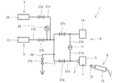
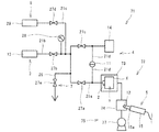
図1のリークテスタ1は、ワークXが有する空間Yを密閉する機構(密閉機構2)と、密閉機構2により密閉された空間Yにトレーサーガスを供給する機構(供給機構3)と、空間Yの圧力変化を検出する圧力センサー11を有する第1検査機構4と、空間Yの外側に設けられ、空間Yの外に漏洩するトレーサーガスを検出するセンサー12を有する第2検査機構5とを備える。供給機構3は、トレーサーガス供給器13を有する。第1検査機構4は、圧力センサー11と、マスター容器14とを有する。また、当該リークテスタ1は、トレーサーガスを回収する機構(回収機構6)と、トレーサーガスを排出する機構(排出機構7)と、制御機構(不図示)とを備える。回収機構6は、トレーサーガス回収器29を有する。排出機構7は、排出用配管26を有する。密閉機構2、トレーサーガス供給器13、圧力センサー11、マスター容器14、トレーサーガス回収器29及び排出用配管26は、配管で接続されている。なお、「ワークXが有する空間Y」とは、少なくともワークXの表面を含む中空状の空間をいう。
[First embodiment]
<Leak tester>
The
(配管)
密閉機構2、トレーサーガス供給器13、圧力センサー11、マスター容器14、トレーサーガス回収器29及び排出用配管26を接続する配管は、一端が密閉機構2に接続され、他端がマスター容器14に接続される主配管21aと、一端が主配管21aに接続され、他端がトレーサーガス供給器13に接続されるトレーサーガス供給用配管21bと、一端が主配管21aに接続され、他端がトレーサーガス回収器29に接続されるトレーサーガス回収用配管21cと、両端が主配管21aに接続され中間に圧力センサー11が配設される接続用配管21dとを有する。また、排出用配管26は、一端が主配管21aに接続され、他端が大気に開放されている。
(Plumbing)
The piping connecting the
〔ワーク〕
ワークXとしては、ガス漏れ検査を必要とする種々の部材が挙げられ、例えばプラスチック容器、金属容器、ラミネート容器等の容器類、チューブレスタイヤ用ホイール、エンジンブロック、シリンダーヘッド等の自動車用部品、パイプ、継手、バルブ、コック等の配管部品などが挙げられる。
〔work〕
Examples of the work X include various members that require a gas leak test. For example, containers such as plastic containers, metal containers, and laminate containers, tubeless tire wheels, engine blocks, automobile parts such as cylinder blocks, pipes, etc. And piping parts such as joints, valves and cocks.
(密閉機構)
密閉機構2は、主配管21aに接続されており、主配管21aとの接続部以外においてワークXの空間Yを密閉可能に構成されている。密閉機構2としては、例えばワークXが容器である場合にはこの容器の開口を封止する蓋、ワークXがタイヤ用ホイールである場合にはこのタイヤ用ホイールの軸方向両端の一対のフランジ間に全周に亘って架け渡されるカバー、ワークXが配管部品である場合には両端を封止する一対の蓋が挙げられる。なお、密閉機構2を構成する蓋等は、1つである必要はなく、複数の蓋等によってワークXの空間Yを密閉してもよい。
(Sealing mechanism)
The
(供給機構)
供給機構3は、前述のようにトレーサーガス供給器13を有する。トレーサーガス供給器13は、主配管21a及びトレーサーガス供給用配管21bを介して密閉機構2及びマスター容器14に接続されている。トレーサーガス供給用配管21bには圧力計28及びバルブ27bが設けられている。また、トレーサーガス供給用配管21bには、トレーサーガス供給器13から供給されるトレーサーガスの圧力を調整する圧力調整弁(不図示)が設けられていてもよい。トレーサーガス供給器13は、トレーサーガスを貯留し、このトレーサーガスを例えば数百kPaオーダーの圧力で供給可能に構成されている。
(Supply mechanism)
The
〔トレーサーガス〕
本実施形態におけるトレーサーガスとしては、第2検査機構5によって空間Y外へのガス漏れを検出できるよう通常空気中に含まれない成分又は空気中における存在量の少ない成分を含むガスが用いられ、例えば水素、ヘリウム、これらのガスを含む混合ガス等が用いられる。
[Tracer gas]
As the tracer gas in the present embodiment, a gas that includes a component that is not normally contained in the air or a component that is not present in the air so that the
(第1検査機構)
第1検査機構4は、空間Y内の圧力変化によってワークXのガス漏れを検出する。第1検査機構4は、特に微量なガス漏れ以外のガス漏れを検出可能に構成されている。第1検査機構4は、前述のように圧力センサー11と、マスター容器14とを有する。
(First inspection mechanism)
The
圧力センサー11は、接続配管21dを介して主配管21aの密閉機構2との接続部近傍及びマスター容器14との接続部近傍に接続されている。圧力センサー11は、2点間の圧力差を測定可能な差圧式圧力センサーである。具体的には、圧力センサー11は、気密性を有する筐体と、この筐体の内部空間を気密的に隔絶してこの内部空間を2つの空間に区画するダイアフラムとを有する。圧力センサー11は、ダイアフラムによって区画される一対の空間に圧力差が生じると、ダイアフラムが圧力が小さい空間側に向かって膨張することで差圧が生じていることを検出可能に構成されている。また、圧力センサー11は、差圧が生じた場合のダイアフラムの変形量によって一対の空間の間で生じている差圧の大きさを検出可能に構成されている。これにより、圧力センサー11は、空間Yとマスター容器14内との差圧を測定可能に構成されている。なお、主配管21aの接続配管21dとの接続部の上流側(トレーサーガス供給器13側)には、一対のバルブ27a,27cが設けられている。
The
マスター容器14は、圧力センサー11によって差圧を測定する際に基準となる圧力を保持するための容器であり、気密性を有する。マスター容器14としては、ワークXと同一の内部容積を有しガス漏れがないことが確認された疑似ワークや、ガス漏れがないことが確認されたワークX等、ガス漏れのない種々の容器を用いることが可能である。
The
(第2検査機構)
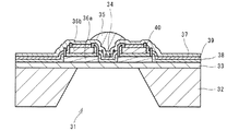
第2検査機構5は、第1検査機構4によっては検出できないワークXの微細な隙間からのガス漏れを検出する。第2検査機構5は、センサー12を内蔵するスニファープローブ15を有する。第2検査機構5は、ワークXにおけるガス漏れのおそれがある部分にスニファープローブ15を近づけた状態で、センサー12によってトレーサーガスの漏洩の検出するよう構成されている。空間Y外に漏洩するトレーサーガスを検出するセンサー12は、接触燃焼式サーモパイルセンサー(以下、単に「サーモパイルセンサー」ともいう)である。以下、図2を参照して、本実施形態におけるサーモパイルセンサーについて説明する。
(Second inspection mechanism)
The
(サーモパイルセンサー)
前記サーモパイルセンサーは、トレーサーガスが燃焼する際に発生する燃焼熱を検出することでトレーサーガスを検量可能に構成されている。前記サーモパイルセンサーは、基板32と、この基板32の一方側に配設されるヒーター34と、このヒーター34の一方側に配設され、燃焼触媒を担持した担体を有する反応層35とを有し、この反応層35及びヒーター34の近傍にサーモパイルの温接点が配設され、基板32の近傍にサーモパイルの冷接点が配設されている。具体的には、前記サーモパイルセンサーは、開口31を有し、シリコン等を主成分とする基板32と、基板32の一方側に積層される第1絶縁層33と、第1絶縁層33の一方側に配設される複数のn型熱電素子36aと、複数のn型熱電素子36aの一方側を覆うように基板32の一方側に積層される第2絶縁層38と、第2絶縁層38の一方側に配設される複数のp型熱電素子36bと、複数のp型熱電素子36bを被覆するように第2絶縁層38の一方側に積層される第3絶縁層39と、開口31の一方側において第3絶縁層39の一方側に配設されるヒーター34と、p型熱電素子36bに接続され、第3絶縁層39を貫通する配線40と、ヒーター34、第3絶縁層39及び配線40の一方側に積層される保護層37と、保護層37を介してヒーター34の一方側に積層される反応層35とを主として有する。前記サーモパイルセンサーは、複数のn型熱電素子36a及び複数のp型熱電素子36bが接続されることで形成される複数の熱電対を有し、この複数の熱電対は、隣接するn型熱電素子36a及びp型熱電素子36bの内側端部を接続した温接点を開口31の一方側に有すると共に、隣接するn型熱電素子36a及びp型熱電素子36bの外側端部を接続した冷接点を基板32の一方側に有する。前記サーモパイルセンサーは、複数のn型熱電素子36a及び複数のp型熱電素子36bが温接点及び冷接点で直列接続されることで、複数の熱電対が直列接続されたサーモパイル構成を有する。
(Thermopile sensor)
The thermopile sensor is configured such that the tracer gas can be calibrated by detecting combustion heat generated when the tracer gas is burned. The thermopile sensor has a
当該リークテスタ1は、トレーサーガスを検出するセンサー12がサーモパイルセンサーであることによって、広ダイナミックレンジ、かつ高速応答でトレーサーガスの漏洩を検出することができる。特に、トレーサーガスを検出するセンサーとして従来の半導体センサーを用いると、トレーサーガスが高濃度である場合にはセンサー出力が飽和して測定精度が低下するおそれがあると共に、センサーが疲弊してセンサー使用後の復帰時間も長くなる。また、従来の半導体センサーは、高濃度のトレーサーガスに晒されると、センサーの性能が劣化するおそれや、故障のリスクが高くなる。つまり、従来の半導体センサーは、比較的多量なガス漏れが生じるおそれがある場合には使用し難い。これに対し、トレーサーガスを検出するセンサー12がサーモパイルセンサーである場合、出力飽和の問題が生じないことに加え、使用後の復帰時間を短縮することができると共に故障のリスクも低減することができるので、多量なガス漏れを検出した場合でも不具合が起こり難い。
The
(回収機構)
回収機構6は、ワークXのガス漏れ検査後にトレーサーガスを回収可能に構成されている。回収機構6は、前述のようにトレーサーガス回収器29を有する。トレーサーガス回収器29は、トレーサーガス回収用配管21cを介して主配管21aに接続されている。また、トレーサーガス回収用配管21cにはバルブ27dが設けられている。
(Recovery mechanism)
The
(排出機構)
排出機構7は、ワークXのガス漏れ検査後にトレーサーガスを排出可能に構成されている。排出機構7は、前述のように一端が主配管21aに接続され他端が大気に開放された排出用配管26を有する。また、排出用配管26にはバルブ27eが設けられている。
(Discharge mechanism)
The
(制御機構)
制御機構は、当該リークテスタ1の動作を制御するもので、例えばCPU、ROM、RAM、HDD等を備えるコンピュータを有する構成とされる。前記制御機構は、バルブ27a〜27eの開閉動作を制御する。また前記制御機構は、圧力センサー11によって検出した差圧に基づいて空間Yからのガス漏れの有無を判断する。
(Control mechanism)
The control mechanism controls the operation of the
<リークテスト方法>
次に、当該リークテスタ1を用いたリークテスト方法を説明する。当該リークテスト方法は、ワークXが有する密閉された空間Yにトレーサーガスを供給する工程(供給工程)と、空間Yの圧力変化を検出する第1検査工程と、空間Y外に漏洩するトレーサーガスを検出する第2検査工程とを備える。また、当該リークテスト方法は、前記第1検査工程及び第2検査工程後にトレーサーガスを回収する工程(回収工程)をさらに備えてもよい。当該リークテスト方法は、前記第1検査工程及び第2検査工程を同時に行う。
<Leak test method>
Next, a leak test method using the
(供給工程)
前記供給工程は、供給機構3によって行われる。前記供給工程では、バルブ27a〜27eが全て閉じられた状態において、バルブ27a〜27cを開く。そして、前記供給工程では、トレーサーガス供給器13からトレーサーガスを空間Y及びマスター容器14内に供給する。これにより、空間Y及びマスター容器14内の内圧が高くなる。さらに、前記供給工程では、空間Y及びマスター容器14内の内圧が高くなった状態でバルブ27a,27cを閉じる。これにより、バルブ27a,27cよりも下流側におけるトレーサーガスの通路が、バルブ27a,27cよりも上流側の通路から遮断された密閉空間として構成される。なお、バルブ27a,27cは、空間Yの圧力及びマスター容器14内の圧力が同じとなったことを確認した上で閉じることが好ましい。前記供給工程における空間Y及びマスター容器14内の圧力としては、例えば5kPa以上1MPa以下程度とされる。
(Supply process)
The supply process is performed by the
(第1検査工程)
前記第1検査工程は、第1検査機構4によって行われる。前記第1検査工程では、バルブ27a,27cが閉じられた状態で、圧力センサー11によって空間Yのガス漏れの有無を検査する。具体的には、バルブ27a,27cが閉じられた状態で、空間Yにガス漏れが生じると空間Yの内圧が低下する。これにより、圧力センサー11の一方の空間の内圧が低下するので、圧力センサー11の一対の空間に一定以上の差圧が生じた場合に前記ダイアフラムによってこの差圧を検出することができる。一方、前記第1検査工程では、空間Yにガス漏れが生じていない場合、又はガス漏れが生じてもこのガス漏れ量が微量である場合には前記ダイアフラムによってガス漏れは検出されない。なお、第1検査工程によって検出されるガス漏れ量の下限としては、例えば10−4Pa・m3/s程度とされる。
(First inspection process)
The first inspection step is performed by the
(第2検査工程)
前記第2検査工程は、第2検査機構5によって行われる。前記第2検査工程では、バルブ27a,27cが閉じられた状態で、スニファープローブ15を微量なガス漏れのおそれがある部分に近づけ、前記サーモパイルセンサーによってガス漏れの有無を検査する。以下、前記サーモパイルセンサーによるガス漏れ検査方法を説明する。
(Second inspection process)
The second inspection step is performed by the
前記サーモパイルセンサーは、トレーサーガスを触媒燃焼させる反応層35を有するので、ヒーター34の発熱によってトレーサーガスを燃焼させることができる。前記サーモパイルセンサーは、このトレーサーガスが燃焼すると、反応層35側に形成された温接点の温度が反応層35の温度と略同一となる一方、基板32側に形成された冷接点の温度は反応層35の温度に起因して上昇しない。これにより、前記サーモパイルセンサーは、温接点と冷接点との温度差により電圧を生じ、サーモパイルが温度検出信号を出力する。これにより、前記サーモパイルセンサーは、トレーサーガスの空間Yからの漏洩の有無を検出することができる。なお、第2検査工程によって検出されるガス漏れ量としては、例えば0.5体積ppm以上2体積%以下程度とされる。
Since the thermopile sensor has the
(回収工程)
前記回収工程は、回収機構6によって行われる。前記回収工程では、第1検査工程及び第2検査工程後にバルブ27b,27eが閉じられた状態でバルブ27a,27c,27dを開き、トレーサーガスをトレーサーガス回収器29に回収する。なお、前記回収工程では、例えば吸引ポンプ(不図示)等を用いてトレーサーガスをトレーサーガス回収器29に回収するようにしてもよい。
(Recovery process)
The collection step is performed by the
なお、当該リークテスト方法は、トレーサーガスを有効利用する点からは前記回収工程によってトレーサーガスをトレーサーガス回収器29に回収することが好ましいが、必要に応じて不要になったトレーサーガスを排出してもよい。このトレーサーガスを排出する工程(排出工程)は、排出機構7によって行われる。前記排出工程では、バルブ27b,27dが閉じられた状態でバルブ27a,27c,27eを開き、トレーサーガスを排出用配管26から大気中に排出する。
In the leak test method, it is preferable to collect the tracer gas in the tracer
<利点>
当該リークテスタ1は、ワークXが有する密閉された空間Yにトレーサーガスを満たした状態で、この空間Yの圧力変化を第1検査機構4によって検出することでワークXの微量なガス漏れ以外のガス漏れを検出することができる。また、当該リークテスタ1は、空間Y外に漏洩するトレーサーガスを第2検査機構5によって検出することでワークXの微量なガス漏れを検出することができる。従って、当該リークテスタ1は、ワークXの比較的多量なガス漏れから微量なガス漏れまでを検出することができる。
<Advantages>
The
当該リークテスト方法は、前記供給工程によってワークXが有する密閉された空間Yにトレーサーガスを満たした状態で、前記第1検査工程によってこの空間Yの圧力変化を検出し、かつ前記第2検査工程によってこの空間Y外に漏洩するトレーサーガスを検出することで、ワークXの比較的多量なガス漏れから微量なガス漏れまでを同時に検出することができる。 In the leak test method, a pressure change in the space Y is detected by the first inspection step in a state where the sealed space Y of the workpiece X is filled with the tracer gas by the supply step, and the second inspection step. Thus, by detecting the tracer gas leaking out of the space Y, it is possible to detect from a relatively large amount of gas leakage to a small amount of gas leakage of the workpiece X at the same time.
[第2実施形態]
<リークテスタ>
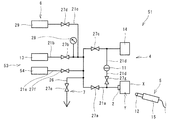
図3のリークテスタ51は、ワークXが有する空間Yを密閉する機構(密閉機構2)と、密閉機構2により密閉された空間Yにトレーサーガスを供給する機構(供給機構53)と、空間Yの圧力変化を検出する圧力センサー11を有する第1検査機構4と、空間Yの外側に設けられ、空間Y外に漏洩するトレーサーガスを検出するセンサー12を有する第2検査機構5とを備える。また、当該リークテスタ51は、トレーサーガスを回収する機構(回収機構6)と、トレーサーガスを排出する機構(排出機構7)と、制御機構(不図示)とを備える。密閉機構2、供給機構53、第1検査機構4、回収機構6及び排出機構7は配管で接続されている。当該リークテスタ51における密閉機構2、第1検査機構4、第2検査機構5、回収機構6、排出機構7及び制御機構は、図1のリークテスタ1と同様のため同一符号を付して説明を省略する。
[Second Embodiment]
<Leak tester>
3 includes a mechanism (sealing mechanism 2) for sealing the space Y of the workpiece X, a mechanism for supplying tracer gas to the space Y sealed by the sealing mechanism 2 (supply mechanism 53), A
(配管)
密閉機構2、供給機構53、第1検査機構4、回収機構6及び排出機構7を接続する配管は、一端が主配管21aに接続され、他端が第1トレーサーガス供給器54に接続される第1トレーサーガス供給用配管21eを有する以外は、図1のリークテスタ1と同様に構成される。なお、本実施形態においては、接続用配管21dにおける圧力センサー11よりも密閉機構2側の部分にバルブ27gが設けられている。
(Plumbing)
One end of the pipe connecting the
(供給機構)
供給機構53は、第1トレーサーガス供給器54と、第2トレーサーガス供給器13とを有する。第1トレーサーガス供給器54は、第1トレーサーガス供給用配管21e及び主配管21aを介して密閉機構2及びマスター容器14に接続されている。第1トレーサーガス供給用配管21eにはバルブ27fが設けられている。第2トレーサーガス供給器13は、図1のトレーサーガス供給器13と同様の構成を有し、トレーサーガス供給用配管21b及び主配管21aを介して密閉機構2及びマスター容器14に接続されている。第1トレーサーガス供給器54は、トレーサーガスとして空気を貯留する以外は第2トレーサーガス供給器13と同様に構成されている。
(Supply mechanism)
The
<リークテスト方法>
当該リークテスタ51を用いたリークテスト方法は、第1トレーサーガス供給工程と、第1検査工程と、第1トレーサーガス排出工程と、第2トレーサーガス供給工程と、第2検出工程とを備える。また、当該リークテスト方法は、第2検査工程後に、第2トレーサーガス供給工程で供給したトレーサーガスを回収する回収工程をさらに備えていてもよい。当該リークテスト方法は、第1トレーサーガス供給工程で供給したトレーサーガスを用いて第1検査工程を行い、この第1検査工程で用いたトレーサーガスを排出した後に第2トレーサーガス供給工程で供給したトレーサーガスを用いて第2検査工程を行う。
<Leak test method>
The leak test method using the
(第1トレーサーガス供給工程)
前記第1トレーサーガス供給工程は、供給機構53によって行われる。前記第1トレーサーガス供給工程では、まずバルブ27a〜27gが全て閉じられた状態において、バルブ27a,27c,27f,27gを開く。そして、前記第1トレーサーガス供給工程では、第1トレーサーガス供給器54からトレーサーガスである空気を空間Y及びマスター容器14内に供給する。これにより、空間Y及びマスター容器14内の内圧が高くなる。さらに、前記第1トレーサーガス供給工程では、空間Y及びマスター容器14内の内圧が高くなった状態でバルブ27a,27cを閉じる。これにより、バルブ27a,27cよりも下流側における空気の通路が、バルブ27a,27cよりも上流側の通路から遮断された密閉空間として構成される。
(First tracer gas supply process)
The first tracer gas supply process is performed by the
(第1検査工程)
前記第1検査工程は、図1のリークテスタ1を用いたリークテスト方法における第1検査工程と同様に行うことができる。
(First inspection process)
The first inspection step can be performed in the same manner as the first inspection step in the leak test method using the
(第1トレーサーガス排出工程)
前記第1トレーサーガス排出工程は、排出機構7によって行われる。前記第1トレーサーガス排出工程では、バルブ27b,27d,27fが閉じられた状態でバルブ27a,27c,27e,27gを開き、空気を排出用配管26から大気中に排出する。
(First tracer gas discharge process)
The first tracer gas discharge step is performed by the
(第2トレーサーガス供給工程)
前記第2トレーサーガス供給工程は、図1のリークテスタ1を用いたリークテスト方法における供給工程と同様に行うことができる。また、前記第2トレーサーガス供給工程は、バルブ27c〜27gを閉じた状態でトレーサーガスを供給し、これによりこのトレーサーガスをマスター容器14には供給せず、空間Yにのみ供給してもよい。当該リークテスト方法は、トレーサーガスを空間Yのみに供給することによって、水素、ヘリウム等を含むトレーサーガスの消費を抑え、検査コストを低減することができる。
(Second tracer gas supply process)
The second tracer gas supply step can be performed in the same manner as the supply step in the leak test method using the
(第2検査工程)
前記第2検出工程は、図1のリークテスタ1を用いたリークテスト方法における第2検査工程と同様に行うことができる。
(Second inspection process)
The second detection step can be performed in the same manner as the second inspection step in the leak test method using the
(回収工程)
前記回収工程は、図1のリークテスタ1を用いたリークテスト方法における回収工程と同様に行うことができる。
(Recovery process)
The recovery step can be performed in the same manner as the recovery step in the leak test method using the
<利点>
当該リークテスタ51は、図1のリークテスタ1と同様、ワークXの比較的多量なガス漏れから微量なガス漏れまでを検出することができる。なお、当該リークテスタ51は、仮に第1検査機構4によってガスの漏洩が検出された場合、第2検査機構5による検査を取り止めてもよい。この場合、当該リークテスタ51は、水素、ヘリウム等を含むトレーサーガスの消費を抑え、検査コストを低減することができる。
<Advantages>
The
当該リークテスト方法は、図1のリークテスタ1を用いたリークテスト方法と同様、ワークXの比較的多量なガス漏れから微量なガス漏れまでを検出することができる。また、当該リークテスト方法は、仮に第1検査工程によってガスの漏洩が検出された場合、第2検査工程を取り止めることができ、これにより水素、ヘリウム等を含むトレーサーガスの消費を抑え、検査コストを低減することができる。
The leak test method can detect from a relatively large amount of gas leak to a small amount of gas leak of the workpiece X, as in the leak test method using the
[第三実施形態]
<リークテスタ>
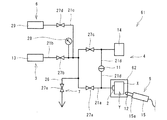
図4のリークテスタ61は、ワークXを内部に収容し、この内部を気密状態に保持可能な収容部62を備え、空間Y外に漏洩するトレーサーガスを検出するセンサー12が収容部62内に配設される以外は図1のリークテスタ1と同様に構成される。そのため、以下では収容部62についてのみ説明する。
[Third embodiment]
<Leak tester>
The
(収容部)
収容部62は、主配管21aが挿入される第1貫通孔及びスニファープローブ15の先端部15aが挿入される第2貫通孔を有し、主配管21a及びスニファープローブ15の先端部15aが一対の貫通孔に挿入された状態で内部を気密状態に保持可能に構成されている。詳細には、収容部62は、主配管21aとの接続部以外におけるガスの出入りが防止されるよう構成されている。
(Container)
The
収容部62の形成材料としては、内部を気密状態に保持可能である限り特に限定されるものではなく、合成樹脂、金属等が挙げられる。また、収容部62の容積としては、密閉機構2によって密閉された状態のワークXを内部に収容可能である限り特に限定されるものではない。但し、収容部62の容積は、収容部62内に漏洩されたトレーサーガスを効果的に検出できる点から小さい方が好ましい。具体的には、ワークXの体積に対する収容部62の容積の比の上限としては、4が好ましく、2がより好ましく、1.5がさらに好ましい。一方、ワークXの体積に対する収容部62の容積の比の下限としては、ワークXの収容容易性の点から、例えば1.2とすることができる。
The material for forming the
<リークテスト方法>
当該リークテスタ61を用いたリークテスト方法は、第1実施形態で説明した前述の第2検査工程を、収容部62内にワークXを収容し、かつこの収容部62内にセンサー12を配設した状態で行う以外、図1のリークテスタ1を用いた前述のリークテスト方法と同様の手順で行うことができる。
<Leak test method>
In the leak test method using the
<利点>
当該リークテスタ61は、ワークXを内部に収容し、この内部を気密状態に保持可能な収容部62を備え、スニファープローブ15の先端部15aが収容部62内に配設されるので、収容部62内に充満するトレーサーガスを検出することで、空間Y外に漏洩するトレーサーガスをより確実に検出することができる。特に、当該リークテスタ61は、収容部62内が気密状態に保たれるので、ワークXにおけるガス漏れ部分から比較的離れた位置にセンサー12が位置する場合でも空間Y外に漏洩するトレーサーガスを検出することができる。
<Advantages>
The
当該リークテスト方法は、前記第2検査工程が収容部62内に充満するトレーサーガスを検出することで、空間Y外に漏洩するトレーサーガスをより確実に検出することができる。特に、当該リークテスト方法は、ワークXにおけるガス漏れ部分から比較的離れた位置にセンサー12が位置する場合でも空間Y外に漏洩するトレーサーガスを検出することができる。
In the leak test method, the tracer gas leaking out of the space Y can be detected more reliably by detecting the tracer gas filled in the
[第四実施形態]
<リークテスタ>
図5のリークテスタ71は、前述の収容部62に代えて、ワークXを収容する第1室73及びこの第1室73に連通する第2室74を有する収容部72を備える。また、当該リークテスタ71は、第2室74内を減圧する減圧機構75を備える。さらに、当該リークテスタ71は、空間Y外に漏洩するトレーサーガスを検出するセンサー12が第2室74内に配設される。当該リークテスタ71は、収容部72及び減圧機構75を備える以外、図1のリークテスタ1と同様に構成される。そのため、以下では収容部72及び減圧機構75についてのみ説明する。
[Fourth embodiment]
<Leak tester>
The
(収容部)
第1室73は、配管によって第2室74と連通している。また、第1室73は、主配管21aが挿入される貫通孔を有する。さらに、第2室74は、スニファープローブ15の先端部15aが挿入される貫通孔を有する。収容部72は、スニファープローブ15の先端部15aが第2室74の貫通孔に挿入された状態で内部を気密状態に保持可能に構成されている。詳細には、収容部72は、主配管21a及び減圧機構75との接続部以外におけるガスの出入りが防止されるよう構成されている。第1室73及び第2室74の形成材料は、図5のリークテスタ61の収容部62と同様とすることができる。また、第1室73の容積は、図5のリークテスタ61の収容部62と同様とすることができる。一方、第2室74の容積は、貫通孔に挿入されたスニファープローブ15のセンサー12によってトレーサーガスを的確に検出する点からは小さい方が好ましい。このような点から、第2室74の容積の上限としては、10cm3が好ましく、5cm3がより好ましい。一方、第2室74の容積の下限としては、スニファープローブ15の先端部15aの挿入容易性の点から、例えば2cm3とすることができる。
(Container)
The
(減圧機構)
減圧機構75は、減圧ポンプ77を有する。減圧ポンプ77の種類としては、第2室74内を減圧できるものであれば特に限定されず、公知の空圧式、油圧式、電気式等のポンプを用いることができる。
(Decompression mechanism)
The
<リークテスト方法>
当該リークテスタ71を用いたリークテスト方法は、第1実施形態で説明した前述の第2検査工程を、第1室73内にワークXを収容し、かつ減圧機構75で第2室74内を減圧しつつ、第2室74内にセンサー12を配設した状態で行う以外、図1のリークテスタ1を用いた前述のリークテスト方法と同様の手順で行うことができる。
<Leak test method>
In the leak test method using the
<利点>
当該リークテスタ71は、空間Y外に漏洩するトレーサーガスを減圧機構75によって第2室74内に誘導しつつ、この第2室74内に存在するトレーサーガスを第2検査機構5によって検出することで、空間Y外に漏洩するトレーサーガスをより確実に検出することができる。特に、当該リークテスタ71は、センサー12をワークXにおけるガス漏れ部分近傍に位置させる必要がないので、空間Y外に漏洩するトレーサーガスの検出容易化を促進することができる。
<Advantages>
The
当該リークテスト方法は、前記第2検査工程が第2室74内に存在するトレーサーガスを検出することで、空間Y外に漏洩するトレーサーガスをより確実に検出することができる。特に、当該リークテスト方法は、センサー12をワークXにおけるガス漏れ部分近傍に位置させる必要がないので、空間Y外に漏洩するトレーサーガスの検出容易化を促進することができる。
In the leak test method, the tracer gas leaking out of the space Y can be more reliably detected by detecting the tracer gas present in the
[その他の実施形態]
なお、本発明に係るリークテスタ及びリークテスト方法は、前記態様の他、種々の変更、改変を施した態様で実施することができる。
[Other Embodiments]
In addition, the leak tester and the leak test method according to the present invention can be implemented in variously modified and modified modes in addition to the above mode.
例えば当該リークテスタは、前述の回収機構及び排出機構を有しなくてもよい。また、当該リークテスタは、空間外に漏洩するトレーサーガスを検出するセンサーが接触燃焼式サーモパイルセンサーである必要はなく、例えばサーモパイルセンサー以外の接触燃焼式センサーや熱電式センサーであってもよい。 For example, the leak tester may not have the above-described recovery mechanism and discharge mechanism. In the leak tester, the sensor for detecting the tracer gas leaking out of the space does not have to be a contact combustion type thermopile sensor, and may be a contact combustion type sensor other than the thermopile sensor or a thermoelectric sensor, for example.
当該リークテスタは、空間外に漏洩するトレーサーガスを検出するセンサーが接触燃焼式サーモパイルセンサーである場合でも、前述の構成の接触燃焼式サーモパイルセンサーを用いる必要はない。 The leak tester does not need to use the contact combustion type thermopile sensor configured as described above even when the sensor for detecting the tracer gas leaking out of the space is a contact combustion type thermopile sensor.
前記圧力センサーは、必ずしも差圧式圧力センサーである必要はなく、例えば直圧式圧力センサー、超音波センサー、赤外線センサー等であってもよい。また、当該リークテスタは、前記圧力センサーとして差圧式圧力センサーを用いる場合でも、前述のマスター容器を必ずしも用いる必要はない。 The pressure sensor is not necessarily a differential pressure sensor, and may be a direct pressure sensor, an ultrasonic sensor, an infrared sensor, or the like. In addition, the leak tester does not necessarily need to use the above-described master container even when a differential pressure sensor is used as the pressure sensor.
当該リークテスタは、トレーサーガスとして空気を貯留する第1トレーサーガス供給器及び空気以外のトレーサーガスを貯留する第2トレーサーガス供給器を有する第2実施形態の構成において、ワークを内部に収容し、この内部を気密状態に保持可能な収容部を備え、ワークが有する空間外に漏洩するトレーサーガスを検出するセンサーが収容部内に配設される構成を採用することも可能である。また、当該リークテスタは、この第2実施形態の構成において、収容部がワークを収容する第1室及びこの第1室に連通する第2室を有し、第2室内を減圧する減圧機構をさらに備え、トレーサーガスを検出するセンサーが、第2室内に配設される構成を採用することも可能である。 In the configuration of the second embodiment, the leak tester has a first tracer gas supply device that stores air as a tracer gas and a second tracer gas supply device that stores a tracer gas other than air. It is also possible to employ a configuration in which a housing portion that can hold the inside in an airtight state is provided, and a sensor that detects tracer gas leaking outside the space of the workpiece is disposed in the housing portion. Further, in the configuration of the second embodiment, the leak tester further includes a first chamber in which the accommodating portion accommodates the workpiece and a second chamber communicating with the first chamber, and further includes a decompression mechanism that decompresses the second chamber. It is also possible to employ a configuration in which the sensor for detecting the tracer gas is provided in the second chamber.
以上説明したように、本発明に係るリークテスタは、ワークの比較的多量なガス漏れから微量なガス漏れまでを検出することができるので、ワークのガス漏れの検出効率を促進可能なリークテスタとして適している。 As described above, the leak tester according to the present invention can detect from a relatively large amount of gas leakage to a small amount of gas leakage of the workpiece, and is therefore suitable as a leak tester capable of promoting the detection efficiency of the workpiece gas leakage. Yes.
1,51,61,71 リークテスタ
2 密閉機構
3,53 供給機構
4 第1検査機構
5 第2検査機構
11 圧力センサー
12 センサー
13 トレーサーガス供給器
14 マスター容器
15 スニファープローブ
15a 先端部
21a 主配管
21b トレーサーガス供給用配管
21c トレーサーガス回収用配管
21d 接続用配管
21e 第1トレーサーガス供給用配管
26 排出用配管
27a〜27g バルブ
28 圧力計
29 トレーサーガス回収器
31 開口
32 基板
33 第1絶縁層
34 ヒーター
35 反応層
36a n型熱電素子
36b p型熱電素子
37 保護層
38 第2絶縁層
39 第3絶縁層
40 配線
54 第1トレーサーガス供給器
62,72 収容部
73 第1室
74 第2室
75 減圧機構
77 減圧ポンプ
X ワーク
Y 空間
1, 51, 61, 71
Claims (5)
前記密閉機構により密閉された空間にトレーサーガスを供給する機構と、
前記空間の圧力変化を検出する圧力センサーを有する第1検査機構と、
前記空間の外側に設けられ、空間外に漏洩するトレーサーガスを検出するセンサーを有する第2検査機構と
を備えるリークテスタ。 A mechanism for sealing the space of the workpiece,
A mechanism for supplying tracer gas to the space sealed by the sealing mechanism;
A first inspection mechanism having a pressure sensor for detecting a pressure change in the space;
A leak tester comprising: a second inspection mechanism provided outside the space and having a sensor for detecting tracer gas leaking out of the space.
前記トレーサーガスを検出するセンサーが、前記収容部内に配設される請求項1に記載のリークテスタ。 The work is housed inside, further comprising a housing portion capable of holding the inside in an airtight state,
The leak tester according to claim 1, wherein a sensor for detecting the tracer gas is disposed in the housing portion.
前記第2室内を減圧する減圧機構をさらに備え、
前記トレーサーガスを検出するセンサーが、前記第2室内に配設される請求項2に記載のリークテスタ。 The storage portion has a first chamber for storing the workpiece and a second chamber communicating with the first chamber,
A pressure reducing mechanism for reducing the pressure in the second chamber;
The leak tester according to claim 2, wherein a sensor for detecting the tracer gas is disposed in the second chamber.
前記空間の圧力変化を検出する第1検査工程と、
前記空間の外に漏洩するトレーサーガスを検出する第2検査工程と
を備え、
前記第1検査工程及び第2検査工程を同時に行うリークテスト方法。 Supplying tracer gas to a sealed space of the workpiece;
A first inspection step for detecting a pressure change in the space;
A second inspection step of detecting tracer gas leaking out of the space,
A leak test method for simultaneously performing the first inspection step and the second inspection step.
Priority Applications (1)
| Application Number | Priority Date | Filing Date | Title |
|---|---|---|---|
| JP2016139380A JP6782003B2 (en) | 2016-07-14 | 2016-07-14 | Leak tester and leak test method |
Applications Claiming Priority (1)
| Application Number | Priority Date | Filing Date | Title |
|---|---|---|---|
| JP2016139380A JP6782003B2 (en) | 2016-07-14 | 2016-07-14 | Leak tester and leak test method |
Publications (2)
| Publication Number | Publication Date |
|---|---|
| JP2018009892A true JP2018009892A (en) | 2018-01-18 |
| JP6782003B2 JP6782003B2 (en) | 2020-11-11 |
Family
ID=60995443
Family Applications (1)
| Application Number | Title | Priority Date | Filing Date |
|---|---|---|---|
| JP2016139380A Active JP6782003B2 (en) | 2016-07-14 | 2016-07-14 | Leak tester and leak test method |
Country Status (1)
| Country | Link |
|---|---|
| JP (1) | JP6782003B2 (en) |
Cited By (5)
| Publication number | Priority date | Publication date | Assignee | Title |
|---|---|---|---|---|
| CN110057416A (en) * | 2019-03-28 | 2019-07-26 | 中国辐射防护研究院 | A kind of measurement method and system of air exchange amount |
| JP2019189111A (en) * | 2018-04-26 | 2019-10-31 | ヤマハファインテック株式会社 | Wheeled tire and method of manufacturing the same |
| CN112098009A (en) * | 2020-09-30 | 2020-12-18 | 浙江华东建设工程有限公司 | Device for underwater leakage tracing inspection and method of using the same |
| KR20220149777A (en) * | 2021-04-30 | 2022-11-08 | 컨템포러리 엠퍼렉스 테크놀로지 씨오., 리미티드 | Box body leak detection method and leak detection system |
| CN119437576A (en) * | 2024-11-12 | 2025-02-14 | 广东裕威实业有限公司 | An intelligently controlled plastic article sealing performance detection device and method thereof |
Citations (4)
| Publication number | Priority date | Publication date | Assignee | Title |
|---|---|---|---|---|
| JP2007278914A (en) * | 2006-04-10 | 2007-10-25 | Fukuda:Kk | Leak test method and leak tester |
| JP2009092585A (en) * | 2007-10-11 | 2009-04-30 | Aisin Seiki Co Ltd | Leak inspection device |
| JP2009198431A (en) * | 2008-02-25 | 2009-09-03 | Kayaba Ind Co Ltd | Apparatus and method of inspecting leakage |
| JP2016061593A (en) * | 2014-09-16 | 2016-04-25 | ヤマハファインテック株式会社 | Catalytic combustion type gas sensor |
-
2016
- 2016-07-14 JP JP2016139380A patent/JP6782003B2/en active Active
Patent Citations (4)
| Publication number | Priority date | Publication date | Assignee | Title |
|---|---|---|---|---|
| JP2007278914A (en) * | 2006-04-10 | 2007-10-25 | Fukuda:Kk | Leak test method and leak tester |
| JP2009092585A (en) * | 2007-10-11 | 2009-04-30 | Aisin Seiki Co Ltd | Leak inspection device |
| JP2009198431A (en) * | 2008-02-25 | 2009-09-03 | Kayaba Ind Co Ltd | Apparatus and method of inspecting leakage |
| JP2016061593A (en) * | 2014-09-16 | 2016-04-25 | ヤマハファインテック株式会社 | Catalytic combustion type gas sensor |
Cited By (10)
| Publication number | Priority date | Publication date | Assignee | Title |
|---|---|---|---|---|
| JP2019189111A (en) * | 2018-04-26 | 2019-10-31 | ヤマハファインテック株式会社 | Wheeled tire and method of manufacturing the same |
| CN110057416A (en) * | 2019-03-28 | 2019-07-26 | 中国辐射防护研究院 | A kind of measurement method and system of air exchange amount |
| CN112098009A (en) * | 2020-09-30 | 2020-12-18 | 浙江华东建设工程有限公司 | Device for underwater leakage tracing inspection and method of using the same |
| KR20220149777A (en) * | 2021-04-30 | 2022-11-08 | 컨템포러리 엠퍼렉스 테크놀로지 씨오., 리미티드 | Box body leak detection method and leak detection system |
| JP2023526886A (en) * | 2021-04-30 | 2023-06-26 | 寧徳時代新能源科技股▲分▼有限公司 | Case leakage detection method and leakage detection system |
| JP7398010B2 (en) | 2021-04-30 | 2023-12-13 | 寧徳時代新能源科技股▲分▼有限公司 | Housing leakage detection method and leakage detection system |
| KR102695251B1 (en) * | 2021-04-30 | 2024-08-13 | 컨템포러리 엠퍼렉스 테크놀로지 씨오., 리미티드 | Method for detecting leaks in a box body and a leak detection system |
| US12259297B2 (en) | 2021-04-30 | 2025-03-25 | Contemporary Amperex Technology (Hong Kong) Limited | Method for box leak detection and leak detection system |
| CN119437576A (en) * | 2024-11-12 | 2025-02-14 | 广东裕威实业有限公司 | An intelligently controlled plastic article sealing performance detection device and method thereof |
| CN119437576B (en) * | 2024-11-12 | 2025-10-17 | 广东裕威实业有限公司 | Intelligent control plastic article sealing performance detection device and method thereof |
Also Published As
| Publication number | Publication date |
|---|---|
| JP6782003B2 (en) | 2020-11-11 |
Similar Documents
| Publication | Publication Date | Title |
|---|---|---|
| JP2018009892A (en) | Leakage tester, and leakage testing method | |
| JP4671462B2 (en) | Airtight inspection method for nickel metal hydride secondary battery | |
| JP4829326B2 (en) | Method for inspecting and locating leaks and apparatus suitable for carrying out the method | |
| JP2012047651A (en) | Leak detector | |
| CN104502038B (en) | A kind of measuring system and method for seal contact interface released gas rate | |
| CN106051469A (en) | Pipeline leakage detection device and detection method | |
| CN206074195U (en) | A kind of low temperature seal experiment test device | |
| CN103712756A (en) | Quantitative leakage detecting method for pressure system | |
| JP2008209220A (en) | Leak inspection method and apparatus | |
| JP2008309698A (en) | Airtight inspection apparatus, airtight inspection method, and airtight product manufacturing method | |
| CN102252939A (en) | Testing apparatus for testing air permeability of high barrier film | |
| JP2017526935A (en) | Film chamber with volumetric function for gross leak detection | |
| CN101424583A (en) | Hard bottle sealability detecting method and device thereof | |
| JP4061779B2 (en) | Leakage measuring device and leak inspection device | |
| JP2021110594A (en) | Inspection method for gas leakage detector, gas leakage inspection method, and gas leakage detector | |
| JP6273703B2 (en) | Inspection method for inspection object and inspection apparatus therefor | |
| CN103712754A (en) | Quantified leak rate detection method of pressure system | |
| JP2003185520A (en) | Method and apparatus for inspecting leakage of container | |
| KR20120134193A (en) | A portable apparatus for inspecting the leakage of a sealed cargo tank for compressed gas and a method thereof | |
| CN104913193A (en) | Leakage detection method and device for inner container of interlayer low-temperature container | |
| JP5733265B2 (en) | Gas filling device, gas tank inspection device, and gas tank inspection method | |
| CN115406593A (en) | Roots compressor helium detection device and detection method | |
| JP3186644B2 (en) | Gas leak inspection method | |
| JP5340802B2 (en) | Leak test apparatus and method | |
| JP4249675B2 (en) | Gas leak inspection system for piping in cryogenic containers |
Legal Events
| Date | Code | Title | Description |
|---|---|---|---|
| A621 | Written request for application examination |
Free format text: JAPANESE INTERMEDIATE CODE: A621 Effective date: 20190412 |
|
| A977 | Report on retrieval |
Free format text: JAPANESE INTERMEDIATE CODE: A971007 Effective date: 20200421 |
|
| A131 | Notification of reasons for refusal |
Free format text: JAPANESE INTERMEDIATE CODE: A131 Effective date: 20200623 |
|
| A521 | Request for written amendment filed |
Free format text: JAPANESE INTERMEDIATE CODE: A523 Effective date: 20200819 |
|
| TRDD | Decision of grant or rejection written | ||
| A01 | Written decision to grant a patent or to grant a registration (utility model) |
Free format text: JAPANESE INTERMEDIATE CODE: A01 Effective date: 20200929 |
|
| A61 | First payment of annual fees (during grant procedure) |
Free format text: JAPANESE INTERMEDIATE CODE: A61 Effective date: 20201012 |
|
| R150 | Certificate of patent or registration of utility model |
Ref document number: 6782003 Country of ref document: JP Free format text: JAPANESE INTERMEDIATE CODE: R150 |
|
| R250 | Receipt of annual fees |
Free format text: JAPANESE INTERMEDIATE CODE: R250 |
|
| R250 | Receipt of annual fees |
Free format text: JAPANESE INTERMEDIATE CODE: R250 |
|
| S531 | Written request for registration of change of domicile |
Free format text: JAPANESE INTERMEDIATE CODE: R313532 |
|
| R350 | Written notification of registration of transfer |
Free format text: JAPANESE INTERMEDIATE CODE: R350 |
|
| R250 | Receipt of annual fees |
Free format text: JAPANESE INTERMEDIATE CODE: R250 |