JP2018009823A - Rubber wear test equipment - Google Patents
Rubber wear test equipment Download PDFInfo
- Publication number
- JP2018009823A JP2018009823A JP2016137239A JP2016137239A JP2018009823A JP 2018009823 A JP2018009823 A JP 2018009823A JP 2016137239 A JP2016137239 A JP 2016137239A JP 2016137239 A JP2016137239 A JP 2016137239A JP 2018009823 A JP2018009823 A JP 2018009823A
- Authority
- JP
- Japan
- Prior art keywords
- test sample
- circumferential surface
- rubber
- rotating body
- test apparatus
- Prior art date
- Legal status (The legal status is an assumption and is not a legal conclusion. Google has not performed a legal analysis and makes no representation as to the accuracy of the status listed.)
- Granted
Links
Images
Classifications
-
- G—PHYSICS
- G01—MEASURING; TESTING
- G01N—INVESTIGATING OR ANALYSING MATERIALS BY DETERMINING THEIR CHEMICAL OR PHYSICAL PROPERTIES
- G01N3/00—Investigating strength properties of solid materials by application of mechanical stress
- G01N3/56—Investigating resistance to wear or abrasion
-
- G—PHYSICS
- G01—MEASURING; TESTING
- G01N—INVESTIGATING OR ANALYSING MATERIALS BY DETERMINING THEIR CHEMICAL OR PHYSICAL PROPERTIES
- G01N33/00—Investigating or analysing materials by specific methods not covered by groups G01N1/00 - G01N31/00
- G01N33/44—Resins; Plastics; Rubber; Leather
- G01N33/445—Rubber
Landscapes
- Chemical & Material Sciences (AREA)
- Health & Medical Sciences (AREA)
- Life Sciences & Earth Sciences (AREA)
- General Health & Medical Sciences (AREA)
- Analytical Chemistry (AREA)
- Biochemistry (AREA)
- Physics & Mathematics (AREA)
- General Physics & Mathematics (AREA)
- Immunology (AREA)
- Pathology (AREA)
- Engineering & Computer Science (AREA)
- Food Science & Technology (AREA)
- Medicinal Chemistry (AREA)
- Investigating Strength Of Materials By Application Of Mechanical Stress (AREA)
Abstract
【課題】実使用に合致したゴムの摩耗状態をより高精度で簡便に把握することができるゴムの摩耗試験装置を提供する。【解決手段】ゴムの試験サンプルSを保持部3により保持し、圧着機構10によってこの試験サンプルSに対して、回転している回転体4の円周面4aに向けた付加力Fを付与することにより、試験サンプルSを所定の定位置で円周面4aに押圧しつつ、付加力Fと反対方向への試験サンプルSの移動を常に許容した状態にして、スティック・スリップ現象を再現して試験サンプルSを摩耗させる。【選択図】図1The present invention provides a rubber wear test apparatus capable of easily and accurately grasping the wear state of rubber that matches actual use. A rubber test sample S is held by a holding portion 3, and an additional force F directed to a circumferential surface 4a of a rotating rotating body 4 is applied to the test sample S by a crimping mechanism 10. Thus, while pressing the test sample S against the circumferential surface 4a at a predetermined fixed position, the test sample S is always allowed to move in the direction opposite to the applied force F, and the stick-slip phenomenon is reproduced. The test sample S is worn. [Selection] Figure 1
Description
本発明は、ゴムの摩耗試験装置に関し、さらに詳しくは、実使用に合致したゴムの摩耗状態を、より高精度で簡便に把握することができるゴムの摩耗試験装置に関するものである。 The present invention relates to a rubber wear test apparatus, and more particularly to a rubber wear test apparatus that can easily and accurately grasp the wear state of rubber that matches actual use.
従来、ゴムの耐摩耗性を評価する試験機として、DIN摩耗試験機やウィリアムス摩耗試験機が知られている。しかしながら、これら摩耗試験機は、予め設定された一定条件下の耐摩耗性を把握することを目的としている。そのため、コンベヤベルトの様々な使用環境に整合した条件に設定することができず、実使用した場合のコンベヤベルトの上カバーゴムの耐摩耗性を精度よく予測することが難しい。 Conventionally, a DIN abrasion tester and a Williams abrasion tester are known as testers for evaluating the wear resistance of rubber. However, these wear testers are intended to grasp the wear resistance under a predetermined condition set in advance. For this reason, it is impossible to set the conditions consistent with various usage environments of the conveyor belt, and it is difficult to accurately predict the wear resistance of the upper cover rubber of the conveyor belt in actual use.
そこで、環状のベルトサンプルおよびベルトコンベヤ装置と類似した機構を用いた摩耗試験装置が提案されている(特許文献1参照)。この試験装置によれば、コンベヤベルトの実際の使用条件に類似した条件下で試験を行えるので、上カバーゴムの耐摩耗性を精度よく把握するには有利である。しかしながら、環状のベルトサンプルが必要となり、試験装置の構造も複雑になる。 Therefore, an abrasion test apparatus using a mechanism similar to an annular belt sample and a belt conveyor apparatus has been proposed (see Patent Document 1). According to this test apparatus, since the test can be performed under conditions similar to the actual use conditions of the conveyor belt, it is advantageous for accurately grasping the wear resistance of the upper cover rubber. However, an annular belt sample is required, and the structure of the test apparatus is complicated.
ところで、対象物とゴムとが接触状態で相対移動してゴムに対して対象物が摺動している場合、両者は常に一様に接触している訳ではない。ゴムが対象物から受ける力(摩擦力)に対抗して弾性変形する工程(粘り工程)と、この摩擦力に対抗できずに弾性変形が解消されて対象物に対してゴムが滑る工程(滑り工程)とを繰り返すスティック・スリップ現象が生じている。従来の試験装置では、このスティック・スリップ現象を十分に考慮してないため、ゴムの摩耗状態を高精度で把握するには改善の余地がある。 By the way, when the target object and the rubber move relative to each other in a contact state and the target object slides with respect to the rubber, they are not always in uniform contact. The process of elastically deforming the rubber against the force (frictional force) received from the object (sticking process), and the process of slipping the rubber against the object after the elastic deformation is resolved without resisting this frictional force (sliding) The stick-slip phenomenon is repeated. Since the conventional test apparatus does not fully consider this stick-slip phenomenon, there is room for improvement in order to grasp the wear state of rubber with high accuracy.
本発明の目的は、実使用に合致したゴムの摩耗状態を、より高精度で簡便に把握することができるゴムの摩耗試験装置を提供することにある。 An object of the present invention is to provide a rubber wear test apparatus that can easily and accurately grasp the wear state of rubber that matches actual use.
上記目的を達成するため本発明のゴムの摩耗試験装置は、ゴムの試験サンプルを保持する保持部と、前記試験サンプルが接触する円周面を有する回転体と、この回転体を回転駆動する駆動部と、前記保持部に保持されている前記試験サンプルに、前記円周面に向けた付加力を付与するとともに、この付加力と反対方向への前記試験サンプルの移動を常に許容する圧着機構とを備えて、回転駆動されている前記回転体に対して前記保持部に保持されている前記試験サンプルを所定の定位置で前記円周面に圧着させる構成にしたことを特徴とする。 In order to achieve the above object, a rubber wear test apparatus according to the present invention comprises a holding portion for holding a rubber test sample, a rotating body having a circumferential surface with which the test sample contacts, and a drive for rotating the rotating body. And a pressure-bonding mechanism that imparts an additional force toward the circumferential surface to the test sample held by the holding portion and always allows movement of the test sample in a direction opposite to the additional force. The test sample held in the holding portion is pressed against the circumferential surface at a predetermined fixed position with respect to the rotating body that is rotationally driven.
本発明によれば、前記圧着機構を用いて、前記保持部に保持されている前記試験サンプルに対して、回転駆動されている前記回転体の前記円周面に向けた付加力を付与して所定の定位置で前記円周面に圧着させるとともに、この付加力と反対方向への前記試験サンプルの移動を常に許容することで、スティック・スリップ現象を再現することができる。そのため、環状のゴムサンプルや複雑な構造の装置を用いることなく、実使用に合致したゴムの摩耗状態を、より高精度で把握することが可能になる。 According to the present invention, by using the pressure-bonding mechanism, an additional force toward the circumferential surface of the rotating body that is rotationally driven is applied to the test sample held by the holding portion. The stick-slip phenomenon can be reproduced by crimping the circumferential surface at a predetermined fixed position and always allowing the test sample to move in a direction opposite to the applied force. Therefore, it is possible to grasp the wear state of the rubber that matches the actual use with higher accuracy without using an annular rubber sample or an apparatus having a complicated structure.
以下、本発明のゴムの摩耗試験装置を、図に示した実施形態に基づいて説明する。 Hereinafter, the rubber abrasion test apparatus of the present invention will be described based on the embodiments shown in the drawings.
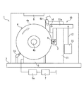
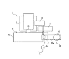
図1〜図2に例示する本発明のゴムの摩耗試験装置1では、試験対象とするゴムの試験サンプルSは環状体ではなく、ブロック状などの塊を使用すればよい。この試験装置1は、試験サンプルSを保持する保持部3と、回転体4と、回転体4を回転駆動する駆動部5と、圧着機構10とを備えている。この実施形態の摩耗試験装置1は、さらに、動力計6a、温度センサ6b、カメラ6c、制御部7、温調機構8およびスクレーパ16を備えていて、動力計6aおよび制御部7を除く構成部品がベース2の上に設置されたケーシング2aによって覆われている。
In the rubber abrasion test apparatus 1 of the present invention illustrated in FIGS. 1 to 2, the rubber test sample S to be tested may be a block-like lump instead of an annular body. The test apparatus 1 includes a holding unit 3 that holds a test sample S, a rotating body 4, a
保持部3は試験サンプルSを着脱自在に保持する。保持部3は単数に限らず、複数設けることもできる。 The holding unit 3 holds the test sample S in a detachable manner. The holding unit 3 is not limited to a single unit, and a plurality of holding units 3 may be provided.
回転体4は、円柱状または円筒状の研磨輪であり、試験サンプルSが接触する円周面4aを有している。円周面4aが試験サンプルSに対する研磨面となる。回転体4は、その円中心に設けられている回転軸4bを中心にして回転可能になっている。
The rotating body 4 is a columnar or cylindrical polishing wheel and has a
円周面4aの材質や表面粗さ等は、試験条件によって適切な仕様が選択される。例えば、円周面4aの仕様が異なる複数の回転体4を用意しておき、必要な円周面4aの仕様に応じて回転体4を交換する構成にする。或いは、円周面4aのみ交換可能な回転体4にすることもできる。この場合は、必要な仕様の円周面4aを回転体4のコアに装着する。
Appropriate specifications are selected for the material, surface roughness, and the like of the
駆動部5は例えば駆動モータであり制御部7に接続されている。制御部7によって回転体4(回転軸4b)の回転速度が所望の速度に制御される。この実施形態では、動力計6aを介して駆動部5と制御部7とが接続されている。動力計6aは回転体4の回転駆動に要するエネルギ(例えば、駆動モータ5の消費電力)を計測する。動力計6aによる計測データは制御部7に入力、記憶される。
The
圧着機構10は、保持部3に保持されている試験サンプルSに対して、円周面4aに向けた付加力Fを付与する。これにより、保持部3に保持されている試験サンプルSを、回転駆動されている回転体4に対して所定の定位置で円周面4aに圧着させる。圧着機構10はさらに、付加力Fと反対方向への試験サンプルSの移動を常に許容する構成になっている。
The
具体的には、この実施形態の圧着機構10は、保持部3が連結されたL字状の保持アーム11aと、保持アーム11aに一端が接続されたワイヤ12と、このワイヤ12の他端に接続された錘15とで構成されている。回転体4の回転軸4bと平行に配置されている支持軸14が、ベース2に立設されている支柱11を貫通して回転自在に支持されている。この支持軸14の一端部に保持アーム11aが固定され、他端部にはバランサー13が固定されている。
Specifically, the
錘15の重量が、ワイヤ12を介して保持アーム11aに作用する。そのため、ワイヤ12の張力によって、保持アーム11aと一体化している保持部3は、試験サンプルSとともに、支持軸14を中心にして回転する。即ち、錘15の重量が保持部3に保持されている試験サンプルSに作用して、試験サンプルSに対して円周面4aに向けた付加力Fを付与する。
The weight of the
付加力Fの大きさは、錘15の重量を変更することで容易に変えることができる。或いは、保持アーム11aに対するワイヤ12の接続位置と支持軸14との水平距離や、バランサー13の重量を変更することで付加力Fの大きさを変更することもできる。また、錘15を取り除いた状態で付加力Fがゼロとなるようにバランサー13を設置することもできる。例えば、錘15を取り除いた状態の圧着機構10の自重を打ち消して付加力Fがゼロとなるように、バランサー13の重量と支持軸14からの距離を選択する。錘15を取り除いた状態で付加力Fがゼロとなるようにバランサー13を設置し、且つ、試験サンプルSと支持軸14との距離と、保持アーム11aに対するワイヤ12の接続位置と支持軸14との距離とを等しくすることにより、錘15の重量と付加力Fとを等しくすることができる。
The magnitude of the additional force F can be easily changed by changing the weight of the
円周面4aに対向する試験サンプルSの表面は、常に一定の大きさの付加力F(規定荷重)によって円周面4aに押圧されて接触した状態になる。付加力Fの向きは、回転体4の回転中心(回転軸4b)に向かう方向にすることが好ましい。この方向にすることで、付加力Fによって試験サンプルSを安定して円周面4aに押圧して接触させることができる。支持軸14を中心とした保持アーム11aの回転を円滑にするために、例えばベアリングを介して支持軸14を支柱11で支持するとよい。
The surface of the test sample S facing the
ここで、試験サンプルSは、錘15の重量に基づいて円周面4aに向かって押圧されているだけである。そのため、保持アーム11aが支持軸14を中心に回転することで、試験サンプルSは付加力Fと反対方向に常時、移動が可能になっている。これに伴い、試験サンプルSに対して付加力Fと反対方向の力が作用すれば、試験サンプルSは円周面4aから離反する方向に移動することが可能である。
Here, the test sample S is only pressed toward the
圧着機構10は、この実施形態に例示した構成に限定されない。圧着機構10は、保持部3に保持されている試験サンプルSに対して、円周面4aに向けた付加力Fを付与して所定の定位置で円周面4aに圧着させるとともに、付加力Fと反対方向への試験サンプルSの移動を常に許容する構成であれば、様々な構成を採用することができる。
The crimping
この実施形態では、試験サンプルSが回転軸4bと同じ水平レベル位置で円周面4aに接触しているが、試験サンプルSが円周面4aに接触する位置(回転体4の周方向位置)はこれに限らない。例えば、回転軸4bの上方の位置で試験サンプルSが円周面4aに接触する構成にすることもできる。このように試験サンプルSを円周面4aに圧着させる所定の定位置は、適宜設定することができる。
In this embodiment, the test sample S is in contact with the
温度センサ6bは、円周面4aまたは試験サンプルSの少なくとも一方の温度を検知する。温度センサ6bによる検知データは、制御部7に入力、記憶される。カメラ6cは、試験サンプルSの動きを撮影し、撮影した動画データは、制御部7に入力、記憶される。
The
温調機構8は、試験サンプルSを所望の温度に調整する。この実施形態では、温調機構8はケーシング2bの上面に備わっている。温調機構8によってケーシング2bの内部温度を所定温度に調整することで、間接的に試験サンプルSの温度が調整される。 The temperature adjustment mechanism 8 adjusts the test sample S to a desired temperature. In this embodiment, the temperature adjustment mechanism 8 is provided on the upper surface of the casing 2b. The temperature of the test sample S is indirectly adjusted by adjusting the internal temperature of the casing 2b to a predetermined temperature by the temperature control mechanism 8.
温調機構8は制御部7によって制御される。試験サンプルSを直接加温するヒータや、直接冷却する冷却器を温調機構8として採用することもできる。 The temperature adjustment mechanism 8 is controlled by the control unit 7. A heater that directly heats the test sample S or a cooler that directly cools the test sample S may be employed as the temperature control mechanism 8.
スクレーパ16は例えばブラシ状であり、円周面4aに接触している。この実施形態では、スクレーパ16は、回転軸4bを挟んで試験サンプルSとは反対側の位置で円周面4aに接触している。
The
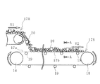
ところで、実際のコンベヤベルトラインでは、図5、図6に例示するように、コンベヤベルト17Aによって搬送された搬送物20が別のコンベヤベルト17Bに投入されて、搬送先に搬送される。コンベヤベルト17Bは、プーリ18、18間に架け渡されていて所定のテンションで張設されている。
By the way, in the actual conveyor belt line, as illustrated in FIGS. 5 and 6, the conveyed
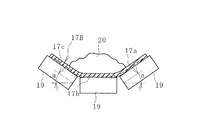
コンベヤベルト17Bは、帆布やスチールコード等の心体で構成される心体層17cと、心体層17cを挟む上カバーゴム17aと下カバーゴム17bとにより構成されている。心体層17cは、コンベヤベルト17Bを張設するためのテンションを負担する。コンベヤベルト17Bのキャリア側では下カバーゴム17bが支持ローラ19により支持され、リターン側では上カバーゴム17aが支持ローラ19により支持されている。コンベヤベルト17Bのキャリア側では、例えばベルト幅方向に3つの支持ローラ19が配置されていて、これらの支持ローラ19によってコンベヤベルト17Bは所定のトラフ角度aで凹状に支持されている。
The
一般に搬送物20は、走行速度V1が相対的に遅いコンベヤベルト17Aから走行速度V2が相対的に速いコンベヤベルト17Bに投入される(走行速度V1<走行速度V2)。コンベヤベルト17Bの上カバーゴム17a上では、投入された搬送物20の速度が走行速度V1からV2に変化することになる。そのため、上カバーゴム17aに対して搬送物20が摺動し、この摺動が主要因の1つとなって上カバーゴム17aは摩耗する。
Generally, the conveyed
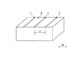
このように搬送物20が上カバーゴム17aに対して摺動する場合、スティック・スリップ現象が生じている。スティック・スリップ現象では、上述したように粘り工程と滑り工程とを繰り返すため、対象物が摺動するゴムRの表面には、図3に例示するように摺動方向FDに所定のピッチPで摩耗の筋Lが形成される。このピッチPは滑り工程に対応し、摩耗の筋Lは粘り工程に対応する。本発明の摩耗試験装置1では、このスティック・スリップ現象を再現することが可能になっている。
Thus, when the conveyed
以下、この摩耗試験装置1を用いてゴムの摩耗状態を把握する方法を説明する。 Hereinafter, a method for grasping the wear state of rubber using the wear test apparatus 1 will be described.
図1、2に例示するように、保持部3には試験サンプルSを保持させる。円周面4aは所望の仕様に設定する。例えば、試験サンプルSとしてコンベヤベルトの上カバーゴム17aを評価する場合には、そのコンベヤベルトによって搬送する搬送物20の形状等に整合する表面粗さの円周面4aを用いる。また、試験サンプルSに所望の付加力Fが付与されるように錘15の重量を設定し、設定した所望の速度で回転体4を回転させる。また、温調機構8を作動させて試験サンプルSを所望の温度に設定する。これらの設定は例えば、試験サンプルSのゴムが実使用される条件に合致するように行われる。
As illustrated in FIGS. 1 and 2, the holding unit 3 holds the test sample S. The
このように設定した摩耗試験装置1では、図1に例示するように試験サンプルSには、回転する回転体4の円周面4aに向けた付加力Fが付与される。試験サンプルSは回転体4に対して所定の定位置で、付加力Fによって円周面4aに押圧されて接触する。回転体4は回転しているため、試験サンプルSと円周面4aとは摺動状態となり、試験サンプルSの円周面4aとの接触面は徐々に摩耗する。
In the wear test apparatus 1 set as described above, as shown in FIG. 1, the test sample S is given an additional force F toward the
所定の試験時間後に、試験サンプルSの摩耗量の測定や摩耗面を観察する。また、試験前後での試験サンプルSの表面粗さを比較して、総合的に試験サンプルSの摩耗状態を把握する。 After a predetermined test time, the wear amount of the test sample S is measured and the wear surface is observed. Further, the surface roughness of the test sample S before and after the test is compared to comprehensively grasp the wear state of the test sample S.
ここで、本発明では、試験サンプルSは付加力Fと反対方向への移動が常に許容されている。そのため、円周面4aで摺動している試験サンプルSでは、円周面4aとの摩擦力に対抗して弾性変形する工程(粘り工程)と、この摩擦力に対抗できずに弾性変形が解消されて円周面4aに対して滑る工程(滑り工程)とを繰り返すことができる。即ち、スティック・スリップ現象が再現される。
Here, in the present invention, the test sample S is always allowed to move in the direction opposite to the applied force F. Therefore, in the test sample S sliding on the
一方、試験サンプルSに対して流体シリンダ等によって付加力Fを付与する構成であると、試験サンプルSは付加力Fと反対方向に移動できる余地がないため、常時、円周面4aに密着した状態になる。そのため、粘り工程と滑り工程とを繰り返すことができずにスティック・スリップ現象を再現することができない。
On the other hand, if the configuration is such that the additional force F is applied to the test sample S by a fluid cylinder or the like, the test sample S has no room to move in the opposite direction to the additional force F, and thus is always in close contact with the
本発明によれば、スティック・スリップ現象を再現することができるので、実使用に合致したゴムの摩耗状態を、より高精度で把握することが可能になる。特に、コンベヤベルトの上カバーゴムの摩耗状態を把握するには好適である。 According to the present invention, since the stick-slip phenomenon can be reproduced, it is possible to grasp the wear state of the rubber that matches the actual use with higher accuracy. In particular, it is suitable for grasping the wear state of the upper cover rubber of the conveyor belt.
また、試験サンプルSはブロック状などの小片でもよく、わざわざ環状体を用意する必要もない。しかも、試験サンプルSに対して回転体4の円周面4aに向けた付加力Fを付与して所定の定位置で円周面4aに圧着させるとともに、付加力Fと反対方向への試験サンプルSの移動を常に許容する構成にするには、複雑な構造の装置を用いる必要はない。
Further, the test sample S may be a small piece such as a block, and it is not necessary to prepare an annular body. In addition, an additional force F directed to the
本発明では、試験中に温度センサ6bにより円周面4aまたは試験サンプルSの少なくとも一方の温度変化を検知できる。試験サンプルSが摩耗する際には熱エネルギが生じるので、温度センサ6bによる検知データに基づいて、摩耗する際のエネルギを把握することができる。ゴムの種類によってこのエネルギの大きさは異なる。そのため、この検知データは、例えば、このエネルギを小さくできるゴム種を把握するには有益である。
In the present invention, the temperature change of at least one of the
動力計6aによって回転体4の回転駆動に要するエネルギを計測することで、エネルギの変動が把握できる。回転体4の回転駆動に要するエネルギは、ティック・スリップ現象の粘り工程では相対的に大きくなり、滑り工程では相対的に小さくなる。そのため、動力計6aにより検知したエネルギの変動に基づいて、その試験サンプルSのティック・スリップ現象における所定のピッチPを把握することが可能になる。このピッチPはゴム種や試験条件によって異なるので、ゴムの摩耗状態を評価するには1つの指標になる。
By measuring the energy required for the rotational drive of the rotating body 4 by the
また、動力計6aによる検知データに基づいて、試験サンプルSに作用する摩耗力を算出することもできる。例えば、付加力Fを付与して試験サンプルSを回転体4の円周面4aに接触させた場合と、接触させない場合とで、回転体4を所定速度で回転駆動させる際に要するエネルギを比較することで、試験サンプルSと円周面4aとの摩擦によって生じているエネルギを算出できる。即ち、比較したエネルギの差が摩擦によるエネルギとして近似できる。そして、回転体4の外径や回転速度等は既知なので、試験サンプルSに作用している摩擦力を概ね算出できる。これにより、ゴム種毎に試験サンプルSに付与する付加力Fと摩擦力との関係を把握することができる。
Moreover, the abrasion force which acts on the test sample S can also be calculated based on the detection data by the
この実施形態では、カメラ6cによって試験サンプルSの動きを撮影することで、スティック・スリップ現象における試験サンプルSの挙動を確認することができる。スティック・スリップ現象における粘り工程と滑り工程とを繰り返す1周期は、回転体4の回転速度やゴム種によって変化するが、例えば0.01秒〜0.03秒程度である。したがって、1秒で100コマ以上の撮影ができる高速度のカメラ6cを用いるとよい。
In this embodiment, the behavior of the test sample S in the stick-slip phenomenon can be confirmed by photographing the movement of the test sample S with the
また、カメラ6cの撮影データにより、試験サンプルSの押圧方向の変形量を把握することもできる。したがって、試験サンプルSの変形量と付加力Fとの関係、この変形量と摩擦力との関係を把握することも可能になる。
Further, the deformation amount in the pressing direction of the test sample S can also be grasped from the photographing data of the
試験サンプルSの耐摩耗性には温度依存性がある。そこで、温調機構8によって試験サンプルSの温度を異ならせて試験をすることで、この温度依存性をゴム種毎に把握することができる。 The abrasion resistance of the test sample S has temperature dependency. Therefore, this temperature dependence can be ascertained for each rubber type by performing the test while varying the temperature of the test sample S by the temperature control mechanism 8.
この実施形態では、回転体4が回転することにより、円周面4aに付着している試験サンプルSの摩耗くず等は、スクレーパ16によって除去される。これにより、円周面4aを常に一定の表面粗さに維持し易くなるため、試験サンプルSのゴムの摩耗状態を高精度で把握するには益々有利になる。スクレーパ16の円周面4aとの接触位置は、試験サンプルSに対して回転体4の回転方向前方側にして、かつ、なるべく下方に配置すると、除去された摩耗くず等が飛散することを防止できる。
In this embodiment, when the rotating body 4 rotates, abrasion scraps and the like of the test sample S adhering to the
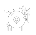
図4に例示する摩耗試験装置1の別の実施形態では、試験サンプルSが接触している円周面4aと、この試験サンプルSとの間に介在物Wを投入する投入機構8を備えている。介在物Wとしては、試験サンプルSのゴムが使用される条件下で、このゴムに付着することが想定される材料等を用いる。介在物Wの具体例としては、水、油、砂などの微小粒子が挙げられる。
In another embodiment of the wear test apparatus 1 illustrated in FIG. 4, a
投入機構8を設けることにより、介在物Wの有無による試験サンプルSの摩耗状態の違いを把握することができる。そのため、実使用に合致したゴムの摩耗状態を精度よく把握するには益々、有利になる。介在物Wの供給量(供給速度)は、制御部7により制御するとよい。 By providing the input mechanism 8, it is possible to grasp the difference in the wear state of the test sample S depending on the presence or absence of the inclusion W. Therefore, it becomes more and more advantageous to accurately grasp the wear state of rubber that matches actual use. The supply amount (supply speed) of the inclusion W may be controlled by the control unit 7.
1 摩耗試験装置
2 ベース
3 保持部
4 回転体
4a 円周面
4b 回転軸
5 駆動部
6a 動力計
6b 温度センサ
6c カメラ
7 制御部
8 温調機構
9 投入機構
10 圧着機構
11 支柱
11a 保持アーム
12 ワイヤ
13 バランサー
14 支持軸
15 錘
16 スクレーパ
17A コンベヤベルト
17B 別のコンベヤベルト
17a 上カバーゴム
17b 下カバーゴム
17c 芯体層
18 プーリ
19 支持ローラ
20 搬送物
S 試験サンプル
W 介在物
DESCRIPTION OF SYMBOLS 1
Claims (8)
Priority Applications (6)
| Application Number | Priority Date | Filing Date | Title |
|---|---|---|---|
| JP2016137239A JP6821981B2 (en) | 2016-07-12 | 2016-07-12 | Rubber wear tester |
| DE112017003544.9T DE112017003544B4 (en) | 2016-07-12 | 2017-02-27 | Rubber abrasion tester |
| US16/316,176 US11333592B2 (en) | 2016-07-12 | 2017-02-27 | Rubber wear testing device |
| CN201780030071.8A CN109313111B (en) | 2016-07-12 | 2017-02-27 | Abrasion test device for rubber |
| AU2017296468A AU2017296468B2 (en) | 2016-07-12 | 2017-02-27 | Rubber wear testing device |
| PCT/JP2017/007439 WO2018012022A1 (en) | 2016-07-12 | 2017-02-27 | Rubber wear testing device |
Applications Claiming Priority (1)
| Application Number | Priority Date | Filing Date | Title |
|---|---|---|---|
| JP2016137239A JP6821981B2 (en) | 2016-07-12 | 2016-07-12 | Rubber wear tester |
Publications (2)
| Publication Number | Publication Date |
|---|---|
| JP2018009823A true JP2018009823A (en) | 2018-01-18 |
| JP6821981B2 JP6821981B2 (en) | 2021-01-27 |
Family
ID=60952524
Family Applications (1)
| Application Number | Title | Priority Date | Filing Date |
|---|---|---|---|
| JP2016137239A Active JP6821981B2 (en) | 2016-07-12 | 2016-07-12 | Rubber wear tester |
Country Status (6)
| Country | Link |
|---|---|
| US (1) | US11333592B2 (en) |
| JP (1) | JP6821981B2 (en) |
| CN (1) | CN109313111B (en) |
| AU (1) | AU2017296468B2 (en) |
| DE (1) | DE112017003544B4 (en) |
| WO (1) | WO2018012022A1 (en) |
Families Citing this family (4)
| Publication number | Priority date | Publication date | Assignee | Title |
|---|---|---|---|---|
| CN111426456B (en) * | 2020-01-17 | 2021-11-26 | 北京工业大学 | Steel rubber roller pair rolling test bed |
| CN114577456B (en) * | 2022-03-10 | 2024-04-09 | 一汽解放汽车有限公司 | A rubber joint performance testing system |
| CN114965124B (en) * | 2022-04-15 | 2025-09-09 | 中联重科股份有限公司 | Device and method for testing abrasion resistance of concrete piston |
| CN115372167B (en) * | 2022-09-06 | 2025-01-28 | 临沂鲁驰新材料科技有限公司 | Detection device and method for rubber conveyor belt quality detection |
Citations (8)
| Publication number | Priority date | Publication date | Assignee | Title |
|---|---|---|---|---|
| JPS6453951U (en) * | 1987-09-29 | 1989-04-03 | ||
| JPH02210243A (en) * | 1989-02-10 | 1990-08-21 | Tokyo Silicone Kk | Frictional wear testing machine |
| JP2002181609A (en) * | 2000-12-19 | 2002-06-26 | Nippon Applied Technology Inc | Fixed volume supply method of fine powder and fixed volume supply device of fine powder |
| JP2004037286A (en) * | 2002-07-04 | 2004-02-05 | Yokohama Rubber Co Ltd:The | Indoor tire durability testing method |
| JP2009198276A (en) * | 2008-02-21 | 2009-09-03 | Bridgestone Corp | Rubber testing machine |
| JP2013113672A (en) * | 2011-11-28 | 2013-06-10 | Toyo Tire & Rubber Co Ltd | Rubber friction test method and rubber friction test device |
| JP2013178163A (en) * | 2012-02-28 | 2013-09-09 | Kayaba Ind Co Ltd | Evaluation method for plastic material |
| JP2016061597A (en) * | 2014-09-16 | 2016-04-25 | 横浜ゴム株式会社 | Wear test apparatus and method |
Family Cites Families (11)
| Publication number | Priority date | Publication date | Assignee | Title |
|---|---|---|---|---|
| US1711866A (en) * | 1927-06-01 | 1929-05-07 | Grasselli Chemical Co | Method of and apparatus for testing materials |
| BE655226A (en) * | 1964-11-04 | 1965-05-04 | ||
| US3899917A (en) * | 1973-12-06 | 1975-08-19 | Frederick N Kisbany | Laboratory wear resistance test machine for tires |
| JPH0818720B2 (en) | 1987-08-25 | 1996-02-28 | 三田工業株式会社 | Paper feeding device of image forming apparatus |
| US4995197A (en) * | 1990-01-29 | 1991-02-26 | Shieh Chiung Huei | Method of abrading |
| CA2035414A1 (en) * | 1990-02-12 | 1991-08-13 | Chiung-Huei Shieh | Method and apparatus for abrading |
| US6412330B1 (en) * | 1998-11-25 | 2002-07-02 | The Goodyear Tire & Rubber Company | Abrasion tester |
| JP5534588B2 (en) * | 2010-02-24 | 2014-07-02 | 株式会社ブリヂストン | Tire rubber index calculation method, apparatus and program |
| CN102735559B (en) | 2011-04-15 | 2015-04-22 | 青岛科技大学 | Novel rubber high temperature abrasion tester for simulating wear of rolling tyre |
| CN202735182U (en) | 2012-09-11 | 2013-02-13 | 中联重科股份有限公司 | Rubber high temperature wear testing equipment |
| JP6394295B2 (en) | 2014-11-06 | 2018-09-26 | 横浜ゴム株式会社 | Wear test apparatus and method |
-
2016
- 2016-07-12 JP JP2016137239A patent/JP6821981B2/en active Active
-
2017
- 2017-02-27 CN CN201780030071.8A patent/CN109313111B/en active Active
- 2017-02-27 WO PCT/JP2017/007439 patent/WO2018012022A1/en not_active Ceased
- 2017-02-27 DE DE112017003544.9T patent/DE112017003544B4/en active Active
- 2017-02-27 AU AU2017296468A patent/AU2017296468B2/en not_active Ceased
- 2017-02-27 US US16/316,176 patent/US11333592B2/en active Active
Patent Citations (8)
| Publication number | Priority date | Publication date | Assignee | Title |
|---|---|---|---|---|
| JPS6453951U (en) * | 1987-09-29 | 1989-04-03 | ||
| JPH02210243A (en) * | 1989-02-10 | 1990-08-21 | Tokyo Silicone Kk | Frictional wear testing machine |
| JP2002181609A (en) * | 2000-12-19 | 2002-06-26 | Nippon Applied Technology Inc | Fixed volume supply method of fine powder and fixed volume supply device of fine powder |
| JP2004037286A (en) * | 2002-07-04 | 2004-02-05 | Yokohama Rubber Co Ltd:The | Indoor tire durability testing method |
| JP2009198276A (en) * | 2008-02-21 | 2009-09-03 | Bridgestone Corp | Rubber testing machine |
| JP2013113672A (en) * | 2011-11-28 | 2013-06-10 | Toyo Tire & Rubber Co Ltd | Rubber friction test method and rubber friction test device |
| JP2013178163A (en) * | 2012-02-28 | 2013-09-09 | Kayaba Ind Co Ltd | Evaluation method for plastic material |
| JP2016061597A (en) * | 2014-09-16 | 2016-04-25 | 横浜ゴム株式会社 | Wear test apparatus and method |
Also Published As
| Publication number | Publication date |
|---|---|
| DE112017003544B4 (en) | 2025-05-15 |
| JP6821981B2 (en) | 2021-01-27 |
| US11333592B2 (en) | 2022-05-17 |
| US20210293680A1 (en) | 2021-09-23 |
| CN109313111A (en) | 2019-02-05 |
| CN109313111B (en) | 2022-03-08 |
| DE112017003544T5 (en) | 2019-03-28 |
| AU2017296468B2 (en) | 2020-04-23 |
| WO2018012022A1 (en) | 2018-01-18 |
| AU2017296468A1 (en) | 2018-11-22 |
Similar Documents
| Publication | Publication Date | Title |
|---|---|---|
| JP6794684B2 (en) | Abrasion resistance evaluation method for rubber | |
| AU2016253804B2 (en) | Abrasive wear test device and method | |
| JP6821981B2 (en) | Rubber wear tester | |
| CN106574886B (en) | Wear test device and method | |
| JP2019529903A (en) | Equipment for measuring rubber wear | |
| JP2016090417A (en) | Device and method for wear test | |
| KR20140035589A (en) | Measuring devices and method of surface hardness for organic materials | |
| JP4299692B2 (en) | Friction test equipment | |
| CN104215536A (en) | Cladding layer abrasion-resisting performance testing device | |
| JP5478464B2 (en) | Abrasion test equipment | |
| JP2016090418A (en) | Device and method for impact testing | |
| CN204116164U (en) | A kind of test unit of coating wear resistance | |
| PL214201B1 (en) | Device for testing of friction in complex rolling-sliding motion | |
| JPH0634506A (en) | Wear test device | |
| JP2008151690A (en) | Method and apparatus for measuring characteristics of wet lubricant | |
| PL125926B1 (en) | Sliding friction testing apparatus | |
| PL211447B1 (en) | Position for testing of grinding wear in conditions of complex stress in the tested material |
Legal Events
| Date | Code | Title | Description |
|---|---|---|---|
| A621 | Written request for application examination |
Free format text: JAPANESE INTERMEDIATE CODE: A621 Effective date: 20190705 |
|
| A131 | Notification of reasons for refusal |
Free format text: JAPANESE INTERMEDIATE CODE: A131 Effective date: 20200602 |
|
| A521 | Request for written amendment filed |
Free format text: JAPANESE INTERMEDIATE CODE: A523 Effective date: 20200706 |
|
| A131 | Notification of reasons for refusal |
Free format text: JAPANESE INTERMEDIATE CODE: A131 Effective date: 20201013 |
|
| A521 | Request for written amendment filed |
Free format text: JAPANESE INTERMEDIATE CODE: A523 Effective date: 20201113 |
|
| TRDD | Decision of grant or rejection written | ||
| A01 | Written decision to grant a patent or to grant a registration (utility model) |
Free format text: JAPANESE INTERMEDIATE CODE: A01 Effective date: 20201208 |
|
| A61 | First payment of annual fees (during grant procedure) |
Free format text: JAPANESE INTERMEDIATE CODE: A61 Effective date: 20201221 |
|
| R150 | Certificate of patent or registration of utility model |
Ref document number: 6821981 Country of ref document: JP Free format text: JAPANESE INTERMEDIATE CODE: R150 |
|
| S531 | Written request for registration of change of domicile |
Free format text: JAPANESE INTERMEDIATE CODE: R313531 |
|
| R350 | Written notification of registration of transfer |
Free format text: JAPANESE INTERMEDIATE CODE: R350 |
|
| R250 | Receipt of annual fees |
Free format text: JAPANESE INTERMEDIATE CODE: R250 |
|
| R250 | Receipt of annual fees |
Free format text: JAPANESE INTERMEDIATE CODE: R250 |
|
| R250 | Receipt of annual fees |
Free format text: JAPANESE INTERMEDIATE CODE: R250 |