JP2018009814A - Gas sensor array, gas measuring device, and gas measuring method - Google Patents
Gas sensor array, gas measuring device, and gas measuring method Download PDFInfo
- Publication number
- JP2018009814A JP2018009814A JP2016137037A JP2016137037A JP2018009814A JP 2018009814 A JP2018009814 A JP 2018009814A JP 2016137037 A JP2016137037 A JP 2016137037A JP 2016137037 A JP2016137037 A JP 2016137037A JP 2018009814 A JP2018009814 A JP 2018009814A
- Authority
- JP
- Japan
- Prior art keywords
- gas
- gas sensor
- flow path
- heater
- sensor
- Prior art date
- Legal status (The legal status is an assumption and is not a legal conclusion. Google has not performed a legal analysis and makes no representation as to the accuracy of the status listed.)
- Granted
Links
Images


Landscapes
- Investigating Or Analyzing Materials By The Use Of Fluid Adsorption Or Reactions (AREA)
Abstract
【課題】小型で高感度のガスセンサアレイを提供する。
【解決手段】ガスセンサアレイ1は、ヒータ13と第1の感ガス材料の第1センサ素子10とを有し第1流路4−1に配置される第1のガスセンサと、第2の感ガス材料の第2センサ素子22を有し第1流路に接続される第2流路4−2に配置される第2のガスセンサ20とを有し、ヒータは加熱により上昇気流を発生し、第2のガスセンサは、ヒータによる加熱で第1のガスセンサから離脱した被測定ガスの分子を検出する。
【選択図】図1A small and highly sensitive gas sensor array is provided.
A gas sensor array (1) includes a heater (13) and a first sensor element (10) made of a first gas sensitive material, a first gas sensor disposed in a first flow path (4-1), and a second gas sensitive gas. And a second gas sensor 20 disposed in a second flow path 4-2 having a second sensor element 22 of material and connected to the first flow path. The gas sensor No. 2 detects molecules of the gas to be measured detached from the first gas sensor by heating with the heater.
[Selection] Figure 1
Description
本発明は、ガスセンサアレイ、ガス測定装置、及びガス測定方法に関する。 The present invention relates to a gas sensor array, a gas measuring device, and a gas measuring method.
ガス成分の分析には、大きく分けて2種類の方法がある。一つはガスクロマトグラフィに代表される大掛かりな分析装置を使用して、特定のガス種を狙った測定を行う方法である。この方法で用いられる分析装置はガス濃縮装置を備えており、低濃度のガスを検出してその成分を詳しく分析することができる。しかし、専門家の操作を要する大型で高価な装置を使用し、結果が得られるまで数時間以上かかるため検査の負担が大きく、研究目的の使用が主体である。 There are roughly two types of methods for analyzing gas components. One is a method for measuring a specific gas type using a large-scale analyzer represented by gas chromatography. The analyzer used in this method is equipped with a gas concentrator, which can detect a low-concentration gas and analyze its components in detail. However, using a large and expensive device that requires expert operation, and it takes several hours or more to obtain a result, the burden of the inspection is large, and it is mainly used for research purposes.
もう一つは、多数のガスセンサを集積した機器で、ガスによるセンサの応答パターンの違いを解析する方法である。この方法は分析結果が出るまでの時間が早く、持ち運び可能で手軽に使用できる。しかし、センサの感度が低く、ガス濃縮装置を備えていない可搬装置では低濃度のガス成分を測ることが困難である。 The other is a method of analyzing the difference in the response pattern of the sensor due to gas in an apparatus in which a large number of gas sensors are integrated. This method takes a short time to obtain an analysis result, is portable and can be used easily. However, it is difficult to measure a low-concentration gas component in a portable device having a low sensor sensitivity and not equipped with a gas concentrator.
ガスセンサとしては、酸化スズをベース材料とするものが多い。ヒーターでガス分子と酸素を熱し、感ガス材料への活性酸素の吸着量を半導体材料の抵抗変化で検出する。主体とする金属の種類や、ガス触媒作用を持つ添加貴金属の種類、ヒーターの加熱量などを調整することで、選択性(ガス種による応答の強さの差)を持たせることができる(たとえば、特許文献1参照)。しかし還元ガスと酸素のバランスを測っているのみであり、感度は高くない。従来の半導体ガスセンサで1ppm以下の低濃度のガス成分を測定できるものは少ない。 Many gas sensors are based on tin oxide. Gas molecules and oxygen are heated with a heater, and the amount of active oxygen adsorbed on the gas-sensitive material is detected by the resistance change of the semiconductor material. Selectivity (difference in response strength depending on the gas type) can be provided by adjusting the main metal type, the type of additive noble metal with gas catalytic action, the heating amount of the heater, etc. (for example, , See Patent Document 1). However, it is only measuring the balance between reducing gas and oxygen, and the sensitivity is not high. There are few conventional semiconductor gas sensors that can measure gas components with a low concentration of 1 ppm or less.
多孔質物質を冷却してガス分子を吸着させる、あるいは空気中の水分により結露させる等により測定対象のガスを濃縮して、ガスセンサの感度を上げることが考えられる。しかし吸着できるガスの種類は少なく、時間がかかるうえに濃縮機構が大型である。多孔質セラミックと冷却装置を組み合わせた冷却吸着式の濃縮装置を集積型のガスセンサ機器に適用すると、装置の大型化・高コスト化を招き、持ち運びが不便になる。 It is conceivable to increase the sensitivity of the gas sensor by concentrating the gas to be measured by, for example, cooling the porous material to adsorb gas molecules, or condensing with moisture in the air. However, the types of gases that can be adsorbed are small, time consuming and the concentration mechanism is large. When a cooling adsorption type concentrating device combining a porous ceramic and a cooling device is applied to an integrated gas sensor device, the device becomes large and expensive, and it is inconvenient to carry.
本発明は、小型で高感度のガスセンサアレイを提供することを目的とする。 An object of the present invention is to provide a small and highly sensitive gas sensor array.
一つの態様では、ガスセンサアレイは、
ヒータと第1の感ガス材料の第1センサ素子とを有し、第1流路に配置される第1のガスセンサと、
第2の感ガス材料の第2センサ素子を有し、前記第1流路に接続される第2流路に配置される第2のガスセンサと、
を有し、
前記ヒータは加熱により上昇気流を発生し、
前記第2のガスセンサは、前記ヒータによる加熱で前記第1のガスセンサから離脱した被測定ガスの分子を検出する。
In one embodiment, the gas sensor array comprises
A first gas sensor having a heater and a first sensor element of a first gas sensitive material and disposed in the first flow path;
A second gas sensor having a second sensor element of a second gas sensitive material and disposed in a second flow path connected to the first flow path;
Have
The heater generates an updraft by heating,
The second gas sensor detects molecules of the gas to be measured detached from the first gas sensor by heating with the heater.
上記構成により、小型で高感度のガスセンサアレイが実現する。 With the above configuration, a small and highly sensitive gas sensor array is realized.
実施形態では、簡易で小型、かつ精度良くガス検出を行うことのできるガスセンサアレイとこれを用いたガス測定技術を提供する。 In the embodiment, a gas sensor array capable of performing gas detection with high accuracy with a simple size and a gas measurement technique using the gas sensor array are provided.
以下で図面を参照して説明するように、実施形態のガスセンサアレイは、少なくとも2個のガスセンサを用いる。第1のガスセンサのヒータの投入により上昇気流を発生させ、第1のガスセンサに吸着したガス分子を離脱させて第2のガスセンサで第1のガスセンサに吸着していたガス分子を検知する。第1のガスセンサで被測定ガスの輸送機能と濃縮機能を実現し、第2のガスセンサで安定した濃度で効率良くガスの検出を行う。 As will be described below with reference to the drawings, the gas sensor array of the embodiment uses at least two gas sensors. Ascending air current is generated by turning on the heater of the first gas sensor, the gas molecules adsorbed on the first gas sensor are separated, and the gas molecules adsorbed on the first gas sensor are detected by the second gas sensor. The first gas sensor realizes the function of transporting and concentrating the gas to be measured, and the second gas sensor efficiently detects the gas with a stable concentration.
実施形態のガスセンサアレイは、広くガスの測定及び分析に適用できるが、以下の例では、ヒトや動物などの体や排泄物から放出される生体ガス(呼気、体臭、尿、屁、便)の検出に適用する。たとえば、呼気分析によりからだの状態の指標を検査し、診断することができる。ヒトや動物の息には肺で血液中の化学物質が気化し放出されたごく低濃度のガスが含まれており、この中には、生体活動や病気と密接に関わっているものがある。ヒトの息に含まれるアンモニアガスは、肝臓の代謝や、胃がんの危険因子であるピロリ菌感染との相関があるといわれている。またアルデヒド類であるノナナールは肺がんマーカー物質の候補とされている物質である。呼気分析により、身体の拘束や採血のような苦痛なしに、手軽な手段で生活習慣の改善や病気の早期発見のためのスクリーニングに有効な特定物質の検出することができる。 The gas sensor array according to the embodiment can be widely applied to measurement and analysis of gas. In the following example, biological gas (exhaled breath, body odor, urine, sputum, stool) released from a body or excrement such as a human or animal Applies to detection. For example, a body condition index can be examined and diagnosed by breath analysis. The breath of humans and animals contains very low concentrations of gas that is released by the vaporization of chemicals in the blood in the lungs, some of which are closely related to biological activity and disease. Ammonia gas contained in human breath is said to have a correlation with liver metabolism and H. pylori infection, which is a risk factor for gastric cancer. Nonanal, which is an aldehyde, is a substance that is a candidate for a lung cancer marker substance. By breath analysis, it is possible to detect specific substances effective for screening for improvement of lifestyle habits and early detection of illness by simple means without pain such as body restraint or blood sampling.
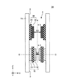
図1は、実施形態のガスセンサアレイ1の概略図である。ガスセンサアレイ1は、第1のガスセンサ10と、第2のガスセンサ20を有する。第1のガスセンサ10は、絶縁膜11と、第1の感ガス材料で形成される第1センサ素子12と、ヒータ13を有する。第2のガスセンサ20は、絶縁膜21と、第2の感ガス材料で形成される第2センサ素子22を有する。ガスセンサアレイ1の使用時に、第1のガスセンサ10は、重力方向で第2のガスセンサ20よりも下側に位置する。
第1のガスセンサ10と第2のガスセンサ20は、流路4を形成する管15の内部に配置されている。管15は、インレット2と、アウトレット3を有する。流路4のうち、インレット2に接続されて第1のガスセンサ10が配置される領域を含む流路を「第1流路4−1」と呼ぶ。第1流路4−1とアウトレット4の間に形成され第2のガスセンサ20が配置される領域を含む流路を「第2流路4−2」と呼ぶ。
The
第1のガスセンサ10は、絶縁膜11の一方の面に形成された第1センサ素子12と、絶縁膜11の他方の面に形成されたヒータ13を有する。絶縁膜11は、酸化アルミニウム(Al2O3)や、その他の熱伝導率の良いセラミクスで形成されてもよい。ヒータ13は、白金(Pt)、酸化ルテニウム(RuO2)、酸化イリジウム(IrO2)等の金属で形成される。図示は省略するが、ヒータ13からPt、金(Au)等の電極パターンが引き出されており、ヒータ13のオン・オフが制御される。
The
第1センサ素子12は、第1の感ガス材料で形成されている。第1の感ガス材料は、たとえば酸化スズ(SnO2)、酸化チタン(TiO2)、酸化亜鉛(ZnO)などを主成分とする多孔質の金属酸化物、炭素(C)、アルミニウム(Al)、またはシリコン(Si)を主成分とする多孔質体等である。絶縁膜11と第1センサ素子12は、あらかじめヒータ13が形成された管15の内壁に、スクリーン印刷、転写印刷、スプレイ(噴霧)法等により絶縁材料と感ガス材料をこの順で形成し、焼結して作製され得る。あるいは、別途作製した第1のガスセンサ10を、管15の内壁に貼り付けてもよい。
The
第1センサ素子12が、SnO2のようにn型半導体である場合、還元性のガスに曝露することで、ガス分子が多孔質の第1センサ素子12に吸着して電子を与える。これによりキャリアが増えて抵抗が減少する。
When the
第2のガスセンサ20は、絶縁膜21上に形成された第2センサ素子22を有する。第2センサ素子22は、第2の感ガス材料で形成される。第2の感ガス材料は、第1の感ガス材料と同じであっても異なっていてもよい。第2センサ素子22は、たとえば銅(Cu)、銀(Ag)等を主成分とする酸化物またはハロゲン化合物、臭化銅(CuBr)、酸化銅(CuO)、固体電解質、SnO2を主成分とする材料等で形成される。
The
第2センサ素子22が、Cu、Agなどを用いたp型半導体である場合、還元性ガスに晒されることで、吸着したガス分子が正孔を捉えてキャリアが減少し、抵抗が増大する。第2センサ素子22がn型半導体である場合は、還元性ガスに曝露することで抵抗が減少する。
When the
図1の例では、第2のガスセンサ20はヒータレスであるが、第2センサ素子22の材料によっては、第2のガスセンサ20をヒータ付きのガスセンサとして形成してもよい。
In the example of FIG. 1, the
第1のガスセンサ10は第1流路4−1に位置し、第2のガスセンサ20は第2流路4−2に位置する。第1流路4−1の最も狭い部分、たとえば、第1センサ素子12の表面と管15の対向する壁面との間の間隙G1は、後述するように一定サイズ以下に設定されている。同様に、第2流路4−2の最も狭い部分、たとえば、第2センサ素子22の表面と管15の対向する壁面との間の間隙G2は、一定サイズ以下に設定されている。第1流路4−1の間隙G1は、ヒータ13で加熱された測定対象のガスと第1のガスセンサ10からの離脱ガス分子を効率良く第2のガスセンサ20へ輸送できる間隙である。第2流路4−2の間隙G2は、第1のガスセンサ10から輸送されてきたガスを効果的に検出できる間隙である。間隙G1とG2の具体的な範囲については、図4及び5を参照して後述する。
The
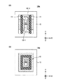
図2は、ガスセンサアレイ1の上面側から見た水平断面図である。上から順に、図1のI−I断面、II-II断面、及びIII-III断面を示す。図2では、断面が矩形の管15を用いている。第1のガスセンサ10の絶縁膜11は、管15の内部空間でy方向の全体にわたって配置され、第1流路4−1のx方向の幅を制限している。これは、第1センサ素子12と管15の内壁との間に、間隙G1よりも大きい隙間をなるべく作らないようにするためである。この配置構成により、第1センサ素子12から第2センサ素子22へ輸送されるガス分子がヒータ13側に回り込むのを防止できる。
FIG. 2 is a horizontal sectional view as seen from the upper surface side of the
同様に、第2のガスセンサ20の絶縁膜21は、管15の内部空間でy方向の全体にわたって配置され、第2流路4−2のx方向の幅を制限している。これは、第2センサ素子22と管15の内壁との間に、間隙G2よりも大きい隙間をなるべく作らないようにするためである。この配置構成により、第1センサ素子12から輸送されてきたガス分子を効率良く第2センサ素子22に吸着させることができる。
Similarly, the insulating
図3は、変形例として管15Aの水平断面形状を示す。上から順に図1のI−I断面、II-II断面、及びIII-III断面である。管15Aは、内壁に突起16を有する。絶縁膜11及び絶縁膜21は、突起16の間に配置されている。突起16及び絶縁膜11及び21bにより、管15Bの内部に間隙G1、G2以上の空間が生じない構成にして、第1のガスセンサ10によるガスの濃縮及び輸送と、第2のガスセンサ20へのガス分子の吸着を効果的に行う。
FIG. 3 shows a horizontal cross-sectional shape of the
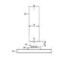
図4及び図5は、第1流路4−1の間隙G1と第2流路4−2の間隙G2の良好な範囲を説明する図である。図4は、最適な流路径を選択する予備実験で用いた配置構成を示す模式図、図5は予備実験の結果を示す。 4 and 5 are diagrams for explaining a favorable range of the gap G1 of the first flow path 4-1 and the gap G2 of the second flow path 4-2. FIG. 4 is a schematic diagram showing an arrangement configuration used in a preliminary experiment for selecting an optimum channel diameter, and FIG. 5 shows a result of the preliminary experiment.
予備実験では、管15の壁面と同じ材料(この例ではセラミクス)のステージ31上に第1のガスセンサ10を配置する。第1のガスセンサ10の第1センサ素子12として、SnO2を主成分とするペーストを5mm×5mm、厚さ50μmに塗布し、650℃で焼結する。第1のガスセンサ10を第1センサ素子12を露出させた状態で石英パッケージに収容して管15の内壁に貼り付ける構成を想定し、第1のガスセンサ10をガラス基板25に搭載してステージ31に置く。
In the preliminary experiment, the
第1のガスセンサ10の上方に、流路径φが9mmの円筒管32を配置する。予備実験では、図1の矩形の管15の内部への縦配置に替えて、第1のガスセンサ10を平置きとしている。円筒管32の内部にフローメータ(流量計)を配置し、第1のガスセンサ10の上面と、円筒管32の下端の間の間隔dを1mm〜7.5mmの間で変化させて、円筒管32を通る流量を測定する。測定中、第1のガスセンサ10のヒータ13をオンにして400℃に加熱する。
A
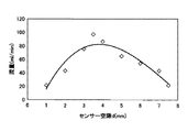
図5は、予備実験の結果を示す。第1のガスセンサ10の平置き配置の場合、間隔dが3.5mmで最大流量が得られている。ステージ31、すなわち壁面からの熱放射による上昇気流は温度境界層をつくり、一定の間隙以上は温度を温めない。間隔dが大きくなると、温められる空気に対する暖められない空気の割合が増加し、効率的な加熱が妨げられて流量が減少する。間隔dを小さくすると効率的に空気を加熱することができるが、空気が間隙を流れる際の粘性抵抗、言い換えると圧損が増加し、流量が減少する。この予備実験の結果は、自然放熱の放熱器で空気の通り道が1〜5mmに設定されていることと一致する。
FIG. 5 shows the results of the preliminary experiment. In the case of the flat arrangement of the
図5の結果に基づくなら、間隔dの良好な範囲は2〜7mmであるが、予備実験は平置き配置であることを考慮すると、図1の構成で第1のガスセンサ10が配置されている第1流路4−1の間隙G1(流路の短辺)は、0.5mm以上、5mm以下とすることが望ましい(0.5mm≦G1≦5mm)。G1が5mmを超えると、十分な加熱効率を得ることが困難になる。G1が0.5mmより小さくなると粘性抵抗が大きくなり第2のガスセンサ20へ向かう単位時間当たりの流量が少なくなる。
Based on the result of FIG. 5, the good range of the distance d is 2 to 7 mm, but considering that the preliminary experiment is a flat placement, the
第1流路4−1での第1のガスセンサ10の設置部の間隙G1の適切な範囲(0.5mm≦G1≦5mm)は、ヒータ13の発する熱により効率良く上昇気流を発生させることのできる範囲である。
An appropriate range (0.5 mm ≦ G1 ≦ 5 mm) of the gap G1 of the installation portion of the
第2のガスセンサ20が配置されている第2流路4−2の間隙G2(流路の短辺)は、0mmより大きく、5mm以下であることが望ましい(0<G2≦5mm)。G2が5mmを超えると、第2のガスセンサ20の感ガス材料、すなわち第2センサ素子22にガス分子を効率良く付着させることが困難になる。間隙G2が0mmだと、第2センサ素子22の主面をガスに曝露させることができない。
The gap G2 (the short side of the flow path) of the second flow path 4-2 where the
第2流路4−2での第2のガスセンサ20の設置部の間隙G2の適切な範囲(0mm<G1≦5mm)は、第2のガスセンサ20の感ガス材に効率良くガス分子を付着させることのできる範囲である。
An appropriate range (0 mm <G1 ≦ 5 mm) of the gap G2 of the installation portion of the
図6は、図1の変形例としてガスセンサアレイ1Aの縦断面(xz面)を示す。図6では、管15の内壁に第1のガスセンサ10が対向して配置されている。同様に、第2のガスセンサ20も管15の内壁で対向して配置されている。第2のガスセンサ20をヒータ付きの構成としてもよい。
FIG. 6 shows a longitudinal section (xz plane) of the gas sensor array 1A as a modification of FIG. In FIG. 6, the
第1流路4−1の第1のガスセンサ10の配置箇所の間隙G1は、0.5mm以上、5mm以下であるのが望ましい。G1をこの範囲に設定することで、ヒータ13が発する熱で効率良く上昇気流を発生させることができる。
The gap G1 at the location where the
第2流路4−2の第2のガスセンサ20の配置箇所の間隙G2は、0mmを超え、5mm以下であるのが望ましい。G2をこの範囲に設定することで、第2センサ素子22の感ガス材に効率良くガス分子を付着させることができる。
The gap G2 at the location where the
図7は、図6のC−Cラインでの水平断面を示す。水平断面の構成として、図7(A)の対向配置と、図7(B)の環状配置のいずれを採用してもよい。 FIG. 7 shows a horizontal cross section taken along the line CC of FIG. As the configuration of the horizontal section, either the opposing arrangement in FIG. 7A or the annular arrangement in FIG. 7B may be adopted.
図7(A)のガスセンサアレイ1Aaでは、管15の対向する内壁に一対の第1のガスセンサ10−1、10−2が配置されている。互いに対向する第1センサ素子12−1と12−2の感ガス材料は同一であってもよいし、異なる組成及び/または材料を用いてもい。
In the
対向する第1のガスセンサ10−1、10−2の絶縁膜11は管15の内部でy方向の両端にわたって形成されている。一対の絶縁膜11により、第1のガスセンサ10−1、10−2の配置位置で、x方向に対称な流路が形成されている。この構成は、図1の構成と比較して、より効率的に上昇気流を発生させることができる。
The insulating
図7(B)のガスセンサアレイ1Abでは、管15の内壁を一周する筒状の第1のガスセンサ10が形成されている。この構成は、図7(A)の構成よりもさらに効率的に上昇気流を発生させることができる。
In the gas sensor array 1Ab of FIG. 7B, a cylindrical
図7(A)と図7(B)のいずれの構成でも、間隙G1は0.5mm≦G1≦5mmの範囲である。また、図7(A)と図7(B)において、第2のガスセンサ20を一対のガスセンサで形成してもよい。たとえば、図2のI−I断面に示す第2のガスセンサ20を2つ用いて、それぞれを管15の対向する内壁に配置してもよい。この場合、互いに対向する2つの第2センサ素子22の感ガス材料の組成及び/または材料を異ならせてもよいし、同一にしてもよい。また、第2のガスセンサ20を環状に配置してもよい。第2のガスセンサ20を対向あるいは環状配置とする場合も、間隙G2は0mm<G2≦5mmであることが望ましい。
In both configurations of FIG. 7A and FIG. 7B, the gap G1 is in the range of 0.5 mm ≦ G1 ≦ 5 mm. In FIGS. 7A and 7B, the
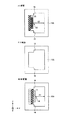
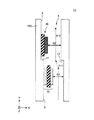
図8は、さらに別の変形例としてガスセンサアレイ1Bの縦断面(xz面)を示す。図8では、L字管15Bを用い、インレット2に接続される第1流路4−1と、アウトレット3に接続される第2流路4−2がL字型に形成されている。
FIG. 8 shows a longitudinal section (xz plane) of the gas sensor array 1B as still another modification. In FIG. 8, the first flow path 4-1 connected to the inlet 2 and the second flow path 4-2 connected to the
第1のガスセンサ10はL字管15Bの内壁の底面151に配置され、第2のガスセンサ20はL字管15Bの内壁の垂直面152に配置されている。インレット2から導入されるガスは、第1流路4−1で第1のガスセンサ10のヒータ13で加熱され、第2流路4−2へ輸送されて上昇する。第2のガスセンサ20は、第1のガスセンサ10から輸送されてきたガスの分子を検出する。
The
第1流路4−1の第1のガスセンサ10の配置箇所の間隙G1は、0.5mm以上、5mm以下に設定され、ヒータ13が発する熱で効率良く上昇気流を発生させる。第2流路4−2の第2のガスセンサ20の配置箇所の間隙G2は、0mmより大きく、5mm以下に設定され、第2センサ素子22の感ガス材に効率良くガス分子を付着させる。図8の構成により、小型で感度の良いガスセンサアレイが実現する。
The gap G1 at the location of the
図9は、さらに別の変形例としてガスセンサアレイ1Cの縦断面(xz面)を示す。図9では、内壁に段差17を設けた管15Cを用いる。図9の構成でも第1のガスセンサ10のヒータ13で上昇気流を発生させて、第2のガスセンサ20へ濃度を高くしたガスを効率良く輸送することができる。
FIG. 9 shows a longitudinal section (xz plane) of the gas sensor array 1C as still another modification. In FIG. 9, a pipe 15C having a
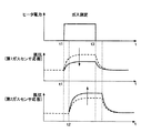
図10は、図1のガスセンサアレイ1の駆動例を示す。図10の上段はヒータ13のオン/オフのタイミングを示す。中段は第1のガスセンサ10の応答を、下段は第2のガスセンサ20の応答を示す。上段、中段、下段のグラフの横軸は時間(t)である。上段のグラフの縦軸はヒータの電力、中段と下段のグラフの縦軸は抵抗値(Ω)である。この例で、ヒータは第1のガスセンサ10にだけ設けられており、第1センサ素子12の感ガス材料をn型半導体であるSnO2、第2センサ素子22の感ガス材料をp型半導体の性質を有するCuBrやCuOとする。
FIG. 10 shows an example of driving the
ヒータ13が通電されていない状態では、流路4に存在するガスにより第1のガスセンサ10と第2のガスセンサ20の抵抗は、それぞれ一定の値になっている。時間t1でヒータ13がONされると、第1のガスセンサ10の温度上昇にともない活性酸素が生成され、第1のガスセンサ10の感ガス材料のキャリアが減少する。その結果、破線で示すように抵抗が上昇する。別の表現をすると、大気中の酸素が感ガス材料の表面で電子を捕捉してO-の形で吸着し、感ガス材で空乏層が広がる。ガス濃度が一定であればこの状態で飽和する。その後、時間t3でヒータ13を切断すると、上述と逆の反応により、抵抗値は緩やかに下がって元の状態に戻る。
In a state where the
第2のガスセンサ20では、ヒータ13の投入から一定の時間遅れて上昇気流が発生する。ヒータ13の投入前に第1のガスセンサ10の感ガス材料または絶縁膜11に付着していた還元性ガスの分子が、ヒータ13の投入により第1のガスセンサ10から第2のガスセンサ20に輸送され、第2のガスセンサ20に還元性ガスの分子が吸着する。したがって、破線で示すように時間t2で抵抗が増加し、ヒータ13の切断から一定時間だけ遅れて緩やかに抵抗値が元にもどる。
In the
次に、管15の内部に被測定ガスを導入する。非測定ガス中の還元性ガスは第1のガスセンサ10の表面に吸着する。第1のガスセンサ10の表面に酸素分子が吸着されている場合、ヒータ13の投入により、被測定ガス中の還元ガスと酸素が反応し、酸素分子が離脱する。これにより補足されていたキャリア電子が移動可能になり、抵抗が低下する。また、n型半導体である感ガス材料に還元性ガスが吸着することによって、第1のガスセンサ10の抵抗は低下する。その結果、図10の中段の実線で示すように、第1のガスセンサ10の抵抗値が破線の状態から実線の状態に変化する。
Next, a measurement gas is introduced into the
第2のガスセンサ20では、ヒータ13のオンにより第1のガスセンサ10の周辺で加熱された還元性ガスが上昇して第2センサ素子22の表面に吸着し、抵抗が上昇する。たとえば、上昇気流にアンモニア分子含まれている場合、アンモニア分子からの電子の供与により、P型半導体の主キャリアである正孔がトラップされてキャリア密度が低下する。その結果、抵抗が上昇する。同時に、ヒータ13の投入前に第1のガスセンサ10の感ガス材料(第1センサ素子12)または絶縁膜11に付着していた還元性ガスの分子が、ヒータ13の投入により第1のガスセンサ10から第2のガスセンサ20に輸送され、第2のガスセンサ20で検知される還元性ガスの量が増え、抵抗が増加する。その結果、図10の下段の実線で示すように、第2のガスセンサの抵抗値が破線の状態から実線の状態に変化する。
In the
図11は、実施形態のガス分析方法のフローチャートである。まず、通常の大気で測定を開始し(S11)、第1のガスセンサ10と第2のガスセンサ20の抵抗初期値を測定する(S12)。抵抗初期値として、ヒータ13を投入しない状態で抵抗値が安定するまで測定を継続し、安定した状態での値をメモリに記録する。S11〜S12の処理を初期測定とする。変形例として、初期測定でヒータ13を一定時間オンにして、大気中での第1のガスセンサ10と第2のガスセンサ20の抵抗プロファイル(時間変化)を測定し、記録しておいてもよい。
FIG. 11 is a flowchart of the gas analysis method of the embodiment. First, measurement is started in normal air (S11), and initial resistance values of the
次に、ヒータ13をオフにした状態で測定対象のガスを充填し(S13)、第1のガスセンサ10と第2のガスセンサ20の抵抗値を測定する(S14)。S12と同様に、抵抗値が安定するまで測定し、安定状態での値をメモリに記録する。測定対象となるガスは、たとえばヒトや動物の体や排泄物から放出される生体ガスである。アルコール類、アルデヒト類、エステル類、カルボン酸類、アミン類などが測定可能であるが、この例では、あらかじめ測定対象のガスの種類が特定されているものとする。
Next, the gas to be measured is filled with the
ステップS14での抵抗測定はヒータ13の投入前の測定であり、第1のガスセンサ10と第2のガスセンサ20の安定期のパラメータ(たとえば飽和出力値)が得られる。被測定ガスの導入により、ヒータ13の投入前でも第1のガスセンサ10及び/または第2のガスセンサ20にガス分子が吸着し得る。この段階でステップS12の抵抗初期値から変化がある場合は、その変化を記録しておいてもよい。
The resistance measurement in step S14 is a measurement before the
次に、ヒータ13をオンにして(S15)、第1のガスセンサ10と第2のガスセンサ20の抵抗値を一定時間、測定する(S16)。ヒータ13のオンにより、被測定ガスが加熱され第2のガスセンサ20へ輸送されると同時に、ヒータ13のオン前に第1のガスセンサ10に吸着していたガス分子を離脱させ、離脱したガス分子も第2のガスセンサ20で検出させる。S15の処理により、ガスの濃縮効果と効率的なガス輸送効果が得られる。ステップS16の測定で、第1のガスセンサ10と第2のガスセンサ20のそれぞれについて、ヒータ投入時のセンサ出力の時間変化に関するパラメータが得られる。センサ出力の時間変化に関するパラメータは、図10のような抵抗変化のプロファイルや抵抗の変化率、時定数などを含む。得られたデータをメモリに記録する。
Next, the
次に、ヒータ13を切断して(S17)、第1のガスセンサ10と第2のガスセンサ20の抵抗を測定する(S18)。ヒータ13の切断により、第1のガスセンサ10と第2のガスセンサ20の感ガス材料の表面で吸着ガスの状態に変化が生じて抵抗値が変化し得る。この抵抗変化を記録することで、ヒータ切断時のセンサ出力の時間変化に関するパラメータ(変化率及び時定数)が得られる。S13〜S18を実測の工程とする。
Next, the
次に、測定結果からガス濃度を決定し(S19)、結果を出力する(S20)。抵抗の変化は、感ガス材料のキャリア(電子または正孔)と反応するガスの分子数に比例する。したがって、抵抗の変化からガス濃度を算出し得る。S19〜S20を分析及び出力工程とする。ガス濃度算出の基礎として、第2のガスセンサ20での抵抗変化を主として用いてもよいし、第1のガスセンサ10の抵抗変化を重み付けに用いてもよい。また、算出したガス濃度と、抵抗値の時間変化を対応付けてメモリに記録し、機械学習により測定精度を向上してもよい。あるいは、機械学習により、測定対象のガスの種類が不明な場合にガス成分を予測してもよい。
Next, the gas concentration is determined from the measurement result (S19), and the result is output (S20). The change in resistance is proportional to the number of molecules of the gas that react with the carrier (electrons or holes) of the gas sensitive material. Therefore, the gas concentration can be calculated from the change in resistance. Let S19-S20 be an analysis and output process. As a basis for calculating the gas concentration, the resistance change in the
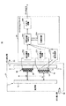
図12は、実施形態のガスセンサアレイ1を用いたガス測定装置50の概略図である。ガス測定装置50は、ガスセンサアレイ1を内部に有する測定チャンバ51と、マイクロコントローラ55を有する。マイクロコントローラ55は、たとえば、測定チャンバ51を収容するハウジング内に埋め込まれていてもよい。
FIG. 12 is a schematic diagram of a gas measuring device 50 using the
測定チャンバ51は、ガス導入部52と、ガス排出部53を有する。ガスセンサアレイ1は、ヒータ13を有する第1のガスセンサ10が、重力方向で第2のガスセンサ20の下方に位置するように測定チャンバ51内に配置されている。第1のガスセンサ10の配置部での間隙G1と、第2のガスセンサ20の配置部での間隙G2は、上述した適切な範囲に設定されており、管15でのガス流量及び流速を最適にする。ガスセンサアレイ1はガス導入部52の近傍または上方にインレット2が位置し、ガス排出部3の近傍にアウトレット3が位置するように、測定チャンバ51の内部に固定されていてもよい。ガス導入部52に呼気吹き込み口または呼気吹き込みチューブが接続されていてもよい。
The
測定チャンバ51内で大気または被測定ガスは均一に存在している。ガスセンサアレイ1で測定チャンバ51内の任意の空間領域での抵抗変化を測定することで、測定チャンバ51に導入された被測定ガスの濃度を測定することができる。
In the
マイクロコントローラ55は、第1の抵抗測定回路551と、第2の抵抗測定回路552と、ヒータ制御回路553と、記憶回路554と、演算回路(マイクロプロセッサMPU)555と、入出力回路556を有する。
The
第1の抵抗測定回路551は、第1のガスセンサ10の第1センサ素子12から引き出されるリードに接続され、電圧印加による電流値から第1のガスセンサ10の抵抗値を決定する。第2の抵抗測定回路552は、第2のガスセンサ20の第2センサ素子22から引き出されるリードに接続され、電圧印加による電流値から第2のガスセンサ10の抵抗値を決定する。
The first
ヒータ制御回路553は、第1のガスセンサ10のヒータ13に接続されており、演算回路555からの指令に基づいてヒータ13のオン・オフのタイミングを制御する。第1のガスセンサ10のヒータ13の投入により上昇気流を発生させて被測定ガスを効率良く第2のガスセンサ20へ送り込む。同時に、第1のガスセンサ10に吸着した吸着分子も第2のガスセンサ20で検出させることで、被測定ガスを濃縮したのと同様の効果が得られる。したがって、低濃度のガスでも効率的に検出可能となる。
The
ヒータ制御回路555は、演算回路555からの指令に基づいて、測定対象とするガスの種類に応じてヒータ13の温度を制御してもよい。たとえば、ガス測定装置50が呼気検査でによりアルコール濃度を検出する場合は、第1のガスセンサ10と第2のガスセンサ20でエタノールの検出感度が最大となる温度に制御する。
The
第1の抵抗測定回路551と第2の抵抗測定回路552の出力は演算回路555に接続され、測定結果が記憶回路554に記録される。記憶回路554は、データの記録及び演算のワークエリアに用いられるランダムアクセスメモリ(RAM)と、演算アルゴリズムや制御プログラムを格納するリードオンリーメモリ(ROM)を含む。演算回路555は記憶回路554に記録されたデータを用いてガス濃度を算出する。ガス濃度の算出に、ヒータ13の投入時の第2のガスセンサ20の出力(抵抗の時間変化に関するパラメータ)を主として用いてもよいし、ヒータ13の投入前と切断後の抵抗値の時間変化を合わせて用いてもよい。また、第1のガスセンサ10の抵抗変化も合わせて用いてもよい。算出結果は、入出力回路556から出力される。
The outputs of the first
測定値は、パーソナルコンピュータ(PC)のモニタ画面やスマートフォンの表示画面に出力されてもよい。この場合、入出力回路556とともに無線通信インタフェースが用いられてもよい。あるいは、測定チャンバ51を収容するハウジングに表示部と操作部を含むユーザインタフェースを設けておき、入出力回路556をユーザインタフェースと接続または一体化してもよい。
The measurement value may be output to a monitor screen of a personal computer (PC) or a display screen of a smartphone. In this case, a wireless communication interface may be used together with the input /
生体ガスの多くは還元性ガスあるいは有機分子(炭化水素)であり、図12のガス測定装置を用いることで、目的とするガスの濃度を簡易かつ精度良く測定することができる。 Most biological gases are reducing gases or organic molecules (hydrocarbons), and the concentration of the target gas can be measured easily and accurately by using the gas measuring device shown in FIG.
図13は、測定チャンバ51内のガスセンサアレイ1の配置例を示す。図12のように測定チャンバ51内にガスセンサアレイ1を垂直配置する構成に替えて、ガスセンサアレイ1を斜め配置にしてもよい。この場合も、第2のガスセンサ20を第1のガスセンサ10の下流側、すなわち重力方向で第1のガスセンサ10よりも上側に配置する。
FIG. 13 shows an arrangement example of the
図13の構成でも、第1のガスセンサ10で加熱された被測定ガスを上昇気流で第2のガスセンサ20に輸送すると同時に、第1のガスセンサ10から離脱した被測定ガスのガス分子も第2のガスセンサ20で検出させる。簡単な構成で被測定ガスのポンピング効果と濃縮効果が得られ、第2のガスセンサ20で精度良く測定することができる。
In the configuration of FIG. 13 as well, the gas to be measured heated by the
実施形態では、第1のガスセンサ10と第2のガスセンサ20を組み合わせ、簡易な構成で送風ポンプと濃縮装置の機能を代替させる。また、複数の過渡応答を入力パラメータにすることで機械学習によるガス成分の測定・分析が可能になる。
In the embodiment, the
実施形態の構成と手法は、採血などの苦痛を伴うことなく、呼気の測定で生活習慣による変動を継続的に調べることができる。また、実施形態のガス測定装置50をスマートデバイスやウェアラブルデバイスに搭載して、体温計のような手軽さで生体ガスを分析する手段とすることができる。また、実施形態の技術を生活習慣の改善や病気の早期発見のためのスクリーニング手段として役立てることができる。 The configuration and method of the embodiment can continuously check the variation due to the lifestyle by measuring the expiration without causing pain such as blood collection. In addition, the gas measuring device 50 according to the embodiment can be mounted on a smart device or a wearable device, and can be used as a means for analyzing biological gas as easily as a thermometer. In addition, the technology of the embodiment can be used as a screening means for improving lifestyle and early detection of diseases.
なお、上述した実施形態は例示にすぎず、多様な変形例が可能である。実施形態では断面が矩形の管15、15A〜15Cを用いたが、図1、6、7のいずれの構成も断面が円形または楕円形の管に適用可能である。いずれの場合も、第1のガスセンサ10で被測定ガスを加熱し、かつ第1のガスセンサ10に吸着したガス分子を離脱させて、第2のガスセンサ20を効率良く被測定ガスに曝露することができる。
In addition, embodiment mentioned above is only an illustration and various modifications are possible. In the embodiment, the
また、マイクロコントローラ55の記憶回路554に、複数種類のガスの抵抗の時間変化に関するパラメータをあらかじめ記録しておき、被測定ガスの種類を特定する構成としてもよい。さらに、第1のガスセンサ10の管ガス材料と第2のガスセンサ20の管ガス材料の組み合わせを変えたガスセンサアレイ1を複数種類用意しておき、測定チャンバ51内に交換可能に配置できる構成としてもよい。
In addition, a configuration may be adopted in which parameters related to temporal changes in the resistances of a plurality of types of gas are recorded in advance in the
以上の説明に対し、以下の付記を提示する。
(付記1)
ヒータと第1の感ガス材料の第1センサ素子とを有し、第1流路に配置される第1のガスセンサと、
第2の感ガス材料の第2センサ素子を有し、前記第1流路に接続される第2流路に配置される第2のガスセンサと、
を有し、
前記ヒータは加熱により上昇気流を生成し、
前記第2のガスセンサは、前記ヒータによる加熱で前記第1のガスセンサから離脱した被測定ガスの分子を検出することを特徴とするガスセンサアレイ。
(付記2)
前記第1のガスセンサは、前記第1流路で対向する一対のガスセンサ、または前記第1流路を取り囲む環状のガスセンサであることを特徴とする付記1に記載のガスセンサアレイ。
(付記3)
前記第1流路の前記第1のガスセンサの配置位置での径または間隙は、0.5mm以上、5mm以下であることを特徴とする付記1または2に記載のガスセンサアレイ。
(付記4)
前記第2のガスセンサは、前記第2流路で対向する一対のガスセンサ、または前記第2流路を囲む環状のガスセンサであることを特徴とする付記1〜3のいずれかに記載のガスセンサアレイ。
(付記5)
前記第2流路の前記第2のガスセンサの配置位置での径または間隙は、0mmよりも大きく、5mm以下であることを特徴とする付記1〜4のいずれかに記載のガスセンサアレイ。
(付記6)
前記第1のガスセンサにおいて、前記一対のガスセンサの前記第1の感ガス材料は異なる組成及び/または材料であることを特徴とする付記2に記載のガスセンサアレイ。
(付記7)
前記第2のガスセンサにおいて、前記一対のガスセンサの前記第2の感ガス材料は異なる組成及び/または材料であることを特徴とする付記4に記載のガスセンサアレイ。
(付記8)
前記第1流路は断面が矩形の流路であり、
前記第1のガスセンサは、前記ヒータと前記第1センサ素子の間に配置される第1の絶縁膜を有し、
前記第1の絶縁膜は、前記矩形の断面で第1の方向にわたって形成されていることを特徴とする付記1〜7のいずれかに記載のガスセンサアレイ。
(付記9)
前記第2流路は断面が矩形の流路であり、
前記第2のガスセンサは、前記第2センサ素子を搭載する第2の絶縁膜を有し、
前記第2の絶縁膜は、前記矩形の断面で第1の方向にわたって形成されていることを特徴とする付記1〜7のいずれかに記載のガスセンサアレイ。
(付記10)
前記第1流路と前記第2流路を形成する管、
を有し、
前記第1のガスセンサの配置位置で前記管の内壁に前記第1流路の幅を制限する突起が形成されていることを特徴とする付記1〜9のいずれかに記載のガスセンサアレイ。
(付記11)
前記第1流路と前記第2流路を形成する管、
を有し、
前記第2のガスセンサの配置位置で前記管の内壁に前記第2流路の幅を制限する突起が形成されていることを特徴とする付記1〜9のいずれかに記載のガスセンサアレイ。
(付記12)
前記第1流路と前記第2流路を形成する管、
をさらに有し、
前記第1のガスセンサと前記第2のガスセンサは、前記管の内壁に配置され、
前記第1のガスセンサは、前記第2のガスセンサよりも重力方向で下側に配置されていることを特徴とする付記1〜11のいずれかに記載のガスセンサアレイ。
(付記13)
前記管はL字管であり、前記第1のガスセンサは前記L字管の底面に配置され、前記第2のガスセンサは前記L字管の垂直部の内壁に配置されていることを特徴とする付記12に記載のガスセンサアレイ。
(付記14)
前記管の内壁で、前記第1流路と前記第2流路の境界近傍に段差が設けられていることを特徴とする付記12に記載のガスセンサアレイ。
(付記15)
付記1〜14のいずれかに記載のガスセンサアレイと、
前記ガスセンサアレイを内部に配置する測定チャンバと、
前記ガスセンサアレイと電気的に接続され、前記ガスセンサアレイの出力に基づいて前記測定チャンバ内のガス濃度とガスの種類の少なくとも一方を推定するコントローラと、
を有するガス測定装置。
(付記16)
前記コントローラは、前記ヒータのオン・オフを制御するヒータ制御回路と、
前記第1のガスセンサと前記第2のガスセンサの抵抗値を測定する測定回路と、
前記測定回路の出力に基づいて前記ガスセンサアレイの出力の時間変化を求める演算回路と、
を有することを特徴とする付記15に記載のガス測定装置。
(付記17)
前記ガスセンサアレイの出力の前記時間変化に関するパラメータを保存する記憶回路、
を有し、前記演算回路は、前記記憶回路に保存された前記パラメータに基づき、前記測定チャンバ内のガス濃度とガスの種類の少なくとも一方を推定することを特徴とする付記16に記載のガス測定装置。
(付記18)
ヒータと第1の感ガス材料を有する第1のガスセンサと、第2の感ガス材料を有する第2のガスセンサとを有するガスセンサアレイで、
前記第1のガスセンサの前記ヒータをオンにして上昇気流を発生し、
前記第2のガスセンサで、前記第1のガスセンサに吸着していた被測定ガスの分子を検出する、
ことを特徴とするガス測定方法。
The following notes are presented for the above explanation.
(Appendix 1)
A first gas sensor having a heater and a first sensor element of a first gas sensitive material and disposed in the first flow path;
A second gas sensor having a second sensor element of a second gas sensitive material and disposed in a second flow path connected to the first flow path;
Have
The heater generates an updraft by heating,
The gas sensor array, wherein the second gas sensor detects molecules of a gas to be measured that has detached from the first gas sensor by heating with the heater.
(Appendix 2)
The gas sensor array according to
(Appendix 3)
The gas sensor array according to
(Appendix 4)
The gas sensor array according to any one of
(Appendix 5)
The gas sensor array according to any one of
(Appendix 6)
The gas sensor array according to appendix 2, wherein in the first gas sensor, the first gas sensitive material of the pair of gas sensors has a different composition and / or material.
(Appendix 7)
The gas sensor array according to
(Appendix 8)
The first channel is a channel having a rectangular cross section;
The first gas sensor has a first insulating film disposed between the heater and the first sensor element,
The gas sensor array according to any one of
(Appendix 9)
The second channel is a channel having a rectangular cross section,
The second gas sensor has a second insulating film on which the second sensor element is mounted,
The gas sensor array according to any one of
(Appendix 10)
A tube forming the first flow path and the second flow path;
Have
10. The gas sensor array according to any one of
(Appendix 11)
A tube forming the first flow path and the second flow path;
Have
10. The gas sensor array according to any one of
(Appendix 12)
A tube forming the first flow path and the second flow path;
Further comprising
The first gas sensor and the second gas sensor are disposed on an inner wall of the pipe,
The gas sensor array according to any one of
(Appendix 13)
The tube is an L-shaped tube, the first gas sensor is disposed on a bottom surface of the L-shaped tube, and the second gas sensor is disposed on an inner wall of a vertical portion of the L-shaped tube. The gas sensor array according to
(Appendix 14)
13. The gas sensor array according to
(Appendix 15)
The gas sensor array according to any one of
A measurement chamber in which the gas sensor array is disposed;
A controller that is electrically connected to the gas sensor array and estimates at least one of a gas concentration and a gas type in the measurement chamber based on an output of the gas sensor array;
A gas measuring device.
(Appendix 16)
The controller includes a heater control circuit that controls on / off of the heater;
A measurement circuit for measuring resistance values of the first gas sensor and the second gas sensor;
An arithmetic circuit for obtaining a time change in the output of the gas sensor array based on the output of the measurement circuit;
The gas measuring device according to
(Appendix 17)
A storage circuit for storing a parameter relating to the time change of the output of the gas sensor array;
The gas measurement according to
(Appendix 18)
A gas sensor array having a heater, a first gas sensor having a first gas sensitive material, and a second gas sensor having a second gas sensitive material;
Turning on the heater of the first gas sensor to generate an updraft;
The second gas sensor detects molecules of the gas to be measured adsorbed on the first gas sensor.
A gas measuring method characterized by the above.
1 ガスセンサアレイ
2 インレット(ガス流入口)
3 アウトレット(ガス流出口)
4 流路
4−1 第1流路
4−2 第2流路
10 第1のガスセンサ
11 絶縁膜
12 第1センサ素子
13 ヒータ
15 管
20 第2のガスセンサ
21 絶縁膜
22 第2センサ素子
50 ガス測定装置
51 測定チャンバ
55 マイクロコントローラ
551、552 抵抗測定回路
553 ヒータ制御回路
554 記憶回路
555 演算回路(MPU)
556 入出力回路
G1、G2 間隙
1 Gas sensor array 2 Inlet (gas inlet)
3 Outlet (gas outlet)
4 channel 4-1 first channel 4-2
556 I / O circuit G1, G2 Gap
Claims (8)
第2の感ガス材料の第2センサ素子を有し、前記第1流路に接続される第2流路に配置される第2のガスセンサと、
を有し、
前記ヒータは加熱により上昇気流を発生し、
前記第2のガスセンサは、前記ヒータによる加熱で前記第1のガスセンサから離脱した被測定ガスの分子を検出することを特徴とするガスセンサアレイ。 A first gas sensor having a heater and a first sensor element of a first gas sensitive material and disposed in the first flow path;
A second gas sensor having a second sensor element of a second gas sensitive material and disposed in a second flow path connected to the first flow path;
Have
The heater generates an updraft by heating,
The gas sensor array, wherein the second gas sensor detects molecules of a gas to be measured that has detached from the first gas sensor by heating with the heater.
前記ガスセンサアレイを内部に配置する測定チャンバと、
前記ガスセンサアレイと電気的に接続され、前記ガスセンサアレイの出力に基づいて前記測定チャンバ内のガス濃度とガスの種類の少なくとも一方を決定するコントローラと、
を有するガス測定装置。 The gas sensor array according to any one of claims 1 to 5,
A measurement chamber in which the gas sensor array is disposed;
A controller that is electrically connected to the gas sensor array and determines at least one of a gas concentration and a gas type in the measurement chamber based on an output of the gas sensor array;
A gas measuring device.
前記第1のガスセンサと前記第2のガスセンサの抵抗値を測定する測定回路と、
前記測定回路の出力に基づいて前記ガスセンサアレイの出力の時間変化を求める演算回路と、
を有することを特徴とする請求項6に記載のガス測定装置。 The controller includes a heater control circuit that controls on / off of the heater;
A measurement circuit for measuring resistance values of the first gas sensor and the second gas sensor;
An arithmetic circuit for obtaining a time change in the output of the gas sensor array based on the output of the measurement circuit;
The gas measuring device according to claim 6, wherein
前記第1のガスセンサの前記ヒータをオンにして上昇気流を発生し、
前記第2のガスセンサで、前記第1のガスセンサに吸着していた被測定ガスの分子を検出する
ことを特徴とするガス測定方法。 A gas sensor array having a heater, a first gas sensor having a first gas sensitive material, and a second gas sensor having a second gas sensitive material;
Turning on the heater of the first gas sensor to generate an updraft;
A gas measuring method, wherein the second gas sensor detects molecules of a gas to be measured adsorbed on the first gas sensor.
Priority Applications (1)
| Application Number | Priority Date | Filing Date | Title |
|---|---|---|---|
| JP2016137037A JP6786918B2 (en) | 2016-07-11 | 2016-07-11 | Gas sensor array, gas measuring device, and gas measuring method |
Applications Claiming Priority (1)
| Application Number | Priority Date | Filing Date | Title |
|---|---|---|---|
| JP2016137037A JP6786918B2 (en) | 2016-07-11 | 2016-07-11 | Gas sensor array, gas measuring device, and gas measuring method |
Publications (2)
| Publication Number | Publication Date |
|---|---|
| JP2018009814A true JP2018009814A (en) | 2018-01-18 |
| JP6786918B2 JP6786918B2 (en) | 2020-11-18 |
Family
ID=60995301
Family Applications (1)
| Application Number | Title | Priority Date | Filing Date |
|---|---|---|---|
| JP2016137037A Active JP6786918B2 (en) | 2016-07-11 | 2016-07-11 | Gas sensor array, gas measuring device, and gas measuring method |
Country Status (1)
| Country | Link |
|---|---|
| JP (1) | JP6786918B2 (en) |
Cited By (5)
| Publication number | Priority date | Publication date | Assignee | Title |
|---|---|---|---|---|
| WO2019188692A1 (en) * | 2018-03-28 | 2019-10-03 | Tdk株式会社 | Gas sensor, gas alarm device, gas shut-off device, and smart device |
| CN111579600A (en) * | 2020-06-28 | 2020-08-25 | 郑州轻工业大学 | A kind of camellia-like ZnO/SnO-SnO2 composite material and its preparation method and application |
| WO2020262252A1 (en) * | 2019-06-28 | 2020-12-30 | 京セラ株式会社 | Gas detection device |
| JP2022548826A (en) * | 2019-09-23 | 2022-11-22 | ナショナル ユニヴァーシティー オブ シンガポール | AI Sensing Device for Wide Range Gas and Vapor Detection |
| JP2023153659A (en) * | 2022-04-05 | 2023-10-18 | 新東工業株式会社 | Gas measuring instruments and gas measuring systems |
Citations (5)
| Publication number | Priority date | Publication date | Assignee | Title |
|---|---|---|---|---|
| JPS5767850A (en) * | 1980-10-16 | 1982-04-24 | Matsushita Electric Ind Co Ltd | Detector of gas and smoke |
| EP0077724A1 (en) * | 1981-10-16 | 1983-04-27 | Association Pour La Recherche Et Le Developpement Des Methodes Et Processus Industriels (Armines) | Method, sensor and apparatus for detecting traces of gas in a gaseous medium |
| JP2006317254A (en) * | 2005-05-12 | 2006-11-24 | Futaba Electronics:Kk | Odor measuring device, odor measuring method and odor measuring program |
| JP2014228447A (en) * | 2013-05-23 | 2014-12-08 | 木村 光照 | Hydrogen gas sensor having concentration function and hydrogen gas sensor probe using the same |
| WO2016013113A1 (en) * | 2014-07-25 | 2016-01-28 | 富士通株式会社 | Measuring apparatus, measuring system, and measuring method for measuring particle and gas |
-
2016
- 2016-07-11 JP JP2016137037A patent/JP6786918B2/en active Active
Patent Citations (5)
| Publication number | Priority date | Publication date | Assignee | Title |
|---|---|---|---|---|
| JPS5767850A (en) * | 1980-10-16 | 1982-04-24 | Matsushita Electric Ind Co Ltd | Detector of gas and smoke |
| EP0077724A1 (en) * | 1981-10-16 | 1983-04-27 | Association Pour La Recherche Et Le Developpement Des Methodes Et Processus Industriels (Armines) | Method, sensor and apparatus for detecting traces of gas in a gaseous medium |
| JP2006317254A (en) * | 2005-05-12 | 2006-11-24 | Futaba Electronics:Kk | Odor measuring device, odor measuring method and odor measuring program |
| JP2014228447A (en) * | 2013-05-23 | 2014-12-08 | 木村 光照 | Hydrogen gas sensor having concentration function and hydrogen gas sensor probe using the same |
| WO2016013113A1 (en) * | 2014-07-25 | 2016-01-28 | 富士通株式会社 | Measuring apparatus, measuring system, and measuring method for measuring particle and gas |
Cited By (12)
| Publication number | Priority date | Publication date | Assignee | Title |
|---|---|---|---|---|
| WO2019188692A1 (en) * | 2018-03-28 | 2019-10-03 | Tdk株式会社 | Gas sensor, gas alarm device, gas shut-off device, and smart device |
| WO2020262252A1 (en) * | 2019-06-28 | 2020-12-30 | 京セラ株式会社 | Gas detection device |
| JPWO2020262252A1 (en) * | 2019-06-28 | 2020-12-30 | ||
| US20220244204A1 (en) * | 2019-06-28 | 2022-08-04 | Kyocera Corporation | Gas detection device |
| JP7258138B2 (en) | 2019-06-28 | 2023-04-14 | 京セラ株式会社 | gas detector |
| US12163910B2 (en) | 2019-06-28 | 2024-12-10 | Kyocera Corporation | Gas detection device |
| JP2022548826A (en) * | 2019-09-23 | 2022-11-22 | ナショナル ユニヴァーシティー オブ シンガポール | AI Sensing Device for Wide Range Gas and Vapor Detection |
| JP7779457B2 (en) | 2019-09-23 | 2025-12-03 | ナショナル ユニヴァーシティー オブ シンガポール | AI Sensing Device for Wide Range Gas and Vapor Detection |
| CN111579600A (en) * | 2020-06-28 | 2020-08-25 | 郑州轻工业大学 | A kind of camellia-like ZnO/SnO-SnO2 composite material and its preparation method and application |
| CN111579600B (en) * | 2020-06-28 | 2022-11-22 | 郑州轻工业大学 | Camellia flower-shaped ZnO/SnO-SnO 2 Composite material and preparation method and application thereof |
| JP2023153659A (en) * | 2022-04-05 | 2023-10-18 | 新東工業株式会社 | Gas measuring instruments and gas measuring systems |
| US12492967B2 (en) | 2022-04-05 | 2025-12-09 | Sintokogio, Ltd. | Gas measuring device and gas measuring system |
Also Published As
| Publication number | Publication date |
|---|---|
| JP6786918B2 (en) | 2020-11-18 |
Similar Documents
| Publication | Publication Date | Title |
|---|---|---|
| JP6786918B2 (en) | Gas sensor array, gas measuring device, and gas measuring method | |
| JP6682975B2 (en) | Gas analyzer and gas analysis method | |
| JP7177522B2 (en) | Device for detecting juvenile and adult insects in stored products by sensing volatile pheromones and semiochemicals | |
| Guntner et al. | E-nose sensing of low-ppb formaldehyde in gas mixtures at high relative humidity for breath screening of lung cancer? | |
| CN105474003B (en) | Gas concentration detection apparatus | |
| EP2458375B1 (en) | Photo-ionization detectors and associated methods thereof | |
| JP2022120051A (en) | Specimen measurement method and specimen measurement system using test strips capable of batch calibration | |
| JP2012112651A (en) | Chemical substance detector | |
| JP2020514767A (en) | Respiratory condensate analyzer | |
| US20180149565A1 (en) | Chemical substance concentrator and chemical substance detection device | |
| CN102890107A (en) | Microsensor with integrated temperature control | |
| JP2001318069A (en) | Breath gas analyzer | |
| WO2020003465A1 (en) | Gas sensor and gas sensor cartridge | |
| TWI688766B (en) | Environmental monitoring system | |
| CN112543866B (en) | Detection method, control system, detection system and recording medium for detection device | |
| Hikmah et al. | Design and simulation of interdigitated electrode for graphene-SnO 2 sensor on acetone gas | |
| CN107490501B (en) | For analyzing the gas collector and method of human breathing sample | |
| JP7126238B2 (en) | Combustible gas analysis method | |
| JP7743103B2 (en) | Method and apparatus for detecting volatile fatty acids | |
| JPH0862211A (en) | Method and apparatus for measuring component of flatus | |
| Tombel et al. | Detection of low PPM of volatile organic compounds using nanomaterial functionalized reduced graphene oxide sensor | |
| Shakin et al. | Pt/Au-loaded ZnO based carbon monoxide sensor with enhanced sensitivity | |
| JP4596664B2 (en) | Gas sensor | |
| JP3554464B2 (en) | Chamber used for low concentration NOx measuring instrument | |
| TWI490489B (en) | Acetone sensor device |
Legal Events
| Date | Code | Title | Description |
|---|---|---|---|
| A621 | Written request for application examination |
Free format text: JAPANESE INTERMEDIATE CODE: A621 Effective date: 20190409 |
|
| A977 | Report on retrieval |
Free format text: JAPANESE INTERMEDIATE CODE: A971007 Effective date: 20200319 |
|
| A131 | Notification of reasons for refusal |
Free format text: JAPANESE INTERMEDIATE CODE: A131 Effective date: 20200428 |
|
| A521 | Request for written amendment filed |
Free format text: JAPANESE INTERMEDIATE CODE: A523 Effective date: 20200611 |
|
| TRDD | Decision of grant or rejection written | ||
| A01 | Written decision to grant a patent or to grant a registration (utility model) |
Free format text: JAPANESE INTERMEDIATE CODE: A01 Effective date: 20200929 |
|
| A61 | First payment of annual fees (during grant procedure) |
Free format text: JAPANESE INTERMEDIATE CODE: A61 Effective date: 20201012 |
|
| R150 | Certificate of patent or registration of utility model |
Ref document number: 6786918 Country of ref document: JP Free format text: JAPANESE INTERMEDIATE CODE: R150 |