JP2018008564A - Bumper reinforcement for vehicles - Google Patents
Bumper reinforcement for vehicles Download PDFInfo
- Publication number
- JP2018008564A JP2018008564A JP2016137261A JP2016137261A JP2018008564A JP 2018008564 A JP2018008564 A JP 2018008564A JP 2016137261 A JP2016137261 A JP 2016137261A JP 2016137261 A JP2016137261 A JP 2016137261A JP 2018008564 A JP2018008564 A JP 2018008564A
- Authority
- JP
- Japan
- Prior art keywords
- main body
- longitudinal direction
- vehicle
- wall
- bumper reinforcement
- Prior art date
- Legal status (The legal status is an assumption and is not a legal conclusion. Google has not performed a legal analysis and makes no representation as to the accuracy of the status listed.)
- Granted
Links
Images


Classifications
-
- B—PERFORMING OPERATIONS; TRANSPORTING
- B60—VEHICLES IN GENERAL
- B60R—VEHICLES, VEHICLE FITTINGS, OR VEHICLE PARTS, NOT OTHERWISE PROVIDED FOR
- B60R19/00—Wheel guards; Radiator guards, e.g. grilles; Obstruction removers; Fittings damping bouncing force in collisions
- B60R19/02—Bumpers, i.e. impact receiving or absorbing members for protecting vehicles or fending off blows from other vehicles or objects
- B60R19/24—Arrangements for mounting bumpers on vehicles
-
- B—PERFORMING OPERATIONS; TRANSPORTING
- B60—VEHICLES IN GENERAL
- B60R—VEHICLES, VEHICLE FITTINGS, OR VEHICLE PARTS, NOT OTHERWISE PROVIDED FOR
- B60R19/00—Wheel guards; Radiator guards, e.g. grilles; Obstruction removers; Fittings damping bouncing force in collisions
- B60R19/02—Bumpers, i.e. impact receiving or absorbing members for protecting vehicles or fending off blows from other vehicles or objects
- B60R19/023—Details
-
- B—PERFORMING OPERATIONS; TRANSPORTING
- B60—VEHICLES IN GENERAL
- B60R—VEHICLES, VEHICLE FITTINGS, OR VEHICLE PARTS, NOT OTHERWISE PROVIDED FOR
- B60R19/00—Wheel guards; Radiator guards, e.g. grilles; Obstruction removers; Fittings damping bouncing force in collisions
- B60R19/02—Bumpers, i.e. impact receiving or absorbing members for protecting vehicles or fending off blows from other vehicles or objects
- B60R19/04—Bumpers, i.e. impact receiving or absorbing members for protecting vehicles or fending off blows from other vehicles or objects formed from more than one section in a side-by-side arrangement
-
- B—PERFORMING OPERATIONS; TRANSPORTING
- B60—VEHICLES IN GENERAL
- B60R—VEHICLES, VEHICLE FITTINGS, OR VEHICLE PARTS, NOT OTHERWISE PROVIDED FOR
- B60R19/00—Wheel guards; Radiator guards, e.g. grilles; Obstruction removers; Fittings damping bouncing force in collisions
- B60R19/02—Bumpers, i.e. impact receiving or absorbing members for protecting vehicles or fending off blows from other vehicles or objects
- B60R19/18—Bumpers, i.e. impact receiving or absorbing members for protecting vehicles or fending off blows from other vehicles or objects characterised by the cross-section; Means within the bumper to absorb impact
- B60R2019/1806—Structural beams therefor, e.g. shock-absorbing
- B60R2019/1813—Structural beams therefor, e.g. shock-absorbing made of metal
- B60R2019/182—Structural beams therefor, e.g. shock-absorbing made of metal of light metal, e.g. extruded
Landscapes
- Engineering & Computer Science (AREA)
- Mechanical Engineering (AREA)
- Body Structure For Vehicles (AREA)
Abstract
【課題】各部の剛性の差を減少させた車両用バンパーリインフォースメントを提供する。【解決手段】 車両用バンパーリインフォースメント1は、車幅方向に延設された本体部10と、車幅方向に延設されていて、本体部10の長手方向における端部に取り付けられる端末部20,20であって、本体部10の端部に重ねあわされた状態で本体部10に接合された端末部20,20と、を備える。本体部10の長手方向における端部の剛性が本体部10の長手方向における中央部の剛性よりも小さく設定されている。【選択図】図3The present invention provides a bumper reinforcement for a vehicle in which a difference in rigidity of each part is reduced. A vehicle bumper reinforcement 1 includes a main body 10 extending in the vehicle width direction, and a terminal 20 extending in the vehicle width direction and attached to an end of the main body 10 in the longitudinal direction. , 20 and terminal portions 20, 20 joined to the main body portion 10 in a state of being overlapped with the end portion of the main body portion 10. The rigidity of the end portion in the longitudinal direction of the main body portion 10 is set to be smaller than the rigidity of the central portion in the longitudinal direction of the main body portion 10. [Selection] Figure 3
Description
本発明は、車両用バンパーリインフォースメントに関する。 The present invention relates to a bumper reinforcement for a vehicle.
下記特許文献1に記載されているように、車両走行中において車両の前端(又は後端)に物体が衝突したとき、その衝撃を吸収する車両用バンパーリインフォースメントは知られている。この車両用バンパーリインフォースメントは、車幅方向に延設された本体部と、前記本体部の長手方方向における端部(左右の端部)にそれぞれ組み付けられた端末部を有する。端末部は、本体部の端部に重ねられた状態で本体部に固定されている。 As described in Patent Document 1 below, a bumper reinforcement for a vehicle that absorbs an impact when an object collides with the front end (or the rear end) of the vehicle while the vehicle is running is known. This vehicle bumper reinforcement has a main body portion extending in the vehicle width direction and a terminal portion assembled to each end portion (left and right end portions) in the longitudinal direction of the main body portion. The terminal portion is fixed to the main body in a state where the terminal is overlapped with the end of the main body.
上記従来の車両用バンパーリインフォースメントの本体部はアルミニウム合金材を押し出し加工して形成される。つまり、本体部の長手方向に垂直な断面の形状は、その断面の位置に関わらず一定である。本体部の端部に端末部が重ねられている。よって、両者が重なった部分の肉厚は、その他の部分(例えば、本体部の長手方向における中央部)の肉厚よりも大きい。したがって、車両用バンパーリインフォースメントのうち、本体部と端末部とが重なった部分の剛性がその他の部分よりも大きい。車両用バンパーリインフォースメントのうちの一部分の剛性が高い場合、車両用バンパーリインフォースメントに衝撃が印加されたとき、上記の剛性が高い部分が最初に破壊される。すなわち、初期段階において、車両用バンパーリインフォースメントが、本体部と端末部とが重なった部分にて破断し、その後、衝撃がほとんど吸収されない。 The body part of the conventional vehicle bumper reinforcement is formed by extruding an aluminum alloy material. That is, the shape of the cross section perpendicular to the longitudinal direction of the main body is constant regardless of the position of the cross section. A terminal portion is overlaid on the end of the main body. Therefore, the thickness of the overlapping portion is larger than the thickness of the other portion (for example, the central portion in the longitudinal direction of the main body). Therefore, the rigidity of the portion where the main body portion and the terminal portion overlap in the bumper reinforcement for the vehicle is larger than the other portions. When the rigidity of a part of the bumper reinforcement for the vehicle is high, when the impact is applied to the bumper reinforcement for the vehicle, the high rigidity part is first destroyed. That is, in the initial stage, the bumper reinforcement for the vehicle breaks at the portion where the main body portion and the terminal portion overlap, and the impact is hardly absorbed thereafter.
本発明は上記問題に対処するためになされたもので、その目的は、各部の剛性の差を減少させた車両用バンパーリインフォースメントを提供することにある。なお、下記本発明の各構成要件の記載においては、本発明の理解を容易にするために、実施形態の対応箇所の符号を括弧内に記載しているが、本発明の各構成要件は、実施形態の符号によって示された対応箇所の構成に限定解釈されるべきものではない。 The present invention has been made to address the above problems, and an object of the present invention is to provide a bumper reinforcement for a vehicle in which the difference in rigidity of each part is reduced. In addition, in the description of each constituent element of the present invention below, in order to facilitate understanding of the present invention, reference numerals of corresponding portions of the embodiment are described in parentheses, but each constituent element of the present invention is The present invention should not be construed as being limited to the configurations of the corresponding portions indicated by the reference numerals of the embodiments.
上記目的を達成するために、本発明の特徴は、車幅方向に延設された本体部(10)と、車幅方向に延設されていて、前記本体部の長手方向における端部に取り付けられた端末部(20)であって、前記本体部の端部に重ねあわされた状態で前記本体部に接合された端末部と、を備え、前記本体部の長手方向における端部の剛性が前記本体部の長手方向における中央部の剛性よりも小さく設定されている、車両用バンパーリインフォースメント(1)としたことにある。 In order to achieve the above object, the present invention is characterized in that a main body portion (10) extending in the vehicle width direction and an end portion in the longitudinal direction of the main body portion are extended in the vehicle width direction. And a terminal portion joined to the main body portion in a state of being overlapped with the end portion of the main body portion, and the rigidity of the end portion in the longitudinal direction of the main body portion is The vehicle bumper reinforcement (1) is set to be smaller than the rigidity of the central portion in the longitudinal direction of the main body.
この場合、前記本体部の長手方向における端部の断面であって、前記本体部の長手方向に垂直な断面の面積が、前記本体部の長手方向における中央部(前記端部を除く部分)の断面であって、前記本体部の長手方向に垂直な断面の面積に比べて小さいとよい。 In this case, the cross-sectional area of the end portion in the longitudinal direction of the main body portion, the area of the cross section perpendicular to the longitudinal direction of the main body portion is the center portion (portion excluding the end portion) in the longitudinal direction of the main body portion. The cross section is preferably smaller than the area of the cross section perpendicular to the longitudinal direction of the main body.
また、この場合、前記本体部の長手方向における端部において、前記本体部の中央部側から前記本体部の一端側へ向かうにしたがって、その長手方向に垂直な断面の面積が徐々に小さくなっているとよい。 Further, in this case, at the end in the longitudinal direction of the main body, the area of the cross section perpendicular to the longitudinal direction gradually decreases from the center of the main body toward the one end of the main body. It is good to be.
また、この場合、前記本体部は、車幅方向を長手方向とし且つ車両高さ方向を幅方向とする第1壁部(11)と、車幅方向を長手方向とし且つ車両前後方向を幅方向とする第2壁部(12)及び第3壁部(13)であって、前記第1壁部の上端部及び下端部からそれぞれ車室側へ延びる第2壁部及び第3壁部と、車幅方向を長手方向とし且つ車両高さ方向を幅方向とする第4壁部(14)及び第5壁部(15)であって、前記第2壁部及び前記第3壁部における車室側の端部から下方及び上方へそれぞれ延びる第4壁部及び第5壁部と、を備え、前記第4壁部及び第5壁部の長手方向における端部の断面であって、前記第4壁部及び第5壁部の長手方向に垂直な断面の面積が、前記第4壁部及び第5壁部の長手方向における中央部の断面であって、前記第4壁部及び第5壁部の長手方向に垂直な断面の面積よりも小さいとよい。 In this case, the main body includes a first wall portion (11) having the vehicle width direction as the longitudinal direction and the vehicle height direction as the width direction, and the vehicle width direction as the longitudinal direction and the vehicle longitudinal direction as the width direction. A second wall portion (12) and a third wall portion (13), the second wall portion and the third wall portion respectively extending from the upper end portion and the lower end portion of the first wall portion to the vehicle compartment side, A fourth wall portion (14) and a fifth wall portion (15) having a vehicle width direction as a longitudinal direction and a vehicle height direction as a width direction, and a vehicle compartment in the second wall portion and the third wall portion A fourth wall portion and a fifth wall portion extending respectively downward and upward from the end portion on the side, and a cross section of the end portion in the longitudinal direction of the fourth wall portion and the fifth wall portion, The area of the cross section perpendicular to the longitudinal direction of the wall portion and the fifth wall portion is the cross section of the central portion in the longitudinal direction of the fourth wall portion and the fifth wall portion. Te, small in it than the area of the cross section perpendicular to the longitudinal direction of the fourth wall portion and the fifth wall portion.
本発明に係る車両用バンパーリインフォースメントにおいては、本体部の端部の剛性が本体部の中央部の剛性よりも小さく設定されている。したがって、本発明に係る車両用バンパーリインフォースメントの本体部と端末部とが重ねあわされた部分の剛性は、本体部の端部の剛性が本体部の中央部の剛性と同等である上記従来の車両用バンパーリインフォースメントに比べて小さい。つまり、車両用バンパーリインフォースメントの各部の剛性の差を、従来の車両用バンパーリインフォースメントより小さくすることができる。よって、本発明によれば、衝突時に車両用バンパーリインフォースメントが変形していく過程の初期段階において本体部と端末部とが重なった部分にて車両用バンパーリインフォースメントが破断してしまうという事態が生じ難く、衝撃を効率的に吸収できる。 In the vehicle bumper reinforcement according to the present invention, the rigidity of the end of the main body is set to be smaller than the rigidity of the central portion of the main body. Therefore, the rigidity of the portion where the main body portion and the terminal portion of the bumper reinforcement for a vehicle according to the present invention are overlapped with each other is equal to the rigidity of the central portion of the main body portion. Smaller than bumper reinforcement for vehicles. That is, the difference in rigidity of each part of the vehicle bumper reinforcement can be made smaller than that of the conventional vehicle bumper reinforcement. Therefore, according to the present invention, there is a situation in which the vehicle bumper reinforcement breaks at the portion where the main body portion and the terminal portion overlap in the initial stage of the process of deforming the vehicle bumper reinforcement at the time of the collision. It is hard to occur and can absorb shocks efficiently.
また、本発明の特徴は、車幅方向に延設された本体部(10)と、車幅方向に延設されていて、前記本体部の長手方向における端部に取り付けられる端末部(20)であって、その一端部が前記本体部の端部に重ねあわされた状態で前記本体部に接合され、その他端部が前記本体部から突出している端末部と、を備え、前記端末部の一端部の剛性が、前記端末部の他端部の剛性よりも小さく設定されている、車両用バンパーリインフォースメント(1)としたことにある。本発明によっても、本体部の端部の剛性を中央部の剛性よりも小さくした車両用バンパーリインフォースメントと同様の効果が得られる。 Further, the present invention is characterized in that a main body portion (10) extending in the vehicle width direction and a terminal portion (20) extending in the vehicle width direction and attached to an end portion in the longitudinal direction of the main body portion. An end portion of which is joined to the main body portion in a state of being overlapped with an end portion of the main body portion, and the other end portion protrudes from the main body portion. The bumper reinforcement (1) for a vehicle has a rigidity at one end set to be smaller than a rigidity at the other end of the terminal portion. According to the present invention, the same effect as that of the vehicle bumper reinforcement in which the rigidity of the end portion of the main body is smaller than the rigidity of the central portion can be obtained.
本発明の一実施形態に係る車両用バンパーリインフォースメント1について説明する。
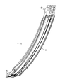
車両用バンパーリインフォースメント1は、図1乃至図3に示すように、本体部10及び端末部20,20を有する。
A vehicular bumper reinforcement 1 according to an embodiment of the present invention will be described.
The bumper reinforcement 1 for vehicles has the main-
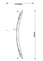
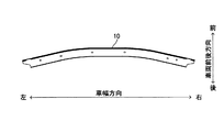
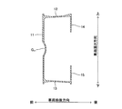
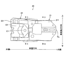
つぎに、本体部10の構成について説明する。本体部10は、図4及び図5に示すように、車幅方向に延設されている。平面視において、本体部10における車幅方向中央部は弓状に湾曲している(図4参照)。すなわち、本体部10の車幅方向内側部分よりも車幅方向外側部分が少し後方に位置している。本体部10の曲率は、車両の前端部のデザイン(バンパーカバーの形状)に応じて決定されている。本体部10は、図6乃至図8に示すように、前壁部11、上壁部12、下壁部13、上側後壁部14、下側後壁部15を有する。前壁部11は、車幅方向を長手方向とし、且つ車両高さ方向を幅方向とする板状に形成されている。前壁部11の前面における車両高さ方向中央部には、車幅方向に延びる溝部G11が形成されている。上壁部12及び下壁部13は、車幅方向を長手方向とし、且つ車両前後方向を幅方向とする板状に形成されている。上壁部12は、前壁部11の上端部から後方(車室側)へ延設されている。下壁部13は、前壁部11の下端部から後方(車室側)へ延設されている。上側後壁部14及び下側後壁部15は、車幅方向を長手方向とし、且つ車両高さ方向を幅方向とする板状に形成されている。つまり、上側後壁部14及び下側後壁部15は、前壁部11に略平行な板状に形成されている。上側後壁部14は、上壁部12の後端から下方へ延設されている。下側後壁部15は、下壁部13の後端から上方へ延設されている。上側後壁部14の下端面と下側後壁部15の上端面とが対向している。つまり、本体部10は後方へ開放されている。
Next, the configuration of the
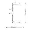
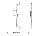
本体部10の右端部10Rにおいて、本体部10の中央部側から本体部10の右端へ向かうに従って、上側後壁部14及び下側後壁部15の幅(上下方向の寸法)が徐々に小さくなっている(図5乃至図8参照)。また、右端部10Rにおける上壁部12及び下壁部13の右側部分の幅(前後方向の寸法)は、右端部10Rにおける上壁部12及び下壁部13の左側部分の幅(前後方向の寸法)よりも小さい。よって、本体部10の右端部10Rにおいて、本体部10の中央部側から本体部10の右端へ向かうに従って、その長手方向に垂直な断面の面積が徐々に小さくなっている。また、本体部10の左端部10Lにおいて、本体部10の中央部側から本体部10の左端へ向かうに従って、上側後壁部14及び下側後壁部15の幅(上下方向の寸法)が徐々に小さくなっている。また、左端部10Lにおける上壁部12及び下壁部13の左側部分の幅(前後方向の寸法)は、左端部10Lにおける上壁部12及び下壁部13の右側部分の幅(前後方向の寸法)よりも小さい。よって、本体部10の左端部10Lにおいて、本体部10の中央部側から本体部10の左端へ向かうに従って、その長手方向に垂直な断面の面積が徐々に小さくなっている。すなわち、本体部10の長手方向における端部の断面であって、本体部10の長手方向に垂直な断面の面積(図7又は図8において斜線を付した部分の面積)が、本体部10の長手方向における中央部の断面であって、本体部10の長手方向に垂直な断面の面積(図6において斜線を付した部分の面積)よりも小さい。
In the
また、本体部10には、各種貫通孔(例えば、端末部20を本体部10に締結するための締結部材(リベット、ボルトなど)が挿入される孔)が設けられている。
The
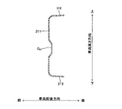
本体部10は、次のようにして形成される。まず、金属材料(例えばアルミニウム合金材)を押出加工して、図9に示すような、直線状の中間成形体Mを形成する。前記金属材料の押出方向が車幅方向に相当する。すなわち、中間成形体Mは車幅方向に延設されている。中間成形体Mの長手方向に垂直な断面は、図6に示す断面と同様の形状を呈する。つまり、中間成形体Mは、前壁部11、上壁部12、下壁部13、上側後壁部14及び下側後壁部15に相当する各壁部を有する。つぎに、中間成形体Mの壁部のうち、上壁部12、下壁部13、上側後壁部14及び下側後壁部15に相当する壁部の右端部及び左端部(図9において斜線を付した部分)をトリミングする。つぎに、中間成形体Mの壁部に、各種貫通孔をそれぞれ形成する。つぎに、中間成形体Mの車幅方向中央部を弓状に曲げ加工する。上記のようにして、本体部10が形成される。
The
つぎに、端末部20の構成について説明する。なお、本体部10の左端部に組み付けられる端末部20と右端部に組み付けられる端末部20とは同一の部材である。つまり、端末部20は、上下対称形状を有しており、本体部10の左端部及び右端部のいずれにも組み付け可能である。
Next, the configuration of the
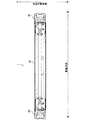
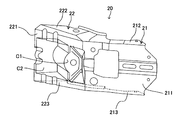
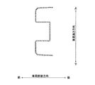
端末部20は、図10乃至図12に示すように、基端部21と突出部22を有する。基端部21は、本体部10の端部に重ね合わされた状態で本体部10に組み付けられる。突出部22は、基端部21に連続していて、端末部20が本体部10に組みつけられた状態において本体部10の端部から突出し、斜め後方へ延びている(図1乃至図3参照)。基端部21の延設方向は本体部10の端部の延設方向に一致しているが、突出部22の延設方向は本体部10の延設方向に対して傾斜している。言い換えれば、端末部20は、図10に示すように、その平面視において湾曲している。基端部21と突出部22との境界部付近の曲率は、本体部10の曲率よりも大きい。
As shown in FIGS. 10 to 12, the
基端部21は、本体部10の前壁部11に略平行な板状の前壁部211を有する。また、基端部21は、本体部10の上壁部12及び下壁部13に略平行な板状の上壁部212及び下壁部213を有する。前壁部211の上端に上壁部212の前端が接続され、前壁部211の下端に下壁部213の前端が接続されている。基端部21の車両高さ方向の寸法は、本体部10の上壁部12の下面と下壁部13の上面との距離よりも少し小さい。
The
前壁部211の前面における車両高さ方向中央部には、車幅方向に延びる溝部G21が形成されている。溝部G21は、溝部G11よりも少し小さく形成されていて、溝部G11に重ね合わせ可能である。また、前壁部211の車両高さ方向における中央部は、前壁部211の上端部及び下端部の車幅方向における内側の端部から見て、車幅方向における内側へさらに突出している。
The vehicle height direction central portion of the front surface of the
突出部22は、基端部21の前壁部211の車幅方向における外側の端部から延設された板状の前壁部221を有する。また、突出部22は、本体部10の上壁部12及び下壁部13に略平行な板状の上壁部222及び下壁部223を有する。上壁部222及び下壁部223は、基端部21の上壁部212及び下壁部213の車幅方向における外側の端部から延設されている。また、前壁部221の上端に上壁部222の前端が接続され、前壁部221の下端に下壁部223の前端が接続されている。
The
前壁部221の前面における車両高さ方向中央部には、凹部C1及び凹部C2が形成されている。凹部C1,C2は、車幅方向に並設されている。凹部C1及び凹部C2における車両高さ方向に垂直な断面は、階段状を呈する(図11参照)。また、上壁部212及び下壁部213の幅(前後方向の寸法)が、上壁部222及び下壁部223の幅(前後方向の寸法)に比べて小さい。すなわち、基端部21の長手方向に垂直な断面の面積は、突出部22の長手方向に垂直な断面の面積に比べて小さい。
A recess C <b> 1 and a recess C <b> 2 are formed in the vehicle height direction center portion on the front surface of the
また、端末部20には、各種貫通孔(例えば、端末部20を本体部10に締結するための締結部材(リベット、ボルトなど)が挿入される孔)が設けられている。
Further, the
端末部20は、金属板をプレス加工することにより、一体的に形成される。
The
上記のように、本体部10の右端部10R及び左端部10Lの断面(図7及び図8)の面積を、本体部10の車幅方向における中央部の断面(図6)の面積よりも小さくした。したがって、本体部10の左右の端部の剛性は、本体部10の車幅方向における中央部の剛性よりも少し低い。一方、端末部20の基端部21の断面(図13)の面積を、突出部22の断面(図14)の面積よりも小さくした。したがって、基端部21の剛性は、突出部22の剛性よりも少し低い。この本体部10の右端部10R及び左端部10L(つまり、本体部10の中央部よりも剛性の低い部分)と、端末部20の基端部21(つまり、突出部22よりも剛性が低い部分)とが重ねられた状態で、本体部10及び端末部20,20が締結部材(リベット、ボルト及びナットなど)を用いて締結される。これにより、従来の車両用バンパーリインフォースメントに比べて、各部の剛性の差(つまり、本体部10と端末部20とが重なった部分と、それ以外の部分との剛性の差)を減少させることができる。よって、衝突後に車両用バンパーリインフォースメント1が変形していく過程の初期段階において本体部10と端末部20とが重なった部分にて破断してしまうという事態が生じ難く、衝撃を効率的に吸収できる。
As described above, the areas of the cross sections (FIG. 7 and FIG. 8) of the
さらに、本発明の実施にあたっては、上記実施形態に限定されるものではなく、本発明の目的を逸脱しない限りにおいて種々の変更が可能である。 Furthermore, in carrying out the present invention, the present invention is not limited to the above embodiment, and various modifications can be made without departing from the object of the present invention.
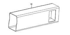
例えば、上記の車両用バンパーリインフォースメント1においては、本体部10の左右の端部の剛性を、本体部10の車幅方向における中央部の剛性よりも少し低く設定するととともに、基端部21の剛性を、突出部22の剛性よりも少し低く設定した。これに代えて、本体部10に関しては上記実施形態と同様に構成し、端末部20の基端部21の剛性と突出部22の剛性を同程度に設定しても良い。例えば、凹部C1,C2を省略しても良い。また、上記実施形態においては、中間成形体Mの壁部のうち、上壁部12、下壁部13、上側後壁部14及び下側後壁部15に相当する壁部の右端部及び左端部をトリミングしている。しかし、例えば、中間成形体Mの壁部のうち、前壁部11に相当する壁部をトリミングしてもよい。つまり、本体部10の右端部10R及び左端部10Lの剛性が本体部10の中央部の剛性よりも低くなるように、中間成形体Mを加工すればよい。また、本体部10の形状は上記実施形態に限られない。例えば、図15に示すように、角筒状の中間成形体Mを形成しておき、その左右の端部に、開口部を形成した部材を本体部10として用いてもよい。
For example, in the vehicle bumper reinforcement 1 described above, the rigidity of the left and right end portions of the
1・・・車両用バンパーリインフォースメント、10・・・本体部、11・・・前壁部、12・・・上壁部、13・・・下壁部、14・・・上側後壁部、15・・・下側後壁部、21・・・基端部、22・・・突出部、211・・・前壁部、212・・・上壁部、213・・・下壁部、221・・・前壁部、222・・・上壁部、223・・・下壁部、M・・・中間成形体
DESCRIPTION OF SYMBOLS 1 ... Vehicle bumper reinforcement, 10 ... Main-body part, 11 ... Front wall part, 12 ... Upper wall part, 13 ... Lower wall part, 14 ... Upper rear wall part, DESCRIPTION OF
上記従来の車両用バンパーリインフォースメントの本体部はアルミニウム合金材を押し出し加工して形成される。つまり、本体部の長手方向に垂直な断面の形状は、その断面の位置に関わらず一定である。本体部の端部に端末部が重ねられている。よって、両者が重なった部分の肉厚は、その他の部分(例えば、本体部の長手方向における中央部)の肉厚よりも大きい。したがって、車両用バンパーリインフォースメントのうち、本体部と端末部とが重なった部分の剛性がその他の部分よりも大きい。車両用バンパーリインフォースメントのうちの本体部と端末部との重ねあわせ部の剛性と他の部分の剛性との差が高い場合、車両用バンパーリインフォースメントに衝撃が印加されたとき、車両用バンパーリインフォースメントが変形していく過程の初期段階において、車両用バンパーリインフォースメントの長手方向における端部にて破断し、その後、衝撃がほとんど吸収されない。
The body part of the conventional vehicle bumper reinforcement is formed by extruding an aluminum alloy material. That is, the shape of the cross section perpendicular to the longitudinal direction of the main body is constant regardless of the position of the cross section. A terminal portion is overlaid on the end of the main body. Therefore, the thickness of the overlapping portion is larger than the thickness of the other portion (for example, the central portion in the longitudinal direction of the main body). Therefore, the rigidity of the portion where the main body portion and the terminal portion overlap in the bumper reinforcement for the vehicle is larger than the other portions. If the difference between the rigidity of the overlapping part of the body part and the terminal part of the bumper reinforcement for the vehicle and the rigidity of the other part is high, when the impact is applied to the bumper reinforcement for the vehicle, the bumper reinforcement for the vehicle In the initial stage of the deformation process , the vehicle bumper reinforcement is broken at the end in the longitudinal direction , and the impact is hardly absorbed thereafter.
本発明に係る車両用バンパーリインフォースメントにおいては、本体部の端部の剛性が本体部の中央部の剛性よりも小さく設定されている。したがって、本発明に係る車両用バンパーリインフォースメントの本体部と端末部とが重ねあわされた部分の剛性は、本体部の端部の剛性が本体部の中央部の剛性と同等である上記従来の車両用バンパーリインフォースメントに比べて小さい。つまり、車両用バンパーリインフォースメントの各部の剛性の差を、従来の車両用バンパーリインフォースメントより小さくすることができる。よって、本発明によれば、衝突時に車両用バンパーリインフォースメントが変形していく過程の初期段階において車両用バンパーリインフォースメントの長手方向における端部にて車両用バンパーリインフォースメントが破断してしまうという事態が生じ難く、衝撃を効率的に吸収できる。
In the vehicle bumper reinforcement according to the present invention, the rigidity of the end of the main body is set to be smaller than the rigidity of the central portion of the main body. Therefore, the rigidity of the portion where the main body portion and the terminal portion of the bumper reinforcement for a vehicle according to the present invention are overlapped with each other is equal to the rigidity of the central portion of the main body portion. Smaller than bumper reinforcement for vehicles. That is, the difference in rigidity of each part of the vehicle bumper reinforcement can be made smaller than that of the conventional vehicle bumper reinforcement. Therefore, according to the present invention, the vehicle bumper reinforcement breaks at the end portion in the longitudinal direction of the vehicle bumper reinforcement at the initial stage of the process of deforming the vehicle bumper reinforcement at the time of the collision. Is less likely to occur and the shock can be absorbed efficiently.
上記のように、本体部10の右端部10R及び左端部10Lの断面(図7及び図8)の面積を、本体部10の車幅方向における中央部の断面(図6)の面積よりも小さくした。したがって、本体部10の左右の端部の剛性は、本体部10の車幅方向における中央部の剛性よりも少し低い。一方、端末部20の基端部21の断面(図13)の面積を、突出部22の断面(図14)の面積よりも小さくした。したがって、基端部21の剛性は、突出部22の剛性よりも少し低い。この本体部10の右端部10R及び左端部10L(つまり、本体部10の中央部よりも剛性の低い部分)と、端末部20の基端部21(つまり、突出部22よりも剛性が低い部分)とが重ねられた状態で、本体部10及び端末部20,20が締結部材(リベット、ボルト及びナットなど)を用いて締結される。これにより、従来の車両用バンパーリインフォースメントに比べて、各部の剛性の差(つまり、本体部10と端末部20とが重なった部分と、それ以外の部分との剛性の差)を減少させることができる。よって、衝突後に車両用バンパーリインフォースメント1が変形していく過程の初期段階において車両用バンパーリインフォースメント1の長手方向における端部にて破断してしまうという事態が生じ難く、衝撃を効率的に吸収できる。
As described above, the areas of the cross sections (FIG. 7 and FIG. 8) of the
Claims (5)
車幅方向に延設されていて、前記本体部の長手方向における端部に取り付けられた端末部であって、前記本体部の端部に重ねあわされた状態で前記本体部に接合された端末部と、を備え、
前記本体部の長手方向における端部の剛性が前記本体部の長手方向における中央部の剛性よりも小さく設定されている、車両用バンパーリインフォースメント。 A main body extending in the vehicle width direction;
A terminal portion that extends in the vehicle width direction and is attached to an end portion in the longitudinal direction of the main body portion, and is joined to the main body portion in a state of being overlapped with the end portion of the main body portion And comprising
The bumper reinforcement for vehicles, wherein the rigidity of the end portion in the longitudinal direction of the main body is set to be smaller than the rigidity of the central portion in the longitudinal direction of the main body.
前記本体部の長手方向における端部の断面であって、前記本体部の長手方向に垂直な断面の面積が、前記本体部の長手方向における中央部の断面であって、前記本体部の長手方向に垂直な断面の面積に比べて小さい、車両用バンパーリインフォースメント。 The bumper reinforcement for a vehicle according to claim 1,
The cross section of the end portion in the longitudinal direction of the main body portion, the area of the cross section perpendicular to the longitudinal direction of the main body portion is the cross section of the central portion in the longitudinal direction of the main body portion, the longitudinal direction of the main body portion Bumper reinforcement for vehicles, which is smaller than the cross-sectional area perpendicular to
前記本体部の長手方向における端部において、前記本体部の中央部側から前記本体部の一端側へ向かうにしたがって、その長手方向に垂直な断面の面積が徐々に小さくなっている、車両用バンパーリインフォースメント。 The bumper reinforcement for a vehicle according to claim 2,
A vehicular bumper in which an area of a cross section perpendicular to the longitudinal direction is gradually reduced from the central portion side of the main body portion toward the one end side of the main body portion at an end portion in the longitudinal direction of the main body portion. Reinforcement.
前記本体部は、
車幅方向を長手方向とし且つ車両高さ方向を幅方向とする第1壁部と、
車幅方向を長手方向とし且つ車両前後方向を幅方向とする第2壁部及び第3壁部であって、前記第1壁部の上端部及び下端部からそれぞれ車室側へ延びる第2壁部及び第3壁部と、
車幅方向を長手方向とし且つ車両高さ方向を幅方向とする第4壁部及び第5壁部であって、前記第2壁部及び前記第3壁部における車室側の端部から下方及び上方へそれぞれ延びる第4壁部及び第5壁部と、を備え、
前記第4壁部及び第5壁部の長手方向における端部の断面であって、前記第4壁部及び第5壁部の長手方向に垂直な断面の面積が、前記第4壁部及び第5壁部の長手方向における中央部の断面であって、前記第4壁部及び第5壁部の長手方向に垂直な断面の面積よりも小さい、車両用バンパーリインフォースメント。 In the bumper reinforcement for vehicles according to claim 2 or 3,
The main body is
A first wall portion having a vehicle width direction as a longitudinal direction and a vehicle height direction as a width direction;
A second wall and a third wall having a vehicle width direction as a longitudinal direction and a vehicle front-rear direction as a width direction, each extending from an upper end portion and a lower end portion of the first wall portion toward a vehicle compartment side And the third wall,
4th wall part and 5th wall part which make a vehicle width direction a longitudinal direction and make a vehicle height direction a width direction, Comprising: It is downward from the edge part by the side of a compartment in the 2nd wall part and the 3rd wall part And a fourth wall portion and a fifth wall portion respectively extending upward,
It is a cross section of the edge part in the longitudinal direction of the 4th wall part and the 5th wall part, Comprising: The area of the cross section perpendicular to the longitudinal direction of the 4th wall part and the 5th wall part is the 4th wall part and the 4th wall part. A bumper reinforcement for a vehicle, which is a cross section of a central portion in the longitudinal direction of the five wall portions and is smaller than an area of a cross section perpendicular to the longitudinal direction of the fourth wall portion and the fifth wall portion.
車幅方向に延設されていて、前記本体部の長手方向における端部に取り付けられる端末部であって、その一端部が前記本体部の端部に重ねあわされた状態で前記本体部に接合され、その他端部が前記本体部から突出している端末部と、を備え、
前記端末部の一端部の剛性が、前記端末部の他端部の剛性よりも小さく設定されている、車両用バンパーリインフォースメント。
A main body extending in the vehicle width direction;
A terminal portion that extends in the vehicle width direction and is attached to an end portion in the longitudinal direction of the main body portion, and is joined to the main body portion with one end portion thereof being overlapped with the end portion of the main body portion. The other end portion protrudes from the main body portion, and
A bumper reinforcement for a vehicle, wherein a rigidity of one end portion of the terminal portion is set to be smaller than a rigidity of the other end portion of the terminal portion.
Priority Applications (3)
| Application Number | Priority Date | Filing Date | Title |
|---|---|---|---|
| JP2016137261A JP6412528B2 (en) | 2016-07-12 | 2016-07-12 | Bumper reinforcement for vehicles |
| US15/646,363 US10414364B2 (en) | 2016-07-12 | 2017-07-11 | Bumper reinforcement for vehicle |
| CN201720844675.3U CN207579811U (en) | 2016-07-12 | 2017-07-12 | Bumper reinforcement |
Applications Claiming Priority (1)
| Application Number | Priority Date | Filing Date | Title |
|---|---|---|---|
| JP2016137261A JP6412528B2 (en) | 2016-07-12 | 2016-07-12 | Bumper reinforcement for vehicles |
Publications (2)
| Publication Number | Publication Date |
|---|---|
| JP2018008564A true JP2018008564A (en) | 2018-01-18 |
| JP6412528B2 JP6412528B2 (en) | 2018-10-24 |
Family
ID=60942406
Family Applications (1)
| Application Number | Title | Priority Date | Filing Date |
|---|---|---|---|
| JP2016137261A Active JP6412528B2 (en) | 2016-07-12 | 2016-07-12 | Bumper reinforcement for vehicles |
Country Status (3)
| Country | Link |
|---|---|
| US (1) | US10414364B2 (en) |
| JP (1) | JP6412528B2 (en) |
| CN (1) | CN207579811U (en) |
Cited By (1)
| Publication number | Priority date | Publication date | Assignee | Title |
|---|---|---|---|---|
| KR20130141040A (en) * | 2012-06-15 | 2013-12-26 | 인텔렉추얼디스커버리 주식회사 | Synthetic gel for allowing only secondary growth from seed crystals of silicalite-1 or zeolite beta |
Families Citing this family (4)
| Publication number | Priority date | Publication date | Assignee | Title |
|---|---|---|---|---|
| JP6722069B2 (en) * | 2016-09-16 | 2020-07-15 | アイシン精機株式会社 | Automotive bumper reinforcements |
| JP6962853B2 (en) * | 2018-04-09 | 2021-11-05 | 本田技研工業株式会社 | Vehicle rear bumper |
| DE102019105188A1 (en) * | 2019-02-28 | 2020-09-03 | Böllhoff Verbindungstechnik GmbH | Impact protection reinforcement of a vehicle structure and connection and manufacturing processes therefor |
| CN112124235A (en) * | 2020-09-24 | 2020-12-25 | 东风柳州汽车有限公司 | Guard bar |
Citations (4)
| Publication number | Priority date | Publication date | Assignee | Title |
|---|---|---|---|---|
| JP2005088740A (en) * | 2003-09-17 | 2005-04-07 | Press Kogyo Co Ltd | Front under run protector |
| JP2009083529A (en) * | 2007-09-27 | 2009-04-23 | Aisin Seiki Co Ltd | Bumper device for vehicle |
| JP2011245910A (en) * | 2010-05-24 | 2011-12-08 | Toyota Motor Corp | Pedestrian collision detector |
| JP2012030722A (en) * | 2010-07-30 | 2012-02-16 | Aisin Seiki Co Ltd | Bumper reinforcement and bumper device for vehicle |
Family Cites Families (4)
| Publication number | Priority date | Publication date | Assignee | Title |
|---|---|---|---|---|
| US6695368B1 (en) * | 2002-10-31 | 2004-02-24 | Shape Corporation | Bumper mount forming corner on end of beam |
| JP5341607B2 (en) | 2009-05-11 | 2013-11-13 | ユニプレス株式会社 | Bumper beam structure for vehicles |
| US9701543B2 (en) * | 2011-07-08 | 2017-07-11 | Hsiao-Yuan Li | Method and apparatus on halting global warming |
| JP5864217B2 (en) * | 2011-11-04 | 2016-02-17 | アイシン精機株式会社 | Bumper reinforcement |
-
2016
- 2016-07-12 JP JP2016137261A patent/JP6412528B2/en active Active
-
2017
- 2017-07-11 US US15/646,363 patent/US10414364B2/en active Active
- 2017-07-12 CN CN201720844675.3U patent/CN207579811U/en active Active
Patent Citations (4)
| Publication number | Priority date | Publication date | Assignee | Title |
|---|---|---|---|---|
| JP2005088740A (en) * | 2003-09-17 | 2005-04-07 | Press Kogyo Co Ltd | Front under run protector |
| JP2009083529A (en) * | 2007-09-27 | 2009-04-23 | Aisin Seiki Co Ltd | Bumper device for vehicle |
| JP2011245910A (en) * | 2010-05-24 | 2011-12-08 | Toyota Motor Corp | Pedestrian collision detector |
| JP2012030722A (en) * | 2010-07-30 | 2012-02-16 | Aisin Seiki Co Ltd | Bumper reinforcement and bumper device for vehicle |
Cited By (1)
| Publication number | Priority date | Publication date | Assignee | Title |
|---|---|---|---|---|
| KR20130141040A (en) * | 2012-06-15 | 2013-12-26 | 인텔렉추얼디스커버리 주식회사 | Synthetic gel for allowing only secondary growth from seed crystals of silicalite-1 or zeolite beta |
Also Published As
| Publication number | Publication date |
|---|---|
| US20180015895A1 (en) | 2018-01-18 |
| JP6412528B2 (en) | 2018-10-24 |
| CN207579811U (en) | 2018-07-06 |
| US10414364B2 (en) | 2019-09-17 |
Similar Documents
| Publication | Publication Date | Title |
|---|---|---|
| JP6412528B2 (en) | Bumper reinforcement for vehicles | |
| JP6052226B2 (en) | Vehicle front structure | |
| CN103079900A (en) | Bumper for vehicle | |
| JP4940044B2 (en) | Resin exterior parts for vehicles | |
| JP2016052859A (en) | Bumper beam for vehicle | |
| JP6581645B2 (en) | Body structure | |
| JP6384203B2 (en) | Center pillar for vehicle | |
| JP6545753B2 (en) | Bumper reinforcement and manufacturing method of bumper reinforcement | |
| JP5534966B2 (en) | Auto body member members | |
| JP2016182908A (en) | Bumper structure | |
| JP2007261525A (en) | Automotive bumper equipment | |
| JP2006111249A (en) | Engine under cover mounting structure | |
| JP6962952B2 (en) | Vehicle front structure | |
| JP4301017B2 (en) | Bumper reinforcement | |
| JP2009107536A (en) | Bumper structure of vehicle | |
| JP6517603B2 (en) | Shock absorbing member | |
| JP4036219B2 (en) | Automotive engine hood structure | |
| JP6125466B2 (en) | Structural members for automobiles | |
| JP4457909B2 (en) | Cowl louva | |
| JP4391909B2 (en) | Bumper beam manufacturing method | |
| JP2016222228A (en) | Door impact beam for vehicle | |
| JP4774804B2 (en) | Automotive engine hood structure | |
| JP3873978B2 (en) | Body frame | |
| JP5862060B2 (en) | Vehicle bumper | |
| JP2009035019A (en) | Bumper structure for vehicles |
Legal Events
| Date | Code | Title | Description |
|---|---|---|---|
| A131 | Notification of reasons for refusal |
Free format text: JAPANESE INTERMEDIATE CODE: A131 Effective date: 20180613 |
|
| A977 | Report on retrieval |
Free format text: JAPANESE INTERMEDIATE CODE: A971007 Effective date: 20180614 |
|
| A521 | Request for written amendment filed |
Free format text: JAPANESE INTERMEDIATE CODE: A523 Effective date: 20180810 |
|
| TRDD | Decision of grant or rejection written | ||
| A01 | Written decision to grant a patent or to grant a registration (utility model) |
Free format text: JAPANESE INTERMEDIATE CODE: A01 Effective date: 20180911 |
|
| A61 | First payment of annual fees (during grant procedure) |
Free format text: JAPANESE INTERMEDIATE CODE: A61 Effective date: 20180928 |
|
| R150 | Certificate of patent or registration of utility model |
Ref document number: 6412528 Country of ref document: JP Free format text: JAPANESE INTERMEDIATE CODE: R150 |
|
| R250 | Receipt of annual fees |
Free format text: JAPANESE INTERMEDIATE CODE: R250 |
|
| R250 | Receipt of annual fees |
Free format text: JAPANESE INTERMEDIATE CODE: R250 |
|
| R250 | Receipt of annual fees |
Free format text: JAPANESE INTERMEDIATE CODE: R250 |
|
| R250 | Receipt of annual fees |
Free format text: JAPANESE INTERMEDIATE CODE: R250 |
|
| R250 | Receipt of annual fees |
Free format text: JAPANESE INTERMEDIATE CODE: R250 |