JP2017528629A - Auxiliary mounting tool for positioning elements with respect to adjacent flats or planes - Google Patents
Auxiliary mounting tool for positioning elements with respect to adjacent flats or planes Download PDFInfo
- Publication number
- JP2017528629A JP2017528629A JP2017526744A JP2017526744A JP2017528629A JP 2017528629 A JP2017528629 A JP 2017528629A JP 2017526744 A JP2017526744 A JP 2017526744A JP 2017526744 A JP2017526744 A JP 2017526744A JP 2017528629 A JP2017528629 A JP 2017528629A
- Authority
- JP
- Japan
- Prior art keywords
- air cushion
- auxiliary tool
- frame
- cushion member
- tool according
- Prior art date
- Legal status (The legal status is an assumption and is not a legal conclusion. Google has not performed a legal analysis and makes no representation as to the accuracy of the status listed.)
- Ceased
Links
Images


Classifications
-
- E—FIXED CONSTRUCTIONS
- E04—BUILDING
- E04F—FINISHING WORK ON BUILDINGS, e.g. STAIRS, FLOORS
- E04F21/00—Implements for finishing work on buildings
- E04F21/0007—Implements for finishing work on buildings for mounting doors, windows or frames; their fitting
-
- B—PERFORMING OPERATIONS; TRANSPORTING
- B66—HOISTING; LIFTING; HAULING
- B66F—HOISTING, LIFTING, HAULING OR PUSHING, NOT OTHERWISE PROVIDED FOR, e.g. DEVICES WHICH APPLY A LIFTING OR PUSHING FORCE DIRECTLY TO THE SURFACE OF A LOAD
- B66F3/00—Devices, e.g. jacks, adapted for uninterrupted lifting of loads
- B66F3/24—Devices, e.g. jacks, adapted for uninterrupted lifting of loads fluid-pressure operated
- B66F3/25—Constructional features
- B66F3/35—Inflatable flexible elements, e.g. bellows
-
- E—FIXED CONSTRUCTIONS
- E04—BUILDING
- E04F—FINISHING WORK ON BUILDINGS, e.g. STAIRS, FLOORS
- E04F21/00—Implements for finishing work on buildings
- E04F21/0007—Implements for finishing work on buildings for mounting doors, windows or frames; their fitting
- E04F21/0015—Implements for finishing work on buildings for mounting doors, windows or frames; their fitting for mounting frames
Abstract
壁開口部内のような、隣接した平坦部に関して窓およびドアのような要素を位置決めするときに使用される補助ツールであって、該補助ツールは、膨らまし可能なエアクッション部材(6)を備え、該エアクッション部材は、ホース接続手段(1)を介して、ポンピング装置(12)、および、エア抜き弁(16)に接続される。前記エアクッション部材は、平らなバッグユニットとして形成されている。補助ツールは、選択的に膨らまし可能である、2つまたはそれ以上の互いに固定されたエアクッション部材(6)を有する1つまたはそれ以上のエアクッション部材を備えるエアクッション部材(6)を互いに固定するための連結要素(42、46、および、48)を含む。これらのエアクッション部材は、前記平らなバッグユニットの面が全体的に、前記補助ツール内で対向した面を提供するように共通の平面上で並置関係に配置される。【選択図】図6および図7An auxiliary tool used when positioning elements such as windows and doors with respect to adjacent flats, such as in a wall opening, said auxiliary tool comprising an inflatable air cushion member (6); The air cushion member is connected to the pumping device (12) and the air vent valve (16) via the hose connecting means (1). The air cushion member is formed as a flat bag unit. The auxiliary tool secures the air cushion member (6) to one another with one or more air cushion members having two or more secured air cushion members (6) that are selectively inflatable. Connecting elements (42, 46, and 48) for These air cushion members are arranged in a side-by-side relationship on a common plane such that the surfaces of the flat bag unit generally provide opposed surfaces within the auxiliary tool. [Selection] FIGS. 6 and 7
Description
本発明は、壁開口部内のような隣接した平坦部または平面に関して窓またはドアフレームのような要素を位置決めするときに使用される補助ツールであって、該補助ツールは、強くて、可撓性の、それぞれに曲げ可能な、しかし実質的に非伸縮性の材料で作られた膨らまし可能なエアクッション部材を備え、該膨らまし可能なエアクッション部材は、ホース部材を介して、膨らまし装置、および、エア抜き弁に接続され、膨らまし可能なエアクッション部材は、互いに対向して配置された平らなバッグ面を有する平らなバッグユニットであり、それによって、平らなバッグ面は、対面して配置された前記材料の層で構成され、それらの自由縁に沿って接合されて。補強された二重層縁部を形成している補助ツールに関する。 The present invention is an auxiliary tool used when positioning an element such as a window or door frame with respect to an adjacent flat or plane, such as within a wall opening, the auxiliary tool being strong and flexible Each of the inflatable air cushion members made of a material that is bendable but substantially non-stretchable, the inflatable air cushion member via the hose member, and The inflatable air cushion member connected to the air vent valve is a flat bag unit having flat bag surfaces arranged opposite to each other, whereby the flat bag surfaces are arranged facing each other. Composed of layers of said material and joined along their free edges. It relates to an auxiliary tool forming a reinforced double layer edge.
かかる補助ツールは、EP0771385号から知られている。EP0771385号を通して、補助ツールは、建物の開口部内にフレーム要素を取り付ける間に使用されることを意図している。かくして、これは、壁開口部内に窓およびドアフレームを位置決めすることに関し、ここで、個々のフレームは、わずかにより大きな壁開口部と或る関係で配置されることが必要である。初期には、導入取り付け手順ステップとして、楔を介してフレームを壁開口部の所定位置に維持することが一般的な実務であった。EP0771385号による補助ツールによって、より複雑さが減少した取り付け手順が達成され、1人だけでこの手順を行うことが可能になった。 Such an auxiliary tool is known from EP0771385. Through EP0771385, auxiliary tools are intended to be used during the installation of the frame element in the opening of the building. Thus, this relates to positioning the window and door frame within the wall opening, where the individual frames need to be placed in a relationship with a slightly larger wall opening. Initially, it was common practice to maintain the frame in place in the wall opening via a wedge as an introductory installation procedure step. The auxiliary tool according to EP0771385 has achieved a mounting procedure with less complexity, making it possible for only one person to perform this procedure.
かくして、選択的に膨らまし可能なエアクッション部材を使用する間に、この膨らまし可能なエアクッション部材は、壁開口部の上記の一方の側にあるこのエアクッション部材が、かくして、他の対向して配置された平らなバッグユニットに同時に及ぼされる圧力に関して多かれ少なかれ膨らまされるようになるので、壁開口部内の特定の個々のフレームの位置が、所望の正確な位置を得るように正確に調節されるように、個々のフレームと、対応する壁開口部との間のスペース内に挿入されるようになり、それによって、1人でフレームを正確に容易に位置決めすることができる。 Thus, during use of the selectively inflatable air cushion member, the inflatable air cushion member is in contact with the air cushion member on the one side of the wall opening, thus opposing the other. Since it becomes more or less inflated with respect to the pressure simultaneously exerted on the placed flat bag unit, the position of a particular individual frame within the wall opening is precisely adjusted to obtain the desired exact position As such, it can be inserted into the space between the individual frame and the corresponding wall opening so that the frame can be accurately and easily positioned by one person.
エアクッション部材「だけ」が、純粋に平らなバッグユニットであることが決定的である。なぜならば、次いで、平らなバッグユニットは影響を受けて、一方向に制御された変位を行うことができ、かくして、同時に、適度のエアバッグ圧力によりフレームが、最終固定が生じるときに最終の正確な調節を達成すべく、他方向に変位されることができるからである。 It is crucial that the air cushion member “only” is a purely flat bag unit. This is because the flat bag unit can then be affected to effect a controlled displacement in one direction, and at the same time, with moderate airbag pressure, the frame will be finally accurate when final fixation occurs. This is because it can be displaced in the other direction to achieve a proper adjustment.
平らなバッグユニットは、小さい作動力によって、むしろ大きな圧力を個々のフレームの外部面に向かって及ぼすことができ、他の理由の中でも、最良の解決法は、個々のフレームの、それぞれ、上部分、下部分に幾分近くに配置された平らなバッグユニットを提供することであり得る。更に、より多くの量のバッグを使用することによって、個々のフレームの外部に膨らむことがある側方部分の直線化を得ることができる。 A flat bag unit can exert a rather large pressure towards the outer surface of the individual frame with a small actuation force, and among other reasons, the best solution is the upper part of each individual frame. It may be to provide a flat bag unit located somewhat close to the lower part. Furthermore, by using a larger amount of bag, it is possible to obtain a linearization of the side portions that may bulge out of the individual frames.
バッグユニットは、バッグユニットが、巻き運動、すなわち、ゴムホースが行うことができる巻きのタイプに対応する運動に抗して安定的であるように実施されることが重要であり、これは、側方方向に及ぼされる圧力を加えることによる「平らな楕円形」横断面を達成し、それによって、かかる場合に、平らなバッグユニットは、個々のフレームと、壁中の受け入れ開口部との間にある鉛直方向に配向された間隙の側面に向かって及ぼされる摩擦力によって個々のフレームを支持することができなくなる。 It is important that the bag unit is implemented so that the bag unit is stable against the winding movement, ie the movement corresponding to the type of winding that the rubber hose can perform, which Achieve a “flat oval” cross-section by applying pressure exerted in the direction so that in such cases the flat bag unit is between the individual frame and the receiving opening in the wall The individual frames cannot be supported by frictional forces exerted toward the side surfaces of the vertically oriented gaps.
かかる種類の安定化は、他方で、好ましくは、強くて、可撓性の、しかし実質的に非伸縮性の材料、すなわち、例えば、装甲プラスチック箔の二重層の形状で実施されるように、容易に達成することができる。最良かつ最も簡単な可能性は、箔材料の単一の矩形片を折り返し、次いで、突出している3つの縁領域を互いに溶接し、折り返し縁領域において、必要な接続用ホースを、膨らましボール、および、含まれるエア抜き弁に接続することである。なぜならば、これは、折り返し縁が、鋭い曲げ折り返しを有することを必要としないので、実際に可能にされているからである。 Such kind of stabilization, on the other hand, is preferably carried out in the form of a strong, flexible, but substantially non-stretchable material, i.e., for example, a double layer of armored plastic foil, Can be easily achieved. The best and simplest possibility is to fold a single rectangular piece of foil material, and then weld the three protruding edge areas together, in which the required connecting hose, the inflating ball, and Connect to the included air vent valve. This is because it is actually possible because the folding edge does not need to have a sharp bend.
技術状態に属するクッション部材は隣接した平坦部に関する部材の位置決めにおいて大きな利点を提供するにもかかわらず、部材が及ぼすことができる力は、使用される材料のために限られている。更に、補助ツールは、単一の荷重箇所を有し、そのため、それぞれの直線化変位を提供するために使用することができる1つの攻撃箇所しか提供しない。 Despite the fact that cushion members belonging to the state of the art offer great advantages in positioning the member with respect to adjacent flats, the force that the member can exert is limited due to the material used. In addition, the auxiliary tool has a single load point, thus providing only one attack point that can be used to provide each linearized displacement.
より大きな力を提供したいときにはいつでも、より多くのクッション部材が使用されなければならない。他方で、これらのクッション部材は、その場合に、互いに関する変位を互いに受け、そのため、所望の支持は、必要とされるその場で現れない。これは、支持される要素の正しい支持および水準化を達成することを困難にする。 More cushion members must be used whenever it is desired to provide greater force. On the other hand, these cushion members are then subject to displacement relative to each other, so that the desired support does not appear where needed. This makes it difficult to achieve correct support and leveling of the supported elements.
多年に亘り、大きな力を提供し、更に安定した支持を提供し、かつ、異なる攻撃箇所で力の調節の可能性を提供する補助ツールが望まれていた。 For many years, there has been a need for an auxiliary tool that provides great force, provides more stable support, and provides the possibility of force adjustment at different points of attack.
本発明は、技術状態に属する平らなバッグユニットに関連した利点を使用し、それによって、異なる攻撃箇所で力の調節の可能性を備える安定した支持を達成することが可能になるように、上記の欠点を回避する補助ツールを記載するという目的を有する。 The present invention uses the advantages associated with a flat bag unit belonging to the state of the art, so that it is possible to achieve a stable support with the possibility of force adjustment at different attack points. The purpose is to describe an auxiliary tool that avoids the disadvantages of
本発明によれば、これは、上記の導入部によるタイプの補助ツールにおいて、該補助ツールは更に、選択的に膨らまし可能であり、前記平らなバッグユニットの面が共に、前記補助ツール内で対向した面を提供するように共通の平面上で並置関係に配置された平らな2つまたはそれ以上の互いに固定されたエアクッション部材を含む補助ツールを提供するために、1つまたはそれ以上の隣接したエアクッション部材を備えるエアクッション部材を互いに固定するための連結要素を含む、ことを特徴とする補助ツールによって達成される。 According to the present invention, this is an auxiliary tool of the type described above, wherein the auxiliary tool can further be selectively inflated, and the surfaces of the flat bag unit are both opposed in the auxiliary tool. One or more adjacent to provide an auxiliary tool that includes two or more flatly secured air cushion members that are arranged in a side-by-side relationship on a common plane to provide a curved surface This is achieved by an auxiliary tool characterized in that it includes a coupling element for securing the air cushion members with each other.
かくして、本発明によれば、互い所定位置にあるエアクッション部材が、上記連結要素によって、固定された状態に維持されるような安定した支持を互いに形成する所望の数の互いに隣接して配置されたエアクッション部材を使用することが可能である。かくして、その他のエアクッション部材に関するエアクッション部材は、それらの位置から遠ざかるように「変位される」ことはできず、要素に関するエアクッション部材の各々の位置も更に安定化される。 Thus, according to the present invention, the air cushion members in place with each other are arranged adjacent to each other in the desired number of mutually forming a stable support that is maintained in a fixed state by the connecting element. It is possible to use an air cushion member. Thus, the air cushion members for the other air cushion members cannot be “displaced” away from their position, and the position of each of the air cushion members for the element is further stabilized.
かくして、使用されているエアクッションの数に対応する複数の荷重支持箇所を備えるマルチポイント構成荷重が達成される。すなわち、無段力調節によって、より大きな領域に亘って作動することができ、支持される要素を押圧し、或いは、移動させるように、それぞれ、調節することを可能にする。このようにして、補助ツールを、均質でない、或いは、特定の場所で所定位置に直立にするために、この操作を実行するために余分の力を必要とする均質な形状および要素を呈しない要素と共に使用することもできる。 Thus, a multipoint configuration load with a plurality of load support locations corresponding to the number of air cushions being used is achieved. That is, the stepless force adjustment can be operated over a larger area, allowing the elements to be supported to be adjusted to be pressed or moved, respectively. In this way, an element that is not homogeneous or does not exhibit a homogeneous shape and elements that require extra force to perform this operation to bring the auxiliary tool upright in place at a particular location Can also be used.
本発明は、主として異なるエアクッション部材内で異なる圧力を提供するために膨らましを使用することに基づくけれども、補助装置に含まれるエアクッション部材の全てまたは一部において同じ圧力を提供するために膨らましを提供することも可能である。 Although the present invention is primarily based on the use of inflections to provide different pressures within different air cushion members, the inflating to provide the same pressure in all or part of the air cushion members included in the auxiliary device. It is also possible to provide.
補助ツールのエアクッション部材は、原則的に、出典を明示することによってその内容が本願に含まれるEP0771385号に記載されているエアクッション部材と同一である。それらの部材は、いくつかの場合には、形状を変えずに使用することができ、或いは、二重層縁は、連結要素に属する対応する相互連結手段との協働を確立することができる相互連結手段を備えることになるので、二重層縁を変更することが必要になり得る。 The air cushion member of the auxiliary tool is in principle the same as the air cushion member described in EP0771385, which is included in the present application by specifying the source. The members can be used in some cases without changing their shape, or the double layer edges can establish mutual cooperation with the corresponding interconnection means belonging to the coupling element. It will be necessary to change the double layer edge as it will be provided with connecting means.
単一のユニットとして扱うことができるエアクッション部材の組立体を提供することができる。これは、大変重い不均質の要素を配置しなければならず、それによって、構造の種類、若しくは、要素の形状により、或いは、要素の整合または水準化に対する変化する要求により、大きな力と、変化される量の影響力が必要とされるときにさえ、1人の作業者だけしか必要としないので、取り扱いを容易にする。 An assembly of air cushion members that can be handled as a single unit can be provided. This requires the placement of very heavy heterogeneous elements, which can cause large forces and changes depending on the type of structure, the shape of the elements, or the changing requirements for element alignment or leveling. Even when the required amount of influence is required, handling is facilitated since only one operator is needed.
本発明は、エアクッション部材が、要素に影響する大変なケアを及ぼす、すなわち、迅速固定手段の初歩的な使用によりいかなる種類の圧力マーキングも残されないので、大きな利点を組み込む。 The present invention incorporates significant advantages since the air cushion member provides great care affecting the element, i.e. no kind of pressure marking is left by the rudimentary use of the quick-fixing means.
更に、エアクッション部材の「バッテリー」の使用が、使用者のために高められた安全レベルを創出する。1つの単一のエアクッション部材が不具合であり、或いは、パンクした場合でさえ、残りのエアクッション部材は、部材が、それに関して部材が所定位置にそれぞれ配置される平坦部または面に押しつけられないようにセーフガードする。すなわち、したがって、圧搾圧力の危険、かくしてまた、それによって、要素、または、支持として役立つ平坦部の損傷の危険を含めて危険が減少され、或いは、完全に防止される。 Further, the use of the “battery” of the air cushion member creates an increased safety level for the user. Even if one single air cushion member is defective or even punctured, the remaining air cushion member is not pressed against the flat or surface on which the member is placed in place, respectively. To be safeguarded. That is, therefore, the risk is reduced or completely prevented, including the risk of squeezing pressure and thus also the risk of damage to the element or the flat which serves as a support.
更に別の実施形態によれば、本発明による容器は、エアクッション部材が、少なくとも1つの隅部に穴または開口部を含む突出する縁フランジを備え、連結要素が、少なくとも1つの前記穴または開口部に係合するための少なくとも1つのピン部材を備えることを特徴とする。穴は、代替的には、隅部の代わりに、長い側部に位置決めされてもよい。更に、穴は、要素に属する平坦部の外部面へのエアクッションの一時的な固定のためのピンを貫通して挿入することができるボアとして役立つことができる。 According to yet another embodiment, the container according to the invention is such that the air cushion member comprises a protruding edge flange comprising a hole or opening in at least one corner and the connecting element is at least one said hole or opening. It comprises at least one pin member for engaging with the part. The holes may alternatively be positioned on long sides instead of corners. Furthermore, the hole can serve as a bore that can be inserted through a pin for temporary fixing of the air cushion to the outer surface of the flat part belonging to the element.
更に別の実施形態によれば、本発明による容器は、連結要素が、開口部を備えたフレーム側方ユニットを備える実質的に平らなフレーム構造からなり、前記フレーム側方ユニットの開口部内で、前記エアクッション部材は、これらが少なくとも前記フレーム構造に属する側面の丁度1つの側面上方に突出しているように、配置されることを特徴とする。フレーム構造が、フィールド内でエアクッション部材を受け入れるための「格子」を提供する簡単な方法を提供し、かくして、フレーム側方ユニットによって提供される。 According to yet another embodiment, the container according to the invention comprises a connecting element comprising a substantially flat frame structure comprising a frame side unit with an opening, in the opening of said frame side unit, The air cushion members are arranged so that they protrude at least one side of the side belonging to the frame structure. The frame structure provides a simple way of providing a “lattice” for receiving an air cushion member in the field and thus provided by the frame side unit.
フレームは、矩形形状、或いは、他の多角形形状、すなわち、六角形形状のような多角形形状を有するのがよい。 The frame may have a rectangular shape or other polygonal shape, i.e. a polygonal shape such as a hexagonal shape.
フレームは、原則的に、膨らまされていないエアクッション部材の厚さに一致する厚さを有するのがよく、それによって、補助ツールは、単一のエアクッション部材を内部に挿入することができる隙間またはスロットと同じ狭い隙間またはスロット内に挿入することができる。 The frame should in principle have a thickness that matches the thickness of the uninflated air cushion member, so that the auxiliary tool has a gap through which a single air cushion member can be inserted. Or it can be inserted into the same narrow gap or slot as the slot.
本発明による容器は、フレーム構造が、連結要素を備える複数のフレーム部分を備えるように形成され、前記連結要素は、協働して、前記フレーム部分を一貫したフレーム構造に連結することを特徴とする更に別の実施形態を有するのがよい。これによれば、簡単な仕方で、所望の寸法および形状を有するフレームを提供するを可能にされる。 The container according to the invention is characterized in that the frame structure comprises a plurality of frame parts comprising coupling elements, the coupling elements cooperating to couple the frame parts to a consistent frame structure, It is preferable to have yet another embodiment. This makes it possible to provide a frame having the desired dimensions and shape in a simple manner.
本発明による容器は、前記連結部材が、解放可能な連結部材であり、好ましくは、協働するピン、および、前記フレーム部分の側縁に沿った凹部である、ことを特徴とする更に別の実施形態を有するのがよい。解放可能な連結部材と共にフレーム部分を使用することによって、使用された後、これらのフレーム部分は、分離されることができ、すると、再使用のための、すなわち、新しい構成の形成のために準備が整う。 The container according to the invention is still further characterized in that the connecting member is a releasable connecting member, preferably a cooperating pin and a recess along a side edge of the frame part. It is good to have an embodiment. By using the frame parts with the releasable coupling members, after being used, these frame parts can be separated and then ready for reuse, i.e. forming a new configuration. Is ready.
本発明による容器は、前記フレームが、選択にしたがって、前記フレーム構造が、エアクッション部材の挿入後に弾力性にされるように可撓性のフレーム側方部分を備えて作られているフレームであるか、或いは、前記縁フランジが、エアクッション部材の挿入後に屈曲可能にされるように剛性のフレーム側方部分および可撓性縁フランジを備えて作られているフレームである、ことを特徴とする更に別の実施形態を有するのがよい。 The container according to the invention is a frame in which the frame is made with flexible frame side portions so that, according to the selection, the frame structure is made elastic after insertion of the air cushion member. Alternatively, the edge flange is a frame made with a rigid frame side portion and a flexible edge flange so as to be bendable after insertion of the air cushion member. It is preferable to have another embodiment.
フレーム側方部分は、エアクッション部材によって膨らまされた後に安定した形状を保持する剛性の材料で作られるのがよい。これは、クッション部材とフレーム構造との間に、可撓性を提供する可能性が存在しなければならず、これにより、膨らまし中エアクッション部材の側縁の反動を補償することができ、或いはさもなくば、縁フランジは、弾力性でなければならないのがよい。或いは、代替として、フレーム側方部分は、これらが、膨らまし中に引かれるように弾力性であるのがよい。 The side portions of the frame may be made of a rigid material that retains a stable shape after being inflated by the air cushion member. This must have the potential to provide flexibility between the cushion member and the frame structure, which can compensate for the recoil of the side edge of the air cushion member during inflation, or Otherwise, the edge flange should be resilient. Alternatively, the side portions of the frame may be resilient so that they are pulled during inflating.
本発明による容器は、前記連結部材が、一貫した組織で作られており、前記一貫した組織内に、複数のポケットが設けられており、前記複数のポケットの各々は、エアクッション部材を収容するのに役立ち、前記複数のポケットの各々は、隣接したポケットの1つまたはそれ以上内に位置決めされている1つまたはそれ以上のエアクッション部材に対するエアクッション部材の固定に役立ち、前記ポケットは、前記組織の一方の側または両側に配置されるものとして設けられている、ことを特徴とする更に別の実施形態を有するのがよい。これによって、容器は、ロール上に巻き形状で保管することができ、ロールから、組織の部分を切断して、1人の作業のために必要であるような所望の形状および所望の寸法に合わせることができる。 In the container according to the present invention, the connecting member is made of a consistent tissue, and a plurality of pockets are provided in the consistent tissue, and each of the plurality of pockets accommodates an air cushion member. Each of the plurality of pockets serves to secure an air cushion member to one or more air cushion members positioned within one or more of adjacent pockets, the pockets comprising: There may be yet another embodiment characterized in that it is provided as being disposed on one or both sides of the tissue. This allows the container to be stored on the roll in a rolled form, from which a portion of tissue is cut to the desired shape and dimensions as needed for one person's work. be able to.
本発明では、用語「組織」は、長い、または、形状が長く引き伸ばされた任意の材料を意味する。かくして、組織は、織りによって作られる必要はない。組織は、長く押し出されてもよく、或いは、長く引き伸ばされた形状の材料であってもよい。 In the present invention, the term “tissue” means any material that is long or elongated in shape. Thus, the tissue need not be made by weaving. The tissue may be extruded for a long time or may be a long stretched material.
二重層組織を使用する場合には、ポケットは、エアクッション部材の相互固定のために一方の側にのみ形成されなければならず、エアクッション部材は、このようにして、共通の平面内に相互に側方に位置決めされるように配置されるようになる。すなわち、平らなバッグユニット面は、補助ツール内で互いに対向する面を形成する。 When using a double layer tissue, the pockets must be formed on only one side for mutual fixation of the air cushion members, and the air cushion members are thus in a common plane. To be positioned laterally. That is, the flat bag unit surfaces form opposing surfaces within the auxiliary tool.
3層組織を使用する場合には、組織の両側にポケットを形成することが可能である。かかるポケットは、好ましくは、2つずつ互いに両側に相互に配置されるように、すなわち、互いに対向する対をなすように、位置決めされ、それにより、エアクッション部材は、2層を形成しながら、位置決めされる。すなわち、ポケットは、2つが互いに上方にあるように「積み重ねられる」ようになる。このようにして、共通の平面内に相互に側方に位置決めされるように配置されたエアクッション部材を使用するのと比べて、より大きな作業高さが達成される。このようにして、1つの層から他の層をまで相互に見て、平らなバッグ面は、補助ツール内で対向する面を提供する。 When using a three-layer tissue, pockets can be formed on both sides of the tissue. Such pockets are preferably positioned so that two of them are mutually arranged on both sides of each other, i.e. in opposite pairs, so that the air cushion member forms two layers, Positioned. That is, the pockets become “stacked” so that the two are above each other. In this way, a greater working height is achieved compared to using air cushion members arranged to be positioned laterally with respect to each other in a common plane. In this way, when viewed from one layer to the other, each other, a flat bag surface provides an opposing surface within the auxiliary tool.
本発明による容器は、組織が、ポケットを備えて作られており、それによって、前記ポケットが各々開口部を備え、これらの開口部は、同じ方向に面している、ことを特徴とする更に別の実施形態を有するのがよい。 The container according to the invention is further characterized in that the tissue is made with pockets, whereby said pockets are each provided with openings, these openings facing in the same direction. It may have another embodiment.
いくつかの状況では、膨らまし装置に対するより容易な接近を達成するために、異なる方向に配向された開口部を備えるのが好ましい。 In some situations, it may be desirable to have openings oriented in different directions to achieve easier access to the inflating device.
本発明による容器は、エアクッション部材が、折り返された材料層から作られている、ことを特徴とする実施形態を有するのがよい。 The container according to the invention may have an embodiment characterized in that the air cushion member is made of a folded material layer.
最も簡単な可能性は、箔材料の1つの単一な矩形形状の材料を折り返し、次いで、設けられた3つの自由縁を互いに溶接し、折り返された領域において、必要な接続用ホースを、膨らまし装置、および、付随するエア抜き弁に接続することによって、エアクッション部材を作ることであり、この可能性は、折り返された鋭い縁を必要としないので、実際に実行することができる。 The simplest possibility is to fold one single rectangular shape of the foil material, then weld the three provided free edges together and inflate the required connecting hose in the folded area. Making the air cushion member by connecting it to the device and the associated air vent valve, this possibility can be done in practice since it does not require a sharp edge that is folded back.
本発明による容器は、エアクッション部材の長さが、エアクッション部材の幅と同じ程度の寸法を有し、好ましくは、約15cmであり、更に、エアクッション部材は、50〜60mmまでの厚さを達成するように膨らまされる、ことを特徴とする更に別の実施形態を有するのがよい。 In the container according to the present invention, the length of the air cushion member has the same size as the width of the air cushion member, preferably about 15 cm, and the air cushion member has a thickness of 50 to 60 mm. Still another embodiment is characterized in that it is inflated to achieve
以下で、本発明を、図面を参照してより詳細に説明する。 In the following, the present invention will be described in more detail with reference to the drawings.
本願明細書のこのより詳細な部分内で、同じ参照番号をもつ要素は、同じ要素または対応する要素である。そして、図面の異なる図内では、各単一の要素につき、以下では繰り返しの説明的記載は与えられない。 Within this more detailed portion of the specification, elements with the same reference number are the same or corresponding elements. And in the different figures of the drawings, repeated explanations are not given below for each single element.
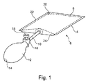
図1に示されているエアクッション部材6は、EP0771385号を通じて、当業者の技術水準に属する。
The
図1には、エアクッション部材6は、好ましくは、容易に曲げ可能であり、しかし実質的に非伸縮性であるべきであり、好ましくは形状が装甲プラスチック箔である、長い、または、長い伸張された材料の矩形の片8を折り返し、縁部4を溶接することによって作られるのがよいことが示されている。折り返された材料を内側に折り返す前に、縁部24に、吸気弁14を含む膨らましボール12への接続部を確立するための突出した曲げ可能なスタッドまたはホース10を含む伸展棒が締結される。作動のためのノブ18を備えたエア抜き弁16が、ボール12への接続部確立手段中に、または、ホール12自体に直接設けられる。平坦水準化溶接縁部22の隅部に、穴20が設けられるのがよい。
In FIG. 1, the
スタッドまたはホース10は、随意には、ボール12が、エアクッション部材から下方に向かうように配置されるように、24の縁部と角度を成しながら突出してもよい。
The stud or
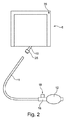
図2には、ホース迅速係止結合要素26が取り付けられたスタッド10を含むエアクッション部材6が示されている。ボール12および弁16と共に、長いホース11が設けられている。任務により、ホースは、省略されてもよい。
FIG. 2 shows an
図3には、弁16と関連して、ホース迅速係止結合要素28が設けられている実施形態が示されている。かくして、ホース11は、任務により省略されてもよい弛み要素として設けられている。
FIG. 3 shows an embodiment in which a hose quick-
図4には、緩いホースが、弁16に取り付けられているホース迅速係止結合要素28によって取り付けられるのがよい、或いは、随意iには、弁16に取り付けられたホースが使用されてもよい実施形態が示されている。ホース11とエアクッション部材6上のホース迅速係止結合要素26の間には、ホース迅速係止結合要素26に結合されるのがよい緩い逆止弁30が設けられている。
In FIG. 4, the loose hose may be attached by a hose quick-
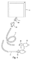
図5には、ポンプに接続されるのがよいより多くのエアクッション部材6が、示されている。マニホルドは、2:1マニホルド、3:1マニホルド、または、4:1マニホルドとして実施されるのがよい。図面には、3:1マニホルド、および、2:1マニホルドが示されている。
FIG. 5 shows more
マニホルド32は、ホース迅速係止結合要素を備えるのがよい出力スタッド34を備えている。マニホルドは、ホース11に連結するためのホース連結スタッド36を含み、ホース連結スタッド36は、ボール12、或いは、フットポンプ38、或いは、電動エアポンプに連結されるのがよい。
The manifold 32 includes an
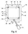
図6には、フレーム構造のためのモジュール要素42が示されている。モジュール要素42は、固定されたフレーム側部44を備え、フレーム側部44によって、突出部46および凹部48が、隣接するモジュール要素42が互いに装着されて単一のフレームを形成するように設けられている。フレームの内側に、エアクッション部材6が存在する。フランジの各隅部には、縁溶接部によって、開口部20が設けられている。開口部20は、フレームモジュール42に固定的に取り付けられているピン手段50と協働する。このようにして、エアクッション部材6は、フレームモジュール42に固定される。開口部20は、円形または長円形であるのがよい。長円形開口部は、構造が弾力的に反応することができる能力を提供する。
FIG. 6 shows a
図7には、2つの隣接したモジュールが突出部46および凹部48によって互いに結合されて、示されている。かくして、フレームモジュールは、複数の開放キャビティ52を含む「格子」を提供することができる。エアクッション部材6は、開放キャビティ52の内側に位置決めされる。
In FIG. 7, two adjacent modules are shown joined together by a
示されている実施形態では、エアクッション部材6は、各隅部で固定的に配置される。代替的には、この固定は、フレームモジュールの隅部の1つまたは2つでのみ提供されてもよい。
In the embodiment shown, the
フレームモジュール42は、開放種類の平らな構造を呈する。エアクッション部材6は、ポンピングすることによって膨らまされ、かくして、平らなフレームに関して見て両側に突出するようになる。
The
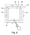
図8には、これまた固定されたフレームを形成することが予定されたフレームモジュールが示されている。フレームは、フレームの上側および下側で可撓性の薄い材料54によって閉じられている。エアクッション部材は、フレーム側部44の間で開放キャビティ50内に「緩く」位置決めされるのがよい。
FIG. 8 shows a frame module that is also intended to form a fixed frame. The frame is closed by flexible
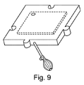
図10には、これまた固定されたフレームを形成することが予定されたフレームモジュールが示されている。固定されたフレームは、底部56を備え、エアクッション部材6は、底部56上に載置している。かくして、エアクッション部材6は、図10に示されているように、所定位置に緩く配置されることができる。代替的には、エアクッション部材は、エアクッション部材6の隅部に設けられた穴と協働するピン手段50によって固定されるのがよい。
FIG. 10 shows a frame module that is also intended to form a fixed frame. The fixed frame includes a
図10および図11に示されているフレームモジュールは、直前に上記のように、所望の数のエアクッションが1つの平面上にある固定されたフレームを形成するように互いに結合されるのがよい。 The frame modules shown in FIGS. 10 and 11 may be coupled together so as to form a fixed frame in which the desired number of air cushions are on a single plane, just as described above. .
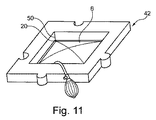
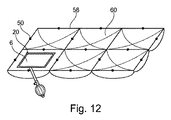
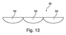
図12および図13には、フレーム58に、エアクッション部材6を受け入れるための複数の側方に位置決めされたくぼみ60が形成されている実施形態が示されている。クッション部材6は、フレーム58内に緩く位置決めされるのがよく、或いは、開口部20がピン手段50と協働する所定位置に固定されるのがよい。
12 and 13 illustrate an embodiment in which the
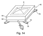
図14には、フレームモジュール58の別の実施形態が示されている。フレームモジュールは、底部分62および覆い部分64からなる。覆い部分64は、底部分62の上方で入れ子状に下向きに変位されることができる。エアクッション部材6が、このように形成されたボックスの内側に配置されており、ポンピングされると、底部分と覆い部分は、互いに遠ざかるように変位されるようになる。
In FIG. 14, another embodiment of the
頂部分の材料は、剛性であっても、或いは、可撓性であってもよい。エアクッション部材6は、形成されたボックスの内側の所定位置に緩く配置されるのがよい。
The top portion material may be rigid or flexible. The
図15には、フレームモジュール42の更に別の実施形態が示されている。この実施形態には、底部分66および頂部分68が設けられている。これらの部分は、エアクッション部材6を膨らませたときに、回動運動を行うことができるように、ヒンジ70によって互いに結合されている。
FIG. 15 shows still another embodiment of the
フレームモジュール42は、開口部74を含むタングまたはフラップ72を備える。この構成によって、複数のフレームモジュールが、ピン部材を開口部74を通して配置することによって互いに連結されることができ、それによって、側方に隣接したフレームモジュールを互いに結合することができる。
The
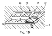
図16および図17には、より多くのキャビティ52を提供し、それによって、これらのキャビティの各々が、エアクッション部材6(図16にのみ示されている)を受け入れるのに役立つ固定されたフレームが示されている。
16 and 17 provide
エアクッション部材6は、エアクッション部材6に設けられた開口部と、フレーム76に連結されたピン部材50との協働によって隅部の1つまたはそれ以上で配置される。
The
図16には、上向きおよび下向きに開放したフレームであるフレームが示されている。図17には、上向きにのみ開放したキャビティ52を備えるフレームが示されており、キャビティ52内には、底部材78が設けられている。
FIG. 16 shows a frame which is a frame opened upward and downward. FIG. 17 shows a frame having a
両実施形態では、フレームは、膨らまされたエアクッションがフレームの上方に突出すうように平らに形成される。エアクッション部材6が非膨らまし状態にあるとき、エアクッション部材6は、フレームの高さ80が、補助ツールが挿入されることができる間の空間またはスロットのために決定的になるように、フレーム内の所定位置に保持されることができる。
In both embodiments, the frame is formed flat so that the inflated air cushion protrudes above the frame. When the
高さ80は、膨らまされていないエアクッション部材6も高さに略一致するように適合されるのがよい。
The
フレーム76は、剛性材料でも、或いは、可撓性の材料でも作られてよい。
The
図18には、より多くのキャビティ52を備え、それによって、これらのキャビティ52の各々がエアクッション部材6を収容するのに役立つフレーム76が示されている。キャビティ52の各々は、個々に移動可能な覆い部材82によって覆われており、個々に移動可能な覆い部材82は、ヒンジ84によって、フレーム76の底部分86に連結されている。エアクッション部材6の個々のポンピングにより、覆い部材82は、個々に上向きに移動される。フレーム76内で、エアクッション部材6は、緩い仕方で構成されているのがよい。
FIG. 18 shows a
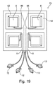
図19には、各々がエアクッション部材6を備える4つのキャビティ52を含むフレームを備える本発明による補助ツールが示されている。フレームは、頂部および底部が、開放されているか、或いは閉じられているものとして実施されることができる。ここでは、フレームは、可撓性材料によって、若しくは、移動可能な覆い部材によって閉じられたものとして、或いは、底部材のみを備え、かくして、反対側に向かって開放されたものとして実施されるのがよい。
FIG. 19 shows an auxiliary tool according to the present invention comprising a frame comprising four
フレーム76は、内部に複数の管86が設けられたくぼみを備え、管86の各々は、前方がエアクッション部材6に接続されるように繋がっており、適切に適合された種類のボール部材12を含む。このようにして、フレーム76内のエアクッション部材6にポンピングする能力を備えるようになる。
The
どのポンピングを付与するボール部材12がフレーム76内のどのキャビティに属するかを指示するために、例えば色によって、マーキングを提供することができる。
A marking can be provided, for example by color, to indicate which cavity in which the
4つのキャビティを備えるものとして示されているけれども、別の数のキャビティを使用することができる。 Although shown as having four cavities, other numbers of cavities can be used.
図20には、複数のエアクッション縁溶接部4内に設けられた開口部20を含む本発明による補助ツールが示されている。開口部20は、各隅部に備えられている。それによって、ピン部材88または同様な連結手段によって、隣接したエアクッション部材6を互いに結合することができるようになる。
FIG. 20 shows an auxiliary tool according to the present
かくして、ピン部材88は、縁溶接部4内に設けられた開口部20を通した把持により隣接したエアクッション部材に代えて直接の固定を提供する。
Thus, the
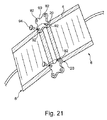
図21には、エアクッション部材6が取付具(fittings)90によって取り付けられる更に別の実施形態が示されている。これらの取付具90は、開口部92を含む各隅部内で実質的に矩形形状を有する。
FIG. 21 shows still another embodiment in which the
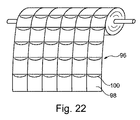
図22には、各々がエアクッション部材6を内部に挿入することができる開口部100を備える複数のポケット98を備える組織96が示されている。
FIG. 22 shows a
組織96は、かくして、例えば例として合計で6個のポケット98が達成される図23に示されているような適当な形状のパターンを提供するように切断することができる。エアクッション部材6のうち、これらのうちの4個だけのポケット98内への位置決めが、図23に示されている。他方で、切り取られた組織内に構成された各ポケット内にエアクッション部材6を配置することもできる。
組織96は、図示されているポケット98に関して見てポケットが反対側に位置することを意味する3層構造として製造することができる。
The
組織は、エアクッション部材をポンピングするときにポケットの膨張が可能になることを達成するようにポケットを形成するための伸縮性の材料に連結された一方の側で非伸縮性材料で作られているのがよい。 The tissue is made of a non-stretch material on one side connected to a stretch material to form the pocket to achieve that the pocket can be expanded when pumping the air cushion member It is good to be.
図24には、エアクッション部材6を受け入れるための開口部50を提供するフレームモジュール42を備える実施形態が示されている。フレームモジュール42は、それらの外側にジッパ102が設けられおり、ジッパ102は、複数のフレームモジュールを互いに結合し、それによって、所望の数のエアクッション部材6を備えることができる完全なフレーム構造を提供する。
FIG. 24 shows an embodiment comprising a
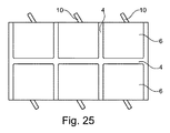
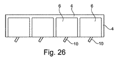
図25および図26には、エアクッション部材がそれらの縁溶接部4を介して連結された更に別の実施形態が示されている。これは、原則的に、エアクッション部材が縁溶接部4を介して互いに連結され、選択的に膨らませることができる複数のチャンバを備える一貫したツールを提供する補助ツールを提供する。 25 and 26 show still another embodiment in which the air cushion members are connected via their edge welds 4. This in principle provides an auxiliary tool that provides a consistent tool with a plurality of chambers in which the air cushion members are connected to each other via edge welds 4 and can be selectively inflated.
図27には、丸い形状のフレーム側方部分102を形成するフレーム側方部分が設けられているフレームモジュール4が示されている。
FIG. 27 shows the frame module 4 provided with a frame side portion that forms a round
図29には、六角形状のフレーム側方部分104を形成するフレーム側方部分が設けられているフレームモジュールが示されている。
FIG. 29 shows a frame module in which a frame side portion forming a hexagonal
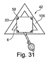
図31には、三角形状のフレーム側方部分106を形成するフレーム側方分が設けられているフレームモジュールが示されている。
FIG. 31 shows a frame module provided with frame side portions forming a triangular
全ての示された実施形態では、開口部20とピン部材50とが協働するように、エアクッション部材6がフレームモジュール42内に取り付けられる。図示されている実施形態では、互いの結合は、エアクッション部材の4つの隅部の各々で提供される。
In all the illustrated embodiments, the
原則的に、図28、図30、および、図32には、それぞれ、図27、図29、および、図31に示されているフレームモジュールによって提供される補助ツールの基本的な構造が示されている。 In principle, FIGS. 28, 30 and 32 show the basic structure of the auxiliary tools provided by the frame modules shown in FIGS. 27, 29 and 31, respectively. ing.
フレームモジュール42の相互の固定は、任意の適当な接合手段によって提供されることができる。ここではまた、突出部または凹部を使用することができる。代替的には、フレームモジュールの表面に、貫通ピン部材を受け入れるための開口部が設けられるのがよい。他の適用な接合手段を使用することもできる。
The mutual fixation of the
図示されている全ての実施形態では、エアクッション部材は、矩形本体の形状で示されている。他方で、エアクッション部材の他の実施も可能である。 In all the illustrated embodiments, the air cushion member is shown in the form of a rectangular body. On the other hand, other implementations of the air cushion member are possible.
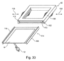
図33には、フレーム部分108が設けられたフレームモジュール42の更に別の実施形態が示されており、フレーム部分108内には、2つの隣接した側方フレーム部分に設けられたトラック112を含む側方フレーム部材に開口部110が設けられている。更に、2つのレール部材116を含む挿入可能なユニット114が設けられており、2つのレール部材116は、エアクッション部材6上に設けられたフランジ上の所定位置に着座されて圧搾されている。レール部材116は、かくして、トラック112内に挿入/スライドされることができる。フレーム側方部分は、エアクッション部材6がポンピングされるときに、矢印118が示す運動によって示されているように、可撓性であるように反応する。
FIG. 33 shows yet another embodiment of a
4 縁溶接部
6 エアクッション部材
10 スタッド
11 ホース
12 膨らましボール
16 エア抜き弁
20 開口部
42 フレームモジュール
44 フレーム側部
46 突出部
48 凹部
50 ピン部材
4 Edge welded
Claims (11)
Priority Applications (1)
| Application Number | Priority Date | Filing Date | Title |
|---|---|---|---|
| JP2021172969A JP7280932B2 (en) | 2014-08-08 | 2021-10-22 | Auxiliary mounting tools for positioning elements with respect to adjacent flats or planes |
Applications Claiming Priority (3)
| Application Number | Priority Date | Filing Date | Title |
|---|---|---|---|
| DKPA201470478 | 2014-08-08 | ||
| DK201470478A DK178296B1 (en) | 2014-08-08 | 2014-08-08 | Auxiliary tool for use in positioning elements in relation to an adjacent surface |
| PCT/DK2015/050231 WO2016019965A1 (en) | 2014-08-08 | 2015-08-06 | Auxiliary mounting tool for the positioning of elements in relation to an adjacent flat or plane |
Related Child Applications (1)
| Application Number | Title | Priority Date | Filing Date |
|---|---|---|---|
| JP2021172969A Division JP7280932B2 (en) | 2014-08-08 | 2021-10-22 | Auxiliary mounting tools for positioning elements with respect to adjacent flats or planes |
Publications (2)
| Publication Number | Publication Date |
|---|---|
| JP2017528629A true JP2017528629A (en) | 2017-09-28 |
| JP2017528629A5 JP2017528629A5 (en) | 2020-01-23 |
Family
ID=54397681
Family Applications (2)
| Application Number | Title | Priority Date | Filing Date |
|---|---|---|---|
| JP2017526744A Ceased JP2017528629A (en) | 2014-08-08 | 2015-08-06 | Auxiliary mounting tool for positioning elements with respect to adjacent flats or planes |
| JP2021172969A Active JP7280932B2 (en) | 2014-08-08 | 2021-10-22 | Auxiliary mounting tools for positioning elements with respect to adjacent flats or planes |
Family Applications After (1)
| Application Number | Title | Priority Date | Filing Date |
|---|---|---|---|
| JP2021172969A Active JP7280932B2 (en) | 2014-08-08 | 2021-10-22 | Auxiliary mounting tools for positioning elements with respect to adjacent flats or planes |
Country Status (11)
| Country | Link |
|---|---|
| US (1) | US10934144B2 (en) |
| EP (1) | EP3177785B1 (en) |
| JP (2) | JP2017528629A (en) |
| KR (1) | KR102393684B1 (en) |
| CN (1) | CN106574464A (en) |
| AU (1) | AU2015299441B2 (en) |
| CA (2) | CA2957152C (en) |
| DK (2) | DK178296B1 (en) |
| ES (1) | ES2835796T3 (en) |
| TW (2) | TWI755330B (en) |
| WO (1) | WO2016019965A1 (en) |
Families Citing this family (9)
| Publication number | Priority date | Publication date | Assignee | Title |
|---|---|---|---|---|
| EP3206985B1 (en) * | 2014-10-13 | 2021-12-22 | Dissing A/S | Device for positioning an element relatively to a surface, method for operating such device, and assembly kit |
| DK180626B1 (en) * | 2016-11-11 | 2021-11-04 | Dissing As | A device for positioning an object relatively to a support by inflatable air cushion members, a method of operating the device, and a method for moving an object |
| US10889477B2 (en) * | 2017-04-12 | 2021-01-12 | Xtreme Air Wedge, LLC | Inflatable air wedge with tool channel and associated method |
| US11814273B2 (en) * | 2019-05-09 | 2023-11-14 | Dissing A/S | Device for positioning an object relatively to a support by an inflatable air cushion member in combination with a support block |
| CN110301731A (en) * | 2019-06-06 | 2019-10-08 | 江苏腾魄休闲用品有限公司 | A kind of removable umbrella shank |
| DE202019004148U1 (en) * | 2019-10-09 | 2021-01-13 | Ernstfried Prade | Split airflow device |
| CN111236582A (en) * | 2020-03-20 | 2020-06-05 | 中国十七冶集团有限公司 | Leveling air bag for mounting door and window frame |
| CN112593809A (en) * | 2020-12-14 | 2021-04-02 | 上海云兰建筑装饰工程有限公司 | Door and window installation method |
| CN113929028A (en) * | 2021-10-13 | 2022-01-14 | 上海名未航空科技有限公司 | Intelligent working vehicle for assembling airplane wings |
Citations (7)
| Publication number | Priority date | Publication date | Assignee | Title |
|---|---|---|---|---|
| US4697290A (en) * | 1984-03-07 | 1987-10-06 | Regionala Stiftelsen I Varmland Med Firma Erress | Device comprising a mattress support |
| JPH0355383A (en) * | 1989-07-22 | 1991-03-11 | Yoshida Kogyo Kk <Ykk> | Jig and device for positioning of sash |
| WO1995013448A1 (en) * | 1993-11-10 | 1995-05-18 | Mogens Laurits Jensen | A method and an accessory for mounting building frames such as window frames in mounting openings |
| JP3026155U (en) * | 1995-12-14 | 1996-07-02 | 株式会社モルテン | Air jack device |
| JPH105289A (en) * | 1996-06-19 | 1998-01-13 | Keepu:Kk | Air mat |
| JPH10157988A (en) * | 1996-11-29 | 1998-06-16 | Hitachi Zosen Corp | Jack device for disaster rescue |
| WO1999015741A1 (en) * | 1997-09-22 | 1999-04-01 | Bernd Ludwig | Device for positioning an object |
Family Cites Families (23)
| Publication number | Priority date | Publication date | Assignee | Title |
|---|---|---|---|---|
| DE2113056A1 (en) * | 1971-03-18 | 1972-09-28 | Doreen Webster | Soil covers - of lightweight panels comprising (expanded) cores in PVC or fabric covers |
| GB1604141A (en) | 1978-01-05 | 1981-12-02 | Modern Precision Engs & Associ | Air cushion lifting device |
| AU5045979A (en) * | 1978-08-30 | 1980-03-06 | Leslie Josiah Buck | Air bearing for palletised or palletless load |
| DE3022936A1 (en) * | 1980-06-19 | 1981-12-24 | Hilti AG, 9494 Schaan | Door or window cast alignment and support - involves inflatable tubes inserted between case and soffit |
| WO1985002648A1 (en) * | 1983-12-08 | 1985-06-20 | Bernd Ludwig | Method and device for aligning an element such as a frame to be inserted for example into a wall opening |
| US5142720A (en) * | 1991-07-22 | 1992-09-01 | Kansas Creative Device, Inc. | Positioning device and method |
| ATE261536T1 (en) | 1997-05-20 | 2004-03-15 | Claus Hornstrup Dissing | DEVICE FOR EMERGENCY OPENING OF VEHICLE DOORS |
| DE29800344U1 (en) * | 1998-01-12 | 1998-05-07 | Fix Gerd | Device for fixing built-in elements in openings of components |
| CH696065A5 (en) | 2002-06-25 | 2006-12-15 | Prospective Concepts Ag | Fluidic clamping and lifting device. |
| CZ12812U1 (en) * | 2002-10-03 | 2002-11-25 | Ziad Ing. Al-Khazraji | Filler element for filling at least a portion of a wall cutout |
| US20040217338A1 (en) * | 2003-04-30 | 2004-11-04 | Abrahamson Guy A. | Device and method for leveling recreational vehicles |
| CA2479521C (en) * | 2004-09-23 | 2006-12-05 | Craig L. Lobson | Modular dock floats |
| US7918167B2 (en) | 2005-05-20 | 2011-04-05 | The Boeing Company | Extremely rapid reversible barrier and formation method |
| DE602006017242D1 (en) * | 2005-10-25 | 2010-11-11 | Maxgrepp Teknik Ab | WEDGE LUGGAGE |
| DE102005056489B4 (en) * | 2005-11-21 | 2010-10-14 | Gollwitzer, Karl | Method for installing a building closure element |
| CN201106358Y (en) | 2007-09-30 | 2008-08-27 | 陈伯朝 | Component for locating aluminum alloy door-window and wall |
| WO2011017589A1 (en) | 2009-08-06 | 2011-02-10 | Gray Tek Llc | Low pressure fluidized horizontal and vertical movement device |
| CN201826443U (en) | 2010-09-03 | 2011-05-11 | 余小哲 | Splicing type polyurethane roofing heat insulation plate |
| US9332735B2 (en) * | 2012-05-07 | 2016-05-10 | Advanced Comfort Technology, Inc. | Animal bed having dual independent support chambers |
| DK177510B1 (en) * | 2012-05-16 | 2013-08-19 | L B D Byg V Lars Birch Dueholm | System for use when installing and installing doors |
| US9725937B2 (en) * | 2013-06-19 | 2017-08-08 | Kids Ii, Inc. | Mattress structure and hinge mechanism |
| CN203562152U (en) | 2013-10-25 | 2014-04-23 | 刘延平 | Hanging and splicing device for display screens |
| CN204169480U (en) | 2014-10-25 | 2015-02-25 | 张志维 | A kind of splicing mattress be convenient for carrying |
-
2014
- 2014-08-08 DK DK201470478A patent/DK178296B1/en active
-
2015
- 2015-08-06 DK DK15829046.0T patent/DK3177785T3/en active
- 2015-08-06 CA CA2957152A patent/CA2957152C/en active Active
- 2015-08-06 ES ES15829046T patent/ES2835796T3/en active Active
- 2015-08-06 CN CN201580042658.1A patent/CN106574464A/en active Pending
- 2015-08-06 EP EP15829046.0A patent/EP3177785B1/en active Active
- 2015-08-06 AU AU2015299441A patent/AU2015299441B2/en active Active
- 2015-08-06 US US15/109,153 patent/US10934144B2/en active Active
- 2015-08-06 WO PCT/DK2015/050231 patent/WO2016019965A1/en active Application Filing
- 2015-08-06 KR KR1020177005894A patent/KR102393684B1/en active IP Right Grant
- 2015-08-06 CA CA3156914A patent/CA3156914C/en active Active
- 2015-08-06 JP JP2017526744A patent/JP2017528629A/en not_active Ceased
- 2015-08-10 TW TW110119285A patent/TWI755330B/en active
- 2015-08-10 TW TW104126051A patent/TWI748932B/en active
-
2021
- 2021-10-22 JP JP2021172969A patent/JP7280932B2/en active Active
Patent Citations (7)
| Publication number | Priority date | Publication date | Assignee | Title |
|---|---|---|---|---|
| US4697290A (en) * | 1984-03-07 | 1987-10-06 | Regionala Stiftelsen I Varmland Med Firma Erress | Device comprising a mattress support |
| JPH0355383A (en) * | 1989-07-22 | 1991-03-11 | Yoshida Kogyo Kk <Ykk> | Jig and device for positioning of sash |
| WO1995013448A1 (en) * | 1993-11-10 | 1995-05-18 | Mogens Laurits Jensen | A method and an accessory for mounting building frames such as window frames in mounting openings |
| JP3026155U (en) * | 1995-12-14 | 1996-07-02 | 株式会社モルテン | Air jack device |
| JPH105289A (en) * | 1996-06-19 | 1998-01-13 | Keepu:Kk | Air mat |
| JPH10157988A (en) * | 1996-11-29 | 1998-06-16 | Hitachi Zosen Corp | Jack device for disaster rescue |
| WO1999015741A1 (en) * | 1997-09-22 | 1999-04-01 | Bernd Ludwig | Device for positioning an object |
Also Published As
| Publication number | Publication date |
|---|---|
| CA2957152C (en) | 2022-07-12 |
| EP3177785A4 (en) | 2018-05-23 |
| JP2022023902A (en) | 2022-02-08 |
| DK178296B1 (en) | 2015-11-09 |
| CA2957152A1 (en) | 2016-02-11 |
| KR102393684B1 (en) | 2022-05-02 |
| EP3177785A1 (en) | 2017-06-14 |
| WO2016019965A1 (en) | 2016-02-11 |
| TWI748932B (en) | 2021-12-11 |
| TW202136625A (en) | 2021-10-01 |
| DK3177785T3 (en) | 2020-11-02 |
| US20160325971A1 (en) | 2016-11-10 |
| ES2835796T3 (en) | 2021-06-23 |
| JP7280932B2 (en) | 2023-05-24 |
| KR20170041234A (en) | 2017-04-14 |
| AU2015299441A1 (en) | 2017-02-23 |
| EP3177785B1 (en) | 2020-07-29 |
| US10934144B2 (en) | 2021-03-02 |
| CN106574464A (en) | 2017-04-19 |
| TW201629306A (en) | 2016-08-16 |
| TWI755330B (en) | 2022-02-11 |
| AU2015299441B2 (en) | 2020-05-07 |
| CA3156914C (en) | 2024-04-16 |
| CA3156914A1 (en) | 2016-02-11 |
Similar Documents
| Publication | Publication Date | Title |
|---|---|---|
| JP7280932B2 (en) | Auxiliary mounting tools for positioning elements with respect to adjacent flats or planes | |
| US11045012B2 (en) | Inflatable airbed mattress internal support system | |
| JP2017528629A5 (en) | ||
| BR112015021361B1 (en) | BLOOD PRESSURE MEASUREMENT CANDLE, AND, METHOD TO MANUFACTURE THE BLOOD PRESSURE MEASUREMENT CANDLE | |
| ITBO20100131A1 (en) | SUPPORT FOR SOLAR PANELS | |
| US20180008064A1 (en) | Foam cushion cover | |
| EP0771385A1 (en) | A method and an accessory for mounting building frames such as window frames in mounting openings | |
| US6102228A (en) | Device for connecting multiple isocontainers | |
| JP2017172312A (en) | Simple toilet house | |
| JP2005030046A (en) | Soundproof/dustproof structure | |
| CN217065855U (en) | Air bag unit for mattress and air bag mattress | |
| US11547621B2 (en) | Cover assembly | |
| EP3231331B1 (en) | Systems for internal airbed structure | |
| US20200323356A1 (en) | Mattress interior, mattress and method of manufacuturing a mattress | |
| JP2023066354A (en) | portable partition |
Legal Events
| Date | Code | Title | Description |
|---|---|---|---|
| A621 | Written request for application examination |
Free format text: JAPANESE INTERMEDIATE CODE: A621 Effective date: 20180802 |
|
| A131 | Notification of reasons for refusal |
Free format text: JAPANESE INTERMEDIATE CODE: A131 Effective date: 20190701 |
|
| A977 | Report on retrieval |
Free format text: JAPANESE INTERMEDIATE CODE: A971007 Effective date: 20190628 |
|
| A601 | Written request for extension of time |
Free format text: JAPANESE INTERMEDIATE CODE: A601 Effective date: 20191001 |
|
| A524 | Written submission of copy of amendment under article 19 pct |
Free format text: JAPANESE INTERMEDIATE CODE: A524 Effective date: 20191202 |
|
| A131 | Notification of reasons for refusal |
Free format text: JAPANESE INTERMEDIATE CODE: A131 Effective date: 20200525 |
|
| A601 | Written request for extension of time |
Free format text: JAPANESE INTERMEDIATE CODE: A601 Effective date: 20200824 |
|
| A601 | Written request for extension of time |
Free format text: JAPANESE INTERMEDIATE CODE: A601 Effective date: 20200825 |
|
| A521 | Request for written amendment filed |
Free format text: JAPANESE INTERMEDIATE CODE: A523 Effective date: 20201125 |
|
| A131 | Notification of reasons for refusal |
Free format text: JAPANESE INTERMEDIATE CODE: A131 Effective date: 20210422 |
|
| A601 | Written request for extension of time |
Free format text: JAPANESE INTERMEDIATE CODE: A601 Effective date: 20210713 |
|
| A521 | Request for written amendment filed |
Free format text: JAPANESE INTERMEDIATE CODE: A523 Effective date: 20211022 |
|
| A01 | Written decision to grant a patent or to grant a registration (utility model) |
Free format text: JAPANESE INTERMEDIATE CODE: A01 Effective date: 20211101 |
|
| A045 | Written measure of dismissal of application [lapsed due to lack of payment] |
Free format text: JAPANESE INTERMEDIATE CODE: A045 Effective date: 20220328 |