JP2017526831A - Method for making a nonwoven material having a discontinuous three-dimensional deformation with a wide base opening bonded to an additional layer - Google Patents
Method for making a nonwoven material having a discontinuous three-dimensional deformation with a wide base opening bonded to an additional layer Download PDFInfo
- Publication number
- JP2017526831A JP2017526831A JP2017513436A JP2017513436A JP2017526831A JP 2017526831 A JP2017526831 A JP 2017526831A JP 2017513436 A JP2017513436 A JP 2017513436A JP 2017513436 A JP2017513436 A JP 2017513436A JP 2017526831 A JP2017526831 A JP 2017526831A
- Authority
- JP
- Japan
- Prior art keywords
- web
- protrusion
- roll
- nonwoven
- layer
- Prior art date
- Legal status (The legal status is an assumption and is not a legal conclusion. Google has not performed a legal analysis and makes no representation as to the accuracy of the status listed.)
- Pending
Links
Images


Classifications
-
- B—PERFORMING OPERATIONS; TRANSPORTING
- B32—LAYERED PRODUCTS
- B32B—LAYERED PRODUCTS, i.e. PRODUCTS BUILT-UP OF STRATA OF FLAT OR NON-FLAT, e.g. CELLULAR OR HONEYCOMB, FORM
- B32B38/00—Ancillary operations in connection with laminating processes
- B32B38/04—Punching, slitting or perforating
-
- A—HUMAN NECESSITIES
- A61—MEDICAL OR VETERINARY SCIENCE; HYGIENE
- A61F—FILTERS IMPLANTABLE INTO BLOOD VESSELS; PROSTHESES; DEVICES PROVIDING PATENCY TO, OR PREVENTING COLLAPSING OF, TUBULAR STRUCTURES OF THE BODY, e.g. STENTS; ORTHOPAEDIC, NURSING OR CONTRACEPTIVE DEVICES; FOMENTATION; TREATMENT OR PROTECTION OF EYES OR EARS; BANDAGES, DRESSINGS OR ABSORBENT PADS; FIRST-AID KITS
- A61F13/00—Bandages or dressings; Absorbent pads
- A61F13/15—Absorbent pads, e.g. sanitary towels, swabs or tampons for external or internal application to the body; Supporting or fastening means therefor; Tampon applicators
- A61F13/15577—Apparatus or processes for manufacturing
- A61F13/15699—Forming webs by bringing together several webs, e.g. by laminating or folding several webs, with or without additional treatment of the webs
-
- A—HUMAN NECESSITIES
- A61—MEDICAL OR VETERINARY SCIENCE; HYGIENE
- A61F—FILTERS IMPLANTABLE INTO BLOOD VESSELS; PROSTHESES; DEVICES PROVIDING PATENCY TO, OR PREVENTING COLLAPSING OF, TUBULAR STRUCTURES OF THE BODY, e.g. STENTS; ORTHOPAEDIC, NURSING OR CONTRACEPTIVE DEVICES; FOMENTATION; TREATMENT OR PROTECTION OF EYES OR EARS; BANDAGES, DRESSINGS OR ABSORBENT PADS; FIRST-AID KITS
- A61F13/00—Bandages or dressings; Absorbent pads
- A61F13/15—Absorbent pads, e.g. sanitary towels, swabs or tampons for external or internal application to the body; Supporting or fastening means therefor; Tampon applicators
- A61F13/51—Absorbent pads, e.g. sanitary towels, swabs or tampons for external or internal application to the body; Supporting or fastening means therefor; Tampon applicators characterised by the outer layers
- A61F13/511—Topsheet, i.e. the permeable cover or layer facing the skin
- A61F13/51104—Topsheet, i.e. the permeable cover or layer facing the skin the top sheet having a three-dimensional cross-section, e.g. corrugations, embossments, recesses or projections
- A61F13/51108—Topsheet, i.e. the permeable cover or layer facing the skin the top sheet having a three-dimensional cross-section, e.g. corrugations, embossments, recesses or projections the top sheet having corrugations or embossments having one axis relatively longer than the other axis, e.g. forming channels or grooves in a longitudinal direction
-
- A—HUMAN NECESSITIES
- A61—MEDICAL OR VETERINARY SCIENCE; HYGIENE
- A61F—FILTERS IMPLANTABLE INTO BLOOD VESSELS; PROSTHESES; DEVICES PROVIDING PATENCY TO, OR PREVENTING COLLAPSING OF, TUBULAR STRUCTURES OF THE BODY, e.g. STENTS; ORTHOPAEDIC, NURSING OR CONTRACEPTIVE DEVICES; FOMENTATION; TREATMENT OR PROTECTION OF EYES OR EARS; BANDAGES, DRESSINGS OR ABSORBENT PADS; FIRST-AID KITS
- A61F13/00—Bandages or dressings; Absorbent pads
- A61F13/15—Absorbent pads, e.g. sanitary towels, swabs or tampons for external or internal application to the body; Supporting or fastening means therefor; Tampon applicators
- A61F13/51—Absorbent pads, e.g. sanitary towels, swabs or tampons for external or internal application to the body; Supporting or fastening means therefor; Tampon applicators characterised by the outer layers
- A61F13/511—Topsheet, i.e. the permeable cover or layer facing the skin
- A61F13/51121—Topsheet, i.e. the permeable cover or layer facing the skin characterised by the material
-
- A—HUMAN NECESSITIES
- A61—MEDICAL OR VETERINARY SCIENCE; HYGIENE
- A61F—FILTERS IMPLANTABLE INTO BLOOD VESSELS; PROSTHESES; DEVICES PROVIDING PATENCY TO, OR PREVENTING COLLAPSING OF, TUBULAR STRUCTURES OF THE BODY, e.g. STENTS; ORTHOPAEDIC, NURSING OR CONTRACEPTIVE DEVICES; FOMENTATION; TREATMENT OR PROTECTION OF EYES OR EARS; BANDAGES, DRESSINGS OR ABSORBENT PADS; FIRST-AID KITS
- A61F13/00—Bandages or dressings; Absorbent pads
- A61F13/15—Absorbent pads, e.g. sanitary towels, swabs or tampons for external or internal application to the body; Supporting or fastening means therefor; Tampon applicators
- A61F13/51—Absorbent pads, e.g. sanitary towels, swabs or tampons for external or internal application to the body; Supporting or fastening means therefor; Tampon applicators characterised by the outer layers
- A61F13/511—Topsheet, i.e. the permeable cover or layer facing the skin
- A61F13/5116—Topsheet, i.e. the permeable cover or layer facing the skin being formed of multiple layers
-
- A—HUMAN NECESSITIES
- A61—MEDICAL OR VETERINARY SCIENCE; HYGIENE
- A61F—FILTERS IMPLANTABLE INTO BLOOD VESSELS; PROSTHESES; DEVICES PROVIDING PATENCY TO, OR PREVENTING COLLAPSING OF, TUBULAR STRUCTURES OF THE BODY, e.g. STENTS; ORTHOPAEDIC, NURSING OR CONTRACEPTIVE DEVICES; FOMENTATION; TREATMENT OR PROTECTION OF EYES OR EARS; BANDAGES, DRESSINGS OR ABSORBENT PADS; FIRST-AID KITS
- A61F13/00—Bandages or dressings; Absorbent pads
- A61F13/15—Absorbent pads, e.g. sanitary towels, swabs or tampons for external or internal application to the body; Supporting or fastening means therefor; Tampon applicators
- A61F13/51—Absorbent pads, e.g. sanitary towels, swabs or tampons for external or internal application to the body; Supporting or fastening means therefor; Tampon applicators characterised by the outer layers
- A61F13/511—Topsheet, i.e. the permeable cover or layer facing the skin
- A61F13/512—Topsheet, i.e. the permeable cover or layer facing the skin characterised by its apertures, e.g. perforations
-
- A—HUMAN NECESSITIES
- A61—MEDICAL OR VETERINARY SCIENCE; HYGIENE
- A61F—FILTERS IMPLANTABLE INTO BLOOD VESSELS; PROSTHESES; DEVICES PROVIDING PATENCY TO, OR PREVENTING COLLAPSING OF, TUBULAR STRUCTURES OF THE BODY, e.g. STENTS; ORTHOPAEDIC, NURSING OR CONTRACEPTIVE DEVICES; FOMENTATION; TREATMENT OR PROTECTION OF EYES OR EARS; BANDAGES, DRESSINGS OR ABSORBENT PADS; FIRST-AID KITS
- A61F13/00—Bandages or dressings; Absorbent pads
- A61F13/15—Absorbent pads, e.g. sanitary towels, swabs or tampons for external or internal application to the body; Supporting or fastening means therefor; Tampon applicators
- A61F13/51—Absorbent pads, e.g. sanitary towels, swabs or tampons for external or internal application to the body; Supporting or fastening means therefor; Tampon applicators characterised by the outer layers
- A61F13/511—Topsheet, i.e. the permeable cover or layer facing the skin
- A61F13/513—Topsheet, i.e. the permeable cover or layer facing the skin characterised by its function or properties, e.g. stretchability, breathability, rewet, visual effect; having areas of different permeability
- A61F13/51394—Topsheet, i.e. the permeable cover or layer facing the skin characterised by its function or properties, e.g. stretchability, breathability, rewet, visual effect; having areas of different permeability creating a visual effect, e.g. having a printed or coloured topsheet, printed or coloured sub-layer but being visible from the topsheet, other than embossing for purposes of bonding, wicking, acquisition, leakage-prevention
-
- B—PERFORMING OPERATIONS; TRANSPORTING
- B29—WORKING OF PLASTICS; WORKING OF SUBSTANCES IN A PLASTIC STATE IN GENERAL
- B29C—SHAPING OR JOINING OF PLASTICS; SHAPING OF MATERIAL IN A PLASTIC STATE, NOT OTHERWISE PROVIDED FOR; AFTER-TREATMENT OF THE SHAPED PRODUCTS, e.g. REPAIRING
- B29C65/00—Joining or sealing of preformed parts, e.g. welding of plastics materials; Apparatus therefor
- B29C65/56—Joining or sealing of preformed parts, e.g. welding of plastics materials; Apparatus therefor using mechanical means or mechanical connections, e.g. form-fits
-
- B—PERFORMING OPERATIONS; TRANSPORTING
- B29—WORKING OF PLASTICS; WORKING OF SUBSTANCES IN A PLASTIC STATE IN GENERAL
- B29C—SHAPING OR JOINING OF PLASTICS; SHAPING OF MATERIAL IN A PLASTIC STATE, NOT OTHERWISE PROVIDED FOR; AFTER-TREATMENT OF THE SHAPED PRODUCTS, e.g. REPAIRING
- B29C66/00—General aspects of processes or apparatus for joining preformed parts
- B29C66/01—General aspects dealing with the joint area or with the area to be joined
- B29C66/05—Particular design of joint configurations
- B29C66/10—Particular design of joint configurations particular design of the joint cross-sections
- B29C66/11—Joint cross-sections comprising a single joint-segment, i.e. one of the parts to be joined comprising a single joint-segment in the joint cross-section
- B29C66/112—Single lapped joints
- B29C66/1122—Single lap to lap joints, i.e. overlap joints
-
- B—PERFORMING OPERATIONS; TRANSPORTING
- B29—WORKING OF PLASTICS; WORKING OF SUBSTANCES IN A PLASTIC STATE IN GENERAL
- B29C—SHAPING OR JOINING OF PLASTICS; SHAPING OF MATERIAL IN A PLASTIC STATE, NOT OTHERWISE PROVIDED FOR; AFTER-TREATMENT OF THE SHAPED PRODUCTS, e.g. REPAIRING
- B29C66/00—General aspects of processes or apparatus for joining preformed parts
- B29C66/01—General aspects dealing with the joint area or with the area to be joined
- B29C66/05—Particular design of joint configurations
- B29C66/20—Particular design of joint configurations particular design of the joint lines, e.g. of the weld lines
- B29C66/21—Particular design of joint configurations particular design of the joint lines, e.g. of the weld lines said joint lines being formed by a single dot or dash or by several dots or dashes, i.e. spot joining or spot welding
-
- B—PERFORMING OPERATIONS; TRANSPORTING
- B29—WORKING OF PLASTICS; WORKING OF SUBSTANCES IN A PLASTIC STATE IN GENERAL
- B29C—SHAPING OR JOINING OF PLASTICS; SHAPING OF MATERIAL IN A PLASTIC STATE, NOT OTHERWISE PROVIDED FOR; AFTER-TREATMENT OF THE SHAPED PRODUCTS, e.g. REPAIRING
- B29C66/00—General aspects of processes or apparatus for joining preformed parts
- B29C66/40—General aspects of joining substantially flat articles, e.g. plates, sheets or web-like materials; Making flat seams in tubular or hollow articles; Joining single elements to substantially flat surfaces
- B29C66/41—Joining substantially flat articles ; Making flat seams in tubular or hollow articles
- B29C66/43—Joining a relatively small portion of the surface of said articles
- B29C66/438—Joining sheets for making hollow-walled, channelled structures or multi-tubular articles
-
- B—PERFORMING OPERATIONS; TRANSPORTING
- B29—WORKING OF PLASTICS; WORKING OF SUBSTANCES IN A PLASTIC STATE IN GENERAL
- B29C—SHAPING OR JOINING OF PLASTICS; SHAPING OF MATERIAL IN A PLASTIC STATE, NOT OTHERWISE PROVIDED FOR; AFTER-TREATMENT OF THE SHAPED PRODUCTS, e.g. REPAIRING
- B29C66/00—General aspects of processes or apparatus for joining preformed parts
- B29C66/40—General aspects of joining substantially flat articles, e.g. plates, sheets or web-like materials; Making flat seams in tubular or hollow articles; Joining single elements to substantially flat surfaces
- B29C66/41—Joining substantially flat articles ; Making flat seams in tubular or hollow articles
- B29C66/45—Joining of substantially the whole surface of the articles
-
- B—PERFORMING OPERATIONS; TRANSPORTING
- B29—WORKING OF PLASTICS; WORKING OF SUBSTANCES IN A PLASTIC STATE IN GENERAL
- B29C—SHAPING OR JOINING OF PLASTICS; SHAPING OF MATERIAL IN A PLASTIC STATE, NOT OTHERWISE PROVIDED FOR; AFTER-TREATMENT OF THE SHAPED PRODUCTS, e.g. REPAIRING
- B29C66/00—General aspects of processes or apparatus for joining preformed parts
- B29C66/70—General aspects of processes or apparatus for joining preformed parts characterised by the composition, physical properties or the structure of the material of the parts to be joined; Joining with non-plastics material
- B29C66/72—General aspects of processes or apparatus for joining preformed parts characterised by the composition, physical properties or the structure of the material of the parts to be joined; Joining with non-plastics material characterised by the structure of the material of the parts to be joined
- B29C66/723—General aspects of processes or apparatus for joining preformed parts characterised by the composition, physical properties or the structure of the material of the parts to be joined; Joining with non-plastics material characterised by the structure of the material of the parts to be joined being multi-layered
-
- B—PERFORMING OPERATIONS; TRANSPORTING
- B29—WORKING OF PLASTICS; WORKING OF SUBSTANCES IN A PLASTIC STATE IN GENERAL
- B29C—SHAPING OR JOINING OF PLASTICS; SHAPING OF MATERIAL IN A PLASTIC STATE, NOT OTHERWISE PROVIDED FOR; AFTER-TREATMENT OF THE SHAPED PRODUCTS, e.g. REPAIRING
- B29C66/00—General aspects of processes or apparatus for joining preformed parts
- B29C66/70—General aspects of processes or apparatus for joining preformed parts characterised by the composition, physical properties or the structure of the material of the parts to be joined; Joining with non-plastics material
- B29C66/72—General aspects of processes or apparatus for joining preformed parts characterised by the composition, physical properties or the structure of the material of the parts to be joined; Joining with non-plastics material characterised by the structure of the material of the parts to be joined
- B29C66/729—Textile or other fibrous material made from plastics
- B29C66/7294—Non woven mats, e.g. felt
-
- B—PERFORMING OPERATIONS; TRANSPORTING
- B29—WORKING OF PLASTICS; WORKING OF SUBSTANCES IN A PLASTIC STATE IN GENERAL
- B29C—SHAPING OR JOINING OF PLASTICS; SHAPING OF MATERIAL IN A PLASTIC STATE, NOT OTHERWISE PROVIDED FOR; AFTER-TREATMENT OF THE SHAPED PRODUCTS, e.g. REPAIRING
- B29C66/00—General aspects of processes or apparatus for joining preformed parts
- B29C66/70—General aspects of processes or apparatus for joining preformed parts characterised by the composition, physical properties or the structure of the material of the parts to be joined; Joining with non-plastics material
- B29C66/73—General aspects of processes or apparatus for joining preformed parts characterised by the composition, physical properties or the structure of the material of the parts to be joined; Joining with non-plastics material characterised by the intensive physical properties of the material of the parts to be joined, by the optical properties of the material of the parts to be joined, by the extensive physical properties of the parts to be joined, by the state of the material of the parts to be joined or by the material of the parts to be joined being a thermoplastic or a thermoset
- B29C66/739—General aspects of processes or apparatus for joining preformed parts characterised by the composition, physical properties or the structure of the material of the parts to be joined; Joining with non-plastics material characterised by the intensive physical properties of the material of the parts to be joined, by the optical properties of the material of the parts to be joined, by the extensive physical properties of the parts to be joined, by the state of the material of the parts to be joined or by the material of the parts to be joined being a thermoplastic or a thermoset characterised by the material of the parts to be joined being a thermoplastic or a thermoset
- B29C66/7392—General aspects of processes or apparatus for joining preformed parts characterised by the composition, physical properties or the structure of the material of the parts to be joined; Joining with non-plastics material characterised by the intensive physical properties of the material of the parts to be joined, by the optical properties of the material of the parts to be joined, by the extensive physical properties of the parts to be joined, by the state of the material of the parts to be joined or by the material of the parts to be joined being a thermoplastic or a thermoset characterised by the material of the parts to be joined being a thermoplastic or a thermoset characterised by the material of at least one of the parts being a thermoplastic
- B29C66/73921—General aspects of processes or apparatus for joining preformed parts characterised by the composition, physical properties or the structure of the material of the parts to be joined; Joining with non-plastics material characterised by the intensive physical properties of the material of the parts to be joined, by the optical properties of the material of the parts to be joined, by the extensive physical properties of the parts to be joined, by the state of the material of the parts to be joined or by the material of the parts to be joined being a thermoplastic or a thermoset characterised by the material of the parts to be joined being a thermoplastic or a thermoset characterised by the material of at least one of the parts being a thermoplastic characterised by the materials of both parts being thermoplastics
-
- B—PERFORMING OPERATIONS; TRANSPORTING
- B29—WORKING OF PLASTICS; WORKING OF SUBSTANCES IN A PLASTIC STATE IN GENERAL
- B29C—SHAPING OR JOINING OF PLASTICS; SHAPING OF MATERIAL IN A PLASTIC STATE, NOT OTHERWISE PROVIDED FOR; AFTER-TREATMENT OF THE SHAPED PRODUCTS, e.g. REPAIRING
- B29C66/00—General aspects of processes or apparatus for joining preformed parts
- B29C66/80—General aspects of machine operations or constructions and parts thereof
- B29C66/81—General aspects of the pressing elements, i.e. the elements applying pressure on the parts to be joined in the area to be joined, e.g. the welding jaws or clamps
- B29C66/814—General aspects of the pressing elements, i.e. the elements applying pressure on the parts to be joined in the area to be joined, e.g. the welding jaws or clamps characterised by the design of the pressing elements, e.g. of the welding jaws or clamps
- B29C66/8141—General aspects of the pressing elements, i.e. the elements applying pressure on the parts to be joined in the area to be joined, e.g. the welding jaws or clamps characterised by the design of the pressing elements, e.g. of the welding jaws or clamps characterised by the surface geometry of the part of the pressing elements, e.g. welding jaws or clamps, coming into contact with the parts to be joined
- B29C66/81433—General aspects of the pressing elements, i.e. the elements applying pressure on the parts to be joined in the area to be joined, e.g. the welding jaws or clamps characterised by the design of the pressing elements, e.g. of the welding jaws or clamps characterised by the surface geometry of the part of the pressing elements, e.g. welding jaws or clamps, coming into contact with the parts to be joined being toothed, i.e. comprising several teeth or pins, or being patterned
-
- B—PERFORMING OPERATIONS; TRANSPORTING
- B29—WORKING OF PLASTICS; WORKING OF SUBSTANCES IN A PLASTIC STATE IN GENERAL
- B29C—SHAPING OR JOINING OF PLASTICS; SHAPING OF MATERIAL IN A PLASTIC STATE, NOT OTHERWISE PROVIDED FOR; AFTER-TREATMENT OF THE SHAPED PRODUCTS, e.g. REPAIRING
- B29C66/00—General aspects of processes or apparatus for joining preformed parts
- B29C66/80—General aspects of machine operations or constructions and parts thereof
- B29C66/83—General aspects of machine operations or constructions and parts thereof characterised by the movement of the joining or pressing tools
- B29C66/834—General aspects of machine operations or constructions and parts thereof characterised by the movement of the joining or pressing tools moving with the parts to be joined
- B29C66/8341—Roller, cylinder or drum types; Band or belt types; Ball types
- B29C66/83411—Roller, cylinder or drum types
- B29C66/83413—Roller, cylinder or drum types cooperating rollers, cylinders or drums
-
- B—PERFORMING OPERATIONS; TRANSPORTING
- B32—LAYERED PRODUCTS
- B32B—LAYERED PRODUCTS, i.e. PRODUCTS BUILT-UP OF STRATA OF FLAT OR NON-FLAT, e.g. CELLULAR OR HONEYCOMB, FORM
- B32B3/00—Layered products comprising a layer with external or internal discontinuities or unevennesses, or a layer of non-planar form; Layered products having particular features of form
- B32B3/26—Layered products comprising a layer with external or internal discontinuities or unevennesses, or a layer of non-planar form; Layered products having particular features of form characterised by a particular shape of the outline of the cross-section of a continuous layer; characterised by a layer with cavities or internal voids ; characterised by an apertured layer
- B32B3/28—Layered products comprising a layer with external or internal discontinuities or unevennesses, or a layer of non-planar form; Layered products having particular features of form characterised by a particular shape of the outline of the cross-section of a continuous layer; characterised by a layer with cavities or internal voids ; characterised by an apertured layer characterised by a layer comprising a deformed thin sheet, i.e. the layer having its entire thickness deformed out of the plane, e.g. corrugated, crumpled
-
- B—PERFORMING OPERATIONS; TRANSPORTING
- B32—LAYERED PRODUCTS
- B32B—LAYERED PRODUCTS, i.e. PRODUCTS BUILT-UP OF STRATA OF FLAT OR NON-FLAT, e.g. CELLULAR OR HONEYCOMB, FORM
- B32B3/00—Layered products comprising a layer with external or internal discontinuities or unevennesses, or a layer of non-planar form; Layered products having particular features of form
- B32B3/26—Layered products comprising a layer with external or internal discontinuities or unevennesses, or a layer of non-planar form; Layered products having particular features of form characterised by a particular shape of the outline of the cross-section of a continuous layer; characterised by a layer with cavities or internal voids ; characterised by an apertured layer
- B32B3/30—Layered products comprising a layer with external or internal discontinuities or unevennesses, or a layer of non-planar form; Layered products having particular features of form characterised by a particular shape of the outline of the cross-section of a continuous layer; characterised by a layer with cavities or internal voids ; characterised by an apertured layer characterised by a layer formed with recesses or projections, e.g. hollows, grooves, protuberances, ribs
-
- B—PERFORMING OPERATIONS; TRANSPORTING
- B32—LAYERED PRODUCTS
- B32B—LAYERED PRODUCTS, i.e. PRODUCTS BUILT-UP OF STRATA OF FLAT OR NON-FLAT, e.g. CELLULAR OR HONEYCOMB, FORM
- B32B38/00—Ancillary operations in connection with laminating processes
- B32B38/06—Embossing
-
- B—PERFORMING OPERATIONS; TRANSPORTING
- B32—LAYERED PRODUCTS
- B32B—LAYERED PRODUCTS, i.e. PRODUCTS BUILT-UP OF STRATA OF FLAT OR NON-FLAT, e.g. CELLULAR OR HONEYCOMB, FORM
- B32B5/00—Layered products characterised by the non- homogeneity or physical structure, i.e. comprising a fibrous, filamentary, particulate or foam layer; Layered products characterised by having a layer differing constitutionally or physically in different parts
- B32B5/02—Layered products characterised by the non- homogeneity or physical structure, i.e. comprising a fibrous, filamentary, particulate or foam layer; Layered products characterised by having a layer differing constitutionally or physically in different parts characterised by structural features of a fibrous or filamentary layer
- B32B5/022—Non-woven fabric
-
- B—PERFORMING OPERATIONS; TRANSPORTING
- B32—LAYERED PRODUCTS
- B32B—LAYERED PRODUCTS, i.e. PRODUCTS BUILT-UP OF STRATA OF FLAT OR NON-FLAT, e.g. CELLULAR OR HONEYCOMB, FORM
- B32B5/00—Layered products characterised by the non- homogeneity or physical structure, i.e. comprising a fibrous, filamentary, particulate or foam layer; Layered products characterised by having a layer differing constitutionally or physically in different parts
- B32B5/02—Layered products characterised by the non- homogeneity or physical structure, i.e. comprising a fibrous, filamentary, particulate or foam layer; Layered products characterised by having a layer differing constitutionally or physically in different parts characterised by structural features of a fibrous or filamentary layer
- B32B5/06—Layered products characterised by the non- homogeneity or physical structure, i.e. comprising a fibrous, filamentary, particulate or foam layer; Layered products characterised by having a layer differing constitutionally or physically in different parts characterised by structural features of a fibrous or filamentary layer characterised by a fibrous or filamentary layer mechanically connected, e.g. by needling to another layer, e.g. of fibres, of paper
-
- B—PERFORMING OPERATIONS; TRANSPORTING
- B32—LAYERED PRODUCTS
- B32B—LAYERED PRODUCTS, i.e. PRODUCTS BUILT-UP OF STRATA OF FLAT OR NON-FLAT, e.g. CELLULAR OR HONEYCOMB, FORM
- B32B5/00—Layered products characterised by the non- homogeneity or physical structure, i.e. comprising a fibrous, filamentary, particulate or foam layer; Layered products characterised by having a layer differing constitutionally or physically in different parts
- B32B5/02—Layered products characterised by the non- homogeneity or physical structure, i.e. comprising a fibrous, filamentary, particulate or foam layer; Layered products characterised by having a layer differing constitutionally or physically in different parts characterised by structural features of a fibrous or filamentary layer
- B32B5/08—Layered products characterised by the non- homogeneity or physical structure, i.e. comprising a fibrous, filamentary, particulate or foam layer; Layered products characterised by having a layer differing constitutionally or physically in different parts characterised by structural features of a fibrous or filamentary layer the fibres or filaments of a layer being of different substances, e.g. conjugate fibres, mixture of different fibres
-
- B—PERFORMING OPERATIONS; TRANSPORTING
- B32—LAYERED PRODUCTS
- B32B—LAYERED PRODUCTS, i.e. PRODUCTS BUILT-UP OF STRATA OF FLAT OR NON-FLAT, e.g. CELLULAR OR HONEYCOMB, FORM
- B32B5/00—Layered products characterised by the non- homogeneity or physical structure, i.e. comprising a fibrous, filamentary, particulate or foam layer; Layered products characterised by having a layer differing constitutionally or physically in different parts
- B32B5/14—Layered products characterised by the non- homogeneity or physical structure, i.e. comprising a fibrous, filamentary, particulate or foam layer; Layered products characterised by having a layer differing constitutionally or physically in different parts characterised by a layer differing constitutionally or physically in different parts, e.g. denser near its faces
- B32B5/142—Variation across the area of the layer
-
- B—PERFORMING OPERATIONS; TRANSPORTING
- B32—LAYERED PRODUCTS
- B32B—LAYERED PRODUCTS, i.e. PRODUCTS BUILT-UP OF STRATA OF FLAT OR NON-FLAT, e.g. CELLULAR OR HONEYCOMB, FORM
- B32B5/00—Layered products characterised by the non- homogeneity or physical structure, i.e. comprising a fibrous, filamentary, particulate or foam layer; Layered products characterised by having a layer differing constitutionally or physically in different parts
- B32B5/22—Layered products characterised by the non- homogeneity or physical structure, i.e. comprising a fibrous, filamentary, particulate or foam layer; Layered products characterised by having a layer differing constitutionally or physically in different parts characterised by the presence of two or more layers which are next to each other and are fibrous, filamentary, formed of particles or foamed
- B32B5/24—Layered products characterised by the non- homogeneity or physical structure, i.e. comprising a fibrous, filamentary, particulate or foam layer; Layered products characterised by having a layer differing constitutionally or physically in different parts characterised by the presence of two or more layers which are next to each other and are fibrous, filamentary, formed of particles or foamed one layer being a fibrous or filamentary layer
- B32B5/26—Layered products characterised by the non- homogeneity or physical structure, i.e. comprising a fibrous, filamentary, particulate or foam layer; Layered products characterised by having a layer differing constitutionally or physically in different parts characterised by the presence of two or more layers which are next to each other and are fibrous, filamentary, formed of particles or foamed one layer being a fibrous or filamentary layer another layer next to it also being fibrous or filamentary
-
- B—PERFORMING OPERATIONS; TRANSPORTING
- B32—LAYERED PRODUCTS
- B32B—LAYERED PRODUCTS, i.e. PRODUCTS BUILT-UP OF STRATA OF FLAT OR NON-FLAT, e.g. CELLULAR OR HONEYCOMB, FORM
- B32B7/00—Layered products characterised by the relation between layers; Layered products characterised by the relative orientation of features between layers, or by the relative values of a measurable parameter between layers, i.e. products comprising layers having different physical, chemical or physicochemical properties; Layered products characterised by the interconnection of layers
- B32B7/04—Interconnection of layers
- B32B7/05—Interconnection of layers the layers not being connected over the whole surface, e.g. discontinuous connection or patterned connection
-
- D—TEXTILES; PAPER
- D04—BRAIDING; LACE-MAKING; KNITTING; TRIMMINGS; NON-WOVEN FABRICS
- D04H—MAKING TEXTILE FABRICS, e.g. FROM FIBRES OR FILAMENTARY MATERIAL; FABRICS MADE BY SUCH PROCESSES OR APPARATUS, e.g. FELTS, NON-WOVEN FABRICS; COTTON-WOOL; WADDING ; NON-WOVEN FABRICS FROM STAPLE FIBRES, FILAMENTS OR YARNS, BONDED WITH AT LEAST ONE WEB-LIKE MATERIAL DURING THEIR CONSOLIDATION
- D04H1/00—Non-woven fabrics formed wholly or mainly of staple fibres or like relatively short fibres
- D04H1/40—Non-woven fabrics formed wholly or mainly of staple fibres or like relatively short fibres from fleeces or layers composed of fibres without existing or potential cohesive properties
- D04H1/44—Non-woven fabrics formed wholly or mainly of staple fibres or like relatively short fibres from fleeces or layers composed of fibres without existing or potential cohesive properties the fleeces or layers being consolidated by mechanical means, e.g. by rolling
- D04H1/45—Non-woven fabrics formed wholly or mainly of staple fibres or like relatively short fibres from fleeces or layers composed of fibres without existing or potential cohesive properties the fleeces or layers being consolidated by mechanical means, e.g. by rolling by forming intermeshing loops or stitches from some of the fibres
-
- D—TEXTILES; PAPER
- D04—BRAIDING; LACE-MAKING; KNITTING; TRIMMINGS; NON-WOVEN FABRICS
- D04H—MAKING TEXTILE FABRICS, e.g. FROM FIBRES OR FILAMENTARY MATERIAL; FABRICS MADE BY SUCH PROCESSES OR APPARATUS, e.g. FELTS, NON-WOVEN FABRICS; COTTON-WOOL; WADDING ; NON-WOVEN FABRICS FROM STAPLE FIBRES, FILAMENTS OR YARNS, BONDED WITH AT LEAST ONE WEB-LIKE MATERIAL DURING THEIR CONSOLIDATION
- D04H1/00—Non-woven fabrics formed wholly or mainly of staple fibres or like relatively short fibres
- D04H1/40—Non-woven fabrics formed wholly or mainly of staple fibres or like relatively short fibres from fleeces or layers composed of fibres without existing or potential cohesive properties
- D04H1/44—Non-woven fabrics formed wholly or mainly of staple fibres or like relatively short fibres from fleeces or layers composed of fibres without existing or potential cohesive properties the fleeces or layers being consolidated by mechanical means, e.g. by rolling
- D04H1/46—Non-woven fabrics formed wholly or mainly of staple fibres or like relatively short fibres from fleeces or layers composed of fibres without existing or potential cohesive properties the fleeces or layers being consolidated by mechanical means, e.g. by rolling by needling or like operations to cause entanglement of fibres
- D04H1/492—Non-woven fabrics formed wholly or mainly of staple fibres or like relatively short fibres from fleeces or layers composed of fibres without existing or potential cohesive properties the fleeces or layers being consolidated by mechanical means, e.g. by rolling by needling or like operations to cause entanglement of fibres by fluid jet
-
- D—TEXTILES; PAPER
- D04—BRAIDING; LACE-MAKING; KNITTING; TRIMMINGS; NON-WOVEN FABRICS
- D04H—MAKING TEXTILE FABRICS, e.g. FROM FIBRES OR FILAMENTARY MATERIAL; FABRICS MADE BY SUCH PROCESSES OR APPARATUS, e.g. FELTS, NON-WOVEN FABRICS; COTTON-WOOL; WADDING ; NON-WOVEN FABRICS FROM STAPLE FIBRES, FILAMENTS OR YARNS, BONDED WITH AT LEAST ONE WEB-LIKE MATERIAL DURING THEIR CONSOLIDATION
- D04H1/00—Non-woven fabrics formed wholly or mainly of staple fibres or like relatively short fibres
- D04H1/40—Non-woven fabrics formed wholly or mainly of staple fibres or like relatively short fibres from fleeces or layers composed of fibres without existing or potential cohesive properties
- D04H1/54—Non-woven fabrics formed wholly or mainly of staple fibres or like relatively short fibres from fleeces or layers composed of fibres without existing or potential cohesive properties by welding together the fibres, e.g. by partially melting or dissolving
- D04H1/558—Non-woven fabrics formed wholly or mainly of staple fibres or like relatively short fibres from fleeces or layers composed of fibres without existing or potential cohesive properties by welding together the fibres, e.g. by partially melting or dissolving in combination with mechanical or physical treatments other than embossing
-
- D—TEXTILES; PAPER
- D04—BRAIDING; LACE-MAKING; KNITTING; TRIMMINGS; NON-WOVEN FABRICS
- D04H—MAKING TEXTILE FABRICS, e.g. FROM FIBRES OR FILAMENTARY MATERIAL; FABRICS MADE BY SUCH PROCESSES OR APPARATUS, e.g. FELTS, NON-WOVEN FABRICS; COTTON-WOOL; WADDING ; NON-WOVEN FABRICS FROM STAPLE FIBRES, FILAMENTS OR YARNS, BONDED WITH AT LEAST ONE WEB-LIKE MATERIAL DURING THEIR CONSOLIDATION
- D04H1/00—Non-woven fabrics formed wholly or mainly of staple fibres or like relatively short fibres
- D04H1/40—Non-woven fabrics formed wholly or mainly of staple fibres or like relatively short fibres from fleeces or layers composed of fibres without existing or potential cohesive properties
- D04H1/54—Non-woven fabrics formed wholly or mainly of staple fibres or like relatively short fibres from fleeces or layers composed of fibres without existing or potential cohesive properties by welding together the fibres, e.g. by partially melting or dissolving
- D04H1/559—Non-woven fabrics formed wholly or mainly of staple fibres or like relatively short fibres from fleeces or layers composed of fibres without existing or potential cohesive properties by welding together the fibres, e.g. by partially melting or dissolving the fibres being within layered webs
-
- D—TEXTILES; PAPER
- D04—BRAIDING; LACE-MAKING; KNITTING; TRIMMINGS; NON-WOVEN FABRICS
- D04H—MAKING TEXTILE FABRICS, e.g. FROM FIBRES OR FILAMENTARY MATERIAL; FABRICS MADE BY SUCH PROCESSES OR APPARATUS, e.g. FELTS, NON-WOVEN FABRICS; COTTON-WOOL; WADDING ; NON-WOVEN FABRICS FROM STAPLE FIBRES, FILAMENTS OR YARNS, BONDED WITH AT LEAST ONE WEB-LIKE MATERIAL DURING THEIR CONSOLIDATION
- D04H1/00—Non-woven fabrics formed wholly or mainly of staple fibres or like relatively short fibres
- D04H1/70—Non-woven fabrics formed wholly or mainly of staple fibres or like relatively short fibres characterised by the method of forming fleeces or layers, e.g. reorientation of fibres
- D04H1/74—Non-woven fabrics formed wholly or mainly of staple fibres or like relatively short fibres characterised by the method of forming fleeces or layers, e.g. reorientation of fibres the fibres being orientated, e.g. in parallel (anisotropic fleeces)
-
- D—TEXTILES; PAPER
- D04—BRAIDING; LACE-MAKING; KNITTING; TRIMMINGS; NON-WOVEN FABRICS
- D04H—MAKING TEXTILE FABRICS, e.g. FROM FIBRES OR FILAMENTARY MATERIAL; FABRICS MADE BY SUCH PROCESSES OR APPARATUS, e.g. FELTS, NON-WOVEN FABRICS; COTTON-WOOL; WADDING ; NON-WOVEN FABRICS FROM STAPLE FIBRES, FILAMENTS OR YARNS, BONDED WITH AT LEAST ONE WEB-LIKE MATERIAL DURING THEIR CONSOLIDATION
- D04H13/00—Other non-woven fabrics
- D04H13/001—Making non-woven fabrics from staple fibres, filaments or yarns, bonded to at least one web-like material, e.g. woven, knitted non-woven fabric, paper, leather, during consolidation
-
- A—HUMAN NECESSITIES
- A61—MEDICAL OR VETERINARY SCIENCE; HYGIENE
- A61F—FILTERS IMPLANTABLE INTO BLOOD VESSELS; PROSTHESES; DEVICES PROVIDING PATENCY TO, OR PREVENTING COLLAPSING OF, TUBULAR STRUCTURES OF THE BODY, e.g. STENTS; ORTHOPAEDIC, NURSING OR CONTRACEPTIVE DEVICES; FOMENTATION; TREATMENT OR PROTECTION OF EYES OR EARS; BANDAGES, DRESSINGS OR ABSORBENT PADS; FIRST-AID KITS
- A61F13/00—Bandages or dressings; Absorbent pads
- A61F13/15—Absorbent pads, e.g. sanitary towels, swabs or tampons for external or internal application to the body; Supporting or fastening means therefor; Tampon applicators
- A61F13/51—Absorbent pads, e.g. sanitary towels, swabs or tampons for external or internal application to the body; Supporting or fastening means therefor; Tampon applicators characterised by the outer layers
- A61F2013/51002—Absorbent pads, e.g. sanitary towels, swabs or tampons for external or internal application to the body; Supporting or fastening means therefor; Tampon applicators characterised by the outer layers with special fibres
- A61F2013/51007—Absorbent pads, e.g. sanitary towels, swabs or tampons for external or internal application to the body; Supporting or fastening means therefor; Tampon applicators characterised by the outer layers with special fibres characterized by the orientation of fibres
-
- A—HUMAN NECESSITIES
- A61—MEDICAL OR VETERINARY SCIENCE; HYGIENE
- A61F—FILTERS IMPLANTABLE INTO BLOOD VESSELS; PROSTHESES; DEVICES PROVIDING PATENCY TO, OR PREVENTING COLLAPSING OF, TUBULAR STRUCTURES OF THE BODY, e.g. STENTS; ORTHOPAEDIC, NURSING OR CONTRACEPTIVE DEVICES; FOMENTATION; TREATMENT OR PROTECTION OF EYES OR EARS; BANDAGES, DRESSINGS OR ABSORBENT PADS; FIRST-AID KITS
- A61F13/00—Bandages or dressings; Absorbent pads
- A61F13/15—Absorbent pads, e.g. sanitary towels, swabs or tampons for external or internal application to the body; Supporting or fastening means therefor; Tampon applicators
- A61F13/51—Absorbent pads, e.g. sanitary towels, swabs or tampons for external or internal application to the body; Supporting or fastening means therefor; Tampon applicators characterised by the outer layers
- A61F2013/51002—Absorbent pads, e.g. sanitary towels, swabs or tampons for external or internal application to the body; Supporting or fastening means therefor; Tampon applicators characterised by the outer layers with special fibres
- A61F2013/51014—Absorbent pads, e.g. sanitary towels, swabs or tampons for external or internal application to the body; Supporting or fastening means therefor; Tampon applicators characterised by the outer layers with special fibres characterized by the connection between the fibres
-
- A—HUMAN NECESSITIES
- A61—MEDICAL OR VETERINARY SCIENCE; HYGIENE
- A61F—FILTERS IMPLANTABLE INTO BLOOD VESSELS; PROSTHESES; DEVICES PROVIDING PATENCY TO, OR PREVENTING COLLAPSING OF, TUBULAR STRUCTURES OF THE BODY, e.g. STENTS; ORTHOPAEDIC, NURSING OR CONTRACEPTIVE DEVICES; FOMENTATION; TREATMENT OR PROTECTION OF EYES OR EARS; BANDAGES, DRESSINGS OR ABSORBENT PADS; FIRST-AID KITS
- A61F13/00—Bandages or dressings; Absorbent pads
- A61F13/15—Absorbent pads, e.g. sanitary towels, swabs or tampons for external or internal application to the body; Supporting or fastening means therefor; Tampon applicators
- A61F13/51—Absorbent pads, e.g. sanitary towels, swabs or tampons for external or internal application to the body; Supporting or fastening means therefor; Tampon applicators characterised by the outer layers
- A61F13/511—Topsheet, i.e. the permeable cover or layer facing the skin
- A61F2013/51186—Topsheet, i.e. the permeable cover or layer facing the skin specially shaped topsheets
-
- B—PERFORMING OPERATIONS; TRANSPORTING
- B29—WORKING OF PLASTICS; WORKING OF SUBSTANCES IN A PLASTIC STATE IN GENERAL
- B29C—SHAPING OR JOINING OF PLASTICS; SHAPING OF MATERIAL IN A PLASTIC STATE, NOT OTHERWISE PROVIDED FOR; AFTER-TREATMENT OF THE SHAPED PRODUCTS, e.g. REPAIRING
- B29C43/00—Compression moulding, i.e. applying external pressure to flow the moulding material; Apparatus therefor
- B29C43/32—Component parts, details or accessories; Auxiliary operations
- B29C43/44—Compression means for making articles of indefinite length
- B29C43/46—Rollers
- B29C2043/461—Rollers the rollers having specific surface features
- B29C2043/463—Rollers the rollers having specific surface features corrugated, patterned or embossed surface
-
- B—PERFORMING OPERATIONS; TRANSPORTING
- B29—WORKING OF PLASTICS; WORKING OF SUBSTANCES IN A PLASTIC STATE IN GENERAL
- B29C—SHAPING OR JOINING OF PLASTICS; SHAPING OF MATERIAL IN A PLASTIC STATE, NOT OTHERWISE PROVIDED FOR; AFTER-TREATMENT OF THE SHAPED PRODUCTS, e.g. REPAIRING
- B29C59/00—Surface shaping of articles, e.g. embossing; Apparatus therefor
- B29C59/02—Surface shaping of articles, e.g. embossing; Apparatus therefor by mechanical means, e.g. pressing
- B29C59/022—Surface shaping of articles, e.g. embossing; Apparatus therefor by mechanical means, e.g. pressing characterised by the disposition or the configuration, e.g. dimensions, of the embossments or the shaping tools therefor
- B29C2059/023—Microembossing
-
- B—PERFORMING OPERATIONS; TRANSPORTING
- B29—WORKING OF PLASTICS; WORKING OF SUBSTANCES IN A PLASTIC STATE IN GENERAL
- B29C—SHAPING OR JOINING OF PLASTICS; SHAPING OF MATERIAL IN A PLASTIC STATE, NOT OTHERWISE PROVIDED FOR; AFTER-TREATMENT OF THE SHAPED PRODUCTS, e.g. REPAIRING
- B29C43/00—Compression moulding, i.e. applying external pressure to flow the moulding material; Apparatus therefor
- B29C43/32—Component parts, details or accessories; Auxiliary operations
- B29C43/44—Compression means for making articles of indefinite length
- B29C43/46—Rollers
-
- B—PERFORMING OPERATIONS; TRANSPORTING
- B29—WORKING OF PLASTICS; WORKING OF SUBSTANCES IN A PLASTIC STATE IN GENERAL
- B29C—SHAPING OR JOINING OF PLASTICS; SHAPING OF MATERIAL IN A PLASTIC STATE, NOT OTHERWISE PROVIDED FOR; AFTER-TREATMENT OF THE SHAPED PRODUCTS, e.g. REPAIRING
- B29C59/00—Surface shaping of articles, e.g. embossing; Apparatus therefor
- B29C59/02—Surface shaping of articles, e.g. embossing; Apparatus therefor by mechanical means, e.g. pressing
- B29C59/022—Surface shaping of articles, e.g. embossing; Apparatus therefor by mechanical means, e.g. pressing characterised by the disposition or the configuration, e.g. dimensions, of the embossments or the shaping tools therefor
-
- B—PERFORMING OPERATIONS; TRANSPORTING
- B29—WORKING OF PLASTICS; WORKING OF SUBSTANCES IN A PLASTIC STATE IN GENERAL
- B29C—SHAPING OR JOINING OF PLASTICS; SHAPING OF MATERIAL IN A PLASTIC STATE, NOT OTHERWISE PROVIDED FOR; AFTER-TREATMENT OF THE SHAPED PRODUCTS, e.g. REPAIRING
- B29C59/00—Surface shaping of articles, e.g. embossing; Apparatus therefor
- B29C59/02—Surface shaping of articles, e.g. embossing; Apparatus therefor by mechanical means, e.g. pressing
- B29C59/04—Surface shaping of articles, e.g. embossing; Apparatus therefor by mechanical means, e.g. pressing using rollers or endless belts
- B29C59/046—Surface shaping of articles, e.g. embossing; Apparatus therefor by mechanical means, e.g. pressing using rollers or endless belts for layered or coated substantially flat surfaces
-
- B—PERFORMING OPERATIONS; TRANSPORTING
- B29—WORKING OF PLASTICS; WORKING OF SUBSTANCES IN A PLASTIC STATE IN GENERAL
- B29C—SHAPING OR JOINING OF PLASTICS; SHAPING OF MATERIAL IN A PLASTIC STATE, NOT OTHERWISE PROVIDED FOR; AFTER-TREATMENT OF THE SHAPED PRODUCTS, e.g. REPAIRING
- B29C65/00—Joining or sealing of preformed parts, e.g. welding of plastics materials; Apparatus therefor
- B29C65/02—Joining or sealing of preformed parts, e.g. welding of plastics materials; Apparatus therefor by heating, with or without pressure
- B29C65/08—Joining or sealing of preformed parts, e.g. welding of plastics materials; Apparatus therefor by heating, with or without pressure using ultrasonic vibrations
-
- B—PERFORMING OPERATIONS; TRANSPORTING
- B29—WORKING OF PLASTICS; WORKING OF SUBSTANCES IN A PLASTIC STATE IN GENERAL
- B29C—SHAPING OR JOINING OF PLASTICS; SHAPING OF MATERIAL IN A PLASTIC STATE, NOT OTHERWISE PROVIDED FOR; AFTER-TREATMENT OF THE SHAPED PRODUCTS, e.g. REPAIRING
- B29C65/00—Joining or sealing of preformed parts, e.g. welding of plastics materials; Apparatus therefor
- B29C65/78—Means for handling the parts to be joined, e.g. for making containers or hollow articles, e.g. means for handling sheets, plates, web-like materials, tubular articles, hollow articles or elements to be joined therewith; Means for discharging the joined articles from the joining apparatus
- B29C65/7858—Means for handling the parts to be joined, e.g. for making containers or hollow articles, e.g. means for handling sheets, plates, web-like materials, tubular articles, hollow articles or elements to be joined therewith; Means for discharging the joined articles from the joining apparatus characterised by the feeding movement of the parts to be joined
- B29C65/7888—Means for handling of moving sheets or webs
- B29C65/7894—Means for handling of moving sheets or webs of continuously moving sheets or webs
-
- B—PERFORMING OPERATIONS; TRANSPORTING
- B29—WORKING OF PLASTICS; WORKING OF SUBSTANCES IN A PLASTIC STATE IN GENERAL
- B29L—INDEXING SCHEME ASSOCIATED WITH SUBCLASS B29C, RELATING TO PARTICULAR ARTICLES
- B29L2031/00—Other particular articles
- B29L2031/48—Wearing apparel
- B29L2031/4871—Underwear
- B29L2031/4878—Diapers, napkins
-
- B—PERFORMING OPERATIONS; TRANSPORTING
- B32—LAYERED PRODUCTS
- B32B—LAYERED PRODUCTS, i.e. PRODUCTS BUILT-UP OF STRATA OF FLAT OR NON-FLAT, e.g. CELLULAR OR HONEYCOMB, FORM
- B32B38/00—Ancillary operations in connection with laminating processes
- B32B38/04—Punching, slitting or perforating
- B32B2038/042—Punching
-
- B—PERFORMING OPERATIONS; TRANSPORTING
- B32—LAYERED PRODUCTS
- B32B—LAYERED PRODUCTS, i.e. PRODUCTS BUILT-UP OF STRATA OF FLAT OR NON-FLAT, e.g. CELLULAR OR HONEYCOMB, FORM
- B32B2250/00—Layers arrangement
- B32B2250/20—All layers being fibrous or filamentary
-
- B—PERFORMING OPERATIONS; TRANSPORTING
- B32—LAYERED PRODUCTS
- B32B—LAYERED PRODUCTS, i.e. PRODUCTS BUILT-UP OF STRATA OF FLAT OR NON-FLAT, e.g. CELLULAR OR HONEYCOMB, FORM
- B32B2262/00—Composition or structural features of fibres which form a fibrous or filamentary layer or are present as additives
- B32B2262/02—Synthetic macromolecular fibres
- B32B2262/0253—Polyolefin fibres
-
- B—PERFORMING OPERATIONS; TRANSPORTING
- B32—LAYERED PRODUCTS
- B32B—LAYERED PRODUCTS, i.e. PRODUCTS BUILT-UP OF STRATA OF FLAT OR NON-FLAT, e.g. CELLULAR OR HONEYCOMB, FORM
- B32B2262/00—Composition or structural features of fibres which form a fibrous or filamentary layer or are present as additives
- B32B2262/02—Synthetic macromolecular fibres
- B32B2262/0261—Polyamide fibres
-
- B—PERFORMING OPERATIONS; TRANSPORTING
- B32—LAYERED PRODUCTS
- B32B—LAYERED PRODUCTS, i.e. PRODUCTS BUILT-UP OF STRATA OF FLAT OR NON-FLAT, e.g. CELLULAR OR HONEYCOMB, FORM
- B32B2262/00—Composition or structural features of fibres which form a fibrous or filamentary layer or are present as additives
- B32B2262/02—Synthetic macromolecular fibres
- B32B2262/0276—Polyester fibres
-
- B—PERFORMING OPERATIONS; TRANSPORTING
- B32—LAYERED PRODUCTS
- B32B—LAYERED PRODUCTS, i.e. PRODUCTS BUILT-UP OF STRATA OF FLAT OR NON-FLAT, e.g. CELLULAR OR HONEYCOMB, FORM
- B32B2262/00—Composition or structural features of fibres which form a fibrous or filamentary layer or are present as additives
- B32B2262/04—Cellulosic plastic fibres, e.g. rayon
-
- B—PERFORMING OPERATIONS; TRANSPORTING
- B32—LAYERED PRODUCTS
- B32B—LAYERED PRODUCTS, i.e. PRODUCTS BUILT-UP OF STRATA OF FLAT OR NON-FLAT, e.g. CELLULAR OR HONEYCOMB, FORM
- B32B2262/00—Composition or structural features of fibres which form a fibrous or filamentary layer or are present as additives
- B32B2262/06—Vegetal fibres
- B32B2262/062—Cellulose fibres, e.g. cotton
-
- B—PERFORMING OPERATIONS; TRANSPORTING
- B32—LAYERED PRODUCTS
- B32B—LAYERED PRODUCTS, i.e. PRODUCTS BUILT-UP OF STRATA OF FLAT OR NON-FLAT, e.g. CELLULAR OR HONEYCOMB, FORM
- B32B2262/00—Composition or structural features of fibres which form a fibrous or filamentary layer or are present as additives
- B32B2262/08—Animal fibres, e.g. hair, wool, silk
-
- B—PERFORMING OPERATIONS; TRANSPORTING
- B32—LAYERED PRODUCTS
- B32B—LAYERED PRODUCTS, i.e. PRODUCTS BUILT-UP OF STRATA OF FLAT OR NON-FLAT, e.g. CELLULAR OR HONEYCOMB, FORM
- B32B2262/00—Composition or structural features of fibres which form a fibrous or filamentary layer or are present as additives
- B32B2262/12—Conjugate fibres, e.g. core/sheath or side-by-side
-
- B—PERFORMING OPERATIONS; TRANSPORTING
- B32—LAYERED PRODUCTS
- B32B—LAYERED PRODUCTS, i.e. PRODUCTS BUILT-UP OF STRATA OF FLAT OR NON-FLAT, e.g. CELLULAR OR HONEYCOMB, FORM
- B32B2262/00—Composition or structural features of fibres which form a fibrous or filamentary layer or are present as additives
- B32B2262/14—Mixture of at least two fibres made of different materials
-
- B—PERFORMING OPERATIONS; TRANSPORTING
- B32—LAYERED PRODUCTS
- B32B—LAYERED PRODUCTS, i.e. PRODUCTS BUILT-UP OF STRATA OF FLAT OR NON-FLAT, e.g. CELLULAR OR HONEYCOMB, FORM
- B32B2305/00—Condition, form or state of the layers or laminate
- B32B2305/10—Fibres of continuous length
- B32B2305/20—Fibres of continuous length in the form of a non-woven mat
-
- B—PERFORMING OPERATIONS; TRANSPORTING
- B32—LAYERED PRODUCTS
- B32B—LAYERED PRODUCTS, i.e. PRODUCTS BUILT-UP OF STRATA OF FLAT OR NON-FLAT, e.g. CELLULAR OR HONEYCOMB, FORM
- B32B2307/00—Properties of the layers or laminate
- B32B2307/70—Other properties
- B32B2307/726—Permeability to liquids, absorption
-
- B—PERFORMING OPERATIONS; TRANSPORTING
- B32—LAYERED PRODUCTS
- B32B—LAYERED PRODUCTS, i.e. PRODUCTS BUILT-UP OF STRATA OF FLAT OR NON-FLAT, e.g. CELLULAR OR HONEYCOMB, FORM
- B32B2432/00—Cleaning articles, e.g. mops, wipes
-
- B—PERFORMING OPERATIONS; TRANSPORTING
- B32—LAYERED PRODUCTS
- B32B—LAYERED PRODUCTS, i.e. PRODUCTS BUILT-UP OF STRATA OF FLAT OR NON-FLAT, e.g. CELLULAR OR HONEYCOMB, FORM
- B32B2555/00—Personal care
-
- B—PERFORMING OPERATIONS; TRANSPORTING
- B32—LAYERED PRODUCTS
- B32B—LAYERED PRODUCTS, i.e. PRODUCTS BUILT-UP OF STRATA OF FLAT OR NON-FLAT, e.g. CELLULAR OR HONEYCOMB, FORM
- B32B2555/00—Personal care
- B32B2555/02—Diapers or napkins
-
- D—TEXTILES; PAPER
- D10—INDEXING SCHEME ASSOCIATED WITH SUBLASSES OF SECTION D, RELATING TO TEXTILES
- D10B—INDEXING SCHEME ASSOCIATED WITH SUBLASSES OF SECTION D, RELATING TO TEXTILES
- D10B2403/00—Details of fabric structure established in the fabric forming process
- D10B2403/01—Surface features
- D10B2403/011—Dissimilar front and back faces
- D10B2403/0111—One hairy surface, e.g. napped or raised
-
- D—TEXTILES; PAPER
- D10—INDEXING SCHEME ASSOCIATED WITH SUBLASSES OF SECTION D, RELATING TO TEXTILES
- D10B—INDEXING SCHEME ASSOCIATED WITH SUBLASSES OF SECTION D, RELATING TO TEXTILES
- D10B2509/00—Medical; Hygiene
- D10B2509/02—Bandages, dressings or absorbent pads
Abstract
第1のシート及び第2のシートで作製される複合シートを形成する方法が開示される。第1及び第2のシートは、いくつかの離間された不連続なシート間接着場所において互いに対して接着される。本方法は、前駆体不織布ウェブを機械的に変形して、その中に変形部を有する第1のウェブを形成することを含む。変形部は、第1のウェブの第1の表面から外向きに伸びる突出部と、ウェブの他方の表面における開口部とを形成する。本方法は、その中に変形部を有する第1の不織布ウェブを接着ニップに供給することを含む、この接着ニップにおいて、変形部の外側の第1のウェブの第1の領域の一部が第2のウェブに接着されて、基部接着された複合ウェブを形成する。A method of forming a composite sheet made of a first sheet and a second sheet is disclosed. The first and second sheets are bonded to each other at a number of spaced apart discontinuous inter-sheet bonding locations. The method includes mechanically deforming a precursor nonwoven web to form a first web having a deformed portion therein. The deformable portion forms a protruding portion extending outward from the first surface of the first web and an opening on the other surface of the web. The method includes supplying a first nonwoven web having a deformation therein to the bonding nip, wherein a portion of the first region of the first web outside the deformation is a first. The two webs are bonded to form a base bonded composite web.
Description
本発明は、幅広の基部開口部を伴う不連続な三次元変形部を有する不織布材料、それを作製する方法、及びそのような不織布材料を含む物品を目的とする。 The present invention is directed to nonwoven materials having discontinuous three-dimensional deformations with wide base openings, methods of making the same, and articles containing such nonwoven materials.
吸収性物品において使用するための様々な材料が、特許文献に開示されている。そのような材料及びそれを作製するための方法について開示している特許公報としては:米国特許第4,323,068号、Aziz;同第5,518,801号、Chappellら;同第5,628,097号、Bensonら;同第5,804,021号、Abutoら;同第6,440,564(B1)号、McLainら;同第7,172,801号、Hoyingら;同第7,410,683号、Curroら;同第7,553,532号、Turnerら;同第7,648,752(B2)号、Hoyingら;同第7,682,686(B2)号、Curroら;同第8,241,543(B2)号、O’Donnellら;同第8,393,374(B2)号、Satoら;同第8,585,958(B2)号、Grayら;同第8,617,449(B2)号、Bakerら;米国特許出願公開第2006/0286343(A1)号;同第2010/0028621(A1)号;同第2010/0297377(A1)号;同第2012/0064298(A1)号;同第2013/0165883(A1)号;同第2014/0121621(A1)号;同第2014/0121623(A1)号;同第2014/0121624(A1)号;同第2014/0121625(A1)号;同第2014/0121626(A1)号;欧州特許第1774940(B1)号;同第1787611(B1)号;同第1982013(B1)号;PCT国際公開第2008/146594(A1)号;及び同第2014/084066(A1)号(Zuiko)が挙げられる。Kao MERRIES(商標)おむつ及びKimberly−Clark HUGGIES(登録商標)おむつは、テクスチャ加工トップシートが、加熱エンボス加工又は水流交絡を介して別のテクスチャ加工されていない層に接着されている、高級製品を有する。 Various materials for use in absorbent articles are disclosed in the patent literature. Patent publications disclosing such materials and methods for making them include: U.S. Pat. No. 4,323,068, Aziz; 5,518,801, Chappell et al .; No. 628,097, Benson et al .; No. 5,804,021, Abuto et al .; No. 6,440,564 (B1), McLain et al .; No. 7,172,801, Hoying et al .; , 410, 683, Curro et al .; 7,553,532, Turner et al .; 7,648,752 (B2), Hoying et al .; 7,682,686 (B2), Curro et al. 8,241,543 (B2), O'Donnell et al .; 8,393,374 (B2), Sato et al; 8,585,958 (B2), Gray No. 8,617,449 (B2), Baker et al .; US Patent Application Publication No. 2006/0286343 (A1); No. 2010/0028621 (A1); No. 2010/0297377 (A1); No. 2012/0064298 (A1); No. 2013/0165883 (A1); No. 2014/0121621 (A1); No. 2014/0121623 (A1); No. 2014/0121624 (A1); 2014/0121625 (A1); 2014/0121626 (A1); European Patent No. 1774940 (B1); 1778711 (B1); 1982013 (B1); PCT International Publication No. 2008/2008 146594 (A1); and 2014/0884066 (A1) (Zuiko) And the like. Kao MERRIES ™ diapers and Kimberly-Clark HUGGIES® diapers are high-end products in which a textured topsheet is bonded to another untextured layer via heat embossing or hydroentanglement. Have.
吸収性物品において使用するための改善された材料、及びそのような材料を作製する方法に対する必要性が存在する。ある特定の場合においては、見た目と手触りが柔らかく、改善された乾燥性を有する、改善された不織布材料又は不織布材料の積層体に対する必要性が存在する。特に、その中に三次元特徴部を形成して、改善された柔軟性及び乾燥性、並びに柔軟性及び乾燥性の視覚信号を提供する、改善された不織布材料に対する必要性が存在する。三次元特徴部は、材料の一方の側に窪みを形成し、反対側に突出部を形成し得る。一部の場合においては、そのような材料を、窪みが吸収性物品のトップシート上で見えるように、吸収性物品中に配置することが望ましくあり得る。そのような場合の一部においては、そのような窪みが良好に画定され、幅広の開口部を形成することが望ましい。これにより、それらの窪みは液体の捕捉を改善するだけでなく、吸収性物品の液体捕捉特性、及び便通等の粘性流体を処理する能力についての「信号」を消費者に提供することができるようになる。そのような材料を、高いライン速度で作製するとき、良好に画定されたままである三次元特徴部を形成することはますます困難となる。加えて、材料が、圧縮下において作製又は包装される製品(使い捨ておむつ等)中に組み込まれる場合、そのような圧縮力に材料を供した後に特徴部/変形部の三次元特性を保存することは困難となる。ある特定の従来の三次元構造は、圧縮後に潰れるか又は閉鎖し、より見えにくくなる傾向にある。更に、水流交絡及びバルジ成形(hydromolding)等の高エネルギープロセスよりも安価な機械的変形方法を用いて、そのような特性を伴って提供することができる材料に対する必要性が存在する。 There is a need for improved materials for use in absorbent articles and methods of making such materials. In certain cases, there is a need for improved nonwoven materials or laminates of nonwoven materials that are soft to the touch and feel and have improved drying properties. In particular, there is a need for improved nonwoven materials that form three-dimensional features therein to provide improved flexibility and drying, as well as flexibility and drying visual signals. The three-dimensional feature may form a depression on one side of the material and a protrusion on the opposite side. In some cases, it may be desirable to place such material in the absorbent article such that the indentation is visible on the topsheet of the absorbent article. In some of such cases, it is desirable to have such a well defined well and form a wide opening. This allows these depressions to not only improve liquid capture, but also provide consumers with a “signal” about the liquid capture properties of the absorbent article and the ability to handle viscous fluids such as bowel movements. become. When making such materials at high line speeds, it becomes increasingly difficult to form three-dimensional features that remain well defined. In addition, if the material is incorporated into a product made or packaged under compression (such as disposable diapers), preserve the three-dimensional properties of the feature / deformation after subjecting the material to such compression force Will be difficult. Certain conventional three-dimensional structures tend to collapse or close after compression and become less visible. Furthermore, there is a need for materials that can be provided with such properties using mechanical deformation methods that are less expensive than high energy processes such as hydroentanglement and hydromolding.
それ故に、圧縮された後でも良好に画定された三次元特徴部を提供する変形部をその中に有する、そのような材料、及びそれを作製する高速で比較的安価な方法に対する必要性が存在する。高速の具体的な様相とは吸収性物品の製造ラインとの適合性であり、これにより、パターンの柔軟性及びゾーニングについての利点が提供され、嵩高な材料を輸送する必要性が低減される。 Therefore, there is a need for such a material having a deformation therein that provides a well-defined three-dimensional feature even after compression, and a fast and relatively inexpensive method of making it. To do. A specific aspect of high speed is compatibility with the production line of absorbent articles, which provides advantages for pattern flexibility and zoning and reduces the need to transport bulky materials.
本発明は、幅広の基部開口部を伴う不連続な三次元変形部を有する不織布材料、それを作製する方法、及びそのような不織布材料を含む物品を目的とする。 The present invention is directed to nonwoven materials having discontinuous three-dimensional deformations with wide base openings, methods of making the same, and articles containing such nonwoven materials.
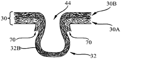
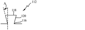
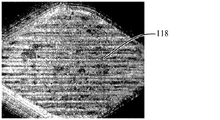
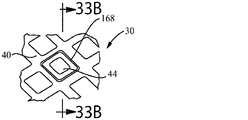
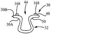
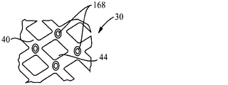
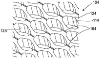
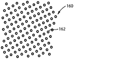
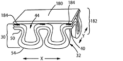
本不織布材料は、その中に形成される変形部を有する。変形部は、不織布材料の第1の表面から外向きに伸びる突出部と、不織布材料の第2の表面に隣接した、突出部の最も狭い部分の内側の基部開口部とを形成する。突出部は、帽部部分を備え得る。突出部の帽部部分の最大内部幅は、基部開口部の幅よりも広くあり得る。突出部は、突出部の基部から突出部の遠位端へと伸び、かつ突出部の側壁及び帽部の一部を形成するのに寄与する繊維を備え得る。一部の場合においては、複数のそのような繊維が、突出部の側壁の周囲に、実質的に完全に配設され得る。一部の場合においては、圧縮力が不織布ウェブに対して印加される場合、突出部のうちの少なくとも一部は、基部開口部が開放されたままであり得るように、制御された様式で潰れるように構成され得る。一部の場合において、突出部の幅は、突出部の長さにわたって異なり得る。一部の場合においては、不織布材料は少なくとも2つの層を備え、これらの層は、突出部中及び突出部の周囲の様々な場所での繊維の濃度及び/又は熱点接着部の存在において異なり得る。一部の場合においては、変形部は、隣接する未変形の領域よりも大きい光透過率を有し得る。本明細書において記載される特性のうちのいずれも、不織布材料において別個に存在してもよく、又は任意の組み合わせで存在してもよい。 The nonwoven material has a deformed portion formed therein. The deformable portion forms a protrusion extending outwardly from the first surface of the nonwoven material and a base opening inside the narrowest portion of the protrusion adjacent to the second surface of the nonwoven material. The protrusion may comprise a cap portion. The maximum internal width of the cap portion of the protrusion can be wider than the width of the base opening. The protrusion may comprise fibers that extend from the base of the protrusion to the distal end of the protrusion and contribute to form part of the sidewall and cap of the protrusion. In some cases, a plurality of such fibers can be disposed substantially completely around the sidewall of the protrusion. In some cases, when compressive force is applied to the nonwoven web, at least some of the protrusions will collapse in a controlled manner such that the base opening may remain open. Can be configured. In some cases, the width of the protrusion can vary over the length of the protrusion. In some cases, the nonwoven material comprises at least two layers that differ in the concentration of fibers and / or the presence of hot spot bonds at various locations in and around the protrusions. obtain. In some cases, the deformed portion may have a greater light transmittance than an adjacent undeformed region. Any of the properties described herein may exist separately in the nonwoven material, or may exist in any combination.
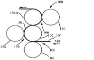
不織布材料中に変形部を形成する方法は、a)少なくとも1つの前駆体不織布ウェブを提供する工程と、b)一対の形成部材を提供する工程であって、これらの形成部材が、複数の不連続な離間された雄形成要素を備える表面を有する第1の形成部材、及び第2の形成部材中の複数の陥凹部を備える表面を有する第2の形成部材を含み、陥凹部が各々、その中に雄形成要素のうちの少なくとも1つを受容するように整列及び構成され、陥凹部が、雄要素の平面外周よりも大きく、かつ完全にそれを取り囲み得る平面外周を有し得る、提供する工程と、c)前駆体不織布ウェブをこれらの形成部材の間に配置し、形成部材で前駆体不織布ウェブを機械的に変形する工程と、を含む。本方法は、概ね平坦な第1の領域と、複数の不連続な変形部とを有する不織布ウェブを形成する。変形部は、不織布ウェブの第1の表面から外向きに伸びる突出部と、不織布ウェブの第2の表面における開口部とを形成する。 The method of forming the deformed portion in the nonwoven material includes: a) providing at least one precursor nonwoven web; and b) providing a pair of forming members, each of the forming members comprising a plurality of non-forming materials. A first forming member having a surface with continuous spaced male forming elements, and a second forming member having a surface with a plurality of recesses in the second forming member, each of the recesses having its Provided, arranged and configured to receive at least one of the male forming elements therein, wherein the recess may have a planar perimeter that is larger than the planar perimeter of the male element and may completely surround it And c) placing the precursor nonwoven web between these forming members and mechanically deforming the precursor nonwoven web with the forming members. The method forms a nonwoven web having a first region that is generally flat and a plurality of discontinuous deformations. The deformable portion forms a protruding portion extending outward from the first surface of the nonwoven web and an opening in the second surface of the nonwoven web.
図面に示される不織布材料、物品、方法、及び装置(複数可)の実施形態(複数可)は本質的に例証的なものであり、「特許請求の範囲」によって定義される本発明の制限であることは意図されない。更に、本発明の特徴は、「発明を実施するための形態」に照らし合わせれば、より完全に明確になり理解されるであろう。 The embodiment (s) of the nonwoven material, article, method and apparatus (s) shown in the drawings are exemplary in nature and are within the limits of the invention as defined by the claims. It is not intended to be. Furthermore, the features of the present invention will become more fully apparent and understood in light of the “DETAILED DESCRIPTION”.
I.定義
用語「吸収性物品」は、生理用ナプキン、パンティライナー、タンポン、陰唇間装置、創傷包帯、おむつ、成人失禁用物品、拭き取り用品等の使い捨て物品を含む。このような吸収性物品の少なくとも一部は、経血又は血液、膣分泌物、尿、及び便等の体液の吸収を意図したものである。拭き取り用品は、体液を吸収するために使用されてもよく、又は、表面を清拭すること等、他の目的に使用されてもよい。上記の様々な吸収性物品は通常、液体透過性トップシートと、このトップシートに接合された液体不透過性バックシートと、トップシートとバックシートとの間の吸収性コアと、を備える。本明細書に記載される不織布材料は、研磨パッド、ウェットモップパッド又はドライモップパッド(SWIFFER(登録商標)パッド等)等の他の物品の少なくとも一部分を備え得る。
I. Definitions The term “absorbent article” includes disposable articles such as sanitary napkins, panty liners, tampons, interlabial devices, wound dressings, diapers, adult incontinence articles, wipes and the like. At least some of such absorbent articles are intended for absorption of menstrual blood or body fluids such as blood, vaginal secretions, urine, and stool. The wipe may be used to absorb bodily fluids or may be used for other purposes such as cleaning the surface. The various absorbent articles described above typically include a liquid permeable top sheet, a liquid impermeable back sheet joined to the top sheet, and an absorbent core between the top sheet and the back sheet. The nonwoven materials described herein may comprise at least a portion of other articles such as polishing pads, wet mop pads, or dry mop pads (such as SWIFFER® pads).
本明細書で使用するとき、用語「吸収性コア」は、液体の貯蔵に主に関与する吸収性物品の構成要素を指す。したがって、吸収性コアは通常、吸収性物品のトップシート又はバックシートを含まない。 As used herein, the term “absorbent core” refers to a component of an absorbent article that is primarily responsible for storing liquids. Thus, the absorbent core typically does not include the topsheet or backsheet of the absorbent article.
本明細書で使用するとき、用語「開孔部」は、意図的に形成され、ウェブ又は構造体を完全に突き抜けて伸びる(すなわち、貫通穴)、定型又は実質的に定型の穴を指す。開孔部は、開孔部の周囲の材料が開孔部の形成前のウェブと同一平面上にあるように、ウェブを通してきれいに穿孔されてもよく(「二次元」開孔部)、あるいは穴は、開口部の周囲の材料の少なくとも一部がウェブの平面から押し出されるように形成されてもよい。後者の場合、開孔部は、その中に開孔部を有する窪みに似ている場合があり、本明細書において、開孔部のサブセットである「三次元」開孔部と呼ばれる場合がある。 As used herein, the term “open hole” refers to a regular or substantially regular hole that is intentionally formed and extends completely through a web or structure (ie, a through hole). The aperture may be cleanly perforated through the web (a “two-dimensional” aperture), or the hole may be such that the material surrounding the aperture is coplanar with the web prior to formation of the aperture. May be formed such that at least a portion of the material around the opening is extruded from the plane of the web. In the latter case, the aperture may resemble a depression having an aperture therein, and may be referred to herein as a “three-dimensional” aperture that is a subset of the aperture. .
本明細書で使用するとき、吸収性物品の「構成要素」という用語は、トップシート、捕捉層、液体処理層、吸収性コア又は吸収性コアの層、バックシート、並びに障壁層及び障壁カフ等の障壁等、吸収性物品の個々の構成成分を指す。 As used herein, the term “component” of an absorbent article refers to a topsheet, acquisition layer, liquid treatment layer, absorbent core or layer of absorbent core, backsheet, and barrier layers and barrier cuffs, etc. Refers to individual components of an absorbent article, such as a barrier.
用語「機械横方向」又は「CD」は、ウェブの平面内で機械方向に垂直な経路を意味する。 The term “cross-machine direction” or “CD” means a path perpendicular to the machine direction in the plane of the web.
本明細書で使用するとき、用語「変形可能な材料」は、印加された応力又はひずみに応答して、形状又は密度を変化させることが可能な材料である。 As used herein, the term “deformable material” is a material that can change shape or density in response to applied stress or strain.
本明細書で使用するとき、用語「不連続(discrete)」は、異なること又は接続されていないことを意味する。用語「不連続」が形成部材上の形成要素に対して使用される場合、形成要素の遠位(又は放射状に最も外側の)端が、(例えば、形成要素の基部はロールの同一表面に形成することができるが)機械方向及び機械横方向を含む全方向で異なること又は接続されていないことを意味する。 As used herein, the term “discrete” means different or not connected. When the term “discontinuous” is used for a forming element on a forming member, the distal (or radially outermost) end of the forming element (eg, the base of the forming element forms on the same surface of the roll) Means different or not connected in all directions, including machine direction and cross machine direction.
用語「使い捨て」は、洗濯される、ないしは別の方法で吸収性物品又は製品として復元若しくは再利用されることを意図しない、吸収性物品及び他の製品を説明するために本明細書で使用される(すなわち、それらは、使用後に廃棄される、好ましくはリサイクルされる、堆肥化される、又はそうでなければ環境に適合する方法で処分されることを意図している)。 The term “disposable” is used herein to describe absorbent articles and other products that are not intended to be washed or otherwise restored or reused as absorbent articles or products. (Ie they are intended to be discarded after use, preferably recycled, composted or otherwise disposed of in an environmentally compatible manner).
本明細書で使用するとき、用語「形成要素」は、ウェブを変形させることが可能である、形成部材の表面上の任意の要素を指す。 As used herein, the term “forming element” refers to any element on the surface of the forming member that is capable of deforming the web.
突出部についての説明で使用する場合の「一体的伸張部」のように本明細書で使用するとき、用語「一体的(integral)」は、前駆体ウェブ(複数可)の繊維から発した突出部の繊維を指す。したがって、本明細書で使用するとき、「一体的」は、突出部の作製を目的として別個の前駆体ウェブに導入又は追加される繊維とは区別されるべきである。 As used herein, such as “integral extension” as used in the description of protrusions, the term “integral” refers to protrusions originating from the fibers of the precursor web (s). Refers to part of the fiber. Thus, as used herein, “integral” should be distinguished from fibers that are introduced or added to a separate precursor web for the purpose of creating protrusions.
用語「接合された」は、ある要素を別の要素に直接固着することによって、その要素が他方の要素に直接固定されている構成;要素を中間部材(複数可)に固着し、次いでその中間部材を他方の要素に固着することによって、その要素が他方の要素に間接的に固定されている構成;及びある要素が別の要素と一体的である構成、すなわち、ある要素が他方の要素の本質的に一部分である構成を包含する。用語「接合された」は、選択された場所においてある要素が別の要素に固定されている構成、並びにある要素が別の要素に対してそれらの要素のうちの1つの表面全体にわたって完全に固定されている構成を包含する。用語「接合した」は、機械的もつれが挙げられるがこれに限定されない、要素が固定され得る任意の既知の方法を含む。 The term “joined” refers to a configuration in which an element is secured directly to another element by securing one element directly to another; the element is secured to the intermediate member (s) and then the intermediate A configuration in which an element is indirectly fixed to the other element by securing the member to the other element; and a configuration in which one element is integral with another element, ie, one element is Includes configurations that are essentially part. The term “joined” refers to a configuration in which one element is secured to another element at a selected location, as well as one element is completely secured to another element over the entire surface of one of the elements. The structure which is made is included. The term “joined” includes any known method by which an element can be secured, including but not limited to mechanical entanglement.
用語「機械方向」又は「MD」は、ウェブ等の材料が製造プロセス中に通って進む経路を意味する。 The term “machine direction” or “MD” means the path a material, such as a web, travels through the manufacturing process.
本明細書で使用するとき、用語「巨視的」は、見る人の目とウェブとの間の垂直距離が約30cm(12インチ)である場合に、20/20の視力を有する人が容易に見ることができ、かつはっきりと識別することができる構造的特徴部又は要素を指す。反対に、用語「微視的」は、そのような条件下で容易に見ることができず、かつはっきりと識別することができない、そのような特徴部を指す。 As used herein, the term “macroscopic” means that a person with 20/20 visual acuity is easy if the vertical distance between the viewer's eyes and the web is about 30 cm (12 inches). Refers to a structural feature or element that can be seen and clearly identified. Conversely, the term “microscopic” refers to such a feature that is not readily visible under such conditions and cannot be clearly identified.
本明細書で使用するとき、用語「機械的に変形する」は、ある材料上に、その材料を永久的に変形させるように機械力が及ぼされるプロセスを指す。 As used herein, the term “mechanically deforming” refers to a process in which a mechanical force is exerted on a material to permanently deform that material.
本明細書で使用するとき、用語「永久的に変形した」は、形状又は密度が、印加された応力又はひずみに応答して永久的に変化した、変形可能な材料の状態を指す。 As used herein, the term “permanently deformed” refers to a deformable material state whose shape or density has changed permanently in response to applied stress or strain.
用語「SELF」又は「SELF加工」は、Procter & Gambleの技術を指し、SELFは、Structural Elastic Like Filmを表す。そのプロセスは元来、有益な構造的特性を有するようにポリマーフィルムを変形するために開発されたが、SELF加工プロセスは、他の材料において有益な構造を作り出すために使用され得ることが見出された。SELFによって作り出されるプロセス、装置、及びパターンは、米国特許第5,518,801号、同第5,691,035号、同第5,723,087号、同第5,891,544号、同第5,916,663号、同第6,027,483号、及び同第7,527,615(B2)号に図示及び記載されている。 The term “SELF” or “SELF processing” refers to the technology of Procter & Gamble, and SELF stands for Structural Elastic Like Film. Although the process was originally developed to deform polymer films to have beneficial structural properties, it has been found that the SELF processing process can be used to create beneficial structures in other materials. It was done. The processes, equipment, and patterns created by SELF are described in US Pat. Nos. 5,518,801, 5,691,035, 5,723,087, 5,891,544, No. 5,916,663, 6,027,483, and 7,527,615 (B2).
本明細書で使用するとき、用語「房」は、不織布ウェブ中の繊維から形成され得る、特定の種類の特徴部を指す。房は、その両端において開口していてもよい、トンネル状構成を有し得る。 As used herein, the term “tuft” refers to a particular type of feature that can be formed from fibers in a nonwoven web. The tufts may have a tunnel-like configuration that may be open at both ends thereof.
用語「ウェブ」は、その主要な次元(primary dimension)がX−Yである、すなわちその長さ(又は長手方向)及び幅(又は横方向)に沿っている、材料を指すように本明細書で使用される。用語「ウェブ」が必ずしも材料の単一層又はシートに限定されないことが理解されるべきである。したがって、ウェブは、必要な種類の材料のいくつかのシートの積層体又は組み合わせを含み得る。 The term “web” is used herein to refer to a material whose primary dimension is XY, ie, along its length (or longitudinal direction) and width (or transverse direction). Used in. It should be understood that the term “web” is not necessarily limited to a single layer or sheet of material. Thus, the web may comprise a laminate or combination of several sheets of the required type of material.
用語「Z次元」は、ウェブ又は物品の長さ及び幅に直交する次元を指す。Z次元は、通常、ウェブ又は材料の厚さに対応する。本明細書で使用するとき、用語「X−Y次元」は、ウェブ又は材料の厚さに直交する平面を指す。X−Y次元は通常、ウェブ又は物品のそれぞれ長さ及び幅に対応する。 The term “Z dimension” refers to the dimension orthogonal to the length and width of the web or article. The Z dimension usually corresponds to the thickness of the web or material. As used herein, the term “XY dimension” refers to a plane perpendicular to the thickness of the web or material. The XY dimensions typically correspond to the length and width of the web or article, respectively.
II.不織布材料
本発明は、不連続な三次元変形部を有する不織布材料を目的とし、この変形部により、材料の一方の側において突出部が提供され、不織布材料の他方の側には開口部が提供されている。本不織布材料を作製する方法もまた開示される。本不織布材料は、吸収性物品及び他の物品において使用することができる。
II. TECHNICAL FIELD The present invention is directed to a nonwoven material having a discontinuous three-dimensional deformed portion, which provides a protrusion on one side of the material and an opening on the other side of the nonwoven material. Has been. A method of making the nonwoven material is also disclosed. The nonwoven material can be used in absorbent articles and other articles.
本明細書で使用するとき、用語「不織布」は、間挿されるが、織布若しくは編布のような繰り返しパターンではない、個々の繊維又は編布の構造を有するウェブ又は材料を指す。後者の種類の布は、典型的には、不規則に配向された繊維又は実質的に不規則に配向された繊維を有しない。不織布ウェブは、ウェブ製造の分野において一般に既知であるように、機械方向(MD)及び機械横方向(CD)を有することになる。「実質的に不規則に配向された」とは、前駆体ウェブのプロセス条件に起因して、CDよりもMDにより多くの量の繊維が配向され得ることを意味し、逆もまた同様である。例えば、スパンボンド加工及びメルトブロープロセスにおいては、繊維の連続的なストランドが、MDに移動する支持材上に堆積される。スパンボンド又はメルトブロー式不織布ウェブの繊維の配向を真に「無作為」とするように試みても、通常は僅かに高い割合の繊維が、CDではなくMDに配向される。 As used herein, the term “nonwoven” refers to a web or material having an individual fiber or knitted fabric structure that is interleaved but not in a repeating pattern such as a woven or knitted fabric. The latter type of fabric typically does not have randomly oriented fibers or substantially randomly oriented fibers. The nonwoven web will have a machine direction (MD) and a cross machine direction (CD), as is generally known in the field of web manufacture. “Substantially randomly oriented” means that due to the process conditions of the precursor web, a greater amount of fibers can be oriented in the MD than in the CD, and vice versa. . For example, in the spunbonding and meltblowing processes, continuous strands of fibers are deposited on a support that moves to the MD. Attempting to make the fiber orientation of spunbond or meltblown nonwoven webs truly “random” usually results in a slightly higher percentage of fibers oriented in the MD rather than the CD.
不織布ウェブ及び材料は、多くの場合、高速の製造ラインにおいて吸収性物品等の製品中に組み込まれる。そのような製造プロセスは、不織布ウェブに対して圧縮力及び剪断力を印加し得、これらの力は、そのようなウェブにおいて意図的に形成されたある特定の種類の三次元特徴部を損傷する場合がある。加えて、不織布材料が、圧縮下において作製又は包装される製品(使い捨ておむつ等)中に組み込まれる場合、そのような圧縮力に材料を供した後に一部の種類の従前の三次元特徴部の三次元特性を保存することは困難となる。 Nonwoven webs and materials are often incorporated into products such as absorbent articles in high speed production lines. Such manufacturing processes can apply compressive and shear forces to the nonwoven web, and these forces damage certain types of three-dimensional features intentionally formed in such webs. There is a case. In addition, when the nonwoven material is incorporated into a product (such as a disposable diaper) that is made or packaged under compression, some types of conventional three-dimensional features of the material after being subjected to such compression force It becomes difficult to preserve the three-dimensional characteristics.
例えば、図1及び2は、房付き構造を有する先行技術の不織布材料10の一例を示している。不織布材料は、2つの端部を有するトンネル様構造16を形成する、ループ繊維14から形成される房12を備える。房12は、不織布材料の平面からZ方向に外向きに伸びる。トンネル様構造は、房の一方の端部から反対側の端部まで実質的に同じである幅を有する。多くの場合、そのような房付き構造は、穴又は開口部18を両方の端部に有し、開口部20をその基部に有することになる。典型的には、房の両端部の開口部18は、房の機械方向(MD)の端部にある。房の両端部の開口部18は、房を形成するために使用されたプロセスの結果であり得る。比較的小さい先端部と、尖端を形成する垂直な前縁及び後縁とを有する歯の形態の形成要素によって房12が形成される場合、これらの前縁及び/又は後縁が、房の両端部のうちの少なくとも一方において、不織布ウェブを穿孔し得る。結果として、開口部18が、房12の一方又は両方の端部において形成され得る。
For example, FIGS. 1 and 2 show an example of a prior
そのような不織布材料10が明確な房12を提供する一方で、房構造の基部における開口部20は、比較的狭く、肉眼では見ることが難しい可能性がある。加えて、図2に示されるように、この狭い基部開口部20を取り囲む房12の材料は、力が房に対して及ぼされる場合、ヒンジ22又はピボット点を形成する傾向にあり得る。不織布が(例えばZ方向に)圧縮されるとすると、多くの場合、房12は一方の側に潰れ、開口部20を閉鎖し得る。典型的には、このような房付き材料の房の大部分が潰れ、開口部20を閉鎖することになる。図2は、房12が潰れた後のその一例を概略的に示している。図2では、房12は左側に折り畳まれている。図3は、いくつかの上向きに配向された房を有し、これらの房の全てが片側に折り畳まれている不織布材料を示す画像である。しかしながら、房12の全てが潰れ、同じ側に折り畳まれるわけではない。多くの場合、一部の房12は一方の側に折り畳まれ、一部の房は他方の側に折り畳まれることになる。房12の潰れた結果として、房の基部の開口部20は閉鎖され、スリット様となり、事実上消え得る。
While such a
円錐構造等の他の特定の種類の三次元変形部を有する、先行技術の不織布材料もまた、圧縮された場合、潰れやすい場合がある。図4に示されるように、圧縮力Fに供される場合、円錐構造24は必ずしもある特定の房付き構造がそうであるように折り畳まれるわけではない。しかしながら、円錐構造24は、その比較的幅広い基部開口部26及びより小さい先端部28によって、円錐構造が不織布材料の平面に向かって、示される構成24A等へと押し戻されるという点において潰れやすい場合がある。
Prior art nonwoven materials having other specific types of three-dimensional deformations, such as conical structures, may also be prone to collapse when compressed. As shown in FIG. 4, when subjected to compressive force F, the conical structure 24 is not necessarily folded as is the case with certain tufted structures. However, the conical structure 24 may be crushed in that the relatively
本明細書に記載される本発明の少なくとも一部の実施形態の不織布材料は、圧縮後に、不織布材料における不連続な三次元特徴部の構造をより良好に保存することを意図する。 The nonwoven material of at least some embodiments of the invention described herein is intended to better preserve the structure of discontinuous three-dimensional features in the nonwoven material after compression.
図5〜14は、突出部32をその中に備える三次元変形部を有する不織布材料30の例を示す。不織布材料30は、第1の表面34、第2の表面36、及びそれらの間の厚さT(この厚さは図12に示されている)を有する。図5は、上向きに配向された、不織布材料の第1の表面34から外向きに伸びる突出部32を有する、不織布材料30の第1の表面34を示している。図6は、その中に形成された三次元変形部を有する、図5に示されるもの等の不織布材料30の第2の表面36を示しており、突出部は下向きに配向され、基部開口部44が上向きに配向されている。図7は、突出部32の斜視図を示すマイクロCTスキャン画像である。図8は、(突出部のより長い側壁のうちの1つの)突出部32の側面図を示すマイクロCTスキャン画像である。図9は、上向きの開口部44を伴う変形部の斜視図を示すマイクロCTスキャン画像である。不織布材料30は、複数の繊維38を備える(図7〜11及び14において示されている)。図7及び9に示されているように、一部の場合においては、不織布材料30は複数の接着部46(熱点接着部等)をその中に有して、繊維38を共に保持し得る。任意のそのような接着部46が、典型的には、不織布材料30を形成する前駆体材料中に存在する。
5-14 illustrate an example of a
突出部32は、一部の場合において、不織布ウェブの平面からZ方向に伸びるように外向きに押し出されるループ繊維38(連続的であり得る)から形成され得る。突出部32は、典型的には、2種類以上のループ繊維を備えることになる。一部の場合において、突出部32は、ループ繊維及び少なくともいくらかの破断繊維から形成され得る。加えて、一部の種類の不織布材料(より短い繊維で構成される、カード処理された材料等)の場合、突出部32は複数の不連続繊維を含むループから形成され得る。ループの形態の複数の不連続繊維は、図15A〜15Fの層30Aとして示されている。ループ繊維は、整列されてもよく(すなわち、実質的に同じ方向に配向されてもよく);整列されなくてもよく;又は、繊維は突出部32内の一部の場所において整列され、突出部の他の部分においては整列されなくてもよい。
The
一部の場合において、突出部32を形成するのに雄/雌形成要素が使用され、雌形成要素が雄形成要素を実質的に取り囲む場合、突出部32の少なくとも一部分における繊維は、前駆体ウェブ(複数可)における繊維の配向と同様に、(整列されるのではなく)実質的に不規則に配向されたままで残り得る。例えば、一部の場合において、繊維は、突出部の帽部では実質的に不規則に配向されたままで残るが、繊維が突出部の基部から帽部へとZ方向に伸びるように、側壁ではより整列され得る。加えて、前駆体ウェブが多層不織布材料を含む場合、繊維の整列の度合いは層間で異なる可能性があり、また同一層内の所与の突出部32の異なる部分の間においても異なる可能性がある。
In some cases, when male / female forming elements are used to form the
不織布材料30は、概ね平坦な第1の領域40を備え得、三次元変形部は、複数の不連続な一体的第2の領域(discrete integral second region)42を構成し得る。用語「概ね平坦な」は、いかなる特定の平坦度、平滑度、又は次元性も示唆するものではない。したがって、第1の領域40は、あるトポグラフィーを有する第1の領域40を提供する他の特徴部を含み得る。そのような他の特徴部としては、限定されるものではないが、小突起、基部開口部44の周囲の隆起ネットワーク領域、及び他の種類の特徴部を挙げることができる。したがって、第1の領域40は、第2の領域42と比較して考察する場合、概ね平坦である。第1の領域40は、任意の好適な平面構成を有し得る。一部の場合において、第1の領域40は、変形部の各々を取り囲む部分を含む、連続的に相互接続されたネットワークの形態である。
The
本明細書で使用するとき、用語「変形部」は、不織布材料の一方の側に形成される突出部32と、材料の反対側に形成される基部開口部44との両方を含む。基部開口部44は、最も多くの場合、開孔部又は貫通穴の形態ではない。代わりに、基部開口部44は窪みとして現れ得る。基部開口部44は、バッグの開口部になぞらえることができる。バッグは、典型的にはバッグを完全には貫通しない開口部を有する。本発明の不織布材料30の場合、図10に示されるように、基部開口部44は、突出部32の内部に向かって開放している。
As used herein, the term “deformation” includes both a
図11は、多層不織布材料30の一例を示しており、この多層不織布材料は、材料の一方の側において突出部32の形態で三次元変形部を有し、この突出部により材料の他方の側において幅広の基部開口部44が提供される。「幅広の」基部開口部の寸法については、下で更に詳細に説明する。この場合、図面において、基部開口部44は上向きに配向されている。2つ以上の不織布層が存在する場合、個々の層は、30A、30B等と示すことができる。個々の層30A及び30Bは各々、第1及び第2の表面を有し、これらは不織布材料の第1及び第2の表面、34及び36と同様に示すことができる(例えば、第1の層30Aの第1及び第2の表面の場合、34A及び36A、並びに第2の層30Bの第1及び第2の表面の場合、34B及び36B)。
FIG. 11 shows an example of a multilayer
図11及び12において示されるように、突出部32は、不織布材料の第1の表面34に近接する基部50と、遠位端54へと伸びる、反対側の拡大された遠位部分若しくは帽部部分、又は「帽部」52と、側壁(又は「側壁」)56と、内部58と、一対の端部60(後者は図5に示されている)と、を備える。突出部32の「基部」50は、突出部の両端部のうちの一方から見たとき、突出部の最も狭い部分を備える。用語「帽部」は、それが、突出部32の遠位端54を含み、かつそれに隣接する、突出部32のより幅広い部分を備える以外には、いかなる特定の形状も示唆しない。側壁56は、内側面56A及び外側面56Bを有する。図11及び12に示されるように、側壁56は、帽部52の一部分へと移行し、それを備えてもよい。それ故に、どこで側壁56が終わり、帽部52が始まるかを精密に定義する必要はない。帽部52は、対向する側壁56の内側面56Aの間において、最大内部幅WIを有することになる。帽部52はまた、対向する側壁56の外側面56Bの間において、最大外部幅Wを有することになる。突出部32の両端部60は、突出部の長手方向軸Lに沿って最も遠く離間された、突出部の部分である。
As shown in FIGS. 11 and 12, the
図11及び12に示されるように、突出部32の最も狭い部分が、基部開口部44を画定する。基部開口部44は、幅WOを有する。基部開口部44は、(z方向において)材料の第2の表面36によって画定される平面と、突出部の遠位端54との間に位置付けられ得る。図11及び12に示されるように、不織布材料30は、第2の表面36において開口部を有し得(「第2の表面の開孔部」64)、この開口部は基部開口部44へと移行し(逆もまた同様)、基部開口部44と同じサイズであるか、又はそれよりも大きい。しかしながら、不織布材料30が、基部開口部44を消費者から見えるようにして物品中に配置される実施形態においては、基部開口部44のサイズが消費者にとってより視覚的に明らかである場合が多いため、一般に、本明細書においては基部開口部44についてより頻繁に考察する。基部開口部44が外を向く(例えば、消費者に向かい、かつ吸収性物品中の吸収性コアから離れる)一部の実施形態等、ある特定の実施形態においては、基部開口部44が、別のウェブによって覆われないこと及び/又は閉鎖されないことが望ましい場合がある。
As shown in FIGS. 11 and 12, the narrowest portion of the
図12に示されるように、突出部32は、不織布ウェブの第2の表面36から、突出部の遠位端54における突出部の内部までで測定される、深さDを有する。突出部32は、不織布ウェブの第2の表面36から、突出部の遠位端54までで測定される、高さHを有する。ほとんどの場合において、突出部32の高さHは、第1の領域40の厚さTよりも大きいことになる。変形部の様々な部分間の関係性は、図11に示されるように、端部から見たとき、突出部の帽部52の最大内部幅WIが、基部開口部44の幅WOよりも広いような関係性であり得る。
As shown in FIG. 12, the
突出部32は、任意の好適な形状であり得る。突出部32は三次元であるため、その形状に対する説明は、それをどこから見るかという角度に左右される。図5等のように上から見たとき(すなわち、ウェブの平面に対して垂直、又は平面図)、好適な形状としては、限定されるものではないが、円形、ダイヤモンド形、丸みを帯びたダイヤモンド形、アメリカンフットボール用ボール形、卵形、三つ葉形、ハート形、三角形、涙滴形、及び楕円形が挙げられる。(基部開口部44は典型的には、突出部32の平面形状に類似する形状を有することになる。)他の場合においては、突出部32(及び基部開口部44)は、非円形であってもよい。突出部32は、全ての方向において類似する平面寸法を有してもよく、又は突出部は1つの次元において別の次元よりも長くてもよい。すなわち、突出部32は、異なる長さ及び幅の寸法を有し得る。突出部32が幅とは異なる長さを有する場合、より長い寸法が、突出部の長さと呼ばれることになる。したがって、突出部32は長さの幅に対する比、すなわちアスペクト比を有し得る。アスペクト比は、約1:1〜約10:1の範囲であり得る。
The
図5に示されるように、突出部32は、突出部を平面図で見たとき、一方の端部60から反対側の端部60までで異なる幅Wを有し得る。幅Wは、突出部の最も幅広い部分が突出部の中間であり、突出部の幅が突出部の両端部60において減少するように異なってもよい。他の場合においては、突出部32は、突出部の中間よりも、一方の端部又は両方の端部60においてより幅広であり得る。更なる他の場合においては、突出部の一方の端部から突出部の他方の端部までで実質的に同じ幅を有する突出部32が形成されてもよい。突出部32の幅が突出部の長さに沿って異なる場合、幅が最大となる突出部の一部が、突出部のアスペクト比を決定する際に使用される。
As shown in FIG. 5, the
突出部32がその幅Wよりも大きい長さLを有するとき、突出部の長さは、不織布材料30に対して任意の好適な方向に配向され得る。例えば、突出部32の長さ(すなわち、突出部の長手方向軸LA)は、機械方向、機械横方向、又は機械方向と機械横方向との間の任意の所望される配向で配向され得る。突出部32はまた、MD−CD平面内で、長手方向軸LAに対して概ね直交する横断軸TAも有し得る。図5及び6に示される実施形態において、長手方向軸LAはMDに対して平行である。一部の実施形態において、全ての離間した突出部32は、概ね平行な長手方向軸LAを有し得る。
When the
突出部32は、側面から見たとき、任意の好適な形状を有してもよい。好適な形状としては、少なくとも1つの側面から見たとき、拡大された寸法を有する遠位部分又は「帽部」と、基部におけるより狭い部分とが存在する形状が挙げられる。用語「帽部」は、キノコの傘部分に類似している。(帽部は、任意の特定の種類のキノコの傘部分と似ている必要はない。加えて、突出部32は、キノコ様の柄部分を有してもよいが、有する必要はない。)一部の場合において、突出部32は、図11等のように、端部60から見たとき、球根の形状を有すると称され得る。本明細書で使用するとき、用語「球根の」は、突出部32の構成が、突出部32の少なくとも1つの側面から見たとき(特に、より短い端部60のうちの1つから見たとき)、拡大された寸法を有する帽部52と、基部におけるより狭い部分とを有すると称されることを意図する。用語「球根の」は、円柱状部分に接合されている円形の又は丸い平面構成を有する突出部に限定されるものではない。示される実施形態(変形部32の長手方向軸LAが、機械方向に配向されている)において、球根の形状は、断面が変形部の横断軸TAに沿って取られた場合(すなわち、機械横方向)に最も明確であり得る。球根の形状は、図8等のように変形部の長さ(又は長手方向軸LA)に沿って変形部を見た場合には、より不明確となり得る。
The
突出部32は、突出部の側壁を少なくとも実質的に取り囲む繊維38を備え得る。これは、突出部32の基部50から突出部の遠位端54へと(例えば、Z方向に)伸び、突出部の側壁56及び帽部52の一部を形成するのに寄与する複数の繊維が存在することを意味する。一部の場合において、突出部32の側壁56では、繊維はZ方向に互いにに実質的に整列され得る。したがって、語句「実質的に取り囲む」は、X−Y平面において、各個々の繊維が、突出部の側壁の周囲に実質的に又は完全に巻き付けられることを必要とするものではない。繊維38が突出部の側壁の周囲に完全に位置付けられる場合、これは、繊維が突出部の周囲360°に位置付けられることを意味する。突出部32は、その端部60において、図1に示される房の先端及び終端における、開口部18等の大きな開口部を有しなくてもよい。一部の場合において、突出部32は、その終端等、その端部のうちの一方のみにおいて開口部を有し得る。突出部32はまた、図4に示されるもの等のエンボス構造とは異なってもよい。エンボス加工構造は、典型的には、その基部から垂直に(すなわち、Z方向に)離間され、本突出部32の帽部52の場合のように、その基部に隣接する部分よりも幅広い遠位部分を有しない。
The
突出部32は、ある特定の追加的な特性を有してもよい。図11及び12に示されるように、突出部32は実質的に中空であってもよい。本明細書で使用するとき、用語「実質的に中空」とは、突出部32が突出部の内部において繊維を実質的に含まない構造を指す。しかしながら、用語「実質的に中空」は、突出部の内部が繊維を完全に含まないことを必要とするものではない。したがって、突出部の内側にいくらかの繊維が存在してもよい。「実質的に中空」である突出部は、その中に陥凹部を有する形成構造上に繊維をエアーレイ又はカード処理すること等によって繊維を敷設することにより製造されたもの等の充填三次元構造とは区別することができる。
The
突出部32の側壁56は、任意の好適な構成を有し得る。図11等のように突出部の端部から見たとき、側壁56の構成は、直線状又は曲線状であってもよく、あるいは側壁は、直線部分及び曲線部分の組み合わせによって形成されてもよい。曲線部分は、凹状、凸状、又は両方の組み合わせであってもよい。例えば、図11に示される実施形態の側壁56は、突出部の基部付近において内向きに凹状の曲線部分と、突出部の帽部付近において外向きに凸状の曲線部分とを備える。側壁56、及び突出部の基部開口部44の周囲の領域は、20倍の倍率の下で、未形成の第1の領域40の不織布の部分よりも、所与の面積当たりの繊維の濃度が目に見えて著しく低くあり得る(これは、より低い坪量又はより低い不透明度の証拠となり得る)。突出部32はまた、側壁56において細線化された繊維を有してもよい。存在する場合、繊維細線化は、200倍の倍率で撮影された走査型電子顕微鏡(SEM)画像において見られるように、繊維38の狭幅領域の形態で明らかとなる。したがって、繊維は、未変形の不織布前駆体ウェブにある場合に第1の断面積を有し、変形済み不織布ウェブの突出部32の側壁56において第2の断面積を有し、第1の断面積は第2の断面積よりも大きい。側壁56はまた、いくらかの破断繊維も含み得る。一部の実施形態において、側壁56は、約30%以上、あるいは約50%以上の破断繊維を備え得る。
The
一部の実施形態において、突出部32の遠位端54は、元の坪量であり、細線化されておらず、かつ破断していない繊維で構成され得る。基部開口部44が上を向いている場合、遠位端54は、突出部によって形成される窪みの底部に存在することになる。遠位端54は、遠位端を完全に貫通して形成される開孔部を含まない。したがって、不織布材料は無孔であり得る。本明細書で使用するとき、用語「開孔部」は、不織布の形成後に不織布において形成される穴を指し、不織布中に典型的に存在する細孔は含まない。用語「開孔部」はまた、その中に変形部を形成するプロセスの過程における材料(複数可)の局所的な引き裂きからもたらされる、図15D〜15F及び図20に示されるもの等の、不織布材料(複数可)における変則的な破断(又は断絶部)のことは指さない。この破断は、前駆体材料(複数可)における変化性に起因する場合がある。遠位端54は、突出部を形成する構造の残りの部分と比較して、相対的により大きい繊維濃度を有し得る。繊維濃度は、顕微鏡で試料を観察し、ある領域内の繊維の数を数えることで測定することができる。しかしながら、下でより詳細に説明されるように、不織布ウェブが2つ以上の層で構成される場合、突出部の異なる部分中の繊維の濃度は、異なる層間で異なってもよい。
In some embodiments, the
突出部32は、任意の好適なサイズであり得る。突出部32のサイズは、突出部の長さ、幅、キャリパー、高さ、深さ、帽部サイズ、及び開口部サイズに関して説明され得る。(特に別途明言されない限り、突出部の長さL及び幅Wは、突出部の外部長さ及び帽部52の幅である。)突出部及び開口部の寸法は、圧縮(7kPa又は35KPaいずれかの圧力の下で、どちらかが指定される)の前及び後に、試験方法セクションに記載される加速圧縮方法に従って測定され得る。突出部はキャリパーを有し、このキャリパーは、加速圧縮方法に従って、高さHと同じ点間で測定されるが、2KPaの負荷がかけられる。突出部及び開口部の、キャリパー以外の全ての寸法(すなわち、長さ、幅、高さ、深さ、帽部サイズ、及び開口部サイズ)は、測定を行う際に圧力を印加せずに、20倍の倍率の顕微鏡を用いて測定される。
The
一部の実施形態において、帽部52の長さは、1.5mm〜約10mmの範囲であり得る。一部の実施形態において、帽部の幅(幅が最大の場所で測定される)は、約1.5mm〜約5mmの範囲であり得る。突出部の帽部部分は、少なくとも約3mm2の平面表面積を有し得る。一部の実施形態において、突出部は、約1mm〜約10mm、あるいは約1mm〜約6mmの範囲である圧縮前高さHを有し得る。一部の実施形態において、突出部は、約0.5mm〜約6mm、あるいは約0.5mm〜約1.5mmの範囲である圧縮後高さHを有し得る。一部の実施形態において、突出部は、約0.25mm〜約5mm、あるいは約0.25mm〜約1mmの範囲である圧縮後の深さDを有し得る。一部の実施形態において、突出部は、約0.25mm〜約5mm、あるいは約0.25mm〜約1mmの範囲である圧縮後の深さDを有し得る。
In some embodiments, the length of the
不織布材料30は、一緒に接合されている2つ以上の不織布材料の複合体を備え得る。そのような場合、第1の層の繊維及び特性は適宜選定され(例えば、第1の層は第1の複数の繊維で構成される)、第2及び後続の層の繊維及び特性は適宜選定される(例えば、第2の層は第2の複数の繊維で構成される)。2つ以上の層の構造において、それらの層がその中に変形部を形成した後に取り得る、可能性のあるいくつかの構成が存在する。これらは多くの場合、それらの層に使用された不織布材料の伸張性に左右されることになる。これらの層のうちの少なくとも1つが、少なくとも1つの断面に沿って、突出部の帽部52の幅が変形部の基部開口部44の幅よりも大きい、本明細書に記載されるような突出部32を形成する変形部を有することが望ましい。例えば、一方の層が吸収性物品のトップシートとして機能し、他方の層が下層(捕捉層等)として機能する二層構造においては、その中に突出部を有する層は、トップシート層を構成し得る。最も典型的には球根の形状を有する層が、ウェブを変形するプロセス中に雄形成部材と接触する層である。図15A〜図15Eは、多層材料における三次元突出部32の異なる代替形態を示す。
図11、12、及び15Aに示されるように、ある特定の実施形態においては、突出部32の形成プロセス中、不連続な雄形成要素から最も離間される層30A、及びプロセス中、雄形成要素に最も近い層30Bを含む、多層不織布材料の各層において、類似する形状のループ繊維が形成され得る。突出部32において、30B等の一方の層の一部が、30A等の他方の層内にフィットし得る。これらの層は、突出部32において「入れ子」構造を形成すると称され得る。入れ子構造の形成は、2種類(以上)の高度に伸張可能な不織布前駆体ウェブの使用を必要とし得る。二層の材料の場合、入れ子構造は2つの完全なループを形成してもよく、又は(以下の図面のうちのいくつかにおいて示されるように)2つの不完全な繊維のループを形成してもよい。
As shown in FIGS. 11, 12, and 15A, in certain embodiments, the
図15Aに示されるように、三次元突出部32は、第1の層30Aにおいて形成される突出部32Aと、第2の層30Bにおいて形成される突出部32Bとを備える。一実施形態において、第1の層30Aは、吸収性物品内に捕捉層として組み込まれ得、第2の層30Bはトップシートであり得、これら2つの層によって形成される突出部は一緒にフィットし得る(すなわち、入れ子にされる)。この実施形態において、第1及び第2の層、30A及び30Bによって形成される突出部32A及び32Bは、一緒にぴったりとフィットする。三次元突出部32Aは複数の繊維38Aを備え、三次元突出部32Bは複数の繊維38Bを備える。三次元突出部32Bは、三次元突出部32A内へと入れ子にされる。示される実施形態において、第1の層30A中の繊維38Aは、第2の層30B中の繊維38Bよりも長さが短い。他の実施形態においては、これらの層中の繊維の相対的長さは同じであってもよく、又は第1の層中の繊維が第2の層中の繊維よりも長いという、反対の関係性であってもよい。加えて、この実施形態において、並びに本明細書に記載される他の実施形態のうちのいずれかにおいて、不織布層は、吸収性物品又は他の物品に組み込まれるとき、突出部32が上(又は外)を向くように裏返されてもよい。そのような場合、トップシートにとって好適な材料が層30Aに使用され、下層にとって好適な材料が層30Bに使用されることになる。
As shown in FIG. 15A, the three-
図15Bは、不織布層が、突出部32全体内で接触する関係性である必要はないことを示している。したがって、第1及び第2の層、30A及び30Bによって形成される突出部32A及び32Bは、異なる高さ及び/又は幅を有し得る。これら2つの材料は、図15Bに示されるように(材料の一方が、他方と同じ湾曲を有する)、突出部32において実質的に同一の形状を有し得る。しかしながら、他の実施形態においては、これらの層は異なる形状を有してもよい。図15Bは単に1つの可能な層の配置を示しているに過ぎず、多くの他の変化形態が可能であるが、全ての図に関して、全ての可能な変化形態の図面を提供することは不可能であることを理解されたい。
FIG. 15B shows that the nonwoven layer need not be in contact relationship within the
図15Cに示されるように、第1の層30A(例えば、捕捉層)等の、層のうちの1つが、三次元突出部32の領域において断裂していてもよい。図15Cに示されるように、突出部32は、第2の層30B(例えば、トップシート)においてのみ形成されており、第1の層30Aの開口部を通って伸びている。すなわち、第2の層30Bの三次元突出部32Bが、断裂した第1の層30Aを貫通している。このような構造によって、トップシートは、下の分散層又は吸収性コアと直接接触して配置され得、これが乾燥性の改善につながり得る。そのような実施形態において、これらの層は、突出部の領域において「入れ子」にされているとはみなされない。(図15D〜15Fに示される他の実施形態においては、これらの層は依然として「入れ子」にされているとみなされる。)このような構造は、第2の層30Bの材料が、第1の層30Aの材料よりも遥かに伸張可能である場合に形成され得る。そのような場合、開口部は、下で詳細に説明されるプロセスを通じて、第1の前駆体ウェブを局所的に断裂させることで形成され得る。断裂した層は、突出部32の領域において、任意の好適な構成を有し得る。断裂は、第1の層30Aにおける開口部が単純な二次元開孔部のままであるように、第1の前駆体ウェブを単に裂き開くことを含み得る。しかしながら、一部の材料の場合、第1の層30Aの一部は、平面外(すなわち、第1の層30Aの平面外)へと偏向されるか、又は付勢されてフラップ70を形成し得る。任意のフラップの形状及び構造は、第1の層30Aの材料特性に高度に左右される。フラップは、図15Cに示される一般的構造を有し得る。他の実施形態において、フラップ70は、突出部32Bがフラップから噴出するかのように、より火山様の構造を有し得る。
As shown in FIG. 15C, one of the layers, such as the
あるいは、図15D〜15Fに示されるように、第1の層30A及び第2の層30Bのうちの一方又は両方が、三次元突出部32の領域において断絶されてもよい(又はその中に破断を有してもよい)。図15D及び15Eは、第1の層30Aの三次元突出部32Aが、その中に断絶部72Aを有し得ることを示している。断絶していない第2の層30Bの三次元突出部32Bは、断絶している第1の層30Aの三次元突出部32Aと合致し、一緒にフィットし得る。あるいは、図15Fは、第1及び第2の層、30A及び30Bの両方が、それらの中に断絶部又は破断(それぞれ、72A及び72B)を有する実施形態を示している。この場合、層30A及び30Bにおける断絶部は、突出部32の異なる場所に存在する。図15D〜15Fは、典型的には不規則な繊維破壊によって形成される、意図的でなく不規則な又は一貫性のない、材料中の破断を示している。これらの破断は概して不整列であり、第1又は第2の層において存在する可能性があるが、典型的には整列せず、両方の層を完全に突き抜けることはない。したがって、典型的には、突出部32の遠位端54において、層の全てを完全に突き抜けて形成される開孔部は存在しないことにある。
Alternatively, as shown in FIGS. 15D-15F, one or both of the
二重層及び他の多層構造の場合、変形済み材料30内の坪量分布(又は繊維の濃度)、並びに任意の熱点接着部46の分布は、層間で異なり得る。本明細書で使用するとき、用語「繊維濃度」は、坪量と類似する意味を持つが、坪量がg/面積であるのに対して、繊維濃度は繊維の数/所与の面積を指す。接着部位46の場合、繊維は溶融される場合があり、これにより接着部位46における材料の密度は増加し得るが、繊維の数は、典型的には溶融前と同じである。
In the case of double layers and other multilayer structures, the basis weight distribution (or fiber concentration) within the
一部のそのような二重層及び多層不織布材料は、本明細書に記載される他の特色(帽部部分の特性、圧縮の下での制御された潰れ、及び突出部の変化する幅等)のうちの1つ以上を要することなく、層間のそのような差異に関して説明することができる。無論、そのような二重層及び多層不織布材料は、これらの他の特徴のうちのいずれかを有し得る。 Some such double-layer and multi-layer nonwoven materials have other features described herein, such as cap portion characteristics, controlled collapse under compression, and varying widths of protrusions. Such differences between layers can be described without requiring one or more of the following. Of course, such bilayer and multilayer nonwoven materials may have any of these other features.
そのような二重層及び多層不織布材料において、層の各々は複数の繊維を備え、ある特定の実施形態において、突出部32は、層の各々において繊維から形成される。例えば、これらの層のうちの一方、第1の層は、不織布材料30の第1の表面34を形成し得、これらの層のうちの一方、第2の層は、不織布材料30の第2の表面36を形成し得る。第1の層中の繊維の一部は、第1の領域40、突出部の側壁56、及び突出部32の遠位端54の一部分を形成する。第2の層中の繊維の一部は、第1の領域40、突出部の側壁56、及び突出部32の遠位端54の一部分を形成する。
In such bilayer and multilayer nonwoven materials, each of the layers comprises a plurality of fibers, and in certain embodiments, the
図16に示されるように、雄形成要素と接触する不織布層(例えば、30B)は、突出部32Bの遠位端54Bにおいて、元の不織布(すなわち、第1の領域40)と同様の坪量を有する大きな部分を有し得る。図17に示されるように、突出部32Bの側壁56Bにおける坪量及び基部開口部44付近での坪量は、不織布層の第1の領域40及び突出部32Bの遠位端54の坪量よりも低くあり得る。しかしながら、図18に示されるように、雌形成要素と接触する不織布層(例えば、30A)は、突出部32Aの帽部52Aにおいて、不織布層の第1の領域40における坪量よりも著しく低い坪量を有し得る。図19に示されるように、突出部32Aの側壁56Aは、不織布の第1の領域40よりも少ない坪量を有し得る。図19A及び19Bは、雌形成要素と接触する不織布層30Aが、第1の領域40において(図19Aの画像の上部において)最大の繊維濃度、及び突出部32の遠位端54において最小の繊維濃度を有し得ることを示している。この場合、側壁56Aにおける繊維濃度は、第1の領域40の繊維濃度未満であるが、突出部32の遠位端54における繊維濃度よりも大きくあり得る。
As shown in FIG. 16, the nonwoven layer (eg, 30B) in contact with the male forming element has a basis weight similar to that of the original nonwoven (ie, first region 40) at the
不織布材料における変形部の形成はまた、層(又は複数の層)内で、接着部46(熱点接着部)にも影響を及ぼし得る。一部の実施形態において、突出部32の遠位端54内の接着部46は、突出部32を形成した変形プロセスによっても無傷で残る(破壊されない)場合がある。しかしながら、突出部32の側壁56においては、前駆体ウェブ中に元々存在した接着部46は破壊され得る。接着部46が破壊され得ると言われる場合、これはいくつかの形態をとり得る。接着部46は破壊され、接着部の残遺物を残し得る。不織布前駆体材料の接着が弱い(underbonded)場合等の他の場合において、繊維は、軽く形成された接着部位から解きほぐされ得(蝶結びをほどくのと同様である)、接着部位は本質的に消えることになる。一部の場合において、変形プロセスの後、突出部32の少なくとも一部の側壁56は、熱点接着部を実質的に含まない場合がある(又は完全に含まない場合がある)。
The formation of deformations in the nonwoven material can also affect the bond 46 (hot spot bond) within the layer (or layers). In some embodiments, the adhesive 46 in the
二重層及び他の多層構造の多数の実施形態が可能である。例えば、図16及び17において示されるもの等の不織布層30Bは、その基部開口部を上に向けて配向され得、二重層又は多層不織布構造のトップシートとして機能し得る(捕捉層として機能する、少なくとも1つの他の層を有する)。この実施形態においては、不織布層30Bの第1の領域40及び突出部32の遠位端54内の接着部46は無傷で残る。しかしながら、突出部32の側壁56において、前駆体ウェブ中に元々存在した接着部46は破壊され、それにより側壁56は熱点接着部を実質的に含まない。そのようなトップシートは、第1の領域40及び突出部32の遠位端54における層30A内の繊維の濃度が、同様に、突出部32の側壁56中の繊維の濃度よりも大きい、捕捉層と組み合わせてもよい。
Numerous embodiments of double layers and other multilayer structures are possible. For example, a
他の実施形態においては、前の段落に記載された捕捉層30Aは、不織布層30Bの第1の領域40及び突出部32の遠位端54内において無傷で残る熱点接着部46を有し得る。しかしながら、突出部32の側壁56においては、捕捉層30Aを備える前駆体ウェブ中に元々存在した接着部46は破壊され、それにより捕捉層30Aの側壁56は熱点接着部を実質的に含まない。他の場合においては、突出部32の頂部における、捕捉層30Aの熱点接着部もまた破壊される場合があり、それにより突出部の少なくとも一部の遠位端54は、熱点接着部を実質的に又は完全に含まない。
In other embodiments, the
他の実施形態において、二重層又は多層構造は、各層の遠位端54における繊維の(その層の他の部分に対する)濃度が層間で異なる、トップシートと、その基部開口部を上に向けて配向される捕捉層とを備えてもよい。例えば、一実施形態において、トップシートを形成する層(第2の層)では、第1の領域及び突出部の遠位端中の繊維の濃度は各々、突出部の側壁中の繊維の濃度よりも大きい。捕捉層を形成する層(第1の層)では、捕捉層の第1の領域中の繊維の濃度が、突出部の遠位端中の繊維の濃度よりも大きくてよい。この実施形態の変化形態において、第1の層(捕捉層)の第1の領域中の繊維の濃度は、第1の層における突出部の側壁中の繊維の濃度よりも大きく、第1の層における突出部の側壁中の繊維の濃度は、第1の層における突出部の遠位端を形成する繊維の濃度よりも大きい。第1の層がスパンボンド不織布材料(ここで、前駆体材料は、全体を通じて実質的に均一に分散された熱点接着部を有した)を備える一部の実施形態において、第1の層中の第1の領域を形成する繊維の一部は熱点接着部を含み、突出部の少なくとも一部の側壁及び遠位端を形成する、第1の層中の繊維の一部は、熱点接着部を実質的に含まなくてもよい。これらの実施形態では、突出部の少なくとも一部において、第1の層中の繊維の少なくとも一部は、図19に示されるように、突出部の幅広の壁と基部との間の移行部において、突出部の周囲に入れ子又は円を形成し得る(すなわち、取り囲む)。
In other embodiments, the bilayer or multilayer structure is such that the concentration of fibers at the
基部開口部44は、任意の好適な形状及びサイズであり得る。基部開口部44の形状は、典型的には、対応する突出部32の平面形状と類似するか、又は同じである。基部開口部44は、おおよそ以下の寸法のうちのいずれかよりも大きい幅を、前(及び圧縮の後)に有し得る:0.5mm、0.7mm、0.8mm、0.9mm、1mm、又は1mmを任意の0.1mm増分で上回る値。基部開口部44の幅は、前述の量のうちのいずれかから最大約4mmまで、又はそれ以上である範囲内であり得る。基部開口部44は、約1.5mm以下〜約10mm以上の範囲の長さを有し得る。基部開口部44は、約1:1〜20:1、あるいは約1:1〜10:1の範囲のアスペクト比を有し得る。基部開口部の寸法の測定は、顕微鏡写真で行うことができる。基部開口部44の幅のサイズが本明細書において特定されるとき、開口部が特定の方向において均一の幅でない場合には、幅WOは図6に示されるように最も広い部分で測定されることが理解されよう。本発明の不織布材料及びそれを作製する方法は、幅の狭い基部を有する特定の従来の構造よりも、幅の広い開口部を伴う変形部を作ることができる。これにより、基部開口部44が肉眼でより視認可能にされる。基部開口部44の幅は関心の対象である。これは、開口部の最も幅が狭い部分であることが、開口部のサイズを最も制限するものであるためである。変形部は、第1の領域40の平面に対して垂直な圧縮の後にその幅広の基部開口部44を保持する。
The
変形部は、負荷を受けたとき圧縮され得る。一部の場合において、不織布が、変形部を着用者の身体と接触させた状態で着用者の身体に対して着用場合、変形部が柔らかく、かつ肌に跡をつけないように、負荷は十分に低いことが望ましい場合がある。これは、突出部32又は基部開口部44のどちらが着用者の身体と接触するように配向される場合についても当てはまる。例えば、変形部は、2kPa以下の圧力の下で圧縮されることが望ましい場合がある。他の場合においては、変形部が着用者の肌に跡をつけるかどうかは問題ではない。不織布材料30中の突出部32のうちの少なくとも1つが、下の試験方法セクションの加速圧縮方法に従って試験したとき、7kPaの負荷を受けて、下に記載される制御された様式で潰れるか又は屈することが望ましい場合がある。あるいは、突出部32の少なくとも一部、又は他の場合において、大部分が、本明細書に記載される制御された様式で潰れ得る。あるいは、突出部32の実質的に全てが、本明細書に記載される制御された様式で潰れ得る。突出部32が潰れる能力もまた、35kPaの負荷の下で測定され得る。7kPaの負荷及び35kPaの負荷は、製造及び圧縮包装の条件をシミュレートするものである。着用条件は、圧力無し又は制限された圧力(着用者が吸収性物品上に座っていない場合)から、最大2kPa、7kPa、又はそれ以上の範囲であり得る。
The deformable portion may be compressed when subjected to a load. In some cases, when the nonwoven fabric is worn against the wearer's body with the deformed portion in contact with the wearer's body, the load is sufficient so that the deformed portion is soft and does not leave a mark on the skin. It may be desirable to be low. This is true even when either the
突出部32は、基部における幅広の開口部44を維持するように、圧縮後、制御された様式で潰れ得る。図13は、圧縮に供された後の、本発明による不織布材料30の第1の表面34を示している。図14は、圧縮に供された後の、単一の、下向きに配向された突出部32の側面図である。図13に示されているように、突出部32が圧縮された場合、基部開口部44の周囲には、不透明度が増加したリング80の形態である、より高濃度の繊維が現れる。圧縮力が不織布材料に印加された場合、突出部32の側壁56は、側壁56が凹状となり、重複する層の領域へと(S字型/アコーディオン型等へと)折り畳まれるように、より望ましい/制御された様式で潰れ得る。不透明度が増加したリング80は、材料の折り畳まれた層を表している。換言すれば、突出部32は、突出部に対してZ方向の力が印加される場合、X−Y平面においてある程度の寸法安定性を有し得る。突出部32の潰れる構成は必ずしも対称である必要はなく、突出部32が不織布の元の平面へと覆い被さるか又は押し戻され、基部開口部のサイズを有意に(例えば、50%以上)低減するのを防ぐことのみが必要とされる。例えば、図14に示されているように、突出部32の左側がz型に折り畳まれた構造を形成してもよく、突出部の右側はそのような構造を形成しないが、折り畳まれた部分における材料の重複の程度により、上から見たときに依然としてより高い不透明度を有するように映る。いかなる特定の理論にも束縛されるものではないが、枢動点を伴わずに組み合わされた幅広の基部開口部44及び大きい帽部52(基部開口部44の幅よりも大きい)が、突出部32を制御された様式で潰れさせる(突出部32が覆い被さることを防ぐ)と考えられる。したがって、突出部32は、さもなくば突出部32が圧縮されたときに側面へと折り畳ませ得るヒンジ構造を含まない。大きい帽部52はまた、突出部32が不織布の元の平面へと押し戻されることも防止する。
The
変形部は、不織布材料30の表面にわたって、任意の好適な密度で配設され得る。変形部は、例えば、10cm2の領域当たり、約5〜約100個の変形部、あるいは、約10〜約50個の変形部、あるいは、約20〜約40個の変形部という密度で存在し得る。
The deformations can be disposed at any suitable density across the surface of the
変形部は、不織布材料の平面にわたって、任意の好適な配列で配設され得る。好適な配列としては、限定されるものではないが、千鳥上の配列及びゾーンが挙げられる。 The deformations can be arranged in any suitable arrangement over the plane of the nonwoven material. Suitable arrangements include, but are not limited to, staggered arrangements and zones.
本明細書に記載される不織布ウェブ30は、吸収性物品の任意の好適な構成要素(複数可)を備え得る。例えば、不織布ウェブは、吸収性物品のトップシートを備えてもよく、又は図25に示されているように、不織布ウェブ30が2つ以上の層を備える場合、不織布ウェブは、おむつ82等の吸収性物品の組み合わされたトップシート84及び捕捉層86を備えてもよい。図25〜27に示されているおむつ82はまた、吸収性コア88、バックシート94、及び分散層96を備える。本開示の不織布材料はまた、バックシート94等の、吸収性物品の外側カバーを形成し得る。不織布ウェブ30は、吸収性物品内に、任意の好適な配向の変形部31を有して配置され得る。例えば、突出部32は上向きであっても下向きであってもよい。換言すれば、突出部32は、図26に示されているように吸収性コア88に向かって配向されてもよい。したがって、例えば、突出部32は、おむつ又は他の吸収性物品中の吸収性コア88に向かって内側を向く(すなわち、身体に面する側から離れて、衣類に面する側を向く)ことが望ましい場合がある。あるいは、突出部32は、図27に示されているように吸収性物品の吸収性コアから離れて伸びるように配向されてもよい。更なる他の実施形態において、不織布ウェブ30は、上向きに配向されたいくつかの突出部32、及び下向きに配向されたいくつかの突出部32を有するように作製することができる。いかなる特定の理論にも束縛されるものではないが、そのような構造は、上向きに配向されている突出部が、滲出物から身体を清潔に保つためにより有効であり得る一方で、下向きに配向されている突出部が、吸収性コアへの滲出物の吸収にとってより有効であり得るという点において有用であり得ると考えられる。それ故に、理論に束縛されるものではないが、これら2種類の突出部の配向の組み合わせは、同一の製品で2つの機能を満たすことができるという利点を提供することになる。
The
2つ以上の層の不織布構造は、流体処理の利点を提供することができる。これらの層が共に一体化され、突出部32が吸収性コアに向かって配向される場合、それらもまた乾燥性という利点を提供する。他方で、ウェットモップ又はドライモップ用のパッドにおいては、清拭という利点を提供するために、突出部32が吸収性コアから離れて外側を向くことが望ましい場合がある。一部の実施形態においては、不織布ウェブ30が吸収性物品中に組み込まれる場合、下層は、トウ繊維を実質的に、又は完全に含まなくてもよい。トウ繊維を含まない好適な下層は、例えば、架橋されたセルロース繊維の層又はパッチを備え得る。一部の場合において、不織布材料30は、別のウェブともつれない(すなわち、別のウェブとのもつれを含まない)ことが望ましい場合がある。
Two or more layers of nonwoven structures can provide fluid treatment benefits. If these layers are integrated together and the
不織布構造の層(例えば、トップシート及び/又は捕捉層)は着色されてもよい。限定されるものではないが、着色顔料による様式を含む任意の好適な様式で、ウェブに色を付与することができる。用語「着色顔料」は、非白色をウェブに付与するために好適な任意の顔料を包含する。したがってこの用語は、典型的には、従来の吸収性物品の層に付加されてそれらに白色外観を付与する、TiO2等の「白色」顔料を含まない。顔料は、例えばインク、塗料、プラスチック、又は他のポリマー材料に見られるように、通常は、ビヒクル又は基材中に分散されて適用される。顔料は、例えば、ポリプロピレンマスターバッチに導入され得る。マスターバッチは、分散媒中に分散された高濃度の顔料及び/又は添加剤を含み、これはその後、未着色のポリマー材料を着色された2成分不織布へと着色又は改変するために使用することができる。導入され得る好適な着色マスターバッチ材料の一例は、Pantoneカラー270 SanylenバイオレットPP 42000634 ex Clariantであり、これは高濃度のバイオレット顔料を含むPP樹脂である。典型的には、導入される顔料の量は、ウェブの重量に基づいて、0.3%〜2.5%であってもよい。あるいは、基材への着色剤の含浸によって、ウェブに色を付与してもよい。染料、顔料、又は組み合わせ等の着色剤は、ポリマー、樹脂、又は不織布等の基材を形成する際に含浸されてもよい。例えば、着色剤は、繊維又はフィラメントの形成中にポリマーの溶融バッチに添加されてもよい。 The layer of non-woven structure (eg, topsheet and / or acquisition layer) may be colored. Color can be imparted to the web in any suitable manner, including but not limited to the manner with colored pigments. The term “color pigment” encompasses any pigment suitable for imparting a non-white color to the web. Thus, the term typically does not include “white” pigments such as TiO 2 that are added to layers of conventional absorbent articles to give them a white appearance. Pigments are usually applied dispersed in a vehicle or substrate, as found, for example, in inks, paints, plastics, or other polymeric materials. The pigment can be introduced, for example, into a polypropylene masterbatch. The masterbatch contains a high concentration of pigments and / or additives dispersed in a dispersion medium, which is then used to color or modify the uncolored polymeric material into a colored two-component nonwoven. Can do. An example of a suitable colored masterbatch material that can be introduced is Pantone Color 270 Sanylen Violet PP 42006634 ex Clarant, which is a PP resin containing a high concentration of violet pigment. Typically, the amount of pigment introduced may be between 0.3% and 2.5% based on the weight of the web. Alternatively, the web may be colored by impregnating the substrate with a colorant. Colorants such as dyes, pigments, or combinations may be impregnated when forming a substrate such as a polymer, resin, or nonwoven fabric. For example, the colorant may be added to the molten batch of polymer during fiber or filament formation.
前駆体材料。
本発明の不織布材料は、任意の好適な不織布材料(「前駆体材料」)で作製され得る。不織布ウェブは、単一層又は多層(例えば、2つ以上の層)から作製され得る。多層が使用される場合、それらの層は、同じ種類の不織布材料、又は異なる種類の不織布材料で構成されてもよい。一部の場合において、前駆体材料は、いかなるフィルム層をも含まなくてもよい。
Precursor material.
The nonwoven material of the present invention can be made of any suitable nonwoven material ("precursor material"). Nonwoven webs can be made from a single layer or multiple layers (eg, two or more layers). If multiple layers are used, the layers may be composed of the same type of nonwoven material or different types of nonwoven materials. In some cases, the precursor material may not include any film layers.
不織布前駆体材料(複数可)の繊維は、限定されるものではないが、天然材料、合成材料、及びそれらの組み合わせを含む、任意の好適な材料で作製され得る。好適な天然材料としては、限定されるものではないが、セルロース、コットンリンター、バガス、羊毛繊維、絹繊維等が挙げられる。セルロース繊維は、限定されるものではないが、個別の繊維、毛羽立ちパルプ、ドライラップ(drylap)、ライナーボード等を含む任意の好適な形態で提供することができる。好適な合成材料としては、限定されるものではないが、ナイロン、レーヨン、及び高分子材料が挙げられる。好適な高分子材料としては、限定されるものではないが、ポリエチレン(PE)、ポリエステル、ポリエチレンテレフタレート(PET)、ポリプロピレン(PP)、及びコポリエステルが挙げられる。しかしながら、一部の実施形態において、不織布前駆体材料は、これらの材料のうちの1つ以上を実質的に又は完全に含まなくてもよい。例えば、一部の実施形態において、前駆体材料は、セルロースを実質的に含まなくてもよく、かつ/又は紙材を除外してもよい。一部の実施形態においては、1つ以上の前駆体材料は、最大100%の熱可塑性繊維を備え得る。それ故に、一部の場合、繊維は実質的に非吸収性であり得る。一部の実施形態において、不織布前駆体材料は、トウ繊維を実質的に又は完全に含まなくてもよい。 The fibers of the nonwoven precursor material (s) can be made of any suitable material, including but not limited to natural materials, synthetic materials, and combinations thereof. Suitable natural materials include, but are not limited to, cellulose, cotton linter, bagasse, wool fiber, silk fiber, and the like. Cellulose fibers can be provided in any suitable form including, but not limited to, individual fibers, fluffed pulp, drylap, linerboard, and the like. Suitable synthetic materials include, but are not limited to, nylon, rayon, and polymeric materials. Suitable polymeric materials include, but are not limited to, polyethylene (PE), polyester, polyethylene terephthalate (PET), polypropylene (PP), and copolyester. However, in some embodiments, the nonwoven precursor material may be substantially or completely free of one or more of these materials. For example, in some embodiments, the precursor material may be substantially free of cellulose and / or exclude paper. In some embodiments, the one or more precursor materials may comprise up to 100% thermoplastic fibers. Thus, in some cases, the fibers can be substantially non-absorbable. In some embodiments, the nonwoven precursor material may be substantially or completely free of tow fibers.
前駆体不織布材料は、任意の好適な種類の繊維を備え得る。好適な種類の繊維としては、限定されるものではないが、単成分、2成分(bicomponent)、及び/又は2成分(biconstituent)の非円形(例えば、成形繊維(限定されるものではないが、三葉断面を有する繊維が挙げられる)及び毛管チャネル繊維)が挙げられる。繊維は、任意の好適なサイズであり得る。例えば、繊維は、0.1〜500マイクロメートルの範囲の主要断面寸法(例えば、円形繊維の直径)を有し得る。繊維サイズはまた、繊維の長さ当たりの重量の単位であるデニールで表すこともできる。構成繊維は、例えば、約0.1デニール〜約100デニールの範囲であり得る。不織布前駆体ウェブ(複数可)の構成繊維はまた、化学的性質(例えば、PE及びPP)、成分(単成分及び2成分)、形状(すなわち、毛管チャネル及び円形)等の特徴において異なる、異なる繊維の種類の混合物であってもよい。 The precursor nonwoven material may comprise any suitable type of fiber. Suitable types of fibers include, but are not limited to, single component, bicomponent, and / or biconstituent non-circular (eg, but not limited to molded fiber ( And fibers having a trilobal cross section) and capillary channel fibers). The fibers can be any suitable size. For example, the fibers can have a major cross-sectional dimension (eg, the diameter of a circular fiber) in the range of 0.1 to 500 micrometers. The fiber size can also be expressed in denier, which is a unit of weight per length of fiber. The constituent fibers can range, for example, from about 0.1 denier to about 100 denier. The constituent fibers of the nonwoven precursor web (s) also differ in characteristics such as chemistry (eg, PE and PP), components (single component and two components), shape (ie, capillary channel and round), etc. It may be a mixture of fiber types.
不織布前駆体ウェブは、例えばエアレイプロセス、湿式プロセス、メルトブロープロセス、スパンボンドプロセス、及びカード処理プロセス等の多くのプロセスによって形成することができる。次いで、ウェブ中の繊維は、スパンレースプロセス、水流交絡、カレンダーボンド、スルーエアボンド、及びレジンボンドを介して接着させることができる。そのような個々の不織布ウェブの一部は、繊維が一緒に接着している接着部位46を有し得る。
Nonwoven precursor webs can be formed by a number of processes such as, for example, airlaid processes, wet processes, meltblowing processes, spunbond processes, and card processing processes. The fibers in the web can then be bonded through a spunlace process, hydroentanglement, calendar bonds, through air bonds, and resin bonds. Some of such individual nonwoven webs may have an
スパンボンドウェブの場合、ウェブは、肉眼での視認性が高くない熱点接着部46のパターンを有し得る。例えば、均等かつ均一に離間された、濃密な熱点接着部パターンは、典型的には視認性が高くない。材料が、嵌合する雄ロール及び雌ロールを通って加工された後でも、熱点接着部パターンは依然として視認性が高くない。あるいは、ウェブは、肉眼での視認性が高い熱点接着部パターンを有してもよい。例えば、ダイヤモンドパターン等のマクロパターンに配列された熱点接着部は、肉眼での視認性がより高い。材料が、嵌合する雄ロール及び雌ロールを通って加工された後でも、熱点接着部パターンは依然として視認性が高く、材料に対して二次的な視認可能なテクスチャ要素を提供し得る。
In the case of a spunbond web, the web may have a pattern of
不織布材料の坪量は通常、1平方メートル当たりのグラム数(gsm)で表される。単一層不織布材料の坪量は、材料30の最終用途に応じて、約8gsm〜約100gsmの範囲であり得る。例えば、トップシート/捕捉層積層体又は複合体のトップシートは、約8〜約40gsm、又は約8〜約30gsm、又は約8〜約20gsmの坪量を有し得る。捕捉層は、約10〜約120gsm、又は約10〜約100gsm、又は約10〜約80gsmの坪量を有し得る。多層材料の坪量は、構成層及び任意の他の添加された構成要素の組み合わせた坪量である。本明細書において対象となる多層材料の坪量は、材料30の最終用途に応じて、約20gsm〜約150gsmの範囲であり得る。不織布前駆体ウェブは、2kPa(0.3psi)において測定すると、約0.01〜約0.4g/cm3の密度を有し得る。
The basis weight of the nonwoven material is usually expressed in grams per square meter (gsm). The basis weight of the single layer nonwoven material can range from about 8 gsm to about 100 gsm, depending on the end use of the
前駆体不織布ウェブは、ある特定の所望される特性を有し得る。前駆体不織布ウェブ(複数可)は各々、第1の表面、第2の表面、及び厚さを有する。前駆体不織布ウェブ(複数可)の第1及び第2の表面は、概ね平坦であり得る。典型的には、前駆体不織布ウェブ材料は、突出部の形態へと繊維が延伸及び/又は再配列することを可能とするように伸張性を有することが望ましい。不織布ウェブが2つ以上の層で構成される場合、それらの層の全てが可能な限り伸張性であることが望ましい場合がある。伸張性は、突出部の周囲の側壁において、少なくともいくらかの破断していない繊維を維持するために望ましい。個別の前駆体ウェブ、又は多層構造内の不織布のうちの少なくとも1つが、およそ以下の量:100%(ウェブの未延伸の長さの2倍)、110%、120%、又は130%〜最大約200%のうちの1つ以上の見かけの伸張(破断力におけるひずみ、ここで破断力はピーク力に等しい)を経ることが可能であることが望ましい場合がある。また、前駆体不織布ウェブは、不織布ウェブがその従前の構成へと回復又は戻りやすくないよう、変形部の構造が定位置に「据え付け」られることを確保するために、塑性変形を経ることが可能であることが望ましい。 The precursor nonwoven web may have certain desired properties. Each of the precursor nonwoven web (s) has a first surface, a second surface, and a thickness. The first and second surfaces of the precursor nonwoven web (s) can be generally flat. Typically, the precursor nonwoven web material is desirably extensible to allow the fibers to be drawn and / or rearranged into the form of protrusions. If the nonwoven web is composed of two or more layers, it may be desirable for all of the layers to be as extensible as possible. Extensibility is desirable to maintain at least some unbroken fiber on the sidewall around the protrusion. At least one of the individual precursor webs, or the nonwovens in the multilayer structure, is approximately the following amount: 100% (twice the unstretched length of the web), 110%, 120%, or 130% to maximum It may be desirable to be able to go through one or more apparent stretches of about 200% (strain at break force, where break force is equal to peak force). In addition, the precursor nonwoven web can undergo plastic deformation to ensure that the structure of the deformed portion is “installed” in place so that the nonwoven web does not easily recover or return to its previous configuration. It is desirable that
十分に伸張可能でない材料(例えば、非伸張性PP)は、変形部の周囲の多くにおいて破断繊維を形成し、より多くの「ぶら下がる穿孔くず」90を作り出し得る(すなわち、突出部32の帽部52は、突出部の残りから少なくとも部分的に破断及び分離され得る(図20に示されているように))。繊維が破断されている突出部の側壁上の領域は、参照番号92で示される。図20に示されている材料等の材料は、単一層構造には適しておらず、使用される場合は典型的には複合体多層構造の一部分であり、この複合体多層構造内では、本明細書に記載される突出部32を別の層が有している。
A material that is not sufficiently stretchable (eg, non-stretchable PP) can form ruptured fibers around much of the deformation and create more “dangling perforations” 90 (ie, the cap portion of the protrusion 32). 52 may be at least partially broken and separated from the remainder of the protrusion (as shown in FIG. 20)). The area on the side wall of the protrusion where the fiber is broken is indicated by
不織布ウェブの繊維がそれほど伸張可能ではない場合、不織布が、最適に接着されるのではなく、弱く接着されることが望ましい場合がある。熱的に接着される不織布ウェブの引張特性は、接着温度を変えることで修正することができる。ウェブは、最適若しくは理想的に接着されてもよく、弱く接着されてもよく、又は過度に接着されてもよい。最適又は理想的に接着されたウェブは、最も高い破断力及び見かけの伸張を特徴とし、破断力に到達した後、強度が急速に減衰する。ひずみを受ける際、接着部位は損なわれ、少量の繊維が接着部位から引き出される。したがって、最適に接着された不織布において、繊維38は、不織布ウェブがある特定のポイントを超えてひずむ場合、接着部位46の周囲で延伸及び破断することになる。多くの場合、熱点接着部位46を取り囲む領域において、繊維直径は僅かに低減する。弱く接着されたウェブは、最適に接着されたウェブと比較した場合、より低い破断力及び見かけの伸張を有し、破断力に到達した後、強度が緩徐に減衰する。ひずみを受ける際、一部の繊維が熱点接着部位46から引き出される。したがって、弱く接着された不織布において、繊維38のうちの少なくとも一部が接着部位46から容易に分離され得、材料がひずむ場合、繊維38が接着部位から引き出され、再配列させ得る。過度に接着されたウェブもまた、最適に接着されたウェブと比較した場合、低下した破断力及び伸張を有し、破断力に到達した後、強度が急速に減衰する。接着部位は、フィルムのような見た目であり、ひずみを受ける際、接着部位の完全な破損につながる。
If the fibers of the nonwoven web are not very extensible, it may be desirable for the nonwoven to adhere weakly rather than optimally. The tensile properties of thermally bonded nonwoven webs can be modified by changing the bonding temperature. The web may be optimally or ideally bonded, weakly bonded, or excessively bonded. An optimally or ideally bonded web is characterized by the highest breaking force and apparent stretch, and after reaching the breaking force, the strength decays rapidly. When subjected to strain, the bonded site is damaged and a small amount of fiber is pulled from the bonded site. Thus, in an optimally bonded nonwoven, the
不織布ウェブが2つ以上の層を備える場合、異なる層は同じ特性を有してもよく、又は互いに対して、特性における任意の好適な差異を有してもよい。一実施形態において、不織布ウェブ30は、吸収性物品中で使用される二層構造を備え得る。便宜上、前駆体ウェブ、及びその前駆体ウェブを形成してできる材料は、一般に、本明細書において同じ参照番号で呼ばれる。しかしながら、一部の場合においては、更なる明確さのために、前駆体ウェブは30’と示されることがある。上に記載されるように、層のうちの1つ、第2の層30Bは、吸収性物品のトップシートとして機能し得、第1の層30Aは、下層(又は副層)であり、捕捉層として機能し得る。捕捉層30Aは、トップシートを通過する液体を受容し、この液体を下にある吸収性層へと分散させる。そのような場合、トップシート30Bは副層(複数可)30Aよりも親水性が低く、これによりトップシートのより良好な脱水につながり得る。他の実施形態において、トップシートは副層(複数可)よりも親水性であり得る。一部の場合において、捕捉層の孔径は、例えばより小さいデニールの繊維を用いることで、又は捕捉層材料の密度を増加させることで低減して、トップシートの細孔をより良好に脱水することができる。
If the nonwoven web comprises more than one layer, the different layers may have the same properties or may have any suitable difference in properties relative to each other. In one embodiment, the
トップシートとして機能し得る第2の不織布層30Bは、任意の好適な特性を有し得る。第2の不織布層の対象とする特性としては、それがトップシートとして機能する場合、十分な伸張性及び塑性変形に加えて、均一性及び不透明度を挙げることができる。本明細書で使用するとき、「均一性」は、不織布ウェブの坪量における巨視的な変動性を指す。本明細書で使用するとき、不織布ウェブの「不透明度」は、可視光の不可入性の尺度であり、巨視的なスケールにおける相対繊維密度の目視判定として使用される。本明細書で使用するとき、単一の不織布変形部の異なる領域の「不透明度」は、変形部を含む不織布の一部の顕微鏡写真を20倍の倍率で、背景を黒として撮影することによって判定される。より暗い領域は、白い領域よりも相対的に低い不透明度(並びにより低い坪量及びより低い密度)を示す。
The second
第2の不織布層30Bとしての使用にとって好適な不織布材料のいくつかの例としては、限定されるものではないが、スパンボンドされた不織布、カード処理された不織布、並びに高い伸張性(上に示された範囲の見かけの伸張)及び構造が据え付けられ、有意に回復しないことを確保するのに十分な塑性変形を有する他の不織布が挙げられる。トップシート/捕捉層複合体構造のトップシートとして好適な不織布材料の1つは、ポリプロピレン及びポリエチレンを備える、伸張性のスパンボンドされた不織布であり得る。繊維は、ポリプロピレン及びポリエチレンのブレンドを含んでもよく、又は繊維は、鞘上にポリエチレンを、並びに繊維の芯にポリプロピレンを伴う芯鞘型繊維等の2成分繊維であってもよい。別の好適な材料は、ポリエチレンの鞘及びポリエチレン/ポリプロピレンブレンドの芯を有する繊維を含む、2成分繊維のスパンボンドされた不織布である。
Some examples of nonwoven materials suitable for use as the second
例えば捕捉層として機能し得る第1の不織布層30Aは、任意の好適な特性を有し得る。第1の不織布層の対象とする特性としては、十分な伸張性及び塑性変形に加えて、均一性及び不透明度を挙げることができる。第1の不織布層30Aが捕捉層として機能する場合、その流体処理特性もまた、この目的に適切でなければならない。そのような特性としては、浸透性、多孔性、毛管圧、キャリパー、並びに空隙容量を維持するのに十分な耐圧縮性及び弾力性等の機械的特性を挙げることができる。第1の不織布層が捕捉層として機能する場合、それに好適な不織布材料としては、限定されるものではないが、スパンボンドされた不織布、スルーエアボンド(「TAB」)されたカード不織布材料、スパンレース不織布、水流交絡不織布、及びレジンボンドされたカード不織布材料が挙げられる。無論、複合体構造は、裏返され、第1の層30Aがトップシートとして機能し、第2の層30Bが捕捉層として機能する物品中に組み込まれてもよい。そのような場合、本明細書に記載される第1及び第2の層の特性及び例示的方法は交換され得る。
For example, the first
2つ以上の層状不織布ウェブ構造の層は、任意の好適な様式で一緒に組み合わせることができる。一部の場合において、これらの層は、互いに対して非接着であり、自主的に(すなわち、その中における変形部の形成によって)共に保持され得る。例えば、前駆体ウェブ30A及び30Bの両方が、「入れ子」の関係性の変形部に繊維を供与し、この関係性によって2つの前駆体ウェブが共に接合され、層間の接着剤又は熱接着の使用又は必要性を伴うことなく多層ウェブを形成する。他の実施形態において、これらの層は、他の機構によって共に接合され得る。所望される場合、層間の接着剤、超音波接着、化学的接着、レジンボンド若しくはパウダーボンド、熱接着、又は熱及び圧力の組み合わせを用いる不連続な部位における接着が、前駆体ウェブのある特定の領域又はその全てを接着するために選択的に活用され得る。加えて、多層は、例えば不織布のうちの1つの層をスパンボンド不織布上にカード処理し、これらの組み合わされた層を熱点接着することで、加工処理中に接着されてもよい。一部の場合において、層間のある特定の種類の接着が除外され得る。例えば、本構造の層は、共に水流交絡されなくてもよい。
The layers of two or more layered nonwoven web structures can be combined together in any suitable manner. In some cases, these layers are non-adhesive to each other and can be held together voluntarily (ie, by forming a deformation therein). For example, both
接着剤が使用される場合、接着剤は、限定されるものではないが、スロット、渦状、スプレー、及びカーテンコーティングを含む、任意の好適な様式又はパターンで適用することができる。接着剤は、限定されるものではないが、約0.5〜約30gsm、あるいは約2〜約5gsmを含む、任意の好適な量又は坪量で適用され得る。接着剤の例としては、ポリオレフィン及びスチレンのブロックコポリマー等のホットメルト接着剤を挙げることができる。 If an adhesive is used, the adhesive can be applied in any suitable manner or pattern, including but not limited to slots, vortices, sprays, and curtain coatings. The adhesive may be applied in any suitable amount or basis weight, including but not limited to about 0.5 to about 30 gsm, alternatively about 2 to about 5 gsm. Examples of adhesives include hot melt adhesives such as polyolefin and styrene block copolymers.
ある特定のレベルの接着剤は、変形プロセスの結果として高い割合の破断繊維が存在し得るにも関わらず、不織布材料の表面上における毛羽のレベルを低減させ得る。本明細書に記載されるように製造される、糊付けされた二重層積層体を、毛羽について評価する。この方法は、ASTM D4966−98に基づいて、Martindale摩耗試験機を活用する。試料を摩耗した後、それらの試料を、毛羽立った繊維の度合いに応じて1〜10のスケールで等級付けする(1=繊維の毛玉無し、10=多量かつサイズの大きい繊維の毛玉)。突出部は摩耗試験機から離して配向されるため、窪みの間のランド領域が、摩耗される主要領域である。試料は、突出部/窪みの側壁において有意な量の繊維破壊(25%超、場合によっては50%超)を有する場合もあるが、層が摩耗中に剥離しない限り、毛羽の値はいくつかの異なる材料の組み合わせにおいて低くあり得る(およそ2)。剥離は、糊の坪量、例えば3gsm超の糊の坪量、及び糊の範囲によって最良に防止される。 Certain levels of adhesives can reduce the level of fuzz on the surface of the nonwoven material, although a high percentage of broken fibers may be present as a result of the deformation process. Glued bilayer laminates manufactured as described herein are evaluated for fluff. This method utilizes a Martindale wear tester based on ASTM D4966-98. After the samples are worn, the samples are graded on a scale of 1-10 depending on the degree of fuzzy fibers (1 = no fiber pills, 10 = large and large fiber pills). Since the protrusions are oriented away from the wear tester, the land area between the depressions is the main area to be worn. The sample may have a significant amount of fiber breakage (over 25%, in some cases over 50%) at the side walls of the protrusions / dents, but there are several fluff values as long as the layer does not delaminate during wear Can be low (approximately 2) in a combination of different materials. Peeling is best prevented by the basis weight of the glue, for example, the basis weight of the glue above 3 gsm, and the glue range.
前駆体不織布ウェブが2つ以上の層を備える場合、これらの層のうちの少なくとも1つが、ロールから巻き戻されるウェブの形態である等、連続的であることが望ましい場合がある。一部の実施形態においては、これらの層の各々が連続的であってもよい。図24等に示されている代替的実施形態においては、これらの層のうちの1つ以上が連続的であってもよく、これらの層のうちの1つ以上が、不連続な長さを有してもよい。これらの層はまた、異なる幅を有してもよい。例えば、吸収性物品用の組み合わされたトップシート及び捕捉層を作製する際、トップシートとして機能することになる不織布層は連続ウェブであり得、捕捉層として機能することになる不織布層は、不連続な長さ(例えば、矩形又は他の形状)の小片の形態で製造ラインに供給され得、これらの片は連続ウェブの上に配置される。そのような捕捉層は、例えば、トップシート層よりも狭い幅を有し得る。これらの層は、上に記載されるように共に組み合わされ得る。 If the precursor nonwoven web comprises more than one layer, it may be desirable for at least one of these layers to be continuous, such as in the form of a web that is unwound from a roll. In some embodiments, each of these layers may be continuous. In alternative embodiments, such as shown in FIG. 24, etc., one or more of these layers may be continuous, and one or more of these layers have a discontinuous length. You may have. These layers may also have different widths. For example, when making a combined topsheet and acquisition layer for an absorbent article, the nonwoven layer that will function as the topsheet may be a continuous web, and the nonwoven layer that will function as the acquisition layer is It can be supplied to the production line in the form of small pieces of continuous length (eg rectangular or other shapes), which are placed on a continuous web. Such a trapping layer can have a narrower width than the topsheet layer, for example. These layers can be combined together as described above.
III.不織布材料の作製方法
本不織布材料は、a)少なくとも1つの前駆体不織布ウェブを提供する工程と、b)第1の形成部材(「雄」形成部材)及び第2の形成部材(「雌」形成部材)を含む、一対の形成部材を備える装置を提供する工程と、c)前駆体不織布ウェブ(複数可)を形成部材の間に配置し、形成部材で前駆体不織布ウェブ(複数可)を機械的に変形する工程と、を含む方法で作製される。形成部材は、機械方向(MD)の配向及び機械横方向(CD)の配向を有する。
III. Method for Making Nonwoven Material The nonwoven material comprises: a) providing at least one precursor nonwoven web; and b) first forming member (“male” forming member) and second forming member (“female” formation). Providing a device comprising a pair of forming members, including a member), c) placing the precursor nonwoven web (s) between the forming members, and machine the precursor nonwoven web (s) with the forming members And a step including a step of mechanically deforming. The forming member has a machine direction (MD) orientation and a cross machine direction (CD) orientation.
第1及び第2の形成部材は、プレート、ロール、ベルト、又は任意の他の好適な種類の形成部材であり得る。一部の実施形態において、「Method and Apparatus for Incrementally Stretching a Web」と題された、米国特許第8,021,591号、Curroらに記載されているように、この特許に記載される作動部材を、本明細書に記載される種類の形成要素に対して提供することで、漸増的にウェブを延伸させるために装置を改変することが望ましい場合がある。図21に示されている装置100の実施形態において、第1及び第2の形成部材、102及び104は、それらの間にニップ106を形成する、非変形型の噛み合った逆回転ロールの形態である。前駆体ウェブ(複数可)は、ロール102とロール104との間のニップ106に供給される。ロール102とロール104との間の空間は本明細書においてはニップとして記載されるが、下でより詳細に考察されるように、場合によっては、可能な限り前駆体ウェブ(複数可)の圧縮を回避することが望ましくあり得る。
The first and second forming members may be plates, rolls, belts, or any other suitable type of forming member. In some embodiments, the actuation member described in this patent, as described in US Pat. No. 8,021,591, Curro et al., Entitled “Method and Apparatus for Incremental Stretching a Web”. It may be desirable to modify the apparatus to incrementally stretch the web by providing for a forming element of the type described herein. In the embodiment of the
第1の形成部材
第1の形成部材(「雄ロール」等)102は、不連続な離間された雄形成要素112を含む複数の第1の形成要素を備える表面を有する。これらの雄形成要素は、機械方向及び機械横方向において離間されている。用語「不連続」は、機械方向及び機械横方向のうちの一方においては離間され得るが、両方では離間されていないリッジを有する段ロール(又は「リングロール」)上のリッジ及び溝等の、連続的又は非不連続形成要素は含まない。
First Forming Member A first forming member (such as a “male roll”) 102 has a surface comprising a plurality of first forming elements including discontinuously spaced
図22に示されているように、雄形成要素112は、第1の形成部材102に接合される(この場合、それと一体的である)基部116と、基部から離間されている頂部118と、雄形成要素の基部116と頂部118との間に伸びる側壁(又は「側壁(sides)」)120とを有する。雄要素112はまた、頂部118と側壁120との間の移行部分又は領域122も有し得る。雄要素112はまた、平面外周及び高さH1(後者は、基部116から頂部118までで測定される)も有する。雄ロール上の不連続要素は、幅広の変形部を作成するために、比較的大きい表面積(例えば、約1mm〜約10mmの幅、及び約1mm〜約20mmの長さ)を有する頂部118を有し得る。したがって、雄要素112は、約1:1〜約10:1の範囲の平面アスペクト比(長さの幅に対する比)を有し得る。アスペクト比を判定する目的のために、雄要素112のより大きい寸法が長さとみなされ、それに対して垂直な寸法が、雄要素の幅とみなされることになる。雄要素112は、任意の好適な構成を有し得る。
As shown in FIG. 22, the
雄要素112の基部116及び頂部118は、限定されるものではないが、図21及び22に示されているような丸みを帯びたダイヤモンド構成、アメリカンフットボール用ボールのような形状、三角形、円形、三つ葉、ハート形、涙滴、卵形、又は楕円形を含む、任意の好適な平面構成を有し得る。雄要素112の基部116の構成及び頂部118の構成は、互いに対して以下の関係性:同一、類似、又は相違のうちのいずれかであり得る。雄要素112の頂部118は、平坦な構成、丸みを帯びた構成、又はそれらの間の任意の構成であり得る。
The
雄要素112の側壁120は、任意の好適な構成を有し得る。雄要素112は、垂直な側壁120、又はテーパ形状の側壁120を有し得る。垂直な側壁とは、側壁120が、側壁の基部116からの垂直面に対して0度の側壁角度を有することを意味する。他の実施形態において、図22Aに示されているように、側壁120は、側壁120が0よりも大きい角度Aを形成するように、雄形成要素112の中心に向かって、基部116から頂部118まで内向きに勾配を付けることができる。更なる他の実施形態においては、図22Bに示されているように、雄形成要素112は、側壁120が雄形成要素112の中心から離れて、雄要素112の基部116から頂部118まで外向きに角度が付くように(すなわち、側壁はアンダーカットされ得る)、基部よりも幅広い頂面を有し得る。側壁角度は、雄要素112の全ての側壁において同じであり得る。あるいは、雄要素112は、それらの側壁のうちの1つ以上において、異なる側壁角度を有してもよい。例えば、雄要素の前縁(又は「LE」)及び後縁(「TE」)(機械方向に関する)は、等しい側壁角度を有してもよく、雄要素の側壁は、等しい側壁角度を有してもよいが、LE及びTEの側壁角度は、これらの側壁の側壁角度とは異なってもよい。ある特定の実施形態においては、例えば、雄要素112の側壁の側壁角度は垂直であってもよく、LE及びTEの側壁は、僅かにアンダーカットされている。
The
雄要素112の頂部118と側壁120との間の移行領域又は「移行部」122もまた、任意の好適な構成であってよい。移行部122は、雄要素の側壁120及び頂部118が合する場所においてアールがゼロである、(図22Cに示されているような)鋭い縁部の形態であってもよく、又は最小限のアールしか存在しない鋭い縁部の形態であってもよい。すなわち、移行部122は、実質的に角度があるか、鋭いか、アールが形成されないか、又は丸みを帯びていない場合がある。図22等に示されている他の実施形態において、雄要素112の頂部118と側壁120との間の移行部122は、アールが形成されるか、あるいは面取りされていてもよい。好適なアールとしては、限定されるものではないが、0(すなわち、移行部は鋭い縁部を形成する)、約0.25mm(0.01インチ)、約0.5mm(0.02インチ)、約0.76mm(0.03インチ)、約1mm(0.04インチ)(又は0.25mm(0.01インチ)を任意の0.25mm(0.01インチ)増分で上回る値)から、最大で図22Dに示されているような完全に丸みを帯びた雄要素までが挙げられる。
The transition region or “transition” 122 between the top 118 and the
一部の場合においては、雄要素112の全て又は一部の表面を粗面化することが所望され得る。雄要素112の表面は、任意の好適な様式で粗面化することができる。雄要素112の表面は、例えば、媒体ブラスト(すなわち、ショットによる粗面化又は「ショットブラスト」);ウェットブラスト(水噴射による粗面化);プラズマコーティング、機械加工、若しくはナーリング加工(すなわち、第1の形成部材の表面の加圧エンボス加工);又はこれらの組み合わせによって粗面化されてもよい。雄要素112の粗面化構成及び特性は、それを粗面化するために使用されるプロセスの種類に左右されることになる。粗面化は、典型的には、雄要素112の少なくとも一部の少なくとも頂部118に、そこから突出する2つ以上の不連続な第1の表面テクスチャ要素を提供することになる。
In some cases, it may be desirable to roughen the surface of all or part of the
雄要素112の表面を粗面化するために媒体ブラスト又はウェットブラストプロセスが使用される場合、このようなプロセスは、典型的には、雄要素112の表面に、不規則に配列される複数のピット138を形成することになり、これらのピットによって、それらの間に、不連続な、不規則に配列される隆起要素、すなわち「第1の表面テクスチャ要素」140が形成される。雄要素112の表面は、図22Eに示されているように、研磨紙に似ている場合がある。雄要素112の表面は、それを粗面化するために使用された媒体の細かさ及び/又は領域当たり(平方インチ当たり等)の隆起要素の数に関して説明することができる。例えば、雄要素112の表面は、80、120、又は150グリット媒体によって粗面化され得る。粗面化された表面については、下で概説される表面テクスチャ特性評価法を用いて説明することができる。
When a media blasting or wet blasting process is used to roughen the surface of the
ナーリング加工が雄要素112の表面を粗面化するために使用される場合、これは典型的には、第1の形成部材102を、第1の形成部材のものよりも硬い素材で作製された回転するパターン付きロールと接触させることで行われる。図22Gに示されているように、ナーリング加工は、雄要素112の頂面118上に材料を移動させて、谷部のパターン144と、それらの間の隆起領域146とを作り出すことにつながる。ナーリング加工は、同様又は類似の様式で、雌形成部材の表面を改変することができる。そのようなプロセスは、典型的には、雄要素112の頂面118上にマクロスケールのテクスチャ(谷部144及び隆起領域146)を形成することになる。そのようなパターンは、例えば約60(粗)〜約160(超微細)の範囲であり得る直径ピッチを有して、例えば、複数のダイヤモンド形要素、斜め線、又は直(MD又はCD)線として平面図において現れ得る。マクロスケールのテクスチャは、例えば、60倍の視野の顕微鏡を用いて特徴付けることができる。要素144及び146のピッチPの間隔は、約0.5〜約2.0mmの範囲であり得る。マクロスケールテクスチャ要素の高さH2は、約0.1〜約2mm、あるいは約0.1〜約0.5mmの範囲であり得る。マクロスケールテクスチャの作製に加えて、ナーリング加工プロセスは、隆起マクロスケールテクスチャ要素146の頂面上に、マイクロスケールテクスチャ148を作製し、これについては下の表面テクスチャ特性評価法を用いて説明することができる。
When knurling is used to roughen the surface of the
上述されるように、雄要素112の任意の好適な部分を粗面化することができる。粗面化することができる雄要素の好適な部分としては、頂面118;側壁120;頂面と側壁との間の移行領域122;又は前述の任意の組み合わせが挙げられる。例えば、一部の実施形態において、頂面118及び移行領域122は両方とも粗面化できる。他の実施形態においては、移行領域122のみが粗面化できる。多くの場合、雄要素112の粗面化することができる部分は、それを粗面化するために使用されるプロセスに左右されることになる。
As described above, any suitable portion of the
上述の技法を用いてテクスチャ形成されたいくつかのロールの表面については、下に示される表面テクスチャ特性評価法を用いて、粗面化されていない表面と対比させることで説明することができる。図22Fに示されているように、粗面化されていない表面は、連続的リッジ及び溝等の機械加工痕を備える場合があるが、それらは非常に規則的であり、かつ本明細書に記載されるテクスチャ形成された表面と比較してほとんど高さを有しない。雄ロールの場合、雄要素112の頂面118、及び頂面と側壁との間の移行領域122について分析が行われる。ナーリング加工された雌ロールの場合、マクロスケール隆起テクスチャ要素146の頂部にあるマイクロテクスチャ148に対して分析が行われる。下の表1のデータは、Sq、Sxp、Str、及びVmpを含む様々な表面テクスチャパラメータについての情報を含む。表1は、マイクロテクスチャ形成された表面のSqが、1.7μm超の値を有し得ることを示している。Sqは、最大約15μm又はそれ以上であってもよい。マイクロテクスチャ形成された表面のSxpは、3.0μm超の値を有してもよく、最大約50μm又はそれ以上であってもよい。マイクロテクスチャ形成された表面のStrは、0.27μm超の値を有してもよく、最大約1.0μmであってもよい。マイクロテクスチャ形成された表面のVmpは、0.07mL/m2超の値を有してもよく、最大約1.1mL/m2又はそれ以上であってもよい。
The surface of some rolls textured using the techniques described above can be described by contrasting with a non-roughened surface using the surface texture characterization method shown below. As shown in FIG. 22F, the non-roughened surface may be provided with machining marks such as continuous ridges and grooves, but they are very regular and are described herein. It has little height compared to the textured surface described. In the case of a male roll, analysis is performed on the

雄形成要素112の多数の他の実施形態が可能である。他の実施形態において、雄要素112の頂部118は、図面に示されているものとは異なる形状であり得る。他の実施形態において、雄形成要素112は、それらの長さを機械方向に配向するのではなく、第1の形成部材102上に他の配向(CD配向、及びMDとCDとの間の配向を含む)で配設され得る。第1の形成部材102上の雄形成要素112は、必ずではないが、全て同じ構成又は特性を有し得る。ある特定の実施形態において、第1の形成部材102は、1つの構成及び/又は特性を有するいくつかの雄形成要素112と、1つ以上の異なる構成及び/又は特性を有する他の雄形成要素112とを備えてもよい。
Many other embodiments of the
不織布材料を作製する方法は、以下の条件:室温;冷却された第1の形成部材102及び/若しくは雄要素112;又は加熱された第1の形成部材及び/若しくは雄要素のうちのいずれかの下で、第1の形成部材102及び雄要素112によって行われ得る。一部の場合においては、第1の形成部材102及び/又は雄要素112の加熱を回避することが所望され得る。第1の形成部材及び/又は雄要素の加熱を完全に回避することが望ましい場合がある。あるいは、第1の形成部材及び/又は雄要素を、不織布の繊維を共に融着させる温度、又はそれよりも高い温度まで加熱することを回避することが望ましい場合がある。一部の場合においては、第1の形成部材及び/又は雄要素を、以下の温度:130℃、110℃、60℃、又は25℃超のうちのいずれか以上の温度まで加熱することを回避することが望ましくあり得る。
The method of making the nonwoven material may be any of the following conditions: room temperature; cooled first forming
第2の形成部材
図21に示されているように、第2の形成部材(「雌ロール」等)104は、複数のキャビティ又は陥凹部114を有する表面124を有する。陥凹部114は、雄形成要素112をその中に受容するように整列及び構成される。したがって、雄形成要素112は、単一の雄形成要素112が単一の陥凹部114の外周内に、並びにz方向において少なくとも部分的に陥凹部114内にフィットするように、陥凹部114と嵌合する。陥凹部114は、雄要素112の平面外周よりも大きい平面外周126を有する。結果として、雌ロール上の陥凹部114は、ロール102及び104が相互に噛み合うときに、不連続な雄要素112を完全に包含し得る。陥凹部114は、図23に示されている深さD1を有する。一部の場合において、陥凹部の深さD1は、雄形成要素112の高さH1よりも大きくあり得る。
Second Forming Member As shown in FIG. 21, the second forming member (such as a “female roll”) 104 has a
陥凹部114は、平面構成と、側壁128と、側壁128が第2の形成部材104の表面124と合する、陥凹部の上部の周囲の頂縁若しくはリム134と、側壁128が陥凹部の底部132と合する、陥凹部の底部132の周囲の底縁130と、を有する。
The
陥凹部114は、任意の好適な平面構成を有し得るが、但し、陥凹部が雄要素112をその中に受容し得ることを条件とする。陥凹部114は、雄要素112と類似する平面構成を有し得る。他の場合においては、陥凹部114の一部又は全てが、雄要素112とは異なる平面構成を有してもよい。
The
陥凹部114の側壁128は、任意の好適な角度で配向され得る。一部の場合において、陥凹部の側壁128は垂直であり得る。他の場合において、陥凹部の側壁128は、ある角度で配向され得る。典型的には、これは、陥凹部114の頂部134から陥凹部の底部132まで内向きに勾配が付いた角度である。陥凹部の側壁128の角度は、一部の場合において、雄要素112の側壁120の角度と同じであり得る。他の場合においては、陥凹部の側壁128の角度は、雄要素112の側壁120の角度と異なり得る。
The
側壁128が第2の形成部材104の表面124と合する、陥凹部の上部の周囲の頂縁又はリム134は、任意の好適な構成を有し得る。リム134は、陥凹部の側壁128が第2の形成部材104と合する場所においてアールがゼロである、(図23に示されているような)鋭い縁部の形態であってもよく、又は最小限のアールしか存在しない鋭い縁部の形態であってもよい。すなわち、リム134は、実質的に角度があるか、鋭いか、アールが形成されないか、又は丸みを帯びていない場合がある。他の実施形態において、図23A等に示されているように、リム134は、アールが形成されるか、あるいは面取りされていてもよい。好適なアールとしては、限定されるものではないが、0(すなわち、鋭い縁部が形成される)、約0.25mm(0.01インチ)、約0.5mm(0.02インチ)、約0.76mm(0.03インチ)、約1mm(0.04インチ)(又は0.25mm(0.01インチ)を任意の0.25mm(0.01インチ)増分で上回る値)から、各陥凹部114の周囲の側壁128の一部若しくは全ての間で完全に丸みを帯びたランド領域までが挙げられる。陥凹部114の底縁130は、鋭くてもよく、又は丸みを帯びていてもよい。
The top edge or rim 134 around the top of the recess where the
一部の場合において、第2の形成部材104及び/又は陥凹部114の全て又は一部の表面を、それに対してその上に複数の不連続な第2の表面テクスチャ要素142を提供することによって粗面化することが望ましい場合がある。第2の形成部材104及び/又は陥凹部114の表面は、雄要素112の表面を粗面化するための上記方法のうちのいずれかで粗面化することができる。これにより、第2の形成部材104及び/又は陥凹部114の表面に対して、雄要素112上の第1の表面テクスチャ要素140と同じ又は類似する特性を有する第2の表面テクスチャ要素142(並びに/又は図22Gに示されているような、谷部144、隆起領域146、及びマイクロスケールテクスチャ148)を提供することができる。したがって、第2の表面テクスチャ要素142は、第2の形成部材104の表面上に、規則的パターン又は不規則パターンで分布させることができる。
In some cases, by providing the surface of all or part of the second forming
第2の形成部材104及び/又は陥凹部114の任意の好適な部分を粗面化することができる。図23Aに示されているように、粗面化することができる第2の形成部材104及び/又は陥凹部114の好適な部分としては、第2の形成部材の表面124;陥凹部の側壁128;側壁128が第2の形成部材104の表面124と合する、陥凹部114の上部の周囲の頂縁若しくはリム134;又は前述の任意の組み合わせが挙げられる。例えば、一部の実施形態において、頂面124及びリム134は両方とも粗面化できる。他の実施形態においては、陥凹部114のリム134のみが粗面化できる。多くの場合、粗面化することができる第2の形成部材104及び/又は陥凹部114の部分は、雄要素の場合と同様に、それを粗面化するために使用されるプロセスに左右されることになる。図23Bは、ダイヤモンド型ナーリング加工で粗面化された表面124を有する、第2の形成部材104の写真である。
Any suitable portion of the second forming
上述のように、陥凹部114は、雄要素112の高さH1よりも深くあり得るため、不織布材料は、雄ロール102と雌ロール104との間で可能な限り挟まれる(又は圧迫される)ことはない。しかしながら、比較的狭い空間をそれらの間に有する2つのロールの間で、前駆体ウェブ(複数可)を通すことは、ウェブ(複数可)に対していくらかの剪断力及び圧縮力を印加する可能性が高いことが理解される。しかしながら、本方法は、雄要素の頂部が材料を雌要素の底部に対してエンボス加工して、それにより材料が圧縮された領域の密度を増加させる、一部のエンボス加工プロセスとは異なる。
As described above, the
係合深さ(DOE)は、形成部材の噛み合いのレベルの尺度である。図23に示されているように、DOEは、雄要素112の頂部118から、雌形成部材114(例えば、陥凹部を有するロール)の(最も外側の)表面124までで測定される。DOEは、伸張性不織布材料と組み合わされたときに、基部開口部44の幅よりも大きい最大幅を有する遠位部又は帽部52を有する突出部32を作り出すために十分深くあるべきである。DOEは、例えば、少なくとも約1.5mm以下〜約5mm以上の範囲であり得る。ある特定の実施形態において、DOEは、約2.5mm〜約5mm、あるいは約3mm〜約4mmであり得る。基部開口部44の幅よりも大きい最大幅を有する遠位部を有する突出部32の形成は、エンボス加工部が典型的には、エンボス加工部の残りよりも幅広い基部開口部を有するエンボス加工要素の構成をとる、大部分のエンボス加工プロセスとは異なると考えられる。
Engagement depth (DOE) is a measure of the level of engagement of the forming member. As shown in FIG. 23, the DOE is measured from the top 118 of the
図23に示されているように、雄要素112の側壁120と、陥凹部114の側壁(又は側壁)128との間には、隙間Cが存在する。隙間及びDOEは、隙間がより大きければ、より深いDOEが使用され得るという関係性を持つ。雄ロールと雌ロールとの間の隙間Cは、雄要素112の周囲において、同じであってもよく、又はそれは異なってもよい。例えば、形成部材は、雄要素112の側壁と、陥凹部114の隣接する側壁128との間の隙間が、雄要素112の端部における側壁と、陥凹部114の隣接する側壁との間の隙間よりも狭いように設計され得る。他の場合においては、形成部材は、雄要素112の側壁120と、陥凹部114の隣接する側壁128との間の隙間が、雄要素112の端部における側壁と、陥凹部の隣接する側壁との間の隙間よりも広いように設計され得る。更なる他の場合においては、雄要素112の一方の側面における側壁と、陥凹部114の隣接する側壁との間の隙間が、同じ雄要素112の反対の側面における側壁と、陥凹部の隣接する側壁との間の隙間よりも広くてもよい。例えば、雄要素112の各端部において異なる隙間が存在してもよく、かつ/又は雄要素112の各側面において異なる隙間が存在してもよい。隙間は、約0.1mm(約0.005インチ)〜約2.5mm(約0.1インチ)の範囲であり得る。
As shown in FIG. 23, a gap C exists between the
前述の雄要素112の構成のうちの一部のみで、又は第2の形成要素104及び/若しくは陥凹部114の構成と併せることで、追加的な利点を提供することができる。これは、雄要素112上において不織布材料をより着実に固定することによるものであり得、これによって、不織布前駆体材料におけるより均一かつ制御されたひずみがもたらされ得る。これにより、より良好に画定された突出部32及び消費者に対するより強力な視覚信号を生み出すことができ、柔軟性、吸収性、及び/又は乾燥性の外観が生み出される。
Additional advantages can be provided by only a portion of the configuration of the
前駆体不織布ウェブ30は、形成部材102と形成部材104との間に配置される。前駆体不織布ウェブは、形成部材の間で、前駆体ウェブのいずれの側面(第1の表面34又は第2の表面36)を、第1の形成部材、雄形成部材102に向けて配置されてもよい。説明の便宜上、前駆体不織布ウェブの第2の表面36が、第1の形成部材102と接触して配置されるように本明細書においては記載される。(無論、他の実施形態においては、前駆体不織布ウェブの第2の表面36を、第2の形成部材104と接触させて配置することができる。)
The
前駆体材料は、形成部材102及び104によって不織布ウェブに対して力が印加されるとき、形成部材102及び104によって機械的に変形される。この力は、任意の好適な様式で印加することができる。形成部材102及び104がプレートの形態である場合、プレートがまとめられるときに力が印加されることになる。形成部材102及び104が逆回転ロール(若しくはベルト、又はロール及びベルトの任意の組み合わせ)の形態である場合、前駆体不織布ウェブが逆回転要素の間のニップを通過するときに力が印加されることになる。形成部材によって印加される力は、前駆体ウェブに影響を及ぼし、前駆体不織布ウェブを機械的に変形する。
The precursor material is mechanically deformed by the forming
多数の追加的なプロセスパラメータが可能である。所望される場合、前駆体不織布ウェブは、それが形成部材102と形成部材104との間に配置される前に加熱され得る。前駆体不織布ウェブが多層構造である場合、それのうちの任意の層(複数可)を、それらの層を組み合わせる前に加熱することができる。あるいは、多層不織布ウェブ全体が、それが形成部材102と形成部材104との間に配置される前に加熱され得る。前駆体不織布ウェブ、又はその層(複数可)は、限定されるものではないが、伝導加熱(ウェブを加熱したロールと接触させること等による)又は対流加熱(すなわち、それを高温エアナイフの下で、若しくはオーブンを通過させることによる)を含む任意の好適な様式で加熱することができる。加熱は、標的化されるべきではなく、かついかなる薬剤の補助も伴うべきではない。第1の形成部材102及び/若しくは第2の形成部材104(又はそれらの任意の好適な部分)もまた、加熱することができる。所望される場合、ウェブは、それが機械的に変形された後に追加的又は代替的に加熱されてもよい。
A number of additional process parameters are possible. If desired, the precursor nonwoven web can be heated before it is placed between the forming
前駆体材料が逆回転ロールを備える形成部材間に供給される場合、いくつかのプロセスパラメータが望ましくあり得る。前駆体ウェブが逆回転ロールの間に供給される速度に関しては、ロール間のニップ106に入るウェブを過剰供給する(負のドロー(negative draw)を作り出す)ことが望ましい場合がある。形成部材102及び104の直ぐ上流の計量ロールの表面速度は、形成部材102及び104の表面速度の約1〜1.2倍であり得る。形成部材102及び104の直前の前駆体ウェブにおける張力は、ウェブの幅0.17mの場合、約22N(約5重量ポンド)未満、あるいは約9N(約2重量ポンド)未満であることが望ましい場合がある。変形されたウェブ30が逆回転ロールの間から取り出される速度に関しては、ロール間のニップから出る正のドロー(positive draw)を作り出すことが望ましい場合がある。形成部材102及び104の直ぐ下流の計量ロールの表面速度は、形成部材102及び104の表面速度の約1〜1.2倍であり得る。形成部材102及び104の直後のウェブにおける張力は、約22N(約5重量ポンド)未満、あるいは約9N(約2重量ポンド)未満であることが望ましい場合がある。
Several process parameters may be desirable when the precursor material is fed between forming members comprising counter rotating rolls. With respect to the speed at which the precursor web is fed between the counter-rotating rolls, it may be desirable to overfeed the web entering the
図24Aに示されているように、前駆体ウェブ30’をニップの前又は後において形成部材のいかなる部分とも接触させずに、形成部材102と形成部材104との間のニップ106に前駆体ウェブ30’を供給するよりも、ウェブがニップ106に入る前には第2の形成要素104に予め巻き付いており、ニップを通過した後にもウェブ30が第2の形成部材104に巻き付くことが望ましくあり得る。
As shown in FIG. 24A, the
ウェブを変形するための装置100は、米国特許出願公開第2012/0064298(A1)号、Orrら等に記載されているように、同じ場所でウェブの一部を変形するための複数のニップを備えてもよい。例えば、本装置は、等しいDOEを有する中央ロール及び衛星ロール、又は各連続的ロールについて漸進的に大きくなるDOEを備えてもよい。これによって、ウェブに対する損傷の低減、及び/又は変形部のウェブにおける永久的な据え付けを更に確実にして、それによりウェブがその未変形状態へと回復することを防止するのに役立つ等の利点を提供することができる。
An
ウェブを変形するための装置はまた、ウェブが機械横方向において内向きに引かれることを防ぐために、ウェブの長手方向縁部を押さえつけるためのベルト又は他の機構を備えてもよい。 The apparatus for deforming the web may also include a belt or other mechanism for pressing against the longitudinal edges of the web to prevent the web from being pulled inward in the cross machine direction.
接着剤によって共に積層されている複数のウェブを変形する場合、糊が形成部材に固着し、それを汚すことを回避するために、形成部材を冷却することが望ましくあり得る。形成部材は、当該技術分野において公知のプロセスを用いて冷却することができる。そのようなプロセスの1つは、プロピレングリコール等の冷却剤を活用する工業用冷却装置であり得る。一部の場合においては、凝縮物の層が形成部材上に形成されるように、多湿環境においてプロセスを運用することが望ましくあり得る。 When deforming a plurality of webs that are laminated together by an adhesive, it may be desirable to cool the forming member to avoid glue sticking to the forming member and contaminating it. The forming member can be cooled using processes known in the art. One such process may be an industrial cooling device that utilizes a coolant such as propylene glycol. In some cases, it may be desirable to operate the process in a humid environment so that a layer of condensate is formed on the forming member.
ウェブを変形するための装置100は、任意の好適なプロセスにおいて、任意の好適な場所にあり得る。例えば、本装置は、不織布ウェブ作製プロセス又は不織布積層体作製プロセスと直列方式で位置付けることができる。あるいは、装置100は、吸収性物品変換プロセス(前駆体ウェブが巻き戻された後、及びそれが吸収性物品の一部分として組み込まれる前等)に直列方式で位置付けることができる。
The
このプロセスは、概ね平坦な第1の領域40と、不織布ウェブの第1の表面34から外向きに伸びる突出部32、及び不織布ウェブの第2の表面36における開口部を備える変形部を備える複数の不連続な一体的第2の領域42とを備える、不織布ウェブ30を形成する。(無論、前駆体不織布ウェブの第2の表面36が、第2の形成部材104と接触して配置される場合、突出部は不織布ウェブの第2の表面から外向きに伸びることになり、開口部は不織布ウェブの第1の表面において形成されることになる。)いかなる特定の理論にも束縛されるものではないが、前駆体ウェブ(又はそれの層のうちの少なくとも1つ)の伸張性が、雄形成要素112によって陥凹部114内に、陥凹部の深さD1未満である係合深さDOEで押し込まれるとき、不織布ウェブの一部を延伸させて、上に記載される拡大された帽部及び幅広の基部開口部を有する突出部を備える変形部を形成すると考えられる。(これは、膨らませていない風船に指を突き立てて、風船の素材を延伸させ、永久的に変形させることになぞらえることができる。)
The process includes a
図24に示されているように、前駆体不織布材料30’が2つ以上の層を備え、かつこれらの層のうちの1つが不織布材料の不連続片の形態である場合、基部開口部44が連続層(30B等)にあり、突出部32が不連続層(30A等)に向かって伸びるように、変形部が形成されることが望ましくあり得る。無論、他の実施形態において、そのような構造における変形部は、反対の配向であってもよい。変形部は、そのような連続層及び不連続層の表面にわたって、任意の好適な様式で分布し得る。例えば、変形部は、連続層の完全長及び/又は幅にわたって分布してもよく、連続層の幅よりも狭い領域に分布してもよく、又は不連続層の領域に限定されてもよい。
As shown in FIG. 24, when the
本明細書に記載される不織布材料を変形する方法は、以下のプロセスを除外することができる(又は、それとは区別することができる):液圧成形(水流交絡);バルジ成形;空気噴流の使用;剛性対弾力性(例えば、鋼/ゴム)のエンボス加工;及び平坦なアンビル面に対するパターン化された表面の使用(例えば、剛性対剛性のエンボス加工)。本方法はまた、構造的弾性体様フィルムを作製するための、Procter & Gamble Companyのプロセス(「SELF」プロセス)も除外することができる(又は、それとは区別することができる)。本明細書において使用される形成部材は、SELFの歯が典型的には比較的小径の先端部を有し、並びに嵌合リングロールのリッジが側壁におけるSELFの歯とのみ境を接し、歯の前面及び後面とは境を接しないという点において、波形構造(及び房付き構造)を形成するためにSELFプロセスにおいて使用される形成部材とは異なる。 The methods of deforming nonwoven materials described herein can exclude (or can be distinguished from) the following processes: hydroforming (hydroentanglement); bulge forming; air jet Use; Rigidity vs. elasticity (eg steel / rubber) embossing; and Use of patterned surface for flat anvil surface (eg stiffness vs. stiffness embossing). The method can also exclude (or can be distinguished from) the Procter & Gamble Company process ("SELF" process) for making structural elastic-like films. The forming member used herein has a SELF tooth typically having a relatively small diameter tip, and the ridge of the mating ring roll borders only the SELF tooth on the side wall. It differs from the forming member used in the SELF process to form a corrugated structure (and a tufted structure) in that it does not touch the front and back surfaces.
IV.任意のプロセス工程
前駆体ウェブ材料30’及び/又はその中に変形部を有する不織布ウェブ材料30は、任意の追加的なプロセス工程に供してもよい。追加的な工程としては、限定されるものではないが、エンボス加工及び/又は接着が挙げられる。
IV. Optional Process Steps The
A.エンボス加工
前駆体ウェブ材料30’及び/又はその中に変形部を有する不織布ウェブ材料30は、任意のエンボス加工工程に供してもよい。前駆体ウェブ材料30’は、その中における変形部の形成よりも前にエンボス加工されてもよい。追加的又は代替的に、本明細書に記載される不織布ウェブ材料30は、その中における変形部(突出部32及び基部開口部44)の形成の後にエンボス加工されてもよい。
A. Embossing The
エンボス加工部は、任意の公知の様式で提供することができる。好適なエンボス加工方法としては、限定されるものではないが、前のセクションに記載された剛性対弾力性及び剛性対剛性の方法が挙げられる。前駆体不織布材料又はその中に変形部を有する不織布ウェブ材料30がエンボス加工される場合、エンボス加工部は、変形部に対して特定の場所に位置決めされ得る。すなわち、エンボス加工部は、変形部に対して位置合わせされ得る。他の実施形態において、エンボス加工部は、変形部に対して不規則に位置決めさられ得る。
The embossed portion can be provided in any known manner. Suitable embossing methods include, but are not limited to, the stiffness vs. elasticity and stiffness vs. stiffness methods described in the previous section. When the precursor nonwoven material or the
B.任意の接着工程
1.変形済み不織布材料の一部を共に接着する。
a)変形済み不織布材料の先端部接着
任意の接着工程の1つは、変形済み不織布ウェブ材料30の一部を、突出部32の頂部又は遠位端54において共に接着することを含む(「先端部接着」)。変形済み不織布材料30が単層材料である場合、この工程は、その層中の繊維を、突出部32の遠位端54において共に接着することになる。変形済み不織布材料30が二重層又は多層不織布材料である場合、この工程は、突出部32の遠位端54において繊維を共に接着し、また突出部32の遠位端54においてそれらの層の各々の繊維を共に接着することになる。
B. Optional bonding process Glue together a portion of the deformed nonwoven material.
a) Tip Adhesion of Deformed Nonwoven Material One optional bonding step involves adhering portions of the deformed
図28は、変形済み不織布材料30を先端部接着するための追加的な接着ロール150を含む、不織布材料を変形するための装置100の一実施形態を示している。図28に示されているように、前駆体ウェブ30’は、第1の形成ロール102と第2の形成ロール104との間の変形ニップ106に供給される。変形ニップ106を退出した後、変形済みウェブ30は、第1の形成ロール、雄ロール102の周囲で部分的に巻き付けられる。変形済みウェブ30が第1の形成ロール102上にあり続けるように、吸引、外れ防止ベルト、又は何らかの他の機構を使用することができる。ウェブ30が雄ロール102と接触したままである間に、ウェブ30は雄ロール102と追加的な接着ロール150との間の第2のニップ156を通過する。追加的な接着ロール150は、突出部32の遠位端54において繊維を共に部分的に溶融及び接着するのに十分な程度、この場所の繊維を圧縮することができる。接着ロール150を、接着の促進に役立つように加熱してもよい。あるいは、接着を促進するために超音波を使用することもできる。本明細書に記載される前駆体材料の少なくとも一部の場合において、材料は、接着ロール150の表面温度が約50℃(120°F)〜約130℃(約270°F)である場合、共に接着することができる。第2のニップ156を出ると、図28に示されているように、ウェブは接着ロール150に巻き付いてもよく、又は雄ロール102に巻き付いてもよい。
FIG. 28 illustrates one embodiment of an
図29に示されているように、これによって、突出部32の頂部(又は遠位端54)において複数の層が共に接着されている突出部32が製造される。これにより、先端部接着部分152が形成されることになる。先端部接着部分152(及び、本明細書に記載される他の任意の接着後の工程において形成される接着部)は、多くの場合、サイズ(すなわち、これらの方が大きい場合がある)、形状、及び場所のうちの少なくとも1つにおいて、スパンボンドされた不織布層に存在するいかなる熱点接着部とも異なることになる。変形後の接着部位は、変形済み不織布における変形部と位置合わせされることになるが、一方で熱点接着部は、スパンボンドされた前駆体ウェブにおいて、別個かつ異なるパターンで提供される。この接着により、より半透明の(フィルム様)接着部分152がもたらされ得る。変形済み材料30に隣接させて、色を含む層を配置することで、主に半透明接着部分152において色が透けて見えるようになり、突出部32をハイライトすることになり得る。
As shown in FIG. 29, this produces a
いかなる特定の理論にも束縛されるものではないが、突出部32の遠位端54において複数の層を共に接着することによって、1)基部開口部44が消費者に向かって配向されている場合、基部開口部の深さがより良好に知覚されること、並びに2)(基部開口部44が消費者に向かって配向されている場合、突出部の底部において流体が滞るのを低減することによって)乾燥性が改善されること、及び3)二重層又は多層前駆体ウェブの層を共に糊付け又は別様に接着する必要性の低減又は排除を含む利点を提供することができると考えられる。
Without being bound to any particular theory, by bonding the layers together at the
b)変形済み不織布材料の基部接着
別の任意の接着工程は、未変形の不織布材料30の一部を、突出部32の基部50の外側の、未変形の第1の領域40内の基部接着部位において共に接着することを含む(「基部接着」)。変形済み不織布材料30が単層材料である場合は、この工程は、その層の繊維を、突出部32の基部50の外側の、未変形の第1の領域40内において共に接着することになる。変形済み不織布材料30が二重層又は多層不織布材料である場合は、この工程は、突出部32の基部の外側の、未変形の第1の領域40内において繊維を共に接着し、また突出部32の基部の外側の、未変形の第1の領域40内においてそれらの層の各々の繊維を共に接着することになる。
b) Base Adhesion of Deformed Nonwoven Material Another optional adhesion step is to bond a portion of the undeformed
図32は、変形済み不織布材料30を基部接着するための追加的な接着ロール160を含む、不織布材料を変形するための装置100の一実施形態を示している。図32において、第1及び第2の形成ロール、102及び104の位置は逆転しており、雌ロール104が雄ロール102の上に位置している。しかしながら、他の実施形態においては、上に記載された先端部接着ロールの構成に示されたように、雄ロール102が上にあってもよい。前駆体不織布ウェブ30’は、第1の形成ロール102と第2の形成ロール104との間の変形ニップ106に供給される。変形ニップ106を退出した後、変形済みウェブ30は、第2の形成ロール、雌ロール104の周囲で部分的に巻き付けられる。変形済みウェブ30が第2の形成ロール104上にあり続けるように、吸引、外れ防止ベルト、又は何らかの他の機構を使用することができる。ウェブ30が雌ロール104と接触したままである間に、ウェブ30は雌ロール104と追加的な接着ロール160との間の第2のニップ166を通過する。追加的な接着ロール160は、突出部32の基部50の外側の、未変形の第1の領域40内において繊維を共に部分的に溶融及び接着するのに十分な程度、この場所の繊維を圧縮することができる。本明細書に記載される前駆体材料の少なくとも一部の場合において、接着ロールを、接着の促進のために加熱しもよい。また、接着を促進するために超音波を使用することもできる。第2のニップ166を出ると、図32に示されているように、ウェブは接着ロール160に巻き付いてもよく、又は雌ロール104に巻き付いてもよい。
FIG. 32 illustrates one embodiment of an
接着工程においては、ロール構成の多数の変化形態が存在する。接着ロール160の表面は、実質的に滑らかであってもよい。あるいは、図32及び35Cに示されているように、接着ロールは、その表面から突出する、複数の不連続な離間された接着要素162を有してもよい。雌ロール104の陥凹部114の外側に位置する、雌ロール104の表面124の一部もまた実質的に滑らかであってもよく、又はこの部分は、表面124から突出する、複数の不連続な離間された接着要素164を有してもよい。雌ロール104の表面124上の接着要素164は、図35Aに示されているような、不連続な離間された接着要素164であってもよく、又は図35Bに示されているような、連続的接着要素164であってもよい。
There are many variations of roll configuration in the bonding process. The surface of the
接着ロール160の表面が実質的に滑らかであるような場合において、基部接着部位168は少なくとも実質的に連続的であり得、ウェブ30の変形部を実質的又は完全に取り囲み得る。図33Aは、連続的基部接着部位168を有するウェブを示している。図33Bは、図33Aに示されているウェブの断面図である。
In cases where the surface of the
図34に示されているように、接着ロール160又は雌ロール104が、それぞれ、それらの表面から突出する、複数の不連続な離間された接着要素162及び164を有するこのような場合においては、これらの接着要素は、突出部32の基部50の外側の、未変形の第1の領域40内のウェブ30の不連続な離間された領域のみを接着することになる。このような場合においては、基部接着部168は、変形部の少なくとも一部に隣接し、かつその外側にある第1の領域40の少なくとも2つの不連続な部分に位置付けられ得る。換言すれば、そのような場合、所与の変形部について少なくとも2つの基部接着部位168が存在し得る。
As shown in FIG. 34, in such a case, the
c)先端部接着及び基部接着
別の実施形態においては、変形済み不織布材料30に、先端部接着及び基部接着の両方が行われてもよい。これは、図28及び32に示されているプロセスの組み合わせであるプロセスにおいて行うことができる。
c) Tip Adhesion and Base Adhesion In another embodiment, the deformed
図40は、そのようなプロセスを実行するための装置100の一実施形態を示している。ロール102、104、及び150は、図28に示されている装置に類似する装置の先端部接着部分を備える。図40は、図40の左側ではなく右側から前駆体ウェブ30’が変形ニップ106に供給されるように示されている点、及び変形済みウェブ30が変形ニップ106を退出した後に、接着ロール150ではなく雄ロール102の周囲に巻き付いている点において異なっている。それ故に、本装置のこの部分の説明には、図28に示されている装置についての上の説明が組み込まれ、ここでその全体を繰り返しはしない。
FIG. 40 shows one embodiment of an
図40に示されている装置は更に、第2の雌ロール104A及び基部接着ロール160を備える。雄ロール102、第2の雌ロール104A、及び基部接着ロール160は、図32に示されている装置に類似する装置の基部接着部分を備える。図40は、変形済み接着ウェブ30が図40の装置を退出する際、基部接着ロール160の周囲に巻き付くのではなく、第2の雌ロール104Aの周囲に巻き付くように示されている点において異なっている。それ故に、本装置のこの部分の説明には、図32に示されている装置についての上の説明が組み込まれ、ここでその全体を繰り返しはしない。
The apparatus shown in FIG. 40 further comprises a second
図40に示されているように、前駆体ウェブ30’は、第1の形成ロール102と第2の形成ロール104との間の変形ニップ106に供給される。変形ニップ106を退出した後、変形済みウェブ30は、第1の形成ロール、雄ロール102の周囲で部分的に巻き付けられる。ウェブ30が雄ロール102と接触したままである間に、ウェブ30は雄ロール102と追加的な接着ロール150との間の第2のニップ156を通過する。追加的な接着ロール150は、突出部32の遠位端54において繊維を共に部分的に溶融及び接着するのに十分な程度、この場所の繊維を圧縮することができる。熱及び/又は超音波を、接着の促進に役立つように使用することもできる。図29に示されているように、これによって、突出部32の頂部(又は遠位端54)において変形済み不織布材料30が共に接着されている突出部32が製造される。次いで、変形済み先端部接着ウェブ30は、雄ロール102と第2の雌ロール104Aとの間を通る。その後、変形済み先端部接着ウェブ30は、第2の雌ロール104Aの周囲で部分的に巻き付けられる。ウェブ30が第2の雌ロール104Aと接触したままである間に、ウェブは30第2の雌ロール104Aと追加的な接着ロール160との間の第2のニップ166を通過する。追加的な接着ロール160は、突出部32の基部50の外側の、未変形の第1の領域40内において繊維を共に部分的に溶融及び接着するのに十分な程度、この場所の繊維を圧縮することができる。熱及び/又は超音波を、接着の促進に役立つように使用することもできる。これによって、図33Aに示されているように連続的であってもよく、又は図34に示されているように不連続であってもよい基部接着部168を有する、先端部接着ウェブが提供されることになる。
As shown in FIG. 40, the
2.不織布材料を追加的な層に接着する
他の実施形態においては、変形済み不織布材料を別の材料に接着して、複合ウェブ又はシートを形成することができる。用語「シート」は、典型的には製造プロセスの最終工程としてウェブから個別の小片へと切り出された、ウェブの一部(例えば、不連続な長さ)を指すように本明細書において使用される。それ故に、ある特性が複合ウェブに存在するとして本明細書に記載される場合、この特性は複合シートにもまた存在することになる。複合シートの構成要素は、共に「部分的に接着されている」として記載され得る。これは、それらの構成要素が、それらの表面上のある特定の場所において共に接着されており、それらの表面全体にわたって共に接着されているわけではないことを意味する。本明細書に記載される実施形態のいずれかにおける複合シートの構成要素は、限定されるものではないが、超音波、接着剤、並びに熱及び/若しくは圧力、又はこれらの組み合わせを含む、任意の好適な種類の接着プロセスを用いて共に接着することができる。
2. Adhering the nonwoven material to the additional layer In other embodiments, the deformed nonwoven material can be adhered to another material to form a composite web or sheet. The term “sheet” is used herein to refer to a portion of a web (eg, a discontinuous length) that is typically cut into individual pieces from the web as the final step in the manufacturing process. The Therefore, if a property is described herein as being present in the composite web, this property will also be present in the composite sheet. The components of the composite sheet can be described as being “partially bonded” together. This means that the components are glued together at a particular location on their surfaces and not glued together across their surfaces. The components of the composite sheet in any of the embodiments described herein may include any, including but not limited to, ultrasound, adhesives, and heat and / or pressure, or combinations thereof They can be bonded together using any suitable type of bonding process.
a)先端部接着
一部の実施形態において、変形済み不織布材料の突出部32の頂部又は遠位端54において複数の層を共に接着することによって、変形済み不織布材料を別の材料に接着して、複合ウェブ又はシートを形成することができる。
a) Tip Adhesion In some embodiments, the deformed nonwoven material is adhered to another material by adhering multiple layers together at the top or
図30は、図28に示される装置と類似する装置100の一実施形態を示している。図30に示されている装置は、不織布材料を変形し、また追加的な接着ロール150も含んでいる。この実施形態において、接着ロール150は、変形済み不織布材料30中の突出部32の遠位端54において、変形済み不織布材料30を追加的な層158に接着するために使用される。図30に示されているように、追加的な接着ロール150は、第1のニップ、変形ニップ106の下流に位置付けられる。接着ロール150は、任意の好適な表面構成を有し得る。一部の実施形態において、接着ロール150の表面は、実質的に滑らかであり得る。他の場合において、接着ロール150は、接着ロール150の表面から突出する複数の接着要素154を有し得る。第2のニップ156は、雄ロール102と接着ロール150との間に形成される。
FIG. 30 shows one embodiment of an
第1のウェブ30を含む、その中に変形部を有する不織布ウェブと、第2の不織布ウェブ170とが、第2のニップ156に供給される。変形済みウェブ30が第2のニップ156に移送される際、この変形済みウェブ30が第1の形成ロール102上にあり続けるように、吸引、外れ防止ベルト、又は何らかの他の機構を使用することができる。その中に変形部を有する不織布ウェブ30は、単層不織布ウェブ、又は二重層若しくは多層不織布ウェブであってもよい。第2の不織布ウェブ170は、不織布材料用の前駆体ウェブとして使用するのに好適であるとして特定される不織布ウェブの種類のうちのいずれかを含み得る。しかしながら、第2の不織布ウェブ170は、第1のウェブ30の場合のように変形される必要はなく、したがって実質的に平坦であり得る。一部の実施形態において、第1のウェブ30及び第2のウェブ170のうちの少なくとも1つは、その中に不連続な接着部位46を有する、スパンボンド不織布を含む。第1のウェブ30は、本明細書に記載される変形済み不織布材料の特性(例えば、1つ以上の層、球根形の突出部、接着部位、異なる繊維濃度を有する領域等)のうちのいずれかを有し得る。接着ロール150は、上に記載される先端部接着プロセスにおいて、任意の他の特性(加熱される、又は加熱されない)及び接着の様式(圧縮及び/又は溶融)を有し得る。加えて、接着を促進するために、第2のニップ156の前に、第2の不織布ウェブ170に接着剤を適用してもよい。
A non-woven web including the
第2のニップ156は、第1のウェブ30中の突出部の遠位端54の少なくとも一部を第2のウェブ170に接着して、先端部接着複合ウェブ172を形成し、この複合ウェブにおいては、第1及び第2のウェブが、ウェブ間接着部位174において共に接着されている。第1のウェブ30は、X方向の配向(機械方向であり得る)、Y方向の配向(機械横方向であり得る)を有するとみなすことができる第1の領域40を有し、突出部32が、Z方向においてそこから外側に伸びている。複合ウェブ172がウェブ間接着部位174の間で全ての方向において未接着領域を有するように、ウェブ間接着部位174は、X方向及びY方向において離間されている。これは、不連続な接着部位においてではなく、典型的には波形の長さにわたって第2の層に接触し、それに接着される波形材料とは異なる。
The
ウェブ間接着部位174は、突出部32の接着部分を含む。一部の実施形態において、突出部32の接着部分174は、第1のウェブ又はシート30の第1の領域40内の繊維よりも密集した繊維を含み得る。一部の場合において、突出部32の接着部分174における繊維の少なくとも一部が溶融されてもよい。接着ロール150の表面が実質的に滑らかであるような場合においては、ウェブ間接着部位174は、第1のウェブ30中の突出部32の、実質的に全体的な遠位端54において形成されることになる。接着ロール150が、接着ロール150の表面から突出する、複数の不連続な離間された接着要素154を有する場合においては、接着要素154は、第1のウェブ30中の突出部32の、遠位端54の一部のみを接着することになる。一部の場合においては、ウェブ間接着部位174は、突出部32の遠位端54上の領域の25%以下において形成され得る。
The
変形済み不織布材料30を別の層又は材料に接着することによって複合シートを形成することは、変形済みウェブ材料30の圧縮力に対する弾力性を改善すると考えられる。
Forming a composite sheet by adhering the deformed
b)基部接着
更なる他の実施形態において、変形済み不織布材料の突出部の基部において複数の層を共に接着することによって、変形済み不織布材料30を別の材料に接着して、複合シートを形成することができる。複合シートの層は、限定されるものではないが、超音波、接着剤、並びに熱及び/若しくは圧力、又はこれらの組み合わせを含む、任意の好適な種類の接着プロセスを用いて共に接着することができる。
b) Base Adhesion In yet another embodiment, the deformed
図35は、変形済み不織布材料30の突出部32の基部50の外側において、変形済み不織布材料30を追加的な層に接着するための追加的な接着ロール160を含む、不織布材料を変形するための装置100の一実施形態を示している。図35に示されているように、追加的な接着ロール160は、第1のニップ106の下流に位置付けられる。第2のニップ166は、雌ロール104と接着ロール160との間に形成される。
FIG. 35 illustrates deforming a nonwoven material that includes an additional
第1のシートを含む、その中に変形部を有する不織布ウェブ30と、第2の不織布ウェブ180とが、第2のニップ166に供給される。変形済みウェブ30が第2のニップ166に移送される際、この変形済みウェブ30が雌ロール104上にあり続けるように、吸引、外れ防止ベルト、又は何らかの他の機構を使用することができる。その中に変形部を有する不織布ウェブ30は、単層不織布ウェブ、又は二重層若しくは多層不織布ウェブであってもよい。第2の不織布ウェブ180は、不織布材料用の前駆体ウェブとしての使用に好適であるとして特定される不織布ウェブの種類のうちのいずれかを含み得、上に記載される(追加的な層に対する変形済み不織布の)先端部接着プロセスにおける第2の不織布ウェブ170の特性のうちのいずれかを有し得る。
A
第2のニップ166は、第1のウェブ30中の突出部32の基部50の外側において、変形済み不織布ウェブ30の少なくとも一部を第2のウェブ180に接着して、基部接着複合ウェブ又はシート182を形成し、この複合ウェブ又はシート182において、第1及び第2のウェブが、ウェブ間接着部位184において共に接着されている。先端部接着プロセスの場合と同様に、ウェブ間接着部位184は、X方向及びY方向において離間されている。
The
ウェブ間接着部位184は、変形部の外側の突出部32の基部50において、及び第1のウェブ30の第1の領域40において接着された部分を含んで、基部接着複合ウェブ182を形成する。一部の実施形態において、基部接着部分184は、第1のウェブ30の第1の領域40内の繊維よりも密集した繊維を含み得る。一部の場合において、第1のウェブ30の基部接着部分184中の繊維の少なくとも一部が溶融されてもよい。
The web-to-
接着工程においては、ロール構成の多数の変化形態が存在する。接着ロール160の表面は、実質的に滑らかであってもよい。あるいは、図35及び35Cに示されているように、接着ロールは、その表面から突出する、複数の不連続な離間された接着要素162を有してもよい。雌ロール104の陥凹部114の外側に位置する、雌ロール104の表面124の一部もまた実質的に滑らかであってもよく、又はこの部分は、表面124から突出する、複数の不連続な離間された接着要素164を有してもよい。雌ロール104の表面124上の接着要素164は、図35Aに示されているような、不連続な離間された接着要素164であってもよく、又は図35Bに示されているような、連続的接着要素164であってもよい。
There are many variations of roll configuration in the bonding process. The surface of the
接着ロール160の表面が実質的に滑らかであるような場合においては、ウェブ間接着部位184は、少なくとも実質的に連続的であり得、図33Aに示されている基部接着部位168と同様に、第1のウェブ30中の変形部を実質的又は完全に取り囲み得る。
In such cases where the surface of the
接着ロール160又は雌ロール104が、それぞれ、それらの表面から突出する、複数の不連続な離間された接着要素162及び164を有するような場合において、これらの接着要素は、第1のウェブ30の不連続な離間された領域(変形部の外側にある)のみを、第2のウェブ180に接着することになる。このような場合においては、ウェブ間接着部184は、変形部の少なくとも一部に隣接し、かつその外側にある第1の領域40の少なくとも2つの不連続な部分に位置付けられ得る。したがって、そのような場合、図34に示されている基部接着部位168と同様に、所与の変形部について少なくとも2つのウェブ間基部接着部位184が存在し得る。
In cases where the
c)先端部接着及び基部接着
他の実施形態において、変形済み不織布材料30を上に記載されるように先端部接着又は基部接着し、その後更に別の材料に接着して、複合ウェブ又はシートを形成してもよい。
c) Tip Adhesion and Base Adhesion In another embodiment, the deformed
図41は、先端部接着した変形済み不織布ウェブ30を次に別の材料に基部接着して、複合ウェブ又はシートを形成する、先端部接着プロセスを実行するための装置100の一実施形態を示している。図41に示されている装置100は、図40に示されている装置と類似している。図41は、追加的な層180が装置内に供給され、変形済み不織布材料30の突出部32の基部50の外側において変形済み不織布材料30に接着されるという点において、図40に示されている装置とは異なる。図41に示されている装置のこの態様(基部接着のために追加的な層を供給する)は、図35に示されているものと類似している。それ故に、図41に示されている装置についての説明には、図35及び40に示されている装置についての上の説明が組み込まれ、ここでその全体を繰り返しはしない。
FIG. 41 illustrates one embodiment of an
図41に示されているように、前駆体ウェブ30’は、第1の形成ロール102と第2の形成ロール104との間の変形ニップ106に供給される。変形ニップ106を退出した後、変形済みウェブ30は、第1の形成ロール、雄ロール102の周囲で部分的に巻き付けられる。ウェブ30が雄ロール102と接触したままである間に、ウェブ30は雄ロール102と追加的な接着ロール150との間の第2のニップ156を通過する。追加的な接着ロール150は、突出部32の遠位端54において繊維を共に部分的に溶融及び接着するのに十分な程度、この場所の繊維を圧縮することができる。図29に示されているように、これによって、突出部32の頂部(又は遠位端54)において変形済み不織布材料30が共に接着されている突出部32が製造される。次いで、変形済み先端部接着ウェブ30は、雄ロール102と第2の雌ロール104Aとの間を通る。その後、変形済み先端部接着ウェブ30は、第2の雌ロール104Aの周囲で部分的に巻き付けられる。ウェブ30が第2の雌ロール104Aと接触したままである間に、ウェブ30は第2の雌ロール104Aと追加的な接着ロール160との間の第2のニップ166を通過する。第2のニップ166は、第1のウェブ30中の突出部32の基部50の外側において、変形済み不織布ウェブ30の少なくとも一部を第2のウェブ180に接着して、基部接着複合ウェブ又はシート182を形成し、この複合ウェブ又はシートにおいて、第1及び第2のウェブが、ウェブ間接着部位184において共に接着されている。ウェブ間基部接着部184は、図33Aに示されている基部接着部168と同様に連続的であってもよく、又は図34に示されている基部接着部168と同様に不連続であってもよい。
As shown in FIG. 41, the
図42は、基部接着した変形済み不織布ウェブ30を次に別の材料に先端部接着して、複合ウェブ又はシートを形成する、基部接着プロセスを実行するための装置100の一実施形態を示している。
FIG. 42 illustrates one embodiment of an
図42に示されているロール102、104、及び160は、図32に示されている装置に類似する装置の基部接着部分を備える。図42は、左側ではなく右側から前駆体ウェブ30’が変形ニップ106に供給されるように示されている点、及び変形済みウェブ30が変形ニップ106を退出した後に、接着ロール160ではなく雌ロール102の周囲に部分的に巻き付いている点において異なっている。それ故に、本装置のこの部分の説明には、図32に示されている装置についての上の説明が組み込まれ、ここでその全体を繰り返しはしない。
The
図42に示されている装置は更に、第2の雄ロール102A及び先端部接着ロール150を備える。雌ロール104、第2の雄ロール102A、及び先端部接着ロール150は、図30に示されている装置に類似する装置の先端部接着部分を備える。図42は、変形済み接着ウェブ30が図42の装置を退出する際、先端部接着ロール150の周囲に巻き付くのではなく、第2の雄ロール102Aの周囲に巻き付くように示されている点において異なっている。それ故に、本装置のこの部分の説明には、図30に示されている装置についての上の説明が組み込まれ、ここでその全体を繰り返しはしない。
The apparatus shown in FIG. 42 further includes a second
図42に示されているように、前駆体ウェブ30’は、第1の形成ロール102と第2の形成ロール104との間の変形ニップ106に供給される。変形ニップ106を退出した後、変形済みウェブ30は、第2の形成ロール、雌ロール104の周囲で部分的に巻き付けられる。ウェブ30が雌ロール104と接触したままである間に、ウェブ30は、変形済み不織布材料30の基部接着のため、雌ロール104と追加的な接着ロール160との間の第2のニップ166を通過する。追加的な接着ロール160は、突出部32の基部50の外側の、未変形の第1の領域40内において繊維を共に部分的に溶融及び接着するのに十分な程度、この場所の繊維を圧縮することができる。これによって、図33Aに示されている基部接着部と同様に連続的であってもよく、又は図34に示されている基部接着部と同様に不連続であってもよい基部接着部168を有する、基部接着ウェブが提供されることになる。次いで、変形済み基部接着ウェブ30は、雌ロール104と第2の雄ロール102Aとの間を通る。その後、変形済み基部接着ウェブ30は、第2の雄ロール102Aの周囲で部分的に巻き付けられる。ウェブ30が第2の雄ロール102Aと接触したままである間に、ウェブ30は第2の雄ロール102Aと追加的な接着ロール150との間の第2のニップ156を通過する。
As shown in FIG. 42, the
第2のニップ156において、追加的な層170が装置内に供給され、突出部32の頂部(又は遠位端54)において、変形済み不織布材料30に接着される。これにより、第2のウェブ170に先端部接着された基部接着変形済みウェブ30を含む、図31に示されているものと同様の複合ウェブ又はシート172が形成されることになる。
At the second nip 156, an
V.試験方法:
A.加速圧縮方法
1.試験する見本のサンプルを10個、及びペーパータオルの小片を11枚、7.6cm×7.6cm(3インチ×3インチ)の正方形に切り出す。
2.2.1kPa及び2秒間の滞留時間で、直径50〜60ミリメートルの円形フットを備えるThwing−Albert ProGage厚さ試験機又は同等物を用いて、10個の見本の各々のキャリパーを測定する。あるいは、0.5kPaの圧力を使用してもよい。圧縮前のキャリパーを、0.01mmの単位で記録する。
3.最初と最後がペーパータオルになるように、試験する見本の層をペーパータオルの小片と交互に配置する。ペーパータオルの選択は重要ではなく、変形されたサンプルにおいて突出部が「入れ子」になることを防ぐために存在している。見本の各々及びペーパータオルの各々の縁部が相対的に整合され、見本の突出部が全て同じ方向に配向されるように、サンプルは配向されるべきである。
4.相対湿度が25±3%で40±2℃のオーブンにサンプルの積層物を入れ、積層物の上に重しを載せる。この重しは、厚さ試験機のフットよりも大きくなければならない。高圧又はバッグ内での積層物の低い高さをシミュレートするため、35kPa(例えば、70×70mmの面積に対して17.5kg重)を印加する。低圧又はバッグ内での積層物の高い高さをシミュレートするため、7.0kPa(例えば、70×70mmの面積に対して3.4kg重)、4.0kPa(例えば、70×70mmの面積に対して1.9kg重)、又は1.0kPa(例えば、70×70mmの面積に対して0.49kg重)を印加する。
5.サンプルをオーブン内で15時間放置する。この時間が経過した後、サンプルから重しを取り除き、サンプルをオーブンから取り出す。
6.圧縮前のキャリパーが記録された順番と同じ順番を維持することを確かめながら、オーブンからサンプルを取り出して30分以内に、上の工程2において説明されるように圧縮後のキャリパーを測定する。見本10個各々の圧縮後のキャリパーを、0.01mmの単位で記録する。
7.サンプルを、いかなる重しもサンプルに載せることなく、25±3%の相対湿度において23±2℃で24時間放置する。
8.24時間後、圧縮前及び圧縮後のキャリパーが記録された順番と同じ順番を維持することを確かめながら、上の工程2において説明されるように見本10個の各々の回復後のキャリパーを測定する。見本10個各々の回復後のキャリパーを、0.01mmの単位で記録する。回復後のキャリパーから圧縮後のキャリパーを引くことで、キャリパーの回復量を計算し、0.01mmの単位で記録する。
9.所望される場合、見本10個の平均を、圧縮前、圧縮後、及び回復後のキャリパーについて計算することもできる。
V. Test method:
A. Accelerated
Measure calipers on each of the 10 specimens using a Thwing-Albert ProGage thickness tester or equivalent equipped with a circular foot 50-50 mm in diameter with a residence time of 2.2.1 kPa and 2 seconds. Alternatively, a pressure of 0.5 kPa may be used. The caliper before compression is recorded in units of 0.01 mm.
3. The sample layers to be tested are placed alternately with small pieces of paper towels so that the first and last are paper towels. The choice of paper towel is not critical and is present to prevent protrusions from becoming “nested” in the deformed sample. The sample should be oriented so that the edges of each of the swatches and each of the paper towels are relatively aligned and the swatch protrusions are all oriented in the same direction.
4). Place the sample stack in an oven at 25 ± 3% relative humidity of 40 ± 2 ° C. and place a weight on the stack. This weight must be larger than the foot of the thickness tester. In order to simulate a high pressure or a low height of the laminate in the bag, 35 kPa (eg 17.5 kg weight for an area of 70 × 70 mm) is applied. To simulate the low pressure or the high height of the laminate in the bag, 7.0 kPa (eg, 3.4 kg weight for 70 × 70 mm area), 4.0 kPa (eg, 70 × 70 mm area) 1.9 kg weight) or 1.0 kPa (for example, 0.49 kg weight for an area of 70 × 70 mm) is applied.
5. The sample is left in the oven for 15 hours. After this time has elapsed, the weight is removed from the sample and the sample is removed from the oven.
6). Within 30 minutes of removing the sample from the oven, measuring the compressed caliper as described in step 2 above, ensuring that the caliper before compression remains in the same order as recorded. The compressed caliper for each of the 10 samples is recorded in units of 0.01 mm.
7). The sample is left at 23 ± 2 ° C. for 24 hours at 25 ± 3% relative humidity without any weight on the sample.
8. After 24 hours, the recovered calipers for each of the 10 samples as described in step 2 above, ensuring that the pre-compression and post-compression calipers maintain the same order as recorded. taking measurement. The recovered caliper for each of the 10 samples is recorded to the nearest 0.01 mm. By subtracting the compressed caliper from the recovered caliper, the amount of caliper recovery is calculated and recorded in units of 0.01 mm.
9. If desired, an average of 10 samples can be calculated for the caliper before compression, after compression, and after recovery.
B.引張方法
MD及びCDの引張特性を、World Strategic Partners(WSP)(2つの不織布の団体、INDA(北米)及びEDANA(欧州)の整合規格)の引張方法110.4(05)オプションBを用いて、50mmのサンプル幅、60mmのゲージ長、及び60mm/分の伸張率で測定する。ゲージ長、伸張率、及び結果として得られるひずみ速度は、この方法内で特定されるものとは異なることに留意されたい。
B. Tensile Method Tensile properties of MD and CD were measured using World Strategic Partners (WSP) (Two nonwoven organizations, harmonized standards of INDA (North America) and EDANA (Europe)) Tensile Method 110.4 (05) Option B , 50 mm sample width, 60 mm gauge length, and 60 mm / min stretch rate. Note that the gauge length, stretch rate, and resulting strain rate are different from those specified in this method.
C.表面テクスチャ特性評価法
雄要素のマイクロスケール表面テクスチャを、3Dレーザー走査型共焦点顕微鏡(好適な3Dレーザー走査型共焦点顕微鏡は、Keyence Corporation of America,Itasca,IL,USAから市販されるKeyence VK−X210である)を用いて分析する。この顕微鏡を、観測を実行するコンピュータ、制御部、及び表面テクスチャ分析ソフトウェア(好適なソフトウェアは、Keyence Corporation of America,Itasca,IL,USAから市販されるKeyence VK Viewerバージョン2.2.0.0及びKeyence VK Analyzerバージョン3.3.0.0)と連動させる。
C. Surface Texture Characterization Method The microscale surface texture of the male element was measured using a 3D laser scanning confocal microscope (a suitable 3D laser scanning confocal microscope is available from Keyence VK-, commercially available from Keyence Corporation of America, Itasca, IL, USA). X210). The microscope is equipped with a computer for performing observations, a controller, and surface texture analysis software (suitable software is Keyence VK Viewer version 2.2.0.0 available from Keyence Corporation of America, Itasca, IL, USA). Keyence VK Analyzer version 3.3.0.0).
3D表面レーザー走査型共焦点顕微鏡は、見本の表面高さを測定し、x−y平面における変位に対する表面高さ(z方向又はz軸)のマップを作り出す。その後、表面マップをISO 25178−2:2012に従って分析し、そこから面積式表面テクスチャパラメータ、Sq、Sxp、Str、及びVmpが計算される。これらのパラメータは、雄要素表面の主要な特性について説明する。 A 3D surface laser scanning confocal microscope measures the surface height of a sample and creates a map of the surface height (z direction or z axis) against displacement in the xy plane. The surface map is then analyzed according to ISO 25178-2: 2012, from which area formula surface texture parameters, Sq, Sxp, Str, and Vmp are calculated. These parameters describe the main characteristics of the male element surface.
20倍の対物レンズ、1.0倍のズームレベル、及び0.50μmのピッチ(Zステップサイズ)を用いて、顕微鏡は、およそ0.7マイクロメートル(μm)/ピクセルのx−yピクセル解像度での、少なくとも500μm×700μmの視野の表面高さ画像を収集するようにプログラムされる。より大きい視野が必要とされる場合は、x−y解像度を維持した、表面上での複数の走査を収集し、単一の分析用画像へと共につなぎ合わせてもよい。高さの解像度は、視野内の全ての山部及び谷部を捕捉するのに十分な高さの範囲にわたって0.1nm/デジットに設定する。 With a 20x objective lens, 1.0x zoom level, and 0.50 μm pitch (Z step size), the microscope has an xy pixel resolution of approximately 0.7 micrometers (μm) / pixel. Are programmed to collect a surface height image of a field of view of at least 500 μm × 700 μm. If a larger field of view is required, multiple scans on the surface that maintain xy resolution may be collected and stitched together into a single analytical image. The height resolution is set to 0.1 nm / digit over a range of height sufficient to capture all peaks and valleys in the field of view.
製造元の仕様書に従って機器を較正する。 Calibrate the instrument according to the manufacturer's specifications.
対物レンズの真下のステージ上に雄要素見本を置く。見本の表面高さ画像(z方向)を、機器製造元によって推奨される測定手順に従って収集する。この手順には、ノイズを最小化し、表面データの質を最大化するために以下のセッティングを使用することが含まれ得る:真の山部の検出、単一/二重走査、表面プロファイルモード、基準領域、高精度品質;オートゲインを用いる、レーザー強度(輝度及びNDフィルタ)セット。表面高さ画像を保存する。 Place the male element sample on the stage just below the objective lens. Sample surface height images (z direction) are collected according to the measurement procedure recommended by the instrument manufacturer. This procedure may include using the following settings to minimize noise and maximize surface data quality: true peak detection, single / double scan, surface profile mode, Reference area, high quality quality; laser intensity (luminance and ND filter) set using auto gain. Save the surface height image.
表面高さ画像を、表面テクスチャ分析ソフトウェアで開く。ISO 25178−2:2012は、推奨されるフィルタリングプロセスについて記載しており、それに応じて以下のフィルタリング手順が各画像に対して行われる:1)2.5μmのネスティングインデックス(カットオフ)を伴うガウシアンローパスS−フィルタ;2)面傾き(自動)補正のF−オペレーション;及び3)0.25mmのネスティングインデックス(カットオフ)を伴うガウシアンハイパスL−フィルタ。ガウシアンフィルタは両方とも、エンド効果補正を活用して実行される。このフィルタリング手順によってSL表面が作り出され、そこから面積式表面テクスチャパラメータが計算されることになる。 Open the surface height image with surface texture analysis software. ISO 25178-2: 2012 describes a recommended filtering process, and the following filtering procedure is performed on each image accordingly: 1) Gaussian with 2.5 μm nesting index (cut-off) Low-pass S-filter; 2) F-operation for surface tilt (automatic) correction; and 3) Gaussian high-pass L-filter with nesting index (cut-off) of 0.25 mm. Both Gaussian filters are implemented using end effect correction. This filtering procedure creates an SL surface from which area-based surface texture parameters are calculated.
測定用に全体の視野を選択し、SL表面における面積式表面粗さパラメータを計算する。 The entire field of view is selected for measurement and the area formula surface roughness parameter at the SL surface is calculated.
表面テクスチャパラメータ、Sq、Sxp、Str、及びVmpについては、ISO 25178−2:2012に記載されている。Sqは、粗さ表面のプロファイル高さの二乗平均平方根である。Sqの単位はμmである。パラメータSxp及びVmpは、表面に対して外挿される、ISO 13565−2:1996規格に記載されている面積式実体比(Areal Material Ratio)(アボットファイアストーン)曲線から導出され、これは、表面高さの範囲に対する表面高さ分布ヒストグラムの積算曲線である。実体比は、所与の高さにおける表面を通過する平面の交差面積の、評価領域の断面積に対する比であり、%として与えられる。極点高さSxpは、面積式実体比の値2.5%(最高の山部、外れ値を除く)から面積式実体比の値50%(平均平面)まででの、表面における高さの差異の尺度である。Sxpの単位はμmである。山部の実体体積、Vmpは、実体比の値10%に対応する高さから最も高い山部(実体比0%)までの表面を含む、材料の実際の体積である。Vmpの単位はmL/m2である。テクスチャのアスペクト比、Strは、表面テクスチャの空間的等方性又は方向性の尺度である。Strは、自己相関関数の数学的技法の使用を含む空間パラメータである。Strパラメータは、0〜1の範囲の値を有し、単位を持たない。等方性の表面が1に近いStrを有する一方で、異方性の強い表面は0に近いStrを有することになる。Strは、s=0.2という閾値を用いて計算される。Strの値が計算できない場合は、見本を30度回転させ、表面を再走査及び再分析する。
Surface texture parameters, Sq, Sxp, Str, and Vmp are described in ISO 25178-2: 2012. Sq is the root mean square of the profile height of the roughness surface. The unit of Sq is μm. The parameters Sxp and Vmp are derived from the Areal Material Ratio (Abbott Firestone) curve described in the ISO 13565-2: 1996 standard extrapolated with respect to the surface, which is the surface height It is an integration curve of a surface height distribution histogram for a range of thickness. The entity ratio is the ratio of the crossing area of the plane passing through the surface at a given height to the cross-sectional area of the evaluation region, and is given as a percentage. The pole height Sxp is the difference in height on the surface from the area formula ratio 2.5% (excluding the highest peak and outlier) to the
3つの複製された雄要素の表面テクスチャを走査及び分析する。3つのSqの値を平均し、0.01μm単位で報告する。3つのSxpの値を平均し、0.01μm単位で報告する。3つのVmpの値を平均し、0.01mL/m2単位で報告する。3つのStrの値を平均し、0.01単位で報告する。 Scan and analyze the surface texture of the three replicated male elements. Three Sq values are averaged and reported to the nearest 0.01 μm. Three Sxp values are averaged and reported to the nearest 0.01 μm. Three Vmp values are averaged and reported to the nearest 0.01 mL / m 2 . Three Str values are averaged and reported in 0.01 units.
D.光透過
特徴部及びランド領域の光透過方法は、見本の特定の領域を透過する光の平均量を測定する。フラットベッドスキャナを用いることで、較正された光透過画像が得られる。所与の高さに閾値を設定して、周囲のランド領域から不連続な特徴部領域を分離した、対応する表面トポグラフィー画像を用いてバイナリーマスクを生成する。次いで、バイナリーマスクを光透過画像に対して位置合わせし、光透過画像において、ランド領域から不連続な特徴部を隔離するために使用する。これにより、計算されるべき各領域についての平均光透過率値が得られる。
D. Light transmission The light transmission method for features and land areas measures the average amount of light transmitted through a particular area of the sample. By using a flatbed scanner, a calibrated light transmission image is obtained. A binary mask is generated using a corresponding surface topography image that sets a threshold for a given height and separates discontinuous feature regions from surrounding land regions. A binary mask is then aligned with the light transmissive image and used to isolate discontinuous features from the land areas in the light transmissive image. This provides an average light transmittance value for each region to be calculated.
サンプル調製−トップシート/下層積層体
吸収性物品を、身体に面する面を上にして、剛性の平坦な表面に対して平面構成で貼り付ける。あらゆる脚部の弾性体(leg elastics)を、物品の平らな配置を促進するために切り落とすことができる。次いで、トップシート/下層(例えば、捕捉層)積層体見本全体を、物品から慎重に取り外す。見本の長手方向及び横方向のあらゆる伸張を回避するために、必要な場合、メス及び/又は低温スプレー(Cyto−Freeze,Control Company,Houston TX USA等)を使用して、追加的な下層から見本を取り外すことができる。トップシート/下層積層体見本は、その周縁部においてピンセットでのみ取り扱われるべきである。トップシートが下層に接合されていない場合、トップシート層のみを見本として慎重に取り外す。
Sample Preparation-Top Sheet / Lower Layer Laminate The absorbent article is applied in a planar configuration to a rigid flat surface with the body facing side up. Any leg elastics can be cut off to facilitate flat placement of the article. The entire topsheet / underlayer (eg, capture layer) laminate sample is then carefully removed from the article. To avoid any longitudinal and lateral stretching of the sample, if necessary, use a scalpel and / or a cold spray (Cyto-Freeze, Control Company, Houston TX USA, etc.) to sample from an additional lower layer. Can be removed. The topsheet / underlayer swatch should only be handled with tweezers at its periphery. If the top sheet is not bonded to the lower layer, carefully remove only the top sheet layer as a sample.
見本の長手方向及び横方向の中心線を中央とする、辺がそれらに対して平行な、40mm×40mmの正方形領域を特定する。黒色のマーカーを用いて見本表面上に位置合わせマークをつけて、特定された40mm×40mmの正方形分析領域の4つの角に小さい点を打つ。同様に、第2及び第3の40mm×40mm正方形分析領域を特定及びマークする。第2の正方形領域は、トップシート/下層積層体の前縁から50mm内周側で、長手方向中心線を中央とし、第3の正方形領域は、トップシート/下層積層体の後縁から50mm内周側で、長手方向中心線を中央とする。見本の長さに応じて、特定された領域が互いに重なり合う場合があるが、その場合は、記載される手順に従い、3つの領域の各々の全体を分析する。トップシートが下層に接合されていない場合、第2及び第3の分析領域の場所を特定するのにトップシートの前縁及び後縁を使用することを除いて、同様の様式で3つの40mm×40mmの分析領域を特定及びマークする。 A square area of 40 mm × 40 mm is specified with the sides parallel to them centered on the longitudinal and lateral centerlines of the sample. Use black markers to make alignment marks on the sample surface and make small dots at the four corners of the identified 40 mm × 40 mm square analysis area. Similarly, the second and third 40 mm × 40 mm square analysis areas are identified and marked. The second square area is 50 mm inner peripheral side from the front edge of the topsheet / lower layer laminate, centered in the longitudinal direction, and the third square area is within 50 mm from the rear edge of the topsheet / lower layer laminate. On the circumferential side, the longitudinal center line is the center. Depending on the length of the sample, the identified regions may overlap each other, in which case the entire of each of the three regions is analyzed according to the described procedure. If the topsheet is not bonded to the lower layer, three 40 mm × 3 in a similar manner, except that the topsheet leading and trailing edges are used to locate the second and third analysis regions. Identify and mark the 40 mm analysis area.
5つの複製されたトップシート/下層積層体見本を、5つの実質的に類似する吸収性物品から得て、分析のために同様に調製する。約23℃±2℃及び約50%±2%の相対湿度で、試験前に約2時間にわたって、見本を予調整する。 Five replicated topsheet / underlayer laminate samples are obtained from five substantially similar absorbent articles and similarly prepared for analysis. Samples are preconditioned at about 23 ° C. ± 2 ° C. and about 50% ± 2% relative humidity for about 2 hours prior to testing.
光透過画像
色差(δE*)の測定は、CIE L*a*b*表色系(CIELAB)に基づく。800dpiで24ビットカラーの最小値を走査することが可能であり、カラーマネジメントの手動制御機能を有する、フラットベッドスキャナ(好適なスキャナは、Epson America Inc.,Long Beach CA USA製のEpson Perfection V750 Proである)を使用して、画像を取得する。スキャナは、カラーマネジメントソフトウェアを実行するコンピュータと連動させる(好適なカラーマネジメントソフトウェアは、X−Rite Grand Rapids,MI USAから入手可能なMonacoEZColorである)。スキャナは、カラーマネジメントソフトウェアを用いて、カラー透過ターゲット及びANSI方法IT8.7/1−1993に準拠する、対応する参照ファイルに対して較正して、較正されたカラープロファイルを構築する。結果として得られた、較正されたスキャナプロファイルを使用して、CIE L*a*b*におけるサンプリングをサポートする画像解析プログラム内で試験見本からの画像を色補正する(好適なプログラムは、Adobe Systems Inc.,San Jose,CA USAから入手可能なPhotoshop S4である)。全ての試験は、約23±2℃及び約50±2%の相対湿度に維持された調湿室内で行われる。
Light transmission image The color difference (δE * ) measurement is based on the CIE L * a * b * color system (CIELAB). Flatbed scanner capable of scanning a minimum of 24-bit color at 800 dpi and having manual control of color management (preferred scanner is Epson Perfection V750 Pro from Epson America Inc., Long Beach CA USA) To get the image. The scanner is linked to a computer running color management software (a preferred color management software is Monaco EZColor available from X-Rite Grand Rapids, MI USA). The scanner uses color management software to calibrate against a color transmission target and corresponding reference file that complies with ANSI method IT8.7 / 1-1993 to build a calibrated color profile. The resulting calibrated scanner profile is used to color correct an image from a test sample within an image analysis program that supports sampling in CIE L * a * b * (a preferred program is Adobe Systems) Inc., San Jose, Photoshop S4 available from CA USA). All tests are performed in a humidity chamber maintained at about 23 ± 2 ° C. and about 50 ± 2% relative humidity.
較正前の30分間、スキャナの電源をオンにする。スキャナソフトウェアに含まれる場合がある、あらゆる自動的色補正又はカラーマネジメントオプションの選択を解除する。自動カラーマネジメントを無効にすることができない場合、そのスキャナは、この用途には不適である。IT8ターゲット面を下に向けてスキャナガラス上に置き、スキャナの蓋を閉じ、200dpi及び24ビットカラーで画像を取得し、IT8ターゲットを取り外す。カラーマネジメントソフトウェアの入ったコンピュータで、画像ファイルを開く。カラーマネジメントソフトウェア内の推奨される工程に従って、較正されたカラープロファイルを作成及びエクスポートする。これらの工程には、走査画像が正しく配向及びトリミングされていることを確保することが含まれ得る。較正されたカラープロファイルは、画像解析プログラムと互換性がなければならない。カラーマネジメントソフトウェアは、取得した画像を使用して、含まれている参照ファイルと比較して較正されたカラープロファイルを作成及びエクスポートする。プロファイルが作成された後、試験見本用のスキャン解像度(dpi)は変更可能であるが、他の全ての設定は、見本の撮像中、一定に保たれる必要がある。 Turn on the scanner for 30 minutes before calibration. Deselect any automatic color correction or color management options that may be included in the scanner software. If automatic color management cannot be disabled, the scanner is unsuitable for this application. Place the IT8 target face down on the scanner glass, close the scanner lid, acquire an image at 200 dpi and 24-bit color, and remove the IT8 target. Open the image file on a computer with color management software. Create and export a calibrated color profile according to the recommended process in the color management software. These steps can include ensuring that the scanned image is correctly oriented and cropped. The calibrated color profile must be compatible with the image analysis program. The color management software uses the acquired image to create and export a color profile that is calibrated against the included reference file. After the profile is created, the scan resolution (dpi) for the test sample can be changed, but all other settings need to be kept constant during sample imaging.
スキャナの蓋を開け、皮膚に面する面をガラスに向けて、スキャナガラスに対して平らに見本を置く。見本の40mm×40mmのマークされた領域の走査を、透過モードにおいて、24ビットカラー及び800dpiで画像解析ソフトウェアに取得及びインポートする。透過モードは、片側から見本を照射し、センサが反対側から画像を捕捉する。4つの位置合わせマークの各々が走査画像の角の内側に位置付けられていることを確保する。画像に、較正されたカラープロファイルを割り当て、色空間モードをCIE L*a*b*規格に対応するL*a*b* Colorに変更する。これにより、解析用の色補正された画像が作成される。この色補正された画像を、TIFFファイル等の非圧縮形式で保存する。 Open the scanner lid and place the sample flat against the scanner glass with the skin facing side facing the glass. A scan of a marked area of 40 mm × 40 mm of the sample is acquired and imported into image analysis software in 24-bit color and 800 dpi in transmission mode. In transmission mode, the sample is illuminated from one side and the sensor captures the image from the opposite side. Ensure that each of the four alignment marks is positioned inside the corner of the scanned image. Assign a calibrated color profile to the image and change the color space mode to L * a * b * Color corresponding to the CIE L * a * b * standard. Thereby, a color-corrected image for analysis is created. The color-corrected image is saved in an uncompressed format such as a TIFF file.
特徴部領域及びランド領域のマスク
不連続特徴部領域及びランド領域の境界を、ある指定された高さにおける3D表面トポグラフィー画像に閾値を設定することで特定してバイナリーイメージを生成し、周囲のランド領域から不連続な特徴部領域を分離する。次いで、対応する光透過画像に対するマスクとしてこのバイナリーイメージを使用して、不連続特徴部領域の平均光透過率値を、周囲のランド領域の平均光透過率値とは別個に測定する。
Feature and land area masks Generate a binary image by identifying the boundaries of discontinuous feature and land areas by setting a threshold on a 3D surface topography image at a specified height, Separate discontinuous feature regions from land regions. Then, using this binary image as a mask for the corresponding light transmission image, the average light transmittance value of the discontinuous feature region is measured separately from the average light transmittance value of the surrounding land region.
3D表面トポグラフィー画像は、光学3D表面トポグラフィー測定システムを用いて得られる(好適な光学3D表面トポグラフィー測定システムは、GFMesstechnik GmbH,Teltow/Berlin,Germanyから市販されるGFM MikroCAD Premium計器である)。このシステムは、以下の主要部品を含む:a)直接デジタル制御マイクロミラーを備えるデジタル光処理(DLP)投影装置;b)少なくとも1600×1200ピクセルの解像度を有するCCDカメラ;c)少なくとも60mm×45mmの測定領域に適合された投影光学系;d)60mm×45mmの測定領域に適合された記録光学系;e)小さな硬石プレートに基づく三脚台;f)青色LED光源;g)測定、制御、及び評価用のコンピュータ実行表面トポグラフィー解析ソフトウェア(好適なソフトウェアは、GFMesstechnik GmbH,Teltow/Berlin,Germanyから入手可能なODSCADソフトウェア、バージョン6.2である);並びに、h)供給メーカーから入手可能な、横方向(x−y)較正及び垂直方向(z)較正用の較正プレート。 3D surface topography images are obtained using an optical 3D surface topography measurement system (a suitable optical 3D surface topography measurement system is a GFM MikroCAD Premium instrument commercially available from GFMestechnik GmbH, Telow / Berlin, Germany). . The system includes the following major components: a) a digital light processing (DLP) projector with a direct digitally controlled micromirror; b) a CCD camera with a resolution of at least 1600 × 1200 pixels; c) at least 60 mm × 45 mm. Projection optics adapted to the measurement area; d) recording optics adapted to the measurement area of 60 mm × 45 mm; e) a tripod base based on a small hard stone plate; f) a blue LED light source; g) measurement, control, and Computer-implemented surface topography analysis software for evaluation (preferred software is ODSCAD software, version 6.2 available from GFMestechnik GmbH, Telto / Berlin, Germany); and h) available from the supplier, Horizontal direction (xy) Positive and vertical (z) calibration plate for calibrating.
光学3D表面トポグラフィー測定システムは、デジタルマイクロミラーパターンフリンジ投影技法を用いて、見本の表面高さを測定する。解析の結果は、x−y平面内の変位に対する表面高さ(z方向又はz軸)のマップである。このシステムは、およそ40マイクロメートルのx−yピクセル解像度を有する、60×45mmの視野を有する。高さの解像度は、±15mmの高さ範囲で、0.5マイクロメートル/カウントに設定される。全ての試験は、約23±2℃及び約50±2%の相対湿度に維持された調湿室内で行われる。 The optical 3D surface topography measurement system measures the surface height of the sample using a digital micromirror pattern fringe projection technique. The result of the analysis is a map of the surface height (z direction or z axis) versus displacement in the xy plane. This system has a 60 × 45 mm field of view with an xy pixel resolution of approximately 40 micrometers. The height resolution is set to 0.5 micrometers / count with a height range of ± 15 mm. All tests are performed in a humidity chamber maintained at about 23 ± 2 ° C. and about 50 ± 2% relative humidity.
製造元の仕様書に従って、供給メーカーから入手可能な、横方向(x−y軸)及び垂直方向(z軸)用の較正プレートを用いて計器を較正する。 Calibrate the instrument using lateral (xy axis) and vertical (z axis) calibration plates available from the manufacturer according to the manufacturer's specifications.
カメラの真下のテーブル上に見本を置く。見本の表面のみが画像において見えるように、見本の40mm×40mmのマークされた解析領域を、カメラの視野内で中央に置く。スチールフレーム(100mm平方、厚さ1.5mmで、70mm平方の開口部を有する)をサンプル上に置いて、見本が最小限の皺しか伴わず平らになるようにし、なおかつ走査される表面領域に対するアクセスが妨害を伴わずに可能であることを確保する。 Place the sample on the table directly under the camera. The 40 mm × 40 mm marked analysis area of the sample is centered in the camera field of view so that only the sample surface is visible in the image. A steel frame (100 mm square, 1.5 mm thick, with 70 mm square opening) is placed on the sample so that the swatch is flat with minimal wrinkles, and against the surface area to be scanned Ensure that access is possible without interruption.
計器製造元の推奨する測定手順に従って、見本の高さ画像(z方向)を収集するが、この手順には、測定システムの焦点を合わせ、輝度調整を行うことが含まれ得る。フィルタリング前オプションは活用されるべきではない。収集した高さ画像ファイルを保存する。 A sample height image (z direction) is collected according to the measurement procedure recommended by the instrument manufacturer, which may include focusing the measurement system and making brightness adjustments. The pre-filtering option should not be exploited. Save the collected height image file.
ソフトウェアの表面解析部分に高さ画像をロードする。次いで、各画像に対して以下のフィルタリング手順を実行する:1)無効な点を取り除く;2)ノイズを除去するための3×3ピクセルメジアンフィルタ;4)フォームを除去するための自動平面アライメント;及び3)サンプル中の大規模なうねりを取り除くための、10mmのカットオフ波長を有するガウシアンハイパスフィルタ。4つの位置合わせマークの各々が、トリミングされる画像の4つの角の内側に位置付けられるように、4つの位置合わせマークによって特定される40mm×40mmの正方形領域へと画像をトリミングする。 Load the height image into the surface analysis portion of the software. The following filtering procedure is then performed on each image: 1) remove invalid points; 2) 3 × 3 pixel median filter to remove noise; 4) automatic planar alignment to remove form; And 3) a Gaussian high-pass filter with a cut-off wavelength of 10 mm to remove large scale undulations in the sample. Trim the image into a 40 mm × 40 mm square area identified by the four alignment marks so that each of the four alignment marks is positioned inside the four corners of the image to be trimmed.
閾値高さレベルの判定には、表面に対して外挿される、ISO 13565−2:1996規格に記載されている面積式実体比(アボットファイアストーン)曲線が活用される。これは、表面高さの範囲に対する表面高さ分布ヒストグラムの積算曲線である。実体比は、所与の高さ(切込深さ)における表面を通過する平面の交差面積の、評価領域の断面積に対する比であり、%として与えられる。見本が、身体に面する表面に対して下向きに配向される窪みである不連続な特徴部を含むか、又は開孔部を含む場合、実体比が75%である切込深さにおいて表面トポグラフィー画像に閾値を設定する。75%の実体比は、深い谷部をランド領域の領域から分離する。見本が、上向きに配向される突出部又は房である不連続な特徴部を含む場合、実体比が25%である切込深さにおいて表面トポグラフィー画像に閾値を設定する。25%の実体比は、突出する山部をランド領域の領域から分離する。上に記載されるレベルに閾値を設定することで、バイナリーマスク画像が作成され、不連続な特徴部領域にはある1つの値が割り当てられ、周囲のランド領域には別の値が割り当てられる。例えば、不連続な特徴部領域は黒い外観であってもよく、周囲のランド領域は白い外観であってもよい。このバイナリーマスク画像を、TIFFファイル等の非圧縮形式で保存する。 For the determination of the threshold height level, an area formula substance ratio (Abbott firestone) curve described in the ISO 13565-2: 1996 standard extrapolated with respect to the surface is used. This is an integrated curve of the surface height distribution histogram for the surface height range. The entity ratio is the ratio of the crossing area of the plane passing through the surface at a given height (cut depth) to the cross-sectional area of the evaluation region, and is given as a percentage. If the sample includes a discontinuous feature that is a depression oriented downward with respect to the body-facing surface, or includes an aperture, the surface topography is at a depth of cut of 75%. A threshold is set for the graphic image. A solid ratio of 75% separates deep valleys from land areas. If the sample contains discontinuous features that are upwardly oriented protrusions or tufts, a threshold is set on the surface topography image at a depth of cut with an entity ratio of 25%. An entity ratio of 25% separates the protruding peaks from the land area. By setting a threshold value at the level described above, a binary mask image is created, one value is assigned to the discontinuous feature region, and another value is assigned to the surrounding land region. For example, the discontinuous feature area may have a black appearance and the surrounding land area may have a white appearance. This binary mask image is stored in an uncompressed format such as a TIFF file.
光透過画像の解析
画像解析ソフトウェアにおいて、色補正された光透過画像及び対応するバイナリーマスク画像の両方を開く。見本の光透過画像を解析するために、まずL*、a*、及びb*チャネルを分離し、L*チャネルのみを解析用に選択する。L*チャネルは画像の「明度」を表し、0〜100の範囲の値を有する。対応する位置合わせマークが整列するように、光透過画像及びバイナリーマスク画像を互いに対して位置合わせする。光透過画像からランド領域を取り除くのにマスクを使用し、残りの不連続特徴部についての平均L*値(光透過率値)を計算する。この値を、特徴部光透過率値として0.1単位で記録する。次いで、光透過画像から不連続特徴部を取り除くのにバイナリーマスクを使用し、残った周囲のランド領域についての平均L*値(光透過率値)を計算する。この値を、ランド領域光透過率値として0.1単位で記録する。この手順を、見本上のその他の2つの領域についても繰り返す。単一の見本上の3つの解析領域の各々について、特徴部光透過率値とランド領域光透過率値との間の差異を計算する。3つの差異を比較し、最も大きい差異を有した40mm×40mmの解析領域からの特徴部光透過率値及びランド領域光透過率値を残して、その他2つの領域からの値は処分する。同様の様式で、複製された見本の全てに対してこの手順を繰り返す。5つの個々の特徴部光透過率値及びランド領域光透過率値の平均を0.1単位で計算し、報告する。
Analysis of light transmission image In the image analysis software, both the color corrected light transmission image and the corresponding binary mask image are opened. In order to analyze the sample light transmission image, first the L * , a * , and b * channels are separated and only the L * channel is selected for analysis. The L * channel represents the “brightness” of the image and has a value in the range of 0-100. The light transmission image and the binary mask image are aligned with respect to each other such that the corresponding alignment marks are aligned. A mask is used to remove the land area from the light transmission image, and an average L * value (light transmission value) is calculated for the remaining discontinuous features. This value is recorded in 0.1 units as the characteristic light transmittance value. A binary mask is then used to remove the discontinuous features from the light transmission image and an average L * value (light transmission value) is calculated for the remaining surrounding land area. This value is recorded in units of 0.1 as a land area light transmittance value. This procedure is repeated for the other two areas on the sample. For each of the three analysis regions on a single sample, the difference between the feature light transmittance value and the land region light transmittance value is calculated. The three differences are compared and the values from the other two areas are discarded, leaving the feature and land area light transmittance values from the 40 mm × 40 mm analysis area having the largest difference. Repeat this procedure for all replicated specimens in a similar manner. An average of five individual feature light transmittance values and land area light transmittance values is calculated in 0.1 units and reported.
比較実施例1
比較実施例1において、材料は2つの材料の複合体であり、これらの材料は、1gsmの追加レベルで、渦状パターンで適用される、St.Paul,Minnesota,U.S.A.のH.B.FullerのD3166ZPホットメルト接着剤を用いて共に糊付けされる。複合材料は、7.6メートル/分(25フィート/分(fpm))及び3.43mm(0.135インチ)DOEで、Procter & Gamble CompanyのSELFロールのうちの1つ、及び米国特許第7,410,683(B2)号、Curroらに記載されるリングロールによって形成されるニップを通して処理される。SELFロールと接触する材料層は、Simpsonville,SC,U.S.A.のFitesaによって製造された20gsmのスパンボンド不織布である。そのような材料については、「Extensible Nonwoven Fabric」と題されたFitesaの米国特許出願第14/206,699号に記載されており、PP及びPEのブレンドを含む2.5デニールの繊維で構成される。リングロールと接触する材料層は、Reicofil of Troisdorf,Germanyによって製造された43gsmのスパンボンド不織布であり、7デニールの共−PET/PET先端三葉形2成分繊維で構成される。
Comparative Example 1
In Comparative Example 1, the material is a composite of two materials, which are applied in a spiral pattern with an additional level of 1 gsm, St. Paul, Minnesota, U. S. A. H. B. They are glued together using Fuller's D3166ZP hot melt adhesive. The composite material is 7.6 meters / minute (25 feet / minute (fpm)) and 3.43 mm (0.135 inch) DOE, one of the SELF rolls of Procter & Gamble Company, and US Pat. 410, 683 (B2), Curro et al., Through a nip formed by a ring roll. The material layer in contact with the SELF roll is described in Simpsonville, SC, U.S. Pat. S. A. 20 gsm spunbond nonwoven fabric manufactured by Fitesa. Such a material is described in Fitesa, US patent application Ser. No. 14 / 206,699, entitled “Extensible Non-Woven Fabric”, composed of 2.5 denier fibers containing a blend of PP and PE. The The material layer in contact with the ring roll is a 43 gsm spunbond nonwoven manufactured by Reicofil of Troisdorf, Germany and is composed of 7 denier co-PET / PET tip trilobal bicomponent fibers.
実施例1.単層
実施例1においては、材料は、50グラム/m2(gsm)の、FitesaからのPE/PP鞘/芯2成分スパンボンド不織布である。これは、7.6メートル/分(25fpm)の速度で、3.94mm(0.155インチ)の係合深さ(DOE)において、雄/雌ツーリング(形成部材)を通して処理される。雄ツール上の歯は、図21に示されるもののような丸みを帯びたダイヤモンド形をしており、側壁は垂直であり、雄要素の頂部と側壁との間の移行部では縁部にアールが形成されるか、又は丸みを帯びている。これらの歯は、長さが4.72mm(0.186インチ)、並びに幅が3.18mm(0.125インチ)であり、CDの間隔が3.81mm(0.150インチ)、並びにMDの間隔が8.79mm(0.346インチ)である。嵌合する雌ロールにおける陥凹部もまた、雄ロールのものと類似する丸みを帯びたダイヤモンド形であり、ロール間の隙間は0.813〜1.6mm(0.032〜0.063インチ)であり、陥凹部の周囲で僅かに変動する。
Example 1. Single Layer In Example 1, the material is 50 grams / m 2 (gsm) of PE / PP sheath / core bicomponent spunbond nonwoven from Fitesa. This is processed through a male / female tooling (former) at an engagement depth (DOE) of 3.94 mm (0.155 inches) at a speed of 7.6 meters / minute (25 fpm). The teeth on the male tool have a rounded diamond shape like that shown in FIG. 21, the side walls are vertical, and the edges are rounded at the transition between the top and side walls of the male element. It is formed or rounded. These teeth are 4.72 mm (0.186 inches) long, 3.18 mm (0.125 inches) wide, with a CD spacing of 3.81 mm (0.150 inches), as well as MD The spacing is 8.79 mm (0.346 inch). The recesses in the mating female roll are also rounded diamond shaped similar to that of the male roll, with a gap between rolls of 0.813 to 1.6 mm (0.032 to 0.063 inches). Yes, it fluctuates slightly around the recess.
実施例2.二層
実施例2において、材料は、比較実施例1において記載されたものと同じ、渦状パターンで適用されるホットメルト接着剤を用いて共に糊付けされた2つの材料の複合体である。この材料は、24.4メートル/分(800フィート/分(fpm))及び3.94mm(0.155インチ)のDOEで、実施例1に記載される雄/雌ツーリングを通して処理される。雄ロールと接触する材料層は、Fitesaによって製造された20gsmのスパンボンド不織布であり、この不織布は、比較実施例1に記載されるPP及びPEのブレンドを有する2.5デニールの繊維で構成されている。雌ロールと接触する材料層は、Beijing,ChinaのBeijing Dayuan Non−Woven Fabric Co,LTDによって製造された、60gsmのスルーエアボンドされたカード処理不織布であり、この不織布は、PE/PET鞘/芯2成分繊維で構成されている。
Example 2 Bilayer In Example 2, the material is a composite of two materials glued together using the same hot melt adhesive applied in a spiral pattern as described in Comparative Example 1. This material is processed through the male / female tooling described in Example 1 at 24.4 meters / minute (800 feet / minute (fpm)) and 3.94 mm (0.155 inch) DOE. The material layer in contact with the male roll is a 20 gsm spunbond nonwoven manufactured by Fitesa, which is composed of 2.5 denier fibers with the PP and PE blends described in Comparative Example 1. ing. The material layer in contact with the female roll is a 60 gsm through-air bonded carded nonwoven fabric manufactured by Beijing Dayuyan Non-Woven Fabric Co, LTD of Beijing, China, which is a PE / PET sheath / core. It is composed of bicomponent fibers.
実施例3.二層
実施例3において、材料は、比較実施例1において記載されたものと同じ、渦状パターンで適用されるホットメルト接着剤を用いて共に糊付けされた2つの材料の複合体である。この材料は、24.4メートル/分(800fpm)及び3.94mm(0.155インチ)のDOEで、実施例1に記載される雄/雌ツーリングを通して処理される。雄ロールと接触する材料層は、Fitesaによって製造された20gsmのスパンボンド不織布であり、この不織布は、実施例2に記載されるPP及びPEのブレンドを有する2.5デニールの繊維で構成されている。雌ロールと接触する材料層は、Reicofilによって製造された86gsmのスパンボンド不織布であり、この不織布は、7デニールの共−PET/PET先端三葉形2成分繊維で構成されている。
Example 3 FIG. Bilayer In Example 3, the material is a composite of two materials glued together with the same hot melt adhesive applied in a spiral pattern as described in Comparative Example 1. This material is processed through the male / female tooling described in Example 1 at 24.4 meters / minute (800 fpm) and 3.94 mm (0.155 inch) DOE. The material layer in contact with the male roll is a 20 gsm spunbond nonwoven manufactured by Fitesa, which is composed of 2.5 denier fibers with the PP and PE blends described in Example 2. Yes. The material layer in contact with the female roll is an 86 gsm spunbond nonwoven manufactured by Reicofil, which is composed of 7 denier co-PET / PET tip trilobal bicomponent fibers.
サンプルを、加速圧縮方法に従って、3.4kgの重し(7kPa)を用いて15時間圧縮する。サンプルの圧縮前のキャリパー及び圧縮後のキャリパーを、2.1kPaの圧力の下で、加速圧縮方法に従って測定する。突出部及び開口部の寸法を、20倍の倍率の顕微鏡を用いて測定する。帽部の外部寸法を、図5に示されているように、突出部を上に向けた状態の斜視図から測定する。突出部の深さ及び内部の帽部幅は、図11に示されているような材料の断面図から測定する。 The sample is compressed for 15 hours using a 3.4 kg weight (7 kPa) according to the accelerated compression method. The caliper before and after compression of the sample is measured according to the accelerated compression method under a pressure of 2.1 kPa. The dimensions of the protrusion and the opening are measured using a microscope with a magnification of 20 times. The external dimensions of the cap are measured from a perspective view with the protrusions facing up, as shown in FIG. The depth of the protrusion and the inner cap width are measured from a cross-sectional view of the material as shown in FIG.
実施例4−光透過率の差異
図37〜40は、異なるプロセスによって形成されたいくつかの不織布トップシートの画像を示している。各々が、材料内に形成されている不連続特徴部を有している。
Example 4-Light Transmittance Differences Figures 37-40 show images of several nonwoven topsheets formed by different processes. Each has discontinuous features formed in the material.
図37は、上向きの基部開口部44(窪みとして現れている)と共に示される、本明細書に記載される不織布材料30を示している。この不織布材料30は、共に接合されてトップシート層及び下にある捕捉層を形成する、2つの層を備えている。これらの層は、25gsmのポリエチレン/ポリプロピレン2成分繊維トップシート層、及び43gsmのスパンボンドPET捕捉層を備えており、1gsmの渦状糊パターンによって共に糊付けされており、本明細書に記載される変形プロセスに供されている。不織布材料30は、概ね平坦な第1の領域40と、不織布材料中において離間された変形部(窪み)を備える複数の不連続な一体的第2の領域42とを備える。第1の領域40は、連続的に相互接続されたネットワーク領域を形成する場合があり、このネットワークの一部が、(窪み)変形部の各々を取り囲んでいる。
FIG. 37 shows the
第1の領域40は、第1の光透過率値を有し、第2の領域42は、第2の透過率値を有する。光透過率値については、下の表3にまとめる。変形部における第2の光透過率値は、第1の光透過率値よりも少なくとも約5単位大きい、あるいは少なくとも約9単位、あるいは約10単位大きい。この実施例では、繊維は密集化又は共に溶融されていないが、これもまたより高い光透過率値につながり得る。本明細書に記載される不織布ウェブを作製する方法は、ウェブ中の繊維を再配列することによって差異を生み出し、窪みの底部において、より低い繊維濃度、及びそれ故のより高い光透過率値がもたらされる。変形部/第2の領域42は約90単位以下の光透過率を有し、変形部の底部において貫通穴が存在しないことが示される。(比較のために、図38は、有孔不織布材料の写真である。繊維を実質的に含まない開孔部は、95〜100単位の光透過率値を有する)。
The
本明細書に記載される不織布材料30は、(図38に示されているトップシートのように)深さを有する開孔部の「外見」を生み出し、それを吸収性及び乾燥性であるように見せつつ、一部の開孔部と関連付けられる柔軟性の(技術的及び知覚的)否定的側面の一部を伴わないという点において独特である。変形部における半透明性の増加に起因して、不織布材料30の後ろに着色層を配置することは、主に窪みにおいて色を透けて見せ、窪みをハイライトし、一部の場合においてはその窪みを更により深く見せることにつながり得る。
The
図39は、現在販売されているKimberly−Clark HUGGIES(登録商標)おむつトップシート190の写真であり、これは上向きに配向された不連続部分又は房192を有している。この実施例において、不連続部分192における光透過率値は、図37の不織布材料のものとは反対の関係性にある。不連続部分192における光透過率値は、連続的ランド領域194における光透過率値よりも、少なくとも約5単位低く、より典型的には少なくとも約7単位低い。 FIG. 39 is a photograph of a currently marketed Kimberly-Clark HUGGIES® diaper topsheet 190 having discontinuities or tufts 192 oriented upward. In this example, the light transmission value at the discontinuous portion 192 is opposite to that of the nonwoven material of FIG. The light transmission value at the discontinuous portion 192 is at least about 5 units lower than the light transmission value at the continuous land region 194, more typically at least about 7 units lower.
本明細書に開示される寸法及び値は、列挙された正確な数値に厳密に制限されると理解されるべきでない。むしろ、特に断りのない限り、そのような各々の寸法は、列挙される値とその値の周辺の機能的に等価な範囲の両方を意味することが意図される。例えば、「90°」として開示される寸法は、「約90°」を意味するものとする。 The dimensions and values disclosed herein are not to be understood as being strictly limited to the exact numerical values recited. Rather, unless otherwise specified, each such dimension is intended to mean both the recited value and a functionally equivalent range surrounding that value. For example, a dimension disclosed as “90 °” shall mean “about 90 °”.
本明細書の全体を通じて与えられる全ての最大数値限定は、より小さい全ての数値限定を、そのようなより小さい数値限定があたかも本明細書に明確に記載されているかのように包含するものと理解すべきである。本明細書の全体を通じて与えられる全ての最小数値限定は、より大きい全ての数値限定を、そのようなより大きい数値限定があたかも本明細書に明確に記載されているかのように包含する。本明細書全体を通じて与えられる全ての数値範囲は、そのようなより広い数値範囲内に入るより狭い全ての数値範囲を、そのようなより狭い数値範囲があたかも全て本明細書に明確に記載されているかのように包含する。 All maximum numerical limits given throughout this specification are understood to include all lower numerical limits as if such lower numerical limits were expressly set forth herein. Should. All minimum numerical limits given throughout this specification include all higher numerical limits as if such higher numerical limits were expressly set forth herein. All numerical ranges given throughout this specification are intended to explicitly describe all narrower numerical ranges that fall within such wider numerical ranges, as if such narrower numerical ranges were all explicitly described herein. Include as if.
「発明を実施するための形態」の中で引用された全ての文献は、関連部分において本明細書に参照により援用されている。いかなる文書の引用も、それが本発明に対する先行技術であることを認めるものとして解釈されるべきではない。本明細書における用語のいずれかの意味又は定義が、参照により組み込まれる文献における用語のいずれかの意味又は定義と対立する範囲においては、本明細書においてその用語に付与した意味又は定義を適用するものとする。 All references cited in “DETAILED DESCRIPTION” are hereby incorporated by reference in the relevant part. Citation of any document should not be construed as an admission that it is prior art to the present invention. To the extent that any meaning or definition of a term in this specification conflicts with any meaning or definition of a term in a document incorporated by reference, the meaning or definition given to that term in this specification applies. Shall.
以上、本発明の特定の諸実施形態を図示、説明したが、本発明の趣旨及び範囲から逸脱することなく他の様々な変更及び改変を行い得る点は当業者には自明であろう。したがって、本発明の範囲内にあるそのような変更及び修正は全て添付される「特許請求の範囲」に網羅されるものとする。 While specific embodiments of the invention have been illustrated and described, it will be apparent to those skilled in the art that various other changes and modifications can be made without departing from the spirit and scope of the invention. Accordingly, all such changes and modifications that are within the scope of this invention are intended to be covered by the appended claims.
Claims (8)
a)前記第1のシートへの形成のために前駆体不織布ウェブを提供する工程であって、前記前駆体不織布ウェブが、第1の表面及び第2の表面を有する、工程と、
b)機械方向配向及び機械横方向配向を有する一対の噛合ロールを提供する工程であって、前記ロールが、それらの間にニップを形成し、前記ニップが、第1のニップを含み、
前記ロールが、
複数の不連続な離間された雄形成要素を備える表面を有する雄ロールであって、該雄形成要素が、前記雄ロールの前記表面に接合される基部、前記基部から離間される頂部、及び前記雄形成要素の前記基部と前記頂部との間に伸びる側面を有し、前記雄要素が、平面外周及び高さを有する、雄ロールと、
雌ロール中の複数の陥凹部を備える表面を有する雌ロールであって、前記陥凹部が、その中に前記雄形成要素を受容するように整列及び構成され、前記陥凹部が、前記雄要素の前記平面外周よりも大きく、かつ前記雄要素の前記平面外周を完全に取り囲む平面外周を有し、前記陥凹部が、側壁、及び前記側壁が前記雌ロールの前記表面と合する移行領域によって画定され、深さを有する、雌ロールと、を含む、工程と、
c)前記前駆体不織布ウェブの前記第2の表面が前記雄ロールと接触して配置されるように、前記前駆体不織布ウェブを前記雄ロールと前記雌ロールとの間の前記ニップに供給し、前記形成部材を用いて前記前駆体不織布ウェブを機械的に変形する工程であって、前記前駆体不織布ウェブが、概ね平坦な第1の領域、及び変形部を備える複数の不連続な一体的第2の領域を備える不織布ウェブへと形成され、前記変形部が、前記不織布ウェブの前記第1の表面から外向きに伸びる突出部、及び前記不織布ウェブの前記第2の表面において形成される開口部を形成し、前記突出部が、前記繊維で構成され、前記突出部が、前記不織布ウェブの前記第1の表面に近接する基部、前記基部からZ方向に外向きに伸びる対向遠位端、前記基部と前記突出部の前記遠位端との間の側壁を含んで、その中に変形部を有する不織布ウェブを含む第1のシートを形成する、工程と、
d)第2のニップを形成する接着ロールを提供する工程であって、前記第2のニップが、前記第1のニップの下流に位置付けられ、前記雌ロールと前記接着ロールとの間に形成される、工程と、
e)前記第2のシートへの形成のために第2のウェブを提供する工程と、
f)その中に変形部を有する不織布ウェブ及び前記第2のウェブを前記第2のニップに供給し、前記変形部の外側の前記第1のウェブの前記第1の領域の一部を前記第2のウェブに接着して、基部接着された複合ウェブを形成する工程と、を含む、方法。 A method of manufacturing a composite sheet comprising a first sheet and a second sheet, wherein the first sheet and the second sheet are partially connected to each other at a number of spaced apart discontinuous inter-sheet bonding locations. The method is characterized in that:
a) providing a precursor nonwoven web for formation on the first sheet, the precursor nonwoven web having a first surface and a second surface;
b) providing a pair of interlocking rolls having a machine direction orientation and a machine direction orientation, the roll forming a nip therebetween, the nip comprising a first nip;
The roll is
A male roll having a surface comprising a plurality of discrete spaced apart male forming elements, wherein the male forming element is joined to the surface of the male roll, a top spaced from the base, and the A male roll having a side surface extending between the base and the top of a male forming element, the male element having a planar perimeter and height;
A female roll having a surface with a plurality of recesses in a female roll, wherein the recesses are aligned and configured to receive the male forming element therein, the recesses being in the male element. A planar outer periphery that is larger than the planar outer periphery and completely surrounds the planar outer periphery of the male element, the recess is defined by a side wall and a transition region where the side wall meets the surface of the female roll A step including a female roll having a depth;
c) supplying the precursor nonwoven web to the nip between the male roll and the female roll such that the second surface of the precursor nonwoven web is placed in contact with the male roll; Mechanically deforming the precursor nonwoven web using the forming member, wherein the precursor nonwoven web comprises a plurality of discontinuous integral first comprising a generally flat first region and a deformable portion. Formed into a non-woven web comprising two regions, the deformed portion extending outwardly from the first surface of the non-woven web, and an opening formed in the second surface of the non-woven web The protrusion is composed of the fiber, and the protrusion is adjacent to the first surface of the nonwoven web, the opposing distal end extending outwardly from the base in the Z direction, Base and said bump It includes side walls between the distal end parts, forming a first sheet comprising a nonwoven web having a deformable portion therein, a step,
d) providing an adhesive roll forming a second nip, wherein the second nip is positioned downstream of the first nip and formed between the female roll and the adhesive roll; The process,
e) providing a second web for formation on the second sheet;
f) supplying a non-woven web having a deformed portion therein and the second web to the second nip, and a part of the first region of the first web outside the deformed portion is Bonding to the two webs to form a base bonded composite web.
Applications Claiming Priority (3)
| Application Number | Priority Date | Filing Date | Title |
|---|---|---|---|
| US201462049388P | 2014-09-12 | 2014-09-12 | |
| US62/049,388 | 2014-09-12 | ||
| PCT/US2015/048347 WO2016040112A1 (en) | 2014-09-12 | 2015-09-03 | Method of making nonwoven material having discrete three-dimensional deformations with wide base openings that are bonded to additional layer |
Publications (1)
| Publication Number | Publication Date |
|---|---|
| JP2017526831A true JP2017526831A (en) | 2017-09-14 |
Family
ID=54147298
Family Applications (4)
| Application Number | Title | Priority Date | Filing Date |
|---|---|---|---|
| JP2017513435A Pending JP2017526830A (en) | 2014-09-12 | 2015-09-03 | Method for making a nonwoven material having a discontinuous three-dimensional deformation with a wide base opening bonded to the tip to an additional layer |
| JP2017513445A Pending JP2017527710A (en) | 2014-09-12 | 2015-09-03 | Method for producing a nonwoven material having a discontinuous three-dimensional deformed part with a wide base opening using a forming member with a surface texture |
| JP2017513436A Pending JP2017526831A (en) | 2014-09-12 | 2015-09-03 | Method for making a nonwoven material having a discontinuous three-dimensional deformation with a wide base opening bonded to an additional layer |
| JP2017513455A Pending JP2017533350A (en) | 2014-09-12 | 2015-09-03 | Apparatus having a forming member with a surface texture for making a nonwoven material having a discontinuous three-dimensional deformation with a wide base opening |
Family Applications Before (2)
| Application Number | Title | Priority Date | Filing Date |
|---|---|---|---|
| JP2017513435A Pending JP2017526830A (en) | 2014-09-12 | 2015-09-03 | Method for making a nonwoven material having a discontinuous three-dimensional deformation with a wide base opening bonded to the tip to an additional layer |
| JP2017513445A Pending JP2017527710A (en) | 2014-09-12 | 2015-09-03 | Method for producing a nonwoven material having a discontinuous three-dimensional deformed part with a wide base opening using a forming member with a surface texture |
Family Applications After (1)
| Application Number | Title | Priority Date | Filing Date |
|---|---|---|---|
| JP2017513455A Pending JP2017533350A (en) | 2014-09-12 | 2015-09-03 | Apparatus having a forming member with a surface texture for making a nonwoven material having a discontinuous three-dimensional deformation with a wide base opening |
Country Status (7)
| Country | Link |
|---|---|
| US (5) | US10076898B2 (en) |
| EP (4) | EP3203961B1 (en) |
| JP (4) | JP2017526830A (en) |
| CN (4) | CN107072829B (en) |
| BR (4) | BR112017004905A2 (en) |
| MX (4) | MX2017003322A (en) |
| WO (4) | WO2016040117A1 (en) |
Families Citing this family (40)
| Publication number | Priority date | Publication date | Assignee | Title |
|---|---|---|---|---|
| US20120273148A1 (en) * | 2011-04-26 | 2012-11-01 | Jill Marlene Orr | Methods of Making Absorbent Members Having Skewed Density Profile |
| EP3426212B1 (en) | 2016-03-11 | 2020-10-21 | The Procter and Gamble Company | Compositioned, textured nonwoven webs |
| US11633904B2 (en) * | 2016-06-15 | 2023-04-25 | Flooring Industries Limited, Sarl | Long plastic layer with embossing in register with pattern and rolling method and device therefor |
| US11633905B2 (en) * | 2016-06-15 | 2023-04-25 | Flooring Industries Limited, Sarl | Long decorative material with embossing in register with pattern and rolling method and device therefor |
| CN106364003A (en) * | 2016-09-20 | 2017-02-01 | 杨明达 | High-elasticity breathable crepe type composite non-woven fabric and forming method |
| CN106364002B (en) * | 2016-09-20 | 2020-05-22 | 杨明达 | Elastic hollow breathable crepe type composite non-woven fabric and forming method |
| CN106541623B (en) * | 2016-09-20 | 2019-10-22 | 杨明达 | Air-permeable elastic rolls over crape formula compound nonwoven cloth and forming method |
| JP6190024B1 (en) * | 2016-09-30 | 2017-08-30 | 大王製紙株式会社 | How to apply perforated nonwoven fabric |
| US10888471B2 (en) | 2016-12-15 | 2021-01-12 | The Procter & Gamble Company | Shaped nonwoven |
| US20180214321A1 (en) * | 2017-01-31 | 2018-08-02 | The Procter & Gamble Company | Shaped nonwoven fabrics and articles including the same |
| KR102433994B1 (en) | 2017-03-07 | 2022-08-19 | 가부시키가이샤 즈이코 | Shaped sheet and manufacturing method thereof |
| JP6680950B2 (en) * | 2017-04-07 | 2020-04-15 | 旭化成株式会社 | Cellulose non-woven fabric having a consolidated part |
| US10813797B2 (en) * | 2017-06-22 | 2020-10-27 | The Procter & Gamble Company | Laminate webs and absorbent articles having the same |
| CN110799161B (en) | 2017-06-30 | 2022-08-26 | 宝洁公司 | Shaped nonwoven fabric |
| US10577722B2 (en) | 2017-06-30 | 2020-03-03 | The Procter & Gamble Company | Method for making a shaped nonwoven |
| CN111194201A (en) * | 2017-11-03 | 2020-05-22 | 宝洁公司 | Patterned substrate |
| US11857397B2 (en) | 2017-11-06 | 2024-01-02 | The Procter And Gamble Company | Absorbent article with conforming features |
| CN108754865A (en) * | 2018-05-31 | 2018-11-06 | 湖州织里创塑塑料科技有限公司 | A kind of production equipment of non-woven fabrics |
| CA3100727A1 (en) | 2018-06-12 | 2019-12-19 | The Procter & Gamble Company | Absorbent articles having shaped, soft and textured nonwoven fabrics |
| US11813148B2 (en) | 2018-08-03 | 2023-11-14 | The Procter And Gamble Company | Webs with compositions applied thereto |
| CN112512475A (en) | 2018-08-03 | 2021-03-16 | 宝洁公司 | Fibrous web having composition thereon |
| BR112021009293A2 (en) * | 2018-11-30 | 2021-08-10 | Kimberly-Clark Worldwide, Inc. | non-woven material |
| EP3898220A1 (en) * | 2018-12-20 | 2021-10-27 | The Procter & Gamble Company | Bonded laminate including a formed nonwoven substrate |
| DE112020001304T5 (en) * | 2019-03-18 | 2021-12-16 | The Procter & Gamble Company | SHAPED FLEECE WITH HIGH VISUAL RESOLUTION |
| JP7390144B2 (en) * | 2019-09-24 | 2023-12-01 | 三菱重工業株式会社 | Composite joint members and joint structures |
| US10981245B2 (en) * | 2019-09-24 | 2021-04-20 | GM Global Technology Operations LLC | Apparatus for ultrasonic welding of polymers and polymeric composites |
| CN110644727A (en) | 2019-09-25 | 2020-01-03 | 浙江永裕竹业股份有限公司 | Online synchronous register co-extrusion SPC floor and production process thereof |
| EP4069461A4 (en) * | 2019-12-04 | 2023-12-06 | 3M Innovative Properties Company | Rotary acoustic horn |
| CN111507944B (en) * | 2020-03-31 | 2023-07-04 | 北京百度网讯科技有限公司 | Determination method and device for skin smoothness and electronic equipment |
| CN115380138A (en) * | 2020-04-16 | 2022-11-22 | 宝洁公司 | Method for producing a deformed nonwoven |
| WO2022088040A1 (en) * | 2020-10-30 | 2022-05-05 | The Procter & Gamble Company | Nonwoven and absorbent articles having the same |
| CN116438343A (en) * | 2020-10-30 | 2023-07-14 | 宝洁公司 | Apparatus and method for deforming a web |
| TWI810746B (en) * | 2020-12-17 | 2023-08-01 | 日商花王股份有限公司 | Package and manufacturing method thereof |
| CN113263740B (en) * | 2021-04-13 | 2022-12-16 | 山东华滋自动化技术股份有限公司 | KN95 gauze mask body flaker |
| IT202100017135A1 (en) * | 2021-06-30 | 2022-12-30 | Gdm Spa | COMPOSITE TAPE |
| IT202100017159A1 (en) * | 2021-06-30 | 2022-12-30 | Gdm Spa | COMPOSITE TAPE |
| EP4112026A1 (en) * | 2021-06-30 | 2023-01-04 | Gdm S.P.A. | Composite web |
| EP4112025A1 (en) * | 2021-06-30 | 2023-01-04 | Gdm S.P.A. | Composite web |
| CN114654818B (en) * | 2022-01-18 | 2023-12-05 | 江苏锦琪昶新材料有限公司 | Fiber material, preparation method and device and sanitary article |
| WO2023205193A1 (en) | 2022-04-22 | 2023-10-26 | The Procter & Gamble Company | Body-conformable absorbent article |
Citations (3)
| Publication number | Priority date | Publication date | Assignee | Title |
|---|---|---|---|---|
| JP2009172354A (en) * | 2007-12-28 | 2009-08-06 | Kao Corp | Absorbent article |
| JP2014018647A (en) * | 2012-07-18 | 2014-02-03 | Kang Na Hsing Enterprise Co Ltd | Surface sheet used in absorbent article, and method and apparatus for manufacturing the same |
| WO2014084066A1 (en) * | 2012-11-30 | 2014-06-05 | 株式会社瑞光 | Composite sheet material and disposable wearing article, and method and device for manufacturing composite sheet material |
Family Cites Families (213)
| Publication number | Priority date | Publication date | Assignee | Title |
|---|---|---|---|---|
| JPS491425A (en) | 1972-04-22 | 1974-01-08 | ||
| JPS4931580A (en) | 1972-07-21 | 1974-03-22 | ||
| JPS5218063B2 (en) | 1972-11-17 | 1977-05-19 | ||
| JPS5074174A (en) | 1973-11-06 | 1975-06-18 | ||
| JPS5099752A (en) | 1973-12-29 | 1975-08-07 | ||
| JPS513100A (en) | 1974-06-27 | 1976-01-12 | Toyota Motor Co Ltd | PISUTONRINGUKANNYUSOCHI |
| JPS5148182A (en) | 1974-10-24 | 1976-04-24 | Matsushita Electric Works Ltd | RODENBUREEKA |
| JPS5268416A (en) | 1975-12-04 | 1977-06-07 | Fujitsu Ltd | Micro-film accommodation system |
| US4041951A (en) | 1976-03-02 | 1977-08-16 | The Procter & Gamble Company | Absorptive structure having improved surface dryness and improved resistance to rewetting in-use |
| IT1065137B (en) | 1976-08-05 | 1985-02-25 | Sir Soc Italiana Resine Spa | MOLDING COMPOSITIONS INCLUDING A NOVOLACCA PHENOLIC RESIN AND PROCEDURE FOR THEIR PREPARATION |
| US4323068A (en) | 1978-07-24 | 1982-04-06 | The Procter & Gamble Company | Diaper with embossed textile sheet |
| US4333979A (en) | 1980-08-18 | 1982-06-08 | Kimberly-Clark Corporation | Soft, bulky, lightweight nonwoven web and method of producing; the web has both fused spot bonds and patterned embossments |
| US4834735A (en) | 1986-07-18 | 1989-05-30 | The Proctor & Gamble Company | High density absorbent members having lower density and lower basis weight acquisition zones |
| US4846821A (en) | 1987-08-24 | 1989-07-11 | The Procter & Gamble Company | Substantially fluid-impervious microbubbled polymeric web exhibiting low levels of noise when subjected to movement |
| EP0379767B1 (en) * | 1987-09-21 | 1992-10-21 | Mitsui Petrochemical Industries, Ltd. | Emboss roll |
| US4921034A (en) * | 1988-04-22 | 1990-05-01 | Scott Paper Company | Embossed paper having alternating high and low strain regions |
| JP2726441B2 (en) | 1988-08-19 | 1998-03-11 | 花王株式会社 | Surface material for absorbent articles |
| EP0409535B1 (en) | 1989-07-18 | 1994-03-23 | Mitsui Petrochemical Industries, Ltd. | A nonwoven fabric and a method of manufacturing the same |
| US5064492A (en) | 1989-10-03 | 1991-11-12 | Friesch Andrew J | Method for producing disposable garment |
| ATE142468T1 (en) | 1991-07-23 | 1996-09-15 | Procter & Gamble | STRETCHABLE ABSORBENT ITEM |
| TW244342B (en) | 1992-07-29 | 1995-04-01 | Procter & Gamble | |
| JP3183365B2 (en) * | 1992-12-08 | 2001-07-09 | 花王株式会社 | Surface material for absorbent articles |
| US5338766A (en) | 1993-03-26 | 1994-08-16 | The Procter & Gamble Company | Superabsorbent polymer foam |
| US5891544A (en) | 1993-08-03 | 1999-04-06 | The Procter & Gamble Company | Web materials exhibiting elastic-like behavior |
| US5916663A (en) | 1993-08-03 | 1999-06-29 | Chappell; Charles W. | Web materials exhibiting elastic-like behavior |
| US5518801A (en) | 1993-08-03 | 1996-05-21 | The Procter & Gamble Company | Web materials exhibiting elastic-like behavior |
| US5554145A (en) | 1994-02-28 | 1996-09-10 | The Procter & Gamble Company | Absorbent article with multiple zone structural elastic-like film web extensible waist feature |
| US5599335A (en) | 1994-03-29 | 1997-02-04 | The Procter & Gamble Company | Absorbent members for body fluids having good wet integrity and relatively high concentrations of hydrogel-forming absorbent polymer |
| KR100393364B1 (en) | 1994-04-29 | 2004-02-18 | 킴벌리-클라크 월드와이드, 인크. | Slit Elastic Fiber Nonwoven Laminate |
| JP3124190B2 (en) | 1994-09-01 | 2001-01-15 | ユニ・チャーム株式会社 | Sanitary article absorber |
| US5938650A (en) | 1995-08-09 | 1999-08-17 | Fibertech Group, Inc. | Absorbent core for absorbing body liquids and method |
| US5628097A (en) | 1995-09-29 | 1997-05-13 | The Procter & Gamble Company | Method for selectively aperturing a nonwoven web |
| DE19725749B4 (en) | 1995-12-19 | 2004-04-22 | Advanced Design Concepts Gmbh | Embossing process for the production of a structured, voluminous fleece |
| DE19547319A1 (en) | 1995-12-19 | 1997-06-26 | Hcd Gmbh | Process for the production of a structured, voluminous fleece |
| US6319239B1 (en) | 1996-12-20 | 2001-11-20 | The Procter & Gamble Company | Absorbent article having improved integrity and acquisition |
| EP0973470B1 (en) | 1996-12-20 | 2003-01-29 | THE PROCTER & GAMBLE COMPANY | Absorbent article having improved integrity and acquisition |
| JP3464587B2 (en) | 1997-02-28 | 2003-11-10 | ユニ・チャーム株式会社 | Body fluid absorbent articles |
| WO1998042289A1 (en) | 1997-03-21 | 1998-10-01 | Kimberly-Clark Worldwide, Inc. | Dual-zoned absorbent webs |
| US5972477A (en) | 1997-06-23 | 1999-10-26 | Hoechst Celanese Corporation | Laminated fiber networks |
| US5888607A (en) | 1997-07-03 | 1999-03-30 | Minnesota Mining And Manufacturing Co. | Soft loop laminate and method of making |
| DE19734414A1 (en) | 1997-08-08 | 1999-02-25 | Sca Hygiene Prod Gmbh | Process for making a relatively soft product as well as the product itself |
| US6080276A (en) | 1997-12-30 | 2000-06-27 | Kimberly-Clark Worlwide, Inc. | Method and apparatus for embossing web material using an embossing surface with off-centered shoulders |
| JP3587677B2 (en) | 1998-03-26 | 2004-11-10 | ユニ・チャーム株式会社 | Liquid permeable surface sheet for body fluid absorbing articles |
| JP4026926B2 (en) | 1998-04-06 | 2007-12-26 | 三井化学株式会社 | Top sheet for disposable diapers and multilayer nonwoven fabric for disposable diapers |
| HUP0101997A3 (en) | 1998-05-08 | 2001-10-29 | Procter & Gamble | Absorbent article having improved integrity and acquisition |
| US6228462B1 (en) | 1998-05-15 | 2001-05-08 | The Procter & Gamble Company | Multilayer compression-resistant apertured web |
| US6344111B1 (en) * | 1998-05-20 | 2002-02-05 | Kimberly-Clark Wordwide, Inc. | Paper tissue having enhanced softness |
| US6368444B1 (en) | 1998-11-17 | 2002-04-09 | Kimberly-Clark Worldwide, Inc. | Apparatus and method for cross-directional stretching of polymeric film and other nonwoven sheet material and materials produced therefrom |
| DE19856223B4 (en) | 1998-12-04 | 2004-05-13 | Advanced Design Concepts Gmbh | Method and device for producing a structured, voluminous nonwoven web or film |
| CA2355746A1 (en) | 1998-12-23 | 2000-07-06 | Camelot Technologies Limited | An absorbent article and process for production therefor |
| JP3623392B2 (en) | 1999-03-18 | 2005-02-23 | ユニ・チャーム株式会社 | Nonwoven manufacturing method |
| US6867156B1 (en) | 1999-04-30 | 2005-03-15 | Kimberly-Clark Worldwide, Inc. | Materials having z-direction fibers and folds and method for producing same |
| US6733626B2 (en) | 2001-12-21 | 2004-05-11 | Georgia Pacific Corporation | Apparatus and method for degrading a web in the machine direction while preserving cross-machine direction strength |
| US7037406B2 (en) | 1999-11-12 | 2006-05-02 | Fort James Corporation | Cross-machine direction embossing of absorbent paper products having an undulatory structure including ridges extending in the machine direction |
| AU2001212423A1 (en) | 2000-03-30 | 2001-10-15 | Kimberly-Clark Worldwide, Inc. | Materials having z-direction fibers and folds and method for producing same |
| JP3764037B2 (en) | 2000-09-01 | 2006-04-05 | ユニ・チャーム株式会社 | Liquid absorber |
| US6700036B2 (en) | 2000-09-22 | 2004-03-02 | Tredegar Film Products Corporation | Acquisition distribution layer having void volumes for an absorbent article |
| US6610904B1 (en) | 2000-09-22 | 2003-08-26 | Tredegar Film Products Corporation | Acquisition distribution layer having void volumes for an absorbent article |
| US20030195487A1 (en) | 2000-09-22 | 2003-10-16 | Tredegar Film Products Corporation | Absorbent article with enhanced cooling |
| JP3877953B2 (en) | 2000-10-31 | 2007-02-07 | ユニ・チャーム株式会社 | Non-woven surface sheet for disposable wearing articles |
| JP3987684B2 (en) | 2000-11-21 | 2007-10-10 | ユニ・チャーム株式会社 | Absorbent articles |
| US20020133131A1 (en) | 2001-01-09 | 2002-09-19 | Krishnakumar Rangachari | Absorbent material incorporating synthetic fibers and process for making the material |
| US6685686B2 (en) | 2001-02-16 | 2004-02-03 | Sca Hygiene Products Ab | Absorbent article |
| ITMI20011540A1 (en) | 2001-07-19 | 2003-01-19 | Bebstone S R L | DOOR STRUCTURE IN STONE MATERIAL |
| DE60225383T2 (en) | 2001-08-10 | 2008-06-12 | Kao Corp. | Upper layer for absorbent article |
| JP3989218B2 (en) | 2001-10-12 | 2007-10-10 | 花王株式会社 | Absorbent articles |
| AR031489A1 (en) | 2001-11-21 | 2003-09-24 | Freudenberg S A | NON-WOVEN FABRIC, APPARATUS FOR GOFRING THE SAME AND ROLLER FOR USE IN THIS DEVICE |
| CA2414668C (en) | 2001-12-21 | 2011-10-25 | Fort James Corporation | An apparatus and method for degrading a web in the machine direction while preserving cross-machine direction strength |
| US6852101B2 (en) | 2002-02-04 | 2005-02-08 | First Quality Products, Inc. | Liquid absorbent pad having a single large through slit and absorbent article comprising same |
| DE60301802T2 (en) | 2002-02-25 | 2006-05-11 | Kao Corp. | Covering layer for absorbent article |
| US20030211802A1 (en) | 2002-05-10 | 2003-11-13 | Kimberly-Clark Worldwide, Inc. | Three-dimensional coform nonwoven web |
| US20040015145A1 (en) | 2002-07-16 | 2004-01-22 | The Procter & Gamble Company | Absorbent article having a graphic visible through body contacting surface |
| CN100497783C (en) * | 2002-08-29 | 2009-06-10 | 宝洁公司 | Low density, high loft nonwoven substrates |
| CN100575584C (en) | 2002-09-26 | 2009-12-30 | 旭化成纤维株式会社 | Spunbond class nonwoven fabric and hygienic material |
| JP3868880B2 (en) | 2002-10-07 | 2007-01-17 | 花王株式会社 | Absorbent articles |
| JP3880502B2 (en) | 2002-10-11 | 2007-02-14 | 花王株式会社 | Top sheet for absorbent articles |
| US7468114B2 (en) | 2002-11-13 | 2008-12-23 | Kao Corporation | Composite sheet and process and apparatus for producing the same |
| JP3868892B2 (en) | 2002-11-19 | 2007-01-17 | 花王株式会社 | Absorbent article surface sheet |
| EP2159043B1 (en) | 2002-12-20 | 2012-06-13 | The Procter & Gamble Company | Tufted laminate web |
| US7838099B2 (en) | 2002-12-20 | 2010-11-23 | The Procter & Gamble Company | Looped nonwoven web |
| ES2873898T3 (en) | 2002-12-20 | 2021-11-04 | Procter & Gamble | Fibrous band with tufts |
| US7732657B2 (en) | 2002-12-20 | 2010-06-08 | The Procter & Gamble Company | Absorbent article with lotion-containing topsheet |
| US7682686B2 (en) | 2002-12-20 | 2010-03-23 | The Procter & Gamble Company | Tufted fibrous web |
| EP1572147A1 (en) | 2002-12-20 | 2005-09-14 | The Procter & Gamble Company | Cloth-like personal care articles |
| US8877316B2 (en) | 2002-12-20 | 2014-11-04 | The Procter & Gamble Company | Cloth-like personal care articles |
| WO2004058118A1 (en) | 2002-12-20 | 2004-07-15 | The Procter & Gamble Company | Tufted laminate web |
| US7060344B2 (en) | 2003-05-05 | 2006-06-13 | North Carolina State University | Three-dimensional deep molded structures with enhanced properties |
| US8211815B2 (en) | 2003-06-13 | 2012-07-03 | Kimberly-Clark Worldwide, Inc. | Absorbent structure having three-dimensional topography on upper and lower surfaces |
| US8241543B2 (en) | 2003-08-07 | 2012-08-14 | The Procter & Gamble Company | Method and apparatus for making an apertured web |
| JP4282428B2 (en) | 2003-09-30 | 2009-06-24 | 花王株式会社 | Composite sheet |
| JP4184253B2 (en) | 2003-12-18 | 2008-11-19 | ユニ・チャーム株式会社 | Sanitary napkin |
| US20050170726A1 (en) | 2003-12-30 | 2005-08-04 | K.B. Aviation, Inc, D/B/A Brunson Associates | Multiple layer nonwoven products and methods for creating color schemes and for producing such products |
| US7678034B2 (en) | 2003-12-30 | 2010-03-16 | Kimberly-Clark Worldwide, Inc. | Embossing roll and embossed substrate |
| US20060194027A1 (en) | 2004-02-04 | 2006-08-31 | North Carolina State University | Three-dimensional deep molded structures with enhanced properties |
| US7297226B2 (en) | 2004-02-11 | 2007-11-20 | Georgia-Pacific Consumer Products Lp | Apparatus and method for degrading a web in the machine direction while preserving cross-machine direction strength |
| US7435313B2 (en) | 2004-05-21 | 2008-10-14 | The Procter & Gamble Company | Process for producing deep-nested embossed paper products |
| KR100848019B1 (en) | 2004-06-21 | 2008-07-23 | 더 프록터 앤드 갬블 캄파니 | Looped nonwoven web |
| EP1774940B1 (en) | 2004-06-30 | 2013-09-11 | Daio Paper Corporation | Humor absorbent article |
| US7842849B2 (en) | 2004-06-30 | 2010-11-30 | Kimberly-Clark Worldwide, Inc. | Diaper structure with alignment indicator |
| ATE523178T1 (en) | 2004-06-30 | 2011-09-15 | Daio Seishi Kk | HUMOR-ABSORBING ARTICLE AND METHOD FOR PRODUCING IT |
| CA2585455A1 (en) | 2004-10-28 | 2006-05-11 | Mcneil-Ppc, Inc. | Disposable absorbent article having viewable indicia |
| JP4540629B2 (en) | 2005-03-24 | 2010-09-08 | 花王株式会社 | Absorbent articles |
| JP4454540B2 (en) | 2005-06-08 | 2010-04-21 | 花王株式会社 | Elastic sheet |
| EP2157223A1 (en) | 2005-06-21 | 2010-02-24 | The Procter and Gamble Company | Tufted fibrous web |
| US20070049153A1 (en) | 2005-08-31 | 2007-03-01 | Dunbar Charlene H | Textured wiper material with multi-modal pore size distribution |
| JP4901425B2 (en) | 2005-12-19 | 2012-03-21 | 花王株式会社 | Non-woven |
| JP4974524B2 (en) | 2005-12-27 | 2012-07-11 | 花王株式会社 | Absorbent articles |
| WO2007090137A2 (en) | 2006-01-31 | 2007-08-09 | Fiberweb Corovin Gmbh | Apparatus and method for stretching an extensible sheet material |
| TW200806271A (en) | 2006-04-05 | 2008-02-01 | Uni Charm Corp | Absorbent wearing article and flexible structure with multiple tubiform portions |
| EP2263627B1 (en) | 2006-04-07 | 2015-08-19 | The Procter and Gamble Company | Absorbent article having nonwoven lateral zones |
| US7971526B2 (en) | 2006-04-17 | 2011-07-05 | Kimberly-Clark Worldwide, Inc. | Embossing or bonding device containing facetted impression elements |
| EP2034073B1 (en) | 2006-06-23 | 2013-10-02 | Uni-Charm Corporation | Absorptive article |
| JP4633698B2 (en) | 2006-09-25 | 2011-02-16 | 大王製紙株式会社 | Absorbent articles |
| US7951127B2 (en) | 2006-12-15 | 2011-05-31 | Kimberly-Clark Worldwide, Inc. | Composite bodyside liner |
| JP4931580B2 (en) | 2006-12-28 | 2012-05-16 | 花王株式会社 | Top sheet for absorbent articles |
| US8502013B2 (en) | 2007-03-05 | 2013-08-06 | The Procter And Gamble Company | Disposable absorbent article |
| US8021591B2 (en) | 2007-03-13 | 2011-09-20 | The Procter & Gamble Company | Method and apparatus for incrementally stretching a web |
| US8895111B2 (en) | 2007-03-14 | 2014-11-25 | Kimberly-Clark Worldwide, Inc. | Substrates having improved ink adhesion and oil crockfastness |
| JP4961242B2 (en) | 2007-03-30 | 2012-06-27 | 日本製紙クレシア株式会社 | Absorbent articles |
| JP5103100B2 (en) | 2007-09-05 | 2012-12-19 | 花王株式会社 | Manufacturing method of surface sheet |
| CN101674793B (en) * | 2007-05-24 | 2013-10-02 | 花王株式会社 | Surface sheet for absorptive article, method of producing surface sheet, and absorptive article |
| JP5099752B2 (en) | 2007-05-24 | 2012-12-19 | 花王株式会社 | Manufacturing method of surface sheet |
| JP5148182B2 (en) | 2007-06-29 | 2013-02-20 | 大王製紙株式会社 | Absorbent articles |
| US8614365B2 (en) | 2007-07-25 | 2013-12-24 | The Procter & Gamble Company | Absorbent article |
| JP5329785B2 (en) * | 2007-08-28 | 2013-10-30 | 花王株式会社 | Absorbent sheet |
| WO2009028236A1 (en) * | 2007-08-28 | 2009-03-05 | Kao Corporation | Shaped sheet and absorbent article utilizing the same |
| JP5084434B2 (en) | 2007-10-10 | 2012-11-28 | 花王株式会社 | Top sheet for absorbent article and method for producing the same |
| JP5180660B2 (en) * | 2007-11-02 | 2013-04-10 | 花王株式会社 | Absorbent articles |
| JP4944743B2 (en) | 2007-11-26 | 2012-06-06 | 花王株式会社 | Composite sheet |
| JP5139050B2 (en) * | 2007-12-25 | 2013-02-06 | 花王株式会社 | Disposable training pants |
| JP5074174B2 (en) | 2007-12-25 | 2012-11-14 | 花王株式会社 | Manufacturing method of three-dimensionally shaped nonwoven fabric |
| JP2009153731A (en) * | 2007-12-27 | 2009-07-16 | Kao Corp | Surface sheet for absorbent article, and its manufacturing method |
| JP5268416B2 (en) | 2008-05-01 | 2013-08-21 | 大王製紙株式会社 | Method for manufacturing absorbent article |
| JP5441356B2 (en) | 2008-05-15 | 2014-03-12 | ユニ・チャーム株式会社 | Top sheet for absorbent article, method for producing the same, and absorbent article using the same |
| JP5197147B2 (en) | 2008-05-15 | 2013-05-15 | ユニ・チャーム株式会社 | Absorbent articles |
| US20100028621A1 (en) | 2008-08-04 | 2010-02-04 | Thomas Timothy Byrne | Embossed fibrous structures and methods for making same |
| CN102170848A (en) | 2008-08-06 | 2011-08-31 | 巴斯夫欧洲公司 | Fluid-absorbent articles |
| US7967801B2 (en) | 2008-08-08 | 2011-06-28 | The Procter & Gamble Company | Regionalized topsheet |
| US8691041B2 (en) | 2008-08-08 | 2014-04-08 | The Procter And Gamble Company | Method of producing a composite multi-layered printed absorbent article |
| US20100035014A1 (en) | 2008-08-08 | 2010-02-11 | John Lee Hammons | Zoned Topsheet |
| JP2010148730A (en) | 2008-12-25 | 2010-07-08 | Kao Corp | Surface sheet of absorbent article |
| CN102348440B (en) | 2009-03-13 | 2013-08-21 | 宝洁公司 | Process for making an embossed web |
| US8585958B2 (en) | 2009-03-13 | 2013-11-19 | The Procter & Gamble Company | Process for making an embossed web |
| JP5319367B2 (en) | 2009-03-31 | 2013-10-16 | 大王製紙株式会社 | Absorbent articles |
| US8153226B2 (en) | 2009-03-31 | 2012-04-10 | The Procter & Gamble Company | Capped tufted laminate web |
| EP2238957A1 (en) | 2009-04-10 | 2010-10-13 | The Procter & Gamble Company | Absorbent core |
| EP2420375B1 (en) * | 2009-04-15 | 2014-10-08 | Daio Paper Corporation | Emboss roller and method for producing surface sheet using emboss roller and absorbent article employing surface sheet |
| US8753737B2 (en) | 2009-05-19 | 2014-06-17 | The Procter & Gamble Company | Multi-ply fibrous structures and methods for making same |
| US20100310810A1 (en) | 2009-06-03 | 2010-12-09 | Eric Bryan Bond | Structured Fibrous Web |
| US20100310837A1 (en) | 2009-06-03 | 2010-12-09 | Eric Bryan Bond | Structured fibrous web |
| CA2678090C (en) | 2009-09-29 | 2011-05-10 | The Procter & Gamble Company | Absorbent products having improved packaging efficiency |
| JP2011131044A (en) | 2009-11-24 | 2011-07-07 | Kao Corp | Absorbent article |
| US20110152813A1 (en) | 2009-12-17 | 2011-06-23 | Daniel Lee Ellingson | Absorbent Article with Channel Portion |
| RU2555770C2 (en) | 2010-02-11 | 2015-07-10 | Дзе Проктер Энд Гэмбл Компани | Absorbing product, containing zones of interaction with liquid |
| US8557169B2 (en) * | 2010-03-11 | 2013-10-15 | The Procter & Gamble Company | Process for making an embossed web |
| JP5587004B2 (en) | 2010-03-25 | 2014-09-10 | 大王製紙株式会社 | Disposable absorbent article and method for producing disposable absorbent article |
| JP5631035B2 (en) | 2010-03-29 | 2014-11-26 | ユニ・チャーム株式会社 | Nonwoven sheet |
| US8343411B2 (en) | 2010-04-23 | 2013-01-01 | The Procter & Gamble Company | Method of producing a web substrate having activated color regions in deformed regions |
| JP5543268B2 (en) | 2010-05-10 | 2014-07-09 | 大王製紙株式会社 | Disposable absorbent article |
| EP2579757B1 (en) | 2010-06-10 | 2018-07-18 | Xamax Industries, Inc. | Textured cotton wipes |
| JP5543856B2 (en) | 2010-06-30 | 2014-07-09 | 大王製紙株式会社 | Absorbent articles |
| JP5649377B2 (en) | 2010-08-31 | 2015-01-07 | ユニ・チャーム株式会社 | Nonwoven fabric and method for producing the same, absorbent article |
| US9067357B2 (en) | 2010-09-10 | 2015-06-30 | The Procter & Gamble Company | Method for deforming a web |
| US9220638B2 (en) | 2010-09-10 | 2015-12-29 | The Procter & Gamble Company | Deformed web materials |
| HUE037093T2 (en) | 2010-10-13 | 2018-08-28 | Drylock Tech Nv | Absorbent structure |
| JP4996766B2 (en) * | 2010-11-30 | 2012-08-08 | ユニ・チャーム株式会社 | Liquid-permeable sheet and method for producing the same |
| US20120136329A1 (en) | 2010-11-30 | 2012-05-31 | Sca Hygiene Products Ab | Absorbent article with an acquisition distribution layer with channels |
| US20120226249A1 (en) | 2011-03-04 | 2012-09-06 | Michael Scott Prodoehl | Disposable Absorbent Articles Having Wide Color Gamut Indicia Printed Thereon |
| US8658852B2 (en) | 2011-03-14 | 2014-02-25 | The Procter & Gamble Company | Disposable absorbent articles with an embossed topsheet |
| US8603277B2 (en) | 2011-03-14 | 2013-12-10 | The Procter & Gamble Company | Method for assembling disposable absorbent articles with an embossed topsheet |
| JP5882094B2 (en) | 2011-05-19 | 2016-03-09 | ユニ・チャーム株式会社 | Container for absorbent articles |
| JP6099030B2 (en) | 2011-06-23 | 2017-03-22 | 花王株式会社 | Absorbent articles |
| USD672152S1 (en) | 2011-07-25 | 2012-12-11 | Suominen Corporation | Fibrous material sheet with patterned surface |
| USD662326S1 (en) | 2011-07-25 | 2012-06-26 | Suominen Corporation | Fibrous material sheet with patterned surface |
| JP5717602B2 (en) | 2011-09-30 | 2015-05-13 | ユニ・チャーム株式会社 | Laminated nonwoven fabric and method for producing the laminated nonwoven fabric |
| JP5960404B2 (en) | 2011-09-30 | 2016-08-02 | 大王製紙株式会社 | Top sheet and absorbent article using the same |
| JP6222886B2 (en) | 2011-11-25 | 2017-11-01 | ユニ・チャーム株式会社 | Absorbent article and manufacturing method thereof |
| JP5989988B2 (en) | 2011-12-16 | 2016-09-07 | 花王株式会社 | Absorbent articles |
| JP5904790B2 (en) | 2011-12-28 | 2016-04-20 | ユニ・チャーム株式会社 | Absorbent articles |
| JP5867152B2 (en) | 2012-02-22 | 2016-02-24 | 王子ホールディングス株式会社 | Method for manufacturing absorbent article |
| JP5999754B2 (en) | 2012-02-28 | 2016-09-28 | 大王製紙株式会社 | Sheet material for absorbent article, absorbent article using the same, and method for producing sheet material for absorbent article |
| US20140054827A1 (en) | 2012-03-14 | 2014-02-27 | The Procter & Gamble Company | Method of Producing Color Change in a Substrate |
| JP5946679B2 (en) | 2012-03-30 | 2016-07-06 | ユニ・チャーム株式会社 | Absorbent articles |
| WO2013156256A1 (en) * | 2012-04-17 | 2013-10-24 | Boegli-Gravures Sa | Method for manufacturing a set of embossing rollers |
| US20130309439A1 (en) | 2012-05-21 | 2013-11-21 | Kimberly-Clark Worldwide, Inc. | Fibrous Nonwoven Web with Uniform, Directionally-Oriented Projections and a Process and Apparatus for Making the Same |
| EP2867010A1 (en) * | 2012-06-29 | 2015-05-06 | The Procter & Gamble Company | Textured fibrous webs, apparatus and methods for forming textured fibrous webs |
| WO2014022362A1 (en) | 2012-08-01 | 2014-02-06 | The Procter & Gamble Company | Diaper structure with enhanced tactile softness attributes |
| US9308132B2 (en) | 2012-08-02 | 2016-04-12 | Zuiko Corporation | Method and device for manufacturing composite sheet |
| JP5961477B2 (en) | 2012-08-08 | 2016-08-02 | 花王株式会社 | Manufacturing method of composite sheet |
| JP6166884B2 (en) | 2012-10-24 | 2017-07-19 | 花王株式会社 | Absorbent articles |
| US9480609B2 (en) | 2012-10-31 | 2016-11-01 | Kimberly-Clark Worldwide, Inc. | Absorbent article with a fluid-entangled body facing material including a plurality of hollow projections |
| US9327473B2 (en) | 2012-10-31 | 2016-05-03 | Kimberly-Clark Worldwide, Inc. | Fluid-entangled laminate webs having hollow projections and a process and apparatus for making the same |
| US9474660B2 (en) | 2012-10-31 | 2016-10-25 | Kimberly-Clark Worldwide, Inc. | Absorbent article with a fluid-entangled body facing material including a plurality of hollow projections |
| US9480608B2 (en) | 2012-10-31 | 2016-11-01 | Kimberly-Clark Worldwide, Inc. | Absorbent article with a fluid-entangled body facing material including a plurality of hollow projections |
| US20140121625A1 (en) | 2012-10-31 | 2014-05-01 | Kimberly-Clark Worldwide, Inc. | Absorbent Article |
| JP6189143B2 (en) | 2012-10-31 | 2017-08-30 | 花王株式会社 | Absorbent articles |
| PL2740449T3 (en) | 2012-12-10 | 2019-07-31 | The Procter & Gamble Company | Absorbent article with high absorbent material content |
| US8979815B2 (en) | 2012-12-10 | 2015-03-17 | The Procter & Gamble Company | Absorbent articles with channels |
| WO2014128594A1 (en) | 2013-02-19 | 2014-08-28 | Koninklijke Philips N.V. | Methods and apparatus for controlling lighting |
| BR112015022743B1 (en) | 2013-03-12 | 2022-08-23 | Fitesa Nonwoven, Inc. | NONWOVEN FABRIC, EXTENDABLE NONWOVEN FABRIC, METHOD OF MANUFACTURING A NONWOVEN FABRIC, LAMINATE COMPOSITE MATERIAL AND ABSORBENT ARTICLE |
| US9861533B2 (en) * | 2013-05-08 | 2018-01-09 | The Procter & Gamble Company | Apertured nonwoven materials and methods for forming the same |
| WO2015031105A1 (en) | 2013-08-28 | 2015-03-05 | The Procter & Gamble Company | Substrate comprising oligogalacturonides and disposable absorbent article comprising the substrate |
| JP6005019B2 (en) | 2013-09-30 | 2016-10-12 | 大王製紙株式会社 | Absorbent articles |
| US9867739B2 (en) | 2013-12-20 | 2018-01-16 | The Procter & Gamble Company | Absorbent article having a clefted topsheet |
| WO2015134371A1 (en) | 2014-03-06 | 2015-09-11 | The Procter & Gamble Company | Multi-component topsheets |
| BR112016023541A2 (en) | 2014-04-08 | 2017-08-15 | Procter & Gamble | absorbent articles with zones |
| RU2677084C2 (en) | 2014-09-10 | 2019-01-15 | Дзе Проктер Энд Гэмбл Компани | Nonwoven web |
| US20160074248A1 (en) | 2014-09-12 | 2016-03-17 | The Procter & Gamble Company | Absorbent article comprising a topsheet/acquisition layer laminate |
| EP3191053A1 (en) | 2014-09-12 | 2017-07-19 | The Procter and Gamble Company | Nonwoven material having discrete three-dimensional deformations forming protrusions having a varying width and wide base openings |
| US20170258649A1 (en) | 2016-03-11 | 2017-09-14 | The Procter & Gamble Company | Multi-component topsheets having three-dimensional materials |
| US20170259550A1 (en) | 2016-03-11 | 2017-09-14 | The Procter & Gamble Company | Method Of Making Nonwoven Material Having Discrete Three-Dimensional Deformations With Holes In Selected Portions Of The Protrusions |
| EP3426213B1 (en) | 2016-03-11 | 2020-11-11 | The Procter and Gamble Company | Nonwoven material having discrete three-dimensional deformations with improved protrusion dimensions after compression |
| EP3426212B1 (en) | 2016-03-11 | 2020-10-21 | The Procter and Gamble Company | Compositioned, textured nonwoven webs |
-
2015
- 2015-09-03 MX MX2017003322A patent/MX2017003322A/en unknown
- 2015-09-03 WO PCT/US2015/048355 patent/WO2016040117A1/en active Application Filing
- 2015-09-03 WO PCT/US2015/048361 patent/WO2016040119A1/en active Application Filing
- 2015-09-03 BR BR112017004905A patent/BR112017004905A2/en not_active Application Discontinuation
- 2015-09-03 JP JP2017513435A patent/JP2017526830A/en active Pending
- 2015-09-03 EP EP15766312.1A patent/EP3203961B1/en active Active
- 2015-09-03 US US14/844,507 patent/US10076898B2/en active Active
- 2015-09-03 BR BR112017005013A patent/BR112017005013A2/en not_active Application Discontinuation
- 2015-09-03 US US14/844,523 patent/US20160076182A1/en not_active Abandoned
- 2015-09-03 BR BR112017004906A patent/BR112017004906A2/en not_active Application Discontinuation
- 2015-09-03 US US14/844,457 patent/US10500826B2/en active Active
- 2015-09-03 CN CN201580049153.8A patent/CN107072829B/en active Active
- 2015-09-03 US US14/844,543 patent/US20160075122A1/en not_active Abandoned
- 2015-09-03 MX MX2017003267A patent/MX2017003267A/en unknown
- 2015-09-03 US US14/844,591 patent/US20160075123A1/en not_active Abandoned
- 2015-09-03 EP EP15766313.9A patent/EP3236908A1/en not_active Withdrawn
- 2015-09-03 WO PCT/US2015/048347 patent/WO2016040112A1/en active Application Filing
- 2015-09-03 JP JP2017513445A patent/JP2017527710A/en active Pending
- 2015-09-03 WO PCT/US2015/048363 patent/WO2016040120A1/en active Application Filing
- 2015-09-03 JP JP2017513436A patent/JP2017526831A/en active Pending
- 2015-09-03 MX MX2017003317A patent/MX2017003317A/en unknown
- 2015-09-03 EP EP15766308.9A patent/EP3203962A1/en not_active Withdrawn
- 2015-09-03 JP JP2017513455A patent/JP2017533350A/en active Pending
- 2015-09-03 CN CN201580048044.4A patent/CN106604704A/en active Pending
- 2015-09-03 MX MX2017003325A patent/MX2017003325A/en unknown
- 2015-09-03 CN CN201580049203.2A patent/CN107073869A/en active Pending
- 2015-09-03 CN CN201580048717.6A patent/CN106687635A/en active Pending
- 2015-09-03 BR BR112017004914A patent/BR112017004914A2/en not_active Application Discontinuation
- 2015-09-03 EP EP15772058.2A patent/EP3212144A1/en not_active Withdrawn
Patent Citations (3)
| Publication number | Priority date | Publication date | Assignee | Title |
|---|---|---|---|---|
| JP2009172354A (en) * | 2007-12-28 | 2009-08-06 | Kao Corp | Absorbent article |
| JP2014018647A (en) * | 2012-07-18 | 2014-02-03 | Kang Na Hsing Enterprise Co Ltd | Surface sheet used in absorbent article, and method and apparatus for manufacturing the same |
| WO2014084066A1 (en) * | 2012-11-30 | 2014-06-05 | 株式会社瑞光 | Composite sheet material and disposable wearing article, and method and device for manufacturing composite sheet material |
Also Published As
Similar Documents
| Publication | Publication Date | Title |
|---|---|---|
| JP2017526831A (en) | Method for making a nonwoven material having a discontinuous three-dimensional deformation with a wide base opening bonded to an additional layer | |
| JP2017534771A (en) | Nonwoven material with wide base opening and discontinuous three-dimensional deformation with specific fiber concentration | |
| EP3426213B1 (en) | Nonwoven material having discrete three-dimensional deformations with improved protrusion dimensions after compression | |
| US20170259550A1 (en) | Method Of Making Nonwoven Material Having Discrete Three-Dimensional Deformations With Holes In Selected Portions Of The Protrusions | |
| US10064766B2 (en) | Nonwoven material having discrete three-dimensional deformations that are configured to collapse in a controlled manner | |
| US20160074254A1 (en) | Nonwoven Material Having Discrete Three-Dimensional Deformations Forming Protrusions Having A Varying Width And Wide Base Openings | |
| JP2017528613A (en) | Non-woven material with separable three-dimensional deformation to form protrusions with varying width and wide base openings | |
| EP3191056B1 (en) | Nonwoven material having discrete three-dimensional deformations with wide base openings | |
| JP2017526832A (en) | Method for producing a non-woven material having a separate three-dimensional deformation with a wide base opening | |
| EP3191057B1 (en) | Nonwoven material having discrete three-dimensional deformations that are configured to collapse in a controlled manner |
Legal Events
| Date | Code | Title | Description |
|---|---|---|---|
| A621 | Written request for application examination |
Free format text: JAPANESE INTERMEDIATE CODE: A621 Effective date: 20170309 |
|
| A977 | Report on retrieval |
Free format text: JAPANESE INTERMEDIATE CODE: A971007 Effective date: 20180420 |
|
| A131 | Notification of reasons for refusal |
Free format text: JAPANESE INTERMEDIATE CODE: A131 Effective date: 20180515 |
|
| A02 | Decision of refusal |
Free format text: JAPANESE INTERMEDIATE CODE: A02 Effective date: 20181204 |