JP2017516620A - Methods and devices for treatment of pelvic conditions - Google Patents
Methods and devices for treatment of pelvic conditions Download PDFInfo
- Publication number
- JP2017516620A JP2017516620A JP2017514394A JP2017514394A JP2017516620A JP 2017516620 A JP2017516620 A JP 2017516620A JP 2017514394 A JP2017514394 A JP 2017514394A JP 2017514394 A JP2017514394 A JP 2017514394A JP 2017516620 A JP2017516620 A JP 2017516620A
- Authority
- JP
- Japan
- Prior art keywords
- cannula
- channel
- suction
- bladder
- distal end
- Prior art date
- Legal status (The legal status is an assumption and is not a legal conclusion. Google has not performed a legal analysis and makes no representation as to the accuracy of the status listed.)
- Pending
Links
Images
Classifications
-
- A—HUMAN NECESSITIES
- A61—MEDICAL OR VETERINARY SCIENCE; HYGIENE
- A61B—DIAGNOSIS; SURGERY; IDENTIFICATION
- A61B18/00—Surgical instruments, devices or methods for transferring non-mechanical forms of energy to or from the body
- A61B18/04—Surgical instruments, devices or methods for transferring non-mechanical forms of energy to or from the body by heating
- A61B18/12—Surgical instruments, devices or methods for transferring non-mechanical forms of energy to or from the body by heating by passing a current through the tissue to be heated, e.g. high-frequency current
- A61B18/14—Probes or electrodes therefor
- A61B18/1485—Probes or electrodes therefor having a short rigid shaft for accessing the inner body through natural openings
-
- A—HUMAN NECESSITIES
- A61—MEDICAL OR VETERINARY SCIENCE; HYGIENE
- A61N—ELECTROTHERAPY; MAGNETOTHERAPY; RADIATION THERAPY; ULTRASOUND THERAPY
- A61N1/00—Electrotherapy; Circuits therefor
- A61N1/02—Details
- A61N1/04—Electrodes
- A61N1/05—Electrodes for implantation or insertion into the body, e.g. heart electrode
- A61N1/0507—Electrodes for the digestive system
- A61N1/0514—Electrodes for the urinary tract
-
- A—HUMAN NECESSITIES
- A61—MEDICAL OR VETERINARY SCIENCE; HYGIENE
- A61N—ELECTROTHERAPY; MAGNETOTHERAPY; RADIATION THERAPY; ULTRASOUND THERAPY
- A61N1/00—Electrotherapy; Circuits therefor
- A61N1/18—Applying electric currents by contact electrodes
- A61N1/32—Applying electric currents by contact electrodes alternating or intermittent currents
- A61N1/36—Applying electric currents by contact electrodes alternating or intermittent currents for stimulation
- A61N1/36007—Applying electric currents by contact electrodes alternating or intermittent currents for stimulation of urogenital or gastrointestinal organs, e.g. for incontinence control
-
- A—HUMAN NECESSITIES
- A61—MEDICAL OR VETERINARY SCIENCE; HYGIENE
- A61B—DIAGNOSIS; SURGERY; IDENTIFICATION
- A61B18/00—Surgical instruments, devices or methods for transferring non-mechanical forms of energy to or from the body
- A61B18/18—Surgical instruments, devices or methods for transferring non-mechanical forms of energy to or from the body by applying electromagnetic radiation, e.g. microwaves
- A61B18/1815—Surgical instruments, devices or methods for transferring non-mechanical forms of energy to or from the body by applying electromagnetic radiation, e.g. microwaves using microwaves
-
- A—HUMAN NECESSITIES
- A61—MEDICAL OR VETERINARY SCIENCE; HYGIENE
- A61B—DIAGNOSIS; SURGERY; IDENTIFICATION
- A61B18/00—Surgical instruments, devices or methods for transferring non-mechanical forms of energy to or from the body
- A61B2018/00053—Mechanical features of the instrument of device
- A61B2018/00273—Anchoring means for temporary attachment of a device to tissue
- A61B2018/00291—Anchoring means for temporary attachment of a device to tissue using suction
-
- A—HUMAN NECESSITIES
- A61—MEDICAL OR VETERINARY SCIENCE; HYGIENE
- A61B—DIAGNOSIS; SURGERY; IDENTIFICATION
- A61B18/00—Surgical instruments, devices or methods for transferring non-mechanical forms of energy to or from the body
- A61B2018/00315—Surgical instruments, devices or methods for transferring non-mechanical forms of energy to or from the body for treatment of particular body parts
- A61B2018/00434—Neural system
-
- A—HUMAN NECESSITIES
- A61—MEDICAL OR VETERINARY SCIENCE; HYGIENE
- A61B—DIAGNOSIS; SURGERY; IDENTIFICATION
- A61B18/00—Surgical instruments, devices or methods for transferring non-mechanical forms of energy to or from the body
- A61B2018/00315—Surgical instruments, devices or methods for transferring non-mechanical forms of energy to or from the body for treatment of particular body parts
- A61B2018/00505—Urinary tract
- A61B2018/00523—Treatment of incontinence
-
- A—HUMAN NECESSITIES
- A61—MEDICAL OR VETERINARY SCIENCE; HYGIENE
- A61B—DIAGNOSIS; SURGERY; IDENTIFICATION
- A61B18/00—Surgical instruments, devices or methods for transferring non-mechanical forms of energy to or from the body
- A61B2018/00571—Surgical instruments, devices or methods for transferring non-mechanical forms of energy to or from the body for achieving a particular surgical effect
- A61B2018/00577—Ablation
-
- A—HUMAN NECESSITIES
- A61—MEDICAL OR VETERINARY SCIENCE; HYGIENE
- A61B—DIAGNOSIS; SURGERY; IDENTIFICATION
- A61B18/00—Surgical instruments, devices or methods for transferring non-mechanical forms of energy to or from the body
- A61B2018/00636—Sensing and controlling the application of energy
- A61B2018/00773—Sensed parameters
- A61B2018/00791—Temperature
- A61B2018/00815—Temperature measured by a thermistor
-
- A—HUMAN NECESSITIES
- A61—MEDICAL OR VETERINARY SCIENCE; HYGIENE
- A61B—DIAGNOSIS; SURGERY; IDENTIFICATION
- A61B18/00—Surgical instruments, devices or methods for transferring non-mechanical forms of energy to or from the body
- A61B2018/00636—Sensing and controlling the application of energy
- A61B2018/00773—Sensed parameters
- A61B2018/00791—Temperature
- A61B2018/00821—Temperature measured by a thermocouple
-
- A—HUMAN NECESSITIES
- A61—MEDICAL OR VETERINARY SCIENCE; HYGIENE
- A61B—DIAGNOSIS; SURGERY; IDENTIFICATION
- A61B18/00—Surgical instruments, devices or methods for transferring non-mechanical forms of energy to or from the body
- A61B2018/00982—Surgical instruments, devices or methods for transferring non-mechanical forms of energy to or from the body combined with or comprising means for visual or photographic inspections inside the body, e.g. endoscopes
-
- A—HUMAN NECESSITIES
- A61—MEDICAL OR VETERINARY SCIENCE; HYGIENE
- A61B—DIAGNOSIS; SURGERY; IDENTIFICATION
- A61B18/00—Surgical instruments, devices or methods for transferring non-mechanical forms of energy to or from the body
- A61B18/04—Surgical instruments, devices or methods for transferring non-mechanical forms of energy to or from the body by heating
- A61B18/12—Surgical instruments, devices or methods for transferring non-mechanical forms of energy to or from the body by heating by passing a current through the tissue to be heated, e.g. high-frequency current
- A61B18/14—Probes or electrodes therefor
- A61B2018/1467—Probes or electrodes therefor using more than two electrodes on a single probe
-
- A—HUMAN NECESSITIES
- A61—MEDICAL OR VETERINARY SCIENCE; HYGIENE
- A61B—DIAGNOSIS; SURGERY; IDENTIFICATION
- A61B18/00—Surgical instruments, devices or methods for transferring non-mechanical forms of energy to or from the body
- A61B18/04—Surgical instruments, devices or methods for transferring non-mechanical forms of energy to or from the body by heating
- A61B18/12—Surgical instruments, devices or methods for transferring non-mechanical forms of energy to or from the body by heating by passing a current through the tissue to be heated, e.g. high-frequency current
- A61B18/14—Probes or electrodes therefor
- A61B2018/1475—Electrodes retractable in or deployable from a housing
-
- A—HUMAN NECESSITIES
- A61—MEDICAL OR VETERINARY SCIENCE; HYGIENE
- A61B—DIAGNOSIS; SURGERY; IDENTIFICATION
- A61B2218/00—Details of surgical instruments, devices or methods for transferring non-mechanical forms of energy to or from the body
- A61B2218/001—Details of surgical instruments, devices or methods for transferring non-mechanical forms of energy to or from the body having means for irrigation and/or aspiration of substances to and/or from the surgical site
- A61B2218/002—Irrigation
Landscapes
- Health & Medical Sciences (AREA)
- Engineering & Computer Science (AREA)
- Life Sciences & Earth Sciences (AREA)
- General Health & Medical Sciences (AREA)
- Animal Behavior & Ethology (AREA)
- Biomedical Technology (AREA)
- Nuclear Medicine, Radiotherapy & Molecular Imaging (AREA)
- Veterinary Medicine (AREA)
- Public Health (AREA)
- Surgery (AREA)
- Heart & Thoracic Surgery (AREA)
- Radiology & Medical Imaging (AREA)
- Physics & Mathematics (AREA)
- Plasma & Fusion (AREA)
- Otolaryngology (AREA)
- Medical Informatics (AREA)
- Molecular Biology (AREA)
- Urology & Nephrology (AREA)
- Cardiology (AREA)
- Gastroenterology & Hepatology (AREA)
- Surgical Instruments (AREA)
Abstract
膀胱中などの軟組織に治療を施すための、侵襲性を最小限にしたアプローチを提供する方法およびデバイス。本デバイスは、治療器具を制御された深さで組織に挿入することが可能なように組織を操作する際に有用である。【選択図】 図14Methods and devices that provide a minimally invasive approach to treating soft tissue such as in the bladder. The device is useful in manipulating tissue such that a treatment instrument can be inserted into the tissue at a controlled depth. [Selection] FIG.
Description
関連出願
本出願は、米国仮出願番号第62/002、742号(出願日:2014年5月23日、名称「Method And Device For Treating Pelvic Conditions」)の利益および優先権を主張する。同出願は、米国特許出願シリアル番号第14,030,869号(出願日:2013年9月18日、名称「骨盤神経組織を調整するための装置および方法」、米国特許出願番号第14/285,627号(出願日:2014年5月22日、名称「骨盤神経組織を調整するための装置および方法」、米国特許出願番号第14/030,905号(出願日:2013年9月18日、名称「膀胱機能を調整するための装置および方法」、米国仮特許出願第61,935,753号(出願日:2014年2月4日、名称「求心性神経シグナルにより引き起こされる症状を治療するための装置および方法」に関連する。本明細書中、全文献の全ては、参照により本開示に含まれる。
RELATED APPLICATION This application claims the benefit and priority of US Provisional Application No. 62 / 002,742 (filing date: May 23, 2014, name “Method And Devices For Training Pelvic Conditions”). No. 14,030,869 (filing date: September 18, 2013, entitled “Devices and Methods for Adjusting Pelvic Nerve Tissue”, US Patent Application No. 14/285). , 627 (filing date: May 22, 2014, name “apparatus and method for conditioning pelvic nerve tissue”, US patent application Ser. No. 14 / 030,905 (filing date: September 18, 2013). , Name “device and method for regulating bladder function”, US Provisional Patent Application No. 61,935,753 (filing date: Feb. 4, 2014, name “treating symptoms caused by afferent nerve signals” The entire apparatus is hereby incorporated by reference in its entirety.
発明の背景
尿失禁(UI)とは、尿が無意識のうちに漏れることである。尿失禁にはいくつかの種類があり、例えば、切迫性尿失禁(UUI)および緊張性尿失禁(SUI)がある。切迫性尿失禁とは、排尿切迫感を突然感じているときに失禁することである。緊張性尿失禁は、典型的には女性に多く、身体活動、運動、咳、くしゃみ、笑い、持ち上げなどに起因して腹圧が上昇したときに発生する失禁である。混合型尿失禁は、SUIおよびUUIの属性の組み合わせである。
Background of the Invention Urinary incontinence (UI) is the unintentional leakage of urine. There are several types of urinary incontinence, such as urge incontinence (UUI) and stress urinary incontinence (SUI). Urinary urinary incontinence is incontinence when a sudden feeling of urination is suddenly felt. Stress urinary incontinence is an incontinence that typically occurs in women and occurs when abdominal pressure increases due to physical activity, exercise, coughing, sneezing, laughing, lifting, and the like. Mixed urinary incontinence is a combination of SUI and UUI attributes.
過活動膀胱(OAB)とは、尿失禁の有無によらず、強く急激な排尿切迫感であり、通常、頻尿頻数および夜間頻尿を伴う。過活動膀胱に関連する切迫感は、いかなる客観的に検証可能な測定基準、条件、挙動または現象の有無によらず、患者の主観的体験を用いて評価することができる。 Overactive bladder (OAB) is a strong and rapid sense of urgency, with or without urinary incontinence, and is usually accompanied by frequent urination and nocturia. The urgency associated with overactive bladder can be assessed using the patient's subjective experience, with or without any objectively verifiable metrics, conditions, behaviors or phenomena.
過活動膀胱についての患者の主観的経験を、検証可能な臨床試験に変換するための試みが、従来からなされている。脊髄損傷患者における研究から、切迫感および尿漏れの結果は、尿膀胱の排尿筋の不随意収縮に起因するという仮説が立てられた。その結果、推定される排尿筋収縮の観察および定量化のため、尿流動態試験を実行する動きがあった。しかし、その結果分かったこととしては、観察された排尿筋過活動と切迫感の経験との間の相関は低く(例えば、60%)、また、無症状の個人が尿流動態試験時において排尿筋収縮を示す場合があることであった。 Attempts have been made in the past to convert a patient's subjective experience with overactive bladder into a verifiable clinical trial. Studies in spinal cord injury patients hypothesized that urgency and urinary leakage results from involuntary contraction of the urinary bladder detrusor muscle. As a result, there was a move to perform a urodynamic test to observe and quantify the estimated detrusor contraction. However, as a result, it was found that the observed correlation between detrusor hyperactivity and experience of urgency was low (eg, 60%), and asymptomatic individuals urinated during the urodynamic test. It may have shown muscle contraction.
尿流動態試験は、制約があるため、過活動膀胱の診断および治療決定は、患者の主観的体験による評価へと完全に移り変わった。しかし、排尿筋およびその収縮は、過活動膀胱において大きな役割を有していると、依然として考えられている。 Because urodynamic studies are constrained, overactive bladder diagnosis and treatment decisions have completely shifted to assessment by patient subjective experience. However, detrusor muscles and their contractions are still thought to have a major role in overactive bladder.
膀胱制御は、随意的および不随意的な神経制御の複雑な組み合わせであり、広く分散した一連の求心性(知覚)神経の膀胱との関連に応答する。また、膀胱壁の収縮活動のうち少なくとも一部は筋原由来であるとの証拠もある。特発性過活動膀胱の記述的特徴(例えば、壁厚さの増加、特徴的な「パッチ状の」脱神経、平滑筋およびコラーゲン形態の変化、電気接続性の増加)は存在するものの、OABの特徴的な具体的な解剖学的原因(例えば、病変、欠陥、損傷)は存在せず、また、この原因に対する相応しい同等の療法も存在しないと考えられている。神経損傷(例えば、脊髄損傷)および膀胱排尿開口部閉塞(BOO)のどちらの場合も、膀胱炎症の慢性化および「高圧」状態の膀胱に起因して過活動膀胱を誘導する。しかし、排尿開口部閉塞を解決することは、これらの患者のうちかなりの割合(例えば、25%)の過活動膀胱症状を直すことができない。 Bladder control is a complex combination of voluntary and involuntary neural control that responds to the association of a widely distributed series of afferent (sensory) nerves with the bladder. There is also evidence that at least some of the contractile activity of the bladder wall is derived from myogens. Although there are descriptive features of idiopathic overactive bladder (eg, increased wall thickness, characteristic “patch-like” denervation, changes in smooth muscle and collagen morphology, increased electrical connectivity), OAB It is believed that there are no characteristic specific anatomical causes (eg, lesions, defects, injuries), and there is no appropriate equivalent therapy for this cause. In both cases of nerve injury (eg spinal cord injury) and bladder outlet opening obstruction (BOO), overactive bladder is induced due to chronic inflammation of the bladder and “high pressure” bladder. However, resolving micturition opening obstruction does not correct a significant proportion (eg, 25%) of overactive bladder symptoms among these patients.
過活動膀胱は、米国だけでも少なくとも3300万人の患者がおり、米国の成人人口の16%を占め、医療コストは約120億ドルにのぼる。過活動膀胱および尿失禁は、生活の質に大きく影響し、また、社会生活、動きやすさまたは独立など、患者がライフスタイルを保つ能力にも影響する。さらに、尿失禁は、長期介護施設(例えば、養護施設)への入居の最も大きな理由の1つであり、切迫感に応じて急いでトイレに行こうとしたときの転倒による怪我の最も大きな危険要因でもある。 Overactive bladder has at least 33 million patients in the United States alone, accounting for 16% of the adult population in the United States, and medical costs are about $ 12 billion. Overactive bladder and urinary incontinence have a significant impact on quality of life and also affect the ability of patients to maintain a lifestyle, such as social life, mobility or independence. In addition, urinary incontinence is one of the biggest reasons for moving into long-term care facilities (eg, nursing homes), and the greatest risk of injury from falling when you rush to the toilet in response to a sense of urgency. It is also a factor.
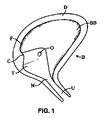
図1〜図3を参照すると、女性の膀胱の解剖構造が、従来から公知の治療様式を議論するためのコンテキストを提供するために記載されており、何故に治療様式の向上の必要性が未だ満たされていないかを示す。詳細には、図1は、膀胱(B)および尿道(U)の解剖学的構造の側方断面を示し、図2は、膀胱および尿道の前方断面図を示す。図1〜図2は、三角部(T)、尿管口(O)(尿管口とも呼ばれる)、排尿筋(D)、頸部(N)、尿管間隆起(C)、底部(F)および本体(BB)をさらに示す。 1-3, the anatomy of the female bladder is described to provide a context for discussing previously known treatment modalities, and why there is still a need for improved treatment modalities Indicates whether it is not satisfied. Specifically, FIG. 1 shows a lateral cross section of the anatomy of the bladder (B) and urethra (U), and FIG. 2 shows an anterior cross section of the bladder and urethra. 1 to 2 show a triangular part (T), a ureteral opening (O) (also called a ureteral opening), a detrusor muscle (D), a neck (N), an interureteral protuberance (C), and a bottom part (F ) And the body (BB) are further shown.
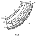
図3は、膀胱の壁の断面図であり、膀胱内領域(IR)(空洞とも呼ばれる)、粘液分泌性の膜(粘膜とも呼ばれる)、固有層(LP)、筋固有層(MP)、外膜(A)および膀胱周囲の脂肪(PF)を含む。粘液分泌性の膜は、膀胱の膀胱内領域(IR)にあり、移行細胞上皮(TCE)または尿路上皮と総称される3層上皮と、基底膜(BM)とを含む。移行細胞上皮の3つの層は、基底細胞層、中間細胞層および表面細胞層を含む。基底細胞層は、移行細胞上皮を細胞分裂により再生させ得る。新細胞は、基底層から表面細胞層へ移動し得、表面細胞層は、グリコサミノグリカン(GAG)層(GL)によって被覆され得る。GAG層の機能は議論を呼んでいるが、恐らくは浸透障害またはさらには移行細胞上皮の抗菌コーティングを提供する可能性がある。基底膜は、細胞の単一層であり、移行細胞上皮を粘膜固有層から分離させる。 3 is a cross-sectional view of the bladder wall, showing the intravesical region (IR) (also called the cavity), mucous secretory membrane (also called the mucosa), lamina (LP), muscle lamina (MP), outer Contains membrane (A) and peri-bladder fat (PF). The mucous secretory membrane is in the intravesical region (IR) of the bladder and includes the three-layer epithelium, collectively referred to as transitional cell epithelium (TCE) or urothelium, and the basement membrane (BM). The three layers of transitional cell epithelium include a basal cell layer, an intermediate cell layer, and a surface cell layer. The basal cell layer can regenerate transitional cell epithelium by cell division. New cells can migrate from the basal layer to the surface cell layer, which can be covered by a glycosaminoglycan (GAG) layer (GL). The function of the GAG layer is controversial, but may possibly provide osmotic damage or even an antimicrobial coating of the transitional cell epithelium. The basement membrane is a single layer of cells that separates the transitional cell epithelium from the lamina propria.
粘膜固有層(粘膜下層または副尿管上皮とも呼ばれる)は、シート状の細胞外材料であり、粘膜のろ過障壁または支持構造として機能し得、環状の結合組織を含み、血管、神経を含み、いくつかの領域においては腺を含む。筋固有層(排尿筋または筋肉層とも呼ばれる)は、粘膜固有層と組み合わされ得、平滑筋、内縦、中輪および外縦筋肉の3層を持ち得る。 The lamina propria (also referred to as the submucosa or accessory ureteral epithelium) is a sheet-like extracellular material that can function as a mucosal filtration barrier or support structure, includes cyclic connective tissue, includes blood vessels, nerves, Some areas contain glands. The lamina propria (also called detrusor or muscular layer) can be combined with the lamina propria and can have 3 layers: smooth muscle, inner longitudinal, middle ring and outer longitudinal muscle.
膀胱が空の場合、粘膜は、皺と呼ばれる多数の折り目を有する。皺および移行細胞上皮は弾性があるため、膀胱に流体が満たされるにつれて、膀胱は膨張していく。膀胱が満杯であるときの粘膜および筋固有層の厚さはおよそ2〜5mmであり得、膀胱が空のときの厚さはおよそ8〜15mmであり得る。 When the bladder is empty, the mucosa has a number of folds called folds. Because the wing and transitional cell epithelium are elastic, the bladder expands as the bladder fills with fluid. When the bladder is full, the thickness of the mucosa and lamina propria can be approximately 2-5 mm, and when the bladder is empty, the thickness can be approximately 8-15 mm.
筋固有層の外面は、膀胱の後方および前方面の周囲において外膜Aによって包囲され得るか、または、膀胱の上方および上側方面の周囲において漿膜によって包囲され得る。膀胱周囲の脂肪(PF)は、漿膜または外膜の外側において膀胱を包囲し得る。いくつかの場合において、多様な筋膜層が、骨盤の臓器を包囲するかまたは支持し得る。尿膀胱の近隣の筋膜は、膀胱周囲の筋膜として参照され得る。 The outer surface of the muscle lamina can be surrounded by the outer membrane A around the posterior and anterior surfaces of the bladder, or it can be surrounded by the serosa around the upper and upper sides of the bladder. Perivesical fat (PF) can surround the bladder outside the serosa or outer membrane. In some cases, various fascial layers may surround or support the pelvic organs. The fascia near the urinary bladder can be referred to as the pericardial fascia.
過活動膀胱の治療法は多数開発されており、抗コリン薬送達、膀胱再訓練、仙骨神経刺激(SNS)、膀胱内薬剤注入、外科的脱神経手術、膀胱容積増加のための手術(例えば、排尿筋筋腫摘出、膀胱拡大術)および膀胱壁中へのボツリヌス毒素(例えば、Botox.RTM.、Dysport.RTM)の注入などを挙げることができる。これらの治療はそれぞれ、以下に記載するように、欠点がある。 Many treatments for overactive bladder have been developed, including anticholinergic drug delivery, bladder retraining, sacral nerve stimulation (SNS), intravesical drug infusion, surgical denervation surgery, surgery to increase bladder volume (e.g., Examples include detruded myomectomy, bladder enlargement) and injection of botulinum toxin (eg, Botox.RTM., Dysport.RTM) into the bladder wall. Each of these treatments has drawbacks, as described below.
抗コリン薬は、単独でも用いられ、または従来の非外科的アプローチ(例えば、膀胱再訓練、ケーゲル体操、バイオフィードバック)と共に用いられ過活動膀胱に対してしばしば最初に用いられる治療法であるが、その作用機序は、確かではない。抗コリン薬の使用は、充填段階(例えば、排尿筋過活動、排尿筋不安定)時における排尿筋の収縮を低下させると当初思われていた。しかし、現在では、抗コリン薬は、排尿筋の収縮性を変化させるのではなく、中枢神経系へ求心性(例えば、コリン作用)神経通行を調節するものと考えられている。 Although anticholinergic drugs are used alone or in conjunction with traditional non-surgical approaches (eg, bladder retraining, kegel exercises, biofeedback), they are often the first treatment used for overactive bladder, The mechanism of action is uncertain. The use of anticholinergic drugs was initially thought to reduce detrusor contraction during the filling phase (eg, detrusor overactivity, detrusor instability). However, anticholinergic drugs are now thought to modulate afferent (eg, cholinergic) nerve traffic to the central nervous system rather than altering detrusor contractility.
抗コリン薬の有効性は一般的には極めて緩やかであり、患者のうちおよそ50%はこのような治療は不適切であると主観的に思っている。典型的には、1日あたりの排尿回数が10%〜20%だけ低減(例えば、排尿回数を11回から9回に低減)し、尿失禁発現が50%だけ低減(例えば、1日あたり2回から1日あたり1回)する。しかし、これらの効果は、患者の生活の質(QOL)を顕著に改善させるのには不適切である場合が多い。多くの患者の場合、本格的な研究のために記録をとらない限り、1日あたり2回の排尿の変化にさえ気づかない。残りの尿失禁発現は、若干少なくなるものの、疾病による兆候は消えず、ライフスタイルも制約される(例えば、旅行ができないまたは活発に動けない、社会的引きこもり)。加えて、抗コリン薬には非常に不愉快な副作用があり得(口渇、便秘、精神状態の変化、かすみ目)、多くの場合、達成される緩やかな恩恵よりも副作用の方が重篤である。患者のおよそ50%は、抗コリン作用治療を6ヶ月以内に放棄する。 The effectiveness of anticholinergic drugs is generally very modest and approximately 50% of patients subjectively believe that such treatment is inadequate. Typically, the number of urinations per day is reduced by 10% to 20% (eg, the number of urinations is reduced from 11 to 9), and the occurrence of urinary incontinence is reduced by 50% (eg, 2 per day). Once per day). However, these effects are often inadequate to significantly improve the patient's quality of life (QOL). Many patients are not even aware of two urination changes per day unless they are recorded for a full study. Remaining urinary incontinence will be slightly less, but signs of disease will not go away and lifestyle will be constrained (eg, unable to travel or not being active, social withdrawal). In addition, anticholinergic drugs can have very unpleasant side effects (dry mouth, constipation, changes in mental state, blurred vision), and in many cases the side effects are more severe than the gradual benefits achieved. is there. Approximately 50% of patients abandon anticholinergic treatment within 6 months.
仙骨神経刺激(SNS)は、有効性はより高い(例えば、適切に選択されかつスクリーニングされた患者において80%まで有効である)が、作用機序がよく理解されていない。尿失禁に対するSNSの臨床的恩恵は、他の状態についてSNSを臨床試験しているときに偶然発見された。SNS術は、複数の欠点を有している:すなわち、高価かつ侵襲性があり、患者反応を試験するために一時的な電極配置の手術が必要であり、その後恒久的な電極配置を行い、一時的電極に対して好ましい反応を示した患者内にパルス発生器を外科的に移植する必要もある。その上、SNS刺激パラメータの漸増のために定期的フォローアップも必要であり、電池交換も定期的に必要になる。 Sacral nerve stimulation (SNS) is more effective (eg, up to 80% effective in appropriately selected and screened patients), but the mechanism of action is not well understood. The clinical benefits of SNS for urinary incontinence were discovered by chance when clinically testing SNS for other conditions. SNS surgery has several drawbacks: expensive and invasive, requires temporary electrode placement surgery to test patient response, then performs permanent electrode placement, There is also a need to surgically implant a pulse generator in a patient who has shown a favorable response to the temporary electrode. In addition, periodic follow-up is also required to gradually increase the SNS stimulation parameters, and battery replacement is also required periodically.
多様な外科的脱神経または混乱手術が文献に記載されているが、ほとんどのものは有効性または耐久性に乏しいことが分かっている。Ingelman−Sundberg術は、最初に1950年代に開発され、Ingelman−Sundberg、A.の「Partial denervation of the bladder: a new operation for the treatment of urge incontinence and similar conditions in women」(Acta Obstet Gynecol Scand、38:487、1959)に記載されており、膀胱底部近隣の膀胱側方面を供給する神経の大規模外科的切開が必要になる。これらの神経は、前方の膣円蓋からアクセスされ、切開は、膀胱側方面へ両方向に延びる。脱神経プロセスは、空間の大きな切開を用い、かつ末端骨盤神経分岐を目指して若干やみくもに達成される。有望な結果を得ることが可能ではあるものの、当初のような手術は、外科的手術につきものの欠陥および費用全てから逃れられない。 A variety of surgical denervation or disruption procedures have been described in the literature, but most have been found to be less effective or durable. The Ingelman-Sundberg technique was first developed in the 1950's and was developed by Ingelman-Sundberg, A. et al. "Partial degeneration of the bladed: a new operation for the treatment of the wound of intension and simulative conditions in womb" (Act OBstet) A large surgical incision of the nerve to do is required. These nerves are accessed from the anterior vaginal fornix and the incision extends in both directions to the lateral side of the bladder. The denervation process is accomplished slightly using a large incision in space and aiming at the distal pelvic nerve bifurcation. Although it is possible to achieve promising results, surgery as initially does not escape all the deficiencies and costs associated with surgical procedures.
McGuireは、Ingelman−Sundberg術を1990年代に修正し、Wan,J.,et al.,「Ingelman−Sundberg bladder denervation for detrusor instability」、“J.Urol.、suppl.、145:358A、abstract581、1991に記載されるように、膀胱の漿膜層内における、より制限された中央切開を用いて、膣円蓋部内に留めるものである。この修正されたIngelman−Sundberg術の外科的候補はスクリーニングされ、三角部下麻酔注入を用いて「レスポンダー」となる可能性のある者を分離し得る。1996年にCespedesがCespedes,R.D..et al.,「Modified Ingelman−Sundberg Bladder Denervation Procedure For Intractable Urge Incontinence」(J.Urol.,156:1744−1747(1996))において報告しているように、術後における平均15ヶ月のフォローアップを行ったところ、64%の有効性が認められた。2002年には、Westneyは、Westney,O.L,et al.,「Long−Term Results Of Ingelman−Sundberg Denervation Procedure For Urge Incontinence Refractory To Medical Therapy」、J.Urol.,168:1044−1047(2002)において、術後フォローアップを平均44ヶ月間行ったところ、同様の有効性が達成されたことを報告した。より最近では、2007年において、Juangは、Juang,C,et al.、「Efficacy Analysis of Trans−obturator Tension−free Vaginal Tape (TVT−O) Plus Modified Ingelman−Sundberg Procedure versus TVT−O Alone in the Treatment of Mixed Urinary Incontinence: A Randomized Study」、E.Urol.,51:1671−1679(2007)において、経膣テープ(TVT)スリング(緊張性失禁の外科的治療法における「金本位制」)および混合失禁患者に対する修正Ingelman−Sundberg手術を組み合わせて用いて、術後フォローアップを12ヶ月間行ったところ、修正Ingelman−Sundberg手術においては、単独でTVTスリングを用いた場合よりも恩恵が大きく上回った、と報告した。 McGuire modified the Ingelman-Sundberg technique in the 1990s. , Et al. , “Ingelman-Sundberg blade degeneration for detrusor instability”, “J. Urol., Suppl., 145: 358A, abstract 581, 1991, using a more restricted central incision in the serosa layer of the bladder. This modified Ingelman-Sundberg surgical candidate can be screened and used to isolate potential "responders" using subtriangular anesthesia injections. In 1996, Cepedes was published by Cepedes, R .; D. . et al. , "Modified Ingelman-Sundberg Blade Degeneration Procedure For Intactable Urge Intinence" (J. Urol., 156: 1744-1747 (1996)), an average of 15 follow-ups as reported. 64% effectiveness was observed. In 2002, Westney was registered in Westney, O.D. L, et al. , "Long-Term Results Of Ingelman-Sundberg Devolution Procedure For Urge Incontinuance Reference To Medical Therapy", J. Am. Urol. 168: 1044-1047 (2002) reported that similar post-operative follow-up was achieved for an average of 44 months and similar efficacy was achieved. More recently, in 2007, Jung, Jung, C, et al. , "Efficacy Analysis of Trans-obturator Tension-free Vaginal Tape (TVT-O) Plus Modified Ingelman-Sundberg Procedure versus TVT-O Alone in the Treatment of Mixed Urinary Incontinence: A Randomized Study", E. Urol. 51: 1671-1679 (2007) using a combination of transvaginal tape (TVT) sling (“gold standard” in surgical treatment of stress incontinence) and modified Ingelman-Sundberg surgery for mixed incontinence patients. After 12 months of follow-up, it was reported that the benefits were significantly greater in the modified Ingelman-Sundberg surgery than when using the TVT sling alone.
このような臨床的成功にも関わらず、しかし、修正Ingelman−Sundberg術の場合、侵襲性が高くまた全身麻酔も必要になるため、幅広い適用に至っていない。さらに、末端神経分岐は外科医が目視することができないため、標的となる神経分岐を直接目視するのではなくおおよその解剖学的目印を用いて切開を行う必要が出てくる。修正Ingelman−Sundberg手術において発生し得る合併症を挙げると、麻酔、失血、膣の知覚麻痺または線維症、接着、瘻孔、膣狭窄、創傷感染症、または性交困難(性交時の痛み)に関連する危険性がある。恐らく最も重要なことは、修正Ingelman−Sundberg術の有効性が外科的なスキルおよび技術に依存する可能性があることである。 Despite such clinical success, however, the modified Ingelman-Sundberg procedure has not been widely applied because it is highly invasive and requires general anesthesia. Furthermore, since the distal nerve branch cannot be seen by the surgeon, an incision must be made using an approximate anatomical landmark rather than directly viewing the targeted nerve branch. Complications that may occur in modified Ingelman-Sundberg surgery are related to anesthesia, blood loss, vaginal numbness or fibrosis, adhesion, fistula, vaginal stenosis, wound infection, or sexual intercourse (pain during intercourse) There is a risk. Perhaps most importantly, the effectiveness of the modified Ingelman-Sundberg procedure may depend on surgical skills and techniques.
より最近では、神経トラフィックの遮断により注入後の一時的な筋肉麻痺を生じさせて過活動膀胱症状に対処するために、膀胱壁中にボツリヌス毒素(例えば、Botox.RTM.)を注入する別の治療法が開発されている。この注入手術は、医師のオフィスにおいて局所麻酔下において行われ得、膀胱鏡を、尿道を通じて膀胱中に導入し、複数の別個のカニューレ注入(例えば、20〜30回)を膀胱壁内において行う。先ず、三角部領域の高密度の求心性神経支配による処置痛および膀胱尿管逆流の可能性に対する懸念のため、2本の尿管および尿道口によって規定された膀胱の領域である三角部を避ける。しかし、より最近では三角部領域も含まれることとなり、膀胱の半球部分を排除することを目的にする場合もある。初期には、ボツリヌス毒素を遠心性運動神経(例えば、排尿筋の部分的麻痺を発生させるもの)のみに対して作用するものと仮定された。より最近の研究によれば、ボツリヌス毒素は、求心性知覚神経にも有効であり得ることが判明している。Versiに付与された米国特許第8,029,496号において、このような治療剤を、膣壁を通じて膀胱へ送達するためのシステムの一例が記載されている。 More recently, another injection of botulinum toxin (eg, Botox. RTM.) Into the bladder wall to cause transient muscle paralysis after injection by blocking nerve traffic to address overactive bladder symptoms. Treatments are being developed. This infusion operation can be performed under local anesthesia in a doctor's office, with a cystoscope introduced into the bladder through the urethra and multiple separate cannula infusions (eg, 20-30 times) performed within the bladder wall. First, avoid the triangle, the area of the bladder defined by the two ureters and the urethral opening, due to concerns about treatment pain and the possibility of vesicoureteral reflux due to high density afferent innervation of the triangle area . However, more recently, the triangular region is also included, and the purpose may be to eliminate the hemispherical portion of the bladder. Initially, it was postulated that botulinum toxin acts only on efferent motor nerves (eg, those that cause partial detrusor paralysis). More recent studies have shown that botulinum toxin can also be effective for afferent sensory nerves. In US Pat. No. 8,029,496 to Versi, an example of a system for delivering such therapeutic agents through the vaginal wall to the bladder is described.
典型的には、ボツリヌス毒素注入の場合、極めて高レベルの有効性(例えば、症状の解消)が達成され、膀胱容量のピークの最大変化が4週間目で発生し、患者のうち半数において完全な随意調節が達成された。しかし、ボツリヌス毒素の場合、全身的作用の危険性(例えば、インフルエンザのような症状、吐き気、呼吸筋の弱体化、一時的な筋肉の弱体化、アレルギー反応、または感受性増加)を伴う。ボツリヌス毒素注入に関連する他の有害事象を挙げると、急性尿閉(AUR)、排尿後残尿量増加(PVR)、排尿困難(「しぶり腹」)、および尿路感染症(UTI)がある。ボツリヌス毒素による治療法の問題点を挙げると、手術スキル(例えば、膀胱鏡および針を用いた器用さ)、薬物拡散の制御不能、針貫通深さの変動、技術再現性がある。加えて、ボツリヌス毒素の効果は経時的、典型的には6〜9ヶ月後に薄れるため、患者の寿命にわたって繰り返し注入する必要がある。 Typically, in the case of botulinum toxin infusions, very high levels of efficacy (eg, resolution of symptoms) are achieved, with a maximum change in peak bladder capacity occurring at 4 weeks and complete in half of patients Voluntary adjustment was achieved. However, botulinum toxins are associated with systemic effects (eg, flu-like symptoms, nausea, respiratory muscle weakness, temporary muscle weakness, allergic reactions, or increased sensitivity). Other adverse events associated with botulinum toxin infusion include acute urinary retention (AUR), increased post urinary residual volume (PVR), difficulty urinating ("shoulder belly"), and urinary tract infection (UTI). is there. Problems with botulinum toxin treatment include surgical skills (eg, dexterity using cystoscopes and needles), uncontrollable drug diffusion, variations in needle penetration depth, and technology reproducibility. In addition, the effects of botulinum toxin diminish over time, typically 6-9 months, and therefore require repeated infusions over the life of the patient.
緊張性尿失禁は、典型的には女性が罹患し、出産などに起因する骨盤床の損傷および弱体化による解剖学的問題である。ここで、第一線の治療は保守的なものであり(例えば、ケーゲル体操またはバイオフィードバック)、多様な侵襲性を最小限にした外科的治療が第2の治療法として利用可能である。これらの第2の治療法の例を挙げると、スリング手術、膀胱頸部懸垂、経膣テープ(TVT)などがある。それぞれにおいて、手術は、外来ベースの日帰り手術で行われている。成功率は高いため、この術は、医療界において受容されている。 Stress urinary incontinence is an anatomical problem that typically affects women and is due to pelvic floor damage and weakening, such as due to childbirth. Here, the first-line treatment is conservative (eg, Kegel exercises or biofeedback), and a variety of minimally invasive surgical treatments are available as the second treatment. Examples of these second therapies include sling surgery, bladder neck suspension, transvaginal tape (TVT) and the like. In each, the surgery is performed on an outpatient day trip. Because of the high success rate, this technique is accepted by the medical community.
加えて、緊張性尿失禁治療のために、例えば、オフィスベースの手術において用いられているNovasys Medical,Inc.から提供されているRenessa Systemといった新しい治療法が開発されている。米国特許第6,692,490号(Edwardsへ付与、Novasys Medicalへ譲渡)において、エネルギーおよび薬剤の付加による尿失禁および他の疾患の治療が開示されている。 In addition, Novasis Medical, Inc., which is used, for example, in office-based surgery, for the treatment of stress urinary incontinence. New therapies are being developed such as the Renesa System provided by U.S. Patent No. 6,692,490 (Granted to Edwards, assigned to Novasys Medical) discloses the treatment of urinary incontinence and other diseases by the addition of energy and drugs.
最後に、大多数の男性において、良性の前立腺肥大(BPH)または「前立腺肥大」に起因する一定レベルの尿閉塞が生涯において発生している。尿閉塞は、過活動膀胱の原因として知られており、男性における膀胱症状は、前立腺肥大に次いで多いと推定されている。しかし、尿閉塞の解消をしても(例えば、前立腺の経尿道治療の多数の変形例の1つによる)、患者の約1/4における膀胱症状は解消されない。そのため、前立腺治療法後も症状が残っているこれらの残りの患者のための、侵襲性を最小限にした治療術を提供することが望まれている。 Finally, in the majority of men, a certain level of urinary obstruction due to benign prostatic hypertrophy (BPH) or “prostatic hypertrophy” occurs throughout life. Urinary obstruction is known as the cause of overactive bladder, and it is estimated that bladder symptoms in men are second only to benign prostatic hyperplasia. However, eliminating urinary obstruction (eg, by one of many variations of prostate transurethral treatment) does not resolve bladder symptoms in about 1/4 of patients. Therefore, it is desirable to provide a minimally invasive treatment for these remaining patients who remain symptomatic after prostate treatment.
さらに、実際の前立腺癌においても前立腺疾患の「経過観察」が好まれる場合も増えてきており、これらの患者のうち多数は、前立腺成長による尿閉塞に起因する過活動膀胱の症状を発生させている。そのため、前立腺そのものを標的とした治療法の前にまたは前立腺そのものを標的とする代わりに、膀胱症状を標的とした治療法を提供する可能性がある。 In addition, there is an increasing number of people who prefer “follow-up” of prostate disease in actual prostate cancer, and many of these patients develop symptoms of overactive bladder due to urinary obstruction due to prostate growth. Yes. Therefore, there is a possibility of providing a treatment targeting the bladder condition before or instead of targeting the prostate itself.
男性が特発性OABを発症する場合もある。すなわち、OABは、前立腺肥大または他の尿閉塞に次ぐ続発性のものではなく、OAB症状に対する一次治療法を必要とする。 Men may develop idiopathic OAB. That is, OAB is not secondary to prostate enlargement or other urinary obstruction and requires a primary treatment for OAB symptoms.
上記を鑑みて、膀胱機能を変化させて過活動膀胱を治療するかまたは解消させ、これらの消耗状態に苦しんでいる患者の長期的な症状緩和を可能にする、侵襲性を最小限にした術式(procedure)を提供することが望まれている。 In view of the above, minimally invasive surgery that alters bladder function to treat or eliminate overactive bladder, allowing long-term relief of patients suffering from these exhausted conditions It would be desirable to provide a procedure.
発明の目的および概要
本発明は、予見されるかされないかに依らず多様な医療手術および治療を行うように構成された装置および方法に関する。非限定的な例示目的のため、本発明の装置および方法は、膀胱機能の調節のために非粘膜標的組織(または組織の標的容積)に対する治療法を提供することに適している。一例において、例えば、膀胱壁の三角部領域の内部またはその近隣に配置された求心性神経といった膀胱の選択された部位にエネルギーを送達して除神経し、膀胱機能の調節とを行うことにより、切迫感、失禁、頻数、夜間頻尿、膀胱容量または痛みのうち少なくとも1つの軽減を可能にする。
OBJECT AND SUMMARY OF THE INVENTION The present invention relates to an apparatus and method configured to perform a variety of medical procedures and treatments, whether foreseen or not. For non-limiting illustrative purposes, the devices and methods of the present invention are suitable for providing a therapy for non-mucosal target tissue (or tissue target volume) for modulation of bladder function. In one example, by delivering energy to a selected portion of the bladder, such as, for example, an afferent nerve located within or near the triangular region of the bladder wall to denervate and regulate bladder function Allows relief of at least one of urgency, incontinence, frequency, nocturia, bladder capacity or pain.
いくつかの例において、脱神経は、熱エネルギー(例えば、RFエネルギー、マイクロ波、または高強度集束超音波)を、粘膜層の下側の膀胱壁(例えば、三角部領域内またはその近隣のもの)の層へ送達することにより、達成され得る。本開示のコンテキストにおいて、エネルギー送達の標的となる女性の解剖構造の組織は、粘膜の下側において前方膣壁へ延び(かつ前方膣壁を含まない)膀胱壁の1つ以上の組織層を含み得、本明細書中において「非表在性組織」と総称される。さらに、本開示のコンテキストにおいて、エネルギー送達の標的となる男性解剖構造の組織は、粘膜の下側にありかつ膀胱周囲の脂肪層に延びて膀胱周囲の脂肪層を含む膀胱壁の1つ以上の層を含み得、本コンテキストにおいて「非表在性組織」とも呼ばれる。さらに他の例において、膀胱壁内部またはその近隣の神経組織(例えば、骨盤神経またはその分岐)へ熱エネルギーを送達して、膀胱の少なくとも一部に出入りする神経トラフィックを調節することにより、膀胱機能を調節する。いくつかの例によれば、吸引を用いて、膀胱壁の粘膜面を把持してデバイスの第1の面へ適合させ、エネルギーを粘膜面から実質的に均等な深さにおいて非表在性標的組織へ送達させることができる。粘膜内における熱蓄積を低減するため、冷却を行ってもよい。しかし、いくつかの例において、例えばデバイスの第1の面から実質的に均等な距離においてエネルギー送達要素を非表在性標的組織中に挿入し、粘膜面の下側の実質的に均等な深さからエネルギーを非表在性標的組織へ送達させることにより、非表在性標的組織に表在する膀胱壁の粘膜面を冷却無しに実質的に無傷のまま保持することができる。本明細書中に記載されるシステムおよび方法は、例えば、熱エネルギーといったエネルギーを、身体臓器例えば、膀胱の内腔または空洞内からまたは例えば膣といった近隣臓器の内腔または空洞から標的組織へ送達するように、構成され得る。 In some examples, denervation involves thermal energy (eg, RF energy, microwave, or high intensity focused ultrasound), bladder wall below the mucosal layer (eg, within or near the triangular region). ) Can be achieved by delivery to a layer of In the context of the present disclosure, the tissue of the female anatomy targeted for energy delivery includes one or more tissue layers of the bladder wall that extend below the mucosa (and exclude the anterior vaginal wall). And collectively referred to herein as "non-superficial tissue". Further, in the context of the present disclosure, the tissue of the male anatomy targeted for energy delivery is one or more of the bladder walls that underlie the mucous membrane and extend to the fat layer around the bladder and include the fat layer around the bladder It may include layers and is also referred to in this context as “non-superficial tissue”. In yet another example, bladder function is achieved by delivering thermal energy to or within neural tissue within or adjacent to the bladder wall (eg, the pelvic nerve or branch thereof) to regulate nerve traffic to and from at least a portion of the bladder. Adjust. According to some examples, suction is used to grasp the mucosal surface of the bladder wall to conform to the first surface of the device and to transfer energy to the non-superficial target at a substantially uniform depth from the mucosal surface. Can be delivered to tissue. Cooling may be performed to reduce heat accumulation in the mucosa. However, in some instances, the energy delivery element is inserted into the non-superficial target tissue, eg, at a substantially equal distance from the first surface of the device, and a substantially equal depth below the mucosal surface. In addition, by delivering energy to the non-superficial target tissue, the mucosal surface of the bladder wall superficial to the non-superficial target tissue can be kept substantially intact without cooling. The systems and methods described herein deliver energy, such as thermal energy, to a target tissue from a bodily organ, such as the lumen or cavity of a bladder or from the lumen or cavity of a neighboring organ, such as the vagina, for example. Can be configured as such.
本明細書中に記載されるシステムおよび方法の代替または任意選択的な付加において、例えば切迫感を抑制するために、膀胱の1つ以上の領域を分離または支持することができる。例えば、外科的障壁または治療を用いて、膀胱の例えば、三角部といった選択領域の伸縮性を低減させるか、あるいは、これをエネルギー送達への付属物として用いて、膀胱の治療部位における神経の再成長を回避することができる。 In an alternative or optional addition to the systems and methods described herein, one or more regions of the bladder can be isolated or supported, eg, to reduce urgency. For example, a surgical barrier or treatment may be used to reduce the elasticity of selected areas of the bladder, such as the triangle, or it may be used as an adjunct to energy delivery to regenerate nerves at the treatment site of the bladder. Growth can be avoided.
この概要は、本特許出願の発明を説明するために記載されたものであり、本発明の排他的または網羅的な説明を提供することを意図していない。詳細な記載は、本特許出願に関するさらなる情報を提供するためのものである。
図面の簡単な説明
This summary is provided to illustrate the invention of this patent application and is not intended to provide an exclusive or exhaustive description of the invention. The detailed description is intended to provide further information regarding this patent application.
Brief Description of Drawings
本発明の実施形態において上記および他の側面、特徴および利点が可能であるかは、本発明の以下の実施形態の説明から明確になる。参照は、添付図面についてのものである。 Whether the above and other aspects, features, and advantages of the embodiments of the present invention are possible will become apparent from the following description of the embodiments of the present invention. Reference is made to the accompanying drawings.
実施形態の説明
ここで、添付図面を参照して、本発明の特定の実施形態について説明する。しかし、本発明は、多数の異なる形態で具現化可能であり、本明細書中に記載される実施形態に限定されるものとして解釈されるべきではなく、これらの実施形態は、本開示が網羅的かつ完全なものとなるように記載されるものであり、本発明の範囲を当業者に詳細に伝達するであろう。添付図面中に示される実施形態の詳細な説明において用いられる用語は、本発明を制限することを意図していない。図面中、類似の参照符号は、類似の要素を指す。
DESCRIPTION OF EMBODIMENTS Specific embodiments of the present invention will now be described with reference to the accompanying drawings. However, the present invention can be embodied in many different forms and should not be construed as limited to the embodiments set forth herein, which are intended to be exhaustive of the present disclosure. Are intended to be complete and complete, and will convey the scope of the invention to those skilled in the art in detail. The terms used in the detailed description of the embodiments illustrated in the accompanying drawings are not intended to limit the present invention. In the drawings, like reference numbers indicate like elements.
図4は、身体組織(例えば、膀胱)の治療のためのシステム10の実施形態を示す。一般的に、本システムは、治療デバイス20を含み、内視鏡12を含み得る。治療デバイス20は、近位端22、遠位端24、近位端22と遠位端24との間の細長シャフト部位26を有する。
FIG. 4 shows an embodiment of a
治療デバイス20の近位端22は、図5に詳細を示すハンドルアセンブリ30を含み得る。ハンドルアセンブリ30は、以下に示す、本体32、スライド機構34(図4aおよび図5a)、1つ以上の吸引ポート36、および電極セットのための少なくとも1つのレシーバ38を含み得る。ハンドルアセンブリ30は一般的には、内視鏡位置を治療デバイスへ固定するように機能し、また、ユーザによる把持を快適に可能にする機能を提供する。この目的のため、ハンドルアセンブリ30は、任意の数の人間工学的形状をとり得る。図に示すものの代替的形状として、「ピストルグリップ状」形状がある。
The
スライド機構34は、内視鏡12の治療デバイスへの縦方向配置または軸方向配置を受容および制御するように機能する。スライド機構34は、ハンドルアセンブリ30の本体32によって若干受容されるスライド管40(図5aを参照)を含む。スライド管40は、本体32内の溝部44内に設けられた停止部42を含む。停止部42および溝部44により、縦方向の動きの範囲が規定され、スライド機構34の本体32に対する回転が回避される。本体32は、近位端に挿入された内視鏡12を収容することが分かる。従来のホプキンスロッド内視鏡が図示されているが、例えば、先端またはその近隣にカメラを備えた内視鏡といった別の画像化デバイスも企図される。図4および図5において、スライド管40が完全挿入位置にある様子が確認でき、図4aおよび図5aにおいて部分的に退避位置にある様子が確認できる。カメラ(図示せず)は、アイピースへ接続され得る。
The
図6は、ハンドルアセンブリ30の近位端の斜視図であり、内部に内視鏡12は挿入されていない。スライド管40によりスコープチャンネル16の近位端が規定され、スコープチャンネル16は、内視鏡12を受容し、治療デバイス20の長さに実質的に延びることが分かる。スライド管40はまた、内視鏡12の垂直制御ポストおよび/または光入力ポート18を収容する切り欠き46を提供する。切り欠き46により、内視鏡がスライド機構34のスライド管40へ完全挿入されたときに、治療デバイス20と内視鏡12との間のラジアル関係が確立される。切り欠きは半球型設計になっているため、ユーザが患者内の治療デバイス20を回転させることなくスコープの目視角度を変更したいと思った場合、ユーザが容易に内視鏡12をスライド管40から若干退避させ、スコープ12そのものを回転させることが可能になる。
FIG. 6 is a perspective view of the proximal end of the
スライド機構34はまた、ロックタブ48を含む。ロックタブ48は、スライド管40を通じて延び、押圧されると、内視鏡12と摩擦係合する。ロックタブ48は、内視鏡12と係合した場合、スライド管40に対する内視鏡12の長手方向の運動を防止する。
The
スライド機構34は手動スライド機構であるが、他の構成も考えられる。これらの他の構成の非限定的例としては、ダイアル、ラック&ピニオン機構、トリガ機構、ロッカースイッチ構成、ウォーム駆動、ギア、ステッパーモーターを挙げることができる。
The
スコープチャンネル16の下側において、ハンドルアセンブリの本体32は、少なくとも1つの吸引ポート36を含む。図示される実施形態は、2つの吸引ポート36を含む。これらの吸引ポート36は、治療デバイス20の長さに延びる吸引チャンネル17と流体連通する。吸引ポート36は、標準的なルアーロック取付具と共に図示されているが、これはあくまで例示目的のためであり、限定的なものを意図していない。
Below the
加えて、これらの吸引ポート36は、潅注または点滴目的のために用いられ得る。フロー制御弁(図示せず)(例えば、停止コック)を用いて、吸引および/または吸引源をポート36へ接続させることができる。ポート36のうち1つ以上は、雰囲気への通気孔としても機能し得る。取付具のうち1つ以上は、シリンジへ恒久的または偶発的に接続され得る。シリンジは、デバイスが内部において用いられる解剖学的構造の内外において一定量の流体の注入または抽出を行うために用いられ得ることも考えられる。
In addition, these
ハンドルアセンブリ30の本体32は、また電極セットのための1つ以上のレシーバ38規定し得る。図示される実施形態は、2つの電極セット54を収容するレシーバ38を含む。これら2つの電極セット54のうち1つは、スコープチャンネル16および吸引チャンネル17のいずれかの側部に設けられる。レシーバ38は、電極セット54の近位端を収容するようなサイズおよび形状にされ、カニューレチャンネル52に誘導するカニューレポート50を提供する。カニューレポート50は、容易なカニューレ挿入を促すためにじょうご状されている様子が図示されている。
The
電極セット54は、図4および図7〜図9に最も良く示されている。電極セット54は、電極56と、そこから遠位方向に延びるカニューレ58とを主に含む。電極56を電源へ接続させる接続ワイヤが理解されるべきであるが、図示されていない。電極56は、カニューレを通じて延び、先端においてカニューレを励起させる。電極の導電性端部がカニューレ内に設けられていないオールインワン電極セットも企図される。本明細書中、明確さのため、電極56は、電極セットのうち電源へ接続された部位がカニューレ励起のための回路を提供するものとみなされる。カニューレ58は、患者内へエネルギーを伝達する電極セットの励起部位である。
The electrode set 54 is best shown in FIGS. 4 and 7-9. The electrode set 54 mainly includes an electrode 56 and a
電極セット54および対応するカニューレチャンネル52は、電極セットがカニューレチャンネル52に完全挿入された場合に、カニューレ58のハブがレシーバ38に隣接しかつカニューレ58の遠位端がカニューレチャンネルの遠位端80を一定量だけ過ぎて延びるようなサイズとされる。図14は、カニューレ58が完全挿入されたときのデバイスの遠位端を示す。図14は、絶縁体59がカニューレ58の端部を除いて全て包囲することにより、カニューレ58の有効治療部位をカニューレの遠位端へ限定することも示す。
The electrode set 54 and the
電極セット54がチャンネル52およびレシーバ38内に配置された後は、電極セット54は、退避位置と挿入位置との間において移動可能である。上記したような挿入位置は、カニューレ58のハブがレシーバ38に隣接するように電極セット54がチャンネル52中へ完全挿入された場合に達成される。退避位置は、電極56が図4に示すように近位方向に牽引された場合、退避位置が達成される。退避位置において、カニューレ58の遠位端は、カニューレチャンネル52内に収容され、カニューレチャンネル端部80から延びない。レシーバ38は、電極セット54が退避位置にある場合であっても、電極56を収容するようなサイズにされる。
After the electrode set 54 is disposed in the
任意の適切な電極を治療デバイスと共に用いることが可能であることが理解されるべきである。好適な種類としては、例えば、Stryker、Cosman、Neurothermによって製造されたもののように針状端部を含むものまたは電極がカニューレ内に配置されたものがあるが、例えば、「ワンピース」型でありかつ外部カニューレ無しに組織を直接貫通することが可能な電極といった、他の電極も企図される。また、先端部に例えば、埋設された熱電対またはサーミスタといった温度測定要素を有する種類の電極を用いることも好適である。Stryker、Cosman、Neurothermによって製造された種類のものは、この機能を含む。 It should be understood that any suitable electrode can be used with the treatment device. Suitable types include, for example, those that include a needle-like end, such as those manufactured by Stryker, Cosman, Neurotherm, or those in which an electrode is disposed within the cannula, but are, for example, “one-piece” types and Other electrodes are also contemplated, such as electrodes that can penetrate tissue directly without an external cannula. It is also preferable to use an electrode of a type having a temperature measuring element such as a thermocouple or a thermistor embedded at the tip. The type produced by Stryker, Cosman, Neurotherm includes this functionality.
オペレータによって組み立てられる別個のコンポーネントを用いる代わりに、電極およびカニューレを治療デバイスそのものと一体化させるシステム10の実施形態が可能であることが見込まれる。さらに、カニューレ前進(図示では、各カニューレの別個の手動軸方向動きとして示される)を、同時前進のためのカニューレの接続およびカニューレ前進のための機構を含むように構成しても想定される。
Instead of using separate components assembled by the operator, it is anticipated that embodiments of the
図4に示す実施形態は、カニューレ58を退避から前進位置へ前進させるための機構を含まない。なぜならば、これは手動で行うことが可能であると考えられるからである。しかし、上述した機構も想定され、デバイスの操作をより高速かつ容易にするために設けてもよい。このような機構の例を挙げると、カニューレの前進および恐らくは退避を行うためのトリガ機構または回転らせん状ねじ込み機構を含む。好適には圧縮状態のばねの形態の保存エネルギーを解放させてカニューレを駆動して組織中へ移動させる「ばね荷重」機構も想定される。
The embodiment shown in FIG. 4 does not include a mechanism for advancing the
1つまたは2つの電極セットを用いて、組織切除を行うことができることが考えられる。図示のように2つの電極セットが用いられる場合、バイポーラ電流が付加され得、カニューレの露出部位間の比較的平面状の空間中へ電流を集中させる。 It is contemplated that tissue ablation can be performed using one or two electrode sets. If two electrode sets are used as shown, a bipolar current can be applied, concentrating the current into a relatively planar space between the exposed areas of the cannula.
加えて、2つの電極セットがバイポーラ構成において用いられる場合(または2つを超えるカニューレが対で励起されるように多重化された場合)、これらのカニューレは、その非絶縁部位に沿って相互に平行に設けられ、その結果、非絶縁長さに沿って均等な断面を有するエネルギー付与領域(すなわち、カニューレ長さに沿って厚さおよび幅が均等な治療)が得られる。 In addition, when two electrode sets are used in a bipolar configuration (or when more than two cannulas are multiplexed to be excited in pairs), these cannulas are connected to each other along their non-insulated sites. An energized region that is provided in parallel and has a uniform cross-section along the non-insulated length (ie, treatment of equal thickness and width along the cannula length) is obtained.
図7〜図9を参照して、ハンドルアセンブリ30の遠位は、シャフト部位26である。シャフト部位26は、概ねスコープチャンネル16、吸引チャンネル17およびカニューレチャンネル52によって構成される。図示のように、カニューレチャンネル52は、遠位面においてより小型のデバイス外形が得られるように曲線状にされ得る。シャフト部位26は、女性尿道に挿入できるような形状およびサイズにされ、また、女性尿道は男性の解剖構造に比べて比較的短く直線状であるため、比較的剛性とされ得る。男性の解剖構造と共に用いられるように設計されたデバイスの実施形態は、柔軟なシャフト部位を用いることができかつステアリング機構を含み得る点を除いて、図示の実施形態に実質的に類似する。
With reference to FIGS. 7-9, distal to the
治療デバイス20は遠位端24を有し、そのうちいくつかの実施形態の詳細を図10〜図15に示す。遠位端24は、概ね吸引ヘッド60、遠位カニューレチャンネル端部80、内視鏡チャンネル遠位端90、およびチューブホルダ94を含む。
The
吸引ヘッド60は、平坦面62およびヒール部位63を、1つ以上の角度付けされたかまたは曲線状の面64と共に含む。これらの面62および64により、少なくとも1つの吸引アパチャ66が規定される。図示の実施形態は、複数の吸引アパチャ66を多様な形状および配置構成で含み、これらそれぞれについて、以下により詳細に説明する。吸引アパチャ66は、吸引チャンネル17と流体連通する吸引室68へと誘導する。
The
吸引ヘッド60は、曲線的な無傷遠位端を含み得る。平坦面62は、吸引ヘッド60の遠位端からヒール部位63へ延び得る。吸引ヘッド60の形状は、吸引室68へ吸引が付加されたときに吸引ヘッド自身を軟組織に対して密封するように設計される。平坦面62により、標的である軟組織との密封が確立される。一方、ヒール部位63の面64により、カニューレチャンネル端部80への緩やかな移行が得られる。
The
図16は、平坦面62の中点においてとられた吸引ヘッド60の軸方向断面図である。吸引ヘッド60の形状は概して半円形であり得ることが図示される。これは、管の一部を切り欠いて比較的平坦な面を取り付けて形成され得る。アパチャ66は、切り欠かれるかまたは他の場合に面中に形成されて、吸引ヘッド60の内部吸引室68中へ開口を形成する。
FIG. 16 is an axial sectional view of the
上記したように、吸引アパチャ66は、多様なサイズ、形状および配置構成と共に構成され得る。例示目的のみのため、図11において示す実施形態において、4つの縦方向に細長形状のアパチャ66が平坦面62において2x2配置構成され、単一のアパチャ66が角度付き面64内に設けられる。図12に示す実施形態において、平坦面62は、12個の円形アパチャ66を2×6配置構成において有し、ヒール部位63は、2つの角度付き面64を有し、そのうち1つは2つのアパチャ66を備え、1つは単一のアパチャ66を備える。図13に示す実施形態において、平坦面62は、横方向に細長形状のアパチャ66を6個有し、第1の角度付き面64を備えるヒール部位63は、同様に横方向に細長形状のアパチャ66を有し、別の角度付き面64は、単一の円形アパチャ66を有する。
As described above, the
代替的にまたは追加的に、アパチャ66は、四角形または任意の他の適切な形状であり得、面およびヒール部位63どちらについても、多様なサイズおよび形状の組み合わせがさらに企図される。窓のうち1つ以上を被覆するスクリーン材料(図示せず)も企図される。図示の吸引面は比較的平面状であるが、例えば、縁部またはその近隣あるいは窓のうち1つ以上に沿った隆起リム、あるいは例えば、吸引窓中への組織侵入を制限するプラグといった陥凹フィーチャなど、面にさらなるフィーチャを持たせてもよいことがさらに企図される。
Alternatively or additionally, the
上記したように、アパチャ66は、吸引チャンネル17と流体連通する吸引室68に誘導する。吸引室68は、図15に最も良く示されている。本実施形態において、吸引室68は、バッフル72を含む。バッフル72により、吸引室68のうち吸引ヘッド60の平坦面62に直接隣接する部位と、吸引室のうちヒール部位63に隣接するかまたはヒール部位63の近位にある部位との間に障壁が得られる。組織が吸引されると、付加されている真空の強度と、組織の厚さおよび弾性との間でバランスされる。所与の真空レベルに対して組織が柔軟過ぎる場合、組織は吸引室68中へ吸引され得る。バッフル72により、吸引室68が組織によって完全に遮断されないことが保証される。そのため、組織がヒール部位63中へ吸引された場合も、真空を平坦面62に隣接して確立させるための経路がバッフル72の反対側上に存在する。
As described above, the
ヒール部位63は、少なくとも2つの機能を提供する。ヒール部位63の第1の機能は、角度付き面64内のアパチャ66と係合している組織を保持し、電極セットが当該組織中に前進しているときに、当該組織が吸引ヘッド60から押し出される事態を回避することである。角度付き面64の方向付けにより、電極セットの前進に起因して組織が縦方向の動きに抵抗することが支援される。
The
上記したように、ヒール部位63の第2の機能は、平坦面62とカニューレチャンネル端部80との間の移行を提供することである。平坦面62と、カニューレチャンネル52との間の垂直分離74(図10)により、電極セット/カニューレが貫通し、標的組織を治療する深さの規定が支援される。この垂直分離74により、膀胱内部の面層の治療を回避または最小化しつつ、電極セットが面の下側の標的組織層と係合する。
As described above, the second function of the
より詳細には、過活動膀胱治療のための膀胱の三角部領域の部位の焼灼などの膀胱用途のために、所望の間隔空けの一例は、0.5〜5.0mmであり、好適には1.0〜4.0mmである。このようにして、膀胱面における熱影響を最小化しつつ、粘膜下層組織の熱治療を、求心性神経の混乱が有効であると考えられる膀胱面から約0.0〜7.0mmの深さに集中させることが考えられる。より大きなまたはより小さな間隔空けも企図される。カニューレ間に水平方向の間隔76を設けると、熱治療ゾーンの幅に影響が出る。(図14に示す)好適な間隔は、3〜5mmである。 More specifically, for bladder applications such as cauterization of a region of the triangular region of the bladder for the treatment of overactive bladder, an example of a desired spacing is 0.5-5.0 mm, preferably 1.0 to 4.0 mm. In this way, heat treatment of the submucosal tissue is performed at a depth of about 0.0 to 7.0 mm from the bladder surface, where afferent nerve disruption is considered effective, while minimizing thermal effects on the bladder surface. It is possible to concentrate. Larger or smaller spacings are also contemplated. Providing a horizontal spacing 76 between the cannulas affects the width of the thermal treatment zone. The preferred spacing (shown in FIG. 14) is 3-5 mm.
図10は、カニューレの軸および吸引ヘッドが平行である(すなわち、カニューレが面62の長さ全体に沿って平坦面62から均等な距離にある)構成を示す。これは好適な実施形態であるものの、パドルとカニューレとの間の特定の非ゼロ角度により、特定の恩恵を得ることができることも見込まれる。例えば、非ゼロ角度が、治療法を異なる優先的な深さへ付勢するかまたは組織を通じて組織特性またはカニューレ追跡の差を修正するように、カニューレの遠位部位(およびよって治療法)を異なる距離において付勢するように選択され得る。
FIG. 10 shows a configuration where the axis of the cannula and the suction head are parallel (ie, the cannula is at an equal distance from the
図10および図15は、デバイス遠位端24が内視鏡チャンネル端部90も含むことを示す。内視鏡チャンネル端部90は、スコープが退避すると、チャンネル端部が無傷の外形を示すように、角度付けされる。
10 and 15 show that the device
図10は、内視鏡チャンネル端部90から突出するように、部分的に前進した位置にある内視鏡12の端部を示す。(比較目的のため、図11は、スコープ12が完全前進位置にある様子を示す)。この部分的に前進した位置において、スコープ12は、吸引ヘッド60と、吸引ヘッド60の前方にある組織との図である。
FIG. 10 shows the end of the
内視鏡を吸引ヘッド60の面からラジアル方向に距離を空けて配置することが望ましい場合がある。このような間隔空けにより、内視鏡画像が吸引ヘッドの存在によって「遮断される」度合いが少なくなるため、吸引ヘッドを所望の身体組織に対してより高精度に配置することが促進される。膀胱用途において、内視鏡が25〜35度の目視角度を有し、直径が約2.5〜3mmの範囲にあり、吸引ヘッドの幅が約4.5〜5.5mmであり、間隔が好適には約.25〜.75mmであるが、上記よりも大きいかまたは小さい値も企図される。間隔を大きくすると、吸引ヘッド60の見えにくさの量はさらに最小化されるものの、デバイス直径全体が大きくならざるを得ないため、例えばデバイスを尿道に挿入する膀胱のように、デバイス外形全体を小さくしたい用途において望ましくない。
It may be desirable to position the endoscope at a distance in the radial direction from the surface of the
デバイス遠位端24は、チューブホルダ94も含み得る。チューブホルダ94は、図10に示すように、治療デバイス20の多様な管/チャンネルを接続するために用いられ得るハウジングである。チューブホルダ94により、内視鏡管16、吸引管17および電極管52が固定される。このような管の配置構成を非円形の外形と共に用いることにより、周辺寸法全体を最小化しつつ、治療デバイスの遠位部位が管状要素全てを所望の配置構成内に含むことが可能になり、これにより、デバイスを尿道などの解剖構造内に挿入して膀胱へアクセスする作業が容易になる。
Device
上記の実施形態と、以下に述べるさらなる実施形態とは、本発明の多様な術式および方法を行う際に有用であり得る。例えば、これらの実施形態を用いて、過活動膀胱(OAB)などの膀胱状態を治療することができる。 The above embodiments and the further embodiments described below may be useful in performing the various procedures and methods of the present invention. For example, these embodiments can be used to treat a bladder condition such as overactive bladder (OAB).
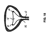
この点について、図17は、女性の解剖構造(例えば、膀胱B、子宮UT、膣Vおよび尿道U)を示す側面図である。三角部領域Tを破線領域内に示す。図18は、膀胱Bの底部位(例えば、三角部領域T、尿管口O、膀胱頸部Nおよび尿道U)の角度付けされた前方の軸方向断面図である。本発明のデバイス実施形態の1つの利用について、女性の解剖構造に関連して述べているが、同一または類似のデバイスを男性の解剖構造に用いることも企図される。例えば、治療デバイスの部位の延長および/またはデバイスの柔軟性および/または屈折性の向上など、いくつかの設計変更が可能である。 In this regard, FIG. 17 is a side view showing the female anatomy (eg, bladder B, uterus UT, vagina V, and urethra U). The triangular area T is shown in the broken line area. FIG. 18 is an angled forward axial cross-sectional view of the bottom portion of the bladder B (eg, the triangular region T, the ureteral orifice O, the bladder neck N and the urethra U). While one use of the device embodiment of the present invention has been described in connection with a female anatomy, it is contemplated that the same or similar devices may be used for a male anatomy. For example, several design changes are possible, such as extending the site of the treatment device and / or increasing the flexibility and / or refraction of the device.
先ず、図19に示すように、治療デバイス20を尿道および膀胱に挿入する(簡潔さのため、カメラおよび光ケーブルは内視鏡12に接続しておらず、吸引管および点滴管または図示のデバイスはポートに繋がれている点に留意されたい。)。このステップにおいて、内視鏡12は好適には、吸引ヘッドの遠位端のより近位に配置するとよい。治療デバイス20および内視鏡12は、尿道内に直接挿入してもよいし、あるいは、前回配置された管状シース(図示せず)を通じて配置してもよい。
First, as shown in FIG. 19, the
標的組織が膀胱の三角領域である場合、先ず尿管口のうち1つを規定することが望ましい場合がある。ガイドワイヤ、ループ状縫合の配置によってこの口を先にマーク付けしてもよいし、あるいは、治療デバイスを口に近づけないように注意を払いつつ、治療デバイスの配置によって口を目視化してもよい。好適な方法において、吸引ヘッドの先端は、尿管口の内側に配置される。別の実施形態において、吸引ヘッドは、尿管口の下側に配置される。どちらの場合も、尿管そのものは保護される。なぜならば、尿管が目視可能な口から側方および上方に移動するとき、内側および後方に配置することにより、尿管が見えなくなる事態が回避されるからである。 If the target tissue is the triangular region of the bladder, it may be desirable to first define one of the ureteral openings. The mouth may be marked first by placement of a guide wire, looped suture, or the mouth may be visualized by placement of the treatment device, taking care not to bring the treatment device close to the mouth. . In a preferred method, the tip of the suction head is placed inside the ureteral orifice. In another embodiment, the suction head is located below the ureteral orifice. In both cases, the ureter itself is protected. This is because, when the ureter moves sideways and upward from the visible mouth, the situation where the ureter becomes invisible can be avoided by arranging the ureter inside and behind.
吸引ヘッド60は、膀胱組織の面上に配置され、吸引が起動されると、図20に示すように、膀胱の面組織は吸引ヘッドの面と密に接触する。ハンドルへ接続された動き安定デバイスの利用が企図される。例えば、吸引を起動させ、組織を吸引ヘッドと係合させた後、治療デバイスの位置を安定させると有用である場合がある。
The
図示していないが、吸引ヘッド60上のアパチャ内において組織が実際に突出する場合がある。吸引により、組織が治療デバイスと係合し、治療デバイスに固定される。組織を吸引ヘッド60へしっかり固定させた後、スコープ先端が吸引ヘッド60の近位端により近い点まで内視鏡12を退避させると好適である。このようにすることにより、カニューレ前進ステップの観察が容易になる。吸引ヘッド先端70を口の近隣に配置した直後でありかつ吸引を組織へ付加する前に、内視鏡12を退避させてもよい。
Although not shown, the tissue may actually protrude within the aperture on the
ここで、図21に示すように、カニューレ管52から吸引ヘッド60の面62へのオフセット距離によって規定されるようにして、カニューレ58を面の下側の組織中へ前進させる。電極セット54のカニューレ58は、これらの間の電流通過によって起動し得、これらの周囲およびこれの間の組織が加熱および切除されて、その結果熱影響ゾーン100が発生する。熱影響ゾーン100は好適には、組織中の一定深さに集中する。膀胱三角部から発生する求心性神経を切除することで、過活動膀胱を発生させる知覚信号を低減させることが考えられる。
Now, as shown in FIG. 21, the
1つの好適な実施形態において、熱影響ゾーン100の選択深さは、膀胱の表在性の層(例えば、粘膜)を損傷から保護するのに充分である。別の好適な実施形態において、選択深さは、表在性の層(例えば、副尿管上皮)を標的とするように選択される。
In one preferred embodiment, the selected depth of the heat affected
好適には、電流は無線周波数範囲であり、好適には2つの電極間においてバイポーラ状に送達される。しかし、これら2つの電極が単極を形成し得、電流がこれらから単極状に接地パッドへ移動することも企図される。単一の電極を単極電流源として用いることも企図される。 Preferably, the current is in the radio frequency range and is preferably delivered in a bipolar fashion between the two electrodes. However, it is also contemplated that these two electrodes can form a unipolar and that current travels unipolarly from them to the ground pad. It is also contemplated to use a single electrode as a monopolar current source.
多極構成も企図され、単一のカニューレを長さに沿って多極とするか、または、バイポーラモードで動作しかつシフトパターンが可能なように、すなわち、3つのカニューレが2バイポーラ対を形成する(中央のカニューレを共通とする)ように、複数の(3またはそれ以上の)カニューレを多重化または電源供給する。 Multipolar configurations are also contemplated, with a single cannula being multipolar along the length, or operating in bipolar mode and capable of shifting patterns, ie, three cannulas form two bipolar pairs Multiple (3 or more) cannulas are multiplexed or powered so that they share a common cannula.
標的位置の治療が行われた後、吸引ヘッド60を雰囲気へ通気させることにより吸引が解放され、その後、治療デバイス20を異なる標的位置に配置し、別の焼灼ステップを行い、膀胱治療に必要な回数だけ繰り返すことができる。
After the target location has been treated, suction is released by venting the
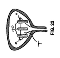
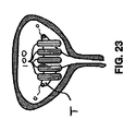
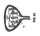
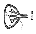
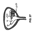
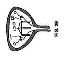
膀胱治療のために、複数の異なる焼灼パターンが考えられ得る。このようなパターンを図22〜図31に示す。これらのパターンは面に相対して図示されているが、上記したように粘膜下層にあることが意図される点に留意されたい。任意の1つの焼灼ゾーンのサイズは、デバイスサイズ、およびカニューレ直径および露出長さ、カニューレ間の間隔空け吸引ヘッド面からのカニューレの深さ、および電気パラメータ(例えば、電流、周波数、「オン時間」、および他の変数)に影響を受け得る。 Several different cauterization patterns can be considered for bladder treatment. Such a pattern is shown in FIGS. Note that although these patterns are illustrated relative to the surface, they are intended to be in the submucosa as described above. The size of any one ablation zone is the device size and cannula diameter and exposure length, the cannula depth from the spaced suction head face between cannulas, and electrical parameters (eg, current, frequency, “on time” , And other variables).
所望のパターンの1つの側面は、単純に各焼灼ゾーンのサイズであり得る。サイズが充分に大きい場合、単一の焼灼ゾーンが適切である。しかし、大きな焼灼サイズを提供することが可能なデバイスは、尿道を単に通過するには大きすぎる場合がある。尿道を容易に通過するだけ充分に小型のデバイスは、例えば図22に示すように、複数の焼灼ゾーンから得られ得る。ここで、3つの比較的平行かつ均等に間隔を空けて配置されたゾーン100が、3つの配置ステップと共に生成される。第1のゾーン100aは、口Oのうち1つの近隣にあり得、第2のゾーン100bは、他方の口Oの近隣にあり得、第3のゾーン100cは、三角部Tの中間の近隣にあり得る。
One aspect of the desired pattern can simply be the size of each ablation zone. If the size is large enough, a single ablation zone is appropriate. However, devices that can provide large ablation sizes may be too large to simply pass through the urethra. A device that is small enough to easily pass through the urethra can be obtained from multiple ablation zones, for example, as shown in FIG. Here, three relatively parallel and evenly spaced
より多数またはより少数の焼灼ゾーン100も企図される(例えば、図23に示すように5個)。OABに関連する神経の多くは三角部内にあると考えられているため、いくつかは、尿管口の側方にあり得るため、口の側方または後法にある膀胱の領域切除を行うと、図24に示すようにさらに恩恵が得られ得る。
More or
焼灼ゾーン100(尿道および膀胱は比較的柔軟な構造であるため、治療デバイスの側方操作によって行われ得る)の比較的平行な間隔に加えて、医師が治療デバイスを焼灼ステップ間に回転またはパンする方が容易である場合もあり、その結果、図25に示すような「ファン状」パターンが得られる。 In addition to the relatively parallel spacing of the ablation zone 100 (the urethra and bladder are relatively flexible structures, which can be done by lateral manipulation of the treatment device), the physician rotates or pans the treatment device between ablation steps. It may be easier to do so, resulting in a “fan-like” pattern as shown in FIG.
三角部から延びている神経のうちOABに関連するものは、尿管口の近隣において合体するとさらに考えられている。図26は、口Oの近隣の複数の集中焼灼ゾーン100を示す。
It is further believed that nerves extending from the triangle that are related to OAB are combined in the vicinity of the ureteral orifice. FIG. 26 shows a plurality of
治療デバイスの遠位部位は、図27に示すように、電極管の吸引ヘッドおよび遠位部位が側方に連結可能であり、より大きく角度付けされた焼灼ゾーン100が可能になることがさらに企図される。このような実施形態は、柔軟なおよび連結内視鏡と共に用いられ得る。このような角度付けされた焼灼ゾーンまたは比較的水平方向の焼灼ゾーンは、上記したような、より垂直な焼灼ゾーンおよび/またはファン状のゾーンと共に組み合わせることができる。
It is further contemplated that the distal portion of the treatment device can be coupled laterally to the suction head and distal portion of the electrode tube, as shown in FIG. 27, allowing a more
図28は、比較的幅狭の焼灼ゾーン100のファン状のパターンを示す。ファン状の形状は、デバイスを平行移動させるのではなく、焼灼間にデバイスを回転させることから得られる。多数のゾーン100が生成される(図28中では5個を示しているが、より多数も可能である)。ゾーン100は好適には、尿管口Oの側方に行かないようにされる。
FIG. 28 shows a fan-like pattern of the relatively
図29に示す焼灼ゾーン100のパターンは、尿管間バー、すなわち、尿管口O間の水平方向の隆起、を回避する。ゾーン100は、この目的を達成するように、充分に短尺化される。
The pattern of the
図30に示す焼灼ゾーン100のパターンは、ファン形状を包含しかつ尿管間バーを回避する。ここでも、ゾーン100は、尿管間バーを回避するように、充分に短尺化される。
The pattern of the
図31に示す焼灼ゾーン100のパターンは、図26に示すパターンに類図するが、尿管口Oの外傷の可能性を最小限にするために、側方燃焼を回避する。このパターンは、他のゾーンを含み得る。図示のゾーン100は、口Oに最も近いものを単に強調したものである。
The pattern of the
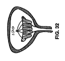
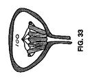
より短尺の焼灼ゾーン100の作製は、カニューレ58の先端と絶縁体59の端部との間の露出Lのより短尺の長さを有する電極カニューレの利用により、達成可能である。図32および図33は、図32中のゾーン100が図33に示すゾーン100よりも短尺である点を除いて、類似のゾーンパターンを示す。図32中のゾーン100は、およそ10mmの露出長さL1を有する図34に示すデバイスにより、作製された。図33中のゾーン100は、およそ15mmの露出長さL2を有する図35に示すデバイスにより、作製された。
Creation of a
上記したように、フォローアップの患者の不快感、感染の危険性および他の恩恵を最小限にするために面組織および尿路上皮には何もしないようにするために、粘膜下層組織内に焼灼ゾーンを生成することが望ましい場合がある。図10に示す実施形態などの上記の治療デバイスの実施形態において、吸引ヘッド60の面62からの電極管52のオフセットは、治療デバイスの全体的高さ/外形に影響を与える。焼灼のための所望の組織深さに応じて、治療デバイスの高さ/外形を所望のものよりも大きくしてもよい。図36および図37に示す別の実施形態において、比較的深い組織深さは可能であるが、デバイス外形への影響は最小限にされる。
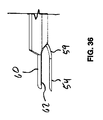
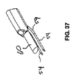
As noted above, in the submucosa tissue to do nothing to the face tissue and urothelium to minimize follow-up patient discomfort, risk of infection and other benefits It may be desirable to create an ablation zone. In the above treatment device embodiments, such as the embodiment shown in FIG. 10, the offset of the
図36および図37に示す実質的ににおいて、例えば、遠位端近隣に「S字状の」形状を有するかまたは概して弓形形状を有する曲線状の設計を含むように事前形成され得る電極セット/カニューレ54が用いられる。電極54を電極管52から前進させると、電極54は管軸から下方に角度付けされて、管軸の下側の組織中に埋設される。その結果、電極管52は、吸引ヘッド60の面62からより小さなオフセット距離を持ち、その結果、治療デバイス20がより小さな高さ/外形を持つことがさらに可能になる。このようなカニューレは、例えば、超弾性ニッケルチタン合金または他の形成可能でありかつ弾性の導電性材料弾性材料から形成され得る。
Substantially as shown in FIGS. 36 and 37, for example, an electrode set / which can be preformed to include a curved design having an “S-shaped” shape near the distal end or having a generally arcuate shape. A
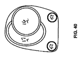
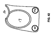
尿道を通過する部位におけるより低い外形/高さデバイスを促進する別の実施形態を図38〜図42に示す。内視鏡チャンネルまたは管16が吸引チャンネルまたは管17に沿ってかつ吸引チャンネルまたは管17に平行に延びる図7〜図9の実施形態と対照的に、別の実施形態において、内視鏡管16は、吸引管17に対して角度αを以てかつ吸引管の側部に対して常駐する。内視鏡管は、治療デバイスの高さを最小化させるように、吸引管の上部の近隣の面に沿って切断され得る。これが断面図40〜42に最も良く示されている。
Another embodiment that facilitates a lower profile / height device at the site through the urethra is shown in FIGS. In another embodiment, in contrast to the embodiment of FIGS. 7-9, the endoscope tube or
位置42において、吸引管17周辺は完全に無傷である。側方方向において外形全体をさらに最小化するために、内視鏡管16は、図示のように吸引管17中に「入れ子状」にされ得、吸引管17は、幅を狭くするように楕円形にされ得る。治療デバイス上において遠位方向に進んで、断面43において、内視鏡管16は、吸引管17内においてより高い位置に配置され、内視鏡管16の上側部位が露出され、その結果、治療デバイスの垂直高さがこの領域において維持される。さらに遠位方向において、断面44において、内視鏡管16は、吸引管17内においてさらに高い位置に配置されて、内視鏡管16の大部分が露出される。さらに遠位方向において、内視鏡管16は配置されない。なぜならば、図39に示すように、内視鏡12は、管類に包囲されずに遠位方向に突出するからである。図39において、内視鏡は配置され、吸引ヘッド60の遠位面の上方に伸長する。
At
使用時において、吸引ヘッド60が膀胱内に入るまで、本実施形態を尿道中に「やみくもに」前進させることができる。ここで、内視鏡は、内視鏡管の完全封入部位においてにおいて、近位方向に配置される。デバイスのこの遠位部位92(図40〜図42)は、図7〜図9の実施形態の比較可能な部位よりもより低い外形である。なぜならば、この送達ステップにおいてこの部位内において内視鏡管または内視鏡は存在しないからである。
In use, the present embodiment can be advanced “swiftly” into the urethra until the
この点において、内視鏡12を膀胱内へ前進させ、吸引ヘッド60の遠位面の上方に移動させる。内視鏡先端を吸引ヘッド60の上方において実質的に間隔を空けて配置して、目視化を向上させて、吸引ヘッド先端70の尿管口Oに対する高精度の配置の恩恵が得られる点に留意されたい。
At this point, the
図43は、尿道内に延びる部位においてより低い外形/高さを有する治療デバイス20のさらなる実施形態を示す。図38〜図42の実施形態と同様に、本実施形態においては、内視鏡12は、デバイス20の細長シャフト部位26に対して角度を以て配置される。
FIG. 43 shows a further embodiment of the
治療デバイス20は、遠位部位92および吸引ヘッド60へ延びる細長吸引管17を含む。本実施形態において、内視鏡管16は、吸引管17に対して角度α(図46)を以て設けられる。ハンドルアセンブリ30をこれらの管の近位端へ接続して、これらの近位端を相互に保持する。内視鏡12を治療デバイス20へ接続させるために、上記実施形態に記載するスライド管40と同様に、任意選択のスライド管40をハンドルアセンブリ30内に設けてもよい。スライド機構は、図4aおよび図5aに示しまた上記したスライド機構34と同様のものであり得、内視鏡12の治療デバイス20への制御された前進を促進するためにさらに設けられ得る。遠位部位92の近位に固定された治療デバイス20の接続ハブ150は、好適には、1つ以上の電極セット54(例えば、図4aを参照)を受容する1つ以上のレシーバ38を含む。1つ以上の吸引ポート36をハンドルアセンブリ30に接続してもよく、吸引管17の内部および吸引ヘッド60の潅注、吸引および/または通気のために、吸引管17の内部と流体連通する。
The
図44は、治療デバイス20の下面図であり、吸引ヘッド60の面62を示す。吸引ヘッド60は、吸引室68に誘導する複数のアパチャ66を含むものとして図示される。これらのフィーチャが図45に最も良く示されており、これは、治療デバイス20の遠位部位92を示す領域45を拡大したものである。
FIG. 44 is a bottom view of the
図46aは、治療デバイス20の遠位部位92の縦断面図である。ここで、内視鏡管16は、面62に対して角度αで延びる縦軸153を有することが分かる。内視鏡管16は曲線状であり得、その場合、開口部152において縦軸153に対する角度αが測定されることが理解されるべきである。これは、開口部152および面62において曲線状の縦軸の接線間の角度を測定するため、より高精度に記述され得る。
FIG. 46 a is a longitudinal cross-sectional view of the
角度αは、1〜20度の範囲である。角度αは、意図される用途に応じて異なり得る。例えば、比較的長尺の尿道を介して手術を行う場合、より浅い角度α(例えば、4〜10度)が所望され得る。平均的長さの女性尿道の場合、角度αを6〜8度にすると、良い結果が達成された。 The angle α is in the range of 1 to 20 degrees. The angle α can vary depending on the intended application. For example, when performing an operation through a relatively long urethra, a shallower angle α (eg, 4-10 degrees) may be desired. For average length female urethra, good results were achieved when the angle α was 6-8 degrees.
図46bに示す実施形態において、吸引面は前方に傾斜される。このような実施形態は、前方に5〜10度以上だけ傾斜した吸引面62を含み得ることが想定される。傾斜した吸引面62が用いられる場合、角度αが増加し得るか、または、吸引管17に対して平行な内視鏡管16を用いてもよい。
In the embodiment shown in FIG. 46b, the suction surface is inclined forward. It is envisioned that such an embodiment may include a
内視鏡管の遠位開口部152は好適には、内視鏡12が退避位置にあるときに治療デバイス20の尿道および膀胱内への通過を容易に行うために、比較的低い外形および平滑な外面を維持するように、吸引管17の外面および存在する場合にはチューブホルダ94と同一平面上にある。
The
図47は、治療デバイス20の側面図であり、軸方向断面図の識別位置48〜50と共に示す。
47 is a side view of the
図48は、図47の切断線48−48に沿ってとられた断面図であり、内視鏡管16が170において吸引管17と交差する位置のちょうど近位にある。ここで、先端に向かって遠位方向に延びる電極管52の断面も目視することができる。内視鏡管16が吸引管17の内部を遠位方向にさらに横断する様子が分かる。
48 is a cross-sectional view taken along section line 48-48 of FIG. 47 and is just proximal to the position where the
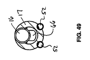
図49は、図47の切断線49−49に沿ってとられた断面図であり、内視鏡管16が吸引管17の上側面から発生する位置のちょうど近位にある。この図のさらに遠位において、ヒール部位63内においてアパチャ66を目視することができる。
49 is a cross-sectional view taken along section line 49-49 of FIG. 47, just proximal to the position where the
図50は、図47の切断線50−50に沿った断面図であり、内視鏡管16が外部に延びるデバイス20の領域内にある。平滑かつ低い外形面を遠位部位92へ付与できるように、内視鏡管16の壁の部位が除去される。この図において、アパチャ66およびバッフル72もただし、存在する場合には確認することができる。本実施形態において、上記した実施形態のうち、いくつかのように別個のチューブホルダ94は無い場合があるが、吸引管17を再形成するか、または、遠位領域内において吸引管17に固定された異なる形状のさらなるセグメントを持つようにすることができる点に留意されたい。例えば、この形状を図示のように「四角形状」にして、電極管52の包含および配置を促進し、吸引ヘッド60への形状以降を可能にすることができる。
FIG. 50 is a cross-sectional view taken along section line 50-50 of FIG. 47, where the
内視鏡管16と吸引管17との間の交点170の部位を溶接するかまたは同様に接続して、これらの管を共に固定し、両者間に気密シールを得ることができる。
The point of
図51は、上記の図43〜図47に示す実施形態に関連して述べたような治療デバイス20を内視鏡12と共に備えたシステム10を示す。この図において、内視鏡は、デバイス20へ固定され、退避位置にある。デバイス20の遠位部位92の外形は目立たないため、尿道を通じて膀胱空間中へ適切に前進させることができる点に留意されたい。デバイス20が膀胱内に入ると、上記した多様な実施形態に関連して上記したように、吸引ヘッド60の1つ以上の所望の位置における位置を目視するために、図52に示すように、内視鏡12を前進させることができる。
FIG. 51 illustrates a
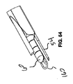
図53〜図55は、上記した実施形態(例えば、図14に関連して述べた実施形態)と類似の実施形態を示す。本実施形態において輪として示されている位置決めフィーチャ160は、吸引ヘッド60の遠位端の近隣に取り付けられる。位置決めフィーチャ160は、面62へ取り付けられ得、面62へ固定することが可能な任意の適切な材料によって作製され得る。例えば、輪160は、例えば、ステンレススチールといった金属製であり得、面62へ溶接、ろう付け、半田付け、または接着剤接合され得る。例えば、ポリマーおよびエラストマー材料他の材料も企図される。例えば、輪は、輪が無傷となるように、柔軟な材料によって構成され得る。輪を図示しているが、位置決めフィーチャ160は、1つ以上のポインター、十字線、円、くさび、または視覚ガイドの提供において有用な他の任意の形状をとり得る。
53-55 illustrate an embodiment similar to the embodiment described above (eg, the embodiment described in connection with FIG. 14). A
位置決めフィーチャ160を用いて、治療対象となる所望の解剖構造に相対するデバイス20の位置の位置決めを支援することができる。例えば、吸引ヘッド60を膀胱中の尿管口に相対する所望の位置に位置決めするために、位置決めフィーチャ160を内視鏡12によって目視して、口と視覚的に整合させることができる。その結果、電極54を組織中へ伸長させたときに、電極54が口からの所望の距離において終端し、電極54を起動させたとき、尿管の組織またはその口へ悪影響を与えることを確実に無くすことができる。
The
1つの実施形態において、口を内視鏡で目視し、口を位置決めフィーチャ160内においてセンタリングさせる場合、輪のサイズは、伸長電極54が口組織の近隣にあるが口組織そのものには配置されないようなサイズにされる。
In one embodiment, when the mouth is viewed with an endoscope and the mouth is centered within the
位置決め輪160は、治療デバイス20の上記実施形態のうちいずれかに任意選択的に付加することができる。
The
図10の実施形態に関連して上記したように、吸引ヘッドの位置決めを高精度かつ比較的遮断が少ないようにするために、内視鏡を吸引ヘッドの上方にオフセット間隔空けするのと同様に、内視鏡を30度下方に目視のために角度付けすることが好適である。これは、従来のホプキンスロッド型の内視鏡の場合である。
As described above in connection with the embodiment of FIG. 10, in order to position the suction head with high accuracy and relatively little blocking, the endoscope is similarly offset above the suction head. It is preferred to angle the
あるいは、図56に示すように、柔軟な屈折可能な内視鏡を用いてもよい。治療デバイス20は、例えば、図10に関連して述べた実施形態といった上記した実施形態のいずれでよいが、柔軟な屈折可能な内視鏡110が図示のように用いられいる。膀胱に進入すると、内視鏡110を好適には図示のように吸引ヘッドから大きく距離を空けた位置において屈折させて、下方を目視する。視野112を破線によって示す。
Alternatively, as shown in FIG. 56, a flexible refractable endoscope may be used. The
屈折可能なスコープが用いられる場合、図10に関連して述べたような内視鏡管のオフセットの必要性は重要ではなくなるため、治療デバイスの高さを低くする機会が得られる。 If a refractory scope is used, the need for an endoscope tube offset as described in connection with FIG. 10 becomes less important, thus providing an opportunity to reduce the height of the treatment device.
あるいは、図57に示すような連節型内視鏡120を用いて、治療デバイスの目視化を向上させることもできる。1つのこのような連節型内視鏡は、屈折先端部中に組み込まれた側方カメラ122を持ち得る。吸引ヘッドに対する画像の高さおよび角度は、遠位先端部位の連節によって変更することができる。
Alternatively, the articulating
本発明について、特定の実施形態および用途を以て説明してきたが、当業者であれば、本教示に鑑み、さらなる実施形態および改変例を特許請求の範囲に記載の発明の意図または範囲から逸脱することなく生成することができる。したがって、本明細書中の図面および記載は、本発明の理解を深めるための例示であり、本発明の範囲を限定するものとして解釈されるべきではないことは理解されるべきである。
Although the present invention has been described with particular embodiments and uses, those skilled in the art will appreciate further embodiments and modifications that depart from the spirit or scope of the claimed invention in light of the present teachings. Can be generated. Accordingly, it is to be understood that the drawings and descriptions in this specification are illustrative examples for better understanding of the present invention and should not be construed as limiting the scope of the present invention.
Claims (20)
近位端のハンドルアセンブリと、
遠位端の吸引ヘッドと、
前記ハンドルアセンブリと前記吸引ヘッドとの間の細長シャフト部位であって、前記細長シャフト部位は、少なくとも1つのカニューレチャンネル、吸引チャンネルおよびスコープチャンネルを含む、細長シャフト部位と、
前記少なくとも1つのカニューレチャンネルのうち1つとスライド可能に関連付けられた少なくとも1つの電極セットであって、前記少なくとも1つの電極セットは、電極およびカニューレを含み、第1の位置と第2の位置との間でスライド可能であり、前記第1の位置において、前記カニューレの遠位端は、前記関連付けられたカニューレチャンネル内に収容され、前記第2の位置において、前記カニューレの前記遠位端は、前記吸引ヘッドの近くの前記関連付けられたカニューレチャンネルの前記遠位端から延びる、少なくとも1つの電極セットと、
を含む、細長形状の器具。 An elongated instrument,
A proximal end handle assembly;
A suction head at the distal end;
An elongate shaft portion between the handle assembly and the suction head, the elongate shaft portion including at least one cannula channel, a suction channel and a scope channel;
At least one electrode set slidably associated with one of the at least one cannula channel, the at least one electrode set including an electrode and a cannula, and having a first position and a second position; In the first position, the distal end of the cannula is received in the associated cannula channel, and in the second position, the distal end of the cannula is At least one electrode set extending from the distal end of the associated cannula channel near a suction head;
An elongated device including
少なくとも1つのカニューレチャンネル、スコープチャンネルおよび吸引チャンネルを含む細長シャフトと、
前記吸引チャンネルの遠位端において吸引面を規定する吸引ヘッドと、
前記少なくとも1つのカニューレチャンネルのうち1つとスライド可能に関連付けられた少なくとも1つの電極セットであって、前記少なくとも1つの電極セットは、電極およびカニューレを含み、第1の位置と第2の位置との間でスライド可能であり、前記第1の位置において、前記カニューレの遠位端は、前記関連付けられたカニューレチャンネル内に収容され、前記第2の位置において、前記カニューレの前記遠位端は、前記関連付けられたカニューレチャンネルの前記遠位端から延び、前記スコープチャンネルは、非ゼロ角度αにおいて前記吸引面へ延びる、少なくとも1つの電極セットと、
を含む、焼灼器具。 A cautery device inserted into the body cavity,
An elongate shaft comprising at least one cannula channel, a scope channel and a suction channel;
A suction head defining a suction surface at a distal end of the suction channel;
At least one electrode set slidably associated with one of the at least one cannula channel, the at least one electrode set including an electrode and a cannula, and having a first position and a second position; In the first position, the distal end of the cannula is received in the associated cannula channel, and in the second position, the distal end of the cannula is At least one electrode set extending from the distal end of an associated cannula channel, the scope channel extending to the suction surface at a non-zero angle α;
Including shochu utensils.
前記少なくとも1つのカニューレチャンネルのうち1つとスライド可能に関連付けられた少なくとも1つの電極セットであって、前記少なくとも1つの電極セットは、電極およびカニューレを含み、第1の位置と第2の位置との間でスライド可能であり、前記第1の位置において、前記カニューレの遠位端は、前記関連付けられたカニューレチャンネル内に収容され、前記第2の位置において、前記カニューレの前記遠位端は、前記関連付けられたカニューレチャンネルの前記遠位端から延びる、少なくとも1つの電極セットと、
組織と係合する遠位ヘッドと、
前記遠位ヘッドと関連付けられた位置決めフィーチャであって、前記位置決めフィーチャは、前記スコープチャンネルを通じて配置されたスコープを介して見られるようにして前記遠位ヘッドと解剖学的特徴との間の視覚的参照を容易とする、位置決めフィーチャと、
を含む、焼灼器具。 A cautery device inserted into the body cavity,
At least one electrode set slidably associated with one of the at least one cannula channel, the at least one electrode set including an electrode and a cannula, and having a first position and a second position; In the first position, the distal end of the cannula is received in the associated cannula channel, and in the second position, the distal end of the cannula is At least one electrode set extending from the distal end of the associated cannula channel;
A distal head engaging the tissue;
A positioning feature associated with the distal head, wherein the positioning feature is a visual feature between the distal head and an anatomical feature as viewed through a scope disposed through the scope channel. Positioning features for easy reference;
Including shochu utensils.
The positioning feature and the electrode set are configured such that, when the positioning feature is aligned with a bladder mouth, an electrode extending from the electrode set enters the tissue proximal to the mouth but does not enter the mouth tissue. 18. The ablation device of claim 17, wherein the ablation device is disposed.
Applications Claiming Priority (3)
| Application Number | Priority Date | Filing Date | Title |
|---|---|---|---|
| US201462002742P | 2014-05-23 | 2014-05-23 | |
| US62/002,742 | 2014-05-23 | ||
| PCT/US2015/032298 WO2015179837A1 (en) | 2014-05-23 | 2015-05-22 | Methods and devices for treating pelvic conditions |
Publications (2)
| Publication Number | Publication Date |
|---|---|
| JP2017516620A true JP2017516620A (en) | 2017-06-22 |
| JP2017516620A5 JP2017516620A5 (en) | 2018-06-21 |
Family
ID=54554877
Family Applications (1)
| Application Number | Title | Priority Date | Filing Date |
|---|---|---|---|
| JP2017514394A Pending JP2017516620A (en) | 2014-05-23 | 2015-05-22 | Methods and devices for treatment of pelvic conditions |
Country Status (7)
| Country | Link |
|---|---|
| US (5) | US10058381B2 (en) |
| EP (1) | EP3145427A4 (en) |
| JP (1) | JP2017516620A (en) |
| CN (1) | CN106999242A (en) |
| AU (1) | AU2015263874B2 (en) |
| CA (1) | CA2949962A1 (en) |
| WO (1) | WO2015179837A1 (en) |
Cited By (2)
| Publication number | Priority date | Publication date | Assignee | Title |
|---|---|---|---|---|
| CN107582235A (en) * | 2016-07-07 | 2018-01-16 | 维纳斯概念有限公司 | For strengthening the beauty appliance of mucosal tissue recovery |
| KR20210030426A (en) * | 2018-09-05 | 2021-03-17 | 드래곤 크라운 메디칼 컴퍼니 리미티드 | Multi channel working sleeve tube |
Families Citing this family (6)
| Publication number | Priority date | Publication date | Assignee | Title |
|---|---|---|---|---|
| EP3145427A4 (en) | 2014-05-23 | 2018-01-24 | Amphora Medical, Inc. | Methods and devices for treating pelvic conditions |
| DE202015106940U1 (en) | 2015-12-18 | 2016-01-11 | Dannoritzer Medizintechnik Gmbh & Co. Kg | Endoscopic surgical instrument |
| US11896823B2 (en) | 2017-04-04 | 2024-02-13 | Btl Healthcare Technologies A.S. | Method and device for pelvic floor tissue treatment |
| WO2019183624A1 (en) * | 2018-03-23 | 2019-09-26 | Avent, Inc. | System and method for controlling energy delivered to an area of tissue during a treatment procedure |
| CN209236109U (en) * | 2018-11-01 | 2019-08-13 | 山东冠龙医疗用品有限公司 | A kind of minimally invasive device of multichannel of doubleway output cold light source |
| US20200305999A1 (en) * | 2019-04-01 | 2020-10-01 | West Virginia University | Surgical devices and methods for bariatric and gastroesophageal surgery |
Family Cites Families (97)
| Publication number | Priority date | Publication date | Assignee | Title |
|---|---|---|---|---|
| US5370675A (en) | 1992-08-12 | 1994-12-06 | Vidamed, Inc. | Medical probe device and method |
| US5342353A (en) | 1990-11-05 | 1994-08-30 | Allen Paul M | System for laser treatment of the female urethra and bladder |
| US5378675A (en) | 1991-11-05 | 1995-01-03 | Konica Corporation | Thermal transfer recording image receiving sheet |
| US5667488A (en) | 1992-08-12 | 1997-09-16 | Vidamed, Inc. | Transurethral needle ablation device and method for the treatment of the prostate |
| US5672153A (en) | 1992-08-12 | 1997-09-30 | Vidamed, Inc. | Medical probe device and method |
| US6632193B1 (en) | 1995-06-07 | 2003-10-14 | Arthrocare Corporation | Systems and methods for electrosurgical tissue treatment |
| IL124038A (en) | 1995-10-13 | 2004-02-19 | Transvascular Inc | Apparatus for bypassing arterial obstructions and/or performing other transvascular procedures |
| US6091995A (en) | 1996-11-08 | 2000-07-18 | Surx, Inc. | Devices, methods, and systems for shrinking tissues |
| CA2300152A1 (en) | 1997-08-13 | 1999-02-25 | Surx, Inc. | Noninvasive devices, methods, and systems for shrinking of tissues |
| US9023031B2 (en) | 1997-08-13 | 2015-05-05 | Verathon Inc. | Noninvasive devices, methods, and systems for modifying tissues |
| IL122111A (en) * | 1997-11-04 | 2004-06-01 | Sightline Techn Ltd | Video rectoscope |
| EP0920025B1 (en) | 1997-11-28 | 2004-02-11 | STMicroelectronics S.r.l. | A low power RAM memory cell |
| US6325798B1 (en) | 1998-02-19 | 2001-12-04 | Curon Medical, Inc. | Vacuum-assisted systems and methods for treating sphincters and adjoining tissue regions |
| US6231518B1 (en) | 1998-05-26 | 2001-05-15 | Comedicus Incorporated | Intrapericardial electrophysiological procedures |
| US6425877B1 (en) | 1999-04-02 | 2002-07-30 | Novasys Medical, Inc. | Treatment of tissue in the digestive circulatory respiratory urinary and reproductive systems |
| US6692490B1 (en) | 1999-05-18 | 2004-02-17 | Novasys Medical, Inc. | Treatment of urinary incontinence and other disorders by application of energy and drugs |
| US7226407B2 (en) | 1999-06-09 | 2007-06-05 | Ethicon, Inc. | Surgical instrument and method for treating female urinary incontinence |
| US7526342B2 (en) | 1999-08-10 | 2009-04-28 | Maquet Cardiovascular Llc | Apparatus for endoscopic cardiac mapping and lead placement |
| EP1244392A1 (en) | 1999-09-28 | 2002-10-02 | Novasys Medical, Inc. | Treatment of tissue by application of energy and drugs |
| US6626930B1 (en) * | 1999-10-21 | 2003-09-30 | Edwards Lifesciences Corporation | Minimally invasive mitral valve repair method and apparatus |
| US6558382B2 (en) | 2000-04-27 | 2003-05-06 | Medtronic, Inc. | Suction stabilized epicardial ablation devices |
| US6514250B1 (en) | 2000-04-27 | 2003-02-04 | Medtronic, Inc. | Suction stabilized epicardial ablation devices |
| US7306591B2 (en) | 2000-10-02 | 2007-12-11 | Novasys Medical, Inc. | Apparatus and methods for treating female urinary incontinence |
| US6692480B1 (en) | 2000-10-27 | 2004-02-17 | Irving M. Bush | Method and apparatus for treating and preventing urinary tract infections |
| US20020193851A1 (en) | 2001-06-14 | 2002-12-19 | Silverman David E. | Energy treatment apparatus for treating gastrointestinal tract and method for using same |
| US6607525B2 (en) | 2001-08-01 | 2003-08-19 | Nicolas Franco | Apparatus and method for treating urinary stress incontinence |
| US7130697B2 (en) | 2002-08-13 | 2006-10-31 | Minnesota Medical Physics Llc | Apparatus and method for the treatment of benign prostatic hyperplasia |
| US20030181904A1 (en) | 2002-01-23 | 2003-09-25 | Levine Andy H. | Electrosurgical cutting, coagulating and suction instrument |
| US8347891B2 (en) | 2002-04-08 | 2013-01-08 | Medtronic Ardian Luxembourg S.A.R.L. | Methods and apparatus for performing a non-continuous circumferential treatment of a body lumen |
| US7617005B2 (en) | 2002-04-08 | 2009-11-10 | Ardian, Inc. | Methods and apparatus for thermally-induced renal neuromodulation |
| US6980093B2 (en) | 2002-05-07 | 2005-12-27 | The Johns Hopkins University | Commercial vehicle electronic screening hardware/software system with primary and secondary sensor sets |
| US20050261673A1 (en) | 2003-01-15 | 2005-11-24 | Medtronic, Inc. | Methods and apparatus for accessing and stabilizing an area of the heart |
| US7238182B2 (en) | 2003-04-25 | 2007-07-03 | Medtronic, Inc. | Device and method for transurethral prostate treatment |
| US7842769B1 (en) | 2003-06-13 | 2010-11-30 | Underground Solutions Technologies Group, Inc. | Polyvinyl chloride formulations |
| US7282050B2 (en) | 2003-10-31 | 2007-10-16 | Medtronic, Inc. | Ablation of exterior of stomach to treat obesity |
| ES2629960T3 (en) | 2004-03-25 | 2017-08-16 | University College Cork-National University Of Ireland, Cork | Apparatus for prophylaxis or tissue treatment |
| US7658738B2 (en) | 2004-05-14 | 2010-02-09 | Ethicon Endo-Surgery, Inc. | Medical devices for use with endoscope |
| US20060089635A1 (en) | 2004-10-22 | 2006-04-27 | Scimed Life Systems, Inc. | Methods and apparatus for focused bipolar tissue ablation using an insulated shaft |
| EP2759276A1 (en) | 2005-06-20 | 2014-07-30 | Medtronic Ablation Frontiers LLC | Ablation catheter |
| WO2007002554A2 (en) | 2005-06-23 | 2007-01-04 | Medtronic Vascular, Inc. | Methods and systems for treating injured cardiac tissue |
| US8641729B2 (en) | 2005-07-13 | 2014-02-04 | Creighton University | Systems and techniques for minimally invasive gastrointestinal procedures |
| US20070021803A1 (en) | 2005-07-22 | 2007-01-25 | The Foundry Inc. | Systems and methods for neuromodulation for treatment of pain and other disorders associated with nerve conduction |
| US8657814B2 (en) | 2005-08-22 | 2014-02-25 | Medtronic Ablation Frontiers Llc | User interface for tissue ablation system |
| US8790281B2 (en) | 2006-04-20 | 2014-07-29 | The Regents Of The University Of California | Method of thermal treatment of myolysis and destruction of benign uterine tumors |
| US8048069B2 (en) | 2006-09-29 | 2011-11-01 | Medtronic, Inc. | User interface for ablation therapy |
| US20080097469A1 (en) | 2006-10-18 | 2008-04-24 | Gruber William H | Intrauterine access and procedure system with laterally deflectable sheath |
| US8475452B2 (en) | 2007-02-21 | 2013-07-02 | Electromedical Associates, Llc | Instruments and methods for thermal tissue treatment |
| US8029496B2 (en) | 2007-03-05 | 2011-10-04 | Ebrahim Versi | Method and device for delivering drug to the trigone of the bladder |
| US8814856B2 (en) | 2007-04-30 | 2014-08-26 | Medtronic, Inc. | Extension and retraction mechanism for a hand-held device |
| US8641711B2 (en) | 2007-05-04 | 2014-02-04 | Covidien Lp | Method and apparatus for gastrointestinal tract ablation for treatment of obesity |
| US8641704B2 (en) | 2007-05-11 | 2014-02-04 | Medtronic Ablation Frontiers Llc | Ablation therapy system and method for treating continuous atrial fibrillation |
| US20100256446A1 (en) | 2007-05-11 | 2010-10-07 | Board Of Regents, The University Of Texas System | Medical scope carrier and scope as system and method |
| US8128592B2 (en) | 2007-07-11 | 2012-03-06 | Apollo Endosurgery, Inc. | Methods and systems for performing submucosal medical procedures |
| US8317771B2 (en) | 2007-07-11 | 2012-11-27 | Apollo Endosurgery, Inc. | Methods and systems for performing submucosal medical procedures |
| US8301265B2 (en) | 2007-09-10 | 2012-10-30 | Medtronic, Inc. | Selective depth electrode deployment for electrical stimulation |
| US8197504B2 (en) | 2008-05-01 | 2012-06-12 | Ethicon Endo-Surgery, Inc. | Safe tissue puncture device |
| US9474574B2 (en) | 2008-05-21 | 2016-10-25 | Atricure, Inc. | Stabilized ablation systems and methods |
| US8721632B2 (en) | 2008-09-09 | 2014-05-13 | Tsunami Medtech, Llc | Methods for delivering energy into a target tissue of a body |
| WO2010048334A1 (en) | 2008-10-21 | 2010-04-29 | Microcube, Llc | Microwave treatment devices and methods |
| EP2349045B1 (en) | 2008-10-21 | 2014-07-16 | Microcube, LLC | Devices for applying energy to bodily tissues |
| WO2010053700A1 (en) | 2008-11-10 | 2010-05-14 | Microcube, Llc | Methods and devices for applying energy to bodily tissues |
| US8083691B2 (en) | 2008-11-12 | 2011-12-27 | Hansen Medical, Inc. | Apparatus and method for sensing force |
| US8468637B2 (en) * | 2009-02-06 | 2013-06-25 | Endoclear Llc | Mechanically-actuated endotracheal tube cleaning device |
| JP4837058B2 (en) | 2009-03-10 | 2011-12-14 | 株式会社東芝 | Arithmetic apparatus and program |
| US9358064B2 (en) | 2009-08-07 | 2016-06-07 | Ulthera, Inc. | Handpiece and methods for performing subcutaneous surgery |
| US20110112434A1 (en) | 2009-11-06 | 2011-05-12 | Ethicon Endo-Surgery, Inc. | Kits and procedures for natural orifice translumenal endoscopic surgery |
| CA2781951A1 (en) | 2009-11-13 | 2011-05-19 | St. Jude Medical, Inc. | Assembly of staggered ablation elements |
| US9820803B2 (en) * | 2010-04-28 | 2017-11-21 | Medtronic, Inc. | Subxiphoid connective lesion ablation system and method |
| US8539989B2 (en) | 2010-08-30 | 2013-09-24 | Health Robotics, S.r.l. | Method for the production of pharmaceutical products |
| EP2637591B1 (en) | 2010-11-12 | 2019-07-17 | Estech, Inc (Endoscopic Technologies, Inc) | Stabilized ablation systems |
| CA3012538C (en) | 2011-02-01 | 2021-03-30 | Channel Medsystems, Inc. | Method and apparatus for cyrogenic treatment of a body cavity or lumen |
| WO2012120495A2 (en) | 2011-03-04 | 2012-09-13 | Rainbow Medical Ltd. | Tissue treatment and monitoring by application of energy |
| US10061115B2 (en) | 2011-03-30 | 2018-08-28 | Designs For Vision, Inc. | Magnification device and assembly |
| US9492113B2 (en) | 2011-07-15 | 2016-11-15 | Boston Scientific Scimed, Inc. | Systems and methods for monitoring organ activity |
| WO2013016590A1 (en) | 2011-07-26 | 2013-01-31 | Dan Sachs | Apparatus and methods to modulate pelvic nervous tissue |
| US20130066308A1 (en) | 2011-08-31 | 2013-03-14 | Jaime Landman | Ablation-based therapy for bladder pathologies |
| US9517083B2 (en) | 2011-09-16 | 2016-12-13 | Boston Scientific Scimed, Inc. | Apparatus for treating an organ and related methods of use |
| US20130090640A1 (en) | 2011-10-07 | 2013-04-11 | University Of Surrey | Methods and systems for detection and thermal treatment of lower urinary tract conditions |
| WO2013052852A1 (en) | 2011-10-07 | 2013-04-11 | Boston Scientific Scimed, Inc. | Methods and systems for detection and thermal treatment of lower urinary tract conditions |
| JP5422634B2 (en) * | 2011-11-18 | 2014-02-19 | 富士フイルム株式会社 | Endoscope insertion aid and endoscope system |
| JP6374374B2 (en) | 2012-04-22 | 2018-08-15 | オムリ ベン−エズラ, | Bladder tissue modification for overactive bladder disorders |
| US20140207136A1 (en) | 2012-05-04 | 2014-07-24 | St. Jude Medical, Inc. | Multiple staggered electrodes connected via flexible joints |
| US10307620B2 (en) | 2012-06-27 | 2019-06-04 | Acoustic Medsystems, Inc. | Noninvasive transvaginal acoustic thermal treatment of female stress urinary incontinence |
| US9078662B2 (en) | 2012-07-03 | 2015-07-14 | Ethicon Endo-Surgery, Inc. | Endoscopic cap electrode and method for using the same |
| WO2014022379A1 (en) | 2012-07-30 | 2014-02-06 | Northwestern University | Radiofrequency probe for circumferential ablation of a hollow cavity |
| EP2879605A4 (en) | 2012-07-30 | 2016-04-06 | Fractyl Lab Inc | Electrical energy ablation systems, devices and methods for the treatment of tissue |
| US10314649B2 (en) | 2012-08-02 | 2019-06-11 | Ethicon Endo-Surgery, Inc. | Flexible expandable electrode and method of intraluminal delivery of pulsed power |
| US9861802B2 (en) | 2012-08-09 | 2018-01-09 | University Of Iowa Research Foundation | Catheters, catheter systems, and methods for puncturing through a tissue structure |
| US8894563B2 (en) | 2012-08-10 | 2014-11-25 | Attenuex Technologies, Inc. | Methods and systems for performing a medical procedure |
| US9339329B2 (en) | 2012-09-17 | 2016-05-17 | The Regents Of The University Of California | Bladder denervation for treating overactive bladder |
| US9066725B2 (en) | 2012-12-06 | 2015-06-30 | St. Jude Medical, Atrial Fibrillation Division, Inc. | Irrigant distribution system for electrodes |
| EP2945556A4 (en) | 2013-01-17 | 2016-08-31 | Virender K Sharma | Method and apparatus for tissue ablation |
| US9895192B2 (en) | 2013-03-13 | 2018-02-20 | Hologic, Inc. | Intrauterine treatment device with articulating array |
| US9555218B2 (en) | 2013-03-15 | 2017-01-31 | Boston Scientific Scimed, Inc. | Methods and systems for treatment of a bladder |
| EP3145427A4 (en) * | 2014-05-23 | 2018-01-24 | Amphora Medical, Inc. | Methods and devices for treating pelvic conditions |
| US20160030107A1 (en) | 2014-07-31 | 2016-02-04 | Boston Scientific Scimed, Inc. | Bladder treatment by ablative denervation |
| JP2023501756A (en) * | 2019-11-18 | 2023-01-18 | サーカ サイエンティフィック インコーポレイテッド | Instrument port with flexible shaft for epicardial ablation |
-
2015
- 2015-05-22 EP EP15796300.0A patent/EP3145427A4/en active Pending
- 2015-05-22 US US14/720,581 patent/US10058381B2/en active Active
- 2015-05-22 WO PCT/US2015/032298 patent/WO2015179837A1/en active Application Filing
- 2015-05-22 JP JP2017514394A patent/JP2017516620A/en active Pending
- 2015-05-22 AU AU2015263874A patent/AU2015263874B2/en active Active
- 2015-05-22 CN CN201580039294.1A patent/CN106999242A/en active Pending
- 2015-05-22 CA CA2949962A patent/CA2949962A1/en not_active Abandoned
-
2018
- 2018-08-27 US US16/113,280 patent/US10548662B2/en active Active
-
2019
- 2019-12-20 US US16/723,129 patent/US11529189B2/en active Active
-
2022
- 2022-11-09 US US17/984,199 patent/US11998263B2/en active Active
-
2024
- 2024-04-25 US US18/646,637 patent/US20240341836A1/en active Pending
Cited By (5)
| Publication number | Priority date | Publication date | Assignee | Title |
|---|---|---|---|---|
| CN107582235A (en) * | 2016-07-07 | 2018-01-16 | 维纳斯概念有限公司 | For strengthening the beauty appliance of mucosal tissue recovery |
| KR20210030426A (en) * | 2018-09-05 | 2021-03-17 | 드래곤 크라운 메디칼 컴퍼니 리미티드 | Multi channel working sleeve tube |
| JP2022502104A (en) * | 2018-09-05 | 2022-01-11 | 山東冠龍医療用品有限公司 | Multi-route work cannula |
| JP7145316B2 (en) | 2018-09-05 | 2022-09-30 | 山東冠龍医療用品有限公司 | multi-path working cannula |
| KR102599677B1 (en) * | 2018-09-05 | 2023-11-07 | 드래곤 크라운 메디칼 컴퍼니 리미티드 | Multi-channel work sleeve pipe |
Also Published As
| Publication number | Publication date |
|---|---|
| EP3145427A1 (en) | 2017-03-29 |
| US10058381B2 (en) | 2018-08-28 |
| US20240341836A1 (en) | 2024-10-17 |
| EP3145427A4 (en) | 2018-01-24 |
| US20180360530A1 (en) | 2018-12-20 |
| US20200138511A1 (en) | 2020-05-07 |
| US20150335381A1 (en) | 2015-11-26 |
| US11529189B2 (en) | 2022-12-20 |
| US10548662B2 (en) | 2020-02-04 |
| CA2949962A1 (en) | 2015-11-26 |
| AU2015263874B2 (en) | 2020-01-30 |
| AU2015263874A1 (en) | 2016-12-15 |
| US11998263B2 (en) | 2024-06-04 |
| WO2015179837A1 (en) | 2015-11-26 |
| CN106999242A (en) | 2017-08-01 |
| US20230070237A1 (en) | 2023-03-09 |
Similar Documents
| Publication | Publication Date | Title |
|---|---|---|
| US11998263B2 (en) | Methods and devices for treating pelvic conditions | |
| JP6250127B2 (en) | Prostate treatment system and method | |
| US20230285072A1 (en) | Devices and methods for transurethral bladder partitioning | |
| KR20120101007A (en) | Systems, apparatuses, and methods for treating tissue and controlling stenosis | |
| CN104080418A (en) | Apparatus and methods to modulate pelvic nervous tissue | |
| Kramolowsky et al. | Use of 5F bipolar electrosurgical probe in endoscopic urological procedures | |
| AU2012329351A1 (en) | A gentle hemorrhoid treatment offering a substantially painless healing | |
| RU2718307C2 (en) | Method for percutaneous endoscopic pelvic tumor removal by a single unit | |
| RU2243729C1 (en) | Method for treating the cases of male enuresis | |
| Lacher et al. | Laparoscopic Approach in Anorectal Malformations: How We Do It | |
| Louie | Per Oral Endoscopic Myotomy: Technique and Tricks for Challenging Anatomy | |
| CN220558082U (en) | System for ablating endometrial tissue of a patient | |
| RU2784189C2 (en) | Method for treatment of urothelial ureter cancer in patients with single or single-functioning kidney | |
| Ye et al. | Use of a new local anesthesia–Intracorpus spongiosum anesthesia–In procedures on anterior urethra | |
| RU2817485C1 (en) | Method for optimizing positioning of working trocars in vesicoscopic ureter reimplantation in children | |
| WO2016198955A2 (en) | Devices and methods for transurethral bladder partitioning | |
| RU2333724C2 (en) | Method of urinary incontinence treatment of men with sling implantation | |
| Montroni et al. | Minimally invasive therapies for fecal incontinence | |
| RU88554U1 (en) | URETHRAL ELECTRODE FOR CARRYING OUT OF MEDICINAL ELECTROPHORESIS IN DISEASES OF THE PROSTATE | |
| Braun et al. | Transurethral needle ablation of the prostate: an alternative minimally invasive therapeutic concept in the treatment of benign prostate hyperplasia | |
| CN116115320A (en) | Pulse ablation device | |
| RU2157105C1 (en) | Method for making transurethral prostate resection | |
| RU101928U1 (en) | Intravesical Electrode for Intraorganic Drug Electrophoresis in Diseases of the Urinary Bladder | |
| Dip et al. | Non-invasive intracranial pressure methods during pneumoperitoneum in an animal model | |
| Stoller | URETHRAL CATHETERIZATION |
Legal Events
| Date | Code | Title | Description |
|---|---|---|---|
| A521 | Request for written amendment filed |
Free format text: JAPANESE INTERMEDIATE CODE: A523 Effective date: 20180508 |
|
| A621 | Written request for application examination |
Free format text: JAPANESE INTERMEDIATE CODE: A621 Effective date: 20180508 |
|
| A131 | Notification of reasons for refusal |
Free format text: JAPANESE INTERMEDIATE CODE: A131 Effective date: 20190305 |
|
| A977 | Report on retrieval |
Free format text: JAPANESE INTERMEDIATE CODE: A971007 Effective date: 20190228 |
|
| A521 | Request for written amendment filed |
Free format text: JAPANESE INTERMEDIATE CODE: A523 Effective date: 20190805 |
|
| A603 | Late request for extension of time limit during examination |
Free format text: JAPANESE INTERMEDIATE CODE: A603 Effective date: 20190805 |
|
| A711 | Notification of change in applicant |
Free format text: JAPANESE INTERMEDIATE CODE: A711 Effective date: 20191220 |
|
| A521 | Request for written amendment filed |
Free format text: JAPANESE INTERMEDIATE CODE: A821 Effective date: 20191220 |
|
| A02 | Decision of refusal |
Free format text: JAPANESE INTERMEDIATE CODE: A02 Effective date: 20200204 |
