JP2017501357A - Drum brake device including parking brake operating in duo servo mode, vehicle and assembly method related thereto - Google Patents
Drum brake device including parking brake operating in duo servo mode, vehicle and assembly method related thereto Download PDFInfo
- Publication number
- JP2017501357A JP2017501357A JP2016544535A JP2016544535A JP2017501357A JP 2017501357 A JP2017501357 A JP 2017501357A JP 2016544535 A JP2016544535 A JP 2016544535A JP 2016544535 A JP2016544535 A JP 2016544535A JP 2017501357 A JP2017501357 A JP 2017501357A
- Authority
- JP
- Japan
- Prior art keywords
- actuator
- shoe
- brake
- drum
- backing plate
- Prior art date
- Legal status (The legal status is an assumption and is not a legal conclusion. Google has not performed a legal analysis and makes no representation as to the accuracy of the status listed.)
- Granted
Links
Images


Classifications
-
- B—PERFORMING OPERATIONS; TRANSPORTING
- B60—VEHICLES IN GENERAL
- B60T—VEHICLE BRAKE CONTROL SYSTEMS OR PARTS THEREOF; BRAKE CONTROL SYSTEMS OR PARTS THEREOF, IN GENERAL; ARRANGEMENT OF BRAKING ELEMENTS ON VEHICLES IN GENERAL; PORTABLE DEVICES FOR PREVENTING UNWANTED MOVEMENT OF VEHICLES; VEHICLE MODIFICATIONS TO FACILITATE COOLING OF BRAKES
- B60T13/00—Transmitting braking action from initiating means to ultimate brake actuator with power assistance or drive; Brake systems incorporating such transmitting means, e.g. air-pressure brake systems
- B60T13/02—Transmitting braking action from initiating means to ultimate brake actuator with power assistance or drive; Brake systems incorporating such transmitting means, e.g. air-pressure brake systems with mechanical assistance or drive
-
- F—MECHANICAL ENGINEERING; LIGHTING; HEATING; WEAPONS; BLASTING
- F16—ENGINEERING ELEMENTS AND UNITS; GENERAL MEASURES FOR PRODUCING AND MAINTAINING EFFECTIVE FUNCTIONING OF MACHINES OR INSTALLATIONS; THERMAL INSULATION IN GENERAL
- F16D—COUPLINGS FOR TRANSMITTING ROTATION; CLUTCHES; BRAKES
- F16D51/00—Brakes with outwardly-movable braking members co-operating with the inner surface of a drum or the like
- F16D51/16—Brakes with outwardly-movable braking members co-operating with the inner surface of a drum or the like shaped as brake-shoes pivoted on a fixed or nearly-fixed axis
- F16D51/18—Brakes with outwardly-movable braking members co-operating with the inner surface of a drum or the like shaped as brake-shoes pivoted on a fixed or nearly-fixed axis with two brake-shoes
- F16D51/20—Brakes with outwardly-movable braking members co-operating with the inner surface of a drum or the like shaped as brake-shoes pivoted on a fixed or nearly-fixed axis with two brake-shoes extending in opposite directions from their pivots
- F16D51/22—Brakes with outwardly-movable braking members co-operating with the inner surface of a drum or the like shaped as brake-shoes pivoted on a fixed or nearly-fixed axis with two brake-shoes extending in opposite directions from their pivots mechanically actuated
-
- B—PERFORMING OPERATIONS; TRANSPORTING
- B60—VEHICLES IN GENERAL
- B60T—VEHICLE BRAKE CONTROL SYSTEMS OR PARTS THEREOF; BRAKE CONTROL SYSTEMS OR PARTS THEREOF, IN GENERAL; ARRANGEMENT OF BRAKING ELEMENTS ON VEHICLES IN GENERAL; PORTABLE DEVICES FOR PREVENTING UNWANTED MOVEMENT OF VEHICLES; VEHICLE MODIFICATIONS TO FACILITATE COOLING OF BRAKES
- B60T13/00—Transmitting braking action from initiating means to ultimate brake actuator with power assistance or drive; Brake systems incorporating such transmitting means, e.g. air-pressure brake systems
- B60T13/10—Transmitting braking action from initiating means to ultimate brake actuator with power assistance or drive; Brake systems incorporating such transmitting means, e.g. air-pressure brake systems with fluid assistance, drive, or release
- B60T13/12—Transmitting braking action from initiating means to ultimate brake actuator with power assistance or drive; Brake systems incorporating such transmitting means, e.g. air-pressure brake systems with fluid assistance, drive, or release the fluid being liquid
-
- B—PERFORMING OPERATIONS; TRANSPORTING
- B60—VEHICLES IN GENERAL
- B60T—VEHICLE BRAKE CONTROL SYSTEMS OR PARTS THEREOF; BRAKE CONTROL SYSTEMS OR PARTS THEREOF, IN GENERAL; ARRANGEMENT OF BRAKING ELEMENTS ON VEHICLES IN GENERAL; PORTABLE DEVICES FOR PREVENTING UNWANTED MOVEMENT OF VEHICLES; VEHICLE MODIFICATIONS TO FACILITATE COOLING OF BRAKES
- B60T13/00—Transmitting braking action from initiating means to ultimate brake actuator with power assistance or drive; Brake systems incorporating such transmitting means, e.g. air-pressure brake systems
- B60T13/10—Transmitting braking action from initiating means to ultimate brake actuator with power assistance or drive; Brake systems incorporating such transmitting means, e.g. air-pressure brake systems with fluid assistance, drive, or release
- B60T13/58—Combined or convertible systems
- B60T13/588—Combined or convertible systems both fluid and mechanical assistance or drive
-
- B—PERFORMING OPERATIONS; TRANSPORTING
- B60—VEHICLES IN GENERAL
- B60T—VEHICLE BRAKE CONTROL SYSTEMS OR PARTS THEREOF; BRAKE CONTROL SYSTEMS OR PARTS THEREOF, IN GENERAL; ARRANGEMENT OF BRAKING ELEMENTS ON VEHICLES IN GENERAL; PORTABLE DEVICES FOR PREVENTING UNWANTED MOVEMENT OF VEHICLES; VEHICLE MODIFICATIONS TO FACILITATE COOLING OF BRAKES
- B60T13/00—Transmitting braking action from initiating means to ultimate brake actuator with power assistance or drive; Brake systems incorporating such transmitting means, e.g. air-pressure brake systems
- B60T13/74—Transmitting braking action from initiating means to ultimate brake actuator with power assistance or drive; Brake systems incorporating such transmitting means, e.g. air-pressure brake systems with electrical assistance or drive
- B60T13/741—Transmitting braking action from initiating means to ultimate brake actuator with power assistance or drive; Brake systems incorporating such transmitting means, e.g. air-pressure brake systems with electrical assistance or drive acting on an ultimate actuator
-
- F—MECHANICAL ENGINEERING; LIGHTING; HEATING; WEAPONS; BLASTING
- F16—ENGINEERING ELEMENTS AND UNITS; GENERAL MEASURES FOR PRODUCING AND MAINTAINING EFFECTIVE FUNCTIONING OF MACHINES OR INSTALLATIONS; THERMAL INSULATION IN GENERAL
- F16D—COUPLINGS FOR TRANSMITTING ROTATION; CLUTCHES; BRAKES
- F16D51/00—Brakes with outwardly-movable braking members co-operating with the inner surface of a drum or the like
- F16D51/16—Brakes with outwardly-movable braking members co-operating with the inner surface of a drum or the like shaped as brake-shoes pivoted on a fixed or nearly-fixed axis
- F16D51/18—Brakes with outwardly-movable braking members co-operating with the inner surface of a drum or the like shaped as brake-shoes pivoted on a fixed or nearly-fixed axis with two brake-shoes
- F16D51/20—Brakes with outwardly-movable braking members co-operating with the inner surface of a drum or the like shaped as brake-shoes pivoted on a fixed or nearly-fixed axis with two brake-shoes extending in opposite directions from their pivots
- F16D51/24—Brakes with outwardly-movable braking members co-operating with the inner surface of a drum or the like shaped as brake-shoes pivoted on a fixed or nearly-fixed axis with two brake-shoes extending in opposite directions from their pivots fluid actuated
-
- F—MECHANICAL ENGINEERING; LIGHTING; HEATING; WEAPONS; BLASTING
- F16—ENGINEERING ELEMENTS AND UNITS; GENERAL MEASURES FOR PRODUCING AND MAINTAINING EFFECTIVE FUNCTIONING OF MACHINES OR INSTALLATIONS; THERMAL INSULATION IN GENERAL
- F16D—COUPLINGS FOR TRANSMITTING ROTATION; CLUTCHES; BRAKES
- F16D51/00—Brakes with outwardly-movable braking members co-operating with the inner surface of a drum or the like
- F16D51/46—Self-tightening brakes with pivoted brake shoes, i.e. the braked member increases the braking action
- F16D51/48—Self-tightening brakes with pivoted brake shoes, i.e. the braked member increases the braking action with two linked or directly-interacting brake shoes
- F16D51/50—Self-tightening brakes with pivoted brake shoes, i.e. the braked member increases the braking action with two linked or directly-interacting brake shoes mechanically actuated
-
- F—MECHANICAL ENGINEERING; LIGHTING; HEATING; WEAPONS; BLASTING
- F16—ENGINEERING ELEMENTS AND UNITS; GENERAL MEASURES FOR PRODUCING AND MAINTAINING EFFECTIVE FUNCTIONING OF MACHINES OR INSTALLATIONS; THERMAL INSULATION IN GENERAL
- F16D—COUPLINGS FOR TRANSMITTING ROTATION; CLUTCHES; BRAKES
- F16D51/00—Brakes with outwardly-movable braking members co-operating with the inner surface of a drum or the like
- F16D51/46—Self-tightening brakes with pivoted brake shoes, i.e. the braked member increases the braking action
- F16D51/60—Self-tightening brakes with pivoted brake shoes, i.e. the braked member increases the braking action with wedging action of a brake-shoe, e.g. the shoe entering as a wedge between the brake-drum and a stationary part
- F16D51/62—Self-tightening brakes with pivoted brake shoes, i.e. the braked member increases the braking action with wedging action of a brake-shoe, e.g. the shoe entering as a wedge between the brake-drum and a stationary part mechanically actuated
-
- F—MECHANICAL ENGINEERING; LIGHTING; HEATING; WEAPONS; BLASTING
- F16—ENGINEERING ELEMENTS AND UNITS; GENERAL MEASURES FOR PRODUCING AND MAINTAINING EFFECTIVE FUNCTIONING OF MACHINES OR INSTALLATIONS; THERMAL INSULATION IN GENERAL
- F16D—COUPLINGS FOR TRANSMITTING ROTATION; CLUTCHES; BRAKES
- F16D51/00—Brakes with outwardly-movable braking members co-operating with the inner surface of a drum or the like
- F16D51/46—Self-tightening brakes with pivoted brake shoes, i.e. the braked member increases the braking action
- F16D51/66—Self-tightening brakes with pivoted brake shoes, i.e. the braked member increases the braking action an actuated brake-shoe being carried along and thereby engaging a member for actuating another brake-shoe
- F16D51/68—Self-tightening brakes with pivoted brake shoes, i.e. the braked member increases the braking action an actuated brake-shoe being carried along and thereby engaging a member for actuating another brake-shoe mechanically actuated
-
- F—MECHANICAL ENGINEERING; LIGHTING; HEATING; WEAPONS; BLASTING
- F16—ENGINEERING ELEMENTS AND UNITS; GENERAL MEASURES FOR PRODUCING AND MAINTAINING EFFECTIVE FUNCTIONING OF MACHINES OR INSTALLATIONS; THERMAL INSULATION IN GENERAL
- F16D—COUPLINGS FOR TRANSMITTING ROTATION; CLUTCHES; BRAKES
- F16D65/00—Parts or details
- F16D65/02—Braking members; Mounting thereof
- F16D65/04—Bands, shoes or pads; Pivots or supporting members therefor
- F16D65/08—Bands, shoes or pads; Pivots or supporting members therefor for internally-engaging brakes
- F16D65/09—Pivots or supporting members therefor
-
- F—MECHANICAL ENGINEERING; LIGHTING; HEATING; WEAPONS; BLASTING
- F16—ENGINEERING ELEMENTS AND UNITS; GENERAL MEASURES FOR PRODUCING AND MAINTAINING EFFECTIVE FUNCTIONING OF MACHINES OR INSTALLATIONS; THERMAL INSULATION IN GENERAL
- F16D—COUPLINGS FOR TRANSMITTING ROTATION; CLUTCHES; BRAKES
- F16D65/00—Parts or details
- F16D65/38—Slack adjusters
- F16D65/40—Slack adjusters mechanical
- F16D65/42—Slack adjusters mechanical non-automatic
- F16D65/46—Slack adjusters mechanical non-automatic with screw-thread and nut
-
- F—MECHANICAL ENGINEERING; LIGHTING; HEATING; WEAPONS; BLASTING
- F16—ENGINEERING ELEMENTS AND UNITS; GENERAL MEASURES FOR PRODUCING AND MAINTAINING EFFECTIVE FUNCTIONING OF MACHINES OR INSTALLATIONS; THERMAL INSULATION IN GENERAL
- F16D—COUPLINGS FOR TRANSMITTING ROTATION; CLUTCHES; BRAKES
- F16D51/00—Brakes with outwardly-movable braking members co-operating with the inner surface of a drum or the like
- F16D2051/001—Parts or details of drum brakes
- F16D2051/003—Brake supports
-
- F—MECHANICAL ENGINEERING; LIGHTING; HEATING; WEAPONS; BLASTING
- F16—ENGINEERING ELEMENTS AND UNITS; GENERAL MEASURES FOR PRODUCING AND MAINTAINING EFFECTIVE FUNCTIONING OF MACHINES OR INSTALLATIONS; THERMAL INSULATION IN GENERAL
- F16D—COUPLINGS FOR TRANSMITTING ROTATION; CLUTCHES; BRAKES
- F16D65/00—Parts or details
- F16D65/38—Slack adjusters
- F16D2065/386—Slack adjusters driven electrically
-
- F—MECHANICAL ENGINEERING; LIGHTING; HEATING; WEAPONS; BLASTING
- F16—ENGINEERING ELEMENTS AND UNITS; GENERAL MEASURES FOR PRODUCING AND MAINTAINING EFFECTIVE FUNCTIONING OF MACHINES OR INSTALLATIONS; THERMAL INSULATION IN GENERAL
- F16D—COUPLINGS FOR TRANSMITTING ROTATION; CLUTCHES; BRAKES
- F16D2121/00—Type of actuator operation force
- F16D2121/02—Fluid pressure
- F16D2121/04—Fluid pressure acting on a piston-type actuator, e.g. for liquid pressure
-
- F—MECHANICAL ENGINEERING; LIGHTING; HEATING; WEAPONS; BLASTING
- F16—ENGINEERING ELEMENTS AND UNITS; GENERAL MEASURES FOR PRODUCING AND MAINTAINING EFFECTIVE FUNCTIONING OF MACHINES OR INSTALLATIONS; THERMAL INSULATION IN GENERAL
- F16D—COUPLINGS FOR TRANSMITTING ROTATION; CLUTCHES; BRAKES
- F16D2121/00—Type of actuator operation force
- F16D2121/18—Electric or magnetic
- F16D2121/24—Electric or magnetic using motors
-
- F—MECHANICAL ENGINEERING; LIGHTING; HEATING; WEAPONS; BLASTING
- F16—ENGINEERING ELEMENTS AND UNITS; GENERAL MEASURES FOR PRODUCING AND MAINTAINING EFFECTIVE FUNCTIONING OF MACHINES OR INSTALLATIONS; THERMAL INSULATION IN GENERAL
- F16D—COUPLINGS FOR TRANSMITTING ROTATION; CLUTCHES; BRAKES
- F16D2123/00—Multiple operation forces
-
- F—MECHANICAL ENGINEERING; LIGHTING; HEATING; WEAPONS; BLASTING
- F16—ENGINEERING ELEMENTS AND UNITS; GENERAL MEASURES FOR PRODUCING AND MAINTAINING EFFECTIVE FUNCTIONING OF MACHINES OR INSTALLATIONS; THERMAL INSULATION IN GENERAL
- F16D—COUPLINGS FOR TRANSMITTING ROTATION; CLUTCHES; BRAKES
- F16D2125/00—Components of actuators
- F16D2125/18—Mechanical mechanisms
- F16D2125/20—Mechanical mechanisms converting rotation to linear movement or vice versa
- F16D2125/34—Mechanical mechanisms converting rotation to linear movement or vice versa acting in the direction of the axis of rotation
- F16D2125/40—Screw-and-nut
-
- F—MECHANICAL ENGINEERING; LIGHTING; HEATING; WEAPONS; BLASTING
- F16—ENGINEERING ELEMENTS AND UNITS; GENERAL MEASURES FOR PRODUCING AND MAINTAINING EFFECTIVE FUNCTIONING OF MACHINES OR INSTALLATIONS; THERMAL INSULATION IN GENERAL
- F16D—COUPLINGS FOR TRANSMITTING ROTATION; CLUTCHES; BRAKES
- F16D2250/00—Manufacturing; Assembly
- F16D2250/0084—Assembly or disassembly
Abstract
本発明は、単動モードの常用ブレーキとして、かつデュオサーボモードの駐車ブレーキとして動作する、車両用の「デュアルモード」ドラムブレーキに関する。本発明はまた、このようなドラムブレーキを含む車両に関し、このようなドラムブレーキを組み立てる方法に関する。常用ブレーキとして動作しているときは、第1のアクチュエータが、ブレーキシューの2つの移動端を離間させる一方で、反対側の複数の端部が、両方とも第2のアクチュエータのハウジングに当接する。駐車ブレーキとして動作しているときは、第2のアクチュエータが、2つの当接している端部を互いに離間させる一方で、移動端は、摩耗調整ロッド等の浮動する挿入部品を介して互いに係合する。制動または保持トルクは全て、1つのブレーキシューの当接端が、第2のアクチュエータのハウジングの片側に係合することで、プレートに伝達される。第2のアクチュエータは、2つのピストンを用い、そのうちの1つは「スプリングパッケージ」であり、全てがピストンの運動と平行な軸線を有するギヤの、予め組み立てられたサブアセンブリによって駆動される、ねじナットシステムによって移動する。本システムは、プレートのもう一方の側にある、1つのリングギヤを共有する2連遊星ギヤセットを有する、電動モータ減速機によって駆動される。The present invention relates to a “dual mode” drum brake for vehicles operating as a single-action mode service brake and as a duo-servo mode parking brake. The invention also relates to a vehicle comprising such a drum brake and to a method for assembling such a drum brake. When operating as a service brake, the first actuator separates the two moving ends of the brake shoe, while the opposite ends are both in contact with the housing of the second actuator. When operating as a parking brake, the second actuator separates the two abutting ends from each other while the moving ends engage with each other via floating inserts such as wear adjustment rods To do. All braking or holding torque is transmitted to the plate by the contact end of one brake shoe engaging one side of the housing of the second actuator. The second actuator uses two pistons, one of which is a “spring package”, all driven by a pre-assembled subassembly of a gear having an axis parallel to the motion of the piston. Move by nut system. The system is driven by an electric motor speed reducer on the other side of the plate that has a dual planetary gear set sharing one ring gear.
Description
本発明は、道路車両、特に軽量型または重量型の道路車両用の、ドラムブレーキに関する。 The present invention relates to a drum brake for a road vehicle, particularly a lightweight or heavy road vehicle.
本ドラムブレーキは、異なるモードに従って動作する、常用ブレーキ、ならびに駐車または緊急ブレーキの機能を提供する。 The drum brake provides a service brake as well as a parking or emergency brake function, operating according to different modes.
常用ブレーキモードでは、第1のアクチュエータが、シューの2つの移動端を離間させる一方で、シューの対向する端部は両方ともアンカーに当接して、「単動」型の動作を行う。 In the service brake mode, the first actuator separates the two moving ends of the shoe, while the opposing ends of the shoe are both in contact with the anchor, performing a “single action” type operation.
駐車ブレーキモードでは、バッキングプレートに固定された第2のアクチュエータが、2つの停止端を互いに離間させる一方で、移動端は、摩耗調整をもたらすロッド等の、浮動するスペーサ部品を介して互いに押圧する。ドラムによってシューに伝達された制動または保持トルクは、1つのシューの停止端によって伝達され、この停止端は、第2のアクチュエータのハウジングを押圧する。第2のアクチュエータは、したがって「デュオサーボ」型の機能を実行し、確実で定評のある「単動」型の常用ブレーキの動作を妨げることなく、格段に向上した作動力を提供する。 In the parking brake mode, a second actuator fixed to the backing plate separates the two stop ends from each other while the moving end presses each other through floating spacer components, such as a rod that provides wear adjustment. . The braking or holding torque transmitted to the shoe by the drum is transmitted by the stop end of one shoe, which presses the housing of the second actuator. The second actuator thus performs a “duo-servo” type function and provides a significantly improved actuation force without interfering with the operation of a reliable and well-established “single-action” type service brake.
第2のアクチュエータは2つのピストンを用い、そのうちの1つは弾性で、ギヤによって駆動されるねじナットシステムによって離間され、その軸線は、全てピストンの変位と平行である。このギヤは、バッキングプレートの一方の側でねじナットシステムを受ける前に、半分に分割された2つのハウジング同士の間に挿入される、予め組み立てられたサブアセンブリを形成し、もう一方の側では、電動ギヤードモータの出力軸が、共通のリングギヤを用いる2連遊星ギヤセットを有している。 The second actuator uses two pistons, one of which is elastic and separated by a screw nut system driven by a gear, whose axis is all parallel to the displacement of the piston. This gear forms a pre-assembled subassembly that is inserted between two halved housings before receiving the screw nut system on one side of the backing plate and on the other side The output shaft of the electric geared motor has a double planetary gear set that uses a common ring gear.
また、本発明は、このようなドラムブレーキを組み込んだ車両または車両のサブアセンブリ、ならびにこのようなドラムブレーキを組み立てる方法、およびこのようなブレーキを装備した車両を組み立てる方法に関する。 The invention also relates to a vehicle or vehicle subassembly incorporating such a drum brake, a method of assembling such a drum brake, and a method of assembling a vehicle equipped with such a brake.
自動車において、常用ブレーキの機能は、主に車両の速度を落とし、これを停止させることからなる。今日の大部分の自動車において、常用ブレーキは、ドラムブレーキまたはディスクブレーキによって提供されるか、もしくは車両の前輪にディスク、後輪にドラムが設けられる。 In automobiles, the function of the service brake mainly consists of reducing the speed of the vehicle and stopping it. In most automobiles today, service brakes are provided by drum brakes or disk brakes, or a disk is provided on the front wheel of the vehicle and a drum on the rear wheel.
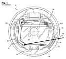
図1は、ドラムブレーキの一般的な例を示し、ホイールと同軸に、ホイールにしっかりと固定して取り付けられたドラム95を備え、そのスカートが内側の制動面96を支持する。このスカートは、ホイールハブの軸線A9と同軸に、バッキングプレート90に取り付けられた機構を覆っている。バッキングプレートは、ハブを支持するハーフアクスルにしっかりと固定される。
FIG. 1 shows a typical example of a drum brake, comprising a
この機構は、1つの円の複数の円弧の形状で、ドラムの回転軸A9の周囲に向かい合って取り付けられた2つのシュー92、93を備える。シューの外面では、シューが外向きに離間されたときに、摩擦ライニング923、933が、ドラムの制動面を押圧する。
This mechanism includes two
「単動」および「複動」と呼ばれるモードでは、各シューは、アクチュエータ91によって1つの端部で離間され、もう1つの反対側の端部は、通常はリベット留めによってバッキングプレート90にしっかりと固定されている当接板94を、回転の接線方向に押す。シューがドラムの制動面に押圧されると、ホイールの回転運動または回転力がシューに回転トルクを与え、シューはこの当接板を介して、これを少なくとも部分的にバッキングプレートに伝える。「単動」構成では、2つのシューは、通常は、バッキングプレートに固定された単複のピストン油圧アクチュエータ91によって、同じ側の2つの端部で作動される。これが従来のモードであり、簡素で、確実かつ一貫して動作する。
In modes called “single-acting” and “double-acting”, each shoe is spaced at one end by an
駐車ブレーキの機能は、車両を長時間継続的に不動のまま保持することからなる。図1に示すように、それ自身はラチェット機構による張力で保持されるケーブル99に引っ張られたレバー97を用いて、同一のドラムブレーキ内で、この機能を常用ブレーキ用として提供することが、長い間知られてきた。レバー97は、シュー92の移動端で枢動し、反応ロッド98を介して、これをもう1つのシューから離間させる。
The parking brake function consists of holding the vehicle stationary for a long time. As shown in FIG. 1, it has long been possible to provide this function for service brakes within the same drum brake using a
緊急ブレーキの機能は、常用ブレーキの制御回路が故障した場合等の特別な状況下で、動いている車両を減速することからなる。この機能は、駐車ブレーキと同一の機構によって実行されることが非常に多い。 The emergency brake function consists of decelerating the moving vehicle under special circumstances, such as when the control circuit of the service brake fails. This function is very often performed by the same mechanism as the parking brake.
常用ブレーキとして十分であり、費用対効果が高いとはいえ、このタイプのドラムブレーキは、特に駐車ブレーキとしては制動トルクが不足する場合がある。 Although this is sufficient as a service brake and is cost effective, this type of drum brake may have insufficient braking torque, especially as a parking brake.
ドラムブレーキについては、「デュオサーボ」と呼ばれる別の動作モードも知られており、これは、アクチュエータが第1のシューの1つの端部を離間させるものである。第1のシューの1つの端部がドラムを押す一方で、そのもう1つの端部が浮動して、浮動するロッドを介して、反対側の端部である、同様に浮動する第2のシューの端部を押す。第2のシューのもう1つの端部は、したがって、唯一当接板を押圧する。このモードは、明らかにより効率的であるが、調整がより困難で、不均一に摩耗する等の他の欠点がある。これは、常用ブレーキとしては広く用いられていない。 For drum brakes, another mode of operation called “Duo Servo” is also known, in which the actuator separates one end of the first shoe. One end of the first shoe pushes the drum, while the other end floats, through the floating rod, the opposite end, the same floating second shoe Press the end of. The other end of the second shoe thus only presses against the abutment plate. This mode is clearly more efficient, but has other drawbacks such as more difficult to adjust and uneven wear. This is not widely used as a service brake.
デュオサーボ型のドラムブレーキは、例えば、常用ブレーキとして作用するディスクの中央ハットの内側をドラムとして用いる、「ドラムインハット」と呼ばれる組み合わせによって、駐車ブレーキとしてのみ用いられることがあり、これは、欧州特許第0416760号明細書で説明されている。 Duo-servo type drum brakes may be used only as parking brakes, for example, in combination with a so-called “drum-in-hat” that uses the inside of the central hat of the disc acting as a service brake as a drum. This is described in Japanese Patent No. 0416760.
既にしばらく前から、単動モードで常用ブレーキとして、ならびにデュオサーボモードで駐車ブレーキとして動作するドラムブレーキを製造することが提案されてきた。様々な組み合わせの中で、仏国特許第2697599号明細書は、当接板に近接して機械式アクチュエータを追加することを提案している。このアクチュエータは、片側で第1のシューの1つの端部を押し、もう一方の側が、追加されたレバーの端部を押すことによって、これらを互いに離間させる。このレバーは、もう1つのシューに沿って自在にスライドし、その反対側の端部がロッドを押し、レバー自身は第1のシューの移動端を押す。 It has already been proposed for some time to produce drum brakes that operate as a service brake in single-acting mode and as a parking brake in duo-servo mode. Among various combinations, French Patent No. 2,697,599 proposes adding a mechanical actuator close to the abutment plate. The actuator pushes one end of the first shoe on one side and the other side pushes the end of the added lever to separate them from each other. The lever slides freely along the other shoe, the opposite end pushes the rod, and the lever itself pushes the moving end of the first shoe.
本発明は、動作の信頼性と静音性とを併せ持ち、印加され保持される作動力に対して、駐車ブレーキとして、あるいは緊急ブレーキとしての効率を改善し、温度の変化による幾何学的変化の管理を改善したドラムブレーキ装置を提案することを目的とする。 The present invention combines the reliability and quietness of operation, improves the efficiency as a parking brake or emergency brake against the applied and held operating force, and manages the geometric change due to temperature change An object of the present invention is to propose a drum brake device with improved performance.
また、単動モードまたは複動モードの利点の全てまたは一部を保持しながら、製造、組み立て、および保守が容易で費用対効果が高い、限られた数の簡素な部品を用いることも目的とする。 It is also intended to use a limited number of simple parts that are easy to manufacture, assemble, and maintain and are cost-effective while retaining all or part of the advantages of single-acting or double-acting modes. To do.
また、電気的制御等の自動車の制御モードにおける技術開発と両立するような装置を提案することを目的とする。 It is another object of the present invention to propose an apparatus that is compatible with technological development in an automobile control mode such as electrical control.
さらに、本装置の既存の車両、または開発途上の車両への適合を多様かつ容易にし、既存の組み立て工程、または開発途上の組み立て工程に柔軟に組み込めることを目的とする。 It is another object of the present invention to make adaptation of the apparatus to an existing vehicle or a vehicle under development various and easy and to be flexibly incorporated into an existing assembly process or an assembly process under development.
本発明は、互いに対して回転運動するドラムとバッキングプレートとの間に、以下のもの同士の間の固体摩擦の効果で制動または保持トルクを生成するタイプの、道路車両用のドラムブレーキ装置を提案する:
一方は、回転シリンダを形成し、ドラムの内面によって支持されている、制動面、そして、
もう一方は、シリンダの内側に配置された第1および第2のシューによって支持されている、ブレーキライニング。
The present invention proposes a drum brake device for road vehicles that generates braking or holding torque between a drum and a backing plate that rotate relative to each other by the effect of solid friction between the following: To:
One forms a rotating cylinder and is supported by the inner surface of the drum, the braking surface, and
The other is a brake lining supported by first and second shoes arranged inside the cylinder.
アイドル位置では、2つのシューは、制動面に接触しないように、ドラムから十分に内側に、すなわち回転軸に向かって離されている。 In the idle position, the two shoes are spaced sufficiently inward from the drum, i.e. towards the axis of rotation, so as not to contact the braking surface.
この装置は、通常は常用ブレーキとして第1の動作モードで作動させることができ、すなわちほとんどの場合に、回転中に生成された摩擦効果によるエネルギーの吸収によって制動トルクが得られる。 This device can usually be operated in the first mode of operation as a service brake, i.e. in most cases the braking torque is obtained by absorption of energy due to the friction effect generated during rotation.
第1の動作モードでは、摩擦は、例えば、必ずしもそうではないがバッキングプレートに固定された、少なくとも1つの第1のアクチュエータの効果による、シューの少なくとも1つ、かつ通常は両方の、外側への移動によって得られる。制動トルクの少なくとも一部は、次に、バッキングプレートに対してシューの少なくとも1つのための当接を形成する、少なくとも1つのアンカーを介して、バッキングプレートに伝達されて、この機構は、第1のブレーキ位置になる。このタイプの動作モードは、特に「単動」および「複動」と呼ばれる構成を有する。 In the first mode of operation, the friction is directed outwardly on at least one and usually both of the shoes, for example by the effect of at least one first actuator, which is not necessarily fixed to the backing plate. Obtained by moving. At least a portion of the braking torque is then transmitted to the backing plate via at least one anchor that forms an abutment for at least one of the shoes with respect to the backing plate, the mechanism comprising: The brake position becomes. This type of operation mode has a configuration called “single action” and “double action” in particular.
本発明による装置は、スペーサ部品と呼ばれる部品を備え、これは、バッキングプレートに対して移動可能であり、移動端と呼ばれる互いに対向するシューの2つの端部を、互いに離しておくために配置される。 The device according to the invention comprises a part called a spacer part, which is movable relative to the backing plate and is arranged to keep the two ends of the opposite shoes, called moving ends, apart from each other. The
本発明によれば、この装置は、停止端と呼ばれる、向かい合って位置するシューの端部を互いに離間させることを可能にするために配置された、少なくとも1つの第2のアクチュエータをさらに備え、これによって、ドラムの制動面を押圧するようにシューを配置する。ドラムと第1のシューとの間の制動または保持トルクは、この摩擦によって生成される。第1のシューは、スペーサ部品を移動端で押圧し、これによって第2のシューの移動端を押し、これにより、制動または保持トルクを、その停止端を介してバッキングプレートに伝達する。第2のアクチュエータのこの動作によって、この機構は、アイドル位置から、あるいは第1のブレーキ位置から、第2のブレーキ位置に移ることができる。この第2のブレーキ位置では、2つのシューは、「圧縮された」シューとして振る舞い、制動または保持トルクは、1つのシューの停止端を介してバッキングプレートに伝達される。この第2の動作モードは、したがって、「デュオサーボ」と呼ばれるタイプの構成に対応する。 According to the invention, the device further comprises at least one second actuator arranged to allow the opposite ends of the shoe, called stop ends, to be spaced apart from each other. The shoe is arranged so as to press the braking surface of the drum. The braking or holding torque between the drum and the first shoe is generated by this friction. The first shoe presses the spacer part at the moving end, thereby pushing the moving end of the second shoe, thereby transmitting braking or holding torque to the backing plate via its stop end. This action of the second actuator allows the mechanism to move from the idle position or from the first brake position to the second brake position. In this second brake position, the two shoes behave as “compressed” shoes and braking or holding torque is transmitted to the backing plate via the stop end of one shoe. This second mode of operation therefore corresponds to a type of configuration called “Duo Servo”.
本発明によるブレーキは、「デュアルモード」ドラムブレーキとして説明することができ、常用ブレーキとして使用できる単動型または複動型の第1のモード、ならびに駐車および緊急ブレーキとして使用できるデュオサーボ型の第2のモードを有する。 The brake according to the invention can be described as a “dual mode” drum brake, the first mode of single-acting or double-acting type that can be used as a service brake, and the duo-servo type first that can be used as parking and emergency brakes. There are two modes.
ドラムブレーキは、移動端を互いに離間させることによって2つのシューを作動させる、1つの第1のアクチュエータと共に配置されることが、現在のところ好ましい。 It is presently preferred that the drum brake is arranged with one first actuator that activates the two shoes by moving the moving ends away from each other.
このようなデュアル・モード・ブレーキは、したがって「単動」として、一般的には常用ブレーキとしてより詳細に説明される、第1のモードを有する。 Such dual mode brakes thus have a first mode, which is described in more detail as “single action”, generally as a service brake.
本発明の特徴によれば、第2のアクチュエータは、これを収容する少なくとも1つのハウジングを介して、バッキングプレートにしっかりと固定して取り付けられる。この装置の第1の動作モードでの作動中は、2つのシューの停止端が、このハウジングを直接的または間接的に押圧する。 According to a feature of the invention, the second actuator is fixedly attached to the backing plate via at least one housing that houses it. During operation of the device in the first mode of operation, the stop ends of the two shoes press the housing directly or indirectly.
第2のアクチュエータは、少なくとも1つの電動モータを備える駆動部品によって駆動されることが好ましい。 The second actuator is preferably driven by a drive component including at least one electric motor.
本発明の特徴によれば、第1のアクチュエータは、油圧の効果による1つ以上のピストンの変位によって動作するタイプのアクチュエータを備え、ピストンは、通常はバッキングプレートに固定されたスレーブシリンダ、および互いに反対方向に離間する2つの同軸ピストンである。次に、第2のアクチュエータが、二重ピストンスレーブシリンダを有する、従来のドラムブレーキと同様の機構に組み合わされる。このような組み合わせは、現行車両または近い将来の車両、特に、小型または中型車両、もしくはエントリーレベル車両の市場部門にとって有益である。 According to a feature of the invention, the first actuator comprises an actuator of the type that operates by displacement of one or more pistons due to the effect of hydraulic pressure, the pistons usually being slave cylinders fixed to a backing plate, and each other Two coaxial pistons spaced in opposite directions. The second actuator is then combined with a mechanism similar to a conventional drum brake having a dual piston slave cylinder. Such a combination is beneficial for the market segment of current vehicles or vehicles in the near future, especially small or medium vehicles, or entry level vehicles.
別の特徴によれば、第1のアクチュエータは、電動式駆動部品、通常は電動式シュースペーサ、特に第2のアクチュエータと同様の電動式シュースペーサの効果による、1つ以上のピストンの変位によって動作するタイプのアクチュエータを含む。したがって、性能の良い駐車ブレーキを有する、完全に電動式のブレーキが得られ、大部分、または全てが電動制御となる次世代の車両にとって有益である。 According to another characteristic, the first actuator operates by displacement of one or more pistons due to the effect of an electrically driven drive component, usually an electrically powered shoe spacer, in particular an electrically powered shoe spacer similar to the second actuator. Type of actuator. Therefore, a fully electric brake having a parking brake with good performance can be obtained, which is beneficial for the next generation vehicle in which most or all is electrically controlled.
いくつかの特徴によれば、電動式駆動部品の1つ以上は、これを設けることによって、電子制御接続によって受信された電子制御信号を受けるために、かつ制御接続とは異なる電気的接続を介して受けた電力を用いた、例えば1つ以上の電力段を介して、電動モータに電力を供給する目的で、この制御信号を解釈するために配置された電子サブアセンブリを備える。 According to some features, one or more of the electrically driven components are provided to receive an electronic control signal received by the electronic control connection and via an electrical connection different from the control connection. An electronic subassembly arranged to interpret this control signal for the purpose of supplying power to the electric motor, for example via one or more power stages, using the received power.
例えば、このブレーキ機構は、例えば、CAN型の内部通信バスを介して、車両の中央コンピュータに直接接続され、これによって制御されてもよい。別の例によれば、このブレーキ機構は、しばしば「ESP」と呼ばれる、経路監視および制御システム、またはしばしば「ABS」と呼ばれるブレーキシステムのコンピュータに直接接続され、これによって制御される。 For example, the brake mechanism may be directly connected to and controlled by the central computer of the vehicle via, for example, a CAN-type internal communication bus. According to another example, the brake mechanism is directly connected to and controlled by a route monitoring and control system, often referred to as “ESP”, or a brake system computer often referred to as “ABS”.
別の変形例では、この駆動部品は、ほとんど電力段を有していないか、または全く有していない。したがって、例えば、このような監視および制御システムの電力段が直接供給する電力による制御を用いることで、ばね下重量の節約、および小型化を行うことが可能になる。 In another variant, the drive component has little or no power stage. Therefore, for example, by using the control by the power directly supplied from the power stage of such a monitoring and control system, it is possible to save the unsprung weight and to reduce the size.
想定される別の特徴によれば、第2のアクチュエータは、機械的制御によって制御される。これは、完全に機械的エネルギーによるか、またはハンドブレーキケーブル等の、アクチュエータ用の電動式駆動部品を制御する、機械的制御による。 According to another envisaged feature, the second actuator is controlled by mechanical control. This is either entirely due to mechanical energy or mechanical control that controls the motorized drive components for the actuator, such as a handbrake cable.
第2のアクチュエータは、運動の伝達方向が不可逆なタイプの機械式運動伝達装置用の、少なくとも1つの接触面を有する機構によって、2つのシューの停止端を離間させることが好ましい。 The second actuator is preferably configured such that the stop ends of the two shoes are separated by a mechanism having at least one contact surface for a mechanical motion transmission device of a type in which the motion transmission direction is irreversible.
特に、このリニア・アクチュエータ・アセンブリは、ねじナットシステムを形成するために互いに係合する、少なくとも1つの第1のねじ付き部品、および1つの第2のねじ付き部品を備え、この第2の部品に対するこの第1の部品の回転の効果で直動を生成する。このねじナットシステムは、このような力の伝達の不可逆性を有することが好ましいが、そうでない場合も想定される。 In particular, the linear actuator assembly comprises at least one first threaded part and one second threaded part that engage with each other to form a screw nut system, the second part. A linear motion is generated by the effect of rotation of this first part with respect to. The screw nut system preferably has such irreversible force transmission, but it is envisaged otherwise.
電動式駆動部品の場合にしばしば必要になる、大幅なギヤ減速比を生成するために、一般的に用いられる解決策は、90度で、または例えば60度まででわずかに傾いた、直交するギヤを駆動させるウォームギヤである。この解決策はまた、所要空間を小さくすることができ、使用する部品が少ない。 In order to produce the large gear reduction ratios that are often required in the case of electrically driven parts, a commonly used solution is an orthogonal gear that is slightly tilted at 90 degrees, for example up to 60 degrees It is a worm gear which drives. This solution can also reduce the required space and use fewer parts.
本発明は、異なる方法で、駆動部品の回転を、互いに平行な軸線を有する機械式ギヤを介して、直動の方向へと、作動ユニットに伝達することを提案する。変形例として、これらの軸線間の角度は小さくてもよく、例えば、合計で30度未満、または15度未満の角度を形成する。 The invention proposes in a different way to transmit the rotation of the drive component to the actuating unit in the direction of linear motion via mechanical gears having axes parallel to each other. As a variant, the angle between these axes may be small, for example forming a total angle of less than 30 degrees or less than 15 degrees.
このタイプの伝達装置により、伝達される力の効率を高めることが可能になり、したがって必要な動力を限定するか、あるいは所与の動力に対する性能を向上させることができる。 This type of transmission device makes it possible to increase the efficiency of the transmitted force and thus limit the required power or improve the performance for a given power.
別の態様によれば、本発明は、本明細書に開示されるような1つ以上のデュアル・モード・ドラム・ブレーキ装置を備える、通常は道路走行車両である、車両または車両のサブアセンブリを提案する。 According to another aspect, the present invention provides a vehicle or vehicle subassembly, typically a road vehicle, comprising one or more dual mode drum brake devices as disclosed herein. suggest.
デュアル・モード・ドラム・ブレーキの第1のアクチュエータは、常用ブレーキ機能と呼ばれる、車両が動いているときに減速および/または停止する機能を実行するために、従来、自動車に取り付けられていたのと同様の方法で、ドラムブレーキに結合され制御される。第2のアクチュエータは、駐車ブレーキ機能と呼ばれる、車両が静止しているときに、介入することなくこれを保持する機能、および/または緊急ブレーキ機能と呼ばれる、常用ブレーキタイプの機能が故障した場合に動いている車両を減速する機能を実行するために、結合され制御される。これは通常、駐車ブレーキ機能と緊急ブレーキ機能とを組み合わせたものである。 The first actuator of a dual mode drum brake is traditionally attached to an automobile to perform a function of decelerating and / or stopping when the vehicle is moving, called a service brake function. In a similar manner, it is coupled to and controlled by the drum brake. The second actuator is called the parking brake function, when the vehicle is stationary, the function of holding it without intervention and / or when the function of the service brake type called emergency brake function fails Combined and controlled to perform the function of decelerating the moving vehicle. This is usually a combination of a parking brake function and an emergency brake function.
このような車両または車両サブアセンブリの特徴によれば、第2のアクチュエータは、車両の電子機能を管理する中央電子コンピュータシステムで制御される電動式駆動部品、もしくは車両のブレーキおよび/または軌道の監視および補正用の電子システム(すなわちABSやESP)を介して制御され給電される、電動式駆動部品によって作動される。 According to such a vehicle or vehicle subassembly feature, the second actuator is a motorized drive component controlled by a central electronic computer system that manages the vehicle's electronic functions, or vehicle brake and / or track monitoring. And actuated by electrically driven drive components that are controlled and powered via a correction electronics system (ie ABS or ESP).
さらに別の態様によれば、本発明は、本明細書に開示されるようなドラムブレーキ装置を組み立てるステップおよび/または取り付けるステップを含む、車両のサブアセンブリを組み立てる方法を提案する。 According to yet another aspect, the present invention proposes a method for assembling a sub-assembly of a vehicle, comprising assembling and / or attaching a drum brake device as disclosed herein.
特に、本発明は、外側を向いたライニングを装備した第1および第2のシューを備えるドラムブレーキ機構を組み立てる方法を提案し、ライニングは、ドラムに覆われてバッキングプレートに取り付けられ、その結果、シューが外向きに離間された場合に、ドラムの内側によって支持された円筒形の制動面との摩擦効果によるエネルギーの吸収によって、制動トルクをバッキングプレートに伝達することが可能になる。本発明によれば、この方法は、以下の順序で、または別の順序で、少なくとも以下のステップを含む:
− 移動端と呼ばれる、互いに対向する2つの端部を押すことによって、シューを外向きに離間できるように配置された、少なくとも1つの第1のアクチュエータをバッキングプレートに固定するステップ;
− シューが第1のアクチュエータによって離間された場合に、停止端と呼ばれる対向する端部が、バッキングプレートの固定されたアンカーに当接できる位置で、シューをバッキングプレートに取り付けるステップ;
− シューの2つの移動端同士の間の分離を保持するために、スペーサ部品を所定の位置に取り付けるステップ;及び、
− 制動面を押圧するように、シューの2つの停止端を動かすことを可能にするために配置された第2のアクチュエータを、バッキングプレートに固定するステップ。
In particular, the present invention proposes a method of assembling a drum brake mechanism comprising first and second shoes equipped with an outwardly facing lining, the lining being covered with a drum and attached to a backing plate, so that When the shoes are spaced outward, the braking torque can be transmitted to the backing plate by absorbing energy due to the friction effect with the cylindrical braking surface supported by the inside of the drum. According to the invention, the method comprises at least the following steps in the following order or in another order:
Fixing at least one first actuator to the backing plate, arranged so that the shoe can be spaced outwardly by pushing two opposite ends, called moving ends;
Attaching the shoe to the backing plate such that when the shoe is separated by the first actuator, the opposite end, called the stop end, can abut the fixed anchor of the backing plate;
-Attaching a spacer part in place to maintain the separation between the two moving ends of the shoe; and
Securing a second actuator, arranged to allow movement of the two stop ends of the shoe to press the braking surface, to the backing plate;
したがって、本発明は、一体的な駐車または緊急ブレーキを備えるドラムブレーキを提案し、これは、今日では費用対効果が高く、非常に高性能な複動モード、および特に単動モードの利点を保持しながら、寸法、および制御に使用されるエネルギーに対する性能が改善されている。 Thus, the present invention proposes a drum brake with integrated parking or emergency brake, which today is cost-effective and retains the advantages of a very high performance double-acting mode, and in particular the single-acting mode However, dimensions and performance with respect to energy used for control are improved.
本発明によるブレーキは、特に駐車または緊急ブレーキの、電気的制御等の制御動作の自動化に用いられる作動用電力のレベルに特に適している。 The brake according to the invention is particularly suitable for the level of operating power used for automating control operations such as electrical control, in particular for parking or emergency braking.
これが駐車ブレーキとして動作することで、一体的な不可逆性をもたらし、かつ製造の費用対効果が高い、簡素で強固なアーキテクチャをもたらす。本ブレーキは、不可逆な特徴にかかわらずエネルギー効率が良好であり、小型で放熱性のある有益な特徴を提供する。 This acts as a parking brake, resulting in a simple and robust architecture that provides integrated irreversibility and is cost effective to manufacture. The brakes are energy efficient regardless of their irreversible features, and provide beneficial features that are small and heat dissipation.
特に、本発明は、駆動部品からアクチュエータアセンブリへ伝達するエネルギー効率を良くすることができ、これにより、より大きいクランプ力またはより高いクランプ速度の取得、あるいはより動力が小さい駆動部品の使用、もしくはこれらの性能間のより良い妥協点を得ることができる。 In particular, the present invention can improve the energy efficiency of transmission from the drive component to the actuator assembly, thereby obtaining a greater clamping force or higher clamping speed, or using a less powered drive component, or these You can get a better compromise between performance.
本発明は、例えば既存の車両モデルに適合させるために、または設計途上の車両に組み込むために、車両または車両サブアセンブリの設計者の要件および制約に、容易かつ柔軟に適合させることができる。 The present invention can be easily and flexibly adapted to the requirements and constraints of a vehicle or vehicle subassembly designer, for example to adapt to an existing vehicle model or to be incorporated into a vehicle under design.
これにより、単一のモデルのアクチュエータで、様々なレベルの駆動性能を実現することが可能になる。 This makes it possible to achieve various levels of driving performance with a single model of actuator.
したがって本発明は、既存の車両モデルまたは工程に対して、設計段階で、および製造段階においても、柔軟かつ多用途で、費用対効果の高い方法で、車両の設計、または車両の製造方法に、このようなブレーキを組み込むことを可能にする。 Accordingly, the present invention provides a vehicle design or vehicle manufacturing method that is flexible, versatile, and cost effective in the design and manufacturing phases of existing vehicle models or processes. It is possible to incorporate such a brake.
本発明の様々な実施形態が想定され、その全ての可能な組み合わせにより、本明細書に開示された様々な任意選択の特徴が組み込まれる。 Various embodiments of the present invention are envisioned and all possible combinations thereof incorporate the various optional features disclosed herein.
本発明の他の特徴および利点は、決して限定的ではない実施形態の詳細な説明、および添付の図面から明らかになるであろう。
デュアル・モード・ブレーキの機構
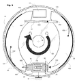
図2は、本発明の実施形態の例における「デュアルモード」のドラムブレーキ機構を表す。この実施形態は、常用ブレーキモード用の様々なタイプのアクチュエータ、ならびに駐車ブレーキまたは緊急ブレーキのアクチュエータ用の様々なタイプの駆動部品で実現することができる。
Dual Mode Brake Mechanism FIG. 2 represents a “dual mode” drum brake mechanism in an example embodiment of the present invention. This embodiment can be realized with various types of actuators for service brake mode, as well as various types of drive components for parking or emergency brake actuators.
図3、図4、および図5は、駐車ブレーキまたは緊急ブレーキとしての、その動作の様々な位置におけるこの機構を表す。 3, 4 and 5 represent this mechanism in various positions of its operation as a parking brake or emergency brake.
常用ブレーキモード
本ドラムブレーキ1は、回転軸A1の周囲で互いに対して回転運動することにより、ドラム(図示せず)とバッキングプレート10との間に制動トルクを生成する。従来の道路車両アーキテクチャでは、バッキングプレート10は、通常は懸架された回転アクスルまたはハーフアクスルを介して、回転するように車両のシャーシに固定されている。ドラムは、ホイールにしっかりと固定され、かつハブおよびベアリング(図示せず)によって、軸線A1の周囲で移動するように固定され、かつ回転するようにガイドされる。
Service brake mode The drum brake 1 generates a braking torque between a drum (not shown) and the
常用ブレーキモードでは、制動トルクは、以下のもの同士の間の摩擦効果による、エネルギーの吸収によって生成される:
一方は、図1のドラムと同様に、ドラムの内面によって支持されている制動面;そして、
もう一方は、第1のシュー12および第2のシュー13によってそれぞれ支持されているブレーキライニング123、133。
In service brake mode, braking torque is generated by energy absorption due to friction effects between:
One, like the drum of FIG. 1, is a braking surface supported by the inner surface of the drum; and
The other is
摩擦は、第1のアクチュエータ11、ここではバッキングプレート10に固定できる油圧シリンダの効果によって、シューを外向きに離間させることによって得られる。アイドル位置から、または駐車ブレーキ位置から、この第1のアクチュエータ11は、このようにしてこの機構を常用ブレーキ位置にし、アイドル位置への復帰は、例えば図2に示すように、2つのシューをリンクする戻りばねによって行われる。
Friction is obtained by separating the shoe outwards by the effect of a hydraulic cylinder that can be fixed to the
この例では、ドラムブレーキは、常用ブレーキとして作動されるときに、単動モードで動作するために配置されている。第1のアクチュエータ11は、2つの対向するピストン111、112を有する「スレーブシリンダ」であり、そのそれぞれは、2つの対向する端部121、131、すなわち回転軸A1の同じ側にあり、本明細書では「移動端」と呼ばれて図の上部にある、2つの端部を互いに離間させることによって、シュー12、13のうちの1つを作動させる。停止端と呼ばれる対向する端部122、132で、各シューは、アンカーを介してバッキングプレート10を押し、アンカーは、バッキングプレートにしっかりと固定されて、このシューの当接部を形成する。このアンカーは同時に、シューとバッキングプレートとの間にトルクを伝達するための部品でもある。この例では、2つのシューのアンカーは、本明細書ではシュースペーサと呼ばれる、第2のアクチュエータ2のハウジング21によって実現され、これによって、バッキングプレート10にしっかりと固定される。ハウジング21のバッキングプレート10へのしっかりとした固定については、図3〜図5に、図の中央下部の接地記号で図式的に示されている。
In this example, the drum brake is arranged to operate in a single action mode when operated as a service brake. The
駐車または緊急ブレーキモード
図3に示すように、シュースペーサ2は、アクチュエータアセンブリ3を備え、これは、駐車または緊急ブレーキモードにおいて、シュー12、13の停止端122、132を互いに離間させるように押して、シューがドラム15の制動面を押圧するようにする。
Parking or Emergency Brake Mode As shown in FIG. 3, the shoe spacer 2 includes an actuator assembly 3 that pushes the stop ends 122, 132 of the
アイドル位置から、または常用ブレーキ位置から、この第2のアクチュエータ2は、このようにしてこの機構を駐車ブレーキ位置にし、アイドル位置への復帰は、例えば同じ戻りばねによって行われる。 From the idle position or from the service brake position, the second actuator 2 thus places the mechanism in the parking brake position and the return to the idle position is effected, for example, by the same return spring.
この例では、リニア・アクチュエータ・アセンブリ3は、第1のピストン33および第2のピストン32を含み、これは、回転軸A1の周囲の接線方向D2において、互いに対して直動で変位する。図3に2つの矢印で示されているように、この変位により、2つのピストンが、第1のシュー12および第2のシュー13の2つの停止端122、132をそれぞれ押す。
In this example, the linear actuator assembly 3 includes a
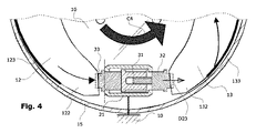
図4および図5に示すように、例えば車両が坂に駐車されているか、または車両が動いているときに緊急ブレーキが作動されることで、1つの方向C4またはもう1つの方向C5の回転トルクが、バッキングプレート10に対するドラム15によってシューに印加されるとすぐに、ドラムは、シューとドラムとの間の摩擦接触の結果、シュー12、13をこのトルクの方向に回転駆動させようとする。
As shown in FIGS. 4 and 5, for example, when the vehicle is parked on a hill or the vehicle is moving, the emergency brake is activated so that the rotational torque in one direction C4 or another direction C5 is obtained. As soon as it is applied to the shoe by the
図5は、時計回りのトルクC5の場合をより詳細に示す。摩擦によって、「第1の」シュー12は、ドラム15からトルクC52を受ける。
FIG. 5 shows in more detail the case of clockwise torque C5. Due to the friction, the “first”
反対側の端部すなわち「移動」端121で、第1のシュー12は、連結部142、例えば、枢動リンク、または互いに係合するノッチ等その他任意の形式の係合を介して、スペーサ部品14を押圧する。
At the opposite end or “moving”
ロッド等のスペーサ部品14は、バッキングプレート10に対して移動可能かまたは「浮動」しており、同様にもう1つのシュー13の「移動」端131に連結され、その結果、2つの移動端121、131を互いに離間させて保持する。この例では、このスペーサ部品は、図2に示すようなライニング123、133の摩耗から生じた遊びを調整する機構を同様に支持する、ロッドによって形成されている。
A
このスペーサ部品は、他の形態、例えば2つのシューを押圧するスペーサ板によっても実現できることに留意されたい。また、ハウジングまたはピストンによって浮動して取り付けられている場合は、スレーブシリンダによっても実現することができる。 It should be noted that this spacer component can also be realized in other forms, for example with a spacer plate that presses two shoes. In addition, when it is mounted floating by a housing or a piston, it can also be realized by a slave cylinder.
第1のシュー12の圧力により、スペーサ部品14は、圧力C23を第2のシュー13の移動端131に、回転軸A1の周囲でほぼ接線方向に伝える。
Due to the pressure of the
スペーサ部品14の圧力により、第2のシュー13は、ドラム15の制動面を押し、シュー自体はドラムからの摩擦によるトルクC53を受ける。この第2のシューは、合計C30の受けたトルクを、その反対側の端部、すなわち「停止端」132を介してピストン32に伝達する。
Due to the pressure of the
シュースペーサ2のハウジング21に対して、アクチュエータアセンブリ3は、その中央位置の両側の停止部によって制限された移動距離にわたって、回転軸A1の周囲で接線方向に移動自在に取り付けられる。図5の回転方向では、ドラム15によって伝えられたトルクC52およびC53の効果により、シューは、アクチュエータアセンブリ3をこれらのトルクの方向、すなわち図に示すように、左向きの白矢印に従った方向D22で、停止位置まで変位させる効果をもつ。
The actuator assembly 3 is attached to the
したがって、駐車または緊急ブレーキモードでは、第2のシュー13の停止端132は、ドラムでシューの圧力によって生成された制動または保持トルクをバッキングプレート10に伝達するために、シュースペーサのハウジング21を押す。
Thus, in the parking or emergency brake mode, the stop end 132 of the
この例では、第2のシュー13の停止端132、および第2のアクチュエータ2のハウジング21は、例えば適切な形状によって、この事例では、図の一点鎖線の垂線でハウジング21の外面に面する、ピストンが支持する肩部329によって、第2のピストン32を介して互いに押し合う。
In this example, the stop end 132 of the
図5のこの回転方向において、シューは、最初に離間された端部122がドラムの運動を最初に受け、これが図の左側のシュー12であり、これは枢動して反対側の端部でピボット142に支持され、これによって「圧縮された」シューを形成する。同様に、この運動を受ける端部131を介して、このように接線力を受ける第2のシュー13もまた、その停止端132で支持される、「圧縮された」シューとして作用する。
In this direction of rotation of FIG. 5, the shoe has the first spaced
したがって、駐車または緊急ブレーキモードでは、第2のアクチュエータ2の作動により、この同じブレーキアセンブリ1を「デュオサーボ」モードで動作させ、これにより、同じシュー作動力で、ドラムに対して、常用ブレーキの単動モードよりもはるかに大きい作動力をもたらす。 Therefore, in the parking or emergency brake mode, the operation of the second actuator 2 causes the same brake assembly 1 to operate in the “Duo Servo” mode, so that the service brake is applied to the drum with the same shoe operating force. It provides much greater actuation force than single-acting mode.
図4に示す逆の回転方向では、もう1つの方向のトルクC4が、シュー12、13、およびスペーサ部品14をこのもう1つの方向に駆動させ、これにより、図に示すように、白矢印に従って、アクチュエータアセンブリ3を右に向かって反対方向D23に、停止位置まで変位させる。制動トルクは、次に、左側のシュー12の停止端122を介し、図の一点鎖線の垂線で、第1のピストン33の肩部339を介して、スペーサのハウジング21に伝達される。
In the reverse direction of rotation shown in FIG. 4, the torque C4 in the other direction drives the
このデュアル・モード・ドラム・ブレーキ機構1は、本明細書では、油圧エネルギーで動作する常用ブレーキアクチュエータ11、ならびに電力によって動作する駐車および緊急ブレーキアクチュエータ2を用いた例で示される。しかしながら、この機構のアーキテクチャは、これらの各アクチュエータ用の他の種類のエネルギー、例えば油圧エネルギーを用いて、あるいは直接的に機械的制御によっても動作可能であり、かつこれによってエネルギーを供給される。
This dual mode drum brake mechanism 1 is shown here as an example using a
駐車および緊急ブレーキアクチュエータの構造
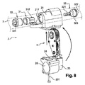
本明細書ではシュースペーサとも呼ばれる、第2のアクチュエータ2の構造および動作について、図6〜図9を参照して、ここでさらに詳しく説明する。図6は、図2の機構の駐車および緊急ブレーキのアクチュエータの全体を示す。
Parking and Emergency Brake Actuator Structure The structure and operation of the second actuator 2, also referred to herein as a shoe spacer, will now be described in more detail with reference to FIGS. FIG. 6 shows the entire parking and emergency brake actuator of the mechanism of FIG.
デュアル・モード・ドラム・ブレーキ1内の第2のアクチュエータとして本明細書に提示されているシュースペーサ2の全ての特徴は、他の種類のドラムブレーキを製造するために、類似または同一のアクチュエータ内でも実現できることに留意されたい。特に、デュオサーボモードでのみ動作するドラムブレーキを製造するために用いることが、本明細書で明確に提案されている。本明細書で提示される装置に対しては、このための第1のアクチュエータ11がなくても十分な場合がある。このような単一モードのデュオサーボブレーキは、例えば、ディスクブレーキの中央ハットの中に組み込まれた形態で提案され、これは、「ドラムインハット」と呼ばれることがあるアーキテクチャにおいて、ブレーキディスクと同軸方向に、その内面で制動面を支持するドラムを形成する。
All features of the shoe spacer 2 presented here as a second actuator in the dual mode drum brake 1 are similar to those in similar or identical actuators to produce other types of drum brakes. But keep in mind that this is possible. In particular, it has been explicitly proposed here to use it to produce a drum brake that operates only in the duo-servo mode. For the device presented here, it may be sufficient without the
リニア・アクチュエータ・アセンブリ
駐車ブレーキ機能は一般的に、外部からの作用を受けることなく、非常にわずかなエネルギー消費で、もしくは好ましくはエネルギーを消費することなく、装置を長時間、例えば数分から数か月、あるいは数年にわたって、制動された位置にしておく能力を必要とする。したがって車両は、通常は駐車ブレーキ位置にロックする機能を提供する機構を備え、また通常は、構成する部品の寸法が変化する場合に、シューをドラムに押しつけるドライブトレインの力を安定させる機能も備える。図1のような装置では、このような機能は「ハンドブレーキ」動作部品、すなわちレバーを保持するラチェットによって、かつシースを装備した制御ケーブル99の弾性によってそれぞれもたらされる。
The linear actuator assembly parking brake function is generally not subject to external action, with very little energy consumption, or preferably without energy consumption, for a long time, eg several minutes to several minutes. Requires the ability to remain in a braked position for months or years. Accordingly, the vehicle is usually provided with a mechanism that provides a function of locking to the parking brake position, and usually also has a function of stabilizing the force of the drive train that presses the shoe against the drum when the dimensions of the constituent parts change. . In a device such as FIG. 1, such a function is provided by the “handbrake” operating part, ie the ratchet holding the lever, and by the elasticity of the
図2の実施形態では、圧力トレインの力の安定化の機能を提供するために、第2のアクチュエータ2は、弾性部品と呼ばれ、「スプリングパック」とも呼ばれる弾性変形可能な部品を介して、作動による運動の軸線に沿って2つのシューの停止端122、132を離間させる。この実施形態では、この弾性部品は、2つのピストンのうちの1つ、ここでは第1のピストン33によって生成される。シュースペーサの変位D2の方向に伝達された力に応じて、この弾性部品は、異なる環境下、または状況が変化する中で、ドラムに対するシューの十分な圧力を維持または回復できる移動距離をもたらすために、決定された剛性を有する。
In the embodiment of FIG. 2, in order to provide the function of stabilizing the force of the pressure train, the second actuator 2 is called an elastic part, via an elastically deformable part, also called a “spring pack”, The stop ends 122, 132 of the two shoes are spaced apart along the axis of motion by actuation. In this embodiment, this elastic part is generated by one of the two pistons, here the
特に、この弾性部品は、この装置が第1のブレーキ位置にあって第2のアクチュエータが作動している間に、この装置を第2のブレーキ位置のまま保持するか、または第2のブレーキ位置にするのに十分な量の機械的エネルギーを、圧縮することによってアクチュエータアセンブリ3に蓄積することができ、この第2のアクチュエータ2の失活後に第1のアクチュエータ11の圧力が遮断された場合に、この第2のアクチュエータを再作動させる必要がない。
In particular, the elastic component holds the device in the second brake position while the device is in the first brake position and the second actuator is actuated, or the second brake position. A sufficient amount of mechanical energy can be stored in the actuator assembly 3 by compression, and when the pressure of the
このような状況は、例えば、運転者が車両を停止させ、常用ブレーキを用いて静止させておいた後に、常用ブレーキの制御を解除する前に駐車ブレーキを適用したとき、例えば坂に停車するために停止したときに発生する。この弾性による留保によって、車両を不動にする需要を満たすのに十分な負荷を確保しながら、1つのブレーキ位置からもう1つのブレーキ位置へ、例えば単動モードからデュオサーボモードに移るのに必要な移動距離を満たすことが可能になる。 For example, when the parking brake is applied before the driver releases the control of the service brake after the driver stops the vehicle and stops using the service brake, for example, the vehicle is stopped on a slope. Occurs when it stops. This elastic retention is necessary to move from one brake position to another, for example, from single-acting mode to duo-servo mode, while ensuring sufficient load to meet the demand to immobilize the vehicle. It becomes possible to satisfy the moving distance.
また、この弾性部品33の移動距離は、ドラムブレーキ1の部品12、13の寸法が変化する中で、第2のアクチュエータ2を作動させることなく、以下のことを可能にする:
1つの方向への寸法変化の場合、例えばシュー、あるいはピストンすなわちシューを離間させる機構等の、この作動力を生成するドライブトレインの部品の熱収縮の場合、もしくは例えばドラムの熱膨張の場合に、制動面に対するシュー12、13の作動力を維持する;そして、
例えば、走行中に常用ブレーキとして加熱された後で、停止時に冷却されたときに、ドラムの熱収縮によって起こり得る、他の方向への寸法変化の場合に、機構内の力の増加を制限する。
Also, the moving distance of the
In the case of a dimensional change in one direction, for example in the case of a thermal contraction of a part of the drive train that produces this actuation force, such as a shoe or a mechanism that separates a piston or shoe, or in the case of a thermal expansion of a drum, Maintaining the actuation force of the
For example, limiting the increase in force in the mechanism in the case of dimensional changes in other directions that can occur due to thermal contraction of the drum when heated as a service brake during travel and then cooled when stopped .
この弾性部品は、したがって、「再クランプ(re−clamping)」とも呼ばれ、エネルギーを消費し、重大な結果になり得る誤動作につながる、駐車中のシステムの自動的な再作動の必要性を限定、および通常は回避できるようにする。 This elastic component is therefore also called “re-clamping” and limits the need for automatic reactivation of the parked system leading to malfunctions that consume energy and can have serious consequences. , And usually to be able to avoid.
シュースペーサの運動が、不可逆なタイプの機構によって得られる実施形態では、弾性部品は、この不可逆な機構の下流にある。 In embodiments in which the movement of the shoe spacer is obtained by an irreversible type mechanism, the elastic part is downstream of this irreversible mechanism.
図6に示すように、この弾性部品は、ここではピストン頭部332を有する第1のピストン33によって実現され、ピストン頭部332は後方に向かってスカートを有し、この内部でピストン頂部333がスライドすることができる。ピストン頭部およびピストン頂部は、ここでは好適には、「皿ばね」ワッシャと呼ばれる、予め圧縮された円錐形の鋼性ワッシャの積み重ねである、圧縮可能な弾性構造331を介して互いに押圧する。このアセンブリは、ここではピストン頂部333の後部の周囲のスカートの端部を、波形にすることによって結合される。
As shown in FIG. 6, this elastic part is realized here by a
図2の実施形態では、リニア・アクチュエータ・アセンブリ3は、ねじナットシステムを形成するために互いに係合する第1のねじ付き部品、および第2のねじ付き部品を備える。ねじナットシステムは、この第1の部品のこの第2の部品に対する回転の効果により、直動を生成する。これにより、部品のうちの1つ31が受けたトルクが、各部品31、32で、それぞれ2つの反対の軸力に変換される。
In the embodiment of FIG. 2, the linear actuator assembly 3 comprises a first threaded part and a second threaded part that engage with each other to form a threaded nut system. The screw nut system generates a linear motion due to the effect of rotation of the first part relative to the second part. Thereby, the torque received by one of the
この実施形態では、このねじナットシステムのねじ山角度は、これら2つの部品を製造するのに使用される一対の材料の摩擦角よりも小さいねじ山角度を選択することによって、得られた力の伝達が不可逆になるように選択される。 In this embodiment, the thread angle of the thread nut system is obtained by selecting a thread angle that is smaller than the friction angle of the pair of materials used to manufacture the two parts. The transmission is chosen to be irreversible.
このねじナットシステムの選択は、このようなねじ山角度の選択と組み合わさって、駐車ブレーキ位置にロック機能をもたらす不可逆性を生成する。すなわち、ピストン32、33がシュー13、12から受けた力は、ねじナットシステムの2つの部品のねじ山同士の間がスライドしないことによって遮断される。したがって、駆動部品に伝わることがなく、モータをロックするか、または負荷をかけておく必要がなくなる。
This choice of screw nut system, combined with such a choice of thread angle, creates an irreversibility that provides a locking function for the parking brake position. That is, the forces received by the
例えば、鍛鋼で作られた、潤滑された部品31、32では、摩擦係数は、0.1〜0.2の間となる。この摩擦係数の0.1の値は、φlimit=5.7度の摩擦角を決定する。つまり、力の伝達は不可逆であり、システムのねじれ角βは、摩擦角未満でなければならず、すなわちβ<5.7度である。
For example, for
ねじナット伝達装置の原理により、非常に大きなギヤ減速を得ることが可能になり、ねじ山角度が小さいほど、さらに大きくなる。 The principle of the screw nut transmission device makes it possible to obtain a very large gear reduction, and the smaller the thread angle, the greater it becomes.
特に電動モータの場合は、駆動部品が頻繁に高速回転をもたらすタイプのものであることが多く、十分な力で小さい変位を得るために、非常に大きいギヤ減速をもたらすことが必要になる。したがって、このギヤ減速をもたらすために、非常に小さいねじれ角を用い、中間ギヤの数を制限することが有益であろう。 In particular, in the case of an electric motor, the drive component is often of a type that frequently causes high-speed rotation, and in order to obtain a small displacement with sufficient force, it is necessary to provide a very large gear reduction. Therefore, it would be beneficial to use a very small helix angle and limit the number of intermediate gears to provide this gear reduction.
しかしながら、この実施形態では、ねじナットシステムのねじ山のねじれ角は、摩擦角未満にとどめながら、なるべく大きくなるように選択される。これにより、ねじナットシステム自身の効率を高めることが可能になる。この機能は、後述する伝達の特徴と組み合わせると特に好適であり、これにより、高い全体効率を維持しながら、さらなるギヤ減速をもたらすことが可能になる。 However, in this embodiment, the twist angle of the thread of the screw nut system is selected to be as large as possible while staying below the friction angle. This makes it possible to increase the efficiency of the screw nut system itself. This function is particularly suitable when combined with the transmission features described below, which allows further gear reduction while maintaining high overall efficiency.
このねじれ角は、例えば、臨界角を下回る0.25度、あるいは0.15度を下回る値で選択される。例えば、15度の台形形状のねじ山で、摩擦係数0.1の場合、選択されるねじれ角は、5.45〜5.7度、あるいは5.55〜5.7度、および好ましくはβ=5.6度、5.55度、または5.7度である。 This twist angle is selected, for example, as a value less than 0.25 degrees below the critical angle, or less than 0.15 degrees. For example, for a 15 degree trapezoidal thread with a coefficient of friction of 0.1, the selected twist angle is 5.45 to 5.7 degrees, or 5.55 to 5.7 degrees, and preferably β. = 5.6 degrees, 5.55 degrees, or 5.7 degrees.
ねじ山の2つの頂同士の間に含まれる区域にわたるねじ山フランクで、雄ねじおよび雌ねじに対する摩擦接触が起こる。1つの変形では、ねじれ角はこの区域で測定され、より確実には、雌ねじの頂に沿って測定される。別の変形では、この角度は接触区域の平均径の円に沿って測定される。選択された直径に応じて、摩擦角に対して、より大きいかまたは小さい安全余裕度が採用される。いずれの場合も、極端な加熱状態、およびねじ山フランクが摩耗した場合を含めて、動作時の不可逆性の保証が確保される。 In the thread flank over the area contained between the two crests of the thread, frictional contact to the male and female threads occurs. In one variation, the torsion angle is measured in this area, more reliably along the top of the female thread. In another variant, this angle is measured along a circle with an average diameter of the contact area. Depending on the selected diameter, a greater or lesser safety margin is employed for the friction angle. In either case, guarantees of irreversibility during operation are ensured, including extreme heating conditions and wear of the thread flank.
図6〜図8の例に示すように、このねじナットシステムは、ピストンの1つ、ここでは第2のピストン32を備える。これは、雄ねじ部品32、およびシュー13の縁部を受ける溝322を有するピストン頭部を備えた、ねじピストンの形態をとる。このねじピストン32は、内径ねじを備えたナット31によって形成された、ねじナットシステムのもう一方の部分と相互作用する。あるいは、ねじナットシステムの雄部品と雌部品とは逆転させてもよい。この実施形態では、ナット31は、作動トルクを受ける。
As shown in the examples of FIGS. 6 to 8, this screw nut system comprises one of the pistons, here a
この実施形態を実現した例では、5.6度のねじ山角度は、摩擦係数に応じて、以下の値を与える。
比率F/C=(得られた直線力)/(印加されたトルク)
伝達装置のエネルギー効率は、以下のようになる。
In an example in which this embodiment is realized, a thread angle of 5.6 degrees gives the following values depending on the coefficient of friction.
Ratio F / C = (Linear force obtained) / (Applied torque)
The energy efficiency of the transmission device is as follows.

ナット31およびピストン33は、ベアリング面が相互にスライドすることによって、互いに対して回転する能力で、軸線方向に互いに押圧し、その結果、ピストン33は、ピストン頭部の溝332と係合しているシュー12の縁部によって、非回転になり、回転に対して不動にされる。
The
伝達装置アセンブリ
この実施形態では、異なる方法で、伝達装置によって、回転が回転駆動部品5からリニア・アクチュエータ・アセンブリ3のねじナットシステムに伝達され、伝達装置は、ギヤ41、42、43を含み、ギヤは平行な複数の軸線を有し、互いに噛み合い、この駆動部品の回転運動をねじナットシステムの回転部品に伝達するために取り付けられる。
Transmission device assembly In this embodiment, in a different way, the transmission device transmits rotation from the
これらのギヤの軸線もまた、モータの軸線A5、および得られた直動の方向D2、さらに駆動部品すなわちモータギヤユニット5の回転軸と平行である。図10に示すように、この回転軸は、モータギヤユニット5を駆動させる電動モータ52の回転軸でもある。
The axes of these gears are also parallel to the motor axis A5 and the resulting linear motion direction D2, as well as the rotational axis of the drive component or
この回転は、この場合はナット31が支持する駆動スプライン312によって生成された外部形状によって、ねじナットシステムの回転部品31に伝達される。
This rotation is in this case transmitted to the
アクチュエータアセンブリ3は、主ハウジングとも呼ばれるシュースペーサ2のハウジング21に取り付けられる。このハウジング21は、バッキングプレート10のアンカーとして機能する。これは例えば鋳造アルミニウム等の金属で作られる。第2のハウジング23は、この主ハウジングに組み付けられて、これらの間に、(少なくとも塵に対して)密封された状態で、いくつかの外歯ギヤ、ここでは3つの補正されたヘリカルギヤを備える、伝達装置サブアセンブリ4を囲む。
The actuator assembly 3 is attached to the
このサブアセンブリ4の従動ギヤ43は、ここではスプラインの内部形状431を有する軸穴430を介して、ねじナットシステムのナット31を駆動させ、軸穴430は、ナット31を囲んで、外部形状331と係合する。
The driven
従動ギヤ43の内部形状431、およびナット31の外部形状331は、移動自在なスライド結合を共に形成し、それぞれの幾何学的形状は、図5および図4にそれぞれ示すように、アクチュエータアセンブリが、伝達される制動または保持トルクの方向で、一方の側329またはもう一方の側339へと完全にスライドできる十分な長さを伴って、作動方向D2において、軸線方向のスライドを可能にするために決定される。
The
伝達装置サブアセンブリ4は、駆動ギヤ41によって駆動され、駆動ギヤ41は、シュースペーサ2の第2のハウジング23に組み付けられて固定されたモータギヤユニット5によって駆動される。
The
この実施形態を実現した例では、この伝達装置サブアセンブリの歯部および寸法は、減速を生成するために決定され、駆動ギヤ41の角速度と、従動ギヤ43の角速度との間の比率によって定義される。これは2よりも大きい値で、例えば0.89〜0.94の効率に対して、ωinput/ωoutput=2.86である。
In an example implementing this embodiment, the teeth and dimensions of this transmission device subassembly are determined to produce a reduction and are defined by the ratio between the angular speed of the
この実施形態では、駆動ギヤ41は、ここでは、駆動形状411を有する軸穴410に、ギヤードモータ5の出力軸557が有する相補的な駆動形状558をはめ込むことによって、駆動部品5に回転結合される。
In this embodiment, the
これら2つの相補的な駆動形状558および411の幾何学的形状は、好適には、伝達される動力出力の障害や損失がほとんどないかあるいは皆無の状態で、これらの間に一定の角度方向の遊びができるタイプから選択される。 The geometry of these two complementary drive shapes 558 and 411 is preferably a constant angular orientation between them with little or no obstruction or loss of transmitted power output. It is selected from the types that can play.
この幾何学的形状は、ここでは多葉型であり、例えば、ISO10664規格で規定された6つの分岐すなわちヘクサロビュラ、または5つの分岐型、もしくはTextron社から「Torx」の名称で市販されているもののいずれかである。 This geometry is here multi-leafed, for example six branches or Hexalobulara as defined in the ISO 10664 standard, or five branches, or those commercially available under the name “Torx” from Textron. Either.
この実施形態では、伝達装置サブアセンブリ4は、ギヤカートリッジと呼ばれる、予め組み立てられたサブアセンブリを形成しており、ギヤ41、42、43を支持するケーシングを備え、これらのギヤを外部環境から切り離して動作位置に保持する。
In this embodiment, the
装置内に予め組み立てられたサブアセンブリが存在することによって、組み立ておよび保守の手順が大幅に簡素化され、体系的に製造コストの削減に寄与する。 The presence of pre-assembled subassemblies in the device greatly simplifies assembly and maintenance procedures and systematically contributes to reducing manufacturing costs.
また、相対的な位置決めの最適な値、特に複数のギヤ間の中心から中心までの距離をより容易に、かつより正確に確保することが可能になり、最適な伝達効率を得るのに大いに役立つ。 In addition, the optimum value of relative positioning, especially the center-to-center distance between multiple gears, can be ensured more easily and accurately, which greatly helps to obtain the optimum transmission efficiency. .
この例では、ケーシングは、例えば金属で作られた、2枚の同一の平行なプレート48、49を備え、スペーサを形成する結合部品471、472、473によって結合されている。結合部品は、ねじ留めされるか、リベット留めあるいはプレートの中に圧力ばめされる。
In this example, the casing comprises two identical
ギヤはプレート同士の間で保持され、その軸はプレートに作られた開口部に配置されて、ベアリングとして作用することができる。いくつかのギヤ、特に(複数の)中間ギヤの軸は、ここでは中間ギヤ42の軸473であり、これもスペーサとして作用する。
The gear is held between the plates, and its shaft is placed in an opening made in the plates and can act as a bearing. The shaft of some gears, in particular the intermediate gear (s), here is the
図7および図8に示すように、シュースペーサ2の主ハウジング21は、バッキングプレート10側に開いた伝達装置凹部22を備え、従動ギヤ43を含む伝達装置サブアセンブリ4の一部を受ける。この凹部22は、凹部217と交差し、凹部217は、主ハウジングを貫通して、アクチュエータアセンブリ3を受ける穴によって形成される。
As shown in FIGS. 7 and 8, the
シュースペーサの第2のハウジング23は、それ自身の伝達装置凹部24でギヤカートリッジ4を密封状態で囲めるように、第1のハウジングに組み付けられ、ギヤセットの駆動ギヤ41を受ける。
The
これらの凹部22および24の壁は、ギヤカートリッジが挿入されるときの移動用のガイドを形成するために配置された1つ以上の溝を有し、例えば、平行なプレートから外向きに突出しているスペーサの頭部およびギヤの軸の頭部をガイドする。特に、このような溝のうちの1つ221は、従動ギヤ43の軸線の周囲の円弧状の内面を有し、ケーシング48から突出している軸439の部分の周囲で中央合わせするための、半径方向停止部を形成する。
The walls of these
カートリッジ4が主ハウジング21内に収まると、従動ギヤ43は、アクチュエータアセンブリ用の凹部に収まり、これにより部品31、32、33をここに挿入することができる。
When the
第2のハウジング23にも、モータギヤユニット5の出力軸557を受ける凹部25が設けられ、ハウジング51が、そこに密封状態で組み付けられる。カートリッジ4が第2のハウジングの凹部24に収まると、駆動ギヤ41は、このギヤードモータの凹部25に収まり、これによってモータギヤユニット5の出力軸557をここに挿入することができる。
The
図11に示すように、シュースペーサ2は、バッキングプレートに取り付けられて固定され、密封状態で開口部100と係合する。次にモータギヤユニット5が、シューの反対側、すなわちプレートの「背面」側に、バッキングプレートを越えて突出している第2のハウジングの部分で、シュースペーサに組み付けられる。
As shown in FIG. 11, the shoe spacer 2 is fixed to the backing plate and engaged with the
したがって、図12に示すように、ギヤカートリッジ4は、バッキングプレート10の開口部100を通って延びている。したがって、駆動部品5およびねじナットシステム31、32は、ほぼ平行な軸線を有し、バッキングプレート10に対して互いに対向する2つの側に配置される。
Therefore, as shown in FIG. 12, the
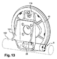
図13に示すように、駆動部品5は、バッキングプレート10の背面に突出する、この機構の唯一の部分である。したがって、その所要空間は限定され、バッキングプレート10を固定するための取付具101の、小さいサイズの切り欠き、例えば後部ハーフアクスルのトレーリングアーム102に収容することができる。
As shown in FIG. 13, the
シュースペーサ2は、主ハウジング21を介してバッキングプレート10にしっかりと固定され、2つの動作モードで、シュー12、13とバッキングプレートとの間に制動または保持トルクを伝達するための当接具の役割を果たす。この主ハウジングは、例えば、鋳造アルミニウム等の、鋳造および機械加工された金属で作られる。
The shoe spacer 2 is firmly fixed to the
主ハウジングは、締結ラグを形成するためにバッキングプレートのキャビティから外向きに延びるタブ218に作られた、締結オリフィス219を介して、リベット留めまたはボルト留めによってバッキングプレートに固定される。ここでは2つの締結オリフィス219があり、回転軸A1のほぼ接線方向に位置合わせされ、シュースペーサの作動方向D2に対して、この回転軸の側の内側に向かって置かれる。
The main housing is secured to the backing plate by riveting or bolting through
主ハウジング21のバッキングプレートへの固定は、このハウジングの主ベアリング面210によって確保され、バッキングプレートに圧接する。図7に示すように、このベアリング面210は、第1の延長部211の外面と共に第1のリベートを形成し、ベアリング面から突出して、バッキングプレートの締結開口部100を貫通している。この第1の延長部211の外面は、バッキングプレートの締結開口部100の外周と係合し、この開口部100に対して主ハウジングを中央合わせするために決定された輪郭を有する。
The fixing of the
この第1の延長部は、第2のベアリング面212を形成する肩部で終わり、これに対して、シュースペーサの第2のハウジングが押圧される。この第2のベアリング面212は、第2の延長部213の外面と共に第2のリベートを形成し、第2のベアリング面に対して突出して、第2のハウジングの伝達装置凹部24の中に延びる。この第2の延長部213の外面は、第2のハウジングの伝達装置凹部24の開口部の外周と係合し、主ハウジングに対して第2のハウジングを中央合わせするために決定された輪郭を有する。
This first extension ends with a shoulder forming a
主ハウジング21の伝達装置凹部22の4つの側面のそれぞれで、キャビティ214が2つのリベートを通過し、第2のハウジングから延びる締結ラグ232が、その中に嵌合する。キャビティは、主ハウジングの主ベアリング面210に入るまで続き、この締結ラグ232の端部を受ける。このラグは、主ハウジング21とバッキングプレートとが互いに締結されるときに、この2つの間にしっかりとクランプされるように、キャビティ214に対して十分な厚さのある寸法にされる。
On each of the four side surfaces of the
したがって、主ハウジング21をバッキングプレートに締結することによって、そのアセンブリも第2のハウジングにクランプする。組み立てる前の2つのハウジング21、23のアセンブリは、わずかな締結手段、例えば簡素な留め具、または図8に示すような1つのねじ231が必要であるか、または締結手段を必要としない。
Thus, by fastening the
モータギヤユニット
本明細書で提示される実施形態では、第2のアクチュエータ2すなわちシュースペーサは、直流モータ等の少なくとも1つの電動モータ52を備える駆動部品5によって駆動される。
Motor Gear Unit In the embodiment presented herein, the second actuator 2 or shoe spacer is driven by a
しかしながら、本明細書で提示されるようなシュースペーサ2の機能は、油圧等の他の種類の駆動部品でも実現することができる。 However, the function of the shoe spacer 2 as presented herein can also be realized with other types of drive components such as hydraulics.
図2の実施形態では、電動モータ52は、例えば全体的に円筒形の形状を有する。このモータは、ほぼ円筒形のハウジング51に囲まれており、ハウジング51は密封状態で後部カバー54に組み付けられ、後部カバー54には、モータの給電および/または制御用の電線529が、密封状態で通っている。
In the embodiment of FIG. 2, the
好適には、ハウジング51は、様々な異なる直径のモータを受けるのに十分な大きさの直径を有する、円筒形の内側凹部を備える。したがって、様々な電力のモータ、例えば34mmまでの様々な直径のモータを用いることで、同じハウジングモデルで様々な電力値のギヤードモータ5を製造することが可能である。
Preferably, the
モータをハウジングにうまく配置および保持するために、モータの直径にかかわらず、モータは、円筒形の支持部53にはめ込まれ、支持部53の厚さは、モータ52の半径と、ハウジング51の内側凹部の半径との間の差異に相当する。所定の範囲で直径が異なるモータの場合は、対応する直径を有するある範囲のケーシングを製造すれば十分であり、寸法が異なるハウジングを製造するよりも簡単で費用対効果が高い。
In order to successfully place and hold the motor in the housing, regardless of the diameter of the motor, the motor is fitted into a
あるいは、後部カバー54は、ある形状を備え、シムケーシング53を組み込む。変形例では、このカバーは、モータ52全体の長さを覆うように、示されているよりも細長い形状を有する。この場合は、同一のハウジング51に対する、異なるモータの幅は、好適には異なるカバーの幅に対応する。
Alternatively, the
円筒形のシムケーシング53、またはカバー54がこれに置き換えられた場合も、電磁干渉に対するシールドを形成するか、かつ/あるいはモータによって生成された熱の熱拡散器を生成するか、もしくは好ましくはその両方を行う材料で作られる。
If the
ハウジング51は、モータ軸の側に、減速ギヤセットサブアセンブリを囲む円筒形の出力開口部510を備え、減速ギヤセットサブアセンブリは、モータによって入力側で駆動され、出力側で、モータギヤユニットの出力軸557を駆動させる。
The
モータ軸は、密封フランジ561を貫通する。密封フランジ561は、これにしっかりと固定された駆動ピニオン551を支持し、かつ第1の遊星ギヤセットを駆動するサンギヤを形成し、このサンギヤは、第1の遊星ギヤ552と噛み合い、第1の遊星ギヤ552自身は、ハウジング51の出力開口部510の内壁にしっかりと固定された第1の外歯リングギヤと噛み合う。これらの第1の遊星ギヤ552は、第1の遊星キャリヤ553に取り付けられており、第1の遊星ギヤセットの出力を形成するために駆動する。第1の遊星キャリヤ553は、第2の遊星ギヤセットの入力を形成する、しっかりと固定された遊星駆動ピニオン554を支持し、このサンギヤは、第2の遊星ギヤ555と噛み合い、第2の遊星ギヤ555自身は、ハウジング51の出力開口部510の内壁にしっかりと固定された第2の外歯リングギヤと噛み合う。これらの第2の遊星ギヤ555は、第2の遊星キャリヤ556に取り付けられており、第2の遊星ギヤセットの出力を形成するために駆動する。この第2の遊星キャリヤ556は、ギヤードモータ5の出力軸557を支持してこれにしっかりと固定され、通常はサークリップである内側可撓ロックリング563によって、ハウジングの開口部510の肩部に対して、所定の位置に保持される。
The motor shaft passes through the sealing
この実施形態では、第1および第2のリングギヤは、2つの遊星ギヤセットに対して1つの連続した歯部559を有し、これは、ギヤードモータのハウジング51の材料に直接切削されるかまたは鋳造された、補正されたヘリカル歯を有することが好ましい。
In this embodiment, the first and second ring gears have one
ギヤードモータのハウジング51およびカバー54は、鋳物、またはガラス繊維を充填したポリマー等で製造することができる。遊星ギヤ552、555は、POM(ポリオキシメチレン)等で製造される。遊星キャリヤ553、556、および出力駆動形態を有するその出力軸554、557は、機械加工またはレーザー焼結された鋼等で製造される。
The geared
この実施形態を実現した例では、モータギヤユニット5の歯部および寸法は、0.85〜0.92の間の効率に対して、ωmotor/ωoutput=23.04の減速率を生成するために決定される。
In the example in which this embodiment is realized, the teeth and dimensions of the
駐車ブレーキアクチュエータの性能
以下の表は、シュースペーサ2全体に対して得られたエネルギー効率値“η”の推定値を示し、本明細書で提示される実施形態では、モータギヤユニット(MGU)、3本の平行な軸線を有する伝達装置カートリッジ4、およびねじナットシステム31、32、ならびに0.1から0.2までの範囲の摩擦係数の2つの境界における、異なる部品の効率に基づく。
Parking Brake Actuator Performance The following table shows an estimate of the energy efficiency value “η” obtained for the entire shoe spacer 2, and in the embodiment presented herein, a motor gear unit (MGU), Based on the efficiency of the different parts at the two boundaries of the
これに関して、ドラムの内径がほぼ220mm程度で標準的な寸法の、本発明によるデュアル・モード・ブレーキ内の駐車アクチュエータの性能の評価が行われた。 In this regard, an evaluation of the performance of a parking actuator in a dual mode brake according to the present invention with a drum internal diameter of approximately 220 mm and standard dimensions was performed.
電圧12V以下の直流電動モータの場合、効率は負荷条件に応じて40%〜60%の間で変化し、ブレーキライニングの最大許容摩耗については、この評価は以下の性能を示す。
最大効率におけるクランプ時間=0.97秒
アンペア数6A
最小効率におけるクランプ時間=1.05秒
アンペア数8.5A
In the case of a DC electric motor with a voltage of 12 V or less, the efficiency varies between 40% and 60% depending on the load condition, and this evaluation shows the following performance for the maximum allowable wear of the brake lining.
Clamping time at maximum efficiency = 0.97 seconds Amps 6A
Clamping time at minimum efficiency = 1.05 seconds Amps 8.5A
本明細書に提示される、本発明の実施形態の特徴の組み合わせにより、現在生産中、または設計中の車両での設計、統合、および製造における柔軟性を飛躍的に高めることを可能にしながら、自動車業界の現在および将来の要件に適した制御モードで、多くの構成を実現するための十分な性能を得ることが可能になる。 While combining the features of the embodiments of the present invention presented herein, it will be possible to dramatically increase the flexibility in designing, integrating, and manufacturing on currently produced or designed vehicles, It is possible to obtain sufficient performance to implement many configurations in a control mode suitable for the current and future requirements of the automotive industry.
現在の製造への適合
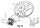
図14に示すように、同一のバッキングプレート10で、数種のドラムブレーキを製造することが可能になる。
Adapting to current manufacturing As shown in FIG. 14, several drum brakes can be manufactured with the
設計工程中、ならびに工場生産中においても、本発明は、いくつかの選択肢からの選択を可能にし、場合によっては、バッキングプレートが既に車両または車両のサブアセンブリに固定されているときでも選択が可能である。 During the design process as well as during factory production, the present invention allows a choice from several options, and in some cases even when the backing plate is already secured to the vehicle or vehicle subassembly It is.
1つの選択肢は、上述したように、常用ブレーキとして単動モードで、および電動式の駐車または緊急ブレーキとしてデュオサーボモードで動作するデュアル・モード・ドラム・ブレーキを製造するために、シュースペーサ2をバッキングプレートの開口部100に固定することである。
One option is to use a shoe spacer 2 as described above to produce a dual mode drum brake that operates in single-acting mode as a service brake and in duo-servo mode as an electric parking or emergency brake. It is fixing to the
別の選択肢は、同じバッキングプレートの開口部100に、この目的のために事前に製造された、受動的な当接板19を固定することである。このような当接板は、シュースペーサ2の締結オリフィス219と同様に配置された締結開口部199を含み、バッキングプレートと接触する面に、シュースペーサの主ハウジング21の第1のリベート210、212と同一のアセンブリ形状を有する。したがって、バッキングプレートの同じ開口部100に取り付けることができ、図1のような制御ケーブル99によって作動される駐車ブレーキレバー97等を用いて単動モードのみで動作する、知られているタイプのブレーキ9と同様のドラムブレーキを、簡単かつ柔軟に製造することを選択的に可能にする。
Another option is to secure a
したがって、シュースペーサ2と互換性のあるバッキングプレート10を用いることによって、かつこのプレートに適した簡素な当接板19を設けることによって、電動式駐車ブレーキにデュアル・モード・ブレーキを取り付ける選択肢からの利益を常に得ながら、従来型のドラムブレーキを装備した車両の製造を想定または継続できるようになる。
Therefore, by using a
バッキングプレート10および当接板19は、非常に低コストであり、設計または製造上の制約が少ないかまたは皆無である。
The
したがって、例えば、異なるブレーキタイプの選択肢を有する車両範囲を想定すること、1つの組み立てライン内での供給を制限すること、あるいは既存のラインまたは既存の車両モデルにこのような異なる選択肢を与えるために、柔軟かつ低コストで適合させることが可能である。 Thus, for example, to envisage a vehicle range with different brake type options, to limit supply within one assembly line, or to give such different options to existing lines or existing vehicle models It can be adapted flexibly and at low cost.
無論、本発明は、説明した例に限定されることはなく、本発明の範囲を超えることなくこれらの例に多くの調整を行うことが可能である。 Of course, the present invention is not limited to the examples described, and many adjustments can be made to these examples without exceeding the scope of the invention.
1 ドラムブレーキ
10 バッキングプレート
100 ベアリング点を締結するための開口部
101 バッキングプレートを固定するための取付具
102 回転するハーフアクスルのトレーリングアーム
11 第1のアクチュエータ−ホイールシリンダ−常用ブレーキ
111,112 ホイール・シリンダ・ピストン
119 ホイールシリンダ油圧入口
12,13 シュー
121,131 シューの移動端
122,132 シューの停止端(当接端)
123,133 摩擦ライニング
14 スペーサ部品−調整ストラット
142,143 スペーサ部品の連結部
15 ホイールドラム
16 ドラムの制動面
19 純粋な単動型のブレーキ当接板
198 当接板締結ラグ
199 当接板締結オリフィス
2 第2のアクチュエータ−シュースペーサ−駐車ブレーキ
21 シュースペーサの主ハウジング
210 主ベアリング面(第1のリベート)
211 バッキングプレートで中央合わせされる第1の延長部(第1のリベート)
212 第2のベアリング面を形成する肩部(第2のリベート)
213 第2のハウジングを中央合わせする第2の延長部(第2のリベート)
214 第2のハウジングの締結ラグを受けるキャビティ
217 リニア・アクチュエータ・アセンブリを受ける凹部
218 主ハウジング締結タブ
219 主ハウジング締結オリフィス
22 主ハウジングのカートリッジ凹部
221 カートリッジスペーサ頭部用のガイド溝
23 シュースペーサの第2のハウジング
231 第2のハウジングを主ハウジングに締結するためのねじ
232 第2のハウジングの締結ラグ
24 第2のハウジングのカートリッジ凹部
25 第2のハウジングのギヤードモータ凹部
3 リニア・アクチュエータ・アセンブリ
31 ねじナットシステムのスプラインナット
311 溝付きナットのねじ山
312 ナットの外歯スプライン
32 ピストンを形成するねじナットシステムのねじ
321 ねじピストンのねじ山
322 ねじピストンの溝
329 ねじピストンの当接肩部−制動トルクの伝達装置
33 リニア弾性ピストン−「スプリングパッケージ」
331 弾性部品−積み重ねられた皿ばねワッシャ
332 ピストン頂部の後ろでスカートが波形にされている、弾性ピストンの頭部
333 弾性ピストン頂部
334 ピストン頭部の溝
339 弾性ピストンの当接肩部−制動トルクの伝達装置
4 伝達装置サブアセンブリ−ギヤカートリッジ
41 第1のギヤ−駆動ギヤ
410 駆動ギヤの軸穴
411 駆動ギヤの内部駆動形状(ヘクサロビュラ)
419,439 第1のギヤおよび第3のギヤの軸
42 第2のギヤ−中間ギヤ
43 第3のギヤ−従動ギヤ
430 従動ギヤの軸穴
431 従動ギヤの内歯スプライン
471,472 スペーサ
473 スペーサとして作用する、第2のギヤの軸
48,49 保持プレート
481 弾性保持ラグ
5 モータギヤユニット
51 ギヤード・モータ・ハウジング
510 円筒形の出力開口−遊星ギヤセット凹部
511 円筒形の入力開口−モータ凹部
52 電動モータ
529 モータへの電源供給
53 電磁シールドおよび熱拡散器を形成する、円筒形のシムケーシング
54 モータの後部カバー
541 後部カバーのシム構造
542 後部カバーの壁
55 遊星減速ギヤ機構
551 第1の遊星ギヤセットの遊星駆動ピニオン−入力駆動ピニオン
552 第1の遊星ギヤセットの遊星ギヤ
553 第1の遊星ギヤセットの遊星キャリヤ
554 第2の遊星ギヤセットの駆動ピニオン
555 第2の遊星ギヤセットの遊星ギヤ
556 第2の遊星ギヤセットの遊星キャリヤ
557 出力軸
558 出力軸の外部駆動形状(ヘクサロビュラ)
559 遊星ギヤセットのリングギヤ
561 入力側密封およびガイドフランジ
563 出力側締結サークリップ
従来技術
9 ドラムブレーキ
90 バッキングプレート
91 ホイールシリンダ
92,93 シュー
923,933 摩擦ライニング
94 当接板
95 ホイールドラム
96 ドラムの制動面
97 駐車ブレーキレバー
98 駐車ブレーキ反応部材
99 駐車ブレーキ制御ケーブル
DESCRIPTION OF SYMBOLS 1
123, 133 Friction lining 14 Spacer part-Adjustment struts 142, 143
211 First extension (first rebate) centered on backing plate
212 Shoulder to form second bearing surface (second rebate)
213 Second extension (second rebate) for centering the second housing
214 Cavity for receiving second
331 Elastic part—stacked
419, 439 First gear and
559 Planetary gear set
Claims (19)
一方は、回転シリンダを形成し、前記ドラムの内面によって支持される制動面と、
もう一方は、第1のシュー(12)および第2のシュー(13)によって支持されるブレーキライニング(123、133)であって、前記シリンダの内側に配置され、前記シューに対する当接を形成する、アンカーと呼ばれる少なくとも1つの部品によって、前記制動トルクを前記バッキングプレートに伝達する、ブレーキライニングと
の間の摩擦効果であって、
前記摩擦は、少なくとも1つの第1のアクチュエータ(11)の効果で、前記シューのうちの少なくとも1つを外向きに離間させることによって得られ、前記装置を第1のブレーキ位置にする、第1の動作モードでブレーキ機能を確保し、
前記装置は、前記バッキングプレート(10)に対して移動可能であって、かつ移動端(121、131)と呼ばれる、互いに対向する前記シューの2つの端部を互いに離間させて保持するために配置される、スペーサ部品(14)と呼ばれる部品を備えることを特徴とし、
停止端(122、132)と呼ばれる、前記シューの反対側にある前記端部を互いに離間させることができるように配置された、少なくとも1つの第2のアクチュエータ(2)をさらに備え、これによって前記シューを前記ドラムの前記制動面に押圧することを特徴とし、
摩擦を用いて、静止しているときに前記ドラムと第1のシュー(12)との間に、制動または保持トルクを伝達することを可能にし、これにより前記移動端(121)を介して前記スペーサ部品(14)を押し、前記スペーサ部品(14)が前記第2のシュー(13)の前記移動端(131)を押し、前記移動端(131)が前記停止端(132)を介して前記制動または保持トルクを前記バッキングプレート(10)に伝達し、これによって、
前記装置を第2のブレーキ位置にする、第2の動作モードでブレーキ機能を提供する、ドラムブレーキ装置(1)。 A drum brake device (1) for road vehicles, in particular automobiles, of the type that generates a braking torque between a drum and a backing plate (10) that rotate relative to each other by absorption of energy due to friction effects, The friction effect is
One of which forms a rotating cylinder and is supported by the inner surface of the drum;
The other is a brake lining (123, 133) supported by a first shoe (12) and a second shoe (13), which is arranged inside the cylinder and forms a contact with the shoe. A friction effect between the brake lining, which transmits the braking torque to the backing plate by at least one component called an anchor,
The friction is obtained by spacing out at least one of the shoes outwardly by the effect of at least one first actuator (11), bringing the device into a first braking position, a first The brake function is secured in the operation mode of
The device is arranged to hold the two ends of the shoe opposite to each other, which are movable relative to the backing plate (10) and are called moving ends (121, 131). Characterized in that it comprises a part called a spacer part (14),
Further comprising at least one second actuator (2), called stop ends (122, 132), arranged such that the ends on the opposite side of the shoe can be spaced apart from each other, whereby Pressing a shoe against the braking surface of the drum,
Friction is used to allow braking or holding torque to be transmitted between the drum and the first shoe (12) when stationary, and thereby via the moving end (121) The spacer part (14) is pushed, the spacer part (14) pushes the moving end (131) of the second shoe (13), and the moving end (131) passes through the stop end (132). Transmitting braking or holding torque to the backing plate (10), thereby
A drum brake device (1) providing a braking function in a second mode of operation, wherein the device is in a second brake position.
前記第1のアクチュエータ(11)は、常用ブレーキ機能と呼ばれる、前記車両が動いているときに減速および/または停止させる機能を実行するために結合かつ制御され、
前記第2のアクチュエータ(2)は、駐車ブレーキ機能と呼ばれる、前記車両が静止しているときに保持する機能、ならびに/もしくは前記常用ブレーキタイプの機能が故障した場合に、動いている前記車両を減速する機能、特に駐車ブレーキと緊急ブレーキとの組み合わせの機能を実行するために結合かつ制御される、
請求項1〜15のいずれか一項に記載の1つ以上のドラムブレーキ装置(1)を備えることを特徴とする、車両または車両のサブアセンブリ。 A vehicle or vehicle subassembly, in particular a road vehicle,
The first actuator (11) is coupled and controlled to perform a function of decelerating and / or stopping when the vehicle is moving, called a service brake function,
The second actuator (2) is a function of holding the vehicle when the vehicle is stationary, called a parking brake function, and / or moving the vehicle when the function of the service brake type fails. Combined and controlled to perform the function of deceleration, especially the combination of parking brake and emergency brake,
A vehicle or a sub-assembly of a vehicle, characterized in that it comprises one or more drum brake devices (1) according to any one of the preceding claims.
前記方法は少なくとも、
− 移動端(121、131)と呼ばれる2つの端部を互いに反対側に押すことによって、前記シューを外向きに離間させることを可能にするために配置された、少なくとも1つの第1のアクチュエータ(11)を前記バッキングプレート(10)に締結するステップと;
− 前記シューが、前記第1のアクチュエータ(11)によって離間されるときに、前記移動端の反対側の前記シューの停止端が、前記バッキングプレートのアンカー(21)を押圧できる位置で、前記シュー(12、13)を前記バッキングプレート(10)に取り付けるステップと;
− 前記シューの前記2つの移動端(121、131)同士の間の離間を維持するために、スペーサ部品(14)を所定の位置に取り付けるステップと;
− 前記制動面を押圧するように、前記シューの前記2つの停止端(122、132)を離間させるために配置された、第2のアクチュエータ(2)を前記バッキングプレート(10)に固定するステップと
を、前記順序でまたは別の順序で含むことを特徴とする方法。 A method of assembling a drum brake mechanism (1) comprising a first shoe (12) and a second shoe (13) equipped with an outwardly facing lining (123, 133), said first shoe (12) and the second shoe (13) are covered by the drum and attached to the backing plate (10), so that when the shoe is spaced outwardly, it is supported by the inside of the drum. By absorbing energy due to the friction effect with the cylindrical braking surface, it becomes possible to transmit the braking torque to the backing plate,
The method is at least
-At least one first actuator (positioned to allow the shoe to be spaced outwardly by pushing the two ends, called the moving ends (121, 131) away from each other; 11) fastening the backing plate (10);
-When the shoe is separated by the first actuator (11), the shoe stop end on the opposite side of the moving end is in a position where the anchor (21) of the backing plate can be pressed; Attaching (12, 13) to the backing plate (10);
Attaching a spacer part (14) in place in order to maintain a separation between the two moving ends (121, 131) of the shoe;
Fixing a second actuator (2) to the backing plate (10), arranged to separate the two stop ends (122, 132) of the shoe so as to press the braking surface; In the said order or in another order.
Applications Claiming Priority (3)
| Application Number | Priority Date | Filing Date | Title |
|---|---|---|---|
| FR1363706A FR3016010B1 (en) | 2013-12-30 | 2013-12-30 | DRUM BRAKE DEVICE INCLUDING PARKING BRAKE OPERATING IN DUO SERVO MODE, VEHICLE AND ASSOCIATED ASSEMBLY METHODS |
| FR1363706 | 2013-12-30 | ||
| PCT/EP2014/078027 WO2015101486A2 (en) | 2013-12-30 | 2014-12-16 | Drum brake device including a parking brake operating in duo servo mode, associated vehicle and assembly methods |
Publications (2)
| Publication Number | Publication Date |
|---|---|
| JP2017501357A true JP2017501357A (en) | 2017-01-12 |
| JP6591986B2 JP6591986B2 (en) | 2019-10-16 |
Family
ID=50483076
Family Applications (1)
| Application Number | Title | Priority Date | Filing Date |
|---|---|---|---|
| JP2016544535A Active JP6591986B2 (en) | 2013-12-30 | 2014-12-16 | Drum brake device including parking brake operating in duo servo mode, vehicle and assembly method related thereto |
Country Status (8)
| Country | Link |
|---|---|
| EP (1) | EP3089898B1 (en) |
| JP (1) | JP6591986B2 (en) |
| CN (1) | CN106164526B (en) |
| ES (1) | ES2668798T3 (en) |
| FR (1) | FR3016010B1 (en) |
| PL (1) | PL3089898T3 (en) |
| PT (1) | PT3089898T (en) |
| WO (1) | WO2015101486A2 (en) |
Cited By (2)
| Publication number | Priority date | Publication date | Assignee | Title |
|---|---|---|---|---|
| JP2020069828A (en) * | 2018-10-29 | 2020-05-07 | 株式会社アドヴィックス | Brake control device |
| JP7461383B2 (en) | 2019-02-25 | 2024-04-03 | ヒタチ アステモ フランス | Electromechanical drum brake with actuator with low stiffness elastic reserve |
Families Citing this family (19)
| Publication number | Priority date | Publication date | Assignee | Title |
|---|---|---|---|---|
| CN105299105A (en) * | 2015-12-01 | 2016-02-03 | 潍坊埃锐制动系统有限公司 | Electronic parking brake device used for drum brake |
| FR3038673B1 (en) * | 2015-12-30 | 2017-07-21 | Chassis Brakes Int Bv | DRUM BRAKE DEVICE COMPRISING AN ACTUATOR MOTORIZATION MOTORIZING ELEMENT AND ASSOCIATED MOTOR VEHICLE |
| ITUA20161540A1 (en) * | 2016-03-10 | 2017-09-10 | Freni Brembo Spa | CRAFT-CABLE IMPLEMENTATION SYSTEM FOR PARKING BRAKE AND RELATIVE PARKING BRAKE |
| DE102016223356A1 (en) | 2016-11-25 | 2018-05-30 | Continental Teves Ag & Co. Ohg | Brake force generator with compact converter |
| CN107745638B (en) * | 2017-10-31 | 2023-10-10 | 天津交通职业学院 | Pure electric bus system device for recovering kinetic energy |
| CN110030298A (en) * | 2018-01-12 | 2019-07-19 | 比亚迪股份有限公司 | Drum brake and vehicle with it |
| DE102018102849A1 (en) * | 2018-02-08 | 2019-08-08 | Brose Fahrzeugteile Gmbh & Co. Kommanditgesellschaft, Bamberg | Drum brake with at least one brake element and a compensation element |
| WO2019161916A1 (en) * | 2018-02-23 | 2019-08-29 | Continental Teves Ag & Co. Ohg | Electric parking brake actuator mounting assembly |
| FR3091324B1 (en) * | 2018-12-27 | 2021-01-29 | Foundation Brakes France | ACTUATOR FOR ELECTROMECHANICAL BRAKE WITH INTEGRATED STATUS DETECTOR |
| FR3093151B1 (en) * | 2019-02-25 | 2021-07-16 | Foundation Brakes France | Electromechanical drum brake comprising an actuator comprising an elastic reserve with limited stroke |
| KR102647979B1 (en) * | 2019-04-12 | 2024-03-15 | 에이치엘만도 주식회사 | Electronic parking brake |
| FR3096013B1 (en) * | 2019-05-13 | 2021-09-17 | Foundation Brakes France | MOTOR VEHICLE BRAKE KIT INCLUDING BRAKE BRACKET, GEAR MOTOR AND GEAR MOTOR HOUSING ASSEMBLED WITH BRAKE BRACKET |
| FR3096422B1 (en) | 2019-05-23 | 2021-07-02 | Foundation Brakes France | REDUCED RESIDUAL TORQUE DRUM BRAKE |
| FR3097019B1 (en) | 2019-06-07 | 2022-06-10 | Foundation Brakes France | COMPACT ELECTROMECHANICAL BRAKE |
| KR20210063199A (en) * | 2019-11-22 | 2021-06-01 | 주식회사 만도 | Electronic parking brake |
| FR3105326B1 (en) | 2019-12-23 | 2021-12-03 | Foundation Brakes France | ELECTROMECHANICAL DRUM BRAKE ACTUATOR |
| CN116368313A (en) | 2020-10-16 | 2023-06-30 | 大陆汽车科技有限公司 | Electric drum brake module comprising an integrated service brake and an integrated electric parking brake |
| DE102020216023B3 (en) | 2020-12-16 | 2022-03-03 | Continental Teves Ag & Co. Ohg | drum brake device |
| US11745714B2 (en) * | 2021-04-09 | 2023-09-05 | GM Global Technology Operations LLC | System for electronic parking brake actuation |
Citations (7)
| Publication number | Priority date | Publication date | Assignee | Title |
|---|---|---|---|---|
| JPS5074074A (en) * | 1973-11-08 | 1975-06-18 | ||
| EP0061961A1 (en) * | 1981-03-31 | 1982-10-06 | BENDIX France | Drum brake with automatic adjustment |
| EP0416760A1 (en) * | 1989-08-29 | 1991-03-13 | Kelsey-Hayes Company | Brake assembly |
| FR2697599A1 (en) * | 1992-10-30 | 1994-05-06 | Bendix Europ Services Tech | Drum brake with mechanical actuation. |
| DE102005048339A1 (en) * | 2005-10-10 | 2007-04-12 | Robert Bosch Gmbh | Parking brake for motor vehicle, has actuation installation having tie rod in form of elastic unit with spring blade and connecting element placed positioned with clearance in through bore, and actuator directly installed in brake unit |
| JP2009092092A (en) * | 2007-10-04 | 2009-04-30 | Toyota Motor Corp | Parking brake system |
| JP2011149763A (en) * | 2010-01-20 | 2011-08-04 | Toyota Motor Corp | Pressing force measurement apparatus |
Family Cites Families (3)
| Publication number | Priority date | Publication date | Assignee | Title |
|---|---|---|---|---|
| FR2697600B1 (en) * | 1992-10-30 | 1994-12-02 | Bendix Europ Services Tech | Drum brake with mechanical actuation. |
| JP3977810B2 (en) * | 2001-11-27 | 2007-09-19 | フレニ・ブレンボ エス・ピー・エー | Dual servo drum brake adjuster with internal shoe |
| KR20100043694A (en) * | 2008-10-21 | 2010-04-29 | 주식회사 만도 | Electronic mechanical drum brake |
-
2013
- 2013-12-30 FR FR1363706A patent/FR3016010B1/en not_active Expired - Fee Related
-
2014
- 2014-12-16 PT PT148280183T patent/PT3089898T/en unknown
- 2014-12-16 JP JP2016544535A patent/JP6591986B2/en active Active
- 2014-12-16 WO PCT/EP2014/078027 patent/WO2015101486A2/en active Application Filing
- 2014-12-16 PL PL14828018T patent/PL3089898T3/en unknown
- 2014-12-16 EP EP14828018.3A patent/EP3089898B1/en active Active
- 2014-12-16 ES ES14828018.3T patent/ES2668798T3/en active Active
- 2014-12-16 CN CN201480075052.3A patent/CN106164526B/en active Active
Patent Citations (7)
| Publication number | Priority date | Publication date | Assignee | Title |
|---|---|---|---|---|
| JPS5074074A (en) * | 1973-11-08 | 1975-06-18 | ||
| EP0061961A1 (en) * | 1981-03-31 | 1982-10-06 | BENDIX France | Drum brake with automatic adjustment |
| EP0416760A1 (en) * | 1989-08-29 | 1991-03-13 | Kelsey-Hayes Company | Brake assembly |
| FR2697599A1 (en) * | 1992-10-30 | 1994-05-06 | Bendix Europ Services Tech | Drum brake with mechanical actuation. |
| DE102005048339A1 (en) * | 2005-10-10 | 2007-04-12 | Robert Bosch Gmbh | Parking brake for motor vehicle, has actuation installation having tie rod in form of elastic unit with spring blade and connecting element placed positioned with clearance in through bore, and actuator directly installed in brake unit |
| JP2009092092A (en) * | 2007-10-04 | 2009-04-30 | Toyota Motor Corp | Parking brake system |
| JP2011149763A (en) * | 2010-01-20 | 2011-08-04 | Toyota Motor Corp | Pressing force measurement apparatus |
Cited By (4)
| Publication number | Priority date | Publication date | Assignee | Title |
|---|---|---|---|---|
| JP2020069828A (en) * | 2018-10-29 | 2020-05-07 | 株式会社アドヴィックス | Brake control device |
| WO2020090706A1 (en) * | 2018-10-29 | 2020-05-07 | 株式会社アドヴィックス | Braking control device |
| JP7155876B2 (en) | 2018-10-29 | 2022-10-19 | 株式会社アドヴィックス | Braking control device |
| JP7461383B2 (en) | 2019-02-25 | 2024-04-03 | ヒタチ アステモ フランス | Electromechanical drum brake with actuator with low stiffness elastic reserve |
Also Published As
| Publication number | Publication date |
|---|---|
| FR3016010A1 (en) | 2015-07-03 |
| WO2015101486A3 (en) | 2015-11-19 |
| PT3089898T (en) | 2018-04-16 |
| EP3089898B1 (en) | 2018-02-14 |
| CN106164526B (en) | 2018-12-18 |
| JP6591986B2 (en) | 2019-10-16 |
| FR3016010B1 (en) | 2016-02-12 |
| WO2015101486A2 (en) | 2015-07-09 |
| CN106164526A (en) | 2016-11-23 |
| PL3089898T3 (en) | 2018-08-31 |
| EP3089898A2 (en) | 2016-11-09 |
| ES2668798T3 (en) | 2018-05-22 |
Similar Documents
| Publication | Publication Date | Title |
|---|---|---|
| JP6591986B2 (en) | Drum brake device including parking brake operating in duo servo mode, vehicle and assembly method related thereto | |
| JP6602306B2 (en) | Geared motor, drum brake, brake device, and disc brake | |
| JP6602305B2 (en) | Actuator having irreversible screw nut system, drum brake, and brake device including the same | |
| JP5513914B2 (en) | Disc brake device with electric parking mechanism | |
| US20130075205A1 (en) | Disk brake apparatus | |
| JP6557239B2 (en) | Actuator driven by gear having axial guide rail, and drum brake and brake device including the same | |
| JP5093476B2 (en) | Electric disc brake | |
| US7806239B2 (en) | Electromechanical actuating device for a wheel brake system of a motor vehicle and a brake system equipped with such an actuating device | |
| JP6557238B2 (en) | Actuator having gear-type transmission device subassembly, and drum brake and brake device including the same | |
| JP2014070670A (en) | Disc brake | |
| KR102363663B1 (en) | Brake force transmission unit, brake subassembly and brake assembly group | |
| CN211308536U (en) | Driving-parking integrated brake for vehicle and vehicle with same | |
| CN115520170B (en) | Electromechanical brake device and vehicle | |
| EP2995834B1 (en) | A brake assembly and a method of assembling said brake assembly | |
| JP2013217468A (en) | Disk brake boosting mechanism | |
| JP6530411B2 (en) | Motor reducer having an electric motor for drum, brake and actuator | |
| JP2019058032A (en) | Electric actuator | |
| JP2014101973A (en) | Electric parking brake device | |
| CN109990021B (en) | Disc brake and vehicle with same | |
| KR100885813B1 (en) | Disk brake for vehicle | |
| US20240077120A1 (en) | Disc brake device and method for assembling same | |
| JP7398345B2 (en) | Disc brake and planetary gear reduction mechanism | |
| CN210799834U (en) | Electronic parking brake drum brake | |
| CN109990020B (en) | Disc brake and vehicle with same | |
| KR20230133139A (en) | Electronic parking brake |
Legal Events
| Date | Code | Title | Description |
|---|---|---|---|
| A621 | Written request for application examination |
Free format text: JAPANESE INTERMEDIATE CODE: A621 Effective date: 20171218 |
|
| A977 | Report on retrieval |
Free format text: JAPANESE INTERMEDIATE CODE: A971007 Effective date: 20181116 |
|
| A131 | Notification of reasons for refusal |
Free format text: JAPANESE INTERMEDIATE CODE: A131 Effective date: 20181127 |
|
| A601 | Written request for extension of time |
Free format text: JAPANESE INTERMEDIATE CODE: A601 Effective date: 20190227 |
|
| A521 | Request for written amendment filed |
Free format text: JAPANESE INTERMEDIATE CODE: A523 Effective date: 20190527 |
|
| TRDD | Decision of grant or rejection written | ||
| A01 | Written decision to grant a patent or to grant a registration (utility model) |
Free format text: JAPANESE INTERMEDIATE CODE: A01 Effective date: 20190827 |
|
| A61 | First payment of annual fees (during grant procedure) |
Free format text: JAPANESE INTERMEDIATE CODE: A61 Effective date: 20190919 |
|
| R150 | Certificate of patent or registration of utility model |
Ref document number: 6591986 Country of ref document: JP Free format text: JAPANESE INTERMEDIATE CODE: R150 |
|
| R250 | Receipt of annual fees |
Free format text: JAPANESE INTERMEDIATE CODE: R250 |
|
| R250 | Receipt of annual fees |
Free format text: JAPANESE INTERMEDIATE CODE: R250 |