JP2017501034A - Device for cleaning the needle of a measuring probe - Google Patents
Device for cleaning the needle of a measuring probe Download PDFInfo
- Publication number
- JP2017501034A JP2017501034A JP2016552398A JP2016552398A JP2017501034A JP 2017501034 A JP2017501034 A JP 2017501034A JP 2016552398 A JP2016552398 A JP 2016552398A JP 2016552398 A JP2016552398 A JP 2016552398A JP 2017501034 A JP2017501034 A JP 2017501034A
- Authority
- JP
- Japan
- Prior art keywords
- cleaning
- needle
- cleaning chamber
- chamber
- needles
- Prior art date
- Legal status (The legal status is an assumption and is not a legal conclusion. Google has not performed a legal analysis and makes no representation as to the accuracy of the status listed.)
- Granted
Links
Images


Classifications
-
- B—PERFORMING OPERATIONS; TRANSPORTING
- B08—CLEANING
- B08B—CLEANING IN GENERAL; PREVENTION OF FOULING IN GENERAL
- B08B3/00—Cleaning by methods involving the use or presence of liquid or steam
- B08B3/02—Cleaning by the force of jets or sprays
-
- G—PHYSICS
- G01—MEASURING; TESTING
- G01B—MEASURING LENGTH, THICKNESS OR SIMILAR LINEAR DIMENSIONS; MEASURING ANGLES; MEASURING AREAS; MEASURING IRREGULARITIES OF SURFACES OR CONTOURS
- G01B5/00—Measuring arrangements characterised by the use of mechanical techniques
- G01B5/004—Measuring arrangements characterised by the use of mechanical techniques for measuring coordinates of points
- G01B5/008—Measuring arrangements characterised by the use of mechanical techniques for measuring coordinates of points using coordinate measuring machines
-
- B—PERFORMING OPERATIONS; TRANSPORTING
- B08—CLEANING
- B08B—CLEANING IN GENERAL; PREVENTION OF FOULING IN GENERAL
- B08B3/00—Cleaning by methods involving the use or presence of liquid or steam
- B08B3/02—Cleaning by the force of jets or sprays
- B08B3/022—Cleaning travelling work
-
- B—PERFORMING OPERATIONS; TRANSPORTING
- B08—CLEANING
- B08B—CLEANING IN GENERAL; PREVENTION OF FOULING IN GENERAL
- B08B3/00—Cleaning by methods involving the use or presence of liquid or steam
- B08B3/02—Cleaning by the force of jets or sprays
- B08B3/024—Cleaning by means of spray elements moving over the surface to be cleaned
-
- B—PERFORMING OPERATIONS; TRANSPORTING
- B08—CLEANING
- B08B—CLEANING IN GENERAL; PREVENTION OF FOULING IN GENERAL
- B08B5/00—Cleaning by methods involving the use of air flow or gas flow
- B08B5/02—Cleaning by the force of jets, e.g. blowing-out cavities
-
- B—PERFORMING OPERATIONS; TRANSPORTING
- B08—CLEANING
- B08B—CLEANING IN GENERAL; PREVENTION OF FOULING IN GENERAL
- B08B5/00—Cleaning by methods involving the use of air flow or gas flow
- B08B5/02—Cleaning by the force of jets, e.g. blowing-out cavities
- B08B5/023—Cleaning travelling work
-
- G—PHYSICS
- G01—MEASURING; TESTING
- G01B—MEASURING LENGTH, THICKNESS OR SIMILAR LINEAR DIMENSIONS; MEASURING ANGLES; MEASURING AREAS; MEASURING IRREGULARITIES OF SURFACES OR CONTOURS
- G01B21/00—Measuring arrangements or details thereof, where the measuring technique is not covered by the other groups of this subclass, unspecified or not relevant
- G01B21/02—Measuring arrangements or details thereof, where the measuring technique is not covered by the other groups of this subclass, unspecified or not relevant for measuring length, width, or thickness
- G01B21/04—Measuring arrangements or details thereof, where the measuring technique is not covered by the other groups of this subclass, unspecified or not relevant for measuring length, width, or thickness by measuring coordinates of points
- G01B21/047—Accessories, e.g. for positioning, for tool-setting, for measuring probes
-
- G—PHYSICS
- G01—MEASURING; TESTING
- G01B—MEASURING LENGTH, THICKNESS OR SIMILAR LINEAR DIMENSIONS; MEASURING ANGLES; MEASURING AREAS; MEASURING IRREGULARITIES OF SURFACES OR CONTOURS
- G01B5/00—Measuring arrangements characterised by the use of mechanical techniques
- G01B5/004—Measuring arrangements characterised by the use of mechanical techniques for measuring coordinates of points
- G01B5/008—Measuring arrangements characterised by the use of mechanical techniques for measuring coordinates of points using coordinate measuring machines
- G01B5/012—Contact-making feeler heads therefor
-
- G—PHYSICS
- G01—MEASURING; TESTING
- G01N—INVESTIGATING OR ANALYSING MATERIALS BY DETERMINING THEIR CHEMICAL OR PHYSICAL PROPERTIES
- G01N35/00—Automatic analysis not limited to methods or materials provided for in any single one of groups G01N1/00 - G01N33/00; Handling materials therefor
- G01N35/10—Devices for transferring samples or any liquids to, in, or from, the analysis apparatus, e.g. suction devices, injection devices
- G01N35/1004—Cleaning sample transfer devices
Landscapes
- Physics & Mathematics (AREA)
- General Physics & Mathematics (AREA)
- A Measuring Device Byusing Mechanical Method (AREA)
- Cleaning In General (AREA)
- Length Measuring Devices With Unspecified Measuring Means (AREA)
Abstract
本発明は、測定プローブ(2)の針(1)を洗浄するための装置に関し、上記装置は、洗浄処理中に上記針(1)を収容するための洗浄チャンバ(4)を備え、上記洗浄チャンバ(4)は、上記針(1)を上記洗浄チャンバ(4)に導入し、かつ上記洗浄チャンバ(4)から取出すための開口部(5)を備え、さらに、上記針(1)を洗浄しかつ/または乾燥させるために、洗浄剤、たとえば洗浄液もしくはエアロゾル、および/または乾燥剤、たとえば空気を上記洗浄チャンバ(4)に供給するための供給手段(7)を備える。本発明はさらに、そのような装置と測定機とのアセンブリに関する。The present invention relates to an apparatus for cleaning the needle (1) of the measuring probe (2), which comprises a cleaning chamber (4) for receiving the needle (1) during the cleaning process, The chamber (4) includes an opening (5) for introducing the needle (1) into the cleaning chamber (4) and removing it from the cleaning chamber (4), and further cleaning the needle (1). And / or drying means, provided with supply means (7) for supplying a cleaning agent, for example cleaning liquid or aerosol, and / or a drying agent, for example air, to the cleaning chamber (4). The invention further relates to an assembly of such a device and a measuring machine.
Description
本発明は、測定プローブの針を洗浄するための装置に関する。
測定対象について測定機が用いられる。該測定機は、針を有する測定プローブを備える。測定装置は、任意の種類の測定装置、たとえば3D測定装置であり得る。特に上記測定装置は、加工機の器具を測定するための加工機の一部であり得る。測定プローブの針が汚染された場合、たとえばほこりまたは他の粒子がそれに付着した場合、測定が正確に行われない場合がある。
The present invention relates to an apparatus for cleaning a needle of a measuring probe.
A measuring machine is used for the measurement object. The measuring machine includes a measuring probe having a needle. The measuring device can be any kind of measuring device, for example a 3D measuring device. In particular, the measuring device can be part of a processing machine for measuring a tool of the processing machine. If the measuring probe needle is contaminated, for example if dust or other particles adhere to it, the measurement may not be accurate.
本発明の目的は、測定プローブの針を洗浄するための装置を提供することである。特に、本発明の目的は、測定処理中に上記針を洗浄するための装置を提供することである。 An object of the present invention is to provide an apparatus for cleaning a needle of a measurement probe. In particular, it is an object of the present invention to provide an apparatus for cleaning the needle during a measurement process.
この目的は、序文に係る装置によって実現され、上記装置は、洗浄処理中に上記針を収容するための洗浄チャンバを備え、上記洗浄チャンバは、上記針を上記洗浄チャンバに導入しかつ上記洗浄チャンバから取出すための開口部を含み、さらに、上記針を洗浄しかつ/または乾燥させるために、洗浄剤、たとえば洗浄液もしくはエアロゾル、および/または乾燥剤、たとえば空気を上記洗浄チャンバに供給するための供給手段を備える。 This object is achieved by an apparatus according to the introduction, said apparatus comprising a cleaning chamber for receiving said needle during a cleaning process, said cleaning chamber introducing said needle into said cleaning chamber and said cleaning chamber A supply for supplying a cleaning agent, such as a cleaning liquid or aerosol, and / or a drying agent, such as air, to the cleaning chamber, in order to clean and / or dry the needle Means.
本発明に係る上記装置は、上記針が上記開口部を介して導入され得る洗浄チャンバを設ける。上記洗浄チャンバに上記針を導入した後、好ましくは第1に、上記針を洗浄するために洗浄剤が上記洗浄チャンバに供給され、好ましくは第2に、上記針を乾燥させるために乾燥剤が上記洗浄チャンバに供給される。上記針を洗浄しかつ/または乾燥させた後で、上記開口部を介して上記洗浄チャンバから針を取出してもよく、測定処理が継続されるかまたは開始されてもよい。 The device according to the invention provides a cleaning chamber into which the needle can be introduced through the opening. After introducing the needle into the cleaning chamber, preferably first, a cleaning agent is supplied to the cleaning chamber to clean the needle, and preferably second, a desiccant is supplied to dry the needle. The cleaning chamber is supplied. After cleaning and / or drying the needle, the needle may be removed from the cleaning chamber through the opening, and the measurement process may be continued or initiated.
本発明に係る装置の一実施形態において、上記供給手段は、上記洗浄剤および/または上記乾燥剤を上記洗浄チャンバに供給するために上記洗浄チャンバに注ぐ少なくとも1つの供給開口部またはノズルを含む。 In one embodiment of the apparatus according to the invention, the supply means comprise at least one supply opening or nozzle for pouring the cleaning agent and / or the drying agent into the cleaning chamber in order to supply it to the cleaning chamber.
供給開口部またはノズルの利点は、上記洗浄剤および/または上記乾燥剤が針の方向に噴霧されるかまたは吹き付けられ得ることである。 The advantage of the supply opening or nozzle is that the cleaning agent and / or the desiccant can be sprayed or sprayed in the direction of the needle.
本発明に係る装置の好ましい実施形態において、上記供給手段は、少なくとも3つの上記供給開口部またはノズルを含む。 In a preferred embodiment of the device according to the invention, the supply means comprise at least three supply openings or nozzles.
複数の供給開口部またはノズル、特に3つ以上の供給開口部またはノズルの利点は、上記針の外面全体が洗浄されかつ/または乾燥され得るように、上記洗浄剤および/または上記乾燥剤が洗浄チャンバ内の異なる場所から上記針の方向に噴霧されるかまたは吹き付けられ得るということである。なお、針が複数の方向から噴霧されるかまたは吹き付けられるように、上記供給手段は、任意の数の供給開口部またはノズル、たとえば3個、4個、5個、6個、7個、8個、9個、10個、またはさらに多くの供給開口部またはノズルを備え得る。
The advantage of a plurality of supply openings or nozzles, in particular more than two supply openings or nozzles, is that the cleaning agent and / or the drying agent can be cleaned so that the entire outer surface of the needle can be cleaned and / or dried. It can be sprayed or sprayed in the direction of the needle from different locations in the chamber. It should be noted that the supply means may be any number of supply openings or nozzles,
好ましくは、上記供給開口部またはノズルは、実質的な等しい角距離で離間され、上記洗浄剤および/または上記乾燥剤を共通の場所に供給するように配置され、上記針は、洗浄および/または乾燥中には上記共通の場所に位置し得る。 Preferably, the supply openings or nozzles are spaced at substantially equal angular distances and are arranged to supply the cleaning agent and / or the desiccant to a common location, the needles being cleaned and / or It may be located at the common location during drying.
針は非常に繊細な測定器具である。洗浄剤および/または乾燥剤を針に供給することにより、上記洗浄剤および/または上記乾燥剤によって影響された正しくない測定データを針に表示させる場合があり、該測定データはしたがって、針の洗浄前後で測定されている対象について表していない。上記針が上記共通の場所に保持され、上記等しく離間された供給開口部またはノズルから上記洗浄剤および/または上記乾燥剤を受取ると、上記針が洗浄剤および/または乾燥剤によって影響されることがないように、かつ正しくない測定データを示さないように、洗浄剤および/または乾燥剤の異なる流れが共通の場所において互いに打消し合うかまたは平衡状態となる。本発明に係る装置のそのような実施形態は、測定処理に影響を及ぼすことがないため、針の洗浄中に測定処理が停止される必要がないという利点を有する。 The needle is a very delicate measuring instrument. Supplying a cleaning agent and / or desiccant to the needle may cause the needle to display incorrect measurement data affected by the cleaning agent and / or the desiccant, and the measurement data is therefore used to clean the needle. It does not represent the subject being measured before and after. When the needle is held in the common location and receives the cleaning agent and / or the desiccant from the equally spaced supply openings or nozzles, the needle is affected by the cleaning agent and / or the desiccant. The different flows of detergent and / or desiccant cancel each other out or equilibrate at a common location so that there is no error and does not indicate incorrect measurement data. Such an embodiment of the device according to the invention has the advantage that the measurement process does not have to be stopped during the cleaning of the needle, since it does not affect the measurement process.
上記複数の供給開口部またはノズルは、上記洗浄チャンバの長手方向に見て同じ高さまたは位置に配置されることが好ましい。 The plurality of supply openings or nozzles are preferably arranged at the same height or position when viewed in the longitudinal direction of the cleaning chamber.
本発明に係る装置の別の実施形態において、上記ノズルの上記供給開口部または排出開口部は、4mmの最大直径、好ましくは1mmの最大直径、より好ましくは0.5mmの最大直径、さらに好ましくはおよそ0.2mmの直径を有する。 In another embodiment of the device according to the invention, the supply or discharge opening of the nozzle is a maximum diameter of 4 mm, preferably a maximum diameter of 1 mm, more preferably a maximum diameter of 0.5 mm, even more preferably. It has a diameter of approximately 0.2 mm.
上記ノズルの、そのように比較的小さな供給開口部または排出開口部は、洗浄剤および/または乾燥剤が針の方向に比較的高圧で噴霧されるかまたは吹き付けられるという利点をもたらす。 Such a relatively small supply or discharge opening of the nozzle provides the advantage that the cleaning and / or desiccant is sprayed or sprayed at a relatively high pressure in the direction of the needle.
なお、上記ノズルの供給開口部または排出開口部の直径は、上記最大範囲内にある任意の寸法を有し得る。 In addition, the diameter of the supply opening or the discharge opening of the nozzle may have any dimension within the maximum range.
本発明に係る装置のさらに別の実施形態において、上記装置は本体を備え、上記本体は、上記洗浄チャンバを取囲み、それによって上記本体と上記洗浄チャンバとの間に空間を規定し、上記本体は、上記洗浄剤および/または上記乾燥剤を上記空間に供給するための入口開口部を含み、上記供給開口部またはノズルは、上記空間を上記チャンバの内空間に接続する。 In yet another embodiment of the apparatus according to the present invention, the apparatus comprises a main body, which surrounds the cleaning chamber, thereby defining a space between the main body and the cleaning chamber, the main body Includes an inlet opening for supplying the cleaning agent and / or the desiccant to the space, the supply opening or nozzle connecting the space to the interior space of the chamber.
そのような配置では、供給開口部またはノズルの数とは無関係に、入口開口部を1つだけ設ければよい。洗浄剤および/または乾燥剤の圧力は、これによりすべての供給開口部またはノズルについて等しい。特に、等しく離間された供給開口部またはノズルを備える実施形態と組合わせると、これは、洗浄および/または乾燥中に針に影響を及ぼさないという効果を支持し得る。 In such an arrangement, only one inlet opening need be provided, regardless of the number of supply openings or nozzles. The pressure of the cleaning agent and / or desiccant is thereby equal for all feed openings or nozzles. In particular, when combined with embodiments with equally spaced supply openings or nozzles, this may support the effect of not affecting the needle during cleaning and / or drying.
本発明に係る装置のさらに別の実施形態において、上記装置は、好ましくは上記測定プローブの複数の針の形状に従って、異なる位置に配置された複数の上記洗浄チャンバを備え、各チャンバは、上記複数の針のうち1つの上記針を上記洗浄チャンバに導入し、かつ上記洗浄チャンバから取出すための上記開口部を含む。 In yet another embodiment of the device according to the invention, the device comprises a plurality of the cleaning chambers arranged at different positions, preferably according to the shape of the plurality of needles of the measuring probe, each chamber comprising the plurality of Including the opening for introducing and removing one of the needles from the cleaning chamber.
上記複数の針のうちそれぞれの針を上記洗浄チャンバに導入し、かつ上記洗浄チャンバから取出すための上記開口部を各々が含む複数の洗浄チャンバを設けることによって、たとえば複雑な形状に配置された複数の針を有するプローブを洗浄することが可能である。 By providing each of the plurality of needles into the cleaning chamber and providing a plurality of cleaning chambers each including the opening for taking out from the cleaning chamber, for example, a plurality of needles arranged in a complicated shape It is possible to wash a probe having a needle.
上記複数の洗浄チャンバは、1つの本体および複数の本体に設けられ得る。複数の本体の本体は、たとえば上記測定プローブの複数の針の形状に従って、異なる位置および/または角度に配置され得る。 The plurality of cleaning chambers may be provided in one body and a plurality of bodies. The bodies of the plurality of bodies can be arranged at different positions and / or angles, for example according to the shape of the needles of the measuring probe.
本発明に係る装置のさらに別の実施形態において、針を外端に保持するペン状体を収容するための、上記洗浄チャンバから延在する少なくとも1つの凹部が設けられる。 In yet another embodiment of the device according to the invention, at least one recess extending from the cleaning chamber is provided for receiving a pen-like body that holds the needle at the outer end.
本発明に係る装置のさらに別の実施形態において、上記は、上記針または上記複数の針を導入し、かつ取出すために上記開口部または上記複数の開口部を閉鎖するための手段を備える。 In yet another embodiment of the device according to the invention, said comprises means for closing the opening or the plurality of openings for introducing and removing the needle or the plurality of needles.
針または複数の針が上記洗浄チャンバに存在しない時、上記開口部は好ましくは閉鎖され得る。装置のこの実施形態は、上記針または複数の針が加工機の一部である測定機の一部である場合に特に有利である。処理中に、削りくず、ほこりなどの(ごみ)粒子が形成され得、他の場合には上記洗浄チャンバの上記開口部に入り込み得るが、上記閉鎖手段によって開口部に入り込むことが妨げられる。 When no needle or needles are present in the cleaning chamber, the opening can preferably be closed. This embodiment of the device is particularly advantageous when the needle or needles are part of a measuring machine that is part of a processing machine. During processing, (dust) particles such as shavings, dust and the like can be formed and in other cases can enter the opening of the cleaning chamber, but are prevented from entering the opening by the closing means.
本発明に係る装置のさらに別の実施形態において、上記装置は、上記洗浄剤および/または上記乾燥剤の圧力を調整するための圧力調整器と、特に、洗浄剤粒子のエアロゾルを空気中で生成するために上記洗浄剤を投入するための投入システムと、上記圧力調整器および/または上記投入システムおよび/または上記供給手段を制御するための制御ユニットとのうち少なくとも1つを備える。 In yet another embodiment of the device according to the invention, the device generates a pressure regulator for adjusting the pressure of the cleaning agent and / or the desiccant, and in particular an aerosol of cleaning agent particles in the air. And a control unit for controlling the pressure regulator and / or the charging system and / or the supply means.
実際には、上記制御ユニットは、上記洗浄チャンバに上記洗浄剤および/または上記乾燥剤を供給するための期間と、上記圧力調整器の圧力と、洗浄剤および/または乾燥剤の供給される量とのうち少なくとも1つを設定するように配置される。 In practice, the control unit is configured to provide a period for supplying the cleaning agent and / or the desiccant to the cleaning chamber, a pressure of the pressure regulator, and a supply amount of the cleaning agent and / or the desiccant. And at least one of them is set.
本発明に係る装置のさらに別の実施形態において、上記装置は、上記針または上記複数の針の存在を検出するための検出器を備え、上記制御ユニットは、上記針または上記複数の針の存在の検出に従って、上記圧力調整器および/または上記投入システムおよび/または上記供給手段を制御するように配置される。 In yet another embodiment of the device according to the present invention, the device comprises a detector for detecting the presence of the needle or the plurality of needles, and the control unit comprises the presence of the needle or the plurality of needles. Is arranged to control the pressure regulator and / or the input system and / or the supply means.
そのような実施形態において、洗浄剤および/または乾燥剤が浪費されないように、上記針または複数の針の存在を検出した後でのみ洗浄および/または乾燥が行われ得る。 In such embodiments, cleaning and / or drying can be performed only after detecting the presence of the needle or needles so that cleaning and / or desiccant is not wasted.
本発明に係る装置のさらに別の実施形態において、上記圧力調整器は、上記圧力が0.5バール〜6バールの間、たとえば2〜4バールの間、たとえば2.5バール〜3バールの間であるように上記圧力を調節する。 In yet another embodiment of the device according to the invention, the pressure regulator is arranged such that the pressure is between 0.5 bar and 6 bar, such as between 2 and 4 bar, such as between 2.5 bar and 3 bar. Adjust the pressure to be
本発明は、請求項1〜13のうちいずれか1項に係る装置と測定機とのアセンブリにも関する。
The invention also relates to an assembly of a device according to any one of
測定機は、任意の種類の測定装置、たとえば3D測定装置であり得る。特に、上記測定装置は、加工機の測定器具のための加工機の一部であり得る。特に、上記測定機は、針または複数の針を含む測定プローブを含む。 The measuring machine can be any kind of measuring device, for example a 3D measuring device. In particular, the measuring device can be part of a processing machine for a measuring instrument of the processing machine. In particular, the measuring machine includes a measuring probe including a needle or a plurality of needles.
本発明に係るアセンブリの一実施形態において、上記アセンブリは、上記洗浄チャンバおよび上記針または複数の針を互いに関して変位させるための手段を備える。 In one embodiment of the assembly according to the invention, the assembly comprises means for displacing the washing chamber and the needle or needles with respect to each other.
針または複数の針は、上記洗浄チャンバへの挿入および上記洗浄チャンバからの取出しのため、かつ/または洗浄中に特定の方向に前後に上記針もしくは複数の針を特定の方向に前後に変位させるように変位され得る。代替的に、上記洗浄チャンバが同じ理由で変位されてもよい。別の実施形態において、上記洗浄チャンバは、上記針または複数の針の形状または寸法に従って変位され得る。 The needle or needles are displaced back and forth in a particular direction for insertion into and removal from the wash chamber and / or during a wash in a particular direction during washing. Can be displaced. Alternatively, the cleaning chamber may be displaced for the same reason. In another embodiment, the cleaning chamber can be displaced according to the shape or size of the needle or needles.
測定処理中に洗浄が行われ得、上記測定処理が影響されることも停止される必要もないように、上記針または複数の針が洗浄中に影響されないことが好ましい。代替的に、上記測定機は、上記針または複数の針の洗浄中に測定データの測定または記録を一時的に停止するように配置される。 It is preferred that the needle or needles are not affected during washing so that washing can take place during the measurement process and the measurement process does not need to be affected or stopped. Alternatively, the measuring machine is arranged to temporarily stop measuring or recording measurement data during the cleaning of the needle or needles.
本発明はさらに、請求項14、15または16に記載のアセンブリに関し、好ましくは上記測定プローブの複数の針の形状に従って異なる位置に配置された複数の上記洗浄チャンバを備え、各チャンバは、上記複数の針のうち1つの上記針を上記洗浄チャンバに導入し、かつ上記洗浄チャンバから取出すための上記開口部を含む。 The present invention further relates to an assembly according to claim 14, 15 or 16, preferably comprising a plurality of said cleaning chambers arranged at different positions according to the shape of the plurality of needles of said measuring probe, each chamber comprising said plurality Including the opening for introducing and removing one of the needles from the cleaning chamber.
本発明は、図面に例示される図を参照してより詳細に説明される。 The invention will be described in more detail with reference to the figures illustrated in the drawings.
図において、同じ要素は同じ参照符号によって示される。
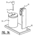
図1A〜図1Cは、測定機(図示せず)の測定プローブ2の針1を洗浄するための装置を示す。上記装置は、洗浄処理中に上記針1を収容するための洗浄チャンバ4を有する本体3を含む。洗浄チャンバ4は、上記針1を上記洗浄チャンバ3に導入し、かつ上記洗浄チャンバ3から取出すための開口部5を備える。
In the figures, the same elements are denoted by the same reference numerals.
1A to 1C show an apparatus for cleaning a
本体3と洗浄チャンバ4との間には空間6が規定される。上記空間6に洗浄剤および/または乾燥剤を供給するための入口開口部7が上記空間6に接続される。上記洗浄剤は、洗浄液、洗浄ガス、または、洗浄液の小滴がガス、たとえば空気に含まれている洗浄エアロゾルなどの任意の好適な洗浄剤であり得る。上記乾燥剤は、任意の好適な乾燥剤、たとえば乾燥ガス、特に空気であり得る。上記洗浄チャンバ4に洗浄剤および/または乾燥剤を供給するために、8個の上記供給開口部8が上記空間6を上記洗浄チャンバ4の内空間に接続する。8個の供給開口部8は、実質的な等しい角距離aで離間される。aは8個の供給開口部8では45°であり、上記洗浄剤および/または上記乾燥剤を共通の場所9に供給するように配置される。共通の場所9には、洗浄および/または乾燥中に上記針1が位置し得る。図1A〜図1Cの装置の洗浄チャンバ4は円筒状である。洗浄剤および/または乾燥剤を径方向に供給するように供給開口部8が配置されるように、供給開口部8は上記円筒壁に接線的に配置され、上記針1は、供給開口部8の高さにおいて洗浄チャンバ4の中央に保持される。出願人は、8個の等しく分散された供給開口部8が径方向に噴霧するかまたは吹付け、針1が中央に保持された構成では、上記洗浄剤および/または乾燥剤によって針1が影響されず、測定処理が洗浄中に停止される必要がないことを見出した。
A
任意に、洗浄および/または乾燥中に、針1のすべての部分を洗浄剤および/または乾燥剤に露出させるために、上記針1が方向10に前後移動され得る。代替的に、上記洗浄チャンバ4が方向10に前後移動されてもよい。方向10は、洗浄チャンバ4の長手方向と平行である。
Optionally, the
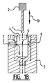
図1Bに示されるように、供給開口部8の直径は洗浄チャンバ4の方向に減少し、それによって洗浄剤および/または乾燥剤の圧力および/または速度が増大する。洗浄チャンバ8の入口における供給開口部8の直径は、図1A〜図1Bの例では0.2mmであり、これは、針1に影響を及ぼすことなく洗浄剤および/または乾燥剤を針1に向けるために好適な圧力および/または速度をもたらすことが判明している。なお、任意の好適な直径が選択され得る。
As shown in FIG. 1B, the diameter of the
図1Aに示されるように、上記装置は上記針1の存在を検出するための検出器11を備える。上記針1を検出すると、洗浄処理が始められ得る。
As shown in FIG. 1A, the device comprises a
本体3および検出器11は両方ともベース12に装着される。ベース12は、テーブルまたは他の支持物上に水平に配置されてもよいし、支持物に垂直に取付けられてもよい。
Both the
図2は、上記洗浄剤および/または上記乾燥剤を図1の装置に供給するフローチャートを示す。ガス、たとえば空気は、ガスの圧力を調整するための圧力調整器21に管20などを介して提供される。ガスの圧力は、たとえば0.5バール〜6バールの間、たとえば2〜4バールの間、たとえば2.5バール〜3バールの間に設定される。圧力下でのガスが次いで流量調節計23に供給され、流量調節計23は、管24などに、または管26などにガスを向ける。管24は、ディスペンサ25に接続する。ディスペンサ25において、洗浄液粒子が上記ガスに含まれるように、洗浄剤が上記ガスに投入される。洗浄液粒子を含む上記ガスは、次いで空間6に、かつそれによって管27および管28を介して洗浄チャンバに供給される。管26は、ガスが上記乾燥剤として空間6および洗浄チャンバ4に供給され得るように、管28に直接接続する。上記圧力調整器21と、ディスペンサ25に投入される液体の量と、針1を洗浄するためにまずディスペンサ25を介して、次いで洗浄後に針1を乾燥させるために直接管26および28を介して、空間6にガスを提供するための期間を制御するための流量調節計23とを制御するための制御ユニットが設けられる。たとえば、まず針1は数秒間洗浄され、次いで針1は数秒間乾燥される。上記期間は好適に選択されてもよく、これに限定されない。
FIG. 2 shows a flow chart for supplying the cleaning agent and / or the desiccant to the apparatus of FIG. A gas, for example air, is provided to the
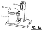
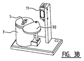
図3Aおよび図3Bは、本発明に係る装置の第2の実施形態の斜視図である。第2の実施形態に係る上記装置は、バルブ30が開口部5を閉鎖する図3Aに示されるような第1の閉位置と、バルブ30が開口部5を閉鎖しない図3Bに示されるような第2の開位置との間で変位可能な閉鎖バルブ30を装置が備える点でのみ第1の実施形態に係る装置とは異なる。バルブ30は、開口部5を閉鎖し、それによって外部の環境から洗浄チャンバ4を保護するため、特に、開口部5を介してその中に入り込むほこりおよび他の粒子から洗浄チャンバ4を保護するためにその第1の位置に常に保持されてもよく、針1を洗浄するために針1が洗浄チャンバ4に導入され得るように開口部5を解放するためにその第2の位置に一時的に変位されてもよい。洗浄後、バルブ30はその第1の位置に戻される。
3A and 3B are perspective views of a second embodiment of the apparatus according to the present invention. The apparatus according to the second embodiment includes a first closed position as shown in FIG. 3A where the
図3Aおよび図3Bに示されるバルブ30は、第1の位置と第2の位置との間で回転する。任意の好適なやり方で、たとえばバルブを並進して変位させることによって、バルブが変位され得ることは当業者にとって明らかであろう。バルブの代わりに、任意の好適な閉鎖手段が設けられ得る。上記閉鎖手段またはバルブ30と上記開口部5との間に任意にシーリングが設けられ得る。
The
なお、図1A〜図1Cに示されるような装置の第1の実施形態に対する図3Aおよび図3Bに示されるような装置の第2の実施形態の相違点のみがここで説明される。図3Aおよび図3Bに係る装置のさらなる説明について、図1A〜図1Cの説明を参照する。 It should be noted that only the differences of the second embodiment of the apparatus as shown in FIGS. 3A and 3B relative to the first embodiment of the apparatus as shown in FIGS. 1A-1C will now be described. For further description of the apparatus according to FIGS. 3A and 3B, reference is made to the description of FIGS. 1A-1C.
図4は、本発明に係る装置の第3の実施形態の斜視図である。第3の実施形態に係る上記装置は、洗浄チャンバ4および開口部5が丸形断面の代わりに六角形の断面を有する点でのみ第1の実施形態に係る装置とは異なる。合計6つの供給開口部が設けられる(図示せず)ように、洗浄チャンバ4の6つの壁セクションの各々に供給開口部が配置される。供給開口部は、好ましくは、洗浄チャンバ4の長手方向に同じ高さに、つまり開口部5から同じ長手距離に配置され、好ましくは、供給開口部が等しい角距離αで離間されるように、洗浄チャンバ4および壁セクションの横断方向に見た各壁セクションの中央に各々が配置されることが好ましく、αは60°である。供給開口部は、上記洗浄剤および/または上記乾燥剤を共通の場所に供給するように配置される。共通の場所は、開口部5および洗浄チャンバ4の中心長手軸である。
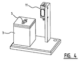
FIG. 4 is a perspective view of a third embodiment of the apparatus according to the present invention. The apparatus according to the third embodiment differs from the apparatus according to the first embodiment only in that the cleaning chamber 4 and the
なお、六角形の断面の代わりに、好適な各多角形断面が選択されてもよい。供給開口部は、各壁セクションに、または壁セクションの一部に設けられてもよい。 Each suitable polygonal cross section may be selected instead of the hexagonal cross section. A supply opening may be provided in each wall section or in a part of the wall section.
さらに、図1A〜図1Cに示される装置の第1の実施形態に対する図4に示される装置の第3の実施形態の相違点のみをここで説明する。図4に係る装置のさらなる説明については、図1A〜図1Cの説明を参照する。 Furthermore, only the differences of the third embodiment of the apparatus shown in FIG. 4 from the first embodiment of the apparatus shown in FIGS. 1A-1C will now be described. For further description of the apparatus according to FIG. 4, reference is made to the description of FIGS. 1A-1C.
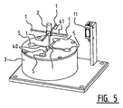
図5は、本発明に係る装置の第4の実施形態の斜視図である。第4の実施形態に係る上記装置は、異なる種類の測定プローブ2の5本の針1を受取るために5つの開口部5を備える点でのみ第1の実施形態に係る装置とは異なる。開口部5は針1の形状に従って1つの本体3の上側面に配置され、凹部40を介して相互に接続され、ペン状要素41によって外端に保持される5本の針1が好ましくは同時に針1を洗浄するためにそれぞれの洗浄チャンバ4に同時に導入され得る。各開口部5は、洗浄チャンバ4への入り口を提供し、各洗浄チャンバ4は、洗浄剤および/または乾燥剤を供給するための1つ以上の供給開口部を備え得る。複数の供給開口部が各洗浄チャンバ4に設けられる場合、各洗浄チャンバ4の供給開口部は等しい角距離で離間され得、洗浄剤および/または乾燥剤を径方向に供給するために接線的に配置され得る。
FIG. 5 is a perspective view of a fourth embodiment of the apparatus according to the present invention. The device according to the fourth embodiment differs from the device according to the first embodiment only in that it comprises five
なお、たとえば測定プローブ2の針1の形状に従って、開口部5を有する任意の好適な数の洗浄チャンバ4が設けられ得る。
Note that any suitable number of cleaning chambers 4 having
さらに、1つの本体4に設けられる複数の洗浄チャンバ4は、凹部40を介して相互に接続され、したがって1つの洗浄チャンバ4とも見なされ得る。
Furthermore, the plurality of cleaning chambers 4 provided in one main body 4 are connected to each other via the
さらに、図1A〜図1Cに示される装置の第1の実施形態に対する図5に示される装置の第4の実施形態の相違点のみをここで説明する。図5に係る装置のさらなる説明については、図1A〜図1Cの説明を参照する。 Furthermore, only the differences of the fourth embodiment of the apparatus shown in FIG. 5 from the first embodiment of the apparatus shown in FIGS. 1A-1C will now be described. For further description of the apparatus according to FIG. 5, reference is made to the description of FIGS.
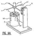
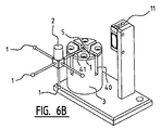
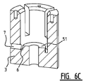
図6A〜図6Dは、本発明に係る装置の第5の実施形態の斜視図である。第5の実施形態に係る上記装置は、本体3の上側面の中央開口部5から本体3の外側の円筒状の周縁に延在する4つの凹部40が設けられる点で第1の実施形態に係る装置と異なる。開口部5は、1回につき測定プローブ2の5本の針1のうちの1本を受取るために1つの中央洗浄チャンバ4への入り口を提供する。中央の下側の針1が本体3の上側面の開口部5に導入される場合、他の4本の針1は、4つの周方向の凹部40を介して本体3の外方に延在する。凹部40は、それらの外端(図6A参照)において針1を保持するプローブ2のペン状要素41を収容する。同じ平面内に配置される他の4本の針1の各々は、針1を有するプローブ2を回転させる必要なしに、それぞれの凹部40を介して開口部5に導入され得る(図6B参照)。
6A to 6D are perspective views of a fifth embodiment of the apparatus according to the present invention. The apparatus according to the fifth embodiment is the same as that of the first embodiment in that four
図6Cおよび図6Dは、分解された状態で本体3および洗浄チャンバ4を構成する2つの要素を示す。図6Dは、外周の一部上で凹部40を取囲む密封体50を各凹部40が備えることを示す。密封体50は、図6Aの組立てられた状態において本体3の内壁および直立の環状突起51に対して配置されることによって、図6Cおよび図6Dに示される空間6を封止する。
6C and 6D show the two elements that make up the
なお、図1A〜図1Cに示される装置の第1の実施形態に対する図6A〜図6Dに示される装置の第5の実施形態の相違点のみをここで説明する。図6A〜図6Dに係る装置のさらなる説明については、図1A〜図1Cの説明を参照する。 Only the differences of the fifth embodiment of the apparatus shown in FIGS. 6A-6D from the first embodiment of the apparatus shown in FIGS. 1A-1C will now be described. For further description of the apparatus according to FIGS. 6A-6D, reference is made to the description of FIGS. 1A-1C.
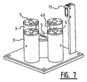
図7は、本発明に係る装置の第6の実施形態の斜視図である。第6の実施形態に係る上記装置は、各々が洗浄チャンバ4および開口部5を備える5つの本体3を備える点で第1の実施形態に係る装置とは異なる。図7の実施形態は、図5および図6のプローブ2の針1を洗浄するのにも好適である。中央の下側の針1が、中央に配置された本体3の洗浄チャンバ4に導入される。図1A〜図1Cに示されたものと同じ、洗浄チャンバ4を有する本体3である。同じ平面内に配置される他の4本の針1は、図5および図6に示されるペン状要素41を収容するために開口部5および凹部40を介して中央に配置された本体3の周りに位置するそれぞれの本体3のそれぞれの洗浄チャンバ4に導入される。各々が凹部40を備える本体3は、図6A〜図6Dに示される本体3と大体同様であるが、凹部40が1つしか備えていないという相違点を有する。本体3のさらなる説明については、図6A〜図6Dの説明を参照する。本体3は、各凹部30が針1の形状に従って中央に配置された本体3に向けられるように配置される。
FIG. 7 is a perspective view of a sixth embodiment of the apparatus according to the present invention. The apparatus according to the sixth embodiment differs from the apparatus according to the first embodiment in that it includes five
なお、図1A〜図1Cに示される装置の第1の実施形態に対する図7に示される装置の第6の実施形態の相違点のみをここで説明する。図7に係る装置のさらなる説明については、図1A〜図1Cの説明を参照する。 Only the differences of the sixth embodiment of the apparatus shown in FIG. 7 from the first embodiment of the apparatus shown in FIGS. 1A-1C will now be described. For further description of the apparatus according to FIG. 7, reference is made to the description of FIGS. 1A-1C.
図8は、本発明に係る装置の第7の実施形態の斜視図である。第7の実施形態に係る上記装置は、4つの外側本体3および中央に配置された本体3の各々間の距離が調整可能であるように、中央に配置された本体3に関して4つの外側本体3が変位可能である点で第6の実施形態に係る装置とは異なる。4つの外側本体3は案内レール60上に配置され、その長さに沿って変位可能である。4つの外側本体3および中央に配置された本体3の各々間の距離を調整することによって、針1を有する特定のプローブ2の寸法に装置を適合させることが可能である。
FIG. 8 is a perspective view of a seventh embodiment of the apparatus according to the present invention. The device according to the seventh embodiment has four
なお、図7に示された装置の第6の実施形態に対する図8に示される装置の第7の実施形態の相違点のみをここで説明する。図8に係る装置のさらなる説明については、図7の説明を参照する。 Only the differences between the sixth embodiment of the apparatus shown in FIG. 8 and the seventh embodiment of the apparatus shown in FIG. 7 will be described here. For a further description of the device according to FIG. 8, reference is made to the description of FIG.
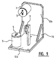
図9は、本発明に係る装置の第8の実施形態の斜視図である。第8の実施形態に係る上記装置は、各々が洗浄チャンバ4および開口部5を有する2つの本体3を備える点で第1の実施形態に係る装置とは異なる。本体3は、図1A〜図1Cに示されるものと各々同様である。第1の本体3および検出器11がベース12a上に配置される。該構成は、図1Aに示される構成と大体同様である。第2の本体3はベース12b上に配置され、ベース12bは、取付け手段70によって90°の角度でベース12aに取付けられている。図5および図6の針1を有するプローブ2は、1つの平面のみにおいて針1を回転させることによって図9に係る装置で洗浄され得る。下側の中央針1は、ベース12aまたは12b上に位置する本体3の洗浄チャンバ4内で洗浄され得、他の4本の針1は他方のベース12bまたは12a上に位置する本体3の洗浄チャンバ4内で洗浄され得る。
FIG. 9 is a perspective view of an eighth embodiment of the apparatus according to the present invention. The apparatus according to the eighth embodiment differs from the apparatus according to the first embodiment in that it includes two
なお、図1A〜図1Cに示される装置の第1の実施形態に対する図9に示される装置の第8の実施形態の相違点のみをここで説明する。図9に係る装置のさらなる説明については、図1A〜図1Cの説明を参照する。 Only the differences of the eighth embodiment of the apparatus shown in FIG. 9 from the first embodiment of the apparatus shown in FIGS. 1A-1C will now be described. For further description of the apparatus according to FIG. 9, reference is made to the description of FIGS. 1A-1C.
本発明は図面に示される変形に制限されず、添付の請求の範囲内にある他の好ましい実施形態も対象とする。 The invention is not limited to the variants shown in the drawings, but also covers other preferred embodiments within the scope of the appended claims.
Claims (17)
洗浄処理中に前記針を収容するための洗浄チャンバを備え、前記洗浄チャンバは、前記針を前記洗浄チャンバに導入しかつ前記洗浄チャンバから取出すための開口部を含み、さらに、
前記針を洗浄しかつ/または乾燥させるために、洗浄剤、たとえば洗浄液もしくはエアロゾル、および/または乾燥剤、たとえば空気を前記洗浄チャンバに供給するための供給手段を備える、装置。 A measurement probe needle cleaning device for cleaning a needle of a measurement probe, the device comprising:
A cleaning chamber for receiving the needle during a cleaning process, the cleaning chamber including an opening for introducing and removing the needle from the cleaning chamber;
An apparatus comprising a supply means for supplying a cleaning agent, for example a cleaning liquid or aerosol, and / or a drying agent, for example air, to the cleaning chamber in order to clean and / or dry the needle.
特に、洗浄剤粒子のエアロゾルを空気中で生成するために前記洗浄剤を投入するための投入システムと、
前記圧力調整器および/または前記投入システムおよび/または前記供給手段を制御するための制御ユニットとのうち少なくとも1つを備える、先行する請求項のうちいずれか1項に係る装置。 A pressure regulator for adjusting the pressure of the cleaning agent and / or the drying agent;
In particular, an input system for introducing the cleaning agent to generate an aerosol of cleaning agent particles in the air;
Device according to any one of the preceding claims, comprising at least one of the pressure regulator and / or the input system and / or a control unit for controlling the supply means.
前記洗浄チャンバに前記洗浄剤および/または前記乾燥剤を供給するための期間と、
前記圧力調整器の圧力と、
洗浄剤および/または乾燥剤の供給される量と、のうち少なくとも1つを設定するように配置される、請求項10に記載の装置。 The control unit is
A period for supplying the cleaning agent and / or the desiccant to the cleaning chamber;
The pressure of the pressure regulator;
The apparatus according to claim 10, wherein the apparatus is arranged to set at least one of a supplied amount of cleaning agent and / or desiccant.
Applications Claiming Priority (3)
| Application Number | Priority Date | Filing Date | Title |
|---|---|---|---|
| NL2011710 | 2013-10-31 | ||
| NL2011710A NL2011710C2 (en) | 2013-10-31 | 2013-10-31 | Device for cleaning a stylus of a measuring probe. |
| PCT/NL2014/050749 WO2015065183A1 (en) | 2013-10-31 | 2014-10-29 | Device for cleaning a stylus of a measuring probe |
Publications (3)
| Publication Number | Publication Date |
|---|---|
| JP2017501034A true JP2017501034A (en) | 2017-01-12 |
| JP2017501034A5 JP2017501034A5 (en) | 2017-09-28 |
| JP6505731B2 JP6505731B2 (en) | 2019-04-24 |
Family
ID=50031466
Family Applications (1)
| Application Number | Title | Priority Date | Filing Date |
|---|---|---|---|
| JP2016552398A Active JP6505731B2 (en) | 2013-10-31 | 2014-10-29 | Device for cleaning the needles of measuring probes |
Country Status (10)
| Country | Link |
|---|---|
| US (1) | US10232411B2 (en) |
| EP (1) | EP3062938B1 (en) |
| JP (1) | JP6505731B2 (en) |
| CN (2) | CN109092770A (en) |
| BR (1) | BR112016009520B1 (en) |
| ES (1) | ES2935195T3 (en) |
| MX (1) | MX2016005435A (en) |
| NL (1) | NL2011710C2 (en) |
| PL (1) | PL3062938T3 (en) |
| WO (1) | WO2015065183A1 (en) |
Families Citing this family (15)
| Publication number | Priority date | Publication date | Assignee | Title |
|---|---|---|---|---|
| EP3422017B1 (en) * | 2016-02-24 | 2022-11-09 | Hitachi High-Tech Corporation | Automated analysis device and cleaning method |
| GB2550549B (en) | 2016-05-09 | 2019-05-08 | Markes International Ltd | A sampling apparatus |
| GB2550548A (en) * | 2016-05-09 | 2017-11-29 | Markes International Ltd | A sampling apparatus |
| EP3455003B1 (en) * | 2016-05-11 | 2023-03-29 | Siemens Healthcare Diagnostics Inc. | Probe wash station for analytical instrumentation |
| CN107030061B (en) * | 2017-04-06 | 2019-07-23 | 武汉华星光电技术有限公司 | Probe cleaning device and probe cleaning method |
| CN108931415B (en) * | 2017-05-23 | 2021-02-19 | 北京诚智光辉科技有限公司 | Cell film-making dyeing all-in-one with wiper mechanism |
| CN108508061A (en) * | 2018-03-09 | 2018-09-07 | 上海宝钢工业技术服务有限公司 | The online mechanics properties testing system and method for steel plate |
| CN109622482B (en) * | 2018-11-13 | 2021-10-01 | 迪瑞医疗科技股份有限公司 | Probe cleaning tank of biochemical analyzer, biochemical analyzer and probe cleaning method |
| DE102019212768B3 (en) * | 2019-08-26 | 2020-11-05 | Carl Zeiss Industrielle Messtechnik Gmbh | Probe cleaning for coordinate measuring machines |
| CA3180492A1 (en) | 2020-05-01 | 2021-11-04 | Agilent Technologies, Inc. | Pipette tip washing devices and methods |
| CN114472252B (en) * | 2020-11-28 | 2023-03-24 | 法特迪精密科技(苏州)有限公司 | Probe fixing method for testing probe cleaning method |
| CN113061835A (en) * | 2021-03-24 | 2021-07-02 | 鑫光热处理工业(昆山)有限公司 | Nitrogen potential monitoring device in heat treatment furnace |
| CN112845230B (en) * | 2021-04-23 | 2022-02-08 | 南京摆渡人网络信息技术有限公司 | Green house monitoring device |
| CN113189165B (en) * | 2021-06-03 | 2024-03-01 | 南京普来森仪器有限公司 | Device for measuring sodium aluminate component by electrochemical principle |
| CN118491916B (en) * | 2024-07-19 | 2024-09-17 | 泰州市成兴环境检测技术有限公司 | Auxiliary cleaning device for soil detector and application method of auxiliary cleaning device |
Citations (13)
| Publication number | Priority date | Publication date | Assignee | Title |
|---|---|---|---|---|
| JPS62242858A (en) * | 1986-04-15 | 1987-10-23 | Nippon Tectron Co Ltd | Cleaning device for probe |
| JPH04323824A (en) * | 1991-04-23 | 1992-11-13 | Tokyo Electron Ltd | processing equipment |
| JPH0843009A (en) * | 1994-07-27 | 1996-02-16 | Ishikawajima Harima Heavy Ind Co Ltd | Three-dimensional measuring device for structures |
| JP2003181388A (en) * | 2001-10-09 | 2003-07-02 | Asahi Denka Kogyo Kk | Cleaning device and cleaning method using the device |
| JP2004325117A (en) * | 2003-04-22 | 2004-11-18 | Olympus Corp | Liquid dispensing apparatus and method of washing dispensing head |
| JP2005012197A (en) * | 2003-05-26 | 2005-01-13 | Sumitomo Heavy Ind Ltd | Method and apparatus of aerosol cleaning |
| JP2006090945A (en) * | 2004-09-27 | 2006-04-06 | Olympus Corp | Profile measuring instrument |
| JP2007078435A (en) * | 2005-09-13 | 2007-03-29 | Canon Inc | Shape measuring method and shape measuring apparatus |
| JP2009042067A (en) * | 2007-08-09 | 2009-02-26 | Hitachi High-Technologies Corp | Automatic analyzer |
| JP2010133727A (en) * | 2008-12-02 | 2010-06-17 | Beckman Coulter Inc | Cleaning mechanism, cleaning method and analyzer |
| US20110283847A1 (en) * | 2008-12-10 | 2011-11-24 | Leo Schreiber | Diameter Measurement in Turning Machines |
| JP2013511721A (en) * | 2009-11-20 | 2013-04-04 | シーメンス・ヘルスケア・ダイアグノスティックス・インコーポレイテッド | Apparatus, system and method adapted to rinse / dry clinical analyzer sample probe |
| JP2013134142A (en) * | 2011-12-26 | 2013-07-08 | Hitachi High-Technologies Corp | Automatic analyzer |
Family Cites Families (15)
| Publication number | Priority date | Publication date | Assignee | Title |
|---|---|---|---|---|
| JPS55140155A (en) * | 1979-04-19 | 1980-11-01 | Olympus Optical Co Ltd | Distribution device |
| US5603342A (en) * | 1995-06-29 | 1997-02-18 | Coulter Corporation | Apparatus for cleaning a fluid sample probe |
| DE19610607A1 (en) * | 1996-03-18 | 1997-09-25 | Boehringer Mannheim Gmbh | Device for cleaning pipetting needles or stirrers |
| CN101499413B (en) * | 2001-11-02 | 2011-05-04 | 应用材料股份有限公司 | Single wafer dryer and drying methods |
| DE10207499A1 (en) * | 2002-02-22 | 2003-09-25 | Evotec Ag | Pipette tip or dispensing unit cleansing system, involves introducing pipette tip into a cleaning chamber, and spraying with a cleaning fluid |
| JP2005241442A (en) * | 2004-02-26 | 2005-09-08 | Olympus Corp | Cleaning device and method, and analyzer using it |
| CN2796866Y (en) * | 2005-06-17 | 2006-07-19 | 张礼明 | Pressure type aerosol cleaning device |
| US20080099057A1 (en) * | 2006-10-27 | 2008-05-01 | Dade Behring Inc. | Method and Device for Cleaning a Liquid Aspiration and Dispense Probe |
| BRPI0908280A2 (en) * | 2008-02-29 | 2018-05-29 | Beckman Coulter Inc | apparatus and method for cleaning a liquid handling probe |
| US20120211026A1 (en) * | 2009-10-30 | 2012-08-23 | Richard Jerome Schoeneck | Apparatus and Methods for Cleaning Reagent Dispensing Tips of a Screening Unit |
| EP2525230A4 (en) * | 2010-01-13 | 2016-09-07 | Hitachi High Tech Corp | AUTOMATIC ANALYSIS DEVICE |
| EP2530473A1 (en) * | 2010-01-29 | 2012-12-05 | Hitachi High-Technologies Corporation | Automatic analyzing device |
| CN202366900U (en) * | 2011-12-16 | 2012-08-08 | 长春迪瑞医疗科技股份有限公司 | Full-automatic urine analyzer cleaning pool |
| CN202527417U (en) * | 2012-03-22 | 2012-11-14 | 北京京东方光电科技有限公司 | Contactless cleaning device |
| CN202700869U (en) * | 2012-06-30 | 2013-01-30 | 长春迪瑞医疗科技股份有限公司 | Probe cleaning mechanism |
-
2013
- 2013-10-31 NL NL2011710A patent/NL2011710C2/en active
-
2014
- 2014-10-29 PL PL14799044.4T patent/PL3062938T3/en unknown
- 2014-10-29 US US15/033,341 patent/US10232411B2/en active Active
- 2014-10-29 CN CN201810962889.XA patent/CN109092770A/en active Pending
- 2014-10-29 MX MX2016005435A patent/MX2016005435A/en active IP Right Grant
- 2014-10-29 JP JP2016552398A patent/JP6505731B2/en active Active
- 2014-10-29 EP EP14799044.4A patent/EP3062938B1/en active Active
- 2014-10-29 CN CN201480060322.3A patent/CN105792950B/en active Active
- 2014-10-29 ES ES14799044T patent/ES2935195T3/en active Active
- 2014-10-29 WO PCT/NL2014/050749 patent/WO2015065183A1/en not_active Ceased
- 2014-10-29 BR BR112016009520-0A patent/BR112016009520B1/en active IP Right Grant
Patent Citations (13)
| Publication number | Priority date | Publication date | Assignee | Title |
|---|---|---|---|---|
| JPS62242858A (en) * | 1986-04-15 | 1987-10-23 | Nippon Tectron Co Ltd | Cleaning device for probe |
| JPH04323824A (en) * | 1991-04-23 | 1992-11-13 | Tokyo Electron Ltd | processing equipment |
| JPH0843009A (en) * | 1994-07-27 | 1996-02-16 | Ishikawajima Harima Heavy Ind Co Ltd | Three-dimensional measuring device for structures |
| JP2003181388A (en) * | 2001-10-09 | 2003-07-02 | Asahi Denka Kogyo Kk | Cleaning device and cleaning method using the device |
| JP2004325117A (en) * | 2003-04-22 | 2004-11-18 | Olympus Corp | Liquid dispensing apparatus and method of washing dispensing head |
| JP2005012197A (en) * | 2003-05-26 | 2005-01-13 | Sumitomo Heavy Ind Ltd | Method and apparatus of aerosol cleaning |
| JP2006090945A (en) * | 2004-09-27 | 2006-04-06 | Olympus Corp | Profile measuring instrument |
| JP2007078435A (en) * | 2005-09-13 | 2007-03-29 | Canon Inc | Shape measuring method and shape measuring apparatus |
| JP2009042067A (en) * | 2007-08-09 | 2009-02-26 | Hitachi High-Technologies Corp | Automatic analyzer |
| JP2010133727A (en) * | 2008-12-02 | 2010-06-17 | Beckman Coulter Inc | Cleaning mechanism, cleaning method and analyzer |
| US20110283847A1 (en) * | 2008-12-10 | 2011-11-24 | Leo Schreiber | Diameter Measurement in Turning Machines |
| JP2013511721A (en) * | 2009-11-20 | 2013-04-04 | シーメンス・ヘルスケア・ダイアグノスティックス・インコーポレイテッド | Apparatus, system and method adapted to rinse / dry clinical analyzer sample probe |
| JP2013134142A (en) * | 2011-12-26 | 2013-07-08 | Hitachi High-Technologies Corp | Automatic analyzer |
Also Published As
| Publication number | Publication date |
|---|---|
| MX2016005435A (en) | 2016-09-07 |
| JP6505731B2 (en) | 2019-04-24 |
| CN105792950A (en) | 2016-07-20 |
| CN109092770A (en) | 2018-12-28 |
| NL2011710C2 (en) | 2015-05-04 |
| PL3062938T3 (en) | 2023-02-20 |
| EP3062938A1 (en) | 2016-09-07 |
| WO2015065183A1 (en) | 2015-05-07 |
| BR112016009520B1 (en) | 2021-05-18 |
| EP3062938B1 (en) | 2022-12-07 |
| ES2935195T3 (en) | 2023-03-02 |
| US10232411B2 (en) | 2019-03-19 |
| CN105792950B (en) | 2019-05-21 |
| US20160263626A1 (en) | 2016-09-15 |
Similar Documents
| Publication | Publication Date | Title |
|---|---|---|
| JP6505731B2 (en) | Device for cleaning the needles of measuring probes | |
| CN110559190B (en) | Capsule filling machine for filling capsules and cleaning unit for use in a capsule filling machine | |
| JP6686005B2 (en) | Unit for grinding biological samples | |
| JP5941980B2 (en) | Device for testing pharmaceutical products, especially hard gelatin capsules | |
| KR101623966B1 (en) | A washing apparatus | |
| JP6236342B2 (en) | Tubular instrument cleaning holder and cleaning apparatus having tubular instrument cleaning holder accommodated in cleaning tank | |
| JP5784394B2 (en) | Needle head | |
| US20120312341A1 (en) | Apparatus for monitoring the rotation of the spraying arms of a multi-rack trolley of a cleaning machine | |
| JP6391408B2 (en) | Sampling device for powder processing equipment | |
| CN105268709B (en) | Grip and cleaning device for medicament containers with closures | |
| JP2014518742A (en) | Inspection sample holding device for inspecting sterilization process or cleaning process | |
| CN110857490B (en) | Sprayer, washing machine inner drum and washing machine | |
| JP5792928B2 (en) | Tool cleaning method and apparatus | |
| JP2019005713A (en) | Air purifier | |
| RU2681061C2 (en) | Holder device for endoscopy monitoring apparatus and method of use thereof | |
| CN105880050A (en) | Slit nozzle | |
| KR101244223B1 (en) | Medicine feed apparatus | |
| JP4866856B2 (en) | Dryer and method of controlling the dryer | |
| IT201600078037A1 (en) | MACHINE FOR FILLING BOTTLES, CARTRIDGES, SYRINGES AND THE LIKE | |
| JP5196182B2 (en) | Nozzle aiming position adjusting apparatus and method for washing machine | |
| KR20210030004A (en) | Apparatus for supplying a silica gel and apparatus for manufacturing bottle cap having the same | |
| CN209362529U (en) | The test tray of atomic absorption spectrophotometer | |
| FI122494B (en) | Method and arrangement of a hose filter | |
| JP2020118503A (en) | Linear gauge | |
| JP2951717B2 (en) | Slow leak detector for liquid-filled bags |
Legal Events
| Date | Code | Title | Description |
|---|---|---|---|
| A521 | Request for written amendment filed |
Free format text: JAPANESE INTERMEDIATE CODE: A523 Effective date: 20170814 |
|
| A621 | Written request for application examination |
Free format text: JAPANESE INTERMEDIATE CODE: A621 Effective date: 20170814 |
|
| A977 | Report on retrieval |
Free format text: JAPANESE INTERMEDIATE CODE: A971007 Effective date: 20180516 |
|
| A131 | Notification of reasons for refusal |
Free format text: JAPANESE INTERMEDIATE CODE: A131 Effective date: 20180605 |
|
| A521 | Request for written amendment filed |
Free format text: JAPANESE INTERMEDIATE CODE: A523 Effective date: 20180905 |
|
| TRDD | Decision of grant or rejection written | ||
| A01 | Written decision to grant a patent or to grant a registration (utility model) |
Free format text: JAPANESE INTERMEDIATE CODE: A01 Effective date: 20190305 |
|
| A61 | First payment of annual fees (during grant procedure) |
Free format text: JAPANESE INTERMEDIATE CODE: A61 Effective date: 20190327 |
|
| R150 | Certificate of patent or registration of utility model |
Ref document number: 6505731 Country of ref document: JP Free format text: JAPANESE INTERMEDIATE CODE: R150 |
|
| R250 | Receipt of annual fees |
Free format text: JAPANESE INTERMEDIATE CODE: R250 |
|
| R250 | Receipt of annual fees |
Free format text: JAPANESE INTERMEDIATE CODE: R250 |
|
| R250 | Receipt of annual fees |
Free format text: JAPANESE INTERMEDIATE CODE: R250 |
|
| R250 | Receipt of annual fees |
Free format text: JAPANESE INTERMEDIATE CODE: R250 |