JP2017227918A - Lens drive device, autofocus camera and mobile terminal device with camera - Google Patents
Lens drive device, autofocus camera and mobile terminal device with camera Download PDFInfo
- Publication number
- JP2017227918A JP2017227918A JP2017180498A JP2017180498A JP2017227918A JP 2017227918 A JP2017227918 A JP 2017227918A JP 2017180498 A JP2017180498 A JP 2017180498A JP 2017180498 A JP2017180498 A JP 2017180498A JP 2017227918 A JP2017227918 A JP 2017227918A
- Authority
- JP
- Japan
- Prior art keywords
- lens
- annular
- optical axis
- magnet
- annular coil
- Prior art date
- Legal status (The legal status is an assumption and is not a legal conclusion. Google has not performed a legal analysis and makes no representation as to the accuracy of the status listed.)
- Granted
Links
Images


Classifications
-
- H—ELECTRICITY
- H02—GENERATION; CONVERSION OR DISTRIBUTION OF ELECTRIC POWER
- H02K—DYNAMO-ELECTRIC MACHINES
- H02K41/00—Propulsion systems in which a rigid body is moved along a path due to dynamo-electric interaction between the body and a magnetic field travelling along the path
- H02K41/02—Linear motors; Sectional motors
- H02K41/035—DC motors; Unipolar motors
- H02K41/0352—Unipolar motors
- H02K41/0354—Lorentz force motors, e.g. voice coil motors
- H02K41/0356—Lorentz force motors, e.g. voice coil motors moving along a straight path
-
- G—PHYSICS
- G02—OPTICS
- G02B—OPTICAL ELEMENTS, SYSTEMS OR APPARATUS
- G02B7/00—Mountings, adjusting means, or light-tight connections, for optical elements
- G02B7/02—Mountings, adjusting means, or light-tight connections, for optical elements for lenses
- G02B7/023—Mountings, adjusting means, or light-tight connections, for optical elements for lenses permitting adjustment
-
- G—PHYSICS
- G02—OPTICS
- G02B—OPTICAL ELEMENTS, SYSTEMS OR APPARATUS
- G02B7/00—Mountings, adjusting means, or light-tight connections, for optical elements
- G02B7/02—Mountings, adjusting means, or light-tight connections, for optical elements for lenses
- G02B7/04—Mountings, adjusting means, or light-tight connections, for optical elements for lenses with mechanism for focusing or varying magnification
- G02B7/08—Mountings, adjusting means, or light-tight connections, for optical elements for lenses with mechanism for focusing or varying magnification adapted to co-operate with a remote control mechanism
-
- G—PHYSICS
- G03—PHOTOGRAPHY; CINEMATOGRAPHY; ANALOGOUS TECHNIQUES USING WAVES OTHER THAN OPTICAL WAVES; ELECTROGRAPHY; HOLOGRAPHY
- G03B—APPARATUS OR ARRANGEMENTS FOR TAKING PHOTOGRAPHS OR FOR PROJECTING OR VIEWING THEM; APPARATUS OR ARRANGEMENTS EMPLOYING ANALOGOUS TECHNIQUES USING WAVES OTHER THAN OPTICAL WAVES; ACCESSORIES THEREFOR
- G03B3/00—Focusing arrangements of general interest for cameras, projectors or printers
- G03B3/10—Power-operated focusing
-
- G—PHYSICS
- G03—PHOTOGRAPHY; CINEMATOGRAPHY; ANALOGOUS TECHNIQUES USING WAVES OTHER THAN OPTICAL WAVES; ELECTROGRAPHY; HOLOGRAPHY
- G03B—APPARATUS OR ARRANGEMENTS FOR TAKING PHOTOGRAPHS OR FOR PROJECTING OR VIEWING THEM; APPARATUS OR ARRANGEMENTS EMPLOYING ANALOGOUS TECHNIQUES USING WAVES OTHER THAN OPTICAL WAVES; ACCESSORIES THEREFOR
- G03B5/00—Adjustment of optical system relative to image or object surface other than for focusing
- G03B5/02—Lateral adjustment of lens
-
- G—PHYSICS
- G03—PHOTOGRAPHY; CINEMATOGRAPHY; ANALOGOUS TECHNIQUES USING WAVES OTHER THAN OPTICAL WAVES; ELECTROGRAPHY; HOLOGRAPHY
- G03B—APPARATUS OR ARRANGEMENTS FOR TAKING PHOTOGRAPHS OR FOR PROJECTING OR VIEWING THEM; APPARATUS OR ARRANGEMENTS EMPLOYING ANALOGOUS TECHNIQUES USING WAVES OTHER THAN OPTICAL WAVES; ACCESSORIES THEREFOR
- G03B2205/00—Adjustment of optical system relative to image or object surface other than for focusing
- G03B2205/0007—Movement of one or more optical elements for control of motion blur
- G03B2205/0015—Movement of one or more optical elements for control of motion blur by displacing one or more optical elements normal to the optical axis
-
- G—PHYSICS
- G03—PHOTOGRAPHY; CINEMATOGRAPHY; ANALOGOUS TECHNIQUES USING WAVES OTHER THAN OPTICAL WAVES; ELECTROGRAPHY; HOLOGRAPHY
- G03B—APPARATUS OR ARRANGEMENTS FOR TAKING PHOTOGRAPHS OR FOR PROJECTING OR VIEWING THEM; APPARATUS OR ARRANGEMENTS EMPLOYING ANALOGOUS TECHNIQUES USING WAVES OTHER THAN OPTICAL WAVES; ACCESSORIES THEREFOR
- G03B2205/00—Adjustment of optical system relative to image or object surface other than for focusing
- G03B2205/0053—Driving means for the movement of one or more optical element
- G03B2205/0069—Driving means for the movement of one or more optical element using electromagnetic actuators, e.g. voice coils
Landscapes
- Physics & Mathematics (AREA)
- General Physics & Mathematics (AREA)
- Optics & Photonics (AREA)
- Engineering & Computer Science (AREA)
- Combustion & Propulsion (AREA)
- Power Engineering (AREA)
- Electromagnetism (AREA)
- Chemical & Material Sciences (AREA)
- Lens Barrels (AREA)
- Adjustment Of Camera Lenses (AREA)
- Studio Devices (AREA)
- Focusing (AREA)
- Automatic Focus Adjustment (AREA)
Abstract
Description
本発明は、レンズ駆動装置、オートフォーカスカメラ及びカメラ付きモバイル端末装置に関する。 The present invention relates to a lens driving device, an autofocus camera, and a mobile terminal device with a camera.
特許文献1には、光ピックアップ用アクチュエータにおいて、レンズ支持体の外周面に周方向に90度の間隔をあけて第1環状コイル及び第2環状コイルを設け、レンズ支持体の径方向外側に各環状コイルに対面するマグネットを配置して、環状コイルに通電することにより、レンズ支持体を光軸方向(フォーカス方向)及びトラック方向(X方向)に移動させることが開示されている。
一方、小型カメラにおいては、レンズ支持体を光軸方向に移動させるのみであって、手振れ補正のためにX−Y方向に移動させる場合には、レンズ駆動装置全体を、X方向に駆動するモータ、Y方向に駆動するモータで移動させていた。
In
On the other hand, in a small camera, when the lens support is only moved in the optical axis direction and is moved in the XY direction for camera shake correction, a motor that drives the entire lens driving device in the X direction. It was moved by a motor driven in the Y direction.
即ち、小型カメラ用のレンズ駆動装置においては、レンズ支持体の光軸方向(Z方向)への移動及びX−Y方向(手振れ補正)への移動を、レンズ支持体のみを移動させておこなうものは従来なかった。
また、レンズ支持体の光軸方向への移動は、特許文献1の技術を用いることができたとしても、特許文献1の技術ではX方向のみの移動が可能なだけで、手振れ補正(X−Y方向(光軸に直交する面)への移動)ができない。
That is, in a lens driving device for a small camera, the lens support is moved in the optical axis direction (Z direction) and in the XY direction (camera shake correction) by moving only the lens support. There was never before.
In addition, even if the technique of
そこで、本発明は、簡易な構成で、レンズ支持体を光軸方向への移動及び手振れ補正の移動ができるレンズ駆動装置、オートフォーカスカメラ及びカメラ付きモバイル端末装置の提供を目的とする。 Accordingly, an object of the present invention is to provide a lens driving device, an autofocus camera, and a camera-equipped mobile terminal device that can move the lens support in the optical axis direction and a camera shake correction with a simple configuration.
請求項1に記載の発明は、内周にレンズを支持するレンズ支持体と、内周側にレンズ支持体を移動自在に支持する固定体と、レンズ支持体の外周に周方向に沿って巻回した第1環状コイルと、レンズ支持体の外周に周方向に90度の間隔をあけて配置した少なくとも2つの第2環状コイルと、固定体に設けてあり第1環状コイルの周方向に沿って所定の間隔に設けた少なくとも4つのマグネットとを備え、第2環状コイルはレンズ支持体の径方向外側から見て環状を成しており、各マグネットは内周面を同じ磁極としてあり且つ内周面が第1環状コイルの外周面に対向して設けてあると共に第2環状コイルが設けてある位置では第2環状コイルにおけるレンズ支持体の径方向外側面に対向してあり、レンズ支持体を光軸方向へ移動するときには第1環状コイルに電流を流し、レンズ支持体を光軸と直交するX−Y方向に移動するときには所定の第2環状コイルに所定の電流を流すことを特徴とするレンズ駆動装置である。 According to the first aspect of the present invention, a lens support that supports the lens on the inner periphery, a fixed body that supports the lens support so as to be movable on the inner periphery, and a winding around the outer periphery of the lens support along the circumferential direction The rotated first annular coil, at least two second annular coils arranged on the outer periphery of the lens support with a 90 degree interval in the circumferential direction, and a fixed body provided along the circumferential direction of the first annular coil And at least four magnets provided at predetermined intervals, the second annular coil is annular when viewed from the outside in the radial direction of the lens support, and each magnet has an inner peripheral surface as the same magnetic pole and an inner The peripheral surface is provided opposite to the outer peripheral surface of the first annular coil and the second annular coil is provided at a position where the peripheral surface is opposed to the radially outer surface of the lens support in the second annular coil. When moving in the direction of the optical axis Flowing a current to the first coil, a lens driving apparatus characterized by flowing a predetermined current to a predetermined second annular coil when moving the lens support an X-Y direction perpendicular to the optical axis.
請求項2に記載の発明は、内周にレンズを支持するレンズ支持体と、内周側にレンズ支持体を移動自在に支持する固定体と、レンズ支持体の外周に周方向に沿って巻回した第1環状コイルと、レンズ支持体の外周に周方向に90度の間隔をあけて配置した少なくとも2つの第2環状コイルと、固定体に設けてあり第1環状コイルの周方向に沿って設けた環状のマグネットとを備え、第2環状コイルはレンズ支持体の径方向外側から見て環状を成しており、マグネットは内周面と外周面とで磁極を異にしてあり且つ内周面が第1環状コイルの外周面に対向して設けてあると共に第2環状コイルが設けてある位置では第2環状コイルにおけるレンズ支持体の径方向外側面に対向してあり、レンズ支持体を光軸方向へ移動するときには第1環状コイルに電流を流し、レンズ支持体を光軸と直交するX−Y方向に移動するときには所定の第2環状コイルに所定の電流を流すことを特徴とするレンズ駆動装置である。 According to a second aspect of the present invention, a lens support that supports the lens on the inner periphery, a fixed member that supports the lens support on the inner periphery in a movable manner, and an outer periphery of the lens support that is wound along the circumferential direction. The rotated first annular coil, at least two second annular coils arranged on the outer periphery of the lens support with a 90 degree interval in the circumferential direction, and a fixed body provided along the circumferential direction of the first annular coil The second annular coil has an annular shape when viewed from the outside in the radial direction of the lens support, and the magnet has different magnetic poles on the inner peripheral surface and the outer peripheral surface, and on the inner side. The peripheral surface is provided opposite to the outer peripheral surface of the first annular coil and the second annular coil is provided at a position where the peripheral surface is opposed to the radially outer surface of the lens support in the second annular coil. When moving in the direction of the optical axis, Flowing a current to a lens drive device characterized by flowing a predetermined current to a predetermined second annular coil when moving the lens support an X-Y direction perpendicular to the optical axis.
請求項3に記載の発明は、請求項1に記載の発明において、固定体はマグネットの外周側に外周側壁を有するヨークを備え、ヨークは前側から見て外周側壁が平面視略四角形形状を成しており、マグネット及び第2環状コイルはヨークの角部に配置してあることを特徴とする。 According to a third aspect of the present invention, in the first aspect of the present invention, the fixed body includes a yoke having an outer peripheral side wall on the outer peripheral side of the magnet, and the outer peripheral side wall has a substantially rectangular shape in plan view when viewed from the front side. The magnet and the second annular coil are arranged at the corners of the yoke.
請求項4に記載の発明は、請求項1〜3のいずれか一項に記載の発明において、固定体は環状のヨークを備え、ヨークは外周側壁と外周側壁の内周に位置する内周側壁と、内周側壁と外周側壁とを連結する連結壁とを備え、マグネットはヨークの外周側壁の内周側に設けてあり、ヨークの内周側壁はレンズ支持体と第1環状コイルとの間に配置してあることを特徴とする。
The invention according to claim 4 is the invention according to any one of
請求項5に記載の発明は、請求1〜4のいずれか一項に記載の発明において、第1環状コイルは光軸方向に複数設けてあり、第2環状コイル及びマグネットは第1環状コイル毎に対応して設けてあることを特徴とする。
The invention according to
請求項6に記載の発明は、請求項1〜5のいずれか一項に記載のレンズ駆動装置と、レンズ支持体のレンズの結像側に設けた画像センサとを備えることを特徴とするオートフォーカスカメラである。 A sixth aspect of the invention is an auto comprising the lens driving device according to any one of the first to fifth aspects, and an image sensor provided on the image forming side of the lens of the lens support. It is a focus camera.
請求項7に記載の発明は、請求項6に記載のオートフォーカスカメラを搭載したことを特徴とするカメラ付きモバイル端末装置である。
モバイル端末装置とは、携帯電話、携帯情報端末(PDA)、ノートパソコン等を言う。
A seventh aspect of the present invention is a camera-equipped mobile terminal device in which the autofocus camera according to the sixth aspect is mounted.
The mobile terminal device refers to a mobile phone, a personal digital assistant (PDA), a notebook computer, and the like.
請求項1及び2に記載の発明によれば、レンズ支持体のフォーカス移動(光軸方向への移動)は、第1環状コイルに通電することでマグネットとの間で生じるレンズ光軸方向の推力によりレンズ支持体を光軸方向へ移動し、手振れ補正は任意の第2環状コイルに通電することでマグネットとの間で生じるレンズ支持体の半径方向の推力によりレンズ支持体をX−Y方向に移動して行う。これにより、レンズ支持体をフォーカス移動及び手振れ補正移動ができる。 According to the first and second aspects of the present invention, the focus movement (movement in the optical axis direction) of the lens support is a thrust in the lens optical axis direction generated between the first annular coil and the magnet. The lens support is moved in the optical axis direction, and the camera shake correction is performed in the XY direction by the radial thrust of the lens support generated between the lens support and the magnet by energizing an arbitrary second annular coil. Move and do. As a result, the lens support can be moved in focus and shake correction.
マグネットの内周面のうち右(左)側部から出た磁束線の向きは半径方向内方と円周方向右(左)方の成分を持ち、マグネットの内周面から離れるほど右(左)側へカーブする。即ち、磁束線の向きは半径方向内方と半径方向に対する左右方向の成分を持つ。同様に、マグネットの内周面のうち前側部から出た磁束線は、内周面から離れるほど前方側へカーブする。また、マグネットの内周面のうち後側部から出た磁束線の向きは半径方向内方と光軸方向後方の成分を持ち、内周面から離れるほど後方側へカーブする。
例えば、第1環状コイルに前方側から見て反時計方向に電流を流すと、半径方向内方の鎖交磁束成分が寄与してフレミングの左手の法則により光軸方向前方へ推力が生じ、レンズ支持体は光軸方向前方へ移動する。
一方、第2環状コイルに外方から見て時計方向に電流を流すと、第2環状コイルの前側部では光軸方向前方の鎖交磁束成分が寄与して半径方向内方へ推力が生じる。同様に、第2環状コイルの後側部、右側部、左側部においても半径方向内方へ推力が生じる。そのため、レンズ支持体は半径方向内方へ移動する。
The direction of the magnetic flux lines coming out from the right (left) side of the inner peripheral surface of the magnet has components inward in the radial direction and right (left) in the circumferential direction, and the right (left) as it moves away from the inner peripheral surface of the magnet. Curve to the side. That is, the direction of the magnetic flux lines has a radially inward component and a horizontal component with respect to the radial direction. Similarly, the magnetic flux lines coming out from the front side portion of the inner peripheral surface of the magnet curve toward the front side as the distance from the inner peripheral surface increases. Further, the direction of the magnetic flux lines coming out from the rear side portion of the inner peripheral surface of the magnet has components inward in the radial direction and rearward in the optical axis direction, and curves backward as the distance from the inner peripheral surface increases.
For example, when a current is passed through the first annular coil in a counterclockwise direction when viewed from the front side, a flux linkage component radially inward contributes, and a thrust is generated forward in the optical axis direction according to Fleming's left-hand rule. The support moves forward in the optical axis direction.
On the other hand, when a current is passed through the second annular coil in a clockwise direction as viewed from the outside, the interlinkage magnetic flux component in the front direction of the optical axis contributes to the front side portion of the second annular coil to generate a thrust inward in the radial direction. Similarly, thrust is also generated radially inward at the rear side, right side, and left side of the second annular coil. Therefore, the lens support moves inward in the radial direction.
この請求項1に記載の発明によれば、マグネットが光軸方向の移動用とX−Y方向の移動用とを兼ねており、1つの第1環状コイルと、少なくとも2つの第2環状コイルと、少なくとも2つのマグネットで、レンズ支持体を光軸方向及びX−Y方向へ移動できるので、簡易な構成で且つ少ない部品点数で、レンズ支持体をフォーカス移動及び手振れ補正移動ができる。 According to the first aspect of the present invention, the magnet serves both for movement in the optical axis direction and for movement in the XY direction, and includes one first annular coil and at least two second annular coils. Since the lens support can be moved in the optical axis direction and the XY direction with at least two magnets, the lens support can be moved in focus and shake correction with a simple configuration and a small number of parts.
また、請求項2に記載の発明によれば、マグネットが光軸方向の移動用とX−Y方向の移動用とを兼ねており、1つの第1環状コイルと、少なくとも2つの第2環状コイルと、1つのマグネットで、レンズ支持体を光軸方向及びX−Y方向へ移動できるので、簡易な構成で且つ少ない部品点数で、レンズ支持体をフォーカス移動及び手振れ補正移動ができる。 According to the second aspect of the present invention, the magnet serves both for movement in the optical axis direction and for movement in the XY direction, and includes one first annular coil and at least two second annular coils. Since the lens support can be moved in the optical axis direction and the XY direction with a single magnet, the lens support can be moved in focus and shake correction with a simple configuration and a small number of parts.
請求項3に記載の発明によれば、請求項1に記載の作用効果を奏すると共に、マグネット及び手振れ補正として機能する第2環状コイルを四角形の奥ゆきのある角部に配置することにより、手振れ補正機能を有しながら、手振れ補正機能を搭載していないレンズ駆動装置と同様なサイズで且つコンパクトな構成にできる。また、ヨークにより、マグネットの磁束密度を高めることができる。 According to the third aspect of the present invention, the effects of the first aspect are achieved, and the second annular coil that functions as the magnet and the camera shake correction is disposed at the corner with the square back, thereby correcting the camera shake. While having a function, it is possible to achieve a size and a compact configuration similar to a lens driving device that does not have a camera shake correction function. The yoke can increase the magnetic flux density of the magnet.
請求項4に記載の発明によれば、請求項1〜3のいずれか一項に記載の作用効果を奏すると共に、ヨークの内周側壁と外周側壁との間では第1コイルを交差する磁束密度を高めることができるので、第1コイルに作用するZ方向の推力を高めることができる。 According to the invention described in claim 4, the magnetic flux density at which the first coil is crossed between the inner peripheral side wall and the outer peripheral side wall of the yoke while exhibiting the operational effect according to any one of the first to third aspects. Therefore, the thrust in the Z direction acting on the first coil can be increased.
請求項5に記載の発明によれば、請求項1〜4のいずれか一項に記載の作用効果を奏すると共に、光軸方向への移動に貢献する第1環状コイルを複数設けてあり、X−Y方向への移動に貢献する第2環状コイルを複数設けてあるので、レンズ支持体の光軸方向への推力及びX−Y方向への推力を高めることができる。
According to the invention described in
請求項6に記載の発明によれば、請求項1〜5のいずれか一項に記載の作用効果を奏するオートフォーカスカメラを提供できる。
According to the invention described in claim 6, it is possible to provide an autofocus camera that exhibits the operational effects described in any one of
請求項7に記載の発明によれば、請求項6に記載の作用効果を奏するカメラ付きモバイル端末装置を提供できる。 According to invention of Claim 7, the mobile terminal device with a camera which show | plays the effect of Claim 6 can be provided.
以下に、添付図面の図1〜図5を参照して本発明の実施の形態を詳細に説明する。本実施の形態に係るレンズ駆動装置1は、携帯電話に組み込まれるオートフォーカスカメラのレンズ駆動装置である。
Embodiments of the present invention will be described below in detail with reference to FIGS. A
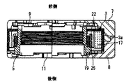
このレンズ駆動装置1は、図1に示すように、内周にレンズ(図示せず)を支持するレンズ支持体5と、内周側にレンズ支持体5を移動自在に支持する固定体としてのヨーク3と、レンズ支持体5と、ヨーク3の光軸方向前側に配置されるフレーム7及び前側スプリング9と、ヨーク3の後側に配置されるベース8及び後側スプリング11とを備えており、後側スプリング11とヨーク3との間にはスペーサ(絶縁材)15が配置されている。図1及び図2に示すように、レンズ支持体5の外周にはコイル体4が固定されている。
As shown in FIG. 1, the
図1に示すように、ヨーク3の外周側壁3aは前側から見て略四角形状を成しており、四角の角部3bは面取りされた形状になっている。ヨーク3の中心部にはレンズ支持体5が配置される開口部が設けられている。
図2(a)に示すように、ヨーク3の外周側壁3aの各角部3bにはその内周にマグネット17が所定の間隔で合計4個固定されている。本実施の形態では、マグネット17の間隔は等間隔とした。
As shown in FIG. 1, the outer
As shown in FIG. 2 (a), a total of four
図2(a)に示すように、各マグネット17は、前側から見た平面がヨーク3の面取りされた角部3bに沿って略台形形状を成しており、その内周側が後述する第1環状コイル19の外周面に沿った円弧状を成している。また、マグネット17は内周側と外周側とで磁極を異にしており、例えば内周側をN極とし、外周側をS極としてある。
As shown in FIG. 2 (a), each
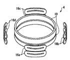
図1に示すように、レンズ支持体5は、略円筒形状であり、その内周側にレンズ(図示せず)が固定されている。レンズ支持体5の外周に固定されているコイル体4は、第1環状コイル19と第2環状コイル16a、16b、16c、16dとから構成されている。
第1環状コイル19は、レンズ支持体5の周方向全周に亘って巻回した円環状を成していると共に帯状をなしている。
As shown in FIG. 1, the
The first
更に、図2(a)に示すように、第1環状コイル19の外周には、4つの第2環状コイル16a〜16dが周方向に等間隔(90度の間隔)で合計4つ配置されている。図1に示すように、各第2環状コイル16a〜16dは各々、レンズ支持体の半径方向外側から見て側面視環状を成しており、環を成す方向にコイルを巻回して形成されている。
Further, as shown in FIG. 2A, a total of four second
各第2環状コイル16a〜16dは、第1環状コイル19の外周面に重ねて配置しており、前側辺部22、後側辺部25及び左右側辺部24、26を第1環状コイル19に重ねている。
各マグネット17は、第2環状コイル16a〜16dに対面して設けてあり、マグネット17の内周側面17aは、第2環状コイルの各辺部22、25、24、26に対面してあり、マグネット17の周方向の寸法は第2環状コイル16a〜16dの周方向の寸法と略同じ寸法としてあると共にマグネット17の内周側面17aの面積は、対面する第2環状コイル16a〜16dの面積と略同じ面積になっている。
Each of the second
Each
尚、各マグネット17は、対面する第2環状コイル16a〜16dを介在して第1環状コイル19に対向している。
Each
第2環状コイル16a〜16dは、図2(b)に示すように、マグネット17の内周面のうち右(左)側部から出た磁束線の向きは半径方向内方と円周方向右(左)方の成分を持ち、マグネット17の内周面17aから離れるほど右(左)側へカーブする。即ち、磁束線の向きは半径方向内方と半径方向に対する左右方向の成分を持つ。同様に、マグネット17の内周面17aのうち光軸方向前側部から出た磁束線は、内周面17aから離れるほど前方側へカーブする。また、マグネット17の内周面17aのうち光軸方向後側部から出た磁束線の向きは半径方向内方と光軸方向後方の成分を持ち、内周面17aから離れるほど後方側へカーブする。
As shown in FIG. 2B, the second
例えば、第1環状コイル19に前方側から見て反時計方向に電流I1を流すと、半径方向内方の鎖交磁束成分が寄与してフレミングの左手の法則により光軸方向前方へ推力が生じ、レンズ支持体5は光軸方向前方へ移動する。第2環状コイル16a〜16dに外方から見て反時計方向に電流I2を流すと、各第2環状コイル16a〜16dの光軸方向前の前側辺部22では光軸方向前方の鎖交磁束成分が寄与して半径方向内方へ推力が生じる。同様に、第2環状コイル16a〜16dの後側辺部25、右側辺部26、左側辺部24においても半径方向内方へ推力が生じる。そのため、レンズ支持体5は半径方向内方へ移動する。
For example, when a current I1 is passed through the first
即ち、第2環状コイル16a、16cは、マグネット17の磁力線のうち第2環状コイル16a、16cに直交する成分の磁力と、第2環状コイル16a、16cに流れる電流によって、フレミングの左手の法則により、図2(a)に示すように、レンズ支持体5の半径方向に推力Eが作用し、第2環状コイル16b、16dも同様に、レンズ支持体5の半径方向に推力Fが作用する。推力Eと推力Fとは互いに直交している。
That is, the second
図4に示すように、第1環状コイル19は、Z駆動部32に接続されており、各第2各環状コイル16a〜16dはX−Y駆動部33に接続されており、各々駆動部32、33から所定値の電流が通電される。尚、図4において、一点鎖線で示すZ駆動部32と第1環状コイル19との接続線及びX−Y駆動部33と第2環状コイル16a〜16dとの接続線は、電流の入力側又は出力側のみの接続を示している。
本実施の形態では、第2環状コイル16a及び16cと、16b及び16dとが直列に接続されており、2つの環状コイル16a及び16cで推力Eの方向に、16b及び16dで推力Fの方向に駆動するようになっている。
As shown in FIG. 4, the first
In the present embodiment, the second
例えば、Z駆動部32では、レンズ支持体5をフォーカス位置へ移動(光軸方向への移動)する場合には、第1環状コイル19に電流Zを流す。
同様に、手振れ補正をする場合には、X−Y駆動部33では、第2環状コイル16a及び16cに電流Eを流してE方向にレンズ支持体5を移動させ、第2環状コイル16b及び16dに電流Fを流してF方向にレンズ支持体5を移動させる。これにより、レンズ支持体5をE―F方向に移動して手振れ補正を行う。
For example, in the
Similarly, in the case of correcting camera shake, the
尚、図2及び図4において、符合Z、E、Fは流した電流に基づいて生じる推力の方向と大きさを示している。
但し、図2に示すように、本実施の形態では、X方向は前面視四角形状のヨーク3の一辺方向であり、Y方向は前面視四角形状のヨーク3の隣りの辺の方向としてあり、ヨーク3の対角線方向に生じる推力E、Fについて、X方向の分力EXとFXの和がX方向の推力として、Y方向の分力EYとFYの和がY方向の推力として作用することになり、X−Y駆動部33では、各X方向の分力の和EX+FXをX方向推力として、各Y方向の分力の和EY+FYをY方向推力となるように制御している。
2 and 4, symbols Z, E, and F indicate the direction and magnitude of thrust generated based on the flowed current.
However, as shown in FIG. 2, in the present embodiment, the X direction is the direction of one side of the
図1に示すように、前側スプリング9は、組み付け前の自然状態が平板状であり、平面視矩形の環状を成す外周側部9aと、外周側部9aの内周に配置され平面視円弧形状の内周側部9bと、外周側部9aと内周側部9bとを連結する4つの腕部9cとで構成されており、Z方向及びX−Y方向への変形が自在にできるようになっている。
As shown in FIG. 1, the front spring 9 has a flat plate shape in a natural state before assembly, and is arranged on the outer
後側スプリング11は、組み付け前の自然状態が平板状であり、平面視矩形の環状を成す外周側部11aと、外周側部11aの内周に配置され平面視円形状の内周側部11bと、外周側部11aと内周側部11bとを連結する4つの腕部11cとで構成されている。
The
前側スプリング9の外周側部9aは、フレーム7とヨーク3との間に挟持されており、内周側部9bはレンズ支持体5の前端に固定されている。後側スプリング11の外周側部11aはベース8と後側スペーサ15との間に挟持されており、内周側部11bはレンズ支持体5の後端に固定されている。これにより、レンズ支持体5は前側スプリング9と後側スプリング11とにより、光軸方向(Z方向)及びX−Y方向に移動自在に支持されている。前側スプリング9又は後側スプリング11の少なくとも一方は、第1環状コイル19、第2環状コイル16a、16c及び第2環状コイル16b、16dの両端に接続して直流電流の供給端子を兼ねている。
An outer
そして、第1環状コイル19に電流を流すことにより、レンズ支持体5が光軸方向前方に移動すると、レンズ支持体5は、前側スプリング9及び後側スプリング11の前後方向の付勢力の合力と、第1環状コイル19及びマグネット17との間で生じる電磁力とが吊り合う位置で停止する。
レンズ支持体5がX−Y方向に移動する場合には、所定の第2環状コイル16a〜16dに所定値の電流を流すことにより、前側スプリング9及び後側スプリング11のX−Y方向のスプリングの合力と、第2環状コイル16a〜16dと各対応するマグネット17との間で生じる電磁力とが吊り合う位置で停止する。
When the
When the
次に、本発明の実施の形態に係るレンズ駆動装置1の組立て、作用及び効果について説明する。レンズ駆動装置1の組み立てに先立って、第1環状コイル19の外周面に各第2環状コイル16a〜16dを接着固定してコイル体4を形成し、レンズ支持体5の外周に固定する。
レンズ駆動装置1の組立ては、図1に示すように、ベース8に、後側スプリング11、後側スペーサ15、コイル体4を外周に固定したレンズ支持体5、各マグネット17を内周側面に固定したヨーク3、前側スプリング9、及びフレーム7をこの順序で組み付けて固定する。
Next, assembly, operation, and effects of the
As shown in FIG. 1, the
そして、コイル体4を固定したレンズ支持体5と、マグネット17を内周面に固定したヨーク3との組み付けは、ヨーク3の内周にその後側から前側に向けてレンズ支持体5を挿入して行う。
Then, the
そして、第1環状コイル19は各々入力端と出力端とをZ駆動部32に接続し、第2環状コイル16a〜16dは、対向するコイル16aと16c、16bと16dを直列に接続した後、X−Y駆動部33に入力端と出力端とを接続する。
The first
本実施の形態に係るレンズ駆動装置1の駆動は、図4において、Z駆動部32が画像センサ31から受ける高域成分(コントラスト)のピークを比較しつつ、合焦点位置へレンズ支持体5をZ方向へ直線移動する。
The
レンズ支持体5のZ方向への直線移動の際には、第1環状コイル19に電流値Zを流すことにより生じるマグネット17との間で生じる電磁力と、前側スプリング9及び後側スプリング11との付勢力の合力とが吊り合う位置で停止する。
When the
また、レンズ支持体5のX−Y制御(手振れ補正)は、ジャイロモジュール等によりXY方向の手振れ量の大きさを信号として受け、X方向及びY方向の手振れ補正量を演算して第2環状コイル16a〜16dの移動量E、Fを各々決定して、第2環状コイル16a、16cと、第2環状コイル16b、16dとに通電する。
The XY control (camera shake correction) of the
本実施の形態によれば、レンズ支持体5のフォーカス移動は、第1環状コイル19に通電することでレンズ支持体を光軸方向に移動し、手振れ補正は任意の第2環状コイル16a〜16dに所定値の電流を通電することで、レンズ支持体5をX−Y方向に移動して行う。これにより、レンズ支持体5のフォーカス移動及び手振れ補正移動ができる。
According to the present embodiment, the focus movement of the
本実施の形態によれば、マグネット17がフォーカス移動用と手振れ補正用とを兼ねており、1つの第1環状コイル19と、4つの第2環状コイル16a〜16dと、4つのマグネット17で、レンズ支持体5を光軸方向及びX−Y方向へ移動できる。そのため、簡易な構成で且つ少ない部品点数で、レンズ支持体5をフォーカス移動及び手振れ補正移動ができる。
According to the present embodiment, the
マグネット17及び手振れ補正として機能する第2環状コイル16a〜16dを前側から見た平面視四角形のヨーク3の奥ゆきのある角部3bに配置することにより、手振れ補正機能を有しながら、手振れ補正機能を搭載していないレンズ駆動装置と同様なサイズで且つコンパクトな構成にできる。
By arranging the
以下に本発明の他の実施の形態を説明するが、以下に説明する実施の形態において、上述の第1実施の形態と同一の作用効果を奏する部分には同一の符合を付することにより、その部分の説明を省略し、以下の説明では第1実施の形態と主に異なる点を説明する。
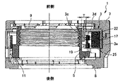
図6〜図8を参照して、第2実施の形態にかかるレンズ駆動装置を説明する。この第2実施の形態では、第1環状コイル19、19を光軸方向に2つ並べて配置しており、これに対応して、第2環状コイル16a〜16d、及びマグネット17も光軸方向に2セット設けている。
Other embodiments of the present invention will be described below. In the embodiments described below, the same reference numerals are given to the portions having the same functions and effects as those of the first embodiment described above. The description of this part is omitted, and the following description will mainly explain the differences from the first embodiment.
The lens driving device according to the second embodiment will be described with reference to FIGS. In the second embodiment, two first
この第2実施の形態によれば、第1実施の形態にかかるレンズ駆動装置と同様の作用効果を奏すると共に、光軸方向の推力Z及び半径方向の推力E、Fを共に第1実施の形態にかかるレンズ駆動装置の約2倍の推力にすることができる。 According to the second embodiment, the same effect as that of the lens driving device according to the first embodiment can be obtained, and both the thrust Z in the optical axis direction and the thrusts E and F in the radial direction can be used in the first embodiment. Thus, the thrust can be made about twice that of the lens driving device.
図9〜図11を参照して、第3実施の形態にかかるレンズ駆動装置を説明する。この第3実施の形態では、ヨーク3は外周側壁3aと外周側壁3aの内周に位置する内周側壁3cと、外周側壁3aと内周側壁3cとを連結する連結壁3dとを備えており、内周側壁3cは角部3bに対応する位置に設けてある。図9に示すように、ヨーク3の角部3bでは、外周側壁3aと内周側壁3cと連結壁3dとで断面略コ字形状としている。
A lens driving device according to a third embodiment will be described with reference to FIGS. In the third embodiment, the
また、コイル体4はレンズ支持体5の外周に隙間Tを形成して配置してあり、この隙間Tにヨーク3の内周側壁3cがレンズ支持体の前側から挿入してある。ヨーク3の内周側壁3cは各第2環状コイル16a〜16dの前側辺部22に対応する位置で、レンズ支持体5と第1環状コイル19との間に配置してある。
The coil body 4 is arranged with a gap T formed on the outer periphery of the
この第3実施の形態によれば、第1実施の形態と同様な作用効果を奏すると共に、図9及び図11に示すように、ヨーク3の外周側壁3aと内周側壁3cとの間には第1環状コイル19の前側部分が位置し、この部分に付与する磁束密度を高めているので、第1環状コイル19に作用するZ方向の推力を高めることができる。これにより、第1及び第2実施の形態に比較してZ方向の推力を高めることができる。
According to the third embodiment, the same operational effects as those of the first embodiment can be obtained, and as shown in FIGS. 9 and 11, the
尚、図10及び11に示すように、第2環状コイル16a〜16dにおいて、左右側辺部24、26には第1実施の形態と同様にマグネット17の内周面17aから離れるほど右左側へカーブする磁束が作用するので、レンズ支持体5をX−Y方向へ移動する推力を生じる。同様に、後側辺部25にもレンズ支持体5をX−Y方向へ移動する推力が生じる。
As shown in FIGS. 10 and 11, in the second
本発明は上述した実施の形態に限らず、本発明の要旨を逸脱しない範囲で種々変形可能である。例えば、第1実施の形態において、第2環状コイル16a〜16d及びマグネット17はヨーク3の各角部3bに設けることに限らず、互いに周方向に90度の間隔をあけていれば良い。
The present invention is not limited to the above-described embodiment, and various modifications can be made without departing from the scope of the present invention. For example, in the first embodiment, the second
第1実施の形態において、ヨーク3は角部3bを有することに限らず、前側から見て平面視円形となる形状としても良い。
第2環状コイル16a〜16dは互いに90度間隔をあけて隣合わせに2つだけ設けても良い。
In the first embodiment, the
Only two second
第1実施の形態において、マグネット17は4つ設けることに限らず、環状に形成したマグネットを1つ設けて、例えば、環状マグネットの内周面をN極とし、外周面をS極として、内周面と外周面とで磁極を異ならすものであっても良い。左側辺部24、右側辺部26において、磁束線の向きは円周方向の成分は持たないため、半径方向の駆動力は生じない。しかし、全周に渡り環状マグネットから磁束線が第1環状コイル19と鎖交するため、光軸方向の駆動力を大きくすることができる。
In the first embodiment, the number of
第1及び第2実施の形態において、第2環状コイル16a〜16dは、第1環状コイル19の内周側に配置しても良い。
第3実施の形態において、内周側壁3cは、図12及び図13に示すように、周方向に亘って連続して設けても良い。
上述した実施の形態において、レンズ駆動装置1は、ズームレンズを備えて、ズーム機能を合わせ持つものであっても良い。
図14に示すように、第1実施の形態において、第1コイル19を前側から見た平面視四角形状とし、第1コイル19の四角の各辺に第2コイル16a〜16dを配置すると共にヨーク3にはその平面視四角形の辺部に各マグネット17を配置する構成としても良い。この図14に示す変形例では、第2コイル16a〜16dに生じる推力は、X及びY方向であるから、上述した実施の形態のように推力E、FをX、Y方向に変換しなくても良い。
更に、図15に示すように、図14に示す変形例において、第3実施の形態のように内周側壁3cを各ヨークの辺部に対向して設けても良い。
In the first and second embodiments, the second
In the third embodiment, the inner
In the above-described embodiment, the
As shown in FIG. 14, in the first embodiment, the
Further, as shown in FIG. 15, in the modified example shown in FIG. 14, the inner
1 レンズ駆動装置
3 ヨーク
3a 外周側壁
3b 角部
3c 内周側壁
5 レンズ支持体
9 前側スプリング
11 後側スプリング
16a〜16d 第2環状コイル
17 マグネット
19 第1環状コイル
DESCRIPTION OF
Claims (6)
前記移動体を移動自在に支持するとともにマグネットを有する固定体と、を備え、
前記環状コイルは、前記レンズの光軸を中心とする径方向の外側から見て環状を成すように巻回形成された空心コイルであり、前記移動体の外周に配置固定され、
前記マグネットの内周面は、同一の磁極であり、前記環状コイルの外周面の全面に対向しており、
前記環状コイルに電流を流すことにより、前記移動体は前記径方向に推力を受けることを特徴とするレンズ駆動装置。 A moving body having a through hole and an annular coil for fixing the lens and moving in a direction perpendicular to the optical axis of the lens;
A stationary body that supports the movable body movably and has a magnet,
The annular coil is an air-core coil that is wound so as to form an annular shape when viewed from the outside in the radial direction centered on the optical axis of the lens, and is disposed and fixed on the outer periphery of the movable body,
The inner peripheral surface of the magnet is the same magnetic pole and faces the entire outer peripheral surface of the annular coil,
The lens driving device according to claim 1, wherein the moving body receives a thrust in the radial direction by passing a current through the annular coil.
前記移動体を移動自在に支持するとともに4つのマグネットを有する固定体と、を備え、
前記4つの環状コイルは、前記レンズの光軸を中心とする径方向の外側から見て環状を成すように巻回形成された空心コイルであり、前記レンズの光軸を中心とする周方向に90度の間隔をあけて前記移動体の外周に配置固定され、向かい合う同士が直列に接続されており、
前記4つのマグネットの内周面は同一の磁極であり、前記マグネットの前記内周面は対応する前記環状コイルの外周面の全面にそれぞれ対向しており、
前記一方の前記向かい合う2つの環状コイルに電流を流すことにより、前記移動体は、この一方の向かい合う方向に推力を受け、前記一方とは異なる他方の向かい合う2つの前記環状コイルに電流を流すことにより、前記移動体はこの他方の向かい合う方向に推力を受けることを特徴とするレンズ駆動装置。 A movable body that has a through-hole for fixing the lens and four annular coils and that moves in a direction orthogonal to the optical axis of the lens and orthogonal to each other;
A movable body that supports the movable body movably and has four magnets,
The four annular coils are air-core coils that are wound so as to form an annular shape when viewed from the outside in the radial direction centered on the optical axis of the lens, and in a circumferential direction centered on the optical axis of the lens. It is arranged and fixed on the outer periphery of the moving body with an interval of 90 degrees, and facing each other is connected in series,
The inner peripheral surfaces of the four magnets are the same magnetic pole, and the inner peripheral surfaces of the magnets are respectively opposed to the entire outer peripheral surface of the corresponding annular coil,
By passing a current through the one of the two annular coils facing each other, the moving body receives a thrust in the one opposing direction, and by passing a current through the two other annular coils different from the one, The lens driving device is characterized in that the moving body receives thrust in the other facing direction.
前記移動体を移動自在に支持するとともにマグネットを有する固定体と、を備え、
前記環状コイルは、前記レンズの光軸を中心とする径方向の外側から見て環状を成すように巻回形成された空心コイルであり、前記移動体の外周に配置固定され、
前記マグネットの内周面は、同一の磁極を有し、前記マグネットの内周面は、中央部及びこの中央部から周辺に亘る周辺部を有し、この周辺部において前記径方向に直交する方向の磁束成分が生じ、この磁束成分がこの周辺部に対応する前記環状コイルの巻線に鎖交するように前記マグネットの内周面が前記環状コイルの外周面に対向しており、
前記環状コイルに電流を流すことにより、前記移動体は前記径方向に推力を受けることを特徴とするレンズ駆動装置。 A moving body having a through hole and an annular coil for fixing the lens and moving in a direction perpendicular to the optical axis of the lens;
A stationary body that supports the movable body movably and has a magnet,
The annular coil is an air-core coil that is wound so as to form an annular shape when viewed from the outside in the radial direction centered on the optical axis of the lens, and is disposed and fixed on the outer periphery of the movable body,
The inner peripheral surface of the magnet has the same magnetic pole, and the inner peripheral surface of the magnet has a central portion and a peripheral portion extending from the central portion to the periphery, and a direction perpendicular to the radial direction in the peripheral portion. The magnetic flux component is generated, and the inner peripheral surface of the magnet is opposed to the outer peripheral surface of the annular coil so that the magnetic flux component is linked to the winding of the annular coil corresponding to the peripheral portion.
The lens driving device according to claim 1, wherein the moving body receives a thrust in the radial direction by passing a current through the annular coil.
前記他の環状コイルに電流を流すことにより、前記移動体は、前記光軸方向に推力を受けて移動することを特徴とする請求項1〜3のいずれか一項に記載のレンズ駆動装置。 The movable body has another annular coil that is wound so as to form an annular shape when viewed from the optical axis direction and faces the inner peripheral surface of the magnet,
The lens driving device according to any one of claims 1 to 3, wherein the moving body moves by receiving a thrust force in the optical axis direction by passing an electric current through the other annular coil.
Applications Claiming Priority (4)
| Application Number | Priority Date | Filing Date | Title |
|---|---|---|---|
| JP2010118659 | 2010-05-24 | ||
| JP2010118659 | 2010-05-24 | ||
| JP2010261015 | 2010-11-24 | ||
| JP2010261015 | 2010-11-24 |
Related Parent Applications (1)
| Application Number | Title | Priority Date | Filing Date |
|---|---|---|---|
| JP2016040010A Division JP2016136272A (en) | 2010-05-24 | 2016-03-02 | Lens drive device, autofocus camera and mobile terminal device with camera |
Publications (2)
| Publication Number | Publication Date |
|---|---|
| JP2017227918A true JP2017227918A (en) | 2017-12-28 |
| JP6601638B2 JP6601638B2 (en) | 2019-11-06 |
Family
ID=44972332
Family Applications (3)
| Application Number | Title | Priority Date | Filing Date |
|---|---|---|---|
| JP2011105902A Active JP5904392B2 (en) | 2010-05-24 | 2011-05-11 | Lens driving device, autofocus camera, and mobile terminal device with camera |
| JP2016040010A Pending JP2016136272A (en) | 2010-05-24 | 2016-03-02 | Lens drive device, autofocus camera and mobile terminal device with camera |
| JP2017180498A Active JP6601638B2 (en) | 2010-05-24 | 2017-09-20 | Lens drive device, autofocus camera and camera-equipped mobile terminal device |
Family Applications Before (2)
| Application Number | Title | Priority Date | Filing Date |
|---|---|---|---|
| JP2011105902A Active JP5904392B2 (en) | 2010-05-24 | 2011-05-11 | Lens driving device, autofocus camera, and mobile terminal device with camera |
| JP2016040010A Pending JP2016136272A (en) | 2010-05-24 | 2016-03-02 | Lens drive device, autofocus camera and mobile terminal device with camera |
Country Status (3)
| Country | Link |
|---|---|
| US (1) | US8577213B2 (en) |
| JP (3) | JP5904392B2 (en) |
| CN (1) | CN102262279B (en) |
Families Citing this family (27)
| Publication number | Priority date | Publication date | Assignee | Title |
|---|---|---|---|---|
| CN103187847B (en) * | 2011-12-29 | 2017-07-11 | 赛恩倍吉科技顾问(深圳)有限公司 | Voice coil motor and camera lens module |
| TWI530061B (en) * | 2012-01-10 | 2016-04-11 | 鴻海精密工業股份有限公司 | Voice coil motor |
| CN104335095B (en) | 2012-05-09 | 2017-10-17 | Lg伊诺特有限公司 | Voice coil motor |
| US9134503B2 (en) | 2012-07-06 | 2015-09-15 | Apple Inc. | VCM OIS actuator module |
| CN109347299B (en) * | 2012-12-20 | 2021-09-24 | 苹果公司 | Voice coil motor optical image stabilization |
| US8861946B2 (en) * | 2013-03-07 | 2014-10-14 | Jahwa Electronics Co., Ltd. | Device for driving camera lens module in portable terminal |
| US9910241B2 (en) | 2013-04-19 | 2018-03-06 | Hong Kong Applied Science & Technology Research Institute Co., Ltd. | Lens moving apparatus |
| US9703068B2 (en) * | 2013-04-19 | 2017-07-11 | Hong Kong Applied Science and Technology Research Institute, Co., Ltd. | Lens moving apparatus |
| US10018800B2 (en) * | 2013-09-27 | 2018-07-10 | Kwok Sing Cheng | Lens driving apparatus |
| CN106062605A (en) * | 2013-10-04 | 2016-10-26 | 郑国星 | Lens driving apparatus |
| JP6320044B2 (en) * | 2014-01-08 | 2018-05-09 | キヤノン株式会社 | Image blur correction device, lens device, and imaging device |
| WO2015111884A1 (en) * | 2014-01-22 | 2015-07-30 | Lg Electronics Inc. | Camera module and method for auto focusing thereof |
| KR101725442B1 (en) * | 2014-03-07 | 2017-04-11 | 자화전자(주) | Camera lens module |
| CN103986300A (en) * | 2014-05-20 | 2014-08-13 | 深圳市世尊科技有限公司 | Three-axis voice coil motor for controlling camera movement |
| KR102262676B1 (en) * | 2014-09-23 | 2021-06-10 | 삼성전자주식회사 | Camera lens module |
| JP6302426B2 (en) * | 2015-03-27 | 2018-03-28 | アルプス電気株式会社 | Lens drive device |
| EP3492958B1 (en) | 2015-04-02 | 2022-03-30 | Corephotonics Ltd. | Dual voice coil motor structure in a dual-optical module camera |
| JP2017161609A (en) * | 2016-03-07 | 2017-09-14 | ミツミ電機株式会社 | Les drive device, camera module, and camera-loaded device |
| US9942462B2 (en) | 2016-03-09 | 2018-04-10 | Lg Electronics Inc. | Apparatus and method for controlling auto focus of camera module |
| KR20170126760A (en) | 2016-05-10 | 2017-11-20 | 엘지전자 주식회사 | Camera module and method for auto focus thereof |
| CN108303777B (en) * | 2017-01-12 | 2024-04-23 | 新思考电机有限公司 | Lens driving device, camera device and electronic device having the same |
| JP2018180285A (en) * | 2017-04-13 | 2018-11-15 | オリンパス株式会社 | Vcm driving device, and image tremor correction device |
| CN107277338B (en) * | 2017-08-14 | 2023-06-20 | 河南皓泽电子股份有限公司 | Automatic focusing device with jitter correction structure |
| TW202029725A (en) * | 2018-12-13 | 2020-08-01 | 韓商Lg伊諾特股份有限公司 | Camera module |
| US11277565B2 (en) * | 2020-06-29 | 2022-03-15 | Western Digital Technologies, Inc. | Optical devices for independent movement control of lenses and image sensors in camera systems |
| US11212447B1 (en) | 2020-06-29 | 2021-12-28 | Western Digital Technologies, Inc. | Optical devices for tilt in camera systems |
| US11277566B2 (en) | 2020-06-29 | 2022-03-15 | Western Digital Technologies, Inc. | Optical devices for independent movement control of lenses and image sensors in camera systems |
Citations (5)
| Publication number | Priority date | Publication date | Assignee | Title |
|---|---|---|---|---|
| JPH07192283A (en) * | 1993-11-29 | 1995-07-28 | Daewoo Electron Co Ltd | Optical pickup actuator of optical disk player |
| JP2006171062A (en) * | 2004-12-13 | 2006-06-29 | Mitsubishi Electric Corp | Imaging apparatus |
| JP2007068273A (en) * | 2005-08-30 | 2007-03-15 | Neomax Co Ltd | Actuator |
| WO2009139543A1 (en) * | 2008-05-14 | 2009-11-19 | (주)하이소닉 | Photography device with anti-shake function |
| JP2010096806A (en) * | 2008-10-14 | 2010-04-30 | Nidec Sankyo Corp | Imaging optical device |
Family Cites Families (26)
| Publication number | Priority date | Publication date | Assignee | Title |
|---|---|---|---|---|
| KR100298825B1 (en) * | 1996-08-19 | 2001-10-26 | 하시모토 야스고로 | Object lens driving apparatus and photo-disk apparatus using thereof |
| KR100408413B1 (en) | 2001-06-08 | 2003-12-06 | 삼성전자주식회사 | Actuator for optical pickup |
| JP2003346359A (en) * | 2002-05-27 | 2003-12-05 | Pioneer Electronic Corp | Coil substrate for lens drive and lens drive |
| JP2004005813A (en) * | 2002-05-31 | 2004-01-08 | Tdk Corp | Optical head device and optical reproducing device using the same |
| JP4415268B2 (en) * | 2005-02-15 | 2010-02-17 | ソニー株式会社 | Lens unit and imaging device |
| US7944798B2 (en) * | 2005-08-26 | 2011-05-17 | Panasonic Corporation | Objective lens unit, optical pickup, and optical information device having ultraviolet-transmissive lens holder |
| CN2842489Y (en) * | 2005-08-29 | 2006-11-29 | 微太科技股份有限公司 | Driving device of automatic focusing lens group |
| CN2862066Y (en) * | 2005-12-31 | 2007-01-24 | 一品国际科技股份有限公司 | Automatic focusing scene module |
| CN2904026Y (en) * | 2006-04-30 | 2007-05-23 | 天津好福来科技发展有限公司 | Camera focusing device for cell phone |
| JP4811724B2 (en) * | 2006-07-13 | 2011-11-09 | シコー株式会社 | Lens drive device |
| JP4612064B2 (en) * | 2006-10-04 | 2011-01-12 | 日本電産サンキョー株式会社 | Lens drive device |
| JP4838754B2 (en) * | 2006-10-10 | 2011-12-14 | 日本電産サンキョー株式会社 | Lens drive device |
| GB0702835D0 (en) * | 2007-02-14 | 2007-03-28 | Johnson Electric Sa | Lens module |
| GB0702897D0 (en) * | 2007-02-15 | 2007-03-28 | Johnson Electric Sa | Voice coil motor |
| CN201181355Y (en) * | 2008-02-15 | 2009-01-14 | 台湾东电化股份有限公司 | Micro-lens anti-electromagnetic interference mechanism |
| DE102009011246A1 (en) * | 2008-02-29 | 2009-09-03 | Johnson Electric S.A. | Lens driving device |
| CN101571659B (en) * | 2008-04-28 | 2014-01-15 | 富准精密工业(深圳)有限公司 | Auto-focus structure of camera |
| JP5106254B2 (en) * | 2008-06-04 | 2012-12-26 | 日本電産サンキョー株式会社 | Optical device for photography |
| KR101113063B1 (en) * | 2008-05-22 | 2012-02-15 | 주식회사 엘지화학 | Photosensitive composition comprising polyimide and novolak resin |
| JP2010008946A (en) * | 2008-06-30 | 2010-01-14 | Nidec Sankyo Corp | Lens drive device |
| JP5071680B2 (en) * | 2008-07-07 | 2012-11-14 | ミツミ電機株式会社 | Lens drive device |
| JP2010066286A (en) * | 2008-09-08 | 2010-03-25 | Nidec Sankyo Corp | Lens drive device |
| JP4626780B2 (en) * | 2008-09-25 | 2011-02-09 | ミツミ電機株式会社 | Camera shake correction device |
| CN201373938Y (en) * | 2009-02-03 | 2009-12-30 | 力相光学股份有限公司 | Minitype magnetic suspension type lens driving device |
| CN101931305B (en) * | 2009-06-25 | 2013-02-13 | 鸿富锦精密工业(深圳)有限公司 | Voice coil motor combination |
| JP2011053600A (en) * | 2009-09-04 | 2011-03-17 | Nidec Sankyo Corp | Lens driving device |
-
2011
- 2011-05-11 JP JP2011105902A patent/JP5904392B2/en active Active
- 2011-05-20 US US13/112,320 patent/US8577213B2/en active Active
- 2011-05-24 CN CN2011101360689A patent/CN102262279B/en active Active
-
2016
- 2016-03-02 JP JP2016040010A patent/JP2016136272A/en active Pending
-
2017
- 2017-09-20 JP JP2017180498A patent/JP6601638B2/en active Active
Patent Citations (5)
| Publication number | Priority date | Publication date | Assignee | Title |
|---|---|---|---|---|
| JPH07192283A (en) * | 1993-11-29 | 1995-07-28 | Daewoo Electron Co Ltd | Optical pickup actuator of optical disk player |
| JP2006171062A (en) * | 2004-12-13 | 2006-06-29 | Mitsubishi Electric Corp | Imaging apparatus |
| JP2007068273A (en) * | 2005-08-30 | 2007-03-15 | Neomax Co Ltd | Actuator |
| WO2009139543A1 (en) * | 2008-05-14 | 2009-11-19 | (주)하이소닉 | Photography device with anti-shake function |
| JP2010096806A (en) * | 2008-10-14 | 2010-04-30 | Nidec Sankyo Corp | Imaging optical device |
Also Published As
| Publication number | Publication date |
|---|---|
| JP2016136272A (en) | 2016-07-28 |
| CN102262279B (en) | 2013-05-15 |
| JP6601638B2 (en) | 2019-11-06 |
| CN102262279A (en) | 2011-11-30 |
| US20110286099A1 (en) | 2011-11-24 |
| JP2012128390A (en) | 2012-07-05 |
| JP5904392B2 (en) | 2016-04-13 |
| US8577213B2 (en) | 2013-11-05 |
Similar Documents
| Publication | Publication Date | Title |
|---|---|---|
| JP6601638B2 (en) | Lens drive device, autofocus camera and camera-equipped mobile terminal device | |
| JP2012008379A (en) | Lens drive unit, autofocus camera, and mobile terminal device with camera | |
| JP2012173713A (en) | Lens drive device, autofocus camera and mobile terminal device with camera | |
| JP2012088477A (en) | Lens drive device, auto-focus camera and mobile terminal device with camera | |
| JP5513834B2 (en) | Lens drive device | |
| JP2012103373A (en) | Lens drive device, autofocus camera and camera-equipped mobile terminal | |
| JP2012177753A (en) | Lens driving device, autofocus camera and mobile terminal device with camera | |
| JP5504517B2 (en) | Lens drive device, autofocus camera and camera phone | |
| JP6187906B2 (en) | Lens driving device, camera device, and electronic device | |
| JP2011232617A (en) | Lens drive device, automatic focus camera, and mobile terminal device with camera | |
| JP2011242509A (en) | Lens drive device, autofocus camera and mobile terminal apparatus with camera | |
| JP6273491B2 (en) | Lens driving device, camera device, and electronic device | |
| JP2011090064A (en) | Lens driving device, autofocus camera and cellular phone with camera | |
| JP2012177754A (en) | Lens driving apparatus, autofocus camera and mobile terminal apparatus with camera | |
| KR101523779B1 (en) | Lens driving apparatus | |
| WO2017154781A1 (en) | Lens drive device, camera module, and camera mount device | |
| JP2015191213A (en) | Lens drive device | |
| JP2011145572A (en) | Spring, lens drive unit, autofocus camera, and cellular phone with camera | |
| JP2012177755A (en) | Lens driving apparatus, autofocus camera and mobile terminal apparatus with camera | |
| JP2012234136A (en) | Lens drive device, autofocus camera, and portable terminal device | |
| JP2011128529A (en) | Lens driving device, autofocus camera and cellular phone with camera | |
| JP2011112709A (en) | Lens drive device, autofocus camera, and cellular phone having built-in camera | |
| JP2012078555A (en) | Lens drive device, autofocus camera, and mobile terminal with camera | |
| JP2009251474A (en) | Lens unit and imaging apparatus | |
| JP2012103558A (en) | Lens drive device, autofocus camera and camera-equipped mobile terminal |
Legal Events
| Date | Code | Title | Description |
|---|---|---|---|
| A621 | Written request for application examination |
Free format text: JAPANESE INTERMEDIATE CODE: A621 Effective date: 20171020 |
|
| A131 | Notification of reasons for refusal |
Free format text: JAPANESE INTERMEDIATE CODE: A131 Effective date: 20181002 |
|
| A521 | Request for written amendment filed |
Free format text: JAPANESE INTERMEDIATE CODE: A523 Effective date: 20181128 |
|
| A131 | Notification of reasons for refusal |
Free format text: JAPANESE INTERMEDIATE CODE: A131 Effective date: 20190205 |
|
| TRDD | Decision of grant or rejection written | ||
| A01 | Written decision to grant a patent or to grant a registration (utility model) |
Free format text: JAPANESE INTERMEDIATE CODE: A01 Effective date: 20190827 |
|
| A61 | First payment of annual fees (during grant procedure) |
Free format text: JAPANESE INTERMEDIATE CODE: A61 Effective date: 20190924 |
|
| R150 | Certificate of patent or registration of utility model |
Ref document number: 6601638 Country of ref document: JP Free format text: JAPANESE INTERMEDIATE CODE: R150 |
|
| S111 | Request for change of ownership or part of ownership |
Free format text: JAPANESE INTERMEDIATE CODE: R313113 |
|
| R371 | Transfer withdrawn |
Free format text: JAPANESE INTERMEDIATE CODE: R371 |
|
| S111 | Request for change of ownership or part of ownership |
Free format text: JAPANESE INTERMEDIATE CODE: R313113 |
|
| R350 | Written notification of registration of transfer |
Free format text: JAPANESE INTERMEDIATE CODE: R350 |
|
| R250 | Receipt of annual fees |
Free format text: JAPANESE INTERMEDIATE CODE: R250 |
|
| R250 | Receipt of annual fees |
Free format text: JAPANESE INTERMEDIATE CODE: R250 |