JP2017226549A - Manufacturing method of sheet glass and manufacturing apparatus of the same - Google Patents
Manufacturing method of sheet glass and manufacturing apparatus of the same Download PDFInfo
- Publication number
- JP2017226549A JP2017226549A JP2016121513A JP2016121513A JP2017226549A JP 2017226549 A JP2017226549 A JP 2017226549A JP 2016121513 A JP2016121513 A JP 2016121513A JP 2016121513 A JP2016121513 A JP 2016121513A JP 2017226549 A JP2017226549 A JP 2017226549A
- Authority
- JP
- Japan
- Prior art keywords
- plate glass
- scribe line
- region
- rolling element
- glass
- Prior art date
- Legal status (The legal status is an assumption and is not a legal conclusion. Google has not performed a legal analysis and makes no representation as to the accuracy of the status listed.)
- Granted
Links
Images


Abstract
Description
本発明は、板ガラスをスクライブ線に沿って割断する工程を含む板ガラスの製造技術の改良に関する。 The present invention relates to an improvement in a manufacturing technique of a plate glass including a step of cleaving a plate glass along a scribe line.
周知のように、液晶ディスプレイ、プラズマディスプレイ、有機ELディスプレイなどのフラットパネルディスプレイ(FPD)用のガラス基板や、有機EL照明用のカバーガラスに代表されるように、各種分野に利用される板ガラスの製造工程では、大面積の板ガラスから小面積の板ガラスを切り出したり、板ガラスの辺に沿う縁部をトリミングしたりする工程が含まれる場合が多い。このような工程では、板ガラスにスクライブ線を形成した後に、そのスクライブ線に沿って板ガラスを割断するのが通例とされている。 As is well known, flat glass displays used in various fields such as glass substrates for flat panel displays (FPD) such as liquid crystal displays, plasma displays, and organic EL displays, and cover glasses for organic EL lighting. In many cases, the manufacturing process includes a step of cutting a small-area plate glass from a large-area plate glass or trimming an edge portion along the side of the plate glass. In such a process, it is customary to form a scribe line on the plate glass and then cleave the plate glass along the scribe line.
板ガラスの割断方法の具体例としては、例えば特許文献1に開示の方法が挙げられる。同文献に開示の方法では、板ガラスの表面にスクライブ線を形成した後、板状の折り割りバーをスクライブ線の近傍で板ガラスの表面に接触させるとともに、その状態で折り割りバーで板ガラスを裏面側に押し込む。この折り割りバーの押し込み動作により、スクライブ線の近傍に曲げ応力を作用させ、板ガラスをスクライブ線に沿って割断する。 As a specific example of the sheet glass cleaving method, for example, a method disclosed in Patent Document 1 can be cited. In the method disclosed in this document, after the scribe line is formed on the surface of the plate glass, the plate-shaped folding bar is brought into contact with the surface of the plate glass in the vicinity of the scribe line, and in this state, the plate glass is moved to the back side by the folding bar. Push into. By the pushing operation of the folding bar, a bending stress is applied in the vicinity of the scribe line, and the plate glass is cut along the scribe line.
しかしながら、特許文献1に開示のように、板状の折り割りバーを押し込んで曲げ応力を作用させようとすると、板ガラスが割断に至る前に撓む場合がある。この場合、板ガラスの撓みに伴って、板ガラスの表面が湾曲面に変化したり折り割りバーに対する板ガラスの角度が変化したりしやすい。そのため、折り割りバーと板ガラスの接触状態が不安定になりやすい。そして、このような不安定な接触状態のまま、折り割りバーを無理に押し込むと、折り割りバーと板ガラスとの間に滑りが生じて板ガラスに曲げ応力が十分に作用せず、板ガラスをスクライブ線に沿って正確に割断できない場合がある。このような問題は、割断対象の板ガラスの厚みが薄くなって撓みが大きくなるに従って顕著になる。 However, as disclosed in Patent Document 1, when a plate-shaped folding bar is pushed in and bending stress is applied, the plate glass may be bent before being broken. In this case, along with the bending of the plate glass, the surface of the plate glass easily changes to a curved surface, or the angle of the plate glass with respect to the folding bar tends to change. Therefore, the contact state between the folding bar and the plate glass tends to become unstable. If the folding bar is forcibly pushed in such an unstable contact state, slippage occurs between the folding bar and the plate glass, and the bending stress does not sufficiently act on the plate glass, so that the plate glass is scribed with a scribe line. May not be cleaved accurately along. Such a problem becomes more prominent as the thickness of the plate glass to be cut becomes thinner and the deflection becomes larger.
本発明は、板ガラスに撓みが生じる場合であっても、曲げ応力によって板ガラスをスクライブ線に沿って確実に割断することを課題とする。 Even if it is a case where bending arises in plate glass, this invention makes it a subject to cut the plate glass along a scribe line reliably by bending stress.
上記課題を解決するために創案された本発明は、板ガラスの第1領域と第2領域との境界部の表面側にスクライブ線を形成し、スクライブ線に沿って板ガラスを割断する割断工程を含む板ガラスの製造方法において、割断工程で、第1領域の裏面側を裏面支持部材で支持した状態で、転動体を第2領域の表面に沿って転動させながら、転動体で第2領域を裏面側に押し込むことによって、スクライブ線に沿って板ガラスを割断することを特徴とする。このような構成によれば、転動体は板ガラスの第2領域の表面に沿って転動しながら板ガラスを押し込むので、板ガラスに撓みが生じても、転動体が板ガラスの角度や形状変化に追従する。そのため、転動体と板ガラスの接触状態が安定し、転動体と板ガラスの間に不当な滑りが生じにくい。したがって、板ガラスに撓みが生じるような場合でも、転動体と裏面支持部材の間に位置するスクライブ線の近傍に曲げ応力が十分に作用し、板ガラスをスクライブ線に沿って確実に割断することができる。 The present invention created to solve the above problems includes a cleaving step of forming a scribe line on the surface side of the boundary between the first region and the second region of the plate glass and cleaving the plate glass along the scribe line. In the manufacturing method of plate glass, in the cleaving step, while the back surface side of the first region is supported by the back surface support member, while rolling the rolling element along the surface of the second region, the second region is backed by the rolling element. The glass sheet is cut along the scribe line by being pushed to the side. According to such a configuration, the rolling element pushes in the plate glass while rolling along the surface of the second region of the plate glass. Therefore, even if the plate glass is bent, the rolling element follows the angle and shape change of the plate glass. . For this reason, the contact state between the rolling element and the plate glass is stabilized, and unfair slippage is unlikely to occur between the rolling element and the plate glass. Therefore, even when bending occurs in the plate glass, bending stress acts sufficiently in the vicinity of the scribe line located between the rolling elements and the back surface support member, and the plate glass can be reliably cut along the scribe line. .
上記の構成において、割断工程で、板ガラスは、スクライブ線が上下方向を向くように、吊り下げ支持されていてもよい。このようにすれば、割断工程の上流側の工程で、板ガラスを吊り下げ支持された縦姿勢で取り扱う場合には、大きな姿勢変換を伴うことなく、そのままの姿勢で割断工程に板ガラスをスムーズに搬送することができる。また、板ガラスを割断後に吊り下げ支持した状態のまま、下流側の工程にスムーズに搬送することができる。さらに、吊り下げ支持された板ガラスは縦姿勢であるため、板ガラスの占める床面積が小さく、省スペース化にも繋がる。 In the above configuration, in the cleaving step, the plate glass may be supported by being suspended so that the scribe line is directed in the vertical direction. In this way, when handling the sheet glass in a vertical position supported by hanging in the upstream process of the cleaving process, the sheet glass is smoothly conveyed to the cleaving process as it is without any significant attitude change. can do. Moreover, it can convey smoothly to a downstream process with the state which suspended and supported the plate glass after the cutting. Furthermore, since the plate glass supported by suspension is in a vertical posture, the floor area occupied by the plate glass is small, which leads to space saving.
上記の構成において、転動体は、スクライブ線の長手方向で対向するガラス板の両端部を除く位置で、第2領域の表面と接触することが好ましい。このようにすれば、破損しやすい板ガラスの端縁に転動体が直接接触しないため、スクライブ線とは無関係な位置で板ガラスの端縁を起点として板ガラスが破損するのを防止することができる。 Said structure WHEREIN: It is preferable that a rolling element contacts the surface of a 2nd area | region in the position except the both ends of the glass plate which opposes in the longitudinal direction of a scribe line. If it does in this way, since a rolling element does not contact directly to the edge of a plate glass which is easy to break, it can prevent that a plate glass breaks starting from the edge of a plate glass in the position unrelated to a scribe line.
上記の構成において、スクライブ線は、スクライブ線の長手方向で対向するガラス板の両端部を除く位置に形成されていることが好ましい。このようにすれば、破損しやすい板ガラスの端縁にスクライブ線が及んでいないため、割断前などの不適当なタイミングで、板ガラスの端縁を起点として板ガラスが破損するのを防止することができる。 Said structure WHEREIN: It is preferable that the scribe line is formed in the position except the both ends of the glass plate which opposes in the longitudinal direction of a scribe line. In this way, since the scribe line does not reach the edge of the sheet glass that is easily damaged, it is possible to prevent the sheet glass from being damaged starting from the edge of the sheet glass at an improper timing before cutting. .
上記の構成において、スクライブ線は、スクライブ線の長手方向で対向するガラス板の両端部を除く位置に形成されており、かつ、転動体は、スクライブ線の両端部を除くスクライブ線の形成範囲内のみで第2領域の表面と接触することが好ましい。本願発明者は、このような構成によって、板ガラスがスクライブ線に沿ってより確実に割断されることを確認している。 In the above configuration, the scribe line is formed at a position excluding both ends of the glass plate opposed in the longitudinal direction of the scribe line, and the rolling element is within a scribe line forming range excluding both ends of the scribe line. It is preferable to contact the surface of the second region alone. The inventor of the present application has confirmed that such a configuration allows the plate glass to be more reliably cleaved along the scribe line.
上記の構成において、転動体は、スクライブ線の長手方向に沿った回転軸を有する円筒状のローラーであってもよい。このようにすれば、一つの転動体で、スクライブ線の長手方向に沿った板ガラスの長尺な連続領域を押し込むことができる。そのため、スクライブ線に曲げ応力を効率よく作用させることが可能となる。 In the above configuration, the rolling element may be a cylindrical roller having a rotation axis along the longitudinal direction of the scribe line. If it does in this way, the long continuous area | region of the plate glass along the longitudinal direction of a scribe line can be pushed in with one rolling element. Therefore, it is possible to efficiently apply a bending stress to the scribe line.
この場合、ローラーが、スクライブ線の長手方向で複数に分割されていることが好ましい。このようにすれば、割断対象の板ガラスの大きさが変更された場合などに、ローラーの位置や数を調整しやすくなる。 In this case, the roller is preferably divided into a plurality of parts in the longitudinal direction of the scribe line. If it does in this way, it will become easy to adjust the position and number of rollers, for example, when the size of the plate glass to be cleaved is changed.
上記の構成において、板ガラスの厚みが、0.3mm以下であることが好ましい。すなわち、このような板ガラスであれば割断時の撓みが大きくなるので、本発明の効果が十分に発揮される。 In said structure, it is preferable that the thickness of plate glass is 0.3 mm or less. That is, with such a plate glass, the bending at the time of cleaving becomes large, so that the effect of the present invention is sufficiently exhibited.
上記課題を解決するために創案された本発明は、第1領域と第2領域との境界部の表面側にスクライブ線が形成された板ガラスを、スクライブ線に沿って割断する割断装置を備えた板ガラスの製造装置において、割断装置は、第1領域の裏面側を支持する裏面支持部材と、スクライブ線に沿って板ガラスを割断するために、第2領域の表面に沿って転動しながら第2領域を裏面側に押し込む転動体とを備えていることを特徴とする。このような構成によれば、既に述べた対応する構成と同様の効果を享受することができる。 The present invention devised to solve the above-described problem includes a cleaving device that cleaves a plate glass having a scribe line formed on the surface side of the boundary between the first region and the second region along the scribe line. In the sheet glass manufacturing apparatus, the cleaving device includes a back surface supporting member that supports the back surface side of the first region, and a second rolling while rolling along the surface of the second region in order to cleave the sheet glass along the scribe line. A rolling element that pushes the region into the back side. According to such a configuration, it is possible to receive the same effect as the corresponding configuration already described.
以上のように本発明によれば、板ガラスに撓みが生じる場合であっても、曲げ応力によって、板ガラスをスクライブ線に沿って確実に割断することができる。 As described above, according to the present invention, even when bending occurs in the plate glass, the plate glass can be reliably cleaved along the scribe line by the bending stress.
以下、本発明に係る一実施形態を添付図面に基づいて説明する。 DESCRIPTION OF EXEMPLARY EMBODIMENTS Hereinafter, an embodiment of the invention will be described with reference to the accompanying drawings.
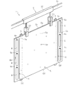
図1に示すように、本発明の一実施形態に係る板ガラスの製造装置に含まれる割断装置1は、第1領域Gaと第2領域Gbとの境界部の表面Gx側にスクライブ線Sが形成された板ガラスGを曲げ応力によってスクライブ線Sに沿って割断するものである。この実施形態では、板ガラスGには2本のスクライブ線Sが形成されており、各スクライブ線Sが上下方向を向くように板ガラスGが縦姿勢(好ましくは鉛直姿勢)で配置されている。また、この実施形態では、幅方向中央部が板ガラスGの必要な部分である第1領域Gaとされ、幅方向両端部のそれぞれが板ガラスGの不要な部分である第2領域Gbとされる。例えば、板ガラスGがオーバーフローダウンドロー法によって成形される場合、第1領域Gaは相対的に薄肉となる製品部分となり、第2領域Gbは相対的に厚肉となる部分を含む非製品部分となる。もちろん、第1領域Gaと第2領域Gbの両方が必要な部分とされてもよい。 As shown in FIG. 1, in the cleaving apparatus 1 included in the sheet glass manufacturing apparatus according to the embodiment of the present invention, the scribe line S is formed on the surface Gx side of the boundary portion between the first region Ga and the second region Gb. The formed glass sheet G is cleaved along the scribe line S by bending stress. In this embodiment, two scribe lines S are formed on the plate glass G, and the plate glass G is arranged in a vertical posture (preferably a vertical posture) so that each scribe line S faces the vertical direction. In this embodiment, the central portion in the width direction is a first region Ga that is a necessary portion of the plate glass G, and both end portions in the width direction are the second regions Gb that are unnecessary portions of the plate glass G. For example, when the glass sheet G is formed by the overflow downdraw method, the first region Ga is a product portion that is relatively thin, and the second region Gb is a non-product portion that includes a portion that is relatively thick. . Of course, both the first region Ga and the second region Gb may be required portions.
割断装置1は、板ガラスGを吊り下げ支持する第1支持装置2と、板ガラスGの第1領域Gaの裏面Gy側を支持する裏面支持部材3と、板ガラスGの第2領域Gbの表面Gxに沿って転動しながら板ガラスGの第2領域Gbの表面Gxを裏面Gy側に押し込む転動体4とを備えている。板ガラスGの表面Gx及び裏面Gyは、板ガラス2の厚み方向で互いに対向する主表面である。すなわち、表面Gxと裏面Gyは、2つの主表面を区別するための用語であり、上下方向を向いた面(上面、下面)を意味するものではない。
The cleaving device 1 includes a
第1支持装置2は、レール部材21と、レール部材21に沿ってスライド移動する移動体22と、移動体22に取り付けられた1又は複数の上部支持部材23とを備えている。
The
この実施形態では、複数(図示例は2つ)の上部支持部材23が1つの移動体22に取り付けられ、移動体22の移動に伴って複数の上部支持部材23が一体的にレール部材21に沿って移動するようになっている。レール部材21は板ガラスGの幅方向に沿って設けられているため、板ガラスGは表裏面に沿う幅方向に搬送される。なお、レール部材21を板ガラスGの表裏面に垂直な方向に設け、板ガラスGを表裏面に垂直な方向に搬送するようにしてもよい。
In this embodiment, a plurality of (two in the illustrated example)
この実施形態では、上部支持部材23は、板ガラスGの第1領域Gaにおいて表裏両側から板ガラスGの上部を挟持して保持するように構成されている。ここで、板ガラスGの上端縁Guは破損しやすいため、上部支持部材23は、板ガラスGの上端縁Guを避けた位置で板ガラスGと接触するように構成されていることが好ましい。なお、複数の上部支持部材23は、互いに接近および離反可能なように、それぞれ独立した移動体22に取り付けられていてもよい。このようにすれば、板ガラスGに幅方向に張力を付与することができたり、板ガラスGの大きさが変更された場合などでも板ガラスGの支持位置の調整が簡単になったりする等の利点がある。また、上部支持部材23は、板ガラスGの第1領域Gaにおいて板ガラスGの上部の片面のみを負圧吸着して保持するように構成されていてもよい。また、上部支持部材23は、移動体22に取り付けられている必要はなく、後述する折り割り動作の際に上端部Guを把持する形態でもよい。
In this embodiment, the
裏面支持部材3は、板ガラスGの第1領域Gaの裏面Gyにおける幅方向両端部において、スクライブ線Sから板ガラスGの幅方向に間隔を置いてスクライブ線Sと平行に配置されている。裏面支持部材3とスクライブ線Sとの幅方向の離間距離D1は、例えば、10〜30mm(好ましくは、10〜20mm)である(図2を参照)。この実施形態では、裏面支持部材3は、板ガラスGの第1領域Gaの裏面Gyを支持する支持面が平面で形成された板状体(定盤)である。なお、裏面支持部材3は、支持面が曲面で形成された丸棒状体などであってもよい。
The back
転動体4は、板ガラスGの各第2領域Gbにおいて、スクライブ線Sから板ガラスGの幅方向に間隔を置いて配置されている。転動体4が板ガラスGと最初に接触する位置における転動体4とスクライブ線Sとの幅方向の離間距離D2は、例えば、70〜130mmである(図2を参照)。この実施形態では、転動体4は、スクライブ線Sと平行な回転軸4aを有する円筒状のローラーからなる。転動体4の直径は、10〜30mmであることが好ましい。転動体4は、上下方向に複数(好ましくは3つ以上)に分割されている。分割された各転動体4は、それぞれの回転軸4aを中心として回転可能となっている。各転動体4の回転軸4aのそれぞれは、互いに連続する同一の軸であってもよいが、この実施形態では、同一直線上に位置する独立した軸である。各転動体4は、フリーローラーであって、板ガラスGの第2領域Gbの表面Gxとの接触によって生じる摩擦力によって、板ガラスGの第2領域Gbの表面Gxに沿って従動回転するようになっている。なお、転動体4は駆動回転させてもよい。また、転動体4は、上下方向に分割されておらず、1本のローラーで構成されていてもよい。さらに、転動体4は、板ガラスGの第2領域Gbの表面Gxに沿って転動可能であればローラーに限られるものではなく、例えば球状体(ボール)などであってもよい。
The rolling
転動体4の表面は、板ガラスGの第2領域Gbの表面Gxに傷が付きにくく、かつ、板ガラスGの第2領域Gbの表面Gxとの間に滑りが生じにくい材質で形成されていることが好ましい。転動体4の表面は、例えば、ゴム、シリコン、樹脂などの弾性体によって形成される。具体的には、転動体3の表面は、例えば、硬度40°〜70°の天然ゴムであることが好ましい。
The surface of the rolling
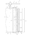
図2に示すように、スクライブ線Sは、上下方向(スクライブ線Sの長手方向)で対向する板ガラスGの上端部(上端縁Guを含む)および下端部(下端縁Gdを含む)を除く位置で、板ガラスGの第2領域Gbの表面Gxに形成されている。すなわち、スクライブ線Sの上端Suおよび下端Sdは、板ガラスGの上端縁Guおよび下端縁Gdから離れている。スクライブ線Sの上端Suと板ガラスGの上端縁Guとの上下方向の離間距離、及びスクライブ線Sの下端Sdと板ガラスGの下端縁Gdとの上下方向の離間距離D3は、例えば、10〜30mmである。 As shown in FIG. 2, the scribe line S is a position excluding the upper end portion (including the upper end edge Gu) and the lower end portion (including the lower end edge Gd) of the plate glass G facing in the vertical direction (longitudinal direction of the scribe line S). Thus, it is formed on the surface Gx of the second region Gb of the plate glass G. That is, the upper end Su and the lower end Sd of the scribe line S are separated from the upper end edge Gu and the lower end edge Gd of the glass sheet G. The vertical distance between the upper end Su of the scribe line S and the upper edge Gu of the glass sheet G, and the vertical distance D3 between the lower edge Sd of the scribe line S and the lower edge Gd of the glass sheet G are, for example, 10 to 30 mm. It is.
また、転動体4は、板ガラスGの上端部および下端部を除く位置で、板ガラスGの第2領域Gbの表面Gxと接触する。すなわち、転動体4と第2領域Gbの表面Gxとの接触部は、板ガラスGの上端縁Guおよび下端縁Gdから離れている。この実施形態では、一番高い位置にある転動体4の接触部と板ガラスGの上端縁Guとの上下方向の離間距離、及び一番低い位置にある転動体4の接触部と板ガラスGの下端縁Gdとの上下方向の離間距離D4は、例えば、10〜50mmである。
Moreover, the rolling
なお、D1、D2、D3及びD4の大きさは、上記に例示した数値範囲に限定されるものではなく、板ガラスGの大きさや厚みに応じて適宜調整することができる。 In addition, the magnitude | size of D1, D2, D3, and D4 is not limited to the numerical range illustrated above, It can adjust suitably according to the magnitude | size and thickness of the plate glass G. FIG.
さらに、この実施形態では、転動体4は、スクライブ線Sの上端部(上端Suを含む)および下端部(下端Sdを含む)を除くスクライブ線Sの形成範囲内のみで板ガラスGの第2領域Gbの表面Gxと接触する。換言すれば、板ガラスGの上下方向寸法L1>スクライブ線の上下方向寸法L2>転動体4と第2領域Gbの表面Gxとの接触部の上下方向寸法L3という大小関係が成立し、かつ、横方向から見た場合に、これら寸法関係を有する3つの領域のうち、上下方向寸法の大きい領域の両端部に、それよりも上下方向寸法の小さい領域の両端部が重なっていない。ここで、この実施形態では、転動体4は上下方向で複数に分割されているので、上下方向寸法L3は、各転動体4と第2領域Gbの表面Gxとの接触部の上下方向寸法L31,L32,L33の合計(L3=L31+L32+L33)である。なお、上下方向寸法L31,L32,L33は同じであってもよいし、異なっていてもよい。後者の場合、例えば、L32>L31=L33なる関係や、L32<L31=L33なる関係を満たすようにしてもよい。
Furthermore, in this embodiment, the rolling
この実施形態では、裏面支持部材3は、板ガラスGの第1領域Gaの裏面Gyにおける上下方向の全域を支持するように、板ガラスGの上端部及び下端部から上下に食み出している。すなわち、裏面支持部材3の上下方向寸法L4は板ガラスGの上下方向寸法L1よりも長い。なお、裏面支持部材3で板ガラスGの第1領域Gaの裏面Gyの上下方向全域を支持する場合、L4はL1と等しくてもよい。また、L4をL1よりも小さくし、裏面支持部材3が、板ガラスGの上端部及び下端部を除く位置で、板ガラスGの第1領域Gaの裏面Gyと接触するようにしてもよい。
In this embodiment, the back
図3に示すように、この実施形態では、割断後に、板ガラスGの第2領域Gbが板ガラスGの第1領域Gaの近傍で落下するのを防止するために、第2領域Gbの裏面Gy側が第2支持装置5によって支持されている。第2支持装置5は、ロボットアーム51と、ロボットアーム51の先端に取り付けられたバキュームカップ(吸盤)52とを備えている。ロボットアーム51は、転動体4による板ガラスGの第2領域Gbの押し込み動作を阻害しないように、バキュームカップ52の位置を板ガラスGの裏面Gy側に後退するように調整する。また、ロボットアーム51は、必要に応じて、バキュームカップ52の角度も調整する。バキュームカップ52は、板ガラスGの撓み変形に応じて変形可能なゴムなどの弾性体からなり、板ガラスGの第2領域Gbの裏面Gyを負圧吸着して保持する。なお、転動を伴う転動体4の押し込み動作を阻害しなければ、第2支持装置5は、例えば、板ガラスGを表裏両側から挟持して支持するように構成されていてもよい。第2支持装置5は省略してもよい。
As shown in FIG. 3, in this embodiment, in order to prevent the second region Gb of the plate glass G from dropping in the vicinity of the first region Ga of the plate glass G after cleaving, the back surface Gy side of the second region Gb is It is supported by the
次に、以上のように構成された板ガラスの製造装置を用いた板ガラスの製造方法を説明する。 Next, the manufacturing method of the plate glass using the plate glass manufacturing apparatus comprised as mentioned above is demonstrated.
まず、図1に示す位置の上流側の工程において、板ガラスGの上部を第1支持装置2の上部支持部材23によって支持した状態で、ホイールカッターによる押圧やレーザーの照射等により、板ガラスGの表面Gxにスクライブ線Sが形成される。スクライブ線Sは、板ガラスGの上端部および下端部を除外して、板ガラスGの上下方向に沿って直線状に形成される。ここで、板ガラスGの厚みは、例えば、0.7mm以下であり、好ましくは0.2mm〜0.5mmであり、より好ましくは0.2mm〜0.3mmである。
First, in the process on the upstream side of the position shown in FIG. 1, the surface of the plate glass G is pressed by a wheel cutter, laser irradiation, or the like while the upper portion of the plate glass G is supported by the
次に、スクライブ線Sが形成された板ガラスGの上部を第1支持装置2の上部支持部材23で支持した状態のまま、レール部材21に沿って移動体22を移動させて板ガラスGを搬送した後、図1に示す位置で停止させる。板ガラスGが停止すると、図3に示すように、裏面支持部材3が板ガラスGの第1領域Gaの裏面Gy側に接近して接触するとともに、転動体4が第2領域Gbの表面Gx側に接近して接触する。さらに、この実施形態では、第2領域Gbの裏面Gy側が第2支持装置5のロボットアーム51の先端に取り付けられたバキュームカップ52によって吸着される。
Next, the moving
この状態で、図4(a)〜(c)に示すように、転動体4で板ガラスGの第2領域Gbの表面Gxを裏面Gy側に押し込む。
In this state, as shown in FIGS. 4A to 4C, the rolling
詳細には、まず、図4(a)に示すように、転動体4は、板ガラスGの第2領域Gbの表面Gxに当接する。このとき、転動体4と板ガラスGの第2領域Gbの表面Gxは点P1で接触する。説明の便宜上、図4(a)における板ガラスGの状態を初期状態とよぶ。
Specifically, first, as shown in FIG. 4A, the rolling
次に、図4(b)に示すように、転動体4は、初期状態の板ガラスGの第2領域Gbの表面Gxに垂直なX方向(板厚方向)に直進移動する。これにより、裏面支持部材3を起点として板ガラスGの第2領域Gbは撓む。この過程で、X方向に移動する転動体4は、板ガラスGとの間に生じる摩擦によって第2領域Gbの表面Gxに沿って転動しながら、板ガラスGに対する相対位置を幅方向外側(スクライブ線Sから離反するY方向)に移動させる。これに伴い、板ガラスGと転動体4の接触位置は、例えば、点P1と点P2の間を点P1から点P2に向かって連続的に変化する。そのため、板ガラスG(第2領域Gb)に撓みが生じても、転動体4は、転動しながら板ガラスGに対する接触位置を順次変化させ、板ガラスGの撓み変形に追従する。したがって、転動体4と板ガラスGの接触状態が安定し、転動体4と板ガラスGの間に不当な滑りは生じにくい。よって、板ガラスGに撓みが生じても、裏面支持部材3の近傍に形成されたスクライブ線Sに曲げ応力が十分作用する。
Next, as illustrated in FIG. 4B, the rolling
そして、図4(c)に示すように、図4(b)の状態から転動体4を更にX方向に移動させると、転動体4の転動を伴いながら、板ガラスGに対する転動体4の相対的な接触位置は、幅方向外方側(Y方向)に更に移動し、例えば、点P2と点P3の間を点P2から点P3に向かって連続的に変化する。このような転動体4の動作により、スクライブ線Sに作用する曲げ応力は更に大きくなり、板ガラスGをスクライブ線Sに沿って確実に割断することができる。
Then, as shown in FIG. 4C, when the rolling
なお、転動体4は、この実施形態ではX方向に一定速度で直進移動するが、X方向に速度を変えながら直進移動してもよい。
In this embodiment, the rolling
また、転動体4は、初期状態の板ガラスGの表面Gxに垂直なX方向に直進移動させる代わりに、X方向と角度をなす斜め方向に直進移動させてもよい。この場合、転動体4を、板ガラスGの裏面Gy側に向かうに従って幅方向外方側に移行するように斜めに移動させてもよいし、板ガラスGの裏面Gy側に向かうに従って幅方向内方側に移行するように斜めに移動させてもよい。前者の場合、転動体4は、板ガラスGとの間に生じる摩擦によって第2領域Gbの表面Gxに沿って幅方向外方側に転動する。また、後者の場合、転動体4は、板ガラスGとの間に生じる摩擦によって第2領域Gbの表面Gxに沿って幅方向内方側に転動する。
Further, instead of moving the rolling
この実施形態では、上記のように転動体4を押し込む際に、図2に示すように、スクライブ線Sや転動体4が板ガラスGの上端縁Gu及び下端縁Gdから離れているため、板ガラスGの上端縁Gu及び下端縁Gdを起点とする不当な割れを防止できる。
In this embodiment, when the rolling
また、この実施形態では、上記のように転動体4を押し込む際に、図2に示すように、スクライブ線Sが板ガラスGの上端縁Gu及び下端縁Gdから離れた位置に形成された状態で、スクライブ線Sの上端部及び下端部を除くスクライブ線Sの形成範囲内(上端Suよりも下方かつ下端Sdよりも上方の領域内)のみで、転動体4が板ガラスGの第2領域Gbの表面Gxを裏面Gy側に押し込む。このような態様で転動体4を押し込むことで、スクライブ線Sに作用する曲げ応力がより適正なものとなり、スクライブ線Sに沿った正確な割断をより確実に実現させることができる。なお、このような態様で割断した場合、スクライブ線Sのうち、中央側領域が初めに割断された後、その割断された領域が上下方向に進展し、スクライブ線Sに沿って板ガラスGの上下方向全域が割断されると考えられる。
Further, in this embodiment, when the rolling
ここで、図4(c)に示すように、板ガラスGが割断された後、板ガラスGの第2領域Gbは落下することなく、ロボットアーム51のバキュームカップ52によって吸着支持された状態を維持する。板ガラスGの第1領域Gaから分離された第2領域Gbは、例えば、板ガラスGの第1領域Gaに影響が生じない位置で、バキュームカップ52の吸着が解除されて落下回収される。
Here, as shown in FIG. 4C, after the plate glass G is cut, the second region Gb of the plate glass G does not fall and maintains the state of being sucked and supported by the
そして、板ガラスGが上述のように割断されると、上部支持部材23によって支持された板ガラスGの第1領域Gaは、後続の製造関連処理(トリミング、面取り等の端面加工、洗浄、成膜など)を施すために、レール部材21に沿った移動体22の移動によって図1に示す位置から下流側の工程へと搬送される。
When the plate glass G is cleaved as described above, the first region Ga of the plate glass G supported by the
以上、本発明の実施形態に係る板ガラスの製造装置及びその製造方法について説明したが、本発明の実施の形態はこれに限定されるわけではなく、本発明の要旨を逸脱しない範囲で種々変更を施すことが可能である。 As mentioned above, although the manufacturing apparatus and the manufacturing method of the plate glass which concern on embodiment of this invention were demonstrated, embodiment of this invention is not necessarily limited to this, In the range which does not deviate from the summary of this invention, various changes are carried out. It is possible to apply.
上記の実施形態において、板ガラスの製造装置(又は製造方法)は、割断装置1の上流側に、溶融ガラスから板ガラスを成形する成形装置(又は成形工程)を更に備えていてもよい。成形装置は、オーバーフローダウンドロー法やフロート法などによって板ガラスGを成形する。ただし、上記の実施形態のように、板ガラスGを吊り下げ支持して縦姿勢の状態で、搬送及び割断する場合には、板ガラスGはオーバーフローダウンドロー法によって成形するのが好ましい。オーバーフローダウンドロー法の場合、板ガラスGが縦姿勢で成形されるので、板ガラスGの搬送及び割断に際して、板ガラスGの大きな姿勢変換が必要ないためである。この場合、製造装置(又は製造方法)は、割断装置1の上流側に、長尺なガラスリボンを所定長さ毎に幅方向に切断(曲げ応力割断、レーザー割断など)する切断装置(又は切断工程)を更に備えていてもよい。 In said embodiment, the manufacturing apparatus (or manufacturing method) of plate glass may further be equipped with the shaping | molding apparatus (or shaping | molding process) which shape | molds plate glass from molten glass in the upstream of the cleaving apparatus 1. FIG. The forming apparatus forms the glass sheet G by an overflow downdraw method, a float method, or the like. However, as in the above-described embodiment, when the glass sheet G is suspended and supported and conveyed and cut in a vertical posture, the glass sheet G is preferably formed by the overflow down draw method. This is because, in the overflow downdraw method, the plate glass G is formed in a vertical posture, so that a large posture change of the plate glass G is not necessary when the plate glass G is conveyed and cleaved. In this case, the manufacturing apparatus (or manufacturing method) is a cutting apparatus (or cutting) that cuts a long glass ribbon in the width direction for every predetermined length (bending stress cleaving, laser cleaving, etc.) upstream of the cleaving apparatus 1. Step) may be further provided.
上記の実施形態において、板ガラスGの姿勢は、横姿勢(好ましくは水平姿勢)であってもよい。この場合、板ガラスGの下面を裏面支持部材3で支持した状態で、板ガラスGの上面を転動体4によって下面側(下方)に押し込むことが好ましい。このようにすれば、板ガラスGを割断した後、その位置で板ガラスGの第2領域Gbを落下させても、板ガラスGの第1領域Gaに接触する事態が生じにくい。なお、第2領域Gbを支持する第2支持装置5は省略してもよい。また、板ガラスGの上面を裏面支持部材3で支持した状態で、板ガラスGの下面を転動体4によって上面側(上方)に押し込むようにしてもよい。なお、板ガラスGの姿勢は、鉛直面や水平面に対して傾斜した傾斜姿勢でもよい。
In said embodiment, the attitude | position of the plate glass G may be a horizontal attitude | position (preferably horizontal attitude | position). In this case, it is preferable to push the upper surface of the plate glass G into the lower surface side (downward) by the rolling
1 割断装置
2 第1支持装置
21 レール部材
22 移動体
23 上部支持部材
3 裏面支持部材
4 転動体
4a 回転軸
5 第2支持装置
51 ロボットアーム
52 バキュームカップ
G 板ガラス
Ga 板ガラスの第1領域
Gb 板ガラスの第2領域
S スクライブ線
DESCRIPTION OF SYMBOLS 1
Claims (9)
前記割断工程で、前記第1領域の裏面を裏面支持部材で支持した状態で、転動体を前記第2領域の表面に沿って転動させながら、前記転動体で前記第2領域を裏面側に押し込むことによって、前記スクライブ線に沿って前記板ガラスを割断することを特徴とする板ガラスの製造方法。 In the manufacturing method of plate glass including a cleaving step of forming a scribe line on the surface side of the boundary portion between the first region and the second region of the plate glass and cleaving the plate glass along the scribe line,
In the cleaving step, in a state where the back surface of the first region is supported by a back surface support member, while rolling the rolling element along the surface of the second region, the second region is moved to the back surface side by the rolling element. A plate glass manufacturing method characterized by cleaving the plate glass along the scribe line by pressing.
前記割断装置は、前記第1領域の裏面側を支持する裏面支持部材と、前記スクライブ線に沿って前記板ガラスを割断するために、前記第2領域の表面に沿って転動しながら前記第2領域を裏面側に押し込む転動体とを備えていることを特徴とする板ガラスの製造装置。 In the manufacturing apparatus of the plate glass provided with the cleaving apparatus which cleaves the plate glass in which the scribe line was formed in the surface side of the boundary part of the 1st field and the 2nd field along the scribe line,
The cleaving device rolls along the surface of the second region in order to cleave the plate glass along the scribe line with a back surface supporting member that supports the back surface side of the first region, and the second device. An apparatus for producing plate glass, comprising: a rolling element that pushes the region into the back side.
Priority Applications (1)
| Application Number | Priority Date | Filing Date | Title |
|---|---|---|---|
| JP2016121513A JP6738557B2 (en) | 2016-06-20 | 2016-06-20 | Sheet glass manufacturing method and manufacturing apparatus thereof |
Applications Claiming Priority (1)
| Application Number | Priority Date | Filing Date | Title |
|---|---|---|---|
| JP2016121513A JP6738557B2 (en) | 2016-06-20 | 2016-06-20 | Sheet glass manufacturing method and manufacturing apparatus thereof |
Publications (2)
| Publication Number | Publication Date |
|---|---|
| JP2017226549A true JP2017226549A (en) | 2017-12-28 |
| JP6738557B2 JP6738557B2 (en) | 2020-08-12 |
Family
ID=60889089
Family Applications (1)
| Application Number | Title | Priority Date | Filing Date |
|---|---|---|---|
| JP2016121513A Active JP6738557B2 (en) | 2016-06-20 | 2016-06-20 | Sheet glass manufacturing method and manufacturing apparatus thereof |
Country Status (1)
| Country | Link |
|---|---|
| JP (1) | JP6738557B2 (en) |
Cited By (11)
| Publication number | Priority date | Publication date | Assignee | Title |
|---|---|---|---|---|
| CN110682450A (en) * | 2019-10-17 | 2020-01-14 | 黄沄沄 | Glass processing device and processing method |
| WO2020084840A1 (en) * | 2018-10-22 | 2020-04-30 | 坂東機工株式会社 | Glass plate cutting/breaking machine |
| JP2020176038A (en) * | 2019-04-22 | 2020-10-29 | 日本電気硝子株式会社 | Apparatus and method for manufacturing glass plate |
| WO2021070579A1 (en) * | 2019-10-08 | 2021-04-15 | 日本電気硝子株式会社 | Method for producing plate glass and production device therefor |
| WO2021085052A1 (en) * | 2019-10-29 | 2021-05-06 | 日本電気硝子株式会社 | Method for manufacturing glass plate and apparatus for manufacturing same |
| CN112960898A (en) * | 2021-03-02 | 2021-06-15 | 甘肃光轩高端装备产业有限公司 | Glass separation apparatus and method |
| WO2021261087A1 (en) * | 2020-06-23 | 2021-12-30 | 日本電気硝子株式会社 | Method for manufacturing glass plate and apparatus for manufacturing same |
| CN114302866A (en) * | 2019-10-08 | 2022-04-08 | 日本电气硝子株式会社 | Method and apparatus for manufacturing sheet glass |
| WO2022097324A1 (en) * | 2020-11-06 | 2022-05-12 | 日本電気硝子株式会社 | Plate glass production method, production device therefor, and plate glass |
| WO2022097352A1 (en) * | 2020-11-06 | 2022-05-12 | 日本電気硝子株式会社 | Method for producing plate glass and apparatus for producing same |
| WO2022130750A1 (en) * | 2020-12-18 | 2022-06-23 | 日本電気硝子株式会社 | Plate glass production method and splitting device |
Citations (4)
| Publication number | Priority date | Publication date | Assignee | Title |
|---|---|---|---|---|
| JP2006124194A (en) * | 2004-10-26 | 2006-05-18 | Nippon Electric Glass Co Ltd | Method for cutting and separating glass plate and apparatus therefor |
| JP2012131706A (en) * | 2010-01-04 | 2012-07-12 | Asahi Glass Co Ltd | Cutting line processing device for sheet glass and cutting line processing method thereof |
| WO2014017577A1 (en) * | 2012-07-27 | 2014-01-30 | 日本電気硝子株式会社 | Sheet glass, method for manufacturing sheet glass, and device for manufacturing sheet glass |
| JP2016104683A (en) * | 2014-11-19 | 2016-06-09 | 坂東機工株式会社 | Splitting method of glass sheet, and splitting device therefor |
-
2016
- 2016-06-20 JP JP2016121513A patent/JP6738557B2/en active Active
Patent Citations (4)
| Publication number | Priority date | Publication date | Assignee | Title |
|---|---|---|---|---|
| JP2006124194A (en) * | 2004-10-26 | 2006-05-18 | Nippon Electric Glass Co Ltd | Method for cutting and separating glass plate and apparatus therefor |
| JP2012131706A (en) * | 2010-01-04 | 2012-07-12 | Asahi Glass Co Ltd | Cutting line processing device for sheet glass and cutting line processing method thereof |
| WO2014017577A1 (en) * | 2012-07-27 | 2014-01-30 | 日本電気硝子株式会社 | Sheet glass, method for manufacturing sheet glass, and device for manufacturing sheet glass |
| JP2016104683A (en) * | 2014-11-19 | 2016-06-09 | 坂東機工株式会社 | Splitting method of glass sheet, and splitting device therefor |
Cited By (23)
| Publication number | Priority date | Publication date | Assignee | Title |
|---|---|---|---|---|
| WO2020084840A1 (en) * | 2018-10-22 | 2020-04-30 | 坂東機工株式会社 | Glass plate cutting/breaking machine |
| CN111356660A (en) * | 2018-10-22 | 2020-06-30 | 坂东机工株式会社 | Glass plate breaking machine |
| US11591251B2 (en) | 2018-10-22 | 2023-02-28 | Bando Kiko Co., Ltd. | Glass plate bend-breaking machine |
| JP2020176038A (en) * | 2019-04-22 | 2020-10-29 | 日本電気硝子株式会社 | Apparatus and method for manufacturing glass plate |
| WO2020217910A1 (en) * | 2019-04-22 | 2020-10-29 | 日本電気硝子株式会社 | Glass plate production device and production method |
| JP7276654B2 (en) | 2019-04-22 | 2023-05-18 | 日本電気硝子株式会社 | Glass plate manufacturing apparatus and manufacturing method |
| CN114302866A (en) * | 2019-10-08 | 2022-04-08 | 日本电气硝子株式会社 | Method and apparatus for manufacturing sheet glass |
| JP7336071B2 (en) | 2019-10-08 | 2023-08-31 | 日本電気硝子株式会社 | Sheet glass manufacturing method and its manufacturing apparatus |
| WO2021070579A1 (en) * | 2019-10-08 | 2021-04-15 | 日本電気硝子株式会社 | Method for producing plate glass and production device therefor |
| KR20220080072A (en) | 2019-10-08 | 2022-06-14 | 니폰 덴키 가라스 가부시키가이샤 | Manufacturing method of flat glass and its manufacturing apparatus |
| KR20220079515A (en) | 2019-10-08 | 2022-06-13 | 니폰 덴키 가라스 가부시키가이샤 | Manufacturing method of flat glass and its manufacturing apparatus |
| CN110682450B (en) * | 2019-10-17 | 2021-04-09 | 江门市江海区金颖钢化玻璃有限公司 | Glass processing device and processing method |
| CN110682450A (en) * | 2019-10-17 | 2020-01-14 | 黄沄沄 | Glass processing device and processing method |
| CN114025931A (en) * | 2019-10-29 | 2022-02-08 | 日本电气硝子株式会社 | Method for producing glass plate and apparatus for producing glass plate |
| WO2021085052A1 (en) * | 2019-10-29 | 2021-05-06 | 日本電気硝子株式会社 | Method for manufacturing glass plate and apparatus for manufacturing same |
| WO2021261087A1 (en) * | 2020-06-23 | 2021-12-30 | 日本電気硝子株式会社 | Method for manufacturing glass plate and apparatus for manufacturing same |
| CN115427362A (en) * | 2020-06-23 | 2022-12-02 | 日本电气硝子株式会社 | Method and apparatus for manufacturing glass plate |
| WO2022097324A1 (en) * | 2020-11-06 | 2022-05-12 | 日本電気硝子株式会社 | Plate glass production method, production device therefor, and plate glass |
| WO2022097352A1 (en) * | 2020-11-06 | 2022-05-12 | 日本電気硝子株式会社 | Method for producing plate glass and apparatus for producing same |
| KR20230098772A (en) | 2020-11-06 | 2023-07-04 | 니폰 덴키 가라스 가부시키가이샤 | Plate glass manufacturing method, its manufacturing device, and plate glass |
| WO2022130750A1 (en) * | 2020-12-18 | 2022-06-23 | 日本電気硝子株式会社 | Plate glass production method and splitting device |
| KR20230122051A (en) | 2020-12-18 | 2023-08-22 | 니폰 덴키 가라스 가부시키가이샤 | Plate glass manufacturing method and cutting device |
| CN112960898A (en) * | 2021-03-02 | 2021-06-15 | 甘肃光轩高端装备产业有限公司 | Glass separation apparatus and method |
Also Published As
| Publication number | Publication date |
|---|---|
| JP6738557B2 (en) | 2020-08-12 |
Similar Documents
| Publication | Publication Date | Title |
|---|---|---|
| JP2017226549A (en) | Manufacturing method of sheet glass and manufacturing apparatus of the same | |
| JP4947488B2 (en) | Glass plate manufacturing method and apparatus | |
| JP6641672B2 (en) | Glass plate manufacturing equipment | |
| US11472728B2 (en) | Method for manufacturing glass plate and manufacturing apparatus therefor | |
| US8820599B2 (en) | Method and apparatus for removing peripheral portion of a glass sheet | |
| JP2012246217A (en) | Method and apparatus for reducing stress variation in glass sheet produced from glass ribbon | |
| KR20120046086A (en) | Method and apparatus for cutting glass ribbon | |
| KR20150087277A (en) | Separation apparatuses and methods for separating glass sheets from glass ribbons | |
| CN104803591B (en) | Scoring device | |
| WO2018168331A1 (en) | Method for manufacturing plate glass and plate glass snapping device | |
| TWI487676B (en) | Glass plate manufacturing method | |
| WO2013035528A1 (en) | Method and apparatus for cutting band-shaped plate glass | |
| WO2018100978A1 (en) | Method for producing sheet glass and device for snap-cutting sheet glass | |
| JP6032428B2 (en) | Glass film cutting apparatus and glass film cutting method | |
| JP5012923B2 (en) | Sheet glass cutting apparatus and method | |
| WO2021070579A1 (en) | Method for producing plate glass and production device therefor | |
| JP6647680B2 (en) | Method and apparatus for manufacturing glass plate | |
| US20220048806A1 (en) | System and method for handling and removing a peripheral region of a glass sheet | |
| JP7417853B2 (en) | Glass plate manufacturing method | |
| CN107922238B (en) | Cutting device and cutting method for non-metal material using roller | |
| CN105293039A (en) | Substrate transferring device |
Legal Events
| Date | Code | Title | Description |
|---|---|---|---|
| A621 | Written request for application examination |
Free format text: JAPANESE INTERMEDIATE CODE: A621 Effective date: 20190219 |
|
| A977 | Report on retrieval |
Free format text: JAPANESE INTERMEDIATE CODE: A971007 Effective date: 20191024 |
|
| A131 | Notification of reasons for refusal |
Free format text: JAPANESE INTERMEDIATE CODE: A131 Effective date: 20191029 |
|
| A601 | Written request for extension of time |
Free format text: JAPANESE INTERMEDIATE CODE: A601 Effective date: 20191216 |
|
| A521 | Request for written amendment filed |
Free format text: JAPANESE INTERMEDIATE CODE: A523 Effective date: 20200203 |
|
| TRDD | Decision of grant or rejection written | ||
| A01 | Written decision to grant a patent or to grant a registration (utility model) |
Free format text: JAPANESE INTERMEDIATE CODE: A01 Effective date: 20200619 |
|
| A61 | First payment of annual fees (during grant procedure) |
Free format text: JAPANESE INTERMEDIATE CODE: A61 Effective date: 20200702 |
|
| R150 | Certificate of patent or registration of utility model |
Ref document number: 6738557 Country of ref document: JP Free format text: JAPANESE INTERMEDIATE CODE: R150 |