WO2018168331A1 - Method for manufacturing plate glass and plate glass snapping device - Google Patents
Method for manufacturing plate glass and plate glass snapping device Download PDFInfo
- Publication number
- WO2018168331A1 WO2018168331A1 PCT/JP2018/005602 JP2018005602W WO2018168331A1 WO 2018168331 A1 WO2018168331 A1 WO 2018168331A1 JP 2018005602 W JP2018005602 W JP 2018005602W WO 2018168331 A1 WO2018168331 A1 WO 2018168331A1
- Authority
- WO
- WIPO (PCT)
- Prior art keywords
- plate glass
- product part
- adsorption
- product
- suction
- Prior art date
Links
- 239000005357 flat glass Substances 0.000 title claims abstract description 97
- 238000000034 method Methods 0.000 title claims abstract description 26
- 238000004519 manufacturing process Methods 0.000 title claims abstract description 15
- 238000001179 sorption measurement Methods 0.000 claims description 81
- 238000003825 pressing Methods 0.000 claims description 40
- 239000011521 glass Substances 0.000 description 15
- 229920001971 elastomer Polymers 0.000 description 9
- 239000005060 rubber Substances 0.000 description 9
- 238000005452 bending Methods 0.000 description 5
- 230000000694 effects Effects 0.000 description 5
- 238000013459 approach Methods 0.000 description 3
- 238000005520 cutting process Methods 0.000 description 3
- JOYRKODLDBILNP-UHFFFAOYSA-N Ethyl urethane Chemical compound CCOC(N)=O JOYRKODLDBILNP-UHFFFAOYSA-N 0.000 description 1
- 244000043261 Hevea brasiliensis Species 0.000 description 1
- 239000004677 Nylon Substances 0.000 description 1
- 238000006124 Pilkington process Methods 0.000 description 1
- 230000001174 ascending effect Effects 0.000 description 1
- 230000015572 biosynthetic process Effects 0.000 description 1
- 239000006059 cover glass Substances 0.000 description 1
- 230000005611 electricity Effects 0.000 description 1
- 239000000835 fiber Substances 0.000 description 1
- -1 for example Polymers 0.000 description 1
- 238000005816 glass manufacturing process Methods 0.000 description 1
- 239000004973 liquid crystal related substance Substances 0.000 description 1
- 238000012986 modification Methods 0.000 description 1
- 230000004048 modification Effects 0.000 description 1
- 229920003052 natural elastomer Polymers 0.000 description 1
- 229920001194 natural rubber Polymers 0.000 description 1
- 229920001778 nylon Polymers 0.000 description 1
- 238000007500 overflow downdraw method Methods 0.000 description 1
- 238000013001 point bending Methods 0.000 description 1
- 238000012805 post-processing Methods 0.000 description 1
- 239000011347 resin Substances 0.000 description 1
- 229920005989 resin Polymers 0.000 description 1
- 230000000630 rising effect Effects 0.000 description 1
- 230000003068 static effect Effects 0.000 description 1
- 239000000758 substrate Substances 0.000 description 1
- 229920003051 synthetic elastomer Polymers 0.000 description 1
- 239000005061 synthetic rubber Substances 0.000 description 1
- 238000009966 trimming Methods 0.000 description 1
Images


Classifications
-
- B—PERFORMING OPERATIONS; TRANSPORTING
- B26—HAND CUTTING TOOLS; CUTTING; SEVERING
- B26F—PERFORATING; PUNCHING; CUTTING-OUT; STAMPING-OUT; SEVERING BY MEANS OTHER THAN CUTTING
- B26F3/00—Severing by means other than cutting; Apparatus therefor
-
- B—PERFORMING OPERATIONS; TRANSPORTING
- B28—WORKING CEMENT, CLAY, OR STONE
- B28D—WORKING STONE OR STONE-LIKE MATERIALS
- B28D5/00—Fine working of gems, jewels, crystals, e.g. of semiconductor material; apparatus or devices therefor
-
- B—PERFORMING OPERATIONS; TRANSPORTING
- B28—WORKING CEMENT, CLAY, OR STONE
- B28D—WORKING STONE OR STONE-LIKE MATERIALS
- B28D7/00—Accessories specially adapted for use with machines or devices of the preceding groups
- B28D7/04—Accessories specially adapted for use with machines or devices of the preceding groups for supporting or holding work or conveying or discharging work
-
- C—CHEMISTRY; METALLURGY
- C03—GLASS; MINERAL OR SLAG WOOL
- C03B—MANUFACTURE, SHAPING, OR SUPPLEMENTARY PROCESSES
- C03B33/00—Severing cooled glass
- C03B33/02—Cutting or splitting sheet glass or ribbons; Apparatus or machines therefor
- C03B33/023—Cutting or splitting sheet glass or ribbons; Apparatus or machines therefor the sheet or ribbon being in a horizontal position
- C03B33/033—Apparatus for opening score lines in glass sheets
-
- C—CHEMISTRY; METALLURGY
- C03—GLASS; MINERAL OR SLAG WOOL
- C03B—MANUFACTURE, SHAPING, OR SUPPLEMENTARY PROCESSES
- C03B33/00—Severing cooled glass
- C03B33/02—Cutting or splitting sheet glass or ribbons; Apparatus or machines therefor
- C03B33/023—Cutting or splitting sheet glass or ribbons; Apparatus or machines therefor the sheet or ribbon being in a horizontal position
- C03B33/037—Controlling or regulating
-
- G—PHYSICS
- G02—OPTICS
- G02F—OPTICAL DEVICES OR ARRANGEMENTS FOR THE CONTROL OF LIGHT BY MODIFICATION OF THE OPTICAL PROPERTIES OF THE MEDIA OF THE ELEMENTS INVOLVED THEREIN; NON-LINEAR OPTICS; FREQUENCY-CHANGING OF LIGHT; OPTICAL LOGIC ELEMENTS; OPTICAL ANALOGUE/DIGITAL CONVERTERS
- G02F1/00—Devices or arrangements for the control of the intensity, colour, phase, polarisation or direction of light arriving from an independent light source, e.g. switching, gating or modulating; Non-linear optics
- G02F1/01—Devices or arrangements for the control of the intensity, colour, phase, polarisation or direction of light arriving from an independent light source, e.g. switching, gating or modulating; Non-linear optics for the control of the intensity, phase, polarisation or colour
- G02F1/13—Devices or arrangements for the control of the intensity, colour, phase, polarisation or direction of light arriving from an independent light source, e.g. switching, gating or modulating; Non-linear optics for the control of the intensity, phase, polarisation or colour based on liquid crystals, e.g. single liquid crystal display cells
-
- G—PHYSICS
- G09—EDUCATION; CRYPTOGRAPHY; DISPLAY; ADVERTISING; SEALS
- G09F—DISPLAYING; ADVERTISING; SIGNS; LABELS OR NAME-PLATES; SEALS
- G09F9/00—Indicating arrangements for variable information in which the information is built-up on a support by selection or combination of individual elements
-
- H—ELECTRICITY
- H05—ELECTRIC TECHNIQUES NOT OTHERWISE PROVIDED FOR
- H05B—ELECTRIC HEATING; ELECTRIC LIGHT SOURCES NOT OTHERWISE PROVIDED FOR; CIRCUIT ARRANGEMENTS FOR ELECTRIC LIGHT SOURCES, IN GENERAL
- H05B33/00—Electroluminescent light sources
- H05B33/02—Details
-
- H—ELECTRICITY
- H05—ELECTRIC TECHNIQUES NOT OTHERWISE PROVIDED FOR
- H05B—ELECTRIC HEATING; ELECTRIC LIGHT SOURCES NOT OTHERWISE PROVIDED FOR; CIRCUIT ARRANGEMENTS FOR ELECTRIC LIGHT SOURCES, IN GENERAL
- H05B33/00—Electroluminescent light sources
- H05B33/02—Details
- H05B33/04—Sealing arrangements, e.g. against humidity
Definitions
- the present invention relates to a plate glass manufacturing method and a plate glass folding apparatus.
- plate glass is used in various fields as represented by glass substrates for flat panel displays (FPD) such as liquid crystal displays, plasma displays, and organic EL displays, and cover glasses for organic EL lighting.
- the plate glass manufacturing process includes a folding (cleaving) step of cutting a small area plate glass from a large area plate glass (mother glass) or trimming an edge along the side of the plate glass.
- a scribe line is formed on the first main surface (for example, the upper surface) of the glass sheet at the boundary between the product part and the non-product part of the glass sheet to be folded, and then bending stress centered on the scribe line. Fold the plate glass along the scribe line.
- the non-product part is removed by adsorbing a suction member such as a suction pad to the non-product part.
- the removed non-product part is transferred to a disposal conveyance path by an adsorption member, for example, and transferred to a disposal port (see, for example, Patent Document 1).
- the non-product part may contact the product part and the product part may be chipped. This is due to the following reason.
- the folding member in order to apply a bending stress around the scribe line to the plate glass, the folding member is pushed into the plate glass from the second main surface side of the plate glass at a position corresponding to the scribe line, and the plate glass is folded. Even after being pressed, the folded member is kept pressed until the suction member is sucked to the non-product portion. Therefore, until the non-product part adsorbs the adsorbing member, the cut end surfaces of the product part and the non-product part are separated from each other.
- the non-product part may be pushed by the adsorbing member to bend and come into contact with the product part. is there.
- the manufacturing method of the sheet glass concerning the present invention created in order to solve the above-mentioned subject, the arrangement process which arranges the sheet glass which has the product part which makes the boundary the scribe line formed in the 1st principal surface, and the non-product part, Of the plate glass, the first main surface of the product part is pressed with a first pressing member, and the first main surface of the non-product part is pressed with a second pressing member, corresponding to the scribe line.
- the adsorption member is inclined along the inclined portion of the non-product portion.
- “to be along the inclined portion” includes not only strictly along the inclined portion but also a case where it is slightly deviated from the inclined portion (hereinafter the same). A preferable inclination angle of the adsorption member will be described later.
- the suction portion of the suction member is inclined along the inclined portion of the non-product portion, the non-product portion is pushed by the suction member and curved when the suction member is sucked by the non-product portion. It is possible to suppress the occurrence of chipping in the product part due to the non-product part coming into contact with the product part.
- the adsorption member in the adsorption step, may be adsorbed by approaching along the perpendicular of the adsorption surface.
- “to be along the vertical line” includes not only strictly along the vertical line but also a case where it is slightly deviated from the vertical line (hereinafter the same).
- the non-product portion is further suppressed from being bent by being pushed by the adsorption member, and the non-product portion comes into contact with the product portion and is missing from the product portion. Can be further suppressed.
- the suction member may be moved along a perpendicular of the suction surface in the moving step.
- This configuration can reduce the possibility that the non-product part contacts the product part when the non-product part is moved by the adsorption member.
- the adsorption member may be disposed closer to the product portion than the second pressing member.
- the adsorption member can be disposed closer to the product portion.
- the suction member disposed near the product portion is likely to cause the non-product portion to contact the product portion. Therefore, the above-described effect due to the suction surface of the suction member being inclined can be more effective.
- the inclination angle of the suction surface of the suction member may be changeable.
- the pushing state of the folding member and the positions of the first pressing member and the second pressing member are changed.
- the inclination angle of the inclined part of the non-product part also changes. If the inclination angle of the adsorption surface of the adsorption member can be changed, the adsorption surface of the adsorption member can be inclined so as to be parallel to the inclined portion of the non-product part even if the folding condition is changed.
- a plurality of the adsorption members are arranged side by side in a direction perpendicular to the scribe line and parallel to the first main surface of the plate glass, and the distance from the product portion is the shortest among the adsorption members.
- the adsorption member may be inclined.
- a sheet glass folding device which was created to solve the above-described problems, includes a plate glass having a product part and a non-product part with a scribe line formed on a first main surface as a boundary.
- a plate glass folding device for breaking the plate glass along a line, an arrangement mechanism for arranging the plate glass, a first pressing member for pressing the first main surface of the product part, and a non-product part A second pressing member that presses the first main surface; and a portion corresponding to the scribe line; the product portion of the plate glass that is folded and pressed into the plate glass from the second main surface side of the plate glass;
- the non-product part is adsorbed and moved in order to remove the non-product part of the folded plate glass and the folding member that forms an inclined part so that the cut end surfaces of the non-product part are separated from each other.
- the suction surface of the suction member is characterized by being inclined along the inclined portion of the non-product portion.
- the adsorption member when the adsorption member is adsorbed to the non-product part after the plate glass breaking step, it is possible to avoid a situation in which the product part is chipped.
- FIG. 1 is a schematic side view showing a sheet glass folding apparatus 1 according to an embodiment of the present invention.
- the folding device 1 folds the glass sheet G along the scribe line S.
- the plate glass G is arranged in a horizontal posture, and the first main surface G1 on which the scribe line S is formed is an upper surface and the second main surface G2 is a lower surface.
- the plate glass G is partitioned into a product part Ga and a non-product part Gb with the scribe line S as a boundary.
- the thickness of the product part Ga of the plate glass G is, for example, 2 mm or less, preferably 0.2 mm to 0.7 mm.
- the horizontal dimension in the figure of the non-product part Gb is changed in the range of 30 mm to 200 mm, for example.
- the non-product part Gb may include a thick part (not shown) having a larger plate thickness than the product part Ga.
- the thick part of the non-product part Gb can be produced when the glass sheet G is formed using, for example, an overflow downdraw method or a float method.
- the product part Ga side is the front side and the non-product part Gb side is the rear side.
- the folding device 1 includes an arrangement mechanism 2, a pressing mechanism 3, a moving mechanism 4, and a folding mechanism 5.
- the arrangement mechanism 2 includes a first mounting table 2a and a second mounting table 2b in which the glass sheet G is arranged upward.
- the arrangement mechanism 2 is a mounting table, but may be a conveyance mechanism such as, for example, a belt conveyor, a roller conveyor, or a robot hand, as long as the plate glass G can be arranged upward.
- the pressing mechanism 3 includes a first pressing member 3a that presses the first main surface G1 of the product portion Ga on the first mounting table 2a so as to be movable up and down.
- the first pressing member 3a is made of rubber (elastic member). Since the rubber elastically deforms following the second main surface G2 of the plate glass G, the rubber follows the delicate movement (including deformation) of the plate glass G.
- the rubber for example, natural rubber or synthetic rubber can be used.
- the elastic member is not limited to rubber, and may be a sponge or the like.
- the moving mechanism 4 includes a moving unit 4a that can move in the vertical and horizontal directions.
- the moving part 4a has the 2nd press member 4b which presses the 1st main surface G1 of the non-product part Gb on the 2nd mounting base 2b.
- the second pressing member 4b can be moved up and down with respect to the moving part 4a.
- the second pressing member 4b is made of rubber (elastic member), like the first pressing member 3a.
- the moving part 4a has an adsorbing member 4c that adsorbs to the non-product part Gb of the folded plate glass G.
- the suction member 4 c is a suction pad, and a plurality of suction members 4 c are arranged in a line along the scribe line S.
- the suction surface 4d (suction portion) of the suction member 4c is the tip surface of the suction member 4c and is in contact with the first main surface G1 of the non-product portion Gb.
- the suction surface 4d of the suction member 4c is inclined such that the front side is further away from the plate glass G than the rear side. More specifically, the suction surface 4d of the suction member 4c is inclined with respect to the horizontal plane so that the front side is higher than the rear side.
- the adsorption member 4c is arrange
- the adsorbing member 4c can move (elevate) along a direction inclined rearward with respect to the vertical direction.
- the adsorption member 4 c is provided on the cylinder rod 6 a of the cylinder mechanism 6.
- the cylinder 6b of the cylinder mechanism 6 is provided with a plurality of bolt holes 6c.
- the cylinder 6b is screwed into the bolt holes 6c via an arc-shaped long hole 4f provided in the wall 4e of the moving part 4a. It fixes to the wall part 4e with the volt
- the inclination angle ⁇ with respect to the vertical direction of the central axis A of the cylinder mechanism 6 can be changed.
- suction member 4c can be changed.
- the central axis A of the cylinder mechanism 6 is a perpendicular to the suction surface 4d of the suction member 4c.
- the angle ⁇ for inclining the adsorption member 4 is an angle ⁇ formed by the normal of the first main surface G1 of the plate glass G before breaking and the perpendicular of the adsorption surface 4d of the adsorption member 4c, and is preferably 1 to 30 °. 5 to 15 ° is more preferable, and 2 to 10 ° is most preferable.
- the adsorption member 4c is made of urethane having a hardness of 30 to 90, for example.
- the split mechanism 5 is disposed in the split space B.
- the folding mechanism 5 includes a folding member 5a that pushes up the second main surface G2 of the plate glass G at a position directly below the scribe line S so as to be movable up and down along the vertical direction.
- the surface facing the second main surface G2 of the folding member 5a is a flat portion 5b straddling both sides of the scribe line S, and a pair of inclined portions inclined downward so as to be separated from the second main surface G2 on both sides of the flat portion 5b. 5c.
- the cross-sectional shape of the surface facing the second main surface G2 of the folding member 5a is an isosceles trapezoid.
- the horizontal dimension in the drawing of the flat portion 5b is preferably 3 to 15 mm.
- the flat part 5b is preferably a horizontal plane.
- the angle ⁇ formed by the flat portion 5b and the inclined portion 5c is preferably 30 to 50 °.
- the first pressing member 3a, the second pressing member 4b, and the folding member 5a are long bodies extending in a direction along the scribe line S.
- the 1st press member 3a, the 2nd press member 4b, and the folding member 5a contact continuously over the full width of the plate glass G.
- the first pressing member 3a, the second pressing member 4b, and the folding member 5a are longer than the entire width of the plate glass G, but at least one of these members 3a, 4b, 5a is made of the plate glass G. It may be the same length as the full width or may be a short length. Further, at least one of the first pressing member 3a, the second pressing member 4b, and the folding member 5a may intermittently contact the glass sheet G in the width direction.
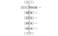
- the manufacturing method of the plate glass which concerns on this embodiment is equipped with scribe line formation process S1, arrangement
- the scribe line S is formed on the boundary between the product part Ga and the non-product part Gb by pressing with a wheel cutter, laser irradiation, or the like.
- the plate glass G has a rectangular shape, and forms a scribe line S parallel to a pair of opposing sides (only two sides) and each side (four sides).
- the inside of the scribe line S is the product part Ga, and the outside of the scribe line S is the non-product part Gb.
- the plate glass G in which the scribe line S was formed is arrange
- the first pressing member 3a that has been retracted above the first main surface G1 of the glass sheet G is lowered, and the first pressing member 3a causes the The first main surface G1 of the one main surface G1 is pressed.
- the moving part 4a retracted above the first main surface G1 of the glass sheet G is lowered and arranged at a predetermined position, and the second pressing member 4b is lowered with respect to the moving part 4a, and the second pressing member
- the first main surface G1 of the non-product part Gb is pressed with 4b. That is, the first main surface G1 of the product part Ga is held by the first pressing member 3a made of rubber, and the first main surface G1 of the non-product part Gb is held by the second pressing member 4b made of rubber.
- the folding member 5a retracted below the plate glass G is raised, and the second main surface G2 of the plate glass G is pushed upward at a position directly below the scribe line S as shown in FIG.
- the folding member 5a is pushed into the plate glass G from the second main surface G2 side of the plate glass G at a position corresponding to the scribe line S.
- bending stress about the scribe line S is applied to the glass sheet G.
- the flat portion 5b of the folding member 5a contacts the second main surface G2 of the plate glass G so as to straddle both sides of the scribe line S.
- the ascending amount of the folding member 5a is, for example, 2 mm to 30 mm upward with the conveyance surface of the glass sheet G (the upper surfaces of the first mounting table 2a and the second mounting table 2b) as a zero reference.
- the rising amount of the folding member 5a may or may not be changed depending on the size and thickness of the non-product part Gb.
- the plate glass G When bending stress is applied to the plate glass G, the plate glass G is folded along the scribe line S as shown in FIG. 5, and the product part Ga and the non-product part Gb are separated. At this time, the second main surface G2 of the plate glass G is pushed up by the flat surface portion 5b at a position directly below the scribe line S to be in a load mode such as four-point bending. As a result, the cracks on the scribe line S are likely to progress straight (perpendicular). As a result, post-processing of the cut end face Ga1 of the product part Ga can be omitted or reduced.
- the folding member 5a maintains the raised state (pressed state). In other words, the folding member 5a is kept pushed. At this time, the space between the cut end face Ga1 of the product part Ga and the cut end face Gb1 of the non-product part Gb is expanded by the flat part 5b of the folding member 5a, and the cut end face Ga1 of the product part Ga and the non-product part Gb are cut. End face Gb1 is in a state of being separated from each other.
- an inclined portion Ga2 is formed in the product portion Ga
- an inclined portion Gb2 is formed in the non-product portion Gb.
- the inclined part Ga2 of the product part Ga and the inclined part Gb2 of the non-product part Gb are in an upwardly inclined state with respect to the plate glass G in the arrangement step S2.
- the suction member 4c is lowered with respect to the moving part 4a that is still located at a predetermined position above the first main surface G1 of the non-product part Gb. .
- the first main surface G1 of the non-product part Gb is sucked and held by the suction member 4c.
- the suction surface 4d of the suction member 4c is brought close to the first main surface G1 of the non-product part Gb so as to be sucked along the perpendicular (center axis A).
- the adsorption surface 4d of the adsorption member 4c adsorbs the inclined part Gb2 of the non-product part Gb. And the adsorption
- suction member 4c inclines so that the 1st main surface G1 of the inclination part Gb2 of the non-product part Gb may be followed.
- the direction in which the adsorption member 4c approaches the non-product portion Gb is inclined rearward with respect to the pushing direction (vertical direction) of the folding member 5a.
- the distance between the foremost suction position of the suction member 4c on the first main surface G1 of the non-product part Gb and the front side end of the first main surface G1 of the non-product part Gb is preferably within 30 mm, more preferably within 20 mm. It is preferably within 15 mm.
- the second pressing member 4b is raised with respect to the moving part 4a.
- the suction member 4c is raised with the non-product part Gb being sucked with respect to the moving part 4a. More specifically, the suction surface 4d of the suction member 4c is moved along the perpendicular (center axis A). At this time, the moving direction of the adsorption member 4c is inclined rearward with respect to the pushing direction (vertical direction) of the folding member 5a.
- the moving part 4 a ascends obliquely rearward with the suction member 4 c holding the non-product part Gb.
- the non-product part Gb is removed from the second mounting table 2b.
- the folding member 5a descends and returns to the standby position at the same time or later.
- the non-product part Gb removed from the second mounting table 2b is moved onto the transport path for disposal by the movement of the moving part 4a. Therefore, the suction holding of the suction member 4c is released, and the non-product part Gb is transported to the disposal place through the transport path.
- the manufacturing method of the present embodiment configured as described above can enjoy the following effects.
- the non-product part Gb Since the adsorption surface 4d of the adsorption member 4c is inclined along the inclined part Gb2 of the non-product part Gb, the non-product part Gb is pushed by the adsorption member 4c when the adsorption member 4c is adsorbed to the non-product part Gb. It is possible to prevent the non-product part Gb from coming into contact with the product part Ga and chipping of the product part Ga.
- a plurality of the adsorbing members 4c may be arranged side by side in a direction perpendicular to the scribe line S and parallel to the first main surface G1 of the plate glass G.
- the adsorption members 4c are arranged in a plurality of rows along the scribe line S.
- the wide non-product part Gb can also be adsorbed and removed.
- the non-product part Gb having a large width has a greater gradient as it approaches the product part Ga.
- the adsorption surface 4d of the adsorption member 4c arranged in the front row is inclined, the effect of suppressing the curvature of the non-product portion Gb becomes remarkable.
- the adsorption member 4c was comprised from the adsorption pad, the adsorption member 4c is not limited to what uses a negative pressure, For example, it utilizes static electricity etc. like an electrostatic chuck. You may do.
- the adsorption member 4c when making the adsorption member 4c approach the non-product part Gb at adsorption
- the moving part 4a after moving the adsorption
- the moving part 4a was provided with the 2nd press member 4b
- the 2nd press member 4b may be arrange
- both the first pressing member 3a and the second pressing member 4b may be constituted by brush-like members, and either one of the first pressing member 3a or the second pressing member 4b is constituted by a brush-like member. May be.
- the bristles of the brush have elasticity and bend following the first main surface G1 of the product portion Ga. That is, the bristles of the brush follow subtle movements (including deformation) of the plate glass G.
- the bristles of the brush are formed from, for example, resin fibers such as nylon.
Abstract
This method for manufacturing a plate glass involves snapping a plate glass G comprising a product part Ga and a non-product part Gb demarcated by a formed scribe line S, then suction attaching a suction attaching member 4c to the non-product part Gb, and moving the non-product part Gb by means of the suction attaching member 4c. Inclined portions Ga2, Gb2 are formed by keeping a snapping member 5a thrusted out so that cut faces Ga1, Gb1 of the product part Ga and the non-product part Gb, respectively, are separated. A suction attaching surface 4d of the suction attaching member 4c is inclined along the inclined portion Gb2 of the non-product part Gb.
Description
本発明は、板ガラスの製造方法及び板ガラスの折割装置に関するものである。
The present invention relates to a plate glass manufacturing method and a plate glass folding apparatus.
周知のように、液晶ディスプレイ、プラズマディスプレイ、有機ELディスプレイなどのフラットパネルディスプレイ(FPD)用のガラス基板や、有機EL照明用のカバーガラスに代表されるように、各種分野で板ガラスが利用される。板ガラスの製造工程では、大面積の板ガラス(マザーガラス)から小面積の板ガラスを切り出したり、板ガラスの辺に沿う縁部をトリミングしたりする折割(割断)工程が含まれる。
As is well known, plate glass is used in various fields as represented by glass substrates for flat panel displays (FPD) such as liquid crystal displays, plasma displays, and organic EL displays, and cover glasses for organic EL lighting. . The plate glass manufacturing process includes a folding (cleaving) step of cutting a small area plate glass from a large area plate glass (mother glass) or trimming an edge along the side of the plate glass.
折割工程では、折り割る対象となる板ガラスの製品部と非製品部との境界において、板ガラスの第一主面(例えば上面)にスクライブ線を形成した後、そのスクライブ線を中心とした曲げ応力を作用させて板ガラスをスクライブ線に沿って折り割る。
In the folding process, a scribe line is formed on the first main surface (for example, the upper surface) of the glass sheet at the boundary between the product part and the non-product part of the glass sheet to be folded, and then bending stress centered on the scribe line. Fold the plate glass along the scribe line.
そして、この折割工程後に、非製品部に吸着パッド等の吸着部材を吸着させることにより、非製品部を取り除く。取り除かれた非製品部は、例えば、吸着部材により廃棄用の搬送路に受け渡され、廃棄口まで移送される(例えば、特許文献1参照)。
And after this folding process, the non-product part is removed by adsorbing a suction member such as a suction pad to the non-product part. The removed non-product part is transferred to a disposal conveyance path by an adsorption member, for example, and transferred to a disposal port (see, for example, Patent Document 1).
ところで、折割工程後に、非製品部に吸着部材を吸着させる際に、非製品部が製品部に接触して製品部に欠けが生じる場合があった。これは、次のような理由によるものである。折割工程では、板ガラスにスクライブ線を中心とした曲げ応力を作用させるために、スクライブ線に対応する位置で、板ガラスの第二主面の側から板ガラスに折割部材を押し込み、板ガラスが折り割られた後も非製品部に吸着部材を吸着させるまで、折割部材の押込み状態を維持する。そのため、非製品部に吸着部材を吸着させるまで、製品部及び非製品部に互いの切断端面が離れるような状態になっている。しかし、従来では、非製品部に吸着部材を吸着させる際に、非製品部が、吸着部材に押されて湾曲し、製品部に接触する場合があり、これにより、製品部に欠けが生じるのである。
By the way, when the adsorption member is adsorbed to the non-product part after the folding process, the non-product part may contact the product part and the product part may be chipped. This is due to the following reason. In the folding process, in order to apply a bending stress around the scribe line to the plate glass, the folding member is pushed into the plate glass from the second main surface side of the plate glass at a position corresponding to the scribe line, and the plate glass is folded. Even after being pressed, the folded member is kept pressed until the suction member is sucked to the non-product portion. Therefore, until the non-product part adsorbs the adsorbing member, the cut end surfaces of the product part and the non-product part are separated from each other. However, conventionally, when adsorbing the adsorbing member to the non-product part, the non-product part may be pushed by the adsorbing member to bend and come into contact with the product part. is there.
本発明は、上記事情に鑑み、板ガラスの折割工程後に、非製品部に吸着部材を吸着させる際に、製品部に欠けが生じる事態を回避することを技術的課題とする。
In view of the above circumstances, it is a technical object of the present invention to avoid a situation in which chipping occurs in a product part when an adsorbing member is adsorbed to a non-product part after a sheet glass folding step.
前記課題を解決するために創案された本発明に係る板ガラスの製造方法は、第一主面に形成されたスクライブ線を境界とする製品部及び非製品部を有する板ガラスを配置する配置工程と、前記板ガラスのうち、前記製品部の前記第一主面を第一押圧部材で押圧し、前記非製品部の前記第一主面を第二押圧部材で押圧した状態で、前記スクライブ線に対応する位置で、前記板ガラスの第二主面の側から前記板ガラスに折割部材を押し込むことにより、前記スクライブ線に沿って前記板ガラスを折り割る折割工程と、前記折割工程後に、前記非製品部に吸着部材の吸着面を吸着させる吸着工程と、前記吸着工程後に、前記非製品部を除去するために前記非製品部を前記吸着部材により移動させる移動工程とを備えた板ガラスの製造方法であって、前記吸着工程で、前記折割部材の押し込み状態を維持することにより、前記製品部及び前記非製品部に互いの切断端面が離れるように傾斜部を形成すると共に、前記吸着部材の前記吸着面が前記非製品部の前記傾斜部に沿うように吸着部材を傾斜させたことを特徴とする。ここで、「傾斜部に沿うように」とは、厳密に傾斜部に沿っている場合だけでなく、傾斜部から多少ずれている場合も含む(以下、同様)。好ましい吸着部材の傾斜角度は、後述する。
The manufacturing method of the sheet glass concerning the present invention created in order to solve the above-mentioned subject, the arrangement process which arranges the sheet glass which has the product part which makes the boundary the scribe line formed in the 1st principal surface, and the non-product part, Of the plate glass, the first main surface of the product part is pressed with a first pressing member, and the first main surface of the non-product part is pressed with a second pressing member, corresponding to the scribe line. In the position, by pushing a breaking member into the glass sheet from the second main surface side of the glass sheet, the non-product part after the folding process of breaking the glass sheet along the scribe line, and the folding process And a moving step of moving the non-product part by the adsorbing member to remove the non-product part after the adsorption process. The In the suction step, by maintaining the pushing state of the folding member, an inclined portion is formed in the product portion and the non-product portion so that the cut end surfaces are separated from each other, and the suction surface of the suction member is The adsorption member is inclined along the inclined portion of the non-product portion. Here, “to be along the inclined portion” includes not only strictly along the inclined portion but also a case where it is slightly deviated from the inclined portion (hereinafter the same). A preferable inclination angle of the adsorption member will be described later.
この構成によれば、吸着部材の吸着部を、非製品部の傾斜部に沿うように傾斜させたため、非製品部に吸着部材を吸着させる際に、非製品部が吸着部材に押されて湾曲することが抑制され、非製品部が製品部に接触して製品部に欠けが生じることを抑制できる。
According to this configuration, since the suction portion of the suction member is inclined along the inclined portion of the non-product portion, the non-product portion is pushed by the suction member and curved when the suction member is sucked by the non-product portion. It is possible to suppress the occurrence of chipping in the product part due to the non-product part coming into contact with the product part.
上記の構成において、前記吸着工程で、前記吸着部材を、前記吸着面の垂線に沿うように接近させて吸着させてもよい。ここで、「垂線に沿うように」とは、厳密に垂線に沿う場合のみだけでなく、垂線から多少ずれている場合も含むものとする(以下、同様)。
In the above-described configuration, in the adsorption step, the adsorption member may be adsorbed by approaching along the perpendicular of the adsorption surface. Here, “to be along the vertical line” includes not only strictly along the vertical line but also a case where it is slightly deviated from the vertical line (hereinafter the same).
この構成であれば、非製品部に吸着部材を吸着させる際に、非製品部が吸着部材に押されて湾曲することがさらに抑制され、非製品部が製品部に接触して製品部に欠けが生じることをさらに抑制できる。
With this configuration, when the adsorption member is adsorbed to the non-product portion, the non-product portion is further suppressed from being bent by being pushed by the adsorption member, and the non-product portion comes into contact with the product portion and is missing from the product portion. Can be further suppressed.
上記の構成において、前記移動工程で、前記吸着部材を、前記吸着面の垂線に沿うように移動させてもよい。
In the above configuration, the suction member may be moved along a perpendicular of the suction surface in the moving step.
この構成であれば、非製品部を吸着部材により移動させる際に、非製品部が、製品部に接触する可能性を低減できる。
This configuration can reduce the possibility that the non-product part contacts the product part when the non-product part is moved by the adsorption member.
上記の構成において、前記吸着部材が、前記第二押圧部材よりも前記製品部の側に配設されていてもよい。
In the above configuration, the adsorption member may be disposed closer to the product portion than the second pressing member.
この構成であれば、吸着部材を、製品部のより近くに配設可能となる。製品部の近くに配設された吸着部材ほど、非製品部が製品部に接触する原因となり易い。そのため、吸着部材の吸着面が傾斜していることによる上述した効果がより有効となり得る。
With this configuration, the adsorption member can be disposed closer to the product portion. The suction member disposed near the product portion is likely to cause the non-product portion to contact the product portion. Therefore, the above-described effect due to the suction surface of the suction member being inclined can be more effective.
上記の構成において、前記吸着部材の前記吸着面の傾斜角度が、変更可能であってもよい。
In the above configuration, the inclination angle of the suction surface of the suction member may be changeable.
ここで、非製品部の寸法等に応じ、折割部材の押し込み状態や第一押圧部材及び第2押圧部材の位置が変更される。この折割り条件の変更に伴い、非製品部の傾斜部の傾斜角度も変化する。吸着部材の吸着面の傾斜角度が変更可能であれば、折割り条件が変更されても、吸着部材の吸着面を非製品部の傾斜部と平行となるように傾斜させることが可能となる。
Here, in accordance with the dimensions of the non-product part, the pushing state of the folding member and the positions of the first pressing member and the second pressing member are changed. With the change of the folding condition, the inclination angle of the inclined part of the non-product part also changes. If the inclination angle of the adsorption surface of the adsorption member can be changed, the adsorption surface of the adsorption member can be inclined so as to be parallel to the inclined portion of the non-product part even if the folding condition is changed.
上記の構成において、前記吸着部材を、前記スクライブ線と垂直かつ前記板ガラスの前記第一主面と平行な方向に並べて複数配置し、前記吸着部材のうちで前記製品部からの距離が最も近い前記吸着部材を傾斜させてもよい。
In the above configuration, a plurality of the adsorption members are arranged side by side in a direction perpendicular to the scribe line and parallel to the first main surface of the plate glass, and the distance from the product portion is the shortest among the adsorption members. The adsorption member may be inclined.
製品部からの距離が近くなるほど、非製品部の勾配が大きくなる。このため、製品部からの距離が最も近い吸着部材を傾斜させれば、吸着面が傾斜していることによる上述した効果がより有効となり得る。
¡The closer the distance from the product part, the greater the gradient of the non-product part. For this reason, if the adsorption | suction member with the shortest distance from a product part is inclined, the effect mentioned above by the adsorption | suction surface inclining may become more effective.
また、前記課題を解決するために創案された本発明に係る板ガラスの折割装置は、第一主面に形成されたスクライブ線を境界とする製品部及び非製品部を有する板ガラスを、前記スクライブ線に沿って前記板ガラスを折り割る板ガラスの折割装置であって、前記板ガラスを配置する配置機構と、前記製品部の前記第一主面を押圧する第一押圧部材と、前記非製品部の前記第一主面を押圧する第二押圧部材と、前記スクライブ線に対応する位置で、前記板ガラスの第二主面の側から前記板ガラスに押し込むと共に、折り割られた前記板ガラスの前記製品部及び前記非製品部に互いの切断端面が離れるように傾斜部を形成する折割部材と、折り割られた前記板ガラスの前記非製品部を除去するために、前記非製品部を吸着すると共に移動させる吸着部材とを備え、前記吸着部材の前記吸着面が前記非製品部の前記傾斜部に沿うように傾斜していることを特徴とする。
In addition, a sheet glass folding device according to the present invention, which was created to solve the above-described problems, includes a plate glass having a product part and a non-product part with a scribe line formed on a first main surface as a boundary. A plate glass folding device for breaking the plate glass along a line, an arrangement mechanism for arranging the plate glass, a first pressing member for pressing the first main surface of the product part, and a non-product part A second pressing member that presses the first main surface; and a portion corresponding to the scribe line; the product portion of the plate glass that is folded and pressed into the plate glass from the second main surface side of the plate glass; The non-product part is adsorbed and moved in order to remove the non-product part of the folded plate glass and the folding member that forms an inclined part so that the cut end surfaces of the non-product part are separated from each other. A Chakubuzai, the suction surface of the suction member is characterized by being inclined along the inclined portion of the non-product portion.
この構成によれば、冒頭の板ガラスの製造方法で説明した作用及び効果と、実質的に同様の作用及び効果を得ることができる。
According to this configuration, it is possible to obtain substantially the same operations and effects as those described in the method for manufacturing a plate glass at the beginning.
以上のように、本発明によれば、板ガラスの折割工程後に、非製品部に吸着部材を吸着させる際に、製品部に欠けが生じる事態を回避することができる。
As described above, according to the present invention, when the adsorption member is adsorbed to the non-product part after the plate glass breaking step, it is possible to avoid a situation in which the product part is chipped.
以下、本発明を実施するための形態について図面に基づき説明する。
Hereinafter, embodiments for carrying out the present invention will be described with reference to the drawings.
図1は、本発明の実施形態に係る板ガラスの折割装置1を示す概略側面図である。折割装置1は、板ガラスGをスクライブ線Sに沿って折り割るものである。
FIG. 1 is a schematic side view showing a sheet glass folding apparatus 1 according to an embodiment of the present invention. The folding device 1 folds the glass sheet G along the scribe line S.
板ガラスGは水平姿勢で配置され、スクライブ線Sが形成された第一主面G1が上面、第二主面G2が下面とされる。板ガラスGは、スクライブ線Sを境界として製品部Gaと非製品部Gbとに区画される。
The plate glass G is arranged in a horizontal posture, and the first main surface G1 on which the scribe line S is formed is an upper surface and the second main surface G2 is a lower surface. The plate glass G is partitioned into a product part Ga and a non-product part Gb with the scribe line S as a boundary.
板ガラスGの製品部Gaの厚みは、例えば、2mm以下であり、好ましくは0.2mm~0.7mmである。非製品部Gbの図での横方向の寸法は、例えば、30mm~200mmの範囲で変更される。非製品部Gbには、製品部Gaよりも板厚の大きい厚肉部(不図示)が含まれている場合がある。非製品部Gbの厚肉部は、例えば、オーバーフローダウンドロー法やフロート法などを用いて板ガラスGを成形したときに生じ得る。
The thickness of the product part Ga of the plate glass G is, for example, 2 mm or less, preferably 0.2 mm to 0.7 mm. The horizontal dimension in the figure of the non-product part Gb is changed in the range of 30 mm to 200 mm, for example. The non-product part Gb may include a thick part (not shown) having a larger plate thickness than the product part Ga. The thick part of the non-product part Gb can be produced when the glass sheet G is formed using, for example, an overflow downdraw method or a float method.
なお、本実施形態では、便宜上、製品部Gaの側を前側とすると共に非製品部Gbの側を後側とする。
In the present embodiment, for convenience, the product part Ga side is the front side and the non-product part Gb side is the rear side.
折割装置1は、配置機構2と、押圧機構3と、移動機構4と、折割機構5とを備えている。
The folding device 1 includes an arrangement mechanism 2, a pressing mechanism 3, a moving mechanism 4, and a folding mechanism 5.
配置機構2は、板ガラスGを上方に配置する第一載置台2aと第二載置台2bで構成される。なお、本実施形態では、配置機構2は、載置台であるが、板ガラスGを上方に配置できればよく、例えば、例えばベルトコンベア、ローラコンベア、ロボットハンド等の搬送機構であってもよい。
The arrangement mechanism 2 includes a first mounting table 2a and a second mounting table 2b in which the glass sheet G is arranged upward. In the present embodiment, the arrangement mechanism 2 is a mounting table, but may be a conveyance mechanism such as, for example, a belt conveyor, a roller conveyor, or a robot hand, as long as the plate glass G can be arranged upward.
押圧機構3は、第一載置台2aの上で製品部Gaの第一主面G1を押圧する第一押圧部材3aを上下方向に昇降可能に備えている。第一押圧部材3aは、ゴム(弾性部材)から構成されている。ゴムは、板ガラスGの第二主面G2に倣って弾性変形するので、板ガラスGの微妙な動き(変形を含む)にも追従する。ゴムとしては、例えば、天然ゴム、合成ゴムなどが使用できる。なお、弾性部材はゴムに限定されず、スポンジなどであってもよい。
The pressing mechanism 3 includes a first pressing member 3a that presses the first main surface G1 of the product portion Ga on the first mounting table 2a so as to be movable up and down. The first pressing member 3a is made of rubber (elastic member). Since the rubber elastically deforms following the second main surface G2 of the plate glass G, the rubber follows the delicate movement (including deformation) of the plate glass G. As the rubber, for example, natural rubber or synthetic rubber can be used. The elastic member is not limited to rubber, and may be a sponge or the like.
移動機構4は、上下方向及び横方向に移動可能な移動部4aを備えている。移動部4aは、第二載置台2bの上で非製品部Gbの第一主面G1を押圧する第二押圧部材4bを有する。移動部4aに対し、第二押圧部材4bは上下方向に昇降可能である。
The moving mechanism 4 includes a moving unit 4a that can move in the vertical and horizontal directions. The moving part 4a has the 2nd press member 4b which presses the 1st main surface G1 of the non-product part Gb on the 2nd mounting base 2b. The second pressing member 4b can be moved up and down with respect to the moving part 4a.
第二押圧部材4bは、第一押圧部材3aと同様に、ゴム(弾性部材)から構成されている。
The second pressing member 4b is made of rubber (elastic member), like the first pressing member 3a.
また、移動部4aは、折り割られた板ガラスGの非製品部Gbに吸着する吸着部材4cを有する。本実施形態では、吸着部材4cは、吸着パッドであり、スクライブ線Sに沿って一列に並べて複数配置されている。また、吸着部材4cの吸着面4d(吸着部)は、吸着部材4cの先端面であり、非製品部Gbの第一主面G1と接触する。吸着部材4cの吸着面4dが、その前側が後側よりも板ガラスGから離隔するように、傾斜している。詳述すれば、吸着部材4cの吸着面4dは、その前側が後側よりも高位置となるように、水平面に対して傾斜している。また、吸着部材4cは、第二押圧部材4bよりも前側に配設されている。
Moreover, the moving part 4a has an adsorbing member 4c that adsorbs to the non-product part Gb of the folded plate glass G. In the present embodiment, the suction member 4 c is a suction pad, and a plurality of suction members 4 c are arranged in a line along the scribe line S. Further, the suction surface 4d (suction portion) of the suction member 4c is the tip surface of the suction member 4c and is in contact with the first main surface G1 of the non-product portion Gb. The suction surface 4d of the suction member 4c is inclined such that the front side is further away from the plate glass G than the rear side. More specifically, the suction surface 4d of the suction member 4c is inclined with respect to the horizontal plane so that the front side is higher than the rear side. Moreover, the adsorption member 4c is arrange | positioned rather than the 2nd press member 4b.
移動部4aに対し、吸着部材4cは、鉛直方向に対して後側に傾斜した方向に沿って移動(昇降)可能である。例えば図2に示すように、吸着部材4cは、シリンダ機構6のシリンダロッド6aに設けられる。シリンダ機構6のシリンダ6bには、複数のボルト穴6cが設けられており、シリンダ6bは、移動部4aの壁部4eに設けられた円弧状の長穴4fを介し、ボルト穴6cに螺合するボルト(不図示)によって壁部4eに固定される。長穴4fに対するボルト穴6cの位置を変更することにより、シリンダ機構6の中心軸Aの鉛直方向に対する傾斜角度αを変更することができる。これにより、吸着部材4cの吸着面4dの水平面Hに対する傾斜角度βを変更することができる。なお、シリンダ機構6の中心軸Aは、吸着部材4cの吸着面4dの垂線である。
With respect to the moving part 4a, the adsorbing member 4c can move (elevate) along a direction inclined rearward with respect to the vertical direction. For example, as shown in FIG. 2, the adsorption member 4 c is provided on the cylinder rod 6 a of the cylinder mechanism 6. The cylinder 6b of the cylinder mechanism 6 is provided with a plurality of bolt holes 6c. The cylinder 6b is screwed into the bolt holes 6c via an arc-shaped long hole 4f provided in the wall 4e of the moving part 4a. It fixes to the wall part 4e with the volt | bolt (not shown) to do. By changing the position of the bolt hole 6c with respect to the long hole 4f, the inclination angle α with respect to the vertical direction of the central axis A of the cylinder mechanism 6 can be changed. Thereby, the inclination | tilt angle (beta) with respect to the horizontal surface H of the adsorption | suction surface 4d of the adsorption | suction member 4c can be changed. The central axis A of the cylinder mechanism 6 is a perpendicular to the suction surface 4d of the suction member 4c.
吸着部材4を傾斜させる角度βは、折割り前の板ガラスGの第1主面G1の法線と吸着部材4cの吸着面4dの垂線がなす角度αで、1~30°が好ましく、1.5~15°がより好ましく、2~10°が最も好ましい。吸着部材4cは、例えば硬度が30~90のウレタン製である。なお、本実施形態のシリンダ機構6は、傾斜角度α=0°とすることが可能であり、その場合、中心軸Aは、鉛直方向に沿う。
The angle β for inclining the adsorption member 4 is an angle α formed by the normal of the first main surface G1 of the plate glass G before breaking and the perpendicular of the adsorption surface 4d of the adsorption member 4c, and is preferably 1 to 30 °. 5 to 15 ° is more preferable, and 2 to 10 ° is most preferable. The adsorption member 4c is made of urethane having a hardness of 30 to 90, for example. In addition, the cylinder mechanism 6 of this embodiment can make the inclination angle α = 0 °, and in this case, the central axis A is along the vertical direction.
折割機構5は、折割空間Bに配置されている。折割機構5は、スクライブ線Sの直下位置で板ガラスGの第二主面G2を押し上げる折割部材5aを鉛直方向に沿って昇降可能に備えている。折割部材5aの第二主面G2と対向する面は、スクライブ線Sの両側に跨る平面部5bと、平面部5bの両側で第二主面G2から離れるように下方傾斜した一対の傾斜部5cとを有する。本実施形態では、折割部材5aの第二主面G2と対向する面は、断面形状が等脚台形状をなす。平面部5bの図での横方向の寸法は、3~15mmであることが好ましい。平面部5bは水平面であることが好ましい。平面部5bと傾斜部5cとのなす角θは、30~50°であることが好ましい。
The split mechanism 5 is disposed in the split space B. The folding mechanism 5 includes a folding member 5a that pushes up the second main surface G2 of the plate glass G at a position directly below the scribe line S so as to be movable up and down along the vertical direction. The surface facing the second main surface G2 of the folding member 5a is a flat portion 5b straddling both sides of the scribe line S, and a pair of inclined portions inclined downward so as to be separated from the second main surface G2 on both sides of the flat portion 5b. 5c. In the present embodiment, the cross-sectional shape of the surface facing the second main surface G2 of the folding member 5a is an isosceles trapezoid. The horizontal dimension in the drawing of the flat portion 5b is preferably 3 to 15 mm. The flat part 5b is preferably a horizontal plane. The angle θ formed by the flat portion 5b and the inclined portion 5c is preferably 30 to 50 °.
第一押圧部材3a、第二押圧部材4b及び折割部材5aは、スクライブ線Sに沿う方向に延びた長尺体である。本実施形態では、第一押圧部材3a、第二押圧部材4b及び折割部材5aは、板ガラスGの全幅に亘って連続的に接触する。なお、本実施形態では、第一押圧部材3a、第二押圧部材4b及び折割部材5aは、板ガラスGの全幅よりも長いが、これらの部材3a,4b,5aの少なくとも一つが、板ガラスGの全幅と同じ長さであってもよいし、短い長さであってもよい。また、第一押圧部材3a、第二押圧部材4b及び折割部材5aの少なくとも一つが、幅方向で板ガラスGと断続的に接触してもよい。
The first pressing member 3a, the second pressing member 4b, and the folding member 5a are long bodies extending in a direction along the scribe line S. In this embodiment, the 1st press member 3a, the 2nd press member 4b, and the folding member 5a contact continuously over the full width of the plate glass G. As shown in FIG. In the present embodiment, the first pressing member 3a, the second pressing member 4b, and the folding member 5a are longer than the entire width of the plate glass G, but at least one of these members 3a, 4b, 5a is made of the plate glass G. It may be the same length as the full width or may be a short length. Further, at least one of the first pressing member 3a, the second pressing member 4b, and the folding member 5a may intermittently contact the glass sheet G in the width direction.
次に、以上のように構成された折割装置1を用いた本実施形態に係る板ガラスの製造方法を説明する。
Next, the manufacturing method of the plate glass which concerns on this embodiment using the folding apparatus 1 comprised as mentioned above is demonstrated.
図3に示すように、本実施形態に係る板ガラスの製造方法は、スクライブ線形成工程S1と、配置工程S2と、折割工程S3と、吸着工程S4と、移動工程S5とを備える。
As shown in FIG. 3, the manufacturing method of the plate glass which concerns on this embodiment is equipped with scribe line formation process S1, arrangement | positioning process S2, folding process S3, adsorption | suction process S4, and movement process S5.
まず、スクライブ線形成工程S1では、板ガラスGの第一主面G1において、製品部Gaと非製品部Gbとの境界に対して、ホイールカッターによる押圧やレーザーの照射等によりスクライブ線Sを形成する。本実施形態では、板ガラスGは、矩形状であり、対向する一組の辺(二辺のみ)や各辺(四辺)に平行にスクライブ線Sを形成する。スクライブ線Sの内側が製品部Ga、スクライブ線Sの外側が非製品部Gbとなる。
First, in the scribe line forming step S1, on the first main surface G1 of the plate glass G, the scribe line S is formed on the boundary between the product part Ga and the non-product part Gb by pressing with a wheel cutter, laser irradiation, or the like. . In this embodiment, the plate glass G has a rectangular shape, and forms a scribe line S parallel to a pair of opposing sides (only two sides) and each side (four sides). The inside of the scribe line S is the product part Ga, and the outside of the scribe line S is the non-product part Gb.
そして、配置工程S2では、図1に示すように、スクライブ線Sが形成された板ガラスGを、第一主面G1を上方に向けた状態で、配置機構2に配置する。
And in arrangement | positioning process S2, as shown in FIG. 1, the plate glass G in which the scribe line S was formed is arrange | positioned in the arrangement | positioning mechanism 2 in the state which orient | assigned the 1st main surface G1.
その後、折割工程S3で、図4に示すように、板ガラスGの第一主面G1の上方に退避していた第一押圧部材3aを下降させ、第一押圧部材3aで製品部Gaの第一主面G1の第一主面G1を押圧する。また、板ガラスGの第一主面G1の上方に退避していた移動部4aを下降させ所定位置に配置し、更に、移動部4aに対して第二押圧部材4bを下降させ、第二押圧部材4bで非製品部Gbの第一主面G1を押圧する。すなわち、ゴムからなる第一押圧部材3aで製品部Gaの第一主面G1が保持され、ゴムからなる第二押圧部材4bで非製品部Gbの第一主面G1が保持される。
Thereafter, in the folding step S3, as shown in FIG. 4, the first pressing member 3a that has been retracted above the first main surface G1 of the glass sheet G is lowered, and the first pressing member 3a causes the The first main surface G1 of the one main surface G1 is pressed. Moreover, the moving part 4a retracted above the first main surface G1 of the glass sheet G is lowered and arranged at a predetermined position, and the second pressing member 4b is lowered with respect to the moving part 4a, and the second pressing member The first main surface G1 of the non-product part Gb is pressed with 4b. That is, the first main surface G1 of the product part Ga is held by the first pressing member 3a made of rubber, and the first main surface G1 of the non-product part Gb is held by the second pressing member 4b made of rubber.
この状態から、板ガラスGの下方に退避していた折割部材5aを上昇させ、図5に示すように、スクライブ線Sの直下位置で、板ガラスGの第二主面G2を上方に押し上げる。換言すると、スクライブ線Sに対応する位置で、板ガラスGの第二主面G2の側から板ガラスGに折割部材5aを押し込む。これにより、スクライブ線Sを中心とする曲げ応力を板ガラスGに作用させる。この際、スクライブ線Sの両側に跨るように、折割部材5aの平面部5bが板ガラスGの第二主面G2と接触する。折割部材5aの上昇量は、板ガラスGの搬送面(第一載置台2a及び第二載置台2bの上面)を零基準として上方に、例えば2mm~30mmである。折割部材5aの上昇量は、非製品部Gbの大きさや板厚によって変化させてもよいし、変化させなくてもよい。
From this state, the folding member 5a retracted below the plate glass G is raised, and the second main surface G2 of the plate glass G is pushed upward at a position directly below the scribe line S as shown in FIG. In other words, the folding member 5a is pushed into the plate glass G from the second main surface G2 side of the plate glass G at a position corresponding to the scribe line S. As a result, bending stress about the scribe line S is applied to the glass sheet G. At this time, the flat portion 5b of the folding member 5a contacts the second main surface G2 of the plate glass G so as to straddle both sides of the scribe line S. The ascending amount of the folding member 5a is, for example, 2 mm to 30 mm upward with the conveyance surface of the glass sheet G (the upper surfaces of the first mounting table 2a and the second mounting table 2b) as a zero reference. The rising amount of the folding member 5a may or may not be changed depending on the size and thickness of the non-product part Gb.
板ガラスGに曲げ応力を作用させると、図5に示すように、スクライブ線Sに沿って板ガラスGが折り割られ、製品部Gaと非製品部Gbとが分離される。この際、スクライブ線Sの直下方位置で板ガラスGの第二主面G2が平面部5bによって押し上げられて四点曲げのような荷重態様となる。これにより、スクライブ線Sのクラックが真っ直ぐ(垂直)に進展しやすくなる。その結果、製品部Gaの切断端面Ga1の後加工を省略又は少なくすることができる。
When bending stress is applied to the plate glass G, the plate glass G is folded along the scribe line S as shown in FIG. 5, and the product part Ga and the non-product part Gb are separated. At this time, the second main surface G2 of the plate glass G is pushed up by the flat surface portion 5b at a position directly below the scribe line S to be in a load mode such as four-point bending. As a result, the cracks on the scribe line S are likely to progress straight (perpendicular). As a result, post-processing of the cut end face Ga1 of the product part Ga can be omitted or reduced.
製品部Gaと非製品部Gbとが分離された後も、折割部材5aは上昇状態(押し込み状態)を維持する。つまり、折割部材5aを押し込んだままの状態にする。このとき、製品部Gaの切断端面Ga1と非製品部Gbの切断端面Gb1との間は折割部材5aの平面部5bによって押し広げられ、製品部Gaの切断端面Ga1と非製品部Gbの切断端面Gb1とが互いに離れた状態となる。また、製品部Gaに傾斜部Ga2が形成されると共に、非製品部Gbに傾斜部Gb2が形成される。製品部Gaの傾斜部Ga2と非製品部Gbの傾斜部Gb2は、配置工程S2の板ガラスGに対して上方に傾斜した状態である。
After the product part Ga and the non-product part Gb are separated, the folding member 5a maintains the raised state (pressed state). In other words, the folding member 5a is kept pushed. At this time, the space between the cut end face Ga1 of the product part Ga and the cut end face Gb1 of the non-product part Gb is expanded by the flat part 5b of the folding member 5a, and the cut end face Ga1 of the product part Ga and the non-product part Gb are cut. End face Gb1 is in a state of being separated from each other. In addition, an inclined portion Ga2 is formed in the product portion Ga, and an inclined portion Gb2 is formed in the non-product portion Gb. The inclined part Ga2 of the product part Ga and the inclined part Gb2 of the non-product part Gb are in an upwardly inclined state with respect to the plate glass G in the arrangement step S2.
この状態で、吸着工程S4では、図6に示すように、非製品部Gbの第一主面G1の上方の所定位置に配置されたままの移動部4aに対して、吸着部材4cを下降させる。そして、吸着部材4cで非製品部Gbの第一主面G1を吸着保持する。換言すると、吸着部材4cの吸着面4dを、その垂線(中心軸A)に沿うように非製品部Gbの第一主面G1に接近させて吸着させる。
In this state, in the suction step S4, as shown in FIG. 6, the suction member 4c is lowered with respect to the moving part 4a that is still located at a predetermined position above the first main surface G1 of the non-product part Gb. . The first main surface G1 of the non-product part Gb is sucked and held by the suction member 4c. In other words, the suction surface 4d of the suction member 4c is brought close to the first main surface G1 of the non-product part Gb so as to be sucked along the perpendicular (center axis A).
吸着部材4cの吸着面4dは、非製品部Gbの傾斜部Gb2を吸着する。そして、吸着部材4cの吸着面4dは、非製品部Gbの傾斜部Gb2の第一主面G1に沿うように傾斜している。なお、吸着部材4cが非製品部Gbに接近する方向は、折割部材5aの押込方向(鉛直方向)に対して後側に傾斜している。
The adsorption surface 4d of the adsorption member 4c adsorbs the inclined part Gb2 of the non-product part Gb. And the adsorption | suction surface 4d of the adsorption | suction member 4c inclines so that the 1st main surface G1 of the inclination part Gb2 of the non-product part Gb may be followed. The direction in which the adsorption member 4c approaches the non-product portion Gb is inclined rearward with respect to the pushing direction (vertical direction) of the folding member 5a.
非製品部Gbの第一主面G1上における吸着部材4cの最も前側の吸着位置と、非製品部Gbの第一主面G1の前側端との距離は、30mm以内が好ましく、20mm以内がより好ましく、15mm以内が最も好ましい。
The distance between the foremost suction position of the suction member 4c on the first main surface G1 of the non-product part Gb and the front side end of the first main surface G1 of the non-product part Gb is preferably within 30 mm, more preferably within 20 mm. It is preferably within 15 mm.
移動工程S5では、図7に示すように、吸着部材4cの吸着保持の後、移動部4aに対して第二押圧部材4bを上昇させる。その後、図8に示すように、移動部4aに対して、非製品部Gbを吸着した状態で吸着部材4cを上昇させる。詳述すると、吸着部材4cの吸着面4dを、その垂線(中心軸A)に沿うように移動させる。この際、吸着部材4cの移動方向は、折割部材5aの押込方向(鉛直方向)に対して後側に傾斜している。
In the moving step S5, as shown in FIG. 7, after the suction holding of the suction member 4c, the second pressing member 4b is raised with respect to the moving part 4a. Thereafter, as shown in FIG. 8, the suction member 4c is raised with the non-product part Gb being sucked with respect to the moving part 4a. More specifically, the suction surface 4d of the suction member 4c is moved along the perpendicular (center axis A). At this time, the moving direction of the adsorption member 4c is inclined rearward with respect to the pushing direction (vertical direction) of the folding member 5a.
次に、図9に示すように、吸着部材4cが非製品部Gbを吸着保持した状態で、移動部4aが斜め後側に上昇する。これらの動作により、第二載置台2b上から非製品部Gbが除去される。また、移動部4aが斜め後側に上昇を開始すると同時又は後に折割部材5aは下降して待機位置に戻る。
Next, as shown in FIG. 9, the moving part 4 a ascends obliquely rearward with the suction member 4 c holding the non-product part Gb. By these operations, the non-product part Gb is removed from the second mounting table 2b. Further, when the moving part 4a starts to rise obliquely rearward, the folding member 5a descends and returns to the standby position at the same time or later.
第二載置台2b上から取り除かれた非製品部Gbは、移動部4aの移動により、廃棄用の搬送路上に移動させられる。そこで、吸着部材4cの吸着保持が解除され、非製品部Gbは搬送路により廃棄場所に搬送されることになる。
The non-product part Gb removed from the second mounting table 2b is moved onto the transport path for disposal by the movement of the moving part 4a. Therefore, the suction holding of the suction member 4c is released, and the non-product part Gb is transported to the disposal place through the transport path.
以上のように構成された本実施形態の製造方法では、以下の効果を享受できる。
The manufacturing method of the present embodiment configured as described above can enjoy the following effects.
吸着部材4cの吸着面4dを、非製品部Gbの傾斜部Gb2に沿うように傾斜させたため、非製品部Gbに吸着部材4cを吸着させる際に、非製品部Gbが吸着部材4cに押されて湾曲することが抑制され、非製品部Gbが製品部Gaに接触して製品部Gaに欠けが生じることを抑制できる。
Since the adsorption surface 4d of the adsorption member 4c is inclined along the inclined part Gb2 of the non-product part Gb, the non-product part Gb is pushed by the adsorption member 4c when the adsorption member 4c is adsorbed to the non-product part Gb. It is possible to prevent the non-product part Gb from coming into contact with the product part Ga and chipping of the product part Ga.
本発明は、上記実施形態に限定されるものでは無く、その技術的思想の範囲内で、様々な変形が可能である。例えば、吸着部材4cは、スクライブ線Sと垂直かつ板ガラスGの第一主面G1と平行な方向にも並べて複数配置されてもよい。この場合、吸着部材4cは、スクライブ線Sに沿って複数列に並べて配置される。これにより、幅が広い非製品部Gbも吸着して除去できる。
The present invention is not limited to the above embodiment, and various modifications are possible within the scope of the technical idea. For example, a plurality of the adsorbing members 4c may be arranged side by side in a direction perpendicular to the scribe line S and parallel to the first main surface G1 of the plate glass G. In this case, the adsorption members 4c are arranged in a plurality of rows along the scribe line S. Thereby, the wide non-product part Gb can also be adsorbed and removed.
折割部材5aの押し込み時、幅が広い非製品部Gbでは、製品部Gaに近くなるに従って勾配が大きくなる。このため、吸着部材4cを複数列に並べて配置する場合、最前列に配置された吸着部材4cの吸着面4dを傾斜させれば、非製品部Gbの湾曲を抑制する効果が顕著となる。このため、製品部Gaからの距離が最も近い吸着部材4cを傾斜させることが好ましい。また、残りの吸着部材4cは、傾斜させないことが好ましい。
When the folding member 5a is pushed in, the non-product part Gb having a large width has a greater gradient as it approaches the product part Ga. For this reason, when arranging the adsorption members 4c in a plurality of rows, if the adsorption surface 4d of the adsorption member 4c arranged in the front row is inclined, the effect of suppressing the curvature of the non-product portion Gb becomes remarkable. For this reason, it is preferable to incline the adsorption | suction member 4c with the shortest distance from the product part Ga. Moreover, it is preferable not to incline the remaining adsorption members 4c.
また、上記実施形態では、吸着部材4cは、吸着パッドから構成されていたが、吸着部材4cは、負圧を利用するものに限定されず、例えば、静電チャックのように、静電気等を利用するものであってもよい。
Moreover, in the said embodiment, although the adsorption member 4c was comprised from the adsorption pad, the adsorption member 4c is not limited to what uses a negative pressure, For example, it utilizes static electricity etc. like an electrostatic chuck. You may do.
また、上記実施形態では、水平姿勢の板ガラスGに対して折割り等の一連の処理を行ったが、これに限定されず、縦姿勢や傾斜姿勢に配置された板ガラスGに対して折割り等の一連の処理を行ってもよい。
Moreover, in the said embodiment, although series of processes, such as a split, were performed with respect to the plate glass G of a horizontal attitude | position, it is not limited to this, a split etc. are applied with respect to the plate glass G arrange | positioned in a vertical attitude | position or an inclination attitude | position A series of processes may be performed.
また、上記実施形態では、吸着工程S4で吸着部材4cを非製品部Gbに接近させる際に、吸着部材4cを吸着面4dの垂線に沿って移動させていたが、上下方向(折割り前の板ガラスGの第1主面G1の法線方向)に移動させてもよい。非製品部Gbの湾曲をさらに抑制する観点では、吸着部材4cの移動方向を傾斜させることが好ましく、吸着面4dの垂線と吸着部材4cの移動方向が一致することがより好ましい。
Moreover, in the said embodiment, when making the adsorption member 4c approach the non-product part Gb at adsorption | suction process S4, the adsorption member 4c was moved along the perpendicular of the adsorption surface 4d. You may make it move to the normal direction of the 1st main surface G1 of the plate glass G). From the viewpoint of further suppressing the bending of the non-product portion Gb, it is preferable to incline the moving direction of the adsorption member 4c, and it is more preferable that the perpendicular of the adsorption surface 4d and the movement direction of the adsorption member 4c coincide.
また、上記実施形態では、移動工程S5で、移動部4aに対して吸着部材4cを上昇させてから、移動部4aを移動させていたが、移動部4aに対して吸着部材4cを上昇させずに、移動部4aを上昇移動させてもよい。
Moreover, in the said embodiment, after moving the adsorption | suction member 4c with respect to the moving part 4a by moving process S5, the moving part 4a was moved, However, The adsorption | suction member 4c is not raised with respect to the moving part 4a. Alternatively, the moving unit 4a may be moved up.
また、上記実施形態では、移動部4aに対して吸着部材4cを上昇させる際、及び、移動部4aを移動させる際のいずれでも、吸着面4dの垂線に沿って移動させていたが、上下方向(折割り前の板ガラスGの第1主面G1の法線方向)に移動させてもよい。非製品部Gbが製品部Gaと接触する可能性を低減する観点では、吸着部材4c及び移動部4aの移動方向を傾斜させることが好ましく、吸着面4dの垂線と吸着部材4cの移動方向が一致することがより好ましい。
Moreover, in the said embodiment, when moving up the adsorption | suction member 4c with respect to the moving part 4a, and when moving the moving part 4a, it was moved along the perpendicular of the adsorption | suction surface 4d, but the up-down direction You may move to (the normal line direction of 1st main surface G1 of the plate glass G before breaking). From the viewpoint of reducing the possibility that the non-product part Gb comes into contact with the product part Ga, it is preferable to incline the moving direction of the adsorption member 4c and the moving part 4a, and the perpendicular of the adsorption surface 4d and the movement direction of the adsorption member 4c coincide. More preferably.
また、上記実施形態では、移動部4aが、第二押圧部材4bを備えていたが、第二押圧部材4bは移動部4aとは別に配設されていてもよい。
Moreover, in the said embodiment, although the moving part 4a was provided with the 2nd press member 4b, the 2nd press member 4b may be arrange | positioned separately from the move part 4a.
また、上記実施形態では、第一押圧部材3aと第二押圧部材4bが共にゴムから構成されていたが、これに限定されるものではない。例えば、第一押圧部材3aと第二押圧部材4bが共にブラシ状部材で構成されていてもよいし、第一押圧部材3aと第二押圧部材4bのいずれか一方がブラシ状部材で構成されていてもよい。ブラシの毛は弾性を有し、製品部Gaの第一主面G1に倣って撓む。すなわち、ブラシの毛は、板ガラスGの微妙な動き(変形を含む)にも追従する。ブラシの毛は、例えば、ナイロンなどの樹脂製繊維から形成される。
Moreover, in the said embodiment, although the 1st press member 3a and the 2nd press member 4b were comprised from rubber | gum, it is not limited to this. For example, both the first pressing member 3a and the second pressing member 4b may be constituted by brush-like members, and either one of the first pressing member 3a or the second pressing member 4b is constituted by a brush-like member. May be. The bristles of the brush have elasticity and bend following the first main surface G1 of the product portion Ga. That is, the bristles of the brush follow subtle movements (including deformation) of the plate glass G. The bristles of the brush are formed from, for example, resin fibers such as nylon.
1 折割装置
2 配置機構
3a 第一押圧部材
4b 第二押圧部材
4c 吸着部材
4d 吸着面(吸着部)
5a 折割部材
A 中心軸(吸着面の垂線)
G 板ガラス
G1 第一主面
G2 第二主面
Ga 製品部
Ga1 切断端面
Ga2 傾斜部
Gb 非製品部
Gb1 切断端面
Gb2 傾斜部
S2 配置工程
S3 折割工程
S4 吸着工程
S5 移動工程
α 傾斜角度
β 傾斜角度 DESCRIPTION OF SYMBOLS 1Folding device 2 Arrangement mechanism 3a 1st press member 4b 2nd press member 4c Adsorption member 4d Adsorption surface (adsorption part)
5a Folding member A Central axis (vertical of suction surface)
G Sheet glass G1 1st main surface G2 2nd main surface Ga Product part Ga1 Cutting end surface Ga2 Inclination part Gb Non-product part Gb1 Cutting end surface Gb2 Inclination part S2 Arrangement process S3 Folding process S4 Adsorption process S5 Moving process α Inclination angle β Inclination angle
2 配置機構
3a 第一押圧部材
4b 第二押圧部材
4c 吸着部材
4d 吸着面(吸着部)
5a 折割部材
A 中心軸(吸着面の垂線)
G 板ガラス
G1 第一主面
G2 第二主面
Ga 製品部
Ga1 切断端面
Ga2 傾斜部
Gb 非製品部
Gb1 切断端面
Gb2 傾斜部
S2 配置工程
S3 折割工程
S4 吸着工程
S5 移動工程
α 傾斜角度
β 傾斜角度 DESCRIPTION OF SYMBOLS 1
5a Folding member A Central axis (vertical of suction surface)
G Sheet glass G1 1st main surface G2 2nd main surface Ga Product part Ga1 Cutting end surface Ga2 Inclination part Gb Non-product part Gb1 Cutting end surface Gb2 Inclination part S2 Arrangement process S3 Folding process S4 Adsorption process S5 Moving process α Inclination angle β Inclination angle
Claims (7)
- 第一主面に形成されたスクライブ線を境界とする製品部及び非製品部を有する板ガラスを配置する配置工程と、
前記板ガラスのうち、前記製品部の前記第一主面を第一押圧部材で押圧し、前記非製品部の前記第一主面を第二押圧部材で押圧した状態で、前記スクライブ線に対応する位置で、前記板ガラスの第二主面の側から前記板ガラスに折割部材を押し込むことにより、前記スクライブ線に沿って前記板ガラスを折り割る折割工程と、
前記折割工程後に、前記非製品部に吸着部材の吸着面を吸着させる吸着工程と、
前記吸着工程後に、前記非製品部を除去するために前記非製品部を前記吸着部材により移動させる移動工程とを備えた板ガラスの製造方法であって、
前記吸着工程で、前記折割部材の押し込み状態を維持することにより、前記製品部及び前記非製品部に互いの切断端面が離れるように傾斜部を形成すると共に、前記吸着部材の前記吸着面が前記非製品部の前記傾斜部に沿うように前記吸着部材を傾斜させたことを特徴とする板ガラスの製造方法。 An arrangement step of arranging a plate glass having a product part and a non-product part with a scribe line formed on the first main surface as a boundary;
Of the plate glass, the first main surface of the product part is pressed with a first pressing member, and the first main surface of the non-product part is pressed with a second pressing member, corresponding to the scribe line. In the position, by pressing a folding member into the plate glass from the second main surface side of the plate glass, a folding step of breaking the plate glass along the scribe line;
An adsorption step of adsorbing the adsorption surface of the adsorption member to the non-product part after the folding step;
And a moving step of moving the non-product part by the adsorption member to remove the non-product part after the adsorption process,
In the suction step, by maintaining the pushing state of the folding member, an inclined portion is formed in the product portion and the non-product portion so that the cut end surfaces are separated from each other, and the suction surface of the suction member is The method for producing a plate glass, wherein the suction member is inclined along the inclined portion of the non-product portion. - 前記吸着工程で、前記吸着部材を、前記吸着面の垂線に沿うように接近させて吸着させることを特徴とする請求項1に記載の板ガラスの製造方法。 The method for producing a plate glass according to claim 1, wherein, in the adsorption step, the adsorbing member is adsorbed by being approached along a perpendicular line of the adsorption surface.
- 前記移動工程で、前記吸着部材を、前記吸着面の垂線に沿うように移動させることを特徴とする請求項1又は2に記載の板ガラスの製造方法。 3. The method for producing a plate glass according to claim 1, wherein, in the moving step, the suction member is moved along a perpendicular of the suction surface.
- 前記吸着部材が、前記第二押圧部材よりも前記製品部の側に配設されていることを特徴とする請求項1~3の何れか1項に記載の板ガラスの製造方法。 The method for producing a plate glass according to any one of claims 1 to 3, wherein the adsorbing member is disposed closer to the product portion than the second pressing member.
- 前記吸着部材の前記吸着面の傾斜角度が、変更可能であることを特徴とする請求項1~4の何れか1項に記載の板ガラスの製造方法。 The method for producing a plate glass according to any one of claims 1 to 4, wherein an inclination angle of the suction surface of the suction member is changeable.
- 前記吸着部材は、前記スクライブ線と垂直かつ前記板ガラスの前記第一主面と平行な方向に並べて複数配置され、
前記吸着部材のうちで前記製品部からの距離が最も近い前記吸着部材を傾斜させることを特徴とする請求項1~5の何れか1項に記載の板ガラスの製造方法。 A plurality of the adsorbing members are arranged in a direction perpendicular to the scribe line and parallel to the first main surface of the plate glass,
The method for producing a plate glass according to any one of claims 1 to 5, wherein the adsorption member having the closest distance from the product portion is inclined among the adsorption members. - 第一主面に形成されたスクライブ線を境界とする製品部及び非製品部を有する板ガラスを、前記スクライブ線に沿って前記板ガラスを折り割る板ガラスの折割装置であって、
前記板ガラスを配置する配置機構と、
前記製品部の前記第一主面を押圧する第一押圧部材と、
前記非製品部の前記第一主面を押圧する第二押圧部材と、
前記スクライブ線に対応する位置で、前記板ガラスの第二主面の側から前記板ガラスに押し込むと共に、折り割られた前記板ガラスの前記製品部及び前記非製品部に互いの切断端面が離れるように傾斜部を形成する折割部材と、
折り割られた前記板ガラスの前記非製品部を除去するために、前記非製品部を吸着すると共に移動させる吸着部材とを備え、
前記吸着部材の吸着面が前記非製品部の前記傾斜部に沿うように傾斜していることを特徴とする板ガラスの折割装置。 A plate glass splitting device that folds the plate glass along the scribe line, the plate glass having a product part and a non-product part with a scribe line formed on the first main surface as a boundary,
An arrangement mechanism for arranging the plate glass;
A first pressing member that presses the first main surface of the product part;
A second pressing member for pressing the first main surface of the non-product part;
At the position corresponding to the scribe line, it is pushed into the plate glass from the second main surface side of the plate glass and is inclined so that the cut end surfaces of the product portion and the non-product portion of the folded plate glass are separated from each other. A folding member forming a portion;
An adsorption member that adsorbs and moves the non-product part in order to remove the non-product part of the folded plate glass;
A plate glass folding device, wherein an adsorption surface of the adsorption member is inclined so as to follow the inclined portion of the non-product part.
Priority Applications (2)
| Application Number | Priority Date | Filing Date | Title |
|---|---|---|---|
| CN201880010244.4A CN110248903B (en) | 2017-03-16 | 2018-02-16 | Method for manufacturing plate-shaped glass and device for breaking plate-shaped glass |
| KR1020197018613A KR102418844B1 (en) | 2017-03-16 | 2018-02-16 | Plate glass manufacturing method and plate glass snapping device |
Applications Claiming Priority (2)
| Application Number | Priority Date | Filing Date | Title |
|---|---|---|---|
| JP2017-051155 | 2017-03-16 | ||
| JP2017051155A JP6792824B2 (en) | 2017-03-16 | 2017-03-16 | Plate glass manufacturing method and plate glass folding device |
Publications (1)
| Publication Number | Publication Date |
|---|---|
| WO2018168331A1 true WO2018168331A1 (en) | 2018-09-20 |
Family
ID=63522125
Family Applications (1)
| Application Number | Title | Priority Date | Filing Date |
|---|---|---|---|
| PCT/JP2018/005602 WO2018168331A1 (en) | 2017-03-16 | 2018-02-16 | Method for manufacturing plate glass and plate glass snapping device |
Country Status (4)
| Country | Link |
|---|---|
| JP (1) | JP6792824B2 (en) |
| KR (1) | KR102418844B1 (en) |
| CN (1) | CN110248903B (en) |
| WO (1) | WO2018168331A1 (en) |
Families Citing this family (5)
| Publication number | Priority date | Publication date | Assignee | Title |
|---|---|---|---|---|
| CN110744145B (en) * | 2019-11-15 | 2021-06-04 | 林华 | Workpiece waste edge breaking clamping jaw structure with cleaning structure |
| JP7398094B2 (en) | 2019-12-20 | 2023-12-14 | 三星ダイヤモンド工業株式会社 | Board pickup device and board pickup method |
| JPWO2021131748A1 (en) * | 2019-12-24 | 2021-07-01 | ||
| TWI784555B (en) * | 2021-06-04 | 2022-11-21 | 晶巧股份有限公司 | Depaneling machine |
| CN113306196A (en) * | 2021-06-07 | 2021-08-27 | 厦门百恒自动化科技有限公司 | Cross cutting shaping cardboard breaking machine |
Citations (2)
| Publication number | Priority date | Publication date | Assignee | Title |
|---|---|---|---|---|
| JP2001163642A (en) * | 1999-12-09 | 2001-06-19 | Toyota Autom Loom Works Ltd | Device for taking out laminated glass panel |
| WO2013073477A1 (en) * | 2011-11-16 | 2013-05-23 | 日本電気硝子株式会社 | Glass plate cleaving device, method for cleaving glass plate, method for manufacturing glass plate, and glass plate cleaving system |
Family Cites Families (3)
| Publication number | Priority date | Publication date | Assignee | Title |
|---|---|---|---|---|
| JP2006108273A (en) * | 2004-10-04 | 2006-04-20 | Disco Abrasive Syst Ltd | Method and apparatus of dividing wafer |
| JP4892916B2 (en) * | 2005-10-04 | 2012-03-07 | セントラル硝子株式会社 | Thin glass folding device and folding method |
| CN205380736U (en) * | 2015-12-31 | 2016-07-13 | 浙江盼家门业有限公司 | Dust adsorbs cutting plate |
-
2017
- 2017-03-16 JP JP2017051155A patent/JP6792824B2/en active Active
-
2018
- 2018-02-16 WO PCT/JP2018/005602 patent/WO2018168331A1/en active Application Filing
- 2018-02-16 KR KR1020197018613A patent/KR102418844B1/en active IP Right Grant
- 2018-02-16 CN CN201880010244.4A patent/CN110248903B/en active Active
Patent Citations (2)
| Publication number | Priority date | Publication date | Assignee | Title |
|---|---|---|---|---|
| JP2001163642A (en) * | 1999-12-09 | 2001-06-19 | Toyota Autom Loom Works Ltd | Device for taking out laminated glass panel |
| WO2013073477A1 (en) * | 2011-11-16 | 2013-05-23 | 日本電気硝子株式会社 | Glass plate cleaving device, method for cleaving glass plate, method for manufacturing glass plate, and glass plate cleaving system |
Also Published As
| Publication number | Publication date |
|---|---|
| KR20190126050A (en) | 2019-11-08 |
| JP2018154514A (en) | 2018-10-04 |
| KR102418844B1 (en) | 2022-07-11 |
| CN110248903A (en) | 2019-09-17 |
| JP6792824B2 (en) | 2020-12-02 |
| CN110248903B (en) | 2022-05-06 |
Similar Documents
| Publication | Publication Date | Title |
|---|---|---|
| WO2018168331A1 (en) | Method for manufacturing plate glass and plate glass snapping device | |
| JP6300187B2 (en) | Sheet glass manufacturing method | |
| TWI656101B (en) | Glass plate manufacturing device | |
| US8276796B2 (en) | Device and method for cutting off substrate of fragile material | |
| JP6738557B2 (en) | Sheet glass manufacturing method and manufacturing apparatus thereof | |
| WO2018100978A1 (en) | Method for producing sheet glass and device for snap-cutting sheet glass | |
| CN104803591B (en) | Scoring device | |
| TW201628981A (en) | Glass plate manufacturing apparatus | |
| JP4447654B2 (en) | Scribing apparatus and scribing method | |
| JP6032428B2 (en) | Glass film cutting apparatus and glass film cutting method | |
| KR102593615B1 (en) | Substrate cutting apparatus | |
| KR20220079515A (en) | Manufacturing method of flat glass and its manufacturing apparatus | |
| TWI649279B (en) | Scribing device for brittle material substrate | |
| KR20220080072A (en) | Manufacturing method of flat glass and its manufacturing apparatus | |
| WO2022270288A1 (en) | Method for producing plate glass, apparatus for producing plate glass, and plate glass | |
| CN100529873C (en) | System and method for removing blank glass from panel | |
| JP7086350B2 (en) | Sheet glass manufacturing method and manufacturing equipment | |
| WO2022097324A1 (en) | Plate glass production method, production device therefor, and plate glass | |
| WO2023100865A1 (en) | Method for producing glass sheet and package of raw glass sheet | |
| KR20180069173A (en) | substrate holding unit and SCRIBING APPARATUS having the same | |
| KR20160123454A (en) | Scribing apparatus | |
| KR102068032B1 (en) | Scribe apparatus |
Legal Events
| Date | Code | Title | Description |
|---|---|---|---|
| 121 | Ep: the epo has been informed by wipo that ep was designated in this application |
Ref document number: 18767700 Country of ref document: EP Kind code of ref document: A1 |
|
| ENP | Entry into the national phase |
Ref document number: 20197018613 Country of ref document: KR Kind code of ref document: A |
|
| NENP | Non-entry into the national phase |
Ref country code: DE |
|
| 122 | Ep: pct application non-entry in european phase |
Ref document number: 18767700 Country of ref document: EP Kind code of ref document: A1 |