JP2017203547A - Metal resin composite gear - Google Patents
Metal resin composite gear Download PDFInfo
- Publication number
- JP2017203547A JP2017203547A JP2017090668A JP2017090668A JP2017203547A JP 2017203547 A JP2017203547 A JP 2017203547A JP 2017090668 A JP2017090668 A JP 2017090668A JP 2017090668 A JP2017090668 A JP 2017090668A JP 2017203547 A JP2017203547 A JP 2017203547A
- Authority
- JP
- Japan
- Prior art keywords
- resin
- gear
- thermoplastic resin
- metal
- composite gear
- Prior art date
- Legal status (The legal status is an assumption and is not a legal conclusion. Google has not performed a legal analysis and makes no representation as to the accuracy of the status listed.)
- Granted
Links
- 229910052751 metal Inorganic materials 0.000 title claims abstract description 88
- 239000002184 metal Substances 0.000 title claims abstract description 88
- 239000000805 composite resin Substances 0.000 title claims abstract description 84
- 229920005992 thermoplastic resin Polymers 0.000 claims abstract description 196
- 239000007769 metal material Substances 0.000 claims abstract description 61
- 229920005989 resin Polymers 0.000 claims description 91
- 239000011347 resin Substances 0.000 claims description 91
- XEEYBQQBJWHFJM-UHFFFAOYSA-N Iron Chemical compound [Fe] XEEYBQQBJWHFJM-UHFFFAOYSA-N 0.000 claims description 19
- 239000000945 filler Substances 0.000 claims description 15
- 229910000838 Al alloy Inorganic materials 0.000 claims description 12
- 229910052782 aluminium Inorganic materials 0.000 claims description 12
- XAGFODPZIPBFFR-UHFFFAOYSA-N aluminium Chemical compound [Al] XAGFODPZIPBFFR-UHFFFAOYSA-N 0.000 claims description 12
- 229910000831 Steel Inorganic materials 0.000 claims description 10
- 239000010959 steel Substances 0.000 claims description 10
- 229910052742 iron Inorganic materials 0.000 claims description 9
- 230000002093 peripheral effect Effects 0.000 claims description 9
- 229920005672 polyolefin resin Polymers 0.000 claims description 9
- 239000010935 stainless steel Substances 0.000 claims description 9
- 229910001220 stainless steel Inorganic materials 0.000 claims description 9
- 229920006122 polyamide resin Polymers 0.000 claims description 7
- 239000004734 Polyphenylene sulfide Substances 0.000 claims description 6
- 239000010949 copper Substances 0.000 claims description 6
- 229920006324 polyoxymethylene Polymers 0.000 claims description 6
- 229920000069 polyphenylene sulfide Polymers 0.000 claims description 6
- RYGMFSIKBFXOCR-UHFFFAOYSA-N Copper Chemical compound [Cu] RYGMFSIKBFXOCR-UHFFFAOYSA-N 0.000 claims description 5
- 229930182556 Polyacetal Natural products 0.000 claims description 5
- 229920006026 co-polymeric resin Polymers 0.000 claims description 5
- 229910052802 copper Inorganic materials 0.000 claims description 5
- 229920001225 polyester resin Polymers 0.000 claims description 5
- 239000009719 polyimide resin Substances 0.000 claims description 5
- 229910000881 Cu alloy Inorganic materials 0.000 claims description 4
- FYYHWMGAXLPEAU-UHFFFAOYSA-N Magnesium Chemical compound [Mg] FYYHWMGAXLPEAU-UHFFFAOYSA-N 0.000 claims description 4
- 229910000861 Mg alloy Inorganic materials 0.000 claims description 4
- 239000004696 Poly ether ether ketone Substances 0.000 claims description 4
- 239000004695 Polyether sulfone Substances 0.000 claims description 4
- 229910001069 Ti alloy Inorganic materials 0.000 claims description 4
- RTAQQCXQSZGOHL-UHFFFAOYSA-N Titanium Chemical compound [Ti] RTAQQCXQSZGOHL-UHFFFAOYSA-N 0.000 claims description 4
- 239000011777 magnesium Substances 0.000 claims description 4
- 229910052749 magnesium Inorganic materials 0.000 claims description 4
- 229920001643 poly(ether ketone) Polymers 0.000 claims description 4
- 229920002285 poly(styrene-co-acrylonitrile) Polymers 0.000 claims description 4
- 229920006350 polyacrylonitrile resin Polymers 0.000 claims description 4
- 229920005668 polycarbonate resin Polymers 0.000 claims description 4
- 239000004431 polycarbonate resin Substances 0.000 claims description 4
- 239000004645 polyester resin Substances 0.000 claims description 4
- 229920006393 polyether sulfone Polymers 0.000 claims description 4
- 229920002530 polyetherether ketone Polymers 0.000 claims description 4
- 229920001721 polyimide Polymers 0.000 claims description 4
- 229920005990 polystyrene resin Polymers 0.000 claims description 4
- 229910052719 titanium Inorganic materials 0.000 claims description 4
- 239000010936 titanium Substances 0.000 claims description 4
- 229920000178 Acrylic resin Polymers 0.000 claims description 3
- 239000004925 Acrylic resin Substances 0.000 claims description 3
- XECAHXYUAAWDEL-UHFFFAOYSA-N acrylonitrile butadiene styrene Chemical compound C=CC=C.C=CC#N.C=CC1=CC=CC=C1 XECAHXYUAAWDEL-UHFFFAOYSA-N 0.000 claims description 3
- 229920000122 acrylonitrile butadiene styrene Polymers 0.000 claims description 3
- 239000004676 acrylonitrile butadiene styrene Substances 0.000 claims description 3
- 239000000463 material Substances 0.000 abstract description 7
- 235000012054 meals Nutrition 0.000 abstract 1
- 238000000034 method Methods 0.000 description 42
- 238000005530 etching Methods 0.000 description 40
- 239000003795 chemical substances by application Substances 0.000 description 39
- 239000002253 acid Substances 0.000 description 36
- 238000007788 roughening Methods 0.000 description 25
- -1 polypropylenes Polymers 0.000 description 22
- XLYOFNOQVPJJNP-UHFFFAOYSA-N water Substances O XLYOFNOQVPJJNP-UHFFFAOYSA-N 0.000 description 18
- 239000007864 aqueous solution Substances 0.000 description 17
- 229910001447 ferric ion Inorganic materials 0.000 description 17
- VTLYFUHAOXGGBS-UHFFFAOYSA-N Fe3+ Chemical compound [Fe+3] VTLYFUHAOXGGBS-UHFFFAOYSA-N 0.000 description 16
- HEMHJVSKTPXQMS-UHFFFAOYSA-M Sodium hydroxide Chemical compound [OH-].[Na+] HEMHJVSKTPXQMS-UHFFFAOYSA-M 0.000 description 15
- 238000000465 moulding Methods 0.000 description 15
- 239000011342 resin composition Substances 0.000 description 14
- 238000001746 injection moulding Methods 0.000 description 12
- JPVYNHNXODAKFH-UHFFFAOYSA-N Cu2+ Chemical compound [Cu+2] JPVYNHNXODAKFH-UHFFFAOYSA-N 0.000 description 11
- 238000004519 manufacturing process Methods 0.000 description 11
- QAOWNCQODCNURD-UHFFFAOYSA-N Sulfuric acid Chemical compound OS(O)(=O)=O QAOWNCQODCNURD-UHFFFAOYSA-N 0.000 description 8
- 229910001437 manganese ion Inorganic materials 0.000 description 8
- JRZJOMJEPLMPRA-UHFFFAOYSA-N olefin Natural products CCCCCCCC=C JRZJOMJEPLMPRA-UHFFFAOYSA-N 0.000 description 7
- LIKMAJRDDDTEIG-UHFFFAOYSA-N 1-hexene Chemical compound CCCCC=C LIKMAJRDDDTEIG-UHFFFAOYSA-N 0.000 description 6
- WSSSPWUEQFSQQG-UHFFFAOYSA-N 4-methyl-1-pentene Chemical compound CC(C)CC=C WSSSPWUEQFSQQG-UHFFFAOYSA-N 0.000 description 6
- VEXZGXHMUGYJMC-UHFFFAOYSA-N Hydrochloric acid Chemical compound Cl VEXZGXHMUGYJMC-UHFFFAOYSA-N 0.000 description 6
- 150000007522 mineralic acids Chemical class 0.000 description 6
- 239000003921 oil Substances 0.000 description 6
- 238000005406 washing Methods 0.000 description 6
- 239000000853 adhesive Substances 0.000 description 5
- 230000001070 adhesive effect Effects 0.000 description 5
- 230000000694 effects Effects 0.000 description 5
- 239000003365 glass fiber Substances 0.000 description 5
- 238000010438 heat treatment Methods 0.000 description 5
- 238000002347 injection Methods 0.000 description 5
- 239000007924 injection Substances 0.000 description 5
- 150000002500 ions Chemical class 0.000 description 5
- 238000002156 mixing Methods 0.000 description 5
- YWAKXRMUMFPDSH-UHFFFAOYSA-N pentene Chemical compound CCCC=C YWAKXRMUMFPDSH-UHFFFAOYSA-N 0.000 description 5
- 230000008569 process Effects 0.000 description 5
- KWKAKUADMBZCLK-UHFFFAOYSA-N 1-octene Chemical compound CCCCCCC=C KWKAKUADMBZCLK-UHFFFAOYSA-N 0.000 description 4
- QGZKDVFQNNGYKY-UHFFFAOYSA-N Ammonia Chemical compound N QGZKDVFQNNGYKY-UHFFFAOYSA-N 0.000 description 4
- OAKJQQAXSVQMHS-UHFFFAOYSA-N Hydrazine Chemical compound NN OAKJQQAXSVQMHS-UHFFFAOYSA-N 0.000 description 4
- WAEMQWOKJMHJLA-UHFFFAOYSA-N Manganese(2+) Chemical compound [Mn+2] WAEMQWOKJMHJLA-UHFFFAOYSA-N 0.000 description 4
- 239000004743 Polypropylene Substances 0.000 description 4
- WCUXLLCKKVVCTQ-UHFFFAOYSA-M Potassium chloride Chemical compound [Cl-].[K+] WCUXLLCKKVVCTQ-UHFFFAOYSA-M 0.000 description 4
- PPBRXRYQALVLMV-UHFFFAOYSA-N Styrene Chemical compound C=CC1=CC=CC=C1 PPBRXRYQALVLMV-UHFFFAOYSA-N 0.000 description 4
- 150000001336 alkenes Chemical class 0.000 description 4
- 238000013329 compounding Methods 0.000 description 4
- 150000001875 compounds Chemical class 0.000 description 4
- ORTQZVOHEJQUHG-UHFFFAOYSA-L copper(II) chloride Chemical compound Cl[Cu]Cl ORTQZVOHEJQUHG-UHFFFAOYSA-L 0.000 description 4
- 238000004090 dissolution Methods 0.000 description 4
- 238000001035 drying Methods 0.000 description 4
- 229920001971 elastomer Polymers 0.000 description 4
- 239000000806 elastomer Substances 0.000 description 4
- 230000009477 glass transition Effects 0.000 description 4
- 150000007529 inorganic bases Chemical class 0.000 description 4
- 238000005304 joining Methods 0.000 description 4
- 229920002647 polyamide Polymers 0.000 description 4
- 229920001155 polypropylene Polymers 0.000 description 4
- 230000003746 surface roughness Effects 0.000 description 4
- 229920002554 vinyl polymer Polymers 0.000 description 4
- QTBSBXVTEAMEQO-UHFFFAOYSA-N Acetic acid Chemical compound CC(O)=O QTBSBXVTEAMEQO-UHFFFAOYSA-N 0.000 description 3
- 229920000049 Carbon (fiber) Polymers 0.000 description 3
- 229910021578 Iron(III) chloride Inorganic materials 0.000 description 3
- MUBZPKHOEPUJKR-UHFFFAOYSA-N Oxalic acid Chemical compound OC(=O)C(O)=O MUBZPKHOEPUJKR-UHFFFAOYSA-N 0.000 description 3
- 239000004952 Polyamide Substances 0.000 description 3
- KWYUFKZDYYNOTN-UHFFFAOYSA-M Potassium hydroxide Chemical compound [OH-].[K+] KWYUFKZDYYNOTN-UHFFFAOYSA-M 0.000 description 3
- 239000000654 additive Substances 0.000 description 3
- 238000005422 blasting Methods 0.000 description 3
- 239000004917 carbon fiber Substances 0.000 description 3
- 150000001732 carboxylic acid derivatives Chemical class 0.000 description 3
- KRKNYBCHXYNGOX-UHFFFAOYSA-N citric acid Chemical compound OC(=O)CC(O)(C(O)=O)CC(O)=O KRKNYBCHXYNGOX-UHFFFAOYSA-N 0.000 description 3
- 238000001816 cooling Methods 0.000 description 3
- XTVVROIMIGLXTD-UHFFFAOYSA-N copper(II) nitrate Chemical compound [Cu+2].[O-][N+]([O-])=O.[O-][N+]([O-])=O XTVVROIMIGLXTD-UHFFFAOYSA-N 0.000 description 3
- ARUVKPQLZAKDPS-UHFFFAOYSA-L copper(II) sulfate Chemical compound [Cu+2].[O-][S+2]([O-])([O-])[O-] ARUVKPQLZAKDPS-UHFFFAOYSA-L 0.000 description 3
- 229910000366 copper(II) sulfate Inorganic materials 0.000 description 3
- 230000008878 coupling Effects 0.000 description 3
- 238000010168 coupling process Methods 0.000 description 3
- 238000005859 coupling reaction Methods 0.000 description 3
- 238000000635 electron micrograph Methods 0.000 description 3
- 239000000835 fiber Substances 0.000 description 3
- 238000000227 grinding Methods 0.000 description 3
- RAXXELZNTBOGNW-UHFFFAOYSA-N imidazole Natural products C1=CNC=N1 RAXXELZNTBOGNW-UHFFFAOYSA-N 0.000 description 3
- 229920000554 ionomer Polymers 0.000 description 3
- RBTARNINKXHZNM-UHFFFAOYSA-K iron trichloride Chemical compound Cl[Fe](Cl)Cl RBTARNINKXHZNM-UHFFFAOYSA-K 0.000 description 3
- VNWKTOKETHGBQD-UHFFFAOYSA-N methane Chemical compound C VNWKTOKETHGBQD-UHFFFAOYSA-N 0.000 description 3
- 239000000203 mixture Substances 0.000 description 3
- 230000008855 peristalsis Effects 0.000 description 3
- 238000005488 sandblasting Methods 0.000 description 3
- 239000000126 substance Substances 0.000 description 3
- 238000004506 ultrasonic cleaning Methods 0.000 description 3
- 239000004711 α-olefin Substances 0.000 description 3
- VXNZUUAINFGPBY-UHFFFAOYSA-N 1-Butene Chemical compound CCC=C VXNZUUAINFGPBY-UHFFFAOYSA-N 0.000 description 2
- CRSBERNSMYQZNG-UHFFFAOYSA-N 1-dodecene Chemical compound CCCCCCCCCCC=C CRSBERNSMYQZNG-UHFFFAOYSA-N 0.000 description 2
- GQEZCXVZFLOKMC-UHFFFAOYSA-N 1-hexadecene Chemical compound CCCCCCCCCCCCCCC=C GQEZCXVZFLOKMC-UHFFFAOYSA-N 0.000 description 2
- HFDVRLIODXPAHB-UHFFFAOYSA-N 1-tetradecene Chemical compound CCCCCCCCCCCCC=C HFDVRLIODXPAHB-UHFFFAOYSA-N 0.000 description 2
- YHQXBTXEYZIYOV-UHFFFAOYSA-N 3-methylbut-1-ene Chemical compound CC(C)C=C YHQXBTXEYZIYOV-UHFFFAOYSA-N 0.000 description 2
- JJLJMEJHUUYSSY-UHFFFAOYSA-L Copper hydroxide Chemical compound [OH-].[OH-].[Cu+2] JJLJMEJHUUYSSY-UHFFFAOYSA-L 0.000 description 2
- VGGSQFUCUMXWEO-UHFFFAOYSA-N Ethene Chemical compound C=C VGGSQFUCUMXWEO-UHFFFAOYSA-N 0.000 description 2
- 239000005977 Ethylene Substances 0.000 description 2
- 229910021380 Manganese Chloride Inorganic materials 0.000 description 2
- GLFNIEUTAYBVOC-UHFFFAOYSA-L Manganese chloride Chemical compound Cl[Mn]Cl GLFNIEUTAYBVOC-UHFFFAOYSA-L 0.000 description 2
- GRYLNZFGIOXLOG-UHFFFAOYSA-N Nitric acid Chemical compound O[N+]([O-])=O GRYLNZFGIOXLOG-UHFFFAOYSA-N 0.000 description 2
- NBIIXXVUZAFLBC-UHFFFAOYSA-N Phosphoric acid Chemical compound OP(O)(O)=O NBIIXXVUZAFLBC-UHFFFAOYSA-N 0.000 description 2
- 239000004698 Polyethylene Substances 0.000 description 2
- 239000006087 Silane Coupling Agent Substances 0.000 description 2
- VYPSYNLAJGMNEJ-UHFFFAOYSA-N Silicium dioxide Chemical compound O=[Si]=O VYPSYNLAJGMNEJ-UHFFFAOYSA-N 0.000 description 2
- FAPWRFPIFSIZLT-UHFFFAOYSA-M Sodium chloride Chemical compound [Na+].[Cl-] FAPWRFPIFSIZLT-UHFFFAOYSA-M 0.000 description 2
- 229910021529 ammonia Inorganic materials 0.000 description 2
- 230000005540 biological transmission Effects 0.000 description 2
- 125000004432 carbon atom Chemical group C* 0.000 description 2
- 238000007334 copolymerization reaction Methods 0.000 description 2
- 229960003280 cupric chloride Drugs 0.000 description 2
- 238000005520 cutting process Methods 0.000 description 2
- LPIQUOYDBNQMRZ-UHFFFAOYSA-N cyclopentene Chemical compound C1CC=CC1 LPIQUOYDBNQMRZ-UHFFFAOYSA-N 0.000 description 2
- 229910003460 diamond Inorganic materials 0.000 description 2
- 239000010432 diamond Substances 0.000 description 2
- 238000004512 die casting Methods 0.000 description 2
- 230000005674 electromagnetic induction Effects 0.000 description 2
- 239000003822 epoxy resin Substances 0.000 description 2
- 229920006228 ethylene acrylate copolymer Polymers 0.000 description 2
- 239000005038 ethylene vinyl acetate Substances 0.000 description 2
- 229910001385 heavy metal Inorganic materials 0.000 description 2
- 238000007654 immersion Methods 0.000 description 2
- 239000012535 impurity Substances 0.000 description 2
- 229910052500 inorganic mineral Inorganic materials 0.000 description 2
- VCJMYUPGQJHHFU-UHFFFAOYSA-N iron(3+);trinitrate Chemical compound [Fe+3].[O-][N+]([O-])=O.[O-][N+]([O-])=O.[O-][N+]([O-])=O VCJMYUPGQJHHFU-UHFFFAOYSA-N 0.000 description 2
- 150000002576 ketones Chemical class 0.000 description 2
- 239000011565 manganese chloride Substances 0.000 description 2
- 235000002867 manganese chloride Nutrition 0.000 description 2
- 229940099607 manganese chloride Drugs 0.000 description 2
- 229940099596 manganese sulfate Drugs 0.000 description 2
- 239000011702 manganese sulphate Substances 0.000 description 2
- 235000007079 manganese sulphate Nutrition 0.000 description 2
- SQQMAOCOWKFBNP-UHFFFAOYSA-L manganese(II) sulfate Chemical compound [Mn+2].[O-]S([O-])(=O)=O SQQMAOCOWKFBNP-UHFFFAOYSA-L 0.000 description 2
- BDAGIHXWWSANSR-UHFFFAOYSA-N methanoic acid Natural products OC=O BDAGIHXWWSANSR-UHFFFAOYSA-N 0.000 description 2
- 235000010755 mineral Nutrition 0.000 description 2
- 239000011707 mineral Substances 0.000 description 2
- TVMXDCGIABBOFY-UHFFFAOYSA-N n-Octanol Natural products CCCCCCCC TVMXDCGIABBOFY-UHFFFAOYSA-N 0.000 description 2
- 229910017604 nitric acid Inorganic materials 0.000 description 2
- JFNLZVQOOSMTJK-KNVOCYPGSA-N norbornene Chemical compound C1[C@@H]2CC[C@H]1C=C2 JFNLZVQOOSMTJK-KNVOCYPGSA-N 0.000 description 2
- CCCMONHAUSKTEQ-UHFFFAOYSA-N octadec-1-ene Chemical compound CCCCCCCCCCCCCCCCC=C CCCMONHAUSKTEQ-UHFFFAOYSA-N 0.000 description 2
- 150000007524 organic acids Chemical class 0.000 description 2
- 235000005985 organic acids Nutrition 0.000 description 2
- 239000002245 particle Substances 0.000 description 2
- VLTRZXGMWDSKGL-UHFFFAOYSA-N perchloric acid Chemical compound OCl(=O)(=O)=O VLTRZXGMWDSKGL-UHFFFAOYSA-N 0.000 description 2
- 238000005498 polishing Methods 0.000 description 2
- 229920001200 poly(ethylene-vinyl acetate) Polymers 0.000 description 2
- 229920000747 poly(lactic acid) Polymers 0.000 description 2
- 229920002492 poly(sulfone) Polymers 0.000 description 2
- 229920001707 polybutylene terephthalate Polymers 0.000 description 2
- 229920001610 polycaprolactone Polymers 0.000 description 2
- 239000004632 polycaprolactone Substances 0.000 description 2
- 229920001123 polycyclohexylenedimethylene terephthalate Polymers 0.000 description 2
- 229920000647 polyepoxide Polymers 0.000 description 2
- 229920000573 polyethylene Polymers 0.000 description 2
- 239000004626 polylactic acid Substances 0.000 description 2
- 230000000379 polymerizing effect Effects 0.000 description 2
- 229920000306 polymethylpentene Polymers 0.000 description 2
- 239000011116 polymethylpentene Substances 0.000 description 2
- 239000004800 polyvinyl chloride Substances 0.000 description 2
- 229920000915 polyvinyl chloride Polymers 0.000 description 2
- IOLCXVTUBQKXJR-UHFFFAOYSA-M potassium bromide Chemical compound [K+].[Br-] IOLCXVTUBQKXJR-UHFFFAOYSA-M 0.000 description 2
- 239000001103 potassium chloride Substances 0.000 description 2
- 235000011164 potassium chloride Nutrition 0.000 description 2
- 238000002360 preparation method Methods 0.000 description 2
- 238000003825 pressing Methods 0.000 description 2
- QQONPFPTGQHPMA-UHFFFAOYSA-N propylene Natural products CC=C QQONPFPTGQHPMA-UHFFFAOYSA-N 0.000 description 2
- 125000004805 propylene group Chemical group [H]C([H])([H])C([H])([*:1])C([H])([H])[*:2] 0.000 description 2
- 238000007493 shaping process Methods 0.000 description 2
- JHJLBTNAGRQEKS-UHFFFAOYSA-M sodium bromide Chemical compound [Na+].[Br-] JHJLBTNAGRQEKS-UHFFFAOYSA-M 0.000 description 2
- 239000000454 talc Substances 0.000 description 2
- 229910052623 talc Inorganic materials 0.000 description 2
- 229920001187 thermosetting polymer Polymers 0.000 description 2
- UMGDCJDMYOKAJW-UHFFFAOYSA-N thiourea Chemical compound NC(N)=S UMGDCJDMYOKAJW-UHFFFAOYSA-N 0.000 description 2
- BJEPYKJPYRNKOW-REOHCLBHSA-N (S)-malic acid Chemical compound OC(=O)[C@@H](O)CC(O)=O BJEPYKJPYRNKOW-REOHCLBHSA-N 0.000 description 1
- DHKHKXVYLBGOIT-UHFFFAOYSA-N 1,1-Diethoxyethane Chemical compound CCOC(C)OCC DHKHKXVYLBGOIT-UHFFFAOYSA-N 0.000 description 1
- BMYNFMYTOJXKLE-UHFFFAOYSA-N 3-azaniumyl-2-hydroxypropanoate Chemical compound NCC(O)C(O)=O BMYNFMYTOJXKLE-UHFFFAOYSA-N 0.000 description 1
- LDTAOIUHUHHCMU-UHFFFAOYSA-N 3-methylpent-1-ene Chemical compound CCC(C)C=C LDTAOIUHUHHCMU-UHFFFAOYSA-N 0.000 description 1
- OSWFIVFLDKOXQC-UHFFFAOYSA-N 4-(3-methoxyphenyl)aniline Chemical compound COC1=CC=CC(C=2C=CC(N)=CC=2)=C1 OSWFIVFLDKOXQC-UHFFFAOYSA-N 0.000 description 1
- CQPBLBQMIFRGLU-UHFFFAOYSA-N 4-(6-azabicyclo[3.1.1]hepta-1(7),2,4-triene-6-carbonyl)benzamide Chemical compound C1=CC(C(=O)N)=CC=C1C(=O)N1C2=CC=CC1=C2 CQPBLBQMIFRGLU-UHFFFAOYSA-N 0.000 description 1
- PCBPVYHMZBWMAZ-UHFFFAOYSA-N 5-methylbicyclo[2.2.1]hept-2-ene Chemical compound C1C2C(C)CC1C=C2 PCBPVYHMZBWMAZ-UHFFFAOYSA-N 0.000 description 1
- NIXOWILDQLNWCW-UHFFFAOYSA-M Acrylate Chemical compound [O-]C(=O)C=C NIXOWILDQLNWCW-UHFFFAOYSA-M 0.000 description 1
- 239000004953 Aliphatic polyamide Substances 0.000 description 1
- LSNNMFCWUKXFEE-UHFFFAOYSA-M Bisulfite Chemical compound OS([O-])=O LSNNMFCWUKXFEE-UHFFFAOYSA-M 0.000 description 1
- OKTJSMMVPCPJKN-UHFFFAOYSA-N Carbon Chemical compound [C] OKTJSMMVPCPJKN-UHFFFAOYSA-N 0.000 description 1
- 229920003043 Cellulose fiber Polymers 0.000 description 1
- 239000004801 Chlorinated PVC Substances 0.000 description 1
- 239000004709 Chlorinated polyethylene Substances 0.000 description 1
- 229920001634 Copolyester Polymers 0.000 description 1
- 239000004593 Epoxy Substances 0.000 description 1
- 229920000219 Ethylene vinyl alcohol Polymers 0.000 description 1
- 101000576320 Homo sapiens Max-binding protein MNT Proteins 0.000 description 1
- 239000004609 Impact Modifier Substances 0.000 description 1
- 229910021569 Manganese fluoride Inorganic materials 0.000 description 1
- 229920009204 Methacrylate-butadiene-styrene Polymers 0.000 description 1
- CTQNGGLPUBDAKN-UHFFFAOYSA-N O-Xylene Chemical compound CC1=CC=CC=C1C CTQNGGLPUBDAKN-UHFFFAOYSA-N 0.000 description 1
- 229920002845 Poly(methacrylic acid) Polymers 0.000 description 1
- 239000004962 Polyamide-imide Substances 0.000 description 1
- 239000004697 Polyetherimide Substances 0.000 description 1
- 108010020346 Polyglutamic Acid Proteins 0.000 description 1
- 229920000954 Polyglycolide Polymers 0.000 description 1
- 229920000331 Polyhydroxybutyrate Polymers 0.000 description 1
- 239000004721 Polyphenylene oxide Substances 0.000 description 1
- 229920001328 Polyvinylidene chloride Polymers 0.000 description 1
- 229920006121 Polyxylylene adipamide Polymers 0.000 description 1
- OFOBLEOULBTSOW-UHFFFAOYSA-N Propanedioic acid Natural products OC(=O)CC(O)=O OFOBLEOULBTSOW-UHFFFAOYSA-N 0.000 description 1
- 229920002125 Sokalan® Polymers 0.000 description 1
- XSQUKJJJFZCRTK-UHFFFAOYSA-N Urea Natural products NC(N)=O XSQUKJJJFZCRTK-UHFFFAOYSA-N 0.000 description 1
- 238000005299 abrasion Methods 0.000 description 1
- 239000011354 acetal resin Substances 0.000 description 1
- 235000011054 acetic acid Nutrition 0.000 description 1
- 150000007513 acids Chemical class 0.000 description 1
- 229920002877 acrylic styrene acrylonitrile Polymers 0.000 description 1
- 229920003231 aliphatic polyamide Polymers 0.000 description 1
- 229920003232 aliphatic polyester Polymers 0.000 description 1
- BJEPYKJPYRNKOW-UHFFFAOYSA-N alpha-hydroxysuccinic acid Natural products OC(=O)C(O)CC(O)=O BJEPYKJPYRNKOW-UHFFFAOYSA-N 0.000 description 1
- 229910000147 aluminium phosphate Inorganic materials 0.000 description 1
- 150000001408 amides Chemical class 0.000 description 1
- 125000003277 amino group Chemical group 0.000 description 1
- 239000003963 antioxidant agent Substances 0.000 description 1
- 239000002216 antistatic agent Substances 0.000 description 1
- 125000003118 aryl group Chemical group 0.000 description 1
- 150000003851 azoles Chemical class 0.000 description 1
- 230000008901 benefit Effects 0.000 description 1
- 230000015572 biosynthetic process Effects 0.000 description 1
- 238000012661 block copolymerization Methods 0.000 description 1
- 238000000071 blow moulding Methods 0.000 description 1
- DQXBYHZEEUGOBF-UHFFFAOYSA-N but-3-enoic acid;ethene Chemical compound C=C.OC(=O)CC=C DQXBYHZEEUGOBF-UHFFFAOYSA-N 0.000 description 1
- NTXGQCSETZTARF-UHFFFAOYSA-N buta-1,3-diene;prop-2-enenitrile Chemical compound C=CC=C.C=CC#N NTXGQCSETZTARF-UHFFFAOYSA-N 0.000 description 1
- 229910052799 carbon Inorganic materials 0.000 description 1
- 230000008859 change Effects 0.000 description 1
- 229920000457 chlorinated polyvinyl chloride Polymers 0.000 description 1
- 235000015165 citric acid Nutrition 0.000 description 1
- 239000004927 clay Substances 0.000 description 1
- 229910052570 clay Inorganic materials 0.000 description 1
- 230000000052 comparative effect Effects 0.000 description 1
- 238000000748 compression moulding Methods 0.000 description 1
- 239000000470 constituent Substances 0.000 description 1
- 239000000356 contaminant Substances 0.000 description 1
- 238000011109 contamination Methods 0.000 description 1
- 230000008602 contraction Effects 0.000 description 1
- 239000002826 coolant Substances 0.000 description 1
- 229920001577 copolymer Polymers 0.000 description 1
- 239000007822 coupling agent Substances 0.000 description 1
- 238000005336 cracking Methods 0.000 description 1
- 239000013078 crystal Substances 0.000 description 1
- ZXIJMRYMVAMXQP-UHFFFAOYSA-N cycloheptene Chemical compound C1CCC=CCC1 ZXIJMRYMVAMXQP-UHFFFAOYSA-N 0.000 description 1
- 238000005238 degreasing Methods 0.000 description 1
- 239000013527 degreasing agent Substances 0.000 description 1
- 238000005237 degreasing agent Methods 0.000 description 1
- 238000010586 diagram Methods 0.000 description 1
- CTNMMTCXUUFYAP-UHFFFAOYSA-L difluoromanganese Chemical compound F[Mn]F CTNMMTCXUUFYAP-UHFFFAOYSA-L 0.000 description 1
- 239000002270 dispersing agent Substances 0.000 description 1
- 229940069096 dodecene Drugs 0.000 description 1
- 125000003700 epoxy group Chemical group 0.000 description 1
- 125000002573 ethenylidene group Chemical group [*]=C=C([H])[H] 0.000 description 1
- 125000000816 ethylene group Chemical group [H]C([H])([*:1])C([H])([H])[*:2] 0.000 description 1
- 229920000840 ethylene tetrafluoroethylene copolymer Polymers 0.000 description 1
- 239000012765 fibrous filler Substances 0.000 description 1
- 239000003063 flame retardant Substances 0.000 description 1
- 229920002313 fluoropolymer Polymers 0.000 description 1
- 235000019253 formic acid Nutrition 0.000 description 1
- WOLATMHLPFJRGC-UHFFFAOYSA-N furan-2,5-dione;styrene Chemical compound O=C1OC(=O)C=C1.C=CC1=CC=CC=C1 WOLATMHLPFJRGC-UHFFFAOYSA-N 0.000 description 1
- 229920000578 graft copolymer Polymers 0.000 description 1
- 230000005484 gravity Effects 0.000 description 1
- 239000012760 heat stabilizer Substances 0.000 description 1
- XLYOFNOQVPJJNP-UHFFFAOYSA-M hydroxide Chemical compound [OH-] XLYOFNOQVPJJNP-UHFFFAOYSA-M 0.000 description 1
- 239000004615 ingredient Substances 0.000 description 1
- RUTXIHLAWFEWGM-UHFFFAOYSA-H iron(3+) sulfate Chemical compound [Fe+3].[Fe+3].[O-]S([O-])(=O)=O.[O-]S([O-])(=O)=O.[O-]S([O-])(=O)=O RUTXIHLAWFEWGM-UHFFFAOYSA-H 0.000 description 1
- 229910000360 iron(III) sulfate Inorganic materials 0.000 description 1
- 239000007788 liquid Substances 0.000 description 1
- 239000000314 lubricant Substances 0.000 description 1
- 239000010721 machine oil Substances 0.000 description 1
- VZCYOOQTPOCHFL-UPHRSURJSA-N maleic acid Chemical compound OC(=O)\C=C/C(O)=O VZCYOOQTPOCHFL-UPHRSURJSA-N 0.000 description 1
- 239000011976 maleic acid Substances 0.000 description 1
- 239000001630 malic acid Substances 0.000 description 1
- 235000011090 malic acid Nutrition 0.000 description 1
- 229940071125 manganese acetate Drugs 0.000 description 1
- UOGMEBQRZBEZQT-UHFFFAOYSA-L manganese(2+);diacetate Chemical compound [Mn+2].CC([O-])=O.CC([O-])=O UOGMEBQRZBEZQT-UHFFFAOYSA-L 0.000 description 1
- MIVBAHRSNUNMPP-UHFFFAOYSA-N manganese(2+);dinitrate Chemical compound [Mn+2].[O-][N+]([O-])=O.[O-][N+]([O-])=O MIVBAHRSNUNMPP-UHFFFAOYSA-N 0.000 description 1
- 239000006082 mold release agent Substances 0.000 description 1
- LNOPIUAQISRISI-UHFFFAOYSA-N n'-hydroxy-2-propan-2-ylsulfonylethanimidamide Chemical compound CC(C)S(=O)(=O)CC(N)=NO LNOPIUAQISRISI-UHFFFAOYSA-N 0.000 description 1
- AFFLGGQVNFXPEV-UHFFFAOYSA-N n-decene Natural products CCCCCCCCC=C AFFLGGQVNFXPEV-UHFFFAOYSA-N 0.000 description 1
- 229920002601 oligoester Polymers 0.000 description 1
- 238000013021 overheating Methods 0.000 description 1
- 235000006408 oxalic acid Nutrition 0.000 description 1
- 238000007254 oxidation reaction Methods 0.000 description 1
- 239000003002 pH adjusting agent Substances 0.000 description 1
- RGSFGYAAUTVSQA-UHFFFAOYSA-N pentamethylene Natural products C1CCCC1 RGSFGYAAUTVSQA-UHFFFAOYSA-N 0.000 description 1
- 229920011301 perfluoro alkoxyl alkane Polymers 0.000 description 1
- 230000002572 peristaltic effect Effects 0.000 description 1
- 239000012466 permeate Substances 0.000 description 1
- 239000000049 pigment Substances 0.000 description 1
- 239000004014 plasticizer Substances 0.000 description 1
- 238000007747 plating Methods 0.000 description 1
- 229920000314 poly p-methyl styrene Polymers 0.000 description 1
- 229920000083 poly(allylamine) Polymers 0.000 description 1
- 229920003207 poly(ethylene-2,6-naphthalate) Polymers 0.000 description 1
- 229920005670 poly(ethylene-vinyl chloride) Polymers 0.000 description 1
- 229920006139 poly(hexamethylene adipamide-co-hexamethylene terephthalamide) Polymers 0.000 description 1
- 229920006111 poly(hexamethylene terephthalamide) Polymers 0.000 description 1
- 229920006117 poly(hexamethylene terephthalamide)-co- polycaprolactam Polymers 0.000 description 1
- 239000005015 poly(hydroxybutyrate) Substances 0.000 description 1
- 229920000889 poly(m-phenylene isophthalamide) Polymers 0.000 description 1
- 229920006128 poly(nonamethylene terephthalamide) Polymers 0.000 description 1
- 229920003366 poly(p-phenylene terephthalamide) Polymers 0.000 description 1
- 229920002037 poly(vinyl butyral) polymer Polymers 0.000 description 1
- 229920002312 polyamide-imide Polymers 0.000 description 1
- 229920001230 polyarylate Polymers 0.000 description 1
- 238000006068 polycondensation reaction Methods 0.000 description 1
- 229920000570 polyether Polymers 0.000 description 1
- 229920001601 polyetherimide Polymers 0.000 description 1
- 239000011112 polyethylene naphthalate Substances 0.000 description 1
- 229920013716 polyethylene resin Polymers 0.000 description 1
- 229920000139 polyethylene terephthalate Polymers 0.000 description 1
- 239000005020 polyethylene terephthalate Substances 0.000 description 1
- 229920002643 polyglutamic acid Polymers 0.000 description 1
- 239000004633 polyglycolic acid Substances 0.000 description 1
- 229920000642 polymer Polymers 0.000 description 1
- 229920006124 polyolefin elastomer Polymers 0.000 description 1
- 229920001955 polyphenylene ether Polymers 0.000 description 1
- 229920006380 polyphenylene oxide Polymers 0.000 description 1
- 229920001343 polytetrafluoroethylene Polymers 0.000 description 1
- 239000004810 polytetrafluoroethylene Substances 0.000 description 1
- 229940058401 polytetrafluoroethylene Drugs 0.000 description 1
- 229920003225 polyurethane elastomer Polymers 0.000 description 1
- 229920002689 polyvinyl acetate Polymers 0.000 description 1
- 239000011118 polyvinyl acetate Substances 0.000 description 1
- 229920001289 polyvinyl ether Polymers 0.000 description 1
- 229920002620 polyvinyl fluoride Polymers 0.000 description 1
- 239000005033 polyvinylidene chloride Substances 0.000 description 1
- 238000001556 precipitation Methods 0.000 description 1
- 238000010107 reaction injection moulding Methods 0.000 description 1
- 230000009467 reduction Effects 0.000 description 1
- 230000003014 reinforcing effect Effects 0.000 description 1
- 238000007151 ring opening polymerisation reaction Methods 0.000 description 1
- 150000003839 salts Chemical class 0.000 description 1
- 229920006012 semi-aromatic polyamide Polymers 0.000 description 1
- 238000000926 separation method Methods 0.000 description 1
- 239000000377 silicon dioxide Substances 0.000 description 1
- 239000011780 sodium chloride Substances 0.000 description 1
- 239000000243 solution Substances 0.000 description 1
- 239000002904 solvent Substances 0.000 description 1
- 238000005507 spraying Methods 0.000 description 1
- 125000000446 sulfanediyl group Chemical group *S* 0.000 description 1
- 239000002344 surface layer Substances 0.000 description 1
- 239000004094 surface-active agent Substances 0.000 description 1
- XBFJAVXCNXDMBH-UHFFFAOYSA-N tetracyclo[6.2.1.1(3,6).0(2,7)]dodec-4-ene Chemical compound C1C(C23)C=CC1C3C1CC2CC1 XBFJAVXCNXDMBH-UHFFFAOYSA-N 0.000 description 1
- 150000003536 tetrazoles Chemical class 0.000 description 1
- 238000003856 thermoforming Methods 0.000 description 1
- 229920006259 thermoplastic polyimide Polymers 0.000 description 1
- NBOMNTLFRHMDEZ-UHFFFAOYSA-N thiosalicylic acid Chemical compound OC(=O)C1=CC=CC=C1S NBOMNTLFRHMDEZ-UHFFFAOYSA-N 0.000 description 1
- 229940103494 thiosalicylic acid Drugs 0.000 description 1
- VZCYOOQTPOCHFL-UHFFFAOYSA-N trans-butenedioic acid Natural products OC(=O)C=CC(O)=O VZCYOOQTPOCHFL-UHFFFAOYSA-N 0.000 description 1
- 238000001721 transfer moulding Methods 0.000 description 1
- 150000003852 triazoles Chemical class 0.000 description 1
- 239000011800 void material Substances 0.000 description 1
- 238000003466 welding Methods 0.000 description 1
- 239000008096 xylene Substances 0.000 description 1
Images


Landscapes
- Moulds For Moulding Plastics Or The Like (AREA)
- Injection Moulding Of Plastics Or The Like (AREA)
- Gears, Cams (AREA)
Abstract
Description
本発明は、金属樹脂複合ギヤに関する。 The present invention relates to a metal resin composite gear.
一般的に、ギヤは、その全体が金属材料により構成されている。しかし、ギヤ全体が金属材料により構成されていると、ギヤの軽量化が困難である。
ギヤを軽量化する方法としては、例えば、ギヤの一部に樹脂を用いる方法が挙げられる。ギヤの一部に樹脂を用いる方法としては、例えば、特許文献1および特許文献2に記載の方法が挙げられる。
Generally, the entire gear is made of a metal material. However, if the entire gear is made of a metal material, it is difficult to reduce the weight of the gear.
As a method of reducing the weight of the gear, for example, a method of using a resin for a part of the gear can be mentioned. Examples of the method of using a resin for a part of the gear include the methods described in Patent Document 1 and Patent Document 2.
特許文献1には、動力伝達に適した樹脂歯車であって、上記樹脂歯車は、吸水処理されたポリアミド樹脂をベース樹脂とする樹脂組成物からなる樹脂部を金属製ハブの外周に一体的に成形し、該樹脂部に噛合用の歯が形成された歯車であることを特徴とする動力伝達に適した樹脂歯車が記載されている。
特許文献2には、金属製の回転軸部と、金属製の歯車部と、上記回転軸部と上記歯車部とにそれぞれ接合して、上記回転軸部と上記歯車部とを相互に連結している樹脂製の連結体と、を有するギヤが開示されている。
Patent Document 1 discloses a resin gear suitable for power transmission, in which the resin gear is integrally formed on the outer periphery of a metal hub with a resin portion made of a water-treated polyamide resin as a base resin. A resin gear suitable for power transmission is described, which is a gear that is molded and formed with meshing teeth on the resin portion.
In Patent Document 2, a metal rotation shaft portion, a metal gear portion, and the rotation shaft portion and the gear portion are joined to each other, and the rotation shaft portion and the gear portion are connected to each other. And a resin-made coupling body.
特許文献1に記載されているような金属と樹脂を一体成形した金属樹脂複合ギヤは、ギヤの一部が重い金属から軽量な樹脂に置き換わるため軽量化が可能である。しかし、本発明者らの検討によれば、このような金属樹脂複合ギヤは、ギヤ歯が樹脂であるが故にギヤとしての噛合強度が不十分であることが予想される。 The metal-resin composite gear formed by integrally molding a metal and a resin as described in Patent Document 1 can be reduced in weight because part of the gear is replaced with a heavy metal instead of a light resin. However, according to the study by the present inventors, such a metal resin composite gear is expected to have insufficient meshing strength as a gear because the gear teeth are resin.
特許文献2に記載されているようなギヤは、樹脂製の連結体を構成する樹脂部材が熱硬化性樹脂部材であるので、接合方法として生産性に優れた射出成形法を採用するためには大きな困難を伴うことが予想される。また、熱硬化性樹脂により構成される樹脂部材は耐衝撃性に劣るため、かさ歯車等の耐衝撃性が求められるギヤの連結体としては適していない。 In the gear as described in Patent Document 2, since the resin member constituting the resin-made coupling body is a thermosetting resin member, in order to adopt an injection molding method with excellent productivity as a joining method. It is expected to involve great difficulties. Moreover, since the resin member comprised with a thermosetting resin is inferior in impact resistance, it is not suitable as a coupling body of a gear with which impact resistance, such as a bevel gear, is calculated | required.
本発明は上記事情に鑑みてなされたものであり、軽量化が可能で、かつ、ギヤとしての十分な強度および耐衝撃性を得ることが可能なギヤを提供するものである。 The present invention has been made in view of the above circumstances, and provides a gear that can be reduced in weight and that can obtain sufficient strength and impact resistance as a gear.
本発明者らは、軽量化が可能で、かつ、ギヤとしての十分な強度および耐衝撃性を得ることが可能なギヤを提供するために鋭意検討した。その結果、熱可塑性樹脂部との接合部表面に微細凹凸構造を有する歯車部と軸受け部を熱可塑性樹脂部により連結することにより、軽量化が可能で、かつ、十分な強度および耐衝撃性を有するギヤが得られることを見出し、本発明に到達した。 The present inventors diligently studied to provide a gear that can be reduced in weight and that can obtain sufficient strength and impact resistance as a gear. As a result, it is possible to reduce the weight by connecting the gear part having a fine concavo-convex structure and the bearing part to the surface of the joint part with the thermoplastic resin part with the thermoplastic resin part, and sufficient strength and impact resistance are provided. The inventors have found that a gear having the above can be obtained, and have reached the present invention.
すなわち、本発明によれば、以下に示す金属樹脂複合ギヤが提供される。 That is, according to the present invention, the following metal resin composite gear is provided.
[1]
第1の金属材料により構成された歯車部と、
第2の金属材料により構成された軸受け部と、
上記歯車部と上記軸受け部とを連結する熱可塑性樹脂部と、を備え、
上記歯車部は、少なくとも上記熱可塑性樹脂部との接合部表面(A)に微細凹凸構造(α)を有しており、
上記微細凹凸構造(α)に上記熱可塑性樹脂部の一部分が浸入することにより上記歯車部と上記熱可塑性樹脂部とが接合されている金属樹脂複合ギヤ。
[2]
上記[1]に記載の金属樹脂複合ギヤにおいて、
上記軸受け部は、少なくとも上記熱可塑性樹脂部との接合部表面(B)に微細凹凸構造(β)を有しており、
上記微細凹凸構造(β)に上記熱可塑性樹脂部の一部分が浸入することにより上記軸受け部と上記熱可塑性樹脂部とが接合されている金属樹脂複合ギヤ。
[3]
上記[1]または[2]に記載の金属樹脂複合ギヤにおいて、
上記歯車部は、少なくとも上記熱可塑性樹脂部との接合部表面(A)に溝構造を有し、
上記熱可塑性樹脂部の一部分が上記溝構造の溝部分に充填されている金属樹脂複合ギヤ。
[4]
上記[1]乃至[3]いずれか一つに記載の金属樹脂複合ギヤにおいて、
上記熱可塑性樹脂部がポリオレフィン系樹脂、ポリエステル系樹脂、ポリアミド系樹脂、ポリフェニレンサルファイド樹脂、ポリカーボネート樹脂、ポリエーテルエーテルケトン樹脂、ポリエーテルケトン樹脂、ポリイミド樹脂、ポリエーテルスルホン樹脂、ポリスチレン樹脂、ポリアクリロニトリル樹脂、スチレン−アクリロニトリル共重合体樹脂、アクリロニトリル−ブタジエン−スチレン共重合体樹脂、(メタ)アクリル系樹脂、およびポリアセタール樹脂から選択される一種または二種以上の熱可塑性樹脂を含む金属樹脂複合ギヤ。
[5]
上記[1]乃至[4]いずれか一つに記載の金属樹脂複合ギヤにおいて、
上記熱可塑性樹脂部が充填材を含む金属樹脂複合ギヤ。
[6]
上記[5]に記載の金属樹脂複合ギヤにおいて、
上記熱可塑性樹脂部全体を100質量%としたとき、上記熱可塑性樹脂部中の上記充填材の含有量が5質量%以上95質量%以下である金属樹脂複合ギヤ。
[7]
上記[1]乃至[6]いずれか一つに記載の金属樹脂複合ギヤにおいて、
上記第1の金属材料および第2の金属材料のうち少なくとも一方が、鉄、鉄鋼材、ステンレス、アルミニウム、アルミニウム合金、マグネシウム、マグネシウム合金、銅、銅合金、チタンおよびチタン合金から選択される一種または二種以上を含む金属樹脂複合ギヤ。
[8]
かさ歯車である、上記[7]に記載の金属樹脂複合ギヤ。
[9]
上記[8]に記載の金属樹脂複合ギヤにおいて、
上記熱可塑性樹脂部が、
上記歯車部の内周面に接合する熱可塑性樹脂部(A)と、
上記軸受け部の外周面に接合する熱可塑性樹脂部(B)と、
上記熱可塑性樹脂部(A)と上記熱可塑性樹脂部(B)の間に周方向と直交するようにして配置される複数のリブ状の熱可塑性樹脂部(C)と、
により構成される金属樹脂複合ギヤ。
[1]
A gear portion made of a first metal material;
A bearing portion made of a second metal material;
A thermoplastic resin portion that connects the gear portion and the bearing portion;
The gear part has a fine concavo-convex structure (α) on at least the joint surface (A) with the thermoplastic resin part,
A metal resin composite gear in which the gear portion and the thermoplastic resin portion are joined by a part of the thermoplastic resin portion entering the fine concavo-convex structure (α).
[2]
In the metal resin composite gear according to the above [1],
The bearing portion has a fine concavo-convex structure (β) at least on the surface (B) of the joint portion with the thermoplastic resin portion,
A metal-resin composite gear in which the bearing portion and the thermoplastic resin portion are joined by part of the thermoplastic resin portion entering the fine concavo-convex structure (β).
[3]
In the metal resin composite gear according to the above [1] or [2],
The gear portion has a groove structure on the surface (A) of the joint with at least the thermoplastic resin portion,
A metal resin composite gear in which a part of the thermoplastic resin portion is filled in a groove portion of the groove structure.
[4]
In the metal resin composite gear according to any one of [1] to [3] above,
The thermoplastic resin part is polyolefin resin, polyester resin, polyamide resin, polyphenylene sulfide resin, polycarbonate resin, polyether ether ketone resin, polyether ketone resin, polyimide resin, polyether sulfone resin, polystyrene resin, polyacrylonitrile resin. A metal resin composite gear comprising one or more thermoplastic resins selected from styrene-acrylonitrile copolymer resin, acrylonitrile-butadiene-styrene copolymer resin, (meth) acrylic resin, and polyacetal resin.
[5]
In the metal resin composite gear according to any one of [1] to [4] above,
A metal resin composite gear in which the thermoplastic resin portion includes a filler.
[6]
In the metal resin composite gear described in [5] above,
A metal resin composite gear in which the content of the filler in the thermoplastic resin part is 5% by mass or more and 95% by mass or less when the entire thermoplastic resin part is 100% by mass.
[7]
In the metal resin composite gear according to any one of [1] to [6] above,
At least one of the first metal material and the second metal material is one or more selected from iron, steel, stainless steel, aluminum, aluminum alloy, magnesium, magnesium alloy, copper, copper alloy, titanium, and titanium alloy Metal resin composite gear containing two or more types.
[8]
The metal resin composite gear according to [7] above, which is a bevel gear.
[9]
In the metal resin composite gear described in [8] above,
The thermoplastic resin part is
A thermoplastic resin part (A) to be joined to the inner peripheral surface of the gear part;
A thermoplastic resin part (B) joined to the outer peripheral surface of the bearing part;
A plurality of rib-shaped thermoplastic resin portions (C) disposed so as to be orthogonal to the circumferential direction between the thermoplastic resin portion (A) and the thermoplastic resin portion (B);
Metal resin composite gear composed of
本発明によれば、軽量化が可能で、かつ、ギヤとしての十分な強度および耐衝撃性を得ることが可能なギヤを提供することができる。 ADVANTAGE OF THE INVENTION According to this invention, the gear which can be reduced in weight and can acquire sufficient intensity | strength and impact resistance as a gear can be provided.
以下に、本発明の実施形態について、図面を用いて説明する。なお、すべての図面において、同様な構成要素には共通の符号を付し、適宜説明を省略する。また、図は概略図であり、実際の寸法比率とは一致していない。文中の数字の間にある「〜」は特に断りがなければ、以上から以下を表す。 Embodiments of the present invention will be described below with reference to the drawings. In all the drawings, similar constituent elements are denoted by common reference numerals, and description thereof is omitted as appropriate. Moreover, the figure is a schematic diagram and does not match the actual dimensional ratio. Unless otherwise specified, “˜” between numbers in the sentence represents the following.
[金属樹脂複合ギヤ]
まず、本実施形態に係る金属樹脂複合ギヤ100について説明する。
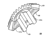
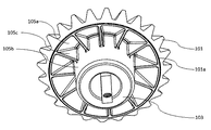
図1は、本発明に係る実施形態の金属樹脂複合ギヤ100の構造の一例を模式的に示した斜視図である。図2および3は、本発明に係る実施形態の金属樹脂複合ギヤ100の構造の一例を模式的に示した、上方から見た斜視断面図である。図4は、本発明に係る実施形態の金属樹脂複合ギヤの構造の一例を模式的に示した、下方から見た斜視図である。
[Metal resin composite gear]
First, the metal
FIG. 1 is a perspective view schematically showing an example of the structure of a metal
本実施形態に係る金属樹脂複合ギヤ100は、第1の金属材料により構成された歯車部101と、第2の金属材料により構成された軸受け部103と、歯車部101と軸受け部103とを連結する熱可塑性樹脂部105と、を備え、歯車部101は、少なくとも熱可塑性樹脂部105との接合部表面(A)に微細凹凸構造(α)を有しており、該微細凹凸構造(α)に熱可塑性樹脂部105の一部分が浸入することにより歯車部101と熱可塑性樹脂部105とが接合されている。
The metal-
ここで、微細凹凸構造(α)は、例えば、間隔周期が5nm以上500μm以下である凸部が林立した微細凹凸構造である。
歯車部101の接合部表面(A)に形成された微細凹凸構造(α)に熱可塑性樹脂部105の一部分が侵入して歯車部101と熱可塑性樹脂部105が接合し、金属―樹脂界面を形成することにより本実施形態に係る金属樹脂複合ギヤ100が得られる。
Here, the fine concavo-convex structure (α) is, for example, a fine concavo-convex structure in which convex portions having an interval period of 5 nm to 500 μm stand.
A portion of the
歯車部101の接合部表面(A)には、歯車部101と熱可塑性樹脂部105との間の接合強度向上に適した微細凹凸構造(α)が形成されているため、例えば、片末端にエポキシ基あるいはアミノ基のいずれかを有するシランカップリング剤、エポキシ樹脂系接着剤、アイオノマー、エチレン−アクリレート共重合体、変性ポリプロピレン、変性ポリエチレン等の接着剤の使用量を削減した場合や、これらの接着剤を使用しない場合であっても、歯車部101と熱可塑性樹脂部105との間の接合性を優れたものにすることができ、その結果、軽量化が可能で、かつ、ギヤとしての十分な強度および耐衝撃性を有するギヤを提供することができる。
具体的には、歯車部101の接合部表面(A)に接するように熱可塑性樹脂部105を成形、好ましくは射出成形(金属インサート成形)することにより、歯車部101の接合部表面(A)の微細凹凸構造(α)の中に熱可塑性樹脂部105を構成する熱可塑性樹脂を進入させることができる。こうすることによって、歯車部101と熱可塑性樹脂部105との間に物理的な抵抗力(アンカー効果)が効果的に発現し、歯車部101と熱可塑性樹脂部105とを強固に接合することが可能になる。
Since the fine uneven structure (α) suitable for improving the joint strength between the
Specifically, the surface of the joint portion (A) of the
このようにして得られた金属樹脂複合ギヤ100はギヤの一部が重い金属から軽量な樹脂に置き換わるため、ギヤ全体が金属材料により構成されているギヤに比べて、軽量にすることができる。また、歯車部101が金属材料により構成されていることにより、ギヤ全体が金属材料により構成されているギヤと同等の耐摩耗性が得られる。さらに歯車部101と熱可塑性樹脂部105との接合が強固なため、ギヤとしての強度を良好なものとすることができる。さらに、ギヤの一部に耐衝撃性に優れる熱可塑性樹脂を用いているため、ギヤの耐衝撃性も優れている。また、歯車部101と熱可塑性樹脂部105との接合部分からの水分や湿気、油分の浸入を効果的に防ぐことができるため、耐湿性や耐油性に優れた金属樹脂複合ギヤ100を実現できる。
The metal-
本実施形態に係る金属樹脂複合ギヤ100において、図3に示すように、歯車部101は、少なくとも熱可塑性樹脂部105との接合部表面(A)に溝構造101bを有することが好ましい。これにより、熱可塑性樹脂部105の一部分が溝構造101bの溝部分に充填され、歯車部101と熱可塑性樹脂部105との接触面積を増加させることができ、その結果、歯車部101と熱可塑性樹脂部105との接合性をより一層良好なものとすることができる。
また、歯車部101に溝構造101bを設けることにより、歯車部101が占める体積を減らすことができ、金属樹脂複合ギヤ100をより一層軽量にすることができる。さらには、歯車部101と熱可塑性樹脂部105の接合部が剥離した場合であっても、歯車部101の脱落防止につなげられる。
溝構造101bの断面形状としては、U字状、V字状、コの字状、ハの字状、逆ハの字状(アリ溝)を挙げることができる。
溝構造101bは、接合部表面(A)の周方向に沿って連続的または断続的に形成されていてもよいし、周方向と直行するように形成されていてもよいし、周方向に対して90°未満の角度で傾斜するように形成されていてもよいし、これらの溝構造の二種類以上が共存する溝構造であってもよい。なお、上記した断続的な形成には点状に窪みが形成されている場合も含む。
In the metal
Further, by providing the
Examples of the cross-sectional shape of the
The
本実施形態に係る金属樹脂複合ギヤ100において、軸受け部103は、少なくとも熱可塑性樹脂部105との接合部表面(B)に微細凹凸構造(β)を有することが好ましい。この場合、上記微細凹凸構造(β)に熱可塑性樹脂部105の一部分が浸入することにより軸受け部103と熱可塑性樹脂部105とが接合されていることが好ましい。
In the metal-
ここで、微細凹凸構造(β)は、例えば、間隔周期が5nm以上500μm以下である凸部が林立した微細凹凸構造である。
軸受け部103の接合部表面(B)に形成された微細凹凸構造(β)に熱可塑性樹脂部105の一部分が侵入して軸受け部103と熱可塑性樹脂部105が接合し、金属―樹脂界面を形成することができる。
Here, the fine concavo-convex structure (β) is, for example, a fine concavo-convex structure in which convex portions having an interval period of 5 nm to 500 μm stand.
A part of the
軸受け部103の接合部表面(B)に、軸受け部103と熱可塑性樹脂部105との間の接合強度向上に適した微細凹凸構造(β)が形成されている場合、例えば、片末端にエポキシ基あるいはアミノ基のいずれかを有するシランカップリング剤、エポキシ樹脂系接着剤、アイオノマー、エチレン−アクリレート共重合体、変性ポリプロピレン、変性ポリエチレン等の接着剤の使用量を削減した場合や、これらの接着剤を使用しない場合であっても、軸受け部103と熱可塑性樹脂部105との間の接合性をより一層優れたものにすることができ、その結果、軽量化が可能で、かつ、より一層良好な強度を有するギヤを提供することができる。
具体的には、軸受け部103の接合部表面(B)に接するように熱可塑性樹脂部105を成形、好ましくは射出成形することにより、軸受け部103の接合部表面(B)の微細凹凸構造(β)の中に熱可塑性樹脂部105を構成する熱可塑性樹脂を進入させることができる。こうすることによって、軸受け部103と熱可塑性樹脂部105との間に物理的な抵抗力(アンカー効果)が効果的に発現し、軸受け部103と熱可塑性樹脂部105とを強固に接合することが可能になる。
本実施形態に係る軸受け部103においては、上記した歯車部101と同様に、少なくても熱可塑性樹脂部105との接合部表面(B)に溝構造を有していてもよい。
When a fine uneven structure (β) suitable for improving the bonding strength between the bearing
Specifically, by forming, preferably injection molding, the
The bearing
図1に示すように、本実施形態に係る金属樹脂複合ギヤ100は、例えば、回転軸部としてのシャフト200を有していてもよい。シャフト200は軸受け部103を貫通している。
また、シャフト200を構成する金属材料としては、例えば、鉄、鉄鋼材、ステンレス、アルミニウム、アルミニウム合金等が挙げられる。シャフト200を構成する金属材料としてアルミニウムやアルミニウム合金等を使用する場合、シャフト200をより軽量にすることができる。一方、シャフト200を構成する金属材料として鉄や鉄鋼材、ステンレス等を使用する場合、シャフト200をより高剛性にすることができる。
As shown in FIG. 1, the metal
Moreover, as a metal material which comprises the
本実施形態に係る金属樹脂複合ギヤ100としては、例えば、ウォームギヤ、ねじ歯車、ラックギヤ、はすば歯車、平歯車、かさ歯車、ハイポイドギヤが挙げられる。本実施形態に係る金属樹脂複合ギヤ100は高強度、軽量および耐衝撃性の性能バランスに優れているため、工作機械や産業用ロボット、生活支援ロボット等のギヤ類として有用なかさ歯車に好適に用いられる。かさ歯車の歯すじは、すぐばかさ歯車であってもよいし、はすばかさ歯車であってもよいし、まがりばかさ歯車であってもよい。さらに、本実施形態に係る金属樹脂複合ギヤ100は、マイタ歯車(以下、マイタギヤとも呼ぶ。)として特に好んで用いられる。ここで、マイタ歯車は、例えば、交わるかさ歯車の歯数が同一であり、ピッチ面が45°である。
Examples of the metal
また、本実施形態に係る金属樹脂複合ギヤ100は、後述する射出成形法によって製造される場合は生産性が極めて高く、形状制御の自由度も高いので、様々な用途に展開することが可能である。本実施形態に係る金属樹脂複合ギヤ100は、例えば、車両用のギヤ、ロボット用のギヤ等に用いることができる。
Further, the metal
以下、本実施形態に係る金属樹脂複合ギヤ100を構成する各部材について説明する。
Hereinafter, each member which comprises the metal
<歯車部>
歯車部101は、所定の厚みを有する円環状に形成されている。本実施形態の場合、歯車部101の外周面に沿って複数の歯が一定間隔で設けられている。歯車部101は、例えば、金型鋳造等により作製される。
<Gear part>
The
歯車部101を構成する第1の金属材料は特に限定されないが、例えば、鉄、鉄鋼材、ステンレス、アルミニウム、アルミニウム合金、マグネシウム、マグネシウム合金、銅、銅合金、チタンおよびチタン合金等を挙げることができる。これらは単独で使用してもよいし、二種以上組み合わせて使用してもよい。
これらの中でも、軽量かつ高強度の点から、アルミニウム(アルミニウム単体)およびアルミニウム合金が好ましく、アルミニウム合金がより好ましい。また、耐摩耗性の観点から、鉄、鉄鋼材およびステンレスが好ましい。歯車部101は特に耐摩耗性が求められるため、歯車部101を構成する第1の金属材料としては、鉄、鉄鋼材およびステンレスが特に好ましい。
Although the 1st metal material which comprises the
Among these, aluminum (aluminum simple substance) and aluminum alloy are preferable from the viewpoint of light weight and high strength, and aluminum alloy is more preferable. From the viewpoint of wear resistance, iron, steel materials and stainless steel are preferable. Since the
歯車部101の接合部表面(A)には、例えば、間隔周期が5nm以上500μm以下である凸部が林立した微細凹凸構造(α)が形成されている。
ここで、微細凹凸構造(α)の間隔周期は凸部から隣接する凸部までの距離の平均値であり、電子顕微鏡またはレーザー顕微鏡で撮影した写真、あるいは表面粗さ測定装置を用いて求めることができる。
電子顕微鏡またはレーザー顕微鏡により測定される間隔周期は通常500nm未満の間隔周期であり、具体的には歯車部101の接合部表面(A)を撮影する。その写真から、任意の凸部を50個選択し、それらの凸部から隣接する凸部までの距離をそれぞれ測定する。凸部から隣接する凸部までの距離の全てを積算して50で除したものを間隔周期とする。一方、500nmを超える間隔周期は通常、表面粗さ測定装置を用いて求める。
なお、通常、歯車部101の接合部表面(A)だけでなく、歯車部101の表面全体に対し、表面粗化処理が施されているため、歯車部101の接合部表面(A)と同一面で、接合部表面(A)以外の箇所から間隔周期を測定することもできる。
On the joint surface (A) of the
Here, the interval period of the fine concavo-convex structure (α) is an average value of the distance from the convex part to the adjacent convex part, and is obtained using a photograph taken with an electron microscope or a laser microscope or a surface roughness measuring device. Can do.
The interval period measured by an electron microscope or a laser microscope is usually an interval period of less than 500 nm, and specifically, the joint surface (A) of the
Usually, not only the joint surface (A) of the
上記間隔周期は、好ましくは10nm以上300μm以下、より好ましくは20nm以上200μm以下である。
上記間隔周期が上記下限値以上であると、微細凹凸構造(α)の凹部に熱可塑性樹脂部105を構成する熱可塑性樹脂が十分に進入することができ、歯車部101と熱可塑性樹脂部105との接合強度をより向上させることができる。また、上記間隔周期が上記上限値以下であると、歯車部101と熱可塑性樹脂部105との接合部分に隙間が生じるのを抑制できる。その結果、金属―樹脂界面の隙間から水分等の不純物が浸入することを抑制できるため、金属樹脂複合ギヤ100を高温、高湿下で用いた際、強度が低下することを抑制できる。
The interval period is preferably 10 nm to 300 μm, more preferably 20 nm to 200 μm.
When the interval period is equal to or more than the lower limit value, the thermoplastic resin constituting the
上記間隔周期を有する微細凹凸構造を形成する方法としては、NaOH等の無機塩基水溶液および/またはHCl、HNO3等の無機酸水溶液に第1の金属材料を浸漬する方法;陽極酸化法により第1の金属材料を処理する方法;機械的切削、例えばダイヤモンド砥粒研削またはブラスト加工によって作製した凹凸を有する金型パンチをプレスすることにより金属表面に凹凸を形成する方法や、サンドブラスト、ローレット加工、レーザー加工により金属表面に凹凸形状を作成する方法;国際公開第2009/31632号パンフレットに開示されているような、水和ヒドラジン、アンモニア、および水溶性アミン化合物から選ばれる1種以上の水溶液に第1の金属材料を浸漬する方法等が挙げられる。これらの方法は、歯車部101を構成する第1の金属材料の種類や、上記間隔周期の範囲内において形成する凹凸形状によって使い分けることが可能である。本実施形態においては、NaOH等の無機塩基水溶液および/またはHCl、HNO3等の無機酸水溶液に第1の金属材料を浸漬する方法が、第1の金属材料を広範囲にわたってまとめて処理することができることや、また第1の金属材料と熱可塑性樹脂との接合力に優れることから好ましい。
As a method of forming the fine concavo-convex structure having the above-described interval period, a method of immersing the first metal material in an inorganic base aqueous solution such as NaOH and / or an inorganic acid aqueous solution such as HCl and HNO 3 ; A method of processing metal materials of: a method of forming irregularities on a metal surface by pressing a die punch having irregularities produced by mechanical cutting, such as diamond abrasive grinding or blasting, sandblasting, knurling, laser A method for producing a concavo-convex shape on a metal surface by processing; firstly, one or more aqueous solutions selected from hydrated hydrazine, ammonia, and a water-soluble amine compound as disclosed in WO2009 / 31632 pamphlet; And a method of immersing the metal material. These methods can be selectively used depending on the type of the first metal material constituting the
また、歯車部101と熱可塑性樹脂部105との接合強度をより一層向上させる観点から、歯車部101の接合部表面(A)上の、十点平均粗さ(Rz)が好ましくは2μm超え、より好ましくは5μm超え、さらに好ましくは10μm超えである。歯車部101と熱可塑性樹脂部105との接合強度の視点からは、更に粗さ曲線要素の平均長さ(RSm)の平均値が好ましくは10μm以上300μm以下、より好ましくは20μm以上200μm以下である要件を満たすことが好ましい。
Further, from the viewpoint of further improving the joint strength between the
歯車部101の接合部表面(A)の間隔周期、十点平均粗さ(Rz)、粗さ曲線要素の平均長さ(RSm)は、歯車部101の接合部表面(A)に対する粗化処理の条件を適切に調節することにより制御することが可能である。
本実施形態においては、とくに粗化処理の温度および時間、エッチング量等が、上記間隔周期や十点平均粗さ(Rz)、粗さ曲線要素の平均長さ(RSm)を制御するための因子として挙げられる。
The interval period, ten-point average roughness (Rz), and average length (RSm) of the roughness curve element of the joint surface (A) of the
In this embodiment, in particular, the temperature and time of the roughening treatment, the etching amount, and the like are factors for controlling the interval period, the ten-point average roughness (Rz), and the average length (RSm) of the roughness curve elements. As mentioned.
次に、上記間隔周期、十点平均粗さ(Rz)、粗さ曲線要素の平均長さ(RSm)等を満たす歯車部101の調製方法について説明する。
このような歯車部101は、例えば、エッチング剤を用いて第1の金属材料の表面を粗化処理することにより形成することができる。
以下、上記間隔周期、十点平均粗さ(Rz)、粗さ曲線要素の平均長さ(RSm)等を満たす歯車部101を得るための第1の金属材料の粗化処理方法の一例を示す。ただし、本実施形態に係る第1の金属材料の粗化処理方法は、以下の例に限定されない。
Next, the preparation method of the
Such a
Hereinafter, an example of a first metal material roughening method for obtaining the
(1)前処理工程
まず、第1の金属材料は、熱可塑性樹脂部105との接合側の表面に酸化膜や水酸化物等からなる厚い被膜がないことが望ましい。このような厚い被膜を除去するため、次のエッチング剤で処理する工程の前に、サンドブラスト加工、ショットブラスト加工、研削加工、バレル加工等の機械研磨や、化学研磨により表面層を研磨してもよい。また、熱可塑性樹脂部105との接合側の表面に機械油等の著しい汚染がある場合は、水酸化ナトリウム水溶液や水酸化カリウム水溶液等のアルカリ性水溶液による処理や、脱脂を行なうことが好ましい。
(1) Pretreatment Step First, it is desirable that the first metal material does not have a thick film made of an oxide film, hydroxide, or the like on the surface on the bonding side with the
(2)表面粗化処理工程
本実施形態において第1の金属材料の表面粗化処理方法としては、後述する酸系エッチング剤による処理を特定のタイミングで行うことが好ましい。具体的には、該酸系エッチング剤による処理を表面粗化処理工程の最終段階で行うことが好ましい。
(2) Surface Roughening Treatment Step In the present embodiment, as the first metal material surface roughening treatment method, it is preferable to perform treatment with an acid-based etching agent described later at a specific timing. Specifically, the treatment with the acid-based etching agent is preferably performed at the final stage of the surface roughening treatment step.
上記酸系エッチング剤を用いて粗化処理する方法としては、浸漬、スプレー等による処理方法が挙げられる。処理温度は20〜40℃が好ましく、処理時間は5〜350秒程度が好ましく、第1の金属材料表面をより均一に粗化できる観点から、20〜300秒がより好ましく、50〜300秒が特に好ましい。 Examples of the roughening treatment using the acid-based etching agent include treatment methods such as immersion and spraying. The treatment temperature is preferably 20 to 40 ° C., the treatment time is preferably about 5 to 350 seconds, and 20 to 300 seconds is more preferred, and 50 to 300 seconds is preferred from the viewpoint that the surface of the first metal material can be more uniformly roughened. Particularly preferred.
上記酸系エッチング剤を用いた粗化処理によって、第1の金属材料の表面が凹凸形状に粗化される。上記酸系エッチング剤を用いた際の第1の金属材料の深さ方向のエッチング量(溶解量)は、溶解した第1の金属材料の質量、比重および表面積から算出した場合、0.1〜500μmであることが好ましく、5〜500μmであることがより好ましく、5〜100μmであることが更に好ましい。エッチング量が上記下限値以上であれば、歯車部101と熱可塑性樹脂部105との接合強度をより向上させることができる。また、エッチング量が上記上限値以下であれば、処理コストの低減が可能となる。エッチング量は、処理温度や処理時間等により調整できる。
By the roughening treatment using the acid-based etching agent, the surface of the first metal material is roughened into an uneven shape. The etching amount (dissolution amount) in the depth direction of the first metal material when the acid-based etching agent is used is 0.1 to 0.1 when calculated from the mass, specific gravity, and surface area of the dissolved first metal material. It is preferably 500 μm, more preferably 5 to 500 μm, and still more preferably 5 to 100 μm. If the etching amount is equal to or greater than the lower limit, the bonding strength between the
なお、本実施形態では、上記酸系エッチング剤を用いて第1の金属材料を粗化処理する際、第1の金属材料表面の全面を粗化処理してもよく、熱可塑性樹脂部105が接合される面だけを部分的に粗化処理してもよい。
In this embodiment, when the first metal material is roughened using the acid-based etchant, the entire surface of the first metal material may be roughened, and the
(3)後処理工程
本実施形態では、上記表面粗化処理工程の後、通常、水洗および乾燥を行うことが好ましい。水洗の方法については特に制限はないが浸漬または流水にて所定時間洗浄することが好ましい。
(3) Post-treatment step In this embodiment, it is usually preferable to perform washing and drying after the surface roughening treatment step. Although there is no restriction | limiting in particular about the method of water washing, It is preferable to wash | clean for predetermined time with immersion or flowing water.
さらに、後処理工程としては、上記酸系エッチング剤を用いた処理により生じたスマット等を除去するため、超音波洗浄を施すことが好ましい。超音波洗浄の条件は、生じたスマット等を除去することができる条件であれば特に限定されないが、用いる溶媒としては水が好ましく、また、処理時間としては、好ましくは1〜20分間である。 Furthermore, as a post-treatment step, it is preferable to perform ultrasonic cleaning in order to remove smut and the like generated by the treatment using the acid-based etching agent. The ultrasonic cleaning conditions are not particularly limited as long as the generated smut and the like can be removed, but the solvent used is preferably water, and the treatment time is preferably 1 to 20 minutes.
(酸系エッチング剤)
本実施形態において、第1の金属材料表面の粗化処理に用いられるエッチング剤としては、後述する特定の酸系エッチング剤が好ましい。上記特定のエッチング剤で処理することにより、第1の金属材料の表面に、熱可塑性樹脂部105との間の密着性向上に適した微細凹凸構造が形成され、そのアンカー効果により歯車部101と熱可塑性樹脂部105との間の接合強度がより一層向上するものと考えられる。
(Acid etching agent)
In this embodiment, as an etching agent used for the roughening process of the 1st metal material surface, the specific acid type etching agent mentioned later is preferable. By treating with the specific etching agent, a fine concavo-convex structure suitable for improving adhesion to the
以下、本実施形態で使用できる酸系エッチング剤の成分について説明する。 Hereinafter, the components of the acid-based etching agent that can be used in this embodiment will be described.
上記酸系エッチング剤は、第二鉄イオンおよび第二銅イオンの少なくとも一方と、酸と、を含み、必要に応じて、マンガンイオン、各種添加剤等を含むことができる。 The acid-based etching agent contains at least one of ferric ions and cupric ions and an acid, and may contain manganese ions, various additives, and the like as necessary.
・第二鉄イオン
上記第二鉄イオンは、第1の金属材料を酸化する成分であり、第二鉄イオン源を配合することによって、酸系エッチング剤中に該第二鉄イオンを含有させることができる。上記第二鉄イオン源としては、硝酸第二鉄、硫酸第二鉄、塩化第二鉄等が挙げられる。上記第二鉄イオン源のうちでは、塩化第二鉄が溶解性に優れ、安価であるという点から好ましい。
-Ferric ion The ferric ion is a component that oxidizes the first metal material, and by incorporating a ferric ion source, the ferric ion is included in the acid-based etching agent. Can do. Examples of the ferric ion source include ferric nitrate, ferric sulfate, and ferric chloride. Among the ferric ion sources, ferric chloride is preferable because it has excellent solubility and is inexpensive.
本実施形態において、酸系エッチング剤中の上記第二鉄イオンの含有量は、好ましくは0.01〜20質量%、より好ましくは0.1〜12質量%、さらに好ましくは0.5〜7質量%、さらにより好ましくは1〜6質量%、特に好ましくは1〜5質量%である。上記第二鉄イオンの含有量が上記下限値以上であれば、第1の金属材料の粗化速度(溶解速度)の低下を防ぐことができる。一方、上記第二鉄イオンの含有量が上記上限値以下であれば、粗化速度を適正に維持することができるため、歯車部101と熱可塑性樹脂部105との間の接合強度向上により適した均一な粗化が可能になる。
In this embodiment, content of the said ferric ion in an acid type etching agent becomes like this. Preferably it is 0.01-20 mass%, More preferably, it is 0.1-12 mass%, More preferably, it is 0.5-7 % By mass, still more preferably 1-6% by mass, particularly preferably 1-5% by mass. If content of the said ferric ion is more than the said lower limit, the fall of the roughening rate (dissolution rate) of a 1st metal material can be prevented. On the other hand, if the content of the ferric ion is not more than the above upper limit value, the roughening rate can be properly maintained, so that the bonding strength between the
・第二銅イオン
上記第二銅イオンは第1の金属材料を酸化する成分であり、第二銅イオン源を配合することによって、酸系エッチング剤中に該第二銅イオン含有させることができる。上記第二銅イオン源としては、硫酸第二銅、塩化第二銅、硝酸第二銅、水酸化第二銅等が挙げられる。上記第二銅イオン源のうちでは、硫酸第二銅、塩化第二銅が安価であるという点から好ましい。
-Cupric ion The said cupric ion is a component which oxidizes a 1st metal material, and can mix | blend this cupric ion in an acid type etching agent by mix | blending a cupric ion source. . Examples of the cupric ion source include cupric sulfate, cupric chloride, cupric nitrate, and cupric hydroxide. Of the cupric ion sources, cupric sulfate and cupric chloride are preferred because they are inexpensive.
本実施形態において、酸系エッチング剤中の上記第二銅イオンの含有量は、0.001〜10質量%であることが好ましく、より好ましくは0.01〜7質量%、さらに好ましくは0.05〜1質量%、さらにより好ましくは0.1〜0.8質量%、さらにより好ましくは0.15〜0.7質量%、特に好ましくは0.15〜0.4質量%である。上記第二銅イオンの含有量が上記下限値以上であれば、第1の金属材料の粗化速度(溶解速度)の低下を防ぐことができる。一方、上記第二銅イオンの含有量が上記上限値以下であれば、粗化速度を適正に維持することができるため、歯車部101と熱可塑性樹脂部105との間の接合強度向上により適した均一な粗化が可能になる。
In this embodiment, it is preferable that content of the said cupric ion in an acid type etching agent is 0.001-10 mass%, More preferably, it is 0.01-7 mass%, More preferably, it is 0.00. It is 05-1 mass%, More preferably, it is 0.1-0.8 mass%, More preferably, it is 0.15-0.7 mass%, Most preferably, it is 0.15-0.4 mass%. If content of the said cupric ion is more than the said lower limit, the fall of the roughening rate (dissolution rate) of a 1st metal material can be prevented. On the other hand, if the content of the cupric ion is less than or equal to the above upper limit value, the roughening rate can be properly maintained, and thus more suitable for improving the bonding strength between the
上記酸系エッチング剤は、第二鉄イオンおよび第二銅イオンの一方のみを含むものであってもよく、両方を含むものであってもよいが、第二鉄イオンおよび第二銅イオンの両方を含むことが好ましい。酸系エッチング剤が第二鉄イオンおよび第二銅イオンの両方を含むことで、歯車部101と熱可塑性樹脂部105との間の接合強度向上により適した良好な粗化形状が容易に得られる。
The acid-based etching agent may contain only one of ferric ion and cupric ion, or may contain both, but both ferric ion and cupric ion It is preferable to contain. By including both the ferric ion and the cupric ion in the acid-based etching agent, a good roughened shape suitable for improving the bonding strength between the
上記酸系エッチング剤が、第二鉄イオンおよび第二銅イオンの両方を含む場合、第二鉄イオンおよび第二銅イオンのそれぞれの含有量が、上記範囲であることが好ましい。また、酸系エッチング剤中の第二鉄イオンと第二銅イオンの含有量の合計は、0.011〜20質量%であることが好ましく、より好ましくは0.1〜15質量%、さらに好ましくは0.5〜10質量%、特に好ましくは1〜5質量%である。 When the acid-based etching agent contains both ferric ions and cupric ions, the contents of ferric ions and cupric ions are preferably in the above ranges. The total content of ferric ions and cupric ions in the acid-based etching agent is preferably 0.011 to 20% by mass, more preferably 0.1 to 15% by mass, and even more preferably. Is 0.5 to 10% by mass, particularly preferably 1 to 5% by mass.
・マンガンイオン
上記酸系エッチング剤には、第1の金属材料表面をむらなく一様に粗化するために、マンガンイオンが含まれていてもよい。マンガンイオンは、マンガンイオン源を配合することによって、酸系エッチング剤中に該マンガンイオンを含有させることができる。上記マンガンイオン源としては、硫酸マンガン、塩化マンガン、酢酸マンガン、フッ化マンガン、硝酸マンガン等が挙げられる。上記マンガンイオン源のうちでは、硫酸マンガン、塩化マンガンが安価である等の点から好ましい。
Manganese ions The acid-based etching agent may contain manganese ions in order to uniformly roughen the surface of the first metal material. Manganese ions can be contained in the acid-based etching agent by blending a manganese ion source. Examples of the manganese ion source include manganese sulfate, manganese chloride, manganese acetate, manganese fluoride, and manganese nitrate. Among the above manganese ion sources, manganese sulfate and manganese chloride are preferable from the viewpoint of being inexpensive.
本実施形態において、酸系エッチング剤中の上記マンガンイオンの含有量は、0〜1質量%であることが好ましく、より好ましくは0〜0.5質量%である。 In this embodiment, it is preferable that content of the said manganese ion in an acid type etching agent is 0-1 mass%, More preferably, it is 0-0.5 mass%.
・酸
上記酸は、第二鉄イオンおよび/または第二銅イオンにより酸化された金属を溶解させる成分である。上記酸としては、塩酸、臭化水素酸、硫酸、硝酸、リン酸、過塩素酸、スルファミン酸等の無機酸や、スルホン酸、カルボン酸等の有機酸が挙げられる。上記カルボン酸としては、ギ酸、酢酸、クエン酸、シュウ酸、リンゴ酸等が挙げられる。上記酸系エッチング剤には、これらの酸を一種または二種以上配合することができる。上記無機酸のうちでは、臭気がほとんどなく、安価である点から硫酸が好ましい。また、上記有機酸のうちでは、粗化形状の均一性の観点から、カルボン酸が好ましい。
-Acid The acid is a component that dissolves a metal oxidized by ferric ions and / or cupric ions. Examples of the acid include inorganic acids such as hydrochloric acid, hydrobromic acid, sulfuric acid, nitric acid, phosphoric acid, perchloric acid, and sulfamic acid, and organic acids such as sulfonic acid and carboxylic acid. Examples of the carboxylic acid include formic acid, acetic acid, citric acid, oxalic acid, malic acid and the like. One or more of these acids can be added to the acid-based etching agent. Of the inorganic acids, sulfuric acid is preferred because it has almost no odor and is inexpensive. Among the organic acids, carboxylic acid is preferable from the viewpoint of uniformity of the roughened shape.
本実施形態において、酸系エッチング剤中の上記酸の含有量は、0.1〜50質量%であることが好ましく、0.5〜50質量%であることがより好ましく、1〜50質量%であることがさらに好ましく、1〜30質量%であることがさらにより好ましく、1〜25質量%であることがさらにより好ましく、2〜18質量%であることがさらにより好ましい。上記酸の含有量が上記下限値以上であれば、第1の金属材料の粗化速度(溶解速度)の低下を防止できる。一方、上記酸の含有量が上記上限値以下であれば、液温が低下した際の第1の金属材料の金属塩の結晶析出を防止できるため、作業性を向上できる。 In the present embodiment, the acid content in the acid-based etching agent is preferably 0.1 to 50% by mass, more preferably 0.5 to 50% by mass, and 1 to 50% by mass. It is still more preferable, it is still more preferable that it is 1-30 mass%, it is still more preferable that it is 1-25 mass%, and it is still more preferable that it is 2-18 mass%. If content of the said acid is more than the said lower limit, the fall of the roughening rate (dissolution rate) of a 1st metal material can be prevented. On the other hand, if the content of the acid is equal to or lower than the upper limit value, it is possible to prevent crystal precipitation of the metal salt of the first metal material when the liquid temperature is lowered, so that workability can be improved.
・他の成分
本実施形態において使用できる酸系エッチング剤には、指紋等の表面汚染物による粗化のむらを防ぐために界面活性剤を添加してもよく、必要に応じて他の添加剤を添加してもよい。他の添加剤としては、深い凹凸を形成するために添加されるハロゲン化物イオン源、例えば、塩化ナトリウム、塩化カリウム、臭化ナトリウム、臭化カリウム等を例示できる。あるいは、粗化処理速度を上げるために添加されるチオ硫酸イオン、チオ尿素等のチオ化合物や、より均一な粗化形状を得るために添加されるイミダゾール、トリアゾール、テトラゾール等のアゾール類や、粗化反応を制御するために添加されるpH調整剤等も例示できる。これら他の成分を添加する場合、その合計含有量は、酸系エッチング剤中に0.01〜10質量%程度であることが好ましい。
Other components To the acid-based etching agent that can be used in the present embodiment, a surfactant may be added to prevent unevenness due to surface contaminants such as fingerprints, and other additives may be added as necessary. May be. Other additives include halide ion sources added to form deep irregularities, such as sodium chloride, potassium chloride, sodium bromide, potassium bromide and the like. Alternatively, thio compounds such as thiosulfate ions and thiourea added to increase the roughening treatment speed, azoles such as imidazole, triazole and tetrazole added to obtain a more uniform roughened shape, Examples thereof include a pH adjuster added to control the oxidization reaction. When these other components are added, the total content is preferably about 0.01 to 10% by mass in the acid-based etching agent.
本実施形態の酸系エッチング剤は、上記の各成分をイオン交換水等に溶解させることにより容易に調製することができる。 The acid-based etching agent of this embodiment can be easily prepared by dissolving each of the above components in ion-exchanged water or the like.
<軸受け部>
図1に示すように、軸受け部103は、例えば、回転軸部としてのシャフト200を貫通させて固定する役割を有する。
軸受け部103は、例えば、金型鋳造等により作製される。
<Bearing part>
As shown in FIG. 1, the bearing
The
軸受け部103を構成する第2の金属材料は特に限定されないが、例えば、鉄、鉄鋼材、ステンレス、アルミニウム、アルミニウム合金、マグネシウム、マグネシウム合金、銅、銅合金、チタンおよびチタン合金等を挙げることができる。これらは単独で使用してもよいし、二種以上組み合わせて使用してもよい。
これらの中でも、軽量かつ高強度の点から、アルミニウム(アルミニウム単体)およびアルミニウム合金が好ましく、アルミニウム合金がより好ましい。また、耐摩耗性の観点から、鉄、鉄鋼材およびステンレスが好ましい。軸受け部103を構成する第2の金属材料としては、アルミニウム(アルミニウム単体)およびアルミニウム合金が特に好ましい。
Although the 2nd metal material which comprises the
Among these, aluminum (aluminum simple substance) and aluminum alloy are preferable from the viewpoint of light weight and high strength, and aluminum alloy is more preferable. From the viewpoint of wear resistance, iron, steel materials and stainless steel are preferable. As the second metal material constituting the bearing
軸受け部103の接合部表面(B)には、例えば、間隔周期が5nm以上500μm以下である凸部が林立した微細凹凸構造(β)が形成されている。
ここで、微細凹凸構造(β)の間隔周期は凸部から隣接する凸部までの距離の平均値であり、電子顕微鏡またはレーザー顕微鏡で撮影した写真、あるいは表面粗さ測定装置を用いて求めることができる。
電子顕微鏡またはレーザー顕微鏡により測定される間隔周期は通常500nm未満の間隔周期であり、具体的には軸受け部103の接合部表面(B)を撮影する。その写真から、任意の凸部を50個選択し、それらの凸部から隣接する凸部までの距離をそれぞれ測定する。凸部から隣接する凸部までの距離の全てを積算して50で除したものを間隔周期とする。一方、500nmを超える間隔周期は通常、表面粗さ測定装置を用いて求める。
なお、通常、軸受け部103の接合部表面(B)だけでなく、軸受け部103の表面全体に対し、表面粗化処理が施されているため、軸受け部103の接合部表面(B)と同一面で、接合部表面(B)以外の箇所から間隔周期を測定することもできる。
On the joint surface (B) of the bearing
Here, the interval period of the fine concavo-convex structure (β) is an average value of the distance from the convex part to the adjacent convex part, and is obtained using a photograph taken with an electron microscope or a laser microscope or a surface roughness measuring device. Can do.
The interval period measured by the electron microscope or the laser microscope is usually an interval period of less than 500 nm. Specifically, the joint surface (B) of the bearing
Usually, not only the joint surface (B) of the bearing
上記間隔周期は、好ましくは10nm以上300μm以下、より好ましくは20nm以上200μm以下である。
上記間隔周期が上記下限値以上であると、微細凹凸構造(β)の凹部に熱可塑性樹脂部105を構成する熱可塑性樹脂が十分に進入することができ、軸受け部103と熱可塑性樹脂部105との接合強度をより向上させることができる。また、上記間隔周期が上記上限値以下であると、軸受け部103と熱可塑性樹脂部105との接合部分に隙間が生じるのを抑制できる。その結果、金属―樹脂界面の隙間から水分等の不純物が浸入することを抑制できるため、金属樹脂複合ギヤ100を高温、高湿下で用いた際、強度が低下することを抑制できる。
The interval period is preferably 10 nm to 300 μm, more preferably 20 nm to 200 μm.
When the interval period is equal to or more than the lower limit value, the thermoplastic resin constituting the
上記間隔周期を有する微細凹凸構造を形成する方法としては、NaOH等の無機塩基水溶液および/またはHCl、HNO3等の無機酸水溶液に第2の金属材料を浸漬する方法;陽極酸化法により第2の金属材料を処理する方法;機械的切削、例えばダイヤモンド砥粒研削またはブラスト加工によって作製した凹凸を有する金型パンチをプレスすることにより金属表面に凹凸を形成する方法や、サンドブラスト、ローレット加工、レーザー加工により金属表面に凹凸形状を作成する方法;国際公開第2009/31632号パンフレットに開示されているような、水和ヒドラジン、アンモニア、および水溶性アミン化合物から選ばれる1種以上の水溶液に第2の金属材料を浸漬する方法等が挙げられる。これらの方法は、軸受け部103を構成する第2の金属材料の種類や、上記間隔周期の範囲内において形成する凹凸形状によって使い分けることが可能である。本実施形態においては、NaOH等の無機塩基水溶液および/またはHCl、HNO3等の無機酸水溶液に第2の金属材料を浸漬する方法が、第2の金属材料を広範囲にわたってまとめて処理することができることや、また第2の金属材料と熱可塑性樹脂との接合力に優れることから好ましい。
As a method of forming the fine concavo-convex structure having the above-mentioned interval cycle, a method of immersing the second metal material in an inorganic base aqueous solution such as NaOH and / or an inorganic acid aqueous solution such as HCl or HNO 3 ; A method of processing metal materials of: a method of forming irregularities on a metal surface by pressing a die punch having irregularities produced by mechanical cutting, such as diamond abrasive grinding or blasting, sandblasting, knurling, laser A method of forming a concavo-convex shape on a metal surface by processing; a second solution containing at least one aqueous solution selected from hydrated hydrazine, ammonia, and a water-soluble amine compound as disclosed in WO2009 / 31632. And a method of immersing the metal material. These methods can be properly used depending on the type of the second metal material constituting the bearing
また、軸受け部103と熱可塑性樹脂部105との接合強度をより一層向上させる観点から、軸受け部103の接合部表面(B)上の、十点平均粗さ(Rz)が好ましくは2μm超え、より好ましくは5μm超え、さらに好ましくは10μm超えである。軸受け部103と熱可塑性樹脂部105との接合強度の視点からは、更に粗さ曲線要素の平均長さ(RSm)の平均値が好ましくは10μm以上300μm以下、より好ましくは20μm以上200μm以下である要件を満たすことが好ましい。
Further, from the viewpoint of further improving the joint strength between the bearing
軸受け部103の接合部表面(B)の間隔周期、十点平均粗さ(Rz)、粗さ曲線要素の平均長さ(RSm)は、軸受け部103の接合部表面(B)に対する粗化処理の条件を適切に調節することにより制御することが可能である。
本実施形態においては、とくに粗化処理の温度および時間、エッチング量等が、上記間隔周期や十点平均粗さ(Rz)、粗さ曲線要素の平均長さ(RSm)を制御するための因子として挙げられる。
The interval period, ten-point average roughness (Rz), and average length (RSm) of the roughness curve element of the joint surface (B) of the bearing
In this embodiment, in particular, the temperature and time of the roughening treatment, the etching amount, and the like are factors for controlling the interval period, the ten-point average roughness (Rz), and the average length (RSm) of the roughness curve elements. As mentioned.
次に、上記間隔周期、十点平均粗さ(Rz)、粗さ曲線要素の平均長さ(RSm)等を満たす軸受け部103の調製方法について説明する。
このような軸受け部103は、例えば、エッチング剤を用いて第2の金属材料の表面を粗化処理することにより形成することができる。エッチング剤を用いた第2の金属材料の表面の粗化処理は、前述した第1の金属材料の粗化処理方法と同様の方法によりおこなうことができる。そのため、ここでの説明は省略する。
Next, the preparation method of the
Such a
<熱可塑性樹脂部>
以下、本実施形態に係る熱可塑性樹脂部105について説明する。
本実施形態に係る熱可塑性樹脂部105は熱可塑性樹脂組成物(P)により構成されている。熱可塑性樹脂組成物(P)は、熱可塑性樹脂(P1)を必須成分として含み、必要に応じて充填材(P2)を含む。さらに、熱可塑性樹脂組成物(P)は必要に応じてその他の配合剤を含む。なお、便宜上、熱可塑性樹脂部105が熱可塑性樹脂(P1)のみからなる場合であっても、熱可塑性樹脂部105は熱可塑性樹脂組成物(P)により構成されていると記載する。
<Thermoplastic resin part>
Hereinafter, the
The
本実施形態に係る熱可塑性樹脂部105の形状については特に限定されないが、金属樹脂複合ギヤ100がかさ歯車である場合は、熱可塑性樹脂部105は、図4に示すとおり、歯車部101の内周面101aに接合する熱可塑性樹脂部(A)105aと、軸受け部103の外周面103bに接合する熱可塑性樹脂部(B)105bと、熱可塑性樹脂部(A)105aと熱可塑性樹脂部(B)105bの二面が成す隙間に、周方向と直交するようにして配置される複数のリブ状の熱可塑性樹脂部(C)105cと、により構成されることが好ましい。熱可塑性樹脂部(A)105aの平均厚み、熱可塑性樹脂部(B)105bの平均厚み、および熱可塑性樹脂部(C)105cの平均厚みは特に限定されないが、相互に2倍以上とはならないことが好ましく、より好ましくは相互に1.5倍以下である。三者の相互の平均厚み比が相互に2倍以下であると、部分的に成形収縮の状態が一定にならず熱可塑性樹脂部にひけ(シンクマーク)、ボイド、或いはそりが発生することを抑制することができる。
熱可塑性樹脂部(A)105a、熱可塑性樹脂部(B)105bおよび熱可塑性樹脂部(C)105cを構成する熱可塑性樹脂の種類は相互に同一であっても異なっていてもよいが、通常、熱可塑性樹脂部105が金属インサート成形(射出成形)によって製造されるという理由によって相互に同一であることが好ましい。
The shape of the
The types of thermoplastic resins constituting the thermoplastic resin part (A) 105a, the thermoplastic resin part (B) 105b, and the thermoplastic resin part (C) 105c may be the same or different from each other. The
熱可塑性樹脂部(A)105a、熱可塑性樹脂部(B)105bおよび熱可塑性樹脂部(C)105cの相互の結合は、成形工程のみで結合一体化されていてもよいし、熱可塑性樹脂部(A)105aと熱可塑性樹脂部(B)105bを成形工程のみで結合・一体化したのちに、次いで熱可塑性樹脂部(C)105cを機械的、接着または溶着等の接合手段によって組み立ててもよい。しかし、通常、熱可塑性樹脂部105が射出成形によって製造されるという理由によって、熱可塑性樹脂部(A)105a、熱可塑性樹脂部(B)105bおよび熱可塑性樹脂部(C)105cの相互の結合は、成形工程のみで一体結合されていることが好ましい。リブ状の熱可塑性樹脂部(C)105cの形状は、熱可塑性樹脂部(A)105aと熱可塑性樹脂部(B)105bの両樹脂部に結合点を有する形状を持ち、金属樹脂複合ギヤ100の補強効果を発現している限りは特に限定されないが、具体的には三角リブ板形状が好ましい。リブ状の熱可塑性樹脂部(C)105cの個数は、金属樹脂複合ギヤ100にかかる力によって随時調整されるが、通常6〜36個、好ましくは8〜18個であり、それぞれ均一角度で放射状に配置される。
The thermoplastic resin part (A) 105a, the thermoplastic resin part (B) 105b, and the thermoplastic resin part (C) 105c may be combined together by only the molding step, or the thermoplastic resin part. (A) After the 105a and the thermoplastic resin part (B) 105b are joined and integrated only by the molding process, the thermoplastic resin part (C) 105c is then assembled by a joining means such as mechanical, adhesive or welding. Good. However, since the
(熱可塑性樹脂(P1))
熱可塑性樹脂(P1)としては特に限定されないが、例えば、ポリオレフィン系樹脂、ポリ(メタ)アクリル酸メチル樹脂等の(メタ)アクリル系樹脂、ポリスチレン樹脂、ポリビニルアルコール−ポリ塩化ビニル共重合体樹脂、ポリビニルアセタール樹脂、ポリビニルブチラール樹脂、ポリビニルホルマール樹脂、ポリメチルペンテン樹脂、無水マレイン酸−スチレン共重合体樹脂、ポリカーボネート樹脂、ポリフェニレンエーテル樹脂、ポリエーテルエーテルケトン樹脂、ポリエーテルケトン樹脂等の芳香族ポリエーテルケトン、ポリエステル系樹脂、ポリアミド系樹脂、ポリアミドイミド樹脂、ポリイミド樹脂、ポリエーテルイミド樹脂、スチレン系エラストマー、ポリオレフィン系エラストマー、ポリウレタン系エラストマー、ポリエステル系エラストマー、ポリアミド系エラストマー、アイオノマー、アミノポリアクリルアミド樹脂、イソブチレン無水マレイン酸コポリマー、ABS、ACS、AES、AS、ASA、MBS、エチレン−塩化ビニルコポリマー、エチレン−酢酸ビニルコポリマー、エチレン−酢酸ビニル−塩化ビニルグラフトポリマー、エチレン−ビニルアルコールコポリマー、塩素化ポリ塩化ビニル樹脂、塩素化ポリエチレン樹脂、塩素化ポリプロピレン樹脂、カルボキシビニルポリマー、ケトン樹脂、非晶性コポリエステル樹脂、ノルボルネン樹脂、フッ素プラスチック、ポリテトラフルオロエチレン樹脂、フッ素化エチレンポリプロピレン樹脂、PFA、ポリクロロフルオロエチレン樹脂、エチレンテトラフルオロエチレンコポリマー、ポリフッ化ビニリデン樹脂、ポリフッ化ビニル樹脂、ポリアリレート樹脂、熱可塑性ポリイミド樹脂、ポリ塩化ビニリデン樹脂、ポリ塩化ビニル樹脂、ポリ酢酸ビニル樹脂、ポリサルホン樹脂、ポリパラメチルスチレン樹脂、ポリアリルアミン樹脂、ポリビニルエーテル樹脂、ポリフェニレンオキシド樹脂、ポリフェニレンサルファイド(PPS)樹脂、ポリメチルペンテン樹脂、オリゴエステルアクリレート、キシレン樹脂、マレイン酸樹脂、ポリヒドロキシブチレート樹脂、ポリスルホン樹脂、ポリ乳酸樹脂、ポリグルタミン酸樹脂、ポリカプロラクトン樹脂、ポリエーテルスルホン樹脂、ポリアクリロニトリル樹脂、スチレン−アクリロニトリル共重合体樹脂等、ポリアセタール樹脂が挙げられる。これらの熱可塑性樹脂は一種単独で使用してもよいし、二種以上組み合わせて使用してもよい。
(Thermoplastic resin (P1))
Although it does not specifically limit as a thermoplastic resin (P1), For example, (meth) acrylic-type resin, such as polyolefin resin and poly (meth) acrylic acid methyl resin, polystyrene resin, polyvinyl alcohol-polyvinyl chloride copolymer resin, Aromatic polyethers such as polyvinyl acetal resin, polyvinyl butyral resin, polyvinyl formal resin, polymethylpentene resin, maleic anhydride-styrene copolymer resin, polycarbonate resin, polyphenylene ether resin, polyether ether ketone resin, polyether ketone resin Ketone, polyester resin, polyamide resin, polyamideimide resin, polyimide resin, polyetherimide resin, styrene elastomer, polyolefin elastomer, polyurethane elastomer, poly Steal elastomer, polyamide elastomer, ionomer, aminopolyacrylamide resin, isobutylene maleic anhydride copolymer, ABS, ACS, AES, AS, ASA, MBS, ethylene-vinyl chloride copolymer, ethylene-vinyl acetate copolymer, ethylene-vinyl acetate Vinyl chloride graft polymer, ethylene-vinyl alcohol copolymer, chlorinated polyvinyl chloride resin, chlorinated polyethylene resin, chlorinated polypropylene resin, carboxyvinyl polymer, ketone resin, amorphous copolyester resin, norbornene resin, fluoroplastic, polytetra Fluoroethylene resin, fluorinated ethylene polypropylene resin, PFA, polychlorofluoroethylene resin, ethylenetetrafluoroethylene copolymer, polyfluoride Vinylidene resin, polyvinyl fluoride resin, polyarylate resin, thermoplastic polyimide resin, polyvinylidene chloride resin, polyvinyl chloride resin, polyvinyl acetate resin, polysulfone resin, polyparamethylstyrene resin, polyallylamine resin, polyvinyl ether resin, polyphenylene Oxide resin, polyphenylene sulfide (PPS) resin, polymethylpentene resin, oligoester acrylate, xylene resin, maleic acid resin, polyhydroxybutyrate resin, polysulfone resin, polylactic acid resin, polyglutamic acid resin, polycaprolactone resin, polyethersulfone Examples thereof include polyacetal resins such as resins, polyacrylonitrile resins, and styrene-acrylonitrile copolymer resins. These thermoplastic resins may be used individually by 1 type, and may be used in combination of 2 or more types.
これらの中でも、熱可塑性樹脂(P1)としては、歯車部101または軸受け部103と熱可塑性樹脂部105との接合強度向上効果をより効果的に得ることができる観点から、ポリオレフィン系樹脂、ポリエステル系樹脂、ポリアミド系樹脂、ポリフェニレンサルファイド樹脂、ポリカーボネート樹脂、ポリエーテルエーテルケトン樹脂、ポリエーテルケトン樹脂、ポリイミド樹脂、ポリエーテルスルホン樹脂、ポリスチレン樹脂、ポリアクリロニトリル樹脂、スチレン−アクリロニトリル共重合体樹脂、アクリロニトリル−ブタジエン−スチレン共重合体樹脂、(メタ)アクリル系樹脂、およびポリアセタール樹脂から選択される一種または二種以上の熱可塑性樹脂が好適に用いられる。
Among these, as the thermoplastic resin (P1), from the viewpoint that the effect of improving the bonding strength between the
上記ポリオレフィン系樹脂は、オレフィンを重合して得られる重合体を特に限定なく使用することができる。
上記ポリオレフィン系樹脂を構成するオレフィンとしては、例えば、エチレン、α−オレフィン、環状オレフィン等が挙げられる。
As the polyolefin-based resin, a polymer obtained by polymerizing olefin can be used without any particular limitation.
Examples of the olefin constituting the polyolefin-based resin include ethylene, α-olefin, and cyclic olefin.
上記α−オレフィンとしては、炭素原子数3〜30、好ましくは炭素原子数3〜20の直鎖状または分岐状のα−オレフィンが挙げられる。より具体的には、プロピレン、1−ブテン、1−ペンテン、3−メチル−1−ブテン、1−ヘキセン、4−メチル−1−ペンテン、3−メチル−1−ペンテン、1−オクテン、1−デセン、1−ドデセン、1−テトラデセン、1−ヘキサデセン、1−オクタデセン、1−エイコセン等が挙げられる。 Examples of the α-olefin include linear or branched α-olefins having 3 to 30 carbon atoms, preferably 3 to 20 carbon atoms. More specifically, propylene, 1-butene, 1-pentene, 3-methyl-1-butene, 1-hexene, 4-methyl-1-pentene, 3-methyl-1-pentene, 1-octene, 1-octene, Decene, 1-dodecene, 1-tetradecene, 1-hexadecene, 1-octadecene, 1-eicocene and the like can be mentioned.
上記環状オレフィンとしては、炭素原子数3〜30の環状オレフィンが挙げられ、好ましくは炭素原子数3〜20である。より具体的には、シクロペンテン、シクロヘプテン、ノルボルネン、5−メチル−2−ノルボルネン、テトラシクロドデセン、2−メチル−1,4,5,8−ジメタノ−1,2,3,4,4a,5,8,8a−オクタヒドロナフタレン等が挙げられる。 As said cyclic olefin, a C3-C30 cyclic olefin is mentioned, Preferably it is C3-C20. More specifically, cyclopentene, cycloheptene, norbornene, 5-methyl-2-norbornene, tetracyclododecene, 2-methyl-1,4,5,8-dimethano-1,2,3,4,4a, 5 , 8,8a-octahydronaphthalene and the like.
上記ポリオレフィン系樹脂を構成するオレフィンとして好ましくは、エチレン、プロピレン、1−ブテン、1−ペンテン、3−メチル−1−ブテン、1−ヘキセン、4−メチル−1−ペンテン、3−メチル−1−ペンテン等が挙げられる。これらのうち、より好ましくは、エチレン、プロピレン、1−ブテン、1−ヘキセン、4−メチル−1−ペンテンであり、さらに好ましくはエチレンまたはプロピレンである。 As the olefin constituting the polyolefin resin, ethylene, propylene, 1-butene, 1-pentene, 3-methyl-1-butene, 1-hexene, 4-methyl-1-pentene, 3-methyl-1- Examples include pentene. Of these, ethylene, propylene, 1-butene, 1-hexene and 4-methyl-1-pentene are more preferable, and ethylene or propylene is more preferable.
上記ポリオレフィン系樹脂は、上述したオレフィンを一種単独で重合して得られたもの、または二種以上を組み合わせてランダム共重合、ブロック共重合、グラフト共重合して得られたものであってもよい。 The polyolefin resin may be obtained by polymerizing the above-mentioned olefin alone, or may be obtained by random copolymerization, block copolymerization, or graft copolymerization in combination of two or more. .
また、上記ポリオレフィン系樹脂としては、直鎖状のものであっても、分岐構造を導入したものであってもよい。 The polyolefin resin may be a linear resin or a resin having a branched structure.
上記ポリエステル系樹脂としては、例えば、ポリ乳酸、ポリグルコール酸、ポリカプロラクトン、ポリエチレンサクシネート等の脂肪族ポリエステル、ポリエチレンテレフタレート、ポリエチレンナフタレート、ポリブチレンテレフタレート(PBT)、ポリシクロヘキシレンジメチレンテレフタレート(PCT)等が挙げられる。 Examples of the polyester resin include aliphatic polyesters such as polylactic acid, polyglycolic acid, polycaprolactone, and polyethylene succinate, polyethylene terephthalate, polyethylene naphthalate, polybutylene terephthalate (PBT), and polycyclohexylenedimethylene terephthalate (PCT). ) And the like.
上記ポリアミド系樹脂としては、例えば、PA6、PA12等の開環重合系脂肪族ポリアミド;PA66、PA46、PA610、PA612、PA11等の重縮合系ポリアミド;MXD6、PA6T、PA9T、PA6T/66、PA6T/6、アモルファスPA等の半芳香族ポリアミド;ポリ(p−フェニレンテレフタルアミド)、ポリ(m−フェニレンテレフタルアミド)、ポリ(m−フェニレンイソフタルアミド)等の全芳香族ポリアミド、アミド系エラストマー等が挙げられる。 Examples of the polyamide resins include ring-opening polymerization aliphatic polyamides such as PA6 and PA12; polycondensation polyamides such as PA66, PA46, PA610, PA612, and PA11; MXD6, PA6T, PA9T, PA6T / 66, PA6T / 6. Semi-aromatic polyamides such as amorphous PA; polyaromatic polyamides such as poly (p-phenylene terephthalamide), poly (m-phenylene terephthalamide), poly (m-phenylene isophthalamide), amide elastomers, etc. It is done.
熱可塑性樹脂(P1)としては、得られる金属樹脂複合ギヤ100の耐衝撃性や強度をより効果的に向上させることができる観点から、ポリアミド系樹脂、ポリフェニレンサルファイド樹脂およびポリアセタール樹脂から選択される一種または二種以上であることが好ましい。
The thermoplastic resin (P1) is a kind selected from a polyamide-based resin, a polyphenylene sulfide resin, and a polyacetal resin, from the viewpoint of more effectively improving the impact resistance and strength of the resulting metal
(充填材(P2))
本実施形態において、歯車部101または軸受け部103と熱可塑性樹脂部105との線膨張係数差の調整や熱可塑性樹脂部105の機械的強度を向上させる観点から、熱可塑性樹脂部105は充填材(P2)をさらに含んでもよい。
(Filler (P2))
In the present embodiment, from the viewpoint of adjusting the difference in linear expansion coefficient between the
充填材(P2)としては、例えば、ガラス繊維、炭素繊維、金属繊維、有機繊維、炭素粒子、粘土、タルク、シリカ、ミネラル、セルロース繊維からなる群から一種または二種以上を選ぶことができる。これらのうち、好ましくは、ガラス繊維、炭素繊維、タルク、ミネラルから選択される一種または二種以上である。 As the filler (P2), for example, one or more kinds can be selected from the group consisting of glass fiber, carbon fiber, metal fiber, organic fiber, carbon particle, clay, talc, silica, mineral, and cellulose fiber. Among these, Preferably, they are 1 type, or 2 or more types selected from glass fiber, carbon fiber, talc, and a mineral.
充填材(P2)の形状は特に限定されず、繊維状、粒子状、板状等どのような形状であってもよい。 The shape of the filler (P2) is not particularly limited, and may be any shape such as a fiber shape, a particle shape, or a plate shape.
熱可塑性樹脂部105が充填材(P2)を含む場合、その含有量は、熱可塑性樹脂部105全体を100質量%としたとき、通常5質量%以上95質量%以下、好ましくは10質量%以上90質量%以下、より好ましくは20質量%以上90質量%以下、さらに好ましくは30質量%以上90質量%以下、特に好ましくは50質量%以上90質量%以下である。
When the
充填材(P2)は、熱可塑性樹脂部105の剛性を高める効果の他、熱可塑性樹脂部105の線膨張係数を制御できる効果がある。特に、本実施形態の金属樹脂複合ギヤ100の場合は、歯車部101または軸受け部103と熱可塑性樹脂部105との形状安定性の温度依存性が大きく異なることが多いので、大きな温度変化が起こると金属樹脂複合ギヤ100に歪みが掛かりやすい。熱可塑性樹脂部105が充填材(P2)を含有することにより、この歪みを低減することができる。また、充填材(P2)の含有量が上記範囲内であることにより、靱性の低減を抑制することができる。
The filler (P2) has an effect of controlling the linear expansion coefficient of the
本実施形態において、充填材(P2)は繊維状充填材であることが好ましく、ガラス繊維および炭素繊維であることがより好ましく、ガラス繊維であることが特に好ましい。
これにより、成形後の熱可塑性樹脂部105の収縮を抑制することができるため、歯車部101または軸受け部103と熱可塑性樹脂部105との接合をより強固なものとすることができる。
In the present embodiment, the filler (P2) is preferably a fibrous filler, more preferably glass fiber and carbon fiber, and particularly preferably glass fiber.
Thereby, since shrinkage | contraction of the
(その他の配合剤)
熱可塑性樹脂部105には、個々の機能を付与する目的でその他の配合剤を含んでもよい。上記配合剤としては、熱安定剤、酸化防止剤、顔料、耐候剤、難燃剤、可塑剤、分散剤、滑剤、離型剤、帯電防止剤、耐衝撃性改質剤等が挙げられる。
(Other ingredients)
The
(熱可塑性樹脂組成物(P)の製造方法)
熱可塑性樹脂組成物(P)の製造方法は特に限定されず、一般的に公知の方法により製造することができる。例えば、以下の方法が挙げられる。まず、熱可塑性樹脂(P1)、必要に応じて充填材(P2)、さらに必要に応じて上記その他の配合剤を、バンバリーミキサー、単軸押出機、2軸押出機、高速2軸押出機等の混合装置を用いて、混合または溶融混合することにより、熱可塑性樹脂組成物(P)が得られる。
(Method for producing thermoplastic resin composition (P))
The manufacturing method of a thermoplastic resin composition (P) is not specifically limited, Generally, it can manufacture by a well-known method. For example, the following method is mentioned. First, a thermoplastic resin (P1), a filler (P2) as necessary, and the above other compounding agents as needed, a Banbury mixer, a single screw extruder, a twin screw extruder, a high speed twin screw extruder, etc. The thermoplastic resin composition (P) is obtained by mixing or melt-mixing using the mixing apparatus.
[金属樹脂複合ギヤの製造方法]
次に、本実施形態に係る金属樹脂複合ギヤ100の製造方法について説明する。
金属樹脂複合ギヤ100の製造方法は、歯車部101および軸受け部103と、熱可塑性樹脂部105とがそれぞれ相互に接合するように金属樹脂複合ギヤ100を成形できる方法であれば特に限定されない。こうした金属樹脂複合ギヤ100を成形できる方法としては、例えば、射出成形法、トランスファー成形法、圧縮成形法、反応射出成形法、ブロー成形法、熱成形法、プレス成形法等が挙げられる。これらの中でも射出成形法が好ましい。以下、射出成形法を用いた例について説明する。
[Production method of metal resin composite gear]
Next, a method for manufacturing the metal
The manufacturing method of the metal
射出成形法を用いた金属樹脂複合ギヤ100の製造方法は、例えば、以下の(i)〜(ii)の工程を含む。
(i)歯車部101および軸受け部103を射出成形用金型内に配置する工程
(ii)熱可塑性樹脂部105の少なくとも一部が歯車部101および軸受け部103とそれぞれ接するように、金型内に熱可塑性樹脂組成物(P)を射出成形し、熱可塑性樹脂部105を成形する工程
以下、具体的に説明する。
The manufacturing method of the metal
(I) Step of disposing the
まず、(i)射出成形用金型を用意し、その金型を開いてそのキャビティ部(空間部)に歯車部101および軸受け部103を配置する。(ii)その後、金型を閉じ、熱可塑性樹脂部105の少なくとも一部が歯車部101および軸受け部103とそれぞれ接するように、上記金型の上記キャビティ部に熱可塑性樹脂組成物(P)を射出して固化し、歯車部101および軸受け部103と熱可塑性樹脂部105とをそれぞれ接合する。その後、金型を開き離型することにより、金属樹脂複合ギヤ100を得ることができる。上記金型としては、例えば、高速ヒートサイクル成形(RHCM、ヒート&クール成形)で一般的に使用される射出成形用金型を用いることができる。
First, (i) an injection mold is prepared, the mold is opened, and the
ここで、上記(ii)の工程において、熱可塑性樹脂組成物(P)の射出開始から保圧完了までの間、上記金型の表面温度を、好ましくは熱可塑性樹脂部105のガラス転移温度(以下、Tgとも呼ぶ。)以上、より好ましくはTg+(5以上100以下)℃以上の温度に維持することが好ましい。
これにより、熱可塑性樹脂組成物(P)が軟化した状態に保ちながら、歯車部101および軸受け部103の表面に熱可塑性樹脂組成物(P)を高圧でより長い時間接触させることができる。
その結果、歯車部101および軸受け部103と熱可塑性樹脂部105との間の接着性を向上できるため、接合強度により一層優れた金属樹脂複合ギヤ100をより安定的に得ることができる。
Here, in the step (ii), the surface temperature of the mold is preferably set between the start of injection of the thermoplastic resin composition (P) and the completion of pressure holding, preferably the glass transition temperature ( Hereinafter, it is also referred to as Tg.) More preferably, it is preferably maintained at a temperature of Tg + (5 to 100) ° C.
Accordingly, the thermoplastic resin composition (P) can be brought into contact with the surfaces of the
As a result, since the adhesiveness between the
また、上記(ii)の工程において、上記保圧完了後、上記金型の表面温度を、好ましくは熱可塑性樹脂部105のガラス転移温度未満、より好ましくはTg−(5以上100以下)℃以下の温度に冷却する。
これにより、軟化状態の熱可塑性樹脂部105を急速に固化させることができる。その結果、金属樹脂複合ギヤ100の成形サイクルを短縮できるため、金属樹脂複合ギヤ100を効率よく得ることができる。
In the step (ii), after completion of the pressure holding, the surface temperature of the mold is preferably less than the glass transition temperature of the
Thereby, the
上記金型の表面温度の調整は、急速加熱冷却装置を金型に接続することにより、実施することができる。急速加熱冷却装置は、一般的に使用されている方式を採用することができる。 The surface temperature of the mold can be adjusted by connecting a rapid heating / cooling device to the mold. As the rapid heating / cooling device, a generally used method can be adopted.
加熱方法として、蒸気式、加圧熱水式、熱水式、熱油式、電気ヒータ式、電磁誘導過熱式のいずれか1方式またはそれらを複数組み合わせた方式でよい。
具体的には、金型の表面の近くに設けられた流路に水蒸気、温水および温油から選択される加熱媒体を導入する、あるいは電磁誘導加熱を用いることにより、上記金型の上記表面温度を熱可塑性樹脂部105のガラス転移温度以上の温度に維持することが好ましい。
As a heating method, any one of a steam type, a pressurized hot water type, a hot water type, a hot oil type, an electric heater type, an electromagnetic induction overheating type, or a combination of them may be used.
Specifically, the surface temperature of the mold is introduced by introducing a heating medium selected from water vapor, hot water and hot oil into a flow path provided near the surface of the mold, or using electromagnetic induction heating. Is preferably maintained at a temperature equal to or higher than the glass transition temperature of the
冷却方法としては、冷水式、冷油式のいずれか1方式またはそれらを組み合わせた方式でよい。
具体的には、金型の表面の近くに設けられた流路に冷水および冷油から選択される冷却媒体を導入することにより、金型の表面温度を熱可塑性樹脂部105のガラス転移温度未満の温度に冷却することが好ましい。
As a cooling method, any one of a cold water type and a cold oil type or a combination thereof may be used.
Specifically, by introducing a cooling medium selected from cold water and cold oil into a flow path provided near the surface of the mold, the surface temperature of the mold is lower than the glass transition temperature of the
上記(ii)の工程において、上記射出開始から上記保圧完了までの時間は、好ましくは1秒以上60秒以下であり、より好ましくは10秒以上50秒以下である。
上記時間が上記下限値以上であると熱可塑性樹脂部105を溶融させた状態に保ちながら、歯車部101および軸受け部103の上記微細凹凸構造に熱可塑性樹脂部105を高圧でより長い時間接触させることができる。これにより、接合強度により一層優れた金属樹脂複合ギヤ100をより安定的に得ることができる。
また、上記時間が上記上限値以下であると、金属樹脂複合ギヤ100の成形サイクルを短縮できるため、金属樹脂複合ギヤ100をより効率よく得ることができる。
In the step (ii), the time from the start of injection to the completion of the pressure holding is preferably 1 second to 60 seconds, and more preferably 10 seconds to 50 seconds.
When the time is equal to or greater than the lower limit, the
Moreover, since the shaping | molding cycle of the metal
以上、本発明の実施形態について述べたが、これらは本発明の例示であり、上記以外の様々な構成を採用することもできる。 As mentioned above, although embodiment of this invention was described, these are illustrations of this invention and various structures other than the above are also employable.
以下、本実施形態を、実施例・比較例を参照して詳細に説明する。なお、本実施形態は、これらの実施例の記載に何ら限定されるものではない。 Hereinafter, the present embodiment will be described in detail with reference to examples and comparative examples. In addition, this embodiment is not limited to description of these Examples at all.
[実施例1]
(歯車部の作製)
次の第一工程、第二工程および第三工程を順次実施することによって表面処理済の歯車部を得た。
≪第一工程≫
鉄鋼材(SCM415)により構成された歯車部を、市販脱脂剤NE−6(メルテック社製)を5重量%になるように希釈した60℃の水溶液中に5分間浸漬(無搖動下)させた後、5秒間の水洗(搖動下)を3回繰り返した。次いで、特開2001−011662号公報の実施例3に記載された条件に準じて第一工程を実施した。すなわち硫酸、硫酸第二銅の5水和物、塩化カリウム、およびチオサリチル酸が各々50重量%、3重量%、3重量%および0.0001重量%含有する30℃の水溶液中に、5分間浸漬(無搖動下)させた。次いで、超音波照射下で30秒間の水洗(搖動下)を3回繰り返すことによって第一の工程を終えた。
[Example 1]
(Production of gear part)
A surface-treated gear part was obtained by sequentially performing the following first step, second step and third step.
≪First process≫
The gear part constituted by the steel material (SCM415) was immersed for 5 minutes in an aqueous solution at 60 ° C. diluted with a commercially available degreasing agent NE-6 (manufactured by Meltech) to 5 wt% (under no peristalsis). Thereafter, washing with water for 5 seconds (under shaking) was repeated three times. Next, the first step was performed according to the conditions described in Example 3 of JP-A-2001-011662. That is, it was immersed for 5 minutes in an aqueous solution at 30 ° C. containing 50% by weight, 3% by weight, 3% by weight and 0.0001% by weight of sulfuric acid, cupric sulfate pentahydrate, potassium chloride, and thiosalicylic acid, respectively. (Unperturbed). Next, the first step was completed by repeating the washing with water for 30 seconds (under peristaltic movement) three times under ultrasonic irradiation.
≪第二工程≫
第一工程で得られた歯車部を、20重量%硝酸水溶液中に90秒間浸漬(無搖動下)させた。その際の水溶液の温度は40℃に維持された。その後、20秒間の水洗(搖動下)を3回繰り返し、次いで80℃に設定された乾燥機中で15分間乾燥させることによって第二工程を終了した。
≪第三工程≫
第二工程で得られた歯車部を、銅めっき剥離剤(メルテックス社製、メルストリップCU−3940)に、40℃で1分間浸漬(無搖動下)させた。その後、超音波照射下で20秒間の水洗(搖動下)を3回繰り返した。次いで80℃に設定された乾燥機中で15分間乾燥させることによって第三工程を終了した。第三工程終了後の歯車部の表面を電子顕微鏡写真により観察したところ、間隔周期が5nm以上500μm以下である凸部が林立した微細凹凸構造が観察された。
≪Second process≫
The gear part obtained in the first step was immersed in a 20 wt% nitric acid aqueous solution for 90 seconds (under no swinging). The temperature of the aqueous solution at that time was maintained at 40 ° C. Thereafter, washing with water for 20 seconds (under shaking) was repeated three times, and then the second step was completed by drying for 15 minutes in a drier set at 80 ° C.
≪Third process≫
The gear part obtained in the second step was immersed in a copper plating release agent (Meltex CU-3940, Melstrip CU-3940) for 1 minute at 40 ° C. (under no peristalsis). Thereafter, washing with water for 20 seconds (under peristalsis) was repeated three times under ultrasonic irradiation. The third step was then completed by drying for 15 minutes in a dryer set at 80 ° C. When the surface of the gear part after completion of the third step was observed with an electron micrograph, a fine concavo-convex structure in which convex parts having an interval period of 5 nm to 500 μm were forested was observed.
(軸受け部の作製)
アルミニウム合金(A7075−T6)により構成された軸受け部を酸系エッチング剤(硫酸:8.2質量%、塩化第二鉄:7.8質量%(Fe3+:2.7質量%)、塩化第二銅:0.4質量%(Cu2+:0.2質量%)、イオン交換水:残部)(30℃)中に80秒間浸漬し、揺動させることによってエッチングした。次いで、流水で超音波洗浄(水中、1分)を行い、乾燥させることにより表面処理済みの軸受け部を得た。
軸受け部の表面を電子顕微鏡写真により観察したところ、間隔周期が5nm以上500μm以下である凸部が林立した微細凹凸構造が観察された。
(Production of bearing part)
The bearing part made of an aluminum alloy (A7075-T6) is made of an acid-based etching agent (sulfuric acid: 8.2% by mass, ferric chloride: 7.8% by mass (Fe 3+ : 2.7% by mass), Etching was carried out by immersing in dicopper: 0.4% by mass (Cu 2+ : 0.2% by mass), ion-exchanged water: balance (at 30 ° C.) for 80 seconds and rocking. Subsequently, ultrasonic cleaning (in water, 1 minute) was performed with running water, and the surface-treated bearing part was obtained by drying.
When the surface of the bearing portion was observed with an electron micrograph, a fine concavo-convex structure in which convex portions having an interval period of 5 nm to 500 μm were forested was observed.
(金属樹脂複合ギヤの作製)
射出成形機に金型を装着し、得られた歯車部および軸受け部を金型内に設置した。
次いで、その金型内に、熱可塑性樹脂組成物(ポリアミド系樹脂(PA6):40質量%、ガラス繊維:60質量%)を射出成形して、歯車部および軸受け部と、熱可塑性樹脂組成物により構成された熱可塑性樹脂部材とをそれぞれ接合し、図4に示す、12枚のリブ状の熱可塑性樹脂部(C)(リブ板)を有する金属樹脂複合ギヤ(ただし、シャフト200は除く)を得た。
(Production of metal resin composite gear)
A mold was mounted on the injection molding machine, and the obtained gear part and bearing part were installed in the mold.
Next, a thermoplastic resin composition (polyamide resin (PA6): 40% by mass, glass fiber: 60% by mass) is injection-molded into the mold, and the gear part and the bearing part, and the thermoplastic resin composition are injected. 4 is a metal resin composite gear (excluding the shaft 200) having twelve rib-shaped thermoplastic resin portions (C) (rib plates) as shown in FIG. Got.
得られた金属樹脂複合ギヤにおける歯車部と熱可塑性樹脂部材との界面、および軸受け部と熱可塑性樹脂部材との界面をそれぞれ電子顕微鏡写真により観察したところ、それぞれの界面には空隙等は観察されず良好な接合状態であることが確認できた。
また、歯車部表面の微細凹凸構造に熱可塑性樹脂部の一部分が浸入することにより歯車部と熱可塑性樹脂部とが接合されていることが確認できた。
同様に、軸受け部表面の微細凹凸構造に熱可塑性樹脂部の一部分が浸入することにより軸受け部と熱可塑性樹脂部とが接合されていることが確認できた。
When the interface between the gear portion and the thermoplastic resin member and the interface between the bearing portion and the thermoplastic resin member in the obtained metal resin composite gear were observed with an electron micrograph, voids and the like were observed at each interface. It was confirmed that the bonding state was good.
Moreover, it has confirmed that the gear part and the thermoplastic resin part were joined, when a part of thermoplastic resin part permeates into the fine concavo-convex structure of the gear part surface.
Similarly, it was confirmed that the bearing portion and the thermoplastic resin portion were joined by part of the thermoplastic resin portion entering the fine uneven structure on the surface of the bearing portion.
また、得られた金属樹脂複合ギヤをマイタギヤとして使用したところ、ギヤの割れや部材間の剥離等の問題は生じず、マイタギヤとして問題なく使用することができた。すなわち、得られた金属樹脂複合ギヤはマイタギヤとして十分な強度および耐衝撃性を有していた。
また、得られた金属樹脂複合ギヤの重量は58gであり、全体が金属材料により構成された現行のマイタギヤ(250g)に比べて、大幅に軽量化できた。
Further, when the obtained metal resin composite gear was used as a miter gear, problems such as gear cracking and separation between members did not occur, and the miter gear could be used without any problem. That is, the obtained metal resin composite gear had sufficient strength and impact resistance as a miter gear.
Moreover, the weight of the obtained metal resin composite gear was 58 g, and it was possible to significantly reduce the weight as compared with the current miter gear (250 g) which is entirely made of a metal material.
以上から、本実施形態によれば、軽量化が可能で、かつ、ギヤとしての十分な強度および耐衝撃性を得ることが可能なギヤを提供できることが確認できた。 From the above, according to the present embodiment, it has been confirmed that a gear capable of being reduced in weight and capable of obtaining sufficient strength and impact resistance as a gear can be provided.
100 金属樹脂複合ギヤ
101 歯車部
101a 内周面
101b 溝構造
103 軸受け部
103a 外周面
105 熱可塑性樹脂部
105a 熱可塑性樹脂部(A)
105b 熱可塑性樹脂部(B)
105c 熱可塑性樹脂部(C)
200 シャフト
DESCRIPTION OF
105b Thermoplastic resin part (B)
105c Thermoplastic resin part (C)
200 shaft
Claims (9)
第2の金属材料により構成された軸受け部と、
前記歯車部と前記軸受け部とを連結する熱可塑性樹脂部と、を備え、
前記歯車部は、少なくとも前記熱可塑性樹脂部との接合部表面(A)に微細凹凸構造(α)を有しており、
前記微細凹凸構造(α)に前記熱可塑性樹脂部の一部分が浸入することにより前記歯車部と前記熱可塑性樹脂部とが接合されている金属樹脂複合ギヤ。 A gear portion made of a first metal material;
A bearing portion made of a second metal material;
A thermoplastic resin portion that connects the gear portion and the bearing portion;
The gear part has a fine concavo-convex structure (α) at least on the joint surface (A) with the thermoplastic resin part,
A metal resin composite gear in which the gear portion and the thermoplastic resin portion are joined by a part of the thermoplastic resin portion entering the fine concavo-convex structure (α).
前記軸受け部は、少なくとも前記熱可塑性樹脂部との接合部表面(B)に微細凹凸構造(β)を有しており、
前記微細凹凸構造(β)に前記熱可塑性樹脂部の一部分が浸入することにより前記軸受け部と前記熱可塑性樹脂部とが接合されている金属樹脂複合ギヤ。 In the metal-resin composite gear according to claim 1,
The bearing portion has a fine concavo-convex structure (β) on at least a surface (B) of a joint portion with the thermoplastic resin portion,
A metal resin composite gear in which the bearing portion and the thermoplastic resin portion are joined by a part of the thermoplastic resin portion entering the fine concavo-convex structure (β).
前記歯車部は、少なくとも前記熱可塑性樹脂部との接合部表面(A)に溝構造を有し、
前記熱可塑性樹脂部の一部分が前記溝構造の溝部分に充填されている金属樹脂複合ギヤ。 The metal resin composite gear according to claim 1 or 2,
The gear part has a groove structure on the surface (A) of the joint with at least the thermoplastic resin part,
A metal resin composite gear in which a part of the thermoplastic resin portion is filled in a groove portion of the groove structure.
前記熱可塑性樹脂部がポリオレフィン系樹脂、ポリエステル系樹脂、ポリアミド系樹脂、ポリフェニレンサルファイド樹脂、ポリカーボネート樹脂、ポリエーテルエーテルケトン樹脂、ポリエーテルケトン樹脂、ポリイミド樹脂、ポリエーテルスルホン樹脂、ポリスチレン樹脂、ポリアクリロニトリル樹脂、スチレン−アクリロニトリル共重合体樹脂、アクリロニトリル−ブタジエン−スチレン共重合体樹脂、(メタ)アクリル系樹脂、およびポリアセタール樹脂から選択される一種または二種以上の熱可塑性樹脂を含む金属樹脂複合ギヤ。 The metal resin composite gear according to any one of claims 1 to 3,
The thermoplastic resin part is a polyolefin resin, polyester resin, polyamide resin, polyphenylene sulfide resin, polycarbonate resin, polyether ether ketone resin, polyether ketone resin, polyimide resin, polyether sulfone resin, polystyrene resin, polyacrylonitrile resin. A metal resin composite gear comprising one or more thermoplastic resins selected from styrene-acrylonitrile copolymer resin, acrylonitrile-butadiene-styrene copolymer resin, (meth) acrylic resin, and polyacetal resin.
前記熱可塑性樹脂部が充填材を含む金属樹脂複合ギヤ。 The metal resin composite gear according to any one of claims 1 to 4,
A metal resin composite gear in which the thermoplastic resin portion includes a filler.
前記熱可塑性樹脂部全体を100質量%としたとき、前記熱可塑性樹脂部中の前記充填材の含有量が5質量%以上95質量%以下である金属樹脂複合ギヤ。 In the metal resin composite gear according to claim 5,
A metal resin composite gear in which the content of the filler in the thermoplastic resin part is 5% by mass or more and 95% by mass or less when the entire thermoplastic resin part is 100% by mass.
前記第1の金属材料および第2の金属材料のうち少なくとも一方が、鉄、鉄鋼材、ステンレス、アルミニウム、アルミニウム合金、マグネシウム、マグネシウム合金、銅、銅合金、チタンおよびチタン合金から選択される一種または二種以上を含む金属樹脂複合ギヤ。 The metal resin composite gear according to any one of claims 1 to 6,
At least one of the first metal material and the second metal material is one or more selected from iron, steel, stainless steel, aluminum, aluminum alloy, magnesium, magnesium alloy, copper, copper alloy, titanium, and titanium alloy Metal resin composite gear containing two or more types.
前記熱可塑性樹脂部が、
前記歯車部の内周面に接合する熱可塑性樹脂部(A)と、
前記軸受け部の外周面に接合する熱可塑性樹脂部(B)と、
前記熱可塑性樹脂部(A)と前記熱可塑性樹脂部(B)の間に周方向と直交するようにして配置される複数のリブ状の熱可塑性樹脂部(C)と、
により構成される金属樹脂複合ギヤ。 The metal resin composite gear according to claim 8,
The thermoplastic resin part is
A thermoplastic resin part (A) joined to the inner peripheral surface of the gear part;
A thermoplastic resin part (B) joined to the outer peripheral surface of the bearing part;
A plurality of rib-shaped thermoplastic resin portions (C) disposed so as to be orthogonal to the circumferential direction between the thermoplastic resin portion (A) and the thermoplastic resin portion (B);
Metal resin composite gear composed of
Applications Claiming Priority (2)
| Application Number | Priority Date | Filing Date | Title |
|---|---|---|---|
| JP2016093293 | 2016-05-06 | ||
| JP2016093293 | 2016-05-06 |
Publications (2)
| Publication Number | Publication Date |
|---|---|
| JP2017203547A true JP2017203547A (en) | 2017-11-16 |
| JP6865628B2 JP6865628B2 (en) | 2021-04-28 |
Family
ID=60321512
Family Applications (1)
| Application Number | Title | Priority Date | Filing Date |
|---|---|---|---|
| JP2017090668A Active JP6865628B2 (en) | 2016-05-06 | 2017-04-28 | Metal resin composite gear |
Country Status (1)
| Country | Link |
|---|---|
| JP (1) | JP6865628B2 (en) |
Cited By (8)
| Publication number | Priority date | Publication date | Assignee | Title |
|---|---|---|---|---|
| CN108443459A (en) * | 2018-05-11 | 2018-08-24 | 济南大学 | A kind of macromolecule gear of automatic heat radiation |
| JP2020001344A (en) * | 2018-06-29 | 2020-01-09 | 三井化学株式会社 | Metal/resin composite structure and method for manufacturing the same |
| WO2020109772A1 (en) * | 2018-11-26 | 2020-06-04 | Lentus Composites Limited | Gears |
| GB2579217A (en) * | 2018-11-26 | 2020-06-17 | Lentus Composites Ltd | Gears |
| WO2020152872A1 (en) * | 2019-01-21 | 2020-07-30 | 株式会社ショーワ | Gear for differential and differential |
| JP2020191376A (en) * | 2019-05-22 | 2020-11-26 | 信越半導体株式会社 | Double-sided polishing device carrier and manufacturing method thereof |
| JP2021519246A (en) * | 2018-03-28 | 2021-08-10 | スリーエム イノベイティブ プロパティズ カンパニー | Flip top cap for dispensing fluid dental material |
| US11906027B2 (en) | 2019-08-30 | 2024-02-20 | Fanuc Corporation | Light-weight gear and manufacturing method thereof, manufacturing method of gear train, and robot |
Citations (7)
| Publication number | Priority date | Publication date | Assignee | Title |
|---|---|---|---|---|
| JPS5891046U (en) * | 1981-12-15 | 1983-06-20 | 株式会社 長谷川鉄工所 | gear |
| JPS616061U (en) * | 1984-06-19 | 1986-01-14 | 三菱レイヨン株式会社 | hybrid gear |
| JPH01102557U (en) * | 1987-12-28 | 1989-07-11 | ||
| US20020078777A1 (en) * | 2000-12-27 | 2002-06-27 | Witucki David E. | Gear assembly |
| JP2008163962A (en) * | 2006-12-27 | 2008-07-17 | Enplas Corp | Injection molded resin bevel gear |
| JP2015203477A (en) * | 2014-04-16 | 2015-11-16 | 住友ベークライト株式会社 | Gear |
| JP2016109197A (en) * | 2014-12-05 | 2016-06-20 | ダイセルポリマー株式会社 | Shaft built-in type gear wheel and method for manufacturing the same |
-
2017
- 2017-04-28 JP JP2017090668A patent/JP6865628B2/en active Active
Patent Citations (7)
| Publication number | Priority date | Publication date | Assignee | Title |
|---|---|---|---|---|
| JPS5891046U (en) * | 1981-12-15 | 1983-06-20 | 株式会社 長谷川鉄工所 | gear |
| JPS616061U (en) * | 1984-06-19 | 1986-01-14 | 三菱レイヨン株式会社 | hybrid gear |
| JPH01102557U (en) * | 1987-12-28 | 1989-07-11 | ||
| US20020078777A1 (en) * | 2000-12-27 | 2002-06-27 | Witucki David E. | Gear assembly |
| JP2008163962A (en) * | 2006-12-27 | 2008-07-17 | Enplas Corp | Injection molded resin bevel gear |
| JP2015203477A (en) * | 2014-04-16 | 2015-11-16 | 住友ベークライト株式会社 | Gear |
| JP2016109197A (en) * | 2014-12-05 | 2016-06-20 | ダイセルポリマー株式会社 | Shaft built-in type gear wheel and method for manufacturing the same |
Cited By (12)
| Publication number | Priority date | Publication date | Assignee | Title |
|---|---|---|---|---|
| JP2021519246A (en) * | 2018-03-28 | 2021-08-10 | スリーエム イノベイティブ プロパティズ カンパニー | Flip top cap for dispensing fluid dental material |
| CN108443459A (en) * | 2018-05-11 | 2018-08-24 | 济南大学 | A kind of macromolecule gear of automatic heat radiation |
| JP2020001344A (en) * | 2018-06-29 | 2020-01-09 | 三井化学株式会社 | Metal/resin composite structure and method for manufacturing the same |
| JP7131991B2 (en) | 2018-06-29 | 2022-09-06 | 三井化学株式会社 | METAL/RESIN COMPOSITE STRUCTURE AND MANUFACTURING METHOD THEREOF |
| WO2020109772A1 (en) * | 2018-11-26 | 2020-06-04 | Lentus Composites Limited | Gears |
| GB2579217A (en) * | 2018-11-26 | 2020-06-17 | Lentus Composites Ltd | Gears |
| GB2579217B (en) * | 2018-11-26 | 2023-04-26 | Polar Tech Management Group Limited | Gears |
| WO2020152872A1 (en) * | 2019-01-21 | 2020-07-30 | 株式会社ショーワ | Gear for differential and differential |
| JP2020118185A (en) * | 2019-01-21 | 2020-08-06 | 株式会社ショーワ | Gear for differential device, and differential device |
| US11391354B2 (en) | 2019-01-21 | 2022-07-19 | Hitachi Astemo, Ltd. | Gear for differential and differential |
| JP2020191376A (en) * | 2019-05-22 | 2020-11-26 | 信越半導体株式会社 | Double-sided polishing device carrier and manufacturing method thereof |
| US11906027B2 (en) | 2019-08-30 | 2024-02-20 | Fanuc Corporation | Light-weight gear and manufacturing method thereof, manufacturing method of gear train, and robot |
Also Published As
| Publication number | Publication date |
|---|---|
| JP6865628B2 (en) | 2021-04-28 |
Similar Documents
| Publication | Publication Date | Title |
|---|---|---|
| JP2017203547A (en) | Metal resin composite gear | |
| JP7042740B2 (en) | Metal / resin composite structure, metal member and method for manufacturing metal member | |
| JP6368667B2 (en) | Metal / resin composite structure, metal member, and method of using metal member | |
| US10827658B2 (en) | Electronic device housing, method for manufacturing electronic device housing, development plan-shaped metal resin joint plate, and electronic apparatus | |
| WO2008047811A1 (en) | Composite of metal with resin and process for producing the same | |
| US20230203670A1 (en) | Metal member, metal-resin composite, and method for manufacturing metal member | |
| JP6482417B2 (en) | Metal / resin composite structure and method for producing metal / resin composite structure | |
| JP2016190412A (en) | Metal/resin composite structure and method for producing metal/resin composite structure | |
| JP2016142119A (en) | Arm for door checker and door checker | |
| EP4093167A1 (en) | Housing, structure, and housing manufacturing method | |
| JP7016273B2 (en) | Plates, housings, and electronic devices | |
| JP2016117228A (en) | Metal/resin composite structure, sliding component and method for producing metal/resin composite structure | |
| JP7112855B2 (en) | Plates, housings, and electronic devices | |
| JP7115868B2 (en) | Device | |
| JP7212451B2 (en) | Metal-resin bonded plates, housings and electronic devices | |
| JP7212453B2 (en) | Metal-resin bonded plates, housings and electronic devices | |
| JP2018140559A (en) | Magnesium alloy-resin composite structure and method for production thereof | |
| JP2018038528A (en) | Toilet seat top plate, toilet seat, heated toilet seat device, and toilet device | |
| JP2023001133A (en) | electronic device | |
| JP2019149519A (en) | Plate material, housing and electronic device | |
| JP2019145745A (en) | Component and electronic device | |
| JP2017218614A (en) | Method for producing surface roughened metal member and method for producing metal/resin composite structure |
Legal Events
| Date | Code | Title | Description |
|---|---|---|---|
| A621 | Written request for application examination |
Free format text: JAPANESE INTERMEDIATE CODE: A621 Effective date: 20200210 |
|
| A977 | Report on retrieval |
Free format text: JAPANESE INTERMEDIATE CODE: A971007 Effective date: 20201203 |
|
| A131 | Notification of reasons for refusal |
Free format text: JAPANESE INTERMEDIATE CODE: A131 Effective date: 20201208 |
|
| A521 | Request for written amendment filed |
Free format text: JAPANESE INTERMEDIATE CODE: A523 Effective date: 20210202 |
|
| TRDD | Decision of grant or rejection written | ||
| A01 | Written decision to grant a patent or to grant a registration (utility model) |
Free format text: JAPANESE INTERMEDIATE CODE: A01 Effective date: 20210323 |
|
| A61 | First payment of annual fees (during grant procedure) |
Free format text: JAPANESE INTERMEDIATE CODE: A61 Effective date: 20210406 |
|
| R150 | Certificate of patent or registration of utility model |
Ref document number: 6865628 Country of ref document: JP Free format text: JAPANESE INTERMEDIATE CODE: R150 |
|
| R250 | Receipt of annual fees |
Free format text: JAPANESE INTERMEDIATE CODE: R250 |