JP2017190887A - Heating cooker - Google Patents

Heating cooker Download PDF

Info

Publication number
JP2017190887A
JP2017190887A JP2016079276A JP2016079276A JP2017190887A JP 2017190887 A JP2017190887 A JP 2017190887A JP 2016079276 A JP2016079276 A JP 2016079276A JP 2016079276 A JP2016079276 A JP 2016079276A JP 2017190887 A JP2017190887 A JP 2017190887A
Authority
JP
Japan
Prior art keywords
heating
heater
air
heating chamber
chamber
Prior art date
Legal status (The legal status is an assumption and is not a legal conclusion. Google has not performed a legal analysis and makes no representation as to the accuracy of the status listed.)
Pending
Application number
JP2016079276A
Other languages
Japanese (ja)
Inventor
前田 達也
Tatsuya Maeda
達也 前田
Current Assignee (The listed assignees may be inaccurate. Google has not performed a legal analysis and makes no representation or warranty as to the accuracy of the list.)
Zojirushi Corp
Original Assignee
Zojirushi Corp
Priority date (The priority date is an assumption and is not a legal conclusion. Google has not performed a legal analysis and makes no representation as to the accuracy of the date listed.)
Filing date
Publication date
Application filed by Zojirushi Corp filed Critical Zojirushi Corp
Priority to JP2016079276A priority Critical patent/JP2017190887A/en
Publication of JP2017190887A publication Critical patent/JP2017190887A/en
Pending legal-status Critical Current

Links

Images

Abstract

PROBLEM TO BE SOLVED: To secure heat quantity of a heating heater and to improve durability by optimizing the arrangement of the heating heater.SOLUTION: A heating cooker includes: a cooking chamber in which an object to be cooked is arranged; a heating chamber 25 partitioned from the heating chamber; a circulation fan 40 for sucking the air in the cooking chamber into the heating chamber 25 from a suction port 21, and for supplying the air in the heating chamber 25 into the cooking chamber from a blowout port 22; and convection heaters 35A, 35B for heating the air supplied by the circulation fan 40. The convection heaters 35A, 35B are arranged in the heating chamber 25 so as to be located between the suction port 21 and the blowout port 22, and when directly facing the heating chamber 25, it is inclined with respect to the vertical direction as well as inclined with respect to the horizontal direction.SELECTED DRAWING: Figure 6

Description

本発明は、加熱調理器に関する。   The present invention relates to a cooking device.

外装体の内部が調理室と加熱室に区画され、循環ファンによって調理室内の空気を加熱室内に吸引し、加熱ヒータによって加熱した空気(熱風)を加熱室から調理室に循環させることで、調理室内の被調理物を調理する加熱調理器が知られている。特許文献1の加熱調理器では、調理室と加熱室とを区画する隔壁の中央に吸込口が設けられ、隔壁の上下端近傍に吹出口が設けられている。循環ファンは、吸込口と対向するように配置されている。加熱ヒータは、吹出口に沿って平行に延びるように、循環ファンと吹出口の間に配置されている。   The interior of the exterior body is partitioned into a cooking chamber and a heating chamber, cooking air is sucked into the heating chamber by a circulation fan, and air (hot air) heated by the heater is circulated from the heating chamber to the cooking chamber. 2. Description of the Related Art Heating cookers that cook indoor cooking objects are known. In the heating cooker of patent document 1, the suction inlet is provided in the center of the partition which divides a cooking chamber and a heating chamber, and the blower outlet is provided in the upper-lower end vicinity of the partition. The circulation fan is arranged to face the suction port. The heater is disposed between the circulation fan and the air outlet so as to extend in parallel along the air outlet.

特開2014−35108号公報JP 2014-35108 A

しかしながら、特許文献1の加熱調理器では、加熱ヒータの配置に関する最適化について、何ら考慮されていない。即ち、加熱室の縦横比が異なり、吹出口を長辺側に形成する場合は、全長が長い加熱ヒータを使用することになり、吹出口を短辺側に形成する場合は、全長が短い加熱ヒータを使用することになる。しかし、両者とも目標とする熱量(出力)、及び耐久性(寿命)が十分でない可能性がある。これは、加熱室の縦横比が同じ場合であっても同様である。   However, in the cooking device of Patent Document 1, no consideration is given to optimization related to the arrangement of the heater. That is, when the aspect ratio of the heating chamber is different and the blower outlet is formed on the long side, a heater with a long overall length is used, and when the blower outlet is formed on the short side, the heating with a short full length is used. A heater will be used. However, there is a possibility that the target heat quantity (output) and durability (life) are not sufficient in both cases. This is the same even when the aspect ratio of the heating chamber is the same.

本発明は、加熱ヒータの配置を最適化することで、加熱ヒータの熱量を確保するとともに耐久性を向上することを課題とする。   It is an object of the present invention to secure the amount of heat of the heater and improve the durability by optimizing the arrangement of the heater.

本発明は、被調理物が配置される調理室と、前記調理室と隔壁によって区画されている加熱室と、前記調理室と前記加熱室とを連通させる吸込口及び吹出口と、前記吸込口から前記調理室内の空気を前記加熱室内に吸引し、前記吹出口から前記加熱室内の空気を前記調理室内に供給する循環ファンと、前記循環ファンによって供給する空気を加熱する加熱ヒータとを備え、前記加熱ヒータは、前記吸込口と前記吹出口の間に位置するように前記加熱室に配置されており、前記加熱室を正対視すると、水平方向に対して傾斜されるとともに垂直方向に対しても傾斜されている、加熱調理器を提供する。   The present invention includes a cooking chamber in which an object to be cooked is disposed, a heating chamber partitioned by the cooking chamber and a partition, a suction port and a blowout port that communicate the cooking chamber and the heating chamber, and the suction port. A suction fan for sucking air from the cooking chamber into the heating chamber and supplying the heating chamber air from the outlet to the cooking chamber; and a heater for heating the air supplied by the circulation fan; The heater is disposed in the heating chamber so as to be positioned between the suction port and the blower outlet. When the heating chamber is viewed directly, the heater is inclined with respect to the horizontal direction and with respect to the vertical direction. Provide a cooker that is even tilted.

この加熱調理器によれば、水平方向及び垂直方向に対して傾斜するように加熱ヒータが加熱室に配置されているため、加熱ヒータを水平方向又は垂直方向に延びるように配置する場合と比較して、全長が長い加熱ヒータを使用することができる。よって、加熱室内の空気を加熱可能な加熱ヒータの加熱領域が長くなるため、効率的に空気を加熱することができる。また、従来よりも全長が長く耐久性が同じ加熱ヒータを用いた場合、熱量を高くすることができるため調理時の加熱効率を向上できる。一方、従来よりも全長が長く熱量が同じ加熱ヒータを用いた場合、耐久性が向上するため使用可能な期間を長くすることができる。   According to this heating cooker, since the heater is arranged in the heating chamber so as to be inclined with respect to the horizontal direction and the vertical direction, compared to the case where the heater is arranged to extend in the horizontal direction or the vertical direction. Thus, a heater having a long overall length can be used. Therefore, since the heating area of the heater that can heat the air in the heating chamber becomes long, the air can be efficiently heated. In addition, when using a heater having a longer overall length and the same durability as before, the amount of heat can be increased, so that the heating efficiency during cooking can be improved. On the other hand, when a heater having a longer overall length and the same calorie is used, durability can be improved and the usable period can be extended.

前記加熱室は、垂直方向の高さと水平方向の幅とは寸法が異なっており、前記高さ及び前記幅のうち寸法が短い方に隣接するように前記吹出口が設けられていてもよい。また、前記吹出口は、前記加熱室の幅方向の端部に高さ方向に延びるように設けられていてもよい。この態様によれば、高さ及び幅のうち寸法が長い方にできたスペースを利用できるため、加熱ヒータの水平方向及び垂直方向に対する傾斜を十分にとることができる。よって、短辺に沿って加熱ヒータを配置する場合と比較して、加熱調理に適した熱量を確保できるとともに、加熱ヒータの耐久性を確実に向上できる。   The heating chamber may have a vertical height and a horizontal width different from each other, and the air outlet may be provided so as to be adjacent to the shorter one of the height and the width. Moreover, the said blower outlet may be provided in the edge part of the width direction of the said heating chamber so that it may extend in a height direction. According to this aspect, since a space having a longer dimension among the height and width can be used, the heater can be sufficiently inclined with respect to the horizontal direction and the vertical direction. Therefore, compared with the case where a heater is arrange | positioned along a short side, while being able to ensure the calorie | heat amount suitable for heating cooking, durability of a heater can be improved reliably.

前記吹出口は、前記加熱室の対向位置に一対設けられていてもよい。この場合、前記吸込口は、前記一対の吹出口の中間位置の1箇所だけに設けられていてもよい。この態様によれば、調理室から加熱室に吸い込んだ空気を効率的に加熱し、加熱室から調理室へ偏りなく加熱した空気(熱風)を供給できる。   A pair of the air outlets may be provided at positions facing the heating chamber. In this case, the said suction inlet may be provided only in one place of the intermediate position of said pair of blower outlet. According to this aspect, the air sucked from the cooking chamber into the heating chamber can be efficiently heated, and heated air (hot air) can be supplied from the heating chamber to the cooking chamber without bias.

本発明の加熱調理器では、水平方向及び垂直方向に対して傾斜するように加熱ヒータが配置されているため、全長が長い加熱ヒータを使用することができる。よって、加熱ヒータの熱量を確保できるとともに、加熱ヒータの耐久性を向上できる。   In the cooking device of the present invention, since the heater is disposed so as to be inclined with respect to the horizontal direction and the vertical direction, a heater having a long overall length can be used. Therefore, the heat quantity of the heater can be ensured and the durability of the heater can be improved.

第1実施形態の加熱調理器を示す斜視図。The perspective view which shows the heating cooker of 1st Embodiment. 図1の加熱調理器を側方から見た断面図。Sectional drawing which looked at the heating cooker of FIG. 1 from the side. 図1の加熱調理器を正面から見た断面図。Sectional drawing which looked at the heating cooker of FIG. 1 from the front. 図1の加熱調理器の背面側を示す分解斜視図。The disassembled perspective view which shows the back side of the heating cooker of FIG. コンベクションヒータを示す分解斜視図。The disassembled perspective view which shows a convection heater. 第1実施形態のコンベクションヒータの配置を示す正面図。The front view which shows arrangement | positioning of the convection heater of 1st Embodiment. 第2実施形態のコンベクションヒータの配置を示す正面図。The front view which shows arrangement | positioning of the convection heater of 2nd Embodiment. 第1比較例のコンベクションヒータの配置を示す正面図。The front view which shows arrangement | positioning of the convection heater of a 1st comparative example. 第2比較例のコンベクションヒータの配置を示す正面図。The front view which shows arrangement | positioning of the convection heater of a 2nd comparative example. 第3比較例のコンベクションヒータの配置を示す正面図。The front view which shows arrangement | positioning of the convection heater of a 3rd comparative example. 第4比較例のコンベクションヒータの配置を示す正面図。The front view which shows arrangement | positioning of the convection heater of a 4th comparative example. 第1変形例のコンベクションヒータの配置を示す正面図。The front view which shows arrangement | positioning of the convection heater of a 1st modification. 第2変形例のコンベクションヒータの配置を示す正面図。The front view which shows arrangement | positioning of the convection heater of a 2nd modification.

以下、本発明の実施の形態を図面に従って説明する。   Hereinafter, embodiments of the present invention will be described with reference to the drawings.

(第1実施形態)
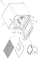
図1から図3は、本発明の第1実施形態に係る加熱調理器10を示す。この加熱調理器10は、グリル調理とコンベクション調理を実行可能な製パン器である。外装体12の内部には、調理室15と加熱室25とが設けられている。ベーカリー処理は、パン材料を収容するパンケース1を調理室15内に配置して行われる。グリル調理とコンベクション調理は、被調理物を載せる載置部材である焼き網2と、被調理物の焼き屑等を受ける屑受け皿3とを調理室15内に配置して行われる。なお、グリル調理には、パンを焼くトースターが含まれている。
(First embodiment)
1 to 3 show a cooking device 10 according to a first embodiment of the present invention. The heating cooker 10 is a bread maker that can perform grill cooking and convection cooking. A cooking chamber 15 and a heating chamber 25 are provided inside the exterior body 12. The bakery process is performed by placing the bread case 1 containing the bread ingredients in the cooking chamber 15. Grill cooking and convection cooking are performed by placing in the cooking chamber 15 a grill net 2 which is a mounting member on which the food is to be placed, and a waste tray 3 for receiving the scraps of the food to be cooked. Grill cooking includes a toaster for baking bread.

(加熱調理器の全体構成)
図1から図3を参照すると、調理室15は、底壁16、一対の側壁17,17、天壁18、及び後壁19によって囲まれ、正面側を開口部20とした空間である。開口部20は、上下以外の正面で横向きに開口しており、外装体12に配置されている開閉可能な蓋体13によって閉塞されている。図2に最も明瞭に示すように、調理室15と加熱室25とは、隔壁である後壁19によって区画されている。図4を併せて参照すると、加熱室25は、一端開口のヒータケース26を後壁19の背面側に配置することで、このヒータケース26の内部に形成されている。後壁19には、調理室15と加熱室25とを連通させる吸込口21と吹出口22とが設けられている。吸込口21は、多数のパンチ孔からなり、加熱室25の中央領域に位置するように1箇所だけ設けられている。吹出口22は、垂直方向に延びるスリットからなり、加熱室25の両端部に対向するように一対設けられている。
(Overall configuration of cooking device)
Referring to FIGS. 1 to 3, the cooking chamber 15 is a space surrounded by a bottom wall 16, a pair of side walls 17, 17, a top wall 18, and a rear wall 19, with the front side being an opening 20. The opening 20 opens laterally on the front surface other than the upper and lower sides, and is closed by an openable / closable lid 13 disposed on the exterior body 12. As most clearly shown in FIG. 2, the cooking chamber 15 and the heating chamber 25 are partitioned by a rear wall 19 that is a partition wall. Referring also to FIG. 4, the heating chamber 25 is formed inside the heater case 26 by disposing a heater case 26 with one end opening on the back side of the rear wall 19. The rear wall 19 is provided with a suction port 21 and a blower port 22 that allow the cooking chamber 15 and the heating chamber 25 to communicate with each other. The suction port 21 is composed of a number of punch holes, and is provided at only one position so as to be located in the central region of the heating chamber 25. The air outlets 22 are formed of slits extending in the vertical direction, and a pair of air outlets 22 are provided so as to face both end portions of the heating chamber 25.

調理室15には、下側の左右と上側の左右に、第1加熱ヒータであるグリルヒータ33A〜33Dが配置されている。加熱室25には、吸込口21と吹出口22の間に位置するように、第2加熱ヒータであるコンベクションヒータ35A,35Bが配置されている。これらヒータ33A〜33D,35A,35Bとしては、絶縁材料で構成された直管状の外郭内に発熱体を配置したガラス管ヒータを用いることができる。また、加熱室25には、一対のコンベクションヒータ35A,35Bの間に循環ファン40が配置されている。この循環ファン40は、吸込口21と対向するように配置されており、ヒータケース26の外方に配置したファンモータ41によって回転される。ファンモータ41の出力軸には、循環ファン40の他に、ファンモータ41を冷却するための冷却ファン42が連結されている。   In the cooking chamber 15, grill heaters 33 </ b> A to 33 </ b> D, which are first heaters, are arranged on the lower left and right and the upper left and right. Convection heaters 35 </ b> A and 35 </ b> B, which are second heaters, are arranged in the heating chamber 25 so as to be positioned between the suction port 21 and the blower port 22. As these heaters 33A to 33D, 35A, and 35B, glass tube heaters in which a heating element is disposed in a straight tubular shell made of an insulating material can be used. In the heating chamber 25, a circulation fan 40 is disposed between the pair of convection heaters 35A and 35B. The circulation fan 40 is disposed so as to face the suction port 21 and is rotated by a fan motor 41 disposed outside the heater case 26. In addition to the circulation fan 40, a cooling fan 42 for cooling the fan motor 41 is connected to the output shaft of the fan motor 41.

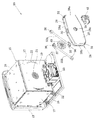
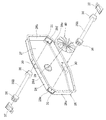
調理室15の側壁17には、焼き網2を装着するための網装着部45が設けられている。また、調理室15の底壁16には、有底筒状の容器であるパンケース1を装着するためのケース装着部48が設けられている。ケース装着部48の内部には、パンケース1内の混練羽根(図示せず)に連結するための連結部材49が回転可能に配置されている。また、調理室15及び加熱室25の外部には、駆動モータ50、小径の第1プーリ51、及び大径の第2プーリ52が配置されている。第1プーリ51と第2プーリ52には、無端状のベルト53が掛け渡されている。また、連結部材49と第2プーリ52とは、回転軸54に対して相対的に回転不可能に固定されることで、一体的に回転可能である。   The side wall 17 of the cooking chamber 15 is provided with a net mounting portion 45 for mounting the grill net 2. The bottom wall 16 of the cooking chamber 15 is provided with a case mounting portion 48 for mounting the pan case 1 which is a bottomed cylindrical container. A connecting member 49 for connecting to a kneading blade (not shown) in the pan case 1 is rotatably disposed inside the case mounting portion 48. A drive motor 50, a small-diameter first pulley 51, and a large-diameter second pulley 52 are disposed outside the cooking chamber 15 and the heating chamber 25. An endless belt 53 is stretched around the first pulley 51 and the second pulley 52. In addition, the connecting member 49 and the second pulley 52 are fixed so as not to rotate relative to the rotation shaft 54, so that they can rotate integrally.

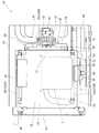
図2に示すように、調理室15にパンケース1を配置してベーカリー処理を実行すると、調理室15内の下側グリルヒータ33A,33B、及び駆動モータ50が動作され、予熱、混練、発酵、及び焼成の各工程を経てパンが製パンされる。図3に示すように、調理室15に焼き網2を配置してグリル調理を実行すると、調理室15内全てのグリルヒータ33A〜33Dが動作され、グリルヒータ33A〜33Dによって調理室15内を加熱することで、輻射熱で被調理物が加熱調理される。焼き網2にパンが載せられている場合には、輻射熱でパンが焼き上げられる。   As shown in FIG. 2, when the bread case 1 is placed in the cooking chamber 15 and the bakery process is performed, the lower grill heaters 33A and 33B and the drive motor 50 in the cooking chamber 15 are operated to preheat, knead, and ferment. And bread is baked through each process of baking. As shown in FIG. 3, when the grill net 2 is arranged in the cooking chamber 15 and grill cooking is performed, all the grill heaters 33A to 33D in the cooking chamber 15 are operated, and the cooking chamber 15 is moved by the grill heaters 33A to 33D. The object to be cooked is heated and cooked by radiant heat. When bread is placed on the grill 2, the bread is baked by radiant heat.

調理室15に焼き網2を配置してコンベクション調理を実行すると、加熱室25内のコンベクションヒータ35A,35B、及びファンモータ41が動作される。すると、循環ファン40が回転することで、吸込口21から調理室15内の空気が加熱室25内に吸引され、加熱室25内の空気が吹出口22から調理室15内へ供給される。加熱室25に吸引された空気は、吹出口22に至るまでの間にコンベクションヒータ35A,35Bの周囲を通過することで、コンベクションヒータ35A,35Bによって加熱される。よって、加熱室25内の空気は昇温され、設定された流速の熱風として、吹出口22から調理室15に供給される。調理室15内では、吹出口22から吐出された熱風が流動し、熱風が被調理物に衝突することで、空気の熱で被調理物が加熱調理される。   When the grill 2 is placed in the cooking chamber 15 and convection cooking is performed, the convection heaters 35A and 35B and the fan motor 41 in the heating chamber 25 are operated. Then, as the circulation fan 40 rotates, the air in the cooking chamber 15 is sucked into the heating chamber 25 from the suction port 21, and the air in the heating chamber 25 is supplied into the cooking chamber 15 from the blower outlet 22. The air sucked into the heating chamber 25 is heated by the convection heaters 35A and 35B by passing around the convection heaters 35A and 35B before reaching the air outlet 22. Therefore, the air in the heating chamber 25 is heated and supplied to the cooking chamber 15 from the blower outlet 22 as hot air having a set flow rate. In the cooking chamber 15, the hot air discharged from the air outlet 22 flows and the hot air collides with the food to be cooked, so that the food to be cooked is heated by the heat of the air.

(コンベクションヒータの配置の詳細)
コンベクション調理で被調理物を加熱調理する際の効率は、空気の加熱効率と熱風の送風量とが影響する。空気の加熱効率が悪くなると被調理物の加熱効率も悪くなり、空気の加熱効率が良くなると被調理物の加熱効率も良くなる。また、空気(熱風)の送風量が少なくなると被調理物の加熱効率は悪くなり、空気の送風量が多くなると被調理物の加熱効率は良くなる。要するに、コンベクション調理により被調理物を調理する効率を向上するには、コンベクションヒータ35A,35Bによる空気の加熱効率を向上し、循環ファン40による送風量を確保することが重要である。
(Details of placement of convection heater)
The efficiency at the time of cooking an object to be cooked by convection cooking is affected by the heating efficiency of air and the amount of hot air blown. When the heating efficiency of air is deteriorated, the heating efficiency of the cooking object is also deteriorated, and when the heating efficiency of air is improved, the heating efficiency of the cooking object is also improved. In addition, the heating efficiency of the object to be cooked is deteriorated when the amount of air (hot air) is reduced, and the heating efficiency of the object is improved when the amount of air is increased. In short, in order to improve the efficiency of cooking an object to be cooked by convection cooking, it is important to improve the heating efficiency of air by the convection heaters 35A and 35B and to secure the amount of air blown by the circulation fan 40.

空気の加熱効率を向上するには、コンベクションヒータ35A,35Bの熱量(出力)を高くすることが考えられる。しかし、コンベクションヒータ35A,35Bの熱量、及びコンベクションヒータ35A,35Bの耐久性(寿命)は、コンベクションヒータ35A,35Bの全長の変化に応じて変わる。即ち、熱量が同一である場合、コンベクションヒータ35A,35Bの耐久性は、全長が短くなるに従って低くなり、全長が長くなるに従って高くなる。逆に、耐久性が同一である場合、コンベクションヒータ35A,35Bの熱量は、全長が短くなるに従って低くなり、全長が長くなるに従って高くなる。要するに、全長が長いコンベクションヒータ35A,35Bを用いることが、空気の加熱効率の向上、及びコンベクションヒータ35A,35Bの耐久性の向上には有効である。   In order to improve the heating efficiency of air, it is conceivable to increase the amount of heat (output) of the convection heaters 35A and 35B. However, the amount of heat of the convection heaters 35A and 35B and the durability (lifetime) of the convection heaters 35A and 35B vary according to changes in the total length of the convection heaters 35A and 35B. That is, when the amount of heat is the same, the durability of the convection heaters 35A and 35B decreases as the total length decreases, and increases as the total length increases. On the other hand, when the durability is the same, the amount of heat of the convection heaters 35A and 35B decreases as the overall length decreases, and increases as the overall length increases. In short, the use of convection heaters 35A and 35B having a long overall length is effective for improving the heating efficiency of air and improving the durability of convection heaters 35A and 35B.

空気の送風量を多くするには、直径が大きい循環ファン40を用いることが有効である。しかし、限られた加熱室25内に直径が大きい循環ファン40を配置すると、コンベクションヒータ35A,35Bを配置するスペースを確保できない。そこで、本実施形態では、コンベクションヒータ35A,35Bの配置を以下のように最適化している。   In order to increase the amount of air blown, it is effective to use the circulation fan 40 having a large diameter. However, if the circulation fan 40 having a large diameter is arranged in the limited heating chamber 25, a space for arranging the convection heaters 35A and 35B cannot be secured. Therefore, in this embodiment, the arrangement of the convection heaters 35A and 35B is optimized as follows.

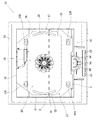
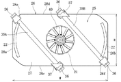
図2及び図4を参照すると、加熱室25を画定するヒータケース26は、後壁19に対して間隔をあけて平行に位置する端壁27と、端壁27の外周縁から屈曲している外周壁28とを備えている。図5及び図6に示すように、ヒータケース26の垂直方向の高さHの寸法と、水平方向の幅Wの寸法とは異なっており、本実施形態のヒータケース26は、高さHが幅Wより短い横長の概ね長方形状に形成されている。図3を参照すると、ヒータケース26の端壁27の中央には、後壁19に形成した吸込口21が位置している。また、ヒータケース26の短辺側(寸法が短い方)である外周壁28の左右の側部28a,28bの横には、後壁19に形成した吹出口22,22が位置している。即ち、吹出口22,22は、側部28a,28bに隣接し、側部28a,28bに沿って高さ方向Hに延びている。   Referring to FIGS. 2 and 4, the heater case 26 that defines the heating chamber 25 is bent from an end wall 27 that is located in parallel to the rear wall 19 at a distance from the rear wall 19, and from the outer peripheral edge of the end wall 27. And an outer peripheral wall 28. As shown in FIGS. 5 and 6, the dimension of the vertical height H of the heater case 26 is different from the dimension of the horizontal width W. The heater case 26 of this embodiment has a height H of It is formed in a horizontally long, generally rectangular shape shorter than the width W. Referring to FIG. 3, the suction port 21 formed in the rear wall 19 is located at the center of the end wall 27 of the heater case 26. Further, air outlets 22 and 22 formed in the rear wall 19 are positioned beside the left and right side portions 28a and 28b of the outer peripheral wall 28 on the short side (the shorter dimension) of the heater case 26. That is, the air outlets 22 and 22 are adjacent to the side portions 28a and 28b and extend in the height direction H along the side portions 28a and 28b.

図5及び図6に示すように、端壁27の中央には、ファンモータ41の出力軸を貫通させるための貫通孔29が設けられている。循環ファン40は、貫通孔29を通してヒータケース26内に位置する出力軸部分に連結されている。これにより循環ファン40は、吸込口Hと対向し、一対の吹出口22,22の中間位置に配置されている。   As shown in FIGS. 5 and 6, a through hole 29 for allowing the output shaft of the fan motor 41 to penetrate is provided in the center of the end wall 27. The circulation fan 40 is connected to the output shaft portion located in the heater case 26 through the through hole 29. Thereby, the circulation fan 40 is opposed to the suction port H, and is disposed at an intermediate position between the pair of outlets 22 and 22.

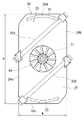
コンベクションヒータ35A,35Bは、循環ファン40と一緒にヒータケース26の内部に配置された状態で、調理室15の後壁19の背面側に配置されている。コンベクションヒータ35A,35Bは、吸込口21と吹出口22,22の間に位置するように、ヒータケース26に対して循環ファン40の両側に傾斜して配置されている。更に詳しく説明すると、図6は、加熱調理器10を設置し、加熱室25を正対視した状態である。この図6に示すように、コンベクションヒータ35A,35Bは、水平方向である幅方向Wに対して傾斜されており、垂直方向である高さ方向Wに対しても傾斜されている。即ち、コンベクションヒータ35A,35Bは、水平方向に延びるようにも垂直方向に延びるようにも配置されていない。   The convection heaters 35 </ b> A and 35 </ b> B are arranged on the back side of the rear wall 19 of the cooking chamber 15 in a state of being arranged in the heater case 26 together with the circulation fan 40. The convection heaters 35 </ b> A and 35 </ b> B are disposed on both sides of the circulation fan 40 with respect to the heater case 26 so as to be positioned between the suction port 21 and the blowout ports 22 and 22. More specifically, FIG. 6 shows a state where the heating cooker 10 is installed and the heating chamber 25 is viewed directly. As shown in FIG. 6, the convection heaters 35A and 35B are inclined with respect to the width direction W which is the horizontal direction, and are also inclined with respect to the height direction W which is the vertical direction. That is, the convection heaters 35A and 35B are not arranged so as to extend in the horizontal direction or in the vertical direction.

図5を参照すると、コンベクションヒータ35A,35Bをヒータケース26に対して斜めに配置するために、ヒータケース26の外周壁28には、各一対の差込孔30,30と位置決め孔31,31が設けられている。差込孔30は、コンベクションヒータ35A,35Bの両端の電気接続部36を挿通可能な大きさの長方形状であり、外周壁28の下部28cと上部28dに形成されている。位置決め孔31,31は、電気接続部36を差し込んで位置決め可能な大きさの長方形状であり、左側部28aと上部28dとの間の上角部28eと、右側部28bと下部28cとの間の下角部28fとに形成されている。   Referring to FIG. 5, in order to arrange the convection heaters 35 </ b> A and 35 </ b> B obliquely with respect to the heater case 26, a pair of insertion holes 30 and 30 and positioning holes 31 and 31 are formed in the outer peripheral wall 28 of the heater case 26. Is provided. The insertion hole 30 has a rectangular shape that can be inserted into the electrical connection portions 36 at both ends of the convection heaters 35A and 35B, and is formed in the lower portion 28c and the upper portion 28d of the outer peripheral wall 28. The positioning holes 31, 31 have a rectangular shape that can be positioned by inserting the electrical connection portion 36, and between the upper corner portion 28e between the left side portion 28a and the upper portion 28d, and between the right side portion 28b and the lower portion 28c. The lower corner portion 28f is formed.

コンベクションヒータ35A,35Bをヒータケース26に配置する際には、例えば一方のコンベクションヒータ35Aを下部28cの差込孔30から差し込み、上角部28eの位置決め孔31に位置決めする。また、他方のコンベクションヒータ35Bを上部28dの差込孔30から差し込み、下角部28fの位置決め孔31に位置決めする。そして、下部28cと電気接続部36の隙間及び上部28dと電気接続部36の隙間に、スペーサ37が配置される。スペーサ37は、外周壁28の外方から嵌め込まれ、外周壁28に対してネジ止めにより固定されている。これによりヒータケース26内には、コンベクションヒータ35A,35Bが左斜め上向きに傾斜して配置されている。なお、コンベクションヒータ35A,35Bの傾斜方向は、右斜め上向きとしてもよい。   When the convection heaters 35A and 35B are arranged in the heater case 26, for example, one convection heater 35A is inserted from the insertion hole 30 of the lower portion 28c and positioned in the positioning hole 31 of the upper corner portion 28e. The other convection heater 35B is inserted through the insertion hole 30 in the upper part 28d and positioned in the positioning hole 31 in the lower corner part 28f. A spacer 37 is disposed in the gap between the lower portion 28 c and the electrical connection portion 36 and in the gap between the upper portion 28 d and the electrical connection portion 36. The spacer 37 is fitted from the outside of the outer peripheral wall 28 and is fixed to the outer peripheral wall 28 by screws. Thereby, in the heater case 26, the convection heaters 35A and 35B are disposed obliquely upward and leftward. In addition, the inclination direction of the convection heaters 35A and 35B may be obliquely upward to the right.

このようにした加熱調理器10では、加熱室25に吸込口21と一対の吹出口22,22の間を横断するように、コンベクションヒータ35A,35Bが傾斜して配置されている。そのため、従来のように吹出口に沿って延びるように加熱ヒータを配置した場合と比較して、全長が長いコンベクションヒータ35A,35Bを使用することができる。よって、コンベクションヒータ35A,35Bの加熱領域が長くなるため、加熱室25内の空気を効率的に加熱することができる。   In the heating cooker 10 configured as described above, the convection heaters 35 </ b> A and 35 </ b> B are inclined and disposed in the heating chamber 25 so as to cross between the suction port 21 and the pair of outlets 22 and 22. Therefore, the convection heaters 35A and 35B having a long overall length can be used as compared with the conventional case where the heater is arranged so as to extend along the blower outlet. Therefore, since the heating area | region of convection heater 35A, 35B becomes long, the air in the heating chamber 25 can be heated efficiently.

また、吹出口に沿って加熱ヒータを配置した場合と耐久性が同じコンベクションヒータ35A,35Bを用いる場合、全長が長い分熱量を高くすることができるため、調理時の加熱効率を向上できる。一方、吹出口に沿って加熱ヒータを配置した場合と熱量が同じコンベクションヒータ35A,35Bを用いる場合、耐久性が向上するため使用可能な期間を長くすることができる。   Moreover, when using the convection heaters 35A and 35B having the same durability as the case where the heater is disposed along the air outlet, the amount of heat can be increased by the length of the entire length, so that the heating efficiency during cooking can be improved. On the other hand, when using the convection heaters 35A and 35B having the same heat quantity as when the heater is arranged along the outlet, durability can be improved and the usable period can be extended.

特に、本実施形態では、横長形状の加熱室25の短辺側に吹出口22を配置し、寸法が長い横方向のスペースをコンベクションヒータ35A,35Bの配置に利用できる。よって、コンベクションヒータ35A,35B水平方向及び垂直方向に対する傾斜を十分にとることができる。そのため、短辺に沿って加熱ヒータを配置する場合と比較して、加熱調理に適した目標とする熱量、及び耐久性を十分に向上できる。   In particular, in this embodiment, the blower outlet 22 is arrange | positioned in the short side of the horizontally long heating chamber 25, and the space of the horizontal direction with a long dimension can be utilized for arrangement | positioning of the convection heaters 35A and 35B. Therefore, the convection heaters 35A and 35B can be sufficiently inclined with respect to the horizontal direction and the vertical direction. Therefore, compared with the case where a heater is arrange | positioned along a short side, the target calorie | heat amount suitable for heat cooking and durability can fully be improved.

また、本実施形態の加熱室25は横長形状であるため、傾斜して配置されている一対のコンベクションヒータ35A,35Bの間には循環ファン40を配置するためのスペースを十分確保できる。よって、空気の送風量を確保できる直径の循環ファン40を用いることができる。その結果、調理室15から加熱室25に吸い込んだ空気を効率的に加熱し、加熱室25から調理室15へ加熱した空気(熱風)を確実に供給できる。   In addition, since the
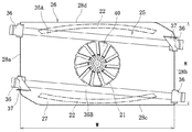
 heating chamber 25 of the present embodiment has a horizontally long shape, a sufficient space for arranging the circulation fan 40 can be ensured between the pair of convection heaters 35A and 35B that are inclined. Therefore, it is possible to use the circulation fan 40 having a diameter that can secure the air blowing amount. As a result, the air sucked into the heating chamber 25 from the cooking chamber 15 can be efficiently heated, and the heated air (hot air) can be reliably supplied from the heating chamber 25 to the cooking chamber 15.

(第2実施形態)
図7は第2実施形態の加熱調理器10の加熱室25を示す。この第2実施形態では、吸込口21の上下に一対の吹出口22,22が位置するように形成され、これらの間を斜めに横断するようにコンベクションヒータ35A,35Bが配置されている点で、第1実施形態と相違する。
(Second Embodiment)
FIG. 7 shows the heating chamber 25 of the heating cooker 10 of the second embodiment. In this 2nd Embodiment, it is formed so that a pair of blower outlets 22 and 22 may be located in the upper and lower sides of the suction inlet 21, and the convection heaters 35A and 35B are arrange | positioned so that between these may be crossed diagonally. This is different from the first embodiment.

詳しくは、ヒータケース26は、高さHが幅Wより短い横長の概ね長方形状に形成されている。コンベクションヒータ35A,35Bは、吸込口21と吹出口22,22の間に幅方向Hに延びるように配置されている。これらコンベクションヒータ35A,35Bは、側部28bから側部28aに向けて左上がりに配置されており、水平方向である幅方向Wに対して傾斜し、垂直方向である高さ方向Wに対しても傾斜している。   Specifically, the heater case 26 is formed in a horizontally long, generally rectangular shape whose height H is shorter than the width W. The convection heaters 35 </ b> A and 35 </ b> B are arranged so as to extend in the width direction H between the suction port 21 and the blowout ports 22 and 22. These convection heaters 35A and 35B are arranged so as to rise to the left from the side portion 28b toward the side portion 28a. Is also inclined.

このようにした加熱調理器10は、上側のコンベクションヒータ35Aと下側のコンベクションヒータ35Bとの間が狭くなるため、第1実施形態と比較して循環ファン40の配置スペースに制約が生じる。しかし、第1実施形態と比較すると、コンベクションヒータ35A,35Bの全長を更に長くすることができるため、コンベクションヒータ35A,35Bによる熱量を更に高めることができるとともに、コンベクションヒータ35A,35Bの耐久性を更に向上できる。   Since the space between the upper convection heater 35 </ b> A and the lower convection heater 35 </ b> B is reduced in the
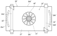
 heating cooker 10 configured as described above, the arrangement space of the circulation fan 40 is restricted as compared with the first embodiment. However, compared with the first embodiment, since the total length of the convection heaters 35A and 35B can be further increased, the amount of heat by the convection heaters 35A and 35B can be further increased, and the durability of the convection heaters 35A and 35B can be increased. This can be further improved.

(本実施形態と比較例との比較)
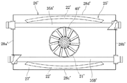
図8から図11は、第1から第4の比較例を示す。これら比較例の加熱調理器は、いずれも横長のヒータケース26’を備えている。そして、吹出口22’は、ヒータケース26’の垂直方向(高さ方向)又は水平方向(幅方向)に延びるように、調理室の後壁に形成されている。また、コンベクションヒータ35A’,35B’は、ヒータケース26’に対して垂直方向(高さ方向)又は水平方向(幅方向)に延びるように配置されている。
(Comparison between this embodiment and comparative example)
8 to 11 show first to fourth comparative examples. Each of the heating cookers of these comparative examples is provided with a horizontally long heater case 26 '. And blower outlet 22 'is formed in the rear wall of a cooking chamber so that it may extend in the perpendicular direction (height direction) or horizontal direction (width direction) of heater case 26'. Further, the convection heaters 35A ′ and 35B ′ are arranged so as to extend in the vertical direction (height direction) or the horizontal direction (width direction) with respect to the heater case 26 ′.

詳しくは、図8の第1比較例では、ヒータケース26’の側部28a’,28b’に隣接するように、垂直方向に延びる吹出口22’,22’が形成されている。また、コンベクションヒータ35A’,35B’は、吹出口22’,22’に沿って延びるように、側部28a’,28b’に沿って垂直方向に配置されている。   Specifically, in the first comparative example of FIG. 8, outlets 22 ′ and 22 ′ extending in the vertical direction are formed so as to be adjacent to the side portions 28 a ′ and 28 b ′ of the heater case 26 ′. Further, the convection heaters 35A 'and 35B' are arranged in the vertical direction along the side portions 28a 'and 28b' so as to extend along the air outlets 22 'and 22'.

この第1比較例では、吸込口21’から吹出口22’に向けた空気の流動方向と、コンベクションヒータ35A,35Bが延びる方向が交差しているため、吹出口22’に向かう空気を高効率で加熱できる。しかし、コンベクションヒータ35A’,35B’を短辺側に配置するため、コンベクションヒータ35A’,35B’の全長が短く、空気を加熱する熱量が少ない。そして、熱量を確保するために出力を高くすると、コンベクションヒータ35A’,35B’の耐久性が悪くなる。   In the first comparative example, since the flow direction of air from the suction port 21 ′ toward the blowout port 22 ′ and the direction in which the convection heaters 35A and 35B extend intersect, the air flowing toward the blowout port 22 ′ is highly efficient. Can be heated. However, since the convection heaters 35A 'and 35B' are arranged on the short side, the overall length of the convection heaters 35A 'and 35B' is short, and the amount of heat for heating the air is small. If the output is increased in order to ensure the amount of heat, the durability of the convection heaters 35A 'and 35B' is deteriorated.

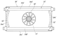
図9の第2比較例では、ヒータケース26’の上部28d’及び下部28c’に隣接するように、水平方向に延びる吹出口22’,22’が形成されている。また、コンベクションヒータ35A’,35B’は、吹出口22’,22’に沿って延びるように、上部28d’及び下部28c’に沿って水平方向に配置されている。この第2比較例の構成は、特許文献1で挙げた加熱調理器の構成と同一である。   In the second comparative example of FIG. 9, the air outlets 22 ′ and 22 ′ extending in the horizontal direction are formed so as to be adjacent to the upper portion 28 d ′ and the lower portion 28 c ′ of the heater case 26 ′. Further, the convection heaters 35A 'and 35B' are arranged in the horizontal direction along the upper part 28d 'and the lower part 28c' so as to extend along the outlets 22 'and 22'. The configuration of the second comparative example is the same as the configuration of the heating cooker described in Patent Document 1.

この第2比較例では、第1比較例と同様に、吸込口21’から吹出口22’に向けた空気の流動方向と、コンベクションヒータ35A’,35B’が延びる方向が交差しているため、吹出口22’に向かう空気を確実に加熱できる。しかし、この第2比較例では、上側のコンベクションヒータ35A’と下側のコンベクションヒータ35B’との間が狭くなるため、小型の循環ファン40’を用いるか、大型のヒータケース26’を用いる必要がある。そして、小型の循環ファン40’を用いた場合、調理室に供給可能な熱風量が少なくなるため、被調理物の加熱効率が低下する。また、大型のヒータケース26’を用いた場合、加熱調理器全体が大型になる。   In the second comparative example, as in the first comparative example, the flow direction of air from the suction port 21 ′ to the blowout port 22 ′ intersects with the direction in which the convection heaters 35A ′ and 35B ′ extend. The air which goes to blower outlet 22 'can be heated reliably. However, in this second comparative example, since the space between the upper convection heater 35A ′ and the lower convection heater 35B ′ becomes narrow, it is necessary to use a small circulation fan 40 ′ or a large heater case 26 ′. There is. And when the small circulation fan 40 'is used, since the amount of hot air that can be supplied to the cooking chamber is reduced, the heating efficiency of the object to be cooked is lowered. Moreover, when the large heater case 26 'is used, the whole heating cooker becomes large.

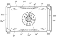
図10の第3比較例では、ヒータケース26’の側部28a’,28b’に隣接するように、垂直方向に延びる吹出口22’,22’が形成されている。また、コンベクションヒータ35A’,35B’は、吹出口22’,22’に対して直交方向に延びるように、上部28d’及び下部28c’に沿って水平方向に配置されている。   In the third comparative example of FIG. 10, outlets 22 ′ and 22 ′ extending in the vertical direction are formed so as to be adjacent to the side portions 28 a ′ and 28 b ′ of the heater case 26 ′. Further, the convection heaters 35A 'and 35B' are disposed in the horizontal direction along the upper portion 28d 'and the lower portion 28c' so as to extend in a direction perpendicular to the outlets 22 'and 22'.

この第3比較例では、吸込口21’から吹出口22’に向けた空気の流動方向と、コンベクションヒータ35A,35Bが延びる方向が同一であるため、加熱されずに吹出口22’に至る空気が多く、空気の加熱効率が悪い。   In the third comparative example, the air flowing from the suction port 21 ′ toward the blowout port 22 ′ and the direction in which the convection heaters 35A and 35B extend are the same, so the air reaching the blowout port 22 ′ without being heated. Many air heating efficiency is poor.

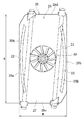
図11の第4比較例では、ヒータケース26’の上部28d’及び下部28c’に隣接するように、水平方向に延びる吹出口22’,22’が形成されている。また、コンベクションヒータ35A’,35B’は、吹出口22’,22’に対して直交方向に延びるように、側部28a’,28b’に沿って垂直方向に配置されている。   In the fourth comparative example of FIG. 11, air outlets 22 ′ and 22 ′ extending in the horizontal direction are formed so as to be adjacent to the upper portion 28 d ′ and the lower portion 28 c ′ of the heater case 26 ′. Further, the convection heaters 35A 'and 35B' are arranged in the vertical direction along the side portions 28a 'and 28b' so as to extend in a direction orthogonal to the outlets 22 'and 22'.

この第4比較例では、コンベクションヒータ35A’,35B’を短辺側に配置するため、コンベクションヒータ35A’,35B’の全長が短く、空気を加熱する熱量が少ない。しかも、第3比較例と同様に、吸込口21’から吹出口22’に向けた空気の流動方向と、コンベクションヒータ35A,35Bが延びる方向が同一であるため、加熱されずに吹出口22’に至る空気が多く、空気の加熱効率が悪い。   In the fourth comparative example, since the convection heaters 35A 'and 35B' are arranged on the short side, the total length of the convection heaters 35A 'and 35B' is short and the amount of heat for heating the air is small. Moreover, as in the third comparative example, the air flow direction from the suction port 21 ′ toward the blowout port 22 ′ and the direction in which the convection heaters 35 </ b> A and 35 </ b> B extend are the same. There is much air to reach, and the heating efficiency of air is bad.

これに対して、図6に示す第1実施形態では、吹出口22とコンベクションヒータ35A,35Bをヒータケース26の短辺側に配置している。しかし、第1及び第4の比較例と比べると、コンベクションヒータ35A,35Bを斜めに配置している分、コンベクションヒータ35A,35Bの全長を長くすることができるため、空気を加熱するための熱量を確保できる。また、第3及び第4の比較例と比べると、吸込口21から吹出口22に向けた空気の流動方向と、コンベクションヒータ35A,35Bが延びる方向が交差しているため、吹出口22に向かう空気を確実に加熱できる。しかも、第2比較例と比べると、コンベクションヒータ35A,35B間に循環ファン40を配置するスペースを十分確保できるため、十分な風量の循環ファン40を配置できる。よって、被調理物を確実に加熱できるとともに、加熱調理器全体が大型になることもない。   In contrast, in the first embodiment shown in FIG. 6, the air outlet 22 and the convection heaters 35 </ b> A and 35 </ b> B are arranged on the short side of the heater case 26. However, compared to the first and fourth comparative examples, since the convection heaters 35A and 35B are arranged obliquely, the total length of the convection heaters 35A and 35B can be increased, and therefore the amount of heat for heating the air. Can be secured. Moreover, compared with the 3rd and 4th comparative example, since the flow direction of the air which went to the blower outlet 22 from the suction inlet 21 and the direction where the convection heaters 35A and 35B extend cross, it goes to the blower outlet 22. Air can be heated reliably. In addition, as compared with the second comparative example, a sufficient space for arranging the circulation fan 40 between the convection heaters 35A and 35B can be secured, so that the circulation fan 40 having a sufficient air volume can be arranged. Therefore, while being able to heat a to-be-cooked thing reliably, the whole heating cooking appliance does not become large sized.

また、図7に示す第2実施形態では、吹出口22とコンベクションヒータ35A,35Bをヒータケース26の長辺側に配置している。そのため、第1及び第4の比較例と比べると、コンベクションヒータ35A,35Bの全長を確保できるため、空気を加熱するための熱量を確保できる。また、第3及び第4の比較例と比べると、吸込口21から吹出口22に向けた空気の流動方向と、コンベクションヒータ35A,35Bが延びる方向が交差しているため、吹出口22に向かう空気を確実に加熱できる。さらに、第2比較例と比べると、コンベクションヒータ35A,35Bを斜めに配置している分、コンベクションヒータ35A,35Bの全長を更に長くすることができるため、空気を加熱するための熱量を確保できる。また、コンベクションヒータ35A,35Bの耐久性を向上できる。   In the second embodiment shown in FIG. 7, the air outlet 22 and the convection heaters 35 </ b> A and 35 </ b> B are arranged on the long side of the heater case 26. Therefore, compared with the 1st and 4th comparative examples, since the full length of convection heaters 35A and 35B can be ensured, the calorie | heat amount for heating air can be ensured. Moreover, compared with the 3rd and 4th comparative example, since the flow direction of the air which went to the blower outlet 22 from the suction inlet 21 and the direction where the convection heaters 35A and 35B extend cross, it goes to the blower outlet 22. Air can be heated reliably. Furthermore, as compared with the second comparative example, since the convection heaters 35A and 35B are arranged obliquely, the overall length of the convection heaters 35A and 35B can be further increased, so that the amount of heat for heating the air can be secured. . Further, the durability of the convection heaters 35A and 35B can be improved.

なお、本発明の加熱調理器は、前記実施形態の構成に限定されず、種々の変更が可能である。   In addition, the heating cooker of this invention is not limited to the structure of the said embodiment, A various change is possible.

例えば、図12及び図13に示すように、ヒータケース26は、高さHの寸法が幅Wの寸法より大きい縦長の概ね長方形状に形成してもよい。図12の第1変形例では、縦長のヒータケース26に対して幅方向Wの両端に吹出口22,22が位置するように形成されている。また、ヒータケース26は、吸込口21と吹出口22,22の間を横断するように斜めに配置されている。図13の第2変形例では、縦長のヒータケース26に対して高さ方向Hの両端に吹出口22,22が位置するように形成されている。また、ヒータケース26は、吸込口21と吹出口22,22の間を横断するように斜めに配置されている。これらのようにしても、前記実施形態と同様の作用及び効果を得ることができる。   For example, as shown in FIGS. 12 and 13, the heater case 26 may be formed in a substantially rectangular shape having a height H dimension that is larger than a width W dimension. In the 1st modification of FIG. 12, it forms so that the blower outlets 22 and 22 may be located in the both ends of the width direction W with respect to the vertically long heater case 26. FIG. Further, the heater case 26 is disposed obliquely so as to cross between the suction port 21 and the air outlets 22 and 22. In the 2nd modification of FIG. 13, it forms so that the blower outlets 22 and 22 may be located in the both ends of the height direction H with respect to the vertically long heater case 26. FIG. Further, the heater case 26 is disposed obliquely so as to cross between the suction port 21 and the air outlets 22 and 22. Even if it does in this way, the effect | action and effect similar to the said embodiment can be acquired.

また、加熱室25を画定するヒータケース26は、概ね長方形状に限らず、概ね正方形状としてもよいし、五角形以上の多角形状としてもよい。また、吹出口22は、加熱室25の対向位置に一対設けたが、3以上設けてコンベクションヒータも3以上配置してもよいし、1個だけ設けてコンベクションヒータも1個だけ配置してもよい。また、吹出口22は、湾曲したスリットに限らず、直線状に延びるスリットとしてもよいし、多数のパンチ孔からなる実質的な帯状に形成してもよい。また、吸込口21も同様に希望に応じて変更が可能である。   Further, the heater case 26 that defines the heating chamber 25 is not limited to a substantially rectangular shape, but may be a substantially square shape or a polygonal shape that is a pentagon or more. In addition, although a pair of air outlets 22 is provided at a position opposite to the heating chamber 25, three or more convection heaters may be provided, or only one convection heater may be provided. Good. Moreover, the blower outlet 22 is not limited to a curved slit, and may be a slit extending linearly, or may be formed in a substantially belt-like shape made up of a number of punch holes. Similarly, the suction port 21 can be changed as desired.

さらに、加熱室25は、隔壁である後壁19にヒータケース26を配置することで形成される構成に限られず、希望に応じて変更が可能である。例えば、底壁16、一対の側壁17,17、天壁18、及び後壁19を備える加熱庫の内部に、後壁と間隔をあけて位置する隔壁を設けて、加熱庫の内部を調理室15と加熱室25に区画してもよい。この場合、吸込口21及び吹出口22は、隔壁に形成するのではなく、底壁16と隔壁との隙間、及び天壁18と隔壁との隙間によって構成してもよいし、各側壁17,17と隔壁との隙間によって構成してもよい。   Furthermore, the heating chamber 25 is not limited to the configuration formed by arranging the heater case 26 on the rear wall 19 which is a partition wall, and can be changed as desired. For example, a partition wall that is spaced apart from the rear wall is provided inside the heating chamber that includes the bottom wall 16, the pair of side walls 17, 17, the top wall 18, and the rear wall 19. 15 and the heating chamber 25 may be partitioned. In this case, the suction port 21 and the air outlet 22 are not formed in the partition wall, but may be configured by a gap between the bottom wall 16 and the partition wall, and a gap between the top wall 18 and the partition wall. You may comprise by the clearance gap between 17 and a partition.

1…パンケース
2…焼き網
3…屑受け皿
10…加熱調理器
12…外装体
13…蓋体
15…調理室
16…底壁
17…側壁
18…天壁
19…後壁(隔壁)
20…開口部
21…吸込口
22…吹出口
25…加熱室
26…ヒータケース
27…端壁
28…外周壁
28a…左側部
28b…右側部
28c…下部
28d…上部
28e…上角部
28f…下角部
29…貫通孔
30…差込孔
31…位置決め孔
33A〜33D…グリルヒータ(第1の加熱ヒータ)
35A,35B…コンベクションヒータ(第2の加熱ヒータ)
36…電気接続部
37…スペーサ
40…循環ファン
41…ファンモータ
42…冷却ファン
45…網装着部
48…ケース装着部
49…連結部材
50…駆動モータ
51…第1プーリ
52…第2プーリ
53…ベルト
54…回転軸
DESCRIPTION OF SYMBOLS 1 ... Bread case 2 ... Grilling net 3 ... Waste tray 10 ... Cooking device 12 ... Exterior body 13 ... Lid body 15 ... Cooking room 16 ... Bottom wall 17 ... Side wall 18 ... Top wall 19 ... Back wall (partition wall)
DESCRIPTION OF SYMBOLS 20 ... Opening part 21 ... Suction port 22 ... Air outlet 25 ... Heating chamber 26 ... Heater case 27 ... End wall 28 ... End wall 28a ... Left side part 28b ... Right side part 28c ... Lower part 28d ... Upper part 28e ... Upper corner part 28f ... Lower corner Portion 29 ... Through hole 30 ... Insertion hole 31 ... Positioning hole 33A-33D ... Grill heater (first heater)
35A, 35B ... Convection heater (second heater)
36 ... Electrical connection part 37 ... Spacer 40 ... Circulation fan 41 ... Fan motor 42 ... Cooling fan 45 ... Net attachment part 48 ... Case attachment part 49 ... Connecting member 50 ... Drive motor 51 ... First pulley 52 ... Second pulley 53 ... Belt 54 ... Rotating shaft

Claims (5)

被調理物が配置される調理室と、
前記調理室と隔壁によって区画されている加熱室と、
前記調理室と前記加熱室とを連通させる吸込口及び吹出口と、
前記吸込口から前記調理室内の空気を前記加熱室内に吸引し、前記吹出口から前記加熱室内の空気を前記調理室内に供給する循環ファンと、
前記循環ファンによって供給する空気を加熱する加熱ヒータとを備え、
前記加熱ヒータは、前記吸込口と前記吹出口の間に位置するように前記加熱室に配置されており、前記加熱室を正対視すると、水平方向に対して傾斜されるとともに垂直方向に対しても傾斜されている、加熱調理器。
A cooking chamber in which food is to be placed;
A heating chamber partitioned by the cooking chamber and a partition;
A suction port and a blowout port for communicating the cooking chamber and the heating chamber;
A circulation fan for sucking air in the cooking chamber from the suction port into the heating chamber, and supplying air in the heating chamber from the outlet to the cooking chamber;
A heater for heating air supplied by the circulation fan,
The heater is disposed in the heating chamber so as to be positioned between the suction port and the blower outlet. When the heating chamber is viewed directly, the heater is inclined with respect to the horizontal direction and with respect to the vertical direction. A cooking device that is even inclined.
前記加熱室は、垂直方向の高さと水平方向の幅とは寸法が異なっており、前記高さ及び前記幅のうち寸法が短い方に隣接するように前記吹出口が設けられている、請求項1に記載の加熱調理器。   The vertical dimension and the horizontal width of the heating chamber are different in size, and the air outlet is provided so as to be adjacent to the shorter of the height and the width. The heating cooker according to 1. 前記吹出口は、前記加熱室の幅方向の端部に高さ方向に延びるように設けられている、請求項2に記載の加熱調理器。   The cooking device according to claim 2, wherein the blower outlet is provided at an end portion in a width direction of the heating chamber so as to extend in a height direction. 前記吹出口は、前記加熱室の対向位置に一対設けられている、請求項1から3のいずれか1項に記載の加熱調理器。   The heating cooker according to any one of claims 1 to 3, wherein a pair of the outlets are provided at positions opposed to the heating chamber. 前記吸込口は、前記一対の吹出口の中間位置の1箇所だけに設けられている、請求項4に記載の加熱調理器。   The heating cooker according to claim 4, wherein the suction port is provided only at one position in an intermediate position between the pair of air outlets.
JP2016079276A 2016-04-12 2016-04-12 Heating cooker Pending JP2017190887A (en)

Priority Applications (1)

Application Number Priority Date Filing Date Title
JP2016079276A JP2017190887A (en) 2016-04-12 2016-04-12 Heating cooker

Applications Claiming Priority (1)

Application Number Priority Date Filing Date Title
JP2016079276A JP2017190887A (en) 2016-04-12 2016-04-12 Heating cooker

Publications (1)

Publication Number Publication Date
JP2017190887A true JP2017190887A (en) 2017-10-19

Family

ID=60084582

Family Applications (1)

Application Number Title Priority Date Filing Date
JP2016079276A Pending JP2017190887A (en) 2016-04-12 2016-04-12 Heating cooker

Country Status (1)

Country Link
JP (1) JP2017190887A (en)

Citations (4)

* Cited by examiner, † Cited by third party
Publication number Priority date Publication date Assignee Title
JPS556138A (en) * 1978-06-27 1980-01-17 Matsushita Electric Ind Co Ltd Heating device
JPS5668805U (en) * 1979-10-31 1981-06-08
JPS63132211U (en) * 1987-02-23 1988-08-30
JP2014035108A (en) * 2012-08-08 2014-02-24 Hitachi Appliances Inc Heating cooker

Patent Citations (4)

* Cited by examiner, † Cited by third party
Publication number Priority date Publication date Assignee Title
JPS556138A (en) * 1978-06-27 1980-01-17 Matsushita Electric Ind Co Ltd Heating device
JPS5668805U (en) * 1979-10-31 1981-06-08
JPS63132211U (en) * 1987-02-23 1988-08-30
JP2014035108A (en) * 2012-08-08 2014-02-24 Hitachi Appliances Inc Heating cooker

Similar Documents

Publication Publication Date Title
RU2410606C1 (en) Heating furnace
CN211212750U (en) Multifunctional roasting tool
JP6898140B2 (en) Cooker
CN110786749A (en) Multifunctional roasting tool
CN102232799A (en) Electric oven
US9962037B2 (en) Food condition maintaining device
CN102232801A (en) Electric oven
JP2007003042A (en) Cooker
JP5377133B2 (en) Cooker
JP2017190887A (en) Heating cooker
KR101411760B1 (en) Electric oven
JP6593961B2 (en) Cooker
CN114587156A (en) Cooking utensil
CN216534973U (en) Cooking device with air frying function
JP6697671B2 (en) Toaster oven
JP6141102B2 (en) Sauce set for cooking and heating cooker
JP4576296B2 (en) Cooker
CN218942969U (en) Cooking equipment
JP3863539B2 (en) Cooker
EP4235039A1 (en) Kitchen oven with counter-rotating fans
JP7297561B2 (en) heating cooker
CN113854853A (en) Cooking device with air frying function
US20230130495A1 (en) Apparatus For Cooking With Ventilated Hot Air And/Or For Grilling Food
CN113633189A (en) Fan cover, oven and integrated kitchen
CN114081366A (en) Hot air baking cooking equipment with air frying function

Legal Events

Date Code Title Description
A621 Written request for application examination

Free format text: JAPANESE INTERMEDIATE CODE: A621

Effective date: 20180418

A131 Notification of reasons for refusal

Free format text: JAPANESE INTERMEDIATE CODE: A131

Effective date: 20190212

A977 Report on retrieval

Free format text: JAPANESE INTERMEDIATE CODE: A971007

Effective date: 20190215

A02 Decision of refusal

Free format text: JAPANESE INTERMEDIATE CODE: A02

Effective date: 20190806