JP2017190850A - Packing - Google Patents
Packing Download PDFInfo
- Publication number
- JP2017190850A JP2017190850A JP2016082080A JP2016082080A JP2017190850A JP 2017190850 A JP2017190850 A JP 2017190850A JP 2016082080 A JP2016082080 A JP 2016082080A JP 2016082080 A JP2016082080 A JP 2016082080A JP 2017190850 A JP2017190850 A JP 2017190850A
- Authority
- JP
- Japan
- Prior art keywords
- packing
- outer edge
- reinforcing wall
- connection
- packing body
- Prior art date
- Legal status (The legal status is an assumption and is not a legal conclusion. Google has not performed a legal analysis and makes no representation as to the accuracy of the status listed.)
- Granted
Links
Images
Landscapes
- Flanged Joints, Insulating Joints, And Other Joints (AREA)
- Gasket Seals (AREA)
Abstract
【課題】例えば高温下で使用しても変形抑制可能であり、それによりパッキンを含む接続構造の変形を防止可能なパッキンを提供する。【解決手段】金属製の締結フランジ20A,20Bを備え、管軸方向Jの一方の端面10pに接続フランジ14を有する樹脂製の接続管10A,10B同士をそれぞれの接続フランジ14の間に挟持させて密閉接続するためのパッキンであって、端面10pに当接して配置可能とされ、接続管10A,10Bの内部を通る媒体が通過可能な孔部6が形成された薄板状のパッキン本体2と、パッキン本体2の外周縁2eの全周からパッキン本体2の厚み方向の両側に延出し、接続フランジ14の外周面14rに当接される外縁補強壁4と、を備えている。【選択図】図2PROBLEM TO BE SOLVED: To provide a packing capable of suppressing deformation even when used at a high temperature, thereby preventing deformation of a connection structure including the packing. SOLUTION: Resin connecting pipes 10A and 10B provided with metal fastening flanges 20A and 20B and having a connecting flange 14 on one end surface 10p of the pipe axial direction J are sandwiched between the respective connecting flanges 14. With a thin plate-shaped packing body 2 which is a packing for hermetically sealed connection and can be arranged in contact with the end face 10p and has a hole 6 formed through which a medium passing through the inside of the connection pipes 10A and 10B can pass. The outer edge reinforcing wall 4 extends from the entire circumference of the outer peripheral edge 2e of the packing main body 2 to both sides in the thickness direction of the packing main body 2 and is in contact with the outer peripheral surface 14r of the connecting flange 14. [Selection diagram] Fig. 2
Description
本発明は、パッキンに関する。 The present invention relates to packing.
従来、例えば特許文献1に示すようなポリオレフィン(PO)系樹脂を含む管等の熱可塑性樹脂管としては、耐震性、柔軟性、耐蝕性を有することから、ガス管、用水管、排水管等に広く使用されているものが知られている。そのような熱可塑性樹脂管では、金属製の締結フランジを備え、管軸方向の一方の端面に接続フランジを有する樹脂製の接続管同士をそれぞれの接続フランジ間に挟持させて密閉接続するためのパッキンを有している。接続管同士の間で対向する面に当接して配置可能とされ、接続管の内部を通る媒体(以下、単に媒体という)が通過可能な孔部が形成されたパッキン本体は、一方の端面に当接して配置可能とされ、前記接続管の内部を通る媒体が通過可能な孔部が形成された薄板状をなしている。 Conventionally, as a thermoplastic resin pipe such as a pipe containing a polyolefin (PO) resin as shown in Patent Document 1, for example, it has earthquake resistance, flexibility, and corrosion resistance, so a gas pipe, a water pipe, a drain pipe, etc. Are widely used. In such a thermoplastic resin pipe, a metal fastening flange is provided, and a resin connection pipe having a connection flange on one end face in the pipe axis direction is sandwiched between the connection flanges for hermetic connection. Has packing. The packing body, which can be arranged in contact with the opposing surfaces between the connecting pipes and has a hole through which a medium passing through the inside of the connecting pipe (hereinafter simply referred to as a medium) can pass, is formed on one end face. It can be arranged in contact with each other, and has a thin plate shape in which a hole through which a medium passing through the inside of the connecting pipe can pass is formed.
しかしながら、特許文献1に記載のパイプ、取付部品、または成形品同士を、例えば60℃に達するような高温下においてパッキンを介して締め付けて接合すると、締め付け圧によって樹脂製の接続フランジの端面や側面およびパッキンが変形する場合があることが分かった。 However, when the pipe, the mounting part, or the molded article described in Patent Document 1 are joined by being fastened through a packing at a high temperature reaching, for example, 60 ° C., the end face or side face of the resin connection flange is caused by the fastening pressure. It was also found that the packing may be deformed.
本発明は、上記事情を鑑みてなされたものであり、例えば高温下で使用しても変形抑制可能であるパッキンを提供する。 This invention is made | formed in view of the said situation, for example, provides the packing which can suppress a deformation | transformation even if it uses it under high temperature.
本発明に係るパッキンは、金属製の締結フランジを備え、管軸方向の一方の端面に接続フランジを有する樹脂製の接続管同士をそれぞれの前記接続フランジ間に挟持させて密閉接続するためのパッキンであって、前記一方の端面に当接して配置可能とされ、前記接続管の内部を通る媒体が通過可能な孔部が形成された薄板状のパッキン本体と、前記パッキン本体の外周縁の全周から前記パッキン本体の厚み方向の両側に延出し、前記接続フランジの外周面に当接される外縁補強壁と、を備えていることを特徴とする。 A packing according to the present invention is provided with a metal fastening flange, and a resin coupling pipe having a connection flange on one end face in the tube axis direction is sandwiched between the connection flanges so as to be hermetically connected. A thin plate-like packing main body formed with a hole through which the medium passing through the inside of the connecting pipe can pass, and the outer peripheral edge of the packing main body. An outer edge reinforcing wall that extends from the circumference to both sides in the thickness direction of the packing body and abuts against the outer circumferential surface of the connection flange.
上述の構成によれば、外縁補強壁が接続フランジの外周面の全周にわたって当接することで、パッキン本体が径方向外側で支持され、これによってパッキン本体及びこのパッキンによって補強されるので、高温下での締め付けや冷熱の繰り返しが発生しても変形抑制可能となる。これにより、パッキン本体と接続フランジとの隙間が生じることがない。 According to the above-described configuration, the outer peripheral wall is in contact with the entire outer periphery of the connection flange, so that the packing body is supported on the outer side in the radial direction, and is thereby reinforced by the packing body and the packing. Deformation can be suppressed even if tightening or cooling is repeated. Thereby, the clearance gap between a packing main body and a connection flange does not arise.
上述のパッキンでは、前記パッキン本体における前記孔部と前記外縁補強壁との間に前記パッキン本体の厚み方向に突出する封止リブが全周にわたって設けられていることが好ましい。 In the above-described packing, it is preferable that a sealing rib protruding in the thickness direction of the packing body is provided over the entire circumference between the hole portion and the outer edge reinforcing wall in the packing body.
上述の構成では、封止リブが接続フランジの端面を押圧するので、接続管の媒体の流通部分の全周にわたってさらに強く封止されるため、媒体の漏れ防止機能が高まる。 In the above-described configuration, since the sealing rib presses the end face of the connection flange, the medium is more strongly sealed over the entire circumference of the circulation portion of the medium of the connection pipe, so that the medium leakage prevention function is enhanced.
上述のパッキンでは、前記パッキン本体の厚み寸法が2mm以上であることが好ましい。 In the above-mentioned packing, it is preferable that the thickness dimension of the said packing main body is 2 mm or more.
上述の構成によれば、パッキン本体の強度が得られるので、冷熱の繰り返しが発生してもより確実にパッキンにより変形抑制可能となる。 According to the above-described configuration, the strength of the packing main body can be obtained, so that even when repeated cooling is generated, deformation can be more reliably suppressed by the packing.
上述のパッキンでは、前記パッキン本体及び前記外縁補強壁の硬さが50以上90以下であることが好ましい。 In the packing described above, it is preferable that the packing body and the outer edge reinforcing wall have a hardness of 50 or more and 90 or less.
上述の構成によれば、パッキンの全体の硬さが得られるので、パッキンの変形抑制機能がさらに高まる。
上述のパッキンでは、前記パッキン本体及び前記外縁補強壁の圧縮永久歪が0%以上70%以下であることが好ましい。
According to the above-described configuration, the overall hardness of the packing is obtained, so that the function of suppressing the deformation of the packing is further enhanced.
In the above packing, it is preferable that the compression set of the packing body and the outer edge reinforcing wall is 0% or more and 70% or less.
上述の構成によれば、パッキンの全体の耐水圧性能が得られるので、媒体が水等である場合に媒体の漏れ防止機能がさらに高まる。 According to the above-described configuration, since the entire water pressure resistance of the packing can be obtained, the medium leakage prevention function is further enhanced when the medium is water or the like.
本発明に係るパッキンによれば、例えば高温下で使用しても変形を抑制することができる。 According to the packing according to the present invention, for example, deformation can be suppressed even when used under high temperature.
以下、本発明を適用したパッキンの実施形態について、図面を参照して説明する。なお、以下の説明で用いる図面は模式的なものであり、長さ、幅、及び厚みの比率等は実際のものと同一とは限らず、適宜変更することができる。 Hereinafter, embodiments of a packing to which the present invention is applied will be described with reference to the drawings. The drawings used in the following description are schematic, and the length, width, thickness ratio, and the like are not necessarily the same as the actual ones, and can be changed as appropriate.
(第一実施形態)
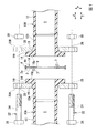
図1及び図2に示すように、第一実施形態のパッキン1Aは、管軸方向Jの一方の端面10pに接続フランジ14を有する樹脂製の接続管10A,10Bを密閉接続するために用いられるパッキンであって、端面10pに当接して配置可能とされ、接続管10A,10Bの中空部(内部)Sを通る媒体が通過可能な孔部6が形成された薄板状のパッキン本体2と、パッキン本体2の外周縁2eの全周からパッキン本体2の厚み方向Tの両側に延出し、接続管10A,10Bの接続フランジ14の外周面14rに当接される外縁補強壁4と、を備えている。
(First embodiment)
As shown in FIGS. 1 and 2, the packing 1 </ b> A of the first embodiment is used for hermetically connecting resin connection pipes 10 </ b> A and 10 </ b> B having a
接続管10A,10Bは、接続対象の所謂フランジ管であって、管本体12と、管本体12の端部12a,12bから管本体12の周方向外側に拡がる接続フランジ14と、を備えている。接続管10A,10Bの管軸方向Jにおいて管本体12と接続フランジ14との間には、管本体12から接続フランジ14へ向かうに従い厚み寸法が増大する厚肉部16が設けられている。
The connection pipes 10 </ b> A and 10 </ b> B are so-called flange pipes to be connected, and include a pipe
管本体12、厚肉部16及び接続フランジ14は、不図示の多層構造を有している。
該多層構造は、内層と、中間層と、外層と、接着層と、ガスバリア層が接続管10A,10Bの内側から外側に向って積層されることで、構成されている。
内層は、接続管10A,10B内を流通するガス等の媒体(即ち、流体)が接する管状の層である。内層の材料としては、例えばポリオレフィン系樹脂が挙げられる。
中間層は、例えばポリオレフィン系樹脂と、ガラス繊維と、相溶化剤と、を含み、ポリオレフィン系樹脂とガラス繊維と相溶化剤とを含むポリオレフィン系樹脂組成物を用いた成形体である。
外層の材料としては、例えばポリオレフィン系樹脂が挙げられる。
The
The multilayer structure is configured by laminating an inner layer, an intermediate layer, an outer layer, an adhesive layer, and a gas barrier layer from the inner side to the outer side of the
The inner layer is a tubular layer in contact with a medium such as a gas (that is, fluid) that flows through the
An intermediate | middle layer is a molded object using the polyolefin resin composition which contains polyolefin resin, glass fiber, and a compatibilizer, for example, and contains polyolefin resin, glass fiber, and a compatibilizer.
Examples of the material for the outer layer include polyolefin-based resins.
接着層は、外層とガスバリア層とを良好に接着するために設けられている。接着層の材料としては、例えばゴム系ホットメルト接着剤、変性ポリエチレン及び変性ポリプロピレン等が挙げられる。
ガスバリア層は、外部環境に晒され、該外部環境から内層と、中間層及び外層を保護するために設けられている。ガスバリア層の材料としては、例えばポリビニルアルコール、エチレンビニルアルコール共重合体、ポリ塩化ビニリデン樹脂及びポリアクリロニトリル等が挙げられる。
なお、上述の内層、中間層、外層、接着層、ガスバリア層の材料や厚み寸法(即ち、接続管10A,10Bの径方向の寸法)は、各層が接続管10A,10Bの径方向において隣接する物質及びその物質との相互作用等を勘案して、適宜選択されることが好ましい。
The adhesive layer is provided to favorably bond the outer layer and the gas barrier layer. Examples of the material for the adhesive layer include rubber-based hot melt adhesives, modified polyethylene, and modified polypropylene.
The gas barrier layer is exposed to the external environment and is provided to protect the inner layer, the intermediate layer, and the outer layer from the external environment. Examples of the material for the gas barrier layer include polyvinyl alcohol, ethylene vinyl alcohol copolymer, polyvinylidene chloride resin, and polyacrylonitrile.
Note that the materials and thickness dimensions of the inner layer, the intermediate layer, the outer layer, the adhesive layer, and the gas barrier layer (that is, the radial dimensions of the connecting
接続管10A,10Bの厚肉部16には、接続管10A,10B同士を接続するためのステンレス(SUS)等の金属製の締結フランジ20A,20Bが外嵌されている。また、締結フランジ20A,20Bは、接続管10A,10Bの管本体12側から接続フランジ14に当接するように配置されている。
締結フランジ20A,20Bの径寸法は、少なくとも接続管10A,10Bの接続フランジ14の径寸法よりも大きい。これにより、締結フランジ20A,20Bにおいて接続フランジ14からはみ出ている部分に、フランジ接合用のボルト22の軸部24を挿通させるための挿通孔28が形成されている。挿通孔28は、締結フランジ20A,20Bの周方向において、少なくとも四個形成されており、六個又は八個形成されていることが好ましい。
Fastening
The diameter dimension of the
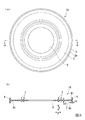
パッキン1Aのパッキン本体2における孔部6と外縁補強壁4との間にパッキン本体2の厚み方向Tに突出する第二封止リブ(封止リブ)7が全周にわたって設けられている。接続管10A,10Bの端面10pを確実に押圧し、接続管10A,10Bの媒体の流通部分を全周にわたってより強く封止する目的から、第二封止リブ7は、パッキン1Aの周方向において二つ設けられている。
A second sealing rib (sealing rib) 7 protruding in the thickness direction T of the
JIS K 6253:1997準拠のタイプAデュロメータで測定されるパッキン本体2及び外縁補強壁4の硬さは、50以上90以下であることが好ましい。パッキン本体2及び外縁補強壁4の硬さが50より低いと、外縁補強壁4の補強機能が低下し、パッキン本体2及び外縁補強壁4の変形が抑制されない。一方、パッキン本体2及び外縁補強壁4の硬さが90より高いと、パッキン1Aが硬すぎて中空部S及び孔部6の密閉性がなくなり、媒体の漏れを防止することができない。
また、70±1℃条件下でJIS K 6262:2013に準拠して測定されるパッキン本体2及び外縁補強壁4の圧縮永久歪が0%以上70%以下であることが好ましく、40%以下であることがより好ましい。
It is preferable that the hardness of the packing
Moreover, it is preferable that the compression set of the
図3(a),(b)に示すように、パッキン1Aのパッキン本体2の厚み寸法t2は、2mm以上であることが好ましく、5mm以上であることがより好ましい。また、外縁補強壁4の厚み寸法t4は、1mm以上であることが好ましく、3mm以上であることがより好ましい。パッキン本体2の厚み寸法t2が2mmより小さいと、パッキン1Aの変形抑制機能がやや低下し、パッキン1Aの変形により隙間が生じた際に媒体が隙間から漏れる虞がある。
As shown in FIGS. 3A and 3B, the thickness t2 of the
パッキン1Aは、射出成形又は圧縮成形によって製造された成形体である。上述の構成及び特性を有するパッキン1Aの材料としては、スチレン・ブタジエンゴム(SBR)、ニトリルゴム(NBR)、エチレン・プロピレン・ジエンゴム(EPDM)、クロロプレンゴム(CR)等が好適であるが、ゴム弾性を有するもの、或いはウレタン系エラストマー、アミド系エラストマーやテフロン(登録商標)系エラストマーであってもよい。
The
上述の構成において、図1に示すように、締結フランジ20Aのボルト孔28に管本体12側からボルト22の軸部24を挿入し、締結フランジ20B側から突出したボルト22の軸部24にナット30を嵌め込む。この際、接続管10A,10Bの接続フランジ14の外周面14rの全周にわたって外縁補強壁4が当接される。これにより、図2に示すように、接続管10A,10Bがフランジ接合された状態となっている。
In the configuration described above, as shown in FIG. 1, the
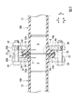
図2に示すように、接続管10A,10Bがフランジ接合された状態では、接続フランジ14の外周面14rの少なくとも端面10p側が外縁補強壁4によって被覆されている。このようにパッキン本体2の板面方向Pにおいて外縁補強壁4で係止されていることから、パッキン1Aは外縁補強壁4によって補強されている。
また、接続管10A,10Bがフランジ接合された状態では、パッキン1Aの第二封止リブ7が接続管10A,10Bの管軸方向L及びパッキン本体2の厚み方向Tに押し潰されている。これにより、第二封止リブ7の形成位置では、第二封止リブ7と接続管10A,10Bの端面10pとが互いに強く押圧し合っており、中空部S及び孔部6は密閉されている。
As shown in FIG. 2, in a state where the connecting pipes 10 </ b> A and 10 </ b> B are flange-joined, at least the
Further, in a state where the connecting
以上説明した第一実施形態のパッキン1Aによれば、上述のように外縁補強壁4が接続フランジ14の外周面14rの全周にわたって当接することで、パッキン本体2が径方向外側で支持され、これによってパッキン本体2が補強されるので、高温下での締め付けや冷熱の繰り返しが発生してもパッキン1Aの変形を抑制することができる。これにより、パッキン本体2と接続管10A,10Bの接続フランジ14との隙間が生じることもなく、中空部S及び孔部6の密閉性を保つことができる。
According to the
また、第一実施形態のパッキン1Aによれば、外縁補強壁4の厚み寸法t4が1mm以上であるため、外縁補強壁4の強度が確保され、パッキン本体2の変形が抑制される。これにより、パッキン本体2の板面方向Pにおける外縁補強壁4の係止力を確実に保持し、パッキン1Aの変形抑制機能をより一層高くすることができる。
Further, according to the
また、第一実施形態のパッキン1Aによれば、パッキン本体2における孔部6と外縁補強壁4との間にパッキン本体2の厚み方向Tに突出する第二封止リブ7が全周にわたって設けられているので、第二封止リブ7と接続管10A,10Bの端面10p(即ち、接続フランジ14の端面)とを互いに強く押圧させ、接続管10A,10Bの媒体の流通部分が全周にわたってさらに強く封止することができる。
Further, according to the
また、第一実施形態のパッキン1Aによれば、パッキン本体2の厚み寸法t2が2mm以上であるため、パッキン本体2の強度が確保され、例えば0℃に達するような低温下或いは60℃に達するような高温下や、冷熱の繰り返し及び環境の激しい温度変化等が発生しても、より確実にパッキン本体2の変形を抑制することができ、媒体が水等である場合には、パッキン1Aにおける媒体の漏れ防止機能をさらに高くすることができる。
Further, according to the
また、第一実施形態のパッキン1Aによれば、パッキン本体2及び外縁補強壁4の硬さが50以上90以下であるため、パッキン1Aの硬さが確保され、パッキンの変形抑制機能をさらに高くすることができる。
さらに、第一実施形態のパッキン1Aによれば、パッキン本体2及び外縁補強壁4の圧縮永久歪が0%以上70%以下であるため、パッキン1Aの全体の耐水圧性能を高めることができる。
Further, according to the
Furthermore, according to the
(第二実施形態)
次いで、第二実施形態のパッキン1Bについて説明する。なお、パッキン1Bの構成要素において、第一実施形態のパッキン1Aの構成要素と同一のものについては、同一の符号を付し、その説明を省略する。
(Second embodiment)
Next, the
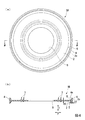
図4に示すように、第二実施形態のパッキン1Bでは、外縁補強壁4におけるパッキン本体2側の内面4nの全周にわたって第一封止リブ5が設けられている。従って、図5に示すように、接続管10A,10Bがフランジ接合された状態では、パッキン1Bの第一封止リブ5がパッキン本体2の板面方向Pに押し潰されている。これにより、第一封止リブ5の形成位置では、第一封止リブ5と接続管10A,10Bの接続フランジ14の外周面14rとが互いに強く押圧し合っており、中空部S及び孔部6は密閉されている。
As shown in FIG. 4, in the packing 1 </ b> B of the second embodiment, the
上述のように、第二実施形態のパッキン1Bによれば、第一封止リブ5と接続管10A,10Bの接続フランジ14の外周面14rと互いに強く押圧させ、外周面14rの全周にわたってより強く封止することができる。これにより、パッキン1Bにおける媒体の漏れ防止機能をより一層高くすることができる。
As described above, according to the
(他の実施形態)
第一、第二の実施形態においては、外縁補強壁4がパッキン本体2の外周縁2eに設けられていたが、板面方向Pにおいてパッキン本体2の外周縁2eが締結フランジ20A,20Bの外周縁まで延設され、このようなパッキン1Cの孔部6から外周縁2eの間のパッキン本体2から外縁補強壁4が厚み方向Tの両側に突出するよう設けられていてもよい。この場合、延設されたパッキン本体2にはボルト22の軸部24を挿通させるための挿通孔が形成される。
(Other embodiments)
In the first and second embodiments, the outer
以上、本発明の好ましい実施形態について詳述したが、本発明は係る特定の実施形態に限定されるものではなく、特許請求の範囲内に記載された本発明の要旨の範囲内において、種々の変形・変更が可能である。 The preferred embodiments of the present invention have been described in detail above. However, the present invention is not limited to the specific embodiments, and various modifications are possible within the scope of the gist of the present invention described in the claims. Deformation / change is possible.
次いで、上述した本発明を適用した実施形態のパッキン1A,1Bのパッキン本体2の厚み寸法t2の効果及び外縁補強壁4の効果を裏付けるために行った実施例及び比較例について説明する。なお、本発明は以下の実施例にのみ限定されるものではない。
Next, examples and comparative examples performed to support the effect of the thickness dimension t2 of the
(実施例1)
図4(a),(b)に示した第二実施形態のパッキン1B及び図5に示す接続構造を形成した。パッキン1Bの材料は、PU系とした。パッキン本体2の中空部Sの口径は100mmとし、外縁補強壁4の孔部6の口径も100mmとした。パッキン本体2及び外縁補強壁4の硬さは、JIS K 6253:1997準拠のタイプAデュロメータで75であった。パッキン本体2及び外縁補強壁4の圧縮永久歪みは65%とし、パッキン本体2の厚み寸法t2は、2mmとした。
上述の接続構造を0℃から60℃の環境下で冷熱繰り返した後、水圧試験を行った。この水圧試験では、一時間ごとの冷熱の繰り返しとし、水圧は4.0MPa×5分とし、2000回行った。媒体を水としたときの漏水有無を調べた結果、合格であった。
Example 1
The
The above connection structure was repeatedly cooled and heated in an environment of 0 ° C. to 60 ° C., and then a water pressure test was performed. In this water pressure test, cooling was repeated every hour, the water pressure was 4.0 MPa × 5 minutes, and the test was performed 2000 times. As a result of examining the presence or absence of water leakage when the medium was water, the result was acceptable.
(実施例2)
実施例1において、パッキン1Bの材料をSBRとし、パッキン本体2及び外縁補強壁4の硬さを50に変更し、圧縮永久歪みを65%に変更し、パッキン本体2の厚み寸法t2を5mmに変更すること以外は、実施例1と同様にして、第二実施形態のパッキン1B及び接続構造を形成した。
実施例1と同じ条件で漏水有無を調べた結果、合格であった。
また、接続フランジ14に変形は見られなかった。
(Example 2)
In Example 1, the material of the
As a result of examining the presence or absence of water leakage under the same conditions as in Example 1, the result was acceptable.
Further, no deformation was seen in the
(実施例3)
実施例2において、パッキン本体2及び外縁補強壁4の硬さを55に変更したこと以外は、実施例1と同様にして、第二実施形態のパッキン1B及び接続構造を形成した。
実施例1と同じ条件で漏水有無を調べた結果、合格であった。
また、接続フランジ14に変形は見られなかった。
(Example 3)
In Example 2, the
As a result of examining the presence or absence of water leakage under the same conditions as in Example 1, the result was acceptable.
Further, no deformation was seen in the
(実施例4)
実施例2において、パッキン本体2及び外縁補強壁4の硬さを60に変更したこと以外は、実施例1と同様にして、第二実施形態のパッキン1B及び接続構造を形成した。
実施例1と同じ条件で漏水有無を調べた結果、合格であった。
また、接続フランジ14に変形は見られなかった。
Example 4
In Example 2, the
As a result of examining the presence or absence of water leakage under the same conditions as in Example 1, the result was acceptable.
Further, no deformation was seen in the
(実施例5)
実施例1において、パッキン1Bの材料をEPDMとし、パッキン本体2及び外縁補強壁4の硬さを55に変更し、圧縮永久歪みを40%に変更し、パッキン本体2の厚み寸法t2を5mmに変更したこと以外は、実施例1と同様にして、第二実施形態のパッキン1B及び接続構造を形成した。
実施例1と同じ条件で漏水有無を調べた結果、合格であった。
また、接続フランジ14に変形は見られなかった。
(Example 5)
In Example 1, the material of the
As a result of examining the presence or absence of water leakage under the same conditions as in Example 1, the result was acceptable.
Further, no deformation was seen in the
(比較例1)
実施例1において、パッキン本体2の外周縁2eに外縁補強壁4を設けないこと以外は、実施例1と同様にして、第二実施形態のパッキン1B及び接続構造を形成した。
また、実施例1と同じ条件で漏水有無を調べた結果、水が漏れず、合格であったが、接続フランジ14に変形が見られた。
(Comparative Example 1)
In Example 1, the
Moreover, as a result of investigating the presence or absence of water leakage under the same conditions as in Example 1, water was not leaked and passed, but the
上述の実施例1から実施例5及び比較例1の条件及び試験結果を表1にまとめて示す。なお、表1の形状の項目において、「縁有り」はパッキン本体2の外周縁2eの全周にわたって外縁補強壁4が設けられていることを示し、「縁無し」はパッキン本体2に外縁補強壁4が設けられていないことを示す。
Table 1 summarizes the conditions and test results of Examples 1 to 5 and Comparative Example 1 described above. In addition, in the item of the shape in Table 1, “With edge” indicates that the outer
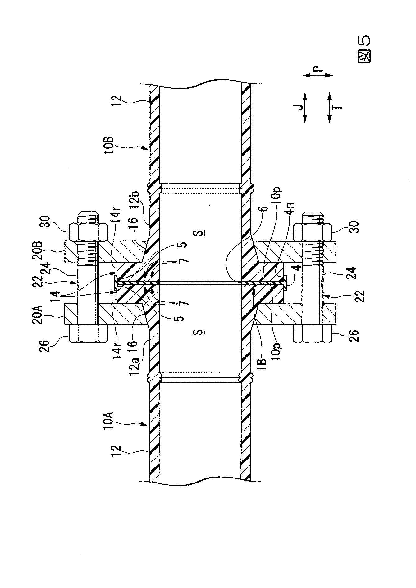
表1に示す条件及び試験結果からもわかるように、パッキン本体2及び外縁補強壁4の硬さ及び圧縮永久歪みを適切に設定することで、パッキン1Bの変形抑制機能及び、特に漏れ防止能力を高めることができる。特に、パッキン本体2及び外縁補強壁4の圧縮永久歪みを70%以下とし、パッキン本体2の厚み寸法t2を2mm以上にすると、パッキン1Bに充分な耐水性能を付与し、漏れ防止能力をより確実に高くすることができる。
As can be seen from the conditions and test results shown in Table 1, by properly setting the hardness and compression set of the
1A,1B…パッキン、2…パッキン本体、4…外縁補強壁、5…第一封止リブ、6…孔部、7…第二封止リブ(封止リブ)、10A,10B…接続管、10p…端面、14…接続フランジ、14r…外周面、20A,20B…締結フランジ
DESCRIPTION OF
Claims (5)
前記一方の端面に当接して配置可能とされ、前記接続管の内部を通る媒体が通過可能な孔部が形成された薄板状のパッキン本体と、
前記パッキン本体の外周縁の全周から前記パッキン本体の厚み方向の両側に延出し、前記接続フランジの外周面に当接される外縁補強壁と、
を備えていることを特徴とするパッキン。 A packing for providing a metal fastening flange and sealingly connecting the resin connection pipes having a connection flange on one end face in the pipe axis direction between the connection flanges,
A thin plate-like packing body which is arranged so as to be in contact with the one end face and in which a hole through which the medium passing through the inside of the connecting pipe can pass is formed;
An outer edge reinforcing wall that extends from the entire circumference of the outer peripheral edge of the packing body to both sides in the thickness direction of the packing body, and is in contact with the outer peripheral surface of the connection flange;
Packing characterized by having.
Priority Applications (1)
| Application Number | Priority Date | Filing Date | Title |
|---|---|---|---|
| JP2016082080A JP6725303B2 (en) | 2016-04-15 | 2016-04-15 | Packing |
Applications Claiming Priority (1)
| Application Number | Priority Date | Filing Date | Title |
|---|---|---|---|
| JP2016082080A JP6725303B2 (en) | 2016-04-15 | 2016-04-15 | Packing |
Publications (2)
| Publication Number | Publication Date |
|---|---|
| JP2017190850A true JP2017190850A (en) | 2017-10-19 |
| JP6725303B2 JP6725303B2 (en) | 2020-07-15 |
Family
ID=60085836
Family Applications (1)
| Application Number | Title | Priority Date | Filing Date |
|---|---|---|---|
| JP2016082080A Active JP6725303B2 (en) | 2016-04-15 | 2016-04-15 | Packing |
Country Status (1)
| Country | Link |
|---|---|
| JP (1) | JP6725303B2 (en) |
Cited By (3)
| Publication number | Priority date | Publication date | Assignee | Title |
|---|---|---|---|---|
| JP2021055742A (en) * | 2019-09-30 | 2021-04-08 | 積水化学工業株式会社 | Pipe joint structure |
| EP3805619A4 (en) * | 2018-05-31 | 2022-03-02 | Asahi Yukizai Corporation | PINCH VALVE |
| JP2023151118A (en) * | 2022-03-31 | 2023-10-16 | 積水化学工業株式会社 | Stub ends and connection structures |
Citations (9)
| Publication number | Priority date | Publication date | Assignee | Title |
|---|---|---|---|---|
| JPS525161U (en) * | 1975-06-27 | 1977-01-13 | ||
| JPS60131784U (en) * | 1984-02-14 | 1985-09-03 | 山浅鋳物株式会社 | Structure of the connection between synthetic resin pipe and iron pipe |
| JPH01118293U (en) * | 1988-02-03 | 1989-08-10 | ||
| JPH0398362U (en) * | 1990-01-26 | 1991-10-11 | ||
| JPH11182756A (en) * | 1997-12-22 | 1999-07-06 | Kurimoto Ltd | Loose flange type pipe joint for polyethylene pipe |
| JP2000179693A (en) * | 1998-12-21 | 2000-06-27 | Bridgestone Corp | Packing material |
| JP2008514957A (en) * | 2004-09-30 | 2008-05-08 | ローズマウント インコーポレイテッド | Gasket structure for sanitary process flow meter |
| JP2009257552A (en) * | 2008-04-21 | 2009-11-05 | Ckd Corp | Sealing member, fluid device connection structure, and fluid device unit |
| JP2015068424A (en) * | 2013-09-30 | 2015-04-13 | 日本バルカー工業株式会社 | Resin-made gasket for seal |
-
2016
- 2016-04-15 JP JP2016082080A patent/JP6725303B2/en active Active
Patent Citations (9)
| Publication number | Priority date | Publication date | Assignee | Title |
|---|---|---|---|---|
| JPS525161U (en) * | 1975-06-27 | 1977-01-13 | ||
| JPS60131784U (en) * | 1984-02-14 | 1985-09-03 | 山浅鋳物株式会社 | Structure of the connection between synthetic resin pipe and iron pipe |
| JPH01118293U (en) * | 1988-02-03 | 1989-08-10 | ||
| JPH0398362U (en) * | 1990-01-26 | 1991-10-11 | ||
| JPH11182756A (en) * | 1997-12-22 | 1999-07-06 | Kurimoto Ltd | Loose flange type pipe joint for polyethylene pipe |
| JP2000179693A (en) * | 1998-12-21 | 2000-06-27 | Bridgestone Corp | Packing material |
| JP2008514957A (en) * | 2004-09-30 | 2008-05-08 | ローズマウント インコーポレイテッド | Gasket structure for sanitary process flow meter |
| JP2009257552A (en) * | 2008-04-21 | 2009-11-05 | Ckd Corp | Sealing member, fluid device connection structure, and fluid device unit |
| JP2015068424A (en) * | 2013-09-30 | 2015-04-13 | 日本バルカー工業株式会社 | Resin-made gasket for seal |
Cited By (5)
| Publication number | Priority date | Publication date | Assignee | Title |
|---|---|---|---|---|
| EP3805619A4 (en) * | 2018-05-31 | 2022-03-02 | Asahi Yukizai Corporation | PINCH VALVE |
| JP2021055742A (en) * | 2019-09-30 | 2021-04-08 | 積水化学工業株式会社 | Pipe joint structure |
| JP7372804B2 (en) | 2019-09-30 | 2023-11-01 | 積水化学工業株式会社 | pipe joint structure |
| JP2023151118A (en) * | 2022-03-31 | 2023-10-16 | 積水化学工業株式会社 | Stub ends and connection structures |
| JP7797291B2 (en) | 2022-03-31 | 2026-01-13 | 積水化学工業株式会社 | Stub ends and connection structures |
Also Published As
| Publication number | Publication date |
|---|---|
| JP6725303B2 (en) | 2020-07-15 |
Similar Documents
| Publication | Publication Date | Title |
|---|---|---|
| US20140319826A1 (en) | Coupling for range of pipe diameters | |
| JP2009281424A (en) | Metal gasket | |
| JP2017190850A (en) | Packing | |
| KR102149690B1 (en) | Flanged Gasket for Piping with Pressure Resistance and Leakage Prevention | |
| JP6962729B2 (en) | Leakage prevention device | |
| US11112038B2 (en) | Pipe-fitting | |
| US20170074401A1 (en) | Press-in-place gasket | |
| JP2004052817A (en) | Flange packing | |
| US20130134707A1 (en) | Pipe coupling for the fluid-tight attachment of components in an air conditioning system | |
| JP3210602U (en) | Fittings for small diameter piping | |
| US9500305B2 (en) | Fitting mechanism for use with multilayer composite pipe | |
| JP2003194226A (en) | Jacket seal | |
| JP4840690B2 (en) | Pipe end anticorrosion material and piping structure | |
| KR102195335B1 (en) | Joint for pipe connection | |
| KR102190003B1 (en) | Joint for pipe connection | |
| KR101555583B1 (en) | Reverse pipe interface device | |
| WO2017130713A1 (en) | Piping | |
| KR200323223Y1 (en) | Gasket using Teflon | |
| KR20160128012A (en) | Gas-tight increasing type gasket by inner pressure and flange pipe for the same | |
| JP7688263B2 (en) | Seal Structure | |
| JP3206965U (en) | Gasket and pipe joint provided with the same | |
| KR101941424B1 (en) | Pipe jointer using z type sealing material | |
| JP3189885U (en) | Housing type fitting | |
| KR100896962B1 (en) | Double pipe with airtight structure to seal pressure pipe secondaryly | |
| US20160061362A1 (en) | Ducting apparatus |
Legal Events
| Date | Code | Title | Description |
|---|---|---|---|
| A621 | Written request for application examination |
Free format text: JAPANESE INTERMEDIATE CODE: A621 Effective date: 20190116 |
|
| A977 | Report on retrieval |
Free format text: JAPANESE INTERMEDIATE CODE: A971007 Effective date: 20200120 |
|
| A131 | Notification of reasons for refusal |
Free format text: JAPANESE INTERMEDIATE CODE: A131 Effective date: 20200128 |
|
| A521 | Request for written amendment filed |
Free format text: JAPANESE INTERMEDIATE CODE: A523 Effective date: 20200330 |
|
| TRDD | Decision of grant or rejection written | ||
| A01 | Written decision to grant a patent or to grant a registration (utility model) |
Free format text: JAPANESE INTERMEDIATE CODE: A01 Effective date: 20200602 |
|
| A61 | First payment of annual fees (during grant procedure) |
Free format text: JAPANESE INTERMEDIATE CODE: A61 Effective date: 20200625 |
|
| R151 | Written notification of patent or utility model registration |
Ref document number: 6725303 Country of ref document: JP Free format text: JAPANESE INTERMEDIATE CODE: R151 |