JP2017190010A - Tractor - Google Patents
Tractor Download PDFInfo
- Publication number
- JP2017190010A JP2017190010A JP2016079367A JP2016079367A JP2017190010A JP 2017190010 A JP2017190010 A JP 2017190010A JP 2016079367 A JP2016079367 A JP 2016079367A JP 2016079367 A JP2016079367 A JP 2016079367A JP 2017190010 A JP2017190010 A JP 2017190010A
- Authority
- JP
- Japan
- Prior art keywords
- reinforcing member
- fixing portion
- fuel tank
- fixed
- driver
- Prior art date
- Legal status (The legal status is an assumption and is not a legal conclusion. Google has not performed a legal analysis and makes no representation as to the accuracy of the status listed.)
- Pending
Links
- 239000002828 fuel tank Substances 0.000 claims abstract description 61
- 230000003014 reinforcing effect Effects 0.000 claims description 76
- 238000000605 extraction Methods 0.000 claims description 3
- 230000002787 reinforcement Effects 0.000 abstract description 18
- 238000003780 insertion Methods 0.000 description 6
- 230000037431 insertion Effects 0.000 description 6
- 230000001681 protective effect Effects 0.000 description 3
- 230000005540 biological transmission Effects 0.000 description 2
- 230000006866 deterioration Effects 0.000 description 2
- 238000012423 maintenance Methods 0.000 description 1
- 230000000630 rising effect Effects 0.000 description 1
Images


Landscapes
- Body Structure For Vehicles (AREA)
Abstract
Description
本発明は、左右のフェンダフレームを連結する補強部材を備えたトラクタに関する。 The present invention relates to a tractor including a reinforcing member that connects left and right fender frames.
運転席と、運転席の左右側方に設けられる左右のフェンダと、左右のフェンダを支持する左右のフェンダフレームと、運転席の後方で左右のフェンダフレームを連結する補強部材と、を備えるトラクタが知られている。例えば、特許文献1、2には、左右のフェンダフレームを連結する補強部材に、ナンバープレートやリヤランプを取り付けたトラクタが記載されている。
A tractor comprising a driver's seat, left and right fenders provided on the left and right sides of the driver's seat, left and right fender frames that support the left and right fenders, and a reinforcing member that connects the left and right fender frames behind the driver's seat Are known. For example,
この種のトラクタでは、同一機種でありながら、用途の違いなど応じて複数の仕様が設定される場合がある。例えば、燃料タンク容量を増量するために運転席の後方に燃料タンク(サブの燃料タンク)が配置される仕様(例えば、水田仕様)と、運転席の後方に燃料タンクが配置されない仕様(例えば、畑作仕様)と、が設定される場合があるが、運転席の後方に燃料タンクが配置される仕様では、レイアウト上の制約により前述した補強部材の設置が困難になり、仕様間で機体強度に差が生じる虞があった。 In this type of tractor, although it is the same model, a plurality of specifications may be set according to the difference in usage. For example, a specification (for example, paddy field specification) in which a fuel tank (sub fuel tank) is disposed behind the driver's seat in order to increase the fuel tank capacity, and a specification in which the fuel tank is not disposed behind the driver's seat (for example, However, in the specifications where the fuel tank is placed behind the driver's seat, it is difficult to install the reinforcing member described above due to layout restrictions, and the strength of the fuselage between the specifications is reduced. There was a risk of differences.
本発明は、上記の如き実情に鑑みこれらの課題を解決することを目的として創作されたものであって、請求項1の発明は、運転席と、前記運転席の左右側方に設けられる左右のフェンダと、左右の前記フェンダを支持する左右のフェンダフレームと、を備えるトラクタであって、前記運転席の後方で左右の前記フェンダフレームを連結する補強部材を備え、左右の前記フェンダフレームは、前記補強部材が選択的に固定される前側固定箇所及び後側固定箇所を備え、前記運転席の後方に燃料タンクが配置される仕様の前記トラクタでは、前記補強部材を前記後側固定箇所に固定して、前記運転席と前記補強部材との間に前記燃料タンクの配置スペースを確保するとともに、前記補強部材で前記燃料タンクを保護し、前記運転席の後方に前記燃料タンクを配置しない仕様の前記トラクタでは、前記補強部材を前記前側固定箇所に固定して前記補強部材の後方突出量を抑制することを特徴とする。
また、請求項2の発明は、請求項1に記載のトラクタであって、前記補強部材は、前後方向に沿い、前記フェンダフレームに固定される左右の固定部と、左右方向に沿い、左右の前記固定部の後端部同士を連結する連結部と、を備える平面視コ字形状を有し、前記固定部は、前記フェンダフレームの前記前側固定箇所に固定されたとき、前記後側固定箇所を覆い隠すことを特徴とする。
また、請求項3の発明は、請求項1又は2に記載のトラクタであって、前記運転席の後方に前記燃料タンクを配置する仕様の前記トラクタでは、前記フェンダフレームの前記前側固定箇所に、前記燃料タンクを支持する燃料タンクブラケットが固定されることを特徴とする。
また、請求項4の発明は、請求項1〜3のいずれか一項に記載のトラクタであって、左右の前記フェンダフレームの上部には、安全フレームを取り付けるための安全フレーム取付台が固定され、前記前側固定箇所及び前記後側固定箇所は、前記安全フレーム取付台に設けられることを特徴とする。
また、請求項5の発明は、請求項1〜4のいずれか一項に記載のトラクタであって、前記補強部材は、ナンバープレート、低速車マーク、外部取出し電源、及び/又は、リヤランプの取付部を備えることを特徴とする。
また、請求項6の発明は、請求項5に記載のトラクタであって、前記補強部材は、左右の前記フェンダフレームに対して着脱自在に固定され、前記連結部には、前記外部取出し電源、及び/又は、前記リヤランプに電気的に接続されるハーネスが配索され、前記補強部材の着脱時に前記ハーネスが前記補強部材と一体に着脱されることを特徴とする。
The present invention has been created in view of the above-described circumstances in order to solve these problems. The invention of
The invention according to
Further, the invention of
A fourth aspect of the present invention is the tractor according to any one of the first to third aspects, wherein a safety frame mounting base for mounting the safety frame is fixed to upper portions of the left and right fender frames. The front side fixing point and the rear side fixing point are provided on the safety frame mounting base.
A fifth aspect of the present invention is the tractor according to any one of the first to fourth aspects, wherein the reinforcing member is a license plate, a low-speed vehicle mark, an external power supply, and / or a rear lamp. It comprises a part.
The invention according to
請求項1の発明によれば、運転席の後方に燃料タンクが配置される仕様及び配置されない仕様のいずれにおいても補強部材を設置して機体強度を高められる。また、運転席の後方に燃料タンクが配置される仕様では、補強部材が燃料タンクの保護部材に兼用されるので、構造の簡略化及びコストダウンが可能になる。また、運転席の後方に燃料タンクが配置されない仕様では、補強部材の後方突出量が抑制されるので、作業機の昇降範囲を広げられる等の利点がある。
また、請求項2の発明によれば、補強部材の固定部は、フェンダフレームの前側固定箇所に固定されたとき、後側固定箇所を覆い隠すので、後側固定箇所の露出による外観の低下等を回避できる。
また、請求項3の発明によれば、運転席の後方に燃料タンクを配置する仕様では、フェンダフレームの前側固定箇所に、燃料タンクを支持する燃料タンクブラケットが固定されるので、固定箇所の兼用化に基づいて構造を簡略化できるだけでなく、前側固定箇所の露出による外観の低下等も回避できる。
また、請求項4の発明によれば、前側固定箇所及び後側固定箇所は、安全フレーム取付台に設けられるので、補強部材との固定により安全フレーム取付台も補強することができる。
また、請求項5の発明によれば、補強部材は、ナンバープレート、低速車マーク、外部取出し電源、及び/又は、リヤランプの取付部を備えるので、補強部材を各種部材の取付部に兼用して構造の簡略化が図れる。
また、請求項6の発明によれば、補強部材の着脱時にハーネスが補強部材と一体に着脱されるので、組立性やメンテナンス性を向上させることができる。
According to the first aspect of the present invention, the strength of the airframe can be increased by installing the reinforcing member in both the specification in which the fuel tank is disposed behind the driver's seat and the specification in which the fuel tank is not disposed. In the specification in which the fuel tank is arranged behind the driver's seat, the reinforcing member is also used as the protective member for the fuel tank, so that the structure can be simplified and the cost can be reduced. In addition, in the specification in which the fuel tank is not disposed behind the driver's seat, there is an advantage that the lifting range of the work implement can be widened because the amount of rearward protrusion of the reinforcing member is suppressed.
According to the invention of
According to the invention of
According to the fourth aspect of the present invention, since the front side fixing portion and the rear side fixing portion are provided on the safety frame mounting base, the safety frame mounting base can also be reinforced by fixing to the reinforcing member.
According to the invention of
According to the invention of
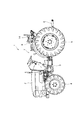
以下、本発明の実施の形態について、図面に基づいて説明する。図1において、1はトラクタであって、該トラクタ1は、図示しないエンジン及び燃料タンクが搭載されるエンジン搭載部2と、エンジン動力を変速するミッションケース3と、ミッションケース3から伝動される動力で回転駆動する前輪4及び後輪5と、図示しない作業機が連結される作業機連結部6と、オペレータが乗車する運転部7と、を備える。
Hereinafter, embodiments of the present invention will be described with reference to the drawings. In FIG. 1,
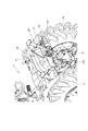
図1及び図2に示すように、運転部7は、オペレータが着座する運転席8を備える。運転席8の左右側方には、後輪5の上方を覆う左右のフェンダ9が配置されており、左右のフェンダ9は、後輪5の内方に立設される左右のフェンダフレーム10で支持されている。図5〜図7に示すように、左右のフェンダフレーム10は、高さ方向中間部同士が左右方向を向く連結フレーム11で連結されるとともに、高さ方向上端部同士が左右方向を向く補強部材12で連結されている。
厳密には、左右のフェンダフレーム10の上端部に、図示しない安全フレームを取り付けるための安全フレーム取付台13が設けられ、左右のフェンダフレーム10に設けられた安全フレーム取付台13同士が補強部材12を介して連結されている。
As shown in FIGS. 1 and 2, the
Strictly speaking, a safety
本実施形態のトラクタ1には、少なくとも2つの仕様が設定されている。一方の仕様は、燃料タンク容量を増量するために運転席8の後方に第2燃料タンク14が配置される第1仕様(例えば、水田仕様)であり、他方の仕様は、運転席8の後方に第2燃料タンク14が配置されない第2仕様(例えば、畑作仕様)である。運転席8の後方に第2燃料タンク14が配置される第2仕様では、取付位置が第2燃料タンク14と干渉して補強部材12の設置が困難になる可能性があるが、本実施形態の補強部材12は、第1仕様及び第2仕様に対応可能であり、以下、補強部材12の具体的な形状及びその固定構造について説明する。
At least two specifications are set for the
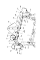
図3及び図4に示すように、本実施形態の補強部材12は、前後方向に沿い、安全フレーム取付台13(フェンダフレーム10)に固定される左右の固定部12aと、左右方向に沿い、左右の固定部12aの後端部同士を連結する連結部12bと、を一体に備える平面視コ字形状を有している。固定部12aは、その前端側に前後方向に並ぶ2つのボルト挿通孔(図示せず)を有し、該ボルト挿通孔に上方から挿通される2つのボルト15で安全フレーム取付台13に対して着脱自在に固定される。
As shown in FIG. 3 and FIG. 4, the reinforcing
本実施形態の安全フレーム取付台13は、フェンダフレーム10の上端部に4つのボルト16を介して固定されるフェンダフレーム固定部13aと、該フェンダフレーム固定部13aから立ち上がる支柱部13bと、該支柱部13bの上端部に設けられる安全フレーム固定部13cと、フェンダフレーム固定部13aの内側上部に設けられる補強部材固定部13dと、を一体に備える。
The safety
補強部材固定部13dは、側面視冂字形状を有し、その上面部には、補強部材12が選択的に固定される前側固定箇所13e及び後側固定箇所13fが形成されている。各固定箇所13e、13fは、補強部材12の2つのボルト挿通孔と対応する2つのボルト挿通孔からなり、補強部材12のボルト挿通孔、及び選択された固定箇所13e、13fのボルト挿通孔に挿通されたボルト15と、該ボルト15に螺合する図示しないナットとの緊締により、補強部材12が前側固定箇所13e又は後側固定箇所13fに固定される。
The reinforcing
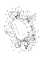
図5〜図7に示すように、運転席8の後方に第2燃料タンク14が配置される第1仕様では、補強部材12が安全フレーム取付台13の後側固定箇所13fに固定される。これにより、運転席8と補強部材12との間に第2燃料タンク14の配置スペースが確保されるとともに、補強部材12を後方衝突から第2燃料タンク14を保護する保護部材に兼用することが可能になる。
As shown in FIGS. 5 to 7, in the first specification in which the
図7に示すように、第2燃料タンク14は、左右の燃料タンクブラケット17を介してフェンダフレーム10に取り付けられる。燃料タンクブラケット17は、第2燃料タンク14と連結される燃料タンク連結部17aと、安全フレーム取付台13に2つのボルト18を介して固定される上側固定部17bと、連結フレーム11に2つのボルト19を介して固定される下側固定部17cと、を一体に備える。本実施形態では、燃料タンクブラケット17の上側固定部17bを安全フレーム取付台13に固定するにあたり、第2仕様において補強部材12を固定するために前側固定箇所13eに燃料タンクブラケット17の上側固定部17bを固定している。
As shown in FIG. 7, the
一方、運転席8の後方に第2燃料タンク14を配置しない第2仕様では、補強部材12が安全フレーム取付台13の前側固定箇所13eに固定される。これにより、補強部材12の後方突出量が抑制されるだけでなく、補強部材12との固定により安全フレーム取付台13を補強することができる。また、補強部材12の固定部12aは、図6から明らかなように、安全フレーム取付台13の前側固定箇所13eに固定されたとき、後側固定箇所13fを覆い隠すことができる。
On the other hand, in the second specification in which the
図3及び図4に示すように、本実施形態の補強部材12は、4つの取付部12c〜12fを備える。図6に示すように、最も左側に位置する第1取付部12cには、図示しないナンバープレートが取り付けられ、その右側に隣接する第2取付部12dには、低速車マーク20が取り付けられ、その右側に隣接する第3取付部12eには、外部取出し電源21が取り付けられ、最も右側に位置する第4取付部12fには、リヤランプ22が取り付けられる。
As shown in FIG.3 and FIG.4, the
図5及び図6に示すように、補強部材12には、外部取出し電源21やリヤランプ22に電気的に接続されるハーネス23が配索されている。具体的には、補強部材12の連結部12bに沿ってハーネス23が配索されるとともに、連結部12b及び固定部12aに設けられる複数の保持部材24でハーネス23が保持されている。
As shown in FIGS. 5 and 6, a
図5に示すように、本実施形態のハーネス23は、フェンダフレーム10の近傍でコネクタ23a、25aを介してメインハーネス25に接続されている。換言すると、本実施形態のハーネス23は、フェンダフレーム10の近傍でメインハーネス25から切り離し可能であり、補強部材12の着脱に際して、ハーネス23が補強部材12と一体に着脱可能となっている。
As shown in FIG. 5, the
叙述の如く構成された本実施形態によれば、運転席8と、運転席8の左右側方に設けられる左右のフェンダ9と、左右のフェンダ9を支持する左右のフェンダフレーム10と、を備えるトラクタ1であって、運転席8の後方で左右のフェンダフレーム10を連結する補強部材12を備え、左右のフェンダフレーム10は、補強部材12が選択的に固定される前側固定箇所13e及び後側固定箇所13fを備え、運転席8の後方に第2燃料タンク14が配置される第1仕様では、補強部材12を後側固定箇所13fに固定して、運転席8と補強部材12との間に第2燃料タンク14の配置スペースを確保するとともに、補強部材12で第2燃料タンク14を保護し、運転席8の後方に第2燃料タンク14を配置しない第2仕様では、補強部材12を前側固定箇所13eに固定して補強部材12の後方突出量を抑制するので、第1仕様及び第2仕様のいずれにおいても補強部材12を設置して機体強度を高められる。
According to the present embodiment configured as described, the
また、運転席8の後方に第2燃料タンク14が配置される第1仕様では、補強部材12が第2燃料タンク14を後方衝突から保護する保護部材に兼用されるので、構造の簡略化及びコストダウンが可能になる。
Further, in the first specification in which the
また、運転席8の後方に第2燃料タンク14が配置されない第2仕様では、補強部材12の後方突出量が抑制されるので、作業機の昇降範囲を広げられる等の利点がある。
Further, in the second specification in which the
また、補強部材12は、前後方向に沿い、フェンダフレーム10に固定される左右の固定部12aと、左右方向に沿い、左右の固定部12aの後端部同士を連結する連結部12bと、を備える平面視コ字形状を有し、固定部12aは、フェンダフレーム10の前側固定箇所13eに固定されたとき、後側固定箇所13fを覆い隠すので、後側固定箇所13fの露出による外観の低下等を回避できる。
The reinforcing
また、運転席8の後方に第2燃料タンク14を配置する第1仕様では、フェンダフレーム10の前側固定箇所13eに、第2燃料タンク14を支持する燃料タンクブラケット17が固定されるので、固定箇所の兼用化に基づいて構造を簡略化できるだけでなく、前側固定箇所13eの露出による外観の低下等も回避できる。
Further, in the first specification in which the
また、左右のフェンダフレーム10の上部には、安全フレームを取り付けるための安全フレーム取付台13が固定され、前側固定箇所13e及び後側固定箇所13fは、安全フレーム取付台13に設けられるので、補強部材12との固定により安全フレーム取付台13も補強することができる。
Further, a safety
また、補強部材12は、ナンバープレート、低速車マーク20、外部取出し電源21及びリヤランプ22の取付部12c〜12fを備えるので、補強部材12を各種部材の取付部に兼用して構造の簡略化が図れる。
Further, since the reinforcing
また、補強部材12は、左右のフェンダフレーム10に対して着脱自在に固定され、連結部12bには、外部取出し電源21及びリヤランプ22に電気的に接続されるハーネス23が配索され、補強部材12の着脱時にハーネス23が補強部材12と一体に着脱されるので、組立性やメンテナンス性を向上させることができる。
The reinforcing
1 トラクタ
8 運転席
9 フェンダ
10 フェンダフレーム
12 補強部材
12a 固定部
12b 連結部
12c〜12f 取付部
13 安全フレーム取付台
13e 前側固定箇所
13f 後側固定箇所
14 第2燃料タンク
17 燃料タンクブラケット
20 低速車マーク
21 外部取出し電源
22 リヤランプ
23 ハーネス
DESCRIPTION OF
Claims (6)
前記運転席の左右側方に設けられる左右のフェンダと、
左右の前記フェンダを支持する左右のフェンダフレームと、を備えるトラクタであって、
前記運転席の後方で左右の前記フェンダフレームを連結する補強部材を備え、
左右の前記フェンダフレームは、前記補強部材が選択的に固定される前側固定箇所及び後側固定箇所を備え、
前記運転席の後方に燃料タンクが配置される仕様の前記トラクタでは、前記補強部材を前記後側固定箇所に固定して、前記運転席と前記補強部材との間に前記燃料タンクの配置スペースを確保するとともに、前記補強部材で前記燃料タンクを保護し、
前記運転席の後方に前記燃料タンクを配置しない仕様の前記トラクタでは、前記補強部材を前記前側固定箇所に固定して前記補強部材の後方突出量を抑制することを特徴とするトラクタ。 The driver ’s seat,
Left and right fenders provided on the left and right sides of the driver seat;
A left and right fender frame that supports the left and right fenders,
A reinforcing member that connects the left and right fender frames behind the driver seat;
The left and right fender frames include a front side fixing portion and a rear side fixing portion to which the reinforcing member is selectively fixed,
In the tractor having a specification in which a fuel tank is disposed behind the driver's seat, the reinforcing member is fixed to the rear fixing portion, and an arrangement space for the fuel tank is provided between the driver's seat and the reinforcing member. And securing the fuel tank with the reinforcing member,
In the tractor having a specification in which the fuel tank is not disposed behind the driver's seat, the reinforcing member is fixed to the front fixing portion to suppress the rearward protruding amount of the reinforcing member.
前記固定部は、前記フェンダフレームの前記前側固定箇所に固定されたとき、前記後側固定箇所を覆い隠すことを特徴とする請求項1に記載のトラクタ。 The reinforcing member includes a left and right fixing portion that is fixed to the fender frame along the front-rear direction, and a connecting portion that connects the rear end portions of the left and right fixing portions along the left-right direction. Has a shape,
2. The tractor according to claim 1, wherein when the fixing portion is fixed to the front fixing portion of the fender frame, the fixing portion covers the rear fixing portion.
前記前側固定箇所及び前記後側固定箇所は、前記安全フレーム取付台に設けられることを特徴とする請求項1〜3のいずれか一項に記載のトラクタ。 On the upper part of the left and right fender frames, a safety frame mounting base for mounting the safety frame is fixed,
The tractor according to any one of claims 1 to 3, wherein the front side fixing portion and the rear side fixing portion are provided on the safety frame mounting base.
前記連結部には、前記外部取出し電源、及び/又は、前記リヤランプに電気的に接続されるハーネスが配索され、
前記補強部材の着脱時に前記ハーネスが前記補強部材と一体に着脱されることを特徴とする請求項5に記載のトラクタ。 The reinforcing member is detachably fixed to the left and right fender frames,
In the connecting portion, a harness that is electrically connected to the external extraction power source and / or the rear lamp is routed,
The tractor according to claim 5, wherein the harness is attached / detached integrally with the reinforcing member when the reinforcing member is attached / detached.
Priority Applications (1)
| Application Number | Priority Date | Filing Date | Title |
|---|---|---|---|
| JP2016079367A JP2017190010A (en) | 2016-04-12 | 2016-04-12 | Tractor |
Applications Claiming Priority (1)
| Application Number | Priority Date | Filing Date | Title |
|---|---|---|---|
| JP2016079367A JP2017190010A (en) | 2016-04-12 | 2016-04-12 | Tractor |
Publications (1)
| Publication Number | Publication Date |
|---|---|
| JP2017190010A true JP2017190010A (en) | 2017-10-19 |
Family
ID=60084407
Family Applications (1)
| Application Number | Title | Priority Date | Filing Date |
|---|---|---|---|
| JP2016079367A Pending JP2017190010A (en) | 2016-04-12 | 2016-04-12 | Tractor |
Country Status (1)
| Country | Link |
|---|---|
| JP (1) | JP2017190010A (en) |
Cited By (1)
| Publication number | Priority date | Publication date | Assignee | Title |
|---|---|---|---|---|
| JP2023175882A (en) * | 2018-12-20 | 2023-12-12 | 株式会社クボタ | work vehicle |
-
2016
- 2016-04-12 JP JP2016079367A patent/JP2017190010A/en active Pending
Cited By (2)
| Publication number | Priority date | Publication date | Assignee | Title |
|---|---|---|---|---|
| JP2023175882A (en) * | 2018-12-20 | 2023-12-12 | 株式会社クボタ | work vehicle |
| JP7504274B2 (en) | 2018-12-20 | 2024-06-21 | 株式会社クボタ | Work vehicle |
Similar Documents
| Publication | Publication Date | Title |
|---|---|---|
| US10618489B2 (en) | Utility vehicle | |
| CN110920752B (en) | Suspension sub-frame structure | |
| JP5984052B2 (en) | Battery pack positioning pin bracket | |
| CN212637663U (en) | All-terrain vehicle and its frame | |
| JP6083358B2 (en) | vehicle | |
| JP7112371B2 (en) | drive unit | |
| JP2017190010A (en) | Tractor | |
| JP5930197B2 (en) | Front body structure of the vehicle | |
| JP4870590B2 (en) | Work vehicle | |
| CN211684980U (en) | Front lower protection device of vehicle and vehicle | |
| CN110316300B (en) | Side cover structure of straddle-type vehicle | |
| JP5785104B2 (en) | Tractor | |
| JP3224222B2 (en) | Car fuel tank support structure | |
| KR102363695B1 (en) | Frame Apparatus of Agricultural Vehicle | |
| JP4255713B2 (en) | Radiator grille mounting structure for saddle-ride type vehicles | |
| JP5857655B2 (en) | Vehicle harness arrangement structure | |
| JP2009166803A (en) | Arrangement structure of horn for vehicle | |
| JP2012017098A (en) | Working vehicle | |
| JP4982167B2 (en) | Wheel loader | |
| JP4392836B2 (en) | Wheel loader | |
| JP6946723B2 (en) | Protector mounting structure | |
| JP5156294B2 (en) | Construction machine mainframe and construction machine equipped with the same | |
| JP7696385B2 (en) | Mounting structure | |
| JP2008081041A (en) | Lower body structure of automobile | |
| KR101807135B1 (en) | Rear floor assembly |