JP2017187226A - Outdoor unit for air conditioner - Google Patents
Outdoor unit for air conditioner Download PDFInfo
- Publication number
- JP2017187226A JP2017187226A JP2016076489A JP2016076489A JP2017187226A JP 2017187226 A JP2017187226 A JP 2017187226A JP 2016076489 A JP2016076489 A JP 2016076489A JP 2016076489 A JP2016076489 A JP 2016076489A JP 2017187226 A JP2017187226 A JP 2017187226A
- Authority
- JP
- Japan
- Prior art keywords
- fan
- outdoor unit
- unit
- air conditioner
- vibration
- Prior art date
- Legal status (The legal status is an assumption and is not a legal conclusion. Google has not performed a legal analysis and makes no representation as to the accuracy of the status listed.)
- Granted
Links
Images


Abstract
Description
本発明は、空気調和装置の室外機に関し、特に、室外機に使用されている送風機のファンの異常検出や信頼性向上に好適なものである。 The present invention relates to an outdoor unit of an air conditioner, and is particularly suitable for detecting abnormality of a fan of a blower used in the outdoor unit and improving reliability.
一般に、ビル用の空気調和装置や小型冷凍機においては、冷媒と室外空気との熱交換を行うため、空気調和装置の室外機や、小型冷凍機の室外機には、クロスフィンチューブ式熱交換器やマイクロチャンネル熱交換器などの空冷式熱交換器が設けられている。また、これらの熱交換器に室外空気を通風して、熱交換器内を流れる冷媒と室外空気とを熱交換させるための送風機も備えられており、前記送風機は前記熱交換器に通風する風量を増加減できるように、インバータなどにより、回転数制御が可能に構成されている。更に、前記送風機は、その効率向上を図るため、ファンは複雑な曲面形状を有しており、樹脂成型品で製作される場合が多い。 Generally, in building air conditioners and small refrigerators, heat exchange is performed between refrigerant and outdoor air. Therefore, cross-fin tube heat exchange is used in outdoor units of air conditioners and small refrigerators. An air-cooled heat exchanger such as a heat exchanger or a microchannel heat exchanger is provided. Further, an air blower for ventilating outdoor air through these heat exchangers to exchange heat between the refrigerant flowing in the heat exchanger and the outdoor air is also provided, and the air flow rate of the air blown through the heat exchanger The number of revolutions can be controlled by an inverter or the like. Further, in order to improve the efficiency of the blower, the fan has a complicated curved surface shape and is often manufactured from a resin molded product.
前記送風機のファンには、冬季には氷柱が落下したり、また夏季においても台風などにより異物が吹き飛ばされるなどして、前記ファンに衝突することがある。送風機は、前記ファンへの落下物などの衝撃も考慮して設計されているものの、ファンの外周側の周速は時速100km/h程度まで高速となるため、樹脂材料で製作されたファンではその破損防止に限界があり、ファンが欠けるなどの損傷が発生することがある。 The fan of the blower may collide with the fan due to a fall of an icy column in winter or a foreign object blown off by a typhoon in summer. Although the blower is designed in consideration of impacts such as falling objects on the fan, the peripheral speed on the outer peripheral side of the fan is as high as about 100 km / h, so in a fan made of resin material, There is a limit to preventing breakage, and damage such as chipping of the fan may occur.
室外機の送風機における前記ファンなどの損傷の程度が大きい場合、風量が大きく低下するので、冷凍サイクルに異常が生じ、このため送風機の異常検知も比較的容易に行える。しかし、前記ファンなどの損傷の程度が小さい場合、風量はある程度出るため、冷凍サイクル側からの異常検知は難しい。 When the degree of damage of the fan or the like in the blower of the outdoor unit is large, the air volume is greatly reduced, so that an abnormality occurs in the refrigeration cycle. Therefore, the abnormality of the blower can be detected relatively easily. However, when the degree of damage to the fan or the like is small, the air volume is to some extent, so it is difficult to detect abnormality from the refrigeration cycle side.
送風機は、正常な状態ではバランスの取れた状態で回転しているが、ファンの損傷が小さい状態で運転を継続すると、ファンの欠けなどの影響により、ファンの重心位置が回転軸の中心からずれて、回転体のバランスが崩れた状態(アンバランス状態)での運転となる。このアンバランスが加振力となり、室外機に大きな振動が発生し、また繰り返し応力により、室外機の他の部品にまで破損が広がり、最悪の場合、熱交換器や配管の破損に至る場合もある。このような状態になると、空気調和装置の継続運転が不可能となり、復旧にも多大な時間と費用を要することになる。 The blower rotates in a balanced state under normal conditions, but if the fan continues to operate with little damage to the fan, the center of gravity of the fan will deviate from the center of the rotating shaft due to the effect of a missing fan. Thus, the operation is performed in a state where the balance of the rotating body is lost (unbalanced state). This imbalance becomes an exciting force, causing large vibrations in the outdoor unit, and repeated stress can cause damage to other parts of the outdoor unit, and in the worst case, the heat exchanger and piping can be damaged. is there. In such a state, continuous operation of the air conditioner becomes impossible, and a great deal of time and cost are required for recovery.
そこで、特開2014-211143号公報(特許文献1)のものでは、送風機の振動を検知する振動検知手段からの出力に基づいて前記送風機の異常を診断し、送風機の運転を停止させるようにしている。 Therefore, in Japanese Patent Application Laid-Open No. 2014-211143 (Patent Document 1), the abnormality of the blower is diagnosed based on the output from the vibration detecting means for detecting the vibration of the blower, and the operation of the blower is stopped. Yes.
上記特許文献1のものでは、送風機の振動を検知する振動検知手段からの出力に基づいて送風機の異常を診断している。前記振動検知手段としては、例えば加速度センサを用い、アンバランス状態の送風機の振動を検知することで、異常を検知することはできる。しかし、加速度センサの出力は、ファンの欠損量に比例し、ファン回転数の2乗に比例する出力となるため、送風機が高い回転数で運転される範囲においては、異常検知の精度は良い。
In the thing of the said
しかし、春や秋など空調負荷の小さい時期においては、室外機の送風機の回転数も低い状態で運転されることが多く、送風機のファンの異常検知が難しいという課題がある。このため、空調負荷が小さく、送風機が中間回転数域や低回転数域で運転される場合においても、送風機の異常検知が可能であることが望まれている。 However, when the air conditioning load is small, such as in spring or autumn, the outdoor unit is often operated with a low rotational speed of the outdoor unit, which makes it difficult to detect abnormality of the fan of the blower. For this reason, even when the air conditioning load is small and the blower is operated in an intermediate rotation speed range or a low rotation speed range, it is desired that abnormality detection of the blower is possible.
また、送風機異常の初期の段階からユーザ若しくはサービスマンが異常を容易に把握でき、送風機の状況悪化を防ぐようにすることが望ましい。 In addition, it is desirable that the user or service person can easily grasp the abnormality from the initial stage of the abnormality of the blower and prevent deterioration of the state of the blower.
本発明の目的は、室外機のファンの異常を軽度の段階から容易に把握することのできる空気調和装置の室外機を得ることにある。 The objective of this invention is obtaining the outdoor unit of the air conditioning apparatus which can grasp | ascertain abnormality of the fan of an outdoor unit easily from a light step.
本発明の他の目的は、安価に、しかもファンの回転数が低い状態からファンの異常を検知できる空気調和装置の室外機を得ることにある。 Another object of the present invention is to obtain an outdoor unit of an air conditioner that can detect an abnormality of a fan at a low cost and in a state where the rotational speed of the fan is low.
上記目的を達成するため、本発明は、ファンを有する室外機を備える空気調和装置の室外機であって、前記ファンの振動を検知する振動検知手段と、前記振動検知手段により得られる振動の大きさを、予め定めた多段階の振動レベルのうちの何れの振動レベルに該当するかを判定する演算部と、振動の大きさを多段階の振動レベルのうちの何れの振動レベルに該当するかを視覚的に表示する表示部と、前記演算部で得られた振動レベルの大きさを、多段階の振動レベルのうちの何れの振動レベルに該当するかを視覚的に認識可能に、前記表示部に表示する出力部を備えていることを特徴とする。 In order to achieve the above object, the present invention is an outdoor unit of an air conditioner including an outdoor unit having a fan, the vibration detecting unit for detecting the vibration of the fan, and the magnitude of vibration obtained by the vibration detecting unit. A calculation unit that determines which of the predetermined multi-level vibration levels corresponds to the vibration level, and which of the multi-level vibration levels the vibration level corresponds to A display unit that visually displays the vibration level, and the level of vibration level obtained by the calculation unit can be visually recognized as to which of the multi-level vibration levels it corresponds to It is characterized by having an output part for displaying on the part.
本発明の他の特徴は、ファンを有する室外機を備える空気調和装置の室外機であって、前記ファンの回転数を制御すると共に、前記ファンの駆動電流を検出する電流検出部を有するインバータ装置と、前記インバータ装置に備えられている前記電流検出部で検出された電流値から、前記ファンの回転に同期する成分の脈動電流を抽出する脈動電流抽出手段と、前記脈動電流抽出手段で抽出された前記脈動電流と前記ファンの回転数から前記ファンの異常を判定する演算部と、この演算部でのファン異常の判定結果を出力する出力部を備えていることにある。 Another feature of the present invention is an outdoor unit of an air conditioner including an outdoor unit having a fan, the inverter unit having a current detection unit that controls the rotational speed of the fan and detects a driving current of the fan. Pulsating current extracting means for extracting a pulsating current of a component synchronized with the rotation of the fan from the current value detected by the current detecting unit provided in the inverter device, and the pulsating current extracting means Further, the present invention is provided with a calculation unit that determines abnormality of the fan from the pulsating current and the rotation speed of the fan, and an output unit that outputs a determination result of fan abnormality in the calculation unit.
本発明によれば、室外機のファンの異常を軽度の段階から容易に把握することのできる空気調和装置の室外機を得ることができる効果がある。 ADVANTAGE OF THE INVENTION According to this invention, there exists an effect which can obtain the outdoor unit of the air conditioning apparatus which can grasp | ascertain abnormality of the fan of an outdoor unit easily from a mild step.
また、インバータ装置に備えられている電流検出部からの電流値を用いる本発明によれば、安価に、しかもファンの回転数が低い状態からファンの異常を検知できる空気調和装置の室外機を得ることができる効果がある。 Further, according to the present invention using the current value from the current detection unit provided in the inverter device, an outdoor unit of an air conditioner capable of detecting a fan abnormality at a low cost and in a state where the fan speed is low is obtained. There is an effect that can.
以下、本発明の空気調和装置の室外機の具体的実施例を、図面を用いて説明する。本発明の空気調和装置の室外機は、特に室外機のファンの異常検知と異常レベルの表示に特徴を有するものである。なお、各図において、同一符号を付した部分は同一或いは相当する部分を示している。 Hereinafter, specific examples of the outdoor unit of the air conditioner of the present invention will be described with reference to the drawings. The outdoor unit of the air conditioner according to the present invention is particularly characterized by abnormality detection of an outdoor unit fan and display of an abnormal level. Note that, in each drawing, the portions denoted by the same reference numerals indicate the same or corresponding portions.
本発明の空気調和装置の室外機の実施例1を図1〜図9を用いて説明する。
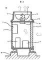
図1は本発明の空気調和装置の室外機の実施例1を示す斜視図、図2は図1のII−II線矢視断面図、図3は本発明の実施例1におけるファンの異常を検知する構成を説明する図である。
1 is a perspective view showing a first embodiment of an outdoor unit of an air conditioner of the present invention, FIG. 2 is a cross-sectional view taken along the line II-II in FIG. 1, and FIG. 3 shows an abnormality of a fan in the first embodiment of the present invention. It is a figure explaining the structure to detect.
空気調和装置は、屋外の基礎(或いは架台)20上に設置された室外機100と、屋内に設置されている1台以上の室内機(図示せず)とが冷媒配管により接続されて冷凍サイクルを構成し、空気調和を行うものである。前記室外機100は、図1、図2に示すように、筐体1に空冷式の熱交換器2と、この熱交換器2に通風するための送風機3(3A,3B)が備えられている。なお、図1に示す室外機100の例では2台の送風機3Aと3Bが具備されている。
In the air conditioner, an
前記送風機3A,3Bは、それぞれファン(プロペラファン)3a、このファン3aの外周に設けられ、ベルマウスやダクトとしての機能するシュラウド3b、前記ファン3aを駆動するモータ(ファンモータ)3c、このモータ3cを支持するモータ支持部材3d及びファンガード3eなどにより構成されている。
The blowers 3A and 3B are respectively provided with a fan (propeller fan) 3a, a
また、前記筐体1の内部には、圧縮機4、アキュームレータ5、制御品箱6などが設けられている。前記制御品箱6内には、外気温度センサや冷凍サイクルの圧力センサなどの各種センサからの情報が入力されて、前記圧縮機4や膨張弁(図示せず)などの冷凍サイクル部品を制御する制御装置、前記送風機3を制御するためのインバータ装置などが収納されている。
In addition, a
図3に示すように、前記制御品箱6の内部には、前記送風機3のモータ(ファンモータ)3cを駆動すると共に、該モータ3cを所望の回転数に制御するためのインバータ装置6aと、前記圧縮機10、前記膨張弁及び前記各種センサなどを有する冷凍サイクル7を制御する制御装置6bなどが設けられている。
As shown in FIG. 3, inside the
前記インバータ装置6aには、前記ファン3aを駆動する駆動電流(モータ電流)を検出する電流検出部61、前記モータ3cの磁極位置を検出する位相検出部62が設けられている。また、前記インバータ装置6aには、前記電流検出部で検出された電流に対して、前記位相検出部62から得られた回転周期に同期したある周期のq軸電流脈動(脈動電流)を抽出する脈動電流検出部63が設けられている。
The
更に、前記インバータ装置6aには、前記脈動電流検出部63で検出された脈動電流と前記ファンの回転数から前記ファン3aの異常を判定する演算部64も設けられている。即ち、本実施例では、前記演算部64は、前記脈動電流の振幅値(脈動電流振幅値)と前記ファンの回転数を乗算し、この乗算した値から前記ファン3aの異常を判定するようにしている。
Further, the
なお、前記演算部64は、脈動電流振幅値と前記ファンの回転数を乗算した算出値を用いるだけでなく、脈動電流値(例えば脈動電流の最大値)とファンの回転数を乗算した算出値を用いて前記ファン3aの異常を判定するようにしても良い。
The
前記制御装置6bは前記インバータ装置6aの前記演算部と通信線等で接続されている。また、前記制御品箱6内には、前記制御装置6bと接続された記憶装置6cが備えられており、この記憶装置6cは前記ファン3aの異常を判定した結果を記憶できるように構成されている。
The control device 6b is connected to the arithmetic unit of the
8は出力部で、この出力部8は、本実施例では、空気調和装置を操作する操作リモコン81で構成し、前記制御装置6bと通信線で接続されている。従って、本実施例では、前記演算部64でのファン3aの異常判定の結果を、前記制御装置6bを介して出力部8である前記操作リモコン81に出力し、その表示部81aに判定結果等を表示することができる。
In this embodiment, the
また、前記記憶装置6cで記憶している前記ファン3aの過去のファンの異常判定履歴についても、前記制御装置を介して、出力部である前記操作リモコン81の表示部81aに表示させることができるように構成されている。
Further, the past fan abnormality determination history of the
なお、前記出力部に出力された振動レベルのデータ等を外部へ送信する送信手段を前記制御装置6bなどに備えるようにすると、外部の遠隔監視システムやパソコン等からもファン3aの振動レベルや異常発生を把握することができる。
If the control device 6b is provided with transmission means for transmitting the vibration level data and the like output to the output unit to the outside, the vibration level and abnormality of the
次に、正常なファンと、ファンの一部が欠損などして回転アンバランスが生じているファンを、前記モータ3cにより駆動して回転させた場合の駆動電流の脈動電流振幅値と、前記各ファンに発生する加振力について、図4及び図5を用いて説明する。
Next, a pulsating current amplitude value of a driving current when a normal fan and a fan in which a rotation imbalance occurs due to a part of the fan being lost or the like is driven by the
図4は脈動電流振幅値とファンの回転数との関係を示す線図、図5はファン加振力とファンの回転数との関係を示す線図である。 FIG. 4 is a diagram showing the relationship between the pulsating current amplitude value and the rotational speed of the fan, and FIG. 5 is a diagram showing the relationship between the fan excitation force and the rotational speed of the fan.
図4において、横軸はファンの回転数、縦軸はファン駆動電流の脈動電流振幅値である。また、Aで示す曲線は正常ファンの回転数に対する脈動電流振幅値、B1で示す破線の曲線はアンバランス小のファンの回転数に対する脈動電流振幅値、B2で示す破線の曲線はアンバランス大のファンの回転数に対する脈動電流振幅値をそれぞれ示している。更に、D1はアンバランス小のファンB1の高回転域での正常ファンAに対する振幅値の差、D2はアンバランス大のファンB2の高回転域での正常ファンAに対する振幅値の差である。 In FIG. 4, the horizontal axis represents the fan rotation speed, and the vertical axis represents the pulsating current amplitude value of the fan driving current. The curve indicated by A is the pulsating current amplitude value with respect to the rotational speed of the normal fan, the broken curve indicated by B1 is the pulsating current amplitude value with respect to the rotational speed of the fan with a small unbalance, and the broken curve indicated by B2 is the large unbalanced. The pulsating current amplitude value with respect to the rotational speed of the fan is shown. Further, D1 is a difference in amplitude value with respect to the normal fan A in the high rotation range of the fan B1 with small unbalance, and D2 is a difference in amplitude value with respect to the normal fan A in the high rotation range of the fan B2 with large unbalance.
この図4に示すように、正常ファンAと、一部欠損などにより回転アンバランスが発生しているファンB1,B2とでは、回転数に対する脈動電流振幅値に違いが観測され、アンバランス大のファンB2では、脈動電流振幅値が、正常ファンと比べ、大きく異なるため、比較的低い回転数からでも、正常/異常の判定が容易である。一方、アンバランス小のファンB1では、脈動電流振幅値が、正常ファンと比べて差が小さく、高い回転数で運転しないと、正常/異常の判定が難しい。 As shown in FIG. 4, a difference is observed in the pulsating current amplitude value with respect to the rotational speed between the normal fan A and the fans B1 and B2 in which rotational imbalance occurs due to a partial deficiency or the like. In fan B2, the pulsating current amplitude value is significantly different from that of a normal fan, so that it is easy to determine normality / abnormality even from a relatively low rotational speed. On the other hand, in the fan B1 with a small unbalance, the difference in the pulsating current amplitude value is smaller than that of a normal fan, and it is difficult to determine normal / abnormal unless it is operated at a high rotational speed.
また、図4に示す脈動電流振幅値は、ある程度の回転数までは、回転数の増加と共に増加していくが、高回転域になると、脈動電流振幅値の増加幅が鈍ることがわかる。
ここで、アンバランス発生によるファン加振力とファン回転数との関係を図5により説明する。図5において、横軸はファンの回転数、縦軸はファン加振力である。また、A,B1,B2で示す曲線は、図3と同様に、それぞれ、正常ファンA、アンバランス小のファンB1及びアンバランス大のファンB2の回転数に対するファン加振力である。
Further, it can be seen that the pulsating current amplitude value shown in FIG. 4 increases with an increase in the rotational speed up to a certain rotational speed, but the increase in the pulsating current amplitude value becomes dull in the high rotational speed range.
Here, the relationship between the fan excitation force and the fan rotation speed due to the occurrence of unbalance will be described with reference to FIG. In FIG. 5, the horizontal axis represents the fan rotation speed, and the vertical axis represents the fan excitation force. Also, the curves indicated by A, B1, and B2 are fan excitation forces with respect to the rotational speeds of the normal fan A, the small unbalanced fan B1, and the large unbalanced fan B2, respectively, as in FIG.
この図5に示すように、ファンが回転することによる加振力は、ファンの回転数の2乗に比例している。また、前記ファン加振力により、前記モータ支持部材3dや前記室外機の筐体1に発生する振動振幅や応力は、前記加振力に概ね比例する傾向となり、ファン回転数の2乗に略比例する。このため、図4に示す高回転域程、ファンのアンバランスによる振動や応力に与える影響が大きくなる。
As shown in FIG. 5, the excitation force generated by the rotation of the fan is proportional to the square of the rotational speed of the fan. Further, the vibration amplitude and stress generated in the
一方、前述した図4に示すように、ファンのアンバランス発生による脈動電流振幅値の変化は、図5に示すファン加振力により発生する振動振幅や応力とは、相関が十分には高くない。このため、ファンの異常検出に用いる指標としては、図4に示す脈動電流振幅値よりも、ファン加振力により発生する振動振幅や応力との相関がより高い指標を用いることが望まれる。即ち、ファン加振力により発生する振動振幅や応力との相関がより高い指標を用いてファン異常、或いは振動レベルの判定を行えば、ファン異常の判定を高精度で行うことができ、室外機の熱交換器、配管、その他の部品等が破損に至るのをより確実に防止することができる。 On the other hand, as shown in FIG. 4 described above, the change in the pulsating current amplitude value due to the occurrence of fan imbalance is not sufficiently correlated with the vibration amplitude and stress generated by the fan excitation force shown in FIG. . For this reason, as an index used for detecting an abnormality of the fan, it is desirable to use an index having a higher correlation with the vibration amplitude and stress generated by the fan excitation force than the pulsating current amplitude value shown in FIG. That is, if a fan abnormality or vibration level is determined using an index having a higher correlation with the vibration amplitude or stress generated by the fan excitation force, the fan abnormality can be determined with high accuracy. It is possible to more reliably prevent the heat exchanger, piping, and other parts from being damaged.
そこで、本実施例では、図3で説明したように、脈動電流検出部63から得られた脈動電流振幅値を、ファン3aの異常或いは振動レベルの判定にそのまま利用するのではなく、次の工夫をしている。即ち、前記位相検出部62から得られるファン回転数を乗算(脈動電流振幅値×回転数)する演算部64を設け、この演算部64での演算結果(算出値)を、空気調和装置を制御・統括する制御装置6bに引き渡すことで、ファン3aの異常判定或いは振動レベルの判定を実施する。
Therefore, in this embodiment, as described with reference to FIG. 3, the pulsating current amplitude value obtained from the pulsating current detecting
なお、図3に示すように、インバータ装置6a内の演算部64において、ファン3aの異常判定或いは振動レベルの判定を実施するものには限られず、或いは前記演算部64の機能を、前記制御装置6b内に設けられている演算部に持たせるようにしても良い。
As shown in FIG. 3, the
本実施例では、前記演算部64で、「脈動電流振幅値×回転数」を算出するようにしているが、この算出値の特徴を図6により説明する。図6は、脈動電流振幅値とファン回転数の積と、ファン回転数との関係を示す線図である。また、図6において、横軸はファンの回転数、縦軸は「脈動電流振幅値×回転数」の算出値である。また、Aで示す曲線は正常ファンの回転数に対する前記算出値、Bで示す破線の曲線はアンバランスのあるファンで、この例では、図4に示すアンバランス小のファンB1と同程度のアンバランスのあるファンの回転数に対する前記算出値である。
In this embodiment, the
図6に示すように、ファンの回転数に対する「脈動電流振幅値×回転数」の算出値は、上記図5で説明した回転数に対するファン加振力の関係により近くなり、また、図4で示すアンバランス小のファンB1の高回転域での正常ファンAに対する振幅値の差D1よりも、図6に示す前記算出値の差D1´の方が格段に大きくなっている。 As shown in FIG. 6, the calculated value of “pulsation current amplitude value × rotation speed” with respect to the rotation speed of the fan is closer to the relationship of the fan excitation force with respect to the rotation speed described above with reference to FIG. The difference D1 ′ in the calculated value shown in FIG. 6 is much larger than the difference D1 in amplitude value from the normal fan A in the high rotation range of the small unbalanced fan B1 shown.
従って、本実施例によれば、ファン3aの異常判定或いは振動レベルの判定をより高精度で行うことが可能になり、室外機100の熱交換器2、配管、その他の部品等が破損に至るのをより確実に防止することができる。なお、図3に示す演算部64或いは制御装置6bの演算部でのファン異常等の判定結果は、図3に示す出力部8の表示部81aに表示される。
Therefore, according to the present embodiment, it is possible to determine the abnormality of the
本実施例によれば、回転数が低く振動レベルが小さい早い段階から、その振動レベルを判定でき、表示部81a等に報知できるので、室外機破損等の予防保全を確実に行うことができる効果が得られる。
According to the present embodiment, the vibration level can be determined from an early stage where the rotation speed is low and the vibration level is small, and can be notified to the
なお、ファンの異常が検知されると、その点検等のため運転停止されるが、頻繁に運転停止になると実運用上不都合も多い。そこで、予防保全の情報は持ちつつも、許容できる振動レベルでは、運転を継続できることが望ましい。本実施例によれば、ファンのアンバランスによる加振力により、モータ支持部材3dや室外機の筐体1に発生する振動振幅や応力と相関が高い指標で異常や振動レベルの判定をするので、精度の高い判定が可能となり、一定の振動レベル以下では継続運転、一定以上の振動レベルになると停止させることで、室外機の運転を効率良く行うことができ且つ室外機が重大な破損に至るのも防止できる。
If an abnormality of the fan is detected, the operation is stopped for inspection or the like, but if the operation is frequently stopped, there are many problems in actual operation. Therefore, it is desirable that the operation can be continued at an allowable vibration level while having information on preventive maintenance. According to the present embodiment, the abnormality and the vibration level are determined by an index highly correlated with the vibration amplitude and stress generated in the
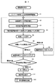
次に、図7のフローチャートを用いて、本実施例におけるファンの異常検知のフローを、図3を参照しつつ説明する。なお、本実施例において、異常検知とは、ファンが異常になって停止させる必要がある場合だけでなく、ファンのアンバランス発生による振動レベルの検知も含まれるものである。 Next, referring to the flowchart of FIG. 7, the flow of fan abnormality detection in the present embodiment will be described with reference to FIG. In this embodiment, the abnormality detection includes not only the case where the fan becomes abnormal and needs to be stopped, but also the detection of the vibration level due to the occurrence of fan imbalance.
図7において、まず、室内の操作リモコン81などから受けた運転開始指令により、室外機の運転開始を準備する。なお、図7のフローチャートでは、室外機の送風機3の運転部分のみを説明し、冷凍サイクル7の制御についての説明は省略している。前記運転開始指令の後、インバータ装置6aによる室外機の送風機3の運転を開始する(ステップS1)。次に、ステップS2に移り、インバータ装置6aの電流検出部(電流センサ)61により、送風機3のモータ3cの駆動電流(モータ電流)を検知する。
In FIG. 7, first, the operation start of the outdoor unit is prepared according to the operation start command received from the indoor operation
次のステップS3では脈動電流検出部63により電流脈動の振幅値を演算する。即ち、前記電流検出部61で検出された電流値から、前記ファン3aの回転周期に同期する成分を抽出し、脈動電流振幅値を演算する。
In the next step S3, the pulsating
次に、ステップS4では、演算部64で、前記脈動電流振幅値と前記ファン3aの回転数の積(脈動電流振幅値×回転数)を演算して算出すると共に、この算出値から前記ファン3aの振動レベル(異常レベル)を判定する。例えば、前記振動レベルを6段階で判定するように決めると共に、前記算出値と前記振動レベルとの関係を予め決めておき、前記算出値の大きさに対応する振動レベルを判定し、この判定した振動レベルを出力部8の表示部81aに表示する(ステップS5)。
Next, in step S4, the
この表示部81aでの表示は、判定された振動レベルの大きさに応じて、その表示が視覚的に変わるようにすると良い。また、判定された振動レベルが第一の閾値を超える場合は、警報表示を行う。例えば、第一の閾値を振動レベル3とし、判定された振動レベルが3以上になると、前記表示部81aなどに警報表示を行う。
The display on the
前記出力部8は、本実施例では室内機を操作する操作リモコン81としているが、室外機100の制御基板上の表示装置(この表示装置は、7セグメントLEDや液晶パネルなどで構成されている)、ビル監視システム、パソコン、または各種通信回線や無線LAN、Bluetooth(登録商標)で接続された機器などに遠隔表示させるようにしても良い。
In the present embodiment, the
前記ステップS5の後、ステップS6に移り、ファン3aの異常を判定するために予め設定されている第二の閾値と、前記判定された振動レベルとを比較する。この第二の閾値は、前記第一の閾値に対し大きな値とし、例えば振動レベル5以上とする。振動レベルが第二の閾値より低い場合には、正常レベルの範疇と判断し、異常状態の継続時間タイマをリセットし(ステップS9)、前記ステップS2に戻る。
After step S5, the process proceeds to step S6, where a second threshold value set in advance for determining abnormality of the
前記ステップS6で、振動レベルが第二の閾値以上となった場合には、異常状態の継続時間タイマをカウントアップする(ステップ7)。次に、ステップS8に移り、前記継続時間タイマの値を、予め定めた継続時間である第三の閾値と比較し、振動レベルが第二の閾値以上の継続時間が前記第三の閾値未満であれば、前記ステップS2に戻る。 If the vibration level becomes equal to or higher than the second threshold value in step S6, the abnormal condition duration timer is counted up (step 7). Next, the process proceeds to step S8, the value of the duration timer is compared with a third threshold value that is a predetermined duration time, and the duration time at which the vibration level is equal to or greater than the second threshold value is less than the third threshold value. If there is, the process returns to step S2.
前記継続時間タイマの値が前記第三の閾値以上であれば、異常と判定し、送風機3のモータ3cを停止する(ステップS10)と共に、前記出力部8に、ファン3aの異常発生による異常停止表示をする(ステップS11)。
If the value of the duration timer is equal to or greater than the third threshold value, it is determined that there is an abnormality, and the
また、この異常停止の履歴は、図3に示す制御装置6bに接続されている記憶装置6cに記録する(ステップS12)。この記憶装置6cは、EEPROMのほか、SSD、HD、SDカードやCFカードなどで構成しても良い。なお、前記第一〜第三の閾値は、前記室外機100の制御基板などに設けられている制御装置6bなどに、予め格納されている。
The abnormal stop history is recorded in the
上記図7のフローチャートのステップS5やステップS11の出力部8での表示について、図8、図9を用いて説明する。
図8は本実施例1における出力部8である操作リモコン81の構成を説明する正面図である。この図8に示す例は、操作リモコン81の表示部81aに、図1に示す送風機3Aに対応するファン1と、送風機3Bに対応するファン2に対して、「振動レベル1」「振動レベル5」などの文字で表示すると共に、それぞれのファンの振動レベルを6段階のうちのどのレベルにあるかについても明確に理解できるように、振動レベルをバーの長さでも表示している。また、この例では、前記表示部81aに、どの室外機に対する表示かわかるように、「4系統1号機」など、室外機を識別するための名称やコード(個体番号)も表示している。更に、この例では、外気温度の表示(−2°)もしている。
The display on the
FIG. 8 is a front view illustrating the configuration of the operation
なお、他の室外機のファンの振動レベルを表示させたい場合には、操作ボタン81bを操作して行うことができる。また、前記表示部81aには、通常は室内温度、設定温度等の表示がなされているが、室外機のファンの振動レベルの表示に切り替え操作する場合には、メニューボタン81cにより行うことができる。更に、通常表示中に、ある室外機のファンの振動レベルが異常レベルになった場合などには、表示部81aに、異常な室外機の個体番号を表示するようにしても良い。
If it is desired to display the vibration level of the fan of another outdoor unit, the
また、この図8の例では、振動レベルを6段階で表示するようにしているが、少なくとも4段階以上のレベル表示ができるようにすると良い。なお、段階表示の代わりに、或いは併せて、「脈動電流振幅値×回転数」の算出値に関連する数値で振動の大きさを表示するようにしても良い。 Further, in the example of FIG. 8, the vibration level is displayed in six stages, but it is preferable that at least four or more levels can be displayed. Note that the magnitude of vibration may be displayed as a numerical value related to the calculated value of “pulsating current amplitude value × rotation speed” instead of or in combination with the step display.
このように、振動レベルや振動の大きさを、バー表示や数値で表示することにより、異常停止とならない振動レベル(異常レベル)でも、ユーザやサービスマンがファンの振動レベルを容易に認識できるから、予防点検を実施し易くなり、室外機破損に至るのを防止できる効果がある。 In this way, by displaying the vibration level and magnitude of vibration with a bar display or numerical values, the user or serviceman can easily recognize the vibration level of the fan even at a vibration level that does not cause an abnormal stop (abnormal level). This makes it easier to carry out preventive inspections and can prevent the outdoor unit from being damaged.
図9は図8に示す出力部8の表示部81aでの表示例に対し、他の表示例を示す正面図である。図9において、図8と同一符号を付した部分は同一或いは相当する部分であり、図8と異なる点を説明する。この図9に示す例では、表示部81aの表示の仕方のみが異なっている。
FIG. 9 is a front view showing another display example with respect to the display example on the
即ち、図9に示す前記表示部81aにおける振動レベルの表示は、バー表示や数値での表示ではなく、ファンの欠損を抽象化したアイコンと正常ファンを抽象化したアイコンで表示するようにしたものである。
That is, the display of the vibration level in the
図1に示す送風機3Aに対応するFAN1は、ファンの欠損を抽象化したアイコンで表示されており、異常であることを表示している。なお、欠損(ファンの白い部分)の大きさも段階的に表示することで、振動レベルの大きさを段階的に表示している。 FAN1 corresponding to the blower 3A shown in FIG. 1 is displayed with an icon that abstracts the missing of the fan, indicating that it is abnormal. In addition, the magnitude of the vibration level is displayed step by step by displaying the size of the defect (white portion of the fan) step by step.
送風機3Bに対応するFAN2は、正常ファンを抽象化したアイコンで表示されており、振動レベルが小さく正常であることを示している。
このように、振動レベルを、ファンを抽象化したアイコンで表示するようにしても、ユーザやサービスマンがファンの振動レベルを容易に認識できるから、室外機破損に至るのを防止できる効果がある。
FAN2 corresponding to the blower 3B is displayed with an icon that abstracts a normal fan, and indicates that the vibration level is small and normal.
As described above, even if the vibration level is displayed with an icon that abstracts the fan, the user and the service person can easily recognize the vibration level of the fan, so that the outdoor unit can be prevented from being damaged. .
上述した図8、図9で説明したように、本実施例では、出力部8の表示部81aは、振動の大きさを多段階の振動レベルのうちの何れの振動レベルに該当するかを視覚的に表示できるように構成されており、前記演算部64で得られた振動レベルの大きさを多段階の振動レベルのうちの何れの振動レベルに該当するかを視覚的に認識可能に、前記表示部81aに表示するようにしているので、ファンの振動レベルを容易に把握して認識でき、室外機破損に至るのを効果的に防止できる効果が得られる。
As described above with reference to FIGS. 8 and 9, in the present embodiment, the
前記表示部81aでの表示は、振動レベル(異常レベル)を、上述したバー表示、数値や文字での表示、ファン等を抽象化したアイコンでの表示の他、グラフバー、図象、記号等で視覚的に認識可能に表示するようにしても良い。
The
次に、上述した実施例1の一部変形例について説明する。上述した実施例1では、前記演算部64は、前記脈動電流振幅値と前記ファン回転数の積(脈動電流振幅値×回転数)を算出すると共に、この算出された値から前記ファンの振動レベルを判定するようにしている。これに対し、本変形例は、前記演算部64が、前記脈動電流振幅値と前記ファンの回転数を二乗した値の積(ファン駆動電流の脈動値×(ファン回転数)2)を算出すると共に、この算出された値から前記ファンの前記振動レベルを判定するようにしたものである。
Next, a partial modification of the above-described first embodiment will be described. In the first embodiment described above, the
このように、前記脈動電流振幅値と前記ファンの回転数を二乗した値の積を算出して、この算出値からファンの振動レベルを判定することにより、ファン回転数の低い段階からより精度良くファンの振動レベルを判定できる。即ち、上記「脈動電流振幅値×(回転数)2」の算出値は、図5に示すファンの回転数に対するファン加振力により近似するので、振動レベルの判定精度が向上し、より低いファン回転数の段階からファンの振動レベルを精度良く検知できる効果がある。 Thus, by calculating the product of the square value of the pulsating current amplitude value and the fan rotation speed, and determining the vibration level of the fan from this calculated value, it is possible to more accurately from the stage where the fan rotation speed is low. The vibration level of the fan can be determined. That is, the calculated value of “pulsation current amplitude value × (rotational speed) 2 ” is approximated by the fan excitation force with respect to the rotational speed of the fan shown in FIG. This has the effect of accurately detecting the vibration level of the fan from the rotational speed stage.
以上説明した本発明の実施例によれば、インバータ装置6aに備えられている電流検出部61で検出された電流値から、ファンの回転に同期する成分の脈動電流を抽出し、この脈動電流とファンの回転数から前記ファンの異常を判定するようにしているので、室外機100に付加部品をほとんど追加することなく、安価に、且つファンの回転数が低い状態からファンの異常を検知できる効果が得られる。
According to the embodiment of the present invention described above, the pulsating current of the component synchronized with the rotation of the fan is extracted from the current value detected by the current detecting
また、振動の大きさを多段階の振動レベルのうちの何れの振動レベルに該当するかを視覚的に表示する表示部を備え、前記演算部で得られた振動レベルの大きさを多段階の振動レベルのうちの何れの振動レベルに該当するかを視覚的に認識可能に、前記表示部に表示する出力部を備えているので、ファンの異常を軽度の段階から容易に把握することができ、室外機100が破損に至るのを防止できる効果がある。
In addition, a display unit for visually displaying which of the multi-level vibration levels the vibration level corresponds to, and the level of the vibration level obtained by the calculation unit is multi-stage Since it has an output part that displays on the display part so that it can be visually recognized which vibration level corresponds to the vibration level, it is possible to easily grasp fan abnormality from a mild stage There is an effect that the
次に、本発明の空気調和装置の室外機の実施例2を、図10及び図11を用いて説明する。図10は本発明の実施例2におけるファンの異常を検知する構成を説明する図、図11は実施例2におけるファンの異常検知を説明するフローチャートである。これら図10及び図11において、図1〜図9と同一符号を付した部分は同一或いは相当する部分であり、実施例1と異なる点を中心に説明し、同一部分については説明を省略する。 Next, Example 2 of the outdoor unit for an air conditioner according to the present invention will be described with reference to FIGS. FIG. 10 is a diagram for explaining a configuration for detecting fan abnormality in the second embodiment of the present invention, and FIG. 11 is a flowchart for explaining fan abnormality detection in the second embodiment. 10 and FIG. 11, the parts denoted by the same reference numerals as those in FIGS. 1 to 9 are the same or corresponding parts, and the description will focus on the differences from the first embodiment, and the description of the same parts will be omitted.
上述した実施例1では、ファン3cの振動検知手段として、インバータ装置6aに備えられている前記電流検出部61で検出された電流値から、前記ファンの回転に同期する成分の脈動電流を抽出し、ファンの振動を検知をする例を説明した。これに対し、本実施例2では、振動検知手段として、ジャイロセンサ(角加速度センサ)を用いたものである。
In the first embodiment described above, the pulsating current of the component synchronized with the rotation of the fan is extracted from the current value detected by the
以下、図10を用いて説明する。図10において、9はジャイロセンサで、このジャイロセンサ9はファン3aのモータ3cを支持するモータ支持部材3dに取り付けられている。なお、前記モータ支持部材3dにおける前記ジャイロセンサ9の取付け位置は、図10に示すように、前記モータ3cが取付けられている位置から離れたモータ支持部材3dの端部側とした方が、角加速度をより精度良く検出できる。
Hereinafter, a description will be given with reference to FIG. In FIG. 10, 9 is a gyro sensor, and this
前記ジャイロセンサ9で検出された角加速度情報は角加速度フィルタ回路65に入力され、この角加速度フィルタ回路65では、インバータ装置6aの位相検出部62から得られる回転数信号を用い、ファン回転数周波数成分のバンドパスフィルタをかける。これにより、ファン3a以外の外乱の影響を排除する。前記角加速度フィルタ回路65でフィルタ後の角加速度情報は積分回路66に送られ、積分されることで前記モータ支持部材3dの振れ角が分かる。従って、前記積分回路66で得られた前記積分値により、前記ファン3aによる振動の大小(振動レベル)を判定できる。
The angular acceleration information detected by the
なお、前記積分回路66で得られた積分値は制御装置6bに渡され、この制御装置6bで前記ファン3aによる振動レベルを判定し、出力部8の表示部81aに表示する。他の構成は上記実施例1と同様である。
The integrated value obtained by the integrating
次に、図11に示すフローチャートを用いて、本実施例2におけるファンの異常検知のフローを、図10を参照しつつ説明する。図11において、ステップS1、S5〜S12は図7での説明と同様であるので、同様の部分については説明を省略し、図7と異なるステップS20〜S23を中心に説明する。 Next, with reference to the flowchart shown in FIG. 11, the flow of fan abnormality detection in the second embodiment will be described with reference to FIG. 11, steps S1 and S5 to S12 are the same as those described with reference to FIG. 7. Therefore, the description of the same parts is omitted, and steps S20 to S23 different from FIG. 7 will be mainly described.
図11において、運転開始指令の後、インバータ装置6aによる室外機の送風機3の運転を開始する(ステップS1)。次に、ステップS20に移り、インバータ装置6aの位相検出部62から、送風機3のモータ3cの回転数を検知する。
In FIG. 11, after the operation start command, the operation of the
次のステップS21では、前記ジャイロセンサ9で角加速度が検知され、この角加速度信号は前記角加速度フィルタ回路65に入力される。次に、ステップS22では、前記角加速度フィルタ回路65で、前記角加速度信号と、前記位相検出部62から得られた回転数信号を用いて、前記角加速度信号にファンの回転数周波数成分のバンドパスフィルタをかけ、フィルタ後の角加速度情報を得る。この得られた角加速度の信号は前記積分回路66に入力される。
In the next step S21, angular acceleration is detected by the
次のステップS23では、前記積分回路66で、前記フィルタ後の角加速度を積分し、前記モータ支持部材3dの振れ角を算出する。この算出値から前記ファン3aの振動レベル(異常レベル)を判定する。この判定した振動レベルは出力部8の表示部81aに表示される(ステップS5)。以下のフローは図7で説明したものと同様である。
In the next step S23, the
本実施例2によれば、ジャイロセンサで検知された角加速度を用い、これを積分して振れ角を算出し、振動レベルを判定するので、従来の加速度センサのみによる振動検出に対し、低周波数の振動(低回転数のファン異常)をより高精度に検知できる効果が得られる。 According to the second embodiment, the angular acceleration detected by the gyro sensor is used, and this is integrated to calculate the deflection angle, and the vibration level is determined. The effect of detecting the vibration (fan abnormality at a low rotational speed) with higher accuracy can be obtained.
本発明の空気調和装置の室外機の実施例3を、図12を用いて説明する。図12は本発明の実施例3における室外機の熱交換器の構成例を説明する斜視図である。また、本実施例3は、上述した実施例1または2などと組み合わせて実施されるものである。
図1に示すように、一つの室外機に、2個の送風機3A,3Bを有する場合であって、上述した実施例1または2により、ファンの異常を検知した場合、異常を検知したファンを有する送風機のみを停止させ、残りの送風機については運転継続させることが好ましい。 As shown in FIG. 1, in the case where one outdoor unit has two fans 3A and 3B, and a fan abnormality is detected according to the first or second embodiment described above, the fan that has detected the abnormality is It is preferable to stop only the blower that has it and continue the operation for the remaining blowers.
図12は図1の筐体内部の熱交換器の構成を示しており、熱交換器2が筐体内部で左右の複数の熱交換器2Aと2Bに分かれている場合、異常を検知したファンを有する送風機、例えば送風機2Aを停止すると、熱交換器2Aと熱交換器2Bを通過する空気の速度分布が異なることになる。即ち、熱交換器2Aに通風される空気量が熱交換器2Bに対する空気量よりも大幅に減少する。
FIG. 12 shows the configuration of the heat exchanger inside the casing of FIG. 1, and when the
そこで、本実施例では、前記左右の熱交換器2A,2Bのそれぞれの冷媒配管に膨張弁(図示せず)を設け、それぞれの膨張弁を独立して制御できるように構成している。そして、例えば、一方の送風機3Aのファンに異常が発生したことを検知すると、このファンを有する送風機3Aを停止させ、他方の正常な送風機3Bは運転継続される。 Therefore, in this embodiment, an expansion valve (not shown) is provided in each refrigerant pipe of the left and right heat exchangers 2A and 2B, and each expansion valve can be controlled independently. For example, when it is detected that an abnormality has occurred in the fan of one blower 3A, the blower 3A having this fan is stopped, and the other normal blower 3B is continuously operated.
また、正常な送風機3Bが設けられている側の熱交換器2Bに対しては、異常を検知して停止している送風機3Aが設けられている側の熱交換器2Aよりも、より多くの冷媒が流れるように、前記各膨張弁を制御する。即ち、停止された送風機3Aに対応する熱交換器2A側の膨張弁開度を、運転継続中の送風機3Bに対応する熱交換器2B側の膨張弁開度よりも小さくなるように制御する。なお、上記膨張弁の制御は前記制御装置6bにより行われる。 Moreover, with respect to the heat exchanger 2B on the side where the normal blower 3B is provided, more heat exchanger 2A than the heat exchanger 2A on the side where the blower 3A is detected and stopped. The expansion valves are controlled so that the refrigerant flows. That is, the expansion valve opening degree on the heat exchanger 2A side corresponding to the stopped blower 3A is controlled to be smaller than the expansion valve opening degree on the heat exchanger 2B side corresponding to the fan 3B during operation. The expansion valve is controlled by the control device 6b.
このように構成することにより、ファンに異常が発生した時の冷凍サイクル(空気調和装置)への影響を最小限にでき、ファンに異常が発生した場合でも効率良く運転できる効果が得られる。なお、図12において、1aは熱交換器2(2A,2B)を支持する前記筐体1のフレームである。 With this configuration, the influence on the refrigeration cycle (air conditioner) when an abnormality occurs in the fan can be minimized, and an effect of efficient operation can be obtained even when an abnormality occurs in the fan. In addition, in FIG. 12, 1a is the flame | frame of the said housing | casing 1 which supports the heat exchanger 2 (2A, 2B).
また、前記室外機100が複数台設けられている室外機マルチ接続構造で冷凍サイクルが構成されている場合、次のように制御すると良い。即ち、何れかの室外機100で送風機3のファン3aの異常を判定した場合、前記制御装置6bは、異常判定したファンを有する室外機のみを停止し、他の室外機については運転を継続するように前記制御装置6bで制御する。
Moreover, when the refrigerating cycle is comprised by the outdoor unit multi-connection structure in which the said
このように、ファンの異常を検知した室外機のみを停止し、他の正常な室外機で運転を継続する、或いは正常な室外機が複数ある場合には、正常な室外機で運転負荷を適宜按分することで、一系統の冷凍サイクル全体が機能不全となることを防ぎ、また負荷が大きくない状況では、室内機側から見た冷暖房能力の低下幅を小さくでき、より信頼性の高い空気調和装置を得ることができる。 In this way, only the outdoor unit that detects the fan abnormality is stopped and the operation is continued with other normal outdoor units, or when there are multiple normal outdoor units, the operation load is appropriately adjusted with the normal outdoor unit. Proper distribution prevents the entire refrigeration cycle from malfunctioning. In situations where the load is not large, the amount of decline in cooling / heating capacity seen from the indoor unit side can be reduced, resulting in more reliable air conditioning. A device can be obtained.
なお、本発明は上述した実施例に限定されるものではなく、様々な変形例が含まれる。また、ある実施例の構成の一部を他の実施例の構成に置き換えることが可能であり、ある実施例の構成に他の実施例の構成を加えることも可能である。
更に、上記した実施例は本発明を分かりやすく説明するために詳細に説明したものであり、必ずしも説明した全ての構成を備えるものに限定されるものではない。
In addition, this invention is not limited to the Example mentioned above, Various modifications are included. Further, a part of the configuration of one embodiment can be replaced with the configuration of another embodiment, and the configuration of another embodiment can be added to the configuration of one embodiment.
Further, the above-described embodiments have been described in detail for easy understanding of the present invention, and are not necessarily limited to those having all the configurations described.
1…筐体、1a…フレーム、
2(2A,2B)…熱交換器、3(3A,3B)…送風機、
3a…ファン、3b…シュラウド、3c…モータ、3d…モータ支持部材、
3e…ファンガード、
4…圧縮機、5…アキュームレータ、
6…制御品箱、6a…インバータ装置、6b…制御装置、6c…記憶装置、
61…電流検出部、62…位相検出部、63…脈動電流振幅値検出部、
64…演算部、65…角加速度フィルタ回路、66…積分回路、
7…冷凍サイクル、
8…出力部、81…操作リモコン、81a…表示部、
9…ジャイロセンサ、100…室外機、
A…正常ファン、B…アンバランスファン、
B1…アンバランス小のファン、B2…アンバランス大のファン。
1 ... Case, 1a ... Frame,
2 (2A, 2B) ... heat exchanger, 3 (3A, 3B) ... blower,
3a ... fan, 3b ... shroud, 3c ... motor, 3d ... motor support member,
3e ... Fan guard,
4 ... Compressor, 5 ... Accumulator,
6 ... Control product box, 6a ... Inverter device, 6b ... Control device, 6c ... Storage device,
61 ... Current detection unit, 62 ... Phase detection unit, 63 ... Pulsating current amplitude value detection unit,
64 ... arithmetic unit, 65 ... angular acceleration filter circuit, 66 ... integration circuit,
7 ... Refrigeration cycle,
8 ... output unit, 81 ... operation remote control, 81a ... display unit,
9 ... Gyro sensor, 100 ... Outdoor unit,
A ... Normal fan, B ... Unbalanced fan,
B1 ... A fan with a small unbalance, B2 ... A fan with a large unbalance.
Claims (14)
前記ファンの振動を検知する振動検知手段と、
前記振動検知手段により得られる振動の大きさを、予め定めた多段階の振動レベルのうちの何れの振動レベルに該当するかを判定する演算部と、
振動の大きさを多段階の振動レベルのうちの何れの振動レベルに該当するかを視覚的に表示する表示部と、
前記演算部で得られた振動レベルの大きさを、多段階の振動レベルのうちの何れの振動レベルに該当するかを視覚的に認識可能に、前記表示部に表示する出力部
を備えていることを特徴とする空気調和装置の室外機。 An outdoor unit of an air conditioner including an outdoor unit having a fan,
Vibration detecting means for detecting vibration of the fan;
A calculation unit for determining which vibration level corresponds to a vibration level obtained by the vibration detection unit among predetermined multi-level vibration levels;
A display unit for visually displaying which of the vibration levels the vibration level corresponds to;
An output unit for displaying on the display unit so that the level of the vibration level obtained by the calculation unit corresponds to which of the multi-stage vibration levels can be visually recognized; An air conditioner outdoor unit characterized by the above.
前記ファンの回転数を制御すると共に、前記ファンの駆動電流を検出する電流検出部を有するインバータ装置と、
前記インバータ装置に備えられている前記電流検出部で検出された電流値から、前記ファンの回転に同期する成分の脈動電流を抽出する脈動電流抽出手段と、
前記脈動電流抽出手段で抽出された前記脈動電流と前記ファンの回転数から前記ファンの異常を判定する演算部と、
この演算部でのファン異常の判定結果を出力する出力部
を備えていることを特徴とする空気調和装置の室外機。 An outdoor unit of an air conditioner including an outdoor unit having a fan,
An inverter device having a current detection unit for controlling a rotational speed of the fan and detecting a driving current of the fan;
Pulsating current extracting means for extracting a pulsating current of a component synchronized with the rotation of the fan from the current value detected by the current detecting unit provided in the inverter device;
A calculation unit for determining an abnormality of the fan from the pulsating current extracted by the pulsating current extracting means and the rotational speed of the fan;
An outdoor unit for an air conditioner, comprising an output unit that outputs a result of fan abnormality determination in the arithmetic unit.
Priority Applications (1)
| Application Number | Priority Date | Filing Date | Title |
|---|---|---|---|
| JP2016076489A JP6692675B2 (en) | 2016-04-06 | 2016-04-06 | Air conditioner outdoor unit |
Applications Claiming Priority (1)
| Application Number | Priority Date | Filing Date | Title |
|---|---|---|---|
| JP2016076489A JP6692675B2 (en) | 2016-04-06 | 2016-04-06 | Air conditioner outdoor unit |
Publications (2)
| Publication Number | Publication Date |
|---|---|
| JP2017187226A true JP2017187226A (en) | 2017-10-12 |
| JP6692675B2 JP6692675B2 (en) | 2020-05-13 |
Family
ID=60045495
Family Applications (1)
| Application Number | Title | Priority Date | Filing Date |
|---|---|---|---|
| JP2016076489A Active JP6692675B2 (en) | 2016-04-06 | 2016-04-06 | Air conditioner outdoor unit |
Country Status (1)
| Country | Link |
|---|---|
| JP (1) | JP6692675B2 (en) |
Cited By (2)
| Publication number | Priority date | Publication date | Assignee | Title |
|---|---|---|---|---|
| KR102050212B1 (en) * | 2019-07-12 | 2019-11-29 | 정동삼 | System for detecting the vibration of out door unit of air conditioner |
| WO2022239836A1 (en) * | 2021-05-12 | 2022-11-17 | 三菱重工サーマルシステムズ株式会社 | Electric compressor control device, electric compressor, and electric compressor control method |
Citations (4)
| Publication number | Priority date | Publication date | Assignee | Title |
|---|---|---|---|---|
| JPH0921578A (en) * | 1995-07-06 | 1997-01-21 | Daikin Ind Ltd | Trouble diagnosing unit for refrigerator |
| JP2010169287A (en) * | 2009-01-21 | 2010-08-05 | Hitachi Appliances Inc | Air conditioner |
| JP2013201304A (en) * | 2012-03-26 | 2013-10-03 | Nec Computertechno Ltd | Clogging degree determination device, clogging degree determination method, and clogging degree determination program |
| JP2013221429A (en) * | 2012-04-13 | 2013-10-28 | Hitachi Appliances Inc | Air conditioner |
-
2016
- 2016-04-06 JP JP2016076489A patent/JP6692675B2/en active Active
Patent Citations (4)
| Publication number | Priority date | Publication date | Assignee | Title |
|---|---|---|---|---|
| JPH0921578A (en) * | 1995-07-06 | 1997-01-21 | Daikin Ind Ltd | Trouble diagnosing unit for refrigerator |
| JP2010169287A (en) * | 2009-01-21 | 2010-08-05 | Hitachi Appliances Inc | Air conditioner |
| JP2013201304A (en) * | 2012-03-26 | 2013-10-03 | Nec Computertechno Ltd | Clogging degree determination device, clogging degree determination method, and clogging degree determination program |
| JP2013221429A (en) * | 2012-04-13 | 2013-10-28 | Hitachi Appliances Inc | Air conditioner |
Cited By (2)
| Publication number | Priority date | Publication date | Assignee | Title |
|---|---|---|---|---|
| KR102050212B1 (en) * | 2019-07-12 | 2019-11-29 | 정동삼 | System for detecting the vibration of out door unit of air conditioner |
| WO2022239836A1 (en) * | 2021-05-12 | 2022-11-17 | 三菱重工サーマルシステムズ株式会社 | Electric compressor control device, electric compressor, and electric compressor control method |
Also Published As
| Publication number | Publication date |
|---|---|
| JP6692675B2 (en) | 2020-05-13 |
Similar Documents
| Publication | Publication Date | Title |
|---|---|---|
| JP6395752B2 (en) | Air conditioner outdoor unit | |
| JP6339950B2 (en) | Air conditioner outdoor unit | |
| JP5289109B2 (en) | Air conditioner | |
| US9683563B2 (en) | Vibration protection in a variable speed compressor | |
| US10330099B2 (en) | HVAC compressor prognostics | |
| EP3073201A1 (en) | Air conditioner and method of controlling the same | |
| JP6436785B2 (en) | Air conditioner | |
| JP6582496B2 (en) | Air conditioning indoor unit | |
| JP6126970B2 (en) | Air conditioner | |
| JP2011094920A (en) | Air conditioner | |
| JP2008202908A (en) | Air conditioner | |
| JP5183507B2 (en) | Air conditioner | |
| JP6692675B2 (en) | Air conditioner outdoor unit | |
| US20160231039A1 (en) | Air conditioner | |
| JP2015222151A (en) | Outdoor unit of air conditioner | |
| JP5882116B2 (en) | Air conditioner | |
| JP2013234797A (en) | Air conditioner | |
| JP2006523805A (en) | Surge detection method for centrifugal compressor | |
| JP2009243800A (en) | Air conditioner | |
| JP7390122B2 (en) | Air conditioning system and abnormality detection system | |
| JP7356832B2 (en) | Air conditioning system and abnormality detection system | |
| KR102470369B1 (en) | Air-conditioner and the method for the same | |
| JP2009041831A (en) | Multi-room type air conditioner | |
| KR20100036783A (en) | Air conditioner and controling method thereof | |
| JP2016151397A (en) | Air conditioner |
Legal Events
| Date | Code | Title | Description |
|---|---|---|---|
| A711 | Notification of change in applicant |
Free format text: JAPANESE INTERMEDIATE CODE: A711 Effective date: 20161130 |
|
| A621 | Written request for application examination |
Free format text: JAPANESE INTERMEDIATE CODE: A621 Effective date: 20190222 |
|
| A977 | Report on retrieval |
Free format text: JAPANESE INTERMEDIATE CODE: A971007 Effective date: 20191025 |
|
| A131 | Notification of reasons for refusal |
Free format text: JAPANESE INTERMEDIATE CODE: A131 Effective date: 20191126 |
|
| A521 | Request for written amendment filed |
Free format text: JAPANESE INTERMEDIATE CODE: A523 Effective date: 20200124 |
|
| TRDD | Decision of grant or rejection written | ||
| A01 | Written decision to grant a patent or to grant a registration (utility model) |
Free format text: JAPANESE INTERMEDIATE CODE: A01 Effective date: 20200317 |
|
| A61 | First payment of annual fees (during grant procedure) |
Free format text: JAPANESE INTERMEDIATE CODE: A61 Effective date: 20200415 |
|
| R150 | Certificate of patent or registration of utility model |
Ref document number: 6692675 Country of ref document: JP Free format text: JAPANESE INTERMEDIATE CODE: R150 |